combining various approaches in geostatistical reservoir ...
Upload
khangminh22Category
view
0download
0
METHODS OF SWEEPING USED IN VARIOUS COUNTRIES
The systems employed for hydrographic sweeping m ay be divided into several principal classes
(1) The hydrographic wire drag using two tugs, such as the American wire d r a g ;
(2) The hydrographic wire drag or sweep using one tug only, and Otter boards ;
(3) The hydrographic wire sweep of the drifting type, consisting of a short-dimensionwire kept tau t b y the vessel herself operating “broadside on” or b y means of a floating spar.
(4) The hydrographic sweep or drag consisting of some rigid material like a rail,a pipe, a bar or a spar for the precise examination of narrow channels or shoals. These m ay be carried or towed b y single or several boats or vessels.
From the historical point of view, sweeps or drags of various kinds and sizes have long been employed in hydrographic work for finding pinnacle rocks or small ledges when the location of these obstructions to navigation are approximately known. Intended to meet some present emergency, they were of primitive design and hastily constructed of material at hand.
A “harbour and channel sweep” was constructed and employed in the United States of America as early as 1902 for the systematic investigation of areas such as channels or anchorages.
To investigate still larger areas economically, it became evident that a very much longer drag would have to be used, so as to traverse a much wider path and thus reduce the area of overlapping work, it being necessary that adjacent strips should overlap to insure that no area has been neglected. The long-rope sweep introduced by the French hydrographers towards 1897 was improved b y the Lake Survey, as described in the Report of the Chief Engineers, United States Army, 1903.
Since that time hydrographic investigations b y means of the long-wire drag have been greatly extended, more especially in the United States of America.
A summary is given below of the methods of hydrographic sweeping and wire dragging used in different countries.
U N IT E D S T A T E S O F A M E R IC A .
The official publications of the United States regarding the construction and operation of the hydrographic wire drag are numerous and detailed. The most recent of them have been drawn up b y Hydrographic Engineer Commander J. H . H a w l e y , Assistant Director of the Coast and Geodetic Survey, who is a specialist on this question.
For reasons of economy the details of these publications are not reproduced here, but they m ay be procured easily, and mention is made of them simply to bring them before the notice of the reader.
The earlier developments of the drag to meet the requirements for coast work are described in Appendix 6, Report of the Superintendent of the Coast and Geodetic Survey for 1905, and in Appendix 7 of the Report for 1907. The Description of the Long Wire Drag was published in 19x0, as Special Publication No. 21; a revised edition was published in 1914 as Special Publication No. 56. Special conditions on the Atlantic coast were described in Special Publication No. 29 - Wire Drag Work on the Atlantic Coast, 1915, and minor modifications which have been found necessary in Alaska are described in Special Publication No. 34 - Wire Drag Work in Alaska, 1916. The Construction and Operation of the Wire Drag was published in 1919, as Special Publication No. 56. The Construction and Operation of the Wire Drag and Sweep, as Special Publication No. 118, was published in 1925 and gives the general details concerning equipment and methods used to date, i. e. -
The Standard Wire D r a g ;The Light Wire D r a g ;The Wire Sweep.

The S t a n d a r d W ir e D r a g for the final examination of regions where ordinary sounding methods are insufficient, consists of a wire maintained in a horizontal position at any desired depths by means of weights suspended by cables from floating buoys and by floats attached to the wire at regular intervals. The upright cables are wound on drums on the tops of the buoys, so th at the depth of the wire can be changed as desired (Fig. i).
'O jO'
jcr
Xio
Fig. la
The wire drag is towed b y a vessel at each end and will catch] on any obstruction extending above the depth at which it is set.
The L ig h t W ir e D r a g , in which the metal buoys are replaced by pneumatic canvas buoys, is provided for use on vessels not regularly engaged in drag work.

The W i r e S w e e p , Fig. 1 (a), is a modification of the drag used in regions where the general depths are considerably greater than the depth to be verified and where few, if any, obstructions are believed to exist. The buoys are much farther apart than in the drag, and no provision is made for changing the depth of the sweep while in use or for preventing sag of wire between buoys.
Adopted in 1906 b y the U. S. Coast and Geodetic Survey, in actual fact the possibilities of the drag as a surveying instrument for extensive areas were not fully recognised until about 191 o, after it had been used to a limited extent on the Atlantic coast. Since that time operations on the coasts of New England and Florida in the vicinity of the Panama Canal have demonstrated its practical value through the large areas covered and the great number of dangers located. This method was introduced in Alaska during the summer oi 1914.
The successive improvements made in the drag, which is now adapted to the different requirements of three classes of work — first, to determine whether or not apparently clear water areas are free from obstructions ; second, to find all obstructions in a shoal area ; third, to develop the maximum safe depth in a channel — are described in the above-mentioned publications.
Since 1910 the improvements in the machinery for taking up the wire drag have resulted in the use of greater lengths than those formerly used.
Lengths of drag under 3,000 feet are rarely used except in channels of less width, or final examination of shoals. The following table gives information relative to drag lengths in ordinary use
Length of drag. Effective width, [in feet).
Conditions.
Less than 3,000 feet........................................ Narrow channels.3,000 feet............................................................ 2,700
3,600
4.500
Very broken bottom. Broken bottom.4,000 feet............................................................
5,000 feet............................................................ Fairly clear bottom. Deep water.6,000 feet and o ver....................... .................
Lengths of drag over 6,000 feet are usually 9,000, 12,000, and 15,000 feet, depending on the area to be covered, current conditions, etc. A drag 24,000 feet long, towed by four launches, has been used, but the above lengths are about all that can be handled with the two towing launches generally available.
It is considered that an examination to a depth of 50 feet below the plane of reference is sufficient to safeguard surface vessels, while an examination to from 85 to 100 feet is necessary for submarines. The policy of the Survey is, therefore, to drag deep-water areas to 85 feet or over, to drag areas with depths between 100 and 50 feet to within 10 or 20 feet from the bottom ; and to drag areas with depths of 50 feet to within about 3 feet from the bottom.
When the drag is towed through the water the bottom wire will usually lift slightly, due to the upward pull of the towlines and the resistance of the water. To obtain the upright length for a certain effective depth it is necessary to add to this depth the estimated amount of lift and the predicted height of the tide above the reference plane.
Improved details of construction of the drag itself include a new form of depth- adjusting apparatus on the large and small buoys. The uprights are graduated in feet and pass through a centre pipe to a hoist on the top of each buoy, so that the distance of the wire below the surface can be adjusted at any time to conform to the bottom contours, as shown b y leadline surveys, and to the rise and fall of the tide. A new form of small buoy has been devised, which is shaped to produce a minimum resistance when passing through the w ater; devices for attaching the upright to the bottom wire and sinker, which save time and prevent kinking on the upright have been added.
The system of control has been improved b y the adoption of the improved signalling apparatus ; the more accurate defining of the ends of the towline base, etc.
Special Publication No. 118, containing 14 illustrations, gives the details of the construction of the standard wire drag ; the description of bottom wire, of large and small buoys, large and small weights and floats, the upright, shackles, special swivels, links and sockets and methods of making connections, the towlines, plans of towing vessels and their equipment. The operation of the drag is described, including the setting out of the drag, organisation of dragging, guide vessel control system, signal system, management on shoals, taking in drag, etc. Work on sheets in the field and at the office is described with methods of keeping record books, plotting smooth and boat sheets by means of a special wire drag position protractor and computer, together with the use of a celluloid buoy spacer and subdivided drag strip.
Long drags of 4,000 feet and over are usually controlled from each end (dual eontrol) ; short drags under 4,000 feet are controlled from the guiding launch only (single vessel control).
The use of large launches has been one of the most marked developments in wire drag work.
The most economical arrangement is to have a shore party to carry on the work, using two launches about 60 feet long for towing the drag. In localities where this arrangement is impracticable it is usually best to provide towing vessels large enough to house the party. This can be done b y replacing one of the launches with a suitably designed vessel about 100 feet in length.
A description of the launch designed b y the survey for its drag work when carried on b y shore parties will give an idea of the requirements. Its dimensions are : length, 60 fe e t; beam, 14 fe e t; draft, 3 feet 7 in ch es; depth, 7 feet. I t is propelled b y two 40-horsepower, 4-cycle, 4-cylinder gasoline engines and has a speed of about 10 knots. Ample power for towing is usually furnished by one engine, while on runs to and from the work both engines are available to increase the speed and reduce the unproductive part of the d ay’s work. This launch, or a smaller launch of the same type, car be used for the end launch, but the length of the end launch should not be less than 40 feet and it should have the same speed as the guide launch.
The l ig h t w i r e d r a g , intended for occasional use by survey vessels, can be operated with ordinary hydrographic motor launches from 24 to 30 feet in length.
Each towing launch should be provided with a line of three-fourths-inch manila rope, made fast to the bow and long enough to reach the stern. The towline is attached to this bowline, which can be shifted to tow from either side of the lauch.
The maximum speed of the drag is about 1 y2 miles per hour and for long drags this speed is decreased owing to the resistance of additional equipment.
The towing vessels and equipment previously described are also used to operate the s w e e p . The most suitable speed for the sweep is usually about 3 miles per hour through the water.
Sweeps from 10,000 to 20,000 feet long are used in Alaska for the deep areas some distance from shore, where the existence of obstructions is very unlikely, and a sweep about 7,000 feet long for the areas closer inshore, where a few shoals m ay be found, especially near the inshore end of the sweep. The latter is made up with two offshore sections of 2,500 feet each and one inshore section of 2,000 feet. After sweeping as close as possible to shore or to shoal areas the survey is completed with the drag. For covering splits and small overlaps a sweep 4,000 or 5,000 feet long is generally used. A sweep with only one section m ay be long enough in many cases, but it is usually more satisfactory to have at least one intermediate buoy in order to detect without delay any accident, such as parting of the bottom wire, to show the approximate curve of the wire, etc.
Aside from the bottom wire, fittings, and large weights that are also used for the drag, the sweep requires only a few gasoline drums with the rounded wooden bottoms and a sweep hook for each upright.
The costs of wire-drag and sweep work vary through a wide range and are affected b y numerous conditions. In all regions the cost increases with the number of shoals that are found. W ith average conditions the cost of combined drag and sweep work will vary from $ 75 to $ 100 per square mile. Surveys of limited areas where current and other conditions are unfavourable m ay cost as much as $ 1,000 per square mile.

N e w m e t h o d o f t e s t in g d r a g d e p t h , (i )
The regular tester, a piece of 14-incb round iron rod six feet in length, is coated with white lead and cup grease. The tester is suspended in the water in front of the drag at a depth equal to that at which the drag is set plus one or two feet. The man making the test suspends the testing line so that an even foot mark is at the surface of the water. When the drag passes the tester the ground wire scrapes the coating of white lead and grease, leaving a definite mark. The distance from the top of the mark to the bottom of the rod is measured and subtracted from the suspended depth of the tester, giving the drag depth. B y this method the drag depth m ay be determined very easily to within one-half a foot, and possibly to a tenth of a foot.
Testing time with this tester averaged about two minutes per section. Tests were taken across the entire drag as soon as dragging commenced, at every change in setting.
U s e o f p ip e d r a g o n w i r e d r a g s u r v e y .
During the 1931 season the Wire Drag Party constructed and used a short p ip e d r a g for the purpose of investigating the reported existence of a wreck in Northport Channel.
Ten sections of galvanized iron pipe (in lengths of twenty feet) were substituted for ground wire. Shackles were fitted at the ends of each section and the drag was set out in the usual manner with uprights, weights, and drag buoys for support.
B y attaching the large end buoys and weights it was found that the launches could be used to tow this drag without causing any lift.
This type of drag is excellent for the investigations of narrow channels or areas, where it is impossible to keep a constant strain on the drag. The pipe drag has no appreciable lift or sag. Therefore, in setting the depth of the drag only one variable factor need be considered, the change in tide.
J A P A N .The w ire drag su rvey in Japan. (2)
(1). The survey by means of the wire drag has been adopted by the Hydrographic Department of the Japanese N avy as a means of supplementing the ordinary methods of hydrographic surveying.
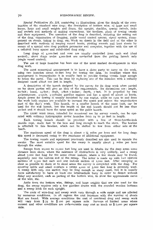
(2). The bottom wire (Fig. 2) is made up in 30 metre (16.4 fm.) units with an eye at each end, and a desired length of bottom wire is obtained b y joining these units with shackles or shackles and swivels.
A heavy weight is attached to the bottom wire at each end of the drag and smaller weights at intervals of from 90 to 120 metres (49.2 to 65.6 fms.).
The cables or uprights connecting weights and buoys are graduated every half metre. Their length is adjusted b y an adjuster attached at the bottom of each buoy.
Floats, each of which has the same buoyancy as the weight of the unit bottom wire, are attached to the wire at the connecting point of each unit between the weights, so that when the drag is not under w ay they keep the wire from sagging and catching on the bottom.
A steel rope, 15 millimetres (9/16 in.) in circumference, consisting of 6 strands of 7 wires each, having a breaking strength of 1,000 kilograms (19 3/4 cwt.), is used for the bottom wire.
Each of the large and small weights is a cast-iron sphere with one flat bottom surface to prevent rolling about deck in a seaway, and has an eye-bolt a t its top. The large weight weighs 30 kg. (66 lbs.) and the small 20 kg. (44 lbs.).
The buoy, conical in shape, made of steel, has an eye-bolt at its bottom end to take a shackle for connection with the upright and its length adjuster (Fig. 3). The buoy has a small screwed hole on one side for the inner pressure which is tightly closed b y a screw bolt. The large buoy has a weight of about 36 kg. (79 1/4 lbs.) and a buoyancy of 100 kg. (220 lbs.); the small buoy 16 kg. (35 1/4 lbs.) and 60 kg. (132 lbs.) respectively.
(1) Communicated by the Director of the U. S. Coast and Geodetic Survey.(2) Communicated by Rear-Admiral Yaiti Ono, Hydrographer of Japan.
*<N .Js
I a
e
I
*
£
t -s*c?
s °
Si Ȥ 2 S S o 05 ftq
The length adjuster is an iron hinge, the axis of which has an eye at the upper end for attachm ent to the buoy with shackles. A desired point of the upright is put between 2 pieces of the hinge and screw-fastened; thus the length of the upright is adjusted.
The float is conical in shape and made of steel. I t has a staple a t its bottom comer and a vertical fin on the same side that the staple is fixed. The float has a buoyancy of 0.27 kg. (9 1/2 oz.) and can stand the water pressure at a depth of about 70 metres (38fms.). I t is attached to the connecting point of the bottom wire with small hemp lanyard.
The upright is a flexible steel-wire rope, 15 mm. (9/16 in.) in circumference, made up of 6 strands of 19 wires each, and has a breaking strength of 1000 kg. (i9 3/4cwt.). It has an eye at each end for receiving shackles connecting it with the buoy and the weight. The upright is similarly marked, starting from the 5 metre point, to the system used for the sounding line.
The towline is simply a continuation of the bottom wire from each end of the drag up to the towing b o a ts ; its upper end is connected with the bowline. The length of the tow-line is determined depending on the length of the upright. In ordinary cases when the length of the upright is 20 metres (10.9 fms.) an adequate length of the tow- line is 150 metres (82 fms.). One end of the bowline, which is a 64 mm. (2 1/2 in.) Manila rope, is made fast at the bow of the towing boat and the other is connected with the upper end of the towline b y the steel hook. An adjusting line extends from the towline to the stem of towing boat, and is used to distribute the towing strain making steering easy when in tow.
(3). The towing boats of a pair tow the drag. The tender is used to patrol the drag, examine and change the length of the upright, sound on shoals, clear it from shoals, remove or warn against obstructions, repair the gear, etc.
The usual party organisation is as follows : Towing boat, 1 surveyor (assistant officer), 6 to 7 boatm en; tender, 1 surveyor (officer), 5 boatmen. The senior officer controls the operation on the tender as a rule. For operation in shoal waters or bending fairways the number of the tender and persons are increased depending on circumstances.
(4). In order to diminish error in plotting the dragged area the scale to be used (for the boat sheet) must be comparatively large. Scales of from 1:20,000 to 1:30,000 are generally used. Larger scales, however, m ay be adopted for narrows or shoaled areas, and sometimes smaller than 1:30,000 for an extended area with greater depths.
On the boat sheet basic points, a scale of distance, and a compass rose are drawn in advance.
(5). The vessels employed for the dragging operations are not specially constructed for th at purpose, but are ordinary surveying boats of 30 feet in length with a 10 to 30 horse-power engine used for lead-sounding, etc., provided only with the reel for the wire. The 30-h.p. boats are fit for an operation in which the length of the bottom wire is 1,200 metres (6 1/2 cables), the distance between buoys 120 metres (65 1/2 fms.), the distance between the towing boats of a pair 1,150 metres (6 1/4 cables), and the towing speed over the ground 1.5 knot, attaining an effective dragged breadth of about 1,050 m. (5 3/4 cables).
(6). The deep - drag work requires long towlines and is thus more likely to catch on shoals, greatly decreasing the working efficiency. Therefore, in ordinary sea areas the survey is generally conducted with an effective depth of 18 metres (9.8 fms.).
(7). The surveyed area is the area covered b y strips, each of which is bounded b y the paths of the large end buoys on either side between the lines representing the starting and ending positions of the bottom wire.
Each of the towing boats of a pair measures simultaneous position angles between 3 located objects to fix its position ; then the angle between the near end buoy (large) and one of the 3 objects. The distance between the boat and the end buoy is obtained from the known length of the towline. The position of the large end buoy is thus obtained from the above data and can be plotted. Successive positions of the buoy are connected b y straight lines representing the path of the buoy and one side of the strip. Each end of the strip is obtained from the position of the towing boats at the starting and ending points.

Each side and the limit of the surveyed strip plotted on the boat sheet b y each of the towing boats are transferred one after the other on to a new sheet b y means of transparent paper, and thus the closed effective surveyed area is completed.
A ll angles should be measured very quickly in order to minimise the error caused by the movement of the boat. In addition, land objects must be selected so that their relative positions make the change in one of the two position angles as small as possible. I t is better to use the land object nearest to the direction of the end buoy for measuring the angle between them. The officer in the tender also measures from time to time the positions of the end buoys and compares them with those measured by the towing boats after the day's work is over.
(8). Before reaching the working grounds the d ay’s work is planned and lines are drawn on the boat sheet representing the proposed course of the towing boats. Each course is numbered for distinction.
The distance between the towing boats of the pair is determined so that an effective width of the drag of about 83 per cent of the length of the bottom wire is obtainable. The length of the upright is determined taking into consideration the height of the tide and the lift of the bottom wire.
It is best to drag with the current if practicable ; when dragging against or across the current, not only is progress retarded bu t there is likely to be considerable variation and uncertainty in the lift (depth). Taking into account the wind and current, the setting out the drag should be so started that on finishing it each towing boat may occupy a favourable position to start dragging.
Each towing boat is provided with a nearly equal part of the drag. Arriving at the point to set out the drag, one of the towing boats passes over the end of the bottom wire to the other, and this is connected with the end of the part on board the latter boat. Each boat heads at slow speed on a course about at right angles to the track, paying ont the bottom wire. A t each connection of units of the bottom wire the engine is stopped while a weight, an upright or a float is attached. While streaming the buoys care must be taken to keep the bottom wire clear of the propeller taking due account of the wind and current. When the bottom wire and towline are set out the end of the towline is attached to the bowline on the side towards the drag, the adjusting line is attached, and the boat is ready to start dragging.
For work in narrow channels or close inshore the drag is usually set out a little distance offshore and then towed in to the starting point.
(9). On finishing setting out the drag the towing boats proceed on the prearranged course, heading out a little from the course. The towing speed should be less than 2 knots. An excessive speed will cause abnormal lift, hence error in depth. The towing boats should keep station as nearly abreast of each other as possible. For this one of the boats becomes the “standard” and the other measures bearings of the standard boat as well as the large buoy and endeavours to keep her proper position b y the use of her engine.
The depth of the bottom wire is determined b y tests conducted from the tender. A t e s t e r used for this purpose consists of a sounding lead and line with a small buoy a t the upper end. The lower part of the line, up to 2 metres (6 ft. 7 in.) from the lower end, has small copper-wire grapnels at intervals of 1/10 metre (3.9 in.) This tester, which is nearly equal to the upright in length, is thrown overboard a short distance ahead of the drag. The lower part of the tester strikes against the bottom wire and then the tester is hauled in. The depth of the bottom wire is known from the number of grapnels with unbent arms. The length of the tester is examined before and after the work.
The lift of the bottom wire will be about 1.5 metre (4 ft. xi in.) at each end and0.5 metre (1 ft. 8 in.) at the remaining part when the towing speed is less than 1.5 knot for a length of the upright of 19 metres (10.4 fm s ) If the length of the uprights of the large buoys be made longer b y 1 metre than those of the small buoys, the depth of the bottom wire may be kept almost uniform at all parts.
(10). If there is a known shoal within the dragging area the tender shortens the length of the uprights of the part or lifts the part of the bottom wire with a grapnel, so that the drag clears the shoal. The position and area where such change in the depth is made is measured and plotted on the sheet. When a part of the bottom wire has a different depth from the rest the lift of the deeper part directly adjacent thereto

will be greater than what is previously stated. Frequent examination of the depth of that part is therefore necessary. The tender prepares a tidal curve and adjusts the length of the upright, if necessary.
If one of the towing boats is disabled the tender takes its place.When a strip is completed the drag m ay be taken up or reversed to cover an
adjoining strip. To reverse the drag, the towing boats stop, shift towline from one side to the other, head at about right angles and the drag is towed endways over to the start of the next strip.
Insufficient overlapping of the strips makes the survey less reliable, possibly leaving uncovered areas which cause troublesome work. Though it m ay differ depending on conditions of land objects and the scale of the chart, an overlap of 100 metres (55 fms.) will be sufficient in ordinary cases for a work on a scale of 1:20,000. For smaller scales the overlap should be increased.
(11). When the drag proceeding with the current catches on a shoal the effect is noticed very quickly. The towing vessels lose headway, swing in from the track lines, and the buoys will begm to line up and point toward the shoal (see Fig. 1). The effect is more noticeable in the vessel nearer to the shoal. The vessel that first observes the grounding reports to the other vessels. The tender sounds with lead and line on the location of the indicated shoal, places a marker buoy, and clears the bottom wire from the shoal so as to allow the towing boats to continue dragging. The tender remains sounding and after finding the least depth rejoins the towing boats. .
When proceeding against the current the buoys will not line up so quickly, and if the towing vessels stop the drag may drift back from the shoal. In this case it is necessary to keep towing at slow speed until the tender can place a buoy a t the indicated location of the shoal.
A shoal of a smooth, small-grained material such as mud or sand will not necessarily stop the drag, but allow it to slide over. The drag should be used to find such mud or sand shoals by placing the buoys fairly close together and watching the drag closely. There will usually be some indications of the existence of such shoals, such as change in the relative positions of the buoys, or effects on the towing boats, etc. The use of the tension indicater is effective not only easily to notice the effect of grounding but also to utilise it for keeping the towing boats in position.
To clear the drag from a rock the tender lifts the bottom wire near the rock, with a grapnel or b y hauling in an upright. When the drag is cleared from the rock the tender goes ahead with the bottom wire lifted until the rock is past, when the wire is again lowered. If the shoal is extensive two tenders are necessary. There m ay be some cases where time can be saved b y taking up the drag and starting work anew. In such a case the area uncovered can be minimised b y dragging in the opposite direction and re-catching the shoal.
The bottom wire m ay sometimes cut deep into an obstruction making the removal very difficult and a portion has to be abandoned. The floats are attached to the bottom wire with small hemp lanyards in order to diminish the occurence of such trouble.
When there is a heavy swell the bottom wire may easily come clear from the shoal after being caught, the effect of the grounding of the drag remaining unnoticed.
(12). To take in the drag each vessel stops, the end of the towline is detached from the bowline and reeled in. When the weights, uprights, buoys and floats come aboard they are detached. Wind and current conditions may require the boats to take in the drag from the bow. Each boat takes in the same amount of drag that it sets out. After the drag is in, the gear is put in readiness for the next set-out.
G R E A T B R IT A IN .Although sweeping operations have been extensively used in the Hydrographic Ser
vice, information relating to the modern method of sweeping used b y Great Britain is not available for the present.
F R A N C E .In an article entitled Notes au Sujet de la Recherche des Roches sous l ’eau (Notes
concerning the Search for Sunken Rocks) Ingénieur Hydrographe R e n a u d published in the Annales Hydrographiques of 1902 a description of the d r a g u e f l o t t a n t e (floating wire drag) used by French hydrographers at that time for the examination of channels in the vicinity of Brest from the year 1897.

In 1931, the French Hydrographic Office issued a booklet, No. 12-102, entitled Description et Emploi des dragues hydrographiques (Description and use of Hydrographie Sweeps) b y Ingénieur Hydrographe C. V i l l a i n .
In this booklet Ingénieur Hydrographe V il l a in states that the technical instructions recommend to the Heads of Hydrographic Missions the verification, b y means of the wire drag, of indications provided b y soundings and b y the ordinary methods of investigation in order that no dangerous shoal m ay escape notice, as only the sweep can establish this with a certainty which cannot be attained b y any other means, and thus obtain security in navigation.
He also adds that there is no doubt that it is necessary to sweep in the first place and to postpone sounding operations intended for the perfecting of submarine relief, as this representation, although of interest to the mariner, has not the same urgency and is not of such imperative necessity as the sweep. B y beginning with wire dragging there is the advantage of certainty that no danger has been passed over, and later on, without inconvenience, regular soundings can be reduced to those indispensable for bottom representation which would be of use to navigators.
The booklet, which constitutes a manual for the use of various drags actually employed by French hydrographic missions, gives a description of the d r a g u e r a il (rail sweep), the d r a g u e r a t e a u (rake sweep), the d r a g u e a v e r g u e or f in l a n d a is e (i ) (spar or Finnish sweep), which are not described here as the areas swept by these means are of inconsiderable breadth only.
The booklet also reproduces a description of the d r a g u e f l o t t a n t e (floating wire drag) or d r a g u e h y d r o g r a p h iq u e f r a n ç a i s e (French hydrographic sweep) and of the A m e r ic a n w i r e d r a g . The French hydrographic sweep differs from the American wire drag solely in that it has an upper rope connecting the buoys and that grapnels are used instead of weights. The width of the swept area, which is already large with the French sweep, is inferior to the extent of the area swept b y the American drag which can cover several thousand metres.
The method of employing the F r e n c h w i r e d r a g consists in allowing it to drift. Thus it differs from the method of using the American wire drag which consists in towing the drag. B y suppressing the upper rope, streaming and taking in the drag are facilitated in the American wire drag. As the lower rope is raised when the drag is towed, the amount varying according to the length, the current and the greater or lesser tension exerted b y the tugs, it is necessary to take as frequent measurements as possible in order to obtain the depth of the lower rope.
The French Hydrographic Office also uses the A m e r ic a n w i r e d r a g with small variations in detail which are described in pamphlet No. 12-102 mentioned above. These variations consist principally in the shape of the floats connected with the bottom rope which is elliptical instead of cylindrical. The uprights of the large buoys are constructed partly of galvanised chain and the plugs for the attachment of the intermediate weights are different.
Tugs used in France are 50 tons displacement, 200 h. p., 20 metres (66 feet) in length, and 2 metres (6 feet 6 in.) draft. When heavier tugs are used a stronger bottom wire must be employed, all the iron rings must be suppressed and heavier weights and larger buoys must be used.
Boats used in wire dragging operations must have a fairly high speed as the change in the length of the uprights must be made with the greatest rapidity possible and, moreover, the boats must sometimes cover a distance approximately equal to the length of the drag for the purpose of disengaging it when caught on a rock.
The type of boat best adapted for dragging operations is at the present time the B r e s t o is type motor-boat with K it c h e n rudder (2). The fuel consumption is small : about 3 litres (2/3 imp. gall.) per hour. The boat has a low enough freeboard for the length of the uprights to be easily operated and the Kitchen rudder allows it to turn on the spot, and facilitates the approach to buoys during operations and the clearing of the drag. Unfortunately the speed of the Brestois type is rather low.
(1) Described in Hydrographic Review, Vol. 1, No 2, May 1924, page 64.(2) Described in Hydrographic Review, Vol. X , No. 2, November 1933, page 82.


Fig . 4
Fig . 5
Sweden — Spar Sweep attached to two motor launches.
Suède — Drague à espar rattachée à deux embarcations à moteur.

The pamphlet issued b y the French Hydrographic Office gives detailed indications for the preparation of the sweep, and the preparation of the scheme of strips on the advance sheet ; the operation of tugs and boats is also described as well as measures for checking the drag depths. A special chapter is devoted to the method of keeping record books of sweeping operations, for the drafting of the system of wire dragging and for the establishment of the fair- sheet in sweeping operations.
SW E D E N .
The following methods are used in Sweden for sweeping for shoals
(1) Spar sweep attached to a vessel.
(2) Drag sweeping with a towed spar sweep.
(3) Spar sweep attached to two motor launches.
(4) Bar sweep.
(5) Wire drag.
O f these five methods (1) and (2) are as already described in Hydrographic Review, Vol. I, No. 2, M ay 1924, pp. 60-66. (The Sentry Sweep described therein is no longer used).
S p a r s w e e p a t t a c h e d t o t w o m o t o r l a u n c h e s .
This sweep is essentially the same as (1), the spar sweep attached to a vessel; the method of sweeping is as described under the heading Sweeping a shoal of very small extent on page 65 of the above-quoted Review. I t is, however, adapted to two coupled motor launches instead of a vessel, and consequently is of lighter dimensions. Plan No. 1 shows the general arrangement of this sweep, and Figures 4 & 5 show the boats sweeping. Detailed drawings showing the construction are available in the I. H . B., copies of which could be supplied on request.
The upright spars are graduated in metres and decimetres (black and white alternately).
I t has been found that when using launches of about 10 metres in length and motors of about 10 h. p. each, there is not usually any need to stop the motors when passing over the top of the shoal.
B a r S w e e p .
This is a handy apparatus used for sweeping shoals, which is designed to be carried on board of every surveying launch. I t consists of a steel bar, 5 metres in length, which is lowered to the depth desired and towed over the shoal to be investigated. I t is kept in a position athwartships below the middle part of the motor launch b y two fore-guys of steel wire from a yoke fastened to the stem, and two upright wire guys passing through blocks at the head of two davits.
Plan No. 2 shows the general arrangement of the sweep and No. 3 details of the bar. Further drawings showing details of the yoke, davits and winches are available in theI. H . B., copies of which could be supplied on request.
I t is essential that the sweep should be towed at low speed (1 to 2 knots). If the speed is too great, the uprights will not be kept taut. When the bar touches the bottom, this is felt very effectively in the upright guys, on which the surveyor and one assistant should always keep his hand while sweeping.
The bar is lowered for use b y the fore guys, and when taking up the bar, the top or upright guys are slackened and the bar is hauled up b y the fore-guys until it is near the water-line. I t is then taken up by aid of boat-hooks, and while the launch proceeds to the next shoal or takes soundings, the bar is lying athwartships abaft the stem and kept in position b y the tightened fore- and top-guys.
The top-guys are marked to whole metres b y leather, white, blue, red and marline marks, and the half-metres are marked b y small marline-marks.
This sweep is still to be regarded as being in the experimental stage, but has already proved very useful for sweeping shoals down to 10 metres.
!
1
à
$.i
ce.s1I
i
Arg
enti
ne
— D
ragu
e hy
drog
raph
ique
.

W i r e d r a g .
This is the same as that used b y the U. S. Coast and Geodetic Survey and described in Special Publication No. 118 of U. S .Coast and Geodetic Survey.
A R G E N T IN A .
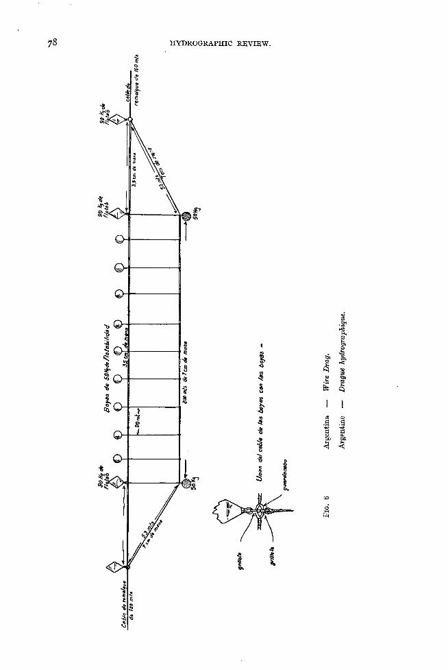
In the Instrucciones generales para las Comisiones Hidrográficas, 1928, (General Instructions for Hydrographic Surveying Expeditions, 1928), published in the Anales Hidrográficas, Tomo IX , Buenos Aires, 1929, the Hydrographic Office of Argentina gives a description of the r a s t r a d e a l a m b r a , i. e. of the American wire drag.
Experimental wire drag work has been carried out at the entrance of the Gulf of San José with a t a u t w i r e h y d r o g r a p h i c s w e e p , as illustrated in the figure opposite, the length of drag being 200 metres (660 feet).
For controlling the position of one of the tugs (the guiding vessel) two position stations were established ashore with theodolites and a third station was established on
•board a vessel anchored in a suitable place for taking sextant measurements of the angles between the tugs and the theodolite stations. The position of this vessel was determined at regular intervals from the theodolite stations. A tidal station was also established for observing the tide.
The sweep was operated from vessels of 800 tons propelled b y two engines.The wire drag, constructed in the form shown in the above illustration, was adjusted
for an effective depth of 10 fathoms.The guiding vessel supervised the work and the position of the other vessel was
determined each time the position of the guiding vessel was fixed by means of the distance of the guide and the angle between it and one of the theodolite stations.
However the prevailing current was about 6 knots and, the traction of the tug being very strong, the resistance of the buoys in spite of the guiding rope connecting them caused the bottom wire to lift.
Experience has shown that in places subject to currents a solution is to be found in the use of a taut wire between two boats, intended merely to maintain the tension of the drag, the latter acting only with the drift of the current.
C H IL E .
Captain E. G ü n t h e r , Assistant-Director of the Oficina de Hidrografía of Valparaiso published in the Anuario Hidrográfico de la Marina de Chile, Book 31, 1918, pages 395- 429, a translation in Spanish of the method for the use of the A m e r i c a n w i r e s w e e p , under the title of Descripción de la Rastra de alambra de gran extension.
D E N M A R K .
Since 1926 has introduced the use of a w i r e d r a g of the same construction as mentioned in U. S. Coast and Geodetic Survey Special Publications Nos. 56 and 118.
E xact depth over stones is found b y means of the s p a r s w e e p mentioned in Hydrographic Review, Vol. I, No. 2, M ay 1924, pp. 64-65.
NORW A Y .
No regular sweeping has yet been put into operation in Norway due to the want of appropriation for working the wire sweep. However a sweeping apparatus has been worked essentially for trial in the Oslofjord during a couple of weeks in 1930 and in 1931.
G E R M A N Y .
The N avy of the Reich does not use apparatus for sweeping foul areas as the bottom of its coastal waters is sandy and only rises very gradually.

N E T H E R L A N D S.
The sweeping apparatus in use for hydrographic work in the Netherlands and its colonies is of such simple construction, owing to the fact that only weak-powered launches are available, that information about it is not reproduced here. Information concerning the method used in the Laoet Strait and in Soerabaja roads appears on page 66 of Hydrogvaphisch Opnemen, ’s-Gravenhage, 1925 by Captain J. L. H. L u y m e s .
B E L G IU M .
The Directeur Général des Voies Hydrauliques has indicated that the use of sweeping on the oozy and sandy bottoms of Belgian waters is not necessary for the purpose of determining submarine contours.
S P A IN .The Spanish Hydrographic Office seldom uses sweeping either for checking the non
existence of reported dangers or for detecting pinnacle rocks.
P O R T U G A L .
The Head of the Portuguese Hydrographic Office indicates that the Portuguese Coastal Hydrographic Service has not so far used the hydrographic sweep method.
I T A L Y .The Bureau has been informed by the Director of the Italian Hydrographic Office
that the method of checking depths in certain areas by means of the hydrographic sweep is not at present used by the Italian Service.
G R EECE.Until 1927 no systematic sweeping for the investigation of shoals had been carried
out.
S IA M .Occasionally the sweeping method is adopted in sounding existing rocks, the position
of which cannot possibly be ascertained b y hand soundings.
C H IN A .The method of sounding b y sweeping is not yet in use in China (1932).
A U S T R A L IA .No sweeping of areas has been carried out in Australia to date (1932).
B R A Z IL .The sweeping apparatus is employed only as a complement to new hydrographic
surveys.
□ □ □

P l a n N ° 1Sweden — Spar Sweep attached to two motor launches
Suède — Drague à esitar r a t ta c h é e à deux embarcations à moteur
n

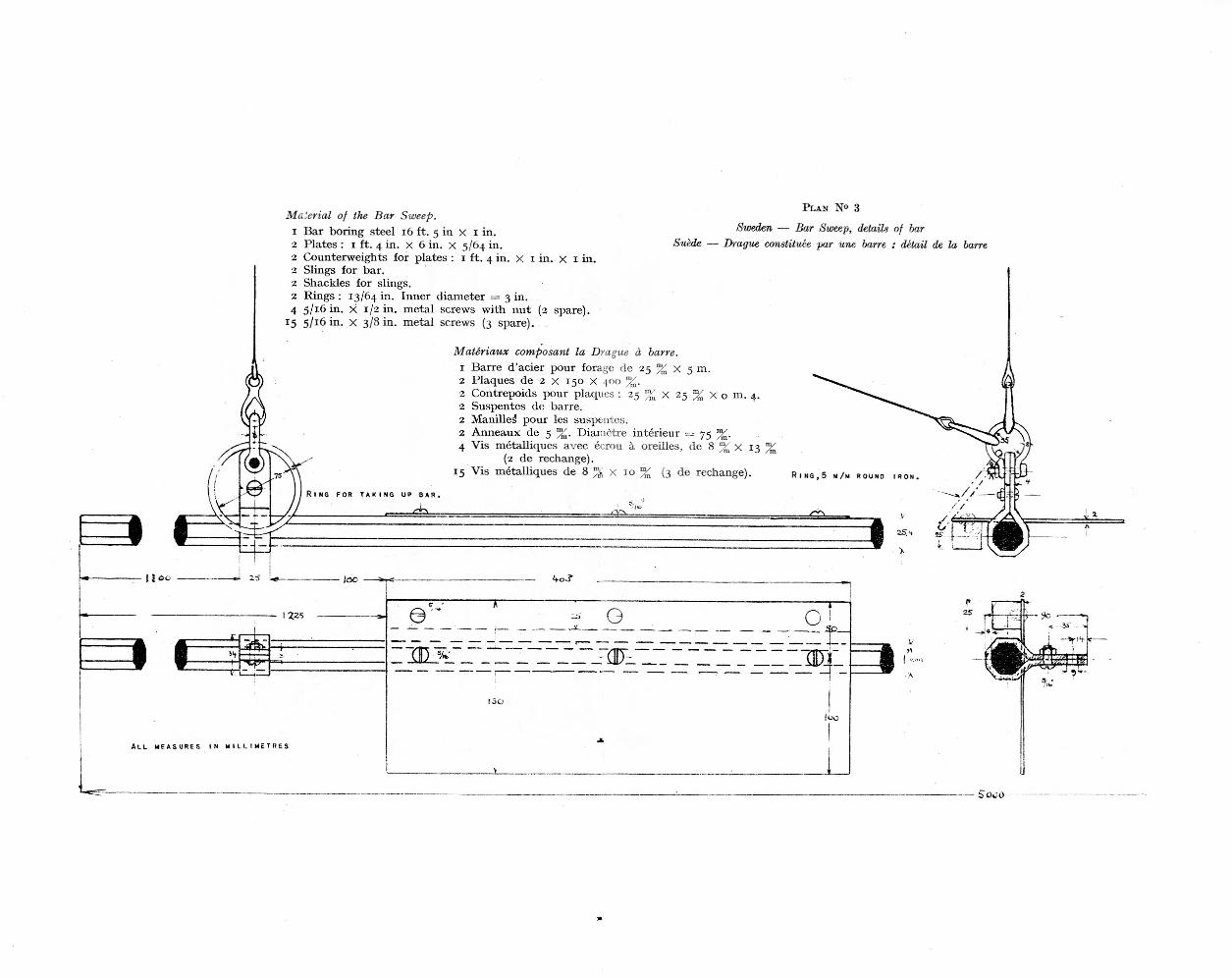
Material of the Bar Sweep.1 Bar boring steel 16 ft. 5 in x I in.
Plates : 1 ft. 4 in. x 6 in. x 5/64 in.Counterweights for plates : 1 ft. 4 in. x 1 in. x x in.
2 Slings for bar.2 Shackles for slings.2 Rings : 13/64 in. Inner diameter = 3 in.4 5/1.6 in. x 1/2 in. m etal screws w ith nut (2 spare).
15 5/16 in. x 3/8 in. m etal screws (3 spare).
22
Suède
Plan N° 3
Sweden — Bar Sweep, details of bar Drague constituée par une barre : détail de la barre
M atériaux composant la Drague à barre.1 Barre d ’acier pour forage de 25 % x 5 m.2 Plaques de 2 x 150 X 400 % .2 Contrepoids pour plaques : 25 % x 25 % x o m. 4. 2 Suspentes de barre.2 Manille^ pour les suspentes.2 A nneaux de 5 Diamètre intérieur = 75 4 V is métalliques avec écrou à oreilles
(2 de rechange).15 V is métalliques de 8 % x 10 % (3 de rechange).
/m*de 8 w X 13 %
R i n g f o r t a k i n g u p b a r .
Copyright © 2022 FDOKUMEN