Methodology for Selecting the Operating Conditions of ... - MDPI
11
materials Article Methodology for Selecting the Operating Conditions of a Vibration Generator Used in the Hot-Dip Galvanizing Process Wojciech Kacalak, Igor Maciejewski, Dariusz Lipi ´ nski * and Bla ˙ zej Balasz Citation: Kacalak, W.; Maciejewski, I.; Lipi ´ nski, D.; Balasz, B. Methodology for Selecting the Operating Conditions of a Vibration Generator Used in the Hot-Dip Galvanizing Process. Materials 2021, 14, 2042. https://doi.org/10.3390/ ma14082042 Academic Editor: Georgios Savaidis Received: 22 March 2021 Accepted: 13 April 2021 Published: 19 April 2021 Publisher’s Note: MDPI stays neutral with regard to jurisdictional claims in published maps and institutional affil- iations. Copyright: © 2021 by the authors. Licensee MDPI, Basel, Switzerland. This article is an open access article distributed under the terms and conditions of the Creative Commons Attribution (CC BY) license (https:// creativecommons.org/licenses/by/ 4.0/). Faculty of Mechanical Engineering, Koszalin University of Technology, 75-620 Koszalin, Poland; [email protected] (W.K.); [email protected] (I.M.); [email protected] (B.B.) * Correspondence: [email protected]; Tel.: +48-94-3478-295 Abstract: A simulation model and the results of experimental tests of a vibration generator in applications for the hot-dip galvanizing process are presented. The parameters of the work of the asynchronous motor forcing the system vibrations were determined, as well as the degree of unbalance enabling the vibrations of galvanized elements weighing up to 500 kg to be forced. Simulation and experimental tests of the designed and then constructed vibration generator were carried out at different intensities of the unbalanced rotating mass of the motor. Based on the obtained test results, the generator operating conditions were determined at which the highest values of the amplitude of vibrations transmitted through the suspension system to the galvanized elements were obtained. Keywords: vibration; hot-dip galvanizing; generator; simulation; zinc coating 1. Introduction Galvanizing is a technology for anticorrosive protection of the surface of metal prod- ucts by applying a mechanically durable zinc coating. One of the most important galvaniza- tion technologies is hot-dip galvanizing for anticorrosive protection of the surface of metal products by applying a mechanically durable zinc coating. Zinc coatings can be applied in the following processes: hot-dip galvanizing, electroplating, and zinc spraying. Hot-dip galvanizing makes it possible to obtain good-quality coatings and provides long-term protection [1]. In the conventional hot-dip galvanizing process, the surface of a steel object is cleaned and then immersed in a zinc bath at a temperature of approximately 450 ◦ C[2]. The hot-dip galvanizing process provides a coating with high strength, deformability, and low weight. Research on the hot-dip galvanizing process is mainly related to the composition of the zinc bath and the method of the surface preparation of products [3]. A significant cost of the hot-dip galvanizing process is the cost of zinc. Zinc consump- tion depends mainly on the thickness of the coating, but is also influenced by specific process conditions resulting in the formation of hard zinc, zinc ashes, oxidation of the bath surface, as well as the formation of solidified zinc droplets [4]. After the hot-dip galvanizing process, the excess of zinc drips from the surface of the steel products by gravity. This results in uneven zinc coating and the accumulation of zinc bath residues in areas that do not allow free zinc flow [5]. As a result, apart from the inaccuracy of the produced zinc coating, the share of waste generated also increases, inter alia, as a result of the mechanical removal of stains and local excessive zinc layers [6]. In the zinc coatings produced on steel elements in the process of hot-dip galvanizing, two layers [7] can be distinguished: the internal diffusion and the external diffusion in the form of a solidifying film during the resurfacing of galvanized elements. The thickness proportions of these layers depend on the parameters of the galvanizing process. The aim is to create a thin diffusion layer with high adhesion and an even but possibly thin outer layer with low porosity. The quality of the produced outer layer depends on the Materials 2021, 14, 2042. https://doi.org/10.3390/ma14082042 https://www.mdpi.com/journal/materials
-
Upload
khangminh22 -
Category
Documents
-
view
3 -
download
0
Transcript of Methodology for Selecting the Operating Conditions of ... - MDPI
materials
Article
Methodology for Selecting the Operating Conditions of aVibration Generator Used in the Hot-Dip Galvanizing Process
Wojciech Kacalak, Igor Maciejewski, Dariusz Lipinski * and Błazej Bałasz
Citation: Kacalak, W.; Maciejewski,
I.; Lipinski, D.; Bałasz, B.
Methodology for Selecting the
Operating Conditions of a Vibration
Generator Used in the Hot-Dip
Galvanizing Process. Materials 2021,
14, 2042. https://doi.org/10.3390/
ma14082042
Academic Editor: Georgios Savaidis
Received: 22 March 2021
Accepted: 13 April 2021
Published: 19 April 2021
Publisher’s Note: MDPI stays neutral
with regard to jurisdictional claims in
published maps and institutional affil-
iations.
Copyright: © 2021 by the authors.
Licensee MDPI, Basel, Switzerland.
This article is an open access article
distributed under the terms and
conditions of the Creative Commons
Attribution (CC BY) license (https://
creativecommons.org/licenses/by/
4.0/).
Faculty of Mechanical Engineering, Koszalin University of Technology, 75-620 Koszalin, Poland;[email protected] (W.K.); [email protected] (I.M.); [email protected] (B.B.)* Correspondence: [email protected]; Tel.: +48-94-3478-295
Abstract: A simulation model and the results of experimental tests of a vibration generator inapplications for the hot-dip galvanizing process are presented. The parameters of the work ofthe asynchronous motor forcing the system vibrations were determined, as well as the degreeof unbalance enabling the vibrations of galvanized elements weighing up to 500 kg to be forced.Simulation and experimental tests of the designed and then constructed vibration generator werecarried out at different intensities of the unbalanced rotating mass of the motor. Based on the obtainedtest results, the generator operating conditions were determined at which the highest values of theamplitude of vibrations transmitted through the suspension system to the galvanized elementswere obtained.
Keywords: vibration; hot-dip galvanizing; generator; simulation; zinc coating
1. Introduction
Galvanizing is a technology for anticorrosive protection of the surface of metal prod-ucts by applying a mechanically durable zinc coating. One of the most important galvaniza-tion technologies is hot-dip galvanizing for anticorrosive protection of the surface of metalproducts by applying a mechanically durable zinc coating. Zinc coatings can be applied inthe following processes: hot-dip galvanizing, electroplating, and zinc spraying. Hot-dipgalvanizing makes it possible to obtain good-quality coatings and provides long-termprotection [1]. In the conventional hot-dip galvanizing process, the surface of a steel objectis cleaned and then immersed in a zinc bath at a temperature of approximately 450 C [2].The hot-dip galvanizing process provides a coating with high strength, deformability,and low weight. Research on the hot-dip galvanizing process is mainly related to thecomposition of the zinc bath and the method of the surface preparation of products [3].
A significant cost of the hot-dip galvanizing process is the cost of zinc. Zinc consump-tion depends mainly on the thickness of the coating, but is also influenced by specificprocess conditions resulting in the formation of hard zinc, zinc ashes, oxidation of thebath surface, as well as the formation of solidified zinc droplets [4]. After the hot-dipgalvanizing process, the excess of zinc drips from the surface of the steel products bygravity. This results in uneven zinc coating and the accumulation of zinc bath residuesin areas that do not allow free zinc flow [5]. As a result, apart from the inaccuracy of theproduced zinc coating, the share of waste generated also increases, inter alia, as a result ofthe mechanical removal of stains and local excessive zinc layers [6].
In the zinc coatings produced on steel elements in the process of hot-dip galvanizing,two layers [7] can be distinguished: the internal diffusion and the external diffusion in theform of a solidifying film during the resurfacing of galvanized elements. The thicknessproportions of these layers depend on the parameters of the galvanizing process. Theaim is to create a thin diffusion layer with high adhesion and an even but possibly thinouter layer with low porosity. The quality of the produced outer layer depends on the
Materials 2021, 14, 2042. https://doi.org/10.3390/ma14082042 https://www.mdpi.com/journal/materials
Materials 2021, 14, 2042 2 of 11
dynamics of zinc displacement on the galvanized product, both during the bath and duringthe removal of the element from the bath.
The properties of the outer layer can be shaped by the appropriate selection ofthe speed of the product emerging from the bath (with an estimated speed of about1.5 m/min [4]). Too slow an extraction speed produces a uniform unalloyed zinc layer. Inthe case of excessive extraction speed, an uneven zinc layer is formed. The heterogeneity ofthe zinc layer affects the locally variable corrosion properties of the produced coatings [8].In hot-dip galvanizing processes, the thickness of the zinc coating can be controlled withthe use of air knife wiping [9]. This process removes any excess of liquid zinc with agas stream. However, the application of this process is limited mainly to the galvanizingprocesses of products with non-complex shapes (e.g., steel strips) [10].
The formation of the outer layer of zinc on tinned elements is the result of adhesion andcohesion processes described by the equations of motion of incompressible fluids of highviscosity. The formation of the liquid layer depends on the friction forces, dependent on theviscosity, surface tension, and inertia forces [11]. The speed of the zinc bath particles in theboundary layer when the elements are withdrawn from the liquid bath depends on theirdistance from the surface of the object. On the surface, the speed of the particles is close tothe speed of the object, and decreases to zero in the border area of the meniscus. The systemof frictional and inertia forces as well as gravity and surface tension shapes the convexmeniscus. Increasing the speed of movement of the pulled-out elements increases thelifting forces. This increases the thickness of the liquid zinc layer, which adversely affectsthe evenness of the layer and increases the consumption of zinc, leading to a reductionin the efficiency of the galvanizing process. The introduction of vibrations increases theforces of dynamic impact on liquid zinc particles, causing the thickness of the layers inzones of excessive thickness and the removal of thin zinc films in the spaces of openingsand small-width recesses.
The use of vibration in technological processes has been the subject of many stud-ies [12,13]. For example, in machining, low-amplitude vibrations (from 2 µm to 100 µm)and frequencies ranging from a few Hz to 40 kHz were introduced [12]. Thanks to theappropriate selection of cutting parameters and the parameters of the vibration process,it was possible to reduce the thickness of the cutting layer in [14,15] and to reduce thecutting forces in [16]. As a result, machined surfaces with more-favorable roughness pa-rameters [17] and with higher dimensional accuracy [18] were obtained. In the automatedhot-dip galvanizing process of steel sheets, the vibration amplitude of a galvanized elementis approximately 1 mm [19]. The uniformity of the thickness of the zinc coating is in thiscase ensured by the use of air knives. In the case of galvanizing elements of complex shapecontaining closed profiles, it is not possible to use air knives. The removal of excess zinccan in this case be achieved by inducing low-frequency and low-amplitude vibrations.
The following paper presents a methodology for selecting the operation conditions ofa vibration generator that can be used in hot-dip galvanizing processes. The assumptionof the modified galvanizing process, in which the stage of removing the products fromthe zinc bath takes place with the participation of mechanical vibrations with a specificamplitude and frequency, depends on the weight of the suspended galvanized elements.The purpose of the vibrations during the emergence of the elements from the zinc bath isto increase the uniformity of the coating thickness, limiting the formation of thin layers ofzinc covering holes with small diameters and shaping a favorable geometric structure ofthe surface.
The main problem to be solved was the development of the structure of vibrationgenerators and the methodology of selecting parameters for controlling their operation forthe assumption that the mass of galvanized elements with their mounting system wouldbe from 500 to 1000 kg. It was assumed that the weight of the casing and other elementssuspended on the transport system, to which vibrations should be transmitted to the leastextent, would be limited by the parameters of the permissible load of this system. The
Materials 2021, 14, 2042 3 of 11
further part of the work presents the results of experimental tests of the manufacturedprototype of a vibration generator for use in the galvanizing process.
2. Simulation Model of the Vibration Generator
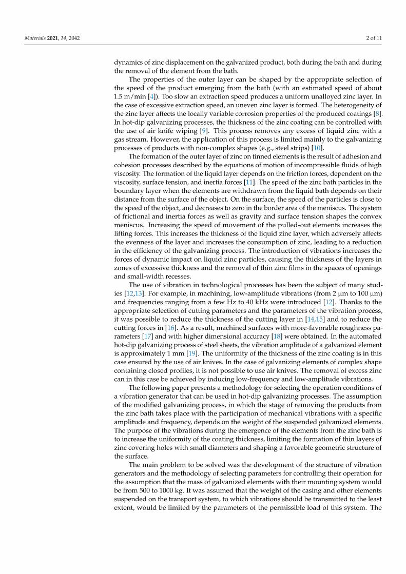
The designed mechanical vibration generator for hot-dip galvanization applications ispresented in Figure 1. The system includes two vibration generators placed between thegantry and the platform with galvanized items.
Materials 2021, 14, x FOR PEER REVIEW 3 of 11
for the assumption that the mass of galvanized elements with their mounting system would be from 500 to 1000 kg. It was assumed that the weight of the casing and other elements suspended on the transport system, to which vibrations should be transmitted to the least extent, would be limited by the parameters of the permissible load of this system. The further part of the work presents the results of experimental tests of the manufactured prototype of a vibration generator for use in the galvanizing process.
2. Simulation Model of the Vibration Generator The designed mechanical vibration generator for hot-dip galvanization applications
is presented in Figure 1. The system includes two vibration generators placed between the gantry and the platform with galvanized items.
(a)
(b) (c)
Figure 1. Visualization of the designed vibration system for galvanizing processes (a); vibration generator 800 mm (L) × 600 mm (W) × 530 mm (H) (b); enlargement of a part of the suspension system (c). Figure 1. Visualization of the designed vibration system for galvanizing processes (a); vibration generator 800 mm (L) ×600 mm (W) × 530 mm (H) (b); enlargement of a part of the suspension system (c).
The system is forced to vibrate by a mechanical vibrator in which unbalanced massesare set in rotation around the axis of the electric motor. The system vibrations are transferredto the suspended elements for galvanizing through a vibrating plate placed in the spring
Materials 2021, 14, 2042 4 of 11
system. The weight of the galvanized products suspended from the vibrating plate affectsthe behavior of the entire system.
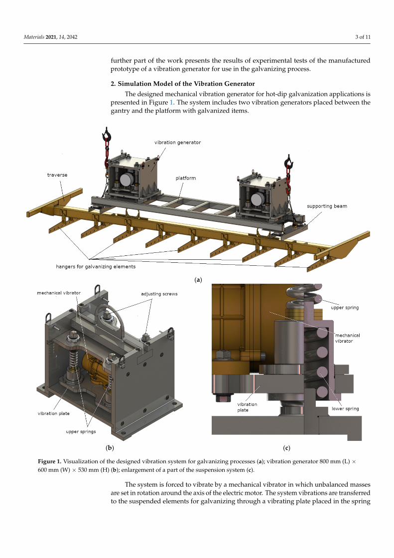
A physical model of the vibration generator tested in laboratory conditions is pre-sented in Figure 2. The presented system comprises a vibration plate with electric shaker(mass m1, its vertical movement y1), the vibrating object (mass m2, its vertical movementy2), and the system housing (mass m3, its vertical movement y3). The generator housing ismounted using viscoelastic elements, which represent the system support for a speciallyprepared frame structure. In the case of the presented model, apart from the verticalvibration of individual elements of the generator, the entire system can generate oscillatorymovements in the direction labeled as x3.
Materials 2021, 14, x FOR PEER REVIEW 4 of 11
The system is forced to vibrate by a mechanical vibrator in which unbalanced masses are set in rotation around the axis of the electric motor. The system vibrations are transferred to the suspended elements for galvanizing through a vibrating plate placed in the spring system. The weight of the galvanized products suspended from the vibrating plate affects the behavior of the entire system.
A physical model of the vibration generator tested in laboratory conditions is pre-sented in Figure 2. The presented system comprises a vibration plate with electric shaker (mass m1, its vertical movement y1), the vibrating object (mass m2, its vertical movement y2), and the system housing (mass m3, its vertical movement y3). The generator housing is mounted using viscoelastic elements, which represent the system support for a specially prepared frame structure. In the case of the presented model, apart from the vertical vi-bration of individual elements of the generator, the entire system can generate oscillatory movements in the direction labeled as x3.
Figure 2. Physical model of the mechanical vibration generator with unbalance of the motor rotat-ing mass.
Equations of motion for individual system components in the vertical direction are presented in the form of ordinary differential equations, which are presented according to the following relationships:
eeFyykyykyycyykym cos44 13321221231111 21221222 yykyycym 343413331133 4444 ycykyykyykym
(1)
where k1 is the stiffness of the lower springs (4 pcs.), c2 and k2 are the damping and stiff-ness of the rod fixing the element excited to mechanical vibrations, k3 is the stiffness of the upper springs (4 pcs.), c4 and k4 are the damping and stiffness representing the system support, Fe is the centrifugal force of the vibration shaker, and θe is the rotational angle of the electric motor.
Vibrations generated by the entire mechanical system in the horizontal direction are explained by using only one ordinary differential equation, as follows:
Figure 2. Physical model of the mechanical vibration generator with unbalance of the motor rotating mass.
Equations of motion for individual system components in the vertical direction arepresented in the form of ordinary differential equations, which are presented according tothe following relationships:
m1..y1 = −4k1(y1 − y3)− c2
( .y1 −
.y2)− k2(y1 − y2) + 4k3(y3 − y1) + Fe cos θe
m2..y2 = c2
( .y1 −
.y2)+ k2(y1 − y2)
m3..y3 = 4k1(y1 − y3)− 4k3(y3 − y1)− 4k4y3 − 4c4
.y3
(1)
where k1 is the stiffness of the lower springs (4 pcs.), c2 and k2 are the damping and stiffnessof the rod fixing the element excited to mechanical vibrations, k3 is the stiffness of theupper springs (4 pcs.), c4 and k4 are the damping and stiffness representing the systemsupport, Fe is the centrifugal force of the vibration shaker, and θe is the rotational angle ofthe electric motor.
Materials 2021, 14, 2042 5 of 11
Vibrations generated by the entire mechanical system in the horizontal direction areexplained by using only one ordinary differential equation, as follows:
(m1 + m2 + m3)..x3 = −4k5x3 − 4c5
.x3 + Fe sin θ (2)
where m1 + m2 + m3 is the total mass of the examined vibration generator and x3 is itsdisplacement measured in the horizontal direction.
The centrifugal force of the element introducing both vertical and horizontal vibrationsinto the system is described with the following relationship:
Fe = δeme.θe
2re, (3)
where δe is the intensity of an unbalanced rotating mass of the motor, me is the mass of therotating element,
.θe is the rotational speed of the electric motor, and re is the lever arm of
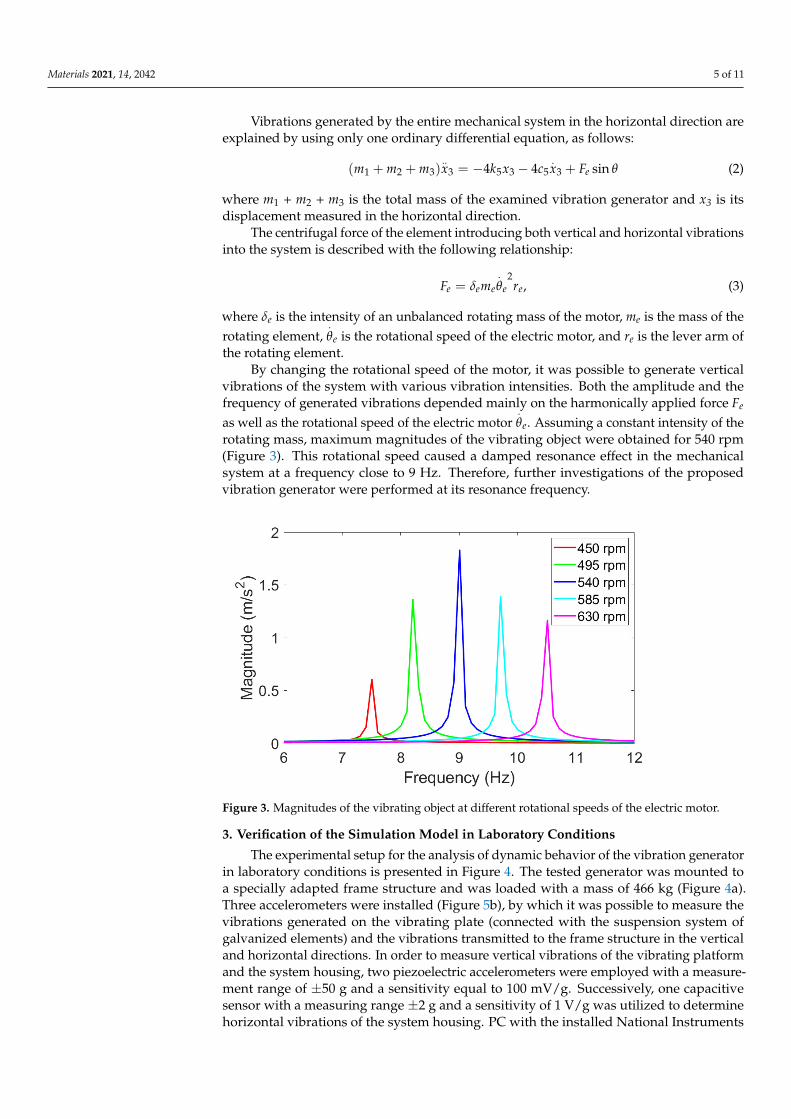
the rotating element.By changing the rotational speed of the motor, it was possible to generate vertical
vibrations of the system with various vibration intensities. Both the amplitude and thefrequency of generated vibrations depended mainly on the harmonically applied force Fe
as well as the rotational speed of the electric motor.θe. Assuming a constant intensity of the
rotating mass, maximum magnitudes of the vibrating object were obtained for 540 rpm(Figure 3). This rotational speed caused a damped resonance effect in the mechanicalsystem at a frequency close to 9 Hz. Therefore, further investigations of the proposedvibration generator were performed at its resonance frequency.
Materials 2021, 14, x FOR PEER REVIEW 5 of 11
sin44 35353321 eFxcxkxmmm (2)
where m1 + m2 + m3 is the total mass of the examined vibration generator and x3 is its dis-placement measured in the horizontal direction.
The centrifugal force of the element introducing both vertical and horizontal vibra-tions into the system is described with the following relationship:
eeeee rmF 2 , (3)
where δe is the intensity of an unbalanced rotating mass of the motor, me is the mass of the rotating element, 𝜃 is the rotational speed of the electric motor, and re is the lever arm of the rotating element.
By changing the rotational speed of the motor, it was possible to generate vertical vibrations of the system with various vibration intensities. Both the amplitude and the frequency of generated vibrations depended mainly on the harmonically applied force Fe as well as the rotational speed of the electric motor 𝜃 . Assuming a constant intensity of the rotating mass, maximum magnitudes of the vibrating object were obtained for 540 rpm (Figure 3). This rotational speed caused a damped resonance effect in the mechanical system at a frequency close to 9 Hz. Therefore, further investigations of the proposed vibration generator were performed at its resonance frequency.
Figure 3. Magnitudes of the vibrating object at different rotational speeds of the electric motor.
3. Verification of the Simulation Model in Laboratory Conditions The experimental setup for the analysis of dynamic behavior of the vibration gen-
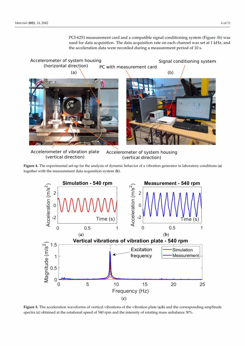
erator in laboratory conditions is presented in Figure 4. The tested generator was mounted to a specially adapted frame structure and was loaded with a mass of 466 kg (Figure 4a). Three accelerometers were installed (Figure 5b), by which it was possible to measure the vibrations generated on the vibrating plate (connected with the suspension system of galvanized elements) and the vibrations transmitted to the frame structure in the vertical and horizontal directions. In order to measure vertical vibrations of the vi-brating platform and the system housing, two piezoelectric accelerometers were em-ployed with a measurement range of ±50 g and a sensitivity equal to 100 mV/g. Succes-sively, one capacitive sensor with a measuring range ±2 g and a sensitivity of 1 V/g was utilized to determine horizontal vibrations of the system housing. PC with the installed National Instruments PCI-6251 measurement card and a compatible signal conditioning system (Figure 4b) was used for data acquisition. The data acquisition rate on each channel was set at 1 kHz, and the acceleration data were recorded during a measurement period of 10 s.
Figure 3. Magnitudes of the vibrating object at different rotational speeds of the electric motor.
3. Verification of the Simulation Model in Laboratory Conditions
The experimental setup for the analysis of dynamic behavior of the vibration generatorin laboratory conditions is presented in Figure 4. The tested generator was mounted toa specially adapted frame structure and was loaded with a mass of 466 kg (Figure 4a).Three accelerometers were installed (Figure 5b), by which it was possible to measure thevibrations generated on the vibrating plate (connected with the suspension system ofgalvanized elements) and the vibrations transmitted to the frame structure in the verticaland horizontal directions. In order to measure vertical vibrations of the vibrating platformand the system housing, two piezoelectric accelerometers were employed with a measure-ment range of ±50 g and a sensitivity equal to 100 mV/g. Successively, one capacitivesensor with a measuring range ±2 g and a sensitivity of 1 V/g was utilized to determinehorizontal vibrations of the system housing. PC with the installed National Instruments
Materials 2021, 14, 2042 6 of 11
PCI-6251 measurement card and a compatible signal conditioning system (Figure 4b) wasused for data acquisition. The data acquisition rate on each channel was set at 1 kHz, andthe acceleration data were recorded during a measurement period of 10 s.
Materials 2021, 14, x FOR PEER REVIEW 6 of 11
Figure 4. The experimental set-up for the analysis of dynamic behavior of a vibration generator in laboratory conditions (a) together with the measurement data acquisition system (b).
(a) (b)
(c)
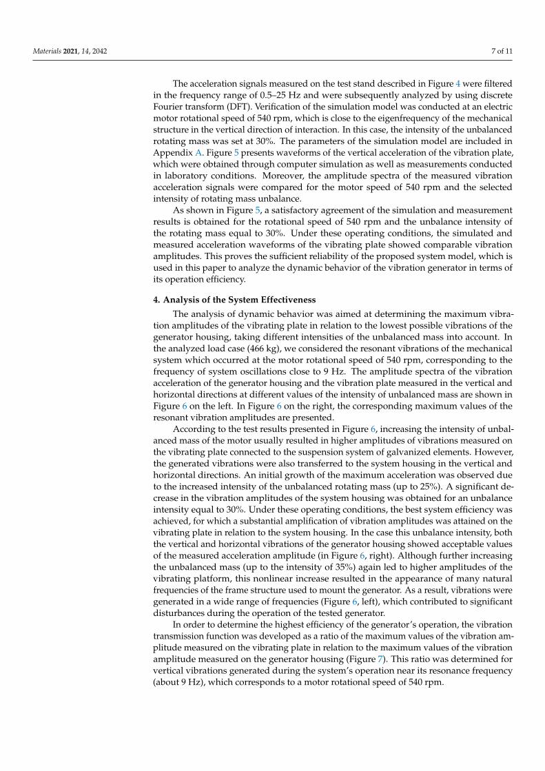
Figure 5. The acceleration waveforms of vertical vibrations of the vibration plate (a,b) and the corresponding amplitude spectra (c) obtained at the rotational speed of 540 rpm and the intensity of rotating mass unbalance 30%.
The acceleration signals measured on the test stand described in Figure 4 were fil-tered in the frequency range of 0.5–25 Hz and were subsequently analyzed by using dis-crete Fourier transform (DFT). Verification of the simulation model was conducted at an electric motor rotational speed of 540 rpm, which is close to the eigenfrequency of the mechanical structure in the vertical direction of interaction. In this case, the intensity of the unbalanced rotating mass was set at 30%. Figure 5 presents waveforms of the vertical acceleration of the vibration plate, which were obtained through computer simulation as
Figure 4. The experimental set-up for the analysis of dynamic behavior of a vibration generator in laboratory conditions (a)together with the measurement data acquisition system (b).
Materials 2021, 14, x FOR PEER REVIEW 6 of 11
Figure 4. The experimental set-up for the analysis of dynamic behavior of a vibration generator in laboratory conditions (a) together with the measurement data acquisition system (b).
(a) (b)
(c)
Figure 5. The acceleration waveforms of vertical vibrations of the vibration plate (a,b) and the corresponding amplitude spectra (c) obtained at the rotational speed of 540 rpm and the intensity of rotating mass unbalance 30%.
The acceleration signals measured on the test stand described in Figure 4 were fil-tered in the frequency range of 0.5–25 Hz and were subsequently analyzed by using dis-crete Fourier transform (DFT). Verification of the simulation model was conducted at an electric motor rotational speed of 540 rpm, which is close to the eigenfrequency of the mechanical structure in the vertical direction of interaction. In this case, the intensity of the unbalanced rotating mass was set at 30%. Figure 5 presents waveforms of the vertical acceleration of the vibration plate, which were obtained through computer simulation as
Figure 5. The acceleration waveforms of vertical vibrations of the vibration plate (a,b) and the corresponding amplitudespectra (c) obtained at the rotational speed of 540 rpm and the intensity of rotating mass unbalance 30%.
Materials 2021, 14, 2042 7 of 11
The acceleration signals measured on the test stand described in Figure 4 were filteredin the frequency range of 0.5–25 Hz and were subsequently analyzed by using discreteFourier transform (DFT). Verification of the simulation model was conducted at an electricmotor rotational speed of 540 rpm, which is close to the eigenfrequency of the mechanicalstructure in the vertical direction of interaction. In this case, the intensity of the unbalancedrotating mass was set at 30%. The parameters of the simulation model are included inAppendix A. Figure 5 presents waveforms of the vertical acceleration of the vibration plate,which were obtained through computer simulation as well as measurements conductedin laboratory conditions. Moreover, the amplitude spectra of the measured vibrationacceleration signals were compared for the motor speed of 540 rpm and the selectedintensity of rotating mass unbalance.
As shown in Figure 5, a satisfactory agreement of the simulation and measurementresults is obtained for the rotational speed of 540 rpm and the unbalance intensity ofthe rotating mass equal to 30%. Under these operating conditions, the simulated andmeasured acceleration waveforms of the vibrating plate showed comparable vibrationamplitudes. This proves the sufficient reliability of the proposed system model, which isused in this paper to analyze the dynamic behavior of the vibration generator in terms ofits operation efficiency.
4. Analysis of the System Effectiveness
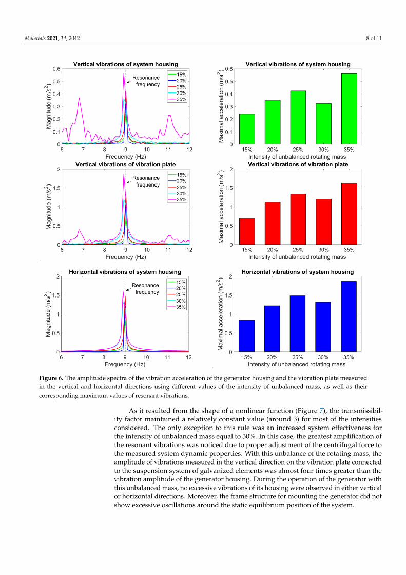
The analysis of dynamic behavior was aimed at determining the maximum vibra-tion amplitudes of the vibrating plate in relation to the lowest possible vibrations of thegenerator housing, taking different intensities of the unbalanced mass into account. Inthe analyzed load case (466 kg), we considered the resonant vibrations of the mechanicalsystem which occurred at the motor rotational speed of 540 rpm, corresponding to thefrequency of system oscillations close to 9 Hz. The amplitude spectra of the vibrationacceleration of the generator housing and the vibration plate measured in the vertical andhorizontal directions at different values of the intensity of unbalanced mass are shown inFigure 6 on the left. In Figure 6 on the right, the corresponding maximum values of theresonant vibration amplitudes are presented.
According to the test results presented in Figure 6, increasing the intensity of unbal-anced mass of the motor usually resulted in higher amplitudes of vibrations measured onthe vibrating plate connected to the suspension system of galvanized elements. However,the generated vibrations were also transferred to the system housing in the vertical andhorizontal directions. An initial growth of the maximum acceleration was observed dueto the increased intensity of the unbalanced rotating mass (up to 25%). A significant de-crease in the vibration amplitudes of the system housing was obtained for an unbalanceintensity equal to 30%. Under these operating conditions, the best system efficiency wasachieved, for which a substantial amplification of vibration amplitudes was attained on thevibrating plate in relation to the system housing. In the case this unbalance intensity, boththe vertical and horizontal vibrations of the generator housing showed acceptable valuesof the measured acceleration amplitude (in Figure 6, right). Although further increasingthe unbalanced mass (up to the intensity of 35%) again led to higher amplitudes of thevibrating platform, this nonlinear increase resulted in the appearance of many naturalfrequencies of the frame structure used to mount the generator. As a result, vibrations weregenerated in a wide range of frequencies (Figure 6, left), which contributed to significantdisturbances during the operation of the tested generator.
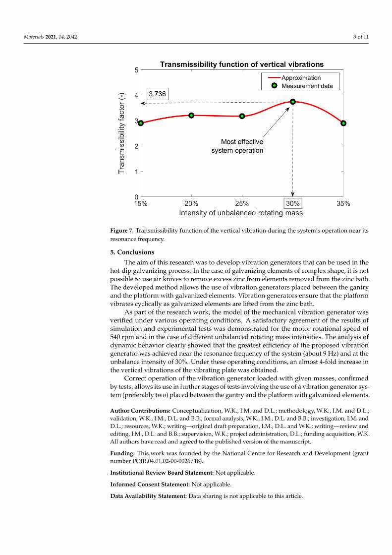
In order to determine the highest efficiency of the generator’s operation, the vibrationtransmission function was developed as a ratio of the maximum values of the vibration am-plitude measured on the vibrating plate in relation to the maximum values of the vibrationamplitude measured on the generator housing (Figure 7). This ratio was determined forvertical vibrations generated during the system’s operation near its resonance frequency(about 9 Hz), which corresponds to a motor rotational speed of 540 rpm.
Materials 2021, 14, 2042 8 of 11
Materials 2021, 14, x FOR PEER REVIEW 7 of 11
well as measurements conducted in laboratory conditions. Moreover, the amplitude spectra of the measured vibration acceleration signals were compared for the motor speed of 540 rpm and the selected intensity of rotating mass unbalance.
As shown in Figure 5, a satisfactory agreement of the simulation and measurement results is obtained for the rotational speed of 540 rpm and the unbalance intensity of the rotating mass equal to 30%. Under these operating conditions, the simulated and meas-ured acceleration waveforms of the vibrating plate showed comparable vibration am-plitudes. This proves the sufficient reliability of the proposed system model, which is used in this paper to analyze the dynamic behavior of the vibration generator in terms of its operation efficiency.
4. Analysis of the System Effectiveness The analysis of dynamic behavior was aimed at determining the maximum vibra-
tion amplitudes of the vibrating plate in relation to the lowest possible vibrations of the generator housing, taking different intensities of the unbalanced mass into account. In the analyzed load case (466 kg), we considered the resonant vibrations of the mechanical system which occurred at the motor rotational speed of 540 rpm, corresponding to the frequency of system oscillations close to 9 Hz. The amplitude spectra of the vibration acceleration of the generator housing and the vibration plate measured in the vertical and horizontal directions at different values of the intensity of unbalanced mass are shown in Figure 6 on the left. In Figure 6 on the right, the corresponding maximum values of the resonant vibration amplitudes are presented.
Materials 2021, 14, x FOR PEER REVIEW 8 of 11
Figure 6. The amplitude spectra of the vibration acceleration of the generator housing and the vibration plate measured in the vertical and horizontal directions using different values of the intensity of unbalanced mass, as well as their corre-sponding maximum values of resonant vibrations.
According to the test results presented in Figure 6, increasing the intensity of un-balanced mass of the motor usually resulted in higher amplitudes of vibrations measured on the vibrating plate connected to the suspension system of galvanized elements. However, the generated vibrations were also transferred to the system housing in the vertical and horizontal directions. An initial growth of the maximum acceleration was observed due to the increased intensity of the unbalanced rotating mass (up to 25%). A significant decrease in the vibration amplitudes of the system housing was obtained for an unbalance intensity equal to 30%. Under these operating conditions, the best system efficiency was achieved, for which a substantial amplification of vibration amplitudes was attained on the vibrating plate in relation to the system housing. In the case this unbalance intensity, both the vertical and horizontal vibrations of the generator housing showed acceptable values of the measured acceleration amplitude (in Figure 6, right). Although further increasing the unbalanced mass (up to the intensity of 35%) again led to higher amplitudes of the vibrating platform, this nonlinear increase resulted in the ap-pearance of many natural frequencies of the frame structure used to mount the generator. As a result, vibrations were generated in a wide range of frequencies (Figure 6, left), which contributed to significant disturbances during the operation of the tested genera-tor.
In order to determine the highest efficiency of the generator’s operation, the vibra-tion transmission function was developed as a ratio of the maximum values of the vibra-tion amplitude measured on the vibrating plate in relation to the maximum values of the vibration amplitude measured on the generator housing (Figure 7). This ratio was de-termined for vertical vibrations generated during the system’s operation near its reso-nance frequency (about 9 Hz), which corresponds to a motor rotational speed of 540 rpm.
Figure 6. The amplitude spectra of the vibration acceleration of the generator housing and the vibration plate measuredin the vertical and horizontal directions using different values of the intensity of unbalanced mass, as well as theircorresponding maximum values of resonant vibrations.
As it resulted from the shape of a nonlinear function (Figure 7), the transmissibil-ity factor maintained a relatively constant value (around 3) for most of the intensitiesconsidered. The only exception to this rule was an increased system effectiveness forthe intensity of unbalanced mass equal to 30%. In this case, the greatest amplification ofthe resonant vibrations was noticed due to proper adjustment of the centrifugal force tothe measured system dynamic properties. With this unbalance of the rotating mass, theamplitude of vibrations measured in the vertical direction on the vibration plate connectedto the suspension system of galvanized elements was almost four times greater than thevibration amplitude of the generator housing. During the operation of the generator withthis unbalanced mass, no excessive vibrations of its housing were observed in either verticalor horizontal directions. Moreover, the frame structure for mounting the generator did notshow excessive oscillations around the static equilibrium position of the system.
Materials 2021, 14, 2042 9 of 11
Materials 2021, 14, x FOR PEER REVIEW 8 of 11
Figure 6. The amplitude spectra of the vibration acceleration of the generator housing and the vibration plate measured in the vertical and horizontal directions using different values of the intensity of unbalanced mass, as well as their corre-sponding maximum values of resonant vibrations.
According to the test results presented in Figure 6, increasing the intensity of un-balanced mass of the motor usually resulted in higher amplitudes of vibrations measured on the vibrating plate connected to the suspension system of galvanized elements. However, the generated vibrations were also transferred to the system housing in the vertical and horizontal directions. An initial growth of the maximum acceleration was observed due to the increased intensity of the unbalanced rotating mass (up to 25%). A significant decrease in the vibration amplitudes of the system housing was obtained for an unbalance intensity equal to 30%. Under these operating conditions, the best system efficiency was achieved, for which a substantial amplification of vibration amplitudes was attained on the vibrating plate in relation to the system housing. In the case this unbalance intensity, both the vertical and horizontal vibrations of the generator housing showed acceptable values of the measured acceleration amplitude (in Figure 6, right). Although further increasing the unbalanced mass (up to the intensity of 35%) again led to higher amplitudes of the vibrating platform, this nonlinear increase resulted in the ap-pearance of many natural frequencies of the frame structure used to mount the generator. As a result, vibrations were generated in a wide range of frequencies (Figure 6, left), which contributed to significant disturbances during the operation of the tested genera-tor.
In order to determine the highest efficiency of the generator’s operation, the vibra-tion transmission function was developed as a ratio of the maximum values of the vibra-tion amplitude measured on the vibrating plate in relation to the maximum values of the vibration amplitude measured on the generator housing (Figure 7). This ratio was de-termined for vertical vibrations generated during the system’s operation near its reso-nance frequency (about 9 Hz), which corresponds to a motor rotational speed of 540 rpm.
Figure 7. Transmissibility function of the vertical vibration during the system’s operation near itsresonance frequency.
5. Conclusions
The aim of this research was to develop vibration generators that can be used in thehot-dip galvanizing process. In the case of galvanizing elements of complex shape, it is notpossible to use air knives to remove excess zinc from elements removed from the zinc bath.The developed method allows the use of vibration generators placed between the gantryand the platform with galvanized elements. Vibration generators ensure that the platformvibrates cyclically as galvanized elements are lifted from the zinc bath.
As part of the research work, the model of the mechanical vibration generator wasverified under various operating conditions. A satisfactory agreement of the results ofsimulation and experimental tests was demonstrated for the motor rotational speed of540 rpm and in the case of different unbalanced rotating mass intensities. The analysis ofdynamic behavior clearly showed that the greatest efficiency of the proposed vibrationgenerator was achieved near the resonance frequency of the system (about 9 Hz) and at theunbalance intensity of 30%. Under these operating conditions, an almost 4-fold increase inthe vertical vibrations of the vibrating plate was obtained.
Correct operation of the vibration generator loaded with given masses, confirmedby tests, allows its use in further stages of tests involving the use of a vibration generator sys-tem (preferably two) placed between the gantry and the platform with galvanized elements.
Author Contributions: Conceptualization, W.K., I.M. and D.L.; methodology, W.K., I.M. and D.L.;validation, W.K., I.M., D.L. and B.B.; formal analysis, W.K., I.M., D.L. and B.B.; investigation, I.M. andD.L.; resources, W.K.; writing—original draft preparation, I.M., D.L. and W.K.; writing—review andediting, I.M., D.L. and B.B.; supervision, W.K.; project administration, D.L.; funding acquisition, W.K.All authors have read and agreed to the published version of the manuscript.
Funding: This work was founded by the National Centre for Research and Development (grantnumber POIR.04.01.02-00-0026/18).
Institutional Review Board Statement: Not applicable.
Informed Consent Statement: Not applicable.
Data Availability Statement: Data sharing is not applicable to this article.
Materials 2021, 14, 2042 10 of 11
Acknowledgments: The authors would like to thank Joanna Wieczynska, from the InternationalCooperation Office of Koszalin University of Technology for manuscript proofreading.
Conflicts of Interest: The authors declare no conflict of interest. The funders had no role in the designof the study; in the collection, analysis, or interpretation of data; in the writing of the manuscript; orin the decision to publish the results.
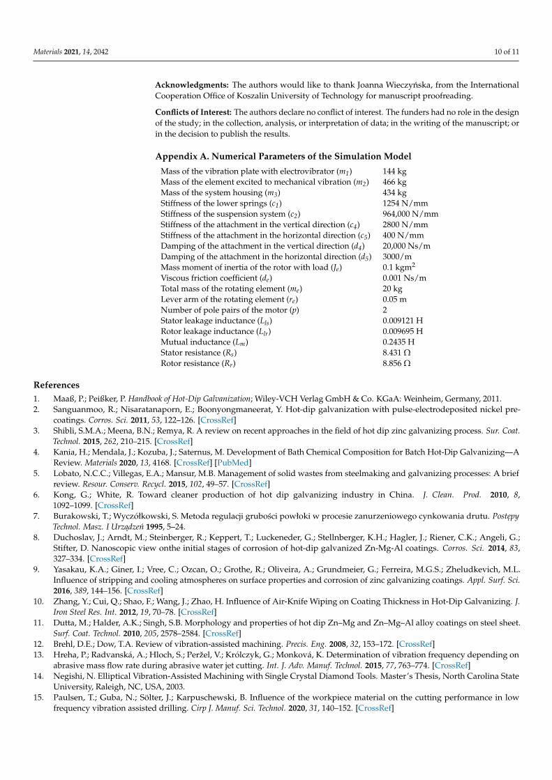
Appendix A. Numerical Parameters of the Simulation Model
Mass of the vibration plate with electrovibrator (m1) 144 kgMass of the element excited to mechanical vibration (m2) 466 kgMass of the system housing (m3) 434 kgStiffness of the lower springs (c1) 1254 N/mmStiffness of the suspension system (c2) 964,000 N/mmStiffness of the attachment in the vertical direction (c4) 2800 N/mmStiffness of the attachment in the horizontal direction (c5) 400 N/mmDamping of the attachment in the vertical direction (d4) 20,000 Ns/mDamping of the attachment in the horizontal direction (d5) 3000/mMass moment of inertia of the rotor with load (Je) 0.1 kgm2
Viscous friction coefficient (de) 0.001 Ns/mTotal mass of the rotating element (me) 20 kgLever arm of the rotating element (re) 0.05 mNumber of pole pairs of the motor (p) 2Stator leakage inductance (Lls) 0.009121 HRotor leakage inductance (Llr) 0.009695 HMutual inductance (Lm) 0.2435 HStator resistance (Rs) 8.431 ΩRotor resistance (Rr) 8.856 Ω
References1. Maaß, P.; Peißker, P. Handbook of Hot-Dip Galvanization; Wiley-VCH Verlag GmbH & Co. KGaA: Weinheim, Germany, 2011.2. Sanguanmoo, R.; Nisaratanaporn, E.; Boonyongmaneerat, Y. Hot-dip galvanization with pulse-electrodeposited nickel pre-
coatings. Corros. Sci. 2011, 53, 122–126. [CrossRef]3. Shibli, S.M.A.; Meena, B.N.; Remya, R. A review on recent approaches in the field of hot dip zinc galvanizing process. Sur. Coat.
Technol. 2015, 262, 210–215. [CrossRef]4. Kania, H.; Mendala, J.; Kozuba, J.; Saternus, M. Development of Bath Chemical Composition for Batch Hot-Dip Galvanizing—A
Review. Materials 2020, 13, 4168. [CrossRef] [PubMed]5. Lobato, N.C.C.; Villegas, E.A.; Mansur, M.B. Management of solid wastes from steelmaking and galvanizing processes: A brief
review. Resour. Conserv. Recycl. 2015, 102, 49–57. [CrossRef]6. Kong, G.; White, R. Toward cleaner production of hot dip galvanizing industry in China. J. Clean. Prod. 2010, 8,
1092–1099. [CrossRef]7. Burakowski, T.; Wyczółkowski, S. Metoda regulacji grubosci powłoki w procesie zanurzeniowego cynkowania drutu. Postepy
Technol. Masz. I Urzadzen 1995, 5–24.8. Duchoslav, J.; Arndt, M.; Steinberger, R.; Keppert, T.; Luckeneder, G.; Stellnberger, K.H.; Hagler, J.; Riener, C.K.; Angeli, G.;
Stifter, D. Nanoscopic view onthe initial stages of corrosion of hot-dip galvanized Zn-Mg-Al coatings. Corros. Sci. 2014, 83,327–334. [CrossRef]
9. Yasakau, K.A.; Giner, I.; Vree, C.; Ozcan, O.; Grothe, R.; Oliveira, A.; Grundmeier, G.; Ferreira, M.G.S.; Zheludkevich, M.L.Influence of stripping and cooling atmospheres on surface properties and corrosion of zinc galvanizing coatings. Appl. Surf. Sci.2016, 389, 144–156. [CrossRef]
10. Zhang, Y.; Cui, Q.; Shao, F.; Wang, J.; Zhao, H. Influence of Air-Knife Wiping on Coating Thickness in Hot-Dip Galvanizing. J.Iron Steel Res. Int. 2012, 19, 70–78. [CrossRef]
11. Dutta, M.; Halder, A.K.; Singh, S.B. Morphology and properties of hot dip Zn–Mg and Zn–Mg–Al alloy coatings on steel sheet.Surf. Coat. Technol. 2010, 205, 2578–2584. [CrossRef]
12. Brehl, D.E.; Dow, T.A. Review of vibration-assisted machining. Precis. Eng. 2008, 32, 153–172. [CrossRef]13. Hreha, P.; Radvanská, A.; Hloch, S.; Peržel, V.; Królczyk, G.; Monková, K. Determination of vibration frequency depending on
abrasive mass flow rate during abrasive water jet cutting. Int. J. Adv. Manuf. Technol. 2015, 77, 763–774. [CrossRef]14. Negishi, N. Elliptical Vibration-Assisted Machining with Single Crystal Diamond Tools. Master’s Thesis, North Carolina State
University, Raleigh, NC, USA, 2003.15. Paulsen, T.; Guba, N.; Sölter, J.; Karpuschewski, B. Influence of the workpiece material on the cutting performance in low
frequency vibration assisted drilling. Cirp J. Manuf. Sci. Technol. 2020, 31, 140–152. [CrossRef]

Materials 2021, 14, 2042 11 of 11
16. Babitsky, V.I.; Mitrofanov, A.V.; Silberschmidt, V.V. Ultrasonically-assisted turning of aviation materials: Simulations andexperimental Study. Ultrasonics 2004, 42, 81–86. [CrossRef] [PubMed]
17. Xiao, M.; Sato, K.; Karube, S.; Soutome, T. The effect of tool nose radius in ultrasonic vibration cutting of hard metal. Int. J. Mach.Tools Manuf. 2003, 43, 1375–1382. [CrossRef]
18. Ma, C.; Shamato, E.; Moriwaki, T.; Wang, L. Study of machining accuracy in ultrasonic elliptical vibration cutting. Int. J. Mach.Tools Manuf. 2004, 44, 1305–1310. [CrossRef]
19. Guelton, N.; Lopès, C.; Sordini, H. Cross Coating Weight Control by Electromagnetic Strip Stabilization at the ContinuousGalvanizing Line of ArcelorMittal Florange. Metall. Mater. Trans. B 2016, 47, 2666–2680. [CrossRef]