Metering Pumps and Control Systems Product - Regal Plastics
52
Metering Pumps and Control Systems Product Effective 01/01/16
-
Upload
khangminh22 -
Category
Documents
-
view
1 -
download
0
Transcript of Metering Pumps and Control Systems Product - Regal Plastics

Metering Pumps and Control Systems
Product
Effective 01/01/16

2
We reserve the right to update the information contained in this catalog without notice.
TABLE OF CONTENTS
Important Information When Placing An Order 3
Feature Selection Guide 4
Model Selection Guide 5-9
PULSAtron - Electronic Metering Pumps
Series MP 10-11
Series E Plus 12-13
Series HV 14-15
Series E 16-17
Series A Plus 20-21
Series T7 22-23
Series C Plus 24-25
Series C 26-27
Electronic Metering Pump Accessories
KOPkits 28-29
Suction/Discharge Valves 30
Parts 31-33
BLACKLINE - Mechanical Diaphragm Pumps
Model Selection 34-35
Accessories and KOPkits 36
Chem-Tech Pumps – Peristaltic Metering Pumps
Series XP 37
Series XPV 38
Series XP and XPV Parts 39
Chem-Tech Pumps – Mechanical Diaphragm Pumps
Prime Performance 40
Series 100, 150, 200 and Parts 41-43
Series 250 and Parts 44
Mec-O-Matic Pumps – Peristaltic Metering Pumps
Dolphin Series and Related Parts 45
VSP Series and Parts 46
2400T, 2400T Plus, 2400T-DC and Parts 47
Policies and Procedures 48-49
Terms and Conditions 50-51

3
We reserve the right to update the information contained in this catalog without notice.
IMPORTANT INFORMATION
WHEN PLACING AN ORDER 1. Fax, mail or telephone orders directly to the Customer Service Department:
Pulsafeeder Incorporated—A Unit of IDEX Corporation
Standard Product Operations Main Office & Manufacturing Facility
27101 Airport Road, Punta Gorda, Florida, USA 33982-2462 E-Mail: [email protected]
Telephone: 800-333-6677 or 941-575-3800 Fax: 800-456-4085 or 941-575-4085
www.pulsatron.com
2. Please have the following information available when placing an order:
Account Name Special Tags or Marks (if needed)
Billing Zip Code Item(s) Being Ordered
Purchase Order Number Quantity of Each Item
Ship To Address Pricing
Payment Terms Shipping Information
3. Orders are entered upon receipt. Our ability to change in house orders is limited. Please be certain your orders are complete
when placed. Any order cancellation or change request is subject to a cancelation fee.
4. Orders are assigned standard lead times based on the size of the order and product mix.
Orders requiring expedited shipping (sooner than the standard lead times) are subject to a expedite charge.
Unless the order clearly requests expedited shipping, the order will be treated as a routine order. When expedited shipping is requested a designated carrier must be selected. Orders that need to ship the same day must be received by 2:00 PM EST. Same day and next working day shipping is generally available for larger orders but not guaranteed, please verify with customer service. Pulsafeeder shall have no liability if it is unable to provide expedited shipping of an order.
5. Repairs and returns are coordinated through our Customer Service Department. All orders returned must have factory
authorization and are subject to a 25% restocking charge for standard product
6. Other Locations:
PULSAFEEDER-Europe
Via Kennedy, 12-20090
Segrate—Milano– Italy
Tel: +0039 377 706 6300
Latin America (Office Only)
Mario Pani 400, Piso 1, Oficina 111
Col. Lomas de Santa Fe, Cuajimalpa de Morelos
C.P 05300, México, D.F.
Tel: 52-55-4738-4124
Prices are subject to change without notice and are effective when order is accepted and acknowledged at point of shipment.
When ordering, specify your P.O. number, model number, quantity, price, shipping and/or billing address and order date.
Standard terms are NET 30 days from date of invoice for approved domestic accounts on open account and NET 60 days from
date of invoice for approved international accounts.
WE ACCEPT VISA AND MASTERCARD.
PAYMENT BY CREDIT CARD WILL NOT RECEIVE AN ADDITIONAL DISCOUNT.
All prices are FCA, Shippers Dock, Punta Gorda, FL.
Custom product sales are final.
Charges for export documentation may apply an very by requirements.
Expedite fees may apply. Orders requiring expedited shipping (sooner than the standard lead times) are subject to an expedite
charge
Fees for changes to or cancellation of orders may apply.
Minimum factory order of $30.
Possession of price schedule does not guarantee right to purchase direct from factory.
Far East (Office Only)
Room 3502-3504, Zhao Feng Plaza
No. 1027 Changning Rd
Shanghai 200050, China
Tel: 86-2163906367
Fax: 86-2163863338
IDEX India Private Ltd.
S14, First Floor
Solitaire Corporate Park,
167, Guru Hargovindji Marg, Chakala
Andheri (East)
Mumbai 400 093, India
Tel: 91-22-66435500
Fax: 91-22-66780055
4
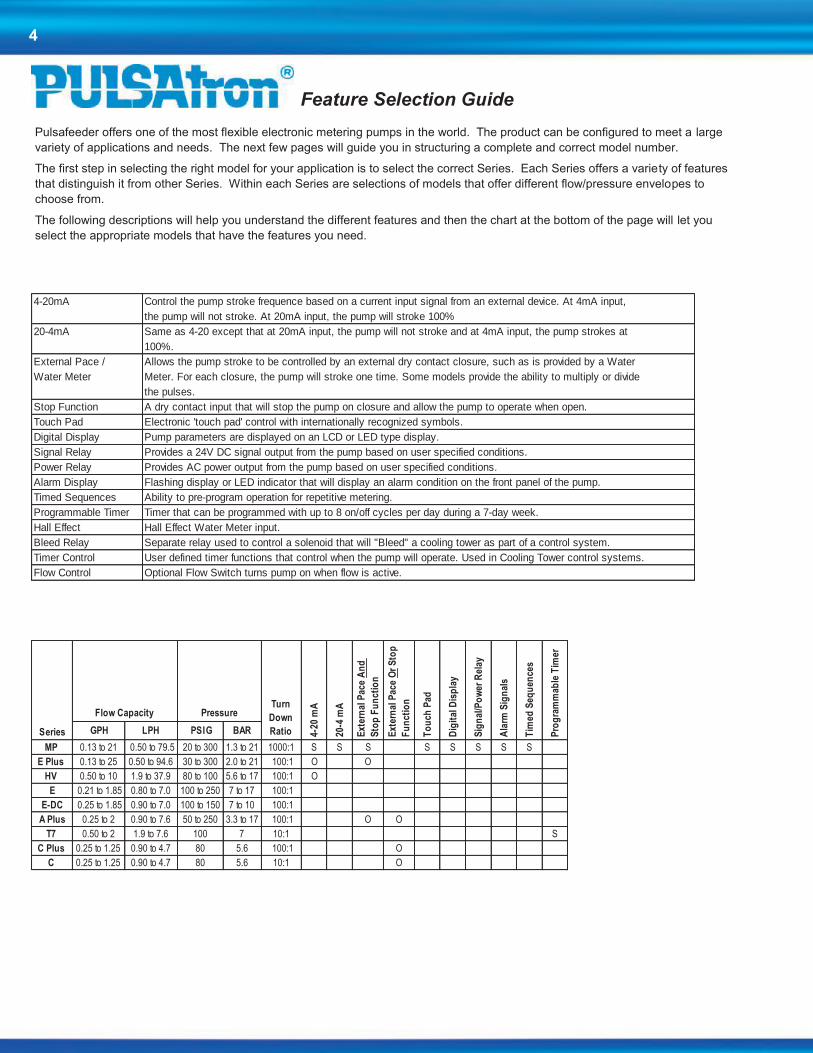
Feature Selection Guide
Pulsafeeder offers one of the most flexible electronic metering pumps in the world. The product can be configured to meet a large
variety of applications and needs. The next few pages will guide you in structuring a complete and correct model number.
The first step in selecting the right model for your application is to select the correct Series. Each Series offers a variety of features
that distinguish it from other Series. Within each Series are selections of models that offer different flow/pressure envelopes to
choose from.
The following descriptions will help you understand the different features and then the chart at the bottom of the page will let you
select the appropriate models that have the features you need.
4-20mA Control the pump stroke frequence based on a current input signal from an external device. At 4mA input,
the pump will not stroke. At 20mA input, the pump will stroke 100%
20-4mA Same as 4-20 except that at 20mA input, the pump will not stroke and at 4mA input, the pump strokes at
100%.
External Pace / Allows the pump stroke to be controlled by an external dry contact closure, such as is provided by a Water
Water Meter Meter. For each closure, the pump will stroke one time. Some models provide the ability to multiply or divide
the pulses.
Stop Function A dry contact input that will stop the pump on closure and allow the pump to operate when open.
Touch Pad Electronic 'touch pad' control with internationally recognized symbols.
Digital Display Pump parameters are displayed on an LCD or LED type display.
Signal Relay Provides a 24V DC signal output from the pump based on user specified conditions.
Power Relay Provides AC power output from the pump based on user specified conditions.
Alarm Display Flashing display or LED indicator that will display an alarm condition on the front panel of the pump.
Timed Sequences Ability to pre-program operation for repetitive metering.
Programmable Timer Timer that can be programmed with up to 8 on/off cycles per day during a 7-day week.
Hall Effect Hall Effect Water Meter input.
Bleed Relay Separate relay used to control a solenoid that will "Bleed" a cooling tower as part of a control system.
Timer Control User defined timer functions that control when the pump will operate. Used in Cooling Tower control systems.
Flow Control Optional Flow Switch turns pump on when flow is active.
GPH LPH PSIG BAR
MP 0.13 to 21 0.50 to 79.5 20 to 300 1.3 to 21 1000:1 S S S S S S S S
E Plus 0.13 to 25 0.50 to 94.6 30 to 300 2.0 to 21 100:1 O O
HV 0.50 to 10 1.9 to 37.9 80 to 100 5.6 to 17 100:1 O
E 0.21 to 1.85 0.80 to 7.0 100 to 250 7 to 17 100:1
E-DC 0.25 to 1.85 0.90 to 7.0 100 to 150 7 to 10 100:1
A Plus 0.25 to 2 0.90 to 7.6 50 to 250 3.3 to 17 100:1 O O
T7 0.50 to 2 1.9 to 7.6 100 7 10:1 S
C Plus 0.25 to 1.25 0.90 to 4.7 80 5.6 100:1 O
C 0.25 to 1.25 0.90 to 4.7 80 5.6 10:1 O
Sig
nal
/Po
wer
Rel
ay
20-4
mATurn
Down
RatioSeries Pro
gra
mm
able
Tim
er
Dig
ital
Dis
pla
y
Ala
rm S
ign
als
Tim
ed S
equ
ence
s
PressureFlow Capacity
4-20
mA
Ext
ern
al P
ace
An
d
Sto
p F
un
ctio
n
Ext
ern
al P
ace
Or
Sto
p
Fu
nct
ion
To
uch
Pad

5
Model Selection Guide
Once you have selected the appropriate Series, you must configure the model so that it is built with the features you desire. The Configuration Guide associated with each Series will present the most popular selections. Select one code from each category to build up a complete model string.
To help you better understand the model string, in the following pages, we will explain what each of the digits represent and provide you some additional charts to help you select options not found in the Configuration Guides.
Model Selection:
The first four digits represent the Series and Flow/Pressure Selection.
LB02 Series
All PULSAtron models begin with this letter. The second letter designates the Series (e.g. Series MP, Series E+, Series A+, etc.). Each series has a different set of features that are available in terms of control and flow/pressure capacity. The next two digits represent the flow/pressure capacity of the pump.
Digits 3 & 4 represent the Flow/Pressure Code.
This code represents the specific flow/pressure rating for the model and can be found in the specification for each Series.
LB02
LB02SA
The first digit will always start with the letter ‘L’. Flow/Pressure Code
Electrical
Controls
Series MP M
Series E Plus P
Series HV V
Series E E
Series E-DC S
Series A Plus B
Series C Plus D
Series C & T7 C
Series Code Designator
Digits 5 & 6 represent the Controls and Electrical selections.
These selections are explained for each model in the Configuration Guide.

6
Selection Guide cont’d.
Selecting the Wet-End Code:
The wet-end code represents the materials of construction that will
be in contact with the chemical you are pumping. It is critical that the
materials selected are compatible. If you do not find the wet-end
code to meet your application in the configuration guides, you can
use the Wet-End Code Selection Guide to determine the correct
Head Material, Seats & O-Rings and Balls. If you do not know what
materials are compatible with the chemicals you are pumping, refer
to the chemical compatibility chart below. We have identified the
proper wet-end code for the chemicals in the list. If your chemical is
not found in the list, please contact your chemical supplier or visit
www.pulsatron.com for a complete listing.
This is an abbreviated version using most common
chemicals. Refer to the Chemical Resistance Guide
(EMP-030) for a more detailed listing.
Liquid End
Chemical Code
ACETIC ACID, 5 - 10% PHC
ALUMINUM SULFATE VHC
AMMONIA, 10% PHC
BROMINE KTC
CALCIUM HYPOCHLORITE VVC
CITRIC ACID, 10 - 20% PHC
DEAE - Steamline Treatment ATS
ETHYLENE GLYCOL PTC
FERRIC CHLORIDE VTC
FERRIC SULFATE PTC
FLUOSILICIC ACID PTT
HYDROCHLORIC ACID, 0 - 37% PTC
HYDROCHLORIC ACID, 37 - 100% KTT
HYDROFLUOSILICIC ACID, 20% PTT
HYDROGEN PEROXIDE, 0 - 30% VVC
LACTIC ACID PTC
NITRIC ACID, 0 - 20% PVC
PHOSPHORIC ACID, 0 - 100% KTC
POTASSIUM CHLORIDE PTC
POTASSIUM PERMANGANATE PTC
SODIUM BI-CARBONATE PTC
SODIUM BI-SULFATE PTC
SODIUM BI-SULFITE PTC
SODIUM CARBONATE PTC
SODIUM HYDROXIDE, 0 - 50% PHC
SODIUM HYPOCHLORITE VVC
SODIUM NITRATE PTC
SODIUM SILICATE PHC
SODIUM SULFATE PHC
SODIUM SULFIDE PHC
SULFURIC ACID, 0 - 10% PTC
SULFURIC ACID, 10 - 75% PTC
SULFURIC ACID, 95 - 100% KTC
Chemical Compatibility Chart
_ _ _
A = 316 Stainless Steel (All models except H8)K = PVDF (Kynar) (Consult factory for J7, H8 models)P = GFPPL (Polypropylene)V = PVC (Poly Vinyl Chloride) (for models rated
< 150 psi excluding J7, K7, H7, H8)W = PVC (for models > 150 psi and J7, K7, H7, H8)
H = CSPET = TFE (not available with TFE ball over 150 psi) V = Viton (150 psi max.)
C = CeramicH = Alloy C (Hastelloy)S = 316 Stainless SteelT = TFE (not available with TFE seat over 150 psi)
CSPE is generic formulation of Hypalon, a registered trademark of E.I. DuPont Co.
Viton is a registered trademark of E.I. DuPont Company.
PULSAtron Wet-End Code Selection Guide
Head & Fittings
Seats
Balls
Selecting the Wet-End Code & Connection Type:
Digits 7-10 in the string represent the wet-end code. It is the group of four digits set apart by the dash lines.
LB02SA-PTC1 These four digits represent your
wet-end code and connection type.
The four digits in the wet-end code represent the Head Material, Seats & O-Rings, Ball Material and Connection type. Using the above example, the code breads down as follows:
P - Head Material, including fittings. In this example, the P represents GFPPL.
T - Seat & O-Ring Material. In this example, the T represents TFE.
C - Types of Balls used in the valves. In this example, the C represents Ceramic.
1 - Connection type. In this example, the 1 represents tubing connections for 3/8” OD tubing.
In the configuration Guide, we have listed the most popular Wet-End
codes. If you don’t find the materials or connection selection to meet
your needs, refer to the following selection guides to configure the
proper Wet-End Code.

7
Code Connect Type Suction Discharge SpringGPH Flow Limitations-125
SPM
GPH Flow Limitations-250
SPMViscosity Other Factors
2 Piping .25" FNPT .25" FNPT 0 - 1.88 0-3.76 1000 up to 3000 cps w/ SS balls No Bleed Valve4 Piping .25" FNPT .25" FNPT 1.63 - 10 3.26-20 1000 up to 3000 cps w/ SS balls No Bleed Valve6 Piping .25" FNPT .25" FNPT Yes Up to 10 NA less than 10,000 cps No Bleed Valve8 Piping .50" FNPT .50" FNPT Yes Up to 25 NA less than 10,000 cps No Bleed ValveC Piping .50" FNPT .50" FNPT 25 50 1000 up to 3000 cps w/ SS balls No Bleed ValveG Piping .25" FNPT .25" FNPT Yes 0 - 1.88 0-3.76 1000 up to 3000 cps w/ SS balls No Bleed ValveI Piping .50" MNPT .50" MNPT Yes Up to 10 NA less than 10,000 cps No Bleed ValveL Piping .50" MNPT .50" MNPT 0 - 1.88 0-3.76 1000 up to 3000 cps w/ SS balls No Bleed ValveX Piping .50" MNPT .50" MNPT 1.63 - 10 3.26-20 1000 up to 3000 cps w/ SS balls No Bleed Valve1 Tubing .25" x .38" .25" x .38" 0 - 1.88 0-3.76 1000 up to 3000 cps w/ SS balls3 Tubing .38" x .50" .38" x .50" 1.63 - 10 3.26-20 1000 up to 3000 cps w/ SS balls5 Tubing .50" x .75" .38" x .50" Yes Up to 10 NA less than 10,000 cps7 Tubing .50" x .75" .50" FNPT Yes Up to 25 NA less than 10,000 cps No Bleed Valve9 Tubing .25" x .38" .25" x .38" Yes 0 - 1.88 0-3.76 1000 up to 3000 cps w/ SS balls Degas Head/No Bleed ValveA Tubing .38" x .50" .38" x .50" 0 - 1.88 0-3.76 1000 up to 3000 cps w/ SS ballsB Tubing .50" x .75" .50" x .75" 25 50 1000 up to 3000 cps w/ SS balls No Bleed ValveD Tubing .25" x .38" .25" x .38" Yes 0 - 1.88 0-3.76 1000 up to 3000 cps w/ SS ballsE Tubing .38" x .50" .38" x .50" Yes 0 - 1.88 0-3.76 1000 up to 3000 cps w/ SS ballsF Tubing .38" x .50" .38" x .50" Yes 1.63 - 10 3.26-20 1000 up to 3000 cps w/ SS balls Not Available In PVDFH Tubing .25" x .38" .25" x .38" 1.63 - 10 3.26-20 1000 up to 3000 cps w/ SS ballsJ Tubing .25" x .38" .25" x .38" 0 - 1.04 0-2.08 1000 up to 3000 cps w/ SS ballsK Tubing .50" x .75" .50" x .75" Yes 1.88 - 25 (<50 psi) NA less than 10,000 cps No Bleed Valve
LPH Flow Limitations LPH Flow LimitationsM Piping G 1/2 A G 1/2 A 6.15 - 37.85 12.3-75.7 1000 up to 3000 cps w/ SS ballsR Piping G 1/2 A G 1/2 A 0 - 7.10 0-14.2 1000 up to 3000 cps w/ SS ballsP Tubing 4 x 6 mm 4 x 6 mm 0 - 3.94 0-7.88 1000 up to 3000 cps w/ SS ballsS Tubing 6 x 8 mm 6 x 8 mm > 18.93 > 37.86 1000 up to 3000 cps w/ SS ballsT Tubing 6 x 8 mm 6 x 8 mm 0 - 7.10 0-14.2 1000 up to 3000 cps w/ SS balls Degas Head/No Bleed ValveU Tubing 6 x 8 mm 6 x 8 mm 0 - 7.10 0-14.2 1000 up to 3000 cps w/ SS ballsV Tubing 12 x 19 mm 12 x 19 mm > 29.96 >59.92 1000 up to 3000 cps w/ SS balls No Bleed ValveW Tubing 8 x 12 mm 8 x 12 mm 3.94 - 37.85 7.88-75.7 1000 up to 3000 cps w/ SS ballsY Tubing 9 x 12 mm 9 x 12 mm 0 - 7.10 0-14.2 1000 up to 3000 cps w/ SS balls
Connection Codes
Metric Connections
Selecting the Connection Code:
Selecting the proper connection code is probably the most difficult part of choosing a PULSAtron pump. Because of the flexibility built into this product line to meet a large variety of applications, the connection codes are determined by alot more factors than just the size of the tubing. Connection code is probably the wrong name for this selection because you are selecting more than just the tubing size. This code also determines the type of valves used in the pump. The valve type is determined by factors such as flow rate of the pump, ball type selected and viscosity of the fluid you will be pumping.
Flow Rate:
The pump you select is rated to pump a certain number of gallons per hour (GPH). When selecting the connection code, please note the GPH limitations and select a connection that fits within the parameters of the pump model that you selected.
Ball Type:
If the material selected for the balls used in the check valves is TFE, you will probably need to use a spring-loaded connection. This is due to the fact that the weight of the balls will not allow them to seat properly without the spring. See the connection chart for a list of spring loaded connection types.
Viscosity:
Viscosity of the fluid you are pumping impacts the connection. The higher viscosity fluids (>3000 cps) require larger connection types and spring-loaded valves. Medium viscosity fluids (1000 to 3000 cps) can be pumped without the spring-loaded valves but you must use SS balls with these connections in order for the balls to seat properly in the valve.
Degassing Head:
The degassing head assembly is the solution to pumping gas producing chemicals such as hydrogen peroxide or high strength sodium hypochlorite. The unique de-gas valve system is designed to allow air to be vented from the pump head while minimizing the return fluid volume. It also prevents the pump from losing its prime due to gas build up. The degassing head will be available on all PULSAtron pumps with volumes <44GPD & pressures <150PSI. This feature is only available with the wet-end codes VVC9, VHC9, and VTC9.
Pumps ranging from 0.25 gph (0.9 lph) to 0.90 gph (3.4 lph) with the stainless steel ball option (“S” in the 9th digit of the model number)
must select a connection code with a spring.
- Pumps less than or equal to .25 gph (0.9 lph) require a connection code with a spring and must use a ceramic ball in place of stainless
steel.
- Stainless steel head assemblies are only available in piping connections.

8
The last three digits of the model string are referred to as the Suffix Code. It is through the suffix code that the pump can be customized with optional features or customer specific features, e.g. private labeling. If your company has specific features that will be ordered on every pump, contact customer service with a description of what you want customized. We will then assign a unique suffix code that can be used as the last three digits in the model string when you place an order.
Standard Suffix Code Descriptions: On the following pages are additional features that can be added to your PULSAtron pump through the use of the Suffix Code. Anytime you order a pump with one of these codes, it will be configured with that option.
CZ_ _ _ _XXX = CE Approval This suffix code tells us that you require CE Approval on the pump you are ordering. This suffix code is seven to nine digits and can be used in conjunction with other suffix codes by replacing the XXX after the CZ _ _ _ _with another suffix code. For instance, if you require CE Approval and a Five Function Valve, the suffix code would be CZEURO500.
130 = PVDF Tubing This suffix code will replace the standard pump tubing with PVDF Tubing.
500 = Five Function Valve The five function valve is easily installed, no tools required. The valve operates with all PULSAtron models up to 240 GPD. The five function valve is packed with features that increase safety, enhance performance and generally improves the convenience of operation.
LB02SA-PTC1-XXX Suffix Code
OPERATION
The functions are selected by setting two dual position selector knobs. The label on the back panel of the valve identifies each function with selector knob positions.
The five function valve is compatible with most PULSAtron pumps. Connected to the existing discharge valve the five function valve is capable of handling a large output flow as well as viscous liquids. A return port located on the side body provides flow of chemical back to the solution tank when in the air bleed or drain discharge mode.
FEATURES Pressure Relief – Allows for relief of excessive pressure in
discharge line to protect connections and tubing.
Back Pressure – Maintains output reproducibility and allows metering into atmospheric discharge.
Anti-Siphon – Prevents siphoning through the pump when point of injection is lower than the pump or into the suction line of another pump. Rated at total vacuum.
Air Bleed – Used during priming to manually remove air from the pump head.
Discharge Drain – Depressurize pump discharge line without loosening tubing or fittings. Protects the operator from chemical exposure.
Selection Guide cont’d.
REAR VIEW FRONT VIEW
SPECIFICATIONS
Material Of Construction:
Valve Body Polyvinylidene Flouride (PVDF)
Diaphragm TFE faced CSPE
O-Rings TFE
Hardware 18-8 Stainless Steel (Recessed)
Maximum Operating
Pressure: 250 PSI/17 BAR
Maximum Flow: 10 GPH (37.85 LPH)
Maximum Viscosity: 1000 CPS
Pressure Relief
Settings: 275 PSI (17 BAR) - red
(nominal cracking 175 PSI (12 BAR) - green
pressure) 125 PSI (8.6 BAR) - blue
50 PSI (2.8 BAR) - black (PVC only) Note: Pressure relief will occur at no more than 50% above maximum rating of pump.
Suffix Code:

9
520 = DG/5FV Five Function Valve with De-Gas
With the DG/5FV you don’t have to give up the accuracy and control
of a solenoid metering pump in order to pump gaseous solutions.
Available in a variety of materials and popular sizes, the DG/5FV is
ready to tackle most applications. Not only does the DG/5FV provide
degassing, it is packed with features that increase safety, enhance
performance and generally improves the convenience of operation.
FEATURES
De-Gas – Bypass gasses and fluid during normal pump operation. Allows for the constant removal of gases that would otherwise “air bind” the pump.
Back Pressure – Maintains output reproducibility and allows metering into atmospheric discharge.
Anti-Siphon – Prevents siphoning through the pump when point of injection is lower than the pump or into the suction line of another pump. Rated at total vacuum.
Air Bleed – Used during priming to manually remove air from the pump head.
Discharge Drain – Depressurize pump discharge line without loosening tubing or fittings. Protects the operator
from chemical exposure.
SPECIFICATIONS Material Of Construction: Valve Body Polyvinylidene Flouride (PVDF)
Diaphragm TFE faced CSPE
O-Rings Viton or CSPE
Hardware 18-8 Stainless Steel (Recessed)
Maximum Flow: 10 GPH (37.85 LPH)
Minimum Flow: 3 GPD (.47LPH)
Maximum Viscosity: 1000 CPS
MAX Pressure Ratings: Up to 250 psi (17 BAR)
Note: Degas/bypass volume is adjustable, typically 1-10% of pump output.
Connections: ¼” (0.635 cm) Male NPT
½” (1.27 cm) OD tubing
3/8” (0.95 cm) OD tubing
All ports (input, output & bypass) on the selected valve will be the same.
REAR VIEW FRONT VIEW
OPERATION
The functions are selected by setting two dual position
selector knobs. The label on the back panel of the
DG/5FV identifies each function with selector knob
positions.
The DG/5FV is compatible with most PULSAtron pumps.
Connected to the existing discharge valve the GG/5FV is
capable of handling a large output flow as well as viscous
liquids. A return port located on the side body provides
flow of chemical back to the solution tank when in the
degas, air bleed or drain discharge mode.
ITS = Integrated Tank System
The ITS System is a completely integrated tank system constructed of high density UV
resistant polyethylene (PE) with a 15 gallon capacity. This tank system is translucent with 5
gallon increments and the tank's low level indicator allows visual monitoring of chemicals
without opening the tank. The tight fitting child-proof lid keeps the chemical free of
contaminants and protects the surrounding area from chemical fumes.
The ITS System also allows for easy access to the liquid end and control panel of the
mounted pump.
A system consists of a chemical tank with lid and bulkhead fittings; a liquid level indicator
float assembly; and feeder mounting hardware.
ITS Tank not available on LM, LP, If you require a different
type or size tank, please refer to our accessory price book.

10
Series MP
Key Features
Automatic Control, Fully scalable 4-20mA current signal that can also be
calibrated to precisely match the current signal reading of the sending device.
Manual Control allows for a combined 1000:1 turndown resulting in accurate
metering for critical applications.
Flow Verification option is available on select sizes.
Relay Output for computer interface or AC power allows for external control.
Six-button Touch Pad Control with internationally recognized symbols for
simplified programming.
Simple Prompts in plain language allow for easy-to-understand instructions for
programming. Available in three languages.
Alarm Signals for signal loss, full count, circuit failure, pulse overflow and pulse
rate high. Liquid low level indicator capability is standard.
Timed Sequences can be set for selected intervals and rate for repetitive
metering.
Pulse Signals can be multiplied or divided by 1 to 999 allowing for pumps to
handle peak requirements.
LCD, 3 line backlit multi-lingual display allows for easy reading and user-friendly
programming.
Calibrated Flow Rate display with total volume pumped last day, month and
since last reset.
Pressure and Flow Rate Capacity LMK2 LMB2 LMA2 LMD3 LMB3 LMA3 LMK3 LMF4 LMD4 LMB4 LMH4 LMG4 LME4 LMK5 LMH5 LMH6 LMK7 LMH7 LMH8
Capacity GPH 0.13 0.21 0.25 0.50 0.50 0.50 0.60 0.85 0.90 1.00 1.70 1.75 1.85 2.50 3.15 5.00 8.00 10.00 21.00
nominal GPD 3 5 6 12 12 12 14 20 22 24 41 42 44 60 76 120 192 240 504
(max.) LPH 0.5 0.8 0.9 1.9 1.9 1.9 2.3 3.2 3.4 3.8 6.4 6.6 7.0 9.5 11.9 18.9 30.3 37.9 79.5
Pressure PSIG 300 250 150 250 150 100 100 250 150 100 250 150 100 150 150 100 50 35 20
(max.) BAR 21 17 10 17 10 7 7 17 10 7 17 10 7 10 10 7 3.3 2.4 1.3
Connections
Note: Flow Verification: Available on K3, B4 and E4 with connection code 1; H6, K7 and H7 with connection code H; 1/4” ID x 3/8” OD only.
1/4" FNPT
1/2" FNPT
1/2" ID X 3/4" OD (LPH8 ONLY)
FLOW VERIFICATION (See Note)
MODEL
Tubing
Piping
3/8" ID X 1/2" OD1/4" ID X 3/8" OD
3/8" ID X 1/2" OD
1/4" FNPT
Electronic Metering Pumps
Engineering Data
Reproducibility: +/- 2% at maximum capacity
Viscosity Max CPS:
For viscosity up to 3000 CPS, select connection size 3, 4, B or C with 316SS ball material. Flow rate will determine connection/ball size. Greater than 3000 CPS require spring loaded ball checks. See Selection Guide for proper connection.
Controls: 6-Station Membrane Switch
Status Display: 16-Position LCD Dot Matrix Backilght
LED Indicator Lights, Panel Mount: Power On - Green Pulsing - Green Flashing
Stop - Red
Stroke Frequency Max SPM: 125
External Stroke Frequency Control (Automatic):
4-20 mADC, 20-4 mADC External Pacing
Output Relay (Signal Level Option): 24 VDC, 10 mA
Output Relay (Power Option): 250 VAC, 50/60 HZ, 0.5A
Stroke Frequency Turn-Down Ratio: 100:1
Stroke Length Turn-Down Ratio: 10:1
Engineering Data
Power Input: 115 VAC/50-60 HZ/1 ph
230 VAC/50-60 HZ/1 ph
Average Current Draw:
@ 115 VAC; Amps: 1.0 Amps
@ 230 VAC; Amps: 0.5 Amps
Peak Input Power: 300 Watts
Average Input Power @ Max SPM: 130 Watts
11
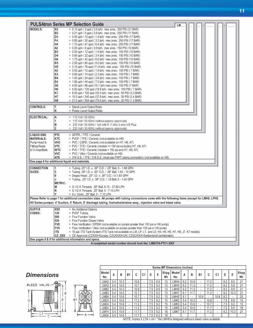
Dimensions
LM_ _ _ _ - _ _ _ _ - _ _ _
MODELS: K2 = 0.13 gph / 3 gpd ( 0.5 lph) max pres.: 300 PSI (21 BAR)B2 = 0.21 gph / 5 gpd ( 0.8 lph) max pres.: 250 PSI (17 BAR)D3 = 0.50 gph / 12 gpd ( 1.9 lph) max pres.: 250 PSI (17 BAR)F4 = 0.85 gph / 20 gpd ( 3.2 lph) max pres.: 250 PSI (17 BAR)H4 = 1.70 gph / 41 gpd ( 6.4 lph) max pres.: 250 PSI (17 BAR)A2 = 0.25 gph / 6 gpd ( 0.9 lph) max pres.: 150 PSI (10 BAR)B3 = 0.50 gph / 12 gpd ( 1.9 lph) max pres.: 150 PSI (10 BAR)D4 = 0.90 gph / 22 gpd ( 3.4 lph) max pres.: 150 PSI (10 BAR)G4 = 1.75 gph / 42 gpd ( 6.6 lph) max pres.: 150 PSI (10 BAR)K5 = 2.50 gph / 60 gpd ( 9.5 lph) max pres.: 150 PSI (10 BAR)H5 = 3.15 gph / 76 gpd (11.9 lph) max pres.: 150 PSI (10 BAR)A3 = 0.50 gph / 12 gpd ( 1.9 lph) max pres.: 100 PSI ( 7 BAR)K3 = 0.60 gph / 14 gpd ( 2.3 lph) max pres.: 100 PSI ( 7 BAR)B4 = 1.00 gph / 24 gpd ( 3.8 lph) max pres.: 100 PSI ( 7 BAR)E4 = 1.85 gph / 44 gpd ( 7.0 lph) max pres.: 100 PSI ( 7 BAR)G5 = 4.00 gph / 96 gpd (15.1 lph) max pres.: 100 PSI (7 BAR)H6 = 5.00 gph / 120 gpd (18.9 lph) max pres.: 100 PSI ( 7 BAR)K7 = 8.00 gph / 192 gpd (30.3 lph) max pres.: 50 PSI (3.3 BAR)H7 = 10.0 gph / 240 gpd (37.9 lph) max pres.: 35 PSI (2.4 BAR)H8 = 21.0 gph / 504 gpd (79.5 lph) max pres.: 20 PSI (1.3 BAR)
CONTROLS: T = Signal Level Output RelayK = Power Level Output Relay
ELECTRICAL: A = 115 Volt / 50-60Hz 1 = 115 Volt / 50-60Hz (without agency approvals) B = 230 Volt / 50-60Hz / 1ph with 6' (1.8m) 3-wire US Plug 2 = 230 Volt / 50-60Hz (without agency approvals)
LIQUID END PTC = GFPPL / TFE / CeramicMATERIALS: KTC = PVDF / TFE / Ceramic (not available on H8)Pump Head & VHC = PVC / CSPE / Ceramic (not available on H7, H8, K7)Fittings/Seats VTC = PVC / TFE / Ceramic (models <= 150 psi excluding H7, H8, K7)& O-rings/Balls WTC = PVC / TFE / Ceramic (models > 150 psi and H7, H8, K7)
VVC = PVC / Viton / Ceramic (not available on H8)ATS = 316 S.S. / TFE / 316 S.S. (must use FNPT piping connection) (not available on H8)
CONNECTION 1 = Tubing .25" I.D. x .38" O.D. / .25" Ball, 0 - 1.88 GPHSIZES: 3 = Tubing .38" I.D. x .50" O.D. / .38" Ball, 1.63 - 10 GPH
9 = Degas Head: .25" I.D. x .38" O.D. / 0-1.83 GPHJ = Tubing, .25" I.D. x .38" O.D. / .19 Ball; 0 - 1.04 GPHMETRIC:M = G 1/2 A Threads, .38" Ball, 6.15 - 37.85 LPHR = G 1/2 A Threads, .25" Ball, 0 - 7.10 LPHY = 9 x 12mm, .25" Ball, 0 - 7.10 LPH
SUFFIX XXX = No Additional OptionsCODES: 130 = PVDF Tubing
500 = Five Function Valve520 = Five Function Degas ValveFVE = Flow Verification / EPDM (not available on pumps greater than 100 psi or H8 pump)FVV = Flow Verification / Viton (not available on pumps greater than 100 psi or H8 pump) ITS = 15 gal. ITS Tank System (ITS Tank not available on LM, LP, LT, and LE: H4, H5, H6, H7, H8, J7, K7 models)CZ_XXX = CE Approval (CZXXX=Europe; CZUKXXX=UK; CZSUIXXX=Switzerland/Liechtenstein)
PULSAtron Series MP Selection Guide
See page 6 for additional liquid end materials.
Please Refer to page 7 for additional connection sizes. All pumps with tubing connections come with the following items (except for LMH8, LPH8,
HV Series pumps): 4' Suction, 4' Return, 8' dischage tubing, footvalve/strainer assy., injection valve and bleed valve.
See pages 8 & 9 for additional information and specs.
A completed model number should look like 'LMB3TA-PTC1-XXX'
Model
No.A B B1 C C1 D E
Shpg
Wt
Model
No. A B B1 C C1 D E
Shpg
Wt
LMA2 5.4 10.3 - 10.8 - 7.5 8.9 13 LMH4 6.2 10.9 - 11.2 - 8.2 9.5 21LMA3 5.4 10.6 - 10.7 - 7.5 9.2 13 LMH5 6.2 11.3 - 11.2 - 8.2 9.9 21LMB2 5.4 10.3 - 10.8 - 7.5 8.9 13 LMH6 6.2 11.3 - 11.2 - 8.2 9.9 21LMB3 5.4 10.6 - 10.7 - 7.5 9.2 13 LMH7 6.1 11.7 - 11.2 - 8.2 10.3 21LMB4 5.4 10.6 - 10.7 - 7.5 9.2 13 LMH8* 6.1 - 10.9 - 10.6 8.2 - 25LMD3 5.4 10.6 - 11.2 - 7.5 9.2 15 LMK2 5.4 10.3 - 10.8 - 7.5 8.9 13LMD4 5.4 10.6 - 11.2 - 7.5 9.2 15 LMK3 5.4 10.6 - 10.7 - 7.5 9.2 13LME4 5.4 10.6 - 11.2 - 7.5 9.2 15 LMK5 5.4 10.9 - 11.7 - 7.5 9.5 18LMF4 5.4 10.6 - 11.7 - 7.5 9.2 18 LMK7 6.1 11.7 - 11.2 - 8.2 10.3 21LMG4 5.4 10.6 - 11.7 - 7.5 9.2 18
Series MP Dimensions (inches)
NOTE: Inches X 2.54 = cm / * the LMH8 is designed without a bleed valve available

12
Series E PLUS
Key Features
Automatic Control, available with 4-20 mADC direct or external
pacing, with stop function.
Manual Control by on-line adjustable stroke rate and stroke length.
Auto-Off-Manual switch.
Highly Reliable timing circuit.
Circuit Protection against voltage and current upsets.
Panel Mounted Fuse.
Solenoid Protection by thermal overload with auto reset.
Water Resistant, for outdoor and indoor applications.
Indicator Lights, panel mounted.
Guided Ball Check Valve Systems, to reduce back flow and
enhance outstanding priming characteristics.
Safe & Easy Priming with durable leak-free bleed valve assembly
(standard).
Pressure and Flow Rate Capacity LPK2 LPB2 LPA2 LPD3 LPB3 LPA3 LPK3 LPF4 LPD4 LPB4 LPH4 LPG4 LPE4 LPK5 LPH5 LPG5 LPH6 LPK7 LPH7 LPJ7 LPH8
Capacity GPH 0.13 0.21 0.25 0.5 0.50 0.50 0.60 0.85 0.90 1.00 1.70 1.75 1.85 2.50 3.15 4 5.00 8.00 10.00 10.00 25.00
nominal GPD 3 5 6 12 12 12 14 20 22 24 41 42 44 60 76 96 120 192 240 240 600
(max.) LPH 0.5 0.8 0.9 1.9 1.9 1.9 2.3 3.2 3.4 3.8 6.4 6.6 7 9.5 11.9 15.1 18.9 30.3 37.9 37.9 94.6
Pressure PSIG 300 250 150 250 150 100 100 250 150 100 250 150 100 150 150 100 100 50 35 80 30
(max.) BAR 21 17 10 17 10 7 7 17 10 7 17 10 7 10 10 7 7 3.3 2.4 5.5 2
Connections
Piping1/4" FNPT 1/4" FNPT
1/2" FNPT
MODEL
Tubing1/4" ID X 3/8" OD 3/8" ID X 1/2" OD
3/8" ID X 1/2" OD 1/2" ID X 3/4" OD (LPH8 ONLY)
Engineering Data
Reproducibility: +/- 2% at maximum capacity
Viscosity Max CPS :
For viscosity up to 3000 CPS, select connection size 3, 4, B or C with 316SS ball material. Flow rate will determine connection/ball size. Greater than 3000 CPS require spring loaded ball checks. See Selection Guide for proper connection.
Stroke Frequency Max SPM: 125
Stroke Frequency Turn-Down Ratio: 10:1
Stroke Length Turn-Down Ratio: 10:1
Power Input: 115 VAC/50-60 HZ/1 ph
230 VAC/50-60 HZ/1 ph
Average Current Draw:
@ 115 VAC; Amps: 1.0 Amps
@ 230 VAC; Amps: 0.5 Amps
Peak Input Power: 300 Watts
Average Input Power @ Max SPM: 130 Watts
Electronic Metering Pumps

13
Dimensions Model
No. A B B1 C C1 D E
Shpg
Wt
Model
No. A B B1 C C1 D E
Shpg
Wt
LPA2 5.4 10.3 - 10.8 - 7.5 8.9 13 LPH4 6.2 10.9 - 11.2 - 8.2 9.5 21LPA3 5.4 10.6 - 10.7 - 7.5 9.2 13 LPH5 6.2 11.3 - 11.2 - 8.2 9.9 21LPB2 5.4 10.3 - 10.8 - 7.5 8.9 13 LPG5 6.2 11.3 - 11.2 - 8.2 9.9 21LPB3 5.4 10.6 - 10.7 - 7.5 9.2 13 LPH6 6.2 11.3 - 11.9 - 8.2 9.9 21LPB4 5.4 10.6 - 10.7 - 7.5 9.2 13 LPH7 6.1 11.7 - 11.9 - 8.2 10.3 21LPD3 5.4 10.6 - 11.2 - 7.5 9.2 15 LPH8* 6.1 - 10.9 - 11.3 8.2 - 26LPD4 5.4 10.6 - 11.2 - 7.5 9.2 15 LPK2 5.4 10.3 - 10.8 - 7.5 8.9 13LPE4 5.4 10.6 - 11.2 - 7.5 9.2 15 LPK3 5.4 10.6 - 10.7 - 7.5 9.2 13LPF4 5.4 10.6 - 11.7 - 7.5 9.2 18 LPK5 5.4 10.9 - 11.7 - 7.5 9.5 18LPG4 5.4 10.6 - 11.7 - 7.5 9.2 18 LPK7 6.1 11.7 - 11.2 - 8.2 10.3 21
LPJ7 6.1 10.0 - 10.7 - - - 21
NOTE: Inches X 2.54 = cm /* the LPH8 is designed without a bleed valve available
Series E Plus Dimensions (inches)
LP_ _ _ _ - _ _ _ _ - _ _ _
MODELS: K2 = 0.13 gph / 3 gpd ( 0.5 lph) max pres.: 300 PSI (21 BAR)B2 = 0.21 gph / 5 gpd ( 0.8 lph) max pres.: 250 PSI (17 BAR)D3 = 0.50 gph / 12 gpd ( 1.9 lph) max pres.: 250 PSI (17 BAR)F4 = 0.85 gph / 20 gpd ( 3.2 lph) max pres.: 250 PSI (17 BAR)H4 = 1.70 gph / 41 gpd ( 6.4 lph) max pres.: 250 PSI (17 BAR)A2 = 0.25 gph / 6 gpd ( 0.9 lph) max pres.: 150 PSI (10 BAR)B3 = 0.50 gph / 12 gpd ( 1.9 lph) max pres.: 150 PSI (10 BAR)D4 = 0.90 gph / 22 gpd ( 3.4 lph) max pres.: 150 PSI (10 BAR)G4 = 1.75 gph / 42 gpd ( 6.6 lph) max pres.: 150 PSI (10 BAR)K5 = 2.50 gph / 60 gpd ( 9.5 lph) max pres.: 150 PSI (10 BAR)H5 = 3.15 gph / 76 gpd (11.9 lph) max pres.: 150 PSI (10 BAR)A3 = 0.50 gph / 12 gpd ( 1.9 lph) max pres.: 100 PSI (7 BAR)K3 = 0.60 gph / 14 gpd ( 2.3 lph) max pres.: 100 PSI (7 BAR)B4 = 1.00 gph / 24 gpd ( 3.8 lph) max pres.: 100 PSI (7 BAR)E4 = 1.85 gph / 44 gpd ( 7.0 lph) max pres.: 100 PSI (7 BAR)G5 = 4.00 gph / 96 gpd ( 15.1 lph) max pres.: 100 PSI (7 BAR)H6 = 5.00 gph / 120 gpd (18.9 lph) max pres.: 100 PSI (7 BAR)K7 = 8.00 gph / 192 gpd (30.3 lph) max pres.: 50 PSI (3.3 BAR)H7 = 10.0 gph / 240 gpd (37.9 lph) max pres.: 35 PSI (2.4 BAR)J7 = 10.0 gph / 240 gpd (37.9 lph) max pres.: 80 PSI (5.5 BAR)H8 = 25.0 gph / 600 gpd (94.6 lph) max pres.: 30 PSI (2 BAR)
CONTROLS: S = Manual On/OffM = 4-20mADC Direct, w/ StopE = External/Remote Pacing, w/ Stop
ELECTRICAL: A = 115 Volt / 50-60Hz 1 = 115 Volt / 50-60Hz (without agency approvals) B = 230 Volt / 50-60Hz / 1ph with 6' (1.8m) 3-wire US Plug 2 = 230 Volt / 50-60Hz (without agency approvals)
LIQUID END PTC = GFPPL / TFE / CeramicMATERIALS: PTT = GFPPL / TFE / TFEPump Head & KTC = PVDF / TFE / Ceramic (not available on H8)Fittings/Seats VHC = PVC / CSPE / Ceramic (not available on H7, H8, J7, K7)& O-rings/Balls VTC = PVC / TFE / Ceramic (models <= 150 psi excluding H7, H8, J7, K7)
WTC = PVC / TFE / Ceramic (models > 150 psi and H7, H8, J7, K7)ATS = 316 S.S. / TFE / 316 S.S. (must use FNPT piping connection) (not available on H8)
CONNECTION 1 = Tubing .25" I.D. x .38" O.D. / .25" Ball, 0 - 1.88 GPHSIZES: 3 = Tubing .38" I.D. x .50" O.D. / .38" Ball, 1.63 - 10 GPH
4 = Piping .25" FNPT / .38" Ball, 1.63 - 10 GPHB = Tubing .50" I.D. x .75" O.D. / .50" Ball, 25 GPH onlyMETRIC:M = G 1/2 A Threads, .38" Ball, 6.15 - 37.85 LPHR = G 1/2 A Threads, .25" Ball, 0 - 7.10 LPHY = 9 x 12mm, .25" Ball, 0 - 7.10 LPH
SUFFIX XXX = No Additional OptionsCODES: 130 = PVDF Tubing
500 = Five Function Valve520 = Five Function Degas ValveITS = 15 gal. ITS Tank System (ITS Tank not available on LM, LP, LT, and LE: H4, H5, H6, H7, H8, J7, K7 models)CZ_XXX = CE Approval (CZXXX=Europe; CZUKXXX=UK; CZSUIXXX=Switzerland/Liechtenstein)
PULSAtron Series E Plus Selection Guide
See page 6 for additional liquid end materials.
Please Refer to page 7 for additional connection sizes. All pumps with tubing connections come with the following items (except for LMH8, LPH8,
HV Series pumps): 4' Suction, 4' Return, 8' dischage tubing, footvalve/strainer assy., injection valve and bleed valve.
See pages 8 & 9 for additional information and specs.
A completed model number should look like 'LPB3SA-PTC1-XXX'
14
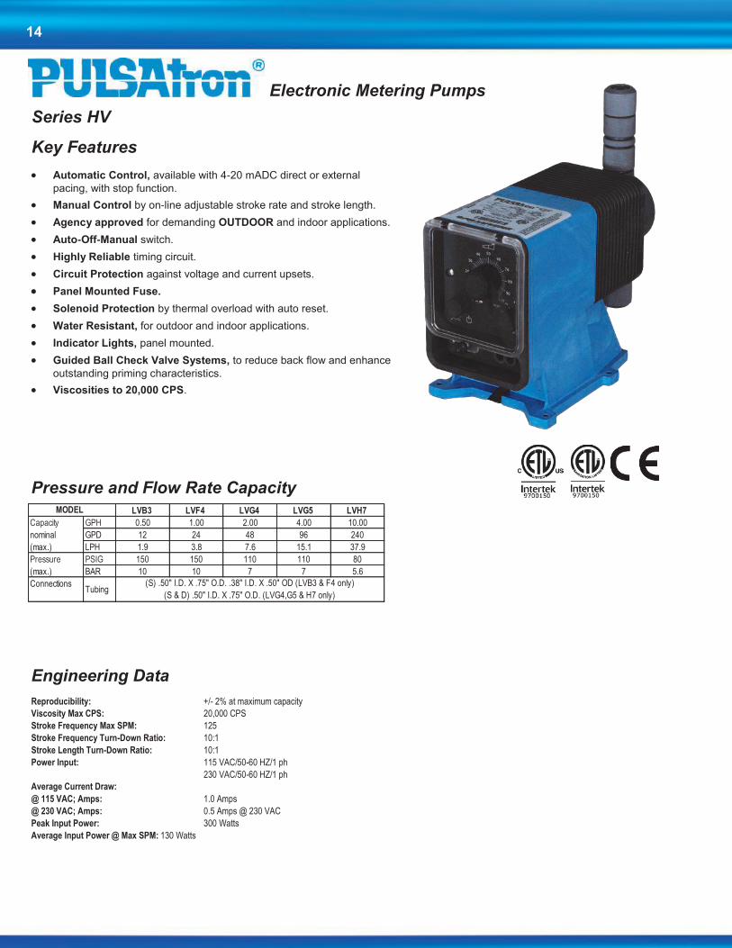
Series HV
Key Features
Automatic Control, available with 4-20 mADC direct or external
pacing, with stop function.
Manual Control by on-line adjustable stroke rate and stroke length.
Agency approved for demanding OUTDOOR and indoor applications.
Auto-Off-Manual switch.
Highly Reliable timing circuit.
Circuit Protection against voltage and current upsets.
Panel Mounted Fuse.
Solenoid Protection by thermal overload with auto reset.
Water Resistant, for outdoor and indoor applications.
Indicator Lights, panel mounted.
Guided Ball Check Valve Systems, to reduce back flow and enhance
outstanding priming characteristics.
Viscosities to 20,000 CPS.
Pressure and Flow Rate Capacity
LVB3 LVF4 LVG4 LVG5 LVH7
Capacity GPH 0.50 1.00 2.00 4.00 10.00
nominal GPD 12 24 48 96 240
(max.) LPH 1.9 3.8 7.6 15.1 37.9
Pressure PSIG 150 150 110 110 80
(max.) BAR 10 10 7 7 5.6
Connections
MODEL
Tubing(S) .50" I.D. X .75" O.D. .38" I.D. X .50" OD (LVB3 & F4 only)
(S & D) .50" I.D. X .75" O.D. (LVG4,G5 & H7 only)
Electronic Metering Pumps
Engineering Data
Reproducibility: +/- 2% at maximum capacity
Viscosity Max CPS: 20,000 CPS
Stroke Frequency Max SPM: 125
Stroke Frequency Turn-Down Ratio: 10:1
Stroke Length Turn-Down Ratio: 10:1
Power Input: 115 VAC/50-60 HZ/1 ph
230 VAC/50-60 HZ/1 ph
Average Current Draw:
@ 115 VAC; Amps: 1.0 Amps
@ 230 VAC; Amps: 0.5 Amps @ 230 VAC
Peak Input Power: 300 Watts
Average Input Power @ Max SPM: 130 Watts
15
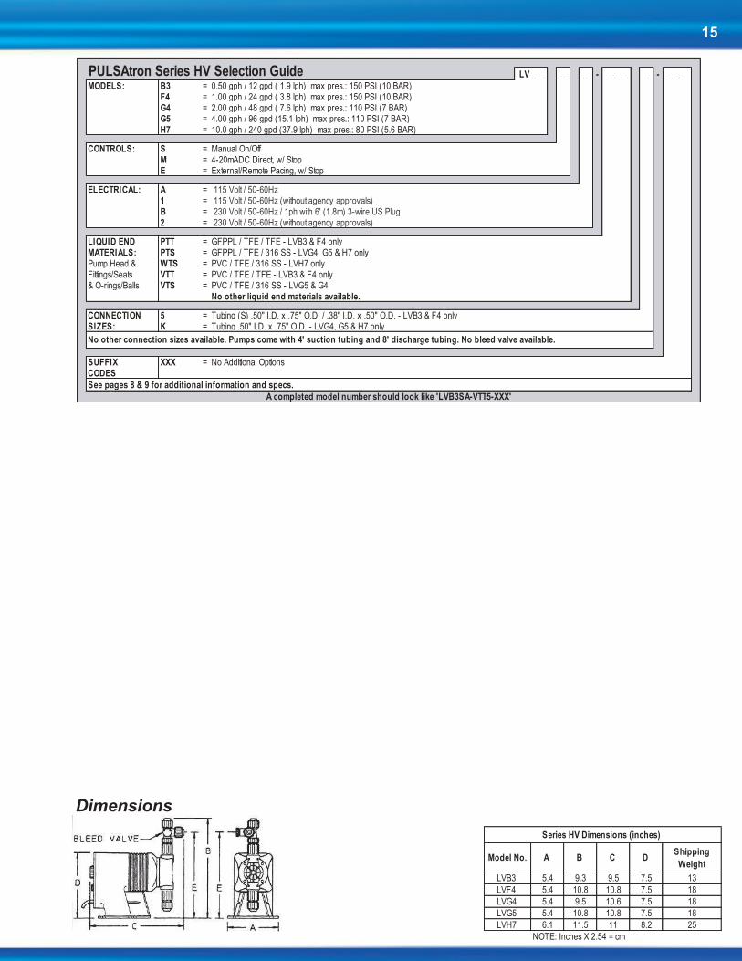
Dimensions
Model No. A B C D Shipping
Weight
LVB3 5.4 9.3 9.5 7.5 13
LVF4 5.4 10.8 10.8 7.5 18
LVG4 5.4 9.5 10.6 7.5 18
LVG5 5.4 10.8 10.8 7.5 18
LVH7 6.1 11.5 11 8.2 25
Series HV Dimensions (inches)
NOTE: Inches X 2.54 = cm
LV _ _ _ _ - _ _ _ _ - _ _ _
MODELS: B3 = 0.50 gph / 12 gpd ( 1.9 lph) max pres.: 150 PSI (10 BAR)F4 = 1.00 gph / 24 gpd ( 3.8 lph) max pres.: 150 PSI (10 BAR)G4 = 2.00 gph / 48 gpd ( 7.6 lph) max pres.: 110 PSI (7 BAR)G5 = 4.00 gph / 96 gpd (15.1 lph) max pres.: 110 PSI (7 BAR)H7 = 10.0 gph / 240 gpd (37.9 lph) max pres.: 80 PSI (5.6 BAR)
CONTROLS: S = Manual On/OffM = 4-20mADC Direct, w/ StopE = External/Remote Pacing, w/ Stop
ELECTRICAL: A = 115 Volt / 50-60Hz 1 = 115 Volt / 50-60Hz (without agency approvals) B = 230 Volt / 50-60Hz / 1ph with 6' (1.8m) 3-wire US Plug 2 = 230 Volt / 50-60Hz (without agency approvals)
LIQUID END PTT = GFPPL / TFE / TFE - LVB3 & F4 onlyMATERIALS: PTS = GFPPL / TFE / 316 SS - LVG4, G5 & H7 onlyPump Head & WTS = PVC / TFE / 316 SS - LVH7 onlyFittings/Seats VTT = PVC / TFE / TFE - LVB3 & F4 only& O-rings/Balls VTS = PVC / TFE / 316 SS - LVG5 & G4
No other liquid end materials available.
CONNECTION 5 = Tubing (S) .50" I.D. x .75" O.D. / .38" I.D. x .50" O.D. - LVB3 & F4 onlySIZES: K = Tubing .50" I.D. x .75" O.D. - LVG4, G5 & H7 only
SUFFIX XXX = No Additional OptionsCODES
PULSAtron Series HV Selection Guide
No other connection sizes available. Pumps come with 4' suction tubing and 8' discharge tubing. No bleed valve available.
See pages 8 & 9 for additional information and specs.
A completed model number should look like 'LVB3SA-VTT5-XXX'

16
Series E
Key Features
Manual Control by on-line adjustable stroke rate and stroke length.
Agency approved for demanding OUTDOOR and indoor applications.
Highly Reliable timing circuit.
Water Resistant excellent for OUTDOOR and indoor applications.
Internally Dampened To Reduce Noise, very acceptable for
household installations.
Guided Ball Check Valve Systems, to reduce back flow and enhance
outstanding priming characteristics.
Premium Standard Wetted Component Materials.
Few Moving Parts and Wall Mountable.
Safe & Easy Priming with durable leak-free bleed valve assembly
(standard).
Pressure and Flow Rate Capacity
LE12 LE02 LE33 LE13 LE03 LE34 LE14 LE44
Capacity GPH 0.21 0.25 0.50 0.50 0.50 0.90 1.00 1.85
nominal GPD 5 6 12 12 12 22 24 44
(max.) LPH 0.8 0.9 1.9 1.9 1.9 3.4 3.8 7
Pressure PSIG 250 150 250 150 100 150 100 100
(max.) BAR 17 10 17 10 7 10 7 7
Connections
Piping
MODEL
Tubing1/4" ID X 3/8" OD
3/8" ID X 1/2" OD
1/4" FNPT
Electronic Metering Pumps
Engineering Data
Reproducibility: +/- 3% at maximum capacity
Viscosity Max CPS: For viscosity up to 3000 CPS, select connection size 3, 4, B or C with 316SS ball material. Flow rate will determine connection/ball size. Greater than 3000 CPS require spring loaded ball checks. See Selection Guide for proper connec-tion.
Stroke Frequency Max SPM: 125
Stroke Frequency Turn-Down Ratio: 10:1
Stroke Length Turn-Down Ratio: 10:1
Power Input: 115 VAC/50-60 HZ/1 ph
230 VAC/50-60 HZ/1 ph
Average Current Draw:
@ 115VAC; Amps: 1.0 Amps
@ 230 VAC; Amps: 0.5 Amps
Peak Input Power: 300 Watts
Average Input Power @ Max SPM: 130 Watts
17
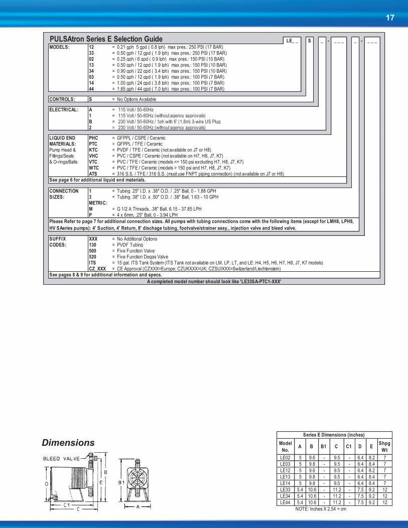
Dimensions Model
No. A B B1 C C1 D E
Shpg
Wt
LE02 5 9.6 - 9.5 - 6.4 8.2 7
LE03 5 9.8 - 9.5 - 6.4 8.4 7
LE12 5 9.6 - 9.5 - 6.4 8.2 7
LE13 5 9.8 - 9.5 - 6.4 8.4 7
LE14 5 9.8 - 9.5 - 6.4 8.4 7
LE33 5.4 10.6 - 11.2 - 7.5 9.2 12
LE34 5.4 10.6 - 11.2 - 7.5 9.2 12
LE44 5.4 10.6 - 11.2 - 7.5 9.2 12
NOTE: Inches X 2.54 = cm
Series E Dimensions (inches)
LE_ _ S _ - _ _ _ _ - _ _ _
MODELS: 12 = 0.21 gph 5 gpd ( 0.8 lph) max pres.: 250 PSI (17 BAR)33 = 0.50 gph / 12 gpd ( 1.9 lph) max pres.: 250 PSI (17 BAR)02 = 0.25 gph / 6 gpd ( 0.9 lph) max pres.: 150 PSI (10 BAR)13 = 0.50 gph / 12 gpd ( 1.9 lph) max pres.: 150 PSI (10 BAR)34 = 0.90 gph / 22 gpd ( 3.4 lph) max pres.: 150 PSI (10 BAR)03 = 0.50 gph / 12 gpd ( 1.9 lph) max pres.: 100 PSI (7 BAR)14 = 1.00 gph / 24 gpd ( 3.8 lph) max pres.: 100 PSI (7 BAR)44 = 1.85 gph / 44 gpd ( 7.0 lph) max pres.: 100 PSI (7 BAR)
CONTROLS: S = No Options Available
ELECTRICAL: A = 115 Volt / 50-60Hz 1 = 115 Volt / 50-60Hz (without agency approvals) B = 230 Volt / 50-60Hz / 1ph with 6' (1.8m) 3-wire US Plug 2 = 230 Volt / 50-60Hz (without agency approvals)
LIQUID END PHC = GFPPL / CSPE / CeramicMATERIALS: PTC = GFPPL / TFE / CeramicPump Head & KTC = PVDF / TFE / Ceramic (not available on J7 or H8)Fittings/Seats VHC = PVC / CSPE / Ceramic (not available on H7, H8, J7, K7)& O-rings/Balls VTC = PVC / TFE / Ceramic (models <= 150 psi excluding H7, H8, J7, K7)
WTC = PVC / TFE / Ceramic (models > 150 psi and H7, H8, J7, K7)ATS = 316 S.S. / TFE / 316 S.S. (must use FNPT piping connection) (not available on J7 or H8)
CONNECTION 1 = Tubing .25" I.D. x .38" O.D. / .25" Ball, 0 - 1.88 GPHSIZES: 3 = Tubing .38" I.D. x .50" O.D. / .38" Ball, 1.63 - 10 GPH
METRIC:M = G 1/2 A Threads, .38" Ball, 6.15 - 37.85 LPHP = 4 x 6mm, .25" Ball, 0 - 3.94 LPH
SUFFIX XXX = No Additional OptionsCODES: 130 = PVDF Tubing
500 = Five Function Valve520 = Five Function Degas ValveITS = 15 gal. ITS Tank System (ITS Tank not available on LM, LP, LT, and LE: H4, H5, H6, H7, H8, J7, K7 models)CZ_XXX = CE Approval (CZXXX=Europe; CZUKXXX=UK; CZSUIXXX=Switzerland/Liechtenstein)
PULSAtron Series E Selection Guide
See page 6 for additional liquid end materials.
Please Refer to page 7 for additional connection sizes. All pumps with tubing connections come with the following items (except for LMH8, LPH8,
HV SAeries pumps): 4' Suction, 4' Return, 8' dischage tubing, footvalve/strainer assy., injection valve and bleed valve.
See pages 8 & 9 for additional information and specs.
A completed model number should look like 'LE33SA-PTC1-XXX'

18
Series E-DC
Key Features
Powered by 12 Volt DC..
Manual Control by on-line adjustable stroke rate and stroke length.
Agency approved for demanding OUTDOOR and indoor applications.
Highly Reliable timing circuit.
Water Resistant excellent for OUTDOOR and indoor applications.
Internally Dampened To Reduce Noise, very acceptable for
household installations.
Guided Ball Check Valve Systems, to reduce back flow and enhance
outstanding priming characteristics.
Premium Standard Wetted Component Materials.
Few Moving Parts and Wall Mountable.
Safe & Easy Priming with durable leak-free bleed valve assembly
(standard).
Pressure and Flow Rate Capacity
LS02 LS13 LS14 LS44
Capacity GPH 0.25 0.50 1.00 1.85
nominal GPD 6 12 24 44
(max.) LPH 0.9 1.9 3.8 7.0
Pressure PSIG 150 150 100 100
(max.) BAR 10 10 7 7
Connections
Piping
Tubing
MODEL
3/8" ID X 1/2" OD
1/4" ID X 3/8" OD
1/4" FNPT
Electronic Metering Pumps
Engineering Data
Reproducibility: +/- 3% at maximum capacity
Viscosity Max CPS:
LS02, 13: 300 CPS
LS14, 44: 1000 CPS
Stroke Frequency Max SPM: 125
Stroke Frequency Turn-Down Ratio: 10:1
Stroke Length Turn-Down Ratio: 10:1
Power Input: 12.6 VDC Nominal Range 11.8-14.0 VDC
Average Current Draw:
LS02, 13, 14 Amps: 4.0 Amps
LS44 Amps: 8.0 Amps
Peak Input Power:
LS02, 13, 14 Power: 138.6 Watts
LS44 Power: 189 Watts
Average Input Power @ Max SPM:
LS02, 13, 14 Power: 50.4 Watts
LS44 Power: 100.8 Watts

19
Dimensions
Model No. A B C D E Shipping
Weight
LS02 5.0 9.6 9.6 6.5 8.2 10
LS13 5.0 9.9 9.5 6.5 8.5 10
LS14 5.0 9.9 9.5 6.5 8.5 10
LS44 5.0 10.6 11.4 7.5 9.2 15
Series E-DC Dimensions (inches)
NOTE: Inches X 2.54 = cm
LS_ _ S 4 - _ _ _ _ - _ _ _
MODELS: 02 = 0.25 gph / 6 gpd (0.9 lph) max pres.: 150 PSI (10 BAR)13 = 0.50 gph / 12 gpd ( 1.9 lph) max pres.: 150 PSI (10 BAR)14 = 1.00 gph / 24 gpd ( 3.8 lph) max pres.: 100 PSI (7 BAR)44 = 1.85 gph / 44 gpd ( 7.0 lph) max pres.: 100 PSI (7 BAR)
CONTROLS: S = No Options Available
ELECTRICAL: 4 = 12V DC
LIQUID END PHC = GFPPL / CSPE / CeramicMATERIALS: PTC = GFPPL / TFE / CeramicPump Head & PVC = GFPPL / Viton / CeramicFittings/Seats VTC = PVC / TFE / Ceramic& O-rings/Balls
CONNECTION 1 = Tubing .25" I.D. x .38" O.D. / .25" Ball, 0 - 1.88 GPHSIZES: J = Tubing .25" I.D. x .38" O.D./ 19" Ball, 0 - 1.04 GPH
METRIC:M = G 1/2 A Threads, .38" Ball, 6.15 - 37.85 LPHR G 1/2 A Threads, .25" Ball, 0 - 7.10 LPH
SUFFIX XXX = No Additional OptionsCODES: 130 = PVDF Tubing
500 = Five Function Valve520 = Five Function Degas ValveITS = 15 gal. ITS Tank System CZ_XXX = CE Approval (CZXXX=Europe; CZUKXXX=UK; CZSUIXXX=Switzerland/Liechtenstein)
PULSAtron Series E-DC Selection Guide
See page 6 for additional liquid end materials.
Please Refer to page 7 for additional connection sizes. All pumps with tubing connections come with the following items (except for LMH8, LPH8,
HV Series pumps): 4' Suction, 4' Return, 8' dischage tubing, footvalve/strainer assy., injection valve and bleed valve.
See pages 8 & 9 for additional information and specs.
A completed model number should look like 'LS02S4-PTC1-XXX'
20
Pressure and Flow Rate Capacity
Electronic Metering Pumps
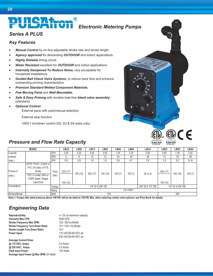
Series A PLUS
Key Features
Manual Control by on-line adjustable stroke rate and stroke length.
Agency approved for demanding OUTDOOR and indoor applications.
Highly Reliable timing circuit.
Water Resistant excellent for OUTDOOR and indoor applications.
Internally Dampened To Reduce Noise, very acceptable for
household installations.
Guided Ball Check Valve Systems, to reduce back flow and enhance
outstanding priming characteristics.
Premium Standard Wetted Component Materials.
Few Moving Parts and Wall Mountable.
Safe & Easy Priming with durable leak-free bleed valve assembly
(standard).
Optional Control:
External pace with auto/manual selection.
External stop function
1000:1 turndown control (S2, S3 & S4 sizes only)
LBC2 LB02 LBC3 LB03 LB04 LB64 LBC4 LBS2 LBS3 LBS4
Capacity GPH 0.25 0.25 0.42 0.50 1.00 1.25 2.00 0.50 1.38 2.42
nominal GPD 6 6 10 12 24 30 48 12 33 58
(max.) LPH 0.9 0.9 1.6 1.9 3.8 4.7 7.6 1.9 5.2 9.14
Pressure1
GFPP, PVDF, 316SS or
PVC (W code) w/TFE
Seats) 250 (17) 250 (17)
(max.) PVC (V code) Viton or
CSPE Seats / Degas
Liquid End 150 (10) 150 (10)
Connections Tubing 3/8" ID X 1/2" OD
Piping
Strokes/Minute SPM
Note 1: Pumps with rated pressure above 150 PSI will be de-rated to 150 PSI Max. when selecting certain valve options, see Price Book for details.
1/4" FNPT
125 250
150 (10) 100 (7) 100 (7) 50 (3.3) 150 (10) 100 (7)
MODEL
PSIG
(Bar)150 (10) 250 (17)
1/4" ID X 3/8" OD 1/4" ID X 3/8" OD
Engineering Data
Reproducibility: +/- 3% at maximum capacity
Viscosity Max CPS: 1000 CPS
Stroke Frequency Max SPM: 125 / 250 by Model
Stroke Frequency Turn-Down Ratio: 10:1 /100:1 by Model
Stroke Length Turn-Down Ratio: 10:1
Power Input: 115 VAC/50-60 HZ/1 ph
230 VAC/50-60 HZ/1 ph
Average Current Draw:
@ 115 VAC; Amps: 0.6 Amps
@ 230 VAC; Amps: 0.3 Amps
Peak Input Power: 130 Watts
Average Input Power @ Max SPM: 50 Watts

21
LB _ _ _ _ - _ _ _ _ - _ _ _
Models
Stroke
Rate
Standard
ValveMax. Viscosity
GPD GPH LPH PSI BAR (SPM) Size (cps)S2 12 0.50 1.9 250 17S3 33 1.38 5.2 150 10S4 58 2.42 9.1 100 7 1C2 6 0.25 0.9C3 10 0.42 1.602 6 0.25 0.903 12 0.50 1.904 24 1.00 3.864 30 1.25 4.7 1C4 48 2.00 7.6 50 3.3 3
ControlsSEPQ
X
ElectricalA 115 VAC, 60HzB 230 VAC, 50-60Hz, 1 Ph, 6' (2m) cord with 3 prong US plug1 115 VAC, 60Hz less Agency Approvals2 230 VAC, 50-60Hz, 1 Ph, 6' (2m) cord, no plug, less Agency
Liquid End Configuration - Head & Valves / Seats & O-Rings / Check Balls
PHC GFPPL / CSPE / Ceramic (150 PSI Max)1
PTC GFPPL / TFE / Ceramic
VTC PVC / TFE / Ceramic (150 PSI Max)1
WTC PVC / TFE / Ceramic (models > 150 PSI Max); For use on S2, C2, C3KTC PVDF / TFE / Ceramic
VVC PVC / Viton / Ceramic (Not available with J Valve) (150 PSI Max)1
VHC PVC / CSPE / Ceramic (Not available with J Valve) (150 PSI Max)1
Other See Page 6 for additional materials of construction
Connection SizesJ Tubing .25" I.D. x .38" O.D. Standard for pumps from 0 - 33 GPD1 Tubing .25" I.D. x .38" O.D. Standard for pumps from 20 - 45 GPD3 Tubing .38" I.D. x .50" O.D. Standard for pumps from 45 - 240 GPD9 Degas Head: Vent Tubing .25" I.D. x .38" O.D. (0-150 PSI pumps only)
MetricR G 1/2 A Threads, .25" Ball, 0-7.1 LPHY Tubing 9 x 12mm, .25" Ball, 0-7.1 LPH
Other See Page 7 for additional connection options
OptionsXXX StandardPump - No Options130 PVDF Tubing500 Five Function Valve520 Five Function Degassing ValveITS 15 gal. ITS Tank System
CZ_XXX
Note 1:Pumps with rated pressure above 150 PSI will be de-rated to 150 PSI Max. when selecting these valve options.
Pulsatron Series A Plus Selection Guide
Product
Code
Flow Rate Pressure Rating1
250J (TFE Only)
External Pace w/ Stop (125 SPM only)
1,000250 17
125J (TFE only)
150 10
100 7
Manual Control (S2,
S3 & S4 sizes only)1000:1 Turndown
10:1 Stroke Length
100:1 Frequency
CE Approval (CZXXX=Europe; CZUKXXX=UK; CZSUIXXX=Switzerland/Liechtenstein)
A completed model number should look like 'LB03SA-PTCJ-XXX'
Manual Control
100:1 Turndown10:1 Stroke Length
10:1 Frequency
External Pace w/ Auto/Manual SwitchStop Function Option
Dimensions Model No. A B C D E
Shipping
Weight
LB02 / S2 5.0 9.6 9.5 6.5 8.2 10
LBC2 5.0 9.9 9.5 6.5 8.5 10
LBC3 5.0 9.9 9.5 6.5 8.5 10
LB03 / S3 5.0 9.9 9.5 6.5 8.5 10
LB04 /S4 5.0 9.9 9.5 6.5 8.5 10
LB64 5.0 9.9 9.5 6.5 8.5 10
LBC4 5.0 9.9 9.5 6.5 8.5 10
Series A PLUS Dimensions (inches)
NOTE: Inches X 2.54 = cm
Dimensions

22
Series T7
Feed Control with 7 Day Timer
The Series T7 was designed to feed chemical products on a timed sched-
ule. Typical applications include the feed of biocides in open-air cooling
towers. The feed cycle is initiated and controlled by the programmable
timer. The Series T7 provides everything you need in one unique, compact
package to create a simple and cost effective metering system for timed
applications.
Principal of Operation
The Series T7 is controlled by a 7-day programmable timer. The timer is
programmable in 1-minute increments with up to 8 on/off cycles per day.
Each timed event can be set to run any day of the week on a 7-day cycle.
Other control features include a standby mode, continuous ‘ON’ mode and
the ability to adjust the stroke length from 0 – 100%.
Features
Isolated from Earth Ground
Mode Select Knob, Stroke Length
12, 22, 30 & 44 GPD @ 100 psi – 7 bar
Stroke length adjust 0-100%. Turn down ratio 10:1
7-Day Timer
Solid-state 7-day electronic timer for easy
adjustment of metering schedules and feed
rates. Manual control allows for easy priming
and start-up. The timer is programmable in 1
minute increments, with up to 8 events per
day.
Pressure and Flow Rate Capacity LC13BA LC14BA LC64BA LC44BA
Capacity GPH 0.50 1.00 1.25 2.00
nominal GPD 12 24 30 48
(max.) LPH 1.9 3.8 4.7 7.6
Pressure PSIG 100 100 100 50
(max.) BAR 7 7 7 3.3
MODEL
Electronic Metering Pumps with Integrated
Controller
Engineering Data
Reproducibility: +/- 3% at maximum capacity
Stroke Length Turn-Down Ratio: 10:1
Power Input: 115 VAC/50-60 HZ/1 ph
230 VAC/50-60 HZ/1 ph
Average Current Draw:
@ 115 VAC; Amps: 0.6 Amps
@ 230 VAC; Amps: 0.3 Amps @ 230 VAC

23
Model No. A B C D E Shipping
Weight
LC13BA 5.0 9.6 9.5 6.5 8.2 10
LC14BA 5.0 9.9 9.5 6.5 8.5 10
LC64BA 5.0 9.9 9.5 6.5 8.5 10
LC44BA 5.4 10.6 11.3 7.4 9.2 11.8
Series T7 Dimensions (inches
NOTE: Inches X 2.54 = cm
Dimensions
LC_ _ B _ - _ _ _ _ - _ _ _
MODELS: 13 = 0.50 gph / 12 gpd (1.9 lph) max pres.: 100 PSI (7 BAR)14 = 1.00 gph / 24 gpd (3.8 lph) max pres.: 100 PSI (7 BAR)64 = 1.25 gph / 30 gpd (4.7 lph) max pres.: 100 PSI (7 BAR)44 = 2.00 gph / 48 gpd (7.6 lph) max pres.: 50 PSI (3.3 BAR)
CONTROLS: B = No Options Available
ELECTRICAL: A = 115 Volt / 50-60Hz 1 = 115 Volt / 50-60Hz (without agency approvals) B = 230 Volt / 50-60Hz / 1ph with 6' (1.8m) 3-wire US Plug 2 = 230 Volt / 50-60Hz (without agency approvals)
LIQUID END PHC = GFPPL / CSPE / CeramicMATERIALS: PTC = GFPPL / TFE / CeramicPump Head & KTC = PVDF / TFE / CeramicFittings/Seats VHC = PVC / CSPE / Ceramic& O-rings/Balls VTC = PVC / TFE / Ceramic
CONNECTION 1 = Tubing .25" I.D. x .38" O.D. / .25" Ball, 0 - 1.88 GPHSIZES: 9 = Degas Head: .25" I.D. x .38" O.D. / 0-1.83 GPH
J = Tubing, .25" I.D. x .38" O.D. / .19 Ball; 0 - 1.04 GPHMETRIC:Y = 9 x 12mm, .25"" Ball, 0 - 7.10 LPHT = 6 x 8mm, Degassing (Note: has 8 mm suction), 0 - 7.10 LPH
SUFFIX XXX = No Additional OptionsCODES: 130 = PVDF Tubing
500 = Five Function Valve520 = Five Function Degas ValveITS = 15 gal. ITS Tank System
PULSAtron Series T7 Selection Guide
See page 6 for additional liquid end materials.
Please Refer to page 7 for additional connection sizes. All pumps with tubing connections come with the following items (except for LMH8, LPH8,
HV Series pumps): 4' Suction, 4' Return, 8' dischage tubing, footvalve/strainer assy., injection valve and bleed valve.
See pages 8 & 9 for additional information and specs.
A completed model number should look like 'LC13BA-PTC1-XXX'
24
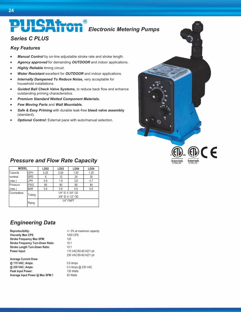
Series C PLUS
Key Features
Manual Control by on-line adjustable stroke rate and stroke length.
Agency approved for demanding OUTDOOR and indoor applications.
Highly Reliable timing circuit.
Water Resistant excellent for OUTDOOR and indoor applications.
Internally Dampened To Reduce Noise, very acceptable for
household installations.
Guided Ball Check Valve Systems, to reduce back flow and enhance
outstanding priming characteristics.
Premium Standard Wetted Component Materials.
Few Moving Parts and Wall Mountable.
Safe & Easy Priming with durable leak-free bleed valve assembly
(standard).
Optional Control: External pace with auto/manual selection.
Pressure and Flow Rate Capacity
LD02 LD03 LD04 LD54
Capacity GPH 0.25 0.50 1.00 1.25
nominal GPD 6 12 24 30
(max.) LPH 0.9 1.9 3.8 4.7
Pressure PSIG 80 80 80 80
(max.) BAR 5.6 5.6 5.6 5.6
Connections
Piping1/4" FNPT
MODEL
Tubing1/4" ID X 3/8" OD
3/8" ID X 1/2" OD
Electronic Metering Pumps
Engineering Data
Reproducibility: +/- 3% at maximum capacity
Viscosity Max CPS: 1000 CPS
Stroke Frequency Max SPM: 125
Stroke Frequency Turn-Down Ratio: 10:1
Stroke Length Turn-Down Ratio: 10:1
Power Input: 115 VAC/50-60 HZ/1 ph
230 VAC/50-60 HZ/1 ph
Average Current Draw:
@ 115 VAC; Amps: 0.6 Amps
@ 230 VAC; Amps: 0.3 Amps @ 230 VAC
Peak Input Power: 130 Watts
Average Input Power @ Max SPM:1 50 Watts

25
Dimensions
Model No. A B C D E Shipping
Weight
LD02 5.0 9.6 9.5 6.5 8.2 10
LD03 5.0 9.9 9.5 6.5 8.5 10
LD04 5.0 9.9 9.5 6.5 8.5 10
LD54 5.0 9.9 9.5 6.5 8.5 10
Series C PLUS Dimensions (inches)
NOTE: Inches X 2.54 = cm
LD_ _ _ _ - _ _ _ _ - _ _ _
MODELS: 02 = 0.25 gph / 6 gpd (0.9 lph) max pres.: 80 PSI (5.6 BAR)03 = 0.50 gph / 12 gpd (1.9 lph) max pres.: 80 PSI (5.6 BAR)04 = 1.00 gph / 24 gpd (3.8 lph) max pres.: 80 PSI (5.6 BAR)54 = 1.25 gph / 30 gpd (4.7 lph) max pres.: 80 PSI (5.6 BAR)
CONTROLS: S = ManualE = External Pacing w/ Auto/Manual SwitchG = External Pacing w/ Prime ButtonP = Stop Function Option
ELECTRICAL: A = 115 Volt / 50-60Hz 1 = 115 Volt / 50-60Hz (without agency approvals) B = 230 Volt / 50-60Hz / 1ph with 6' (1.8m) 3-wire US Plug 2 = 230 Volt / 50-60Hz (without agency approvals)
LIQUID END PHC = GFPPL / CSPE / CeramicMATERIALS: PTC = GFPPL / TFE / CeramicPump Head & KTC = PVDF / TFE / CeramicFittings/Seats VHC = PVC / CSPE / Ceramic& O-rings/Balls VTC = PVC / TFE / Ceramic
CONNECTION 1 = Tubing .25" I.D. x .38" O.D. / .25" Ball, 0 - 1.88 GPHSIZES: A = Tubing .38" I.D. x .50" O.D. / .25" Ball, 0 - 1.88 GPH
J = Tubing, .25" I.D. x .38" O.D./ .19 Ball; 0 - 1.04 GPHMETRIC:R = G 1/2 A Threads, .25" Ball, 0 - 7.10 LPHY = 9 x 12mm, .25" Ball, 0 - 7.10 LPH
SUFFIX XXX = No Additional OptionsCODES: 130 = PVDF Tubing
500 = Five Function Valve520 = Five Function Degas ValveITS = 15 gal. ITS Tank System CZ_XXX = CE Approval (CZXXX=Europe; CZUKXXX=UK; CZSUIXXX=Switzerland/Liechtenstein)
A completed model number should look like 'LD03SA-PTC1-XXX'
PULSAtron Series C Plus Selection Guide
See page 6 for additional liquid end materials.
Please Refer to page 7 for additional connection sizes. All pumps with tubing connections come with the following items (except for LMH8, LPH8,
HV Series pumps): 4' Suction, 4' Return, 8' dischage tubing, footvalve/strainer assy., injection valve and bleed valve.
See pages 8 & 9 for additional information and specs.

26
Series C
Key Features
Automatic Control by external pacing with prime switch (optional).
Manual Control by on-line adjustable stroke length (fixed stroke rate).
Liquid Low Level Option available to prevent loss of prime.
Agency approved for demanding OUTDOOR and indoor applications.
Highly Reliable timing circuit.
Water Resistant excellent for OUTDOOR and indoor
applications.
Internally Dampened To Reduce Noise, very
acceptable for household installations.
Guided Ball Check Valve Systems, to reduce back
flow and enhance outstanding priming characteristics.
Premium Standard Wetted Component Materials.
Few Moving Parts and Wall Mountable.
Safe & Easy Priming with durable leak-free bleed
valve assembly (standard).
Pressure and Flow Rate Capacity
LC02 LC03 LC04 LC54
Capacity GPH 0.25 0.50 1.00 1.25
nominal GPD 6 12 24 30
(max.) LPH 0.9 1.9 3.8 4.7
Pressure PSIG 80 80 80 80
(max.) BAR 5.6 5.6 5.6 5.6
Connections
Piping1/4" FNPT
MODEL
Tubing1/4" ID X 3/8" OD
3/8" ID X 1/2" OD
Electronic Metering Pumps
Engineering Data
Reproducibility: +/- 3% at maximum capacity
Viscosity Max CPS: 1000 CPS
Stroke Frequency Max SPM: 125
Stroke Length Turn-Down Ratio: 10:1
Power Input: 115 VAC/50-60 HZ/1 ph
230 VAC/50-60 HZ/1 ph
Average Current Draw:
@ 115 VAC; Amps: 0.6 Amps
@ 230 VAC; Amps: 0.3 Amps @ 230 VAC
Peak Input Power: 130 Watts
Average Input Power @ Max SPM: 50 Watts
Degas Head Option

27
Dimensions
Model No. A B C D E Shipping
Weight
LC02 5.0 9.6 9.5 6.5 8.2 10
LC03 5.0 9.9 9.5 6.5 8.5 10
LC04 5.0 9.9 9.5 6.5 8.5 10
LC54 5.0 9.9 9.5 6.5 8.5 10
Series C Dimensions (inches)
NOTE: Inches X 2.54 = cm
LC_ _ _ _ - _ _ _ _ - _ _ _
MODELS: 02 = 0.25 gph / 6 gpd (0.9 lph) max pres.: 80 PSI (5.6 BAR)03 = 0.50 gph / 12 gpd (1.9 lph) max pres.: 80 PSI (5.6 BAR)04 = 1.00 gph / 24 gpd (3.8 lph) max pres.: 80 PSI (5.6 BAR)54 = 1.25 gph / 30 gpd (4.7 lph) max pres.: 80 PSI (5.6 BAR)
CONTROLS: S = ManualE = External Pacing w/ Auto/Manual SwitchG = External Pacing w/ Prime ButtonP = Stop Function Option
ELECTRICAL: A = 115 Volt / 50-60Hz 1 = 115 Volt / 50-60Hz (without agency approvals) B = 230 Volt / 50-60Hz / 1ph with 6' (1.8m) 3-wire US Plug 2 = 230 Volt / 50-60Hz (without agency approvals)
LIQUID END PHC = GFPPL / CSPE / CeramicMATERIALS: PTC = GFPPL / TFE / CeramicPump Head & VHC = PVC / CSPE / CeramicFittings/Seats VTC = PVC / TFE / Ceramic& O-rings/Balls VVC = PVC / Viton / Ceramic
CONNECTION 1 = Tubing .25" I.D. x .38" O.D. / .25" Ball, 0 - 1.88 GPHSIZES: A = Tubing .38" I.D. x .50" O.D. / .25" Ball, 0 - 1.88 GPH
J = Tubing, .25" I.D. x .38" O.D./ .19 Ball; 0 - 1.04 GPHMETRIC:P = 4 x 6mm, .25" Ball, 0 - 3.94 LPHU = 6 x 8mm, .25" Ball, 0 - 7.10 LPH
SUFFIX XXX = No Additional OptionsCODES: 130 = PVDF Tubing
500 = Five Function Valve520 = Five Function Degas ValveITS = 15 gal. ITS Tank System CZ_XXX = CE Approval (CZXXX=Europe; CZUKXXX=UK; CZSUIXXX=Switzerland/Liechtenstein)
A completed model number should look like 'LC03SA-PTC1-XXX'
PULSAtron Series C Selection Guide
See page 6 for additional liquid end materials.
Please Refer to page 7 for additional connection sizes. All pumps with tubing connections come with the following items (except for LMH8, LPH8,
HV series pumps): 4' Suction, 4' Return, 8' dischage tubing, footvalve/strainer assy., injection valve and bleed valve.
See pages 8 & 9 for additional information and specs.

28
KOPkits
Selecting a KOPkit:
All KOPkit model strings begin with the letter K. The remainder of the string can be determined by knowing your pump model.
When you select your KOPkit, you will need to build the model number based on the pump model string that you purchased. The two pieces of information you need are the head size and the wet-end code, which is part of the model string of the pump.
The pump head size is the fourth digit in the pump model number.
LB02SA-PTC1-XXX
The 2 represents your pump head size.
Digits 7-20 in the pump model string represent the wet-end code. It is the group of four digits set apart by the dash lines.
LB02SA-PTC1-XXX
These four digits represent your wet-end code.
In the following selection guide, you will break down your wet-end code into the four parts to get your total price for the KOPkit. The four digits in the wet-end code represent the Head Material, Seats & O-Rings, Ball Material and Connection Type. Using the above example, the code breaks down as follows:
P - Head Material, including fittings. In this example, the P represents GFPPL.
T - Seat & O-Ring Material. In this example, the T represents Teflon.
C - Types of Balls used in the valves. In this example, the C represents Ceramic.
1 - Connection type. In this example, the 1 represents tubing connections for 3/8” OD tubing.
The completed KOPkit number for the above example is:
K2PTC1
Note: If you do not find your connection size in the following selection guide, please consult the factory for accurate pricing. Our
philosophy with the PULSAtron product line is to make it as flexible as our customers need it to be.

29
K_ _ _ _ _
HEAD SIZE 2 =
3 =
4 =
5 =
6 =
7 =
8 = (Applies to WTCB only-for other options Consult factory)
HEAD MATERIALS A = 316 Stainless SteelK = PVDF (Kynar)P = GFPPL (Polypropylene)V = PVC (Poly Vinyl Chloride) (models <= 150 psi
excluding H7, H8, K7)W = PVC (models > 150 psi and H7, H8, K7)
SEATS/O-RINGS H = CSPEV = VitonT = TFE
BALLS T = TFEC = CeramicS = 316 Stainless SteelH = Alloy C (Hastelloy)
CONNECTION TYPE Type Suction Discharge Spring1 = Tubing .25" x .38" .25" x .38"2 = Piping .25" FNPT .25" FNPT3 = Tubing .38" x .50" .38" x .50"4 = Piping .25" FNPT .25" FNPT5 = Tubing .50" x .75" .38" x .50" Yes6 = Piping .25" FNPT .25" FNPT Yes7 = Tubing .50" x .75" .50" FNPT Yes8 = Piping .50" FNPT .50" FNPT Yes9 = Tubing 25" x .38" .25" x .38" Yes DegasA = Tubing .38" x .50" .38" x .50"B = Tubing .50" x .75" .50" x .75"C = Piping .50" FNPT .50" FNPTD = Tubing .25" x .38" .25" x .38" YesE = Tubing .38" x .50" .38" x .50" YesF = Tubing .38" x .50" .38" x .50" YesG = Piping .25" FNPT .25" FNPT YesI = Piping .50" MNPT .50" MNPT YesJ = Tubing 25" x .38" .25" x .38"K = Tubing .50" x .75" .50" x .75" YesL = Piping .50" MNPT .50" MNPTM = Piping G 1/2 A G 1/2 AP = Tubing 4 x 6 mm 4 x 6 mmR = Piping G 1/2 A G 1/2 AS = Tubing 6 x 8 mm 6 x 8 mmT = Tubing 6 x 8 mm 6 x 8 mm DegasU = Tubing 6 x 8 mm 6 x 8 mmV = Tubing 12 x 19 mm 12 x 19 mmW = Tubing 8 x 12 mm 8 x 12 mmY = Tubing 9 x 12 mm 9 x 12 mmX = Piping .50" MNPT .50" MNPT
PULSAtron KOPkit Selection Guide
The digits 2-8 following the K
represents the pump head size.
This is represented by the fourth digit
in the pump model string.

30
Suction/Discharge Valves
L3_ _ _ _ _ _ - _ _ _
VALVE TYPE: 101 = Suction Valve201 = Discharge Valve
SEATS: H = CSPEV = VitonT = TFE
BALLS: T = TFEC = CeramicS = 316 Stainless SteelH = Alloy C (Hastelloy)
1 = Double Balls when TFE seats selected2 = Double Balls when TFE seats selected3 = Double Balls when TFE seats selected4 = Double Balls when TFE seats selected5* = Available for Discharge Only (L3201)6 =7* = Available for Suction Only (L3101)8 =A =B* =C =D = Spring Loaded with SS BallsE = Spring Loaded with SS BallsF = Spring Loaded with SS BallsG = Spring Loaded with SS BallsI =J =K* =L =M =P =R =S =U =V* =W =Y =X =
FPP = Glass Filled PolypropylenePVC = Poly Vinyl ChloridePVD = Kynar(not available w/ "B" connection type)316 = 316 Stainless Steel
* Available with Ceramic Balls and PVC Body Only - Consult factory for pricing on other options
Suction/Discharge Valve Selection Guide
CONNECTION TYPE:
MATERIALS OF
CONSTRUCTION:

31
LIQUID END COMPONENTS DRIVE END COMPONENTS DRIVE END COMPONENTS
Ite m
No.Pa rt Numbe r De sc ription
Ite m
No.Pa rt Numbe r De sc ription
Ite m
No.Pa rt Numbe r De sc ription
1 L0 2 0 0 2 0 0 - 3 16 HEAD, PUMP .750 50 L0 10 0 10 0 - 115 EPM A, B, K2, 3 115V 81 L5 0 2 8 2 0 1- 115 CNTRL PANEL ASSY, LVH7, LP/LVH8 115V
1 L0 2 0 0 9 0 0 - FPP HEAD, PUMP HSA #2 HEAD J .750 50 L0 10 0 3 0 0 - 115 EPM F, G, K5 115V 81 L5001401-115 CNTRL PANEL ASSY, EXT/STOP; H SIZE 115V1 L0 2 0 0 9 0 0 - PVC HEAD, PUMP HSA #2 HEAD J .750 51 L0 5 0 0 10 0 - 0 8 0 HOUSING #3 .080 STRK 81 L5001401-230 CNTRL PANEL ASSY, EXT/STOP; H SIZE 230V1 L0 2 0 0 3 0 0 - FPP HEAD, PUMP 1.000 51 L0 5 0 110 0 - 0 4 0 HOUSING #2 .040 STRK 81 L5028301-115 CNTRL PANEL ASSY, EXT/STOP; LVH7, 115V1 L0 2 0 2 5 0 0 - HPV HEAD, PUMP 1.000 51 L0 5 0 110 0 - 0 8 0 HOUSING #2 .080 STRK 81 L5028300-230 CNTRL PANEL ASSY, EXT/STOP; LVH7, 230V1 L0 2 0 0 3 0 0 - PVD HEAD, PUMP 1.000 51 L0 5 0 0 3 0 0 - 0 4 0 HOUSING #1 .040 STRK 81 L5001501-115 CNTRL PANEL ASSY, 4-20MA/STOP; H 115V1 L0 2 0 0 3 0 0 - PVC HEAD, PUMP 1.000 51 L0 5 0 0 3 0 0 - 0 8 0 HOUSING #1 .080 STRK 81 L5001501-230 CNTRL PANEL ASSY, 4-20MA/STOP; H 230V1 L0 2 0 10 0 0 - FPP HEAD, PUMP HSA #3 HEAD J 1.000 52 L0700101-125 CNTRL BD, A-B-D-E SIZE SLD 115V 81 L5028401-115 CNTRL PANEL ASSY, 4-20MA/STOP; 115V1 L0 2 0 10 0 0 - PVC HEAD, PUMP HSA #3 HEAD J 1.000 52 L0700102-125 CNTRL BD, A-B-D-E SIZE SLD 230V 81 L5028401-230 CNTRL PANEL ASSY, 4-20MA/STOP; 230V1 L0 2 0 0 4 0 0 - FPP HEAD, PUMP 1.250 52 L0700201-125 CNTRL BD, EXT/STOP; A, B, D, E 115V 81 L5000100-115 CNTRL PANEL ASSY, SERIES E; 0- 115V1 L0 2 0 0 4 0 0 - PVC HEAD, PUMP 1.250 52 L0700202-125 CNTRL BD, EXT/STOP; A, B, D, E 230V 81 L5000100-230 CNTRL PANEL ASSY, SERIES E; 0- 230V1 L0 2 0 0 4 0 0 - PVD HEAD, PUMP 1.250 52 L0700401-125 CNTRL BD, 4-20MA/STOP; A, B, D, E 115V 81 L5000200-115 CNTRL PANEL ASSY, 3-4 SIZE SLDS 115V1 L0 2 0 0 5 0 0 - SST HEAD, PUMP 1.625 52 L0700402-125 CNTRL BD, 4-20MA/STOP; A, B, D, E 230V 81 L5000200-230 CNTRL PANEL ASSY, 3-4 ZISE SLDS 230V1 L0 2 0 0 5 0 0 - FPP HEAD, PUMP 1.625 52 L0700501-150 CNTRL BD, F-G SIZE SLD 115V 81 L5002900-115 CNTRL PANEL ASSY SIN-FUNC; 0-SIZE 115V1 L0 2 0 0 5 0 0 - PVC HEAD, PUMP 1.625 52 L0700502-150 CNTRL BD, F-G SIZE SLD 230V 81 L5003000-115 CNTRL PANEL ASSY SIN-FUNC; 5-SIZE 1 L0 2 0 0 5 0 0 - PVD HEAD, PUMP 1.625 52 L0700501-200 CNTRL BD, H-K SIZE SLD 115V 81 L5011000-115 CNTRL PANEL ASSY EXT PACE; SIZE 1 L0 2 0 0 6 0 0 - SST HEAD, PUMP 2.000 52 L0700502-200 CNTRL BD, H-K SIZE SLD 230V 81 L5013000-115 CNTRL PANEL ASSY EXT PACE; SIZE 1 L0 2 0 0 6 0 0 - FPP HEAD, PUMP 2.000 52 L0709401-220 CNTRL BD, LEH8 115V 81 L5003016-115 CNTRL PANEL ASSY, 4-20MA/STOP; 115V1 L0 2 0 0 6 0 0 - PVC HEAD, PUMP 2.000 52 L0709402-220 CNTRL BD, LEH8 230V 81 L5003701-115 CNTRL PANEL ASSY, STD; K SIZE SLD 115V1 L0 2 0 0 6 0 0 - PVD HEAD, PUMP 2.000 52 L0709101-220 CNTRL BD, LVH7, LP/LVH8 115V 81 L5003801-115 CNTRL PANEL ASSY, EXT/STOP; K SIZE 115V1 L0 2 0 0 7 0 0 - 3 16 HEAD, PUMP 2.500 52 L0709102-220 CNTRL BD, LVH7, LP/LVH8 230V 81 L5003801-230 CNTRL PANEL ASSY, EXT/STOP; K SIZE 230V1 L0 2 0 0 7 0 0 - FPP HEAD, PUMP 2.500 52 L0700801-150 CNTRL BD, EXT/STOP; F, G 115V 81 L5003903-115 CNTRL PANEL ASSY, 4-20MA/STOP; K7 115V1 L0 2 0 0 7 0 0 - HPV HEAD, PUMP 2.500 52 L0700802-150 CNTRL BD, EXT/STOP; F, G 230V 81 L5003903-230 CNTRL PANEL ASSY, 4-20MA/STOP; K7 230V1 L0 2 0 0 7 0 0 - PVD HEAD, PUMP 2.500 52 L0700801-200 CNTRL BD EXT/STOP H SIZE SLD 115V 81 L5004100-115 CNTRL PANEL ASSY, SIN-FUNC; SIZE 115V 1 L0 2 0 0 8 0 0 - PPL HEAD, PUMP 3.625 52 L0700802-200 CNTRL BD EXT/STOP H SIZE SLD 230V 81 L5010800-230 CNTRL PANEL ASSY EXT PACE; SIZE 230V1 L0 2 0 0 8 0 0 - HPV HEAD, PUMP 3.625 52 L0709301-220 CNTRL BD EXT/STOP LVH7, LP/LVH8 115V 81 L5010900-230 CNTRL PANEL ASSY EXT PACE; SIZE 230V2 L0 3 0 0 9 0 0 - THY DIAPHRAGM .750 52 L0709302-220 CNTRL BD EXT/STOP LVH7, LP/LVH8 230V 81 L5005200-115 CNTRL PANEL ASSY; SIZE 02, 03, 04, 115V2 L0 3 0 10 0 0 - THY DIAPHRAGM 1.000 52 L0700901-150 CNTRL BD, 4-20 MA/STOP; F, G 115V 81 L5005300-230 CNTRL PANEL ASSY; SIZE 02, 03, 04, 230V2 L0 3 0 110 0 - THY DIAPHRAGM 1.250 52 L0700902-150 CNTRL BD, 4-20 MA/STOP; F, G 230V 81 L5004800-115 CNTRL PANEL ASSY; SIZE 54, 64 115V2 L0 3 0 12 0 0 - THY DIAPHRAGM 1.625 52 L0700901-200 CNTRL BD, 4-20 MA/STOP; H 115V 81 L5007501-115 CNTRL PNL ASSY LMK2; SIGNAL RELAY 115V2 L0 3 0 13 0 0 - THY DIAPHRAGM 2.000 52 L0700902-200 CNTRL BD, 4-20MA/STOP; H 230V 81 L5007301-115 CNTRL PNL ASSY LM A,B,C,D,E,K3; 115V2 L0 3 0 14 0 0 - THY DIAPHRAGM 2.500 52 L0709201-220 CNTRL BD, 4-20MA/STP, LVH7, LP/LVH8 81 L5007301-230 CNTRL PNL ASSY LM A,B,C,D,E,K3; 230V2 L0 3 0 16 0 0 - THY DIAPHRAGM 3.625 52 L0709202-220 CNTRL BD, 4-20MA/STP, LVH7, LP/LVH8 81 L5007401-115 CNTRL PNL ASSY LM A,B,C,D,E,K3; 115V18 L15 0 13 0 0 - HYP SUC/DIS VLV O- RING, CSPE 52 L0701900-150 CNTRL BD, E - DC 81 L5007401-230 CNTRL PNL ASSY LM A,B,C,D,E,K3; 230V18 L15 0 13 0 0 - TFE SUC/DIS VLV O- RING, TFE 52 L9906500-000 CNTRL BD, 0, 5 SIZE SING FUNC 115V 81 L5007701-115 CNTRL PNL ASSY LMK5; SIGNAL RELAY 115V18 L15 0 13 0 0 - VTN SUC/DIS VLV O- RING, VTN 52 L9906600-000 CNTRL BD, 0, 5 SIZE SING FUNC 230V 81 L5007101-115 CNTRL PNL ASSY LM F, G; SIGNAL 115V24 L110 3 4 0 0 - PVC COUPLING NUT 5/16" OD 52 L9906201-000 CNTRL BD, C+, A+ 115V 81 L5007701-230 CNTRL PNL ASSY LMK5; SIGNAL RELAY 230V24 L110 0 3 0 0 - FPP COUPLING NUT 3/8" OD 52 L9906202-000 CNTRL BD, C+, A+ 230V 81 L5007101-230 CNTRL PNL ASSY LM F, G; SIGNAL 230V24 L110 0 3 0 0 - PVC COUPLING NUT 3/8" OD 52 L0702801-190 CNTRL BD, LM H, K7 Signal Relay 115V 81 L5007801-115 CNTRL PNL ASSY LMK5; POWER RELAY 115V24 L110 0 3 0 0 - PVD COUPLING NUT 3/8" OD 52 L0705006-120 CNTRL BD, EXT, C+, A+ 230V 81 L5007201-115 CNTRL PNL ASSY LM F, G; POWER 115V24 L110 0 4 0 0 - FPP COUPLING NUT 1/2" OD 52 L0705110-120 CNTRL BD, EXT, C (LC54) 230V 81 L5007901-115 CNTRL PNL ASSY LMK7; SIGNAL RELAY 115V24 L110 0 4 0 0 - PVC COUPLING NUT 1/2" OD 53 L0601600-000 CNTRL PNL (ALL H & K7 PUMPS) 81 L5006901-115 CNTRL PNL ASSY LM H; SIGNAL RELAY 115V24 L110 0 4 0 0 - PVD COUPLING NUT 1/2" OD 54 L1600400-000 DUST COVER, CONT PNL HSG #3 81 L5007901-230 CNTRL PNL ASSY LMK7; SIGNAL RELAY 230V25 L9 9 0 6 7 0 0 - 0 0 0 WEIGHT, CERAMIC TUBE 54 L1600500-000 DUST COVER, CONT PNL HSG #2 81 L5006901-230 CNTRL PNL ASSY LM H; SIGNAL RELAY 230V36 L15 0 12 0 0 - TFE BLEED VLV O- RING, TFE 55 L2000100-040 SHAFT, ADJ FEMALE .040 HSG #2,3 81 L5007001-115 CNTRL PNL ASSY H; POWER RELAY 115V60 L15 0 0 7 0 0 - NTR SECONDARY SEAL, O- RING 2- 109 55 L2000100-080 SHAFT, ADJ FEMALE .080 HSG #2,3 88 L9804000-000 GROUND LUG NUT
55 L2000200-040 SHAFT, ADJ FEMALE .040 HSG #1 89 L9800500-STL GROUND LUG BOLT
DRIVE END COMPONENTS 55 L2000200-080 SHAFT, ADJ FEMALE .080 HSG #1 92 L9700800-000 BREAKER COVER
Ite m
No.Pa rt Numbe r De sc ription
56 L2000300-PBT SHAFT, ADJ MALE HSG #2,3 L9700200-000 CORD, SIGNAL, 10 FT3 L2 10 0 2 0 0 - FPP DEFLECTION PLATE .750 56 L2000400-PBT SHAFT, ADJ MALE HSG #1 L9700201-000 CORD, SIGNAL, 20 FT3 L2 10 0 3 0 0 - FPP DEFLECTION PLATE 1.000 59 L1500100-EPB O-RING, HSG #1/CONT PNL L9700800-000 PROTECTIVE BOOT, CKT BRKER3 L2 10 0 4 0 0 - FPP DEFLECTION PLATE 1.250 59 L1500300-NTR O-RING, HSG #2/CONT PNL3 L2 10 0 5 0 0 - FPP DEFLECTION PLATE 1.625 59 L1500500-NTR O-RING, HSG #3/CONT PNL3 L2 10 0 6 0 0 - FPP DEFLECTION PLATE 2.000 61 L9900600-000 CONNECTOR, LIQUID TIGHT3 L2 10 0 7 0 0 - FPP DEFLECTION PLATE 2.500 61 L9900700-000 CONNECTOR, STRAIN RELIEF4 L0 4 0 0 2 0 0 - FPP ADAPTER, .750 HSG #2 62 L9700300-000 CORD, POWER, SERIES C, E 125V4 L0 4 0 0 3 0 0 - FPP ADAPTER, 1.000 HSG #2 62 L9700400-000 CORD, POWER, SERIES C, E 230V4 L0 4 0 0 4 0 0 - FPP ADAPTER, 1.250 HSG #2 62 L9701200-000 CORD,POWER, SERIES E PLUS 125V4 L0 4 0 0 5 0 0 - FPP ADAPTER, 1.625 HSG #2 62 L9701300-000 CORD,POWER, SERIES E PLUS 230V4 L0 4 0 0 6 0 0 - FPP ADAPTER, 1.250 HSG #3 63 L9700700-250 CIRCUIT BREAKER, SERIES MP4 L0 4 0 0 7 0 0 - FPP ADAPTER, 1.625 HSG #3 63 L9707300-000 FUSE 2 AMP, SERIES E, E PLUS4 L0 4 0 0 8 0 0 - FPP ADAPTER, 2.000 HSG #3 63 L9706900-000 BOARD MNTD FUSE, SERIES A+, C+, C, E4 L0 4 0 0 9 0 0 - FPP ADAPTER, 2.500 HSG #3 64 L9800200-188 CNTRL PNL SCREW4 L0 4 0 110 0 - FPP ADAPTER, .750 HSG #1 65 L1500800-NTR GROMMET, STROKE LENGTH4 L0 4 0 12 0 0 - FPP ADAPTER, 1.000 HSG #1 66 L1900800-000 KNOB, STROKE RATE/SWITCH4 L0 4 0 13 0 0 - FPP ADAPTER, 1.250 HSG #1 71 L1900100-FPP KNOB, STROKE LENGTH4 L0 4 0 14 0 0 - PPL ADAPTER, 3.625 HSG #3 71 L1900300-FPP KNOB, STROKE LENGTH5 L9 9 0 12 0 0 - BRS SHIM, DIAPHRAGM 72 L9800200-188 KNOB MOUNTING SCREW6 L15 0 0 4 0 0 - NTR EPM/ADAPTER O- RING 76 L1500900-NTR GROMMET STROKE LENGTH6 L15 0 0 6 0 0 - NTR 81 L5000801-115 CNTRL PANEL ASSY; A-B-D-E SIZE SLDS, 115V7 L9 8 0 17 0 0 - 18 8 #10- 32 X 2.62 PAN HEAD, PHILLIPS LP_2- 4 81 L5000901-115 CNTRL PANEL ASSY, EXT/STOP; A-B-D-E 115V7 L9 8 0 18 0 0 - 18 8 .25- 20 X 2.62 PAN HEAD, PHILLIPS LP_5- 7 81 L5000901-230 CNTRL PANEL ASSY, EXT/STOP; A-B-D-E 230V7 L9 8 0 3 4 0 0 - 18 8 .25- 20 X 2.00 PAN HEAD LP_8 81 L5001001-115 CNTRL PANEL ASSY, 4-20MA/STOP; A-B-D- 115V7 L9 8 0 3 3 0 0 - 18 8 #10- 32 X 2.00 PAN HEAD 316SS 81 L5001001-230 CNTRL PANEL ASSY, 4-20MA/STOP; A-B-D- 230V8 L9 8 0 13 0 0 - 18 8 #10 REG FLAT WASHER LP_2- 4 81 L5001301-115 CNTRL PANEL ASSY, H SIZE SLD 115V8 L9 8 0 14 0 0 - 18 8 .25 REG FLAT WASHER LP_5- 8 81 L5028500-115 CNTRL PANEL ASSY, LEH8 115V
EPM/ADAPTER O- RING (ALL H PUMPS)

32
LIQUID END COMPONENTS DRIVE END COMPONENTS DRIVE END COMPONENTS
Ite m
No.Pa rt Numbe r De sc ription
Ite m
No.Pa rt Numbe r De sc ription
Ite m
No.Pa rt Numbe r De sc ription
1 L0 2 0 0 2 0 0 - 3 16 HEAD, PUMP .750 50 L0 10 0 10 0 - 115 EPM A, B, K2, 3 115V 81 L5 0 2 8 2 0 1- 115 CNTRL PANEL ASSY, LVH7, LP/LVH8 115V
1 L0 2 0 0 9 0 0 - FPP HEAD, PUMP HSA #2 HEAD J .750 50 L0 10 0 3 0 0 - 115 EPM F, G, K5 115V 81 L5001401-115 CNTRL PANEL ASSY, EXT/STOP; H SIZE 115V1 L0 2 0 0 9 0 0 - PVC HEAD, PUMP HSA #2 HEAD J .750 51 L0 5 0 0 10 0 - 0 8 0 HOUSING #3 .080 STRK 81 L5001401-230 CNTRL PANEL ASSY, EXT/STOP; H SIZE 230V1 L0 2 0 0 3 0 0 - FPP HEAD, PUMP 1.000 51 L0 5 0 110 0 - 0 4 0 HOUSING #2 .040 STRK 81 L5028301-115 CNTRL PANEL ASSY, EXT/STOP; LVH7, 115V1 L0 2 0 2 5 0 0 - HPV HEAD, PUMP 1.000 51 L0 5 0 110 0 - 0 8 0 HOUSING #2 .080 STRK 81 L5028300-230 CNTRL PANEL ASSY, EXT/STOP; LVH7, 230V1 L0 2 0 0 3 0 0 - PVD HEAD, PUMP 1.000 51 L0 5 0 0 3 0 0 - 0 4 0 HOUSING #1 .040 STRK 81 L5001501-115 CNTRL PANEL ASSY, 4-20MA/STOP; H 115V1 L0 2 0 0 3 0 0 - PVC HEAD, PUMP 1.000 51 L0 5 0 0 3 0 0 - 0 8 0 HOUSING #1 .080 STRK 81 L5001501-230 CNTRL PANEL ASSY, 4-20MA/STOP; H 230V1 L0 2 0 10 0 0 - FPP HEAD, PUMP HSA #3 HEAD J 1.000 52 L0700101-125 CNTRL BD, A-B-D-E SIZE SLD 115V 81 L5028401-115 CNTRL PANEL ASSY, 4-20MA/STOP; 115V1 L0 2 0 10 0 0 - PVC HEAD, PUMP HSA #3 HEAD J 1.000 52 L0700102-125 CNTRL BD, A-B-D-E SIZE SLD 230V 81 L5028401-230 CNTRL PANEL ASSY, 4-20MA/STOP; 230V1 L0 2 0 0 4 0 0 - FPP HEAD, PUMP 1.250 52 L0700201-125 CNTRL BD, EXT/STOP; A, B, D, E 115V 81 L5000100-115 CNTRL PANEL ASSY, SERIES E; 0- 115V1 L0 2 0 0 4 0 0 - PVC HEAD, PUMP 1.250 52 L0700202-125 CNTRL BD, EXT/STOP; A, B, D, E 230V 81 L5000100-230 CNTRL PANEL ASSY, SERIES E; 0- 230V1 L0 2 0 0 4 0 0 - PVD HEAD, PUMP 1.250 52 L0700401-125 CNTRL BD, 4-20MA/STOP; A, B, D, E 115V 81 L5000200-115 CNTRL PANEL ASSY, 3-4 SIZE SLDS 115V1 L0 2 0 0 5 0 0 - SST HEAD, PUMP 1.625 52 L0700402-125 CNTRL BD, 4-20MA/STOP; A, B, D, E 230V 81 L5000200-230 CNTRL PANEL ASSY, 3-4 ZISE SLDS 230V1 L0 2 0 0 5 0 0 - FPP HEAD, PUMP 1.625 52 L0700501-150 CNTRL BD, F-G SIZE SLD 115V 81 L5002900-115 CNTRL PANEL ASSY SIN-FUNC; 0-SIZE 115V1 L0 2 0 0 5 0 0 - PVC HEAD, PUMP 1.625 52 L0700502-150 CNTRL BD, F-G SIZE SLD 230V 81 L5003000-115 CNTRL PANEL ASSY SIN-FUNC; 5-SIZE 1 L0 2 0 0 5 0 0 - PVD HEAD, PUMP 1.625 52 L0700501-200 CNTRL BD, H-K SIZE SLD 115V 81 L5011000-115 CNTRL PANEL ASSY EXT PACE; SIZE 1 L0 2 0 0 6 0 0 - SST HEAD, PUMP 2.000 52 L0700502-200 CNTRL BD, H-K SIZE SLD 230V 81 L5013000-115 CNTRL PANEL ASSY EXT PACE; SIZE 1 L0 2 0 0 6 0 0 - FPP HEAD, PUMP 2.000 52 L0709401-220 CNTRL BD, LEH8 115V 81 L5003016-115 CNTRL PANEL ASSY, 4-20MA/STOP; 115V1 L0 2 0 0 6 0 0 - PVC HEAD, PUMP 2.000 52 L0709402-220 CNTRL BD, LEH8 230V 81 L5003701-115 CNTRL PANEL ASSY, STD; K SIZE SLD 115V1 L0 2 0 0 6 0 0 - PVD HEAD, PUMP 2.000 52 L0709101-220 CNTRL BD, LVH7, LP/LVH8 115V 81 L5003801-115 CNTRL PANEL ASSY, EXT/STOP; K SIZE 115V1 L0 2 0 0 7 0 0 - 3 16 HEAD, PUMP 2.500 52 L0709102-220 CNTRL BD, LVH7, LP/LVH8 230V 81 L5003801-230 CNTRL PANEL ASSY, EXT/STOP; K SIZE 230V1 L0 2 0 0 7 0 0 - FPP HEAD, PUMP 2.500 52 L0700801-150 CNTRL BD, EXT/STOP; F, G 115V 81 L5003903-115 CNTRL PANEL ASSY, 4-20MA/STOP; K7 115V1 L0 2 0 0 7 0 0 - HPV HEAD, PUMP 2.500 52 L0700802-150 CNTRL BD, EXT/STOP; F, G 230V 81 L5003903-230 CNTRL PANEL ASSY, 4-20MA/STOP; K7 230V1 L0 2 0 0 7 0 0 - PVD HEAD, PUMP 2.500 52 L0700801-200 CNTRL BD EXT/STOP H SIZE SLD 115V 81 L5004100-115 CNTRL PANEL ASSY, SIN-FUNC; SIZE 115V 1 L0 2 0 0 8 0 0 - PPL HEAD, PUMP 3.625 52 L0700802-200 CNTRL BD EXT/STOP H SIZE SLD 230V 81 L5010800-230 CNTRL PANEL ASSY EXT PACE; SIZE 230V1 L0 2 0 0 8 0 0 - HPV HEAD, PUMP 3.625 52 L0709301-220 CNTRL BD EXT/STOP LVH7, LP/LVH8 115V 81 L5010900-230 CNTRL PANEL ASSY EXT PACE; SIZE 230V2 L0 3 0 0 9 0 0 - THY DIAPHRAGM .750 52 L0709302-220 CNTRL BD EXT/STOP LVH7, LP/LVH8 230V 81 L5005200-115 CNTRL PANEL ASSY; SIZE 02, 03, 04, 115V2 L0 3 0 10 0 0 - THY DIAPHRAGM 1.000 52 L0700901-150 CNTRL BD, 4-20 MA/STOP; F, G 115V 81 L5005300-230 CNTRL PANEL ASSY; SIZE 02, 03, 04, 230V2 L0 3 0 110 0 - THY DIAPHRAGM 1.250 52 L0700902-150 CNTRL BD, 4-20 MA/STOP; F, G 230V 81 L5004800-115 CNTRL PANEL ASSY; SIZE 54, 64 115V2 L0 3 0 12 0 0 - THY DIAPHRAGM 1.625 52 L0700901-200 CNTRL BD, 4-20 MA/STOP; H 115V 81 L5007501-115 CNTRL PNL ASSY LMK2; SIGNAL RELAY 115V2 L0 3 0 13 0 0 - THY DIAPHRAGM 2.000 52 L0700902-200 CNTRL BD, 4-20MA/STOP; H 230V 81 L5007301-115 CNTRL PNL ASSY LM A,B,C,D,E,K3; 115V2 L0 3 0 14 0 0 - THY DIAPHRAGM 2.500 52 L0709201-220 CNTRL BD, 4-20MA/STP, LVH7, LP/LVH8 81 L5007301-230 CNTRL PNL ASSY LM A,B,C,D,E,K3; 230V2 L0 3 0 16 0 0 - THY DIAPHRAGM 3.625 52 L0709202-220 CNTRL BD, 4-20MA/STP, LVH7, LP/LVH8 81 L5007401-115 CNTRL PNL ASSY LM A,B,C,D,E,K3; 115V18 L15 0 13 0 0 - HYP SUC/DIS VLV O- RING, CSPE 52 L0701900-150 CNTRL BD, E - DC 81 L5007401-230 CNTRL PNL ASSY LM A,B,C,D,E,K3; 230V18 L15 0 13 0 0 - TFE SUC/DIS VLV O- RING, TFE 52 L9906500-000 CNTRL BD, 0, 5 SIZE SING FUNC 115V 81 L5007701-115 CNTRL PNL ASSY LMK5; SIGNAL RELAY 115V18 L15 0 13 0 0 - VTN SUC/DIS VLV O- RING, VTN 52 L9906600-000 CNTRL BD, 0, 5 SIZE SING FUNC 230V 81 L5007101-115 CNTRL PNL ASSY LM F, G; SIGNAL 115V24 L110 3 4 0 0 - PVC COUPLING NUT 5/16" OD 52 L9906201-000 CNTRL BD, C+, A+ 115V 81 L5007701-230 CNTRL PNL ASSY LMK5; SIGNAL RELAY 230V24 L110 0 3 0 0 - FPP COUPLING NUT 3/8" OD 52 L9906202-000 CNTRL BD, C+, A+ 230V 81 L5007101-230 CNTRL PNL ASSY LM F, G; SIGNAL 230V24 L110 0 3 0 0 - PVC COUPLING NUT 3/8" OD 52 L0702801-190 CNTRL BD, LM H, K7 Signal Relay 115V 81 L5007801-115 CNTRL PNL ASSY LMK5; POWER RELAY 115V24 L110 0 3 0 0 - PVD COUPLING NUT 3/8" OD 52 L0705006-120 CNTRL BD, EXT, C+, A+ 230V 81 L5007201-115 CNTRL PNL ASSY LM F, G; POWER 115V24 L110 0 4 0 0 - FPP COUPLING NUT 1/2" OD 52 L0705110-120 CNTRL BD, EXT, C (LC54) 230V 81 L5007901-115 CNTRL PNL ASSY LMK7; SIGNAL RELAY 115V24 L110 0 4 0 0 - PVC COUPLING NUT 1/2" OD 53 L0601600-000 CNTRL PNL (ALL H & K7 PUMPS) 81 L5006901-115 CNTRL PNL ASSY LM H; SIGNAL RELAY 115V24 L110 0 4 0 0 - PVD COUPLING NUT 1/2" OD 54 L1600400-000 DUST COVER, CONT PNL HSG #3 81 L5007901-230 CNTRL PNL ASSY LMK7; SIGNAL RELAY 230V25 L9 9 0 6 7 0 0 - 0 0 0 WEIGHT, CERAMIC TUBE 54 L1600500-000 DUST COVER, CONT PNL HSG #2 81 L5006901-230 CNTRL PNL ASSY LM H; SIGNAL RELAY 230V36 L15 0 12 0 0 - TFE BLEED VLV O- RING, TFE 55 L2000100-040 SHAFT, ADJ FEMALE .040 HSG #2,3 81 L5007001-115 CNTRL PNL ASSY H; POWER RELAY 115V60 L15 0 0 7 0 0 - NTR SECONDARY SEAL, O- RING 2- 109 55 L2000100-080 SHAFT, ADJ FEMALE .080 HSG #2,3 88 L9804000-000 GROUND LUG NUT
55 L2000200-040 SHAFT, ADJ FEMALE .040 HSG #1 89 L9800500-STL GROUND LUG BOLT
DRIVE END COMPONENTS 55 L2000200-080 SHAFT, ADJ FEMALE .080 HSG #1 92 L9700800-000 BREAKER COVER
Ite m
No.Pa rt Numbe r De sc ription
56 L2000300-PBT SHAFT, ADJ MALE HSG #2,3 L9700200-000 CORD, SIGNAL, 10 FT3 L2 10 0 2 0 0 - FPP DEFLECTION PLATE .750 56 L2000400-PBT SHAFT, ADJ MALE HSG #1 L9700201-000 CORD, SIGNAL, 20 FT3 L2 10 0 3 0 0 - FPP DEFLECTION PLATE 1.000 59 L1500100-EPB O-RING, HSG #1/CONT PNL L9700800-000 PROTECTIVE BOOT, CKT BRKER3 L2 10 0 4 0 0 - FPP DEFLECTION PLATE 1.250 59 L1500300-NTR O-RING, HSG #2/CONT PNL3 L2 10 0 5 0 0 - FPP DEFLECTION PLATE 1.625 59 L1500500-NTR O-RING, HSG #3/CONT PNL3 L2 10 0 6 0 0 - FPP DEFLECTION PLATE 2.000 61 L9900600-000 CONNECTOR, LIQUID TIGHT3 L2 10 0 7 0 0 - FPP DEFLECTION PLATE 2.500 61 L9900700-000 CONNECTOR, STRAIN RELIEF4 L0 4 0 0 2 0 0 - FPP ADAPTER, .750 HSG #2 62 L9700300-000 CORD, POWER, SERIES C, E 125V4 L0 4 0 0 3 0 0 - FPP ADAPTER, 1.000 HSG #2 62 L9700400-000 CORD, POWER, SERIES C, E 230V4 L0 4 0 0 4 0 0 - FPP ADAPTER, 1.250 HSG #2 62 L9701200-000 CORD,POWER, SERIES E PLUS 125V4 L0 4 0 0 5 0 0 - FPP ADAPTER, 1.625 HSG #2 62 L9701300-000 CORD,POWER, SERIES E PLUS 230V4 L0 4 0 0 6 0 0 - FPP ADAPTER, 1.250 HSG #3 63 L9700700-250 CIRCUIT BREAKER, SERIES MP4 L0 4 0 0 7 0 0 - FPP ADAPTER, 1.625 HSG #3 63 L9707300-000 FUSE 2 AMP, SERIES E, E PLUS4 L0 4 0 0 8 0 0 - FPP ADAPTER, 2.000 HSG #3 63 L9706900-000 BOARD MNTD FUSE, SERIES A+, C+, C, E4 L0 4 0 0 9 0 0 - FPP ADAPTER, 2.500 HSG #3 64 L9800200-188 CNTRL PNL SCREW4 L0 4 0 110 0 - FPP ADAPTER, .750 HSG #1 65 L1500800-NTR GROMMET, STROKE LENGTH4 L0 4 0 12 0 0 - FPP ADAPTER, 1.000 HSG #1 66 L1900800-000 KNOB, STROKE RATE/SWITCH4 L0 4 0 13 0 0 - FPP ADAPTER, 1.250 HSG #1 71 L1900100-FPP KNOB, STROKE LENGTH4 L0 4 0 14 0 0 - PPL ADAPTER, 3.625 HSG #3 71 L1900300-FPP KNOB, STROKE LENGTH5 L9 9 0 12 0 0 - BRS SHIM, DIAPHRAGM 72 L9800200-188 KNOB MOUNTING SCREW6 L15 0 0 4 0 0 - NTR EPM/ADAPTER O- RING 76 L1500900-NTR GROMMET STROKE LENGTH6 L15 0 0 6 0 0 - NTR 81 L5000801-115 CNTRL PANEL ASSY; A-B-D-E SIZE SLDS, 115V7 L9 8 0 17 0 0 - 18 8 #10- 32 X 2.62 PAN HEAD, PHILLIPS LP_2- 4 81 L5000901-115 CNTRL PANEL ASSY, EXT/STOP; A-B-D-E 115V7 L9 8 0 18 0 0 - 18 8 .25- 20 X 2.62 PAN HEAD, PHILLIPS LP_5- 7 81 L5000901-230 CNTRL PANEL ASSY, EXT/STOP; A-B-D-E 230V7 L9 8 0 3 4 0 0 - 18 8 .25- 20 X 2.00 PAN HEAD LP_8 81 L5001001-115 CNTRL PANEL ASSY, 4-20MA/STOP; A-B-D- 115V7 L9 8 0 3 3 0 0 - 18 8 #10- 32 X 2.00 PAN HEAD 316SS 81 L5001001-230 CNTRL PANEL ASSY, 4-20MA/STOP; A-B-D- 230V8 L9 8 0 13 0 0 - 18 8 #10 REG FLAT WASHER LP_2- 4 81 L5001301-115 CNTRL PANEL ASSY, H SIZE SLD 115V8 L9 8 0 14 0 0 - 18 8 .25 REG FLAT WASHER LP_5- 8 81 L5028500-115 CNTRL PANEL ASSY, LEH8 115V
EPM/ADAPTER O- RING (ALL H PUMPS)
BLEED VALVE ASSEMBLIES
Ite m
No.Pa rt Numbe r De sc ription
Ite m
No.Pa rt Numbe r De sc ription
11 L3 3 0 0 H0 1- FPP FPP/CSPE 3/8" 13 J4 17 6 7 FPP/CSPE/C 3/8" X 1/2"
11 L3 3 0 0 H0 1- PVC PVC/CSPE 3/8" 13 J4 18 6 3 FPP/CSPE/316 3/8" X 1/2"
11 L3 3 0 0 H0 3 - FPP FPP/CSPE 1/2" 13 J4 17 7 3 FPP/CSPE/TFE 3/8" X 1/2"
11 L3 3 0 0 H0 3 - PVC PVC/CSPE 1/2" 13 4 17 16 FPP/VTN/C 3/8" X 1/2"
11 L3 3 0 0 T0 1- FPP FPP/TFE 3/8" 13 J4 18 8 2 FPP/VTN/316 3/8" X 1/2"
11 L3 3 0 0 T0 1- PVC PVC/TFE 3/8" 13 J4 17 7 5 FPP/VTN/TFE 3/8" X 1/2"
11 L3 3 0 0 T0 1- PVD PVD/TFE 3/8" 13 J4 18 7 2 FPP/FTF/C 3/8" X 1/2"
11 L3 3 0 0 T0 3 - FPP FPP/TFE 1/2" 13 J4 18 7 9 FPP/FTF/316 3/8" X 1/2"
11 L3 3 0 0 T0 3 - PVC PVC/TFE 1/2" 13 J4 18 7 5 FPP/FTF/TFE 3/8" X 1/2"
11 L3 3 0 0 T0 3 - PVD PVD/TFE 1/2" 13 J4 16 9 4 PVC/CSPE/C 3/8" X 1/2"
11 L3 3 0 0 V0 1- FPP FPP/VTN 3/8" 13 4 16 9 8 PVC/CSPE/C 6" 3/8" X 1/2"
11 L3 3 0 0 V0 1- PVC PVC/VTN 3/8" 13 4 17 0 2 PP/VTN/C 6" 3/8" X 1/2"
11 L3 3 0 0 V0 1- PVD PVD/VTN 3/8" 13 J4 18 6 5 PVC/CSPE/316 3/8" X 1/2"
11 L3 3 0 0 V0 3 - FPP FPP/VTN 1/2" 13 J4 17 5 9 PVC/CSPE/TFE 3/8" X 1/2"
11 L3 3 0 0 V0 3 - PVC PVC/VTN 1/2" 13 J4 17 14 PVC/VTN/C 3/8" X 1/2"
11 L3 3 0 0 V0 3 - PVD PVD/VTN 1/2" 13 J4 17 6 1 PVC/VTN/TFE 3/8" X 1/2"
13 J4 18 7 3 PVC/FTF/C 3/8" X 1/2"
Ite m
No.Pa rt Numbe r De sc ription 13 J4 18 8 1 PVC/FTF/316 3/8" X 1/2"
12 J4 0 117 FPP/CSPE/C 3/8" X 1/2" 13 J4 18 7 7 PVC/FTF/TFE 3/8" X 1/2"
12 J4 0 12 3 FPP/CSPE/TFE 3/8" X 1/2" 13 J6 10 7 3 PVD/FTF/TFE 3/8" X 1/2"
12 J6 0 5 0 9 FPP/VTN/C 3/8" X 1/2" 13 J6 10 2 1 PVD/FTF/C 3/8" X 1/2"
12 J4 0 14 1 FPP/VTN/316 3/8" X 1/2" 13 J4 17 6 6 FPP/CSPE/C 1/4" X 3/8"
12 J4 0 12 5 FPP/VTN/TFE 3/8" X 1/2" 13 J4 18 6 2 FPP/CSPE/316 1/4" X 3/8"
12 J4 0 2 12 FPP/FTF/C 3/8" X 1/2" 13 J4 17 7 2 FPP/CSPE/TFE 1/4" X 3/8"
12 J4 0 17 5 FPP/FTF/316 3/8" X 1/2" 13 4 17 15 FPP/VTN/C 1/4" X 3/8"
12 J4 0 17 1 FPP/FTF/TFE 3/8" X 1/2" 13 4 17 0 1 FPP/VTN/C 6" 1/4" X 3/8"
12 J6 0 7 2 8 PVD/FTF/C 3/8" X 1/2" 13 J4 18 6 6 FPP/VTN/316 1/4" X 3/8"
12 J6 0 7 2 9 PVD/CSPE/C 3/8" X 1/2" 13 J4 17 7 4 FPP/VTN/TFE 1/4" X 3/8"
12 J6 0 7 3 0 PVD/VTN/C 3/8" X 1/2" 13 J6 10 9 8 FPP/FTF/C 1/4" X 3/8"
12 J4 0 116 FPP/CSPE/C 1/4" X 3/8" 13 J4 18 7 8 FPP/FTF/316 1/4" X 3/8"
12 J4 0 15 6 FPP/CSPE/316 1/4" X 3/8" 13 J4 18 7 4 FPP/FTF/TFE 1/4" X 3/8"
12 J4 0 12 2 FPP/CSPE/TFE 1/4" X 3/8" 13 4 16 9 3 PVC/CSPE/C 1/4" X 3/8"
12 J6 0 5 2 4 FPP/VTN/C 1/4" X 3/8" 13 4 17 0 5 PVC/CSPE/C 6" 1/4" X 3/8"
12 J4 0 15 8 FPP/VTN/316 1/4" X 3/8" 13 J4 17 5 8 PVC/CSPE/TFE 1/4" X 3/8"
12 J4 0 12 4 FPP/VTN/TFE 1/4" X 3/8" 13 J6 12 3 7 PVC/VTN/C 1/4" X 3/8"
12 J4 0 2 11 FPP/FTF/C 1/4" X 3/8" 13 J4 18 6 7 PVC/VTN/316 1/4" X 3/8"
12 J4 0 17 0 FPP/FTF/316 1/4" X 3/8" 13 4 17 6 0 PVC/VTN/TFE 1/4" X 3/8"
12 J4 0 16 9 FPP/FTF/TFE 1/4" X 3/8" 13 J4 19 9 6 PVC/FTF/C 1/4" X 3/8"
12 J6 0 7 16 PVD/FTF/C 1/4" X 3/8" 13 J4 18 8 0 PVC/FTF/316 1/4" X 3/8"
12 J6 0 7 17 PVD/CSPE/C 1/4" X 3/8" 13 J4 18 7 6 PVC/FTF/TFE 1/4" X 3/8"
12 J6 0 7 18 PVD/VTN/C 1/4" X 3/8" 13 J6 10 2 0 PVD/FTF/C 1/4" X 3/8"
12 J4 0 0 9 5 316 .25 NPT 13 J6 10 2 6 PVD/FTF/TFE 1/4" X 3/8"
12 J4 0 19 5 FPP/CSPE/C .25 NPT 13 J4 19 11 FPP/CSPE/C .25 NPT
12 J4 0 18 7 FPP/VTN/C .25 NPT 13 J4 19 0 1 FPP/VTN/C .25 NPT
12 J4 0 17 9 FPP/FTF/C .25 NPT 13 J4 19 4 4 FPP/FTF/C .25 NPT
12 J6 0 5 0 3 FPP .50 NPT 13 J4 19 0 4 PVC/CSPE/C .25 NPT
12 J6 0 5 6 1 FPP 1/2 X 3/4" 13 J4 18 5 8 PVC/VTN/C .25 NPT
12 J6 0 5 6 4 FPP/FTF/C 3/16 X 5/16" 13 J4 19 0 8 PVC/FTF/C .25 NPT
12 J6 0 7 12 PVD/FTF/C 3/16 X 5/16" 13 J6 10 15 PVD/FTF/C .25 NPT
12 J60564 FPP/TFE/C 13 J6 10 2 5 316/FTF/316 .25 NPT
12 J60712 PVD/TFE/C 13 J4 19 6 9 PVC/CSPE/C 1/2 X 3/4"
13 J6 114 9 - 10 P FPP/FTF/C 1/2 X 3/4"
Pa rt Numbe r De sc ription 13 J6 115 7 - 10 P PVC/FTF/C .50 NPT
L9 9 0 4 2 0 0 - 3 16 VALVE REPAIR KIT - ATS2 13 J6 115 6 - 10 P PVC/TFE/S .50 NPT
L9 9 0 4 6 0 0 - 3 16 VALVE REPAIR KIT - ATS4
L9 9 0 4 9 0 0 - 3 16 VALVE REPAIR KIT - ATSG Pa rt Numbe r De sc ription
2 6 8 5 8
Pa rt Numbe r De sc ription Pe r Foot 2 6 8 5 9
0 0 0 0 7 SUCT, 3/8 OD, CLEAR PVC FT 2 6 8 6 0
0 0 0 0 8 DISCH, 1/2 OD, WHITE PE FT 2 6 8 6 7
0 0 0 0 9 DISCH, 1/2 OD, BLACK PE FT L9 9 0 5 0 0 0 - PVC
0 0 0 10 DISCH, 3/8 OD, WHITE PE FT L9 9 0 5 10 0 - PVC
0 0 0 11 DISCH, 3/8 OD, BLACK PE FT L9 9 0 6 9 0 1- 0 0 0
J0 0 0 12 DISCH, 1/2 OD, HI PRES, WHITE FT L9 9 0 7 0 0 1- 0 0 0
0 0 0 13 DISCH, 1/2 OD, HI PRES, BLACK FT L9 9 0 7 10 1- 0 0 0
J0 0 0 2 2 DISCH, 3/8 OD, HI PRES, WHITE FT J0 0 0 2 3 SUCT, 1/2 OD, CLEAR PVC FTJ0 0 0 2 4 DISCH, 3/8 OD, HI PRES, BLACK FTJ0 0 0 3 2 SUCT/DISCH, 3/4 OD, CLEAR PVC FTL9 9 0 2 9 0 0 - 0 0 0 PVDF TUBING, 3/8 OD FTL9 9 0 3 0 0 0 - 0 0 0 PVDF TUBING, 1/2 OD FTL9 9 0 4 3 0 0 - PEB SUCT, 5/16 OD, PE BLACK FTL9 9 0 4 3 0 0 - PEW SUCT, 5/16 OD, PE WHITE FTL9 9 0 4 3 0 0 - PVC SUCT, 5/16 OD, CLEAR PVC FTL9 9 0 4 3 0 0 - PVD SUCT, 5/16 OD, PVDF WHITE FTL9 9 0 4 5 0 0 - PEW DISCH, 1/2 X 5/8, PE WHITE FTL9 9 13 2 0 0 - BRD PVC CLEAR BRAIDED, 3/4 OD FT
INJECTION BACK PRESS VALVE ASSEMBLIES
FOOT VALVE / STRAINER ASSEMBLIES
STAINLESS STEEL VALVE REPAIR KITS
OTHER
TUBING BULKHEAD FITTING - PP 1/2"
CONV. KIT (1.00" VVC9) DEGAS HEAD
CONV. KIT (1.25" VVC9) DEGAS HEAD
BULKHEAD FITTING - PVC 1/2"
BULKHEAD FITTING - PVC 3/8"
BULKHEAD FITTING - PP 3/8"
J CONVERSION KIT (PVC/TFE/C)
J CONVERSION KIT (PVC/TFE/C)
CONV. KIT (.75" VVC9) DEGAS HEAD

33
BLEED VALVE ASSEMBLIES
Ite m
No.Pa rt Numbe r De sc ription
Ite m
No.Pa rt Numbe r De sc ription
11 L3 3 0 0 H0 1- FPP FPP/CSPE 3/8" 13 J4 17 6 7 FPP/CSPE/C 3/8" X 1/2"
11 L3 3 0 0 H0 1- PVC PVC/CSPE 3/8" 13 J4 18 6 3 FPP/CSPE/316 3/8" X 1/2"
11 L3 3 0 0 H0 3 - FPP FPP/CSPE 1/2" 13 J4 17 7 3 FPP/CSPE/TFE 3/8" X 1/2"
11 L3 3 0 0 H0 3 - PVC PVC/CSPE 1/2" 13 4 17 16 FPP/VTN/C 3/8" X 1/2"
11 L3 3 0 0 T0 1- FPP FPP/TFE 3/8" 13 J4 18 8 2 FPP/VTN/316 3/8" X 1/2"
11 L3 3 0 0 T0 1- PVC PVC/TFE 3/8" 13 J4 17 7 5 FPP/VTN/TFE 3/8" X 1/2"
11 L3 3 0 0 T0 1- PVD PVD/TFE 3/8" 13 J4 18 7 2 FPP/FTF/C 3/8" X 1/2"
11 L3 3 0 0 T0 3 - FPP FPP/TFE 1/2" 13 J4 18 7 9 FPP/FTF/316 3/8" X 1/2"
11 L3 3 0 0 T0 3 - PVC PVC/TFE 1/2" 13 J4 18 7 5 FPP/FTF/TFE 3/8" X 1/2"
11 L3 3 0 0 T0 3 - PVD PVD/TFE 1/2" 13 J4 16 9 4 PVC/CSPE/C 3/8" X 1/2"
11 L3 3 0 0 V0 1- FPP FPP/VTN 3/8" 13 4 16 9 8 PVC/CSPE/C 6" 3/8" X 1/2"
11 L3 3 0 0 V0 1- PVC PVC/VTN 3/8" 13 4 17 0 2 PP/VTN/C 6" 3/8" X 1/2"
11 L3 3 0 0 V0 1- PVD PVD/VTN 3/8" 13 J4 18 6 5 PVC/CSPE/316 3/8" X 1/2"
11 L3 3 0 0 V0 3 - FPP FPP/VTN 1/2" 13 J4 17 5 9 PVC/CSPE/TFE 3/8" X 1/2"
11 L3 3 0 0 V0 3 - PVC PVC/VTN 1/2" 13 J4 17 14 PVC/VTN/C 3/8" X 1/2"
11 L3 3 0 0 V0 3 - PVD PVD/VTN 1/2" 13 J4 17 6 1 PVC/VTN/TFE 3/8" X 1/2"
13 J4 18 7 3 PVC/FTF/C 3/8" X 1/2"
Ite m
No.Pa rt Numbe r De sc ription 13 J4 18 8 1 PVC/FTF/316 3/8" X 1/2"
12 J4 0 117 FPP/CSPE/C 3/8" X 1/2" 13 J4 18 7 7 PVC/FTF/TFE 3/8" X 1/2"
12 J4 0 12 3 FPP/CSPE/TFE 3/8" X 1/2" 13 J6 10 7 3 PVD/FTF/TFE 3/8" X 1/2"
12 J6 0 5 0 9 FPP/VTN/C 3/8" X 1/2" 13 J6 10 2 1 PVD/FTF/C 3/8" X 1/2"
12 J4 0 14 1 FPP/VTN/316 3/8" X 1/2" 13 J4 17 6 6 FPP/CSPE/C 1/4" X 3/8"
12 J4 0 12 5 FPP/VTN/TFE 3/8" X 1/2" 13 J4 18 6 2 FPP/CSPE/316 1/4" X 3/8"
12 J4 0 2 12 FPP/FTF/C 3/8" X 1/2" 13 J4 17 7 2 FPP/CSPE/TFE 1/4" X 3/8"
12 J4 0 17 5 FPP/FTF/316 3/8" X 1/2" 13 4 17 15 FPP/VTN/C 1/4" X 3/8"
12 J4 0 17 1 FPP/FTF/TFE 3/8" X 1/2" 13 4 17 0 1 FPP/VTN/C 6" 1/4" X 3/8"
12 J6 0 7 2 8 PVD/FTF/C 3/8" X 1/2" 13 J4 18 6 6 FPP/VTN/316 1/4" X 3/8"
12 J6 0 7 2 9 PVD/CSPE/C 3/8" X 1/2" 13 J4 17 7 4 FPP/VTN/TFE 1/4" X 3/8"
12 J6 0 7 3 0 PVD/VTN/C 3/8" X 1/2" 13 J6 10 9 8 FPP/FTF/C 1/4" X 3/8"
12 J4 0 116 FPP/CSPE/C 1/4" X 3/8" 13 J4 18 7 8 FPP/FTF/316 1/4" X 3/8"
12 J4 0 15 6 FPP/CSPE/316 1/4" X 3/8" 13 J4 18 7 4 FPP/FTF/TFE 1/4" X 3/8"
12 J4 0 12 2 FPP/CSPE/TFE 1/4" X 3/8" 13 4 16 9 3 PVC/CSPE/C 1/4" X 3/8"
12 J6 0 5 2 4 FPP/VTN/C 1/4" X 3/8" 13 4 17 0 5 PVC/CSPE/C 6" 1/4" X 3/8"
12 J4 0 15 8 FPP/VTN/316 1/4" X 3/8" 13 J4 17 5 8 PVC/CSPE/TFE 1/4" X 3/8"
12 J4 0 12 4 FPP/VTN/TFE 1/4" X 3/8" 13 J6 12 3 7 PVC/VTN/C 1/4" X 3/8"
12 J4 0 2 11 FPP/FTF/C 1/4" X 3/8" 13 J4 18 6 7 PVC/VTN/316 1/4" X 3/8"
12 J4 0 17 0 FPP/FTF/316 1/4" X 3/8" 13 4 17 6 0 PVC/VTN/TFE 1/4" X 3/8"
12 J4 0 16 9 FPP/FTF/TFE 1/4" X 3/8" 13 J4 19 9 6 PVC/FTF/C 1/4" X 3/8"
12 J6 0 7 16 PVD/FTF/C 1/4" X 3/8" 13 J4 18 8 0 PVC/FTF/316 1/4" X 3/8"
12 J6 0 7 17 PVD/CSPE/C 1/4" X 3/8" 13 J4 18 7 6 PVC/FTF/TFE 1/4" X 3/8"
12 J6 0 7 18 PVD/VTN/C 1/4" X 3/8" 13 J6 10 2 0 PVD/FTF/C 1/4" X 3/8"
12 J4 0 0 9 5 316 .25 NPT 13 J6 10 2 6 PVD/FTF/TFE 1/4" X 3/8"
12 J4 0 19 5 FPP/CSPE/C .25 NPT 13 J4 19 11 FPP/CSPE/C .25 NPT
12 J4 0 18 7 FPP/VTN/C .25 NPT 13 J4 19 0 1 FPP/VTN/C .25 NPT
12 J4 0 17 9 FPP/FTF/C .25 NPT 13 J4 19 4 4 FPP/FTF/C .25 NPT
12 J6 0 5 0 3 FPP .50 NPT 13 J4 19 0 4 PVC/CSPE/C .25 NPT
12 J6 0 5 6 1 FPP 1/2 X 3/4" 13 J4 18 5 8 PVC/VTN/C .25 NPT
12 J6 0 5 6 4 FPP/FTF/C 3/16 X 5/16" 13 J4 19 0 8 PVC/FTF/C .25 NPT
12 J6 0 7 12 PVD/FTF/C 3/16 X 5/16" 13 J6 10 15 PVD/FTF/C .25 NPT
12 J60564 FPP/TFE/C 13 J6 10 2 5 316/FTF/316 .25 NPT
12 J60712 PVD/TFE/C 13 J4 19 6 9 PVC/CSPE/C 1/2 X 3/4"
13 J6 114 9 - 10 P FPP/FTF/C 1/2 X 3/4"
Pa rt Numbe r De sc ription 13 J6 115 7 - 10 P PVC/FTF/C .50 NPT
L9 9 0 4 2 0 0 - 3 16 VALVE REPAIR KIT - ATS2 13 J6 115 6 - 10 P PVC/TFE/S .50 NPT
L9 9 0 4 6 0 0 - 3 16 VALVE REPAIR KIT - ATS4
L9 9 0 4 9 0 0 - 3 16 VALVE REPAIR KIT - ATSG Pa rt Numbe r De sc ription
2 6 8 5 8
Pa rt Numbe r De sc ription Pe r Foot 2 6 8 5 9
0 0 0 0 7 SUCT, 3/8 OD, CLEAR PVC FT 2 6 8 6 0
0 0 0 0 8 DISCH, 1/2 OD, WHITE PE FT 2 6 8 6 7
0 0 0 0 9 DISCH, 1/2 OD, BLACK PE FT L9 9 0 5 0 0 0 - PVC
0 0 0 10 DISCH, 3/8 OD, WHITE PE FT L9 9 0 5 10 0 - PVC
0 0 0 11 DISCH, 3/8 OD, BLACK PE FT L9 9 0 6 9 0 1- 0 0 0
J0 0 0 12 DISCH, 1/2 OD, HI PRES, WHITE FT L9 9 0 7 0 0 1- 0 0 0
0 0 0 13 DISCH, 1/2 OD, HI PRES, BLACK FT L9 9 0 7 10 1- 0 0 0
J0 0 0 2 2 DISCH, 3/8 OD, HI PRES, WHITE FT J0 0 0 2 3 SUCT, 1/2 OD, CLEAR PVC FTJ0 0 0 2 4 DISCH, 3/8 OD, HI PRES, BLACK FTJ0 0 0 3 2 SUCT/DISCH, 3/4 OD, CLEAR PVC FTL9 9 0 2 9 0 0 - 0 0 0 PVDF TUBING, 3/8 OD FTL9 9 0 3 0 0 0 - 0 0 0 PVDF TUBING, 1/2 OD FTL9 9 0 4 3 0 0 - PEB SUCT, 5/16 OD, PE BLACK FTL9 9 0 4 3 0 0 - PEW SUCT, 5/16 OD, PE WHITE FTL9 9 0 4 3 0 0 - PVC SUCT, 5/16 OD, CLEAR PVC FTL9 9 0 4 3 0 0 - PVD SUCT, 5/16 OD, PVDF WHITE FTL9 9 0 4 5 0 0 - PEW DISCH, 1/2 X 5/8, PE WHITE FTL9 9 13 2 0 0 - BRD PVC CLEAR BRAIDED, 3/4 OD FT
INJECTION BACK PRESS VALVE ASSEMBLIES
FOOT VALVE / STRAINER ASSEMBLIES
STAINLESS STEEL VALVE REPAIR KITS
OTHER
TUBING BULKHEAD FITTING - PP 1/2"
CONV. KIT (1.00" VVC9) DEGAS HEAD
CONV. KIT (1.25" VVC9) DEGAS HEAD
BULKHEAD FITTING - PVC 1/2"
BULKHEAD FITTING - PVC 3/8"
BULKHEAD FITTING - PP 3/8"
J CONVERSION KIT (PVC/TFE/C)
J CONVERSION KIT (PVC/TFE/C)
CONV. KIT (.75" VVC9) DEGAS HEAD

34
Series MD
Key Features
Liquid End Materials – GFPPL, 316SS & PVDF.
Rugged double-sided PTFE faced, long life diaphragm.
Oil Lubricated Ball Bearings in die-cast aluminum housing.
Manual micrometer style stroke adjustment; 10:1 turndown, up to 100:1
with VFD Vector drive.
Standard NEMA 56C or IEC71 motor frames available.
Optional Features
Variable Frequency Drive for Automatic Control.
Fully Scalable 4-20mA, 0-10VDC signals.
NEMA 4X Enclosure.
ATEX Group II, Category 3 – Zone 2/22 for non-flammable liquids with
proper motor selection.
Pressure and Flow Rate Capacity
Engineering Data
Reproducibility: +/- 2% at maximum capacity
Viscosity Max CPS: up to 1000 CPS
Stroke Frequency Max SPM: 60 to 138 Strokes Per Minute max.
(Depending on model selection)
Stroke Length Turn-Down Ratio: 10:1
Power Input: 115 VAC/60 Hz/1 ph
230 VAC/50-60 Hz/1 ph or 3 ph
Max Ambient Temperature: 104O F (40O C)
Max Fluid Temperature: 104O F (40O C)
Oil Capacity: 15.2 oz (0.4 L)
Mechanical Diaphragm Pumps
MD1A MD1B MD1C MD1D MD1E MD2F MD2G MD2H MD3G
Capacity GPH 7 14 22 29 35 59 79 98 132
nominal (max.) LPH 26 53 82 111 133 225 298 371 501
Pressure PSIG 150 150 150 150 150 90 90 75 75
(max.) BAR 10 10 10 10 10 6 6 5 5
Connections: FNPT
BSPT-F
Strokes/Minute SPM 84 60 84 116 138 84 118 138 118
MODEL
1/2" 3/4" 1"
VFD VECTOR
(Optional)

35
Dimensions
MD_ _ _ _ _ _ _ _ - XXX
MODELS: 1A = 7 gph ( 26 lph) max pres.: 150 PSI (10 BAR)1B = 14 gph ( 53 lph) max pres.: 150 PSI (10 BAR)1C = 22 gph ( 82 lph) max pres.: 150 PSI (10 BAR)1D = 29 gph / ( 111 lph) max pres.: 150 PSI (10 BAR)1E = 35 gph / ( 133 lph) max pres.: 150 PSI (10 BAR)2F = 59 gph / ( 225 lph) max pres.: 90 PSI (6 BAR)2G = 79 gph / (298 lph) max pres.: 90 PSI (6 BAR)2H = 98 gph / ( 371lph) max pres.: 75 PSI (5 BAR)3G = 132 gph / (501 lph) max pres.: 75 PSI (5 BAR)
LIQUID END KTP = PVDF Head / PTFE Valve Seat / Pyrex Valve Check BallSize 1A-E PPP = Glass Filled Polypropylene Head / PVC Valve Seat / Pyrex Valve Check Ball
AAS = 316SS Head / 316SS Valve Seat / 316SS Valve Check BallKMM** = PVDF Head / Incoloy 825 Valve Seat / Hastelloy C-276 Valve Check BallKTP = PVDF Head / PTFE Valve Seat / Pyrex Valve Check Ball
Size 2F-H PPP = Glass Filled Polypropylene Head / PVC Valve Seat / Pyrex Valve Check BallAAS = 316SS Head / 316SS Valve Seat / 316SS Valve Check BallKMM** = PVDF Head / Incoloy 825 Valve Seat / Hastelloy C-276 Valve Check BallKTP = PVDF Head / PTFE Valve Seat / Pyrex Valve Check Ball
Size 3G PPP = Glass Filled Polypropylene Head / PVC Valve Seat / Pyrex Valve Check BallAAS = 316SS Head / 316SS Valve Seat / 316SS Valve Check BallKMM** = PVDF Head / Incoloy 825 Valve Seat / Hastelloy C-276 Valve Check Ball
VALVE N = NPT ConnectionCONNECTION: B = BSPT Connection
MOTOR 1 = TEFC - NEMA 56C, 1P, 115/230V, 60Hz, 1/2 HpSELECTION: 2 = TEFC - NEMA 56C, 3P, 230/460V, 50/60Hz, 1/2 Hp (VFD 10:1)
3 = Ex.Proof - NEMA 56C, 1P, 115/230V, 60Hz, 1/2 Hp 4 = Ex. Proof - NEMA 56C, 3P, 230/460V, 60Hz, 1/2 Hp6 = TEFC - IEC 71, 3P, 220/380/460V, 50/60Hz, .37kW (VFD 10:1, Required for CE Approved VFD)8 = Ex. Proof - IEC 71, 3P, 220/380/460V, 50/60Hz, .37kWX = No Motor - NEMA 56C Frame ReadyY = No Motor - IEC 71 Frame Ready
VFD OPTIONS A = No VFDC = VFD, 115/230V, NEMA 4X, IP65 Enclosure, 1 Phase, Motor 2 & 6 Only
OPTIONS XXX = No Options
** For use with high concentration of Sulfuric acid and poly-alum-chloride.
Blackline Series MD Selection Guide
A completed model number should look like 'MD1BKTPN1A-XXX'
Model Box DimensionsWeight Plastic
(lbs)
Weight Stainless
Steel (lbs)
MD1A (NO MOTOR) 19 x 19 x 10 21.5 26.0
MD1B (NO MOTOR) 20 x 19 x 10 21.5 26.0
MD1C (NO MOTOR) 21 x 19 x 10 21.5 26.0
MD1D (NO MOTOR) 22 x 19 x 10 21.5 26.0
MD1E (NO MOTOR) 23 x 19 x 10 21.5 26.0
MD2F (NO MOTOR) 24 x 19 x 10 26.0 37.0
MD2G (NO MOTOR) 25 x 19 x 10 26.0 37.0
MD2H (NO MOTOR) 26 x 19 x 10 26.0 37.0
MD3G (NO MOTOR) 27 x 19 x 10 29.0 46.0
MD1A W/VFD & MOTOR 27 x 17.4 x 18.75 67.0 71.5
MD1B W/VFD & MOTOR 28 x 17.4 x 18.75 67.0 71.5
MD1C W/VFD & MOTOR 29 x 17.4 x 18.75 67.0 71.5
MD1D W/VFD & MOTOR 30 x 17.4 x 18.75 67.0 71.5
MD1E W/VFD & MOTOR 31 x 17.4 x 18.75 67.0 71.5
MD2F W/VFD & MOTOR 32 x 17.4 x 18.75 71.5 82.5
MD2G W/VFD & MOTOR 33 x 17.4 x 18.75 72.5 83.5
MD2H W/VFD & MOTOR 34 x 17.4 x 18.75 73.5 84.5
MD3G W/VFD & MOTOR 35 x 17.4 x 18.75 74.5 91.5
Series MD Dimensions (inches)
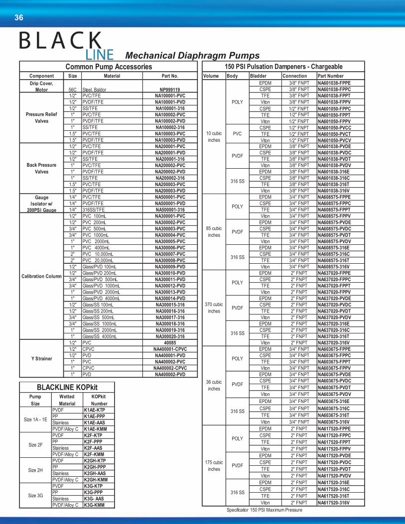
36
Component Size Material Part No. Volume Body Bladder Connection Part Number Pump Wetted KOPkit
Drip Cover, EPDM 3/8" FNPT NA601038-FPPE Size Material Number
Motor 56C Steel, Baldor NP999119 CSPE 3/8" FNPT NA601038-FPPC PVDF K1AE-KTP
1/2" PVC/TFE NA100001-PVC TFE 3/8" FNPT NA601038-FPPT PP K1AE-PPP
1/2" PVDF/TFE NA100001-PVD Viton 3/8" FNPT NA601038-FPPV Stainless K1AE-AAS
1/2" SS/TFE NA100001-316 CSPE 1/2" FNPT NA601050-FPPC PVDF/Alloy C K1AE-KMM
1" PVC/TFE NA100002-PVC TFE 1/2" FNPT NA601050-FPPT PVDF K2F-KTP
1" PVDF/TFE NA100002-PVD Viton 1/2" FNPT NA601050-FPPV PP K2F-PPP
1" SS/TFE NA100002-316 CSPE 1/2" FNPT NA601050-PVCC Stainless K2F-AAS
1.5" PVC/TFE NA100003-PVC TFE 1/2" FNPT NA601050-PVCT PVDF/Alloy C K2F-KMM
1.5" PVDF/TFE NA100003-PVD Viton 1/2" FNPT NA601050-PVCV PVDF K2GH-KTP
1/2" PVC/TFE NA200001-PVC EPDM 3/8" FNPT NA601038-PVDE PP K2GH-PPP
1/2" PVDF/TFE NA200001-PVD CSPE 3/8" FNPT NA601038-PVDC Stainless K2GH-AAS
1/2" SS/TFE NA200001-316 TFE 3/8" FNPT NA601038-PVDT PVDF/Alloy C K2GH-KMM
1" PVC/TFE NA200002-PVC Viton 3/8" FNPT NA601038-PVDV PVDF K3G-KTP
1" PVDF/TFE NA200002-PVD EPDM 3/8" FNPT NA601038-316E PP K3G-PPP
1" SS/TFE NA200002-316 CSPE 3/8" FNPT NA601038-316C Stainless K3G- AAS
1.5" PVC/TFE NA200003-PVC TFE 3/8" FNPT NA601038-316T PVDF/Alloy C K3G-KMM
1.5" PVDF/TFE NA200003-PVD Viton 3/8" FNPT NA601038-316V
Gauge 1/4" PVC/TFE NA500001-PVC EPDM 3/4" FNPT NA608575-FPPE
Isolator w/ 1/4" PVDF/TFE NA500001-PVD CSPE 3/4" FNPT NA608575-FPPC
200PSI Gauge 1/4" 316SS/TFE NA500001-316 TFE 3/4" FNPT NA608575-FPPT
1/2" PVC 100mL NA300001-PVC Viton 3/4" FNPT NA608575-FPPV
1/2" PVC 200mL NA300002-PVC EPDM 3/4" FNPT NA608575-PVDE
3/4" PVC 500mL NA300003-PVC CSPE 3/4" FNPT NA608575-PVDC
3/4" PVC 1000mL NA300004-PVC TFE 3/4" FNPT NA608575-PVDT
1" PVC 2000mL NA300005-PVC Viton 3/4" FNPT NA608575-PVDV
1" PVC 4000mL NA300006-PVC EPDM 3/4" FNPT NA608575-316E
2" PVC 10,000mL NA300007-PVC CSPE 3/4" FNPT NA608575-316C
2" PVC 20,000mL NA300008-PVC TFE 3/4" FNPT NA608575-316T
1/2" Glass/PVD 100mL NA300009-PVD Viton 3/4" FNPT NA608575-316V
1/2" Glass/PVD 200mL NA300010-PVD EPDM 2" FNPT NA637020-FPPE
3/4" Glass/PVD 500mL NA300011-PVD CSPE 2" FNPT NA637020-FPPC
3/4" Glass/PVD 1000mL NA300012-PVD TFE 2" FNPT NA637020-FPPT
1" Glass/PVD 2000mL NA300013-PVD Viton 2" FNPT NA637020-FPPV
1" Glass/PVD 4000mL NA300014-PVD EPDM 2" FNPT NA637020-PVDE
1/2" Glass/SS 100mL NA300015-316 CSPE 2" FNPT NA637020-PVDC
1/2" Glass/SS 200mL NA300016-316 TFE 2" FNPT NA637020-PVDT
3/4" Glass/SS 500mL NA300017-316 Viton 2" FNPT NA637020-PVDV
3/4" Glass/SS 1000mL NA300018-316 EPDM 2" FNPT NA637020-316E
1" Glass/SS 2000mL NA300019-316 CSPE 2" FNPT NA637020-316C
1" Glass/SS 4000mL NA300020-316 TFE 2" FNPT NA637020-316T
1/2" PVC 40085 Viton 2" FNPT NA637020-316V
1/2" CPVC NA400001-CPVC EPDM 3/4" FNPT NA603675-FPPE
1/2" PVD NA400001-PVD CSPE 3/4" FNPT NA603675-FPPC
1" PVC NA400002-PVC TFE 3/4" FNPT NA603675-FPPT
1" CPVC NA400002-CPVC Viton 3/4" FNPT NA603675-FPPV
1" PVD NA400002-PVD EPDM 3/4" FNPT NA603675-PVDE
CSPE 3/4" FNPT NA603675-PVDC
TFE 3/4" FNPT NA603675-PVDT
Viton 3/4" FNPT NA603675-PVDV
EPDM 3/4" FNPT NA603675-316E
CSPE 3/4" FNPT NA603675-316C
TFE 3/4" FNPT NA603675-316T
Viton 3/4" FNPT NA603675-316V
EPDM 2" FNPT NA617520-FPPE
CSPE 2" FNPT NA617520-FPPC
TFE 2" FNPT NA617520-FPPT
Viton 2" FNPT NA617520-FPPV
EPDM 2" FNPT NA617520-PVDE
CSPE 2" FNPT NA617520-PVDC
TFE 2" FNPT NA617520-PVDT
Viton 2" FNPT NA617520-PVDV
EPDM 2" FNPT NA617520-316E
CSPE 2" FNPT NA617520-316C
TFE 2" FNPT NA617520-316T
Viton 2" FNPT NA617520-316V
Specifications:150 PSI Maximum Pressure
Common Pump Accessories 150 PSI Pulsation Dampeners - Chargeable BLACKLINE KOPkit
10 cubic
inches
POLYSize 1A - 1E
Pressure Relief
ValvesSize 2F
PVC
Size 2H
Size 3G
316 SS
85 cubic
inches
POLY
Calibration Column
PVDF
316 SS
370 cubic
inches
Y Strainer
36 cubic
inches
POLY
PVDF
316 SS
Back Pressure
Valves
PVDF
175 cubic
inches
POLY
PVDF
316 SS
POLY
PVDF
316 SS
Mechanical Diaphragm Pumps
Component Size Material Part No. Volume Body Bladder Connection Part Number Pump Wetted KOPkit
Drip Cover, EPDM 3/8" FNPT NA601038-FPPE Size Material Number
Motor 56C Steel, Baldor NP999119 CSPE 3/8" FNPT NA601038-FPPC PVDF K1AE-KTP
1/2" PVC/TFE NA100001-PVC TFE 3/8" FNPT NA601038-FPPT PP K1AE-PPP
1/2" PVDF/TFE NA100001-PVD Viton 3/8" FNPT NA601038-FPPV Stainless K1AE-AAS
1/2" SS/TFE NA100001-316 CSPE 1/2" FNPT NA601050-FPPC PVDF/Alloy C K1AE-KMM
1" PVC/TFE NA100002-PVC TFE 1/2" FNPT NA601050-FPPT PVDF K2F-KTP
1" PVDF/TFE NA100002-PVD Viton 1/2" FNPT NA601050-FPPV PP K2F-PPP
1" SS/TFE NA100002-316 CSPE 1/2" FNPT NA601050-PVCC Stainless K2F-AAS
1.5" PVC/TFE NA100003-PVC TFE 1/2" FNPT NA601050-PVCT PVDF/Alloy C K2F-KMM
1.5" PVDF/TFE NA100003-PVD Viton 1/2" FNPT NA601050-PVCV PVDF K2GH-KTP
1/2" PVC/TFE NA200001-PVC EPDM 3/8" FNPT NA601038-PVDE PP K2GH-PPP
1/2" PVDF/TFE NA200001-PVD CSPE 3/8" FNPT NA601038-PVDC Stainless K2GH-AAS
1/2" SS/TFE NA200001-316 TFE 3/8" FNPT NA601038-PVDT PVDF/Alloy C K2GH-KMM
1" PVC/TFE NA200002-PVC Viton 3/8" FNPT NA601038-PVDV PVDF K3G-KTP
1" PVDF/TFE NA200002-PVD EPDM 3/8" FNPT NA601038-316E PP K3G-PPP
1" SS/TFE NA200002-316 CSPE 3/8" FNPT NA601038-316C Stainless K3G- AAS
1.5" PVC/TFE NA200003-PVC TFE 3/8" FNPT NA601038-316T PVDF/Alloy C K3G-KMM
1.5" PVDF/TFE NA200003-PVD Viton 3/8" FNPT NA601038-316V
Gauge 1/4" PVC/TFE NA500001-PVC EPDM 3/4" FNPT NA608575-FPPE
Isolator w/ 1/4" PVDF/TFE NA500001-PVD CSPE 3/4" FNPT NA608575-FPPC
200PSI Gauge 1/4" 316SS/TFE NA500001-316 TFE 3/4" FNPT NA608575-FPPT
1/2" PVC 100mL NA300001-PVC Viton 3/4" FNPT NA608575-FPPV
1/2" PVC 200mL NA300002-PVC EPDM 3/4" FNPT NA608575-PVDE
3/4" PVC 500mL NA300003-PVC CSPE 3/4" FNPT NA608575-PVDC
3/4" PVC 1000mL NA300004-PVC TFE 3/4" FNPT NA608575-PVDT
1" PVC 2000mL NA300005-PVC Viton 3/4" FNPT NA608575-PVDV
1" PVC 4000mL NA300006-PVC EPDM 3/4" FNPT NA608575-316E
2" PVC 10,000mL NA300007-PVC CSPE 3/4" FNPT NA608575-316C
2" PVC 20,000mL NA300008-PVC TFE 3/4" FNPT NA608575-316T
1/2" Glass/PVD 100mL NA300009-PVD Viton 3/4" FNPT NA608575-316V
1/2" Glass/PVD 200mL NA300010-PVD EPDM 2" FNPT NA637020-FPPE
3/4" Glass/PVD 500mL NA300011-PVD CSPE 2" FNPT NA637020-FPPC
3/4" Glass/PVD 1000mL NA300012-PVD TFE 2" FNPT NA637020-FPPT
1" Glass/PVD 2000mL NA300013-PVD Viton 2" FNPT NA637020-FPPV
1" Glass/PVD 4000mL NA300014-PVD EPDM 2" FNPT NA637020-PVDE
1/2" Glass/SS 100mL NA300015-316 CSPE 2" FNPT NA637020-PVDC
1/2" Glass/SS 200mL NA300016-316 TFE 2" FNPT NA637020-PVDT
3/4" Glass/SS 500mL NA300017-316 Viton 2" FNPT NA637020-PVDV
3/4" Glass/SS 1000mL NA300018-316 EPDM 2" FNPT NA637020-316E
1" Glass/SS 2000mL NA300019-316 CSPE 2" FNPT NA637020-316C
1" Glass/SS 4000mL NA300020-316 TFE 2" FNPT NA637020-316T
1/2" PVC 40085 Viton 2" FNPT NA637020-316V
1/2" CPVC NA400001-CPVC EPDM 3/4" FNPT NA603675-FPPE
1/2" PVD NA400001-PVD CSPE 3/4" FNPT NA603675-FPPC
1" PVC NA400002-PVC TFE 3/4" FNPT NA603675-FPPT
1" CPVC NA400002-CPVC Viton 3/4" FNPT NA603675-FPPV
1" PVD NA400002-PVD EPDM 3/4" FNPT NA603675-PVDE
CSPE 3/4" FNPT NA603675-PVDC
TFE 3/4" FNPT NA603675-PVDT
Viton 3/4" FNPT NA603675-PVDV
EPDM 3/4" FNPT NA603675-316E
CSPE 3/4" FNPT NA603675-316C
TFE 3/4" FNPT NA603675-316T
Viton 3/4" FNPT NA603675-316V
EPDM 2" FNPT NA617520-FPPE
CSPE 2" FNPT NA617520-FPPC
TFE 2" FNPT NA617520-FPPT
Viton 2" FNPT NA617520-FPPV
EPDM 2" FNPT NA617520-PVDE
CSPE 2" FNPT NA617520-PVDC
TFE 2" FNPT NA617520-PVDT
Viton 2" FNPT NA617520-PVDV
EPDM 2" FNPT NA617520-316E
CSPE 2" FNPT NA617520-316C
TFE 2" FNPT NA617520-316T
Viton 2" FNPT NA617520-316V
Specifications:150 PSI Maximum Pressure
Common Pump Accessories 150 PSI Pulsation Dampeners - Chargeable BLACKLINE KOPkit
10 cubic
inches
POLYSize 1A - 1E
Pressure Relief
ValvesSize 2F
PVC
Size 2H
Size 3G
316 SS
85 cubic
inches
POLY
Calibration Column
PVDF
316 SS
370 cubic
inches
Y Strainer
36 cubic
inches
POLY
PVDF
316 SS
Back Pressure
Valves
PVDF
175 cubic
inches
POLY
PVDF
316 SS
POLY
PVDF
316 SS

37
Peristaltic Pumps
XP_ _ _ _ _ _ _
Duplex'H' Tube 'L' Tube 'F' Tube 'L' Tube
XP004 4 GPD (0.6 LPH) 80 (5.5) 30XP007 7 GPD (1.1 LPH) 50XP009 9 GPD (1.4 LPH) 70 (4.8) 30XP015 15 GPD (2.4 LPH) 50XP014 14 GPD (2.3 LPH) 50 (3.4) 30XP023 23 GPD (3.6 LPH) 50XP030 30 GPD (4.7 LPH) 80 (5.5) 40 (2.8) 30XP050 50 GPD (7.9 LPH) 50XP048 48 GPD (7.5 LPH) 25 (1.7) 30XP080 80 GPD (12.6 LPH) 50
L 115V, 60HzH 230V, 50/60HzR 230V, 50Hzwith Grounded Right Angle European Plug
Note: 50Hz pumps will produce 5/6 of the rated flow
F Fixed Rate, On / Off OnlyA Adjustable 20:1 Turndown, On / Off with Current Interrupter TimerG Duplex Head - Fixed Rate, On / Off Only, 'L' TubeB Duplex Head - Adjustable, On / Off with Current Interrupter Timer, 'L' Tube1 Pulse Input, .1 to 1 Second Timer2 Pulse Input, .2 to 10 Second Timer3 Pulse Input, 1 to 60 Second Timer4 Dry Contact Input - Fixed Rate Pump5 Dry Contact Input - Adjustable Pump6 Flow Switch Activated with 3/4" NPT Flow Switch - Fixed Rate Pump7 Flow Switch Activated with 3/4" NPT Flow Switch - Adjustable Rate Pump8 7 Day - 8 Event Electronic Timer - Fixed Rate Pump
L Low Pressure Norprene with 1/4" Tube FittingsH High Pressure Norprene with 1/4" Tube Fittings3 Low Pressure Norprene with 3/8" Tube Fittings4 High Pressure Norprene with 3/8" Tube FittingsF Fluran, Acid resistant tubing with 1/4" Tube Fittings (Doesnot include strainer & injector accessories)G Fluran, Acid resistant tubing with 3/8" Tube Fittings (Doesnot include strainer & injector accessories)
X Pump Only1 15 Gallon Tank System3 35 Gallon Tank SystemT 15 Gallon ITS System
Chem-Tech XP Series Selection Guide
MODELS:
Pump
Size Flow
Pressure Rating - PSI (Bar)Tube
Size
Speed
(RPM)Single Head Options
125 (8.6) 80 (5.5) 60 (4.1) 2
110 (7.6) 70 (4.8) 50 (3.4) 3
100 (5.9) 50 (3.4) 40 (2.8) 4
40 (2.8) 6
A completed model should look like "XP030LFLX"
25 (1.7) 8
ELECTRICAL:
DRIVE:
TUBING:
SYSTEM:
Series XP
The Chem-Tech XP Series with peristaltic technology delivers worry-free dosing in a modern design. Each and every component of the XP Series is designed and manufactured for optimum riability and durability for REAL Performance.
The electronic timing circuit in the adjustable ‘A’ Models provides reliable pump control, without relying on mechanical adjustment components that wear out over time.
The intuitive interface and controls provide easy operation and the peristaltic design is virtually maintenance-free.
Tailor-made for the water conditioning market, the XP Series offer affordable solutions in both initial cost and operation. A rugged gear train and computer-aided peristaltic design ensure
long-lasting performance.
Tested and Certified by WQA
against NSF/ANSI 61-Section 8.
and CSA B483.1

38
XP_ _ _ _ _ _ _
Duplex
'H' Tube 'L' Tube 'F' Tube 'L' Tube
XP008 8 GPD (1.3 LPH) 125 (8.6) 80 (5.5) 60 (4.1) 80 (5.5) 2
XP017 17 GPD (2.7 LPH) 110 (7.6) 70 (4.8) 50 (3.4)1 70 (4.8) 3
XP033 33 GPD (5.2 LPH) 100 (5.9) 50 (3.4) 40 (2.8)2 50 (3.4) 4
XP055 55 GPD (8.7 LPH) 80 (5.5) 40 (2.8) 40 (2.8) 6
XP100 100 GPD (15.8 LPH) 25 (1.7) 25 (1.7) 8
L 115V, 60HzH 230V, 60/50HzR 230V, 60/50Hz with Grounded Right Angle European Plug
V Variable Input Control with I/O CableG Duplex Head - Low Pressure Norprene with 1/4" Tube Fitting
L Low Pressure Norprene with 1/4" Tube FittingsH High Pressure Norprene with 1/4" Tube Fittings3 Low Pressure Norprene with 3/8" Tube Fittings4 High Pressure Norprene with 3/8" Tube FittingsF Fluran, Acid resistant tubing with 1/4" Tube Fittings (Doesnot include strainer & injector accessories)G Fluran, Acid resistant tubing with 3/8" Tube Fittings (Doesnot include strainer & injector accessories)
X Pump Only1 15 Gallon Tank System3 35 Gallon Tank SystemT 15 Gallon ITS System
1Max flow rate is 15 GPD (2.4 LPH) with Fluran tube.2 Max flow rate is 28 GPD (4.4 LPH) with Fluran tube.
Tube
Size
Speed
(RPM)Single Head Options
65 Max.
60 Max.
ELECTRICAL:
DRIVE:
TUBING:
SYSTEM:
A completed model should look like "XP033LVLX"
Chem-Tech XPV Series Selection Guide
MODELS:
Pump
Size Flow
Pressure Rating - PSI (Bar)
Series XPV
The Chem-Tech XPV Series pump combines the best in variable speed peristaltic pump technology with state of the art control electronics, providing you with unparalleled performance, control and value. The XPV represents the leading edge of microprocessor performance management, giving you many choices of input signal types, and onboard timer programs to customize this pump to any application. Of course, this pump is as rugged and reliable as it’s fixed speed siblings, the XPF and the XPA.
Chem-Tech Series XPV uses Chem-Tech Large Pump Discount Structure
Key Features
Variable Speed
Fully Scalable 4-20mA Input
Hall Effect Input
Contacting Head Water Meter
Flow Totalization
Cycle Timer
Daily Timer
LCD Display
Peristaltic Pumps
Tested and Certified by WQA
against NSF/ANSI 61-Section 8.
and CSA B483.1

39
Part Number Description Part Number Description
KOPkits - Low Pressure Parts
NCKA2LPAP1 KOPkit XP - 004 / 007 / 008 J63051 Access. Kit, PVC/VTN, .25N
NCKA3LPAP1 KOPkit XP - 009 / 015 / 017 J30257 Grease Kit
NCKA4LPAP1 KOPkit XP - 023 / 033 / 014 J60609 Strainer Assembly w/o Valve
NCKA6LPAP1 KOPkit XP - 030 / 050 / 055 J63002 Control Panel Cover (Clear)
NCKA8LPAP1 KOPkit XP - 048 / 080 / 100 J63004 Rain Hood
KOPkits - High Pressure J63007 Switch, On-Off
NCKA2HPAP1 KOPkit XP - 004 / 007 / 008 J63013 Timer Assy
NCKA3HPAP1 KOPkit XP - 009 / 015 / 017 J63016 Gear Motor, 30RPM / 120V / 50-60Hz
NCKA4HPAP1 KOPkit XP - 023 / 033 / 014 J63017 Gear Motor, 30RPM / 240V / 50-60Hz
NCKA6HPAP1 KOPkit XP - 030 / 055 J63018 Gear Motor, 50RPM / 120V / 50-60Hz
NCKA24PAP1 KOPkit XP - 004 / 008 - 3/8" J63019 Gear Motor, 50RPM / 240V / 50-60Hz
NCKA34PAP1 KOPkit XP - 009 / 015 / 017- 3/8" J63023 Housing Assy, 100% Fixed Rate
NCKA44PAP1 KOPkit XP - 033 / 014 - 3/8" L1900500-000 Thumb Screw #6 (Control Pnl Cover)
KOPkits - Duplex Low Pressure NC110002-PVC Coupling Nut, .25 NPT
NCKD2LPAP1 KOPkit XP - 004 / 008 NC110016-000 Sleeve, .25 OD Tube
NCKD3LPAP1 KOPkit XP - 009 / 017 NC170004-000 Label, Earth Ground
NCKD4LPAP1 KOPkit XP - 033 / 014 NC190000-000 Knob, #10 Thumb Screw (Head Mtg)
NCKD6LPAP1 KOPkit XP - 030 / 055 U8800712 Injection Valve Assembly
NCKD8LPAP1 KOPkit XP - 048 / 100 NC82XX3LP1-XXXXX Roller Assembly For Size 2-6 Tubes
NC82XX8LP1-XXXXX Roller Assembly For Size 8 Tube
TUBE KITS
Low Pressure 1/4" Tube Fittings TANK / WALL MOUNT KITS
NC90XX2LPA-XXXXX Kit, Tube Assy - 004 / 007 / 008 J63047 15 Gal Tank Bracket
NC90XX3LPA-XXXXX Kit, Tube Assy - 009 / 015 / 017 J63048 ITS Tank Adaptor Plate
NC90XX4LPA-XXXXX Kit, Tube Assy - 023 / 033 / 014
NC90XX6LPA-XXXXX Kit, Tube Assy - 030 / 050 / 055 XPV Series PartsNC90XX8LPA-XXXXX Kit, Tube Assy - 048 / 080 / 100 J63006 Drive Motor, Variable Speed
High Pressure 1/4" Tube Fittings J63115 Fuse Kit, Variable Speed
NC90XX2HPA-XXXXX Kit, Tube Assy - 004 / 007 / 008
NC90XX3HPA-XXXXX Kit, Tube Assy - 009 / 015 / 017
NC90XX4HPA-XXXXX Kit, Tube Assy - 023 / 033 / 014
NC90XX6HPA-XXXXX Kit, Tube Assy - 030 / 055
Low Pressure 3/8" Tube Fittings
NC90XX23PA-XXXXX Kit, Tube Assy - 004 / 007 / 008
NC90XX33PA-XXXXX Kit, Tube Assy - 009 / 015 / 017
NC90XX43PA-XXXXX Kit, Tube Assy - 023 / 033 / 014
NC90XX63PA-XXXXX Kit, Tube Assy - 030 / 050 / 055
NC90XX83PA-XXXXX Kit, Tube Assy - 048 / 080 / 100
High Pressure 3/8" Tube Fittings
NC90XX24PA-XXXXX Kit, Tube Assy - 004 / 007 / 008
NC90XX34PA-XXXXX Kit, Tube Assy - 009 / 015 / 017
NC90XX44PA-XXXXX Kit, Tube Assy - 023 / 033 / 014
NC90XX64PA-XXXXX Kit, Tube Assy - 030 / 055
Fluran 1/4" Tubing Fittings
NC90XX2FPA-XXXXX Kit, Tube Assy - 004 / 007 / 008
NC90XX3FPA-XXXXX Kit, Tube Assy - 009 / 015 / 017
NC90XX4FPA-XXXXX Kit, Tube Assy - 023 / 033 / 014
Fluran 3/8" Tubing Fittings
NC90XX2GPA-XXXXX Kit, Tube Assy - 004 / 007 / 008
NC90XX3GPA-XXXXX Kit, Tube Assy - 009 / 015 / 017
NC90XX4GPA-XXXXX Kit, Tube Assy - 023 / 033 / 014
XP & XPV Series Parts Schedule
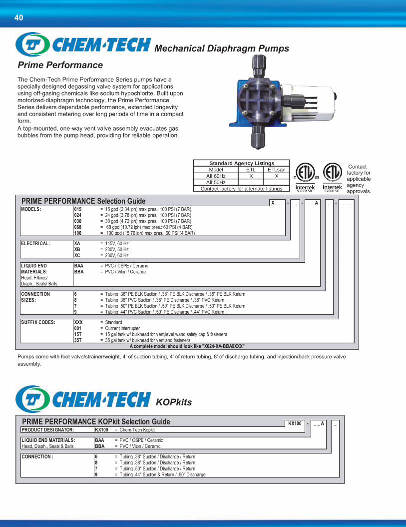
40
Contact factory for applicable agency approvals.
Prime Performance
The Chem-Tech Prime Performance Series pumps have a specially designed degassing valve system for applications using off-gasing chemicals like sodium hypochlorite. Built upon motorized-diaphragm technology, the Prime Performance Series delivers dependable performance, extended longevity and consistent metering over long periods of time in a compact form.
A top-mounted, one-way vent valve assembly evacuates gas bubbles from the pump head, providing for reliable operation.
Pumps come with foot valve/strainer/weight, 4' of suction tubing, 4' of return tubing, 8' of discharge tubing, and injection/back pressure valve
assembly.
Mechanical Diaphragm Pumps
X_ _ _ - _ _ - _ _ A _ - _ _ _
MODELS: 015 = 15 gpd (2.34 lph) max pres.: 100 PSI (7 BAR)024 = 24 gpd (3.78 lph) max pres.: 100 PSI (7 BAR)030 = 30 gpd (4.72 lph) max pres.: 100 PSI (7 BAR)068 = 68 gpd (10.72 lph) max pres.: 60 PSI (4 BAR)100 = 100 gpd (15.76 lph) max pres.: 60 PSI (4 BAR)
ELECTRICAL: XA = 115V, 60 HzXB = 230V, 50 Hz XC = 230V, 60 Hz
LIQUID END BAA = PVC / CSPE / Ceramic MATERIALS: BBA = PVC / Viton / CeramicHead, Fittings/Diaph., Seats/ Balls
CONNECTION 6 = Tubing .38" PE BLK Suction / .38" PE BLK Discharge / .38" PE BLK ReturnSIZES: 8 = Tubing .38" PVC Suction / .38" PE Discharge / .38" PVC Return
7 = Tubing .50" PE BLK Suction / .50" PE BLK Discharge / .50" PE BLK Return9 = Tubing .44" PVC Suction / .50" PE Discharge / .44" PVC Return
SUFFIX CODES: XXX = Standard001 = Current Interrupter15T = 15 gal tank w/ bulkhead for vent,level wand,safety cap & fasteners35T = 35 gal tank w/ bulkhead for vent and fasteners
PRIME PERFORMANCE Selection Guide
A complete model should look like "X024-XA-BBA9XXX"
KX100 - _ _ A _
PRODUCT DESIGNATOR: KX100 = Chem-Tech Kopkit
LIQUID END MATERIALS: BAA = PVC / CSPE / Ceramic Head, Diaph., Seats & Balls BBA = PVC / Viton / Ceramic
CONNECTION : 6 = Tubing .38" Suction / Discharge / Return8 = Tubing .38" Suction / Discharge / Return7 = Tubing .50" Suction / Discharge / Return9 = Tubing .44" Suction & Return / .50" Discharge
PRIME PERFORMANCE KOPkit Selection Guide
KOPkits
For CT 100-200 Buletin
Model ETL ETLsan
All 60Hz X X
100-150 50Hz
200 50Hz
For Prime Performance Buletin
Model ETL ETLsan
All 60Hz X X
All 50Hz
Standard Agency Listings
Standard Agency Listings
Contact factory for alternate listings
Contact factory for alternate listings

41
Series 100, 150, 200
Series 100 Models - The preferred metering pump for water conditioning professionals around the world. Perfect for applications where economical, consistent performance is required. Capable of a wide range of flows, from less than 3 USgpd up to 30 USgpd and pressures up to 100 psig.
Series 150 Models - Built upon the same solid platform as the 100 Models, these units are capable of higher flowrates. With a range offering up to 100 USgpd, the Series 150 can meet the demands of larger applications. Maximum pressure is 60 psig.
Series 200 Models – The pump popular for their rugged design for continuous duty operation offers feed rates from 10 to 120 gpd and pressures up to 150 psi.
Note: Standard Features do not add to the pump price.
_ _ _ _ - _ _ - _ _ _ _ _ _ _
MODELS:X003 = 3 gpd (0.47 lph) max pres.: 100 PSI (7 BAR)X007 = 7 gpd (1.00 lph) max pres.: 100 PSI (7 BAR)X015 = 15 gpd (2.34 lph) max pres.: 100 PSI (7 BAR)X024 = 24 gpd (3.78 lph) max pres.: 100 PSI (7 BAR)X030 = 30 gpd (4.72 lph) max pres.: 100 PSI (7 BAR)
X068 = 68 gpd (10.72 lph) max pres.: 60 PSI (4 BAR)X100 = 100 gpd (15.76 lph) max pres.: 60 PSI (4 BAR)
X210 = 10 gpd (1.5 lph) max pres.: 150 PSI (10 BAR)X215 = 15 gpd (2.34 lph) max pres.: 150 PSI (10 BAR)X220 = 20 gpd (3.15 lph) max pres.: 150 PSI (10 BAR)X230 = 30 gpd (4.72 lph) max pres.: 125 PSI (9 BAR)X240 = 40 gpd (6.31 lph) max pres.: 125 PSI (9 BAR)X260 = 60 gpd (9.46 lph) max pres.: 125 PSI (9 BAR)X280 = 80 gpd (12.6 lph) max pres.: 100 PSI (7 BAR)2100 = 100 gpd (15.76 lph) max pres.: 100 PSI (7 BAR)2120 = 120 gpd (18.91 lph) max pres.: 80 PSI (6 BAR)
ELECTRICAL: XA = 115V, 60 HzXB = 230V, 50 Hz (not available in 2120)XC = 230V, 60 HzXD = 115V, 50/60 Hz, T.E.F.C. (X200's only)XL = 230V, 50/60 Hz, T.E.F.C. (X200's only)
LIQUID END AAA = Clear PVC / CSPE / CeramicMATERIALS: AAB = Clear PVC / CSPE / TFEPump Head & ABA = Clear PVC / Viton / CeramicFittings/Seats ABB = Clear PVC / Viton / TFE& O-rings/Balls ACA = Clear PVC / TFE/Viton / Ceramic
AHA = Clear PVC / TFE/CSPE / CeramicBAA = PVC / CSPE / CeramicBAB = PVC / CSPE / TFEBBA = PVC / Viton / CeramicBBB = PVC / Viton / TFEBHA = PVC / TFE/CSPE / CeramicDAA = PP / CSPE / CeramicDAB = PP / CSPE / TFEDBA = PP / Viton / CeramicDBB = PP / Viton / TFEGFA = Clear PVC / TFE / Ceramic (dbl)GFB = Clear PVC / TFE / TFE (dbl)EFC = 316SS / TFE / 316SS (dbl)
CONNECTION A = Tubing .44" PVC Suction / .50" PE DischargeSIZES: C = Tubing .38" PVC Suction / .38" PE Discharge
F = Tubing .44" PVC Suction / .50" PE BLK DischargeS = Tubing .38" PVC Suction / .38" PE BLK DischargeX w/ 316 = .25" FNPT Suction / .25" FNPT Discharge
SUFFIX XXX = StandardCODES: 001 = Current Interrupter
500* = Five Function Valve520* = Five Function Degas ValveITS = 15 gal ITS Tank System
Chem-Tech Series 100, 150, 200 Selection GuideSeries 100
Series 150
Series 200
* Not available in SS. Adder price is per head.
A completed model number should look like "X015-XA-BAAAXXX"
Mechanical Diaphragm
Pumps
For CT 100-200 Buletin
Model ETL ETLsan
All 60Hz X X
100-150 50Hz
200 50Hz
For Prime Performance Buletin
Model ETL ETLsan
All 60Hz X X
All 50Hz
Standard Agency Listings
Standard Agency Listings
Contact factory for alternate listings
Contact factory for alternate listings
Contact factory for applicable agency approvals.

42
KX100 - _ _ _ _
PRODUCT DESIGNATOR: KX100 = Chem-Tech Kopkit
LIQUID END MATERIALS: AAA = Clear PVC / CSPE / CeramicHead, Diaph., Seats & Balls AAB = Clear PVC / CSPE / TFE
ABA = Clear PVC / Viton / CeramicABB = Clear PVC / Viton / TFEACA = Clear PVC / TFE/Viton / CeramicAHA = Clear PVC / TFE/CSPE / CeramicBAA = PVC / CSPE / CeramicBAB = PVC / CSPE / TFEBBA = PVC / Viton / CeramicBBB = PVC / Viton / TFEBHA = PVC / TFE/CSPE / CeramicDAA = PP / CSPE / CeramicDAB = PP / CSPE / TFEDBA = PP / Viton / CeramicDBB = PP / Viton / TFEGFA = Clear PVC / TFE / Ceramic (dbl)GFB = Clear PVC / TFE / TFE (dbl)EFC = 316SS / TFE / 316SS (dbl)
CONNECTION : A = Tubing .44" PVC Suction / .50" PE DischargeC = Tubing .38" PVC Suction / .38" PE DischargeF = Tubing .44" PVC Suction / .50" PE BLK DischargeS = Tubing .38" PVC Suction / .38" PE BLK DischargeX w/ 316 = .25" FNPT Suction / .25" FNPT Discharge
Chem-Tech KOPkit Selection Guide
Part Number Description
00006 Suction Tubing - per foot 7/16" OD00007 Suction Tubing - per foot 3/8"00008 Discharge Tubing - per foot 1/2" OD
00009 Discharge Tubing - per foot 1/2" Black00010 Discharge Tubing - per foot 3/8"00011 Discharge Tubing - per foot 3/8" Black20038 1/2" NPT Connection - PVC - fits Suction side of Pump Head and Back Ck. Vlv. Assy. (per connection)20039 1/2" NPT Connection - PVC - fits Discharge side of Pump Head and Strainer Assy. (per connection)
J20560 Ball Check (ceramic)21829 Drive Bracket Assy. S10021971 Diaphragm Shaft Bushing22255 Cam Bearing Assy. S100 - 3, 7, 15, 30 GPD22256 Cam Bearing Assy. S100 - 24 GPD22257 Cam Bearing Assy. S150 - 68, 100 GPD
J24269 Oil (quart)24450 Current Interrupter - S100 - 115V24453 Current Interrupter/Plug Receptacle S200 - 115V24454 Current Interrupter/Plug Receptacle/Bottom Plate (Std) 115V24820 Cord Assy. - 115V, 60 Hz24821 Cord - 230V, 50 or 60 Hz
J24960 Coupling Nut, PVC 1/2" (Standard)24961 Coupling Nut, PP 1/2"24963 Coupling Nut, PVC 3/8"25180 Motor Cover25704 Diaphragm, CSPE25706 Diaphragm, Viton25707 Diaphragm, PTFE Coated
J26780 Injection Fitting, PVC 3/8"26781 Injection Fitting, PVC 1/2"26858 Bulkhead Fitting (PP-1/2")26867 Bulkhead Fitting (PP-3/8")
J26907 Bulkhead Fitting (PVC-1/2")J26910 Bulkhead Fitting without strainer (PVC-3/8")J26905 Bulkhead Fitting for ITS (PVC-1/4")J27903 Gasket, TFE
27911 Gasket28215 Gear Housing Assembly #26028217 Gear Housing Assembly #2-10028218 Gear Housing Assembly #2-12028521 Grommet 28800 Head, Clear PVC 28803 Head, Polypropylene 28899 Head Assy, (PP-VT-C-1/2" S/D) 28902 Head Assy, (PVC-VT-C-3/8" S/D) 29230 Motor Housing 29313 Main Housing 10, 15, 20, 30, 40, 60, 100 GPD 29314 Main Housing 120 GPD only 30460 Output Adjustment Knob 30467 Output Adj Knob Asm S150
J30496 Housing - S100 - 3, 7, 15, 30 GPD J30498 Housing - S150, 68, 100 GPD J30503 Motor - 115V, 60 Hz, S200 J30504 Motor - 230V, 50 Hz, S200 J30505 Motor - 230V, 60 Hz, S200 J30507 Kit, Bleed, Valve, PVC/HPY/ 3/8 J30509 Kit, Bleed, Valve, PVC/VTN/ 3/8 J30510 Kit, Bleed, Valve, PVC/TFE/ 3/8 J30511 Kit, Bleed, Valve, FPP/CSPE/ 3/8 J30513 Kit, Bleed, Valve, FPP/VTN/ 3/8
Series 100, 150, 100D, 150D And 200 Parts Schedule
KOPkits
Part Number Description
00006 Suction Tubing - per foot 7/16" OD00007 Suction Tubing - per foot 3/8"00008 Discharge Tubing - per foot 1/2" OD
00009 Discharge Tubing - per foot 1/2" Black00010 Discharge Tubing - per foot 3/8"00011 Discharge Tubing - per foot 3/8" Black20038 1/2" NPT Connection - PVC - fits Suction side of Pump Head and Back Ck. Vlv. Assy. (per connection)20039 1/2" NPT Connection - PVC - fits Discharge side of Pump Head and Strainer Assy. (per connection)
J20560 Ball Check (ceramic)21829 Drive Bracket Assy. S10021971 Diaphragm Shaft Bushing22255 Cam Bearing Assy. S100 - 3, 7, 15, 30 GPD22256 Cam Bearing Assy. S100 - 24 GPD22257 Cam Bearing Assy. S150 - 68, 100 GPD
J24269 Oil (quart)24450 Current Interrupter - S100 - 115V24453 Current Interrupter/Plug Receptacle S200 - 115V24454 Current Interrupter/Plug Receptacle/Bottom Plate (Std) 115V24820 Cord Assy. - 115V, 60 Hz24821 Cord - 230V, 50 or 60 Hz
J24960 Coupling Nut, PVC 1/2" (Standard)24961 Coupling Nut, PP 1/2"24963 Coupling Nut, PVC 3/8"25180 Motor Cover25704 Diaphragm, CSPE25706 Diaphragm, Viton25707 Diaphragm, PTFE Coated
J26780 Injection Fitting, PVC 3/8"26781 Injection Fitting, PVC 1/2"26858 Bulkhead Fitting (PP-1/2")26867 Bulkhead Fitting (PP-3/8")
J26907 Bulkhead Fitting (PVC-1/2")J26910 Bulkhead Fitting without strainer (PVC-3/8")J26905 Bulkhead Fitting for ITS (PVC-1/4")J27903 Gasket, TFE
27911 Gasket28215 Gear Housing Assembly #26028217 Gear Housing Assembly #2-10028218 Gear Housing Assembly #2-12028521 Grommet 28800 Head, Clear PVC 28803 Head, Polypropylene 28899 Head Assy, (PP-VT-C-1/2" S/D) 28902 Head Assy, (PVC-VT-C-3/8" S/D) 29230 Motor Housing 29313 Main Housing 10, 15, 20, 30, 40, 60, 100 GPD 29314 Main Housing 120 GPD only 30460 Output Adjustment Knob 30467 Output Adj Knob Asm S150
J30496 Housing - S100 - 3, 7, 15, 30 GPD J30498 Housing - S150, 68, 100 GPD J30503 Motor - 115V, 60 Hz, S200 J30504 Motor - 230V, 50 Hz, S200 J30505 Motor - 230V, 60 Hz, S200 J30507 Kit, Bleed, Valve, PVC/HPY/ 3/8 J30509 Kit, Bleed, Valve, PVC/VTN/ 3/8 J30510 Kit, Bleed, Valve, PVC/TFE/ 3/8 J30511 Kit, Bleed, Valve, FPP/CSPE/ 3/8 J30513 Kit, Bleed, Valve, FPP/VTN/ 3/8
Series 100, 150, 100D, 150D And 200 Parts Schedule

43
Part No. Description
J30514 Kit, Bleed, Valve, FPP/TFE/ 3/8 J30515 Kit, Bleed, Valve, PVC/HPY/ 1/2 J30517 Kit, Bleed, Valve, PVC/VTN/ 1/2 J30518 Kit, Bleed, Valve, PVC/TFE/ 1/2 J30519 Kit, Bleed, Valve, FPP/CSPE/ 1/2
L3300V03-FPP Kit, Bleed, Valve, FPP/VTN/ 1/2 J30522 Kit, Bleed, Valve, FPP/TFE/ 1/2
31081 Locking Lever - S100, 215, 230, 260 31082 Locking Lever 20, 40, GPD S200 31083 Locking Lever - S150, 280, 2-100, 2-120 32520 Motor - 7 SPM, 115V, 60 Hz, 003 32521 Motor - 13 SPM, 115V, 60 Hz, 007 32522 Motor - 25 SPM, 115V, 60 Hz, 015 32523 Motor - 51 SPM, 115V, 60 Hz, 024/030/068 32524 Motor - 7 SPM, 230V, 60 Hz, 003 32527 Motor - 51 SPM, 230V, 60 Hz, 024/030/068 32528 Motor - 7 SPM, 230V, 50 Hz, 003 32530 Motor - 25 SPM, 230V, 50 Hz, 015 32531 Motor - 51 SPM, 230V, 50 Hz, 024/030/068 32532 Motor - 70 SPM, 115V, 60 Hz, 100 32533 Motor - 70 SPM, 230V, 50 Hz, 100 32535 Motor - 70 SPM, 230V, 60 Hz, 100
J34379 Backing Plate 34405 Plate, Motor Cover 34423 Back Plate 34532 Oil Filler Plug w/Cap 37080 Output Adjust Screw 10, 20, 40 GPD 37081 Output Adjust Screw 15, 30, 60 GPD 37083 Output Adjust Screw 80, 100, 120 GPD 37300 Oil Seal
J37440 Valve Seat, CSPE J37442 Valve Seat, Viton
37886 Diaphragm Shaft 38080 Locking Sleeve 38980 Diaphragm Return Spring 38981 Coupling Spring 38984 Valve Spring - top - light
J38985 Valve Spring J60717 Foot Valve & Strainer Assy (PVD-CSPE-C-3/8") J60729 Foot Valve & Strainer Assy (PVD-CSPE-C-1/2") J60718 Foot Valve & Strainer Assy (PVD-VT-C-3/8") J60730 Foot Valve & Strainer Assy (PVD-VT-C-1/2") J41540 Valve Housing Discharge, PVC 1/2"
41543 Valve Housing Discharge, PVC 3/8" 41544 Valve Housing Discharge, PP 3/8"
J41548 Valve Housing Suction, PVC 1/2" J41834 Valve Housing Suction, PP 1/2"
41551 Valve Housing Suction, PVC 3/8" J41835 Valve Housing Suction, PP 3/8"
28218 Gear Housing Assembly #2-12028521 Grommet 28800 Head, Clear PVC 28803 Head, Polypropylene 28899 Head Assy, (PP-VT-C-1/2" S/D) 28902 Head Assy, (PVC-VT-C-3/8" S/D) 29230 Motor Housing 29313 Main Housing 10, 15, 20, 30, 40, 60, 100 GPD 29314 Main Housing 120 GPD only 30460 Output Adjustment Knob 30467 Output Adj Knob Asm S150
J30496 Housing - S100 - 3, 7, 15, 30 GPD J30498 Housing - S150, 68, 100 GPD J30503 Motor - 115V, 60 Hz, S200 J30504 Motor - 230V, 50 Hz, S200 J30505 Motor - 230V, 60 Hz, S200 J30507 Kit, Bleed, Valve, PVC/HPY/ 3/8 J30509 Kit, Bleed, Valve, PVC/VTN/ 3/8 J30510 Kit, Bleed, Valve, PVC/TFE/ 3/8 J30511 Kit, Bleed, Valve, FPP/CSPE/ 3/8 J30513 Kit, Bleed, Valve, FPP/VTN/ 3/8
41588 Anti-Siphon Valve (PVC-VT-1/2") 41624 Anti-Siphon Valve (PVC-CSPE-1/2") (Standard) 41657 Back Check Valve Assy (PVC-CSPE-C-3/8")
J41658 Back Check Valve Assy (PVC-CSPE-C-1/2") 41659 Back Check Valve Assy (PP-VT-C-1/2") 41661 Back Check Valve Assy (PVC-VT-C-1/2")
J41667 Double Ball Ck Vlv Cart Assy (PVC-1/2") Suct41668 Double Ball Ck Vlv Cart Assy (PVC-3/8") Disch
J41669 Double Ball Ck Vlv Cart Assy (PVC-1/2") DischJ41694 Back Check Valve Assy (PVC-CSPE-C-1/2")
41695 Back Check Valve Assy (PVC-VT-C-3/8") 41696 Back Check Valve Assy (PP-VT-C-3/8") 41705 6" Ck Vlv Inj Assy (PVC-CSPE-C-3/8") 41707 6" Ck Vlve Inj Assy (PVC-VT-C-3/8") 41708 6" Ck Vlv Inj Assy (PVC-VT-C-1/2") 41710 6" Ck Vlv Inj Assy (PP-VT-C-1/2") 41720 Anti-Siphon Valve (PVC-CSPE-1/2" NPT) 41795 Back Check Valve Assy (PVC-CSPE-C-1/2" x 1/2" NPT)
J42020 Head Bolt Washer SS .20 x .38J42030 Fiber Washer
42031 Washer, Fiber J60030 Head Assy (SAN-CSPE-C-3/8" D) J61222 Kit, 5 Function Valve incl L380DT03-PVC for Series 100/200J61539 Kit, 5 Function Valve incl L380DT02-PVC for Series 100/200J61503 Kit, S200 Back Plate Screws (5 - J37017, 5 - J42030) J61504 Kit, S200 Motor Cover Hdwe (2 - J37002, 2 - J42030) J61508 Kit, S200 Main Housing Screw (2 - 37021, 2 - J42083, 2 - 42031) J61509 Kit, S200 Shaft Coupling Motor (1 - 24966, 1 - 37060) J61510 Kit, S200 Shaft Coupling Gear (1 - 24967, 1 - 37061) J61511 Kit, Screw Motor Cover (2 - J37073)
Series 100, 150, 100D, 150D And 200 Parts Schedule
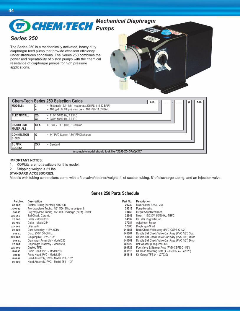
44
Series 250
The Series 250 is a mechanically activated, heavy duty diaphragm feed pump that provide excellent efficiency under strenuous conditions. The Series 250 combines the power and repeatability of piston pumps with the chemical resistance of diaphragm pumps for high pressure applications.
IMPORTANT NOTES:
1. KOPkits are not available for this model.
2. Shipping weight is 21 lbs.
STANDARD ACCESSORIES:
Models with tubing connections come with a footvalve/strainer/weight, 4' of suction tubing, 8' of discharge tubing, and an injection valve.
X25_ - _ _ - _ _ _ Q XXX
MODELS: 3 = 76.8 gpd (12.11 lph) max pres.: 225 PSI (15.52 BAR)4 = 108 gpd (17.03 lph) max pres.: 160 PSI (11.03 BAR)
ELECTRICAL: XD = 115V, 50/60 Hz, T.E.F.C.XL = 230V, 50/60 Hz, T.E.F.C.
LIQUID END GFA = PVC / TFE (dbl) / Ceramic MATERIALS:
CONNECTION Q = 44" PVC Suction / .50" PP Discharge SIZES:
SUFFIX XXX = StandardCODES:
Chem-Tech Series 250 Selection Guide
A complete model should look like "X253-XD-GFAQXXX"
Part No. Description Part No. Description0 0 0 0 6 Suction Tubing (per foot) 7/16" OD 29230 Motor Cover / 253 - 254
J0 0 0 12 Polypropylene Tubing, 1/2" OD - Discharge (per ft) 29313 Pump Housing 0 0 0 13 Polypropylene Tubing, 1/2" OD-Discharge (per ft) - Black 30460 Output Adjustment Knob
J2 0 5 6 0 Ball Check, Ceramic 32545 Motor, 115/230V, 50/60 Hz, TEFC 2 3 7 0 5 Collar - Model 253 34532 Oil Filler Plug with Cap 2 3 7 0 6 Collar - Model 254 37084 Adjustment Screw
J2 4 2 6 9 Oil (quart) 37886 Diaphragm Shaft 2 4 8 2 0 Cord Assembly, 115V, 60Hz J41658 Back Check Valve Assy (PVC-CSPE-C-1/2") 2 4 8 2 1 Cord, 230V, 50-60 Hz J41667 Double Ball Check Valve Cart Assy (PVC 1/2") Suc.
J2 4 9 6 0 Coupling Nut - PVC 1/2" 41668 Double Ball Check Valve Cart Assy (PVC 3/8") Disch 2 5 6 8 1 Diaphragm Assembly - Model 253 J41669 Double Ball Check Valve Cart Assy (PVC 1/2") Disch 2 5 6 8 2 Diaphragm Assembly - Model 254 J42020 Bolt Washer (4 required) SS
J2 7 9 0 3 Gasket, TFE J60729 Foot Valve & Strainer Assy (PVD-CSPE-C-1/2") J2 8 8 15 Pump Head, PVC - Model 253 J61516 Kit, Head Mounting Bolts (4 - J37005, 4 - J42020)
2 8 8 16 Pump Head, PVC - Model 254 J61518 Kit, Gasket TFE (4 - J27930) J2 8 9 19 Head Assembly, PVC - Model 253 - 1/2" 2 8 9 2 0 Head Assembly, PVC - Model 254 - 1/2"
Series 250 Parts Schedule
Mechanical Diaphragm
Pumps

45
Part No. Description Part No. Description0 0 0 0 6 Suction Tubing (per foot) 7/16" OD 29230 Motor Cover / 253 - 254
J0 0 0 12 Polypropylene Tubing, 1/2" OD - Discharge (per ft) 29313 Pump Housing 0 0 0 13 Polypropylene Tubing, 1/2" OD-Discharge (per ft) - Black 30460 Output Adjustment Knob
J2 0 5 6 0 Ball Check, Ceramic 32545 Motor, 115/230V, 50/60 Hz, TEFC 2 3 7 0 5 Collar - Model 253 34532 Oil Filler Plug with Cap 2 3 7 0 6 Collar - Model 254 37084 Adjustment Screw
J2 4 2 6 9 Oil (quart) 37886 Diaphragm Shaft 2 4 8 2 0 Cord Assembly, 115V, 60Hz J41658 Back Check Valve Assy (PVC-CSPE-C-1/2") 2 4 8 2 1 Cord, 230V, 50-60 Hz J41667 Double Ball Check Valve Cart Assy (PVC 1/2") Suc.
J2 4 9 6 0 Coupling Nut - PVC 1/2" 41668 Double Ball Check Valve Cart Assy (PVC 3/8") Disch 2 5 6 8 1 Diaphragm Assembly - Model 253 J41669 Double Ball Check Valve Cart Assy (PVC 1/2") Disch 2 5 6 8 2 Diaphragm Assembly - Model 254 J42020 Bolt Washer (4 required) SS
J2 7 9 0 3 Gasket, TFE J60729 Foot Valve & Strainer Assy (PVD-CSPE-C-1/2") J2 8 8 15 Pump Head, PVC - Model 253 J61516 Kit, Head Mounting Bolts (4 - J37005, 4 - J42020)
2 8 8 16 Pump Head, PVC - Model 254 J61518 Kit, Gasket TFE (4 - J27930) J2 8 9 19 Head Assembly, PVC - Model 253 - 1/2" 2 8 9 2 0 Head Assembly, PVC - Model 254 - 1/2"
Series 250 Parts Schedule
Peristaltic Pumps
Part No. Description Part No. DescriptionJ60552 Strainer Assembly w/o valve U0818616 Gearmotor Assembly, 120V, 10 RPM - D1024820 Power Cord 120V U0818617 Gearmotor Assembly, 240V, 10 RPM - D1024821 Power Cord 240V U0818618 Gearmotor Assembly, 120V, 50 RPM - D50U0817635 Knob U0818619 Gearmotor Assembly, 240V, 50 RPM - D50U0817923 Switch, Rocker U0818620 Gearmotor Assembly, 120V, 75 RPM - D75U0817942 Screw 10 - 32 X .688", Motor Mount U0818621 Gearmotor Assembly, 240V, 75 RPM - D75U0819142 Box, Front U8800431 Tubing cut 1/4" X 15 ft. PEU0819143 Box, Back U8800637 Tubing Replacement Kit (7/16"Norprene Crm)U0818180 Potentiometer Assembly U8800651 Pump Head AssemblyU0818564 Fan D10 (CW) U8800712 Injection FittingU0818565 Fan D50, D75 (CCW) U8800740 Kit, Timer 120V (1 - U0818183, 1 - U0020522)U0812955 Screw 8 - 32 X 1/4", Fan U8800741 Kit, Timer 240V (1 - U0818182, 1 - U0020522)L9900700-000 Strain Relief U8800742 Kit, Pump Head Bearings (2 - U0817121)
U8800743 Kit, Collars (2 - U0817123)U8800758 Kit, Pump Head Tubing (Viton)
DOLPHIN Series Parts Schedule
Dolphin Series Exclusive quick-release, twist-off, clear polycarbonate, acid-resistant head to
withstand the harshest environment.
Self-lubricating chemical resistant roller assembly. Durable, long lasting tubing with no tube adjustment.
Rugged and dependable – Heavy-duty shaded pole gearmotor with lifetime
lubrication.
Flexibility in feed rates - from .13 gallons to 97 gallons per day ... to meet the
demands of the pool and spa Industry, and elsewhere.
Agency approvals.
UD_ _ - _ _ - _ _ _ U XXX
MODELS: 10 = 13.0 gpd (2.05 lph) max pres.: 25 PSI (1.72 BAR)50 = 60.0 gpd (9.46 lph) max pres.: 25 PSI (1.72 BAR)75 = 97.0 gpd (15.30lph) max pres.: 25 PSI (1.72 BAR)
ELECTRICAL: XA = 115V, 60 HzXL = Standard 230V, 50/60 Hz, used w/ Model 10 onlyXB = Standard 230V, 50 Hz, used w/ Models 50 & 75 onlyXC = Standard 230V, 60 Hz, used w/ Models 50 & 75 only
LIQUID END LSA = Norprene TubingMATERIALS: LBA = Viton Tubing
CONNECTION U = Tubing .25" I.D. X .44" O.D. SIZES:
SUFFIX XXX = StandardCODES:
Mec-O-Matic DOLPHIN Series Selection Guide
A completed model should look like "UD75-XA-LBAUXXX"
Junction Box option is available on 230V models at no additional charge. Contact the factory for model numbers.
Shipping weight for Dolphin Pumps is 7 lbs.
KUDXX - _ _ _ _
PRODUCT DESIGNATOR: KUDXX = Dolphin Kopkit
LIQUID END MATERIALS: LSAU = Norprene Tubing CRMLLAU = Norprene Tubing BLKLBAU = Viton Tubing
Mec-O-Matic DOLPHIN KOPkit Selection Guide
KOPkits
Contact factory for applicable agency approvals.
Tested and Certified by WQA
against NSF/ANSI 61-Section 8.
and CSA B483.1
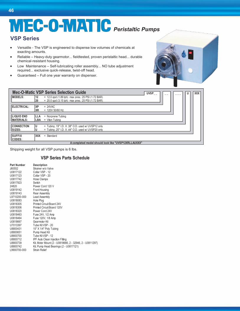
46
VSP Series
Versatile - The VSP is engineered to dispense low volumes of chemicals at
exacting amounts.
Reliable – Heavy-duty gearmotor... fieldtested, proven peristaltic head... durable
chemical-resistant housing.
Low Maintenance – Self-lubricating roller assembly... NO tube adjustment
required... exclusive quick-release, twist-off head.
Guaranteed – Full one year warranty on dispenser.
UVSP_ _ _ _ _ _ _ U XXX
MODELS: 12 = 12.0 gpd (1.89 lph) max pres.: 25 PSI (1.72 BAR)20 = 20.0 gpd (3.15 lph) max pres.: 25 PSI (1.72 BAR)
ELECTRICAL: XP = 24VACXR = 120V 50/60 Hz
LIQUID END LLA = Norprene TubingMATERIALS: LBA = Viton Tubing
CONNECTION U = Tubing .19" I.D. X .38" O.D. used w/ UVSP12 onlySIZES: U = Tubing .25" I.D. X .44" O.D. used w/ UVSP20 only
SUFFIX XXX = StandardCODES:
Mec-O-Matic VSP Series Selection Guide
A completed model should look like "UVSP12XRLLAUXXX"
Shipping weight for all VSP pumps is 6 lbs.
Part Number DescriptionJ60552 Strainer w/o ValveU0817122 Collar VSP - 12U0817123 Collar VSP - 20U0817742 Hose ClampsU0817923 Switch24820 Power Cord 120 VU0819142 Front HousingU0819143 Rear AssemblyL9710200-000 Lead AssemblyU0818083 Hole PlugU0818305 Printed Circuit Board 24VU0818306 Printed Circuit Board 120VU0818320 Power Cord 24VU0818463 Fuse 24V, 1/2 AmpU0818464 Fuse 120V, 1/8 AmpU0818667 Gearmotor KitU7013397 Tube Kit VSP - 20U8800431 15" X 1/4" Poly TubingU8800651 Pump Head KitU8800700 Tube Kit VSP - 12U8800712 IPF Auto Clean Injection FittingU8800739 Kit, Motor Mount (2 - U0818666, 2 - 32946, 2 - U0811297)U8800742 Kit, Pump Head Bearings (2 - U0817121)L9900700-000 Strain Relief
VSP Series Parts Schedule
Peristaltic Pumps

47
Peristaltic Pumps
Series 2400T Grease Trap Dispenser
Capable of Dispensing Low Volumes
Programmable
Simple Installation
Prime Push Button for Quick Start-Up
Quick Release Twist Off Head
Built-In Timer
No Tube Adjustment Needed
Self Lubricating Roller Assembly
UT24 _ _ _ - _ _ _ _ _ _ _
MODELS: UT24 = 2.5 gpd (0.39 lph) max pres.: 25 PSI (1.72 BAR) used w/ 2400T & 2400T PLUSUT24 = 3.0 Oz / 1 Min max pres.: 25 PSI (1.72 BAR) used w/ 2400T-DC only
ELECTRICAL: -XA = 115V, 60 Hz used w/ 2400T only PXA = 115V, 60 Hz used w/ 2400T PLUS only-AD = 12V DC used w/ 2400T-DC only
LIQUID END LT = Silicone TubingMATERIALS: LB = Viton Tubing
LL = Norprene Tubing used w/ 2400T-DC only
CONNECTION AU = Tubing .125" I.D. X .31" O.D.SIZES: XU = Tubing .25" I.D. X .44" O.D. used w/ 2400T-DC only
SUFFIX XXX = StandardCODES:
Mec-O-Matic 2400T Series Selection Guide
A completed model should look like "UT24-XA-LBAUXXX"
1. 2400T comes standard with 24 hour mechanical timer. 2400T plus and DC utilizes a 7 day, 8 event programmable timer
2. 2400T DC Pump requires 8 "D" cell batteries (not included).
3. Shipping weight is 7.5 lbs.
Part No. Description Part No. DescriptionJ60552 Strainer Assembly w/o Valve U0819143 Pump Housing (rear) U0817131 Tubing Assy 5/16" X 9" Silicone U0818564 Fan U0817742 Hose Clamp U0818602 Gearmotor Assembly U0817888 Pump Head Screw U0818740 Timer (2400T Plus) U0817942 Screw 10 - 30 X .688", Motor Mount U8800431 15' X 1/4" PE Tubing U0817952 Timer (2400T) U8800712 Injection Fitting U0818018 Indicator Light U8800753 Pump Head Assembly Kit (No Tubing) U0819145 Pump Housing (front-2400T Plus) U0812955 Hex Screw 8 - 32 X 1/4" U0819144 Pump Housing (front-2400T) L9900700-000 Strain Relief
Part No. Description Part No. DescriptionU0812955 Screw 6 - 32 X .25" PHP U0818902 Battery Holder Assembly U0817888 Shoulder Screw U0819037 12V DC Timer LO AMP U0818026 Spacer SST (Motor) U8800490 Injection Fitting U0818666 Screw 8 - 32 X 1.25 FHP U8800637 7/16" Tubing Kit (Peristaltic) U0818881 12V DC Motor U8800651 Pump Head Assembly Kit (No Tubing) U0818895 1/4" X 20' Tubing PE U8800700 3/8" Tubing Kit
U8800742 Kit, Pump Head Bearings (2 - U0817121)
2400T & T PLUS Series Parts Schedule
2400T DC Series Parts Schedule
Contact factory for applicable agency approvals.

48
Product Repair Cost
Pumps and Pump Accessories – within 5 years of sale date Current List Price x .50 x Part Discount Multiplier
Controllers and Controller Accessories within 5 years of sale date Current List Price x .50 x Part Discount Multiplier
Any item older than 5 years from date of sale With purchase order, $50 bench fee to evaluate. The $50 bench fee may be applied
towards repair cost of unit or towards a new controller
Policies and Procedures
1. Manufacturer’s Equipment Warranty
a. Pulsafeeder warrants all pumps and controllers of its manufacture to be free of defects in material or workmanship. Liability under this policy extends for 24 months from the date of shipment. The manufacturer’s liability is limited to repair or replacement of any failed equipment or part which is proven defective in material or workmanship upon manufacturer’s examination. This warranty does not include removal or installation costs and in no event shall the manufacturer’s liability exceed the selling price of such equipment or part.
b. The manufacturer disclaims all liability for damage to its products through improper installation, maintenance, use or attempts to operate such products beyond their functional capacity, intentionally or otherwise, or any other unauthorized repair. The manufacturer is not responsible for consequential or other damages, injuries or expense incurred through the use of its products.
c. The above warranty is in lieu of any other warranty, whether expressed or implied. The manufacturer makes no warranty of fitness or merchantability. No agent of ours is authorized to provide any warranty other than the above.
2. Pulsafeeder’s Parts and Accessory Warranty
a. Pulsafeeder, Inc. warrants parts and accessories provided to be free of defects in material or workmanship. Unless otherwise noted below, liability under this policy extends for 90 days from date of shipment from the factory when sold as service parts. (Replaceable elastomeric parts (PTFE) are expendable and are not covered by any warranty either expressed or implied.)
b. This policy is extended to a full 12 months from the date of installation or 18 months from shipment from the factory whichever comes first on the following accessories;
Digital Glycol Feeders Pre-Engineered Systems Corrosion Coupon Racks Analog Timers Water Meters Flow Controllers
c. MicroTrac and MicroVision toroidal probes are warranted for 24 months from date of shipment from the factory when purchased in conjunction with the controller.
All other electrodes/probes and sensors are considered maintenance items and such are warranted for six (6) months from the date of shipment when purchased in conjunction with the controller.
Any electrodes/probes other than toroidal and sensors purchased as spare parts are warranted for 90 days from date of shipment.
d. The manufacturer’s liability is limited to repair or replacement of any failed equipment or part which is proven defective in material or workmanship upon manufacturer’s examination. This warranty does not include removal or installation costs and in no event shall the manufacturer’s liability exceed the selling price of such equipment or part.
e. The manufacturer disclaims all liability for damages to its products through improper installation, maintenance, use or attempts to operate such products beyond their functional capacity, intentionally or otherwise, or any unauthorized repair. The manufacturer is not responsible for consequential or other damages, injuries or expense incurred through the use of its products.
f. The above warranty is in lieu of any other warranty, whether expressed or implied. The manufacturer makes no warranty of fitness or merchantability. No agent of ours is authorized to provide any warranty other than the above.
3. Process for All Returned Goods (Warranty Items)
a. Please contact our Technical Service Department to request a RMA (Return Material Authorization) number prior to returning any goods. The following information will be required:
Billing and ship-to address
Model number and serial number
Contact name and phone number
Reason for return
Purchase order (where applicable)
A packing slip will be provided to the shipper and MUST accompany the product being returned. Packages received without our proper packing list will be refused by the receiver.
b. All material must be returned freight prepaid.
c. All material must be properly packaged to prevent damage in shipment.
d. All products used in a chemical application MUST accompany an MSDS
e. All products MUST be wiped and flushed clean of any and all chemicals, solvents or buffers and be warranted to be safe for handling. You will be requested to acknowledge the condition of the product being returned on our packing list. Any product received that is deemed to be unsafe for handling or without this acknowledgement will be refused by our receiver.
f. All warranty repairs will follow the 2 year warranty policy and will refer to the original purchase date.
4. Non-Warranty Return Procedure (Charge Repair)
a. If you are experiencing a concern with your Pulsafeeder product, first consult the distributor, dealer or Regional Sales Manager or the operation and maintenance manual for assistance. If service of your non-warranty unit is necessary, you must request a return material authorization. A RMA form will be issued and must be used as the packing list attached to the outside of the box. Please send the unit freight prepaid with the RMA number visibly displayed on the outside of the carton. All products MUST be wiped and flushed clean of any and all chemicals, solvents or buffers and be warranted to be safe for handling. You will be requested to acknowledge the condition of the product being returned on our packing list. Any product received that is deemed to be unsafe for handling or without this acknowledgement will be refused by our receiver.
b. All products used in a chemical application MUST accompany an MSDS
c.. The charges listed in the following table will apply.
All Charge Repairs have a 90 day warranty from date of repair.

49
Policies and Procedures continued
5. Credit for Return of New, Unused Equipment
a. No equipment will be accepted beyond six months after date of shipment from factory for credit.
b. Only new, unused and undamaged standard equipment will be accepted for return to stock.
c. All credits are based on evaluation and acceptance of material as new and unused by Pulsafeeder. You will be requested to acknowledge the condition of the product being returned on our packing list. Any product received that is deemed to be unsafe for handling or without this acknowledgement will be refused by our receiver.
d. A restocking fee of 25% will apply to returned goods. When a PO is provided for a replacement item at the time of the return request the restocking fee will be 15%. Note: any product mounted on a panel or skid will be charged a 50% re-stocking fee.
e. A request for a Returned Material Authorization (RMA) number must be made prior to returning product to Pulsafeeder.
f. All equipment shall be returned with the RMA Packing List form attached to the outside of the box.
g. If any chemical, solvent or buffer has been introduced into the product it must be wiped and flushed clean of any and all substances prior to returning to Pulsafeeder.
h. All material shall be returned freight prepaid.
i. Private label products or Engineered Panel Mount Systems are not returnable.
6. Pricing Errors
a. Pulsafeeder does their very best to avoid errors in billing. You will receive a confirmation of your order within 24 hours of order entry. If upon review the customer feels there is a discrepancy, they should contact Pulsafeeder Customer Service as soon as possible to resolve.
b. Should an invoice be received that the customer believes to have incorrect pricing, they should notify Pulsafeeder Customer Service to investigate.
7. Missing Items
a. If a product is received by the customer with an item missing the customer must notify Pulsafeeder Customer Service within 7 days of receipt of the product by the end user. A replacement item will be sent at no charge as quickly as possible.
b. If a shipment is received by the customer with a line item missing they must notify Pulsafeeder Customer Service within 7 days of receipt of the product by the end user. If the customer had been billed for that item, a credit will be issued against the original Sales Order and a new Sales Order will be created for the replacement product.
8. Damaged Items
a. Should the customer receive an order that was damaged in transit, the customer must notify the carrier directly to initiate a claim on the day of delivery.
b. Should the customer receive a product with damaged components due to improper packaging they should notify Pulsafeeder Customer Service within 7 days of receipt of product by end user. A replacement item will be sent at no charge as quickly as possible.
9. Technical Support Services Available
a. Pulsafeeder’sSales Support teamavailableall yourand support. The principle mission of this group is to sell and support our customer base in a timely and effective manner. This includes the ability to provide in-field service training, assistance in start-upof our products and perform field repair of goods when required.
b. Scope Pulsafeeder, Inc. factory Field Service Technicians are available throughout the World for field services on all Pulsafeeder products. Services include:
i. Maintenance Training Seminars, including Classroom slide presentations and or Hands-on Training. The seminar will take approximately four to five hours, and if time permits minor repair and or adjustments may be made to the customer’s pumps, controllers or accessories.
ii. Pre-start up inspections and start up testing/calibration of pumps, controllers and accessories.
iii. Field repairs of pumps controllers and accessories iv. Diagnosing and recommending solutions to systems problems.
(1) All rates listed in this section are actual hourly and daily rates, not reference rates
Fee Schedule Service Rate (1)
Normal 8 hour day $125.00 / hour
Overtime (in excess of 8 hrs each day) $175.00 / hour
Sundays, National Holiday $225.00 / hour
Travel time to job site and return $115.00 / hour
Travel expenses (air fare, hotel, car and meals) Chargeable to customer at cost.
Minimum charge 4 hour labor, plus travel time and expenses
End User Training Seminars
Normal work day $1000.00 / day plus expenses (air fare, car rental, hotel and meals at cost)
Sundays, National Holiday $1800.00 / day plus expenses (air fare, car rental, hotel and meals at cost)

50
TERMS & CONDITIONS
1 . AGREEMENT. The contract of sale resulting from Seller’s documentation together with these terms and conditions (“Contract”) constitutes the entire
agreement between the parties hereto, except as modified in writing signed by both the Seller and Purchaser. The Seller is Pulsafeeder, Inc. and the
Purchaser is identified in the Contract. Any terms in a purchase order, irrespective of their materiality, which are either different from or additional to
Seller’s conditions of sale, are objected to and are excluded unless the Seller expressly agrees in writing to such terms. Execution of such forms by Sell-
er to accommodate Purchaser’s procurement or accounting procedures or to evidence agreed up on change orders shall not be construed as assent to
Purchaser’s terms. Acceptance of the goods shipped shall constitute assent to Seller’s conditions of sale. This Contract shall be binding up on Purchaser
and Seller, and on their successors and assigns.
2 . PROPOSAL OR QUOTATION. A proposal shall not become binding up on Seller until it has been executed and returned by Purchaser. An oral quo-
tation shall not be considered an offer: only a written confirmation thereof incorporating Seller’s terms and conditions shall constitute an offer. All quota-
tions are valid for 30 days unless stated different on the written quotation.
3. ORDER PLACEMENT. All orders shall be subject to acknowledgement by Pulsafeeders and shall be subject to Pulsafeeder’s terms and conditions in
effect on the date the order is accepted. No modifications to the terms and conditions referred to or contained in any request for proposal, order, or other
document from a customer shall apply unless negotiated and approved via written documentation with Pulsafeeder SPO. Any order cancellation or
change request is subject to a cancelation / change fee.
The minimum order amount is US$30.00 based on Pulsafeeders list prices in effect at the time the order is received.
All orders must be submitted with correct pricing and shipping information. Orders submitted without correct pricing and shipping information may be
rejected or delayed.
4 . CREDIT. Credit terms of payment must have the approval of Seller’s Credit Department and must be specified in writing on Seller’s invoice or in the
Contract. If Purchaser’s credit is found by Seller to be unsatisfactory . Seller may rescind or terminate this contract. If at any time during the term of this
contract purchaser’s financial responsibility becomes impaired or unsatisfactory to Seller, Seller reserves the right to stop shipment on notification to
Purchaser, project owner and surety with a demand for payment in advance or at time of delivery for future deliveries or to require other security satisfac-
tory to Seller and in the absence thereof, to cancel the unfilled portion of the Contract. Seller will notify Purchaser promptly of its decision to stop ship-
ments and give an advance notice to the extent this is possible. In the absence of credit terms, sales are for cash.
5. PAYMENT. Specific terms of payment for this order shall be set forth on the reverse side of this Contract or identified and appended hereto. Purchaser
agrees to make payment at Seller’s location specified in this Contract in lawful money of the United States. Purchaser further agrees to make all pay-
ments when due to Seller in accordance with the agreed terms of payment in this Contract without reference to Purchaser’s agreement with or payments
by the owner and with no right of retention.
6 . INTEREST AND COSTS. Purchaser agrees to pay interest at 1.5% per month (to the extent permitted by law) on all delinquent balances if and when
assessed by Seller, and any attorney’s fees or court costs arising out of and made necessary in collection of its obligation to Seller created by this Con-
tract.
7 . TAXES. Any federal, state or local tax assessment, fee, duty or charge hereafter imposed on or measured by the products purchased hereunder shall
be for Purchaser’s account unless Purchaser furnishes Seller an acceptable exemption certificate from such tax, fee, duty or charge prior to shipment.
8 . FORCE MAJEURE. Seller shall make delivery in accordance with the terms of this Contract or within a reasonable time in the absence of any com-
mitment, but Seller shall not be liable for delays or defaults in delivery caused by floods, fires, storms, or other acts of God, by war or act of public enemy
(or civil disturbance), strikes, lock outs, shortages of labor or raw materials and supplies (including fuel) or production facilities, transportation service or
equipment shortages or failures, action of any governmental authority or other conditions beyond Seller’s reasonable control.
9 . CANCELLATION. If Purchaser desires to cancel or change any portion of this Contract, the purchaser must make such request in writing to Seller.
Seller may, in its sole discretion, accept or reject any such request. If accepted, the Purchaser nonetheless must take delivery and make payment to
Seller for all material manufactured and in process of manufacture at time of notice, and all special materials ordered at time of notice and for which
Seller must take delivery , unless otherwise agreed by Seller in writing. All such materials must be removed from Seller’s premises within 30 days after
payment and payment will due at time of notice. Seller also reserves the right to make a cancellation charge in the event of cancellation by the Purchaser
of an order placed in Seller’s shipping schedule and acknowledged by Seller. Any order cancellation is subject to a cancelation fee.
10 . INSPECTION AND TESTING . Seller’s standard specifications and tests apply to all orders. All charges for inspections or tests not regularly fur-
nished are for Purchaser’s account and subject to prior negotiation. All inspections shall be conducted at Seller’s plant, and failure of Purchaser to avail
himself of inspection privileges shall be deemed a waiver of such privileges.
11 . PRICES. Prices are subject to change without notice. Orders based on published prices and accepted for scheduled shipment will be invoiced at
Seller’s applicable price in effect on the scheduled date of shipment, unless otherwise specifically noted on the order acknowledgment. All prices will be
in accordance with applicable government regulations. Orders specifying palletizing or special packaging will involve special charges.
12 . DELAYS. All orders are accepted subject to Seller’s ability to make delivery at the time and in the quantities specified, and Seller shall not be liable
for damages for failure to make partial or complete shipment or for any delay in making shipments. Purchaser shall be liable for any added expenses
incurred by Seller because of Purchaser’s delay in furnishing requested information to Seller, delay resulting from order changes by Purchaser, or delay
in unloading shipments at delivery point.
13 . SHIPMENT. Seller will select method of shipment and routing when transportation charges are for account of Seller. When shipping instructions are
specified by the Purchaser, all costs will be for the account of the Purchaser. The foregoing includes, but is not limited to, carriers charges for notification
prior to delivery, demurrage, delay in unloading, diversion, or reconsignment. All shipments are Free Carrier (FCA) or EX Works( EXW) (Incoterms 2010)
shippers dock Punta Gorda FL.
On all customer arranged freight (will advise) the customer has 48 hours after Pulsafeeder has advised them that the shipment is complete and ready for
shipment to arrange pickup. If the shipment has not left Pulsafeeder within the 48 hour period the customer will be charged 1% of the shipment invoice
value for each 24 hour period that the shipment remains at the Pulsafeeder facility. Pulsafeeder may also place the shipment in a public storage at the
customer’s expense and without liability to Pulsafeeder.
Any expedited order will be subject to a expedite fee.

51
Unless the order clearly requests expedited shipping, the order will be treated as a routine order. When expedited shipping is requested a designated carri-
er must be selected. Orders that need to ship the same day must be received by 2:00 PM EST. Same day and next working day shipping is generally avail-
able for larger orders but not guaranteed, please verify with customer service. Pulsafeeder shall have no liability if it is unable to provide expedited shipping
of an order.
14 . TITLE. Title to products transfers up on shipment from the Pulsafeeder facility according to FCA Shippers Dock or EXW Punta Gorda FL (Incoterms
2010). Purchaser is then responsible for proper protection of product, placement, compliance with all regulations and ordinances, and will indemnify Seller
against all claims for personal injuries or property damage arising from the storage, use or handling of such products.
15 . IN TRANSIT CLAIMS. Claims for damage or shortage in transit must be made against the carrier by the owner of the shipment according to the FCA or
EXW terms of the Contract. Purchaser has the responsibility to inspect shipments before or during unloading to identify any such damage or shortage and
see that appropriate notation is made on the delivery tickets or an inspection report furnished by the local agent of the carrier in order to support a claim.
16 . CLAIMS. Notice of Claims against Seller hereunder for any reason, must be made to Seller in writing promptly after discovery and within any applica-
ble warranty period. Failure to give such notice to Seller shall constitute a waiver by Purchaser of any right later to assert such a claim.
17 . RETURNS. Returned goods shall be accepted for credit only if in salable condition and only with evidence of Seller’s prior written consent. Seller will
assess charges for freight both ways and any costs necessary to restore such goods to the regular plant inventory . The amount of credit given will depend
further up on the degree of salability of products accepted in opinion of Seller.
18 . PATENTS. Seller agrees to defend, and to protect Purchaser against loss or damage arising out of any legal action for patent infringement in connec-
tion with the manufacture of its products sold to Purchaser, provided Seller is notified promptly of any such action with complete information and is given an
opportunity to defend.
19 . WARRANTY : LIMITATION OF LIABILITY. Seller warrants title to each individual product sold under this Contract and further warrants for a period of
twenty four (24 ) months from ship date, but only to the extent and limit of the purchase price paid for such individual product, that such product conforms to
the specifications set forth in the Contract and is free from defects in material and workmanship under normal service and use for which it was designed.
Seller’s sole obligation and Purchaser’s exclusive remedy under this warranty shall be limited to one of the following, as selected by Seller: delivering to
Purchaser a replacement for any product or part thereof determined by Seller to be defective, repairing such product or part, or refunding the purchase
price (or an equitable portion thereof) paid for such product or part by Purchaser. SELLER MAKES NO WARRANTY OF FITNESS OR MERCHANTABIL-
ITY, AND NO OTHER WARRANTY, WHETHER EXPRESS OR ARISING BY OPERATION OF LAW, COURSE OF DEALING, USAGE OF TRADE OR
OTHERWISE IMPLIED SHALL EXIST IN CONNECTION WITH SELLER’S PRODUCTS OR ANY SALE OR USE THERE OF. Purchaser must notify Seller
promptly and within the warranty period of any claim under this warranty. Seller’s warranty extends only to the first purchaser of a product from Seller or
Seller’s authorized distributor. All goods not manufactured by Seller are warranted only to the extent of the warranties of the original manufacturer. Seller
disclaims any liability arising from tort, including strict liability , and Seller further disclaims any liability (whether arising under this or any other provision of
this Contract or otherwise) for any costs (including costs of removal or replacement), liabilities, lost profits, loss of good will or any other general, special,
incidental or consequential damages incurred by Purchaser in connection with this Contract or any product purchased there under.
20 . LAW . This order shall be governed by and shall be construed by the law of the State of New York .
21 . GOVERNMENTAL REGULATIONS. Seller warrants that no code, law, regulation or ordinance of the United States, a state or any other governmental
authority or agency or any applicable Executive Order has been violated in the manufacture or sale of the items covered by this Agreement and warrants
that the equipment, supplies, and/or articles covered thereby conform with all such requirements.
22 . NUCLEAR FINANCIAL PROTECTION. Purchaser agrees to procure and maintain, as available to it, nuclear energy liability insurance, in a form of
policy approved by the Nuclear Regulatory Commission, and protection, as available, against liability for nuclear incidents not covered by such insurance
through an indemnity agreement, as provided in Section 170 of the Atomic Energy Act of 1954, as amended, or any succeeding comparable statutory pro-
vision, and the regulations there under. Such financial protection shall be effective prior to the time any equipment purchased from us is used or installed at
or in connection with any nuclear facility and shall cover us an insured party . To the extent that such financial protection is not suitable to Purchaser. Pur-
chaser agrees to use its best efforts to cause such financial protection to be obtained by eligible parties. We will cooperate with Purchaser and representa-
tives of the nuclear energy insurance syndicates in complying with all underwriting requirements and with those insurance recommendations which may be
mutually agreed up on. Notwithstanding any representations or warranties made by us elsewhere in these conditions of sale, we shall not be responsible
for any bodily injury or property damage liability or any other public liability for any nuclear incidents, whether or not in respect of or arising in connection
with use or installation of our equipment at any nuclear facility or in connection with any such facility . Purchaser hereby assumes any liability which might
otherwise be imposed up on us and agrees to indemnify us and hold harmless from any such liability and costs or expenses in connection therewith.

PLM001 L15