Metastability testing at FPGA circuit design using propagation time characterization
6
Metastability Testing at FPGA Circuit Design using Propagation Time Characterization Branka Medved Rogina, Peter Škoda, Karolj Skala, Ivan Michieli Ru�er Boškovi� Institute 10000 Zagreb, Croatia [email protected] Maja Vlah, Siniša Marijan KON�AR – Electrical Engineering Institute 10000 Zagreb, Croatia Abstract This paper describes the measurement method and experimental technique with advanced instrumentation setup for analysing the metastability behavior and performance measurement of flip-flops used in programmable logic devices. In order to demonstrate this testing approach, the results for metastable characteristics parameters of one FPGA digital circuit fabricated commercially in 90 nm CMOS process are presented. The same test methods can also be used for evaluation of timing reliability in digital circuits as well. 1. Introduction Metastability is a central issue in synchronization of two or more asynchronous signals. A usual method for accomplishing this task is to employ a D flip-flop (FF) as the synchronizing element. Metastability failure appears if data and clock input signals violate setup and hold times, then output signal of the FF becomes unpredictable [1]. The increased size of structural and functional complexity of today’s digital circuits, such as FPGAs (Field Programmable Gate Array), has caused circuit designs with high number of asynchronous clock domains, where metastability problems occur most often, when signal is transfered between circuitry in unrelated or completely asynchronous clock domains [2]. Concerning the reliability of digital circuit design, metastability is a problem that can not be avoided It should be noted that manufacturers of digital circuits rarely give information about these parameters. Different experimental procedures have been employed to accurately determine metastability characteristics, but number of results cannot be compared because of different excitation and recording methods, so there is no standard test method. The results are very often presented through value of MTBF (Mean Time Between Failure) due to metastability, as an estimate of the average time between instances when signal transfers could cause metastability problems and design failure [3, 4]. We have already presented practical measurement technique to determine the MTBF characteristics of nonprogrammable and programmable logic devices using high accuracy time interval measurement setup [5, 6, 7]. Here we present the later approach based on integrated propagation time characteristics, using high speed digital storage oscilloscope for acquisition, measurement and statistical timing data analysis of metastable FF in FPGA devices. Although input (IOB) FFs are normally used to synchronize asynchronous input signals, the tests are performed both for FFs located in IOB (Input Logic Block) and CLB (Configurable Logic Block) areas as well. 2. Characterizing metastability 2.1. Metastability equation It is well known that the input to a synchronizing FF must be stable for a minimum time before the clock edge (setup time t SU ) and for a minimum time after the clock edge (hold time t HD ), in order to ensure reliable operation. The synchronizer output is then available after a specified clock-to-output propagation time (t CO ), like shown on Fig. 1. ������ �� ������������� �� 978-1-4244-9556-6/10/$26.00 ©2010 IEEE
-
Upload
independent -
Category
Documents
-
view
0 -
download
0
Transcript of Metastability testing at FPGA circuit design using propagation time characterization
Metastability Testing at FPGA Circuit Design
using Propagation Time Characterization
Branka Medved Rogina, Peter Škoda,
Karolj Skala, Ivan Michieli
Ru�er Boškovi� Institute
10000 Zagreb, Croatia
Maja Vlah, Siniša Marijan
KON�AR – Electrical Engineering Institute
10000 Zagreb, Croatia
Abstract
This paper describes the measurement method and
experimental technique with advanced instrumentation
setup for analysing the metastability behavior and
performance measurement of flip-flops used in
programmable logic devices. In order to demonstrate
this testing approach, the results for metastable
characteristics parameters of one FPGA digital circuit
fabricated commercially in 90 nm CMOS process are
presented. The same test methods can also be used for
evaluation of timing reliability in digital circuits as
well.
1. Introduction
Metastability is a central issue in synchronization of
two or more asynchronous signals. A usual method for accomplishing this task is to employ a D flip-flop (FF) as the synchronizing element. Metastability failure appears if data and clock input signals violate setup and hold times, then output signal of the FF becomes unpredictable [1]. The increased size of structural and functional complexity of today’s digital circuits, such as FPGAs (Field Programmable Gate Array), has caused circuit designs with high number of asynchronous clock domains, where metastability problems occur most often, when signal is transfered between circuitry in unrelated or completely asynchronous clock domains [2]. Concerning the reliability of digital circuit design, metastability is a problem that can not be avoided It should be noted that manufacturers of digital circuits rarely give information about these parameters.
Different experimental procedures have been employed to accurately determine metastability characteristics, but number of results cannot be compared because of different excitation and recording methods, so there is no standard test method. The results are very often presented through value of MTBF (Mean Time Between Failure) due to metastability, as an
estimate of the average time between instances when signal transfers could cause metastability problems and design failure [3, 4].
We have already presented practical measurement technique to determine the MTBF characteristics of nonprogrammable and programmable logic devices using high accuracy time interval measurement setup [5, 6, 7]. Here we present the later approach based on integrated propagation time characteristics, using high speed digital storage oscilloscope for acquisition, measurement and statistical timing data analysis of metastable FF in FPGA devices. Although input (IOB) FFs are normally used to synchronize asynchronous input signals, the tests are performed both for FFs located in IOB (Input Logic Block) and CLB (Configurable Logic Block) areas as well.
2. Characterizing metastability 2.1. Metastability equation
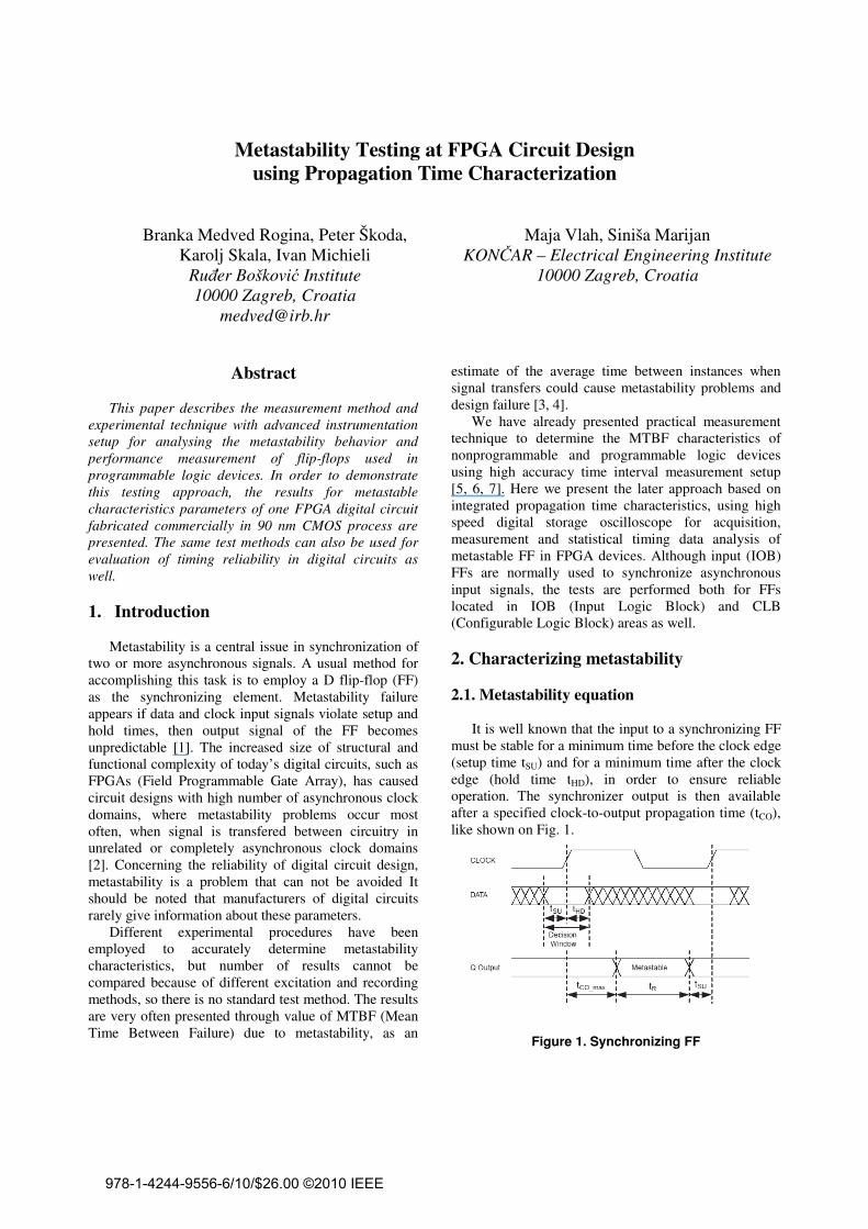
It is well known that the input to a synchronizing FF
must be stable for a minimum time before the clock edge (setup time tSU) and for a minimum time after the clock edge (hold time tHD), in order to ensure reliable operation. The synchronizer output is then available after a specified clock-to-output propagation time (tCO), like shown on Fig. 1.
���������������������������
978-1-4244-9556-6/10/$26.00 ©2010 IEEE

The problem with metastable events is not merely their occurrence, but when the event causes inconsistent values to be latched into subsequent flip-flops. One manifestation of metastability behavior is excessive propagation time of this transition [8]. This increased delay will normally cause timing violations in the subsequent (synchronous) circuit if the output has not resolved itself by the time that it must be valid for use, for example as an input to another stage. Because of the greater densities and more aggressive clocking strategies today, FPGAs have become more susceptible to these delay faults [9].
Metastability failure rate is usually calculated using the equation that relates mean time between two failures with operating conditions [10]:
wffMTBF
dc
t
d
R
⋅⋅⋅=
2
10τ
(1)
where: • tR is the resolve time or the maximum time a
digital output can remain in a metastable state without causing a synchronization failure,
• w is the metastable window and represents the likelihood that a device enters into a metastable state,
• τd is the metastability resolution time constant and describes the speed by which the metastable condition is resolved,
• fc is the frequency of the system clock, • fd is the frequency of the input signal.
Available resolve time is calculated from:
( )
SUCOcR ttft −−= max_1 (2)
Therefore, the amount of resolve time tR allowed a
device to settle, plays a significant role in calculating its failure rate. In our practical measurement technique, we determine device depending characteristics, the metastability resolution time constant τd and metastable window w, so we can calculate circuit’s failure rate for different resolving time values at specific frequencies of clock and data signals. 2.2. Metastability measurement method
The common methods to explore the MTBF use the stimulating data and clock signal out of phase, representing asynchronous signals that are most used in real systems today [11]. However, the probability of a FF going into metastable state will be higher if the input
signal more often violates the setup time or hold time of the FF. Therefore, we use synchronous data and clock input signals to deliberately induce metastability in testing FF. However, it is necessary to consider the following. MTBF parameter is used to calculate the mean time between synchronization failure events and is valid for random events, input events that are uniformly distributed over the clock period. Since we use history dependent method of generating input events we must take care that it does not affect the data, however to get the results that correspond to the excitation of random, asynchronous input signals.
As for the analysis of the results, we do not predetermine the time (after the clock signal) at what the output state of a FF is analyzed, like in LTD (Late Transition Detection) method [11]. We just measure clock to output propagation time at various setup, hold time values and store the data for later processing.
0.00 -0.05 -0.10 -0.15 -0.20 -0.25
1.0
1.5
2.0
2.5
Delay D-CLK (ns)
Pro
pa
gatio
n tim
e C
LK
-Outp
ut
(ns)
0
20
40
60
80
100
Nu
mb
er o
f core
ct eve
nts
(%)
�����������������������������������������������������
����������������������������������������
As an example, Fig. 2. shows propagation time characteristic measured for one general purpose FPGA circuit, Xilinx’s 90 nm FPGA Spartan-3 at various setup and hold time relationships. It is evident that the clock-to-output propagation time starts to increase (black line) as time interval between data and clock signals becomes less than 0.2 ns (setup time). At the same time, the number of output signals with increased propagation time but of regular voltage level (logical correct events) decreases (blue line). The largest measured increase in propagation time is 1.3 ns, with only 10 % of transitions occurred. The measurement results correspond to data listed in the manufacturer's specifications [12].
To experimentally determine the metastability resolution time constant τd and the metastable window w the edge of the data signal is set at the centre of the metastable window. This is usually adjusted so the
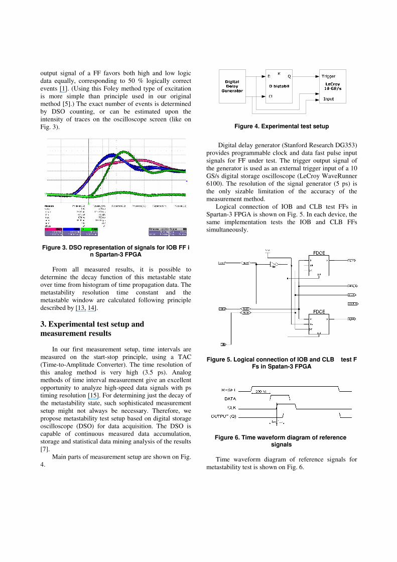
output signal of a FF favors both high and low logic data equally, corresponding to 50 % logically correct events [1]. (Using this Foley method type of excitation is more simple than principle used in our original method [5].) The exact number of events is determined by DSO counting, or can be estimated upon the intensity of traces on the oscilloscope screen (like on Fig. 3).
���������������������������������������������������������������������
From all measured results, it is possible to
determine the decay function of this metastable state over time from histogram of time propagation data. The metastability resolution time constant and the metastable window are calculated following principle described by [13, 14].
3. Experimental test setup and
measurement results In our first measurement setup, time intervals are
measured on the start-stop principle, using a TAC (Time-to-Amplitude Converter). The time resolution of this analog method is very high (3.5 ps). Analog methods of time interval measurement give an excellent opportunity to analyze high-speed data signals with ps timing resolution [15]. For determining just the decay of the metastability state, such sophisticated measurement setup might not always be necessary. Therefore, we propose metastability test setup based on digital storage oscilloscope (DSO) for data acquisition. The DSO is capable of continuous measured data accumulation, storage and statistical data mining analysis of the results [7].
Main parts of measurement setup are shown on Fig. 4.
���������������������������������
Digital delay generator (Stanford Research DG353)
provides programmable clock and data fast pulse input signals for FF under test. The trigger output signal of the generator is used as an external trigger input of a 10 GS/s digital storage oscilloscope (LeCroy WaveRunner 6100). The resolution of the signal generator (5 ps) is the only sizable limitation of the accuracy of the measurement method.
Logical connection of IOB and CLB test FFs in Spartan-3 FPGA is shown on Fig. 5. In each device, the same implementation tests the IOB and CLB FFs simultaneously.
�
��
�������������������������������������������������������������������������
�
������������������������������������������������������
Time waveform diagram of reference signals for
metastability test is shown on Fig. 6.
3.1. Evaluating the metastability parameters
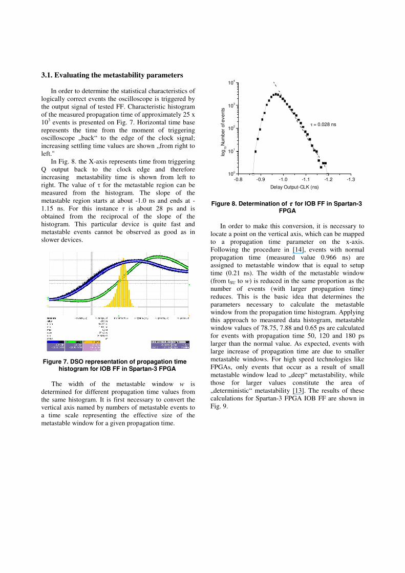
In order to determine the statistical characteristics of logically correct events the oscilloscope is triggered by the output signal of tested FF. Characteristic histogram of the measured propagation time of approximately 25 x 103 events is presented on Fig. 7. Horizontal time base represents the time from the moment of triggering oscilloscope „back“ to the edge of the clock signal; increasing settling time values are shown „from right to left."
In Fig. 8. the X-axis represents time from triggering Q output back to the clock edge and therefore increasing metastability time is shown from left to right. The value of � for the metastable region can be measured from the histogram. The slope of the metastable region starts at about -1.0 ns and ends at -1.15 ns. For this instance � is about 28 ps and is obtained from the reciprocal of the slope of the histogram. This particular device is quite fast and metastable events cannot be observed as good as in slower devices.
��������������������������������������������������������������������������������������������
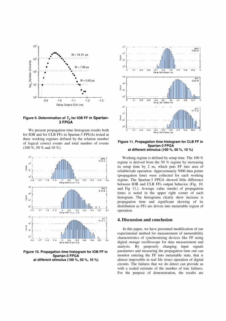
The width of the metastable window w is determined for different propagation time values from the same histogram. It is first necessary to convert the vertical axis named by numbers of metastable events to a time scale representing the effective size of the metastable window for a given propagation time.
-0.8 -0.9 -1.0 -1.1 -1.2 -1.3100
101
102
103
104
τ = 0.028 ns
log
10
Num
ber
of e
ven
ts
Delay Output-CLK (ns)
���������������������������ττττ �������������������������
������
In order to make this conversion, it is necessary to locate a point on the vertical axis, which can be mapped to a propagation time parameter on the x-axis. Following the procedure in [14], events with normal propagation time (measured value 0.966 ns) are assigned to metastable window that is equal to setup time (0.21 ns). The width of the metastable window (from tSU to w) is reduced in the same proportion as the number of events (with larger propagation time) reduces. This is the basic idea that determines the parameters necessary to calculate the metastable window from the propagation time histogram. Applying this approach to measured data histogram, metastable window values of 78.75, 7.88 and 0.65 ps are calculated for events with propagation time 50, 120 and 180 ps larger than the normal value. As expected, events with large increase of propagation time are due to smaller metastable windows. For high speed technologies like FPGAs, only events that occur as a result of small metastable window lead to „deep“ metastability, while those for larger values constitute the area of „deterministic“ metastability [13]. The results of these calculations for Spartan-3 FPGA IOB FF are shown in Fig. 9. �
-0.9 -1.0 -1.1 -1.2 -1.3100
101
102
103
104
W = 7.88 ps
W = 0.65 ps
W = 78.75 ps
log
10
Num
ber
of e
ven
ts
Delay Output-CLK (ns)
��
�����������������������������������������������������������
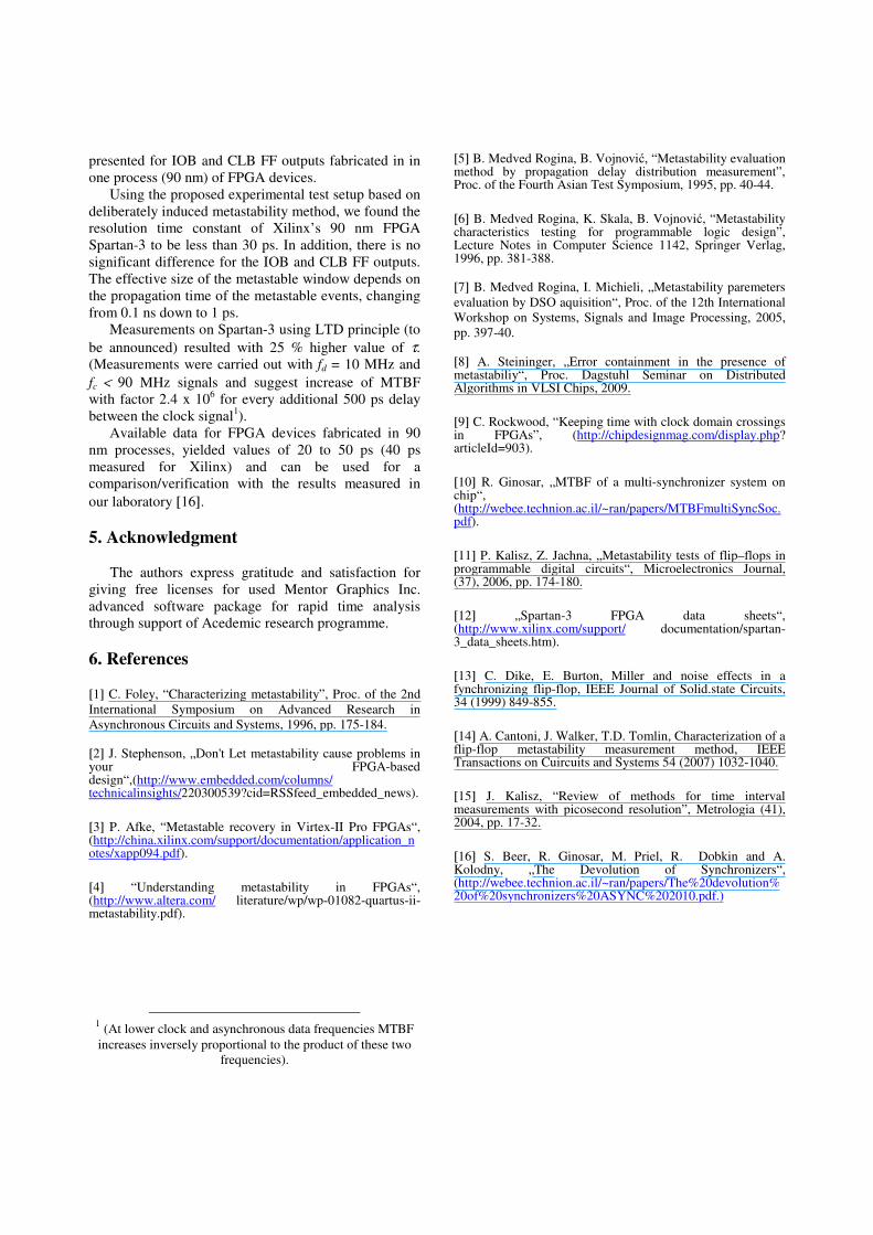
We present propagation time histogram results both
for IOB and for CLB FFs in Spartan-3 FPGAs tested at three working regimes defined by the relation number of logical correct events and total number of events (100 %, 50 % and 10 %).
����������������������������������������������������
���������������������������������������������������������
���������������������������������������������������
����������������������������������������������������������
������Working regime is defined by setup time. The 100 % regime is derived from the 50 % regime by increasing its setup time by 2 ns, which puts FF into area of reliable/safe operation. Approximately 5000 data points (propagation time) were collected for each working regime. The Spartan-3 FPGA showed little difference between IOB and CLB FFs output behavior (Fig. 10. and Fig 11.). Average value (mode) of propagation times is noted in the upper right corner of each histogram. The histograms clearly show increase is propagation time and significant skewing of its distribution as FFs are driven into metastable region of operation.
4. Discussion and conclusion
In this paper, we have presented modification of our
experimental method for measurement of metastability characteristics of synchronizing devices like FF using digital storage oscilloscope for data measurement and analysis. By purposely changing input signals parameters and measuring the propagation time one can monitor entering the FF into metastable state, that is almost impossible in real life (true) operation of digital circuits. The failures that we do detect can provide us with a scaled estimate of the number of true failures. For the purpose of demonstration, the results are
presented for IOB and CLB FF outputs fabricated in in one process (90 nm) of FPGA devices.
Using the proposed experimental test setup based on deliberately induced metastability method, we found the resolution time constant of Xilinx’s 90 nm FPGA Spartan-3 to be less than 30 ps. In addition, there is no significant difference for the IOB and CLB FF outputs. The effective size of the metastable window depends on the propagation time of the metastable events, changing from 0.1 ns down to 1 ps.
Measurements on Spartan-3 using LTD principle (to be announced) resulted with 25 % higher value of τ. (Measurements were carried out with fd = 10 MHz and fc < 90 MHz signals and suggest increase of MTBF with factor 2.4 x 10⁶ for every additional 500 ps delay between the clock signal1).
Available data for FPGA devices fabricated in 90 nm processes, yielded values of 20 to 50 ps (40 ps measured for Xilinx) and can be used for a comparison/verification with the results measured in our laboratory [16].
5. Acknowledgment
The authors express gratitude and satisfaction for
giving free licenses for used Mentor Graphics Inc. advanced software package for rapid time analysis through support of Acedemic research programme.
6. References
[1] C. Foley, “Characterizing metastability”, Proc. of the 2nd International Symposium on Advanced Research in Asynchronous Circuits and Systems, 1996, pp. 175-184. [2] J. Stephenson, „Don't Let metastability cause problems in your FPGA-based design“,(http://www.embedded.com/columns/ technicalinsights/220300539?cid=RSSfeed_embedded_news). [3] P. Afke, “Metastable recovery in Virtex-II Pro FPGAs“, (http://china.xilinx.com/support/documentation/application_notes/xapp094.pdf). [4] “Understanding metastability in FPGAs“, (http://www.altera.com/ literature/wp/wp-01082-quartus-ii-metastability.pdf).
1 (At lower clock and asynchronous data frequencies MTBF increases inversely proportional to the product of these two
frequencies).
[5] B. Medved Rogina, B. Vojnovi�, “Metastability evaluation method by propagation delay distribution measurement”, Proc. of the Fourth Asian Test Symposium, 1995, pp. 40-44. [6] B. Medved Rogina, K. Skala, B. Vojnovi�, “Metastability characteristics testing for programmable logic design”, Lecture Notes in Computer Science 1142, Springer Verlag, 1996, pp. 381-388. [7] B. Medved Rogina, I. Michieli, „Metastability paremeters evaluation by DSO aquisition“, Proc. of the 12th International Workshop on Systems, Signals and Image Processing, 2005, pp. 397-40. [8] A. Steininger, „Error containment in the presence of metastabiliy“, Proc. Dagstuhl Seminar on Distributed Algorithms in VLSI Chips, 2009. [9] C. Rockwood, “Keeping time with clock domain crossings in FPGAs”, (http://chipdesignmag.com/display.php? articleId=903). [10] R. Ginosar, „MTBF of a multi-synchronizer system on chip“, (http://webee.technion.ac.il/~ran/papers/MTBFmultiSyncSoc.pdf). [11] P. Kalisz, Z. Jachna, „Metastability tests of flip–flops in programmable digital circuits“, Microelectronics Journal, (37), 2006, pp. 174-180. [12] „Spartan-3 FPGA data sheets“, (http://www.xilinx.com/support/ documentation/spartan-3_data_sheets.htm). [13] C. Dike, E. Burton, Miller and noise effects in a fynchronizing flip-flop, IEEE Journal of Solid.state Circuits, 34 (1999) 849-855. [14] A. Cantoni, J. Walker, T.D. Tomlin, Characterization of a flip-flop metastability measurement method, IEEE Transactions on Cuircuits and Systems 54 (2007) 1032-1040. [15] J. Kalisz, “Review of methods for time interval measurements with picosecond resolution”, Metrologia (41), 2004, pp. 17-32. [16] S. Beer, R. Ginosar, M. Priel, R. Dobkin and A. Kolodny, „The Devolution of Synchronizers“, (http://webee.technion.ac.il/~ran/papers/The%20devolution%20of%20synchronizers%20ASYNC%202010.pdf.)