METAL OXIDE SURGE ARRESTERS 5 kA AND 10 kA ...
24
HELLENIC ELECTRICITY DISTRIBUTION NETWORK OPERATOR Perrevou 20 & Kallirrois 5 Τ 210 9281600 [email protected] 117 43 Athens F 210 9281698 www.deddie.gr 1/24 Network Department Syggrou Av. 24, 117 42 Athens HEDNO TECHNICAL DESCRIPTION ND-399/29.11.2018 METAL OXIDE SURGE ARRESTERS 5 kA AND 10 kA, WITHOUT GAPS, WITH COMPOSITE HOUSING, FOR 20kV DISTRIBUTION NETWORKS CONTENTS 1. SCOPE 2. KEYWORDS 3. OPERATING CONDITIONS 4. STANDARDS - SPECIFICATIONS 5. DESCRIPTION 6. TESTS 7. MARKING 8. PACKING 9. ANNEXES - DRAWINGS
-
Upload
khangminh22 -
Category
Documents
-
view
2 -
download
0
Transcript of METAL OXIDE SURGE ARRESTERS 5 kA AND 10 kA ...

HELLENIC ELECTRICITY DISTRIBUTION NETWORK OPERATOR
Perrevou 20 & Kallirrois 5 Τ 210 9281600 [email protected] 117 43 Athens F 210 9281698 www.deddie.gr 1/24
Network Department
Syggrou Av. 24, 117 42 Athens
HEDNO TECHNICAL DESCRIPTION ND-399/29.11.2018
METAL OXIDE SURGE ARRESTERS 5 kA AND 10 kA, WITHOUT GAPS,
WITH COMPOSITE HOUSING, FOR 20kV DISTRIBUTION NETWORKS
CONTENTS
1. SCOPE
2. KEYWORDS
3. OPERATING CONDITIONS
4. STANDARDS - SPECIFICATIONS
5. DESCRIPTION
6. TESTS
7. MARKING
8. PACKING
9. ANNEXES - DRAWINGS
ND-399 2/24
HEDNO TECHNICAL DESCRIPTION ND-399/29.11.2018
METAL OXIDE SURGE ARRESTERS 5 kA AND 10 kA, WITHOUT GAPS,
WITH COMPOSITE HOUSING, FOR 20kV DISTRIBUTION NETWORKS
1. SCOPE
The present Technical Description (TD) determines the manufacturing and testing requirements
for metal oxide surge arresters (ΖnΟ) without gaps, of class distribution high-DH, 10 kA, and
distribution medium-DM, 5 kA, according to the EN 60099-1 classification, intended for the
protection of 20kV overhead and underground distribution networks and MV/LV substations. The surge arrester (assembly) shall consist of the main body (surge arrester), the disconnecting
device and the insulating mounting bracket, which shall be steadily assembled together.
Τhe surge arrester shall be suitable for mounting on the transformer tank or on a cross arm
(wooden or steel). The surge arrester is mounted on the transformer via a special supporting assembly (accompanying the transformer), placed on the transformer tank (Drawing 1). The
surge arrester is mounted on the cross arms via a steel mounting assembly (Drawing 2).
Surge arresters shall be supplied either with or without steel mounting assembly (Drawing 2),
with a corresponding formulation of the inquiry.
2. KEYWORDS
Surge arrester, disconnecting device, insulating mounting bracket, Medium Voltage, lightning
protection, steel mounting assembly
3. OPERATING CONDITIONS
3.1. Environmental conditions
The surge arrester shall be suitable for outdoor operation and operation in areas with high
corrosion (deposits of dust, salt, industrial pollutants, presence of humidity, rain, and snow).
The majority of installations are placed at altitude of up to 1000 m above sea level.
Environmental conditions are defined below:
Maximum ambient air temperature : +40 ο C
Minimum ambient air temperature : - 40 ο C Maximum mean value of the ambient air temperature
measured at a period of 24 hours
:
+35 ο C
Direct exposure to sun, rain, snow and wind : Yes
Minimum duration of direct exposure to sunlight : 2800 h
3.2. System characteristics – Medium Voltage (MV) Network
The surge arrester is intended for use on three - phase, three conductors distribution MV
networks, with earthed neutral node of the HV/MV transformer, through a resistor limiting the earth fault current to 1000 Α, with the following characteristics:
ND-399 3/24
- Nominal system voltage, UN : 20kV
- Maximum system voltage : 24kV
- Frequency : 50Ηz
- Short circuit power : 250 ΜVΑ
- Maximum earth fault current : 1000 Α
4. STANDARDS - SPECIFICATIONS
− ΕΝ 60099-4 : Surge Arresters – Part 4: Metal Oxide Surge Arresters
without gaps for a.c. systems − EN 60060-1 : High-voltage test techniques – Part 1: General
definitions and test requirements
− EN 61952 : Insulators for overhead lines - Composite line post
insulators for A.C. systems with a nominal voltage greater than 1 000 V - Definitions, test methods and
acceptance criteria
− PPC Technical Specification
ΧΚ 11.02/10.03.88
: Hot dip zinc coating of iron or steel articles
NOTE: The text of the present Technical Description is predominant and its requirements prevail
against any other Standard or Specification.
5. DESCRIPTION
5.1 Electrical Characteristics
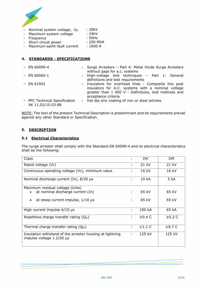
The surge arrester shall comply with the Standard EN 60099-4 and its electrical characteristics shall be the following:
Class : DH DM
Rated voltage (Vr) : 21 kV 21 kV
Continuous operating voltage (Vc), minimum value
: 16 kV 16 kV
Nominal discharge current (In), 8/20 μs : 10 kA 5 kA
Maximum residual voltage (Ures) at nominal discharge current (In)
at steep current impulse, 1/10 μs
: :
65 kV
65 kV
65 kV
65 kV
High current impulse 4/10 μs : 100 kA 65 kA
Repetitive charge transfer rating (Qrs) :
≥0.4 C ≥0.2 C
Thermal charge transfer rating (Qth) : ≥1.1 C ≥0.7 C
Insulation withstand of the arrester housing at lightning impulse voltage 1.2/50 μs
: 125 kV 125 kV

ND-399 4/24
Insulation withstand of the arrester housing at power frequency voltage under wet conditions, 1 min
: 54 kV 43 kV
SSL (Specified short-term load) : 100 Nm min 100 Nm min
SLL (Specified long-term load) : 100 Nm min 100 Nm min
5.2 Housing material
The outer housing of the surge arrester shall be made of silicon rubber with a minimum creepage distance of 670 mm, suitable for the environmental conditions described in par. 3.1
of the present TD. Overcoated insulators are not acceptable.
5.3 Manufacturing characteristics
5.3.1. Surge arrester
5.3.1.1. The surge arrester shall be equipped with a disconnecting device, which shall be intended for connection to the earthing conductor and it shall be automatically disconnected from the surge arrester in case of an electric fault of the arrester. The disconnection shall be visible by an observer standing a few meters away from the surge arrester, for example near the pole, where it is installed. The disconnecting device shall present a current-time curve lower than the current-time curve of the 10Τ fuse (as per ANSI C 37.43), when both curves are plotted on the same logarithmic chart. The current-time curve of the 10T fuse shall be plotted on a logarithmic chart taking into account the following points:
Melting time (s) 300 or 600 10 0,1
Minimum current value (A) 19,5 26,5 224
5.3.1.2. The surge arrester shall be equipped with two tightening lugs. The lugs shall be stainless, suitable for connecting Cu conductors of 16 to 35 mm2 effective cross section. 5.3.1.3. The metallic parts of the surge arrester shall be made of stainless steel or tin plated bronze with minimum tin-plating thickness of 15 μm. 5.3.1.4. The surge arrester shall be equipped with a suitable insulating mounting bracket, which shall be placed between the main body of the surge arrester and the steel mounting assembly that is described in par. 1. The distance between the axes of the insulating bracket holes, at which the surge arrester lower bolt and the mounting bolt of the steel mounting assembly are fastened, shall be minimum 13 cm. The insulating mounting bracket shall withstand the system voltages described in par. 3.2 and it shall be subjected to the tests described in par. 6.1.13 of the present TD. Furthermore, the insulating bracket shall withstand environmental stress (exposure to sunlight, rain, humidity, etc.) and its withstand shall be proved by documents submitted with the technical offer (technical brochures, test reports, etc.)
5.3.1.5. The surge arrester shall be suitable to withstand the forces from the connection of the network conductor, as well as the forces applied to the housing of the surge arrester when it is connected to the network. Particularly, its cantilever strength shall be minimum:

ND-399 5/24
SSL (Specified short-term load) = 100 Nm min and
SLL (Specified long-term load) = 100 Νm min.
and it shall be proved by test report of bending moment as per par. 10.8.11 and ANEX G of the EN 60099-4.
5.3.1.6. The surge arrester shall be accompanied by tinned copper flexible stranded wire (or braid of circular cross-section) of 16 mm2 minimum cross-section and a minimum length of 0.70 m. The flexible wire at its one edge shall end to a lug with hole (of minimum diameter 13 mm) suitable for the connection to the disconnecting device. The other edge shall be free for the connection with the earthing conductor of the pole through a brass split bolt connector. Each flexible wire shall be delivered adapted to the disconnecting device of each surge arrester. 5.3.2. Steel mounting assembly (if it is included in the purchase) Each surge arrester shall be suitable for mounting on a cross-arm of width 50-126 mm and of height 100-176 mm, through the mounting assembly shown in Drawing 1. The supporting base of the surge arrester (item 1 in Drawing 2) and the back plate for the mounting of the base (item 2 in Drawing 2) shall have suitable shape, so as the two bolts of minimum diameter M 10 mm (item 3 in Drawing 2), which go through the supporting base and the back plate, can be adjusted to the following vertical distances between their axes: 120, 135, 140 and 190 mm. The upper holes, both on the base of the surge arrester and the mounting back plate, can be continuous through serrate type opening. All the parts of the surge arrester mounting assembly shall be hot-dip zinc coated in accordance with the Technical Specification ΧΚ 11.02/10.03.88 or other equivalent European Standard. In any case, zinc coating thickness shall be the one specified in the text of the above mentioned HEDNO Specification. Other equivalent mounting assemblies may become acceptable, at the absolute discretion of the technical evaluation body.
6. TESTS
For the purposes of the present Technical Description, the tests are distinguished in type tests, routine tests and acceptance tests. All the tests mentioned below, shall be performed according
to the requirements of the latest publication of the Standard EN 60099-4.
6.1. Type tests
The type tests, specified in ΕΝ 60099-4, shall be performed at the beginning of a contract and
they may be repeated, at the absolute discretion of the Corporation, any time during the
Contract execution, whenever the design or the production process is modified. At the absolute
discretion of the Corporation, certificates issued by an accredited laboratory may be accepted. In addition to the tests described in EN, the dielectric tests on the insulating mounting bracket,
specified in paragraph 6.1.13 of the present TD, shall be performed.
Specifically the type tests are the following:
6.1.1. Insulation withstand tests on the arrester housing
As specified in paragraph 10.8.2 of EN 60099-4.
6.1.2. Residual voltage tests
As specified in paragraph 10.8.3 of EN 60099-4.
6.1.3. Test to verify long term stability under continuous operating voltage

ND-399 6/24
As specified in paragraph 10.8.4 of EN 60099-4.
6.1.4. Test to verify the repetitive charge transfer rating (Qrs)
As specified in paragraph 10.8.5 of EN 60099-4.
6.1.5. Heat dissipation behavior verification of test sample
As specified in paragraph 10.8.6 of EN 60099-4.
6.1.6. Operating duty tests
As specified in paragraph 10.8.7 of EN 60099-4.
6.1.7. Power frequency voltage-versus-time test
As specified in paragraph 10.8.8 of EN 60099-4.
6.1.8. Tests of arrester disconnector
As specified in paragraph 10.8.9 of EN 60099-4.
6.1.9. Short-circuit tests
As specified in paragraph 10.8.10 of EN 60099-4.
6.1.10. Test of the bending moment
As specified in paragraph 10.8.11 and in ΑΝΝΕΧ G of EN 60099-4.
6.1.11. Test to verify the dielectric withstand of the internal components of an arrester
As specified in paragraph 10.8.15 of EN 60099-4.
6.1.12. Weather ageing test
As specified in paragraph 10.8.17 of EN 60099-4.
6.1.13. Tests on the insulating mounting bracket
6.1.13.1. Dielectric test: Power frequency voltage withstand test, 40 kV under wet conditions, for 1 min, as per ΕΝ 60060-1.
6.1.13.2. Flammability test, as per par. 6.4.4 of EN 61952 or other equivalent European
standard.
6.2. Acceptance tests
6.2.1. Acceptance tests shall be performed according to paragraph 9.2 of EN 60099-4.
6.2.1.1. Measurement of power-frequency voltage at reference current
As specified in par. 9.2.1.a. of EN 60099-4.

ND-399 7/24
6.2.1.2. Lightning impulse residual voltage at nominal discharge current
As specified in par. 9.2.1.b. of EN 60099-4.
6.2.1.3. Internal partial discharge test
As specified in par. 9.2.1.c. of EN 60099-4.
6.2.1.4. In addition to the upper mentioned acceptance tests, visual inspection and
dimensional testing will be performed.
6.2.1.5. Steel mounting assembly of the surge arrester
6.2.1.5.1. Visual inspection – dimensional testing
6.2.1.5.2. Protection against corrosion test
The purpose of this test is to verify that all metal parts are sufficiently protected against
corrosion. The zinc coating test will be performed in accordance with the Technical Specification
ΧΚ 11.02/10.03.88.
6.3. Routine tests
Routine Tests specified in paragraph 9.1 of ΕΝ 60099-4, shall be performed at the manufacturer's factory, during the production procedure of the material, with detailed
registration of the data in records, subject to the assessment by the Corporation’s material
Inspector.
7. MARKING
7.1. Surge arresters
7.1.1. Marking on the surge arrester
The following data shall be clearly and permanently marked (not with stickers) on the metallic part of the surge arrester: − Manufacturer’s Name or Trademark − Type and identification code (e.g. serial number) of the surge arrester − Nominal discharge current, in kA − Continuous operating voltage, in kV − Rated voltage, in kV − Contract number − Year of manufacture
7.1.2. Marking on the packing
The heavy duty wooden crates, in which the surge arresters are packed (see par. 8 of the
present TD) shall have suitable metallic nameplates, where the following data shall be embossed and easily readable: Manufacturer’s Name or Trademark Type and identification code (e.g. serial number) of the surge arrester Nominal discharge current, in kA Continuous operating voltage, in kV

ND-399 8/24
Rated voltage, in kV HEDNO code number Number of pieces Gross weight in kg Contract number Year of manufacture
7.2. Steel mounting assembly of the surge arrester
7.2.1. Marking on the mounting assembly
The following data shall be clearly and permanently marked (not with stickers) on the metallic part of the surge arrester:
− Contract number
− Year of manufacture
7.2.2. Marking on the packing
The heavy duty wooden crates, in which the surge arresters are packed (see par. 8 of the present TD) shall have suitable metallic nameplates, where the following data shall be
embossed and easily readable:
− Manufacturer’s Name or Trademark
− HEDNO code number
− Number of pieces
− Gross weight in kg
− Contract number − Year of manufacture
8. PACKING
8.1. Surge arresters The material shall be packed in heavy duty wooden crates and each one shall contain six (6) surge arresters. The wooden crates shall be delivered packed in wooden EU palettes (“Europalettes”), containing surge arresters and mounting assemblies, the proportion of which shall be defined in the Inquiry (if they are included in the purchase). The total weight of each palette shall not exceed 550 kg. The total height of the materials packed in the palette shall not exceed 1.2 m, but it shall be as close to this dimension as it is possible. The packed wooden crates shall be fastened in the palette with at least two (2) vertical steel foils (lags) in length and two (2) in width (total 4), which shall pass under the palette’s woods. Also, if it is necessary, the crates shall be fastened with two (2) horizontal foils. The above steel foils shall be preferably externally plasticized. Plastic foils are not acceptable, due to their fast degradation by solar radiation.
8.2. Steel mounting assembly
The mounting brackets shall be packed in separate heavy duty wooden crates, each one shall contain a number of mounting assemblies multiple of 6 and equal in all heavy duty wooden crates. The weight of each crate containing mounting assemblies will not exceed 25 kg.
The wooden crates shall be delivered packed in wooden EU palettes (“Europalettes”) as
described in paragraph 8.1 of the present TD.

ND-399 9/24
9. ANNEX-DRAWINGS
9.1. ANNEX 1
Data to be submitted with the offer.
9.2. COMPLIANCE SHEET Table Α1: Data required by the Inquiry for each offered class of surge arrester
Table Α2: Test certificates
Table Β: Data required by the Technical Description ND-399
o Β.1: Surge arrester 10 kA (DH class) o Β.2: Surge arrester 5 kA (DM class)
o B.3: Steel mounting assembly (if it is included in the purchase)
9.3. DRAWING 1 Surge arrester mounting on the transformer tank
9.4. DRAWING 2
Surge arrester mounting assembly on the cross arms

ND-399 10/24
ANNEX 1
(Paragraph 9.1. of the Technical Description HEDNO ND–399)
PART Β OF THE TENDER INQUIRY “TECHNICAL OFFER”
Part Β “Technical Offer” of the Inquiry contains:
13.2.Β.1. Quantity and type of the offered materials. For this purpose, bidders should fill in
the Technical Offer Exemplar, according to the corresponding Annex of the Inquiry.
13.2.Β.2. Location and factory of manufacture of the offered surge arresters, as well as the
inspection location.
13.2.Β.3. Compliance declaration of the offered surge arresters with the requirements of the present Technical Description.
13.2.Β.4. Declaration of the manufacturing factory of the offered surge arresters accompanied
with detailed information (mailing address, personnel employed, brief description of facilities, description of ability to perform tests, etc.). The factory shall have
sufficient measuring and quality control equipment.
13.2.Β.5. ISO 9001 certificate of the manufacturing factory of the offered surge arresters covering the production field of the materials under purchase. It is noticed that the
bidder shall submit communication data of the certification body as well as any other
relevant data requested during the technical evaluation which shall facilitate the
verification of ISO 9001 certification validity.
Furthermore, bidders shall include a declaration that the manufacturer undertakes the responsibility to proceed with all the necessary actions for ensuring the
uninterrupted update of ISO 9001 certificate for the manufacturing factory,
throughout the duration of any Contract with HEDNO SA.
13.2.Β.6. Completed the Table for the implementation of the REACH Regulation of the EU or
a declaration that the materials offered do not fall under the provisions of the REACH
Regulation in accordance with the corresponding ANNEX of the Inquiry.
13.2.Β.7. Declaration of the offered surge arresters type and of the metal oxide discs type and
manufacturing factory.
13.2.Β.8. Test certificates for all required type tests described in par. 6.1 of the present TD
for every offered surge arrester, in accordance to the Standard EN 60099-4. Test certificates shall be issued by test laboratories accredited by an independent private
or public authority.
Submission of test certificates is not mandatory for bidders that offer MV surge
arresters, which have been installed on the network of HEDNO and operate in a
satisfactory manner. Repetition of test types, in case of Contract signing, depends
on HEDNO’s discretion.
13.2.Β.9. Drawings of the manufacturer with the detailed designing of the offered surge
arrester, namely fully dimensional drawing and legend with the materials used and
their treatments. Additionally, the following documents shall be submitted:

ND-399 11/24
drawings of the lugs used, including description of them and declaration of their
manufacturing material.
full data of the insulating housing used (type of material, characteristics, etc.) detailed drawing of the steel mounting assembly (if it is included in the purchase)
13.2.Β.10. Documents verifying the manufacturing factory’s experience, such as sales
catalogues, reference letters (original or copies), copies of contracts (price units are not necessary to be visible) or any other data proving the ability of the
manufacturing factory in manufacturing of surge arresters. The documents shall
concern the offered or similar materials.
As similar materials are considered metal oxide surge arresters with composite housing, without gaps of equal or higher rated voltage and of equal or higher
nominal discharge current.
The documents shall refer to materials manufactured in the factory, where the
offered surge arresters will be manufactured. Submission of the required documents is not mandatory for manufacturers that offer
MV surge arresters, which have been installed on the network of HEDNO and operate
in a satisfactory manner.
13.2.Β.11. Declaration of the disconnecting device type, description of its operation and submission of its current-time curve, drawn in the same sheet with the current-time
curve of the 10Τ fuse, as it is defined in paragraph 5.3.1 of the present TD.
13.2.Β.12. Data (technical brochures, test reports, etc.) proving the long term withstand of the insulating mounting bracket against environmental stress (exposure to sunlight,
rain, humidity, etc.)
13.2.Β.13. Installation, operation and maintenance instructions for the offered surge arresters. One copy of the above mentioned instructions, in the Greek language, shall be
delivered with each packing crate.
13.2.Β.14. Guarantee of the materials for a period of three (3) years after the date of their
delivery at HEDNO’s warehouses.
13.2.Β.15. Bill of lading of the offered material sample.
13.2.Β.16. Any further technical data, at the discretion of the bidder.
13.2.Β.17. The below Conformity Sheet filled in for the offered materials. In addition to the
filled in Conformity Sheet, the bidder shall submit for the Tables B.1 and B.2,
documents (technical brochures, test certificates, etc.) that prove the technical characteristics with No 3, 4, 6, 8 and 12.1-12.9. Simple declaration of the
manufacturer is not considered sufficient.
For the rest of the technical characteristics the bidder shall submit declarations or
drawings.

ND-399 12/24
COMPLIANCE SHEET
It is noted that filling in all data in the tables below is mandatory and all required information shall be provided.
Table Α1: Documents required by the Inquiry for each offered surge arrester class
Surge arrester class ……………………………
No Paragraph of
the Inquiry
concerning the required
documents
Required document to be
submitted with the
Technical Offer
Submitted document with
the Technical Offer
Location in the
Technical Offer, where
the required document is found
1 13.2.Β.2 Location and factory of
manufacture of the offered surge arresters, as well as the
inspection location
2 13.2.Β.3 Compliance declaration of the
offered surge arresters with the requirements of the
present Technical Description
3 13.2.Β.4 Detailed information of the manufacturing factory
4 13.2.Β.4 Description of factory’s
measurement and quality
control equipment
5 13.2.Β.5 ISO 9001 certificate of the manufacturing factory
6 13.2.Β.5 Communication data of the
certification body which shall
facilitate the verification of ISO 9001 certification validity
7 13.2.Β.5 Declaration of uninterrupted
update of ISO 9001
8 13.2.Β.6 Completed the table for the implementation of the REACH
Regulation of the EU of the
corresponding Annex of the Inquiry or declaration that the
REACH EU regulation does not fall under the provisions of the
REACH Regulation for each of
the offered items
9 13.2.Β.6 Material Safety Data Sheets (MSDS) according to REACH
Regulation or a declaration
that it is not needed by the above regulation to submit
MSDS for the offered material, as well as its individual
ingredients, for each of the
offered items.
10 13.2.Β.7 Declaration of the offered
surge arresters type
11 13.2.Β.7 Declaration of the metal oxide
discs type and manufacturing factory
12 13.2.Β.9 Drawings of the manufacturer with the detailed designing of
the offered product; fully dimensional drawing and

ND-399 13/24
legend with the materials used
and their treatments
13 13.2.Β.9 Drawings of the lugs used, including description of them
and declaration of their
manufacturing material.
14 13.2.Β.9 Full data of the insulating
housing used (type of material,
characteristics, etc.)
15 13.2.B.9 Detailed drawing of the
mounting assembly (if it is
included in the purchase)
16 13.2.Β.10 Documents verifying the manufacturing factory’s
experience for the offered
surge arresters
17 13.2.Β.10 Documents verifying the manufacturing factory’s
experience for similar materials and data that prove
that the documents refer to
similar materials
18 13.2.Β.10 Contract copies with HEDNO for the supply of the offered
surge arresters, in case of
exemption of submission of the required documents
19 13.2.Β.11 Declaration of the
disconnecting device type
20 13.2.Β.11 Description of the disconnecting device
operation
21 13.2.Β.12 Data (technical brochures, test
reports, etc.) which prove the long term withstand of the
insulating bracket against
environmental stress (exposure to sunlight, rain,
humidity, etc.)
22 13.2.Β.13 Installation, operation and
maintenance instructions
23 13.2.Β.13 Declaration that one copy of the above mentioned
instructions, in the Greek
language, will be delivered with each packing crate
24 13.2.Β.14 3 years guarantee
25 13.2.Β.15 Sample bill of lading
26 13.2.Β.16 Any further technical data

ND-399 14/24
Table Α2: Test certificates
No Paragraph
of the Inquiry
concerning the
required
data
Required test
certificate to be submitted
Number and
issue date of the test
certificates / Name of
test laboratory
that issued the test
certificate
Manufacturin
g factory name and
material type subjected to
the test (as mentioned on
the test certificate)
Location
(paragraph) of test certificate,
where the test procedure is
described
Data that prove
that the test laboratory that
issued the certificate is
accredited by an independent
private or public
authority
25 13.2.Β.8 Tests on the surge
arrester
Contract copies with
HEDNO for the supply of the offered surge
arresters, in case of
exemption of submission of test
certificates
25.1 6.1.1 Insulation withstand tests on the arrester
housing
25.2 6.1.2 Residual voltage tests
25.3 6.1.3 Test to verify long
term stability under
continuous operating
voltage
25.4 6.1.4 Test to verify the
repeptitive charge
transfer rating (Qrs)
25.5 6.1.5 Heat dissipation
behavior verification of
test sample
25.6 6.1.6 Operating duty tests
25.7 6.1.7 Power frequency
voltage versus time
characteristics
25.4 6.1.8 Tests of arrester
disconnector
25.5 6.1.9 Short-circuit tests
25.6 6.1.10 Test of the bending
moment
25.7 6.1.11 Tests to verify the
dielectric withstand of
the internal
components of an
arrester
25.8 6.1.12 Weather ageing test
26 6.1.13
Tests on the insulated
mounting bracket
26.1 6.1.13.1
Dielectric test
26.2 6.1.13.2
Flammability test
ND-399 15/24
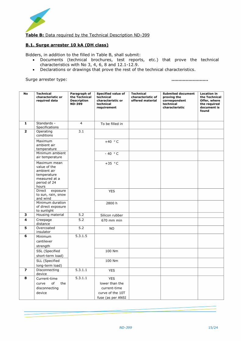
Table Β: Data required by the Technical Description ND-399
Β.1. Surge arrester 10 kA (DH class)
Bidders, in addition to the filled in Table Β, shall submit:
Documents (technical brochures, test reports, etc.) that prove the technical
characteristics with No 3, 4, 6, 8 and 12.1-12.9. Declarations or drawings that prove the rest of the technical characteristics.
Surge arrester type: ………..……………
No Technical characteristic or
required data
Paragraph of the Technical
Description ND-399
Specified value of technical
characteristic or technical
requirement
Technical characteristic of
offered material
Submited document proving the
correspondent technical
characteristic
Location in the Technical
Offer, where the required
document is found
1 Standards -
Specifications
4 To be filled in
2 Operating
conditions
3.1
Maximum
ambient air temperature
+40 ο C
Minimum ambient
air temperature - 40 ο C
Maximum mean
value of the ambient air
temperature
measured at a period of 24
hours
+35 ο C
Direct exposure
to sun, rain, snow and wind
YES
Minimum duration
of direct exposure
to sunlight
2800 h
3 Housing material 5.2 Silicon rubber
4 Creepage
distance
5.2 670 mm min
5 Overcoated insulator
5.2 NO
6 Minimum
cantilever
strength
5.3.1.5
SSL (Specified
short-term load)
100 Νm
SLL (Specified
long-term load)
100 Νm
7 Disconnecting
device
5.3.1.1 YES
8 Current-time
curve of the
disconnecting
device
5.3.1.1 YES
lower than the
current-time
curve of the 10Τ
fuse (as per ANSI

ND-399 16/24
C 37.43), when
both curves are
plotted on the
same logarithmic
chart
9 Lugs
5.3.1.2
Type To be filled in
Material Stainless
10 Metallic parts 5.3.1.3
Material Stainless steel or
tin plated bronze
Tin-plating thickness
15 μm min
11 Insulating
bracket
5.3.1.4 YES
Distance between
the axes of the
holes
13 cm min
12 Electrical characteristics
5.1
12.1 Rated voltage 5.1 21 kV
12.2 Continuous operating voltage
(Vc), minimum
value
5.1 16 kV
12.3 Nominal discharge
current, 8/20 μs
5.1 10 kA
12.4 Maximum
residual voltage:
5.1
At nominal
discharge
current
65 kV
At steel current impulse 1/10
μs
65 kV
12.5 High current
impulse 4/10 μs
5.1 100 kA
12.6 Repetitive charge transfer rating
(Qrs)
5.1 ≥0.4 C
12.7 Thermal charge
transfer rating (Qth)
5.1 ≥1.1 C
12.8 Insulation withstand of the
arrester housing at lightning
impulse voltage
1.2/50 μs
5.1 125 kV
12.9 Insulation withstand of the
arrester housing
at power frequency voltage
under wet conditions, 1 min
5.1 54 kV
12.10 Reference current and reference
voltage at
To be filled in

ND-399 17/24
environmental
temperature
13 Tinned copper
flexible stranded wire (or braid of
circular cross-
section) at the
disconnecting device
5.3.1.6 YES
Minimum cross section
16 mm2
Length 0,70 m min
Carries lug with hole
YES
Hole diameter 13 mm min
The other edge
shall be free for
the connection with the earthing
conductor of pole through a brass
split bolt connector
YES
14 Marking on the
surge arrester
7.1.1 Manufacturer’s
Name or Trademark
Type and
identification code (e.g. serial
number) of the surge arrester
Nominal
discharge current, in kA
Continuous operating
voltage, in kV
Rated voltage, in kV
Contract number
Year of manufacture
15 Marking on the
packing
7.1.2 Manufacturer’s
Name or Trademark
Type and identification
code (e.g. serial
number) of the surge arrester
Nominal discharge
current, in kA
Continuous operating
voltage, in kV Rated voltage, in
kV
HEDNO code number
Number of pieces
Gross weight in kg
Contract number

ND-399 18/24
Year of
manufacture
16 Packing 8.1 Wooden crates with 6 surge
arresters
Wooden crates in EU pallettes of
total weight ≤
550 kg The packed
wooden crates shall be fastened
in the palette
with externally plasticised steel
foils (lags): at least two (2)
vertical in length
and two (2) in width (total 4),
which shall pass under the
palette’s woods.
Also, if it is necessary, the
crates shall be
fastened with two (2)
horizontal foils
Β.2. Surge arrester 5 kA (DΜ class)
Bidders, in addition to the filled in Table Β, shall submit:
Documents (technical brochures, test reports, etc.) that prove the technical characteristics with No 3, 4, 6, 8 and 12.1-12.9.
Declarations or drawings that prove the rest of the technical characteristics.
Surge arrester type: ………..……………
No Technical
characteristic or
required data
Paragraph of the Technical
Description ND-399
Specified value of technical
characteristic or technical
requirement
Technical characteristic of
offered material
Submited document proving the
correspondent technical
characteristic
Location in the Technical
Offer, where the required
document is found
1 Standards -
Specifications
4 To be filled in
2 Operating conditions
3.1
Maximum ambient air
temperature
+40 ο C
Minimum ambient
air temperature - 40 ο C
Maximum mean
value of the ambient air
temperature
measured at a
+35 ο C

ND-399 19/24
period of 24
hours
Direct exposure
to sun, rain, snow
and wind
YES
Minimum duration of direct exposure
to sunlight
2800 h
3 Housing material 5.2 Silicon rubber
4 Creepage
distance
5.2 670 mm min
5 Overcoated
insulator
5.2 NO
6 Minimum
cantilever
strength
5.3.1.5
SSL (Specified
short-term load)
100 Νm
SLL (Specified
long-term load)
100 Νm
7 Disconnecting device
5.3.1.1 YES
8 Current-time
curve of the
disconnecting
device
5.3.1.1 YES
lower than the
current-time
curve of the 10Τ
fuse (as per ANSI
C 37.43), when
both curves are
plotted on the
same logarithmic
chart
9 Lugs
5.3.1.2
Type To be filled in
Material Stainless
10 Metallic parts 5.3.1.3
Material Stainless steel or
tin plated bronze
Tin-plating
thickness 15 μm min
11 Insulating
bracket
5.3.1.4 YES
Distance between
the axes of the holes
13 cm min
12 Electrical
characteristics
5.1
12.1 Rated voltage 5.1 21 kV
12.2 Continuous
operating voltage
(Vc), minimum value
5.1 16 kV
12.3 Nominal
discharge
current, 8/20 μs
5.1 5 kA
12.4 Maximum residual voltage:
5.1

ND-399 20/24
At nominal
discharge
current
65 kV
At steel current impulse 1/10
μs
65 kV
12.5 High current
impulse 4/10 μs
5.1 65 kA
12.6 Repetitive charge
transfer rating (Qrs)
5.1 ≥0.2 C
12.7 Thermal charge
transfer rating (Qth)
5.1 ≥0.7 C
12.8 Insulation withstand of the
arrester housing at lightning
impulse voltage
1.2/50 μs
5.1 125 kV
12.9 Insulation withstand of the
arrester housing
at power frequency voltage
under wet conditions, 1 min
5.1 43 kV
12.10 Reference current and reference
voltage at environmental
temperature
To be filled in
13 Tinned copper
flexible stranded wire (or braid of
circular cross-
section) at the disconnecting
device
5.3.1.6 YES
Minimum cross section
16 mm2
Length 0,70 m min
Carries lug with hole
YES
Hole diameter 13 mm min
The other edge
shall be free for the connection
with the earthing
conductor of pole through a brass
split bolt connector
YES
14 Marking on the
surge arrester
7.1.1 Manufacturer’s
Name or Trademark
Type and identification
code (e.g. serial
number) of the surge arrester
Nominal
discharge current, in kA

ND-399 21/24
Continuous
operating
voltage, in kV Rated voltage, in
kV
Contract number Year of
manufacture
15 Marking on the packing
7.1.2 Manufacturer’s Name or
Trademark Type and
identification
code (e.g. serial number) of the
surge arrester Nominal
discharge
current, in kA Continuous
operating voltage, in kV
Rated voltage, in
kV HEDNO code
number
Number of pieces Gross weight in
kg Contract number
Year of
manufacture
16 Packing 8 Wooden crates
with 6 surge
arresters Wooden crates in
EU palettes of total weight ≤
550 kg
The packed wooden crates
shall be fastened in the palette
with externally
plasticised steel foils (lags): at
least two (2)
vertical in length and two (2) in
width (total 4), which shall pass
under the
palette’s woods. Also, if it is
necessary, the crates shall be
fastened with
two (2) horizontal foils
ND-399 22/24
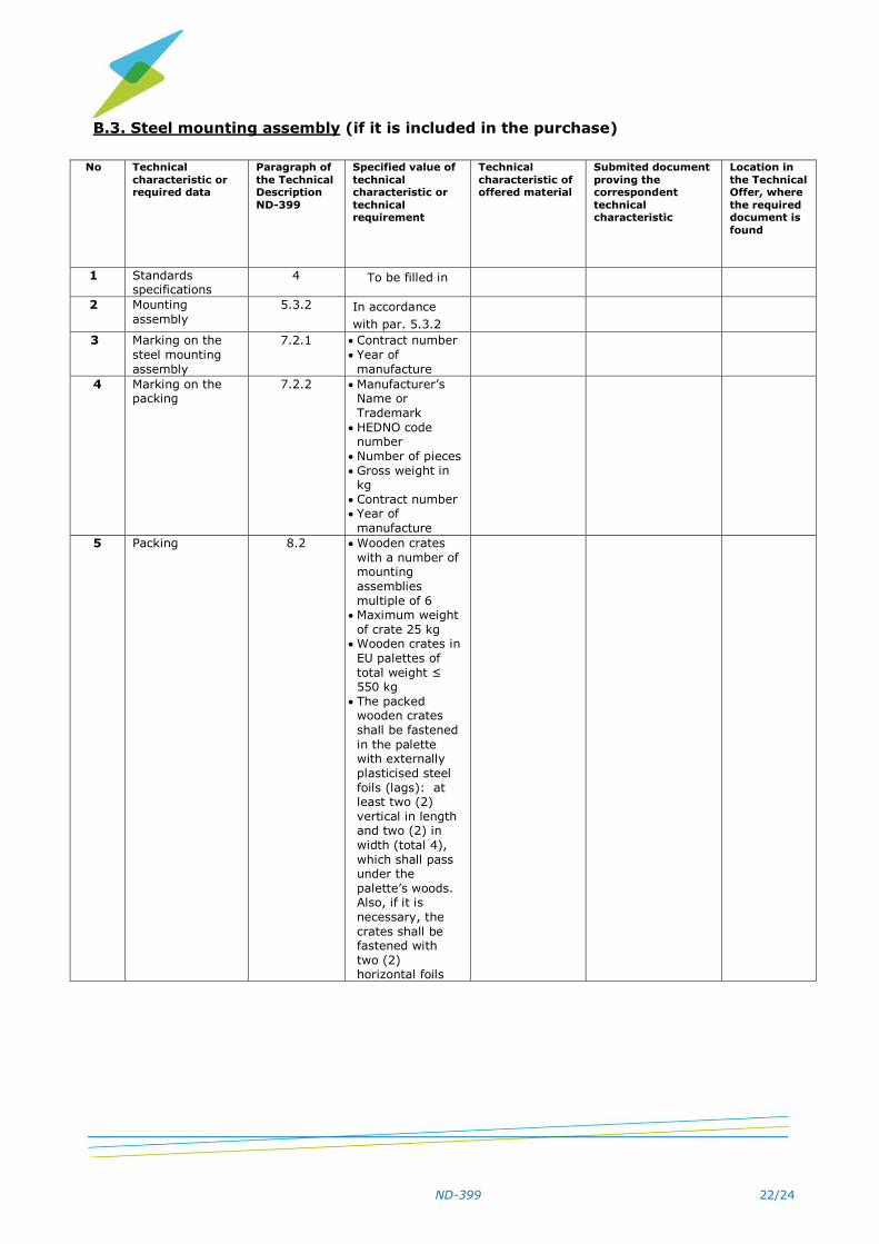
Β.3. Steel mounting assembly (if it is included in the purchase)
No Technical
characteristic or required data
Paragraph of
the Technical Description
ND-399
Specified value of
technical characteristic or
technical requirement
Technical
characteristic of offered material
Submited document
proving the correspondent
technical characteristic
Location in
the Technical Offer, where
the required document is
found
1 Standards specifications
4 To be filled in
2 Mounting
assembly
5.3.2 In accordance
with par. 5.3.2
3 Marking on the
steel mounting
assembly
7.2.1 Contract number
Year of
manufacture
4 Marking on the packing
7.2.2 Manufacturer’s Name or
Trademark
HEDNO code number
Number of pieces
Gross weight in kg
Contract number Year of
manufacture
5 Packing 8.2 Wooden crates
with a number of mounting
assemblies
multiple of 6 Maximum weight
of crate 25 kg Wooden crates in
EU palettes of
total weight ≤ 550 kg
The packed wooden crates
shall be fastened
in the palette with externally
plasticised steel
foils (lags): at least two (2)
vertical in length and two (2) in
width (total 4),
which shall pass under the
palette’s woods. Also, if it is
necessary, the
crates shall be fastened with
two (2) horizontal foils

ND-399
23/24
HEDNO TECHNICAL DESCRIPTION
ND - 399
DRAWING TITLE
Surge Arrester Mounting
on the Transformer Tank
DRAWING No
1

ND-399
24/24
HEDNO TECHNICAL DESCRIPTION
ND - 399
DRAWING TITLE
Surge Arrester Mounting Assembly
on the cross arms
DRAWING No
2