Geomorphic Mesozoic and Cenozoic evolution in the Oka-Jombolok region (East Sayan ranges, Siberia)
Upload
independentCategory
view
0download
0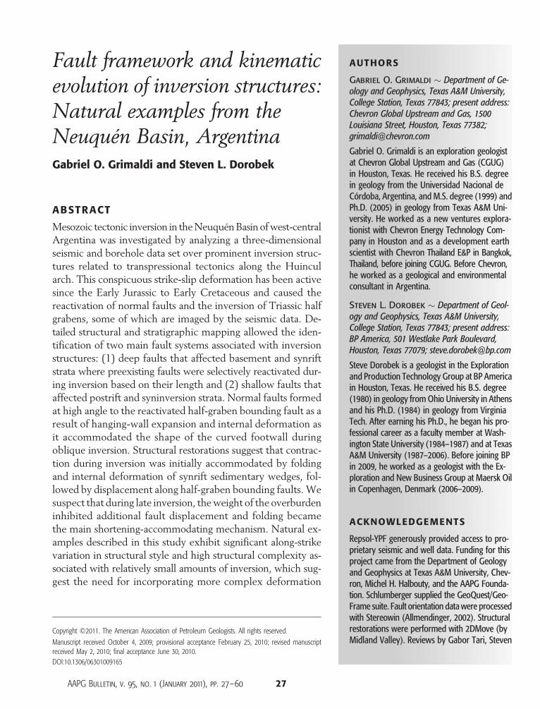
AUTHORS
Gabriel O. Grimaldi � Department of Ge-ology and Geophysics, Texas A&M University,College Station, Texas 77843; present address:Chevron Global Upstream and Gas, 1500Louisiana Street, Houston, Texas 77382;[email protected]
Gabriel O. Grimaldi is an exploration geologistat Chevron Global Upstream and Gas (CGUG)
Fault framework and kinematicevolution of inversion structures:Natural examples from theNeuquén Basin, ArgentinaGabriel O. Grimaldi and Steven L. Dorobek
in Houston, Texas. He received his B.S. degreein geology from the Universidad Nacional deCórdoba, Argentina, and M.S. degree (1999) andPh.D. (2005) in geology from Texas A&M Uni-versity. He worked as a new ventures explora-tionist with Chevron Energy Technology Com-pany in Houston and as a development earthscientist with Chevron Thailand E&P in Bangkok,Thailand, before joining CGUG. Before Chevron,he worked as a geological and environmentalconsultant in Argentina.
Steven L. Dorobek � Department of Geol-ogy and Geophysics, Texas A&M University,College Station, Texas 77843; present address:BP America, 501 Westlake Park Boulevard,Houston, Texas 77079; [email protected]
Steve Dorobek is a geologist in the Explorationand Production Technology Group at BP Americain Houston, Texas. He received his B.S. degree(1980) in geology from Ohio University in Athensand his Ph.D. (1984) in geology from VirginiaTech. After earning his Ph.D., he began his pro-fessional career as a faculty member at Wash-ington State University (1984–1987) and at TexasA&M University (1987–2006). Before joining BPin 2009, he worked as a geologist with the Ex-ploration and New Business Group at Maersk Oilin Copenhagen, Denmark (2006–2009).
ACKNOWLEDGEMENTS
Repsol-YPF generously provided access to pro-prietary seismic and well data. Funding for thisproject came from the Department of Geologyand Geophysics at Texas A&M University, Chev-ron, Michel H. Halbouty, and the AAPG Founda-
ABSTRACT
Mesozoic tectonic inversion in theNeuquénBasin ofwest-centralArgentina was investigated by analyzing a three-dimensionalseismic and borehole data set over prominent inversion struc-tures related to transpressional tectonics along the Huincularch. This conspicuous strike-slip deformation has been activesince the Early Jurassic to Early Cretaceous and caused thereactivation of normal faults and the inversion of Triassic halfgrabens, some of which are imaged by the seismic data. De-tailed structural and stratigraphic mapping allowed the iden-tification of two main fault systems associated with inversionstructures: (1) deep faults that affected basement and synriftstrata where preexisting faults were selectively reactivated dur-ing inversion based on their length and (2) shallow faults thataffected postrift and syninversion strata. Normal faults formedat high angle to the reactivated half-graben bounding fault as aresult of hanging-wall expansion and internal deformation asit accommodated the shape of the curved footwall duringoblique inversion. Structural restorations suggest that contrac-tion during inversion was initially accommodated by foldingand internal deformation of synrift sedimentary wedges, fol-lowed by displacement along half-graben bounding faults.Wesuspect that during late inversion, theweight of the overburdeninhibited additional fault displacement and folding becamethe main shortening-accommodating mechanism. Natural ex-amples described in this study exhibit significant along-strikevariation in structural style and high structural complexity as-sociated with relatively small amounts of inversion, which sug-gest the need for incorporating more complex deformation
tion. Schlumberger supplied the GeoQuest/Geo-Frame suite. Fault orientation data were processedwith Stereowin (Allmendinger, 2002). Structuralrestorations were performed with 2DMove (byMidland Valley). Reviews by Gabor Tari, Steven
Copyright ©2011. The American Association of Petroleum Geologists. All rights reserved.
Manuscript received October 4, 2009; provisional acceptance February 25, 2010; revised manuscriptreceived May 2, 2010; final acceptance June 30, 2010.DOI:10.1306/06301009165
AAPG Bulletin, v. 95, no. 1 (January 2011), pp. 27–60 27

Henry, and Frances Whitehurst resulted in sig-nificant improvements in the manuscript. TheAAPG Editor thanks the following editors fortheir work on this paper: Steven G. Henry andGabor C. Tari.
EDITOR ’S NOTE
Color versions of Figures 3–8, 12–15, and 19may be seen in the online version of this paper.
28 Mesozoic Inversion in Argentina
scenarios into analog models. Fault framework developmentand its linkage to a specific mechanism (e.g., hanging-wall de-formation because of oblique inversion) enables the predictiveanalysis of subseismic faulting and fracture distribution, whichcan impact our understanding of the petroleum systems in theNeuquén Basin’s northern embayment, especially regardingthe significant fault development within the Cuyo Group,which may impact the Los Molles petroleum system.
INTRODUCTION
Inversion structures develop when normal faults formed dur-ing a previous stage of crustal extension undergo reverse dis-placement during later contractional deformation (Haywardand Graham, 1989; Coward, 1994; Sibson, 1995). Basin in-version is commonly recognizedwhere dip-slip reversal of half-graben bounding faults produces uplift of synrift and postriftsequences (Brun and Nalpas, 1996; Buiter and Pfiffner, 2003).Inverted parts of basins are turned inside out to become posi-tive features (Hayward and Graham, 1989; Buchanan andMcClay, 1991).
Several factors affect the occurrence and style of inversionstructures: (1) capability of fault reactivation (Sibson, 1985;Etheridge, 1986; Sibson, 1995); (2) fault geometry (Buchananand McClay, 1991, 1992), preinversion geometry of the basin(Butler, 1989), (3) thermal state of the lithosphere at the timeof inversion (Sandiford, 1999; Nielsen and Hansen, 2000;Sandiford et al., 2003), and (4) plate-tectonic setting (Kluthand Coney, 1981; Ziegler et al., 1998; Marshak et al., 2000).The interplay of these factors produces complex structuralstyles, areal distribution, and timing of inversion structures, asrecognized in natural examples (Kluth and Coney, 1981;McClay, 1989; Ziegler, 1989; Homovc et al., 1995; Mancedaand Figueroa, 1995; Uliana et al., 1995; Marshak et al., 2000;Beauchamp, 2004; Chambers et al., 2004).
An inverted half graben is the simplest inversion structure(Figure 1) (Williams et al., 1989; Mitra, 1993). Its develop-ment typically involves the reactivation and potential propa-gation of preexisting extensional faults into postrift strata.Contraction is accommodated by reverse displacement alongthese faults, the development of new faults, and folding ofpreinversion and syninversion strata (cf. Koopman et al., 1987).The North Sea is a classic location for natural examples ofinverted half grabens (Badley et al., 1989; Cartwright, 1989;Hayward and Graham, 1989; Nalpas et al., 1995; Thomas andCoward, 1995). Although published studies from the North
Sea provide basin-scale descriptions of inversionpatterns, few document in detail structural andstratigraphic complexities of individual inversionstructures. Basin inversion also has been describedin other regions like the Alps (Gillcrist et al., 1987;Butler, 1989; Coward et al., 1991), Alpine foreland(Gillcrist et al., 1987; Ziegler, 1987; Ziegler et al.,1995; Cristallini et al., 1997; Kley and Monaldi,2002), Atlas Mountains (Beauchamp et al., 1996;Beauchamp et al., 1997), Ancestral Rockies (Kluth,1991; Marshak et al., 2000), Andean foreland(Dellapé and Hegedus, 1995; Homovc et al., 1995;Manceda and Figueroa, 1995; Uliana et al., 1995;Welsink et al., 1995), and SouthChina Sea (Letouzeyet al., 1990; Olson, 2001; Chambers et al., 2004)
but, again, detailed descriptions of the complexstructural and stratigraphic relationships are rarelyprovided.
Most detailed descriptions of inverted half gra-bens come from scaled analogs. Analog models ofinversion provide insight into the kinematics andgeometries of inversion under controlled conditions.These studies typically investigate two-dimensional(2-D) (cross sectional) aspects of structural devel-opment as influencedby footwall geometry (McClay,1989; Buchanan and McClay, 1991, 1992; Yamadaand McClay, 2004), the mechanical properties ofbasin-filling sediments (Buchanan andMcClay, 1991,1992; Brun andNalpas, 1996), angularity betweenearly extensional and later contractional directions
Figure 1. Conceptual model and key terms for a classical half-graben inversion structure. (A) Sequential diagrams showing the con-tractional inversion of an extensional fault. The null point (NP) moves progressively downward through the synrift sequence with increasedinversion (from Williams et al., 1989). (B) Generalized cross sections of a half graben undergoing total inversion and developing a fault-propagation fold in the postrift strata (modified from Willliams et al., 1989; Bailey et al., 2002).
Grimaldi and Dorobek 29
(Brun and Nalpas, 1996; Dubois et al., 2002), andamounts of extension and shortening (BuchananandMcClay, 1991, 1992; Keller andMcClay, 1995;Brun and Nalpas, 1996). Other analog modelingstudies have included the third dimension by in-vestigating structural development during inversionin both cross sectional and plan views. Keller andMcClay (1995) describe fault linkage patterns onthe surface of an initially extended sandbox whensubjected to coaxial contraction and showed thatthe extensional fault fabric strongly influences in-version geometry. They also argue that transfer zonesbetween adjacent extensional faults were reactivatedduring inversion.
Yamada and McClay recently investigated thestructural relationships associatedwith inversion ofthree-dimensional (3-D) (i.e., curved in map view)listric faults (Yamada andMcClay, 2003a, b; 2004).Their analog models are intended to reproducestratal and structural geometries associated withchanges in fault strike and transfer ofmaterialwithinthe hanging wall, parallel to the fault trace. Theirwork shows that fault shape greatly influencesstructural development. In addition, the 3-D in-version thrust architecture is controlled by the ge-ometry of themain fault and locations ofmaximuminversion-related uplift and synrift subsidence arecoincident (Yamada and McClay, 2004).
Despite the importance of inversion-relateddeformation relative to the development of petro-leum systems, natural examples of 3-D tectonic in-version are poorly documented andunderstood.Thegeometry of inversion structures can make themsuitable traps for hydrocarbon accumulation. Inaddition, inversion tectonics can have significanteffects on other aspects of petroleum systems. Forexample, inversion-related uplift can affect burialhistory and oil generation andmaturation, porosityevolution, fault and fracture development, migra-tion pathways, and alteration of fault scaling prop-erties (Coward, 1994).
In this study, we characterize, in full 3-D, struc-tural development associated with tectonic inver-sion in a transpressional setting. We analyzed anextensive 3-D seismic and borehole data set overa series of Mesozoic inversion structures in thepetroleum-rich Neuquén Basin of west-central Ar-
30 Mesozoic Inversion in Argentina
gentina. We use time-structure maps, fault orien-tation analysis, and structural restorations to docu-ment variations in structural styles, fault linkage andpropagation patterns, and fold development asso-ciated with inversion.
We provide natural examples of inverted halfgrabens where two main fault systems developedas a consequence of extension and oblique inver-sion. Deep faults were selectively reactivated dur-ing inversion based on their orientation and length.Shallow faultswere caused by internal hanging-walldeformation during inversion. We interpret fold-ing and internal deformation of the synrift wedgeto accommodate shortening during early stages ofinversion, followed by bounding fault reverse re-activation and propagation during later stages.
GEOLOGIC SETTING
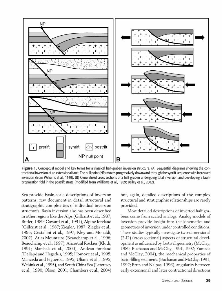
The Neuquén Basin extends from 33 to 41°S andfrom 67 to about 72°W across the Andean fore-land ofArgentina and neighboringChile (Figure 2).It is the second most important petroleum prov-ince in the country in terms of cumulative produc-tion, with about 3.4 billion bbl of oil and 21.2 tcfof gas produced as of March 2010, and remainingreserves of more than 1.1 billion bbl and 9.8 tcf ofoil and gas, respectively. In March 2010, the basinproduced at average daily rates of 260 Mbbl of oiland 2.46 bcf of natural gas from 7726 currentlyproducing wells.
The tectonic history of the basin is character-ized by two major evolutionary stages: (1) LateTriassic–Early Cretaceous backarc extension fol-lowed by (2) a Late Cretaceous–Holocene retroarcforeland setting (Dewey, 1988;Legarreta andUliana,1991; Uliana and Legarreta, 1993; Vergani et al.,1995; Franzese and Spalletti, 2001; Franzese et al.,2003). The main Triassic normal fault trends thatdeveloped during extension are oriented northeast-southwest and east-northeast–west-southwest in thesouthern part of the basin (Ramos, 1978; Verganiet al., 1995). This area is tectonically dominated bythe Huincul arch, an east-west right lateral shearzone characterized by transpressive uplift that wasactive from the Early Jurassic to Late Cretaceous
(Orchuela et al., 1981; Ploszkiewicz et al., 1984;Tankard et al., 1995; Vergani et al., 1995). TheHuincul arch divides the Neuquén Basin into twomain depocenters, known as the northern andsouthern subbasins (Figure 3).
The area investigated during this study coversthe northern subbasin along the northern flank ofthe Huincul deformation zone. In this region, LateTriassic half grabens were tectonically inverted dur-ing transpressional deformation along a restrainingbend in the Huincul arch principal displacementzone (Ploszkiewicz et al., 1984;Vergani et al., 1995;Cruz et al., 2002). Compressional stress that causedthe inversion of rift depocenters likely had a generalnorth-south orientation. The most conspicuous in-version structures in the study area are the SierraBarrosa structure (SBS) and Aguada Toledo struc-ture (ATS), which are themain focus of this study.
Prerift basement rocks in the Neuquén Basinare dominated by early Paleozoic metamorphicand igneous rocks. Prerift basement is overlain by
up to 7000 m (23,000 ft) of Mesozoic–Cenozoicstrata.
Synrift strata include deposits informally knownas “pre-Cuyo” and the lowest Cuyo Group, whichconsist mostly of siliciclastic facies that were de-posited in alluvial fan, fluvial, and lacustrine en-vironments (Legarreta and Gulisano, 1989; Urienand Zambrano, 1994) with a significant pyroclasticcomponent.
The postrift succession was deposited duringthree main transgressive-regressive cycles: (1) theToarcian-Bathonianmiddle to upper CuyoGroup;(2) the Callovian-Oxfordian Lotena Group; and(3) theKimmeridgian-AlbianMendoza andRayosogroups (Digregorio, 1972; Digregorio and Uliana,1980; Gulisano and Pando, 1981; Hinterwimmerand Jáuregui, 1985; Legarreta and Gulisano, 1989;Urien and Zambrano, 1994). Continental depositsof theUpperCretaceous (Cenomainan–Campanian)Neuquén Group cap the section in the study area.These postrift sedimentary units are bounded by
Figure 2. Generalized tectonic map of the Neuquén Basin showing main provinces and structural elements.
Grimaldi and Dorobek 31

five major unconformities of variable areal extentand duration throughout the central Neuquén Ba-sin. These unconformities, in ascending order, arereferred to as the intra-Liassic, intra-Callovian,intra-Malm, intra-Valanginian, and intra-Senonian(Figure 4). The intra-Liassic unconformity caps the
32 Mesozoic Inversion in Argentina
synrift sedimentation and is associated with upliftand erosion previous to the first Cuyo transgression.The intra-Callovian unconformity marks the firstsignificant tectonic event along the Huincul arch,which resulted in initial inversion across the studyarea. The intra-Malm unconformity is associated
Figure 3.Main structural elements of the central Neuquén Basin and location of the seismic data set. (A) Main faults associated with theHuincul arch following Mesozoic transpressional tectonics. The Huincul arch is the approximately 10-km (6-mile) wide deformation zoneindicated by the shaded line. RCEZ = Ramón Castro extension zone; HF = Huincul fault; ABF = Aguada Baguales fault; CT = Challacótrough; ATF = Aguada Toledo fault; SBF = Sierra Barrosa fault; RNFZ = Río Negro fault zone. Based on Orchuela et al. (1981), Ploszkiewiczet al. (1984), Pángaro and Bruveris (1999), Vergani et al. (1995), and Maretto and Lara (2002). (B) Composite seismic section across thesouthern Neuquén Basin showing location and style of early Mesozoic faults and associated inversion structures. Modified from Ulianaet al. (1995). Line of section shown in panel A.
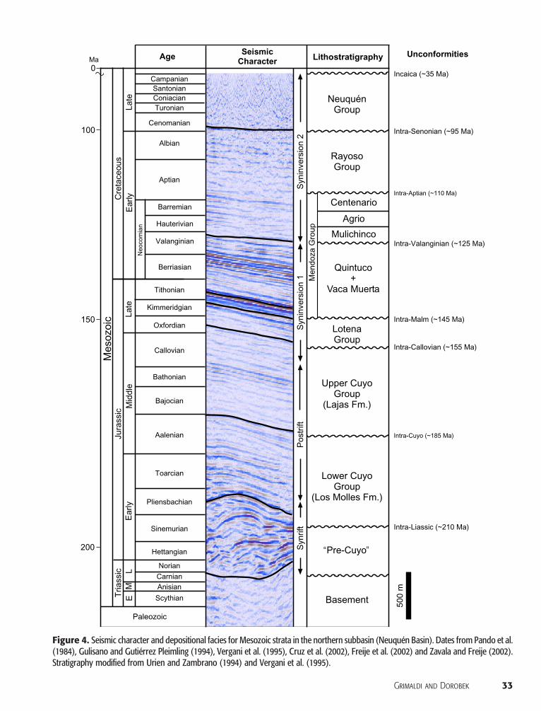
Figure 4. Seismic character and depositional facies for Mesozoic strata in the northern subbasin (Neuquén Basin). Dates from Pando et al.(1984), Gulisano and Gutiérrez Pleimling (1994), Vergani et al. (1995), Cruz et al. (2002), Freije et al. (2002) and Zavala and Freije (2002).Stratigraphy modified from Urien and Zambrano (1994) and Vergani et al. (1995).
Grimaldi and Dorobek 33
with the strongest inversion event in the area. Theintra-Valanginian and intra-Senonian unconformi-ties are the result of less intense tectonic eventsalong theHuincul arch, which resulted in uplift anderosion of Lower and Upper Cretaceous strata,respectively. Subordinate breaks in the stratigraphicrecord are observed locally as intraformational un-conformities and reflect local response to tectonism.
At least three petroleum systems have been de-fined in the Neuquén Basin associated with sourcerocks in the, from oldest to youngest, Los MollesFormation (Cuyo Group), Vaca Muerta Forma-tion (lower Mendoza Group), and Agrio Forma-tion (upper Mendoza Group). Although the VacaMuerta shales contain the largest amount of organiccarbon in the basin, the Los Molles system dom-inates in the area of interest, where mostly gas andsubordinated oil were generated and expulsed dur-ing the Late Jurassic to Early Cretaceous.
DATA AND METHODS
The seismic data set consists of two 3-D seismic re-flection surveys that cover an area of about 560 km2
(216 mi2) in the southern part of the northernsubbasin along the northern flank of the Huincularch deformation zone (Figure 3). Borehole datainclude log curves (spontaneous potential, gamma-ray, sonic, and resistivity curves) and mud-loggingreports from five exploratory wells that partiallypenetrated the Lower Jurassic section in the area.
Seismic and well data were visualized and in-terpreted in a workstation environment and usingstate-of-the-art software applications. Structural res-torations were performed on selected vertical seis-mic profiles previously converted to depth usinginterval velocities obtained from nearby wells.
RESULTS
General Description of Inversion Structures
Structural and stratigraphic mapping shows thatthe most prominent inversion structures in the
34 Mesozoic Inversion in Argentina
area are the SBS and ATS structures. The SBS isan elongated asymmetrical inversion anticline ofabout 22 km (14mi) long and a maximum of 6 km(4mi)wide (Figure 5). The sinuous fold axis plungesgently to the west and east-southeast and fold am-plitude decreases upsection, which results from thecombination of parallel-style folding with signifi-cant erosion at certain stratigraphic levels (i.e.,folded unconformities). Two culminations withinthe SBS are linked by a saddle whose width in-creases at higher stratigraphic levels within thepostrift strata. The western culmination exhibitsthe largest amount of uplift and has a north- tonorth-northeast–dipping axial plane and a southernlimb cut by a southward-verging fault zone thatchanges with depth from reverse to normal. Thesouthern limb of the SBS is defined by an east-westsyncline, whereas the northern limb is locally af-fected by the ATS to the north (Figure 5).
A master reverse fault cuts the southern limbof the SBS and affects both basement and overly-ing strata. The master fault is mappable as a singlesurface on seismic sections with associated short-cut faults or antithetic normal faults in some partsof the structure (Figure 6). The master fault zonedoes not cut completely through the steeper south-ern limb of the SBS anticline, although upsectionflattening of the fault plane is observed in someparts of the structure. Themaster fault is listric andhas an average dip angle of about 70° to the northin the uppermost postrift section.
Another prominent inversion structure is lo-cated on the northern flank of the SBS. The ATS isan elongated asymmetrical inversion anticline thatextends in an east-west direction for about 10 km(6 mi) and has a maximum width of about 3 km(2mi) (Figure 5). The fold axis, located about 5 km(3 mi) north of the SBS axis, plunges gently to theeast and west. The amplitude of the anticline de-creases upsection, mostly because of parallel-stylefolding (angular unconformities within the Cuyoand Mendoza groups are more subtle than for theSBS). A northward-dipping half-graben–boundingfault was reactivated in a reverse sense during in-version and cuts upsection into the postrift strata,resulting in an inversion-related fault-propagationfold. No displacement across this fault is observed

at the lower Mendoza Group level, although sig-nificant folding of these and shallower strata isapparent. The ATS main bounding fault is listric,
with northward dip angles ranging from 40 to 70°and is imaged as a thin zone of discrete deforma-tion that cuts through the uppermost CuyoGroup.
Figure 5. Time-structure maps of the Sierra Barrosa (SBS) and Aguada Toledo (ATS) inversion structures at the top of the lower CuyoGroup (A) and base of Vaca Muerta Formation (B). Contour interval = 50 ms. Note how north-south–oriented faults are fewer in number,have shorter lengths in plan view, and have less apparent heave at the shallower Vaca Muerta level than at the deeper lower Cuyo level.See Figure 3 for location. Cross section BB′ is shown in Figure 6.
Grimaldi and Dorobek 35

Seismic-Stratigraphic Relationships
TheSBS andATS record important tectonic eventsthat occurred during the Late Triassic to LateCretaceous and predate the main phases of theAndean orogeny. Five main tectonostratigraphic
36 Mesozoic Inversion in Argentina
units were identified: prerift basement, synrift, post-rift, syninversion 1, and syninversion 2 (Figure 4).
Synrift strata (pre-Cuyo to lowest Cuyo strata)are imaged as wedge-shaped intervals characterizedby a complex seismic signature, where divergentcontinuous reflections are intermixed with chaotic
Figure 6. Uninterpreted and in-terpreted seismic section BB′through the western part of theSierra Barrosa structure, depictingsome structural elements (seetext for description and Figure 5for line of section).
to almost reflection-free packages that are boundedby faults or onlap against basement. The upper partof the synrift interval is imaged as continuous re-flections corresponding to basal strata of the LosMolles Formation. In outcrop, basal synrift strataconsist of intermixed volcanic and coarse continen-tal siliciclastic strata that were deposited in iso-lated depocenters (Gulisano and Legarreta, 1987;Legarreta et al., 1993; Vergani et al., 1995).
Lowermost postrift strata correspond to theCuyo Group (deep-marine shales and interbed-ded turbiditic sandstones of the upper Los MollesFormation), which are overlain by southeast-to-northwest–prograding shoreface and deltaic de-posits of the Lajas Formation (Figure 4).
A stratigraphic record of pulsed basin inversionexists throughout most of the postrift section andis seismically expressed by multiple angular un-conformities across the crest of inversion highsand thin stratal packages that onlap against bothlimbs of inversion anticlines. Syninversion stratawere divided into two units: syninversion 1 (strong)and syninversion 2 (mild). The lower part of syn-inversion 1 strata consists of fluvial to deltaic depositsof the lower Lotena Group (discontinuous, sub-parallel, and low-amplitude reflections), which areoverlain by basinal shales and northwest-progradingcarbonate facies of the lowerMendozaGroup (high-amplitude, continuous, and parallel reflections).More significant inversion, however, is recordedwithin this unit by the upper part of the QuintucoFormation (lowerMendozaGroup) along the limbsof the SBS and ATS. Onlap of high-amplitudecontinuous upper Quintuco reflections, togetherwith thickness changes across the anticlines’ crests,record inversion and uplift of the SBS and ATSduring the Berriasian and Valanginian. The intra-Valanginian unconformity truncates syninversion1 strata and separates them from syninversion 2strata above, which comprise the upper Mendoza,Rayoso, andNeuquén groups. These are onlymildlyaffected by inversion-related folding and uplift,and stratal patterns show that the intensity of in-version deformation waned upsection (Figure 6).Syninversion 2 strata contain another significantangular unconformity (intra-Senonian), which re-flects renewed folding and uplift during the Ceno-
manian. This tectonostratigraphic unit is representedby relatively discontinuous and low-amplitude re-flections characteristic of continental deposits likethe Neuquén Group (0–400 ms two-way travel-time [TWT]; Figure 4).
Fault Development
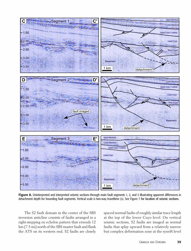
Fault Framework for SBS and ATSThe structural framework that developed in con-junction with extension during rifting and latercontraction during inversion can be divided intotwo main fault systems. A “deep” fault system af-fects mostly basement and synrift strata and has ageneral east-west orientation. It consists of reac-tivated and nonreactivated extensional faults thatcomprised the original rift fabric plus newly formedfaults that accommodated part of the shortening as-sociated with inversion (i.e., backthrusts and “short-cut” faults). Some of the synrift faults bound wedge-shaped synrift strata. The largest invertedhalf grabensof the SBS are bounded by a composite extensionalfault system composed of three main segments andtwo accommodation zones (Figure 7). Listric half-graben–bounding faults apparently join detachmentlevels at different depths. Bounding-fault segment2 seems to be the deepest fault and is imaged as aclear reflection that flattens into a horizontal de-tachment at about 3.75 s TWT (Figure 8). Seg-ment 2 also bounds the largest and thickest synriftdepocenter and corresponds to the part of the SBSstructure that underwentmaximumuplift. Bounding-fault segments 1 and 3 flatten at shallower levelsbased on their dip angles at the synrift and postriftlevels, with detachment levels interpreted to bebetween 3.00 and 3.25 s TWT (Figure 8). Synriftwedges bounded by segments 1 and 3 have similarthicknesses, but uplift caused by inversion is greaterfor the depocenter bounded by segment 3.
Faults within the synrift section are classifiedinto three types based on their interpreted kine-matic history: D1 (synrift faults not reactivatedduring inversion), D2 (synrift faults reactivatedduring inversion), andD3 (new syninversion faults).The strike of most faults of each type is very con-sistent, with D3 faults deviating the least from the
Grimaldi and Dorobek 37

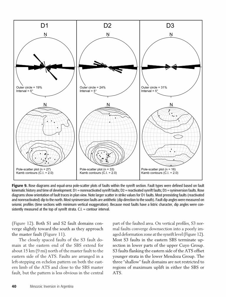
overall east-west orientation. Fault orientation anal-ysis shows that most synrift faults (i.e., D1 and D2faults) dip toward the north, whereas D3 synin-version faults dip southward, with D1 faults ex-hibiting larger scatter in fault attitude (Figure 9)(Grimaldi, 2005).
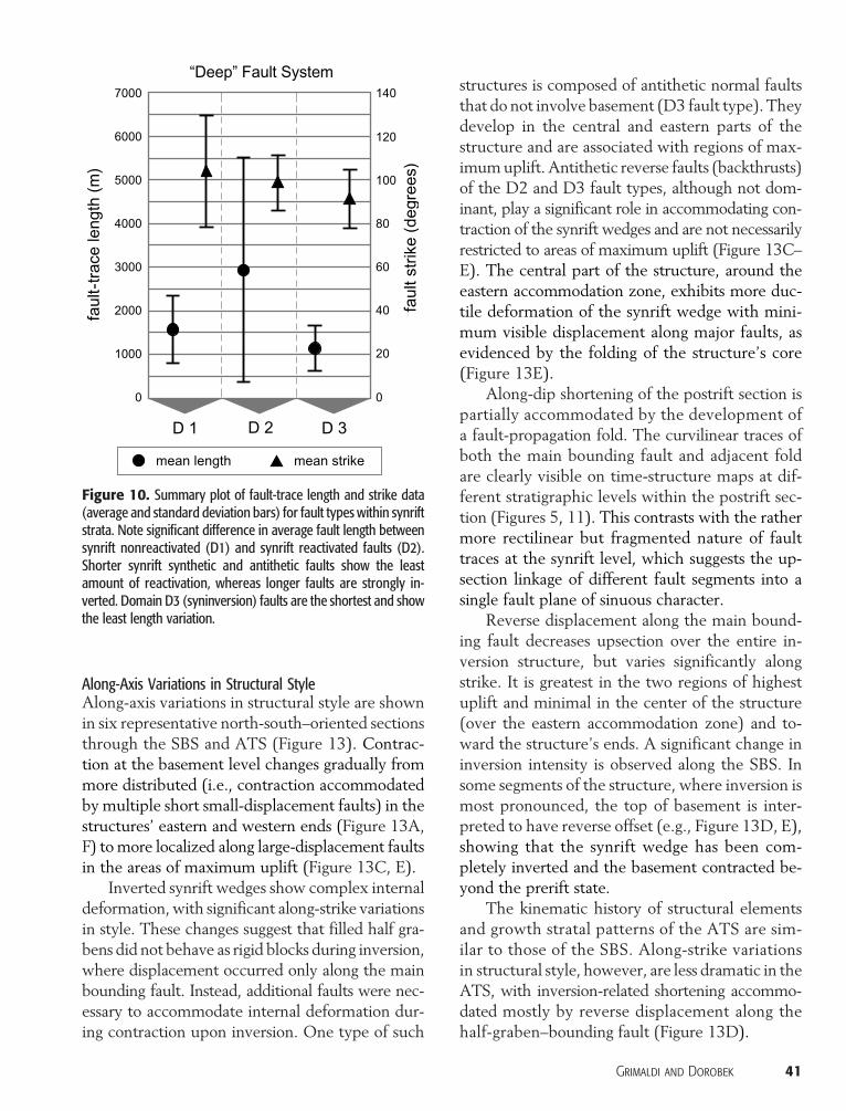
Average strike for the three fault types differsslightly, with a difference of about 5° between D1and D2 faults (Figure 10). Nonreactivated synriftfaults (D1) are, on average, significantly shorterthan their reactivated counterparts (D2 faults), al-though differences in length are smaller (i.e., lowerstandard deviation). Syninversion faults (D3) are theshortest and have the least scatter in length values.Synrift reactivated faults (D2) exhibit the greatestlength variability, ranging between 0.7 (0.4 mi) and12.2 km (7.6 mi). Smaller synrift synthetic and an-tithetic faults show the least amount of reactiva-tion, whereas larger faults are strongly inverted.
38 Mesozoic Inversion in Argentina
Syninversion faults that cut the postrift sec-tion showmarkeddifferences in geometry, attitude,and distribution with respect to faults that cut thesynrift section. Postrift strata are cut by normal faultsthat are oriented north-south to north-northwest–south-southeast, dip predominantly to the west,and are mostly restricted to the SBS hanging wall(Figure 11). These faults are grouped into threeroughly north-south–trending domains that are rec-ognizable at different stratigraphic levels on time-structure maps. The westernmost fault domain inthe SBS hanging wall (S1 faults; Figure 11) consistsof northwest-southeast–striking faults that extendfor about 10 km (6mi) north of themaster boundingfault. S1 faults exhibit a crude left-stepping enechelon pattern in map view that becomes less ob-vious southwestward, where S1 faults transition intoa series of faults associated with another large in-version structure south of the SBS.
Figure 7. Time-structure map at the top of pre-Cuyo (synrift) illustrating the characteristics of the “deep” fault system affecting the SBSand ATS. Contour interval = 50 ms.
The S2 fault domain in the center of the SBSinversion anticline consists of faults arranged in aright-stepping en echelon pattern that extends 12km (7.5mi) north of the SBSmaster fault and flankthe ATS on its western end. S2 faults are closely
spaced normal faults of roughly similar trace lengthat the top of the lower Cuyo level. On verticalseismic sections, S2 faults are imaged as normalfaults that splay upward from a relatively narrowbut complex deformation zone at the synrift level
Figure 8. Uninterpreted and interpreted seismic sections through main fault segments 1, 2, and 3 illustrating apparent differences indetachment depth for bounding fault segments. Vertical scale is two-way traveltime (s). See Figure 7 for location of seismic sections.
Grimaldi and Dorobek 39
(Figure 12). Both S1 and S2 fault domains con-verge slightly toward the south as they approachthe master fault (Figure 11).
The closely spaced faults of the S3 fault do-main at the eastern end of the SBS extend forabout 15 km (9mi) north of themaster fault to theeastern side of the ATS. Faults are arranged in aleft-stepping en echelon pattern on both the east-ern limb of the ATS and close to the SBS masterfault, but the pattern is less obvious in the central
40 Mesozoic Inversion in Argentina
part of the faulted area. On vertical profiles, S3 nor-mal faults converge downsection into a poorly im-ageddeformationzoneat the synrift level (Figure 12).Most S3 faults in the eastern SBS terminate up-section in lower parts of the upper Cuyo Group.S3 faults flanking the eastern side of the ATS offsetyounger strata in the lower Mendoza Group. Thethree “shallow” fault domains are not restricted toregions of maximum uplift in either the SBS orATS.
Figure 9. Rose diagrams and equal-area pole-scatter plots of faults within the synrift section. Fault types were defined based on faultkinematic history and time of development. D1 = nonreactivated synrift faults; D2 = reactivated synrift faults; D3 = syninversion faults. Rosediagrams show orientation of fault traces in plan view. Note larger scatter in strike values for D1 faults. Most preexisting faults (reactivatedand nonreactivated) dip to the north. Most syninversion faults are antithetic (dip direction to the south). Fault dip angles were measured onseismic profiles (time sections with minimum vertical exaggeration). Because most faults have a listric character, dip angles were con-sistently measured at the top of synrift strata. C.I. = contour interval.
Along-Axis Variations in Structural StyleAlong-axis variations in structural style are shownin six representative north-south–oriented sectionsthrough the SBS and ATS (Figure 13). Contrac-tion at the basement level changes gradually frommore distributed (i.e., contraction accommodatedby multiple short small-displacement faults) in thestructures’ eastern and western ends (Figure 13A,F) tomore localized along large-displacement faultsin the areas of maximum uplift (Figure 13C, E).
Inverted synrift wedges show complex internaldeformation, with significant along-strike variationsin style. These changes suggest that filled half gra-bens did not behave as rigid blocks during inversion,where displacement occurred only along the mainbounding fault. Instead, additional faults were nec-essary to accommodate internal deformation dur-ing contraction upon inversion. One type of such
structures is composed of antithetic normal faultsthat do not involve basement (D3 fault type). Theydevelop in the central and eastern parts of thestructure and are associated with regions of max-imumuplift. Antithetic reverse faults (backthrusts)of the D2 and D3 fault types, although not dom-inant, play a significant role in accommodating con-traction of the synrift wedges and are not necessarilyrestricted to areas of maximum uplift (Figure 13C–E). The central part of the structure, around theeastern accommodation zone, exhibits more duc-tile deformation of the synrift wedge with mini-mum visible displacement along major faults, asevidenced by the folding of the structure’s core(Figure 13E).
Along-dip shortening of the postrift section ispartially accommodated by the development ofa fault-propagation fold. The curvilinear traces ofboth the main bounding fault and adjacent foldare clearly visible on time-structure maps at dif-ferent stratigraphic levels within the postrift sec-tion (Figures 5, 11). This contrasts with the rathermore rectilinear but fragmented nature of faulttraces at the synrift level, which suggests the up-section linkage of different fault segments into asingle fault plane of sinuous character.
Reverse displacement along the main bound-ing fault decreases upsection over the entire in-version structure, but varies significantly alongstrike. It is greatest in the two regions of highestuplift and minimal in the center of the structure(over the eastern accommodation zone) and to-ward the structure’s ends. A significant change ininversion intensity is observed along the SBS. Insome segments of the structure, where inversion ismost pronounced, the top of basement is inter-preted to have reverse offset (e.g., Figure 13D, E),showing that the synrift wedge has been com-pletely inverted and the basement contracted be-yond the prerift state.
The kinematic history of structural elementsand growth stratal patterns of the ATS are sim-ilar to those of the SBS. Along-strike variationsin structural style, however, are less dramatic in theATS, with inversion-related shortening accommo-dated mostly by reverse displacement along thehalf-graben–bounding fault (Figure 13D).
Figure 10. Summary plot of fault-trace length and strike data(average and standard deviation bars) for fault types within synriftstrata. Note significant difference in average fault length betweensynrift nonreactivated (D1) and synrift reactivated faults (D2).Shorter synrift synthetic and antithetic faults show the leastamount of reactivation, whereas longer faults are strongly in-verted. Domain D3 (syninversion) faults are the shortest and showthe least length variation.
Grimaldi and Dorobek 41

Evidence for Fault Interactions during Extension and InversionCareful analyses of synrift and syninversion faultsystems and growth strata are necessary to evalu-ate the relative influence of preexisting faults onlater inversion. To approximate the preinversionconfiguration of synrift half grabens that form thecore of the SBS, a traverse seismic section in mid–hanging-wall position through the structure wasflattened at the top of the synrift strata (Figure 14).Two main depocenters, separated by an accommo-dation zone, are obvious on the flattened seismicsection. The western depocenter is significantly larg-er. Onlap of basal synrift strata against basement isapparent on the flattened sections, as well as di-vergent stratal patterns within the synrift fill. Thetop of the synrift wedge is downlapped by lowerCuyo strata that apparently progradated from eastto west across filled half-graben depocenters dur-ing early postrift stages. Lateral continuity of late
42 Mesozoic Inversion in Argentina
synrift strata across the eastern accommodationzone indicates half-graben coalescence during ex-tension, probably through a breached relay ramp.Early synrift deposition in distinct depocenters isclearly evidenced by onlapping reflections withineach half graben. This arrangement of synrift faultsystems and accommodation zones contrasts withthe single through-going curved fault zone thatdefines the southern boundary of the SBS inver-sion anticline (Figures 5, 11). The sinuous char-acter of this fault zone, as well as the geometry ofthe anticline’s axial plane, however, are related tothe location of the main basin-bounding exten-sional fault segments and accommodation zones.In addition, the areas of greatest inversion in eachsubstructure of the SBS and ATS coincide withthe thickest parts of the synrift wedges, whereasless inversion occurred along the inferred synriftaccommodation zones.
Figure 11. Time-structure map at the top of lower Cuyo Group (contour interval = 50 ms), with “shallow” fault domains (encircled bydashed gray line) interpreted at this stratigraphic level. Fault domains S1, S2, and S3 group faults with approximately north-southorientation affecting the SBS hanging wall and extending northward through the ATS.

Kinematics
The viability of the structural interpretation of theSBS was tested by balancing and restoring a crosssection through the structure to its preextensionalstage. This analysis contributed to a better under-standing of the geologic evolution of the structureand allowed the estimation of amounts of exten-sion and contraction across the structure from theLate Triassic to Late Cretaceous. Restoration alsocontributed to visualizing stratal geometries beforeand during the different Mesozoic inversion events.The western depocenter of the SBS was chosenfor restoration because the amount of inversion isgreatest there and the shape of the master fault atdepth is best imaged.
Tectonic Transport DirectionsA balanced cross section should be ideally con-structed in the direction of tectonic transport, which
must be estimated based on kinematic indicators orstructural features. For inverted rift basins, how-ever, the transport direction is especially difficultto estimate because extension and contractionmay not be coaxial. Careful selection of transportdirection(s)minimizes the departure from the plane-strain constraint for 2-D restorations. If the an-gle between the restored cross section and thedirection of extension is less than 25°, then theerror in the estimated amount of extension willbe less than 10% with respect to an ideally ori-ented section (Dula, 1991; Hill and Cooper, 1996).Applying the same concept to both contractionand extension directions, a cross section can be re-stored for transport directions up to 50° apart, ifthe cross section bisects the angle (Hill andCooper,1996).
To determine the extensional transport direc-tion, we applied the dip analysis method devel-oped by Scott at al. (1994), in which true dip
Figure 12. Uninterpreted and interpreted representative seismic profiles of “shallow” fault domains S1 (FF′), S2 (GG′), and S3 (HH′).Vertical displacement along the largest faults is greatest (∼50 ms) at the top of lower Cuyo horizon and diminishes upsection anddownsection. Profiles are subparallel to the main bounding fault zone. See Figure 11 for location.
Grimaldi and Dorobek 43

Figure 13. Uninterpreted and interpreted seismic profiles A–F through the SBS. Insets show the location of seismic sections and faultsat the top of the synrift level. B = Basement; SR = synrift strata; PR = postrift strata; SI1 = syninversion 1 strata; SI2 = syninversion 2strata; TWT = two-way traveltime.
44 Mesozoic Inversion in Argentina
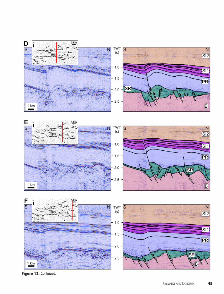
Figure 13. Continued.
Grimaldi and Dorobek 45
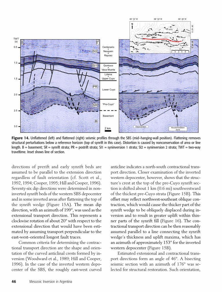
directions of prerift and early synrift beds areassumed to be parallel to the extension directionregardless of fault orientation (cf. Scott et al.,1992, 1994;Cooper, 1995;Hill andCooper, 1996).Seventy-six dip directions were determined in non-inverted synrift beds of the western SBS depocenterand in some inverted areas after flattening the top ofthe synrift wedge (Figure 15A). The mean dipdirection, with an azimuth of 199°, was used as theextensional transport direction. This represents aclockwise rotation of about 20° with respect to theextensional direction that would have been esti-mated by assuming transport perpendicular to theeast-west–oriented longest fault traces.
Common criteria for determining the contrac-tional transport direction are the shape and orien-tation of the curved anticlinal crests formed by in-version (Woodward et al., 1989; Hill and Cooper,1996). In the case of the inverted western depo-center of the SBS, the roughly east-west curved
46 Mesozoic Inversion in Argentina
anticline indicates a north-south contractional trans-port direction. Closer examination of the invertedwestern depocenter, however, shows that the struc-ture’s crest at the top of the pre-Cuyo synrift sec-tion is shifted about 1 km (0.6 mi) southwestwardof the thickest pre-Cuyo strata (Figure 15B). Thisoffset may reflect northwest-southeast oblique con-traction, which would cause the thicker part of thesynrift wedge to be obliquely displaced during in-version and to result in greater uplift within thin-ner parts of the synrift fill (Figure 16). The con-tractional transport direction can be then reasonablyassumed parallel to a line connecting the synriftwedge’s thickness and uplift maxima, which hasan azimuth of approximately 153° for the invertedwestern depocenter (Figure 15B).
Estimated extensional and contractional trans-port directions form an angle of 46°. A bisectingseismic section with an azimuth of 176° was se-lected for structural restoration. Such orientation,
Figure 14. Unflattened (left) and flattened (right) seismic profiles through the SBS (mid–hanging-wall position). Flattening removesstructural perturbations below a reference horizon (top of synrift in this case). Distortion is caused by nonconservation of area or linelength. B = basement; SR = synrift strata; PR = postrift strata; SI1 = syninversion 1 strata; SI2 = syninversion 2 strata; TWT = two-waytraveltime. Inset shows line of section.
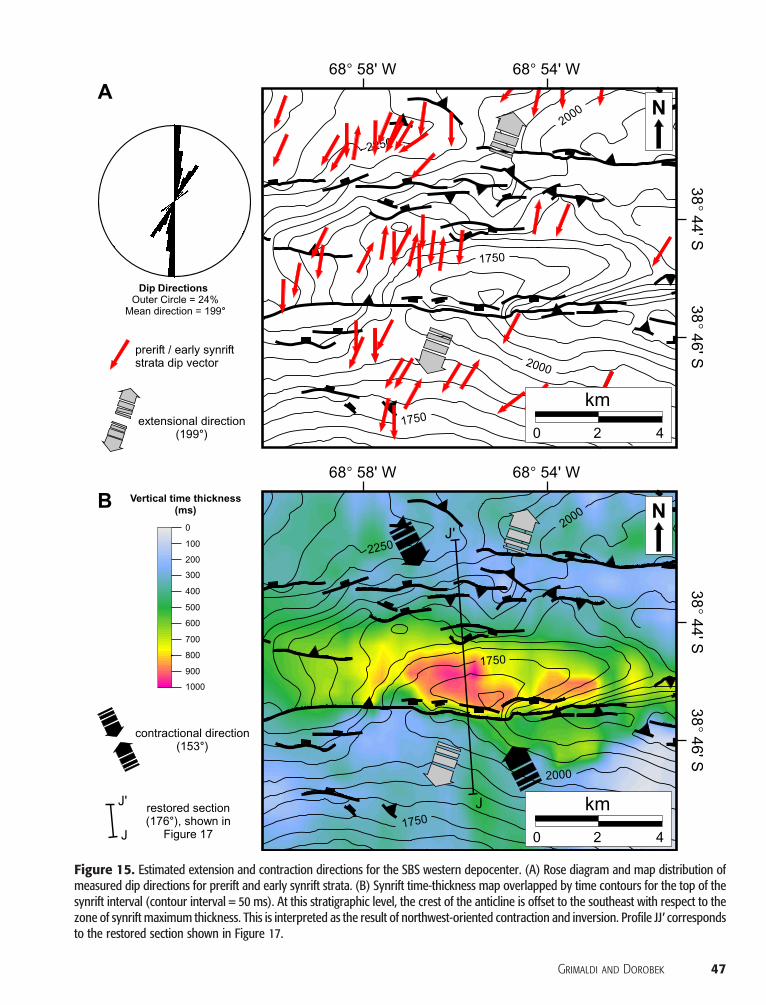
Figure 15. Estimated extension and contraction directions for the SBS western depocenter. (A) Rose diagram and map distribution ofmeasured dip directions for prerift and early synrift strata. (B) Synrift time-thickness map overlapped by time contours for the top of thesynrift interval (contour interval = 50 ms). At this stratigraphic level, the crest of the anticline is offset to the southeast with respect to thezone of synrift maximum thickness. This is interpreted as the result of northwest-oriented contraction and inversion. Profile JJ′ correspondsto the restored section shown in Figure 17.
Grimaldi and Dorobek 47

within 25° from contraction and extension direc-tions, should result in restorationswith a small errorin the estimated amount of extension and shortening.
Section Restoration and Timing of DeformationThe seismic profile selected for structural restora-tion was converted to depth using a velocity modelconsisting of 12 layers. Average interval velocitieswere assigned to each layer based on dominant li-thology and sonic-log data from nearby wells. The1:1 depth-converted section was digitized and se-quentially undeformed at different stratigraphichorizons to show development of the hanging-wallanticline and progressive displacement along themaster fault.
Restorations were done using a combinationof algorithms within the 2DMove software pack-age. The algorithms were selected based on theneed to maintain fault geometry and area-balanceconstraints instead of assuming that certain foldingmechanisms are critical to the restoration.
During successive restoration stages, a part ofthe sedimentary column was stripped off, and un-derlying units were decompacted and isostaticallyadjusted. The results of nine stages of restorationand backstripping are shown in Figure 17 and sub-sequently summarized in a forward fashion to char-acterize the kinematic evolution of the structurefrom the Late Triassic to Early Cretaceous. Further
48 Mesozoic Inversion in Argentina
details about the restoration algorithms used andmodel assumptions are described byGrimaldi (2005).
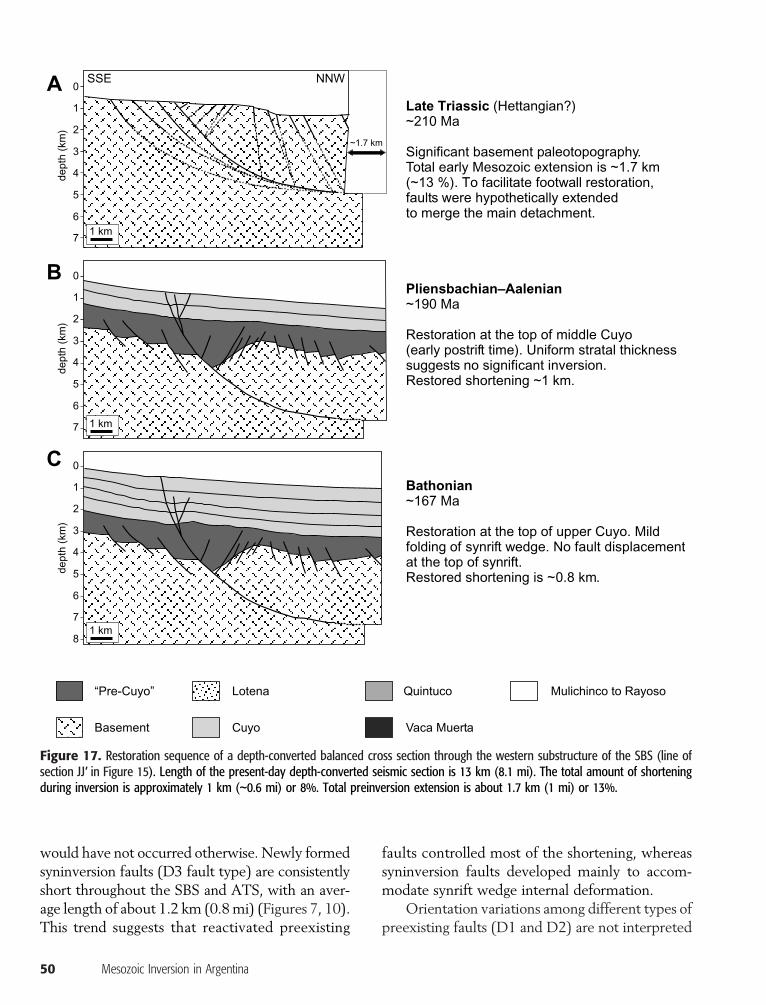
Restoration to the Late Triassic prerift stageshows a total extension of 1.7 km (1.1 mi) withsignificant basement paleotopography (Figure 17A).This antecedent relief is seismically expressed byonlapping early synrift strata.
The early postrift stage (top of themiddleCuyoGroup; Figure 17B) shows that no significant in-version of the SBS occurred during the Early Ju-rassic (Pliensbachian to early Aalenian). This is re-flected by the constant thickness and dip angle oflower to middle Cuyo strata and lack of offsetacross the master fault.
Restoration at the top of the Cuyo Group (syn-inversion 1; Figure 17C) shows incipient folding ofpre-Cuyo and lower Cuyo strata, suggesting initi-ation of inversion by Bathonian to early Calloviantime. No displacement along the master fault isobserved at the top of the synrift strata, althoughthe amount of extensional displacement at the topof basement has reduced. This step required re-construction of the missing section eroded fromthe crest of the SBS during development of theintra-Callovian unconformity. The section addedwas estimated from thickness of the Cuyo Groupin noninverted areas.
Thickness adjustment of the Lotena Groupcaused by the intra-Malmunconformitywas needed
Figure 16. Contractional trans-port direction in an inverted halfgraben bounded by a curvedlistric fault. Contour lines illus-trate topography at the top ofsynrift strata. (A) Development ofthe half graben. (B) Invertedsynrift wedge with maximumcompressive stress parallel to theoriginal extension direction. Thethickest portion of the synriftwedge coincides with the regionof greater uplift. (C) Inverted syn-rift wedge with maximum com-pressive stress forming an anglewith the original extension direc-
tion. The region of greater uplift isoffset with respect to the thickestportion of the synrift wedge.
before performing the restoration at the top of thisunit (Oxfordian–early Kimmeridgian; Figure 17D).Increased shortening during this inversion stagewas accommodated by folding at the top of synriftand early postrift levels. Displacement along themaster fault at the top of synrift strata is incipient.
Folding of the entire section and clear reversedisplacement along the master fault are noticeableon the restored section at the top of TithonianVacaMuerta Formation (lowest Mendoza Group; syn-inversion 1). These strata mark the most importantflooding event in the basin, with uniform thicknesssuggesting tectonic quiescence (Figure 17E).
The Quintuco Formation (lower MendozaGroup) comprisesmost of the syninversion strata inthe SBS, partially eroded by the intra-Valanginianunconformity. Restoration at the top of this unitrequired estimation of Quintuco original thicknessbased on deposition in nearby noninverted areasand on growth-strata geometries (e.g., onlap ontothe SBS limbs indicating syntectonic depositionand thinning over the structure’s crest). The Quin-tuco Formation was then restored to estimate theamount of shortening and structural configurationbefore the Valanginian inversion (Figure 17F).
Further folding of the postrift section and in-creased reverse displacement along themaster faultare noticeable on the restored section at the top ofRayoso Group (syninversion 2; Figure 17G).
DISCUSSION
Faulting Associated with Inversion
Differential Uplift and Detachment DepthSignificant along-strike variation occurs in theamount of uplift in the substructures that com-prise the SBS. This may be related to differences indetachment depths for the different half-graben–bounding fault segments. Coincidence of the deep-est detachment level along segment 2 (Figure 8)with the region of maximum uplift is consistentwith observations from analog models (Buchanan,1991; Bulnes and McClay, 1999). For deeper de-tachment levels, the same amount of shorteningwill cause a larger volume of material to be up-
lifted above the preinversion regional datum. Forsynrift wedges with similar volume, those withdeeper detachments will bemore strongly inverted.In the SBS, the apparent volume of synrift depo-centers bounded by fault segments 1 and 3 aresimilar, but uplift is greater for the depocenterbounded by the deeper segment 3. Greatest upliftalong segment 2 may be the combined result of aslightly bigger synrift wedge and the deepest de-tachment level. Different detachment levels can,therefore, occur within a single inversion structure,which may be controlled by the original segmen-tation of older extensional faults.
Trends in Fault ReactivationThe two principal inversion structures identifiedin the study area, SBS and ATS, present a faultframework that combines nonreactivated structureswith syninversion reactivated and newly formedfaults. The “deep” fault system is characterized bya significant difference in fault-trace length, dipangle, and, to a lesser degree, orientation betweennonreactivated (D1) and reactivated (D2) synriftextensional faults (Figure 9).
The occurrence of a few fault segments that aresignificantly larger than the rest is a consequence ofsome faults propagating and linking at the expenseof others during extension (Kim and Sanderson,2005). The data show that the larger synrift masterfault segments were preferentially reactivated, ac-commodating much of the contractional strain dur-ing inversion with minimum reverse displacementalong smaller faults. Mean fault-trace lengths ofabout 3 km (2mi) and 1.5 km (1 mi) for D1 faultsand D2 faults, respectively (Figure 10), suggesta threshold length value between 1.5 km (1 mi)and 3 km (2 mi) above which faults were reverse-reactivated during inversion, whereas faults smallerthan the thresholdmay ormay not have reactivated.A similar trend has been observed at a smaller scale(hundreds ofmeters) in outcrop studies where largerfaults, assumed to have lower frictional strengthbecause of the formation of a thicker fault gauge,are more likely to undergo reverse reactivation(Marone, 1995; Kelly et al., 1999). However, someof the D2 faults may grow during inversion and linkwith D1 segments, triggering their reactivation that
Grimaldi and Dorobek 49
would have not occurred otherwise. Newly formedsyninversion faults (D3 fault type) are consistentlyshort throughout the SBS and ATS, with an aver-age length of about 1.2 km (0.8mi) (Figures 7, 10).This trend suggests that reactivated preexisting
50 Mesozoic Inversion in Argentina
faults controlled most of the shortening, whereassyninversion faults developed mainly to accom-modate synrift wedge internal deformation.
Orientation variations among different types ofpreexisting faults (D1 and D2) are not interpreted
Figure 17. Restoration sequence of a depth-converted balanced cross section through the western substructure of the SBS (line ofsection JJ′ in Figure 15). Length of the present-day depth-converted seismic section is 13 km (8.1 mi). The total amount of shorteningduring inversion is approximately 1 km (∼0.6 mi) or 8%. Total preinversion extension is about 1.7 km (1 mi) or 13%.
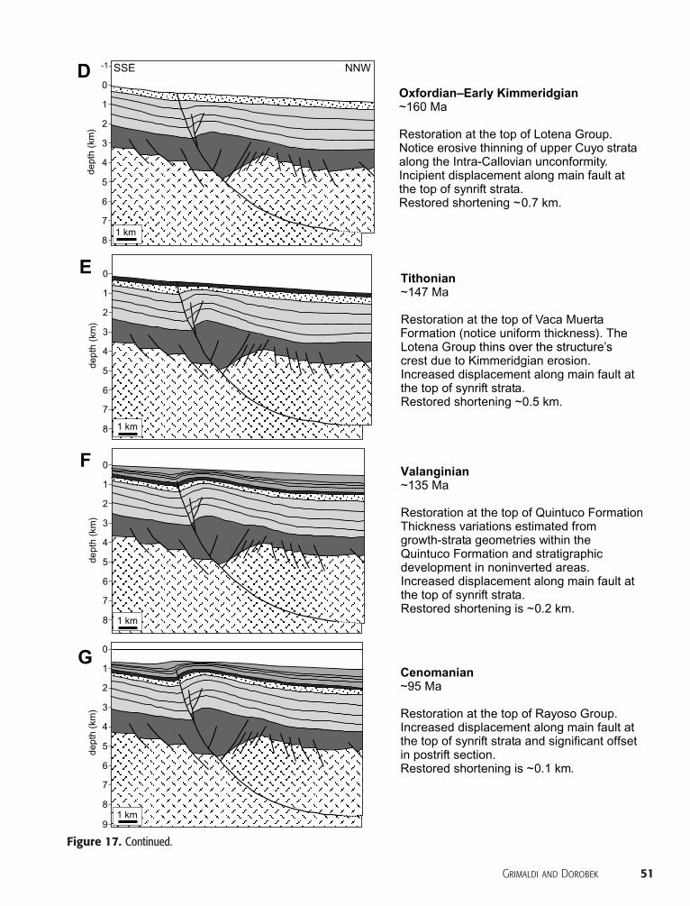
Figure 17. Continued.
Grimaldi and Dorobek 51
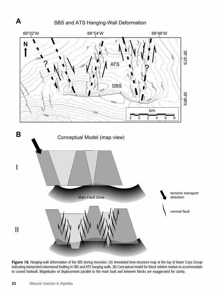
Figure 18. Hanging-wall deformation of the SBS during inversion. (A) Annotated time-structure map at the top of lower Cuyo Groupindicating interpreted extensional faulting in SBS and ATS hanging walls. (B) Conceptual model for block relative motion to accommodateto curved footwall. Magnitudes of displacement parallel to the main fault and between blocks are exaggerated for clarity.
52 Mesozoic Inversion in Argentina
to influence fault reactivation significantly. Thewider range of strike and dip angle values for synriftnonreactivated faults (D1), however, may con-tribute in part to their behavior because of greaterdeparture from optimum orientations (Figure 9).
Coalescent synrift wedges on flattened seismicprofiles through SBSmain depocenters indicate faultlinkage during extension (Figure 14). The develop-ment of accommodation zones between boundingfault segments produced a zone of distributed de-formation during the extensional phase. During thecontractional phase, however, fault systems in ac-commodation zones evolved into a through-goingreverse fault at postrift and syninversion strati-graphic levels. The correspondence between mas-ter fault bends, structure crests, and extensionalaccommodation zones evidences the fundamentalcontrol of synrift fault architecture on inversion
geometry. In this way, the displacement-transferzones that developed during extension remained ac-tive during contraction (Keller andMcClay, 1995),resulting in regions of lesser uplift.
Inversion and Hanging-Wall DeformationThe “shallow” fault system that affects the SBS andATS probably reflects (1) uplift and expansion ofpostrift strata in the hanging wall during inversionand (2) internal hanging-wall deformation to ac-commodate the curved shape of the master fault.Restriction of the shallow fault domains to the SBShanging wall suggests their syninversion origin. Ex-pansion of the postrift section during inversion canbe inferred from the formation of extensional faultswithin an overall contractional setting. Some of theextensional faults exhibit downward-decreasing dis-placement and terminatewithin shale-rich levels in
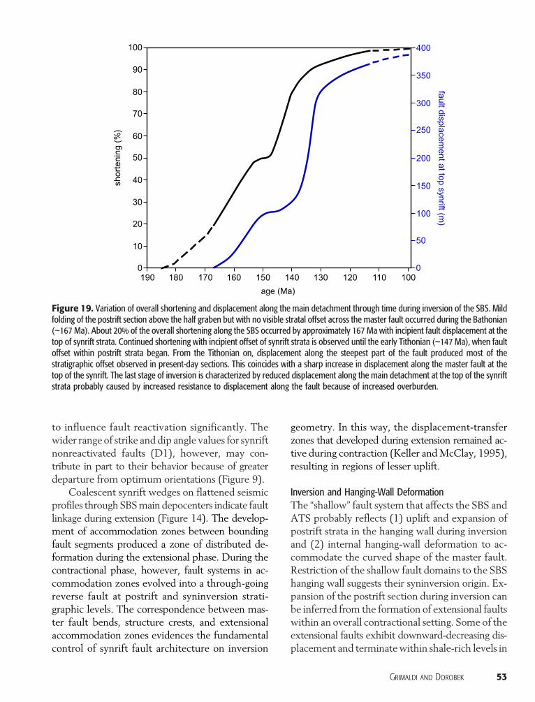
Figure 19. Variation of overall shortening and displacement along the main detachment through time during inversion of the SBS. Mildfolding of the postrift section above the half graben but with no visible stratal offset across the master fault occurred during the Bathonian(∼167 Ma). About 20% of the overall shortening along the SBS occurred by approximately 167 Ma with incipient fault displacement at thetop of synrift strata. Continued shortening with incipient offset of synrift strata is observed until the early Tithonian (∼147 Ma), when faultoffset within postrift strata began. From the Tithonian on, displacement along the steepest part of the fault produced most of thestratigraphic offset observed in present-day sections. This coincides with a sharp increase in displacement along the master fault at thetop of the synrift. The last stage of inversion is characterized by reduced displacement along the main detachment at the top of the synriftstrata probably caused by increased resistance to displacement along the fault because of increased overburden.
Grimaldi and Dorobek 53
the lowerCuyoGroup,where contractionmighthavebeen takenup by ductile ormorewidely distributeddeformation.No extensional faults formed over thestructure’s accommodation zones, which in turnexperienced the least amount of uplift during in-version (Figure 11). Higher extensional fault den-sity occurs along the inverted depocenters. Syn-inversion faults, however, are not restricted to theregions of maximum uplift, which would be ex-pected if only east-west tensile stress upon inver-sion had developed. This is particularly obvious inthe SBS western substructure and in the ATS,where extensional faults flank the structures in-stead of cutting through regions of maximum ele-vation. Concurrent mechanisms are, therefore, pro-posed to explain fault distribution and attitude.
Syninversion “shallow” extensional faults, show-ing en echelon arrangements within each domain inmapview (Figure 11) and negative-flower-structuregeometries in cross section (Figure 12), suggest thata deep-rooted mechanism also influenced straindistribution. These faults, although imaged as nor-mal in our seismic data set, may have a strike-slipcomponent to them. Flower structures are inter-preted to result from incipient strike-slip motionbetween discrete blocks within the SBS hangingwall as it is obliquely thrusted over a highly cor-rugated footwall (Figure 18). The relative motionof blocks allows the hanging wall to accommo-date to the shape of the footwall. This mechanismprobably acts in conjunction with the postrift sec-tion expansion during inversion. Superimposed in-version and incipient strike-slip deformation, alongwith mild translation of the hanging wall parallelto the master fault, produces significant structuraloverprinting.
Substantial hanging-wall internal deformationshould be expected in highly 3-D inversion struc-tures, where faulting purely associated with inver-sion may be obscured by structural features thatresult from hanging-wall along-strike translationand expansion. In addition, observations from thisstudy suggest the need to incorporate more com-plex deformation scenarios into scaled model ex-periments, like oblique inversion of curved (in planview) faults and hanging-wall discrete block de-formation mechanisms.
54 Mesozoic Inversion in Argentina
Kinematic Evolution
Theworkflow used for structural restoration in thisstudy may result in significant error accumulationthrough various stages, namely (1) well data-to-seismic correlations, (2) seismic mapping, (3) es-timation of tectonic transport directions, (4) depthconversion, (5) decompaction and isostatic adjust-ment, and (6) selection of restoration algorithms.After completion of all these steps, the sequen-tial restoration also involves additional interpretivechallenges like estimation of the original thicknessof eroded strata, paleobathymetry, and other res-toration parameters. The limitations and caveatsof this process are especially important when re-storing inversion structures because the existenceof a reactivated fault adds significant complexity.Despite these considerations, clear trends emergedfrom the analysis.
Earliest inversion in the SBSmay have occurredby the Bathonian (∼167 Ma), expressed by mildwarping of the postrift section above the half gra-ben, with no offset observed across the masterfault. The lack of offset within the synrift andpostrift fill cannot be interpreted, however, as lackof movement along the master fault during thistime. Deeper segments of the listric master faultmay have been reactivated during the earliest stagesof inversion because fault dip angles are lower andthe fault was easier to reactivate there. At the sametime, steep fault dip angles at shallower strati-graphic levelsmay cause the fault to lock up duringreactivation so that the structure accommodatesshortening by dilation and internal deformation ofthe hanging wall (Sibson, 1995). Similar patternsare observed in analog studies, where significantshortening is accommodated by fault parallel move-ment of particles deep in the section, whereas theremay be no shallow manifestation of inversion(Eisenstadt and Withjack, 1995; McClay, 1995).Thus, about 20%of the overall shortening along theSBS occurred by approximately 167 Ma with novisible fault displacement at the top of synrift strata(Figure 19). Continued shortening with significantfolding and incipient offset of synrift strata is ob-served until the early Tithonian (∼147 Ma), whenfault offset within postrift strata began. Between

the Tithonian and Valanginian, increased foldingof the postrift section continued, with no signifi-cant offset increase along the master fault. Mostsyninversion faults of the D3 type may have de-veloped during this stage of inversion becausemost shortening had to be accommodated by in-ternal synrift wedge deformation.
From Valanginian time on, displacement alongthe steepest part of the fault produced most of thestratigraphic offset observed in present-day sec-tions. This coincides with a sharp increase in dis-placement along the master fault at the top of thesynrift (Figure 19). During this stage of inversion,most fault reactivation probably occurred (D2 faulttype), as internal synrift wedge deformation wasalready “consumed.” Most upsection propagationof the master fault may have also occurred at thistime.
The master fault tip did not propagate upsec-tion beyond the ValanginianQuintuco Formation,although folding continued and the anticline keptgrowing until the Cenomanian. This last stage ofinversion is also characterized by reduced dis-placement along the main detachment at the top ofsynrift strata probably because of higher resistanceto displacement along the fault associated withincreasing overburden (Figure 19).
The amounts of extension- and inversion-relatedshortening of the SBS are an order of magnitudesmaller than typically suggested by analog studiesof inversion structures. The small amounts of short-ening estimated by structural restoration may ex-plain the lack of pervasive backthrusting or short-cut faulting in the SBS. Backthrusts and shortcutfaults are common in scaled models for inversionbut typically develop where shortening values arethe same as or greater than the amount of exten-sion (Eisenstadt and Withjack, 1995; McClay,1995; Yamada and McClay, 2004). Where back-thrusts form at relatively low amounts of shorten-ing (Buchanan andMcClay, 1991), they commonlynucleate at the tip of preexisting hanging-wall col-lapse grabens that formed during prior extension.The SBS and ATS do not exhibit well-developedcollapse grabens, and their synrift wedge structuremay be, therefore, less likely to nucleate faults asbackthrusts.
Although the natural examples of inversionstructures described here are similar to scaledmodelresults, structural and stratigraphic relationshipswithin the SBS and ATS are more complex andvaried than predicted by analog model studies.The highly complex faulting of the SBS and ATSdocumented in this 3-D study, even for mild ex-tension and contraction amounts, raises concernsabout mechanical scaling of analog models.
The definitions of geometrical constraintslike “null line” (Williams et al., 1989; Turner andWilliams, 2004) and “inversion ratio” (Williams et al.,1989; Song, 1997) are based on 2-D descriptionsand seem insufficient to characterize amounts ofinversion. Along-strike variations in those parame-ters within a single inversion structure, such as theSBS, cast serious doubts about their usefulness asmeasures of inversion intensity. The increasingavailability of 3-D seismic data and computer ap-plications for 3-D structural modeling may facil-itate the use of volumetric parameters to char-acterize inversion. In the case of an inverted halfgraben, for example, the ratio of volumes of synriftfill above and below a regional datum could pro-vide more reliable estimates of the intensity of in-version, regardless of along-strike variations.
Implications for Exploration and Developmentin the Neuquén and Other Basins
Most oil and gas fields in the northern subbasin ofthe Neuquén Basin are associated with invertedhalf grabens related to Huincul arch tectonics.Assessing the extent and timing of fault develop-ment at the field level, as well as fault geneticlinkage to each deformation stage (i.e., extensionand later inversion) is a key contribution to moreaccurate modeling of the petroleum systems. Inaddition, fault development and its linkage to aspecificmechanism (e.g., hanging-wall deformationcaused by oblique inversion) enables the predictiveanalysis of subseismic faulting and fracture distri-bution, which directly impact reservoir quality andseal integrity and also affect the petroleum systembehavior (i.e., folding and internal deformation ac-commodating contraction during the early and latestages of development of the SBS). Tying findings
Grimaldi and Dorobek 55

from this study to existing or future basin modelsfor the northern embayment could further con-strain current results, especially regarding fault de-velopmentwithin theCuyoGroup,whichmayhavea significant impact on the Los Molles petroleumsystem.
Modifications to fault and bedding geometryduring inversion can also impact structural andstratigraphic interpretations during field develop-ment, as inversion-specific geometries can develop.Features observed in the SBS and ATSmay exist inanalogous structures throughout the basin, and theirproper assessment can contribute to a better under-standing of the fields and to optimized develop-ment programs.
Identifying the extent and timing of the con-traction phase is important not only for the Neu-quén Basin, but for other settings where oil and gasfields are related to inverted half grabens, like theNorth Sea, West African rift system, South ChinaSea, and Gulf of Suez. Extensive 3-D seismic datasets cover parts of these basins and may allow for adetailed inspection of inversion-related faultingand accurate timing of events. More mature fieldswill also benefit from the incorporation of drillingand production results into the study, which mayallow the identification of other issues possibly as-sociatedwith inversion andwith a direct impact onreservoir performance and drilling hazards, like po-rosity preservation and overpressure development.
CONCLUSIONS
This study documents the structural style, faultdevelopment aspects, and kinematics of inversionstructures in the central Neuquén Basin. Interpre-tations were based on detailed structural and strat-igraphic mapping of a 3-D seismic data set, faultorientation analysis, and structural restorations.
The northern subbasin of the Neuquén Basinincludes a series of inversion structures that consistof Triassic half grabens that underwent pulsed in-version between the Early Jurassic and Late Cre-taceous. Two of these inversion structures, the SBSand ATS anticlines, are some of the most promi-nent subsurface features in the northern subbasin.
56 Mesozoic Inversion in Argentina
The SBS inversion structure has twomain faultsystems. A deep fault system that affected base-ment and synrift strata was selectively reactivatedduring inversion. Larger faults that formed duringextension were preferentially reverse-reactivatedduring inversion, whereas smaller faults were typ-ically not reactivated during inversion.
A complex set of syninversion normal faultsformed at high angle to the master fault of the SBSduring inversion. These faults affected both post-rift and syninversion strata in the SBS. The mappatterns, location, and kinematic history of thesefaults indicate that the hanging wall of the SBSexpanded upon uplift and internally deformed as itaccommodated the shape of the curved footwallduring oblique inversion. Similar structures arenot reported in analog model studies.
Within the postrift and younger section, a sin-gle through-going but curved fault defines thesouthern boundary of the SBS inversion structure.This single fault changes into a series of fault seg-ments, separatedby accommodation zones, at depth.Fault systems in former accommodation zonesthat formed during extension became linked into athrough-going reverse fault during inversion.
Folding and internal deformation were prob-ably the dominant mechanisms that accommo-dated contraction during the early and late stagesof development of the SBS. Initial fault “lock-up”at shallower stratigraphic and structural levelswas caused by the steep dip angles of the masterfault at these levels, which is not conducive toreactivation. As internal synrift wedge deforma-tion was “consumed,” the half-graben–boundingfault became reverse reactivated and propagatedupsection. By the late Valanginian, the weight ofthe overburden inhibited additional fault displace-ment, and folding became the main mechanismthat accommodated shortening until the LateCretaceous.
Along-strike variations in structural style aresignificant within the SBS and ATS. Structural fea-tures and intensity of inversion (e.g., position ofnull point and inversion ratio Ri; Williams, 1989)vary significantly within these inversion structures.This variability emphasizes the need for volumet-ric descriptors of inversion.

The SBS shows significant structural complex-ity associated with relatively small amounts of ex-tension and inversion, which suggests the need toincorporate more complex deformation scenariosinto scaled model experiments, like oblique inver-sion of corrugated faults and hanging-wall blockdeformation mechanisms.
REFERENCES CITED
Allmendinger, R. W., 2002, StereoWin [computer program]:http://www.geo.cornell.edu/geology/faculty/RWA/programs.html (accessed July 19, 2005).
Badley, M. E., J. D. Price, and L. C. Backshall, 1989, Inver-sion, reactivated faults and related structures: Seismicexamples from the southern North Sea, inM. A. Cooperand G. D. Williams, eds., Inversion tectonics: GeologicalSociety (London) Special Publication 44, p. 201–219.
Bailey, C. M., S. Giorgis, and L. Coiner, 2002, Tectonic inver-sion and basement buttressing: An example from thecentral Appalachian Blue Ridge province: Journal ofStructural Geology, v. 24, p. 925–936, doi:10.1016/S0191-8141(01)00102-X.
Beauchamp, W., 2004, Superposed folding resulting from in-version of a synrift accommodation zone, Atlas Moun-tains, Morocco, in K. R. McClay, ed., Thrust tectonicsand hydrocarbon systems: AAPG Memoir 82, p. 635–646.
Beauchamp, W., M. Barazangi, A. Demnati, and M. El Alji,1996, Intracontinental rifting and inversion: Missour Ba-sin andAtlasMountains,Morocco: AAPGBulletin, v. 80,p. 1459–1482.
Beauchamp, W., M. Barazangi, A. Demnati, and M. El Alji,1997, Inversion of synrift normal faults on the High AtlasMountains, Morocco: The Leading Edge, v. 16, p. 1171–1175, doi:10.1190/1.1437760.
Brun, J. -P., and T. Nalpas, 1996, Graben inversion in natureand experiments: Tectonics, v. 15, p. 677–687, doi:10.1029/95TC03853.
Buchanan, P. G., 1991, Geometries and kinematic analysis ofinversion tectonics from analogmodel studies: Ph.D. dis-sertation, Royal Holloway and Bedford New College,University of London, London, UK, 189 p.
Buchanan, P. G., and K. R. McClay, 1991, Sandbox experi-ments of inverted listric and planar fault systems: Tecto-nophysics, v. 188, p. 97–115, doi:10.1016/0040-1951(91)90317-L.
Buchanan, P. G., and K. R. McClay, 1992, Experiments onbasin inversion above reactivated domino faults: Marineand Petroleum Geology, v. 9, p. 486–500, doi:10.1016/0264-8172(92)90061-I.
Buiter, S. J. H., and O. A. Pfiffner, 2003, Numerical modelsof the inversion of halfgraben basins: Tectonics, v. 22,no. 5, p. 1057, doi:10.1029/2002TC001417.
Bulnes, M., and K. McClay, 1999, Benefits and limitations ofdifferent 2D algorithms used in cross section restoration
of inverted extensional faults: Application to physical ex-periments: Tectonophysics, v. 312, p. 175–189, doi:10.1016/S0040-1951(99)00161-4.
Butler, R. W. H., 1989, The influence of preexisting basinstructure on thrust systems evolution in the westernAlps, inM.A. Cooper andG.D.Williams, eds., Inversiontectonics: Geological Society (London) Special Publica-tion 44, p. 105–122.
Cartwright, J. A., 1989, The kinematics of inversion in theDan-ish Central Graben, inM. A. Cooper and G. D. Williams,eds., Inversion tectonics: Geological Society (London)Special Publication 44, p. 153–175.
Chambers, J. L. C., I. Carter, I. R. Cloke, J. Craig, S. J. Moss,and D. W. Paterson, 2004, Thin-skinned and thick-skinned inversion-related thrusting: A structural model forthe Kutai Basin, Kalimantan, Indonesia, in K. R. McClay,ed., Thrust tectonics and hydrocarbon systems: AAPGMemoir 82, p. 614–634.
Cooper, G. T., 1995, Seismic structure and extensional devel-opment of the eastern Otway Basin–Torquay embay-ment: The Australian Petroleum Exploration AssociationJournal, v. 35, p. 241–256.
Coward, M., 1994, Inversion tectonics, in P. Hancock, ed.,Continental deformation: Oxford, United Kingdom,Pergamon Press, p. 289–304.
Coward, M. P., R. Gillcrist, and B. Trudgill, 1991, Extensionalstructures and their tectonic inversion in the westernAlps, in M. Roberts Alan, G. Yielding, and B. Freeman,eds., The geometry of normal faults: Geological Society(London) Special Publication 56, p. 93–112.
Cristallini, E., A. H. Cominguez, and V. A. Ramos, 1997,Deep structure of the Metan-Guachipas region, tectonicinversion in northwestern Argentina: Journal of SouthAmerican Earth Sciences, v. 10, p. 403–421, doi:10.1016/S0895-9811(97)00026-6.
Cruz, C. E., A. Boll, R. Gómez Omil, E. A. Martínez, C. D.Arregui, C. A. Gulisano, G. A. Laffitte, and H. J. Villar,2002, Hábitat de hidrocarburos y sistemas de carga LosMolles y Vaca Muerta en el sector central de la cuencaNeuquina, Argentina: V Congreso de Exploración y De-sarrollo de Hidrocarburos, Trabajos Técnicos, InstitutoArgentino del Petróleo y del Gas, CD-ROM, 20 p.
Dellapé, D. A., and A. Hegedus, 1995, Structural inversionand oil occurrence in the Cuyo Basin of Argentina, inA. J. Tankard, R. S. Suárez, and H. J. Welsink, eds., Pe-troleum basins of South America: AAPG Memoir 62,p. 359–367.
Dewey, J. F., 1988, Extensional collapse of orogens: Tectonics,v. 7, p. 1123–1139, doi:10.1029/TC007i006p01123.
Digregorio, J. H., 1972, Neuquén, inH. A. Leanza, ed., Geol-ogía regional Argentina: Córdoba, Argentina, AcademiaNacional de Ciencias, p. 439–505.
Digregorio, J. H., andM. A. Uliana, 1980, Cuenca Neuquina:Simposio de Geología Regional Argentina, AcademiaNacional de Ciencias de Córdoba, v. 2, p. 985–1032.
Dubois, A., F. Odonne, G. Massonnat, T. Lebourg, and R.Fabre, 2002, Analog modeling of fault reactivation: Tec-tonic inversion and oblique remobilisation of grabens:Journal of Structural Geology, v. 24, p. 1741–1752,doi:10.1016/S0191-8141(01)00129-8.
Grimaldi and Dorobek 57
Dula, W. F., 1991, Geometric models of listric normal faultsand rollover folds: AAPG Bulletin, v. 75, p. 1609–1625.
Eisenstadt, G., and M. O. Withjack, 1995, Estimating inver-sion: Results from clay models, in J. G. Buchanan andP. G. Buchanan, eds., Basin inversion: Geological Society(London) Special Publication 88, p. 119–136.
Etheridge, M. A., 1986, On the reactivation of extensionalfault systems: Philosophical Transactions of the RoyalSociety of London, Series A, Mathematical and PhysicalSciences, v. A317, p. 179–194.
Franzese, J., L. Spalletti, I. Gómez Pérez, and D. Macdonald,2003, Tectonic and paleoenvironmental evolution ofMesozoic sedimentary basins along the Andean foothillsof Argentina (32°–54°S): Journal of South AmericanEarth Sciences, v. 16, p. 81–90, doi:10.1016/S0895-9811(03)00020-8.
Franzese, J. R., and L. A. Spalletti, 2001, Late Triassic–EarlyJurassic continental extension in southwestern Gondwa-na: Tectonic segmentation and pre-breakup rifting: Jour-nal of South American Earth Sciences, v. 14, p. 257–270,doi:10.1016/S0895-9811(01)00029-3.
Freije, H., G. Azúa, R. González, J. J. Ponce, and C. Zavala,2002, Actividad tectónica sinsedimentaria en el Jurásicosur de la cuenca Neuquina: V Congreso de Exploracióny Desarrollo de Hidrocarburos, Trabajos Técnicos, Insti-tuto Argentino del Petróleo y del Gas, CD-ROM, 17 p.
Gillcrist, R., M. Coward, and J. L. Mugnier, 1987, Structuralinversion and its controls: Examples from the Alpineforeland and the French Alps: Geodinamica Acta, v. 1,p. 5–34.
Grimaldi, G. O., 2005, Mesozoic tectonic inversion in theNeuquén Basin of west-central Argentina: College Sta-tion, Texas, Texas A&M University, 166 p.
Gulisano, C. A., and A. R. Gutiérrez Pleimling, 1994, Fieldguide: The Jurassic of the Neuquén Basin: Neuquén Prov-ince, Secretaría de Minería de la Nación-AsociaciónGeológica Argentina, 111 p.
Gulisano, C. A., and L. Legarreta, 1987, Análisis secuencialdel Jurásico, Cretácico y Eoterciario de la Cuenca Neu-quina, Argentina: X Congreso Geológico Argentino,Actas v. 5, p. 16–17.
Gulisano, C. A., and G. A. Pando, 1981, Estratigrafía y faciesde los depósitos jurásicos entre Piedra del Águila y Sañi-có, departamento Collón Curá, provincia del Neuquén:VIII Congreso Geológico Argentino, Actas v. 3, p. 553–577.
Hayward, A. B., and R. H. Graham, 1989, Some geometricalcharacteristics of inversion, in M. A. Cooper and G. D.Williams, eds., Inversion tectonics: Geological Society(London) Special Publication 44, p. 17–39.
Hill, K. C., and G. T. Cooper, 1996, A strategy for palinspas-tic restoration of inverted basins: thermal and structuralanalyses in SE Australia, in P. G. Buchanan and D. A.Nieuwland, eds., Modern developments in structural in-terpretation, validation and modeling: Geological So-ciety (London) Special Publication 99, p. 99–115.
Hinterwimmer, G. A., and J. M. Jáuregui, 1985, Análisis defacies de los depósitos de turbiditas de la F. LosMolles enel sondeo Barda Colorada Este, provincia del Neuquén:IXCongreso Geológico Argentino, Actas v. 5, p. 124–135.
58 Mesozoic Inversion in Argentina
Homovc, J. F., G. A. Conforto, P. A. Lafourcade, and L. A.Chelotti, 1995, Fold belt in the San Jorge Basin, Argen-tina: An example of tectonic inversion, in J. G. Buchananand P. G. Buchanan, eds., Basin inversion: Geological So-ciety (London) Special Publication 88, p. 235–248.
Keller, J. V. A., and K. R. McClay, 1995, 3D sandbox modelsof positive inversion, in J. G. Buchanan and P.G. Buchanan,eds., Basin inversion: Geological Society (London) SpecialPublication 88, p. 137–146.
Kelly, P. G., D. C. P. Peacock, D. J. Sanderson, and A. C.McGurk, 1999, Selective reverse-reactivation of normalfaults, and deformation around reverse-reactivated faultsin the Mesozoic of the Somerset coast: Journal of Struc-tural Geology, v. 21, p. 493–509, doi:10.1016/S0191-8141(99)00041-3.
Kim, Y.-S., and D. J. Sanderson, 2005, The relationship be-tween displacement and length of faults: A review: Earth-Science Reviews, v. 68, p. 317–334, doi:10.1016/j.earscirev.2004.06.003.
Kley, J., and C.Monaldi, 2002, Tectonic inversion in the SantaBarbara system of the central Andean foreland thrustbelt, northwestern Argentina: Tectonics, v. 21, no. 6,p. 1061, doi:10.1029/2002TC902003.
Kluth, C. F., 1991, Inversion and reinversion of the Sangre deCristo-Rio Grande rift area, southern Colorado andnorthern New Mexico (abs.), in J. W. Geissman, W. E.Elston, and G. R. Keller, eds.: Geological Society ofAmerica, Rocky Mountain Section: Abstracts with Pro-grams, v. 23, p. 39.
Kluth, C. F., and P. J. Coney, 1981, Plate tectonics of theancestral Rocky Mountains: Geology, v. 9, p. 10–15,doi:10.1130/0091-7613(1981)9<10:PTOTAR>2.0.CO;2.
Koopman, A., A. Speksnijder, and W. T. Horsfield, 1987,Sandbox model studies of inversion tectonics: Tectono-physics, v. 137, p. 379–388, doi:10.1016/0040-1951(87)90329-5.
Legarreta, L., and C. A. Gulisano, 1989, Análisis estratigráficosecuencial de la Cuenca Neuquina (Triásico superior-Terciario inferior), in G. A. Chebli and L. A. Spalletti,eds., Cuencas sedimentarias argentinas: Serie CorrelaciónGeológica, v. 6, Programa Internacional de CorrelaciónGeológica Proyecto 192, Desarrollo del Cámbrico y Or-dovícico de Latinoamérica, p. 221–243.
Legarreta, L., and M. A. Uliana, 1991, Jurassic-Cretaceousmarine oscillations and geometry of back-arc basin fill,central Argentine Andes, in D. I. M. Macdonald, ed.,Sedimentation, tectonics and eustasy. Sea-level changesat active margins: International Association of Sedimen-tologists Special Publication 12, p. 429–450.
Legarreta, L., C. A. Gulisano, and M. A. Uliana, 1993, Lassecuencias sedimentarias Jurásico-Cretácicas: XII Con-greso Geológico Argentino y II Congreso de Exploraciónde Hidrocarburos, Actas v. 1, p. 87–114.
Letouzey, J., P.Werner, and A.Marty, 1990, Fault reactivationand structural inversion: Backarc and intraplate compres-sive deformations: Example of the eastern Sunda shelf(Indonesia): Tectonophysics, v. 183, p. 341–362,doi:10.1016/0040-1951(90)90425-8.
Manceda, R., and D. Figueroa, 1995, Inversion of theMesozoic

Neuquén rift in theMalargüe fold and thrust belt,Mendoza,Argentina, in A. J. Tankard, R. S. Soruco, and H. J.Welsink, eds., Petroleum basins of South America: AAPGMemoir 62, p. 369–382.
Maretto, H., and M. E. Lara, 2002, Discontinuidades estrati-gráficas, distribución de fluidos y calidad de reservorio:Un ejemplo de la Formación Tordillo en Loma la Lata:V Congreso de Exploración y Desarrollo de Hidrocar-buros, Trabajos Técnicos, Instituto Argentino del Petró-leo y del Gas, CD-ROM, 14 p.
Marone, C., 1995, Fault zone strength and failure criteria:Geophysical Research Letters, v. 22, p. 723–726, doi:10.1029/95GL00268.
Marshak, S., K. E. Karlstrom, and J. M. Timmons, 2000, In-version of Proterozoic extensional faults, an explanationfor the pattern of Laramide and Ancestral Rockies intra-cratonic deformation, United States: Geology, v. 28,p. 735–738, doi:10.1130/0091-7613(2000)28<735:IOPEFA>2.0.CO;2.
McClay, K., 1989, Analog models of inversion tectonics, inM. A. Cooper and G. D. Williams, eds., Inversion tec-tonics: Geological Society (London) Special Publication44, p. 41–59.
McClay, K. R., 1995, The geometries and kinematics of in-verted fault systems: A review of analog model studies,in J. G. Buchanan and P. G. Buchanan, eds., Basin inver-sion: Geological Society (London) Special Publication 88,p. 97–118.
Mitra, S., 1993, Geometric and kinematic evolution of in-version structures: AAPG Bulletin, v. 77, p. 1159–1191.
Nalpas, T., S. Le Douaran, J.-P. Brun, P. Unternehr, and J.-P.Richert, 1995, Inversion of the Broad Fourteens Basin(offshore Netherlands): A smallscale model investiga-tion: Sedimentary Geology, v. 95, p. 237–250, doi:10.1016/0037-0738(94)00113-9.
Nielsen, S. B., and D. L. Hansen, 2000, Physical explana-tion of the formation and evolution of inversion zonesand marginal troughs: Geology, v. 28, p. 875–878,doi:10.1130/0091-7613(2000)28<875:PEOTFA>2.0.CO;2.
Olson, C., 2001, Timing and tectonic implications of basininversion in the Nam Con Son Basin and adjacent areas,southern South China Sea: M.S. thesis, Texas A&MUni-versity, College Station, Texas, 176 p.
Orchuela, I. A., V. J. Ploszkiewicz, and R. F. Viñes, 1981, Re-interpretación estructural de la denominada “DorsalNeuquina”: VII Congreso Geológico Argentino, Actasv. 3, p. 281–293.
Pando, G. A., S. G. Del Vó, G. Laffitte, and M. Arguijo,1984, Posibilidades oleogenéticas, migración y entram-pamiento en las sedimentitas Jurásicas (Lias-Dogger)de la región centro-meridional de la Cuenca Neuquina:IX Congreso Geológico Argentino, Actas v. 7, p. 52–67.
Pángaro, F., and P. Bruveris, 1999, Reactivación tectónicamultiepisódica de sistemas extensionales, Cuenca Neu-quina, Argentina: XIV Congreso Geológico Argentino,Actas v. 1, p. 231–234.
Ploszkiewicz, J. V., I. A. Orchuela, J. C. Vaillard, and R. F.
Viñes, 1984, Compresión y desplazamiento lateral en laZona de Falla Huincul, estructuras asociadas, Provinciadel Neuquén: IX Congreso Geológico Argentino, Actasv. 2, p. 163–169.
Ramos, V. A., 1978, Estructura, in E. O. Rolleri, ed., Geologíay recursos naturales del Neuquén: Relatorio VII Congre-so Geológico Argentino: Buenos Aires, Argentina, p. 99–118.
Sandiford, M., 1999, Mechanics of basin inversion: Tectono-physics, v. 305, p. 109–120, doi:10.1016/S0040-1951(99)00023-2.
Sandiford, M., S. Frederiksen, and J. Braun, 2003, The long-term thermal consequences of rifting: Implications for ba-sin reactivation: Basin Research, v. 15, p. 23–43, doi:10.1046/j.1365-2117.2003.00196.x.
Scott, D. L., M. A. Etheridge, and B. R. Rosendahl, 1992,Oblique-slip deformation in extensional terranes: Acase study from the Lakes Tanganyika and Malawi riftzones, East Africa: Tectonics, v. 11, p. 998–1009, doi:10.1029/92TC00821.
Scott, D. L., J. Braun, andM. A. Etheridge, 1994, Dip analysisas a tool for estimating regional kinematics in extensionalterranes: Journal of Structural Geology, v. 16, p. 393–401, doi:10.1016/0191-8141(94)90043-4.
Sibson, R. H., 1985, A note on fault reactivation: Journal ofStructural Geology, v. 7, p. 751–754, doi:10.1016/0191-8141(85)90150-6.
Sibson, R. H., 1995, Selective fault reactivation during basininversion: Potential for fluid redistribution through fault-valve action, in J. G. Buchanan and P. G. Buchanan, eds.,Basin inversion: Geological Society (London) SpecialPublication 88, p. 3–19.
Song, T., 1997, Inversion styles in the Songliao Basin (north-east China) and estimation of the degree of inversion:Tectonophysics, v. 283, p. 173–188, doi:10.1016/S0040-1951(97)00147-9.
Tankard et al., A. J., 1995, Structural and tectonic controls ofbasin evolution in southwestern Gondwana during thePhanerozoic, in A. J. Tankard, R. Suárez Soroco, andH. J. Welsink, eds., Petroleum basins of South America:AAPG Memoir 62, p. 5–52.
Thomas, D. W., and M. P. Coward, 1995, Late Jurassic–EarlyCretaceous inversion in the northern East Shetland Basin,northernNorth Sea, in J. G. Buchanan and P.G. Buchanan,eds., Basin inversion: Geological Society (London) Spe-cial Publication 88, p. 275–306.
Turner, J. P., and G. A. Williams, 2004, Sedimentary basininversion and intraplate shortening: Earth-Science Re-views, v. 65, p. 277–304, doi:10.1016/j.earscirev.2003.10.002.
Uliana, M. A., and L. Legarreta, 1993, Hydrocarbons habitatin a Triassic-to-Cretaceous sub-Andean setting; NeuquénBasin, Argentina: Journal of Petroleum Geology, v. 16,p. 397–420, doi:10.1111/j.1747-5457.1993.tb00350.x.
Uliana, M. A., M. E. Arteaga, L. Legarreta, J. J. Cerdan, andG. O. Peroni, 1995, Inversion structures and hydrocar-bon occurrence in Argentina, in J. G. Buchanan andP. G. Buchanan, eds., Basin inversion: Geological Society(London) Special Publication 88, p. 211–233.
Urien, C. M., and J. J. Zambrano, 1994, Petroleum systems in
Grimaldi and Dorobek 59

the Neuquén Basin, Argentina, inL. B.Magoon andW.G.Dow, eds., The petroleum system: From source to trap:AAPG Memoir 60, p. 513–534.
Vergani, G. D., A. J. Tankard, H. J. Belotti, and H. J. Welsink,1995, Tectonic evolution and paleogeography of theNeuquén Basin, Argentina, inA. J. Tankard, R. S. Soruco,and H. J. Welsink, eds., Petroleum basins of South Amer-ica: AAPG Memoir 62, p. 383–402.
Welsink, H. J., E. Martinez, O. Aranibar, and J. Jarandilla,1995, Structural inversion of a Cretaceous rift basin,southern Altiplano, Bolivia, inA. J. Tankard, R. S. Suárez,and H. J. Welsink, eds., Petroleum basins of South Amer-ica: AAPG Memoir 62, p. 305–324.
Williams,G.D., C.M. Powell, andM.A. Cooper, 1989,Geom-etry and kinematics of inversion tectonics, in M. A.Cooper and G. D. Williams, eds., Inversion tectonics:Geological Society (London) Special Publication 44,v. 44, p. 3–15.
Woodward, N. B., S. E. Boyer, and J. Suppe, 1989, Balancedgeological cross sections: An essential technique in geo-logical research and exploration: Short Course in Geol-ogy, American Geophysical Union, v. 6, 128 p.
Yamada, Y., and K. McClay, 2003a, Application of geometricmodels to inverted listric fault systems in sandbox experi-ments, paper 1: 2D hanging wall deformation and sectionrestoration: Journal of Structural Geology, v. 25, p. 1551–1560, doi:10.1016/S0191-8141(02)00181-5.
Yamada, Y., and K. McClay, 2003b, Application of geometricmodels to inverted listric fault systems in sandbox experi-ments, paper 2: Insights for possible along strike migra-
60 Mesozoic Inversion in Argentina
tion of material during 3D hanging wall deformation:Journal of Structural Geology, v. 25, p. 1331–1336,doi:10.1016/S0191-8141(02)00160-8.
Yamada, Y., and K. R.McClay, 2004, 3-DAnalogmodeling ofinversion thrust structures, in K. R. McClay, ed., Thrusttectonics and hydrocarbon systems: AAPG Memoir 82,p. 276–301.
Zavala, C., and H. Freije, 2002, Cuñas clásticas Jurásicas vin-culadas a la Dorsal de Huincul. Un ejemplo del área dePicún Leufú. Cuenca Neuquina, Argentina. V Congresode Exploración y Desarrollo de Hidrocarburos, TrabajosTécnicos, Instituto Argentino del Petróleo y del Gas,CD-ROM, 14 p.
Ziegler, P. A., 1987, Late Cretaceous and Cenozoic intraplatecompressional deformations in the Alpine foreland: Ageodynamic model: Tectonophysics, v. 137, p. 389–420, doi:10.1016/0040-1951(87)90330-1.
Ziegler, P. A., 1989, Geodynamic model for Alpine intra-plate compressional deformation inWestern and CentralEurope, in M. A. Cooper and G. D. Williams, eds., In-version tectonics: Geological Society (London) SpecialPublication 44, p. 63–85.
Ziegler, P. A., S. Cloetingh, and J.-D. van Wees, 1995, Dy-namics of intraplate compressional deformation: TheAlpine foreland and other examples: Tectonophysics,v. 252, p. 7–59, doi:10.1016/0040-1951(95)00102-6.
Ziegler, P. A., J.-D. van Wees, and S. Cloetingh, 1998, Me-chanical controls on collision related compressional in-traplate deformation: Tectonophysics, v. 300, p. 103–129, doi:10.1016/S0040-1951(98)00236-4.
Copyright © 2022 FDOKUMEN