Megavoltage cone-beam CT: System description and clinical applications
11
doi:10.1016/j.meddos.2005.12.009 MEGAVOLTAGE CONE-BEAM CT: SYSTEM DESCRIPTION AND CLINICAL APPLICATIONS OLIVIER MORIN, B.S.E., AMY GILLIS, M.D., JOSEPHINE CHEN,PH.D. MICHÈLE AUBIN, M.S.E.E., M. KARA BUCCI, M.D., MACK ROACH, III, M.D. and JEAN POULIOT,PH.D. University of California San Francisco Comprehensive Cancer Center, Department of Radiation Oncology, San Francisco, CA; and University of California San Francisco/University of California Berkeley Joint Graduate Group in Bioengineering, San Francisco, CA ( Accepted 21 December 2005) Abstract—In this article, we describe a clinical mega-voltage cone-beam computed tomography (MV CBCT) system, present the image acquisition and patient setup procedure, discuss the positioning accuracy and image quality, and illustrate its potential use for image-guided radiation therapy (IGRT) through selected clinical examples. The MV CBCT system consists of a standard linear accelerator equipped with an amorphous-silicon flat panel electronic portal-imaging device adapted for mega-electron volt (MeV) photons. An integrated computer workspace provides automated acquisition of projection images, image reconstruction, CT to CBCT image registration, and couch shift calculation. The system demonstrates submillimeter localization precision and sufficient soft-tissue resolution to visualize structures such as the prostate. In our clinic, we have used the MV CBCT system to detect nonrigid spinal cord distortions, monitor tumor growth and shrinkage, and locate and position stationary tumors in the lung. MV CBCT has also greatly improved the delineation of structures in CT images that suffer from metal artifacts. MV CBCT has undergone significant development in the last few years. Current image quality has already proven sufficient for many IGRT applications. Moreover, we expect the range of clinical applications for MV CBCT to grow as imaging technology continues to improve. © 2006 American Association of Medical Dosimetrists. Key Words: External beam, Image-guided radiation therapy, Radiotherapy imaging, MV cone-beam CT. INTRODUCTION Image-guided radiation therapy (IGRT) refers to the use of patient imaging in the treatment room to increase the conformality of the radiation dose to the tumor, improv- ing tumor control, and reducing normal tissue complica- tions. The development of image-guidance tools and tech- niques in radiotherapy has been greatly motivated by the continual advances in external beam radiation delivery. With 3-dimensional (3D) conformal radiotherapy and intensity-modulated radiotherapy (IMRT), it is now pos- sible to deliver radiation doses that conform tightly to the tumor volume. Many clinical studies and simulations indicate that these more conformal, higher dose treat- ments can decrease both the spread of disease and nor- mal tissue complications. 1–5 However, as the planned dose distributions conform more closely to the pre- treatment planning computed tomography (CT), the pre- cision of dose delivery becomes limited by the validity of using the planning CT to represent the patient on the treatment table throughout an extended course of treat- ment. Organs may change in size, shape, and position from day to day and week to week due to normal ana- tomical variability, as well as due to the patient’s reac- tion to radiation therapy, such as tumor shrinkage or weight loss. 6 –10 Therefore, patient anatomical and posi- tional information that can be obtained immediately be- fore treatment is extremely valuable. Imaging has long played a key role in assuring the accuracy of radiation therapy treatment. Recent imple- mentation of highly sensitive and automated on-board electronic portal imaging devices (EPIDs) now enables daily low-dose portal imaging to visualize and adjust the patient position before each treatment. However, the utility of portal imaging to adjust the patient position is limited by reduced soft-tissue and 3D geometrical visu- alization caused by projection onto a 2-dimensional (2D) plane. This has motivated the development of 3D imag- ing of the patient while lying on the treatment table. Because CT is the current standard for localization of soft-tissue organs and target in treatment planning, there is a growing interest in CT imaging in the treatment room. Several systems have been developed including (1) a “CT on rails” system 11,12 requiring an additional diagnostic (CT) machine in the treatment room; (2) a kilovoltage cone-beam CT (kV CBCT) system 13,14 con- sisting of an additional kV x-ray source and detector attached to the treatment gantry; (3) a mobile C-arm Reprint requests to: Jean Pouliot, UCSF Comprehensive Cancer Center, Department of Radiation Oncology, 1600 Divisadero Street, Suite H1031, San Francisco, CA 94143. E-mail: Pouliot@ radonc17.ucsf.edu Medical Dosimetry, Vol. 31, No. 1, pp. 51-61, 2006 Copyright © 2006 American Association of Medical Dosimetrists Printed in the USA. All rights reserved 0958-3947/06/$–see front matter 51
-
Upload
independent -
Category
Documents
-
view
1 -
download
0
Transcript of Megavoltage cone-beam CT: System description and clinical applications
doi:10.1016/j.meddos.2005.12.009
MEGAVOLTAGE CONE-BEAM CT: SYSTEM DESCRIPTION ANDCLINICAL APPLICATIONS
OLIVIER MORIN, B.S.E., AMY GILLIS, M.D., JOSEPHINE CHEN, PH.D.MICHÈLE AUBIN, M.S.E.E., M. KARA BUCCI, M.D., MACK ROACH, III, M.D. and
JEAN POULIOT, PH.D.University of California San Francisco Comprehensive Cancer Center, Department of Radiation Oncology, San
Francisco, CA; and University of California San Francisco/University of California Berkeley Joint Graduate Groupin Bioengineering, San Francisco, CA
(Accepted 21 December 2005)
Abstract—In this article, we describe a clinical mega-voltage cone-beam computed tomography (MV CBCT)system, present the image acquisition and patient setup procedure, discuss the positioning accuracy and imagequality, and illustrate its potential use for image-guided radiation therapy (IGRT) through selected clinicalexamples. The MV CBCT system consists of a standard linear accelerator equipped with an amorphous-siliconflat panel electronic portal-imaging device adapted for mega-electron volt (MeV) photons. An integratedcomputer workspace provides automated acquisition of projection images, image reconstruction, CT to CBCTimage registration, and couch shift calculation. The system demonstrates submillimeter localization precision andsufficient soft-tissue resolution to visualize structures such as the prostate. In our clinic, we have used the MVCBCT system to detect nonrigid spinal cord distortions, monitor tumor growth and shrinkage, and locate andposition stationary tumors in the lung. MV CBCT has also greatly improved the delineation of structures in CTimages that suffer from metal artifacts. MV CBCT has undergone significant development in the last few years.Current image quality has already proven sufficient for many IGRT applications. Moreover, we expect the rangeof clinical applications for MV CBCT to grow as imaging technology continues to improve. © 2006 AmericanAssociation of Medical Dosimetrists.
Key Words: External beam, Image-guided radiation therapy, Radiotherapy imaging, MV cone-beam CT.
INTRODUCTION
Image-guided radiation therapy (IGRT) refers to the useof patient imaging in the treatment room to increase theconformality of the radiation dose to the tumor, improv-ing tumor control, and reducing normal tissue complica-tions.
The development of image-guidance tools and tech-niques in radiotherapy has been greatly motivated by thecontinual advances in external beam radiation delivery.With 3-dimensional (3D) conformal radiotherapy andintensity-modulated radiotherapy (IMRT), it is now pos-sible to deliver radiation doses that conform tightly to thetumor volume. Many clinical studies and simulationsindicate that these more conformal, higher dose treat-ments can decrease both the spread of disease and nor-mal tissue complications.1–5 However, as the planneddose distributions conform more closely to the pre-treatment planning computed tomography (CT), the pre-cision of dose delivery becomes limited by the validity ofusing the planning CT to represent the patient on thetreatment table throughout an extended course of treat-ment. Organs may change in size, shape, and position
from day to day and week to week due to normal ana-tomical variability, as well as due to the patient’s reac-tion to radiation therapy, such as tumor shrinkage orweight loss.6–10 Therefore, patient anatomical and posi-tional information that can be obtained immediately be-fore treatment is extremely valuable.
Imaging has long played a key role in assuring theaccuracy of radiation therapy treatment. Recent imple-mentation of highly sensitive and automated on-boardelectronic portal imaging devices (EPIDs) now enablesdaily low-dose portal imaging to visualize and adjust thepatient position before each treatment. However, theutility of portal imaging to adjust the patient position islimited by reduced soft-tissue and 3D geometrical visu-alization caused by projection onto a 2-dimensional (2D)plane. This has motivated the development of 3D imag-ing of the patient while lying on the treatment table.Because CT is the current standard for localization ofsoft-tissue organs and target in treatment planning, thereis a growing interest in CT imaging in the treatmentroom. Several systems have been developed including(1) a “CT on rails” system11,12 requiring an additionaldiagnostic (CT) machine in the treatment room; (2) akilovoltage cone-beam CT (kV CBCT) system13,14 con-sisting of an additional kV x-ray source and detectorattached to the treatment gantry; (3) a mobile C-arm
Reprint requests to: Jean Pouliot, UCSF Comprehensive CancerCenter, Department of Radiation Oncology, 1600 DivisaderoStreet, Suite H1031, San Francisco, CA 94143. E-mail: [email protected]
Medical Dosimetry, Vol. 31, No. 1, pp. 51-61, 2006Copyright © 2006 American Association of Medical Dosimetrists
Printed in the USA. All rights reserved0958-3947/06/$–see front matter
51
kilovoltage imager15; (4) a megavoltage cone-beam CT(MV CBCT) system 16,17 using the pre-existing treat-ment machine and EPID for imaging; (5) an MV CTsystem18,19 using the pre-existing treatment machinewith an attached change arc of detectors; and (6) atomotherapy system20 replacing the traditional treatmentmachine (beam) with a CT ring and an MV beam source.The potential clinical applications of these IGRT tech-nologies will depend on imaging performance, whichcontinues to improve for many of the systems. As welearn more about patient anatomical variability usingin-room 3D imaging, more clinical applications will alsobecome apparent. In general, the goal is to provide moreaccurate and reproducible patient setup. The possibilityof delivered dose verification combined with in-roomimaging is also being explored and should provide anextra level of verification in the radiotherapy processes.
We present the recent developments in MV CBCT,describe an MV CBCT system, including the time re-quired for acquisition and setup, the positioning accu-racy, and the image quality. Then, a few chosen clinicalexamples are presented to illustrate how MV CBCT canbe used for patient setup based on bony anatomy and/orsoft tissue, to identify non-rigid deformation of the pa-tient anatomy on the treatment couch and to monitoranatomical changes due to weight loss or tumor re-sponse. The superiority of MV volumetric imaging inpresence of metallic objects is also demonstrated. Fi-nally, ongoing research to improve image quality isdiscussed, as well as research to combine image guid-ance with dose verification.
BASICS OF MEGAVOLTAGE CONE-BEAM CT
A cone-beam CT image is reconstructed from a setof open-field projection images acquired at different po-sitions around the patient. The process is similar toconventional CT, which uses the signal from a single rowof detectors to reconstruct a slice. For conventional CT,the 3D image is formed by translating the patient andimaging several slices. For CBCT, a 2D detector array isused and the reconstructed data set is a direct 3D imagewithout multiple gantry rotations, table movement, orslice artifact. For MV CBCT, projection images areacquired using a radiotherapy linear accelerator (linac)with photons primarily in the mega-electron volt (MeV)energy range.
Historical perspective of 3D MV imagingApproximately 20 years ago, researchers in radia-
tion oncology first used a linac beam for 3D imaging.These early systems reconstructed 2D slices using afan-beam geometry.21,22 Recently, MV fan-beam CT hasbeen integrated into the helical tomotherapy system (To-motherapy Inc., Madison, WI).20,23 As the technology of2D x-ray detectors has advanced,24 cone-beam recon-struction systems have become increasingly feasible.
Several researchers have acquired MV CBCT imagesusing standard linacs with liquid-filled ionization cham-ber detectors,25 video-based EPIDs,25,26 and amorphoussilicon (a-Si) flat panel detectors.27,28 In much of theearly work, signal was maximized by applying highdoses (50–200 cGy). Strategies such as the developmentof more sensitive detectors29,30 and the restriction of theimaging volume to the treatment volume31,32 have re-duced these doses to clinically acceptable values and willcontinue to decrease imaging doses. Other developmentsinclude the adaptation of MV CBCT for lung tumorvisualization by synchronizing image acquisition withrespiration.16
The University of California San Francisco (UCSF),in collaboration with Siemens Oncology Care Systems,has been working on the clinical implementation of MVCBCT for the last 5 years. Our first MV CBCT imagingsystem has been previously described.17 During thistimes, we have reduced exposure and improved imagequality using a special triggered acquisition,33 reducedthe acquisition time, demonstrated soft-tissue contrast34
and, recently, initiated a clinical patient setup study com-paring portal imaging to MV CBCT.
Soft-tissue visualization using kV and MV imagingThe shared use of the linac beam for treatment and
imaging is inexpensive and convenient. However, theuse of MeV photons for imaging is a departure from thegeneral preference for kilo-electron volt (keV) beams indiagnostic imaging. The basic physics of x-ray interac-tion with matter can be used to explain the tradeoffsbetween using keV or MeV beams for imaging in radio-therapy. The visibility of large low-contrast objects intomographic images, for example the prostate, dependson the contrast-to-noise ratio. Contrast is determined bythe differential attenuation of the beam through differentbodily tissues. In the MeV range, Compton scatteringprovides the majority of the beam attenuation. Due to thesmall energy dependence of Compton interaction, thecontrast in MeV imaging is thus relatively constant overa large energy range. However, the greater dose perphoton deposited by MeV photons reduces the imagingbeam intensity that may be applied given patient doseconstraints, thus reducing the signal. Moreover, the at-tenuation coefficient differences between bodily tissuesare smaller for MeV energies, diminishing image con-trast. The other important parameter, noise, includes thestatistical fluctuation of photon detection as well as anysource of unwanted radiation (i.e., radiation containingno imaging information). In transmission imaging, thex-rays reaching the detector consist of unscattered (pri-mary) and scattered (secondary) components. The pri-mary fluence produces the signal in the resulting image,while the secondary fluence introduces noise and imageartifacts and produces quantitative inaccuracies in thereconstructed CT numbers. The magnitude of scatterreaching the detector depends on the photon energy, the
Medical Dosimetry Volume 31, Number 1, 200652
field size, the object (size and composition), and theobject-to-detector distance. The fan beam geometry re-jects a considerable amount of scattered radiation, whilethe cone-beam geometry exposes the detector to scatterradiation. For a typical kV CBCT pelvic image (coneangle !10°) acquired with the optimal air gap, the scat-ter-to-primary ratio (SPR) is greater than 170%, leadingto CT number inaccuracies on the order of 40%.35 Meth-ods of reducing the effects of scatter include changingthe acquisition parameters (dose, field-of-view, voxelsize, etc.), using an antiscatter grid, performing prepro-cessing of the 2D projection raw images, and applyingpost-processing on the 3D reconstruction. Antiscattergrids have been studied for kV images but, so far, havenot greatly improved the contrast-to-noise ratio for high-scatter acquisitions.36 For an MV projection image of apelvis (cone angle !14°), the SPR is much smaller, onthe order of 20–40%.37 The small energy dependence ofMeV photon interaction also makes the scatter fluenceless dependent on the patient internal anatomy. Thereduced effect of scatter for MeV images greatly narrowsthe difference in kV and MV cone-beam imaging quality.The lower dependence of the scatter on the exact patientanatomy may also make it easier to correct MV CBCTfor scatter and allows for the accurate calibration of thevoxel intensities into electron or physical density. SimpleMV CBCTs of 2 water cylinders (pelvis and head-sizecylinders) have been used with good results to developgeometric models of correction factors that reverse thespatially-induced cupping artifact. This correction of thenonuniformity caused by scatter allows dose calculationto be performed directly on the MV CBCT image.
Imaging systemOur clinic has 2 in-room MV imaging systems
capable of portal imaging and cone-beam CT. Both sys-tems consist of a standard treatment unit, one Primus™and one ONCOR™ linear accelerator (Siemens MedicalSolutions, Concord, CA) equipped with an amorphoussilicon (a-Si) flat-panel adapted for MV photons. The 41" 41 cm2 flat-panel x-ray detector (AG9-ES,PerkinElmer, Optoelectronics) consists of a 1-mm cop-per plate and a Kodak Lanex Fast scintillator plate(Gd2O2S:Tb) overlaid on top of light-sensing andcharge-integrating thin-film transistor (TFT) array. Theflat panel has 1024 " 1024 TFT detector elements witha pitch of 0.4 mm. The detector is mounted on a retract-able support, which deploys in less than 10 seconds witha positional reproducibility of 1 mm in any direction.38
The entire imaging system, presented in Fig. 1, operatesunder a prototype SYNGO™-based COHERENCE™therapist workspace, which communicates to the controlconsole, the linac, and a local patient database. Theworkspace contains applications allowing for the auto-matic acquisition of projection images, image recon-struction, CT-to-CBCT image registration, and couchposition adjustment. Each projection of the CBCT acqui-
sition is corrected for defective pixels, as well asfor pixel-to-pixel offset and gain variations before 3Dreconstruction.
Imaging geometryIn conventional CT, the relative source and de-
tector positions are constant during rotation, and ana-lytical equations can be used to describe the geometryof the reconstruction. The linac x-ray source and anEPID positioner, however, often lose their ideal iso-centric positions as the gantry rotates, due to saggingof the mechanical supports. A geometric calibra-tion17,39 is performed to correct for this effect andconserve image quality. The position of the EPID mustthen only be reproducible for the calibration to remaingeometrically accurate. The absolute position of thereconstruction volume isocenter is determined by theplacement of the calibration phantom during geomet-ric calibration. The room lasers are used to accuratelyplace the phantom at the isocenter. The validity of thecalibration method was verified by reconstructing agold seed placed at isocenter with the room lasers. Thecenter of the seed was located at the central voxel ofthe reconstruction, as expected. Simulations indicatethat lateral deviations from the calibration geometry assmall as 1 mm cause streaking artifact around high-contrast regions, while longitudinal deviations createshifts in the reconstruction volume, potentially intro-ducing setup errors.40 Our system was found to bereproducible to better than 1 mm in both directionsover several months.38 Routine geometrical calibra-
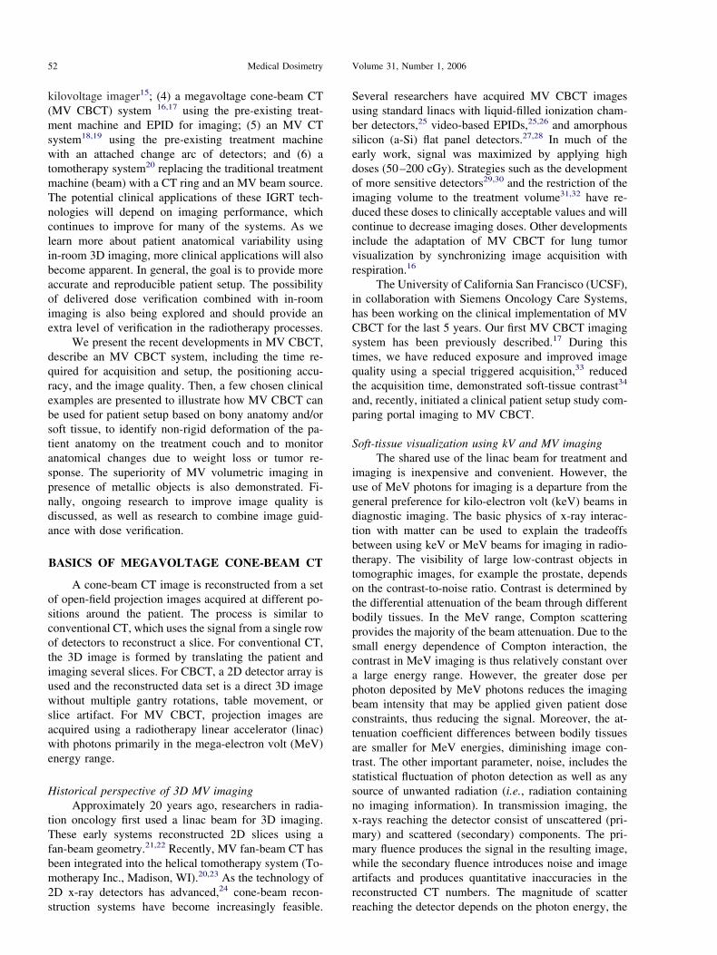
Fig. 1. MV CBCT imaging system using a conventional linacand a flat-panel EPID adapted for the detection of MeV pho-tons. In 45 seconds, the gantry rotates 200° around the patientacquiring one image per degree. The shift required to registerthe daily MV CBCT with the reference planning CT is avail-able approximately 3 minutes after the beginning of the image
acquisition.
IGRT with MV CBCT ! O. MORIN et al. 53
tions are conducted to assure image quality and willbe used to track the system long-term geometricalstability.
Imaging procedureAn MV CBCT acquisition is similar to an arc treat-
ment. The user first creates imaging template protocolsby specifying the total dose for a CBCT acquisition(2–60 monitor units [MU]), the reconstruction size (128,256, or 512), and the slice interval (1, 2, or 3 mm). ACBCT acquisition field is added to the existing patienttreatment field list using one of the pre-defined CBCTprotocols, which contain all the information needed bythe system to perform the acquisition (field size, start andend angle, total dose, flat panel distance, etc.). The fieldparameters are directly transferred to the control consoleof the linac and the user can rapidly place the system inposition for imaging. The linac gantry then rotates in acontinuous 200° arc (270° to 110°, clockwise), acquiringone portal image for each angle. This acquisition proce-dure lasts 45 seconds. The image reconstruction startsimmediately after the acquisition of the first portal im-age, and a typical 256 " 256 " 274 reconstructionvolume (1.1 " 1.1 " 1.0 mm3 voxel size) is completedin 110 seconds. The reconstructed MV CBCT and theraw projection images are saved in the patient databaseas DICOM images.
3D setup methodThe MV CBCT imaging procedure is well inte-
grated in the clinical workflow for patient alignment.Upon start of the MV CBCT acquisition, the referenceplanning CT of the patient is automatically loaded intothe COHERENCE™ Adaptive Targeting registrationsoftware, with the anatomical contours and the points ofinterest (Fig. 2a) defined in the planning system. Imme-diately after reconstruction, the software automaticallyregisters the MV CBCT with the reference CT using amaximization of mutual information algorithm. Furthermanual adjustment of the registration in any of the typ-ical planes (axial, coronal, and sagittal) is possible. In thecurrent software version, rotations have been disabledfrom the registration. The system can display each CTwith different color scheme, and the transparency levelscan be adjusted to visualize either CT or the MV CBCTimage sets. The table shift correction is constantly up-dated as the user fine-tunes the registration. The shiftrepresents the distance between the planned treatmentisocenter as specified on the CT image during planningand the true treatment isocenter, which corresponds in-trinsically to the center voxel of the MV CBCT recon-struction. The table shift needed to align the treatmentimage with the diagnostic CT is typically available 3minutes after the start of the MV CBCT acquisition.
System validationTo validate the new setup method, MV CBCT im-
ages (1 mm3 voxel size) and orthogonal portal images ofa phantom with 3 embedded gold seeds were obtainedwith the phantom positioned at 30 different known loca-tions in the treatment field. The initial alignment of theseeds served as the reference position. The Syngo-basedCOHERENCE™ therapist workspace was used to mea-sure the applied translations using the Portal Imaging(2D-2D) and the Adaptive Targeting (3D-3D) registra-tion applications. The mean and standard deviation of thedifferences between the applied shift and the measuredshift were 0.0 mm and 0.25 mm, respectively, for bothdata sets. This indicates that MV CBCT used with theAdaptive Targeting tool has the potential to verify pa-tient shifts with submillimeter precision. Portal imagingwas also demonstrated to be highly accurate in identify-ing translations of gold seeds.
Similar measurements were performed using an an-thropomorphic head phantom (Rando) to compare a 2Dsetup technique using digitally-reconstructed radio-graphs (DRR) and portal images with a 3D setup tech-nique using a diagnostic CT and MV CBCT images. TwoCT scans were acquired on Rando using (A) a typicalspiral 3-mm slice thickness, and (B) a fine sequential1-mm slice thickness. The CT room laser alignment wasmarked on Rando using 3 small fiducials. The images
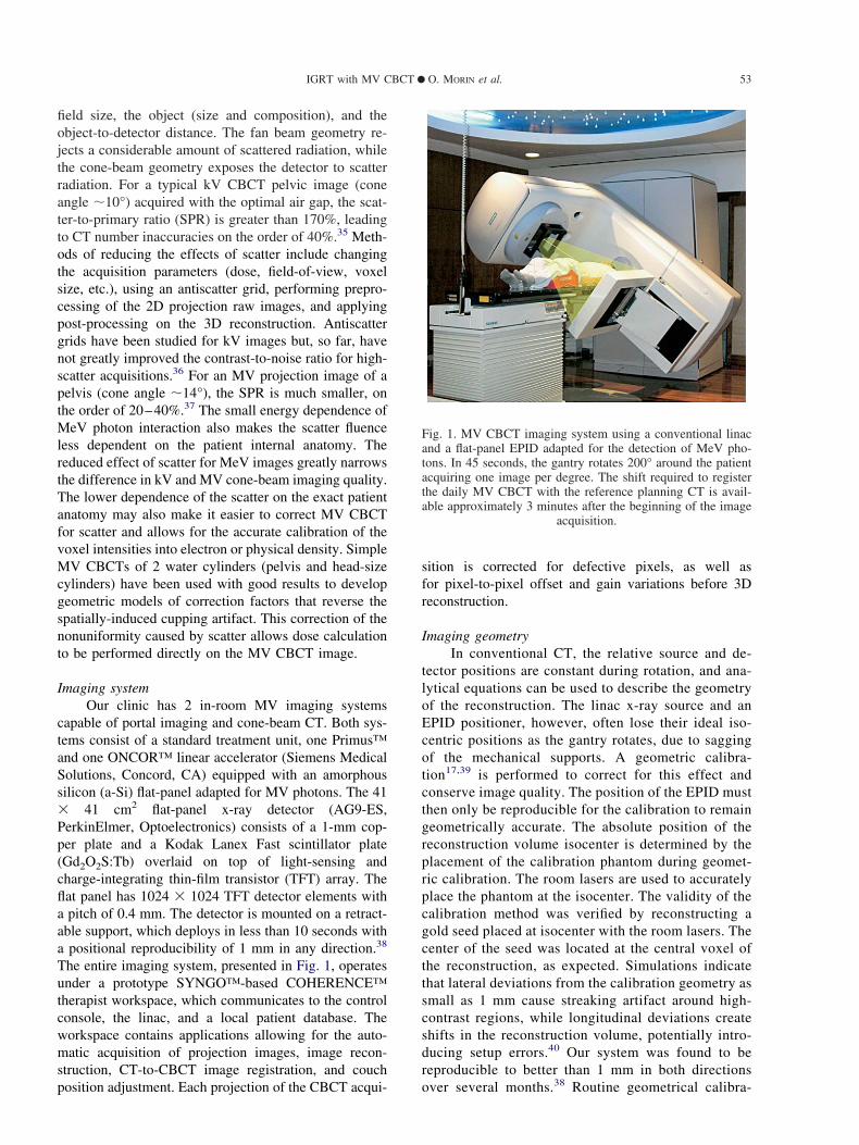
Fig. 2. A comparison of (a) a reference planning CT (gray) ofa prostate patient, (b) an MV CBCT of the patient lying on thetreatment table (color), and (c) a fusion of the 2 images. Withan MV CBCT of 14.4 MUs, structures such as the prostate,rectum, fat, muscles, bone, and gold seeds are visible. Regis-tration can be done automatically or manually using the 3typical views (axial, sagittal, and coronal). The planning con-tours and the points of interest can be displayed on the MV
CBCT to facilitate the registration.
Medical Dosimetry Volume 31, Number 1, 200654

were imported into the planning system and a simple2-field plan was created using the fiducials to define thetreatment isocenter. Two pairs of orthogonal DRRs werecreated using CT scans (A) and (B). Finally, the plan, theCT scans, the treatment isocenter points, and the DRRswere transferred to the treatment unit. The Rando headwas then aligned on the treatment table and translated to30 different locations in the treatment field. For eachposition, a pair of orthogonal portal images was acquiredto compare with the coarse (A) and fine (B) DRR refer-ences. MV CBCT images were also acquired at eachposition to compare with CT scans (A) and (B) in theAdaptive Targeting application. Only the automatic reg-istration was used to align the MV CBCT acquisitionswith the CT scans. The standard deviation of the differ-ences between the applied shift and the measured shiftwas 0.4 mm and 0.9 mm for the 3D registration using thefine and the typical CT scans, respectively. This suggeststhat finer CT scans are more accurate for patient posi-tioning using 3D alignment. Because the registration wasalmost entirely based on bony anatomy, there was nodifference in the setup accuracy using the 2D or 3Dmethod. However, the possibility of verifying setup inevery plane in 3D greatly facilitated the process of ob-taining the shift. Three-dimensional alignment shouldalso provide an added benefit in the case of objectrotation, which was excluded in the 2 described studies.Future work will include small rotations to study howthey affect the shift assessments made using the 2D and3D methods.
CLINICAL APPLICATIONS
The MV CBCT system described above offers sev-eral image-guided techniques outlined in Fig. 3. Onepossibility is the monitoring of intrafraction motion ofhigh-contrast features or fiducial markers using the flatpanel in ciné mode.7 This could be used to gate treat-ments for anatomical sites where in-treatment motion
may be problematic. With the same system, portal im-aging can be used to ensure setup based on bony anat-omy or gold seeds. Finally, with the introduction of anMV CBCT acquisition mode, it is possible to perform 3Dsetup based on bony anatomy and soft tissues to deter-mine patient specific anatomical variation using images.This new information can be used to tailor the treatmentplan for future fractions to account for the individual’svariation. The application of this technique to differentanatomical sites will depend on the ability to visualizethe relevant organs.
The following sections describe the work that hasbeen done to introduce MV CBCT in the clinic. OurIGRT objectives are to improve target positioning and tomonitor anatomical changes as the treatment progresses.The patient acquisitions performed so far have demon-strated that MV CBCT provides information about thepatients that was not available with portal imaging. Sev-eral studies are underway to determine the best usage ofthese new images.
Patient acquisitionsTo date, 90 acquisitions have been performed on a
total of 45 patients. The anatomical sites imaged includehead and neck, lung, and pelvis. All patients imaged withMV CBCT are required to give informed consent, andthe image acquisitions are performed in accordance withthe institutional review board’s ethical standards. Thepatients enrolled in our setup study are positioned on thetable using traditional immobilization devices and mark-ings and are aligned with the room lasers. Both an MVCBCT and an orthogonal pair of 2D portal images areacquired in this initial position. The patients are thenaligned using the orthogonal portal images comparedwith the reference DRRs. The applied shift is recordedand compared offline with the shift that would have beenapplied using MV CBCT. The dose used for MV CBCT
Fig. 3. An overview of various image-guided radiation therapy schemes using only a conventional linac and a flat-panelEPID. The large gray arrow represents the conventional flow of treatment with the main radiotherapy processes, and the
small arrows indicate the possible points of feedback into the processes.
IGRT with MV CBCT ! O. MORIN et al. 55

images ranges from 2 to 15 MUs depending on thefrequency of the acquisition and on the anatomical site.
Figure 4 provides a comparison of a diagnostic CT(left) with the MV CBCT (right) performed on the firstday of treatment for a typical head-and-neck patient. Thewindow level of both sets of images was adjusted toallow the best soft-tissue contrast. Only 7 MU was de-livered for the MV CBCT.
Patient dose in MV CBCTThe dose delivered to the patient during the MV
CBCT was estimated using a commercial treatment plan-ning software (Philips Pinnacle, Bothell, WA). An arctreatment was simulated on typical prostate and head-and-neck patients. With our current acquisition settings(projection angles and field size), the dose at the centersof the head and prostate were 0.9 and 0.75 cGy per MU,respectively. The maximum dose reached 1.24 cGy/MU
in a small anterior portion of the field of view. Althoughthe dose delivered during MV CBCT imaging is gener-ally negligible compared to the therapy dose, this extradose could easily be taken into account in the patient’streatment plan.
MV CBCT for prostate patient setupThe prostate can shift daily up to 1 cm relative to
pelvic bones due to gas and variations in rectal/bladderfilling.7 The variability in rectal distension can decreasethe probability of biochemical control, local control, andrectal toxicity in patients who are treated without dailyimage-guided prostate localization.8 At UCSF, mostprostate patients treated by external beam radiotherapyhave 3 gold markers implanted in the prostate, which arevisualized daily on orthogonal portal images for align-ment.41 Gold seeds are implanted via a minor invasiveprocedure, usually well tolerated; however, this may notbe feasible or appropriate in all circumstances. Patientsare asked to have their bladder full and an empty rectumat the time of treatment to place the gland at the mostinferior and posterior position in the body. In the exam-ple we present below, a typical prostate patient wasaligned using the 3 markers on portal images. After setupbut prior to treatment, the patient was imaged with MVCBCT. A total dose of 10.8 cGy (in the center of theprostate) was used to obtain the MV CBCT image. Alarge portion of the nonuniformity effect caused by scat-tered radiation was removed from the MV CBCT recon-struction using a gain calibration performed with solidwater in the field of view. This had the effect of com-pensating for the additional signal in the center of thepanel caused by scattered radiation on a given projection.The axial and coronal views of the patient diagnostic CTwith anatomical contours are presented on Figs. 2a. Fig-ure 2b shows that MV CBCT is capable of volumetricimaging with a good amount of soft-tissue information.Structures such as the prostate, the rectum, muscles, fat,air cavities, and gold seeds can be seen. It is clear bycomparing the gold seeds on Fig. 2a and 2b that MVimaging performs better in the presence of metal objects.Figure 2c represents the patient anatomy prior to treat-ment fused with the reference anatomy and the anatom-ical contours of the planning. Despite some minorchange in the rectum filling, the prostate shape andposition at the time of treatment matches well with theanatomy on the diagnostic CT. In the presence of goldseeds, we have found that MV CBCT acquisitions of lessthan 2 MU can be used for direct 3D alignment. Figure2c, however, shows the potential of using MV CBCT toalign the patient based on soft tissue without the need ofgold seeds. MV CBCT acquisitions of approximately 9MU are currently required on typical pelvic patients forconsistent prostate visualization without the need of goldseeds. By superimposing the anatomical contours on theCBCT image, the user may verify the impact of dailychanges in rectum filling on the definition of the gross
Fig. 4. Comparison of a diagnostic CT (left) with a 7-MU MVCBCT (right) for a typical head-and-neck patient. The windowlevel of both sets of images was adjusted to provide the best
soft-tissue contrast.
Medical Dosimetry Volume 31, Number 1, 200656

tumor volume (GTV). More accurate treatment schemesusing MV CBCT images could be studied by displayinganatomical contours and isodose lines from the treatmentplan on the MV CBCT. Therapists could ensure, forexample, that the rectal wall would not receive more thana limit dose on a given day of treatment.
MV CBCT for evaluating complex spinal cord displace-ment during setup
In this example, a patient with a T2N2b squamouscell carcinoma of the hypopharynx was imaged duringradiation treatment using MV CBCT. The patient waspositioned using an aquaplast head-and-shoulder maskindexed to the treatment couch. Originally, a TIMO-Chead holder was used, which provided a more pro-nounced angle of neck flexion during treatment. A stan-dard CT was used to obtain images for IMRT treatmentplanning. MV CBCT images were acquired at varioustimes during treatment. Orthogonal pairs of 2D portalimages were also obtained at the time of MV CBCTacquisition to compare the 2 modalities.
Figure 5a displays a DRR of the patient as initiallysimulated and planned. Easily visible structures such asthe posterior vertebral bodies, base of skull, anteriormaxilla, and aquaplast mask are outlined. Several weeksinto the treatment, an MV CBCT and a corresponding set
of portal images were acquired for this patient. Figure 5bshows the outlines from Fig. 5a superimposed on thisportal image. Although the base of skull and mask lineup well, the line of the anterior maxilla is not alignedwith the current position of the anterior maxilla. Addi-tionally, the line of the posterior vertebral bodies isdifficult to compare with the spinal anatomy. Figure 5cdisplays a sagittal image from the MV CBCT (grayscale) overlaid on the planning CT (color). The 2 sets ofimages have been registered to obtain an overall align-ment based on the anatomy of the skull and face, as wassimilarly done using the 2D technique.
As seen in Fig. 5c, the patient alignment using theMV CBCT and planning CT allows for further assess-ment of not only global position, but also the relativepositions of structures. Although the base of the skull iswell aligned, a 6-mm difference in the position of theanterior vertebral bodies between the planning CT andthe MV CBCT is clearly visible. The patient was subse-quently resimulated using a head holder with less flexion(TIMO-B) to place the patient in a robust and morecomfortable position. Once this plan was complete, anadditional MV CBCT was obtained, as seen overlyingthe new planning CT in Fig. 5d. Comparison of the newMV CBCT and planning CT indicates that overall align-ment, from the base of skull and along the vertebralbodies, was significantly improved using the new setup.
In this case, MV CBCT provided clear, informativeimages that allowed a more complete evaluation of pa-tient setup. The 2D portal images did show some varia-tion in patient positioning, but did not reveal the originand the full magnitude of the misalignment. Using MVCBCT images, we were able to measure the magnitudeof the misalignment, identify its source (a distortion ofthe neck), and confirm the correction of the problem. MVCBCT was a critical tool that led to replanning for moreaccurate treatments.
MV CBCT to monitor anatomical changesIn this next example, a patient with a T4bN1 squa-
mous cell carcinoma of the nasal cavity was imagedusing MV CBCT at various times while under treatmentwith external radiation therapy. The tumor involved theright nasal cavity and extended anterolaterally into themaxillary sinus and posteriorly to the nasopharynx. Priorto treatment, the extent of tumor was only evaluable onCT or magnetic resonance imaging examination. Thetumor was unresectable, and the patient was treateddefinitively with concurrent chemoradiation. A conven-tional noncontrast CT was used to obtain base images fortreatment planning. Four MV CBCTs were obtainedduring the course of radiation treatment in an effort toassess tumor anatomy variation that could not otherwisebe easily visualized.
Representative images of the planning CT and 2subsequent MV CBCTs are shown in Fig. 6. T0 repre-sents the start of radiation treatment. Examination of the
Fig. 5. Assessment and correction of a complex neck distortionusing MV CBCT. On the same day, a head-and-neck patientpositioned with a TIMO-C head holder was imaged usingportal imaging (b) and MV CBCT (c). A difference in thearching of the neck is difficult to detect using the lateral DRR(a) overlaid onto the portal image (b). Registration of thepatient MV CBCT (gray scale) with the kV CT (color) in (c)revealed a complex distortion of the lower neck region, whichcreates a 6-mm misalignment of the vertebral bodies and spinalcord. A new MV CBCT (color) compared with the new CT
(gray) in (d) showed improvement in the 3D alignment.
IGRT with MV CBCT ! O. MORIN et al. 57

MV CBCTs revealed an obvious soft-tissue densitywithin the right maxillary sinus. The air interface presentanteriorly provided excellent contrast with the soft-tissuedensity. In comparison, the left maxillary sinus wascompletely air filled, as seen on the planning CT andsubsequent MV CBCTs. These images show that there ismore soft-tissue density within the right maxillary sinuson the first MV CBCT (T0 # 6 days) as compared to theoriginal planning CT (T0 $ 14 days). This may indicatethat there was tumor growth between planning and startof treatment. A comparison of the first (T0 # 6 days) andsecond (T0 # 14 days) MV CBCT shows some decreasein the amount of soft tissue in the cavity.
The amount of air filling for each side of the max-illary sinus at the given timepoints was calculated. Thisis plotted for the right (tumor affected sinus) and the leftmaxillary sinus (uninvolved sinus) in Fig. 6. If we were
to assume that the soft-tissue density within the affectedsinus were exclusively tumor, rather than a combinationof tumor and secretions, this quantitative assessment ofair volume within the sinuses may serve as a surrogatefor tumor response. This example demonstrates the po-tential of this imaging modality to monitor changes intarget volume that are not otherwise evaluable.
The variation in target volume over a course oftreatment may have important dosimetric consequencesthat require replanning. At what point during treatment apatient needs to be replanned is currently difficult todefine. Because the MV CBCT images are obtained inthe treatment position, it is possible to project the radi-ation treatment plan onto these images to assess the exactdaily delivered dose.42
Dose calculation using MV CBCTA recent validation study of dose calculation using
MV CBCT in a commercial planning system was per-formed to assess the dose calculation accuracy.42 AnIMRT plan for a nasopharyngeal carcinoma was firstdefined using a conventional CT. On the first day oftreatment, an MV CBCT acquisition was acquired. Thepatient anatomy and position on the MV CBCT was ingood agreement with the initial CT. The same plan(isocenter, contours, and beams) was applied to the MVCBCT image, which had been corrected for nonunifor-mity and calibrated for electron density. The isodosesand the dose-volume histograms from the regular CT andthe MV CBCT were in very good agreement. A gammafunction43 was computed to compare quantitatively the 2dose distributions. The dose calculation accuracy usingMV CBCT was better than 3% or 3 mm everywhere.This result opens the possibility of using MV CBCT tomonitor the dosimetrical impact of setup errors, localdeformations, weight loss, and soft-tissue shrinkage/swelling.
MV CBCT to perform setup for lung tumorAn MV CBCT was used to position a patient with a
T2N0M0 squamous cell carcinoma of the lung. Thepatient had refused surgery and, therefore, was treatedwith definitive radiation therapy. At the time of fluoro-scopic simulation, the tumor was noted to be immobile.This is obviously not the case for most lung tumors.6 Theisocenter was placed within the tumor volume and anongated planning CT was obtained.
A hypofractionated course of radiation was pre-scribed, and it was therefore exceedingly important toensure accurate set up of the tumor within the field. Forthis reason, and because of the reduced number of frac-tions, MV CBCT was used for daily setup.
On the first day of treatment, a pair of orthogonalportal images and an MV CBCT was acquired. The MVCBCT images were aligned with the planning CT usingthe soft-tissue mass itself to ensure adequate tumor dose.On the first treatment day, 2 additional MV CBCTs were
Fig. 6. Tumor size variation during the course of radiotherapy.The planning CT (left) of a patient affected by a right maxillarysinus tumor was acquired 14 days before the beginning of thetreatment fractions T0. Two MV CBCTs (middle and right)were acquired 6 days and 14 days after T0. The evolution of thetumor size is visible on the axial (top) and sagittal (middle)views. The bottom plot presents the air volume in the cavities
as a function of time.
Medical Dosimetry Volume 31, Number 1, 200658

obtained to verify this positioning method; the first fol-lowing the applied shift, and the second after treatmentdelivery to evaluate any intrafraction motion during the20 minutes of IMRT treatment. The post-shift MVCBCT showed excellent alignment with the planningCT, and the post-treatment MV CBCT remained wellaligned. On subsequent days, a single MV CBCT wasperformed for positioning.
As an academic exercise, the measured shift thatcould have been made using only 2D portal images forpositioning was applied to the MV CBCT and referenceCT images. As can be seen in Fig. 7, if the sternum isaligned (Fig. 7c), the tumor in the right lung is not (Figs.7a and 7b), and would be underdosed. A similar mis-alignment of tumor happens when the MV CBCT and theplanning CT are aligned based on vertebral body posi-tion, a common way to verify the position of thoracicpatients.
MV CBCT to complement planning for patient withdense metal objects
Metal artifacts on diagnostic CT images cause asignificant problem for identifying structures. Severalpost-processing algorithms have been developed to re-duce the image degradation.44 However, the level ofartifact reduction is still only adequate on images af-fected by small metal objects, such as gold seeds. Incomparison to the keV energy range, the presence ofhigh atomic number (Z) material has relatively littleimpact on the image quality of MV CBCT. Therefore,MV CBCT images can be used to complement missinginformation during planning or patient position verifica-tion. Figure 8 demonstrates the superiority of MV CBCTin the presence of metal objects. An MV CBCT wasperformed on a patient who underwent major reconstruc-tion of the left portion of the pelvis. Figures 8a and 8bcompare the same sagittal and axial slices on the diag-nostic CT (left) and the MV CBCT (right). Figure 8cshows that only the MV cone-beam image, which was
window leveled to show the metal pieces, can render the3D object correctly.
The presence of metal artifacts in CT makes itimpossible to use the CT numbers quantitatively for dosecalculations. For these cases the treated volume is usu-ally assumed to be water-equivalent in the treatment plancalculations. Treating the volume as water and ignoringthe presence of metal may cause severe deviations be-tween the planned dose distribution and the real dosedelivered. Ongoing research is being performed to cali-brate the MV CBCT for direct use in dose calculations,thus allowing for more accurate dose calculations usinginhomogeneity corrections. Currently at UCSF, mostprostate patients with hip prosthesis undergo an MVCBCT acquisition to complement the CT during thecontouring process in the planning system.45 Other caseswhere MV CBCT could be used include patients withdental amalgam or implants, orthopedic implants or pros-theses, and high-dose-rate brachytherapy catheters.
FUTURE DIRECTIONS
We have described the performance of a clinicalMV CBCT system and discussed some of its possible
Fig. 7. Images comparing the use of MV CBCT and portalimaging for setup of a hypofractionated lung patient with alarge and relatively immobile tumor. On the first fraction, theshift assessment was done using the sternum on portal images.This shift was then applied to an MV CBCT acquired the sameday. Three views of the CT (gray scale) fused with the MVCBCT (color) are shown. While the sternum is well aligned on(c) the tumor is not on (a) and (b). For this reason, the patientwas aligned using the soft-tissue information on the MV CBCT
images.
Fig. 8. Images showing the superior performance of MV CBCT(right) over CT (left) in the presence of dense metal objects. Allmetal pieces used for this hip reconstruction are clearly visible
on the MV CBCT 3D rendering (bottom).
IGRT with MV CBCT ! O. MORIN et al. 59

uses in IGRT. Despite the simplicity of the system,which consists of a conventional linac with an attachedEPID, we have been able to locate objects with millime-ter accuracy and visualize a variety of organs, includingthe prostate. Clinically, MV CBCT has already provenuseful to evaluate the alignment of the spinal cord, locateand position immobile lung tumors, track the evolutionof tumors in the sinus, and improve the delineation ofstructures in CT images that suffer from metal artifacts.These examples demonstrate the potential for MV CBCTto increase our understanding of the patient position onthe treatment table and improve tumor targeting.
Soft-tissue resolution is key for in-room 3D imag-ing to complement the offering of portal imaging. Usingour current MV CBCT system, we are able to visualizethe prostate using approximately 9 MU. Ongoing re-search to improve image quality will further increasesoft-tissue resolution. Monte Carlo simulations and ex-periments have demonstrated that using a lower-Z targetgenerates more low-energy photons and enhances thecontrast of portal images significantly.46,47 In fact, sim-ply removing the flattening filter causes contrast im-provement in the order of 200%.48 Combinations oftarget and flattener have been studied to optimize thecombined applications of therapy and high-contrastmegavoltage imaging.44 Recent acquisitions of MVCBCT on a sheep head and on a CT contrast phantomusing a carbon target and no flattening filter showedcontrast resolution on the order of 0.5% for a dose of 3.5cGy. The difference in density between the prostate andthe surrounding tissues is in the order of 1–4%. With theimproved beam line, one could project the resolution ofthe prostate and optic nerve with 1–2 cGy. Clinicalimages will soon be acquired with the new beam line todetermine the extent of soft-tissue resolution.
New adaptive filtering schemes for MV imaginghave also been developed and showed important noisereduction on projection images.30 Finally, the biggestimprovement in image quality might come from thedetector itself, using denser and new scintillation mate-rials, which would push the detection efficiency peaktoward the photon energies of the treatment beam. Thenet result of all these efforts is that the contrast-to-noiseratio can still be significantly improved, which will allowMV CBCT to become a routine option for a wider rangeof clinical applications.
While the use of 3D imaging to account for thepatient anatomy at treatment time is a great advance inassuring radiotherapy accuracy, the true determining fac-tor for treatment outcomes is the dose delivered to thepatient. MV CBCT may also play a key role in trackingthe dose distributions delivered to the patient. As previ-ously mentioned, we are currently researching the cor-rection of MV CBCT image artifacts and the calibrationof MV CBCT for electron or physical density. Thecalibrated MV CBCT images could be used to recalcu-late the dose delivered by the treatment plan to obtain a
more accurate estimate of the true delivered dose.42
Another possibility under investigation is the additionaluse of the EPID during treatment to measure the energyfluence delivered by the linac. The measured fluence andthe MV CBCT of the patient would be used together toestimate the delivered dose.49–51 In this case, the effectof both patient anatomical changes as well as linac de-livery errors could be assessed. These dosimetric verifi-cations may provide additional information, which canbe used to further optimize and improve radiation ther-apy treatments.
Acknowledgment—The authors thank the following persons for theirvaluable contributions, enlightening discussions, and active participa-tion on the acquisition of the clinical cone-beam images: Albert Chan,Michael Ballin, Chris Malfati, Ping Xia, and Lynn Verhey at UCSF;and Ali Bani-Hashemi and his team at Siemens OCS. This research wassupported by Siemens Oncology Care Systems (OCS). One of theauthors (O.M.) acknowledges a doctoral scholarship from the NationalSciences and Engineering Research Council of Canada (NSERC).
REFERENCES
1. Jacob, R.; Hanlon, A.; Horwitz, E.; et al. The relationship ofincreasing radiotherapy dose to reduced distant metastases andmortality in men with prostate cancer. Cancer 100:538–43; 2004.
2. Lee, N.; Xia, P.; Fischbein, N.J.; et al. Intensity-modulated radia-tion therapy for head-and-neck cancer: The UCSF experiencefocusing on target volume delineation. Int. J. Radiat. Oncol. Biol.Phys. 57:49–60; 2003.
3. Kuban, D.; Pollack, A.; Huang, E.; et al. Hazards of dose escala-tion in prostate cancer radiotherapy. Int. J. Radiat. Oncol. Biol.Phys. 57:1260–8; 2003.
4. Hurkmans, C.W.; Cho, B.C.J.; Damen, E.; et al. Reduction ofcardiac and lung complication probabilities after breast irradiationusing conformal radiotherapy with or without intensity modula-tion. Radiother. Oncol. 62:163–71; 2002.
5. Tubiana, M.; Eschwege, F. Conformal radiotherapy and intensity-modulated radiotherapy: Clinical data. Acta Oncol. 39:555–67;2000.
6. Shih, H.A.; Jiang, S.B.; Aljarrah, K.M.; et al. Internal targetvolume determined with expansion margins beyond compositegross tumor volume in three-dimensional conformal radiotherapyfor lung cancer. Int. J. Radiat. Oncol. Biol. Phys. 60:613–22; 2004.
7. Lometti, M.W.; Morin, O.; Aubin, M.; et al. Intra- fractional andinter/intra-field organ motion and a proposal for a new patientset-up protocol. American Association of Physicists in Medicine47th Annual Meeting, Seattle, WA. Med. Phys. 32:2160; 2005.
8. de Crevoisier R.; Tucker, S.L.; Dong, L.; et al. Increased risk ofbiochemical and local failure in patients with distended rectum onthe planning CT for prostate cancer radiotherapy. Int. J. Radiat.Oncol. Biol. Phys. 62:965; 2005.
9. Hansen, E.K.; Xia, P.; Quivey, J.; et al. The roles of repeat CTimaging and re-planning during the course of IMRT for patientswith head and neck cancer. Int. J. Radiat. Oncol. Biol. Phys.60:S159; 2004.
10. Barker, Jr.; J.L., Garden, A.S.; Ang, K.K.; et al. Quantification ofvolumetric and geometric changes occurring during fractionatedradiotherapy for head- and-neck cancer using an integrated CT/linear accelerator system. Int. J. Radiat. Oncol. Biol. Phys. 59:960–70; 2004.
11. Ma, C.-M.; Paskalev, K.; et al. In-room CT techniques for image-guided radiation therapy. Med. Dosim. 31:30–9; 2006.
12. Wong, J.R.; Cheng, C.W.; Grimm, L.; et al. Clinical implementa-tion of the world’s first Primatom, a combination of CT scannerand linear accelerator, for precise tumor targeting and treatment.Med. Phys. 17:271–6; 2001.
13. Jaffray, D.A.; Siewerdsen, J.H.; Wong, J.W.; et al. Flat-panelcone-beam computed tomography for image-guided radiation ther-apy. Int. J. Radiat. Oncol. Biol. Phys. 53:1337–49; 2002.
Medical Dosimetry Volume 31, Number 1, 200660

14. Oelfke, U.; Tucking, T.; Nill, S.; et al. Linac-integrated KV cone-beam CT: Technical features and first applications. Med. Dosim.31:62–70; 2006.
15. Sorensen, S.P.; Chow, E.; Kriminski, S.; et al. Image guidedradiotherapy using a mobile kilovoltage x-ray device. Med. Dosim.31:40–50; 2006.
16. Sillanpaa, J.; Chang, J.; Mageras, G.; et al. Developments inmegavoltage cone beam CT with an amorphous silicon EPID:Reduction of exposure and synchronization with respiratory gat-ing. Med. Phys. 32:819–29; 2005.
17. Pouliot, J.; Bani-Hashemi, A.; Chen, J.; et al. Low-dose megavolt-age cone-beam CT for radiation therapy. Int. J. Radiat. Oncol.Biol. Phys. 61:552–60; 2005.
18. Gildersleve, J.; Dearnaley, D.P.; Evans, P.M.; et al. A randomisedtrial of patient repositioning during radiotherapy using a megavolt-age imaging system. Radiother. Oncol. 31:161–8; 1994.
19. Evans, P.M.; Gildersleve, J.Q.; Rawlings, C.; et al. Technical note:The implementation of patient position correction using a mega-voltage imaging device on a linear accelerator. Br. J. Radiol.66:833–8; 1993.
20. Mackie, T.R.; Kapatoes, J.; Ruchala, K.; et al. Image guidance forprecise conformal radiotherapy. Int. J. Radiat. Oncol. Biol. Phys.56:89–105; 2003.
21. Swindell, W.; Simpson, R.G.; Oleson, J.R.; et al. Computed to-mography with a linear accelerator with radiotherapy applications.Med. Phys. 10:416–20; 1983.
22. Nakagawa, K.; Akanuma, A.; Aoki, Y.; et al. A quantitative patientset-up and verification system using megavoltage CT scanning. Int.J. Radiat. Oncol. Biol. Phys. 21:228; 1991.
23. Ruchala, K.J.; Olivera, G.H.; Schloesser, E.A.; et al. MegavoltageCT on a tomotherapy system. Phys. Med. Biol. 44:2597–621;1999.
24. Mosleh-Shirazi, M.A.; Evans, P.M.; Swindell, W.; et al. A cone-beam megavoltage CT scanner for treatment verification in con-formal radiotherapy. Radiother. Oncol. 48:319–28; 1998.
25. Midgley, S.; Millar, R.M.; Dudson, J. A feasibility study formegavoltage cone beam CT using a commercial EPID. Phys. Med.Biol. 43:155–69; 1998.
26. Spies, L.; Ebert, M.; Groh, B.A.; et al. Correction of scatter inmegavoltage cone-beam CT. Phys. Med. Biol. 46:821–33; 2001.
27. Ford, E.C.; Chang, J.; Mueller, K.; et al. Cone-beam CT withmegavoltage beams and an amorphous silicon electronic portalimaging device: Potential for verification of radiotherapy of lungcancer. Med. Phys. 29:2913–24; 2002.
28. Groh, B.A.; Siewerdsen, J.H.; Drake, D.G.; et al. A performancecomparison of flat-panel imager-based MV and kV cone-beam CT.Med. Phys. 29:967–75; 2002.
29. Seppi, E.J.; Munro, P.; Johnsen, S.W.; et al. Megavoltage cone-beam computed tomography using a high-efficiency image recep-tor. Int. J. Radiat. Oncol. Biol. Phys. 55:793–803; 2003.
30. Ghelmansarai, F.; Bani-Hashemi, A.; Pouliot, J.; et al. Soft tissuevisualization using a highly efficient megavoltage cone beam CTimaging system. Proceedings of the International Society for Op-tical Engineering Meeting, San Diego, 2003. San Diego: MedicalImaging; 5745:159–70; 2005.
31. Sidhu, K.; Ford, E.C.; Spirou, S.; et al. Optimization of conformalthoracic radiotherapy using cone-beam CT imaging for treatmentverification. Int. J. Radiat. Oncol. Biol. Phys. 55:757–67; 2003.
32. Anastasio, M.A.; Daxin, S.; Xiaochuan, P.; et al. A preliminaryinvestigation of local tomography for megavoltage CT imaging.Med. Phys. 30:2969–80; 2003.
33. Ghelmansarai, F.A.; Misra, S.; Pouliot, J. Electronic readout ofa-Si EPIDs for optimum signal-to-noise ratio. Proceedings of theInternational Society for Optical Engineering Meeting, San Diego,2003. San Diego: Medical Imaging; 5030:788–98; 2003.
34. Pouliot, J.; Bani-Hashemi, A.; Aubin, M.; et al. Clinical integrationof a MV cone-beam system for image-guided treatment. American
Association of Physicists in Medicine 47th Annual Meeting,Seattle, WA. Med. Phys. 32:1938; 2005.
35. Siewerdsen, J.H.; Jaffray, D.A. Cone-beam computed tomographywith a flat-panel imager: Magnitude and effects of x-ray scatter.Med. Phys. 28:220–31; 2001.
36. Siewerdsen, J.H.; Moseley, D.J.; Bakhtiar, B.; et al. The influenceof antiscatter grids on soft-tissue detectability in cone-beam com-puted tomography with flat-panel detectors. Med. Phys. 31:3506–20; 2004.
37. Jaffray, D.A.; Battista, J.J.; Fenster, A.; et al. X-ray scatter inmegavoltage transmission radiography: Physical characteristicsand influence on image quality. Med. Phys. 21:45–60; 1994.
38. Morin, O.; Chen, J.; Aubin, M.; et al. Evaluation of the mechanicalstability of megavoltage imaging system using a new flat panelpositioner. Proceedings of the International Society for OpticalEngineering Meeting, San Diego, 2005. San Diego: Medical Im-aging; 5745:704–10; 2005.
39. Wiesent, K.; Barth, K.; Navab, N.; et al. Enhanced 3D-reconstruc-tion algorithm for C-arm systems suitable for interventional pro-cedures. IEEE Trans. Med. Imaging 19:391–403; 2000.
40. Morin, O.; Bose, S.; Chen, J.; et al. The impact of portal imagershifts and the assumption of rigid isocentricity on megavoltagecone-beam CT images. American Association of Physicists inMedicine 47th Annual Meeting, Seattle, WA. Med. Phys. 32:1916;2005.
41. Downs, T.M.; Roach, M.; Grossfeld, G.D.; et al. The University ofCalifornia, San Francisco (UCSF) experience with permanentlyimplanted gold markers for daily prostate realignment during ra-diation therapy. Int. J. Radiat. Oncol. Biol. Phys. 54:280; 2002.
42. Morin, O.; Chen, J.; Aubin, M.; et al. Dose calculation usingmegavoltage cone-beam CT. American Society for TherapeuticRadiology and Oncology 47th Annual Meeting, Denver, CO. Int. J.Radiat. Oncol. Biol. Phys. 63:S62–3; 2005.
43. Low, D.A.; Harms, W.B.; Mutic, S.; et al. A technique for thequantitative evaluation of dose distributions. Med. Phys. 25:656–61; 1998.
44. Mahnken, A.H.; Raupach, R.; Wildberger, J.E.; et al. A newalgorithm for metal artifact reduction in computed tomography: Invitro and in vivo evaluation after total hip replacement. Invest.Radiol. 38:769–75; 2003.
45. Aubin, M.; Morin, O.; Bucci, K.; et al. Effectiveness of MV CBCTfor patients with implanted high-Z material. American Associationof Physicists in Medicine 47th Annual Meeting, Seattle, WAMed.Phys. 32:1933; 2005.
46. Nishimura, K.; Svatos, M.; Zheng, Z.; et al. Target flattener com-binations for combined therapy and high contrast megavoltageimaging. American Association of Physicists in Medicine 47thAnnual Meeting, Seattle, WA. Med. Phys. 32:1909; 2005.
47. Flampouri, S.; Evans, P.M.; Verhaegen, F.; et al. Optimization ofaccelerator target and detector for portal imaging using MonteCarlo simulation and experiment. Phys. Med. Biol. 47:3331–49;2002.
48. Zheng, Z.; Ghelmansarai, F.; Svatos, M. Simplified beamlines forhigh performance portal imaging. American Association of Phys-icists in Medicine 46th Annual Meeting, Pittsburgh, PA. Med.Phys. 30:1474; 2003.
49. Chen, J.; Chuang, C.F.; Morin, O.; Aubin, M.; Pouliot, J. Calibra-tion of an amorphous-silicon flat panel portal imager for exit-beamdosimetry. Med. Phys. 33:584–94; 2006.
50. Partridge, M.; Ebert, M.; Hesse, B.M. IMRT verification by three-dimensional dose reconstruction from portal beam measurements.Med. Phys. 29:1847–58; 2002.
51. Pouliot, J.; Chen, J.; Zheng, Z.; et al. Dose reconstruction fromMV conebeam CT for dose-guided radiation therapy. AmericanAssociation of Physicists in Medicine 46th Annual Meeting, Pitts-burgh, PA. Med. Phys. 31:1832; 2004.
IGRT with MV CBCT ! O. MORIN et al. 61