
Medistim MiraQ™ System User Manual
122
Medistim MiraQ™ System User Manual MQ1990GB Rev D - Software Version 4.1
-
Upload
khangminh22 -
Category
Documents
-
view
0 -
download
0
Transcript of Medistim MiraQ™ System User Manual
Medistim MiraQ™ SystemUser ManualMQ1990GB Rev D - Software Version 4.1

2 © Medistim 2015 2
1. INTRODUCTION 8
1.1 Purpose . . . . . . . . . . . . . . . . . . . . . . . . . . . . . . . . . . . . . . .8
1.2 Contact information . . . . . . . . . . . . . . . . . . . . . . . . . . . . .8
1.3 Scope. . . . . . . . . . . . . . . . . . . . . . . . . . . . . . . . . . . . . . . . .8
1.4 Manual structure and use . . . . . . . . . . . . . . . . . . . . . . . .8
1.4.1 Relevant books and documents . . . . . . . . . . . . . . . . . . 8
1.4.2 Update of User Manual . . . . . . . . . . . . . . . . . . . . . . . . . 8
1.4.3 User Manual language options . . . . . . . . . . . . . . . . . . . 8
1.4.4 Technical description . . . . . . . . . . . . . . . . . . . . . . . . . . 9
1.4.5 Warning statements and safety markings . . . . . . . . . . 9
1.5 Acronyms,abbreviationsanddefinitions . . . . . . . . . . . .9
1.5.1 Overview of symbols . . . . . . . . . . . . . . . . . . . . . . . . . . 10
2. INDICATIONS FOR USE 11
2.1 Indication for use statement . . . . . . . . . . . . . . . . . . . . .11
2.2 Contraindications . . . . . . . . . . . . . . . . . . . . . . . . . . . . .11
2.3 Intended use . . . . . . . . . . . . . . . . . . . . . . . . . . . . . . . . . .12
2.4 Operational requirements for use . . . . . . . . . . . . . . . . .12
2.4.1 Intended conditions for use . . . . . . . . . . . . . . . . . . . . 12
2.5 Intendeduserprofiles&personnelrequirements . . . .13
2.6 Limitations for use . . . . . . . . . . . . . . . . . . . . . . . . . . . . .17
2.6.1 Acoustic power reporting . . . . . . . . . . . . . . . . . . . . . . 17
2.6.2 Interpreting Thermal and Mechanical Index . . . . . . . . 17
2.7 Environment, health and safety. . . . . . . . . . . . . . . . . . .18
2.8 Possibleoperationalinfluence . . . . . . . . . . . . . . . . . . .18
2.9 Consumables . . . . . . . . . . . . . . . . . . . . . . . . . . . . . . . . .19
2.9.1 Necessary consumable items: . . . . . . . . . . . . . . . . . . 19
2.9.2 Optional consumable items: . . . . . . . . . . . . . . . . . . . . 19
2.10 Warranty . . . . . . . . . . . . . . . . . . . . . . . . . . . . . . . . . . . . .19
2.11 Access to spare parts and service . . . . . . . . . . . . . . . .19
3. SYSTEM OVERVIEW 20
3.1 The Medistim MiraQ™ Systems . . . . . . . . . . . . . . . . . .21
3.2 Touch monitor . . . . . . . . . . . . . . . . . . . . . . . . . . . . . . . . .21
3.3 Monitor arm. . . . . . . . . . . . . . . . . . . . . . . . . . . . . . . . . . .22
3.3.1 Transport mode . . . . . . . . . . . . . . . . . . . . . . . . . . . . . . 22
3.4 Graphical user interface. . . . . . . . . . . . . . . . . . . . . . . . .23
3.5 Frontpanelandchannelconfigurations . . . . . . . . . . . .23
3.5.1 The Medistim MiraQ™ System model number . . . . . 24
3.6 Storagecompartment . . . . . . . . . . . . . . . . . . . . . . . . . .25
3.7 Media panel. . . . . . . . . . . . . . . . . . . . . . . . . . . . . . . . . . .25
3.7.1 Key card reader . . . . . . . . . . . . . . . . . . . . . . . . . . . . . . 26
3.7.2 External monitor interface . . . . . . . . . . . . . . . . . . . . . . 26
3.7.3 USB port connections. . . . . . . . . . . . . . . . . . . . . . . . . 26
3.7.4 Network connector . . . . . . . . . . . . . . . . . . . . . . . . . . . 26
3.8 Printer and printer module . . . . . . . . . . . . . . . . . . . . . . .26
Contents

3© Medistim 20152
3.9 Ventilation . . . . . . . . . . . . . . . . . . . . . . . . . . . . . . . . . . . .27
3.10 Cable hooks and power cable . . . . . . . . . . . . . . . . . . . .27
3.11 Lockable wheels . . . . . . . . . . . . . . . . . . . . . . . . . . . . . . .27
4. DELIVERY AND CONFIGURATION 28
4.1 Delivery . . . . . . . . . . . . . . . . . . . . . . . . . . . . . . . . . . . . . .28
4.1.1 Receiving the Medistim MiraQ™ System . . . . . . . . . . 28
4.1.2 Unpacking and packing . . . . . . . . . . . . . . . . . . . . . . . 28
4.2 SystemVerification . . . . . . . . . . . . . . . . . . . . . . . . . . . . .28
4.2.1 Verifying system identity . . . . . . . . . . . . . . . . . . . . . . . 28
4.2.2 Verifying electrical safety . . . . . . . . . . . . . . . . . . . . . . 28
4.3 Initialconfiguration . . . . . . . . . . . . . . . . . . . . . . . . . . . . .28
4.3.1 Basicsoftwareconfiguration . . . . . . . . . . . . . . . . . . . 28
5. OPERATING THE MEDISTIM MiraQ™ SYSTEM 30
5.1 Preparations . . . . . . . . . . . . . . . . . . . . . . . . . . . . . . . . . .30
5.2 Startup. . . . . . . . . . . . . . . . . . . . . . . . . . . . . . . . . . . . . . .31
5.2.1 Starting the system . . . . . . . . . . . . . . . . . . . . . . . . . . . 31
5.2.2 Selecting application. . . . . . . . . . . . . . . . . . . . . . . . . . 31
5.3 Patient data . . . . . . . . . . . . . . . . . . . . . . . . . . . . . . . . . . .32
5.3.1 Entering patient data . . . . . . . . . . . . . . . . . . . . . . . . . . 32
5.3.2 Retrieving patient data . . . . . . . . . . . . . . . . . . . . . . . . 32
5.3.3 Accessing patient data using DICOM . . . . . . . . . . . . 33
5.4 Selectingworkflow . . . . . . . . . . . . . . . . . . . . . . . . . . . . .33
5.5 Connectingprobes . . . . . . . . . . . . . . . . . . . . . . . . 345.6 TTFMprobeverification . . . . . . . . . . . . . . . . . . . . . . . . .35
5.7 Definingmeasurementlocation. . . . . . . . . . . . . . . . . . .36
5.8 Performinglivemeasurements . . . . . . . . . . . . . . . . . . .37
5.8.1 Activating and deactivating input channels . . . . . . . . 37
5.8.2 Adjusting volume . . . . . . . . . . . . . . . . . . . . . . . . . . . . . 38
5.8.3 AdjustingflowcurvesandDopplerdisplays . . . . . . . 38
5.8.4 Probe and measurement properties . . . . . . . . . . . . . . 39
5.9 Savingmeasurements. . . . . . . . . . . . . . . . . . . . . . . . . .39
5.10 Review of recorded data . . . . . . . . . . . . . . . . . . . . . . . .39
5.11 Creatingandviewingcasereports . . . . . . . . . . . . . . . .41
5.11.1 Tasks after operation by surgeon . . . . . . . . . . . . . . . . 41
5.12 Cleaning,disinfectionandsterilization. . . . . . . . . . . . .41
5.12.1 System . . . . . . . . . . . . . . . . . . . . . . . . . . . . . . . . . . . . . 41
5.12.2 Probes . . . . . . . . . . . . . . . . . . . . . . . . . . . . . . . . . . . . . 41
6. MEASUREMENT TYPES 42
6.1 Transittimeflowmeasurement(TTFM) . . . . . . . . . . . .42
6.1.1 The TTFM principle . . . . . . . . . . . . . . . . . . . . . . . . . . . 42
6.1.2 Tasks during procedure by surgeon . . . . . . . . . . . . . . 42
6.1.3 Tasks during procedure by operator . . . . . . . . . . . . . 43
6.2 Doppler measurement . . . . . . . . . . . . . . . . . . . . . . . . . .43
6.2.1 The Doppler principle . . . . . . . . . . . . . . . . . . . . . . . . . 43
6.2.2 Operation . . . . . . . . . . . . . . . . . . . . . . . . . . . . . . . . . . . 44
6.2.3 Tasks during procedure by operator . . . . . . . . . . . . . 44
6.2.4 Performing vessel search . . . . . . . . . . . . . . . . . . . . . . 45
6.2.5 Detect position and quantify a stenosis . . . . . . . . . . 45

4 © Medistim 2015 4
6.3 Pressure inputs. . . . . . . . . . . . . . . . . . . . . . . . . . . . . . . .46
6.3.1 Calibrating the pressure transducer . . . . . . . . . . . . . . 46
6.4 Auxiliary inputs . . . . . . . . . . . . . . . . . . . . . . . . . . . . . . . .46
6.4.1 Calibrating the AUX channel for ECG . . . . . . . . . . . . . 47
6.4.2 Calibrating the AUX channel for pressure . . . . . . . . . 48
6.5 ImagingMeasurements . . . . . . . . . . . . . . . . . . . . . . . . .48
7. ULTRASOUND IMAGING 49
7.1 General . . . . . . . . . . . . . . . . . . . . . . . . . . . . . . . . . . . . . .49
7.1.1 Imaging presets . . . . . . . . . . . . . . . . . . . . . . . . . . . . . . 49
7.1.2 Selecting mode . . . . . . . . . . . . . . . . . . . . . . . . . . . . . . 50
7.1.3 The Imaging Screen . . . . . . . . . . . . . . . . . . . . . . . . . . 50
7.1.4 Auto-freeze . . . . . . . . . . . . . . . . . . . . . . . . . . . . . . . . . 53
7.1.5 Imaging properties . . . . . . . . . . . . . . . . . . . . . . . . . . . 54
7.1.6 Exposure and ultrasound statistics . . . . . . . . . . . . . . 56
7.2 2D mode . . . . . . . . . . . . . . . . . . . . . . . . . . . . . . . . . . . . .56
7.2.1 2D tab . . . . . . . . . . . . . . . . . . . . . . . . . . . . . . . . . . . . . 56
7.2.2 2D control panel . . . . . . . . . . . . . . . . . . . . . . . . . . . . . 56
7.3 Color mode . . . . . . . . . . . . . . . . . . . . . . . . . . . . . . . . . . .57
7.3.1 Color tab . . . . . . . . . . . . . . . . . . . . . . . . . . . . . . . . . . . 57
7.3.2 Region of interest (ROI) . . . . . . . . . . . . . . . . . . . . . . . 57
7.3.3 Velocity Scale . . . . . . . . . . . . . . . . . . . . . . . . . . . . . . . 58
7.3.4 Color control panel . . . . . . . . . . . . . . . . . . . . . . . . . . . 59
7.3.5 Color Flow tips . . . . . . . . . . . . . . . . . . . . . . . . . . . . . . 60
7.4 PWmode(Pulsed-WaveDoppler) . . . . . . . . . . . . . . . . .61
7.4.1 PW tab . . . . . . . . . . . . . . . . . . . . . . . . . . . . . . . . . . . . . 61
7.4.2 PW gate control . . . . . . . . . . . . . . . . . . . . . . . . . . . . . . 61
7.4.3 PW control panel . . . . . . . . . . . . . . . . . . . . . . . . . . . . . 63
7.5 Playback . . . . . . . . . . . . . . . . . . . . . . . . . . . . . . . . . . . . .63
7.6 Measurement and annotations . . . . . . . . . . . . . . . . . . .64
7.6.1 Using the Annotations and Caliper tools . . . . . . . . . . 64
7.6.2 Setting up custom tools . . . . . . . . . . . . . . . . . . . . . . . 65
8. UNDERSTANDING GUIDED WORKFLOWS 66
8.1 WhatisaGuidedWorkflow? . . . . . . . . . . . . . . . . . . . . .66
8.2 LivemeasurementwithWorkflow . . . . . . . . . . . . . . . . .66
8.3 ManagingWorkflows . . . . . . . . . . . . . . . . . . . . . . . . . . .67
8.3.1 TheWorkfloweditor . . . . . . . . . . . . . . . . . . . . . . . . . . 68
9. DATA MANAGEMENT 70
9.1 Export and import data . . . . . . . . . . . . . . . . . . . . . . . . .70
9.2 Saferemovalofstoragedevices . . . . . . . . . . . . . . . . . .70
10. ADVANCED FEATURES 71
10.1 Anatomicallocations,graftsandattributes . . . . . . . .71
10.1.1 Managing components . . . . . . . . . . . . . . . . . . . . . . . . 71
10.1.2 Defininganewcomponent . . . . . . . . . . . . . . . . . . . . . 72
10.2 Measurement comparison. . . . . . . . . . . . . . . . . . . . . . .73
10.2.1 Selecting measurement sets to compare . . . . . . . . . 73
10.2.2 Side-by-side display of two measurement sets . . . . . 74
10.3 Advanced Doppler functions . . . . . . . . . . . . . . . . . . . . .75

5© Medistim 20154
10.3.1 Doppler controls . . . . . . . . . . . . . . . . . . . . . . . . . . . . . 75
10.3.2 Optimizing display gain . . . . . . . . . . . . . . . . . . . . . . . . 75
10.3.3 Adjust sample volume . . . . . . . . . . . . . . . . . . . . . . . . . 76
10.3.4 Changefiltersettings . . . . . . . . . . . . . . . . . . . . . . . . . 76
10.3.5 Tuning Doppler noise . . . . . . . . . . . . . . . . . . . . . . . . . 76
10.4 Derived traces. . . . . . . . . . . . . . . . . . . . . . . . . . . . . . . . .78
10.4.1 Fast Fourier Transformation (FFT) . . . . . . . . . . . . . . . 79
10.5 Trend measurements . . . . . . . . . . . . . . . . . . . . . . . . . . .79
10.5.1 Save, review and edit trend curves . . . . . . . . . . . . . . . 80
10.6 Measurementandanalysis(M&A). . . . . . . . . . . . . . . . .80
10.7 ManagingImagingpresets . . . . . . . . . . . . . . . . . . . . . .80
10.8 Probe test mode . . . . . . . . . . . . . . . . . . . . . . . . . . . . . . .82
11. SYSTEM SETTINGS AND CONFIGURATION 83
11.1 HospitalSpecifications . . . . . . . . . . . . . . . . . . . . . . . . .83
11.2 Configurationpull-downmenus . . . . . . . . . . . . . . . . . .83
11.3 Configurationcheckboxes . . . . . . . . . . . . . . . . . . . . . . .83
11.4 Surgeonsetup. . . . . . . . . . . . . . . . . . . . . . . . . . . . . . . . .83
11.5 Anatomical Location Setup . . . . . . . . . . . . . . . . . . . . . .83
11.6 ReportSettings. . . . . . . . . . . . . . . . . . . . . . . . . . . . . . . .84
11.7 Probe Report. . . . . . . . . . . . . . . . . . . . . . . . . . . . . . . . . .84
11.8 ManageProject. . . . . . . . . . . . . . . . . . . . . . . . . . . . . . . .84
11.9 Advanced System Functionality . . . . . . . . . . . . . . . . . .84
12. TROUBLESHOOTING 86
12.1 The Help Screen and User Manual. . . . . . . . . . . . . . . .86
12.2 Service of the Medistim MiraQ™ System. . . . . . . . . . .86
12.3 Basictroubleshooting . . . . . . . . . . . . . . . . . . . . . . . . . .86
13. MAINTENANCE 89
13.1 Probe statistics. . . . . . . . . . . . . . . . . . . . . . . . . . . . . . . .89
13.2 Periodic maintenance. . . . . . . . . . . . . . . . . . . . . . . . . . .90
13.3 Software Maintenance mode. . . . . . . . . . . . . . . . . . . . .90
13.4 Storage . . . . . . . . . . . . . . . . . . . . . . . . . . . . . . . . . . . . . .91
13.5 Disposal instructions . . . . . . . . . . . . . . . . . . . . . . . . . . .91
14. PROBE CLEANING, DISINFECTION AND STERILIZATION 92
14.1 General . . . . . . . . . . . . . . . . . . . . . . . . . . . . . . . . . . . . . .92
APPENDIX A. ACOUSTIC OUTPUT REPORT 93
A.1 Probe Description. . . . . . . . . . . . . . . . . . . . . . . . . . . . . .93
A.1.1 L15 High-frequency Ultrasound Imaging probe . . . . . 93
A.2 Safetyguidelines . . . . . . . . . . . . . . . . . . . . . . . . . . . . . .93
A.2.1 L15 Acoustic Output - 2D Mode . . . . . . . . . . . . . . . . 94
A.2.2 L15 Acoustic Output - Color Flow Mode . . . . . . . . . 94
A.2.3 L15 Acoustic Output - PW Doppler Mode . . . . . . . . 95
APPENDIX B. PROBE APPLICATION OVERVIEW 96
B.1 Probeapplicationandsizeguide . . . . . . . . . . . . . . . . .96
B.2 List of available Medistim probes . . . . . . . . . . . . . . . . .98
APPENDIX C. OVERVIEW OF ERROR MESSAGES 101
C.1 Proberelatederrormessages . . . . . . . . . . . . . . . . . . .101

6 © Medistim 2015 6
C.2 Imaginghardwarerelatederrormessages. . . . . . . . .103
C.3 Smartcardrelatederrormessages . . . . . . . . . . . . . .105
C.4 Othererrormessages. . . . . . . . . . . . . . . . . . . . . . . . . .107
APPENDIX D. ICON DESCRIPTION 111
D.1 Icon Description . . . . . . . . . . . . . . . . . . . . . . . . . . . . . . 111
APPENDIX E. DICOM FUNCTIONALITY 115
E.1 Introduction. . . . . . . . . . . . . . . . . . . . . . . . . . . . . . . . . . 115
E.2 ConfiguringtheDICOMfunctionality . . . . . . . . . . . . . 115
E.2.1 Configuringnetworksettings . . . . . . . . . . . . . . . . . . 115
E.2.2 ConfiguringaDICOMserver . . . . . . . . . . . . . . . . . . . 116
E.2.3 Configuringthehospitalservers . . . . . . . . . . . . . . . 116
E.3 UsingtheDICOMfunctionality . . . . . . . . . . . . . . . . . . 117
E.3.1 Importing patient data from a worklist server . . . . . 117
E.3.2 Exporting recorded data to a DICOM server . . . . . . 117
E.3.3 Export job queue . . . . . . . . . . . . . . . . . . . . . . . . . . . . 118
E.4 Offlineuse . . . . . . . . . . . . . . . . . . . . . . . . . . . . . . . . . . . 119
E.4.1 Worklist import . . . . . . . . . . . . . . . . . . . . . . . . . . . . . 119
E.5 DICOM icon description. . . . . . . . . . . . . . . . . . . . . . . .120

7© Medistim 20156
8 © Medistim 2015 8
1 . INTRODUCTION
1 .1 Purpose
The purpose of this user manual is to give a thorough descrip-tion and guidance for use of the Medistim MiraQ™ System.
1 .2 Contact information
For contact details of your local Medistim subsidiary or dis-tributor, visit Medistim’s web page (www.medistim.com).
1 .3 Scope
This manual is applicable to all Medistim MiraQ™ System modelsandconfigurations.Available system models are:
• MiraQ™ Cardiac
• MiraQ™ Vascular
• MiraQ™ Ultimate
1 .4 Manual structure and use
1.4.1 Relevant books and documents
Please refer to the following relevant information in addition to this user manual:
• www.medistim.com
• Service manual for MiraQ™
• ‘IntraoperativeGraftPatencyVerificationduringOn-and Off Pump Coronary Bypass Surgery’ by Hratch L. Karamanoukian, MD and Harry W. Donias, MD, Medistim ref. number MM117803.
• ‘IntraoperativeGraftPatencyVerificationinCardiacand Vascular Surgery’, Giuseppe D’Ancona et al., ISBN 0-87993-488-3.
For the requirements applicable to this document and the Medistim MiraQ™ System please refer to:
• IEC 60601-1 3rd Edition
• IEC 60601-2-37
• IEC 60601-1-6
1.4.2 Update of User Manual
IntheincidenceofadditionalmodificationstotheMedistim MiraQ™ System, a revision of the User Manual will be made available by Medistim ASA.
1.4.3 UserManuallanguageoptions
The MiraQ™ System User Manual is available in multiple lan-guages and can be supplied upon request.

9© Medistim 20158
1.4.4 Technical description
A technical description of the Medistim MiraQ™ System can be found in the Medistim MiraQ™ System Service Manual.
1.4.5 Warningstatementsandsafetymarkings
This User Manual contains warnings and notes according to thefollowingdefinitions:
WarningA warning describes clinical contraindications and possible damage to the device if the recommended instructions or recommendations are not followed. Please read and follow these warnings carefully. If Warnings and Notes are not taken into consideration, the manufacturer cannot be held liable for injury or damage caused by disregarding these precautions.
NoteA Note contains important tips, recommendations and supplementary information intended to optimize the use of the system.
1 .5 Acronyms, abbreviations and definitions
Table 1-1 lists the most common acronyms, abbreviations and definitionsusedthroughoutthisUserManual:
Abbreviation Definitions
2D Two-Dimensional
ACI Acoustical Contact Indicator or Acoustical Coupling Index
ALIASING Refers to the frequency wrap around that occurs when a continuous time signal has frequencies larger than half of the sampling rate.
FR Frame Rate
GUI Graphical User Interface
MI Mechanical Index
MiraQ™ Brand name for the Medistim MiraQ™ System
PRF Pulse Repetition Frequency
PW-Doppler Pulsed-Wave Doppler
TGC Time Gain Compensation
TI Thermal Index
TIS Thermal Index for Soft tissue
USB Universal Serial Bus
TTFM Transit Time Flow Measurement
Table 1-1 Description of commonly used acronyms and abbre-viations

10 © Medistim 2015 10
1.5.1 Overview of symbols
BelowisanoverviewofallthesymbolsaffixedtotheMedistimMiraQ™Systemwithashortdescriptionoftheirmeaning.
Power button.No light = System has no AC connection / is not plugged inGreen = System is activeBlue = System is in standby mode
This symbol is used to indicate a hazard. Consult the user manual before using this feature, important information on its use is explained there.
DefibrillatorprooftypeCFappliedpart
Potential equalization conductor terminal
Consult the user manual before using this feature, important information on its use is explained there
Catalogue number
Serial number
Manufacturer contact address
Please recycle. Read disposal instructions before discarding
CE mark - Conformitè Europèenne
USB port - See “3.7.3 USB port connections” and “9.2 Saferemovalofstoragedevices” for information on proper use of the USB ports on the MiraQ™ System
Network Port - Used for DICOM communication or data backup. See also “3.7.3 USB port connections”
Maximum total system weight

11© Medistim 201511
2. INDICATIONS FOR USE
2.1 Indication for use statement
The Medistim MiraQ™ System is an intraoperative system that utilizes ultrasonography to visualize blood flow and guide surgeons to successfully plan and accomplish surgical inter-ventions.
The clinical indications for the device are:
1. Accurate transit time blood volume and Dopplervelocity flow measurements during cardiovascular-,vascular-, transplantation-, and neuro-surgery.
2. Simultaneous measurements of blood pressure, vas-cular resistance, interfaced physiological signals andother derived parameters during these procedures.
3. Detection of normal and abnormal blood volume andDoppler velocity flow patterns during these proce-dures.
4. Provides guidance to prepare surgical plans at theinitiation of surgery and to support the successfulaccomplishment of surgery including detection andlocation of vessels during surgical procedures.
5. Detection and quantification of the degree of stenosisin arteries by using the Doppler velocity profile.
2.2 Contraindications
WarningDo not use this system for other applications than the in-tended use.
WarningManipulation of vessels with thrombus, calcification or other conditions may have serious consequences for the patient, and represents a contraindication for the measurement of blood flow. Sound medical judgment should therefore be exercised and the final responsibility for measuring flow in diseased vessels lies with the physician. Avoid any pinching of vessels while conducting flow measurements.
WarningThe Medistim MiraQ™ System is not intended for use in the following surgical applications: • Fetal ultrasound and Doppler scanning• Ophthalmic ultrasound and Doppler scanning• Cranial / transcranial ultrasound and Doppler scanning• Neonatal cephalic use
12 © Medistim 2015 12
2.3 Intended use
The system is designed to perform intraoperative guidance and quality control during cardiovascular surgical proce-dures and meets the demands for documentation of surgical procedures. To successfully operate the system, at least two persons are required, one controlling the probe and the other controlling the system. See section “2.5 Intended user pro-files & personnel requirements” for more information.
2.4 Operational requirements for use
• Correct electrical supply
• Proper grounding of system
• Indoor use only
• For intraoperative use only
• Environmental operating conditions including EMCaccording to Service manual
WarningMedical electrical equipment needs special precautions re-garding electromagnetic compatibility (EMC) and needs to be installed and put into service according to the instructions provided in the service manual. Portable and mobile radio frequency (RF) communications equipment can affect medi-cal electrical equipment.
2.4.1 Intended conditions for use
Condition Description
General Normally the system will be placed in an area of the hospital with restricted access, either an oper-ating room or a hospital office. The main system will be positioned in the operating room outside the sterile field, while the probes will be used within the sterile field.
Visibility • Ambient illumination levels: 300-400 lux in op-erating rooms and 50-180 lux in staff offices.
• Viewing distance: 40-100cm for buttons, con-trols and texts (operator) 100-350cm for ul-trasound images, traces, and measurementvalues or indices relevant for the surgical pro-cedure.
• The viewing angle, normal to the display willbe quite small for the surgeon, who is stand-ing away from the screen (<±20°). The operatormay need to look at the screen from a largerangle during surgery (<±50°).
Physical • Ambient temperature is normally slightly belownormal room temperature. Normal temperaturerange is 20° C to 23° C.
• Humidity in the operating room is typically 20%to 60%.
Frequency of use
The frequency of use is from once a month to several times a day.
Table 2-1 Intended conditions for use of the MiraQ™ System

13© Medistim 201512
Condition Description
Mobility The Medistim MiraQ™ System is a trolley-based system. When the probes are in active use, the system will be placed in a stationary position in the vicinity of the sterile field. When the probes are not in active use, the system may be repositioned in the operating room or transported to another operating room or a hospital office by one person. During such transportation, the system may be maneuvered in and out of hospital elevators and over low door thresholds
Table 2-1 Intended conditions for use of the MiraQ™ System
2.5 Intended user profiles & personnel require-ments
In most cases, an operating room nurse will prepare the sys-tem before use, adjust the system during operation, and save essential data to document the procedure. The surgeon will control the probe(s) inside the sterile field. The probe(s) may also be handled by a nurse in the sterile field, assisting the surgeon.
In the operating room, it should be expected that persons other than the main surgeon/probe operator and system operator may perform certain tasks related to the Medistim MiraQ™ System, for example press an on-screen button, prepare or hold the probes(s) while the main system operator is busy with other tasks.
In addition, a system maintainer may access the software user interface to perform changes to the system configuration (e.g. network settings or profile settings), disk maintenance, upgrades or other service tasks.
Other hospital staff may also interact with the system, such as personnel responsible for receiving and unpacking the system on-site.
The following Table 2-2 lists and describes the characteristics for the different intended user profiles.

14 © Medistim 2015 14
User Profiles Description Detailed Profile
System operator The system operator is the person that has the main responsibility for operating the touch screen user interface.
Education:• No special educational background needed, but certification as operating room nurse or
other relevant clinical background is recommended.
Knowledge:• Has basic computer skills, including operation of touch screen buttons.• Has a basic understanding of the principle of operation for the system.• Knows the frequently used functions for the system relevant for the procedure, or is capable
of operating the system by detailed instructions from a supervisor (e.g. the surgeon).
Language understanding:• Understands language of surgeon.• Reads and understands language of software user interface and user manual.
Experience:• Previous participation in similar surgical interventions.• Familiarization with the MiraQ™ System user interface before the surgical intervention.• May have previous experience with older Medistim flowmeters, as VeriQ™/VeriQ C™, Car-
dioMed or Butterfly.
Permissible impairments:• Speech impairments.• One arm capable of operating the touch screen.• Monocular vision.• Olfactory and gustatory impairments.• Lower limb mobility impairments.
Table 2-2 Medistim MiraQ™ System User Profiles

15© Medistim 201514
User Profiles Description Detailed Profile
Surgeon / Probe operator
The probe operator is the person that has the main responsibility for operating the probe(s) during surgical interven-tions.
Education:• Certified surgeon or other health professional supervised by a certified surgeon
Knowledge:• Has detailed knowledge of the surgical procedure.• Has a basic understanding of the principle of operation for the system.• Knows the frequently used functions for the Medistim MiraQ™ System relevant for the pro-
cedure, or is capable of operating the system by detailed instructions from a supervisor (e.g. the surgeon).
Language Understanding:• Reads and understands language of software user interface and User Manual.
Experience:• Previous participation in similar surgical interventions.• Familiarization with the Medistim MiraQ™ System user interface and probes before the sur-
gical intervention.• May have previous experience with older Medistim flowmeters, as VeriQ™/VeriQ C™, Car-
dioMed or Butterfly.
Permissible impairments:• One arm capable of operating the probe.• Olfactory and gustatory impairments.• Lower limb mobility impairments.
Table 2-2 Medistim MiraQ™ System User Profiles

16 © Medistim 2015 16
User Profiles Description Detailed Profile
System Main-tainer
The system maintainer is any person that may perform system config-uration or maintenance tasks, for instance a Medistim sales or service representative, or a system responsible at the hospital.
Education• Preferably completed secondary education or higher education.
Knowledge• Has detailed knowledge of the specific task or is operating the system following detailed
instructions from a Medistim representative with knowledge of the task.• Has a basic understanding of the principle of operation of touch screen buttons.
Language understanding• Reads and understands language of software user interface and the instructions/service
manual/User Manual relevant to the task.
Experience• Familiar with the Medistim MiraQ™ System user interface.
Permissible impairments• Speech impairments.• One arm capable of operating the touch screen.• Monocular vision.• Olfactory and gustatory impairments.• Lower limb mobility impairments.
Probe preparer and cleaner
The user responsible for preparing and /or cleaning the probes after use will often share most of the characteristics listed for the System operator. Though probe preparers/cleaners do not need to have any computer skills, they should have detailed knowledge about the cleaning methods valid for the probes in use as well as the Hospital’s procedures for decon-tamination.
Sterilization / Disinfection staff
The sterilization and disinfection of probes would normally be performed by dedicated staff or a Hospital Sterilization and Disinfection Unit (HSDU). The persons involved in the sterilization and disinfection of probes and system should have detailed knowledge about the instructions for handling, cleaning and sterilization of the Medistim products, as well as the decontamination procedures for the Hospital.
Table 2-2 Medistim MiraQ™ System User Profiles
17© Medistim 201516
2.6 Limitations for use
TTFM and Doppler flow measurements are routinely used for non-diseased vessels such as saphenous vein grafts, different arteries and harvested mammaries. In these vessels, throm-bus or calcified plaque will not be present.
Thrombus or calcified plaque may be present before certain clinical procedures such as carotid endarterectomy or before performing a proximal anastomosis on the aortic arch. In such procedures, or similar procedures, the surgeon may want to measure blood volume flow or velocities prior to any surgical intervention.
Manipulation of vessels with thrombus, calcification or other malfunctions in order to measure blood flow may have serious consequences for the patient and is a possible contraindica-tion for performing blood flow measurements. Sound medical judgment should be exercised and the final responsibility for measuring flow in diseased vessels lie with the physician. Any pinching of the vessels during flow measurement should be avoided.
2.6.1 Acoustic power reporting
For Acoustic Output tables, refer to “Appendix A. Acoustic output report”.
2.6.2 Interpreting Thermal and Mechanical Index
The Thermal Index (TI) and Mechanical Index (MI) are two parameters that are always displayed on the screen during ultrasound imaging, and give information about ultrasonic ex-posure to the patient. This chapter provides guidance on how to interpret these parameters.
The MI gives a relative indication of the potential for me-chanical effects, such as cavitation. The TI gives a relative indication of the potential for temperature increase along the ultrasound beam. For the Medistim MiraQ™ System, Thermal Index for Soft Tissue (TIS) is displayed.
The TIS and MI indices do not provide safety limits, but they do provide an indication of the conditions which are more likely than others to produce thermal and/or mechanical ef-fects. See Table 2-3 for an overview of the relative importance of maintaining low exposure indices in various scanning situ-ations.

18 © Medistim 2015 18
Of greater importance Of lesser importance
MI With contrast materialCardiac scanning (lung expo-sure)
Abdominal scanning (bowel gas)
In the absence of gas bodies: i.e. in most tissue imaging
TI First trimester scanningFoetal skull and spinePatient with fever
In any poorly perfused tissue
Ophthalmic scanning (requires different risk estimate)
If ribs or bone are exposed
In well perfused tissue, i.e. liver, spleen
In cardiac scanning
In vascular scanning
Table 2-3 Relative importance of maintaining low exposure indi-ces in various scanning situations. (Source: International Standard IEC 60601-2-37)
2.7 Environment, health and safety
No environmental, health, or safety considerations are related to the Medistim MiraQ™ System. For disposal instructions see chapter “13.5 Disposal instructions”.
2.8 Possible operational influence
As probe size, positioning and placement on the vessel may influence accuracy, it is important that all measurements are performed as described in this manual.
To avoid the disruption or corruption of the calculated Dia-stolic Filling percentage (DF), no action should be taken that compromises the quality of the ECG signal, as DF is depen-dent on a stable ECG recording.
WarningThe Medistim MiraQ™ System does not incorporate any pro-tective means to avoid burns to the patient when used with high frequency surgical equipment that has a defect in the neutral electrode connection. In order to ensure safe use, all probes connected to the system should be removed from the patient during use of high frequency surgical equipment.
Warning The protection of the equipment against the effect of the discharge of a cardiac defibrillator is dependent upon the appropriate use of the Medistim MiraQ™ System.
NoteSimultaneous use of Diathermy and flow/velocity measure-ments should be avoided as the Diathermy interferes with the measurements and can make them unreliable.

19© Medistim 201518
2.9 Consumables
2.9.1 Necessary consumable items:
• Sterile ultrasound couplant
• A selection of different probe sizes for use during the surgical procedure.
2.9.2 Optional consumable items:
• Ink cartridges for color printer1
• Printer paper1
2.10 Warranty
The Medistim MiraQ™ System is warranted against defective material and poor workmanship for a period of 24 months after installation, and limited to 25 months from date of ship-ment. The Medistim TTFM and Doppler Probes are warranted against defective material and poor workmanship for a period of 12 months after first use.
The Medistim L15 High-frequency Ultrasound Imaging Probe is warranted against defective material and poor workmanship for a period of 12 months after first use, or up to 100 uses, whichever comes first.
1 Only on systems equipped with the printer module
2.11 Access to spare parts and service
Please contact your local representative to request service or spare parts for the Medistim MiraQ™ System. See www.medistim.com for a list of local contacts and distributors.
WarningNo modification of this equipment is allowed without the au-thorization from the manufacturer.
WarningIf this equipment is modified, appropriate inspection and testing must be conducted by authorized Medistim personnel to ensure continued safe use of the equipment.
Warning The internal lithium battery must be replaced by trained ser-vice personnel. There is danger of explosion if the battery is incorrectly replaced. Replace only with same or equivalent type recommended by manufacturer. Dispose used batteries according to the manufacturer’s instructions.

19” Touch Screen with GUI
Storage Compartment
Power button
Ventilation
The optional printer and printer unit will be placed here on systems equipped with this option
Front Panel
Monitor Arm
Media Panel
Cable Hooks and Power Cable
Lockable Wheels
Handle
Front view of the Medistim MiraQ™ System Rear view of the Medistim MiraQ™ System
3. SYSTEM OVERVIEW
20 © Medistim 2015 20
3.1 The Medistim MiraQ™ Systems
The Medistim MiraQ™ Systems are designed for intraopera-tive surgical guidance and quality assessment. Utilizing the combination of transit time flow measurements, Doppler velocity measurements and ultrasound imaging they help de-velop optimal surgical strategies and document graft patency.
For optimal adaption to various surgical procedures, the Medistim MiraQ™ Systems are available in different models and configurations. The MiraQ™ Cardiac System is specifi-cally designed and optimized for CABG surgery, while the MiraQ™ Vascular System is designed to meet the various re-quirements of general vascular surgery. The MiraQ™ Ultimate System combine the features of both systems and are suitable for shared-services situations.
The Medistim MiraQ™ Systems are trolley systems, operated with a graphical, icon-driven, touch interface. All reports and documentation can be written to file and stored on a con-nected USB stick, to a local server or printed1 if the system is equipped with a printer.
1 Only on systems equipped with the printer module
3.2 Touch monitor
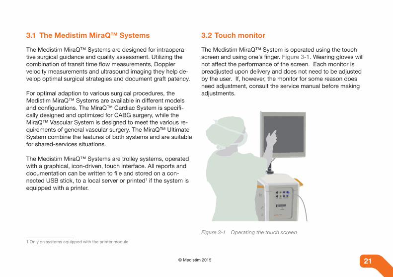
The Medistim MiraQ™ System is operated using the touch screen and using one’s finger. Figure 3-1. Wearing gloves will not affect the performance of the screen. Each monitor is preadjusted upon delivery and does not need to be adjusted by the user. If, however, the monitor for some reason does need adjustment, consult the service manual before making adjustments.
Figure 3-1 Operating the touch screen
21© Medistim 201520
NoteDo not use the power button on the monitor to turn off the touch screen. The screen will turn off automatically when powering down the system by pressing the system power button.
3.3 Monitor arm
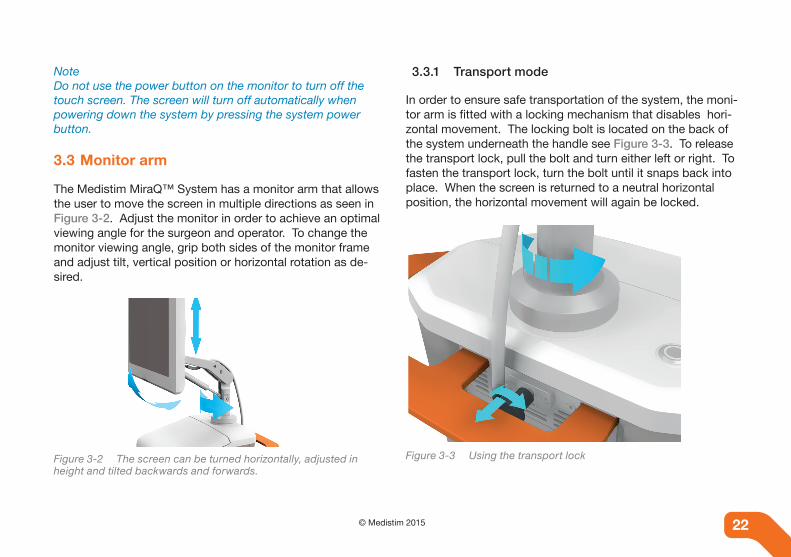
The Medistim MiraQ™ System has a monitor arm that allows the user to move the screen in multiple directions as seen in Figure 3-2. Adjust the monitor in order to achieve an optimal viewing angle for the surgeon and operator. To change the monitor viewing angle, grip both sides of the monitor frame and adjust tilt, vertical position or horizontal rotation as de-sired.
Figure 3-2 The screen can be turned horizontally, adjusted in height and tilted backwards and forwards.
3.3.1 Transport mode
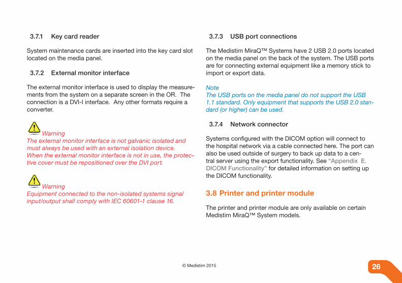
In order to ensure safe transportation of the system, the moni-tor arm is fitted with a locking mechanism that disables hori-zontal movement. The locking bolt is located on the back of the system underneath the handle see Figure 3-3. To release the transport lock, pull the bolt and turn either left or right. To fasten the transport lock, turn the bolt until it snaps back into place. When the screen is returned to a neutral horizontal position, the horizontal movement will again be locked.
Figure 3-3 Using the transport lock
22 © Medistim 2015 22

NoteAlways apply the transport lock before transporting the Medistim MiraQ™ System within the hospital.
3.4 Graphical user interface
The Medistim MiraQ™ System incorporates a touch screen with a Graphical User Interface (GUI). Operation of the system is intended to be very intuitive, eliminating non-essential commands, and presenting an on-screen keyboard only when necessary. To hide the keyboard, press the hide keyboard icon .
To further simplify operation for novice users, certain ad-vanced functions are hidden. Advanced functions can be activated once the operator is familiar with the basic system operation. See chapter ““10. Advanced Features”.
NoteIf the screen surface becomes contaminated with gel or other fluids, the touch screen operation can be affected and the screen may have to be cleaned before normal function can be resumed.
The Medistim MiraQ™ System uses six main screen views:
1. Home screen
2. Patient screen
3. Live Session screen
a. Imaging & TTFM
b. TTFM only
4. Archive reporting screen
5. Help screen
6. System Settings screen
See chapter “5. Operating the Medistim MiraQ™ System” for a detailed description of each screen. A list of all icons utilized in the software is found in “D.1 Icon Description”.
3.5 Front panel and channel configurations
The Medistim MiraQ™ System can be supplied with a range of different channel configurations to accommodate various clinical needs. The front panel shown in Figure 3-4, has four flow channels, two pressure channels, two auxiliary channels and an imaging probe connector.
23© Medistim 201522

Figure 3-4 Probe panel
For systems without the imaging module, a configuration with additional Doppler channel is avaialble.
Figure 3-5 Configuration with additional Doppler channel
NotePlease note that not all MiraQ™ System configurations are available in all markets. Ask your distributor which models are available in your territory.
3.5.1 The Medistim MiraQ™ System model number
The model number is part of the system identity and can be found on the back of the system, between the cable hooks.The model number is defined by the channel configuration of the system. The diagram in Figure 3-6 shows the structure and different elements of the model number.
Figure 3-6 Diagram of model number selection
24 © Medistim 2015 24

3.6 Storage compartment
The top part of the system incorporates a storage compart-ment Figure 3-7, which is intended for storage of the User Manual (this document) and other non-sterile equipment.
Figure 3-7 Storage compartment
3.7 Media panel
The media panel is located on the back of the system, Figure 3-8. All connections to the system except for probes and the power cord are located on this panel.
Figure 3-8 Media panel
The following elements can be located on the media panel:
• Ground potential equalization point
• External (OR) monitor (DVI) connection
• 2x USB 2.0 ports
• Key card reader
• Isolated Ethernet connection - DICOM connection
25© Medistim 201524
3.7.1 Key card reader
System maintenance cards are inserted into the key card slot located on the media panel.
3.7.2 External monitor interface
The external monitor interface is used to display the measure-ments from the system on a separate screen in the OR. The connection is a DVI-I interface. Any other formats require a converter.
WarningThe external monitor interface is not galvanic isolated and must always be used with an external isolation device.When the external monitor interface is not in use, the protec-tive cover must be repositioned over the DVI port.
WarningEquipment connected to the non-isolated systems signal input/output shall comply with IEC 60601-1 clause 16.
3.7.3 USB port connections
The Medistim MiraQ™ Systems have 2 USB 2.0 ports located on the media panel on the back of the system. The USB ports are for connecting external equipment like a memory stick to import or export data.
NoteThe USB ports on the media panel do not support the USB 1.1 standard. Only equipment that supports the USB 2.0 stan-dard (or higher) can be used.
3.7.4 Network connector
Systems configured with the DICOM option will connect to the hospital network via a cable connected here. The port can also be used outside of surgery to back up data to a cen-tral server using the export functionality. See “Appendix E. DICOM Functionality” for detailed information on setting up the DICOM functionality.
3.8 Printer and printer module
The printer and printer module are only available on certain Medistim MiraQ™ System models.
26 © Medistim 2015 26

Warning Only connect a printer specified by Medistim. Connecting other electrical equipment can lead to reduced level of safety.
WarningConnecting electrical equipment to the printer power socket effectively leads to creating a ME system and can result in a reduced level of safety.
3.9 Ventilation
To ensure adequate airflow and cooling to the system, the Medistim MiraQ™ System has ventilation holes on the sides and back of the unit.
NoteIt is important that the ventilation is not blocked or obstructed as this may compromise the air flow to the system.
3.10 Cable hooks and power cable
There are two cable hooks located on the back of the system allowing for easy and secure coiling of the power cable when the system is not in use and during transport.
WarningTo avoid risk of electric shock, this equipment must only be connected to a power supply mains with protective earth.
NoteWhen positioning the Medistim MiraQ™ System, ensure that the power cable is not obstructed in any way.
3.11 Lockable wheels
The Medistim MiraQ™ System is equipped with four lockable wheels. To lock a wheel, press the locking lever down and to unlock it pull the lever up as shown in Figure 3-9.
Figure 3-9 Locking a wheel will lock both rotation and orientation of the wheel.
27© Medistim 201526

28 © Medistim 2015 28
4. DELIVERY AND CONFIGURATION
The purpose of this chapter is to prevent damage to property and injury to personnel through the delivery and configuration of the Medistim MiraQ™ System.
4.1 Delivery
4.1.1 Receiving the Medistim MiraQ™ System
The system is shipped complete in one large, wooden crate. Probes and accessories may be packed in a separate carton and placed inside the crate.
Upon receipt, please check that there is no visible damage to the crate itself and that the handling indicators (shock and tilt) attached to the crate are still intact.
Any visible damage should be reported to the freight forward-er and to the Medistim Service Department.
4.1.2 Unpacking and packing
Please refer to the instructions provided with each crate for proper unpacking.
For safe transportation, please use only original packing materials. Note that a special shipping container, specifically designed to protect the electronic unit and monitor assembly, is available from your local distributor.
4.2 System Verification
4.2.1 Verifying system identity
The model and serial number can be found on the back of the system on the label located between the power cable hooks.
4.2.2 Verifying electrical safety
The system has been tested for electrical safety prior to deliv-ery and a report is attached to the system configuration form. This form can be found in the storage compartment together with the User Manual.
4.3 Initial configuration
Before use, the Medistim MiraQ™ System should be con-figured and the auxiliary channels should be calibrated in accordance with the user requirements. See Chapter “6.3.2 Calibrating the AUX channel for ECG” and “6.3.3 Calibrating the AUX channel for pressure” for more information.
4.3.1 Basic software configuration
Start the system and open System Settings screen by press-ing the icon on the top of the screen. The system setup menu can be accessed by pressing System Settings on the top left of the screen.

29© Medistim 201528
Figure 4-1 System information
Software versionTo identify the installed software version go to the Advanced System Functionality page and open the System Information page Figure 4-1.
Enter hospital name and addressBefore use, the hospital name and address should be entered. To do this, press Edit in the upper left-hand corner of the System Settings screen and fill in the available dialog boxes. Press OK when complete.
Select ECG channelThe Medistim MiraQ™ System should always be connected to the anesthesia monitoring system in order to display the ECG signal. The ECG signal is used to synchronize the timing of the recorded flow or velocity traces.
Set measuring unitMetric or US measuring units can be selected from the Mea-suring Unit drop down menu. Note that the measuring unit is for display use only and can be changed at any time without influencing data already stored in the system.

30 © Medistim 2015 30
5. OPERATING THE MEDISTIM MiraQ™ SYSTEM
The purpose of this chapter is to provide the user with clear instructions on how to prepare for use, and operate the Medistim MiraQ™ System.
5.1 Preparations
Figure 5-1 Example of operating room setup.
As shown in Figure 5-1, the Medistim MiraQ™ System should be placed in the operating room in such a way that the surgeon has a clear view of the screen, and the operating room nurse has easy access to the touch monitor during the procedure. Two people are needed to operate the system, one controlling the touch screen and another controlling the probe(s).
The surgeon will determine which probes will be necessary during the procedure based on the diameter of the vessels to be measured. The operator will then know which probe(s) to connect.
Arterial conduits, such as the internal mammary arteries, have to be skeletonized for a length corresponding to the width of the probe, approximately 1cm.
Depending on the surgical procedure, a variety of sizes of TTFM probes will be required to verify graft patency. An Ul-trasound Imaging and Doppler probe should also be available. See chapter “6. Measurement types” for more information on the supported measurement types.
31© Medistim 201530
5.2 Startup
5.2.1 Starting the system
Ensure that the power cable is connected to a functioning mains outlet. To start the system, press the power button. The button will light green when the system is running and blue when it is in stand-by mode. After a short booting se-quence the system will be ready for use.
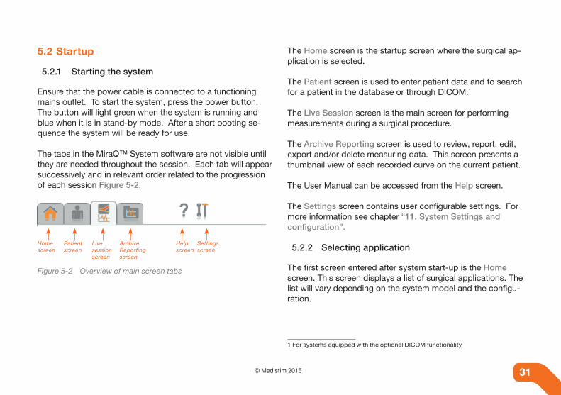
The tabs in the MiraQ™ System software are not visible until they are needed throughout the session. Each tab will appear successively and in relevant order related to the progression of each session Figure 5-2.
Home screen
Patient screen
Live session screen
Archive Reporting screen
Help screen
Settings screen
Figure 5-2 Overview of main screen tabs
The Home screen is the startup screen where the surgical ap-plication is selected.
The Patient screen is used to enter patient data and to search for a patient in the database or through DICOM.1
The Live Session screen is the main screen for performing measurements during a surgical procedure.
The Archive Reporting screen is used to review, report, edit, export and/or delete measuring data. This screen presents a thumbnail view of each recorded curve on the current patient.
The User Manual can be accessed from the Help screen.
The Settings screen contains user configurable settings. For more information see chapter “11. System Settings and configuration”.
5.2.2 Selecting application
The first screen entered after system start-up is the Home screen. This screen displays a list of surgical applications. The list will vary depending on the system model and the configu-ration.
1 For systems equipped with the optional DICOM functionality

32 © Medistim 2015 32
Cardiac Surgery applications are indicated by the orange but-tons and Vascular Surgery applications are indicated by blue buttons. The choice of application will optimize the system for the specific use, and determine the available selection of workflows and anatomical locations. If the planned procedure is not covered by any of the applications in the list, it is rec-ommended to use either the Other Peripheral Vascular or the Other Cardiac application as these provide the most flexibility.
The following icons are displayed along the right side of the screen:
Search icon - press to open an existing patient.
New Patient icon - press to to proceed to the Patient screen. See also “5.3 Patient data”
Worklist icon - on systems purchased with the option-al DICOM module, press this icon to retrieve patient information from the hospital network. Se also “5.3.3 Accessing patient data using DICOM”.
5.3 Patient data
5.3.1 Entering patient data
In the Patient screen, fill in the required patient information. Medistim recommends that the patient name is entered in an orderly and uniform manner for easy storage and retrieval. For systems enabled with DICOM, see “5.3.3 Accessing patient data using DICOM” and “Appendix E. DICOM Functional-ity”.
After entering patient data, press OK to continue to the Live session screen to perform measurements.
NoteIf no patient name is entered, the date and time of operation will be used as the default patient identifier.
5.3.2 Retrieving patient data
All measurements are stored in a database associated with the patient’s record. The database can store about 40,000 records depending on the number of measurements stored per patient.

33© Medistim 201532
To retrieve a patient from the database do the following:
1. Go to the Home screen by pressing the Home icon.
2. Press the Search button.
3. Specify the search criteria and press Perform search.
4. To select a patient, click applicable name and press Se-lect patient at the bottom of the page.
5. Press the Data icon to view the stored data for the se-lected patient.
NoteThe project can be used to identify patients that are part of a study making search easier.
5.3.3 Accessing patient data using DICOM
Systems purchased with the optional DICOM module can receive patient and study information from a network worklist server, and export the acquired measurement sets for storage on a network storage server / Picture Archiving and Communi-cation System (PACS). See “Appendix E. DICOM Function-ality”.
Pressing the Worklist button in the top right-hand corner of the Patient screen will perform a worklist request towards the selected worklist server. The result of this request is a list of procedures scheduled, and is displayed in the Worklist Result page.
Patient information retrieved in this operation is automatically added to the database and entered in the appropriate fields. Upon selecting the desired procedure, the system will enter the Live Session screen.
5.4 Selecting workflow
To activate the workflow selector, press the Workflow button on the Patient screen Figure 5-3. Preview and/or select the desired workflow from the list of available workflows.
Figure 5-3 Workflow selector veiw

34 © Medistim 2015 34
The workflow control will now be visible and the user can begin the live session. For more information on using guided workflows, see chapter “8. Understanding guided work-flows”.
5.5 Connecting probes
The MiraQ™ System probe panel and probe connectors are equipped with unique keying features. This feature prevents connector mismatching or misalignment, ensuring that only TTFM probes can be inserted into the flow channels and vice versa for the other channels.
All Medistim probes should be previously sterilized in accor-dance with the cleaning instructions manual provided with each probe, see “5.12 Cleaning, disinfection and steriliza-tion” and “14. Probe cleaning, disinfection and steriliza-tion”.
The Medistim probes require very little force to be inserted or removed. If excessive force is needed to connect a probe, this is a sign that something is damaged either in the probe con-nector or on the system probe panel connector. Inspect both connectors carefully to identify possible bent or broken pins, or otherwise obstructed holes in the probe connector or the system’s probe panel connector.
See also chapter “12. Troubleshooting” and “C.1 Probe related error messages” for more information.
To remove a probe, take hold of the widest part of the probe connector and pull straight out Figure 5-4. This will release the locking mechanism and the probe will unplug correctly.Do not attempt to disconnect a probe by pulling on the cable or strain relief Figure 5-5. This will not release the locking mechanism and may damage the probe.
The connector part of the probe should never reenter the ster-ile field once connected to the MiraQ™ System probe panel.
Figure 5-4 Correct removal Figure 5-5 Incorrect removal

35© Medistim 201534
To connect a Medistim ultrasound imaging probe, first place the locking lever into the unlocked position Figure 5-6; i.e. the upright position. With the probe cable to the right, insert the connector into the system in one smooth horizontal motion Figure 5-6. Do not insert or remove the connector at an angle as this may cause damage to the probe connector Figure 5-7. When the probe is completely inserted, move the locking lever into locked position; i.e. down.
Figure 5-6 Correct connection Figure 5-7 Incorrect connection
NoteDo not force the locking lever as this may cause damage to the system. The imaging probe is detected by the system within a few seconds.
5.6 TTFM probe verification
Medistim recommends that a probe functionality test is performed before a TTFM probe is used. This simple test will reveal any reduction in functionality the probe may have suf-fered. Performing this check before every use will ensure that the probe and system is functioning optimally and will improve the acoustical coupling of the probe when placed on a vessel.
Follow these steps to perform a probe functionality test:
1. Remove the sterile probe from the container it has been stored in.
2. Connect the connector plug to the MiraQ™. For each connected probe, a graft dialog may appear depending on how the system has been configured. It is not neces-sary to fill in a vessel name at this point, so just press Cancel to close the dialog.
3. When the probe is connected a measurement trace will appear on screen. The probe properties button as seen in Figure 5-8 will show the channel name correspond-ing to the name on the probe connector. If the system is set up to start in probe test mode as described in “10.8 Probe test mode”, the probe test view will be shown for the connected probe until the probe is activated.
4. Place the probe in a container with sterile saline solution.
5. With the probe immersed in saline, look for the green Acoustical Contact Indicator, which indicates appropri-

36 © Medistim 2015 36
ate contact between the probe and the vessel. All TTFM probes should obtain an ACI value of > 90% Figure 5-8. If the ACI value is lower than this during testing, ensure that there are no air bubbles surrounding the probe, as this can significantly affect the ACI value. Simply shake the probe gently in the saline solution to remove.
6. If the water is still, the measurement offset for the probe should be low relative to the intended measurement vol-ume.
Probes that fail to register an ACI value of > 90% in sterile saline are not working properly and should be replaced.
Figure 5-8 Probe icon
5.7 Defining measurement location
When a probe is connected, the Anatomical Location Dialog page will automatically appear as seen in Figure 5-9. Here the user can label the measurement with an anatomical location.
Figure 5-9 Anatomical location dialog
NoteThe automatic appearance of the dialog page can be switched off in the system settings menu.
37© Medistim 201536
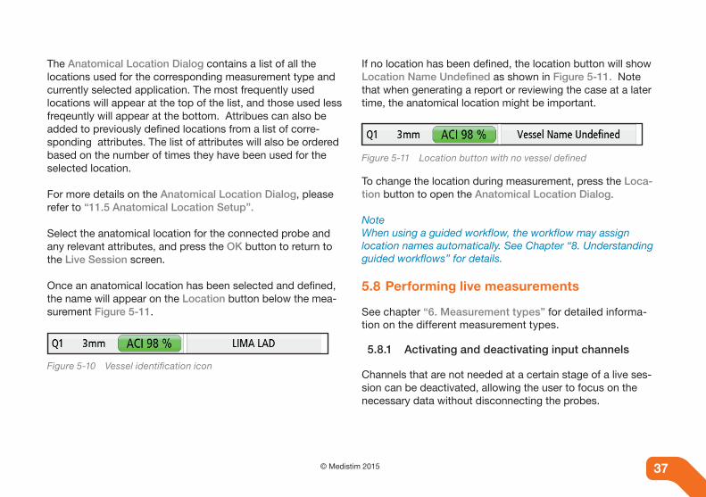
The Anatomical Location Dialog contains a list of all the locations used for the corresponding measurement type and currently selected application. The most frequently used locations will appear at the top of the list, and those used less freqeuntly will appear at the bottom. Attribues can also be added to previously defined locations from a list of corre-sponding attributes. The list of attributes will also be ordered based on the number of times they have been used for the selected location.
For more details on the Anatomical Location Dialog, please refer to “11.5 Anatomical Location Setup”.
Select the anatomical location for the connected probe and any relevant attributes, and press the OK button to return to the Live Session screen.
Once an anatomical location has been selected and defined, the name will appear on the Location button below the mea-surement Figure 5-11.
Figure 5-10 Vessel identification icon
If no location has been defined, the location button will show Location Name Undefined as shown in Figure 5-11. Note that when generating a report or reviewing the case at a later time, the anatomical location might be important.
Figure 5-11 Location button with no vessel defined
To change the location during measurement, press the Loca-tion button to open the Anatomical Location Dialog.
NoteWhen using a guided workflow, the workflow may assign location names automatically. See Chapter “8. Understanding guided workflows” for details.
5.8 Performing live measurements
See chapter “6. Measurement types” for detailed informa-tion on the different measurement types.
5.8.1 Activating and deactivating input channels
Channels that are not needed at a certain stage of a live ses-sion can be deactivated, allowing the user to focus on the necessary data without disconnecting the probes.

38 © Medistim 2015 38
To deactivate a channel, press the Minimize icon: located in the top right-hand corner of each measurement. The inactive channels will be placed in a row at the bottom of the screen, and can be easily reactivated when needed by press-ing the appropriate Inactive Channel button as seen in Figure 5-12.
Only active measurements will be stored to disk when the measurement set is saved.
Figure 5-12 Inactive channels button
5.8.2 Adjusting volume
The Volume controls set the overall sound volume. Press and drag the control to set to the desired level.
5.8.3 Adjusting flow curves and Doppler displays
5.8.3.1 Change of vertical scale
If the Doppler spectrum or TTFM curves appear very small, or exceed the height of the display, the vertical scale should be adjusted.
1. Press to increase the scale. This will decrease the height of the displayed signal.
2. Press to decrease the scale. This will increase the height of the displayed signal.
5.8.3.2 Adjusting baseline position
The baseline position can be changed by dragging the displayed curve or spectrum area up or down. To invert the baseline press this icon: The Doppler baseline can only be adjusted when recording Live mode, whereas the flow and AUX channels can be adjusted in Pause, Edit and Live recording modes.
5.8.3.3 Sweep length adjustments
The Medistim MiraQ™ System displays the flow curve at a default 5-second sweep rate upon probe connection.
To increase timesweep press this icon:
To decrease timesweep press this icon:

39© Medistim 201538
5.8.4 Probe and measurement properties
Additional information about the probe and measurement - such as probe usage information, frequency, filter settings, M&A index selection, etc. - can be accessed by pressing the button on the lower left-hand corner of each measurement. The button will be labeled with the name of the corresponding input channel (e.g. Q1 or ECG), or the name of the imaging probe (e.g. L15).
The TTFM probes can be calibrated to the correct sound velocity, either by selecting the correct fluid type and tempera-ture or by entering the sound velocity directly.
5.9 Saving measurements
Press the Save icon in the menu to store recorded traces. When saving, the last 60 seconds of the recorded trace will be stored. During a search for vessels, only the velocity trace of the located vessel is necessary to save. When detecting a stenosis, it will be important to save both the reference veloc-ity trace as well as the trace from the position of the stenosis. A transit time flow measurement can be saved as soon as a stable measurement is reached.
Memory scroll and trace reviewThe measurements need to be paused before memory scroll can be performed. To pause, press the Pause icon . When paused, recorded data can be reviewed by dragging finger across the display. To go backward, move from left to right. To go forward, move from right to left.
The measurement can also be scrolled by dragging the slider at the bottom of the screen. The numbers to the left of the slider show the total length of the recorded data and the start time for the displayed curve/spectrum respectively.
If the measurement contains imaging data it may be possible to navigate to a timepoint where there is curve/spectrum data, but no imaging data. This is because the last 5 seconds of ul-trasound imaging is stored, while the last 60 seconds of other data types is stored. In this case the ultrasound image will be replaced by the text “No imaging data available”.
To store the current position, press the Save icon. Memory scroll can be used in the Archive and reporting tab or in paused mode when editing curves.
5.10 Review of recorded data
All stored measurement data can be reviewed and edited. To access a patient’s measurements, select the patient’s name from a search, press OK and press the Archive and reporting tab.

40 © Medistim 2015 40
Select the desired measurement set(s) by pressing the cor-responding thumbnail(s) as shown in Figure 5-13. Use the scroll bar to view any thumbnails that may not be visible on the screen. A check mark will appear next to each thumbnail. See chapter “Appendix D. Icon description” for a list of avail-able thumbnail views.
NoteAll thumbnails can be selected simultaneously, by pressing the box containing the date and time of operation.
1
2
5
6
3
4
Figure 5-13 Thumbnail screen view
Press the Edit button to open the selected measurement set(s). See number 5 in Figure 5-13. Move between the select-ed measurements by pressing the arrows visible at the bottom of the screen. To store the edited curves, press the Save but-ton. This will overwrite the previous measurement.
This view allows the user to explore and edit the recorded measurements. Depending on the measurement type, “6. Measurement types”, interaction may include scrolling the curve back and forth, dragging the baseline up or down, changing vertical scale, changing measurement location, add-ing or editing comments, as well as playback.
For the more advanced user, an Advanced system mode can be chosen in system settings. In this mode, it is possible to set up derived traces and perform calculations, see “10.4 De-rived traces” and “10.6 Measurement and analysis (M&A)”.
Note After editing a measurement set, changes can be made per-manent by pressing the “Save” icon. When multiple measure-ment sets are selected for editing, pressing the arrows on the bottom of the screen will bring the next selected file into edit mode.
Press the Back icon to re-enter the thumbnail view screen when in editing mode. To delete a measurement set, select the corresponding thumbnail and press the Delete button. See number 6 in Figure 5-13.

41© Medistim 201540
To export measurements to PDF format, select the applicable measurements and press Export report. The screen Specify file-name and folder will appear. Choose a folder into which the file will be exported, specify the name of the file and press OK. The report can be exported to the hard disk, an external USB or LAN storage device.
The full screen can be exported as a picture file for inserts into presentations or other documents by pressing the Screen capture button. Follow the dialog box to store the picture file on a removable media.
On systems equipped with a printer, use the Print button to print measurements. To change the number of measurements visible on a printed page, change the setting under Report Settings on the System settings page.
To delete measurements, press on the applicable curve and press Delete.
5.11 Creating and viewing case reports
Select a measurement set and press the New Report button. Press the corresponding icons to review, export, delete or print1 a report.
1 only on systems equipped with a printer
To return to thumbnail view, press OK. Generated reports will be placed at the top of the thumbnail view. Click on any report to re-enter the report preview page.
5.11.1 Tasks after operation by surgeon
Following the operation, the surgeon should review the stored data in the Archive Reporting screen, and select the appropri-ate files that best represent the performed surgical procedure.
5.12 Cleaning, disinfection and sterilization
5.12.1 System
The surface of the system can be cleaned with hospital grade disinfectants or a damp cloth. Avoid excessive use of water or liquids on the system.
5.12.2 Probes
All Medistim probes are validated for different sterilization methods and should be handled differently according to these procedures. See Chapter “14. Probe cleaning, disinfection and sterilization” for further information.

42 © Medistim 2015 42
6. MEASUREMENT TYPES
The purpose of this chapter is to provide a detailed descrip-tion of the different measurements that can be performed using the Medistim MiraQ™ System.
6.1 Transit time flow measurement (TTFM)
6.1.1 The TTFM principle
The TTFM principle is based on measuring the difference between upstream and downstream transit time of a wide ultrasound beam. The transit time difference is directly
proportional to the blood volume flow. This measurement principle gives an accurate quantification of the real time volume flow that compliments the ultrasound imaging.
6.1.2 Tasks during procedure by surgeon
The surgeon will judge the diameter of the vessels to be mea-sured and inform the operator which probe(s) to connect.The operator needs to be informed of which type of conduit, connection, and target vessel that is being measured.
Arterial conduits such as the internal mammary arteries have to be skeletonized for a length corresponding to the width of the probe, approximately 1cm.
When the TTFM probe is placed onto a conduit, the system will generate a simulated Doppler sound, indicating that flow has been detected. The volume of this sound is adjustable, using the on-screen buttons.
To ensure accurate flow measurement, it is important that the probe is placed perpendicular to a straight segment of the measured vessel. All parts of the vessel should be inside the probe as shown in Figure 6-1.

43© Medistim 201542
Figure 6-1 Recommended probe placement on straight vessel segments.
6.1.3 Tasks during procedure by operator
The operator should inform the surgeon of the mean flow rate, the pulsatility index (PI) and the diastolic filling (DF). As soon as a stable measurement is reached, the measurement should be saved by pressing the Save button.
6.2 Doppler measurement
NoteThe Doppler functionality is only available on certain Medistim MiraQ™ System models. Ask your distributor which models are available in your territory.
6.2.1 The Doppler principle
The Doppler principle is based on measuring the frequency shift between transmitted and reflected ultrasound waves. The ultrasound is reflected from particles in the blood such as red blood cells. The frequency shift is used to calculate the blood flow velocity. The result is displayed as a spectrogram, show-ing the distribution of velocities in the blood vessel.
Figure 6-2 The Doppler principle

44 © Medistim 2015 44
6.2.2 Operation
To obtain an accurate velocity measurement, the Doppler probe should be held perpendicular to the vessel being mea-sured, as its transmitting crystal is fixed at a 45º angle from the probe’s surface.
The operator can change the filter settings by pressing theDoppler properties button as shown in Figure 6-3.
Movements of the probe, such as those caused by a beating heart, will cause a strong low-frequency noise on the Dop-pler spectrum. This can be avoided by applying a mechanical stabilizer, or for smaller movements, by increasing the low velocity filter in the system.
Figure 6-3 Doppler properties button
The Doppler probe should be held with the angled crystal pointing against the flow direction as shown in Figure 6-4. If the probe is held the opposite way, the velocity curve will ap-pear below the baseline.
Figure 6-4 Correct Doppler probe placement
For correct data management, it is important to provide the system operator with the measured vessel name and the probe position on the vessel (e.g. LAD Proximal, LAD Stenosis or LAD Distal) and to inform the operator when to save the recorded Doppler spectrum.
6.2.3 Tasks during procedure by operator
The Medistim MiraQ™ System will display the Doppler spec-trum at the default 5-second sweep rate as soon as a probe is connected as seen in Figure 6-5.
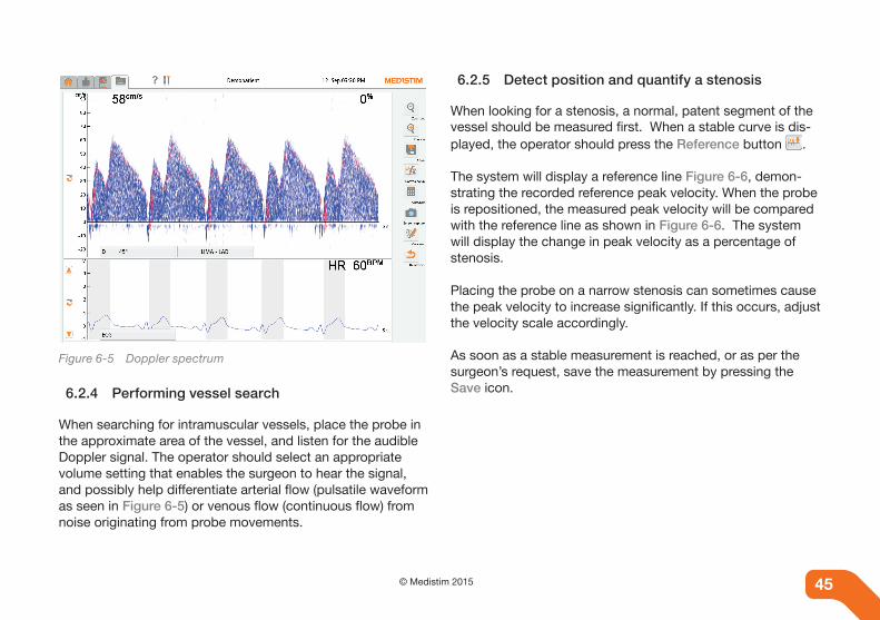
45© Medistim 201544
Figure 6-5 Doppler spectrum
6.2.4 Performing vessel search
When searching for intramuscular vessels, place the probe in the approximate area of the vessel, and listen for the audible Doppler signal. The operator should select an appropriate volume setting that enables the surgeon to hear the signal, and possibly help differentiate arterial flow (pulsatile waveform as seen in Figure 6-5) or venous flow (continuous flow) from noise originating from probe movements.
6.2.5 Detect position and quantify a stenosis
When looking for a stenosis, a normal, patent segment of the vessel should be measured first. When a stable curve is dis-played, the operator should press the Reference button .
The system will display a reference line Figure 6-6, demon-strating the recorded reference peak velocity. When the probe is repositioned, the measured peak velocity will be compared with the reference line as shown in Figure 6-6. The system will display the change in peak velocity as a percentage of stenosis.
Placing the probe on a narrow stenosis can sometimes cause the peak velocity to increase significantly. If this occurs, adjust the velocity scale accordingly.
As soon as a stable measurement is reached, or as per the surgeon’s request, save the measurement by pressing the Save icon.

46 © Medistim 2015 46
Figure 6-6 Reference line view
6.3 Pressure inputs
The pressure inputs allows connection of pressure transduc-ers for direct monitoring of the patient’s blood pressure. The Medistim MiraQ™ System can be delivered with up to two pressure inputs, each providing 5V driving voltage for the transducers. Interface cables to common commercially avail-able transducers can be ordered from Medistim.
6.3.1 Calibrating the pressure transducer
After connecting a pressure transducer, the system allows the setting of zero-level and fine-tuning of the gain for optimal measurements. The procedure requires reference signals of 0 mmHg and 100 mmHg. Enter the calibration screen by press-ing the Pressure properties button.
First apply 0 mmHg and press the zero-button. Wait until the curve stabilizes at zero. Then apply 100 mmHg and adjust the gain until the curve rests at 100 mmHg. The calibration of the pressure channels are non-persistent and must be done for each new transducer.
NoteCalibration requires a reference signal with a defined zero level and another level of known value.
6.4 Auxiliary inputs
The auxiliary inputs can be used to measure any external voltage signal within ± 4V. The signal is filtered, conditioned, assigned to a measurement unit and included in the MiraQ™ System measurement set.
The available signal ranges are ±10mV, ±100mV, ±500mV and ±4V. The user can select signal level, measurement unit, filter-ing and signal condition from the AUX calibration screen as described in the sections below.

47© Medistim 201546
When selecting mmHg as the measurement unit, the system treats the AUX input as a pressure input with respect to de-rived traces and calculations.
The AUX channel selected for ECG (see chapter “11.2 Con-figuration pull-down menus”) input will automatically display the heart rate in BPM and the systolic and diastolic phases can be drawn on the curve trace (user selectable).
For other measurement units selected, the curve trace will show the measured value in terms of the selected unit.
NoteCalibration requires a reference signal with a defined zero level and another level of known value.
NoteWhen using an auxiliary input to display a signal from a medi-cal monitoring system, please refer to the monitoring system as the primary data source. The MiraQ™ input may be used for ECG triggering, as reference display, for calculating derived curves and for saving input data together with MiraQ™ mea-surements etc.
6.4.1 Calibrating the AUX channel for ECG
Turn on the system and connect the ECG cable to the anesthesia monitoring system. For the purpose of calibration, an ECG simulator can be used with the monitoring system. Select the Live session screen, and the Auxiliary curve window will appear. Depending on signal strength, the ECG waveform will be visible. If the scale and measuring unit ap-pear correct, no further adjustments are necessary.
To improve the settings for optimal display, press the ECG properties button and the Calibrating ECG window will ap-pear.
Select an input range which corresponds to the input signal level. If the displayed signal has a low amplitude, then select a smaller input range. Note the AD range displayed in the upper right-hand corner of the curve window, as it is important that the AD range is less then the saturation level of 100%. For fine adjustments within the selected range, use the Scaling up and down buttons.
When the correct ECG curve is displayed, the settings should be saved by pressing the Save button. To ensure that the new setup is used whenever the ECG is connected, press the Set current as default button.

48 © Medistim 2015 48
Note When using the Medistim MiraQ™ System with more than one monitoring system that requires independent adjustments, dif-ferent calibration settings can be saved under a profile name, such as OT 1 and OT 2. The operator can choose the stored calibration each time the system is moved by entering the cali-bration menu and selecting the appropriate saved profile.
6.4.2 Calibrating the AUX channel for pressure
Turn on the system and insert the cable from the signal moni-tor. For calibration, a simulator that emits known signals can be used. Select the Live session screen, and the auxiliary curve window will appear. Depending on the signal strength, the monitored curve may be visible straight away. To calibrate the curve, press the A1/A2 properties button and the Cali-brating A1/A2 window will appear.
In order to calibrate the curve properly, a signal with two known amplitudes is needed. One of these is typically zero, the other can be chosen randomly as long as it is feasible and known.
First, select the correct measuring unit. (For pressure, it would be mmHg.) Then select an input range that corresponds to the physical signal. If the signal has low amplitude, select a smaller input range.
It is important that the AD range displayed in the upper part of the curve window is less than the saturation level of 100%. When the signal from the monitor is set to zero, press the Zero button on the lower right side of the curve view to set the zero signal level. Change to the signal value with known amplitude and use the scale up and scale down buttons to adjust the displayed value so that it fits the input. Readjust the input range if necessary.
When the calibration is satisfactory, assign the profile an ap-propriate name in the Current profile edit box and press Save.
To set the active profile as default for the channel, press the Set current as default button on the lower left part of the screen.
For all types of AUX measurements the calibration process is exactly the same. Exchange the unit to suit the measured vari-able. Adjust input range and gain so that the signal is within saturation limits and correct for two known values.
6.5 Imaging Measurements
Proceed to Chapter 7 - Ultrasound Imaging - For detailed information on how to perform imaging measurements.

49© Medistim 201549
7. ULTRASOUND IMAGING
7.1 General
To perform imaging measurements, connect an imaging probe as described in chapter “5.4 Connecting probes” and press the Live Session tab Figure 7-1.
Figure 7-1 Live Session screen tab - Imaging
The Medistim MiraQTM System will begin scanning using the default application settings. An ultrasound image will be dis-played as soon as the transducer is placed on tissue.
Ultrasound scanning is very sensitive to the coupling between the probe face and the tissue. Any air gaps will cause ineffec-tive coupling which can result in dark vertical shadowing or a complete loss of image.
If the surface to be scanned is rough, has pockets where air can be trapped or is not moist enough, sterile ultrasound coupling gel could be used between the tissue and the trans-ducer.
7.1.1 Imaging presets
The Medistim MiraQ™ System comes with a selection of im-aging presets, which contains ultrasound acquisition param-eters that are optimized for typical applications. For example, the typical control settings for scanning the aorta are different from those used to scan coronary arteries.
To select a different imaging preset, press the Imaging Preset button to display the Select Imaging Preset dialog. See Table 7-2 and Figure 7-2 for overview of button placement.
The Select Imaging Preset dialog also contains a Save Current Imaging Configuration option, which allows saving the current live ultrasound imaging configuration as a new user-defined imaging preset. The configuration may be saved using an existing preset name, as long as it is not one of the standard presets provided by Medistim.
See also “10.7 Managing Imaging presets” for information about how to delete, rename or order imaging presets.
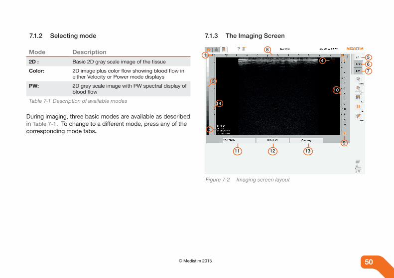
50 © Medistim 2015 50
7.1.2 Selecting mode
Mode Description
2D : Basic 2D gray scale image of the tissue
Color: 2D image plus color flow showing blood flow in either Velocity or Power mode displays
PW: 2D gray scale image with PW spectral display of blood flow
Table 7-1 Description of available modes
During imaging, three basic modes are available as described in Table 7-1. To change to a different mode, press any of the corresponding mode tabs.
7.1.3 The Imaging Screen
14
8
10
14
3
5
67
2
11 12 13
9
Figure 7-2 Imaging screen layout

51© Medistim 201550
# Screen Element
1 Probe Orientation
2 Exposure Statistics
3 Gray Scale Map (color flow map)
4 TGC
5 Mode Tab: 2D
6 Mode Tab: Color
7 Mode Tab: PW
8 Lateral Scale
9 Depth Control
10 Depth Scale
11 Imaging Properties
12 Vessel Name
13 Current Imaging Preset
14 Focal Points
Table 7-2 Description of the Imaging screen layout
7.1.3.1 Probe orientation indicator
In the top corner on either side of the 2D display, a dot will be shown. The probe will also have a dot on one end of the transducer to indicate how the image is oriented with respect to the probe. If the probe does not have a dot, then the end of the transducer where the cable exits, will correspond to the dot.
7.1.3.2 Adjusting depth
Press the Depth icons to increase or decrease the maximum depth of the display. Deeper depths may have slower update rates, (frame rates) so it is best to use shallower depths when possible.
7.1.3.3 Image flip
To accommodate different scanning situations the image can be flipped left/right.
Flipping the image enables a mirroring of the scanning, the probe movements will correspond to the on-screen move-ments for a more intuitive user experience.
To flip the image, press the probe orientation marker in the top left or right of the image.

52 © Medistim 2015 52
7.1.3.4 Gray scale and color bar
The gray scale bar indicates how the intensity of the received signal is mapped into the display brightness. When in color mode, the bar changes to a color bar, indicating how velocity or power is mapped to color.
Note that the velocities shown during velocity mode are without Doppler angle correction. Use Pulsed Wave (PW) to obtain velocities with Doppler angle correction.
7.1.3.5 TGC (Time Gain Compensation)
The image brightness should be approximately uniform with depth. The brightness can be adjusted using the Time Gain Compensation (TGC) controls. To access these, press the TGC icon to access the TGC slider controls. See Figure 7-3. If the overall brightness needs to be increased or decreased, use the 2D gain control.
Each slider controls the imaging gain at the corresponding depth.
Press and drag the controls to the desired setting. To hide the TGC slider controls, press the TGC icon again.
Figure 7-3 TGC controls

53© Medistim 201552
7.1.4 Auto-freeze
Figure 7-4 Auto-freeze view
When the user interface has not been in use for 5 minutes, the system will stop scanning and freeze the image automatically.To stop scanning and freeze the image, press the stop button Figure 7-4. This will now change to the play button to begin scanning again.
The following table lists the settings available in auto-freeze mode.
1 Zoom in
2 Zoom out
3 Save
4 Start
5 Derived setup*
6 Calculate*
7 Comment
8 Screen Capture
9 Playback
Table 7-3 Description of elements in Figure 7-4
Note* Indicates controls that are available only when Advanced Mode has been selected under System Settings.
NoteThe Zoom In and Zoom Out buttons refer only to the time scale. They do not affect the size of the 2D image.

54 © Medistim 2015 54
7.1.5 Imaging properties
Pressing the Imaging properties tab displays information about the probe and current operating conditions. See Figure 7-5.
Figure 7-5 Imaging properties in B-mode
B-Mode properties
Frame Rate: How often the image is updated (in frames per second)
Number of beams: Number of 2D ultrasound beams that make up an image (relates to lateral resolution and frame rate)
Depth: Maximum depth currently displayed
Frequency: Operating frequency (the transmit frequency may be different than the transducer center frequency)
Focal Points: Available focal points. Select / deselect the desired focal points by pressing the box
Table 7-4 Description of B-mode properties
Color flow (if in color mode)
Frame Rate: How often the image is updated (in frames per second)
Number of Beams: Number of Color ultrasound beams that make up the image (relates to lateral reso-lution and frame rate)
LVR: Low Velocity Reject (velocities below this are attenuated by the system)
Frequency: Ultrasound frequency used for Color
PRF:
Pulse Repetition Frequency (relates to the maximum velocity that can be displayed, determines aliasing frequency)
Table 7-5 Description of Color flow properties

55© Medistim 201554
Color flow (if in color mode)
Focus: Current focal point (calculated by system based on ROI position and size)
Hide Flow: Same function as described in section 6.7.3 under the subtitle - Hide Color
Table 7-5 Description of Color flow properties
PW Doppler mode Description
Frame Rate: How often the image is updated (in frames per second)
Frequency Doppler operating frequency
PRF: Pulse Repetition Frequency for Doppler
Gate depth: Depth for the center of the Doppler gate
Gate size: Width of the Doppler gate
Table 7-6 Description of PW Doppler mode properties
7.1.5.1 Adjusting focal zones
The image can be optimized in zones as a function of depth, called focal zones. Up to four focal zones can be selected and used simultaneously. However, at deeper depths, using multiple focal zones can cause the scanner to operate at a slower frame rate. In Color and PW mode, only one focal zone is used and is controlled by the location of the Region of Interest (ROI), or gate position.
Figure 7-6 Imaging properties in color flow mode
Item Description
Probe: Name of the current probe model
Usage: Number of times this probe has been used
S/N: Serial number of the current probe
First Used: Date that this probe was first used
Table 7-7 Overview of imaging properties (figure 7-6)

56 © Medistim 2015 56
7.1.6 Exposure and ultrasound statistics
This system conforms to the ISO 60601-2-37 standard for reporting acoustic power output. It is the responsibility of the user to monitor these indices and ensure safe exposure levels for the specific application being performed. See also “2.6.1 Acoustic power reporting”and “2.6.2 Interpreting Thermal and Mechanical Index”.
Abbreviation Description
f: Operating frequency (maximum transmit fre-quency / Doppler frequency)
TIS: Thermal Index for Soft Tissue*
TIB: Thermal Index for Bone*
TIC : Thermal Index for Cranial bone*
MI: Mechanical Index*
FR: Frame rate (number of times the 2D image is updated each second)
Table 7-8 Description of exposure and ultrasound statistics
Note *Only shown during live imaging (not shown during playback)
7.2 2D mode
The 2D Mode displays a gray scale image with no color or PW. To get the best possible 2D image use this mode. When using other modes, trade-offs are sometimes made to im-prove other performance parameters, such as frame rate.
7.2.1 2D tab
Pressing the 2D tab, Figure 7-7, will change the imaging mode to 2D (gray scale only). If the system was already in 2D, then a menu appears with more advanced controls for optimizing the 2D image.
7.2.2 2D control panel
Figure 7-7 2D tab with 2D control panel

57© Medistim 201556
7.2.2.1 Gain
Use the gain control to increase or decrease the overall bright-ness of the image. If set too high, the brighter echoes may saturate resulting in the loss of high level detail and overall noise may increase. If set too low, low level echoes may not be visible, and the depth of penetration will be less.
7.2.2.2 Persistence
It is possible to filter some of the noise in the image by using additional persistence.
Persistence uses a time averaging technique to reduce noise, but this will also blur any tissue that is moving too fast for the persistence selected.
7.3 Color mode
In color mode, the system displays a 2D gray scale image with an overlay of color that represents the blood flow in the region of interest.
7.3.1 Color tab
Pressing the Color tab Figure 7-8, will change the operating mode to color. If the system was already in color mode then a menu will appear allowing access to additional color controls.
Figure 7-8 Color tab with color control panel
7.3.2 Region of interest (ROI)
The ROI is the area of the image that the system is analyzing for blood flow, Figure 7-9. A wide ROI will often slow the frame rate down. Narrowing the ROI will often increase the frame rate.
7.3.2.1 Steering angle
Press and drag the steering icon to the desired angle.

58 © Medistim 2015 58
7.3.2.2 Position
Press the center of the ROI and drag the ROI to the desired position.
7.3.2.3 Size
Press the lower right hand corner of the ROI to change the size of the ROI. Increasing the width of the ROI may slow the frame rate.
4
1
2 3
Figure 7-9 Color mode
# Description of figure 7-9
1 Region of interest
2 Steering angle
3 Size
4 Velocity scale control
Table 7-9 Features in color mode
7.3.3 Velocity Scale
High flow rates require a high Doppler PRF in order to acquire data without aliasing. Low PRF should be used when analyz-ing low flow rates.
If PRF is too high, low flow components of the spectrum will be at the extreme low end of the frequency scale and pos-sibly attenuated by the wall filter. If PRF is too low, high flow signals will alias and wrap around the spectrum (a high flow signal will appear as flow in the opposite direction).
Set the flow rate or PRF by using the scale buttons in the spectrum display as for other curves. The Doppler PRF will be changed accordingly, the actual PRF can be viewed in the properties screen.

59© Medistim 201558
7.3.4 Color control panel
7.3.4.1 Velocity/Power
Color flow can operate in either velocity mode or power mode. Velocity mode will calculate the mean velocity of the flow and display a color that represents the magnitude and direction of flow. Red indicates flow towards the transducer, while blue indicates flow away from the transducer.
Note If the flow is aliased, both the direction and velocity can be displayed incorrectly.
NoteVelocities displayed during color flow are not corrected for Doppler angle. PW mode should be used to obtain velocities that have been corrected for Doppler angle.
In Power Mode, the system calculates the power returned from the flow echo for display. Flow direction information is not available in power mode. See the following examples Figure 7-10, Figure 7-11, Figure 7-12.
Figure 7-10 In velocity mode, the color is dependant on angle
Figure 7-11 In velocity mode, the color is dependant on angle
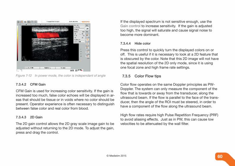
60 © Medistim 2015 60
Figure 7-12 In power mode, the color is independant of angle
7.3.4.2 CFM Gain
CFM Gain is used for increasing color sensitivity. If the gain is increased too much, false color echoes will be displayed in ar-eas that should be tissue or in voids where no color should be present. Operator experience is often necessary to distinguish between false color and real color from blood.
7.3.4.3 2D Gain
The 2D gain control allows the 2D gray scale image gain to be adjusted without returning to the 2D mode. To adjust the gain, press and drag the control.
If the displayed spectrum is not sensitive enough, use the Gain control to increase sensitivity. If the gain is adjusted too high, the signal will saturate and cause signal noise to become more dominant.
7.3.4.4 Hide color
Press this control to quickly turn the displayed colors on or off. This is useful if it is necessary to look at a 2D feature that is obscured by the color. Note that this 2D image will not have the spatial resolution of the 2D only mode, since it is using one focal zone and high frame rate settings.
7.3.5 Color Flow tips
Color flow operates on the same Doppler principles as PW-Doppler. The system can only measure the component of the flow that is towards or away from the transducer, along the ultrasound beam. If the flow is parallel to the face of the trans-ducer, then the angle of the ROI must be steered, in order to have a component of the flow along the ultrasound beam.
High flow rates require high Pulse Repetition Frequency (PRF) to avoid aliasing effects. Just as in PW, this can cause low velocities to be attenuated by the wall filter.

61© Medistim 201560
The velocity scale on the left side of the screen can be ad-justed to increase or decrease the PRF. If flows are low they may not be seen on screen, increasing the PRF will allow visualization of these lower flows. If the PRF is set too low the result will be aliasing of higher flows (color indicating high flow moving in the opposite direction) and tissue motion may look like flashing flow).
Often when searching for a low velocity vessel (typically a vein) it is best to use a low PRF until it is found and then ad-just the PRF to avoid aliasing.
When in color mode, the system will automatically switch to a single focal zone and high frame rate. While this sacrifices some 2D image quality, it is important to make this trade-off to achieve reasonable color frame rates. While in color mode, the system will adjust the focal zone to track the ROI position.
7.4 PW mode (Pulsed-Wave Doppler)
In PW mode Figure 7-14, the system displays a 2D gray scale image with a graphical representation of the PW gate.
7.4.1 PW tab
Pressing the PW tab Figure 7-13, will change the operating mode to PW. If the system was already in PW mode then a menu with additional PW controls will appear.
Figure 7-13 PW tab
7.4.2 PW gate control
The PW gate control shows the ultrasound beam position and the depth that are used to collect data for the Doppler analy-sis. Making the gate smaller will provide narrower bandwidth spectrums, with some loss in sensitivity. It is easier to locate vessels when using a large gate, however, since velocities across the entire vessel are being sampled, the spectrums will be broad.
The timescale of the PW measurement is by default 5 sec-onds. To change this, first enter stopped mode by pressing the Stop button. The zoom controls will appear in the top right corner. These can be used to either shorten or lengthen the timescale on the currently stopped measurement. The set-tings are maintained when returning to live mode.

62 © Medistim 2015 62
Figure 7-14 PW mode view
# Description
1 PW gate control
2 Gate position
3 Gate size
4 Velocity correction angle
5 Velocity scale
6 Invert spectrum
Table 7-10 Features in PW mode
7.4.2.1 Steering angle
The ultrasound beam must always be angled towards the flow direction.
The Doppler angle should always be kept as small as possi-ble. At 90o to the flow, no flow will be detected. The user must adjust both the orientation of the probe and the Doppler angle to get the best flow data.
The system will always select the optimal steering angle based on the PW-gate placement and velocity correction angle combination.
7.4.2.2 Position
To adjust the gate position, press the Position icon and drag the gate to the desired position.
7.4.2.3 Size
Press and drag either Size icon to achieve the desired gate size.
7.4.2.4 Angle correction
Press and drag the Velocity correction angle icon to align the line so that it is parallel to the flow.

63© Medistim 201562
The Doppler principle can only measure the component of the flow vector along the ultrasound beam. A correction for the flow direction must be made in order to display the actual flow velocity in the vessel. When the Velocity correction angle line is aligned parallel to the flow, the system will automatically correct the displayed velocity.
7.4.3 PW control panel
7.4.3.1 PW gain
PW gain is used for increasing the gain level for the display of the PW Doppler spectrum.
7.4.3.2 2D gain
The 2D gain control allows the 2D gray scale image gain to be adjusted without returning to the 2D mode. To adjust the gain, press and drag the control.
7.5 Playback
1
2
3
4 5
6
Figure 7-15 Autofreeze mode
In auto-freeze mode and edit mode, it is possible to playback the most recent data. When pressing the Play button (#1 in Figure 7-15), the data between the cursors is looped and an indicator shows the current playback position.

64 © Medistim 2015 64
The arrows (#2 in Figure 7-15) on the left and right side of the Play button steps respectively one image back or forth in the data. The playback speed control (#3 in Figure 7-15) has four different speed settings - Normal speed, 1/2-speed, 1/4-speed and 1/8-speed.
The skip controls (#4 in Figure 7-15) allow the user to skip back or forth one heart-cycle in the collected data as long as the signal has valid phase information. If the signal does not have valid phase information the controls move the cursors a distance equal to the distance between them.
When a real ECG signal with heart-cycle information is pres-ent the loop-length control (#5 in Figure 7-15) can be used to automatically extend, or shorten the playback loop by one cardiac cycle. If the signal does not have phase information or no signal is present, the loop length control simply doubles the distance between the cursors.
The Caliper tool (#6 in Figure 7-15) is used for measuring distance. After selecting the tool, press and hold the point on the image where the measurement should start, then drag to the end point and release. The caliper can be re-sized and re-positioned if necessary.
7.6 Measurement and annotations
The measurement and annotation functionality allows the user to further analyze and add context to the ultrasound images acquired.
7.6.1 Using the Annotations and Caliper tools
Measurement and annotation functionality is only available in stopped mode. To select a function and start measuring or annotating the image, push the icon to the left of the probe button Figure 7-16.
Figure 7-16 Measurement and annotation icon

65© Medistim 201564
This will replace the Probe button with the measure and An-notation button. By pressing this once, the currently selected tool is enabled. By pressing twice, the Select tool dialogue is shown. A list of the available tools is shown and the user can select which one to use.
Press the Annotation tool to add text on the image Figure 7-17. Annotations can be edited or deleted at any time.
Figure 7-17 Annotation tool
7.6.2 Setting up custom tools
Custom tools can be configured by entering the Measure-ments and Annotations configuration page. To find this page, go to System settings, Advanced System Functionality and push the Measurements / Annotations button.
Before adding any custom tools only the default annotation and caliper tools will be present in this list. To add new tools, press the Add button.
This will access the Add configuration dialogue box - Figure 7-18. Here the user can configure custom tools to better suit their specific needs. After adding new tools these will be vis-ible in the tools menu in the Live session screen.
Figure 7-18 Measurements and annotations configuration page

8. UNDERSTANDING GUIDED WORKFLOWS
8.1 What is a Guided Workflow?
A guided Workflow is a predefined template for specified clinical scenarios. The Workflow defines a set of steps to be performed, and makes the most relevant anatomical locations easily available. The purpose of a Workflow is to minimize the need for user interaction with the Medistim MiraQ™ System during surgery, and ensure consistent quality assessment and reporting.
Each Workflow consists of a list of steps, each of which contains the configuration information needed to prepare the system for acquisition of a measurement set.
8.2 Live measurement with Workflow
Within the Workflow are a series of panels that each repre-sent a step in the current Workflow. The current step will be highlighted in orange. To proceed to the next step, press the next step button, or press to select any of the other steps in the Workflow control.
Each step contains a list of applicable channels and measure-ment locations (e.g. grafts). When selected, the relevant chan-nels are displayed on the screen and the predefined location names are applied.
If a step contains channels with multiple optional measure-ment locations, a button for selecting the correct anatomical location is available in the step panel. Select this button to access the Quick Location Select dialog.
Next step Add step
List of active channels and grafts for current step
Current Workflow step Next Workflow step
Figure 8-1 Workflow screen
66 © Medistim 2015 66

Press the Minimize Workflow icon to minimize the Workflow control. It is possible to scroll the Workflow control horizontally by pressing and dragging in the Workflow area.
Press the Workflow step information icon for a detailed description on how to acquire the measurements for this step.
Extra steps not defined in the Workflow can also be added by pressing the Add step button.
The following options are available:
• Repeat step: Repeats the current step and allows the user to enter a custom step name.
• Add custom step: Opens the step editor dialog for defining a new custom step.
• Insert Workflow: This step brings up the Workflow selec-tor, and allows you to insert a Workflow into the current Workflow at any step. This option might be useful for sub-procedures.
The current step may be deleted by pressing the Remove Step button. For steps containing imaging channels, an Action icon may be shown next to the channel name. This indicates that the step has been configured to automatically perform one or more actions when the step is activated, e.g. changing imaging mode or imaging preset.
8.3 Managing Workflows
By entering Manage Applications in System Settings, the Manage Workflows button is accessible. The Manage Work-flows page enables the user to hide, edit, add, delete, export and rearrange the available Workflows. A Workflow may also be set as the default Workflow selection on startup. When the default selection is deleted, the next live session that is initi-ated will not contain a default Workflow.
Figure 8-2 Manage workflows page
67© Medistim 201566

8.3.1 The Workflow editor
The Workflow editor is opened from the Manage Workflows page by pressing New or by selecting a Workflow and press-ing Edit. If a Workflow has been selected before pressing New, a copy of the selected Workflow is generated in the Workflow editor. Otherwise, an empty Workflow will be gener-ated.
Figure 8-3 Workflow editor page
In the Workflow editor the Workflow name, general description and recommended equipment can be changed. The recom-mended equipment is entered as free text and added to the Workflow by pressing the plus symbol .
The Workflow steps are shown at the bottom of the Workflow editor. Add, delete or edit a step using the buttons to the right of the step currently selected. Change the order by moving the current Workflow step forward or backward with the but-tons in the lower right-hand corner.
Figure 8-4 Workflow step editor
68 © Medistim 2015 68

Pressing the Edit button brings up the Workflow Step Editor page, where the user can edit step name, description and input channels with associated anatomical locations. Illustra-tions in Portable Network Graphics format (PNG) can also be added to better describe the Workflow step.
For each input channel, except for the ECG channel, there will be a Edit button that allows configuration of the anatomical locations that should be selectable for this step. When this button is pressed, the Workflow Channel Configuration page is displayed. Here, the user can add one or more locations that should be available for the step, or configure the chan-nel to continue to use the same location as the previous step. The selected locations may then be chosen directly from the Workflow control during live measurements to simplify the location selection during surgery.
For imaging channels, it is possible to configure the channel to use a specific imaging mode (i.e “2D”, “Color” or “PW”) or a specific imaging preset (e.g. “Aorta”). In order for this to work, a probe type must be selected in the probe type dropdown menu. An Add Action button will then be displayed, that can be used to specify the required actions.
Figure 8-5 Workflow channel configuration page
69© Medistim 201568

70 © Medistim 2015 70
9. DATA MANAGEMENT
9.1 Export and import data
It is possible to export the entire patient database or portions of it for backup purposes. This can be done by using an exter-nal USB or LAN storage device. Choose Advanced mode un-der System settings to access the export function. Go to the Patient data screen and press Search followed by Perform Search to access the full list of patients. Select the applicable patient data and check the box under Export next to the pa-tient name. Multiple patients can be selected. All patients can be selected by pressing the column header Export.
The screen Specify File-Name and Folder will appear. Choose a folder to export the file to and specify the name of the file and press OK.
To import data, go to the Advanced functionality menu under System Settings and press Import. Select the applicable folder or files to import and press OK.
Note The raw patient data files can only be read by Medistim MiraQ™ System software.
9.2 Safe removal of storage devices
Removable storage devices must be prepared for safe re-moval before disconnecting from the system.
If a removable storage device is disconnected while the sys-tem is transferring or saving data there is a risk of data loss or data corruption.
The option for safe removal will appear automatically but can also be selected under System settings. Once a removable storage device has been prepared for safe removal, it must be disconnected and then reconnected in order to be detected by the system for further use.
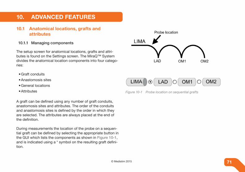
71© Medistim 201571
10. ADVANCED FEATURES
10.1 Anatomical locations, grafts and attributes
10.1.1 Managing components
The setup screen for anatomical locations, grafts and attri-butes is found on the Settings screen. The MiraQ™ System divides the anatomical location components into four catego-ries:
• Graft conduits
• Anastomosis sites
• General locations
• Attributes
A graft can be defined using any number of graft conduits, anastomosis sites and attributes. The order of the conduits and anastomosis sites is defined by the order in which they are selected. The attributes are always placed at the end of the definition.
During measurements the location of the probe on a sequen-tial graft can be defined by selecting the appropriate button in the GUI which lists the components as shown in Figure 10-1, and is indicated using a * symbol on the resulting graft defini-tion.
Figure 10-1 Probe location on sequential grafts
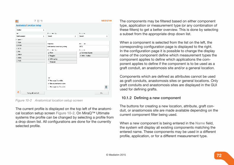
72 © Medistim 2015 72
Figure 10-2 Anatomical location setup screen
The current profile is displayed on the top left of the anatomi-cal location setup screen Figure 10-2. On MiraQ™ Ultimate systems the profile can be changed by selecting a profile from a drop down list. All configurations are done for the currently selected profile.
The components may be filtered based on either component type, application or measurement type (or any combination of these filters) to get a better overview. This is done by selecting a subset from the appropriate drop down list.
When a component is selected from the list on the left, the corresponding configuration page is displayed to the right. In the configuration page it is possible to change the display name of the component define which measurement types the component applies to define which applications the com-ponent applies to define if the component is to be used as a graft conduit, an anastomosis site and/or a general location.
Components which are defined as attributes cannot be used as graft conduits, anastomosis sites or general locations. Only graft conduits and anastomosis sites are displayed in the GUI used for defining grafts.
10.1.2 Defining a new component
The buttons for creating a new location, attribute, graft con-duit, or anastomosis site are made available depending on the current component filter being used.
When a new component is being entered in the Name field, the system will display all existing components matching the entered name. These components may be used in a different profile, application, or for a different measurement type.

73© Medistim 201572
If one of these existing components is selected it will be included in the profile, application and measurement types which match the current filter settings. If there is no existing match then a new component will be added by giving it a unique name and selecting OK. The new component will be added to the system according to the current filter settings.
10.2 Measurement comparison
The Measurement Comparison mode makes it possible to compare the live measurement set with a stored measurement set, for example to compare the flow pattern before and after an intervention, or to compare two stored measurement sets.
The comparison mode is activated by pressing the Compare button, which is located in the button column on the right side of the Live Session and Archive Reporting screens.
10.2.1 Selecting measurement sets to compare
When the Compare button is pressed from Live Session screen, the right button column is hidden and the screen is divided into two panes. The left pane shows a thumbnail list of all stored measurement sets for the current patient, while the right pane shows a narrowed view of the current measurement set. To select a reference measurement set, press one of the thumbnails in the left pane, and the measurement sets will be shown side-by-side. Refer to section “10.2.2 Side-by-side display of two measurement sets”.
When reentering Measurement comparison mode from the Live Session screen, without changing the patient, the last used reference measurement set would be automatically selected.
When the Compare button is pressed from the Archive Re-porting screen, both the left and the right screen will show a thumbnail list of the stored measurement set.
Figure 10-3 Selecting a reference measurement set to compare

74 © Medistim 2015 74
10.2.2 Side-by-side display of two measurement sets
The Side-by-Side view shows narrowed, simplified versions of the two measurement sets. The current (usually newest) measurement set is shown on the right pane, and the refer-ence measurement set is shown in the left pane. Note that some functionality, e.g. the Probe button, the Loca-tion button, the Vertical Scale buttons (for curves), and the Imaging Preset button (for imaging) will not be accessible from this view.
All measurement sets except for live measurements can be opened in editing mode. An Edit button will be shown below each measurement set. The Edit button opens the measure-ment set in editing mode. Stored measurement sets will in ad-dition have a Return button that opens the thumbnail explorer again so another stored measurement set can be selected.
To exit the Measurement Comparison mode, press the Exit Comparison Mode button.
Figure 10-4 Side-by-side comparison of two measurement sets

75© Medistim 201574
10.3 Advanced Doppler functions
10.3.1 Doppler controls
If the probe controls are not visible in the Doppler display there are two options:
1. Press the button reading D 45° and adjust the settings in the screen that appears.
2. Press the button reading D 45°, select Show Probe Con-trols in Curve View. The selection will be active until it is deselected.
10.3.2 Optimizing display gain
When the Doppler spectrum appears faint or saturated, the gain can be adjusted.
1. Press the + button to increase the gain if the spectrum appears faint.
2. Press the - button to decrease the gain if the spectrum appears noisy.
Figure 10-5 Adjusting Doppler gain, sample volume, and depth

76 © Medistim 2015 76
10.3.3 Adjust sample volume
By default the system measures all velocities at depths between 2 mm and 8 mm. The field of measurement and the sample volume can changed.
1. Press the + button in the Doppler display to increase the sample volume.
2. Press the - button in the Doppler display to decrease the sample volume.
3. To increase or decrease depth, press the top or bottom of the scale respectively.
Figure 10-6 Sample volume
As shown in Figure 10-6, the number on the right indicates the depth of the measurement in mm (5). The Doppler in this example is set to measure flow velocity at a depth between 2 and 8 mm.
NoteThe depth is measured from the probe surface and indicates the real depth to the center of the sample volume. However, since the beam is transmitted at a 45º angle, the actual measured sample is situated in front of or behind the probe depending on probe direction.
10.3.4 Change filter settings
Probe movements may cause noise close to the baseline, especially when measuring on a beating heart. Increasing the filter setting can reduce the amount of noise. Press the D 45° button and select a higher filter value under HP Filter Fre-quency. The factory default is 100Hz.
10.3.5 Tuning Doppler noise
The Doppler measurement is sensitive to noise from other instruments nearby, and may cause innacurate calculation of values of the measurement. Setup should therefore be done in an environment resembling the working environment of the Medistim MiraQ™ System in question. To tune the noise reduction the probe can be placed in water.

77© Medistim 201576
Figure 10-7 Doppler settings
1. Turn on the Medistim MiraQ™ System and insert a Dop-pler probe.
2. Enter Doppler Settings, Figure 10-7. 3. Press the Advanced button. The Noise Suppression
setting should now be visible Figure 10-8.
The slider indicates the level of noise reduction to be applied to the measurement. A negative value will make the measure-ment more sensitive to weak signals and noise, and a large positive value will make it less sensitive.
Setting the noise reduction too high may cause problems cal-culating measurement parameters, as the measured signal is interpreted mostly as noise. Similarly, setting the value too low will result in much noise being incorporated into the calcula-tions. Adjust the slider so that the probe stops measuring the environmental noise.
The noise reduction value can be readjusted at any time if the value initially chosen is causing problems or the environment changes.
Figure 10-8 Noise suppression setting

78 © Medistim 2015 78
10.4 Derived traces
Derived traces can be calculated from flow, pressure and/or auxiliary traces with the MiraQ™ System in advanced mode see “11. System Settings and configuration”.
To enable derived traces follow these steps Figure 10-9:
1. Go to measurement with trace data either in live, stopped or edit mode.
2. Press Derived Setup.3. Choose the desired calculations of traces and press OK.
The available calculations are addition, subtraction, division and frequency analysis (FFT) see “10.4.1 Fast Fourier Trans-formation (FFT)”. The derived curves are normally displayed as pulsatile curves, with the exception of flow divided by flow which is displayed as the absolute value of the two mean flows, and FFT which is displayed as a frequency spectrum.
For two or more flow measurements, all calculations are avail-able. For simultaneous pressure and flow measurements the vascular resistance may be calculated by dividing pressure (or a pressure difference) with flow. One example of use is when measuring the carotid bifurcation, the flow in the Carotis Externa and the Carotis Interna can be derived into one total flow amount by summing the two flow measurements.
Figure 10-9 Enabling derived curves

79© Medistim 201578
10.4.1 Fast Fourier Transformation (FFT)
Included in the M&A software is a capability of doing Fourier analysis (frequency analysis). The analysis can be performed on all flow, Doppler, pressure and AUX curves. By using this capability it is possible to analyze the frequency content of the physiological signals, changing the x-axis into a frequency axis with the unit Hz. The signal is converted into different col-umns along the x-axis, showing where the different frequency components are located. The height of the different columns is proportional to the intensity of the different frequency com-ponents. The highest frequency component is normalized to 1 on the display.
It is recommended that a long time signal, 30 seconds or longer, is used when performing a Fourier analysis of a physi-ological signal. To perform the Fourier analysis, press the Derived Curves button.
In the pop-up menu select the channel to be FFT analyzed. The result of a Fourier analysis will be shown in a new window at the bottom of the screen. The Fourier analysis can be stored and printed. M&A calculations can also be performed on an analyzed signal. By moving the cursors CI and C2 along the x-axis, frequency and intensity of the different frequency component will be updated in the M&A window.
NoteFor the best possible result on the FFT it is important to have stable measurements for 30 seconds or more.
10.5 Trend measurements
Recording the flow trend over longer periods of time is an-other option available in the advanced mode. For example, when continuously measuring cardiac output, trend measure-ment will display the flow development over time. To enable trend measurements do the following:
1. Enter the Live Session screen2. Insert flow probe3. Press Trend Setup4. Choose the correct flow channel under Available Chan-
nels and the desired sweep length under Display Sweep Length
5. Press OK
The user can switch between trend mode and live mode by pressing Switch Between Trend and Live Mode. To stop trend logging, press Trend Setup and choose Stop Logging. Press OK to the question Stop Trend Data Collection?. The trend measurement will be automatically saved.

80 © Medistim 2015 80
WarningDo not remove the probe(s) used for trend measurements during data logging. If this is done a warning message will be displayed and each removed probe has to be reconnected to the same channel from where it was removed.
10.5.1 Save, review and edit trend curves
The Save function works differently in trend mode than in live mode. Pressing Save will save the trend measurement and the event at that exact time. This enables the user to review trend as well as timing of, for example, injection of medication etc.
Pressing Save will make the screen Event Description appear. Fill in a description of the event and press Done. Repeat this until all the events are saved and with the desired sweep time to be observed. The trend measurement is automatically saved every minute, and is stored as a whole when logging is stopped.
To review or edit the trend curves, go to the Archive screen. Select the measurements to review or edit, and press the Edit button. The trend measurement may be edited like other measurements.
Events are highlighted in pink on the trend measurement curve. To view description of events, press the Events button at the bottom of the screen. This text may be edited by click-ing in the textbox.
To return to the trend measurement, press Trend. The events are also stored as separate flow curves, which may be reviewed, edited and printed like any flow measurement. To print trend measurements, select the measurements and press Print. 1
10.6 Measurement and analysis (M&A)
Pushing the Calculate icon enters the Measurement and Analysis mode. In this mode, various different calculations and indexes related to the measurement curves are shown on a pane to the left of the curves.
The cursors displayed on the screen define the time interval over which the computations are performed and these can be moved sideways by dragging the cursor handles.
10.7 Managing Imaging presets
Press the System settings tab, and the Advanced System Functionality button, to access the Manage Imaging Presets menu.
1 Only on systems equipped with a printer

81© Medistim 201580
Each preset has predefined system settings that are optimal for scanning specific anatomical structures. An aortic preset, for example, is set to deep depth and focal zones for imaging deep vessel walls, whilst a coronary preset is set to scan ves-sels closer to the imaging probe.
Figure 10-10 Manage imaging presets
The Manage imaging presets menu lists all imaging presets associated with an imaging probe type.The Hide buttons in the Visibility column make it possible to select the presets that should be available from the Select Imaging Preset dialog during live data acquisition. See also “7.1.1 Imaging presets”.
Select one of the entries in the preset list to enable the action buttons below the list:
• The Up and Down buttons may be used to change the preset list order.
• The Set as default button sets the currently selected preset to be used as default when the imaging probe is con-nected.
• The Delete imaging preset button permanently removes the selected preset from the device.
• The Rename button makes it possible to change the name of the selected preset.
Standard presets provided by Medistim are marked as read-only and can be hidden but not deleted. The preset that is currently set as the default preset cannot be hidden or deleted.

82 © Medistim 2015 82
10.8 Probe test mode
The probe test mode makes it possible to check the probe status before use. Probe test mode is activated/deactivated on the System Settings tab by checking/unchecking the Start in Probe Test Mode button. The MiraQ™ System will have to be restarted for the change to take effect.
When connecting a flow, Doppler or imaging probe in test mode, the system displays probe information instead of the measurement curve or ultrasound image. The probe informa-tion includes usage information and function (ACI, Doppler signal or a pixelated ultrasound image). The usage count for the probes is not increased until the probe is activated, ending the test mode and entering normal operation.

83© Medistim 201583
11. SYSTEM SETTINGS AND CONFIGURATION
In the Settings screen, there is a comprehensive system set-tings menu for accessing system configurations and features not frequently used. The following settings can be found here.
11.1 Hospital Specifications
The name and address of the hospital can be entered/edited. The information is included in the saved data files and in the patient report.
11.2 Configuration pull-down menus
There are 3 pull-down menus:
1. ECG channel select, where the AUX channel used for theECG signal is set or the system is set up for no ECG.
2. Measurement unit allows the displayed unit to bechanged from metric to US.
3. In System mode the most advanced functions can behidden for easier operation by selecting Clinical Mode.Some features, such as derived and trend measurementsare only available in Advanced Mode.
11.3 Configuration checkboxes
There are four optional selections which are activated by tick-ing the corresponding check box.
1. Use Automatic Vessel Pop-up will prompt use for vesselname each time a probe is connected. See “5.6 Definingmeasurement location”.
2. Enable Auto Invert automatically inverts the flow curvewhen the mean value is negative.
3. Show Button Help Text explains the function of eachscreen icon.
4. Start in probe test mode provides the option to test theprobes before they are activated. See ”10.8 Probe testmode”.
11.4 Surgeon setup
Under Surgeon setup new surgeons can be added to the sys-tem and the existing surgeons can be removed or the surgeon information edited.
11.5 Anatomical Location Setup
Selecting Anatomical Location Setup makes it possible to customize the anatomical locations, grafts and attributes and their link to system profile, measurement type and application. See “10.1 Anatomical locations, grafts and attributes” for details.
84 © Medistim 2015 84
11.6 Report Settings
Report Settings gives the option to select the desired number of curves per page in the patient report.
11.7 Probe Report
Probe Report indicates the usage status of each probe being used on the system. The probe report can be filtered with the pull-down menu to only display a subset of the used probes. All column names may also be selected to sort the probes according to the column information. The Select column will select/deselect all listed probes. The selected probes may be deleted from the list or printed as a probe report. Printing a report of expired probes and probes in need of replacement can be helpful when ordering new probes. See chapter “13.1 Probe statistics”for more information.
11.8 Manage Project
Projects may be added, renamed and deleted by selecting Manage Project.
11.9 Advanced System Functionality
The Advanced System Functionality setting allows for man-agement of patient database and other rarely used system operations.
1. System Information lists software and hardware infor-mation. The option to Generate system report can be useful for error reporting.
2. System use gives an overview of usage statistics and the possibility to export a system usage report.
3. Display Settings is used for calibrating the touch screen if the touch accuracy is suboptimal, and for configuring an external monitor.
4. Printer Management gives access to the printer status, printer queue, printer preferences and the option to print a test page.
5. Under Database Maintenance are the options to remove patients and surgeons with no associated saved data.
6. Export Data makes it possible to copy data from the MiraQ™ System to an external USB drive. All clinical data, language data, system settings and graphical user interface (GUI) settings can be copied, either for backup purposes or for making an identical setup on another MiraQ™ System.
7. Import makes it possible to import patient data, lan-guage data or system settings from another MiraQ™ System or from Medistim. See also Export Data above.
8. Move / Copy files can be used for basic file manage-ment on the Medistim MiraQ™ System.
9. Manage Workflows gives access to advanced workflow management and editing. Workflows may be renamed, deleted, hidden, sorted and the default workflow may be

85© Medistim 201584
changed. See “8.3 Managing Workflows”for details on editing workflows.
10. Manage Imaging Presets is available on imaging sys-tems and lets the user organize the name, order and visibility of the imaging presets on the system. User gen-erated imaging presets may be deleted from the system.
11. Measurements / Annotations provides setup tools for the ultrasound imaging tools explained in “7.6 Measure-ment and annotations”. New predefined annotations or calipers may be added and existing ones edited or deleted.
12. Language Settings gives the option to change screen and/or user manual languages if more than one language is installed on the system. The Language Settings but-ton is marked with a small flag to facilitate changing of screen language without being able to read the currently selected language. See also Import above.
13. Set time and date on the system and select time format (24h or AM/PM).
14. Mean Average Time sets the time window used for all live mean values calculated by the MiraQ™ System. The default value is 7 seconds.

86 © Medistim 2015 86
12. TROUBLESHOOTING
12.1 The Help Screen and User Manual
The User Manual can be accessed in the Help Screen.
Use the explorer on the left-hand side of the screen to browse through and navigate to any chapter. Press the Chapter head-ings to expand the list and use the arrow buttons to scroll through page by page, and .
Press the outline button to toggle the display of the out-line explorer.
To close the Help Screen, press any of the tabs in the top row.
12.2 Service of the Medistim MiraQ™ System
For service instructions, consult the Medistim MiraQ™ System service manual, or contact the Medistim service department directly.
12.3 Basic troubleshooting
The following are some basic tips in the case that the Medistim MiraQ™ System is not operating properly.
Contact the hospital technician if these tips do not resolve the issue.
• Ensure that the system is connected to a functioningpower outlet and that the system is switched on.
• Verify that all probe connections are properly insert-ed at the junction point.
• Visually inspect probes for damage and replace witha new probe if necessary.
• Confirm that all settings are done in accordance withthe instructions in this user manual.
• Verify that connections are made in accordance withthe wiring diagram.
NoteRefer to the system’s part number and serial number when reporting any issues.

87© Medistim 201586
Symptom Possible failure mode (investigate in listed order)
Resolution
MONITOR
No picture on monitor (power but-ton green)
1. Monitor powered off Use power switch on the monitor if needed, check OSD settings, (refer to Monitor’s user’s Guide)
2. DVI-I Cable or Monitor power cable not properly attached
Connect the cables to the monitor
SYSTEM OPERATION
System does not start when pressing power button
System not connected to mains Check that power plug is properly connected to a powered grounded outlet
CONNECTING PROBES
Probes / AUX or Pressure con-tacts cannot be inserted into port
Pinhole(s) of port obstructed Use other port if available.Report to technician.Until resolved, block failing port with tape.
Flow/Doppler Probe not detected when inserted orPressure/AUX signals not de-tected orSystem message “probe failed” or 0% ACI.
1. Probe connector not fully inserted into port
Check that probe connector is fully inserted
2. Broken/bent pins inside the probe con-nector
Visually inspect the connector
3. Other probe damage Try using probe on other port of same type. If the problem persists, dispose and replace with a new probe.
PRINTING
Poor printing quality Out of Ink Replace ink cartridge. (Refer to the printer user guide)
Table 12-1 Troubleshooting Users Guide for the Medistim MiraQ™ System

88 © Medistim 2015 88
Symptom Possible failure mode (investigate in listed order)
Resolution
No print is generated 1. No paper loaded
2. Printer has accidently been turned off
3. Printer power or USB cables unplugged
Load paper. (Refer to printer User’s guide)
Switch the printer on (Refer to printer User’s guide)
Check that the cables are correctly attached. (Refer to printer User’s guide)
Table 12-1 Troubleshooting Users Guide for the Medistim MiraQ™ System
Symptom Possible failure mode (investigate in listed order)
Resolution
TOUCH MONITOR RESPONSE
Incorrect function evoked when pressing the screen
Touch screen dirty Clean the screen
No response when pressing the screen
USB cable disconnected from monitor Reconnect cable and reboot the system.
Table 12-1 Troubleshooting Users Guide for the Medistim MiraQ™ System

89© Medistim 201589
13. MAINTENANCE
The purpose of this chapter is to provide applicable informa-tion regarding maintenance and warranty requirements as well as information about user-replaceable parts and miscel-laneous repair procedures.
13.1 Probe statistics
When a probe is connected, the system will automatically identify the probe’s serial number and other pertinant probe data.
Probes are limited to 50 uses and can be removed and recon-nected as many times as needed during a seven-hour period with only one usage being counted. If, however, the system is turned off and restarted again during the seven hours a new usage will be counted when inserting a probe.
The system automatically generates a message when there are 5 uses remaining. When there is only one available use remaining, the system will generate a probe expiration warn-ing. If a probe that has been used 50 times is connected, the system will reject the probe.
To access probe usage statistics do the following:
1. Enter System settings and click on the Probe report button.
2. Information for all probes will appear on the screen. Different filters can be applied.
The probes are identified by a serial number. To sort the probe list push the header row buttons. To print or delete probe information use the toggle buttons in the Select col-umn. To select/deselect all probes in the list push the Select button in the header row.
Pushing the Delete selected button will delete all currently selected probes from the list. (The deleted probes may still be listed by using the Deleted probes filter.)
The Print selected button1 prints a probe report containing the selected probes.
See Figure 13-1 and Table 13-1 for available probe filters.
1 Only on systems equipped with a printer
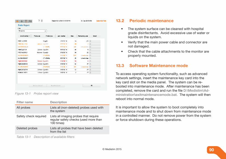
90 © Medistim 2015 90
Figure 13-1 Probe report view
Filter name Description
All probes Lists all (non-deleted) probes used with the system
Safety check required Lists all imaging probes that require regular safety checks (used more than 100 times)
Deleted probes Lists all probes that have been deleted from the list
Table 13-1 Description of available filters
13.2 Periodic maintenance
• The system surface can be cleaned with hospital grade disinfectants. Avoid excessive use of water or liquids on the system.
• Verify that the main power cable and connector are not damaged.
• Check that the cable attachments to the monitor are properly mounted.
13.3 Software Maintenance mode
To access operating system functionality, such as advanced network settings, insert the maintenance key card into the key card slot on the media panel. The system can be re-booted into maintenance mode. After maintenance has been completed, remove the card and run the file D:\Medistim\Ad-ministration\exitmaintenancemode.bat. The system will then reboot into normal mode.
It is important to allow the system to boot completely into maintenance mode and to shut down from maintenance mode in a controlled manner. Do not remove power from the system or force shutdown during these operations.

91© Medistim 201590
13.4 Storage
The probes should be kept in their container when not in use.The system and probes can be stored under the followingconditions:
• Temperature between -20°C to 70 °C (-4°F to 158°F)
• Humidity between 20 % - 95 % RH, non condensing
When the system or probes are moved between locations with different temperature and humidity, please allow sufficient time for acclimatization in order to prevent condensation.
13.5 Disposal instructions
The system contains various plastic materials, electronic com-ponents and metals. Please follow local rules and regulations when disposing.
Follow hospital safety regulations for equipment that has been in contact with blood.

92 © Medistim 2015 92
14. PROBE CLEANING, DISINFECTION AND STERILIZATION
14.1 General
Cleaning For cleaning of probes prior to sterilization, consult the In-structions for Use (IFU) manual included with each probe.
Disinfection
Approved disinfectants are specified in the IFU manual in-cluded with each probe.
Note that any approved disinfectants are recommended be-cause of their chemical compatibility with product materials, not their biological effectiveness. For the biological effective-ness of a disinfectant, refer to the guidelines and recommeda-tions of the disinfectant manufacturer.
Sterilization
Each probe series is approved for one or more of the following sterilization methods:
• STERRAD® *
• RENO Plasma Sterilizers **
• Ethylene Oxide gas (EtO)
• Steam Autoclave*STERRAD® is a registered trademark of the company ASP.** RENO Plasma Sterilizers are manufactured by RENOSEM CO., LTD.
Consult the corresponding IFU manauls for an overview of validated sterilization methods for each probe series. It is very important that the cleaning, disinfection, and sterilization instructions are followed carefully.

93© Medistim 201593
Appendix A. ACOUSTiC OUTpUT RepORT
A.1 probe description
A.1.1 L15 High-frequency Ultrasound Imaging probe
Feature description
Type Linear Array
Width of image 15.2mm
Frequency 15MHz
Table A-1 Description of probe features
A.2 Safety guidelines
The Medistim MiraQ™ System is an intraoperative diagnostic system to be used by surgeons during surgical interventions with 2D ultrasound imaging that is intended for Epicardiac and Epiaortic scanning. As seen in table 2-3 in “2.6.2 Interpreting Thermal and Mechanical Index”, the relative importance of maintaining low exposure is considered “of less importance” both for TI and for MI. One should be aware of the fact that the adverse biological effects of ultrasound on tissue appear to be threshold effects. When tissue is repeatedly exposed to ultrasound, with intervals in between, there will likely be no cumulative biological effect. If a certain threshold has been passed, biological effects may occur.
Recommendations for use :
• In general it is recommended to start examination with lowest possible settings for TI and MI, and mod-ify from this level until a satisfactory image, or Dop-pler signal is obtained, keeping track of TI and MI. However, the power levels are set by the Medistim MiraQTM System based on the operating mode and focal zone settings. The operator must monitor the TI and MI indices and assure that they are appropriate for the tissue being exposed.
• Minimize the exposure by keeping the exposure time as short as possible.
Note The maximum probe face temperature for the Medistim L15 High-frequency Ultrasound Imaging Probe is 43°C.

94 © Medistim 2015 94
A.2.1 L15 Acoustic Output - 2D Mode
Acoustic output reporting table, ieC 60601-2-37:
Acoustic output reporting for
Sound Technology Inc. transducer E
L100015
Docum
ent No. T
D-M
M-13001
Ver. 1.1
TD
_MM
_13001_STI_E
L100015.docx
CO
NFID
EN
TIA
L
A
UR
OT
EC
H ultrasound A
S June 6
th, 2013 8 of 11
Output R
eporting Tables Table 3: G
lobal maxim
um M
I and TI values for the 2D - IN
VA
SIVE application of the STI EL100015
transducer (format: A
coustic Output R
eporting Table 201.103, IEC 60601-2-37:2007).
TIC
1.22
13.4
14.6
4.0
1.5
1.5
5.9
65
2
13.9
TIB
non-scanning
-
-
-
-
-
-
-
-
-
-
-
-
-
TIS
non-scanning
Aaprt>1cm2
-
-
-
-
-
-
-
-
-
-
-
-
-
-
Aaprt≤1cm2
-
-
-
-
-
-
-
-
-
-
-
-
scannning
0.96
15.2
14.0
10.0
1.5
1.8
18.0
48
2
11.4
MI
1.64
6.2
3.6
14.6
0.09
17929
7.5
2013
1.2
3.9
46
2
13.9
Index label
Maximum index value
[MPa]
[mW]
[mW]
[mm]
[mm]
[mm]
[mm]
[mm]
[MHz]
X [mm]
Y [mm]
[µs]
[Hz]
[MPa]
[mm]
[W/cm2]
FLx [mm]
FLy [mm]
[]
[mm]
[Vpp]
[]
[MHz]
pr.3
P
min[(P.3(zs), Ita.3(zs)]
zs
zbp
zb
z at max[Ipi.3]
deq(zb)
fawf
dim. of Aaprt
td
prr
pr at max[Ipi]
deq at max[Ipi]
Ipa.3 at max[MI]
focal length
F-number
focal depth
drive voltage
half cycles
transmit frequency
Associated acoustic parameters
Other information
Operating control conditions
A.2.2 L15 Acoustic Output - Color Flow Mode
Acoustic output reporting table, ieC 60601-2-37:
Acoustic output reporting for
Sound Technology Inc. transducer E
L100015
Docum
ent No. T
D-M
M-13001
Ver. 1.1
TD
_MM
_13001_STI_E
L100015.docx
CO
NFID
EN
TIA
L
A
UR
OT
EC
H ultrasound A
S June 6
th, 2013 10 of 11
Table 5: Global m
aximum
MI and TI values for the PW
- INV
ASIV
E application of the STI EL100015 transducer (form
at: Acoustic O
utput Reporting Table 201.103, IEC
60601-2-37:2007).
TIC
0.77
10.3
12.5
6
1.5
1.7
10.3
60
30
12.5
TIB
non-scanning
1.00
10.3
9.9
1.0
12.5
6
1.5
1.0
1.7
10.3
60
30
12.5
TIS
non-scanning
Aaprt>1cm2
-
-
-
-
-
-
-
-
-
-
-
-
-
-
Aaprt≤1cm2
0.73
12.3
12.5
10.1
1.5
-
-
1.8
18.0
25
30
12.5
scannning
-
-
-
-
-
-
-
-
-
-
MI
1.63
5.8
3.4
12.6
0.60
283
6.7
1961
1.2
3.9
36
16
12.5
Index label
Maximum index value
[MPa]
[mW]
[mW]
[mm]
[mm]
[mm]
[mm]
[mm]
[MHz]
X [mm]
Y [mm]
[µs]
[Hz]
[MPa]
[mm]
[W/cm2]
FLx [mm]
FLy [mm]
[]
[mm]
[Vpp]
[]
[MHz]
pr.3
P
min[(P.3(zs), Ita.3(zs)]
zs
zbp
zb
z at max[Ipi.3]
deq(zb)
fawf
dim. of Aaprt
td
prr
pr at max[Ipi]
deq at max[Ipi]
Ipa.3 at max[MI]
focal length
F-number
focal depth
drive volatge
half cycles
transmit frequency
Associated acoustic parameters
Other information
Operating control conditions
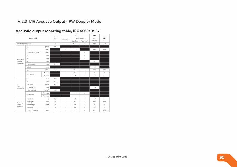
95© Medistim 201594
A.2.3 L15 Acoustic Output - PW Doppler Mode
Acoustic output reporting table, ieC 60601-2-37
Acoustic output reporting for
Sound Technology Inc. transducer E
L100015
Docum
ent No. T
D-M
M-13001
Ver. 1.1
TD
_MM
_13001_STI_E
L100015.docx
CO
NFID
EN
TIA
L
A
UR
OT
EC
H ultrasound A
S June 6
th, 2013 10 of 11
Table 5: Global m
aximum
MI and TI values for the PW
- INV
ASIV
E application of the STI EL100015 transducer (form
at: Acoustic O
utput Reporting Table 201.103, IEC
60601-2-37:2007).
TIC
0.77
10.3
12.5
6
1.5
1.7
10.3
60
30
12.5
TIB
non-scanning
1.00
10.3
9.9
1.0
12.5
6
1.5
1.0
1.7
10.3
60
30
12.5
TIS
non-scanning
Aaprt>1cm2
-
-
-
-
-
-
-
-
-
-
-
-
-
-
Aaprt≤1cm2
0.73
12.3
12.5
10.1
1.5
-
-
1.8
18.0
25
30
12.5
scannning
-
-
-
-
-
-
-
-
-
-
MI
1.63
5.8
3.4
12.6
0.60
283
6.7
1961
1.2
3.9
36
16
12.5
Index label
Maximum index value
[MPa]
[mW]
[mW]
[mm]
[mm]
[mm]
[mm]
[mm]
[MHz]
X [mm]
Y [mm]
[µs]
[Hz]
[MPa]
[mm]
[W/cm2]
FLx [mm]
FLy [mm]
[]
[mm]
[Vpp]
[]
[MHz]
pr.3
P
min[(P.3(zs), Ita.3(zs)]
zs
zbp
zb
z at max[Ipi.3]
deq(zb)
fawf
dim. of Aaprt
td
prr
pr at max[Ipi]
deq at max[Ipi]
Ipa.3 at max[MI]
focal length
F-number
focal depth
drive volatge
half cycles
transmit frequency
Associated acoustic parameters
Other information
Operating control conditions

96 © Medistim 2015 96
Appendix B. pROBe AppLiCATiOn OVeRVieW
B.1 probe application and size guide
Cardiac Surgery
Surgery/Vessel Vessel Size Recommended Medistim probes
Saphenous Vein Graft 3-5 mm 3mm, 4mm and 5mm Medistim TTFM probes (PS, PQ and PV probe series)
Internal Mammary Artery 2-3 mm 2mm and 3mm Medistim TTFM probes (PS, PQ and PV probe series)
Radial Artery 2-4 mm 2mm, 3mm and 4mm Medistim TTFM probes (PS, PQ and PV probe series)
Ascending Aorta 20-35 mm Please contact your sales representative or Medistim directly for information
Pulmonary Artery 20-35 mm Please contact your sales representative or Medistim directly for information
Pediatric Surgery 6-20 mm Please contact your sales representative or Medistim directly for information
All probes are available with or wihout handle. See section B.2 for a full list of available probes.
Transplant Surgery
Surgery/Vessel Vessel Size Recommended Medistim probes
Hepatic Artery 5-8 mm 5mm, 6mm, 7mm and 8mm Medistim TTFM probes (PV, PS, or PQ probe series)
Portal Vein 10-14 mm 10mm, 12mm, and 14mm Medistim TTFM probes (PV probe series)
Renal Artery 4-6 mm 4mm, 5mm and 6mm Medistim TTFM probes (PV, PS, or PQ probe series)
Renal Vein 8-11 mm 8mm, 10mm, and 12mm Medistim TTFM probes (PV probe series)
Common Iliac Artery 6-8 mm 6mm, 7mm, and 8mm Medistim TTFM probes (PV or PS probe series)
All probes are available with or wihout handle. See section B.2 for a full list of available probes.
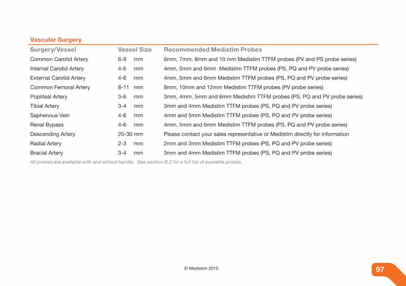
97© Medistim 201596
Vascular Surgery
Surgery/Vessel Vessel Size Recommended Medistim probes
Common Carotid Artery 6-9 mm 6mm, 7mm, 8mm and 10 mm Medistim TTFM probes (PV and PS probe series)
Internal Carotid Artery 4-6 mm 4mm, 5mm and 6mm Medistim TTFM probes (PS, PQ and PV probe series)
External Carotid Artery 4-6 mm 4mm, 5mm and 6mm Medistim TTFM probes (PS, PQ and PV probe series)
Common Femoral Artery 8-11 mm 8mm, 10mm and 12mm Medistim TTFM probes (PV probe series)
Popliteal Artery 3-6 mm 3mm, 4mm, 5mm and 6mm Medistim TTFM probes (PS, PQ and PV probe series)
Tibial Artery 3-4 mm 3mm and 4mm Medistim TTFM probes (PS, PQ and PV probe series)
Saphenous Vein 4-6 mm 4mm and 5mm Medistim TTFM probes (PS, PQ and PV probe series)
Renal Bypass 4-6 mm 4mm, 5mm and 6mm Medistim TTFM probes (PS, PQ and PV probe series)
Descending Artery 20-30 mm Please contact your sales representative or Medistim directly for information
Radial Artery 2-3 mm 2mm and 3mm Medistim TTFM probes (PS, PQ and PV probe series)
Bracial Artery 3-4 mm 3mm and 4mm Medistim TTFM probes (PS, PQ and PV probe series)
All probes are available with and wihout handle. See section B.2 for a full list of available probes.

98 © Medistim 2015 98
B.2 List of Available Medistim probes
Medistim QuickFit™ TTFM probes - pS probe Series
probe name probe sizes part numbers*QuickFit™ TTFM probes 1.5mm
2mm
3mm
4mm
5mm
7mm
pS101011, pS101012
pS100021, pS100022
pS100031, pS100032
pS100041, pS100042
pS100051, pS100052
pS100071, pS100072
Medistim PS probe series with handle
*Part numbers that end with 1 indicate probes without handle and part numbers that end with 2 indicate probes with handle.
Medistim QuickFit™ TTFM probes - pQ probe Series
probe name probe sizes part numbers*QuickFit™ TTFM probes 1.5mm
2mm
3mm
4mm
5mm
pQ101011, pQ101012
pQ100021, pQ100022
pQ100031, pQ100032
pQ100041, pQ100042
pQ100051, pQ100052
Medistim PQ probe with handle
*Part numbers that end with 1 indicate probes without handle and part numbers that end with 2 indicate probes with handle.

99© Medistim 201598
Medistim Vascular TTFM probes - pV probe Series
probe name probe sizes part numbers*Vascular TTFM probes 1,5mm
2mm
3mm
4mm
5mm
6mm
8mm
10mm
12mm
14mm
16mm
pV101011
pV100021
pV100031, pV100032
pV100041, pV100042
pV100051, pV100052
pV100061, pV100062
pV100081, pV100082
pV100101, pV100102
pV100121, pV100122
pV100141, pV100142
pV100161, pV100162Complete range of Medistim PV probes
*Part numbers that end with 1 indicate probes without handle and part numbers that end with 2 indicate probes with handle.
Medistim Ultrasound imaging probe
probe name probe size part numberL15 Ultrasound imaging probe One size eL100015
Medistim Ultrasound Imaging probe

100 © Medistim 2015 100
Medistim doppler probe - pd probe
probe name probe size part numberdoppler probe* One size pd110752
Medistim PD probe
*Doppler probes are delivered with a removable handle and four stabilizer cups.
Medistim Cardiac Output TTFM probes - pR probe Series
probe name probe size part numberCardiac Output TTFM probes 25mm
20mm
35mm
pR100251
pR100301
pR100351
Medistim Cardiac Output probe

101© Medistim 2015101
Appendix C. OVeRVieW OF eRROR MeSSAGeS
C.1 probe related error messages
Message description / Cause Actions
“xx” uses remaining The message is displayed when connecting a probe where the number of uses left is below a predefined value for the probe (typically below 5 uses). This is to inform the user that the probe will soon have to be replaced.
No action necessary.
Probe expired The message is displayed when connecting a probe where the probes usage count has reached its maximum value.
Disconnect the probe. The probe must be replaced by a new one.
Probe failed The message is displayed when a probe is connected and the system is unable to properly identify it.The most likely causes are:• Damaged probe connector• Error in the probe memory
Check probe connector for bent pins or water before trying to reconnect the probe.Replace the probe.
The connected imaging probe is not for clinical use
The message is displayed when connection an imaging probe which is striclty for non-clinical use.
Remove the probe from the system unless it shall only be used non clinically (demonstra-tions etc).
Probe file error Displayed when connecting an imaging probe. Caused by an error in the probe file for the connected probe.
Import a valid probe file for the connected imaging probe.
The connected imaging probe has been used more than “xx” times.
Displayed when connecting an imaging probe with unrestricted use if the current number of uses is above a predefined number for the probe. This is a reminder to ensure that the user per-forms the electrical safety check when this is required. Confirm that the probe has passed the mandatory electrical safety check.
After the probe has been used it must pass the electrical safety check before it can be used again. Ensure that the probe is tested accord-ing to the probe’s instructions for use.
Table C-1 Probe related error messages

102 © Medistim 2015 102
Message description / Cause Actions
This input channel is in use by an active trend measurement.The probe has been disconnected from chan-nel [1]!Please reconnect probe [2] to channel [1] or stop the trend data collection.
The message is displayed if the system is in trend logging mode and a probe with an active trend measurement is re-moved.
Reconnect the probe to the correct channel or stop the trend data collection.
This input channel is in use by an active trend measurement.Wrong probe connected to channel [1]!Please reconnect probe [2] to channel [1] or stop the trend data collection.
The message is displayed if the system is in trend logging mode, a probe with an active trend measurement has been re-moved and a different probe is connected to the trend channel.
Reconnect the correct probe to the correct channel or stop the trend data collection.
Table C-1 Probe related error messages

103© Medistim 2015102
C.2 imaging hardware related error messages
Message description / Cause Actions
Lost connection to the Imaging module. Attempt to reconnect?
The message is displayed if the system software for some reason becomes disconnected from the imaging hardware. This is most likely due to an error situation in the imaging firmware causing the imaging hardware to shut down. It can also be the result of a hardware shutdown due to overheating. Imaging functionality will be disabled unless a connection with the imag-ing module can be restored.
Select yes to attempt to reconnect, no other-wise.If the error occurs directly after system start-up, the network connectivity with the imaging hardware should be checked. Try accessing the imaging hardware while in maintenance mode using Internet Explorer to access ad-dress http:\\10.0.0.3. If the imaging hardware does not respond, check the network cable which goes from the main board to the imag-ing hardware.
Imaging functionality disabled. To restore the functionality, reboot the system.
The system software has lost communication with the imaging hardware and the user has chosen not to try to reconnect with the imaging hardware (or the reconnect operation have failed).This is most likely due to an error situation in the imaging firm-ware causing the imaging hardware to shut down. It can also be the result of a hardware shutdown due to overheating.
The system must be rebooted in order to restore the imaging functionality. If the problem persists, contact [email protected].
No probefile defined for probe type [1]. Please import a valid probefile for this probe type.
The message is displayed if the system software does not have a probe file registered for the probe type connected.
Disconnect the imaging probe.Import the correct probe file for the probe.Reconnect the imaging probe.
No imaging preset regis-tered for the connected imaging probe type. Please import a valid im-aging preset settings file for this probe type.
The message is displayed if the system software does not have a preset settings file registered for the probe type connected.
Disconnect the imaging probe.Import a valid imaging preset settings file.Reconnect the imaging probe.
Table C-2 Imaging hardware related messages

104 © Medistim 2015 104
Message description / Cause Actions
Imaging preset file is missing or invalid.
The message is displayed if the system software is unable to load the selected imaging preset settings file. The file is missing from the hard drive or the file is not valid
Either delete the selected imaging preset file through the user interface of the system soft-ware, or try to import the imaging preset file which is missing or invalid.
The default imaging pre-set file for the connected imaging probe type was not found. Please import a valid imaging preset file or change the default imag-ing preset.
The message is displayed if the system software is unable to load the default imaging preset settings file when connecting an imaging probe. The file is missing from the hard drive or cannot be opened by the software.
Either change the default imaging preset through the user interface of the system soft-ware, or try to import the imaging preset file which is missing.
Mismatch between probe ID and probefile ID
The message is displayed if the probe file registered for the probe connected is not the correct file for the probe. There is either an error in the systems database or the correct probe file has been replaced by a different file.
Disconnect the imaging probe.Import the correct probe file for the probe.Reconnect the imaging probe.
The probefile for the connected imaging probe type was not found. Please import a valid probefile.
The message is displayed if the system software is unable to load the corresponding probe file when connecting an imag-ing probe. The file is missing from the hard drive or cannot be opened by the software.
Disconnect the imaging probe.Import the correct probe file for the probe.Reconnect the imaging probe.
The probefile format is not valid. Please import a valid probefile
This message is displayed when connecting an imaging probe and there is an error in the corresponding probe file.
Disconnect the imaging probe.Import the correct probe file for the probe.Reconnect the imaging probe.
Imaging preset file format is not valid. Please import a valid imaging preset file.
This message is displayed when connecting an imaging probe and there is an error in the default imaging preset file.
Either delete the selected imaging preset file through the user interface of the system soft-ware, or try to import the imaging preset file which is invalid.
Table C-2 Imaging hardware related messages

105© Medistim 2015104
C.3 Smart card related error messages
Message description / Cause Action
Write Error The message is displayed when the system software fails to write to the connected smart card. This is most likely caused by a poor connection with the smart card or the smart card reader.
Remove and reinsert smart card and try the intended operation again. If the problem per-sists, contact [email protected].
Read Error The message is displayed when the system software fails to read from the connected smart card. This is most likely caused by a poor connection with the smart card or the smart card reader.
Remove and reinsert smart card and try the intended operation again. If the problem per-sists, contact [email protected].
Code Verification Error The message is displayed when the system software fails to gain access to the information stored in the smart card because of an error in the access code supplied. This can be caused by a communication error resulting from a poor connection with the smart card or the smart card reader. The error can also be displayed if the smart card is not a valid Medistim card.
Remove and reinsert the smart card and try the operation again.Make sure that the smart card being used is a valid Medistim smart card.If the problem persists, contact [email protected].
The card is not valid, or is inserted the wrong way.
The message is displayed if the system software fails to com-municate with the card, or the card is inserted the wrong way.
Remove the card. Make sure the card is inserted the correct way (chip up, and inserted with the chip first).
Unsupported Medistim card
The message is displayed if the system software detects a smart card of a type which is not supported by the system or the system software.
Remove the smart card.
Table C-3 Smart card related error messages
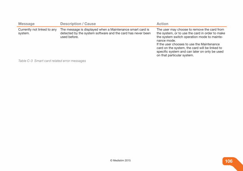
106 © Medistim 2015 106
Message description / Cause Action
Currently not linked to any system.
The message is displayed when a Maintenance smart card is detected by the system software and the card has never been used before.
The user may choose to remove the card from the system, or to use the card in order to make the system switch operation mode to mainte-nance mode.If the user chooses to use the Maintenance card on the system, the card will be linked to specific system and can later on only be used on that particular system.
Table C-3 Smart card related error messages
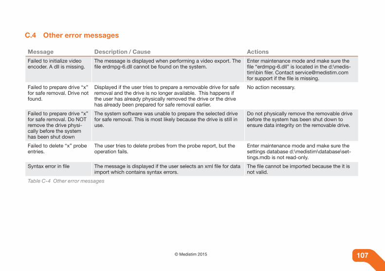
107© Medistim 2015106
C.4 Other error messages
Message description / Cause Actions
Failed to initialize video encoder. A dll is missing.
The message is displayed when performing a video export. The file erdmpg-6.dll cannot be found on the system.
Enter maintenance mode and make sure the file “erdmpg-6.dll” is located in the d:\medis-tim\bin filer. Contact [email protected] for support if the file is missing.
Failed to prepare drive “x” for safe removal. Drive not found.
Displayed if the user tries to prepare a removable drive for safe removal and the drive is no longer available. This happens if the user has already physically removed the drive or the drive has already been prepared for safe removal earlier.
No action necessary.
Failed to prepare drive “x” for safe removal. Do NOT remove the drive physi-cally before the system has been shut down
The system software was unable to prepare the selected drive for safe removal. This is most likely because the drive is still in use.
Do not physically remove the removable drive before the system has been shut down to ensure data integrity on the removable drive.
Failed to delete “x” probe entries.
The user tries to delete probes from the probe report, but the operation fails.
Enter maintenance mode and make sure the settings database d:\medistim\database\set-tings.mdb is not read-only.
Syntax error in file The message is displayed if the user selects an xml file for data import which contains syntax errors.
The file cannot be imported because the it is not valid.
Table C-4 Other error messages

108 © Medistim 2015 108
Message description / Cause Actions
Measurement file(s) could not be imported due to the following error(s):
Displayed if the user imports clinical data and a file operation fails. This is most likely due to the fact that data files referenced in the imported file does not exist on the media from which data are imported. Details about the error will be part of the error message.
The database used by the system will not be consistent and will contains records about measurements which lacks their correspond-ing data files.The system software will report to the user whenever the user tries to review data where the data file is missing. Delete the affected measurements from the system to prevent those error messages from being displayed.
Time conversion error Displayed if an illegal time value has been selected when se-lecting time and date.
Specify a valid time value
Date conversion error Displayed if an illegal date value has been selected when se-lecting time and date.
Specify a valid date value.
An error occurred while exporting the data. Please check your target location and try again.
The error message is displayed when a data export operation fails.
Check to make sure that the target location has enough free space available for storing the data currently being exported.
Warning. No probe data loaded
Displayed if the user tries to view probe information for a stored measurement file and the measurement file does not contain probe data.
No action necessary.
Invalid license file Displayed if the user tries to import a DICOM license file which is not valid for the system. May occur if the system hardware has been changed (e.g. new motherboard).
Contact [email protected] to get a valid license file for the system.
Table C-4 Other error messages

109© Medistim 2015108
Message description / Cause Actions
Unable to delete imaging preset.
The user has selected to delete an imaging preset but the system software failed to delete the specified file from the data-base. The settings database is read-only or there is a discrep-ancy in the settings database related to the imaging presets available on the system.
Enter maintenance mode and verify that the database files located under d:\medistim\data-base is not read-only.If the imaging preset is still in the list of avail-able imaging presets after a system restart, contact [email protected] to get help re-moving the imaging preset from the database.
Save Assistant is busy. Must wait for it to finish.
The message is displayed if the user has triggered a save operation and then quickly triggered a different operation which cannot be performed while a save operation is in progress.Some operations in the software requires that there are no active save operations running in the background while they are being performed. These operations must wait for the active save operation to finish before they can be executed.
No action necessary. This is by design in order to ensure data integrity. As soon as the on-go-ing save operation has finished, the software will continue with the scheduled task.
Save Assistant is busy. Waiting
The message is displayed if the user tries to save multiple im-aging measurements within a very short time period. The sys-tem software performs the save operation in the background while the software continues on with other tasks. The system software can only execute one save operation at a time in order to ensure data integrity.
No action necessary. This is by design in order to ensure data integrity. As soon as the on going save operation has finished, the second save operation will be executed.
Measurement file is miss-ing or corrupt!
This message is displayed when trying to load a measurement file from disk and the file is missing or corrupt. This is most likely due to an incomplete data import which have been per-formed earlier, which have resulted in an inconsistent database.
Corrupt or missing files cannot be recovered. Delete the affected measurements from the system to prevent the error messages from being displayed.
Table C-4 Other error messages
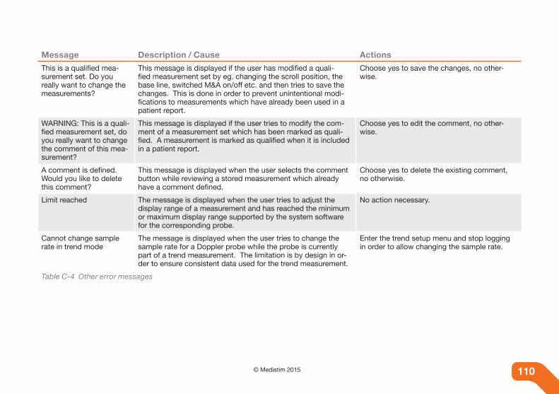
110 © Medistim 2015 110
Message description / Cause Actions
This is a qualified mea-surement set. Do you really want to change the measurements?
This message is displayed if the user has modified a quali-fied measurement set by eg. changing the scroll position, the base line, switched M&A on/off etc. and then tries to save the changes. This is done in order to prevent unintentional modi-fications to measurements which have already been used in a patient report.
Choose yes to save the changes, no other-wise.
WARNING: This is a quali-fied measurement set, do you really want to change the comment of this mea-surement?
This message is displayed if the user tries to modify the com-ment of a measurement set which has been marked as quali-fied. A measurement is marked as qualified when it is included in a patient report.
Choose yes to edit the comment, no other-wise.
A comment is defined. Would you like to delete this comment?
This message is displayed when the user selects the comment button while reviewing a stored measurement which already have a comment defined.
Choose yes to delete the existing comment, no otherwise.
Limit reached The message is displayed when the user tries to adjust the display range of a measurement and has reached the minimum or maximum display range supported by the system software for the corresponding probe.
No action necessary.
Cannot change sample rate in trend mode
The message is displayed when the user tries to change the sample rate for a Doppler probe while the probe is currently part of a trend measurement. The limitation is by design in or-der to ensure consistent data used for the trend measurement.
Enter the trend setup menu and stop logging in order to allow changing the sample rate.
Table C-4 Other error messages

111© Medistim 2015111
Appendix d. iCOn deSCRipTiOn
d.1 icon description
The following overview gives a description of all icons used in the different system screens.
Home screen - This is also the start-up screen where the profile and user can be entered or selected.
Patient screen - record and edit patient information and retrieve saved information.
Live Session screen - Imaging and TTFM, identify ves-sel names, and save measurements.
Live Session screen - TTFM only - identify vessel names, and save measurements.
Help screen - The electronic User Manual for the Medistim MiraQ™ System can be found here.
Outline - Press to toggle display of the chapter outline in the user manual on the system.
Archive Reporting screen - Edit, delete, print and export saved measuerments.
System Settings - Customize system setup here.
Time Compression - Decrease time sweep for all traces in steps. Down to 1 second.
Time Expansion - Increase time sweep for all traces in steps. Up to 60 seconds.
Save Data - Save recorded data to the patient data-base.
Measurement Pause - Press to pause measurement. The icon will change to the play symbol.
Measurement Play - Press to resume measurement. The icon will change to the pause symbol.
Derived Curves - Choose combination of flow and pressure channels for derived curves.
Trend Setup - choose number of channels and set sweep time for trend recordings.
Trend / Live - In trend measurement mode, switch between trend and live mode measurements.
Measure and Analyze - Displays calculated values and measurement tools.
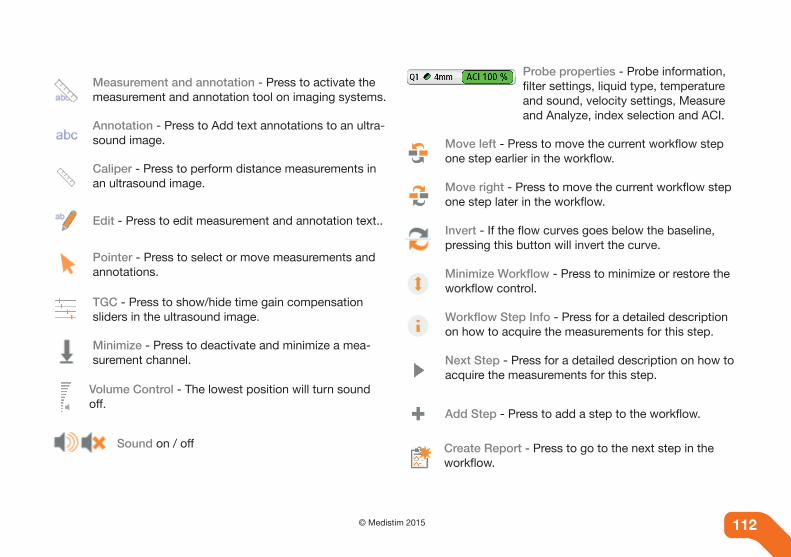
112 © Medistim 2015 112
Measurement and annotation - Press to activate the measurement and annotation tool on imaging systems.
Annotation - Press to Add text annotations to an ultra-sound image.
Caliper - Press to perform distance measurements in an ultrasound image.
Edit - Press to edit measurement and annotation text..
Pointer - Press to select or move measurements and annotations.
TGC - Press to show/hide time gain compensation sliders in the ultrasound image.
Minimize - Press to deactivate and minimize a mea-surement channel.
Volume Control - The lowest position will turn sound off.
Sound on / off
Probe properties - Probe information, filter settings, liquid type, temperature and sound, velocity settings, Measure and Analyze, index selection and ACI.
Move left - Press to move the current workflow step one step earlier in the workflow.
Move right - Press to move the current workflow step one step later in the workflow.
Invert - If the flow curves goes below the baseline, pressing this button will invert the curve.
Minimize Workflow - Press to minimize or restore the workflow control.
Workflow Step Info - Press for a detailed description on how to acquire the measurements for this step.
Next Step - Press for a detailed description on how to acquire the measurements for this step.
Add Step - Press to add a step to the workflow.
Create Report - Press to go to the next step in the workflow.

113© Medistim 2015112
Report - Press to open report.
Export Report - Selected measurements are exported to an external memory device in PDF format.
Print - All selected measurements will be printed.
Delete - Will delete selected item(s).
Select / Edit - View or edit selected measurement curves.
Display 4 measurements - Displays measurements with large thumbnails in a 2 by 2 arrangement.
Display 9 measurements - Displays measurements with large thumbnails in a 3 by 3 arrangement.
Display 16 measurements - Displays measurements with small thumbnails in a 4 by 4 arrangement.
Thumbnails - Go to thumbnail veiw. Press this icon to return to the thumbnail view when in editing mode.
Screen shot or video export - Export screen shot or video of an ultrasound recording to an external device.
Move up one level when browsing the file system.
Create new folder.
Increase Doppler gain - The spectrum will become darker with the possibility of increased noise.
Decrease Doppler gain - The spectrum will become more transparent with less noise.
Increase Sample Volume - Increases the sample vol-ume of the Doppler by 1mm.
Doppler Reference Speed - Marks current maximum speed and uses it for stenosis grade calculations.
Skip forward - Press to skip one heart-cycle forward during playback of ultrasound images.
Skip Backward - Press to skip one heart-cycle back-ward during playback of ultrasound images.

114 © Medistim 2015 114
Decrease Loop Length - Press to decrease loop length by one heart-cycle during playback of ultra-sound images.
Increase Loop Length - Press to increase loop length by one heart-cycle during playback of ultrasound im-ages.
Search Archive - Triggers a search operation and searches for patient (s) in the internal archive.
New Patient - Creates a new patient in the internal archive and opens a “new patient” screen.
Edit Patient Info - Edit or add information to a patient file.
Comments - Opens a comments field for the current measurement set.
Conduit - Indicates the conduit in a graft definition.
Location - Indicates the measurement location.
Attribute - Indicates the attributes added to a mea-surement location.
Comparison (imaging) - Opens measurement com-parison on systems with imaging support.
Comparison - Opens measurement comparison on systems without imaging support.
Action - Indicates that the workflow step has been configured to automatically perform one or more ac-tions when the step is activated, e.g. changing imaging mode or imaging preset.
Backspace - Removes the last component from a measurement location.

115© Medistim 2015115
Appendix e. diCOM FUnCTiOnALiTY
e.1 introduction
Systems with the optional DICOM functionality have the pos-sibility to receive patient and study information from a network worklist server and export the acquired measurement sets for storarge on a network storage server / Picture Archiving and Communication System (PACS).
In order to utilize the full DICOM functionality, the department must have a working Ethernet configuration with a DICOM worklist server and a DICOM storage server / PACS. In addi-tion, the MiraQ™ System needs access to an Ethernet jack in order to connect to the network.
e.2 Configuring the DICOM functionality
Before the MiraQ™ System can be connected to a DICOM storage or worklist server, the local network connection and the remote servers must be configured.
E.2.1 Configuring network settings
Before initiating the configuration, ensure that the network cable is connected and that the network icon on top of the screen indicates a valid connection. See “E.5 DICOM icon description”.
Start the MiraQ™ System and open the System Settings screen. Press the Advanced System Functionality button and then press the Network Settings button to open the Network settings page. Here, the MiraQ™ System network connection is configured using parameters obtained from the hospital IT department. Enter the addresses and values obtained from the hospital IT department in their corresponding fields Figure E-1. If the hospital uses DHCP, select the Use DHCP button instead of configuring the network settings manually.
Figure E-1 Network settings page

116 © Medistim 2015 116
E.2.2 Configuring a DICOM server
To configure the DICOM server, navigate to the Network Set-tings page and press the Add button. This will bring up the DICOM server configuration page Figure E-2.
Enter the appropriate values in the corresponding fields, and choose how the server should be managed. After entering the server’s IP address the TCP/IP communication can be tested by pressing the Ping button. This will perform a ping com-mand to the specified address, and the result will be displayed on screen. In the Server type dropdown menu, specify whether the serv-er is a DICOM storage server or a DICOM Modality Worklist server. When server type has been selected, the screen will change in accordance to the server type. The configuration page for the worklist server contains less parameters to set up than the configuration page for the storage server. After entering the server’s IP address and DICOM configura-tion, the DICOM communication can be tested by pressing the Verify button. This will perform a DICOM C-ECHO request that tests that the server and the Medistim MiraQ™ System are configured in a way that allows them to communicate. The result of the Verify operation will be displayed on screen.
Figure E-2 Server configuration page
E.2.3 Configuring the hospital servers
The MiraQ™ System must be added as an Application Entity (AE) on the servers that it is will communicate with. The pro-cess for doing this will be different from server to server, so there will be no detailed guide for doing this in this manual. Consult the applicable server manual for more information. Alternatively, assistance from the hospital DICOM manager could be requested.
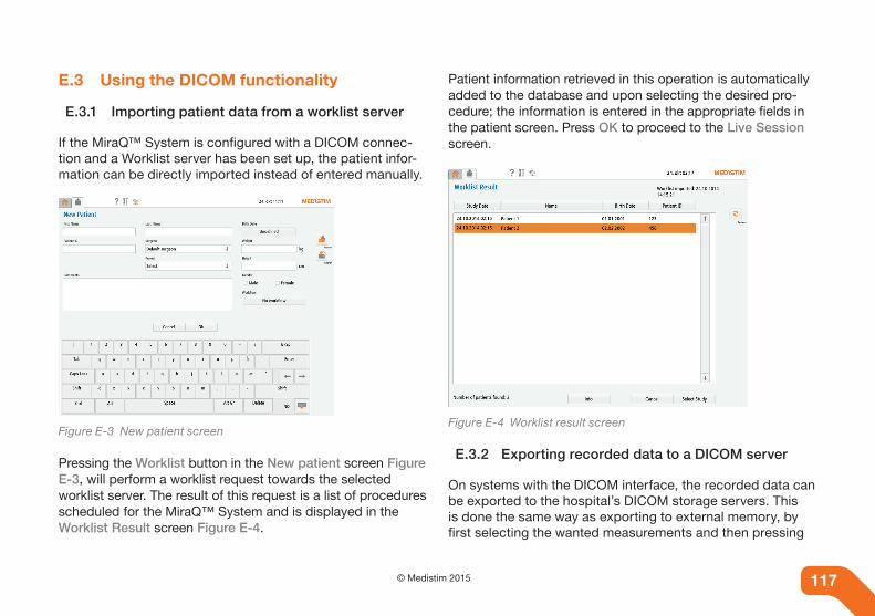
117© Medistim 2015116
e.3 Using the DICOM functionality
E.3.1 Importing patient data from a worklist server
If the MiraQ™ System is configured with a DICOM connec-tion and a Worklist server has been set up, the patient infor-mation can be directly imported instead of entered manually.
Figure E-3 New patient screen
Pressing the Worklist button in the New patient screen Figure E-3, will perform a worklist request towards the selected worklist server. The result of this request is a list of procedures scheduled for the MiraQ™ System and is displayed in the Worklist Result screen Figure E-4.
Patient information retrieved in this operation is automatically added to the database and upon selecting the desired pro-cedure; the information is entered in the appropriate fields in the patient screen. Press OK to proceed to the Live Session screen.
Figure E-4 Worklist result screen
E.3.2 Exporting recorded data to a DICOM server
On systems with the DICOM interface, the recorded data can be exported to the hospital’s DICOM storage servers. This is done the same way as exporting to external memory, by first selecting the wanted measurements and then pressing

118 © Medistim 2015 118
the DICOM Export button. Exporting measurements to the server can be queued as normal even if the MiraQ™ System is not connected to the network. All jobs will then be flagged as Pending until the MiraQ™ System is reconnected to the network.
Alternatively, all patient information including all measure-ments can be exported from the Search result screen. This is done by selecting the patient and pressing the Export button. This will bring up the Select Destination pop-up as seen in Figure E-5.
Figure E-5 Select Destination
The Select Destination pop-up allows the user to select which server to export the measurements to. It also has the option to choose Local Drive – XML Export which is the conventional XML export (Not DICOM). After selecting the desired server and pressing Export, the MiraQ™ System will begin generat-ing DICOM files to transfer.
E.3.3 Export job queue
After generating DICOM files for export, the progress of the export job can be monitored in the DICOM Job Queue window. The job queue is accessed either by pressing the network icon to the right, Figure E-6, of the system settings tab or by pressing the Job Queue button, Figure E-7 in the System Settings screen.
Figure E-6 Network Indicator
Figure E-7 Job queue
In the Job Queue window, Figure E-8, is an overview of all pending, active, failed or recently completed transfer jobs. The status of the job is displayed in the Status column, and the number of transferred elements can be seen in the Progress column.
More information about the individual transfer jobs can be viewed by selecting them in the Select column, and pressing the Info button. This will bring up a window with additional information about the transfer or a detailed error message if the transfer has failed.
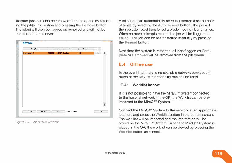
119© Medistim 2015118
Transfer jobs can also be removed from the queue by select-ing the job(s) in question and pressing the Remove button. The job(s) will then be flagged as removed and will not be transferred to the server.
Figure E-8 Job queue window
A failed job can automatically be re-transferred a set number of times by selecting the Auto Resend button. The job will then be attempted transferred a predefined number of times. When no more attempts remain, the job will be flagged as Failed. The job can be re-transferred manually by pressing the Resend button.
Next time the system is restarted, all jobs flagged as Com-plete or Removed will be removed from the job queue.
e.4 Offline use
In the event that there is no available network connection, much of the DICOM functionality can still be used.
E.4.1 Worklist import
If it is not possible to have the MiraQ™ Systemconnected to the hospital network in the OR, the Worklist can be pre-imported to the MiraQ™ System.
Connect the MiraQ™ System to the network at an appropriate location, and press the Worklist button in the patient screen. The worklist will be imported and the information will be stored on the MiraQ™ System. When the MiraQ™ System is placed in the OR, the worklist can be viewed by pressing the Worklist button as normal.
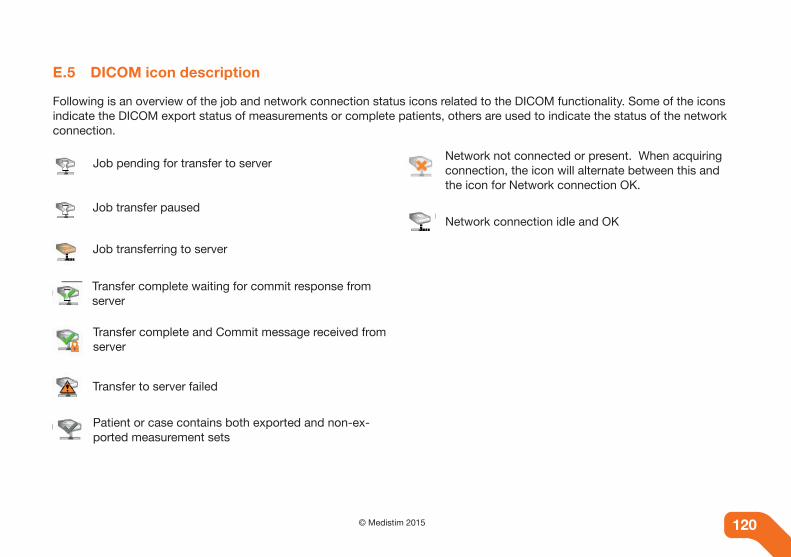
120 © Medistim 2015 120
e.5 DICOM icon description
Following is an overview of the job and network connection status icons related to the DICOM functionality. Some of the icons indicate the DICOM export status of measurements or complete patients, others are used to indicate the status of the network connection.
Job pending for transfer to server
Job transfer paused
Job transferring to server
Transfer complete waiting for commit response from server
Transfer complete and Commit message received from server
Transfer to server failed
Patient or case contains both exported and non-ex-ported measurement sets
Network not connected or present. When acquiring connection, the icon will alternate between this and the icon for Network connection OK.
Network connection idle and OK

121© Medistim 2015120

Medistim ASA (Head office)Økernveien 940579 Oslo NorwayPhone +47 23 05 96 60
Medistim Danmark ApSGøngetoften 132950 VedbækDenmarkPhone +45 2276 5669
Medistim USA Inc.14000 25th Ave N. Ste. 108Plymouth, MN 55447USAPhone +1 763 208 9852
Medistim Deutschland GmbHBahnhofstr. 3282041 DeisenhofenGermanyPhone +49 (0) 89 62 81 90 33
Medistim Norge ASØkernveien 940579 OsloNorwayPhone +47 23 03 52 50
Medistim UK Limited34 Nottingham South Ind Est Ruddington LaneWilford, NG11 7EPNottingham, UKPhone +44 (0) 115 981 0871
MQ
1990
GB
Rev
.D