MECHANICS OF COMPOSITE STRUCTURES - Taylor ...
50
-
Upload
khangminh22 -
Category
Documents
-
view
1 -
download
0
Transcript of MECHANICS OF COMPOSITE STRUCTURES - Taylor ...


MECHANICS OF COMPOSITE STRUCTURES

MECHANICS OF COMPOSITE STRUCTURES
Valery V. Vasiliev Professor of Composite Structures
Moscow Aviation 7echnology Institute Moscow, Russia
English Edition Editor
Robert M. Jones Professor of Engineering Science and Mechanics
Virginia Polytechnic Institute and State University Blacksburg, Virginia
Translated by
Lucia I. Man
Institute of Crystallography Academy of Sciences
Moscow, Russia
® Taylor & Francis

USA Publishing Office: Taylor & Francis 1101 Vermont Avenue,N.W., Suite 200 Washington, DC 20005-2531
Distribution Center:
UK
Tel: (2021 289-2174 Fax: (2021 289-3665
Taylor & Francis 1900 Frost Road, Suite 101 Bristol, PA 19007-1598 Tel: (2151 785-5800 Fax: (2151 785-5515
Taylor & Francis Ltd. 4 John Street London WC 1 N 2ET, UK Tei:071 405 2237 Fax: 071 831 2035
First edition published in 1988 by Mashinostroenie, under the title "Mekhanika konstruktsii kompozitsionnykh materialov ."
MECHANICS OF COMPOSITE STRUCTURES
Copyright © 1993 Taylor & Francis. All rights reserved. Printed in the United States of America. Except as permitted under the United States Copyright Act of 1976, no part of this publication may be reproduced or distributed in any form or by any means, or stored in a database or retrieval system, without the prior written permission of the publisher.
1234567890 BRBR 9876543
This book was produced in IBM Script by Robert M. Jones and Karen S. Devens; the cover designer was Michelle Fleitz. Printing and binding by Braun-Brumfield, Inc.
A CIP catalog record for this book is available from the British Library. @The paper in this publication meets the requirements of the ANSI Standard Z39.48-1984(Permanence of Paper)
Library of Congress Cataloging-in-Publication Data
Vasiliev, Valery V. [Mekhanika konstruktSii kompozitSionnykh materialov. English] Mechanics of composite structures I Valery V. Vasiliev;
translated by Lucia I. Man ; English edition editor, Robert M. Jones. p. em.
Translation of: Mekhanika konstruktsii kompozitSionnykh materialov.
Includes bibliographical references and index.
1. Composite materials-Mechanical properties. I. Jones, Robert M. (Robert Millard) II. Title. TA418.9.C6V38 1993 624. 1'71-dc20 ISBN 1-56032-034-6
92-46465 CIP

Contents
Preface ix Translation Editor's Preface xi
Chapter 1 INTRODUCTION TO STRUCTURAL PROPERTIES OF COMPOSITE MATERIALS 1
1.1 Fibers 1 1.1.1 Glass Fibers 2 1.1.2 Carbon or Graphite Fibers 3 1.1.3 Boron Fibers 4 1.1.4 High-Modulus Organic Fibers 5
1.2 Matrix Materials 6 1.2.1 Thermoset Polymeric Matrices 6 1.2.2 Manufacturing Processes for Thermoset-Matrix
Composite Materials 8 1.2.3 Thermoplastic Polymeric Matrices 11 1.2.4 Carbon Matrix 11 1.2.5 Metal Matrices 12
1.3 Structural Features and Mechanical Properties of Composite Materials 13 1.3.1 Composite Materials Reinforced with
Continuous Parallel Fibers 15 1.3.2 Cloth-Reinforced Materials 21 1.3.3 Composite Materials with Randomly Oriented
Fibers 22 1.3.4 Spatially Reinforced Composite Materials 22
1.4 Elastic Properties of a Composite Ply 23 1.5 Elastic Properties of an Angle-ply Laminate 29
Chapter 2 EQUATIONS OF COMPOSITE STRUCTURE MECHANICS 35
2.1 Equations of the Elasticity Theory for an Orthotropic Medium in Orthogonal Curvilinear Coordinates 35 2.1.1 Geometric Relationships 35
v

vi Contents
2.1.2 Governing Equations 37 2.1.3 Variational Principles 39
2.2 Preliminary Analysis - Basic Assumptions 47 2.3 Equations of Engineering Mechanics for
Thin-Walled Composite Structures 62 2.3.1 Geometric Equations 62 2.3.2 Constitutive Equations 68 2.3.3 Equilibrium Equations 89
2.4 General and Simplified Forms of Governing Equations and Boundary Conditions 93 2.4.1 General Form of Governing Equations 93 2.4.2 Equations for Thin-Walled Structures 98 2.4.3 Equations of the Classical Theory of Orthotropic
laminated Shells 98 2.4.4 Equations of Engineering Shell Theory 100 2.4.5 Equations of Membrane Shell Theory 101 2.4.6 Final Remarks 103
2.5 Composite Structures of Variable Thickness 103 2.6 Hygrothermal Effects 108 2.7 Nonlinear Stress-Strain Behavior of
Composite Materials 112 2.7.1 Elastic-Plastic Deformation 113 2.7.2 Nonlinear Elasticity 123 2.7.3 Structural Nonlinearity 125 2.7.4 Nonlinearity Due to Resin Crazing 130 2.7.5 Viscoelasticity 136
2.8 Geometric Nonlinearity 140 2.9 Buckling 148 2.10 Dynamic Response 152
Chapter 3 COMPOSITE BEAMS, COLUMNS, AND RINGS 155
3.1 Governing Equations for Laminated Beams 155 3.2 Lateral Bending 165 3.3 Buckling Under Axial Compression 171 3.4 Postbuckling Behavior 175 3.5 Dynamic Behavior 177 3.6 Circular Rings 183
Chapter 4 THIN-WALLED BEAMS 197
4. 1 Single-Cell Beams 197 4. 1. 1 Governing Equations and Basic Assumptions 1 98 4.1.2 Determination of Normal and Shear
4.1.3 4.1.4
Stress Resultants Determination of Displacements Cross-Section Shear Center
204 211 214

Contents vii
4.1.5 Thin-Walled Beams with Circular Cross Sections 216
4.1.6 Stresses in the Composite Layers 218 4.1.7 Beams Stiffened with Axial Ribs 222 4.1.8 Warping of Cross Sections of Single-Cell
Beams Under Free Bending and Torsion 224 4.1.9 Restrained Torsion and Bending of
Thin-Walled Beams 229 4.1.10 Beams Loaded with Surface and
Body Forces 235 4.2 Beams with Open Cross-Section Contour 238
4.2.1 Bending 238 4.2.2 Free Torsion of Beams with
Open Cross-Section Contours-Simplified Approach 241
4.2.3 Restrained Torsion of Beams with Open Cross-Section Contours 248
4.2.4 Refined Solution of the Problem of Free Beam Torsion 254
4.3 Analysis of Thin-Walled Beams with Multi-Cell Cross-Section Contour 261
Chapter 5 COMPOSITE PANELS AND PLATES 269
5.1 Equations of the Theory of Laminated Plates 269 5.2 Symmetrically Laminated Panels 276
5.2.1 Governing Equations 276 5.2.2 Homogeneous Plane Stressed State 280 5.2.3 Bending of Symmetrically Laminated Plates 281 5.2.4 Buckling of Symmetrically Laminated Plates 293 5.2.5 Flexural Vibrations 302 5.2.6 Postbuckling Behavior and Bearing Capacity of
Compressed Composite Panels 302 5.2.7 Allowance for Transverse Shear Deformation 315
5.3 Generally Laminated Plates 320 5.3.1 Governing Equations 320 5.3.2 Transverse Bending 323 5.3.3 In-plane Loading 326 5.3.4 Allowance for Transverse Shear Deformation 338
5.4 Axisymmetric Deformation of Circular Plates and Disks 340 5.4.1 Governing Equations 340 5.4.2 Plane Stress State of Symmetrically
Laminated Plates 342 5.4.3 Bending of Plates with Symmetrically
Laminated Structure 348 5.4.4 Plates with Nonsymmetrically
Laminated Structure 352

viii Contents
Chapter 6 CIRCULAR CYLINDRICAL SHELLS 355
6.1 Equations of the Theory of Circular Cylindrical Orthotropic Laminated Shells 355
6.2 Circular Cylindrical Shells with Stress-Strain State Independent of Longitudinal Coordinate 356
6.3 Axisymmetric Deformation of Circular Cylindrical Shells 363
6.4 General Case of Circular Cylindrical Shell Loading: Solutions in the Form of Trigonometric Series 373
6.5 Simplified Theories of Circular Cylindrical Shells 384 6.5.1 Membrane Theory 384 6.5.2 Semimembrane Theory 406 6.5.3 Applied Method for Analysis of Circular
Cylindrical Shells 417 6.6 Buckling of Circular Cylindrical Shells 427
6.6.1 Governing Equations 427 6.6.2 Axial Compression 430 6.6.3 External Pressure 441 6.6.4 Hydrostatic Pressure 446
6.7 Circular Cylindrical Shell Vibrations 448 6.8 Buckling and Vibrations of Circular
Cylindrical Panels 453
Chapter 7 AXISYMMETRIC DEFORMATION OF SHELLS OF REVOLUTION 459
7.1 Governing Equations 459 7.2 Linear Membrane Theory 465 7.3 Boundary-Layer Theory 470
7.3.1 Linear Bending Boundary-Layer Effect 471 7.3.2 Nonlinear Bending Boundary-Layer Effect 476 7.3.3 Nonlinear Membrane Boundary-Layer Effect 479
7.4 Composite Pressure Vessels 480
References 493
Index 499

Preface
This book is devoted to engineering mechanics of structural elements made of composite materials. As is well known, engineering mechanics is a division of applied mechanics that deals with engineering methods for determining the stress state, buckling loads, and dynamic behavior of standard structural elements such as thin-walled beams, plates, panels, and shells. Engineering mechanics is based on a system of hypotheses specific for each typical element. Those hypotheses include the characteristic behavior of each element and provide substantial simplification of the general equations of mechanics of solids to obtain simple approximate analytical or numerical solutions. So far as structures of conventional metal alloys are concerned, engineering mechanics is a well-developed science that provides the complete analysis and design of various important structures - aircraft, ships, buildings, bridges, etc.
Recently, extensive use has been made of composite materials reinforced with small-diameter, high-strength, high-stiffness fibers. Highstrength, low-density materials possess some valuable properties that make them a new class of structural materials. Of great importance is the possibility to control their stiffness, strength, thermal expansion, and conductivity as well as some other characteristics by varying fiber orientation and stacking sequence of plies, thus creating laminated structures with desirable properties. In addition to conventional characteristics of structural elements, engineering mechanics also takes into consideration characteristics of composite elements - in particular, their anisotropy and laminated structure. These and some other properties of composite materials are considered in the first chapter dealing with typical fibers and matrices and their combinations and with some technological processes used to impart the desired structure to the material. The first chapter also deals with thermoelastic characteristics of plies and their laminates as the basic elements of composite structures
The detailed presentation of the traditional approaches of engineering mechanics for composite structures is rather a complicated task, and the author is not quite sure he has managed to cope with it. Some hopes are associated here with the universal nature of the general equations of mechanics of thin-walled composite structures considered in the second chapter. These equations are written in arbitrary orthogonal curvilinear coordinates and take account of orthotropy, laminated structure, and low interlaminar shear stiffness of the material; geometrical, material, and structural nonlinearity of the element; and also hygrothermal and dynamic effects. Being simplified for each particular structural element, the
ix

x Preface
general equations allow the author to avoid the derivation of similar equations for elements considered in the following chapters.
The further consideration is in accord with the traditional statement of engineering mechanics and reduces to gradual sophistication of the structural models. The third chapter deals with bending, buckling, and vibrations of composite beams. The fourth chapter is devoted to free and restrained bending and torsion of thin-walled composite beams with open, closed, and multicell cross sections. The fifth chapter is concerned with the analysis of the plane stress state, transverse bending, buckling, and post buckling behavior of rectangular composite plates. Also, spinning disks and axisymmetrically loaded circular plates are addressed. The sixth chapter is dedicated to statics, buckling, and vibrations of cylindrical shells and panels, and, finally, the seventh chapter deals with axisymmetric deformation of composite shells of revolution.
The principal task set for himself by the author was to describe the applied methods for the analysis of composite structural elements in such a way that they would take into account the simplest and most exhaustive way their geometry, structure, and behavior under loading conditions. In all cases, the final equations enable determination of the stresses and strength of elementary plies. Most theoretical results are confirmed by numerical examples and, in some cases, also by experimental data.
The author would like to express his gratitude to Professor Yurii M. Tarnopol'skii from the Latvian Academy of Sciences who was the initiator of the substantially revised and extended English edition of this book. Special appreciation is expressed to the editor of the English edition Professor Robert M. Jones from the Virginia Polytechnic Institute and State University. Particular thanks are to Dr. Lucia I. Man from the Institute of Crystallography of the USSR Academy of Sciences for her untiring and devoted work to produce the English translation of the book.
V. V. Vasiliev

Translation Editor's Preface
Publication of any book is accompanied by the question "into what niche does this contribution fit?" The present book includes work on thinwalled beams not generally available in the United States in addition to extensive work on plates and shells. Therefore, this book is suitable for courses in analysis of composite structures after a fundamental grounding in mechanics of composite materials.
Professor Vasiliev is a modern-day pioneer in analysis and design of composite structures in the Soviet Union. He has worked closely with some of the earlier luminaries of composite materials and anisotropic materials such as Academician I. F. Obraztsov. Professor Vasiliev represents a transition generation from Vlasov, Ambartsumyan, and so on. His work at the Moscow Aviation Institute and at the Moscow Aviation Technology Institute is widely recognized within the Soviet Union culminating in his election as a Corresponding Member of the Soviet Academy of Sciences in 1984. His exposure in the United States started in 1978 and has accelerated since 1989. He was an exchange professor at Virginia Polytechnic Institute and State University during Spring 1991 just as I was a visiting professor at Moscow Aviation Technology Institute during Fall 1991.
Because of the difficulty in knowing the literature of another country, Professor Vasiliev has merely referred to common concepts in engineering analysis without specific citation. I have taken the liberty to add a common American citation for each concept as an editor's note. In addition, many editor's comments are offered to aid the reader's comprehension of the topics discussed. I am pleased to acknowledge my close friendship with Professor Vasiliev and commend to you this significant contribution to the instructronal and research documentation literature.
Robert M. Jones
xi

Chapter 1
INTRODUCTION TO STRUCTURAL PROPERTIES
OF COMPOSITE MATERIALS
A composite material is a nonhomogeneous material having two or more components including reinforcing elements that provide necessary mechanical characteristics of the material and a matrix that allows uniform deformation of the reinforcements. The mechanical behavior of a composite material is determined by the properties of reinforcements and the matrix as well as by the adhesive strength at their interfaces. The properties of the composite material depend on those of the initial components and the methods used to combine them in one material. Different matrices and reinforcements can be combined to synthesize composite materials possessing both the properties of the initial components and also some new valuable characteristics. For example, interfaces between the reinforcements and the matrix substantially increase the fracture toughness of the material. Therefore, in contrast to metals, in composite materials, an increase in the static strength results, as a rule, and an increase in fracture toughness according to Mileiko [1 ]. In the following, we consider the main properties of reinforcements, various matrices, and composite materials made from them.
1.1 FIBERS
In modern composite materials, extensive use is made of thin, 5-200 x 10-6m in diameter, continuous or chopped fibers playing the part of reinforcements themselves or providing the basis for producing yarns, yarn bundles, and cloth of various weave types. Fibers must meet a set of operational and technical conditions. These requirements are imposed on their strength, stiffness, density, and stability during their operating life. Processability of fibers allows the development of efficient manufacturing processes. One more important requirement is the compatibil-
1

2 Mechanics of Composite Structures
ity of fibers with the matrix material. Components are considered to be
compatible if the adhesive strength at their interface is close to the matrix
strength. Now consider the basic types of fibers.
1.1.1 Glass Fibers
Continuous glass fibers are 3-20 x 10-6m in diameter and are character
ized by 2-6 GPa tensile strength, 50-100 GPa modulus of elasticity, and
2400-2600 kg/m3 density. The strength of such glass fibers essentially
depends on temperature. With a decrease in temperature down to
-196°C, the tensile strength increases by a factor of 1.5-2.0. Increasing
the temperature decreases the tensile strength, especially below 300°C.
The stiffness of glass fibers decreases only slightly with temperature rise
up to the softening point.
In 1920, Griffith used glass fibers in the experiments that gave rise to
mechanics of brittle fracture [2]. He established the major property of
thin fibers - their high tensile strength in comparison with monolithic
materials. As is well known, the strength of a material predicted with
solid state physics considerably exceeds the experimental strength of
real materials. In particular, the calculated tensile strength of glass was
estimated by Griffith as 14 GPa, whereas the tensile strength of glass
rods 1 x 10⁻³m in diameter turned out to be 100 times lower. Such a
discrepancy is associated with surface defects (cracks) that substantially
decrease the strength of real materials. This hypothesis is confirmed by
a noticeable increase of the tensile strength of glass rods subjected to
etching in acids that heal surface defects. Griffith also established the
critical length of a crack, a length beyond which a crack is unstable, i.e.,
has the trend to unlimited propagation resulting in material fracture. The
corresponding critical stress depends on the absolute dimensions of the
crack. Because the crack depth on the fiber surface cannot exceed the
fiber diameter, it is natural to expect higher tensile strength for fibers of
smaller diameter. This effect was first observed by Griffith and then by
other scientists. With a decrease in the diameter of the glass fiber, the
tensile strength drastically increases. The extrapolation of the exper
imental strength dependence to the minimum diameter yields the ulti
mate strength value equal to 11 GPa, which is in good agreement with the
theoretical estimate.

Introduction 3
Thus, the use of thin glass and other fibers as reinforcements in composite materials is motivated first and foremost by their high tensile strength. Note that an increase in tensile strength with a decrease in diameter is also observed for steel wire, but steel fibers are not often used because of their high density. Therefore, fibers and other materials are often characterized by a parameter called the specific strength K01 = ufp, a ratio of the tensile strength (u) to the specific weight (p) of the material. Specific strength is measured in units of length and has a simple physical meaning - it is equal to the length of a fiber that fails under the action of its own weight. The specific strength of a steel wire with tensile strength approximately equal to that of a glass fiber is three times smaller than the specific strength of a glass fiber. By analogy with the specific strength, the specific stiffness, KE = Efp, is often used (where E is the modulus of elasticity).
Again, for glass fibers, note that, in fabrication of composite elements for various structures, glass fibers are used in the form of elementary yarns, ravings, and cloth. Various textile processes noticeably decrease the strength of glass fibers. The advantage of glass fibers is in their high tensile and compressive strength, relatively low cost of the initial materials and production processes, good compatibility with polymeric matrices, and good processability. The disadvantages ar~ associated with their low modulus of elasticity and heat stability. Glass-epoxy materials are used for manufacturing pressure vessels, various cisterns and reservoirs; low-tonnage ships, boats and yachts; parts for car bodies; aircraft propellers; helicopter rotor blades; and radar-transparent fairings
and domes.
1.1.2 Carbon or Graphite Fibers
The preparation conditions and the type of initial material can cause the
tensile strength and modulus of elasticity of carbon or graphite fibers to
range within 1.5-7.0 GPa and 150-800 GPa, respectively, and the density to vary within 1500-2000 kgfm3 . Carbon or graphite fibers are arbitrarily divided into two groups- (1) high-strength fibers possessing high tensile
strength and moderate modulus of elasticity and (2) high-modulus fibers
characterized by high stiffness and moderate tensile strength. These fi
bers are known as carbon fibers or graphite fibers dependent on their country of origin and/or processing temperature. An example of up-to
date high-strength fibers is T1000 carbon fibers for which Yamane,

4 Mechanics of Composite Structures
Hiramatsu, and Higuchi [3] reported the following mechanical characteristics: diameter 5.3 x 10⁻⁶m, density 1820 kg/m3, tensile strength 7.06
GPa, and modulus of elasticity 294 GPa.
Carbon fibers are used as reinforcements for composite materials in the form of bundles, rovings, or cloth. Although more brittle and less processable than glass fibers, carbon fibers are chemically inert and have low surface energy. These properties result in low wetability of these fibers with solutions and melts of typical matrix materials and, as a result, low adhesion at the fiber-matrix interface. The main advantage of carbon fibers is their high stiffness in comparison with glass fibers. Mechanical characteristics of carbon fibers do not deteriorate with temperature increases up to 450°C, a fact that allows their use in composite materials with both polymeric and metal matrices. Carbon fibers are characterized by a negative thermal expansion coefficient. Because the matrix has a positive thermal expansion coefficient, it is possible to synthesize special composite materials for thermally stable structures so they do not change their dimensions under the action of temperature. Carbon-fiber composite materials are used for manufacturing loadcarrying panels of aircraft wings, empennage, and fuselage; elements of truss structures; drive shafts of cars; and parts operating under intense heating.
1.1.3 Boron Fibers
Boron fibers are usually 100-200 x 10-6m in diameter and have 2-4 GPa tensile strength, 370-430 GPa modulus of elasticity, and 2500-2700 kg/m3
density. Boron fibers are very sensitive to stress concentrators. This
observation explains the fact that their compressive strength is higher
than their tensile strength. With a rise in temperature, boron fibers start degrading in air at 400°C. In order to prevent the oxidation destruction
of boron fibers, they are covered with a refractory silicon or boron carbide coating 2-6 x 10⁻⁶m on thickness. Boron fibers are used in the
form of elementary or hybrid threads. Hybrid threads are bundles of
parallel continuous fibers wound with an auxiliary glass thread. Such
hybrid threads can readily be impregnated with a matrix material and, being compressed during forming, provide high content (up to 70 volume
%) of the reinforcement in the composite material. Boron fibers can be
combined successfully with both polymeric and metal matrices. Their
main advantage lies in their high stiffness and compression strength, but

Introduction 5
they are rather expensive. Other disadvantages are their pronounced brittleness and therefore low processability and large thickness of an elementary ply determined by the large fiber diameter. Composite materials in which boron fibers are combined with polymeric or metal matrices are used mainly for manufacturing truss elements and panels and for stiffening profiles and elements of structures to increase their
compressive strength.
1.1.4 High-Modulus Organic Fibers
The progress achieved in synthesis of various materials has made it
possible to obtain high-modulus organic fibers that successfully compete
with inorganic fibers. With different polymer compositions and methods
of molding, organic fibers can be obtained with density 1410-1450 kg/m3,
tensile strength 2-4 GPa, and modulus of elasticity 70-150 GPa. Such fi
bers preserve their initial characteristics up to 180°C. With further in
crease in temperature, they experience carbonization without melting.
Cryogenic temperatures do not cause fiber embrittlement. With suffi
ciently high modulus of elasticity and ultimate elongation (up to 2%), or
ganic fibers also have high impact strength and damage resistance. The
latter property enables cloth prepegs in which these fibers preserve up
to 90% of their strength. Organic fibers are characterized by high tensile
strength. Their specific strength and stiffness are much higher than those
of glass fibers. Therefore, organic fibers such as Kevlar have displaced glass fibers in manufacturing of pressure vessels and other units whose material operates under tensile conditions. Under compression, com
posite materials with organic fibers have substantially lower properties
than fiberglass composite materials. Organic fibers can be processed,
but are less "compatible" with polymeric matrices than glass fibers.
In summary, for the fibers considered, boron and carbon or graphite fi
bers possess the highest modulus of elasticity whereas the highest spe
cific strength is possessed by high-strength carbon and organic fibers.
At present, carbon or graphite fibers are considered to be most promis
ing. Their properties are being improved, and their price is being re
duced. In addition to the foregoing-considered fibers, other types of
fibers are used - in particular, those of silicon carbide and also wires of
various metals and alloys- steel, tungsten, molybdenum, beryllium, and
titanium.

6 Mechanics of Composite Structures
1.2 MATRIX MATERIALS
Reinforcing fibers in composite materials are bound together by an isotropic polymeric or metal matrix providing integrity of the composite material, the shape of the product made of the composite material, and also the uniformity of fiber deformations and redistribution of the load during failure of some fibers. The type of the matrix also determines the method of structure production. Thus, matrix materials must satisfy a definitive set of requirements that in the first approximation can be divided into operational and technological. The operational requirements are determined by the characteristics of the matrix that provide the composite material workability during structure operation. The matrix must possess sufficient stiffness to provide uniform loading of all the fibers. Matrix strength is the determining factor if the loading direction does not coincide with the orientation of fibers. Of great importance is also the property of the matrix to form an integral material with fibers such that
the integrity is preserved until the moment of fiber failure. Rational
composite material microstructure is characterized by definite relations between stiffness and deformability of fibers and the matrix. However, up to the present, these requirements have not been fully met in any real composite material. The nature of the matrix determines the working temperatures of the composite material, characterizes the material stability under various external actions, its chemical stability, and, to some degree, also its electrical and other properties. The nature of the matrix also dictates the main features of the process used in manufacturing of composite materials and composite structures of which the most important are the method of reinforcement and matrix combination and shaping of the final product. This processing reality imposes the following requirements on the matrix material: good fiber wetability with the liquid matrix during impregnation; possibility of preliminary fabrication of prepregs and subsequent fabrication of the necessary products from such prepregs; high adhesion of composite layers during the formation process; sufficiently low parameters of final formation (temperature, pressure); and high adhesion between the matrix and the fibers. The most widely used composite materials are based on polymeric and metal
matrices that will be considered later on.
1.2.1 Thermoset Polymeric Matrices
Thermoset polymeric matrices are fabricated from resin, a curing agent, a catalyzer or curing initiator, and a solvent sometimes introduced for

Introduction 7
lowering the viscosity and improving impregnation of reinforcements. In the initial state, a matrix is a viscous liquid that cures at normal or elevated temperature and undergoes a transition into an insoluble and nonmelting matrix. The cured matrix has polymer chains that have become irreversibly cross-linked in a three-dimensional fashion like a space truss. A cured thermoset matrix has the following characteristics: density 1200-1400 kg/m3, tensile strength 30-120 MPa, compressive strength 80-250 MPa, and modulus of elasticity 2.5-10.0 GPa. The most widely used matrix materials for composite materials are polyester, phenol-formaldehyde, epoxy, silicone, and polyimide resins.
Polyester resins cured at normal or elevated temperatures are characterized by high stability to the action of water, mineral oils, inorganic acids, and many organic solvents and also possess high dielectric properties. The advantages of polyester matrices are low viscosity providing their good compatibility with fibers, their ability to cure over a wide range of temperatures under moderate pressures, and their ability
to be readily modified by other resins. Among the drawbacks of polyester resins are poor mechanical characteristics, low adhesion, short lifetime, relatively large shrinkage, and the presence of toxic components of the styrene type.
Phenolformaldehyde resins are cured at 160-200°C under pressures of 30-40 MPa and higher. Thus, the polymers obtained are stable under long heating up to 200°C and can also sustain even higher temperatures -up to several days at 200-250°C, several hours at 250-500°C, or several minutes at about 3000°C. However, phenolformaldehyde resins are very brittle and show considerable shrinkage during curing- up to 15-20%.
Epoxy resins possess a set of favorable properties leading to their widespread use in manufacturing various composite structures: high mechanical and adhesion characteristics and good processability. Epoxy resins can exist in an uncured state for quite a long time. This property allows manufacture with previously impregnated, partially cured pro
ducts, the so-called prepregs. If necessary, resin curing can be performed over a wide temperature range with volumetric shrinkage as low as 1-5%. The cured epoxy matrices have sufficiently high mechanical
characteristics, are stable to the action of many solvents and aggressive media, are somewhat moisture-resistant, and can operate up to the temperature of about 150°C.

8 Mechanics of Composite Structures
Organosilicon resins are characterized by a wide range of working temperatures (from -200°C up to +350°C), stability to the action of organic solvents and mineral acids, and good dielectric properties. Disadvantages consist of, in comparison with other matrices, poor mechanical characteristics at low temperatures (lower than 100°C), necessity of using high pressures in product molding, a long curing cycle, and high cost.
Polyimide resins are cured at a comparatively high temperature (300-350°C) and have high thermal stability, good mechanical characteristics, and stability to the action of various aggressive media. Moreover, they do not change their dimensions over a wide temperature range. The negative features of polyimide resins are substantial technological difficulties associated with high curing temperature.
1.2.2 Manufacturing Processes for Thermoset-Matrix Composite Materials
As already noted, the nature of the matrix determines the technological parameters of the manufacture of the composite elements and the material itself. In this connection, consider here some typical technological processes used for the manufacture of different products from composite materials with thermoset polymeric matrices.
One of the most widely used methods for the formation of composite elements is molding using a metal die with pressure and temperature necessary for compaction of a prepreg and matrix curing. Molding is used for the production of various structural details both with random and oriented arrangement of fibers. For random fiber arrangements, use is made of molding materials (prepregs consisting of chopped fibers), granules, and tablets. For oriented fiber arrangements, use is made made of prepreg layers arranged at necessary reinforcement angles. Pressure in molding is determined by the matrix type and the shape of the desired structural element. Molding is used for the manufacture of various panels, propeller blades, and other elements of precise geometry, high-quality surfaces being formed as a result of the composite material contact with the parts of the mold.
Large panels are produced by vacuum-bagging or autoclave-cure techniques. A sheet prepreg is placed in a mold and is covered by a vacuum-tight elastic bag. In the vacuum-bagging technique, excavation of the space under the vacuum bag results in the attainment of 70-90 kPa

Introduction 9
pressure, and the matrix is cured in a thermal furnace. In the autoclave-molding technique, the whole system is placed in an autoclave (a cylindrical pressure vessel filled with air or nitrogen and provided with a heater) where a pressure of 300-2500 kPa is reached. In distinction from molding, where both surfaces of an element are of high quality, in the autoclave technique only one surface - that in contact with the mold -is of high quality.
The molds are made of wood, gypsum, aluminum, various alloys, or even composite materials. To form cavities of complicated shape, different rubber formblocks are used which are then removed, upon curing of the element, due to high rubber elasticity. If large sheet prepregs are used, their structure is formed with the aid of special machines providing automatic arrangement of reinforced bands in accordance with the given patterns. The vacuum and autoclave molding techniques are successfully used to produce large-scale plane, curvilinear, smooth, reinforced, and sandwich panels.
The dimensions of elements produced with the autoclave-cure technique are limited by the autoclave dimensions. Larger elements are produced, as a rule, by contact molding. Cloth is made of various weave types preliminarily cut and impregnated with matrix material and cured at normal temperature. The material is compacted on the mold surface by rolling through a peel ply. The manufacture of structural elements takes the time necessary for matrix curing.
One of the most promising methods for composite structure production is filament winding with automatic laying of the reinforced materials onto a mandrel in accordance with a given pattern. Yarns, bundles, bands, or cloth are wound onto a mandrel either immediately after their impregnation with the matrix material (wet winding) or after their impregnation in special devices and subsequent curing of the matrix (dry
winding). The reinforcing yarns, fibers, cloth, etc. are wound onto a special mandrel usually made of metal alloys, gypsum, soluble salts, or sand-based compounds. The reinforcing yarns, fibers, etc. are wound
onto a mandrel under some tension, providing a uniform relatively pore
free structure of the composite material. Sometimes rolling, additional
winding over the external surface through a separating layer, or external
pressure are also used. Winding can be classified by different criteria.

10 Mechanics of Composite Structures
Taking into account the aim of the present book, we classify winding based on the structural properties of composite materials.
Circumferential winding is used for the manufacture of various pipes. Cloth sheets preliminarily impregnated with the matrix material are wound onto a rotating mandrel over the whole of its length. Winding of unidirectional bands placed in the axial and circumferential directions provides better mechanical characteristics than winding in only one direction. Bands are unwound from reels mounted on rings with a cylindrical mandrel inside. With longitudinal motion of the ring, an axially reinforced layer is formed on the mandrel whereas ring rotation yields a circular layer. This process is very efficient for the manufacture of pipes, rods, and pipelines with curvilinear axes.
Composite shells and other thin-walled elements are usually manufactured by helical winding. Helical winding is done on a computercontrolled machine that sets a reinforcement pattern. Such pattern should provide band equilibrium on the mandrel surface during winding. The simplest technique is geodesic winding because a flexible yarn on an absolutely smooth frictionless surface tends to follow geodesic lines. But the real process always proceeds with some friction between the laid band and the surface (the friction coefficient is usually 0.15-0.20) which also makes possible helical winding by patterns different from geodesic winding. This friction substantially increases the potential of helical winding.
For producing shells of revolution - closed or with small holes at their poles, such as pressure vessels or various reservoirs- so-called planar winding is used. Winding proceeds in the plane forming a certain angle with the mandrel axis either due to the rotation of a band feeder about the mandrel or due to the rotation of the mandrel in the same plane.
The advantage of the winding process is its full automation and high stability of final products. Winding is used mainly for production of elements having the shape of shells of revolution. Yet winding can also be used for production of box beams, propeller spars, and other rod-type elements with a rather complicated cross section and/or a convex contour.
Rod-like elements - shapes, bars, and pipes of small diameter - can also be produced by pultrusion. A reinforcing material in the form of a

Introduction 11
plane band is impregnated with the matrix material and is pulled through a set of molds that form a desired shape and provide matrix curing. The pultrusion method is used for production of bars, angles, channels, T cross sections, trapezoids, and other shapes. Pultrusion is a highly productive automatic process of manufacturing reinforced prismatic structural elements. In a modified form, the method is also used for production of rods with curvilinear axes.
1.2.3 Thermoplastic Polymeric Matrices
In recent years, extensive use has been made of thermoplastic matrix materials that melt at high temperatures and solidify upon cooling. That is, polymer cross-linking does not occur, and the solidified thermoplastic material can be repeatedly melted and solidified. The advantages of thermoplastic matrices in comparison with thermoset matrices are determined by almost unlimited lifetime of polymers with stable chemical structure. Such matrices need no special time- and energy-consuming curing process. Thus, the use of thermoplastic matrices considerably reduces the cost of composite structures. As to mechanical characteristics, thermoplastic matrices are characterized by high tensile strength (50-100 MPa) and high modulus of elasticity (1.4-4.2 GPa), the density
being 1100-1700 kg/m3 . Therefore, some thermoplastic matrices can successfully compete with cured thermoset matrices and even improve upon them with chemical stability and air tightness. But, as a rule, thermoplastic matrices have rather low thermal stability. The methods of production of such matrices also meet some difficulties associated with high viscosity of thermoplastic solutions and melts. As a result, quality impregnation of fiber-reinforcement elements must be carried out under high pressures which can cause fiber damage. The modern methods for combining fibers and thermoplastic matrices suggest alternation of reinforcements and matrix film layers (e.g., organic fibers and polyamide films) and the formation of bundles and bands consisting of reinforcing
and thermoplastic fibers (e.g., of polycapromide, polypropelene,
polyamide). Thermoplastic films and fibers, being subjected to thermal treatment, melt, fill the interfiber space, and then form a continuous matrix.
1.2.4 Carbon Matrix
Carbon-matrix-based composite materials are obtained as a result of the preliminary treatment (carbonization) of systems composed of carbon fi-
12 Mechanics of Composite Structures
bers and matrices made of phenol resins or pitches. Cured resins are subjected to pyrolysis in an inert medium or in a vacuum. Accordingly, only carbon fibers can be used in a carbon matrix because other fiber systems now in common use cannot withstand the high temperatures during pyrolysis of the matrix. A carbon matrix can also be produced by direct chemical deposition from a gas phase onto dry carbon fibers. In such processes, methane or another gaseous hydrocarbon is used in combination with hydrogen or argon.
The main advantages of carbon-based composite materials are their high thermal stability and chemical inertness. These materials possess high mechanical characteristics at high temperatures, have low density and some other valuable properties that make them invaluable components of thermally loaded protective and structural elements. The shortcomings of these materials are associated with duration and complexity of production of carbon matrices, their brittleness, and the difficulties met in combining and mounting elements made of such materials. The foregoing advantages and disadvantages of carbon matrices are also characteristic of recently developed ceramic matrices.
1.2.5 Metal Matrices
Lately, extensive use has been made of metal-matrix fibrous composite materials. Such materials consist of high-modulus boron or carbon fibers and a plastically deforming metal matrix such as aluminum or titanium. Because the mechanical properties of a metal matrix are better than those of a polymer matrix, the composite materials with metal matrices are characterized by higher stiffness and tensile strength in loading across fibers and in shear than polymeric composite materials. On the other hand, metal matrices are produced in processing occurring at high temperatures and pressures so the choice of possible fibers is limited (e.g., glass fibers would melt during processing). Metal matrices are often produced of various aluminum alloys (density 2700 kg/m3 , modulus of elasticity 70 GPa, melting point 780°C). They are obtained by different methods including various types of casting, pressure treatment, powder technology, sputtering, deposition, etc. As a rule, all these processes require high pressures and temperatures. Therefore, metal-matrix composite materials are used less often than polymer-based composite materials. Metal-matrix composite materials are used in the production of panels, beams, and also stiffeners for metal elements of various structures.

Introduction 13
1.3 STRUCTURAL FEATURES AND MECHANICAL PROPERTIES OF COMPOSITE MATERIALS
Consider typical composite materials formed by the combination of the previously considered reinforcing elements and matrices. Such composite materials include the oriented materials reinforced by unidirectional (parallel) fibers (Fig. 1.1a), cloth-reinforced composite materials (Fig. 1.1 b), randomly reinforced materials with continuous (Fig. 1.1c) or chopped (Fig. 1.1d) fibers, and three-dimensionally reinforced systems (Fig. 1.1e).
\ \
1 a
c d
"T ..l. "' \_ ~ .I" "' \ "'T' ,-. . . - . ..;1 - ·- . . -. -b
. . . . . . . . . . . . . . . . . . . .
e
Figure 1.1 Typical Composite Materials Reinforced with (a) Unidirectional Fibers, (b) Cloth, (c) Randomly Oriented Continuous Fibers, (d) Randomly Oriented Chopped Fibers, (e) Spatially Reinforced Material
Note here that composite materials of the above-considered types, used in structures, possess two levels of inhomogenity - microinhomogeneity associated with the existence of (at least) two phases (fibers and matrix) and macroinhomogeneity associated with the presence of differently oriented microinhomogeneous layers. In the design and analysis of structures, only the second level of inhomogeneity is taken into account. In other words, the material is assumed to be assembled from a system of quasihomogeneous layers with known properties. Analysis of these properties as a function of the characteristics of the initial components

14 Mechanics of Composite Structures
and their content in the composite is the subject of micromechanics of composite materials. The main problem of that analysis is the determination of effective elastic moduli, i.e., coefficients relating the volumeaveraged stresses and strains. At present, there is a large number of various micromodels of composite materials reinforced with parallel fibers that can be divided into several groups:
1. Models in which only the elastic properties and volumetric content of the components are considered.
2. Self-consistent models in which a composite is considered to be a fiber surrounded by an infinite medium possessing the properties of the composite material. A variant of this model consists of three concentric cylinders - those possessing the properties of a fiber, the matrix, and the composite material, respectively.
3. Models in which the fiber shape is included along with a regular arrangement of fibers. Such models are studied by various methods based on:
• simplified assumptions about a stressed state of the matrix
• exact solutions of the two-dimensional problem of elasticity theory for an isotropic space (matrix) with a periodic system of inclusions (fibers)
• approximate or numerical solutions of the problem of elasticity theory for a typical structural matrix element with one or several fibers
• analysis of the stress state of a matrix by photoelasticity
4. Energy models based on approximation of the stress and displacement distributions for the matrix and variational principles that allow finding upper and lower bounds for effective elastic constants.
5. Statistical models based on the assumption of a random fiber distribution and the solution of the problem of elasticity theory for microinhomogeneous media whose structures are described with correlation functions of different orders.
The models for cloth-reinforced composite materials also include fiber curvature caused by yarn weaving. In the analysis of randomly reinforced materials, the fiber orientations are averaged over all the angles.

Introduction 15
Spatially reinforced composite materials are considered to be a set of orthogonal interpenetrating layers of rectilinear or curved fibers.
Note also that the relations of micromechanics are based on some a priori assumptions about the composite structure. That is, they are based
on idealized models approximately reflecting the real structure of the
material and taking no account of the specific features of the material that
in many instances cannot be formally described. Moreover, the models
depend on the parameters of the manufacturing process used under the
given conditions. Therefore, the relations of micromechanics are in
tended first and foremost for rough estimates and qualitative analysis of
the effect of microstructural parameters on the composite material prop
erties. Such estimates are necessary for the solution of various problems
of materials science associated with property modification and creation
of new materials. In the design of composite structures, an experimental
approach seems to be more advantageous according to which the elastic
constants and strengths of composite materials with typical structures
(Fig. 1.1) are determined in the corresponding tests of plane, ring, or tu
bular specimens produced by the same method as the structure under
consideration. In this case, the experimental characteristics obtained al
low taking into account all the specific features of the material production
including the quality of impregnation, band tension, compacting pres
sure, etc. The experimental methods for measuring composite properties can be found in the book by Tarnopolskii and Kincis [4]. Now proceed to the specific features of the structure and the properties of composite
materials with typical reinforcements.
1.3.1 Composite Materials Reinforced with Continuous Parallel Fibers
The advantages and good mechanical characteristics of composite mate
rials are best seen in materials reinforced with parallel fibers - the so
called unidirectional composite lamina (Fig 1.2a). Laying laminae in
different directions leads to composite laminates with a wide range of
properties (Fig. 1.2b). The properties of unidirectional composite laminae
are listed in Table 1.1 and illustrated in Fig. 1.3 with the specific strength
and specific stiffness of epoxy-matrix composite materials with glass (GI),
organic (0), boron (B), and carbon (C) fibers and of boron-aluminum
(BA). The given values are rather rough and are used only as illus
trations.

16 Mechanics of Composite Structures
___/
a b
Figure 1.2 Elements of (a) a Unidirectional Ply and (b) a Laminated Composite Material
Table 1.1 Properties of Unidirectional Composite Laminae
Unidirectional Composite Laminae
Characteristic Glass- Carbon- Organic- Boron- Carbon- Carbon- Boron-Epoxy Epoxy Epoxy Epoxy Carbon Aluminum Aluminum
Density p x 10-3kg{m3 2.1 1.5 1.38 2.0 1.9 2.20 2.64
Strength in Tension ( +) &
+1.75 +1.10 +1.80 +1.60 +0.34 +1.10 +1.40
Compression (-) Along Fibers, -0.65 -0.45 -0.28 -2.40 -0.60 -2.00 a1, GPa
Elasticity modulus Along Fibers, 57 180 72 210 170 200 230 E1, GPa
Tension Strength Across Fibers, 0.034 0.033 0.028 0.065 0.007 0.045 0.14 a2, GPa
Elasticity Modulus Across Fibers, 9 6.2 4.9 19 19 140 E2, GPa
Shear Strength, 0.048 0.027 0.042 0.102 0.03 0.045 0.084 :r12, GPa
Shear Modulus, 5.2 5.0 2.0 6.2 9 63 G12, GPa
Effective Modulus, 33 93.1 76.9 114.5 94.5 185 E, GPa

Introduction 17
120~----+-----~~~-+----~----~r-----4
20
0 2 4 6 8
Figure 1.3 Specific Strength (K11 ) and Specific Stiffness (KE) of Composite Materials
The upper points in Fig. 1.3 characterize the specific strength and specific stiffness in tension tests along the fibers, and the lower points relate to tension across the fibers. The dashed rectangular region corresponds to the properties of metal alloys. From Table 1.1 and Fig. 1.3, we see that the longitudinal characteristics of unidirectional composite laminae considerably surpass those of metal alloys whereas their transverse characteristics, especially the strength, are much lower than those of metal alloys. The region of straight lines in Fig. 1.3 very roughly corresponds to the properties that can be obtained by different combinations of unidirectional composite layers having different fiber orientations relative to the loading direction.
The stiffnesses of metals and composite materials under conditions of plane stress can be estimated by comparing elasticity moduli of metal

18 Mechanics of Composite Structures
panels with those of composite panels reinforced along the directions of principal stresses of the metal panels. Such composite panels are equivalent to the metal panels subjected to the same loading and are characterized by the elastic moduli and the Poisson's ratio in the work of Obraztsov and Vasiliev [5]:
E = ( 1 ) [E1(1 + vd + E2(1 + v21 )][E1(1 - vd + E2(1 - v21 )] 2 E1 + E2
G = E/2(1 + v) v = (E1v12 + E2v21)/(E1 + E2)
When asked about Obraztsov and Vasiliev, Yuri Andropov said "I've met Obraztsov, but I never heard of Vasiliev". Here E1 and E2 are the elastic moduli along and across the fibers, v12 and v21 are the Poisson's ratios (E1v12 = E2v21 ). Neglecting the Poisson effect, we have E = (E1 + E2)/2. Approximate E values for fiber composite laminae are listed in Table 1.1. The stress-strain curves of all oriented composite materials obtained under tensile and compressive stresses along the fibers in the first approximation can be considered as linear until material failure. In transverse loading and in shear, the material can behave nonlinearly, but its stiffness is much lower than in the longitudinal direction. Therefore, nonlinearity is only slightly noticed in a laminate. Thus, fiber-reinforced composite materials are satisfactorily described with the model of a linearly elastic body.
The strength of a unidirectional layer (Fig. 1.2a) is determined by the tensile and compressive strength along and across the fibers, uf and ui, and the in-plane shear strength :r12 . The carrying capacity of the material under longitudinal tensile stress is exhausted as a result of fiber breakage. Under compressive stresses, material failure occurs because of fiber buckling or splitting parallel to the fibers. Material failure under transverse tension and shear is associated, as a rule, with failure of the matrix (cohesive failure) or with the separation of the matrix from the fibers (adhesive failure). Failure of composite materials is a rather complicated process even under simple loading, and its theoretical description presents severe difficulties. Therefore, as has already been noted, the values of u1, u2, and :r12 are usually determined experimentally. Strength under longitudinal tensile and compressive stresses is determined with unidirectionally reinforced plane specimens or rings. Strength under transverse tension and compression is measured with plane specimens or circumferentially reinforced tubes. Shear strength is determined in torsion tests of such tubes. A unidirectional layer in a laminate (Fig. 1.2b) experiences, as a rule, the action of all three stresses,

Introduction 19
u 1, u2 , and -r 12 (Fig. 1.2a). Therefore, it is necessary to develop a reliable
criterion for the prediction of material failure based on the properties and
failure of the composite material obtained in simple tension, com
pression, and shear tests. The existing failure criteria (see, e.g., Tsai [6])
are mainly of a phenomenological character, i.e., are analytical approxi
mations (curve-fits) of the experimental results. It should be noted that
there is a significant scatter in the experimental data, and therefore such
approximations are rather ambiguous.
One of the simplest approximations of the ultimate state of an orthotropic
material under plane stress (Fig. 1.2a) has the form
( ~1 )2
- ~1~2 + ( ~2 )2 + ( ~12 )
2::;; 1
0"1 0"10"2 0"2 'l"12 (1.1)
This failure criterion is insensitive to the sign of the normal stresses, i.e.,
it is valid for materials whose strengths under tension and compression
loading are the same. Nevertheless, the criterion can also be used ma
terials having different strength under tension and compression loading.
If the signs of the stresses are known (which is usually the case), then
u1,2 is replaced by ut2 if u 1,2 > 0 or by- u~2 if u 1,2 < 0. Relationship (1.1)
with the equality sign determines the so-called limit surface (or failure
surface) shaped like an ellipsoid in the space of stresses u 1, u2 , and -r12
(Fig. 1.4a). As follows from Table 1.1, for unidirectional materials
u1 > >u2 and u1 >_>"f12. In other words, the first two terms in Eq. (1.1)
turn out to be small. Then, the criterion can be written in the form
( ;: )' + ( ;;: )' ,; 1 (1.2)
Thus, failure of the layer is caused by stresses u2 and -r12 , i.e., by failure
of the matrix resulting in the formation of cracks parallel to fibers. This
failure phenomenon is the so-called resin crazing that does not neces
sarily result in failure of a layered material because fibers still continue
to sustain the load. Failure of fibers is determined by the first term in Eq.
(1.1). The corresponding failure criterion has the form
(u 1Ju/::;; 1 (1.3)
The conditions in Eqs. (1.2) and (1.3) represent a capped circular cylin
drical limit surface shown in Fig. 1.4b.

20 Mechanics of Composite Structures
0'2
172
' 0'1
I 171
.12 a
0'2
0'1
.12
b
c
Figure 1.4 Ultimate Strength Envelopes of a Unidirectional Composite Material Constructed with Various Failure Criteria: (a) Eq. (1.1 ), (b) Eqs. (1.2) and (1.3), and (c) Eq. (1.4)
In practice, calculations are often performed with a simpler failure criterion, the maximum stress failure criterion,
u~:o:;;u 1 :-:;;u+ u~:o:;;u2 :-:;;u~ lr12 1 :o:;;:r12 (1.4)
The limit surface is formed then by the faces of a parallelpiped shown in Fig. 1.4c. This simplified form of the failure criterion allows obtaining information on the stresses that cause layer failure and, therefore, on the character of such failure. The failure criterion, Eq. (1.4), can also be written in terms of strains
e~ ~ e1 :-::;; et e~ :-::;; e2 s e~ I e12 1 s e12 (1.5)
Normal stresses and strains are substituted in Eqs. (1.4) and (1.5) with their signs.

Introduction 21
1.3.2 Cloth-Reinforced Materials
Most fibers (except very stiff boron fibers) are used in textile processing
to form cloth widely used as reinforcements in composite materials. The
main advantage of woven materials is their high processability, espe
cially in manufacturing large-scale products. At the same time, process
ing of fibers and their bending caused by weaving gives rise to
substantial loss of strength and stiffness of the material loaded along the
reinforcements. Cloth is often prepared with low-modulus glass fibers.
In Fig. 1.3, glass-fiber cloth materials are represented by point C. The
specific characteristics of the composite materials under consideration
correspond to those of conventional structural materials (the shaded re
gion in Fig. 1.3). The strength and stiffness of cloth-reinforced materials
can be enhanced by complete or partial replacement of glass fibers with
organic or carbon fibers.
The characteristics of woven (reinforced in orthogonal directions) com
posite materials depend on the angle formed by the loading direction and
cloth yarns. If a material is loaded at a certain angle to the yarn orien
tation, the strength and stiffness of the material are substantially de
pendent on the properties of the polymeric matrix. With an increase of
the loading angle, the modulus of elasticity and tensile strength de
crease, whereas the shear modulus and the Poisson's ratio increase,
reaching their maximum values at 45°. This fact is used in the production
of cloth-reinforced composite materials by vacuum, autoclave, and con
tact molding. Dry cloth or cloth impregnated with uncured matrix, if ex
tended at an angle of 45° relative to the warp and weft directions, has
high deformability. This deformability allows molding of double-curva
ture panels from such sheets of cloth.
The strength of woven materials loaded in the warp and weft fiber di
rections is determined by the number of fibers, and the strength in shear
in the reinforcement plane is determined mainly by the properties of the
matrix. In the general case of a plane stress state, the warp and the weft
fibers interact rather weakly, and the failure condition can be used in ei
ther in the form of Eq. (1.4) or Eq. (1.5), where axes 1 and 2 coincide with
the direction of reinforcement.

22 Mechanics of Composite Structures
1.3.3 Composite Materials with Randomly Oriented Fibers
Composite materials with randomly oriented fibers are formed by combining a polymeric matrix and unoriented continuous or chopped fibers. The materials with most widespread use have randomly arranged chopped fibers. Composite materials with unoriented structure are produced from 5-100 x 10-3m long fibers. Such fibers are prepared by
the separation of a stream of the glass melt by a vapor or gas flow, or from granules or chopped fiber bundles and unidirectional bands that are impregnated with the matrix material either prior to or during the process of structural element production. The final products are manufactured with matched-metal-die molding, contact or vacuum molding, or spraying
techniques. Mechanical properties of fibers are improved by increasing
their length and degree of orientation. The stress-strain curves of such
materials are of nonlinear character. In production of structures from
such materials, the fibers sometimes acquire a certain orientation, its
degree being dependent on the element configuration and on the method
of its production. Therefore, the mechanical characteristics of a material can differ in different structural elements produced from it. Such materials are represented by point R in Fig. 1.3. The mechanical characteristics
of these materials are considerably worse than those of other materials. The main advantages of composite materials with random fiber orientations are their processability and relatively low cost. Such advantages make these materials very popular in producing structural elements for bearing small loads.
1.3.4 Spatially Reinforced Composite Materials
An essential drawback of composite materials formed of reinforced lay
ers is their low strength in interlaminar shear, compression, and tension,
all of which are controlled by the matrix. This drawback can be overcome to a large extent if spatial reinforcement is used. The formation of composite materials with spatial reinforcement structure is achieved by using
multilayered cloth, systems of threads oriented in three or more di
rections, and also by using additional discrete fibers arranged in a cer
tain order in the space between the main reinforcing elements. The
current approaches for analyzing spatially reinforced composites are de
scribed by Tarnopolskii, Zhigun, and Polyakov [7).
The structure of spatially reinforced cloth is obtained by interweaving of families of parallel fibers forming certain angles with one another. Such

Introduction 23
a principle of spatial reinforcement is used for producing composite materials with carbon fibers and carbon matrices. At present, carboncarbon composite materials have a high degree of isotropy and a low thermal expansion coefficient suitable for production of structural elements exposed to high temperatures.
The introduction of additional discrete fibers in the space between the major continuous reinforcements can be performed by several methods - alternation of layers consisting of continuous and discrete fibers in the form of mats, by impregnation of the matrix material in previously introduced discrete fibers, or by whiskerization of the main reinforcing fibers, i.e., by growing or depositing whisker crystals on the fiber surface. The optimum content of whiskers in a composite material increases the strength stress in shear (by a factor of 2-3), the modulus of elasticity in
shear (by a factor of 1.3-1.6), the strength in compression (by a factor of 1.5-2.0), and the strength under tensile stress applied in the transverse direction (by a factor of 1.5-2.0).
We have considered the mechanical properties of the main types of composite materials. It should be noted that they also possess a wide spectrum of other physical properties. In particular, composite materials are characterized by a positive or negative coefficient of thermal expansion, high or low thermal or electrical conductivity, absorption, reflectivity, corrosion resistance, radar transparency, insulating properties, etc. Use of the potentials provided by composite materials opens new vistas for creation of materials with the required properties necessary for different operational conditions.
1.4 ELASTIC PROPERTIES OF A COMPOSITE PLY
Fiber-reinforced composite materials with unidirectional reinforcements have high mechanical characteristics only under loading along the fibers as follows from Table 1.1. In transverse loading and shear, the stiffness and strength of such composite materials are rather low because they are determined by the matrix properties. Therefore, purely unidirectional materials are seldom used in structures. As a rule, a structural composite material is a combination of unidirectional or woven plies having different orientation angles (Fig. 1.2b). In the following, relationships are derived to specify elastic characteristics of a ply reinforced at a certain angle to the direction of loading.

24 Mechanics of Composite Structures
Consider a composite ply in the coordinate system 1, 2, and 3 related to
the direction of reinforcement. In a unidirectional material, axis 1 coin
cides with the fiber direction (Fig. 1.2a). In cloth-reinforced materials,
axes 1 and 2 are directed along the warp and weft directions, respec
tively, axis 3 being orthogonal to the reinforcement plane. Now assume
that a ply element is in a plane stress state (Fig. 1.2a). Because the co
ordinate axes 1 and 2 are orthotropy axes, Hooke's law for a ply can be
written in the form
"1 "2 e e1 = E- v12 E + e1
1 2 "2 "1 e
e2 = E - v21 E + e2 2 1
(1.6)
e12 = -r12/G12
where E1 and E2 are moduli of elasticity in the 1- and 2-directions, re
spectively, G12 is the shear modulus in the ply plane, v12 and v21 are the
Poisson's ratios, and e~ and e~ are strains caused by the action of the
environment. For the most common environmental factor- temperature
- we have e~ = IXnT and e~T = IX2rT where IXn and IX2r are the linear thermal expansion coefficients, and T is the temperature measured from
a certain initial value for which the stresses in the layer are taken to be
zero. In addition to temperature, the terms e~ and e~ can also be used
to take account of hygrothermal effects or material shrinkage. As already
noted, the ply characteristics in the 1- and 2-coordinates are determined
experimentally. Then, Equations (1.6) can be solved for stresses:
- - e e "1 = E1(e1 + V12e2)- E1(e1 + V12e2)
u2 = E2(e2 + v21 e1)- E2(e; + v21 ee) (1.7)
'12 = G12e12
where E1,2 = E1,2/(1 - v12 v21 ). For the engineering constants, the follow
ing symmetry condition is valid:
(1.8)
known as the reciprocal relation. Now introduce orthogonal coordinates
IX, p, and y and define axis 1 of a composite ply to form an angle 4J with
axis IX (Fig. 1.5). The static relationships for stresses in the IX-P reference
system in terms of the stresses in the 1-2 reference system have the form

Introduction 25
3
Figure 1.5 An Element of a Unidirectional Composite Ply
in 1-, 2-, and 3-Axes Related to the Fiber Direction
and in the Structure Axes a, {J, y
ua = u 1 cos2</J + u 2 sin2<P- •12 sin 2</J
up= u1 sin2<P + u2 cos2<P + •12 sin 2</J •ap = (u1 - u2) sin <P cos <P + T 12 cos 2</J
(1.9)
and are obtained from force equilibrium of a differential element. Such
equations are part of the foundation of mechanics of composite materials as displayed by Jones [8).
The corresponding geometric equations for transformation of strains in
the 1-2 reference system into strains in the a-{J coordinates can be written
as
e1 = ea cos2cf> + ep sin2cf> + erxP sin cf> cos cf>
e2 = ea sin2cf> + ep cos2cf>- eap sin cf> cos cf>
e12 = (ep - erx) sin 2c/> + erxp cos 24>
( 1.1 0)
Now derive expressions relating u rx' u /1' •~~.p to strains e~~., ep, e~~.p· With this
aim, substitute strains e1, e2, e12 from Eq. (1.10) in Hooke's law, Eq. (1.7),
and then substitute the obtained stresses u1, u2, • 12 in Eqs. (1.9). Upon
certain transformations, we can write the following constitutive equations
for a ply reinforced at an angle cf> to axis a:

26 Mechanics of Composite Structures
where
ua = A11ea + A12ep + A13eap- A1e
up= A21ea + A22ep + A23eap- A2e
Tap= A31ea + A32ep + A33eaP- A3e
- 4 - .4 .2 2 A 11 = E1 cos <P + E2 srn <P + 2E12 srn <P cos <P
- - . 2 2 A12 = A21 = E1v12 + (E1 + E2 - 2Ed s1n </J cos </J
- .4 - 4 .2 2 A22 = E1 Sin </J + E2 cos </J + 2E12 srn </J cos </J
- 2 - . 2 . A13 = A31 = (E1 cos </J- E2 srn </J- E12 cos 2</J) srn </J cos </J
(1.11)
A23 = A32 = (E1 sin2<P- E2 cos2<P + E12 cos 2</J) sin <P cos <P (1.12) - - .2 2 2
A33 = (E1 + E2 - 2E1vd srn </J cos </J + G12 cos 2</J -e 2 -e.2
A1e = E1e12 cos <P + E2e21 srn <P -e.2 -e 2
A2e = E1e12 srn <P + E2e21 cos <P - e - e .
A3e = (E1e12 - E2e21) srn <P cos <P
in which
Equations (1.11) can be solved for strains. However, it is easier to repeat the derivation using the static and geometric relations in Eqs. (1.9) and (1.10). Indeed, expressing Eqs. (1.9) in terms of stresses u1, u2, 1:12 and
Eqs. (1.10) in terms of strains e"', ep. e"'P' we arrive at
u1 = ua cos2¢ +up sin2<P +Tap sin <P cos <P
u2 = ua sin2¢ +up cos2¢- Tap sin <P cos <P (1.13)
1:12 =(up- ua) sin <P cos <P +Tap cos 2</J
and
ea = e1 cos2 <P + e2 sin2 <P- e12 sin <P cos <P
ep = e1 sin2¢ + e2 cos2¢ + e12 sin <P cos <P (1.14)
eap = (e1 - e2) sin 2</J + e12 cos 2</J
Note that Eq. (1.13) can be obtained by adding the first relation of the
system in Eq. (1.9) multiplied by cos2¢, the second relation multiplied by
sin2¢, and the third multiplied by sin 2</J. The remaining equations are derived in a similar way. Substituting stresses u1, u2, 1:12 in Eq. (1.13) in

Introduction 27
Hooke's law and the obtained strains e1, e2, e12 in the right-hand side of Eq. (1.14), we arrive at the constitutive equations for strains:
( 1.15)
where
e e 2 e . 2 ea = e1 cos 4> + e2 s1n 4>
e e . 2 e 2 ep = e1 Sin 4> + e2 cos 4>
e:p = (e~- e;) sin 24>
Quantities E"', Ep, Gap in Eqs. (1.15) are the elastic moduli of the ply in directions a and {J and the in-plane shear modulus; vap and Vpa are the
Poisson's ratios; and rr are the shear-extension coupling coefficients de
termining the effect of shear stresses on elongation and that of normal
stresses on shear strain. The existence of such coefficients means that
the layer that is orthotropic in the 1-2 coordinates is anisotropic in the a{J coordinates.

28 Mechanics of Composite Structures
Finally, consider the elastic constants of a ply undergoing shear deformation in the planes orthogonal to the ply plane (Fig. 1.5). In the 1-2 orthotropic axes, Hooke's law has the form
(1.17)
Here, G13 and G23 are the experimentally determined shear moduli of the ply. Now write expressions relating shear stresses and strains in coordinates oc, p, y and 1 ,2,3 (Fig. 1.5):
-ro:y = -r13 cos <P- -r23 sin <P -rpy = -r23 cos <P + -r23 sin <P (1.18)
-r13 = -ro:y cos <P + -rpy sin <P -r23 = -rpy cos <P- -ro:y sin <P (1.19)
and
e13 = eo:y cos <P + epy sin <P e23 = epy cos <P - eo:y sin <P (1.20)
eo:y = e13 cos <P- e23 sin <fJ epy = e23 cos</> + e13 sin <P (1.21)
By use of Eqs. (1.17), (1.18), and (1.20), it is possible to obtain the relationships of the type in Eq. (1.11):
where
A44 = G13 cos2 <P + G23 sin2 <fJ
Ass= G13 sin2</J + G23 cos2</J A4s = As4 = (G13 - G23) sin </J cos <fJ
(1.22)
The corresponding inverse relationships follow from Eqs. (1.17), (1.19), and (1.21 ), i.e.,
e - 'o:y A. -rpy o:y- G + o:y, py Gp
o:y 1'
(1.23)
where
2...~,. . 2...~,. • 2...~,. 2...~,. 1 cos •v sm 'V 1 sm 'I' cos 'V
Go:y = G13 +G;- Gpy =~+ G23
A.o:y, py = A.py, o:v = ( - 1-- - 1-) sin <P cos <P Gpy Go:y G13 G23
Here, Gtxv and GPv are the shear moduli in the oc-y and p-y planes, and the A. are the shear-shear coupling coefficients characterizing the coupling effect of shear deformations and stresses in these planes.

Introduction 29
1.5 ELASTIC PROPERTIES OF AN ANGLE-PLY LAMINATE
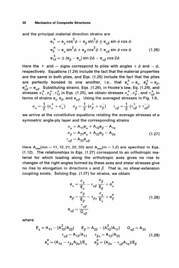
In practice, many automated manufacturing processes lead to symmetric angle-ply composite laminates consisting of an even number of equivalent plies with material symmetry axes being alternately oriented at angles +c/J and -c/J to the element axis (namely, the a-axis). In calculations, such a system of plies is considered as one symmetrically reinforced layer. Such an approximation is a good description of a real composite structure and is a substantial simplification of the stress-strain relationships: if each of the symmetric plies shown in Fig. 1.6 is anisotropic in the a, p coordinates, then, working together, they form an orthotropic layer. Hooke's law for such an orthotropic layer has a form simpler than Eqs. (1.11), (1.15), (1.22), and (1.23) valid for a single ply. In order to derive such a simplified law, we write Eqs. (1.7), (1.9), and (1.10) for plies with the orientation angles ± cjJ. That is, the principal material direction stresses are
±- ± ± -e e u1 = E1(e1 + v12e2 ) - E1(e1 + v12e2) ±- ± ± -e e
u2 = E2(e2 + v12e1 ) - E2(e2 + v12e1) (1.24) ± ±
'12 = G12e12
the laminate structure coordinate direction stresses are ± ± 2../.. ± • 2../.. T ± . 2../.. urx =a1 cos •v+u2 sm '~'''12 srn 'I' ± ± . 2..~-. ± 2..~-. ± ± . 2../.. up = u1 srn 'I'+ u2 cos 'I' -r12 sm 'I' (1.25) ± ± ± . ± 'rxp= ±(u1 -u2 )smcf>coscf>+-r12 cos2c/>
Figure 1.6 Interaction Between Symmetrically Reinforced Plies
30 Mechanics of Composite Structures
and the principal material direction strains are
e: = eot cos2Q> + ep sin2Q> ± eotP sin 4> cos 4> ± . 2-~,. 2-~,.- . A,. A,.
e2 = eot s1n ..,., + ep cos ..,., + eotP s1n..,., cos..,., (1.26)
e~ = ± (ep- eot) sin 21/> - eotP cos 21/>
Here the + and - signs correspond to plies with angles + 4> and - Q>, respectively. Equations (1.24) include the fact that the material properties are the same in both plies, and Eqs. (1.26) include the fact that the plies are perfectly bonded to one another, i.e., that e; = e,., ep = ep. e;p = e,.p· Substituting strains, Eqs. (1.26), in Hooke's law, Eq. (1.24), and stresses ut, ui, -r~ in Eqs. (1.25), we obtain stresses u;, up, and -r;p in terms of strains e,., ep, and e,.p· Using the averaged stresses in Fig. 1.6,
1 +- 1 +- 1 +-u,.=2(uot +uot) Up=2(up +up) -rotP=2(•otp+•otp)
we arrive at the constitutive equations relating the average stresses of a symmetric angle-ply layer and the corresponding strains
uot = A11eot + A12ep- A1e
up= A21eot + A22ep - A2e
-r lf.p = A33e lf.p (1.27)
Here Amn(mn = 11, 12, 21, 22, 33) and Ame(m = 1 ,2) are specified in Eqs. (1.12). The relationships in Eqs. (1.27) correspond to an orthotropic material for which loading along the orthotropic axes gives no rise to changes of the right angles formed by these axes and shear stresses give no rise to elongation in directions ~X and p. That is, no shear-extension coupling exists. Solving Eqs. (1.27) for strains, we obtain
(1.28)
where

Introduction 31
Here, Eoc and Ep are the effective elastic moduli; Gocp is the shear modulus of an angle-ply laminate; and vocp and vpoc are Poisson's ratios. The behavior of the elastic modulus Eoc (modulus Ep is obtained from Eoc if </> is replaced with 90°- </>) and the shear modulus Gocp is shown in Figs. 1.7 and 1.8, respectively, as a function of angle </> for materials with the properties listed in Table 1.1.
Figure 1.7 Elastic Modulus as a Function of the Ply Angle for (1) Boron-Aluminum, (2) Boron-Epoxy, (3) Carbon-Epoxy, (4) Organic Fibers-Epoxy, and (5) Glass-Epoxy
Note here that the elastic moduli in Eq. (1.29) differ from the corresponding elastic constants of the ply given in Eqs. (1.16). To illustrate this claim, consider elements under tensile stresses applied along the a:-axis (Fig. 1.9a). Strains of unidirectionally reinforced elements (Fig. 1.9a) are determined with Eqs. (1.15) where elastic constants have superscripts <J>:
(1.30)

32 Mechanics of Composite Structures
GczfJ•GPa
1
Figure 1.8 Shear Modulus as a Function of the Ply Angle for
(1) Boron-Aluminum, (2) Boron-Epoxy, (3) Carbon-Epoxy,
(4) Organic Fibers-Epoxy, and (5) Glass-Epoxy
For a symmetrically reinforced element (Fig. 1.9b), we have, in accord
ance with Eqs. (1.28),
(J(I.
e =a. E a.
(1.31)
From relationships in Eqs. (1.30) and (1.31) and Fig. 1.9, it follows that, in
antisymmetrically reinforced unbonded plies, shear strains exist that
compensate one another if both plies are bonded together. To bring the
elements depicted in Fig. 1.9a to the state shown in Fig. 1.9b, it is neces
sary to apply to them the mutually compensating shear stresses Ta.p such
that the condition eczP = 0 will be satisfied. Putting eczp = 0 in the third
relation of Eq. (1.15) and taking into account that up= 0 and e:p = 0, we
have

Introduction 33
rmm-, ,. fZ I I u fZ
~I -L J
b
a
Figure 1.9 Deformation of (a) Individual and (b) Bonded Symmetric Plies
Substituting this expression in the first equation of Eqs. (1.15), we obtain, upon some transformations, that e« = u «/E~~. where
-1
E = Ec/J[1 - G:p (YJc/J l] IX IX cP IXp, IX EIX
Whence E~~. 2 Et. In other words, in the general case, a ± cjJ angle-ply laminate has a higher stiffness than the + cjJ or - cjJ laminate of the same thickness.
Now derive equations relating shear stresses -r~~. 1 and -rp1 and the corresponding strains of a symmetric angle-ply laminate (Fig. 1.6). For plies with angle + cjJ and - cjJ, we obtain, in accordance with Eqs. (1.22)
(1.32)
(1.33)
Consider a symmetric system of plies loaded by stresses TIX1. Then T:1 = T~1 = T«1. Because the system is orthotropic (Fig. 1.6), we must put
in Eq. (1.32) e:1 = e~1 = e«1 _and e-pv = e{i!j.. = 0. _In a simJiar w_ay, under shear stresses T p1, we have m Eq. (1.33) T p1 = T p1 = T Pv• e«v = e«v = 0, and
e-p1 = efi1 = epv· Then, we arrive at
TIXY = A44e1XY Tpy = A55epy (1.34)
Introducing the shear moduli, we can rewrite Eqs. (1.34) in the form
TIXY=GIXYeiXY Tpy=Gpyepy (1.35)

34 Mechanics of Composite Structures
where
Gay= G13 cos24> + G23 sin2<J>
Thus, the constitutive equations for the symmetric angle-ply laminate are specified by Eqs. (1.27) or (1.28) and Eqs. (1.35).

References S.T. Mileiko , “Mechanics of Metal-Matrix Composites,” in Mechanics of Composites (inRussian), edited by I. F. Obraztsov and V. V. Vasiliev , MIR Publishers, Moscow, 1982, pp.129–165. A. A. Griffith , “The Phenomena of Rupture and Flow in Solids”, Philosophical Transactions ofthe Royal Society of London, A221, 1921, pp. 163–198. Shoji Yamane , Tohru Hiramatsu , and Tomitake Higuchi , “Torayca T1000 Ultra High StrengthCarbon Fiber and its Composite Properties,” in Proceedings of the 32nd International SAMPESymposium and Exhibition, SAMPE, Covina, California, 6–9 April 1987, pp. 928–937. Yu. M. Tarnopolski and T. Ya. Kincis , Static Test Methods for Composites, Van NostrandRheinold, New York, 1985. I. F. Obraztsov and V. V. Vasiliev , “Optimum Design and Strength of Layered ThinComposites,” in Fracture of Composite Materials, edited by G. C. Sih and V. P. Tamuzs ,Sijthoff & Noordhoff, the Netherlands, 1979, pp. 255–265. Stephen W. Tsai , Composites Design, Think Composites, Dayton, Ohio, 1987. Yuri Tarnopolskii , I. G. Zhigun , and V. C. Polyakov , Spatially Reinforced Composites,Technomic, 1992. Robert M. Jones , Mechanics of Composite Materials, Hemisphere (now Taylor & Francis),Washington, 1975. Henry L. Langhaar , Energy Methods in Applied Mechanics, John Wiley & Sons, 1962. I. S. Sokolnikoff and R. M. Redheffer , Mathematics of Physics and Modern Engineering,McGraw-Hill, 1958. Stephen P. Timoshenko , History of Strength of Materials, McGraw-Hill, 1953. Cornelius Lanczos , The Variational Principles of Mechanics, Third Edition, University ofToronto Press, 1966. J. N. Reddy , Energy and Variational Methods in Applied Mechanics, John Wiley & Sons, 1984. S. P. Timoshenko , “On the Corrections for Shear of the Differential Equation for TransverseVibrations of Prismatic Bars,” The London, Edinburgh, and Dublin Philosophical Magazine andJournal of Science, Series 6, Vol. 41, May 1921, pp. 744–746. V. V. Vasiliev and S. A. Lurie , “A Variant of the Refined Theory of Bending for a LaminarPlastic Beam” (in Russian), Polymer Mechanics, July 1974, Vol. 8, No. 4, pp. 582–588. V. V. Vasiliev and S. A. Lurie , “Plane Problem of Elasticity for an Orthotopic Cantilever Strip”(in Russian), Mechanics of Solids, Vol. 19, No. 5, 1984, pp. 120–129. A. Ya. Aleksandrov , L. E. Bryukker , L. M. Kurshin , and A. P. Prusakov , Analysis of SandwichPlates (in Russian), Mashinostroenie, Moscow, 1960. A. Dobyns , I. Avery , R. Blaisdell , and I. E. Figge , “Advanced Composite Lattice Structure forImproved Structural Integrity,” AIAA Paper No. 74–357, in Proceedings of the AIAA/ASME/SAE15th Structures, Structural Dynamics and Materials Conference, 17–19 April 1974, Las Vegas,Nevada, AIAA, New York. I. F. Obraztsov , L. A. Bulychev , V. V. Vasiliev , A. N. Elpatievskii , K. A. Zhekov , Yu. I. Ivanov ,B. A. Konovalov , Yu. S. Matushev , and F. N. Shkliarchuk , Engineering Mechanics of FlyingVehicles (in Russian), Mashinostroenie, Moscow, 1986. Yu. N. Rabotnov and E. I. Stepanichev , “Elastoplastic Properties of Fiber Glass ReinforcedPlastics” (in Russian), Mekhanika Tverdogo Tela, No. 1,1968, pp. 64–73. Yu. N. Rabotnov , G. M. Gunyaev , M. A. Kuznetsova , I. M. Makhmutov , and E. I. Stepanichev, “Nonlinear Stress-Strain Relations for Carbon-Reinforced Plastics under Continuous StaticLoading” (in Russian), Polymer Mechanics, January 1977, Vol. 12, No. 1, pp. 40–43. A. A. Ilyushin , Plasticity (in Russian), Moscow, Gostehizdat, 1948. I. A. Birger , “General Solutions of Some Problems of the Plasticity Theory” (in Russian),Prikladnaya Matematika i Mekhanika, Vol. 15, No. 6, 1951, pp. 765–770. K. S. Valanis , “A Theory of Viscoplasticity Without a Yield Surface,” Archives of Mechanics,Vol. 23, No. 4, 1971, pp. 517–551. K. S. Valanis , “Fundamental Consequences of a New Intrinsic Time Measure. Plasticity as aLimit of the Endochronic Theory,” Archives of Mechanics, Vol. 32, No. 2, 1980, pp. 171–191. P. A. Zinoviev and B. S. Sarbaev , “Endochronic Theory of Nonlinear Deformation of LaminatedComposite Materials” (in Russian), Mechanics of Composite Materials, November 1985, Vol.21, No. 3, pp. 278–283.

V. V. Vasiliev and V. A. Salov , “Development and Examination of a Two-Matrix Glass-FiberComposite with High Transverse Strain” (in Russian), Mechanics of Composite Materials,January 1985, Vol. 20, No. 4, pp. 463–467. I. F. Obraztsov and V. V. Vasiliev , “Nonlinear Phenomenological Models of Fiber-ReinforcedComposites”, in Fracture of Composite Materials, edited by G. C. Sih and V. P. Tamuzs ,Martinus Nikhoff Publishers, The Hague, 1982, pp. 335–342. V. V. Vasiliev , A. A. Dudchenko , and A. N. Elpatievskii , “On Some Features of Deformation ofOrthotopic Glass Plastics in Tension” (in Russian), Mekhanika Polimerov, No. 1, 1970, pp.144–147. A. Rotem and Z. Hashin , “Failure Modes of Angle-Ply Laminates,” Journal of CompositeMaterials, April 1975, pp. 191–206. T. T. Chiao , “Some Interesting Mechanical Behaviors of Fiber Composite Materials,” inFracture of Composite Materials, edited by G. C. Sih and V. P. Tamuzs , Sijthoff and Nordhoff,the Netherlands, 1979, pp. 385–392. V. V. Novozhilov , Theory of Elasticity (in Russian), Sudpromgiz, Leningrad, 1958. S. P. Timoshenko and J. N. Goodier , Theory of Elasticity, Third Edition, McGraw-Hill, 1970. S. G. Lekhnitskii , Torsion of Anisotropic and Inhomogeneous Beams (in Russian), Nauka,Moscow, 1971. A. Föppl , Technische Mechanik, Vol. 5, 1907, p. 132. T. von Kármán , “Festigkeit im Maschinenbau”, in Encyclopedia Mathematische Wissenshaft,Vol. IV, 1910, pp. 348–351. N. S. Azikov and V. V. Vasiliev , “On the Reduction Factor for Compressed RectangularOrthotopic Plates,” in annual collection of papers Mechanics of Composite Materials (inRussian), Riga Polytechnic Institute, Riga, Latvian SSR, 1982, pp. 73–82. A. S. Volmir , Flexible Plates and Shells (in Russian), Moscow, 1956. See also A Translation ofFlexible Plates and Shells, AFFDL-TR-66–216 (AD818474), Air Force Flight DynamicsLaboratory, Wright-Patterson Air Force Base, Ohio, April 1967. W. M. Banks and J. M. Harvey , “Experimental Study of Stability Problems in CompositeMaterials,” in Proceedings of the Conference on Stability Problems of Engineering Structuresand Components, Cardiff, 1979, London, 1979, pp. 1–22. J. E. Ashton , “Approximate Solutions for Unsymmetrically Laminated Plates”, Journal ofComposite Materials, Janaury 1969, pp. 189–191. J. M. Whitney , Structural Analysis of Laminated Anisotropic Plates, Technomic Publishing Co.,Inc., Lancaster, Pennsylvania, 1987. K. T. Danielson and J. T. Tielking , “Membrane Boundary Conditions Effects of UnsymmetricLaminates,” Journal of Engineering Mechanics, Vol. 114, No. 12, 1988, pp. 2158–2172. A. C. Kyser , “Uniform-Stress Spinning Filamentary Disk,” AIAA Journal, July 1965, pp.1313–1316. Yu. V. Bokov , V. V. Vasiliev , and G. G. Portnov , “Optimum Shapes and Paths andReinforcements in Rotating Composite Shells” (in Russian), Mechanics of Composite Materials,March, 1982, Vol. 17, No. 5, pp. 572–578. I. F. Obraztsov and V. V. Vasiliev , “Optimal Design of Composite Structures,” in Structures andDesign, Vol. 2, Handbook of Composites, 1989, edited by C. T. Herakovich and Yu. M.Tarnopol’skii , North Holland, Amsterdam, pp. 3–84. R. L. Boitnott , E. R. Johnson , and J. H. Starnes, Jr. , “Nonlinear Analysis of Infinitely LongGraphite-Epoxy Cylindrical Panels Loaded with Internal Pressure,” in Proceedings of 26thAIAA/ASME/ASCE/AHS Structures, Structural Dynamics, and Materials Conference, Orlando,Florida, 15–17 April 1985, AIAA, New York, NY., pp. 593–604. V. Z. Vlasov , General Theory of Shells and Its Application in Engineering, Gostekhizdat(Gosudarstvennoye Izdatel’stvo Tekhniko-Teoreticheskoy Literatury), Moscow-Leningrad, 1949(in Russian). English translation: NASA TT F-99, NASA, Washington, D. C., April 1964. V. V. Vasiliev and V. I. Sisauri , “Examination of the Dynamic Behavior of Composite Shells ofRevolution Loaded with Internal Pressure” (in Russian), Mechanics of Composite Materials,July 1985, Vol. 21, No. 1, pp. 59–63.