Mechanical tunneling in solid rock - ROSA P
252
j DEPART] AENT OF HE TRANSPORTATION 1 8.5 . A37 NÜV G bdO no dot- jo. UMTA-MA-06-0100-79-12 TSC- LfBH ARY UMTA- L — 7Q-4H MECHANICAL TUNNELING IN SOLID ROCK by Werner Rutschmann Consulting Engineer ETH 34 Wald Strasse 8134 Adliswil Zurich, Switzerland MAY 1980 FINAL TRANSLATION DOCUMENT IS AVAILABLE TO THE PUBLIC THROUGH THE NATIONAL TECHNICAL INFORMATION SE R V I CE . SPR I NG F I E LD, VIRGINIA 22161 Prepared for U.S. DEPARTMENT OF TRANSPORTATION URBAN MASS TRANSPORTATION ADMINISTRATION OFFICE OF TECHNOLOGY DEVELOPMENT AND DEPLOYMENT Office of Rail and Construction Technology Washi ngton , DC 20590
-
Upload
khangminh22 -
Category
Documents
-
view
0 -
download
0
Transcript of Mechanical tunneling in solid rock - ROSA P

j
DEPART] AENT OF ?
HE TRANSPORTATION1 8.5. A37 NÜV G bdOno
.
dot- jo. UMTA-MA-06-0100-79-12TSC-
1
LfBH ARYUMTA- L —7Q-4H
MECHANICAL TUNNELING IN SOLID ROCK
by
Werner RutschmannConsulting Engineer ETH
34 Wald
i
Strasse8134 Adliswil
Zurich, Switzerland
MAY 1980
FINAL TRANSLATION
DOCUMENT IS AVAILABLE TO THE PUBLIC
THROUGH THE NATIONAL TECHNICALINFORMATION SE R V I CE
.SP R I NG F I E LD,
VIRGINIA 22161
Prepared forU.S. DEPARTMENT OF TRANSPORTATION
URBAN MASS TRANSPORTATION ADMINISTRATIONOFFICE OF TECHNOLOGY DEVELOPMENT AND DEPLOYMENT
Office of Rail and Construction TechnologyWashi ngton , DC 20590

NOTICE
This document is disseminated under the sponsorshipof the Department of Transportation in the interestof information exchange. The United States Govern-ment assumes no liability for its contents or usethereof
.
NOTICE
The United States Government does not endorse pro-ducts or manufacturers. Trade or manufacturers’names appear herein solely because they are con-sidered essential to the object of this report.
First published 1974 by VDI-Verlag, Düsseldorf, Federal Republic of Geraany,
underneath the title: Mechanischer Tunnelvortrieb im Festgestein by Dipl. -Ing.
Werner Rutschmann
0VDI-Verlag GmbH, Düsseldorf, Federal Republic of Germany, 1974
All rights reserved. No part of this publication may be reproduced in any form
or by any means, including photocopying and recording, without the written per-
mission of the copyright holder, application for which should be addressed to
the VDI-Verlag GmbH; Verlagsbereich Bucher; Lizenzen/Nebenrechte; Graf Recke-
Strasse 84; Postfach 1139; D—4 Düsseldorf, West Germany. Such written permis
sion must also be obtained before any part of this publication is stored in a
retrieval system of any nature.

H B18 , sr
,A17)0T-T3C'
u,5. Dep1. o-f Titansp0^40.+ 1 0^^, Tta», s po r-fa+i’o^v C«s-'^«r^
2- fj
Technical Report Documentation Page
l'
,«/i>
1. Report No.
UMTA-MA-06-0 100-79- 12
2. Government Accession No.
PB '«Ö- ix/ 0 /3
3. Recipient’s Cotolog No.
4. Title ond Subtitle
MECHANICAL TUNNELING IN SOLID ROCK
5. Report Dote
May 19806. P er fo rm i n g. 0
rgon i 20 ti on Code
DEPARThiEi'- C. V I i
7. Author^s)
Werner RutschmannTRANSPOiiTATIOM 5
8. Performing Orgonizotion Report No.
DOT-TSC-UMTA-79-40.
WiTT^ IMT
LIBRARY
9. Performing Organization Name ond Address
*Werner RutschmannConsulting Engineer ETH I
34 Waldistrasse8134 Adliswil; Zurich, Switzerland '
10. Work Umt No, (TRAIS)
UM948/R974511. Controct or Grant No.
DOT-TSC-1281
12. Sponsoring Agency Nome and Address
U.S. Department of TransportationUrban Mass Transportation AdministrationOffice of Technology Development and DeploymentOffice of Rail and Construction TechnologyWashington DC 2Q59Q
13. Type of Report ond Period Covered
Final Translation
14. Sponsoring Agency Code
UTD-3015. Supplementary Notes Dr. Keith H. Morehouse
-'Translated by; Raytheon Service Co.
Cambridge, MA 02142 and
;
Professor Herbert Einstein, MITCambridge MA 02139Richard Robbins, The Robbins Co.Seattle WA 98108
16.
Abstract
This report is a complete translation of the German book "MechanischerTunnelvortrieb im Festgestein". It is an introduction to the principles ofmechanized tunneling and provides detailed guidelines for practical application.The subject is introduced with a detailed review of technical aspects and termsrelating to mechanized tunneling. This is followed by a discussion of the mechanicsof rock cutting and implications on machine performance. Two related issues, thestability of underground openings and rock mass classification for tunneling are thenpresented; this serves the purpose of familiarizing the reader with aspects other thanrock cutting that affect machine tunneling. All this forms the basis for a compre-hensive description of the entire mechanized tunneling system and its operation.Finally, recommendations for bid preparation and project execution are given,followed by a discussion of application limits.
17,
Key Words
Tunnel Boring Machines, MechanicalTunneling, Rock, Tunne ling
18.
Distribution Statement
DOCUMENT IS A VAI CABLE TO THE PUBLICTHROUGH THE NATIONAL TECHNICALINFORMATION SERVICE, SPRINGFIELDVIRGINIA 22161
19.
Security Clossif. (of this report)
Unclassified
20.
Security Clossif, (of this page)
Unclassified
21. No. of P ages
246
22. Price
Fotm DOT F 1700.7 (8-72) Reproduction of completed poge authorized


author's foreword
Machine tunneling, which according to reliable sources was donefor the first time in the U.S.A. in 1856, and which was usedsuccessfully from 1881 to 1883 for the boring of two experimentaltunnels for the English channel tunnel project, is a tunnelingprocess which has gained increasing importance ever since the1950's. Originating in the U.S.A. where it was used with spectac-ular success, mechanical tunnel cutting (or boring) has sincebeen used on other continents and in other countries. Today,the greatest density of tunnel boring machines by any standardcan be found in Europe. Although initially it was only used inlow-strength sediments, mechanical tunnel boring machines todayalso cut high-strength and abrasive organic rock with technicalas well as with economical success.
Apart from a great number of successful tunneling projectswhich total several hundred kilometers, failures have also beenrecorded. Only in a few cases these could be attributed to theboring machines that were used. More often, the drive system wasinsufficient, or the condition of the rock required the withdrawalof a tunnel boring machine which was only designed for solid rock,or the management of the tunneling project did not acknowledgethe special requirements of tunnel boring.
Theseavoided, atunnelingboring werunavailablthe procestrends, thtunnel borrock, andsections
.
failures, whs well as thesymposiums one dealt with,e so far, havs from all ite emphasis ofing in mediumthus on full
ich for the most part could have beenfact that in journals and on occasion of
ly partial aspects of mechanical tunneland that a complete presentation has been
e motivated the author to try to describes aspects. According to developmentalthe presentation lies on mechanicaland high-strength as well as in abrasive
face excavation of radially symmetric cross
This document is intended for construction managers, designand project engineers, as well as for students. The reader willfind that mechanical tunnel boring is not the magic answer fortunnel building. However, he should also arrive at the conclusionthat with critical planning and a project-oriented design ofboring machines and systems as well as with a highly qualifiedwork team and supervisory personnel, tunnels can be constructedwithin a wide range of geological conditions. These projectscan be technically and economically more successful and can beconstructed with more safety and speed than ever before.
The author wants to express appreciation for:
- the permission to visitconstruction companies
the construction sites of numerousin Europe, North America and Africa.
i i i

- the good contacts - in part existing for fourteen years:the manufacturers and representatives of the tunnelingmachine companies Atlas Copco Cp^’eviously Habegger)
,
Calweld, Demag, Dresser, Jarva, Lawrence, Robbins, andWirth
.
- the permission to publish research material of the Gotthardbasis tunnel project: Dipl.-Ing. M. Portmann, directorof the construction service of the Swiss Federal Railways.
- the proofreading of the manuscript or parts thereof byDipl.-Ing. W. Diethelm, Dipl.-Ing. A. Hurter, Dipl.-Ing.M.A. Borel and Dr.-Ing. M.A. Gaillard.
Adi iswil/ Zur ich,May 1974 Werner Rutschmann
Author
IV

TRANSLATOR'S FOREWORD
The widespread use of mechanized tunnel excavation hasbrought with it publication of many case histories and avariety of research reports and papers. Still missing so farwas a textbook or similar publication that introducesprinciples and basic practical issues and that provides thetunnel designer and project manager with a guideline on howto consider mechanized tunneling. This gap has, to a largeextent, been closed by the book "Mechanischer Tunnelvortriebi n Fes tgestein"
,which has been completely translated and Ts^
presented as this Report No. UMTA-MA- 0 6 - 0100 - 79 - 1 2 . Theauthor, Werner Rutschmann,* a tunnel designer and projectmanager with over 30 years of experience, has been involvedin modern mechanized tunneling since its beginning. Duringthe course of his work he not only became a leading expertin the area, reflected by his many consulting jobs involvingtunnel boring machine application, but he also became con-vinced that the tunnel engineer needs to tailor his designto the excavation methods shown herein and thus should befamiliar with machined tunnels.
As indicated in Rutschmann's foreword, the book attemptsto satisfy this objective and to serve also as an educationaltool for civil and mining engineering students. The book wasoriginally written in German and published by VDI PublishingHouse, Düsseldorf, in 1974 (VDI, Verein Deutscher Ingenieure,the German Engineering Society) . Richard Robbins who wasaware of the book's existence and who saw the necessity ofproviding the tunnel design profession and newcomers tomechanized tunneling with a solid background, suggested itstranslation to the U.S. Department of Transportation. RusselMacFarland favorably responded to this idea and initiatednegotiations with the author and publisher. Both generouslyagre ed to have the b ook translated for the b ene fit of thet unn e ling pr of e ssion to have a limi ted is s ue of 200 copiespubl ished an d s old through NTIS, an d to fo re go any compensa
-
t ion . Th e t ran s lat i on was performe d by Dr Kei th H . Morehouseof R ay the on Ser vice Go
.
,
Gambr idge
,
Mas s ac hu set ts;Richard
Robb ins and thi s wr i ter checked the t r ans 1 at ion for accuracyand techn ica 1 t erminology
.
*Werner Rutschmann, Gonsulting Engineer, 34 Waldistrasse
,
8134 Adliswil, Zurich, Switzerland.
V
PREFACE
Statisticalnational organizunderground consrelevant figuresdeveloped countrgreatest numbersection of functor pipe conduitsdiameters
.
surveys and prospective s
ations have revealed an extruction in the near futur. These projects which aries will serve a wide variconcerns elongated cavitieion and type; constructed,horizontally or inclined
tudies conducted by inter-traordinary demand fore, and have also producede planned primarily forety of purposes. Thes with a constant crosseither as traffic tunnels
,with large or small
Aside from demand, the art of tunneling itself is goingthrough a change at present. Technical progress, the desiredbetter working conditions, and economical factors have - at leastin some countries, for the time being - given in a relatively shorttime a great impetus to the application and the development ofmechanical boring of tunnels and galleries. There is no doubt ofthe increased use of this method in the future considering thenumber of successful projects and the great growth potential thatmust surely exist.
By scientific exploration of the many involved phenomena, bysuccessive technical solutions of the problems that are still tobe solved, and also in view of the technological progress which canbe expected, mechanical tunneling will become applicable in otherfields even though it will never be a standard method under allconditions. Unlike most other construction projects, mechanicaltunneling is a multi-disciplinary activity. A great number ofdifferent areas of knowledge are tapped: from petrography andengineering geology via rock mechanics to the art of engineering,and from machine and electrical engineering to problems of metallurgy,ventilation, and management, and general problems of constructionsite installations.
Dipl.-Ing. W. Rutschmann deserves great merit for tackling thisdifficult task. With great care and much work he has managed tocollect and evaluate the experience and insights which have beengained worldwide. He has been successful in dealing with the sub-ject matter in a clear and intelligible way and also - consideringthe amount of material - in giving a concise and nevertheless compre-hensive survey of the whole field, thus closing a gap in tunnelingliterature. Although obviously inspired with a justified enthusiasmfor this new method, which is undergoing rapid development, theauthor nevertheless does not neglect to point out system-relatedlimitations in order to prevent failures and rashly conceivedexpectations
.
The fact that not only unsolved problems are mentioned but alsothat ideas are formulated concerning their possible solution, shouldbe an incentive for continued research.
VI
Hopefully, this first comprehensive work on mechanicaltunneling will serve as a contribution to the progress of thishighly interesting and future- or iented field of engineering.
Locarno, May 1974 Dr.-Ing. G. Lombard
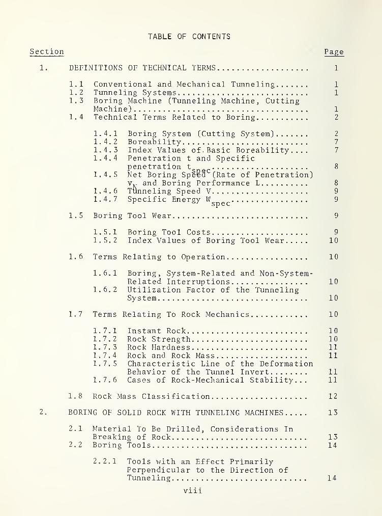
TABLE OF CONTENTS
Section “ Page
1. DEFINITIONS OF TECHNICAL TERMS 1
1.1 Conventional and Mechanical Tunneling 1
1.2 Tunneling Systems 1
1.3 Boring Machine (Tunneling Machine, CuttingMachine) 1
1.4 Technical Terms Related to Boring 2
1.4.1 Boring System (Cutting System) 2
1.4.2 Boreability 7
1.4.3 Index Values of. Basic Boreability.... 7
1.4.4 Penetration t and Specificpenetration t 8
1.4.5 Net Boring SpliB*"(Rate of Penetration)and Boring Performance L 8
1.4.6 Tunneling Speed V 9
1.4.7 Specific Energy 9
1.5 Boring Tool Wear 9
1.5.1 Boring Tool Costs 9
1.5.2 Index Values of Boring Tool Wear 10
1.6 Terms Relating to Operation 10
1.6.1 Boring, System-Related and Non-System-Related Interruptions 10
1.6.2 Utilization Factor of the TunnelingSystem 10
1.7 Terms Relating To Rock Mechanics 10
1.7.1 Instant Rock 101.7.2 Rock Strength 101.7.3 Rock Hardness 111.7.4 Rock and Rock Mass 111.7.5 Characteristic Line of the Deformation
Behavior of the Tunnel Invert 111.7.6 Cases of Rock-Mechanical Stability... 11
1.8 Rock Mass Classification 12
2. BORING OF SOLID ROCK WITH TUNNELING MACHINES 13
2.1 Material To Be Drilled, Considerations InBreaking of Rock 13
2.2 Boring Tools 14
2.2.1 Tools with an Effect PrimarilyPerpendicular to the Direction ofTunneling 14
viii

TABLE OF CONTENTS (cONT'd)
Section Page2.2.2
Tools With An Effect Primarilyin the Direction of Tunneling 17
2.3 Boreability of Rock and Rock Mass 32
2.3.1 Rock-Related Boreability On BasicBoreability 33
2. 3.1.1 Analysis With a Linearapparatus at the Twin CitiesMining Research Center(TCMRC) of the Bureau ofMines 33
2. 3. 1.2 Investigation With DiskRoller Bits Rolling in Con-centric Circles, Conductedat the Technical Universityof Clausthal 34
2. 3. 1.3 Boreability Analyses bythe Lawrence Company 39
2. 3.1.4 Investigation with TunnelingMachines on RelationsBetween Rock Properties andRock Boreability 41
2.3.2 Influence of the Rock Main Structureon the Boreability 53
2. 3. 2.1 Favorable Influence ofSeparation Planes onBoreability 54
2. 3. 2.
2
Impairment of Boreability bySeparation Planes 54
2. 3. 2.
3
Influence of the OverburdenDepth on the Boreability... 56
2. 3. 2.
4
Prognosis of the Influenceof the Rock Mass Structureon the Boreability 56
2.4 The Net Boring Speed (Rate of Penetration). 57
2.4.1 Cutting Head Penetration 572.4.2 The Cutting Head Revolution 61
2.5 Boring Tool Wear 61
2.5.1 Wear of the Roller Bit Bearings 632.5.2 Wear of the Roller Bit Cutting Edges 63
IX

TABLE OF CONTENTS (cONT'd)
Section Page
2.6 Pretreatment of Formations Which Are ToBe Cut 68
2.6.1 Reduction of the Rock Strength byReduction of its Surface Energy 69
2.6.2 Reduction of the Rock Strength byEnlarging Existing, or ProducingNew Cracks 69
2.6.3 Influencing the Formation of Cracksin the Rock, and Grain Erosion byMeans of a Water Jet 7 0
3. STABILITY OF TUNNELS 72
3.1 Basic Rock-Mechanical Behavior of the RockMass 72
3.2 Characteristics of the Deformation Behavior. 733.3 Rock-Mechanical Cases of Stability 76
3.3.1 Definitions 763.3.2 Parameters of the Stability Behavior. 79
3. 3. 2.1 Parameters of the Rock Mass. 793. 3. 2.
2
Parameters of the TunnelProject 79
3.4 Possibilities of Securing and Stabilizingthe Rock Mass During the Tunneling 81
3.4.1 Characteristics of the Lining 813.4.2 Combination of Characteristics 843.4.3 Installation of the Support and
Lining During the Tunneling 86
3. 4. 3.1 Preconditions andPossibilities 86
3. 4. 3.
2
Rock Bolt Support Lining.... 873. 4. 3.
3
Gunite and Shotcrete Lining. 87
3. 4. 3.
4
Steel Set Support 893.4. 3.
5
Lining with Segmented(Prefabricated) Elements.... 89
3.4.4 Special Support of the TunnelingMachine 90
3.4.5 Tunneling Through Fault Zones thatCannot be Excavated by TMB 92
X
TABLE OF CONTENTS (CONT'd)
Section Page
4. ROCK MASS CLASSIFICATION FOR TUNNELING 94
4.1 Geological Documentation 944.2 Rock-Mechanical Prognosis 954.3 Definition of Rock Mass Classes 103
4.3.1 Basic Principles of Classification... 1034.3.2 Classification According to
Boreability 1084.3.3 Classification According to Cutting
Tool Wear 1084.3.4 Classification According to Supporting
Requirements 109
4.4 Practical Application of the TripleClassification 113
5. TUNNELING MACHINE 114
5.1 Tunneling Machine 114
5.1.1 Maximum Dimension and Weights ofParts or Components 114
5.1.2 Requirements Concerning AssemblyDismantling 115
5.1.3 Cutting Head 115
5. 1.3.1 Minimum cutting diameter, andpossibility for diametervariation 115
5. 1.3.
2
Basic Construction 1165. 1.3.
3
Cutting Head Shape 1175. 1.3.
4
Cutting Tools 1195. 1.3.
5
Scrap ers 120
5.1.4 Cutting head carrier, cutting headbearing, bearing lubrication andsealing, dust shield, sludge pusher.. 120
5.1.5 Cutting head drive 120
5.1. 5.1 Cutting head drive motors,revolution control 120
5.1. 5.2 Torque, drive power 1245. 1.5.
3
Power transmission 125
5.1.6 Gripping, Propulsion, RollingCompensation, Travel Length, Supports 127
5.1.7 Aligning, Steering 1305.1.8 Electrical Equipment 131
XI

TABLE OF CONTENTS (CONT'd)
Section Page
5.1.9 Hydraulic System 1335.1.10 Water Distribution 1345.1.11 Compressed Air Distribution 1355.1.12 Excavations Removal 1355.1.13 Support-Install and Transportation
Equipment 1365.1.14 Test Drilling Equipment 1375.1.15 Protection of Structural Parts Against
Abrasive Cuttings 1375.1.16 Trailers 1375.1.17 Non- technical Criteria for the
Evaluation of an Offer 138
5.1.17.1 Delivery Date 1385.1.17.2 Factory Costs 1385.1.17.3 Guarantees 1385.1.17.4 Spare Parts 1395.1.17.5 Service 139
5.1.18 Summary of Offer Evaluation 139
5.2
Auxiliary Installations 141
5.2.1 Removal of the Borings 141
5. 2.1.1 Conveyor Belt Operation 1435. 2.1.2 Pneumatic Removal 1435. 2. 1.3 Hydraulic Removal 1445. 2. 1.4 Operation by Rail 145
5.2.2 Supply of the Machine Area 148
5. 2. 2.1 Transportation of Personneland Material 148
5. 2.2.
2
Supply Lines andInstallations 148
5.2.3 Ventilation, Dust Removal, Cooling... 151
5. 2. 3.1 Ventilation 1515. 2. 3.
2
Dust collection 1525. 2. 3.
3
Cooling 1565. 2. 3.
4
Examples of calculations withsimplified assumptions 159
5.2.4 Devices for Directional Control 1645.2.5 Gas Detection 165
xii

TABLE OF CONTENTS (cONT'd)
Sections Page
6. THE BIDDING PROCESS, AND THE EXECUTION OF THETUNNELING PROJECT 167
6.1 Bid Documents 167
6.1.1 Possibilities for Contract Design.... 1676.1.2 Presentation of the Extent of Work
and of the Work Conditions on theBasis of Standard Prices 167
6.1.3 Examples for Contract Combination.... 169
6. 1.3.1 Provision of the TunnelingMachine 169
6.1. 3.
2
Price Per Tunneled CubicMeter or Meter 171
6.2 Project Execution 174
6.2.1 Work Time and Shifts 174
6. 2. 1.1 Shift Types 1746. 2. 1.2 Responsibilities of the
Shifts 1746. 2. 1.3 Sequence of the Shifts 1756. 2. 1.4 Distribution of the Work
Time 1756. 2. 1.5 System Utilization Factor... 177
6.2.2 Personnel and Specifications Sheets.. 179
6. 2. 2.1 Personnel 1796. 2. 2. 2 Specification Sheets for
Personnel 180
6.2.3 Checking of the Tunneling System 1806.2.4 Checking of the Tunneling Operations. 184
6. 2. 4.1 Work Progress 1846. 2. 4.
2
Boring Tool Wear 186
7. USE OF MECHANICAL TUNNELING 188
7.1 Advantages and Disadvantages 1887.2 Limitations 1897.3 Special tunneling projects 190
7.3.1 Large Sections 1907.3.2 Inclined Galleries 1967.3.3 Tunneling in Mines 203
xiii

TABLE OF CONTENTS (cONT'd)
Section Page
8. REFERENCES 208
APPENDIX - REPORT OF NEW TECHNOLOGY 217
XIV

LIST OF ILLUSTRATIONS
Figure Page
1-1 Tunneling System with Tunneling Machine,Bridging and Loading Belt, and Air DuctTelescope 2
1-2 Suggestion for a Systematic Classification ofTunneling Machines Under Various Aspects 3
1-3 Manufacturer Lawrence 4
1-4 Manufacturer Robbins 4
1-5 Manufacturer Wirth 5
1-6 Tunnel Cross Section Cut with a Tunneling MachineEquipped with Roller Bits (Hughes Tool Co.) 6
1-7 Tunnel Cross Section Cut with a Partial FaceCutting Machine (Anderson Mavor Ltd.) 6
1-8 Photo of Work Face 7
1-
9 Drawing Corresponding to Photo 7
2-
1 Drag Bit 15
2-2 Drum with Cutting Heads and Undercutting PlatesFor the Cutting of Circular Sections 16
2-3 Fullfacer with Four Cutting Heads for Cutting ofRectangular Sections 4. 8x2. 6m. 16
2-4 Mini Fullfacer with Cutting Head for the Cuttingof Upright Minimal Rectangular Sections 1.5x2. 4m. 18
2-5 Disaggregation of the Work Face 18
2-6 Muck 19
2-7 Muck After Flushing Out of Fine Material 19
2-8 Cutting Teeth 20
2-9 Styli in Cutting Head Center 20
2-10 Work Face Cut with Button Roller Bits 22
2-11 Caliber (Gauge) Bit 22
2-12 Inner Bit 22
XV

LIST OF ILLUSTRATIONS (CONT'd)
Figure Page
2-13 Caliber (Gauge) Bit 23
2-14 Inner Bit 23
2-15 Muck 24
2-16 After Flushing Out of Fine Material 24
2-17 Geometric Forms of Sharp-edged Disk Cutters 24
2-18 Work Face in Limestone Cut With Sharp -edged DiskCutters (Tunnel Circumference Top Left) 26
2-19 Grooves Cut by Disk Cutters in Plastic Rock 27
2-20 Cuttings Cut With Disk Bits 27
2-21 Disk Cutter Design 28
2-22 Cuttings from Migh-s trength Limestone in Muck.... 28
2-23 Cuttings After Flushing Out of Fine Material 29
2-24 Bit Design (Lawrence) 29
2-25 Cuttings from High-strength Limestone 30
2-26 Cuttings After Flushing Out of Fine Material 30
2-27 Bit Design 31
2-28 Cuttings from High-strength Limestone 31
2-29 Cuttings After Flushing Out of Fine Material 31
2-30 Bit Design 32
2-31 Cuttings Consisting of Mica- and Hornblende-Gneiss 32
2-32 Linear Apparatus of the Twin Cities MiningResearch Center (TCMRC) [6] 33
2-33 Tool Holder With Disk Bit 35
2-34 Tool Holder With Button Bit 35
2-35 Forces Acting On a Disk Roller Bit 36
2-36 Arrangement on a Free Surface 38
XV i

LIST OF ILLUSTRATIONS (cONT'd)
Figure Page
2-37 Arrangement in Steps 38
2-38 Arrangement Perpendicular To the Work Face 38
2-39 Arrangement for The Boring of a Cavity 38
2-40 Relation Between the Penetration t and the ForcesF , p£, and F with Cutter Spacing^b = 50 mm, andvtrious Cone inclination Angles (0° Correspondsto an Edge Position Perpendicular to the WorkFace [17]) 38
2-41 Basalt 40
2-42 Barre Granite 40
2-43 Dolomitic Limestone 40
2-44 Stress -strain Relation 43
2-45 Uniaxial (Cylinder) Compressive Strength 43
2-46 Brazilian Test 43
2-47 Saw-cutting (Abrasion) Hardness 43
2-48 Uniaxial (cyl) Compressive Strength 3^ 46
2-49 Cleavage Tensile Strength from Brazilian Test. 46
2-50 Tangent Modulus of Elasticity (E^5 q)
46
2-51 Saw-cutting Hardness SH. 46
2-52 Example for Results from Mineralogical -Petro -
graphical Analysis 47
2-53 Cleavage Tensile Strength 3 to Uniaxial (Cylinder)Compressive Strength 3p. 49
2-54 Cleavage Tensile Strength 3 to Modulus ofElasticity 50% E.^^. ^ 50
' t 5 0
2-55 Cleavage Tensile Strength 3 to Saw-cuttingHardness SH ^ 50
2-56 Open Boundary Zone Between Layers in a Tunnel Facein Limestone 53
XV 11

LIST OF ILLUSTRATIONS (cONT'd)
Figure Page
2-57 Map of Rock Types in the Tunnel Circumference 55
2-58 Disk Bits 59
2-59 Tricone Tooth Bits 59
2-60 Monocone Multiple Button Disk Bits 59
2-61 Tricone Button Bits 59
2-62 Boring System with Button Bits in Center and OnCaliber and Inner Disk Bits, Limestone 60
2-63 System with Disk Bits: With Distinct SeparatingPlanes 60
2-64 System with Multiple Disk Bits, Compact 60
2-65 System with Button Bits; Mylonitized Granite 60
2-66 Theoretically 64
2-67 Practically 64
2-68 Rock Abrasive Easy to Penetrate 64
2-69 Rock Abrasive, Hard to Penetrate, Cutting Head"Flutter" Possible 64
2-70 Ring Worm so That the Cutting Edge is Already inIts Non-hardened "Soft" Core 64
2-71 Position of Concentric Tracks of the Double DiskCutting Edges on Work Face 65
2-72 Position of Effective Tracks of the Button Bits onthe Work Face 65
2-73 Position of the Concentric Tracks of the Mono-diskCutting Edges on the Work Face 66
2-74 Consumption of Monodisk Cutting Edges in theIndividual Rows, and of Center Bits 67
2-75 Rolled Distances of Monodisk Rings for theIndividual Rows 67
2-76 Rolled Distances of Monodisk Rings for theIndividual Rows 67
xviii

LIST OF ILLUSTRATIONS (cONT'd)
Figure Page
3-1 Characteristic Curve of Displacement Behaviorof the Tunnel Circumference Outside the WorkFace Area, Perforated Disk 74
3-2 Characteristic Curve of Work Face, DisplacementBehavior, Core Disk 76
3-3 Rock-Mechanical Cases of Stability 77
3-4 Rock -Mechanical Cases of Stability 77
3-5 Rock-Mechanical Cases of Stability 77
3-6 Influence of Rock Mass Parameters on StabilityBehavior 80
3-7 Influence of Rock Mass Parameters on StabilityBehavior 80
3-8 Influence of Rock Mass Parameters on StabilityBehavior 80
3-9 Influence of Project Parameters on StabilityBehavior [35] 82
3-10 Influence of Tunneling Process on StabilityBehavior [35] 82
3-11 Characteristic Curves for Steel Rings, HEBSteel 37 83
3-12 Characteristic Curves for Concrete, Shotcrete . . . . 83
3-13 Characteristic for Concrete Precast Elements withPolyurethane, Joint Inserts 83
3-14 Theoretical Case of Support Installation DirectlyAt Face 8 5
3-15 Practical Case of Support Installation (Steel) Ata Certain Distance From the Face 85
3-16 Drilling of Bolt Holes From the Tunneling MachineDuring Tunneling 88
3-17 Overhead Protection Consisting of SystematicallyInstalled Bolts, Sheet Metal Segments, and WireMesh Chain-Link Wire 88
xix

LIST OF ILLUSTRATIONS (cONT'd)
Figure Page
3-18 Tunneling Machine Equipped with Bolt Drillingand Shotcrete Equipment for Systematic Stabilizingof the Rock Mass and Extension of the TunnelInvert During the Tunneling in Progress 89
3-19 Ring Sliding In Direction of Machine Axis andPivoting Around It, for Assembly and Installationof Steel Support Segments and Installation 91
3-20 Installation of Prefabricated Segments withErector Behind Basic Machine Between Steel RingsInstalled Directly Behind Cutting Head Carrier. . . 91
3-21 Segmented Cutting Head Shield, With Shoe, andRadially Sliding Segments 91
3-
22 Segmented Shield Consisting of Two SupportSystems 91
4-
1 Stratification of Rock 97
4-2 Topographical Longitudinal Section and ReliefLine 103
4-
3 Stratification of Rock 105
5-
1 Closed Cutting Head 116
5-2 Cutting Tool Holder Attached to the Back Side ofa Cutting Head Plate 117
5-3 Open Cutting Head 118
5-4 Flat (Lawrence) 118
5-5 Slightly Conical (Calweld) 118
5-6 Conical (Wirth) 118
5-7 Hemispherical (Robbins) 118
5-8 Insufficiency of Sludge Pushers (Scrapers) 121
5-9 Insufficiency of Sludge Pushers (Scrapers) 121
5-10 Synchronous Motors Mounted on the Cutting HeadCarrier 122
5-11 Hydromotors Mounted on the Cutting Head Carrierof an Expansion Machine 130
XX

LIST OF ILLUSTRATIONS (cONT'd)
Section Page
5-12 Position at the Beginning of One Stroke 130
5-13 Position at the End of One Stroke 130
5-14 Transport System for Segmented (Prefabricated)Liner Elements 136
5-15 Trailers on Tracks Installed Behind the BasicMachine (Wirth) 140
5-16 Trailers Rolling on Tires 140
5-17 Mobile Train Passing System 140
5-18 Conveyor Belt Moving on Rails 146
5-19 Conveyor Belt Pulled on Skids 146
5-20 Bridging and Loading Belt with Use of Bunker Car. 146
5-21 Conveyor Belt Rolling on Tires 147
5-22 Tracks Consisting of a Steel Box Serving as TunnelDrainage Trench and Welded-On Rails 147
5-23 Prefabricated Concrete Tunnel Invert Segments;Rear End of Machine with Protective Cage 148
5-24 Spool with Machine Cable 149
5-25 Loop Storage of Machine Cable 149
5-26 High-Voltage Junction Box 149
5-27 Supply Car Loaded with Rails, Air Duct, Water andCompressed Air Pipes, and with All ConnectingEquipment for Systematic Installation 150
5-28 Air Duct Telescope Connected to a Dust Collector,and Installed at the Side of a Loading BeltFrame 150
5-29 Suction Ventilation 152
5-30 Blow Ventilation 152
5-31 Amount of Heat from Rock Mass; i.e.. HeatAbsorption of Rock Mass in the Machine area [45]. 158
XXI
LIST OF ILLUSTRATIONS (cONT'd)
Figure Page
5-32 Climate Limits for Average Work UndergroundBased on An Energy Consumption 242 kcal/hand an Air Speed of 0.3 m/s [41] 159
5-
33 Mollier-Diagram 162
6-
1 Price Per Tunneled Meter, Without Cutting ToolCosts, Depending on Net Boring Speed and CuttingTool-Related Interruptions 173
6-2 Graph Work Progress 186
6-
3 Graphic Representation of Boring Tool Change 187
7-
1 Excavation of a Road Tunnel After PreviousMechanical Excavation of One Gallery Each in theApex and the Corners (Abutments) of the Tunnel... 191
7-2 Robbins Tunneling Machine Model 371-110 192
7-3 Robbins Tunneling Machine Model 341-111 192
7-4 Robbins Tunneling Machine Model 371-110,Modified 192
7-5 Robbins Tunneling Machine Model 352-128 193
7-6 Wirth Tunneling Machine TBE 350/770 H and TBE770/1046 for Two-Stage-Expansion of a Tunnel 193
7-7 Overall View 195
7-8 Detail of Inner Disc with Three Console Bits, andPart of the Outer Ring with Four Console Bits.... 195
7-9 Tunneling Machine with Slip Safety Attached toBox of Combination Gear 199
7-10 Auxiliary Gripping for Installation Between BasicMachine and Trailer 200
7-11 Basic Machine with Auxiliary Gripping, Assembled. 200
7-12 Robbins Tunneling Machine with An AuxiliarySupport on Floor Segments 201
7-13 Demag Tunneling Machine with Auxiliary Grippingand Support Tube 202
xxii

LIST OF ILLUSTRATIONS (cONT'd)
Figure Page
7-14 Scrapers Attached to the Boring Head of anExpansion Machine in Front of the Boring Tools... 204
7-15 Bottom Chamber of a Bored Inclined Gallery withCable Car and Flushing Water Chutes 204
7-16 Bored and Systematically Supported Heading ina Coal Mine 206
xxiii

LIST OF TABLES
Table Page
1-1 CLASSIFICATION OF ROCK ON THE BASIS OF ITSUNIAXIAL COMPRESSIVE STRENGTH 11
1-
2 CASES OF STABILITY OF ROCK MASS BEHAVIOR 12
2-
1 BORING SYSTEMS USED FOR BOREABILITY EXPERIMENTSWITH TUNNELING MACHINES 46
2-2 INDEX VALUES AND MINERALOGI CAL-PETROGRAPHI CALCHARACTERISTICS OF SOME TYPES OF ROCK 51
2-
3 CUTTING SPEED FOR VARIOUS MANUFACTURERS OFTUNNELING MACHINES 62
3-
1 ROCK -MECHANICAL CASES OF STABILITY 79
3-
2 MOST COMMON TYPES OF SUPPORTS 86
4-
1 TECHNICAL POSSIBILITIES FOR STABILIZING THE ROCKMiASS DURING TUNNELING WITH FULLFACER TUNNELINGMACHINES 102
4-
2 ROCK MASS CLASSIFICATION WITH REGARD TO SUPPORTINGREQUIREMENTS 110
5-
1 GUTTING HEAD DRIVE MOTORS.... 121
5-2 EFFECTIVENESS OF THE ELEMENTS OF THE CUTTING HEADDRIVE IN PERCENT 126
5-3 MASS IN t/h, AND VOLUME IN m^/h OF CUTTINGS WITHDIFFERENT CUTTING DIAMETERS AND NET CUTTINGSPEEDS 142
5-4 FUNCTION OF THE MOST COMMONLY USED REMOVALSYSTEMS 142
5-5 MAK VALUES FOR VERY- FINE - GRAIN DUST CONTAININGQUARTZ 153
5-
6 MOST IMPORTANT HEAT SOURCES OF TUNNELING MACHINE,AND THEIR ZONES OF OCCURRENCE 156
6-
1 MODIFICATION FOR THE LUMP SUM PRICE FOR THEPROVISION OF THE TUNNELING NLACHINE 171
6-2 BASIS FOR THE PRICE DETERMINATION OF THE METERWITHOUT BORING TOOL COSTS, DEPENDING ON NETBORING SPEED AND BORING -TOOL-RELATED TUNNELINGINTERRUPTION 173
XXIV

LIST OF TABLES (cONT'd)
Table Page
6-3 FACTORS OF UTILIZATION FOR SOME TUNNELINGSITES DETERMINED BEFORE THE END OF THE TUNNELINGPROCESS 179
6-4 EXCERPT FROM A SPECIFICATION SHEET FOR THEPERSONNEL, EXAMPLE 181
6-5 SAMPLE OF A TUNNELING SHIFT CHECKLIST 183
6-6 SAMPLE CHECKLIST FOR MAINTENANCE SHIFT 184
6-
7 SHIFT REPORT SAMPLE 185
7-
1 MECHANICALLY EXCAVATED TUNNELS WITH LARGEDIAMETERS 191
7-2 PERFORMANCE OF A FULLFACER AND OF AN EXPANSIONSYSTEM WITH ALTERNATELY DRIVEN PILOT AND EXPANSIONMACHINE WITH A BORING DIAMETER OF 11.1 m AND24-h OPERATION 197
7-3 SUITABLE TUNNELING MACHINE FOR A CUTTINGDIAMETER OR 11.1m 197
XXV
ABBREVIATIONS AND SYMBOLS
WDa
ab
3d3Zc
YD6
'^m
n
P
Pm
Q
SH
otTlTput
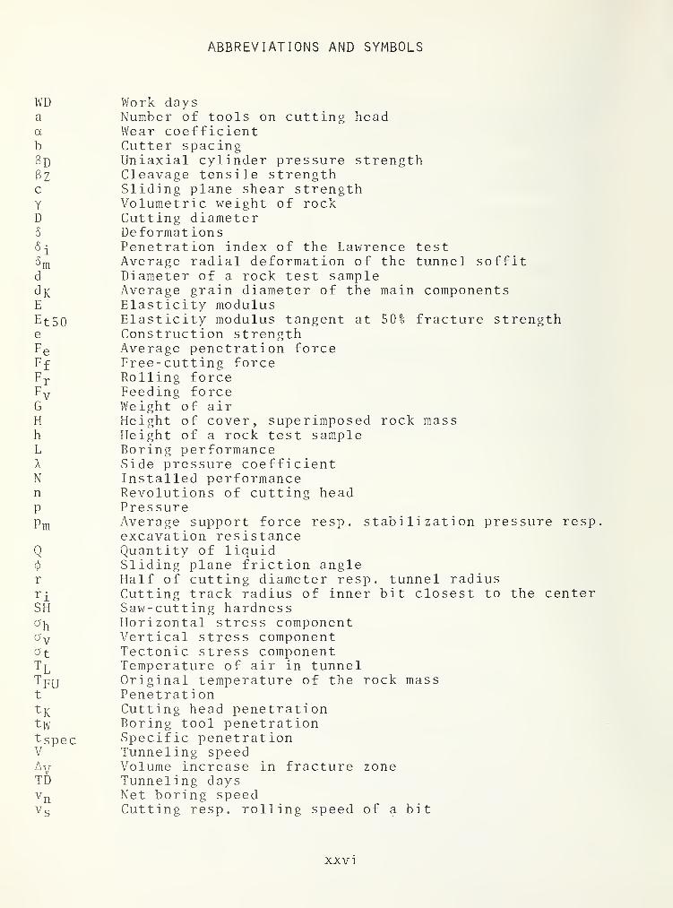
Work daysNumber of tools on cutting headWear coefficientCutter spacingUniaxial cylinder pressure strengthCleavage tensile strengthSliding plane shear strengthVolumetric weight of rockCutting diameterDeformat ionsPenetration index of the Lawrence testAverage radial deformation of the tunnelDiameter of a rock test sample
soffit
dK Average grain diamete r of the main componentsE Elastic ity modulusEtSO Elastic ity modulus tangent at 50% fracture strengthe Construction strengthFe Average penetration forceFf Free-cutting forceFr Rolling forceFv Feeding forceG Weight of airH Height of cover, supe r imposed rock massh Height of a rock test sampleL Boring performanceA Side pressure coeffic lentN Install ed performance
Revolutions of cutting headPressureAverage support force resp. stabilization pressure respexcavation resistanceQuantity of liquidSliding plane friction angleHalf of cutting diameter resp. tunnel radiusCutting track radius of inner bit closest to the centerSaw-cutting hardnessHorizontal stress componentVertical stress componentTectonic stress componentTemperature of air in tunnelOriginal temperature of the rock massPenetration
penetration
in fracture zone
Fk Cutting headtw Boring tool pFspec Specific peneV Tunneling speAv Volume increaTD Tunneling day
^n Net boring spVs Cutting resp. rolling speed of a bit
XXVI
ABBREVIATIONS AND SYMBOLS (CONTINUED)
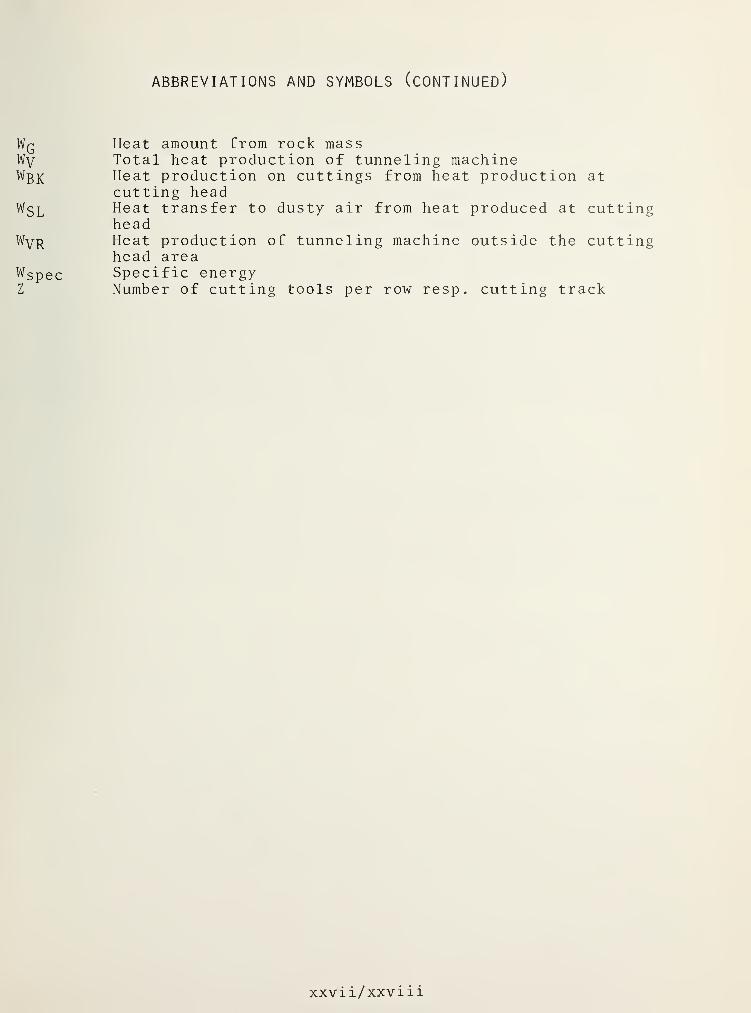
Wq Heat amount from rock massWy Total heat production of tunneling machineWßK Heat production on cuttings from heat production at
cutting headWgL Heat transfer to dusty air from heat produced at cutting
headWyp Heat production of tunneling machine outside the cutting
head areaWspec Specific energyZ Number of cutting tools per row resp. cutting track
xxvii/xxviii


1 . DEFINITIONS OF TECHNICAL TERMS
1.1
CONVENTIONAL AND MECHANICAL TUNNELING
Conventional tunneling or tunneling by means of explosives insolid rock is divided into four main operations: drilling
,blast-
ing, mucking, and supporting of the blasted cavity. The threeoperations mentioned first, and often all four, follow each otherconsecutively. They require the use of various machinery at theface: the carriage with the hammer drills, in large profiles de-vices for tamping the bore holes, loading machines and, if temporarysupport is necessary, also support installation machinery. Mech-anical tunnel cutting or tunnel boring is done by means of a tun-nel boring machine. It simultaneously disaggregates the rock, col-lects the muck, and removes them from the boring zone. Unless thetunneling cross sections are small, the machinery for the instal-lation of temporary support is part of the tunneling machine, andthe securing of the bored cavity can take place in many cases with-out interruption of the boring process.
1.2
TUNNELING SYSTEMS
A tunneling system consists of the totality of the installa-tions in the tunnel which are necessary for the tunneling, and forthe processes directly connected with it, among others: boringmachine, transportation installations, supply lines, installationsfor dust elimination and ventilation, and if applicable, also theair condition units for the work places or the operation center orthe machine area. Figure 1-1.
1.3
BORING MACHINE (TUNNELING MACHINE, CUTTING MACHINE)
A suggestion for the systematic classification under variousaspects is given in Figure 1-2.
A full face cutting machine usually consists of a basic machinewith one or more auxiliary trailers.
The most important functional elements of a basic machine are:cutting head, cutting head carrier, machine frame, the hydraulicallyoperated bracing-and support - devices
,as well as the cutting head
drive motors. In Figures 1-3 to 1-5, the design and relativeposition of these elements is given for boring machines manu-facutred by Lawrence, Robbins and Wirth. Electrical installationand hydraulic supply machinery is usually arranged on a trailer.
1

Figure 1^1, Tunneling System with Tunneling Machine, Transferand Loading Belt, and Air Duct Telescope
1.4 TECHNICAL TERMS RELATED TO BORING
1.4.1 Boring System (Cutting System)
This term refers to the cutting head or the boring tool car-rier of a tunneling machine. It defines its geometric form as wellas type, number and arrangement on the head of the boring tool.
The boring tools of a full face tunneling machine work on thewhole cross section of the tunnel face simultaneously. They cut acircular cross section, Figure 1-6. Those of a partial face machineonly cut partial sections, and the boring of the whole cross sec-tion is achieved by successive cutting of partial sections. Usually,partial face boring machines permit the boring of non-circular crosssections. Figure 1-7. The shape of the tunnel cross section isdependent on the boring system. Exceptions confirm the rule.Figure 1-8 shows the tunnel face cut by a machine with the under-cutting head arrangement presented in Figure 1-9.
2

3
Figure
l'-2.
Suggestion
For
A
Systematic
Classification
of
Tunneling
Machines
Under
Various
Aspects

t^/1
a cutting headb cutting head carrierc machine framed gripper pad
Cutting head drive motors
e (advancing device)
,
j acksf pilot drillg anchor
located on head carrier.
Figure ,Manufacturer Lawrence
p-L?
cutting headcutting head carrier withskid, lateral guides andtop shield
c machine frame
d gripper padse (advancing device)
,
j acks
Cutting head motors located on cutting head carrier.
Figure 1-4. Manufacturer Robbins
thrust
cn A-A
an A A<-7C
thrust
4
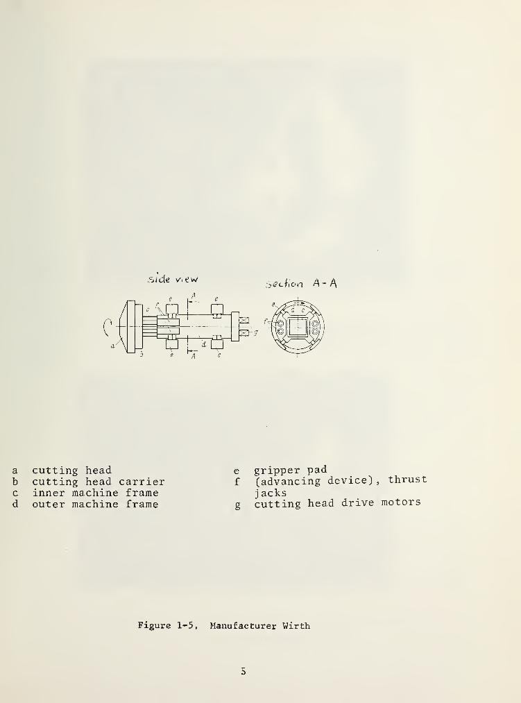
fjide Vi<iw:y(?ciion A-
A
a cutting headb cutting head carrierc inner machine framed outer machine frame
e gripper padf (advancing device)
j acks
g cutting head drive
Figure l'-5. Manufacturer Wirth
thrust
motors
5

Figure 1-6. Tunnel Bored with a Tunneling Machine Equipped with Roller Bite(Hughes Tool Co.)
Figure 1-7. Tunnel Bored with a Partial Face Cutting Machine(Anderson Mavor Ltd.)
6

Figure 1-8. Tunnel Face Cut By Machine Figure 1-9. Arrangement of Undercutting
Shown in Figure 1-9 Heads on Hubegger-AtlasCopco Machine
1.4.2 Boreability
This is the property o£ a geological formation to suffer, whensubjected to certain boring tools, the expansion of existing cracksand weak points of the material components or of the materialformation until fracture occurs.
The boreability of the material formation rock may be calledbasic boreability. Usually, it is smaller than the boreability ofthe rock mass formed by this rock because in the large materialformation - rock mass - weak spots which are an important pre-condition of the disaggregation of rock, occur more frequently.The boreability is dependent on:
-the formation to be bored and-the tunneling machine, in particular it is dependent onthe boring system.
1.4.3 Index Values of Basic Boreability
Mechanical rock characteristics can be defined as influentialfactors for boreability. The following index values apply:
-uniaxial cylinder compression strength-cleavage tensile strength 3^-elasticity modulus tangent at 50% compression strength Et50>-a hardness definition, such as sawing hardness SH.
7

1.4.4 Penetration t and specific penetration t spec
The penetration is a measure for the boreability of a certainformation by means of full face tunneling machines.
Boring heation of the borof the head and
Boring tooof the cutt ingthe boring face
d penetration t^ (in mm) meansing head into the formation withe boring tool carrier.
1 penetration t;^(in mm) meansedges of an individual tool wi
thth
theth
e average penetra-a single rotation
average penetrationa single pass over
The boring tool penetration corresponds to the boring headpenetration if all tools on a head have different geometric arrange-ments, i.e., if in one row only a single tool is installed.
The penetration is influenced by-the formation to be bored,-the tunneling machine, (the boring system in particular) andon
-the actual drive force Fy of the machine being effective onthe boring head, and the average penetration force Fg of aboring tool
:
F e
F—,with ”a'' as the number of boring tools on the
^ head.
Specific ppenetration to
enetration tspecthe penetration
is the relationforce :
of the boring head
^Fspec - p p—e V
a
1.4.5 Net Boring Speed (Rate of Penetration) V]\j and BoringPerformance L
Net boring speed Vj^ means the actual tunneling speed of fullface tunneling machines excluding all down times for technicalreasons
.
Vn = t^n,
with "n" as the revolutions of the cutting head.
Here, it is practical to give V]\[ in cm/min or m/h,
tj( in cm orm and n in 1/min or 1/h.
8

When tunneling machines with variable cutting head revolutionsare concerned, it is practical to avoid the term of cutting headrevolution "n" and to use the actual boring time for the calculation
boring length'^N actual boring time •
The boring performance L is a term which can be used for fullas well as for partial tunneling machines. It consists of a netperformance in relation to natural rock:
L = net boring speed x tunnel cross section
performance in m /h, speed in m/h, tunnel cross section in m^
.
1.4.6 Tunneling Speed V
It consists of the tunneling work per time unit without con-sideration of the actual boring time:
y _ advancetime
Here, the advance can be given in meters (m) , the tunnelingtime in work days (WD)
,tunneling days (TD) ,
weeks (W),or months
(M).
1.4.7 Specific Energy Wspec
This term which is used occassionally means the relation of theenergy used for boring to the solid volume of the cut rock:
W = ^ ^ ^ ^ ^
^
with Wspec kWh/m^ , electric energy inspec cut rock / > &/
kWh, and cut rock in m^.
1.5 BORING TOOL WEAR
1.5.1 Boring Tool Costs
The wear is expressed collectively by the term of boring toolcosts. This is defined as the sum of the actual material costs forcomplete tools without tool holders at the manufacturing plant(black costs) for m^ cut rock, without transportation costs,customs duties, and labor costs for exchange and regular maintenance
9
1.5.2Index Values of Boring Tool Wear
This concerns
:
-a strength standard combined with-the nature, the portion, and the average grain diameter of themain components of the rock.
1.6 TERMS RELATING TO OPERATION
1.6.1 Boring, System-Related and Non-System-Related Interruptions
The effective working time in the tunnel is divided into:-boring, (or tunneling),-system-related down-times and-non- system-related down-times.
System-related down-times are caused by lack of technicaloperation readiness at the point of operation of the components inthe tunnel system used. Non- system-related interruptions arewaiting times for the tunneling system which, technically speaking,is functional.
1.6.2
Utilization Factor of the Tunneling System
The utilization factor, or coefficient of utilization, meansthe relation of boring time (i.e., of effective revolution time ofthe cutting head) to the total effective working time on or behindthe system, expressed in percent.
1.7 TERMS RELATING TO ROGK MEGHANICS
1.7.1 Instant Rock
Instant rock is a compound of minerals with isotropic andanisotropic structures or directed textures whose cohesion is notinfluenced by water, unless it is in the form of ice. We distin-guish between:
-igneous rock-sedimentary rock and-metamorphous rock.
1.7.2
Rock Strength
The uniaxial compressive strength is the most commonly usedstandard for the determination of rock strength. A universallystandardized classification of compressive strength, ranging for acorresponding classification of rock does not exist. On occasion,,the following classification is used as shown in Table 1-1.
10

TABLE 1-1. CLASSIFICATION OF ROCK ON THE BASIS OF ITS UNIAXIALCOMPRESSIVE STRENGTH
Compressive strengthkg/ cm2
Classification
over 2800 very high
1800 to 2800 high
800 to 1800 medium
400 to 800 low
below 400 very low
21 kg/cm = 1 bar1.7.3
Rock Hardness
Rock hardness generally means the resistance against mechanicalinfluences. The terms "soft” or "hard” which are often used forrock are not defined in a standard way. In any case, hardness doesnot mean strength. High strength and a large portion of mineralsthat are harder than steel (among others quartz, garnet, fieldspar,hornblende) characterize the term "hard rock".
1.7.4
Rock and Rock Mass
Rock mass is the large spatial formation of rock. This masscontains discontinuities; for example, bedding planes, joints, andfaults which separate faces with sediments and chavage planes.
1.7.5
Characteristic Line of the Deformation Behavior of theTunnel Invert
This characteristic curve is the graphic representation ofthe average radial deformation of the tunnel invert as dependenton the average support force P
, and on the stabilization pressure,and the lining resistance of t’l^is pressure.
1.7.6
Cases of Rock-Mechanical Stability
Four cases of stability can be distinguished in relation tothe behavior of the tunnel invert and the work face during tunnel-ing as shown in Table 1-2.
11
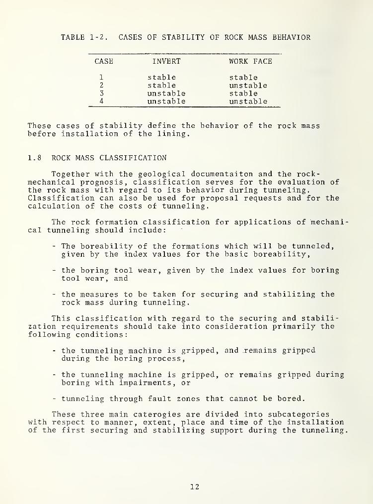
TABLE 1-2. CASES OF STABILITY OF ROCK MASS BEHAVIOR
CASE INVERT WORK FACE
1 stable stable2 stable unstable3 unstable stable4 unstable unstable
These cases of stability define the behavior of the rock massbefore installation of the lining.
1.8 ROCK MASS CLASSIFICATION
Together with the geological documentaiton and the rock-mechanical prognosis, classification serves for the evaluation ofthe rock mass with regard to its behavior during tunneling.Classification can also be used for proposal requests and for thecalculation of the costs of tunneling.
The rock formation classification for applications of mechanical tunneling should include:
- The boreability of the formations which will be tunneled,given by the index values for the basic boreability,
- the boring tool wear, given by the index values for boringtool wear, and
- the measures to be taken for securing and stabilizing therock mass during tunneling.
This classification with regard to the securing and stabili-zation requirements should take into consideration primarily thefollowing conditions:
- the tunneling machine is gripped, and remains grippedduring the boring process,
- the tunneling machine is gripped, or remains gripped duringboring with impairments, or
- tunneling through fault zones that cannot be bored.
These three main caterogies are divided into subcategorieswith respect to manner, extent, place and time of the installationof the first securing and stabilizing support during the tunneling
12

2 . BORING OF SOLID ROCK WITH TUNNELING MACHINES
2.1 MATERIAL TO BE DRILLED, CONSIDERATIONS IN BREAKING OF ROCK
The material which will be subjected to the tools of a tunnelboring machine is a formation of minerals. In general, it is only-in limited areas that this formation - the rock - shows structuraluniformity - genetic structure, characterized by size, shape, andinterrelation of the components of the matrix (1) - and a uniformtexture - spatial structure, characterized by the spatial arrange-ment of the components of the matrix, and their space filling (2)
.
This structural and textural inhomogeneity, again as a generalrule, is responsible for the anisotropy - dissimilar behavior indifferent directions - of the mechanical properties. The mechani-cal properties which are decisive in disaggregation are the hard-ness of the minerals and the mineral matrix, as well as the pro-perties of strength and deformation.
In principle, the matrix is attacked primarily by applying apressure load of continuous or intermittent nature. The mineralcomponents and the mineral matrix are crushed within the immediateeffective radius of a tool which is applied with high pressure,and for this reason penetrates the rock. Within a wider radiusfrom the point at which the tool is applied, however, the matrixis not destroyed directly by the pressure load. Compressivestrength is the predominant strength property of rock. Shearstrength and tensile strength are distinctly lower in comparison.
Except for the zones at the beginning of a load and beforethe breaking, the compression increase follows a curve which ispractically linear to the increasing load on a test rock sample.Also, solid rock between these two zones shows a practicallyelastic behavior; i.e., when the load is removed, the deformationsare reversed. For most hard rocks, the zone of elastic deforma-tion is much greater than the starting zone which is usuallycharacterized by permanent deformation, and the zone with plasticbehavior before the actual fracture. The destruction of the for-mation can be explained as follows: the compression load appliedto the interior of the rock creates stresses which affect itsweakest strength properties (i.e., the shear strength and tensilestrength) until fracture occurs. The formation of fracture planesis facilitated by the presence of weak spots in the formation orwithin its components. Weak spots already present in the micro-structure (i.e., in basic rock bodies) may be of genetic origin,such as faults in the mineral crystallization, in the graincohesion of igneous rocks, or in the cementation of sediments.However, they can also be caused by a metamorphosis of the rock,for example by lamination of minerals, and also by mechanicalstresses such as Mylonitization of hard minerals.
13

Mechanical stress is, with few exceptions, also responsiblefor cracks forming weak spots in the large spatial formations ofrock, the rock mass. Rock discontinuities are another weak spotin the large formation rock mass.
These weak spots are especially helpful for disaggregationif they are positioned as planes within the field of the interiorshear and tensile load caused by exterior pressure loads in such away that the shear loads occur plane-parallel; the tensile loadsoccur perpendicular to the plane of weakness.
2.2 BORING TOOLS
With regard to the direction of pressure on the cutting faceof a tunnel and the work taking place there, basically two groupsof boring tools can be distinguished [2]:
- tools with an effect primarily perpendicular to the tunnel-ing direction, and
- tools whith an effect primarily in the direction of thetunneling.
2.2.1 Tools with an Effect Primarily Perpendicular to the Direc-tion of Tunneling
These are:
- drag bits or teeth, and
- cutting heads with undercutting plates.
These drag bits. Figure 2-1, armored by hard metals, aremounted on the spokes. The blade arms of the cutting head form asmall angle to the plane of the tool carrier. During rotation ofthe cutting head, under pressure, the blades dig into the workface, and cut concentric grooves into the uneven edges of therock. The rock to be peeled, which is relatively brittle, breaksduring the peeling process. Use of these tools is successful onlyin practically non-abrasive rocks; i.e., in low-strength rockswhich cause little wear to the boring tools. However, these toolsare suited for the boring of material with ductile behavior.
Like cutting blades, drag bits can also be mounted at the cir-cumference of cutters (i.e., cutting heads). Figure 2-2. For theboring of circular profiles, two or four cutters are arranged ona drum. During the slow revolution of the cutting heads aroundthe machine axis, they also rotate relatively fast around theiraxes in the direction opposite to the drum because the cutters arearranged on the drum in such a way that their axes form smallangles with the axis of the machine. During simultaneous rotationof the drum and of the cutter heads, as well as during simultaneous
14

Photo: Calweld
Figure 2-1. Drag Bits
advance of the machine frame, the individual undercutting platesmove in the form of cycloids on the work face. The cutting headsequipped with the undercutting plates have the tendency, due tothe divergence of their axes with the axis of the drum, to cutinto the work face (Figures 1-8 and 1-9).
Tunneling machines equipped with this type of cutting edgehave also been developed for the cutting of rectangular profiles.The fullfacer of Atlas Copco is equipped with four cutting headsarranged in two pairs at the face of the machine frame. Duringthe boring each can be rotated in pairs around a vertical axis(Figure 2 - 3)
.
The mini- fullfacer by the same manufacturer for the boring ofminimal, upright rectangular profiles has only one cutting headwith a horizontal swivel axis. During the boring, the rotating
15

Photo: Atl.is Copco
Figure 2-2. Drum with Cutting Heads and Undercutting Plates For the
Cutting of Circular Sections
Photo: Atlas Copco
Figure 2-3. Fullfacer with Four Cutting Heads for Cutting of RectangularSections 4.8 x 2.6 m
16

cutting head swivels upward, (Figure 2-4). The form of rock dis-aggregation developed by Wohlraeyer, and further developed byHabegger and Atlas Copco, is called the undercutting process, or’’milling". When the cutting heads penetrate the work face, brittlerock in the path of the hard metal undercutting plates is shearedoff in the form of chips. Non-brittle material is ground up asthe cutting heads undercut the work face. The undercut rock doesnot form shavings due to its mechanical properties, but breaksinto relatively large chips, (Figures 2-5 to 2-7). The advantageof the relatively small feeding force required is counter-balancedby problems related to the material of the undercutting plateswhich consist of hard metals: i.e., a sintered alloy with tungstencarbide as the wear-resistant main component, and cobalt as binder.During the cutting, several of the hard metal undercutting platesof a cutting head are always in sliding contact with the rock.Here, wear of the cutting edges occurs as the tungsten carbidegrains break out of the sinter structure. Occurrence of high fric-tion temperatures also lead to oxidation of the tungsten carbidegrains. Impact stresses during the cutting cause mechanical fati-gue of the sinter structure [3]. The content of abrasive mineralsand their grain size; the strength properties of the rock; as wellas the cutting speed influence even the wear of tools which areproperly cooled with water or a water-compressed air mixture.Tunnel boring, by means of the undercutting process in high-strength and simultaneously abrasive rock, is more closely limitedby technical and economical factors than by methods employingroller bits.
2.2.2 Tools With An Effect Primarily in the Direction of Tunneling
These are:
- cutting teeth as well as styli, and
- roller bits, i.e. tooth, button and disk roller bits.
These tools mounted on spokes or plates of the cutting headdescribe concentric circles on the work face with rotating toolcarrier, and form either grooves or furrows., depending on thenature of the rock and on the tool.
Cutting teeth. Figure 2-8, and styli. Figure 2-9, producefurrows in a rock of low strength. The ridges remaining betweenthe furrows are removed either by the wedge effect of the teethand styli further penetrating into the rock, or are cut radiallyagainst the neighboring furrows by roller bits rolling betweenthese tools. Successful use of teeth and styli is limited to rocksof low strength and low abrasiveness.
The roller bits rotate around axes that are approximatelyparallel to the work face, but they are not driven. Their blades,the teeth, the buttons, and disk rings roll on the work face whenthe cutting head is rotating. Instead of the sliding friction
17

Photo: Atias Copco
Figure 2-4. Mini Fullfacer with Cutting Head for the Cutting of SmallUpright Rectangular Sections 1.5 x 2.4 m
Figure 2-5. Undercutting of the Face in Sandstone
18
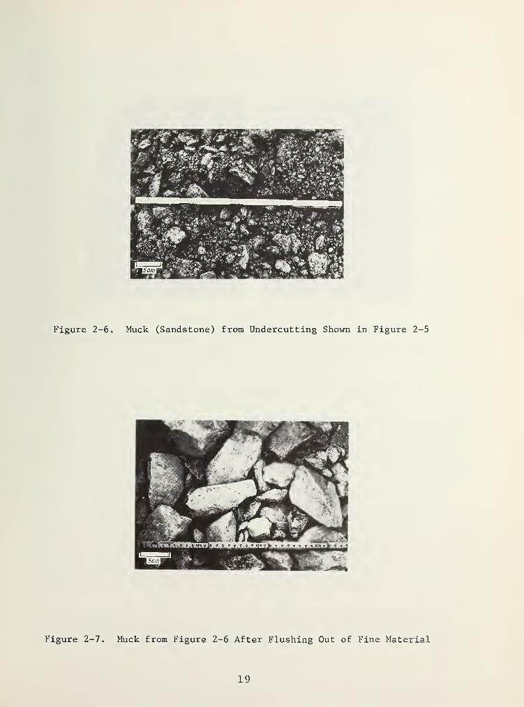
Figure 2-6. Muck (Sandstone) from Undercutting Shown in Figure 2-5
Figure 2-7. Muck from Figure 2-6 After Flushing Out of Fine Material
19

PhoTo: KiniKMr Mootlic 'I'unncling Machines Ltd. Photo; (,alwcld
Figure 2-8. Cutting TeethFigure 2-9. Styli in Cutting HeadCenter
effect characterizing the functional principles of the toolsmounted in a fixed position on the cutting head described so far,the effect of these tools is based on a rolling friction betweencutting edge and work face. Due to the process of the drilling ofthe work face, the contact between cutting edge and rock is notpermanent, and not all roller bits mounted on a cutting head arein contact with the rock simultaneously. Sliding friction isreduced to a very high degree but is not eliminated completely.
Under the static effect of the pressure, and the dynamic effectof the rotation, the cutting edges penetrate the rock in varyingdegrees. The mineral matrix and its components are crushed in theimmediate radius of effect of any kind of penetrating cutting edgecarrying a pressure load. The tips of the teeth of the tooth bits,and the tips of the hard metal button of the button bits formcraters in the work face whose volume is larger than that of themetal pushed into them. In addition, they disaggregate the rockin a direction tangential to the rolling tool as well as perpendi-cular to it.
The edges of the tooth and button roller bits are identicalto those of the tricone rock bits as used for drilling of holes,e.g., for oil wells. The body of the bit, however, has the shape
20

of a truncated cone. The tooth and button roller bits are mountedon the cutting head in such a way that, during rotation of thecutting head, the whole area of the work face is covered by thetooth tips; i.e., the hard metal lugs. Figure 2-10.
The body of the bit, and the teeth of the tooth bits machinedfrom it (Figures 2-11 and 2-12) consist of heat-treated alloyedsteel [4]. According to the strength behavior of the rock to bebored, bit types, i.e., the geometric form and the number of teethare selected. Types with few, long, and relatively sharp-angledteeth per row are used for a rock of lesser strength. When thebit rolls over the rock, the teeth penetrate the work face invarying extents, forming craters and shearing off chips in atangential direction. The bit types for solid and hard rock havemany rows of short and relatively obtuse-angled teeth. The natureof the rock allows only small penetration, and the disaggregationof the work face is achieved predominantly by removal of smallrock chips.
In hard and also abrasive formations, the use even of surface-armored tooth bits becomes uneconomical. In their place, buttonbits (Figures 2-13 and 2-14) are used. Hard metal pins with a
diameter of 5 millimeters are inserted at distances of approximately4 cm into the steel body of this type of roller bit. If they arepressed into the rock, under high pressure and during rotation,the above-mentioned craters form underneath the buttons, as wellas cracks in their vicinity, and shallow fractures whose planesare approximately parallel to the work face. The chipped-off rockparticles can have the dimensions of a coin (Figures 2-15 and 2-16).The button bit is a technically suitable and expensive tool forthe boring of high-strength and abrasive formations which do notprovide a spectacular penetration.
The disk roller bit (which due to its basic design consistingof bearing bit body, bearing seals, and cutting edge also belongsamong the roller bits) has been developed especially for machinetunneling. It has not been in use long for large diameter boring,but it has replaced the traditional types of roller bits. Thecutting edge of a disk bit represents an endless wedge. The wedgeangles in use range from 60® to 105°, Figure 2-17. No cuttingedge has the sharpness of a knife. However, relatively durableblades are produced today that may justly be called sharp-edged,and whose cross section between the flanks no longer shows a
rounding with a radius in the magnitude of millimeters. Underpressure, a sharp-edged wedge has excellent penetration properties.These are still further improved by the rolling motion. Even awork face consisting of high-strength rock is penetrated at leastsuperficially. A groove with varying depth, with flat slopes whichdo not at all correspond to the wedge angle, and is filled withrock powder at the bottom, marks the course of a sharp disk biton the work face. The work face is directly affected only in theimmediate zone of the disk course. The distance between thecourses is, called cutter spacing b. Figure 2-18. The fracture
21

Photo: \\ irth & Co. -,
Figure 2-10. Face Cut with Button Roller Bits
Photo: Smith Tool Co.
Figure 2-11. Caliber (Gauge) Bit Figure 2-12. Inner Bit
22

Figure 2-13. Caliber (Gauge) Bit
Photo: Smith Tool Co.
Figure 2-14. Inner Bit
23

Geometrie Shapes Of Sharp-edged Disk Cutters
'2 4
Figure 2-17.

planes extending from both sides of the groove usually form onlyafter the disk has rolled over the work face several times underpressure, and are directed either against the work face or againstthe neighboring grooves. In rock which deforms in a double manner(Figure 2-19), or with too large a cutter spacing, the effect of adisk blade may be restricted to the formation of grooves. Inextreme cases, the disks dig in until the body of the bit rests onthe rock. In brittle rock, and with appropriate cutter spacing,chips the size of a hand are splintered off above the fractureplanes. The cross section of these chips corresponds to that ofan airplane wing. Figure 2-20. The chips have a predominantlyoblong shape. A generally applicable statement on the granulometryof the cuttings cannot be made. It is influenced by a great numberof factors such as wedge angle and condition of the blade, cutterspacing, rock properties, separation planes of the rock, etc.
Depending on the manufacturer, the ring blade of the disk ispart of the disk body, or it is shrunk into the disk body as ringwith wedge-shaped cross section. This last-mentioned type con-struction is found more often. It is based on the experience thatusually the blade of a disk roller bit has a shorter life than thedisk body and the bearing.
Manufacturing of replaceable ring blades of construction steelor of tool steel is basically very simple and inexpensive. Alarge problem arises from the requirement that the sharpness ofthe blade should be retained as long as possible, even in hard andabrasive rock. For this purpose the following measures are used:
- hardening of the wedge planes of the steel ring blades,
- armoring of the wedge planes by means of welded-on hardmetal which, however, leads to a certain loss of the bladesharpness, and thus a loss of penetration capacity underequal pressure,
- attaching hard metal inserts to the circumference of thering blade that show the cross section of sharp wedges,
- disk bit whose blunt disk is manufactured as part of thedisk body, and where hard metal buttons inserted into theperiphery serve as blades,
- ring blades made from hard metal.
Besides the blade characteristics with regard to satisfactoryabrasion resistance, the different versions of disk roller bitsalso differ in the number of the blades or ring blades mounted onthe bit body:
- monodisk bit. Figures 2-21 to 2-26,
- double or multiple disk roller bits with two or more neigh-boring blades rolling over the work face. Figures 2-27 to2-29,
25

double or multiple disk roller bits with two or more ringblades which roll on the work face on both sides of a trackbelonging to a neighboring bit. Figures 2-30 and 2-31.
The single disk with surface-hardened steel ring blade is theeffective, relatively inexpensive, and commonly used tool fortunneling. Its use is limited less by the forces applied to thering blade through large penetration pressure than by a largeportion of wear- intensive minerals in the rock to be bored. Forsuch cases, the button disk roller bit may, for the time being,be used as a less effective and also more expensive replacementof the sharp-edged single-disk bit. It will be used until attemptshave been successful to develop an economical material and aneconomical production process for sharp-edged disk ring bladeswith high strength properties and high resistance against theabrasive effect of minerals.
Figure 2-18. Face in Limestone Cut with Sharp-edged DiskCutters (Tunnel Circumference Top Left)
26

Figure 2-19, Grooves Cut By Disk Cutters In Ductile Rock
~5cm
Figure 2-20. Cuttings Cut With Disk Bits. From Left To Right:
Medium-Hard Sandstone, Soft Sandstone, High-strengthLimestone, Soft Sandstone, Medium-hard Granite (All
Cut With Robbins Machine) ,Medium-hard Granite (Wirth)
,
Hard Limeston (Jarva) , Hard Granite (Demag)
27

Figure 2-21. Disk Cutter Design
Figure 2-22. Muck, High-strength Limestone Bored withDisk Cutters Shown in Figure 2-21
28

Figure 2-23. Muck of Figure 2-22 After Flushing Outof Fine Material
Figure 2-24. Bit Design (Lawrence) Button DiskRoller Bits
29

Figure 2-25. Muck, High-strength Limestone Bored with
Button Disk Rollers Shown in Figure 2-26
Figure 2-26. Muck of Figure 2-25 After Flushing Outof Fine Material
30
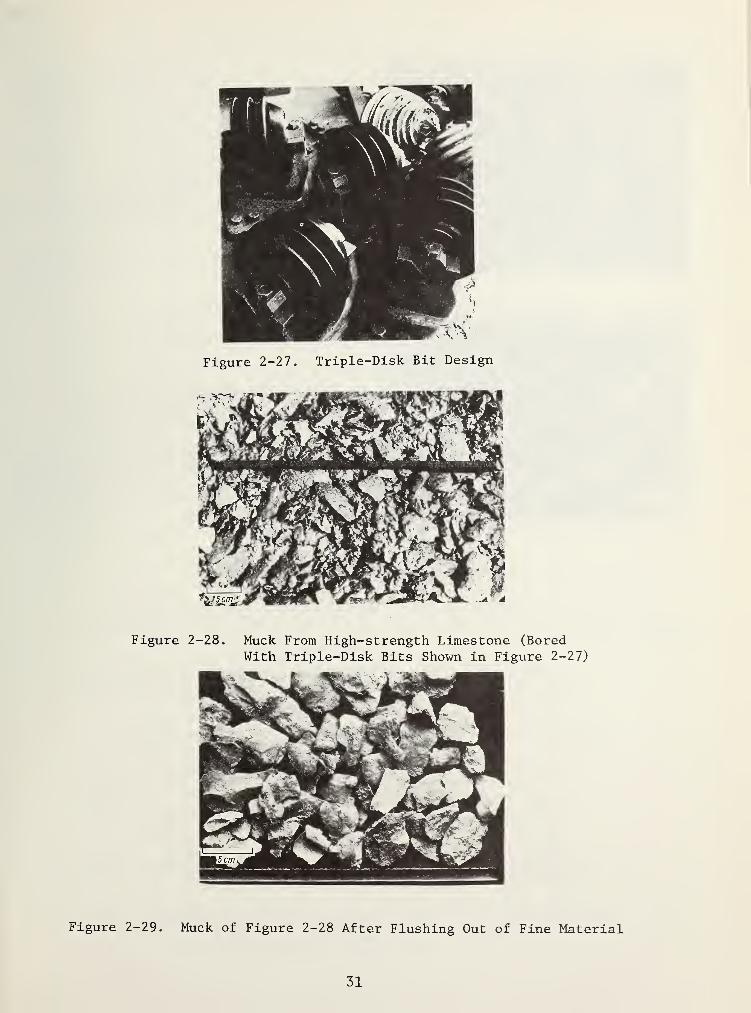
Figure 2-28. Muck From High-strength Limestone (BoredWith Triple-Disk Bits Shown in Figure 2-27)
Figure 2-29. Muck of Figure 2-28 After Flushing Out of Fine Material
31
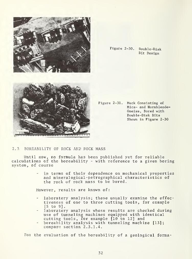
Figure 2-30. Double-DiskBit Design
Figure 2-31. Muck Consisting of
Mica- and Hornblende-Gneiss, Bored withDouble-Disk BitsShown in Figure 2-30
2.3 BOREABILITY OF ROCK AND ROCK MASS
Until now, no formula has been published yet for reliablecalculations of the boreability - with reference to a given boringsystem, of course
in terms of their dependence on mechanical propertiesand mineralogical -petrographical characteristics ofthe rock of rock mass to be bored.
However, results are known of:
laboratory analysis; these usually examine the effec-tiveness of one to three cutting tools, for example[5 to 9] .
laboratory analysis whose results are checked duringuse of tunneling machines equipped with identicalcutting tools, for example [10 to 12] andboreability analysis with tunneling machine [13]
;
compare section 2. 3. 1.4.
Foi the evaluation of the boreability of a geological forma-
32

tion the tunneling system to be used must be defined first, in anycase, and, in addition, it must be distinguished between:
rock-related boreability, i.e., basic boreability,and theinfluence of the rock mass structure on the basicboreability
.
2.3.1 Rock-related boreability on basic boreability
In the following, the preconditions and the most importantresults of analyses on the basic boreability are described, inparticular
:
a laboratory analysis with a linear apparatus,sect ion 2 . 3 . 1 . 1
,
a laboratory analysis with a rotary table, section2. 3.1. 2. ,
laboratory analysis, verified on location by means ofa tunneling machines, section 2. 3. 1.3.,experiments on location with tunneling systems respec-tively tunneling machines, section 2. 3. 1.4.
2. 3. 1.1 Analysis with a linear apparatus at the Twin Cities MiningResearch Center [TCMRCl of the Bureau of Mines - At the TCMRC [6]
,
experiments were conducted on the influence o£ cutting tools onfour different kinds of rock, and on the forces necessary forpenetration. A linear apparatus was used. Figure 2-32.
horizontal movement
a linear potentiometer c wire strain gauge e test specimenb pulley d disk bit f recorder
Figure 2-32. Linear Testing Apparatus of the Twin Cities MiningResearch Center (TCMRC) [6]
33

By means of this test installation, one disk roller bit, eachwith a wedge angle of 60° or 90°, was pulled over the cut surfaceof the test rock. The vertical penetration force F , maximallyapproximately 5 Mp(50kN), and the horizontal rollinf force Fnecessary to overcome the rolling friction were measured and^recorded continuously. In addition, the depth, i.e., the penetra-tion t of the disk blade, and the volume of the groove weredetermined. The most important results of these tests conductedunder limited conditions are:
a) relation between penetration force F^ and penetration t:
between penetration force and penetration a linearrelation exists.with equal penetration forces, the penetration achievedwith a 60° disk blade is larger than the one causedby a 90° disk blade, for all rock samples used in thetest
.
under the condition of equal penetration force andequal angles of the disk blade, the penetration in a
rock of lesser strength and surface hardness as wellas with a smaller elasticity modulus E is larger thanin a rock with higher strength, hardness, and stiffness.
b) relation between penetration force F and rolling forceF :
®
r
with increasing penetration force, the necessary roll-ing force increases slightly more than proportionally,with equal penetration force, the rolling forcenecessary for advancing a disk bit with a 60° diskblade is larger than the rolling force necessary forthe rolling of a disk with a 90° disk blade,the rolling force necessary for bit movement over rockof high strength, hardness, and stiffness is smallerthan that necessary for rolling a bit over rock whoserelevant properties are inferior.
The special value of the TCMRC analysis consists of therecognition of qualitative relationships between the parameterscutting tool, penetration force, rolling force, and rock. Thenarrow limitation of the test conditions - among others, the modelsimilarity is questionable, and only the production of the groovetrack and not the actual disaggregation of the rock by separationof chips were simulated - limits the application of the quantita-tive data obtained here for the evaluation or construction oftunneling machines.
2. 3. 1.2 Investigation with disk roller bits rolling in concentriccircles, conducted at the Technical University o f Clausthal-
These analyses [7] had the goal of determining the forces tobe supplied by the tunneling machine, torques and drive power for
34

a certain penetration and net tunneling speed. The tests wereconducted in particular with bit configurations for appropriateexploitation of the relatively inferior strength properties of therock. The modified rotary talDle of an oil drilling rig as carrierof the test samples was used as test device. Three cutting toolholders with one disk roller bit each were mounted on a supportinstalled in the rotational axis of the table. This support couldbe moved axially. The construction of the holders permitted variations of the cutter spacing between the bits as well as variableindication of the bits for boring of a conical work face. Figures2-33 and 2 - 34
.
Figure 2-33. Tool Holder With Disk Bit
Figure 2-34. Tool Holder With Button Bit
The construction of the tool holders also permitted the sepa-ration of the so-called action forces influencing the bits duringboring into axial, tangential, and radial components in relationto the rotating rock samples; i.e., into the penetration force F^,
35

the rolling force F;^,and, with conical work face along with disks
rolling non-perpendicular to the work face, into the free cuttingforce Ff as shown in Figure 2-35. These three cutting force compo-nents and, among others, the penetration t as well as the boringdistance were measured and recorded.
Fg penetration forceF^ rolling forceFf free cutting force (= force
separating chip from rockmass
)
Fg resulting cutting force.
Figure 2-35. Forces Acting On A Disk Roller Bit
Three abrasive sedimetary rocks with different strength pro-perties, and, to a lesser extent, also one granite were used astest rock samples. The mill-stone-shaped test bodies were freeof cracks, and of relatively homogenous structure. The dimensionsand the installed power of the system, as well as the dimensionsof the rock test samples with a finished diameter of one meter,permitted - notwithstanding the constructively less realisticmodel disk roller bits - the conducting of tests on a 1:1 scalefor a continuous, real disaggregation of the rock, and the gather-ing of data which are also quantitatively relevant to a high degreefor practical tunneling. The most important results of thesetests are:
peak values of the action forces
The penetration forces Fg andFf, with conical tunnel face,that were three times as highThe peak of the rolling forcevalue of the average.
the free cutting forcereached peak valuesas the average values,reached the ten-fold
relation between the action forces and the penetration
The penetration force Fg and, less distinctive, thefree cutting force F£ with conical tunnel face showeda parabolic dependence on the penetration t, i.e.,with increasing penetration force, the penetrationincreased more than proportionally. This rule whichhad occurred during cutting in all solid rock in-creased with increasing cone angle of a cone-shapedwork face. The rolling force F^ showed linear de-pendence on the penetrations t.
36

the influence of the cutting speed on the action forces
The penetration force F necessary to achieve the pen-etration t, as well as the other action forces re-sulting from that were independent of the rollingcutting speed of the disk roller bits.
influence of the curvature of a disk track on the actionforces
The necessary penetration force Fg as well as the re-sulting other action forces for the penetration t wereindependent of the disk track curvature. This isexplained by the observation that always only a smallsection of the straight disk blade is in contact withthe rock.
influence of the shape of the work face on the actionforces
The penetration force Fg necessary for a certain pene-tration t as well as the resulting other action forceswas smallest when boring free surfaces. They increasedwith decreasing cone angle of a cone-shaped tunnel face,and were largest during the boring of a cavity, Figures2-36 to 2-39. The net cutting speed, and the specificenergy consumption during cutting, changed accordingly.
Relation of the quantitative results
Figure 2-40 shows the relation between the penetration t andthe action forces on a disk roller bit for various coneangles of the work face respectively for various anglesbetween the blade plane and the tunnel face (cutter spacingb=50 mm), and for a representative solid and abrasivesedimentary rock, such as a typical Ruhr valley sandstonewith uniaxial pressure strength of approximately 1,600 kg/cm (equals 1,600 bar) with test sample dimensions d:h =
1 : 1 .
37

Figure 2-36.
Arrangementon a freesurface
Figure 2-37-
Arrangementin steps
Figure 2-38.
Arrangementperpendicularto the work
face
Figure 2-39.
Arrangement forthe boringof a cut
Figures 2-36 to 2-39. Arrangement of the disk bits in rela-tion to the work face [7]. b is cutter spacing and s, S;]^, S£ areheight of steps.
0 1 2 3 5 B 7 mm 9
Penetration t
Figure 2-40.
Relation between the penetration t and the forcesFg, Ff, and F^ with cutter spacing b = 50 mm, andvarious cone inclination angles (0° corresponds toa disk position perpendicular to the work face asin Figure 2-38 [7])
38

2.3.1. 3 Boreability Analyses by the Lawrence Company - Thistunneling machine manufacturer nas developed a process for directpredetermination of the rock boreability [5, 10] for use with theirown tunneling system equipped with button disk bits.
The rock sample which is to be tested is cast together with aspecial mortar with defined strength and expansion properties in asteel cylinder with 11.2 cm diameter in such a way that a cut rocksurface is obtained on one cylinder frontal face. This rock sur-face should be oriented towards the cylinder axis in correspondenceto the orientation of the rock in nature to the tunnel axis . Ahard metal pin is pressed in the direction of the cylinder axisinto the surface of the test rock inserted into the cylinder tosimulate natural conditions. This pin corresponds to the buttonsas they are used for insertion into a disk ring blade. For purposesof testing the rock, the permanent deformation 6 resulting fromfour to six increasing values of the penetration force ismeasured, Figures 2-41 to 2-43. Based on this, the so-calledpenetration index 6 i is calculated as follows:
6i6
Under the condition of a penetration force F^, for example 12Mp C120kN), the penetration t which is to be expected during theactual drilling operation (for the Lawrence tunneling system, thecutting tool penetration t^ and the cutting head penetration t^^
are equal) will be:
t
and the net cutting speed of the tunneling machine with acutting head revolution:
VN
tn
.
A comparison of basic boreability, or net cutting speeds(those predicted by means of laboratory experiments, and thosemeasured during the operation of tunneling machines) showed goodconsistency. Under the condition of sufficient cutter spacing,the errors of the prediction were claimed not to have exceededapproximately 151.
39
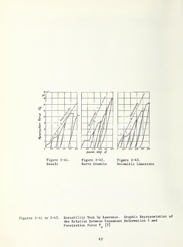
Figures
pe.rm . dej"' d
Figure 2-41.
BasaltFigure 2-42. Figure 2-43.
Barre Granite Dolomitic Limestone
-41 to 2-43. Boreability Test by Lavnrence. Graphic Representation of
the Relation Between Permanent Deformation 6 and
Penetration Force F^ [5]
40

2 . 3 . 1 . 4 Investigation with Tunneling Machines on Relations BetweenRock Properties and Roclc Boreability - Ever since 1970. the authorhas made observations, taken readings on location, and had the cutrock tested with a goal to recognize relations between the penetra-tion of cutting systems equipped with roller bits on the one hand,and mechanical properties, and maybe also mineralogical-petrographical characteristics of the rock, on the other hand.The express limitation of the analysis on the boreability of therock implies that observation and measurements on tunneling sitescan only then be used if the work face consists predominantly ofthe rock of the same kind or at least of basically identical rock,and if tunneling takes place in undisturbed rock formations. Atany one location meeting these requirements the following datasamples were taken:
a) Concerning the tunneling machine
- cutting diameter D,
- feeding force during cutting F^,
- net cutting speed Vj^,
- cutting head revolutions during cutting n,
- cutting system;
b) Concerning the geological conditions
- rock-characteristics formation relative to the tunnelaxis
,
- geological specimen or drill cores for mechanical andmineralogical-petrographical analyses
,
- cuttings.
In reference to the anlyses and observations mentioned insection 2. 3. 1.1 to 2. 3.1. 3, it is assumed that with a given boringsystem, the boreability of the rock is influenced decisively bysome of its mechanical properties; i.e., by its strength and defor-mation behavior as well as by its hardness in a wider sense. Ingeneral, none of these properties by itself characterizes thebehavior of the rock under the influence of cutting tools . Theoccassionally mentioned connection between strength and boreabilityonly applies to individual kinds of rock. The boreability must beassumed as a result of the interaction of mechanical properties.The following index values for boreability were defined:
- uniaxial compressive strength of cylinders 3^,
- tensile cleavage strength of disks 32 »
41

- tangent modulus of elasticity at 50% compressive strengthon cylinders 50,
- saw-cutting hardness SH during sawing of disks.
- Of these index values, two characterize the strengthbehavior, and one each, the deformation behavior as well asa special hardness. The concentration on these propertiesin particular is also based on the possibility to determinethe saw-cutting hardness already during the production ofcertain test specimens, and to determine the uniaxial com-pressive strengths simultaneously with the deformationbehavior
.
a) test specimen dimensions
Only rock pieces or drilled cores that are macroscopicallyfree of cracks are used for the production of test bodies.
- cylinder- test body, diameter d = 24.7 mm, height h =
50.0 + 0.5 mm; i.e., d:h = approximately 1:2 is usedfor tlie determination of
:
stress/strain relation and cylinder pressure strength.
Selection of the cylinder form made a comparison possiblewith data in American publications without questionableconversions [14]. The relation d:h = approximately 1:2largely, if not completely, excludes an influence on theresults by the geometric form of the test samples [15]
.
The absolute values of the dimensions take into accountthe difficulty to take rock samples from undisturbed rockformations out of bored tunnels without special equipment.Smaller dimensions which would be desirable in thisrespect are problematic with coarse-grained rock, forexample porphyritic rocks or matrices. In most cases,the chosen absolute dimensions are sufficient with regardto practice. If coarse-grained components are present,they should be increased with the ratio of d:h = approxi-mately 1:2 kept the same:
- disk test samples, diameter d=24.7 mm height h=9.050.05 mm are used to determine the cleavage tensilestrength and, during their production, they serve todetermine the saw-cutting hardness.
The ratio d:h = approximately 2.7:1 is sufficient topractically prohibit an influence on the results by thedimensions of the test sample [16, 17]. In many cases,the chosen dimensions of diameters and height make itpossible to produce disk test samples out of chips thatcan easily be recovered at the tunneling site.
42
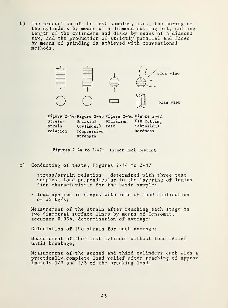
b) The production of the test samples, i.e., the boring ofthe cylinders by means of a diamond cutting bit, cuttinglength of the cylinders and disks by means of a diamondsaw, and the production of strictly parallel end facesby means of grinding is achieved with conventionalmethods
.
Figure 2-44. Figure 2-45. Figure 2-46. Figure 2-47.
Stress- Uniaxial Brazilian Saw-cuttingstrain (cylinder) test (abrasion)relation compressive hardness
strength
Figures 2-44 to 2-47: Intact Rock Testing
c) Conducting of tests. Figures 2-44 to 2-47
- stress/strain relation: determined with three testsamples, load perpendicular to the layering of lamina-tion characteristic for the basic sample;
- load applied in stages with rate of load applicationof 25 kg/s;
Measurement of the strain after reaching each stage ontwo diametral surface lines by means of Tensomat,accuracy 0.05%, determination of average;
Calculation of the strain for each average;
Measurement of the^first cylinder without load reliefuntil breakage;
Measurement of the second and third cylinders each with a
practically^ complete load relief after reaching of approx-imately 1/3 and 2/3 of the breaking load;
43
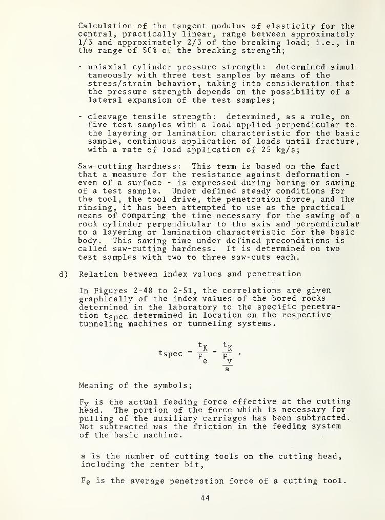
Calculation of the tangent modulus of elasticity for thecentral, practically linear, range between approximately1/3 and approximately 2/3 of the breaking load; i.e., inthe range of 50% of the breaking strength;
- uniaxial cylinder pressure strength: determined simul-taneously with three test samples by means of thestress/strain behavior, taking into consideration thatthe pressure strength depends on the possibility of alateral expansion of the test samples;
- cleavage tensile strength: determined, as a rule, onfive test samples with a load applied perpendicular tothe layering or lamination characteristic for the basicsample, continuous application of loads until fracture,with a rate of load application of 25 kg/s
;
Saw-cutting hardness: This term is based on the factthat a measure for the resistance against deformation -
even of a surface - is expressed during boring or sawingof a test sample. Under defined steady conditions forthe tool, the tool drive, the penetration force, and therinsing, it has been attempted to use as the practicalmeans of comparing the time necessary for the sawing of arock cylinder perpendicular to the axis and perpendicularto a layering or lamination characteristic for the basicbody. This sawing time under defined preconditions iscalled saw-cutting hardness. It is determined on twotest samples with two to three saw-cuts each.
d) Relation between index values and penetration
In Figures 2-48 to 2-51, the correlations are givengraphically of the index values of the bored rocksdetermined in the laboratory to the specific penetra-tion tspec determined in location on the respectivetunneling machines or tunneling systems.
a
Meaning of the symbols;
Fy is the actual feeding force effective at the cuttinghead. The portion of the force which is necessary forpulling of the auxiliary carriages has been subtracted.Not subtracted was the friction in the feeding systemof the basic machine.
t- _tspec - p
e
a is the number of cutting tools on the cutting head,including the center bit,
Fe is the average penetration force of a cutting tool.
44

From Figures 2-48 to 2-51 (showing relation between the indexvalues o£ the basic boreability and the specific penetration tj( Fg)it can be seen that there is a tendency for a dependence betweenall defined index values and the specific penetration ty:Fg. Thespecific penetration decreases with increasing index values.
For the evaluation of the results, the following must be takeninto consideration:
- the curves are drawn for three to five observations.The portions of the work face that were cut by the caliber(gauge), inner, and center bits were of different size ineach observation.
- the penetration force was calculated as an average underthe precondition that all bits, i.e., caliber (gauge),inner, as well as center bits, take the same portion ofthe feeding force effective at the cutting head.
Despite the simplified assumptions, the empirical method ofthe boreability determination has proved for four different boringsystems the present tendency of an interrelationship between thegiven index values and the specific penetration. The relationsdescribed here were determined during the boring of undisturbedrock formations consisting of the same rock. This boreability,expressed by the specific penetration dependent on defined mechani-cal properties of the rock, can be called rock boreability or basicboreability.
e) Mineralogical-petrogpaphical characteristics of rock
Besides mechanical properties, mineralogical-petrographicalcharacteristics of rock were analyzed also. On the basisof thin sections which were evaluated microscopically andalso by means of crossed Nicols, and also by means of
' hand specimen, the following were determined:
- rock-forming minerals, qualitatively and quantitatively,
- structure, qualitatively,
- texture, qualitatively, and
- diaclase, qualitatively.
Figure 2-52 shows as example the results of mineralogical-petrographical analyses.
The results of the determination of the main components of a
rock formation serve, together with the cleavage tensile strength,to calculate the so-called wear coefficient a [18].
45

Figures 2-48 to 2-51. Relation between index values forbasic boreability and the specific penetration ti^/F-^. SystemsA, B, C, D, Table 2-1. ^ ® ^
Figure 2-48.
Uniaxial (cyl) compressivestrength 3^
Figure 2-49.
Cleavage tensile strength 3from Brazilian test
^
FigureTangent
2-50.
Modulus of ElasticityFigure 2-51.
Saw-cutting hardness SH
Figures 2-48 to 2-51 include the boring systems given inTable 2-1.
TABLE 2-1. BORING SYSTEMS USED FOR BOREABILITY EXPERIMENTSWIT]-[ TUNNELING MACHINES
System boring diameter bit cutting width penetrationb = cutter force F^
m cm spacing Mp
A 4.2 to 5.6 button disk 6.5 to 7 8 to 11B 4.2 to 5.5 monodisk 8 to 8 .
5
8 to 12C 2.2 to 10.5 double disk 5 .
0
7 to 8
D 3.8 triple disk 4.0 13 to 14
1 Mp ~ 10,000 N
46

47
Figure
2-52.
Example
For
Results
From
Mineralogical-Petrographical
Analysis

^ TMThe symbols in this equation mean:
% percentage portion of the main components with hardness relatingto quartz [19 ]
,
djr average weight of the grain diameters in cm of the main com-ponents with the hardness in relation to quartz as weight,
23^cleavage tensile strength in kg/cm (bar).
f) Comparison of the index values and mineralogical-petrographical characteristics of different rock.
In Table 2-2, the defined index values and mineralogical-petrographical characteristics of some kinds of rock are given,subdivided into the groups
:
granites, limestones andbasalts, metamorphous rock,sandstones
Figures 2-53 to 2-55 show relations between the index valuesof the basic boreability.
Figure 2-53, 3 - 3 ^: the uniaxial cylinder pressure strengthincreases with increasing cleavage tensile strength. There isthe tendency of the linear relation
for the granites and the gneisses #9, 28, 53, 55, 56, 57, 58,62, 63, 65, 66 :
as well as for limestones and sandstones:
There appears to be no mathematical interrelationships for themetamorphous rock, with the exception of the gneisses that aresimilar to granite.
Figure 2-54, 3 :E | 5Ö becomes larger with increasing cleav-age tensile strength. ^The tendency of the linear connection can bebe seen
for granite and gneisses similar to granite 3 „ : 1 50 1:4000as well as for limestones and sandstones 3^:E^i50 1:2450.
Except for rock similar to granites, a mathematical interrela-tionship is not evident for metamorphous rock.
Figure 2-55, 32 ’SH: the saw-cutting hardness increases withincreasing cleavage tensile strength.
48

<5(2.
c
3000
2000
1000
• Grat/ufcm SciiA<iah)A
tOCk^
A 35
A37
/.52 .62
•“ • 51 /
•.yi 17
V »64 A?5
,3
C^V ^23
X
A'^ .2**
6 <
>
• 53 /
AeJ
• 1822^
^6 / «6 >/ // •’
45 / /C^'/ yio/.58 •' 26
/ .8
t' y
«4
//• '9
40 ^/"^43*^ A 20
Am i4
100 200 300 kp/cm 2
Figure 2-53. (Cleavage) Tensile Strength ß.
49

Figure 2-54. Relation;Cleavage tensile strength 3,
to modulus of elasticity50% E
Figure 2-55. Relation:Cleavage tensile strength 3to saw-cutting hardness SH
^
Figures 2 53 to 2 55. Relations Between The Index Values for Basic Boreability
50

TABLE 2-2 INDEX VALUES AND MINERALOGI CAL-PETROGRAPHI CALCHARACTERISTICS OF SOME ROCK TYPES'^
no . name or Igln2 Index values£uiO Pi) P% S>H
kp’‘:m* kp/cm* kp,'cni* s
main components (5)Qu;ir/ J cld^pa Hern- ,
biende
. 3av. gam
&yntn
Y^zojr
granite
17. Biotite granite Gurtnellen, Switz
.
6,0 • W 2210 160 65 3.S 60 5
18. Granite Goschenen, Switz 4,3 1830 140 47 25 To — —51. Granite GrimselpaB
,Switz
.
7.2 2300 130 48
64. Biotite granite Goschenen, Switz.5,1 20J0 160 40 25 7L‘ 5
71. Granite Nehanga, Zambia - - ro 18*) !S 80 -
basalt31. Basalt Sudan S.3 2610 4f0 59 30 65
72. Basalt Sudan _ 510 51 30 55 1=
(glae, Erz)^ (Augit)^
sandstones10. Sandstone Rorschach, Switz. 3,6 1400 15Ö 20 45 10 - -11. Sandstone, slight ly breccia- like Rorschach ,
Switz
.
4,2 1640 185 29 15 5 — —12. Sandstone Rorschach, Switz. 1.8 80 9 2= 20 — —26. Sandstone White Pine, USA 4.2 1350 170 10 70 30 — —41. Sandstone Zurich, Switz. 0,5 180 30 1 15 5
43. Sandstone
,
marlaceous Zurich, Switz.lr2 600 6U 7 5 5
60.
74.
SandstoneSandstone
Sihltal, Switz.
Sudan1,2 660 70
360
8
40 40 20
15. Biomicrit limestone
20. Biomicrit limestone
22. Limestone23. Limestone
33. Limestone34. Limestone35. Limestone37. Limestone39. Lime-arenite
,marlaceous
40. Limestone, marlaceous
Simmental, Switz.
Herbern, Bundesrep, W. GenChicago, USAChicago, USAVierwaldstättersee, Switz.
Vierwaldstättersee, Switz.
Vierwaldstättersee, Switz.
Vierwaldstättersee, Switz.
Zurich, Switz.
Zurich, Switz.
limestones7,0 1540 175 37
yO.73 62(1 80 8
5,5 IS70 190 11
8.1 2380 280 15
8,3 2030 190 40
6.0 1620 165 33
6,7 3620 265 45
7,0 3300 335 60
1.1 560 60 6
1.3 hlO 65 8
2
(Kal/iucom, in z. T. kiesclii(ci' Mat' x)
5 — — 5
- 4 33,02
“ 0,'.6
2.' 18,44J
— 33,15
-0,6
8,27
]4,<K)
40 0,2 1,-8
80 0.3 1.05
50 0.i = O.J9
— 0,1 1 5S
80 0.15 0,08
9U 0,03 0,03
0.2 5.80
100 hctcrc<;..n
98
U)0 0.1^5 0 03100 0 0* 0.04
100 o.Oi 0.05
10<3 O.Jl 0.()1
100 0.02 0/t2
95 i‘02
W 0.02
metamorphic rock1. Muscovite gneiss Gotthardpaß , Switz
.
4.3 1590 255 30 40 10 _ 5'-’ 0.5 *'.~4
2. Hornblend schist Gotthardpaß ,Switz
.
5,5 1530 195 14 25 25 45 5 0.2 1*36
3. Hornblend schist Gotthardpaß, Switz
.
11,0 2820 240 41 5 5 90 — — 0,2 bis 0,3 0.53
5Airolo, Switz.
(Uraaat)
4. Two-mica gneiss 3.0 1180 235 18 50
(inkl.
Grsnat)
10 40 0.3 3,85
5. Two-mica gneiss, straitedTwo-mica gneiss^
Lukmanierpaß, Switz. 3,5 1030 130 36 4<J 55 — 5 — 0,5 3,67
6. Biasca, Switz. 4.8 1730 160 45 35 60 — 5 — 1.0 8.487. Two-mica gneiss® Chiggiogna, Switz. 3.4 1340 120 34 40 50 — 10 — 1.0 6^».0
8. Two-mica gneiss^ Airolo, Switz. 1030 160 20 35
(inkl.
20 45 0,8
9. Granite porphyry, gneissic Lukmanierpaß,Switz
.
4,4 1670 130 36 30 65 — 5 — hctcrcccn
13. Calcite marble Oberhalbstein, Switz. 4.1 1270 130 22 15 — — - - 55 c.r '.23
14. Limestone, slightly marbleized Oberhalbstein, Switz. 5.3 2660 285 yj 10 — -- 0.08 •-'.29
19. Chlorite gneiss Andermatt, Switz. 810 55 7 40 15* — — 0.05 'M2
24. Siltstone, argillaceous Boston, USA 6,2 :c*60 2.3(^ 14 50 — ^ 50 — 0,05
27. Biotite gneiss Rveras,Switz. 5.0 1440 205 28 3- 60 — 5 ~ 0.5/1.5 -'.43
28. Granite porphyry, gneissic Gotthardpaß, Switz. 5 4 1820 125 24 3C- 65 — 5 — 0.5 bis l.U 2 *i9
29. Monzonite (syenite-diorite) Chateland, Switz. 5!o 1290 145 30 — 95 — — — licicroccr.
30. Granodiorite Chateland, Switz. 3,7 2040 215 26 35 60 — 5 — 3.0' 34, !S
52. Microcline-plagioclase gneiss Grimselpaß, Switz. 4.4 2830 125 58
53. Grandiorite Grimselpaß, Switz. 3,6 1280 60 28
54. Sericite-chlorite gneiss Gletsch, Switz. 3.3 1160 40 42
55. Mica gneiss Gletsch, Switz. 4.9 2500 K = 54
56. Quartz diorite (tonalite) Gletsch, Switz. 2,8 880 70 2657. Ortho gneiss Ulrichen, Switz. 2,2 1120 60 21
58. Paragneiss Ulrichen, Switz. 3^5 1330 105
59. Garnet schist Nufenenpaß, Switz. 5,8 1850 270 39
61. Chlorite gneiss Amstag, Switz. 3.2 1480 100 15 35 35 — — —62. Biotite granite^ Gurtnellen, Switz. 6.1 2S30 175 58 20 75 -- 5 2,5 !5.'9
63. Biotite granite gneiss Goschenen, Switz. 6.1 1970 140 2^) 20 “5 5 2.5 14.8865. Biotite gneiss, sericitized Goschenen, Switz. 5.2 1340 no 29 20 "0 10 0.2 0,9066. Gneissic granite porphyry Lukmanierpaß, Switz.
5,9 1'70 120 28 50 40 10 hctmurci;67. Hornblend gneiss Airolo, Switz. 3.8 1400 100 19 20 30 35 5 10 1 .0 3.0S68. Two-mica gneiss^ Chiggiona, Switz. 5.4 1600 180 36 35 55 — 10 — 1.5 13.9.J
^kp/cm2 JV 1 bar
^Under; Origin, terminal word -pa0 in compound
names = Pass,e.g. Gotthard Pass
3Nos. 15,20,9,29 and 66 annotated under
"av. grain 0 mm" as - heterogenous4All commas in numerical values to
be read as decimal p.oints
^No. 72, basalt annotated under "main
components": quartz (glass, mineral);
hornblend (augite)
^Annotation under: main components -
4,5 include garnet.
^Slightly foliated (schistoid)
51

The tendency o£ a linear relation is evident for sandstonesand for limestones, with the exception of numbers 22 and 23,both from Chicago.
There is evidence for an exponential relation for granitesand abrasive rock in general. However, no mathematical interrela-tionship can be seen for non-abrasive metamorphous rock.
The saw-cutting hardness increases with increasing wearcoefficient. There is no evidence for a mathematical growth withany kind of rock.
The tendency for mathematical interrelationships between theindex values of the basic boreability of the analyzed rock is
- evident for sandstones,
- somewhat less evident for limestone, with the exception ofdeposits from the Molasse and the alpine Mesozoic periods,and is only evident with restrictions for granites andgeneisses that are similar to granite.
No mathematical interrelationship is proven for the wearcoefficient and the index values of the analyzed rock. The wearcoefficient is the only numerical value which is determineddirectly from the also quantitatively determined mineralogical
-
petrographical characteristics. Until now, the attempt wasunsuccessful to derive index values for boreability from themineralogical-petrographical characteristics of a rock. Of course,the characteristics are expressed indirectly by the interaction,for example by the cleavage tensile strength characterizing thequality of the mineral matrix [15].
g) Application of the results of the analysis
The basic boreability, expressed by the specific penetra-tion and related to a certain boring system, caneasily^be^est imated for sandstone and - with restric-tions - also for limestones. The estimation requires asa precondition the knowledge of one of the four definedindex values 3^, 3 , 50, or SH, as well as theirrelationship for example Figures 2-48 to 2-51, for therespective boring system.
For -all other rock without mathematical interrelationshipsbetween the index values, the specific penetration foreach individual index value is to be determined by meansof the respective relationship and the basic boreabilityas arithmetic average of the four individual values isto be calculated in consideration of the interaction.
Index value with relationship tgpgc
‘^K“'tspec Fe-
52

2.3.2 Influence of the Rock Main Structure on the Boreability
The boreability of geological formation in relation to a cer-tain boring system depends on the properties of the rock and onthose of the rock mass.
It is influenced by:
a) the boreability of the rock, i.e., the basic boreability,
b) the number, the nature, and the quality of the discon-tinuities on a large scale, as well as their positionrelative to the primary working direction of the boringtools , i.e.:
- separating rock for numbers and bedding planes sedimentsFigure 2-56, and also inclusions.
- planes of chavage that are not part of the fundamentalrock sbustance, and cracks, as well as by, under certaincircumstances
,
c) the tectonic tensions characteristics for the rock mass,i.e., by the primary tension conditions.
Separation planes and tectonic tensions in the rock for-mation can increase the boreability, but they can alsocreate conditions which exclude the application of mechan-ical tunneling for obvious reasons. In any case, separa-tion planes are weak points in the rock formation.
Figure 2-56.
Open boundary (zone) between layers in a tunnel face
in limestone
53

2 . 3 . 2 . 1 Favorable Influence of Separation Planes on Boreability -
The boreability is increased by closed, i . e 7^ dense , or not clearlyrecognizeable separation planes. The increase can become especi-ally significant with intensive layering and chavage, with heavycracking, and with a position of the separation planes approxi-mately perpendicular to the tunnel axis. In this position, theseparation planes are situated approximately parallel to the workface, and therefore - if roller bits are used - parallel to thepreferred fracture planes. These separation planes, as weak spots,have approximately the same directions as the interior shearingstresses, and follow a direction which is approximately perpendi-cular to the interior tensile stresses to which the disaggregationof the rock formation can be attributed due to the relatively smallrespective strengths. The presence of rock with different qualityof the mechanical properties in the work face generally increasesthe boreability of a formation. This increase is the more notice-able the more intensive the change of rock. Figure 2-57 shows theresult of a relevant analysis proving this tendency. If tunnelingmachines are used whose cutting head or cutting tool carrier isequipped with hard metal buttons or if ripper machines are usedwhich are equipped with a ripping arm, this phenomenon is exploitedfor the start of the cutting of a new work cycle. A favorableformation of hard, and less hard rock can make such a machinetechnically and economically successful, whereas the presence ofcompact hard rock exclusively would reduce the success, or evenprohibit any success. Thus, one of these tunneling machines isoffered expressly as suitable for rock with a uniaxial pressurestrength up to approximately 1,100 kg/cm^, but under the conditionof "sliding planes and fractures."
2. 3. 2.
2
Impairment of Boreability by Separation Planes - Theboreability by means of tunneling machines is reduced by notice-ably open separation planes, and by an alternation of layersgreatly differing in strength. In both cases, the effective roll-ing of the cutting tools on the work face is impaired. They areexposed to especially strong blows, and thus to increased wear.Separation planes parallel to the tunnel axis have an especiallyunfavorable influence since large pieces of rock can be knockedloose above them. These can get stuck in the cutting tool holders,in the scraper which picks up the cuttings
,in the transportation
buckets or in the loading channel for the conveyor belts, and maythus at least stop the tunneling machine. Such break-outs mayoccur singularly. However, they may also occur systematicallywith increasing superpositioned heights as well as with largecutting diameters and low strength and deformation properties ofthe rock formation.
The effectiveness of a tunneling machine, however, can alsobe reduced or rendered ineffective by phenomena which do not occuron the work face but are also caused by the separation planes ofthe rock formation. The rock mass is subjected to heavy stresses
54

clVI^
Naa33d 9
9AJUjny j3Aj
HSlS/^5 3MdCLN!
32inS53^Sd
4-1
Ö m•H
CD
CD
OJ MDl, Ö>, *H4-1 T3
. (1)
^ 0)
in o 4-1
I o.
CN !-4 <D
42OJ 4-4 -U
u o3 d00 D- *H
•i-( CÖ
p4 :s a
55
the
tunnel
surface
(above),
net
boring
speed
and
pressure

through the weights of a tunneling machine gliding or supportedon the tunnel floor, or by the pressure of its gripper shoes [20].Existing separation planes can become sliding planes if theirangle of friction or their shearing strength are insufficient forthe load. The gripper shoes, or the sliding shoe and the supportcolumn can squeeze the sliding material out of the tunnel wallsand out of the tunnel floor. The tunneling machine may lose itsbraceability
, or may even sag down under its own weight. Atunneling machine which cannot be gripped properly should not be,and in many cases, cannot be used for cutting. Before the tunnel-ing work can be resumed, the rock mass must be stabilized.
2 . 3 . 2 . 3 Influence of the Overburden Depth on the Boreability -
The strength behavior of a material depends on the state o^ itsstress. In natural rock formations, the stress condition changeswith the depth. The weight of the superimposed rock mass causesa stress in the lower-placed rock or rock mass. In particular,the compressive strength is increased [21]. On the basis of thisfact which is known from the drilling of deep wells and from lab-oratory tests the question must be asked concerning the influenceof the height of the superimposed rock mass on the boreability.
At present, we have little practical experience conceringmechanical tunneling under high superimposed rock mass. By meansof rock-mechanical considerations, however, a general estimationcan be given.
During the tunneling, no matter whether conventional ormechanical, the forces which are originally present in the rockmass are shifted, and the work face and the tunnel invert, canshift in the direction of the cavity. These displacements arelimited, and come to a stop fairly quickly provided the strengthand deformation property of the rock mass in the zone of workface and tunnel invert are sufficient to accept the increasedload caused by the redistribution of the forces. The work face,which is higher stressed, but still shows elastic behavior andis not deformed to the point of fracture, will be harder to cutthan under lower stress, i.e. with smaller superimposed heights.If, however, the rock formation cannot absorb the increased stress,the deformations will not stop. After an initial elastic defor-mation, the rock mass will begin sliding towards the cavity on theexisting separation planes. If the movements necessary to reacha new state of balance cannot use the existing separation planesas preferred sliding planes, additional sliding planes will beformed in the rock mass by fracture of the rock. The area aroundthe cavity will become a fracture zone showing plastic behavior.The boreability of the work face deformed and fractured beyondits elasticity limit is larger than prior to the beginning ofsliding
.
2 2 • 2 .
4
Prognosis of the Influence of the Rock Mass Structure onthe Boreability The types of rock can be easily determined, andthe separation planes can be determined by means of a tectonicsurvey based on a surface analysis as well as on evidence fromexisting mines and also on drill cores. The reliability of the
56

construction of a geological longitudinal profile on the basis ofextrapolations of the cores of determined rock separation andchavaging planes is reduced with increasing depth, and is proble-matic with a complex rock mass structure. It is more difficultfor a rock mass consisting of horizontal layers than for a struc-ture consisting of vertical tectonic units. The projection offissures or cracks to the route of a tunnel, which is lower or offto the side, must assume identical types of rock, identical de-posits, and identical forming of the rock mass. Even under theseconditions, this projection cannot give more than a rough guide-line for the structural configuration.
For certain types of rock with observed discontinuity planeconfigurations the boreability has been measured. Figure 2-56 and[22; 23]. The results of such measurements have been shown to bevery sensitive to changes of the parameters, i.e., the type, thenature and the position of the separation planes relative to thetunnel axis. The transposition of such results to a prognosedseparation plane configuration which has only the character of a
guideline is very problematic.
Therefore, it can only be stated with certainty, that theboreability of a rock mass is influenced by the separation planesof the rock mass, that the influence depends heavily on the con-figuration of the separation planes, and that for locally occur-ring, evidently optimal configurations, the boreability determinedby rock and rock mass can be - locally - a multiple of the basicboreability which is exclusively determined by the type of rock.
2.4 THE NET BORING SPEED (RATE OF PENETRATION)
The net cutting speed is the product of cutting head pene-tration and cutting head revolutions:
2.4.1 Cutting Head Penetration
For boring systems with, apart from the center and from thecaliber (gauge)
,only one boring tool per row, the following
applies theoretically:
cutting head penetration = boring tool penetration.
Cutting systems equipped with Z tools per cutting track showa greater theoretical effectiveness:
cutting head penetration = Z x boring tool penetration.
With regard to the type and the arrangement on the cuttinghead, three different types of boring tools must be distinguished:
57

center bit,inner bit andcaliber (gauge) bit.
The boring tool penetration determined in laboratory testsis representative for the inner bits. However, this is based onthe assumption that the effective zones of the boring toolsoriginating from neighboring cutting tracks overlap to such anextent that no ribs remain between the tracks during the cuttingprocess. The disaggregation of the rock must be more or lesslevel within the entire rolling area of the inner bits.
The proportionality of cutting head and boring tool penetra-tion is also tied to the condition that the rock disaggregationin the zone of effect of the center and the caliber (gauge) bitsis the same as in the rolling zone of the inner bits. The caliber(gauge) bits cut the periphery of the work face as well as thecorner formed by work face and tunnel invert. As far as forcesare concerned, they are stressed differently and more heavilythan the inner bits, and roll on the longer track as well as witha higher rolling speed. In this zone, cutting performance can beachieved without difficulty by equipping the rows with severalcutters, and by very small cutter spacing between the rows. Forthis reason, there are always several tools installed in the cali-ber zone of a cutting head, frequently even on the same track.
In the center zone of the cutting head the available spaceis insufficient for the installation of boring tools that showthe same variety as inner and caliber (gauge) bits. Apart fromhaving the same effectiveness as the inner and caliber bits, thecenter bits must also have an appropriate lifespan. The familiarvariants for center installation which also depend on the rock arenumerous. Figures 2-58 to 2-61 and 5-3. They give evidence forthe attempt of the designers of boring (cutting) systems to achievean effectiveness of the center tool which is equal to that of theother tools.
In case of a cutting head with Z tools per row the assumedhead penetration as the Z-fold tool penetration can only beachieved, if all cutting tracks of the inner bits have the samenumber of tools, and if the center and caliber (gauges) bits areequally as effective as the inner bits.
In addition, the precision of production and installationof the cutting head and of the boring tool holders of one row,and also the condition of the installed tools must be such thatthey have an equal effect on the work face. The cutting edges ofthe boring tools must have the same exterior dimensions and thesame degree of wear. In order to fulfill this requirement, alltools in one row must be replaced if the replacement of one boringtool becomes necessary.
Figures 2-62 to 2-65 show the relation between average pene-tration force Fe and cutting head penetration for four boring
58
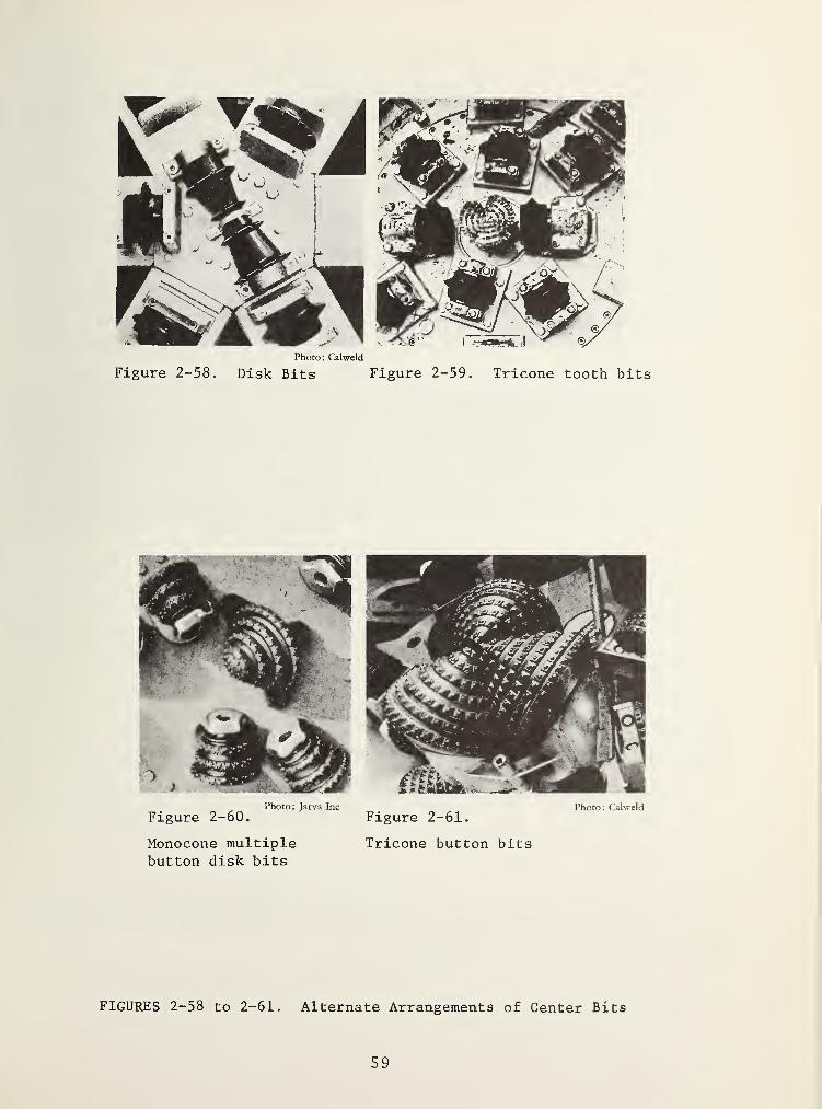
Figure 2-58.Photo: Calweid
Disk Bits Figure 2-59, Tricone tooth bits
Photo: Jarva Inc
Figure 2-60.
Monocone multiplebutton disk bits
Photo: Calweld
Figure 2-61.
Tricone button bits
FIGURES 2-58 to 2-61. Alternate Arrangements of Center Bits
59

V
ail' pei't. -faxt
Figure 2-62.
Boring system with buttonbits in center and on gaugecaliber and inner diskbits, hard limestone
Boring system with multiple
disk bits, limestone-schist
compact
Figures 2-62 to 2-65.
Relation between average penetration
force Fg and specific penetration t^
O.V. pZiA. force.
Figure 2-63.
Boring system with disk bits:Limestone-schist with distinctdiscontinuities
Figure 2-65.
Boring system with buttonbits; mylonitized granite
60

systems, measured in location. The measurements were conductedin different geological formations. This representation there-for cannot serve for comparison of the effectiveness of the boringsystems but characterizes the relation between these two para-meters .
2.4.2 The Cutting Head Revolution
The rotation of the cutting head is produced by its drive mot-ors, i.e. by electric motors or hydro -motors . Usually, the tunnel-ing machines equipped with synchronous motors have constant revolu-tions. The synchronous motors can also be equipped with mechanicalgears, or are pole-reversible. The revolutions can then be controlledin two or three, at the most four stages. Collector motors con-nected via controllable rectifiers provide variable revolution con-trol. Hydrostatic cutting head drives also permit variable revolu-tion control.
The maximum revolutions of a cutting head depend ususally onthe highest permissible rolling speed cutting speed Vs of the cali-ber (gauge) bits installed at the periphery of the cutting head.With increasing rolling speed, the temperature of the bearings andof the cutting edges of the boring tools increases, leading to in-creased wear of the boring tools. In individual cases the cuttinghead revolution may be determined by the performance of the bucketsremoving the cuttings. The following relation exists between thecutting speed and the cutting head revolution.
Vc
V = 7T Dn respectively n = ^-t- •
S ^ TTl) »
The symbols mean:
Vs
cutting respectively rolling speed in m/min.
D cutting diameter in m.
n cutting head revolution per min.
The maximum cutting speed varies depending on the manufacturer ofthe tunneling machine and roller bits. Table 2-3.
2.5 BORING TOOL WEAR
The wear of the boring tools is one of the main problems ofmechanical tunneling. The unavoidable, periodically recurring ne-cessity of tool replacement creates costs for
the replacement, or the repairthe installation, and forthe closing down of tunneling during the removal of theworn and the installation of the new boring tools.
61

Under certain circumstances, these costs can greatly increasethe expenses of mechanical tunneling, and may render this processeconomically unfeasible. Generally, the relation applies:
boring tool costs ~ rock strength and rock abrasiveness .
penetration
The boring tool costs, however, are also influenced by:
- the construction and quality of the material used aswell as those of the tool production,
- the precision of the installation of the boring toolholders on the cutting head
- the effectiveness of the scrapers at the cutting headperiphery, and the buckets for removal of the cuttingsfrom the tunnel floor; incomplete removal of the cut-tings has the effect that the caliber (gauge) tools mustcut through these, and are therefore exposed to addi-tional wear,
- the way the tunneling machine is operated; tunnelingwith too high a feeding force, abrupt steering duringcutting, or alignment of the machine while cutting headand work face are still in contact cause extraordinarystresses on the tools; neglecting checks and maintenanceas well as timely replacement of damaged tools also in-creases the cost.
TABLE 2-3. CUTTING SPEED FOR VARIOUS MANUFACTURERS OFTUNNELING MACHINES
manufacturercutting head
drivecutting head
diameterm
cutting headrpm/min.
max. cuttingspeedm/min.
Demag el. 3.9 a. 4.3 7.5 92 and lOl"^'^
el
.
4.4 a. 4.8 7 97 and 106
Jarva el
.
4.2 8 105
Lawrence hydr
.
5.05 0 to 8.4 133hydr
.
5.6 0 to 9 141
Robbins el
.
4.8a. 5.1 4.95 75 and 79
el
.
6.4 a . 6.65 3.75 76 and 79el
.
10.65 2 67
Wirth hydr
.
3.0 a . 3.3 0 to 10 94 and 104el
.
5.3a. 5.6 3.075 a. 6.15 102 and 108hydr
.
5.9 0 to 6.15 114
+) These values correspond to the respective cutting diameters.
62

The cutting tool costs are defined as the sum of the pure ma-terial costs for complete tools at the manufacture plant (blackcosts) per m^ of cut rock. According to this definition, trans-portation costs and customs duties are not included. These costsalso do not consider labor costs incurred during closed-down periods,the costs for removal and installation and the operation of a bor-ing tool shop. They also do not include the holders of the toolson the cutting head.
The following refers to roller bits whose basic constructionconsists of bearing, bit body, bearing seals, and cutting edge.With regard to the roller bit design most commonly used for mech-anical tunneling, we differentiate between the bearing wear on theone hand, and the wear of the cutting edges on the other hand.
2.5.1 Wear of the Roller Bit Bearings
With prescribed lubrication, a given stress, and a given re-volution per time unit, a bearing has a certain life span which isexpressed in hours of operation. Peak loads, as well as shock loadsand increased revolutions reduced its life span.
In the practice of cutting, the wear of roller bit bearings,i.e., of cups, balls, cylinders, and seals if frequently expressedby the average number of hours of operation of the tunneling mach-ine, or by the tunnel length produced between two bearing changes.These are general data. They do not consider whether a bit wasrolling slowly in one of the inner rows, and was practically stressedonly radially, or whether it was rolling relatively fast in thecaliber row, and was also stressed axially. Not infrequently, thecost of the bearing wear for an advance is not at all determineddirectly. This procedure is understandable if at least in thecourse, and after the termination of the advance, the total costsof the boring tool wear as well as those of the wear of the cuttingedges and bearing bodies are determined, and the costs of thebearing wear are calculated as the difference. It is not possibleto give the generally applicable statement on the portion of thecosts of the bearing wear relative to the total boring tool costs,or on the relation between the costs of bearings and cutting edges.The data collected on numerous construction sites, and also parti-ally for comparable conditions, vary over a wide range; for example,cutting edge costs, costs of the bearing and the bit bodies equal1:1.25 to 1:3.
2.5.2 Wear of the Roller Bit Cutting Edges
The forces effective at the cutting edge of a roller bit arereactions of the radial penetration force Fe, the tangential roll-ing force F^, and during the cutting of a free surface or of aconical work face, also the free cutting force Ff.
During the production of craters by teeth and buttons, and ofgrooves by disk cutters, the components of the rock and powderized.
63

In part, this mineral powder remains in the grooves. The flanks ofthe cutting edges of the rolling bits rub in this powder, and par-tially also along the slopes of the craters, or grooves. Dependingon the content of abrasive minerals - mainly quartz, but also feld-spars - of this abrasive compound, the tip and the flanks of thecutting edge are worn off. The teeth of the tooth bits, and thehard metal pins of the button bits can also break off during cut-ting, and the buttons can be pulled out of the bit body.
Of special interest is the wear of sharp-edged disk rollerbits. These edges do not become worn when they are rolling pene-tratingly. The abrasive mineral powder, and the groove slopesgrind off the hardened flanks of the steel cutting ring, but thesharpness of the edge is preserved. Figures 2-66 and 2-67. Theself -grinding of the sharp-edged disk blades during penetratingrolling may lead to interesting forms of the cutting edges. Figures2-68 to 2-70. On the basis of these cutting ring cross sections,conclusions can be drawn, among others, concerning the suitabilityof the selection of a certain wedge angle or concerning the sta-bility of the cutting head during the cutting process.
Figure 2-66. Theoretically Figure 2-67. PracticallyFigures 2-66 and 2-67. Self grinding of sharp-edged
disks
.
Figure 2-68 Figure 2-69. Figure 2-70.
Rock abrasiveeasy to penetrate
Rock abrasive. Diskring to such an ex-hard to penetrate, tent that the cutting"flutter” of cut- edge is already in itsting head possible non-hardened "soft"
core.
Figure 2-68 to 2-70, Wear of Sharp Edged Disks,
The useful life of roller bit cutting edges is, like that ofbearings, sometimes given as the average number of cutting hoursor as the length of the tunnel cut between two changes of edges.These data, too, are little informative, and are only useful fora certain object, a certain type of tunneling machine.
It is much more appropriate to give wear of roller bit cuttingedges in terms of the so-called rolling distance. The rolling
64

distance is the length of a path along which the cutting edge rolls
during the cutting process on the work face. In Figures 2-71 and
2-72, the work face of a tunnel with diameter of 2.25 m is_ shown
as an example, (Figure 2-71) cut with double disk roller bits,
(Figure 2-72) cut with button bits. In this case, the average
tunnel length cut between two cutting ring changes which amounts
to 75 m (also 75 cutting hours) corresponds to an average rolling
distance of approximately 295,000 m. The average tunnel length
cuts between two changes of a button body amounted to 315 m,
corresponding to 370 cutting hours, and the rolling distance
amounted to approximately 1.4 x 10°m.
Figure 2-71.
Position ot concentric tracesof the double disk cutting edgeson tunnel.
Inner roller bits No. 1 to 6 (6 bits)Caliber (gauge) roller bits No. 7
(2 bits). No. 8 (3 bits), (total5 bits)Cutting head revolutions 12. 51 /min.total rolled distance/h 86,400 mtunnel advance 75 maverage rolled distance perdisk ring 295,000 mrock mass, schistose mylonitized
gneissquartz content 0-30%feldspar content 60-90%
Position of button bits traceon the tunnel face.
Inner roller bits No. 1 to 3(2bits; total 6 bits) Caliber(gauge) roller bits No. 4
(5 bits: total 5 bits)Cutting head revolutions 12. 51 /min.
total distance rolled by all bitsper h 41,800 mtunnel advance 315 mcutting time 370 maverage rolled distance perbutton 1.4 X 10^ mrock mass, more or less porphyricgranite partially jointed zones
Figures 2-71 and 2-72. Determination of the average rolled distanceduring the tunneling of a tunnel with a diam-eter of 2.25 m.
65

The rolling distance as expression of the cutting edge wearis not the same for all bits arranged in different rows, or cuttingtracks, on a cutting head. The caliber bit cutting edges which areexposed to higher forces and roll with a higher cutting speed areexposed to a higher wear that those of the inner bits. The Figures2-73 to 2-76 show as an example the result of an observation con-cerning the wear of sharp-edged single disk cutting rings. Theposition of the concentric paths of the cutting edges can be seenin Figures 2-73. Figure 2-74 shows the tendency that, with theexception of the rows close to the center, the number of worn diskroller bits increases to the outside. Figure 2-75 and 2-76 showthat the rolled distances of caliber (gauge) bits are smaller thanthose of inner bits. They also show - in this case for practicallyuniform abrasiveness of the rock and uniform penetration force -
that in a rock which is harder to cut. Figure 2-75, the rollingdistances are smaller than in a rock which is easier to cut; Figure2-76 shows the use of the same tunneling system in other tunnels.Average rolling distances of approximately 900,000 m in solidlimestone, and of 2-3 x 10^ m in marly sandstone have been deter-mined.
Figure 2-73. Position of the concentric mono-disktraces on the tunnel face
console bits close to center No.l and No. 2 (2 bits)Inner bits No. 3 to No. 19 (17 bits)Caliber (gauge) bits No. 20 to No. 27 (8 bits)
66

trace
Number of worn-out disk rings and center bits.
Figure 1-1k. Consumption of monodisk cutting edges in end tracerows, and of center bits
tunnel diameter 3.66 m tunnel advance 825 mcutting head rpm's 6.25 min. cutting hours 822 hrock was granite of changing strength, partiallyfractured, quartz content appr. 20%, feldspar appr. 75%.
trace21 r
25
C 21
19
1—7
^3
f\vexxx<j
p=o__j—t
Avarcif^e.
0 100 200 300 m m-10-
Figure 2-75
trace27|
& =§ 23
tj 21 _-
19^=^
n15
11
9
7
5
.g
J 0
a-o !<J
f--s-
Avera\jC
=^ri
roll eddistance
100 200 300 m 500 600 100 m. 800-10^
tunnel advancecutting hoursaverage netboring speedrock: granite.
209 m242 h
0.86 m/hfractured
Figure 2-76
tunnel advance 314 mcutting hours 299 haverage net boringspeed 1.14 m/hrock: granite, in part heavilv fractured
Figure 2-75 and 2-76. Rolled distances of monodiskrings for each trace
67

The abrasive behavior of a rock towards the cutting edges andalso towards the bit bodies is influenced significantly by itscontent of abrasive minerals, in particular, of quartz. The wearcoefficient a [18] has proved to be a suitable term for the deter-mination and prognosis of wear of hard metal cutting edges mountedin a boring tool carrier. The possibility of a useful applicationof such tools is said to be limited by a = 0 . 5 [18]. On the basisof other experiences, such tools were used at another constructionsite with technical and economical justification up to a value ofa ~ 1. It may also be useful to use the coefficient for the eval-uation of the cutting edge wear of roller bits. Rock with a wearcoefficient of a ~ 30 has been cut with sharp-edged disk rollerbits with technically justifiable but economically problematicsuccess
.
Every tunneling machine manufacturer uses a more or less re-liable method for the prediction of the penetration and of thecutting tool wear, respectively of the boring tool costs. Withone exception, these methods are well kept secrets of the manu-facturers. Practical tunneling offers the possibility to collectexperience concerning the penetration and the boring tool wear.This possibility, however, can only be exploited by systematicallyoperating observers of the contractor, or of the construction sup-ervision, or even of the machine maufacturer. The observation mustbe evaluated systematically, and must be recorded with referenceto the process. Among such boreability and wear analyses belongsin any case the determination whether the cut work face consistspredominantly of the same rock or of different types of rock, andwhether the rock mass has seperating planes. If only one type ofrock is present or, at least, predominates, and if no separatingplanes are existent in the rock mass, the basic boreability and a
normal cutting tool wear may be derived from these observationsfor the boring system used. If this condition of uniformity ofthe rock does not apply, and if the rock mass has fault zones, onlyresults can be obtained that are locally applicable, and whosevalue for a generalization is restricted.
2.6 PRETREATMENT OF FORMATIONS WHICH ARE TO BE CUT
The hardness of the minerals and of the mineral formation, aswell as the stress/strain properties of a rock are assumed to bedecisive for the disaggregation by means of cutting tools. The mech-anical disaggregation increases with increasing primarily effectivepressure force. Today, roller cutting tools are available for anaverage operational bearing load up to approximately 15 Mp (150 kN)and with disk cutting edges which can accept a penetration forceof well above 10 Mp (100 kN) under conditions of permanent opera-tion. High penetration forces are necessary for the cutting ofhigh-strength rock in order to achieve performances that are com-parable to those of conventional methods. The design and construc-tion of tunneling machines with appropriate drive and gripping in-stallations are relatively easy. These machines, however, will be
68

even heavier than the present ones. The possibilities for a transi-tion to distinctly higher penetration forces, however, are limitedfor the time being by the effectiveness of the boring tools. Thecutting with tools manufactured from the materials which were useduntil now, and of the same design which is in use now, would causeextraordinarily high tool costs, especially in abrasive rock.Mechanical tunneling would lose its attractivity even in caseswhere not its economy but other advantages count. This fact whichat present cannot be disregarded has also led to a consideration ofother processes that also provide a disaggregation of the rock.These are:
a) Reduction of the rock strength by- reduction of the surface energy, and by- enlargement of existing, or production of new cracks,
as weak spots in the formation will facilitate dis-aggregation, as well as
b) Influencing of crack formations, and the grain erosion.
2.6.1 Reduction of the Rock Strength by Reduction of its SurfaceEnergy
The specific surface energy of a rock may be reduced by meansof chemicals [24; 25]. Thirty different surface-active substanceswere used in laboratory tests; among others, a fluid on the basisof fluoride, and a 0.1^ aluminum chloride solution. This pro-cess was also tested in practice, i.e., during tunneling in hardlimestone and sandstone. The strength reduction depends aboveall on the type of rock, on the fluid sprayed onto the work face,and on the duration of the soaking. During the limited tests onlocation, an increase of the net boring speed of 10 to 20^ was de-termined. This process, which does not produce spectacular in-creases of performance, is little developed for practical appli-cation, and also involves the problem of corrosion protection ofthe tunneling system if certain chemicals are used.
2.6.2 Reduction of the Rock Strength by Enlarging Existing, orProducing New CrackF
The heating, and the production of temperature differences,lead to temperature stresses in the rock which surpass its strenghThis may lead to spalling on the rock surface, and to the enlarge-ment of existing, or the production of new cracks in the surfacezones of the rock. Laboratory tests have been conducted on theheat treatment of rock by means of laser and electron beams withregard to their application in mechanical tunneling. In both cases,the highly concentrated heat energy produced by the transformationof electric energy is said to merely cause a reduction of the rockstrength through crack enlargement and multiplication, but in nocase the melting of the rock. It appears reasonable to consider
69

strength reduction by heat treatment initially for the hard-to-cutcenter of the work face, and for the effective zone of the caliber(gauge) bits that are exposed to a specially high wear. The heattreatment may cause a weakened ring, or even a furrow within thearea of a roller bit track. The effect of the heat treatment de-pends mainly on the type of rock, on the applied energy, and on theduration of the heat radiation. On the basis of laboratory testswith a 600-Watt laser, and a linear device with a penetration forceof the roller bit of approximately 2 Mp (20 kN)
,an increase of the
cutting performance of approximately 50^ was estimated for practicalcutting operations [26]. This process requires very high amountsof energy, and the devices for the energy transformation and forthe beam generation require much space. The efficiency of a laseris small [24]
,
and the energy not used for the heat treatment ofthe rock must be eliminated in the form of heat. It cannot be usedyet for the practice of tunnel cutting.
2.6.3 Influencing the Formation of Cracks in the Rock, and GrainErosion by Means of a Water Jet
The use of hydraulic energy for mechanical rock disaggregationhas been used for a long time in mining for the production of coal,ore, and precious stones, as well as for the elimination of looserock in excavation. The application of this process for solidrock has become known in connection with a so-called water cannon.A relatively small volume of water is shot at the rock cyclincally,as well as with high pressure and high speed by means of a watercannon. For mechanical tunneling, the use of a continuous highpressure water jet has been' considered [27]. The water jet shotat the rock surface under high pressure and with high speed pro-duces a crater, under the condition, such that the jet pressure isapproximately 50% higher than the rock strength. The formation ofthe crater is caused by the erosion of rock grains or particles.This type of stress also enlarges the existing cracks, and pro-duces new ones. With extremely high jet pressure and unchangingposition of the jet, rock chips may be separated from the crateror from the vincinity of the hole. With a jet moved continuouslyover the work face, a slot can be produced, and the mechanicaldisaggregation of the rock can be continued by means of bits roll-ing in this slot or between slots. The periphery and the center ofthe work face are preferred areas for the application of this pro-cess. On the basis of laboratory tests, it is assumed that theefficiency of this process during the boring of crystalline rockis two to three times higher than that of a process that only em-ploys disk roller bits. The most important components of the ne-cessary hydraulic system are the water supply, the high pressurepump, and the jets of a very small caliber. The special construc-tive problems which must be solved if this process is to be appliedin practice are the water tightness of the high pressure componentsof the system. The life span of the jets, as well as the installa-tions for the production of concentric slots on the work face withthe speed of a rotating cutting head. This process is also charac-terized by extraordinarily high requirements of specific energy, by
70

its high noise. and by thethe elimination of the larThis process, too. has notin practice.
problems involved with thege amounts of water throughreached the stage where it
supply andthe tunnel,can be used
All processes mentioned above concerning therock strength, and also that concerning grain erosjects of continuing research. Their practical appbination with roller bits appears feasible for the
reduction of theion, are sub-lication in corn-
future .
71

3 STABILITY OF TUNNELS
3.1 BASIC ROCK-MECHANICAL BEHAVIOR OF THE ROCK MASS
Before the excavation of a tunnel, a stress equilibrium existsin the rock mass, and so-called primary stress conditions. Thestresses are caused by the interaction overburden depth of strengthand deformation properties of the rock and the rock mass, tectonicstresses, water saturation of the rock, and of separation planes.In the absence of better information it is assumed in approximationthat the vertical component of the stress corresponds to the weightof the overburden depth rock mass. The horizontal stress componentvaries between half to twice the superimposed load.
Primary stresses:
vertical component =
horizontal component ah
These are:
yh +
= Xo .
V
Y volumetric weight of the rock.
H overburden depth.
tectonic stress component,
X lateral stress coefficient.
During the tunneling, parts of the rock mass which had pre-viously been under stress, and had participated in the transfer offorces, are eliminated. A force transfer takes place onto rockmass areas in the zone around the cavity that are not directlyinvolved by the tunnel excavation. At the same time, it nowbecomes possible for the work face and the invert which are nolonger exposed to all-around pressure to shift in the direction ofthe tunnel. In consequence, the force and stress redistributioncontinue, and the deformation increases until, after a certaintime, a new stress equilibrium has been reached, the secondarystress condition. The deformations are relatively small and cometo a stand-still relatively quickly if, after the stress redis-tribution, the concerned parts of the rock mass are able to acceptthe increased stresses. The deformations continue if the strengthas well as the deformation capacity of the work face and thetunnel invert are exceeded by the new distribution of the forces.After initially elastic deformations, the rock mass starts slidingin direction of the cavity on the existing separating planes.Also, additional sliding planes can be formed in the rock massthrough fracture of the rock if the displacements necessary toreach a new equilibrium cannot take place on the existing
72
separating planes that act as preferred sliding planes. The areaaround the cavity becomes a so-called fracture zone or plasticzone whose behavior follows the laws of plasticity. Depending onthe structure of the rock, and on the configuration of the separ-ating planes, ravelling and rock falls may occur with continuingdeformation as well as in certain cases, a cavity which is leftunsupported may close up.
By securing the excavated surfaces the falling of rock dueto loosening can be prevented.
By stabilizing the tunneled rock mass, a state of equilibriumcan be creased, and the deformations can be arrested in a certainphase or after a certain period. The stabilization is achieved byapplying a pressure from the inside to the tunnel invert, ifnecessary also to the work face. This stabilization pressuretunneling resistance of support force can be applied by means ofthe lining or supporting method such as concrete, rock golts, orsteel, sets, and, in part, also through the tunneling machine.The interior pressure which can be produced only reaches a frac-tion of the original value present in the primary stress condi-tion, especially with tunnels with a high superimposed rock mass.However, experience and calculations show that the deformationsand the increase of the fracture zone can be arrested with arelatively small supporting force.
3.2 CHARACTERISTICS OF THE DEFORMATION BEHAVIOR
The problems involved in rock-mechanical calculations havechanges. Previously, it was attempted to determine the forces ineffect during the temporary or final stage of the tunneling.This was based on assumptions concerning the position of the tunnelcavity and the weights of loosened rock mass portions resting onthe lining that were only subject to the laws of gravity. A con-nection between this loosened mass and the still solid rock masswas not assumed. That period of rock-mechanical calculations hasbeen called "loosening-pressure period" [28]. The new tendenciesof exploration are directed towards the quantitative relationbetween supporting force and deformation [29;30]. They take intoconsideration the fact that during the tunneling process, de-formations of its circumference, and in a majority of the casesalso a more or less extensive fracture zone must be expected,whose generation is even desirable and necessary within certainlimits. Today’s state of the knowledge of elas toplastic theories,the possibility and also the desire to include the observationsduring actual construction as boundary conditions in mathematicalformulations of the equilibrium conditions, as well as the avail-ability of computers for purposes of calculation are preconditionsfor a relevant and fast solution of these problems. This inter-action is taken into consideration between:
the stress/s train properties of the rock mass before thetunneling as well as during and after, the tunneling, and
73

also in differing degrees for the fracture zone withplastic behavior, and for the outer rock mass which is sub-ject to the laws of elasticity,
the construction method and
the stress/s train properties of the lining.
It is not one natural condition by itself, but all these factorsthat cannot be combined in one closed equation which are involvedin the phenomenon called pressure of the rock mass.
average support force
Figure 3-1. Characteristic Curve for
Displacement Behavior of the Tunnel
Circumference at a Distance from the
Tunnel Face Perforated Disk
a elastic behaviorb elasto-plastic behavior
This rock-mechanical calculation method which is being usedincreasingly may be called' characteristic- curve-method [29;31;32;33] . The graphic representation of the average radial displacement6m of the soffit in dependence on the average support force pm onit is defined as the characteristic curve of the deformationbehavior of the tunnel invert. Figure 3-1. A certain supportingforce is assumed for the calculation of one point of the character-istic curve. In the following, the stresses that are produced arecalculated under consideration of the zones with plastic and withelastic behavior, and the displacements resulting from the changeof stress are then determined. The average displacement resultingfor the tunnel invert is related to is the graphic representationof the assumed supporting force. If the supporting force cor-responds to the primary stress condition, point A, no radical dis-placement occurs. With decreasing supporting force, i.e., withcontinuing advancement of the tunnel, a change of shape occurs.Up to a certain reduced value of a supporting force, point B, thedeformation increases in a linear way. Following that, the in-crease may be more than proportional since, beside the elasticdeformation of the rock mass, the deformation and the volumeincrease of the plastic zone generated by the sliding and thefracture of the rock mass around the cavity begins. If thesupporting force is further reduced, the radial displacement mayreach a point, depending on the strength and the defomationbehavior of the rock mass, which leads to a collapse of the cavity,or it is squeezed together.
For the calculation of the characteristic curve of the tunnelinvert outside the work face zone, the rock mass is assumed as a
plane, perforated disk of a certain thickness, and the primary-stress condition as well as the strength of the deformationbehavior of the rock mass is assumed to be uniform over a definedlength of the tunnel, the so-called homogeneous area. The rock-mechanical calculation requires the knowledge of the followingconditions
:
a) primary stress condition of the rock mass
If no measurements are. available,
it is assumed that:
the vertical and the horizontal stress are principalstresses,the vertical^-stress corresponds to the weight of thesuperimposed rock mass, and thatthe horizontal stress is equal to the product ofvertical stress and lateral stress coefficient.
b) strength properties of the rock mass
The separating planes existing in the rock mass, i.e.,the rock joint faces, the chavage planes, and the cracks,are weak zones. The strength of the rock mass can beexpressed by the friction angle 4)(friction angle) of theseparating plane or sliding plane and by the sliding planesteering strength c (cohesion) characterized by thewaviness and roughness on a macroscale [34].
We distinguish:
the area with static friction subject to the laws ofelasticity, andthe fracture zone with sliding friction.
c) deformation properties of the rock mass
It must be distinguished between the elasticity modulusE :
in the outer zone with elastic behavior, andin the zone bordering on the cavity with plasticbehavior
.
In addition, hypothetical values must be assumed for:
the transverse expansion according to Poisson, andthe volume increase in the fracture zone.
None of these conditions, however, offers a possibility forthe prognosis by calculation of a rock burst. The calculation of
75

the characteristic of the tunnel invert in the area of the workface requires as a model no longer a perforated disk, but takesinto consideration the spatial conditions. Also, a characteristiccurve of the deformation behavior of the work face can be deter-mined, Figure 3-2. For this calculation, the work face is assumedto be a core disk whose thickness is smaller than that of theperforated disk representing the tunnel. This assumption takesinto consideration the reduced stiffness of the work face which isno longer supported by horizontal forces. The radial forcesoccurring at the circumference of the work face, caused by therock mass which has lost its radial supports, cause correspondingdeformation. Depending on the tunnel diameter and on the over-burden depth mass, the unsupported work face is subjected to astress which corresponds no longer to its strength and deformationproperties. Sliding occurs in the rock mass forming the work face,and under certain circumstances, also fracturing of the rock. Thevalues of the numerous calculation parameters must be based forthe time being on estimations as well as on results of rock testswhich were then applied to the natural separating planes, because,until now, only a few systematic measurements have been conductedon location. The calculations
Figure 3-2. Characteristic Curvefor Displacement Behavior of TunnelFace Core Diska unstressed core disk with
elastic behavior,b re-stressed weakened core
disk with elastic behaviorc re-stressed weakened core
disk, no longer elastic afteryielding
3.3 ROCK-MECHANICAL CASES OF STABILITY
3.3.1 Definitions
In Figures 3-3 to 3-5 [35], characteristic curves of the de-formation behavior of the invert and of the work face of a tunnelwith eleven m boring diameter, and 1,000 m height of covering rockmass are represented. The three representations are based ondifferent sliding planes friction angles 4> and sliding planesheering strengths c, and they are also based on two assumptionsconcerning the volume increase AV in the fracture zone. Allcharacteristic curves of the invert show that the rock mass sur-rounding the tunnel does not show any longer elastic behavior,and that a fracture zone exists all around the cavity. Thecharacteristic curves of the work face and of a core disk withhalf the thickness of the perforated disk also indicate the be-ginning of sliding. The failed tunnel invert is stable due to
76

O.V. £Uf>pcrh p>y,
Figure 3-3.
Elast. Zone (p= 45°
^Friction Angle Fractured Zone;?= 40
2Sliding Plane Elast. Zone = 2 kg/ cm
Shear Strength Fractured Zone =
1 kg/ cm
G, Points of Equilibrium
AV Volume Increase
1
V
0 10 50 100 Mp/rru^ 150
a\^ Su-ppcrf jcmce pfn
Figure 3-4.
Sliding Plane Friction AngleElast. Zone CP = 40°
Fractured Zone ^ = 35°
Sliding Plane Shear Strength „
Elast. Zone C = 1.5 kg/ cmFracture Zone C = 0.5 kg/cm'
Figure 3-5.
Sliding Plane Friction AngleElast. Zone = 35°
Fractured Zone cj^ = 30°
Sliding Plane Shear StrengthElast . Zone C
Fracture Zone C
Figures 3-3 to 3-5.
of Stability [35]
Tunnel Cp D
Overburden HElasticity ModuliElastic Zone E
Fracture Zone E
Coefficient ofLateral Stress X
1.5 kg/ cm0.5 kg/ cm^
Rock-Mechanical Cases
= 11.0 m= 1,000 m
= 4 X 10^ kg/cm^= 2 X 10 kg/ cm
= 0.7
the existing sliding plane friction angle and the sliding planeshearing strength as long as the equilibrium condition given byits characteristic curve is met. The failed work face, too, is
77

kept together due to the present strength properties, as long asthe radial compression is not larger than the calculated criticalvalue for failure.
In Figures 3-3 and 3-4, the curves of the invert and that ofthe work face intersect. The intersections G and Gn express astate of equilibrium for the invert and for the work face. Thework face is stressed by a radial compression of the invert, andreacts by creating a supporting force for the invert. Work faceand invert are deformed to the same extent at this point. Thesections of the characteristic curves of the invert expending tothe right from the equilibrium point G and Gi characterize thestress - deformat ion behavior in front of the work face necessaryfor the equilibrium. The distribution of stress produced by thetunneling is effective in front of the work face already, i.e.,on the other side of the work face. No tunneling is done in un-touched rock, i.e., a rock mass that is not influenced by prepara-tory work. The deformations occurring in that zone, however, canonly be determined with special measuring methods ,
and are notevident for an observer stationed in the tunnel. The character-istic curve sections extending to the left from the equilibriumpoints G and Gi represent the s tress - deformat ion equilibrium con-ditions on the excavated side of the work face.
In Figure 3-3, the characteristic surves of the invert inter-sect the ordinate, i.e., in spite of the absence of a supportingforce, the invert still shows only a relatively limited deforma-tion, and is theoretically stable. In case the relation betweenthe deformation and the tunnel diameter exceeds a certain measure,individual occurrences of falling rock must be expected even in a
"stable tunnel."
In Figure 3-4, the characteristic curves of the invert do notintersect the ordinate; i.e., due to the decrease of the support-ing force on this side of the work face, very large deformationsof the invert occur. The invert is no longer stable. During theexcavation, a supporting force stabilizing the rock mass must becreated by the installation of a support.
In Figure 3-5, the characteristic curves do not intersect.The cavity is no longer stable. Without special technical meas-ures that would lead to a displacement of the invert character-istic to the left, or to a displacement of the work face charac-teristic to the right, the tunnel could not be advanced.
Finally, the case not represented graphically of a stableinvert and of an unstable work face must be mentioned, the char-acteristic curve of which would practically coincide with theordinate. Such a case can occur, for example, if there arecracks, or a distinct joint approximately perpendicular to thetunnel axis, and if the work face has low strength properties.
78

On the basis of the characteristic curves of the tunnel invertand of the work face, four rock-mechanical cases of stability mustbe distinguished, Table 3-1.
TABLE 3-1. ROCK-MECHANICAL CASES OF STABILITY
Case Circumference Face
1 stable stable2 stable unstable3 unstable stable4 unstable unstable
These cases of stability define the behavior of the rock massbefore installation of the support.
3.3.2 Parameters of the Stability Behavior
3. 3. 2.1 Parameters of the Rock Mass - The parameters influencingthe stability behavior o^ the rock mass are:
the sliding plane friction angle,the sliding plane shearing strength,the elasticity modulus,the volume increase of the fracture zone, andthe lateral stress coefficient.
In Figures 3-6 to 3-8 [35], the characteristic curves of theinvert and of the work face are given for different sliding planefriction angle (Figure 2-6), sliding plane shearing strengths(Figure 3-7), and side pressure coefficients (Figure 3-8) for atunnel with 4 m boring diameter, a height of cover of 1,000 m,and a volume increase in the fracture zone of 0.1 percent.
The other parameters remaining the same, the stability condi-tions become worse with:
decreasing sliding plane friction angles,decreasing sliding plane shearing strength,increasing lateral stress coefficient
and, as can be seen from Figures 3-3 to 3-5, with increasingvolume of the fracture zone.
3. 3. 2.
2
Parameters of the Tunnel Project - Increasing overburdendepth H, and increasing boring diameter D influence the stabilityof the tunnel in an unfaborable way, if the parameters of the rockmass remain the same. Figure 3-9 [35].
79

Figure 3-6. Dependence on (Sliding)Plane) Friction AngleSL. Plane Shear Strength _
Elast. Zone C =2.0 kg/cm^Fractured Zone C =1.0 kg/cmLateral Stress Coefficient
A = 0.7
Figure 3-7. Dependence on(Sliding Plane) ShearShear StrengthSL. Plane Friction Angle
Elast. Zone 0^ = 40°
Fractured Zone = 35°
Lateral Stress CoefficientA
Figure 3-8. Dependence on Lateral StressCoefficient A Assuming O is ConstantSliding Plane Friction AngleElast. Zone = 45°
Fractures Zone = 40°
SL. Plane Shear Strength^
Elast. Zone C =2.0 kg/ cm2
Fractures Zone C = 1.0 kg/cm
Figures 3-6 to 3-8. Influence of RockMass Parameters on Stability Behavior
[35]
Tunnel Diameter D = 4.0 mOverburden Height H = 1000 mVolume Increase of Fractured Zone
AV = 0.1%.
3.3.2.
3
Tunneling Processes - Figure 3-10 [35] shows the char-act er is tic~clTrv^oT~OTe~Tiw o£ a bored, and of a conventionallyadvanced, tunnel with with a diameter of 4 m for the same primarystress condition and the same parameters of the rock mass.
80

During conventional excavations, an initial fracture zone iscreated abruptly by the blasting. Beside the original slidingplanes which have now become activated, it also creates cracksthat are caused by the blasting. The supporting capacity of thisrock mass zone is reduced immediately, and accordingly, an imme-diate redistribution of forces begins. Usually, however, thecorresponding deformation only begins slowly, and with a delay.If the rock mass bordering on the initial fracture zone, and notaffected by the blasting, is capable of supporting the subsequentincreased stress, no further fracture zone is formed. Except forthe loosening caused by the blasting, the rock mass shows a stablebehavior. If the neighboring rock mass cannot support the newstresses, the relocation of stress forms a second fracture zone;compare Figure 3-10.
During mechanical tunneling the relocation of forces is a slowprocess corresponding to the net boring speed. Usually, the cor-responding deformation starts slowly and with a delay, as with thetunneling by blasting. If the rock mass surrounding the tunnelcavity cannot accept the increased stresses, a fracture zone isformed. This applies to the example shown in Figure 3-10. Theexpansion of the finally existing fracture zone is smaller with abored tunnel than with a blasted tunnel, all other conditions beingthe same. The tunneling process can thus change the stability,as in the example shown.
3.4 POSSIBILITIES OF SECURING AND STABILIZING THE ROCK MASSDURING THE TUNNELING
3.4.1 Characteristics of the lining
The lining has the following tasks:
preventing of individual rock falls
,
creating a supporting force for the tunnel invert toreduce (but in no case prohibit the deformation to a
tolerable measure of activating the co -supportingcapacities of the rock mass, also of the possiblyexisting fracture zone, i.e., stabilization, and, undercertain circumstances,preventing of the contact between air and rock mass iscase of moisture-sensitive rock by means of a directsurface-covering lining.
The necessity for the installation of lining is givenfrom protection against weathering) if:(apart
bodies of rock are not connected coherently any longerwith the surrounding rock mass due to open separatingplanes, and, at the same time, have lost their supportsthrough the elimination of rock mass portions by thetunneling process, so-called singular rock fall, and
81
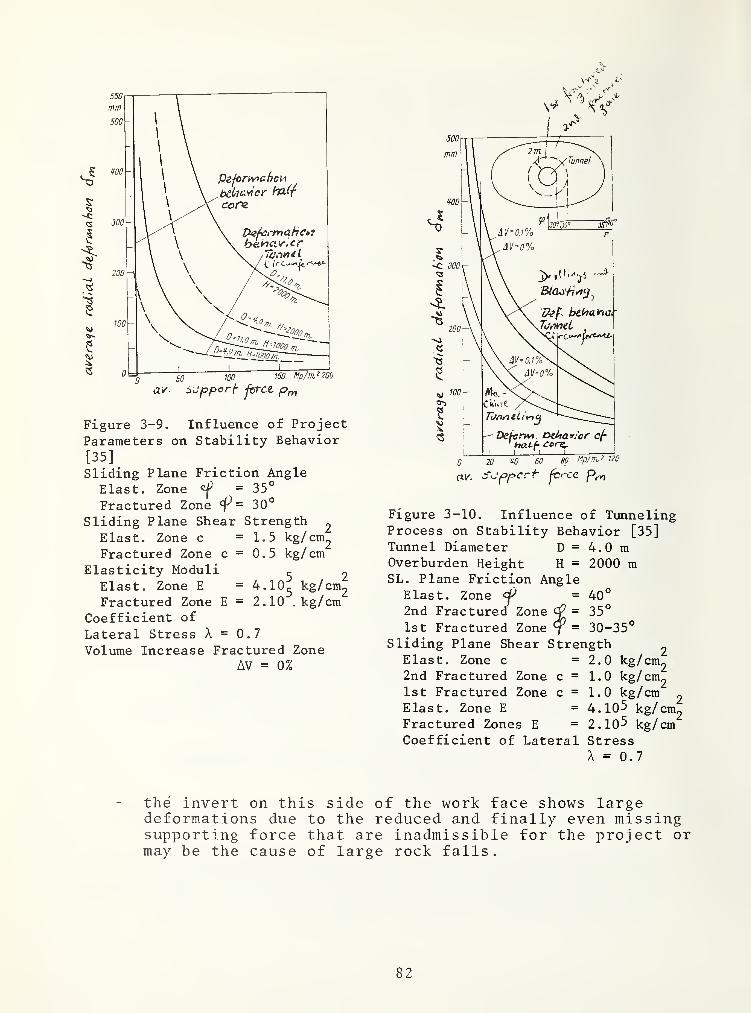
Figure 3-9. Influence of ProjectParameters on Stability Behavior
[35]
Sliding Plane Friction AngleElast. Zone = 35
°
Fractured Zone 30°
Sliding Plane Shear Strength
Elast. Zone c =1.5 kg/ cm2
Fractured Zone c = 0.5 kg/ cm
Elasticity Moduli^ 2
Elast. Zone E = 4.10^ kg/ cm2
Fractured Zone E = 2.10 ,kg/cmCoefficient of
Lateral Stress X = 0.7
Volume Increase Fractured ZoneAV = 0%
Figure 3-10. Influence of TunnelingProcess on Stability Behavior [35]Tunnel Diameter D = 4.0 mOverburden Height H = 2000 mSL. Plane Friction Angle
Elast. Zone = 40°
2nd Fractured Zone ^ = 35°
1st Fractured Zone 7 ” 30-35°
Sliding Plane Shear Strength^
Elast. Zone c =2.0 kg/cm2
2nd Fractured Zone c = 1.0 kg/ cm2
1st Fractured Zone c = 1.0 kg/cm^
Elast. Zone E = 4.10^ kg/ cm2
Fractured Zones E = 2.10^ kg/cmCoefficient of Lateral Stress
the invert on this side of the work face shows largedeformations due to the reduced and finally even missingsupporting force that are inadmissible for the project ormay be the cause of large rock falls.
82

A characteristic curve can be calculated for any kind oftemporary or permanent lining. Its characteristic curves dependon the lining material, whose strength and deformation propertiesare well known, and on the construction of the lining, such asrock bolt density, distance of lining rings. The curve of thesecharacteristics is determined by the tunnel diameter. Figures 3-11to 3-13 [35]
.
The stiffer the lining, the greater its capacity to acceptthe load. Increased loads, however, also mean increased stress.On the other hand, the load acceptance capacity of a flexiblelining is relatively small. The lining shows the tendency to evadethe load, i.e., it is deformed, and cannot accept any further loadafter reaching a certain deformation. Especially with the presenceof large primary stresses (cover height)
,no lining can exert a
supporting force on the invert that would be equal to that beforethe tunneling. However, this is also not necessary. It mustrather be assured that the lining produces a supporting forcewhich guarantees the equilibrium of the invert as long as the un-avoidable deformations are admissible for the project, and havenot caused rock falls. We must admit, however, that at the presenttime reliable and generally applicable knowledge concerning thetime dependent behavior of deformations is not available.
1010 15 20 30 W 50 60 e=dOcm
WO 200 300
a/- sufiport force j=>fri
Figure 3-12. Characteristic Curves For
Concrete, Shotcretee=Concrete Thickness
mm e=30W50
0 50 Mp/m? WO
o.r. Sc/opciifforce Pm
Figure 3-11. CharacteristicCurves for Steel Rings, HEBSteel 37
Figures 3-11 to 3-13.Characteristic Curves forthe Deformation Behaviorof Supports [35]
Figure 3-13. Characteristic tor ConcretePrecast Elements with Polyurethane JointInsertse Concrete Thickness
Figure 3-13.
0 wo 200 Mp/m2 300
uLi/ o,epf>crr
100

The number of observations conducted systematically is stillvery small, and is limited to certain kinds of rock masses andtunneling processes.
3.4.2 Combination of Characteristics
The characteristic of a rock mass can be combined with thoseof a lining, Figures 3-14 and 3-15 [35]. If a lining could beinstalled directly at the work face. Figure 3-14, the deformationof work face and invert that would be invisible from the tunnelwould already amount to 6]^. Until the equilibrium is reached, thelining would have a radial deformation in the extent of A6
,and
the rock mass would have a total deformation of 5^, respectively
6^ + A6.^
If a lining can be installed only at a certain distance fromthe work face. Figure 3-15, the deformation of the invert willalready have reached the measure + 6?. The equilibrium isreached after the lining is deformed by A6, and after the invertis deformed by a total of 6,, i.e., 5, + 6^ + A6 . Both cases arebased on a steel support that is in full contact with the tunnelcircumference. A lining as protection against singular rock fall,or against weathering, should be installed as soon as possible.
In order to determine the type of lining against the pressureof the rock mass, two aspects are decisive, apart from the costsand the available possibilities:
in order to avoid large-scale loosening of the rock massaround the tunnel, the lining should be installed as soonas possible after the advancement of the tunnel. If thelining is installed as early as possible, however, therock mass is only relatively little deformed, and itsstabilization requires a large supporting force,in order to avoid the necessity of a massive lining, acertain tolerable deformation, i.e., loosening of the rockmust be accepted, and the lining should be installed onlysometime after the advancing of the tunnel.
The justly increased safety requirements in the interest ofthe tunnel workers usually demand an immediate support lining. Aconcrete vaulting of the tunnel, sometimes of great thicknessand stiffness, is impossible at this time, if only due to con-structional reasons. Generally, however, a quickly effective andflexible lining should be installed.
The most common types of lining show, in the sequence oftheir listing, increasing supporting force, and decreasingdeformability
,Table 3-2.
84

ftv. t^Ojoparf- Pf~n
Figure 3-14. Theoretical Case ofSupport Installation Directly AtF^ce Figure 3-15. Practical Case of Support
Installation (Steel) At a Certain
Distance From the Face
Figures 3-14 and 3-15. Combination of Rock Mass Characteristics With SupportCharacteristics [35]
Tunnel Diameter D = 11.0 m, Overburden Height H
Sliding Plane Friction Angle Elastic ZoneFractured Zone dP
, t
Sliding Plane Shear Strength Elastic Zone c
Fractured Zone c
Elastic Zone E
Fractured Zone E
Lateral Stress Coefficient Z = 0-7
Volume Increased in = 0%
Fractured Zone AV
1.000 m40°
35°
1 . 0 kg/ cm^
0.5 kg/ cm _
4.10 kg/ cm »
2. 10^ kg/ cm
85

TABLE 3-2. MOST COMMON TYPES OF SUPPORTS
Types Remarks
bolting usually only temporary supportthin shotcreteyielding steel rings later used for permanent supportrigid steel ringsprecast rings with
articulated jointsprecast rings with usually permanent support
rigid joints
3.4.3 Installation of the Support and Lining During the Tunneling
3. 4. 3.1 Preconditions and Possibilities - During tunneling,singular rock fall, and also frequently significant deformationsof the tunnel cross section with the above-mentioned consequencesmust be reckoned with. These facts make it difficult to under-stand the pamphlets and offers of manufacturers concerning tun-neling machines for "stable rock." The protection cage (Figure5-23) that sometimes surrounds the tunneling machine and theprotective roofs against rock falls have no stabilizing influenceon the rock mass
.
Mechanical tunneling has available the same instruments forsecuring the rock mass as the conventional processes. Theirapplication, hoever, is tied to the precondition, that sufficientwork room is available, and that the relevant additional devicesare installed on the tunneling machine, such as bolt drills,steel ring segments, transportation and installation devices forsteel, shotcrete equipment, or prefabricated segment installationdevices
.
A temporary lining support can be installed in the area of a
tunneling machine regardless of its type:
between basic machine and first trailer,between the trailers, andbehind the tunneling machine.
These lining zones are approximately 10, 15 to 30 m this sideof the work face. Cages (Figure 5-23), and protective roofs overthe tunneling machine are useless whenever the time for excavatingthe stretch between work face and the point of lining installationis longer than the time span of stability of the rock mass abovethe same stretch. They only offer protection against singular rockfalls. If large deformations must be expected, a lining should beinstalled as close as possible to the work face, i.e., immediatelybehind the cutting head.
86

This possibility is easier to realize with conventionaltunneling, and with tunneling by means o£ partial tunnelingmachines, than when full-face tunneling machines are used. Theminimal distance between work face and foremost lining pointamounts to 1.5 to 3m for such machines. In addition to that, thepossible point of time for the installation of the lining, thedistance from the work face as well as the nature and the extentof possible measures for stabilization of the rock mass depend onthe boring diameter, and - at present still to a quite decisivedegree - on the construction, i.e., on the manufacturer of thetunneling machine. Generally, the possibilities are; the lesslimited, the larger the boring diameter.
Table 3-3 (compare page 86) shows the presently most widelyused technical possibilities for rock mass stabilization duringtunneling with full-face tunneling machines. In the following,some of these processes are explained.
3. 4. 3.
2
Rock Bolt Support Lining - The drilling of anchor boltholes can be done systematically and with great precision fromthe tunneling machine. Figure 3-16. Under conditions that resemblethose of a workshop, the bolts can be installed, and even methodscan be applied that require special care, such as the use of shortsynthetic resin cartridges with fast hardening adhesive for thebottom of the bolt holes, and the use of longer cartridges withadhesives that react relatively slowly for the remaining lengthof the hole. This process makes it possible to pre-stress thebolts after the hardening of the fast- react ing adhesives, and tomortar them to the rock mass subsequently over their whole length.By means of this technique, a stabilizing segment can be installedin the crown of the tunnel. Figure 3-17, and possibly a system-atically constructed stabilizing and flexible ring all around thetunnel segment element.
3. 4. 3.
3
Gunite and Shotcrete Lining - The gunite and shotcretelining, for example as local cover, or as the "New AustrianTunneling Method" is a possibility of securing a rock mass which is
very well adapted to the rock mass behavior. Two restrictions,however, cannot be overlooked;
the moist and dusty, also muggy, climate caused by theshotcrete application makes it difficult to hire andretain workers for this rather unpleasant type of work,dust and rebound are deposited on the tunneling machine.Through a special design of sensitive parts of the tunnel-ing machine, for example through casing of joints, casingof motors, damage can be avoided. Also, a special designof the shotcrete equipment may be able to localize thedust and rebound.
87

In order to reduce the technical disadvantages of the shot-crete lining during mechanical tunneling, an alternating processis sometimes used, if the rock mass behavior permits it, withtunneling and simultaneous bolt lining as well as installation ofinvert prefabricated (segmented) elements in two work shifts, andsubsequent shotcrete lining in one daily work shift.
Figure 3-16. Drilling of Bolt Holes From The Tunneling MachineDuring Tunneling
Figure 3-17. Overhead Protection Con-sisting of Systematically PlacedBolts, Sheet Metal Segments, and WireMesh
88

cteyice^ S'äji i?cx
Figure 3-18. Tunneling Machine Equipped With Bolt Drilling and Shotcrete
Equipment for Systematic Stabilizing of The Rock Mass and Extension of The
Tunnel Invert During Tunneling Advance
3. 4. 3. 4 Steel Set Support - Flexible or relatively rigid steelrings consisting of individual segments can be installed from thetunneling machine by means of installation devices, or at leastwith installation aids, Figure 3-19. By means of a simplyhydraulic press, the ring can be pressed against the tunnel invertbefore the last segment connection is tightened. This ring whichis in close contact with the circular invert, and is bolted to it,produces a large supporting force. The steel can accept consider-ably plastic deformations without the ring losing its supportingcapacity immediately. The disadvantages of steel lining duringconventional tunneling, such as its sensitivity to localized loadsor the requirement to fill up the space remaining between ringand an irregular rock face, do not apply.
3. 4. 3.
5
Lining with Segmented (Prefabricated) Elements - Liningwith segmented (prefabricated) elements is a type of lining whichis well adapted to mechanical tunneling. By means of erectors,the segments and flexible element rings can be installed from thetunneling machine. However, the segments can only be installedbehind the basic machine unless special designs provide openspaces for the gripper shoes of the tunneling machine. Leavingtemporary openings in the flexible element rings, however, is an
89

emergency solution, and usually the segmented elements are installedonly behind the gripper shoes. If the startup time of the invertis shorter than the excavation time necessary to complete a tunnelstretch corresponding to the distance between work face and instal-lation point, a temporary support of the invert between cuttinghead and element installation point is unavoidable. A combinedsteel ring elements lining could be used. Figure 3-20. Sometimes,the use of a shield tunneling machine is recommended for such rockmass behavior. Such a machine may be of advantage in loose groundunder certain conditions. Its use in hard rock, especially, asassumed, in a rock mass showing especially large deformations, isextremely problematic. The deposit of fracture zone material onthe shield mantel can impair, or eliminate the possibility of con-trolling and adjusting the tunneling machine because even verysmall movements of the mantel against the rock mass encounter varylarge passive rock pressure. A so-called segmented shield sur-rounding the basic machine (compare section 3.4.4), may offerthe opportunity to support the rock mass and guarantee the freemovement of the tunneling machine. A carefully installed segmentedlining where the ring space is filled after the deformations havesubsided may become a permanent support.
3.4.4 Special Support of the Tunneling Machine
The cutting head of every tunneling machine has a supportingeffect on the work face as long as the boring tools are in contactwith the rock mass under pressure. When the tunneling machine isremoved, during inspection, maintenance, etc., in front of thecutting head, this support is eliminated.
By means of special types of the tunneling machine, thestability behavior of the rock mass can be influenced withinlimits, even during the readjustment of the tunneling machine, andpartially also during work in front of the cutting head. By meansof a short cutting head shield consisting of several parts whosesegments can be shifted radially, a supporting force can beapplied to the rock mass all around the cutting head. Thissupporting force stabilizes the tunnel invert locally, and reducesthe pressure of the invert on the work face. Figure 3-21.
In the rear section of the short cutting head shield segments,rock bolts, liner plates, or steel rings can be installed. Incases where an exclusive lining with segmented elements is plannedfor a rock mass with a short time of stability, the cutting headshield of the tunneling machine can be supplemented by twosupport systems in form of a supporting in stages. Figure 3-22.These support systems have radially adjustable support beams andare arranged all around the basic machine behind the cutting headshield. The cutting head shield and the support beams must over-lap for a little more than one length of travel before the state
90

Figure 3-19. Ring Sliding In
Direction of Machine Axis and
Pivoting Around It, For Assemblyand Installation of Steel Support
Segments
Figure 3-20. Installation of Pre-fabricated Segments with ErectorBehind Basic Machine. Steel RingsHave Been Previously InstalledDirectly Behind Cutting Head Carrier
Figure 3-21. Segmented Cutting Head
Shield, with Gripper Plate, and
Radially Sliding Segments
Photo: The Robbins Company
Figure 3-22. Segmented Shield Con-sisting of Two Suppport Systems
91

of the excavation. Such a special construction may be called asegmented shield. The stiffness of the construction can be selected.According to that, the influence on the deformation of the rock masscan be controlled. During the excavation process, the short headshield which is in close contact with the rock mass slides forwardwith the cutting head, and the beams of both support systemsremain pressed to the invert. These systems are moved forward oneafter the other after one stroke.
3.4.5 Tunneling Through Fault Zones that Cannot be Excavated byTMB
The previous presentation of proven technical possibilitiesfor stabilizing rock masses should not lead to the opinion that atunneling machine equipped with all kinds of support features, andwith large boring diameters, can be used for cutting through everyfault zone. The full use of the tunneling machine in solid rockcan be limited technically, if:
the machine cannot be braced sufficiently for boring byany method, such as shotcrete lining of broken-out holes,or cushioning the bracing plates with timber,the tunneling machine cannot even be supported via the rearfaces of its gripping by a heavily bolted support whichwould make boring with shoes reduced force possible,the tunneling machine settles in the rock mass under itsown weight
,
the rock mass is extremely inhomogeneous, and consists,for example, of blocks of solid rock imbedded in clay, orifthe standing time of the rock mass is shorter than the timenecessary for boring the section corresponding to thedistance between the work face and the cutting headcarrier as the first point for the installation of a
temporary support.
Whenever such conditions arise, the tunneling should bestopped temporarily. The tunneling machine should be pulled backa few meters, and the problematic zone should be defined withhorizontal test drill holes, and should be tunneled conventionally.The tunnel profile, usually in pickable rock, should be cut largeenough that its diameter permits the advancing of the tunnelingmachine after completed stabilization by means of a temporarysupport, i.e., after the deformations of the invert have subsided.The access to the work place at the work face, and its supply withlining material must be guaranteed for the entire zone of themachine. The dismantling of the dust shield of the tunnelingmachine, or an open cutting head (Figure 3-28) facilitate thesemovements. The material resulting from manual tunneling or fromblasting may be pushed by means of a scraper into the range of thescraper and buckets of the tunneling machine. There, it is pickedup by the totating cutting head of the immobile tunneling machine.
92
and is transported through the machine area by means of the cut-tings transportation system to the loading belt, and from this itis loaded into the transportation vehicles.
Alertness and adaptiveness o
construction supervision, in partthe change of operation, are decimethod.
f construction management andicular a timely organization osion for the success of this
f
93/94


ROCK MASS CLASSIFICATION FOR TUNNELING
The evaluation of the rock mass with regard to itsbehavior during tunneling as well as with regard to measuresfor the stabilizing of the rock mass which might becomenecessary is of great importance for the project design,the determination of the construction program and the con-struction costs, as well as the bidding process of the con-tractor. This evaluation is usually expressed by:
- a geological documentation, and- a rock-mechanical forecast.
However, it should also be expressed by:
- a prognosis of the classification of identical areasof the tunnel track, the so-called rock mass classes,or of types
4.1 GEOLOGICAL DOCUMENTATION
The requirement of a geological survey for a tunnelproject, and for the bidding process is undisputed. Usually,this survey must give information on the type of the rock thatwill be tunneled through, as well as on its nature, on itsposition relative to the tunnel axis, on the amount of waterthat can be expected, and on gas which might be encountered,assumed temperature of the rock mass in cases with large over-burden height. A diagram showing the discontinuity configura-tion would be desirable. The engineer in charge of the pro-ject should formulate the questions which are to be answeredwith regard to the project by the geologist. These questionsshould facilitate this survey. The engineer expects fromthe geologist that he will answer those questions by applyingthe theories of geology, by using his experience, and byemploying all relevant methods of geological exploration.This is the more difficult the more complex the rock mass isstructured, and the deeper the tunnel track is located belowthe surface. By asking for absolutely correct prognostics,the engineer would ask the impossible from the geologist, andhe would also ignore the difficulties of the task. However,with regard to the reliability of the project design, he mayask the geologist to classify all his statements according towhether they are based on factual knowledge, or, if that doesnot apply, according to probability and possibility of unfav-orable conditions for the project.
95

A long text preference should be given to a geologicaldocumentation with emphasis on diagrams - for example, a long-itudinal section, a horizontal section at the tunnel level,and, if possible, one of each with regard to probability andto possibility - with a listing of geological data for theregions that are representative for the project with regardto rock mass structure and rock, and with a survey of thepetrographic characteristics and the most important geotech-nical properties of the rock types.
4.2 ROCK-MECHANICAL PROGNOSIS
The geological documentation Cin particular the informa-tion on the type, the nature, and the position of the rock,and if available beyond doubt, the diagram of the discontinuityconfiguration of the rock mass which is to be tunneledthrough) is an important basis for the subsequent rock-mechani-cal prognosis conducted by a trained engineering geologist, orby an engineer who is familiar with the field of rock mechanics.
The actual rock-mechanical calculations are preceded bythe determination of the computation parameters and of the so-called homogeneous areas. The rock type longitudinal profileof the tunnel. Figure 4-1, shows the homogeneous areas. Ahomogeneous area is characterized by identical assumednumerical values of the sliding plane friction angle and of thesliding plane shearing strength as well as by approximatelyidentical elasticity moduli and height of cover layer. Itwould be justified to relate the height of cover to therelief line instead of to the topographical longitudinal pro-file. The heights of the relief line at one point of thetrack correspond to the average heights of the topographicalcross profile perpendicular to the tunnel axis, whose widthon both sides of the axis is as large as the cover layerheight of the tunnel that relates to the topographical pro-file, Figure 4-2.
In the first phase of the rock-mechanicthe stability behavior for each homogeneousby means of, for example, the characteristicThe results can be represented in a longitudthe assumed local distribution of the casesFigure 4-3, line a.
al calculation,area is determined- curve -method
.
inal section ofof stability.
In the second phase of the rock-mechanical calculationsonly those areas of tunnel track are considered for which a
nonstable behavior of the tunnel invert on the work face canbe expected. These require support in any case. On the basisof a catalogue for the tecnnical possibilities of securingsupport the rock mass during the tunneling, for exampleTable 4-1 and for the characteristic stabilizing of the rock
96

(This page left blank intentionally.)
97

/rt c Af
30CO
Uhff. . 'ng t/cr Oes^e/ne
~ '- sc/?*y^c/? gesc/7/e/er/
z:^ ”- /3eu//ic^ gesc/iieferf
no s/drA gescA)/e/erf
lll^ _se/}r s/drA gesc/i/A/e^f
If'fC ^ dfr M/(////‘/^c^enAo/7A‘ffiyrd^/{>/f
tyi'/V/nddCii/ge Zc/A-t.'iu/'/g
mi/^e/nidsc/iige ZerA/uA/ung
A/e/nmdscA/ge ZerA/u/Zung
tntensiye mdcAdn/sc/yd ye/'ScA?/e/eru/?g ur?<^
ZerA/o/Aong /n/A seAir t'AeAen Argno/A^cAfen
A
ß
C
V
5
FÖ
H
f
K
Adge ifer ScA?/cA?/ung i/mfScAj/e/eri/ng A?ezugA At/AioeAdcAyse
Idge c/er AAi//AsysAe/7?e öezagAfc/r)A?eAdcA)se free/Aer fdAAkr/nAe/)
OesAe/nsdrA
Adoge ßer6’/cA?e /h m
A/eS&rAagerur>gsA7o/7e //7 /t?
ScA7/eAenj/7g <Zdr AFesAe/ne
U/AAiaAaA cAd'~ A’Ai/AAAAdcAydd -
Ao/7A/gardA/od
CAe//AAdcA?dnre/A^i//7gs»'/oAeA A. ödsA/n/vAdr> PrcA^en c//reAA i/i/rcA?
//lAcrpdA^A/on / f/9rucAf20ndJÖAe'AZAdcAienre^AAc/ngsn'/nAeA F, di/s
Prdden dA?geAe/AeA Ai/r /?dAi/rA/cAd
AreonAAdcAjen fA Sn/cA?zo/7e/
6Ae/AAAdcA?e/7scA}erAesA/gAd/A c //> Ap/c/r? ^
' r—^
T^
i i1
• iZdO AS50
r\
—TIFTi
~; — — “— —1
JO es W A* A* 33
J3 Ad ' fa . X'
!
A* 3/ 36
A,
A
o.s&rae OS fA A.A
98

i
I
Figure 4-1. Probable Geologic ProfileAlong a Tunnel Alignment
99

Text for Figures 4-1 and 4-5. A Attitude of layers and jointsets relative to tunnel axis
Table 4-lA.
Foliation of the rock
slightly foliateddistinctly foliatedheavily foliatedvery heavily foliated
Discontinuity configuration
wide - spacingmedium- spacingnarrow- spacing
intensivefoliation and jointingwith very many discon-tinuity planes
B Attitude ofrelative todip angle)
discontinuitiestunnel axis (real
Type of r 0 ck
Length of zone s in m
Overburden in m
Fol iat
i
on
Discont inu ity conf igur at ion
SI Iding pi ane fr ict
i
on angleobt aine d d ir ec tly wi th samples
,
or by inte rpol at ion
Sliding pi ane f r ict i on anglefrom sampl es d er ived for naturasliding pi anes
Sliding pi ane shear s t rengthc in kg/cm 2
Table 4-3A.A Attitude of layers and foliation
chavage relative to tunnel axis
Supports
Rock bolts installedbehind cutting head.
Steel rings installedafter each round
Shotcr ete
.
Prefab segmentsinstalled behind machine.
Concrete cast in place
1500, 100 mean^ 1700, 120 maximum
B Attitude of discontinuitiesrelative to tunnel axis (realdip angle)
C
D
E
F
Type of ro
Length of
a) stabil!
b) support
ck
areas in m
tv category
temporarypermanent
G c) basic boreability
H d) cutting tool wear
I e) rock burst
100

Text for Figure 4-1 and 4-5 (Continued)
Column ’’Types of Rock*' (identical in both Figures) .
1. muscovite and sericite gneiss and schist with local inclusions of
2. granite and
3. amphibolite
4. chlorite schist and gneiss with lense-shaped inclusions ofheavily foliated carboniferous schist 5. and of quartz porphyry6. changing to sericte schist 7.
1. more or less chloritized mica gneiss and schist with differingstreaks of aplite and pegmatite (injection gneiss and mixedgneiss)
.
2. large inclusions of granite porphyry.
3. inclusions of amphibolite.
4. large and branched-out inclusion of foliated granite porphyry,originally changing to granoporphyry
.
5. alternat ingly deposited with injected mica gneiss and schists.
6. veins of aplite with local concentrations.
7. homogeneous granite with
8. diorite inclusions.
9. slightly foliated syenite with inclusions of country rock 10.and streaked with aplite 6. and lamprophyr 11.
12. complex zone with pieces of granite and diorite, stronglystreaked with pegmatite 13. and aplite 6. and lamprophyr 11.
14. granite porphyry changing to syenite at the boundaries,dikes of aplite 6 and lamprophyr 11.
1. light mica gneiss with lamprophyr 2.
3. complex zones of granite and diorites with extensive veins
4. predominantly dark mica gneiss and schists.
5. northern boundary of mica gneiss with many veins(injection gneiss).
6. quartzite.
101

TABLE
4-1.
TECHNICAL
POSSIBILITIES
FOR
STABILIZING
THE
ROCK
MASS
DURING
TUNNELING
WITH
FULLFACER
TUNNELING
MACHINES
I
I bOcu !=: Td Td PD -H
cd0 0
Jh rH p 0 pg^ (U bO cd p.
n CD (=: cdp p
O -P !=! P "H CP P•H n :=! /
—\ /—
\
0 P bO-P -H K 4S > in
nJ 0 Td •H Pd
r-H P m (/)(/) t/3 O O in p Oj
rH p o 0 0 0 Cd Cd 0 b02d o o in o O03 O >s I—
i
p p p p 0 p Pp> c Cd P •H >v(/) 4-> O o o p pC -H -H 0•H :2 Td p
P cd
K3 0nd P Td
d cd P bO P•H CNl O CVJ
!=: rC T3 bO 0 W)O CD o3 X Cd Td 0 r ^ P•H .X3 0 P 'H P P 2d P •HP 0 p (VI cd P 0 pcd > p Td >i-H t-H bO 0 Td in *H 0 TdrH P fd in o (A IT) o in P P 'H IS in pcd U -H 0 cd 0 0 cd 0 0 Td 0 O in in
P> 0 P X i-H > Td l~l P 0 0(/) p P cd P 0 P p p pß -H di o o '—
^ P Ph o o•H Td O
o P P O p p p p p P pO 0 0 o 0 0 0 0 0 0 0cvi 0 0 rg 0 0 0 0 0 0 0
P rH t/l t/l P in in in in in m mCd
0 !d 0 0 cd 0 0 0 0 0 0 p P 0P ^ P P 15 p 1^ p P 1—
1
IS Is PX o o o o o o o o O o o o o0 p .r: ^ p 2d 2d 2d 2d 2d 2d p P 2d
0 :s 12 0 :s IS IS 0 0 IS
O
X p «S
p p P p P p p P >> P >vp d p d p P 0 p P P p P P P P
bO P P p P p P P p P P p 0 P P pP o o o O o o P O o P p P P P P•H cx Q-( CP CP e CP CP O o P O o op Ph s S e s £ P £ £ CP CP £ CP CP CP•H p 0 0 0 0 0 0 0 0 £ £ P £ £ £
in p p p p p Ph p p 0 0 0 0 0 0p p CPP p p
in
P bO in
P 0 P P o0 CP 0 p CPCP CP CP 0 •
CP •rH CP P in
•H p •rH P Pp bO p 2d 0bO bO p
P P 0in P P P P £p P 2d P 2d Pp 2d p 2d p •H
0 o P p 2d TdP dd P p p in
P 0 P 0 p 0 Td p 0in p 2d 0 (—
H
0 •rH P bOd •H p 0 bO tH 0 bO rH IS 0 p0 p *H p P o3 1
—1 P 03 £ p
S p Is P P £ P p £ Td 0 pin bC P P /—
\
in P P LO p p0 in o 2d 2d o 2d CP 0 2d
in p W) p 0 p 0 p p 0 p 0 pp d 0 P CP 0 Td 0 Td CP 0 Td 0 p Td pp rH P •H P p P • rH p • rH P 0 0 bO IS
o CP 0 p p P P IS >> p P CP p P2i P 2d P p > +-> P Ph P •H in
p 0 P bO in Td in Td p p Td in P 0 P 0Pd 0 P 0 P •H P p p 0 p p •rH P £ P X0 p O 0 p Td CPTd CP 2d Td P-Td bO bO oo •H Pd p 0 p /—
\
p rH in m 1 ! in bO •K
102

mass as well as of the supports, the extent, the place, andthe time of the installation of the support is determinedsubsequently for each area. During this determination, thesafety and the economy of possible solutions are also con-sidered. These results can be represented in a longitudinalsection of the assumed local distribution of the supportlining, respectively of the rock mass classes with regardto the linings. Figure 4-'3, line b.
/I
I-*-
Cross Section A-B
Figure 4-2. Topographical Longitudinal Sectionand Relief Line
4.3 DEFINITION OF ROCK MASS CLASSES
4.3.1 Basic Principles of Classification
The classification of a rock -mass that is to be tunneledthrough with regard to measures that are unequivocally definedqualitatively as well as quantitatively, and which arenecessary for the tunneling in order to prohibit singular rockfall, and in order to retain the stability of the tunneluntil the permanent lining can be installed, has proved itsgeneral validity for conventional tunneling. It does notdepend on geological terms whose interpretation depends onthe planner. Measureable values, i.e., the nature, theextent, the place, and the time of the application of thosemeasures during the construction are its basis. This typeof classification indeed largely characterizes a conventionaltunnel project of given excavation shape and surface. Theestimation of the support requirement also implies a determina-tion of the requirements with regard to workers, to equipment,and to the tunneling performance. On this basis, and after
103
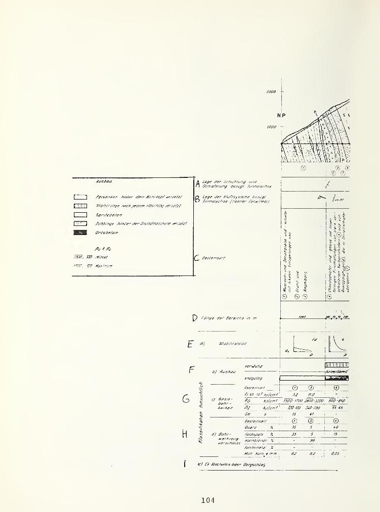
2000
/5V// /Cor/7 ^ /77m 0,05
€) J6sc/t^/en o//er Se/yschiag
104

nsm- '! r'l
0 0 © -- 06.0 6! 5
A
5.0 i 4.5 5.11 50 4,8
2650-2000 165Ö- f750 ^750 ' /300\
• fSJO 2350 205Ö -2250 J3ÖÖ -1350 7T5S - 1050 745
Ted-m Tj0-t20 72Ö- r30 1*0 -r25 f60'm 1*5 - 160 160-175
Si 53 36 28;
47 40;
:*5
0 © 1 © i ® 1* ® 0JS 20 JO SO
! 25 25 35
60 25 65 40 70 70 05 ^:
60- - - - - - -
5 5 5 ^0 5 51
- 5^.0 25 Oeferoffen 15 2.5
1
OeSeroger? 7.0 0.
E 3
Figure 4-3. Probable Geologic ProfileAlong a Tunnel Alignment
105

an estimation o£ the drilling steel consumption, the drillingtime, and the explosive requirement, a cost calculation can beconducted for conventional tunneling. An error in the esti-mation of the drilling steel or even of the explosive con-sumption per cubic meter of rock, influences the price of itsexcavation only by a few percentage points.
The advantages of this classification system also suggestits evaluation with regard to mechanical tunneling. Thesystem may be applied but not all aspects of mechanicaltunneling are covered by it. The classification with regardto the nature, the extent, the place and the time of theinstallation of temporary support lining does not relate tothe boreability of the rock mass - and with that to a boringsystem - or to the cutting tool wear. It is insufficientfor a cost calculation.
Mechanical tunneling cannot be described by a singleterm including all significant characteristics of the processas is largely possible for conventional tunneling. Mechanicaltunneling must be classified with regard to three aspects:
- boreability of the formation to be tunneled,- boring tool wear, and- braceability of the tunneling machine, as well astemporary lining.
All three classifications should be formulated withgeneral applicability, and not with regard to only one certainboring system, or a given tunneling machine manufacturer.
4.3.2 Classification According to Boreability
On the basis of a proven and apparently existing tendencyof an interrelationship between strength, deformation, andhardness properties of a rock on the one hand, and the penetra-tion of a boring system on the other hand. The above-mentionedproperties may be used as index values for basic boreability.
The difficulty in prognosing a reliable diagram for thediscontinuity configuration, and the problem to reliablydetermine the discontinuity planes influence on the boreabil-ity in a quantitative way, make it impossible at the presenttime, to also define index values for the discontinuity planeconfiguration influencing a given basic boreability.
4.3.3 Classification According to Cutting Tool Wear
The content and the grain size of abrasive minerals as
106
well as the strength o£ the rock largely determine the wearof cutting edges and bit bodies. Strength properties werealready mentioned fortthe classification with regard to basicboreability. The nature, the portion, and the average grainsize of the main components of the rock may also be used asindex values for the cutting tool v;ear
.
The quantitative consideration of the influence ofseparating planes of the rock mass on the cutting tool wearis problematic and it should refrain from defining corres-ponding index values at the present time.
4.3.4 Classification According to Supporting Requirements
This classification relates to the measures to be takenduring the tunneling concerning the braceability of the tunnel-ing machine, and also concerning the stabilization of the rockmass, and, in certain cases, concerning the profile types ofthe lining that will be used, and which differ basically asfar as their strength is concerned. A relevant determinationof rock mass classes considering the special conditions ofmechanical tunneling is given in Table 4-2. Three mainclasses are distinguished:
a) The tunneling machine retains its grip unimpairedduring the cutting.
b) The tunneling machine retains its grip during thecutting not without impairment,
c) Tunneling through fault zones that cannot be bored.
These three main classes are divided into subclasses.Those are defined by the nature, the extent, the place and thepoint of time of the installation of the first support liningduring the advancement of the tunnel. This subdivision isbased on the most commonly used technical possibilities forthe rock mass during tunneling with the tunneling machine(given in Table 4-1). The processes contained in one sub-class do not lead, or do lead to approximately equally longnon- system- related interruption during tunneling - on thecondition of a suitably designed tunneling machine equippedwith lining installation equipment.
The continuous development in the design of tunnelingmachines, and the imagination of trailor owners may welllead to a modification of the presented classification, or toa new definition of the sub-classes. Such requirements canbe recognized during the bidding process, and can be con-sidered during the bidding negotiations.
107/108


, ß 1
U•H
ß ß ß ß ßß pP I
—f U ß ß
CD ß 1—
1 O -H pp g •H ppe ß ß ß ß ß P g ßß ß ß I—1 ß •H ß ß •H•H ß ß ß ß pp ß ß ß •rH ß Ln ;s u ßß CD ß CD pp P O >> p • tH
PM ß •H CD >>13 ß bO ß ß pp bß ß >> ß ßpp ß ß p ß ß ß ß ß ß o
•H ß ß ß ß e ß ß p ß ß ß PDCO •H e ß PP I
—1 g g 1
—i P ß P
H ß pp O CD p ^ ß —'I—
c
O 1P U2 ß . ^ LT) ß CD pp ß p: LO p P ß ßW O ß •H ß •H •
1—
i ß • ß ß -H ßS ßi O • ß :s ß - :s • ß ß •rH • ß ß pp ßw ß S ß ß ß CD • ß :s • ß P ß . »,
•H ß >>ß U np »H ß CH i—H,
d *H p1—
1
CH o CD ß ß ß ß W) P P i3 bO O P 13 pD O ß ß ß g CD ß ß ß ß I—
1
ß ß g '' ßC/ bo ß ß ß ß •H •H ß ß ‘H P •H P ß pw ß ß CNJ ß O ß CD O ß U pp ß ß U U ß CJ PPi •H ß • ß CD CH ß ß U (X ß ß ß ß ß P p
1—
1 CD 1—
1 ß >> 6 rH ß ß ß Ph ß >> p o CHu CD ß CH ß ß ß Ti O ß e o CH ß ß ß ß p ß g
ß x: ß O ß pp O P pp ß O O ß PD P ßH-
1
ß CD ß ß ß ß ß bO u PD bO •H •H ß »H PH ß ß CD 3 ß ß
6 ß oI—
1 pp ß •H bO P ß 1P ß g P PPi ß CD ß U O ß ß ß ß u PP •H ß ß ß HO pp ß ß ß o ^ -H ß ß •ß ß ß ß ß O U -H • • PPh bO ß 1
—1 ß ß PMß :s PD ip ß •H Ph P pp CH
PM ß u ß o >s •H ß ß ß •H U o PHD •H ß ß rH P ß o ß P O •H U ß PCO ß o ß •H ß pp ß p ^ u O u •H U Cß ß g ß •H
PC ß •H pp ß ß ß ß ß u Ti / H ß P bD o ßo ß ß CD ß p pp p ß ß >> p »H P ß bO •H ßH •H W) ß ß e PM ß bO ß Ti ß > ß 13 ß -H ß ß P
rH PM ß ß ß ßnß p ß • ß P ß ß -H ßQ 0) •H ß •H ß O CD bß 6 ß ß ßß • ß p CH P ß ß I
—1 P P
Pi ß ß ß iNl O Ph ß ß o ^ g O • O pp g pp ^ ß P •H Pß< ß bO ß ß CH u ß ß • CH '—
'
ß O g ß rH ßß CD ß - iä ß • u P ß U bO P P ß PM
w +-> ß U o »S ß ß • ß ß O p •H • ß • ß ppp pH PPi ß CD bO t3 CD 1P ß • •H ß-H ß 1p • •H •H ß ß P
bC •iH ß CD ß ß ß e • u •H ß X ß • U pp ß ß ß >x; ß ß ß CD ß ß p ß ß ß P ß ß •HOP p oH •H ß ß ß pp ß • p p bOi—
H
pp p P Ti ß ß pp •H1—
1
ß ß u ß ß 1—
1
ß /—
^
ß «\I—
1 ß •rH u o P P ß ß pß •H ß b4i ;s ß ß p ß •H • ß ß ß tß •H •rH :s ß ß ß ßnd ß o ß ß o ß o ßnß ß pp ß ß ß ß CH 4-> 13 ß •H -H 13 g •rH
ß •H o •H ß p >^ o ß ß P ß ß •H O ß Ti ß o ß ß ß P ßo ß (D ß Cß ß U g ß ß ß P Ti ß ß p ß ß P ß •H •H ß ß -H ß ß1—
1
(D ß ß ß W) ß ß •H •H e ß Ph Ph pp ß bO bopp ß bOH ßi N ß ß p ß •H ß :s bO p ß ß P ß P >>< ß ß ß ß U ß ß o ß «H O ß - 1—
t
u rv O ß PD U P P PD ß PU +-> ß ß ß pp ß P ß ßj •H ß p U) P •H O O Oh—
1
•H •H ß 1P ß bß o ß bO ß ß S P Ti CH bO ß Ph rH P •H
PM CD X X ß ß ß ß pp ß ß P ß O U iP ß o ß P Ph I—
1
pH P P O g P1—
I
rO U ß CD •H ß ß D «sI—1 *H ß ß ß p •rH •iH ß •rH ß Pnß ß ß
CO ß ß U pp O ß o P ß ß ß ß 1—1 ß ß pp ß ß ß ß u ß PPP Ul P
CO o S ß ß CD pp ß ß p O ß ß p o W) p P P ß P< 4-> ß pp rH H ß 1—
1
ß ß ß ß p rP •H ß ß ß u U U -H ß PbO ß pp ß pp pp P P ß g ß p ß •H • rH ß ß Pß ß ß
CJ <f) ß ß d> • • U ß ß U ß P o •H bO >S ß p O ß 1P ß OOP ß Oß •H ß pp rH ß o P ß ß ß ß ß ß •ß P rH I—H ß ß PP ß pH p3 ß p pp
CO ß iß s M o ß e ;s g ß ß u bO ß ß ß •M 1—
I ß u ß ß g cn ß g rH in
CO ß O Tp U CJ P U ß P P< (/) ß 1—
\
CU ß 1 ( 1 P bO 1 <D ß 1 pp ß 1 1
s ß ß u ß f-. o ß ß ß ß ßß ß o o •H •H ß O • rH ß • rH
S H Pi :s Q ß Q ß Q •rH w ßCJoPi
ß• ß
CNI ß1 fß ß CnI K) 1-0
u • • • • •
XI ß rH 1—
1
nH rHw ßhJ COpq<H
ßßß ßßCJ
109
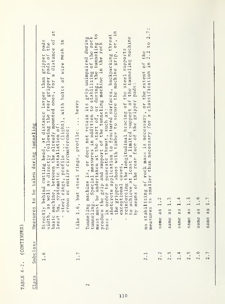
Class
Subclass
Measures
to
be
taken
during
tunneling
p P r--
p o p •' H •
bOP p P P (XI
(T) p P P U P PP o •H •H o bOPC P p rH OPH p p P o p; o P P
CL, P p p D rH o p in uu in P p !—
1
P p p P {X]
C P p p p P bO P P £ P •
CD O p E P p P p P H o P (XI
P. p P P ,PH rH p P bC
P. P in P P p P P bC P P p p•H nd «H P •H o P O P '• rH O •Hp P P •H P P P P CO rPbO pH P bO P H Or P P P P
P £ P PH ri^ •H p P P OP P p •H •H P CD CJ
,hP p P O • fH
Oj P P o P M p u p P +-> -p
rP Ph o P •H «N '•H pi p p P X P•M Phm in t—
i
bßPH £ CO to P U•H p P •H P CJ r P p ‘iH
P p rH •rH p •H p in P p P p p pP bC in o P p p £ P nP PH P p P -HtJD P p bO p p u P p P CO
P P P p nd bO p P p CO
P P o p > in P p P P o p p pt-H P p p p o P •H P P o p O p
P nd • rH p •H p O rH P P p p uP P p p CO CO u bO p •H r
u P P P P p p p P o P Pp PH P • *H o MH p nd CO •rH p bO Pp P P , s
• P •H O P SH P u p P Pp O • • p • P p p U P O p p P CO Op bO e P p . .s P •rH P P P P p CO P CO P*H P o bc p • • P P P p in p pn P p
•H • iH u p P P PH u P nd UIS nd p T—\ p ,p P P P P r p P p P P p p
P o P o p •H O in P p P P P O p pP p P •H p p P P P in p £ P •H CO
rH P p • p o • rH P O P •H •rH E P CO CO
o 1—
1
p . p p in rP P o M nd •fH u •H Pnd p P 1—
I
• £ p P in P P PH p P rH p uP ?—
1
P O p P P rP p p CO PP X P p CD u nd P P o p P •rH 03 CO pPH ,—
1
P p p in P P Ph P o •H bO p- pp P in •H •H bO P in Ph P •rH P p p £ P
bO u P u P O P P P P P r O CO p pP p P •H o *H P P in P P CO CO r—
i
p p p p*H p P 5-h p P «S £ rP P u p p p U PP *H P u P. P (/) P nd P •rH o CO P rP p oP nd IS • H H P •rH P P P P P PH P p; p p pP p P P P P P P bC, P-,
CO u p P p pU P p P in P P P •rH P P P p p
P p 6 ön P P P u nd Ph O P P r—
1 bC p O pnd p p in •iH p P •H p P P P P o pP P p •H P P p., P p P P, P •rH > bo e•H ,
—
1 p in o p U CO bCi P P P o u P CO PPH P p P P P P P •rH •rH P • rH P • fH
LO vOP IS •H in rH p P £ rO P nd P P P o p P M in (XI K)
Pi P p 15. PH P u bc;1 PP-I u P •H *H • • • • •
in U p O ' bO brOP P O p P p p £ rH r—
1
r—
1
p rP t—
1
>s p P £ p P \o P p in o p u •H • rH mto to toE LO in u •
•H •H P P P PH PH X p o ^ CD to to
p rv rH 1—
i
i-H £ U •rH in p p p p P p p p P p P pO p; u P 1 p p P p p p P pP p •H in P p p in nd CO r r in in p PP nd n P P p p in O CO P £ £ £ £ £•H •H P P •H p p P P p O P p P P p PQ P P P H p £ Ph £ P £ to to to to in
(-H
CD
Soj
(/)
CO rH CXI LO cO• • • • • • •
rH rH CXI CXI Os] r<i CXI (XI
rsj
110
as

rPCO
pbO 6p
b,0 p CD
Pi P p d•H Pi CD CD •H'P O P P
CD CD PL, P CD
PI PI PP P rP ^ t3•H p; ^3 P P U Ppp pi c/5 •H p PU P CD ;s ort P pip PI CO CO
S P Pi O P in in d Po3 o3 •H P O P
bO d Pi p p o dH hP op; o o o3 O CD o u X5P -H Ph > P pp p e o3 CD p P . .H p rXCD Pi CD P) CJ P o in CJ
t3 P3 CD P X p p p U rX OCD Pi > CD 03 P -d O u din pi PI P > e p p:| oO POO •"Tj •H D P d d:pQ u o3 o3 in p P Pp Pi CD rH S d^ •H
CD o o P P P ;s
rP • p P P p P. P •HPi p CD n P £ |2 CD •
p CJ O o3 CD p •H P U CD
O cc3 P 1—
1
U O' in O CO «S P PPi pO P P P CD u~i in • P •HPI 1 o3 o3 P c/i O P rP • P
bfl o3 P Pi P X5 pH P P • • P PU P CD c/3 CD p P 0) o bO
•H 0 P P Pi C/5
p—
1
P POP P in rP •H p d(U Oj O 4_) in CD m d OÖ pPl P CD tD P P P CD U o O!=1 P 03 rC PI •H o e P u P- CD
3 U P o3 P P P pH P- PP in O U CD P CD
CD P P r*H O PC d <P •> CO dbO PI o S P P, CJ p o CO UPI o »> PQ CJ in O Is bO d•H tsl bO d H CD CD d bO P p o?H P o d 5h P p d^Pi p •H »H C.) P P P •H d P in
Tj 1—
1
p p o p p Ppi CD o3 P P •H r-H o
P o3 P iNi Tj P p in 1—
i
P p(D P P P P p :s P -d P p
P P o p CD P o P p X5o3 pC P o3 tJ in CO tJ PP bO bO CD bO CD CD ß 1
—1 U CO
3 >-( Pi c/5 P P U bO P P P CO
CD o o3 O p P O o3 P O oP Pi U CD rH O p in p p p
PP P Pi itD O i—i Ph P p PO P P CD Ö 0) T—
1
rO o PP o3 nii P P in CJ P . ». •H CO
bOrCi p: -h P P P CD p rv pin PI o p e P d P CD P T—
H
p roCD p CD P CD CD p e H • p • pP. p e O P bo P P e P K) r*H to rPPi CD bO P CD P CD P P P CD
in Pi P P rP p e d:| P CD bO <D P CD ;s
03 p: O oS p d P CJ in CD CO/—
\
0 pi P dH P P P P d •H P •H CO
QWD
H cy^ U ;s np TD S in in O t—
1 •H p
1—
1
in
tno oiu pV u T—
H
K3 'H-• • •
3 hO ro K3 to• in
(N1
w inhJ in
PO o3
< P K3H CJ
111/112


4.4 PRACTICAL APPLICATION OF THE TRIPLE CLASSIFICATION
The longitudinal classification section of a tunneltrack, Figure 4-3, represents the assumed local distributionof the cases of stability, line a, as well as the rock massclasses with regard to support - the first and the secondmain classes are combined - line b, with regard to basicboreability, line c, and with regard to cutting tool wear,line d. Line e gives an indication of possible cave-ins orrock bursts that are phenomena which cannot be covered by a
rock-mechanical stability calculation.
The classification of the rock mass with regard tosupport requirements is effected by means of direct data onthe nature, the extent, the place and the point of time ofthe installation of the support. If the classified geologicalprognosis of a longitudinal section is based on ’’factualknowledge”, and if the rock type longitudinal profile alsois not questionable, a single representation of the supportrequirements is sufficient. However, if the geologicalevaluation is reflected by a ’’probable” and a ’’possible”prognosed longitudinal profile, and if also the data of therock type longitudinal profile are not substantiated, tworepresentations are necessary for the support requirements.The classification of the rock mass with regard to boreabilityand cutting tool wear is based on index values, and not ondirect data, as, for example, the boring system-relatedpenetration or the maximum rolling distance of a bit edge.These data also consider the deviations found with rock testsand analyses. The knowledge of these deviations is ofspecial importance if the longitudinal classificationprofile is to be used as the document for the bidding processrepresenting the extent of work and the working conditions.During the construction, the class boundaries may shift. Thispossibility must be considered by accordingly formulating thebidding documents; the actual cost calculation must followthe actual distribution and length.
If, for any reasons, the production of a reliable geo-logical documentation, or a reliable classification of therock mass is not possible, the tunnel project can be plannedonly to a limited extent. However, the unavailability ofthese documents would also influence decisively the biddingprocess, the award of the bid, the tunneling process, and theaccounting of the tunneling.
113

5 . TUNNELING SYSTEM
5.1 TUNNELING MACHINE
The acquisition of a tunneling machine through purchase,leasing, or renting is in most cases a significant project for a
contractor. Usually, a machine will be used for several tunnelingprojects. This fact must be considered in the decision in favorof a certain manufacturer or a certain model. A polyvalent tunnel-ing machine suitable without compromise for loose rock as well asfor solid rock will not be on the market in the foreseeable future.The requirements for a machine suitable for soft ground are muchtoo different from those concerning the cutting of solid rock,thus making it almost impossible to combine the strictly differentcharacteristics in the same design. However, the band width of a
possible use has become wider in recent years. Deposits in theform of blocks can also be tunneled through with individual specialloose-rock machines designed for tunneling with a work face whichfully rests on the cutting head. Individual solid rock machinesare suitable for the cutting of marl and of granite, and are equip-ped with special installations for measures concerning the secur-ing and the stabliliat ion of the rock mass in the machine area.From an objective point of view, no one manufacturer of the presentlyavailable solid rock machines could be called best, but some manu-facturers are better suited for certain construction purposes thanothers
.
When soliciting offers of a tunneling machine, a project de-scription, the geological documentation, and samples of the rocktypes representative for the tunnel track should be submitted tothe manufacturers whose products are being considered. With re-gard to directly comparable offers it is also recommended, to sub-mit to the manufacturing firms the desired specifications or re-quirements concerning the design of the tunneling machine. Foreach point of this catalogue, the offer should contain a detailedsuggestion of the manufacturer. In general, the questionnairesprepared by individual manufacturing firms for their clients aremuch too general, and the offers relating to these do not enablea potential customer to conduct a comparison of the offers, and donot supply all data necessary for his decision.
In the following, the technical specifications and the non-technical criteria to be considered for the evaluation of an offerconcerning a full-face tunneling machine for solid rock are dealtwith.
5.1.1 Maximum Dimension and Weights of Parts or Components
These should be determined by the contractor with regard totransportation
:
114

by rail,via roads and bridges to the construction site,if applicable, through a previously conventionally excavatedtunnel, which may contain supply lines,if applicable, through a shaft inside an elevator, or asa load attached to same,if applicable, after terminated or suspended tunnelingthrough the tunnel and temporarily or permanently linedtunnel which may already contain a road surface.
5.1.2 Requirements Concerning Assembly Dismantling
It must be possible to assemble or dismantle the constructionparts and component groups without extraordinary efforts concern-ing personnel and equipment on the surface as well as in an assem-bly chamber underground.
The basic construction of a machine must provide a sufficientaccessibility to all components that need inspection, maintenance,and frequently scheduled repairs. General repairs and replacementof all components must be possible inside the tunnel. It mustbe possible to exchange all parts without largely dismantlingother elements in the interest of accessibility. Only in case ofextraordinary repair work underground a local enlarging of thetunnel profile should be necessary.
5.1.3 Cutting Head
5. 1.3.1 Minimum cutting diameter, and possibility for diametervar iation~ For the determination of the cutting diameter of atunnel
,the planning engineer and the contractor must consider
thatthe cutting diameter may be reduced by up to approximately3 cm. due to the wear of the guage bits, and thatit is not easy to follow, during the tunneling, the pre-cise direction and inclination of the tunnel.
Whereas deviations from the planned course are of no great im-portance for some objects, this condition must be considered forpipe conduits and traffic tunnels. The prefabricated meet liner,the lane dividers in road tunnels and, without any restrictions, thetracks in railroad tunnels must be installed according to plan, andthe filling around the segmented elements and the lining of thetunnel must be installed with the prescribed thickness.
This requires an enlarging of the cutting diameter relativeto the theoretical profile. A total technical leeway of 20 cm.relative to the planned radius is reasonable for a two-trackrailroad tunnel. The possibilities are limited to cuts with variouscutting diameters by means of a tunneling machine without requiring
115

different cutting heads.
IVith some models, the diameter can be increased in two orthree stages by extending or relocating the buckets and thescrapers. With other models new buckets and scrapers must be in-stalled. Enlarging the diameter also requires the installation ofadapters on gripper shoes, also sometimes on the support, and onthe top or on the cutting head shield. It requires the considera-tion of dimensioning the cutting head bearing and of the drivesystem.
5.1. 3. 2 Basic construction .- A closed cutting head. Figure 5-1
whose static construction is covered by plates carrying the innerbit holders, does not at all offer the ease in cutting a jointedwork face as is often assumed.
Figure 5-1. Closed cutting head
Photo: Jarva Inc.
Pieces of rock may lodge between the cutting tools or be-tween the tools and the work face and the soffit. Covering theperipheral spaces between the gauge bits with steel bars or bentplates. Figure 5-1, and. above all. the installation of the cuttingtool holders on the rear side of the head plates. Figure 5-2, re-duce damage and interruptions of operation. However, a closedcutting head cannot take over the function of a face shield for
116

Figure 5-2. Cutting tool holder attached to theback side of a cutting head
Photo: Calweld.
mechanical tunneling where the work face is resting fully on thecutting head.
With an open cutting head, Figure 5-3, with scrapers andbuckets mounted on the inside, pieces of rock of a limited sizethat were pulled out of the work face can fall through the spokescarrying the cutting tools into the removal system of the tunnel-ing machine. The same openings may serve for replacing individualcutting tools from the side without forcing the personnel to stepdirectly in front of the work face. They also offer a relativelyfree access to the work face, for example for the disaggregationof larger pieces of rock, or for purposes of conventional tunnelingon the other side of the tunneling machine in fault zones that can-not be cut.
5. 1.3. 3 Cutting head shape .- This is an important characteristic
of the boring systems of the individual machine manufacturers
,
Figures 5-4 to 5-7. A buyer will have hardly an influence on theshape
.
When a new tunneling machine is delivered, the responsibilityfor the boring system, and therefore also for the cutting tools,and the other components of the machine must rest fully with themanufacturer. He may consider suggestions of the buyer, for exampleconcerning certain types and makes of cutting tools. At a laterpoint, the manufacturer may assist with the change to the cuttingtools of another manufacturer, if it turns out that the deliveredboring system does not meet the expectations. Such an enterprise.
117

Figure 5-3. Open cutting head.
Photo: The Robbins Corapany.
Figures 5-4 to 5-7. Shapes of cutting heads.
Figure 5-4. Flat (Lawrence)Figure 5-5. Slightly conical (Calweld)
Figure 5-6. Conical (Wirth)Figure 5-7. Hemispherical (Robbins)
118

however, involves significant changes on the available cuttinghead. Usually, it requires the delivery of a new head with tunedgeometry of cutting tool arrangement, cutting head shape, and ofscrapers and buckets.
5.1. 3.4 Cutting tools - Type and manufacturer, as well as numberof the center, inner, and gauge bits, holders, cutter spacing ofthe inner bits, average operational bearing load (penetrationforce), necessity of a cutting tool cooling .
With a few exceptions, the manufacturers of tunneling machinesproduce the cutting tools of their machines themselves, and mostof them are in a position to offer several varieties of bits. Thispossibility is of advantage when the tunneling machine is used informations with differing index values of boreability and cuttingtool wear. It permits the equipment of the cutting head with themost suitable type of bit provided the formations in one tunnelproject are long enough, or for subsequent tunnel projects.
The installation of the cutting tool in saddle-shaped holdersis preferable to that in console-type holders. These holding de-vices should accept all tool varieties of one manufacturer. Theattachment of the holding devices on the cutting head must beappropriate for the exceptionally large stress. Pinning, in addi-tion to bolting or welding, is of advantage. Specially useful areholding devices for gauge bits that permit a replacement of thesetools without having to cut a cavity into the tunnel soffit.
When double and triple disk bits are used, the cutter spacingis determined once and for all. If single disk bits are employed,the cutter spacing may- be changed. This, however requires theexpensive relocation of the holding devices.
Material, construction, and production today permit the avail-ability of cutting tools with weights that are acceptable for thetunneling practice for an average operational bearing load up toapproximately 15 Mp (150 kN) . Since sharp-edge disk cutting bladescan be manufactured that will economically withstand a penetrationforce of distinctly more than 10 Mp (100 kN) during permanent opera-tion it is not easy to understand why triple and multiple disksare still being offered, if one considers that the penetration in-creases at least proportionally to the penetration force. Withlimited s-pace on the cutting head, the installation of single diskbits with small cutter spacing may be problematic. The use ofdouble disk bits whose cutting rings roll on the work face on bothsides of the track of a cutting edge belonging to a neighboringbit, is an acceptable compromise in this case.
The cooling of the cutting tools with water may be acceptablewithin limits if the rock does not swell too much. The waterused for this should be sprayed in order to simultaneously bindpart of the dust generated in the cutting head area. However, itmust be settled completely by the cuttings. Cutting tool cooling
119

which leads to free water and to cutting sludge which cannot becompletely absorbed by the cuttings must be reduced.
5.1.3. 5 Scrapers - Their arrangement and construction is of specialimportance for a thorough removal of the cuttings from the tunnelfloor. Also, the gauge bits which are subject to increased wearanyway, would be worn additionally if they were to roll throughremaining excavations. For the purpose of controlling adjustingmovements of the tunneling machine, the diameter of the scraperarea must always be 4 to 6 centimeters smaller than the cuttingdiameter, and a minimum layer of excavation on the tunnel flooris unavoidable. Their detrimental influence can be reduced bythe installation of small spring loaded scrapers in front of theguage bits.
5.1.4 Cutting head carrier, cutting head bearing, bearing lubri-cation and sealing, dust shield, sludge pusher
The cutting head bearing is arranged between the cutting headand the support shaft of the machine frame. Depending on themanufacturer, the axial and the radial forces are carried by thesame bearing, or the machine has an axial as well as a radialbearing.
The lubrication and the sealing are decisive for the usefullife of the cutting head bearing.
The dust shield which is equipped with rubber skirts at itsperiphery, must have manholes offering access to the cutting headthat are easy to open. With regard to the sometimes necessaryconventional tunneling in fault zones that cannot be bored, itmust be easy to remove and easy to reinstall.
With tunneling machines whose cutting head carried rests onthe tunnel floor on a sliding shoe, the cuttings not removed fromthe scrapers are continuously pushed into the range of the scrapersby the sliding shoe in the course of forward movement. On thisside of the sliding shoe, the tunnel floor is practically com-pletely clean of cuttings. Tunneling machines without slidingshoe require a so-called sludge pusher. The designs that are be-ing offered are usually insufficient. Figures 5-8 and 5-9.
Without effective sludge pusher scraped, a special workermust frequently be for a preliminary cleaning of the tunnel floorduring the tunneling.
5,1.5 Cutting head drive
5-1-5.1 Cutting head drive motors, revolution control - Electricor hydromotors, constant or variable cutting head revolutions.
120

Figures 5-8 and 5-9. Insufficiency of sludge (muck) scrapers
TABLE 5-1. CUTTING HEAD DRIVE MOTORS
Cutting head revolutions Electric motor Hydromotor
constant 3-phaseacsynchronous motor
Stepwise control 3-phaseac withmechanicalgearssynchronous motor
3- phaseacpole-switchsynchronous motor
variable control dccollectormotor
rotary pistonradial pistonaxial pistongear motor
The cutting head drive employs primarily electric energy.Electric or hydraulic motors may be used as the actual cutting head
121

drive motors. A decision for one or the other types of motor aswell as for a certain type of electric motor involves also a de-cision regarding the control of the cutting head revolutions. Thebasic possibilities are given in Table 5-1.
Variable revolution control offers the following possiblities
:
- starting up the cutting head with full power and low re-volution and corresponding high torque,
- reduction of the cutting head revolution for slow cutting,for example in a blocky formation,
- optimum combination of revolution and feeding force withregard to a small cutting tool wear,
- adaptation of the revolutions when the tunneling machine isused for the transportation of material from rock falls, orfrom conventional tunneling in front of the cutting head,
- avoiding vibrations which may occur in the basic machineat a certain revolution.
The synchronous motor and the hydromotor are the types mostcommonly used for driving cutting heads. The following shortdescription of some charaterist ics of the individual drives is notto be considered as a critical evaluation.
The electric direct drive with synchronous motors. Figure 5-10,is characterized by the relation : N ~nM, with N as power, n asmotor revolution, and M as torque.
Figure 5-10. Synchronous motors mounted on the
cutting head carrier
With the exception of a hardly noticeable slip between therotary field in the stator and the rotor, the revolution "n" isconstant during normal operational load. The pole-switch synchro-nous motors used for cutting head drive are usually designed forthree revolutions: 1/2, 3/4, and full revolutions. With a large
122
feeding force on the cutting head, or with a cutting head blockeddue to geological circumstances, the motor can be overloaded withregard to its torque. The rotor can follow the rotary field ofthe stator only irregularly, or, under certain circumstances, notat all. At first, however, the motor current increases, a'nd thusthe torque. The motor may be overloaded within certain limits ofits nominal power. The measure of this overload is not the samefor all products of one manufacturer. A motor that cannot be over-loaded over longer periods of time is hardly controlling itself.If, with increasing load, the rotor cannot follow the rotary fieldany longer, the motor would tip if an overload protection does notswitch if off first. With the exception of a stuck cutting head,the motors should be started without the cutting tools and the workface in contact. It should be first switched to a star connection,and then to a triangle connection, in order to avoid current peaks.Starting under load leads to an extraordinary stress on the mech-anical parts of the drive in the absence of a clutch, and may leadto a thermal overload and to switch-off.
The synchronous motor is built simply and solidly, and requirespractically no maintenance. It is a high-speed motor. This driverequires a multiple reduction gear between motor and drive sprocketin the cutting head.
The hydrostatic drive requires the syncrhonous motor as pumpdrive, requires pumps for the hydraulic fluid, hydromotors. Figure5-11, as well as pipes and hoses for the fluid circulation. Ahydrostatic cutting head drive has a closed circulation. Thefollowing relation applies again N~nM.
The rpm "n" of a hydromotor is directly proportional to thepumped quantity of fluid Q, and has variable control. The torqueM increases linearly with increasing pressure "p”, i.e.:
N~pQ.
Under normal conditions, constant, maximally admissible, oroptimal rpm's are used for cutting. Correspondingly, a constantamount of liquid circulates in the circulation system of thehydraulic system. With increasing feeding force, or with blockedcutting head, the pressure in the drive circulation increases,and the torque increases also. As long as the quantity of the cir-culating fluid is not changed, the cutting head rpm’s remain con-stant. As soon as the maximally admissible pressure in the drivecirculation is reached, a safety valve is activated, and a part ofthe circulating hydraulic fluid flows through a bypass back to thefluid container, not reaching the hydromotors. During excessivepressure increases with corresponding excess increase of the nom-inal torque of the tunneling machine, the circulation is short-circuited completely. In a system which is properly adjusted, thehydraulic circuit adjusts itself, and the synchronous motor driv-ing the pump is not exposed to a thermal overload.
123

Under normal conditions, the drive should be started up withthe cutting head slightly removed from the work face. After theelectric pump drive motors are switched on, the amount of the cir-culating fluid is selected according to the admissible operationalcutting head revolutions, and the feeding device is activated. Asa consequence of that, the pressure in the circulating system in-creases. If the cutting head is blocked, an attempt should be madeto start with revolutions that are as low as possible. If the cir-culating fluid quantity in the circulation system is sm.all, a highpressure results. When the nominal torque is reached, the circula-tion is short-circuited.
The hydrostatic drive includes more components than the directdrive by means of synchronous motors. However, it is also veryreliable. The tightness of the circultion system is no longerproblematic; cases of hydromotors are known that have operated forseveral thousand hours without interruption. Hydromotors have re-latively low rpm’s. The power transfer to the cutting head can beachieved by means of a single-step gear. Hydromotor and built-ingears have small dimensions.
A cutting head drive using DC voltage is little tested inpractical operation. It consists of the components collector mo-tor and controlled rectifier. Thyristors are modern and of simpleconstruction and do not have rotating parts for the rectificationof current and voltage. They permit any desired intersection ofthe phases and thus also the control of current and voltage. Forthe DC drive, too, the relation N~nM applies.
The DC motor is a collector motor. Current is supplied to thestator as well as - via the collector - to the rotor. The currentflowing through the rotor in the stationary field of the stator inturn produces an electromagnetic force, and a torque. The detailconstruction of DC motors is different mainly by the mode of thecurrent supply to the stator and to the rotor. The so-called com-pound motor is an intermediate design between a series-wound motorand a shunt-wound motor. By changing the supplied voltage, themotor rpm's can be changed as desired. With decreasing rpm's, thetorque increases. In addition, a given torque can be producedwithin a certain range of rpm’s again by changing the voltage.
In addition to the cooling related to the rpm’s, the collectormotors require an auxiliary cooling system; both requiring mainte-nance. The high-speed motor is sensitive to dust. A multiple re-
duction gear is necessary for driving the cutting head. A drivingunit consisting of motor and gears requires much room.
5. 1.5.
2
Torque, drive power - The torque to be provided by thecutting head determines to a high degree the installed performanceof the tunneling machine. If a constant cutter spacing b = g- isassumed between tlie center and the gauge, as well as an averagerolling force per disk, the torque is calculated with only one
124

bit per cutting path as
F
and sufficiently accurate
if each cutting path is equipped with Z bits, the torque is cal-culated sufficiently accurate as
For a cutting head with a separately driven center, or acutting head with a ring-shape design, such as with an enlargingmachine, the torque is - if equipped with-Z x a cutting tools, andthe cutting path radius r^ of the bit rolling closest to themachine axis - :
for the installed power N in kW of the cutting head drive thefollowing applies:
M -^ “ PT4"7T»
with M in kpm, "n” in 1/min, and 7T as total effectiveness of allelements of the drive; here.
Table 5-2 shows the magnitude of the effect of the individualelements
.
5. 1.5.
3
Power transmission - Cutting head drive motors installedon the cutting head carrier or on the machine frame, gears, maxi-mum cutting head revolutions, clutches.
The arrangement of the cutting head drive motors should nottake up much space in the area of the basic machine, and shouldnot restrict at all the possibilities for the installation of thesupport lining immediately behind the cutting head carrier. Allmotors must be easily accessible, and easy to replace. The motorsmay be installed on the cutting head carrier, or on the machineframe which is rigidly connected with it. The installation on theside of the machine frame requires several shafts running along the
M = F Z ar
1,000 X 60
2 IT X 9.81
125

frame in order to transmit the power to the cutting head or to a
transmission. If the motors and the gear box are attached at therear end of the frame, the power transmission is done by means ofa shaft leading through the machine frame. Such a machine is
called a shaft machine. The operations should not be interrupedfor long through breakdowns of one motor or of the power train,and the machine should be capable of tunneling, within limitseven with a reduced number of motors.
TABLE 5-2. EFFECTIVENESS OF THE ELEMENTS OF THECUTTING HEAD DRIVE IN PERCENT
ElementElectricvoltage
ac*hydrostatic
Electric dcvoltage
synchronous motor 92 92 -
rectifier - - 95
pump - 90 -
hydromotor - 90 -
collector motor - - 90
gear and cutting head bearing 88 90 88
Total effect 81 67 75
*if an hydraulic clutch is used,its effectiveness of approximately97% must be considered.
With the mechanical gears which usually cannot be shifted,the rpm’s of the cutting head drive motors are reduced to thoseof the cutting head. The maximally admissible cutting head revo-lutions are almost always determined by the highest admissiblerolling speed of the gauge bits.
Clutches installed between the synchronous motors and thecutting head, at least in case of tunneling machines with highdriving power, are useful for the starting of the cutting headmotors, and hydraulic clutches are also effective for the tunneling.
126

Mechanical clutches are operated by means of compressed air.The motors are started with the clutches disengaged. Thus, thestarting voltage can be limited. It increases first during theclutch release, and then of course, when the driving force isapplied to the cutting head. In case of a stuck cutting head,the clutch release leads to a sudden transfer of the kineticenergy released by the rotating rotors to the head. The stickingmay thus be overcome, under certain circumstances, however, thismay also produce a breaking effect on the rotating masses. Withthe clutch release, the current consumption of the motors in-creases immediately; if the cutting head cannot be freed, themotors are protected from overload by switching-off. Thismethod requires extremely strong gears.
Hydraulic clutches connect the drive motors elasticallywith the cutting head. They are an overload protection duringthe starting of the motors, and during cutting. A hydraulicclutch receives increasing flow-through during the start of itsmotor. The maximum torque is only reached with the full flowthrough the clutch. Momentary forces and acceleration affectingthe head during the tunneling process are compensated by theclutch. The drive motors cannot be overloaded as fast, andoccurring shocks are dampened. During the start-up of themotors with blocked cutting head, a hydraulic clutch may bedisadvantageous due to its compensating effect.
5.1.6 Gripping, Propulsion, Rolling Compensation, Travel Length ,
Supports
System and arrangement of the machine gripping and of theadvance system, possibilities for the compensation of the rollingtravel length, support of the machine during relocation of thegripping system are discussed.
The advance joints which are also connected through artic-ulated joints with the cutting head carrier are supported bythe gripping system which remains stationary during the tunnelingThese joints transmit the hydraulically produced advancing forceonto the cutting head carrier and the cutting head. After onetravel length has been tunneled, and the machine frame supported,the reversibly activated advancing joints also advance thegripping system. They also serve for pulling back the tunnelingmachine from the work face.
The unimpaired gripping of the tunneling machine which con-tinues during the tunneling process is a fundamental conditionfor the tunneling of hard rock, and necessary to prohibit rollingof the machine. Insufficient gripping leads to a flutter of thecutting head, and thus to a reduction of the penetration, and anincrease of the cutting tool wear. In Figures 1-3 to 1-5,three of the most commonly used systems of machine gripping arerepresented
.
127

-Figure 1-3: gripping is done by means of plates behindthe cutting head against the tunnel walls, and by meansof an expanding anchor which leads the shaft of the pilotdrill, in front of the cutting head in the pilot’s drillhole. This system is characteristic for the Lawrencetunneling machine.
-Figure 1-4: two bracing plates behind the cutting headpressed against the tunnel walls serve for the bracing.The head is not gripped but supported on the tunnel floorby means of a sliding shoe, and is guided during thetunneling process through plates arranged at the sides,as well as through a top shield, all of which can be movedradially, and are pressed slightly against the tunnel wallsduring the cutting process. This system is used for thetunneling machines of the manufacturers Dresser andRobbins
.
-Figure 1-5: the machine frame consists of two parts. Theinterior frame is connected rigidly to the cutting headcarrier, and moves forward axially during the cuttingprocess. The outer frame encloses and guides the innerone. In front and in the rear it carries two or fourbracing plates each of which is pressed against the tun-nel soffit during the tunneling process. This system is
used by the firms Calweld, Demag, Jarva, and Wirth.
With tunneling machines intended for use in less solidformations, gripping is sometimes achieved by means of a pushring that can be pressed against the tunnel wall, or by grippingagainst the already installed lining.
The bracing plates must be attached to the hydraulic cylin-ders via articulated joints so they are also in full contactwith the rock mass in zones with irregular surface. The pressurewhich must be transferred from the plates to the rock mass,and with it the quality of the bracing depends, with a givenplate surface, on the sliding plane friction angle and on thesliding plane shearing strength of the rock mass forming thetunnel soffit. Depending on the size of the plate surface whichis variable only within certain limits with respect to thepower-flow in the joints, and on the strength and deformationproperties of the rock mass, a fracture zone may form under theplates. Also, the unstressed rock all around the plate may becomeplastically deformed and may be sheared out of the tunnel sof-fit [20].
128

The gripping cylinders are arranged either horizontally,with one pair of plates (Figures 1-3 and 1-4) , or diagonally,with two pairs of plates (Figure 1-5) . With a basic machinewithout supporting sliding shoe that is very top heavy, diagonalbracing plates reduce the possibility of the cutting head sag-ging. in relatively deformable rock.
Bracing which is even slightly impaired may also lead torolling of the machine, i.e. the basic machine turns aroundits axis under the influence of the reaction forces in the oppo-site direction of the cutting head. For this reason, themachine should be equipped with a device for straightening itup again. Theoretically, the possibility exists to let thecutting head turn in the opposite direction periodically. Thispossibility could be used with electric as well as with hydraulicdrive systems as long as the cutting head is equipped with asystem of scrapers and buckets that is adapted to this modeof operation.
After one travel length has been cut, the advance of thetunneling must be interrupted, and the bracing system must berelocated. The time of the interruption necessary for thisrelocation is different for the individual manufacturers ofmachines, but remains within the magnitude of minutes in anycase. With regard to a satisfactory exploitation of the tunnel-ing machine, a long travel length would be desirable. However,this is opposed for structural reasons, by the requirement of acomplete and uniform gripping of the machine during the tunneling,and by considerations relating to the installation of a steellining behind the cutting head. The practical travel lengthlimited by a limiter switch should correspond to the distanceof the lining rings. Figures 5-12 and 5-13. The maximum strokeshould be larger by about 5 cm.
The basic machine must be supported on the tunnel floorwhen it is not braced. This requires a support in front and inthe rear. With machines equipped with a sliding shoe the frontsupport is provided by this. If, beside the rear one, a machineis also equipped with hydraulically operated supports in front,their arrangement between cutting head carrier and grippingsystem should not impair the installation of an anchor andsteel ring support lining, or of liner plates, even immediatelyat the beginning of a cutting phase.
For top heavy basic machines without sliding shoe, the con-tact surface of the front supports must have large enoughdimensions
.
A front support by means of columns may help with the free-ing of blocked cutting heads.
129

Figure 5-11. Hydromotors mountedon the cutting head carrier of an
enlargement machine
Figure 5-12. Position at the begin-
ning of one stroke
Figure 5-13. Position at the end
of one stroke
Figures 5-12 and 5-13. Interrelation between stroke length, between spacing of
front and rear gripper plates, and support ring spacing
5.1.7 Aligning, Steering
There is the possibility to align the basic machineonly when not in operation, or the possibility to steer duringthe tunneling, system, pivoting point.
At the beginning of each tunneling phase, the basic machinemust be aligned according to the planned course. The require-ment that it should also be steerable during the tunneling mightbe based on the necessity for the cutting of curves, or for thecorrection of a deviation from the planned course that has occurr'edduring one tunneling phase. A course deviation may indeedoccur in distinctly inhomogeneous rock due to differing stressdistribution on the cutting head, or through impaired braceabilityof the machine. The advantages of the steerability of themachine must be compared to its effect on the machine.
130

The tunneling machine can be aligned on a new tunneling courseby means o£ horizontal and vertical adjustments relative to theaxis o£ the cut tunnel o£ the machine frame that is rigidlyconnected with the cutting head carrier, or only of the cuttinghead carrier as with the Dresser tunneling machine. These move-ments are carried out by means of hydraulic joints, by means ofthe support columns for adjustment in non-braced condition, inbraced condition by uneven pressuring of the gripping cylinders,for steering during the cutting by means of steering cylinders.These movements cause a small tilting of the cutting head, asa consequence of this, squeezing may occur in the gauge zone,and, if the head is in contact with the work face, over the wholecutting head depending on the geometric shape of the head, andon the position of the pivot point in relation to the head. Thecutting edges and the bearings of the cutting tools, in particularthose of the gauge bits, and also the cutting head bearing arethus exposed to increase wear, which may be extraordinary undercertain circumstances. Alignment of the tunneling machine shouldtherefore only be conducted when the cutting head is not in con-tact with the work face. In order to limit the tilting of thecutting head during alignment or steering, a pressure limitershould be installed in the respective hydraulic circuit.
The curves of a tunnel should be planned with a radius thatis as large as possible, and they may be cut in form of polygonswith sides that correspond to one travel length.
The actual position of the basic machine in relation to theplanned position can be determined by means of a photo-electricmeasuring device, and the result may be fed into the control cen-ter of the machine operator. Necessary corrective movements areusually executed manually. Automatic steering is possible.However, its reliability is still problematic, and there is nogreat necessity for it.
5.1.8 Electrical Equipment
The electrical equipment of a tunneling machine must complywith the local regulations, and must also meet the requirementsand standards determined by the project.
The buyer makes a decision concerning:
a) • voltage of the tunnel supply, and
131

b) connected power of special consumers, as for example,
-sludge pump behind the cutting head carrier,-ventilators in the machine area,-air condition,-dust collection system,-bridging and trail conveyor belt,-traveling winches,-lighting,-laser equipment, and-reserves
.
The manufacturer determines the power to be installed for
a) cutting head drive, inclusive of its nominal voltage,b) electric motors of the hydraulic pumps for all circuits,c) basic machine and trailer conveyor belts,d) lining, and transportation installation.
The following is determined in cooperation by buyer and manufacturer
a) installed power of the main transformer on the machine,as well as transformer type and number (secondary nominalvoltage corresponds to that of the electric motors ofthe cutting head drive) . The main transformer musthave a circuit in case a large voltage loss occurs inthe cables of the primary supply in longer tunnels;
b) transformation for the control circuits, if necessarya separate one for the lighting;
c) controls for the high voltage supply and for the lowvoltage networks;
d) protective installations in addition to the officialregulations
;
e) lock settings, for example with regard to the startingof the motors: bracing, cutting head lubrication,starting of the cutting head drive, water supply forthe cutting head;
f) the secondary distributions based on the main distribution(with their consumers)
.
Usually, water-protected electrical equipment is used.Explosion protection must meet the regulations connected withthe project.
132

5.1.9 Hydraulic System
Users o£ hydraulic energy, main circuit, secondary circuits,hydraulic fluid, and power are discussed.
Hydraulic energy is needed for the following functions ofa tunneling machine:
-gripping of the base machine,-advancing of the cutting head, and pulling of thetrailers, if necessary, also of the bridging and loadingbelt, simultaneously with, or after a travel length,and also holding of all not directly braced machineparts during the cutting of inclined tunnels,-alignment, if necessary, steering,-supporting
,
-depending on the manufacturer of the tunneling machine,also for the driving of the complete cutting head, thecenter bit, or the pilot bit, the lubrication of ele-ments of the power transmission, the operation oflateral guide plates and of the top shield of the cut-ting head, if necessary, also for supporting or liningequipment, for the cutting head shield, and for asegmented telescopic shield.
Gripping and advancing require relatively high pressures,approximately 150 to 250 kg/cm^ (approximately 150 to 250 bar),and small amounts of hydraulic fluid. During normal cuttingoperation, the hydromotors of a hydraulic cutting head driveswallow large flow-through quantities at pressures between 100and 150 kg/cm2 (approximately 100 to 150 bar). With increasingtorque, the pressure rises by approximately 50%, and the flow-through volume decreases. Other users, sometimes supplied withpressures below 100 kg/cm2 (100 bar) . Some models have separatemain circuits with respective pumps for high pressure and forlow pressure operation. The circuits are connected with thesemain circuits, or with a single pump circuit. They consist of,for example:
-operating valve, pressure reduction valve, tubing,push cylinders for the advance,
-operating valve, pressure control, tubing, grippingcylinders for the gripping,
-pump, check valve, distributor to hydromotors and/orhydraulic fluid container, pressure relief valve,tubing, hydromotors.
133

In most cases, mineral oil is used as hydraulic fluid.For special application, for example in coal mining, the use ofa non-flammable hydraulic fluid such as Pydraul is required. Theuse of Pydraul requires a specially designed hydraulic system.
This fluid-is corrosive, especially for gaskets,-has less lubrication capacity than mineral oil,-heats up more than mineral oil,-is malodorous, and also environmentally detrimentalin other aspects.
Pyrogard has fewer disadvantages, but still does not havethe properties of mineral oil.
The tubing, in particular the hoses, must be protectedagainst rock fall through their installation under the protectivecover of less sensitive machine parts, or by means of sheet metalshields
.
5.1.10 Water Distribution
The machine manufacturer determines the water supply for
a) cutting tool cooling,b) cooling of the cutting head drive motors,c) cooling of the hydraulic fluid, andd) removal of the cuttings from the pilot drill hole.
The buyer determines the water requirements for
a) spraying the cutting zone in order to bind part of thedust generated by the cutting process,
b) dust collecting system,c) cleaning purposes, andd) if necessary, anchor drilling machines.
In the interest of a reduced need for water, and of a
limitation of the amount of water which would have to be pumpedor otherwise removed from the tunnel floor, this water shouldbe used several times if possible. Thus, the water used for thecooling of the hydraulic fluid may be used, under the conditionthat it is not too hot, subsequently for the cooling of thecutting tools and for the spraying of the cutting area. In anycase, an electric locking device must be included for the cuttinghead drive, the water supply for the cutting head, and also forthe sludge removal of the dust collection system. Supply andoverflow will be put in operation only with the starting of thecutting head drive, and will be switched off together with it.
134

5.1.11 Compressed Air Distribution
The buyer determines the compressed air need for:
a) cleaning purposes,b) anchor hole drills, andc) if necessary, compressed air motors for various devices.
The operation of the Lawrence tunneling machine requires a
mixture of water and compressed air for the removal of the cuttingsfrom the pilot drill holes. The operation of a compressed airclutch in the cutting head drive, if present, also requirescompressed air.
5.1.12 Excavations Removal
Position in relation to the machine, type and nature of thedrive of the basic machine and of the trailer conveyor belt,conveyor belt transfer point.
The cuttings that are picked up by scrapers and shovels,or by falling into the collecting pockets of an open cutting headthrough a feeding hopper in the cutting head carrier, or byfalling directly onto the basic machine conveyor belt.
Depending on the manufacturer of the tunneling machine,this may be located
-above the basic machine, for example Jarva, Wirth,-inside the machine frame, for example Dresser, Robbins, or-below the basic machine, for example Demag.
If the conveyor belt is located above the machine frame, themachine can be protected by means of a sheet metal shield againstdirt. With smaller cutting diameters, this location of the con-veyor belt impedes the access to the cutting head. The cleaningof the machine frame interior, and certain maintenance and repairwork require the time-consuming dismantling of a conveyor beltwhich goes through the machine frame. In the case of theoccurrence of water pockets in the rock mass, the cuttings maybe flushed off the conveyor belt if this is located below themachine. This arrangement also requires a greater length on themachine because the low machine belt must be led up to the bridgingand loading belts which are located high up. A mixture ofcuttings and water cannot be elevated at all, even if a scraper-conveyor is employed. Rubber belts, if necessary cleated onboth sides, or chain conveyors are used. With abrasive cuttings,the chain conveyors are subject to increased wear.
135

The drive rollers may be driven by means of electric orhydraulic motors. The surface of those for rubber conveyor beltsshould be specially treated in order to avoid slipping with wetcuttings. Width and speed of the conveyor belts must be dimen-sioned so that the cuttings produced during maximum net boringspeed can be removed without overflowing of the belts.
Self-adjusting scrapers should clean the belts on both sides
The belt transfer point should have a small height. Incase of significant dust development, it should be encased.
5.1.13 Support- Install and Transportation Equipment
Only a tunneling machine equipped with supporting aids,if necessary with a cutting head shield and a segmented shield,meets the requirement for tunnel cutting which is infrequentlyinterrupted by the rock mass behavior.
Anchor drills mounted on machine parts stationary during thetunnel process as well as installations for the insertion ofsteel rings are elementary aids for the installation of tempo-rary support lining between the cutting head carrier and the foremost gripper plates.
Usually a steel ring can be installed faster with simpleinstallation gear that eliminates more heavy work but not allmanual work than with a fully mechanized but sensitive lininginstallation device.
Figure 5-14. Transport System for Segmented (Prefabricated) Liner Elements
136

The installation devices as well as the transportationequipment for the lining material through the whole machine area(Figure 5-14) should be designed cooperatively by manufacturerand user.
5,1.14
Test Drilling Equipment
A jackhammer drill for the drilling of even relatively longtest holes should be mountable on the basic machine. These testholes should not be drilled into the work face but should bestarted in the transition zone between the work face and thetunnel walls and should follow a course diverging from thetunnel axis. This arrangement prevents the impediment ofsubsequent tunneling through broken off and stuck drills.5.1.15
Protection of Structural Parts Against Abrasive Cuttings
Those parts of the structure coming in direct contact withabrasive cuttings, or sliding on the tunnel soffit, such ascutting tool holders, scrapers, shovels, the feeding hopper forthe basic machine conveyor belt, and even the sliding shoe,the lateral guide plates and the top shield of the cutting head,or a cutting head shield, must be armored with hard metal, ormust be made of special wear-resistant material. Bolted connec-tions are unsuitable in the cutting head area. The bolt headsmay not only be torn off, they might also be eroded.
5.1.16
Trailers
Number, movement on sliding or rolling carriage, movementduring the tunneling or during the advancing process.
If the space on the basic machine is insufficient, parts ofthe electrical equipment, such as machine cables, transformers,distribution boxes, parts of the hydraulic systems such as elec-tric motors, pumps, fluid containers, and possibly even thedriver stand and the dust collecting system are arranged ontrailers. Usually, they are distributed over several trailers,especially with smaller cutting diameters. This facilitatesthe transportation, the assembly, and the dismantling as wellas the curve negotiating characteristic of the machine, butalso necessitates considerable length of the structure.
These trailers may be equipped either with skids and may bepulled over the tunnel floor, or they may be equipped withwheels so that they can roll directly on the floor, or on tracks.Rolling on tracks is usually preferable to direct rolling on thefloor because of the great weight of the trailers. However,it requires the installation of tracks between the basic machineand the first trailer, and also the installation of a bridging
137
belt between these as well as an extension of the tunnelingmachine. Figure 5-15. On the other hand, this system is morereliable than a carriage rolling directly on the tunnel floor.Figure 5-16. In spite of steerable bogies, the stabilization ofthe trailer is not easy, and the negotiation of the floor seg-ments of a steel support requires the installation of some kindof rolling surface, such as boards or U-rails.
No matter how the trailers are moved, it must be consideredthat the pulling of the trailers during the tunneling consumesa considerable portion of the driving force of the machine.With the exception of movement on rails, the necessary pullingforce does not simply correspond to the product of trailerweight and friction coefficient. Rather, it is influenced byother forces that are generated during the movement of the trailersdue to a lack of steering. Generally, the trailers and the load-ing belt which is hitched to them should remain stationary duringthe tunneling, and should only be pulled up during the reloca-tion of the gripping system of the basic machine. This makes itnecessary that the connection between that part of the basicmachine which remains in place during the tunneling and the firsttrailer is established by means of hydraulic cylinders.
5.1.17 Non- technical Criteria for the Evaluation of an Offer5.1.17.1
Delivery Date - The term of delivery for a new tunnel-ing machine amounts to 8 to 12 months. If the delivery requiresnew designs, if components other than those offered by themanufacturer are to be used, or if the buyer wants numerousspecial options, the term of delivery will be longer.
5.1.17.2
Factory Costs - In order to determine the factory costof a tunneling machine, the following must be considered: priceat the production plant, possible changes of this price throughfluctuations of labor and material costs, or changes of theforeign exchange rates , financing costs largely depending onthe purchase terms, costs of letters of credit and deliveryguarantees, transportation and transportation insurance, customduties and other expenses.
5.1.17.3
Guarantees - In his offer, the machine manufacturermust describe expressly the characteristic of his delivery whichhe is prepared to guarantee. The interest of the buyer does notconcentrate primarily on the electric power installed in thetunneling machine, the available torque, or the generateddriving force. Rather, he should ask the manufacturer for bindingguarantees concerning:
138

-performance, i.e, guaranteed net boring speed for rockcorresponding to the submitted samples, length of thetest stretch, or the testing time for the proof ofthe guaranteed net boring speed, consequences for themachine manufacturer in case the guaranteed netboring speeds are not reached,
-technical availability within twenty-four hours,checking process, consequences in case the guaranteedvalues are not reached,
-cutting tool costs, guaranteed costs or splitting ofthe risk, possibly a suggestion for a so-calledcutting tool contract which requires the manufacturerto provide the maintenance and the replacement of thecutting tools during the whole tunneling project, orparts thereof, and requires the buyer to pay a fixedprice per meter or cubic meter of cut tunnel,
-material and production quality, boring length or numberof operating hours of operation during which themanufacturer replaces defective parts at his cost,consequences for the manufacturer from the occurrenceof secondary damage resulting from damage of themachine
.
5.1.17.4 Spare Parts - The offer should contain a list of thoseparts, with prices, which, according to experience, must bereplaced relatively frequently, and which should therefore bestored in sufficient numbers at the construction site.
Also, agreement should be suggested concerning the supplyof parts whose replacement usually is necessary only infrequently,such as the cutting head bearing, but which should be availablefrom the parts department of the manufacturer or his representa-tive at short notice in order to avoid prolonged down-time ofthe tunneling.
5.1.17.5 Service - Reliable service, provided by the manufacturerdirectly, or by a representative who is not only a sales repre-sentative but also familiar with the problems of mechanicaltunneling, is not only desireable but necessary.
5.1.18 Summary of Offer Evaluation
A comparative calculation relating to the specific tunnelingproject under consideration offers good technical and economicalinformation necessary for a decision by a contractor who isfaced with a choice of a tunneling machine. It should includeat least:
139

140
Figure
5-16.
Trailers
Rolling
on
Tires
Figure
5-17.
Mobile
Train
Switching
System

-the actual cost of the tunneling machine, as a func-tion of the factory cost, the net boring speed, andthe extent of its use,
-the labor cost for the personnel employed for the tun-neling, dependent on the necessary number of personnel,the net boring speed, and the extent of its use,
-the costs for the cutting tools and the frequentlyrequired spare parts, and
-the estimated costs of the overhaul after the termina-tion of the project.
Such a comparative calculation which, in any case, shouldbe conducted for a machine prototype with rational alternativesconcerning net boring speed, cutting tool costs, utilizationfactor, and possibility for the installation of the lining, maypossibly lead to the discovery that the purchase of a signifi-cantly more expensive machine may permit the submission of alower bid than would be possible with the use of a less expen-sive machine.
5.2 AUXILIARY INSTALLATIONS
The system, the construction, the aquisition, and the oper-ation of the installations following the tunneling machine mustbe given as much attentipn as the machine itself. Here, the con.-
tractor also usually makes the decisions. In certain cases, asfor example in mining, his project owner may supply alreadyexisting transportation systems, supply lines, or ventilationinstallations
.
5.2.1 Removal of the Borings
Table 5-3 gives an impression of the magnitude of the weightand of the volume of the cuttings produced by mechanical tunneling(assuming a swell factor of 1.8). It is well possible, that theseweights and volumes will be produced uninterruptedly for hours,except for short interruptions during the relocation of thegripping system device of the tunneling machine.
The remark "waiting for removal" can be found in numerousshift reports from construction sites. Its frequent repetitiongives evidence of the fact that the removal system is inadequatefor the requirements of mechanical tunneling. Usually, thecontinuous production of cuttings meets with a removal systemwhich operates continuously only with restrictions (Table 5-4)
.
141

TABLE 5-3. MUCK-MASS IN t/h, AND VOLUME IN m^/h WITHDIFFERENT CUTTING DIAMETERS AND NET BORING SPEEDS
1.0
Net boring speed
m/h 2.0 m/h 4.0 m/hTunneldiameter
mass volume mass volume mass volume
3.0 m 19 13 38 26 76 52
5.0 m 52 35 104 70 208 140
10.0 m 210 140 420 280 - -
TABLE 5-4. FUNCTION OF THE MOST COMMONLY USED MUCK REMOVAL SYSTEMS
Cont inuous Partially
continuous
Not
continuous
conveyor belt vehicles with vehicles with
pneumatic transportation bunkering transfer distinctly
hydraulic transportation transfer within behind the machine
- machine area -
142

Removal by truck can only be considered during the tunnelingof large profiles. The removal by vehicle usually involves theuse of rails.
5. 2. 1.1 Conveyor Belt Operation - This is the removal systembest suited for mechanical tunneling. It requires the followinginstallations
:
-transfer between trailer belt and conveyor belt thatcan be extended,
-a conveyor belt that can be extended during the tunnel-ing, immediately behind the tunneling machine and pulledby it, and
-stationary conveyor belt that can be extended in stages.
The conveyor belt can be installed alongside the soffit orin the crown of the tunnel. This method has been proven, providedsuitable belts are used, and there are no problems with thetransfer points which vjill possibly have to be encased. It isespecially well suited for the cutting of large profiles. Therequirement of an additional transportation system for supply,and the limited available space with smaller cutting profilesrestrict its application.
5. 2. 1.2 Pneumatic Removal - The removal is done by means of aspray, and requires:
-an air generator, usually producing large volumes atlow pressure,
-possibly a crusher if the cuttings are too large, as,for example when disk bits are used,
-feeding installation between conveyor belt and removalpipe,
-removal pipe,
-installation of output with dust collecting system, and
-also an air supply line in case the air generatorscannot be installed next to the feeding installation.
The air supply and the removal pipe may be installed along-side the soffit of the tunnel. The supply requires an additionaltransportation system. This process has been little used duringtunneling, and further development is necessary. Its specialproblems are [36]
:
143

-large installed power of the air generators, forexample around 400kW for maximum operational pressure
air quantitycuttings quantitytransportation distance horizontaltransportation distance verticalremoval pipe diameter
21.0 kp/cm (appr. 1 bar)160 m^/min,1.5 t/min,300 m,75 m,254 mm
;
-resistance of the removal pipe, in particular itsbent parts, against abrasive cuttings;
-noise generation in the zone of the air generators,transfer and output installations;
-dust development at the transfer and output installa-tion points;
-accidents in case of breakage of the removal line.
5. 2. 1.3 Hydraulic Removal -A suspension consisting of cuttingsand water is removed. This process requires:
-solid removal pumps.
-possibly crushers,
-feeding installation between conveyor belt and removalpipe,
-removal pipe,
-water supply pipe,
-output installation with sift system and sedimenta-tion basin.
The water supply and removal pipes can be installed along-side the soffit of the tunnel. This process also requires anadditional transportation system for the supply. It has beenused occasionally during tunneling, primarily for the removal ofloose rock. It needs further development. From the descriptionof one application for the removal of solid rock [37] thefollowing can be seen:
installed power of removal pumps 1260 kW,quantity water 6 m3/min,quantity solid rock 5 t/min,transportation distance horizontally 20 m,transportation distance vertically 130 m,
removal line diameter 224 mm.
144
5. 2. 1.4 Operation by Rail - As a rule, it is desirable to re-move the cuttings o£ one stroke with one train, and to exchangethe full train for an empty one during the relocation of thegripping system of the tunneling machine. Even so, interrup-tions of the tunneling can only be avoided if:
-the-empty train is either positioned in a waiting zonepossibly close behind the tunneling machine, providedthe two trains can pass each other; a mobile train passinginstallation consisting of two symmetrical switches withtwo parallel track systems in between are usually used forthis purpose. Figure 5-17; this system is usually advancedperiodically during the maintenance shift for the tunnelingmachine
,
-or if, after the relocation, tunneling can be resumed with-out the necessity to wait for the empty train; this requiresa bunker, frequently bunker vehicles with chain conveyorsbuilt into the bottoms are used as actual bunkers as in ashuttle car train composition.
The loading of trains consisting of dump cars requires,apart from the vertical car change, a loading conveyor belt.Figures 5-18 to 5-20, of the approximate length of a train. Aloading belt in form of a cleated rubber belt or scraper canbe designed with curve negotiation characteristics. By meansof deflecting flaps at the transfer point, or by special designof the facing walls of the cars, the dumping of cuttings betweenthe car bodies can be avoided.
A short loading belt. Figure 5-20, is sufficient for the
loading of a bunker car or bunker train. The filling capacityof cars with conveyor bottoms depends on the granulometry and
on the water content of the cuttings. Fine-grain plastic cut-
tings can form a bridge between the walls of the cars throughthe opening of which only little material can be transported.
Between the trailer conveyor belt and the loading conveyorbelt a bridging conveyor belt is installed unless the trailersalso move on rails. The rails are installed underneath these
belts, possibly also floor segments. Figures 5-22 and 5-23.
145
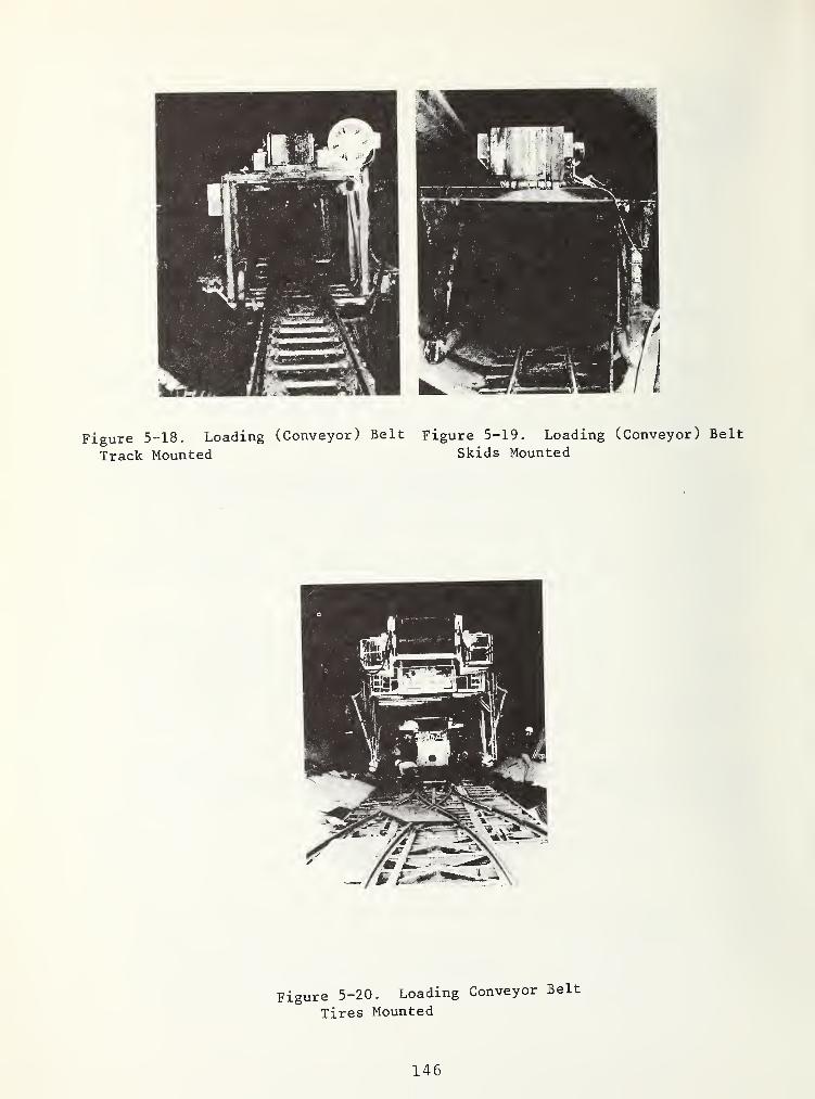
Figure 5-18. Loading (Conveyor) Belt Figure 5-19. Loading (Conveyor) Belt
Track Mounted Skids Mounted
Figure 5-20. Loading Conveyor Belt
Tires Mounted
146

Figure 5-21. Transfer and Loading Belt with Use of Bunker Car
a conveyor beltb converterc spool for high voltage
cabled machine air ducte air duct telescopef tunnel air duct
g catwalksh storage for pipes and railsi spindle for negotiating curvesj sliding plate with slotk trough for rail transport
Figure 5-22. Tracks Consisting of a Steel Box Serving as TunnelDrainage Trench with Welded-On Rails
147

under the condition that those are not part o£ a temporary lining,and are installed already in the machine area. The loading beltis not pulled along during the tunneling like the trailers o£the tunneling machine but it is pulled up during the relocationo£ the bracing system. A pulling rod connection between the rear-most trailer and the loading belt is better than the use o£steel wires or chains causing jerky movements.
5.2.2 Supply o£ the Machine Area
5. 2. 2.1 Transportation o£ Personnel and Material - This isusually done by rail.
5. 2. 2.
2
Supply Lines and Installations - The machine area issupplied
:
-with electric energy via a high voltage cable, in £orm o£a permanently installed cable up to a maximal distance o£approximately 300 meters to the machine, and £rom there bymeans o£ a special cable which rolls o£f a cable roll in-stalled on a trailer during the tunneling process.Figure 5-24, or is pulled o££ a loop storage. Figure 5-25.The permanently installed cable is advanced in intervalso£ 300 meters, and the special cable is rolled up again.
Figure 5-23. Prefabricated Concrete Tunnel InvertSegments; Rear End of Machine with Protective Cage
148

The cables are connected with each other in a high voltagejunction box, Figure 5-26. High voltage transformers are connect-ed to the permanently installed cable in intervals of one totwo kilometers. The ventilators and lighting equipment, pos-sibly also locally employed laser devices, are supplied by thelow voltage currents taken out at these points. The machinearea is supplied further
-with water, for the distribution of operating water, andin special cases also for the cooling water recirculationof heat exchangers, through one pipeline each with hoseconnection
,
-with compressed air also through a pipeline with hoseconnection
,
Figure 5-24. Spool withMachine Cable
Figure 5-25. Loop Storage of
Machine Cable
Figure 5-26. High-VoltageJunction Box
149

-with fresh air either through the cut tunnel, i.e. suctionventilation with regard to the machine area, or throughan air duct, i.e. blow ventilation; likewise, the usedair returns to the tunnel entrance either through an airduct, or through the bored tunnel.
The connecting hoses are the mobile connections between thepermanently installed water, compressed air line, and thecorresponding distributions on the tunneling machine. In general,they are at least twice as long as the individual pipes. Afterseveral strokes have been cut, with a total length of at leastone pipe, the pipelines are advanced, too. At the same time,the rails and the air duct can also be installed, provided theyare of the same length. Figure 5-27. Air duct telescopes.Figure 5-28, are installations for the flexible connection of theair ducts and of those parts of the ventilation system locatedin the machine area.
Figure 5-27. Supply Car Loadedwith Rails, Air Duct, Water and
Compressed Air Pipes, and Con-
nectors for SystematicInstallation
Figure 5-28, Airduct Telescope Con-nected to a DustCollector, and In-
stalled at the Side
of a Loading Belt
Frame
Photo: Dresser.
150

A pump line consisting of permanently installed pipes and ofa connecting hose to the pump on the tunneling machine is alsoinstalled in stages .
Usually, the machine area is connected by telephone with theinstallation area at the tunnel entrance, and with the transferarea in case of tunneling projects originating from the bottom ofa shaft. This telephone connection consists of a permanently in-stalled cable and of an intermediate cable leading to the telephoneon the tunneling machine that rolls off during the tunneling pro-cess. The installation of this connection is done in the samefashion as the installation of the high voltage cable.
5.2.3 Ventilation, dust removal, cooling
The machine area as well as the rear area of the tunnel wherepeople are working must be ventilated, the concentration ofpossible noxious material must be diluted, and this stretch ofthe tunnel must be cooled. The measures necessary for the venti-lation, dust removal, and, if necessary, for cooling, will not begiven individually, but within the framework of a summarizingevaluation. The requirements to be met are not the same for allcountries. Besides generally valid guidelines, project-relatedregulations and standards must be observed for special work, suchas mining.
5. 2. 3.1 Ventilat ion - The ventilation during the tunneling serves:
the air renewal for the personnel,thinning of the dust concentration,the dilution of the irritant concentration during the useof diesel engines, for example for the traction during thecutting removal and the supply of points of operation,the dilution of the concentration, and the increase ofthe air speed in the presence of natural gas, as well asheat dispersion.
Two different ventilation systems can be used, either
suction ventilation. Figure 5-29; the fresh air flowsthrough the excavated tunnel up to the cutting head, theused air is led to the entrance of the tunnel by means ofan air duct, orblow ventilation. Figure 5-30; the fresh air is led intothe machine area by means of an air duct, and the usedair flows back through the excavated tunnel to its entrance.
151

Figure 5-29.
Suction ventilation
Figure 5-30.
Blow ventilation
Figures 5-29 and 5-30. Ventilation Systems
Apart from possible project-related regulations, ventilation,dust removal, and, if necessary, also the cooling must be consideredduring the selection of a system. The length of the tunnel andits diameter, as well as work places possibly located betweentunnel entrance and tunneling machine are influential factors.Whereas usually tunneling projects with predominantly small cuttingdiameters are ventilated by means of suction, blow ventilation ispreferred for long tunnels, and for the cutting of galleries inmining operations.
With regard to the well-being of the personnel, and withelectric traction, a fresh air quantity can be assumed for the airrenewal on the basis of the precondition that smaller tunneldiameters, up to approximately 25 m2, cutting diameters approxi-mately 5.5 m, should have air speed of at least 0.1 m/s, and largertunnels, from approximately 25 m2, should have an air speed of atleast 0.05 m/s. The air quantities derived from this refer to themachine area. Considering the unavoidable air losses in air ducts,a correspondingly larger amount of air should be sucked in at thetunnel entrance, and the fans should be operated with low pressures.For this reason, several fans distributed along the air duct arepreferable to one high pressure blower.
5. 2. 3.
2
- Dust collection - During mechanical tunneling, dust isformed
,
in the cutting zone, during the penetration of the cuttingtools into the rock, during the falling of the cuttingsas well as by its movements caused by scrapers and shovels,in the feeding hopper between the shovels of the cuttinghead and the basic machine conveyor belt, as well asat the transfer points of the conveyor belt.
The quantity and the grain size distribution of the dustdepends on
152

the type and the portion of the main components, as wellas on the strength of the rock,on the boring system, in particular on the bit type andon the condition of the cutting edges, as well as onthe moisture of the rock.
The amount of dust generated in the cutting zone amounts tosome 100 g/m^ of cut rock even with spraying of water [38], Thetrapping of dust is an absolute necessity with dust containingquartz. Grain sizes smaller than 5 ym can pass into the lungs,and are major health hazards for this reason. The bearable con-centration of hazardous materials is expressed by the so-calledMAK values, maximum work place concentration for a daily workperiod of 8 hours. The MAK value for very fine-grain dust con-taining quartz, determined by the Swiss accident insurance companySUVA can be seen in Table 5-5 [39].
Dust trapping is done by:
spraying of water,supply of fresh air for dilution of the concentration,
TABLE 5-5. MAK VALUES FOR VERY-FINE-GRAINED DUST CONTAINING QUARTZ
Quartz contentof the dust
%
MAK valuesfor grain sizes
<5 ymmg/m^ air
10 to 20 10
20 to 30 5
30 to 50 3
50 to 70 2
over 70 1
dust collectors.
The spraying of water for the purpose of trapping suspendeddust is a traditional method of dust trapping. However, its effec-tiveness is insufficient even with large amounts of water - unde-sirable for other reasons - and is unable to meet the requirementsset by the MAK values [40]. Only relatively large dust grainfractions adhere to the water droplets under atmospheric condi-tions, whereas the smaller particles that are capable of passinginto the lungs remain largely free. The reduction of the dustconcentration through dilution requires the supply of a very largequantity of fresh air.
Even the removal of the dust-containing air, and the bindingof the dust grains in dust collectors, does not completely fulfill
153

the requirements. The effectiveness of the dust trapping systemwhich also depends on the dust content of the raw air is smallerthan 100%, and the residual dust contained in the released air,the so-called pure air, consists predominantly of the fractionsthat are capable of passing into the lungs. During machinetunneling, a combination of these three dust trapping methods isusually used.
No matter whether the machine area is ventilated by suctionor by blowing, the cutting zone must be separated from the remain-ing machine area by means of a shield due to the very heavy dustgeneration occurring there. By producing a water fog in thecutting zone - possibly the water necessary for the boring toolcooling may be used - primarily the surfaces of the cuttings willbe moistened more or less. In addition, part of the generateddust will be bound to the water droplets, and will be deposited.The dust concentration in the air sucked from the cutting zone,the so-called raw air, decreases with increasing amount of sprayedwater. According to that, large amounts of water would seem to bemost effective. However, this is contradicted by the experiencethat cuttings and cutting sludge that are dripping wet wear outmachine parts; in addition, the requirement must be consideredthat the cuttings should completely absorb the sprayed water,which is difficult with a large quantity of water. Also, the useof water should not be considered for rock masses that have atendency to swell.
Despite the spraying of water, the air circulating inside thecutting zone is saturated with dust. It must be sucked off con-tinuously. Otherwise, it would pass through the openings of thedust shield, and would cause, together with the cuttings, anintolerable visible and smellable dusting of the rear machinearea. The amount of air to be sucked up must stay within certainlimits. The speed of the air entering the cutting zone throughthe openings in the cutting head carrier must be large enough sothat the air turbulence in the cutting zone dones not permit atany point a counter-flow of the dust -containing air to the outside.On the other hand, it must not be so large that fine cuttings arestirred up, and are removed with the raw air. In general, it canbe assumed that the raw air quantity G that is to be sucked offis proportional to the cutting performance L, and correspondinglyto the cutting head penetration t^. and to the cutting diameter D.
G^L = Vj^ F = ntF'\^^ t D^ = tD.
For tunneling projects with blow ventilation, and with cuttingdiameters around 5 m, and with cutting performances with 0.5 to1 m^/min solid rock, it was shown to be sufficient to suck off 90to 100 m^/min dusty air from the cutting zone, to process it inthe dust collector, and to subsequently mix it with the remainingfresh air in order to reduce the following dilution ratio results:
Total amount of fresh air at the point of operat ion^ 2 . 3 : 1 to 5:1 [38]
amount sucked out of the cutting head.
154

For ventilation by suction less thorough dust catching is
necessary because the clean air leaving the dust collector directlyenters, and flows in, the air ducts. According to experiencesgained so far, 1 to 1,5 m^/s raw air should be sucked out of thesprayed cutting zone for a cutting diameter of approximately 3 to5 m.
The low pressure necessary for the suction of the air out ofthe cutting zone is produced by means of an air duct fan, or, ifa dust collector unit follows, by means of a fan integrated in thedust collector, the raw air is transported by means of two flexibleair ducts made of medium-hard plastic material connected to theupper part of the dust shield. In order to avoid dust deposits inthe air duct, the air speed feed should be at least 20m/s.
Whenever a point of operation is ventilated by blow-ventila-tion, a dust collector must be installed. This would not benecessary for ventilation through suction if the speed of the rawair in the extracting air duct amounts to approximately 20 m/s,and if the sand blasting effect of the raw air on the air duct andon the ventilators is considered acceptable. In general, thismethod is only used for short tunnels, and with small amounts ofair, with ventilation through suction.
For mechanical tunneling, wet dust collectors must be em-ployed, in particular, so-called high-performance wet dust collectorswith ventilation by blowing. With all manufacturers, the basicdesign of a high-performance dust collector consists of the actualdust collector with a following fan of a water circulation withpumps, conduits, and sludge catchers, of the solids removal unit,and of the electrical installations. The dust-containing raw airfrom the cutting zone flows through the dust collector with veryhigh speed. Here, the air comes in contact with finely sprayedwater. After different processes characterizing the individualdust collector manufacturers, the dust particles are firstabsorbed by water droplets, and are then separated from the airwhile clinging to the water. The sludge, consisting of water anddeposited dust particles, is collected in a catcher, and may beadded to the cuttings by means of a sludge pump.
With ventilation by suction, the use of a system slightly lesseffective than a high-performance dust collector is justifiablebecause the small quantities of finely fractioned residual dustremaining in the pure air will not come in contact anymore withthe tunnel air. A future reduction of the emission limits toapproximately 100 mg solids per m^ pure air entering the atmosphere,however, may preclude the use of coarse dust collectors.
If an appropriate amount of water is sprayed in the cuttingzone, additional dust-collective measures are usually not necessaryat the conveyor belt transfer points. If necessary, water may besprayed again at these points, or they may be encased with suctionventilation of the dust and an air quantity of approximately 0.5m^/s may be arranged.
155

5, 2. 3. 3 Cooling - Heat is generated by the mechanical tunneling.The heat sources are:
the tunneling system, in particular the tunneling machine,andpossibly also the rock mass.
The generated heat is called heat output, and the heat transferredto the air in the machine area, or in the working zone, is calledheat amount.
TABLE 5-6. MOST IMPORTANT HEAT SOURCES OF TUNNELING MACHINE, ANDTHEIR ZONES OF OCCURRENCE
Trailer Basic machinerear cutting head work face
carrier
- Conversion at
Head drive- hydraulic
- electricDC voltagemotors on
head carrier- electric
AC voltageshaft machine
- electricAC voltagemotors on
head carrier
advancegrippingsteeringdust collectionventilationreserve
- Main converter
E - motorsH - pumps
- H
Rectifier
H - motorsgears
,
head bearinglines -
E - motorsgears,head bearing
E - motors head bearinggearsH - clutches
- drive shaft -
E - motorsgearshead bearing
- cylinders -
E - motorsH - pumpsdust collectoradditional ventilationMiscellaneouspossibly coolingpossibly air conditioningcompressor
crushing
crushing
crushing
crushing
For practical purposes, it can be assumed with sufficientaccuracy that the electric energy transmitted to the tunneling
156
machine is transformed completely into heat. The largest heatoutputs are found in the areas summarized in Table 5-6.
The following basic distribution of its total heat outputWv applies for the tunneling machine:
W = WV
+ WSL
+ WVR
The predominant part of the electric energy supplied to thetunneling machine is transformed into heat output at the workface. Of this, the major portion V/ßj( is produced on the surfacesof the cuttings. The estimate of approximately 901 is justifiedbecause it considers that the heat is generated in the directeffective area of the boring tools, and in the disaggregationplanes in the rock. If the average temperature of the cuttingsremoved from the cutting zone is larger than the temperature ofthe air in the tunnel, the cuttings release part of their heatcontent into the tunnel air. The calculation of this heat amountis difficult, and depends on numerous parameters, among others, onhow the cuttings are loaded onto the conveyor belt. Cuttings thatare distinctly colder than the air in the tunnel absorb heat fromthe tunnel air.
The remaining portion of the heat output produced at the workface - approximately 101 - is the heat amount WsL* lb is removedtogether with the dusty air sucked out of the cutting zone.
The heat output Wyp generated in the remaining area of thebasic machine and on the trailers, with the exception of the heatremoved by cooling water, is absorbed by the tunnel air.
The heat amount from the rock mass Wq is dependent on theoriginal temperature of the rock mass Tpy, on the air temperaturein the tunnel Tp, on the time which has passed since the beginningof the tunneling, and on material constants. For the calculationof the original temperature in the tunnel track it must bedistinguished between an extensively flat, approximately horizontal,and an actually mountainous earth surface. In the first case, itcan be assumed that, starting from the average yearly temperatureof the area, the temperature increase in the ground amounts toapproximately 3°C/100m of depth. This assumption is insufficientfor tunnels in mountains. The geothermal gradient below mountainranges is larger, and accordingly the heat gradient is smallerthan under plains. The conditions are reversed underneath valleys.The calculation can be conducted following the method suggestedby Thoma and Koenigsberger [42;43].
A calculation method for the temporal curve of the heat flowfrom the rock mass with a given original temperature Tpp and atunnel air temperature Tp has been described by Carslaw and Jaeger[44]. It requires the knowledge of a temperature conductivity andof the heat transfer number of the rock mass, as well as of theheat transfer number for the tunnel invert. The heat amount per
157
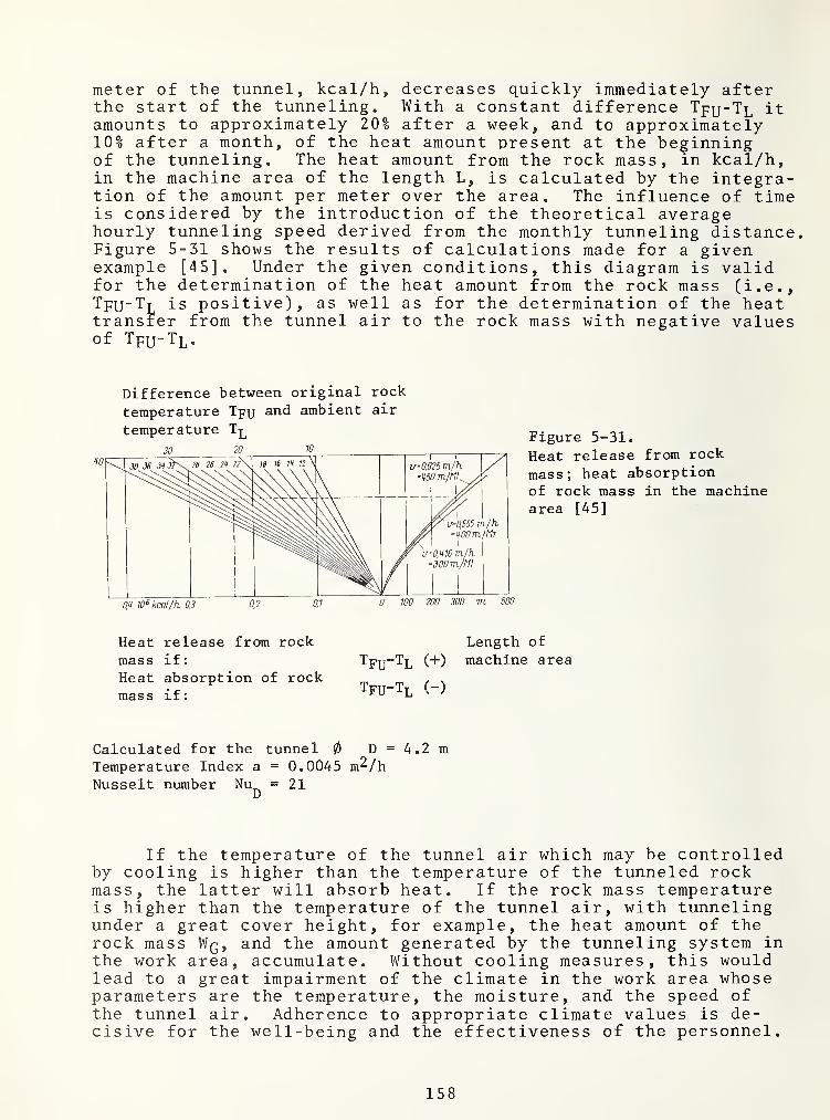
meter of the tunnel, kcal/h, decreases quickly immediately afterthe start of the tunneling. With a constant difference Tpy-TL itamounts to approximately 20% after a week, and to approximately10% after a month, of the heat amount present at the beginningof the tunneling. The heat amount from the rock mass, in kcal/h,in the machine area of the length L, is calculated by the integra-tion of the amount per meter over the area. The influence of timeis considered by the introduction of the theoretical averagehourly tunneling speed derived from the monthly tunneling distance.Figure 5-31 shows the results of calculations made for a givenexample [45]. Under the given conditions, this diagram is validfor the determination of the heat amount from the rock mass (i.e,,TfU"TT| is positive), as well as for the determination of the heattransfer from the tunnel air to the rock mass with negative valuesof Tpu-Tp.
Difference between original rock
temperature Tpu ambient air
temperature Figure 5*-31.
Heat release from rock
mass; heat absorptionof rock mass in the machinearea [45]
Heat release from rockmass if:
Heat absorption of rockmass if:
Length of
Tpy-TL (+) machine area
Tfu-Tl (-)
Calculated for the tunnel 0 D = 4.2 mTemperature Index a = 0.0045 m^/hNusselt number Nu^ = 21
If the temperature of the tunnel air which may be controlledby cooling is higher than the temperature of the tunneled rockmass, the latter will absorb heat. If the rock mass temperatureis higher than the temperature of the tunnel air, with tunnelingunder a great cover height, for example, the heat amount of therock mass Wq, and the amount generated by the tunneling system inthe work area, accumulate. Without cooling measures, this wouldlead to a great impairment of the climate in the work area whoseparameters are the temperature, the moisture, and the speed ofthe tunnel air. Adherence to appropriate climate values is de-cisive for the well-being and the effectiveness of the personnel.
158

Figure 5-32 shows the critical climate values determined by theSwiss accident insurance company for medium-heavy work underground.
Figure 5-32.
Comfort limits for averageunderground work based on anenergy of 242 kcal/h and anair speed of 0.3 m/s [41]
t = rectal temperatureK
At = increase of rectal temperatureK
During the tunneling, normal heat removal takes place:
during the replacement of the air needed for ventilationand dust removalpossibly with the cuttings, andwith water, if a water cooling system is installed at all,as for example, for the hydraulic fluid or for the elec-tric cutting head drive motors.
If this heat removal is insufficient to meet the requirementsof the climate limits, special cooling is necessary. This may bedone by
:
a) increasing the original amount of air; however, becausethe heat removal by means of air is limited due to therelatively small practically producible enthalpy differ-ence and the relatively small amount of air which canbe moved in practice, by
b) cooling of the air by means of water
by spraying to achieve cooling through evaporation, orby using heat exchangers with a cooling water circula-tion.
5. 2. 3,
4
Examples of calculations with simplified assumptions - Theexact calculation of the amount and the removal of heat during thetunneling process is complex since numerous processes influenceeach other. They must be considered as estimates of a magnitude.The following examples are based on simplified assumptions:
159

\
Given tunneling machine and its heat output
Tunnel diameter
Maximum cutting rpm
Nominal torque at the cutting head
Electric nominal performance of thecutting head drive
Version A AC voltage 55,000*7.6
Version B hydrostatic 55,000*7.60.65*974
4.2 m
7.6 1/min
55,000 kpm
= appr . 540 kW
= appr. 660 kW
Assumed average drive performance 75% of the nominal performance
Total average power for:
cutting head driverest of hydraulic systemdust collector systemventilatorsvarious consumers
Of these, at the work face
Alternative A Alternative B
440 kW 500 kW30 kW 39 kW15 kW 40 kW5 kW 30 kW
10 kW 20 kWTOT"TW Tw
80% 1of 400 kW 65<1 of 500 kW= 320 kW = 320 kW
140 kW 300 kW
The transformers are neglected.
Total average heat output Wyof this, at the work face
Removal with cuttings, 90%:Removal in dusty air, 10%:
‘
of this, in the remaining machine^area, Wy^Net boring speedtheoretical average tunneling speedat 375 m/MTcuttings
solid volumeweightspecific heatheat content per h and °C
395, 000 530,000 kcal/h275 ,
000 275,000 kcal/h250, 000 250,000 kcal/h25, 000 25,000 kcal/h
120, 000 255,000 kcal/h2 .7 m/h
0 .52; m/h
37 .5 m^/h98 ,500 kg/h0. 19 kcal/kg ‘
’C
18 ,7010 kcal/h
Average temperature increase of cuttings250,000:18,700 = rd. 13.5 °C
Length of the work section respectivelyof the machine area 150 m
160

Example 1: Tunneling machine version A, suction ventilation
Original temperature of the rock mass Tp^ (assumption) 8°C
Fresh air when entering the machine area in the tunnel cross sectionVolume (assumption) 2,5 m^/s = 9,000 m^/hWeight G 10,000 kg/hTemperature 8°CMoisture, absolute/relative 4.5 g/kg/60%
The following steps of the calculation may be done by using aMollier diagram, Figure 5-33.
Input Enthalpy 4,5 kcal/kg
Fresh air in front of the cutting head carrierTemperatureMoisture, absolute/relativeOutput enthalpy
34 °C4.5 g/kg/lOl10,8 kcal/kg
Enthalpy differenceHeat removal by air 6.3*10,000Average temperature of the tunnelair Tp = 1/2. (8 + 34) = Tp^ - T^
i.e, the rock mass absorbs heatheat absorption by the rock mass -
compare Figure 5-31
6.3 kcal/kg63,000 kcal/h21°C-13°C
57,000 kcal/h
Total heat removal 120,000 kcal/h(W^j^ = 120,000 kcal/h)
Average temperature of cuttings 13,5 + 8 = 21,5®Ci.e., between the cuttings and the practicallyequally warm tunnel air, a significant heattransfer does not take place. Therefore,only Wyp must be removed from the machinearea
.
No special cooling is necessary.
Air removed by suction at the cutting head for dust trappingVolume (assumption)Weight GTemperatureMoisture, absoluteInput enthalpy
Enthalpy difference, necessary for theremoval of W
SL25,000 : 5,000
1.25 m^/s = 4,500 m^/h5,000 kg/h34°C4.5 g/kg10,8 kcal/kg
5 kcal/kg
161

Figure 5-33. Mollier-Diagram (Absolute Humidity g Water/kg Air)
Air for dust removal, after the cutting headcarrier
Output enthalpy 15.8 kcal/kgAdditional moistening in cutting zone 5 g/kgTotal moisture, absolute 9.5 g/kgTemperature A2°C
Exhaust air during exit from the machine areain the _
Air duct 1.25 m'^/s from the machine area to thefront of the cutting head, and dust-free from thecutting head.
3Volume (assumption) 2.5 m /sMoisture 7 g/kgTemperature 38°C
Example 2: Tunneling machine version B, blow-ventilation
Tunneling machine with hydraulic fluid cooling (assumption)Heat removal 20% of 500 kW approximately 85,000 kcal/h
Original temperature of the rock mass T (assumption) 40°Cr U
162

Fresh air when entering the machine area in theair duct
Volume (assumption)Weight G
TemperatureMoisture, relativeInput enthalpy
5.0 m^/s = 18,000 m^/h20.000 kg/h40°C20 %
15.8 kcal/kg
Exhaust air at the exit from the machine area in thetunnel cross section _ „
Volume (assumption) 3.75 m’^/s + 1.25 m'^/s 5.0 m"^/s
Weight GTemperatureMoisture, relative (the same absolute moistureis assumed as in fresh air)Output enthalpy
18.000 m^/h20.000 kg/h25°C
49 ^
12.2 kcal/kg
Enthalpy difference between fresh air and exhaust air 3,6 kcal/kg
Additional heat to be removed due to a temperature differencebetween
fresh air and exhaust air 3.6*20,000 = appr. 70,000 kcal/h
Heat amountFrom the cuttings produced at the work face, from the conveyorbelts in the machine area, estimate: 50% of the heat excess ofthe cuttings(13.4 + 40-25) °C*18, 700 kcal/h °C appr. 265,000 kcal/hfrom other sources in the machinearea Wyj^
from the rock mass Wg, Tpy-Tp = 15°C,compare Figure 5-31due to temperature difference betweenfresh air and exhaust airdirect removal by hydraulic fluidcoolingto be transferred primarily to tunnelair
255.000 kcal/h
70.000 kcal/h
70.000 kcal/h
./. 85,000 kcal/h
575.000 kcal/h
No special cooling is necessary
Basic design of the heat exchanger1. Heat exchangers on loading belt in front of
air duct exit 5 m^/s.Inputs 40°C/20%, output 16°C/85% humidity
2. and 3. Heat exchanger for tunnel airrecirculat iondistribution according to the heat amountsflow-through of fresh air and of recircu-lated air
Suction at the cuttinglhead for dust-trappingpurposes (assumption)Dusty air: fresh air
120,000 kcal/h
2x230,000 kcal/h
1.25 m^/s1:4
163

Cooling wateruseable temperature difference(assumption) 10®Cspecific heat 1.0 kcal/kg, °Cnecessary volume
s
.
t be guaranteed under allrol that the tunnelingthe design inclination,t control, and allcontrol becomes defec-
tive. These requirements cannot be repeated often enough, andmust be strictly enforced, since deviations from the course canbe very expensive.
This pilot control, a line-of-sight device, or a narrow beamof light, is installed parallel to the design axis alongside thetunnel soffit, or under the tunnel crown with straight tunneling.During the tunneling of curves, it represents a tangent or a secanton a circular curve which is concentric to the axis of the designcurve. The horizontal and the vertical distance of the pilot con-trol from the tunnel axis must be determined before the start oftunneling, and remains the same during the tunneling process.One target each is installed on the cutting head carrier andpossibly also at the rear end of the machine frame with the samedistance to the axis of the basic machine.
The use of the line-of-sight method as pilot control is anobvious choice. It was commonly used when the mechanical tunnel-ing was first introduced. The line-of-sight may be given bymeans of targets, or by the telescope axis of a theodolite. Anobserver checks the course and gives directions for a correctionto the machine driver, if necessary. In order to avoid the dis-advantages of periodic control, the observer may be replaced by acommercial television camera. The theodolite telescope must beconnected with the television camera by means of a very preciseadapter. The picture of the camera is transmitted via videocablesto a viewing screen in the control center of the tunneling machine.
Much more often, however, a laser beam with a gas laser lightsource is used as pilot control. In principal, the laser is anenergy converter. The systems used on construction sites acceptenergy in form of electric current, and emit radiation in the redlight range. At the exit of the laser tube, the beam is verytightly focused, and has only a very small divergence. Withmodern systems, it is so small that a relocation is only necessaryafter a tunneling advance of several hundred meters. By means ofa theodolite, targets are installed, and the laser tube is thenaligned with these targets so that the axis of the tube is coaxial
b / bUUU + ö bUUU—rrü = 66,000 kg/h - 18,3 1/
5.2.4 Devices for Directional Control
During the tunneling process, it muscircumstances by means of continuous contmachine follows the design direction andThe machine must be connected with a pilotunneling must be stopped when this pilot
164

to the pilot control.
In order to simplify this process, the theodolite whose axiscoincides with that of the pilot control may be left as is, and a
laser tube may be attached to the theodolite in such a way thatthe axis of the tube is parallel to the axis of the theodolite.However, this involves a parallax between the two axes.
This parallax can be avoided with a laser theolite. Only aregular theodolite is used for this. The accompanying laser withits supply can be installed at its suspension or in a corner ofthe tunnel. The produced beam is led into the telescope of thetheodolite by way of light transmission cable, and leaves thetelescope in its axis. The practical range of a laser beam fedthrough a theodolite telescope is at present still shorter thanthat of a laser beam exiting directly from a laser tube.
Whenever a laser beam is used as pilot control, it must becontrolled with 2 shutters or laser beam control in front of thedevice. When the device is displaced, through collision, orthrough a deformation of the tunnel soffit, the beam through theshutters is interrupted. This beam deflection is signaled by thelaser beam control.
Photo-electric grids may be used as targets. They permit theregistration of the impact points of the laser beam on the target.The measurements can be transferred to a target representing thisgrid plate located in the control center of the machine.
Laser beams have an extraordinary beam intensity. A beamhitting the human eye directly is very damaging. The personnelmust be informed of this. Some countries have issued regulationsfor the protection of ' the personnel in the tunneling machine area.
5,2.5 Gas detection
Tunneling in formations containing natural gas requires, (asdo conventional methods),
continuous analyses of the composition of the tunnel air,andthe preparation of organizational and technical measuresto be taken when the gas content of the air reaches thehighest admissible value.
Methane (CH4 ) is the most commonly occurring natural- gas.It can occur either by itself, or together with other gases. Itis colorless and odorless, and can only be detected with gasdetectors. A mixture of air and 4,5 to 15% CH4 is explosive. Inthe presence of other gases, this range may be extended on bothsides. The explosion can be caused by a spark. Below its explo-sion point, the air-gas mixture is flammable.
165

Individual countries have - differing - regulations concern-ing the protection of a tunneling project during gas occurrence.In any case, early detection of gas is of utmost importance. Forthis purpose, detectors are installed in the suction air ductsleading from the dust shield of the tunneling machine to the dustcollector, and in the tunnel apex. In special cases, the pilotdrill of the tunneling machine may be used. The air samples takenout of these pilot drill holes may be analyzed by means of thedetectors; the accuracy of these instruments amounts to approxi-mately 0.11. As soon as a gas content of the air above thetolerance limit is determined, security measures must be put intoeffect by all means, such as a preliminary warning with a contentof 1.5%, and switching off of all electrical systems, with theexception of the lighting and the ventilator motors which areexplosion-safe, with a content of larger than 2% [46]. Usually,the amount of fresh air injected into the machine area is in-creased with regard to a better air turbulence, thus avoidinglayering of air, or formation of air stagnation in the tunnel.Equipping the tunneling machine with an electric installationwhich is explosion-safe in all its parts is very expensive.
166

6. THE BIDDING PROCESS^ AND THE EXECUTION OF THETUNNELING PROJECT
6.1 BID DOCUMENTS
6.1.1 Possibilities for Contract Design
The common basic forms of a contract for the construction in-dustry are:
- unit price contract,
- lump sum contract,
- cost-plus contract,
- cost-plus with incentive, and sometimes a
- combination contract.
Most commonly used are the request for bids, awarding, execu-tion, and accounting for a tunneling project on the basis of unitprice, i.e. with lump sum prices for the construction installa-tions and for equipment rental, and with standard prices for theactual construction work. Underground construction with itsspecific uncertainties is little suited for the use of flat-rateprices for the total construction. The contractor cannot be expec-ted to be responsible for, and to bear the consequences of, defi-ciencies of the earth crust which he does not know, or does notknow sufficiently well. Construction based on cost-plus, or oncost-plus with incentive, is justified, or even necessary, if anextraordinary capital investment is required from the contractor,if a long construction time is projected, and if the extent of thework, or the work conditions are not known well enough to warranta pre -calculation with fixed prices. This may be the case withrisks that cannot be calculated or controlled, such as especiallyunfavorable geological-constructional conditions, or with thecooperation of third parties that is necessary but whose avail-ability is uncertain, if interference with other operations mustbe avoided, if there is influence by third parties, or if the pro-tection of the environment is involved. Combination contracts mayalso be suitable, such, as for example, the application of flat-rate prices to the construction installations and equipment on theone hand, and the compensation according to cost for all or partsof the tunneling and lining construction on the other hand.
6 .* 1 . 2 Presentation of the Extent of Work and of the Work Condi-tions on the Basis of Standard Prices
The complete and determinative presentation of the extent ofthe work and of the work condition for the bidding requests for a
167

construction project on the basis of standard prices is an impor-tant and possibly consequential duty of the owner, and of theengineer designing and supervising the project on his behalf.
This presentation can be done, for example, by:
- the wording of the construction contract as such,
- the schedule,
- the object-related conditions,
- the plans including the geological documentation andthe longitudinal section of the assumed local distri-bution of the rock mass classes with regard to basicboreability, cutting tool wear, and support liningrequirements
,
- the performance regulations, and
- the safety regulations.
The engineer must communicate his knowledge concerning theprojects, often based on years of preparation, and the technicalconditions for its realization to the contractor. Of special im-portance is the geological documentation and the rock mass classi-fication commissioned by the owner or by his engineer. The classi-fication of the geological information according to substantiatedknowledge, or, if that is unavailable, according to "probable” andto "possible" status must also be submitted to the bidding contrac-tor. This information determines a geological and construction-technical area of the activity of the contractor. On the basis ofthe index values for the boreability and for the cutting tool wear,as well as by the prognosed supporting requirements the contractorcan determine the basic requirements for the tunneling machinewhich he is to provide. The geological documentation and theclassification of the rock mass are fundamental information for thedevelopment of the bid submitted by the contractor. For this rea-son, they must also be recognized as parts of the constructioncontract for the project.
In order to keep the bid simple and easy to understand, setdimensions for the longitudinal extension of the rock mass classesand for the profile type distribution must be included in the pricelist. Allowances for the deviations from the assumptions on whichthe bid is based can be made in final accounting which considersthe actual extent of the work. Also, the flat-rate price for theinstallation based on an advance quantity given in the bid documentsmay be adjusted to a change in the construction time under consid-eration of the actual longitudinal extension of the rock mass classor also profile type areas.
168

The condition that the owner and his engineer must presentthe extent of the work and the working conditions, and that thesubmitting contractors must choose their equipment as well as theconstruction methods and also must conduct a pre-calculation onthis basis, defines unequivocally the responsibilities, and deter-mines the risk of the contractor. In preparing and documentingthe project for the bidding process, the engineer must proceed withgreat care. The processing of the bidding documents, in particularthe wording and formulation of the texts, is the domain ofengineers with great experience in construction work, and not ofrecent graduates of engineering schools. The project and itsspecial problems must be the center of the presentation. Copyingand re-copying of standard texts used at many construction sitesdoes not serve the purpose. A project engineer with constructionsite experience will also have a better understanding for theoften-times significant problems of the contractors. His formula-tions should be of sufficient clarity, but their tone should alsoexpress the intention of a fair partnership between the owner andthe contractor. The contractor can and should cooperate duringthe preparation, and later during the execution of the project.He does not have the right to revise his bid and to question theconstruction contract based on his bid as long as the actual con-ditions which he meets with during the execution coincide with thepresentation of the extent of work and of the working conditionsgiven in the bid documents. The owner is not responsible for thedecisions which the contractor makes on the basis of his evalua-tions of the working conditions and of the extent of work that werepresented correctly by the engineer. However, he must bear theconsequences, and he must respond to the demands of the contractor,if the actual conditions are different and require performances ofthe contractor which are not covered by the description given inthe bid documents.
6.1.3 Examples for Contract Combination
6. 1.3.1 Provision of the Tunneling Machine - The tunneling machineto be used for a certain project is usually selected and providedby the contractor. The owner who best knows the extent of thework and the working conditions may determine special conditons tobe met by the tunneling machine in form of specifications. He maypre-select types and brands of tunneling machines available on themarket, and may submit a list of machines that are suitable, inhis opinion, to the contractor. However, he will hardly prescribea certain brand of tunneling machine, or details of the machineconstruction. Such extensive specification would have to becoupled with the acceptance of certain responsibilities. Theselection and the provision of the machine on the part of thebuilder is the exception, although such cases are known. A buildermay buy or lease his own machine if he also provides further per-formances for the tunnel project such as personnel or materialsupply, and if his tunnel construction program makes it possibleto depreciate the purchased machine within a foreseeable period.
169

A bid-submitting contractor who would be required to assume respon-sibilities for a tunneling machine provided by the builder shouldretract his offer if he is not convinced of the suitability of themachine
.
Whenever the extent of the work and the working conditions areknown, the builder may ask for the provision of the tunnelingmachine bought or leased by the contractor at a fixed price, eitheras :
- lump sum price, guaranteed for the length of the tunnelproject as described in the contract, or for the tunnelingtime described in the contract, or
- as lump sum price calculated as a per-meter price, andcontained in the per-meter price.
Deviations of the actual longitudinal expansions of theclasses, possibly also of the profile types area which may influ-ence the tunneling time are provided for by the second possibility.
However, these deviations can also be considered, if a lumpsum price has been agreed on the basis of the prognosed tunnelingtime mentioned in the contract. Table 6-1. Instead of this lumpsum price, a modified lump sum price may be used. In this case,the tunneling time determining this modification must first bedetermined. It is calculated for each area of the longitudinalprofile of the tunnel track as the quotient of actual length tocontractual tunneling performance. The relation between the modi-fied lump sum price and the lump sum price of the accepted bid isthe same as that between the modified tunneling time and the con-tractual tunneling time. This means a transfer to the owner ofthe risk caused by the uncertainty of the longitudinal extensionof the rock mass classes with regard to supporting requirementsand boreability. However, the contractor still has the respon-sibility for providing the contractual tunneling performances.
The amount of the lump sum price for the provision of a tun-neling machine may preclude the use of the mechanical tunnelingprocess, especially if a tunneling machine must be first bought,or if the tunnel to be bored is short. However, the owner hasseveral possibilities which permit the contractor to submit a lowerlump sum:
- the combination of several tunnels with approximately equalboring diameters within the framework of a common construc-tion program in which several builders may participate [2]
,
- the condition that the builder receives a certain portionof the lump sum price as a refund from the contractor ifthe contractor receives a new contract, possibly by anotherbuilder, within a certain period after the termination ofthe tunneling process.
170

TABLE 6-1. MODIFICATION FOR THE LUMP SUM PRICE FOR THE PROVISIONOF THE TUNNELING MACHINE
Bidding, contractTectonic unitgeneral designation
Type of rockA A B B B B
general designation 1 4 1 2 1 4
zone lengths in m 1280 540 480 900 2200support during tunneling - C+ T+ - RB+boreab il ity A1 conv
.
B1 B2 B1tunneling speed in m/TD'*’ 23.0 3.0 16.0 21.0 18.5advance rate in TD+ 56 180 30 43 119tunneling machinelump sum price G1 G2 G3 G4 G5
Total price of contract : G1 + C2 + G3 + ...
Execution of workzone lengths in m 1280 540 560 600/250 1950/200support during tunneling - C T - /RB RBboreabilitytunneling speed in m/TD
A1 conv
.
B1 B2 B1/B2
effective 23.0 2.8 16.0 21.0/21.,0 17. 5/22.0contractual
advance rate in TD
23.0 3.0 16.0 21.0/21.,0 18.5/21.0
effective 56 193 35 27/12 111/9relevant for mod.
Modified lump sum price56 180 35 29/12 105/10
for tunneling machine G1 G2 35 X G3 41 X G4 115 X G530 43 119
Total modified lump sum price: G1 + G2 + G3' +
= G3 ' = G4 ’ = G5'
+) RB rock bolt T precast (segmented) liner elements C concrete TD tunneling day
6. 1.3. 2 Price Per Tunneled Cubic Meter or Meter - A builder sub-mitting a reliable geological documentation, a reliable rock massclassification with respect to boreability, boring tool wear, aswell as lining requirements, and a construction program to the con-tractor, may generally ask for the execution of the tunneling pro-ject on the basis of a firm price per cubic meter or meter. Esti-mating the net boring speed, the boring tool wear, and the utiliza-tion factor of the tunneling system, i.e. the numerical values ofthese terms that have an influence on each other, is then the taskof the contractor.
171

Unfortunately it is not possible for every tunnel project toprovide a reliable geological documentation or rock mass classifi-cation, and for some applications, areas of mechanical tunneling,little practical experience is available. This last statementapplies especially to the tunneling of crystalline rock, and totunneling with high cover heights. Only a few contractors andmanufacturers of tunneling machines were involved in such projects.
During the bid requests and the execution of such constructionprojects the objective uncertainties must be considered withoutreducing the requirements of the contractor in areas in which hehas a controlling influence. In such a case, the builder couldaccept the risk for the net boring speed and the cutting tool costsand could leave the risk for the technical readiness of the tunnel-ing machine and of the utilization factor of the tunneling systemto the contractor, under consideration, however, of the influenceof net boring speed and cutting tool wear. Such a distribution ofrisk can be included in a contract, and the determination caneasily be realized during the tunneling process:
a) the contractor offers gradated fixed cubic meter of meterprices supporting each rock mass class. There is a grada-tion for each class. The net boring speed as well as thedown-time of the tunneling process caused exclusively bythe maintenance and the exchange of the boring tools arethe parameters of this gradation. These unit pricescontain all costs of the tunneling, including those forthe periodic inspection of the boring tools but excludingall others that are directly connected to the boring toolwear
.
b) for the boring tool wear, the builder pays the contractor:
- a lump sum price per time unit for the down-time of thetunneling caused exclusively by the maintenance andexchange of the boring tools, exclusive of the provisionof the construction installations and equipment,
- according to cost, the personnel for maintenance, re-placement and repair if the boring, and (if the builderdoes not buy them himself) for new boring tools andtheir spare parts.
c) the billing and accounting, exclusive of the purchase ofnew boring tools and spare parts, is done for each workday. The supervising engineer and the construction sitemanager determine together the tunneling speed in metersper work day (m/WD)
, the average net boring speed (m/h)
,
the down-time caused exclusively by the boring tool wear,as well as the hours of work performed in connection withthe wear.
The costs of new cutting tools and their spare parts are paidupon billing. The principle of this arrangement can be seen fromTable 6-2 and Figure 6-1.
172

TABLE 6-2. BASIS FOR THE PRICE DETERMINATION OF THE METER WITHOUTBORING TOOL COSTS, DEPENDING ON NET BORING SPEED AND BORING-TOOL-RELATED TUNNELING INTERRUPTION
Precondition: Three-shift operation with shift change in machine area, cycle length oftunneling machine 1.0m, muck removal by train with change after two travel lengths.
boring speed
net boring speed 1.0 m/h 2.0 m/h 3.0 m/h
cnttincT-tonl - related interrnntinn‘ h/Tn 2 4 6 2 4 6 2 4 6
min/TD 120 240 360 120 240 360 120 240 360
remaining working timemin/TD 1320 1200 1080 1320 1200 1080 1300 1200 1080
estimate of contractorboring time min/TD 880 800 720 660 600 540 530 480 430remaining interr. min/TD 440 400 360 660 600 540 790 720 650(relocation TM^
,train change
,
inspections, repairs etc .)
resulting from estimateutilization factor 0.
•0 60 55 50 46 41.5 37 37 33.5 30advance rate m/TD 14 6 13.3 12.0 22.0 20.0 18 .
0
26.5 24 21.5
1 2TD tunneling day TM tunneling machine
0 12 3 m/h If
ne t £pee<t \/^
Figure 6-1. Price Per Tunneled Meter, Without Cutting Tool Costs, DependingOn Net Boring Speed and Cutting Tool-Related Interruptions (TD)
173

6.2 PROJECT EXECUTION
6.2.1 Work Time and Shifts
Mechanical tunneling is done in two or three (in mining alsoin four) shifts. The employment of personnel at the work sitearound the clock permits the largest possible exploitation of thetunneling system. For this reason, it is used frequently, butrequires at least a three-shift operation with a shift change atthe point of operation, and also an uninterrupted presence of thepersonnel in the tunnel for at least eight hours. The meal breaksat the work site are staggered. Since the members of a work teamdo not all take their meal break at the same time, the tunnelingcan go on without interruption.
Legal and trade-union regulations which are different forindividual nations, the contractual construction program, the workmorale of the personnel, and possibly also the rock mass behaviorare decisive for the number of the weekly work days and shifts.
6. 2. 1.1 Shift Types - The shift types, and the sequence of theiruse depends on the construction project. In any case, it must bedifferentiated between:
- tunneling shifts and
- maintenance shifts.
If the permanent lining is installed simultaneously with thetunneling, and if this lining consists of concrete, and if thetunnel diameter is too small to permit removal of the cuttings andthe supply of the tunneling process through the section to belined, the lining shifts must also be provided. Only the tunnel-ing and maintenance shifts, typical for mechanical tunneling, arementioned in the following.
6. 2. 1.2 Responsibilities of the Shifts - A tunneling shift has theresponsibility for:
- the tunneling operation and, if necessary, the installationof the temporary lining, of pre-fabricated invert elementsor of a precast lining, inclusive of all necessary trans-portation
,
- the relocation, possibly without interruption of the tun-neling and, possibly, only temporarily, of the tracks orthe rails of an overhead conveyor, for the removal of thecuttings and the supply of the tunneling, the supply linesfor water and compressed air, of the air ducts, and possiblyof a pump line.
174

- inspection, maintenance and small repairs of the tunnelingsystem either with or without interruption of the tunnelingprocess
.
A maintenance shift is responsible for:
- cleaning of the tunneling machine,
- maintenance of the total tunneling system through inspec-tion, maintenance, and prophylactic as well as necessaryrepairs
,
- improvement of the auxiliary installations installed bythe tunneling shifts,
- cooperation during the periodical relocation of the align-ment devices such as the laser system.
After 250 to 300 meters of tunneling a special work assignmentof advancing the high voltage cables is necessary beside thetunneling or the maintenance shifts.
6. 2.1. 3 Sequence of the Shifts - It is distinctly shown by experi-ence that successful mechanical tunneling depends on special main-tenance shifts during which the tunneling operation is stopped.
The use of a special maintenance shift may be necessary afterthree to five tunneling shifts under conditions of fast tunnelingin well boreable and largely identical rock masses, with relativelysmall wear and short down-times for the replacement of the boringtools. Slow tunneling in differing rock masses, and especiallywith a relatively large wear and frequent and also prolonged down-times for the exchange of the boring tools offers sufficient timefor the personnel of the tunneling shifts to carefully conductinspection, maintenance, and also smaller repair work according totheir check list. One or two special maintenance shifts per weekcan be sufficient.
In any case, the relation of tunneling shifts to special main-tenance shifts depends significantly on the tunneling system, notinfrequently on the tunneling machine in particular, and, of course,on the time requirement for repairs necessary due to defects.
6. 2.1.4 Distribution of the work time - The effective work timein the tunnel is divided in:
- tunneling and boring,
- system-related down-times, and
- non-system-related down-times.
175

The attempt must be made - but in no case at the expense ofinspection, maintenance, and prophylactic repairs - to continuethe tunneling as long as possible during each shift.
System-related down-times are caused by missing technicaloperational readiness of the components of the tunneling systememployed at the operation point, among others during:
- advancement of the tunneling machine,
- inspections, maintenance, and all kinds of repairs, inclu-sive of cutting tools,
- installation works in the machine area.
System-related down-times are unavoidable. Non-system-relateddown-times are waiting times for the technically functional tunnel-ing system at the point of operation. Such down-times occur whilewaiting for:
- removal and supply,
- electric energy, water, compressed air, ventilation, unlessoccurring in connection with the installation works in themachine area,
- installation works, maintenance, and repair outside of themachine area,
- survey and under certain circumstances, for the
- execution of measures for stabilizing the rock mass, orfor the removal of excess water.
A large part of the non-system-related down-times occurringat construction sites could be avoided by the tunneling manage-ment. System-related down-times occur, in part, with a certainrhythm depending on time or tunneled distance. Inspections, main-tenance, and scheduled repairs, for example, are t ime -related
.
After a certain tunneled distance interruptions occur, for examplecaused by the relocation of the tunneling machine, or by a trainchange. The necessity for repairs caused by defects is independentof tunneling time or tunneled meters.
Whenever an interruption occurs, no matter whether scheduledor unexpected, it must be attempted on the basis of the presentwork status,’ to use the interruption of the tunneling also for theexecution of other work which might have necessitated an interrup-tion within a foreseeable period.
Examples
:
176
- during a checking of the cutting tools which is done on a
scheduled basis depending on the type of rock and on thetectonics, the necessity for the replacement of three bitsis determined. The interruption necessary for this exceedsone hour. This time is used to advance rails and supplypipelines, which otherwise would only have been necessaryafter three more meters of tunneling.
- checking of the reduced performance of a hydraulic valve ofthe tunneling machine shows the necessity for its replace-ment. A spare valve is not in stock, and must be furnishedby the manufacturer. An interruption of approximately 12hours must be expected. This interruption is used to exe-cute the maintenance work which otherwise would not havebeen necessary for another two days.
Non-machine and non-system-related down-times may be avoided byappropriate installations and by an appropriate organization ofthe operation.
Example
:
- during the tunneling with a relatively small cutting dia-meter, the use of a bunker car necessitates waiting forthe cuttings removal at least up to a certain tunnel length,length.
- on the trailers of the tunneling machine, or beside thebunker car any kind of constantly needed material shouldbe stored, if possible: hydraulic fluid, grease, lubrica-tion oil, pipes, most frequently used sealing rings, somecutting bits, all tools for inspections and maintenanceaccording to check list.
The consumption of material, in this case exclusive of railsand air ducts, should be organized in such way that the materialstored in the machine area is used, and that the supply based on ageneral plan serves for the replenishment of this storage.
- The material storage of the construction site should con-tain the most frequently needed spare parts of the system,as well as those whose unavailability in case of need wouldinterrupt the tunneling for longer periods of time.
6. 2. 1.5 System Utilization Factor - Frequently, the system utili-zation factor serves ^or the evaluation of a tunneling process.
System utilization factor
boring time and revolution timeof the cutting head x 100
working time in or behind theTBM system
177

This definition only contains the effective work at the pointof operation and in or behind the machine area. This value doesnot consider the transportation time to the site of operation whichis different for each construction site. They do not apply to athree-shift operation with shift changes at the operation site.However, during the tunneling of an inclined gallery with shiftchanges at the face of the tunnel, they may amount to 15 minutesat the beginning, and 45 minutes at the end of the operations.
Net boring speed, cutting tool wear, and system utilizationfactor influence each other, compare Table 6-2. Here, it must benoted
:
- the utilization factor drops with increasing net boringspeed.
- if the net boring speed decreases, whereas the propellingforce remains the same, an increased cutting tool wearfrequency occurs.
- increased boring tool wear requires longer cutting-tool-related down-times, and thus leads to a lower utilizationfactor. During the execution of a tunneling project, thesystem utilization factor is determined for each work day.After termination of the tunneling, it is calculated forthe total tunneling time. The boreability and the behaviorof the rock mass must be considered for the evaluation ofthe system utilization factor. A utilization factor of 30%is not spectacular for tunneling in solid granite. A utili-zation factor of 55% is remarkable for tunneling in solidmarly sandstone. Table 6-3 shows utilization factors deter-mined at some construction sites.
The system utilization factor of a tunneling system must bedistinguished from the other terms mentioned in the following:
technical operating condition of time of the full technicaltunneling machine availability _ availability of the TM x 100
working time on or behindthe TB system
time of the full technical avail-ability of the system x
| ^
work time oh or behind thesystem
With none of these tunneling projects did significant interruptionscaused by the rock mass occur. The utilization factor of a tunnel-
ing system is always smaller than its technical operationavailability
.
technical operating availabilityof the tunneling system
178

TABLE 6-3. UTILIZATION FACTORS FOR SOME TUNNELING SITESDETERMINED BEFORE THE END OF THE TUNNELING PROCESS
tunnel tunneled tunneling effective utilizationdiameter length time work time f actor
m type of rock m h h a'S
5.61 shale 3,860 985 3,360 296.40 sandstone 3,450 2,000 6,250 325.03 hard sand and clay stones 3,320 2,182 7,440 294.16 hard limestone 920 493 1,790 284.20 hard limestone 4,380 2,438 4 ,650 52
5.13 hard limestone 3,410 1,868 4,760 393.30 limestone, also cherty
1 imestone1,675 2,069 2,800 75
2.25 granite and gneiss partiallyjointed
975 1,242 3,400 36
3.66 granite, part, jointed 1,260 1,339 5,280 25
In none of these tunneling projects did significant interruptions caused by the rock
mass occur. The utilization factor of a tunneling system is always smaller than its
technical operational availability.
6.2.2 Personnel and Specification Sheets
6. 2. 2.1 Personnel - The selection of the personnel and the selec-tion of personnel for the individual shifts is even more importantwith mechanical tunneling than with the conventional process.Mechanical tunneling requires more specialists, but less personnelfor large diameters.
The following jobs should be given to specialists:
- chief mechanic-electrician,
- foreman, and shift supervisor,
- machine operator,
- electrician,
- mechanic for general work, and
- mechanic for boring tool repair.
Substitutes must be trained and kept available with regard tovacations, sickness, accidents, and job changes. The chiefmechanic-electrician, the machine operators, the electricians, andthe mechanics for general work must know all components of thetunneling system thoroughly. They should be trained by experiencedpersonnel of the machine manufacturer for the operation, inspec-tion, maintenance, and repair of the tunneling machine. The chief
179

chanic-electrician should have a specially intensive training.me
The number of the personnel of a tunneling shift is decisivelyinfluenced by the type and the extent of necessary measures forsecuring and stabilizing the rock mass. The following are normallyused for tunneling in stable rock masses:
a) in the machine area: one foreman as shift supervisor,one machine operator, possibly one mechanic for generalwork, possibly one electrician, one handiman at the dis-charge point of the cuttings into the conveyor belt, upto three laborers for supply installations;
b) between machine area and dump: train driver, possiblyhandimen for supervision of the operation with conveyorremoval, one handiman at the dump;
c) at the plant at the tunnel entrance, present only duringthe day shift, but otherwise available at short notice,at least: chief mechanic-electrician, one electrician,also as store manager of small construction sites, onemechanic for general work, one to three mechanics forcutting tool repairs, one handiman. A shift containingat least one mechanic and one electrician is used asmaintenance shift.
6. 2. 2.
2
Specification Sheets for Personnel - It is recommendedto issue specification sheets defining their work at least for thespecialists in a tunnel construction project. This specificationsheet is fundamental. It goes without saying that each member ofa shift will help out with work assigned to another member if heis not busy with his own work himself. Table 6-4 shows an excerptfrom a specification sheet.
6.2.3 Checking of the Tunneling System
Inspections and maintenance of the components of the systemmust be carried out to increase the technical operation conditionsIt must be distinguished between:
- continuous inspection and control of, for instance, tempera-tures, tightness, degree of the filling of containers,
- inspections, possibly connected with maintenance, by eachtunneling shift,
- inspections and maintenance by a maintenance shift.
- long-term maintenance (for example, electric motors andwheel bearings)
.
180

TABLE 6-4. EXCERPT FROM A SPECIFICATION SHEET FOR THEPERSONNEL, EXAMPLE
a) Chief mechanic-electrician
He is responsible for the functional availability of the tunnel-ing system,
- supervises the operation of the tunneling system and of itscomponents
,
- supervises inspections and maintenance as well as the repairof small defects by the personnel of the tunneling andmaintenance shifts,
- localizes and repairs larger defects with the help of themechanic/electrician and of the machine operator,
- supervises the bit shop, the general shop, and the store,
- orders material and spare parts on the basis of orderssubmitted by the store manager,
- supervises and improves the training of the machine opera-tors, the training of drivers, electricians, and mechanics,
- continually checks the relevance and completeness of thecheck lists and of the directions of operation, changes oradds to them, if necessary after consultation with themanufacturers of system components.
b) Foreman
He is in charge of his tunneling shift,
- coordinates and directs the tunneling operation
- gives first directions during interruption of the opera-tion, in particular during unscheduled ones,
- continuously supervises the storage of material in themachine area and, in the case of interrupted supply orinterrupted muck removal of the cuttings, immediately con-tacts the personnel at the plant site at the tunnelportal
,
- determines by means of spot checks whether the inspectionsand the maintenance of the components of the system arecarried out in accordance with the tunneling shift checklist, and whether the operation follows the direction,
- writes the shift report.
181

TABLE 6-4. EXCERPT FROM A SPECIFICATION SHEET FOR THEPERSONNEL, EXAMPLE (CONTINUED)
c) Machine operator
Organizationally, he answers to the foreman and, technically,to the chief mechanic-electrician,
- operates the tunneling machine according to operatinginstructions
,
- carries out inspections and maintenance work according tothe tunneling shift checklist, with the exception of thechecking of the boring tools,
- supervises, by means of spot checks, the boring tool checkcarried out by the workman for the loading process,
- localizes and repairs defects of the tunneling machine ifhe is qualified for this. In special cases, he notifiesthe electrician or the mechanic for this purpose, andassists them,
- he furnishes information concerning the tunneling machineto the foreman for purposes of the shift report.
d) Electrician, stationed at the plant.
He supervises and repairs, if necessary, all electric machinery,apparatus, and installations of the construction site,
- is a member of the maintenance shift,
- manages the material and spare parts store of the con-struction site,
- supervises the consumption,
- submits orders to the chief mechanic-electrician.
e) Mechanic for general work, stationed at the plant.
He operates the machine shop of the construction site, withthe exception of the cutting tool shop,
- is a member of the maintenance shift, and conducts checksand the maintenance according to the maintenance shiftchecklist
,
- localizes and repairs defects of the tunneling system ifthe machine operator is not qualified for this; notifiesthe chief mechanic-electrician and assists him if his ownboring qualification is insufficient.
182

TABLE 6-4. EXCERPT FROM A SPECIFICATION SHEET FOR THEPERSONNEL, EXAMPLE (CONTINUED)
£) Mechanic for boring tools
He operates the cutting tool workshop,
- repairs, if possible, the dismantled bits,
- manages spare cutting tools and boring tool spare parts,
- has the administrative control over the boring tools.
The objects and the timing of inspections and maintenancecan be seen from the operating instructions of the component manu-facturers. Their combination and representation leads to a check-list, compare Table 6-5, to a tunneling shift checklist, and Table6-6, maintenance checklist. Both lists given here are examples.
TABLE 6-5. SAMPLE OF A TUNNELING SHIFT CHECKLIST
Date: Shift: Foreman:
Tunneling machine checked servicedcutting tools:cutters, bearings, holders
water jetsreduction gear oillubrication oillube oil filtermain bearing sealhydraulic fluid containerhydraulic hoses, pipeshydraulic oil filter
electric cable connectionsconveyor beltsbasic machinetrailers
vent ilat ion
dust collector
Transfer belt
Loading belt
Train switching system
Muck cars
183

TABLE 6-6. SAMPLE CHECKLIST FOR MAINTENANCE SHIFT
Date
:
Foreman
:
checked serviced
Tunneling machineCleaningall inspections and maintenance
according to tunneling shiftchecklist executed
buckets - scraperswater filterhydraulic fluid, samplingspikes on gripper padsguide plates and scrapers
Lubr icat ion
InstallationsTracks
compressed air, water, pump line
air duct
6.2.4 Checking of the Tunneling Operations
6. 2. 4.1 Work Progress - The organization of the work, and thetechnical operation condition of the system should be checked con-tinuously. This checking permits the recognition of defects,especially of systematic ones, it is the basis for each improve-ment, always with a goal to use the tunneling system effectively,and with a high system utilization factor. In order to avoid anunnecessary increase of administrative activity at the construc-tion site, all data for the checking and for the accounting aswell as for the work, should be supplied by a single report.Table 6-7 shows, as example, the form of such a shift report.
The graphic representation of the course of work. Figure 6-2,which is based on the shift reports provides comprehensive infor-mation on the course of the work and on the causes of defects andinterruptions
.
184

TABLE
6-7.
SHIFT
REPORT
SAMPLE
P• rC • •H
• • • e• 1
• E- • • • p*>
S o• 0 'P
• rH • po 0 rP • rP p n3)
iz: p 0 •V (/)
p • s • p p p 0•M p • • •
1 p 0 p0 H • • ^ tH e p0 • • O 0 •H PrC • • p p P uCO
• e p•HE
M p"
'
+-> p •H (Ü rHM-l 0 rO 1 .n 0•H p p •H e prP p »'X p p pin *H P P P o p P
X 0 0 .H p. pV5 P E T3
o 1 *1- p P •'
<P S p •V 0 P P5h +j o 0 1 0 bO •H 5h
O P P P P P P 0pH p n:3 p ä P P O P0 M P O P .P •H <P 0P 0 p >p u o p o e
+-> P -P P pO 0 o •H
•H •H rH *H ErP 4-> 0 PU) •H P -H
V) P trt •
O P O rHo Ph H Ph P PCNl
P o 60 P p u+-> 'P o \CÖ E W)T?
PP0
^ <Pu
bOP bO
•H P0 rH •HU 0 r—t bO bsl
P P rH P P 6P P 0 -H P UP P Ph-P P0 H O 0 P S bO+J in P 0 .pP P P.P P•H Pp oe p: <U P .P
p Pi 0 pp O > bo
• p e P P P E• *H • • P P 0
• • t/5 +J P•
• p • • P• p • • •rH
• P • • E• -p « •
p• •
• « Pip • • • • rH
e p • • • • W 0 o p0 4h 0 0 S P p p
-H 6 e l-H P *H oO rP •H »H H P P Pi H<p in p p
185

ohLtZO-hcuifactor
htt
>peca,-e^i e.
C 5C ioc
ccrih
maiia CCUUS&S
fcr i^-th-CtrufohciriS
_ fcp<Xtr~rM- bit chd-mgC- inshcxUahct'i- yy\iAjcJt. 'r€.»r»vv C
<S'i<^oc^Y qrauvit-e
Schi is
Figure 6-2. Graph of Work Progress
6. 2. 4.
2
Boring Tool Wear - The boring tools must be inspected andserviced according to the checklist. At the start o£ the tunnel-ing, with rock changes and with strongly jointed rock masses, theinspections must be conducted more frequently. Under such condi-tions, inspection intervals of two to three hours are not unusual.Defective cutting tools must be replaced immediately.
Each exchange of bits is recorded in the shift report. Thegraphic representation of the cutting tool replacement for theindividual rows of the cutting head. Figure 6-3, shows not onlythe wear of bearings and boring edges, but possibly also a defec-tive installation of boring tool mountings or an irregularity inthe geometric shape of the head.
186

j-ru.ce. i^p.
Figure 6-3. Graphic Representation of Cutting Tool Change
187

7 . USE OF MECHANICAL TUNNELING
7.1 ADVANTAGES AND DISADVANTAGES
Mechanical tunneling should be used when it has advantagesin comparison with the conventional methods. Usually, economicaladvantages are the basis of such considerations. However, timesavings, savings with regard to personnel, or avoidance of emis-sions may also count.
Mechanical tunneling has advantages because:- it causes little noise and is free of vibration, doestherefore not impair the living conditions in residentialand business areas, and does generally not cause damageby vibration;
- the stability of a mechanical tunnel-bored profile islarger than that of a blasted one, and because the fracturezone which possibly may form around the tunnel is smaller,with favorable consequences with regard to the supportingrequirements, the labor market, and the constructioncosts
;
- at least for the tunneling with larger cutting diametersfewer personnel are necessary, with favorable consequencesfor the labor market and the construction costs;
- the hiring and keeping of workers is less problematic dueto the increased attractiveness of the physically saferwork places, the almost eliminated heavy work, and thehighly sophisticated tunneling operation.
Advantages may be there, not in every case, but for individualprojects, if:
- greater tunneling performance can be achieved and thus anearlier termination of the tunnel project, resulting inreduced interest payments and an early start of operationsor production;
- apart from a reduced requirement for tunnel support and forsmaller numbers of personnel, construction costs may besaved because in a tunnel that must be lined no overbreakconcrete must be installed, or, at least, less concretethan with a blasted profile; because a shorter constructiontime requires a shorter supply time for the conventionalauxiliary installations; or because a smaller number ofworkers is affected by a possible inflation die to a
shorter construction time.
The process also has disadvantages
:
- the purchasing costs of a tunneling system, in particularthose of a tunneling machine, are great. These, as wellas the usual capital interest and amortization, requirehigh charges for its operation;
- the boring tool costs in really hard and abrasive rock arehigh;
188

- between the signing of the order and a terminated assemblyof a tunneling machine which is ready for operation, a timeperiod of eight to twelve months must be anticipated. Thiswould delay the start of the tunneling unless an alreadyexisting machine is available;
- the number of the personnel for a mechanical tunnelingprocess is smaller, at least with large diameters, thanwith conventional tunneling, but the portion of specialists,however, such as electricians, mechanics, and hydraulicmechanics, is larger;
- the excavation section of a tunnel bored with a full-faceboring machine is circular. Generally, this shape isfavorable as far as static considerations are concerned.However, it is not suitable for all projects. The necessityfor the installation of a tunneling floor increases theconstruction costs;
- the resulting cuttings are little or not suitable as fillersfor concrete.
7.2 LIMITATIONS
The use of a tunneling machine may be limited technically oreconomically. The technical limit is reached, if:
- a fault zone e^cists which cannot be bored, or- there is a requirement for the installation of supporting
immediately behind the cutting head carrier, and themachine cannot be equipped with the necessary installationdevices, either because the boring diameter is too small,or because the design of the machine is unsuitable evenwith a larger cutting diameter.
The economy may be limited due to the nature of the project,or by fault of the contractor. A limitation on the part of theproject exists if:
- the tunnel is not long enough for the necessary installationwork
,
- the boreability is small due to the type of rock or type ofrock mass
,
- the boring tool costs are high,- the non-system-related down-times necessary for measuresconcerning stabilization of the rock mass, or concerningremoval of large amounts of water occur frequently andfor longer periods of time, and if
- besides the actual tunneling other work must be carriedout which impairs the use of the system.
The still permissible extent of these phenomena and character-istics which increase the construction costs cannot be given bya general formula. It depends on the project and on the time.Thus, the use of a tunneling machine may be unavoidable even fora short tunnel because constructions above it prohibit any kind ofemission; or a tunnel must be bored in spite of small net boringspeed and high boring tools because no workers can be found for
189
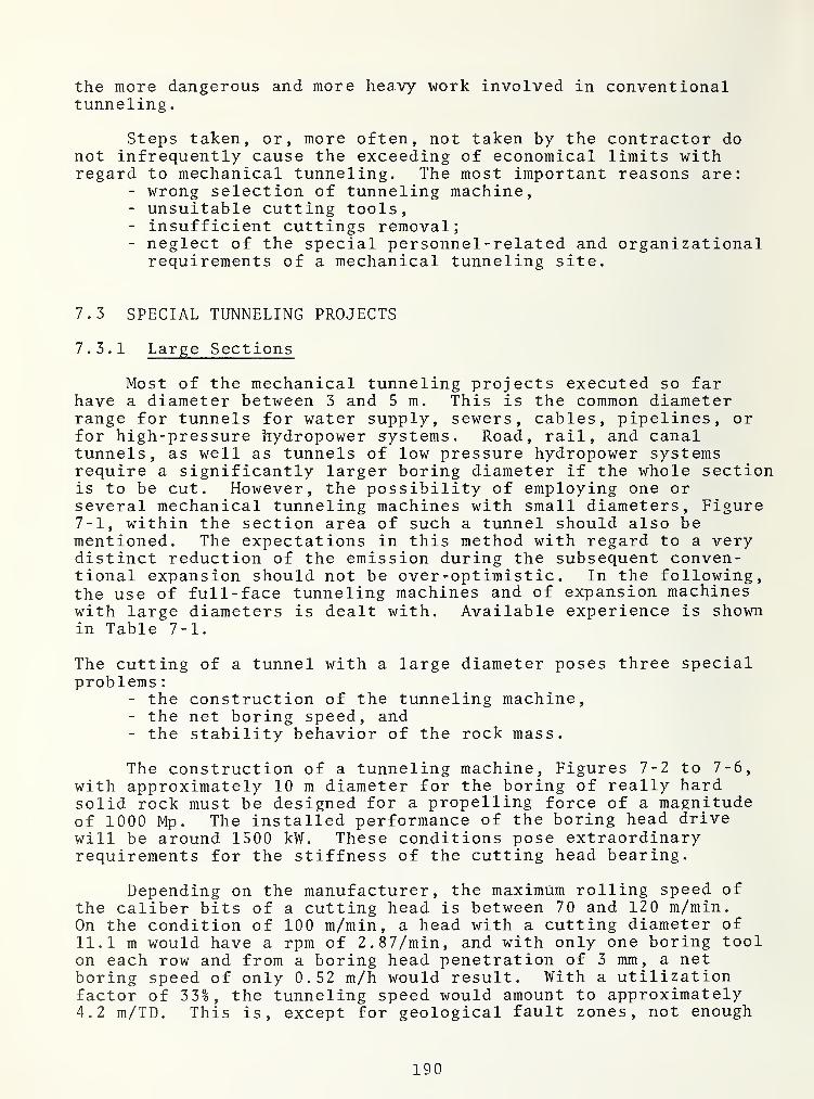
the more dangerous and more heavy work involved in conventionaltunneling
.
Steps taken, or, more often, not taken by the contractor donot infrequently cause the exceeding of economical limits withregard to mechanical tunneling. The most important reasons are:
- wrong selection of tunneling machine,- unsuitable cutting tools,- insufficient cuttings removal;- neglect of the special personnel -related and organizationalrequirements of a mechanical tunneling site.
7.3 SPECIAL TUNNELING PROJECTS
7.3.1 Large Sections
Most of the mechanical tunneling projects executed so farhave a diameter between 3 and 5 m. This is the common diameterrange for tunnels for water supply, sewers, cables, pipelines, orfor high-pressure hydropower systems. Road, rail, and canaltunnels, as well as tunnels of low pressure hydropower systemsrequire a significantly larger boring diameter if the whole sectionis to be cut. However, the possibility of employing one orseveral mechanical tunneling machines with small diameters. Figure7-1, within the section area of such a tunnel should also bementioned. The expectations in this method with regard to a verydistinct reduction of the emission during the subsequent conven-tional expansion should not be over-optimistic. In the following,the use of full-face tunneling machines and of expansion machineswith large diameters is dealt with. Available experience is shownin Table 7-1.
The cutting of a tunnel with a large diameter poses three specialproblems
:
- the construction of the tunneling machine,- the net boring speed, and- the stability behavior of the rock mass.
The construction of a tunneling machine. Figures 7-2 to 7-6,with approximately 10 m diameter for the boring of really hardsolid rock must be designed for a propelling force of a magnitudeof 1000 Mp . The installed performance of the boring head drivewill be around 1500 kW. These conditions pose extraordinaryrequirements for the stiffness of the cutting head bearing.
Depending on the manufacturer, the maximum rolling speed ofthe caliber bits of a cutting head is between 70 and 120 m/min.On the condition of 100 m/min, a head with a cutting diameter of11.1 m would have a rpm of 2.87/min, and with only one boring toolon each row and from a boring head penetration of 3 mm, a netboring speed of only 0.52 m/h would result. With a utilizationfactor of 33%, the tunneling speed would amount to approximately4.2 m/TD. This is, except for geological fault zones, not enough
190

Figure 7-1. Excavation of a Road Tunnel After Previous MechanicalExcavation; One Drift Each in the Crown and the
(Abutments) of the Tunnel
TABLE 7-1. MECHANICALLY EXCAVATED TUNNELS WITH LARGE DIAMETERS
cuttingdiameter project type of illustration
m rock Year and literature
11.20 Feed tunnel, Mangla dam,
irrigation and hydropowersystem
10.25 Subway tunnel, Paris
10.40 2nd Mersey tunnel,Liverpool
10.67 Heitersberg railwaytunnel, Zurich
10.46 Sonnenberg road tunnel.Lucerne
soft sand= 1963/4 148 [47]
stone, clay
limestone, marl 1965/68 149 [47]
sandsoft sand= 1967-70 150 [47]
stonesandstone
,
1970-72 151 [48]
clay, marlsandstone, marl 1970-73 152[47]
191

Figure 7-2. Robbins Tunneling Machine Model 371-110
Figure 7-3. Robbins Tunneling Machine Model 341-111
Figure 7-4. Robbins Tunneling Machine Model 371-110,modified
192

4-J
c(Ü
§bOUCO
I—
I
cwI
0)
bOCO
UC/3
I
o
uoCM
vO«O’O
O
MpqHXlCCO
MOr-'
oLOcn
wpqH0)
c•H
OcO
sMC
Q) t—
<
ti (U
S^ §HrC4J CO
•H IW13: O
vO
<u
Ö0•rH
Pm
Ö T3 CO 0) <U
H 4-1 (1)
4-4 «HCO E 4-1 CO-1 «H (U (U^ 43 C•H J-l
5 O CO
a, ex 4-) CO CO 4q0) CU CO
4-* 3 CCO CO «r4
0) oß P COH CO s
CO
(U
d•rH
-CoCO
B
CO
po4J
0e
1p.
4:4-1
c<u
e0)
t)0
p
'T3
CO
(U
-C
00ß
C4-C ß
CO ß(X (U
g3 »4-t
CL, o
o <u
CO
tH 3IS -H
3 PCJ X)
3rt <u
P 4J
X) ß^ ßJ3 P
(U
73 4-1
ß -Hß ß
O X)
ß 43
193
Figures
72to
76.
Machines
Build
So
Far
for
Large
Cutting
Diameters

for a 3-shift operation. The question is, if and how it can beincreased without increasing the utilization factor or the boringhead revolutions or the average penetration force of a roller bit.This possibility is available. It can be realized by dividingthe boring head into an inner circular disk and into an outercircular ring; The circular disk can rotate faster than thecircular ring, for reasons of space, however, it can be equippedonly with one bit per row. The circular ring must rotate slowerthan the circular disk, but it offers the possibility to installZ bits on one cutting track. Since it is assumed that the netboring speed V]^ of the inner cutting head disk with a radius
^disc identical with that of the outer ring with the outsideradius "r", and that the average boring tool penetration t^ is thesame for all tools with identical penetration force p 0 ,
the follow-ing applies
Z = and rITdisc
Zrdisc
and, for the relation of the revolutions "n" of the two parts ofthe boring head:
^disc _ r_
n . r j
.
ring disc
The two-piece boring head has been used in practice already.However, it has proved unsuitable in hard solid rock, among otherreasons, because rock pieces lodging between the two parts of theboring head have damaged or torn off boring tool holders. Also,this head design requires the use of a relatively large number ofroller bits with console holders. Figures 7-7 and 7-8.
With the so-called reaming method, the tunnel section isdivided into an inner circular section and into an outer circularring, and each one of these sections is bored with a specialcutting head or a special tunneling machine. The pilot machinewith the cutting radius r^jis^ drives a gallery in the axis of thetunnel. Subsequently, the expansion machine with a ring-shapedcutting head with the radius r expands the pilot gallerycentrically to the tunnel Figure 7-6. Whenever this method wasused so far [50] , the pilot gallery and the expansion were nevercut simultaneously. Either, the pilot gallery was first bored inits full length, and subsequently expanded to a tunnel in oneor two steps, or the pilot and expansion machines were boringalternately by using the same drive unit.
The expansion method is of advantage, if:- a previously cut pilot gallery exists,- a pilot machine is available at short notice when thecontract is awarded, and if the delivery time for a machinewith boring diameter of the tunnel is longer than thetunneling time of the pilot gallery, and if
- both machines can cut simultaneously.
194

Figures 7-7 and 7-8.
Two-part cutting head (Robbins)
Figure 7-7.
Overall view
Figure 7-8.
Detail of inner part with threeconsole bits, and part of the outerring with four console bits
In any case, this method involves the problem of the rock massstability between the pilot and the expansion of machines whichshould not be underestimated. If the expansion is not to beseriously delayed by the prior installation of a temporary support,only limited possibilities for the securing and the stabilizationof the rock mass are available, i.e., simple steel ring supportingthat can be easily dismantled, or shotcrete lining, but no combina-tion of these methods, and also no anchor support. If two cuttingsteps follow each other directly, i.e., if a transportation distancedoes not have to be stabilized the use of a progressive supportingbetween the stages is suitable.
Whenever a temporary lining is not necessary in the area ofthe pilot machine, and if no lining is necessary between thepilot machine and the expansion machine, or if the progressive
195

supporting is sufficient, an expansion system is more effectivethan a full-face cutting machine, even if the pilot and the ex-pansion machine can only be operated alternately. The net cuttingspeeds that can be achieved with the pilot and with the expansionmachine are greater. The utilization factors of each machine ofthe system is smaller, but the utilization factor of the systemis usually larger since scheduled inspections, service, andrepairs can be carried out on one machine of the system whilethe other machine is operating. Table 7-2 shows a relevant com-parison .
A suitable tunneling machine for large diameters is a combina-tion of the design of a full-face cutting machine with a two-pieceboring head with the design of a system of a pilot and an expan-sion machine cutting at different times and at different locations.It consists of two units, a center machine and an expansion machine.The center machine can be aligned and braced within the frame boxof the expansion machine. Its circular-disk-shape cutting headprotrudes normally by approximately 2.5 meters from that of theexpansion machine. The expansion machine can also be aligned, andis braced against the tunnel invert. Its circular-ring-shapedhead counter-rotates relative to that of the center machine. Bothmachines cut simultaneously and independently of each other.However, their operational independence is limited in so far asduring normal protrusion of the center machine of approximately2.5 meters, the distance between the work faces of the two machinescannot fall below 2.0 meters, and may not exceed 3.0 meters. Overthis length, the invert of the pilot gallery is covered, and ifnecessary, supported by the segmented boring head shield of thecenter machine. This design does not have the disadvantages of atunneling machine with a two-piece boring head and of a system fortraditional expansion; however, it combines their advantages. Forexample, a machine combination as in Table 7-3 could be used fora tunneling project with a cutting diameter of, for example,11.1 m.
The stability behavior of the rock mass is more unfavorablewith large cutting diameters, all other conditions being equal,than with a small boring diameter. The possibilities for theinstallation of a temporary support immediately behind the cuttinghead carrier are the less limited the larger the boring diameter.Also, special constructions for stabilization of the rock mass,such as installation aids, or a segmented shield, are easier toattach to a tunneling machine with a large boring diameter.
7.3.2 Inclined Galleries
Inclined galleries [51] are used in underground constructionand in mining. In underground construction they serve as pipeconduits or pressure galleries of hydropower systems, ventilationgalleries of conventional thermic power stations, ventilationgalleries of road tunnels, or access, cable car, ventilation, andpipe galleries of underground installations with various purposes.In mining they are used for conveyor belts or ventilation.
196

TABLE 7-2. PERFORMANCE OF A FULLFACER AND OF AN EXPANSION SYSTEMWITH ALTERNATELY DRIVEN PILOT AND EXPANSION MACHINE WITH A BORINGDIAMETER OF 11.1 m AND 24 -h OPERATION
Full-facer
Expansionpilot
machine
Systemexpansionmachine
number bits/trace number 1 1 3
boring diameter m 11.1 3.7 11.1max. rolling speed
of caliber bits m/min 100 100 100boring head rpm 1/min 2.87 8.6 2.87boring tool penetration e
.g . mm 3 3 3
boring head penetration mm appr. 3 appr . 3 appr. 9*)
net boring speed m/h appr. 0.52 appr. 1.55 appr. 1.55utilization factor
alternative 1 % h 33 8 16.5 4 16.5 4
alternative 2 % h - 25 25 6
advance ratealternative 1 m/TD**) appr. 4.2 appr. 6.2 appr. 6.2
alternative 2 m/TD**) — appr. 9.3 appr . 9.3
*Perfect geometry of boring head and uniform condition of all boring tools in
one trace are a precondition.**TD = Tunneling day
TABLE 7-3. SUITABLE TUNNELING MACHINE FOR A CUTTING DIAMETEROF 11.1 m
machine data center machine expansion machine
number bits/trace number 1 3
boring diameter m 3.7 11.1
max. rolling speedof caliber bits m/min 100 100
boring head rpm 1/min 8.6 2.87
boring tool penetration mm 3 3
boring head penetration mm 3 9*)
net boring speed m/h appr. 1.55 appr. 1.55
utilization factor % h 33 8 33 8
advance rate m/VT**) 12.4 12.4
^Perfect geometry of boring head and uniform condition of all boring tools in
one trace are a precondition.**TD = Tunneling day
197

No matter by which method an inclined gallery is builtconventionally, its execution always involves considerable dangerfor personnel and equipment. The excavated material will neverall slide down to the bottom of the gallery. In a floor coverlayer of varying thickness consisting of sand and small pieces,even larger pieces of rock lodge. The balance of this mass isunstable. It is very sensitive to even small vibrations, butespecially to inflow of water. Parts of this deposit may startsliding in form of an avalanche. Pieces of rock falling out ofthe tunnel invert do not simply drop to the tunnel floor but willcontinue bouncing through the gallery.
These conditions which cannot be avoided make conventionaltunneling of inclined galleries a dangerous enterprise. For thisreason, it is not surprising that of the number of tunnel workers,that is decreasing anyhow, fewer and fewer are prepared to exposethemselves to the danger and to the hard work involved in inclinedgalleries. This fact has opened the way for mechanical tunnelingin the year 1968, under conditions, that were not ideal withregard to the boreability of the formations and the economy ofthe process.
Machines of the same design are used for the boring ofinclined galleries as for horizontal mechanical tunneling. How-ever, some parts are changed, and the machines must be equippedwith a safety device to prevent sliding in galleries with steepinclinations. Two principles were observed during the boringof inclined galleries by conventional methods:
- tunneling should be done from below, with an excavationsection that is as small as possible.
- if the excavation section prescribed by the project designis distinctly larger than the minimum excavation profilethat is technically possible, the excavation should bedone in two stages, one excavation process with theminimum work section from below, and subsequently an expan-sion to the designed excavation profile from above. Withthe exception of two mining projects in the United States,this method has been used until now also for the mechanicaltunneling of inclined galleries.
With boring of tunnels from below whose inclination exceedsapproximately 30°, and with rock masses which do not swell, theremoval of boring can be made very simple. The chips can beflushed out from the steep floor. The buckets of the boringheads as well as the basic machine and the trailer conveyor beltare dismantled before the machine is put into operation. Abridging and a loading belt are not necessary.
With a tunnel inclination exceeding 20°, the tunneling machinemust be equipped with a safety device against sliding. This willsecure the tunneling machine against sliding back when the bracingdevices are relocated. Three different systems are used, singlyor in combination:
- steel cams attached excentrically to the boring head
198

carrier or the machine frame which move forward and wedgethe machine when it is sliding back,
- an auxiliary gripping system which becomes immediatelyeffective when the effect of the main bracing is reducedfor any reason, and
- segments installed in the tunnel floor against which thetunneling machine can be braced during the relocation ofthe machine.
Figure 7-9. Tunneling machine with slip safety attached to boxof combination gear
The auxiliary gripping system is the most frequently useddesign for a safety device against sliding. It can either beattached to the inner machine frame that is rigidly connected witha boring head. Figure 7-9, or can be arranged behind the basicmachine separated from it by design. Figures 7-10 and 7-11. Themain components of an auxiliary gripping system built into theframe are the gripper shoes, the springs pressing them againstthe tunnel invert, as well as hydraulic rams which, when activated,cancel the force of the springs. While the machine is braced,i.e. during the boring process, these presses are also activated,i.e. the auxiliary gripping is not effective, and is moved forwardbeing attached to the basic machine. After the boring of onesystem, and whenever the pressure in the gripping system circuitof the hydraulic system drops, the presses of the auxiliarygripping released, and the hydraulic fluid leaves those cylinders,and the gripper shoes are pressed against the invert by the forceof the strong springs. The auxiliary gripping unit is connectedwith the boring head carrier through push and pull rods.
The excentric cams and the auxiliary gripping have the dis-advantage that they become ineffective as soon as the tunnelingmachine cannot be braced anymore, as, for example, in very looserock masses, or rock masses with plastic behavior, or in faultzones that cannot be bored. If the effectiveness of the basicmachine gripping and of the auxiliary gripping cannot be restoredby means of a shotcrete, or by cushioning the gripper shoes withhardwood, a special safety device against sliding is necessary.Two solutions are known, i.e. the support of the tunneling machineby two-piece floor segments, or by a supporting tube.
199

With the first-mentioned process, Figure 7-12, a two-piecefloor segment is installed behind the tunneling machine, and is
anchored to the floor. During the cutting process, the machine isbraced against the floor segments by means of two hydraulic pressesthat serve for support as well as for forward thrust. After onestroke is bored, first one, and then the other half of a new seg-ment is installed which is as long as the length of one stroke.During the installation of one half of a segment, the machinesupports itself by means of a press braced against the other half.If this process is applied over the whole length of the gallery,the floor segments can be made in form of a box with a channelfor flushing out the chips, and possibly with an opening that canserve as a ventilation duct.
Photo
:
Wirth & Co.
Figure 7-10. Auxiliary gripping system for installationbetween basic machine and trailer
Photo
:
Wirth & Co.
Figure 7-11. Basic machine with auxiliary gripping system, assembled
200

Schnitt A-B
a boring headb propel cylinderc gripper padsd auxiliary support
e invert segment halvesf monorail crane for installation of invert
d
Figure 7-12
Kobbins Tunneling Machine withan auxiliary support bearingon invert segments
segments
With the second process, Figure 7-13, a support tube isinstalled between the basic machine and the first trailer which islonger than the rock mass zone that cannot be braced. A two-pieceauxiliary gripping system axially adjustable is installed on thissupport pipe. This auxiliary support system remains in the stablerock during the boring process. During the tunneling, the rearpart of this system is braced. The front part is clamped on thesupport pipe, and is thus connected with the tunneling machine.The propel cylinders between the two parts of the auxiliarygripping push forward the support tube with the tunneling machine.After one travel length of these cylinder jacks is cut, thesupport tube is clamped to the rear part of the auxiliary grippingsystem, and the front part is loosened and pulled back. Thesystem again is ready for boring after the front part of theauxiliary gripping system is clamped onto the support tube, andafter the connection between the rear part and the support tube isloosened. The rear part of the auxliary gripping system remainsbraced also during the relocation. The equipment of both partswith gripper shoes permits the climbing-up of the auxiliary grip-ping unit on the support tube while the tunneling machine is heldby itself.
201

Figure 7-13
Demag Tunneling Machinewith auxiliary grippingsystem and supporting tube
a boring headb propel cylinders of TMc gripper plates of TMd auxiliary gripping system with propel
cylinders and gripper plates
e suppport tube
Design: Demag AG
There are three possibilities to employ tunneling machines forthe construction of shafts with large diameters. The first twopossibilities correspond to the principles of conventional tunnelboring
:
- boring of a pilot gallery from below, with subsequent conven-tional expansion, preferably from above.
- boring of a pilot gallery from below, with subsequentmechanical expansions from below or, under certain circum-stances, from above.
The last possibility is less recommended:- full-facing of the section from below, unless the projectmakes it necessary.
The advantages of the pilot gallery are generally recongnized.The decision in favor of a conventional, or of a mechanicalexpansion depends on various condition, such as the intended useof the gallery and its required quality, economy, finish date, as
202

well as availability o£ working personnel and of an expansionmachine
.
In case of mechanical expansion, a decision must be madewhether the tunneling machine will be employed from below or fromabove. In both cases, the chips are flushed out towards the lowerend. With expansion from above, the problem must be solved ofremoving the chips from the corner formed by work face and floorinto the pilot gallery in the center of the tunnel axis. If chipsand water remain in this corner, heavy boring tool wear would beunavoidable. In addition, the boring head penetration would bereduced. The attachment of special scrapers in front of the boringtools for purposes of cleaning the effective range of the bits ismandatory. Figure 7-14. Expansion from below requires a tunnel-ing machine with a safety device against sliding.
With mechanical tunneling of an inclined gallery from below,and with mechanical expansion of a pilot gallery from below orfrom above, the resulting chips are flushed out via the galleryfloor if the inclination is large enough. The quantity of watermust be controlled in such a way that a continuous flushing isguaranteed, and avalanches are avoided. In order to avoid uncon-trolled movements of larger rock, the floor section necessary forthe flushing can either be covered with wire mesh, or a steel boxclosed on top is installed on the floor. In special cases, as forexample, in galleries with a small inclination, a conveyor chuteis necessary. This chute is subject to heavy wear during theremoval of chips [52]. At the lower end of the gallery the chipsand the flushing water are caught in special cars. Figure 7-15.Before entering public water ways, the overflowing flushing watermust at least be pre-treated in several sedimentation basins.
For the transportation of personnel and supplies, a transpor-tation system is necessary in the gallery, either as a cable car,or as a monorail conveyor. For this purpose, either tracks mustbe installed on the floor of the gallery, or a rail in the crownof the gallery. The drive winch for the transport system isinstalled at the foot of the gallery, and a guide pulley for thecable is attached to the rear-most trailer of the tunneling machine.
The floor covering, the tracks and the rail, and the supplylines, among them the pump lines for the flushing water as well asthe air duct, are installed continuously behind the tunnelingmachine as with a horizontal tunneling process.
7.3.3 Tunneling in Mines
Long after the first mechanical production in mining, andafter the first mechanical wall mining, a rock tunnel was excavatedby means of a tunneling machine for the first time in 1971 inWest German coal mining.
203
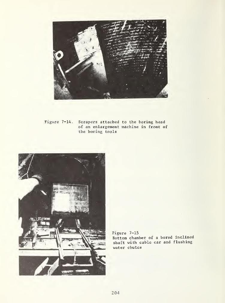
Figure 7-14. Scrapers attached to the boring headof an enlargement machine in front ofthe boring tools
Figure 7-15
Bottom chamber of a bored inclined
shaft with cable car and flushing
water chutes
204

The delayed introduction of mechanical tunneling for hori-zontal or inclined transportation and ventilation of tunnels andshafts can be explained by the fact that its advantages in com-parison to conventional methods are not as obvious for coal miningas they are for underground construction. In addition, a certainreverence for tradition in coal mining may have favored the blast-ing method.
The advantages of mechanical tunneling for rock tunnels inmining operations are not directly evident because the process ismore expensive than conventional methods:
- the bored section is circular, its use as transportationtunnel with tracks requires filling of the floor with chips.
- the tunneled sections must always be supported. Steel-lining is the rule, and even in stable sandstone anchorsupporting for purposes of head-protection is hardly per-mitted; the advantages converning the relatively smalldisturbing effect of mechanical tunneling can only be usedup to a certain limit because the support must frequentlybe dimensioned with regard to the subsequent effect of themining operation, and not only with regard to the one-timeredistribution of forces and stresses occuring during tunnel-ing, and to the secondary stress distribution.
- the tunneling of rock tunnels in a mine is not an individualproject but marginal within the framework of an operationdirected towards production, the scarcity of empty carswill effect the tunneling before the mining, and coal willhave transportation priority above the chips and the tunnel-ing supply; under these conditions, the non- system-relateddown-times will become longer.
- the existing regulations of the mining authority geared tothe excavation and blasting operations limit the freedom ofthe contractor during the planning and execution of a
tunneling project in comparison with underground construc-tion. Special permits are not easy to obtain.
- the personnel requirements of a tunneling shift amountingto 10 to 11 miners, and to 2 to 3 supervisors are high, andalthough the labor cost amounts to only about 2/3 of thatfor conventional tunneling, it is however high calculatedabsolutely, and in comparison with heavy construction.
However, there are also advantages:- the excavation speed is distinctly higher with mechanicaltunneling than with the blasting process. Depending onthe portion of sandstone, sandy shale, and shale, anaverage tunneling performance of 15 to 25 m/WD can beassumed for boring diameters of approximately 5 m, asopposed to 5 to 6 m/WD during conventional excavation of asection of 16 to 20m2. The exploration of a new fieldor of a new gallery can be done faster, and capital costscan be saved with the later start of an excavation process.
- mechanical tunneling reduces the danger of accidents, thegreater physical safety of the work place may slow down
205

the change of miners to other jobs, and may facilitate thehiring of new personnel.
- a systematically installed support with bolted steel ringsflush against the invert usually without backfill, reducesthe maintenance costs. Figure 7-16.
- The planning and the execution of a mechanical tunnelingprocess in mining operations is an extraordinarily interest-ing and demanding job for an engineer. The planners of thecoal mines must design a course for the horizontal orinclined galleries to be cut that is geared to the machineand avoids small curve radii. A planning team composed ofengineers of both sides (the coal mine and the contractor)
,
will be confronted with all problems of mechanical tunnel-ing, and will have to make special decisions, for exampleon
:
- the tunneling machine with segmented cutting head shield,efficient supporting aids, explosion-protective electricalsystem, and a hydraulic system operated with a non-flam-mable fluid,
- a fresh-air supply designed for degassing,- a dust trapping system which will meet the strict require-ments of the MAK for mining, or on
- the air conditioning at the point of operation under con-sideration of the heat generated by the tunneling systemand the rock mass.
Figure 7-16
Bored and systematic-ally supported head-ing in a coal mine
206

Also, during the tunneling, constant contact, and close cooperation between the representative for the tunneling project andthe coal mine management is unavoidable in order to meet the re-quirements of mechanical tunneling - an auxiliary process in acoal mine operation - concerning the removal of chips and the supply with as few restrictions as possible.
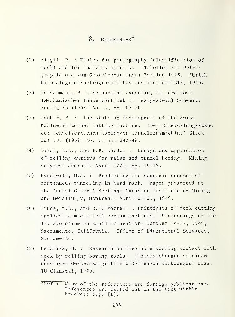
8. REFERENCES*
(1) Niggli, P. : Tables for petrography (classification of
rock) and for analysis of rock. (Tabellen zur Petro-
graphie und zum Gesteinbestimmen) Edition 1943. Zürich
Mineralogisch-petrographisches Institut der ETH, 1943.
(2) Rutschmann, W. : Mechanical tunneling in hard rock.
(Mechanischer Tunnelvortrieb im Festgestein) Schweiz.
Bauztg 86 (1968) No. 4, pp. 65-70.
(3) Lauber, E. : The state of development of the Swiss
Wohlmeyer tunnel cutting machine. (Der EntwicklungsstandI ! M
der schweizerischen Wohlmeyer- Tunnelfrasmachine) Glück-
auf 105 (1969) No. 8, pp. 343-49.
(4) Dixon, R.L., and E.P. Worden : Design and application
of rolling cutters for raise and tunnel boring. Mining
Gongress Journal, April 1971, pp . 40- 47.
(5) Handewith, H.J. : Predicting the economic success of
continuous tunneling in hard rock. Paper presented at
the Annual General Meeting, Canadian Institute of Mining
and Metallurgy, Montreal, April- 21-23, 1969.
(6) Bruce, W.E., and R.J. Morrell : Principles of rock cutting
applied to mechanical boring machines. Proceedings of the
II. Symposium on Rapid Excavation, October 16-17, 1969,
Sacramento, California. Office of Educational Services,
Sacramento
.
(7) Hendriks, H. : Research on favorable working contact with
rock by rolling boring tools. (Untersuchungen zu einem? t
Günstigen Gesteinsangriff mit Rollenbohrwerkzeugen) Diss.
TU Claustal, 1970.
*N0TE : Many of the references are foreign publications.References are called out in the text withinbrackets e
.g
. [ 1 ]
.
208

REFERENCES (CONT.)
(8) Gaye, F. : Efficient excavation with particular reference
to cutting head design of hard rock tunneling machines.
Tunnels and Tunneling, 1972, pp . 39-48; 135-43.
(9) Roxborough, F.F., and A. Rispin: The mechanical cutting
characteristics of the lower chalk. Tunnels and Tunneling
1973, pp. 45-67.
(10) Handewith, H.J. ; Machine boring and the mechanical
properties of hard rock. Paper presented at the
Australian Geomechanics Society Raise- and Tunnel Boring
Symposium, Univeristy of Melbourne, Australia,
August 14, 1970.
(11) Hustrulid, W.A. : A comparison of laboratory cutting
results and actual tunnel boring performance. Proceed-
ings 1st North American Rapid Excavation and Tunneling
Conference, June 5-7, 1972, Chicago, Illinois, pp . 1299-
1323.
(12) Misawa, S., T. Sakurai and A. Takahashi : Some methods
of test and survey for estimating the maschinability of
rocks in excavation by rock tunneling machines. Japan
National Railways, Quarterly Reports, 13 (1972), No. 4,
pp. 187-91.
(13) Descoeudres, F., and G. Rechsteiner: Study of the
correlation between the geology, the mechanical properties
and the machinabil ity of the rock of the Crespera- Gemmo
.
(Etude de correlations entre la geologie, les proprietes
mecaniques et la forabilite des roches de Crespera- Gemmo)
Schweiz. Bauztg. 91 (1973), No. 12, pp . 289-96.
209

REFERENCES (CONT.)
(14) Deere, D.U., and R.P. Miller : Engineering classifica-
tion and index properties of intact rock. Technical
Report No. AFWL-TR-65-116,December 1966. Reproduced by
the Clearinghouse for Federal Scientific 6 Technical
Information, Springfield, Va
.
(15) de Quervain, F. ; Technical lithology (petrography).! t
(Technische Gesteinskunde), 2. Edition. Basel: Birkauser
Verlag 1967
.
(16) Fleyne ,K.-H. : Article on the tensile strength of rocks,
a comparison of different methods of determination of
tensile strength. (Beitrag zur Zugfestigkeit von Gesteinen,
Vergleich verschiedener Methoden der Zugfestigkeits-
bestimmung) Bergakamie 15 (1963) No. 5, pp. 356-66.T f
(17) Heyne, K.-H., and K.-F. Hofer : The segment compression
test - an efficient method for the determination of the
tensile strength of rocks. (Der Scheibendruckversuch -
eine rationelle Methode zur Bestimmung der Zugfestigkeit
von Gesteinen) Bergakadamie 15 (1963) No. 5, pp. 367-70.
(18) Schimazek, J., and H. Knatz : The influence of the
composition of rock on the speed of cutting and the
cutting tool wear of tunneling machines. (Der Einfluss
des Gesteinsaufbaus auf die Schnittgeschwindigkeit und
den Meisselverschleiss von Streckenvortr iebsmachinen)
Glückauf 106 (1970) No. 6, pp. 274-78.
(19) Rosiwal, A. : Recent results in the hardness grading of
minerals and rocks. - An absolute measure for the hard-f I
ness of brittle substances. (Neuere Ergebnisse der Harte-
bestimmung von Mineralien und Gesteinen. - Ein absolutesM t» M 'I
Mass fur die Harte spröder Körper) Verhandlungen (Proceed-
ings) der k 5 k Geologischen Reichsanstalt, Jg. 1916. Wien:
Verlag der k ^ k Geologischen Reichsanstalt, 1916, pp. 117-147
210

REFERENCES (CONT.)
(20) Duvall, W.I., and V/. Blake : Stresses and displacements
induced in rock by tunnel boring machine props. Bureau
of Mines, Report of Investigations 7200, Nov. 1968.
(21) Marx, C. : Concerning the shattering of rock at greatM Tl
depth by rotating boring. (Über die GesteinszerstorungI T
in grosser Teufe beim drehenden Bohren) Erdo 1 - Erdgas
-
Zeitschrift, 83 (1967) October, pp. 354-63.
(22) Wanner, W.J.: Employment of tunnel drilling machines
in a crystalline rock mass. Correlation of the rate of
advance to the geological-petrographical conditions.
(Einsatz von Tunnelbohrmaschinen im kristallinen Gebirge.n
Abhängigkeit des Vrotriebes von den geologisch-petro
-
! T
graphischen Bedingungen) Diss. ETH Zurich. (in progress)
(23) Aeberli, U. : Employment of tunneling machines in
diagenet ical ly compacted sedimentary rocks. Correlation
of the rate of advance to geologic-petrographic condi-
tions. (Einsatz von Tunnel -Vortriebsmaschinen inIT
diagenetisch verfestigten Sedimentgesteinen. Abhängigkeit
des Vortriebes von den geologisch -petrographischenT
I
Bedingungen) Diss. ETH Zurich (in progress).
(24) Einstein, H.H.: The Northeast Corridor Project.
Technical structural research at the Massachusetts
Institute of Technology. (Das Nordostkorr idor-Proj ekt
.
Bautechnische Forschungsarbeiten am Massachusetts
Institute of Technology) Neue Zürcher Ztg. Technik,
No. 214 of 9/4/1969.
(25) McGarry, F.J., and Moavenzadeb: Rock weakening poten-
tials of surface active agents. Proceeding 1st North
American Rapid Excavation and Tunneling Conference,
June 5-7, 1972. Chicago, Illinois, pg. 1361.
211

REFERENCES (CONT.)
(26) Carstens, J.P.: Thermal fracture of rock - a review of
experimental results. Proceeding 1st North American Rapid
Excavation and Tunneling Conference, June 5-7, 1972,
Chicago, Illinois, pp. 1363-92.
(27) Cooley, W.C.: hater jets and rock hammers for tunneling
in the USA and USSR. Proceeding 1st North American
Rapid Excavation and Tunneling Conference, June 5-7,
1972, Chicago, Illinois, pp . 1325-60
(28) V. Rabcewicz, L.: Dimensioning of hollowed out construc-
tion, the "New Austrian construction style" and its
influence on the effect of rock mass pressure and
dimensioning. (Bemessung von Hohlraumbauten, die „Neue1
1
österreichische Bauweise" und ihr Einfluss auf Gebirgs-
druckwirkung und Dimensionierung) Felsmechanik U. Ingen-
ieurgeologie, vol. 1/3-4, 1963, pp. 224-44.
(29) Daemen, J.J.K., C. Fairhurst and A.M. Starfield: Ratio-
nal design of tunnel supports. Paper presented at the
2nd Symposium on Rapid Excavation, Sacramento, California,
October 16-17, 1969.
(30) Lombardi, G.: The influence of the characteristics of
solid rock on the stability of hollowed spaces. (DerM
Einfluss von Felseigenschaften auf die Stabilität von
Hohlraumen) Schweiz. Bauztg 87 (1969), No. 3, pp. 39-47.
(31) Lombardi, G.: On the dimensioning of tunnel lining with
regard to the construction process. (Zur Bemessung derI
!
Tunnelauskleidung mit Berücksichtigung des Bauvorganges)
Schweiz. Bauztg 89 (1971), No. 32, pp. 793-801. or:
Lombardi, G. Dimensioning of tunnel lining. Tunnels and
Tunneling 1973, pp. 340-51.
212
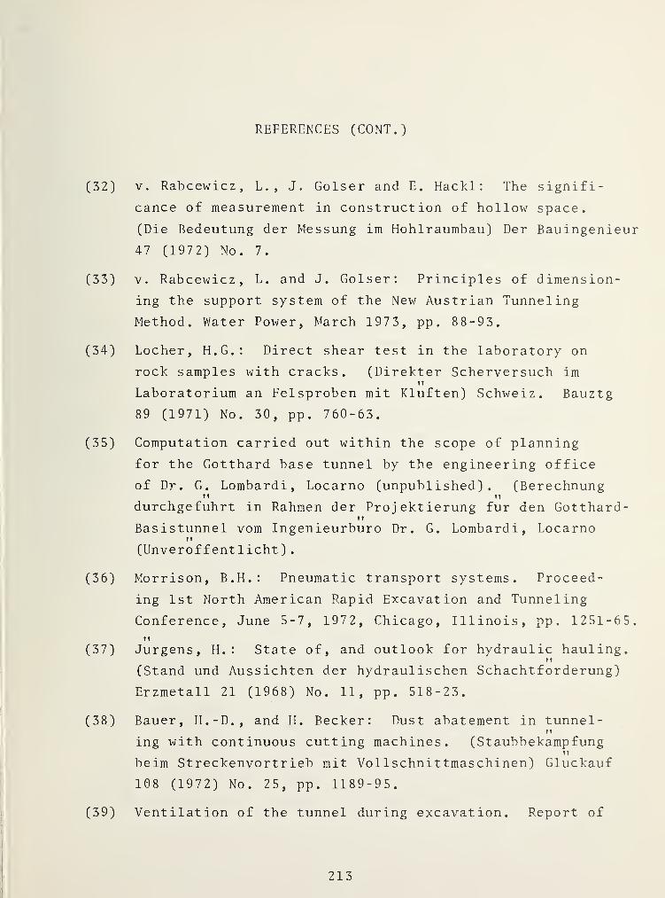
REFERENCES (CONT.)
(32) V. Rabcewicz, L., J. Golser and E. Hackl : The signifi-
cance of measurement in construction of hollow space.
(Die Bedeutung der Messung im Hohlraumbau) Der Bauingenieur
47 (1972) No. 7.
(33) V. Rabcewicz, L. and J. Golser; Principles of dimension-
ing the support system of the New Austrian Tunneling
Method. Water Power, March 1973, pp . 88-93.
(34) Locher, H.G.: Direct shear test in the laboratory on
rock samples with cracks. (Direkter Scherversuch im
Laboratorium an Felsproben mit Kluften) Schweiz. Bauztg
89 (1971) No. 30, pp. 760-63.
(35) Computation carried out within the scope of planning
for the Gotthard base tunnel by the engineering office
of Dr. G. Lombardi, Locarno (unpublished). (BerechnungT» tf
durchgefuhrt in Rahmen der Projektierung fur den Gotthard-It
Basistunnel vom Ingenieurbüro Dr. G. Lombardi, LocarnoTT
(Unveröffentlicht)
.
(36) Morrison, B.H.: Pneumatic transport systems. Proceed-
ing 1st North American Rapid Excavation and Tunneling
Conference, June 5-7, 1972, Chicago, Illinois, pp. 1251-65.It
(37) Jurgens, H. : State of, and outlook for hydraulic hauling.IT
(Stand und Aussichten der hydraulischen Schachtförderung)
Erzmetall 21 (1968) No. 11, pp. 518-23.
(38) Bauer, H.-D., and H. Becker: Dust abatement in tunnel-n
ing with continuous cutting machines. (Staubbekämpfung1
1
beim Streckenvortrieb mit Vol 1 Schnittmaschinen) Glückauf
108 (1972) No. 25, pp. 1189-95.
(39) Ventilation of the tunnel during excavation. Report of
213

REFERENCES (CONT.)
the Working Group for Ventilation in Tunnel Construction,ft It
(Die Luftung der Tunnel Wahrend dem Ausbruck, Bericht derIf M
Arbeitsgruppe für Luftung im Tunnelbau), Mitteilung (Bull-M
etin) Nr. 20 des Institutes für Strassen- und Untertagbau
(No. 20 of the Institute for Street and UndergroundM
Construction) an der ETH Zurich.
(40) Breuer, H. : New information in the reduction of dust
and silicosis. (Neue Erkenntnisse in der Staub- undII
Sil ikosebekampfung) Gewerkschaft!. Rundsch. 10/11 (1967)
pp. 397-406.
(41) Swiss Accident Insurance Agency. Leaflet on work under-
ground under warm and humid climatic conditions. (Schweiz-II
erische Unfallversicherunganstalt. Merkblatt über die
Arbeit unter feuchtwarmen Klimabedingungen unter Tag),
July 1972.
(42) Thoma, E. : Concerning the problem of heat conduction
next to a surface defined as wavy and its application toII M
tunnel construction. (Über das Warmeleitungsprob lem beiII
wellig begrenzter Oberfläche und dessen Anwendung auf
Tunnelbauten) Diss. TU Karlsruhe, 1906.
(43) Koenigsberger and E. Thoma : Concerning the influence
of mountains and valleys, strata position, and flowingII
water on the geothermal gradient. (Über die BeeinflussungII
ger geothermischen Tiefenstufe durch Berge und Taler,
Schichtstellung, durch fliessendes wasser usw.) Ecl. geol.
Helv., Bd. (vol) IX, No. 1, 1906.
(44) Carslaw, H.S., and J.C. Jaeger: Conduction of heat in
solids. Second Edition» Oxford at the Clarendon Press:
1959 .
214

REFERENCES (CONT.)
(45) Computation carried out within the scope of planning
for the Gotthard base tunnel by the Electro-Watt Engin-
eering Enterprise AG (Elektro -Wat t Ingenieurunternehmungff
AG) (Berechnung durchgefuhrt im Rahmen der Projektierungff
für den Gotthard-Basistunnel von El ektro -Wat t . . . AG),ft
Zurich. (Unpublished).
(46) Laser Steers big Mole in bad rock under lake. Engineer-
ing News Record, January 8, 1970, pp. 26-28.
(47) Robbins, R.J. : Vehicular tunnels in hard rock, a direc-
tion for development. Paper presented at the Joint ASCE-
ASME National Transportation Engineering Conference,
Seattle, Washington, July 25-30, 1971.
(48) Heltersberg Tunnel, brochure published by the Swiss
Federal Railroads (He iter sber gtunnel,
Los Ost. Prospekt
herausgegeben von den Schweizerischen Bundesbahnen), 1971.
(49) Beusch, E., and V!. Studer : Excavation and lining of the
Sonnenberg Tunnel (Ausbruch und Verkleidung des Sonnen-
bergtunnels) . Schweiz. Bauztg 90 (1972) No. 36, pp. 853-57.
(50) Schafhausen, K. : Conception and construction (design)
of the Wirth tunnel drilling machines (Konzeption undft
Konstruktion der Wirth-Tunnelbohrmaschinen),Glückauf
108 (1972) No. 10, pp. 376-79.
(51) Rutschmann, W. : Employment of tunneling machines for
the boring of slanting shafts (Einsatz von Strecken-ft ft
Vortriebsmaschinen beim Bohren von Schragschacht en)
.
Erzmetall 23 (1970) No. 6, pp. 269-78.
215
REFERENCES (CONT.)
(52) Lange, R. : The slanted shaft Caprun, new methods of a
fully mechanical tunneling of an unusual structure inIt
the alpine mountains (Der Schragschacht Kaprun, neue
Wege einer vollmechanischen Auffahrung eines ausser-fl
gewöhnlichen Bauwerkes im Hochgebirge) . Erzmetall 26
(1973) No. 8, pp. 367-76.
216
APPENDIX
REPORT OF NEW TECHNOLOGY
This report is a complete translation of the book writtenby Werner Rutshmann entitled "Mechanischer Tunnelvortrieb imFestgestein." The work performed under this contract,while leading to no new inventions, will be beneficial toengineers, managers and students associated with the tunnel-ing profession on the principles, practical issues andoperation of mechanized tunneling. The information containedin this report fills in the gap created by the lack ofknowledge of tunnel designers and project managers of guide-lines on how to consider the area of mechanized tunnelexcavation in their everyday work.
U.S. GOVERNMENT PRINTING OFFICE : 1980—600-844/62
217/218


'J1 <0
^ 5-
t—' 3Q)
a-:3
Oo ^O<
X)crfin
O::3-
303
33
X.m
^ 'CO
0=* •
I03
-4 •
OI W-> -J
c+2: O
' 3 CD•
3 3 o3
0)
3o
t—
•
i-‘"\
3 •
vQ
W)H-*- Q

OOGQ'ilBT
-i
fit
/