
Mechanical Engineering | June 2015
110
06 137 JUNE 2015 ASME.ORG ROBOTS OUT OF THE CAGE PAGE 38 DSC: HUMANOID ROBOTS PAGE 49 ENERGY SOURCES & PROCESSING PAGE 71 No. Mechanical Technology that moves the world THE MAGAZINE OF ASME GAS TURBINES ARE CHANGING THE WORLD — IN THE AIR AND ON LAND. power & ENERGY ENGINEERING
-
Upload
khangminh22 -
Category
Documents
-
view
0 -
download
0
Transcript of Mechanical Engineering | June 2015

06137
JUNE 2015ASME.ORG
ROBOTS OUT OF THE CAGEPAGE 38
DSC: HUMANOID ROBOTSPAGE 49
ENERGY SOURCES & PROCESSINGPAGE 71
No.
Mechanical Technology that moves the worldTHE
MAGAZINE OF ASME
GAS TURBINES ARE CHANGING THE
WORLD — IN THE AIR AND ON LAND.
power &ENERGY
ENGINEERING
LOG ON ASME.ORG
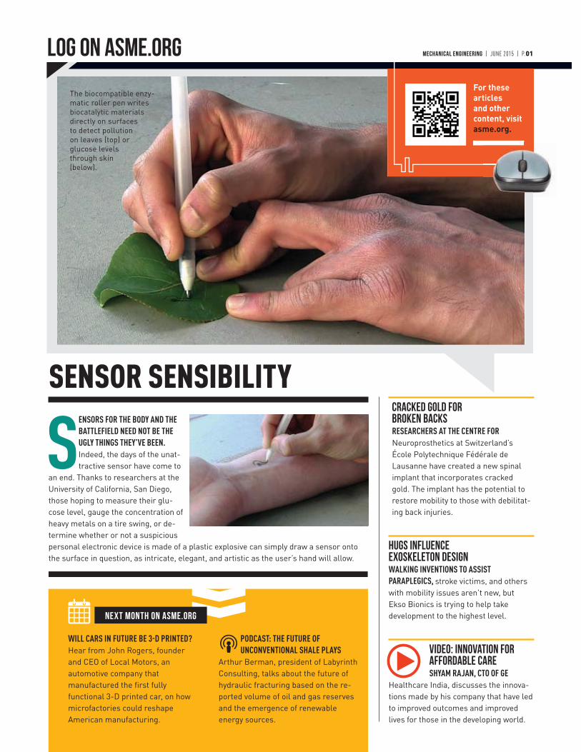
SENSORS FOR THE BODY AND THE
BATTLEFIELD NEED NOT BE THE
UGLY THINGS THEY’VE BEEN.
Indeed, the days of the unat-tractive sensor have come to
an end. Thanks to researchers at the University of California, San Diego, those hoping to measure their glu-cose level, gauge the concentration of heavy metals on a tire swing, or de-termine whether or not a suspicious personal electronic device is made of a plastic explosive can simply draw a sensor onto the surface in question, as intricate, elegant, and artistic as the user’s hand will allow.
SENSOR SENSIBILITY
WILL CARS IN FUTURE BE 3-D PRINTED?
Hear from John Rogers, founder and CEO of Local Motors, an automotive company that manufactured the first fully functional 3-D printed car, on how microfactories could reshape American manufacturing.
PODCAST: THE FUTURE OF
UNCONVENTIONAL SHALE PLAYS
Arthur Berman, president of Labyrinth Consulting, talks about the future of hydraulic fracturing based on the re-ported volume of oil and gas reserves and the emergence of renewable energy sources.
NEXT MONTH ON ASME.ORG
Cracked Gold for Broken BacksRESEARCHERS AT THE CENTRE FOR
Neuroprosthetics at Switzerland’s École Polytechnique Fédérale de Lausanne have created a new spinal implant that incorporates cracked gold. The implant has the potential to restore mobility to those with debilitat-ing back injuries.
Hugs Influence Exoskeleton DesignWALKING INVENTIONS TO ASSIST
PARAPLEGICS, stroke victims, and others with mobility issues aren’t new, but Ekso Bionics is trying to help take development to the highest level.
Video: Innovation for Affordable CareSHYAM RAJAN, CTO OF GE
Healthcare India, discusses the innova-tions made by his company that have led to improved outcomes and improved lives for those in the developing world.
MECHANICAL ENGINEERING | JUNE 2015 | P.01
For these articles and other content, visit asme.org.
The biocompatible enzy-matic roller pen writes biocatalytic materials directly on surfaces to detect pollution on leaves (top) or glucose levels through skin (below).
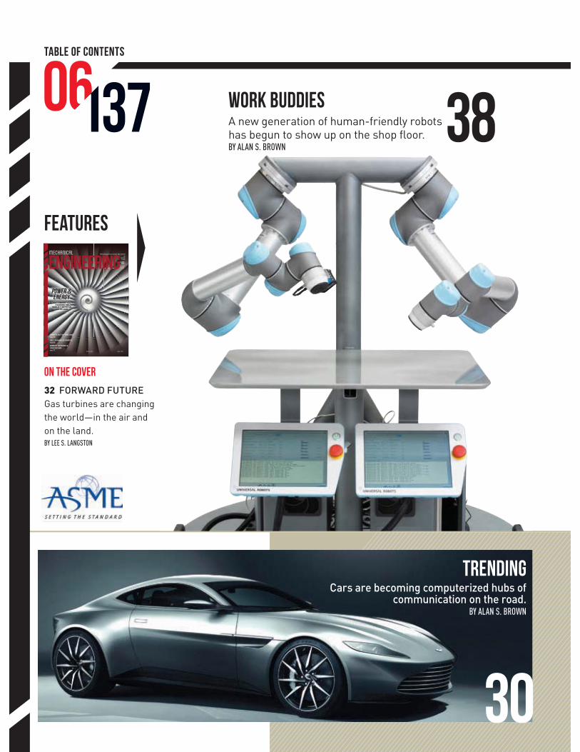
TABLE OF CONTENTS
06137
JUNE 2015ASME.ORG
ROBOTS OUT OF THE CAGEPAGE 38
DSC: HUMANOID ROBOTSPAGE 49
ENERGY SOURCES & PROCESSINGPAGE 71
No.
Mechanical Technology that moves the worldTHE
MAGAZINE OF ASME
GAS TURBINES ARE CHANGING THE
WORLD — IN THE AIR AND ON LAND.
power &ENERGY
ENGINEERING
FEATURES
3813706
ON THE COVER
32 FORWARD FUTURE
Gas turbines are changing the world—in the air and on the land. BY LEE S. LANGSTON
Work BuddiesA new generation of human-friendly robots has begun to show up on the shop floor.BY ALAN S. BROWN
TRENDINGCars are becoming computerized hubs of
communication on the road.BY ALAN S. BROWN
30
MECHANICAL ENGINEERING | JUNE 2015 | P.03
18
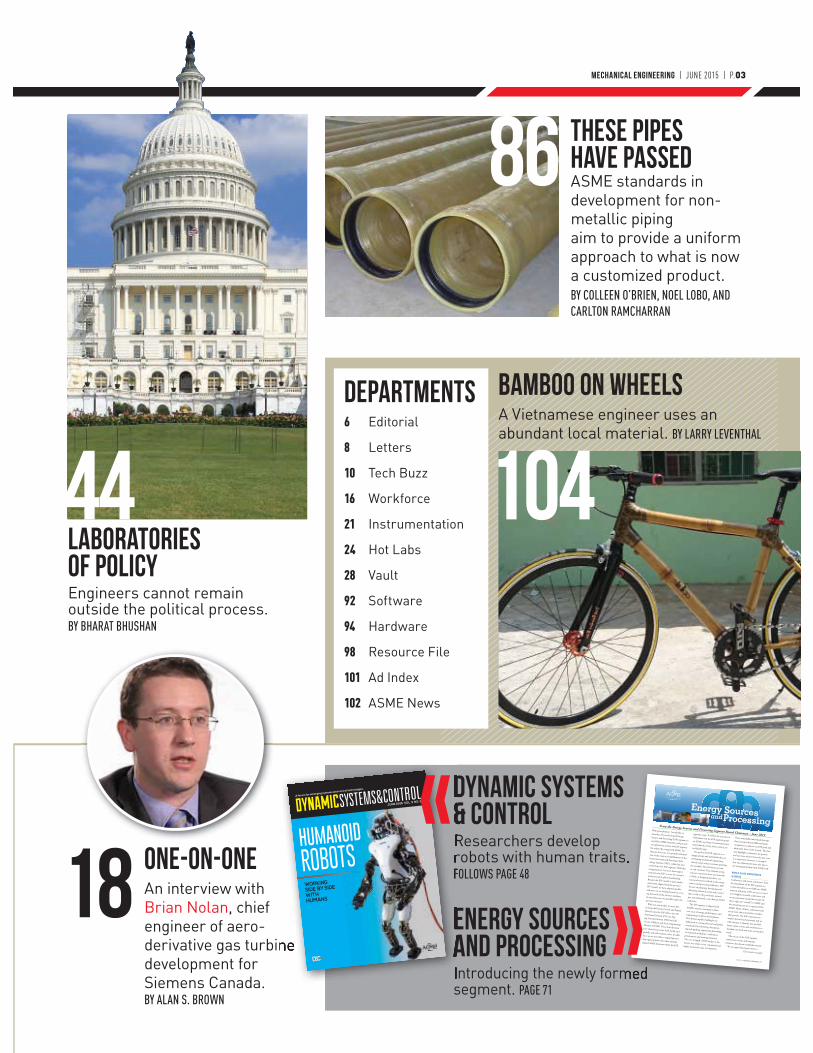
LABORATORIES OF POLICYEngineers cannot remain outside the political process.BY BHARAT BHUSHAN
DYNAMIC SYSTEMS & CONTROLResearchers develop robots with human traits.FOLLOWS PAGE 48
ENERGY SOURCES AND PROCESSINGIntroducing the newly formed segment. PAGE 71
DEpartments
446 Editorial
8 Letters
10 Tech Buzz
16 Workforce
21 Instrumentation
24 Hot Labs
28 Vault
92 Software
94 Hardware
98 Resource File
101 Ad Index
102 ASME News
Bamboo on WheelSA Vietnamese engineer uses an abundant local material. BY LARRY LEVENTHAL
ONE-ON-ONEAn interview with Brian Nolan, chief engineer of aero-derivative gas turbine development for Siemens Canada.BY ALAN S. BROWN
these pipes Have PassedASME standards in development for non-metallic piping aim to provide a uniform approach to what is now a customized product.BY COLLEEN O’BRIEN, NOEL LOBO, AND CARLTON RAMCHARRAN
WORKING SIDE BY SIDE
WITH HUMANS
A forum for emerging systems and control technologies.
JUNE 2015 VOL. 3 NO. 2
d 1
4/27/15 4:46 PM
104
86
MAY 2015 | MECHANICAL ENGINEERING 71
PETROLEUM DIVISION ......................................................................................49
PIPELINE SYSTEMS DIVISION ...........................................................................53
OCEAN OFFSHORE AND ARCTIC ENGINEERING DIVISION ...............................59From the Energy Sources and Processing Segment Board Chairman – June 2015
With great pleasure, I would like to introduce the newly formed Energy Sources and Processing (ESP) segment to my fellow ASME members, and provide an explanation on how the ESP segment fits within the reorganized ASME. For the past few years, I’ve proudly informed you of the many accomplishments of the former International Petroleum Tech-nology Institute (IPTI), which has now evolved into the ESP segment. With this reorganization, I see even more oppor-tunity for the ESP to serve the Society’s missions and its global membership. Because the ESP model is quite similar and closely aligned with the previous IPTI model, we have adapted quickly and now, we are looking forward to serv-ing the needs of the Society’s members in ways that were not possible under the previous structure. With our new model, we were able to bring the Pressure Vessels and Piping Division into the ESP fold to join the Petroleum Division (PD), the Pip-ing Systems Division (PSD) and the Ocean, Offshore and Arctic Engineering Division (OOAE). These four divisions have always been active both locally and globally and will continue to be. In addi-tion, we are now able to expand partner-ship opportunities with other similarly aligned ASME divisions within the ESP
segment scope. To follow the activities of ESP, please visit the ESP segment group on ASME.org (https://community.asme.org/technical_events_and_content_sec-tor/default.aspx). The goal of the ESP segment is to engage groups and individuals that are developing mechanical engineering-related energy sources content spanning the complete lifecycle from raw state to end-customer. This includes energy sources, conversion from raw materials to fuels, or designing products, sys-tems and services utilized in the energy sources and processing industries. ESP focuses on planning, developing and delivering technical events and content that is vital to the petroleum, natural gas, petrochemicals, coal, shale and LNG industries.
The ESP segment is aligned with ASME’s mission statement in three core areas of energy, global impact and engineering workforce development. The division updates highlight our dedication to serving the local and global community by advancing, disseminat-ing and applying engineering knowledge via technical workshops, conferences, presentations and training initiatives. The core strength of ESP, similar to the Society as a whole, is our committed and highly motivated corps of volunteers.
These remarkable individuals leverage their strong technical skills and name recognition to achieve our ESP goals and ultimately, those of the Society. The divi-sion highlights summarize the growth and successes achieved over the past year. It is important, however, to recognize that our achievements were also due to our strong partnership with ASME staff.
WORLD-CLASS CONFERENCES & EVENTSConferences and events continue to form the foundation of the ESP segment ac-tivities that allow us to fulfill our ASME mission and goals. ESP’s success is rooted in 18 highly successful conferences and events presented around the world. Of these, eight are “owned” by ASME and the remaining ten are co-sponsored by ASME. Many of these conferences and events have the potential for consider-able growth. The ESP volunteers are market-focused and motivated and we will continue to identify new and dif-ferent topics, events and conferences to broaden our reach and meet our markets’ needs.
The success of the ESP segment conferences, events and training initiatives has drawn worldwide interest. We are approached quite often to (Continued next page)
INTERNATIONAL PETROLEUM TECHNOLOGY INSTITUTEEnergy Sources Processing
and
me_june_2015_final.indd 71

Contact Mechanical Engineering
Mechanical Engineering
[email protected] p. 212.591.7783 f. 212.591.7841
Two Park Avenue, New York, NY 10016
President J. Robert SimsPresident-Elect Julio C. Guerrero
Past President Madiha El Mehelmy Kotb
Governors
John F. Elter; Urmila Ghia; John E. Goossen;Stacey E. Swisher Harnetty; Bernard E. Hrubala;
Richard T. Laudenat; Andrew C. Taylor; John M. Tuohy; William M. Worek
Executive Director Thomas G. Loughlin
Secretary and Treasurer Warren R. Devries
Assistant Secretary John Delli Venneri
Assistant Treasurer William Garofalo
Second Assistant Treasurer June Ling
Senior Vice PresidentsStandards & Certification Laura Hitchcock
Technical Events & Content Robert E. Grimes
Public Affairs & Outreach William J. Wepfer
Student & Early Career Development Cynthia M. Stong
Mechanical Engineering magazine Advisory BoardHarry Armen; Leroy S. Fletcher;
Richard J. Goldstein
Published since 1880 by the American Society of Mechanical Engineers (ASME). Mechanical Engineering identifies emerging technologies and trends and provides a perspective on the role
of engineering and technology advances in the world and on our lives. Opinions expressed in Mechanical Engineering do not
necessarily reflect the views of ASME.
Give me the place to stand, and I shall
move the earth—Archimedes
PublisherNicholas J. Ferrari
Integrated Media Sales ManagerGreg Valero
Circulation CoordinatorMarni Rice
Media Sales AssistantJames Pero
Classified and Mailing List212.591.7534
Editor in Chief John G. Falcioni
Executive EditorHarry Hutchinson
Senior EditorJeffrey Winters
Associate EditorAlan S. Brown
Contributing WritersMichael Abrams, Benedict Bahner, Mark Crawford,
Tom Gibson, Rob Goodier, Lee Langston, Bridget Mintz Testa, Ronald A.L. Rorrer, Kirk Teska, Evan Thomas, Jack Thornton, Michael Webber, Frank Wicks, Robert O. Woods
Design Consultant Bates Creative Group
ASME.ORG
EditorDavid Walsh
Managing EditorChitra Sethi
Senior EditorJohn Kosowatz
Managing Director Publishing Philip V. DiVietro
Managing Director Conformity Assessment & Publishing Michael Merker
Customer Sales & Service e-mail [email protected]
p. 973.882.1170 f. 973.882.1717
22 Law Drive, Fairfield , NJ 07007 In U.S. toll-free 800 THE ASME
international 973.882.1167
Washington Center 202.785.3756 1828 L Street, N.W., Suite 810 Washington, DC 20036-5104
Int’l Gas Turbine Institute http://igti.asme.org
p. 404.847.0072 f. 404.847.0151
6525 The Corners Parkway, Suite 115; Norcross, GA 30092-3349
Int’l Petroleum Technology Institute asme-ipti.org
p. 281.493.3491 f. 281.493.3493 11757 Katy Freeway, Suite 380; Houston, TX 77079-1733.
Europe Office [email protected]
p. +32.2.743.1543 f +32.2.743.1550
Avenue De Tervueren, 300, 1150 Brussels, Belgium
Asia Pacific LLC p. +86.10.5109.6032 f. +86.10.5109.6039
Unit 09A, EF Floor, East Tower of Twin Towers; No. B12, JianGuo MenWai DaJie; ChaoYang District;
Bejing, 100022 People's Republic of China
India Office [email protected]
p. +91.124.430.8413 f. +91.124.430.8207
c/o Tecnova India Pvt.Ltd.; 335, Udyog Vihar, Phase IV; Gurgaon 122 015 (Haryana)
Mechanical Engineering (ISSN 0025-6501) is published monthly by The American Society of Mechanical Engineers, Two Park Avenue, New York, NY 10016-5990. Periodicals postage paid at New York, N.Y., and additional mailing offices. POSTMASTER: Send address changes to Mechanical Engineering, c/o The American Society of Mechanical Engineers, 22 Law Drive, Box 2300, Fairfield, NJ 07007-2300. Return Canadian undeliverable addresses to P.O. BOX 1051, Fort Erie, On, L2A 6C7. PRICES: To members, annually $32 for initial membership subscription, single copy $7; subscription price to nonmembers available upon request. COPYRIGHT © 2015 by The American Society of Mechanical Engineers. Canadian Goods & Services Tax Registration #126148048. Printed in U.S.A. Authorization to photocopy material for internal or personal use under circumstances not falling within the fair use provisions of the Copyright Act is granted by ASME to libraries and other users registered with the Copyright Clearance Center Transactional Reporting Service, 222 Rosewood Drive, Danvers, MA 01923. Request for special permission or bulk copying should be addressed to Reprints/Permissions Department.
asme.orgon.fb.me/MEMAGAZINE
memagazineblog.org
Advertising Sales Offices
East Coast Michael [email protected]
p. 410.893.8003 f. 410.893.8004900-A South Main Street, Suite 103;
Bel Air, MD 21014
Northeast Jonathon [email protected]
p. 845.987.8128 c. 646.220.26452 Park Avenue, New York, NY 10016
Southeast Bob [email protected]
p. 770.587.9421 f. 678.623.02768740 Glen Ferry Drive, Alpharetta, GA 30022
Central Thomas McNulty [email protected]
p. 847.842.9429 f. 847.842.9583 P.O. Box 623; Barrington, IL 60011
West and Southwest Phoebe [email protected]
p. 212.268.3344 f. 917.210.298913-17 Laight St., Suite 401, Box 7, New York, NY 10013
UK/Europe Christian Hoelscher [email protected]. +49 89.9500.2778 f. 49 89.9500.2779
Huson International MediaAgilolfingerstrasse 2a, 85609 Aschheim/Munich, Germany
James [email protected]
p. +44 (0) 1932.564999 f. +44 (0) 1932.564998Huson European Media
Cambridge House, Gogmore Lane, Chertsey, Surrey, KT16 9AP, England
Stuart [email protected]
p: +44 (0) 1932.564999direct: 00 32 (0)2 7626913
mobile: 00 32 (0)471 758757Huson European Media
Cambridge House, Gogmore Lane, Chertsey, Surrey, KT16 9AP, England
Headquarters p. 212.591.7722 f. 212.591.7674
Two Park Avenue, New York, NY 10016
For reprints contact Jill Kaletha [email protected] (866) 879-9144 ext.168
ASME offices
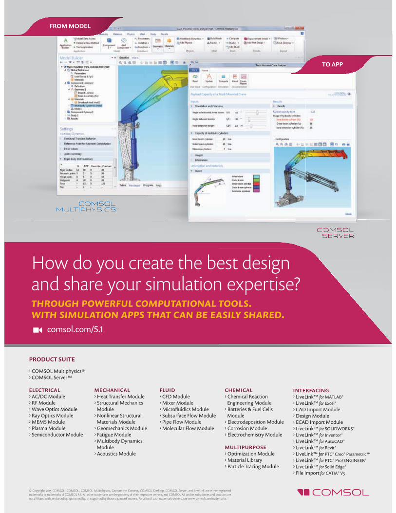
How do you create the best design and share your simulation expertise?
comsol.com/5.1
through powerful computational tools.with simulation apps that can be easily shared.
FROM MODEL
TO APP
PRODUCT SUITE
› COMSOL Multiphysics®› COMSOL Server™
ELECTRICAL› AC/DC Module› RF Module› Wave Optics Module› Ray Optics Module› MEMS Module› Plasma Module› Semiconductor Module
MECHANICAL› Heat Transfer Module› Structural Mechanics Module› Nonlinear Structural Materials Module› Geomechanics Module› Fatigue Module› Multibody Dynamics Module› Acoustics Module
FLUID› CFD Module› Mixer Module› Microfl uidics Module› Subsurface Flow Module› Pipe Flow Module› Molecular Flow Module
CHEMICAL› Chemical Reaction Engineering Module› Batteries & Fuel Cells Module› Electrodeposition Module› Corrosion Module› Electrochemistry Module
MULTIPURPOSE› Optimization Module› Material Library› Particle Tracing Module
INTERFACING› LiveLink™ for MATLAB®
› LiveLink™ for Excel®
› CAD Import Module› Design Module› ECAD Import Module› LiveLink™ for SOLIDWORKS®
› LiveLink™ for Inventor®
› LiveLink™ for AutoCAD®
› LiveLink™ for Revit®
› LiveLink™ for PTC® Creo® Parametric™› LiveLink™ for PTC® Pro/ENGINEER®
› LiveLink™ for Solid Edge®
› File Import for CATIA® V5
© Copyright 2015 COMSOL. COMSOL, COMSOL Multiphysics, Capture the Concept, COMSOL Desktop, COMSOL Server, and LiveLink are either registered trademarks or trademarks of COMSOL AB. All other trademarks are the property of their respective owners, and COMSOL AB and its subsidiaries and products are not affi liated with, endorsed by, sponsored by, or supported by those trademark owners. For a list of such trademark owners, see www.comsol.com/trademarks.
// FOLLOW @JOHNFALCIONI FROM THE EDITOR
GETTING CLOSE TOWORKING CLOSERThe immediacy of the web and social
networks has turned up the heat on the notoriously brutal big-city tab-
loid wars. Reporters are fighting harder than ever to be the first to break the news on which nightclub a certain NBA player was seen at last night, or be first to un-dress a local official who was caught with his hand in the town’s kitty.
But technology magazines like Me-chanical Engineering are usually spared such excitement. We certainly aim to be the first to spot technology trends, but not necessarily to break news. Our editors’ unique lens helps them analyze the impact of technology in ways that other publications don’t. Nonetheless, it’s always great to run an article in the magazine and then see a similar story appear a few weeks later in a newspaper, a consumer magazine, or a business-to-business publication. This happens more frequently than you might suspect. Sometimes it’s coincidence, but we prefer to believe that they read it here first.
Then there are instances like what hap-pened with our “Work Buddies” article in this issue. When I was proofreading Alan Brown’s article on collaborative robots that work side-by-side with humans, I spotted a similar article on the front page of the business section of that day’s The New York Times. The newspaper called the article, “A Softer Side of Robotics.” A day later, The Wall Street Journal’s front page had yet another similar article. This one headlined: “Factory Workers Warm Up to Their Mechanical Colleagues.”
My first thought was: We got scooped! Now, as I sit here in front of my keyboard composing this month’s column, I glance over to today’s Wall Street Journal and I see yet another related front-page story. This one is about a robotics competi-tion featuring automatons that don’t
just interact with humans; they also mix cocktails. ThinBot, for example, is four feet tall, has flashing lights, and makes 17 tasty drinks.
We’ve been covering developments in robotics technology and the convergence of robots and humans for decades. Other publications have too, and now the gen-eral media have realized the importance of covering robots in some depth. Great robotics stories abound and non-tech-nologists should know what’s around the corner—if not the technical details that engineers are interested in.
One of Brown’s inspirations for the article came on a trip he and I took a few months ago to a Caterpillar plant in Clayton, N.C. CAT has been using state-of-the-art robotic systems for some time and it was clear to us that the interaction between robots and humans has gotten tighter and tighter.
Even though much of our visit to the CAT plant was “off-the-record” due to the proprietary nature of the systems they employ, Brown found other compa-nies that would share anecdotes on how their robots mingle with employees. In researching the article, he convinced Uni-versal Robots to bring one of its robots to our offices so we could, literally, shake hands and interact.
Having robots deftly work side-by-side in assembly and manufacturing plants is a major step forward in factory auto-mation. It’s also interesting to observe how comfortable human workers have become working alongside the robots.
But because I don’t work on a shop floor, I’d rather have one of the cocktail-mixing robots greet me when I get home, especially on days we get scooped by another magazine. Maker’s Mark Manhat-tan up, ThinBot; stirred, not shaken—and don’t forget the bitters. ME
FEEDBACK
Are robots taking jobs away from humans?Email me.
John G. FalcioniEditor-in-Chief

ENGINEERS START HEREAccess 500,000 in-stock electronics products, custom services, tools and expertise—all in one place. Plus, count on customer service that goes above & beyond to deliver your needs. Complete engineering solutions start at Newark element14.
1 800 463 9275 | newark.com
LETTERS & COMMENTS
Two readers keep alive the ongoing dialogue over climate change. And another finds a justification
for calling each snowflake unique.
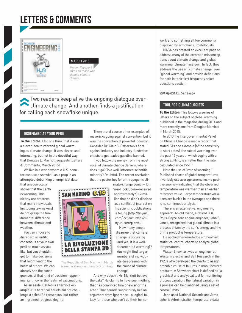
Reader Rapoport takes on those who dispute climate change .
MARCH 2015
DISREGARD AT YOUR PERIL
To the Editor: I for one think that it was a clever idea to rebrand global warm-ing as climate change. It was clever, and interesting, but not in the deceitful way that Douglas L. Marriott suggests (Letters & Comments, March 2015).
We live in a world where a U.S. sena-tor can use a snowball as a prop in an attempted debunking of empirical data that unequivocally shows that the Earth is warming. This clearly underscores that many individuals (including lawmakers) do not grasp the fun-damental difference between climate and weather.
You can choose to disregard scientific consensus at your own peril as much as you like, but you shouldn’t get to make decisions that might lead to the harm of others. We can already see the conse-quences of that kind of decision happen-ing right now in the realm of vaccinations.
As an aside, Galileo is a terrible ex-ample. His heretical beliefs did not chal-lenge a scientific consensus, but rather an ingrained religious dogma.
There are of course other examples of mavericks going against convention, but it was the convention of powerful industry. Consider Dr. Clair C. Patterson’s fight against industry and industry-funded sci-entists to get leaded gasoline banned.
If you follow the money from the most vocal of climate change deniers, where does it go? To a well-informed scientific minority? Doubtful. The recent revelation that the poster boy for anthropogenic cli-
mate-change denial— Dr. Wei-Hock Soon—received approximately $1.2 mil-lion that he didn’t disclose as a conflict of interest on his scientific publications is telling (http://tinyurl.com/lcc8ea9; http://ti-nyurl.com/pjofv6u).
How many people disagree that climate change is occurring (and yes, it is a well-documented warming)? You might find larger numbers of individu-als disagreeing with the cause of climate change.
And why doesn’t Mr. Marriott believe the data? He claims to have seen nothing that has convinced him one way or the other. That sounds suspiciously like an argument from ignorance—a logical fal-lacy for those who don’t do their home-
work and something all too commonly displayed by armchair climatologists.
NASA has created an excellent page to address many of the common misconcep-tions about climate change and global warming (climate.nasa.gov). In fact, they address the use of “climate change” over "global warming” and provide definitions for both in their first frequently asked questions section.
Scott Rapoport, P.E., San Diego
TOOL FOR CLIMATOLOGISTS
To the Editor: This follows a series of letters on the subject of global warming published in the magazine during 2014 and more recently one from Douglas Marriott in March 2015.
In 2013 the Intergovernmental Panel on Climate Change issued a report that stated, "As one example [of the sensitivity to start dates], the rate of warming over the past 15 years ... which begins with a strong El Niño, is smaller than the rate calculated since 1951."
Note the use of "rate of warming." Published charts of global temperatures invariably use average anomalies—a posi-tive anomaly indicating that the observed temperature was warmer than an earlier reference value. Large temperature varia-tions are buried in the averages and there is no continuous analysis.
There is an alternative, engineering approach. An old friend, a retired U.K. Rolls-Royce aero engine engineer, John S. Jones, recognized that global climate is a process driven by the sun's energy and the prime product is temperature.
He applied his knowledge of Shewhart statistical control charts to analyze global temperatures.
Walter Shewhart was an engineer at Western Electric and Bell Research in the 1920s who developed the charts to assign probable cause of failures in manufactured products. A Shewhart chart is defined as "a graphical and analytical tool for monitoring process variation; the natural variation in a process can be quantified using a set of control limits."
John used National Oceanic and Atmo-spheric Administration temperature data
The Republic of San Marino in March issued a stamp saluting 3-D printing.
MECHANICAL ENGINEERING | JUNE 2015 | P.09
from 98 land weather stations to develop Shewhart charts (x-axis from 1890-1990, and the y axis for temperature) in the conventional manner, with upper and lower control limit lines.
His graphs show continuous tem-perature plots generally tracking within the control limits and excursions (out of "control") which may indicate events—a change of energy (sunspot activity etc.) or a terrestrial influence (volcanic activity etc.).
There is no doubt that this engineering technique would be a revolutionary tool for climatologists to use.
Gordon N. Rogers, ASME Life Member, Toronto
ACKNOWLEDGING AGREEMENT
To the Editor: With regard to the letter appearing in the February 2015 issue from Craig R. Norris of Memphis, Tenn., regarding the June 2012 article, “Design
in Nature,” my letter addressing the same article appeared in the January 2013 issue.
I am gratified to note that Mr. Nor-ris’s reaction to the “constructal law” is identical to mine. So there are at least two engineers who refuse to accept this so-called law.
Marvin A. Moss, North Hills, Calif.
DEFINING ‘UNIQUE’
To the Editor: The article titled “Every Snowflake Is Not Unique” in the January 2015 issue tries to address the question of uniqueness of snowflakes. However, it does not provide a direct answer to this ques-tion. Instead, the article focuses on the fact that all snowflakes “share one architec-ture, determined by the way heat flows.”
Having the same architecture and fol-lowing the same laws of nature, however, do not address the uniqueness question.
Interestingly, while the article tries to disprove that snowflakes are unique, it presents a very good argument for their uniqueness.
It says, “To give credit to the view that every snowflake is unique, the actual configuration depends on many second-ary effects, which are of random origin.” This argument, contrary to what the article planned to show, is a reasonable justifica-tion for the uniqueness of the snowflakes.
Mehrdaad Ghorashi, P.E., Gorham, Maine
FEEDBACK Send us your letters and com-ments via hard copy or e-mail [email protected] (subject line "Letters and Comments"). Please include full name, address and phone number. We reserve the right to edit for clarity, style, and length. We regret that unpublished letters cannot be acknowledged or returned.
TECH BUZZ
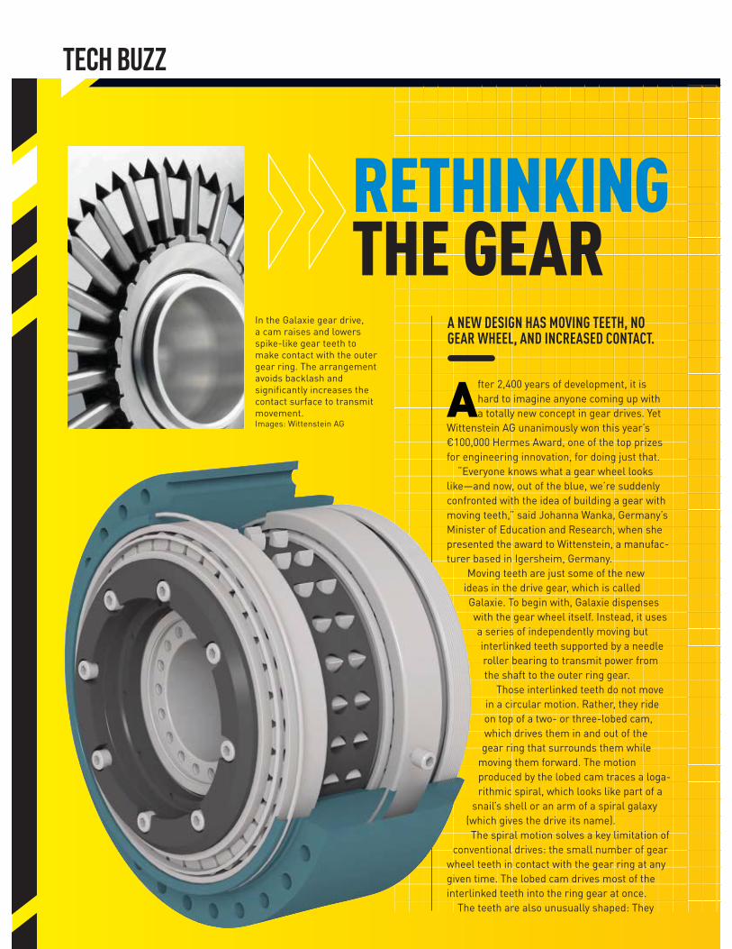
In the Galaxie gear drive, a cam raises and lowers spike-like gear teeth to make contact with the outer gear ring. The arrangement avoids backlash and significantly increases the contact surface to transmit movement.Images: Wittenstein AG
RETHINKING THE GEAR
After 2,400 years of development, it is hard to imagine anyone coming up with a totally new concept in gear drives. Yet
Wittenstein AG unanimously won this year’s €100,000 Hermes Award, one of the top prizes for engineering innovation, for doing just that.
“Everyone knows what a gear wheel looks like—and now, out of the blue, we’re suddenly confronted with the idea of building a gear with moving teeth,” said Johanna Wanka, Germany’s Minister of Education and Research, when she presented the award to Wittenstein, a manufac-turer based in Igersheim, Germany.
Moving teeth are just some of the new ideas in the drive gear, which is called Galaxie. To begin with, Galaxie dispenses with the gear wheel itself. Instead, it uses a series of independently moving but interlinked teeth supported by a needle roller bearing to transmit power from the shaft to the outer ring gear.
Those interlinked teeth do not move in a circular motion. Rather, they ride on top of a two- or three-lobed cam, which drives them in and out of the gear ring that surrounds them while
moving them forward. The motion produced by the lobed cam traces a loga-rithmic spiral, which looks like part of a
snail’s shell or an arm of a spiral galaxy (which gives the drive its name).The spiral motion solves a key limitation of
conventional drives: the small number of gear wheel teeth in contact with the gear ring at any given time. The lobed cam drives most of the interlinked teeth into the ring gear at once.
The teeth are also unusually shaped: They
A NEW DESIGN HAS MOVING TEETH, NO GEAR WHEEL, AND INCREASED CONTACT.
MECHANICAL ENGINEERING | JUNE 2015 | P.11
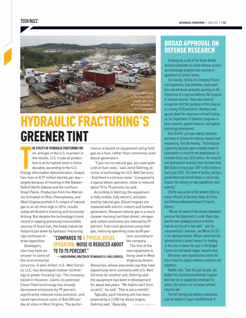
FIVE TEAMS OF RESEARCHERS are finalists for a $2 million award for pH sensors as part of the Wendy Schmidt Ocean Health X Prize. The competition is intended to produce instruments capable of cheaply and accurately monitoring acid levels in the oceans.
Rising levels of carbon dioxide are implicated with global warming, but the change in atmospheric composition has affected the chemistry of the ocean as well. Indeed, of every 100 kg of CO2 emitted into the atmosphere, 30 to 40 kg wind up dissolving into the ocean or freshwater lakes and riv-ers. This dissolved CO2 is, in turn, converted into carbonic acid, increasing the acidity level of the water and disrupting shellfish and corals.
Beginning in 2013, the X Prize Foundation opened a competition to international teams to develop marine pH sensing systems that would be tested both in laboratory conditions as well as the open ocean. Fourteen teams from five countries entered, and after two sets of trials, five finalists were selected:• ANB Sensors (Cambridge, England), from the Schlumberger Gould Research Center; • HpHS (Yokosuka, Japan), from the Kimoto Electric Co. Ltd. and Japan Agency for Marine-Earth Science and Technology;• Sunburst Sensors (Missoula, Mont.), from Sunburst Sensors, LLC;• Team Durafet (Plymouth, Minn.), from Sea-Bird Scientific, Monterey Bay Aquarium Research In-stitute, Scripps Institution of Oceanography at the Univer-sity of Califor-nia, San Diego, and Honeywell Aerospace Advanced Tech-nology group; and • Team XYLEM (Bergen, Norway, and Beverly, Mass.), from Aanderaa Data Instruments and YSI.
The teams competed in open ocean trials in May. The week-long deep sea challenge will assess the sensors’ ability to measure ocean pH values throughout the water column in a 110 square mile region about 100 miles off the northern shore of Oahu at depths of up to 3,000 meters.
The prize money will be given in two categories: accuracy and afford-ability, with $750,000 for first place and $250,000 for runner up in each. Winners will be announced in July. ME
FIVE TEAMS VIE FOR OCEAN SENSOR X PRIZE
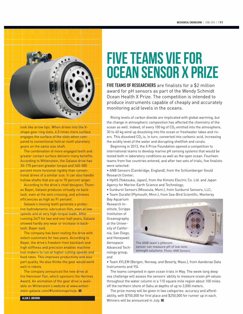
look like arrow tips. When driven into the V-shape gear ring slots, 6.5 times more surface engages the surface of the slots when com-pared to conventional helical-tooth planetary gears on the same size shaft.
The combination of more engaged teeth and greater contact surface delivers many benefits. According to Wittenstein, the Galaxie drive has 30-170 percent greater torque and 340-580 percent more torsional rigidity than conven-tional drives of a similar size. It can also handle hollow shafts that are up to 70 percent larger.
According to the drive’s chief designer, Thom-as Bayer, Galaxie produces virtually no back-lash, even at the zero crossing, and achieves efficiencies as high as 91 percent.
Galaxie’s moving teeth generate a protec-tive hydrodynamic lubrication film, even at low speeds and at very high torque loads. After running 24/7 for two and one-half years, Galaxie showed hardly any wear or increase in back-lash, Bayer said.
The company has been testing the drive with select customers for two years. According to Bayer, the drive’s freedom from backlash and high stiffness and precision enables machine tool makers to run at higher cutting speeds and feed rates. This improves productivity and also part quality. He also thinks the gear would work well in robots.
The company announced the new drive at the Hannover Fair, which sponsors the Hermes Award. An animation of the gear drive is avail-able on Wittenstein’s website at www.witten-stein-galaxie.com/#funktionsprinzip. ME
ALAN S. BROWN
The ANB team's pHenom sensor can measure pH of low ionic strength solutions. Photo: ANB Sensors
MECHANICAL ENGINEERING | JUNE 2015 | P.12
HYDRAULIC FRACTURING’S GREENER TINT
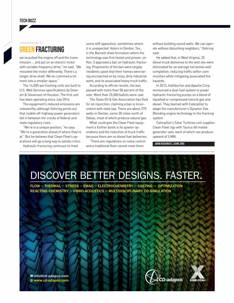
The utility of hydraulic fracturing for oil and gas in the U.S. is proven in the results. U.S. crude oil produc-tion is at its highest level in three decades, according to the U.S.
Energy Information Administration. Output has risen to 8.97 million barrels per day—largely because of fracking in the Bakken field in North Dakota and the northern Great Plains. Production from the Marcel-lus formation in Ohio, Pennsylvania, and West Virginia pushed U.S. output of natural gas to an all-time high in 2014, results solely attributed to fracking and horizontal drilling. But despite the technology’s track record in tapping previously inaccessible sources of fossil fuel, the heavy industrial footprint put down by hydraulic fracturing rigs continues to draw opposition.
Developers now may have an answer to some of the environmental concerns. A well-driller, U.S. Well Servic-es LLC, has developed cleaner technol-ogy to power fracking rigs. The company, based in Houston, claims its patented Clean Fleet technology has already decreased emissions by 99 percent, significantly reduced noise pollution, and saved operational costs of $40,000 per day at sites in West Virginia. The perfor-
mance is based on equipment using field gas as a fuel, rather than commonly used diesel generators.
“If you run on natural gas, you save quite a bit on fuel costs,” said Jared Oehring, di-rector of technology for U.S. Well Services. “And there’s a lot less noise.” Compared to a typical diesel operation, noise is reduced about 70 to 75 percent, he said.
According to Oehring, the equipment is fully mobile, fully electric, and pow-ered by natural gas. Diesel engines are replaced with electric motors and turbine-generators. Because natural gas is a much cleaner-burning fuel than diesel, nitrogen and carbon emissions are reduced by 99 percent. Fuel costs plummet using field gas, reducing operating costs by 80 per-
cent, according to the company.
The first of the new equipment is being used in West Virginia by Antero
Resources, whose executives say they have signed long-term contracts with U.S. Well Services for another unit. Oehring said the equipment has been in development for about two years. “We had to start from scratch,” he said. “This is not a retrofit.”
Typically, each fracking unit has been powered by a 2,250-hp diesel engine, Oehring said. “Basically,
A typical drill pad in the Marcellus
Shale gas play of southwestern
Pennsylvania.
continued on page 14 »
TECH BUZZ
“COMPARED TO A TYPICAL DIESEL OPERATION, NOISE IS REDUCED ABOUT 70 TO 75 PERCENT.”
— JARED OEHRING, DIRECTOR OF TECHNOLOGY, U.S. WELL SERVICES.
BROAD APPROVAL ON DEFENSE RESEARCH
A hearing by a unit of the House Armed
Services Committee to review defense science
and technology programs has resulted in
agreement on several issues.
The hearing, held by the Emerging Threats
and Capabilities Subcommittee, found mem-
bers and witnesses generally agreeing on the
importance of a vigorous defense S&T program
to national security. There was universal
recognition that the backbone of this program
is a strong STEM workforce. Members also
agreed about the importance of level funding
for the Department of Defense’s programs in
basic research, applied research, and applied
technology development.
Alan Shaffer, principal deputy, assistant
secretary of defense for defense research and
engineering, told the hearing: “Technological
superiority depends upon a steady stream of
investments in research and development. In
constant fiscal year 2015 dollars, the research
and development accounts have declined from
$88 billion in fiscal year 2009 to $64 billion in
fiscal year 2015. This level of decline, during a
period where the United States is still at war,
impacts the delivery of new capabilities most
severely.”
Shaffer was joined at the witness table by
senior officials of the Army, Navy, Air Force,
and Defense Advanced Research Projects
Agency.
“We are all aware of the intense downward
pressure the department is under these days
and the ever-growing universe of threats
that we are forced to deal with,” said the
subcommittee’s chairman, Joe Wilson (R-SC),
in his opening remarks. Wilson noted that the
administration’s overall request for funding
in this area is above the caps in the Budget
Control Act and would trigger sequestration.
Witnesses said sequestrration risked the
loss of hard-to-replace defense scientists and
engineers.
Shaffer said, “Over the past decade, the
budget has declined precipitously. Coupled
with the rise in capabilities developed by
others, the nation is at increased national
security risk.”
The full hearing and witness testimonies
may be viewed at tinyurl.com/DefenseR-D.

TECH BUZZ
FLOW − THERMAL − STRESS − EMAG − ELECTROCHEMISTRY − CASTING − OPTIMIZATION REACTING CHEMISTRY − VIBRO-ACOUSTICS − MULTIDISCIPLINARY CO-SIMULATION
DISCOVER BETTER DESIGNS. FASTER.
we’ve pulled the engine off and the trans-mission … and put on an electric motor with variable frequency drive,” he said. “We mounted the motor differently. There’s a longer drive shaft. We’ve crammed a lot more into a smaller space.”
The 14,500-psi fracking units are built to U.S. Well Services specifications by Stew-art & Stevenson of Houston. The first unit has been operating since July 2014.
The equipment’s reduced emissions are noteworthy, although Oehring points out that mobile off-highway power generators fall in between the cracks of federal and state regulatory rules.
“We’re in a unique position,” he says. “We’re a generation ahead of where they’re at.” But he believes that Clean Fleet’s op-erations will go a long way to satisfy critics.
Hydraulic fracturing continues to meet
some stiff opposition, sometimes where it is unexpected. Voters in Denton, Tex., in the Barnett shale formation where the technology was first tested and proven, on Nov. 5 approved a ban on hydraulic fractur-ing. Proponents of the ban were largely residents upset that their homes were be-ing encroached on by noisy, dirty industrial work, and its associated heavy truck traffic.
According to official results, the ban passed with more than 58 percent of the vote. More than 25,000 ballots were cast.
The Texas Oil & Gas Association has filed for an injunction, claiming a ban is incon-sistent with state law. There are about 270 wells in Denton, some 30 miles north of Dallas, most of which produce natural gas.
What could give the Clean Fleet equip-ment a further boost is its quieter op-erations and the reduction of truck traffic because there are no diesel fuel deliveries.
“There are regulations on noise control and a traditional fleet cannot meet them
without building sound walls. We can oper-ate without disturbing neighbors,” Oehring said.
He added that, in West Virginia, 25 diesel truck deliveries to the well site were eliminated for an average horizontal well completion, reducing traffic within com-munities while mitigating associated fire hazards.
In 2013, Halliburton and Apache Corp. announced a dual-fuel system to power hydraulic fracturing pumps on a blend of liquefied or compressed natural gas and diesel. They teamed with Caterpillar to adapt the manufacturer’s Dynamic Gas Blending engine technology to the fracking system.
Caterpillar’s Solar Turbines unit supplies Clean Fleet rigs with Taurus 60 mobile generator sets, each of which can produce upward of 5 MW.
JOHN KOSOWATZ, ASME.ORG
continued from page 12 »
Green fracturing
MECHANICAL ENGINEERING | JUNE 2015 | P.15
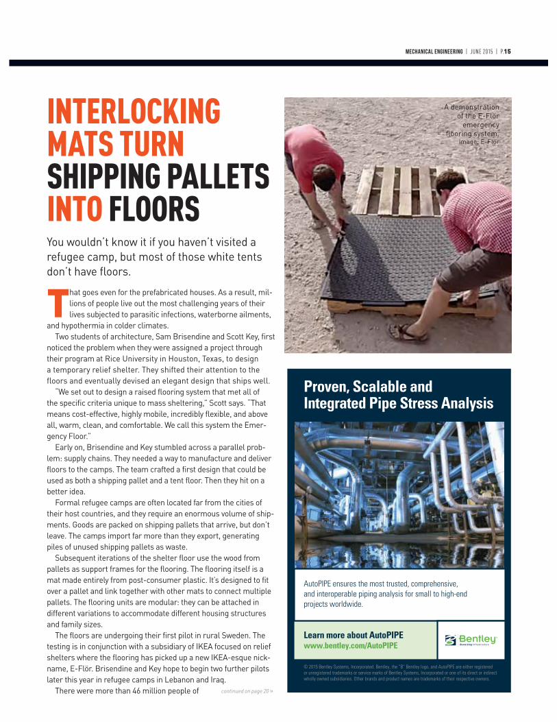
You wouldn’t know it if you haven’t visited a refugee camp, but most of those white tents don’t have floors.
That goes even for the prefabricated houses. As a result, mil-lions of people live out the most challenging years of their lives subjected to parasitic infections, waterborne ailments,
and hypothermia in colder climates. Two students of architecture, Sam Brisendine and Scott Key, first
noticed the problem when they were assigned a project through their program at Rice University in Houston, Texas, to design a temporary relief shelter. They shifted their attention to the floors and eventually devised an elegant design that ships well.
“We set out to design a raised flooring system that met all of the specific criteria unique to mass sheltering,” Scott says. “That means cost-effective, highly mobile, incredibly flexible, and above all, warm, clean, and comfortable. We call this system the Emer-gency Floor.”
Early on, Brisendine and Key stumbled across a parallel prob-lem: supply chains. They needed a way to manufacture and deliver floors to the camps. The team crafted a first design that could be used as both a shipping pallet and a tent floor. Then they hit on a better idea.
Formal refugee camps are often located far from the cities of their host countries, and they require an enormous volume of ship-ments. Goods are packed on shipping pallets that arrive, but don’t leave. The camps import far more than they export, generating piles of unused shipping pallets as waste.
Subsequent iterations of the shelter floor use the wood from pallets as support frames for the flooring. The flooring itself is a mat made entirely from post-consumer plastic. It’s designed to fit over a pallet and link together with other mats to connect multiple pallets. The flooring units are modular: they can be attached in different variations to accommodate different housing structures and family sizes.
The floors are undergoing their first pilot in rural Sweden. The testing is in conjunction with a subsidiary of IKEA focused on relief shelters where the flooring has picked up a new IKEA-esque nick-name, E-Flör. Brisendine and Key hope to begin two further pilots later this year in refugee camps in Lebanon and Iraq.
There were more than 46 million people of
INTERLOCKING MATS TURN SHIPPING PALLETS INTO FLOORS
A demonstration of the E-Flör
emergency flooring system.
Image: E-Flör
Proven, Scalable and Integrated Pipe Stress Analysis
© 2015 Bentley Systems, Incorporated. Bentley, the “B” Bentley logo, and AutoPIPE are either registered or unregistered trademarks or service marks of Bentley Systems, Incorporated or one of its direct or indirect wholly owned subsidiaries. Other brands and product names are trademarks of their respective owners.
AutoPIPE ensures the most trusted, comprehensive, and interoperable piping analysis for small to high-end projects worldwide.
Learn more about AutoPIPE www.bentley.com/AutoPIPE
continued on page 20 »
HIGH ROADS NOT TAKENThe best way to not become replaceable, is to put yourself into the position of doing the replacing.
Decisions you make in your thirties will haunt you the rest of your life. Clearly this is one of those state-
ments that is true, but is not very helpful without clarification. I want to focus on career decisions.
Many of my friends and I, all in our fifties, are wondering how our careers ended up where they are. Actually my friends are wondering more than me, since I overanalyze things and have a relatively good idea how my career has come to pass.
Many of my friends are dismayed to find that they are now working for some-one they have come to disrespect. In addition, some of them have either been threatened with or have barely avoided being laid off, despite the positive con-tributions that they have made to their organizations, in many cases over the last 20 to 30 years.
These individuals are in private industry, national labs, and universities. My wife’s theory is that they make too much money and that is the reason their organizations are marginalizing them or laying them off.
I have a different view. Many of us passed on the opportunity to become managers when the opportunity arose in our thirties and forties. We wanted to do the fun work and not listen to the
whining of subordinates and superiors, or attend meetings as managers.
When I was making $60,000 per year, I was asked to become a business man-ager in the company where I worked. I was told on a Friday that I would make $80,000 starting the next Monday if I said yes.
When I said no, the manager started to come over the top of his desk. When
he was halfway across, I thought, “I don’t think this old guy can take me!”
Right before he grabbed my lapels he came to his senses and dropped back into his seat. He apologized and then asked me “What the hell is wrong with you?” We did not have enough time in my remaining year and a half with the company to cover that topic in detail.
I have told my friends that I was going to write this article. It is not about bash-ing them, because I am their comrade in arms. It is actually a note of warning to younger people: You may make contri-butions to an organization as a working professional, but the organization cer-tainly perceives the management staff to be more valuable.
We are all replaceable, except the ones doing the replacing. Of course, they also get replaced when palace
coups occur. I have to admit that some of the individuals who are marginal-ized in their fifties are a surprise to me. Their contributions and commitment to their organizations have been in my opinion quite extraordinary. However, their organizations clearly do not feel the same way.
When you are in your late twen-ties and thirties, look around you at
the older individuals in an organiza-tion (especially those in their fifties). Employees in their sixties are living on borrowed time. A technical, non-management employee, even a Ph.D. in a national laboratory, has a window of value to the organization.
You may not aspire or even want to be a manager. Becoming a manager, especially a mid-level manager, does not ensure that you will avoid being laid off. However, I think it is fair to say in general that the higher up you are in an organization the more valuable you are perceived to be. It can put you above organizational machinations, unless the palace coup—such as corporate merger or takeover—occurs. ME
RONALD A.L. RORRER is director of motorsports at the
University of Colorado Denver.
YOU MAY NOT WANT TO BE A MANAGER. I THINK IT IS FAIR TO SAY THAT THE HIGHER UP YOU ARE IN AN ORGANIZATION, THE MORE VALUABLE YOU ARE PERCEIVED TO BE.
TECH BUZZ || WORKFORCE DEVELOPMENT BY RONALD A.L. RORRER MECHANICAL ENGINEERING | JUNE 2015 | P.16

Proto Labs uses proprietary software and a massive compute cluster to accelerate manufacturing
of prototypes and production parts for every industry.
Got a project? Get 1 to 10,000+ plastic, metal or liquid silicone rubber parts in as fast as 1 day.
Rapid Manufacturing with a Polite Disregard for Tradition
Tech-driven injection molding, CNC machining and 3D printing for those who need parts tomorrow
Major Credit Cards Accepted | © 2015 Proto Labs, Inc.
Request your free Torus design aid at go.protolabs.com/ME5GB
ISO 9001:2008 Certified | ITAR Registered
TECH BUZZ || ONE-ON-ONE BY ALAN S. BROWN
ME: What was your goal in developing this new indus-
trial dry low emission (DLE) turbine?
B.N: We’re trying to demonstrate that DLE gas turbines can successfully operate on a wider range of gases. Gas turbines historically have operated on high-methane sources from natural gas fields. Over the years, we have seen fields with a wider and wider range of gases, including more associated gases.
Our customers want to run our gas turbines on those gases. In addition to methane, they include non-methane carbon molecules, such as ethane, propane, and butane. There are also inert gases, typically carbon dioxide or nitrogen.
ME: What were some of the challenges you faced?
B.N: When you consider the high pressure ratio and flex-ibility of large aircraft derivative turbines, there can be several challenges. The first is the battle for air used to cool the large combustion system surfaces versus the air we premix with natural gas to control emissions.These high pressure ratios also generate combustion noise, and it can have a powerful effect on the hardware.
Lastly, these machines accelerate and decelerate rap-idly. It’s really important to thoroughly understand how transient hardware behavior and combustion unsteady effects combine to create complex emergent behaviors.
ME: You have been building DLE machines for more
than a decade. What are some of the notable improve-
ments in this new turbine?
B.N: Three particularly come to mind. On the manufactur-ing side, we introduced water jet drilled cooling effusion holes. They provide a smoother bore finish than laser drilled holes, which protects against crack initiation.
The second innovation involved using powerful 3-D computational fluid dynamics. This enabled us to look at unsteady combustion effects happening in tens of mil-liseconds, and really guided combustion design.
The last innovation involved design simplification. For example, we removed such features as the torch ignition system, and went with a simpler two-stage rather than three-stage fueling regime. We also built in passive acoustic dampening. Together, they really added a level of robustness and reliability to the overall combustion system.
ME: So where does your new turbine fit in? What are
the applications?
B.N: With the growth of wind and other intermittent renewables, there is increasing demand for distributed power generation that can respond very rapidly to de-mand swings and stabilize the grid.
It gives oil and gas customers who need very high power density and a broad operating envelope access to
low-emissions technology. Also, it can have a significant positive impact on the efficiency and life cycle economics of liquefied natural gas operations.
ME: What about future gas turbines?
B.N: There is still room to increase pressure ratios and efficiencies. We also see benefits from our increased computational capability. We’ve already made great headway in our thermal understanding. I believe combustion noise will the next big area for design improvements. We also want to go to virtual test beds, so we can limit our engine testing. We want to close the gap between DLE and non-DLE turbines, so that, at some point in the future, there will be no such thing as a non-DLE engine because DLE will perform just as well in terms of economics, efficiency, and reliability.
ME: So, how did you get involved in turbines?
B.N: What really drew me to gas turbines was that this field is on the cutting edge of a wide variety of technologies. As a development engineer, I got involved with everything from stress analysis and combustion engi-neering to controls and engine testing. It exposed me to lots of things that I had an interest in. ME
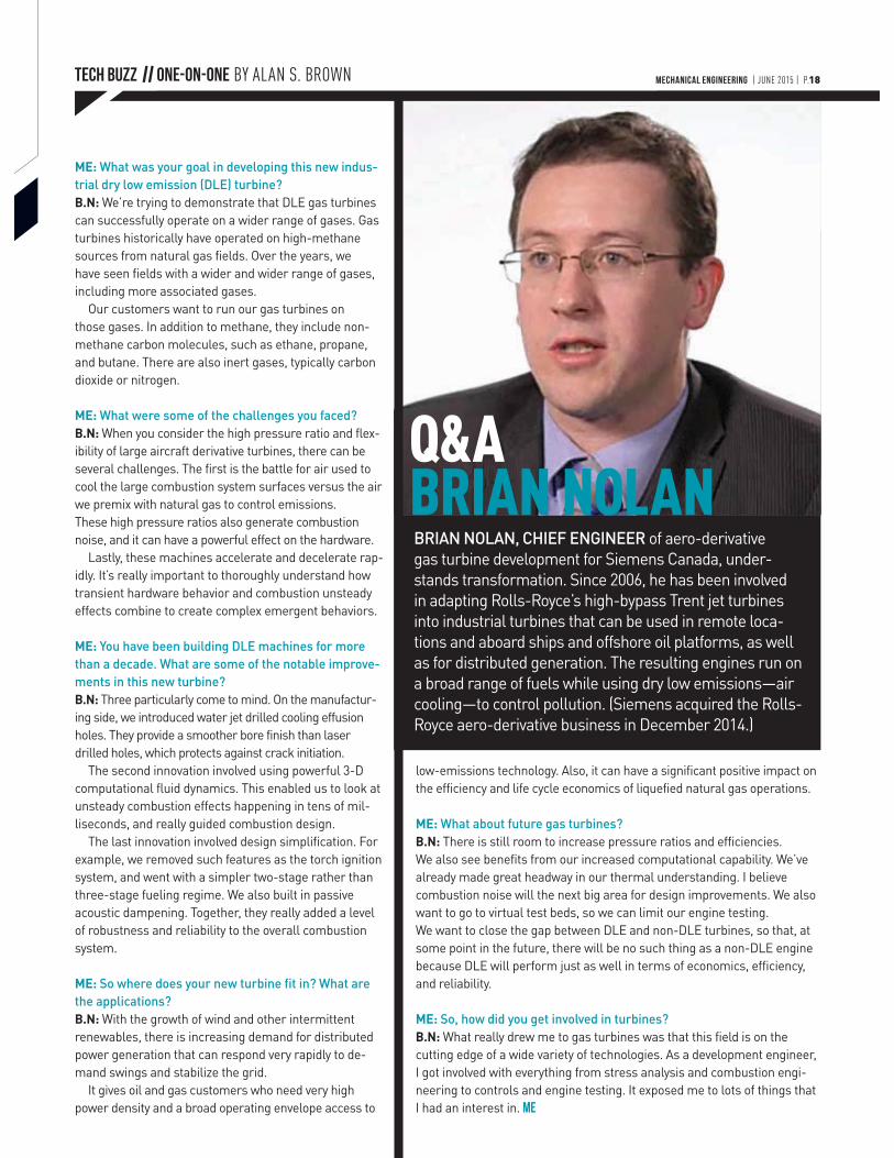
Q&A BRIAN NOLANBRIAN NOLAN, CHIEF ENGINEER of aero-derivative gas turbine development for Siemens Canada, under-stands transformation. Since 2006, he has been involved in adapting Rolls-Royce’s high-bypass Trent jet turbines into industrial turbines that can be used in remote loca-tions and aboard ships and offshore oil platforms, as well as for distributed generation. The resulting engines run on a broad range of fuels while using dry low emissions—air cooling—to control pollution. (Siemens acquired the Rolls-Royce aero-derivative business in December 2014.)
MECHANICAL ENGINEERING | JUNE 2015 | P.18
TECH BUZZ
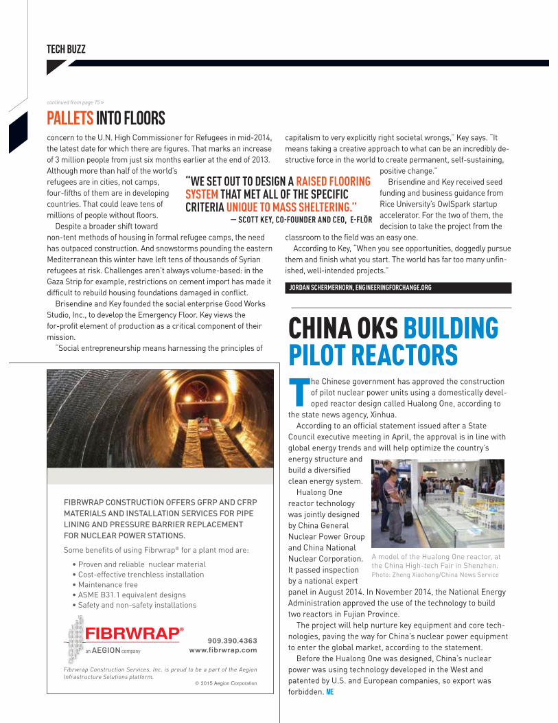
concern to the U.N. High Commissioner for Refugees in mid-2014, the latest date for which there are figures. That marks an increase of 3 million people from just six months earlier at the end of 2013. Although more than half of the world’s refugees are in cities, not camps, four-fifths of them are in developing countries. That could leave tens of millions of people without floors.
Despite a broader shift toward non-tent methods of housing in formal refugee camps, the need has outpaced construction. And snowstorms pounding the eastern Mediterranean this winter have left tens of thousands of Syrian refugees at risk. Challenges aren’t always volume-based: in the Gaza Strip for example, restrictions on cement import has made it difficult to rebuild housing foundations damaged in conflict.
Brisendine and Key founded the social enterprise Good Works Studio, Inc., to develop the Emergency Floor. Key views the for-profit element of production as a critical component of their mission.
“Social entrepreneurship means harnessing the principles of
capitalism to very explicitly right societal wrongs,” Key says. “It means taking a creative approach to what can be an incredibly de-structive force in the world to create permanent, self-sustaining,
positive change.”Brisendine and Key received seed
funding and business guidance from Rice University’s OwlSpark startup accelerator. For the two of them, the decision to take the project from the
classroom to the field was an easy one. According to Key, “When you see opportunities, doggedly pursue
them and finish what you start. The world has far too many unfin-ished, well-intended projects.”
JORDAN SCHERMERHORN, ENGINEERINGFORCHANGE.ORG
continued from page 15 »
pallets Into floors
“WE SET OUT TO DESIGN A RAISED FLOORING SYSTEM THAT MET ALL OF THE SPECIFIC CRITERIA UNIQUE TO MASS SHELTERING.”
— SCOTT KEY, CO-FOUNDER AND CEO, E-FLÖR
CHINA OKS BUILDING PILOT REACTORS The Chinese government has approved the construction
of pilot nuclear power units using a domestically devel-oped reactor design called Hualong One, according to
the state news agency, Xinhua.According to an official statement issued after a State
Council executive meeting in April, the approval is in line with global energy trends and will help optimize the country’s energy structure and build a diversified clean energy system.
Hualong One reactor technology was jointly designed by China General Nuclear Power Group and China National Nuclear Corporation. It passed inspection by a national expert panel in August 2014. In November 2014, the National Energy Administration approved the use of the technology to build two reactors in Fujian Province.
The project will help nurture key equipment and core tech-nologies, paving the way for China’s nuclear power equipment to enter the global market, according to the statement.
Before the Hualong One was designed, China’s nuclear power was using technology developed in the West and patented by U.S. and European companies, so export was forbidden. ME
A model of the Hualong One reactor, at the China High-tech Fair in Shenzhen. Photo: Zheng Xiaohong/China News Service
MECHANICAL ENGINEERING | JUNE 2015 | P.21
CNPt SeriesStarts at
$205
omega.com®
1-888-826-6342© COPYRIGHT 2015 OMEGA ENGINEERING, INC ALL RIGHTS RESERVED
For Sales and Service Call
Prices listed are those in effect at the time of publication and are subject to change without notice. Please contact OMEGA’s sales department for current prices.
The Most Powerful PID Controller on the Market is Now Also the Easiest to UseIntroducing the OMEGA® PLATINUMTM Series Temperature and Process Controllers
Universal Input Supports Thermocouples, RTDs, Thermistors, Analog Current, and Bidirectional Voltage
High Performance (20 Samples Per Second with 24 Bit ADC) and High Accuracy
Full Autotune PID with Fuzzy Logic Adaptive Control
Up to 99 Chainable Ramp and Soak Programs with Up to 16 Segments Each
No Jumpers to Set, Totally Firmware Configurable
USB Communications Come Standard on Every Model, Ethernet and Serial Also Available
Visit omega.com/cnpt_series
With USB port.
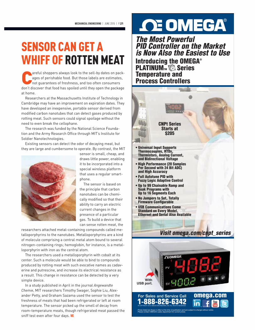
SENSOR CAN GET A WHIFF OF ROTTEN MEAT
Careful shoppers always look to the sell-by dates on pack-ages of perishable food. But those labels are estimates, not guarantees of freshness, and too often consumers
don’t discover that food has spoiled until they open the package at home.
Researchers at the Massachusetts Institute of Technology in Cambridge may have an improvement on expiration dates. They have developed an inexpensive, portable sensor derived from modified carbon nanotubes that can detect gases produced by rotting meat. Such sensors could signal spoilage without the need to even break the cellophane.
The research was funded by the National Science Founda-tion and the Army Research Office through MIT’s Institute for Soldier Nanotechnologies.
Existing sensors can detect the odor of decaying meat, but they are large and cumbersome to operate. By contrast, the MIT
sensor is small, cheap, and draws little power, enabling it to be incorporated into a special wireless platform that uses a regular smart-phone.
The sensor is based on the principle that carbon nanotubes can be chemi-cally modified so that their ability to carry an electric current changes in the presence of a particular gas. To build a device that can sense rotten meat, the
researchers attached metal-containing compounds called me-talloporphyrins to the nanotubes. Metalloporphyrins are a kind of molecule comprising a central metal atom bound to several nitrogen-containing rings; hemoglobin, for instance, is a metal-loporphyrin with iron as the central atom.
The researchers used a metalloporphyrin with cobalt at its center. Such a molecule would be able to bind to compounds produced by rotting meat with such evocative names as cadav-erine and putrescine, and increase its electrical resistance as a result. This change in resistance can be detected by a very simple device.
In a study published in April in the journal Angewandte Chemie, MIT researchers Timothy Swager, Sophie Liu, Alex-ander Petty, and Graham Sazama used the sensor to test the freshness of meats that had been refrigerated or left at room temperature. The sensor picked up the smell of decay from room-temperature meats, though refrigerated meat passed the sniff test even after four days. ME

ONEPARTNERFOR EVERY
From 3D printed prototyping to full-scale production, Stratasys Direct Manufacturing empowers designers and
engineers with solutions at every stage of the design and development process. Discover our industry-leading
machine capacity and full suite of traditional and advanced manufacturing services to manufacture your products
better, faster and more affordably. To learn how Stratasys combined the widest breadth of technology and experience
from the industry’s top service pioneers, visit S T R A T A S Y S D I R E C T . C O M
PART
N
N
S T R ATA S Y S D I R E C T. C O M
1- 8 8 8 [email protected]
A F U L L S U I T E O F T R A D I T I O N A L
& A D D I T I V E M A N U F A C T U R I N G
TECHNOLOGIES
TECH BUZZ || HOT LABS BY HARRY HUTCHINSON
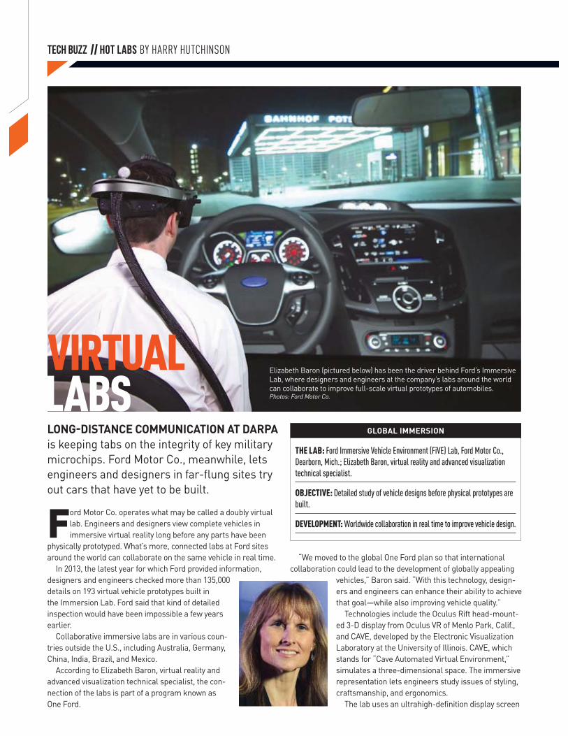
VIRTUAL LABS
Elizabeth Baron (pictured below) has been the driver behind Ford’s Immersive Lab, where designers and engineers at the company’s labs around the world can collaborate to improve full-scale virtual prototypes of automobiles.Photos: Ford Motor Co.
LONG-DISTANCE COMMUNICATION AT DARPA is keeping tabs on the integrity of key military microchips. Ford Motor Co., meanwhile, lets engineers and designers in far-flung sites try out cars that have yet to be built.
THE LAB: Ford Immersive Vehicle Environment (FiVE) Lab, Ford Motor Co., Dearborn, Mich.; Elizabeth Baron, virtual reality and advanced visualization technical specialist.
OBJECTIVE: Detailed study of vehicle designs before physical prototypes are built.
DEVELOPMENT: Worldwide collaboration in real time to improve vehicle design.
GLOBAL IMMERSION
Ford Motor Co. operates what may be called a doubly virtual lab. Engineers and designers view complete vehicles in immersive virtual reality long before any parts have been
physically prototyped. What’s more, connected labs at Ford sites around the world can collaborate on the same vehicle in real time.
In 2013, the latest year for which Ford provided information, designers and engineers checked more than 135,000 details on 193 virtual vehicle prototypes built in the Immersion Lab. Ford said that kind of detailed inspection would have been impossible a few years earlier.
Collaborative immersive labs are in various coun-tries outside the U.S., including Australia, Germany, China, India, Brazil, and Mexico.
According to Elizabeth Baron, virtual reality and advanced visualization technical specialist, the con-nection of the labs is part of a program known as One Ford.
“We moved to the global One Ford plan so that international collaboration could lead to the development of globally appealing
vehicles,” Baron said. “With this technology, design-ers and engineers can enhance their ability to achieve that goal—while also improving vehicle quality.”
Technologies include the Oculus Rift head-mount-ed 3-D display from Oculus VR of Menlo Park, Calif., and CAVE, developed by the Electronic Visualization Laboratory at the University of Illinois. CAVE, which stands for “Cave Automated Virtual Environment,” simulates a three-dimensional space. The immersive representation lets engineers study issues of styling, craftsmanship, and ergonomics.
The lab uses an ultrahigh-definition display screen
MECHANICAL ENGINEERING | JUNE 2015 | P.25
THE LAB: Integrity and Reliability of Integrated Circuits program, Defense Advanced Research Projects Agency; Kerry Bernstein, program manager. With the Naval Surface Warfare Center and Air Force Research Laboratory.
OBJECTIVE: Assuring that microchips supplied for use in military electronics perform to specification.
DEVELOPMENT: A lab using the Internet and other resources to identify substandard or counterfeit chips.
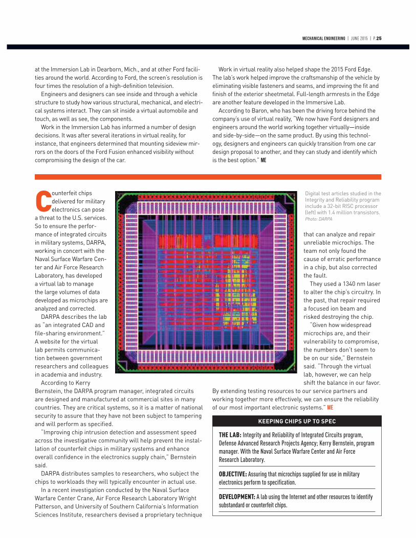
KEEPING CHIPS UP TO SPEC
Counterfeit chips delivered for military electronics can pose
a threat to the U.S. services. So to ensure the perfor-mance of integrated circuits in military systems, DARPA, working in concert with the Naval Surface Warfare Cen-ter and Air Force Research Laboratory, has developed a virtual lab to manage the large volumes of data developed as microchips are analyzed and corrected.
DARPA describes the lab as “an integrated CAD and file-sharing environment.” A website for the virtual lab permits communica-tion between government researchers and colleagues in academia and industry.
According to Kerry Bernstein, the DARPA program manager, integrated circuits are designed and manufactured at commercial sites in many countries. They are critical systems, so it is a matter of national security to assure that they have not been subject to tampering and will perform as specified.
“Improving chip intrusion detection and assessment speed across the investigative community will help prevent the instal-lation of counterfeit chips in military systems and enhance overall confidence in the electronics supply chain,” Bernstein said.
DARPA distributes samples to researchers, who subject the chips to workloads they will typically encounter in actual use.
In a recent investigation conducted by the Naval Surface Warfare Center Crane, Air Force Research Laboratory Wright Patterson, and University of Southern California’s Information Sciences Institute, researchers devised a proprietary technique
that can analyze and repair unreliable microchips. The team not only found the cause of erratic performance in a chip, but also corrected the fault.
They used a 1340 nm laser to alter the chip’s circuitry. In the past, that repair required a focused ion beam and risked destroying the chip.
“Given how widespread microchips are, and their vulnerability to compromise, the numbers don’t seem to be on our side,” Bernstein said. “Through the virtual lab, however, we can help shift the balance in our favor.
By extending testing resources to our service partners and working together more effectively, we can ensure the reliability of our most important electronic systems.” ME
at the Immersion Lab in Dearborn, Mich., and at other Ford facili-ties around the world. According to Ford, the screen’s resolution is four times the resolution of a high-definition television.
Engineers and designers can see inside and through a vehicle structure to study how various structural, mechanical, and electri-cal systems interact. They can sit inside a virtual automobile and touch, as well as see, the components.
Work in the Immersion Lab has informed a number of design decisions. It was after several iterations in virtual reality, for instance, that engineers determined that mounting sideview mir-rors on the doors of the Ford Fusion enhanced visibility without compromising the design of the car.
Work in virtual reality also helped shape the 2015 Ford Edge. The lab’s work helped improve the craftsmanship of the vehicle by eliminating visible fasteners and seams, and improving the fit and finish of the exterior sheetmetal. Full-length armrests in the Edge are another feature developed in the Immersive Lab.
According to Baron, who has been the driving force behind the company’s use of virtual reality, “We now have Ford designers and engineers around the world working together virtually—inside and side-by-side—on the same product. By using this technol-ogy, designers and engineers can quickly transition from one car design proposal to another, and they can study and identify which is the best option.” ME
Digital test articles studied in the Integrity and Reliability program include a 32-bit RISC processor (left) with 1.4 million transistors. Photo: DARPA
TECH BUZZ
T he 2015 Engineering Public Policy Symposium in Washington, D.C., focused on big data, energy, and manufacturing issues. The event brought together
more than 100 leaders from 44 national engineering societ-ies representing more than two million engineers. ASME served as the chair and lead organizer of the event, which was made possible by a grant from the United Engineering Foundation.
The day-long symposium featured key speakers from the administration, Congress, and federal agencies who dis-cussed strategies to encourage a resurgence in the U.S. manufacturing and energy sectors and the challenges and opportunities of big data.
Tom Kalil, deputy director for technology and innovation at the White House Office of Science and Technology Policy, as keynote speaker discussed the administration’s emphasis on technology innovation, R&D, and the maker culture in the United States. Kalil asked engineers for support in promot-ing manufacturing events around the country—like the White
House Maker Faire—to encourage the maker movement and a culture that celebrates engineering and science.
Several speakers addressed the use of big data and its impact on a range of industries. Suzanne Iacono, acting as-sistant director for the Computing and Information Science and Engineering Directorate at the National Science Founda-tion, highlighted some of the benefits of big data, including improved efficiency in transportation systems and a more stable electric grid. Irene Qualters, director of the Division of Advanced Cyberinfrastructure at the National Science Foun-dation, said that recent research and projects undertaken by NSF are expected to improve and develop a cyberinfrastruc-ture that can advance the U.S. in the 21st century.
A panel representing various parts of the federal govern-ment examined the current state of U.S. manufacturing poli-cy and looked at recommendations for future developments. J.J. Raynor, special assistant to the President for economic policy, talked about the continued progress of the National Network for Manufacturing Innovation. So far five institutes have been established and three are in development—one on flexible hybrid electronics, another on smart manufacturing, and the third on integrated photonics.
Michael Molnar, director of the Advanced Manufacturing National Program Office at the National Institute of Stan-dards and Technology, asked all Symposium participants to encourage their organizations to participate in National Manufacturing Day on October 2.
Robert Ivester, deputy director in the Advanced Manufac-turing Office for the Department of Energy, talked about the successes the DOE has had investing in many new technolo-gies. DOE-backed research programs range from combined heat and power applications to advanced lithium batteries.
Erik Antonsson, a member of the National Academy of Engineering’s Making Value in America Committee, offered a number of recommendations to move U.S. manufacturing forward in order to continue to be competitive in the global economy.
Speakers included Bruce Westerman, one of a handful of engineers in Congress, who said his experience in engineer-ing and local politics inspired him to run for the U.S. House of Representatives. Westerman, an Arkansas Republican, said he is currently making efforts to apply his engineering perspectives to public policy.
Following the conclusion of the Symposium, outreach to congressional leaders continued. Participants met with their congressional representatives in the House and Senate to discuss engineering and science issues. Topics included budget priorities, federal funding to support manufacturing and R&D, and the Manufacturing Universities Act of 2015. ME
SYMPOSIUM WEIGHS BIG DATA, ENERGY
MECHANICAL ENGINEERING | JUNE 2015 | P.27
Like cramped seats, overpriced snacks, and excessive charges for checked bags, noise inside the passenger cabin is just one of the annoyances we’ve come to put
up with on airplane flights. But few people realize just how much noise they have to endure. According to a 2006 study published by the Canadian Acoustical Association, cabin noise levels are a continuous 80 to 85 dB during flight. That’s louder than standing next to a busy freeway—all the way from JFK to Heathrow.
Researchers at North Carolina State University in Raleigh and the Massachusetts Institute of Technology in Cambridge believe they have a way to cut that noise considerably. It’s a very thin membrane that can be stretched across the floor and ceil-ing of the airplane cabin.
To keep airplanes lightweight, they are constructed with panels made from honeycomb-like composites. While strong, these stiff panels let low-frequency sound from the engine
pass through into the passenger compartment. Sound-block-ing insulation might help, but it’s generally left out to save on weight.
To find an alternative noise-control material, mechanical engineers at N.C. State and MIT turned to adding a membrane of latex rubber just one-hundredth of an inch thick. When sandwiched between two rigid panels of honeycombed compos-ites, the membrane could flex within the open cells, absorbing sound that might otherwise transmit through.
In spite of adding only about 6 percent to the weight of the panels, experimental results showed that a single membrane was able to cut sound by a factor of 100 or more. That’s enough to make it easier to hear when a steward asks you for your drink preference.
The research was published in April in the journal, Applied Physics Letters. Yun Jing, assistant professor of mechanical engineering at N.C. State, was the senior author. ME
THIN MEMBRANE CAN KNOCK OUT AIRCRAFT CABIN NOISE
TECH BUZZ // VAULT JUNE 1965
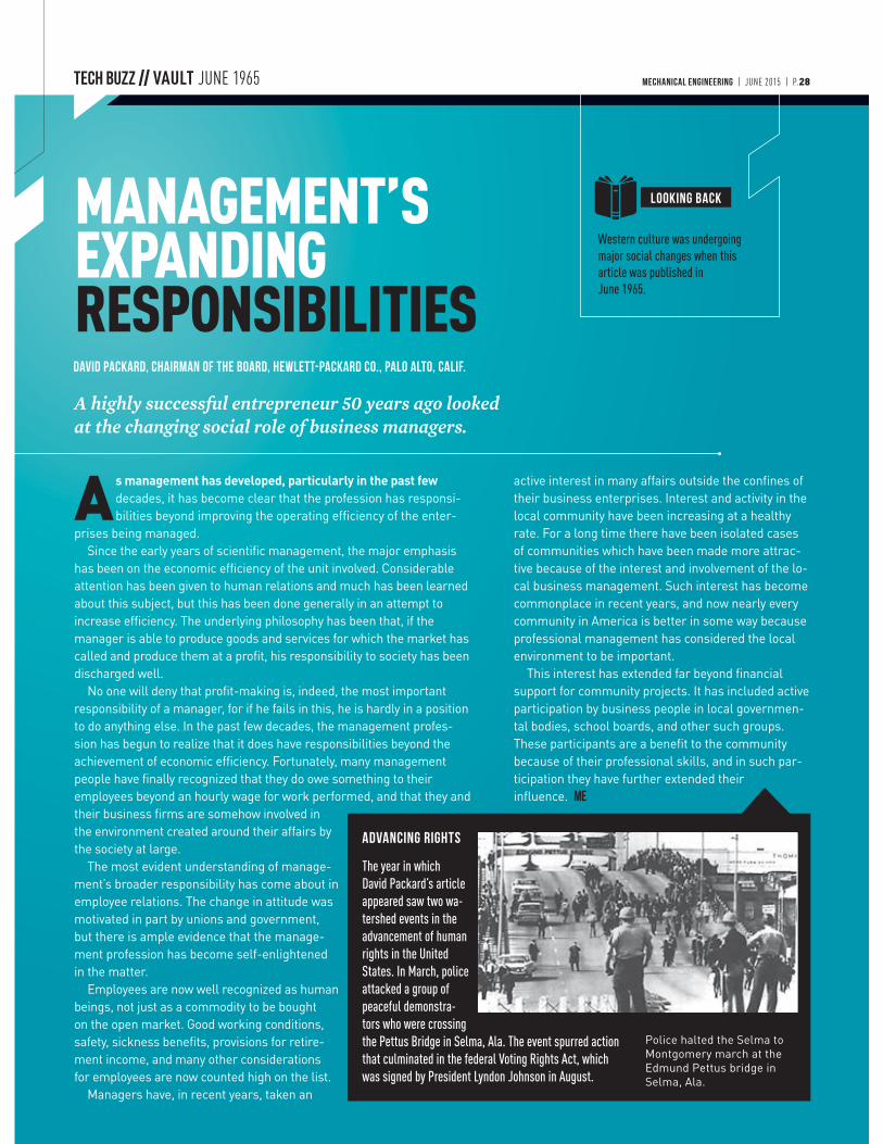
Western culture was undergoing major social changes when this article was published in June 1965.
A highly successful entrepreneur 50 years ago looked at the changing social role of business managers.
David Packard, chairman of the board, Hewlett-Packard Co., Palo Alto, Calif.
MANAGEMENT’S EXPANDING RESPONSIBILITIES
As management has developed, particularly in the past few decades, it has become clear that the profession has responsi-bilities beyond improving the operating efficiency of the enter-
prises being managed.Since the early years of scientific management, the major emphasis
has been on the economic efficiency of the unit involved. Considerable attention has been given to human relations and much has been learned about this subject, but this has been done generally in an attempt to increase efficiency. The underlying philosophy has been that, if the manager is able to produce goods and services for which the market has called and produce them at a profit, his responsibility to society has been discharged well.
No one will deny that profit-making is, indeed, the most important responsibility of a manager, for if he fails in this, he is hardly in a position to do anything else. In the past few decades, the management profes-sion has begun to realize that it does have responsibilities beyond the achievement of economic efficiency. Fortunately, many management people have finally recognized that they do owe something to their employees beyond an hourly wage for work performed, and that they and their business firms are somehow involved in the environment created around their affairs by the society at large.
The most evident understanding of manage-ment’s broader responsibility has come about in employee relations. The change in attitude was motivated in part by unions and government, but there is ample evidence that the manage-ment profession has become self-enlightened in the matter.
Employees are now well recognized as human beings, not just as a commodity to be bought on the open market. Good working conditions, safety, sickness benefits, provisions for retire-ment income, and many other considerations for employees are now counted high on the list.
Managers have, in recent years, taken an
active interest in many affairs outside the confines of their business enterprises. Interest and activity in the local community have been increasing at a healthy rate. For a long time there have been isolated cases of communities which have been made more attrac-tive because of the interest and involvement of the lo-cal business management. Such interest has become commonplace in recent years, and now nearly every community in America is better in some way because professional management has considered the local environment to be important.
This interest has extended far beyond financial support for community projects. It has included active participation by business people in local governmen-tal bodies, school boards, and other such groups. These participants are a benefit to the community because of their professional skills, and in such par-ticipation they have further extended their influence. ME
ADVANCING RIGHTS
Police halted the Selma to Montgomery march at the Edmund Pettus bridge in Selma, Ala.
MECHANICAL ENGINEERING | JUNE 2015 | P.28
LOOKING BACK
The year in which David Packard’s article appeared saw two wa-tershed events in the advancement of human rights in the United States. In March, police attacked a group of peaceful demonstra-tors who were crossing the Pettus Bridge in Selma, Ala. The event spurred action that culminated in the federal Voting Rights Act, which was signed by President Lyndon Johnson in August.

TIM SHINBARA
VP of Manufacturing TechnologyAMT
Participating Organizations Include:America MakesAutoDesk ResearchCarl Zeiss IMTCumminsHoneywell AerospaceGE Global ResearchVoxel8FormLabsSenvolAliconaFraser Advanced IS
Don’t get lost in the crowd, like many larger tradeshows! DRILL DOWN INTO KEY AM APPLICATIONS-BASED TOPICS AND CONVERSE IN AN INTIMATE SETTING ONLY PROVIDED AT AM3D:
• Design for additive manufacturing using topology optimization• Considerations for materials selection and certification• Equipment selection and investment analysis• Process monitoring technologies to improve results• Post production qualification methods• How Standards development will increase demand • The future of AM and distributed manufacturing
go.asme.org/3dprintingGet Social #AM3D
W H E R E W I L L Y O U R I N D U S T R Y P E E R S B E T H I S A U G U S T ?
Interact with AM leaders and learn how to transform your business:
ADDITIVE MANUFACTURING+3D
AM3DConference & Expo
PRINTINGA
Emerging trends and applications in DIGITAL MANUFACTURING AND DESIGN
WAYNE KING
Director of the Accelerated Certification of Additively Manufactured Metals InitiativeLawrence Livermore National Labs
MARCIN BAUZA
Director of New Technology & InnovationCarl Zeiss IMT
SIMIN ZHOU
VP of Digital Manufacturing TechnologyUL
WILL YOU JOIN THE RANKS, OR BE LEFT BEHIND?
Titan IndustriesVirginia Tech DREAMS LabSchlumbergerLawrence Livermore National LabsMITULAction Engineering3D Printing ReportsMORF3DAssociation For Manufacturing Technology (AMT)
Join us at the 2015 Additive Manufacturing + 3D Printing Conference & Expo (AM3D), the only event in the AM marketplace designed exclusively for the Engineering Community. Over three days attend in-depth technical sessions, listen to dynamic panels and participate in exciting networking functions where you’ll gain perspectives from cross-industry AM leaders.
A S M E ’ S A D D I T I V E M A N U FACT U R I N G + 3 D P R I N T I N G C O N F E R E N C E
For full session descriptions & additional information, visit
go.asme.org/3dprinting
Emerging trends and applications in DIGITAL MANUFACTURING AND DESIGN
AUGUST 2-5, 2015 HYNES CONVENTION CENTER BOSTON, MAMARK YOUR CALENDAR
REGISTER ONLINE BY JUNE 1, 2015 T O R E C E I V E U P TO $120 OFF THE STANDARD RATE!
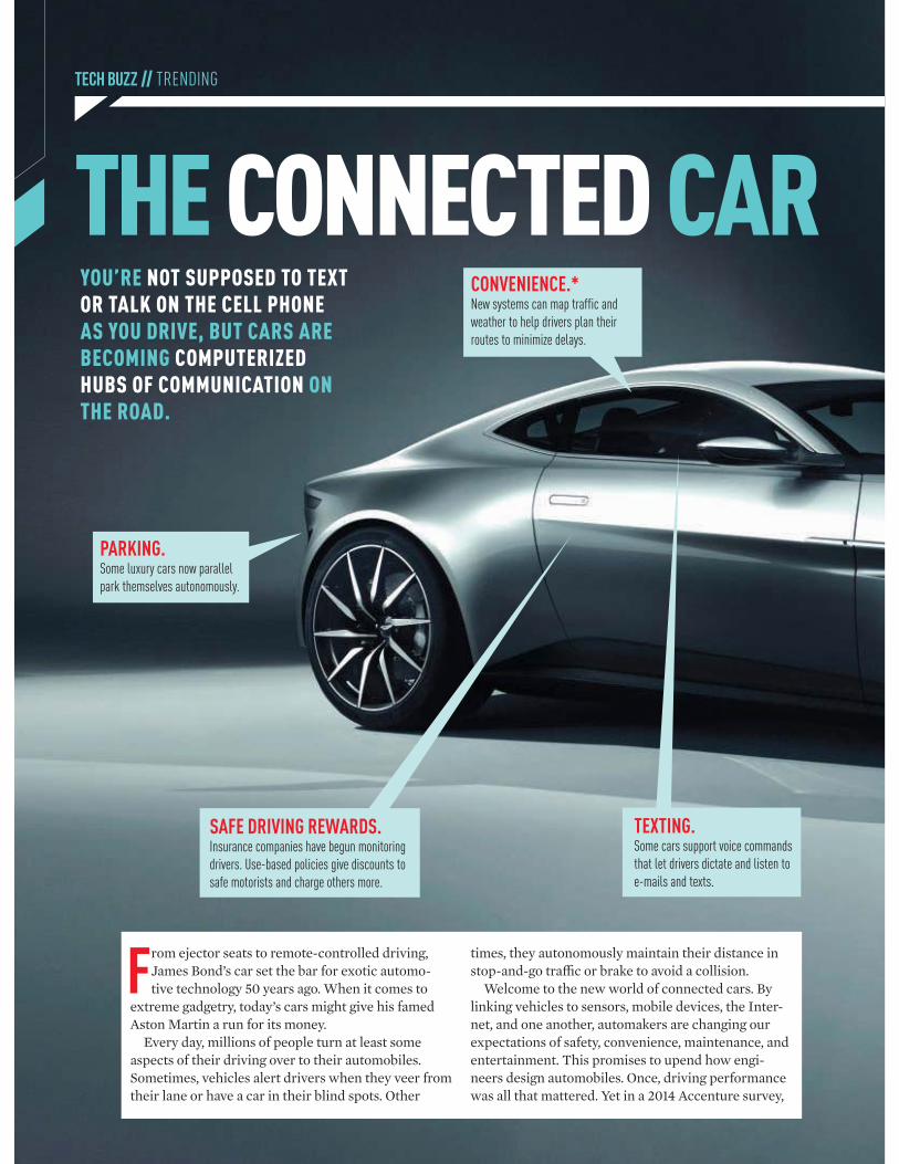
TECH BUZZ // TRENDING
THE CONNECTED CAR
TEXTING.Some cars support voice commands
that let drivers dictate and listen to
e-mails and texts.
SAFE DRIVING REWARDS.Insurance companies have begun monitoring
drivers. Use-based policies give discounts to
safe motorists and charge others more.
CONVENIENCE.*New systems can map traffic and
weather to help drivers plan their
routes to minimize delays.
PARKING.Some luxury cars now parallel
park themselves autonomously.
From ejector seats to remote-controlled driving, James Bond’s car set the bar for exotic automo-tive technology 50 years ago. When it comes to
extreme gadgetry, today’s cars might give his famed Aston Martin a run for its money.
Every day, millions of people turn at least some aspects of their driving over to their automobiles. Sometimes, vehicles alert drivers when they veer from their lane or have a car in their blind spots. Other
times, they autonomously maintain their distance in stop-and-go traffic or brake to avoid a collision.
Welcome to the new world of connected cars. By linking vehicles to sensors, mobile devices, the Inter-net, and one another, automakers are changing our expectations of safety, convenience, maintenance, and entertainment. This promises to upend how engi-neers design automobiles. Once, driving performance was all that mattered. Yet in a 2014 Accenture survey,
YOU’RE NOT SUPPOSED TO TEXT OR TALK ON THE CELL PHONE AS YOU DRIVE, BUT CARS ARE BECOMING COMPUTERIZED HUBS OF COMMUNICATION ON THE ROAD.
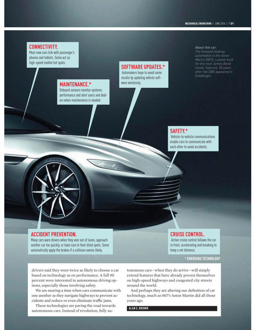
SOFTWARE UPDATES.* Automakers hope to avoid some
recalls by updating vehicle soft-
ware wirelessly. MAINTENANCE.*Onboard sensors monitor systems
performance and alert users and deal-
ers when maintenance is needed.
SAFETY.* Vehicle-to-vehicle communications
enable cars to communicate with
each other to avoid accidents.
ACCIDENT PREVENTION.Many cars warn drivers when they veer out of lanes, approach
another car too quickly, or have cars in their blind spots. Some
automatically apply the brakes if a collision seems likely.
CONNECTIVITY.Most new cars link with passenger’s
phones and tablets. Some act as
high-speed mobile hot spots.
CRUISE CONTROL. Active cruise control follows the car
in front, accelerating and breaking to
keep a set distance.
drivers said they were twice as likely to choose a car based on technology as on performance. A full 90 percent were interested in autonomous driving op-tions, especially those involving safety.
We are nearing a time when cars communicate with one another as they navigate highways to prevent ac-cidents and reduce or even eliminate traffic jams.
These technologies are paving the road towards autonomous cars. Instead of revolution, fully au-
tonomous cars—when they do arrive—will simply extend features that have already proven themselves on high-speed highways and congested city streets around the world.
And perhaps they are altering our definition of car technology, much as 007’s Aston Martin did all those years ago.
ALAN S. BROWN
MECHANICAL ENGINEERING | JUNE 2015 | P.31
* EMERGING TECHNOLOGY
About this car:The forward-looking automobile is the Aston Martin DB10, custom built for the next James Bond movie, Spectre, 50 years after the DB5 appeared in Goldfinger.
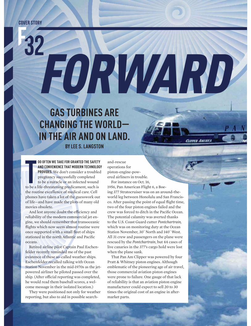
GAS TURBINES ARE CHANGING THE WORLD —IN THE AIR AND ON LAND.
BY LEE S. LANGSTON
FORWARD
TOO OFTEN WE TAKE FOR GRANTED THE SAFETY
AND CONVENIENCE THAT MODERN TECHNOLOGY
PROVIDES. We don’t consider a troubled pregnancy successfully completed to be a miracle or an infected wound
to be a life-threatening predicament, such is the routine excellence of medical care. Cell phones have taken a lot of the guesswork out of life—and have made the plots of many old movies obsolete.
And lest anyone doubt the effi ciency and reliability of the modern commercial jet en-gine, we should remember that transoceanic fl ights which now seem almost routine were once supported with a small fl eet of ships stationed in the north Atlantic and Pacifi c oceans.
Retired airline pilot Captain Paul Eschen-felder recently reminded me of the past existence of these so-called weather ships. Eschenfelder recalled talking with Ocean Station November in the mid-1970s as the jet-powered airliner he piloted passed over the ship. (After offi cial reporting was completed, he would read them baseball scores, a wel-come message in their isolated location.)
They were positioned not only for weather reporting, but also to aid in possible search-
and-rescue operations for piston-engine-pow-ered airliners in trouble.
For instance on Oct. 16, 1956, Pan American Flight 6, a Boe-ing 377 Stratocruiser was on an around-the-world leg between Honolulu and San Francis-co. After passing the point of equal fl ight time, two of the four piston engines failed and the crew was forced to ditch in the Pacifi c Ocean. The potential calamity was averted thanks to the U.S. Coast Guard cutter Pontchartrain, which was on monitoring duty at the Ocean Station November, 30˚ North and 140˚ West. All 31 crew and passengers on the plane were rescued by the Pontchartrain, but 44 cases of live canaries in the 377’s cargo hold were lost when the plane sank.
That Pan Am Clipper was powered by four Pratt & Whitney piston engines. Although emblematic of the pioneering age of air travel, those commercial aviation piston engines were prone to failure. One gauge of that lack of reliability is that an aviation piston engine manufacturer could expect to sell 20 to 30 times the original cost of an engine in after-market parts.
COVER STORY
F32

MECHANICAL ENGINEERING | FEBRUARY 2013 | P.033
FUTURE
A Boeing 377 on a 1956 round-the-world flight ditched
in the Pacific when two of its four engines failed.
Fortunately, a U.S. Coast Guard weather ship was
stationed nearby and rescued the passengers before the
plane sank. Image credit: Boeing Company (top), William Simpson,
U.S. Coast Guard (insets).
MECHANICAL ENGINEERING | JUNE 2015 | P.33
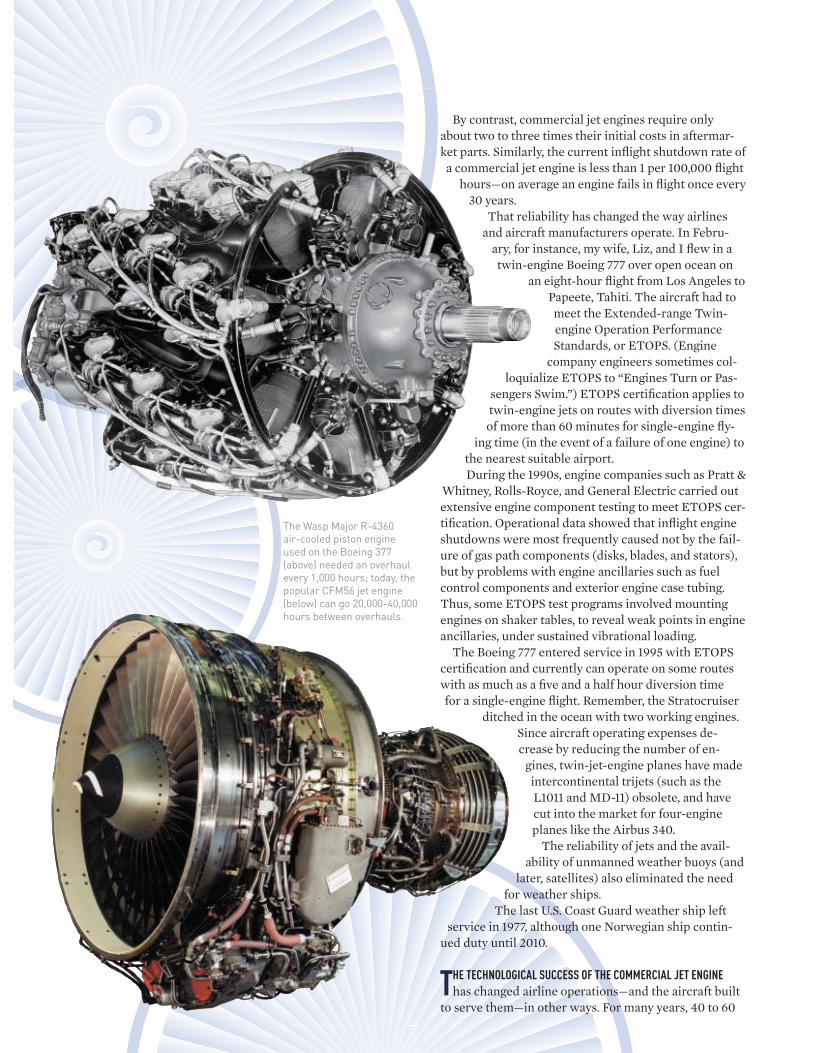
By contrast, commercial jet engines require only about two to three times their initial costs in aftermar-ket parts. Similarly, the current infl ight shutdown rate of
a commercial jet engine is less than 1 per 100,000 fl ight hours—on average an engine fails in fl ight once every
30 years. That reliability has changed the way airlines
and aircraft manufacturers operate. In Febru-ary, for instance, my wife, Liz, and I fl ew in a twin-engine Boeing 777 over open ocean on
an eight-hour fl ight from Los Angeles to Papeete, Tahiti. The aircraft had to meet the Extended-range Twin-engine Operation Performance Standards, or ETOPS. (Engine
company engineers sometimes col-loquialize ETOPS to “Engines Turn or Pas-
sengers Swim.”) ETOPS certifi cation applies to twin-engine jets on routes with diversion times of more than 60 minutes for single-engine fl y-
ing time (in the event of a failure of one engine) to the nearest suitable airport. During the 1990s, engine companies such as Pratt &
Whitney, Rolls-Royce, and General Electric carried out extensive engine component testing to meet ETOPS cer-tifi cation. Operational data showed that infl ight engine shutdowns were most frequently caused not by the fail-ure of gas path components (disks, blades, and stators), but by problems with engine ancillaries such as fuel control components and exterior engine case tubing. Thus, some ETOPS test programs involved mounting engines on shaker tables, to reveal weak points in engine ancillaries, under sustained vibrational loading.
The Boeing 777 entered service in 1995 with ETOPS certifi cation and currently can operate on some routes with as much as a fi ve and a half hour diversion time for a single-engine fl ight. Remember, the Stratocruiser
ditched in the ocean with two working engines.Since aircraft operating expenses de-crease by reducing the number of en-
gines, twin-jet-engine planes have made intercontinental trijets (such as the L1011 and MD-11) obsolete, and have cut into the market for four-engine planes like the Airbus 340.
The reliability of jets and the avail-ability of unmanned weather buoys (and
later, satellites) also eliminated the need for weather ships.
The last U.S. Coast Guard weather ship left service in 1977, although one Norwegian ship contin-
ued duty until 2010.
THE TECHNOLOGICAL SUCCESS OF THE COMMERCIAL JET ENGINE
has changed airline operations—and the aircraft built to serve them—in other ways. For many years, 40 to 60
The Wasp Major R-4360 air-cooled piston engine used on the Boeing 377 (above) needed an overhaul every 1,000 hours; today, the popular CFM56 jet engine (below) can go 20,000-40,000 hours between overhauls.
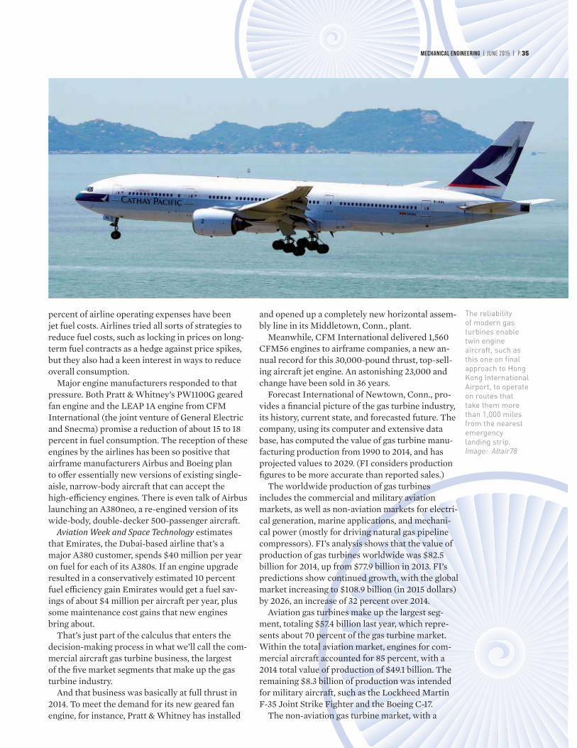
percent of airline operating expenses have been jet fuel costs. Airlines tried all sorts of strategies to reduce fuel costs, such as locking in prices on long-term fuel contracts as a hedge against price spikes, but they also had a keen interest in ways to reduce overall consumption.
Major engine manufacturers responded to that pressure. Both Pratt & Whitney’s PW1100G geared fan engine and the LEAP 1A engine from CFM International (the joint venture of General Electric and Snecma) promise a reduction of about 15 to 18 percent in fuel consumption. The reception of these engines by the airlines has been so positive that airframe manufacturers Airbus and Boeing plan to off er essentially new versions of existing single-aisle, narrow-body aircraft that can accept the high-effi ciency engines. There is even talk of Airbus launching an A380neo, a re-engined version of its wide-body, double-decker 500-passenger aircraft.
Aviation Week and Space Technology estimates that Emirates, the Dubai-based airline that’s a major A380 customer, spends $40 million per year on fuel for each of its A380s. If an engine upgrade resulted in a conservatively estimated 10 percent fuel effi ciency gain Emirates would get a fuel sav-ings of about $4 million per aircraft per year, plus some maintenance cost gains that new engines bring about.
That’s just part of the calculus that enters the decision-making process in what we’ll call the com-mercial aircraft gas turbine business, the largest of the fi ve market segments that make up the gas turbine industry.
And that business was basically at full thrust in 2014. To meet the demand for its new geared fan engine, for instance, Pratt & Whitney has installed
and opened up a completely new horizontal assem-bly line in its Middletown, Conn., plant.
Meanwhile, CFM International delivered 1,560 CFM56 engines to airframe companies, a new an-nual record for this 30,000-pound thrust, top-sell-ing aircraft jet engine. An astonishing 23,000 and change have been sold in 36 years.
Forecast International of Newtown, Conn., pro-vides a fi nancial picture of the gas turbine industry, its history, current state, and forecasted future. The company, using its computer and extensive data base, has computed the value of gas turbine manu-facturing production from 1990 to 2014, and has projected values to 2029. (FI considers production fi gures to be more accurate than reported sales.)
The worldwide production of gas turbines includes the commercial and military aviation markets, as well as non-aviation markets for electri-cal generation, marine applications, and mechani-cal power (mostly for driving natural gas pipeline compressors). FI’s analysis shows that the value of production of gas turbines worldwide was $82.5 billion for 2014, up from $77.9 billion in 2013. FI’s predictions show continued growth, with the global market increasing to $108.9 billion (in 2015 dollars) by 2026, an increase of 32 percent over 2014.
Aviation gas turbines make up the largest seg-ment, totaling $57.4 billion last year, which repre-sents about 70 percent of the gas turbine market. Within the total aviation market, engines for com-mercial aircraft accounted for 85 percent, with a 2014 total value of production of $49.1 billion. The remaining $8.3 billion of production was intended for military aircraft, such as the Lockheed Martin F-35 Joint Strike Fighter and the Boeing C-17.
The non-aviation gas turbine market, with a
The reliability of modern gas turbines enable twin engine aircraft, such as this one on final approach to Hong Kong International Airport, to operate on routes that take them more than 1,000 miles from the nearest emergency landing strip.Image: Altair78
MECHANICAL ENGINEERING | JUNE 2015 | P.35
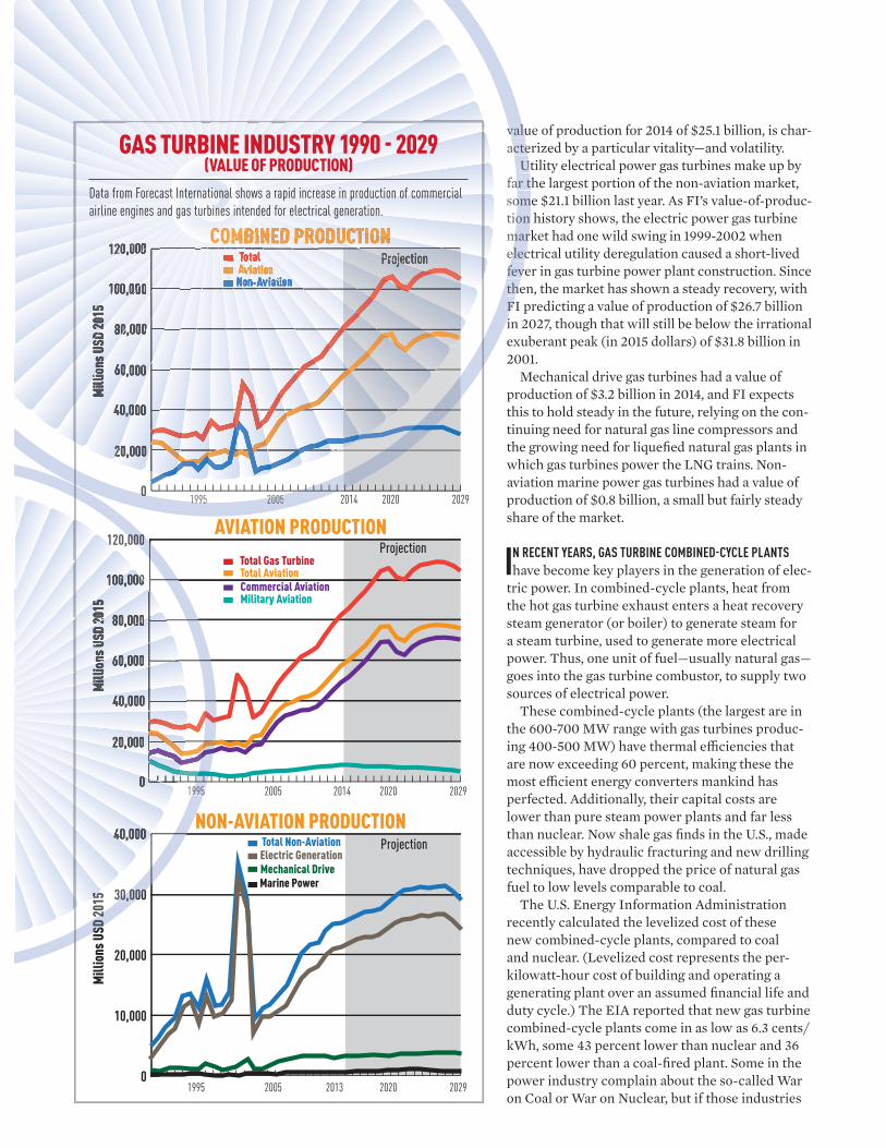
value of production for 2014 of $25.1 billion, is char-acterized by a particular vitality—and volatility.
Utility electrical power gas turbines make up by far the largest portion of the non-aviation market, some $21.1 billion last year. As FI’s value-of-produc-tion history shows, the electric power gas turbine market had one wild swing in 1999-2002 when electrical utility deregulation caused a short-lived fever in gas turbine power plant construction. Since then, the market has shown a steady recovery, with FI predicting a value of production of $26.7 billion in 2027, though that will still be below the irrational exuberant peak (in 2015 dollars) of $31.8 billion in 2001.
Mechanical drive gas turbines had a value of production of $3.2 billion in 2014, and FI expects this to hold steady in the future, relying on the con-tinuing need for natural gas line compressors and the growing need for liquefi ed natural gas plants in which gas turbines power the LNG trains. Non-aviation marine power gas turbines had a value of production of $0.8 billion, a small but fairly steady share of the market.
IN RECENT YEARS, GAS TURBINE COMBINED-CYCLE PLANTS
have become key players in the generation of elec-tric power. In combined-cycle plants, heat from the hot gas turbine exhaust enters a heat recovery steam generator (or boiler) to generate steam for a steam turbine, used to generate more electrical power. Thus, one unit of fuel—usually natural gas—goes into the gas turbine combustor, to supply two sources of electrical power.
These combined-cycle plants (the largest are in the 600-700 MW range with gas turbines produc-ing 400-500 MW) have thermal effi ciencies that are now exceeding 60 percent, making these the most effi cient energy converters mankind has perfected. Additionally, their capital costs are lower than pure steam power plants and far less than nuclear. Now shale gas fi nds in the U.S., made accessible by hydraulic fracturing and new drilling techniques, have dropped the price of natural gas fuel to low levels comparable to coal.
The U.S. Energy Information Administration recently calculated the levelized cost of these new combined-cycle plants, compared to coal and nuclear. (Levelized cost represents the per-kilowatt-hour cost of building and operating a generating plant over an assumed fi nancial life and duty cycle.) The EIA reported that new gas turbine combined-cycle plants come in as low as 6.3 cents/kWh, some 43 percent lower than nuclear and 36 percent lower than a coal-fi red plant. Some in the power industry complain about the so-called War on Coal or War on Nuclear, but if those industries
Projection
0
20,000
40,000
60,000
80,000
100,000
120,000
0
10,000
20,000
30,000
40,000
2014 202020051995 2029
2013 202020051995 2029
Electric GenerationMechanical DriveMarine Power
Total Non-Aviation
Total AviationCommercial AviationMilitary Aviation
Total Gas Turbine
Projection
Mill
ions
USD
2015
Mill
ions
USD
2015
0
20,000
40,000
60,000
80,000
100,000
120,000
2014 202020051995 2029
Aviation Total
Non-Aviation
Projection
Mill
ions
USD
2015
NON-AVIATION PRODUCTION
COMBINED PRODUCTION
AVIATION PRODUCTION
vac
fasotiomef
0
2
20051995
valuacte
Uar tomon
marelecfevtheFi
020051995
CCCOOOMMBB
0
120,00
30,0
19
2015
000
30,000
995
SD 2
N
GAS TURBINE INDUSTRY 1990 - 2029(VALUE OF PRODUCTION)
Data from Forecast International shows a rapid increase in production of commercial
airline engines and gas turbines intended for electrical generation.
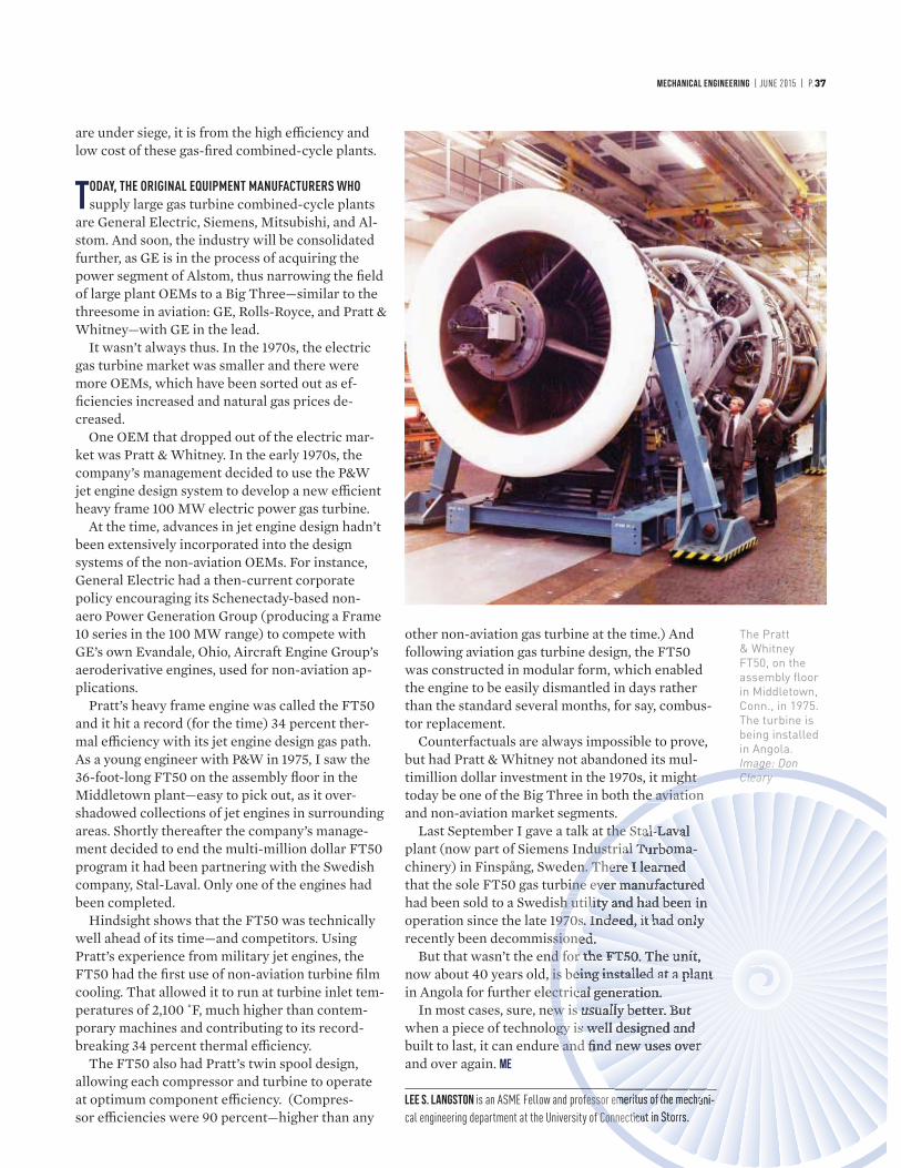
MECHANICAL ENGINEERING | JUNE 2015 | P.37
are under siege, it is from the high effi ciency and low cost of these gas-fi red combined-cycle plants.
TODAY, THE ORIGINAL EQUIPMENT MANUFACTURERS WHO
supply large gas turbine combined-cycle plants are General Electric, Siemens, Mitsubishi, and Al-stom. And soon, the industry will be consolidated further, as GE is in the process of acquiring the power segment of Alstom, thus narrowing the fi eld of large plant OEMs to a Big Three—similar to the threesome in aviation: GE, Rolls-Royce, and Pratt & Whitney—with GE in the lead.
It wasn’t always thus. In the 1970s, the electric gas turbine market was smaller and there were more OEMs, which have been sorted out as ef-fi ciencies increased and natural gas prices de-creased.
One OEM that dropped out of the electric mar-ket was Pratt & Whitney. In the early 1970s, the company’s management decided to use the P&W jet engine design system to develop a new effi cient heavy frame 100 MW electric power gas turbine.
At the time, advances in jet engine design hadn’t been extensively incorporated into the design systems of the non-aviation OEMs. For instance, General Electric had a then-current corporate policy encouraging its Schenectady-based non-aero Power Generation Group (producing a Frame 10 series in the 100 MW range) to compete with GE’s own Evandale, Ohio, Aircraft Engine Group’s aeroderivative engines, used for non-aviation ap-plications.
Pratt’s heavy frame engine was called the FT50 and it hit a record (for the time) 34 percent ther-mal effi ciency with its jet engine design gas path. As a young engineer with P&W in 1975, I saw the 36-foot-long FT50 on the assembly fl oor in the Middletown plant—easy to pick out, as it over-shadowed collections of jet engines in surrounding areas. Shortly thereafter the company’s manage-ment decided to end the multi-million dollar FT50 program it had been partnering with the Swedish company, Stal-Laval. Only one of the engines had been completed.
Hindsight shows that the FT50 was technically well ahead of its time—and competitors. Using Pratt’s experience from military jet engines, the FT50 had the fi rst use of non-aviation turbine fi lm cooling. That allowed it to run at turbine inlet tem-peratures of 2,100 ˚F, much higher than contem-porary machines and contributing to its record-breaking 34 percent thermal effi ciency.
The FT50 also had Pratt’s twin spool design, allowing each compressor and turbine to operate at optimum component effi ciency. (Compres-sor effi ciencies were 90 percent—higher than any
other non-aviation gas turbine at the time.) And following aviation gas turbine design, the FT50 was constructed in modular form, which enabled the engine to be easily dismantled in days rather than the standard several months, for say, combus-tor replacement.
Counterfactuals are always impossible to prove, but had Pratt & Whitney not abandoned its mul-timillion dollar investment in the 1970s, it might today be one of the Big Three in both the aviation and non-aviation market segments.
Last September I gave a talk at the Stal-Laval plant (now part of Siemens Industrial Turboma-chinery) in Finspång, Sweden. There I learned that the sole FT50 gas turbine ever manufactured had been sold to a Swedish utility and had been in operation since the late 1970s. Indeed, it had only recently been decommissioned.
But that wasn’t the end for the FT50. The unit, now about 40 years old, is being installed at a plant in Angola for further electrical generation.
In most cases, sure, new is usually better. But when a piece of technology is well designed and built to last, it can endure and fi nd new uses over and over again. ME
LEE S. LANGSTON is an ASME Fellow and professor emeritus of the mechani-
cal engineering department at the University of Connecticut in Storrs.
The Pratt & Whitney FT50, on the assembly floor in Middletown, Conn., in 1975. The turbine is being installed in Angola. Image: Don Cleary
viation
he Stal-strial T
Therne eveutili
70s. onefor
s betric
w is uy is wand fi
ssor eme
onnecticu
Clearyghte aviatio
the Sdust
n. Tine
h u97siod is
ectewogy
an
fesso
f Conn
gCleary
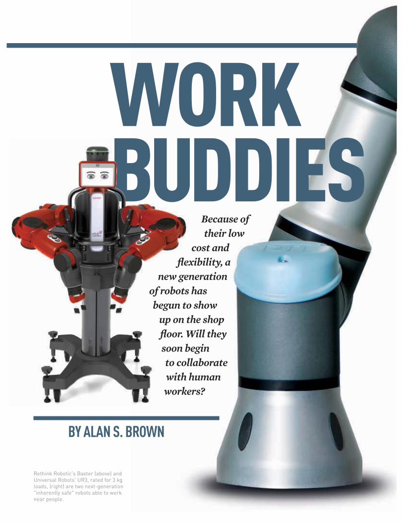
WORK BUDDIES
BY ALAN S. BROWN
Because of their low cost and
flexibility, a new generation
of robots has begun to show up on the shop
floor. Will they soon begin
to collaborate with human workers?
Rethink Robotic's Baxter (above) and Universal Robots' UR3, rated for 3 kg loads, (right) are two next-generation "inherently safe" robots able to work near people.
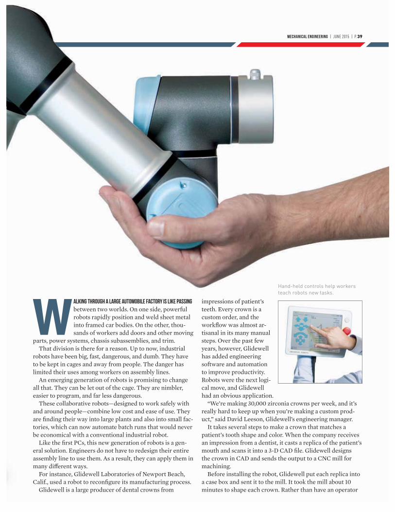
MECHANICAL ENGINEERING | JUNE 2015 | P.39
Walking through a large automobile factory is like passing between two worlds. On one side, powerful robots rapidly position and weld sheet metal into framed car bodies. On the other, thou-sands of workers add doors and other moving
parts, power systems, chassis subassemblies, and trim.That division is there for a reason. Up to now, industrial
robots have been big, fast, dangerous, and dumb. They have to be kept in cages and away from people. The danger has limited their uses among workers on assembly lines.
An emerging generation of robots is promising to change all that. They can be let out of the cage. They are nimbler, easier to program, and far less dangerous.
These collaborative robots—designed to work safely with and around people—combine low cost and ease of use. They are finding their way into large plants and also into small fac-tories, which can now automate batch runs that would never be economical with a conventional industrial robot.
Like the first PCs, this new generation of robots is a gen-eral solution. Engineers do not have to redesign their entire assembly line to use them. As a result, they can apply them in many different ways.
For instance, Glidewell Laboratories of Newport Beach, Calif., used a robot to reconfigure its manufacturing process.
Glidewell is a large producer of dental crowns from
impressions of patient’s teeth. Every crown is a custom order, and the workflow was almost ar-tisanal in its many manual steps. Over the past few years, however, Glidewell has added engineering software and automation to improve productivity. Robots were the next logi-cal move, and Glidewell had an obvious application.
“We’re making 30,000 zirconia crowns per week, and it’s really hard to keep up when you’re making a custom prod-uct,” said David Leeson, Glidewell’s engineering manager.
It takes several steps to make a crown that matches a patient’s tooth shape and color. When the company receives an impression from a dentist, it casts a replica of the patient’s mouth and scans it into a 3-D CAD file. Glidewell designs the crown in CAD and sends the output to a CNC mill for machining.
Before installing the robot, Glidewell put each replica into a case box and sent it to the mill. It took the mill about 10 minutes to shape each crown. Rather than have an operator
Hand-held controls help workers teach robots new tasks.
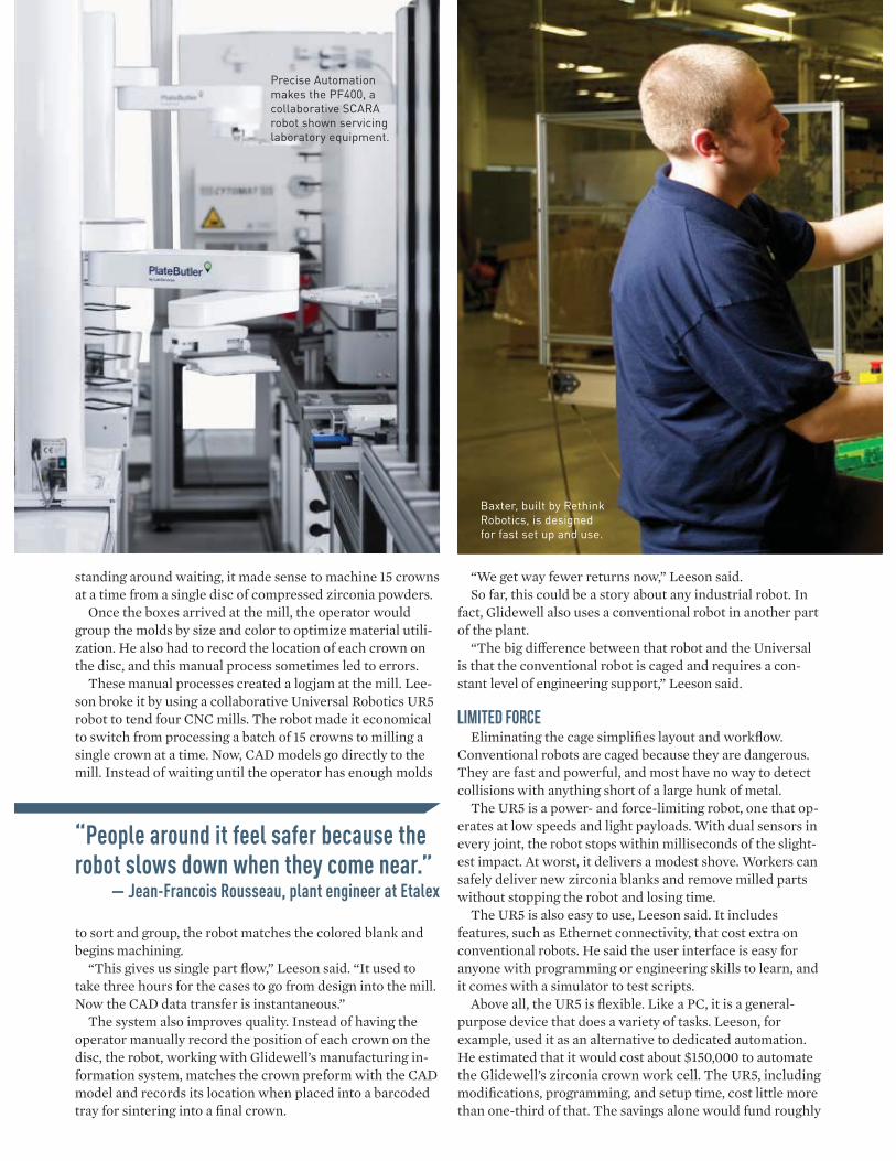
standing around waiting, it made sense to machine 15 crowns at a time from a single disc of compressed zirconia powders.
Once the boxes arrived at the mill, the operator would group the molds by size and color to optimize material utili-zation. He also had to record the location of each crown on the disc, and this manual process sometimes led to errors.
These manual processes created a logjam at the mill. Lee-son broke it by using a collaborative Universal Robotics UR5 robot to tend four CNC mills. The robot made it economical to switch from processing a batch of 15 crowns to milling a single crown at a time. Now, CAD models go directly to the mill. Instead of waiting until the operator has enough molds
to sort and group, the robot matches the colored blank and begins machining.
“This gives us single part flow,” Leeson said. “It used to take three hours for the cases to go from design into the mill. Now the CAD data transfer is instantaneous.”
The system also improves quality. Instead of having the operator manually record the position of each crown on the disc, the robot, working with Glidewell’s manufacturing in-formation system, matches the crown preform with the CAD model and records its location when placed into a barcoded tray for sintering into a final crown.
“We get way fewer returns now,” Leeson said. So far, this could be a story about any industrial robot. In
fact, Glidewell also uses a conventional robot in another part of the plant.
“The big difference between that robot and the Universal is that the conventional robot is caged and requires a con-stant level of engineering support,” Leeson said.
LIMITED FORCE
Eliminating the cage simplifies layout and workflow. Conventional robots are caged because they are dangerous. They are fast and powerful, and most have no way to detect collisions with anything short of a large hunk of metal.
The UR5 is a power- and force-limiting robot, one that op-erates at low speeds and light payloads. With dual sensors in every joint, the robot stops within milliseconds of the slight-est impact. At worst, it delivers a modest shove. Workers can safely deliver new zirconia blanks and remove milled parts without stopping the robot and losing time.
The UR5 is also easy to use, Leeson said. It includes features, such as Ethernet connectivity, that cost extra on conventional robots. He said the user interface is easy for anyone with programming or engineering skills to learn, and it comes with a simulator to test scripts.
Above all, the UR5 is flexible. Like a PC, it is a general-purpose device that does a variety of tasks. Leeson, for example, used it as an alternative to dedicated automation. He estimated that it would cost about $150,000 to automate the Glidewell’s zirconia crown work cell. The UR5, including modifications, programming, and setup time, cost little more than one-third of that. The savings alone would fund roughly
“People around it feel safer because the robot slows down when they come near.”
— Jean-Francois Rousseau, plant engineer at Etalex
Precise Automation makes the PF400, a collaborative SCARA robot shown servicing laboratory equipment.
Baxter, built by Rethink Robotics, is designed for fast set up and use.
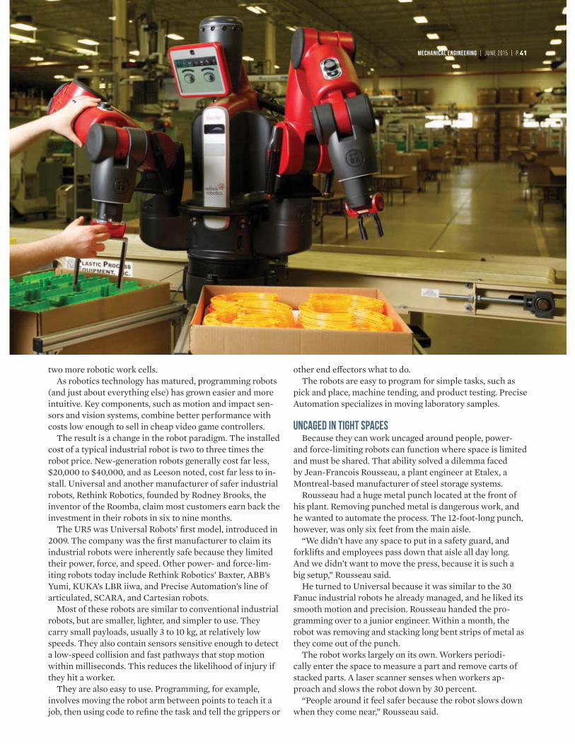
MECHANICAL ENGINEERING | JUNE 2015 | P.41
two more robotic work cells.As robotics technology has matured, programming robots
(and just about everything else) has grown easier and more intuitive. Key components, such as motion and impact sen-sors and vision systems, combine better performance with costs low enough to sell in cheap video game controllers.
The result is a change in the robot paradigm. The installed cost of a typical industrial robot is two to three times the robot price. New-generation robots generally cost far less, $20,000 to $40,000, and as Leeson noted, cost far less to in-stall. Universal and another manufacturer of safer industrial robots, Rethink Robotics, founded by Rodney Brooks, the inventor of the Roomba, claim most customers earn back the investment in their robots in six to nine months.
The UR5 was Universal Robots’ first model, introduced in 2009. The company was the first manufacturer to claim its industrial robots were inherently safe because they limited their power, force, and speed. Other power- and force-lim-iting robots today include Rethink Robotics’ Baxter, ABB’s Yumi, KUKA’s LBR iiwa, and Precise Automation’s line of articulated, SCARA, and Cartesian robots.
Most of these robots are similar to conventional industrial robots, but are smaller, lighter, and simpler to use. They carry small payloads, usually 3 to 10 kg, at relatively low speeds. They also contain sensors sensitive enough to detect a low-speed collision and fast pathways that stop motion within milliseconds. This reduces the likelihood of injury if they hit a worker.
They are also easy to use. Programming, for example, involves moving the robot arm between points to teach it a job, then using code to refine the task and tell the grippers or
other end effectors what to do. The robots are easy to program for simple tasks, such as
pick and place, machine tending, and product testing. Precise Automation specializes in moving laboratory samples.
unCAGEd in tight spaces
Because they can work uncaged around people, power- and force-limiting robots can function where space is limited and must be shared. That ability solved a dilemma faced by Jean-Francois Rousseau, a plant engineer at Etalex, a Montreal-based manufacturer of steel storage systems.
Rousseau had a huge metal punch located at the front of his plant. Removing punched metal is dangerous work, and he wanted to automate the process. The 12-foot-long punch, however, was only six feet from the main aisle.
“We didn’t have any space to put in a safety guard, and forklifts and employees pass down that aisle all day long. And we didn’t want to move the press, because it is such a big setup,” Rousseau said.
He turned to Universal because it was similar to the 30 Fanuc industrial robots he already managed, and he liked its smooth motion and precision. Rousseau handed the pro-gramming over to a junior engineer. Within a month, the robot was removing and stacking long bent strips of metal as they come out of the punch.
The robot works largely on its own. Workers periodi-cally enter the space to measure a part and remove carts of stacked parts. A laser scanner senses when workers ap-proach and slows the robot down by 30 percent.
“People around it feel safer because the robot slows down when they come near,” Rousseau said.
Eliminating fences also makes it easier to change tooling. With conventional robots, Rousseau would have to remove the fence and robot to get a forklift carrying the massive tool-ing through. Now, he unlatches a bracket and slides the robot out of the way to access the center of the press.
In most factories, the only difference between power- and force-limiting robots and conventional industrial robots is the absence of fences. With Baxter (and its new Sawyer robot for machine tending), Rethink Robotics hopes to bring greater flexibility to the shop floor.
“We designed it to roll the robot off, train it easily, and change tasks from month to month,” said Rethink product manager Brian Benoit.
Baxter comes with several innovative features. One is the robot positioning system. By using a camera embedded in its wrist, it can orient itself by locating markers posted around the workspace.
“Now you can design tasks in two different cells, turn on the positioning system, and the robot will orient itself and get right to work,” Benoit said.
Baxter also has what Benoit calls “adjustable behavior.” “Baxter knows where the part is in the work cell, and
knows if it is holding a piece or misses a pick,” Benoit said. “It won’t just continue with the process. It will pick up the part or repack it again. It has sensors on board that make it possible to put these behaviors in place.”
Unlike most robots, whose joints use gear boxes with hard stops, Baxter has elastic actuators. They make it slightly compliant. If its arm bumps into someone, it gives a little bit.
That gives Baxter an extra margin of safety. Compliance, when coupled with built-in force sensitivity, also lets Baxter perform more tasks. It could, for example, test a circuit board. This usually involves inserting the tester guide pin through a hole on the board.
“A human would use the guide pin to feel his way in and give it a shake to mount it,” Benoit said. “A typical robot would have to go top down. Baxter comes in at an angle, like a person, and when it feels the force feedback, it has another move that seats it.”
At Du-Co Ceramics in Saxonburg, Pa., process engineer Josh Rupp is taking advantage of Baxter’s flexibility to add automation to short production runs.
Du-Co created a small work cell with a simple conveying system. Ceramic preforms come down the line, one at a time and oriented in the same direction. When they arrive at a known location, the system controller tells Baxter to pick them up. The robot then places them in trays for sinter-ing. Workers periodically enter to deliver empty trays and remove full ones.
“We can look at production runs we could never automate before, because the time required to set up the work cell wouldn’t have justified it. In the past, we would have done it with people. Now, we can create a versatile cell that we can move from machine to machine,” Rupp said.
As with other power- and force-limiting robots, program-ming was simple. In fact, Rupp hopes he can eventually train workers to set up Baxter.
“That’s the best way to utilize its flexibility,” Rupp said.
Emerging safety standardWhile power- and force-limiting robots have many boost-
ers, their payloads are limited. At most, they might lift 14 kilograms. That’s a problem for companies that work with large or heavy parts.
General Motors’ principal robot engineer, Marty Linn, sums it up succinctly: “Inflatable hammers are inherently safe, but not very good at pounding in nails.”
That is why engineers are developing ways to instrument conventional industrial robots to work safely near humans. A new standard under development, ISO 15066, Safety Requirements for Industrial Robots—Collaborative Operation, outlines four distinct safety strategies.
One, of course, is limiting power and force. The second is the safety-rated monitored stop, where the robot stops as soon as a worker triggers a sensor (such as a light curtain or pressure mat) by walking into its space. It resumes work once the human leaves.
Third is hand guiding, which allows humans to teach an arm a new set of motions while it is in live automatic mode.
Fourth is speed and separa-tion monitoring, which uses sensors to track work-ers and to slow or stop the robot if humans get too close.
Many industrial robots are already equipped with these safety-rated sensors.
“The major industrial robot makers have been doing functional safety for more than four years,” said Erik Nieves, technology director for Yaskawa Motoman.
Those robots could be used in collaborative applications once ISO 15066 is adapted, he added.
In fact, some companies are already using industrial robots collaboratively. Nieves described one customer that uses a worker-robot team to move 400-pound castings.
“The robot can’t pick up the parts blind, because they are unwieldy and come on a pallet in a variety of positions,” Nieves said. “The robot has an autonomous program and moves where the part ought to be, then waits for the opera-tor to move the robot into position to pick it up.
"After the operator walks out of cell, the robot resumes the
“We designed it to roll the robot off, train it easily, and change tasks from month to month.”
— Brian Benoit, Rethink product manager
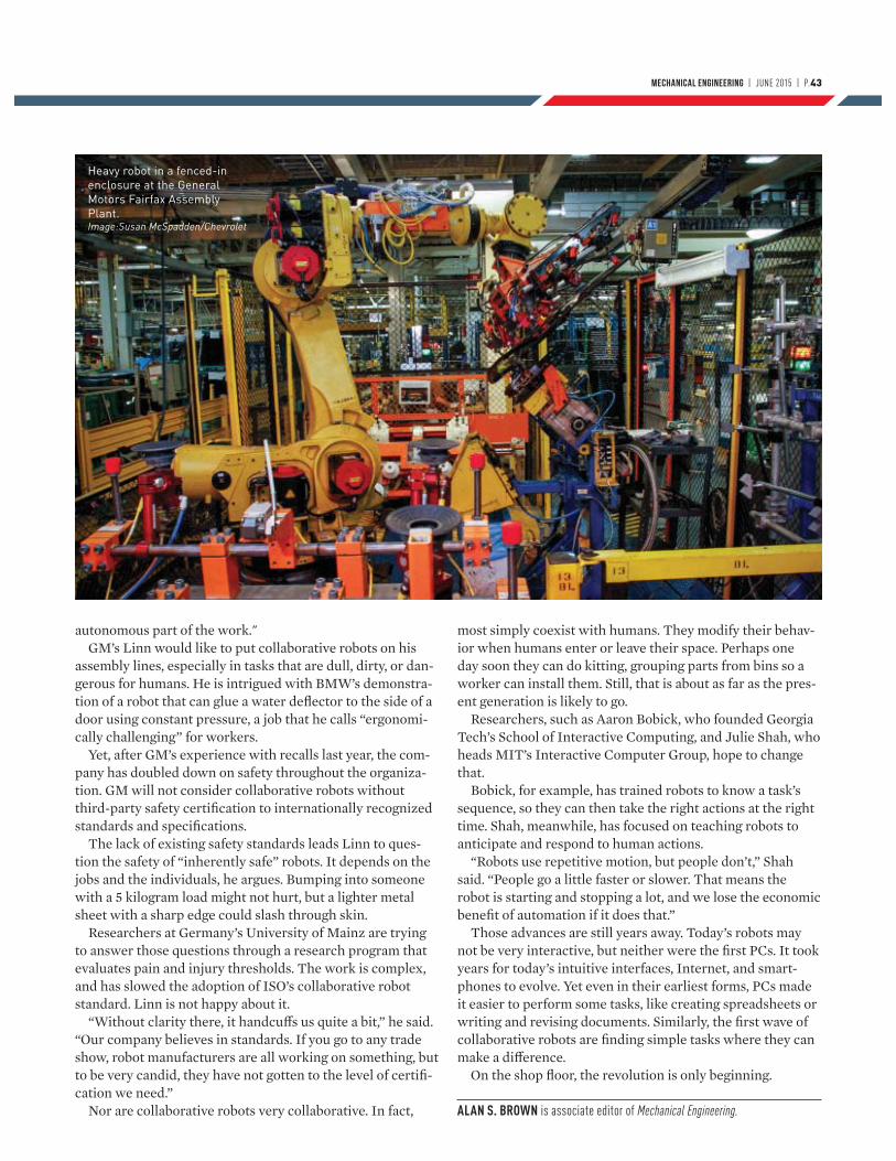
MECHANICAL ENGINEERING | JUNE 2015 | P.43
autonomous part of the work."GM’s Linn would like to put collaborative robots on his
assembly lines, especially in tasks that are dull, dirty, or dan-gerous for humans. He is intrigued with BMW’s demonstra-tion of a robot that can glue a water deflector to the side of a door using constant pressure, a job that he calls “ergonomi-cally challenging” for workers.
Yet, after GM’s experience with recalls last year, the com-pany has doubled down on safety throughout the organiza-tion. GM will not consider collaborative robots without third-party safety certification to internationally recognized standards and specifications.
The lack of existing safety standards leads Linn to ques-tion the safety of “inherently safe” robots. It depends on the jobs and the individuals, he argues. Bumping into someone with a 5 kilogram load might not hurt, but a lighter metal sheet with a sharp edge could slash through skin.
Researchers at Germany’s University of Mainz are trying to answer those questions through a research program that evaluates pain and injury thresholds. The work is complex, and has slowed the adoption of ISO’s collaborative robot standard. Linn is not happy about it.
“Without clarity there, it handcuffs us quite a bit,” he said. “Our company believes in standards. If you go to any trade show, robot manufacturers are all working on something, but to be very candid, they have not gotten to the level of certifi-cation we need.”
Nor are collaborative robots very collaborative. In fact,
most simply coexist with humans. They modify their behav-ior when humans enter or leave their space. Perhaps one day soon they can do kitting, grouping parts from bins so a worker can install them. Still, that is about as far as the pres-ent generation is likely to go.
Researchers, such as Aaron Bobick, who founded Georgia Tech’s School of Interactive Computing, and Julie Shah, who heads MIT’s Interactive Computer Group, hope to change that.
Bobick, for example, has trained robots to know a task’s sequence, so they can then take the right actions at the right time. Shah, meanwhile, has focused on teaching robots to anticipate and respond to human actions.
“Robots use repetitive motion, but people don’t,” Shah said. “People go a little faster or slower. That means the robot is starting and stopping a lot, and we lose the economic benefit of automation if it does that.”
Those advances are still years away. Today’s robots may not be very interactive, but neither were the first PCs. It took years for today’s intuitive interfaces, Internet, and smart-phones to evolve. Yet even in their earliest forms, PCs made it easier to perform some tasks, like creating spreadsheets or writing and revising documents. Similarly, the first wave of collaborative robots are finding simple tasks where they can make a difference.
On the shop floor, the revolution is only beginning.
ALAN S. BROWN is associate editor of Mechanical Engineering.
Heavy robot in a fenced-in enclosure at the General Motors Fairfax Assembly Plant.Image:Susan McSpadden/Chevrolet
Laboratories of
PolicyI remember being fascinated by Washington,
D.C., from my fi rst visit. The White House and Capitol Building weren’t just symbols but the seat of power for the greatest country
in the world. The decisions and laws made in those buildings didn’t only aff ect us as Americans, but had an impact on the entire civilization. During one of my trips, I realized that I wanted to come back someday and participate in lawmaking.
I returned in 2013 not as a visitor, but as a Science and Technology Policy Fellow, part of the ASME Congressional Fellows program. To be accepted for the program was a great honor, I knew, but what I didn’t realize in advance was the way that having a trained engineer on a congressional staff could have an important and long-lasting impact
on public policy. I thought I would be one of many people trained in the physical sciences helping shape complex technical policy; too often, I was pretty much the only one.
Indeed, what I took home from my year in Washington was not a wonder at the magic of self-government but a realization that engineers and other scientifi cally trained individuals are not doing enough to infl uence policy.
So many public policy issues deal with questions that have a science or engineering basis, and those issues are being decided in many cases without an understanding of what is at stake. For instance, dur-ing the 113th Congress, which met in 2013 and 2014, only 12 House and Senate members had engineer-ing degrees. A mere 5 to 10 percent of the Congres-
I
MECHANICAL ENGINEERING | MAY 2015 | P.45
sional staff who prepare the legislation typically possess physical science or engineering degrees. And at the state level, the numbers are no better.
Engineers could bring a perspective that is too often not considered in the halls of Congress. Too often, we hang back and let important decisions get made by people who don’t really understand scientific and engineering principles behind the policy they are deciding.
WASHINGTON AT WORKFor my fellowship, I was assigned to the Subcom-mittee on Research and Technology of the House Committee on Science, Space, and Technology. Given my academic background and major focus
on nanotechnology, the subcommittee seemed to be the most appropriate training ground and the best opportunity to contribute. Not only is the Subcommittee on Research and Technology responsible for funding for the National Science Foundation and the National Institute of Standards and Technology, as well as other technology agen-cies and science education programs, but it is also responsible for 21st Century Nanotechnology R&D Reauthorization Act. I approached the chair of the committee and let him know about my expertise; they were keen on having me there.
One of my duties was to prepare the subcom-mittee for hearings on major bills. For instance, I worked on the preparations for a May 2014 hear-ing to be titled, “Nanotechnology: From Laborato-
Engineers cannot remain outside the political process.
Their expertise is needed to ensure that technical policy
is crafted to do the most good.
By Bharat Bhushan
MECHANICAL ENGINEERING | JUNE 2015 | P.45
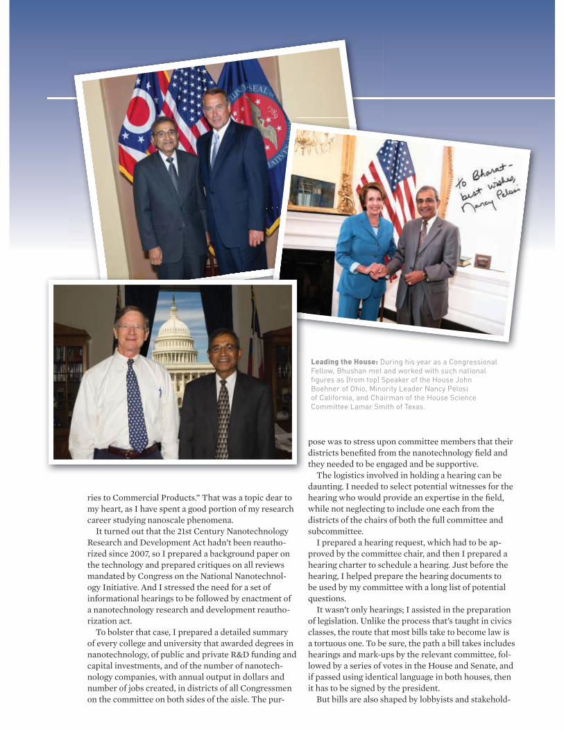
ries to Commercial Products.” That was a topic dear to my heart, as I have spent a good portion of my research career studying nanoscale phenomena.
It turned out that the 21st Century Nanotechnology Research and Development Act hadn’t been reautho-rized since 2007, so I prepared a background paper on the technology and prepared critiques on all reviews mandated by Congress on the National Nanotechnol-ogy Initiative. And I stressed the need for a set of informational hearings to be followed by enactment of a nanotechnology research and development reautho-rization act.
To bolster that case, I prepared a detailed summary of every college and university that awarded degrees in nanotechnology, of public and private R&D funding and capital investments, and of the number of nanotech-nology companies, with annual output in dollars and number of jobs created, in districts of all Congressmen on the committee on both sides of the aisle. The pur-
pose was to stress upon committee members that their districts benefi ted from the nanotechnology fi eld and they needed to be engaged and be supportive.
The logistics involved in holding a hearing can be daunting. I needed to select potential witnesses for the hearing who would provide an expertise in the fi eld, while not neglecting to include one each from the districts of the chairs of both the full committee and subcommittee.
I prepared a hearing request, which had to be ap-proved by the committee chair, and then I prepared a hearing charter to schedule a hearing. Just before the hearing, I helped prepare the hearing documents to be used by my committee with a long list of potential questions.
It wasn’t only hearings; I assisted in the preparation of legislation. Unlike the process that’s taught in civics classes, the route that most bills take to become law is a tortuous one. To be sure, the path a bill takes includes hearings and mark-ups by the relevant committee, fol-lowed by a series of votes in the House and Senate, and if passed using identical language in both houses, then it has to be signed by the president.
But bills are also shaped by lobbyists and stakehold-
Leading the House: During his year as a Congressional Fellow, Bhushan met and worked with such national figures as (from top) Speaker of the House John Boehner of Ohio, Minority Leader Nancy Pelosi of California, and Chairman of the House Science Committee Lamar Smith of Texas.
We can lobby legislators in favor of policies, educate our fellow citizens on the engineering
ers, and get tainted by the political process. The legisla-tors have constituents to please, and a party platform to observe.
As most people realize, the political climate while I was fellow was not conducive toward passing new laws and regulations. The partisan divide was almost unbridgeable. The 110th Congress saw nearly 14,000 pieces of legislation proposed, and about 97 percent were rejected.
But in my time on the subcommittee staff , I was able to see a few landmark pieces of legislation through the committee. For instance, I participated in the put-ting together of the Frontiers in Innovative Research, Science, and Technology Act, intended to reauthorize funding for various science agencies and programs. In the process, we had to not only develop the legal docu-ment, but also negotiate details with various commit-tee members and their staff s, and to continuously seek critiques from inside and outside. And, surprising to me, there were many hearings: ones to introduce the bill, which involved external witnesses, and mark-up hearings organized by the subcommittee and the full committee, for which we prepared responses to pro-posed amendments.
I also worked on the Revitalize American Manu-facturing and Innovation Act of 2013, which provides funding for establishing national networks for manu-facturing innovation in targeted areas, and the STEM Education Act of 2014, which provides funding to promote STEM education at all levels, from kindergar-ten through college, with some focus on economically disadvantaged and minorities.
ENGAGING THE PUBLICMy time as a Congressional Fellow was a life-changing experience. But let’s face it: there are not enough staff positions in Washington for every engineer to become engaged in policy through that sort of program. I be-lieve it is critical that engineers fi nd a way to become involved with policy making, so it’s important to fi nd ways of doing that closer to home.
Back home in Columbus, for instance, my colleagues and I have created an undergraduate minor in science,
engineering, and public policy, a joint program between the College of Engineering and the John Glenn College of Public Aff airs at my university. I have been appointed an affi liated faculty member in public aff airs and cham-pion the engagement of engineers in public policy at every opportunity. I am giving lectures in a cross-listed course on science and public policy. And I am ready to give talks at other colleges and universities about this and the importance of federal R&D investment, a policy on which I feel strongly.
This sort of engagement can make up for the lack of science and technology literacy among legislators, especially at the state and local levels. There are many ways that engineers can get involved, including directly, by taking up positions on the staff of state or federal representatives—or even by running for offi ce them-selves. We can lobby legislators in favor of policies and educate our fellow citizens on the engineering view of issues.
Above all, we must gain the training and experience needed to reach out to the public, both in speaking skills and in writing for a general audience.
There is a longstanding bias among engineers against engaging in public policy debates. We tend to let our research and products do the talking for us. But to me, this approach is mistaken. More than ever before, engineers need to be in policy making or aggressively engage their policy makers. Those of us in academia need to develop minors and develop cross-listed cours-es on science and public policy. This would provide a window to students on public policy and some may take a path of public policy either full time or in an advisory capacity at some point in their careers.
Engineers have to be champions for pro-science and pro-technology policies. They have the knowledge, pas-sion, and drive to encourage state and federal lawmak-ers to implement these policies. We would be shirking our professional and social responsibilities if we did not participate to the fullest extent.
BHARAT BHUSHAN is Ohio Eminent Scholar and Howard D. Winbigler
Professor in Engineering at the Ohio State University in Columbus. Bhushan
is also a Fellow and Life Member of ASME. He was an ASME Science and
Technology Policy Fellow from September 2013 to September 2014.
MECHANICAL ENGINEERING | JUNE 2015 | P.47
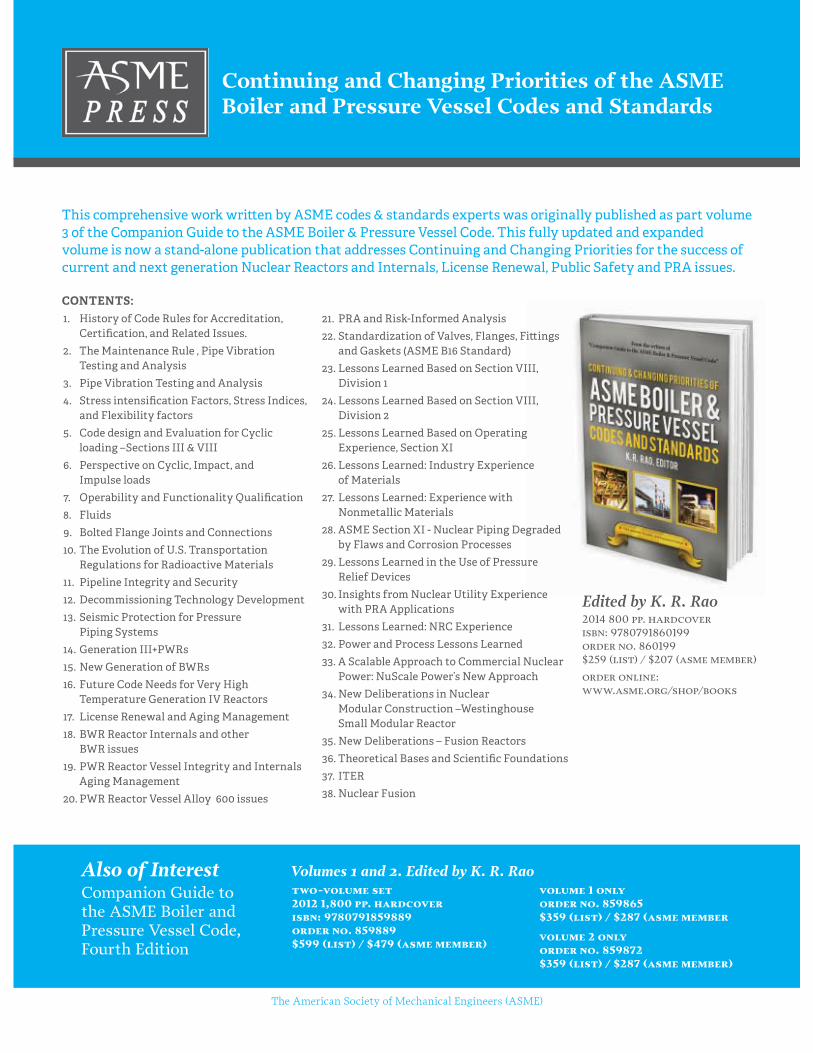
Continuing and Changing Priorities of the ASME Boiler and Pressure Vessel Codes and Standards
two-volume set 2012 1,800 pp. hardcover isbn: 9780791859889 order no. 859889 $599 (list) / $479 (asme member)
volume 1 only order no. 859865 $359 (list) / $287 (asme member
volume 2 only order no. 859872 $359 (list) / $287 (asme member)
Volumes 1 and 2. Edited by K. R. RaoCompanion Guide to the ASME Boiler and Pressure Vessel Code, Fourth Edition
Also of Interest
The American Society of Mechanical Engineers (ASME)
Edited by K. R. Rao2014 800 pp. hardcover isbn: 9780791860199 order no. 860199 $259 (list) / $207 (asme member)
order online: www.asme.org/shop/books
CONTENTS:1. History of Code Rules for Accreditation,
Certification, and Related Issues.
2. The Maintenance Rule , Pipe Vibration Testing and Analysis
3. Pipe Vibration Testing and Analysis
4. Stress intensification Factors, Stress Indices, and Flexibility factors
5. Code design and Evaluation for Cyclic loading –Sections III & VIII
6. Perspective on Cyclic, Impact, and Impulse loads
7. Operability and Functionality Qualification
8. Fluids
9. Bolted Flange Joints and Connections
10. The Evolution of U.S. Transportation Regulations for Radioactive Materials
11. Pipeline Integrity and Security
12. Decommissioning Technology Development
13. Seismic Protection for Pressure Piping Systems
14. Generation III+PWRs
15. New Generation of BWRs
16. Future Code Needs for Very High Temperature Generation IV Reactors
17. License Renewal and Aging Management
18. BWR Reactor Internals and other BWR issues
19. PWR Reactor Vessel Integrity and Internals Aging Management
20. PWR Reactor Vessel Alloy 600 issues
21. PRA and Risk-Informed Analysis
22. Standardization of Valves, Flanges, Fi�ings and Gaskets (ASME B16 Standard)
23. Lessons Learned Based on Section VIII, Division 1
24. Lessons Learned Based on Section VIII, Division 2
25. Lessons Learned Based on Operating Experience, Section XI
26. Lessons Learned: Industry Experience of Materials
27. Lessons Learned: Experience with Nonmetallic Materials
28. ASME Section XI - Nuclear Piping Degraded by Flaws and Corrosion Processes
29. Lessons Learned in the Use of Pressure Relief Devices
30. Insights from Nuclear Utility Experience with PRA Applications
31. Lessons Learned: NRC Experience
32. Power and Process Lessons Learned
33. A Scalable Approach to Commercial Nuclear Power: NuScale Power’s New Approach
34. New Deliberations in Nuclear Modular Construction –Westinghouse Small Modular Reactor
35. New Deliberations – Fusion Reactors
36. Theoretical Bases and Scientific Foundations
37. ITER
38. Nuclear Fusion
This comprehensive work wri�en by ASME codes & standards experts was originally published as part volume 3 of the Companion Guide to the ASME Boiler & Pressure Vessel Code. This fully updated and expanded volume is now a stand-alone publication that addresses Continuing and Changing Priorities for the success of current and next generation Nuclear Reactors and Internals, License Renewal, Public Safety and PRA issues.

WORKING SIDE BY SIDE WITH HUMANS
A forum for emerging systems and control technologies.
JUNE 2015 VOL. 3 NO. 2
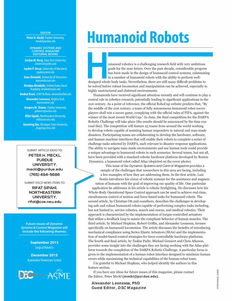
EDITOR
Peter H. Meckl, Purdue University, [email protected]
DYNAMIC SYSTEMS AND CONTROL MAGAZINE
EDITORIAL BOARD
Jordan M. Berg, Texas Tech University, [email protected]
Jaydev P. Desai, University of Maryland, [email protected]
Hans DeSmidt, University of Tennessee, [email protected]
Kiriakos Kiriakidis, United States Naval Academy, [email protected]
Venkat Krovi, SUNY Buff alo, vkrovi@buff alo.edu
Alexander Leonessa, Virginia Tech, [email protected]
Gregory M. Shaver, Purdue University, [email protected]
Rifat Sipahi, Northeastern University, [email protected]
Guoming Zhu, Michigan State University, [email protected]
Future issues of Dynamic Systems & Control Magazine will include the following themes:
September 2015
Surgical Robotics
December 2015
Automotive Powertrain Control
SUBMIT ARTICLE IDEAS TO:
PETER H. MECKL,PURDUE
UNIVERSITY, [email protected]
(765) 494-5686
SUBMIT DSCD NEWS ITEMS TO:
RIFAT SIPAHI, NORTHEASTERN
UNIVERSITY, [email protected]
Humanoid Robots
This issue of the Dynamic Systems and Control Magazine o i es s e of the h e es th t ese he s i this e e f i i u i
fe e es of ho the e essi the the st ti e uis e tis i t o u es his isio of o oti s ste s fo the ssist e u e
t tio of hu s ith the o of i o i ou u it of ife e ti u i tio he esses i his ti e is o oti e hti e is usses ho his
ho e o e tio e o t o o h e use to hie e e ti e si u t eous o t o of otio fo e se t s s fo hu oi o ots The se o ti e h isti tt o utho s es i es the h e es i e e oi s fe o ust hu oi o ots e of e fo i o e t s s i u i
ut ot i ite to se i e o oti s se h es ue e i o oti s Thei o h is h te i e the i e e t tio of to ue o t o e tu to s
th t uti i e fee oo to i i the o i t eh io of hu us es The thi ti e i h e o i s o e t i e e eo ess fo uses s e i o hu oi o o otio The ti e is usses the e e ts of i t o u i
e h i o i e usi e ies sti tu to s s the i e e ttio of o e se o t o st te ies fo fo e o t o e h e tfo s The fou th ti e T s i i i h e e e t h is t eso
o i es so e i si ht i to the h e es the e f i o i ith the t s tfo to s the o etio of the o oti h e e ti u fo us is
i e to the i e e t tio of hu o ot i te f e esi e to i i i e hu e o s hi e i i i the te h i i ities of the hu o ot te
tefu to i h e o i s ho he e i e tif the utho s i this feature section.
f ou ha e an i eas for future issues of this a a ine ease contact the itor eter ec ([email protected]).
Alexander Leonessa, PhDGuest Editor, DSC Magazine CO
VER
IMAG
E: D
ARPA
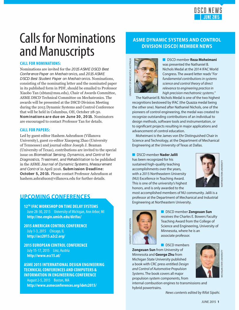
ASME DYNAMIC SYSTEMS AND CONTROL
DIVISION (DSCD) MEMBER NEWS
DSCD member Reza Moheimani was presented the Nathaniel B. Nichols Medal at the 2014 IFAC World Congress. The award letter reads “For fundamental contributions in systems science and control theory of direct relevance to engineering practice in high precision mechatronic systems.”
The Nathaniel B. Nichols Medal is one of the two highest recognitions bestowed by IFAC (the Quazza medal being the other one). Named after Nathaniel Nichols, one of the pioneers of control engineering, the medal was created to recognize outstanding contributions of an individual to design methods, software tools and instrumentation, or to significant projects resulting in major applications and advancement of control education.
Moheimani is the James von Ehr Distinguished Chair in Science and Technology, at the Department of Mechanical Engineering at the University of Texas at Dallas.
DSCD member Nader Jalili has been recognized for his sustained high-quality teaching accomplishments over the years, with a 2015 Northeastern University (NU) Excellence in Teaching Award. This is one of the university’s highest honors, and is only awarded to the most accomplished members of NU community. Jalili is a professor at the Department of Mechanical and Industrial Engineering at Northeastern University.
DSCD member Zongxuan Sun receives the Charles E. Bowers Faculty Teaching Award from the College of Science and Engineering, University of Minnesota, where he is anassociate professor.
DSCD members Zongxuan Sun from University of Minnesota and George Zhu from Michigan State University published a book with CRC press entitled Design and Control of Automotive Propulsion Systems. The book covers all major propulsion system components, from internal combustion engines to transmissions and hybrid powertrains. News contents edited by Rifat Sipahi.
D S C D N E W S
JUNE 2015
JUNE 2015 1
UN
IVER
SITY
OF
MIN
NES
OTA
NO
RTH
EAST
ERN
UN
IVER
SITY
MIC
HIG
AN S
TATE
UN
IVER
SITY
12TH IFAC WORKSHOP ON TIME DELAY SYSTEMS
June 28-30, 2015 University of Michigan, Ann Arbor, MI
http://me.engin.umich.edu/dirifac/
2015 AMERICAN CONTROL CONFERENCE
July 1-3, 2015 Chicago, IL
http://acc2015.a2c2.org/
2015 EUROPEAN CONTROL CONFERENCE
July 15-17, 2015 Linz, Austria
http://www.ecc15.at/
ASME 2015 INTERNATIONAL DESIGN ENGINEERING
TECHNICAL CONFERENCES AND COMPUTERS &
INFORMATION IN ENGINEERING CONFERENCE
August 2-5, 2015 Boston, MA
http://www.asmeconferences.org/idetc2015/
UPCOMING CONFERENCES
Calls for Nominations and ManuscriptsCALL FOR NOMINATIONS:
Nominations are invited for the 2015 ASME DSCD Best Conference Paper on Mechatronics, and 2015 ASME DSCD Best Student Paper on Mechatronics. Nominations, consisting of the nominating letter and the nominated paper in its published form in PDF, should be emailed to Professor Xiaobo Tan ([email protected]), Chair of Awards Committee, ASME DSCD Technical Committee on Mechatronics. The awards will be presented at the DSCD Division Meeting during the 2015 Dynamic Systems and Control Conference that will be held in Columbus, OH, October 28-30. Nominations are due on June 30, 2015. Nominators are encouraged to contact Professor Tan for details.
CALL FOR PAPERS:
ed by guest editor Hashem Ashra uon ( illanova University), guest co-editor Xiaopeng Zhao (University of Tennessee) and journal editor Joseph J. Beaman (University of Texas), contributions are invited to the special issue on Biomedical Sensing, Dynamics, and Control for Diagnostics, Treatment, and Rehabilitation to be published in the ASME Journal of Dynamic Systems, Measurement and Control in April 2016. Submission Deadline: October 5, 2015. Please contact Professor Ashra uon at hashem.ashra [email protected] for further details.
UN
IVER
SITY
OF
NEW
CAST
LE, A
UST
RALI
A
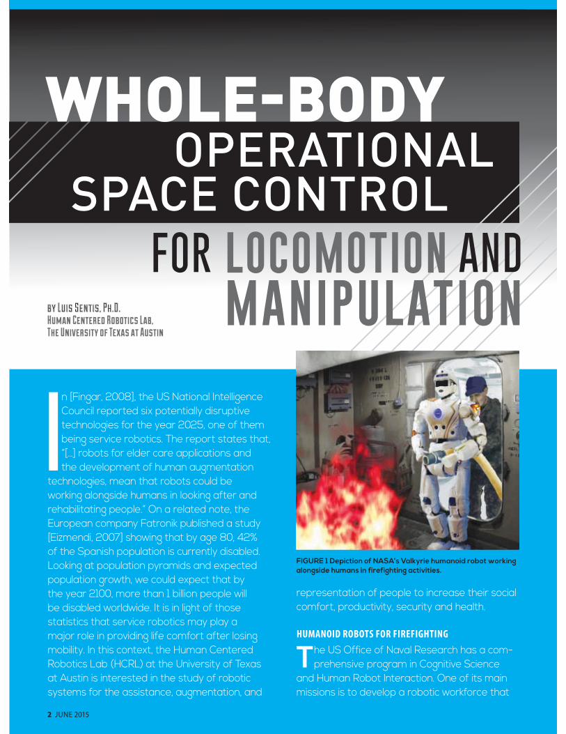
WHOLE-BODY
2 JUNE 2015
In [Fingar, 2008], the US National Intelligence Council reported six potentially disruptive technologies for the year 2025, one of them being service robotics. The report states that, “[…] robots for elder care applications and the development of human augmentation
technologies, mean that robots could be working alongside humans in looking after and rehabilitating people.” On a related note, the European company Fatronik published a study [Eizmendi, 2007] showing that by age 80, 42% of the Spanish population is currently disabled. Looking at population pyramids and expected population growth, we could expect that by the year 2100, more than 1 billion people will be disabled worldwide. It is in light of those statistics that service robotics may play a major role in providing life comfort after losing mobility. In this context, the Human Centered Robotics Lab (HCRL) at the University of Texas at Austin is interested in the study of robotic systems for the assistance, augmentation, and
representation of people to increase their social comfort, productivity, security and health.
HUMANOID ROBOTS FOR FIREFIGHTING
The US Office of Naval Research has a com-prehensive program in Cognitive Science
and Human Robot Interaction. One of its main missions is to develop a robotic workforce that
FIGURE 1 Depiction of NASA’s Valkyrie humanoid robot working alongside humans in firefighting activities.
by Luis Sentis, Ph.D.
Human Centered Robotics Lab,The University of Texas at Austin
FOR LOCOMOTION AND MANIPULATION
OPERATIONALSPACE CONTROL
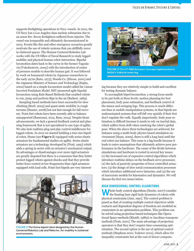
JUNE 2015 3
Fo c u s o n D y n a m i c S y s t e m s & C o n t r o l
FIGURE 2 The Hume biped robot designed by the Human Centered Robotics Lab and Meka Inc. for mobility in cluttered environments.
FIGURE 3 The UT-SEA Actuator Concept implemented in NASA’s Valkyrie lower leg.
supports re ghting operations in Navy vessels. n 2012, the US Navy lost a os Angeles class nuclear submarine due to an arson re. Seven re ghters su ered from injuries. The vessel was irreparable and ultimately decommissioned in 2013. Events li e this and other emergency scenarios greatly motivate the use of robotic systems that can s illfully move in cluttered spaces. The Human Centered obotics ab wor s with the US O ce of Naval esearch to study legged mobility and physical human robot interaction. Bipedal locomotion dates bac to the 1 0s in the former ugosla-via u obratovic, 2005 with the introduction of center of pressure models to describe human gait. t was followed by wor on humanoid robots by Japanese researchers in the early 1 0s ato, 1 3 , Honda Co. Hirose, 2001 and the Japanese Ministry of Science and Technology ajita, 2002 based on a simple locomotion model called the inear nverted Pendulum Model. M T pioneered agile bipedal
locomotion using ule Based Methods that enabled robots to run, jump and perform ips in the air aibert, 1 8 .
Sampling based methods have been successful for slow climbing Bretl, 2005 and uasi-static mobility in rough terrains Hauser, 2008 but not fast enough for fall recov-ery. Point feet robots have been recently able to balance unsupported ame ani, 2015, Buss, 201 . Despite those advancements, we lac a general feedbac control and plan-ning framewor that is not speciali ed to one type of agility.
e also lac realtime plug and play control middleware for legged robots. n 2012 we started building a teen si e biped-al robot, Hume (see Figure 2) e uipped with series elastic actuators for fundamental studies on agility. Series elastic actuators are a technology developed by Pratt, 1 5 which adds a spring in series with an actuator s mechanical output. ts advantages or disadvantages over more rigid actuators
are greatly disputed but there is a consensus that they better protect legged robots against shoc s and that they provide better force control at low fre uencies than rigid actuators e uipped with load cells. Point foot bipeds are very interest-
ing because they are relatively simple to build and excellent for testing dynamic balance.
To accomplish biped locomotion, a strong focus needs to be put forth at three levels motion planning for foot placement, body pose estimation, and feedbac control of the stance and swinging legs. This process is much di er-ent than in mobile manipulation systems, in that bipeds are underactuated systems that will fall very uic ly if their feet don t regulate the wal . E ually importantly, body pose es-timation is di cult because it needs to rely on inertial data, which su ers from drift when resolving the robot s global pose. hen the above three technologies are achieved, for instance using a multi-body physics based simulation en-vironment Haan, 200 , there is still a long haul until the real robot can balance. This issue is a big hurdle because it leads to naive assumptions that ultimately achieve poor per-formance in the hardware. The cause of the divide between simulations and hardware is rooted in several ey issues (1) the increased use of expensive control algorithms which introduce realtime delays on the feedbac servo processes (2) the lac of passivity properties of force controlled actua-tors (3) the design of slow serial communication processes which introduce additional servo latencies and ( ) the use of inaccurate models for inematics and dynamics. e will discuss the rst two issues below.
HIGH DIMENSIONAL CONTROL ALGORITHMS
Whole-body control algorithms Sentis, 200 consider the oating base rigid body dynamics of robots with
physical constraints Jain, 1 1 . The control problem is posed as that of creating multiple control objectives while contacts and dependent degrees of freedom are modeled as constraints in an optimi ation problem. This problem can be solved using projection-based techni ues li e Opera-tional Space methods hatib, 1 86a or Jacobian-transpose methods Pratt, 2001 . The main advantage of projection operators is that they don t re uire time-consuming opti-mi ation. The second option is the use of optimal control methods Stephens 2010, Todorov 2012 , which allow for ine uality constraints but at the cost of slower computa-
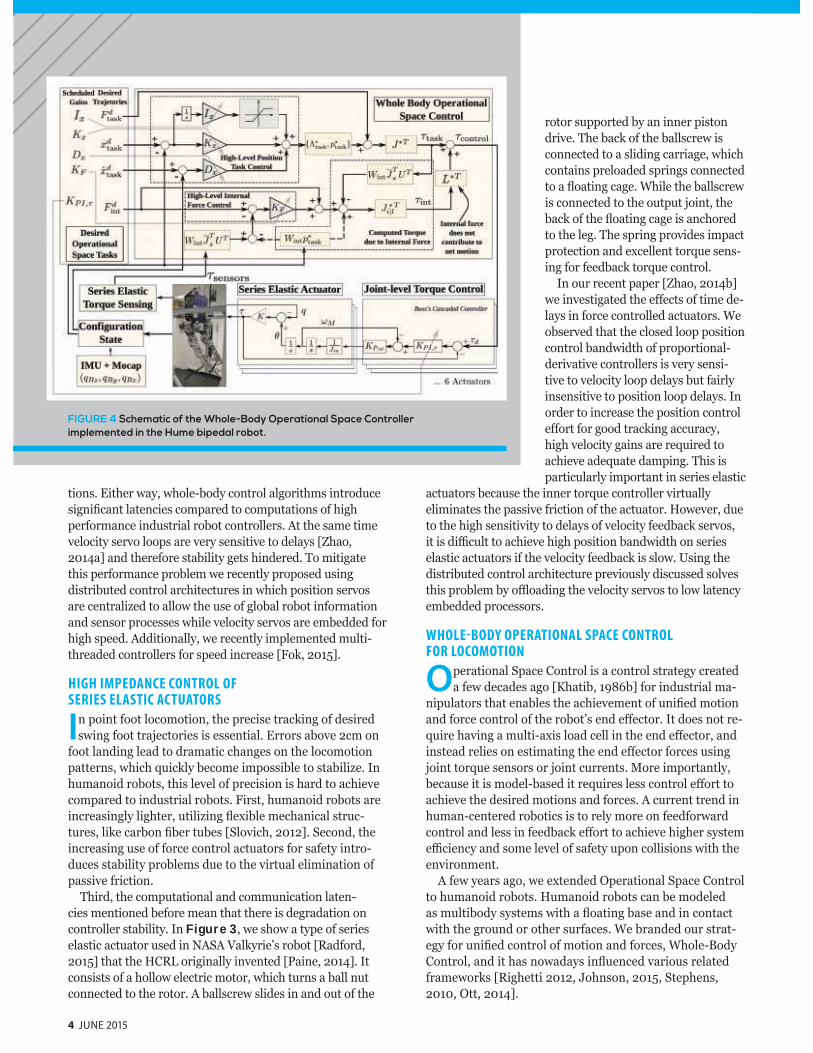
4 JUNE 2015
tions. Either way, whole-body control algorithms introduce signi cant latencies compared to computations of high performance industrial robot controllers. At the same time velocity servo loops are very sensitive to delays Zhao, 201 a and therefore stability gets hindered. To mitigate this performance problem we recently proposed using distributed control architectures in which position servos are centrali ed to allow the use of global robot information and sensor processes while velocity servos are embedded for high speed. Additionally, we recently implemented multi-threaded controllers for speed increase Fo , 2015 .
HIGH IMPEDANCE CONTROL OF SERIES ELASTIC ACTUATORS
In point foot locomotion, the precise trac ing of desired swing foot trajectories is essential. Errors above 2cm on
foot landing lead to dramatic changes on the locomotion patterns, which uic ly become impossible to stabili e. n humanoid robots, this level of precision is hard to achieve compared to industrial robots. First, humanoid robots are increasingly lighter, utili ing exible mechanical struc-tures, li e carbon ber tubes Slovich, 2012 . Second, the increasing use of force control actuators for safety intro-duces stability problems due to the virtual elimination of passive friction.
Third, the computational and communication laten-cies mentioned before mean that there is degradation on controller stability. n Figure 3, we show a type of series elastic actuator used in NASA al yrie s robot adford, 2015 that the HC originally invented Paine, 201 . t consists of a hollow electric motor, which turns a ball nut connected to the rotor. A ballscrew slides in and out of the
rotor supported by an inner piston drive. The bac of the ballscrew is connected to a sliding carriage, which contains preloaded springs connected to a oating cage. hile the ballscrew is connected to the output joint, the bac of the oating cage is anchored to the leg. The spring provides impact protection and excellent tor ue sens-ing for feedbac tor ue control.
n our recent paper Zhao, 201 b we investigated the e ects of time de-lays in force controlled actuators. e observed that the closed loop position control bandwidth of proportional-derivative controllers is very sensi-tive to velocity loop delays but fairly insensitive to position loop delays. n order to increase the position control e ort for good trac ing accuracy, high velocity gains are re uired to achieve ade uate damping. This is particularly important in series elastic
actuators because the inner tor ue controller virtually eliminates the passive friction of the actuator. However, due to the high sensitivity to delays of velocity feedbac servos, it is di cult to achieve high position bandwidth on series elastic actuators if the velocity feedbac is slow. Using the distributed control architecture previously discussed solves this problem by o oading the velocity servos to low latency embedded processors.
WHOLE-BODY OPERATIONAL SPACE CONTROL FOR LOCOMOTION
Operational Space Control is a control strategy created a few decades ago hatib, 1 86b for industrial ma-
nipulators that enables the achievement of uni ed motion and force control of the robot s end e ector. t does not re-
uire having a multi-axis load cell in the end e ector, and instead relies on estimating the end e ector forces using joint tor ue sensors or joint currents. More importantly, because it is model-based it re uires less control e ort to achieve the desired motions and forces. A current trend in human-centered robotics is to rely more on feedforward control and less in feedbac e ort to achieve higher system e ciency and some level of safety upon collisions with the environment.
A few years ago, we extended Operational Space Control to humanoid robots. Humanoid robots can be modeled as multibody systems with a oating base and in contact with the ground or other surfaces. e branded our strat-egy for uni ed control of motion and forces, hole-Body Control, and it has nowadays in uenced various related framewor s ighetti 2012, Johnson, 2015, Stephens, 2010, Ott, 201 .
FIGURE 4 Schematic of the Whole-Body Operational Space Controller implemented in the Hume bipedal robot.
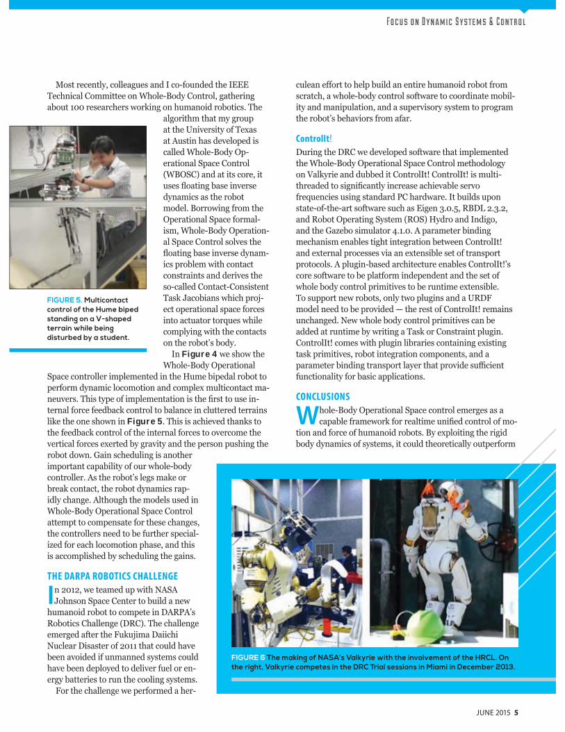
Fo c u s o n D y n a m i c S y s t e m s & C o n t r o l
Most recently, colleagues and co-founded the EEE Technical Committee on hole-Body Control, gathering about 100 researchers wor ing on humanoid robotics. The
algorithm that my group at the University of Texas at Austin has developed is called hole-Body Op-erational Space Control ( BOSC) and at its core, it uses oating base inverse dynamics as the robot model. Borrowing from the Operational Space formal-ism, hole-Body Operation-al Space Control solves the oating base inverse dynam-
ics problem with contact constraints and derives the so-called Contact-Consistent Tas Jacobians which proj-ect operational space forces into actuator tor ues while complying with the contacts on the robot s body.
n Figure 4 we show the hole-Body Operational
Space controller implemented in the Hume bipedal robot to perform dynamic locomotion and complex multicontact ma-neuvers. This type of implementation is the rst to use in-ternal force feedbac control to balance in cluttered terrains li e the one shown in Figure 5. This is achieved than s to the feedbac control of the internal forces to overcome the vertical forces exerted by gravity and the person pushing the robot down. ain scheduling is another important capability of our whole-body controller. As the robot s legs ma e or brea contact, the robot dynamics rap-idly change. Although the models used in
hole-Body Operational Space Control attempt to compensate for these changes, the controllers need to be further special-i ed for each locomotion phase, and this is accomplished by scheduling the gains.
THE DARPA ROBOTICS CHALLENGE
In 2012, we teamed up with NASA Johnson Space Center to build a new
humanoid robot to compete in DA PA s obotics Challenge (D C). The challenge
emerged after the Fu ujima Daiichi Nuclear Disaster of 2011 that could have been avoided if unmanned systems could have been deployed to deliver fuel or en-ergy batteries to run the cooling systems.
For the challenge we performed a her-
culean e ort to help build an entire humanoid robot from scratch, a whole-body control software to coordinate mobil-ity and manipulation, and a supervisory system to program the robot s behaviors from afar.
ControlIt!
During the D C we developed software that implemented the hole-Body Operational Space Control methodology on al yrie and dubbed it Control t Control t is multi-threaded to signi cantly increase achievable servo fre uencies using standard PC hardware. t builds upon state-of-the-art software such as Eigen 3.0.5, BD 2.3.2, and obot Operating System ( OS) Hydro and ndigo, and the a ebo simulator .1.0. A parameter binding mechanism enables tight integration between Control t and external processes via an extensible set of transport protocols. A plugin-based architecture enables Control t s core software to be platform independent and the set of whole body control primitives to be runtime extensible. To support new robots, only two plugins and a U DF model need to be provided the rest of Control t remains unchanged. New whole body control primitives can be added at runtime by writing a Tas or Constraint plugin. Control t comes with plugin libraries containing existing tas primitives, robot integration components, and a parameter binding transport layer that provide su cient functionality for basic applications.
CONCLUSIONS
Whole-Body Operational Space control emerges as a capable framewor for realtime uni ed control of mo-
tion and force of humanoid robots. By exploiting the rigid body dynamics of systems, it could theoretically outperform
FIGURE 6 The making of NASA’s Valkyrie with the involvement of the HRCL. On the right, Valkyrie competes in the DRC Trial sessions in Miami in December 2013.
JUNE 2015 5
FIGURE 5. Multicontact control of the Hume biped standing on a V-shaped terrain while being disturbed by a student.
REFERENCES
Bretl, Tim, et al. “Multi-step motion planning for free-
climbing robots.” Algorithmic Foundations of Robotics VI.
Springer Berlin Heidelberg, 2005. 59-74.
Buss, Brian G., et al. “Preliminary walking experiments
with underactuated 3d bipedal robot marlo.” Intelligent
Robots and Systems (IROS 2014), 2014 IEEE/RSJ International
Conference on. IEEE, 2014.
Eizmendi, Gorka, Azkoita, Jose Miguel, “Technologies and
active strategies for an ageing population”, IHE Assistive
Technology, 2007
Fingar, Thomas, Global Trends 2025: A Transformed World,
US National Intelligence Council, 2008
Fok, Chien.-Liang., Johnson, Gwen, and Sentis, Luis.
“ControlIt!: A Middleware for Whole-Body Operational Space
Control.” International Journal of Humanoid Robotics.
Under Review, 2015.
Haan, J, Kim, B., and Lee, J. “srLib – Seoul National University
Robotics Library,” June 2009. [Online]. Available: http://r-
station.co.kr/srlib/index.html
Hart, Stephen W., et al. “Robot task commander with
extensible programming environment.” U.S. Patent
Application 13/803,017.
Hauser, Kris, et al. “Motion planning for legged robots on
varied terrain.” The International Journal of Robotics Research
27.11-12 (2008): 1325-1349.
Hirose, Masato. “Development of humanoid robot ASIMO.”
Proc. IEEE/RSJ Int. Conference on Intelligent Robots and
Systems (Oct. 29, 2001). 2001.
Jain, Abhinandan. “Unified formulation of dynamics for
serial rigid multibody systems.” Journal of Guidance,
Control, and Dynamics 14.3 (1991): 531-542.
Johnson, Matthew, et al. “Team IHMC’s Lessons Learned
from the DARPA Robotics Challenge Trials.” Journal of Field
Robotics 32.2 (2015): 192-208.
Kajita, Shuuji, et al. “A realtime pattern generator for biped
walking.” Robotics and Automation, 2002. Proceedings.
ICRA’02. IEEE International Conference on. Vol. 1. IEEE, 2002.
Kato, Ichiro, Tsunoo, Mitsunobu, and Hirabayashi, Hisaaki.
“Legs of the WABOT (Waseda Leg-5)— Human Type
Hydraulic Walking Machine—.” Waseda Daigaku Rikogaku
Kenkyujo Hokoku 62 (1973): 3.
Khatib, Oussama, and Burdick, Joel. “Motion and force
control of robot manipulators.” Robotics and Automation.
Proceedings. 1986 IEEE International Conference on. Vol. 3.
IEEE, 1986a.
Khatib, Oussama. “Real-time obstacle avoidance for
manipulators and mobile robots.” The international journal of
robotics research 5.1 (1986b): 90-98.
Ott, Christian , Mukherjee, Ranjan, and Nakamura, Yoshihiko.
“A Hybrid System Framework for Unified Impedance and
Admittance Control.” Journal of Intelligent & Robotic Systems
(2014): 1-17.
Paine, Nicholas, Oh, Sehoon, and Sentis, Luis. “Design and
control considerations for high-performance series elastic
actuators.” Mechatronics, IEEE/ASME Transactions on 19.3
(2014): 1080-1091.
Pratt, Gill A., and Williamson, Matthew M. “Series elastic
actuators.”, Proceedings of the IEEE/RSJ Intelligent Robots and
Systems, 1995
Pratt, Jerry, et al. “Virtual model control: An intuitive
approach for bipedal locomotion.” The International Journal
of Robotics Research 20.2 (2001): 129-143.
Radford, Nicolaus A., et al. “Valkyrie: NASA’s First Bipedal
Humanoid Robot.” Journal of Field Robotics (2015).
Raibert, Marc H., Brown, H. Benjamin, and Chepponis,
Michael. “Experiments in balance with a 3D one-legged
hopping machine.” The International Journal of Robotics
Research 3.2 (1984): 75-92.
Ramezani, Alireza, et al. “Performance analysis and
feedback control of ATRIAS, a three-dimensional bipedal
robot.” Journal of Dynamic Systems, Measurement, and
Control 136.2 (2014): 021012.
Righetti, Ludovic, and Schaal, Stefan. “Quadratic
programming for inverse dynamics with optimal
distribution of contact forces.” Humanoid Robots
(Humanoids), 2012 12th IEEE-RAS International Conference
on. IEEE, 2012.
Sentis, Luis. Synthesis and control of whole-body behaviors in
humanoid systems. Diss. stanford university, 2007.
Slovich, M., et al. “Hume: A bipedal robot for human-
centered hyper-agility.” Dynamic Walking conference. 2012.
Stephens, Benjamin J., and Atkeson, Christopher G..
“Dynamic balance force control for compliant humanoid
robots.” Intelligent Robots and Systems (IROS), 2010 IEEE/
RSJ International Conference on. IEEE, 2010.
Todorov, Emanuel, Erez, Tom, and Tassa, Yuval. “MuJoCo: A
physics engine for model-based control.” Intelligent Robots
and Systems (IROS), 2012 IEEE/RSJ International Conference
on. IEEE, 2012.
Vukobratović, Miomir, Borovac, Branislav, and Babković,
Kalman. “Contribution to the study of anthropomorphism
of humanoid robots.” International Journal of Humanoid
Robotics 2.03 (2005): 361-387.
Zhao, Ye, Paine, Nicholas, and Sentis, Luis. “Sensitivity
Comparison to Loop Latencies Between Damping Versus
Stiffness Feedback Control Action in Distributed Controllers.”
ASME 2014 Dynamic Systems and Control Conference.
American Society of Mechanical Engineers, 2014a.
Zhao, Ye, Paine, Nicholas, and Sentis, Luis. “Feedback
parameter selection for impedance control of series
elastic actuators.” Humanoid Robots (Humanoids), 2014
14th IEEE-RAS International Conference on. IEEE, 2014b.
Ubuntu operating system, the TA realtime ernel, the obot Operating System, visuali ation tools, and several
libraries for algebraic and rigid body dynamic computations. Additionally, to shave time on computation, Control t relies on a multi-threaded architecture in which the feedbac servos, the global models and the tas models are computed as separate processes. This implementation allows achieving rates that signi cantly reduce the trac ing error for practi-cal operations. Control t is easy to connect to high level planners. During our participation in DA PA s obotics Challenge, the behaviors of Control t were programmed us-ing NASA s obot Tas Commander software Hart, 2013 . More recently, new behaviors have been programmed using Smach from the OS framewor . n the near future, we will support visual servoing to achieve adaptive manipulation of everyday objects in the environment. Also, we will pursue cloud based capabilities and an advanced user interface for programming and calibrating behaviors.
6 JUNE 2015
high-speed industrial manipulators while providing the grounds for new types of service-oriented applications that re uire contact. By relying on joint tor ue sensors, BOSC opens up the potential to interact with the physical environ-ment using any part of the robot s body while regulating the e ective mechanical impedances to safe values. This capabil-ity is very important in human-centered applications because the robot could not only detect collisions on any mechanical lin age of its body but also respond to collisions with low impedance behaviors to provide safety.
Until recently no whole-body control software environ-ment with a focus on usability and integration with modern math and communication libraries had been developed.
ith Control t we provide a strict and easy way to use the BOSC AP consisting of compound tas s which de ne
the operational space, and constraint sets which de ne the contacts with the environment as well as dependent degrees of freedom. Control t is well integrated with the latest

JUNE 2015 7
For fulfilling predefined tasks of rather low complexity, specialized automats usually do a better job than general purpose machines, such as humanoid robots. Yet, for
more complex and diverse tasks in a priori unknown human environments general purpose humanoids can provide a high degree of flexibility. In certain scenarios such as disaster management, robots may have to use tools and navigate through environments that were designed for humans. This is obviously true also if we think about future general purpose household robots, able to carry out all human housekeeping tasks. This motivates the design of anthropomorphic robots such as TORO and Rollin’ Justin. Also in tele-operation scenarios, human-like robots tend to be more intuitively operated by humans, due to their kinematic similarity.
Torque–controlled humanoid robot Rollin’ Justin.
1 Corresponding author
by Christian Ott 1
Alexander Dietrich
Daniel Leidner
Alexander Werner
Johannes Englsberger
Bernd Henze
Sebastian Wolf
Maxime Chalon
Werner Friedl
Alexander Beyer
Oliver Eiberger
Alin Albu-Schäffer
German Aerospace
Center (DLR), Weßling,
Germany
FROM TORQUE-CONTROLLED TO INTRINSICALLY COMPLIANT
Fo c u s o n D y n a m i c S y s t e m s & C o n t r o l
HUMANOIDROBOTS
HUMANOIDROBOTS
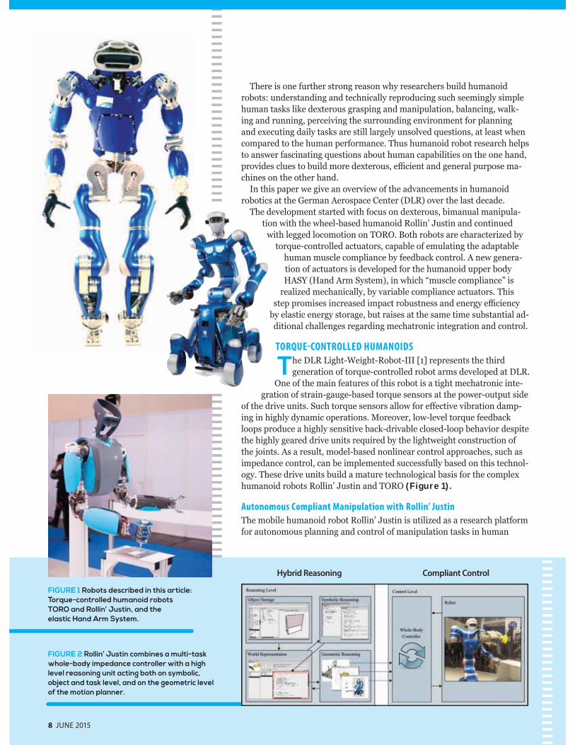
There is one further strong reason why researchers build humanoid robots: understanding and technically reproducing such seemingly simple human tasks like dexterous grasping and manipulation, balancing, walk-ing and running, perceiving the surrounding environment for planning and executing daily tasks are still largely unsolved questions, at least when compared to the human performance. Thus humanoid robot research helps to answer fascinating questions about human capabilities on the one hand, provides clues to build more dexterous, e cient and general purpose ma-chines on the other hand.
In this paper we give an overview of the advancements in humanoid robotics at the German Aerospace Center (DLR) over the last decade.
The development started with focus on dexterous, bimanual manipula-tion with the wheel-based humanoid Rollin’ Justin and continued
with legged locomotion on TORO. Both robots are characterized by torque-controlled actuators, capable of emulating the adaptable
human muscle compliance by feedback control. A new genera-tion of actuators is developed for the humanoid upper body HASY (Hand Arm System), in which “muscle compliance” is
realized mechanically, by variable compliance actuators. This step promises increased impact robustness and energy e ciency
by elastic energy storage, but raises at the same time substantial ad-ditional challenges regarding mechatronic integration and control.
TORQUE-CONTROLLED HUMANOIDS
The DLR Light-Weight-Robot-III [1] represents the third generation of torque-controlled robot arms developed at DLR.
One of the main features of this robot is a tight mechatronic inte-gration of strain-gauge-based torque sensors at the power-output side
of the drive units. Such torque sensors allow for e ective vibration damp-ing in highly dynamic operations. Moreover, low-level torque feedback loops produce a highly sensitive back-drivable closed-loop behavior despite the highly geared drive units required by the lightweight construction of the joints. As a result, model-based nonlinear control approaches, such as impedance control, can be implemented successfully based on this technol-ogy. These drive units build a mature technological basis for the complex humanoid robots Rollin’ Justin and TORO (Figure 1).
Autonomous Compliant Manipulation with Rollin’ Justin
The mobile humanoid robot Rollin’ Justin is utilized as a research platform for autonomous planning and control of manipulation tasks in human
8 JUNE 2015
FIGURE 1 Robots described in this article: Torque-controlled humanoid robots TORO and Rollin’ Justin, and the elastic Hand Arm System.
FIGURE 2 Rollin’ Justin combines a multi-task whole-body impedance controller with a high level reasoning unit acting both on symbolic, object and task level, and on the geometric level of the motion planner.
Hybrid Reasoning Compliant Control
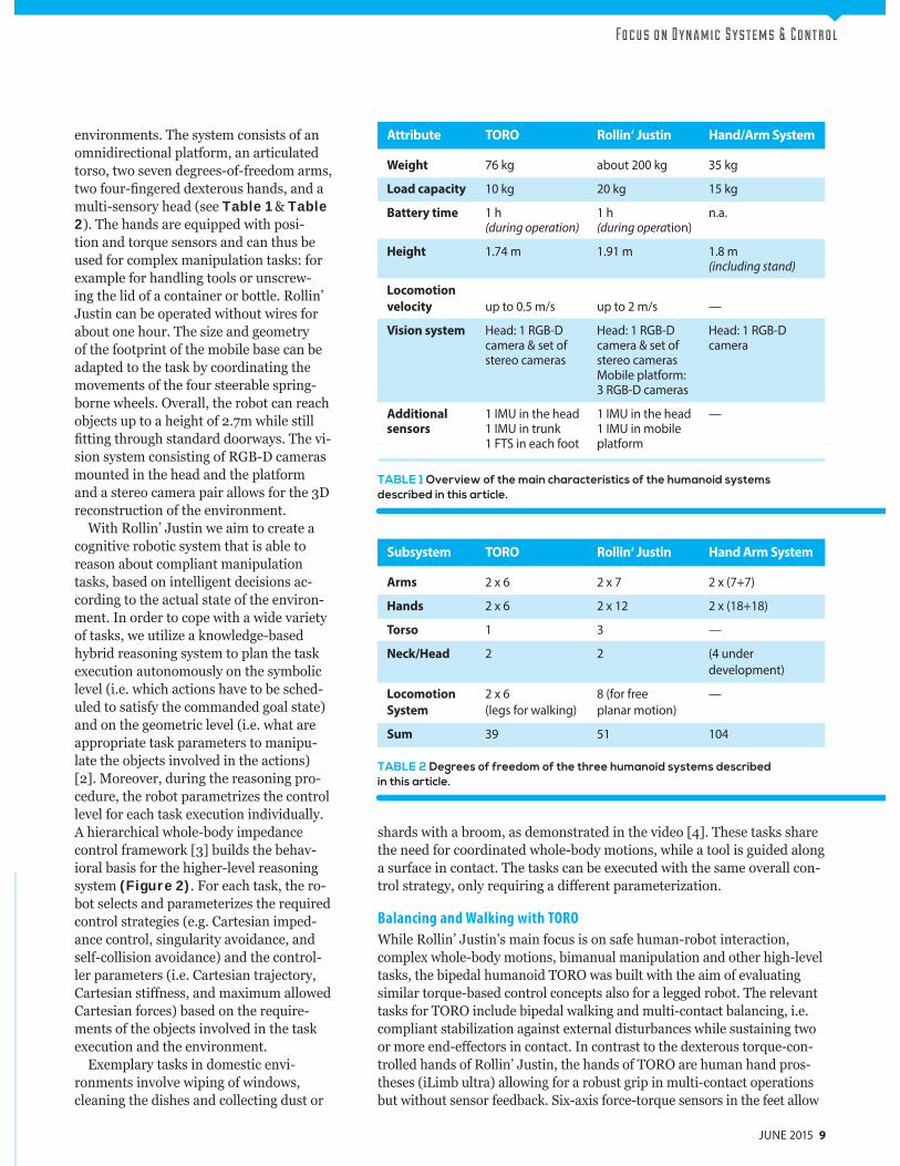
Fo c u s o n D y n a m i c S y s t e m s & C o n t r o l
Subsystem TORO Rollin‘ Justin Hand Arm System
Arms 2 x 6 2 x 7 2 x (7+7)
Hands 2 x 6 2 x 12 2 x (18+18)
Torso 1 3 —
Neck/Head 2 2 (4 under development)
Locomotion 2 x 6 8 (for free —System (legs for walking) planar motion)
Sum 39 51 104
TABLE 2 Degrees of freedom of the three humanoid systems describedin this article.
environments. The system consists of an omnidirectional platform, an articulated torso, two seven degrees-of-freedom arms, two four- ngered dexterous hands, and a multi-sensory head (see Table 1 & Table 2). The hands are equipped with posi-tion and torque sensors and can thus be used for complex manipulation tasks: for example for handling tools or unscrew-ing the lid of a container or bottle. Rollin’ Justin can be operated without wires for about one hour. The size and geometry of the footprint of the mobile base can be adapted to the task by coordinating the movements of the four steerable spring-borne wheels. Overall, the robot can reach objects up to a height of 2.7m while still
tting through standard doorways. The vi-sion system consisting of RGB-D cameras mounted in the head and the platform and a stereo camera pair allows for the 3D reconstruction of the environment.
With Rollin’ Justin we aim to create a cognitive robotic system that is able to reason about compliant manipulation tasks, based on intelligent decisions ac-cording to the actual state of the environ-ment. In order to cope with a wide variety of tasks, we utilize a knowledge-based hybrid reasoning system to plan the task execution autonomously on the symbolic level (i.e. which actions have to be sched-uled to satisfy the commanded goal state) and on the geometric level (i.e. what are appropriate task parameters to manipu-late the objects involved in the actions) [2]. Moreover, during the reasoning pro-cedure, the robot parametrizes the control level for each task execution individually. A hierarchical whole-body impedance control framework [3] builds the behav-ioral basis for the higher-level reasoning system (Figure 2). For each task, the ro-bot selects and parameterizes the required control strategies (e.g. Cartesian imped-ance control, singularity avoidance, and self-collision avoidance) and the control-ler parameters (i.e. Cartesian trajectory, Cartesian sti ness, and maximum allowed Cartesian forces) based on the require-ments of the objects involved in the task execution and the environment.
Exemplary tasks in domestic envi-ronments involve wiping of windows, cleaning the dishes and collecting dust or
JUNE 2015 9
shards with a broom, as demonstrated in the video [4]. These tasks share the need for coordinated whole-body motions, while a tool is guided along a surface in contact. The tasks can be executed with the same overall con-trol strategy, only requiring a di erent parameterization.
Balancing and Walking with TORO
While Rollin’ Justin’s main focus is on safe human-robot interaction, complex whole-body motions, bimanual manipulation and other high-level tasks, the bipedal humanoid TORO was built with the aim of evaluating similar torque-based control concepts also for a legged robot. The relevant tasks for TORO include bipedal walking and multi-contact balancing, i.e. compliant stabilization against external disturbances while sustaining two or more end-e ectors in contact. In contrast to the dexterous torque-con-trolled hands of Rollin’ Justin, the hands of TORO are human hand pros-theses (iLimb ultra) allowing for a robust grip in multi-contact operations but without sensor feedback. Six-axis force-torque sensors in the feet allow
TABLE 1 Overview of the main characteristics of the humanoid systems described in this article.
Attribute TORO Rollin‘ Justin Hand/Arm System
Weight 76 kg about 200 kg 35 kg
Load capacity 10 kg 20 kg 15 kg
Battery time 1 h 1 h n.a. (during operation) (during operation)
Height 1.74 m 1.91 m 1.8 m (including stand)
Locomotion
velocity up to 0.5 m/s up to 2 m/s —
Vision system Head: 1 RGB-D Head: 1 RGB-D Head: 1 RGB-D camera & set of camera & set of camera stereo cameras stereo cameras Mobile platform: 3 RGB-D cameras
Additional 1 IMU in the head 1 IMU in the head —sensors 1 IMU in trunk 1 IMU in mobile 1 FTS in each foot platform
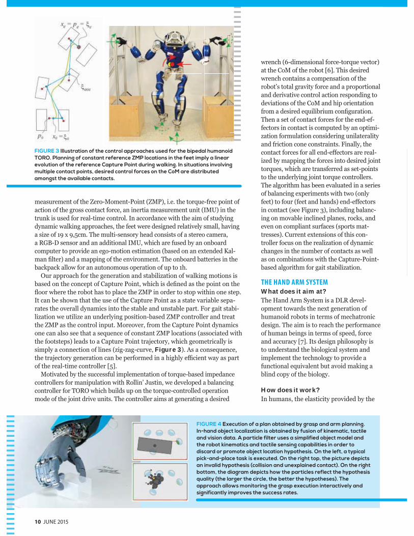
wrench (6-dimensional force-torque vector) at the CoM of the robot [6]. This desired wrench contains a compensation of the robot’s total gravity force and a proportional and derivative control action responding to deviations of the CoM and hip orientation from a desired equilibrium con guration. Then a set of contact forces for the end-ef-fectors in contact is computed by an optimi-zation formulation considering unilaterality and friction cone constraints. Finally, the contact forces for all end-e ectors are real-ized by mapping the forces into desired joint torques, which are transferred as set-points to the underlying joint torque controllers. The algorithm has been evaluated in a series of balancing experiments with two (only feet) to four (feet and hands) end-e ectors in contact (see Figure 3), including balanc-ing on movable inclined planes, rocks, and even on compliant surfaces (sports mat-tresses). Current extensions of this con-troller focus on the realization of dynamic changes in the number of contacts as well as on combinations with the Capture-Point-based algorithm for gait stabilization.
THE HAND ARM SYSTEM
What does it aim at?The Hand Arm System is a DLR devel-opment towards the next generation of humanoid robots in terms of mechatronic design. The aim is to reach the performance of human beings in terms of speed, force and accuracy [7]. Its design philosophy is to understand the biological system and implement the technology to provide a functional equivalent but avoid making a blind copy of the biology.
How does it work?In humans, the elasticity provided by the
FIGURE 4 Execution of a plan obtained by grasp and arm planning. In-hand object localization is obtained by fusion of kinematic, tactile and vision data. A particle filter uses a simplified object model and the robot kinematics and tactile sensing capabilities in order to discard or promote object location hypothesis. On the left, a typical pick-and-place task is executed. On the right top, the picture depicts an invalid hypothesis (collision and unexplained contact). On the right bottom, the diagram depicts how the particles reflect the hypothesis quality (the larger the circle, the better the hypotheses). The approach allows monitoring the grasp execution interactively and significantly improves the success rates.
10 JUNE 2015
measurement of the Zero-Moment-Point (ZMP), i.e. the torque-free point of action of the gross contact force, an inertia measurement unit (IMU) in the trunk is used for real-time control. In accordance with the aim of studying dynamic walking approaches, the feet were designed relatively small, having a size of 19 x 9,5cm. The multi-sensory head consists of a stereo camera, a RGB-D sensor and an additional IMU, which are fused by an onboard computer to provide an ego-motion estimation (based on an extended Kal-man lter) and a mapping of the environment. The onboard batteries in the backpack allow for an autonomous operation of up to 1h.
Our approach for the generation and stabilization of walking motions is based on the concept of Capture Point, which is de ned as the point on the oor where the robot has to place the ZMP in order to stop within one step.
It can be shown that the use of the Capture Point as a state variable sepa-rates the overall dynamics into the stable and unstable part. For gait stabi-lization we utilize an underlying position-based ZMP controller and treat the ZMP as the control input. Moreover, from the Capture Point dynamics one can also see that a sequence of constant ZMP locations (associated with the footsteps) leads to a Capture Point trajectory, which geometrically is simply a connection of lines (zig-zag-curve, Figure 3). As a consequence, the trajectory generation can be performed in a highly e cient way as part of the real-time controller [5].
Motivated by the successful implementation of torque-based impedance controllers for manipulation with Rollin’ Justin, we developed a balancing controller for TORO which builds up on the torque-controlled operation mode of the joint drive units. The controller aims at generating a desired
FIGURE 3 Illustration of the control approaches used for the bipedal humanoid TORO. Planning of constant reference ZMP locations in the feet imply a linear evolution of the reference Capture Point during walking. In situations involving multiple contact points, desired control forces on the CoM are distributed amongst the available contacts.
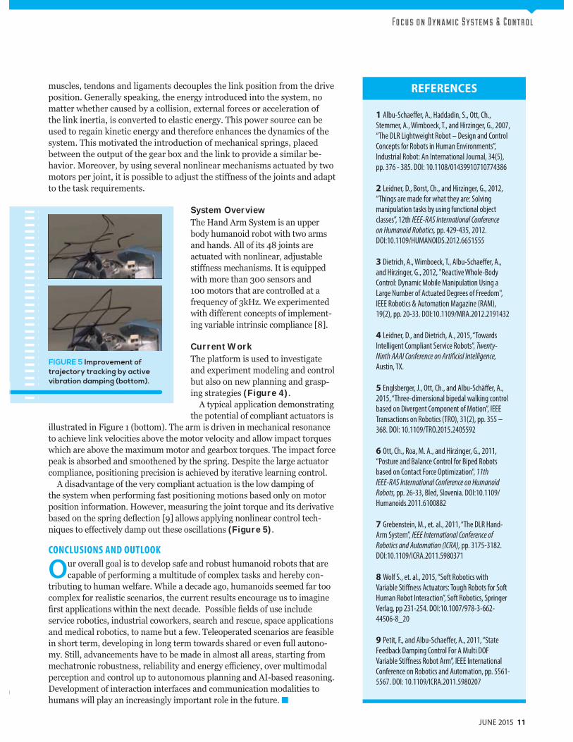
Fo c u s o n D y n a m i c S y s t e m s & C o n t r o l
muscles, tendons and ligaments decouples the link position from the drive position. Generally speaking, the energy introduced into the system, no matter whether caused by a collision, external forces or acceleration of the link inertia, is converted to elastic energy. This power source can be used to regain kinetic energy and therefore enhances the dynamics of the system. This motivated the introduction of mechanical springs, placed between the output of the gear box and the link to provide a similar be-havior. Moreover, by using several nonlinear mechanisms actuated by two motors per joint, it is possible to adjust the sti ness of the joints and adapt to the task requirements.
System OverviewThe Hand Arm System is an upper body humanoid robot with two arms and hands. All of its 48 joints are actuated with nonlinear, adjustable sti ness mechanisms. It is equipped with more than 300 sensors and 100 motors that are controlled at a frequency of 3kHz. We experimented with di erent concepts of implement-ing variable intrinsic compliance [8].
Current WorkThe platform is used to investigate and experiment modeling and control but also on new planning and grasp-ing strategies (Figure 4).
A typical application demonstrating the potential of compliant actuators is
illustrated in Figure 1 (bottom). The arm is driven in mechanical resonance to achieve link velocities above the motor velocity and allow impact torques which are above the maximum motor and gearbox torques. The impact force peak is absorbed and smoothened by the spring. Despite the large actuator compliance, positioning precision is achieved by iterative learning control.
A disadvantage of the very compliant actuation is the low damping of the system when performing fast positioning motions based only on motor position information. However, measuring the joint torque and its derivative based on the spring de ection [9] allows applying nonlinear control tech-niques to e ectively damp out these oscillations (Figure 5).
CONCLUSIONS AND OUTLOOK
Our overall goal is to develop safe and robust humanoid robots that are capable of performing a multitude of complex tasks and hereby con-
tributing to human welfare. While a decade ago, humanoids seemed far too complex for realistic scenarios, the current results encourage us to imagine
rst applications within the next decade. Possible elds of use include service robotics, industrial coworkers, search and rescue, space applications and medical robotics, to name but a few. Teleoperated scenarios are feasible in short term, developing in long term towards shared or even full autono-my. Still, advancements have to be made in almost all areas, starting from mechatronic robustness, reliability and energy e ciency, over multimodal perception and control up to autonomous planning and AI-based reasoning. Development of interaction interfaces and communication modalities to humans will play an increasingly important role in the future.
JUNE 2015 11
REFERENCES
1 Albu-Schaeffer, A., Haddadin, S., Ott, Ch.,
Stemmer, A., Wimboeck, T., and Hirzinger, G., 2007,
“The DLR Lightweight Robot – Design and Control
Concepts for Robots in Human Environments”,
Industrial Robot: An International Journal, 34(5),
pp. 376 - 385. DOI: 10.1108/01439910710774386
2 Leidner, D., Borst, Ch., and Hirzinger, G., 2012,
“Things are made for what they are: Solving
manipulation tasks by using functional object
classes”, 12th IEEE-RAS International Conference
on Humanoid Robotics, pp. 429-435, 2012.
DOI:10.1109/HUMANOIDS.2012.6651555
3 Dietrich, A., Wimboeck, T., Albu-Schaeffer, A.,
and Hirzinger, G., 2012, "Reactive Whole-Body
Control: Dynamic Mobile Manipulation Using a
Large Number of Actuated Degrees of Freedom",
IEEE Robotics & Automation Magazine (RAM),
19(2), pp. 20-33. DOI:10.1109/MRA.2012.2191432
4 Leidner, D., and Dietrich, A., 2015, “Towards
Intelligent Compliant Service Robots”, Twenty-
Ninth AAAI Conference on Artificial Intelligence,
Austin, TX.
5 Englsberger, J., Ott, Ch., and Albu-Schäffer, A.,
2015, “Three-dimensional bipedal walking control
based on Divergent Component of Motion”, IEEE
Transactions on Robotics (TRO), 31(2), pp. 355 –
368. DOI: 10.1109/TRO.2015.2405592
6 Ott, Ch., Roa, M. A., and Hirzinger, G., 2011,
“Posture and Balance Control for Biped Robots
based on Contact Force Optimization”, 11th
IEEE-RAS International Conference on Humanoid
Robots, pp. 26-33, Bled, Slovenia. DOI:10.1109/
Humanoids.2011.6100882
7 Grebenstein, M., et. al., 2011, “The DLR Hand-
Arm System”, IEEE International Conference of
Robotics and Automation (ICRA), pp. 3175-3182.
DOI:10.1109/ICRA.2011.5980371
8 Wolf S., et. al., 2015, “Soft Robotics with
Variable Stiffness Actuators: Tough Robots for Soft
Human Robot Interaction”, Soft Robotics, Springer
Verlag, pp 231-254. DOI:10.1007/978-3-662-
44506-8_20
9 Petit, F., and Albu-Schaeffer, A., 2011, “State
Feedback Damping Control For A Multi DOF
Variable Stiffness Robot Arm”, IEEE International
Conference on Robotics and Automation, pp. 5561-
5567. DOI: 10.1109/ICRA.2011.5980207
FIGURE 5 Improvement of trajectory tracking by active vibration damping (bottom).
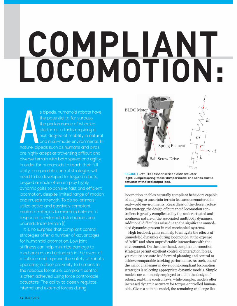
12 JUNE 2015
locomotion enables naturally compliant behaviors capable of adapting to uncertain terrain features encountered in real-world environments. Regardless of the chosen actua-tion strategy, the design of humanoid locomotion con-trollers is greatly complicated by the underactuated and nonlinear nature of the associated multibody dynamics. Additional di culties arise due to the signi cant unmod-eled dynamics present in real mechanical systems.
High feedback gains can help to mitigate the e ects of unmodeled dynamics during locomotion at the expense of “sti ” and often unpredictable interactions with the environment. On the other hand, compliant locomotion strategies permit excellent control of interaction forces, yet require accurate feedforward planning and control to achieve comparable tracking performance. As such, one of the major challenges in developing compliant locomotion strategies is selecting appropriate dynamic models. Simple models are commonly employed to aid in the design of robust, real-time control laws, while complex models o er increased dynamic accuracy for torque-controlled human-oids. Given a suitable model, the remaining challenge lies
As bipeds, humanoid robots have the potential to far surpass the performance of wheeled platforms in tasks requiring a high degree of mobility in natural and man-made environments. In
nature, bipeds such as humans and birds are highly adept at traversing difficult and diverse terrain with both speed and agility. In order for humanoids to reach their full utility, comparable control strategies will need to be developed for legged robots. Legged animals often employ highly dynamic gaits to achieve fast and efficient locomotion, despite limited range of motion and muscle strength. To do so, animals utilize active and passively compliant control strategies to maintain balance in response to external disturbances and unpredictable terrain [1].
It is no surprise that compliant control strategies offer a number of advantages for humanoid locomotion. Low joint stiffness can help minimize damage to mechanisms and actuators in the event of a collision and improve the safety of robots operating in close proximity to humans. In the robotics literature, compliant control is often achieved using force controllable actuators. The ability to closely regulate internal and external forces during
FIGURE 1 Left: THOR linear series elastic actuator. Right: Lumped spring-mass-damper model of a series elastic actuator with fixed output load.
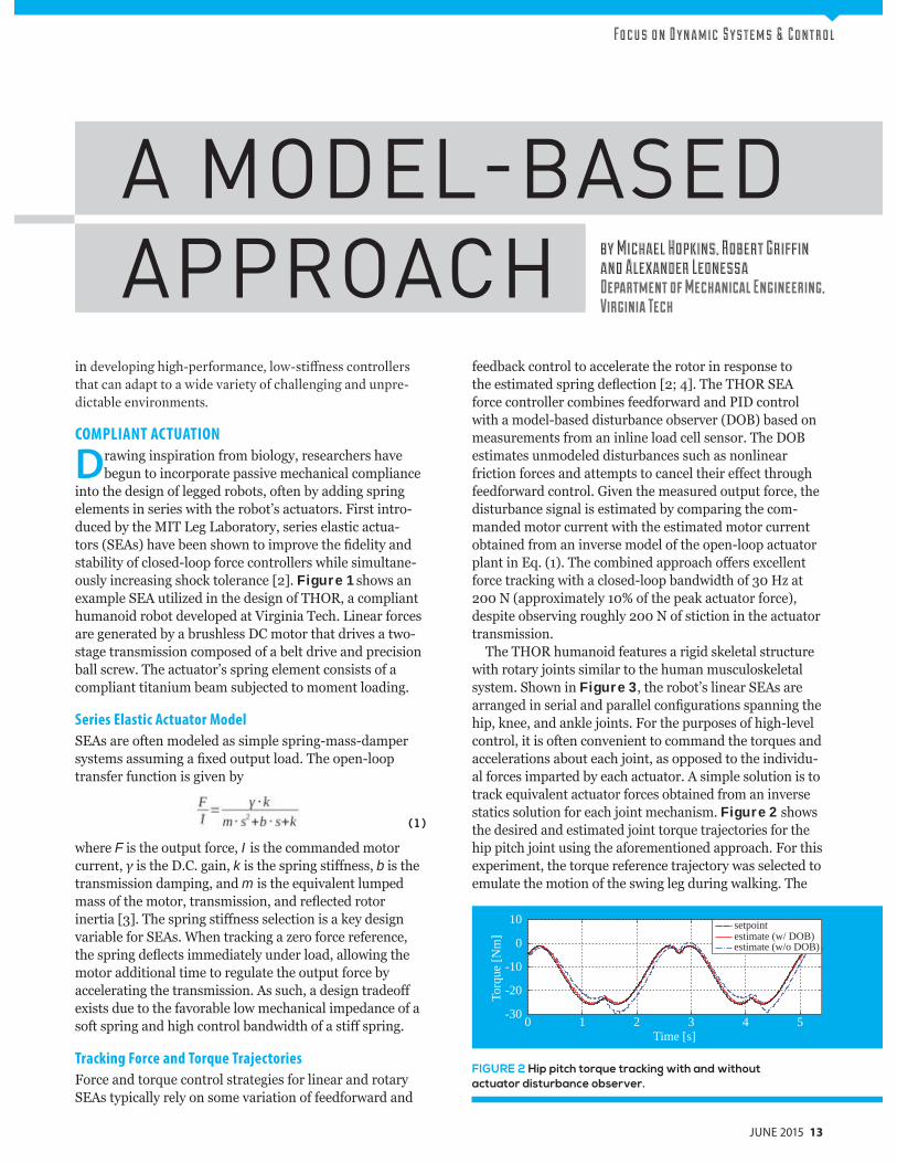
in developing high-performance, low-stiffness controllers that can adapt to a wide variety of challenging and unpre-dictable environments.
COMPLIANT ACTUATION
Drawing inspiration from biology, researchers have begun to incorporate passive mechanical compliance
into the design of legged robots, often by adding spring elements in series with the robot’s actuators. First intro-duced by the MIT Leg Laboratory, series elastic actua-tors (SEAs) have been shown to improve the delity and stability of closed-loop force controllers while simultane-ously increasing shock tolerance [2]. Figure 1 shows an example SEA utilized in the design of THOR, a compliant humanoid robot developed at Virginia Tech. Linear forces are generated by a brushless DC motor that drives a two-stage transmission composed of a belt drive and precision ball screw. The actuator’s spring element consists of a compliant titanium beam subjected to moment loading.
Series Elastic Actuator Model
SEAs are often modeled as simple spring-mass-damper systems assuming a xed output load. The open-loop transfer function is given by
( 1 )
where F is the output force, I is the commanded motor current, is the D.C. gain, k is the spring sti ness, b is the transmission damping, and m is the equivalent lumped mass of the motor, transmission, and re ected rotor inertia [3]. The spring sti ness selection is a key design variable for SEAs. When tracking a zero force reference, the spring de ects immediately under load, allowing the motor additional time to regulate the output force by accelerating the transmission. As such, a design tradeo exists due to the favorable low mechanical impedance of a soft spring and high control bandwidth of a sti spring.
Tracking Force and Torque Trajectories
Force and torque control strategies for linear and rotary SEAs typically rely on some variation of feedforward and
feedback control to accelerate the rotor in response to the estimated spring de ection [2 4]. The THOR SEA force controller combines feedforward and PID control with a model-based disturbance observer (DOB) based on measurements from an inline load cell sensor. The DOB estimates unmodeled disturbances such as nonlinear friction forces and attempts to cancel their e ect through feedforward control. Given the measured output force, the disturbance signal is estimated by comparing the com-manded motor current with the estimated motor current obtained from an inverse model of the open-loop actuator plant in Eq. (1). The combined approach o ers excellent force tracking with a closed-loop bandwidth of 30 Hz at 200 N (approximately 10% of the peak actuator force), despite observing roughly 200 N of stiction in the actuator transmission.
The THOR humanoid features a rigid skeletal structure with rotary joints similar to the human musculoskeletal system. Shown in Figure 3, the robot’s linear SEAs are arranged in serial and parallel con gurations spanning the hip, knee, and ankle joints. For the purposes of high-level control, it is often convenient to command the torques and accelerations about each joint, as opposed to the individu-al forces imparted by each actuator. A simple solution is to track equivalent actuator forces obtained from an inverse statics solution for each joint mechanism. Figure 2 shows the desired and estimated joint torque trajectories for the hip pitch joint using the aforementioned approach. For this experiment, the torque reference trajectory was selected to emulate the motion of the swing leg during walking. The
A MODEL-BASEDAPPROACH
JUNE 2015 13
Fo c u s o n D y n a m i c S y s t e m s & C o n t r o l
by Michael Hopkins, Robert Griffin
and Alexander Leonessa
Department of Mechanical Engineering, Virginia Tech
FIGURE 2 Hip pitch torque tracking with and without actuator disturbance observer.
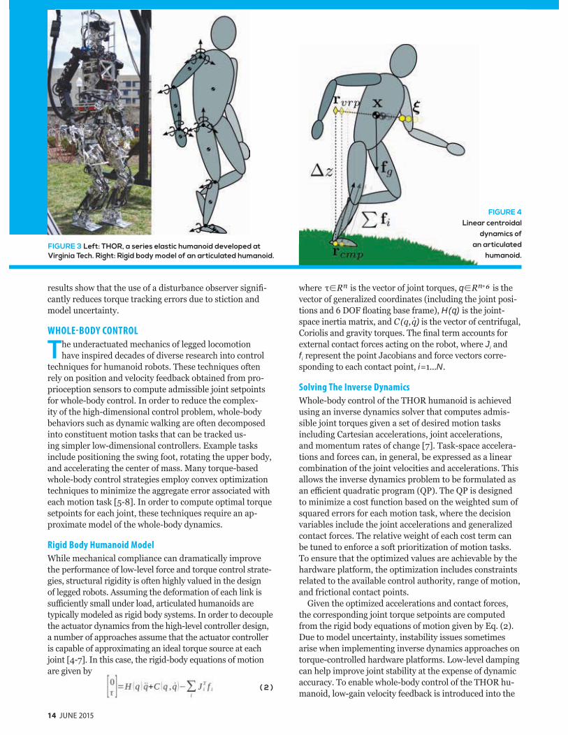
14 JUNE 2015
results show that the use of a disturbance observer signi -cantly reduces torque tracking errors due to stiction and model uncertainty.
WHOLE-BODY CONTROL
The underactuated mechanics of legged locomotion have inspired decades of diverse research into control
techniques for humanoid robots. These techniques often rely on position and velocity feedback obtained from pro-prioception sensors to compute admissible joint setpoints for whole-body control. In order to reduce the complex-ity of the high-dimensional control problem, whole-body behaviors such as dynamic walking are often decomposed into constituent motion tasks that can be tracked us-ing simpler low-dimensional controllers. Example tasks include positioning the swing foot, rotating the upper body, and accelerating the center of mass. Many torque-based whole-body control strategies employ convex optimization techniques to minimize the aggregate error associated with each motion task [5-8]. In order to compute optimal torque setpoints for each joint, these techniques require an ap-proximate model of the whole-body dynamics.
Rigid Body Humanoid Model
While mechanical compliance can dramatically improve the performance of low-level force and torque control strate-gies, structural rigidity is often highly valued in the design of legged robots. Assuming the deformation of each link is su ciently small under load, articulated humanoids are typically modeled as rigid body systems. In order to decouple the actuator dynamics from the high-level controller design, a number of approaches assume that the actuator controller is capable of approximating an ideal torque source at each joint [4-7]. In this case, the rigid-body equations of motion are given by
( 2 )
where is the vector of joint torques, q + is the vector of generalized coordinates (including the joint posi-tions and 6 DOF oating base frame), H(q) is the joint-space inertia matrix, and ) is the vector of centrifugal, Coriolis and gravity torques. The nal term accounts for external contact forces acting on the robot, where Ji and fi represent the point Jacobians and force vectors corre-sponding to each contact point, i=1...N.
Solving The Inverse Dynamics
Whole-body control of the THOR humanoid is achieved using an inverse dynamics solver that computes admis-sible joint torques given a set of desired motion tasks including Cartesian accelerations, joint accelerations, and momentum rates of change [7]. Task-space accelera-tions and forces can, in general, be expressed as a linear combination of the joint velocities and accelerations. This allows the inverse dynamics problem to be formulated as an e cient quadratic program ( P). The P is designed to minimize a cost function based on the weighted sum of squared errors for each motion task, where the decision variables include the joint accelerations and generalized contact forces. The relative weight of each cost term can be tuned to enforce a soft prioritization of motion tasks. To ensure that the optimized values are achievable by the hardware platform, the optimization includes constraints related to the available control authority, range of motion, and frictional contact points.
Given the optimized accelerations and contact forces, the corresponding joint torque setpoints are computed from the rigid body equations of motion given by Eq. (2). Due to model uncertainty, instability issues sometimes arise when implementing inverse dynamics approaches on torque-controlled hardware platforms. Low-level damping can help improve joint stability at the expense of dynamic accuracy. To enable whole-body control of the THOR hu-manoid, low-gain velocity feedback is introduced into the
FIGURE 3 Left: THOR, a series elastic humanoid developed at Virginia Tech. Right: Rigid body model of an articulated humanoid.
FIGURE 4Linear centroidal
dynamics of an articulated
humanoid.
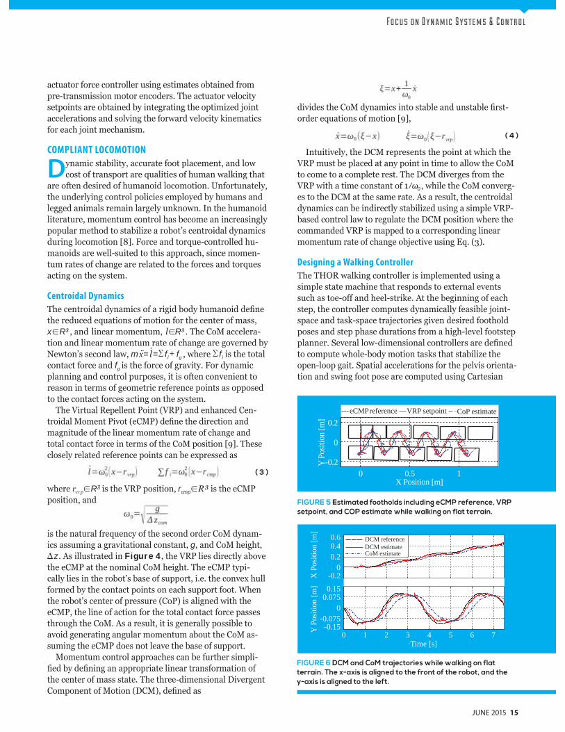
Fo c u s o n D y n a m i c S y s t e m s & C o n t r o l
JUNE 2015 15
actuator force controller using estimates obtained from pre-transmission motor encoders. The actuator velocity setpoints are obtained by integrating the optimized joint accelerations and solving the forward velocity kinematics for each joint mechanism.
COMPLIANT LOCOMOTION
Dynamic stability, accurate foot placement, and low cost of transport are qualities of human walking that
are often desired of humanoid locomotion. Unfortunately, the underlying control policies employed by humans and legged animals remain largely unknown. In the humanoid literature, momentum control has become an increasingly popular method to stabilize a robot’s centroidal dynamics during locomotion [8]. Force and torque-controlled hu-manoids are well-suited to this approach, since momen-tum rates of change are related to the forces and torques acting on the system.
Centroidal Dynamics
The centroidal dynamics of a rigid body humanoid de ne the reduced equations of motion for the center of mass, x R³, and linear momentum, R³. The CoM accelera-tion and linear momentum rate of change are governed by Newton’s second law, mx= = fi f , where fi is the total contact force and f is the force of gravity. For dynamic planning and control purposes, it is often convenient to reason in terms of geometric reference points as opposed to the contact forces acting on the system.
The Virtual Repellent Point (VRP) and enhanced Cen-troidal Moment Pivot (eCMP) de ne the direction and magnitude of the linear momentum rate of change and total contact force in terms of the CoM position [9]. These closely related reference points can be expressed as
( 3 )
where rvrp R3 is the VRP position, rcmp is the eCMP position, and
is the natural frequency of the second order CoM dynam-ics assuming a gravitational constant, g, and CoM height,
z . As illustrated in Figure 4, the VRP lies directly above the eCMP at the nominal CoM height. The eCMP typi-cally lies in the robot’s base of support, i.e. the convex hull formed by the contact points on each support foot. When the robot’s center of pressure (CoP) is aligned with the eCMP, the line of action for the total contact force passes through the CoM. As a result, it is generally possible to avoid generating angular momentum about the CoM as-suming the eCMP does not leave the base of support.
Momentum control approaches can be further simpli-ed by de ning an appropriate linear transformation of
the center of mass state. The three-dimensional Divergent Component of Motion (DCM), de ned as
divides the CoM dynamics into stable and unstable rst-order equations of motion [9],
( 4 )
Intuitively, the DCM represents the point at which the VRP must be placed at any point in time to allow the CoM to come to a complete rest. The DCM diverges from the VRP with a time constant of 1 0, while the CoM converg-es to the DCM at the same rate. As a result, the centroidal dynamics can be indirectly stabilized using a simple VRP-based control law to regulate the DCM position where the commanded VRP is mapped to a corresponding linear momentum rate of change objective using Eq. (3).
Designing a Walking Controller
The THOR walking controller is implemented using a simple state machine that responds to external events such as toe-o and heel-strike. At the beginning of each step, the controller computes dynamically feasible joint-space and task-space trajectories given desired foothold poses and step phase durations from a high-level footstep planner. Several low-dimensional controllers are de ned to compute whole-body motion tasks that stabilize the open-loop gait. Spatial accelerations for the pelvis orienta-tion and swing foot pose are computed using Cartesian
FIGURE 5 Estimated footholds including eCMP reference, VRP setpoint, and COP estimate while walking on flat terrain.
FIGURE 6 DCM and CoM trajectories while walking on flat terrain. The x-axis is aligned to the front of the robot, and the y-axis is aligned to the left.
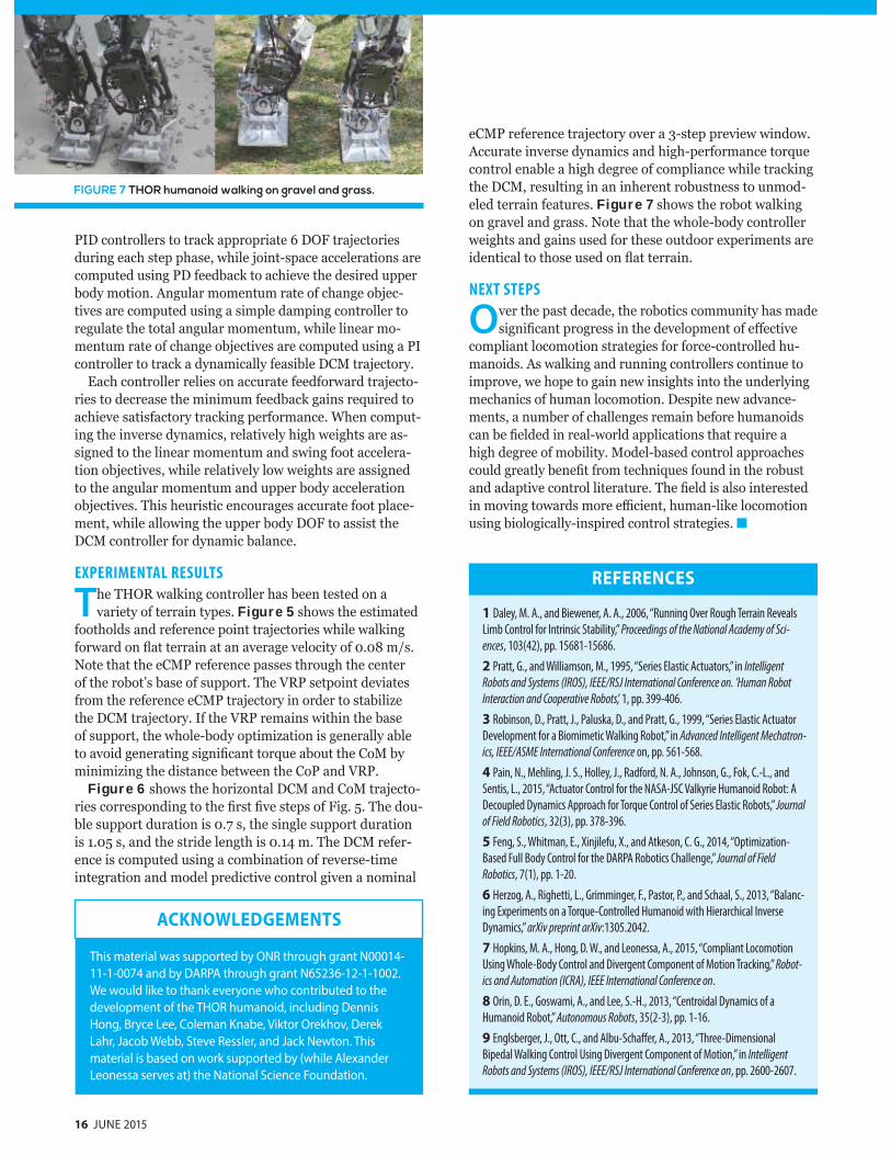
16 JUNE 2015
PID controllers to track appropriate 6 DOF trajectories during each step phase, while joint-space accelerations are computed using PD feedback to achieve the desired upper body motion. Angular momentum rate of change objec-tives are computed using a simple damping controller to regulate the total angular momentum, while linear mo-mentum rate of change objectives are computed using a PI controller to track a dynamically feasible DCM trajectory.
Each controller relies on accurate feedforward trajecto-ries to decrease the minimum feedback gains required to achieve satisfactory tracking performance. When comput-ing the inverse dynamics, relatively high weights are as-signed to the linear momentum and swing foot accelera-tion objectives, while relatively low weights are assigned to the angular momentum and upper body acceleration objectives. This heuristic encourages accurate foot place-ment, while allowing the upper body DOF to assist the DCM controller for dynamic balance.
EXPERIMENTAL RESULTS
The THOR walking controller has been tested on a variety of terrain types. Figure 5 shows the estimated
footholds and reference point trajectories while walking forward on at terrain at an average velocity of 0.08 m s. Note that the eCMP reference passes through the center of the robot’s base of support. The VRP setpoint deviates from the reference eCMP trajectory in order to stabilize the DCM trajectory. If the VRP remains within the base of support, the whole-body optimization is generally able to avoid generating signi cant torque about the CoM by minimizing the distance between the CoP and VRP.
Figure 6 shows the horizontal DCM and CoM trajecto-ries corresponding to the rst ve steps of Fig. 5. The dou-ble support duration is 0.7 s, the single support duration is 1.05 s, and the stride length is 0.14 m. The DCM refer-ence is computed using a combination of reverse-time integration and model predictive control given a nominal
REFERENCES
1 Daley, M. A., and Biewener, A. A., 2006, “Running Over Rough Terrain Reveals
Limb Control for Intrinsic Stability,” Proceedings of the National Academy of Sci-
ences, 103(42), pp. 15681-15686.
2 Pratt, G., and Williamson, M., 1995, “Series Elastic Actuators,” in Intelligent
Robots and Systems (IROS), IEEE/RSJ International Conference on. ’Human Robot
Interaction and Cooperative Robots’, 1, pp. 399-406.
3 Robinson, D., Pratt, J., Paluska, D., and Pratt, G., 1999, “Series Elastic Actuator
Development for a Biomimetic Walking Robot,” in Advanced Intelligent Mechatron-
ics, IEEE/ASME International Conference on, pp. 561-568.
4 Pain, N., Mehling, J. S., Holley, J., Radford, N. A., Johnson, G., Fok, C.-L., and
Sentis, L., 2015, “Actuator Control for the NASA-JSC Valkyrie Humanoid Robot: A
Decoupled Dynamics Approach for Torque Control of Series Elastic Robots,” Journal
of Field Robotics, 32(3), pp. 378-396.
5 Feng, S., Whitman, E., Xinjilefu, X., and Atkeson, C. G., 2014, “Optimization-
Based Full Body Control for the DARPA Robotics Challenge,” Journal of Field
Robotics, 7(1), pp. 1-20.
6 Herzog, A., Righetti, L., Grimminger, F., Pastor, P., and Schaal, S., 2013, “Balanc-
ing Experiments on a Torque-Controlled Humanoid with Hierarchical Inverse
Dynamics,” arXiv preprint arXiv:1305.2042.
7 Hopkins, M. A., Hong, D. W., and Leonessa, A., 2015, “Compliant Locomotion
Using Whole-Body Control and Divergent Component of Motion Tracking,” Robot-
ics and Automation (ICRA), IEEE International Conference on.
8 Orin, D. E., Goswami, A., and Lee, S.-H., 2013, “Centroidal Dynamics of a
Humanoid Robot,” Autonomous Robots, 35(2-3), pp. 1-16.
9 Englsberger, J., Ott, C., and Albu-Schaffer, A., 2013, “Three-Dimensional
Bipedal Walking Control Using Divergent Component of Motion,” in Intelligent
Robots and Systems (IROS), IEEE/RSJ International Conference on, pp. 2600-2607.
eCMP reference trajectory over a 3-step preview window. Accurate inverse dynamics and high-performance torque control enable a high degree of compliance while tracking the DCM, resulting in an inherent robustness to unmod-eled terrain features. Figure 7 shows the robot walking on gravel and grass. Note that the whole-body controller weights and gains used for these outdoor experiments are identical to those used on at terrain.
NEXT STEPS
Over the past decade, the robotics community has made signi cant progress in the development of e ective
compliant locomotion strategies for force-controlled hu-manoids. As walking and running controllers continue to improve, we hope to gain new insights into the underlying mechanics of human locomotion. Despite new advance-ments, a number of challenges remain before humanoids can be elded in real-world applications that require a high degree of mobility. Model-based control approaches could greatly bene t from techniques found in the robust and adaptive control literature. The eld is also interested in moving towards more e cient, human-like locomotion using biologically-inspired control strategies.
This material was supported by ONR through grant N00014-11-1-0074 and by DARPA through grant N65236-12-1-1002. We would like to thank everyone who contributed to the development of the THOR humanoid, including Dennis Hong, Bryce Lee, Coleman Knabe, Viktor Orekhov, Derek Lahr, Jacob Webb, Steve Ressler, and Jack Newton. This material is based on work supported by (while Alexander Leonessa serves at) the National Science Foundation.
ACKNOWLEDGEMENTS
FIGURE 7 THOR humanoid walking on gravel and grass.
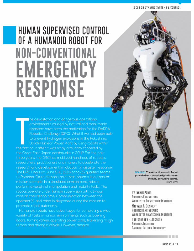
JUNE 2015 17
The devastation and dangerous operational environments caused by natural and man-made disasters have been the motivation for the DARPA Robotics Challenge (DRC). What if we had been able to prevent hydrogen explosions in the Fukushima Daiichi Nuclear Power Plant by using robots within
the first hour after it was hit by a tsunami triggered by the Great East Japan earthquake in 2011? For the past three years, the DRC has mobilized hundreds of robotics researchers, practitioners and makers to accelerate the research and development in robotics for disaster response. The DRC Finals on June 5-6, 2015 bring 25 qualified teams to Pomona, CA to demonstrate their systems in a disaster mission scenario. In a simulated environment, robots perform a variety of manipulation and mobility tasks. The robots operate under human supervision with a 1-hour mission completion time. Communication between the operator(s) and robot is degraded during the mission to promote robot autonomy.
Humanoid robots have advantages for completing a wide variety of tasks in human environments such as opening doors, turning valves, operating power tools, traversing rough terrain and driving a vehicle. However, despite
FIGURE 1 The Atlas Humanoid Robot provided as a standard platform for
the DRC software teams.PHOTO: DARPA
HUMAN SUPERVISED CONTROL OF A HUMANOID ROBOT FOR
NON-CONVENTIONAL
EMERGENCYRESPONSE
Fo c u s o n D y n a m i c S y s t e m s & C o n t r o l
by Taskin Padir,
Robotics EngineeringWorcester Polytechnic Institute Michael A. Gennert
Robotics EngineeringWorcester Polytechnic Institute Christopher G. Atkeson
Robotics InstituteCarnegie Mellon University
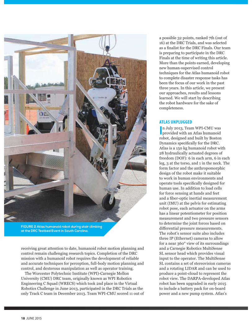
18 JUNE 2015
FIGURE 2 Atlas humanoid robot during stair climbing at the DRC Testbed Event in South Carolina.
a possible 32 points, ranked 7th (out of 16) at the DRC Trials, and was selected as a nalist for the DRC Finals. Our team is preparing to participate in the DRC Finals at the time of writing this article. More than the points earned, developing new human-supervised control techniques for the Atlas humanoid robot to complete disaster response tasks has been the focus of our work in the past three years. In this article, we present our approaches, results and lessons learned. We will start by describing the robot hardware for the sake of completeness.
ATLAS UNPLUGGED
In July 2013, Team WPI-CMU was provided with an Atlas humanoid
robot, designed and built by Boston Dynamics speci cally for the DRC. Atlas is a 150 kg humanoid robot with 28 hydraulically actuated degrees of freedom (DOF): 6 in each arm, 6 in each leg, 3 at the torso, and 1 in the neck. The form factor and the anthropomorphic design of the robot make it suitable to work in human environments and operate tools speci cally designed for human use. In addition to load cells for force sensing at hands and feet and a ber-optic inertial measurement unit (IMU) at the pelvis for estimating robot pose, each actuator on the arms has a linear potentiometer for position measurement and two pressure sensors to determine the joint forces based on di erential pressure measurements. The robot’s sensor suite also includes three IP (Ethernet) cameras to allow for a near 360° view of its surroundings and a Carnegie Robotics MultiSense SL sensor head which provides visual input to the operator. The MultiSense SL contains a set of stereovision cameras and a rotating LIDAR and can be used to produce a point-cloud to represent the robot view. The DARPA-developed Atlas robot has been upgraded in early 2015 to include a battery pack for on-board power and a new pump system. Atlas’s
receiving great attention to date, humanoid robot motion planning and control remain challenging research topics. Completion of the DRC mission with a humanoid robot requires the development of reliable and accurate techniques for perception, full-body motion planning and control, and dexterous manipulation as well as operator training.
The Worcester Polytechnic Institute (WPI)-Carnegie Mellon University (CMU) DRC team, originally known as WPI Robotics Engineering C Squad (WRECS) which took 2nd place in the Virtual Robotics Challenge in June 2013, participated in the DRC Trials as the only Track C team in December 2013. Team WPI-CMU scored 11 out of
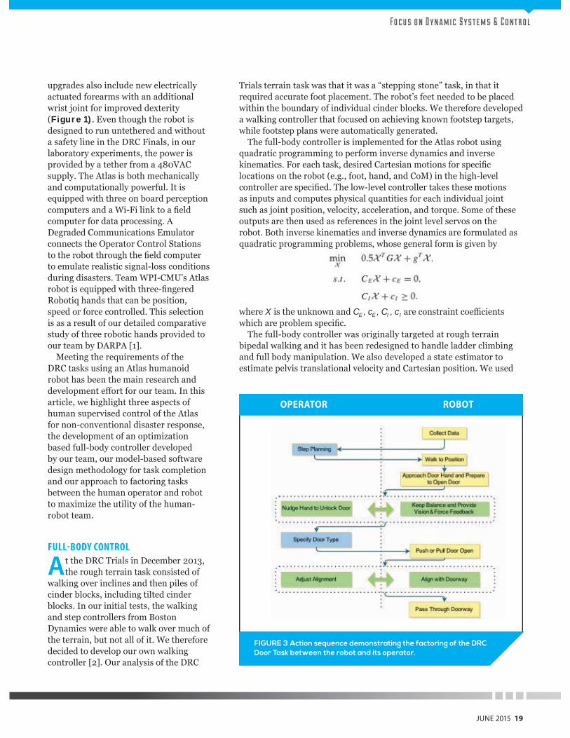
Fo c u s o n D y n a m i c S y s t e m s & C o n t r o l
upgrades also include new electrically actuated forearms with an additional wrist joint for improved dexterity (Figure 1). Even though the robot is designed to run untethered and without a safety line in the DRC Finals, in our laboratory experiments, the power is provided by a tether from a 480VAC supply. The Atlas is both mechanically and computationally powerful. It is equipped with three on board perception computers and a Wi-Fi link to a eld computer for data processing. A Degraded Communications Emulator connects the Operator Control Stations to the robot through the eld computer to emulate realistic signal-loss conditions during disasters. Team WPI-CMU’s Atlas robot is equipped with three- ngered Robotiq hands that can be position, speed or force controlled. This selection is as a result of our detailed comparative study of three robotic hands provided to our team by DARPA [1].
Meeting the requirements of the DRC tasks using an Atlas humanoid robot has been the main research and development e ort for our team. In this article, we highlight three aspects of human supervised control of the Atlas for non-conventional disaster response, the development of an optimization based full-body controller developed by our team, our model-based software design methodology for task completion and our approach to factoring tasks between the human operator and robot to maximize the utility of the human-robot team.
FULL-BODY CONTROL
At the DRC Trials in December 2013, the rough terrain task consisted of
walking over inclines and then piles of cinder blocks, including tilted cinder blocks. In our initial tests, the walking and step controllers from Boston Dynamics were able to walk over much of the terrain, but not all of it. We therefore decided to develop our own walking controller [2]. Our analysis of the DRC
Trials terrain task was that it was a “stepping stone” task, in that it required accurate foot placement. The robot’s feet needed to be placed within the boundary of individual cinder blocks. We therefore developed a walking controller that focused on achieving known footstep targets, while footstep plans were automatically generated.
The full-body controller is implemented for the Atlas robot using quadratic programming to perform inverse dynamics and inverse kinematics. For each task, desired Cartesian motions for speci c locations on the robot (e.g., foot, hand, and CoM) in the high-level controller are speci ed. The low-level controller takes these motions as inputs and computes physical quantities for each individual joint such as joint position, velocity, acceleration, and torque. Some of these outputs are then used as references in the joint level servos on the robot. Both inverse kinematics and inverse dynamics are formulated as quadratic programming problems, whose general form is given by
where X is the unknown and CE , cE , CI , cI are constraint coe cients which are problem speci c.
The full-body controller was originally targeted at rough terrain bipedal walking and it has been redesigned to handle ladder climbing and full body manipulation. We also developed a state estimator to estimate pelvis translational velocity and Cartesian position. We used
OPERATOR ROBOT
FIGURE 3 Action sequence demonstrating the factoring of the DRC Door Task between the robot and its operator.
JUNE 2015 19
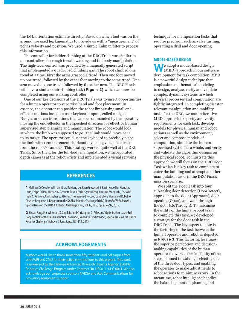
the IMU orientation estimate directly. Based on which foot was on the ground, we used leg kinematics to provide us with a “measurement” of pelvis velocity and position. We used a simple Kalman lter to process this information.
The controller for ladder climbing at the DRC Trials was similar to our controllers for rough terrain walking and full body manipulation. The high-level control was provided by a manually generated script that implemented a quadruped climbing gait. The robot climbed one tread at a time. First the arms grasped a tread. Then one foot moved up one tread, followed by the other foot moving to the same tread. One arm moved up one tread, followed by the other arm. The DRC Finals will have a similar stair climbing task (Figure 2) which can now be completed using our walking controller.
One of our key decisions at the DRC Trials was to insert opportunities for a human operator to supervise hand and foot placement. In essence, the operator can position the robot limbs using small end-e ector motions based on user keyboard inputs, called nudges. Nudges are 1 cm translations that can be commanded by the operator, moving the end-e ector in the speci ed direction for e ective human supervised step planning and manipulation. The robot would look at where the limb was supposed to go. The limb would move near to its target. The operator could use the keyboard to precisely place the limb with 1 cm increments horizontally, using visual feedback from the robot’s cameras. This strategy worked quite well at the DRC Trials. Since then, for the full-body manipulation, we incorporated depth cameras at the robot wrists and implemented a visual servoing
technique for manipulation tasks that require precision such as valve turning, operating a drill and door opening.
MODEL-BASED DESIGN
We adopt a model-based design (MBD) approach in our software
development for task completion. MBD is a powerful design technique that emphasizes mathematical modeling to design, analyze, verify and validate complex dynamic systems in which physical processes and computation are tightly integrated. In completing disaster relevant manipulation and mobility tasks for the DRC, we use an iterative MBD approach to specify and verify requirements for each task, develop models for physical human and robot actions as well as the environment, select and compose models of computation, simulate the human-supervised system as a whole, and verify and validate the algorithm designs on the physical robot. To illustrate this approach we will focus on the DRC Door Task which is a key task to complete to enter the building and attempt all other manipulation tasks in the DRC Finals mission scenario.
We split the Door Task into four sub-tasks door detection (DoorDetect), approach to the door (Approach), door opening (Open), and walk through the door (GoThrough). To maximize the utility of the human-robot team to complete this task, we developed a strategy for the door task in the DRC Trials. The key aspect to note is the factoring of the task between the human operator and robot as depicted in Figure 3. This factoring leverages the superior perception and decision-making capabilities of the human operator to oversee the feasibility of the steps planned in walking, selecting one of the three door types, and enabling the operator to make adjustments to robot actions to minimize errors. In the meantime, robot intelligence handles the balancing, motion planning and
Authors would like to thank more than fifty students and colleagues from both WPI and CMU for their active contributions to this project. This work is sponsored by the Defense Advanced Research Projects Agency, DARPA Robotics Challenge Program under Contract No. HR0011-14-C-0011. We also acknowledge our corporate sponsors NVIDIA and Axis Communications for providing equipment support.
ACKNOWLEDGEMENTS
REFERENCES
1 Mathew DeDonato, Velin Dimitrov, Ruixiang Du, Ryan Giovacchini, Kevin Knoedler, Xianchao
Long, Felipe Polido, Michael A. Gennert, Taskin Padir, Siyuan Feng, Hirotaka Moriguchi, Eric Whit-
man, X. Xinjilefu, Christopher G. Atkeson, “Human-in-the-Loop Control of a Humanoid Robot for
Disaster Response: A Report from the DARPA Robotics Challenge Trials”, Journal of Field Robotics,
Special Issue on the DARPA Robotics Challenge Trials, vol.32, no.2, pp. 275-292, 2015.
2 Siyuan Feng, Eric Whitman, X. Xinjilefu, and Christopher G. Atkeson , “Optimization-based Full
Body Control for the DARPA Robotics Challenge”, Journal of Field Robotics, Special Issue on the DARPA
Robotics Challenge Trials, vol.32, no.2, pp. 293-312, 2015.
20 JUNE 2015
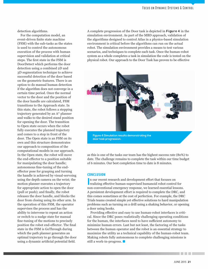
Fo c u s o n D y n a m i c S y s t e m s & C o n t r o l
detection algorithms. For the computation model, an
event-driven nite state machine (FSM) with the sub-tasks as the states is used to control the autonomous execution of the process with human supervision and validation at critical steps. The rst state in the FSM is DoorDetect which performs the door detection using a combined 2D and 3D segmentation technique to achieve successful detection of the door based on the geometric features. There is an option to do manual human detection if the algorithm does not converge in a certain time period. Once the normal vector to the door and the position of the door handle are calculated, FSM transitions to the Approach state. In this state, the robot follows a stepping trajectory generated by an A planner and walks to the desired stand position for opening the door. The transition to Open state occurs when the robot fully executes the planned trajectory and comes to a stop in front of the door. The Open state is an FSM on its own and this structure demonstrates our approach to composition of the computational models in our approach. In the Open state, the robot will move the end-e ector to a position suitable for manipulating the door handle autonomous ne-tuning of the end-e ector pose for grasping and turning the handle is achieved by visual-servoing using the depth camera on the wrist the motion planner executes a trajectory for appropriate action to open the door (pull or push) and nally, the robot releases the door handle, and blocks the door from closing using its other arm. In the operation of this FSM, the operator supervises the process and has the ability to intervene to repeat an action or switch to a nudge state for manual ne-tuning of the motions to precisely
position the robot end-e ector. The nal state in the FSM is GoThrough during which the path planner generates an optimal trajectory to go through the door using a dynamic arti cial potential eld.
A complete progression of the Door task is depicted in Figure 4 in the simulation environment. As part of the MBD approach, validation of the algorithms designed to control Atlas in a physics-based simulation environment is critical before the algorithms can run on the actual robot. The simulation environment provides a means to test various scenarios, and techniques to complete each task. Once the human-robot system as a whole completes a task in simulation the code is tested on the physical robot. Our approach to the Door Task has proven to be e ective
as this is one of the tasks our team has the highest success rate (80%) to date. The challenge remains to complete the task within our time budget of 6 minutes. Our best completion time to date is 8 minutes.
CONCLUSION
In our recent research and development e ort that focuses on realizing e ective human-supervised humanoid robot control for
non-conventional emergency response, we learned essential lessons. A persistent development e ort is required to complete the DRC, and this comes sometimes at the cost of perfection. For example, the DRC Trials teams created simple yet e ective solutions to hard manipulation problems such as turning on a drill using a shaking behavior, or opening a door using hooks.
Providing e ective and easy to use human-robot interfaces is criti-cal. Since the DRC poses realistically challenging operating conditions for the human, the interfaces need to have su cient autonomy to minimize human errors. Last but not least, the factoring of the tasks between the human operator and the robot is an essential strategy to maximize the utility as a technical capability of the human-robot team. Making robots fully autonomous to complete challenging missions is still a work-in-progress.
Figure 4 Simulation results demonstrating the door task progression.
JUNE 2015 21
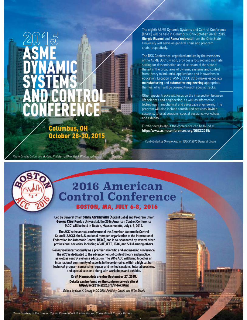
ASME DYNAMIC SYSTEMS AND CONTROL CONFERENCE
Columbus, OHOctober 28-30, 2015
The eighth ASME Dynamic Systems and Control Conference (DSCC) will be held in Columbus, Ohio October 28-30, 2015. Giorgio Rizzoni and Rama Yedavalli from the Ohio State University will serve as general chair and program chair, respectively.
The DSC Conference, organized and led by the members of the ASME DSC Division, provides a focused and intimate setting for dissemination and discussion of the state of the art in the broad area of dynamic systems and control from theory to industrial applications and innovations in education. Location of ASME DSCC 2015 makes especially manufacturing and automotive engineering appropriate themes, which will be covered through special tracks.
Other special tracks will focus on the intersection between life sciences and engineering, as well as information technology in mechanical and aerospace engineering. The program will also include contributed sessions, invited sessions, tutorial sessions, special sessions, workshops, and exhibits.
Further details about the conference can be found athttp://www.asmeconferences.org/DSCC2015/
Contributed by Giorgio Rizzoni (DSCC 2015 General Chair)
Photo Credit: Columbus skyline. Rod Berry/Ohio Stock Photography
Photo courtesy of the Greater Boston Convention & Visitors Bureau Convention & Visitors Bureau
2016 American Control Conference
BOSTON, MA, JULY 6-8, 2016
2015 | MECHANICAL ENGINEERING 71
PETROLEUM DIVISION ......................................................................................49PIPELINE SYSTEMS DIVISION ...........................................................................53OCEAN OFFSHORE AND ARCTIC ENGINEERING DIVISION ...............................59
From the Energy Sources and Processing Segment Board Chairman – June 2015
With great pleasure, I would like to
introduce the newly formed Energy
Sources and Processing (ESP) segment to
my fellow ASME members, and provide
an explanation on how the ESP segment
fits within the reorganized ASME. For
the past few years, I’ve proudly informed
you of the many accomplishments of the
former International Petroleum Tech-
nology Institute (IPTI), which has now
evolved into the ESP segment. With this
reorganization, I see even more oppor-
tunity for the ESP to serve the Society’s
missions and its global membership.
Because the ESP model is quite similar
and closely aligned with the previous
IPTI model, we have adapted quickly
and now, we are looking forward to serv-
ing the needs of the Society’s members
in ways that were not possible under the
previous structure.
With our new model, we were able
to bring the Pressure Vessels and Piping
Division into the ESP fold to join the
Petroleum Division (PD), the Pip-
ing Systems Division (PSD) and the
Ocean, Offshore and Arctic Engineering
Division (OOAE). These four divisions
have always been active both locally and
globally and will continue to be. In addi-
tion, we are now able to expand partner-
ship opportunities with other similarly
aligned ASME divisions within the ESP
segment scope. To follow the activities of
ESP, please visit the ESP segment group
on ASME.org (https://community.asme.
org/technical_events_and_content_sec-
tor/default.aspx).
The goal of the ESP segment is to
engage groups and individuals that are
developing mechanical engineering-
related energy sources content spanning
the complete lifecycle from raw state
to end-customer. This includes energy
sources, conversion from raw materials
to fuels, or designing products, sys-
tems and services utilized in the energy
sources and processing industries. ESP
focuses on planning, developing and
delivering technical events and content
that is vital to the petroleum, natural
gas, petrochemicals, coal, shale and LNG
industries.
The ESP segment is aligned with
ASME’s mission statement in three
core areas of energy, global impact and
engineering workforce development.
The division updates highlight our
dedication to serving the local and global
community by advancing, disseminat-
ing and applying engineering knowledge
via technical workshops, conferences,
presentations and training initiatives.
The core strength of ESP, similar to the
Society as a whole, is our committed and
highly motivated corps of volunteers.
These remarkable individuals leverage
their strong technical skills and name
recognition to achieve our ESP goals and
ultimately, those of the Society. The divi-
sion highlights summarize the growth
and successes achieved over the past year.
It is important, however, to recognize
that our achievements were also due to
our strong partnership with ASME staff.
WORLD-CLASS CONFERENCES & EVENTSConferences and events continue to form
the foundation of the ESP segment ac-
tivities that allow us to fulfill our ASME
mission and goals. ESP’s success is rooted
in 18 highly successful conferences and
events presented around the world. Of
these, eight are “owned” by ASME and
the remaining ten are co-sponsored by
ASME. Many of these conferences and
events have the potential for consider-
able growth. The ESP volunteers are
market-focused and motivated and we
will continue to identify new and dif-
ferent topics, events and conferences to
broaden our reach and meet our markets’
needs.
The success of the ESP segment
conferences, events and training
initiatives has drawn worldwide interest.
We are approached quite often to
(Continued next page)
INTERNATIONAL PETROLEUM TECHNOLOGY INSTITUTEEnergy Sources Processingand
72 MECHANICAL ENGINEERING | 2015
host or partner on similarly aligned
events. This is a testament to the power
of the ASME brand and the global
respect it garners — a direct result of the
hard work that goes into organizing and
staging world-class events by volunteers
and staff. These events and conferences
allow us to achieve the ASME goal
of knowledge sharing through paper
presentations and networking. Undoubt-
edly, you have heard of such signature
annual events as the Offshore Technol-
ogy Conference (OTC) in Houston, the
Ocean, Offshore and Arctic Engineering
(OMAE) conference, the Pressure Vessels
and Piping Conference, and the biennial
International Pipeline Conference (IPC)
in Calgary. In addition, each ESP divi-
sion hosts other events. I encourage you
to visit www.asme.org (http://calendar.
asme.org/) to learn more about them and
to register.
The ESP segment continually looks
for opportunities to add value for our
members. This includes organizing
events in partnership with other
ASME segments to share knowledge
across energy systems. In 2014, for
example, we successfully partnered with
another Society to co-sponsor an LNG
conference that examined LNG lifecycle
challenges, including unconventional
natural gas extraction, transportation,
and processing and offshore structures.
In addition, we are currently organizing
a Fall 2015 event with another ASME
segment that includes the nuclear sector
to focus on the critical issues of asset
reliability and integrity. This diverse
gathering of integrity and reliability
specialists from many industrial sectors
will serve to identify problems and
solutions common to all.
The ESP segment volunteers continue
to be committed and excited about the
ever-expanding portfolio of technical
engineering courses and workshops.
The courses offered by the Divisions are
designed to appeal to a broad audience,
from entry-level engineers to senior
engineers who seek more master-level
knowledge. Due to past successes, the
ESP segment is able to attract world-
recognized subject matter experts to
provide this training. In keeping with the
Society mission statement of having a
global impact and engineering workforce
development, volunteer trainers come
together to offer training affordable to
our international community.
DEVELOPING YOUNG ENGINEERING TALENT The ESP segment continues to address
the impending shortage in engineering
expertise. Numerous ESP volunteers
deliver presentations to young students
and sponsor teacher workshops. Our
four divisions have proven track records
of active and growing programs that
engage engineering students and young
professionals. These programs success-
fully communicate the attractions of the
mechanical engineering field and the
many benefits of ASME membership
including networking opportunities,
scholarship and internship programs, in
addition to skill enhancement through
training initiatives. These programs
include the support and participation of
the Collegiate Council and the sponsor-
ship of student paper competitions at
many of our conferences. All students are
welcome at our events and we encour-
age their participation with significantly
reduced registration fees.
If you are a student or young
professional, I encourage you to join
us and discover the career-enhancing
opportunities available to you. For a
complete list of our student programs
and scholarships, including application
forms, please visit asme.org (https://
www.asme.org/about-asme/professional-
membership/benefits-for-students).
In addition, we are always looking
for student volunteer leaders and are
committed to providing you with the
support you need to succeed.
The ESP segment and our divisions
appreciate all of the time our tireless
volunteers contribute to the Society and
honor these contributions with awards
that recognize exceptional volunteer and
career effort. These awards include peer
recognition of members who have helped
advance the practice of engineering.
And to help engineering students
achieve their potential, we regularly
award financial assistance in the form of
scholarships. To learn more about these
awards, please visit our website at asme.
org (https://www.asme.org/about-asme/
professional-membership/benefits-for-
students).
We are excited about the ASME’s ESP
segment’s future and encourage you to
share your vision with us to help further
the engineering profession.
Joe Paviglianiti
Energy Sources and
Processing
Segment Chairman
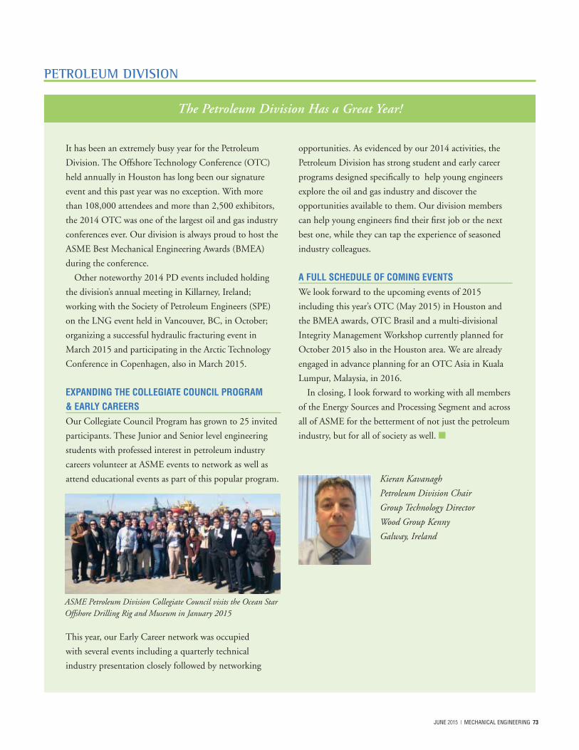
2015 | MECHANICAL ENGINEERING 73
PETROLEUM DIVISION
The Petroleum Division Has a Great Year!
It has been an extremely busy year for the Petroleum
Division. The Offshore Technology Conference (OTC)
held annually in Houston has long been our signature
event and this past year was no exception. With more
than 108,000 attendees and more than 2,500 exhibitors,
the 2014 OTC was one of the largest oil and gas industry
conferences ever. Our division is always proud to host the
ASME Best Mechanical Engineering Awards (BMEA)
during the conference.
Other noteworthy 2014 PD events included holding
the division’s annual meeting in Killarney, Ireland;
working with the Society of Petroleum Engineers (SPE)
on the LNG event held in Vancouver, BC, in October;
organizing a successful hydraulic fracturing event in
March 2015 and participating in the Arctic Technology
Conference in Copenhagen, also in March 2015.
EXPANDING THE COLLEGIATE COUNCIL PROGRAM & EARLY CAREERSOur Collegiate Council Program has grown to 25 invited
participants. These Junior and Senior level engineering
students with professed interest in petroleum industry
careers volunteer at ASME events to network as well as
attend educational events as part of this popular program.
This year, our Early Career network was occupied
with several events including a quarterly technical
industry presentation closely followed by networking
opportunities. As evidenced by our 2014 activities, the
Petroleum Division has strong student and early career
programs designed specifically to help young engineers
explore the oil and gas industry and discover the
opportunities available to them. Our division members
can help young engineers find their first job or the next
best one, while they can tap the experience of seasoned
industry colleagues.
A FULL SCHEDULE OF COMING EVENTSWe look forward to the upcoming events of 2015
including this year’s OTC (May 2015) in Houston and
the BMEA awards, OTC Brasil and a multi-divisional
Integrity Management Workshop currently planned for
October 2015 also in the Houston area. We are already
engaged in advance planning for an OTC Asia in Kuala
Lumpur, Malaysia, in 2016.
In closing, I look forward to working with all members
of the Energy Sources and Processing Segment and across
all of ASME for the betterment of not just the petroleum
industry, but for all of society as well.
Kieran Kavanagh
Petroleum Division Chair
Group Technology Director
Wood Group Kenny
Galway, Ireland
ASME Petroleum Division Collegiate Council visits the Ocean Star Offshore Drilling Rig and Museum in January 2015
74 MECHANICAL ENGINEERING | 2015
PETROLEUM DIVISION
Arthur Lubinski Best ASME Mechanical Engineering Paper Presented at OTC 2015
2015 WINNEROTC 25643-MS
Next Generation HPHT Subsea Wellhead Systems Design Challenges and Opportunities
Jim Kaculi, D.Eng., P.E., Dril-Quip, Inc.
Copyright 2015, Offshore Technology Conference
This paper was prepared for presentation at the Offshore Technology Conference held in Houston, Texas, USA, 4–7 May 2015.
This paper was selected for presentation by an OTC program committee following review of information contained in an abstract submitted by the author(s). Contents of the paper have not been reviewed by the Offshore Technology Conference and are subject to correction by the author(s). The material does not necessarily reflect any position of the Offshore Technology Conference, its officers, or members. Electronic reproduction, distribution, or storage of any part of this paper without the written consent of the Offshore Technology Conference is prohibited. Permission to reproduce in print is restricted to an abstract of not more than 300 words; illustrations may not be copied. The abstract must contain conspicuous acknowledgment of OTC copyright.
AbstractThe oil and gas industry is targeting operations in much deeper waters and well depths resulting in high pressure and high
temperature (HPHT) applications, creating a need for development of new technology to meet the challenges faced in these new
frontiers. Considering the higher loads encountered in these environments, the existing industry equipment are reaching their limits
and the manufacturing sector is looking into the development of the next generation equipment. Subsea wellheads form a critical
part of the drilling and production systems, and they are the driver for designing and sizing other equipment, such as connectors,
risers, BOPs, and casing programs. The typical wellhead systems that the industry currently uses include mandrels with 27 in. and
30 in. OD and conductor casing with up to 36 in. OD. However, these configurations may not be able to resist the high load
magnitudes and combinations expected in these new applications. Moving to higher capacity wellhead systems will require a larger
mandrel and conductor casing size to accommodate the high loads encountered during drilling and production operations for
normal, extreme, and survival loading conditions. Considering the ongoing industry efforts to standardize equipment, it is a great
opportunity to define the anticipated loads and select an appropriate larger wellhead size that will cover the needs of the industry for
the coming decades.
Numerous analytical studies using 3D finite element analysis (FEA) and other advanced tools have been performed looking
into the changes needed and an innovative solution is presented for the next generation subsea wellhead equipment. This is
tied with the development of new wellhead connectors with much higher static capacities and the appropriate conductor sizes
needed. Considerations are given to structural integrity, fatigue performance, and metal-to-metal sealing capability. Various load
combinations (bending, tension/compression, pressure) were applied to generate the wellhead system capacity envelopes covering
a wide range of operating windows. The need for the industry to define the anticipated normal, extreme and survival loading
requirements and a standard set of fatigue loads is discussed. The fatigue performance and life expectancy of the equipment, as well
as challenges faced with the lack of material properties at various HPHT environments are discussed.
Testing facilities to validate designs and safety margins at both component and system levels have been developed to accommodate
the various high load magnitudes and their combinations. Validation testing is absolutely paramount to verify analysis methodologies
and ensure high performance, safe, robust and reliable equipment designs.
2015 | MECHANICAL ENGINEERING 75
PETROLEUM DIVISION
2015 Lubinski Paper Nominees
1st Runner-up
OTC 25850 Daniel Hiller, Developing An Innovative Deepwater Riser System: From Concept To The Full
Production of Buoy Supporting Risers (bsr)
2nd Runner-up
OTC 25832 Ivan Cruz, The New Technology Enablers Developed And Deployed On A Live Project
3rd Runner-up
OTC 25717 Dan Fraser, Hydro-rest Rick Minimization Through Design And Processing For Subsea HP/HT
Well Equipment
4th Runner-up
OTC 25889 Colin Stevenson, Development And Execution Of A Wax Remidiation Pigging Program
For A Subsea Oil Export Pipeline
5th Runner-up
OTC 25729 Amadeu Sum, Multiphase Flow Modeling For Gas Hydrates In Flow Assurance
Introducing the First ASME Integrity Management in Energy Workshop
October 4-6, 2015
La Torretta Lake Resort & Spa
Lake Conroe (outside Houston), Texas
This first ever multi-divisional
program is designed to share best
practices and provide insight into
key integrity management and
associated topics, including failure
analysis and integrity of designs
for the full life cycle of products,
processes and systems.
Benefits to all participating
groups and attendees will include:
• Unique content focused on
bringing specific disciplines
together to learn as a team
• An interactive platform to
identify and solve integrity
management problems
• A premier marketplace of ASME
groups for innovative technology
exchange between vendors and
users
Track topics will include:
• Process safety
• HSE and integrity management
relationship
• Integrity management advances
in data mining and real time
monitoring
• Best practices from codes and
standards in energy and non-
energy industries
• Discipline-specific tracks:
pipelines, nuclear, power,
pressure vessels & piping and
petroleum
For additional information or to
participate, please contact:
Jamie Hart, Manager
Conferences & Events,
ESP Segment
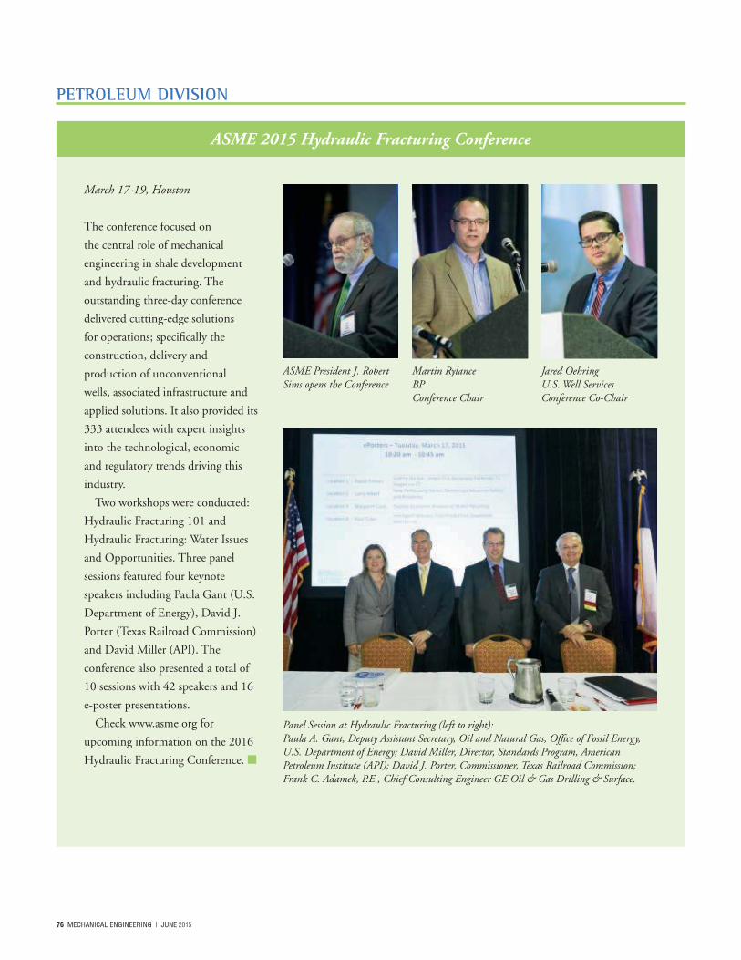
76 MECHANICAL ENGINEERING | 2015
PETROLEUM DIVISION
ASME 2015 Hydraulic Fracturing Conference
March 17-19, Houston
The conference focused on
the central role of mechanical
engineering in shale development
and hydraulic fracturing. The
outstanding three-day conference
delivered cutting-edge solutions
for operations; specifically the
construction, delivery and
production of unconventional
wells, associated infrastructure and
applied solutions. It also provided its
333 attendees with expert insights
into the technological, economic
and regulatory trends driving this
industry.
Two workshops were conducted:
Hydraulic Fracturing 101 and
Hydraulic Fracturing: Water Issues
and Opportunities. Three panel
sessions featured four keynote
speakers including Paula Gant (U.S.
Department of Energy), David J.
Porter (Texas Railroad Commission)
and David Miller (API). The
conference also presented a total of
10 sessions with 42 speakers and 16
e-poster presentations.
Check www.asme.org for
upcoming information on the 2016
Hydraulic Fracturing Conference.
Panel Session at Hydraulic Fracturing (left to right):Paula A. Gant, Deputy Assistant Secretary, Oil and Natural Gas, Office of Fossil Energy, U.S. Department of Energy; David Miller, Director, Standards Program, American Petroleum Institute (API); David J. Porter, Commissioner, Texas Railroad Commission; Frank C. Adamek, P.E., Chief Consulting Engineer GE Oil & Gas Drilling & Surface.
ASME President J. Robert Sims opens the Conference
Martin RylanceBPConference Chair
Jared OehringU.S. Well ServicesConference Co-Chair
2015 | MECHANICAL ENGINEERING 77
From the Pipeline Systems Division Chair – April 2015
A highlight of our year was the
biennial International Pipeline
Conference held last fall in Calgary,
which has grown in terms of attendance
and paper submissions. This past year,
two associated special events included
the award of the Pipeline Systems
Division (PSD) medal to our division’s
first chairman and industry leader, Dr.
Alan Murray, as well as the publication
of a commemorative collection of the
best papers presented at past conferences.
Also of particular note for 2014 were
two highly successful PSD-sponsored
conferences held in India and Colombia.
This year, I’d like to note that our
division benefits from the continued
contributions of our past chairmen,
who are also leaders within the
pipeline industry, and from the efforts
and dedication of our membership.
An example of such leadership and
dedication is Rafael Mora, Pipeline and
Distribution Integrity Advisor, Imperial
Oil Canada, who has worked tirelessly
to organize what is now the biennial
International Pipeline and Geotechnical
Conference to be held in July 2015 in
Bogota, Colombia.
PROMOTING UPCOMING ENGINEERING TALENT
Our division is committed to
supporting new, potential and student
mechanical engineers who are interested
in careers focused on the pipeline
industry. We support the established
Young Pipeliners Association of Canada
(YPAC) and the rapidly growing US-
based Young Pipeline Professionals
(YPP). We urge students and early-career
MEs to consider the pipeline industry as
a career choice and to network through
involvement with the YPAC and YPP.
The energy transmission pipeline sector
is a dynamic arena for engineers, both
young and seasoned. By becoming
active within the PSD, pipeline
engineers are tapping into career-
enriching opportunities to network,
transfer knowledge and socialize with
enthusiastic and respected peers in the
industry.
Moness Rizkalla
Pipeline Systems
Division
WorleyParsons
PIPELINE SYSTEMS DIVISION
The ASME Pipeline Systems Division’s Global Pipeline Award (GPA) recognizes outstanding innovations and technological advances by various organizations in the field of pipeline transportation. The following finalists and winners were honored at the ASME Awards Dinner at this past year’s IPC.
The 2014 GPA Winner Penspen & Northumbria University for their MSc in Pipeline Integrity Management Distance Learning Program. For more information visit: http://www.penspen.com/capabilities/services/training-education/distance-learning/
2014 GPA Finalists • Magnatech International for the
Hartweel Project, Oman.• Hunter McDonnel Pipeline
Services, Inc., for the ArmadilloRemote Tracking Unit
• Transcanada for the TamazunchaleExtension Pipeline Project
• Enerco S.p.A. for TPR TrenchlessPipeline Removal
Past Pipeline Systems Division (PSD) Chairs and recent Fellows were also recognized.
Past Chairs Pat Vieth, 2010 - 2011Joe Paviglianiti, 2011 - 2012Bill Byrd, 2012 - 2013Taylor Shie, 2013 – 2014, Immediate Past Chair
ASME PSD Fellows Marcelino GomesKevin Bodenhamer, P.E.Mike Yoon, Ph.D.
In addition, Rafael Mora was named PSD Exceptional Volunteer for his work in establishing the International Pipeline Geotechnical Conference and the associated Recommended Practice Document. Dr. Alan Murray, founder of the Pipeline Systems Division, received the first Pipeline Systems Division Medal. This award recognizes excellence in engineering and service to the ASME PSD.
To learn more about the GPA program, please contact Kim Miceli at [email protected] or visit http://www.internationalpipelineconference.com/conference/global_pipeline_award.php
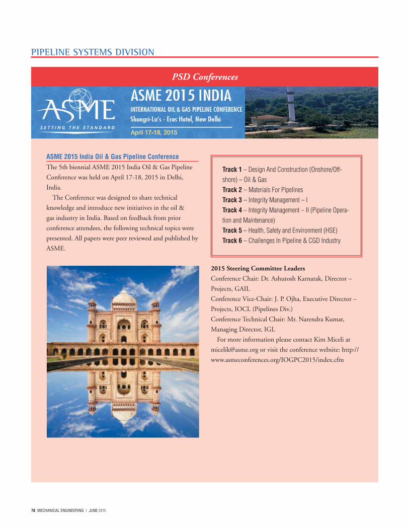
78 MECHANICAL ENGINEERING | 2015
ASME 2015 India Oil & Gas Pipeline ConferenceThe 5th biennial ASME 2015 India Oil & Gas Pipeline
Conference was held on April 17-18, 2015 in Delhi,
India.
The Conference was designed to share technical
knowledge and introduce new initiatives in the oil &
gas industry in India. Based on feedback from prior
conference attendees, the following technical topics were
presented. All papers were peer reviewed and published by
ASME.
2015 Steering Committee Leaders
Conference Chair: Dr. Ashutosh Karnatak, Director –
Projects, GAIL
Conference Vice-Chair: J. P. Ojha, Executive Director –
Projects, IOCL (Pipelines Div.)
Conference Technical Chair: Mr. Narendra Kumar,
Managing Director, IGL
For more information please contact Kim Miceli at
[email protected] or visit the conference website: http://
www.asmeconferences.org/IOGPC2015/index.cfm
PIPELINE SYSTEMS DIVISION
PSD Conferences
Track 1 – Design And Construction (Onshore/Off-shore) – Oil & Gas Track 2 – Materials For Pipelines Track 3 – Integrity Management – I Track 4 – Integrity Management – II (Pipeline Opera-tion and Maintenance)Track 5 – Health, Safety and Environment (HSE)Track 6 – Challenges In Pipeline & CGD Industry
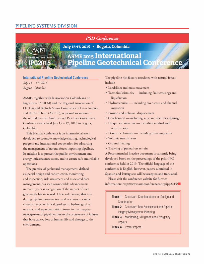
2015 | MECHANICAL ENGINEERING 79
PIPELINE SYSTEMS DIVISION
PSD Conferences
International Pipeline Geotechnical ConferenceJuly 15 – 17, 2015
Bogota, Colombia
ASME, together with la Asociación Colombiana de
Ingenieros (ACIEM) and the Regional Association of
Oil, Gas and Biofuels Sector Companies in Latin America
and the Caribbean (ARPEL), is pleased to announce
the second biennial International Pipeline Geotechnical
Conference to be held July 15 – 17, 2015 in Bogota,
Colombia.
This biennial conference is an international event
developed to promote knowledge sharing, technological
progress and international cooperation for advancing
the management of natural forces impacting pipelines.
Its mission is to protect the public, environment and
energy infrastructure assets, and to ensure safe and reliable
operations.
The practice of geohazard management, defined
as special design and construction, monitoring
and inspection, risk assessment and associated data
management, has seen considerable advancements
in recent years as recognition of the impact of such
geohazards has increased. These risk factors, that arise
during pipeline construction and operations, can be
classified as geotechnical, geological, hydrological or
tectonic, and represent critical issues in the integrity
management of pipelines due to the occurrence of failures
that have caused loss of human life and damage to the
environment.
The pipeline risk factors associated with natural forces
include
• Landslides and mass movement
• Tectonics/seismicity — including fault crossings and
liquefaction
• Hydrotechnical — including river scour and channel
migration
• Erosion and upheaval displacement
• Geochemical — including karst and acid rock drainage
• Unique soil structure — including residual and
sensitive soils
• Desert mechanisms — including dune migration
• Volcanic mechanisms
• Ground freezing
• Thawing of permafrost terrain
A Recommended Practice document is currently being
developed based on the proceedings of the prior IPG
conference held in 2013. The official language of the
conference is English; however, papers submitted in
Spanish and Portuguese will be accepted and translated.
Please visit the conference website for further
information: http://www.asmeconferences.org/ipg2015/
Track 1 – Geohazard Considerations for Design and Construction
Track 2 – Geohazard Risk Assessment and Pipeline Integrity Management Planning
Track 3 – Monitoring, Mitigation and Emergency Repairs
Track 4 – Poster Papers
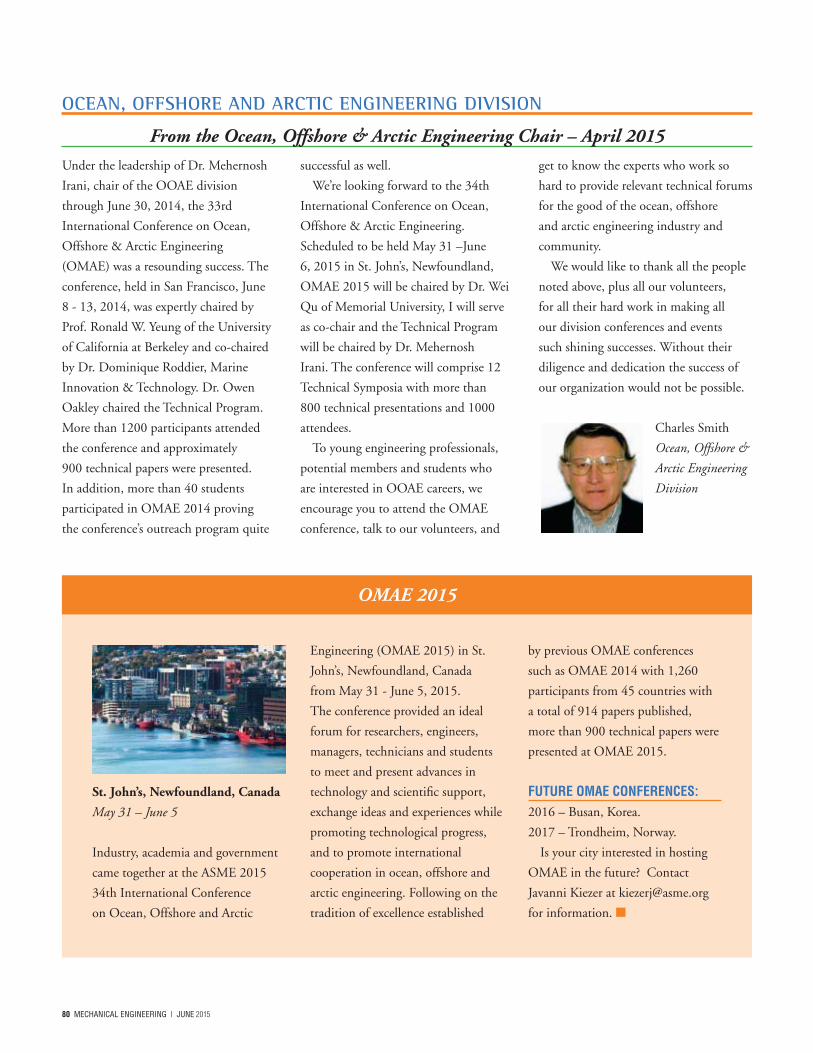
80 MECHANICAL ENGINEERING | 2015
OCEAN, OFFSHORE AND ARCTIC ENGINEERING DIVISION
St. John’s, Newfoundland, Canada
May 31 – June 5
Industry, academia and government
came together at the ASME 2015
34th International Conference
on Ocean, Offshore and Arctic
Engineering (OMAE 2015) in St.
John’s, Newfoundland, Canada
from May 31 - June 5, 2015.
The conference provided an ideal
forum for researchers, engineers,
managers, technicians and students
to meet and present advances in
technology and scientific support,
exchange ideas and experiences while
promoting technological progress,
and to promote international
cooperation in ocean, offshore and
arctic engineering. Following on the
tradition of excellence established
by previous OMAE conferences
such as OMAE 2014 with 1,260
participants from 45 countries with
a total of 914 papers published,
more than 900 technical papers were
presented at OMAE 2015.
FUTURE OMAE CONFERENCES: 2016 – Busan, Korea.
2017 – Trondheim, Norway.
Is your city interested in hosting
OMAE in the future? Contact
Javanni Kiezer at [email protected]
for information.
OMAE 2015
From the Ocean, Offshore & Arctic Engineering Chair – April 2015
Under the leadership of Dr. Mehernosh
Irani, chair of the OOAE division
through June 30, 2014, the 33rd
International Conference on Ocean,
Offshore & Arctic Engineering
(OMAE) was a resounding success. The
conference, held in San Francisco, June
8 - 13, 2014, was expertly chaired by
Prof. Ronald W. Yeung of the University
of California at Berkeley and co-chaired
by Dr. Dominique Roddier, Marine
Innovation & Technology. Dr. Owen
Oakley chaired the Technical Program.
More than 1200 participants attended
the conference and approximately
900 technical papers were presented.
In addition, more than 40 students
participated in OMAE 2014 proving
the conference’s outreach program quite
successful as well.
We’re looking forward to the 34th
International Conference on Ocean,
Offshore & Arctic Engineering.
Scheduled to be held May 31 –June
6, 2015 in St. John’s, Newfoundland,
OMAE 2015 will be chaired by Dr. Wei
Qu of Memorial University, I will serve
as co-chair and the Technical Program
will be chaired by Dr. Mehernosh
Irani. The conference will comprise 12
Technical Symposia with more than
800 technical presentations and 1000
attendees.
To young engineering professionals,
potential members and students who
are interested in OOAE careers, we
encourage you to attend the OMAE
conference, talk to our volunteers, and
get to know the experts who work so
hard to provide relevant technical forums
for the good of the ocean, offshore
and arctic engineering industry and
community.
We would like to thank all the people
noted above, plus all our volunteers,
for all their hard work in making all
our division conferences and events
such shining successes. Without their
diligence and dedication the success of
our organization would not be possible.
Charles Smith
Ocean, Offshore &
Arctic Engineering
Division
2015 | MECHANICAL ENGINEERING 81
OCEAN, OFFSHORE AND ARCTIC ENGINEERING DIVISION
The Ocean, Offshore and Arctic
Engineering Division (OOAE) of
ASME hosted a specialty forum at
OMAE 2015. The specialty forum
was designed for both students and
early professionals not familiar with
the industry, as well as those who are.
This is the ninth year of the
Outreach for Engineers Forum.
Highlights of the Forum included:
• Presentations of various
technologies, such as ocean
and/or offshore engineering,
civil engineering, petroleum
engineering, aerospace
engineering, mechanical/
structural engineering and
project management
• Job opportunities
• Possible career paths
• Team building activities
In addition, Outreach for Engineers
Specialty Forum delegates were
provided with the opportunity to
participate at the 34th International
Conference on Ocean, Offshore
and Arctic Engineering as full
conference delegates. This conference
showcased more than 900 technical
papers from engineers and scientists
from around the world and 12
symposia representing the range of
technologies.
Through the generosity of our
sponsors and the OOAE Division,
attendance scholarships were made
available to qualified students and
early professionals.
You can find further information
about the Outreach program here:
http://www.asmeconferences.org/
OMAE2015/Outreach.cfm
9th Outreach for Engineers Specialty Forum at OMAE
PRESSURE VESSELS & PIPING DIVISION
Pressure Vessels & Piping Joins ASME’s Energy Sources & Processing Segment
For Pressure Vessels & Piping, 2014 was an extraordinary
year. In addition to our outstanding annual PVP
Conference, held last July in Anaheim, California, ASME
reorganization opened new avenues for our division to
collaborate with the others within the Energy Sources &
Processing and Energy Sources & Conversion Segments,
as well as others. We expect this new collaboration with
our partner divisions to strengthen our capabilities, enable
growth and allow us to continue providing outstanding
technical content and mentorship.
The 2014 PVP Conference mentioned above
featured plenary talks regarding High Pressure High
Temperature (HPHT) applications and design guidelines
in development in the subsea oil and gas markets, as well
as technical forums and exhibits on Non-Destructive
Evaluation (NDE) and advanced software applications.
In all, there were 1100 registrants from 37 countries, 179
technical sessions, one technical workshop and several
tutorials.
GLOBAL OUTREACH & COLLABORATIONNew initiatives and global outreach continue to be
noteworthy endeavors for our division. We are working
diligently to identify and strengthen our portfolio
of content and events. Some new events of note
include cross-sector collaboration with the Standards
and Certification sector to host a Post-Construction
Committee (PCC) Workshop as part of the 2015 PVP
conference. This one-day workshop will include an
overview of all the current post-construction standards,
along with break-out panel sessions for the discussion of
(Continued next page)
82 MECHANICAL ENGINEERING | 2015
PRESSURE VESSELS & PIPING DIVISION
future direction and opportunities for enhancement of
standards. Our division is also participating along with
our partner divisions in the Energy Sources & Processing
segment to develop the Integrity Management in Energy
workshop to be held outside Houston on October 4-6,
2015. This event will cover integrity management, failure
analysis and lifecycle management.
TAKING THE INITIATIVE...The reorganization that occurred within ASME this
past year, including the creation of the Technical Events
and Content sector continues to evolve. Accordingly,
PVP is adapting and changing as needed. In addition
to the “behind the scene” changes to the normal
business operations of the division, we are in the process
of developing many new initiatives, new events and
opportunities for our membership and the PVP industry
as a whole. We are also continuing close collaborating
with the Board on Pressure Technology Codes and
Standards (BPTCS) of the Standards and Certification
sector, and continue to look for innovative ways to
enhance the relationship and support the efforts of ASME
as the world leader in standards development.
THANKS AND REMEMBRANCESAs Chair of the PVP Division, I would like to extend a
special note of thanks to all who are currently involved in
planning for the 2015 PVP Conference. This includes Dr.
Marina Ruggles-Wrenn, the Conference Chair, Dr. Doug
Scarth, the Technical Conference Chair, and Ron Hafner,
the head of the Student Paper Competition, as well as all
of the Technical Committee Chairs, Technical Program
Chairs, Session Developers and Authors who continue to
make PVP one of ASME’s premier technical conferences.
This past year, we lost two of our leaders — Dr. Robert
Nickel, past ASME President and past PVP Division
Chair, and Dr. Luc Geraets, past Division Chair and Vice
President of the former Knowledge and Communities
sector. Their leadership and friendship will be sorely
missed.
FOR OUR YOUNG PROFESSIONALS AND STUDENTS New and student members are encouraged to become
involved in our many activities. For students interested in
PVP-related careers, we are offering the 23rd annual Rudy
Scavuzzo Student Paper Competition at PVP 2105. This
is a terrific opportunity to showcase your research and
development work while interfacing with colleagues and
potential employers. The competition includes a travel
allowance for attending and presenting at the conference
and monetary awards for both the BS/MS and PhD
categories. The PVP Conference also offers a great
number of networking and educational opportunities.
You’ll rub elbows with experts in such areas as Codes &
Standards, Fitness for Service, design, advanced materials,
fluid structure interaction, high pressure technology and
many other specializations.
A BRIGHT FUTUREOur division will continue to be a leader within ASME.
New programs, initiatives and leveraging technology and
knowledge will allow us to continue to grow and provide
outstanding technical content. Our future looks bright for
our energetic and dedicated membership.
Daniel T. Peters
Pressure Vessels & Piping Division
Chair
Associate
Structural Integrity Associates, Inc.
Edinboro, PA
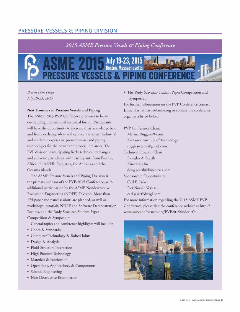
2015 | MECHANICAL ENGINEERING 83
Boston Park Plaza
July 19-23, 2015
New Frontiers in Pressure Vessels and Piping
The ASME 2015 PVP Conference promises to be an
outstanding international technical forum. Participants
will have the opportunity to increase their knowledge base
and freely exchange ideas and opinions amongst industrial
and academic experts in pressure vessel and piping
technologies for the power and process industries. The
PVP division is anticipating lively technical exchanges
and a diverse attendance with participants from Europe,
Africa, the Middle East, Asia, the Americas and the
Oceania islands.
The ASME Pressure Vessels and Piping Division is
the primary sponsor of the PVP-2015 Conference, with
additional participation by the ASME Nondestructive
Evaluation Engineering (NDEE) Division. More than
175 paper and panel sessions are planned, as well as
workshops, tutorials, NDEE and Software Demonstration
Forums, and the Rudy Scavuzzo Student Paper
Competition & Symposium.
General topics and conference highlights will include:
• Codes & Standards
• Computer Technology & Bolted Joints
• Design & Analysis
• Fluid-Structure Interaction
• High Pressure Technology
• Materials & Fabrication
• Operations, Applications, & Components
• Seismic Engineering
• Non-Destructive Examination
• The Rudy Scavuzzo Student Paper Competition and
Symposium
For further information on the PVP Conference contact
Jamie Hart at [email protected] or contact the conference
organizers listed below:
PVP Conference Chair:
Marina Ruggles-Wrenn
Air Force Institute of Technology
Technical Program Chair:
Douglas A. Scarth
Kinectrics Inc.
Sponsorship Opportunities:
Carl E. Jaske
Det Norske Veritas
For more information regarding the 2015 ASME PVP
Conference, please visit the conference website at http://
www.asmeconferences.org/PVP2015/index.cfm
2015 ASME Pressure Vessels & Piping Conference
PRESSURE VESSELS & PIPING DIVISION
84 MECHANICAL ENGINEERING | 2015
2015
Offshore Technology Conference
May 4 – 7
Houston, Texas
International Conference of Ocean,
Offshore and Arctic Engineering
May 31 – June 5
St. John’s, Newfoundland, Canada
2015 Power and Energy Conference
June 28 – July 2
San Diego, California
International Geotechnical Pipeline
Conference
July 15 – 17
Bogota, Colombia
|ASME 2015 Pressure Vessels & Pipeline
Conference
July 19 – 23
Boston, Massachusetts
Rio Pipeline Conference
September 22 – 24
Rio de Janeiro, Brazil
ASME Integrity Management in Energy
Workshop
October 4 – 6
Houston, Texas
OTC Brasil
October 27 – 29
Rio de Janeiro, Brazil
2016
ASME Hydraulic Fracturing Conference
Houston, Texas
2016 Banff Pipeline Workshops
Banff, Alberta, Canada
OTC Asia 2016
Kuala Lumpur, Malaysia
Offshore Technology Conference
Houston, Texas
Arctic Technology Conference 2016
St. John’s, Newfoundland
2017
India Oil & Gas Pipeline Conference 2017
New Delhi, India
2015 – 2017 Technical Conferences & Expositions
Educational & Networking EventsInternational Offshore Pipeline Lunch and
Learns (quarterly)
Houston, Texas
Annual ASME OTC Golf Tournament
April 30, 2016
Houston, Texas
Early Career Mixers
Houston, Texas
Annual ASME Sporting Clays
Tournament
October 16, 2016
Houston, Texas
2015 – 2016 OTC Events
May 4-7Offshore Technology
ConferenceNRG Park, Houston
October 27-29OTC Brasil
Rio de Janeiro
March 22-25, 2016OTC Asia
Kuala Lumpur, Malaysia
October 2016OTC ArcticTechnologyConferenceSt. John’s,
Newfoundland

PIPELINE PERSONNEL
QUALIFICATIONNEWLY REVISED!
A S M E H A S B E E N D E F I N I N G S A F E T Y FO R P I P E L I N E S A N D P I P I N G S I N C E 1922. Our portfolio of B31 Codes prescribe minimum requirements for the design, materials, fabrication, erection, test, inspection, operation, and maintenance of piping systems found across a wide range of industries.
Keep current with the latest technology…while achieving the operational, cost, and safety benefits to be gained from the many industry best-practices detailed within these volumes. ASME also offers related training courses, technical publications, and professional conferences to help you keep current with these B31 Codes. Learn more at go.asme.org/B31.
The American Society of Mechanical Engineers (ASME)
GO.ASME.ORG/B31
These B31 Codes have been updated by industry experts to meet the needs of fast-changing markets:
A S M E ’ S
POWER PIPINGNEWLY REVISED!
B31.1
PROCESS PIPINGNEWLY REVISED!
B31.3
GAS TRANSMISSION AND DISTRIBUTION
PIPING SYSTEMSNEWLY REVISED!
B31.8
MANAGING SYSTEM INTEGRITY OF GAS
PIPELINESNEWLY REVISED!
B31.8S
HYDROGEN PIPING AND PIPELINES NEWLY REVISED!
B31.12 B31Q
Essential requirements for construction of pipelines and pipingB31C O D E S :
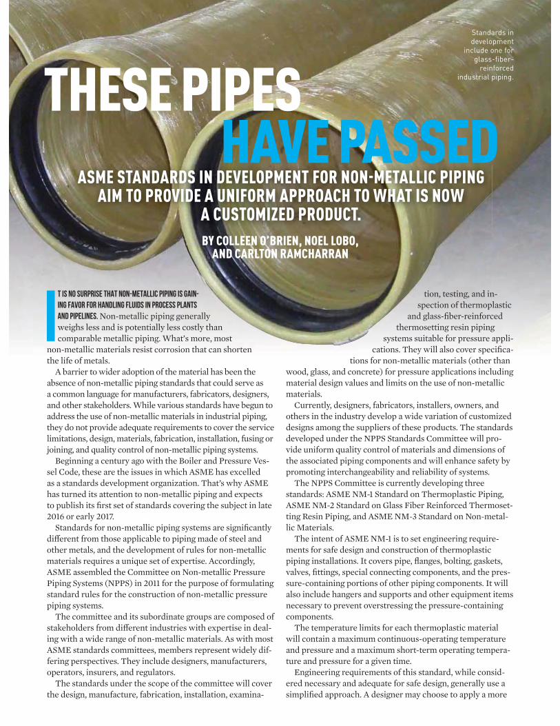
It is no surprise that non-metallic piping is gain-ing favor for handling fluids in process plants and pipelines. Non-metallic piping generally weighs less and is potentially less costly than comparable metallic piping. What’s more, most
non-metallic materials resist corrosion that can shorten the life of metals.
A barrier to wider adoption of the material has been the absence of non-metallic piping standards that could serve as a common language for manufacturers, fabricators, designers, and other stakeholders. While various standards have begun to address the use of non-metallic materials in industrial piping, they do not provide adequate requirements to cover the service limitations, design, materials, fabrication, installation, fusing or joining, and quality control of non-metallic piping systems.
Beginning a century ago with the Boiler and Pressure Ves-sel Code, these are the issues in which ASME has excelled as a standards development organization. That’s why ASME has turned its attention to non-metallic piping and expects to publish its fi rst set of standards covering the subject in late 2016 or early 2017.
Standards for non-metallic piping systems are signifi cantly diff erent from those applicable to piping made of steel and other metals, and the development of rules for non-metallic materials requires a unique set of expertise. Accordingly, ASME assembled the Committee on Non-metallic Pressure Piping Systems (NPPS) in 2011 for the purpose of formulating standard rules for the construction of non-metallic pressure piping systems.
The committee and its subordinate groups are composed of stakeholders from diff erent industries with expertise in deal-ing with a wide range of non-metallic materials. As with most ASME standards committees, members represent widely dif-fering perspectives. They include designers, manufacturers, operators, insurers, and regulators.
The standards under the scope of the committee will cover the design, manufacture, fabrication, installation, examina-
tion, testing, and in-spection of thermoplastic
and glass-fi ber-reinforced thermosetting resin piping
systems suitable for pressure appli-cations. They will also cover specifi ca-
tions for non-metallic materials (other than wood, glass, and concrete) for pressure applications including material design values and limits on the use of non-metallic materials.
Currently, designers, fabricators, installers, owners, and others in the industry develop a wide variation of customized designs among the suppliers of these products. The standards developed under the NPPS Standards Committee will pro-vide uniform quality control of materials and dimensions of the associated piping components and will enhance safety by promoting interchangeability and reliability of systems.
The NPPS Committee is currently developing three standards: ASME NM-1 Standard on Thermoplastic Piping, ASME NM-2 Standard on Glass Fiber Reinforced Thermoset-ting Resin Piping, and ASME NM-3 Standard on Non-metal-lic Materials.
The intent of ASME NM-1 is to set engineering require-ments for safe design and construction of thermoplastic piping installations. It covers pipe, fl anges, bolting, gaskets, valves, fi ttings, special connecting components, and the pres-sure-containing portions of other piping components. It will also include hangers and supports and other equipment items necessary to prevent overstressing the pressure-containing components.
The temperature limits for each thermoplastic material will contain a maximum continuous-operating temperature and pressure and a maximum short-term operating tempera-ture and pressure for a given time.
Engineering requirements of this standard, while consid-ered necessary and adequate for safe design, generally use a simplifi ed approach. A designer may choose to apply a more
THESE PIPES HAVE PASSED
BY COLLEEN O’BRIEN, NOEL LOBO, AND CARLTON RAMCHARRAN
ASME STANDARDS IN DEVELOPMENT FOR NON-METALLIC PIPING AIM TO PROVIDE A UNIFORM APPROACH TO WHAT IS NOW
A CUSTOMIZED PRODUCT.
Standards in development
include one for glass-fiber-
reinforced industrial piping.
MECHANICAL ENGINEERING | JUNE 2015 | P.87
rigorous analysis, but the approach must be documented and accepted by the owner.
At present, engineering companies designing this equipment for electric power generating plants have diffi culty justifying their designs using existing standards. ASME B31.1 and ASME B31.3 limit the pressure in thermoplastic piping systems to 150 psi at 140 °F. However, there are applications for thermoplastic piping systems above 150 psi at a wide range of temperatures. The NM-1 Standard will provide realistic temperature and pressure ranges for using thermoplastic piping systems.
ASME NM-2 will provide requirements for the design, materials, manufacture, fabrication, installation, examination, and testing of glass-fi ber-reinforced thermosetting resin piping systems. In industrial use, this type of piping is commonly re-ferred to as FRP piping. The abbreviation stands for “fi berglass reinforced plastic.”
“There are a number of FRP product standards available in the industry that provide procedures for designing products for pressure containment,” said Bruce Hebb, vice president of engineering at RPS Composites in Mahone Bay, Nova Scotia, and a member of the NM-2 Subcommittee, “but there is very little direction on how to properly analyze FRP piping systems. The most common type of FRP pipe, i.e. pipe that is fi lament wound at 55 degrees to the pipe axis, displays signifi cantly diff erent axial strengths depending on whether the stress is due to pressure or due to other loads, such as bending due to weight loading. Proper analysis of the piping must recognize that behavior so as to achieve a consistent margin of safety under various loading conditions.
“It is also necessary to recognize that FRP is not a ductile material: it does not shake down to elastic behavior,” Hebb said. “So it is not appropriate to deal with displacement-induced loadings in the same way as is done for ductile materials. The new ASME FRP pipe standard will address these very impor-tant issues. Adherence to the requirements of the Standard will provide greater confi dence in the safety of FRP piping, and greater reliability of FRP piping systems.”
Like the ASME NM-1 Standard, NM-2 will address pipe and piping components which are produced as standard products, as well as custom products designed for specifi c applications. This standard also includes hangers and supports and other equipment necessary to prevent overstressing the pressure-containing components. In addition, the ASME NM-2 standard will cover piping and piping components manufactured by contact molding, centrifugal casting, fi lament winding, and other methods.
Present rules for FRP Piping are found in ASME B31, RTP-1, and BPV Codes in which they only address rules for reinforced thermoset plastic corrosion-resistant equipment, and none specifi cally for pipe and piping components or other non-metallic product forms. The Boiler and Pressure Vessel Code Section III has a few Code Cases that address rules for selected non-metallic piping and components including fi berglass rein-forced plastic and selected thermoplastics such as high density polyethylene and polyvinyl chloride. However, in some of these
cases, this represented old methodology. Similar to the function that Section II of the Boiler and Pres-
sure Vessel Code serves for metallic materials, ASME NM-3 will provide a repository for allowable stress values and physi-cal properties of non-metallic materials. Initially NM-3 will specifi cally support the NM-1 and NM-2 construction stan-dards, but the long-term vision for NM-3 is to support ASME construction codes including the Boiler and Pressure Vessel Code, B31 Pressure Piping, B16 Valves, Flanges, Fittings, and Gaskets, and Reinforced Thermoset Plastic Corrosion Resis-tant Equipment.
At present, the design of non-metallic piping systems requires the designer to rely heavily on manufacturer-specifi c material properties and suggested allowable stress values. As a result, a complete set of required properties is not always readily available and suggested values can vary signifi cantly between manufacturers. Additionally, the bases of and inher-ent margins in the allowable stress values are not always well defi ned. Collectively, these diff erences can result in wide varia-tions from one system to another in overall design margin.
ASME NM-3 will provide a complete set of required physi-cal properties and allowable stress values for many non-metal-lic materials in a consistent format, along with clearly defi ned bases for these properties and values. The NM-3 standard will also include numerous non-metallic material specifi cations for this initial set of materials and will lay out a robust process for including additional non-metallic materials in future editions. The NM-3 Standard intends to provide greater uniformity, consistency, and transparency for the identifi cation and estab-lishment of physical properties and allowable stress values for materials in non-metallic piping systems.
“ASME codes and standards have become the gold standard for the design and construction of metallic pressure vessels and piping systems throughout North America and around the world,” said Thomas Musto of Sargent & Lundy LLC in Chicago. Musto serves as chairman of the NM-3 Subcommit-tee. “The ASME Non-metallic Pressure Piping Systems Code looks to build on this tradition of excellence by expanding the scope of ASME codes and standards to provide end users with a robust approach for design and construction of non-metallic piping systems.”
The development of the new standards also refl ect the growing international role of ASME standards. According to Mohinder Nayyar, chairman of the NPPS Standards Commit-tee 2011-2014, the committee is considering best practices and requirements from various international references, in addi-tion to sources in the United States.
The standards for thermoplastic and FRP piping systems are being developed to fi ll the unmet need for comprehensive documents in these areas. The committee expects them to gain acceptance in both the domestic and international industry. ME
COLLEEN O’BRIEN is a project engineer, NOEL LOBO a project engineering advisor,
and CARLTON RAMCHARRAN an engineer in the Pressure Technology Department
of ASME Standards & Certification.
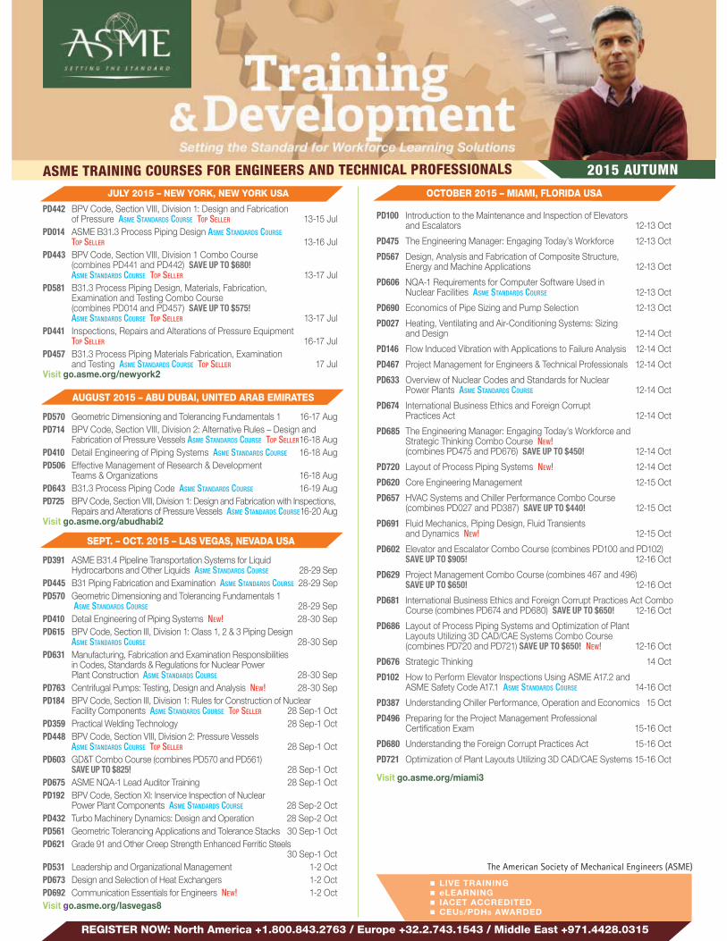
ASME TRAINING COURSES FOR ENGINEERS AND TECHNICAL PROFESSIONALS 2015 AUTUMN
The American Society of Mechanical Engineers (ASME)
REGISTER NOW: North America +1.800.843.2763 / Europe +32.2.743.1543 / Middle East +971.4428.0315
OCTOBER 2015 – MIAMI, FLORIDA USA
PD100 Introduction to the Maintenance and Inspection of Elevators and Escalators 12-13 Oct
PD475 The Engineering Manager: Engaging Today’s Workforce 12-13 Oct
PD567 Design, Analysis and Fabrication of Composite Structure, Energy and Machine Applications 12-13 Oct
PD606 NQA-1 Requirements for Computer Software Used in Nuclear Facilities ASME STANDARDS COURSE 12-13 Oct
PD690 Economics of Pipe Sizing and Pump Selection 12-13 Oct
PD027 Heating, Ventilating and Air-Conditioning Systems: Sizing and Design 12-14 Oct
PD146 Flow Induced Vibration with Applications to Failure Analysis 12-14 Oct
PD467 Project Management for Engineers & Technical Professionals 12-14 Oct
PD633 Overview of Nuclear Codes and Standards for Nuclear Power Plants ASME STANDARDS COURSE 12-14 Oct
PD674 International Business Ethics and Foreign Corrupt Practices Act 12-14 Oct
PD685 The Engineering Manager: Engaging Today’s Workforce and Strategic Thinking Combo Course NEW! (combines PD475 and PD676) SAVE UP TO $450! 12-14 Oct
PD720 Layout of Process Piping Systems NEW! 12-14 Oct
PD620 Core Engineering Management 12-15 Oct
PD657 HVAC Systems and Chiller Performance Combo Course (combines PD027 and PD387) SAVE UP TO $440! 12-15 Oct
PD691 Fluid Mechanics, Piping Design, Fluid Transients and Dynamics NEW! 12-15 Oct
PD602 Elevator and Escalator Combo Course (combines PD100 and PD102) SAVE UP TO $905! 12-16 Oct
PD629 Project Management Combo Course (combines 467 and 496) SAVE UP TO $650! 12-16 Oct
PD681 International Business Ethics and Foreign Corrupt Practices Act Combo Course (combines PD674 and PD680) SAVE UP TO $650! 12-16 Oct
PD686 Layout of Process Piping Systems and Optimization of Plant Layouts Utilizing 3D CAD/CAE Systems Combo Course (combines PD720 and PD721) SAVE UP TO $650! NEW! 12-16 Oct
PD676 Strategic Thinking 14 Oct
PD102 How to Perform Elevator Inspections Using ASME A17.2 and ASME Safety Code A17.1 ASME STANDARDS COURSE 14-16 Oct
PD387 Understanding Chiller Performance, Operation and Economics 15 Oct
PD496 Preparing for the Project Management Professional Certi cation E am 15-16 Oct
PD680 Understanding the Foreign Corrupt Practices Act 15-16 Oct
PD721 Optimization of Plant Layouts Utilizing 3D CAD/CAE Systems 15-16 Oct
Visit go.asme.org/miami3
JULY 2015 – NEW YORK, NEW YORK USA
PD442 BPV Code, Section VIII, Division 1: Design and Fabrication of Pressure ASME STANDARDS COURSE TOP SELLER 13-15 Jul
PD014 ASME B31.3 Process Piping Design ASME STANDARDS COURSE
TOP SELLER 13-16 JulPD443 BPV Code, Section VIII, Division 1 Combo Course
(combines PD441 and PD442) SAVE UP TO $680!ASME STANDARDS COURSE TOP SELLER 13-17 Jul
PD581 B31.3 Process Piping Design, Materials, Fabrication, E amination and Testing Combo Course (combines PD014 and PD457) SAVE UP TO $575! ASME STANDARDS COURSE TOP SELLER 13-17 Jul
PD441 Inspections, Repairs and Alterations of Pressure EquipmentTOP SELLER 16-17 Jul
PD457 B31.3 Process Piping Materials Fabrication, E amination and Testing ASME STANDARDS COURSE TOP SELLER 17 Jul
Visit go.asme.org/newyork2
AUGUST 2015 – ABU DUBAI, UNITED ARAB EMIRATES
PD570 Geometric Dimensioning and Tolerancing Fundamentals 1 16-17 AugPD714 BPV Code, Section VIII, Division 2: Alternative Rules – Design and
Fabrication of Pressure Vessels ASME STANDARDS COURSE TOP SELLER 16-18 AugPD410 Detail Engineering of Piping Systems ASME STANDARDS COURSE 16-18 AugPD506 Effective Management of Research & Development
Teams & Organizations 16-18 AugPD643 B31.3 Process Piping Code ASME STANDARDS COURSE 16-19 AugPD725 BPV Code, Section VIII, Division 1: Design and Fabrication with Inspections,
Repairs and Alterations of Pressure Vessels ASME STANDARDS COURSE 16-20 AugVisit go.asme.org/abudhabi2
SEPT. – OCT. 2015 – LAS VEGAS, NEVADA USA
PD391 ASME B31.4 Pipeline Transportation Systems for Liquid Hydrocarbons and Other Liquids ASME STANDARDS COURSE 28-29 Sep
PD445 B31 Piping Fabrication and E amination ASME STANDARDS COURSE 28-29 SepPD570 Geometric Dimensioning and Tolerancing Fundamentals 1
ASME STANDARDS COURSE 28-29 SepPD410 Detail Engineering of Piping Systems NEW! 28-30 SepPD615 BPV Code, Section III, Division 1: Class 1, 2 & 3 Piping Design
ASME STANDARDS COURSE 28-30 SepPD631 Manufacturing, Fabrication and E amination Responsibilities
in Codes, Standards & Regulations for Nuclear Power Plant Construction ASME STANDARDS COURSE 28-30 Sep
PD763 Centrifugal Pumps: Testing, Design and Analysis NEW! 28-30 SepPD184 BPV Code, Section III, Division 1: Rules for Construction of Nuclear
Facility Components ASME STANDARDS COURSE TOP SELLER 28 Sep-1 OctPD359 Practical Welding Technology 28 Sep-1 OctPD448 BPV Code, Section VIII, Division 2: Pressure Vessels
ASME STANDARDS COURSE TOP SELLER 28 Sep-1 OctPD603 GD&T Combo Course (combines PD570 and PD561)
SAVE UP TO $825! 28 Sep-1 OctPD675 ASME NQA-1 Lead Auditor Training 28 Sep-1 OctPD192 BPV Code, Section XI: Inservice Inspection of Nuclear
Power Plant Components ASME STANDARDS COURSE 28 Sep-2 OctPD432 Turbo Machinery Dynamics: Design and Operation 28 Sep-2 OctPD561 Geometric Tolerancing Applications and Tolerance Stacks 30 Sep-1 OctPD621 Grade 91 and Other Creep Strength Enhanced Ferritic Steels
30 Sep-1 OctPD531 Leadership and Organizational Management 1-2 OctPD673 Design and Selection of Heat E changers 1-2 OctPD692 Communication Essentials for Engineers NEW! 1-2 OctVisit go.asme.org/lasvegas8
LIVE TRAINING eLEARNING IACET ACCREDITED CEUS/PDHS AWARDED

ASME TRAINING COURSES FOR ENGINEERS AND TECHNICAL PROFESSIONALS 2015 AUTUMN
REGISTER NOW: Visit go.asme.org/training
NOVEMBER 2015 – DUBAI, UNITED ARAB EMIRATES
PD618 Root Cause Analysis Fundamentals 1-3 NovPD715 Principles of Welding and BPV Code, Section IX:
Welding and Brazing Quali cations ASME STANDARDS COURSE 1-3 NovPD723 B31.4 and B31.8, Liquids and Gas Pipelines 1-3 NovPD726 API 579-1/ASME FFS-1 Fitness-For-Service Evaluation 1-3 NovPD642 ASME B31.1 Power Piping Code ASME STANDARDS COURSE 1-4 NovPD675 ASME NQA-1 Lead Auditor Training 1-4 NovPD725 BPV Code, Section VIII, Division 1: Design and Fabrication
with Inspections, Repairs and Alterations of Pressure VesselsASME STANDARDS COURSE 1-4 Nov
Visit go.asme.org/dubai5
NOVEMBER 2015 – SAN DIEGO, CALIFORNIA USA
PD107 Elevator Maintenance Evaluation 9-10 NovPD382 How to Predict Thermal-Hydraulic Loads on Pressure
Vessels and Piping 9-10 NovPD077 Failure Prevention, Repair and Life E tension of Piping,
Vessels and Tanks ASME STANDARDS COURSE 9-11 NovPD146 Flow Induced Vibration with Applications to Failure Analysis 9-11 NovPD389 Nondestructive E amination-Applying ASME Code Requirements
(BPV Code, Section V) ASME STANDARDS COURSE 9-11 NovPD410 Detail Engineering of Piping Systems NEW! 9-11 NovPD506 Effective Management of Research & Development
Teams and Organizations 9-11 NovPD513 TRIZ: The Theory of Inventive Problem Solving 9-11 NovPD515 Dimensioning and Tolerancing Principles for Gages
and Fi tures 9-11 NovPD702 Process Safety and Risk Management for
Mechanical Engineers NEW! 9-11 NovPD359 Practical Welding Technology 9-12 NovPD448 BPV Code, Section VIII, Division 2: Pressure Vessels
ASME STANDARDS COURSE TOP SELLER 9-12 NovPD013 B31.1 Power Piping Code ASME STANDARDS COURSE TOP SELLER 9-13 NovPD665 BPV Code, Section I: Power Boilers ASME STANDARDS COURSE 9-13 NovVisit go.asme.org/sandiego3
NOVEMBER 2015 – ATLANTA, GEORGIA USA
PD391 ASME B31.4 Pipeline Transportation Systems for Liquid Hydrocarbons and Other Liquids ASME STANDARDS COURSE 16-17 Nov
PD449 Mechanical Tolerancing for Si Sigma 16-17 NovPD595 Developing a 10-Year Pump Inservice Testing Program 16-17 NovPD624 Two-Phase Flow and Heat Transfer 16-17 NovPD706 Inline Inspections for Pipelines 16-17 NovPD618 Root Cause Analysis Fundamentals 16-18 NovPD683 Probabilistic Structural Analysis, Design and
Reliability-Risk Assessment 16-18 NovPD711 ASME NQA-1 and DOE Quality Assurance Rule 10 CFR 830
ASME STANDARDS COURSE NEW! 16-18 NovPD394 Seismic Design and Retro t of Equipment and Piping 16-19 NovPD622 BPV Code: Plant Equipment Requirements
ASME STANDARDS COURSE 16-19 NovPD632 Design in Codes, Standards and Regulations for Nuclear
Power Plant Construction ASME STANDARDS COURSE 16-19 NovPD596 Developing a 10-Year Valve Inservice Testing Program 18-20 NovPD591 Developing Con ict Resolution Best Practices 19-20 NovPD583 Pressure Relief Devices: Design, Sizing, Construction,
Inspection and Maintenance ASME STANDARDS COURSE 19-21 NovVisit go.asme.org/atlanta6
OCTOBER 2015 – BARCELONA, SPAIN
PD442 BPV Code, Section VIII, Division 1: Design and Fabrication of Pressure Vessels ASME STANDARDS COURSE TOP SELLER 19-21 Oct
PD635 ASME NQA-1 Quality Assurance Requirements for Nuclear Facility Applications 19-21 Oct
PD645 Code, Section IX: Welding, Brazing and Fusing Quali cations 19-21 OctPD720 Layout of Process Piping Systems NEW! 19-21 OctPD767 Pressure Relief Devices: Design, Sizing, Construction,
Inspection and Maintenance ASME STANDARDS COURSE NEW! 19-21 OctPD616 API 579 /ASME FFS-1 Fitness-for-Service Evaluation 19-22 OctPD643 B31.3 Process Piping Code ASME STANDARDS COURSE 19-22 OctPD644 Advanced Design and Construction of Nuclear Facility
Components Per BPV Code, Section III ASME STANDARDS COURSE 19-22 OctPD443 BPV Code, Section VIII, Division 1 Combo Course ASME STANDARDS COURSE
(combines PD441 & PD442) SAVE UP TO €800! TOP SELLER 19-23 OctPD686 Layout of Process Piping Systems and Optimisation of Plant
Layouts Utilising 3D CAD/CAE Systems Combo Course (combines PD720 and P721) SAVE UP TO €750! NEW! 19-23 Oct
PD441 Inspections, Repairs and Alterations of Pressure EquipmentASME STANDARDS COURSE TOP SELLER 22-23 Oct
PD721 Optimisation of Plant Layouts Utilising 3D CAD/CAE Systems NEW! 22-23 Oct
Visit go.asme.org/barcelona2
OCTOBER 2015 – HOUSTON, TEXAS USA
PD539 Bolted Joints and Gasket Behavior 26-27 OctPD190 BPV Code, Section IX: Welding, Brazing and
Fusing Quali cations ASME STANDARDS COURSE TOP SELLER 26-28 OctPD231 Shock and Vibration Analysis 26-28 OctPD268 Fracture Mechanics Approach to Life Predictions 26-28 OctPD370 B31.8 Gas Transmission & Distribution Piping Systems
ASME STANDARDS COURSE 26-28 OctPD395 API 579-1/ASME FFS-1 Fitness-for-Service 26-28 OctPD442 BPV Code, Section VIII, Division 1: Design & Fabrication
of Pressure Vessels ASME STANDARDS COURSE TOP SELLER 26-28 OctPD619 Risk and Reliability Strategies for Optimizing Performance 26-28 OctPD014 ASME B31.3 Process Piping Design ASME STANDARDS COURSE
TOP SELLER 26-29 OctPD644 Advanced Design and Construction of Nuclear Facility
Components Per BPV Code, Section III ASME STANDARDS COURSE 26-29 OctPD679 Selection of Pumps and Valves for Optimum System Performance 26-29 OctPD764 Introduction to Hydraulic Systems NEW! 26-29 OctPD443 BPV Code, Section VIII, Division 1 Combo Course ASME STANDARDS COURSE
(combines PD441 and PD442) SAVE UP TO $680! TOP SELLER 26-30 OctPD581 B31.3 Process Piping Design, Materials, Fabrication, E amination and
Testing Combo Course (combines PD014 and PD457) SAVE UP TO $575! ASME STANDARDS COURSE TOP SELLER 26-30 Oct
PD601 Bolting Combo Course (combines PD539, PD386 and PD577) SAVE UP TO $1,275! 26-30 Oct
PD386 Design of Bolted Flange Joints 28 OctPD441 Inspections, Repairs and Alterations of Pressure Equipment
ASME STANDARDS COURSE TOP SELLER 29-30 OctPD575 Comprehensive Negotiating Strategies®: Engineers & Technical
Professionals 29-30 OctPD577 Bolted Joint Assembly Principles Per PCC-1-2013
ASME STANDARDS COURSE 29-30 OctPD457 B31.3 Process Piping Materials Fabrication, E amination
and Testing ASME STANDARDS COURSE TOP SELLER 30 OctVisit go.asme.org/houston8
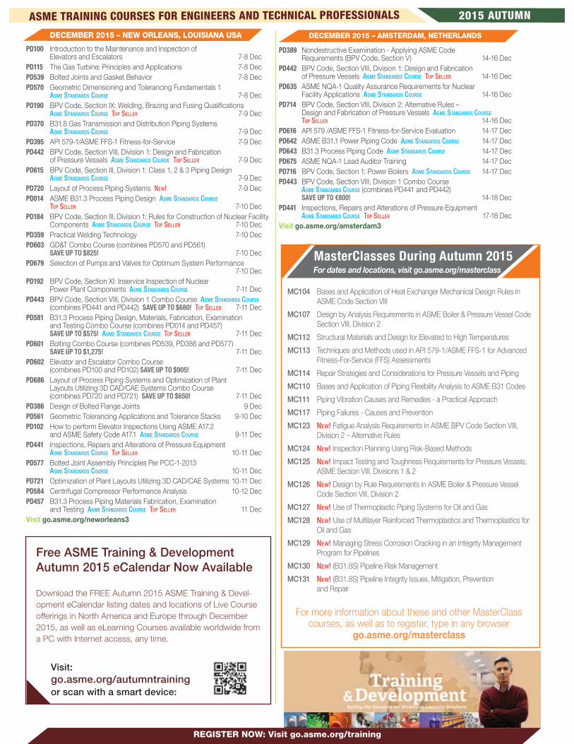
ASME TRAINING COURSES FOR ENGINEERS AND TECHNICAL PROFESSIONALS 2015 AUTUMN
DECEMBER 2015 – AMSTERDAM, NETHERLANDS
PD389 Nondestructive E amination - Applying ASME Code Requirements (BPV Code, Section V) 14-16 Dec
PD442 BPV Code, Section VIII, Division 1: Design and Fabrication of Pressure Vessels ASME STANDARDS COURSE TOP SELLER 14-16 Dec
PD635 ASME NQA-1 Quality Assurance Requirements for Nuclear Facility Applications ASME STANDARDS COURSE 14-16 Dec
PD714 BPV Code, Section VIII, Division 2: Alternative Rules – Design and Fabrication of Pressure Vessels ASME STANDARDS COURSE TOP SELLER 14-16 Dec
PD616 API 579 /ASME FFS-1 Fitness-for-Service Evaluation 14-17 DecPD642 ASME B31.1 Power Piping Code ASME STANDARDS COURSE 14-17 DecPD643 B31.3 Process Piping Code ASME STANDARDS COURSE 14-17 DecPD675 ASME NQA-1 Lead Auditor Training 14-17 DecPD716 BPV Code, Section 1: Power Boilers ASME STANDARDS COURSE 14-17 DecPD443 BPV Code, Section VIII, Division 1 Combo Course
ASME STANDARDS COURSE (combines PD441 and PD442) SAVE UP TO €800! 14-18 Dec
PD441 Inspections, Repairs and Alterations of Pressure EquipmentASME STANDARDS COURSE TOP SELLER 17-18 Dec
Visit go.asme.org/amsterdam3
DECEMBER 2015 – NEW ORLEANS, LOUISIANA USA
PD100 Introduction to the Maintenance and Inspection of Elevators and Escalators 7-8 Dec
PD115 The Gas Turbine: Principles and Applications 7-8 DecPD539 Bolted Joints and Gasket Behavior 7-8 DecPD570 Geometric Dimensioning and Tolerancing Fundamentals 1 ASME STANDARDS COURSE 7-8 DecPD190 BPV Code, Section IX: Welding, Brazing and Fusing Quali cations
ASME STANDARDS COURSE TOP SELLER 7-9 DecPD370 B31.8 Gas Transmission and Distribution Piping Systems
ASME STANDARDS COURSE 7-9 DecPD395 API 579-1/ASME FFS-1 Fitness-for-Service 7-9 DecPD442 BPV Code, Section VIII, Division 1: Design and Fabrication
of Pressure Vessels ASME STANDARDS COURSE TOP SELLER 7-9 DecPD615 BPV Code, Section III, Division 1: Class 1, 2 & 3 Piping Design
ASME STANDARDS COURSE 7-9 DecPD720 Layout of Process Piping Systems NEW! 7-9 DecPD014 ASME B31.3 Process Piping Design ASME STANDARDS COURSE
TOP SELLER 7-10 DecPD184 BPV Code, Section III, Division 1: Rules for Construction of Nuclear Facility
Components ASME STANDARDS COURSE TOP SELLER 7-10 DecPD359 Practical Welding Technology 7-10 DecPD603 GD&T Combo Course (combines PD570 and PD561)
SAVE UP TO $825! 7-10 DecPD679 Selection of Pumps and Valves for Optimum System Performance
7-10 DecPD192 BPV Code, Section XI: Inservice Inspection of Nuclear
Power Plant Components ASME STANDARDS COURSE 7-11 DecPD443 BPV Code, Section VIII, Division 1 Combo Course ASME STANDARDS COURSE
(combines PD441 and PD442) SAVE UP TO $680! TOP SELLER 7-11 DecPD581 B31.3 Process Piping Design, Materials, Fabrication, E amination
and Testing Combo Course (combines PD014 and PD457) SAVE UP TO $575! ASME STANDARDS COURSE TOP SELLER 7-11 Dec
PD601 Bolting Combo Course (combines PD539, PD386 and PD577) SAVE UP TO $1,275! 7-11 Dec
PD602 Elevator and Escalator Combo Course (combines PD100 and PD102) SAVE UP TO $905! 7-11 Dec
PD686 Layout of Process Piping Systems and Optimization of Plant Layouts Utilizing 3D CAD/CAE Systems Combo Course (combines PD720 and PD721) SAVE UP TO $650! 7-11 Dec
PD386 Design of Bolted Flange Joints 9 DecPD561 Geometric Tolerancing Applications and Tolerance Stacks 9-10 DecPD102 How to perform Elevator Inspections Using ASME A17.2
and ASME Safety Code A17.1 ASME STANDARDS COURSE 9-11 DecPD441 Inspections, Repairs and Alterations of Pressure Equipment
ASME STANDARDS COURSE TOP SELLER 10-11 DecPD577 Bolted Joint Assembly Principles Per PCC-1-2013
ASME STANDARDS COURSE 10-11 DecPD721 Optimization of Plant Layouts Utilizing 3D CAD/CAE Systems 10-11 DecPD584 Centrifugal Compressor Performance Analysis 10-12 DecPD457 B31.3 Process Piping Materials Fabrication, E amination
and Testing ASME STANDARDS COURSE TOP SELLER 11 DecVisit go.asme.org/neworleans3
REGISTER NOW: Visit go.asme.org/training
MC104 Bases and Application of Heat E changer Mechanical Design Rules in ASME Code Section VIII
MC107 Design by Analysis Requirements in ASME Boiler & Pressure Vessel Code Section VIII, Division 2
MC112 Structural Materials and Design for Elevated to High Temperatures
MC113 Techniques and Methods used in API 579-1/ASME FFS-1 for Advanced Fitness-For-Service (FFS) Assessments
MC114 Repair Strategies and Considerations for Pressure Vessels and Piping
MC110 Bases and Application of Piping Fle ibility Analysis to ASME B31 Codes
MC111 Piping Vibration Causes and Remedies - a Practical Approach
MC117 Piping Failures - Causes and Prevention
MC123 NEW! Fatigue Analysis Requirements in ASME BPV Code Section VIII, Division 2 – Alternative Rules
MC124 NEW! Inspection Planning Using Risk-Based Methods
MC125 NEW! Impact Testing and Toughness Requirements for Pressure Vessels; ASME Section VIII, Divisions 1 & 2
MC126 NEW! Design by Rule Requirements in ASME Boiler & Pressure Vessel Code Section VIII, Division 2
MC127 NEW! Use of Thermoplastic Piping Systems for Oil and Gas
MC128 NEW! Use of Multilayer Reinforced Thermoplastics and Thermoplastics for Oil and Gas
MC129 NEW! Managing Stress Corrosion Cracking in an Integrity Management Program for Pipelines
MC130 NEW! (B31.8S) Pipeline Risk Management
MC131 NEW! (B31.8S) Pipeline Integrity Issues, Mitigation, Prevention and Repair
MasterClasses During Autumn 2015 For dates and locations, visit go.asme.org/masterclass
For more information about these and other MasterClass courses, as well as to register, type in any browser
go.asme.org/masterclass
Free ASME Training & Development Autumn 2015 eCalendar Now Available
Download the FREE Autumn 2015 ASME Training & Devel-
opment eCalendar listing dates and locations of Live Course
offerings in North America and Europe through December
2015, as well as eLearning Courses available worldwide from
a PC with Internet access, any time.
Visit: go.asme.org/autumntraining
or scan with a smart device:
LIVE FROM NEW YORK
ASME Pressure Vessels, Piping and
Geometric Dimensioning & Tolerancing Training Events
June 8–12, 2015 and July 13–17, 2015 • ASME Headquarters
New York, NY USA
Visit or call: go.asme.org/training * +1.800.843.2763 (US and Canada) * +1.001.800.2763 (Mexico) *
+32.2.743.1543 (Europe) * +971.4.4508555 (Middle East) * +1.973.882.1170 (Outside North America)
LEARN FROM THE PROS WHO WRITE THE CODES at two special training events presented by ASME
Training & Development, a leader in workforce learning solutions for engineers and technical professionals.
Ten ASME Code Course training programs will be delivered by ASME-approved instructors who are experts
within their professional disciplines. Each instructor is an ASME Code Committee Member who understands
and can communicate code or standard relevance and their impacts on safety, quality and integrity.
AVAILABLE THIS JULY:
ASME BPV Code, Section VIII, Division 1 Combo Course (PD443) July 13–17 (Combines PD 442 and PD 441 and saves up to $680)
ASME BPV Code, Section VIII, Division 1: Design and Fabrication of Pressure Vessels (PD442)July 13–15 • Instructor: Kamran Mokhtarian, PE
Inspections, Repairs and Alterations of Pressure Equipment (PD441)July 16–17 • Instructor: Kamran Mokhtarian, PE
B31.3 Process Piping Design, Materials, Fabrication, Examination and Testing Combo Course (PD581)July 13–17 (Combines PD014 and PD457 and saves up to $575)
ASME B31.3 Process Piping Design (PD014) July 13–16 • Instructor: Ronald W. Haupt, PE
B31.3 Process Piping Materials Fabrication, Examination and Testing (PD457)July 17 • Instructor: Philip D. Flenner, PE
AVAILABLE THIS JUNE:
Geometric Dimensioning and Tolerancing Combo Course (PD603) June 8–11 (Combines PD570 and PD561 andsaves up to $835)
Geometric Dimensioning and Tolerancing Fundamentals 1 (PD570)June 8–9 • Instructor: Scott Neumann
Geometric Tolerancing and Tolerance Stacks Applications (PD561)June 10–11 • Instructor: Scott Neumann
B31.1 Power Piping Code (PD013) June 8–12 • Instructors: Ronald W. Haupt, PE and Philip D. Flenner, PE
The American Society of Mechanical Engineers (ASME)
For more information and to register, type in any browser: go.asme.org/newyork1
For more information and to register, type in any browser: go.asme.org/newyork2
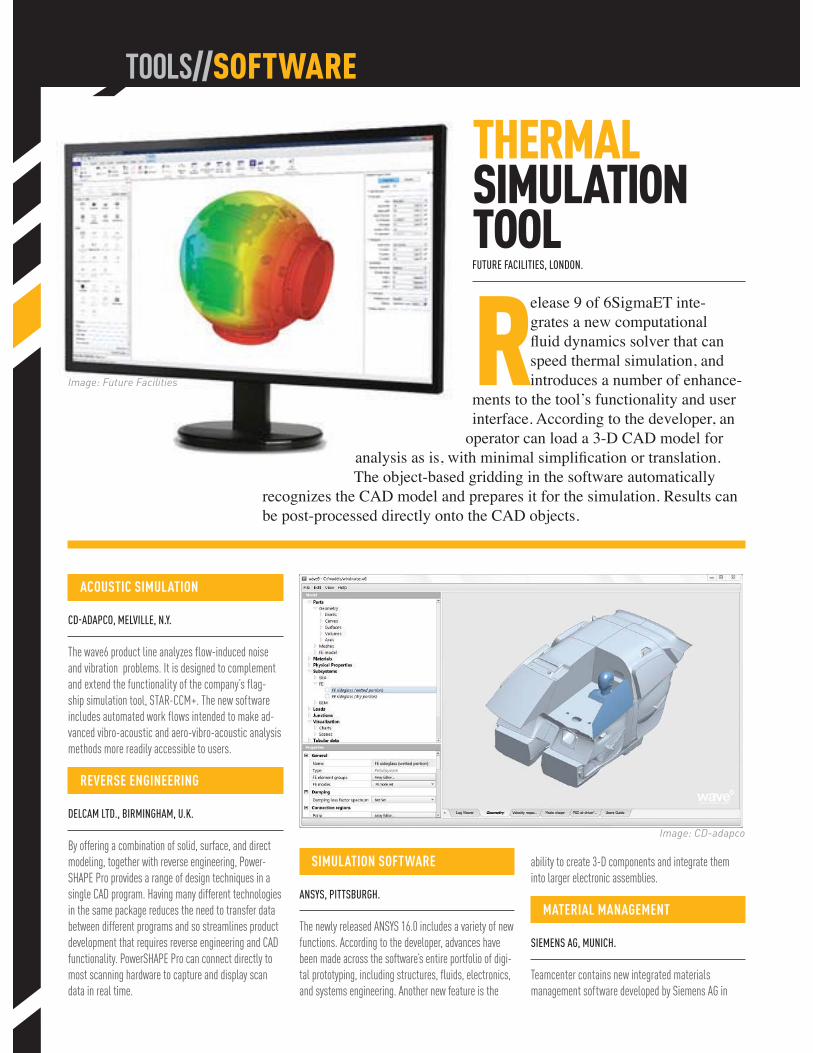
ACOUSTIC SIMULATION
CD-ADAPCO, MELVILLE, N.Y.
The wave6 product line analyzes flow-induced noise
and vibration problems. It is designed to complement
and extend the functionality of the company’s flag-
ship simulation tool, STAR-CCM+. The new software
includes automated work flows intended to make ad-
vanced vibro-acoustic and aero-vibro-acoustic analysis
methods more readily accessible to users.
REVERSE ENGINEERING
DELCAM LTD., BIRMINGHAM, U.K.
By offering a combination of solid, surface, and direct
modeling, together with reverse engineering, Power-
SHAPE Pro provides a range of design techniques in a
single CAD program. Having many different technologies
in the same package reduces the need to transfer data
between different programs and so streamlines product
development that requires reverse engineering and CAD
functionality. PowerSHAPE Pro can connect directly to
most scanning hardware to capture and display scan
data in real time.
SIMULATION SOFTWARE
ANSYS, PITTSBURGH.
The newly released ANSYS 16.0 includes a variety of new
functions. According to the developer, advances have
been made across the software’s entire portfolio of digi-
tal prototyping, including structures, fluids, electronics,
and systems engineering. Another new feature is the
ability to create 3-D components and integrate them
into larger electronic assemblies.
MATERIAL MANAGEMENT
SIEMENS AG, MUNICH.
Teamcenter contains new integrated materials
management software developed by Siemens AG in
TOOLS//SOFTWARE
THERMAL SIMULATION TOOLFUTURE FACILITIES, LONDON.
Release 9 of 6SigmaET inte-grates a new computational
Image: CD-adapco
Image: Future Facilities
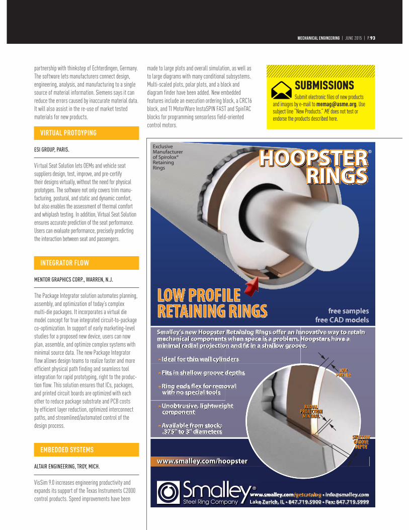
partnership with thinkstep of Echterdingen, Germany.
The software lets manufacturers connect design,
engineering, analysis, and manufacturing to a single
source of material information. Siemens says it can
reduce the errors caused by inaccurate material data.
It will also assist in the re-use of market tested
materials for new products.
VIRTUAL PROTOYPING ESI GROUP, PARIS. Virtual Seat Solution lets OEMs and vehicle seat
suppliers design, test, improve, and pre-certify
their designs virtually, without the need for physical
prototypes. The software not only covers trim manu-
facturing, postural, and static and dynamic comfort,
but also enables the assessment of thermal comfort
and whiplash testing. In addition, Virtual Seat Solution
ensures accurate prediction of the seat performance.
Users can evaluate performance, precisely predicting
the interaction between seat and passengers.
INTEGRATOR FLOW MENTOR GRAPHICS CORP., WARREN, N.J.
The Package Integrator solution automates planning,
assembly, and optimization of today’s complex
multi-die packages. It incorporates a virtual die
model concept for true integrated circuit-to-package
co-optimization. In support of early marketing-level
studies for a proposed new device, users can now
plan, assemble, and optimize complex systems with
minimal source data. The new Package Integrator
flow allows design teams to realize faster and more
efficient physical path finding and seamless tool
integration for rapid prototyping, right to the produc-
tion flow. This solution ensures that ICs, packages,
and printed circuit boards are optimized with each
other to reduce package substrate and PCB costs
by efficient layer reduction, optimized interconnect
paths, and streamlined/automated control of the
design process.
EMBEDDED SYSTEMS ALTAIR ENGINEERING, TROY, MICH.
VisSim 9.0 increases engineering productivity and
expands its support of the Texas Instruments C2000
control products. Speed improvements have been
made to large plots and overall simulation, as well as
to large diagrams with many conditional subsystems.
Multi-scaled plots, polar plots, and a block and
diagram finder have been added. New embedded
features include an execution ordering block, a CRC16
block, and TI MotorWare InstaSPIN FAST and SpinTAC
blocks for programming sensorless field-oriented
control motors.
MECHANICAL ENGINEERING | FEBRUARY 2013 | P.093MECHANICAL ENGINEERING | JUNE 2015 | P.93
SUBMISSIONSSubmit electronic files of new products
and images by e-mail to [email protected]. Use subject line “New Products.” ME does not test or endorse the products described here.

TOOLS//HARDWARE
CONDUCTIVITY CONTROLLERSOMEGA ENGINEERING, STAMFORD, CONN.
OMEGA’s new CDTX-111/CDTX-112 series of conduc-tivity controllers are panel instruments for online moni-toring of industrial process
conductivity. The CE compliant prod-ucts include such features as linearized data, automatic temperature compensation, no error due to cable length changes, and maintenance-free cells. The controllers can be used in the automotive, chemical, and water industries, for instance, for measurement and control of conductivity in water, electronics, chemical, and manufacturing processes.
Measure all six components of force and torque in a compact, rugged sensor.
www.ati-ia.com/mes919.772.0115
ROBOTIC END-EFFECTORS
Low-noise Electronics—interfaces for Ethernet, PCI, USB, EtherNet/IP, PROFINET, CAN, EtherCAT, Wireless, and more
Interface Structure—high-strength alloy provides IP60, IP65, and IP68 environmental protection as needed
Sensing Beams and Flexures—designed for high stiffness and overload protection
The F/T Sensor outperforms traditional load cells, instantly providing all loading data in every axis. Engineered for high overload protection and low noise, it’s the ultimate force/torque sensor. Only from ATI.
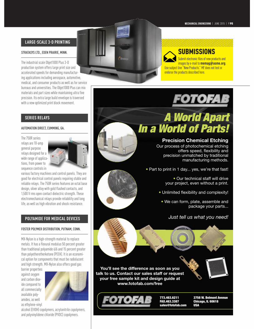
MECHANICAL ENGINEERING | JUNE 2015 | P.95
SUBMISSIONSSubmit electronic files of new products and images by e-mail to [email protected].
Use subject line “New Products.” ME does not test or endorse the products described here.
A World Apart In a World of Parts!
Precision Chemical EtchingOur process of photochemical etching
offers speed, fl exibility andprecision unmatched by traditional
manufacturing methods.
• Part to print in 1 day... yes, we’re that fast!
• Our technical staff will drive your project, even without a print.
• Unlimited fl exibility and complexity!
• We can form, plate, assemble andpackage your parts...
Just tell us what you need!
You’ll see the difference as soon as you talk to us. Contact our sales staff or request
your free sample kit and design guide at www.fotofab.com/free
773.463.6211 3758 W. Belmont Avenue FAX.463.3387 Chicago, IL [email protected] USA
LARGE-SCALE 3-D PRINTING STRATASYS LTD., EDEN PRAIRIE, MINN.
The industrial scale Objet1000 Plus 3-D
production system offers large print size and
accelerated speeds for demanding manufactur-
ing applications including aerospace, automotive,
medical, and consumer products as well as for service
bureaus and universities. The Objet1000 Plus can mix
materials and part sizes while maintaining ultra fine
precision. Its extra large build envelope is traversed
with a new optimized print block movement.
SERIES RELAYS AUTOMATION DIRECT, CUMMING, GA.
The 750R series
relays are 10-amp
general purpose
relays designed for a
wide range of applica-
tions, from power to
sequence controls in
various factory machines and control panels. They are
good for electrical control panels requiring stable and
reliable relays. The 750R series features an octal base
design, silver alloy with gold flashed contacts, and
1,500 V rms open contact dielectric strength. These
electromechanical relays provide reliability and long
life, as well as high vibration and shock resistance.
POLYAMIDE FOR MEDICAL DEVICES FOSTER POLYMER DISTRIBUTION, PUTNAM, CONN.
MX-Nylon is a high-strength material to replace
metals. It has a flexural modulus 50 percent greater
than traditional polyamide 6/6 and 15 percent greater
than polyetheretherketone (PEEK). It is an economi-
cal option for components that must be radiolucent
and high strength. MX-Nylon also offers good gas
barrier properties
against oxygen
and carbon diox-
ide compared to
all commercially
available poly-
amides, as well
as ethylene-vinyl
alcohol (EVOH) copolymers, acrylonitrile copolymers,
and polyvinylidene chloride (PVDC) copolymers.
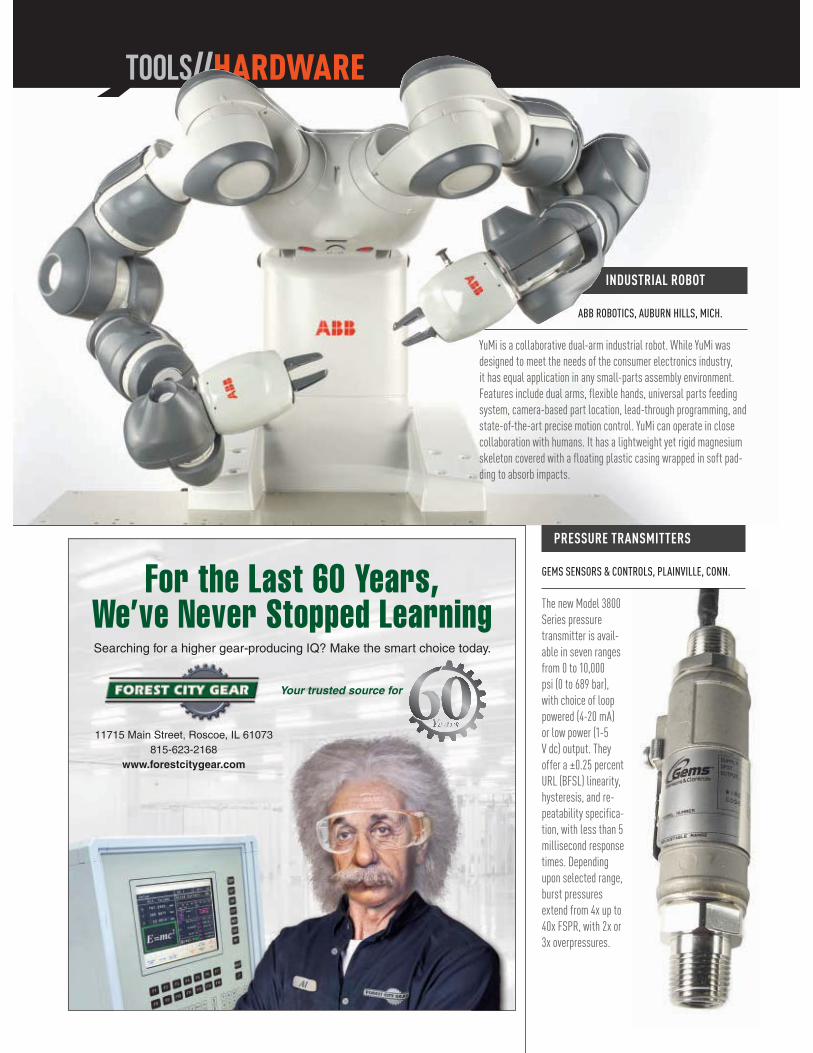
11715 Main Street, Roscoe, IL 61073815-623-2168
www.forestcitygear.com
Your trusted source for
For the Last 60 Years,We’ve Never Stopped LearningSearching for a higher gear-producing IQ? Make the smart choice today.
INDUSTRIAL ROBOT
ABB ROBOTICS, AUBURN HILLS, MICH.
YuMi is a collaborative dual-arm industrial robot. While YuMi was
designed to meet the needs of the consumer electronics industry,
it has equal application in any small-parts assembly environment.
Features include dual arms, flexible hands, universal parts feeding
system, camera-based part location, lead-through programming, and
state-of-the-art precise motion control. YuMi can operate in close
collaboration with humans. It has a lightweight yet rigid magnesium
skeleton covered with a floating plastic casing wrapped in soft pad-
ding to absorb impacts.
TOOLS//HARDWARE
PRESSURE TRANSMITTERS
GEMS SENSORS & CONTROLS, PLAINVILLE, CONN.
The new Model 3800
Series pressure
transmitter is avail-
able in seven ranges
from 0 to 10,000
psi (0 to 689 bar),
with choice of loop
powered (4-20 mA)
or low power (1-5
V dc) output. They
offer a ±0.25 percent
URL (BFSL) linearity,
hysteresis, and re-
peatability specifica-
tion, with less than 5
millisecond response
times. Depending
upon selected range,
burst pressures
extend from 4x up to
40x FSPR, with 2x or
3x overpressures.
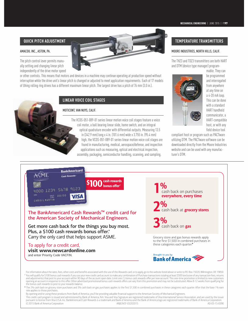
QUICK PITCH ADJUSTMENT AMACOIL INC., ASTON, PA.
The pitch control lever permits manu-
ally setting and changing linear pitch
independently of the drive motor speed
or other controls. This means that motors and devices in a machine may continue operating at production speed without
interruption while the drive unit’s linear pitch is changed or adjusted to meet application requirements. Each of 17 models
of Uhing rolling ring drives has a different maximum linear pitch. The largest drive has a pitch of 76 mm (3.0 in.).
TEMPERATURE TRANSMITTERS MOORE INDUSTRIES, NORTH HILLS, CALIF.
The THZ3 and TDZ3 transmitters are both HART
and DTM (device type manager) program-
mable. They can
be programmed
and interrogated
from anywhere
at any time on
a 4-20 mA loop.
This can be done
with a standard
HART handheld
communicator, a
HART-compatible
host, or with any
field device tool
compliant host or program such as PACTware
utilizing DTM. The PACTware software can be
downloaded directly from the Moore Industries
website and can be used with any manufac-
turer’s DTM.
The BankAmericard Cash Rewards™ credit card for the American Society of Mechanical Engineers.
Get more cash back for the things you buy most. Plus, a $100 cash rewards bonus offer.*Carry the only card that helps support ASME.
To apply for a credit card, visit www.newcardonline.com and enter Priority Code VACFIN.
1%cash back on purchaseseverywhere, every time
2%cash back at grocery stores
3%cash back on gas
$100 cash rewardsbonus offer*
Grocery store and gas bonus rewards apply to the first $1,500 in combined purchases in these categories each quarter .▼
For information about the rates, fees, other costs and benefits associated with the use of this Rewards card, or to apply, go to the website listed above or write to P.O. Box 15020, Wilmington, DE 19850.* You will qualify for $100 bonus cash rewards if you use your new credit card account to make any combination of Purchase transactions totaling at least $500 (exclusive of any transaction fees, returns
and adjustments) that post to your account within 90 days of the account open date. Limit one (1) bonus cash rewards offer per new account. This one-time promotion is limited to new customers opening an account in response to this offer. Other advertised promotional bonus cash rewards offers can vary from this promotion and may not be substituted. Allow 8-12 weeks from qualifying for the bonus cash rewards to post to your rewards balance.
▼ The 2% cash back on grocery store purchases and 3% cash back on gas purchases applies to the first $1,500 in combined purchases in these categories each quarter. After that the base 1% earn rate applies to those purchases.
By opening and/or using these products from Bank of America, you’ll be providing valuable financial support to the American Society of Mechanical Engineers. This credit card program is issued and administered by Bank of America, N.A. Visa and Visa Signature are registered trademarks of Visa International Service Association, and are used by the issuer
pursuant to license from Visa U.S.A. Inc. BankAmericard Cash Rewards is a trademark and Bank of America and the Bank of America logo are registered trademarks of Bank of America Corporation. © 2015 Bank of America Corporation ARJ63VCF-03202015 AD-03-15-0390
MECHANICAL ENGINEERING | JUNE 2015 | P.97
LINEAR VOICE COIL STAGES MOTICONT, VAN NUYS, CALIF.
The VCDS-051-089-01 series linear motion voice coil stages feature a voice
coil motor, a ball bearing linear slide, home switch, and an integral
optical quadrature encoder with differential outputs. Measuring 13.5
in (342.9 mm) long x 4 in. (101.6 mm) wide x 3.755 in. (95.4 mm)
high, the VCDS-051-089-01 series linear motion voice coil stages are
found in manufacturing, medical, aerospace/defense, and inspection
applications such as measuring, optical and electrical inspection,
assembly, packaging, semiconductor handling, scanning, and sampling.
MECHANICAL ENGINEERING | JUNE 2015 | P.98
The next generation in crossflow cooling technology.
See it now at evapco.com
Handheld Bluetooth® Wireless Temperature, Humidity and pH Transmitter
Visit omega.com/uwbt
UWBT Series Starts at
$325
Free App Available for AndroidTM and iOSTM Devices, Configurable in 9 Different Languages
Available in Four Models; Thermocouple, RTD, Relative Humidity and Temperature, and pH and Temperature
Tablet not included
© COPYRIGHT 2015 OMEGA ENGINEERING, INC ALL RIGHTS RESERVED
Prices listed are those in effect at the time of publication and are subject to change without notice. Please contact OMEGA’s sales department for current prices.
1-888-826-6342
■ Prototyping
■ Custom Manufacturing
■ R&D
■ Education
■ Home/Business
Personal CNC
Enable Your Ideaswww.tormach.com
$10,4853 Axis Mill
(plus shipping)includes 3 axis mill, deluxe stand, machine arm, and more
packages starting at
Visit omega.com/px509hl
$
© COPYRIGHT 2015 OMEGA ENGINEERING, INC ALL RIGHTS RESERVED
Prices listed are those in effect at the time of publication and are subject to change without notice. Please contact OMEGA’s sales department for current prices.
A bimonthly listing of the indus-try’s latest technical literature and product information avail-able FREE to Mechanical Engi-neering readers.
Receive an item by visiting http://mecheng.hotims.com
and click on the company name.
Instrumentation & Control
Power Transmission & Motion Control
Fluid Handling
Materials & Assembly
Engineering Tools
Other Products & Services
EVAPCO
YASKAWA
OMEGA
TORMACH
CEI
COMSOL
OMEGA
RESOURCEFILE
Confident. Consistent. Capable. Be Capable of More.As a machine builder or
equipment user you have limited time, limited resources, and tight deadlines.
For nearly 100 years, Yaskawa has been providing cutting-edge automation technology, operational excellence and a breadth of engineering expertise to help customers solve their specific motion challenges.
Products That Perform.System Performance
Initial Quality. Competitive Price YASKAWA AMERICA, INC. Waukegan, IL Toll Free: (800) 927-5292 Local: (847) 887-7000 Fax: (847) 887-7310 Web: yaskawa.com
MOTION


MECHANICAL ENGINEERING | JANUARY 2013 | P.101MECHANICAL ENGINEERING | JUNE 2015 | P.101
ADVERTISERINDEX
PAGE WEBSITE PHONE
To purchase or receive information from our advertisers, go to http://me.hotims.com, visit the advertiser’s website,
or call a number listed below.
CONSULTING
ASME AM3D 29 go.asme.org/3dprinting
ASME B31 Codes 85 go.asme.org/B31
ASME IMECE 100 asmeconferences.org /IMECE2015
ASME Power & Energy C3 GO.ASME.ORG/POWENERGY
ASME Press 48 www.asme.org/shop/books
ASME Training & Development 90-91 go.asme.org/training 800-843-2763
ATI Industrial Automation 94 ati-ia.com/mes 919-772-0115
Bank of America 97 newcardonline.com
Bentley Systems 15 bentley.com/AutoPIPE
Bimba Manufacturing C4, 98-99 bimba.com/smarter
Calnetix Technologies 26 calnetix.com 562-293-1660
Computational Dynamics(CD-Adapco) 14 cd-adapco.com
Computer Engineering, Inc. 98-99 THINKCEI.COM/DC
COMSOL, Inc. 5, 98-99 comsol.com
Dassault Systemes 13 3DS.COM/INDUSTRIAL- EQUIPMENT
Dynatect 98-99 dynatect.com 800-298-2066
Evapco 98-99 evapco.com
Fibrwrap 20 fibrwrap.com 909-390-4363
Forest City Gear 96, 98-99 forestcitygear.com 815-623-2168
Fotofab, Inc. 95, 98-99 fotofab.com/free 773-463-6211
Lifting Gear Hire 27 lgh-usa.com 800-878-7305
MasterBond 98-99 masterbond.com 201-843-8983
Newark/element14 7, 98-99 newark.com 800-463-9275
Omega Engineering, Inc. 21, 98-99 omega.com 888-826-6342
Penn State’s Altoona Rail Transportation Program 19 ALTOONA.PUS.EDU/RTE
Proto Labs, Inc. 17, 98-99 go.protolabs.com
Smalley Steel Ring, Inc. 93, 98-99 Smalley.com/GETCATALOG 847-719-5900
Stratasys 22-23 STRATASYSDIRECT.COM 888-311-1017
XYZ Scientific 9 truegrid.com/TLA.pdf 925-373-0628
Yaskawa C2, 98-99 yaskawa.com 1-800-YASKAWA
For all recruitment advertising opportunities, contact:
GREG VALERO (212) 591-8356
Technology that Moves the world
mechanical
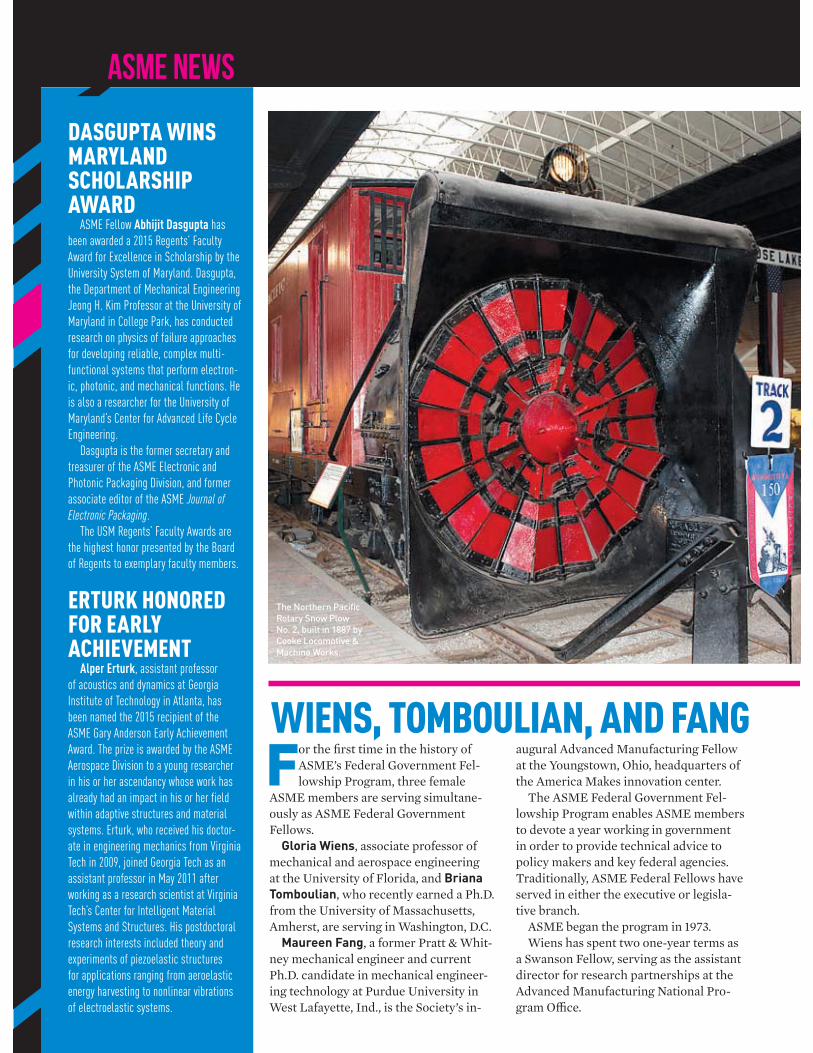
ASME NEWS
WIENS, TOMBOULIAN, AND FANG For the first time in the history of
ASME’s Federal Government Fel-lowship Program, three female
ASME members are serving simultane-ously as ASME Federal Government Fellows.
Gloria Wiens, associate professor of mechanical and aerospace engineering at the University of Florida, and Briana Tomboulian, who recently earned a Ph.D. from the University of Massachusetts, Amherst, are serving in Washington, D.C.
Maureen Fang, a former Pratt & Whit-ney mechanical engineer and current Ph.D. candidate in mechanical engineer-ing technology at Purdue University in West Lafayette, Ind., is the Society’s in-
augural Advanced Manufacturing Fellow at the Youngstown, Ohio, headquarters of the America Makes innovation center.
The ASME Federal Government Fel-lowship Program enables ASME members to devote a year working in government in order to provide technical advice to policy makers and key federal agencies. Traditionally, ASME Federal Fellows have served in either the executive or legisla-tive branch.
ASME began the program in 1973.Wiens has spent two one-year terms as
a Swanson Fellow, serving as the assistant director for research partnerships at the Advanced Manufacturing National Pro-gram Office.
DASGUPTA WINS MARYLAND SCHOLARSHIP AWARD
ASME Fellow Abhijit Dasgupta has
been awarded a 2015 Regents’ Faculty
Award for Excellence in Scholarship by the
University System of Maryland. Dasgupta,
the Department of Mechanical Engineering
Jeong H. Kim Professor at the University of
Maryland in College Park, has conducted
research on physics of failure approaches
for developing reliable, complex multi-
functional systems that perform electron-
ic, photonic, and mechanical functions. He
is also a researcher for the University of
Maryland’s Center for Advanced Life Cycle
Engineering.
Dasgupta is the former secretary and
treasurer of the ASME Electronic and
Photonic Packaging Division, and former
associate editor of the ASME Journal of Electronic Packaging.
The USM Regents’ Faculty Awards are
the highest honor presented by the Board
of Regents to exemplary faculty members.
ERTURK HONORED FOR EARLY ACHIEVEMENT
Alper Erturk, assistant professor
of acoustics and dynamics at Georgia
Institute of Technology in Atlanta, has
been named the 2015 recipient of the
ASME Gary Anderson Early Achievement
Award. The prize is awarded by the ASME
Aerospace Division to a young researcher
in his or her ascendancy whose work has
already had an impact in his or her field
within adaptive structures and material
systems. Erturk, who received his doctor-
ate in engineering mechanics from Virginia
Tech in 2009, joined Georgia Tech as an
assistant professor in May 2011 after
working as a research scientist at Virginia
Tech’s Center for Intelligent Material
Systems and Structures. His postdoctoral
research interests included theory and
experiments of piezoelastic structures
for applications ranging from aeroelastic
energy harvesting to nonlinear vibrations
of electroelastic systems.
The Northern Pacific
Rotary Snow Plow
No. 2, built in 1887 by
Cooke Locomotive &
Machine Works.
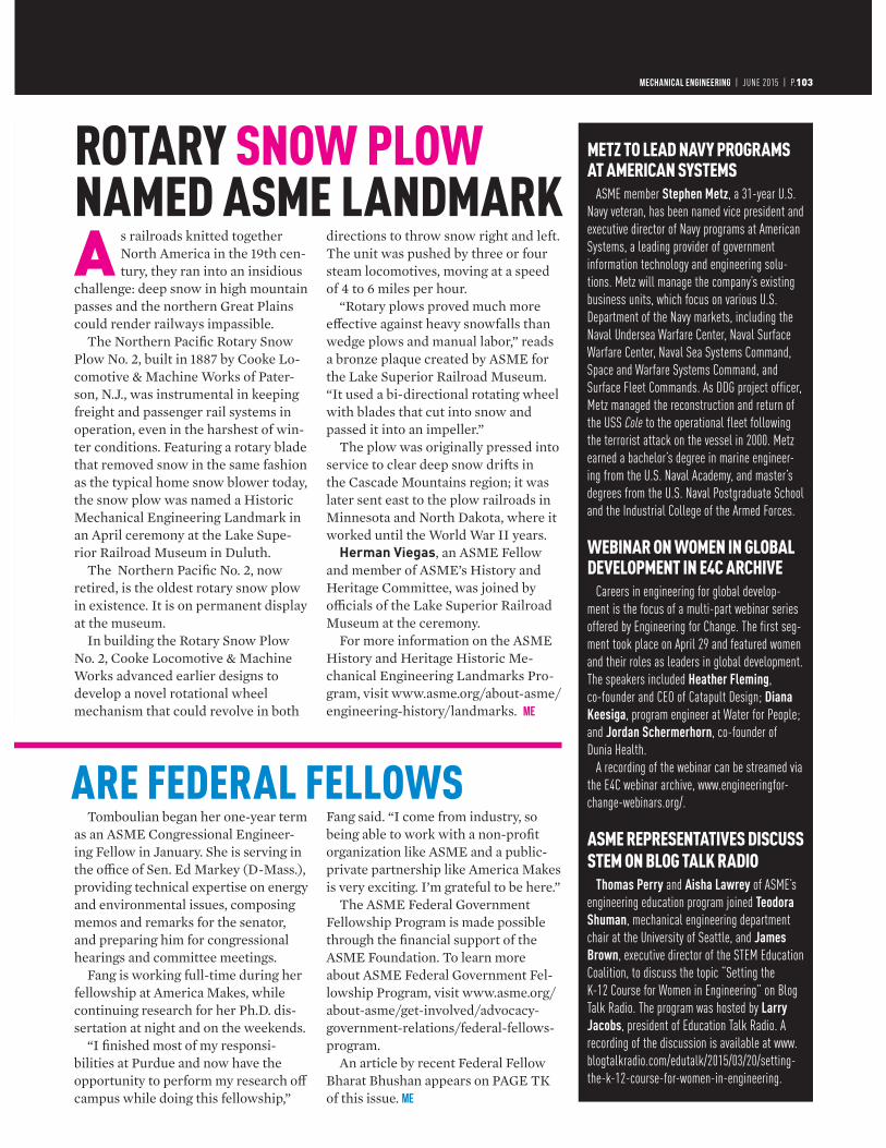
MECHANICAL ENGINEERING | FEBRUARY 2013 | P.0103MECHANICAL ENGINEERING | JUNE 2015 | P.103
ROTARY SNOW PLOWNAMED ASME LANDMARK
ARE FEDERAL FELLOWS
A s railroads knitted together North America in the 19th cen-tury, they ran into an insidious
challenge: deep snow in high mountain passes and the northern Great Plains could render railways impassible.
The Northern Pacific Rotary Snow Plow No. 2, built in 1887 by Cooke Lo-comotive & Machine Works of Pater-son, N.J., was instrumental in keeping freight and passenger rail systems in operation, even in the harshest of win-ter conditions. Featuring a rotary blade that removed snow in the same fashion as the typical home snow blower today, the snow plow was named a Historic Mechanical Engineering Landmark in an April ceremony at the Lake Supe-rior Railroad Museum in Duluth.
The Northern Pacific No. 2, now retired, is the oldest rotary snow plow in existence. It is on permanent display at the museum.
In building the Rotary Snow Plow No. 2, Cooke Locomotive & Machine Works advanced earlier designs to develop a novel rotational wheel mechanism that could revolve in both
directions to throw snow right and left. The unit was pushed by three or four steam locomotives, moving at a speed of 4 to 6 miles per hour.
“Rotary plows proved much more effective against heavy snowfalls than wedge plows and manual labor,” reads a bronze plaque created by ASME for the Lake Superior Railroad Museum. “It used a bi-directional rotating wheel with blades that cut into snow and passed it into an impeller.”
The plow was originally pressed into service to clear deep snow drifts in the Cascade Mountains region; it was later sent east to the plow railroads in Minnesota and North Dakota, where it worked until the World War II years.
Herman Viegas, an ASME Fellow and member of ASME’s History and Heritage Committee, was joined by officials of the Lake Superior Railroad Museum at the ceremony.
For more information on the ASME History and Heritage Historic Me-chanical Engineering Landmarks Pro-gram, visit www.asme.org/about-asme/engineering-history/landmarks. ME
METZ TO LEAD NAVY PROGRAMS AT AMERICAN SYSTEMS
ASME member Stephen Metz, a 31-year U.S.
Navy veteran, has been named vice president and
executive director of Navy programs at American
Systems, a leading provider of government
information technology and engineering solu-
tions. Metz will manage the company’s existing
business units, which focus on various U.S.
Department of the Navy markets, including the
Naval Undersea Warfare Center, Naval Surface
Warfare Center, Naval Sea Systems Command,
Space and Warfare Systems Command, and
Surface Fleet Commands. As DDG project officer,
Metz managed the reconstruction and return of
the USS Cole to the operational fleet following
the terrorist attack on the vessel in 2000. Metz
earned a bachelor’s degree in marine engineer-
ing from the U.S. Naval Academy, and master’s
degrees from the U.S. Naval Postgraduate School
and the Industrial College of the Armed Forces.
WEBINAR ON WOMEN IN GLOBAL DEVELOPMENT IN E4C ARCHIVE
Careers in engineering for global develop-
ment is the focus of a multi-part webinar series
offered by Engineering for Change. The first seg-
ment took place on April 29 and featured women
and their roles as leaders in global development.
The speakers included Heather Fleming,
co-founder and CEO of Catapult Design; Diana
Keesiga, program engineer at Water for People;
and Jordan Schermerhorn, co-founder of
Dunia Health.
A recording of the webinar can be streamed via
the E4C webinar archive, www.engineeringfor-
change-webinars.org/.
ASME REPRESENTATIVES DISCUSS STEM ON BLOG TALK RADIO
Thomas Perry and Aisha Lawrey of ASME’s
engineering education program joined Teodora
Shuman, mechanical engineering department
chair at the University of Seattle, and James
Brown, executive director of the STEM Education
Coalition, to discuss the topic “Setting the
K-12 Course for Women in Engineering” on Blog
Talk Radio. The program was hosted by Larry
Jacobs, president of Education Talk Radio. A
recording of the discussion is available at www.
blogtalkradio.com/edutalk/2015/03/20/setting-
the-k-12-course-for-women-in-engineering.
Tomboulian began her one-year term as an ASME Congressional Engineer-ing Fellow in January. She is serving in the office of Sen. Ed Markey (D-Mass.), providing technical expertise on energy and environmental issues, composing memos and remarks for the senator, and preparing him for congressional hearings and committee meetings.
Fang is working full-time during her fellowship at America Makes, while continuing research for her Ph.D. dis-sertation at night and on the weekends.
“I finished most of my responsi-bilities at Purdue and now have the opportunity to perform my research off campus while doing this fellowship,”
Fang said. “I come from industry, so being able to work with a non-profit organization like ASME and a public-private partnership like America Makes is very exciting. I’m grateful to be here.”
The ASME Federal Government Fellowship Program is made possible through the financial support of the ASME Foundation. To learn more about ASME Federal Government Fel-lowship Program, visit www.asme.org/about-asme/get-involved/advocacy-government-relations/federal-fellows-program.
An article by recent Federal Fellow Bharat Bhushan appears on PAGE TK of this issue. ME
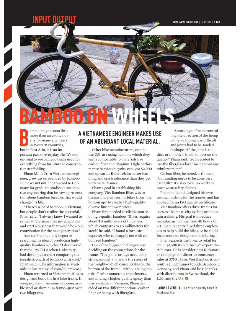
INPUT OUTPUT MECHANICAL ENGINEERING | JUNE 2015 | P.104
Bamboo might seem little more than an exotic nov-elty for many engineers in Western countries,
but in East Asia, it is an im-portant part of everyday life. It’s not unusual to see bamboo being used for everything from furniture to construc-tion scaffolding.
Pham Minh Tri, a Vietnamese engi-neer, grew up surrounded by bamboo. But it wasn’t until he traveled to Ger-many for graduate studies in automo-tive engineering that he saw a presenta-tion about bamboo bicycles that would change his life.
“There’s a lot of bamboo in Vietnam, but people don’t realize the potential,” Pham said. “I always knew I wanted to return to Vietnam after my education and start a business that would be a real contribution for the next generation.”
And so, Pham quietly began re-searching his idea of producing high-quality bamboo bicycles. “I discovered that the RWTH Aachen University had developed a chart comparing the tensile strength of bamboo with steel,” Pham said. (The information is avail-able online at tinyurl.com/m3emwyo.)
Pham returned to Vietnam in 2012 to design and build his first bike frame. It weighed about the same as a compara-ble steel or aluminum frame—just over two kilograms.
Other bike manufacturers, even in the U.S., are using bamboo, which they say is comparable to materials like carbon fiber and titanium. High-perfor-mance bamboo bicycles can cost $2,000 and upwards. Riders claim better han-dling and crash tolerance than they get with metal frames.
Pham’s goal in establishing his company, Viet Bamboo Bike, was to design and engineer his bikes from “the bottom up,” to create a high-quality, diverse line at lower prices.
Pham first needed a reliable source of high-quality bamboo. “Bikes require about 4.5 millimeters of thickness, which compares to 1.5 millimeters for steel,” he said. “I found a furniture exporter who can supply me with car-bonized bamboo.”
One of the biggest challenges was deciding on the connections for the frame. “The joints or lugs need to be strong enough to handle the stress of the weight—which concentrates on the bottom of the frame—without being too thick.” After numerous experiments, and finding a higher quality epoxy than was available in Vietnam, Pham de-cided on two different options: carbon fiber, or hemp with fiberglass.
According to Pham, control-ling the direction of the hemp while wrapping was difficult and joints had to be sanded to shape. “If the joint is too
thin, or too thick, it will impact on the quality,” Pham said. “So I decided to use the fiberglass layer inside to ensure reinforcement.”
Carbon fiber, he noted, is thinner, “but sanding needs to be done very carefully.” It’s also toxic, so workers must wear safety clothes.
Pham built and designed his own testing machine for the frames, and has applied for an ISO quality certificate.
Viet Bamboo offers three frames for uses as diverse as city cycling or moun-tain trekking. His goal is to reduce manufacturing time from 40 hours to 20. Pham recently hired three employ-ees to help build the bikes, so he could focus more on design and marketing.
Pham expects the bikes to retail for about $1,500 if sold through export dis-tributors. He is considering a Kickstart-er campaign for direct-to-consumer sales at $750 a bike. Viet Bamboo is cur-rently selling frames to Ride Bamboo in Germany, and Pham said he is in talks with distributors in Switzerland, the U.K., and the U.S. ME
LARRY LEVENTHAL is a writer currently based in
Southeast Asia.
A VIETNAMESE ENGINEER MAKES USE OF AN ABUNDANT LOCAL MATERIAL.
BAMBOO ON WHEELS

SAN DIEGO CONVENTION CENTER | SAN DIEGO, CALIFORNIA | GO.ASME.ORG/POWERENERGY ENERGY SOLUTIONS FOR A SUSTAINABLE FUTURE
GO.ASME.ORG/POWERENERGY
Join us at ASME's 2015 Power & Energy Conference!
• Keynote Sessions with Energy Leaders
• 800 Presentations
• Multiple Technical Workshops
• Industry Forums on Cyber Security & EPA Clean Air Act
• Technical Tours
• Poster Sessions
• 60 - 100 Advanced Energy Exhibitions
If you are a….• Manufacturer• Engineer• Researcher• Utilities Company• Government Organization• Academic
…this event is for YOU!
JUNE 28-JULY 2, 2015
Four of ASME’s major conferences (ASME Power Conference, ASME Energy Sustainability Conference, ASME Fuel Cell Conference, and ASME Nuclear Forum) come together to create an event of major impact for the Power and Energy sectors: ASME Power & Energy Conference & Expo.
CAREN ANDERSVice President of Emerging Technology & Transmission Affairs, Duke Energy
GREG ASHLEYPresident of Bechtel Nuclear Power
DAN BAERMANDirector of Origination and Portfolio Design, San Diego Gas & Electric
JOSEPH DESMONDSenior Vice President of Marketing and Government Affairs, BrightSource Energy
Our Confirmed Keynote Speakers Include:
DAVID HOCHSCHILDCommissioner, California Energy Commission
ASIM HUSSAINSenior Director of Marketing and Customer Experience, Bloom Energy
LLOYD MACNEILPartner, Dechert LLP
MARK C. MCCULLOUGHExecutive Vice President - Generation, American Electric Power
THE HONORABLE JERRY MCNERNEYU.S. House of Representatives
DAVE POGUEGlobal Director of Corporate Responsibility, CBRE
BRUCE RISINGStrategic Business Manager, Power Systems Sales, Siemens Energy, Inc
MARK ROTHLEDERVice President, Market Quality and Renewable Integration, California Independent System Operator Corporation
Silver SponsorGold Sponsor Bronze Sponsor
The American Society of Mechanical Engineers (ASME)
WHY ATTEND?
In Just Five Days, You’ll Gain Access To
REGISTER ONLINE BY
JUNE 15 AND SAVE $100!
Visit our website to view all speakers!

PNEUMATICS 2.0™ HAS ARRIVEDIntroducing IntelliSense®, a one-of-a-kind technology platform that delivers real-time
performance data on standard Bimba pneumatic devices for maximum uptime. Never
before has such a wide range of industries been able to move from emergency repair
to proactive maintenance, thus optimizing plant effi ciency and production as a whole.
bimba.com/smarter
© Copyright 2015 Bimba Manufacturing Company. All Rights Reserved.
– THE EXPERTS AGREE –
WINS THREE PRESTIGIOUS AWARDS FROM LEADING INDUSTRY TRADE PUBLICATIONS
INTELLISENSE®
UPTIME TIME


![mechaNICAL ENGINEERING [CAY 2019-20]](https://static.fdokumen.com/doc/165x107/6315d572c72bc2f2dd04da92/mechanical-engineering-cay-2019-20.jpg)