Advanced Engineering Building Mechanical Services ...
410
Authorised for Issue Project Leader Date BNE0911900.SPEC.M01.KJS101203 - Cover Page Form Revision: F 11/06 WSP Lincolne Scott Pty Ltd ABN 47 005 113 468 1 Gardner Close PO Box 2227 Milton Queensland 4064 Australia T. 61 7 3368 6600 F. 61 7 3368 6699 [email protected] wsplincolnescott.com This proposal, prepared specifically for Hassell/RKA is the intellectual property of WSP Lincolne Scott. It is protected by copyright and it is presented in circumstances of complete confidentiality. It remains the exclusive property of WSP Lincolne Scott and must not be given, reproduced or disseminated, to any person, public authority, institution or organisation without the express permission of WSP Lincolne Scott in writing. Advanced Engineering Advanced Engineering Advanced Engineering Advanced Engineering Building Building Building Building Mechanical Services Mechanical Services Mechanical Services Mechanical Services Specification Specification Specification Specification Construction Construction Construction Construction Issue Issue Issue Issue Rev Rev Rev Rev. . . . C May May May May 2011 2011 2011 2011 Reference Reference Reference Reference BNE0911900 BNE0911900 BNE0911900 BNE0911900 Client Hassell/RKA Hassell/RKA Hassell/RKA Hassell/RKA
-
Upload
khangminh22 -
Category
Documents
-
view
1 -
download
0
Transcript of Advanced Engineering Building Mechanical Services ...
Authorised for Issue
Project Leader Date
BNE0911900.SPEC.M01.KJS101203 - Cover Page Form
Revision: F 11/06
WSP Lincolne Scott Pty Ltd
ABN 47 005 113 468
1 Gardner ClosePO Box 2227 Milton
Queensland 4064 Australia
T. 61 7 3368 6600F. 61 7 3368 6699
This proposal, prepared specifically for Hassell/RKA is the intellectual property of WSP Lincolne Scott. It is protected by copyright and it is presented in circumstances of complete confidentiality. It remains the exclusive property of WSP Lincolne Scott and must not be given, reproduced or disseminated, to any person, public authority, institution or organisation without the express permission of WSP Lincolne Scott in writing.
Advanced Engineering Advanced Engineering Advanced Engineering Advanced Engineering BuildingBuildingBuildingBuilding
Mechanical ServicesMechanical ServicesMechanical ServicesMechanical Services
SpecificationSpecificationSpecificationSpecification
ConstructionConstructionConstructionConstruction IssueIssueIssueIssue RevRevRevRev. . . . CCCC
May May May May 2011201120112011
Reference Reference Reference Reference BNE0911900BNE0911900BNE0911900BNE0911900
Client
Hassell/RKAHassell/RKAHassell/RKAHassell/RKA
AUJJ01231
Pen
AUJJ01231
Text Box
31/05/2011
Advanced Engineering Building, UQ Mechanical Services
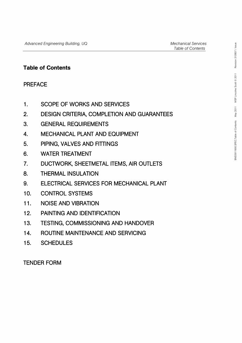
Table of Contents
BNE0911900.SPEC.Table of Contents May 2011 W
SP Lincolne Scott © 2011 Revision 310807 / Issue
Table of Contents
PREFACEPREFACEPREFACEPREFACE
1.1.1.1. SCOPE OF WORKS AND SERVICESSCOPE OF WORKS AND SERVICESSCOPE OF WORKS AND SERVICESSCOPE OF WORKS AND SERVICES
2.2.2.2. DESIGN CRITERIA, COMPLETION AND GUARANTEESDESIGN CRITERIA, COMPLETION AND GUARANTEESDESIGN CRITERIA, COMPLETION AND GUARANTEESDESIGN CRITERIA, COMPLETION AND GUARANTEES
3.3.3.3. GENERAL REQUIREMENTSGENERAL REQUIREMENTSGENERAL REQUIREMENTSGENERAL REQUIREMENTS
4.4.4.4. MECHANICAL PLANT AND EQUIPMENTMECHANICAL PLANT AND EQUIPMENTMECHANICAL PLANT AND EQUIPMENTMECHANICAL PLANT AND EQUIPMENT
5.5.5.5. PIPING, VALVES AND FITTINGSPIPING, VALVES AND FITTINGSPIPING, VALVES AND FITTINGSPIPING, VALVES AND FITTINGS
6.6.6.6. WATER WATER WATER WATER TREATMENTTREATMENTTREATMENTTREATMENT
7.7.7.7. DUCTWORK, SHEETMETAL ITEMS, AIR OUTLETSDUCTWORK, SHEETMETAL ITEMS, AIR OUTLETSDUCTWORK, SHEETMETAL ITEMS, AIR OUTLETSDUCTWORK, SHEETMETAL ITEMS, AIR OUTLETS
8.8.8.8. THERMAL INSULATIONTHERMAL INSULATIONTHERMAL INSULATIONTHERMAL INSULATION
9.9.9.9. ELECTRICAL SERVICES FOR MECHANICAL PLANTELECTRICAL SERVICES FOR MECHANICAL PLANTELECTRICAL SERVICES FOR MECHANICAL PLANTELECTRICAL SERVICES FOR MECHANICAL PLANT
10.10.10.10. CONTROL SYSTEMSCONTROL SYSTEMSCONTROL SYSTEMSCONTROL SYSTEMS
11.11.11.11. NOISE AND VIBRATIONNOISE AND VIBRATIONNOISE AND VIBRATIONNOISE AND VIBRATION
12.12.12.12. PAINTING AND IDENTIFICATIONPAINTING AND IDENTIFICATIONPAINTING AND IDENTIFICATIONPAINTING AND IDENTIFICATION
13.13.13.13. TESTING, COMMISSIONING AND HANDOVERTESTING, COMMISSIONING AND HANDOVERTESTING, COMMISSIONING AND HANDOVERTESTING, COMMISSIONING AND HANDOVER
14.14.14.14. ROUTINE MAINTENANCE AND SERVICINGROUTINE MAINTENANCE AND SERVICINGROUTINE MAINTENANCE AND SERVICINGROUTINE MAINTENANCE AND SERVICING
15.15.15.15. SCHEDULESSCHEDULESSCHEDULESSCHEDULES
TENDER FORMTENDER FORMTENDER FORMTENDER FORM
Advanced Engineering Building, UQ Mechanical Services
Preface
Table of Contents - Page 1
BNE0911900.SPEC.M01.KJS101203 - Preface May 2011 WSP Lincolne Scott © 2011 Revision 310807 / Construction Issue
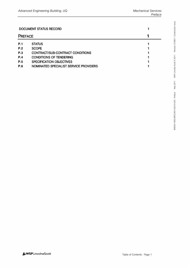
DOCUMENT STATUS RECODOCUMENT STATUS RECODOCUMENT STATUS RECODOCUMENT STATUS RECORDRDRDRD 1
PPPPREFACEREFACEREFACEREFACE 1
P.1 STATUSSTATUSSTATUSSTATUS 1
P.2 SCOPESCOPESCOPESCOPE 1
P.3 CONTRACT/SUBCONTRACT/SUBCONTRACT/SUBCONTRACT/SUB----CONTRACT CONDITIONSCONTRACT CONDITIONSCONTRACT CONDITIONSCONTRACT CONDITIONS 1
P.4 CONDITIONS OF TENDERCONDITIONS OF TENDERCONDITIONS OF TENDERCONDITIONS OF TENDERINGINGINGING 1
P.5 SPECIFICATION OBJECTSPECIFICATION OBJECTSPECIFICATION OBJECTSPECIFICATION OBJECTIVESIVESIVESIVES 1
P.6 NOMINATED SPECIALISTNOMINATED SPECIALISTNOMINATED SPECIALISTNOMINATED SPECIALIST SERVICE PROVIDERSSERVICE PROVIDERSSERVICE PROVIDERSSERVICE PROVIDERS 1
Advanced Engineering Building, UQ Mechanical Services
Preface
Document Status Record - Page 1
BNE0911900.SPEC.M01.KJS101203 - Preface May 2011 WSP Lincolne Scott © 2011 Revision 310807 / Construction Issue
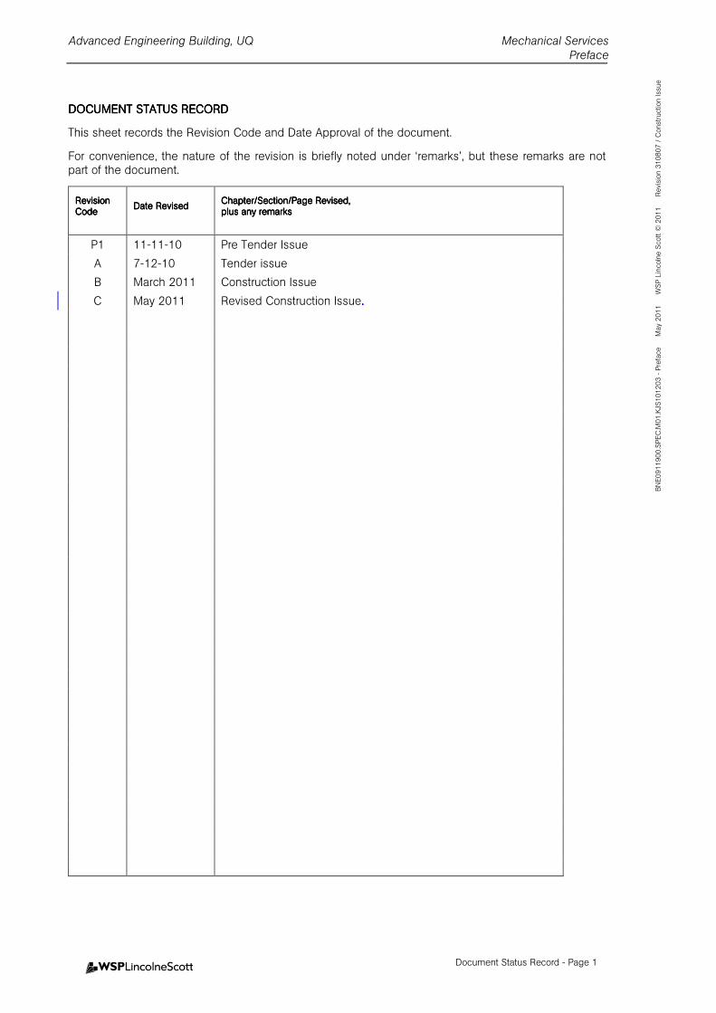
DOCUMENT STATUS RECORDDOCUMENT STATUS RECORDDOCUMENT STATUS RECORDDOCUMENT STATUS RECORD
This sheet records the Revision Code and Date Approval of the document.
For convenience, the nature of the revision is briefly noted under ‘remarks’, but these remarks are not part of the document.
ReReReRevision vision vision vision CodeCodeCodeCode
Date RevisedDate RevisedDate RevisedDate Revised Chapter/Section/Page Revised,Chapter/Section/Page Revised,Chapter/Section/Page Revised,Chapter/Section/Page Revised, plus any remarks plus any remarks plus any remarks plus any remarks
P1 11-11-10 Pre Tender Issue
A 7-12-10 Tender issue
B March 2011 Construction Issue
C May 2011 Revised Construction Issue....
Advanced Engineering Building, UQ Mechanical Services
Preface
Preface - Page 1
BNE0911900.SPEC.M01.KJS101203 - Preface May 2011 WSP Lincolne Scott © 2011 Revision 310807 / Construction Issue
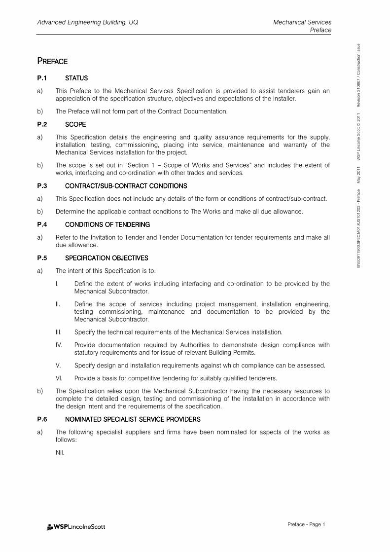
PPPPREFACEREFACEREFACEREFACE
P.1 STATUSSTATUSSTATUSSTATUS
a) This Preface to the Mechanical Services Specification is provided to assist tenderers gain an appreciation of the specification structure, objectives and expectations of the installer.
b) The Preface will not form part of the Contract Documentation.
P.2 SCOPESCOPESCOPESCOPE
a) This Specification details the engineering and quality assurance requirements for the supply, installation, testing, commissioning, placing into service, maintenance and warranty of the Mechanical Services installation for the project.
b) The scope is set out in “Section 1 – Scope of Works and Services” and includes the extent of works, interfacing and co-ordination with other trades and services.
P.3 CONTRACT/SUBCONTRACT/SUBCONTRACT/SUBCONTRACT/SUB----CONTRACT CONDITIONSCONTRACT CONDITIONSCONTRACT CONDITIONSCONTRACT CONDITIONS
a) This Specification does not include any details of the form or conditions of contract/sub-contract.
b) Determine the applicable contract conditions to The Works and make all due allowance.
P.4 CONDITIONS OF TENDERCONDITIONS OF TENDERCONDITIONS OF TENDERCONDITIONS OF TENDERINGINGINGING
a) Refer to the Invitation to Tender and Tender Documentation for tender requirements and make all due allowance.
P.5 SPECIFICATION OBJECTSPECIFICATION OBJECTSPECIFICATION OBJECTSPECIFICATION OBJECTIVESIVESIVESIVES
a) The intent of this Specification is to:
I. Define the extent of works including interfacing and co-ordination to be provided by the Mechanical Subcontractor.
II. Define the scope of services including project management, installation engineering, testing commissioning, maintenance and documentation to be provided by the Mechanical Subcontractor.
III. Specify the technical requirements of the Mechanical Services installation.
IV. Provide documentation required by Authorities to demonstrate design compliance with statutory requirements and for issue of relevant Building Permits.
V. Specify design and installation requirements against which compliance can be assessed.
VI. Provide a basis for competitive tendering for suitably qualified tenderers.
b) The Specification relies upon the Mechanical Subcontractor having the necessary resources to complete the detailed design, testing and commissioning of the installation in accordance with the design intent and the requirements of the specification.
P.6 NOMINATED SPECIALISTNOMINATED SPECIALISTNOMINATED SPECIALISTNOMINATED SPECIALIST SERVICE PROVIDERSSERVICE PROVIDERSSERVICE PROVIDERSSERVICE PROVIDERS
a) The following specialist suppliers and firms have been nominated for aspects of the works as follows:
Nil.
Advanced Engineering Building, UQ Mechanical Services Scope of Works and Services– Section 1
Table of Contents - Page i
BNE0911900.SPEC.M01.KJS101124 - Section 01 May 2011 WSP Lincolne Scott © 2011 Revision 21/10/2008/ Construction Issue
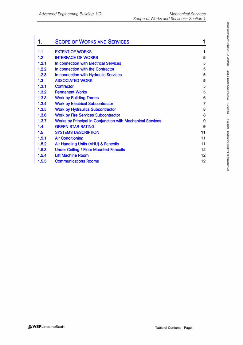
1.1.1.1. SSSSCOPE OF COPE OF COPE OF COPE OF WWWWORKS AND ORKS AND ORKS AND ORKS AND SSSSERVICESERVICESERVICESERVICES 1
1.11.11.11.1 EXTENT OF WORKSEXTENT OF WORKSEXTENT OF WORKSEXTENT OF WORKS 1
1.21.21.21.2 INTERFACE OF WORKSINTERFACE OF WORKSINTERFACE OF WORKSINTERFACE OF WORKS 5
1.2.11.2.11.2.11.2.1 In connection with ElectrIn connection with ElectrIn connection with ElectrIn connection with Electrical Servicesical Servicesical Servicesical Services 5
1.2.21.2.21.2.21.2.2 In connection with the ContractorIn connection with the ContractorIn connection with the ContractorIn connection with the Contractor 5
1.2.31.2.31.2.31.2.3 In connection with Hydraulic ServicesIn connection with Hydraulic ServicesIn connection with Hydraulic ServicesIn connection with Hydraulic Services 5
1.31.31.31.3 ASSOCASSOCASSOCASSOCIATED WORKIATED WORKIATED WORKIATED WORK 5
1.3.11.3.11.3.11.3.1 ContractorContractorContractorContractor 5
1.3.21.3.21.3.21.3.2 Permanent WorksPermanent WorksPermanent WorksPermanent Works 5
1.3.31.3.31.3.31.3.3 Work by Building TradesWork by Building TradesWork by Building TradesWork by Building Trades 6
1.3.41.3.41.3.41.3.4 Work by ElectricWork by ElectricWork by ElectricWork by Electrical Subcontractoral Subcontractoral Subcontractoral Subcontractor 7
1.3.51.3.51.3.51.3.5 Work by Hydraulics SubcontractorWork by Hydraulics SubcontractorWork by Hydraulics SubcontractorWork by Hydraulics Subcontractor 8
1.3.61.3.61.3.61.3.6 Work by Fire Services SubcontractorWork by Fire Services SubcontractorWork by Fire Services SubcontractorWork by Fire Services Subcontractor 8
1.3.71.3.71.3.71.3.7 Works by PrincipalWorks by PrincipalWorks by PrincipalWorks by Principal in Conjunction with Mechanical Servicesin Conjunction with Mechanical Servicesin Conjunction with Mechanical Servicesin Conjunction with Mechanical Services 9
1.41.41.41.4 GREEN STAR RATINGGREEN STAR RATINGGREEN STAR RATINGGREEN STAR RATING 9
1.51.51.51.5 SYSTEMS DESCRIPTIONSYSTEMS DESCRIPTIONSYSTEMS DESCRIPTIONSYSTEMS DESCRIPTION 11
1.5.11.5.11.5.11.5.1 Air ConditioningAir ConditioningAir ConditioningAir Conditioning 11
1.5.21.5.21.5.21.5.2 Air Handling Units (AHU) & FancoilsAir Handling Units (AHU) & FancoilsAir Handling Units (AHU) & FancoilsAir Handling Units (AHU) & Fancoils 11
1.5.31.5.31.5.31.5.3 Under Ceiling / Floor Mounted FancoilsUnder Ceiling / Floor Mounted FancoilsUnder Ceiling / Floor Mounted FancoilsUnder Ceiling / Floor Mounted Fancoils 12
1.5.41.5.41.5.41.5.4 Lift Machine RoomLift Machine RoomLift Machine RoomLift Machine Room 12
1.5.51.5.51.5.51.5.5 Communications RoomsCommunications RoomsCommunications RoomsCommunications Rooms 12
Advanced Engineering Building, UQ Mechanical Services Scope of Works and Services– Section 1
Section 1 - Page 1
BNE0911900.SPEC.M01.KJS101124 - Section 01 May 2011 WSP Lincolne Scott © 2011 Revision 21/10/2008/ Construction Issue
1.1.1.1. SSSSCOPE OF COPE OF COPE OF COPE OF WWWWORKS AND ORKS AND ORKS AND ORKS AND SSSSERVICESERVICESERVICESERVICES
1.11.11.11.1 EXTENT OF WORKSEXTENT OF WORKSEXTENT OF WORKSEXTENT OF WORKS
Scope of Works comprise the design, supply, installation, commissioning, testing, placing into service, warranty and defects liability including materials, labour and plant in accordance with this Specification as may be amended by the Contract.
Works include the necessary and incidental works required to implement the intent and meaning of the Specification. Whether or not particular works are described in the Specification all items and materials needed for the complete works are required and shall be installed unless clearly excluded.
The works comprise the supply, delivery, installation, commissioning, testing, placing into service and maintenance of air conditioning, mechanical ventilation and piped gas services. The Contractor shall supply all plant, labour, materials and supervision to carry out the work (in accordance with Specification, Drawings and the Contract) which shall include but not necessarily be limited to:
• Chilled Water Refrigeration Plant compromising four (4) water cooled helical rotary chillers (one as light load chiller), four (4) counter flow fibreglass cooling towers, one (1) cooling tower water maintenance (holding) tank (nom. 8000 litres, c/w pump and hose connections) associated chilled water primary and secondary pumps, condenser water pumps, chilled water buffer tank, chemical treatment system, side stream filtration systems, impressed current protection systems, and all associated pipework, valves and accessories as shown on the drawings and as outlined later in this specification and located at level 7 roof plantroom.
• Chilled water distribution to two (2) adjacent precinct buildings, Zelman Cowan building and General Purpose South building (including associated chilled water pumps – duty/standby).
• Provision of Solar Air Conditioning plant including Solar Collectors (Nominally 70kWr), heat exchangers, pumps and Absorption Chiller (Cost option item)
• Provision of Microturbine heat reclaim hot water pump, pipework and associated controls (Cost option item)
• Provision of Fuel Cell heat reclaim hot water pump, pipework and associated controls (Cost option item)
• Removal of existing redundant central chilled water system serving General Purpose South building.
• Provide “Refrigerant Recovery” in accordance with Green Star Education EMI-3. Tender to provide description of Refrigerant Recovery with Tender Offer.
• Displacement air conditioning system to serve the Level 2 Lecture Theatre/auditorium.
• Air conditioning plant comprising chilled water packaged air conditioning equipment as shown on drawings and as outlined later in this specification.
Air handling units shall have centrifugal supply air fans, aluminium finned, copper tube cooling coils with in-built condensate trays, air filters, motorised outside air and motorised return dampers where required for CO2 control and smoke mode operation. All FCU located outside plant rooms shall be provided with insulated stainless steel safety tray under separately trapped and drained to tundish/floor waste.
All control valves, isolating valves, test pressure/temperature points and any other equipment subject to condensation shall be provided with stainless steel safety trays under, separately trapped and drained. All pressure/temperature test points, valves, etc, shall be insulated.
• Smoke control mode of operation will be incorporated as detailed on the drawings and as outlined later in this specification.
Advanced Engineering Building, UQ Mechanical Services Scope of Works and Services– Section 1
Section 1 - Page 2
BNE0911900.SPEC.M01.KJS101124 - Section 01 May 2011 WSP Lincolne Scott © 2011 Revision 21/10/2008/ Construction Issue
• Air conditioning air distribution systems comprising low pressure, low velocity, sheet metal ductwork, ductwork insulation (internal and external), grilles, motorized dampers, spigots, flexible ductwork, diffusers. Heating of supply air shall be by hot water heating coils.
• Air conditioning plant to serve general office areas on Levels 4, 5 & 6.
• Air conditioning plant to serve engineering teaching areas and laboratories on levels 1, 2, 3, 4, 5 & 6.
• Specialist air conditioning systems to serve Concrete Creep Lab, Concrete Shrinkage Room and Constant Environmental Room.
• Desk supply air distribution system to Northern offices and AMPAM offices including dedicated air handling units, ductwork distribution system, motorised dampers and controls.
For discrete offices, the complete system is by the mechanical services subcontractor. The supply air nozzles for these areas are supplied to the mechanical subcontractor by the Contractor as associated works.
For open office areas, the mechanical scope ends at the supply duct connection to the
proprietary in- furniture task air ductwork connection. Horizontal ducting from this point
at desk level and the supply nozzles are by the Contractor (associated works).
• Air conditioning plant to serve minor Café space.
• Air conditioning to serve general areas
• Air conditioning plant to serve each of Boardroom and Executive Suite
• Air conditioning to Lift Machine Rooms
• Duty/Standby AC serving Communication Rooms at Level 1 & 4.
• AC to AV Server Room
• Atrium tempered air supply system, including some stainless steel supply air columns.
• Heat Recovery System serving Auditorium comprising outside air and extract air backward curved centrifugal fans, built up casings, access doors, internal lighting, primary filters & motorised dampers.
• Operable façade control facility including building weather station.
• Hot water heating system comprising gas fired hot water heaters, circulation pumps and insulated water pipe work, control valves and fittings. All hot water systems located in roof plant rooms shall be provided with stainless steel safety tray under, separately trapped and drained. Provide flue discharging above roof to comply with AS 5601. System to be suitable for integration with Solar Thermal collectors for utilisation when available.
• Mechanical ventilation systems generally including the following:-
- Laboratory supply and exhaust systems as required
- Specialist Laboratory exhaust systems
- Specialist Workshop exhaust systems
- Utilities exhaust systems
- Toilet exhaust systems
- Bicycle amenities exhaust
- Waste area general exhaust
- Chiller and plantroom ventilations systems
Advanced Engineering Building, UQ Mechanical Services Scope of Works and Services– Section 1
Section 1 - Page 3
BNE0911900.SPEC.M01.KJS101124 - Section 01 May 2011 WSP Lincolne Scott © 2011 Revision 21/10/2008/ Construction Issue
- Switchroom ventilation systems
- Substation ventilation systems
- Gas Store, Corrosives store, Flammable Liquids Store and Class 4.2 & 4.3 Store ventilation systems.
• Café kitchen exhaust system complete with water wash exhaust canopy, ductwork, fan and accessories as shown on the drawings and as outlined later in this specification. Exhaust ductwork shall be provided with ductwork access panels to meet AS1668.1 (1998).
• Fume cupboards and associated exhaust systems (including scrubbers where nominated)
• Supplementary ventilation system risers to building Southern façade.
• Provide a duplex compressed air system complete with air compressor, receiver, filters, refrigerated dryer, gauges, relief valves, drain valves, regulators, isolation valves, pipework, outlets, controls and electrics as shown on the drawings and as further specified. Register the receiver vessel with Worksafe and display a copy of the registration certificate adjacent to the plant. Provide a copy of the registration certificate in the Operation and Maintenance Manual.
• Duplex vacuum plant and associated pipework reticulation.
• Provide exhaust systems complete with exhaust arms, ductwork, fan, motor, controls and electrics as shown on the drawings.
• Scientific gas reticulation systems including auto-change-over manifolds, pressure regulators, safety relief valves, pressure gauges, pressure sensors, non-return valves, isolation valves, emergency shut off valves, pipework controls and electrics as shown on the drawings.
• Provision of Oxygen depletion monitoring and alarm systems as required.
• Provision of one new process cooler, with pipework reticulation for both new and relocated process coolers to suit laboratory equipment requirements as indicated within associated plans. Existing process coolers will be provided and installed by the Principal.
• Supplementary chilled water, condenser water and heating water risers and takeoffs for future flexibility.
• Steam system piping in the Concrete Lab.
• Supply and installation of fire collars / fire dampers for mechanical services as required.
• Supply and installation of mechanical services switchboards and all electrical power and control wiring from the mechanical services switchboards to all air conditioning plant and ventilation equipment. Provide separate non-essential/essential/fire essential switchboard as scheduled in Section 15.0 and where shown on the drawing. Termination of sub mains provided by the Electrical Subcontractor.
• BMS provisions to suit on site systems and Live Building learning outcomes (existing site BMS head end to be utilised), including interface and recommissioning of BMS elements serving Zelman Cowan building and General Purpose South building to suit programmed new central plant handover.
• De-commissioning, removal and disposal of existing mechanical services serving General Purpose South building, including, but not limited to, existing chillers, cooling towers, pumps, redundant pipework, electrics and controls. Works to be staged to facilitate continued operation of GPS systems until new precinct plant is operational. Coordinate changeover and interface and modify electrics and controls as required. Existing GPS mechanical switchboard to be modified as required to suit new precinct plant. Replace existing level 5 ducted DX water-cooled CRAC with new split air cooled CRAC. On level 4, remove one supply air diffuser and flexible duct to suit new fire stair, and cap the 200 dia spigot.
Advanced Engineering Building, UQ Mechanical Services Scope of Works and Services– Section 1
Section 1 - Page 4
BNE0911900.SPEC.M01.KJS101124 - Section 01 May 2011 WSP Lincolne Scott © 2011 Revision 21/10/2008/ Construction Issue
• Provision of vibration isolation for all rotating equipment.
• Provision of Plinth surrounds and Pump Inertia Bases.
• Provision of fire rated ductwork as shown on the associated drawings.
• Provision of stainless steel attenuators to cooling tower fan discharges.
• Complete commissioning of the air conditioning systems, ventilation systems, smoke exhaust systems, hot water systems, chilled water systems, gas systems, compressed air and vacuum systems including hot smoke tests for passive smoke exhaust systems.
• Compilation of all information required in relation to mechanical services to facilitate achievement of Greenstar As-built rating.
• Painting, labelling and identification of all mechanical plant, ventilation plant, fume and extraction systems, cable trays, pipework and ductwork support systems and associated pipework systems. This includes painting of all mechanical services elements except those enclosed in solid building riser enclosures.
• Provision of minor core holes and penetrations. Placing, casting in and protection of pipe sleeves and conduits. Chasing is not acceptable.
• Provision of ductwork penetrations for the installation of fire sprinklers and smoke detection equipment.
• Packing and sealing around duct pipe and cable penetrations to provide fire rated/acoustic sealing as required.
• Provision of condensate drain pipes to tundishes adjacent.
• Provision of LCD digital flow meters to each building served.
• Preparation and submission of design schematics and calculations prior to shop drawing.
• Preparation and submission of shop drawings and equipment schedules prior to construction. Subcontractor shall note requirement to ensure that all control sensors, valves and actuators, air flow schematics and air registers are in included on shop drawings. Refer to Section 3 for additional Information.
• Submissions as later detailed.
• Preparation and supply of complete and detailed Operating and Maintenance Manuals which include all commissioning data. Ensure Operation and Maintenance Manuals clearly indicate on an individual equipment basis a schedule of maintenance routines, inspections, preventative maintenance procedures, test surveys and records conducted on the fire and smoke protections systems installed as outlined in AS1851. Generic type procedures / inspections are not acceptable.
• Provision of 12 months defects liability period from the date of practical completion.
• Provision of complete service and maintenance of all systems during the defects liability period.
• Replacement of all system filters at the end of the 12 months maintenance period.
• Erection and disassembly of scaffolding only required to install mechanical equipment and all associated costs.
Advanced Engineering Building, UQ Mechanical Services Scope of Works and Services– Section 1
Section 1 - Page 5
BNE0911900.SPEC.M01.KJS101124 - Section 01 May 2011 WSP Lincolne Scott © 2011 Revision 21/10/2008/ Construction Issue
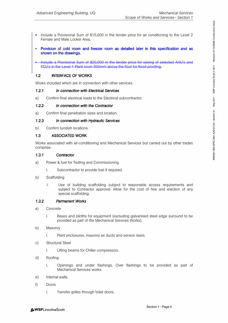
•••• Include a Provisional Sum of $15,000 in the tender price for air conditioning to the Level 2 Female and Male Locker Area.
• Provision of cold room and freezer room as detaileProvision of cold room and freezer room as detaileProvision of cold room and freezer room as detaileProvision of cold room and freezer room as detailed later in this specification and as d later in this specification and as d later in this specification and as d later in this specification and as shown on the drawings.shown on the drawings.shown on the drawings.shown on the drawings.
• Include a Provisional Sum of $20,000 in the tender price for raising of selected AHU’s and FCU’s in the Level 1 Plant room 500mm above the floor for flood proofing.
1.21.21.21.2 INTERFACE OF WORKSINTERFACE OF WORKSINTERFACE OF WORKSINTERFACE OF WORKS
Works included which are in connection with other services.
1.2.11.2.11.2.11.2.1 In connection with Electrical ServicesIn connection with Electrical ServicesIn connection with Electrical ServicesIn connection with Electrical Services
a) Confirm final electrical loads to the Electrical subcontractor.
1.2.21.2.21.2.21.2.2 In connection with In connection with In connection with In connection with thethethethe ContractorContractorContractorContractor
a) Confirm final penetration sizes and location.
1.2.31.2.31.2.31.2.3 In connection with In connection with In connection with In connection with HydrauHydrauHydrauHydraulic Serviceslic Serviceslic Serviceslic Services
b) Confirm tundish locations.
1.31.31.31.3 ASSOCIATED WORKASSOCIATED WORKASSOCIATED WORKASSOCIATED WORK
Works associated with air-conditioning and Mechanical Services but carried out by other trades comprise:
1.3.11.3.11.3.11.3.1 ContractorContractorContractorContractor
a) Power & fuel for Testing and Commissioning
I. Subcontractor to provide fuel if required.
b) Scaffolding
I. Use of building scaffolding subject to reasonable access requirements and subject to Contractor approval. Allow for the cost of hire and erection of any special scaffolding.
1.3.21.3.21.3.21.3.2 Permanent WorksPermanent WorksPermanent WorksPermanent Works
a) Concrete
I. Bases and plinths for equipment (excluding galvanised steel edge surround to be provided as part of the Mechanical Services Works).
b) Masonry
I. Plant enclosures, masonry air ducts and service risers.
c) Structural Steel
I. Lifting beams for Chiller compressors.
d) Roofing
I. Openings and under flashings. Over flashings to be provided as part of Mechanical Services works.
e) Internal walls.
f) Doors
I. Transfer grilles through toilet doors.
Advanced Engineering Building, UQ Mechanical Services Scope of Works and Services– Section 1
Section 1 - Page 6
BNE0911900.SPEC.M01.KJS101124 - Section 01 May 2011 WSP Lincolne Scott © 2011 Revision 21/10/2008/ Construction Issue
II. Undercutting of doors for ventilation purposes.
III. Access doors and hatches for maintenance of Mechanical Services equipment.
1.3.31.3.31.3.31.3.3 Work by BuildWork by BuildWork by BuildWork by Building Tradesing Tradesing Tradesing Trades
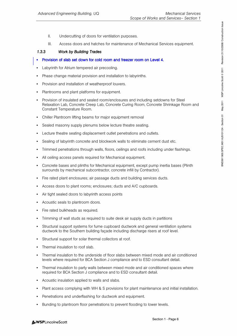
•••• Provision of slab set down for cold room and freezer room on Level 4.Provision of slab set down for cold room and freezer room on Level 4.Provision of slab set down for cold room and freezer room on Level 4.Provision of slab set down for cold room and freezer room on Level 4.
• Labyrinth for Atrium tempered air precooling.
• Phase change material provision and installation to labyrinths.
• Provision and installation of weatherproof louvers.
• Plantrooms and plant platforms for equipment.
• Provision of insulated and sealed room/enclosures and including setdowns for Steel Relaxation Lab, Concrete Creep Lab, Concrete Curing Room, Concrete Shrinkage Room and Constant Temperature Room.
• Chiller Plantroom lifting beams for major equipment removal
• Sealed masonry supply plenums below lecture theatre seating.
• Lecture theatre seating displacement outlet penetrations and outlets.
• Sealing of labyrinth concrete and blockwork walls to eliminate cement dust etc.
• Trimmed penetrations through walls, floors, ceilings and roofs including under flashings.
• All ceiling access panels required for Mechanical equipment.
• Concrete bases and plinths for Mechanical equipment, except pump inertia bases (Plinth surrounds by mechanical subcontractor, concrete infill by Contractor).
• Fire rated plant enclosures; air passage ducts and building services ducts.
• Access doors to plant rooms; enclosures; ducts and A/C cupboards.
• Air tight sealed doors to labyrinth access points
• Acoustic seals to plantroom doors.
• Fire rated bulkheads as required.
• Trimming of wall studs as required to suite desk air supply ducts in partitions
• Structural support systems for fume cupboard ductwork and general ventilation systems ductwork to the Southern building façade including discharge risers at roof level.
• Structural support for solar thermal collectors at roof.
• Thermal insulation to roof slab.
• Thermal insulation to the underside of floor slabs between mixed mode and air conditioned levels where required for BCA Section J compliance and to ESD consultant detail.
• Thermal insulation to party walls between mixed mode and air conditioned spaces where required for BCA Section J compliance and to ESD consultant detail.
• Acoustic insulation applied to walls and slabs.
• Plant access complying with WH & S provisions for plant maintenance and initial installation.
• Penetrations and underflashing for ductwork and equipment.
• Bunding to plantroom floor penetrations to prevent flooding to lower levels.
Advanced Engineering Building, UQ Mechanical Services Scope of Works and Services– Section 1
Section 1 - Page 7
BNE0911900.SPEC.M01.KJS101124 - Section 01 May 2011 WSP Lincolne Scott © 2011 Revision 21/10/2008/ Construction Issue
• Making good of all roof openings, wall openings, slab penetrations etc.
• Provision of steel wall framing as required to suit multiple exhaust discharge ducts exiting laboratory external walls and entering and exiting roof plantroom southern wall.
• Reinstatement of trafficable finishes as required to suit extent of trenching and pits required for reticulation of chilled water and associated electrical and controls cabling to serve adjacent Zelman Cowan and General Purpose South buildings.
• Provision of sun shading elements to southern facade where mechanical risers do not provide an effective sun shading element at lower laboratory levels.
• Provision of complete motorised louvre system, including all controllers and wiring between the louvres and the controllers.
• Provision of complete external motorised blind system, including all controllers and wiring between the blinds and the controllers.
• Provision of complete internal motorised blind system, including all controllers and wiring between the blinds and the controllers.
• Provision of cranage to facilitate removal of existing chilled water plant from General Purpose South building including existing chiller plantroom and cooling towers. All associated builders work to be included, including removal and replacement of outdoors slab access hatches.
• Provision of cranage to facilitate installation of new air cooled plant serving General Purpose South building computer AC plant air cooled conversion.
• Other normal associated Builders Works items.
• Provision of floor markings around mechanical plant designating student access areas and clearances.
• Provision of trenches for underground mechanical services including excavation, backfilling and making good. Preparation and submission of ‘as installed’ drawings on completion of the works.
• For open office areas in AMPAM and the Northern office areas, provision of all desk-level horizontal ductwork and supply air nozzles (task air system).
• For discrete offices in AMPAM and the Northern office areas, provision of all supply air nozzles to the mechanical subcontractor.
• Above-bench shelving and services reticulation systems in laboratory for island benches, including laboratory gas outlets piped to the ceiling space.
• All auditorium displacement supply air outlets.
• Level 3 atrium displacement supply air outlets (integrated in seats).
• Trafficable tempered air plenum to the underside of level 3 slab, grids A5 to A10, with access panels. Of coolroom panel construction, or similar.
1.3.41.3.41.3.41.3.4 Work by ElectricWork by ElectricWork by ElectricWork by Electrical Subcontractoral Subcontractoral Subcontractoral Subcontractor
• Supply of RS485 cable and final connection to energy meters installed by mechanical subcontractor.
• Supply of submains to Mechanical Services Switchboards. All cables to be tested, dressed and prepared for termination by electrical subcontractor. Final termination by mechanical subcontractor. Mechanical subcontractor responsible for supply of mechanical services switchboard complete with suitable lugs, gland plates, connectors and isolators.
• Provision of UPS submains to selected Mechanical Services Switchboards for selected BMS
Advanced Engineering Building, UQ Mechanical Services Scope of Works and Services– Section 1
Section 1 - Page 8
BNE0911900.SPEC.M01.KJS101124 - Section 01 May 2011 WSP Lincolne Scott © 2011 Revision 21/10/2008/ Construction Issue
Controllers. All cables to be tested, dressed and prepared for termination by electrical subcontractor. Final termination by mechanical subcontractor.
• Non-Essential Submains to the Mechanical Services Switchboards. Essential submains to the level 7 stair pressurisation switchboard and to the level 1 atrium tempered air supply system. Power supplies to mixed mode motorized façade elements control panels including motorised louvers and motorised external sun shades.
• Power supplies to process coolers.
1.3.51.3.51.3.51.3.5 Work by Work by Work by Work by Hydraulics SubcontractorHydraulics SubcontractorHydraulics SubcontractorHydraulics Subcontractor
• Provision of drain tundishes adjacent air conditioning plant.
• Provision of hose taps in plant enclosures.
• Provision of 50 diameter capped connections for make up water to Cooling Tower.
• Production and reticulation of domestic hot water downstream of mechanical services hot water isolating valves.
• Provision of pulsed water meter to cooling tower supply (water meter to cooling tower bleed water connection by mechanical subcontractor).
• Provide approved drainage point adjacent the air compressor and vacuum plant in roof plantroom.
• Provision of metered gas supply to heating plant.
• Pulsed water meters; pulsed gas meters; pump alarms, level alarms; for monitoring and Green Star compliance (refer to Section 10 for detailed listing).
• Water connection adjacent to each fume cupboard for use in the cupboard misting sprinkler fire protection.
1.3.61.3.61.3.61.3.6 Work by Fire Services Work by Fire Services Work by Fire Services Work by Fire Services SubcSubcSubcSubcontractorontractorontractorontractor
• Provision of fire signal wiring (GFA) to terminal strips in the MSSB’s. Final connection to MSSB’s terminal strip by mechanical subcontractor.
• Provision of stairwell pressurisation fan swtiching (at FIP) and control wiring to MSSB’s to control stairwell pressurisation fan via FIP. Final connection to MSSB’s terminal strip by mechanical subcontractor.
• Provision of stairwell pressurisation fan status wiring to terminal strips in the MSSB’s. Final connection to MSSB’s terminal strip by mechanical subcontractor. Current sensor & relay by mechanical subcontractor.
• Provision of atrium treated air supply air fan switching (at FIP) and control wiring to MSSB’s to control atrium treated air supply air fan via FIP. Final connection to MSSB’s terminal strip by mechanical subcontractor.
• Provision of atrium treated air supply air fan status wiring to terminal strips in the MSSB’s. Final connection to MSSB’s terminal strip by mechanical subcontractor. Current sensor & relay by mechanical subcontractor
• Installation of smoke detectors and sprinklers in ductwork, filter chambers and the like. (Access panels to suit by Mechanical Services subcontractor.)
Advanced Engineering Building, UQ Mechanical Services Scope of Works and Services– Section 1
Section 1 - Page 9
BNE0911900.SPEC.M01.KJS101124 - Section 01 May 2011 WSP Lincolne Scott © 2011 Revision 21/10/2008/ Construction Issue
• Provision of fire extinguishers to mechanical plant spaces, gas and flammable liquids storage areas.
1.3.71.3.71.3.71.3.7 WorkWorkWorkWorks by Principals by Principals by Principals by Principal in Conjunction wiin Conjunction wiin Conjunction wiin Conjunction with Mechanical Services th Mechanical Services th Mechanical Services th Mechanical Services
• Provision of final gas bottles (gases for testing by mechanical subcontractor).
• Relocation and connection of reused scientific, laboratory and workshop equipment.
• Supply & installation of new scientific and engineering equipment.
• Supply and installation of temperature sensors for heat conduction monitoring as part of the project Live Learning elements.
• Supply, installation and certification of a proprietary “Paint Spray Booth” in the level 6 foundry area. Exhaust system by mechanical subcontractor.
1.41.41.41.4 GREEN STAR RATINGGREEN STAR RATINGGREEN STAR RATINGGREEN STAR RATING
The building is required to have a Green Star Education Design Version 1 As-built Rating of 5 stars.
Refer to the following Green Star requirements which the mechanical services installation must meet.
Provide sufficient documentary evidence in accordance with the Green Star Technical Manual to support the Green Star Educational As-Built certification submission.
a) Man-2 Commissioning - Provide comprehensive pre-commissioning, commissioning and quality monitoring in accordance with CIBSE commissioning codes and ASHRAE Guideline 1. . Summary commission report to be produced including dates, tests carried out and outcomes and changes made as a result of the commissioning process. This report shall demonstrate compliance with either ASHRAE Guidelines or the CIBSE Commissioning codes S.
Provide a Commissioning Report including all dates, tests and results of the commissioning process. The report must demonstrate compliance with the ASHRAE Guideline 1 and CIBSE Commissioning Codes.
Transfer information to the Superintendant regarding design intent, as-installed details, commissioning report and training of building management staff. Provide training to the building manager and maintenance staff in the operations of the building services systems.
b) Man-3 Commissioning – Building Tuning - Provide 12 months building tuning program – quarterly reviews and a final recommissioning after the first 12 months of occupancy.
c) Man-7 Waste Management - A minimum of 60% of construction waste is to be recycled. The contractor shall avoid or minimise waste generation on site where possible. Waste that cannot be avoided shall be recycled or re-used if possible. There is an aspiration to recycle more than 80% waste by weight generated on site. All waste and recycling products shall be disposed of in accordance with the Construction Manager’s Environmental Management Plan
d) IEQ-1 Ventilation Rates – Outside air rates at a 50% improvement above AS1668.2-1991.
e) IEQ-3 Carbon Dioxide and VOC Monitoring and Control - Provide air conditioned areas with recirculated air to include CO2 sensors and control to modulate the outside air flow rate in response to CO2 levels.
Provide air conditioned areas with recirculated air to include VOC sensors for monitoring and alarm.
Advanced Engineering Building, UQ Mechanical Services Scope of Works and Services– Section 1
Section 1 - Page 10
BNE0911900.SPEC.M01.KJS101124 - Section 01 May 2011 WSP Lincolne Scott © 2011 Revision 21/10/2008/ Construction Issue
f) IEQ-7 Internal Noise Levels - Mechanical services installation to meet the recommended design sound levels provided in Table 1 of AS/NZS 2107:2000.
g) IEQ-8 Volatile Organic Compounds – Adhesives & Sealants - All adhesives and sealants are to be low VOC to South Coast Air Quality Management District (California, U.S.) Rule 1168.
h) IEQ-8 Volatile Organic Compounds - Paints - All paints shall comply with Greenstar requirements and comply with Good environment Choice Australia (GECA) standard number GECA-23-2005 version 1.0 and the maximum TVOC content limits values for paints and varnishes as stated in Annex II, Table A of Directive 2004/42/CE of the European Parliament and of the Council of 21 April 2004.
i) Provide two dedicated utility area exhaust risers installed to provide exhaust for utility spaces to enhance local indoor air quality.
j) Ene-1 Energy Improvement - Provision of energy consuming plant and equipment as specified to achieve As-Built rating. Negative deviations from specified electrical ratings and energy performance in general will not be accepted.
k) Ene-2 Energy Sub-metering - Provide electrical sub-metering to all loads greater than 100kVA or as nominated.
l) Ene-7 Unoccupied Areas – HVAC systems are designed to automatically shut down when not in use or designed for a wider temperature control band when not in use.
m) Ene-10 Shared Energy Systems – Project includes a chilled water plant supplying three buildings.
n) WAT-2 Water Meters – water meters are installed for all major water uses in the project, and are linked to the BMS for monitoring.
o) Wat-4 Heat Rejection Water - Final selection of the cooling tower system shall be based on providing a turnover rate of the tower/s of not less than 6 cycles. Provide a report outline the operation of the cooling towers with reference to the commissioning report and demonstrates that the cooling towers and water treatment systems achieve 6 cycles of concentration or better in operation.
p) Mat-6 PVC minimisation – Note that PVC minimisation is not being targeted for Mechanical Services.
q) Emi-1 Refrigerant ODP – All refrigerants have ODP of zero. Provide a report summarizing all refrigerant systems installed in the base building, listing volumes and types of refrigerant used. Provide certification demonstrating that the Chillers installed met this requirement.
r) Emi-3 Refrigerant Leaks - Provide refrigerant leak detection to all Chillers’ refrigerant systems in the base building. Provide a report describing the type and installation of the system and its operation. Provide extract from the commissioning report demonstrating the system operation. The Operation and Maintenance Manual is to include an explanation of the operation of the system.
Each chiller includes an automated refrigerant pump-down and recovery system.
s) Emi-4 Insulant ODP –Provide a list of all insulations used on the project and confirmation that all insulations installed avoid the use of ozone depleting substances in either manufacture or composition.
Information must be supplied prior to purchase for all proposed insulation including that used for pipework, ductwork or building works, demonstrating that the insulation does not contain and was not manufactured using ozone-depleting substances.
Advanced Engineering Building, UQ Mechanical Services Scope of Works and Services– Section 1
Section 1 - Page 11
BNE0911900.SPEC.M01.KJS101124 - Section 01 May 2011 WSP Lincolne Scott © 2011 Revision 21/10/2008/ Construction Issue
1.51.51.51.5 SYSTEMS DESCRIPTIONSYSTEMS DESCRIPTIONSYSTEMS DESCRIPTIONSYSTEMS DESCRIPTION
1.5.11.5.11.5.11.5.1 Air Conditioning Air Conditioning Air Conditioning Air Conditioning
A new precinct chilled water plant will be established within the roof plantroom for the AEB building. This plant will serve the AEB building, Zelman Cowan building and the General Purpose south building. Chilled water pipework will be reticulated from the AEB building and connect to existing infrastructure serving the adjacent buildings.
A primary/secondary pumping system will be provided generally as detailed on the associated plans. Pumps will be provided on a duty/standby basis with operation controlled in accordance with UQ Technical Guideline TG 13 requirements.
Chilled water will be reticulated throughout the building to air handling units, fancoils and underceiling fancoils. Generally AHU’s and fancoils have been located within dedicated plantrooms to limit maintenance access requirements.
The building is provided with a passive cooling option via underground concrete blockwork labyrinths and phase change banks resulting in tempered air provision. This tempered air connects to two air handling units. One air handling unit serves the Atrium and one serves two desk air supply systems (AMPAM Offices and Northern Office), auditorium pre conditioning and general pre -treated outside air distribution to plant rooms. When available pre-treated air is distributed to air handling units with delivery preference to Level 3 North (Industry Hub, Simulation Labs etc) and Level 3 & 4 Eastern teaching labs.
Dual purpose heating/cooling coils will be provided at inlet to phase change banks to assist freezing of phase change material when required. Motorised bypasses will be provided around coils and phase change banks to limit system pressure drop when ambient conditions facilitate passive operation.
The treated air supplying the auditorium will be used to reduce mould growth in the space and humidity will be controlled for this purpose when required.
Where required excess make up air for Southern labs will be via motorized fire & smoke dampers from the atrium space. Excess atrium treated air is relieved out the top of the atrium via motorized louvres.
Chilled water air handling units and fancoils will be distributed generally within plantrooms to provide cooling to Office, Teaching Spaces and Laboratories.
Heating will be provided by hot water heating coils to air handling units and fancoils. Smaller underceiling fancoils and special condition plant will have SCR controlled electric heating.
The Auditorium will be provided with a displacement air conditioning system with air distributed via an underfloor plenum and displacement outlets. Return air will be collected and return to the Auditorium Air Handling Unit via a heat reclaim unit to reclaim energy for outside air preconditioning.
The building will operate in mixed mode arrangement for Atrium and Office spaces when appropriate ambient conditions prevail.
1.5.21.5.21.5.21.5.2 Air Handling Units (AHU)Air Handling Units (AHU)Air Handling Units (AHU)Air Handling Units (AHU) & Fancoils& Fancoils& Fancoils& Fancoils
Air Handling Units and fancoils with variable speed drives will be provided with Variable Air Volume boxes to accommodate the varying thermal zones to be provided at each level or space.
Spaces served by Air Handling Units and Fancoils are scheduled in Section 15 of this specification.
Outside air to be pre-filtered and ducted in accordance with UQ Technical Guidelines.
Advanced Engineering Building, UQ Mechanical Services Scope of Works and Services– Section 1
Section 1 - Page 12
BNE0911900.SPEC.M01.KJS101124 - Section 01 May 2011 WSP Lincolne Scott © 2011 Revision 21/10/2008/ Construction Issue
Controls will be in accordance with UQ Technical Guidelines TG13. Carbon Dioxide and VOC control is required to be provided in accordance with Greenstar credit requirements. Modulating motorised dampers to be return air and outside air plant with Carbon Dioxide control.
The Auditorium is served by two Air handling units and is a displacement system. One AHU serves seating area and balconies and one serves stage and perimeter zone.
Heat reclaim will be provided to the plant serving the Auditorium in the form of an air to air heat exchanger at Level 3 plantroom.
1.5.31.5.31.5.31.5.3 UnderUnderUnderUnder CCCCeilingeilingeilingeiling / Floor Mounted/ Floor Mounted/ Floor Mounted/ Floor Mounted FancoilFancoilFancoilFancoilssss
The following spaces are to be provided with under ceiling (or floor mounted) chilled water fancoils:
- Wardens Office/Building Control (Under Ceiling)
- UPS Room (Under Ceiling)
1.5.41.5.41.5.41.5.4 Lift Machine RoomLift Machine RoomLift Machine RoomLift Machine Room
Provide chilled water fancoils with ducting as required to each of two lift machine rooms. Installation to comply with current Lift Code requirements.
1.5.51.5.51.5.51.5.5 Communications RoomsCommunications RoomsCommunications RoomsCommunications Rooms
Provide Computer Room Air Conditioning units (CRAC’s) on a duty/standby basis to each of two communications rooms, one each located at level 1 and level 4 in AEB.
Provide one new CRAC to serve the existing level 5 computer room in GPS building.
Advanced Engineering Building, UQ Mechanical Services
Design Criteria, Completion & Guarantees - Section 2
Table of Contents - Page 1
BNE0911900.SPEC.M01.KJS101217- Section 02 May 2011 WSP Lincolne Scott © 2011 Revision 21/10/2008/ Construction Issue
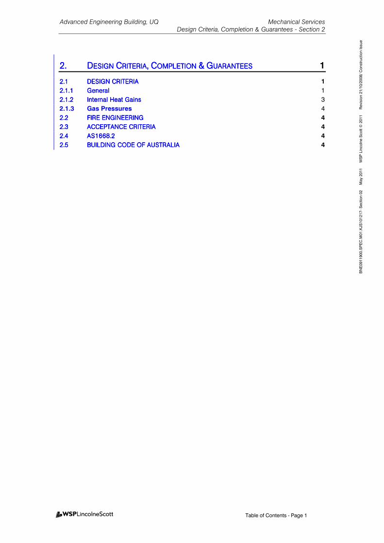
2.2.2.2. DDDDESIGN ESIGN ESIGN ESIGN CCCCRITERIARITERIARITERIARITERIA,,,, CCCCOMPLETION OMPLETION OMPLETION OMPLETION &&&& GGGGUARANTEESUARANTEESUARANTEESUARANTEES 1
2.12.12.12.1 DESIGN CRITERIADESIGN CRITERIADESIGN CRITERIADESIGN CRITERIA 1
2.1.12.1.12.1.12.1.1 GeneralGeneralGeneralGeneral 1
2.1.22.1.22.1.22.1.2 Internal Heat GainsInternal Heat GainsInternal Heat GainsInternal Heat Gains 3
2.1.3 Gas Pressures 4
2.22.22.22.2 FIRE ENGINEERINGFIRE ENGINEERINGFIRE ENGINEERINGFIRE ENGINEERING 4
2.32.32.32.3 ACCEPTANCE CRITERIAACCEPTANCE CRITERIAACCEPTANCE CRITERIAACCEPTANCE CRITERIA 4
2.42.42.42.4 AS1668.2AS1668.2AS1668.2AS1668.2 4
2.52.52.52.5 BUILDING CODE OF AUSBUILDING CODE OF AUSBUILDING CODE OF AUSBUILDING CODE OF AUSTRALIATRALIATRALIATRALIA 4

Advanced Engineering Building, UQ Mechanical Services
Design Criteria, Completion & Guarantees - Section 2
Section 2 - Page 1
BNE0911900.SPEC.M01.KJS101217- Section 02 May 2011 WSP Lincolne Scott © 2011 Revision 21/10/2008/ Construction Issue
2.2.2.2. DDDDESIGN ESIGN ESIGN ESIGN CCCCRITERIARITERIARITERIARITERIA,,,, CCCCOMPLETION OMPLETION OMPLETION OMPLETION &&&& GGGGUARANTEESUARANTEESUARANTEESUARANTEES
2.12.12.12.1 DESIGN CRITERIADESIGN CRITERIADESIGN CRITERIADESIGN CRITERIA
2.1.12.1.12.1.12.1.1 GeneralGeneralGeneralGeneral
Design conditions will be in accordance with UQ Technical Guide TG13 and are scheduled below. Specialist user requirements are also scheduled and noted:
ParameterParameterParameterParameter Design CriteriaDesign CriteriaDesign CriteriaDesign Criteria
Office and Teaching Spaces
External Ambient Conditions
(for air conditioning plant full load performance)
Summer
32.0°C dry bulb maximum
25.0°C wet bulb maximum
Winter
9.0°C dry bulb minimum
Concrete Creep, Concrete Curing, Concrete Shrinkage and Controlled Environment Room
External Ambient Conditions
(for air conditioning plant full load performance)
Summer
35.4°C dry bulb maximum
26.5°C wet bulb maximum
Winter
0.0°C dry bulb minimum
Office and Teaching Spaces
Internal Conditions
(for air conditioning plant full load performance)
Summer
23°C dry bulb maximum at point of control
Winter
21°C dry bulb at the point of control
Relative humidity generally in the range 40%-60% but noting that no humidity controls are specified.
Upper limit on humidity of 60% is controlled by virtue of cooling coil performance only.
Set point control will be in accordance with UQ Technical Guidelines for Relaxed Mode and Occupied operational modes.
Concrete Creep Lab – C1
Design Conditions
22°C to 27°C (adjustable) Controlled Temperature (Nominal +/- 1°C), 35% to 70% (adjustable) Controlled Relative humidity (Nominal +/- 5%)
Concrete Curing Room – C2
Design Conditions
24°C/50% nominal (No controlled relative humidity )
Advanced Engineering Building, UQ Mechanical Services
Design Criteria, Completion & Guarantees - Section 2
Section 2 - Page 2
BNE0911900.SPEC.M01.KJS101217- Section 02 May 2011 WSP Lincolne Scott © 2011 Revision 21/10/2008/ Construction Issue
ParameterParameterParameterParameter Design CriteriaDesign CriteriaDesign CriteriaDesign Criteria
Concrete Shrinkage Lab – C3
Design Conditions
23°CControlled Temperature (Nominal +/- 1°C),
50% Controlled Relative Humidity (Nominal +/- 5%)
Controlled Environment Room – C5 Design Conditions
25°C to 40°C (adjustable) Controlled Temperature (Nominal +/- 1°C),
10% to 99% (adjustable) Controlled Relative Humidity (Nominal +/- 5%)
Air Conditioning System Controls Tolerance ±1.0°C dry bulb at point of control UNO
Ventilation Outside Air: To AS1668.1 and as enhanced for Greenstar compliance (+50%)
Carbon dioxide control setpoints 800ppm.
Exhaust Air General Requirements: As per AS1668.2 1991 & UQ Technical Guidelines TG13 – Mechanical Engineering
Hours of Operation 7:30am to 6pm Monday to Friday (Excludes critical control spaces)
Central Chilled Water Inlet Water Temperature - 6.0°C Outlet Water Temperature - 14.0°C
PC2 Labs (rooms 418, 419 and 530) Comply with AS2243.3, including operation at negative pressure relative to surrounding areas.
Advanced Engineering Building, UQ Mechanical Services
Design Criteria, Completion & Guarantees - Section 2
Section 2 - Page 3
BNE0911900.SPEC.M01.KJS101217- Section 02 May 2011 WSP Lincolne Scott © 2011 Revision 21/10/2008/ Construction Issue
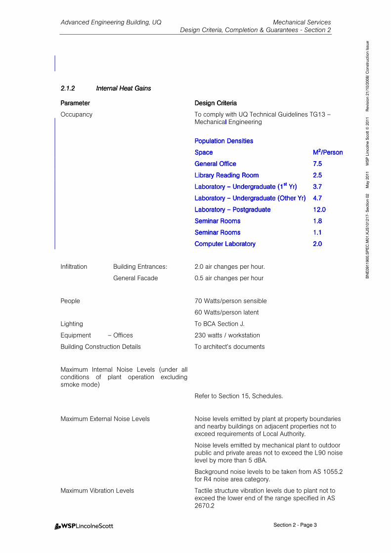
2.1.22.1.22.1.22.1.2 Internal Heat GainsInternal Heat GainsInternal Heat GainsInternal Heat Gains
ParameterParameterParameterParameter Design CriteriaDesign CriteriaDesign CriteriaDesign Criteria
Occupancy To comply with UQ Technical Guidelines TG13 – Mechanicallll Engineering
Population Population Population Population DensitiesDensitiesDensitiesDensities
SpaceSpaceSpaceSpace M²/PersonM²/PersonM²/PersonM²/Person
GeneralGeneralGeneralGeneral OfficeOfficeOfficeOffice 7.57.57.57.5
Library Reading RoomLibrary Reading RoomLibrary Reading RoomLibrary Reading Room 2.52.52.52.5
Laboratory Laboratory Laboratory Laboratory –––– Undergraduate Undergraduate Undergraduate Undergraduate (1(1(1(1stststst Yr)Yr)Yr)Yr) 3.73.73.73.7
Laboratory Laboratory Laboratory Laboratory –––– Undergraduate (Other Yr)Undergraduate (Other Yr)Undergraduate (Other Yr)Undergraduate (Other Yr) 4.74.74.74.7
Laboratory Laboratory Laboratory Laboratory –––– PostgraduatePostgraduatePostgraduatePostgraduate 12.012.012.012.0
Seminar RoomsSeminar RoomsSeminar RoomsSeminar Rooms 1.81.81.81.8
Seminar RoomsSeminar RoomsSeminar RoomsSeminar Rooms 1.11.11.11.1
Computer LaboratoryComputer LaboratoryComputer LaboratoryComputer Laboratory 2.02.02.02.0
Infiltration Building Entrances: 2.0 air changes per hour.
General Facade 0.5 air changes per hour
People 70 Watts/person sensible
60 Watts/person latent
Lighting To BCA Section J.
Equipment – Offices 230 watts / workstation
Building Construction Details To architect’s documents
Maximum Internal Noise Levels (under all conditions of plant operation excluding smoke mode)
Refer to Section 15, Schedules.
Maximum External Noise Levels Noise levels emitted by plant at property boundaries and nearby buildings on adjacent properties not to exceed requirements of Local Authority.
Noise levels emitted by mechanical plant to outdoor public and private areas not to exceed the L90 noise level by more than 5 dBA.
Background noise levels to be taken from AS 1055.2 for R4 noise area category.
Maximum Vibration Levels Tactile structure vibration levels due to plant not to exceed the lower end of the range specified in AS 2670.2
Advanced Engineering Building, UQ Mechanical Services
Design Criteria, Completion & Guarantees - Section 2
Section 2 - Page 4
BNE0911900.SPEC.M01.KJS101217- Section 02 May 2011 WSP Lincolne Scott © 2011 Revision 21/10/2008/ Construction Issue
ParameterParameterParameterParameter Design CriteriaDesign CriteriaDesign CriteriaDesign Criteria
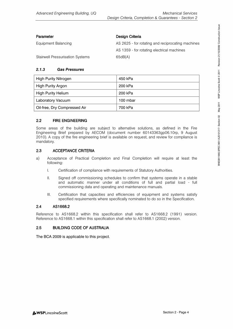
Equipment Balancing AS 2625 - for rotating and reciprocating machines
AS 1359 - for rotating electrical machines
Stairwell Pressurisation Systems 65dB(A)
2.1.3 Gas Pressures
High Purity Nitrogen 450 kPa
High Purity Argon 200 kPa
High Purity Helium 200 kPa
Laboratory Vacuum 100 mbar
Oil-free, Dry Compressed Air 700 kPa
2.22.22.22.2 FIRE ENGINEERING FIRE ENGINEERING FIRE ENGINEERING FIRE ENGINEERING
Some areas of the building are subject to alternative solutions, as defined in the Fire Engineering Brief prepared by AECOM (document number 60143363gp06.10rp, 9 August 2010). A copy of the fire engineering brief is available on request, and review for compliance is mandatory.
2.32.32.32.3 ACCEPTANCE CRITERIAACCEPTANCE CRITERIAACCEPTANCE CRITERIAACCEPTANCE CRITERIA
a) Acceptance of Practical Completion and Final Completion will require at least the following:
I. Certification of compliance with requirements of Statutory Authorities.
II. Signed off commissioning schedules to confirm that systems operate in a stable and automatic manner under all conditions of full and partial load - full commissioning data and operating and maintenance manuals.
III. Certification that capacities and efficiencies of equipment and systems satisfy specified requirements where specifically nominated to do so in the Specification.
2.42.42.42.4 AS1668.2AS1668.2AS1668.2AS1668.2
Reference to AS1668.2 within this specification shall refer to AS1668.2 (1991) version. Reference to AS1668.1 within this specification shall refer to AS1668.1 (2002) version.
2.52.52.52.5 BUILDING CODE OF AUSBUILDING CODE OF AUSBUILDING CODE OF AUSBUILDING CODE OF AUSTRALIATRALIATRALIATRALIA
The BCA 2009 is applicable to this project.
Advanced Engineering Building, UQ Mechanical Services General Requirements– Section 3
Table of Contents - Page 1
BNE0911900.SPEC.M01.KJS101130 - Section 03 May 2011 WSP Lincolne Scott © 2011 Revision 310807 / Construction Issue
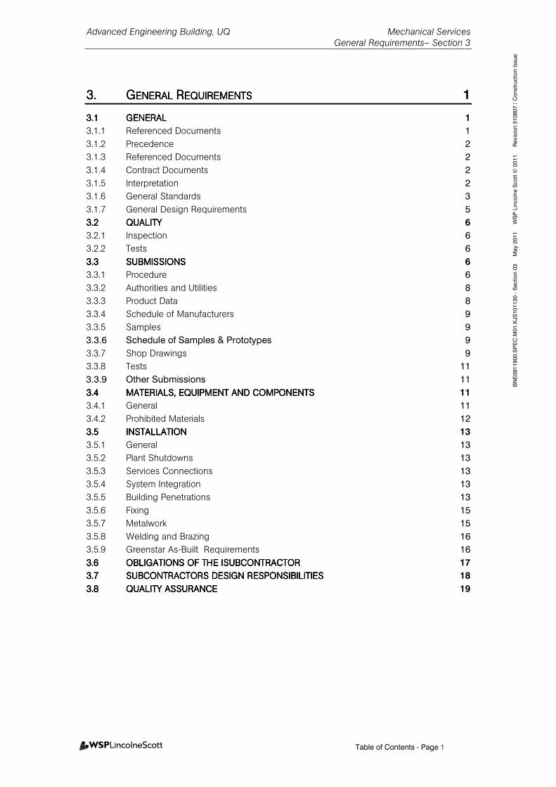
3.3.3.3. GGGGENERAL ENERAL ENERAL ENERAL RRRREQUIREMENTSEQUIREMENTSEQUIREMENTSEQUIREMENTS 1
3.13.13.13.1 GENERALGENERALGENERALGENERAL 1
3.1.1 Referenced Documents 1
3.1.2 Precedence 2
3.1.3 Referenced Documents 2
3.1.4 Contract Documents 2
3.1.5 Interpretation 2
3.1.6 General Standards 3
3.1.7 General Design Requirements 5
3.23.23.23.2 QUALITYQUALITYQUALITYQUALITY 6
3.2.1 Inspection 6
3.2.2 Tests 6
3.33.33.33.3 SUBMISSIONSSUBMISSIONSSUBMISSIONSSUBMISSIONS 6
3.3.1 Procedure 6
3.3.2 Authorities and Utilities 8
3.3.3 Product Data 8
3.3.4 Schedule of Manufacturers 9
3.3.5 Samples 9
3.3.6 Schedule of Samples & Prototypes 9
3.3.7 Shop Drawings 9
3.3.8 Tests 11
3.3.9 Other Submissions 11
3.43.43.43.4 MATERIALS, EQUIPMENTMATERIALS, EQUIPMENTMATERIALS, EQUIPMENTMATERIALS, EQUIPMENT AND COMPONENTSAND COMPONENTSAND COMPONENTSAND COMPONENTS 11
3.4.1 General 11
3.4.2 Prohibited Materials 12
3.53.53.53.5 INSTALLATIONINSTALLATIONINSTALLATIONINSTALLATION 13
3.5.1 General 13
3.5.2 Plant Shutdowns 13
3.5.3 Services Connections 13
3.5.4 System Integration 13
3.5.5 Building Penetrations 13
3.5.6 Fixing 15
3.5.7 Metalwork 15
3.5.8 Welding and Brazing 16
3.5.9 Greenstar As-Built Requirements 16
3.63.63.63.6 OBLIGATIONS OF THE IOBLIGATIONS OF THE IOBLIGATIONS OF THE IOBLIGATIONS OF THE ISUBCONTRACTORSUBCONTRACTORSUBCONTRACTORSUBCONTRACTOR 17
3.73.73.73.7 SUBCONTRACTORS DESIGSUBCONTRACTORS DESIGSUBCONTRACTORS DESIGSUBCONTRACTORS DESIGN RESPONSIBILITIESN RESPONSIBILITIESN RESPONSIBILITIESN RESPONSIBILITIES 18
3.83.83.83.8 QUALITY ASSURANCEQUALITY ASSURANCEQUALITY ASSURANCEQUALITY ASSURANCE 19
Advanced Engineering Building, UQ Mechanical Services General Requirements– Section 3
Section 3 - Page 1
BNE0911900.SPEC.M01.KJS101130 - Section 03 May 2011 WSP Lincolne Scott © 2011 Revision 310807 / Construction Issue
3.3.3.3. GGGGENERAL ENERAL ENERAL ENERAL RRRREQUIREMENTSEQUIREMENTSEQUIREMENTSEQUIREMENTS
3.13.13.13.1 GENERALGENERALGENERALGENERAL
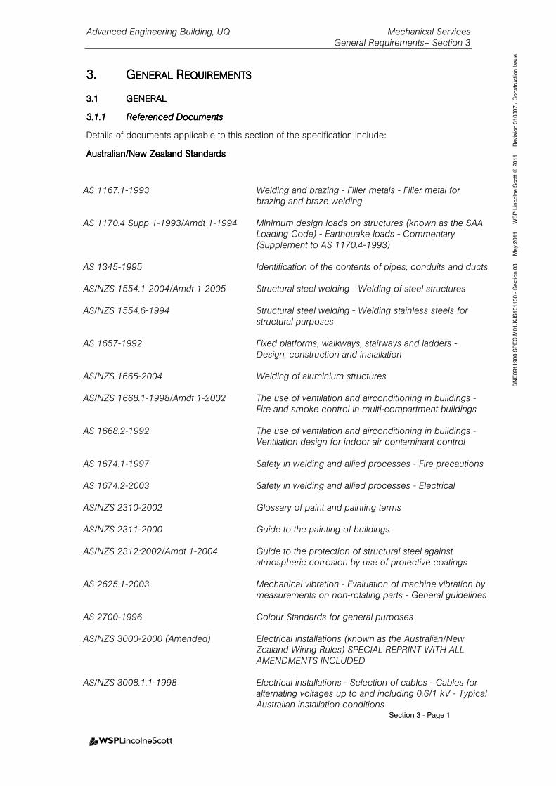
3.1.13.1.13.1.13.1.1 Referenced DocumentsReferenced DocumentsReferenced DocumentsReferenced Documents
Details of documents applicable to this section of the specification include:
Australian/New ZAustralian/New ZAustralian/New ZAustralian/New Zealand Standardsealand Standardsealand Standardsealand Standards
AS 1167.1-1993 Welding and brazing - Filler metals - Filler metal for brazing and braze welding
AS 1170.4 Supp 1-1993/Amdt 1-1994 Minimum design loads on structures (known as the SAA
Loading Code) - Earthquake loads - Commentary (Supplement to AS 1170.4-1993)
AS 1345-1995 Identification of the contents of pipes, conduits and ducts AS/NZS 1554.1-2004/Amdt 1-2005 Structural steel welding - Welding of steel structures AS/NZS 1554.6-1994 Structural steel welding - Welding stainless steels for
structural purposes AS 1657-1992 Fixed platforms, walkways, stairways and ladders -
Design, construction and installation AS/NZS 1665-2004 Welding of aluminium structures AS/NZS 1668.1-1998/Amdt 1-2002 The use of ventilation and airconditioning in buildings -
Fire and smoke control in multi-compartment buildings AS 1668.2-1992 The use of ventilation and airconditioning in buildings -
Ventilation design for indoor air contaminant control AS 1674.1-1997 Safety in welding and allied processes - Fire precautions AS 1674.2-2003 Safety in welding and allied processes - Electrical AS/NZS 2310-2002 Glossary of paint and painting terms AS/NZS 2311-2000 Guide to the painting of buildings AS/NZS 2312:2002/Amdt 1-2004 Guide to the protection of structural steel against
atmospheric corrosion by use of protective coatings AS 2625.1-2003 Mechanical vibration - Evaluation of machine vibration by
measurements on non-rotating parts - General guidelines AS 2700-1996 Colour Standards for general purposes AS/NZS 3000-2000 (Amended) Electrical installations (known as the Australian/New
Zealand Wiring Rules) SPECIAL REPRINT WITH ALL AMENDMENTS INCLUDED
AS/NZS 3008.1.1-1998 Electrical installations - Selection of cables - Cables for
alternating voltages up to and including 0.6/1 kV - Typical Australian installation conditions
Advanced Engineering Building, UQ Mechanical Services General Requirements– Section 3
Section 3 - Page 2
BNE0911900.SPEC.M01.KJS101130 - Section 03 May 2011 WSP Lincolne Scott © 2011 Revision 310807 / Construction Issue
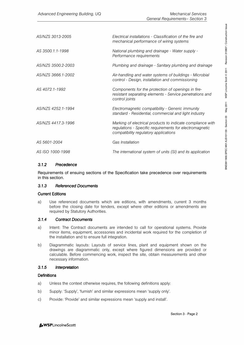
3.1.23.1.23.1.23.1.2 PrecedencePrecedencePrecedencePrecedence
Requirements of ensuing sections of the Specification take precedence over requirements
in this section.
3.1.33.1.33.1.33.1.3 Referenced DocumentsReferenced DocumentsReferenced DocumentsReferenced Documents
Current EditionsCurrent EditionsCurrent EditionsCurrent Editions
a) Use referenced documents which are editions, with amendments, current 3 months before the closing date for tenders, except where other editions or amendments are required by Statutory Authorities.
3.1.43.1.43.1.43.1.4 Contract DocumentsContract DocumentsContract DocumentsContract Documents
a) Intent: The Contract documents are intended to call for operational systems. Provide minor items, equipment, accessories and incidental work required for the completion of the installation and to ensure full integration.
b) Diagrammatic layouts: Layouts of service lines, plant and equipment shown on the drawings are diagrammatic only, except where figured dimensions are provided or calculable. Before commencing work, inspect the site, obtain measurements and other necessary information.
3.1.53.1.53.1.53.1.5 InterpretationInterpretationInterpretationInterpretation
DefinitionsDefinitionsDefinitionsDefinitions
a) Unless the context otherwise requires, the following definitions apply:
b) Supply: ‘Supply’, ‘furnish’ and similar expressions mean ‘supply only’.
c) Provide: ‘Provide’ and similar expressions mean ‘supply and install’.
AS/NZS 3013-2005 Electrical installations - Classification of the fire and
mechanical performance of wiring systems AS 3500.1.1-1998 National plumbing and drainage - Water supply -
Performance requirements AS/NZS 3500.2-2003 Plumbing and drainage - Sanitary plumbing and drainage AS/NZS 3666.1-2002 Air-handling and water systems of buildings - Microbial
control - Design, installation and commissioning AS 4072.1-1992 Components for the protection of openings in fire-
resistant separating elements - Service penetrations and control joints
AS/NZS 4252.1-1994 Electromagnetic compatibility - Generic immunity
standard - Residential, commercial and light industry AS/NZS 4417.3-1996 Marking of electrical products to indicate compliance with
regulations - Specific requirements for electromagnetic compatibility regulatory applications
AS 5601-2004 Gas Installation AS ISO 1000-1998 The international system of units (SI) and its application
Advanced Engineering Building, UQ Mechanical Services General Requirements– Section 3
Section 3 - Page 3
BNE0911900.SPEC.M01.KJS101130 - Section 03 May 2011 WSP Lincolne Scott © 2011 Revision 310807 / Construction Issue
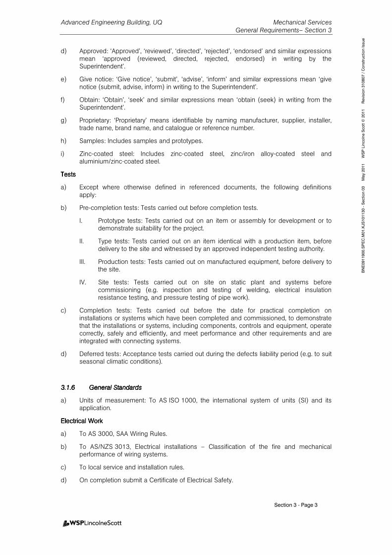
d) Approved: ‘Approved’, ‘reviewed’, ‘directed’, ‘rejected’, ‘endorsed’ and similar expressions mean ‘approved (reviewed, directed, rejected, endorsed) in writing by the Superintendent’.
e) Give notice: ‘Give notice’, ‘submit’, ‘advise’, ‘inform’ and similar expressions mean ‘give notice (submit, advise, inform) in writing to the Superintendent’.
f) Obtain: ‘Obtain’, ‘seek’ and similar expressions mean ‘obtain (seek) in writing from the Superintendent’.
g) Proprietary: ‘Proprietary’ means identifiable by naming manufacturer, supplier, installer, trade name, brand name, and catalogue or reference number.
h) Samples: Includes samples and prototypes.
i) Zinc-coated steel: Includes zinc-coated steel, zinc/iron alloy-coated steel and aluminium/zinc-coated steel.
TestsTestsTestsTests
a) Except where otherwise defined in referenced documents, the following definitions apply:
b) Pre-completion tests: Tests carried out before completion tests.
I. Prototype tests: Tests carried out on an item or assembly for development or to demonstrate suitability for the project.
II. Type tests: Tests carried out on an item identical with a production item, before delivery to the site and witnessed by an approved independent testing authority.
III. Production tests: Tests carried out on manufactured equipment, before delivery to the site.
IV. Site tests: Tests carried out on site on static plant and systems before commissioning (e.g. inspection and testing of welding, electrical insulation resistance testing, and pressure testing of pipe work).
c) Completion tests: Tests carried out before the date for practical completion on installations or systems which have been completed and commissioned, to demonstrate that the installations or systems, including components, controls and equipment, operate correctly, safely and efficiently, and meet performance and other requirements and are integrated with connecting systems.
d) Deferred tests: Acceptance tests carried out during the defects liability period (e.g. to suit seasonal climatic conditions).
3.1.63.1.63.1.63.1.6 General StandardsGeneral StandardsGeneral StandardsGeneral Standards
a) Units of measurement: To AS ISO 1000, the international system of units (SI) and its application.
Electrical WorkElectrical WorkElectrical WorkElectrical Work
a) To AS 3000, SAA Wiring Rules.
b) To AS/NZS 3013, Electrical installations – Classification of the fire and mechanical performance of wiring systems.
c) To local service and installation rules.
d) On completion submit a Certificate of Electrical Safety.

Advanced Engineering Building, UQ Mechanical Services General Requirements– Section 3
Section 3 - Page 4
BNE0911900.SPEC.M01.KJS101130 - Section 03 May 2011 WSP Lincolne Scott © 2011 Revision 310807 / Construction Issue
Fixed Access WaysFixed Access WaysFixed Access WaysFixed Access Ways
a) To AS 1657, Fixed platforms, walkways, stairways and ladders.
Mechanical Ventilation and Air ConditioningMechanical Ventilation and Air ConditioningMechanical Ventilation and Air ConditioningMechanical Ventilation and Air Conditioning
a) To AS/NZS 1668.1, Fire and smoke control in multi-compartment buildings and AS 1668.2, Mechanical ventilation for acceptable indoor air quality, as required by the Building Code of Australia.
Microbial ControlMicrobial ControlMicrobial ControlMicrobial Control
a) To AS/NZS 3666.1, Air handling and water systems of buildings – Microbial control.
Water SupplyWater SupplyWater SupplyWater Supply
a) To AS/NZS 3500.1.1, Water supply – Performance requirements and AS/NZS 3500.1.2, Water supply – Acceptable solutions.
Gas InstallationGas InstallationGas InstallationGas Installation
a) To AS 5601, Gas installation code.
Plumbing and DrainagePlumbing and DrainagePlumbing and DrainagePlumbing and Drainage
a) To AS/NZS 3500.2, sanitary plumbing and drainage.
Electromagnetic CompatibilityElectromagnetic CompatibilityElectromagnetic CompatibilityElectromagnetic Compatibility
a) Comply with Australian Communications Authority requirements for electrical and electronics products to limit electromagnetic interference (EMI).
b) Emissions:
I. Passive products with C-tick or Regulatory Compliance Mark (RCM) to AS/NZS 4417.3, marking of electrical products to indicate compliance with regulations – Specific requirements for electromagnetic compatibility regulatory applications.
c) Immunity:
I. Electrical and electronic apparatus: To AS/NZS 4252.1, Electromagnetic compatibility – Generic immunity standard – Residential, commercial and light industry (EN 50082-1), or
II. EN 5008-2, Electromagnetic compatibility – Generic immunity standard – Industrial environment.
d) Harmonics and Voltage Surges:
I. Levels of emissions to be acceptable to the electricity suppliers.
Seismic LoadingSeismic LoadingSeismic LoadingSeismic Loading
a) Design criteria to AS 1170.4, Earthquake loads:
b) Earthquake design category III
c) Probability factor kp=1.3
d) Hazard factor Z=0.05
e) Performance factor Sp=0.77
f) Ductility factor u=2
Advanced Engineering Building, UQ Mechanical Services General Requirements– Section 3
Section 3 - Page 5
BNE0911900.SPEC.M01.KJS101130 - Section 03 May 2011 WSP Lincolne Scott © 2011 Revision 310807 / Construction Issue
3.1.73.1.73.1.73.1.7 General Design RequirementsGeneral Design RequirementsGeneral Design RequirementsGeneral Design Requirements
Space RequirementsSpace RequirementsSpace RequirementsSpace Requirements
a) Check space requirements of equipment and services which are indicated diagrammatically in the Contract documents. Select equipment with dimensions to suit the available space.
b) Lay out equipment and services to be accessible for operation, maintenance and replacement and so as not to interfere with access to other installations. Make offsets as necessary.
c) Set out access ways 2.1m high and 1.0m wide to all major plant clear of all obstructions, unless otherwise approved.
CoCoCoCo----OrdinationOrdinationOrdinationOrdination
a) Co-ordinate the layout of plant and services with the building layout and structure, and with other plant and services.
b) Neatly group services, with separate layers for crossing services.
c) Note that almost all services are exposed to view, and neatness of installation in all forms is essential.
Electrical Supply SystemElectrical Supply SystemElectrical Supply SystemElectrical Supply System
a) 415V, 3-phase, 4-wire, 50Hz.
Rotating Machinery VibrationRotating Machinery VibrationRotating Machinery VibrationRotating Machinery Vibration
a) Vibration severity: At least Satisfactory, to AS 2625.1.
Mechanical System ResistancesMechanical System ResistancesMechanical System ResistancesMechanical System Resistances
a) Calculate system resistances to fluid flow based upon the actual plant layout and selected equipment. Allow for dirty filters and diversified flows. Allow for standby plant and future demand as shown.
b) Amend piping, fans, pumps, motors and electrical power supplies to suit the requirements of the actual installation. Submit amended selections for review. Comply with the stricter of the BCA Section J maximum power ratings and those in the schedules.
Electrical Cable SizingElectrical Cable SizingElectrical Cable SizingElectrical Cable Sizing
a) Calculate cable rating and voltage drops based upon actual cable lengths and selected make of cables. Allow for standby plant and future demand as shown. Take into consideration installation conditions, and external influences short-circuit fault levels and ratings of protection equipment.
b) Standard: To AS/NZS 3008.1.1 Cables for alternating voltages up to and including 0.6/1kV.
c) Amend cable sizes or installation to suit. Submit amended selections for review.
ElElElElectrical Protection and Gradingectrical Protection and Gradingectrical Protection and Gradingectrical Protection and Grading
a) Protect and grade the electrical reticulation and distribution system so that all faults are cleared by the protective device immediately upstream of the system circuit fault.
b) It is intended that the grading shall be applied from the point of supply to the terminal equipment of the building.
Advanced Engineering Building, UQ Mechanical Services General Requirements– Section 3
Section 3 - Page 6
BNE0911900.SPEC.M01.KJS101130 - Section 03 May 2011 WSP Lincolne Scott © 2011 Revision 310807 / Construction Issue
Balance of Electrical LoadsBalance of Electrical LoadsBalance of Electrical LoadsBalance of Electrical Loads
a) Balance loads evenly over all phases.
3.23.23.23.2 QUALITYQUALITYQUALITYQUALITY
3.2.13.2.13.2.13.2.1 InspectionInspectionInspectionInspection
NoticeNoticeNoticeNotice
a) Inspect witness points: If notice for inspection is to be given in respect of parts of the works, advise if and when those parts are to be concealed.
b) Inspection hold points: If notice of inspection is to be given in respect of parts of the works, do not conceal those parts without approval.
c) Minimum notice for inspections to be made: 4 hours for inspections full time on-site, otherwise 2 working days for on-site inspections, and 5 working days for local pre-delivery inspections.
d) Concealed services: Give notice so that inspection may be made of services to be concealed.
3.2.23.2.23.2.23.2.2 TestsTestsTestsTests
NoticeNoticeNoticeNotice
a) Witness tests: Give sufficient notice so that designated tests may be witnessed.
b) Minimum notice for tests to be witnessed:
I. 5 working days for site tests; and
II. 10 working days for local pre-delivery tests.
c) Test hold points: Do not carry out designated tests without approval.
TTTTesting Authoritiesesting Authoritiesesting Authoritiesesting Authorities
a) General: Except for Site Tests, have type tests carried out by authorities accredited by NATA to test in the relevant field, or an approved organisation outside Australia recognised by NATA through a mutual recognition agreement. Co-operate as required with testing authorities.
b) Site tests: Use instruments calibrated by authorities accredited by NATA.
ReportsReportsReportsReports
a) General: Submit copies of test reports, including certificates for type tests, showing the observations and results of tests and compliance or non-compliance with requirements.
EndorsementEndorsementEndorsementEndorsement
a) If tests are to be carried out on parts of the work, do not conceal those parts and do not commence further work on those parts until the tests have been satisfactorily completed and compliance verified.
3.33.33.33.3 SUBMISSIONSSUBMISSIONSSUBMISSIONSSUBMISSIONS
3.3.13.3.13.3.13.3.1 ProcedureProcedureProcedureProcedure
GeneralGeneralGeneralGeneral
a) Submit documents and samples for review.
Advanced Engineering Building, UQ Mechanical Services General Requirements– Section 3
Section 3 - Page 7
BNE0911900.SPEC.M01.KJS101130 - Section 03 May 2011 WSP Lincolne Scott © 2011 Revision 310807 / Construction Issue
TimingTimingTimingTiming
a) General: Make submissions in a timely manner, to suit the construction programme. Co-ordinate submissions of related items. Allow time for review and possible amendment and resubmission. Allow for five (5) weeks for review of work shop drawings unless otherwise agreed in the Contract.
b) Delays: Avoid delays by making early and adequate submissions.
c) Notice: Give notice before commencing work affected by Subcontractor’s submissions, unless the submissions have been reviewed with no exception taken.
d) Hold points: Where hold points are specified, do not commence work affected by Subcontractor’s submission until the submissions have been reviewed with no exception taken.
Submissions Submissions Submissions Submissions ScheduleScheduleScheduleSchedule
a) Maintain and submit monthly a schedule of shop drawings and submission to identify all proposed drawings and submissions designated in the following categories:
I. Accepted.
II. Submitted awaiting acceptance with submission date and revision number.
III. Outstanding.
QuantityQuantityQuantityQuantity
a) Submissions for review:
I. Loose documents up to and including A0 size: 1 copy black and white on bond paper, suitable for photocopying.
II. Bound documents: 3 copies.
III. Samples: 1 each.
IV. Construction issue following review: 6 copies.
V. Alternatively submit electronically if agreed.
IdentificationIdentificationIdentificationIdentification
a) Identify the project, Contractor, Subcontractor or supplier, manufacturer, applicable product, model number and options, as appropriate and include pertinent Contract document or equipment identifier references. Include service connection requirements and product certification. Identify non-compliances with project requirements, and characteristics which may be detrimental to successful performance of the completed work.
AmendmentsAmendmentsAmendmentsAmendments
a) Submit amended documents as appropriate, highlighting changes since the previous submission.
DeviationsDeviationsDeviationsDeviations
a) Where selected equipment of systems does not fully comply with the Contract, submit details of proposed deviations for approval. Where such deviations require any changes to the structure, building works or services, these shall be provided by the Subcontractor without variation to the Contract.
Advanced Engineering Building, UQ Mechanical Services General Requirements– Section 3
Section 3 - Page 8
BNE0911900.SPEC.M01.KJS101130 - Section 03 May 2011 WSP Lincolne Scott © 2011 Revision 310807 / Construction Issue
AlternativesAlternativesAlternativesAlternatives
a) If alternatives are proposed, submit proposed alternatives and include cost, samples where specified, technical information, advantages and disadvantages of proposed substitutions including life, operating costs and effect on programme. State if use of proposed alternatives will necessitate alteration to other parts of the works and include consequent costs.
DesignDesignDesignDesign
a) General: If part or all of an installation is to be designed by the Subcontractor, submit documents showing the layout and details of the installation and details of the design.
3.3.23.3.23.3.23.3.2 Authorities and UtilitiesAuthorities and UtilitiesAuthorities and UtilitiesAuthorities and Utilities
a) Correspondence: Submit copies of correspondence and notes of meetings with authorities and utilities.
b) Authorities and utilities approvals: Submit documents showing approval of the authorities and utilities whose requirements may apply to the work.
3.3.33.3.33.3.33.3.3 Product DataProduct DataProduct DataProduct Data
a) Provide technical data submissions for items of equipment and plant proposed, for review and comment by the Superintendent.
Where the manufacturer’s technical data and information forwarded by the subcontractor (technical data submission) does not cover all the specification requirements, a schedule of items which are different from the tender specification shall be submitted.
Apart from the non-conforming details/items listed in the submission, it would be assumed that the equipment proposed meets with all other specified requirements.
Review of plant/equipment proposed will be undertaken on the above basis.
Failure to identify any deviation from the specified requirements at the proposal stage could result in equipment having to be replaced after installation. It is therefore important that all tenderers and equipment suppliers are made aware of this requirement.
The technical review will be undertaken on the basis that non-complying equipment may be rejected at any time.
a) Hold points: Do not commence production of equipment, materials, components of equipment, materials, components or systems until submission have been reviewed with no exceptions taken.
b) Extent of submissions: Submit manufacturer’s data for equipment, materials, components and systems comprising:
I. Technical specifications and drawings.
II. Size, arrangement, operating and maintenance clearances.
III. Operating weight.
IV. Type test reports.
V. Performance and rating curves or tables marked with each selection showing for duty point and part load conditions:
aa) capacity;
ab) energy consumption and power factor;
ac) sound power level.
Advanced Engineering Building, UQ Mechanical Services General Requirements– Section 3
Section 3 - Page 9
BNE0911900.SPEC.M01.KJS101130 - Section 03 May 2011 WSP Lincolne Scott © 2011 Revision 310807 / Construction Issue
VI. Motor power requirements (full load and starting).
VII. Control details.
VIII. Recommendations for installation and maintenance.
IX. Evidence of compliance with specified product certification schemes.
X. Range of submissions: Submit manufacturer’s data for all equipment, materials components and systems to be provided including the following as applicable.
3.3.43.3.43.3.43.3.4 Schedule of ManufacturersSchedule of ManufacturersSchedule of ManufacturersSchedule of Manufacturers
a) Submit within three weeks of award of the Contract a schedule of manufacturers of equipment, materials and components including relevant items listed.
b) Mechanical Services:
I. Air conditioning units II. Air filters
III. All major equipment such as chillers, cooling towers, boilers, etc.
IV. Dampers
V. Ductwork VI. Electric heaters
VII. Expansion joints VIII. Fans
IX. Fire dampers X. Gauges
XI. Instruments XII. Mechanical control system
XIII. Mechanical services switchboards XIV. VAV boxes
XV. Painting and identification XVI. Piping
XVII. Pumps XVIII. Registers, diffusers and grilles
XIX. Sound attenuators XX. Constant Environment Room equipment
XXI. Vibration isolating mountings XXII. Volume dampers
3.3.53.3.53.3.53.3.5 SamplesSamplesSamplesSamples
a) General: Submit one sample of each designated item with copies of supporting documentation. Submit a range of samples if choice of colour or finish is required. Amend and resubmit samples which are not approved.
b) Retention and incorporation: Keep approved samples in good condition on site, until practical completion. Incorporate in the works samples which have been approved for installation. Do not incorporate after other samples. Work on site to match approved samples.
3.3.6 Schedule of Samples & Prototypes
a) Refer to Section 15 for schedule of samples and prototypes required.
3.3.73.3.73.3.73.3.7 Shop DrawingsShop DrawingsShop DrawingsShop Drawings
a) General: Prepare and submit dimensioned drawings showing details of the fabrication, layout and installation of all plant and equipment, including relationship to building structure and other services.
b) Co-ordinate the technical and spatial aspects of plant, including construction tolerances.

Advanced Engineering Building, UQ Mechanical Services General Requirements– Section 3
Section 3 - Page 10
BNE0911900.SPEC.M01.KJS101130 - Section 03 May 2011 WSP Lincolne Scott © 2011 Revision 310807 / Construction Issue
c) Provide drawings and details of associated work by other subcontractors (e.g. plinth layouts, holding bolt setout, penetration locations) and details of interfaces in sufficient time to allow incorporation in the works in the most economical manner.
d) Provide 3 dimensional co-ordinated shop drawings, based on importing models from the other services subcontractors. Liaise with services tsubcontractors during preparation to ensure services are co-ordinated. Provide all necessary advice during the preparation of these drawings to ensure that the drawings accurately represent what will be installed including any proposed changes to the design drawings. The shop drawings are to highlight any clashes between services that are unable to be coordinated to allow resolution prior to commencing construction
e) Confirm dimensions by site measurement.
f) Format: AutoCAD REVIT 2010, version to match the architectural requirements, with standard metric scale and dimension scale line for drawing reduction.
g) Sheet sizes: Standard metric series.
h) At the end of the process the mechanical subcontractor is responsible not only for mechanical drawings, but also for importing construction models from the architect and from other services subcontractors, and co-ordinating and producing fully dimensioned set out drawings for all relevant subcontractors including cable trays, bus ducts, pipework, items on ceiling and penetration drawings. Modify the 3D drawings to as constructed status on completion for inclusion within as constructed submissions.
i) REVIT Model Plots and AutoCAD schematics for review to include:
I. Plantroom layout plans 1:50 scale, with sections and details at 1:20 scale.
II. Floor plans at 1:50 scale, with detailed sections.
III. Access to and removal of all plant including locations and sizes of access doors to be installed in finished building surfaces.
IV. Schematic and layout drawings of piping, ducting, tray and conduits, electrical and controls.
V. Schedule of electrical loadings.
VI. Switchboard and control panel layouts and schematics with terminal numbering.
VII. Cable type, size and marking details.
VIII. Location and identifier for all equipment.
IX. Locations of all control sensors (eg temperature sensors, velocity sensors, valves and actuators shall be shown on floor plan drawings).
X. Air Flow Schematics for all systems and buildings.
XI. Register schedule containing all registers and air flows (both design and actual)
XII. Detail of all interfaces with other services and utilities.
XIII. Services co-ordination drawings for spatial co-ordination with building structure and other services with details for restricted locations.
XIV. Control logic diagrams with settings.
XV. Protection relay and circuit breaker settings.
XVI. Foundations, plinths, chases, ducts, pits and penetrations through structure.
XVII. Layout and details of services cast in concrete.
Advanced Engineering Building, UQ Mechanical Services General Requirements– Section 3
Section 3 - Page 11
BNE0911900.SPEC.M01.KJS101130 - Section 03 May 2011 WSP Lincolne Scott © 2011 Revision 310807 / Construction Issue
XVIII. Structural loadings and earthquake forces due to plant.
XIX. Structural support details and methods of fixing to structure.
XX. Construction loadings.
XXI. Lifting point loads.
XXII. Label schedules.
XXIII. Additional drawings specified elsewhere.
XXIV. Drawings shall be checked and signed by a responsible person to verify conformity with the requirements of the Contract.
3.3.83.3.83.3.83.3.8 TestsTestsTestsTests
a) Test programme: Submit a testing and commissioning programme which is consistent with the construction programme. Include particulars of test stages and procedures.
b) Test records: For designated tests, including pre-delivery tests, records results and submit reports or certificates in a form suitable for inclusion in Operation and Maintenance Manuals.
3.3.9 Other Submissions
a) Certified schedule of compliance for all plant and equipment, prior to placing orders.
b) Certified schedule of competency for all tradesmen intended to work on the project.
c) All product data, performance test and commissioning results required by this Specification.
d) Inspection and test plans for every section of the works. Detail:
I. The procedure of how to complete the task;
II. The skill or competency of the person undertaking the works;
III. The review or testing procedure to assure satisfactory completion of the task; and
IV. The person within the subcontractorr’s organisation authorised to sign-off the task as accepted.
e) Client handover/training proposals.
f) Record and installation drawings.
g) Operating and Maintenance manuals.
c) Maintenance/Service records during the defects liability period
3.43.43.43.4 MATERIALS, EQUIPMENTMATERIALS, EQUIPMENTMATERIALS, EQUIPMENTMATERIALS, EQUIPMENT AND COMPONENTSAND COMPONENTSAND COMPONENTSAND COMPONENTS
3.4.13.4.13.4.13.4.1 GeneralGeneralGeneralGeneral
QualityQualityQualityQuality
a) Provide new materials, equipment and components shall be new, of good quality and fit for purpose, selected for a reasonable service life. Do not provide without approval products that are obsolete, discontinued or about to be discontinued.
Proprietary ItemsProprietary ItemsProprietary ItemsProprietary Items
a) Implication: Identification of a proprietary item does not necessarily imply exclusive preference for the item so identified, but indicates a deemed to comply item.
Advanced Engineering Building, UQ Mechanical Services General Requirements– Section 3
Section 3 - Page 12
BNE0911900.SPEC.M01.KJS101130 - Section 03 May 2011 WSP Lincolne Scott © 2011 Revision 310807 / Construction Issue
Equipment SelectionEquipment SelectionEquipment SelectionEquipment Selection
a) Manufacturers: Provide equipment and associated accessories which are the products of established manufacturers regularly engaged in the manufacture of such equipment, who issue comprehensive rating data and certified test data on their products.
b) Consistency: For the whole quantity of each material or product use the same manufacturer or source and provide consistent type, size, quality and appearance.
c) Safety: Provide all necessary safety devices for the protection of personnel against injury and the protection of plant and equipment against damage including relief valves, belt guards, safety railing, effective earthing of electrical components, electrical interlocks, warning lights, and signs, alarms and local lighting. Provide permanent lifting eyes for equipment exceeding 40kg.
Manufacturers’ or Suppliers’ RecommendationsManufacturers’ or Suppliers’ RecommendationsManufacturers’ or Suppliers’ RecommendationsManufacturers’ or Suppliers’ Recommendations
a) General: Select, if no selection is given, and transport, deliver, store, handle, protect, finish, adjust, prepare for use, and use manufactured items in accordance with the current written recommendations and instructions of the manufacturer or supplier.
b) Instructions: Submit the recommendations and instructions, and advise of conflicts with other requirements.
c) Project modifications: Advise of activities that supplement, or are contrary to, manufacturers or suppliers’ written recommendations and instructions.
d) Product certification: If products must comply with product certification schemes, use them in accordance with the certification requirements.
Manufacturer’s NameplatesManufacturer’s NameplatesManufacturer’s NameplatesManufacturer’s Nameplates
a) Provide permanently fixed plates indicating manufacturer, model, serial number, capacity and electrical data for all equipment.
b) Lettering height: 5mm maximum, 1.5mm minimum.
Sealed ContainersSealed ContainersSealed ContainersSealed Containers
a) If materials or products are supplied by the manufacturer in closed or sealed containers or packages, bring the materials or products to point of use in the original containers or packages.
3.4.23.4.23.4.23.4.2 Prohibited MaterialsProhibited MaterialsProhibited MaterialsProhibited Materials
a) Do not use any of the following materials:
I. Asbestos.
II. Lead where the metal or its corrosion products may be directly ingested, inhaled or absorbed, or any lead-based paints or primers.
III. Chromate paint pigment or chromate water treatment.
IV. Urea formaldehyde foam or materials which may release formaldehyde in quantities which may be hazardous or irritant.
V. Synthetic mineral fibres except in accordance with Worksafe Australia National Standard and National Code of Practice.
VI. Materials in which chlorofluorocarbons, hydro chlorofluorocarbons or hexa-fluoroacetones have been used as a blowing agent.
VII. Chlorofluorocarbons.
VIII. Polychlorinated biphenyls.
Advanced Engineering Building, UQ Mechanical Services General Requirements– Section 3
Section 3 - Page 13
BNE0911900.SPEC.M01.KJS101130 - Section 03 May 2011 WSP Lincolne Scott © 2011 Revision 310807 / Construction Issue
IX. Other substances generally known to be deleterious to health or safety or which would adversely affect the works.
X. Any which would prevent achievement of the required Green Star As-Built rating.
3.53.53.53.5 INSTALLINSTALLINSTALLINSTALLATIONATIONATIONATION
3.5.13.5.13.5.13.5.1 GeneralGeneralGeneralGeneral
InstallationInstallationInstallationInstallation
a) General: Carry out the work in a proper and workmanlike manner.
b) Arrangement: Install equipment and services parallel or perpendicular to building elements. Organise reticulated services neatly. Provide for movement in both structure and service. Under suspended ground floors, keep services at least 150mm clear above ground surface, additional to insulation.
c) Movement and expansion: Provide expansion facilities in ductwork, piping, cables, cable trays and supports to accommodate thermal expansion and movement at structural expansion joints.
d) Protection: Protect equipment from weather and the ingress of dirt, moisture, vandalism and tampering.
e) Access: Provide access to all components requiring entry, inspection or maintenance.
3.5.23.5.23.5.23.5.2 Plant ShPlant ShPlant ShPlant Shutdownsutdownsutdownsutdowns
a) If interruptions to supply of any service are required co-ordinate the shutdowns to the satisfaction of the Superintendent, advise the occupants, minimise inconvenience, and advise when supply is reinstated. Arrange shutdowns out of hours.
b) Coordinate the installation of services to the Zelman Cowan Building and the General Purpose South buildings to ensure that building use and function are not impeded. Carry out pre commissioning wherever viable prior to final connections to eliminate risk of plant faults on cutover. Provide detailed program of proposed cutovers for Superintendent’s approval. All cutovers to be completed out of hours.
3.5.33.5.33.5.33.5.3 Services ConnectionsServices ConnectionsServices ConnectionsServices Connections
Utility RequirementsUtility RequirementsUtility RequirementsUtility Requirements
a) If the utility provider elects to perform or supply part of the works, make the necessary arrangements. Install equipment supplied, but not installed, by the utility provider.
3.5.43.5.43.5.43.5.4 System IntegrationSystem IntegrationSystem IntegrationSystem Integration
GeneralGeneralGeneralGeneral
a) Interconnect system elements so that the installations perform their designated functions.
3.5.53.5.53.5.53.5.5 Building PenetrationsBuilding PenetrationsBuilding PenetrationsBuilding Penetrations
Fire ResistingFire ResistingFire ResistingFire Resisting Building ElementsBuilding ElementsBuilding ElementsBuilding Elements
a) Seal penetrations to comply with BCA using a system to AS 4072.1-1992, Components for the protection of openings in fire-resistant separating elements – Services penetrations and control joints.
b) Comply with Section 3 of AS/NZS 1668:1, Fire and smoke control in multi compartment buildings.
Advanced Engineering Building, UQ Mechanical Services General Requirements– Section 3
Section 3 - Page 14
BNE0911900.SPEC.M01.KJS101130 - Section 03 May 2011 WSP Lincolne Scott © 2011 Revision 310807 / Construction Issue
c) AS4072.1-2005 inter-alia Appendix B and AS1851-2005 inter-alia Clause 17.2.3.1 shall be complied with in as-built documentation to identify all fire and smoke containment compartment walls and barriers. To satisfy specific identification requirements to AS4072.1 Appendix B4 and AS1851 Clause 17.2.4, permanently fixed labelling, tagging and signage of all passive fire and smoke containment systems must be provided for on-site identification. Fire stopping barriers and penetrations shall comply in particular with reference to a service label affixed adjacent to each fire stop barrier and service penetration (or close proximity group) as detailed on Page 25 of AS4072.1 and Page 165 of AS1851-2005. This as-built provision amongst other as-built documentation and manuals is essential as part of handing over the building to the Principal.
NonNonNonNon----Fire Resisting Building ElementsFire Resisting Building ElementsFire Resisting Building ElementsFire Resisting Building Elements
a) Seal penetrations around conduits and sleeves. Seal around cables within sleeves. If the building element is weatherproof, acoustic rated or subject to pressure, maintain the rating. Acoustically seal penetrations through plantroom walls and floors.
Piping SleevesPiping SleevesPiping SleevesPiping Sleeves
a) General: Provide zinc coated steel or uPVC sleeves formed from pipe sections, for circular penetrations through building elements.
b) Sleeve diameter (for non fire-rated building elements): Sufficient to provide an annular space around the service of at least 12mm. Allow for thermal expansion.
c) Minimum sleeve thickness:
I. Zinc coated steel: 1mm.
II. uPVC: 3mm
d) Sleeve terminations:
I. If cover plates are fitted: Flush with the finished building surface.
II. In floors draining to floor wastes: 50mm above finished floor.
III. In fire-rated and acoustic-rated building elements: 50mm beyond finished building surface.
IV. Elsewhere: 5mm beyond finished building surface.
V. Finish: Prime paint ferrous surfaces.
Cable SleevesCable SleevesCable SleevesCable Sleeves
a) Provide uPVC sleeves formed from pipe sections, for circular penetrations through ground floor slabs and beams and external walls by cables not enclosed on conduit. In addition, for fire rated cables, provide sleeves for penetrations through masonry.
ChasesChasesChasesChases
a) Chasing is not permitted.
LimitationsLimitationsLimitationsLimitations
a) General: Do not penetrate the following without approval:
I. Structural building elements including external walls, core walls, fire walls, floor slabs, beams or columns.
II. Acoustic barriers.
III. Other building services.
Advanced Engineering Building, UQ Mechanical Services General Requirements– Section 3
Section 3 - Page 15
BNE0911900.SPEC.M01.KJS101130 - Section 03 May 2011 WSP Lincolne Scott © 2011 Revision 310807 / Construction Issue
IV. Membrane elements including damp-proof courses, waterproofing membranes and roof coverings.
V. Membranes: If approval is given to penetrate membranes, provide a waterproof seal between the membrane and the penetrating compound.
FlashingFlashingFlashingFlashing
a) Provide overflashing for ducts, piping, conduits, cabling and supports passing through roofs, external walls, and floors and walls of wet areas.
b) Sheetmetal ducts: Galvanised, riveted sealed and painted, lapping the underflashing by 100mm.
c) Piping, cabling: Similar material to the service, sealed and secured to ensure durability and water tightness.
Escutcheon PlatesEscutcheon PlatesEscutcheon PlatesEscutcheon Plates
a) If piping or cabling emerges from building surface, exposed to view, provide coverplates of non-ferrous material, finished to match the pipe, or of stainless steel, close fitting and firmly fixed in place. Coverplate diameter to be 50mm larger than the outside diameter of the pipe including insulation.
3.5.63.5.63.5.63.5.6 FixingFixingFixingFixing
GeneralGeneralGeneralGeneral
a) Fix all plant directly to structure in approved manner. Submit details of types of fixings, locations and loads for approval.
b) Fix only light weight items to non-structural building elements.
c) Do not pierce waterproof roofs, floors or walls with fixings.
EartEartEartEarthquake Loadingshquake Loadingshquake Loadingshquake Loadings
a) Components and attachments to resist horizontal earthquake forces in any direction up to half the mass of components to AS 1170:4.
FastenersFastenersFastenersFasteners
a) Standard: To appropriate Australian Standards.
b) Type: Use proprietary corrosion resistant fasteners capable of transmitting the loads imposed, and sufficient to ensure the rigidity of the assembly. Use metal expansion bolts for concrete and masonry. Do not use explosive charge fixings without approval.
c) Corrosion protection: Use corrosion resistant and electrolytically compatible fasteners. Provide electrically insulating spacers where necessary.
3.5.73.5.73.5.73.5.7 MetalworkMetalworkMetalworkMetalwork
GeneralGeneralGeneralGeneral
a) General: Use metalwork capable of transmitting the loads imposed, and sufficient to ensure the rigidity of the assembly without causing deflection or distortion of finished surfaces. Construct to prevent rattle and nuisance.
b) Metal separation: Prevent contact between electrolytically dissimilar metals, by using concealed insertion layers.
FabricationFabricationFabricationFabrication
a) Edges and surfaces: Keep clean, neat and free from burrs and indentations. Remove sharp edges.
Advanced Engineering Building, UQ Mechanical Services General Requirements– Section 3
Section 3 - Page 16
BNE0911900.SPEC.M01.KJS101130 - Section 03 May 2011 WSP Lincolne Scott © 2011 Revision 310807 / Construction Issue
3.5.83.5.83.5.83.5.8 Welding and BrazingWelding and BrazingWelding and BrazingWelding and Brazing
Safety PrecautionsSafety PrecautionsSafety PrecautionsSafety Precautions
a) Fire and electrical: To AS 1674.1and AS 1674.2, Safety in welding and allied processes, fire precautions and electrical.
WeldingWeldingWeldingWelding
a) Steel: To AS/NZS 1554.1, Welding of steel structures.
b) Aluminium: To AS/NZS 1665, Welding of aluminium structures.
c) Stainless steel: To AS/NZS 1554.6, welding stainless steels for structural purposes.
BrazingBrazingBrazingBrazing
a) General: Ensure brazed joints have sufficient lap to provide a mechanically sound joint. Do not use butt joints relying on the filler metal fillet only.
b) Filler metal:
I. General: To AS 1167.1, Filler metal for brazing and braze welding as follows:
aa) Copper-to-copper: Minimum 15% silver content.
ab) Copper-to-brass: Minimum 34% silver content.
II. Potable water supply: Do not use alloys containing cadmium.
3.5.93.5.93.5.93.5.9 Greenstar Greenstar Greenstar Greenstar AsAsAsAs----Built Built Built Built RequirementsRequirementsRequirementsRequirements
GeneralGeneralGeneralGeneral
The building will be obtaining a Green Star As-built rating under the Greenstar Education V1 Rating Tool. Liaise with the Contractor to assist and collate all data required to facilitate achievement of the credits scheduled below:
a) Man-2 Commissioning - Provide extracts from Commissioning Report. - Report on Design intent. - As-built drawings - Extracts from Operations and maintenance Manual - Details of training provided to building management staff The detailed scope of information provided shall be in accordance with Green Star – Education V1, Man-2 Commissioning Clauses, Documentation: As Built Rating.
b) Man-3 Commissioning – Building Tuning - Provide Building Tuning Report. The detailed scope of information provided shall be in accordance with Green Star – Education V1, Man-3 Building Tuning Clauses, Documentation: As Built Rating.
c) Man-7 Waste Management – Liaise with the Managing Contractor to ensure that recycling is carried out in accordance with The detailed scope of information provided shall be in accordance with Green Star – Education V1, Man-7 Waste Management Clauses, Documentation: As Built Rating.
d) Ene-2 Energy Sub Metering - Provide Report describing how Credit Criteria has been met and including summary table of separately metered spaces and how energy consumption data will be effectively monitored. - As-built schematic with uses, loads and location of sub-meters designated. - As-built BMS points schedule detailing inputs from sub-meters The detailed scope of information provided shall be in accordance with Green Star – Education V1, Ene 2 Energy Sub-metering Clauses, Documentation: As Built Rating.
Advanced Engineering Building, UQ Mechanical Services General Requirements– Section 3
Section 3 - Page 17
BNE0911900.SPEC.M01.KJS101130 - Section 03 May 2011 WSP Lincolne Scott © 2011 Revision 310807 / Construction Issue
e) IEQ-3 Carbon Dioxide and VOC Monitoring and Control To Greenstar requirements
f) IEQ-7 Internal Noise Levels - Provide extracts from Commissioning Report detailing the results of noise level testing and outlining conditions under which tests where carried out. The detailed scope of information provided shall be in accordance with Green Star – Education V1, IEQ-7 Internal Noise Levels Clauses, Documentation: As Built Rating.
g) IEQ-8 Volatile Organic Compounds – Adhesives & Sealants – Liaise with the Managing Contractor to ensure that all data required to achieve this credit is available. The detailed scope of information provided shall be in accordance with Green Star – Education V1, IEQ-8 Volatile Organic Compounds Clauses, Documentation: As Built Rating.
h) IEQ-8 Volatile Organic Compounds - Paints – Liaise with the Managing Contractor to ensure that all data required to achieve this credit is available. The detailed scope of information provided shall be in accordance with Green Star – Education V1, IEQ-8 Volatile Organic Compounds Clauses, Documentation: As Built Rating.
i) Wat-4 Heat Rejection Water To Greenstar requirements
j) Mat-6 PVC minimisation – Note that PVC minimisation is not being targeted for Mechanical Services.
k) Emi-1 Refrigerant ODP To Greenstar requirements
l) Emi-3 Refrigerant Leaks - Provide extracts from Commissioning Report. - Report on brief report describing HVAC system, identifying all systems that contain refrigerants, indicating all types and volumes of refrigerants used, outline operation of leak detection system and refrigerant recovery systems. - As-built drawings - Extracts from Commissioning Report - Extracts from Operations and maintenance Manual The detailed scope of information provided shall be in accordance with Green Star – Education V1, Emi-3 Refrigerant Leaks Clauses, Documentation: As Built Rating.
m) Emi-4 Insulant ODP –Data confirming type, properties and quantities of insulants provided to the project. - Manufacturers Data Sheets clearly indicating that the insulants are free of ozone depleting substances. The detailed scope of information provided shall be in accordance with Green Star – Education V1, Emi-4 Insulant ODP Clauses, Documentation: As Built Rating.
I.
3.63.63.63.6 OBLIGATIONS OF THE OBLIGATIONS OF THE OBLIGATIONS OF THE OBLIGATIONS OF THE IIIISUBCONTRACTORSUBCONTRACTORSUBCONTRACTORSUBCONTRACTOR
a) In writing this Specification the Principal expects and relies upon the subcontractor possessing specialist trade expertise necessary to complete the works in accordance with documentation.
b) In addition, the subcontractor has the following obligations:
I. To raise in good time, issues requiring design input or clarification from the Superinntendent, particularly in respect to:
aa) interpretation of the Specification or drawings;
ab) problems in complying with the Specification;
Advanced Engineering Building, UQ Mechanical Services General Requirements– Section 3
Section 3 - Page 18
BNE0911900.SPEC.M01.KJS101130 - Section 03 May 2011 WSP Lincolne Scott © 2011 Revision 310807 / Construction Issue
ac) omissions from the tender documents;
ad) suggested alternatives/substitutions.
II. To allow the design verification costs of the Superintendent when suggesting alternatives and departures from the Specification.
III. To certify compliance with Contract documents, including all variation instructions, at Practical Completion as required by this Specification.
IV. To certify compliance with Authority requirements.
V. To pay all fees applicable to the works.
VI. To obtain all Authority permits and certificates to allow the progress of the work.
VII. To provide manufacturer’s and construction drawings of sufficient detail to allow proper fabrication, co-ordination and installation and a scale not less than 1:50.
VIII. To provide samples and prototypes where specified and as directed by the Contractor.
3.73.73.73.7 SUBCONTRACTOSUBCONTRACTOSUBCONTRACTOSUBCONTRACTORS RS RS RS DESIGN RESPONSIBILITDESIGN RESPONSIBILITDESIGN RESPONSIBILITDESIGN RESPONSIBILITIESIESIESIES
a) The subcontractor shall be responsible for the detailed design activities listed below, in addition to those activities normally undertaken through the custom and practice of the industry.
b) The subcontractor shall be responsible for ensuring that the detailed design that he undertakes is fully co-ordinated and compatible with the remainder of the project design.
c) The subcontractor’s design obligation shall include:
I. Details of Electrical wiring diagrams of all equipment supplied by the subcontractor showing all interconnections between equipment to enable the necessary wiring to be undertaken.
II. Thermal expansion accommodation and anchorage, including provision of bellows or bends, taking into account final installation details and consistent with specified requirements.
III. Acoustic design or modification of actual selected equipment that may require change, to meet with the noise levels specified. Such change to approval of the Superintendent. Specified levels to be achieved with all plant operating.
IV. Valve, damper and access locations.
V. System water capacities and chemical additives.
VI. Selection of all anti-vibration mountings to suit the particular application of the mounts.
VII. Final locations of control sensors, detectors and thermostats.
VIII. Capacity, location and design of electrical conduit system, similarly trunking where used in lieu of multi-conduit installation.
IX. Detailed design of earthing and bonding requirements for electrical engineering services, mechanical engineering services, architectural and structural elements requiring earthing and bonding.
Advanced Engineering Building, UQ Mechanical Services General Requirements– Section 3
Section 3 - Page 19
BNE0911900.SPEC.M01.KJS101130 - Section 03 May 2011 WSP Lincolne Scott © 2011 Revision 310807 / Construction Issue
3.83.83.83.8 QUALITY ASSURANCEQUALITY ASSURANCEQUALITY ASSURANCEQUALITY ASSURANCE
a) Provide a Quality Assurance plan in order to propose, establish, maintain, monitor and document a quality assurance system covering all aspects of the design, purchase, fabrication, installation and completion of the works. The plan shall be in accordance with ISO 9001:2000 (as appropriate).
b) Designate a Project Quality Inspector to discharge the quality plan, which must include the following minimum:
I. Check all shop drawings for conformance to requirements prior to submission.
II. Check equipment compliance schedule against the particular Specification requirements and equipment schedules prior to submission.
III. Check all samples for conformance to requirements prior to submission.
IV. Check all tests required for proper manufacturing of the equipment.
V. Check all manufactured items for compliance prior to dispatch to site.
VI. Check installation of all items fixed under this Specification.
VII. Check all materials, welding, joining, terminations, fixing and finishes.
VIII. Check all on-site tests required to commission the works.
IX. Check operating and maintenance manuals to ensure they contain adequate information to permit systems to be operated by the Principal at the end of defects liability period. (Including adequate training and tuition of the Principal’s representative).
c) Submit the following documentation:
I. Quality System third party certification, if any, to the Standards specified by the Joint Accreditation System of Australia and New Zealand.
II. Quality manual detailing, corporate Q.A. policy statement, system element description, register of procedures and project specific ITPs.
Advanced Engineering Building, UQ Mechanical Services Mechanical Plant & Equipment - Section 4
Table of Contents - Page 1
BNE0911900.SPEC.M
01.KJS101215 - Section 04 M
ay 2011 W
SP Lincolne Scott ©
2011 Revision 21/10/2008/ Construction Issue
4.4.4.4. MMMMECHANICAL ECHANICAL ECHANICAL ECHANICAL PPPPLANT LANT LANT LANT &&&& EEEEQUIPMENTQUIPMENTQUIPMENTQUIPMENT 1
4.1 GENERAL 1
4.1.1 Referenced Documents 1
4.2 MOTORS 2
4.2.1 General 2
4.2.2 Motor Protection and Control 3
4.2.3 Variable Speed Operation 4
4.3 BELTS, PULLEYS AND DRIVES 4
4.4 REFRIGERANT MONITORING 4
4.5 CHILLER SET - WATER COOLED 5
4.5.1 General 5
4.5.2 Compressor and Drive - Helical (Screw) 5
4.5.3 Evaporator 5
4.5.4 Condenser 6
4.5.5 Frame 6
4.5.6 Safety and Operating Controls 6
4.5.7 Insulation 7
4.5.8 Factory Performance Testing 8
4.6 LOW TEMPERATURE HOT WATER DRIVEN VAPOR ABSORPTION CHILLER 8
4.6.1 Manufacturers 8
4.6.2 Manufactured Units 8
4.6.3 Pumps 8
4.6.4 Valves 8
4.6.5 Solution and Refrigerant Distribution Means 8
4.6.6 Heat Exchangers 8
4.6.7 Water Boxes 9
4.6.8 Insulation 9
4.6.9 Sight Glasses 9
4.6.10 Electrical Requirements 9
4.6.11 Piping Requirements 9
4.6.12 Lithium Bromide and Refrigerant Charge 9
4.6.13 PurgeSYystem 10
4.6.14 Power Panel 10
4.6.15 Controls 10
4.6.16 Energy Management Interface 11
4.7 CHILLER CATHODIC PROTECTION SYSTEM 12
4.7.1 General 12
4.7.2 Outline 12
4.7.3 Anodes 12
4.7.4 Reference Electrodes 12
4.7.5 Transformer Rectifier Unit 12
4.7.6 Commissioning 12
4.8 AIR & DIRT SEPARATOR 13
4.8.1 General 13
4.9 COOLING TOWER - FIBREGLASS CONSTRUCTION 13
4.9.1 General 13
4.9.2 Type 13
4.9.3 Structure 13
Advanced Engineering Building, UQ Mechanical Services Mechanical Plant & Equipment - Section 4
Table of Contents - Page 2
BNE0911900.SPEC.M
01.KJS101215 - Section 04 M
ay 2011 W
SP Lincolne Scott ©
2011 Revision 21/10/2008/ Construction Issue
4.9.4 Water Basin and Distribution 14
4.9.5 Tower Fill 14
4.9.6 Fans 14
4.9.7 Access Ladders 14
4.10 HOT WATER HEATER - ATMOSPHERIC TYPE 14
4.10.1 General 14
4.10.2 Heat Exchanger 15
4.10.3 Burners 15
4.10.4 Flue 15
4.10.5 Electrical Systems 15
4.10.6 Safety and Operating Controls 15
4.10.7 Safe Tray 16
4.10.8 Gas Water Heater Monitoring Units 16
4.114.114.114.11 WATER HEAT EXCHANGERWATER HEAT EXCHANGERWATER HEAT EXCHANGERWATER HEAT EXCHANGERS S S S ---- PLATEPLATEPLATEPLATE 16
4.11.14.11.14.11.14.11.1 GeneralGeneralGeneralGeneral 16
4.4.4.4.11.211.211.211.2 ConstructionConstructionConstructionConstruction 16
4.12 WATER PUMP - BACK PULL OUT 17
4.12.1 General 17
4.12.2 Pump Casing 17
4.12.3 Impellers and Shafts 17
4.12.4 Bearings and Seals 18
4.12.5 Pump Motor Base 18
4.13 WATER PUMP - IN LINE CIRCULATING 18
4.14 EXPANSION TANK - OPEN 18
4.14.1 General 18
4.14.2 Construction and Materials 18
4.14.3 Tank Supports 19
4.15 EXPANSION TANK - CLOSED 19
4.15.1 General 19
4.16 COIL - CHILLED WATER 19
4.16.1 Construction 19
4.16.2 Condensate Tray 19
4.16.3 Protection during Transport and Erection 20
4.17 COIL - HEATING WATER 20
4.17.1 Construction 20
4.17.2 Protection During Transport and Erection 20
4.18 AIR FILTERS 20
4.18.1 General 20
4.18.2 Temporary Pre-Filters 21
4.18.3 Disposable Dry Media Panel Filters 21
4.18.4 Disposable Dry Media Extended Surface Filters 22
4.18.5 Filters – Grease. 22
4.19 AIR CONDITIONING UNIT – AIR COOLED COMPUTER ROOM 23
4.19.1 General 23
4.19.2 Casing 23
4.19.3 Fans and Motors 23
4.19.4 Condensers 23
4.19.5 Cooling Coils 23
4.19.6 Compressors 23
4.19.7 Humidifiers 24
Advanced Engineering Building, UQ Mechanical Services Mechanical Plant & Equipment - Section 4
Table of Contents - Page 3
BNE0911900.SPEC.M
01.KJS101215 - Section 04 M
ay 2011 W
SP Lincolne Scott ©
2011 Revision 21/10/2008/ Construction Issue
4.19.8 Electric Heater Banks 24
4.19.9 Filters 24
4.19.10 Electrical and Controls 24
4.19.11 Mounting 25
4.19.12 Commissioning 25
4.19.13 Spare Parts 25
4.20 AIR CONDITIONING UNIT - CHILLED WATER, COMPUTER ROOM 25
4.20.1 General 25
4.20.2 Casing 25
4.20.3 Fans and Motors 26
4.20.4 Cooling Coils 26
4.20.5 Humidifiers 26
4.20.6 Electric Heater Banks 26
4.20.7 Filters 26
4.20.8 Electrical and Controls 26
4.20.9 Mounting 27
4.20.10 Commissioning 27
4.20.11 Spare Parts 27
4.21 FAN COIL AND AIR HANDLING UNIT- SANDWICH CONSTRUCTION 27
4.21.1 General 27
4.21.2 Safety Tray 27
4.21.3 Filter Plenums 28
4.21.4 Safety Tray 28
4.21.5 Fan Corrosion Protection 28
4.21.6 Casing 29
4.21.7 Access Panels 29
4.21.8 Fans 29
4.21.9 Bearings 29
4.21.10 Coils and Condensate Trays 29
4.21.11 Air Filters 29
4.21.12 Lighting 29
4.22 FAN - CENTRIFUGAL 30
4.22.1 General 30
4.22.2 Casing 30
4.22.3 Impellers 30
4.22.4 Drive Shaft 30
4.22.5 Bearings 30
4.23 FAN - AEROFOIL AXIAL FLOW 31
4.23.1 General 31
4.23.2 Casing 31
4.23.3 Impeller 31
4.23.4 Fan Motor 31
4.23.5 Construction - Smoke Exhaust 31
4.24 FAN - CENTRIFUGAL FUME HANDLING 31
4.24.1 General 31
4.24.2 Casing 32
4.24.3 Impellers 32
4.24.4 Drive Shafts 32
4.24.5 Bearings 32
4.25 FAN - ROOF MOUNTED 32
Advanced Engineering Building, UQ Mechanical Services Mechanical Plant & Equipment - Section 4
Table of Contents - Page 4
BNE0911900.SPEC.M
01.KJS101215 - Section 04 M
ay 2011 W
SP Lincolne Scott ©
2011 Revision 21/10/2008/ Construction Issue
4.25.1 General 32
4.25.2 Construction 32
4.25.3 Fan/Motor Assembly 33
4.26 TERMINAL UNIT - VARIABLE VOLUME SINGLE DUCT 33
4.26.1 General 33
4.26.2 Casing 33
4.26.3 Combined Variable Regulator and Static Pressure Regulator 33
4.26.4 Box Air Leakage 33
4.26.5 Heating Elements 33
4.26.6 Electrical and Controls 33
4.26.7 Acoustic Performance 33
4.27 ATTENUATORS 34
4.27.1 Rectangular Attenuators 34
4.27.2 Cylindrical Attenuators 34
4.28 ACOUSTIC LOUVRES 34
4.28.1 General 34
4.29 COOLING TOWER WATER HOLDING TANK 35
4.30 KITCHEN EXHAUST HOOD 35
4.31 WELDING EXTRACTION ARMS 36
4.32 SMALL EXTRACTION ARMS 36
4.33 AIR HEAT EXCHANGER 36
4.33.1 General 36
4.34 COMPRESSED AIR SYSTEM 36
4.34.1 General 36
4.34.2 Rotary Screw Air Compressor/Motor Assemblies 36
4.34.3 Receivers 37
4.34.4 Refrigerated Dryers 37
4.35 FUME CUPBOARDS 37
4.35.1 General 37
4.35.2 External Casing 37
4.35.3 Internal Casing 37
4.35.4 Workmanship 37
4.35.5 Fume Cupboard Floor 38
4.35.6 Vertical Sliding Sash Door 38
4.35.7 Instruments 38
4.35.8 Piped Services 38
4.35.9 Thermal Detector and Fire Sprinkler 38
4.35.10 Socket Outlets 39
4.35.11 Support Stand 39
4.35.12 Lights 39
4.35.13 Site Test 39
4.36 GAS CYLINDER STORAGE FACILITIES 39
4.36.1 Bottle Support 39
4.36.2 Manifolds 39
4.37 VACUUM PLANT 40
4.37.1 General 40
4.37.2 Pumps 40
4.37.3 Receiver 40
4.37.4 Separator 41
4.37.5 Bacterial Filter 41
Advanced Engineering Building, UQ Mechanical Services Mechanical Plant & Equipment - Section 4
Table of Contents - Page 5
BNE0911900.SPEC.M
01.KJS101215 - Section 04 M
ay 2011 W
SP Lincolne Scott ©
2011 Revision 21/10/2008/ Construction Issue
4.37.6 Controls 41
4.38 GAS ALARM PANELS 41
4.38.1 General 41
4.38.2 Panels 41
4.38.3 Alarm Message 42
4.38.4 DC Power Supply 42
4.39 PRESSURE/VACUUM SWITCHES 42
4.40 SPECIALIST AIR CONDITIONING UNITS 42
4.41 CHILLED WATER STORAGE TANK 42
4.41.1 General 42
4.41.2 Construction 42
4.41.3 Fittings 42
4.41.4 Thermal Installation 43
4.42 HOT WATER STORAGE TANK 43
4.43 CEILING SWEEP FANS 43
4.44 HIGH TEMPERATURE SOLAR COLLECTORS 43
4.45 HEAT TRANSFER FLUID COOLER 44
4.46 STEAM BOILER BLOWDOWN TANK 44
4.47 STEAM FEEDWATER SYSTEM 45
4.48 HOT OIL PUMP 45
4.49 GENERAL EXHAUST HOODS 45
4.50 PROCESS CHILLER 45
4.51 ADDITIONAL GREEN STAR REQUIREMENTS 45
4.52 COOL/COLD ROOM - PREFABRICATED 45
4.52.1 General 45
4.52.2 Wall and Ceiling Construction 46
4.52.3 Floor Construction 47
4.52.4 Door Construction 47
4.52.5 Internal Lighting 48
4.52.6 Thermometers 48
4.52.7 Pressure Relief Vents 48
4.53 COOL/COLD ROOM - FORCED DRAFT COOLER 49
4.53.1 General 49
4.53.2 Construction 49
4.53.3 Electric Defrost Control 49
4.54 COOL/COLD ROOM - CONDENSING SET 50
4.54.1 General 50
4.54.2 Construction 50
4.55 COOL/COLD ROOM - REFRIGERANT PIPING, VALVES AND FITTINGS 50
4.55.1 Piping 50
4.55.2 Valves 51
4.55.3 Expansion Valves 51
4.55.4 Liquid Dryers 51
4.55.5 Liquid Flow and Moisture Indicators 51
4.56 COOL/COLD ROOM - CONTROL AND INSTRUMENTATION 51
Advanced Engineering Building, UQ Mechanical Services Mechanical Plant & Equipment - Section 4
Section 4 - Page 1
BNE0911900.SPEC.M
01.KJS101215 - Section 04 M
ay 2011 W
SP Lincolne Scott ©
2011 Revision 21/10/2008/ Construction Issue
4.4.4.4. MMMMECHANICAL ECHANICAL ECHANICAL ECHANICAL PPPPLANT LANT LANT LANT &&&& EEEEQUIPMENTQUIPMENTQUIPMENTQUIPMENT
4.14.14.14.1 GENERALGENERALGENERALGENERAL
a) This section sets out the engineering and quality assurance requirements for the design, materials components, fabrication, installation and testing of the Mechanical Services equipment.
b) Plant and equipment shall be suitable for the application and comply with the requirements of this Specification, University of Queensland Technical Guide TG-13 - Mechanical Engineering and the relevant Statutory Authorities.
I. Meet structural and architectural conditions,
II. All equipment to achieve a workmanlike appearance with adequate provision for maintenance and replacement,
III. Be of service proven design and shall operate satisfactorily within the standard ranges of capacities,
IV. Include safety devices for the protection of personnel against injury and the protection of plant and equipment against damage and comply with occupational health and safety requirements,
V. All equipment to be provided with adequate provision for lifting, installation maintenance and replacement of heavy parts,
VI. Include all equipment safety devices and signage required to protect the equipment against damage.
VII. Carry visible manufacturer's nameplates permanently fitted to each and every item of equipment and showing the manufacturer's name, type and/or model number, serial number, and all essential operating data such as speed, capacity, voltage, current draw, etc.,
c) Additional nameplates shall be provided where required to provide permanent details of equipment performance details as scheduled in the equipment schedules such as pump duty and capacity, etc. This section is to be read in conjunction with all the sections of this specification.
4.1.14.1.14.1.14.1.1 Referenced DocumentsReferenced DocumentsReferenced DocumentsReferenced Documents
Details of documents applicable to this section of the specification include:
Australian/New Zealand StandardsAustralian/New Zealand StandardsAustralian/New Zealand StandardsAustralian/New Zealand Standards
AS 1210 Supp1-1990/Amdt 2-1997 Unfired Pressure Vessels - Advanced design and construction (Supplement to AS 1210-1997)
AS 1324.1-2001 Air filters for use in general ventilation and air
conditioning - Application, performance and construction
AS 1324.2-2003 Air filters for use in general ventilation and air
conditioning - Methods of test AS 1345-1995 Identification of the contents of pipes, conduits and
ducts AS 1359.0-1998 Rotating electrical machines - General requirements -
Introduction and list of Parts AS 1360.11-1980 Rotating electrical machines of particular types or for
particular applications - Dimensions and performance of small power electrical machines

Advanced Engineering Building, UQ Mechanical Services Mechanical Plant & Equipment - Section 4
Section 4 - Page 2
BNE0911900.SPEC.M
01.KJS101215 - Section 04 M
ay 2011 W
SP Lincolne Scott ©
2011 Revision 21/10/2008/ Construction Issue
AS 1366.1-1992/Amdt 1-1992 Rigid cellular plastics sheets for thermal insulation - Rigid cellular polyurethane (RC/PUR)
AS 1366.3-1992/Amdt 1-1993 Rigid cellular plastics sheets for thermal insulation - Rigid
cellular polystyrene - Moulded (RC/PS - M) AS/NZS 1530.3-1999 Methods for fire tests on building materials, components
and structures - Simultaneous determination of ignitability, flame propagation, heat release and smoke release
AS/NZS 1668.1-1998/Amdt 1-2002 The use of ventilation and air conditioning in buildings -
Fire and smoke control in multi-compartment buildings AS 1668.2-1991 Refrigerating systems - Refrigerant classification AS/NZS 1677.1-1998/Amdt 1-2002 Refrigerating systems - Refrigerant classification AS/NZS 1677.2-1998/Amdt 2-2000 Refrigerating systems – Safety Requirements for Fixed
Applications AS/NZS 1716-2003 Respiratory protective devices AS/NZS 2243.8-2001 Safety in laboratories - Fume cupboards AS/NZS 2311-2000 Guide to the painting of buildings AS/NZS 2312-2002/Amdt 1-2004 Guide to the protection of structural steel against
atmospheric corrosion by use of protective coatings AS 4041-1998/Amdt 1-2001 Pressure Piping AS 4260-1997 High efficiency particulate air (HEPA) filters -
Classification, construction and performance AS 60947.8-2005 Low voltage switchgear and control gear - Protection of
electric motors - Built-in thermal detectors and associated control units for rotating electrical parts
Other StandardsOther StandardsOther StandardsOther Standards
University of Queensland Technical Guide TG13.
4.24.24.24.2 MOTORSMOTORSMOTORSMOTORS
4.2.14.2.14.2.14.2.1 GeneralGeneralGeneralGeneral
a) Unless specified otherwise select all motors continuously rated squirrel cage metric induction type to be non-overloading at all operating conditions.
b) Comply with AS 1359.0 and AS 1360.11. Where this is not possible, submit full details of variations to these requirements with the tender.
c) Design specifically to operate on either 415 Volts 3 phase or 240 Volts single phase supply 50Hz and of high efficiency performance.
d) Select enclosures suitable for the conditions of operation and adequately protected against corrosion.
e) In plantroom areas and for open drive compressors use the drip proof or totally enclosed fan cooled type.
f) Use totally enclosed fan cooled fan motors in conditioned air streams.
g) Use totally enclosed air cooled axial flow fan motors.
Advanced Engineering Building, UQ Mechanical Services Mechanical Plant & Equipment - Section 4
Section 4 - Page 3
BNE0911900.SPEC.M
01.KJS101215 - Section 04 M
ay 2011 W
SP Lincolne Scott ©
2011 Revision 21/10/2008/ Construction Issue
h) Use totally enclosed fan cooled motors exposed to weather. Fully weather-proof using additional seals, shrouds, etc as required and fitted with porous drain plugs.
i) Select motors suitable for direct on line starting having minimum Class B insulation and rated for Class B temperature rise, with the exception of smoke exhaust fans associated with fire and smoke control.
j) Provide motors with insulated motor bearings where motors are to be operated by variable speed drives.
k) Provide motors used for smoke control with totally enclosed fan cooled enclosures with Class H insulation, in accordance with AS 1939 and relevant statutory Authority.
l) Similarly, select fan motors for air cooled condensers having minimum Class F insulation and rated for Class F temperature rise.
m) Provide Class F and Class H insulated motors with high temperature leads and terminals. Bearings packed with high temperature grease and guaranteed for operation at the specified duty.
n) Install motors in dynamic and electrical balance free from vibration during starting and running.
o) Ensure the torque characteristics are suitable for the load characteristics.
p) Design synchronous speed: Not exceeding 24 rps unless otherwise specified.
q) Power output ratings: Not less than those shown in the 'Schedule of Equipment'.
r) Ensure the locked rotor torque is adequate to provide satisfactory starting of the load being driven considering the load inertia and all other relevant factors but in any case not less than 150% full load torque.
s) Locked rotor current: Not exceeding the limitations specified in AS 1359 for Design B Motors.
t) Fitted with thermal overloads.
u) Carefully match motors driving high inertia loads such as centrifugal fans to the load, bearing in mind the starting method, in order to accelerate the load to full speed well within the maximum start time specified by the motor manufacturer, without overheating of the motor or its associated starting equipment.
v) End shield mount bearings wherever possible and having a minimum service life of 100,000 hours continuous operation at the installed duty where possible.
w) On small motors up to and including 15kW incorporate permanently lubricated 'sealed for life' bearings.
x) Lubricate by means of readily accessible lubrication points, capable of greasing with the motor in operation.
y) Fit pressure relief devices such that grease cannot enter the motor for motors over 15kW.
z) Provide captive dust caps on lubrication points.
4.2.24.2.24.2.24.2.2 Motor Protection and ControlMotor Protection and ControlMotor Protection and ControlMotor Protection and Control
a) Accept responsibility for selection of correct types of starting equipment.
b) Ensure starter selected gives proper overload protection during starting.
c) Overloads: In circuit at all times.
d) Starting equipment and/or the drive motor will be rejected if tripping during starting occurs.
e) Set overloads to the full name plate current of the motor.
f) Provide positive temperature co-efficient thermistors for motors rated at 11kW and above.
Advanced Engineering Building, UQ Mechanical Services Mechanical Plant & Equipment - Section 4
Section 4 - Page 4
BNE0911900.SPEC.M
01.KJS101215 - Section 04 M
ay 2011 W
SP Lincolne Scott ©
2011 Revision 21/10/2008/ Construction Issue
g) Do not provide thermistor protection for motors that operate only on fire conditions and are essential for fire and smoke control as defined in AS 1668.1. Such items include smoke exhaust air fans and stairwell pressurising fans.
4.2.34.2.34.2.34.2.3 Variable Speed OperationVariable Speed OperationVariable Speed OperationVariable Speed Operation
a) Ensure each speed controlled motor is compatible with the associated variable frequency speed controller to provide smooth operation over the entire speed range, without objectionable noise.
b) Select the electric motor capable of continuous operation at any constant speed setting throughout the speed range, without overheating.
c) Provide supplementary cooling of the motor as required to prevent overheating at sustained low speed where so recommended by the manufacturer.
4.34.34.34.3 BELTS, PULLEYS AND DBELTS, PULLEYS AND DBELTS, PULLEYS AND DBELTS, PULLEYS AND DRIVESRIVESRIVESRIVES
a) Select all belts, pulleys, couplings and drives as the products of one manufacturer, and to be dynamically balanced and aligned in accordance with the drive manufacturer’s recommendation.
b) Pulleys: 'Fenner Dodge' or approved equivalent fixed with keyed taper lock bushes to shafts.
c) A minimum two belts are required on each pulley.
d) Belt drives: 'V' belt type and the drive assembly incorporating belt tension adjustment.
e) Flexible couplings: Rubber pin shear spacer type of 'Thomas' or approved equivalent.
f) Guards for belt drives shall completely enclose the drive, be adequately ventilated, readily removable, allow for adjustment of belts and components and permit speed measurements to be taken with a tachometer at pulley shafts without guard removal.
g) Use guards for couplings of rigid construction and permitting ventilation of the enclosed components.
h) Align all belts.
i) Align flexible couplings by a firm specialising in the work.
4.44.44.44.4 REFRIGERANT MONITORIREFRIGERANT MONITORIREFRIGERANT MONITORIREFRIGERANT MONITORINGNGNGNG
a) Comply with as AS/NZS 1677.2.
b) Provide one permanently installed multi-point sensing system in the level 7 chiller plantroom.
c) Install one sampling point below each chiller. Pipe all sampling points to the non-dispersive infra-red gas analyser using 8mm dia nylon tubing.
d) Gas analyser to be Gas Detection Australia model TQ4200 or accepted alternative. Unit shall monitor the absorption of infra-red energy at wavelengths specific to the chiller refrigerant. It shall be self-zeroing, fail safe, and require recalibration no more than once a year.
e) Sampling time for each sensing point to be a maximum of 1 minute.
f) If any detector senses refrigerant concentration exceeding its set point, an alarm shall be raised in the chiller plantroom and on the BMS.
g) The chiller plantroom ventilation fans shall have manual controls on the switchboard and an overriding key switch outside the chiller plantroom personnel access door.
h) Provide a self contained breathing apparatus, minimum effective life 25 minutes, complying with AS/NZS 1716, in a secure cabinet outside the chiller plantroom.
i) Visible (2 strobe type lamps) and audible alarms located outside and inside chiller plantroom.
Advanced Engineering Building, UQ Mechanical Services Mechanical Plant & Equipment - Section 4
Section 4 - Page 5
BNE0911900.SPEC.M
01.KJS101215 - Section 04 M
ay 2011 W
SP Lincolne Scott ©
2011 Revision 21/10/2008/ Construction Issue
One strobe (amber) activated when refrigerant vapour at a value greater than 10ppm.
Second strobe (red) for value greater than 500ppm.
Audible alarm energised with red strobe.
Label strobe lamps.
j) Provide mute buttons locally to override audible alarm (not lights or BMS).
k) The detector sensing a refrigerant leak shall send a signal to the related chiller through the BMS – refer to chiller specification.
4.54.54.54.5 CHILLER SET CHILLER SET CHILLER SET CHILLER SET ---- WATER COOLEDWATER COOLEDWATER COOLEDWATER COOLED
4.5.14.5.14.5.14.5.1 GeneralGeneralGeneralGeneral
a) Comprise controls, motor, electrical, refrigeration compressor/s, evaporator, shell and tube condenser and supplementary equipment.
b) Sealed and shipped with a refrigerant or dry nitrogen holding charge.
c) Rated and tested to ARI 550/590 as appropriate.
d) Operate on refrigerant R407C, R-134a, or other approved non-CFC/HCFC refrigerant.
e) The specified capacity is to be met at the specified conditions, whilst the specific power consumption must be no more than 5% above the tendered figures at each level of load operation.
f) All heavy parts fitted with lifting lugs.
g) Be capable of continuous and stable operation under reduced capacities down to 25% of its full load capacity with our without condenser temperature relief.
h) Machine to be mounted on spring sets as specified.
i) Chiller to include a refrigerant recovery system with automatic pumpdown to the condenser.
4.5.24.5.24.5.24.5.2 Compressor and Drive Compressor and Drive Compressor and Drive Compressor and Drive ---- Helical (Screw)Helical (Screw)Helical (Screw)Helical (Screw)
a) Close grain cast iron compressor casing.
b) Carbon steel rotor.
c) Operate at maximum 48 rps.
d) Controlled temperature integral forced feed lubrication system.
e) Stepless capacity regulating control.
f) Open or hermetic refrigerant cooled induction type motors suitable for full or reduced voltage starting.
4.5.34.5.34.5.34.5.3 EvaporatorEvaporatorEvaporatorEvaporator
a) Multi-pass type with water side fouling factor of 0.018m²K/kW.
b) Welded shell construction from hot rolled low carbon steel plates.
c) Seamless copper tubes with expanded ends rolled into end tube plates.
d) Mild steel evaporator tube plates.
e) Carbon steel refrigerant heads with external equaliser connections. Internal fittings shall include intermediate tube supports and baffles for even distribution of entering fluids
f) Minimum water side working pressure 1050kPa
g) Design and test water circuits at 1.5 times design operating pressure

Advanced Engineering Building, UQ Mechanical Services Mechanical Plant & Equipment - Section 4
Section 4 - Page 6
BNE0911900.SPEC.M
01.KJS101215 - Section 04 M
ay 2011 W
SP Lincolne Scott ©
2011 Revision 21/10/2008/ Construction Issue
h) Flanged or Victaulic piping connections.
4.5.44.5.44.5.44.5.4 CondenserCondenserCondenserCondenser
a) Multi-pass shell and tube type rated with water side fouling factors of 0.044m²K/kW and circuited to give not less than 3.5K sub-cooling.
b) Welded shell construction from hot rolled low carbon steel plates.
c) Seamless copper tubes with expanded ends rolled into end tube plates.
d) Straight tube bundles, internally plain and mechanically cleanable.
e) Include on internal fittings intermediate tube supports, baffles for even distribution of entering fluids and separation of gases and liquids.
f) Welded steel or cast iron water boxes with lifting lugs and impressed current cathodic protection.
g) Welded steel or cast iron marine style water boxes with lifting lugs and sockets sized and located to suit the impressed current cathodic protection system. Minimum water side working pressure 1050kPa.
h) Design and test water circuits at 1.5 times design operating pressure.
i) Maximum water velocity in tubes not to exceed 2.0m/sec and be not less than, 1.5m/sec.
j) Flanged or Victaulic water piping connections.
k) Complete with motorised refrigerant isolating valves for the safe automated pump down and storage of at least 95% of the unit maximum refrigerant chanrge.
4.5.54.5.54.5.54.5.5 FrameFrameFrameFrame
a) Build compressor, motor assembly and vessels on a mild steel structural frame mounted on spring sets.
4.5.64.5.64.5.64.5.6 Safety and Operating ControlsSafety and Operating ControlsSafety and Operating ControlsSafety and Operating Controls
a) Factory fitted electronic control panel Indication and interlocks to protect against the following:
IndicationIndicationIndicationIndication
a) System on.
b) Entering and leaving chilled water temperature.
c) Entering and leaving condenser water temperature.
d) Chilled water set point.
e) Voltage for each phase for solid state starters.
f) Drawn current on each phase.
g) Electrical current limited set point.
h) Chiller diagnostics.
i) Remote chilled water set point signals.
j) Hours run meter.
k) Start counter.
l) General fault relay.
m) Refrigerant suction and discharge temperatures.
n) Compressor oil pressure.
Advanced Engineering Building, UQ Mechanical Services Mechanical Plant & Equipment - Section 4
Section 4 - Page 7
BNE0911900.SPEC.M
01.KJS101215 - Section 04 M
ay 2011 W
SP Lincolne Scott ©
2011 Revision 21/10/2008/ Construction Issue
Interlocks and Safety DevicesInterlocks and Safety DevicesInterlocks and Safety DevicesInterlocks and Safety Devices
a) Chilled water flow - by electrical interlock and flow switches.
b) Condenser water flow - by electrical interlock and flow switches.
c) Condenser high pressure.
d) Bearings high temperature.
e) Motor winding high temperature.
f) Refrigerant low temperature.
g) Low oil pressure.
h) Compressor capacity control to ensure no load starting.
i) Oil pump delay timer.
j) Compressor short cycling.
k) Motor overload control.
Remote MonitoringRemote MonitoringRemote MonitoringRemote Monitoring
a) Common alarm signal connected into a remote monitoring system.
b) High level interface to enable building management system to interrogate the control panel, or reset the chiller set points.
Operation Operation Operation Operation
a) Chillers start unloaded and subsequent loading and unloading by the control system.
b) Leaving chilled water temperature control system to maintain desired setting by modulation of the compressor slide valve.
c) Maximum current draw control to limit the compressor motor load by monitoring the 3 phases of supply power.
d) Control to permit continuous manual control of power demand at operating points from 25 - 100% of full load power.
Refrigerant LeakageRefrigerant LeakageRefrigerant LeakageRefrigerant Leakage
a) On refrigerant leak detector activation, the BMS will send an alarm signal to the chiller.
b) The motorised outlet valve on the condenser shall close, and the compressor shall run until its suction pressure drops to a level indicating that all possible refrigerant has been transferred to the condenser. Then the motorised inlet valve to the condenser is to be closed and then the compressor stopped.
c) Chiller will not be enabled to restart until the refrigerant leak alarm has been cleared. When cleared, the inlet and outlet motorised valves shall open to allow refrigerant pressure in the chiller to equalise before a compressor starts.
4.5.74.5.74.5.74.5.7 InsulationInsulationInsulationInsulation
a) Minimum 50mm thick insulation applied to the evaporator shell in two or more layers with all joints offset.
b) Polystyrene foam or flexible closed cell elastomeric of the self extinguishing type in accordance with AS 1366, a thermal conductivity after six months aging of not greater than 0.038W/mK at a mean temperature of 0°C.
c) Aluminium foil vapour barrier, all joints taped and sealed.
d) Prior to application of the insulation, thoroughly clean the vessel free of scale, rust, grease and dirt.
Advanced Engineering Building, UQ Mechanical Services Mechanical Plant & Equipment - Section 4
Section 4 - Page 8
BNE0911900.SPEC.M
01.KJS101215 - Section 04 M
ay 2011 W
SP Lincolne Scott ©
2011 Revision 21/10/2008/ Construction Issue
e) Apply a bedding/filler material compatible with the insulation to both the vessel and the insulation before the insulation is applied with joints butted together and sealed to ensure that no air space or gaps are left.
f) Metal sheath all insulation where evaporator and/or connections are exposed.
g) Use metal sheathing that is easily removable at the chilled water connections and water boxes.
h) Select the insulation vapour barrier at these boxes so that it does not stick to the metal cladding.
4.5.84.5.84.5.84.5.8 Factory Performance TestingFactory Performance TestingFactory Performance TestingFactory Performance Testing
a) Factory chiller test to determine the capacity and specific power consumption at 25%, 40%, 60%, 80% and 100% of specified load.
4.64.64.64.6 LOW TEMPERATURE HOT LOW TEMPERATURE HOT LOW TEMPERATURE HOT LOW TEMPERATURE HOT WATER DRIVEN VAPOR AWATER DRIVEN VAPOR AWATER DRIVEN VAPOR AWATER DRIVEN VAPOR ABSORPTION CHILLERBSORPTION CHILLERBSORPTION CHILLERBSORPTION CHILLER
4.6.14.6.14.6.14.6.1 MMMManufacturersanufacturersanufacturersanufacturers
a) Approved Manufacturers: Thermax, Broad or accepted alternative
4.6.24.6.24.6.24.6.2 MMMManufacturedanufacturedanufacturedanufactured UUUUnitsnitsnitsnits
a) Description: Factory assembled and leak tested, packaged, water-cooled absorption water chiller, consisting of absorber / evaporator assembly, condenser / generator assembly, solution heat exchanger, solution and refrigerant pumps and motor, purge system, control panel with machine status, diagnostic display and safeties, interconnecting piping, absorbent, inhibitor and refrigerant, auxiliary components and accessories.
4.6.34.6.34.6.34.6.3 PPPPumpsumpsumpsumps
a) Solution and refrigerant pumps shall be centrifugal, canned motor type. Isolation valves should be welded at inlet and outlet to enable easy maintenance of the pumps for machines greater than and equal to 340 kWr capacity. Pumps shall not be hermetically sealed and bearings and filters should be removable for maintenance.
4.6.44.6.44.6.44.6.4 VVVValvesalvesalvesalves
a) All valves used for adjusting the solution are fully welded to prevent leakage of air into the unit. Valves should not have actuators to avoid any potential air leakage. Additionally, all connections of valves to unit piping are fully welded.
b) All isolation and service valves shall have double seal arrangement with one seal having no moving parts.
c) The hot water flow control valve shall be pneumatic or electrical - power / air fail to close type.
d) Non return valve shall be provided for vacuum pump.
4.6.54.6.54.6.54.6.5 SSSSolutionolutionolutionolution andandandand RRRRefrigerantefrigerantefrigerantefrigerant DDDDistributionistributionistributionistribution MMMMeanseanseanseans
a) Gravity feed spraying technology shall be applied to solution spraying in evaporator, absorber and generator. Solution in spraying tubes shall spray downward to ensure good film thickness and better heat transfer. The system shall be of non-clogging design, specifically designed for the intended duty.
4.6.64.6.64.6.64.6.6 HHHHeateateateat EEEExchangersxchangersxchangersxchangers
a) Generator shall be a shell and tube heat exchanger. Hot water shall pass inside the tubes and the absorbent solution shall pass outside these tubes.
b) A heat exchanger shall be an integral part of the machine to increase efficiency by pre-heating weak solution with strong solution. This shall be a plate type heat exchanger. The plates shall be of stainless steel with copper brazing.
Advanced Engineering Building, UQ Mechanical Services Mechanical Plant & Equipment - Section 4
Section 4 - Page 9
BNE0911900.SPEC.M
01.KJS101215 - Section 04 M
ay 2011 W
SP Lincolne Scott ©
2011 Revision 21/10/2008/ Construction Issue
c) Tubes in evaporator, absorber and condenser shall be plain or enhanced surface and of copper.
d) Eliminators shall be positioned to separate absorber from evaporator and in condenser from low temperature generator. Eliminators shall be constructed of stainless steel.
4.6.74.6.74.6.74.6.7 WWWWaterateraterater BoxesBoxesBoxesBoxes
a) Unit shall have bonnet type water boxes on the condenser and absorber bundles. All water boxes shall be provided with drain and vent connections.
4.6.84.6.84.6.84.6.8 IIIInsulationnsulationnsulationnsulation
a) Insulation of hot and cold surface areas shall be carried out at the manufacturer’s factory. However, for multi-sectional shipment this shall be provided by installing subcontractor according to manufacturer’s recommended thickness, installation instructions and material type and as required to meet code.
b) Non-combustible insulation material is used – rubber foam shall be used for cold surfaces and hot surfaces. Insulation for evaporator header, high temperature generator header, chilled water flow switch, chilled water freeze protection thermostat, chilled water temperature sensor shall be removable.
4.6.94.6.94.6.94.6.9 SSSSightightightight GGGGlasseslasseslasseslasses
a) Unit shall be equipped with at least one sight glasses in the evaporator, absorber and generator each, to permit exact adjustment of solution and refrigerant levels for tuning and troubleshooting.
4.6.104.6.104.6.104.6.10 EEEElectricallectricallectricallectrical RRRRequirementsequirementsequirementsequirements
a) Power supply to the unit shall be as specified on the equipment schedule and as indicated on the electrical drawings. A multitap transformer shall provide 400 / 380 V, 50 Hz, three phase secondary power for the control panel.
b) Contractor shall supply and install all auxiliary electrical protection devices per local code requirements and as indicated necessary by the chiller manufacturer.
c) Contractor shall supply and install all electrical wiring (both low voltage and line voltage) and devices required to interface the chiller controls with the building control system.
4.6.114.6.114.6.114.6.11 PPPPipingipingipingiping RRRRequirementsequirementsequirementsequirements
a) Piping and instrumentation for the chilled water, cooling water, hot water supply and breaching shall be supplied and installed by the subcontractor.
b) The supply and installation of the absorber to condenser piping shall be furnished by the chiller manufacturer.
c) Chilled water flow switch shall be factory supplied and factory installed in the evaporator water nozzle. Condenser water flow switch should be avoided.
4.6.124.6.124.6.124.6.12 LLLLithiumithiumithiumithium BBBBromideromideromideromide andandandand RRRRefrigerantefrigerantefrigerantefrigerant CCCChargehargehargeharge
a) Lithium Bromide should be packed separately outside the chiller main body so that during transportation it will not cause heavy movements to avoid shifting of centre of gravity causing possibility of toppling. If the machine is tested at factory maximum possible solution should be taken out.
b) Lithium bromide solution shall contain a corrosion inhibitor, to minimize the rate of copper and ferrous metal corrosion on the solution side of the unit. The corrosion inhibitor used shall be non toxic and shall not generate ammonia in order to protect copper tubes in the chiller. Lithium bromide solutions containing chromates or arsenites as corrosion inhibitors shall not be acceptable.
Advanced Engineering Building, UQ Mechanical Services Mechanical Plant & Equipment - Section 4
Section 4 - Page 10
BNE0911900.SPEC.M
01.KJS101215 - Section 04 M
ay 2011 W
SP Lincolne Scott ©
2011 Revision 21/10/2008/ Construction Issue
4.6.134.6.134.6.134.6.13 PPPPurgeurgeurgeurgeSYSYSYSYystemystemystemystem
a) System shall be designed to automatically remove non-condensable gas from chiller to purge tank during machine operation. The removal of non-condensable gas from the purge tank shall be manual.
b) The purge shall be installed and wired in the factory.
4.6.144.6.144.6.144.6.14 PPPPowerowerowerower PPPPanelanelanelanel
a) The Power Panel enclosure shall be of Class IP42 and shall house the following components: single point wiring connection for incoming power supply; non fused disconnect switch; motor starters, complete with current overload protection, for solution pump(s), refrigerant pump, and purge pump (current overloads only); and a 240 VAC 50 Hz Control Power Transformer.
4.6.154.6.154.6.154.6.15 CCCControlsontrolsontrolsontrols
a) The chiller(s) shall be controlled by a stand-alone, branded Programmable Logic Control (PLC) System. A dedicated chiller control panel is to be supplied with each chiller by the chiller manufacturer. The panel shall be microprocessor-based, with factory packaging and commissioning of all required control components for reliable equipment operation.
b) The chiller control panel shall be factory mounted in a IP42 enclosure and provide control of chiller operation, monitoring of chiller modules, sensors, actuators, relays and switches.
c) Safeties – The chiller control panel shall monitor the following:
I. Solution pump motor starts.
II. Evaporator water flow status.
III. Purge run time and status.
e) The chiller control panel shall incorporate advanced motor protection to safeguard the motor throughout the starting and running cycles from the adverse effects of:
I. Motor overload.
II. Starter contractor fault protection.
f) Since chilled water flow safety is extremely important to prevent ice formation, more than one device should be provided to sense low chilled water flow. Two different construction instruments are desirable.
g) Safety (Total) shutdowns – Panel shall be pre-programmed to shut the unit down and close “safety shutdown” contacts under any of the following conditions:
I. Low / loss of chilled water flow.
II. Chilled water pump trip.
III. Leaving chilled water temperature sensor.
IV. Low leaving chilled water temperature / antifreeze trip.
V. Solution pump trip / not responding.
h) All safety shutdowns will require unit to be manually restarted.
i) Whenever a safety shutdown occurs, except power failure, logging of last six alarms should take place in PLC. After any alarm, operator has to acknowledge the alarm & reset the alarm to start the machine again.
j) Warning Conditions – PLC Panel shall close warning contacts and generate a unique message whenever one of the following operating conditions is detected:
I. Purge pump current overload.
II. Faulty chilled water inlet temperature sensor.
Advanced Engineering Building, UQ Mechanical Services Mechanical Plant & Equipment - Section 4
Section 4 - Page 11
BNE0911900.SPEC.M
01.KJS101215 - Section 04 M
ay 2011 W
SP Lincolne Scott ©
2011 Revision 21/10/2008/ Construction Issue
III. Cycling (Dilution) Shutdowns – The Panel shall be pre-programmed to shut unit down whenever one of the following conditions is detected:
IV. High generator temperature.
V. All temperature sensor errors – except chilled water inlet and outlet temperature sensors.
VI. Low entering cooling water temperature.
VII. Refrigerant pump trip / not responding.
VIII. Power failure.
Last six alarms will be logged in Operator Panel. After each normal / abnormal shutdown, only manual start is required.
k) The chiller control panel shall be capable of displaying system data in the following formats:
I. English or Metric units
II. Display numerical as whole numbers or one digit right of decimal.
l) The front of the chiller control panel shall be capable of displaying the following in clear language, without the use of codes, look-up tables, or gauges:
I. Entering evaporator water temperature.
II. Leaving evaporator water temperature.
III. Leaving cooling water temperature.
IV. Entering cooling water temperature.
V. Strong solution temperature leaving generator.
VI. Percentage opening of control valve.
VII. Chiller running hours.
VIII. Purge operating mode.
IX. Purge pump out time last or current cycle.
X. Total purge pump out time.
XI. Time / date of last purge pump out.
XII. Chilled water setpoint.
XIII. Current chiller status.
m) If chilled water temperature goes low, refrigerant pump and the hot water supply should be stopped to avoid chilled water temperature reaching antifreeze setting thereby avoiding the tripping of the chiller. When chilled water temperature goes above set point value, refrigerant pump and hot water supply should commence automatically.
n) The chiller control panel shall provide potential free individual relay outputs for the following:
I. Chilled water pump start / stop.
II. Condenser water pump start / stop.
o) The chiller control panel shall have the ability to receive the leaving chilled water temperature setpoint in the form of 4-20 mA or 2 –10 V DC signal from a remote source.
4.6.164.6.164.6.164.6.16 EEEEnergynergynergynergy ManagementManagementManagementManagement InterfaceInterfaceInterfaceInterface
a) Read only MODBUS RTU shall be provided.
Advanced Engineering Building, UQ Mechanical Services Mechanical Plant & Equipment - Section 4
Section 4 - Page 12
BNE0911900.SPEC.M
01.KJS101215 - Section 04 M
ay 2011 W
SP Lincolne Scott ©
2011 Revision 21/10/2008/ Construction Issue
4.74.74.74.7 CHILLER CATHODIC PROCHILLER CATHODIC PROCHILLER CATHODIC PROCHILLER CATHODIC PROTECTION SYSTETECTION SYSTETECTION SYSTETECTION SYSTEMMMM
4.7.14.7.14.7.14.7.1 GeneralGeneralGeneralGeneral
a) An impressed current cathodic protection system shall be installed to provide protection to the internal surfaces of the condenser water boxes.
b) The design, supply, installation and commissioning of the system shall be carried out by an approved cathodic protection specialist company with verified and specific experience with chillers.
4.7.24.7.24.7.24.7.2 OutlineOutlineOutlineOutline
a) The system shall comprise anodes, reference electrodes, transformer rectifier unit and connecting cables.
4.7.34.7.34.7.34.7.3 AnodesAnodesAnodesAnodes
a) The anodes shall be mixed metal oxide coated titanium suitable for cathodic protection in fresh chemically treated water.
b) The quantity, size and position of the anodes shall be chosen to ensure uniform protection to all areas of each compartment of the specific chiller water boxes.
c) The anodes shall be installed via welded sockets or drilled and tapped entries in the water boxes. The anodes shall be insulated from the water box.
d) Means of adjusting and measuring the current to each anode (or group of anodes) shall be provided.
4.7.44.7.44.7.44.7.4 Reference ElectrodesReference ElectrodesReference ElectrodesReference Electrodes
a) To allow for monitoring of the level of protection, reference electrodes shall be installed in suitable positions in each compartment of the water boxes.
4.7.54.7.54.7.54.7.5 Transformer Rectifier UnitTransformer Rectifier UnitTransformer Rectifier UnitTransformer Rectifier Unit
a) The anodes shall be energised by a suitably sized and rated transformer rectifier unit. The positive output shall be connected to the anodes and the negative output to the chiller frame.
b) The unit shall be designed to maintain an adjustable constant current output under conditions of varying water resistivity.
c) DC output voltmeter and ammeter shall be provided.
d) “Mains On” and “Unit On” indicator LED’s and adjustable High and Low Current alarms with LED display shall be installed on the instrument panel.
e) Voltage free contacts shall be provided for connection to a remote monitoring or building management system.
4.7.64.7.64.7.64.7.6 CommissioningCommissioningCommissioningCommissioning
On completion of installation and after stabilisation of the water treatment system, a commissioning survey shall be undertaken and shall include:
a) Measurement of potential of condenser water boxes with respect to in-built reference electrodes.
b) Adjustment of transformer rectifier output to achieve cathodic protection in compliance with AS 2832.4 -1994. Guide To The Cathodic Protection Of Metals, Part 4: Internal Surfaces.
c) Measurement of anode current outputs.
d) A written commissioning report including:
I. Test results
II. Criterion for cathodic protection
Advanced Engineering Building, UQ Mechanical Services Mechanical Plant & Equipment - Section 4
Section 4 - Page 13
BNE0911900.SPEC.M
01.KJS101215 - Section 04 M
ay 2011 W
SP Lincolne Scott ©
2011 Revision 21/10/2008/ Construction Issue
III. Discussion of test results
IV. Recommendations for any remedial action which may be required.
4.84.84.84.8 AIR & DIRT SEPARATORAIR & DIRT SEPARATORAIR & DIRT SEPARATORAIR & DIRT SEPARATOR
4.8.14.8.14.8.14.8.1 GeneralGeneralGeneralGeneral
Provide dual air & dirt Separators, equal to ‘Optivent’ as supplied by Masterflow Solutions or accepted alternative for the removal of dissolved air in the form of microbubbles and dirt particles down to 10micron. Separator must have:
a) Internal stainless steel 316 spiral concentrator
b) Complete with a fast bleed air valve
c) Automatic air release valve of brass construction and with a guided, solid float valve.
d) Manual ball valve for the removal of collected solids
e) PN16/Table E flanges
f) Low-pressure drop of no more than 10kPa
g) Bi-directional flow
h) Maximum operating pressure of 10 bar
i) Rated to 16 Bar
The velocity through the separator shall not be in excess of 1.5 m/s. Operating temperature must not exceed 90°C and operating pressure shall be within 0-10bar.
Include Automatic Purge system for the periodic removal of sludge from separator, comprising of steel control panel, manual override, programmable time clock, and solenoid valve.
4.94.94.94.9 COOLING TOWER COOLING TOWER COOLING TOWER COOLING TOWER ---- FIBREGLASS CONSTRUCTFIBREGLASS CONSTRUCTFIBREGLASS CONSTRUCTFIBREGLASS CONSTRUCTIONIONIONION
4.9.14.9.14.9.14.9.1 GeneralGeneralGeneralGeneral
a) Comply with requirements of AS/NZS 3666.1, University of Queensland TG13 and relevant local Statutory Authority Technical Directives.
b) Demonstrate correct performance selection by reference to type test results and calculations allowing for actual site enclosure conditions.
4.9.24.9.24.9.24.9.2 TypeTypeTypeType
a) Factory assembled of circular or rectangular counter flow type of approved manufacturer, constructed generally of fibreglass and PVC complete with fan, water distributing system, fill, tower basin, sump, drift eliminators, valves and fittings.
b) Select capacity of tower rated to suit location indicated on Drawings, with adequate clearances for installation, operation and maintenance.
c) Install externally to the building designed to withstand maximum stress imposed by winds equivalent to 1.5kPa of projected surface.
4.9.34.9.34.9.34.9.3 StructureStructureStructureStructure
a) Fibreglass matt reinforced polyester or PVC construction manufactured from UV stabilised non-corrosive materials, all fastenings of stainless steel.
b) Fit casings with access doors/panels required for access to all internal parts, viz water distribution system, without the removal of the fill.
Advanced Engineering Building, UQ Mechanical Services Mechanical Plant & Equipment - Section 4
Section 4 - Page 14
BNE0911900.SPEC.M
01.KJS101215 - Section 04 M
ay 2011 W
SP Lincolne Scott ©
2011 Revision 21/10/2008/ Construction Issue
c) Support legs, framing and structural members from steel, hot dip galvanised after fabrication.
d) Use minimum grade 316 stainless steel for metal parts, including nuts, bolts, brackets and other hardware.
4.9.44.9.44.9.44.9.4 Water Basin and DistributionWater Basin and DistributionWater Basin and DistributionWater Basin and Distribution
a) Floor sloped to an integral sump fitted with a removable screened suction outlet connection, overflow, valved drain and float controlled make-up connection.
b) Water distribution system designed for 140 percent of the specified capacity without causing overflow or splashing.
c) Nozzles/splash plates to be poly acetal, brass, aluminium, alloy or other corrosion resistant materials.
d) Nozzle type: Low loss replaceable.
e) Water distribution piping: Polypropylene or other non-ferrous material.
4.9.54.9.54.9.54.9.5 Tower FillTower FillTower FillTower Fill
a) Corrugated honeycomb packs for tower fill, removable or otherwise made accessible for cleaning.
4.9.64.9.64.9.64.9.6 FansFansFansFans
a) Slow speed direct or belt driven, quiet in operation and statically and dynamically balanced.
b) Impeller: Aluminium alloy or glass reinforced nylon attached to a stainless steel shaft.
c) Motors and drives to comply with 'Motors' and 'Belts, Pulleys and Drives' Clauses in this Section of the Specification.
d) High efficiency motors.
4.9.74.9.74.9.74.9.7 Access LaddersAccess LaddersAccess LaddersAccess Ladders
a) Hot dip galvanised or stainless steel, ready means of access to water distributing system and fans.
b) Ladders and access openings to comply with local Workplace Health and Safety regulations.
4.104.104.104.10 HOT WATER HEATER HOT WATER HEATER HOT WATER HEATER HOT WATER HEATER ---- ATMOSPHERIC TYPEATMOSPHERIC TYPEATMOSPHERIC TYPEATMOSPHERIC TYPE
4.10.14.10.14.10.14.10.1 GeneralGeneralGeneralGeneral
a) Select instantaneous hot water boilers of approved manufacture.
b) Comply with AS 5601.
c) Minimum efficiency of 80% and suitable for use with L.P Gas.
d) Manufacture and install to the requirements of relevant statutory authority.
e) Provide capacity certification.
f) Install boilers for efficient combustion independent of flue draught.
g) Design to operate on the naturally aspirated firing system.
h) Line as necessary with layers of refractory insulating panels.
i) Select all refractory materials to suit the specified operating conditions.
Advanced Engineering Building, UQ Mechanical Services Mechanical Plant & Equipment - Section 4
Section 4 - Page 15
BNE0911900.SPEC.M
01.KJS101215 - Section 04 M
ay 2011 W
SP Lincolne Scott ©
2011 Revision 21/10/2008/ Construction Issue
4.10.24.10.24.10.24.10.2 Heat ExchangerHeat ExchangerHeat ExchangerHeat Exchanger
a) Single bank, vee baffled multi-pass arrangement constructed of 25mm minimum diameter integral copper fin tubes with fin spacing of not less than 275 fins per metre.
b) Use fire box steel for tube sheet.
c) Use high pressure cast bronze for headers.
d) Join them to the copper tubes and tube sheets by means of silicone ‘O' rings or similar approved method to form a positive seal between the copper tubes and bronze headers.
e) Secure headers to the tube sheets by properly spaced stud bolts and flange nuts.
f) To be cleanable from either the right or left sides of the boiler by removing the headers or external piping.
g) Construct waterways of copper and bronze to prevent galvanic action within the boiler by positively sealing off water contact between ferrous and non-ferrous metals.
4.10.34.10.34.10.34.10.3 BurnersBurnersBurnersBurners
a) Provide gas train and burner, capable of quiet ignition and extinction and equipped with fixed primary air ports.
b) Include control system with main flame control through pilot flame sequence, flame failure device, safety thermostat and a flow switch installed in the flow pipe to the boiler.
c) Provide a solenoid shut-off valve for the burner and wire it in parallel with the shut-off valve supplied with the burner (double block and bleed arrangement).
d) Incorporate modulating inlet dampers to control air flow to ensure maximum operating efficiency at all operating load conditions.
4.10.44.10.44.10.44.10.4 FlueFlueFlueFlue
a) Supply and install the flue with sufficient height above the roof to satisfy the requirements of the relevant Authorities.
b) Fabricate the flue from 3.00mm mild steel or 1.15mm type 304 stainless steel adequately supported and with provision for thermal expansion.
c) Where necessary, drain the flues to waste via minimum 32 diameter pipework.
d) Flue insulation: 50mm thick high temperature mineral wool and sheathed with 0.8mm thick metal cladding where exposed to view above the roof with 0.8mm thick Type 316 or 321 stainless steel fitted with welded weatherproof stainless steel overskirt.
4.10.54.10.54.10.54.10.5 Electrical SystemsElectrical SystemsElectrical SystemsElectrical Systems
a) Provide dustproof totally enclosed control panel of steel construction factory finished.
b) Within the panel, include power supply isolators, starter for pump motor, burner controls, test and control switches, indicating instruments, fuses and any other necessary apparatus.
c) Ensure all electrical equipment and controls supplied integrally with the boiler are factory wired to the control panels.
4.10.64.10.64.10.64.10.6 Safety and Operating ControlsSafety and Operating ControlsSafety and Operating ControlsSafety and Operating Controls
a) Furnish each boiler with the following operating and safety control components in addition to the integral control components detailed in the 'Controls' Section of this Specification:
I. Hot water operating limit thermostat. (Adjustable range for each burner.)
II. Hot water high temperature cut out thermostat. (Manual re-set.)
III. Low water cut out controls connected to burner control circuit to prevent operation when boiler water falls below the safe level.

Advanced Engineering Building, UQ Mechanical Services Mechanical Plant & Equipment - Section 4
Section 4 - Page 16
BNE0911900.SPEC.M
01.KJS101215 - Section 04 M
ay 2011 W
SP Lincolne Scott ©
2011 Revision 21/10/2008/ Construction Issue
IV. Pressure relief valve or valves.
V. Flow and return water thermometer pockets.
VI. Flow and return water temperature gauges.
4.10.74.10.74.10.74.10.7 Safe TraySafe TraySafe TraySafe Tray
Provide a safe tray under hot water systems or where shown on the drawings. Construct from 0.6mm copper with 50mm sides. All joints to be lapped and soldered with silver solder. Fold the top edges of the sides to stiffen the tray and provide a safe edge. Allow 75mm minimum clearance between the heater and the side of the tray. Timber Battens: Provide hardwood battens of 75mm by 12mm thickness between the heater and the copper tray. Allow a minimum clearance of 20mm between the battens and the sides of the safe tray.
4.10.84.10.84.10.84.10.8 Gas Water Heater Monitoring UnitsGas Water Heater Monitoring UnitsGas Water Heater Monitoring UnitsGas Water Heater Monitoring Units
The Hot Water Monitoring Unit (HMU) shall be provided for all hot water heaters and is designed to advise a Building Management System (BMS), of an ignition failure of any Hot Water Heater.
When the HWU commences an ignition cycle, the HMU monitors both the initial ignition cycle and the subsequent re-ignition cycle if the initial attempt at ignition fails.
Following this ignition sequence, the HWU has failed to ignite, the alarm relay operates allowing an alarm signal to be generated.
The HMU will also send an alarm signal when the HWH attempts to light if the gas is turned off before or during heating operation or when the front access door is off or is taken off during heating operation.
Notes:Notes:Notes:Notes:
The HMU ignition monitoring timer is preset at 8 minutes and does not require field adjustment.
The voltage free alarm contacts of the HMU must be connected to the BMS system. Alarm contacts are rated at 240VAC 2A
4.114.114.114.11 WATER HEAT EXCHANGERWATER HEAT EXCHANGERWATER HEAT EXCHANGERWATER HEAT EXCHANGERS S S S ---- PLATEPLATEPLATEPLATE
4.11.14.11.14.11.14.11.1 GeneralGeneralGeneralGeneral
a) Use sandwiched plate type of approved manufacture consisting of gasketted heat exchange plates, fixed end plate, removable pressure plate, upper carrying bar, lower guide bar, end support column, clamping rods, lifting lugs, mounting feet and screwed drain connections.
4.11.24.11.24.11.24.11.2 ConstructionConstructionConstructionConstruction
a) Fabricate heat exchanger plates from AISI 304 or AISI 316 stainless steel with a 2B finish or titanium with a bright annealed finish. Plates must be pressed in a single step to ensure adequate resistance against failure. Plate thickness must be no less than 0.5mmPlate thickness must be no less than 0.5mmPlate thickness must be no less than 0.5mmPlate thickness must be no less than 0.5mm. Plates must be reinforced at upper and lower mounting slots and must be fixed into the frame. Plates must have no holes for attachment of gaskets.
b) Align adjoining plates corrugations in orthogonal directions to produce a herringbone flow pattern.
c) Arrange flow and return apertures between plates to provide a single pass of each water circuit with full counterflow conditions maintained throughout.
d) Fully gasket flow passages between adjoining plates to prevent intermixing or external leakage.
e) Use gaskets of nitrile rubber manufacture of grade suitable for the working temperatures and pressures, thermally bonded to the heat exchange plates.
Advanced Engineering Building, UQ Mechanical Services Mechanical Plant & Equipment - Section 4
Section 4 - Page 17
BNE0911900.SPEC.M
01.KJS101215 - Section 04 M
ay 2011 W
SP Lincolne Scott ©
2011 Revision 21/10/2008/ Construction Issue
f) End plates and pressure plates: Machined carbon steel.
g) Make all external flow and return pipe connections solely to the end plate.
h) Provide the end plate with flanged and gasketted nozzles.
i) Mate the pressure plate to the upper carrying bar and lower guide bar.
j) Fit the pressure plate with rollers to permit ease of withdrawal by a single tradesperson.
k) Fabricate carrying bars, guide bars and end support columns from rolled steel sections.
l) Use machined roller surfaces for carrying and guide bars of sufficient size to permit an additional 40% accommodation of heat exchange plates if required, without restriction to the serviceability of individual plates.
m) Fabricate clamping rods and nuts of high tensile steel and ensure they are readily removable for access to heat exchange plates.
n) Except for heat exchanger plates and roller surfaces the frame of the unit shall be factory de-scaled and painted with a zinc rich 2-part epoxy primer. Two intermediate coats of 2-part micaceous iron oxide epoxy paint shall be applied, followed by a 2-part polyurethane final coat. High tensile steel tightening bolts shall be greased and covered with protective plastic sheathing. All other steel components shall be hot dipped galvanised.
4.124.124.124.12 WATER PUMP WATER PUMP WATER PUMP WATER PUMP ---- BACK PULL OUTBACK PULL OUTBACK PULL OUTBACK PULL OUT
4.12.14.12.14.12.14.12.1 GeneralGeneralGeneralGeneral
a) Centrifugal of one manufacturer, non-overloading, volute type, at not more than 24rps unless otherwise scheduled.
b) Impeller diameters do not exceed 98% of the maximum size impeller pump casing can accommodate. Full size impellers may be used on VSD pumps subject to the pump operating under 50 Hz at maximum design capacity.
c) Motors and drives to comply with 'Motors' and 'Belts, Pulleys and Drives' Clauses in this Section of the Specification.
d) Spacer coupled, direct drive.
e) All pumps to be selected to operate within 2% of the Best Efficiency Point on the pump curve. The final commissioned system shall operate within a range of 1% of the duty point submitted for review with all valves fully open. No throttling of pump discharge or index circuit to achieve desired head is acceptable.
4.12.24.12.24.12.24.12.2 Pump CasingPump CasingPump CasingPump Casing
a) Close grained cast iron AS 1830 grade T200 or equal for chilled, condenser and heating water services.
b) Domestic cold/hot water duties use bronze to AS 1565 grade 922C or 316 stainless steel.
c) Casings: Design and test at 1.5 times maximum pump operating pressure.
d) Chilled water pumps assemblies to be mounted on drained stainless steel drip trays designed and installed to collect all condensate forming and dripping from the pump.
e) Insulate the pump (heating or chilled) as per the appropriate pipe insulation.
4.12.34.12.34.12.34.12.3 Impellers and ShaftsImpellers and ShaftsImpellers and ShaftsImpellers and Shafts
a) Shrouded type with replaceable wearing collars manufactured from bronze Alloy 922C or equal.
b) Balance impellers statically and dynamically.
c) Shafts type 420 stainless steel.

Advanced Engineering Building, UQ Mechanical Services Mechanical Plant & Equipment - Section 4
Section 4 - Page 18
BNE0911900.SPEC.M
01.KJS101215 - Section 04 M
ay 2011 W
SP Lincolne Scott ©
2011 Revision 21/10/2008/ Construction Issue
d) Casing and shaft wear rings in bronze or cast iron suitable for the application.
4.12.44.12.44.12.44.12.4 Bearings anBearings anBearings anBearings and Sealsd Sealsd Sealsd Seals
a) Greasable self aligning ball or roller type positively located on shafts.
b) Bearings operating life of not less than 100,000 hours.
c) Fit bearings with lubricant retaining and dust excluding seals and grease relief.
d) 'Crane' or equal for unbalanced mechanical seals.
e) 'Chesterton' or equal for balanced mechanical seals.
4.12.54.12.54.12.54.12.5 Pump Motor BasePump Motor BasePump Motor BasePump Motor Base
a) Hot dip galvanised, rigid, fully welded steel base fabricated from rolled steel sections.
b) Provide concrete inertia base as specified
4.134.134.134.13 WATER PUMP WATER PUMP WATER PUMP WATER PUMP ---- IN LINE CIRCULATINGIN LINE CIRCULATINGIN LINE CIRCULATINGIN LINE CIRCULATING
a) Centrifugal, in line of approved manufacturer, non-overloading volute type operating at not more than 48rps.
b) Pump housing, rotor cam and shell, shaft, impeller and bearing retainer of stainless steel, designed and tested for not less than 1050kPa pressure at 100°C water temperature.
c) Bearing: Ceramic/tungsten carbide.
d) Pumps to have union piping connections with direct driven electric motors.
e) Motors removable without removal of pump and/or breaking of pipe connections.
f) Comply with the 'Motors' Clause in this Section of the Specification.
4.144.144.144.14 EXPANSION TANK EXPANSION TANK EXPANSION TANK EXPANSION TANK ---- OPENOPENOPENOPEN
4.14.14.14.14.14.14.14.1 GeneralGeneralGeneralGeneral
a) Cylindrical tank, conical tank cover, tank valves and fittings, driptray, timber bearers, supporting steelwork and connecting pipework.
b) Ensure tanks are readily accessible for inspection and servicing.
c) Provide tanks that are not immediately accessible from floor level with a permanently fixed galvanised steel ladder and landing platform to permit safe and ready access to all valves and tank internals in accordance with local Workplace Health and Safety Regulations.
4.14.24.14.24.14.24.14.2 Construction and MaterialsConstruction and MaterialsConstruction and MaterialsConstruction and Materials
a) Each tank cylinder, tank bottom, cover and driptray shall be fabricated from 1.0mm copper sheet, and all joints shall be soldered watertight.
b) Roll-form tank cylinders in a corrugated finish with the top edge folded inwards to provide a rigid and smooth seating for the tank cover.
c) Fit tank covers with a collar for stiffening and to provide a neat fit with the tank cylinder.
d) Fit cover with handles and a gooseneck vent at its apex.
e) Include the following:
I. make-up water isolating valve,
II. full-flow ball float valve - for hot water application use a copper or brass float,
III. tank drain valve,
IV. overflow.
f) Use distortion-free driptrays and provide them with 100mm reinforced upturned edges.
Advanced Engineering Building, UQ Mechanical Services Mechanical Plant & Equipment - Section 4
Section 4 - Page 19
BNE0911900.SPEC.M
01.KJS101215 - Section 04 M
ay 2011 W
SP Lincolne Scott ©
2011 Revision 21/10/2008/ Construction Issue
g) Provide each tray with a drain point connecting to the common overflow and drain pipe from the tank before running to waste.
4.14.34.14.34.14.34.14.3 Tank SupportsTank SupportsTank SupportsTank Supports
a) Place timber bearers in each driptray for uniform support of the tank.
b) 75mm x 25mm dressed hardwood.
c) Fabricate associated supporting steelwork from welded galvanised steel sections and provide a uniform bearing surface for the support of tanks and driptrays. Cold galvanise all joints after fabrication.
4.154.154.154.15 EXPANSION TANK EXPANSION TANK EXPANSION TANK EXPANSION TANK ---- CLOSEDCLOSEDCLOSEDCLOSED
4.15.14.15.14.15.14.15.1 GeneralGeneralGeneralGeneral
a) Sealed membrane pressure tank with internal rubber membrane.
b) Welded steel construction in accordance with requirements of local Statutory Authority.
c) Complete with make-up pump and valves including isolating valve, check and pressure reducing valves, pressure gauge and relief valves, automatic air vents and drain cock.
d) Approved backflow preventer device to be fitted on incoming water supply side.
4.164.164.164.16 COIL COIL COIL COIL ---- CHILLED WATER CHILLED WATER CHILLED WATER CHILLED WATER
4.16.14.16.14.16.14.16.1 ConstructionConstructionConstructionConstruction
a) Counterflow circuit of copper tube.
b) Mechanically bond aluminium fins to the tubes.
c) Not to exceed 400 fins per metre.
d) Test to 2000kPa.
e) Guaranteed for 1050kPa working pressure.
f) Face velocities: Not exceeding 2.2m/s.
g) Maximum water velocity: 1.5 m/s.
h) Headers of seamless copper tube complete with vents and drains.
i) Flanged brass connection for inlet and outlet connections over 50mm diameter.
j) Braze all core joints and brass adaptor connections with approved copper brazing alloys.
k) Heavy gauge aluminium for associated top and bottom support frames and tube end plates.
l) Mount banks of cooling coils on common support fabricated from minimum 50mm x 50mm x 5mm steel angle framework hot dipped galvanised after fabrication.
m) Coil supports not to penetrate condensate tray.
n) Prevent contact between dissimilar metals using neoprene gaskets or equal.
4.16.24.16.24.16.24.16.2 Condensate TrayCondensate TrayCondensate TrayCondensate Tray
a) Under each cooling coil.
b) Fabricate from a minimum of 1.0mm thick copper or 0.9mm stainless steel sheet.
c) Provide upstanding edges not less than 75mm high and a lip to prevent condensate overflow.
d) Grade each tray with waste connection from bottom of the tray.
e) Drains on built up air handling units not less than 40mm diameter.

Advanced Engineering Building, UQ Mechanical Services Mechanical Plant & Equipment - Section 4
Section 4 - Page 20
BNE0911900.SPEC.M
01.KJS101215 - Section 04 M
ay 2011 W
SP Lincolne Scott ©
2011 Revision 21/10/2008/ Construction Issue
f) Provide water trap to suit fan pressure and be not less than 50mm of water.
g) Provide insulation to underside of tray.
4.16.34.16.34.16.34.16.3 Protection Protection Protection Protection duringduringduringduring Transport and ErectionTransport and ErectionTransport and ErectionTransport and Erection
a) Prevent fin and tube damage by factory fitted sheets of 'Masonite' or sheet metal.
b) Fit this protection prior to coils being shipped from the factory.
c) Do not remove protection until shortly before commissioning.
4.174.174.174.17 COIL COIL COIL COIL ---- HEATING WATERHEATING WATERHEATING WATERHEATING WATER
4.17.14.17.14.17.14.17.1 ConstructionConstructionConstructionConstruction
a) Counterflow circuit of copper tube.
b) Mechanically bond aluminium fins to the tubes.
c) Not to exceed 400 fins per metre.
d) Test to 2000kPa.
e) Guaranteed for 1050kPa working pressure.
f) Face velocities: Not to exceed 3.0m/s.
g) Water velocity: Not to exceed 1.5m/s.
h) Headers of seamless copper tube complete with vents and drains.
i) Flanged brass connection for inlet and outlet connections over 50mm diameter.
j) Braze core joints and brass adaptor connections with approved copper brazing alloys.
k) Use heavy gauge aluminium for top and bottom support frames and tube end plates.
l) Mount banks on common support fabricated from minimum 50mm x 50mm x 5mm steel angle framework hot dipped galvanised after fabrication.
m) Prevent contact between dissimilar metals using neoprene gaskets or equal.
4.17.24.17.24.17.24.17.2 Protection During Transport and ErectionProtection During Transport and ErectionProtection During Transport and ErectionProtection During Transport and Erection
a) Protect coil faces by factory fitted sheets of 'Masonite' or sheet metal to prevent fin and tube damage.
b) Fit this protection prior to coils being shipped from the factory.
c) Do not remove protection until shortly before commissioning.
4.184.184.184.18 AIR FILTERSAIR FILTERSAIR FILTERSAIR FILTERS
4.18.14.18.14.18.14.18.1 GeneralGeneralGeneralGeneral
a) Comply with AS1324.1 and AS1324.2. Where this is not possible submit full details of variations to these requirements with the tender.
b) Install filters with sufficient provision for maintenance and the replacement of media. Allow for service access from the dirty air side of filters.
c) The bottom of plenums and housings to be trafficable without damage by service personnel.
d) Include mezzanine access catwalk on filter banks higher than 2400mm for service access without the use of ladders.
e) Install mounting frames with a continuous airtight silicone seal between each frame. Seal airtight filter frames and adjoining casings. Provide adequate structural support to the frames against air pressure forces and mechanical action during filter replacement.
Advanced Engineering Building, UQ Mechanical Services Mechanical Plant & Equipment - Section 4
Section 4 - Page 21
BNE0911900.SPEC.M
01.KJS101215 - Section 04 M
ay 2011 W
SP Lincolne Scott ©
2011 Revision 21/10/2008/ Construction Issue
f) Base all filter modules and mounting frames on the standard universal size of 610mm/610mm.
g) Manufacture mounting frames from folded galvabond or stainless steel. Mounting frames to be open and free from integral wire supports or mechanisms.
h) Fit mounting frames with spring retaining clips and a continuous neoprene gasket at the filter to frame contact surface. Clips must not insert under gaskets but fix to tags on front of frame. Do not use self adhesive foam strip gaskets or ‘P’ type clips.
i) Do not use slide type housings unless specified. Slide housings where used shall comprise ‘Farr’ Glide pack or equal approved with tested bypass leakage at less than 1% at 375 Pa pressure differential and comprise side removable universal filter holding frames.
j) Provide gauges across filters on Air Handling Units and Fancoils: Dial type, graduated 0 - 500 Pa, Connect the gauge to the filter chamber with copper or aluminium tubes. Level, adjust and permanently mark gauges at the appropriate pressure - 'Filter Dirty - Replace'. Provide DDC analogue static pressure transducers on all filters plenums (AHU, FCU, SAF & HRW Systems) Connect the transducers to the filter chamber with copper or aluminium tubes.
k) Full test reports shall be submitted for all filters offered.
l) No system shall be operated without filters in place.
m) Include for the provision and replacement of all filters at the end of the 12 months maintenance defects period.
n) Provide engraved labels to filter chamber access doors clearly identifying the installed filter combination and F ratings.
o) Select filters at maximum 2m/s face velocity unless otherwise noted.
4.18.24.18.24.18.24.18.2 Temporary PreTemporary PreTemporary PreTemporary Pre----FiltersFiltersFiltersFilters
a) Install to protect all filters prior to fan start up on all units.
b) Do not remove from the installed permanent filters until just before practical completion is achieved.
c) Renew temporary filters when combined pressure drop of dirty pre-filters and the installed filters exceeds the dirty pressure drop allowance of the installed permanent final filters alone.
d) When tested to AS1324.2 the average arrestance of the temporary filter media shall not be less than 90%. (G4)
e) For pre-filters, use either disposable panel filters or media fitted across the front of permanent filters.
4.18.34.18.34.18.34.18.3 Disposable Dry Media PanelDisposable Dry Media PanelDisposable Dry Media PanelDisposable Dry Media Panel FiltersFiltersFiltersFilters
a) Panel filters shall be of the disposable extended surface cardboard frame type with a 595/595mm panel type 100mm thick and of dry, fire resistant construction. The non woven media shall be supported on an expanded metal backing grid integrally adhered into a die cut, rigid, beverage board housing. Pleat separators as part of the cardboard frame shall maintain Media pleats.
b) The filters shall achieve the following performance criteria when tested to AS 1324.2:
Classification to AS 1324.2Classification to AS 1324.2Classification to AS 1324.2Classification to AS 1324.2 GGGG4444
For Rating face velocity m/s 2.5
Maximum final resistance Pa 250
Minimum efficiency % 20

Advanced Engineering Building, UQ Mechanical Services Mechanical Plant & Equipment - Section 4
Section 4 - Page 22
BNE0911900.SPEC.M
01.KJS101215 - Section 04 M
ay 2011 W
SP Lincolne Scott ©
2011 Revision 21/10/2008/ Construction Issue
Classification to AS 1324.2Classification to AS 1324.2Classification to AS 1324.2Classification to AS 1324.2 GGGG4444
Average efficiency % 20-40
Average arrestance % >90
Dust holding capacity @ 250 Pa resistance gram 250
c) Each filter shall include a permanent identification label stating the make, model and F rating.
4.18.44.18.44.18.44.18.4 Disposable Dry Media Extended SurfaceDisposable Dry Media Extended SurfaceDisposable Dry Media Extended SurfaceDisposable Dry Media Extended Surface FiltersFiltersFiltersFilters
a) Deep bed filters shall be of the disposable, modular extended surface type, with 595/595mm frame and dry fire resistant construction.
b) The filter module shall be corrosion resistant, and rigid to provide an airtight seal with mounting frame gasket and permanently retain and support the filter media in a leak free manner. Media shall be adhesive sealed or mechanically fixed into the module to eliminate air bypass leakage.
c) Filter media shall be constructed of dry unbreakable fibres. Media shall be fully sealed and supported against air flow induced movement and bypass and arranged for even air flow across the full area of the media.
d) Filters with adhesive coatings or of media that sags or of arrangements requiring permanent installed wire supports to the mounting frames shall be rejected. Where sewn seams are employed they shall be sealed against ‘pin hole‘ leakage of air or dust via the stitching.
e) Deep Bed filter modules shall achieve the following performance criteria when tested to AS 1324.2.
Classification to 1324.2Classification to 1324.2Classification to 1324.2Classification to 1324.2 F5F5F5F5
For Rating face velocity m/s 2.5
Maximum final resistance Pa 450
Minimum efficiency % 25
Average efficiency % 40-60
Average a life arrestance % >95%
Dust holding capacity @ 375 Pa resistance
gram 200
f) Each filter shall include a permanent identification label stating the make, model and F rating.
4.18.54.18.54.18.54.18.5 Filters Filters Filters Filters –––– GreaseGreaseGreaseGrease....
a) Construction: 50mm thick, washable aluminium or stainless steel type complying with AS/NZS 1668.1.
b) Face velocity: Not exceeding 1.8m/s.
c) Initial (clean) resistance: approximately 20Pa. Dirty resistance at rated capacity 100Pa.
d) Average grease filtering efficiency: 90% @ 1.8m/s.
e) Holding frame: Integral to exhaust hood with drain holes to grease gutter.
Advanced Engineering Building, UQ Mechanical Services Mechanical Plant & Equipment - Section 4
Section 4 - Page 23
BNE0911900.SPEC.M
01.KJS101215 - Section 04 M
ay 2011 W
SP Lincolne Scott ©
2011 Revision 21/10/2008/ Construction Issue
4.194.194.194.19 AIR CONDITIONING UNIAIR CONDITIONING UNIAIR CONDITIONING UNIAIR CONDITIONING UNIT T T T –––– AIR COOLED COMPUTER AIR COOLED COMPUTER AIR COOLED COMPUTER AIR COOLED COMPUTER ROOMROOMROOMROOM
4.19.14.19.14.19.14.19.1 GeneralGeneralGeneralGeneral
a) Units to have local factory support.
b) Units to be of top ducted , free standing console type.
c) Units to be quiet running and free from vibration.
d) Units to be complete with outer casing, evaporator coil and fan, compressor/motor assembly, humidifier, heating elements and remote air cooled condenser.
e) Operate on refrigerant R-407C, R410A, R-134a or other approved non-CFC/HCFC refrigerant.
4.19.24.19.24.19.24.19.2 CasingCasingCasingCasing
a) Unit casings fabricated from welded and galvanised steel frame and 1.15mm zinc coated steel sheet with factory finish.
b) Casings to be braced as necessary and fitted with removable panels to provide full access for maintenance. Panels to be gasketted for air tightness and catches to be simple to operate without tools and close firmly on gasket.
c) Casings and access panels to be internally insulated with not less than 25mm of aluminium foil faced mineral wool or 12mm of foil faced polyethylene foam.
d) One piece fully welded drip tray suitably treated to avoid corrosion and insulated.
e) Minimum 25mm drain connections.
4.19.34.19.34.19.34.19.3 Fans and MotorsFans and MotorsFans and MotorsFans and Motors
a) All fans to be direct drive EC backward curved type, fully balanced both statically and dynamically.
b) Fan bearings to be of self aligning ball bearing packed for life type selected for 100,000 hours operation.
c) Motors to be fitted with thermal overloads and manual reset.
d) Fan discharge velocity to not exceed 8m/s.
4.19.44.19.44.19.44.19.4 CondensersCondensersCondensersCondensers
a) Corrosion resistant construction including stainless steel fittings and coil high performance epoxy coating.
b) Fully balanced, direct drive, external rotor, high efficiency fans.
4.19.54.19.54.19.54.19.5 Cooling CoilsCooling CoilsCooling CoilsCooling Coils
a) Two independent evaporator circuits where multiple compressors are provided.
b) Copper tube and aluminium fins mechanically bonded and treated to resist corrosion with stainless steel condensate tray with trapped drain pipe of not less than 20mm extended to the face of the unit casing.
c) Face velocity maximum 2.25m/s.
4.19.64.19.64.19.64.19.6 CompressorsCompressorsCompressorsCompressors
a) Digital scroll type.
b) Protect compressors from electrical short-circuit. Also provide manual reset thermal cut-out on motor windings.
c) Compressors to be fitted with:
Advanced Engineering Building, UQ Mechanical Services Mechanical Plant & Equipment - Section 4
Section 4 - Page 24
BNE0911900.SPEC.M
01.KJS101215 - Section 04 M
ay 2011 W
SP Lincolne Scott ©
2011 Revision 21/10/2008/ Construction Issue
I. Fully automatic lubrication system designed to maintain positive lubrication of all moving parts at any operating condition.
II. Crankcase heaters; on when the compressors not running; served by separately fused circuits.
III. Discharge mufflers.
IV. Anti vibration mounts.
V. Filter dryer, oil strainer.
VI. Controls:
a) Automatic reset low pressure switch.
b) Manual reset high pressure switch.
c) Start limiting timer.
d) Head pressure control devices and automatic pump down as required.
4.19.74.19.74.19.74.19.7 HumidifiersHumidifiersHumidifiersHumidifiers
a) Electrode boiler type or evaporative type designed to prevent the injection of liquid droplets into the air steam.
b) Unit to distribute particle free clean vapour evenly into the bypass air stream and allow for constant humidification rate regardless of supply water pressure and flow conditions.
c) Fully serviceable and complete with water level monitoring, water level alarms and adjustable water overfeed.
d) Inlet water filters/purifiers to be provided if recommended by the manufacturer.
e) To incorporate an automatic flush cycle to reduce contaminants in the humidifier bottle.
f) All metal parts in contact with water to be stainless steel.
4.19.84.19.84.19.84.19.8 Electric Heater BanksElectric Heater BanksElectric Heater BanksElectric Heater Banks
a) Comply with AS 1668.2.
b) Heaters to be phase balanced, protected with fuses or ACBs and electrically interlocked with the fan to prevent them operating when the fan is de-energised.
c) Fit over temperature safety thermostat.
4.19.94.19.94.19.94.19.9 FiltersFiltersFiltersFilters
a) Removable filters of Type 1, Class A as defined by AS1324.1, or other as scheduled.
b) Not less than 50% efficient by the N.B.S. Automatic Dust Spot Test.
c) Accessible for service.
d) Frames and holding frames to be complete with airtight seals.
4.19.104.19.104.19.104.19.10 ElectricElectricElectricElectrical and Controlsal and Controlsal and Controlsal and Controls
a) Electrical sub-board incorporating circuit breakers, contactors, overloads and controls factory fitted, wired within the unit and connected as required to terminal strip for field wiring.
b) Supplementary additional equipment necessary for satisfactory operation shall be incorporated.
c) Automatic control by an electric or integrated solid state control system including temperature and humidity controls and visual display of operating modes and alarms.
Advanced Engineering Building, UQ Mechanical Services Mechanical Plant & Equipment - Section 4
Section 4 - Page 25
BNE0911900.SPEC.M
01.KJS101215 - Section 04 M
ay 2011 W
SP Lincolne Scott ©
2011 Revision 21/10/2008/ Construction Issue
FunctionsFunctionsFunctionsFunctions
a) Separate stop and start button.
b) Alarm mute button.
c) Alarm indication (red) for:
I. Loss of air flow.
II. Filter pressure drop.
III. High space temperature and humidity.
d) Operating indication (white or green) for:
I. Fan.
II. Heating.
III. Humidification.
IV. Dehumidification.
e) Available alarms and indicators to be nominated as standard or options.
4.19.114.19.114.19.114.19.11 MountingMountingMountingMounting
a) Supported on the floor slab with neoprene anti-vibration pads fitted between the unit and the slab.
4.19.124.19.124.19.124.19.12 CommissioningCommissioningCommissioningCommissioning
a) Factory tested and supplier commissioned and tested on site.
b) Commissioning data to be submitted to the Superintendent.
4.19.134.19.134.19.134.19.13 Spare PartsSpare PartsSpare PartsSpare Parts
a) Complete stock of spare parts to be readily available in Brisbane.
4.204.204.204.20 AIR CONDITIONING UNIAIR CONDITIONING UNIAIR CONDITIONING UNIAIR CONDITIONING UNIT T T T ---- CHILLED WATER, COMPUCHILLED WATER, COMPUCHILLED WATER, COMPUCHILLED WATER, COMPUTER ROOMTER ROOMTER ROOMTER ROOM
4.20.14.20.14.20.14.20.1 GeneralGeneralGeneralGeneral
a) Units to have local factory support.
b) Units to be of top blow or down blow, free standing console type, as scheduled.
c) Units to be quiet running and free from vibration.
d) Units to be complete with outer casing, evaporator coil and fan, humidifier and heating elements.
4.20.24.20.24.20.24.20.2 CasingCasingCasingCasing
a) Unit casings fabricated from welded and galvanised steel frame and 1.15mm zinc coated steel sheet with factory finish.
b) Casings to be braced as necessary and fitted with removable panels to provide full access for maintenance. Panels to be gasketted for air tightness and catches to be simple to operate without tools and close firmly on gasket.
c) Casings and access panels to be internally insulated with not less than 25mm of aluminium foil faced mineral wool or 12mm of foil faced polyethylene foam.
d) One piece fully welded drip tray suitably treated to avoid corrosion and insulated.
e) 25mm drain connections.
Advanced Engineering Building, UQ Mechanical Services Mechanical Plant & Equipment - Section 4
Section 4 - Page 26
BNE0911900.SPEC.M
01.KJS101215 - Section 04 M
ay 2011 W
SP Lincolne Scott ©
2011 Revision 21/10/2008/ Construction Issue
4.20.34.20.34.20.34.20.3 Fans and Motors Fans and Motors Fans and Motors Fans and Motors
a) All fans to be direct drive EC backward curved type, fully balanced both statically and dynamically.
b) Fan bearings to be of self aligning ball bearing packed for life type selected for 100,000 hours operation.
c) Motors to be fitted with thermal overloads and manual reset.
d) Fan discharge velocity to not exceed 8 m/s.
4.20.44.20.44.20.44.20.4 Cooling CoilsCooling CoilsCooling CoilsCooling Coils
a) Copper tube and aluminium fins mechanically bonded and treated to resist corrosion with stainless steel condensate tray with trapped drain pipe of not less than 20mm extended to the face of the unit casing.
b) Face velocity maximum 2.25m/s.
4.20.54.20.54.20.54.20.5 HumidifiersHumidifiersHumidifiersHumidifiers
a) Electrode boiler type or evaporative type designed to prevent the injection of liquid droplets into the air steam.
b) Unit to distribute particle free clean vapour evenly into the bypass air stream and allow for constant humidification rate regardless of supply water pressure and flow conditions.
c) Fully serviceable and complete with water level monitoring, water level alarms and adjustable water overfeed.
d) Inlet water filters/purifiers to be provided if recommended by the manufacturer.
e) To incorporate an automatic flush cycle to reduce contaminants in the humidifier bottle.
f) All metal parts in contact with water to be stainless steel.
4.20.64.20.64.20.64.20.6 Electric Heater BanksElectric Heater BanksElectric Heater BanksElectric Heater Banks
a) Comply with AS 1668.2.
b) Heaters to be phase balanced, protected with fuses or ACBs and electrically interlocked with the fan to prevent them operating when the fan is de-energised.
c) Fit over temperature safety thermostat.
4.20.74.20.74.20.74.20.7 FiltersFiltersFiltersFilters
a) Removable filters of Type 1, Class A as defined by AS1324.1, or other as scheduled.
b) Not less than 50% efficient by the N.B.S. Automatic Dust Spot Test.
c) Accessible for service.
d) Frames and holding frames to be complete with airtight seals.
4.20.84.20.84.20.84.20.8 Electrical and ControlsElectrical and ControlsElectrical and ControlsElectrical and Controls
a) Electrical sub-board incorporating circuit breakers, contactors, overloads and controls factory fitted, wired within the unit and connected as required to terminal strip for field wiring.
b) Supplementary additional equipment necessary for satisfactory operation shall be incorporated.
c) Automatic control by an electric or integrated solid state control system including temperature and humidity controls and visual display of operating modes and alarms.
FunctionsFunctionsFunctionsFunctions
a) Separate stop and start button.
Advanced Engineering Building, UQ Mechanical Services Mechanical Plant & Equipment - Section 4
Section 4 - Page 27
BNE0911900.SPEC.M
01.KJS101215 - Section 04 M
ay 2011 W
SP Lincolne Scott ©
2011 Revision 21/10/2008/ Construction Issue
b) Alarm mute button.
c) Alarm indication (red) for:
I. Loss of air flow.
II. Filter pressure drop.
III. High space temperature and humidity.
d) Operating indication (white or green) for:
I. Fan.
II. Heating.
III. Humidification.
IV. Dehumidification.
e) Cycling of duty and standby unit to an agreed schedule.
f) Outputs for remote (BMS) indication of run and fault for each unit.
g) Control of supply air motorised damper where detailed (opens when a CRAC is the operating unit).
h) Available alarms and indicators to be nominated as standard or options.
4.20.94.20.94.20.94.20.9 MountingMountingMountingMounting
a) Supported off the floor slab by an adjustable galvanised steel stand specifically designed to support the unit in a level position at the raised floor height.
b) Down blow units to be complete with air turn ‘scoop’ to direct air under the raised floor.
c) Neoprene anti-vibration pads fitted between the unit and the stand.
4.20.104.20.104.20.104.20.10 CommissioningCommissioningCommissioningCommissioning
a) Factory tested and supplier commissioned and tested on site.
b) Commissioning data to be submitted to the Superintendent.
4.20.114.20.114.20.114.20.11 Spare PartsSpare PartsSpare PartsSpare Parts
a) Complete stock of spare parts to be readily available in Brisbane.
4.214.214.214.21 FAN COIL FAN COIL FAN COIL FAN COIL AND AIR HANDLING UNIAND AIR HANDLING UNIAND AIR HANDLING UNIAND AIR HANDLING UNITTTT---- SSSSANDWICH CONSTRUCTIONANDWICH CONSTRUCTIONANDWICH CONSTRUCTIONANDWICH CONSTRUCTION
4.21.14.21.14.21.14.21.1 GeneralGeneralGeneralGeneral
a) Factory assembled, complete with air filters holding frames, inlet plenum, coils, insulated drain tray, centrifugal fans, volume control and/or mixing dampers, enclosed in insulated casing.
b) Submit construction details to demonstrate that cold tracking or sweating will not occur.
4.21.24.21.24.21.24.21.2 Safety TraySafety TraySafety TraySafety Tray
a) Provide a tray to the following:
• Condensate tray under the evaporator coils so that any water carryover will be trapped.
• Under any intermediate cooling coils.
• Under components on which condensate may occur.
b) MATERIAL: Stainless steel or marine grade aluminium with folded edges.
c) DRAIN PIPE: Provide a drain pipe fitting minimum size 32 mm.
Advanced Engineering Building, UQ Mechanical Services Mechanical Plant & Equipment - Section 4
Section 4 - Page 28
BNE0911900.SPEC.M
01.KJS101215 - Section 04 M
ay 2011 W
SP Lincolne Scott ©
2011 Revision 21/10/2008/ Construction Issue
d) INSULATION: Provide 25mm insulation to underside of tray.
4.21.34.21.34.21.34.21.3 Filter PlenumsFilter PlenumsFilter PlenumsFilter Plenums
a) The casing shall consist of sandwich panels consisting of 25mm minimum thickness polyurethane foam insulation between two 0.6mm thick zincanneal sheets. Construct the insulated framework to stand alone with all panels removed.
b) Floors shall be insulated, provide Z section at 200 mm centres on the longest side to support a person without bending the perforated sheeting.
c) Lighting: Provide a 18-watt with .085 power factor correction industrial waterproof fluorescent light fitting in the filter plenum chamber.
• SWITCHING: Wire a service light to a single switch mounted on the external surface of the filter plenum. Provide a weatherproof switch where plenum is exposed to the weather.
• LABELLING: Label the switch "SERVICE LIGHT" in 6 mm high colour infill engraving on the surface of the switch plate.
• INDICATION: Provide red indication light on the light switch to indicate when the service light is on.
4.21.44.21.44.21.44.21.4 SafetySafetySafetySafety Tray Tray Tray Tray
Provide a safe tray mounted below each fan coil unit which is not floor mounted. The tray to have the following:
• Constructed from minimum 1.2 mm galvanised metal;
• Minimum 50 mm wider than unit;
• Side to be 50 mm high with turned over edges;
• Tray drained to waste with minimum 20 mm UPVC drain.
4.21.54.21.54.21.54.21.5 Fan Corrosion ProtectionFan Corrosion ProtectionFan Corrosion ProtectionFan Corrosion Protection
Power Coating System Treatment is to be applied to inside and outside of fan.
a) Unprotected Steel: Remove rust by abrasive blast to AS 1627.4 Class 3, clean by immersing in trichlorethylene or an alkaline solution, and apply a coat of iron phosphate.
b) Galvanised Steel: Clean by immersing in a suitable alkaline or acidic solution, apply a chromate or zinc phosphate chemical conversion coating, rinse and degas.
c) Application: Apply powder using an electrostatic spray gun or fluidised bed such that no dust particles or other impurities blemish the final product.
d) Baking: After application, bake the film in an oven accurately controlled to the temperature recommended by the coating manufacturer.
e) MOTORS:
• Select all motors of approved make and type suitable for the duty and use applied. Motors to comply with any specific requirements specified or shown on drawings. All motors shall have a power factor of 0.8 or better at between 90% and 100% of rated power, note maximum power consumption requirements as specified.
• Three phase motors shall be squirrel cage induction, single phase motors shall be compactor start. Minimum requirement for motors shall be Class E insulation, vacuum impregnated, and shall not exceed 65oC rise when the ambient is 40oC. Motors shall be fitted with grease packed ball or roller bearings. All motors shall be capable of starting the equipment to which they are connected with the supply voltage at 85% of nominal value.
Advanced Engineering Building, UQ Mechanical Services Mechanical Plant & Equipment - Section 4
Section 4 - Page 29
BNE0911900.SPEC.M
01.KJS101215 - Section 04 M
ay 2011 W
SP Lincolne Scott ©
2011 Revision 21/10/2008/ Construction Issue
• All three phase motors shall be protected by three (3) thermal overloads so that, with the mains voltage of 415 volts and with the motor operating at full load, failure of one phase of the power supply will cause the motor contractor to trip and stop the motor within 1.5 minutes of the power failure.
• All motors shall be fitted with thermistor sensing elements, one to each phase winding to provide protection against thermal damage of the motor winding. Thermistors are in addition to the thermal overloads to be incorporated in the motor starters.
• Locked rotor current of motors on D.O.L. starting shall not exceed six times the full load running current.
4.21.64.21.64.21.64.21.6 CasingCasingCasingCasing
a) Insulated double zincanneal skin panels not less than 0.6mm thick, factory colour bonded.
b) Panels stiffened with channel sections or fitted into a structured perimeter frame, for a distortion free smooth surface free from drumming and deflection.
c) Panels insulated with 50mm thick expanded polyurethane foam of the self extinguishing, rot-resistant and non-hygroscopic type.
4.21.74.21.74.21.74.21.7 Access PanelsAccess PanelsAccess PanelsAccess Panels
a) To allow full and easy access to all internal areas.
b) Construct similar to the skin panels and fit with T-handle door locks for ease of removal.
4.21.84.21.84.21.84.21.8 FansFansFansFans
a) Mount on a common frame with motor independently sprung within the fan chamber.
b) Selected to provide air flow rates 10% more than specified against corresponding increased system resistance.
c) Select for variable volume applications maximum efficiency at 80% of the design air flow.
d) To operate from 40% to 110% of design capacity without going into a surge condition.
e) Discharge velocity not to exceed 9m/s.
f) Motors and drives to comply with 'Motors' and 'Belts, Pulleys and Drives' Clauses in this Section of Specification.
4.21.94.21.94.21.94.21.9 BearingsBearingsBearingsBearings
a) Self aligning ball or roller type fitted with lubricant retaining and dust excluding seals.
b) Suitable operating life of not less than 100,000 hours.
c) In grease relief housings, lubricated through grease nipples situated in readily accessible positions.
4.21.104.21.104.21.104.21.10 Coils and Condensate TraysCoils and Condensate TraysCoils and Condensate TraysCoils and Condensate Trays
a) Comply with 'Cooling Coils' and 'Heating Coils' Clauses in this Section of Specification.
4.21.114.21.114.21.114.21.11 Air FiltersAir FiltersAir FiltersAir Filters
a) Comply with 'Air Filters' Clauses in this Section of the Specification.
4.21.124.21.124.21.124.21.12 LightingLightingLightingLighting
a) Provide each separate compartment of the fan coil (including filter plenum) unit with ceiling mounted light fittings.
b) Light fittings of the weather proof type, with not less than 1 x 18 watt fluorescent tube.

Advanced Engineering Building, UQ Mechanical Services Mechanical Plant & Equipment - Section 4
Section 4 - Page 30
BNE0911900.SPEC.M
01.KJS101215 - Section 04 M
ay 2011 W
SP Lincolne Scott ©
2011 Revision 21/10/2008/ Construction Issue
4.224.224.224.22 FAN FAN FAN FAN ---- CENTRIFUGALCENTRIFUGALCENTRIFUGALCENTRIFUGAL
4.22.14.22.14.22.14.22.1 GeneralGeneralGeneralGeneral
a) Centrifugal fans: Backward curved, aerofoil blade, limit load type with V-belt drives, drive guards, motors and steel bases.
b) Single inlet - single width or double inlet - double width, as scheduled.
c) Select fans and motors to provide air flow rates of 10% more than specified against corresponding increased system resistance.
d) Able to be used for variable volume applications for maximum efficiency at 80% of design air flow and operate from 40% to 110% of design capacity without going into a surge condition.
e) Discharge velocity at design air flow: Not to exceed 9 m/s.
f) Comply motor and drive with the 'Motors' and 'Belts, Pulleys and Drives' Clauses in this Section of Specification.
g) Provide fan operating status/interlock by flow switch mounted in the discharge side of the fan, conditioner, casing or duct.
h) Alternatively differential pressure sensor as part of the control system may be used.
i) Fan contactors and auxiliary relays fed from the fan power supply are not to be used for fan status or interlock signals unless in series with a remote sensor such as differential pressure switch or flow switch.
4.22.24.22.24.22.24.22.2 CasingCasingCasingCasing
a) Mild steel plate braced as necessary depending on duty.
b) Incorporate angle flanged outlets, curved inlet rings, sealed access panels and 40 diameter screwed and plugged drain connections.
c) Fit lifting lugs on fans over 500mm diameter.
d) Access panels to provide full access to the fan interior.
e) Fit access panels with wedge type clamps to provide airtight sealing.
f) Use removable curved inlet rings to allow removal of impeller.
4.22.34.22.34.22.34.22.3 ImpellersImpellersImpellersImpellers
a) Mild steel all welded construction, die-formed aerofoil blades and front plates, balanced both statically and dynamically.
b) Securely key hub to the drive shaft.
4.22.44.22.44.22.44.22.4 Drive ShaftDrive ShaftDrive ShaftDrive Shaft
a) Machined high tensile steel and stepped to facilitate easy impeller removal.
b) Countersink shaft ends at the shaft centres to take a tachometer.
4.22.54.22.54.22.54.22.5 BearingsBearingsBearingsBearings
a) Self aligning ball or roller type fitted with lubricant retaining and dust excluding seals.
b) Select for an operating life of not less than 100,000 hours.
c) Accommodate in grease relief housings, lubricate through grease nipples situated in readily accessible positions.
Advanced Engineering Building, UQ Mechanical Services Mechanical Plant & Equipment - Section 4
Section 4 - Page 31
BNE0911900.SPEC.M
01.KJS101215 - Section 04 M
ay 2011 W
SP Lincolne Scott ©
2011 Revision 21/10/2008/ Construction Issue
4.234.234.234.23 FAN FAN FAN FAN ---- AEROFOIL AXIAL FLOW AEROFOIL AXIAL FLOW AEROFOIL AXIAL FLOW AEROFOIL AXIAL FLOW
4.23.14.23.14.23.14.23.1 GeneralGeneralGeneralGeneral
a) Non-overloading aerofoil type of approved manufacture, minimum efficiency of 65% at the design air flow rate.
b) Select to provide air flow rates of 10% more than that specified against the corresponding increase in system resistance.
c) Provide fan operating status/interlock by flow switch mounted in the discharge side of the fan, conditioner, casing or duct.
d) Alternatively differential pressure sensor as part of the control system may be used.
e) Fan contactors and auxiliary relays fed from the fan power supply are not to be used for fan status or interlock signals unless in series with a remote sensor such as differential pressure switch or flow switch.
4.23.24.23.24.23.24.23.2 CasingCasingCasingCasing
a) Flanged hot dipped galvanised tubular extending over the length of the fan and motor (unless specified otherwise).
b) Provide an airtight access door suitably placed for fan inspection, on units above 450mm diameter.
c) Use matching flanges for mounting fans within the ductwork. Do not connect flexible connections directly to fan inlet or discharge flanges. Fit flexible connections at first duct connection.
d) On open systems fit inlet cones and heavy gauge galvanised steel mesh guards over inlet and/or discharge.
4.23.34.23.34.23.34.23.3 ImImImImpellerpellerpellerpeller
a) Adjustable pitch, injection moulded, glass reinforced polypropylene on fans up to 1000mm diameter; aluminium alloy on larger sizes.
b) Balance statically and dynamically.
4.23.44.23.44.23.44.23.4 Fan MotorFan MotorFan MotorFan Motor
a) Comply with the 'Motors' Clause in this Section of Specification.
b) Ball or roller type bearings, sealed for life on fans up to 1200mm diameter, grease packed fitted with lubricant retaining and dust excluding seals extended through the casing on larger sizes. All selected for an operating life of not less than 100,000 hours.
4.23.54.23.54.23.54.23.5 CCCConstruction onstruction onstruction onstruction ---- Smoke ExhaustSmoke ExhaustSmoke ExhaustSmoke Exhaust
a) To fully comply with AS/NZS 1668.1.
b) To continue operating when handling spill air at 200°C for a period of not less than two hours.
c) Do not fit motors mounted in the air stream with integral high temperature cutouts.
4.244.244.244.24 FAN FAN FAN FAN ---- CENTRCENTRCENTRCENTRIFUGAL FUME HANDLINGIFUGAL FUME HANDLINGIFUGAL FUME HANDLINGIFUGAL FUME HANDLING
4.24.14.24.14.24.14.24.1 GeneralGeneralGeneralGeneral
a) Backward curved, aerofoil blade, limit load type complete with V-belt drives, drive guards, motors and galvanised steel bases.
b) Single inlet - single width design.
c) Select fans and motors to provide air flow rates of 10% more than that specified against the corresponding increased system resistance and for maximum efficiency operating at 100% design air flow rates.

Advanced Engineering Building, UQ Mechanical Services Mechanical Plant & Equipment - Section 4
Section 4 - Page 32
BNE0911900.SPEC.M
01.KJS101215 - Section 04 M
ay 2011 W
SP Lincolne Scott ©
2011 Revision 21/10/2008/ Construction Issue
d) Motor and drive to comply with the 'Motor' and 'Belts, Pulleys and Drives' Clauses in this Section of Specification.
e) Provide fan operating status/interlock by flow switch mounted in the discharge side of the fan, conditioner, casing or duct.
f) Alternatively differential pressure sensor or current sensor as part of the control system may be used.
g) Fan contactors and auxiliary relays fed from the fan power supply are not to be used for fan status or interlock signals unless in series with a remote sensor such as differential pressure switch or flow switch.
4.24.24.24.24.24.24.24.2 CasingCasingCasingCasing
a) Unplasticised PVC plate reinforced with PVC bars and angles.
b) Incorporate angle flanged outlet, inlet rings and 40 diameter screwed and plugged drain connections.
c) Fit lifting lugs on fans over 500mm diameter.
4.24.34.24.34.24.34.24.3 ImpellersImpellersImpellersImpellers
a) PVC construction with aerofoil blades, balanced both statically and dynamically.
b) Securely key hub to the drive shaft.
4.24.44.24.44.24.44.24.4 Drive ShaftsDrive ShaftsDrive ShaftsDrive Shafts
a) High tensile steel completely covered with PVC, stepped to facilitate easy impeller removal.
b) Countersink shaft ends at the shaft centres to take a tachometer.
4.24.54.24.54.24.54.24.5 BearingsBearingsBearingsBearings
a) Self aligning ball or roller type fitted with lubricant retaining and dust excluding seals selected for an operating life of not less than 100,000 hours.
b) Large bearings lubricate through grease nipples situated in readily accessible positions and fit with grease relief.
4.254.254.254.25 FAN FAN FAN FAN ---- ROOF MOUNTED ROOF MOUNTED ROOF MOUNTED ROOF MOUNTED
4.25.14.25.14.25.14.25.1 GeneralGeneralGeneralGeneral
a) Totally weatherproof centrifugal, mixed flow or axial flow housed in a compact base fitted with weathering skirt surmounted by a bird-proof cowl with a curved contour.
b) Select fans and motors to provide air flow rates of 10% more than specified against corresponding increase in system resistance.
c) Comply with the 'Motors' and 'Belts, Pulleys and Drives' Clauses in this Section of Specification.
d) Provide fan operating status/interlock by flow switch mounted in the discharge side of the fan, conditioner, casing or duct.
e) Alternatively differential pressure sensor as part of the control system may be used.
f) Fan contactors and auxiliary relays fed from the fan power supply are not to be used for fan status or interlock signals unless in series with a remote sensor such as differential pressure switch or flow switch.
4.25.24.25.24.25.24.25.2 ConstructionConstructionConstructionConstruction
a) All welded and hot dipped galvanised after fabrication or fibreglass suitably stiffened and braced.
b) Isolate all rotating parts from casings by approved resilient mountings.
Advanced Engineering Building, UQ Mechanical Services Mechanical Plant & Equipment - Section 4
Section 4 - Page 33
BNE0911900.SPEC.M
01.KJS101215 - Section 04 M
ay 2011 W
SP Lincolne Scott ©
2011 Revision 21/10/2008/ Construction Issue
4.25.34.25.34.25.34.25.3 Fan/Motor AssemblyFan/Motor AssemblyFan/Motor AssemblyFan/Motor Assembly
a) Comply with the 'Motors' Clause.
b) Motor bearings: Ball or roller type, sealed for life selected for an operating life of not less than 30,000 hours.
c) Allow access to motor and fan via a hinged cowl or a service door in the cowl.
d) Position motors and impellers to allow servicing from above the roof.
4.264.264.264.26 TERMINAL UNIT TERMINAL UNIT TERMINAL UNIT TERMINAL UNIT ---- VARIABLE VOLUME SINGVARIABLE VOLUME SINGVARIABLE VOLUME SINGVARIABLE VOLUME SINGLE DUCT LE DUCT LE DUCT LE DUCT
4.26.14.26.14.26.14.26.1 GeneralGeneralGeneralGeneral
a) Factory tested with sound reduction air chamber, static pressure regulator, automatic variable volume control and minimum volume regulator, complete with factory set controls.
b) Sealing compounds: Non-oxidising, long lasting type.
c) Maximum 9.5m/s inlet velocity at design air flow.
d) Airfoil control valve to provide near a linear flow/stroke relationship, non-turbulent airflow, and reduced low- and mid-frequency sound levels.
e) Of Celmec or accepted alternative manufacture.
4.26.24.26.24.26.24.26.2 CasingCasingCasingCasing
a) Galvabond sheet steel construction of rigid construction with removable airtight access panels for access to all internal parts.
b) Minimum 13mm thick acoustic lining with perforated aluminium facing to meet noise emanation levels at inlet pressure up to 250Pa.
c) Note requirement for one small, quiet box to have an uninsulated clear polycarbonate casing for demonstration purposes.
4.26.34.26.34.26.34.26.3 Combined Variable Regulator and Static Pressure RegulatorCombined Variable Regulator and Static Pressure RegulatorCombined Variable Regulator and Static Pressure RegulatorCombined Variable Regulator and Static Pressure Regulator
a) Adjustable automatic type, independent of outlet pressure variations, to modulate delivered air volume between the specified maximum and minimum.
b) Maintain a positive control of air volume at ±5% at any point in the range regardless of variations in inlet static pressure between 50Pa and 250Pa.
4.26.44.26.44.26.44.26.4 Box Air LeakageBox Air LeakageBox Air LeakageBox Air Leakage
a) Max. 5% of the maximum rated capacity at test pressures of 250Pa on the downstream side and 1.5kPa on the upstream side of the volume control.
4.26.54.26.54.26.54.26.5 Heating ElementsHeating ElementsHeating ElementsHeating Elements
a) Mount in or adjacent to unit discharge.
b) Of the hot water heating type, refer also to Clause “COIL – HEATING WATER”.
4.26.64.26.64.26.64.26.6 Electrical and ControlsElectrical and ControlsElectrical and ControlsElectrical and Controls
a) Mount equipment in separate enclosure.
b) Provide wiring to elements with the unit.
c) Pressure terminals mounted in the controls enclosure, such that all on-site connections are made in controls enclosure.
d) Mount clearly labelled isolating switch on the side of the controls enclosure.
4.26.74.26.74.26.74.26.7 Acoustic PerformanceAcoustic PerformanceAcoustic PerformanceAcoustic Performance
a) Carry out all acoustic tests in an approved N.A.T.A. Testing Laboratory.
Advanced Engineering Building, UQ Mechanical Services Mechanical Plant & Equipment - Section 4
Section 4 - Page 34
BNE0911900.SPEC.M
01.KJS101215 - Section 04 M
ay 2011 W
SP Lincolne Scott ©
2011 Revision 21/10/2008/ Construction Issue
b) Table sound power level tests results for both air discharge and casing radiation noise for all octave bands from 63Hz to 4000Hz for 100Pa and 250Pa inlet pressure.
c) Submit acoustic details for approval prior to ordering.
4.274.274.274.27 ATTENUATORSATTENUATORSATTENUATORSATTENUATORS
4.27.14.27.14.27.14.27.1 Rectangular AttenuatorsRectangular AttenuatorsRectangular AttenuatorsRectangular Attenuators
a) Use approved manufacture with casings and bull-nose splitter inlets fabricated from perforated galvabond up to 1200 wide 0.95, greater than 1200 wide 1.15 attenuator connection to match specified duct joints of TDF, METU or Ductmate.
b) Use acoustic splitters with bull-nose air inlet and square ended discharges.
c) Use fire resistant fibreglass or mineral wool complying with AS/NZS 1530.3 'Test for Early Hazard Properties of Materials' with the following results guaranteed by an approved authority. Ignitability Index 0. Smoke Developed Index 0.
d) Seal all acoustic material in a hygienic membrane - similar to Mylar or Melinex complying with the above fire resisting requirements.
e) Scrim coat all lining before cladding with perforated metal.
f) Sheath the in-fill and membrane with 0.55 galvabond of 11% free area.
g) Manufacturer certified insertion losses supplied to the Superintendent.
4.27.24.27.24.27.24.27.2 Cylindrical AttenuatorsCylindrical AttenuatorsCylindrical AttenuatorsCylindrical Attenuators
a) Attenuators shall be of approved manufacture with casings and bull-nose pod inlets generally fabricated from galvabond mild steel sheet of 0.95mm up to 1200Ø and 1.15mm greater than 1200Ø. For 2400Ø and larger 1.55mm galvabond. The cooling tower discharge attenuators shall be of all 316 stainless steel construction.
b) Direct bolt with galvanised or cadmium plated bolts via flush finished captive nuts to duct or fan (316 stainless steel for cooling tower units).
c) Use fire resistant fibreglass or mineral wool complying with the AS/NZS 1530.3 ‘Test for Early Hazard Properties of Materials' with the following results guaranteed by an approved authority. Ignitability Index 0. Smoke Developed Index 0.
d) Seal all acoustic material in a hygienic membrane complying with the above fire resisting requirements.
e) For kitchen exhaust application, use 19 micron thick polyester membrane similar to Mylar of Melinex sheet between perforated metal facings and absorptive in-fill.
f) Sheath the in-fill material and membrane with 0.55 galvabond of 11% free area (316 stainless steel for cooling tower units).
g) Manufacturer certified insertion losses supplied to the Superintendent.
4.284.284.284.28 ACOUSTIC LOUVRESACOUSTIC LOUVRESACOUSTIC LOUVRESACOUSTIC LOUVRES
4.28.14.28.14.28.14.28.1 GeneralGeneralGeneralGeneral
a) Use weatherproof, bird-proof type of approved manufacture for louvres (fitted to external walls).
b) Fabricate louvres, blades and surrounding frames from galvabond frames 1.55 blades 0.95 up to 3000 longer than 3000 use 0.95.
c) Use fire resistant fibreglass or mineral wool complying with the AS/NZS 1530.39 'Test for Early Hazard Properties of Materials' with the following results guaranteed by an approved authority. Ignitability Index 0. Smoke Developed Index 0.
d) Provide scrim coating to all acoustic material.
Advanced Engineering Building, UQ Mechanical Services Mechanical Plant & Equipment - Section 4
Section 4 - Page 35
BNE0911900.SPEC.M
01.KJS101215 - Section 04 M
ay 2011 W
SP Lincolne Scott ©
2011 Revision 21/10/2008/ Construction Issue
e) Seal all acoustic material in a hygienic membrane complying with the above fire resisting requirements
f) Sheath the in-fill material and membrane with 0.55 galvabond of 11% free area.
g) Louvres shall be manufacturer certified for insertion loss, which shall be supplied to the Superintendent for review.
4.294.294.294.29 COOLING TOWER WATER COOLING TOWER WATER COOLING TOWER WATER COOLING TOWER WATER HOLDING TANKHOLDING TANKHOLDING TANKHOLDING TANK
Provide one (1) heavy duty rigid PVC holding tank of nominal 8000 litre capacity (equivalent to two cooling tower basin volumes) to contain chemically treated water during cooling tower shutdown for maintenance. Holding tank construction shall be resistant to the cooling tower water treatment chemicals and have low level valved drainage point and high level intake point. Provide a transportable commercial grade pump located on hand held trolley complete with suitable hose connections to pump down the selected cooling tower prior to maintenance.
Note: The intent of the holding tank is to minimise water and chemical usage during annual/breakdown maintenance of the cooling tower/s.
4.304.304.304.30 KITKITKITKITCHEN EXHAUST HOODCHEN EXHAUST HOODCHEN EXHAUST HOODCHEN EXHAUST HOOD
The exhaust hoods shall be of a design that effectively meets the requirements of Clause 3.3 of AS 1668.2-1991. Ductwork shall be to the requirements of Clause 7.5.3 of AS 1668.1-1991. The exhaust hoods shall comply with Clauses E3, E4, E5, E6 and E8 of Appendix E of AS 1668.2-1991. The exhaust hoods shall be constructed of 18 gauge stainless steel. Panels not exposed to view may be of galvanised steel sheet. The exhaust plenum and all external seams and joints shall be of fully welded liquid tight construction. Grind and polish all stainless steel welds exposed to view. The exhaust hoods shall utilise cartridge type grease arresting devices, whereby a series of baffles scrubs aerosols from the exhaust air stream by numerous sudden changes in direction, together with an automatic detergent and hot water wash cycle. The cartridges shall have a nominal grease extraction efficiency of 95%, being certified by an independent testing laboratory. The cartridges shall be of stainless steel construction, self draining and installed horizontally. The cartridges shall extend along the full length of the back section of the hood so as to form a continuous high velocity slot. Minimum intake slot velocities shall be 5.5 m/s. The cartridges shall be easily removed for cleaning in a commercial dishwasher. Provide a tool for removal thereof. Removal of the cartridges shall give access at the rear plenum chamber for cleaning purposes. The bottom of the rear exhaust plenum shall be formed into a pitched gutter so as to drain grease residues by gravity flow to covered stainless steel container. The grease collection container shall have a nominal capacity of 4 litres and be easily removable for daily cleaning. The exhaust hoods shall be furnished with integral lighting. Light fixtures shall be of the recessed fluorescent type in vapour proof enclosures. Provide recessed stainless steel screws for access to light fitting. Exhaust hood to be complete with an automatic wash down controller, tank, detergent dosing equipment, and water pump.
Advanced Engineering Building, UQ Mechanical Services Mechanical Plant & Equipment - Section 4
Section 4 - Page 36
BNE0911900.SPEC.M
01.KJS101215 - Section 04 M
ay 2011 W
SP Lincolne Scott ©
2011 Revision 21/10/2008/ Construction Issue
The exhaust hoods design shall be Underwriters Laboratory (U.L.) certified, or such other independent third party certification as may be deemed equivalent and acceptable. Furnish proof of such independent assessment and certification. 4.314.314.314.31 WELDING EXTRACTION AWELDING EXTRACTION AWELDING EXTRACTION AWELDING EXTRACTION ARMRMRMRMSSSS
Provide articulated arms as shown on the drawing. The arms shall have an unrestricted air flow (i.e. have no internal linkages) and be manufactured to a fully developed design currently in quantity production by a manufacturer who specialises in fume extraction equipment.
The articulated arms shall be of light aluminium alloy construction, with a maximum extension of 3000 mm and nominal width of 200 mm. The arms shall be self-supporting, without droop, and be able to be positioned with minimal force at any location within 360 degrees rotation and from 150mm above the welding bench to 1800 mm above the floor. Each arm shall include an airflow regulator and the inlet shall have an aluminium hood and positioning handle. Flexible ducting fabric shall be tear resistant and flame retardant. The maximum force required to move an arm in any direction shall be 150 Newtons.
The system shall be designed such that the each arm exhausts a minimum of 250 l/s with the arm in any position. The arms shall have a maximum air pressure drop of 250 Pa when exhausting the required air quantity in this position. The exhaust arms shall be Nederman NEX HD or accepted alternative.
Provide matching explosion-proof fans from the fume arm supplier.
4.324.324.324.32 SMALL SMALL SMALL SMALL EXTRACTION ARMEXTRACTION ARMEXTRACTION ARMEXTRACTION ARMSSSS
The extraction arms shall incorporate the following features:
• Shall be securely mounted with a proprietary type wall mounting bracket. • Arm shall be capable of extraction of 100 l/s. • A swivel bracket to enable 180o rotation. • A telescopic arm to extent from 0.87 to 1.6m. • Clear plastic suction hood.Individual volume control damper in hood assembly. • Local switching for the exhaust system. • The arm shall be ‘NEDERMAN FX 100 Extraction Arm’ or accepted alternative. • Provide matching explosion-proof fans from the fume arm supplier.
4.334.334.334.33 AIRAIRAIRAIR HEAT EXHEAT EXHEAT EXHEAT EXCCCCHANGERHANGERHANGERHANGER
4.33.14.33.14.33.14.33.1 GeneralGeneralGeneralGeneral
• Cabinets shall be constructed of 50mm BHP Colorbond Coolroom panelc/w UV treated polymer joiners are used to eliminate heat loss through the body of the unit.
• extremely large access doors to ensure that all parts are easily accessible. • three phase fan motors directly coupled c/w VSD’s.
Units shall be Air Change ERV-/HRV4000 or accepted alternative.
4.344.344.344.34 COMPRESSED AIR SYSTECOMPRESSED AIR SYSTECOMPRESSED AIR SYSTECOMPRESSED AIR SYSTEMMMM
4.34.14.34.14.34.14.34.1 GeneralGeneralGeneralGeneral
a) Provide oil-free rotary screw compressor, MEPS 2 motors, inlet filters, silencers, refrigerated dryer, clean-air filter package, air receiver, aftercooler, reducing valve and gauges.
b) Use valved individual components to isolate equipment items during system operation.
c) Select each compressor/receiver combination for sufficient capacity to operate under normal conditions with a maximum of 6 starts per hour with a duty cycle of 30%.
4.34.24.34.24.34.24.34.2 Rotary Screw Air Compressor/Motor AssembliesRotary Screw Air Compressor/Motor AssembliesRotary Screw Air Compressor/Motor AssembliesRotary Screw Air Compressor/Motor Assemblies
a) Rotary oil-free screw air cooled type of approved manufacture complete with an after-cooler capable of a 10.0°C approach.
Advanced Engineering Building, UQ Mechanical Services Mechanical Plant & Equipment - Section 4
Section 4 - Page 37
BNE0911900.SPEC.M
01.KJS101215 - Section 04 M
ay 2011 W
SP Lincolne Scott ©
2011 Revision 21/10/2008/ Construction Issue
b) Mount assemblies on mild steel structural frames on spring mounts with level adjustments and neoprene inserts.
4.34.34.34.34.34.34.34.3 ReceiversReceiversReceiversReceivers
a) Free standing, of welded steel construction and manufactured in accordance with relevant statutory Authority.
b) Fit:
I. Air inlet connection.
II. Air outlet connection.
III. Minimum 25mm diameter drain connection fitted with automatic and manual drain valves.
IV. 100mm diameter pressure gauge and isolating valve.
V. Pressure relief valve.
VI. Inspection opening.
VII. Two connections fitted with stop/start and spare pressure switches and isolating valves.
VIII. Lifting lugs.
4.34.44.34.44.34.44.34.4 Refrigerated DryerRefrigerated DryerRefrigerated DryerRefrigerated Dryerssss
a) Provide fully automatic, air cooled, refrigerated packaged type air dryers complete with water separators, automatic and manual drain valves, insulated cold surfaces, high/low refrigerant safety switches and compressors.
b) Refrigerated dryers shall be capable of achieving a 10.0°C dew point.
4.354.354.354.35 FUME CUPBOARDSFUME CUPBOARDSFUME CUPBOARDSFUME CUPBOARDS
4.35.14.35.14.35.14.35.1 GeneralGeneralGeneralGeneral
a) Manufacture and test to comply with the requirements of AS 2243.8 and the relevant statutory authority necessary.
b) Where required, incorporate provision in the design for the addition of solvent cupboards and connection to scrubbing systems.
4.35.24.35.24.35.24.35.2 External CasingExternal CasingExternal CasingExternal Casing
a) Construct the external casing using ivory coloured 6mm thick UPVC..
b) Provide aerodynamic tapered air inlet flaring to each cupboard to minimise air turbulence.
4.35.34.35.34.35.34.35.3 Internal CasingInternal CasingInternal CasingInternal Casing
a) Manufacture the interior from industrial quality pressed UPVC sheet.
b) Use ivory for all interior UPVC surfaces except use white for the removable rear baffles and translucent for light diffuser panel.
4.35.44.35.44.35.44.35.4 WorkmanshipWorkmanshipWorkmanshipWorkmanship
a) Reinforce the structure shall be where necessary.
b) Weld joints by forming a vee and filling with a minimum of three runs of weld.
c) Shave flat and buff joints exposed to view or in the air stream to produce a neat finish.
Advanced Engineering Building, UQ Mechanical Services Mechanical Plant & Equipment - Section 4
Section 4 - Page 38
BNE0911900.SPEC.M
01.KJS101215 - Section 04 M
ay 2011 W
SP Lincolne Scott ©
2011 Revision 21/10/2008/ Construction Issue
4.35.54.35.54.35.54.35.5 Fume CupFume CupFume CupFume Cupboard Floorboard Floorboard Floorboard Floor
a) Moulded UPVC, suitably stiffened on the underside with UPVC ribs and reinforced with bonded fire retardant fibreglass.
b) Incorporate with the floor a rear runnel complete with recessed well and 50mm diameter, waste outlet.
c) Grade the floor 1:50 towards the rear runnel, nominal 100 x 100mm at the rear of the work zone.
d) Fit a Trespa (unless otherwise scheduled) horizontal working surface above a ventilated bottom catchment area.
e) Unless otherwise scheduled, provide a 250 x 100 x 150 deep sink in each cupboard.
4.35.64.35.64.35.64.35.6 Vertical Sliding Sash DoorVertical Sliding Sash DoorVertical Sliding Sash DoorVertical Sliding Sash Door
a) Manufacture from 6mm thick armour plate glass and include finger grip holes.
b) Counter balance the sash and ensure that all materials used in the counter gear are acid and alkali resistant.
c) Do not allow the sash guides to protrude into the air stream and construct them to cause the least interference with the air flow into the work zone.
d) When fully down, allow air to flow in the gap between the bottom of the sash and the bottom of the cupboard.
e) Sash is to be fully motorised with a specifically designed electronic controller. System to include all required sash and people (PIR) sensors; manual open/close switch on front of cupboard; electronic timers and delays; facility to preset the sash opening height. System actions include the sash to automatically drop to the set minimum position if no movement is sensed in front of the cupboard for a nominated time.
4.35.74.35.74.35.74.35.7 InstrumentsInstrumentsInstrumentsInstruments
a) Provide a fully integrated complete control system. In complete compliance with AS2243.8, AS3000 and AS2430.3.
b) Controls shall include purge cycle, isolators, fan boost, light control, audible and visible fault indication, fan status, fan speed control, alarm mute, sash system control, flow sensing, etc.
4.35.84.35.84.35.84.35.8 Piped ServicesPiped ServicesPiped ServicesPiped Services
a) All to be pre-piped and pre-plumbed. Provide stainless steel flexible hoses for connection to all piped services.
b) Valves and spouts to be of Broen manufacture colour coded to Australian Standards. Valve handles shall be outside the cupboard, and of epoxy-coated brass construction.
c) Colour code water and gases valves and spouts.
4.35.94.35.94.35.94.35.9 Thermal DetectorThermal DetectorThermal DetectorThermal Detector and Fire Sprinklerand Fire Sprinklerand Fire Sprinklerand Fire Sprinkler
a) Provide suitable socket and access panel in the exhaust throat to allow installation of a thermal detector.
b) Coordinate the type of thermal detector with the fire services subcontractor to provide a compatible detector with the building fire system (range 50 to 110 oC).
c) A water sprinkler not connected to the main fire sprinkler system and designed to create a misting effect when operated shall be fitted in the fume cupboard throat to protect the exhaust duct by cooling any hot gases being drawn in to the exhaust. The sprinkler shall be protected against corrosion or made from corrosion - resistant materials. The sprinkler shall be fitted with a manual cut off, and shall be operated by activation of the thermal detector located in the exhaust throat.
Advanced Engineering Building, UQ Mechanical Services Mechanical Plant & Equipment - Section 4
Section 4 - Page 39
BNE0911900.SPEC.M
01.KJS101215 - Section 04 M
ay 2011 W
SP Lincolne Scott ©
2011 Revision 21/10/2008/ Construction Issue
d) Activation shall initiate the functions required by AS 2243.8. Set to activate at 55 oC, +/_ 5oC (adjustable in increments of 2oC).
e) Provide a 15mm diameter, normally closed 240-volt solenoid valve in the cold water spray supply line.
4.35.104.35.104.35.104.35.10 Socket OutletsSocket OutletsSocket OutletsSocket Outlets
a) Unless otherwise scheduled, provide one double 10-amp socket outlet on each side of each fume cupboard.
4.35.114.35.114.35.114.35.11 Support StandSupport StandSupport StandSupport Stand
a) Supply support stand with each fume cupboard.
b) Powder coated steel construction with adjustable stainless steel feet.
c) Supply and install the support stands under fume cupboard to allow the operator to be seated while working, or to allow the installation of under-bench storage cabinets..
4.35.124.35.124.35.124.35.12 LightsLightsLightsLights
a) Provide a 36 watt fluorescent unit, and mount it behind a translucent UPVC panel welded into the top of the work zone.
b) Ensure the luminaire is accessible for servicing.
c) Connect to the back of the switch panel by a cord and three pin plug so that it can be completely removed for servicing if desired.
d) Mount a luminaire switch on the most convenient side of the fume cupboard, and link to the automatic sash controller.
e) For the switch use a flameproof type suitable for operation in a zone 2 area and mount it at a suitable height.
4.35.134.35.134.35.134.35.13 Site TestSite TestSite TestSite Test
a) Test the for air flow and pressure drop by means of face velocity tests and air flow patterns.
b) Take responsibility for the provision of all testing equipment.
4.364.364.364.36 GAS CYLINDER STORAGEGAS CYLINDER STORAGEGAS CYLINDER STORAGEGAS CYLINDER STORAGE FACILITIESFACILITIESFACILITIESFACILITIES
4.36.14.36.14.36.14.36.1 Bottle SupportBottle SupportBottle SupportBottle Support
a) Comply with AS 2896 for medical gases.
b) Provide racks for vertical storage of size G full cylinders.
c) Provide manifold cylinder restraints for size G cylinders.
d) Identify cylinder storage areas and racks by colour coded sign writing on the walls and racks with letter not less than 100mm high using engraved panels indicating gas type and storage type.
4.36.24.36.24.36.24.36.2 ManifoldsManifoldsManifoldsManifolds
a) Comply with AS 2896 for medical gases.
b) Single action reset in both the ‘in-use’ and ‘standby’ sides of the supply.
c) Ball type non-return valves at all connections from the manifold headers to the cylinders complete with flexible connections and ‘gas specific fittings’ to each cylinder.
d) Minimum 50mm diameter pressure regulating gauges to indicate cylinder pressures in each manifold header.
Advanced Engineering Building, UQ Mechanical Services Mechanical Plant & Equipment - Section 4
Section 4 - Page 40
BNE0911900.SPEC.M
01.KJS101215 - Section 04 M
ay 2011 W
SP Lincolne Scott ©
2011 Revision 21/10/2008/ Construction Issue
e) First stage pressure gauges regulating valve, common relief valve and non-return valve on each manifold header.
f) For duty and standby manifolds automatic change-over valves to change over the gas supply from the ‘Duty’ bank of cylinders to the ‘Standby’ bank on loss of pressure from the ‘Duty’ bank with lever operated emergency changeover.
g) Cylinder bank changeover alarm switch.
h) Second stage line regulatory valve and 100mm diameter pressure gauge downstream of the line regulator.
i) Pressure switches on the main reticulation pipeline arranged to energise an alarm signal in the event of reticulation pressure falls below the acceptable operating pressures.
j) Relief valves arranged to relieve the reticulation system pressure to atmosphere in the event of over pressure due to failure of the second stage pressure regulating valve.
k) Provide each manifold system with clearly visible plates engraved with appropriate instructions for operation of the systems and replacement of the cylinders.
4.374.374.374.37 VACUUM PLANTVACUUM PLANTVACUUM PLANTVACUUM PLANT
4.37.14.37.14.37.14.37.1 General General General General
a) Modular plant, pre-piped, pre-wired and factory tested.
b) Multiple vacuum pumps, mounted on top of a horizontal receiver.
c) Use valved individual components to isolate equipment.
4.37.24.37.24.37.24.37.2 PumpsPumpsPumpsPumps
a) Of Busch manufacture.
b) Liquid ring type suitable for both intermittent and continuous operation in an ambient of 48°C.
c) Bronze pump impellers.
d) Mount each pump and motor on rigid, fully welded, steel base fabricated from rolled steel sections and provided with brackets for spring mounts.
e) Mounts shall be complete with level adjustment with neoprene inserts for sound isolation.
f) Water seals with safety interlocks
4.37.34.37.34.37.34.37.3 ReceiveReceiveReceiveReceiver r r r
a) Welded steel construction and manufactured in accordance with relevant statutory Authority:
b) Receiver fitted with:
I. Air inlet connection
II. Air outlet connection
III. Minimum 25mm diameter drain connection with automatic and manual drain valves.
IV. 100mm diameter gauge and isolating valve.
V. Inspection opening
Advanced Engineering Building, UQ Mechanical Services Mechanical Plant & Equipment - Section 4
Section 4 - Page 41
BNE0911900.SPEC.M
01.KJS101215 - Section 04 M
ay 2011 W
SP Lincolne Scott ©
2011 Revision 21/10/2008/ Construction Issue
VI. Lifting lugs.
4.37.44.37.44.37.44.37.4 SeparatorSeparatorSeparatorSeparator
a) Suitable for trapping entrained fluid in the system and removable for sterilisation.
b) Separator bowls either transparent material such as Pyrex glass or of stainless steel with external fluid level sight glass and suitable for sterilisation with steam to 140°C and hot air to 160°C.
4.37.54.37.54.37.54.37.5 Bacterial FilterBacterial FilterBacterial FilterBacterial Filter
a) Duplicate filters and drain traps installed in parallel.
b) Renewable two stage filter elements capable of having a sodium chloride penetration not exceeding 0.05% when tested at the design flow in accordance with BS 3928 and AS 4260.
c) Complete with drain isolating valves.
d) Housing distinctly marked with words ‘BIO-HAZARD’.
e) Maximum clean resistance of 5kPa at design flow.
4.37.64.37.64.37.64.37.6 ControlsControlsControlsControls
a) Run (green), standby (amber) and fault (red) light for each pump.
b) Key operated auto-off control for each pump.
c) Pump sequence selector switch to enable any pump to be selected as the lead pump.
d) Hours run meter for each pump.
e) Warning lights for each pump.
f) Warning lights for “Supply Normal” (green), “Low Pressure” (amber) and “Supply Failure” (red).
g) System pressure and receiver pressure gauge.
4.384.384.384.38 GAS ALARM PANELSGAS ALARM PANELSGAS ALARM PANELSGAS ALARM PANELS
4.38.14.38.14.38.14.38.1 GeneralGeneralGeneralGeneral
a) Operate on 24 Volts DC with power being derived from a transformer rectifier power local power pack supply.
b) Comply with AS2896 for medical gases.
4.38.24.38.24.38.24.38.2 PanelsPanelsPanelsPanels
a) Manufacture from hard acrylic material, rendered light tight and hose proof.
b) Flush mount panels in wall using a matching wall box designed to house the equipment and incoming cables.
c) Assembly to comprise two parts. The first part to house the main printed circuit board, fluorescent message display, alarm buzzer, alarm lights and operating buttons. The second part to contain the secondary printed circuit board with power supply, conditioning components and terminal block.
d) Arrange front panel to plug in to the secondary part via flat ribbon cable.
Advanced Engineering Building, UQ Mechanical Services Mechanical Plant & Equipment - Section 4
Section 4 - Page 42
BNE0911900.SPEC.M
01.KJS101215 - Section 04 M
ay 2011 W
SP Lincolne Scott ©
2011 Revision 21/10/2008/ Construction Issue
4.38.34.38.34.38.34.38.3 Alarm MessageAlarm MessageAlarm MessageAlarm Message
a) Incorporate preprogrammed alarm messages, automatically displayed on receipt of the appropriate signal.
b) Alarm buzzer to sound on alarm.
c) General gas/panel alarm to be sent to the BMS.
d) Rotate display in sequence displaying all alarms should more than on alarm exist at any one time.
e) Make allowance for programming alarm messages as required to suit the installation, in accordance with UQ requirements.
f) Install signal cables strictly in accordance with the manufacturer’s recommendations.
4.38.44.38.44.38.44.38.4 DC Power SupplyDC Power SupplyDC Power SupplyDC Power Supply
a) Provide a 24 Volt DC output rated at 30% above the maximum requirement for all panels inclusive of future panels.
b) Maintain 24 Volt DC = 0%-10% under all conditions of normal operation. Output filtered to provide a ripple of less than 5%.
4.394.394.394.39 PRESSURE/VACUUM SWITPRESSURE/VACUUM SWITPRESSURE/VACUUM SWITPRESSURE/VACUUM SWITCHESCHESCHESCHES
a) Install pressure and vacuum switches where shown on drawings and where shown on the drawings and where required to perform the control and monitoring functions specified.
b) Pressure switches shall be ‘Honeywell Model 404 A’ or approved equal to suit the pressures nominated.
c) Vacuum switches shall be ‘Danfoss Model RT’ or approved equivalent to suit the vacuum nominated.
4.404.404.404.40 SPECIALSPECIALSPECIALSPECIALISTISTISTIST AIR CONDITIONIAIR CONDITIONIAIR CONDITIONIAIR CONDITIONING UNITSNG UNITSNG UNITSNG UNITS
a) To be Munters ML+ Series or accepted alternative manufacture.
b) Complete packaged units incorporating chilled water pre-cooling coil; dessicant dehumidifier with SSR-controlled electric reactivation heater; chilled water post-cooling coil; electric supply air heating elements; humidifier; minimum grade F5 air filters; self-contained DDC control package; double wall insulated casing.
c) Units to receive required room temperature and humidity setpoints from the BMS; to automatically carry out cooling/heating/humidification/dehumidification as required; and to send alarms to the BMS (room out-of-range and unit fault).
4.414.414.414.41 CHILLED WATER STORAGCHILLED WATER STORAGCHILLED WATER STORAGCHILLED WATER STORAGE TANKE TANKE TANKE TANK
4.41.14.41.14.41.14.41.1 GeneralGeneralGeneralGeneral
a) Use horizontal or vertical cylinder storage type manufactured and tested to comply with the requirements of AS1210 and the relevant Statutory Authority.
4.41.24.41.24.41.24.41.2 ConstructionConstructionConstructionConstruction
a) Fabricate the vessel and internal baffles from mild steel.
b) Incorporate the shell with a nominal 450mm diameter manhole with flanged and bolted cover.
c) Support tank from rigid hot dip galvanised steel frame with floor plates.
4.41.34.41.34.41.34.41.3 FittingsFittingsFittingsFittings
a) Flanged flow and return connections, with diffusers.
Advanced Engineering Building, UQ Mechanical Services Mechanical Plant & Equipment - Section 4
Section 4 - Page 43
BNE0911900.SPEC.M
01.KJS101215 - Section 04 M
ay 2011 W
SP Lincolne Scott ©
2011 Revision 21/10/2008/ Construction Issue
b) Screwed connections for drain, vacuum breaker where necessary, relief valve, thermostat, thermometer and pressure gauge, spare socket and remote monitoring where applicable.
c) Lifting lugs.
4.41.44.41.44.41.44.41.4 TTTThermal Installationhermal Installationhermal Installationhermal Installation
a) Apply thermal installation over the entire surface of the tank shell, including vapour retarder.
b) Insulation consists of 80mm polystyrene having a thermal conductivity not exceeding 0.025W/mk at a mean temperature of 25˚C.
c) Sheath insulation with 1.0mm thick aluminium sheet with pop riveted joints at 150mm centres.
d) Roll all edges of sheathing for strength and appearance.
e) Do not extend insulation and sheathing beyond the tube plate flange.
4.424.424.424.42 HOT WATER STORAGE TAHOT WATER STORAGE TAHOT WATER STORAGE TAHOT WATER STORAGE TANKNKNKNK
a) Vented Hot Water Storage Tank with minimum usable volume of 6000 litres.
b) Tank must be fully insulated and vapour sealed in polyurethane insulation of suitable thickness to achieve R value as indicated in Section15. Insulation shall be encased in stainless steel cladding. The legs and lifting lugs shall be insulated and cladded on site by mechanical subcontractor.
c) The following minimum features and instrumentation shall be incorporated:-
• Vent and 25mm drain. • Inspection opening – minimum 450mm • Flanged inlet and outlet size DN125 • 1 x Solar Hot Water Copper Heat Dissipation Coil (80mm in/out) (max. tube
velocity 1.8 m/s) • 1 x Gas Fired Turbine Copper Heat Dissipation Coil (65mm in/out) (max. tube
velocity 1.8 m/s) • 1 x Fuel Cell Copper Heat Dissipation Coil (25mm in/out) (max. tube velocity
1.8 m/s) • 1 x Future Gas Fired Turbine Copper Heat Dissipation Coil (65mm in/out)
(max. tube velocity 1.8 m/s) • 1 x Future Fuel Cell Copper Heat Dissipation Coil (25mm in/out) (max. tube
velocity 1.8 m/s) • Other connections as detailed on Heating Hot Water Schematic • Lifting lugs and legs • Insulation and stainless steel cladding. • Temperature Sensors
4.434.434.434.43 CEILING CEILING CEILING CEILING SWEEP SWEEP SWEEP SWEEP FANSFANSFANSFANS
a) Big Ass Isis or accepted alternative.
b) Quiet, slow fans with aerofoil blades
c) Stylish blades and motor enclosure.
d) Gearless direct drive, variable speed.
e) Complete with wall-mounted controller.
4.444.444.444.44 HIGH TEMPERATURE SOLHIGH TEMPERATURE SOLHIGH TEMPERATURE SOLHIGH TEMPERATURE SOLAR COLLECTORSAR COLLECTORSAR COLLECTORSAR COLLECTORS
a) Supplied by “The Solar Guys” or accepted alternative.
b) Solar Collectors shall have the following performance:
Stagnation resistance: < 350 deg. C.

Advanced Engineering Building, UQ Mechanical Services Mechanical Plant & Equipment - Section 4
Section 4 - Page 44
BNE0911900.SPEC.M
01.KJS101215 - Section 04 M
ay 2011 W
SP Lincolne Scott ©
2011 Revision 21/10/2008/ Construction Issue
Vacuum Stability: 10-3 Pa within 5% over 20 years
Collector: Not panelised, 10 reflectors and 10 tubes per manifold.
Number of Collectors: 10
Operating Pressure: 3 bar
Flow rate range (serial model): 0.13 to 2 l/s
Flow rate range (parallel model): 0.166 to 3 l/s.
Concentrator Characteristics: Anodised aluminium with proprietary coatings 0.5mm.
Receiver Size: D65 x L1800mm
Receiver Coating Surface TiNox
Receiver Absorber Outside Diameter: 56mm
Absorptance: 0.94 alpha S +- 0.001
Emittance (80 Deg. C): 3.8%
Stagnation Temperature: 287 Deg. C
c) Design shall be continuous flow, non-panelised, in order to eliminate redundant frames, connection and reduce weight. The minimum unit is a single sided manifold which accepts ten tubes. The frame is comprised of right angle and box aluminium, which mounts to standoffs in the desired angle. A double copper pipe header shall be used with flared cowling.
d) Solar Collectors shall be approximately 15.5 kg per square meter or 68 kg per manifold / ten tubes.
4.454.454.454.45 HEAT TRANSFER FLUID HEAT TRANSFER FLUID HEAT TRANSFER FLUID HEAT TRANSFER FLUID COOLERCOOLERCOOLERCOOLER
Heat Transfer Fluid Cooler shall have the following:
a) Hot dipped galvanised support frame complete with vibration isolation mounts
b) Designed for a maximum fluid temperature of 300 Deg. C.
c) Tested to 10,300 kPa.
d) Maximum sound pressure level of 72 dB(A) at 1m.
e) Three phase 6-pole motor.
f) Heat rejection in kW per deg C. temperature difference between oil entering the cooler and ambient air: 0.6 kW/deg.C @ 3 l/s heat transfer fluid flow rate.
4.464.464.464.46 STEAM BOILER BLOWDOWSTEAM BOILER BLOWDOWSTEAM BOILER BLOWDOWSTEAM BOILER BLOWDOWN TANKN TANKN TANKN TANK
a) Vertical cylinder type, fabricated from mild steel or boiler plate, minimum 5mm thick.
b) All welded construction, in compliance with AS 1210, working pressure not less than 400 kPa.
c) Complete with blowdown inlet and wear plate; overflow standpipe; inspection door; drain valve; vent.
d) Complete with an outer heat screen of expanded or perforated metal, minimum 1mm thick (protection for personnel against accidental contact).
Advanced Engineering Building, UQ Mechanical Services Mechanical Plant & Equipment - Section 4
Section 4 - Page 45
BNE0911900.SPEC.M
01.KJS101215 - Section 04 M
ay 2011 W
SP Lincolne Scott ©
2011 Revision 21/10/2008/ Construction Issue
4.474.474.474.47 STEAM FEEDWATESTEAM FEEDWATESTEAM FEEDWATESTEAM FEEDWATER SYSTEMR SYSTEMR SYSTEMR SYSTEM
a) Provide feedwater tank complete with make-up water system, steam sparge inlet, drain, insulation, and all necessary automatic controls.
b) Provide automatic packaged feedwater water softening/oxygen reduction system.
4.484.484.484.48 HOT OIL PUMPHOT OIL PUMPHOT OIL PUMPHOT OIL PUMP
a) Cast iron gear pump, Viking or accepted alternative manufacture.
b) Mechanical seal.
c) Suitable for hot oil at 300o, Sg approx. 1.0, viscosity <1 cps.
4.494.494.494.49 GENERAL EXHAUST HOODGENERAL EXHAUST HOODGENERAL EXHAUST HOODGENERAL EXHAUST HOODSSSS
a) For collection of heat and/or some fumes.
b) Exterior of hoods to be constructed from minimum 18 gauge stainless steel. Internal sloping transitions to the exhaust ducts may be of galvanised steel sheet.
c) All external seams and joints to be fully welded, ground and polished.
d) Provide minimum 40mm wide gutter all round for stiffening of the hood (drain plugs not required as no moisture is expected in the hoods).
4.504.504.504.50 PROCESS CHILLERPROCESS CHILLERPROCESS CHILLERPROCESS CHILLER
a) Complete proprietary stand-alone air-cooled packaged unit incorporating compressor, heat exchangers, buffer tank, pumps feed/expansion capabilities, thermal insulation, all required controls and all required electrical.
b) Operate on refrigerant R407C, R-134a, or other approved non-CFC/HFC refrigerant.
c) Be capable of continuous, reliable and stable operation under reduced capacities down to at least 10% of its design capacity.
d) Electronic controls to include display panel showing all system information.
e) Provide voltage-free status and fault outputs to the BMS.
f) Provide a leaving chilled water temperature analogue signal for the BMS to log.
4.514.514.514.51 ADDITIONAL GREEN STAADDITIONAL GREEN STAADDITIONAL GREEN STAADDITIONAL GREEN STAR REQUIREMENTSR REQUIREMENTSR REQUIREMENTSR REQUIREMENTS
The following additional requirements are to be met for compliance with Green Star requirements
a) All insulation is to be free of ozone depleting gases in manufacture and composition.
b) All painted surfaces to use low-VOC paint (refer to Painting and Identification for further details).
4.524.524.524.52 COOL/COLD ROOM COOL/COLD ROOM COOL/COLD ROOM COOL/COLD ROOM ---- PREFABRICATEDPREFABRICATEDPREFABRICATEDPREFABRICATED
4.52.14.52.14.52.14.52.1 GeneralGeneralGeneralGeneral
a) Use prefabricated modular type, constructed to the nominal dimensions indicated
on the drawings or schedule.
b) Use enclosures rigid, free-standing and self-supporting complete with insulated
and vapour-sealed walls, floors, ceilings and doors.
c) Panel construction: Totally vermin-proof.
d) Effectively seal cavities between room enclosures and the building structure.
e) Comply with the requirements of AS/NZS 1677.1.
Advanced Engineering Building, UQ Mechanical Services Mechanical Plant & Equipment - Section 4
Section 4 - Page 46
BNE0911900.SPEC.M
01.KJS101215 - Section 04 M
ay 2011 W
SP Lincolne Scott ©
2011 Revision 21/10/2008/ Construction Issue
4.52.24.52.24.52.24.52.2 Wall and Ceiling ConstructionWall and Ceiling ConstructionWall and Ceiling ConstructionWall and Ceiling Construction
a) Construct walls and ceilings from prefabricated flat panel sections consisting of
an inner and outer steel skin and a solid core of self-extinguishing expanded
polystyrene complying with AS 1366.3.
b) Pressure bond the inner and outer skins to the core with a thermosetting
adhesive.
c) The inner and outer skins: 0.6mm thick 'Colourbond' steel with a satin white finish.
d) The outer skin forms an inherent vapour barrier to the room enclosure.
e) Core thicknesses: 150mm having a conductivity of not more than 0.031W/mK at
10°C.
f) Use butted joints on adjoining co-planar panels to accommodate hardwood
alignment splines.
g) Draw panels together to form a tight joint and to eliminate voids between the
adjoining core sections.
h) Use checked joints on wall and ceiling panels and check each ceiling panel into
the wall panel to half its thickness.
i) Use lapped joints for corner joints between adjacent walls and walls and floor.
j) Where necessary, extend outer skins and cut back inner skins to ensure that
intersecting skins meet positively at corners.
k) Under no circumstances extend inner skins into the thickness of the core or not
allow outer skins to meet at corners.
l) Cover all flat and corner joints along inner and outer skins with suitable extruded
aluminium sections held in place with sealed type blind pop rivets.
m) Vapour-seal all joints on outer skins with an approved waterproof non-hardening
sealant and apply it prior to the fixing of cover sections.
n) Where ceiling panels exceed a span of 3.5 metres, support them by means of
100mm deep lightweight high strength folded galvanised steel channel stiffeners.
o) Bolt these stiffeners to the ceiling panels using 12mm diameter nylon bolts.
p) Make fixings through panels through PVC sleeves and vapour seal them using
non-hardening sealant.
q) Use openings through panels for the penetration of pipework and electrical
conduits of PVC sleeves with welded PVC collars on the inner and outer skins.
r) Vapour seal the clearance between the outer collar and the outer skin using non-
hardening sealant.
s) The internal diameter of each sleeve: Approximately four times the external
diameter of the pipe or conduit.
t) Fill the annulus between the sleeve and pipe or conduit with in-situ foamed
insulation.
u) Fix a stainless steel or bright aluminium escutcheon plate or split cover plate of
0.7mm minimum thickness to both the internal and external skins following
application of non-hardening mastic sealant.

Advanced Engineering Building, UQ Mechanical Services Mechanical Plant & Equipment - Section 4
Section 4 - Page 47
BNE0911900.SPEC.M
01.KJS101215 - Section 04 M
ay 2011 W
SP Lincolne Scott ©
2011 Revision 21/10/2008/ Construction Issue
4.52.34.52.34.52.34.52.3 FloorFloorFloorFloor ConstructionConstructionConstructionConstruction
a) Construct composite floors directly upon the structural sub-floor provided by
other trades, and coincide the finished floor level with the finished level of the
surrounding external floor.
b) The composite floor structure consists of the following:
I. 0.25mm heavy duty polythene vapour barrier sheet with 150mm lapped
edges with all joints continuously sealed with non-setting mastic.
II. Provide two layers of insulation with lapped joints where floor panel adjoins
walls. Ensure total thickness of floor insulation is equal to the wall core
thickness.
III. Grade a trafficable reinforced concrete slab of 75mm minimum thickness
towards the door. Trowel the edges of the slab to a continuous coving strip
of extruded aluminium and rivet and sealed to the internal walls.
IV. Provide the concrete slab with a wood float finish. Concrete: 25 MPA
strength and reinforcing steel: F72 mesh.
V. Finish the concrete slab with an approved slip-proof sealant impervious to
acid and alkali attack and resistant to mechanical penetration.
VI. Apply the sealant in liquid form and cover all edges around the wall
interfaces for a height of 75mm.
Additional for Cold RoomsAdditional for Cold RoomsAdditional for Cold RoomsAdditional for Cold Rooms
a) Provide low temperature electrical heating grid below insulation and above
structural support slab.
b) The grid consists of 240 Volts self-limiting trace heating cables of suitable heat
density to maintain a uniform temperature of +5°C within the sand bedding.
4.52.44.52.44.52.44.52.4 Door ConstructionDoor ConstructionDoor ConstructionDoor Construction
a) Refer to drawings for details of door types.
b) Unless otherwise shown on the Drawings, provide all doorways with a clear
opening as scheduled, of 2100mm x 900mm without projections and without hobs
or raised thresholds.
c) Provide doors of the same thickness and finish as adjoining wall panels, and
construct them to the same material Specification.
d) Alternatively construct doors with continuous glass-reinforced plastic inner and
outer skins with in-situ foamed polyurethane insulation.
e) Locate timber blocks within the insulation material for the fixing of door hardware.
f) Edge doors with a heavy duty extruded glass reinforced plastic or aluminium
channel frame.
g) Fix and continuously seal this frame to both the inner and outer skins.
h) Use a similar frame on door openings.
i) Construct door thresholds from 1.6mm thick Grade 304 stainless steel and extend
for the full width of the doorway.
j) Hang sliding doors on wheels which run on a horizontal overhead steel rail
channel.
Advanced Engineering Building, UQ Mechanical Services Mechanical Plant & Equipment - Section 4
Section 4 - Page 48
BNE0911900.SPEC.M
01.KJS101215 - Section 04 M
ay 2011 W
SP Lincolne Scott ©
2011 Revision 21/10/2008/ Construction Issue
k) Machine or form the rail channel in a manner which ensures that the door
commences to seal as it approaches its closed position, and has fully and evenly
sealed in its final closed position.
l) For sliding door sealing gaskets use the labyrinth type, of neoprene or silicon
rubber manufacture, and fix them to the door surround.
m) Provide heavy duty rubber buffers to prevent damage to the door when fully
opened.
n) Fit hinged doors with heavy duty chrome-plated die-cast alloy hinges and lever-
type door catches.
o) Use hinged door sealing gaskets of the replaceable closed cell foamed neoprene
balloon type and fix them to the doors by riveted aluminium strips or approved
adhesive.
p) Construct and install all doors and door hardware so that any door can be readily
opened by a person from inside the room at all times.
q) Glass doors double pane, rubber gasketted which seal all round, magnetic hold
close lockable.
Additional for Cold RooAdditional for Cold RooAdditional for Cold RooAdditional for Cold Roomsmsmsms
a) Doorways to rooms for storage temperatures of 0°C and below are to be heated.
b) Provide anti-frost heaters consisting of 240 Volts electric self-limiting trace
heating cables installed within the door surround and below the door threshold.
4.52.54.52.54.52.54.52.5 Internal LightInternal LightInternal LightInternal Lightinginginging
a) All rooms to have ceiling mounted fluorescent lights.
b) Ceiling mount, supply, install and wire fittings to an external junction box outside
the coolroom during manufacture of the room.
c) Allow the light fitting to be controlled via an internal switch such that the light
cannot be switched off from outside the room.
d) Vapour seal all cable penetrations and where conduit is used, seal the cables in
the conduit.
e) Cool room lights: Similar to 'Pierlite NPSK 136H’.
f) Cold room lights: Similar to 'Pierlite NLT 136H’.
4.52.64.52.64.52.64.52.6 ThermometersThermometersThermometersThermometers
a) Install a remote bulb dial thermometer externally on the free side of each doorway
at 1.8 metres above finished floor level.
b) Each thermometer has a dial face of 150mm diameter.
c) House the thermometer in a chrome-plated brass casing suitable for surface
mounting.
d) Fix sensing bulb inside the room and in a position offering the least likelihood of
physical damage.
e) Neatly coil and fix excess capillary beside the bulb.
4.52.74.52.74.52.74.52.7 Pressure Relief VentsPressure Relief VentsPressure Relief VentsPressure Relief Vents
a) Install a pressure relief vent in each room designed for a storage temperature of
0°C or below.
b) The vent consists of an open-ended aluminium or ABS plastic section.
Advanced Engineering Building, UQ Mechanical Services Mechanical Plant & Equipment - Section 4
Section 4 - Page 49
BNE0911900.SPEC.M
01.KJS101215 - Section 04 M
ay 2011 W
SP Lincolne Scott ©
2011 Revision 21/10/2008/ Construction Issue
c) Collar this section and sleeved through the wall of the room.
d) Ensure the pressure compensating valve allows passage of air in either direction
if the pressure balance is disturbed.
e) Fit an anti-frost heater consisting of a low temperature 240 Volts self-limiting trace
heating cable, around the box section.
4.534.534.534.53 COOL/COLD ROOM COOL/COLD ROOM COOL/COLD ROOM COOL/COLD ROOM ---- FORCED DRAFT COOLERFORCED DRAFT COOLERFORCED DRAFT COOLERFORCED DRAFT COOLER
4.53.14.53.14.53.14.53.1 GeneralGeneralGeneralGeneral
a) Use the ceiling suspended low profile type, complete with outer casing,
evaporator coil, expansion valve, forced draft fan and motor, drip tray, and electric
defrost controls.
b) Ensure that coolers satisfy the minimum refrigeration capacities and are capable
of maintaining the specified storage temperatures when the room is fully loaded
with storage product.
4.53.24.53.24.53.24.53.2 ConstructionConstructionConstructionConstruction
a) Use casings of bare stainless steel or aluminium construction.
b) For evaporator coils use the direct expansion finned-coil type, with copper tubes
and aluminium fins.
c) For fin spacing do not exceed 120 fins/metre for storage temperatures of 0°C and
below, and 160 fins/metre for storage temperatures above 0°C.
d) Evaporator fans: Propeller type with bare stainless steel or aluminium blades.
e) Select fans capable of maintaining a uniform and substantial air movement
throughout the room.
f) Use stainless steel, aluminium, copper or fibreglass construction for drip trays.
g) Allow condensate lines to be removable from drip trays for servicing and
inspection, and run to waste without water seals.
h) Condensate lines: 25mm clear polythene for storage temperatures above 0°C, and
25mm copper for storage temperature of 0°C and below.
i) Condensate lines at below 0°C to be heated to prevent freezing and insulated to
the floor waste or tundish.
4.53.34.53.34.53.34.53.3 Electric Defrost ControElectric Defrost ControElectric Defrost ControElectric Defrost Controllll
a) Fit electric defrost heaters to all evaporator coils, condensate trays and
condensate lines in rooms having storage temperatures of 0°C and below.
b) Ensure each defrost cycle is time initiated and pressure terminated.
c) A time switch shall shut the liquid line solenoid valve, de-energise the evaporator
fans, and energise the defrost heaters.
d) On subsequent rise in pressure a suction line pressurestat, de-energises the
defrost heaters, opens the liquid line solenoid valve and energises the evaporator
fans.
e) Ensure the timer is capable of being adjusted on site to suit re-programming of
defrost frequencies.
f) Fit with a time termination safety device to override the suction line pressurestat
and de-energise the defrost heaters after a predetermined time.
Advanced Engineering Building, UQ Mechanical Services Mechanical Plant & Equipment - Section 4
Section 4 - Page 50
BNE0911900.SPEC.M
01.KJS101215 - Section 04 M
ay 2011 W
SP Lincolne Scott ©
2011 Revision 21/10/2008/ Construction Issue
4.544.544.544.54 COOL/COLCOOL/COLCOOL/COLCOOL/COLD ROOM D ROOM D ROOM D ROOM ---- CONDENSING SETCONDENSING SETCONDENSING SETCONDENSING SET
4.54.14.54.14.54.14.54.1 GeneralGeneralGeneralGeneral
a) Use air-cooled packaged type, consisting of a hermetic compressor/motor
assembly, air-cooled condenser, condenser fan and motor, and integral liquid
receiver.
b) Incorporate with all controls and ancillaries.
c) Factory assemble on supporting hot-dipped galvanised steel frame.
d) Clearly and permanently label the type of refrigerant used on each liquid receiver.
e) Where located outdoors, protect with a permanent enclosure consisting of
galvanised security mesh over a framework of hot-dipped galvanised steel tube.
f) Provide padlocked steel mesh gates for ready access, finish entire enclosure with
a corrugated galvanised steel rain cover.
4.54.24.54.24.54.24.54.2 ConstructionConstructionConstructionConstruction
a) Use compressors of the hermetic type with flooded crankcases and splash feed
lubrication for compressors rated at 11.5kW and below.
b) Use combination splash feed and pressure feed for compressors rated above
11.5kW.
c) Provide an oil sight glass.
d) Compressor speeds: Not to exceed 24 revs/sec.
e) Motors and drives to comply with the 'Motors' and 'Belts, Pulleys and Drives'
Clauses in this Section of the Specification.
f) Use condenser coils of the finned type with copper tubes and aluminium fins.
g) Grade coils to permit natural drainage of condensate to the receiver.
h) For condenser fans use direct drive, fully balanced of aluminium or zinc plates
steel fitted with removable safety guards.
4.554.554.554.55 COOL/COLD ROOM COOL/COLD ROOM COOL/COLD ROOM COOL/COLD ROOM ---- REFRIGERANT PIPING, REFRIGERANT PIPING, REFRIGERANT PIPING, REFRIGERANT PIPING, VALVES AND FITTINGSVALVES AND FITTINGSVALVES AND FITTINGSVALVES AND FITTINGS
a) Provide evaporator units and associated condensing units with all necessary
inter-connecting copper liquid and suction lines complete with all necessary stop
valves, strainers, dryers, liquid flow and moisture indicating sight glasses (at
compressor), solenoid valves, expansion valves, and insulation.
4.55.14.55.14.55.14.55.1 PipingPipingPipingPiping
a) Comply with all applicable Australian Standards, Codes, Statutory Requirements
and Regulations.
b) Use refrigerant grade copper and all joints brazed or silver soldered except that
connections to line equipment such as valves etc may be made with flared
compression fittings for sizes up to and including 20.
c) Deliver to the site in clean moisture free coils and straight lengths with sealed
ends and keep it clean and free of moisture at all times during construction.
d) Neatly install true and square and with the minimum number of bends with all
necessary brackets and supports to provide firm fixings and obviate sagging.
e) Tape uninsulated lines for isolation from direct contact with ferrous materials.
f) Insulate suction lines with not less than 38mm thick sponge rubber sleeve type
insulation similar to 'ARMAFLEX' or approved alternative manufacture.
Advanced Engineering Building, UQ Mechanical Services Mechanical Plant & Equipment - Section 4
Section 4 - Page 51
BNE0911900.SPEC.M
01.KJS101215 - Section 04 M
ay 2011 W
SP Lincolne Scott ©
2011 Revision 21/10/2008/ Construction Issue
g) Provide insulated lines with timber saddles or galvanised sheet metal sleeves to
obviate compression of the insulation at points of support.
h) Provide suction risers with traps at all low points and the line sizes shall be such
that they will ensure adequate gas velocities for the return of oil up the risers.
4.55.24.55.24.55.24.55.2 ValvesValvesValvesValves
a) Manufacture valves of brass or bronze with stainless steel trim and of the
packless type suitable for operation on 240V ±10%, 50Hz supply within an
ambient temperature range of 0°C to 40°C and a maximum operating pressure
differential of up to 850kPa.
4.55.34.55.34.55.34.55.3 Expansion ValvesExpansion ValvesExpansion ValvesExpansion Valves
a) Brass or bronze with stainless steel trim and having copper capillaries and sensor
bulbs.
b) Provide thermostatic expansion type with external equalisers and adjustable
super-heat controls.
c) Provide correctly sized orifices for the loads and pressure drops involved and
capillaries of adequate length to permit correct location of the sensor bulbs on the
suction lines.
d) Incorporate all valves with integral fine mesh filters fitted to the inlet connections.
4.55.44.55.44.55.44.55.4 Liquid DryersLiquid DryersLiquid DryersLiquid Dryers
a) Brass or copper construction with brass or stainless steel mesh screens and
charged with silica-gel or activated alumina desiccant.
4.55.54.55.54.55.54.55.5 Liquid Flow and Moisture IndicatorsLiquid Flow and Moisture IndicatorsLiquid Flow and Moisture IndicatorsLiquid Flow and Moisture Indicators
a) Provide 'bulls-eye' type of brass or bronze construction, designed to minimise
sediment deposits, clearly show inadequate refrigerant flows and to indicate the
presence of moisture in the refrigerant by means of a colour change.
4.564.564.564.56 COOL/COLD ROOM COOL/COLD ROOM COOL/COLD ROOM COOL/COLD ROOM ---- CONTROL AND INSTRUMECONTROL AND INSTRUMECONTROL AND INSTRUMECONTROL AND INSTRUMENTATIONNTATIONNTATIONNTATION
Provide each cool and cold room with a controls cabinet complete with all controls and
instrumentation as specified hereunder:
Controls CabinetsControls CabinetsControls CabinetsControls Cabinets
a) Fabricate cabinets from type 316 polished stainless steel of all welded
construction. All welds ground smooth and polished.
b) Cabinets to have hinged access doors with cylindrical type locks.
c) Cabinets to have removable internal back plates for mounting all controls
complete with all necessary wiring logically grouped, clearly labelled and neatly
run in looms or plastic ducts.
d) Mount all switches, indicator lights, temperature gauges and audible alarms in a
hinged panel above the access doors.
e) Label all indicator light switches with engraved labels, with black lettering on a
white background.
f) Ensure cabinets are suitable for wall mounting and are located outside and
adjacent to the cool or cold room doors at a height of approximately 1700 from the
floor level to the centre of the panel.
g) Locate all penetrations for wiring and capillaries etc at the backs of the cabinets
and conceal all wiring and capillaries etc as far as practicable.
Advanced Engineering Building, UQ Mechanical Services Mechanical Plant & Equipment - Section 4
Section 4 - Page 52
BNE0911900.SPEC.M
01.KJS101215 - Section 04 M
ay 2011 W
SP Lincolne Scott ©
2011 Revision 21/10/2008/ Construction Issue
Temperature ControlTemperature ControlTemperature ControlTemperature Control
a) Provide each room with a remote type thermostat with its sensor bulb located in
the return air stream immediately behind the evaporator unit.
b) Ensure the thermostat is suitable for operation on 240V, 50Hz supply and
adjustable in the range of -30°C to 10°C with a fixed differential not exceeding 1°C
and de-energise the liquid line solenoid valve specified above, on temperature
fall.
High Temperature AlarmHigh Temperature AlarmHigh Temperature AlarmHigh Temperature Alarm
a) Provide each room with either a separate high temperature alarm thermostat
exactly as specified above.
b) Alternatively use the temperature control thermostat of the two step type with
additional contacts suitable for activating a remote alarm signal.
Defrost ControlDefrost ControlDefrost ControlDefrost Control
a) Provide each evaporator with a remote low refrigerant pressure cut-out switch
connected to the refrigerant suction line at evaporator unit.
b) Arrange for 'off-cycle' defrosting of the units when the accumulation of ice on the
coil causes a substantial reduction of the evaporating pressure.
c) Ensure the pressure switches are suitable for operation on 240V, 50Hz supply and
adjustable in the range of 120 to 170kPa with a differential adjustable between 50
to 110kPa and de-energise the liquid line solenoid valve(s) specified above on
pressure fall.
d) The initial set point: 145kPa with an initial differential setting of 80kPa.
Alarms
a) Where required by AS 1677.2, provide alarm lights or audible alarms to indicate
personnel in the room may be in difficulty.
Indicator LightsIndicator LightsIndicator LightsIndicator Lights
a) Provide each cool room with pilot lights to indicate each of the following
functions:
I. Evaporator fan(s) energised (separate light for each fan).
II. Cool room lights energised.
III. Cool room occupied. i.e. light switched on from inside the room.
IV. High temperature signal energised.
Alternative
a) Provide an integrated controls and instrumentation system such as Carel or TACm
to provide all of the above functions.
Advanced Engineering Building, UQ Mechanical Services Piping, Valves and Fittings - Section 5
Table of Contents - Page 1
BNE0911900.SPEC.M01.KJS101201 - Section 05 May 2011 WSP Lincolne Scott © 2011 Revision 21/10/2008/ Construction Issue
5.5.5.5. PPPPIPINGIPINGIPINGIPING,,,, VVVVALVES AND ALVES AND ALVES AND ALVES AND FFFFITTINGSITTINGSITTINGSITTINGS 1
5.15.15.15.1 GENERALGENERALGENERALGENERAL 1
5.1.1 Scope 1
5.1.2 Referenced Documents 1
5.25.25.25.2 DESIGNDESIGNDESIGNDESIGN 2
5.2.1 General 2
5.2.2 Authority Standards and Codes 3
5.2.3 Design Pressure 3
5.2.4 Pipe Anchors, Expansion Joints and Supports 3
5.2.5 Refrigeration Systems 3
5.35.35.35.3 QUALITY ASSURANCEQUALITY ASSURANCEQUALITY ASSURANCEQUALITY ASSURANCE 3
5.45.45.45.4 PIPING SYSTEMSPIPING SYSTEMSPIPING SYSTEMSPIPING SYSTEMS 4
5.4.1 General 4
5.4.2 Steel (Water) 4
5.4.3 Copper (Water) 6
5.4.4 Stainless Steel (Water) 7
5.4.5 ABS and UPVC (Water/Drain) 8
5.4.6 Refrigerant Copper 8
5.4.7 Steam 10
5.4.8 Copper laboratory Gas Piping 10
5.55.55.55.5 VALVES & FITTINGSVALVES & FITTINGSVALVES & FITTINGSVALVES & FITTINGS 11
5.5.1 General Requirements 11
5.5.2 Water Services Valves & Fittings 11
5.5.3 Steam Valves 15
5.5.4 Refrigerant Systems Valves & Fittings 15
5.5.5 Vacuum Valves 16
5.5.6 Compressed Air Valves 16
5.5.7 Laboratory Gas Valves 16
5.65.65.65.6 LABORATORY GAS OUTLELABORATORY GAS OUTLELABORATORY GAS OUTLELABORATORY GAS OUTLETSTSTSTS 18
5.6.1 General 18
5.6.2 Wall Outlets 18
5.75.75.75.7 VACUUM DRAINSVACUUM DRAINSVACUUM DRAINSVACUUM DRAINS 18
5.85.85.85.8 GAUGES & INSTRUMENT GAUGES & INSTRUMENT GAUGES & INSTRUMENT GAUGES & INSTRUMENT FITTINGSFITTINGSFITTINGSFITTINGS 18
5.95.95.95.9 FLOWFLOWFLOWFLOW MEASURING DEVICESMEASURING DEVICESMEASURING DEVICESMEASURING DEVICES 19
5.105.105.105.10 GAUGES & INSTRUMENT GAUGES & INSTRUMENT GAUGES & INSTRUMENT GAUGES & INSTRUMENT FITTINGSFITTINGSFITTINGSFITTINGS 20
5.115.115.115.11 INSTALLATIONINSTALLATIONINSTALLATIONINSTALLATION 21
5.11.1 Arrangement 21
5.11.2 Pipework Supports and Anchors 21
5.11.3 Pipeline Gradients, Air Vents & Drains 23
5.11.4 Vibration Isolators 24
5.11.5 Pipe Expansion and Contraction 24
5.11.6 Pipe Penetrations 24
5.12 UNDERGROUND PIPE 24
5.135.135.135.13 TESTING OF PIPEWORKTESTING OF PIPEWORKTESTING OF PIPEWORKTESTING OF PIPEWORK 25

Advanced Engineering Building, UQ Mechanical Services Piping, Valves and Fittings - Section 5
Section 5 - Page 1
BNE0911900.SPEC.M01.KJS101201 - Section 05 May 2011 WSP Lincolne Scott © 2011 Revision 21/10/2008/ Construction Issue
5.5.5.5. PPPPIPINGIPINGIPINGIPING,,,, VVVVALVES AND ALVES AND ALVES AND ALVES AND FFFFITTINGSITTINGSITTINGSITTINGS
5.15.15.15.1 GENERALGENERALGENERALGENERAL
5.1.15.1.15.1.15.1.1 ScopeScopeScopeScope
a) This section sets out the engineering and quality assurance requirements for the completion of the installation design, materials, components, general installation and testing of the Mechanical Services piping systems.
b) Piping systems shall be complete with all valves, fittings, vents, drains, expansion facilities, anchors, supports and other items necessary for their safe, reliable and efficient testing, commissioning, operation and maintenance.
c) Piping systems, permitted material selections, design pressure, temperature ranges and testing criteria and procedures are specified in the Schedules.
d) Read this section in conjunction with all other sections of the specification.
5.1.25.1.25.1.25.1.2 Referenced DocumentsReferenced DocumentsReferenced DocumentsReferenced Documents
Details of documents applicable to this section of the specification include:
Australian/New Zealand StandardsAustralian/New Zealand StandardsAustralian/New Zealand StandardsAustralian/New Zealand Standards
AS 1074-1989 Steel tubes and tubulars for ordinary service AS 1163-1991/Amdt 2-1996 Structural steel hollow sections AS 1167.1-1993 Welding and brazing - Filler metals - Filler metal
for brazing and braze welding AS 1170.4 Supp 1-1993/Amdt 1-1994 Minimum design loads on structures (known as
the SAA Loading Code) - Earthquake loads - Commentary (Supplement to AS 1170.4-1993)
AS 1271-2003/Amdt 1-2004 Safety valves, other valves, liquid level gauges
and other fittings for boilers and unfired pressure vessels
AS 1349-1986/Amdt 1-1987 Bourdon tube pressure and vacuum gauges AS 1432-2004 Copper tubes for plumbing, gasfitting and
drainage applications AS/NZ 1477- 1999/Amdt 1-2003 PVC pipes and fittings for pressure applications AS 1530.4-1997 Methods for fire tests on building materials,
components and structures - Fire-resistance tests of elements of building construction
AS/NZS 1571-1995 Copper - Seamless tubes for air conditioning and
refrigeration AS 1628-1999/Amdt 1-2001 Water supply - Metallic gate, globe and non-
return valves AS/NZS 1677.1-1998/Amdt 1-2002 Refrigerating systems - Refrigerant classification AS 1722.1-1975 Pipe threads of Whitworth form - Sealing pipe
threads
Advanced Engineering Building, UQ Mechanical Services Piping, Valves and Fittings - Section 5
Section 5 - Page 2
BNE0911900.SPEC.M01.KJS101201 - Section 05 May 2011 WSP Lincolne Scott © 2011 Revision 21/10/2008/ Construction Issue
AS 1796-2001/Amdt 1-2002 Certification of welders and welding supervisors AS 1910-2004 Water supply - Float control valves for use in hot
and cold water AS 2129–2000 Flanges for pipes, valves and fittings AS/NZS 2280 – 2004 Ductile iron pipes and fittings AS 2528–1982 Bolts, studbolts and nuts for flanges and other
high and low temperature applications AS 2738–2000 Copper and copper alloys - Compositions and
designations of refinery products, wrought products, ingots and castings
AS/NZS 3500.1-2003 National plumbing and drainage - Water supply -
Acceptable solutions AS 3518-2004 Acrylonitrile butadiene styrene (ABS) pipes and
fittings for pressure applications - Solvent cement fittings
AS 3578–1993 Cast iron non-return valves for general purposes AS/NZS 3666.1-2002 Air-handling and water systems of buildings -
Microbial control - Design, installation and commissioning
AS 3688-2005 Water supply - Copper and copper alloy body
compression and capillary fittings and threaded-end connectors
AS/NZS 3992-1998/Amdt 1-2000 Pressure equipment - Welding and brazing
qualification AS 4041-1998/Amdt 1-2001 Pressure piping AS 4072.1–1992 Components for the protection of openings in
fire-resistant separating elements - Service penetrations and control joints
AS 5601-2004 Gas installations American Petroleum InstituteAmerican Petroleum InstituteAmerican Petroleum InstituteAmerican Petroleum Institute
API 5L Line pipe
University of QueensUniversity of QueensUniversity of QueensUniversity of Queenslandlandlandland
TG13 Technical Guide, Mechanical Services
5.25.25.25.2 DESIGNDESIGNDESIGNDESIGN
5.2.15.2.15.2.15.2.1 GeneralGeneralGeneralGeneral
a) Complete the detail design and engineering of the piping installation to the specified requirements.
Advanced Engineering Building, UQ Mechanical Services Piping, Valves and Fittings - Section 5
Section 5 - Page 3
BNE0911900.SPEC.M01.KJS101201 - Section 05 May 2011 WSP Lincolne Scott © 2011 Revision 21/10/2008/ Construction Issue
5.2.25.2.25.2.25.2.2 Authority Standards and CodesAuthority Standards and CodesAuthority Standards and CodesAuthority Standards and Codes
a) Comply with applicable authority design guidelines and codes of practice and requirements:
I. Condenser Water Systems: To AS/NZS 3666.1.
II. Refrigerant Systems: To AS/NZS 1677.1.
III. Pressure piping to AS 4041.
5.2.35.2.35.2.35.2.3 Design PressureDesign PressureDesign PressureDesign Pressure
a) Design pressure shall be not less than the sum of the following:
I. Maximum hydrostatic pressure taking account of closed system pressurisation or head tank height.
II. Pump shut-off head with maximum size impeller – pump selections to be confirmed following selection of equipment and controls.
5.2.45.2.45.2.45.2.4 Pipe Anchors, Expansion Joints and SupportsPipe Anchors, Expansion Joints and SupportsPipe Anchors, Expansion Joints and SupportsPipe Anchors, Expansion Joints and Supports
a) Pipework anchors, supports and expansion joints shall be specifically designed and selected to accommodate weight of full piping, pressure thrust forces (including those generated by test pressures), thermal expansion and contraction, seismic restraint requirements, and building dynamic and time-dependent movement and plant movement.
b) Report to be provided by the Subcontractors specialist supplier according to the Contractors final equipment selections and system layout.
c) Proprietary type tested pipework anchors may be used for light duty anchor installations.
d) For systems operating above 750kPa design pressure, pipework anchor design shall be carried out by qualified structural engineer to comply with relevant structural codes. Submit structural reaction forces and installation details for acceptance.
e) Pipework installation and jointing systems to be designed in accordance with supplier design manuals for systems with specific requirements.
f) All pipework anchors and expansion joints shall have permanent access arrangements for inspection and maintenance.
g) Provide hot dip galvanised external pipework structural steel supports.
5.2.55.2.55.2.55.2.5 Refrigeration SystemsRefrigeration SystemsRefrigeration SystemsRefrigeration Systems
a) Piping design shall be generally in accordance with AS/NZS 1677.1 and, where applicable, equipment manufacturer’s guidelines.
b) Refrigerant piping shall be sized and designed so as to achieve proper oil return, freedom from slugging and trapping of refrigerant and oil.
c) System design shall include oil traps, reservoirs, oil stills and suction separators necessary to provide satisfactory operation of the system.
5.35.35.35.3 QUALITY ASSURANCEQUALITY ASSURANCEQUALITY ASSURANCEQUALITY ASSURANCE
a) Refer to the Mechanical Services Specification General Requirements for requirements in relation to quality assurance.
b) The following details additional submissions, requirements and approvals in relation to the design, materials, components, fabrication, installation and testing of the Mechanical Services piping systems:
Advanced Engineering Building, UQ Mechanical Services Piping, Valves and Fittings - Section 5
Section 5 - Page 4
BNE0911900.SPEC.M01.KJS101201 - Section 05 May 2011 WSP Lincolne Scott © 2011 Revision 21/10/2008/ Construction Issue
Design SubmissionsDesign SubmissionsDesign SubmissionsDesign Submissions
I. System pipe schematics confirming system design, materials selection, expansion and contraction design, anchors, jointing, valves and fitting selections, gauges and DDC service points, testing and commissioning information.
II. System operating pressures incorporating final equipment selections and installation layout noting closed loop system pressurisation or make-up tank head.
III. Pipe selection and jointing method schedule including quality assurance procedures.
IV. Pipe expansion/contraction device support and pipe anchor thrust and weight forces at test pressure conditions.
V. Structural design for pipe riser supports and anchors indicating structural loads and building contraction and expansion provisions.
Material and Equipment SubmissionsMaterial and Equipment SubmissionsMaterial and Equipment SubmissionsMaterial and Equipment Submissions
I. Valve Schedule: schedule of valve types indicating application, manufacturer, figure number, materials, pressure rating.
Shop DrawingsShop DrawingsShop DrawingsShop Drawings
I. Pipework support, expansion and anchor details.
InstallationInstallationInstallationInstallation
I. Qualification and training records for welders, pipe joiners and supervisors.
Testing and InspectionTesting and InspectionTesting and InspectionTesting and Inspection
I. Allow for non-destructive testing or cutting out up to three welded joints and for opening up at least three other types of joints in each system for inspection. Make good joints cut out or opened up after inspection.
II. Records of hydrostatic and pressure testing.
CompletionCompletionCompletionCompletion
I. Compliance statement with respect to the BCA Clause C3.15 fire resistance requirements for services openings including submission of type test reports in accordance with AS 4072.1 and AS 1530.4.
5.45.45.45.4 PIPING SYSTEMSPIPING SYSTEMSPIPING SYSTEMSPIPING SYSTEMS
5.4.15.4.15.4.15.4.1 GeneralGeneralGeneralGeneral
a) Supply piping in clean, full standard, straight lengths, free from any defects, mill scale, rust, burns, dents and kinks and protected against mechanical damage.
5.4.25.4.25.4.25.4.2 SteelSteelSteelSteel (Water)(Water)(Water)(Water)
a) Pipes:
I. Closed Water Systems: AS 4041, API 5L Grade B to specified design pressure and temperature ranges. Minimum wall thickness: 4.8mm for pipes less than DN150, 6.4mm for pipes ND150 and over.
II. Open Water Systems: AS 4041, API 5L Grade B to specified design pressure and temperature ranges.
III. Minimum wall thickness: Standard Grade B.
IV. All pipes to be supplied with black lacquer finish.
Advanced Engineering Building, UQ Mechanical Services Piping, Valves and Fittings - Section 5
Section 5 - Page 5
BNE0911900.SPEC.M01.KJS101201 - Section 05 May 2011 WSP Lincolne Scott © 2011 Revision 21/10/2008/ Construction Issue
V. Pipes to be used with weld joints and flanges to be supplied with factory bevelled ends to AS 1163.
VI. Pipes to be used with rolled groove couplings shall be supplied with factory roll grooves by Victaulic certified supplier. Pipes under DN150 may be supplied with bevelled ends to AS 1163; DN150 be supplied with plain ends.
VII. AS/NZS 2280: Ductile iron pipes and fittings.
VIII. Pipes specified to be galvanised shall comply with AS/NZ 4792 with a minimum coating of 300g/m2.
b) Joints:
I. Weld Joints: Full penetration welded. Comply with AS 4041 welding requirements and welder certification. For systems with a design pressure greater than 1400 kPa all welds are to be carried out by qualified welders with the appropriate AS 1796 certificate.
II. Flanged Joints: to AS 2129 and AS 2528. Gasket material shall be preformed proprietary type at least 0.8mm thick selected for application.
III. Screwed joints: to AS 1074 and AS 1722.1. Screw threads to be sealed with degreased PTFE tape or an approved thread sealing compound, hemp and paste similar to ‘HAWKINS’. Hemp shall not be used for systems with a design temperature above 60°C.
IV. Rolled groove couplings: Victaulic supplied only. Rolled grooves to be factory rolled by Victaulic registered supplier. Site rolled grooves to be undertaken by factory-trained personnel, stamped, and recorded to factory approved quality control system. All Victaulic couplings shall use flush type seals. Design and install in accordance with Victaulic Design and Installation Manual.
V. Brazed joints to copper pipe and fittings are not permitted.
c) Connections:
I. Connections to equipment up to and including DN50 to be ground joint, steel socket welded unions to AS 1074.
II. Connections to equipment over DN50 to be rolled groove Victaulic type arranged to permit removal without cutting pipework or breaking any structure.
III. Connections to copper piping and dissimilar metal components to incorporate flange isolation kits, bronze coupling or Victaulic Style 47 coupling.
d) Bends:
I. Centreline radius not less than 1.5 times the pipe diameter. Pipe bends with centre line radius of 1.0 time pipe diameter shall not be accepted.
II. Victaulic Style 10 & 11 are acceptable.
e) Branches:
I. Branches to be welded swept tee type with a minimum centreline radius of not less than one and a half times the diameter of the pipe.
f) Reducers:
I. Use concentric reducers or Victaulic Style 50 type on all vertical lines.
II. Use eccentric reducers or Victaulic Style 51 on all horizontal line connections ≥ DN50 to pump suctions with installed flat on top and to other items of equipment with the flat of the eccentric arranged on the top or bottom of the pipe to allow venting and drainage as required.
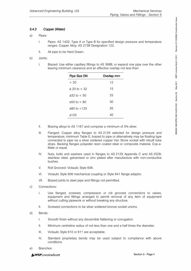
Advanced Engineering Building, UQ Mechanical Services Piping, Valves and Fittings - Section 5
Section 5 - Page 6
BNE0911900.SPEC.M01.KJS101201 - Section 05 May 2011 WSP Lincolne Scott © 2011 Revision 21/10/2008/ Construction Issue
5.4.35.4.35.4.35.4.3 CopperCopperCopperCopper (Wa(Wa(Wa(Water)ter)ter)ter)
a) Pipes:
I. Pipes: AS 1432: Type A or Type B for specified design pressure and temperature ranges. Copper Alloy: AS 2738 Designation 122.
II. All pipe to be Hard Drawn.
b) Joints:
I. Brazed: Use either capillary fittings to AS 3688, or expand one pipe over the other leaving minimum clearance and an effective overlap not less than:
Pipe Size DNPipe Size DNPipe Size DNPipe Size DN Overlap mmOverlap mmOverlap mmOverlap mm
< 20 12
≥ 20 to < 32 15
≥32 to < 50 25
≥50 to < 80 30
≥80 to <125 35
≥125 40
II. Brazing alloys to AS 1167 and comprise a minimum of 5% silver.
III. Flanged: Copper alloy flanges to AS 2129 selected for design pressure and temperature, minimum Table E, brazed to pipe or alternatively may be floating type connected to pipe via a silver soldered copper Van Stone socket with inbuilt tube stops. Backing flanges polyester resin coated steel or composite material, Cop-a-Mate or equal.
IV. Nuts, bolts and washers used in flanges to AS 2129 Appendix C and AS 2528; stainless steel, galvanised or zinc plated after manufacture with non-conductive bushes.
V. Roll Grooved: Victaulic Style 606.
VI. Victaulic Style 606 mechanical coupling or Style 641 flange adaptor.
VII. Brazed joints to steel pipe and fittings not permitted.
c) Connections:
I. Use flanged, screwed, compression or roll grooved connections to valves, equipment and fittings arranged to permit removal of any item of equipment without cutting pipework or without breaking any structure.
II. Screwed connections to be silver soldered bronze socket unions.
d) Bends:
I. Smooth finish without any discernible flattening or corrugation.
II. Minimum centreline radius of not less than one and a half times the diameter.
III. Victaulic Style 610 or 611 are acceptable.
IV. Standard proprietary bends may be used subject to compliance with above conditions.
e) Branches:
Advanced Engineering Building, UQ Mechanical Services Piping, Valves and Fittings - Section 5
Section 5 - Page 7
BNE0911900.SPEC.M01.KJS101201 - Section 05 May 2011 WSP Lincolne Scott © 2011 Revision 21/10/2008/ Construction Issue
I. Branches from main pipelines to be of swept tee type fabricated from abovementioned bends.
f) Reducers:
I. Use concentric reducers or Victaulic Style 650 type on all vertical lines.
II. Use eccentric reducers or Victaulic Style 651 on all horizontal lines, connections to pump suctions to have flat on top and to other items of equipment with the flat of the eccentric arranged on the top or bottom of the pipe to allow venting and drainage as required.
5.4.45.4.45.4.45.4.4 Stainless Steel Stainless Steel Stainless Steel Stainless Steel (Water)(Water)(Water)(Water)
a) Pipes:
I. AS 4041, ASTM A 312M Grade 316 L.
II. Minimum Wall Thickness: Piping up to DN 150: 1.6mm
Piping from DN 150 to DN 300: 2mm.
b) Joints:
I. Use stainless steel of the same grade and wall thickness as the pipe.
II. Weld Joints: Full penetration welded. Comply with AS 4041 Welding Requirements and AS/NZS 3992. Provide details of qualified welding procedure to be carried out by qualified welding personnel with appropriate AS 1796 certificate.
III. Flanged Joints: to AS 2129 and AS 2528. Use flange jointing material similar to Bestobel J2100 preformed proprietary type at least 0.8mm thick.
IV. Screwed joints: to AS 1722.1. Screw threads to be sealed with degreased PTFE tape or an approved thread sealing compound, hemp and paste similar to ‘HAWKINS’.
V. Rolled groove couplings: Victaulic supplied only. Rolled grooves to be factory rolled by Victaulic registered supplier. Site rolled grooves to be undertaken by factory trained personnel. Use only flush type seals. Design and Install in accordance with Victaulic Design and Installation Manual.
VI. In stainless steel pipe systems use only stainless steel nuts, bolts and washers of same grade as piping.
c) Connections:
I. Victaulic rolled groove couplings or flanged joints for connections over 50mm to all equipment to permit their removal without cutting pipework or breaking any structure.
II. Connections up to and including 50mm to be ground joint, steel socket welded unions to AS 1074.
III. All connections between copper piping and dissimilar metals to incorporate flange isolation kits, bronze coupling or Victaulic Style 47 coupling.
d) Bends:
I. Centreline radius not less than one and a half times the diameter of the pipe.
II. Victaulic Style 10 & 11 are acceptable.
e) Branches:
I. Branches from main pipelines to be welded swept tee type with a minimum centreline radius of not less than one and a half times the diameter of the pipe.
Advanced Engineering Building, UQ Mechanical Services Piping, Valves and Fittings - Section 5
Section 5 - Page 8
BNE0911900.SPEC.M01.KJS101201 - Section 05 May 2011 WSP Lincolne Scott © 2011 Revision 21/10/2008/ Construction Issue
f) Reducers:
I. Use concentric reducers or Victaulic Style 50 type on all vertical lines.
II. Use eccentric reducers or Victaulic Style 51 on all horizontal lines. Connections to pump suctions to have flat on top and to other items of equipment with the flat of the eccentric arranged on the top or bottom of the pipe to allow venting and drainage as required.
5.4.55.4.55.4.55.4.5 ABS and UPVCABS and UPVCABS and UPVCABS and UPVC (Water/Drain)(Water/Drain)(Water/Drain)(Water/Drain)
a) Pipes:
UPVC: AS/NZ 1477.
I. Min Wall thickness UPVC PN9 or higher to suit selected pressure and temperature rating.
b) Joints:
I. Socket formed solvent cement welded type to piping manufacturers recommendations and instructions for applications where pipework is located in plant rooms, with allowances for changes in direction via bends and offsets and is not subject to excessive thermal expansion.
II. When subject to expansion and contraction and long lengths of piping above 200mm are involved, use Durapipe post formed expansion units with lipped neoprene 'O' ring or alternatively use rubber bellows type.
c) Connections:
I. Flanged joints for connections to valves, fittings and equipment to consist of UPVC flanges, galvanised backing rings drilled to match flanges and neoprene gaskets.
d) Bends:
I. Plain radius type.
II. Fabricate large bends from mitred standard type having at least five sections per bend and with sections welded with hot gas filler rod technique or other approved.
III. Cover all fabricated fittings with an applied layer of 60g CMS fibreglass,
consolidated with polyester resin type RP161 at the rate of 1.2 to 1.9kg per m².
e) Branches:
I. Use standard tee type branch connections for smaller pipes.
II. Use telescopic branch connections for larger pipes to ensure a smooth entry of water to the reduced port.
III. Use preformed saddles fully welded to the pipe for branch connections for flow switches, sensors and other fittings.
f) Reducers:
I. Use concentric reducers on all vertical lines.
II. Use eccentric reducers on all horizontal lines. Connections to pump suctions to have flat on top and to other items of equipment with the flat of the eccentric arranged on the top or bottom of the pipe to allow venting and drainage as required.
5.4.65.4.65.4.65.4.6 Refrigerant CopperRefrigerant CopperRefrigerant CopperRefrigerant Copper
a) Pipes:

Advanced Engineering Building, UQ Mechanical Services Piping, Valves and Fittings - Section 5
Section 5 - Page 9
BNE0911900.SPEC.M01.KJS101201 - Section 05 May 2011 WSP Lincolne Scott © 2011 Revision 21/10/2008/ Construction Issue
I. Pipes: AS/NZS 1571. Type A or Type B for specified design pressure and temperature ranges.
II. Use refrigerant grade copper to suit application.
III. All pipe to be Hard Drawn.
IV. Deliver to the site in clean moisture free coils and straight lengths with sealed ends and keep it clean and free of moisture at all times during construction.
V. Comply with all applicable Australian Standards, Codes, Statutory Requirements and Regulations.
VI. Neatly install true and square and with the minimum number of bends with all necessary brackets and supports to provide firm fixings and obviate sagging.
VII. Tape uninsulated lines for isolation from direct contact with ferrous materials.
VIII. Provide insulated lines with timber saddles or galvanised sheet metal sleeves to obviate compression of the insulation at points of support.
IX. Provide suction risers with traps at all low points and the line sizes shall be such that they will ensure adequate gas velocities for the return of oil up the risers.
b) Joints:
I. Silver soldered to AS 4041, AS 3688, AS/NZS 1677.1.
II. Use demountable connections to valves, equipment and fittings arranged to permit removal of any item of equipment without cutting pipework and without breaking any structure.
III. Flared compression fittings may be used up to 20mm. Use compression fittings to AS/NZS 1677.1.
IV. Flanges to be Table E copper alloy flanges to AS 2129, of silver soldered type with recessed gaskets.
V. Use flange bolts, nuts and washers complying with AS 2129 and AS 2528, of stainless steel, or galvanised or zinc plated after manufacture and with non conductive bushes.
VI. Use flange gaskets of Klingerit 400 Universal type.
VII. Brazed: Use either capillary fittings to AS 3688, or expand one pipe over the other leaving minimum clearance and an effective overlap not less than:
VIII. Brazing alloys to AS 1167.1 and comprises a minimum of 5% silver.
c) Connections:
Pipe Size DNPipe Size DNPipe Size DNPipe Size DN Overlap mmOverlap mmOverlap mmOverlap mm
< 20 12
≥ 20 to < 32 15
≥32 to < 50 25
≥50 to < 80 30
≥80 to <125 35
≥125 40
Advanced Engineering Building, UQ Mechanical Services Piping, Valves and Fittings - Section 5
Section 5 - Page 10
BNE0911900.SPEC.M01.KJS101201 - Section 05 May 2011 WSP Lincolne Scott © 2011 Revision 21/10/2008/ Construction Issue
I. Use fittings such as couplings of forged and wrought copper type of Heldon manufacture or offered equal.
d) Bends:
I. Use fittings such as elbows and return bends of forged and wrought copper type of Heldon manufacture or offered equal.
e) Branches:
I. Use fittings such as tees, stop ends and Y pieces of forged and wrought copper type of Heldon manufacture or offered equal.
f) Reducers:
I. Use fittings such as reducing bushes of forged and wrought copper type of Heldon manufacture or offered equal.
II. Use concentric reducers on vertical lines.
III. Use eccentric reducers on horizontal lines and connections to equipment with the flat of the eccentric arranged at the top or bottom as appropriate for gas venting or oil and liquid return as appropriate.
5.4.75.4.75.4.75.4.7 SteamSteamSteamSteam
a) Pipes:
I. Steam Lines: AS 4041, API 5L Grade B to specified design pressure and temperature ranges. Minimum wall thickness: 4.8mm for pipes less than DN150, 6.4mm for pipes ND150 and over.
II. Condensate: Copper to AS 1432 type B.
5.4.85.4.85.4.85.4.8 Copper Copper Copper Copper laboratory laboratory laboratory laboratory Gas PipingGas PipingGas PipingGas Piping
a) Pipes
I. Pipes: AS 1571 with dimension not less than those for AS 1432 Type B.
II. Thoroughly cleaned, at least up to medical gas (AS 2896) standards.
III. All pipe to be hard drawn.
IV. Minimum size to be 15mm diameter.
b) Joints, connections & bends
I. Silver-cooper phosphorous brazing alloy in accordance with AS 1167.1 for alloy B4 (15% silver). No Flux shall be used.
II. Do not used screwed connections except as required between gauges and companion fittings. Use Oxygen Compatible PTFE tape for joining compound.
III. Do not used flanged connections except as required between equipment, primarily for vacuum service, and companion fittings.
IV. Screwed connections to be silver soldered bronze socket unions.
V. Use joints of narrow bell type on tubular pipe Sections.
VI. For branch take off joints radius all joints.
VII. Pass dry nitrogen gas through pipelines during all silver brazing operations. Verify nitrogen atmosphere is present on joint being made by use of flow meter.
VIII. Seal weld open pipe ends each day and overnight pressure test. Resolve any pressure loss and make good before proceeding with installation
Advanced Engineering Building, UQ Mechanical Services Piping, Valves and Fittings - Section 5
Section 5 - Page 11
BNE0911900.SPEC.M01.KJS101201 - Section 05 May 2011 WSP Lincolne Scott © 2011 Revision 21/10/2008/ Construction Issue
IX. Bend all pipes below 20mm where possible.
X. Smooth finish without any discernible flattering or corrugation.
XI. Minimum centreline radius of not less than three times the pipe diameter.
XII. Standard propriety bends may be used subject to compliance with above conditions.
XIII. Branches from main pipelines to be of swept tee type fabricated from aforementioned bends.
5.55.55.55.5 VALVES & FITTINGSVALVES & FITTINGSVALVES & FITTINGSVALVES & FITTINGS
5.5.15.5.15.5.15.5.1 General RequirementsGeneral RequirementsGeneral RequirementsGeneral Requirements
a) Use valves suitably sized for the application and at least line size unless used for control when a smaller size may be necessary.
b) Select valves and fittings to meet the operating pressures and operating characteristics of the relevant systems and to meet higher test pressures where applicable.
c) Design pressure of valves and fittings not less than the system design pressure.
d) All isolating valves and throttling valves shall be rated for full shut-off pressure.
e) All valves and fittings shall be installed in accordance with manufacturer’s recommendations and with valve shafts installed on or above the horizontal plane and with all tapping points a minimum of 45 degrees off the vertical downwards plane.
f) Provide extended shafts or bodies for insulated valves to allow full thickness of insulation.
g) Valves up to 50mm diameter; screwed connections to AS 1722.1.
h) Valves over 50mm diameter; flanged connections to AS 2129 Type E minimum or Victaulic rolled groove.
i) Handwheels and handles to be removable with the direction of closing to be marked clearly.
j) Select valves to water supply authority approval where applicable; valves to be stamped with approval details.
k) For each type of valve and fitting, valves and fittings to be supplied from one manufacturer throughout the project.
l) Where copper alloy valves used, select valves of dezincification resistant type.
5.5.25.5.25.5.25.5.2 Water Services Valves & FittingsWater Services Valves & FittingsWater Services Valves & FittingsWater Services Valves & Fittings
5.5.2.1 Throttling Valves (up to and including 50mm)
a) Double Regulating Valves:
I. Continuously adjustable graduated limit stop for precise setting of maximum valve opening.
II. Numeric indication of valve opening.
III. Pressure tappings across variable orifice or across fixed orifice flow measuring device.
IV. Copper alloy body and copper alloy trim.
V. Screwed connections.
VI. PTFE seat.
VII. Tour and Anderson STAD.
Advanced Engineering Building, UQ Mechanical Services Piping, Valves and Fittings - Section 5
Section 5 - Page 12
BNE0911900.SPEC.M01.KJS101201 - Section 05 May 2011 WSP Lincolne Scott © 2011 Revision 21/10/2008/ Construction Issue
5.5.2.2 Throttling Valves (over 50mm)
a) Butterfly Valves:
I. Lug type to BS5155.
II. High tensile cast iron body, stainless steel shaft, bronze disc and keyed replaceable EDPM seat.
III. Suitable for installation between flanges with spool piece or retaining flanges to facilitate removal of downstream pipework with valve remaining in place for isolation.
IV. Lever operated with adjustable infinitely variable memory stops.
V. For valves over 150mm diameter, geared or motorised operators with adjustable travel stops.
VI. Provide chainwheels and chain with handwheel with memory stops or permanently marked at low level for manually operated valves over 150mm in size, when located above 2 metres above finished floor level.
b) Double Regulating Valves:
I. Continuously adjustable graduated limit stop for precise setting of maximum valve opening position.
II. Pressure tappings across variable orifice.
III. Flanged bronze body type and stainless steel trim.
IV. PTFE seat.
V. Tour and Anderson STA-F.
5.5.2.3 Automatic/Dynamic Balancing Valves (up to and including 40mm)
a) Valves shall be of DZR brass with BSP union connections.
b) Flow control cartridges shall be adjustable, rolling diaphragm style of composite construction.
c) Valves shall include 2 P/T Hyflo plugs and an integral isolating ball valve.
d) Body style will ensure that cartridge is accessible while valve remains in line.
e) Flow control accuracy as a minimum will be +5% within cartridge control range.
f) Manufacturer’s warranty shall be for 5 years from date of system start-up.
g) FlowCon ABV or equal approved.
5.5.2.4 Automatic/Dynamic Balancing Valves (over 40mm)
a) Valves shall be of ductile iron in wafer body configuration.
b) Flow control cartridges shall be of stainless steel.
c) Valves shall include 2 P/T Hyflo plugs and extensions.
d) Flow control accuracy as a minimum will be +5% within cartridge control range.
e) Manufacturer’s warranty shall be for 5 years from date of system start-up.
f) FlowCon AHU wafer, class 150 wafer or equal approved.
Advanced Engineering Building, UQ Mechanical Services Piping, Valves and Fittings - Section 5
Section 5 - Page 13
BNE0911900.SPEC.M01.KJS101201 - Section 05 May 2011 WSP Lincolne Scott © 2011 Revision 21/10/2008/ Construction Issue
5.5.2.5 Isolating Valves (up to and including 50mm)
a) Ball Valves:
I. Full bore pattern with handle parallel to direction of flow when fully open.
II. Bronze bodied with hard chromed brass or stainless steel ball, stainless steel stem and PTFE seat.
III. Screwed connections.
IV. John 350 or equal approved.
5.5.2.6 Isolating Valves (over 50mm)
a) Ball Valves:
I. Full bore pattern with handle parallel to direction of flow when fully open.
II. Bronze bodied with stainless steel ball, stem and PTFE seat.
III. Watermark (as defined in SAA MPS2 Section 012) and AGA approved.
IV. Flanged or rolled groove connection.
V. John 360 or equal approved.
VI. Victaulic style 721 are acceptable.
b) Butterfly Valves:
I. Lug type to BS 5155.
II. High tensile cast iron body, stainless steel shaft, bronze disc and bonded EDPM seat.
III. Rated for dead end and bi-directional service.
IV. Suitable for installing between flanges with spool piece or retaining flanges to facilitate removal of downstream pipework with valve remaining in place for isolation.
V. Memory stop for throttling, metering or balancing service.
VI. For valves over 150mm, geared or motorised operators.
VII. Provide chainwheels and chain with chain at low level for manually operated valves over 150mm in size when located above 2 metres above finished floor level.
5.5.2.7 Non Return Valves (up to 50mm)
a) Bronze body swing check type to AS 1628 with stainless steel trim.
b) Screwed connections.
c) To be completely free of hammering under all operating conditions.
d) John Figure 4B or equal approved.
5.5.2.8 Non Return Valves (over 50mm)
a) Cast iron spring loaded dual flap type to AS 3578 with stainless steel spring and pin, stainless steel plates, integral nitrile rubber seat.
b) Flanged connections or rolled groove connections.
c) Hyflo, Stockham or approved equal.
d) Victaulic Style 716 are acceptable.
Advanced Engineering Building, UQ Mechanical Services Piping, Valves and Fittings - Section 5
Section 5 - Page 14
BNE0911900.SPEC.M01.KJS101201 - Section 05 May 2011 WSP Lincolne Scott © 2011 Revision 21/10/2008/ Construction Issue
5.5.2.9 Control Valves
a) General Control Valves:
I. Modified linear or equal percentage type.
II. Valve bodies bronze or cast iron with stainless steel trim and renewable discs and seats.
III. Visible position indicators for valve actuators connected to valves above 32mm diameter.
IV. Arranged as normally closed valves with 100% close off to items controlled except for bypass valves which are to be normally open.
V. Select for demand authority of items served and for minimum fully open resistance (identified by KV or CV Valves) of not less than 1.5 times the combined pressure drop of the branch pipe and item served.
b) Dynamic Modulating Control Valves (up to 40mm):
I. Valves shall be DZR brass body with stainless steel and brass components and BSP union connections.
II. Valves will be fitted with pressure tapping points.
III. Valve authority to be 100% with flow variation for each valve position not to exceed ±5% across the working pressure drop range of the valve.
IV. Valve actuator will be adjustable to any one of 50 different maximum flow rate limits.
V. Control input and position output signals will be 2-10 Volts dc, 4-20 mA or 3 point floating.
VI. Manufacturer’s warranty shall be 3 years from date of system start-up.
VII. FlowCon Model SM100 or equal approved.
5.5.2.10 Pressure Relief Valves
a) Direct acting, spring loaded, side outlet type with adjustable setting to AS 1271.
b) Designed to discharge at full capacity at a pressure not greater than 10% higher than set point pressure.
c) Bronze bodied with renewable stainless steel disc and seat with springs protected from working fluid.
d) Provide easing gear.
e) Lockable shield to prevent unauthorised alteration to setting.
f) Valve drained to waste.
5.5.2.11 Ball Float Valves
a) Copper alloy or bronze bodied to AS 1910 or cast iron.
b) Bronze needle and pins.
c) Copper or plastic float with brass or stainless steel linkage.
5.5.2.12 Cold Water Stop Taps
a) Select stop taps of brass to the requirements of the Local Water Supply Authority.
Advanced Engineering Building, UQ Mechanical Services Piping, Valves and Fittings - Section 5
Section 5 - Page 15
BNE0911900.SPEC.M01.KJS101201 - Section 05 May 2011 WSP Lincolne Scott © 2011 Revision 21/10/2008/ Construction Issue
5.5.2.13 Strainers
a) Y type or Victaulic Style 731 suction diffusers complete with pre-filter 16 mesh for pressures up to 2065kPA.
b) Screwed bronze body on all lines up to and including 50mm and flanged cast iron body above 50mm with easily removed perforated stainless steel or brass strainer basket.
c) Select mesh for 15kPa maximum pressure drop.
d) Fit ball valve and drain line to waste for strainers over 50mm as follows:
I. 65, 80 and 100mm strainer – 25mm drain; 125mm – 32mm drain; 150 and 200mm – 40mm drain; 250, 300 and 350 – 50mm drain.
5.5.2.14 Automatic Air Vents
a) Float operated with cast iron or copper alloy body and stainless steel or solid plastic floats and mechanisms.
b) Air vents are to be fully rates for the system operating conditions; minimum acceptable is 1,000kPa and 120°C.
c) All vents are to be fitted with separate isolation valve on the inlet to allow servicing of the vent without draining the system.
d) Combined air vent discharge capacity of any section of the system being filled must exceed the flow rate at the fast fill system.
e) Flamco Flexvent, Flexvent Super or equal.
5.5.2.15 Expansion Joints
a) Non Metallic:
I. Flanged type of high grade neoprene.
II. Powersorb type REJ or equal.
b) Metalic Braided:
I. Stainless steel braided flexible connection.
II. Flanged type of high grade EPDM and spirally wound wire and reinforcing having a nominal max length of 300mm.
5.5.2.16 Flexible Pipework Connections
a) Flanged type of high grade EPDM and spirally wound wire and reinforcing having a nominal length of 6 times nominal pipe diameter.
b) Hyflo C-Flex or equal approved.
5.5.35.5.35.5.35.5.3 Steam ValvesSteam ValvesSteam ValvesSteam Valves
a) Globe type.
5.5.45.5.45.5.45.5.4 Refrigerant Systems Valves & FittingsRefrigerant Systems Valves & FittingsRefrigerant Systems Valves & FittingsRefrigerant Systems Valves & Fittings
a) Refrigerant Valves:
I. Forged steel, brass or bronze, packed cap, backseating type of F. L. Hudson manufacture or equal.
II. Alternatively a packed, capped ball valve of low loss type of Apollo manufacture.
III. Use brass packed valves with brass caps or packless valves of Heldon manufacture.
Advanced Engineering Building, UQ Mechanical Services Piping, Valves and Fittings - Section 5
Section 5 - Page 16
BNE0911900.SPEC.M01.KJS101201 - Section 05 May 2011 WSP Lincolne Scott © 2011 Revision 21/10/2008/ Construction Issue
IV. Suitable for operation on 240V ± 10%, 50Hz supply within an ambient temperature range of 0°C to 40°C and a maximum operating pressure differential of up to 850kPa.
V. Check valves of lifting type with manual lifting provisions.
VI. Supply and install individual gauge valves as close to equipment and main lines as possible.
b) Thermometer Pockets:
I. Supply and install thermometer pockets on each compressor suction and discharge line.
c) Refrigerant Pressure Gauges:
I. 100mm chrome plated flanged pressure gauges with dials marked with combined pressure temperature scales.
II. Supply and install gauges for each compressor to measure suction pressure, discharge pressure and oil pressure.
d) Refrigerant Sight Glass and Dryness Indicator:
I. Heldon or equal.
II. Install prior to each expansion valve and at least 500mm downstream of solenoid valve.
III. Provide 'bulls-eye' type of brass or bronze construction, designed to minimise sediment deposits, clearly show inadequate refrigerant flows and indicate the presence of moisture in the refrigerant by means of a colour change.
e) Refrigerant Dryer:
I. Supply and install a refrigerant dryer in a valved bypass in the liquid line from the liquid receiver or condenser to the evaporator.
II. Brass or copper construction with brass or stainless steel mesh screens and charged with silica-gel or activated alumina desiccant.
f) Refrigerant Strainer:
I. Supply a strainer of YK or equal manufacture in the main liquid line with isolating valves to permit maintenance.
g) Pressure Relief Valve:
I. Supply and fit pressure relief valves, bursting disc or fusible plug set to operate at a test pressure at least 175kPa below the test pressure specified and sized to ensure that system pressure cannot exceed test pressure. The pressure relieve valve shall be vented in accordance with authority requirements.
5.5.55.5.55.5.55.5.5 Vacuum ValvesVacuum ValvesVacuum ValvesVacuum Valves
a) Isolating Valves:
I. Teflon lined ball valves:
5.5.65.5.65.5.65.5.6 CompresseCompresseCompresseCompressed Air Valvesd Air Valvesd Air Valvesd Air Valves
a) Isolating Valves:
I. Diaphragm type..
5.5.75.5.75.5.75.5.7 Laboratory Laboratory Laboratory Laboratory Gas ValvesGas ValvesGas ValvesGas Valves
a) General
Advanced Engineering Building, UQ Mechanical Services Piping, Valves and Fittings - Section 5
Section 5 - Page 17
BNE0911900.SPEC.M01.KJS101201 - Section 05 May 2011 WSP Lincolne Scott © 2011 Revision 21/10/2008/ Construction Issue
I. Comply with AS 2896 for medical gas services.
II. All components including pipes, valves and fittings shall be factory cleaned and packed prior to delivery to site.
III. Piping shall be capped and suitably labelled before delivery.
IV. Fittings shall be packed in sealed plastic bags.
V. Valves for medical gases, high purity gases and ultra high purity gases shall be packed individually in seal welded plastic bags and labelled “cleaned for Oxygen Service”.
a) Two Way Valve Isolation
I. Suitable for the particular service.
II. Bronze body ball type with bolted cover to allow replacement of all internal components without removal of the body from the pipeline.
III. Ball and stem 316 stainless steel, seals PTFE.
IV. Gas service valves socket wells ends complete with 500 long copper pipe stubs brazed.
a) Pressure Reducing Valves
I. Suitable for particular gas service.
II. Supplied clean to the standards required for oxygen service packed accordingly.
III. Accuracy of 2% maximum with hysteresis and repeatability of 5kPa maximum.
IV. Sized for total design throughout plus 25% at the least pressure difference that will be encountered under operating conditions.
V. Bronze body with stainless steel trim compatible with particular gas service.
a) Pressure Relief Valves
I. Suitable for particular gas service application.
II. Supplied clean to the standards required for oxygen service and packed accordingly.
III. Externally adjustable and provide leak tight shut off up to relief pressure.
IV. Threaded discharge suitable for pipe connection to atmosphere.
V. Sized to accommodate the maximum possible throughout of the reducing valve under failure conditions with a line pressure not exceeding 110% of the line design pressure.
VI. Valve body bronze with stainless steel trim compatible with particular gas service.
a) Check Valves
I. In-line spring loaded style suitable for particular gas service application.
II. Supply clean to the standards required for oxygen service and packed accordingly.
III. Differential pressure required for opening shall not exceed 10kPa.
IV. Maximum pressure drop at full flow condition not to exceed 5% of the nominal line pressure.
Advanced Engineering Building, UQ Mechanical Services Piping, Valves and Fittings - Section 5
Section 5 - Page 18
BNE0911900.SPEC.M01.KJS101201 - Section 05 May 2011 WSP Lincolne Scott © 2011 Revision 21/10/2008/ Construction Issue
V. Valve body bronze or stainless steel with trim compatible with the particular gas services.
a) Solenoid Valves
I. Suitable for the particular gas service.
II. Normally closed, with 240 volt coil (energised to open).
5.65.65.65.6 LABORATORY LABORATORY LABORATORY LABORATORY GAS OUTLETSGAS OUTLETSGAS OUTLETSGAS OUTLETS
5.6.15.6.15.6.15.6.1 GeneralGeneralGeneralGeneral
a) Suitable for the particular gas service.
b) Colour coded to suit the gas service.
c) Shall be of Broen manufacture, complete with Ballofix isolating valve for each outlet.
5.6.25.6.25.6.25.6.2 Wall OutletsWall OutletsWall OutletsWall Outlets
a) Outlets on walls to be single “ wall mounted” type off stainless steel plates..
b) Provide horizontal discharge outlets, with screw-on tapered nozzles suitable for flexible hose.
c) Broen Class 2.0 cleanliness range for vacuum and compressed air, and Class 4.0 cleanliness range for the other gases.
5.75.75.75.7 VACUUM DRAINSVACUUM DRAINSVACUUM DRAINSVACUUM DRAINS
a) Provide drains at all vacuum system low points and at least at the riser connection point on each level.
a) Provide a pipe branch of 15 diameter from the bottom of the pipe at the lowest point and incorporate a ball valve.
b) Provide a connection at the inlet to the valve to accommodate a standard vacuum flask for draining any liquid carry-over.
c) Provide connection with an airtight cap.
5.85.85.85.8 GAUGES & INSTRUMENT GAUGES & INSTRUMENT GAUGES & INSTRUMENT GAUGES & INSTRUMENT FITTINGSFITTINGSFITTINGSFITTINGS
a) Universal Test Points
I. Binder Twinlock type.
II. Test points to be installed a minimum of 45o above the vertical downwards plane and as required to provide access.
b) Thermometers
I. 100mm dial type mercury in steel thermometers matching pressure gauges and calibrated in Deg. C.
II. Dial range twice operating temperature range.
III. Accuracy ±1% of scale range.
IV. Bulb type 316 stainless steel.
c) Thermometer Pockets
I. Locate thermometer pockets in positions where no adverse flow conditions exist.
II. Use thermometer pockets of removable screwed stainless steel type in steel lines, inserted through screwed type boss welded to the pipe.
Advanced Engineering Building, UQ Mechanical Services Piping, Valves and Fittings - Section 5
Section 5 - Page 19
BNE0911900.SPEC.M01.KJS101201 - Section 05 May 2011 WSP Lincolne Scott © 2011 Revision 21/10/2008/ Construction Issue
III. Use thermometer pockets of fixed copper tube type brazed into copper piping lines.
IV. Length of pockets and depth of insertion in pipe adequate to ensure accurate headings.
V. Fill pockets with heat conducting fluid to a minimum depth of 50mm and fit caps to each pocket.
VI. Enlarge pipes smaller than 65mm so as to retain free area.
VII. Install pockets vertically or at an angle to retain heat conducting fluid.
d) Pressure Gauges (Water)
I. Oil filled 100mm dial Bourdon pipe type to AS 1349–1986.
II. Fit with ball valve.
III. Manually adjustable set point needle incorporated on face of gauge.
IV. Chrome plated escutcheon and suitable for recessed mounting.
V. Select compound type gauges for pump suctions graduated in mm of mercury on vacuum side and kPa on the pressure side.
VI. Bourdon pipe material stainless steel for hot water and steam, phosphor bronze for other services.
VII. Bosses for pressure gauges, standard internally screwed type welded or brazed to side of piping.
e) Pressure Gauges (Gas)
I. 100mm diameter dial.
II. Full scale reading between 120 and 150% of the design pressure reading and be graduated in kPa.
III. Direct mounting or surface mounting as required by installation.
IV. Specifically constructed and assembled free from oil, designed for oxygen duty and provided with blow-out rear disc.
f) Vacuum Gauges
I. 100mm diameter dial.
II. Full scale reading 0 to –100kPa.
III. Direct mounting or surface mountings as required by the installation.
g) Gauge Panels
I. Folded sheet metal of adequate stiffness, painted or powder coated with gauges logically grouped and mounted to approval.
5.95.95.95.9 FLOW MEASURING DEVICFLOW MEASURING DEVICFLOW MEASURING DEVICFLOW MEASURING DEVICESESESES
a) Common manufacture and type throughout project.
b) Low pressure loss type.
c) Magnetic or ultrasonic tube type shall be Panametrics or approved equal.
d) Install in accordance with manufacturers' recommendations and with adequate lengths of straight pipe on either side of the device.
Advanced Engineering Building, UQ Mechanical Services Piping, Valves and Fittings - Section 5
Section 5 - Page 20
BNE0911900.SPEC.M01.KJS101201 - Section 05 May 2011 WSP Lincolne Scott © 2011 Revision 21/10/2008/ Construction Issue
e) Label with brass plate stamped to indicate all relevant piping data, gauge ranges, flow and temperature coefficient.
f) Select gauge ranges suitable for each device with the design flow at midscale.
5.105.105.105.10 GAUGES & INSTRUMENT GAUGES & INSTRUMENT GAUGES & INSTRUMENT GAUGES & INSTRUMENT FITTINGSFITTINGSFITTINGSFITTINGS
a) Universal Test Points:
I. Binder Twinlock type or approved alternative.
II. Test points to be installed a minimum of 45o above the vertical downwards plane and as required to provide access.
b) Thermometers:
I. 100mm dial type mercury in steel thermometers matching pressure gauges and calibrated in Deg. C.
II. Dial range twice operating temperature range.
III. Accuracy ±1% of scale range.
IV. Bulb type 316 stainless steel.
c) Thermometer Pockets:
I. Locate thermometer pockets in positions where no adverse flow conditions exist.
II. Use thermometer pockets of removable screwed stainless steel type in steel lines, inserted through screwed type boss welded to the pipe.
III. Use thermometer pockets of fixed copper tube type brazed into copper piping lines.
IV. Length of pockets and depth of insertion in pipe adequate to ensure accurate headings.
V. Fill pockets with heat conducting fluid to a minimum depth of 50mm and fit caps to each pocket.
VI. Enlarge pipes smaller than 65mm so as to retain free area.
VII. Install pockets vertically or at an angle to retain heat conducting fluid.
d) Pressure Gauges:
I. Oil filled 100mm dial Bourdon pipe type to AS 1349.
II. Fit with ball valve.
III. Manually adjustable set point needle incorporated on face of gauge.
IV. Chrome plated escutcheon and suitable for recessed mounting.
V. Select compound type gauges for pump suctions graduated in mm of mercury on vacuum side and kPa on the pressure side.
VI. Bourdon pipe material stainless steel for hot water and steam, phosphor bronze for other services.
VII. Bosses for pressure gauges, standard internally screwed type welded or brazed to side of piping.
e) Gauge Panels:
I. Folded sheet metal of adequate stiffness, painted or powder coated with gauges logically grouped and mounted to approval.
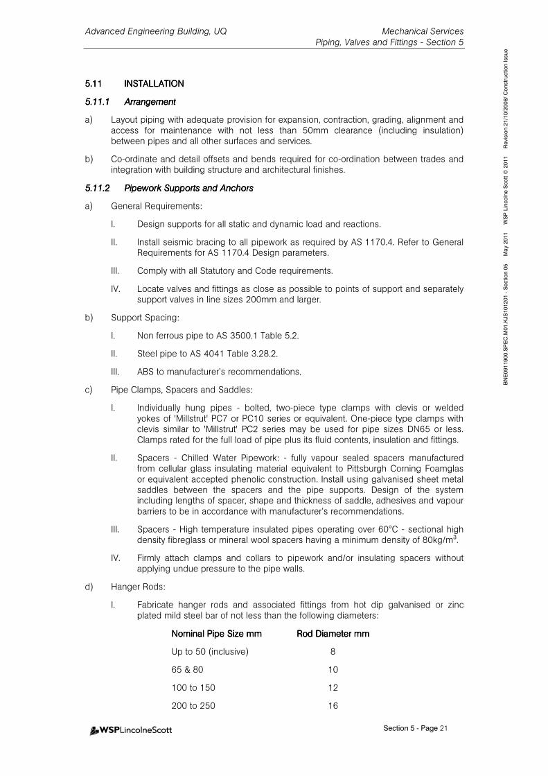
Advanced Engineering Building, UQ Mechanical Services Piping, Valves and Fittings - Section 5
Section 5 - Page 21
BNE0911900.SPEC.M01.KJS101201 - Section 05 May 2011 WSP Lincolne Scott © 2011 Revision 21/10/2008/ Construction Issue
5.115.115.115.11 INSTALLATIONINSTALLATIONINSTALLATIONINSTALLATION
5.11.15.11.15.11.15.11.1 ArrangementArrangementArrangementArrangement
a) Layout piping with adequate provision for expansion, contraction, grading, alignment and access for maintenance with not less than 50mm clearance (including insulation) between pipes and all other surfaces and services.
b) Co-ordinate and detail offsets and bends required for co-ordination between trades and integration with building structure and architectural finishes.
5.11.25.11.25.11.25.11.2 Pipework Supports and AnchorsPipework Supports and AnchorsPipework Supports and AnchorsPipework Supports and Anchors
a) General Requirements:
I. Design supports for all static and dynamic load and reactions.
II. Install seismic bracing to all pipework as required by AS 1170.4. Refer to General Requirements for AS 1170.4 Design parameters.
III. Comply with all Statutory and Code requirements.
IV. Locate valves and fittings as close as possible to points of support and separately support valves in line sizes 200mm and larger.
b) Support Spacing:
I. Non ferrous pipe to AS 3500.1 Table 5.2.
II. Steel pipe to AS 4041 Table 3.28.2.
III. ABS to manufacturer’s recommendations.
c) Pipe Clamps, Spacers and Saddles:
I. Individually hung pipes - bolted, two-piece type clamps with clevis or welded yokes of 'Millstrut' PC7 or PC10 series or equivalent. One-piece type clamps with clevis similar to 'Millstrut' PC2 series may be used for pipe sizes DN65 or less. Clamps rated for the full load of pipe plus its fluid contents, insulation and fittings.
II. Spacers - Chilled Water Pipework: - fully vapour sealed spacers manufactured from cellular glass insulating material equivalent to Pittsburgh Corning Foamglas or equivalent accepted phenolic construction. Install using galvanised sheet metal saddles between the spacers and the pipe supports. Design of the system including lengths of spacer, shape and thickness of saddle, adhesives and vapour barriers to be in accordance with manufacturer’s recommendations.
III. Spacers - High temperature insulated pipes operating over 60°C - sectional high density fibreglass or mineral wool spacers having a minimum density of 80kg/m³.
IV. Firmly attach clamps and collars to pipework and/or insulating spacers without applying undue pressure to the pipe walls.
d) Hanger Rods:
I. Fabricate hanger rods and associated fittings from hot dip galvanised or zinc plated mild steel bar of not less than the following diameters:
Nominal Pipe Size mmNominal Pipe Size mmNominal Pipe Size mmNominal Pipe Size mm Rod DiameterRod DiameterRod DiameterRod Diameter mmmmmmmm
Up to 50 (inclusive) 8
65 & 80 10
100 to 150 12
200 to 250 16
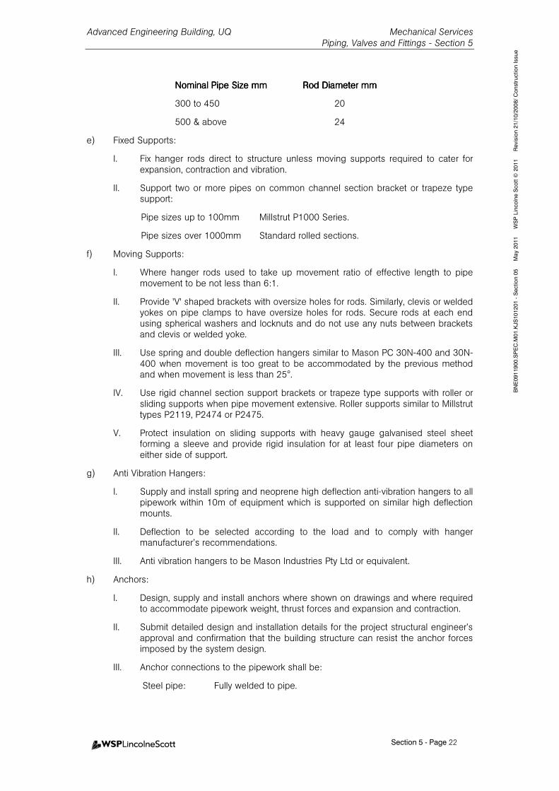
Advanced Engineering Building, UQ Mechanical Services Piping, Valves and Fittings - Section 5
Section 5 - Page 22
BNE0911900.SPEC.M01.KJS101201 - Section 05 May 2011 WSP Lincolne Scott © 2011 Revision 21/10/2008/ Construction Issue
Nominal Pipe Size mmNominal Pipe Size mmNominal Pipe Size mmNominal Pipe Size mm Rod DiameterRod DiameterRod DiameterRod Diameter mmmmmmmm
300 to 450 20
500 & above 24
e) Fixed Supports:
I. Fix hanger rods direct to structure unless moving supports required to cater for expansion, contraction and vibration.
II. Support two or more pipes on common channel section bracket or trapeze type support:
Pipe sizes up to 100mm Millstrut P1000 Series.
Pipe sizes over 1000mm Standard rolled sections.
f) Moving Supports:
I. Where hanger rods used to take up movement ratio of effective length to pipe movement to be not less than 6:1.
II. Provide 'V' shaped brackets with oversize holes for rods. Similarly, clevis or welded yokes on pipe clamps to have oversize holes for rods. Secure rods at each end using spherical washers and locknuts and do not use any nuts between brackets and clevis or welded yoke.
III. Use spring and double deflection hangers similar to Mason PC 30N-400 and 30N-400 when movement is too great to be accommodated by the previous method and when movement is less than 25°.
IV. Use rigid channel section support brackets or trapeze type supports with roller or sliding supports when pipe movement extensive. Roller supports similar to Millstrut types P2119, P2474 or P2475.
V. Protect insulation on sliding supports with heavy gauge galvanised steel sheet forming a sleeve and provide rigid insulation for at least four pipe diameters on either side of support.
g) Anti Vibration Hangers:
I. Supply and install spring and neoprene high deflection anti-vibration hangers to all pipework within 10m of equipment which is supported on similar high deflection mounts.
II. Deflection to be selected according to the load and to comply with hanger manufacturer’s recommendations.
III. Anti vibration hangers to be Mason Industries Pty Ltd or equivalent.
h) Anchors:
I. Design, supply and install anchors where shown on drawings and where required to accommodate pipework weight, thrust forces and expansion and contraction.
II. Submit detailed design and installation details for the project structural engineer’s approval and confirmation that the building structure can resist the anchor forces imposed by the system design.
III. Anchor connections to the pipework shall be:
Steel pipe: Fully welded to pipe.
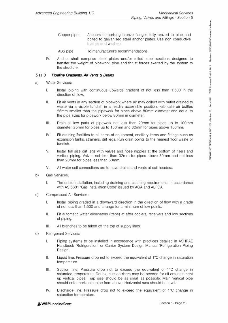
Advanced Engineering Building, UQ Mechanical Services Piping, Valves and Fittings - Section 5
Section 5 - Page 23
BNE0911900.SPEC.M01.KJS101201 - Section 05 May 2011 WSP Lincolne Scott © 2011 Revision 21/10/2008/ Construction Issue
Copper pipe: Anchors comprising bronze flanges fully brazed to pipe and bolted to galvanised steel anchor plates. Use non conductive bushes and washers.
ABS pipe To manufacturer’s recommendations.
IV. Anchor shall comprise steel plates and/or rolled steel sections designed to transfer the weight of pipework, pipe and thrust forces exerted by the system to the structure.
5.11.35.11.35.11.35.11.3 Pipeline Gradients, Air Vents & DrainsPipeline Gradients, Air Vents & DrainsPipeline Gradients, Air Vents & DrainsPipeline Gradients, Air Vents & Drains
a) Water Services:
I. Install piping with continuous upwards gradient of not less than 1:500 in the direction of flow.
II. Fit air vents in any section of pipework where air may collect with outlet drained to waste via a visible tundish in a readily accessible position. Fabricate air bottles 25mm smaller than the pipework for pipes above 80mm diameter and equal to the pipe sizes for pipework below 80mm in diameter.
III. Drain all low parts of pipework not less than 20mm for pipes up to 100mm diameter, 25mm for pipes up to 150mm and 32mm for pipes above 150mm.
IV. Fit draining facilities to all items of equipment, ancillary items and fittings such as expansion tanks, strainers, dirt legs. Run drain points to the nearest floor waste or tundish.
V. Install full size dirt legs with valves and hose nipples at the bottom of risers and vertical piping. Valves not less than 32mm for pipes above 50mm and not less than 20mm for pipes less than 50mm.
VI. All water coil connections are to have drains and vents at coil headers.
b) Gas Services:
I. The entire installation, including draining and cleaning requirements in accordance with AS 5601 ‘Gas Installation Code’ issued by AGA and ALPGA.
c) Compressed Air Services:
I. Install piping graded in a downward direction in the direction of flow with a grade of not less than 1:500 and arrange for a minimum of low points.
II. Fit automatic water eliminators (traps) at after coolers, receivers and low sections of piping.
III. All branches to be taken off the top of supply lines.
d) Refrigerant Services:
I. Piping systems to be installed in accordance with practices detailed in ASHRAE Handbook ‘Refrigeration’ or Carrier System Design Manual ‘Refrigeration Piping Design’.
II. Liquid line. Pressure drop not to exceed the equivalent of 1°C change in saturation temperature.
III. Suction line. Pressure drop not to exceed the equivalent of 1°C change in saturated temperature. Double suction risers may be needed for oil entertainment up vertical pipes. Trap size should be as small as possible. Main vertical pipe should enter horizontal pipe from above. Horizontal runs should be level.
IV. Discharge line. Pressure drop not to exceed the equivalent of 1°C change in saturation temperature.
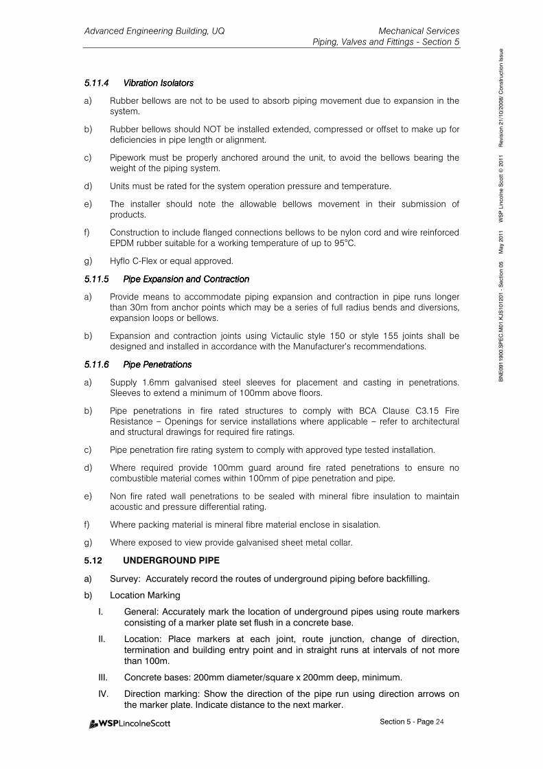
Advanced Engineering Building, UQ Mechanical Services Piping, Valves and Fittings - Section 5
Section 5 - Page 24
BNE0911900.SPEC.M01.KJS101201 - Section 05 May 2011 WSP Lincolne Scott © 2011 Revision 21/10/2008/ Construction Issue
5.11.45.11.45.11.45.11.4 Vibration IsolatorsVibration IsolatorsVibration IsolatorsVibration Isolators
a) Rubber bellows are not to be used to absorb piping movement due to expansion in the system.
b) Rubber bellows should NOT be installed extended, compressed or offset to make up for deficiencies in pipe length or alignment.
c) Pipework must be properly anchored around the unit, to avoid the bellows bearing the weight of the piping system.
d) Units must be rated for the system operation pressure and temperature.
e) The installer should note the allowable bellows movement in their submission of products.
f) Construction to include flanged connections bellows to be nylon cord and wire reinforced EPDM rubber suitable for a working temperature of up to 95°C.
g) Hyflo C-Flex or equal approved.
5.11.55.11.55.11.55.11.5 Pipe Expansion and ContractionPipe Expansion and ContractionPipe Expansion and ContractionPipe Expansion and Contraction
a) Provide means to accommodate piping expansion and contraction in pipe runs longer than 30m from anchor points which may be a series of full radius bends and diversions, expansion loops or bellows.
b) Expansion and contraction joints using Victaulic style 150 or style 155 joints shall be designed and installed in accordance with the Manufacturer’s recommendations.
5.11.65.11.65.11.65.11.6 Pipe PenetratioPipe PenetratioPipe PenetratioPipe Penetrationsnsnsns
a) Supply 1.6mm galvanised steel sleeves for placement and casting in penetrations. Sleeves to extend a minimum of 100mm above floors.
b) Pipe penetrations in fire rated structures to comply with BCA Clause C3.15 Fire Resistance – Openings for service installations where applicable – refer to architectural and structural drawings for required fire ratings.
c) Pipe penetration fire rating system to comply with approved type tested installation.
d) Where required provide 100mm guard around fire rated penetrations to ensure no combustible material comes within 100mm of pipe penetration and pipe.
e) Non fire rated wall penetrations to be sealed with mineral fibre insulation to maintain acoustic and pressure differential rating.
f) Where packing material is mineral fibre material enclose in sisalation.
g) Where exposed to view provide galvanised sheet metal collar.
5.12 UNDERGROUND PIPE
a) Survey: Accurately record the routes of underground piping before backfilling.
b) Location Marking
I. General: Accurately mark the location of underground pipes using route markers
consisting of a marker plate set flush in a concrete base.
II. Location: Place markers at each joint, route junction, change of direction,
termination and building entry point and in straight runs at intervals of not more
than 100m.
III. Concrete bases: 200mm diameter/square x 200mm deep, minimum.
IV. Direction marking: Show the direction of the pipe run using direction arrows on
the marker plate. Indicate distance to the next marker.
Advanced Engineering Building, UQ Mechanical Services Piping, Valves and Fittings - Section 5
Section 5 - Page 25
BNE0911900.SPEC.M01.KJS101201 - Section 05 May 2011 WSP Lincolne Scott © 2011 Revision 21/10/2008/ Construction Issue
V. Plates: Brass, minimum size 75 x 75 x 2mm thick.
VI. Plate fixing: Waterproof adhesive and 4 brass or stainless steel countersunk
screws.
VII. Marker height: Set the marker plate flush with paved surfaces, and 25mm above
other surfaces
5.135.135.135.13 TESTING OF PIPEWORKTESTING OF PIPEWORKTESTING OF PIPEWORKTESTING OF PIPEWORK
a) Pressure test all sections of pipework prior to lagging or painting using calibrated pressure gauges. Provide signed test reports for each pressure test.
b) Isolate any equipment that will not withstand test pressures prior to testing.
c) Provide detailed water treatment and pipework passivation proposal for approval prior to filling any part of the system. Water which is not chemically treated shall not enter any part of any system. Introduce corrosion inhibiting chemicals in water used for hydrostatic testing in strict accordance with the recommendations of a water treatment specialist. If chemically treated water is left in piping after testing the water must be circulated and monitored to assure protection is maintained.
d) Circulate test water to ensure continuity and effectiveness of corrosion inhibition providing temporary circulation facility if required.
e) Remake any leaking joint and retest.
Advanced Engineering Building, UQ Mechanical Services Water Treatment- Section 6
Table of Contents - Page 1
BNE0911900.SPEC.M01.KJS101201 - Section 06 May 2011 WSP Lincolne Scott © 2011 Revision 310807 /Construction Issue
6.6.6.6. WWWWATER ATER ATER ATER TTTTREATMENTREATMENTREATMENTREATMENT 1
6.16.16.16.1 GENERALGENERALGENERALGENERAL 1
6.1.1 Scope 1
6.26.26.26.2 REFERENCED DOCUMENTSREFERENCED DOCUMENTSREFERENCED DOCUMENTSREFERENCED DOCUMENTS 1
6.36.36.36.3 DESIGNDESIGNDESIGNDESIGN 1
6.3.1 General 1
6.3.2 Authority Standards and Codes 1
6.46.46.46.4 SUBMISSIONSSUBMISSIONSSUBMISSIONSSUBMISSIONS 1
6.56.56.56.5 GENERAL REQUIREMENTSGENERAL REQUIREMENTSGENERAL REQUIREMENTSGENERAL REQUIREMENTS 1
6.66.66.66.6 PRESSURE TESTING OF PRESSURE TESTING OF PRESSURE TESTING OF PRESSURE TESTING OF SYSTEMSSYSTEMSSYSTEMSSYSTEMS 3
6.76.76.76.7 PRECOMMISSION CLEANIPRECOMMISSION CLEANIPRECOMMISSION CLEANIPRECOMMISSION CLEANING AND PASSIVATION ONG AND PASSIVATION ONG AND PASSIVATION ONG AND PASSIVATION OF ALL WATER SYSTEMSF ALL WATER SYSTEMSF ALL WATER SYSTEMSF ALL WATER SYSTEMS 3
6.86.86.86.8 CLOSED WATER SYSTEMSCLOSED WATER SYSTEMSCLOSED WATER SYSTEMSCLOSED WATER SYSTEMS 4
6.96.96.96.9 OPEN CONDENSER WATEROPEN CONDENSER WATEROPEN CONDENSER WATEROPEN CONDENSER WATER SYSTEMSSYSTEMSSYSTEMSSYSTEMS 4
6.106.106.106.10 COOLING TOWER COOLING TOWER COOLING TOWER COOLING TOWER –––– SIDE STREAM FILTRATSIDE STREAM FILTRATSIDE STREAM FILTRATSIDE STREAM FILTRATIONIONIONION 5
Advanced Engineering Building, UQ Mechanical Services Water Treatment- Section 6
Section 6 - Page 1
BNE0911900.SPEC.M01.KJS101201 - Section 06 May 2011 WSP Lincolne Scott © 2011 Revision 310807 /Construction Issue
6.6.6.6. WWWWATER ATER ATER ATER TTTTREATMENTREATMENTREATMENTREATMENT
6.16.16.16.1 GENERALGENERALGENERALGENERAL
6.1.16.1.16.1.16.1.1 ScopeScopeScopeScope
a) This section sets out the engineering and quality assurance requirements for the completion of the installation design, materials, components, general installation and testing of the Mechanical Services water treatment systems.
b) This section is to be read in conjunction with the Schedules.
c) This section is to be read in conjunction with all other sections of this specification.
6.26.26.26.2 REFERENCED DOCUMENTSREFERENCED DOCUMENTSREFERENCED DOCUMENTSREFERENCED DOCUMENTS
Details of documents referenced and applicable to this section of the specification include:
Australian/New Zealand StandardsAustralian/New Zealand StandardsAustralian/New Zealand StandardsAustralian/New Zealand Standards
AS/NZS 3666.1-2002 Air-handling and water systems of buildings – Microbial control – Design, Installation and Commissioning
AS/NZS 3666.2-2002 Air-handling and water systems of buildings – Microbial control –
Operation and Maintenance AS/NZS 3666.3-2000 Performance-based maintenance of cooling water systems ASTM D 2688-1994 Standard test methods for corrosivity of Water in the absence of Heat
Transfer (Weight Loss Methods) 6.36.36.36.3 DESIGNDESIGNDESIGNDESIGN
6.3.16.3.16.3.16.3.1 GeneralGeneralGeneralGeneral
a) Complete the detail design and engineering of the water treatment system and installation to the specified requirements.
6.3.26.3.26.3.26.3.2 Authority Standards and CodesAuthority Standards and CodesAuthority Standards and CodesAuthority Standards and Codes
Comply with applicable authority design guidelines and codes of practice and requirements:
6.46.46.46.4 SUBMISSIONSSUBMISSIONSSUBMISSIONSSUBMISSIONS
Provide the following submissions
a) System conditions report.
b) System volume and dosing rate calculations.
c) Commissioning and maintenance monthly site reports.
d) Equipment selection submittals.
6.56.56.56.5 GENERAL REQUIREMENTSGENERAL REQUIREMENTSGENERAL REQUIREMENTSGENERAL REQUIREMENTS
a) Engage a specialist water treatment company to provide a water treatment programme, to comply with AS/NZS 3666 and local Authority requirements and control corrosion, scale and biological activity of the water circuits, both during construction and thereafter during the Maintenance and Defects Liability Period.
b) Prior to the commencement of the water treatment programme, the specialist water treatment company is to assess and submit a written report on the entire system conditions likely to affect the programme, including design issues such as selection of piping materials, dirt legs, flow rates under maximum and minimum operating conditions and construction issues such as jointing methods and separation of dissimilar metals,
Advanced Engineering Building, UQ Mechanical Services Water Treatment- Section 6
Section 6 - Page 2
BNE0911900.SPEC.M01.KJS101201 - Section 06 May 2011 WSP Lincolne Scott © 2011 Revision 310807 /Construction Issue
system dead legs and means to ensure circulation, valves and bypasses for maintenance, etc. Review piping specification and schematic drawings to ensure understanding of system configuration, materials and water velocities. Submit calculations used to determine system volumes and chemical dosing rates to achieve the required concentrations for review by the Consulting Engineer, prior to commencing treatment.
c) Indemnify the Proprietor for all liabilities and damages as a result of the use of Water Treatment processes, chemical / cleaning agents or methods of disposal which are not approved by relevant Authorities or which violate relevant legislation.
d) Guarantee the effectiveness of the entire water treatment programme commencing with the pre-cleaning of piping, hydrostatic pressure testing, further pre-cleaning and passivation of pipework and on going water treatment until Final Completion.
e) Select chemicals to suit the application and to meet the requirements of the appropriate authority responsible for discharge of effluent to waste.
f) Commission the water treatment plant, inspect and test systems as required but at least monthly until the completion of the maintenance period. Provide written site reports of all activities during commissioning and maintenance.
g) Acceptance program criteria will be:
I. General Corrosion rate of metals not to exceed 0.13mm/year (approx. 5mpy) for carbon steel, 0.005mm/year (approx 0.2mpy) for stainless steel with no pitting and 0.005mm/year (approx. 0.2mpy) for copper based on corrosion coupons tested in accordance with ASTM D 2688.
II. Maximum pit corrosion rate of metals not to exceed 0.02mm/year (approx. 8mpy) for carbon steel, zero mm/year for stainless steel and 0.02mm/year (approx. 0.8mpy) for copper based on coupons tested for long term corrosion rates in accordance with ASTM D 2688.
III. System to be clean and free of corrosion products, deposits, sludge and other foulants.
IV. Total plate count to not exceed 100,000cfu/ml as measured by an independent certified laboratory when measured in accordance with AS/NZS 3666.3 requirements.
V. Legionella count not to exceed 10cfu/ml as measured by an independent certified laboratory when measured in accordance with AS/NZS 3666.3 requirements.
h) Following each visit to site, submit a comprehensive report stating the condition of each water system, giving details of chemicals added, commenting on the results of the water analysis and commenting on general operation and maintenance of systems particularly relating to the minimisation of corrosion and prevention of Legionnaires Disease. Water treatment reports to include but not be limited to water analysis covering make up water and system water to be tested comparing targeted values with recorded values.
i) Minimum test requirements:
Open CircuitsOpen CircuitsOpen CircuitsOpen Circuits Closed CircuitsClosed CircuitsClosed CircuitsClosed Circuits
Conductivity/Total Dissolved Solids Conductivity/Total Dissolved Solids
Chlorides PH
Hardness Calcium and Total Iron
PH Copper if present in the circuit
Iron
Advanced Engineering Building, UQ Mechanical Services Water Treatment- Section 6
Section 6 - Page 3
BNE0911900.SPEC.M01.KJS101201 - Section 06 May 2011 WSP Lincolne Scott © 2011 Revision 310807 /Construction Issue
Copper if present in the circuit Inhibitor Level
Cycles of Concentration
M Alkalinity
Total Plate Count (cfu/ml)
Legionella Count (cfu/ml)
Note:Note:Note:Note: The water treatment specialist is to set out target values for The water treatment specialist is to set out target values for The water treatment specialist is to set out target values for The water treatment specialist is to set out target values for each each each each of of of of the above parameters together with actual measured values the above parameters together with actual measured values the above parameters together with actual measured values the above parameters together with actual measured values with with with with an an an an explanation or comment on any variance.explanation or comment on any variance.explanation or comment on any variance.explanation or comment on any variance.
j) Supply and install corrosion coupons on the open condenser water circuits and monitor and report on corrosion rates both general and pitting.
k) Provide test kits for analysis of water systems together with log sheets, product bulletins, MSDS sheets and dosing instructions for all work to be carried out on site. In summary provide an operating manual for the systems treated.
l) Instruct plant personnel in the correct procedure for chemical handling dosing and testing of the various systems and record routine test results in a log book, which will form part of the operating manual.
m) At the conclusion of the Maintenance and Defects Liability period submit a comprehensive report which summarises all of the previous reports and gives a detailed overview of the condition of all systems with recommendations for future treatment.
6.66.66.66.6 PRESSURE TESTING OF PRESSURE TESTING OF PRESSURE TESTING OF PRESSURE TESTING OF SYSTEMSSYSTEMSSYSTEMSSYSTEMS
a) Systems are to be filled in the presence of the specialist water treatment company to assure provision of required water treatment guarantees.
b) At no time is the system to be filled without the addition of a corrosion inhibitor and passive chemicals.
c) Install temporary circulation and dosing pumps together with interconnections as required to assure circulation of treated water and protection of the entire installation. Treated water shall not be left in the systems for extended periods of time without means of circulation.
6.76.76.76.7 PRECOMMISSION CLEANIPRECOMMISSION CLEANIPRECOMMISSION CLEANIPRECOMMISSION CLEANING AND PASSIVATION ONG AND PASSIVATION ONG AND PASSIVATION ONG AND PASSIVATION OF ALL WATER SYSTEMSF ALL WATER SYSTEMSF ALL WATER SYSTEMSF ALL WATER SYSTEMS
a) Thoroughly clean and flush out all water systems with non-foaming precleaner to remove superficial dirt, oil and corrosion products. This precleaner needs to be disposed of correctly. Leave the pipe internals clean and passive.
b) Ensure biological treatment in maintained at all times.
c) Mechanical Contractor to remove and clean strainers where necessary following pre-cleaning.
d) Install temporary pumps as necessary to assist in flushing when normal circulating velocities may be insufficient to remove undissolved solids.
e) Review effectiveness of pre-cleaning and if necessary redo until the pipework including butt welds are free of oil and grease, corrosion product and deposits.
f) Immediately following cleaning, add high dosage of suitable corrosion inhibitors and circulate for some days until residuals show the system has stabilised and that internal surfaces have become passivated.
g) Following passivating commission the water treatment programme and monitor weekly until stability is reached.
Advanced Engineering Building, UQ Mechanical Services Water Treatment- Section 6
Section 6 - Page 4
BNE0911900.SPEC.M01.KJS101201 - Section 06 May 2011 WSP Lincolne Scott © 2011 Revision 310807 /Construction Issue
h) At no time is the system to be filled or operated without the addition of a suitable applicable corrosion inhibitor and biocide.
6.86.86.86.8 CLOSED WATER SYSTEMSCLOSED WATER SYSTEMSCLOSED WATER SYSTEMSCLOSED WATER SYSTEMS
a) After completing the pre-clean, protect each water system with a corrosion inhibitor introduced into the system via a dosing by-pass pot connected across the supply and return water pipes. After dosing and recirculating check final inhibitor concentration is correct to ensure continued pipe line protection. Adjust if necessary.
6.96.96.96.9 OPEN OPEN OPEN OPEN CONDENSER WATER SYSTCONDENSER WATER SYSTCONDENSER WATER SYSTCONDENSER WATER SYSTEMSEMSEMSEMS
a) After completing the pre-treatment involving pre-cleaning and passivation, protect the system by implementing an automated Water Treatment program, to include:
I. A Water Treatment control centre,
II. At least two types of biocides
III. One an oxidising agent to be either slug dosed on a timer basis or metered using Oxygen Reducing Potential (ORP) control and introduced to an area of turbulence (typically the tower basin), and
IV. The second biocide a Legionella effective non oxidising biocide also dosed to an area of turbulence, on a timer basis.
V. The auto dosing system shall have the provision to shut off the tower bleed during and for a variable time after biocide additions to maximise biocide retention in the water system.
VI. Biodispersants and dispersants are to be included as part of the operating program, and shall be batch dosed, or dosed continually via the Water Treatment control centre.
b) The automatic dosing equipment (Control Centre) shall include appropriately sized chemical storage tanks with lids and chemical injection pumps with adjustable output to provide proportional addition of chemicals. Chemical storage capacity shall be at least 1.5 times service frequency time.
c) The condenser water bleed rate shall be controlled from an automatic conductivity or total dissolved solids meter, with manual bleed, all part of the Control Centre. The system bleed shall be discharged to sewer.
d) The location of the bleed and meter is to be carefully considered with respect to the entire system configuration and is to be at a point where the ‘worst case’ conditions are likely to occur.
e) The Water Treatment Control Centre shall be electrically interlocked with the system recirculation pumps such that chemicals are only dosed when the condenser water system is operative. A Water Meter on the tower make up line may be used in conjunction with the Control Centre to initiate dosage of corrosion inhibitors or dispersants.
f) The Control Centre shall provide all interfacing requirements for electrical and water connections.
g) Unless otherwise specified or instructed, supply and install either a cyclone filtration system or a commercially available sand filter complete with pump, automatic backwash facility (set for weekly) all necessary valves, maintenance bypass lines, fittings, drains and vents to provide continuous filtration of the cooling tower basin.
h) Size the system to provide a turnover rate of the tower/s of not less than 6.
Advanced Engineering Building, UQ Mechanical Services Water Treatment- Section 6
Section 6 - Page 5
BNE0911900.SPEC.M01.KJS101201 - Section 06 May 2011 WSP Lincolne Scott © 2011 Revision 310807 /Construction Issue
6.106.106.106.10 COOLING TOWER COOLING TOWER COOLING TOWER COOLING TOWER –––– SIDE STREAM FILTSIDE STREAM FILTSIDE STREAM FILTSIDE STREAM FILTRATIONRATIONRATIONRATION
a) Provide side stream filtration system(s) complete with automatic self-cleaning screen filters, eductors, ABS piping, pumps, automatic backwash facility and strainer and all necessary valves, fittings, controls, drains and vents to provide continuous filtration and agitation of the cooling tower basins. Backwashing shall be carried out using system pressure to automatically back-flush the screen effectively with low water use over a maximum of 10 seconds.
b) Type of screen mesh to be used to be confirmed at the time of selection of the unit, allow for range of 80 to 200 micron.
c) Provide manufacturer’s written acceptance of the installation following completion.
d) Utilise the BMS to operate all main condenser water circulating pumps on a time schedule at full capacity and to open the control valves to achieve cleaning.
e) Backwash provisions shall be automatic based on pressure differential across the strainer. Provide visible backwash discharge to allow manual checks for leakage of the unit backwash system.
Advanced Engineering Building, UQ Mechanical Services Ductwork, Sheet Metal Items, Air Outlets - Section 7
Table of Contents - Page 1
BNE0911900.SPEC.M01.KJS101202 - Section 07 May 2011 WSP Lincolne Scott © 2011 241008 / Construction Issue
7.7.7.7. DDDDUCTWORKUCTWORKUCTWORKUCTWORK,,,, SSSSHEET HEET HEET HEET MMMMETAL ETAL ETAL ETAL IIIITEMSTEMSTEMSTEMS,,,, AAAAIR IR IR IR OOOOUTLETSUTLETSUTLETSUTLETS 1
7.17.17.17.1 GENERALGENERALGENERALGENERAL 1
7.1.1 Scope 1
7.1.2 Referenced Documents 1
7.27.27.27.2 DESIGNDESIGNDESIGNDESIGN 2
7.2.1 General 2
7.2.2 Authority Standards and Codes 2
7.37.37.37.3 SUBMISSIONSSUBMISSIONSSUBMISSIONSSUBMISSIONS 2
7.47.47.47.4 GENERAGENERAGENERAGENERAL REQUIREMENTSL REQUIREMENTSL REQUIREMENTSL REQUIREMENTS 2
7.57.57.57.5 INFORMATION REQUIREDINFORMATION REQUIREDINFORMATION REQUIREDINFORMATION REQUIRED 2
7.67.67.67.6 DUCTWORK MATERIALSDUCTWORK MATERIALSDUCTWORK MATERIALSDUCTWORK MATERIALS 2
7.6.1 Sheet Metal 2
7.6.2 UPVC 3
7.6.3 Flexible Circular Ducting 3
7.6.4 Flexible Connections 3
7.6.5 Fire Rated Ductwork 3
7.6.6 Ductwork Supports 3
7.77.77.77.7 GREEN STAR REQUIREMEGREEN STAR REQUIREMEGREEN STAR REQUIREMEGREEN STAR REQUIREMENTSNTSNTSNTS 3
7.87.87.87.8 DUCT CONSTRUCTIONDUCT CONSTRUCTIONDUCT CONSTRUCTIONDUCT CONSTRUCTION 3
7.8.1 General 3
7.8.2 Rectangular Sheet Metal Ductwork 3
7.8.3 Circular and Oval Sheet Metal Ductwork 4
7.8.4 UPVC Ductwork 4
7.8.5 Kitchen Exhaust Ductwork 4
7.8.6 Stainless Steel Ductwork 4
7.97.97.97.9 DUCTWORK INSTALLATIODUCTWORK INSTALLATIODUCTWORK INSTALLATIODUCTWORK INSTALLATIONNNN 5
7.9.1 Requirements 5
7.9.2 Flexible Ductwork 5
7.107.107.107.10 DAMPERSDAMPERSDAMPERSDAMPERS 5
7.10.1 General Requirements 5
7.10.2 Fire and Smoke Dampers 5
7.10.3 Splitter Dampers 6
7.10.4 Opposed Blade Dampers 6
7.10.5 Motorised Dampers 7
7.10.6 Non Return Dampers 7
7.117.117.117.11 PITOT TUBE OPENINGSPITOT TUBE OPENINGSPITOT TUBE OPENINGSPITOT TUBE OPENINGS 7
7.11.1 General Requirements 7
7.11.2 Number and Position 8
7.127.127.127.12 ACCESS PANELS AND DOACCESS PANELS AND DOACCESS PANELS AND DOACCESS PANELS AND DOORSORSORSORS 8
7.12.1 General Requirements 8
7.137.137.137.13 INTERNAL DUCTWORK ININTERNAL DUCTWORK ININTERNAL DUCTWORK ININTERNAL DUCTWORK INSULATIONSULATIONSULATIONSULATION 8
7.13.1 General 8
7.13.2 Insulation Material 8
7.13.3 Adhesives 9
7.13.4 Aluminium Foil Facing 9
7.13.5 Perforated Sheet Metal Facing 9
7.13.6 Mechanical Fixing 9
7.13.7 Conditioner Casings and Plenums 9
7.13.8 Acoustic Performance 9
Advanced Engineering Building, UQ Mechanical Services Ductwork, Sheet Metal Items, Air Outlets - Section 7
Table of Contents - Page 2
BNE0911900.SPEC.M01.KJS101202 - Section 07 May 2011 WSP Lincolne Scott © 2011 241008 / Construction Issue
7.147.147.147.14 SITE BUILT CONDITIONSITE BUILT CONDITIONSITE BUILT CONDITIONSITE BUILT CONDITIONER CASINGS & PLENUMSER CASINGS & PLENUMSER CASINGS & PLENUMSER CASINGS & PLENUMS 10
7.14.1 General Requirements 10
7.14.2 Sheet Metal Construction 10
7.14.3 Sandwich Panel Construction 10
7.14.4 Access Doors 10
7.14.5 Conditioner Lighting 10
7.14.6 ANCILLARY ITEMS 10
7.157.157.157.15 AIR OUTLETS AND GRILAIR OUTLETS AND GRILAIR OUTLETS AND GRILAIR OUTLETS AND GRILLESLESLESLES 11
7.15.1 General Requirements 11
7.15.2 Louvre Face Diffusers 11
7.15.3 Side Wall Register 11
7.15.4 Linear Slot Diffusers 11
7.15.5 Jet Diffusers 12
7.15.6 Return/Exhaust - Single Blade Type 12
7.15.7 Return/Exhaust - Egg Crate Type 12
7.15.8 Door Grilles 12
7.15.9 Srirl Diffusers 12
7.15.10 Mesh Grilles - Heavy Duty 12
Advanced Engineering Building, UQ Mechanical Services Ductwork, Sheet Metal Items, Air Outlets - Section 7
Section 7 - Page 1
BNE0911900.SPEC.M01.KJS101202 - Section 07 May 2011 WSP Lincolne Scott © 2011 241008 / Construction Issue
7.7.7.7. DDDDUCTWORKUCTWORKUCTWORKUCTWORK,,,, SSSSHEET HEET HEET HEET MMMMETAL ETAL ETAL ETAL IIIITEMSTEMSTEMSTEMS,,,, AAAAIR IR IR IR OOOOUTLETSUTLETSUTLETSUTLETS
7.17.17.17.1 GENERALGENERALGENERALGENERAL
7.1.17.1.17.1.17.1.1 ScopeScopeScopeScope
a) This section sets out the engineering and quality assurance requirements for the completion of the installation design, materials, components, general installation and testing of the Mechanical Services ductwork, sheet metal items, air outlets, grilles and fittings.
b) Read this section in conjunction with all other sections of this specification.
7.1.27.1.27.1.27.1.2 ReferencedReferencedReferencedReferenced DocumentsDocumentsDocumentsDocuments
Details of documents applicable to this section of the specification include:
Australian/New Zealand StandardsAustralian/New Zealand StandardsAustralian/New Zealand StandardsAustralian/New Zealand Standards
AS 1045–1988 Acoustics - Measurement of sound absorption in a reverberation room
AS 1170.4 Supp 1-1993/Amdt 1-1994
Minimum design loads on structures (known as the SAA Loading Code) - Earthquake loads - Commentary (Supplement to AS 1170.4-1993)
AS 1366.3-1992/Amdt 1-1993 Rigid cellular plastics sheets for thermal insulation -
Rigid cellular polystyrene - Moulded (RC/PS - M) AS 1397-2001 Steel sheet and strip - Hot-dipped zinc-coated or
aluminium/zinc-coated AS 1449–1994/Amdt 1-1994 Wrought alloy steels - Stainless and heat-resisting steel
plate, sheet and strip AS 1657–1992 Fixed platforms, walkways, stairways and ladders -
Design, construction and installation AS 1668.2-1991 The use of ventilation and airconditioning in buildings -
Ventilation design for indoor air contaminant control AS 1682.2-1990 Fire dampers - Installation AS 4254-2002/Amdt 2-2004 Ductwork for air-handling systems in buildings AS/NZS 1254-2002 PVC pipes and fittings for storm and surface water
applications AS/NZS 1530.3-1999 Methods for fire tests on building materials,
components and structures - Simultaneous determination of ignitability, flame propagation, heat release and smoke release
AS/NZS 1668.1-1998 Fixed platforms, walkways, stairways and ladders -
Design, construction and installation AS/NZS 3666.1-2002 Air-handling and water systems of buildings - Microbial
control - Design, installation and commissioning AS/NZS 4859.1-2002
Materials for the thermal insulation of buildings - General criteria and technical provisions
Advanced Engineering Building, UQ Mechanical Services Ductwork, Sheet Metal Items, Air Outlets - Section 7
Section 7 - Page 2
BNE0911900.SPEC.M01.KJS101202 - Section 07 May 2011 WSP Lincolne Scott © 2011 241008 / Construction Issue
7.27.27.27.2 DDDDESIGNESIGNESIGNESIGN
7.2.17.2.17.2.17.2.1 GeneralGeneralGeneralGeneral
a) Complete the detail design and engineering of the ductwork installation to the specified requirements.
7.2.27.2.27.2.27.2.2 Authority Standards and CodesAuthority Standards and CodesAuthority Standards and CodesAuthority Standards and Codes
a) Comply with applicable authority design guidelines and codes of practice and requirements.
7.37.37.37.3 SUBMISSIONSSUBMISSIONSSUBMISSIONSSUBMISSIONS
a) Duct system pressure drop calculation.
b) Air dampers.
c) Air outlets and grilles.
7.47.47.47.4 GENERAL REQGENERAL REQGENERAL REQGENERAL REQUIREMENTSUIREMENTSUIREMENTSUIREMENTS
a) Supply and install ductwork systems complete with transitions, bends, tees, supports, dampers, offsets, flexible connections, take offs, air outlets, grilles and fittings necessary for the satisfactory operation of the air handling system.
b) Sizes are clear internal dimensions of the air passage and, in the case of rectangular ductwork, the first dimension quoted is the dimension of the side in view on the particular plan or elevation.
c) Comply with AS 4254.
d) Install seismic bracing to all ductwork as required by AS 1170.
7.57.57.57.5 INFORMATION REQUIREDINFORMATION REQUIREDINFORMATION REQUIREDINFORMATION REQUIRED
a) Provide the following:
I. Shop drawings.
II. Evidence of Local Authority approval for method of fire rating ductwork.
III. Test certificates for fire dampers.
IV. Certification of early fire hazard properties for acoustic lining.
V. Records of NATA approved laboratory tests for air outlets and grilles.
VI. Evidence of Local Authority approval for fire stop collars for UPVC ductwork.
7.67.67.67.6 DUCTWORK MATERIALSDUCTWORK MATERIALSDUCTWORK MATERIALSDUCTWORK MATERIALS
7.6.17.6.17.6.17.6.1 Sheet MetalSheet MetalSheet MetalSheet Metal
a) Zinc coated steel:
I. To AS 1397 galvanised steel sheet to coating.
II. Class G2/Z275.
b) Stainless steel:
I. To AS 1449 Type 312 or as specified.
c) Fasteners:
I. Rivets: aluminium expanding solid end type.
II. Self tapping screws: bright zinc plated.
III. Bolts, nuts and washers: Zinc plated steel, service condition No. 2.
Advanced Engineering Building, UQ Mechanical Services Ductwork, Sheet Metal Items, Air Outlets - Section 7
Section 7 - Page 3
BNE0911900.SPEC.M01.KJS101202 - Section 07 May 2011 WSP Lincolne Scott © 2011 241008 / Construction Issue
7.6.27.6.27.6.27.6.2 UPVCUPVCUPVCUPVC
a) Material:
I. Sheet: External use - pressed grey UPVC sheet with UV inhibitors; painted with two coats Taubmans Sunproof Acrylic Gloss when exposed to UV radiation. Internal use - extruded grey UPVC sheet.
II Pipe: Stormwater pipe to AS/NZS 1254, minimum wall thickness 6mm, UV stabilised and painted with two coats of Taubmans Sunproof Acrylic Gloss when exposed to UV radiation.
7.6.37.6.37.6.37.6.3 Flexible Circular DuctingFlexible Circular DuctingFlexible Circular DuctingFlexible Circular Ducting
a) Performance in accordance with BCA and AS 4254.
b) Submit test results for compliance with AS/NZS 1530.3 and UL181.
c) Mechanically locked seams
d) Where insulated comply with AS 4508.
7.6.47.6.47.6.47.6.4 Flexible ConnectionsFlexible ConnectionsFlexible ConnectionsFlexible Connections
a) Neoprene coated glass fabric with density not less than 1 kg/m² for temperatures up to 90°C.
b) Non combustible woven glass fabric; Thermofab MFT-4-1000 for temperatures above 90°C and smoke spill applications.
c) Where exposed to weather, protect by galvanised steel covers.
7.6.57.6.57.6.57.6.5 Fire Rated DuctworkFire Rated DuctworkFire Rated DuctworkFire Rated Ductwork
a) To Local Authority and BCA requirements.
7.6.67.6.67.6.67.6.6 Ductwork SupportsDuctwork SupportsDuctwork SupportsDuctwork Supports
a) In accordance with AS 4254.
7.77.77.77.7 GREEN STAR REQUIREMEGREEN STAR REQUIREMEGREEN STAR REQUIREMEGREEN STAR REQUIREMENTSNTSNTSNTS
The following additional requirements are to be met for compliance with Green Star:
a) Adhesives and sealants are to have maximum levels of 65 grams of VOC/litre.
b) All thermal and acoustic insulation is to be free of ozone depleting gases in manufacture and composition.
7.87.87.87.8 DUCT CONSTRUCTIONDUCT CONSTRUCTIONDUCT CONSTRUCTIONDUCT CONSTRUCTION
7.8.17.8.17.8.17.8.1 GeneralGeneralGeneralGeneral
a) To AS 4254, AS/NZS 1668.1, AS 1668.2 and AS/NZS 3666.
7.8.27.8.27.8.27.8.2 Rectangular Sheet Metal DuctworkRectangular Sheet Metal DuctworkRectangular Sheet Metal DuctworkRectangular Sheet Metal Ductwork
a) Fabrication:
I. Machine bent, free from waves and buckles.
II. Galvanising unbroken after fabrication.
III. Adequately stiffened to avoid drumming.
IV. Free of sharp burrs, edges and protrusions into air stream.
b) Joints:
I. In accordance with SMACNA, AS 4254.
Advanced Engineering Building, UQ Mechanical Services Ductwork, Sheet Metal Items, Air Outlets - Section 7
Section 7 - Page 4
BNE0911900.SPEC.M01.KJS101202 - Section 07 May 2011 WSP Lincolne Scott © 2011 241008 / Construction Issue
II. Using proprietary system such as Duct Mate, TDF, METU.
III. Seal as per AS 4254, except that ALL transverse joints shall be sealed for all duct work, not just for Pressure Class 500 and above.
7.8.37.8.37.8.37.8.3 CirculCirculCirculCircular and Oval Sheet Metal Ductworkar and Oval Sheet Metal Ductworkar and Oval Sheet Metal Ductworkar and Oval Sheet Metal Ductwork
a) Fabrication:
I. To AS 4254.
II. Galvanising unbroken after fabrication.
III. Note that ductwork exposed to the weather and some internal ductwork (refer to drawings) is to be manufactured from stainless steel.
IV. Manufactured from full size sheets roll formed on heavy ribbed spiral wound such as Spiroduct, Duraduct and Veloduct.
V. Free of sharp burrs, edges and protrusions into air stream.
VI. Where exposed to view in occupied spaces, which is most ductwork, use minimum 1mm thick Spiroduct with spigot joints with backing ring, no exposed fastenings, free from damage, dents, blemishes and suitable for high quality finish painting.
7.8.47.8.47.8.47.8.4 UPVC DuctworkUPVC DuctworkUPVC DuctworkUPVC Ductwork
a) Fabrication:
I. ductwork thickness, stiffening and other details as follows:
LongestLongestLongestLongest SideSideSideSide mmmmmmmm
MaterialMaterialMaterialMaterial ThickThickThickThicknessnessnessness mmmmmmmm
FrameFrameFrameFrame mmmmmmmm
ReinforcingReinforcingReinforcingReinforcing mmmmmmmm
600 4.5 Butt Joint Nil
800 6.0 60x60x6 Angle 60x10 Rib 1200 ctr
800 6.0 60x60x10 Angle
60x10 Rib 800 ctr
II. Joints: continuously welded including seams, stiffeners, flanges and corners of fabricated bends, tees and fittings; stiffeners to be welded both sides; butt welds 60° chamfered; less than or equal to 4mm thickness one run of 3mm welding rod; over 4mm thickness triple run of 3mm welding rod.
III. Cross joints flanged: weld flanges to ductwork and connect with 6mm diameter. bolts at 25mm centres.
IV. Cross joints, socket type: weld UPVC backing ring to one duct, solvent weld overlapping surfaces and finish with fully welded joint.
V. Bends: lobster back with at least 5 segments, butt welded, with centreline radius 1.5 times duct diameter. Alternatively use proprietary smooth swept bends of minimum wall thickness specified above.
7.8.57.8.57.8.57.8.5 Kitchen Exhaust DuctworkKitchen Exhaust DuctworkKitchen Exhaust DuctworkKitchen Exhaust Ductwork
a) Fabrication and installation to AS 4254 and AS/NZS 1668.1and AS 1668.2.
7.8.67.8.67.8.67.8.6 Stainless Steel DuctworkStainless Steel DuctworkStainless Steel DuctworkStainless Steel Ductwork
a) For use in particular applications where ductwork is exposed to moisture or corrosion.
b) Fabrications and installation to AS 4254. All exposed stainless steel ductwork shall be spiral wound and with grade suitable for application.
Advanced Engineering Building, UQ Mechanical Services Ductwork, Sheet Metal Items, Air Outlets - Section 7
Section 7 - Page 5
BNE0911900.SPEC.M01.KJS101202 - Section 07 May 2011 WSP Lincolne Scott © 2011 241008 / Construction Issue
7.97.97.97.9 DUCTWORK INSTALLATIODUCTWORK INSTALLATIODUCTWORK INSTALLATIODUCTWORK INSTALLATIONNNN
7.9.17.9.17.9.17.9.1 RequirementsRequirementsRequirementsRequirements
a) In accordance with AS 4254 and AS/NZS 1668.1:
I. Pay particular attention to neat tidy appearance with duct runs adjacent and parallel to each other and building elements as most ductwork is exposed to view..
II. Designed and arranged with all necessary anchoring and flexible connections to prevent damage to ducts and building structure due to expansion and/or contraction or building shrinkage and to prevent transmission of noise and vibration from equipment.
b) Spacing (in each case the minimum permitted):
I. 25mm between ducts (and external insulation).
II. 25mm between duct flanges or upper surfaces of ducts and soffit of building structure.
III. 50mm between ducts and electric cables.
IV. 150mm between ducts and ground below suspended slabs.
c) Reactangular ducts exposed to weather to be constructed with graded top surface to prevent pooling of water.
d) Prior to and during installation progressively clean interior of ducts to remove dust and building debris and maintain cover over open ends.
e) Install approved bracing to ductwork for seismic restraint, where required by AS 1170.4.
7.9.27.9.27.9.27.9.2 Flexible DuctworkFlexible DuctworkFlexible DuctworkFlexible Ductwork
a) Maximum length 5m.
b) Fittings galvanised sheet metal.
c) Connect to ducting, cushion head boxes or other devices using a galvanised sheet metal spigot which incorporates a convex swage at least 3mm high. Cover spigot with duct sealant, (equivalent to ‘Expandite’) fit inner duct onto spigot over swage then secure with a tensioning band (equivalent to ‘Jubilee’).
d) Band the external insulation behind the swage then tape the whole joint at least 75mm each side of the clamping band.
e) Screws or rivets shall not be used.
7.107.107.107.10 DAMPERSDAMPERSDAMPERSDAMPERS
7.10.17.10.17.10.17.10.1 General RequirementsGeneral RequirementsGeneral RequirementsGeneral Requirements
a) Free of rattles, fluttering and slack movement.
b) Locate where required for correct and proper air balancing and commissioning and as shown on drawings as detailed in specification.
c) Suitable for operating pressures of ductwork.
d) Capable of adjustment over normal operating range without excessive self generated noise.
e) Volume control dampers in ducts up to 350mm deep single blade butterfly type. Dampers in ducts over 350mm deep opposed blade dampers.
7.10.27.10.27.10.27.10.2 Fire and Smoke DampersFire and Smoke DampersFire and Smoke DampersFire and Smoke Dampers
a) General Requirements:
Advanced Engineering Building, UQ Mechanical Services Ductwork, Sheet Metal Items, Air Outlets - Section 7
Section 7 - Page 6
BNE0911900.SPEC.M01.KJS101202 - Section 07 May 2011 WSP Lincolne Scott © 2011 241008 / Construction Issue
I. To Building Code of Australia, AS1668.1, AS1530 series and AS1682.1 & 2.
II. Tested and approved by Local Authority.
III. Any fasteners used for connection of duct to fire damper to be of material having fusion temperature below 700oC.
b) Curtain and Blade type Fire Dampers:
I. Free cross section area of at least 85% of face area.
II. Fusible link or frangible bulb approved by Local Authority.
c) Intumescent Type Fire Dampers:
I. Aerodynamic aluminium foil sheathed intumescent material slats mounted in a steel frame
II. Comply with AS1668.1 closure time
III. Air pressure drop equal to or less than 35 pa at 6 m/s for sizes greater than 200 x 200 or 200 nominal dia.
IV. Intumescent fire dampers similar to Lorient LVH series
d) Motorised Fire and Smoke Dampers:
I. Free cross section area of at least 85% of face area.
II. Fusible link, frangible bulb or combined heat/electrically actuated link approved by Local Authority.
III. Smoke dampers similar to AGC Smoke Stop Model 30 SD, Holyoake IBD range and to comply with requirements for motorised dampers.
7.10.37.10.37.10.37.10.3 Splitter DampersSplitter DampersSplitter DampersSplitter Dampers
a) Zinc coated steel construction comprising single blade, adjusting rod spindle and bearings.
b) Blade thickness 0.8mm minimum and double folded.
c) Adjusting rod galvanised steel with external locking mechanism.
d) Spindle 12mm bright mild steel with brass, nylon or Acetal bearings.
7.10.47.10.47.10.47.10.4 Opposed Blade DampersOpposed Blade DampersOpposed Blade DampersOpposed Blade Dampers
a) Galvanised sheet steel construction:
I. Blades: 1.15mm thick with 12mm wide edge breaks; max. blade length 1200mm; maximum blade with 175mm.
II Spindles: 12mm diameter. cadmium plated steel.
III Bearings: oil impregnated sintered bronze, ball bearings, Teflon or Acetal.
IV Frames: 1.15mm thick folded sheet to form channels approximately 150mm wide; corners of frames spot welded, cleaned and coated with one coat of cold galvanising paint.
V Linkages: Zinc coated steel fixed securely to blades so that blades rotate equally and without slip.
VI Control: Dampers controlled by use of quadrants, control lever and locking device.
b) Aluminium construction:
I. Blades: 3mm thick with 12mm wide edge breaks; maximum blade length 1200mm; max. blade width 175mm or similar to Holyoake HCD-75
Advanced Engineering Building, UQ Mechanical Services Ductwork, Sheet Metal Items, Air Outlets - Section 7
Section 7 - Page 7
BNE0911900.SPEC.M01.KJS101202 - Section 07 May 2011 WSP Lincolne Scott © 2011 241008 / Construction Issue
type.
II Spindles: 12mm diameter. zinc plated steel.
III Bearings: oil impregnated sintered bronze, ball bearings, Teflon or Acetal.
IV Frames: 2.5mm thick folded sheet to form channels 150mm wide; welded at corners.
V Linkages: aluminium fixed securely so that blades rotate equally without slip.
VI Control: dampers controlled by use of quadrants, control lever and locking device.
7.10.57.10.57.10.57.10.5 Motorised DMotorised DMotorised DMotorised Dampersampersampersampers
a) General requirements:
I. Comply with requirements for opposed blade dampers.
II. Aluminium dampers similar to AGC 30MT, HCD-150 or Unique UVAD and suitable for 10,000 operations maintenance free.
III. Side seals and blade tip seals of aluminium, neoprene or silicon rubber to be mechanically fastened in position for dampers required to close tightly; air leakage less than 30, 40 and 52 l/s m² when closed against static pressures of 250,500 and 1000 Pa respectively.
IV. Drive shafts square or hexagonal and run full length of the blade and extended for motor connection.
V. For motorised dampers exceeding 1m² face area fit ball bearings throughout.
VI. Dampers required to control areas greater than 1.2m² to be divided into multiple sections each of 1.2m² maximum face area with an individual drive motor for each section.
VII. Free from distortion or flexing of frame during operation.
7.10.67.10.67.10.67.10.6 Non Return DampersNon Return DampersNon Return DampersNon Return Dampers
a) General Requirements:
I. Aluminium construction with blades 0.7mm minimum thickness and frames 2.5mm folded sheet to form channels 150mm wide welded at the corners.
II. Damper blades parallel action type.
III. Spindles type 316 stainless steel with ball bearings.
IV. Arrange counterweight of calibrated adjustable type to allow opening to air flow with minimum resistance and closure by gravity or adjustable spring tensioner.
V. Free from fluttering.
7.117.117.117.11 PITOT TUBE OPENINGSPITOT TUBE OPENINGSPITOT TUBE OPENINGSPITOT TUBE OPENINGS
7.11.17.11.17.11.17.11.1 General RequirementsGeneral RequirementsGeneral RequirementsGeneral Requirements
a) Provide where necessary for accurate balancing and control purposes and in all main ducts and branches.
b) Pitot openings in low pressure ductwork to be 15mm diameter sealed with rubber grommet.
c) Pitot openings in medium and high pressure ductwork to be proprietary fittings similar to Ventlok type as manufactured by I & M Industries.
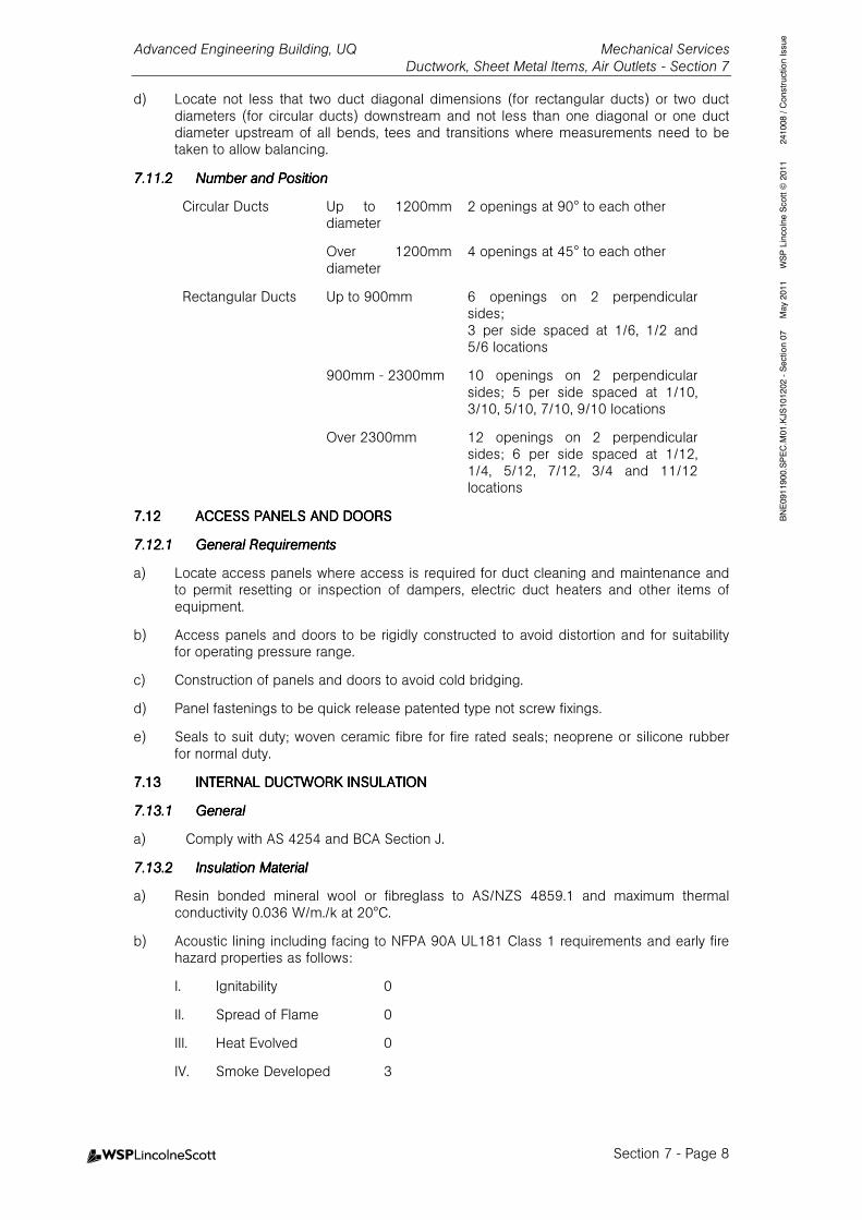
Advanced Engineering Building, UQ Mechanical Services Ductwork, Sheet Metal Items, Air Outlets - Section 7
Section 7 - Page 8
BNE0911900.SPEC.M01.KJS101202 - Section 07 May 2011 WSP Lincolne Scott © 2011 241008 / Construction Issue
d) Locate not less that two duct diagonal dimensions (for rectangular ducts) or two duct diameters (for circular ducts) downstream and not less than one diagonal or one duct diameter upstream of all bends, tees and transitions where measurements need to be taken to allow balancing.
7.11.27.11.27.11.27.11.2 Number and PositionNumber and PositionNumber and PositionNumber and Position
Circular Ducts Up to 1200mm diameter
2 openings at 90° to each other
Over 1200mm diameter
4 openings at 45° to each other
Rectangular Ducts Up to 900mm 6 openings on 2 perpendicular sides; 3 per side spaced at 1/6, 1/2 and 5/6 locations
900mm - 2300mm 10 openings on 2 perpendicular sides; 5 per side spaced at 1/10, 3/10, 5/10, 7/10, 9/10 locations
Over 2300mm 12 openings on 2 perpendicular sides; 6 per side spaced at 1/12, 1/4, 5/12, 7/12, 3/4 and 11/12 locations
7.127.127.127.12 ACCESS PANELS AND DOACCESS PANELS AND DOACCESS PANELS AND DOACCESS PANELS AND DOORSORSORSORS
7.12.17.12.17.12.17.12.1 General RequirementsGeneral RequirementsGeneral RequirementsGeneral Requirements
a) Locate access panels where access is required for duct cleaning and maintenance and to permit resetting or inspection of dampers, electric duct heaters and other items of equipment.
b) Access panels and doors to be rigidly constructed to avoid distortion and for suitability for operating pressure range.
c) Construction of panels and doors to avoid cold bridging.
d) Panel fastenings to be quick release patented type not screw fixings.
e) Seals to suit duty; woven ceramic fibre for fire rated seals; neoprene or silicone rubber for normal duty.
7.137.137.137.13 INTERNAL INTERNAL INTERNAL INTERNAL DUCTWORKDUCTWORKDUCTWORKDUCTWORK INSULATIONINSULATIONINSULATIONINSULATION
7.13.17.13.17.13.17.13.1 GeneralGeneralGeneralGeneral
a) Comply with AS 4254 and BCA Section J.
7.13.27.13.27.13.27.13.2 Insulation MaterialInsulation MaterialInsulation MaterialInsulation Material
a) Resin bonded mineral wool or fibreglass to AS/NZS 4859.1 and maximum thermal conductivity 0.036 W/m./k at 20°C.
b) Acoustic lining including facing to NFPA 90A UL181 Class 1 requirements and early fire hazard properties as follows:
I. Ignitability 0
II. Spread of Flame 0
III. Heat Evolved 0
IV. Smoke Developed 3
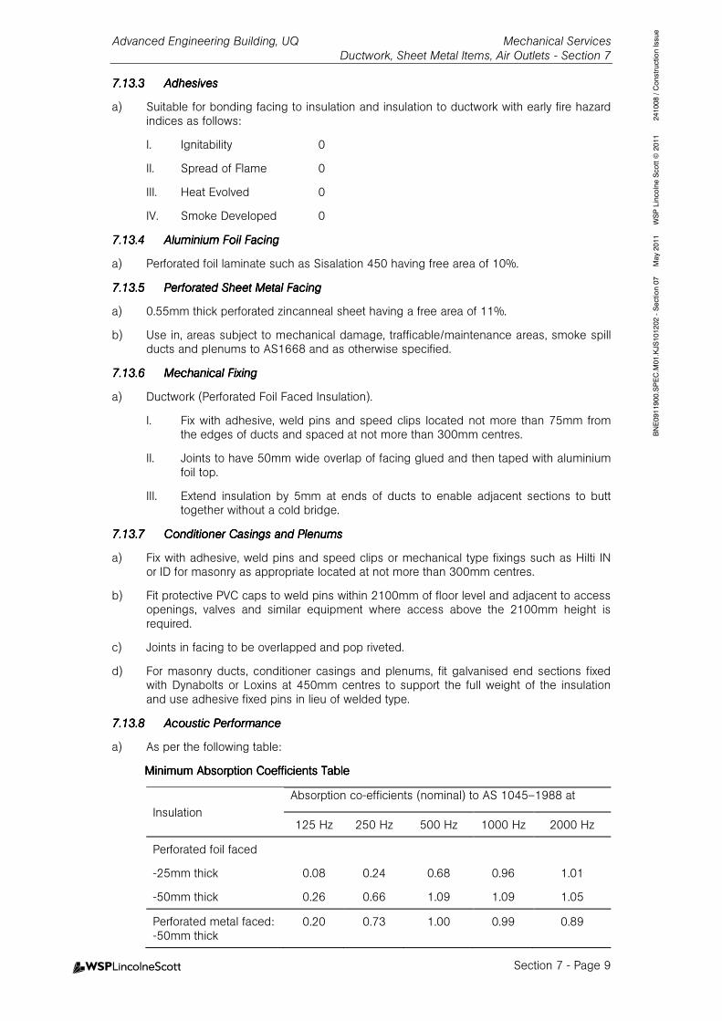
Advanced Engineering Building, UQ Mechanical Services Ductwork, Sheet Metal Items, Air Outlets - Section 7
Section 7 - Page 9
BNE0911900.SPEC.M01.KJS101202 - Section 07 May 2011 WSP Lincolne Scott © 2011 241008 / Construction Issue
7.13.37.13.37.13.37.13.3 AdhesivesAdhesivesAdhesivesAdhesives
a) Suitable for bonding facing to insulation and insulation to ductwork with early fire hazard indices as follows:
I. Ignitability 0
II. Spread of Flame 0
III. Heat Evolved 0
IV. Smoke Developed 0
7.13.47.13.47.13.47.13.4 Aluminium Foil FacingAluminium Foil FacingAluminium Foil FacingAluminium Foil Facing
a) Perforated foil laminate such as Sisalation 450 having free area of 10%.
7.13.57.13.57.13.57.13.5 Perforated Sheet Metal FacingPerforated Sheet Metal FacingPerforated Sheet Metal FacingPerforated Sheet Metal Facing
a) 0.55mm thick perforated zincanneal sheet having a free area of 11%.
b) Use in, areas subject to mechanical damage, trafficable/maintenance areas, smoke spill ducts and plenums to AS1668 and as otherwise specified.
7.13.67.13.67.13.67.13.6 Mechanical FixingMechanical FixingMechanical FixingMechanical Fixing
a) Ductwork (Perforated Foil Faced Insulation).
I. Fix with adhesive, weld pins and speed clips located not more than 75mm from the edges of ducts and spaced at not more than 300mm centres.
II. Joints to have 50mm wide overlap of facing glued and then taped with aluminium foil top.
III. Extend insulation by 5mm at ends of ducts to enable adjacent sections to butt together without a cold bridge.
7.13.77.13.77.13.77.13.7 Conditioner Casings and PlenumsConditioner Casings and PlenumsConditioner Casings and PlenumsConditioner Casings and Plenums
a) Fix with adhesive, weld pins and speed clips or mechanical type fixings such as Hilti IN or ID for masonry as appropriate located at not more than 300mm centres.
b) Fit protective PVC caps to weld pins within 2100mm of floor level and adjacent to access openings, valves and similar equipment where access above the 2100mm height is required.
c) Joints in facing to be overlapped and pop riveted.
d) For masonry ducts, conditioner casings and plenums, fit galvanised end sections fixed with Dynabolts or Loxins at 450mm centres to support the full weight of the insulation and use adhesive fixed pins in lieu of welded type.
7.13.87.13.87.13.87.13.8 Acoustic PerformanceAcoustic PerformanceAcoustic PerformanceAcoustic Performance
a) As per the following table:
Minimum Absorption Coefficients TableMinimum Absorption Coefficients TableMinimum Absorption Coefficients TableMinimum Absorption Coefficients Table
Insulation
Absorption co-efficients (nominal) to AS 1045–1988 at
125 Hz 250 Hz 500 Hz 1000 Hz 2000 Hz
Perforated foil faced
-25mm thick 0.08 0.24 0.68 0.96 1.01
-50mm thick 0.26 0.66 1.09 1.09 1.05
Perforated metal faced: -50mm thick
0.20 0.73 1.00 0.99 0.89

Advanced Engineering Building, UQ Mechanical Services Ductwork, Sheet Metal Items, Air Outlets - Section 7
Section 7 - Page 10
BNE0911900.SPEC.M01.KJS101202 - Section 07 May 2011 WSP Lincolne Scott © 2011 241008 / Construction Issue
7.147.147.147.14 SITE BUILT CONDITIONSITE BUILT CONDITIONSITE BUILT CONDITIONSITE BUILT CONDITIONER CASINGS & PLENUMSER CASINGS & PLENUMSER CASINGS & PLENUMSER CASINGS & PLENUMS
7.14.17.14.17.14.17.14.1 General RequirementsGeneral RequirementsGeneral RequirementsGeneral Requirements
a) Includes all supply, return, relief and filter air plenum chambers and enclosures for and air passages between air inlets, heating and cooling coils and fans.
b) Not applicable to factory assembled units.
c) Install on concrete plinths.
d) Provide air tight seals at all openings.
e) It is mandatory to submit construction details to demonstrate that cold tracking or sweating will not occur.
f) Eliminate rattling, excess deflection, or flexibility.
7.14.27.14.27.14.27.14.2 Sheet Metal ConstructionSheet Metal ConstructionSheet Metal ConstructionSheet Metal Construction
a) Zinc coated steel sheet of 1.55mm minimum thickness machine folded to form 450mm dished panels with 50mm deep stand up edges and 15mm deep returns with corners welded and cold galvanised.
b) 50x50x5 thick galvanised steel bracing angles.
c) All joints airtight and bolted at 150mm centres using galvanised nuts, bolts and washers and gaskets or silicone sealant.
d) Fix casing to floor via 50x50x5 thick galvanised steel folded channel which is bolted to floor at 300mm centres with expanding masonry type anchors. Fix panels to channels at 150mm centres with bolts and nuts.
e) Alternatively construct casings from Tri-Lock not less than 1.15mm thick.
7.14.37.14.37.14.37.14.3 Sandwich Panel ConstructionSandwich Panel ConstructionSandwich Panel ConstructionSandwich Panel Construction
a) Construct casings with prefabricated cool room panels with metal skin both sides comprising polystyrene sheet to AS 1366.3 Class M of suitable thickness to suit range of operating pressures, minimum thickness 50mm with metal skin 0.55mm thick zinc coated steel sheet, colourbonded.
b) Joints - aluminium extrusions inside and out and silicone bead seal.
c) Penetrations - seal with galvanised aluminium sleeve and polyurethane sealant.
7.14.47.14.47.14.47.14.4 Access DoorsAccess DoorsAccess DoorsAccess Doors
a) To allow full and easy access to all internal areas.
b) Fit hinged doors with heavy duty chrome-plated die-cast alloy hinges and lever-type door catches.
c) Use hinged door sealing gaskets of the replaceable closed cell foamed neoprene balloon type and fix them to the doors by riveted aluminium strips or approved adhesive.
d) Construct and install all doors and door hardware so that a person from inside can readily open any door.
7.14.57.14.57.14.57.14.5 Conditioner LightingConditioner LightingConditioner LightingConditioner Lighting
a) Weatherproof 18W fluorescent type such as Vandalite or Cassalux in each compartment.
7.14.67.14.67.14.67.14.6 ANCILLARY ITEMSANCILLARY ITEMSANCILLARY ITEMSANCILLARY ITEMS
a) Supply and install access ladders, platforms, handrails, gratings and similar items necessary for safe, easy access to items such as valves, modulating motors, expansion tanks and the like.
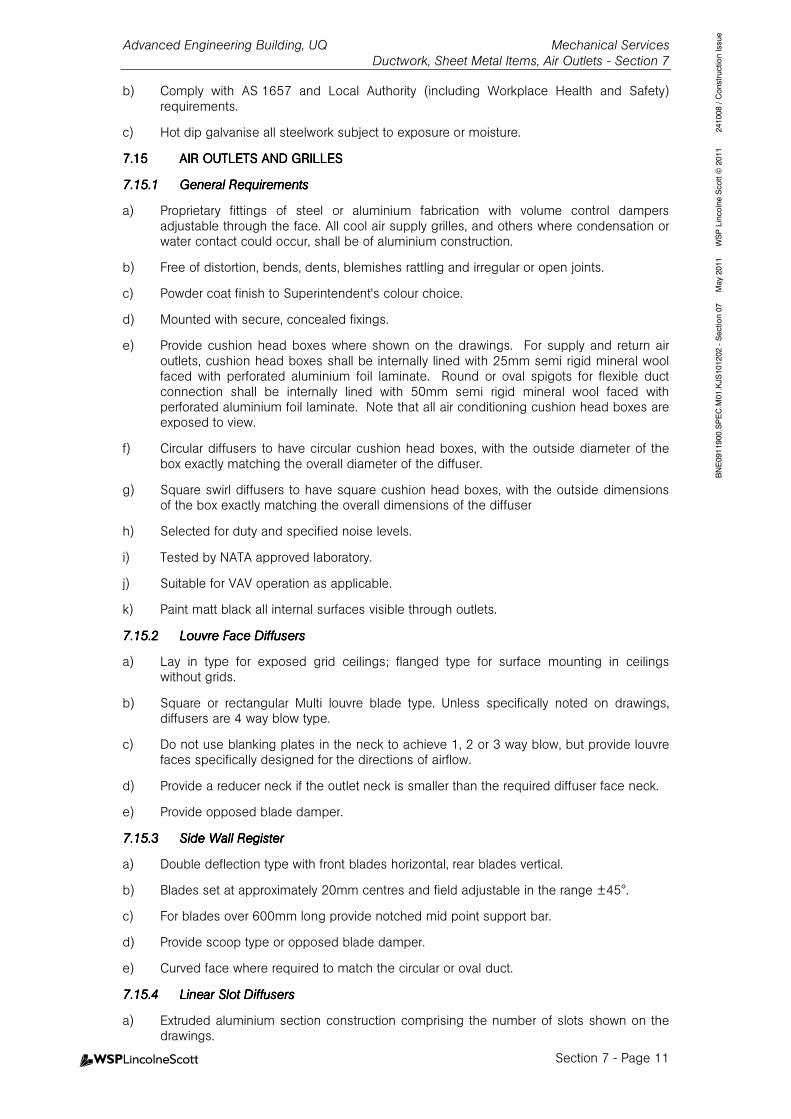
Advanced Engineering Building, UQ Mechanical Services Ductwork, Sheet Metal Items, Air Outlets - Section 7
Section 7 - Page 11
BNE0911900.SPEC.M01.KJS101202 - Section 07 May 2011 WSP Lincolne Scott © 2011 241008 / Construction Issue
b) Comply with AS 1657 and Local Authority (including Workplace Health and Safety) requirements.
c) Hot dip galvanise all steelwork subject to exposure or moisture.
7.157.157.157.15 AIR OUTLETS ANDAIR OUTLETS ANDAIR OUTLETS ANDAIR OUTLETS AND GRILLESGRILLESGRILLESGRILLES
7.15.17.15.17.15.17.15.1 General RequirementsGeneral RequirementsGeneral RequirementsGeneral Requirements
a) Proprietary fittings of steel or aluminium fabrication with volume control dampers adjustable through the face. All cool air supply grilles, and others where condensation or water contact could occur, shall be of aluminium construction.
b) Free of distortion, bends, dents, blemishes rattling and irregular or open joints.
c) Powder coat finish to Superintendent's colour choice.
d) Mounted with secure, concealed fixings.
e) Provide cushion head boxes where shown on the drawings. For supply and return air outlets, cushion head boxes shall be internally lined with 25mm semi rigid mineral wool faced with perforated aluminium foil laminate. Round or oval spigots for flexible duct connection shall be internally lined with 50mm semi rigid mineral wool faced with perforated aluminium foil laminate. Note that all air conditioning cushion head boxes are exposed to view.
f) Circular diffusers to have circular cushion head boxes, with the outside diameter of the box exactly matching the overall diameter of the diffuser.
g) Square swirl diffusers to have square cushion head boxes, with the outside dimensions of the box exactly matching the overall dimensions of the diffuser
h) Selected for duty and specified noise levels.
i) Tested by NATA approved laboratory.
j) Suitable for VAV operation as applicable.
k) Paint matt black all internal surfaces visible through outlets.
7.15.27.15.27.15.27.15.2 Louvre Face DiffuseLouvre Face DiffuseLouvre Face DiffuseLouvre Face Diffuserrrrssss
a) Lay in type for exposed grid ceilings; flanged type for surface mounting in ceilings without grids.
b) Square or rectangular Multi louvre blade type. Unless specifically noted on drawings, diffusers are 4 way blow type.
c) Do not use blanking plates in the neck to achieve 1, 2 or 3 way blow, but provide louvre faces specifically designed for the directions of airflow.
d) Provide a reducer neck if the outlet neck is smaller than the required diffuser face neck.
e) Provide opposed blade damper.
7.15.37.15.37.15.37.15.3 Side Wall RegisterSide Wall RegisterSide Wall RegisterSide Wall Register
a) Double deflection type with front blades horizontal, rear blades vertical.
b) Blades set at approximately 20mm centres and field adjustable in the range ±45°.
c) For blades over 600mm long provide notched mid point support bar.
d) Provide scoop type or opposed blade damper.
e) Curved face where required to match the circular or oval duct.
7.15.47.15.47.15.47.15.4 Linear Linear Linear Linear Slot DiffusersSlot DiffusersSlot DiffusersSlot Diffusers
a) Extruded aluminium section construction comprising the number of slots shown on the drawings.
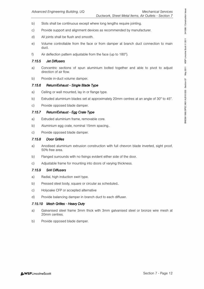
Advanced Engineering Building, UQ Mechanical Services Ductwork, Sheet Metal Items, Air Outlets - Section 7
Section 7 - Page 12
BNE0911900.SPEC.M01.KJS101202 - Section 07 May 2011 WSP Lincolne Scott © 2011 241008 / Construction Issue
b) Slots shall be continuous except where long lengths require jointing.
c) Provide support and alignment devices as recommended by manufacturer.
d) All joints shall be flush and smooth.
e) Volume controllable from the face or from damper at branch duct connection to main duct.
f) Air deflection pattern adjustable from the face (up to 180°).
7.15.57.15.57.15.57.15.5 Jet DiffusersJet DiffusersJet DiffusersJet Diffusers
a) Concentric sections of spun aluminium bolted together and able to pivot to adjust direction of air flow.
b) Provide in-duct volume damper.
7.15.67.15.67.15.67.15.6 Return/Exhaust Return/Exhaust Return/Exhaust Return/Exhaust ---- Single Blade TypeSingle Blade TypeSingle Blade TypeSingle Blade Type
a) Ceiling or wall mounted, lay in or flange type.
b) Extruded aluminium blades set at approximately 20mm centres at an angle of 30° to 45°.
c) Provide opposed blade damper.
7.15.77.15.77.15.77.15.7 Return/Exhaust Return/Exhaust Return/Exhaust Return/Exhaust ---- Egg Crate TypeEgg Crate TypeEgg Crate TypeEgg Crate Type
a) Extruded aluminium frame, removable core.
b) Aluminium egg crate, nominal 15mm spacing..
c) Provide opposed blade damper.
7.15.87.15.87.15.87.15.8 Door GrillesDoor GrillesDoor GrillesDoor Grilles
a) Anodised aluminium extrusion construction with full chevron blade inverted, sight proof, 50% free area.
b) Flanged surrounds with no fixings evident either side of the door.
c) Adjustable frame for mounting into doors of varying thickness.
7.15.97.15.97.15.97.15.9 Srirl DiffusersSrirl DiffusersSrirl DiffusersSrirl Diffusers
a) Radial, high induction swirl type.
b) Pressed steel body, square or circular as scheduled..
c) Holyoake CFP or accepted alternative
d) Provide balancing damper in branch duct to each diffuser.
7.15.107.15.107.15.107.15.10 Mesh Grilles Mesh Grilles Mesh Grilles Mesh Grilles ---- Heavy DutyHeavy DutyHeavy DutyHeavy Duty
a) Galvanised steel frame 3mm thick with 3mm galvanised steel or bronze wire mesh at 20mm centres.
b) Provide opposed blade damper.

Advanced Engineering Building, UQ Mechanical Services Thermal Insulation - Section 8
Table of Contents - Page 1
BNE0911900.SPEC.M01.KJS101202 - Section 08 May 2011 WSP Lincolne Scott © 2011 Revision 241008 / construction Issue
8.8.8.8. TTTTHERMAL HERMAL HERMAL HERMAL IIIINSULATIONNSULATIONNSULATIONNSULATION 1111
8.18.18.18.1 GENERALGENERALGENERALGENERAL 1111
8.1.1 Scope 1
8.1.2 Referenced Documents 1
8.28.28.28.2 DESIGNDESIGNDESIGNDESIGN 1111
8.2.1 General 1
8.2.2 Authority Standards and Codes 1
8.38.38.38.3 SUBMISSIONSSUBMISSIONSSUBMISSIONSSUBMISSIONS 1111
8.48.48.48.4 GENERAL REQUIREMENTSGENERAL REQUIREMENTSGENERAL REQUIREMENTSGENERAL REQUIREMENTS 1111
8.58.58.58.5 EARLY FIRE HAZARD PREARLY FIRE HAZARD PREARLY FIRE HAZARD PREARLY FIRE HAZARD PROPERTIESOPERTIESOPERTIESOPERTIES 2222
8.68.68.68.6 LOW TEMPERATURE PIPILOW TEMPERATURE PIPILOW TEMPERATURE PIPILOW TEMPERATURE PIPING AND EVAPORATOR HENG AND EVAPORATOR HENG AND EVAPORATOR HENG AND EVAPORATOR HEADS INSULATIONADS INSULATIONADS INSULATIONADS INSULATION 2222
8.6.1 General Requirements 2
8.6.2 Installation 2
8.6.3 Site Sample 4
8.78.78.78.7 POLYETHYLENE PIPEWORPOLYETHYLENE PIPEWORPOLYETHYLENE PIPEWORPOLYETHYLENE PIPEWORK INSULATIONK INSULATIONK INSULATIONK INSULATION 4444
8.88.88.88.8 MEDIUM TEMPERATURE PMEDIUM TEMPERATURE PMEDIUM TEMPERATURE PMEDIUM TEMPERATURE PIPING INSULATIONIPING INSULATIONIPING INSULATIONIPING INSULATION 4444
8.8.1 General Requirements 4
8.8.2 Installation 4
8.98.98.98.9 METAL CLADDINGMETAL CLADDINGMETAL CLADDINGMETAL CLADDING 4444
8.9.1 Requirements 4
8.108.108.108.10 EXTERNAL DUCTWORK INEXTERNAL DUCTWORK INEXTERNAL DUCTWORK INEXTERNAL DUCTWORK INSULATIONSULATIONSULATIONSULATION 5555
8.10.1 Mineral Wool or Fibreglass 5
8.118.118.118.11 ADDITIONAL GREEN STAADDITIONAL GREEN STAADDITIONAL GREEN STAADDITIONAL GREEN STAR REQUIREMENTSR REQUIREMENTSR REQUIREMENTSR REQUIREMENTS 5555
Advanced Engineering Building, UQ Mechanical Services Thermal Insulation - Section 8
Section 8 - Page 1
BNE0911900.SPEC.M01.KJS101202 - Section 08 May 2011 WSP Lincolne Scott © 2011 Revision 241008 / construction Issue
8.8.8.8. TTTTHERMAL HERMAL HERMAL HERMAL IIIINSULATIONNSULATIONNSULATIONNSULATION
8.18.18.18.1 GENERALGENERALGENERALGENERAL
8.1.18.1.18.1.18.1.1 ScopeScopeScopeScope
a) This section sets out the engineering and quality assurance requirements for the completion of the installation design, materials, components, general installation and testing of the Mechanical Services thermal insulation.
b) Refer to Schedule of Thermal Insulation for required insulation criteria.
c) This section is to be read in conjunction with all other sections of this specification.
8.1.28.1.28.1.28.1.2 Referenced DocumentsReferenced DocumentsReferenced DocumentsReferenced Documents
Details of documents applicable to this section of the specification include:
Australian/New Zealand StandardsAustralian/New Zealand StandardsAustralian/New Zealand StandardsAustralian/New Zealand Standards
AS/NZS 4859.1-2002 Mineral wool thermal insulation -Batt and blanket AS 1366.3-1992/Amdt 1-1993 Rigid cellular plastics sheets for thermal insulation -
Rigid cellular polystyrene - Moulded (RC/PS - M) AS/NZS 1530.3-1999 Methods for fire tests on building materials,
components and structures - Simultaneous determination of ignitability, flame propagation, heat release and smoke release
8.28.28.28.2 DESIGNDESIGNDESIGNDESIGN
8.2.18.2.18.2.18.2.1 GeneralGeneralGeneralGeneral
a) Complete the detail design and engineering of the thermal insulation installation to the specified requirements.
8.2.28.2.28.2.28.2.2 Authority Standards and CodesAuthority Standards and CodesAuthority Standards and CodesAuthority Standards and Codes
a) Comply with applicable authority design guidelines and codes of practice and requirements.
8.38.38.38.3 SUBMISSIONSSUBMISSIONSSUBMISSIONSSUBMISSIONS
a) Product safety sheets.
b) Product Fire rating test sheets.
8.48.48.48.4 GENERAL REQUIREMENTSGENERAL REQUIREMENTSGENERAL REQUIREMENTSGENERAL REQUIREMENTS
a) Installation by skilled tradesmen experienced and competent in this type of work.
b) Use only insulation materials clearly marked or identified as to grade, materials that are dry and free from objectionable smells and materials which are suitable for the full range of operating conditions.
c) Clean all surfaces thoroughly of rust, grease, oil and dirt prior to application of insulation.
d) Complete all pressure and leak testing prior to application of insulation.
e) Make insulation continuous with joints firmly butted together, cold tracking eliminated and vapour barrier for cold pipes sealed.
f) Allow for thermal movement.
g) Insulate equipment connections, flexible connections, valves and similar to the same level as the connecting piping.
Advanced Engineering Building, UQ Mechanical Services Thermal Insulation - Section 8
Section 8 - Page 2
BNE0911900.SPEC.M01.KJS101202 - Section 08 May 2011 WSP Lincolne Scott © 2011 Revision 241008 / construction Issue
8.58.58.58.5 EARLY FIRE HAZARD PREARLY FIRE HAZARD PREARLY FIRE HAZARD PREARLY FIRE HAZARD PROPERTIESOPERTIESOPERTIESOPERTIES
a) Use only insulation materials and systems tested in accordance with AS/NZS 1530.3 and complying with the Building Code of Australia and relevant Statutory Authorities.
b) Thermal insulation systems including adhesives, vapour barriers, facings and coatings early fire hazard properties:
Ignitability Index 0
Spread of Flame 0
Heat Evolved Index 0
Smoke Developed Index 3 max
8.68.68.68.6 LOW TEMPERATURE PIPILOW TEMPERATURE PIPILOW TEMPERATURE PIPILOW TEMPERATURE PIPINGNGNGNG AND EVAPAND EVAPAND EVAPAND EVAPORATOR HEADSORATOR HEADSORATOR HEADSORATOR HEADS INSULATIONINSULATIONINSULATIONINSULATION
8.6.18.6.18.6.18.6.1 General RequirementsGeneral RequirementsGeneral RequirementsGeneral Requirements
a) Operating conditions below ambient.
b) Sectional moulded machine cut polystyrene foam to AS 1366.3 Class S or SL, self extinguishing grade. Internal diameter of the insulation section to be 2mm larger than pipe.
c) Thermal conductivity after six months ageing of not greater than 0.036 W/mk at a mean temperature of 25°C.
d) Type 1 Piping Insulation has vapour barrier comprising reinforced aluminium foil facing factory such as Sisalation 450 or equal.
e) Type 2 Piping Insulation has vapour barrier comprising foam sealing and vapour barrier products strictly to manufacturer's recommendations.
8.6.28.6.28.6.28.6.2 InstallationInstallationInstallationInstallation
a) Type 1 Piping Insulation (Steel or Copper Pipe – DX Systems):
I. Wire brush loose material from pipework.
II. Fix insulation to piping with tack coat of adhesive and aluminium fixing bands at each butt joint and in mid position on each section (approximately 450mm centres).
III. Overlap all joints of aluminium foil facing by 25mm and seal with non flammable adhesive.
b) Type 2 Piping Insulation (Steel Pipe – Chilled Water Systems):
I. Remove scale, rust, grease and the like from pipework surface and ensure that the surface is clean and dry.
II. All steel pipework to have one coat of zinc phosphate primer before insulation commences.
III. Apply an oil based mastic, Foster Foam Seal 30-45 or Childers CP70 with minimum thickness of 1.6mm to the following
• All mating surfaces of polystyrene at joints between sections
• To the section of pipe to be insulated and mating faces of polystyrene
• To the faces of the polystyrene and pipe support blocks at the joints
• Both longitudinal joints of the polystyrene insulation
IV. Longitudinal joints to be staggered a minimum of 25mm between sections.

Advanced Engineering Building, UQ Mechanical Services Thermal Insulation - Section 8
Section 8 - Page 3
BNE0911900.SPEC.M01.KJS101202 - Section 08 May 2011 WSP Lincolne Scott © 2011 Revision 241008 / construction Issue
I. Press mating surfaces together firmly and squeeze out any air bubbles to obtain complete contact. Both longitudinal and butt joints of the insulation need to be coated. All joints to be close butted and sealed to ensure no air space or gaps are left.
V. Cut the insulation into segments to follow the contour of the bend, glue together and fix to the pipework.
VI. Where insulation comprises several sections overlap longitudinal joints by at least 100mm.
VII. Fix insulation to piping with aluminium fixing bands at each butt joint and in mid position on each section (approximately 450mm centres).
VIII. The insulation shall be cut and formed to fit around fitting, valves and flanges. Where not possible use mineral wool insulation or pug to fill the air gap. Where the insulation thickness has been reduced, apply a further layer of polystyrene section to maintain thickness for the pipe. Use removable clip-on system for valves and fittings requiring service. Mark the location of concealed unions or fittings by labels or sign writing on the insulation surface.
IX. Apply a brush coat of Foster Vapoursafe Mastic 30-90 at the rate of 0.8l/m².
X. Embed No.10 Glass cloth into the Vapoursafe Mastic 30-90 overlapping all joints by 50mm minimum. Smooth out wrinkles.
XI. Apply a second coat of Foster Vapoursafe Mastic 30-90 at the rate of 1.6 l/m².
XII. Flash insulation using Foster Foamseal 30-45 to seal all joints.
c) Type 2 Piping Insulation (Copper Pipe – Chilled Water Systems):
I. Remove scale, rust, grease and the like from pipework surface and ensure that the surface is clean and dry.
II. Apply Foster insulation adhesive 252WB. Surfaces at a rate of 0.5l/m² to the following
• All mating surfaces of polystyrene at joints between sections
• To the section of pipe to be insulated and mating faces of polystyrene
• To the faces of the polystyrene and pipe support blocks at the joints
• Both longitudinal joints of the polystyrene insulation
III. Longitudinal joints to be staggered a minimum of 25mm between sections.
IV. Press mating surfaces together firmly and squeeze out any air bubbles to obtain complete contact. Both longitudinal and butt joints of the insulation need to be coated. All joints to be close butted and sealed to ensure no air space or gaps are left.
V. Cut the insulation into segments to follow the contour of the bend, glue together and fix to the pipework.
VI. Where insulation comprises several sections overlap longitudinal joints by at least 100mm.
VII. Fix insulation to piping with aluminium fixing bands at each butt joint and in mid position on each section (approximately 450mm centres).
VIII. The insulation shall be cut and formed to fit around fitting, valves and flanges. Where not possible use mineral wool insulation or pug to fill the air gap. Where the insulation thickness has been reduced, apply a further layer of polystyrene section to maintain thickness for the pipe. Use removable clip-on system for valves and fittings requiring service. Mark the location of concealed unions or fittings by labels or sign writing on the insulation surface.
IX. Apply a brush coat of Foster Vapoursafe Mastic 30-90 at the rate of 0.8l/m².
Advanced Engineering Building, UQ Mechanical Services Thermal Insulation - Section 8
Section 8 - Page 4
BNE0911900.SPEC.M01.KJS101202 - Section 08 May 2011 WSP Lincolne Scott © 2011 Revision 241008 / construction Issue
X. Embed No.10 Glass cloth into the Vapoursafe Mastic 30-90 overlapping all joints by 50mm minimum. Smooth out wrinkles.
XI. Apply a second coat of Foster Vapoursafe Mastic 30-90 at the rate of 1.6 l/m².
XII. Flash insulation using Foster Foamseal 30-45 to seal all joints.
8.6.38.6.38.6.38.6.3 Site SampleSite SampleSite SampleSite Sample
I. Allow to remove for the purposes of site witnessing of correct application, one (1) 300mm sample of finished insulation for every 100 m of chilled water pipe work installed or part thereof. Allow to re-instate in accordance with the above removed sample with new. For each sample not installed in accordance with the specification another site sample will be taken.
8.78.78.78.7 POLYETHYLENE PIPEWORPOLYETHYLENE PIPEWORPOLYETHYLENE PIPEWORPOLYETHYLENE PIPEWORK INSULATIONK INSULATIONK INSULATIONK INSULATION
a) Use for refrigerant piping and condensate drainage.
b) Minimum 25mm thick flexible, laminated closed cell polyethylene foam of Armaflex FR Thermotec, Quick Seal, Sealed Tube or equal accepted 4-zero type.
c) Thermal conductivity not greater than 0.042 W/mK at mean temperature of 20°C.
d) Cover entire surface of pipework with insulation, do not slit.
e) Fix with contact adhesive. Open joints will be rejected.
f) Butt joint tightly together, glue all joints.
g) Paint exposed insulation with 2 coats of water based paint supplied by the insulation manufacturer and suitable for the purpose.
h) Install and tape joints to manufacturers recommendations.
8.88.88.88.8 MEDIUM TEMPERATURE PMEDIUM TEMPERATURE PMEDIUM TEMPERATURE PMEDIUM TEMPERATURE PIPIPIPIPING INSULATIONING INSULATIONING INSULATIONING INSULATION
8.8.18.8.18.8.18.8.1 General RequirementsGeneral RequirementsGeneral RequirementsGeneral Requirements
a) Operating conditions above ambient and not exceeding 300°C.
b) Sectional moulded resin bonded mineral wool or glass wool.
c) Thermal conductivity not greater than 0.043 W/mK at a mean temperature of 100°C.
d) Reinforced aluminium foil facing factory applied such as Sisalation 450 or equal.
e) For solar collector piping & accessories (using heat transfer fluid) utilise a high temperature closed cell insulation (such as Corning FoamGlas and HiTherm HT-450)
8.8.28.8.28.8.28.8.2 InstallationInstallationInstallationInstallation
a) Fix insulation to piping with aluminium fixing bands at each butt joint and in mid position on each section (approx 450 centres).
b) Overlap all joints of aluminium foil facing by 25mm and seal with non flammable adhesive.
c) Small lines up to 20mm diameter and not exceeding 80°C may be insulated with 12mm thick (or thicker as needed for BCA Section J compliance) flexible closed cell sponge type insulation such as Armaflex or equal having a thermal conductivity of not greater than 0.042 W/mK at a mean temperature of 24°C. Apply as recommended by the manufacturer and fully seal all joints.
8.98.98.98.9 METAL CLADDINGMETAL CLADDINGMETAL CLADDINGMETAL CLADDING
a) Sheath all insulated piping
8.9.18.9.18.9.18.9.1 RequirementsRequirementsRequirementsRequirements
a) Minimum 0.55mm thick zincanneal or galvanised steel sheet.
Advanced Engineering Building, UQ Mechanical Services Thermal Insulation - Section 8
Section 8 - Page 5
BNE0911900.SPEC.M01.KJS101202 - Section 08 May 2011 WSP Lincolne Scott © 2011 Revision 241008 / construction Issue
b) Cut and roll sheeting to the required sizes with beaded transfer joints and 25mm overlapping circumferential joints.
c) Longitudinal joints faced away from view.
d) Fixed with galvanised steel or aluminium straps for low temperature piping and either straps or self tapping screws for medium temperature piping. Do not violate vapour barrier.
e) Cut sheet to form lobster back segments for curved surfaces. Seal all holes.
f) Seal joints with sealing compound for piping exposed to weather or moisture.
g) Seal up all penetrations for gauges, instruments drains and vents.
h) Readily removable at evaporator heads, strainers, and similar areas where removal for maintenance is anticipated.
8.108.108.108.10 EXTERNAL DUCTWORK INEXTERNAL DUCTWORK INEXTERNAL DUCTWORK INEXTERNAL DUCTWORK INSULATIONSULATIONSULATIONSULATION
8.10.18.10.18.10.18.10.1 Mineral Wool or FibreglassMineral Wool or FibreglassMineral Wool or FibreglassMineral Wool or Fibreglass
a) Resin bonded batt, board or blanket to AS/NZS 4859.1.
b) Thermal conductivity 0.036 W/mK at 20°C maximum.
c) Factory faced with reinforced aluminium foil of 0.007mm thickness (Sisalation 450 or equal.)
d) Cover entire surface of ductwork with insulation including all flanges, stiffeners and support angles.
e) Butt joints tightly together and overlap foil facing by at least 50mm and firmly adhere with fire resistant non flammable adhesive.
f) Tape all joints with 75mm aluminium foil tape.
g) Fix bottom and sides of insulation with pin fixings at 450mm centres.
h) Fix aluminium or polypropylene fixing bands at each joint in the insulation and between each joint at approximately 600mm centres when ductwork dimensions exceed maximum. Do not damage aluminium foil facing when placing fixing bands.
8.118.118.118.11 ADDITIONAL GREEN STAADDITIONAL GREEN STAADDITIONAL GREEN STAADDITIONAL GREEN STAR REQUIREMENTSR REQUIREMENTSR REQUIREMENTSR REQUIREMENTS
The following additional requirements are to be met for compliance with Greenstar requirements.
All insulation is to be free of ozone depleting gases in manufacture and composition. Only use insulation products that have an ODP of 0 for both its manufacture and composition.
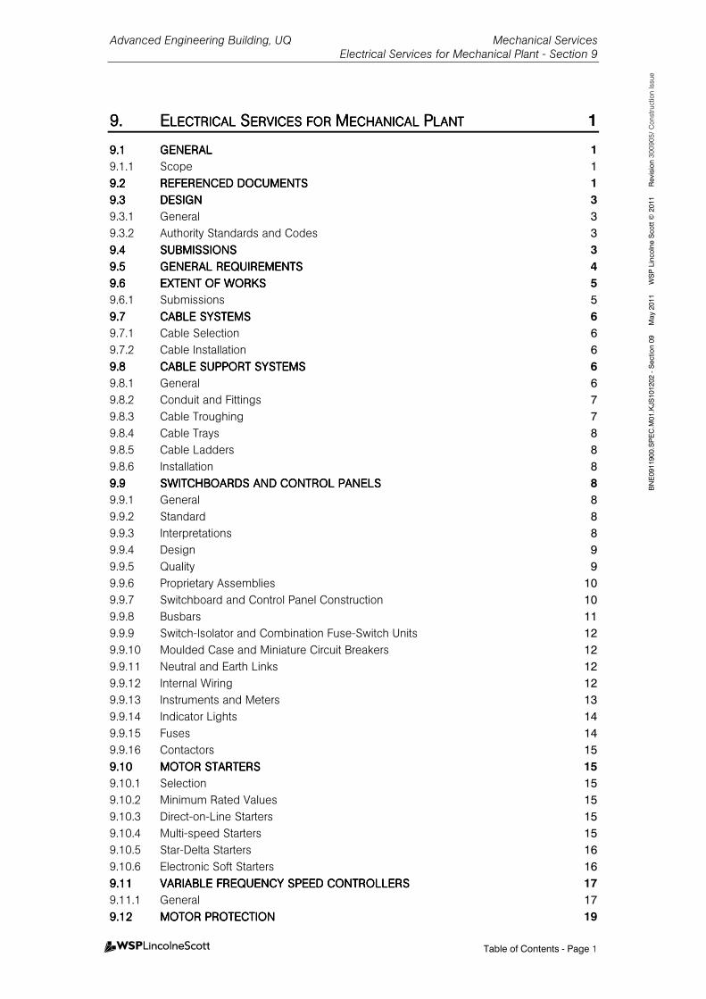
Advanced Engineering Building, UQ Mechanical Services Electrical Services for Mechanical Plant - Section 9
Table of Contents - Page 1
BNE0911900.SPEC.M
01.KJS101202 - Section 09 M
ay 2011 W
SP Lincolne Scott ©
2011 Revision 3
00905/
Const
ruct
ion Is
sue
9.9.9.9. EEEELECTRICAL LECTRICAL LECTRICAL LECTRICAL SSSSERVICES FOR ERVICES FOR ERVICES FOR ERVICES FOR MMMMECHANICAL ECHANICAL ECHANICAL ECHANICAL PPPPLANTLANTLANTLANT 1
9.19.19.19.1 GENERALGENERALGENERALGENERAL 1
9.1.1 Scope 1
9.29.29.29.2 REFERENCED DOCUMENTSREFERENCED DOCUMENTSREFERENCED DOCUMENTSREFERENCED DOCUMENTS 1
9.39.39.39.3 DESIGNDESIGNDESIGNDESIGN 3
9.3.1 General 3
9.3.2 Authority Standards and Codes 3
9.49.49.49.4 SUBMISSIONSSUBMISSIONSSUBMISSIONSSUBMISSIONS 3
9.59.59.59.5 GENERAL GENERAL GENERAL GENERAL REQUIREMENTSREQUIREMENTSREQUIREMENTSREQUIREMENTS 4
9.69.69.69.6 EXTENT OF WORKSEXTENT OF WORKSEXTENT OF WORKSEXTENT OF WORKS 5
9.6.1 Submissions 5
9.79.79.79.7 CABCABCABCABLE SYSTEMSLE SYSTEMSLE SYSTEMSLE SYSTEMS 6
9.7.1 Cable Selection 6
9.7.2 Cable Installation 6
9.89.89.89.8 CABLE SUPPORT SYSTEMCABLE SUPPORT SYSTEMCABLE SUPPORT SYSTEMCABLE SUPPORT SYSTEMSSSS 6
9.8.1 General 6
9.8.2 Conduit and Fittings 7
9.8.3 Cable Troughing 7
9.8.4 Cable Trays 8
9.8.5 Cable Ladders 8
9.8.6 Installation 8
9.99.99.99.9 SWITCHBOARDS AND CONSWITCHBOARDS AND CONSWITCHBOARDS AND CONSWITCHBOARDS AND CONTROL PANELSTROL PANELSTROL PANELSTROL PANELS 8
9.9.1 General 8
9.9.2 Standard 8
9.9.3 Interpretations 8
9.9.4 Design 9
9.9.5 Quality 9
9.9.6 Proprietary Assemblies 10
9.9.7 Switchboard and Control Panel Construction 10
9.9.8 Busbars 11
9.9.9 Switch-Isolator and Combination Fuse-Switch Units 12
9.9.10 Moulded Case and Miniature Circuit Breakers 12
9.9.11 Neutral and Earth Links 12
9.9.12 Internal Wiring 12
9.9.13 Instruments and Meters 13
9.9.14 Indicator Lights 14
9.9.15 Fuses 14
9.9.16 Contactors 15
9.109.109.109.10 MOTOR STARTERSMOTOR STARTERSMOTOR STARTERSMOTOR STARTERS 15
9.10.1 Selection 15
9.10.2 Minimum Rated Values 15
9.10.3 Direct-on-Line Starters 15
9.10.4 Multi-speed Starters 15
9.10.5 Star-Delta Starters 16
9.10.6 Electronic Soft Starters 16
9.119.119.119.11 VARIABLE FREQUENCY SVARIABLE FREQUENCY SVARIABLE FREQUENCY SVARIABLE FREQUENCY SPEED CONTROLLERSPEED CONTROLLERSPEED CONTROLLERSPEED CONTROLLERS 17
9.11.1 General 17
9.129.129.129.12 MOTOR PROTECTIONMOTOR PROTECTIONMOTOR PROTECTIONMOTOR PROTECTION 19
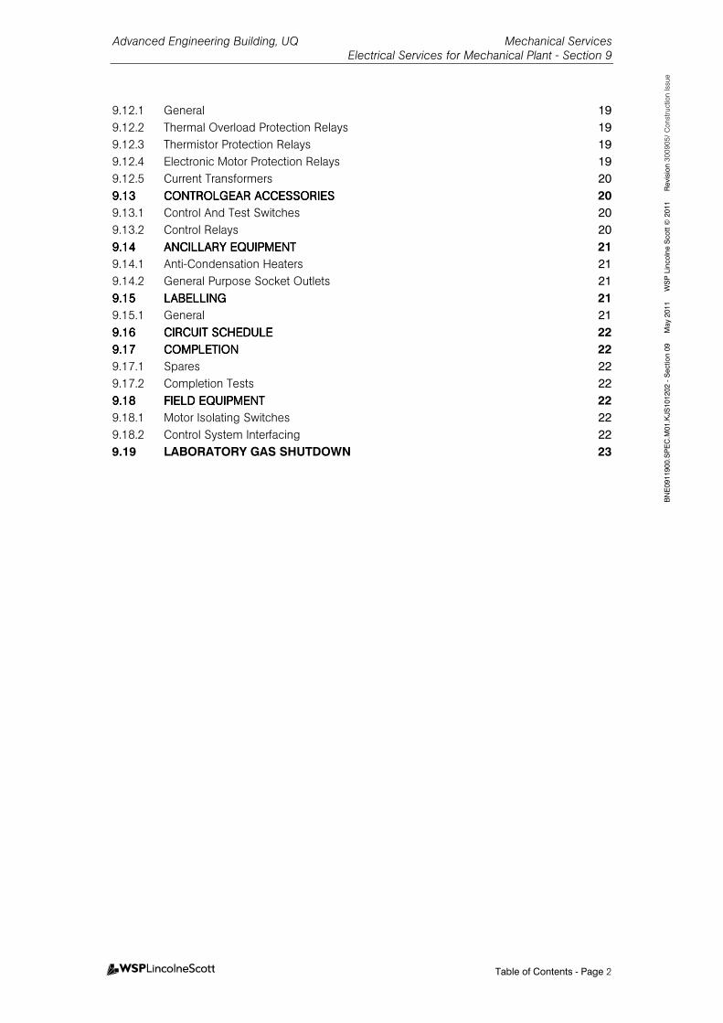
Advanced Engineering Building, UQ Mechanical Services Electrical Services for Mechanical Plant - Section 9
Table of Contents - Page 2
BNE0911900.SPEC.M
01.KJS101202 - Section 09 M
ay 2011 W
SP Lincolne Scott ©
2011 Revision 3
00905/
Const
ruct
ion Is
sue
9.12.1 General 19
9.12.2 Thermal Overload Protection Relays 19
9.12.3 Thermistor Protection Relays 19
9.12.4 Electronic Motor Protection Relays 19
9.12.5 Current Transformers 20
9.139.139.139.13 CONTROLGEAR ACCESSORCONTROLGEAR ACCESSORCONTROLGEAR ACCESSORCONTROLGEAR ACCESSORIESIESIESIES 20
9.13.1 Control And Test Switches 20
9.13.2 Control Relays 20
9.149.149.149.14 ANCILLARY EQUIPMENTANCILLARY EQUIPMENTANCILLARY EQUIPMENTANCILLARY EQUIPMENT 21
9.14.1 Anti-Condensation Heaters 21
9.14.2 General Purpose Socket Outlets 21
9.159.159.159.15 LABELLINGLABELLINGLABELLINGLABELLING 21
9.15.1 General 21
9.169.169.169.16 CIRCUIT SCHEDULECIRCUIT SCHEDULECIRCUIT SCHEDULECIRCUIT SCHEDULE 22
9.179.179.179.17 COMPLETIONCOMPLETIONCOMPLETIONCOMPLETION 22
9.17.1 Spares 22
9.17.2 Completion Tests 22
9.189.189.189.18 FIELD EQUIPMENTFIELD EQUIPMENTFIELD EQUIPMENTFIELD EQUIPMENT 22
9.18.1 Motor Isolating Switches 22
9.18.2 Control System Interfacing 22
9.19 LABORATORY GAS SHUTDOWN 23
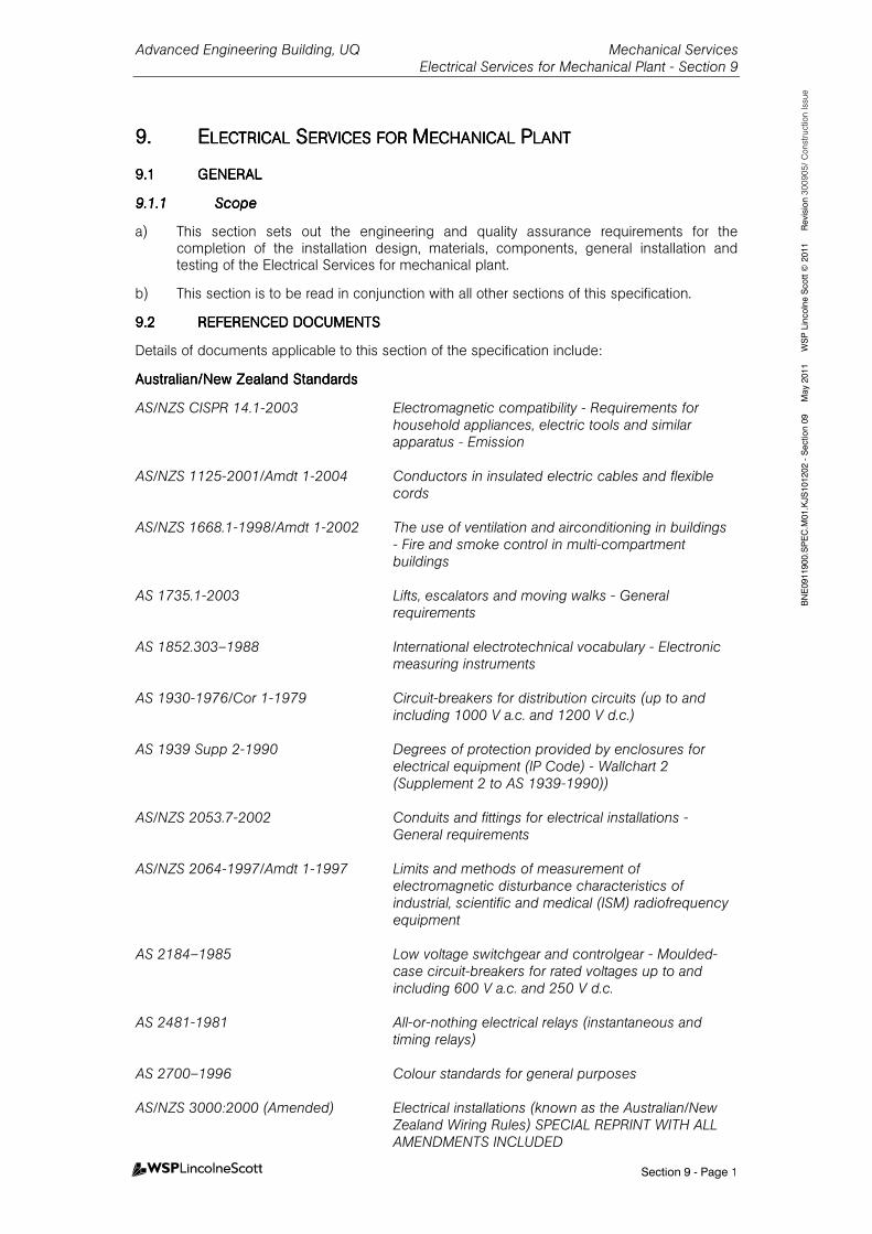
Advanced Engineering Building, UQ Mechanical Services Electrical Services for Mechanical Plant - Section 9
Section 9 - Page 1
BNE0911900.SPEC.M
01.KJS101202 - Section 09 M
ay 2011 W
SP Lincolne Scott ©
2011 Revision 3
00905/
Const
ruct
ion Is
sue
9.9.9.9. EEEELECTRICAL LECTRICAL LECTRICAL LECTRICAL SSSSERVICES FOR ERVICES FOR ERVICES FOR ERVICES FOR MMMMECHANICAL ECHANICAL ECHANICAL ECHANICAL PPPPLANTLANTLANTLANT
9.19.19.19.1 GENERALGENERALGENERALGENERAL
9.1.19.1.19.1.19.1.1 ScopeScopeScopeScope
a) This section sets out the engineering and quality assurance requirements for the completion of the installation design, materials, components, general installation and testing of the Electrical Services for mechanical plant.
b) This section is to be read in conjunction with all other sections of this specification.
9.29.29.29.2 REFERENCED DOCUMENTSREFERENCED DOCUMENTSREFERENCED DOCUMENTSREFERENCED DOCUMENTS
Details of documents applicable to this section of the specification include:
Australian/New Zealand StandardsAustralian/New Zealand StandardsAustralian/New Zealand StandardsAustralian/New Zealand Standards
AS/NZS CISPR 14.1-2003 Electromagnetic compatibility - Requirements for household appliances, electric tools and similar apparatus - Emission
AS/NZS 1125-2001/Amdt 1-2004 Conductors in insulated electric cables and flexible
cords AS/NZS 1668.1-1998/Amdt 1-2002 The use of ventilation and airconditioning in buildings
- Fire and smoke control in multi-compartment buildings
AS 1735.1-2003 Lifts, escalators and moving walks - General
requirements AS 1852.303–1988 International electrotechnical vocabulary - Electronic
measuring instruments AS 1930-1976/Cor 1-1979 Circuit-breakers for distribution circuits (up to and
including 1000 V a.c. and 1200 V d.c.) AS 1939 Supp 2-1990 Degrees of protection provided by enclosures for
electrical equipment (IP Code) - Wallchart 2 (Supplement 2 to AS 1939-1990))
AS/NZS 2053.7-2002 Conduits and fittings for electrical installations -
General requirements AS/NZS 2064-1997/Amdt 1-1997 Limits and methods of measurement of
electromagnetic disturbance characteristics of industrial, scientific and medical (ISM) radiofrequency equipment
AS 2184–1985 Low voltage switchgear and controlgear - Moulded-
case circuit-breakers for rated voltages up to and including 600 V a.c. and 250 V d.c.
AS 2481-1981 All-or-nothing electrical relays (instantaneous and
timing relays) AS 2700–1996 Colour standards for general purposes AS/NZS 3000:2000 (Amended) Electrical installations (known as the Australian/New
Zealand Wiring Rules) SPECIAL REPRINT WITH ALL AMENDMENTS INCLUDED
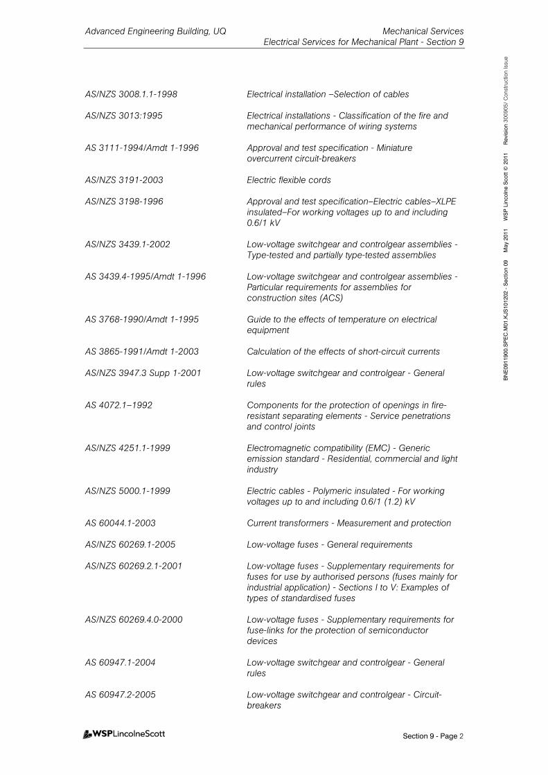
Advanced Engineering Building, UQ Mechanical Services Electrical Services for Mechanical Plant - Section 9
Section 9 - Page 2
BNE0911900.SPEC.M
01.KJS101202 - Section 09 M
ay 2011 W
SP Lincolne Scott ©
2011 Revision 3
00905/
Const
ruct
ion Is
sue
AS/NZS 3008.1.1-1998 Electrical installation –Selection of cables AS/NZS 3013:1995 Electrical installations - Classification of the fire and
mechanical performance of wiring systems AS 3111-1994/Amdt 1-1996 Approval and test specification - Miniature
overcurrent circuit-breakers AS/NZS 3191-2003 Electric flexible cords AS/NZS 3198-1996 Approval and test specification–Electric cables–XLPE
insulated–For working voltages up to and including 0.6/1 kV
AS/NZS 3439.1-2002 Low-voltage switchgear and controlgear assemblies -
Type-tested and partially type-tested assemblies AS 3439.4-1995/Amdt 1-1996 Low-voltage switchgear and controlgear assemblies -
Particular requirements for assemblies for construction sites (ACS)
AS 3768-1990/Amdt 1-1995 Guide to the effects of temperature on electrical
equipment AS 3865-1991/Amdt 1-2003 Calculation of the effects of short-circuit currents AS/NZS 3947.3 Supp 1-2001 Low-voltage switchgear and controlgear - General
rules AS 4072.1–1992 Components for the protection of openings in fire-
resistant separating elements - Service penetrations and control joints
AS/NZS 4251.1-1999 Electromagnetic compatibility (EMC) - Generic
emission standard - Residential, commercial and light industry
AS/NZS 5000.1-1999 Electric cables - Polymeric insulated - For working
voltages up to and including 0.6/1 (1.2) kV AS 60044.1-2003 Current transformers - Measurement and protection AS/NZS 60269.1-2005 Low-voltage fuses - General requirements AS/NZS 60269.2.1-2001 Low-voltage fuses - Supplementary requirements for
fuses for use by authorised persons (fuses mainly for industrial application) - Sections I to V: Examples of types of standardised fuses
AS/NZS 60269.4.0-2000 Low-voltage fuses - Supplementary requirements for
fuse-links for the protection of semiconductor devices
AS 60947.1-2004 Low-voltage switchgear and controlgear - General
rules AS 60947.2-2005 Low-voltage switchgear and controlgear - Circuit-
breakers

Advanced Engineering Building, UQ Mechanical Services Electrical Services for Mechanical Plant - Section 9
Section 9 - Page 3
BNE0911900.SPEC.M
01.KJS101202 - Section 09 M
ay 2011 W
SP Lincolne Scott ©
2011 Revision 3
00905/
Const
ruct
ion Is
sue
AS 60947.4.1-2004 Low-voltage switchgear and controlgear - Contactors and motor-starters - Electromechanical contactors and motor-starters
AS 60947.5.1-2004 Low-voltage switchgear and controlgear - Control
circuit devices and switching elements - Electromechanical control circuit devices
AS 60947.8-2005 Low voltage switchgear and controlgear - Protection
of electric motors - Built-in thermal detectors and associated control units
AS/NZS 61000.1.1-2000 Electromagnetic compatibility (EMC) - General -
Application and interpretation of fundamental definitions and terms
AS 61800.3-2005 Adjustable speed electrical power drive systems -
EMC product standard including specific test methods
9.39.39.39.3 DESIGNDESIGNDESIGNDESIGN
9.3.19.3.19.3.19.3.1 GeneralGeneralGeneralGeneral
a) Complete the detail design and engineering of the Electrical Services for mechanical plant to the specified requirements.
9.3.29.3.29.3.29.3.2 Authority Standards and CodesAuthority Standards and CodesAuthority Standards and CodesAuthority Standards and Codes
a) The following standards are applicable to the electrical works associated with mechanical services:
I. Electrical work: To AS/NZS 3000.
II. Degree of protection: To AS 1939.
III. Building Code of Australia.
IV. Relevant Occupational/Workplace Health and Safety legislation.
V. Radio frequency interference: To AS/NZS CISPR 14.1.
VI. Electromagnetic compatibility: To AS/NZS 4251.1
VII. Low voltage switchgear and control gear assemblies: AS 3439-1.
VIII. Cable selection: AS/NZS 3008.1.1.
IX. Fire and mechanical performance of cables: AS/NZS 3013.
X. Fire and smoke control equipment: AS/NZS 1668.1.
9.49.49.49.4 SUBMISSIONSSUBMISSIONSSUBMISSIONSSUBMISSIONS
a) Provisional Loads.
b) Variable speed drive technical data sheets.
c) Distribution board wiring and control schematics.
d) Type test certificates for components, functional units and assemblies including internal arcing-fault tests and factory test data where specified.
e) Shop drawings of switchboards and control panels showing:
I. Detailed dimensions.
Advanced Engineering Building, UQ Mechanical Services Electrical Services for Mechanical Plant - Section 9
Section 9 - Page 4
BNE0911900.SPEC.M
01.KJS101202 - Section 09 M
ay 2011 W
SP Lincolne Scott ©
2011 Revision 3
00905/
Const
ruct
ion Is
sue
II. General arrangement, plan view, front elevations and cross-section of each compartment.
III. Fault level and rated short circuit capacity characteristics.
IV. IP rating.
V. Fixing details for floor or wall mounting.
VI. Front and back equipment connections and top and bottom cable entries.
VII. External and internal paint colours and paint systems.
VIII. Quantity, brand name, type and rating of control and protection equipment.
IX. Construction and plinth details, ventilation openings, internal arcing-fault venting and gland plate details.
X. Terminal block layouts and control circuit identification.
XI. Single line power and circuit diagrams.
XII. Details of cable routes within assemblies.
XIII. Busbar arrangements, links and supports and spacing between busbar phases.
XIV. Dimensions of busbars and interconnecting cables.
XV. Internal separation and form of separation and details of shrouding of terminals.
XVI. Labels and engraving schedules.
f) Details of:
I. Cable tray routes co-ordinated with other services.
II. Underground reticulation routes co-ordinated with other services.
9.59.59.59.5 GENERAL REQUIREMENTSGENERAL REQUIREMENTSGENERAL REQUIREMENTSGENERAL REQUIREMENTS
a) Supply and install the electrical works associated with mechanical services plant and equipment.
b) Carry out the works (incorporating detailed design and construction) by a specialist mechanical electrical company. Use only experienced electrical mechanical trades personnel.
c) Use all new electrical equipment, wiring and fittings of best quality and of the same manufacture throughout the installation.
d) Confirm provisional loads prior to purchase of submains by electrical subcontractor.
e) Seal cable penetrations through fire rated building elements using a system to AS 4072.1–1992 and the specified fire rating.
f) Seal cable penetrations through non fire rated building elements; maintain acoustic and pressure differential rating.
g) A minimum of 25% spare capacity shall be provided in all switchboards, sub-boards and control panels to allow for future extension, including an additional 25% spare in cable ducts and cable trays etc. Fully air conditioned buildings shall be provided with 10% spare capacity generally and 25% spare in cable entries, exits and switchboard cable ducts.
Advanced Engineering Building, UQ Mechanical Services Electrical Services for Mechanical Plant - Section 9
Section 9 - Page 5
BNE0911900.SPEC.M
01.KJS101202 - Section 09 M
ay 2011 W
SP Lincolne Scott ©
2011 Revision 3
00905/
Const
ruct
ion Is
sue
9.69.69.69.6 EXTENT OF WORKSEXTENT OF WORKSEXTENT OF WORKSEXTENT OF WORKS
a) The electrical services works for the mechanical plant comprise the detailed design, supply and installation of the complete electrical installation required for satisfactory operation, control, maintenance and safety of the mechanical services:
I. Mechanical Distribution Boards as specified in the equipment schedules including final connection of power supplies (provided by electrical subcontractor).
II. Provision of Energy Meter Circutor CVM NRG 96 HAR - RS485 or approved equal to MSSB-2-1, MSSB-3-1, MSSB-4-1, MSSB-5-1 and MSSB-6-1. Provision and final connection of RS485 cable to energy meter by electrical contractor.
III. Motor starters, variable speed drives, switchgear and controls, complete with all necessary accessories for all electrically operated equipment.
IV. Internal wiring of Mechanical Switchboards to facilitate Fire Mode operation of the Mechanical services. Wiring from MFIP to the mechanical switchboard for fan status, fan control and fire alarm zoning signals shall be by the fire detection subcontractor.... Final connection to the mechanical board shall be by the mechanical subcontractor for mechanical services switchboards. All final power circuits between the switchboards and the various plant components, including connections to boards and equipment.
V. All power wiring to controllers including motorised valves and the like.
VI. As installed documentation.
VII. Testing and commissioning of the entire installation in conjunction with other subcontractors.
9.6.19.6.19.6.19.6.1 SubmissionsSubmissionsSubmissionsSubmissions
GeneralGeneralGeneralGeneral
a) Submit type test certificates for components, functional units and assemblies including internal arcing-fault tests and factory test data where specified.
Shop Drawings of Switchboard and Control Panel AssembliesShop Drawings of Switchboard and Control Panel AssembliesShop Drawings of Switchboard and Control Panel AssembliesShop Drawings of Switchboard and Control Panel Assemblies
a) Submit shop drawings showing:
I. Detailed dimensions.
II. General arrangement, plan view, front elevations and cross-section of each compartment.
III. Fault level and rated short circuit capacity characteristics.
IV. IP rating.
V. Fixing details for floor or wall mounting.
VI. Front and back equipment connections and top and bottom cable entries.
VII. External and internal paint colours and paint systems.
VIII. Quantity, brand name, type and rating of control and protection equipment.
IX. Construction and plinth details, ventilation openings, internal arcing-fault venting and gland plate details.
X. Terminal block layouts and control circuit identification.
XI. Single line power and circuit diagrams.
XII. Details of cable routes within assemblies.
XIII. Busbar arrangements, links and supports and spacing between busbar phases.
Advanced Engineering Building, UQ Mechanical Services Electrical Services for Mechanical Plant - Section 9
Section 9 - Page 6
BNE0911900.SPEC.M
01.KJS101202 - Section 09 M
ay 2011 W
SP Lincolne Scott ©
2011 Revision 3
00905/
Const
ruct
ion Is
sue
XIV. Dimensions of busbars and interconnecting cables.
XV. Internal separation and form of separation and details of shrouding of terminals.
XVI. Labels and engraving schedules.
Cable RoutesCable RoutesCable RoutesCable Routes
a) Submit details of the following:
I. Cable tray routes co-ordinated with other services.
II. Underground reticulation routes co-ordinated with other services.
9.79.79.79.7 CABLE SYSTEMSCABLE SYSTEMSCABLE SYSTEMSCABLE SYSTEMS
9.7.19.7.19.7.19.7.1 Cable SelectionCable SelectionCable SelectionCable Selection
a) PVC insulated and/or sheathed and flexible cables: To AS/NZS 5000.1and AS 1125.
b) XLPE insulated and/or sheathed: To AS/NZS 3198.
c) Flexible cords: To AS/NZS 3191.
d) Fire resistant cables: To AS/NZS 3013 with classification of WS52W or higher.
e) Use all multi-stranded high conductivity annealed copper conductors.
f) Minimum size conductors:
I. Power - maximum 3% voltage drop or 2.5mm², whichever is the greater.
II. Field Control - 1.5mm² subject to control voltage drops.
III. Electronic equipment wiring - as recommended by the manufacturer.
IV. Switchboard control wiring - 1.0mm² flexible stranded.
g) Marking - Mark all terminals and each control cable end with a numbering system reflecting the schematic wiring diagrams, including any spare cores.
9.7.29.7.29.7.29.7.2 Cable InstallationCable InstallationCable InstallationCable Installation
a) Install all cables in accordance with AS/NZS 3000, AS/NZS 3008.1.1 and specifically in accordance with manufacturer’s recommendations.
b) Provide fire stops and sealant at all cable penetrations of fire walls and floors and wherever acoustic treatment is required.
c) Fix fire resistant cables with stainless steel straps.
d) Loop cables at all terminations subjected to equipment vibration.
9.89.89.89.8 CABLE SUPPORT SYSTEMCABLE SUPPORT SYSTEMCABLE SUPPORT SYSTEMCABLE SUPPORT SYSTEMSSSS
9.8.19.8.19.8.19.8.1 GeneralGeneralGeneralGeneral
a) Co-ordinate cable support systems with other services complete with all necessary brackets, off-sets, fixings, penetrations and sealing.
b) Enclose services exposed to weather in heavy duty UV resistant rigid PVC conduit, with all fittings sealed.
c) Enclose underground cabling in heavy duty rigid PVC complying with AS/NZS 3000.
d) Cabling in Low Temperature Areas: Enclose cabling in controlled environment rooms in halogen free plastic alloy conduit, suitable for use at low temperature. Cabling as follows:
I. EPR insulated and CSP sheathed.
Advanced Engineering Building, UQ Mechanical Services Electrical Services for Mechanical Plant - Section 9
Section 9 - Page 7
BNE0911900.SPEC.M
01.KJS101202 - Section 09 M
ay 2011 W
SP Lincolne Scott ©
2011 Revision 3
00905/
Const
ruct
ion Is
sue
II. Flexible without brittleness down to -20°C.
III. Use multi-core flexible cable for connection to items within the rooms requiring maintenance adjustment.
e) DDC Cabling: Install DDC Sensor cabling associated with electronic devices in accordance with the manufacturer’s recommendations.
9.8.29.8.29.8.29.8.2 ConduiConduiConduiConduit and Fittingst and Fittingst and Fittingst and Fittings
a) Circular steel conduit, heavy gauge welded galvanised with screwed connections complying with AS/NZS 2053.7, minimum nominal diameter 20mm.
b) Circular rigid PVC light duty, heavy duty conduit and flexible conduit of the high impact, self extinguishing type, complying with AS/NZS 2053.7, minimum nominal diameter 20mm.
c) Provide future use conduits with 2.5mm² galvanised steel draw wire.
d) Use only approved bending machine.
e) Install conduit 100mm from all other pipe systems.
f) Space conduit saddles 1000mm apart or reduce to 500mm where subject to high temperatures or severe duty. Use double sided saddles for 25mm diameter conduit and above.
g) Provide draw in boxes at intervals not exceeding 25m horizontally and 7.5m in the vertical.
h) Provide flexible conduit connection to motors/appliances, minimum length 150mm, maximum length 500mm.
i) Provide flexible couplings where structural expansion joints occur.
j) Fix conduits between top and bottom reinforcing steel where run in concrete slabs, space conduits 75mm apart, avoid crossovers and co-ordinate with structural requirements.
k) Firmly fix conduits laid in plaster or wall chases to prevent movement and provide a minimum of 15mm final cover.
l) Where flexible conduit is subject to mechanical damage, use jacketed steel wound ‘Anaconda’ type complete with all proprietary fittings installed in accordance with the manufacturer’s instruction.
m) Where conduits pass through cold chambers eg low temperature side of air conditioner casings, cool rooms, the conduiting should be run external to chamber, have cables silicone sealed to inside of conduit where passing through wall. Condensation from inside the conduit cannot enter switches or fittings.
9.8.39.8.39.8.39.8.3 Cable TroughingCable TroughingCable TroughingCable Troughing
a) Troughing constructed of folded 1.15mm zinc coated mild steel, 1.55mm half hard aluminium sheet, 1.55mm thick extruded aluminium section or 2mm thick extruded rigid PVC section, complete with detachable lid and powder coated (Superintendent to confirm colour).
b) Use proprietary manufactured covers, cable retainers, bends, tees, joiners, blanking ends and junctions.
c) Provide 50% spare space for future allowance.
d) Where troughing passes through walls or floors, provide a pop riveted section of lid extending 40mm each side of penetration.
e) Support troughing at maximum 1000mm intervals using Unistrut support brackets or suspension hangers.
Advanced Engineering Building, UQ Mechanical Services Electrical Services for Mechanical Plant - Section 9
Section 9 - Page 8
BNE0911900.SPEC.M
01.KJS101202 - Section 09 M
ay 2011 W
SP Lincolne Scott ©
2011 Revision 3
00905/
Const
ruct
ion Is
sue
f) Support cabling within vertical troughing at a maximum of 4 metre intervals or at every floor level with an approved method of clamping to the trough.
9.8.49.8.49.8.49.8.4 Cable TraysCable TraysCable TraysCable Trays
a) Cable trays: Galvanised and powder coated (Superintendent to confirm colour).
b) Minimum steel thickness:
I. Trays < 150mm wide: 0.9mm.
II. Trays > 150mm, < 300mm wide: 1.15mm.
III. Trays > 300mm wide: 1.55mm.
c) Provide purpose made proprietary bends and tees.
9.8.59.8.59.8.59.8.5 Cable LaddersCable LaddersCable LaddersCable Ladders
a) Use 2 folded steel or extruded structural grade aluminium side rails with cable support rungs between the rails and powder coated (Superintendent to confirm colour).
b) Steel ladders: Galvanised and powder coated (Superintendent to confirm colour).
c) Rung spacing: 300mm maximum.
9.8.69.8.69.8.69.8.6 InstallationInstallationInstallationInstallation
a) Spacing: Space supports at maximum intervals of 1.5m for trays and 3m for ladders.
b) Provide rounded support surfaces under cables where they leave trays or ladders.
c) Hot water pipes: 200mm maximum clearance.
d) Boilers or furnaces: 500mm minimum clearance.
9.99.99.99.9 SWITCHBOSWITCHBOSWITCHBOSWITCHBOARDS AND CONTROL PANARDS AND CONTROL PANARDS AND CONTROL PANARDS AND CONTROL PANELSELSELSELS
9.9.19.9.19.9.19.9.1 GeneralGeneralGeneralGeneral
a) Supply and install all mechanical services switchboards and control panels in compliance with the following:
I. Incorporate all necessary starting arrangements, associated controls and accessories/ switchgear as required to form a complete and functioning system.
II. Designed and built by a recognised specialist switchboard manufacturer.
III. Ascertain from architectural drawings or site measurement the exact space available for the switchboard.
IV. Provide a minimum of 25% spare capacity and space for future requirements to all elements of the switchboard.
V. Provide space and din rail for BMS, kWh metering system and other Interface terminal strips.
9.9.29.9.29.9.29.9.2 StandardStandardStandardStandard
GeneralGeneralGeneralGeneral
a) To AS 3439.4.
9.9.39.9.39.9.39.9.3 InterpretationsInterpretationsInterpretationsInterpretations
DefinitionsDefinitionsDefinitionsDefinitions
a) Proprietary assemblies: Low voltage switchgear and controlgear assemblies available as a catalogue item, consisting of manufacturer’s standard layouts and equipment.

Advanced Engineering Building, UQ Mechanical Services Electrical Services for Mechanical Plant - Section 9
Section 9 - Page 9
BNE0911900.SPEC.M
01.KJS101202 - Section 09 M
ay 2011 W
SP Lincolne Scott ©
2011 Revision 3
00905/
Const
ruct
ion Is
sue
b) Custom-built assemblies: Low voltage switchgear and controlgear assemblies manufactured to order.
c) Rated currents: Rated currents are continuous uninterrupted currents ratings within the assembly environment under in-service operating conditions.
AbbreviationsAbbreviationsAbbreviationsAbbreviations
a) TTA: Type tested assemblies.
b) NTTA: Non-type tested assemblies.
c) PTTA: Partially type tested assemblies.
9.9.49.9.49.9.49.9.4 DesignDesignDesignDesign
Service CondService CondService CondService Conditionsitionsitionsitions
a) Normal service conditions.
Rated CurrentsRated CurrentsRated CurrentsRated Currents
a) Rated currents: minimum continuous uninterrupted rated currents within the assembly environment, under in-service operating conditions.
Fault LevelsFault LevelsFault LevelsFault Levels
SeparationSeparationSeparationSeparation
Main plant switchboard power distribution section Form 3B with incoming circuit segregated from outgoing zones.
Drive and control section Form 2
Secondary mechanical panels Form 1
Fire drive switchboards comprising more than 1 drive
Form 3A
Control gear associated with life safety equipment to be totally separated from other equipment by means of sheet steel barriers.
Life safety equipment including control and switchgear to be served by separate dedicated power supplies.
Degree of ProtectionDegree of ProtectionDegree of ProtectionDegree of Protection
a) Minimum: IP43.
b) Assemblies for outdoor use: IP54 for exterior surfaces.
MountingMountingMountingMounting
a) Floor mounted: Assemblies generally.
b) Wall mounted: Front access assemblies with frontal areas <2m².
ConnectionConnectionConnectionConnection
a) Indoor cable entries: Top and bottom.
b) Outdoor cable entries: Bottom.
9.9.59.9.59.9.59.9.5 QualityQualityQualityQuality
a) Give notice so that inspection may be made at the following stages:
I. Fabrication and painting completed.
II. Assembly ready for routine testing and dispatch.
Advanced Engineering Building, UQ Mechanical Services Electrical Services for Mechanical Plant - Section 9
Section 9 - Page 10
BNE0911900.SPEC.M
01.KJS101202 - Section 09 M
ay 2011 W
SP Lincolne Scott ©
2011 Revision 3
00905/
Const
ruct
ion Is
sue
III. Assembly installed and connected.
IV. Acceptance.
9.9.69.9.69.9.69.9.6 Proprietary AssembliesProprietary AssembliesProprietary AssembliesProprietary Assemblies
a) Carry out to the original manufacturer’s standards and methods of construction.
b) Provide lockable doors.
9.9.79.9.79.9.79.9.7 Switchboard and Control Panel ConstructionSwitchboard and Control Panel ConstructionSwitchboard and Control Panel ConstructionSwitchboard and Control Panel Construction
a) Use construction methods verified by required tests to at least the nominated fault level and temperature-rise limits and internal arcing-fault containment and venting.
b) Fabricate from sheet metal of rigid folded and welded construction. Obtain approval for non-welded forms of construction.
c) General: Minimum 1.55mm thick zinc-coated sheet steel, coating class Z200.
d) Outdoor assemblies: Coating class Z450.
e) No Vents on the front of the enclosures.
f) Insect proof ventilation openings using non-combustible and non-corroding 1mm mesh.
Cable EntriesCable EntriesCable EntriesCable Entries
a) Cover plates: Provide 150mm maximum width cover plates butted together and covering the continuous cable entry slot.
b) Gland plates: Provide removable gland plates fitted with gaskets to maintain the degree of protection.
c) Materials: 1.55mm thick steel, 5mm thick composite material or laminated phenolic. Use 6mm thick brass for MIMS cables and cable glands.
Doors and CoversDoors and CoversDoors and CoversDoors and Covers
a) Maximum width: 900mm.
b) At least 90° door swing.
c) Provide stays to outdoor assembly doors.
d) Space adjacent doors to allow both to open to 90° at the same time.
e) Provide single right angle return on all sides and fit suitable resilient sealing rubber to provide the degree of protection and prevent damage to paintwork.
f) Provide corrosion-resistant pintle hinges or integrally constructed hinges to support doors. For removable doors, provide staggered pin lengths to achieve progressive engagement as doors are fitted. Provide 3 hinges for doors higher than 1m. Provide restraining devices and opposed hinges for non-lift-off doors.
g) Provide corrosion-resistant lever-type handles, operating a latching system with latching bar and guides strong enough to withstand explosive force resulting from fault conditions within the assembly.
h) Provide dual, edge mounted, corrosion-resistant ‘T’ handles with provision for key locking cylinder.
i) Provide captive, corrosion-resistant knurled thumb screws.
j) Incorporate cylinder locks in the latching system. Key alike throughout project, 2 keys per assembly.
k) Protect or shroud door mounted equipment and terminals to prevent inadvertent contact with live terminals, wiring, or both.

Advanced Engineering Building, UQ Mechanical Services Electrical Services for Mechanical Plant - Section 9
Section 9 - Page 11
BNE0911900.SPEC.M
01.KJS101202 - Section 09 M
ay 2011 W
SP Lincolne Scott ©
2011 Revision 3
00905/
Const
ruct
ion Is
sue
l) Maintain earth continuity to door mounted indicating or control equipment using multi-stranded, flexible earth wire, or braid of equal cross-sectional area, bonded to the door.
m) Maximum cover dimensions: 900mm wide and 1.2m² surface area. Fix covers to frames using at least 4 fixings. Provide corrosion-resistant acorn nuts if the cover exceeds 600mm in width. Rest cover edges on the cubicle body or on mullions. Do not use interlocked covers. Provide corrosion-resistant ‘D’ type handles.
n) For doors enclosing circuit breakers, provide escutcheon plates as barriers between operating mechanisms and live parts.
o) Provide plates or removable covers with neat circuit breaker toggle cut-outs allowing inter-changeability of 1, 2 and 3 pole circuit breakers. Provide corrosion-resistant lifting handles or knobs. Provide unused circuit breaker toggle cut-outs with blanking in-fill pole covers. Maximum dimensions: 900mm wide and 1.2m² surface area.
Factory FinishesFactory FinishesFactory FinishesFactory Finishes
a) Apply protective coatings to internal and external metal surfaces of assembly cabinets including covers, except to stainless steel, galvanised, electroplated, or anodised surfaces and to ventilation mesh covers.
b) Finish coat thermoset powder coating or two-pack liquid coating. Colour to AS 2700 using manufacturer’s standard colour.
9.9.89.9.89.9.89.9.8 BusbarsBusbarsBusbarsBusbars
a) Provide main circuit supply busbars within assemblies, extending from incoming supply terminals to the line side of protective equipment for outgoing functional units and for future functional units, to AS 3768, AS 3865 and IEC 890.
b) Definitions:
I. Incoming Busbars: Busbars connecting incoming terminals to line side terminals of main switches.
II. Main circuit supply busbars: Busbars extending the full width of the switchboard, connecting incoming functional unit terminals, or incoming busbars where no main switches are included, to outgoing functional unit terminals or outgoing functional unit tee-offs.
III. Tee-off Busbars: Busbars connecting main busbars to incoming terminals of outgoing functional units.
c) Material Hard-drawn high-conductivity electrolytic tough pitched copper alloy bars, designation 110.
d) Maximum rated current temperature rise limits: 40°C at ambient temperature of 40°C by type test or calculation to AS 3768 or IEC 890.
e) Maximum short-circuit withstand current temperature rise limits: 160°C by calculation AS 3865.
f) Provide 25mm minimum width colour bands permanently applied to busbars at 500mm maximum intervals with at least one colour band for each busbar section within each compartment. Do not use adhesive type colour bands.
g) Use multi-pole proprietary busbar assemblies or busbar systems, which have been verified for short circuit capacity and temperature rise-limits by type tests.
h) Use four pole busbar systems for all main busbar zones with neutral busbars of an equivalent size to the phase busbars. Phase and neutral busbars shall be installed in the same metallic enclosure.
i) Current carrying capacity:
Advanced Engineering Building, UQ Mechanical Services Electrical Services for Mechanical Plant - Section 9
Section 9 - Page 12
BNE0911900.SPEC.M
01.KJS101202 - Section 09 M
ay 2011 W
SP Lincolne Scott ©
2011 Revision 3
00905/
Const
ruct
ion Is
sue
I. Active conductors: Take into account thermal stresses due to short circuit current, assuming magnetic material enclosures located indoors in well-ventilated rooms and 75°C final temperature.
II. Neutral conductors: Size to match incoming neutral conductor current carrying capacity.
j) For current transformers, provide removable busbar links < 450mm long.
k) Pre-drill the main circuit supply busbar for future extensions and extend busbar droppers into future functional unit locations.
l) Use high tensile steel bolts, washers and nuts, with lock nuts or locking tabs for jointing. Do not use tapped holes, star washers, studs or the like for jointing current carrying sections.
9.9.99.9.99.9.99.9.9 SwitchSwitchSwitchSwitch----Isolator Isolator Isolator Isolator aaaand Combination Fusend Combination Fusend Combination Fusend Combination Fuse----Switch UnitsSwitch UnitsSwitch UnitsSwitch Units
a) Totally enclosed construction to AS/NZS 3947.3.
b) Independent manual operation including positive ‘ON/OFF’ indicator.
c) Provide for padlocking in the ‘OFF’ position.
9.9.109.9.109.9.109.9.10 Moulded Case and Miniature Circuit BreakersMoulded Case and Miniature Circuit BreakersMoulded Case and Miniature Circuit BreakersMoulded Case and Miniature Circuit Breakers
a) Fault capacity > 10kA: To calculated site conditions to AS/NSZ 60947.2; moulded case circuit breakers to AS 2184; miniature current circuit breakers to AS 3111.
b) Full discrimination utilisation category.
c) Provide for locking circuit breakers in the open position.
9.9.119.9.119.9.119.9.11 Neutral and Earth LinksNeutral and Earth LinksNeutral and Earth LinksNeutral and Earth Links
a) Provide terminals for future circuits.
b) Mount neutral links on an insulated base.
c) Provide separate neutral and earth links for control circuits.
d) Provide labels for neutral and earth terminals.
e) Provide bolts or studs for cables > 10mm².
9.9.129.9.129.9.129.9.12 Internal WiringInternal WiringInternal WiringInternal Wiring
a) Provide 0.6/1kV copper cables. Use V90HT insulation where directly connected to active and neutral busbars.
b) For the main circuit supply, provide cable interconnections as follows:
I. Use 1.5mm² (minimum) internal cables, with minimum V75 insulation rating with stranded copper conductors rated to AS/NZS 3008.1.1. Use cables with current ratings suitable for the internal assembly ambient air temperature and for temperature rise limits of equipment within the assembly.
II. Internal cables not to be les than 1.5mm².
III. Run cables clear of busbars and metal edges.
IV. Provide cables capable of withstanding maximum thermal and magnetic stresses associated with relevant fault level and duration.
V. Run cables neatly. Provide slotted trunking sized for future cables or tie at 150mm maximum intervals using ties strong enough to withstand magnetic stresses created at the specified fault current. Do not use adhesive supports.
Advanced Engineering Building, UQ Mechanical Services Electrical Services for Mechanical Plant - Section 9
Section 9 - Page 13
BNE0911900.SPEC.M
01.KJS101202 - Section 09 M
ay 2011 W
SP Lincolne Scott ©
2011 Revision 3
00905/
Const
ruct
ion Is
sue
VI. Identify power and control cables at both ends using neat fitting ring type ferrules agreeing with work-as-executed circuit diagrams.
VII. Terminate control cables and motor control circuits in tunnel terminals or, if necessary, use suitable palm type lugs and correct crimp tool.
VIII. For equipment mounted on hinged doors run cables on the hinge side to avoid restricting the door opening. Bundle cables using spiral wrap PVC.
c) Adjacent circuit breakers: If suitable proprietary multi-pole busbar assemblies are available to link adjacent circuit breakers, do not use cable interconnections.
9.9.139.9.139.9.139.9.13 Instruments and MetersInstruments and MetersInstruments and MetersInstruments and Meters
a) Standards to AS 1852.303.
b) Provide damped movement and impact resistant glass cover. Provide for external adjustment of the zero. Support moving elements of indicating instruments between shock resistant jewel bearings.
c) Meter scales direct reading analogue type with black lettering on white background with black pointer, capable of indicating the maximum value of the measured variable.
d) Accuracy:
I. Indicating instruments and accessories: Accuracy class 1.5 or lower class index number except Class 3 for thermal maximum demand indicators.
II. Power factor meters, phase angle meters and synchroscopes: 2 electrical degrees maximum error.
III. Transducers: Class 0.5.
e) Ammeters:
I. Type: Moving iron type oil dampened for motor starter circuits.
II. Overscale: For ammeters subject to motor starting currents, overscale to at least 5 x full load current.
III. Overscale: For ammeters not subject to motor starting currents :
aa) Moving iron 50% continuous
ab) Bimetallic 20% continuous
IV. Selector switches: 4-position type with positions designated ‘R/W/B/OFF’. Mount under or next to relevant ammeters.
f) Maximum Demand Indicators:
I. General: Provide a meter in each phase with 15 minute response time. Provide for sealing the reset mechanism. Provide a combination 3 point indicator consisting or an instantaneous red ammeter pointer, a red maximum demand slave pointer with external resent facility, and a white maximum demand pointer.
II. Instantaneous type: Combined type with bi-metal maximum demand ammeter element and moving iron instantaneous ammeter element.
III. Thermal type: Combined type with bi-metal maximum demand ammeter element.
IV. Accuracy, instantaneous: Class 1.5.
V. Accuracy, maximum demand: Class 3.
g) Voltmeters:
I. Class 1 Accuracy.
Advanced Engineering Building, UQ Mechanical Services Electrical Services for Mechanical Plant - Section 9
Section 9 - Page 14
BNE0911900.SPEC.M
01.KJS101202 - Section 09 M
ay 2011 W
SP Lincolne Scott ©
2011 Revision 3
00905/
Const
ruct
ion Is
sue
II. Moving iron for AC, moving coil for dc.
III. Selector switches: 7-position voltage transfer type for measurement of phase-to-phase and phase-to-neutral voltages with off. Mount under or next to relevant voltmeters.
h) Hours run meters synchronous motor driven with 6 figure (minimum) cyclometer dial with last digit read-out in 0.1 hour increments.
i) Watthour Meters:
I. Electronic type. If metering is connected across 3 phases, use polyphase meters suitable for balanced 3 phase, 4 wire loads. Use single phase meters for 2 or 1 phase metering only.
II. Current rating: To suit load and overload conditions. Use direct connect meters suitable for current range of 15 - 100A.
III. Register: Provide a direct reading register of the large figure type. Mark on the scale the metering transformer ratios and the multiplying factor applied to the meter constant.
IV. Covers: Seal main covers.
V. Phase Angle Meters:
VI. General: Provide for 3 phase, 4 wire balanced loads.
VII. Scales: 0.5 leading to 0.5 lagging.
9.9.149.9.149.9.149.9.14 Indicator LightsIndicator LightsIndicator LightsIndicator Lights
a) To AS 60947.5.1.
b) Use only neon or multiple LED cluster type indicators equal to EMAIL IDEC TW series.
c) Pilot lights shall be of the LED type coloured as follows:
Green − Safe, may mean ‘run’ in certain conditions. Red − Fault, Dangerous. Amber − Change in condition, eg Fire Alarm. Blue − Designated function, eg Economy Cycle
Operating. White Special Designation if required.
d) Degree of protection at least that of the assembly/operating face.
e) Incandescent indicators will not be accepted.
f) Neon indicators 240V, 12mm diameter with in-built resistor.
g) Multiple LED Cluster Type Indicators corrosion-resistant bezel minimum 16mm diameter with 50,000 hour lamp life.
h) Provide a common press-to-test lamp push-button per compartment/ subsection.
9.9.159.9.159.9.159.9.15 FusesFusesFusesFuses
a) To AS/NZS 60269.2.1 and AS/NZS 60269.4.0.
b) Fuses to be used for extra low voltage power supply protection only. Circuit breakers to be used for all other protection applications.
c) Mount fuse-holders so that fuse carriers may be withdrawn directly towards the operator and away from live parts. Provide fixed insulation which shrouds live metal when the fuse carrier is withdrawn.
Advanced Engineering Building, UQ Mechanical Services Electrical Services for Mechanical Plant - Section 9
Section 9 - Page 15
BNE0911900.SPEC.M
01.KJS101202 - Section 09 M
ay 2011 W
SP Lincolne Scott ©
2011 Revision 3
00905/
Const
ruct
ion Is
sue
d) Provide 2 spare fuse links for each rating of fuse link on each assembly. Mount spares on clips within the spares cabinet.
9.9.169.9.169.9.169.9.16 ContactorsContactorsContactorsContactors
a) AC and DC contactors: To AS 60947.1.
b) Block type, air break, electro-magnetic, 3 poles, rated not less than 16A.
c) Utilisation category:
I. Motors: AC-3 or DC-3.
II. Heater banks: AC-1 or DC-1.
d) Contacts life: 1 million operations at AC-3 or DC-3.
e) Provide auxiliary contacts with at least one normally-open and one normally-closed separate contacts with rating of 6A at 240 V AC.
f) Auxiliary contacts utilisation category: AC-1.
g) Mount with sufficient clearance to allow full access for maintenance, removal and replacement of coils and contacts, without the need to disconnect wiring or remove other equipment.
h) Do not connect contactors in series or parallel to achieve ratings.
9.109.109.109.10 MOTOR STARTERSMOTOR STARTERSMOTOR STARTERSMOTOR STARTERS
9.10.19.10.19.10.19.10.1 SelectionSelectionSelectionSelection
a) Motor starters to be:
I. Direct On Line (DOL)
II. Multispeed.
III. Star-Delta closed transition.
IV. Semiconductor ‘Soft’ starters.
9.10.29.10.29.10.29.10.2 Minimum Rated ValuesMinimum Rated ValuesMinimum Rated ValuesMinimum Rated Values
a) Rated operational current: The full load current of the load controlled.
b) Rated duty: Intermittent class 0.1.
c) Utilisation category: AC-3.
9.10.39.10.39.10.39.10.3 DirectDirectDirectDirect----onononon----Line StartersLine StartersLine StartersLine Starters
a) Standard: To AS 60947.4.1.
b) Type: Direct-switching electromagnetic contactor.
c) Overload protection: Thermal overload unit giving overload protection in each phase of supply.
9.10.49.10.49.10.49.10.4 MultiMultiMultiMulti----speed Startersspeed Startersspeed Startersspeed Starters
a) Comply with DirectDirectDirectDirect----onononon----line startersline startersline startersline starters and the following:
I. Mechanically and electronically interlocked.
II. Time delay relay with nominal 0-30s adjustable time delay.
III. Separate thermal overload protection for each speed configuration.

Advanced Engineering Building, UQ Mechanical Services Electrical Services for Mechanical Plant - Section 9
Section 9 - Page 16
BNE0911900.SPEC.M
01.KJS101202 - Section 09 M
ay 2011 W
SP Lincolne Scott ©
2011 Revision 3
00905/
Const
ruct
ion Is
sue
9.10.59.10.59.10.59.10.5 StarStarStarStar----Delta StartersDelta StartersDelta StartersDelta Starters
a) Standard: To AS 60947.4.1.
b) Controlgear: Provide electromagnetically operated controlgear incorporating the following:
I. Closed transition type.
II. Time delay relay with nominal 0-30s adjustable time delay, to control the star to delta switching contactors.
9.10.69.10.69.10.69.10.6 Electronic Soft StartersElectronic Soft StartersElectronic Soft StartersElectronic Soft Starters
9.10.6.1 General
a) Electronically controlled solid state soft starters installed strictly in accordance with the manufacturer’s recommendations and complying with AS 60947.4.1.
9.10.6.2 Technical Requirements
a) Rated for 10 starts per hour, each of 30 seconds maximum duration and fitted with the following control adjustments.
I. Initial voltage adjustment, zero to 100% Volts.
II. Maximum current adjustment, 150% to 500% (to minimise starting current after acceleration has commenced).
III. Acceleration ramp time.
IV. Status from the starter to indicate an ‘on‘ condition after completion of start up.
V. Phase loss protection against partial loss of supply before and after the starter.
VI. Phase sequence protection for immediate shut down upon sensing incorrect phase sequence.
VII. Over temperature protection shut down when the operating temperature of the unit exceeds a preset limit.
VIII. Electronic start/stop and reset to allow the motor to be started and stopped by the soft starter. Input shall be switched active low (+12/2+24 VdL)
IX. SCRs protected against short circuit and earth faults.
X. Indication faults indicated by LEDs on alarm module mounted on the unit.
b) Provide ‘On Board‘ indication in the starter as recommended by the manufacturer to allow fault finding.
c) Connect a separate 240V auxiliary supply to the starter, allowing retention of alarms on shut down.
d) Install a manual reset button on the starter.
e) Indicate any starter fault as a common alarm for that starter via a pilot light on the switchboard.
9.10.6.3 Commissioning
a) The soft starter supplier or his representative to attend at commissioning to check connections of units, to set up and finally adjust all operating and safety settings and to prove satisfactory operation of the unit.
9.10.6.4 Engineering Back-up
a) Make available a complete technical engineering service and spare parts facility locally, with service and reinstatement of the starter to full working conditions following a failure, guaranteed within 24 hours.
Advanced Engineering Building, UQ Mechanical Services Electrical Services for Mechanical Plant - Section 9
Section 9 - Page 17
BNE0911900.SPEC.M
01.KJS101202 - Section 09 M
ay 2011 W
SP Lincolne Scott ©
2011 Revision 3
00905/
Const
ruct
ion Is
sue
b) The soft starter should be microprocessor based and manufactured under ISO 9001-2000, International Quality Standard.
c) The starter shall have following minimum electrical specifications:
I. Input voltage: 380-440V AC, 3 phase.
II. Input Supply Tolerance: -20%, +10%.
III. Input Frequency: 45 - 65Hz.
IV. Input Supply Loss Hold Up 2 cycles (‘Ride through’ in case of power loss).
d) Semiconductor fuses shall be incorporated for protection of the thyristors motor protection shall be via built-in comprehensive microprocessor based thermal modelling of the motor.
e) Starter shall accept an input signal for protection of the motor, in accordance with the requirements of AS 60947.8.
f) The starter shall include a high limit current trip ‘Shear Pin’ option.
9.119.119.119.11 VARIABLE FREQUENCY SVARIABLE FREQUENCY SVARIABLE FREQUENCY SVARIABLE FREQUENCY SPEED CONTROLLERSPEED CONTROLLERSPEED CONTROLLERSPEED CONTROLLERS
9.11.19.11.19.11.19.11.1 GeneralGeneralGeneralGeneral
a. Variable Speed Drives shall be Danfoss VLT HVAC Drive FC102 Alternative VSDs may be offered for consideration.
b. VSD shall be contained within a minimum IP54 fully integrated enclosure incorporating
all the accessories necessary to meet this specification without using a secondary enclosure.
c. VSD shall be selected based on operating in a maximum peak ambient temperature of
45°C at its nominal current rating. To ensure continued operation of the plant during times of extreme ambient temperature conditions it shall be capable of operation at reduced performance in temperatures from -10°C to +55°C.
d. Electromagnetic Compatibility
I. Harmonics – VSD shall incorporate a dual DC link choke harmonic filter. VSDs with AC input chokes, swinging DC chokes or small DC link capacitance designs are not acceptable alternatives.
II. Radio Frequency Interference - VSD shall be CE marked in accordance with the European Union EMC Directive legislation and C-Tick marked in accordance with Australian Communications Authority (ACA) regulations. Within its enclosure the VSD shall include a radio frequency suppression filter to ensure compliance with the conducted emission requirements of IEC 61800.3 2nd Edition 2004 with 50m motor cable as below:
Category C1 for powers ≤90kW Category C2 for powers >90kW
e. VSD shall have proven high level interface capabilities with BMS systems to include
Johnson Controls Metasys N2, Modbus RTU, LonWorks FTP and BACnet MSTP.
f. VSD shall provide the following minimum programmable I/O points:
I. 6 x digital inputs
II. 2 x digital outputs (provided by relays with changeover volt free contacts (rated for 240V AC) and on/off delay timers)
III. 2 x analogue inputs (each selectable for voltage or current signals, direct or reverse acting, with the minimum and maximum range independently scaleable from 0-10V DC and 0-20mA)
IV. 1 x analogue output (0/4-20mA)
Advanced Engineering Building, UQ Mechanical Services Electrical Services for Mechanical Plant - Section 9
Section 9 - Page 18
BNE0911900.SPEC.M
01.KJS101202 - Section 09 M
ay 2011 W
SP Lincolne Scott ©
2011 Revision 3
00905/
Const
ruct
ion Is
sue
g. VSD shall have the facility to expand its I/O capability through the addition of option modules including the facility to provide Pt1000/Ni1000 temperature sensor inputs and 0-10V DC analogue outputs.
h. It shall be possible to read the status of all digital and analogue inputs (including those on I/O expansion modules) via the high level interface making them available as remote inputs for the BMS.
i. VSD shall have temperature controlled cooling fan(s) to minimize audible noise,
minimize losses and ensure optimum fan lifetime of at least 10years.
j. It shall be possible to control all digital and analogue outputs (including those on the I/O expansion modules) via the high level interface making them available as remote outputs for control by the BMS. When controlled by the BMS in the event of the high level interface network failing the digital/analogue outputs shall override to a programmable default condition/value.
k. VSD shall include a full 3-zone, 3 setpoint, 3 feedback PID controller as standard with the ability to auto-tune the PI terms and also incorporate a flow compensation function to dynamically adjust the setpoint based on flow.
l. VSD shall have three additional auto-tune PID controllers which can provide setpoint reset or control damper and valve actuators in the system.
m. The output voltage to frequency ratio shall be suitable for fan and centrifugal pump control. An automatic energy optimization function shall be incorporated to dynamically optimize the voltage to the motor throughout the operating range.
n. VSD shall be able to automatically tune itself to the motor to optimise motor performance and efficiency, improve start capabilities and compensate for motor cable variances. This function shall be carried out with the motor at standstill (i.e. without spinning the motor) and without the need to decouple the motor from the driven load.
o. VSD shall have a standard USB port for direct connection of a PC to the VSD. The
manufacturer shall provide PC software to enable the as commissioned configuration of the VSD to be simply saved and documented through the USB port. It shall be possible to communicate to the VSD through this USB port without interrupting VSD communications to the BMS via the high level interface.
p. When the VSD is installed within sight and within 10m of the motor, as an alternative to the local motor disconnect switch specified elsewhere in this specification, the VSD shall incorporate a factory fitted mains disconnect switch with auxiliary contacts available for status indication.
q. VSD shall incorporate a keypad with LCD alpha-numeric and graphical backlit display providing the following:
I. Hand-Off-Auto keys to start and stop the VSD and determine the source of control. It shall be possible to disable these keys or password protect them from undesired operation.
II. Reset key to enable local/manual resetting of alarms.
III. “Info” key to provide “on-line” context sensitive assistance for programming and troubleshooting.
IV. Password protected keypad providing two levels of password protection.
V. Display five simultaneous meter displays/operating variables.
VI. Display setpoints and feedbacks (e.g. static duct pressure or condenser water return temperature) in appropriate engineering units (e.g. Pa, kPa, bar, mbar, in WG, psi, °C, °F).
VII. Display the value of each analogue input and output for system setup and troubleshooting.
Advanced Engineering Building, UQ Mechanical Services Electrical Services for Mechanical Plant - Section 9
Section 9 - Page 19
BNE0911900.SPEC.M
01.KJS101202 - Section 09 M
ay 2011 W
SP Lincolne Scott ©
2011 Revision 3
00905/
Const
ruct
ion Is
sue
VIII. Display the status of each digital input and output for system setup and troubleshooting.
IX. Display of plant equipment identification name/number (e.g. AHU-B-4, SCHWP-3)
9.129.129.129.12 MOTOR PROTECTIONMOTOR PROTECTIONMOTOR PROTECTIONMOTOR PROTECTION
9.12.19.12.19.12.19.12.1 GeneralGeneralGeneralGeneral
a) Provide over-current protection as part of the equipment assembly for each motor starter.
b) Overload and thermistor protection not required for the fire or smoke control equipment override in the case of dual function drives when operating under fire condition.
9.12.29.12.29.12.29.12.2 Thermal Overload Protection RelaysThermal Overload Protection RelaysThermal Overload Protection RelaysThermal Overload Protection Relays
a) To be provided for all motors except fire or smoke control equipment.
b) Standard: To AS 60947.4.1.
c) For 3 phase operation provide triple pole relays with differential trip bar operation for single phase protection, and ambient temperature compensation. Provide the following:
I. One normally-open and one normally-closed set of auxiliary contacts with minimum operational current of 4A at 240 V AC.
II. Thermal overloads connected directly to contactor using proprietary links, except where operated separately by current transformers.
d) Reset: Manual.
9.12.39.12.39.12.39.12.3 Thermistor Protection RelaysThermistor Protection RelaysThermistor Protection RelaysThermistor Protection Relays
a) To be provided for all motors equal to or greater than 11kW except fire and smoke control equipment.
b) Standard: AS 60947.8.
c) Thermistor control unit: Compatible with thermistor installed in the motor.
d) Contacts: Provide at least one normally-open and one normally-closed set of contacts rated at the starter control circuit voltage and minimum 4A. Connect contacts to open the starter at the setting temperature.
e) Utilisation category: AC-11.
f) Type: Automatic reset following power failure. Arrange the circuit so that thermistor failure, failure of other control system components, or excessive winding temperature, causes the motor circuit to trip.
g) Reset: Manual, to restore the motor circuit when tripped due to excessive winding temperature.
h) Light emitting diode indication: Provide on the thermistor control unit, to indicate that circuit is in normal operating mode.
9.12.49.12.49.12.49.12.4 Electronic Motor Protection RelaysElectronic Motor Protection RelaysElectronic Motor Protection RelaysElectronic Motor Protection Relays
a) To be provided for all motors serving as chiller drives.
I. Standard: AS 60947.4.1.
II. Single phasing protection and phase sequence protection.
III. Thermal overload protection.
IV. Loss of load protection.
V. Thermistor protection.
Advanced Engineering Building, UQ Mechanical Services Electrical Services for Mechanical Plant - Section 9
Section 9 - Page 20
BNE0911900.SPEC.M
01.KJS101202 - Section 09 M
ay 2011 W
SP Lincolne Scott ©
2011 Revision 3
00905/
Const
ruct
ion Is
sue
VI. Excessive motor run-up and stall protection.
VII. Earth fault protection.
VIII. Adjustable settings of protection parameters: LED indication of fault conditions.
IX. Manual reset.
X. One normally-open and one normally-closed set of auxiliary contacts with minimum current rating of 4A at 240V AC.
XI. Facilities for relay testing.
9.12.59.12.59.12.59.12.5 Current TransformersCurrent TransformersCurrent TransformersCurrent Transformers
a) To AS 60044.1.
b) Saturating at 10 - 15 x full load current, Class 10P. Provide adjustment facilities allowing matching of current transformer characteristics.
9.139.139.139.13 CONTROLGEAR ACCESSORCONTROLGEAR ACCESSORCONTROLGEAR ACCESSORCONTROLGEAR ACCESSORIESIESIESIES
9.13.19.13.19.13.19.13.1 Control And Test SwitchesControl And Test SwitchesControl And Test SwitchesControl And Test Switches
a) To AS 60947.1.
b) Utilisation category: AC-22 to AS 60947.1.
c) At least the degree of protection for the assembly.
d) Push-buttons:
I. Type: Oil-tight, minimum 22mm diameter, or 22 x 22mm.
II. Rated operational current: At least 4A at 240V AC.
III. Marking: identify functions of each push-button. For latched ‘STOP’ or ‘EMERGENCY STOP’ push-buttons, state instructions for releasing latches.
e) Rotary Switches:
I. General: Cam operated type with switch positions arranged with displacement of 60°.
II. Off position: Locate at the 12 o’clock position. Test positions must spring return to ‘off’ position.
III. Rated operational current: At least 6A 240V AC.
f) Time Switches:
I. Operation: 7 day with electronically controlled drive from 240V 50Hz supply. Provide day omit and manual override facilities.
II. Mains failure operation: By battery with 100 hour minimum operating capacity and guaranteed 10 year minimum life.
III. Contact rating: 16A at 240V AC.
IV. Construction: Provide readily accessible means of adjustment. Provide operational settings that are clearly visible when switch cover is fitted.
V. Either analogue with 2 hands, or digital with hour and minute display.
9.13.29.13.29.13.29.13.2 Control RelaysControl RelaysControl RelaysControl Relays
a) To AS 2481.
b) Suitable for continuous operation with minimum mechanical life of 5 million operations, and plug in DIN rail mounted base.
Advanced Engineering Building, UQ Mechanical Services Electrical Services for Mechanical Plant - Section 9
Section 9 - Page 21
BNE0911900.SPEC.M
01.KJS101202 - Section 09 M
ay 2011 W
SP Lincolne Scott ©
2011 Revision 3
00905/
Const
ruct
ion Is
sue
c) Latch plug-in types to receptacle bases using captive clips that can be applied and released without using tools.
d) Pneumatic relays will not be accepted.
9.149.149.149.14 ANCILLARY EQUIPMENTANCILLARY EQUIPMENTANCILLARY EQUIPMENTANCILLARY EQUIPMENT
9.14.19.14.19.14.19.14.1 AntiAntiAntiAnti----Condensation HeatersCondensation HeatersCondensation HeatersCondensation Heaters
a) Provide heaters rated at not less than 20W/m² of total external area including top of weatherproof enclosure.
b) Black heat type that may be touched without injury, mechanically protected and thermostatically controlled.
9.14.29.14.29.14.29.14.2 General PurGeneral PurGeneral PurGeneral Purpose pose pose pose Socket OutletSocket OutletSocket OutletSocket Outletssss
a) Provide all socket outlets mounted on switchboards with RCD.
b) All socket outlets to be IP54.
9.159.159.159.15 LABELLINGLABELLINGLABELLINGLABELLING
9.15.19.15.19.15.19.15.1 GeneralGeneralGeneralGeneral
a) Provide labels including control and circuit equipment ratings, functional units, notices for operational and maintenance personnel, incoming and outgoing circuit rating, sizes and origin of supply and kW ratings of motor starters.
b) Provide labels fixed to access panels, doors, covers and escutcheon panels and internal equipment, indicating the relevant section and component.
c) Minimum Lettering Heights:
I. Main assembly designation: 25mm.
II. Distribution assembly designations: 15mm.
III. Small proprietary distribution boards: 10mm.
IV. Main switches: 10mm.
V. Outgoing functional units: 8mm.
VI. Identifying labels (on outside of cabinet rear covers): 4mm.
VII. Danger, warning and caution notices: 10mm for main heading, 5mm for remainder.
VIII. Other labels including equipment labels within cabinets: 6mm.
d) Label Colours:
I. Generally: Black lettering on white background.
II. Main switch and caution labels: Red lettering on white background.
III. Danger, warning labels: White lettering on red background.
e) Fix labels securely using one of the following:
I. Screws and double-sided adhesive.
II. Fixed in extruded aluminium sections fixed to panels using rivets or countersunk screws.
f) Provide warning notices stating that assemblies may be energised from the stand-by supply at any time.
g) To prevent accidental switching off, provide caution notices for anti-condensation heaters.
Advanced Engineering Building, UQ Mechanical Services Electrical Services for Mechanical Plant - Section 9
Section 9 - Page 22
BNE0911900.SPEC.M
01.KJS101202 - Section 09 M
ay 2011 W
SP Lincolne Scott ©
2011 Revision 3
00905/
Const
ruct
ion Is
sue
9.169.169.169.16 CIRCUIT SCHEDULECIRCUIT SCHEDULECIRCUIT SCHEDULECIRCUIT SCHEDULE
a) Single line diagrams non-fading print, at least A3 size, showing the as-installed situation.
b) Enclose in a non-reflective glazed metal frame and wall mount close to assembly.
9.179.179.179.17 COMPLETIONCOMPLETIONCOMPLETIONCOMPLETION
9.17.19.17.19.17.19.17.1 SparesSparesSparesSpares
a) Provide one set of racking tools for circuit breakers, and special installation, operation and servicing tools.
b) Provide 3 spare lamps (at least one of each colour) and one lamp extractor per 10 indicating lights. Locate in switchboard.
9.17.29.17.29.17.29.17.2 Completion TestsCompletion TestsCompletion TestsCompletion Tests
a) AS 3439 routine tests prior to practical completion:
b) Electrical operation and inspection.
c) Dielectric.
d) Conductivity (ducter) test for all switchgear and checking of protective measures.
e) Insulation resistance.
f) Provide documented evidence of tests including test reports and test instrument printouts. Locate one copy within the maintenance manuals.
g) Thermographic tests during the warranty period on mechanical switchboards during normal operating loads.
h) Provide documented evidence of tests including test reports, colour thermographic photographs of all switchgear and controlgear and test instrument printouts. Locate one copy within the maintenance manuals.
9.189.189.189.18 FIELD EQUIPMENTFIELD EQUIPMENTFIELD EQUIPMENTFIELD EQUIPMENT
9.18.19.18.19.18.19.18.1 Motor Isolating SwitchesMotor Isolating SwitchesMotor Isolating SwitchesMotor Isolating Switches
a) Locate adjacent to and identify with the name of the drive.
b) Rated to interrupt 800% full load motor current and padlockable.
c) Use emergency palm operated keyed release control isolators for motor 11kW and above.
d) Provide 2hr Fire Resistant isolators for fire equipment with an additional label ‘DO NOT SWITCH OFF EXCEPT IN EMERGENCY’.
9.18.29.18.29.18.29.18.2 Control System InterfacingControl System InterfacingControl System InterfacingControl System Interfacing
a) Provide separate blue colour terminal strips segregated in each switchboard for connection of Control System interface cabling.
b) Provide potential free low contact resistance compatible for use with extra low voltage Control System monitoring for status and alarm conditions.
c) Control outputs from the Control System provided by Control System driven interface relays located within each switchboard.
d) Relay coil voltage and burden to be compatible with Control System. Relay switching to suit circuit requirements.
e) Do not mix Control System status information contacts and 240V circuit switching contacts on the same relay, provide additional slave relays as required for separation.
Advanced Engineering Building, UQ Mechanical Services Electrical Services for Mechanical Plant - Section 9
Section 9 - Page 23
BNE0911900.SPEC.M
01.KJS101202 - Section 09 M
ay 2011 W
SP Lincolne Scott ©
2011 Revision 3
00905/
Const
ruct
ion Is
sue
f) Provide the required number of looped terminals for common connections to ensure every field interface cable core receives individual terminals.
9.19 LABORATORY GAS SHUTDOWN
a) As shown on the drawings, most gases have an individual pair of solenoid isolating valves (240-volt) for each floor. Coordinate with the electrical subcontractor who will provide adjacent voltage-free contacts to isolate the power when the relevant laboratory emergency shutdown button is pressed.
b) Connect solenoid valves, power supply and shut-down signals in control panels adjacent to the gas risers.
c) On closing of the contacts from the electrical subcontractor (signifying that normal operation is required), the pilot solenoid shall open on each gas supply on each floor. The main solenoid valves shall only open if the respective downstream pressure switch has reached its set pressure within 60 seconds (adjustable) – indicating that all gas outlets have been shut off. If not reached within this time, the pilot solenoid valve shall close. Provide reset buttons on the control panels to allow further attempts to open solenoid valves after floor valves have been closed.

Advanced Engineering Building, UQ Mechanical Services Control Systems – Section 10
Table of Contents - Page i
BNE0911900.SPEC.M01.KJS101216 - Section 10 May 2011 WSP Lincolne Scott © 2011 Revision 300905 / Pre Tender Issue e
10.10.10.10. CCCCONTROL ONTROL ONTROL ONTROL SSSSYSTEMSYSTEMSYSTEMSYSTEMS 1
10.110.110.110.1 GENERALGENERALGENERALGENERAL 1
10.1.110.1.110.1.110.1.1 ScopeScopeScopeScope 1
10.1.210.1.210.1.210.1.2 Cross ReferencesCross ReferencesCross ReferencesCross References 1
10.210.210.210.2 REFERENCED DOCUMENTSREFERENCED DOCUMENTSREFERENCED DOCUMENTSREFERENCED DOCUMENTS 1
10.310.310.310.3 DESIGNDESIGNDESIGNDESIGN 1
10.3.110.3.110.3.110.3.1 GeneralGeneralGeneralGeneral 1
10.3.210.3.210.3.210.3.2 Authority Standards and CodesAuthority Standards and CodesAuthority Standards and CodesAuthority Standards and Codes 1
10.410.410.410.4 SUBMISSIONSSUBMISSIONSSUBMISSIONSSUBMISSIONS 1
10.510.510.510.5 GENERAL REQUIREMENTSGENERAL REQUIREMENTSGENERAL REQUIREMENTSGENERAL REQUIREMENTS 2
10.5.110.5.110.5.110.5.1 Extent of WorkExtent of WorkExtent of WorkExtent of Work 2
10.5.210.5.210.5.210.5.2 Works CoWorks CoWorks CoWorks Covered by Other Sections of this Specificationvered by Other Sections of this Specificationvered by Other Sections of this Specificationvered by Other Sections of this Specification 3
10.610.610.610.6 MECHANICAL SERVICESMECHANICAL SERVICESMECHANICAL SERVICESMECHANICAL SERVICES 3
10.6.110.6.110.6.110.6.1 SystemsSystemsSystemsSystems 3
10.6.2 Mechanical Services Control Strategies 4
10.6.310.6.310.6.310.6.3 Building Mixed Mode ControlBuilding Mixed Mode ControlBuilding Mixed Mode ControlBuilding Mixed Mode Control 9
10.6.410.6.410.6.410.6.4 Fire ModFire ModFire ModFire Mode Operatione Operatione Operatione Operation 10
10.6.510.6.510.6.510.6.5 Communications Rooms and UPS RoomCommunications Rooms and UPS RoomCommunications Rooms and UPS RoomCommunications Rooms and UPS Room 12
10.6.610.6.610.6.610.6.6 AV Rack Room (level 2)AV Rack Room (level 2)AV Rack Room (level 2)AV Rack Room (level 2) 12
10.6.710.6.710.6.710.6.7 General Exhaust Fan OperationGeneral Exhaust Fan OperationGeneral Exhaust Fan OperationGeneral Exhaust Fan Operation 12
10.6.810.6.810.6.810.6.8 Ducted Fume Cupboard ControlDucted Fume Cupboard ControlDucted Fume Cupboard ControlDucted Fume Cupboard Control 12
10.6.910.6.910.6.910.6.9 Chiller Room RChiller Room RChiller Room RChiller Room Refrigerant Monitoringefrigerant Monitoringefrigerant Monitoringefrigerant Monitoring 12
10.6.1010.6.1010.6.1010.6.10 Gas Appliance InterlockGas Appliance InterlockGas Appliance InterlockGas Appliance Interlock 13
10.6.1110.6.1110.6.1110.6.11 Compressed Air PlantCompressed Air PlantCompressed Air PlantCompressed Air Plant 13
10.6.1210.6.1210.6.1210.6.12 Vacuum PlantVacuum PlantVacuum PlantVacuum Plant 13
10.6.1310.6.1310.6.1310.6.13 Control FunctionsControl FunctionsControl FunctionsControl Functions 13
10.6.1410.6.1410.6.1410.6.14 Temperature SensorsTemperature SensorsTemperature SensorsTemperature Sensors 16
10.6.1510.6.1510.6.1510.6.15 Static and Differential Pressure Sensors (Air)Static and Differential Pressure Sensors (Air)Static and Differential Pressure Sensors (Air)Static and Differential Pressure Sensors (Air) 16
10.6.1610.6.1610.6.1610.6.16 Static and Differential Pressure Sensors (Water)Static and Differential Pressure Sensors (Water)Static and Differential Pressure Sensors (Water)Static and Differential Pressure Sensors (Water) 16
10.6.1710.6.1710.6.1710.6.17 Electronic Controller ModulesElectronic Controller ModulesElectronic Controller ModulesElectronic Controller Modules 16
10.6.1810.6.1810.6.1810.6.18 Humidity SensorsHumidity SensorsHumidity SensorsHumidity Sensors 17
10.6.1910.6.1910.6.1910.6.19 Motorised ConMotorised ConMotorised ConMotorised Control Valvestrol Valvestrol Valvestrol Valves 17
10.6.2010.6.2010.6.2010.6.20 Valve and Damper MotorsValve and Damper MotorsValve and Damper MotorsValve and Damper Motors 17
10.6.2110.6.2110.6.2110.6.21 Fan Status IndicationFan Status IndicationFan Status IndicationFan Status Indication 18
10.6.2210.6.2210.6.2210.6.22 TransducersTransducersTransducersTransducers 18
10.6.2310.6.2310.6.2310.6.23 Electronic ControllersElectronic ControllersElectronic ControllersElectronic Controllers 18
10.6.2410.6.2410.6.2410.6.24 Local Touch ScreensLocal Touch ScreensLocal Touch ScreensLocal Touch Screens 19
10.6.2510.6.2510.6.2510.6.25 VOC SensorsVOC SensorsVOC SensorsVOC Sensors 19
10.6.2610.6.2610.6.2610.6.26 Flow MetersFlow MetersFlow MetersFlow Meters 19
10.6.2710.6.2710.6.2710.6.27 Gas DetectorsGas DetectorsGas DetectorsGas Detectors 19
10.6.2810.6.2810.6.2810.6.28 Chilled Water Energy MetersChilled Water Energy MetersChilled Water Energy MetersChilled Water Energy Meters 19
10.6.2910.6.2910.6.2910.6.29 Alarm Sounder and FlasherAlarm Sounder and FlasherAlarm Sounder and FlasherAlarm Sounder and Flasher 20
10101010.6.30.6.30.6.30.6.30 Weather StationWeather StationWeather StationWeather Station 20
10.6.31 Movement Detectors 20
10.710.710.710.7 MISCELLANEOUS EQUIPMMISCELLANEOUS EQUIPMMISCELLANEOUS EQUIPMMISCELLANEOUS EQUIPMENT & INDEPENDENT SYENT & INDEPENDENT SYENT & INDEPENDENT SYENT & INDEPENDENT SYSTEMSSTEMSSTEMSSTEMS 20
10.810.810.810.8 GRAPHIC USER INTERFAGRAPHIC USER INTERFAGRAPHIC USER INTERFAGRAPHIC USER INTERFACECECECE 20
10.8.110.8.110.8.110.8.1 Operating SystemOperating SystemOperating SystemOperating System 20
10.8.210.8.210.8.210.8.2 Alarm MonitoringAlarm MonitoringAlarm MonitoringAlarm Monitoring 21
Advanced Engineering Building, UQ Mechanical Services Control Systems – Section 10
Table of Contents - Page ii
BNE0911900.SPEC.M01.KJS101216 - Section 10 May 2011 WSP Lincolne Scott © 2011 Revision 300905 / Pre Tender Issue e
10.8.310.8.310.8.310.8.3 Colourgraphic Visual Display Unit OperationColourgraphic Visual Display Unit OperationColourgraphic Visual Display Unit OperationColourgraphic Visual Display Unit Operation 22
10.8.410.8.410.8.410.8.4 Response TimesResponse TimesResponse TimesResponse Times 26
10.8.510.8.510.8.510.8.5 Control PrioritiesControl PrioritiesControl PrioritiesControl Priorities 27
10.8.610.8.610.8.610.8.6 Soft StartingSoft StartingSoft StartingSoft Starting 27
10.8.710.8.710.8.710.8.7 Point MonitoringPoint MonitoringPoint MonitoringPoint Monitoring 27
10.8.810.8.810.8.810.8.8 Remote Access to Data StoredRemote Access to Data StoredRemote Access to Data StoredRemote Access to Data Stored 27
10.910.910.910.9 CONTROL SYSTEM EQUIPCONTROL SYSTEM EQUIPCONTROL SYSTEM EQUIPCONTROL SYSTEM EQUIPMENTMENTMENTMENT 27
10.9.110.9.110.9.110.9.1 GeneralGeneralGeneralGeneral 27
10.9.210.9.210.9.210.9.2 Control UnitsControl UnitsControl UnitsControl Units 28
10.9.310.9.310.9.310.9.3 ProgrammingProgrammingProgrammingProgramming 30
10.9.410.9.410.9.410.9.4 Control PanelsControl PanelsControl PanelsControl Panels 30
10.9.510.9.510.9.510.9.5 Power SupplyPower SupplyPower SupplyPower Supply 31
10.1010.1010.1010.10 INSTALLATIONINSTALLATIONINSTALLATIONINSTALLATION 31
10.10.110.10.110.10.110.10.1 GeneralGeneralGeneralGeneral 31
10.10.210.10.210.10.210.10.2 WiringWiringWiringWiring 31
10.10.310.10.310.10.310.10.3 Interface to Mechanical Services Switchboard/SwitchpanelInterface to Mechanical Services Switchboard/SwitchpanelInterface to Mechanical Services Switchboard/SwitchpanelInterface to Mechanical Services Switchboard/Switchpanel 31
10.1110.1110.1110.11 OPERATION OF SYSTEMSOPERATION OF SYSTEMSOPERATION OF SYSTEMSOPERATION OF SYSTEMS 32
10.11.110.11.110.11.110.11.1 GeneralGeneralGeneralGeneral 32
10.1210.1210.1210.12 TESTINGTESTINGTESTINGTESTING 32
10.12.110.12.110.12.110.12.1 GeneralGeneralGeneralGeneral 32
10.1310.1310.1310.13 MAINTENANCEMAINTENANCEMAINTENANCEMAINTENANCE 33
10.13.110.13.110.13.110.13.1 Warranty and MaintenanceWarranty and MaintenanceWarranty and MaintenanceWarranty and Maintenance 33
10.1410.1410.1410.14 TRAININGTRAININGTRAININGTRAINING 33
10.1510.1510.1510.15 DOCUMENTATIONDOCUMENTATIONDOCUMENTATIONDOCUMENTATION 33
10.1610.1610.1610.16 POINT SCHEDULEPOINT SCHEDULEPOINT SCHEDULEPOINT SCHEDULE 34
10.16.110.16.110.16.110.16.1 Interpretation of SchedulesInterpretation of SchedulesInterpretation of SchedulesInterpretation of Schedules 34
Advanced Engineering Building, UQ Mechanical Services Control Systems - Section 10
Section 10 - Page 1
BNE0911900.SPEC.M01.KJS101216 - Section 10 May 2011 WSP Lincolne Scott © 2011 Revision 300905 / Pre Tender Issue e
10.10.10.10. CCCCONTROL ONTROL ONTROL ONTROL SSSSYSTEMSYSTEMSYSTEMSYSTEMS
10.110.110.110.1 GENERALGENERALGENERALGENERAL
10.1.110.1.110.1.110.1.1 ScopeScopeScopeScope
a) This section sets out the engineering and quality assurance requirements for the completion of the installation design, materials, components, general installation and testing of the Mechanical Services control systems.
b) Control systems shall be complete with all items necessary for their safe, reliable and efficient testing, commissioning, operation and maintenance.
c) Control systems shall comply with the requirements of Queensland University Technical Guidelines TG13. Programming staff shall be available to attend meetings during construction.
d) The University's buildings are monitored and controlled by a Johnson Controls METASYS network. This network consists of operator workstations and DDC systems and subsystems through the campus. Other control systems must be compatible with Metasys and may only be used with the approval of the EM.
e) Provide DDC controllers capable of full stand alone operation and not reliant on any other network devices for local control functions. Arrange for each controller to control a maximum of two air handling units. Arrange the system so that all inputs and outputs relating to one item of controlled equipment are connected to one controller, with only global variables required to be transmitted across the LAN.
f) The installation shall include for the supply and installation of the appropriate system components to allow for the monitoring and control of new plant by the BMS. These components shall be compatible with the existing network and consistent with UQ network upgrade requirements. N2 bus shall be 18 gauge single twisted pair (Belden 8760 BMS or equal) and the LAN installation shall be CAT6.
10.1.210.1.210.1.210.1.2 Cross ReferencesCross ReferencesCross ReferencesCross References
a) This section is to be read in conjunction with all other sections of the specification.
10.210.210.210.2 REFERENCED DOCUMENTSREFERENCED DOCUMENTSREFERENCED DOCUMENTSREFERENCED DOCUMENTS
Details of documents referenced and applicable to this section of the specification inculde:
Australian/New Zealand StandarAustralian/New Zealand StandarAustralian/New Zealand StandarAustralian/New Zealand Standardsdsdsds
AS/NZS 3000:2000 (Amended) Electrical installations (known as the Australian/New Zealand Wiring Rules)
AS 60947.5.1-2004 Electromechanical control circuit devices
10.310.310.310.3 DESIGNDESIGNDESIGNDESIGN
10.3.110.3.110.3.110.3.1 GeneralGeneralGeneralGeneral
Complete the detail design and engineering of the control systems to the specified requirements.
10.3.210.3.210.3.210.3.2 Authority Standards and CodesAuthority Standards and CodesAuthority Standards and CodesAuthority Standards and Codes
Comply with applicable authority design guidelines and codes of practice and requirements:
10.410.410.410.4 SUBMISSIONSSUBMISSIONSSUBMISSIONSSUBMISSIONS
a) Functional Descriptions
Advanced Engineering Building, UQ Mechanical Services Control Systems - Section 10
Section 10 - Page 2
BNE0911900.SPEC.M01.KJS101216 - Section 10 May 2011 WSP Lincolne Scott © 2011 Revision 300905 / Pre Tender Issue e
b) Hardware data sheets
c) Configuration schematics
d) Long term maintenance proposal
e) Owner/user/operator Training schedule
10.510.510.510.5 GENERAL REQUIREMENTSGENERAL REQUIREMENTSGENERAL REQUIREMENTSGENERAL REQUIREMENTS
a) Supply, design, installation and commissioning by specialist trades competent in this type of work with local support for ongoing maintenance and back-up for components offered.
b) This specification has been prepared to indicate ‘intent’ of systems operation and peripheral equipment deemed to be required. It is not intended to unduly restrict suppliers from offering their components.
c) Use Direct Digital Control systems.
d) Electronic controls throughout.
e) Use supplementary electric and electronic systems to fulfil operational requirements.
f) Use common brand and supplier throughout.
g) Offer deviations from specified intent only as an option.
h) System level availability shall exceed 99.8% per annum.
i) System shall facilitate periodic testing, monitoring and maintenance.
j) System shall be capable of continuous operation and self initiation after shutdown.
10.5.110.5.110.5.110.5.1 Extent of WorkExtent of WorkExtent of WorkExtent of Work
The digital control and monitoring system is to include but not limited by the following extent of work:
I. Control Equipment.
II. Graphic User Interfaces.
III. Control System Equipment.
IV. Installation.
V. Operation.
VI. Testing.
VII. Maintenance.
VIII. Training.
IX. Documentation.
X. BMS Functions.
XI. Mechanical Services: Fire Mode Control System (FMC) emulation.
XII. Electrical Services.
XIII. Fire Protection Services.
XIV. Hydraulic Services.
XV. Transportation Services
Advanced Engineering Building, UQ Mechanical Services Control Systems - Section 10
Section 10 - Page 3
BNE0911900.SPEC.M01.KJS101216 - Section 10 May 2011 WSP Lincolne Scott © 2011 Revision 300905 / Pre Tender Issue e
XVI. Miscellaneous equipment and Independent Systems, including data acquisition for the building “Live Learning” system..
10.5.210.5.210.5.210.5.2 Works Covered by Other Sections of this SpecificationWorks Covered by Other Sections of this SpecificationWorks Covered by Other Sections of this SpecificationWorks Covered by Other Sections of this Specification
a) Mechanical Services electrical switchboards including items on each switchboard for each item of plant equipment:
I. Auto/Off/Test switch.
II. Green and red indication lights – as per AS 60947.5.1 and Section 9 of this specification.
III. Lead/Lag/Remote Control switch for standby/duty equipment.
b) Other Switchboard items include:
I. Amber fire alarm indication lights.
c) Integral controls for equipment excluding thermostats and interface to the control system where applicable.
d) Local indicating devices including annubars, pressure gauge, temperature gauge etc.
e) All 240 Volt power cabling from mechanical electrical switchboards to motors, actuators, heaters etc.
f) Motor speed drives and controllers.
10.610.610.610.6 MECHANICAL SERVICESMECHANICAL SERVICESMECHANICAL SERVICESMECHANICAL SERVICES
10.6.110.6.110.6.110.6.1 SystemsSystemsSystemsSystems
• Thermal Water Systems
- Cooling Towers
- Chilled Water Pumps (Primary and Secondary)
- Condenser Water Pumps
- Chemical Dosing System
- Impressed Current Corrosion Suppression System
- Side Stream Filtration
- Chillers
- Chilled Water Buffer Tank
• Air handling Plant
- Air Handling Units and Fan Coil Units
- Heat Recovery Heat Exchanger
- Motorised Dampers
- Atrium Supply Air Systems
- Desk Air Supply Systems
• Ventilation Systems
- Supply Air Systems
- Toilet Exhaust Fans
Advanced Engineering Building, UQ Mechanical Services Control Systems - Section 10
Section 10 - Page 4
BNE0911900.SPEC.M01.KJS101216 - Section 10 May 2011 WSP Lincolne Scott © 2011 Revision 300905 / Pre Tender Issue e
- Fume Cupboard Exhaust systems
- Exhaust Hood Exhaust systems
- Articulated Arm Exhaust systems
- Miscellaneous Fans
- Motorised Dampers
- Varaible Air Volume boxes
• Hot Water Generation
- Heaters
- Pumps
- Solenoid and control valves
• Absorption Chiller and Solar Collectors (option)
• Works associated with microturbines and a fuel cell (options)
• Fire Mode Control Systems
• Environmental controlled rooms
• Laboratory Gases
10.6.2 Mechanical Services Control Strategies
a) Sequence of operation
i. Ensure that no settings of control parameters introduce instability or fluctuations into the system.
ii. The system shall be totally automatic in operation. The system shall return to normal operation following restoration of loss of power to any part of the system or loss of power to the site.
b) Chiller Start/Stop Sequences - in the following sections, when a chiller is called to start the following occurs:
i. The chilled water pump will be enabled and status confirmed.
ii. The condenser pump started and status confirmed.
iii. The chiller enabled.
Also, when a chiller is called to stop the following occurs:
i. The chiller disabled.
ii. The condenser pump stops after 1 minute.
iii. The chilled water pump stops after 1 minute. c) Load Steps
The system shall run at the following load steps depending on the system load:
i. Chillers shall alternate between lead, lag and lag-lag chillers automatically at midnight on Thursday, excepting that if the lead chiller is operating the changeover shall occur when all large chillers are not running. If a chiller or its respective pump fails to start, that chiller shall be locked out from further operation and an alarm raised.
Load-Up:
i. A cooling call shall occur if any chilled water valve is open at more than 75% for five minutes
ii. Loading shall be determined by monitoring the Chilled Water (CHW) supply and return water temperatures. In the event of high supply or return temperatures a timer shall start.
Advanced Engineering Building, UQ Mechanical Services Control Systems - Section 10
Section 10 - Page 5
BNE0911900.SPEC.M01.KJS101216 - Section 10 May 2011 WSP Lincolne Scott © 2011 Revision 300905 / Pre Tender Issue e
If the temperature drops to an acceptable level, the timer shall be reset to zero and not restart until high temperature are reached. If the timer reaches the trip time, the system shall step up to the next load step.
Unloading:
i. Chiller sets shall be unloaded in the event that the sum currents of the running chillers sufficiently reduce. In the event of low running amps, a timer shall start. If the amps increase, the timer shall be reset and not restart until low amps are again indicated. If the timer reaches the calculated trip time, the system shall step down to the next load step. FLA being full load amps for one chiller. The trip time shall decrease linearly as the current drops below to the maximum current nominated above.
d) Chilled Water Bypass - The bypass valves shall be controlled sequentially by the return water temperature sensor to suit the chiller manufacturer’s requirements. They shall operate only when the chiller is operating.
e) Condenser Water Control – Chiler 4 shall be provided complete with 0-10 Volt Output signal to drive VSD pump (via BMS) to regulate condenser water flow.
f) Chiller Faults: If any fault occurs during load-up or while a chiller is running (i.e. chilled water pump fail (indicated by flow switch), chiller-fault, chiller "fail to start, condenser water pump fail (indicated by flow switch)), the chiller system will automatically bring in another chiller to replace the defective machine.
When a chiller is deemed to be in fault, it shall be disabled and its corresponding CHW and Condenser Water (CCW) pumps stopped. An alarm shall be generated. The pump status shall be indicated by a differential pressure switch across the respective chiller vessel. If the chiller call up signal and its status mismatch (for both states of the call up signal), an alarm shall be generated. Provide a 3 second delay at all times to prevent nuisance tripping.
Generate an alarm if the differential pressure switch indicates loss of flow at any time, however do not place the chiller in alarm unless flow is lost for 3 seconds. The 3 second delay shall be hard wired via a timer in the electrical switchboard, and the chiller safety connected to the output of the timer such that the chiller shall not shut itself down unless flow is lost for more than 3 seconds.
g) Cooling Towers: When any condenser pump is running, the cooling tower fan control algorithm is enabled. The CT fans are enabled so that the fan speed is modulated in order to keep CT leaving temperature at set point. CT leaving temperature set point is calculated by adding 3oC to the ambient wet bulb temperature, but has a minimum value of 22oC or other temperature as recommended by the chiller manufacturer. The fans shall be controlled by VSDs.
The outside air dry bulb temperature and the outside air relative humidity will be used to calculate an outside air enthalpy. This outside air enthalpy will then be used to calculate via a straight line approximation the wet bulb temperature.
h) Primary Pump VSD Control arrange for the pump VSDs to maintain a constant differential pressure across the chiller vessels.
i) Secondary Pump VSD Control arrange for the pump VSDs to maintain a constant field differential pressure. The secondary pumps shall operate on a Duty/Standby arrangement and shall alternate between lead and lag pumps automatically at midnight on Sunday, excepting that if the lead pump is operating the changeover shall occur when both pumps are not running. If a pump fails to start, that pump shall be locked out from further operation and an alarm raised. ((force changeover))
Advanced Engineering Building, UQ Mechanical Services Control Systems - Section 10
Section 10 - Page 6
BNE0911900.SPEC.M01.KJS101216 - Section 10 May 2011 WSP Lincolne Scott © 2011 Revision 300905 / Pre Tender Issue e
j) Air Handling Units Starting and Stopping: Fans shall start and stop under control of the system master software time clock. Provide a backup software time clock to function in the event of loss of communications with the controller containing the master software time clock. Provide a delay so that following a signal to start from the master software, time clock, or following loss of power, not more than 20% of AHUs start in any 30 second period. A local software time clock shall be set up for each AHU to allow the AHU to run after hours if so programmed. An after hours switch shall also be provided for each AHU to cause the AHU to run for two hours following actuation, starting immediately. The fan status shall be indicated by the air flow switch. If the fan call up signal and its status mismatch (for both states of the call up signal), an alarm shall be generated. Provide a 30 second delay on startup and shutdown to prevent nuisance tripping.
k) Air Handling Units (Single Zone, No VAVs): If the fan is called to run by the DDC system, the chilled water valve shall be enabled. In the event that the temperature rises 0.5oC above the local set point, the chilled water valve shall commence opening. If the temperature rises to 1.5oC above the local set point, the chiller water valve shall be 100% open.
If the fan is called to run and the fan status indicates that the fan is running, the heater shall be enabled. In the event that the temperature falls to 0.5oC below the local set point, the heater shall commence operation. If the temperature falls to 1.0oC below the local set point, the heater shall operate at full current.
l) Air Handling Units - air handling units with variable air volume (VAV) boxes for zonal control shall generally operate as described for single zone AHUs and the following. Each zone shall generate a control signal based on the difference between the local set point and its respective controlling temperature sensor. If the temperature is 0.50C above the local set point, the signal shall be 0% and at 1.00C, the signal shall be 100%. The highest signal shall control the chilled water valve.
VAV’s shall be pressure independent, with the supply air quantity as measured by a differential pressure across a grid controlled by the DDC system analogue output. The actual air quantity shall be confirmed by measurements from the supply air grilles supplied by the VAV box with the system being calibrated in this manner. The supply air quantity shall rise from 30% of maximum to 100% of maximum as the temperature rises from 0.50C to 1.5+0C above set point. Local heater shall run at 0% at 0.5oC below set point modulating to 100% at 1.0oC below set point.
AHU’s supplying VAVs shall incorporate a pressure sensor in the supply air duct to provide an analogue signal. If the pressure rises above set point the fan speed shall be reduced under proportional control.
In after-hours mode the VAVs shall remain fully closed unless the after hours button for that zone has been pressed.
m) Training and Seminar Rooms: The air conditioning shall operate when scheduled through the DDC system as centrally controlled rooms. One hour prior to the scheduled start the unit or zone shall run in relaxed mode then upgraded to occupied mode 30 minutes prior to the scheduled starts. The unit or zone shall run in relaxed mode between scheduled periods and then switch off at the end of the day’s schedule.
The air conditioning can be started outside the scheduled times or upgraded from relaxed to occupied modes when the swipe card of the security system is operated. The door is opened via the security system from a signal provided by the security system i.e. scheduled for occupation or the security swipe card is operated.
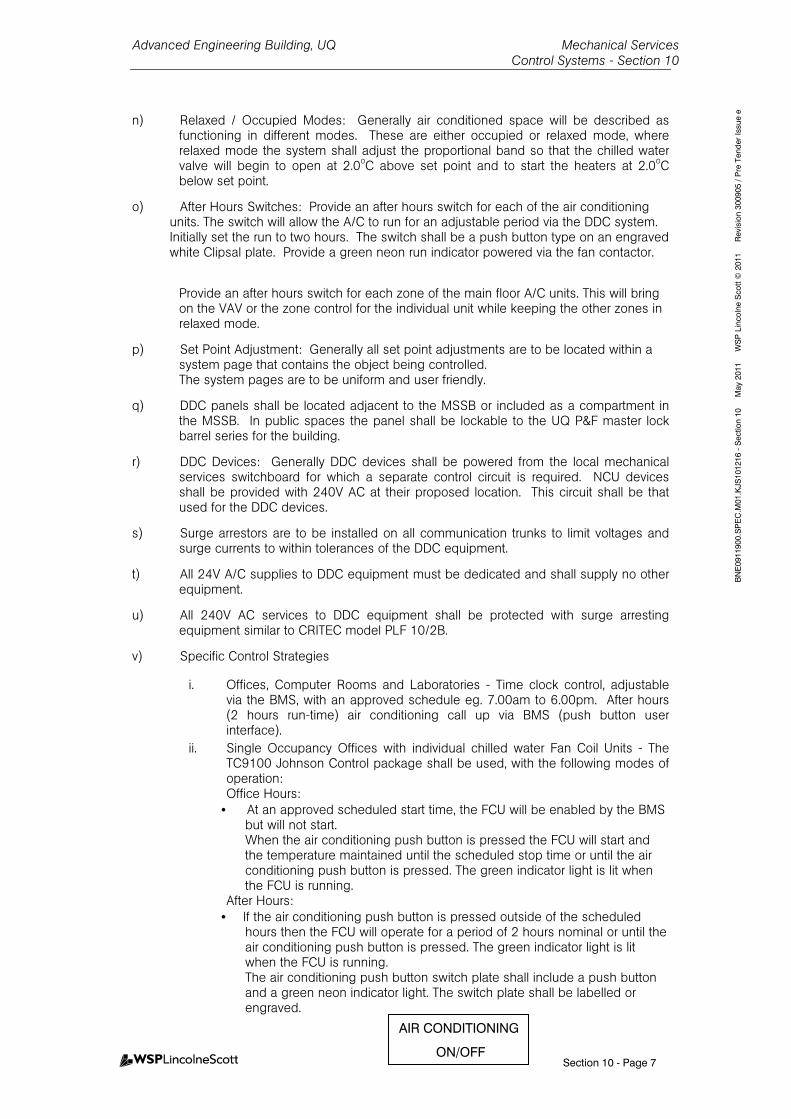
Advanced Engineering Building, UQ Mechanical Services Control Systems - Section 10
Section 10 - Page 7
BNE0911900.SPEC.M01.KJS101216 - Section 10 May 2011 WSP Lincolne Scott © 2011 Revision 300905 / Pre Tender Issue e
n) Relaxed / Occupied Modes: Generally air conditioned space will be described as functioning in different modes. These are either occupied or relaxed mode, where relaxed mode the system shall adjust the proportional band so that the chilled water valve will begin to open at 2.0oC above set point and to start the heaters at 2.0oC below set point.
o) After Hours Switches: Provide an after hours switch for each of the air conditioning units. The switch will allow the A/C to run for an adjustable period via the DDC system. Initially set the run to two hours. The switch shall be a push button type on an engraved white Clipsal plate. Provide a green neon run indicator powered via the fan contactor.
Provide an after hours switch for each zone of the main floor A/C units. This will bring on the VAV or the zone control for the individual unit while keeping the other zones in relaxed mode.
p) Set Point Adjustment: Generally all set point adjustments are to be located within a system page that contains the object being controlled. The system pages are to be uniform and user friendly.
q) DDC panels shall be located adjacent to the MSSB or included as a compartment in the MSSB. In public spaces the panel shall be lockable to the UQ P&F master lock barrel series for the building.
r) DDC Devices: Generally DDC devices shall be powered from the local mechanical services switchboard for which a separate control circuit is required. NCU devices shall be provided with 240V AC at their proposed location. This circuit shall be that used for the DDC devices.
s) Surge arrestors are to be installed on all communication trunks to limit voltages and surge currents to within tolerances of the DDC equipment.
t) All 24V A/C supplies to DDC equipment must be dedicated and shall supply no other equipment.
u) All 240V AC services to DDC equipment shall be protected with surge arresting equipment similar to CRITEC model PLF 10/2B.
v) Specific Control Strategies
i. Offices, Computer Rooms and Laboratories - Time clock control, adjustable via the BMS, with an approved schedule eg. 7.00am to 6.00pm. After hours (2 hours run-time) air conditioning call up via BMS (push button user interface).
ii. Single Occupancy Offices with individual chilled water Fan Coil Units - The TC9100 Johnson Control package shall be used, with the following modes of operation: Office Hours:
• At an approved scheduled start time, the FCU will be enabled by the BMS but will not start. When the air conditioning push button is pressed the FCU will start and the temperature maintained until the scheduled stop time or until the air conditioning push button is pressed. The green indicator light is lit when the FCU is running.
After Hours: • If the air conditioning push button is pressed outside of the scheduled
hours then the FCU will operate for a period of 2 hours nominal or until the air conditioning push button is pressed. The green indicator light is lit when the FCU is running. The air conditioning push button switch plate shall include a push button and a green neon indicator light. The switch plate shall be labelled or engraved. AIR CONDITIONING
ON/OFF
Advanced Engineering Building, UQ Mechanical Services Control Systems - Section 10
Section 10 - Page 8
BNE0911900.SPEC.M01.KJS101216 - Section 10 May 2011 WSP Lincolne Scott © 2011 Revision 300905 / Pre Tender Issue e
iii. Auditorium and Civil Engineering Seminar Room - The BMS shall control these spaces. These rooms have three modes: CLOSED, LECTURE, RELAXED.
CLOSED Mode: All doors locked. A/C disabled. A/V disabled. Normal lighting disabled. Minimal safety lighting activated (including EXIT lights).
LECTURE Mode: All doors unlocked. A/C enabled. A/V enabled. Full lighting control enabled.
RELAXED Mode: (Between lectures during normal operational times). All doors locked.
A/C enabled. Setpoint relaxed to 27°C during summer, 19°C during winter, resume to normal operation 30 minutes prior to next occupation.
A/V disabled. Normal lighting disabled. Minimal safety lighting activated (including EXIT lights).
The modes will be switched by either: Time schedules in the BMS or An override key switch located outside the main door of the lecture
theatre. The key switch shall be a three position switch marked LOCK / AUTO /
OPEN.
iv. When in the AUTO position the lecture theatre mode will be dictated by the BMS time schedule (Lecture/Relaxed)
v. When in the OPEN position the lecture theatre will be in LECTURE mode.
vi. When in the LOCK position the lecture theatre will be in the CLOSED mode. The doors are to be fitted with fail secure electronic locks. In the event of a fire alarm, all doors are to be unlocked. The BMS shall monitor the state of the doors and override key switch. An
alarm is to be sent to Security if a door is opened for a given period when it should be closed.

Advanced Engineering Building, UQ Mechanical Services Control Systems - Section 10
Section 10 - Page 9
BNE0911900.SPEC.M01.KJS101216 - Section 10 May 2011 WSP Lincolne Scott © 2011 Revision 300905 / Pre Tender Issue e
10.6.310.6.310.6.310.6.3 Building Mixed Mode CBuilding Mixed Mode CBuilding Mixed Mode CBuilding Mixed Mode Controlontrolontrolontrol
a) Building Wide
Sensors in an external weather station on the building will inform decisions made by the BMS to determine the optimal operational mode.
External Air temperature – this dictates ventilation mode. Windspeed – louvres partially close (20%) when wind speed > 10m/s, adjustable Traditional internal temperature and relative humidity sensors. b) Control Strategy
All areas with mixed mode capability will be linked to the outside air temperature, which governs the ventilation strategy. The strategy for these areas is as follows; BMS control strategy for Northern Offices on Levels 4, 5 and 6; Teaching and Learning area on Level 3 north; AMPAM office on southern areas of levels 4, 5 and 6; level 6 Boardroom; level 5 Civil Seminar Room; Level 5 Kitchen:
State State State State Outside Outside Outside Outside TemperatureTemperatureTemperatureTemperature
Windows Windows Windows Windows Task AirTask AirTask AirTask Air (where (where (where (where provided)provided)provided)provided)
VAV VAV VAV VAV
Hot > 26 Closed On On
Comfortable (warm)
< 26 Fully open On Off
( modulate between these states - when 19 < Outside Temp < 26) Comfortable (cool)
> 19 Slightly open1 Min flow2 Off
Cold < 18 Closed Min flow2 On Note 1: Initially set at 20%. Note 2; Task air AHUs at 50% of design air flow.
CLOSED
CLEANI NG
LECTURE
LECT URE THEATRE ST ATUS
KEY SWITCH OVERRIDE
AUTO
OPEN
RECTANGU LAR INDICA TING LEDSSE CURED AGAINS T VA NDALIS MCOLOURS:
RE D FOR C LOSED
GREEN FOR LECTURE
STAINLESS STEE L PLATEENGRAVE D WITH B LACK LETTER INGSIZES AND FONT TO BE APPROVE DBY P RIN CIPAL
B& G B ILOCK KEY
SWITCH A31KRAUS AND NAIME R BRAND
MOME NTARY CONTACTSP RING RETURN TO CENTREKE Y REMOVABLE A T CE NTRE(AVA ILA BLE FROM J.BA RNES)
LOCK
Advanced Engineering Building, UQ Mechanical Services Control Systems - Section 10
Section 10 - Page 10
BNE0911900.SPEC.M01.KJS101216 - Section 10 May 2011 WSP Lincolne Scott © 2011 Revision 300905 / Pre Tender Issue e
10.6.410.6.410.6.410.6.4 Fire Mode OperationFire Mode OperationFire Mode OperationFire Mode Operation
a) All fire mode operation is directly controlled by hard wiring from fire alarm relays. Install, test and commission.
b) BMS shall sequentially restart the systems upon clearance of the fire alarm.
HVAC equipment includes the normal building air conditioning systems, general exhaust and supply air ventilation systems, specialised exhaust and supply air ventilation systems for laboratory equipment, and facilities for integration of the mixed mode natural ventilation system.
All systems except those noted below will be controlled in fire-mode and will generally be a system shutdown arrangement in the fire-affected compartment in accordance with the relevant sections of AS 1668.1-1998 unless otherwise noted.
Systems not requiring fire mode operation include specialised laboratory ventilation systems, minor supply or exhaust ventilation systems, treated air supply system, and external louvre panels providing natural ventilation to areas not connected to the atrium. Specialist ventilation systems and other miscellaneous mechanical ventilation systems will operate in accordance with the relevant provisions of AS1668.1.
Base tender is to include for a motorised damper at the atrium wall on each of the acoustic transfer plenums (total of 15) at:
• grid lines AB-A4, AB-A7, AB-A10 on Level 3 • Gridlines AB-A4-A5, AB-A9-A10 on Levels 4, 5 and 6.
Each damper is to be open during normal air conditioning operation, and closed at other times (including in fire mode).
Fire mode operation for the atrium and adjacent interconnected areas has been based on the following methodology:
Fire alarm in the atrium
• The treated air supply plant in the Level 1 labyrinth starts or continues to run unless shut down upon actuation of non-latching smoke detectors located in the supply air path,
• Treated air supply at low level to the atrium starts or continues to run • Treated air supply to Stair 5 starts or continues to run • External louvre panels at atrium roof level drive to the open position, • External louvre panels to the Level 2 structures workshop drive to the open position, • External louvre panels on the Levels 4-6 office areas drive to the open position, • External louvre panels in Stair 5 drive to the closed position, • Internal controllable openings between the structures workshop and Level 3 of the atrium drive
to the open position, • Internal controllable openings between the Levels 4-6 office areas and the atrium drive to the
closed position, • Internal blinds in the Levels 4-6 office areas drive to the open position, • Air conditioning systems to any areas connected to the atrium on Levels 2-6 shut down, • Fire doors to Stair 5 and any other fire doors in the atrium bounding construction which are
held open during normal occupancy are released and close automatically, • Stair 6 pressurisation system starts.
Fire alarm in Level 2 Structures Workshop
• The treated air supply plant in the Level 1 labyrinth will start or continue to run unless shut down upon actuation of non-latching smoke detectors located in the supply air path,
• Treated air supply at low level to the atrium starts or continues to run, • Treated air supply to Stair 5 starts or continues to run, • External louvre panels at atrium roof level drive to the open position,
Advanced Engineering Building, UQ Mechanical Services Control Systems - Section 10
Section 10 - Page 11
BNE0911900.SPEC.M01.KJS101216 - Section 10 May 2011 WSP Lincolne Scott © 2011 Revision 300905 / Pre Tender Issue e
• External louvre panels to the Level 2 structures workshop drive to the open position, • External louvre panels on the Levels 3-6 office areas drive to the open position, • Internal controllable openings between the structures workshop and Level 3 drive to the
closed position, • Internal controllable openings between the Levels 4-6 office areas and the atrium drive to the
closed position, • Air conditioning systems to any areas connected to the atrium on Levels 3-6 shut down, • Fire doors to Stair 5 and any other fire doors in the atrium bounding construction which are
held open during normal occupancy are released and close automatically, • Stair 6 pressurisation system starts.
Fire alarm in Levels 3-6 North office areas
• The treated air supply plant in the Level 1 labyrinth will continue to run unless shut down upon actuation of non-latching smoke detectors located in the supply air path,
• Treated air supply at low level to the atrium starts or continues to run, • Treated air supply to Stair 5 starts or continues to run, • External louvre panels at roof level drive to the open position, • External louvre panels on the fire-affected floor of the Levels 3-6 office areas drive to the open
position, • Internal blinds in the fire-affected floor of the Levels 3-6 office areas drive to the open position, • Internal controllable openings between the fire-affected floor of the Levels 3-6 office areas
drive to the closed position, • Internal controllable openings between the structures workshop and Level 3 of the atrium drive
to the open position, • Air conditioning systems to the fire-affected floor of the Levels 3-6 office areas shut down. • Any other air conditioning systems associated with or linked to the fire-affected area shut
down, • Fire doors to Stair 5 and any other fire doors in the atrium bounding construction which are
held open during normal occupancy are released and close automatically, • Stair 6 pressurisation system starts.
Fire alarm in areas other than noted above
• The treated air supply plant in the Level 1 labyrinth will continue to run unless shut down upon actuation of non-latching smoke detectors located in the supply air path,
• Treated air supply at low level to the atrium starts or continues to run, • Treated air supply to Stair 5 starts or continues to run, • External louvre panels at roof level drive to the open position, • Internal controllable openings between the structures workshop and Level 3 of the atrium drive
to the open position, • Air conditioning systems to the fire-affected area shut down, • Any other air conditioning systems associated with or linked to the fire-affected area shut
down, • Fire doors to Stair 5 and any other fire doors in the atrium bounding construction which are
held open during normal occupancy are released and close automatically, • Stair 6 pressurisation system starts.
Fire mode operation of Stair 5:
• If smoke is detected by smoke detectors located within Stair 5, the external louvres on Stair 5 will open, the fire doors to the stair, if held open, will release and close automatically, and the treated air supply will continue to run;
• If smoke is detected by a smoke detector located in the treated air supply to Stair 5, the treated air supply will shut down and the external louvres to Stair 5 will open.
Manual fire mode controls:
Manual override controls for ventilation systems will be provided at the FIP in accordance with AS1668.1-1998 for use by the attending fire brigade, particularly in relation to the control of the natural ventilation provisions for the atrium. These controls will include:
Advanced Engineering Building, UQ Mechanical Services Control Systems - Section 10
Section 10 - Page 12
BNE0911900.SPEC.M01.KJS101216 - Section 10 May 2011 WSP Lincolne Scott © 2011 Revision 300905 / Pre Tender Issue e
• a control switch for the Stair 6 pressurising fan, • separate control switches for the Stair 5 treated air supply and external louvres, • control switches on a level-by-level basis for external louvre panels to the offices on Levels 4-
6, • separate control switches for the associated internal controllable openings from the offices to
the atrium on Levels 4-6, • a control switch for the external louvre openings to the Level 2 structures workshop, • a separate control switch for the internal controllable openings from the Level 2 Structures
workshop to the atrium, • a control switch for the roof level louvre panels providing smoke relief from the atrium, • a control switch for the treated air make-up supply fans on Level 1.
Other controls may be required for fire brigade use subject to QFRS feedback on the proposed fire mode operation of the natural ventilation system.
c) Stairwell Pressurisation fan shall operate on reciept of fire signal from FIP.
d) Atrium tempered air supply fan shall operate at full speed when requierd to run in fire mode.
10.6.510.6.510.6.510.6.5 Communications Rooms and UPS RoomCommunications Rooms and UPS RoomCommunications Rooms and UPS RoomCommunications Rooms and UPS Room
a) UPS room fan coil unit fan shall run continuously, room temperature set at 23oC.
b) Duty CRAC unit runs continuously in each communications room.
c) Chilled water valves shall modulate to maintain the set room temperature. After hours, a cooling call from a data room unit shall be delayed until the room temperature has reached 26oC.
d) Raise a high temperature alarm at 27oC.
10.6.610.6.610.6.610.6.6 AV Rack AV Rack AV Rack AV Rack Room (level 2)Room (level 2)Room (level 2)Room (level 2)
a) CRAC unit shall run continuously, room temperature set at 23oC.
b) If room temperature exceeds 24oC, start the supplementary fan coil unit.
c) Chilled water valves shall modulate to maintain the set room temperature. After hours, a cooling call from a data room unit shall be delayed until the room temperature has reached 26oC.
d) Raise a high temperature alarm at 27oC.
10.6.710.6.710.6.710.6.7 General Exhaust Fan OperationGeneral Exhaust Fan OperationGeneral Exhaust Fan OperationGeneral Exhaust Fan Operation
a) As per UQ standard scenarios except where noted below.
10.6.810.6.810.6.810.6.8 Ducted Fume Cupboard ControlDucted Fume Cupboard ControlDucted Fume Cupboard ControlDucted Fume Cupboard Control
a) The fume hood exhaust fans are controlled from the proprietary cupboard packaged controllers.
b) Where required for air balance atrium fire smoke dampers shall drive open to suit fume cupboard make up air requirements.
c) Fan VSD speed to be input to the BMS.
d) Raise a flow failure alarm.
10.6.910.6.910.6.910.6.9 Chiller Room Refrigerant MonitoringChiller Room Refrigerant MonitoringChiller Room Refrigerant MonitoringChiller Room Refrigerant Monitoring
a) Provide strobes lights and audible alarms both inside and outside the chiller plantroom at each entranceat each entranceat each entranceat each entrance, wired directly from the refrigerant monitoring system.
b) Provide switching at ground level.
Advanced Engineering Building, UQ Mechanical Services Control Systems - Section 10
Section 10 - Page 13
BNE0911900.SPEC.M01.KJS101216 - Section 10 May 2011 WSP Lincolne Scott © 2011 Revision 300905 / Pre Tender Issue e
c) BMS to receive and alarm on a refrigerant monitoring system fault, and on a high refrigerant level.
10.6.1010.6.1010.6.1010.6.10 Gas Appliance InterlockGas Appliance InterlockGas Appliance InterlockGas Appliance Interlock
a) Provide interlock to shut down the gas supply via the low pressure and high pressure gas solenoid valves within the Solar Hot Water Generation Room upon failure of the supply air system. The interlock sensor shall be of the type that senses the actual air movement, and fail safe.
10.6.1110.6.1110.6.1110.6.11 Compressed Air PlantCompressed Air PlantCompressed Air PlantCompressed Air Plant
a) Air compressors and driers run under their own controls.
b) Raise a common fault for the compressor set.
c) Raise a common fault for either drier.
10.6.1210.6.1210.6.1210.6.12 Vacuum PlantVacuum PlantVacuum PlantVacuum Plant
a) Runs under its own controls.
b) Raise a common fault alarm.
10.6.1310.6.1310.6.1310.6.13 Control FunctionsControl FunctionsControl FunctionsControl Functions
10.6.13.110.6.13.110.6.13.110.6.13.1 Existing BMSExisting BMSExisting BMSExisting BMS
The end result will be a single BMS system that provides all monitoring and editing functions through a single interface as outlined in this specification. Carry out works to existing BMS as required to suit specified requirements This includes, but not limited to:
- Common graphics for all new and old systems - Common reporting for all BMS data - Common alarm interface for all BMS alarms
Modifications toModifications toModifications toModifications to Existing BMSExisting BMSExisting BMSExisting BMS Where required, make modifications to the existing BMS to suit the new installation. This includes, but not limited interface cards, hard ware, software, etc. The existing central chilled water plant in GPS, also serving Zelman Cowan, is abandoned. Interface and recommission existing building cooling call and other necessary signals back to/from the new AEB/GPS/ZC precinct chilled water plant in AEB.
10.6.13.210.6.13.210.6.13.210.6.13.2 Air Handling UnitsAir Handling UnitsAir Handling UnitsAir Handling Units & FCU’s& FCU’s& FCU’s& FCU’s
Start/Stop ControlStart/Stop ControlStart/Stop ControlStart/Stop Control
- Start/stop control of each AHU on an individual basis by the Mechanical
Control System time schedule, operator override (where available on control panel), after hours control (where available on control panel) and switchboard auto/off/on switch.
Time SchedTime SchedTime SchedTime Scheduleuleuleule - Time schedule shall be via an adjustable 24hr, 365 day programmable
calendar, individually programmable for each unit.
Advanced Engineering Building, UQ Mechanical Services Control Systems - Section 10
Section 10 - Page 14
BNE0911900.SPEC.M01.KJS101216 - Section 10 May 2011 WSP Lincolne Scott © 2011 Revision 300905 / Pre Tender Issue e
Carbon Dioxide Control (C0Carbon Dioxide Control (C0Carbon Dioxide Control (C0Carbon Dioxide Control (C02222)))) - C02 sensor (wall mounted or located within return air duct) shall modulate
the motorised outside air damper (or utilise the low speed of the HX system where installed) for the respective AHU and FCU based on C02 level.
- A C02 upper limit of 800 PPM shall not be exceeded. - Outside air dampers modulation shall be limited to not less than 10% of
the design outdoor air flow. After Hours Push ButtonAfter Hours Push ButtonAfter Hours Push ButtonAfter Hours Push Button - After hours push buttons shall be initially set to 2hr programmable and
adjustable via the BMS. During after hours period PIR and C02 control shall be enabled.
Optimum Start/Stop ControlOptimum Start/Stop ControlOptimum Start/Stop ControlOptimum Start/Stop Control - The Mechanical Control System shall include an optimising temperature
control strategy to start and stop the air handling units in order to bring the space to operating temperature for normal occupancy, consistent with minimum energy consumption.
10.6.13.310.6.13.310.6.13.310.6.13.3 Variations on Typical AHU/FCU ConVariations on Typical AHU/FCU ConVariations on Typical AHU/FCU ConVariations on Typical AHU/FCU Controlstrolstrolstrols
- FCU-4-3. When the fume cupboard VSD is above a set speed, the room
spill air fan shuts down. If the VSD is at high speed, the pre-conditioned outdoor air quantity into the FCU increases to limit the negative differential pressure across the laboratory doors. Set points to be determined during commissioning.
- FCU-5-3. When the fume cupboard VSD is above a set speed, the room spill air fan shuts down. If the VSD is at high speed, the pre-conditioned outdoor air quantity into the FCU increases to limit the negative differential pressure across the laboratory doors. Set points to be determined during commissioning.
- FCU-7-1 and FCU-7-2 (for the LMRs) control at a room setpoint of 28oC. Raise alarm at a room temperature of 40oC. Comply with AS1735.2 (the Lift Code).
- FCUFCUFCUFCU----3333----1, 61, 61, 61, 6----1, AHU1, AHU1, AHU1, AHU----3333----1, 31, 31, 31, 3----3, 33, 33, 33, 3----3, 33, 33, 33, 3----4, 44, 44, 44, 4----2. For each, link to the A2. For each, link to the A2. For each, link to the A2. For each, link to the AVVVV AMX AMX AMX AMX system. system. system. system. AV console selects “AV console selects “AV console selects “AV console selects “RRRRoomoomoomoom----inininin----UUUUse” or “Roose” or “Roose” or “Roose” or “Roommmm----UUUUnoccupiednoccupiednoccupiednoccupied”””” as as as as the lecturers log in and outthe lecturers log in and outthe lecturers log in and outthe lecturers log in and out. When the air conditioning unit is time. When the air conditioning unit is time. When the air conditioning unit is time. When the air conditioning unit is time----clock enabled by the BMS buclock enabled by the BMS buclock enabled by the BMS buclock enabled by the BMS but the t the t the t the roomroomroomroom is unoccupied, widen the VAV is unoccupied, widen the VAV is unoccupied, widen the VAV is unoccupied, widen the VAV box temperature control bands by 2box temperature control bands by 2box temperature control bands by 2box temperature control bands by 2ooooC both higher and lower.C both higher and lower.C both higher and lower.C both higher and lower.
- AHUAHUAHUAHU----4444----4, 54, 54, 54, 5----6, 66, 66, 66, 6----3 (3 (3 (3 (AMPAM Offices) and AHUAMPAM Offices) and AHUAMPAM Offices) and AHUAMPAM Offices) and AHU----4444----1111, 5, 5, 5, 5----1 61 61 61 6----1 (northern 1 (northern 1 (northern 1 (northern offices). Pick up movement detector signals from the security system.offices). Pick up movement detector signals from the security system.offices). Pick up movement detector signals from the security system.offices). Pick up movement detector signals from the security system. When the air condiWhen the air condiWhen the air condiWhen the air conditioning unit is timetioning unit is timetioning unit is timetioning unit is time----clock enabled by the BMS but an clock enabled by the BMS but an clock enabled by the BMS but an clock enabled by the BMS but an “unoccupied” signal is received, widen the VAV box temperature control “unoccupied” signal is received, widen the VAV box temperature control “unoccupied” signal is received, widen the VAV box temperature control “unoccupied” signal is received, widen the VAV box temperature control bands by 2bands by 2bands by 2bands by 2ooooC both higher and lower.C both higher and lower.C both higher and lower.C both higher and lower.
10.6.13.410.6.13.410.6.13.410.6.13.4 Hot Water Hot Water Hot Water Hot Water BoilersBoilersBoilersBoilers
- Automatic control by each proprietary control system. - Lead lag rotated by the BMS. - Lag units called up when the lead unit cannot maintain design temperatures.
Advanced Engineering Building, UQ Mechanical Services Control Systems - Section 10
Section 10 - Page 15
BNE0911900.SPEC.M01.KJS101216 - Section 10 May 2011 WSP Lincolne Scott © 2011 Revision 300905 / Pre Tender Issue e
- Automatic start/stop control an indicated status of each water heater and hot water pump as outlined in the DDC Points Schedule.
10.6.13.510.6.13.510.6.13.510.6.13.5 Hot Water PumpsHot Water PumpsHot Water PumpsHot Water Pumps
- Provide an automatic controlled system to run each pump when required and to control water temperature within a given range.
- Where thermostatically controlled, the duty pump is to operate continuously during normal hours with thermostatic override to cycle the pump during out of hours operation. When the return water falls to a set temperature, the pump will run until the return water reaches the cut out setting.
10.6.13.610.6.13.610.6.13.610.6.13.6 Supply Air, Ventilation Air and Exhaust SystemsSupply Air, Ventilation Air and Exhaust SystemsSupply Air, Ventilation Air and Exhaust SystemsSupply Air, Ventilation Air and Exhaust Systems
GeneralGeneralGeneralGeneral - Start/stop control of each fan on an individual basis by the Mechanical
Control System, time schedule, operator control panel, local panel and switchboard auto/off/on switch.
- Each fan’s status monitored by the BMS. - All supply air, ventilation air and exhaust systems shall be interlocked
with their respective building AHU’s / FCU’s such that when the AHU’s / FCU’ is operational the respective supply air, ventilation or exhaust fan is operation. Afterhours operation of AHU’s / FCU’s shall also start respective supply air, ventilation air and exhaust system.
Time SchedulTime SchedulTime SchedulTime Scheduleeee - Time schedule shall be via an adjustable 24hr, 365 day programmable
calendar.
Differing Differing Differing Differing VVVVentilation Fan Controlsentilation Fan Controlsentilation Fan Controlsentilation Fan Controls - GEF-4-2, GEF-4-3, GEF-4-4, and AEF-4-1. If any of these fans is running,
the outside louvre windows to the Heat Transfer Room 415 are to open.
- Level 6 Foundry Areas. If any of the exhaust fans is running, the outside louvre windows to the relevant room are to open.
- Stairwell 6 pressurisation system (SP-7-1) is initiated by alarms from the FIP via relays in the mechanical services switchboards. The pressure in the stairwell pressurisation shaft, sensed 2/3 down the shaft, shall be held constant by adjustment of the fan speed via the VSD by the mechanical control system. The control system shall incorporate a function to motorise ‘open’ the motorised relief damper (located downstream of the stairwell pressurisation fan) when the VSD set point is less than 35% (adjustable) and the pressure within shaft exceeds set point.
- GSFGSFGSFGSF----1111----3 and GEF3 and GEF3 and GEF3 and GEF----1111----3 (3 (3 (3 (level 1 level 1 level 1 level 1 structures bastructures bastructures bastructures basement). Mechanical sement). Mechanical sement). Mechanical sement). Mechanical controls controls controls controls installer to provide a installer to provide a installer to provide a installer to provide a movementmovementmovementmovement detectiondetectiondetectiondetection system in the area.system in the area.system in the area.system in the area. If operation of the ventilation system has been requested (BMS time If operation of the ventilation system has been requested (BMS time If operation of the ventilation system has been requested (BMS time If operation of the ventilation system has been requested (BMS time clock or local control) butclock or local control) butclock or local control) butclock or local control) but no movement is detected for 15 minutes no movement is detected for 15 minutes no movement is detected for 15 minutes no movement is detected for 15 minutes (adjustable), then the fans shall be stopped.(adjustable), then the fans shall be stopped.(adjustable), then the fans shall be stopped.(adjustable), then the fans shall be stopped.
- GSFGSFGSFGSF----1111----1 and 1 and 1 and 1 and GEFGEFGEFGEF----1111----1 (1 (1 (1 (level 1 hydraulics lab). Mechanical controls level 1 hydraulics lab). Mechanical controls level 1 hydraulics lab). Mechanical controls level 1 hydraulics lab). Mechanical controls installer to provide a movement detection system in the area. If installer to provide a movement detection system in the area. If installer to provide a movement detection system in the area. If installer to provide a movement detection system in the area. If operation of the ventilation system has been requested (BMS time operation of the ventilation system has been requested (BMS time operation of the ventilation system has been requested (BMS time operation of the ventilation system has been requested (BMS time clock or local control) but no movement is detected for 15 minutes clock or local control) but no movement is detected for 15 minutes clock or local control) but no movement is detected for 15 minutes clock or local control) but no movement is detected for 15 minutes (ad(ad(ad(adjustable), then the fans shall be stopped.justable), then the fans shall be stopped.justable), then the fans shall be stopped.justable), then the fans shall be stopped.
- GSFGSFGSFGSF----1111----2 and GEF2 and GEF2 and GEF2 and GEF----1111----2 (level 1 workshop). 2 (level 1 workshop). 2 (level 1 workshop). 2 (level 1 workshop). Mechanical controls installer Mechanical controls installer Mechanical controls installer Mechanical controls installer to provide a movement detection system in the area. If operation of to provide a movement detection system in the area. If operation of to provide a movement detection system in the area. If operation of to provide a movement detection system in the area. If operation of the ventilation system has been requested (BMS time clock or local the ventilation system has been requested (BMS time clock or local the ventilation system has been requested (BMS time clock or local the ventilation system has been requested (BMS time clock or local
Advanced Engineering Building, UQ Mechanical Services Control Systems - Section 10
Section 10 - Page 16
BNE0911900.SPEC.M01.KJS101216 - Section 10 May 2011 WSP Lincolne Scott © 2011 Revision 300905 / Pre Tender Issue e
controcontrocontrocontrol) but no movement is detected for 15 minutes (adjustable), then l) but no movement is detected for 15 minutes (adjustable), then l) but no movement is detected for 15 minutes (adjustable), then l) but no movement is detected for 15 minutes (adjustable), then the fans shall be stopped.the fans shall be stopped.the fans shall be stopped.the fans shall be stopped.
10.6.13.710.6.13.710.6.13.710.6.13.7 Water MetersWater MetersWater MetersWater Meters
Allow to monitor and log pulsed inputs from water meters to BMS. BMS shall continually trend water usage for each water meter and raise an urgent alarm should the water meter usage fall outside trended data. 10.6.1410.6.1410.6.1410.6.14 Temperature SensorsTemperature SensorsTemperature SensorsTemperature Sensors
a) Provide temperature sensors of the bulb or thermistor type with ranges selected to suit the particular application.
b) House sensors so that access to terminal strips and cabling can only be achieved by removal of a cover.
c) Supply duct sensors of the averaging type with capillary adequately supported to prevent sagging.
d) Mount sensors such that effects of radiation from heating elements are minimised.
e) Provide insertion sensors complete with stainless steel wells.
f) Supply wells to the pipework installer for fitting into pipes.
g) Mount sensors to ensure a rapid response to changing temperature (of the sensed medium) is achieved.
h) Nominate the location of all sensors to the pipework installer.
i) Achieve calibration of sensors (to compensate for non-linear characteristics, line resistance and similar items) in the control unit programme.
j) When used in conjunction with the control system or a separate control unit, the accuracy of the temperature sensors displayed value is ±0.1K.
k) Where shown fitted on circular columns, plates are to be of brushed stainless steel with the sensor centrally mounted behind an approved low profile raised and slotted stainless steel cover.
10.6.1510.6.1510.6.1510.6.15 Static and Differential PressuStatic and Differential PressuStatic and Differential PressuStatic and Differential Pressure Sensors (Air)re Sensors (Air)re Sensors (Air)re Sensors (Air)
a) Provide static pressure sensors of the differential pressure type.
b) Sensor range (span) to be adjustable.
c) Accuracy of sensor including controller to be ±2% of span.
d) Sensors to be capable of withstanding a total pressure differential of 1000 Pa.
10.6.1610.6.1610.6.1610.6.16 Static and Differential Pressure Sensors (Water)Static and Differential Pressure Sensors (Water)Static and Differential Pressure Sensors (Water)Static and Differential Pressure Sensors (Water)
a) Provide static and differential pressure sensors of industrial quality complete with span and zero point adjustment from either software or hardware techniques.
b) Accuracy of sensors to be +1% of span.
c) Sensors to be capable of withstanding pressure ranges of vacuum to 2000 kPa without permanent effect on the operation of the device.
10.6.1710.6.1710.6.1710.6.17 Electronic Controller ModulesElectronic Controller ModulesElectronic Controller ModulesElectronic Controller Modules
a) Accept a signal from the associated electronic sensor and provide an analogue output to controlled items.
b) Incorporate an adjustable authority setting in dual input controllers.
Advanced Engineering Building, UQ Mechanical Services Control Systems - Section 10
Section 10 - Page 17
BNE0911900.SPEC.M01.KJS101216 - Section 10 May 2011 WSP Lincolne Scott © 2011 Revision 300905 / Pre Tender Issue e
c) Use proportional plus integral (P & I) controllers for static pressure control, chilled and heating water flow control and supply air temperature control.
d) P & I controller to incorporate an adjustable reset time.
e) Outputs to be compatible with the controlled item.
f) Control output accuracy ±1% of output span.
10.6.1810.6.1810.6.1810.6.18 Humidity SensorsHumidity SensorsHumidity SensorsHumidity Sensors
a) High quality capacitance type compatible with BMS system.
b) Complete with duct sampling devices and protected from air borne dust particles and free air moisture.
c) Relative humidity sensors to be temperature compensated such that when used in conjunction with the BMS or separate controller the accuracy of the displayed value is +3.0% RH.
10.6.1910.6.1910.6.1910.6.19 Motorised Control ValvesMotorised Control ValvesMotorised Control ValvesMotorised Control Valves
a) Generally as detailed in the 'Pipework, Valves and Fittings' section of this specification.
b) Suitable for all working pressures and pressure differentials experienced under normal operating conditions.
c) Design and materials of valves and motors to be such that leakage of water from the stem packing does not cause corrosion of any working part.
d) Select modulating control valves to demand authority of the items served.
e) Minimum fully open resistance to the flow of one and one half times that of the combined pressure drop of the branch pipe and the item served.
f) Do not use butterfly or ball valves for control through coils.
g) To verify the selections made, prior to installation of valves, submit a valve schedule detailing valve make and model, valve pressure drop at design flow, valve flow coefficient (KV), pressure drop of item served at design flow and valve actuator.
h) Prior to installation of the valves verify selections made.
10.6.2010.6.2010.6.2010.6.20 Valve and Damper MotorsValve and Damper MotorsValve and Damper MotorsValve and Damper Motors
GeneralGeneralGeneralGeneral
a) Conservatively select all motors for the duty required.
b) Select or adjust operating speeds so that the motor will remain in step with controllers without hunting, regardless of motor variations.
c) Motors operating in sequence with other motors to have adjustable operating ranges and starting points to permit adjustment of the control sequence as required by the operating characteristics of the system.
d) Life span in excess of 50,000 open-close operations.
e) Accept an analogue or pulsed digital signal directly from the BMS control unit.
f) Time proportional feedback into the BMS is acceptable.
Damper MotorsDamper MotorsDamper MotorsDamper Motors
a) Spring return type (excluding VAV motors), such that, in the event of power failure, they will 'fail safe in either the normally open or normally closed position to suit the job condition.
b) A maximum of 40 seconds spring return time.

Advanced Engineering Building, UQ Mechanical Services Control Systems - Section 10
Section 10 - Page 18
BNE0911900.SPEC.M01.KJS101216 - Section 10 May 2011 WSP Lincolne Scott © 2011 Revision 300905 / Pre Tender Issue e
c) A maximum spring tension time of 200 seconds.
d) Once tensioned the spring shall not engage the actuator mechanism unless power supply is lost.
e) Provide sufficient motors to ensure correct operation of dampers under all operating conditions.
f) 1.2m² maximum size damper (CRVD) driven by a single motor.
g) Actuators shall indicate the position of percentage open.
Valve MotorsValve MotorsValve MotorsValve Motors
a) Motors to be linear in operation fitted with a manual operator such that, in the event of a power or other failure, manual operation can be achieved.
b) Select motors for all valves to ensure correct operation and close-off, of the valves controlled, under all operating conditions.
c) Actuators shall indicate the position of percentage open.
10.6.2110.6.2110.6.2110.6.21 Fan Status IndicationFan Status IndicationFan Status IndicationFan Status Indication
a) Air flow switches to indicate the status of selected fans.
b) Air flow switches of the differential pressure type with adjustable set point incorporating a single pole double throw switch mechanism arranged to changeover on a pressure rise and vice versa.
c) Switches complete with pitot tubes to sense the differential pressure between the suction and discharge sides of the fan.
d) Position tubes to eliminate blockage of tube openings.
e) Current switches may be offered as an alternative, subject to acceptance by the Superintendent.
10.6.2210.6.2210.6.2210.6.22 TransducersTransducersTransducersTransducers
a) Generally active type with an accuracy of +1% of span.
b) Accept a signal from the necessary transformers (current and/or voltage) and convert the signal(s) to a signal compatible with the BAS control unit.
c) Supply transducers to the relevant switchboard supplier for installation.
d) Use electronic to pneumatic transducers of industrial quality.
e) Accurate to 3% of span and repeatable to 3% of span.
f) Supply and install above items as part of the control system.
g) Temperature compensated over the full span of the device.
10.6.2310.6.2310.6.2310.6.23 Electronic ControllersElectronic ControllersElectronic ControllersElectronic Controllers
a) Controllers shall accept a signal from the associated electronic sensor and provide an analogue output to controlled items.
b) Where dual input controllers are required these shall incorporate and adjustable authority setting.
c) Proportional plus integral (P & I) controllers shall be used where specified for static pressure control, chilled and heating water flow control and supply air temperature control P & I controller shall incorporate an adjustable reset time.
d) Outputs from all controllers shall be compatible with the controlled item.
Advanced Engineering Building, UQ Mechanical Services Control Systems - Section 10
Section 10 - Page 19
BNE0911900.SPEC.M01.KJS101216 - Section 10 May 2011 WSP Lincolne Scott © 2011 Revision 300905 / Pre Tender Issue e
e) Where required, controllers shall incorporate provision for remote set point adjustment. Controllers shall be of the plug-in module type such that controllers can be replaced without necessitating removal and replacing or wiring.
f) Control output accuracy shall be ±2% of output span.
g) Each DDC controller shall be capable of data logging software and hardware points. Each controller shall have sufficient on-board memory to retain up to 100,000 time or event based readings. When the log memory is full, the oldest data shall be overwritten by the newest data.
10.6.2410.6.2410.6.2410.6.24 Local Touch ScreensLocal Touch ScreensLocal Touch ScreensLocal Touch Screens
a) Where indicated in the points schedule, provide a local recessed touch screen control panel.
b) Colour LCD type with 5.6-inch TFT Active matrix 256 display.
c) IP65 front panel
d) Three communications ports (RS-232/422/485) and 10 Base-T Ethernet port.
e) Include minimum 2MB non-volatile flash memory.
10.6.2510.6.2510.6.2510.6.25 VOC SensorsVOC SensorsVOC SensorsVOC Sensors
a) Locate in return air duct for each FCU/AHU.
b) Provide an alarm when pollutants reach 0.9 mg/m3.
10.6.2610.6.2610.6.2610.6.26 Flow MetersFlow MetersFlow MetersFlow Meters
a) Provide flow meters of the magnetic type.
b) Maximum full sale error of +/_ 1%.
c) Flow meters shall indicate the direction of flow..
d) Either a 4-20mA or 0-10V DC output signal.
10.6.2710.6.2710.6.2710.6.27 Gas DetectorsGas DetectorsGas DetectorsGas Detectors
a) General
I. Provide NATA test certificates at time of commissioning.
b) Atmospheric Gas Sensors (Fixed)
I. Atmospheric gas sensors shall be carbon dioxide (CO2 sensors).
II. Sensors shall be complete with sensing elements and electronics mounted in an aesthetic single piece casing.
III. Provide analogue measurement to the control system.
IV. Sensors range, 0-2,000ppm with less than ±5% Accuracy of full scale.
c) Oxygen Depletion Sensing Systems
I. Electro-chemical cell sensors with 4 – 20mA transmitter.
II. Control panel to include LCD displays; alarm and fault output relays; in-built alarm sounder and mute button.
III. Include lights external to each room: green for “safe” and red for “alarm”.
10.6.2810.6.2810.6.2810.6.28 Chilled Water Energy MetersChilled Water Energy MetersChilled Water Energy MetersChilled Water Energy Meters
a) Provide fully self-contained chilled water energy meters similar to Siemens “Sono” range.
Advanced Engineering Building, UQ Mechanical Services Control Systems - Section 10
Section 10 - Page 20
BNE0911900.SPEC.M01.KJS101216 - Section 10 May 2011 WSP Lincolne Scott © 2011 Revision 300905 / Pre Tender Issue e
b) Utilise ultrasonic transducer and detector integral with built-in and remote temperature sensors.
c) Provide pulsed output signal.
10.6.2910.6.2910.6.2910.6.29 Alarm Sounder and FlasherAlarm Sounder and FlasherAlarm Sounder and FlasherAlarm Sounder and Flasher
a) Similar to Gas Detection model AV-20-R with plain white casing.
b) 120 dB at 1metre.
10.6.3010.6.3010.6.3010.6.30 Weather StationWeather StationWeather StationWeather Station
The weather station shall consist of the following as a minimum.
a) Wind direction indicator detailing wind direction in degrees and minutes.
b) Wind speed with a minimum range of 0-20 m/s.
c) Ambient temperature monitoring, Accuracy 0.5 °C.
d) Relative humidity sensor.
e) Rain detector.
f) Five solar heat incidence levels.
g) All equipment is to be in minimum IP56 rated enclosures and to be mounted in such a way as to allow accurate reading.
h)h)h)h) Equipment to be of industrial grade, Vaisala or accepted similar.
10.6.31 Movement Detectors
a) Rokonet Zodiac Quad or accepted alternative.
b) Four element sensor for improved false alarm immunity.
c) High RFI immunity.
d) Range 12 metre.
e) Stable in temperatures up to 50oC.
f) Provide matching dc power supply.
h)g) Wire all detectors in each space so that operation of any one detector will
send a signal to the BMS.
10.710.710.710.7 MISCELLANEOUS EQUIPMMISCELLANEOUS EQUIPMMISCELLANEOUS EQUIPMMISCELLANEOUS EQUIPMENT & INDEPENDENT SYENT & INDEPENDENT SYENT & INDEPENDENT SYENT & INDEPENDENT SYSTEMSSTEMSSTEMSSTEMS
a) Provide power failure utilities to automatically execute an orderly shut-down of all controllers, as well as backup.
10.810.810.810.8 GRAPHIC USER INTERFAGRAPHIC USER INTERFAGRAPHIC USER INTERFAGRAPHIC USER INTERFACECECECE
10.8.110.8.110.8.110.8.1 Operating SystemOperating SystemOperating SystemOperating System
a) Schedule all programmes for execution and support a multi-tasking programme environment which provides for the concurrent execution of multiple real time programmes and programme development.
b) Incorporate a multi-user capability such that multiple operation for multiple input/output devices shall be able to concurrently issue commands to the running system programme.
c) Provide a foreground/background structure to allow the real time control and operator interface programmes to run in the foreground while programme assembly, compiling, de-bugging and loading executes in the background.
Advanced Engineering Building, UQ Mechanical Services Control Systems - Section 10
Section 10 - Page 21
BNE0911900.SPEC.M01.KJS101216 - Section 10 May 2011 WSP Lincolne Scott © 2011 Revision 300905 / Pre Tender Issue e
d) Manage a scheme of storage protection that will enable background activities to proceed without affecting the operating system or real time programmes. Such protection to prevent accidental modification of the Operating System or real time programmes resulting from execution of any background activities.
e) Shutdown in an orderly manner when a power failure occurs.
f) Automatically execute a ‘bootstrap’ routine to restart the system when power is restored.
g) Return the system to full operation by automatic restart.
h) Audibly annunciate a failure of any transmission data path on the system operator’s terminals.
10.8.210.8.210.8.210.8.2 Alarm MonitoringAlarm MonitoringAlarm MonitoringAlarm Monitoring
a) Provide monitored input alarms to the control system from any of the functional zones or remote site.
b) Assign as required or inhibit until required for each point of strategy.
c) Use time delays or filters to ensure an establishment time has elapsed prior to alarming or sequence changing.
d) Provide digital signals for monitoring high limit or high/low level fault conditions.
e) Provide time delays or filters to prevent spurious or spontaneous high or low limit faults for only short duration (i.e. non critical).
f) Use analogue inputs for monitoring the condition of certain variables which incorporate high and low level inputs considered to be detrimental to operation comfort conditions.
g) Values of these high and low limits to be as directed during the commissioning process and automatic changes to setpoints in either occupied/unoccupied conditions.
h) Only use alarms of this type if the monitored equipment is scheduled to operate.
i) Apply different variable time delays once stabilisation has occurred following start up.
Alarm PrioritiesAlarm PrioritiesAlarm PrioritiesAlarm Priorities
a) Prioritise each alarm:
Level 1 Critical - Urgent
Level 2 Important - Not Critical
Level 3 Maintenance
b) In each case log the alarm to a file and maintain an alarm history.
c) In each case print the alarm on the Alarm printer.
d) Include the date, type of alarm, time, current value, alarm priority, alarm limit, operator name, alarm group name and any comment.
e) User selectable for displays.
Level 1 Level 1 Level 1 Level 1 ---- Critical Critical Critical Critical ---- UrgentUrgentUrgentUrgent
a) Assign Level 1 alarms to critical operational aspects requiring immediate attention and rectification.
b) Sequence as follows:
During Occupied TimesDuring Occupied TimesDuring Occupied TimesDuring Occupied Times
a) Local alarm at the control system front end computer using third party icon or multi-tasking prompt.
Advanced Engineering Building, UQ Mechanical Services Control Systems - Section 10
Section 10 - Page 22
BNE0911900.SPEC.M01.KJS101216 - Section 10 May 2011 WSP Lincolne Scott © 2011 Revision 300905 / Pre Tender Issue e
b) Local alarm at all personal computers connected to the control system or multi-tasking prompt.
c) Activate the pager link if not acknowledge within 5 minutes. Message - Level 1 alarm.
During Unoccupied TimesDuring Unoccupied TimesDuring Unoccupied TimesDuring Unoccupied Times
a) Dial pager link. Message - Level 1 Alarm.
b) Further disseminate alarms and page to the relevant services personnel, eg fire, security, mechanical, electrical.
Level 2 Level 2 Level 2 Level 2 ---- Important Important Important Important ---- Not CriticalNot CriticalNot CriticalNot Critical
a) Assign Level 2 alarms to either non-critical failure, or where failed plant has auxiliary back-up and will continue to operate satisfactorily without immediate action.
b) Sequence as follows:
I. During Occupied Times
aa) Local alarm at the BMS front end computer using third party icon or multi-tasking prompt.
ab) Activate the pager link if not acknowledge within 60 minutes to a specially assigned pager. Message - Level 2 alarm.
II. During Unoccupied Times - Weekdays and Weekends
aa) Local alarm at the control system front end computer using third party icon or multi-tasking prompt.
III. During Unoccupied Times - Weekends - Daytime 8.00 am to 9.00 pm
aa) Dial pager link and page to a specially assigned pager. Message - Level 2 Alarm.
ab) Further disseminate alarms and page to the relevant services personnel, eg fire, security, mechanical, electrical.
Level 3 Level 3 Level 3 Level 3 ---- MaintenanceMaintenanceMaintenanceMaintenance
a) Assign Level 3 alarms to non-critical processes and use to flag matters overdue for maintenance attention. These may relate to filter life exceeded where failure is not likely, but if left unchecked could fail.
b) Sequence as follows:
I. At All Times
aa) Local alarm at the control system front end computer using third party icon.
10.8.310.8.310.8.310.8.3 Colourgraphic Visual Display Unit OperationColourgraphic Visual Display Unit OperationColourgraphic Visual Display Unit OperationColourgraphic Visual Display Unit Operation
a) Incorporate instantaneous updating of dispersed real time data
b) Provide effective means for the operator to relate to the field.
c) Utilise full alphanumerics which spell out in plain English any condition, value, or action to be taken.
d) Incorporate in each graphic adequate freely assigned connected or calculated points (min 40).
e) Construct and store graphics in the CPU mass storage units ready to be displayed.
f) Position all dynamic data points to their respective location on the static portion of the graphic.
Advanced Engineering Building, UQ Mechanical Services Control Systems - Section 10
Section 10 - Page 23
BNE0911900.SPEC.M01.KJS101216 - Section 10 May 2011 WSP Lincolne Scott © 2011 Revision 300905 / Pre Tender Issue e
g) Provide keyboard programmable graphics and all related dynamic data display points without interfering with the on-line operation of the system.
h) Use an interactive, conversational mode to construct graphics data files and display them.
i) Use programmable colourgraphics with dispersed dynamic data providing real time system information.
j) Provide a system diagram associated with a point in alarm indexed from the dedicated alarm section of the screen, displayed by activating a Command Function via the keyboard or (as a programmable option) automatically on receipt of an alarm.
k) Flashing symbols and point identifiers on the diagram in a pre-programmed alarm colour will enunciate until acknowledged.
l) An acknowledged alarm will stop flashing.
m) The point in alarm will return to normal when the alarm is corrected in the field, only after acknowledgement.
n) Periodically update graphics (<10 seconds) to keep displayed data current with actual field conditions.
o) Allow to display up to 70 variables on each graphic.
p) Ability to display software and hardware points on graphics.
q) Ability to override input and output values from graphics.
r) Ability to navigate around system directly from a graphic to any other graphic.
s) Use a number of interactive construction programmes and a library of standard symbols representing devices such as coils, smoke detectors, temperature sensors, thermals, contacts, speakers, pumps, fans, dampers, motors and relays to enable easy development of system colourgraphics via the keyboard and mouse controller.
t) Use graphic construct programmes to place the desired line drawings or symbols in the appropriate place on the screen, assign point type, colours and text.
u) Test completed diagrams for accuracy and validity.
v) Standard symbols library shall be augmented by user defined symbols at any time.
w) Provide editing features for adding, deleting and modifying data, as well as format controls.
x) Provide software controlled access to colourgraphics so that only designated operators can display or modify files.
y) Identify each manually forced point (i.e., not in automatic control) on the graphic via inverse video with a different background colour to that associated with alarm.
z) Identify each point associated with a failed communications line and/or controller on the graphic via inverse video with a different background colour to either alarms or manual forcing function.
aa) Provide control loops capable of being investigated by graphic penetration, i.e. construct all graphics in levels as follows.
Level 1 Graphics detailing building overview.
Level 2 Graphics detailing floor plans.
Level 3 Graphics detailing control loops on each floor/system.
bb) System software to accept adequate penetration levels of graphics (min 6)

Advanced Engineering Building, UQ Mechanical Services Control Systems - Section 10
Section 10 - Page 24
BNE0911900.SPEC.M01.KJS101216 - Section 10 May 2011 WSP Lincolne Scott © 2011 Revision 300905 / Pre Tender Issue e
cc) System software to raise and lower the level of the graphic by moving the cursor, via the mouse, to a selected window or entering a single character command via the keyboard.
dd) Supply separate graphics for each sub-system and control loop within a sub-system.
ee) Do not provide separate graphics for multiple identical equipment (e.g. VAV boxes), re-use the graphic with specific tabular information inserted.
ff) Provide facility for storage and retrieval of information pertaining to each group of equipment (e.g. VAV box) via a common logical group.
gg) Allow for the construction of graphics for all control loops and sub systems or 60 off, whichever is greater.
System Logs and DisplaysSystem Logs and DisplaysSystem Logs and DisplaysSystem Logs and Displays
a) Provide facility for operator to display system logs (on either the visual display terminal or the printer) on request.
b) Logs to include:
I. Alarm Summary logs: Summary of all current alarms.
II. Status Logs: Review of the status of all system points.
III. Time Schedule logs: Review of all, or selected, time schedules.
IV. Logical Group Logs: Review of all points in a particular group.
V. Event Programme Logs: Review of all event programmes.
VI. Trend logs: Log of the value of selected points as recorded at predetermined intervals.
aa) Provide for a minimum of 10 logs each trending 10 points.
ab) Provide for adjustment of sample times in one minute increments from 1 min. to 24 hrs.
Note: Destination of the log report (eg printer, file and/or operator's terminal) to be operator selectable.
TTTTime and Event Initiated Programmesime and Event Initiated Programmesime and Event Initiated Programmesime and Event Initiated Programmes
a) Provide a facility to issue commands to various points in the system from the control system central equipment.
I. Initiate commands as follows:
aa) Manually, via operation of an operator's terminal keyboard.
ab) On a time schedule basis (including holiday override).
ac) On an event basis. Events to consist of changes of state (eg controller system alarms including analogue alarms), fire alarms, power failures, changing of a point value (eg a calculation result) and similar items).
II. Include typical commands as follows:
aa) Sequential starting or stopping of selected equipment (with time delays between starts)
ab) Changing the value of a controller system parameter (eg setpoint).
ac) Initiation of power fail modes.
ad) Initiation of a system report.
HistorHistorHistorHistorical Loggingical Loggingical Loggingical Logging
a) Store selected information on the control system mass storage unit.
Advanced Engineering Building, UQ Mechanical Services Control Systems - Section 10
Section 10 - Page 25
BNE0911900.SPEC.M01.KJS101216 - Section 10 May 2011 WSP Lincolne Scott © 2011 Revision 300905 / Pre Tender Issue e
b) Contain historical data in a file in two ways - as a ‘wrap around’ file and as a ‘one shot’ file.
c) Overwrite the oldest information with new incoming data when a wrap around file is full.
d) Store information in a one shot fill to the limits of the defined capacity.
e) Audibly annunciate the fact that a one shot file is almost full and initiate a COS message.
f) Select system activity to be stored in the historical files. Include the following options:
I. Selected (or all) change of state information (Off/On as well as Alarm/Normal)
II. Selected (or all) hours run information.
III. Selected (or all) analogue information (trend logs).
IV. Any combination of the above.
g) Historically record all alarms and data for subsequent retrieval.
h) Record and automatically print hours run information from each plant (in a 'plant run' report) at the end of each week.
Control Unit ProgrammesControl Unit ProgrammesControl Unit ProgrammesControl Unit Programmes
a) Retain a copy of all connected control unit programmes on the Central Equipment.
b) Downline load these programmes to the control units.
c) Upline load control unit programmes to update the Central Equipment.
Clock SynchronisationClock SynchronisationClock SynchronisationClock Synchronisation
Regularly synchronise the real time clocks in each controller to ensure that each control unit operates in synchronisation with all other controllers.
Help FunctionHelp FunctionHelp FunctionHelp Function
a) Windows type help feature to guide system operators in the selection or operation of system functions.
b) Facility to enable operator to display help pages via operation of a single help key.
DocumentationDocumentationDocumentationDocumentation
Software which enables display, printout and alteration of system configuration documentation, as detailed elsewhere in this section of the specification.
Operator FunctionsOperator FunctionsOperator FunctionsOperator Functions
a) Alter existing or enter new programmes.
b) Display reports (on visual display terminals or printers).
c) Display point information.
d) Command system points (including controller parameters).
e) Perform similar functions on-line from the ‘signed-on’ visual display terminal.
f) Examples of functions to be performed by authorised operators include:
I. Display point status information.
II. Alter system control parameters.
III. Manually initiate time and event programmes.
Advanced Engineering Building, UQ Mechanical Services Control Systems - Section 10
Section 10 - Page 26
BNE0911900.SPEC.M01.KJS101216 - Section 10 May 2011 WSP Lincolne Scott © 2011 Revision 300905 / Pre Tender Issue e
IV. Display system logs and reports.
V. Alter time schedules and creating new time schedules.
VI. Alter event programmes and create new event programmes by simple mouse driven graphics.
VII. Assign operator access levels and sign-on codes.
VIII. Downline and upline loading programmes to controllers.
IX. Review historical data.
X. Create or modify historical logging files.
XI. Alter controller control strategies and create new control strategies.
XII. Assign new input/output points.
XIII. Alter existing, or assign new descriptors or action messages.
XIV. Other similar functions.
10.8.410.8.410.8.410.8.4 Response TimesResponse TimesResponse TimesResponse Times
General:General:General:General:
a) The response times detailed below are the maximum acceptable response times for various sequences/processes in the control system. (Note operator’s interface terminal shall mean VDU and/or printer as appropriate).
b) Achieve times with a fully configured and operational system (as defined herein) not affected by addition of spare hardware or software as specified.
Alarm Displays:Alarm Displays:Alarm Displays:Alarm Displays:
Time not to exceed 1 second for activation of an alarm (at the source) to registration on the operator's interface terminal.
Change of State Registration on Operator's Interface Terminal:Change of State Registration on Operator's Interface Terminal:Change of State Registration on Operator's Interface Terminal:Change of State Registration on Operator's Interface Terminal:
Time not to exceed 2 seconds from activation of a change of status or value of a control unit input, to the update of the input in the data base and registration on the system operator's interface terminal.
Graphic Displays:Graphic Displays:Graphic Displays:Graphic Displays:
a) Time not to exceed 2 seconds from activation of an alarm, or change of status or value of an input, to the registration of this new information on a displayed graphic.
b) Time not to exceed 2 seconds for entry of a request for a graphic display until complete output of such display.
System Logs and Reports:System Logs and Reports:System Logs and Reports:System Logs and Reports:
Time not to exceed 20 seconds from execution of a request for a system log or report to commencement of the printout or display of that report.
Historical Data Retrieval:Historical Data Retrieval:Historical Data Retrieval:Historical Data Retrieval:
Time not to exceed 30 seconds from execution of a request for display of historical data to commencement of the display.
Event Initiated Programmes:Event Initiated Programmes:Event Initiated Programmes:Event Initiated Programmes:
Not to exceed 2 seconds from occurrence of an event (at the source) to the activation of an associated event programme.
Advanced Engineering Building, UQ Mechanical Services Control Systems - Section 10
Section 10 - Page 27
BNE0911900.SPEC.M01.KJS101216 - Section 10 May 2011 WSP Lincolne Scott © 2011 Revision 300905 / Pre Tender Issue e
Manually Initiated Commands:Manually Initiated Commands:Manually Initiated Commands:Manually Initiated Commands:
Time not to exceed 1 second from execution of a manual command (via the system operator's interface terminals) to response of the commanded item.
10.8.510.8.510.8.510.8.5 Control PrioritiesControl PrioritiesControl PrioritiesControl Priorities
a) Control units to respond to programme control in the following priority (highest priority is listed
SourceSourceSourceSource ActionActionActionAction
Control Unit : Fire Mode Control
Control Unit : Power Fail Restart
Control Unit : Local control programme
b) Arrange the control system programme such that manual override of equipment (dampers, etc.) will not prevent correct operation of plant during power fail and fire modes.
c) To ensure this priority it may be necessary to effect override control of equipment via a parameter change in the BMS programme, rather than 'forcing' control unit outputs/inputs.
10.8.610.8.610.8.610.8.6 Soft StartingSoft StartingSoft StartingSoft Starting
a) Monitor the Power Authority’s incoming supply by a 3 phase, phase failure sensor.
b) On power restoration sequentially re-start all plant operating prior to Power Authority’s supply failure.
10.8.710.8.710.8.710.8.7 Point MonitoringPoint MonitoringPoint MonitoringPoint Monitoring
a) Carry out point monitoring for nominated control interactions.
b) Utilise point monitoring for maximum run times.
c) Allow to totalise run times for all equipment.
d) Utilise totalised run times for maintenance management of components to manufacturers’ requirements through maintenance management software.
e) All the facility to monitor all connected equipment for both pressure failure and operation.
10.8.810.8.810.8.810.8.8 Remote Access to Data StoredRemote Access to Data StoredRemote Access to Data StoredRemote Access to Data Stored
a) Provide the capability for selected staff, with suitable access permission levels, to log on to the BMS system from their computers.
b) Allow to download selected agreed data (e.g room temperature and humidity on a regular basis) for chosen time periods in an Excel data format.
c) Allow these users to vary data collection periods within agreed limits (e.g every 15 mins for 12 months).
10.910.910.910.9 CONTROL SYSTEM EQUIPCONTROL SYSTEM EQUIPCONTROL SYSTEM EQUIPCONTROL SYSTEM EQUIPMENTMENTMENTMENT
10.9.110.9.110.9.110.9.1 GeneralGeneralGeneralGeneral
a) DDC Controls shall be mounted in stand alone cabinets adjacent to the MSSB.
b) Provide equipment suitable for operation in ambient conditions normally encountered in non-air conditioned plantrooms (up to 50°C) of input/output devices).
Advanced Engineering Building, UQ Mechanical Services Control Systems - Section 10
Section 10 - Page 28
BNE0911900.SPEC.M01.KJS101216 - Section 10 May 2011 WSP Lincolne Scott © 2011 Revision 300905 / Pre Tender Issue e
10.9.210.9.210.9.210.9.2 Control UnitsControl UnitsControl UnitsControl Units
GeneralGeneralGeneralGeneral
a) Provide control units complete with power supplies, real time clock, input and output modules, memory and all other items necessary for proper and correct operation of the control system.
b) Control units shall be capable of stand alone operation.
c) Each control unit shall support a fully operable connection by the control system LAN, laptop/notebook computer or hand held operators terminal via a RJ-45, RJ-11 or DB9 connection.
d) Calibrate each analogue input to compensate for non-linear characteristics of input devices, line resistance and similar items.
e) Retain calibration data in controller memory.
f) Once programmed, calibration equipment must not require adjustment.
g) Allow for high and low alarm facility to be assigned to each analogue input.
h) Allow for ‘Lock out’ of alarms when associated equipment is not operating.
i) Use digital inputs in the form of voltage free contacts (with ‘wetting’ voltage supplied by the controller) which open for the ON, or alarm condition.
j) Use digital outputs in the form of voltage free contacts (relay outputs) which close for the ON position.
k) Include relays to achieve contact outputs where control units utilise switched voltage outputs.
l) Minimum rating of contacts, 80 VA at 24 V, 50 Hz.
m) Supply each output with an AUTO-ON-OFF switch which overrides the control unit output in the ON and OFF positions.
n) Isolate control unit inputs and outputs including transmission trunk, via optical couplers or other approved means, to provide protection against voltage surges, incorrect voltages and other such disturbances.
o) Input/output hardware used (provide as spares per control unit a minimum of 10% of each input and output type. These are not detailed on any point schedules).
p) In the event of a power failure, control units to perform the following functions:
I. All operating programmes, data files and control algorithms to be contained in each control unit.
II. Retain in memory for a minimum of 24 hours all programmes, data files, control algorithms and time schedules.
III. Maintain current time by the real time clock.
IV. De-energise all outputs when not scheduled to function.
q) Upon restoration of power, controllers to perform the following functions:
I. Check all inputs (including the real time clock).
II. Perform necessary control actions to bring all outputs to the required state at the time of power restoration.
r) The control unit to recognise open or closed circuits on sensor inputs and annunciate as alarms.
Small Point Control UnitsSmall Point Control UnitsSmall Point Control UnitsSmall Point Control Units
Monitor and control VAV terminals or any item of plant that requires only a small input/output capacity.
Advanced Engineering Building, UQ Mechanical Services Control Systems - Section 10
Section 10 - Page 29
BNE0911900.SPEC.M01.KJS101216 - Section 10 May 2011 WSP Lincolne Scott © 2011 Revision 300905 / Pre Tender Issue e
Include all hardware and programmes required for communications with control unit or other communications device.
Control programmes to reside in the control unit.
Application programmes to be maintained in ROM.
Setpoints and configuration data to be maintained in EE PROM (or similar).
Communications speed and protocol to be capable of ensuring that with the maximum number of control units on a channel, response times are such that safe, correct and timely operation of all controlled items is ensured.
Control units shall be complete with all inputs and outputs as required to monitor and control the connected equipment (eg VAV box) together with an additional 2 digital inputs and 2 digital outputs.
SoftwareSoftwareSoftwareSoftware
a) Utilise standard, proven software specifically designed for HVAC control functions for the control system.
b) Include diagnostic routines that check hardware for correct operation.
c) Annunciate all hardware faults on the operator’s terminal.
d) Ensure systems are capable of forcing input and output values in the software to enable programme verification and diagnostics (eg capable of forcing an analogue input to set value). Highlight points ‘in test’ so forced when displayed on any display terminal (portable or central).
e) Scan times of programmes configured so as to ensure safe and correct operation of all controlled items.
f) Ensure the rate at which data is exchanged between different controllers is sufficient to enable correct and timely operation of equipment.
g) Maximum transfer time between controllers not to exceed 1 second.
h) Maximum scan and programme execution time to be 1 second (i.e. all inputs scanned and outputs altered in accordance with control strategies within this time).
i) Total response times of equipment in alarm and fire modes (eg from receipt of input to final positioning of output device) to be less than 30 seconds at all times.
j) Include the following software regardless of whether specifically required to perform functions described in this Specification.
I. Communications software to enable monitoring, control and programming from the central equipment.
II. Communications software to enable transfer of data between controllers (including small point controllers) without the requirement for any other communications device.
III. Standard Energy Management software including Optimum start and stop, Enthalpy control (economy cycle), night purge, power peak demand forecasting and load shedding, duty cycling, night setback and load reset.
IV. Proportional, proportional plus integral and proportional plus integral plus derivative control.
V. On/off control and floating control.
VI. Pulse width modulating control.
VII. Time proportional control.
VIII. Time schedule (time switch) control based on time of day and calendar date (including holiday override)
IX. 10 minutes maximum increment for time control.

Advanced Engineering Building, UQ Mechanical Services Control Systems - Section 10
Section 10 - Page 30
BNE0911900.SPEC.M01.KJS101216 - Section 10 May 2011 WSP Lincolne Scott © 2011 Revision 300905 / Pre Tender Issue e
X. An independently adjustable start and stop time for each time controlled item.
XI. Derived alarms (alarms resulting from a series of logic comparisons).
XII. Sequential control.
XIII. Ability to develop control strategies using standard operations which include arithmetic operators (add, divide, multiply, subtract, square root etc.), timers, logic comparisons (less than, greater than, high select, low select etc.), logic sequences (if...then...) (or, and, nor) and other similar functions.
10.9.310.9.310.9.310.9.3 ProgrammingProgrammingProgrammingProgramming
a) Include for complete programming of the control system to achieve all functions described in this Specification (including configuration and provision of spare points as nominated earlier in this section).
b) Operating parameters and programming instructions capable of being loaded into the control units prior to the units being installed on site, such that the units are installed within the time limit capacity of the memory battery back-up system.
c) Provide facilities to print out the control programme of each control unit. This may be achieved locally (at the control unit) or via the central equipment.
d) Demonstrate satisfactory operation of control system hardware and all software programmes intended for the project, in his premises, before permission is given for loading software on site.
e) Programming to be loaded via the man-machine interface using basic English language instructions.
f) Control system programming is not to require a computer programmer.
g) Copy onto a disk unit or similar approved device the entire programme and load back into the system via the unit in the event of memory loss.
h) Include updating of programme parameters, as required during commissioning.
i) During the defects liability period carry out correction of any defective software as required.
j) Provide hard copies (printouts or other written records) of configuration data.
k) Provide the following in respect of ownership, support and general use of application software (including Central Equipment Software as described in this specification).
I. Proprietor to retain ownership of application software.
II. Allow unrestricted access to the Proprietor, both on and off site, to carry out modifications and adjustment to programmes as necessary.
III. Tender price is deemed to include all royalties and other ownership fees payable for software.
IV. No agreements of any kind preventing the Proprietor's staff from modifying programmes themselves, after final completion.
10.9.410.9.410.9.410.9.4 Control PanelsControl PanelsControl PanelsControl Panels
a) Install Control System equipment, together with associated relays, power supplies and ancillary devices in control panels located in the Mechanical Services plantrooms and electrical risers as required.
b) Panels shall be equivalent in construction standard to those panels specified in the Electrical Section of this Specification.
c) Provide labels in accordance with the Electrical Section.
d) Mount all control items on a removable panel within the control panel.
Advanced Engineering Building, UQ Mechanical Services Control Systems - Section 10
Section 10 - Page 31
BNE0911900.SPEC.M01.KJS101216 - Section 10 May 2011 WSP Lincolne Scott © 2011 Revision 300905 / Pre Tender Issue e
10.9.510.9.510.9.510.9.5 Power SupplyPower SupplyPower SupplyPower Supply
GeneralGeneralGeneralGeneral
a) Include all transformers, voltage regulators, power conditioning, surge suppressors and similar items required to ensure safe and correct operation of the system.
b) Installer to be responsible for power supplies to each controller/data gathering panel.
c) Fire rate power supplies to panels serving the level 1 atrium supply air fan and the level 7 stair pressurisation fan.
d) Supply surge and over voltage protection to ensure correct operation of control systems to account for any power supply disturbances throughout the maintenance and warranty period.
e) Supply each control unit with isolating transformers, filters and voltage regulators as a minimum.
f) Provide equipment compatible with the site power.
Uninterruptible PowerUninterruptible PowerUninterruptible PowerUninterruptible Power Supply Supply Supply Supply
a) Nominate panels which contain controllers logging temperature and/or humidity data for FCU—2-, AC-2-1, AC-2-2 and AC-4-1. Controllers logging this data shall be powered from the building central UPS supply) provided by the electrical subcontractor).
10.1010.1010.1010.10 INSTALLATIONINSTALLATIONINSTALLATIONINSTALLATION
10.10.110.10.110.10.110.10.1 GeneralGeneralGeneralGeneral
a) In accordance with relevant clauses of the ‘Electrical’ Section of this specification and as further detailed below.
b) The controls supplier to supply, install and connect all field mounted devices and pressure sensors and after hours switches.
10.10.210.10.210.10.210.10.2 WiringWiringWiringWiring
a) Install all wiring in plantrooms in heavy duty, painted rigid PVC conduit.
b) Make terminations for field devices (eg temperature sensors) in plantrooms from flexible conduit.
c) Alternatively, use metal cable duct for cabling installation (refer Electrical section).
d) Select all wiring to suit control system.
e) Use shielded cable where required to provide protection against induced noise.
f) Use stranded cable with a minimum cross section of .8mm².
g) Cables installed in concealed ceiling spaces may be installed neatly clipped to the underside of the floor in accordance with AS/NZS 3000:2000 (Amended) ‘Cables Likely to be Disturbed’. Cables to be PVC/PVC.
10.10.310.10.310.10.310.10.3 Interface to Mechanical Services Switchboard/SwitchpanelInterface to Mechanical Services Switchboard/SwitchpanelInterface to Mechanical Services Switchboard/SwitchpanelInterface to Mechanical Services Switchboard/Switchpanel
a) Controls supplier to wire control cabling to mechanical switchboards and terminate cables in terminal strips provided in each board.
b) Digital inputs to be voltage free contacts, opening for the on or alarm condition.
c) Digital outputs to be voltage free, closing for the on condition and suitable for switching of 24V 50Hz supplied from the mechanical services switchboard.
d) Incorporate all works not specifically mentioned in the Associated Works Section of this Specification under the BMS Scope of Works to achieve the intent of the BMS Contract Works.
Advanced Engineering Building, UQ Mechanical Services Control Systems - Section 10
Section 10 - Page 32
BNE0911900.SPEC.M01.KJS101216 - Section 10 May 2011 WSP Lincolne Scott © 2011 Revision 300905 / Pre Tender Issue e
10.1110.1110.1110.11 OPEOPEOPEOPERATION OF SYSTEMSRATION OF SYSTEMSRATION OF SYSTEMSRATION OF SYSTEMS
10.11.110.11.110.11.110.11.1 GeneralGeneralGeneralGeneral
a) Monitor analogue and digital inputs and control analogue and digital outputs in accordance with the control system and programme.
b) All input sensors and devices and all output devices to be directly compatible with control system.
c) Control strategies: provide functional description of the manner in which the control system is programmed to control various items and systems. (Strategies are typical for typical units).
d) Nominated setpoints, time delays, deadbands, high and low limit values, proportional bands and similar items are indicative only. Adjustable parameters in the control system programme are required for these items. Provide facility for on line alteration of parameters.
e) Set adjustable parameters during commissioning.
f) Provide manual keyboard override facility for all control strategies.
g) Assign separate, independently adjustable parameters to each controlled item’s (eg, fan speed control, cooling valve) associated control strategy.
10.1210.1210.1210.12 TESTINGTESTINGTESTINGTESTING
10.12.110.12.110.12.110.12.1 GeneralGeneralGeneralGeneral
a) Test and verify all equipment and strategies.
b) Supply all test equipment and communication devices (eg, 2-way radio, mobile telephone).
c) Maintain a log book of all tests showing dates, time, personnel, observers initials, etc.
d) Provide valid calibration certificates for all test equipment.
I. Point to point check of all digital I/O for continuity and correct execution of the functional operation.
Advanced Engineering Building, UQ Mechanical Services Control Systems - Section 10
Section 10 - Page 33
BNE0911900.SPEC.M01.KJS101216 - Section 10 May 2011 WSP Lincolne Scott © 2011 Revision 300905 / Pre Tender Issue e
10.1310.1310.1310.13 MAINTENANCEMAINTENANCEMAINTENANCEMAINTENANCE
10.13.110.13.110.13.110.13.1 Warranty and MaintenanceWarranty and MaintenanceWarranty and MaintenanceWarranty and Maintenance
a) Warrant and maintain the entire installation (including valves and other control components) throughout the defects liability period.
b) Warranty to include correction of all faults and defects (hardware and software) which occur during the above period.
c) Maintenance to include regular visits to site during the warranty period. As a minimum requirement visit the site for 1 full day (8 hours) per month.
d) Check operation of system and perform any maintenance required during these visits.
e) Allow in tender for more frequent visits to maintain particular items, if required.
f) Following each site visit submit a report detailing maintenance carried out and problems encountered to the Superintendent.
10.1410.1410.1410.14 TRAININGTRAININGTRAININGTRAINING
a) Provide personnel skilled in all aspects of the operation of the control system for 3 weeks from date of practical completion to competently and thoroughly instruct the facility’s personnel in all aspects of operation, maintenance and trouble shooting techniques associated with the installation.
a) Training personnel will be required to work a total of 40 hours per week or alternatively, meet the Principal’s requirements.
10.1510.1510.1510.15 DOCUMEDOCUMEDOCUMEDOCUMENTATIONNTATIONNTATIONNTATION
a) Supply the following documentation as a minimum:
I. Operator’s Manual.
II. Programmer’s Manual.
III. Functional description of the System Application programme, in English (submitted for approval prior to commencement of programming).
IV. Full programme listings and flow charts (as installed) including a printout of each supplier’s programme.
V. List of all inputs and outputs in the system including device type, location, point number, controller connected to, function and details of programmes using or controlling the point.
VI. Block diagram of system layout.
VII. Schematic diagram of each system and air conditioning unit.
VIII. Panel layouts.
IX. Maintenance instructions for all system components submitted.
X. Specifications, drawings and descriptions of operation of all system components.
b) Submit all system information for approval prior to commencement of work.
c) At completion provide all information listed above on CD, suitable for loading onto and modification via the Central Processing Unit.
d) Include all items listed above in the system operation and maintenance manual and submit as part of the overall maintenance manuals. (Refer to ‘Testing and Commissioning Section’).
Advanced Engineering Building, UQ Mechanical Services Control Systems - Section 10
Section 10 - Page 34
BNE0911900.SPEC.M01.KJS101216 - Section 10 May 2011 WSP Lincolne Scott © 2011 Revision 300905 / Pre Tender Issue e
10.1610.1610.1610.16 POINT SCHEDULEPOINT SCHEDULEPOINT SCHEDULEPOINT SCHEDULE
a) The point schedule provided is indicative of the monitoring requirements and control operation of the system.
b) The BMS specialist shall add/amend according to his interpretation of the demands made by the performance specification and the BMS equipment he proposes to supply.
c) If any parts are omitted, the BMS specialist shall state the reasons for doing so at time of Tender.
d) A schedule of outstation shall be submitted showing the points connected to each indicating the I/O capacity supplied, and the spare capacity for future additions.
e) The target spare capacity of I/O and software should be 10% or better for each point type at all outstations not regarded as Small Point Controllers.
10.16.110.16.110.16.110.16.1 Interpretation of SchedulesInterpretation of SchedulesInterpretation of SchedulesInterpretation of Schedules
a) Inputs
Digital: Digital input shall be achieved by means of voltage free contacts. Contacts will be either maintained or pulsed. Pulsed inputs are indicated by the letter P in brackets after the number.
Analogue: The input shall be from an analogue sensor or device. All input sensors shall be compatible with the Outstation.
b) Outputs
Digital: Digital outputs shall be two types – Maintained (Main.) or Pulsed (Puls.) Maintained outputs shall be voltage free contacts, which close for the ON condition and open for the OFF condition. Pulsed outputs shall comprise two separate pulsed outputs, one for ON and one for OFF. Pulse duration shall be compatible with the controlled device.
Analogue: The output shall proportionally vary in accordance with the DDC programme. The output will either directly control a device (e.g. valve actuator) or act as input to a primary control loop for setpoint adjustment. (e.g. adjustment of the setpoint of a separate controller).
Should pulsed outputs (time proportioned or pulse width modulated) be utilised in lieu of analogue outputs, a feedback as to the controlled device’s position shall be included. Note that this feedback is not detailed on the schedules as analogue outputs are presumed.
c) Event Type
This column indicated the action to be taken or event type associated with the input. Event types are as detailed below:
I. Run Time: Accumulate the hours run time for this input (i.e. time input is in the on state). Run times shall be continually updated on the central equipment mass memory (to avoid loss of information).
II. History: Each change of state shall be logged on the central equipment and stored in mass memory for subsequent material.
III. Trend: The status of value of the input shall be periodically sampled and stored in mass memory for subsequent retrieval.
d) Alarm Type
The column indicates that an alarm shall be raised when the prescribed conditions are met.
Alarm types are as follows:
Advanced Engineering Building, UQ Mechanical Services Control Systems - Section 10
Section 10 - Page 35
BNE0911900.SPEC.M01.KJS101216 - Section 10 May 2011 WSP Lincolne Scott © 2011 Revision 300905 / Pre Tender Issue e
U1: Urgent alarm: activated whenever the associated input is activated.
U2: Urgent analogue alarm: activated when the associated input exceeds pre-set low or high values (as described above).
U3: Urgent run status alarm: the input shall be compared with the associated output (e.g. fan start and fan status). If the input status does not match the command output status within a preset time (adjustable) an urgent alarm shall be raised. Once an item has started a subsequent failure shall be annunciate immediately.
U4: Urgent derived alarm: an alarm shall be raised based on a sequence of event governed by a control strategy (e.g. failure of fire mode to activate).
N1 – N4: as above except alarms shall be non-urgent (warning).

Advanced Engineering Building, UQ Mechanical Services Control Systems - Section 10
Section 10 - Page 36
BNE0911900.SPEC.M01.KJS101216 - Section 10 May 2011 WSP Lincolne Scott © 2011 Revision 300905 / Pre Tender Issue e INDICATIVE INDICATIVE INDICATIVE INDICATIVE POINTS SCHEDULE, MECPOINTS SCHEDULE, MECPOINTS SCHEDULE, MECPOINTS SCHEDULE, MECHANICAL SHANICAL SHANICAL SHANICAL SERVICESERVICESERVICESERVICES
EquipmentEquipmentEquipmentEquipment DescriptionDescriptionDescriptionDescription DigitalDigitalDigitalDigital AnalogueAnalogueAnalogueAnalogue Event Event Event Event
TypeTypeTypeType Alarm Alarm Alarm Alarm TypeTypeTypeType
Device, Connection and CommentDevice, Connection and CommentDevice, Connection and CommentDevice, Connection and Comment DIDIDIDI DODODODO AIAIAIAI AOAOAOAO
CHILLERCHILLERCHILLERCHILLER PLANTPLANTPLANTPLANT
GENERAL
Common CHW entering temperature 3 III Flow Header (Averaging and error detection)
Common CHW leaving temperature 3 III Flow Header (Averaging and error detection)
Common CCW entering temperature 3 III Flow Header (Averaging and error detection)
Common CCW leaving temperature 3 III Flow Header (Averaging and error detection)
CHW Bypass valves 2
CHW Flow/Return differential pressure 3 One ea for GPS, AEB and ZC Bldgs
CHW FLow 3 One ea for GPS, AEB and ZC Bldgs
CHW LCD Visual Displays on L7 3 One ea for GPS, AEB and ZC Bldgs
CHW return temperature 3 One ea for GPS, AEB and ZC Bldgs
CCW Bypass valve 1 Screw Chiller
Refrigerant Monitor Alarm
4
1
II U1
Activate Ventilation Fan + Alarm
Activate relevant chiller pumpdown
Weather Station 10 Air speed, direction, temp, RH, rain and 5 solar heat incidence levels
EACH CHILLER
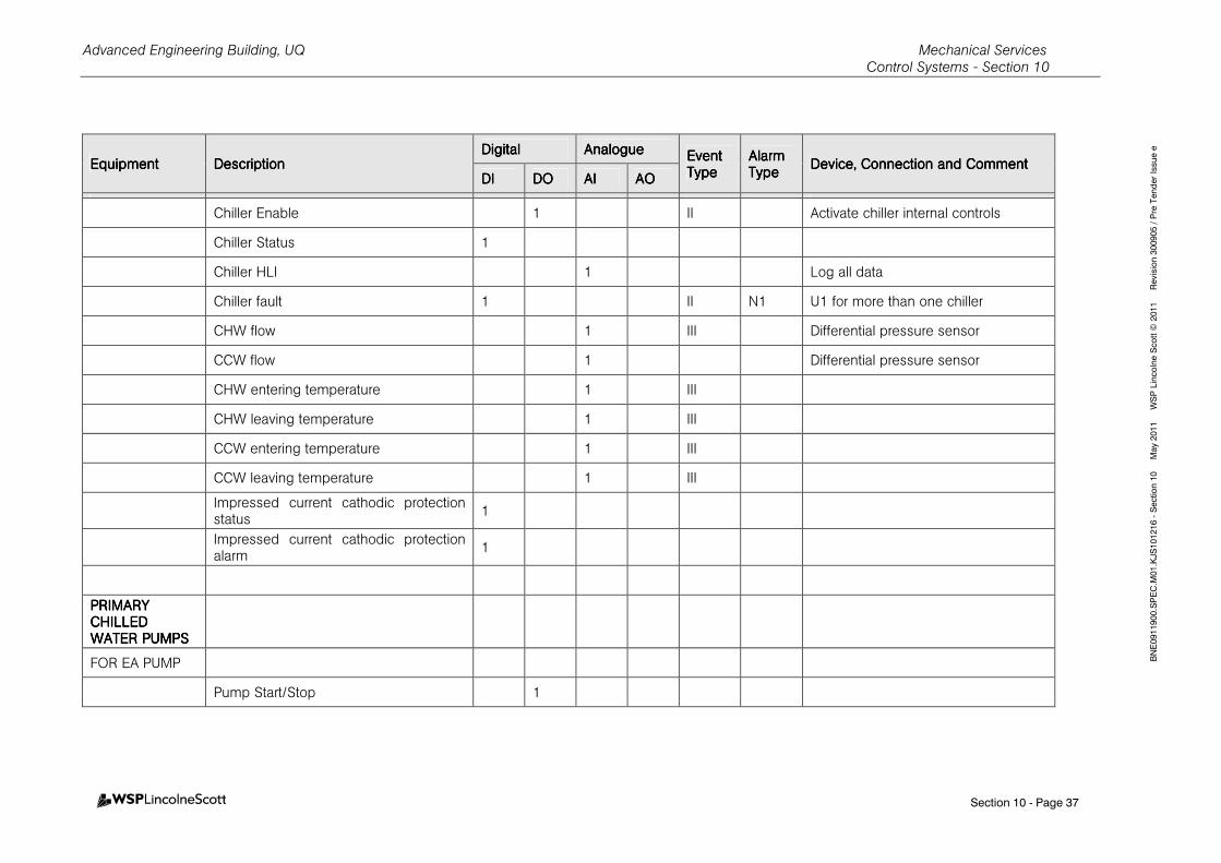
Advanced Engineering Building, UQ Mechanical Services Control Systems - Section 10
Section 10 - Page 37
BNE0911900.SPEC.M01.KJS101216 - Section 10 May 2011 WSP Lincolne Scott © 2011 Revision 300905 / Pre Tender Issue e
EquipmentEquipmentEquipmentEquipment DescriptionDescriptionDescriptionDescription DigitalDigitalDigitalDigital AnalogueAnalogueAnalogueAnalogue Event Event Event Event
TypeTypeTypeType Alarm Alarm Alarm Alarm TypeTypeTypeType
Device, Connection and CommentDevice, Connection and CommentDevice, Connection and CommentDevice, Connection and Comment DIDIDIDI DODODODO AIAIAIAI AOAOAOAO
Chiller Enable 1 II Activate chiller internal controls
Chiller Status 1
Chiller HLI 1 Log all data
Chiller fault 1 II N1 U1 for more than one chiller
CHW flow 1 III Differential pressure sensor
CCW flow 1 Differential pressure sensor
CHW entering temperature 1 III
CHW leaving temperature 1 III
CCW entering temperature 1 III
CCW leaving temperature 1 III
Impressed current cathodic protection status
1
Impressed current cathodic protection alarm
1
PRIMARY PRIMARY PRIMARY PRIMARY CHILLED CHILLED CHILLED CHILLED WATER WATER WATER WATER PUMPS PUMPS PUMPS PUMPS
FOR EA PUMP
Pump Start/Stop 1
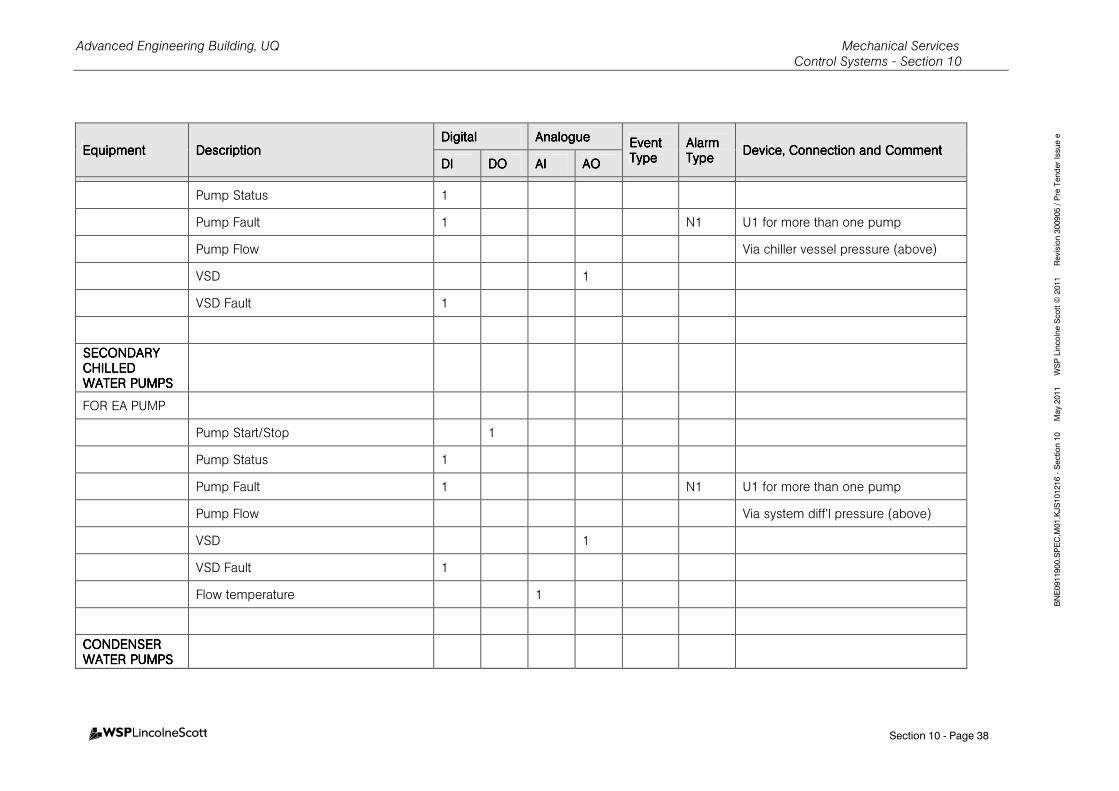
Advanced Engineering Building, UQ Mechanical Services Control Systems - Section 10
Section 10 - Page 38
BNE0911900.SPEC.M01.KJS101216 - Section 10 May 2011 WSP Lincolne Scott © 2011 Revision 300905 / Pre Tender Issue e
EquipmentEquipmentEquipmentEquipment DescriptionDescriptionDescriptionDescription DigitalDigitalDigitalDigital AnalogueAnalogueAnalogueAnalogue Event Event Event Event
TypeTypeTypeType Alarm Alarm Alarm Alarm TypeTypeTypeType
Device, Connection and CommentDevice, Connection and CommentDevice, Connection and CommentDevice, Connection and Comment DIDIDIDI DODODODO AIAIAIAI AOAOAOAO
Pump Status 1
Pump Fault 1 N1 U1 for more than one pump
Pump Flow Via chiller vessel pressure (above)
VSD 1
VSD Fault 1
SECONDARY SECONDARY SECONDARY SECONDARY CHILLED CHILLED CHILLED CHILLED WATER WATER WATER WATER PUMPS PUMPS PUMPS PUMPS
FOR EA PUMP
Pump Start/Stop 1
Pump Status 1
Pump Fault 1 N1 U1 for more than one pump
Pump Flow Via system diff’l pressure (above)
VSD 1
VSD Fault 1
Flow temperature 1
CONDENSER CONDENSER CONDENSER CONDENSER WATER WATER WATER WATER PUMPS PUMPS PUMPS PUMPS
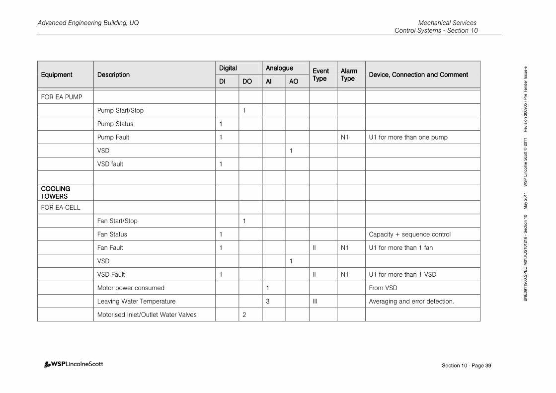
Advanced Engineering Building, UQ Mechanical Services Control Systems - Section 10
Section 10 - Page 39
BNE0911900.SPEC.M01.KJS101216 - Section 10 May 2011 WSP Lincolne Scott © 2011 Revision 300905 / Pre Tender Issue e
EquipmentEquipmentEquipmentEquipment DescriptionDescriptionDescriptionDescription DigitalDigitalDigitalDigital AnalogueAnalogueAnalogueAnalogue Event Event Event Event
TypeTypeTypeType Alarm Alarm Alarm Alarm TypeTypeTypeType
Device, Connection and CommentDevice, Connection and CommentDevice, Connection and CommentDevice, Connection and Comment DIDIDIDI DODODODO AIAIAIAI AOAOAOAO
FOR EA PUMP
Pump Start/Stop 1
Pump Status 1
Pump Fault 1 N1 U1 for more than one pump
VSD 1
VSD fault 1
COOLING COOLING COOLING COOLING TOWERSTOWERSTOWERSTOWERS
FOR EA CELL
Fan Start/Stop 1
Fan Status 1 Capacity + sequence control
Fan Fault 1 II N1 U1 for more than 1 fan
VSD 1
VSD Fault 1 II N1 U1 for more than 1 VSD
Motor power consumed 1 From VSD
Leaving Water Temperature 3 III Averaging and error detection.
Motorised Inlet/Outlet Water Valves 2
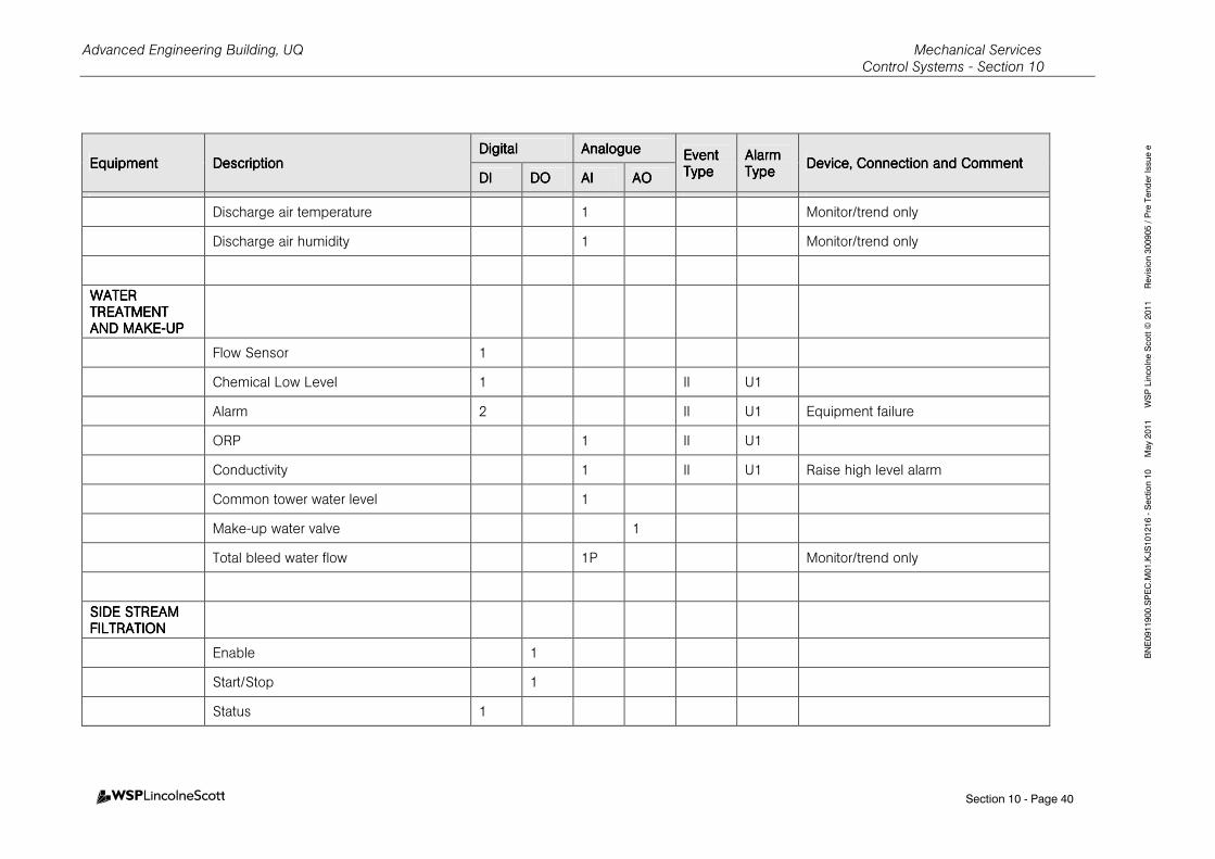
Advanced Engineering Building, UQ Mechanical Services Control Systems - Section 10
Section 10 - Page 40
BNE0911900.SPEC.M01.KJS101216 - Section 10 May 2011 WSP Lincolne Scott © 2011 Revision 300905 / Pre Tender Issue e
EquipmentEquipmentEquipmentEquipment DescriptionDescriptionDescriptionDescription DigitalDigitalDigitalDigital AnalogueAnalogueAnalogueAnalogue Event Event Event Event
TypeTypeTypeType Alarm Alarm Alarm Alarm TypeTypeTypeType
Device, Connection and CommentDevice, Connection and CommentDevice, Connection and CommentDevice, Connection and Comment DIDIDIDI DODODODO AIAIAIAI AOAOAOAO
Discharge air temperature 1 Monitor/trend only
Discharge air humidity 1 Monitor/trend only
WATER WATER WATER WATER TREATMENTTREATMENTTREATMENTTREATMENT AND MAKEAND MAKEAND MAKEAND MAKE----UPUPUPUP
Flow Sensor 1
Chemical Low Level 1 II U1
Alarm 2 II U1 Equipment failure
ORP 1 II U1
Conductivity 1 II U1 Raise high level alarm
Common tower water level 1
Make-up water valve 1
Total bleed water flow 1P Monitor/trend only
SIDE STREAMSIDE STREAMSIDE STREAMSIDE STREAM FFFFILTRATIONILTRATIONILTRATIONILTRATION
Enable 1
Start/Stop 1
Status 1
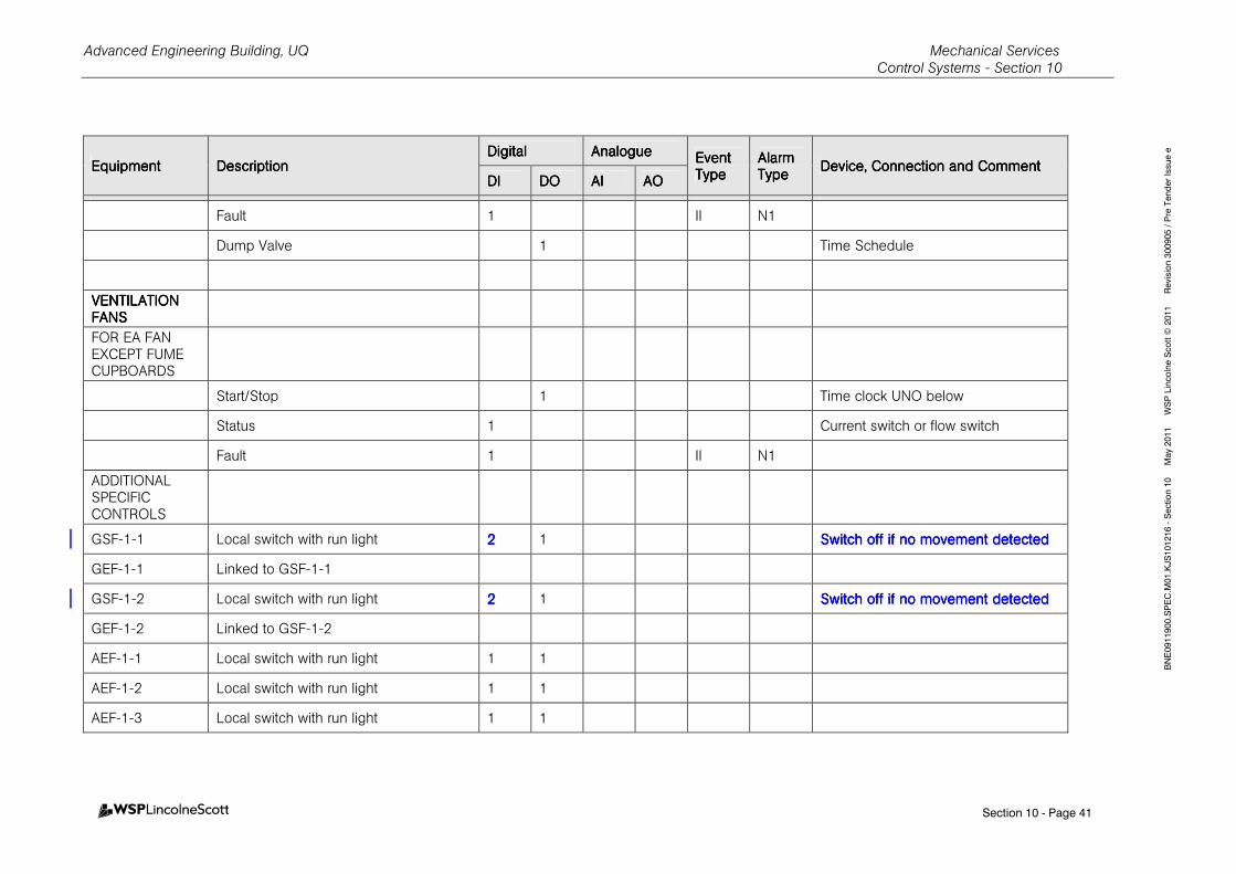
Advanced Engineering Building, UQ Mechanical Services Control Systems - Section 10
Section 10 - Page 41
BNE0911900.SPEC.M01.KJS101216 - Section 10 May 2011 WSP Lincolne Scott © 2011 Revision 300905 / Pre Tender Issue e
EquipmentEquipmentEquipmentEquipment DescriptionDescriptionDescriptionDescription DigitalDigitalDigitalDigital AnalogueAnalogueAnalogueAnalogue Event Event Event Event
TypeTypeTypeType Alarm Alarm Alarm Alarm TypeTypeTypeType
Device, Connection and CommentDevice, Connection and CommentDevice, Connection and CommentDevice, Connection and Comment DIDIDIDI DODODODO AIAIAIAI AOAOAOAO
Fault 1 II N1
Dump Valve 1 Time Schedule
VENTILAVENTILAVENTILAVENTILATION TION TION TION FANSFANSFANSFANS
FOR EA FAN EXCEPT FUME CUPBOARDS
Start/Stop 1 Time clock UNO below
Status 1 Current switch or flow switch
Fault 1 II N1
ADDITIONAL SPECIFIC CONTROLS
GSF-1-1 Local switch with run light 2222 1 SwitchSwitchSwitchSwitch off if no movementoff if no movementoff if no movementoff if no movement detecteddetecteddetecteddetected
GEF-1-1 Linked to GSF-1-1
GSF-1-2 Local switch with run light 2222 1 Switch off if no movement detectedSwitch off if no movement detectedSwitch off if no movement detectedSwitch off if no movement detected
GEF-1-2 Linked to GSF-1-2
AEF-1-1 Local switch with run light 1 1
AEF-1-2 Local switch with run light 1 1
AEF-1-3 Local switch with run light 1 1
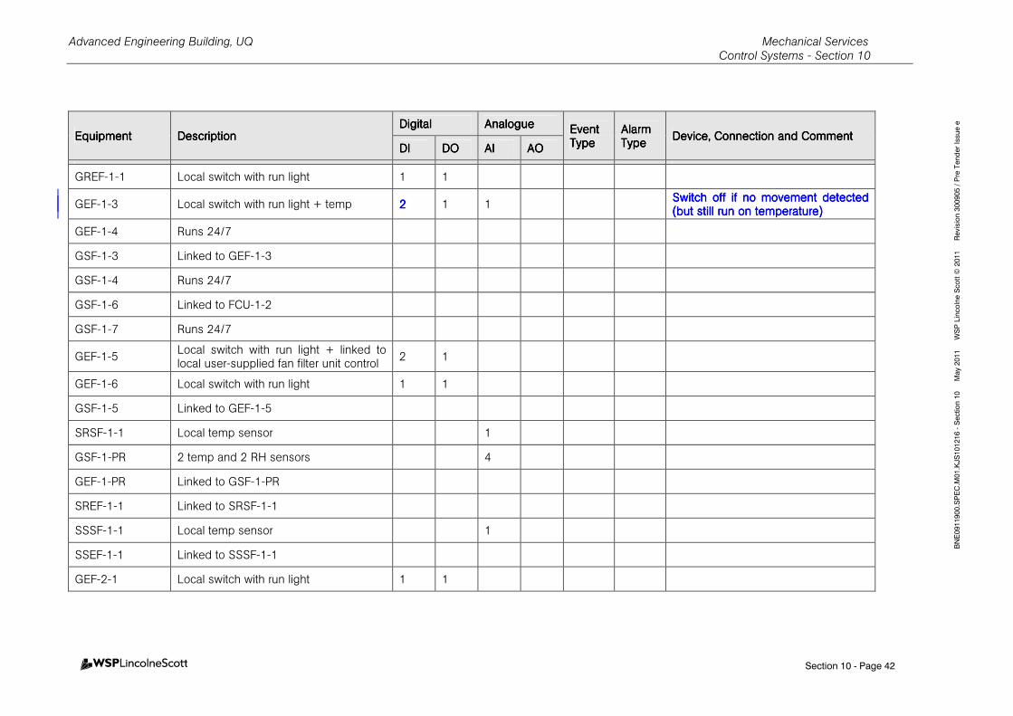
Advanced Engineering Building, UQ Mechanical Services Control Systems - Section 10
Section 10 - Page 42
BNE0911900.SPEC.M01.KJS101216 - Section 10 May 2011 WSP Lincolne Scott © 2011 Revision 300905 / Pre Tender Issue e
EquipmentEquipmentEquipmentEquipment DescriptionDescriptionDescriptionDescription DigitalDigitalDigitalDigital AnalogueAnalogueAnalogueAnalogue Event Event Event Event
TypeTypeTypeType Alarm Alarm Alarm Alarm TypeTypeTypeType
Device, Connection and CommentDevice, Connection and CommentDevice, Connection and CommentDevice, Connection and Comment DIDIDIDI DODODODO AIAIAIAI AOAOAOAO
GREF-1-1 Local switch with run light 1 1
GEF-1-3 Local switch with run light + temp 2222 1 1 Switch off if no movement detectedSwitch off if no movement detectedSwitch off if no movement detectedSwitch off if no movement detected (but still run on temperature(but still run on temperature(but still run on temperature(but still run on temperature))))
GEF-1-4 Runs 24/7
GSF-1-3 Linked to GEF-1-3
GSF-1-4 Runs 24/7
GSF-1-6 Linked to FCU-1-2
GSF-1-7 Runs 24/7
GEF-1-5 Local switch with run light + linked to local user-supplied fan filter unit control
2 1
GEF-1-6 Local switch with run light 1 1
GSF-1-5 Linked to GEF-1-5
SRSF-1-1 Local temp sensor 1
GSF-1-PR 2 temp and 2 RH sensors 4
GEF-1-PR Linked to GSF-1-PR
SREF-1-1 Linked to SRSF-1-1
SSSF-1-1 Local temp sensor 1
SSEF-1-1 Linked to SSSF-1-1
GEF-2-1 Local switch with run light 1 1
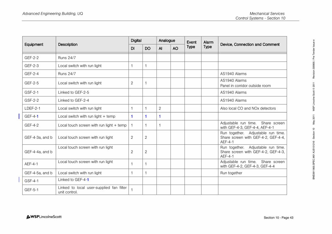
Advanced Engineering Building, UQ Mechanical Services Control Systems - Section 10
Section 10 - Page 43
BNE0911900.SPEC.M01.KJS101216 - Section 10 May 2011 WSP Lincolne Scott © 2011 Revision 300905 / Pre Tender Issue e
EquipmentEquipmentEquipmentEquipment DescriptionDescriptionDescriptionDescription DigitalDigitalDigitalDigital AnalogueAnalogueAnalogueAnalogue Event Event Event Event
TypeTypeTypeType Alarm Alarm Alarm Alarm TypeTypeTypeType
Device, Connection and CommentDevice, Connection and CommentDevice, Connection and CommentDevice, Connection and Comment DIDIDIDI DODODODO AIAIAIAI AOAOAOAO
GEF-2-2 Runs 24/7
GEF-2-3 Local switch with run light 1 1
GEF-2-4 Runs 24/7 AS1940 Alarms
GEF-2-5 Local switch with run light 2 1 AS1940 Alarms
Panel in corridor outside room
GSF-2-1 Linked to GEF-2-5 AS1940 Alarms
GSF-2-2 Linked to GEF-2-4 AS1940 Alarms
LDEF-2-1 Local switch with run light 1 1 2 Also local CO and NOx detectors
GEF-4-1111 Local switch with run light + temp 1111 1111 1111
GEF-4-2 Local touch screen with run light + temp 1 1 1 Adjustable run time. Share screen with GEF-4-3, GEF-4-4, AEF-4-1
GEF-4-3a, and b Local touch screen with run light 2 2 Run together. Adjustable run time. Share screen with GEF-4-2, GEF-4-4, AEF-4-1
GEF-4-4a, and b Local touch screen with run light
2 2 Run together. Adjustable run time. Share screen with GEF-4-2, GEF-4-3, AEF-4-1
AEF-4-1 Local touch screen with run light
1 1 Adjustable run time. Share screen with GEF-4-2, GEF-4-3, GEF-4-4
GEF-4-5a, and b Local switch with run light 1 1 Run together
GSF-4-1 Linked to GEF-4-1111
GEF-5-1 Linked to local user-supplied fan filter unit control.
1
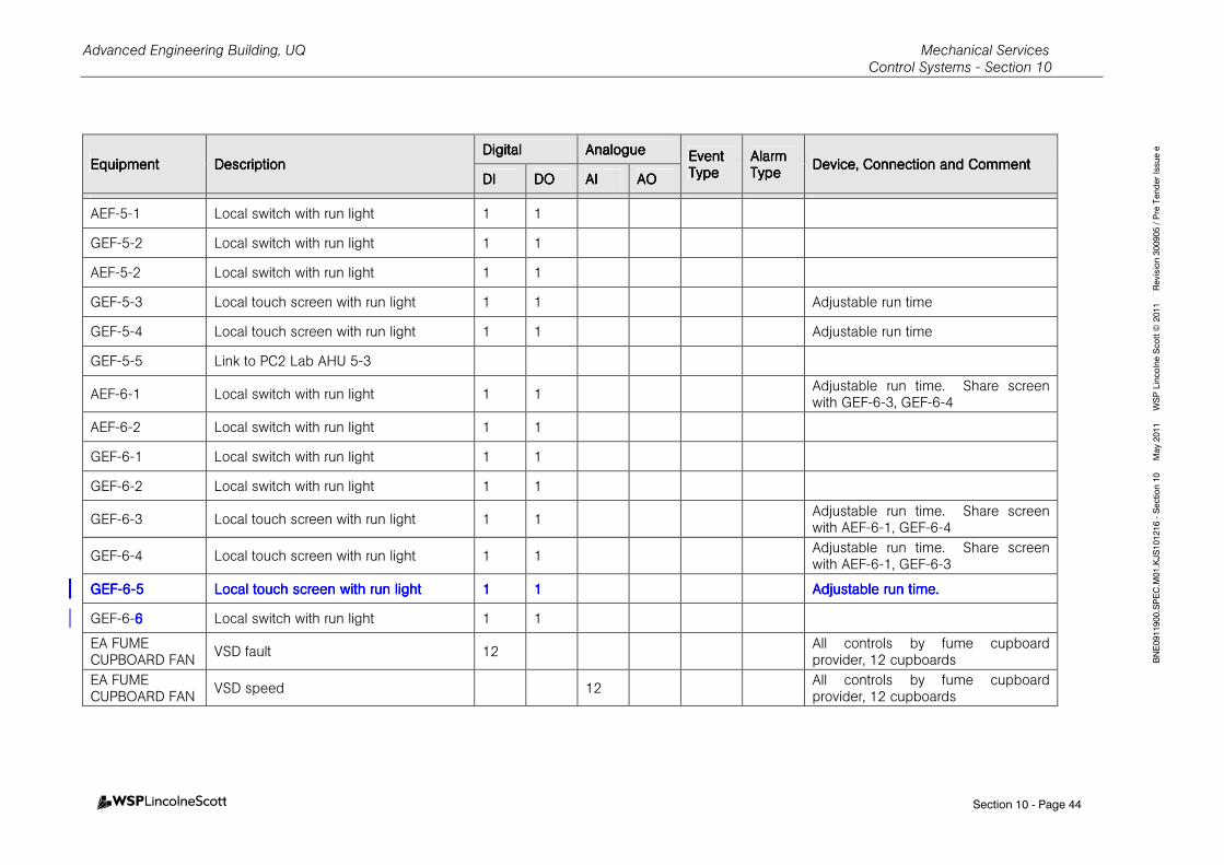
Advanced Engineering Building, UQ Mechanical Services Control Systems - Section 10
Section 10 - Page 44
BNE0911900.SPEC.M01.KJS101216 - Section 10 May 2011 WSP Lincolne Scott © 2011 Revision 300905 / Pre Tender Issue e
EquipmentEquipmentEquipmentEquipment DescriptionDescriptionDescriptionDescription DigitalDigitalDigitalDigital AnalogueAnalogueAnalogueAnalogue Event Event Event Event
TypeTypeTypeType Alarm Alarm Alarm Alarm TypeTypeTypeType
Device, Connection and CommentDevice, Connection and CommentDevice, Connection and CommentDevice, Connection and Comment DIDIDIDI DODODODO AIAIAIAI AOAOAOAO
AEF-5-1 Local switch with run light 1 1
GEF-5-2 Local switch with run light 1 1
AEF-5-2 Local switch with run light 1 1
GEF-5-3 Local touch screen with run light 1 1 Adjustable run time
GEF-5-4 Local touch screen with run light 1 1 Adjustable run time
GEF-5-5 Link to PC2 Lab AHU 5-3
AEF-6-1 Local switch with run light 1 1 Adjustable run time. Share screen with GEF-6-3, GEF-6-4
AEF-6-2 Local switch with run light 1 1
GEF-6-1 Local switch with run light 1 1
GEF-6-2 Local switch with run light 1 1
GEF-6-3 Local touch screen with run light 1 1 Adjustable run time. Share screen with AEF-6-1, GEF-6-4
GEF-6-4 Local touch screen with run light 1 1 Adjustable run time. Share screen with AEF-6-1, GEF-6-3
GEFGEFGEFGEF----6666----5555 Local touch screen with run lightLocal touch screen with run lightLocal touch screen with run lightLocal touch screen with run light 1111 1111 Adjustable run time.Adjustable run time.Adjustable run time.Adjustable run time.
GEF-6-6666 Local switch with run light 1 1
EA FUME CUPBOARD FAN
VSD fault 12 All controls by fume cupboard provider, 12 cupboards
EA FUME CUPBOARD FAN
VSD speed 12 All controls by fume cupboard provider, 12 cupboards
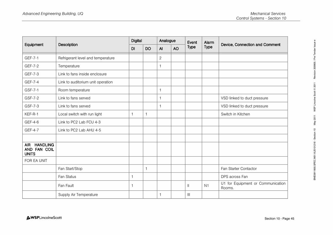
Advanced Engineering Building, UQ Mechanical Services Control Systems - Section 10
Section 10 - Page 45
BNE0911900.SPEC.M01.KJS101216 - Section 10 May 2011 WSP Lincolne Scott © 2011 Revision 300905 / Pre Tender Issue e
EquipmentEquipmentEquipmentEquipment DescriptionDescriptionDescriptionDescription DigitalDigitalDigitalDigital AnalogueAnalogueAnalogueAnalogue Event Event Event Event
TypeTypeTypeType Alarm Alarm Alarm Alarm TypeTypeTypeType
Device, Connection and CommentDevice, Connection and CommentDevice, Connection and CommentDevice, Connection and Comment DIDIDIDI DODODODO AIAIAIAI AOAOAOAO
GEF-7-1 Refrigerant level and temperature 2
GEF-7-2 Temperature 1
GEF-7-3 Link to fans inside enclosure
GEF-7-4 Link to auditorium unit operation
GSF-7-1 Room temperature 1
GSF-7-2 Link to fans served 1 VSD linked to duct pressure
GSF-7-3 Link to fans served 1 VSD linked to duct pressure
KEF-R-1 Local switch with run light 1 1 Switch in Kitchen
GEF-4-6 Link to PC2 Lab FCU 4-3
GEF-4-7 Link to PC2 Lab AHU 4-5
AIR HANDLING AIR HANDLING AIR HANDLING AIR HANDLING AND FAN COIL AND FAN COIL AND FAN COIL AND FAN COIL UNITSUNITSUNITSUNITS
FOR EA UNIT
Fan Start/Stop 1 Fan Starter Contactor
Fan Status 1 DPS across Fan
Fan Fault 1 II N1 U1 for Equipment or Communication Rooms.
Supply Air Temperature 1 III

Advanced Engineering Building, UQ Mechanical Services Control Systems - Section 10
Section 10 - Page 46
BNE0911900.SPEC.M01.KJS101216 - Section 10 May 2011 WSP Lincolne Scott © 2011 Revision 300905 / Pre Tender Issue e
EquipmentEquipmentEquipmentEquipment DescriptionDescriptionDescriptionDescription DigitalDigitalDigitalDigital AnalogueAnalogueAnalogueAnalogue Event Event Event Event
TypeTypeTypeType Alarm Alarm Alarm Alarm TypeTypeTypeType
Device, Connection and CommentDevice, Connection and CommentDevice, Connection and CommentDevice, Connection and Comment DIDIDIDI DODODODO AIAIAIAI AOAOAOAO
Return Air Temperature 1 III Duct Temperature Sensor
Return Air Relative Humidity 1 III
After Hours Push Button + light 1 1
Chilled Water Valve 1
Duct Pressure 1
Heating Water Valve 1 Where heating coil fitted in AHU
Filter Pressure Drop 1 N2
CO2 Value 1
Outside Air Modulating Damper Position 1
Tempered Outside Air Modulating Damper Position
1
Return Air Modulating Damper Position 1
VOC sensor 1 In return air duct adjacent to unit
VSD, where scheduled 1 1
ADD FOR EA VAV AHU
Zone Temperature X Provide for each box
VAV Damper X Provide for each box
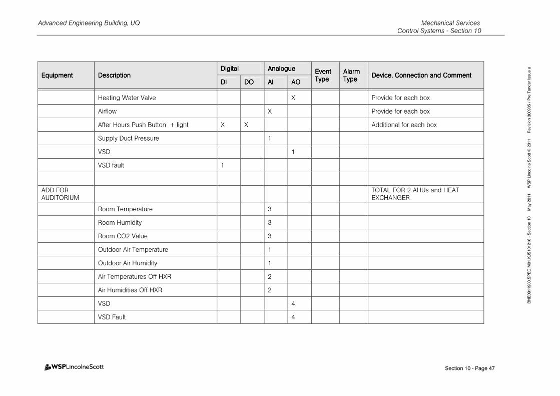
Advanced Engineering Building, UQ Mechanical Services Control Systems - Section 10
Section 10 - Page 47
BNE0911900.SPEC.M01.KJS101216 - Section 10 May 2011 WSP Lincolne Scott © 2011 Revision 300905 / Pre Tender Issue e
EquipmentEquipmentEquipmentEquipment DescriptionDescriptionDescriptionDescription DigitalDigitalDigitalDigital AnalogueAnalogueAnalogueAnalogue Event Event Event Event
TypeTypeTypeType Alarm Alarm Alarm Alarm TypeTypeTypeType
Device, Connection and CommentDevice, Connection and CommentDevice, Connection and CommentDevice, Connection and Comment DIDIDIDI DODODODO AIAIAIAI AOAOAOAO
Heating Water Valve X Provide for each box
Airflow X Provide for each box
After Hours Push Button + light X X Additional for each box
Supply Duct Pressure 1
VSD 1
VSD fault 1
ADD FOR AUDITORIUM
TOTAL FOR 2 AHUs and HEAT EXCHANGER
Room Temperature 3
Room Humidity 3
Room CO2 Value 3
Outdoor Air Temperature 1
Outdoor Air Humidity 1
Air Temperatures Off HXR 2
Air Humidities Off HXR 2
VSD 4
VSD Fault 4
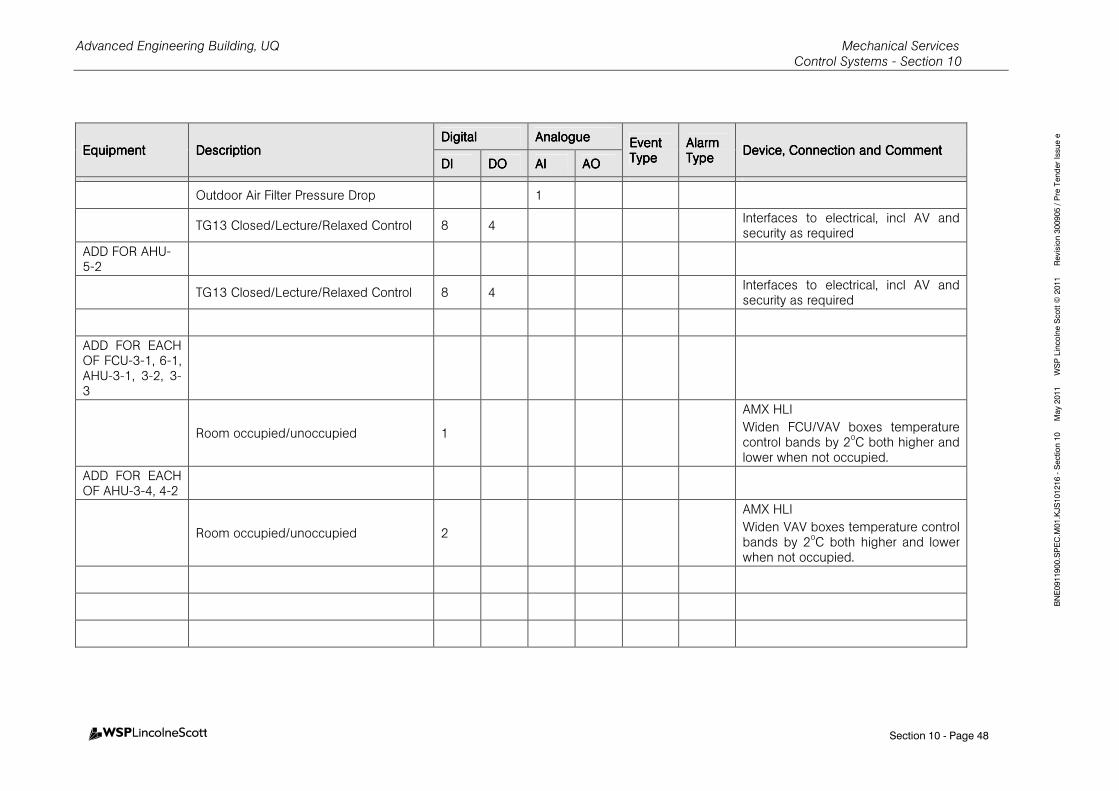
Advanced Engineering Building, UQ Mechanical Services Control Systems - Section 10
Section 10 - Page 48
BNE0911900.SPEC.M01.KJS101216 - Section 10 May 2011 WSP Lincolne Scott © 2011 Revision 300905 / Pre Tender Issue e
EquipmentEquipmentEquipmentEquipment DescriptionDescriptionDescriptionDescription DigitalDigitalDigitalDigital AnalogueAnalogueAnalogueAnalogue Event Event Event Event
TypeTypeTypeType Alarm Alarm Alarm Alarm TypeTypeTypeType
Device, Connection and CommentDevice, Connection and CommentDevice, Connection and CommentDevice, Connection and Comment DIDIDIDI DODODODO AIAIAIAI AOAOAOAO
Outdoor Air Filter Pressure Drop 1
TG13 Closed/Lecture/Relaxed Control 8 4 Interfaces to electrical, incl AV and security as required
ADD FOR AHU-5-2
TG13 Closed/Lecture/Relaxed Control 8 4 Interfaces to electrical, incl AV and security as required
ADD FOR EACH OF FCU-3-1, 6-1, AHU-3-1, 3-2, 3-3
Room occupied/unoccupied 1
AMX HLI
Widen FCU/VAV boxes temperature control bands by 2oC both higher and lower when not occupied.
ADD FOR EACH OF AHU-3-4, 4-2
Room occupied/unoccupied 2
AMX HLI
Widen VAV boxes temperature control bands by 2oC both higher and lower when not occupied.
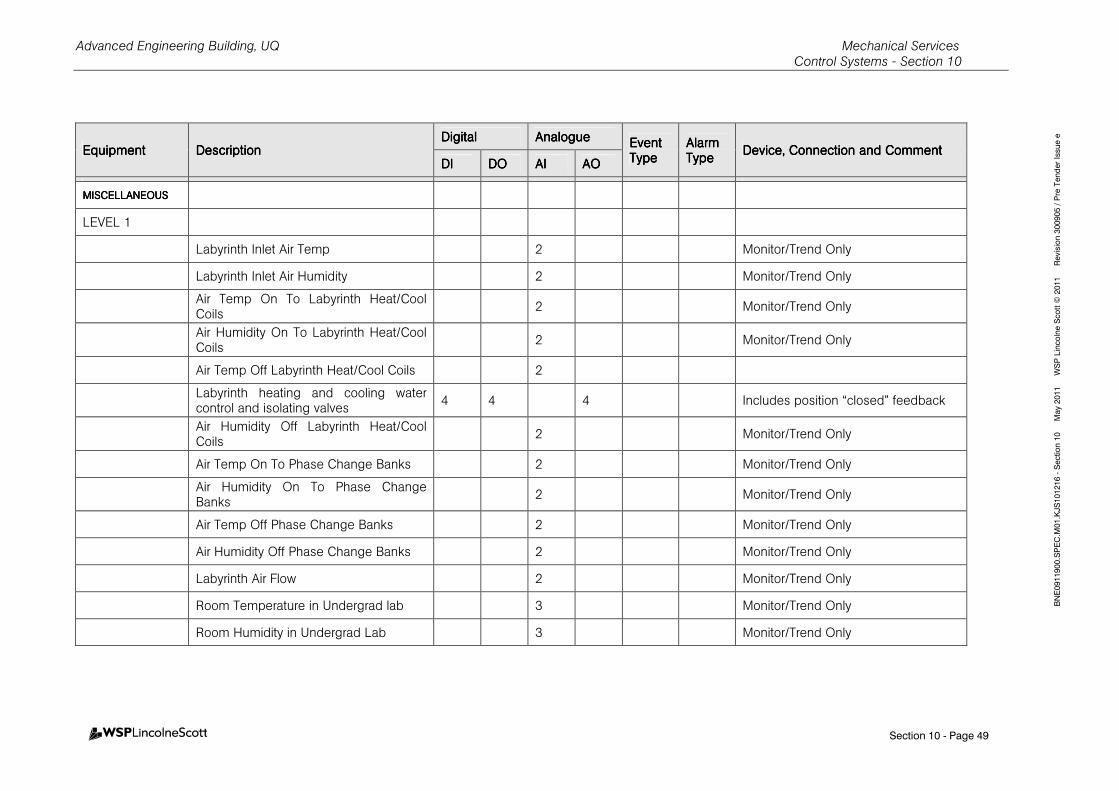
Advanced Engineering Building, UQ Mechanical Services Control Systems - Section 10
Section 10 - Page 49
BNE0911900.SPEC.M01.KJS101216 - Section 10 May 2011 WSP Lincolne Scott © 2011 Revision 300905 / Pre Tender Issue e
EquipmentEquipmentEquipmentEquipment DescriptionDescriptionDescriptionDescription DigitalDigitalDigitalDigital AnalogueAnalogueAnalogueAnalogue Event Event Event Event
TypeTypeTypeType Alarm Alarm Alarm Alarm TypeTypeTypeType
Device, Connection and CommentDevice, Connection and CommentDevice, Connection and CommentDevice, Connection and Comment DIDIDIDI DODODODO AIAIAIAI AOAOAOAO
MISCELLANEOUSMISCELLANEOUSMISCELLANEOUSMISCELLANEOUS
LEVEL 1
Labyrinth Inlet Air Temp 2 Monitor/Trend Only
Labyrinth Inlet Air Humidity 2 Monitor/Trend Only
Air Temp On To Labyrinth Heat/Cool Coils
2 Monitor/Trend Only
Air Humidity On To Labyrinth Heat/Cool Coils
2 Monitor/Trend Only
Air Temp Off Labyrinth Heat/Cool Coils 2
Labyrinth heating and cooling water control and isolating valves
4 4 4 Includes position “closed” feedback
Air Humidity Off Labyrinth Heat/Cool Coils
2 Monitor/Trend Only
Air Temp On To Phase Change Banks 2 Monitor/Trend Only
Air Humidity On To Phase Change Banks
2 Monitor/Trend Only
Air Temp Off Phase Change Banks 2 Monitor/Trend Only
Air Humidity Off Phase Change Banks 2 Monitor/Trend Only
Labyrinth Air Flow 2 Monitor/Trend Only
Room Temperature in Undergrad lab 3 Monitor/Trend Only
Room Humidity in Undergrad Lab 3 Monitor/Trend Only

Advanced Engineering Building, UQ Mechanical Services Control Systems - Section 10
Section 10 - Page 50
BNE0911900.SPEC.M01.KJS101216 - Section 10 May 2011 WSP Lincolne Scott © 2011 Revision 300905 / Pre Tender Issue e
EquipmentEquipmentEquipmentEquipment DescriptionDescriptionDescriptionDescription DigitalDigitalDigitalDigital AnalogueAnalogueAnalogueAnalogue Event Event Event Event
TypeTypeTypeType Alarm Alarm Alarm Alarm TypeTypeTypeType
Device, Connection and CommentDevice, Connection and CommentDevice, Connection and CommentDevice, Connection and Comment DIDIDIDI DODODODO AIAIAIAI AOAOAOAO
CO2 Value in Undergrad Lab 3 Monitor/Trend Only
Labyrinth Motorised Bypass Dampers 6
Other Motorised Dampers 10
Computer Room Unit Fault 2 CRACs with Self Contained Controls
Computer Room Temperature 1 Monitor/Trend/Alarm Only
Ventilation Fan Filter Bank Pressure Drop 9 N2
Hydraulic Pump Unit 2 CCW system avail to run, and running
Hydraulic Pump Unit 1 Start CCW system
Goods lift pit oxygen level, with audible and visual alarms, mute, and signal to security system
2 3 1 Alarms in both workshop (111A) and circulation (114).
Eastern atrium tempered air supply duct damper (near grids A12/AC)
1 Open normally, closed in fire mode
Tempered air riser damper serving stair 5 etc. (near grids A12/AA)
1 Open normally; normally closed in fire mode; connected to FFCP
Dampers for future L2 café air conditioning and on L5 for staff kitchen
2 4 Normal operation from local switches with “open” lights, shut in fire mode
LEVEL 2
Foyer temperature 1 Monitor/Trend Only
Foyer Humidity 1 Monitor/Trend Only
Foyer CO2 level 1 Monitor/Trend Only

Advanced Engineering Building, UQ Mechanical Services Control Systems - Section 10
Section 10 - Page 51
BNE0911900.SPEC.M01.KJS101216 - Section 10 May 2011 WSP Lincolne Scott © 2011 Revision 300905 / Pre Tender Issue e
EquipmentEquipmentEquipmentEquipment DescriptionDescriptionDescriptionDescription DigitalDigitalDigitalDigital AnalogueAnalogueAnalogueAnalogue Event Event Event Event
TypeTypeTypeType Alarm Alarm Alarm Alarm TypeTypeTypeType
Device, Connection and CommentDevice, Connection and CommentDevice, Connection and CommentDevice, Connection and Comment DIDIDIDI DODODODO AIAIAIAI AOAOAOAO
Room Temp in Concrete Lab 1 Monitor/Trend Only
Room Humidity in Concrete Lab 1 Monitor/Trend Only
Atrium Supply Duct Temperature 1 Monitor/Trend Only
Atrium Supply Duct Humidity 1 Monitor/Trend Only
Room Temp in Advanced Forming 1 Monitor/Trend Only
Room Humidity in Advanced Forming 1 Monitor/Trend Only
CO2 Value in Advanced Forming 1 Monitor/Trend Only
Room Temp in Structural Lab 1 Monitor/Trend Only
Room Humidity in Structural Lab 1 Monitor/Trend Only
Other Motorised Dampers 2
Lab gas panel Alarm 1
CHW Energy Meter 3 Total energy for AHU 2.2 and 2.3
Oxygen Depletion Alarm 2 2 1 Fault and depletion alarm (Rm 209)
LEVEL 3
Foyer Temperature 2 Monitor/Trend Only
Foyer Humidity 2 Monitor/Trend Only
Foyer CO2 level 2 Monitor/Trend Only
Additional Room Temp Sensors 4 Monitor/Trend Only
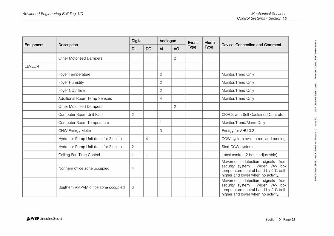
Advanced Engineering Building, UQ Mechanical Services Control Systems - Section 10
Section 10 - Page 52
BNE0911900.SPEC.M01.KJS101216 - Section 10 May 2011 WSP Lincolne Scott © 2011 Revision 300905 / Pre Tender Issue e
EquipmentEquipmentEquipmentEquipment DescriptionDescriptionDescriptionDescription DigitalDigitalDigitalDigital AnalogueAnalogueAnalogueAnalogue Event Event Event Event
TypeTypeTypeType Alarm Alarm Alarm Alarm TypeTypeTypeType
Device, Connection and CommentDevice, Connection and CommentDevice, Connection and CommentDevice, Connection and Comment DIDIDIDI DODODODO AIAIAIAI AOAOAOAO
Other Motorised Dampers 2
LEVEL 4
Foyer Temperature 2 Monitor/Trend Only
Foyer Humidity 2 Monitor/Trend Only
Foyer CO2 level 2 Monitor/Trend Only
Additional Room Temp Sensors 4 Monitor/Trend Only
Other Motorised Dampers 2
Computer Room Unit Fault 2 CRACs with Self Contained Controls
Computer Room Temperature 1 Monitor/Trend/Alarm Only
CHW Energy Meter 3 Energy for AHU 3.2
Hydraulic Pump Unit (total for 2 units) 4 CCW system avail to run, and running
Hydraulic Pump Unit (total for 2 units) 2 Start CCW system
Ceiling Fan Time Control 1 1 Local control (2 hour, adjustable)
Northern office zone occupied 4
Movement detection signals from security system. Widen VAV box temperature control band by 2oC both higher and lower when no activity.
Southern AMPAM office zone occupied 3
Movement detection signals from security system. Widen VAV box temperature control band by 2oC both higher and lower when no activity.
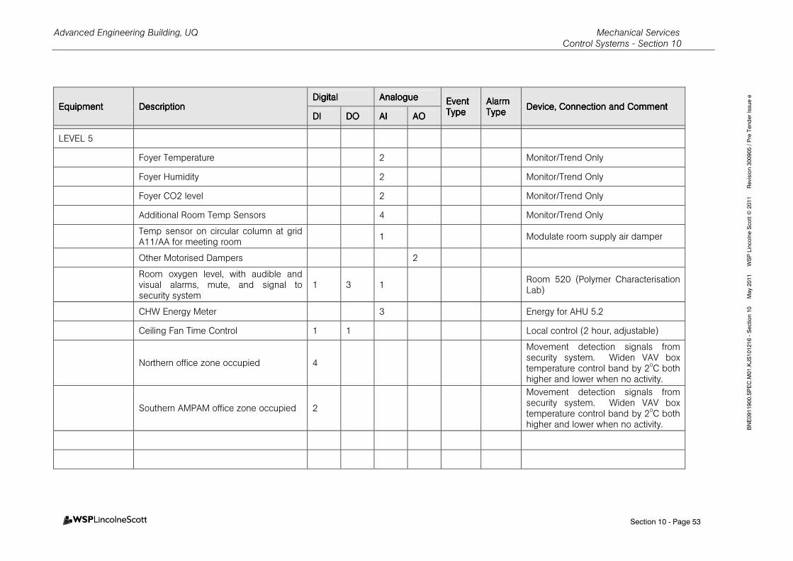
Advanced Engineering Building, UQ Mechanical Services Control Systems - Section 10
Section 10 - Page 53
BNE0911900.SPEC.M01.KJS101216 - Section 10 May 2011 WSP Lincolne Scott © 2011 Revision 300905 / Pre Tender Issue e
EquipmentEquipmentEquipmentEquipment DescriptionDescriptionDescriptionDescription DigitalDigitalDigitalDigital AnalogueAnalogueAnalogueAnalogue Event Event Event Event
TypeTypeTypeType Alarm Alarm Alarm Alarm TypeTypeTypeType
Device, Connection and CommentDevice, Connection and CommentDevice, Connection and CommentDevice, Connection and Comment DIDIDIDI DODODODO AIAIAIAI AOAOAOAO
LEVEL 5
Foyer Temperature 2 Monitor/Trend Only
Foyer Humidity 2 Monitor/Trend Only
Foyer CO2 level 2 Monitor/Trend Only
Additional Room Temp Sensors 4 Monitor/Trend Only
Temp sensor on circular column at grid A11/AA for meeting room
1 Modulate room supply air damper
Other Motorised Dampers 2
Room oxygen level, with audible and visual alarms, mute, and signal to security system
1 3 1 Room 520 (Polymer Characterisation Lab)
CHW Energy Meter 3 Energy for AHU 5.2
Ceiling Fan Time Control 1 1 Local control (2 hour, adjustable)
Northern office zone occupied 4
Movement detection signals from security system. Widen VAV box temperature control band by 2oC both higher and lower when no activity.
Southern AMPAM office zone occupied 2
Movement detection signals from security system. Widen VAV box temperature control band by 2oC both higher and lower when no activity.
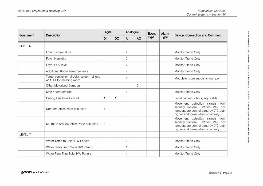
Advanced Engineering Building, UQ Mechanical Services Control Systems - Section 10
Section 10 - Page 54
BNE0911900.SPEC.M01.KJS101216 - Section 10 May 2011 WSP Lincolne Scott © 2011 Revision 300905 / Pre Tender Issue e
EquipmentEquipmentEquipmentEquipment DescriptionDescriptionDescriptionDescription DigitalDigitalDigitalDigital AnalogueAnalogueAnalogueAnalogue Event Event Event Event
TypeTypeTypeType Alarm Alarm Alarm Alarm TypeTypeTypeType
Device, Connection and CommentDevice, Connection and CommentDevice, Connection and CommentDevice, Connection and Comment DIDIDIDI DODODODO AIAIAIAI AOAOAOAO
LEVEL 6
Foyer Temperature 2 Monitor/Trend Only
Foyer Humidity 2 Monitor/Trend Only
Foyer CO2 level 2 Monitor/Trend Only
Additional Room Temp Sensors 4 Monitor/Trend Only
Temp sensor on circular column at grid A11/AA for meeting room
1 Modulate room supply air damper
Other Motorised Dampers 2
Stair 5 temperature 1 Monitor/Trend Only
Ceiling Fan Time Control 1 1 Local control (2 hour, adjustable)
Northern office zone occupied 4
Movement detection signals from security system. Widen VAV box temperature control band by 2oC both higher and lower when no activity.
Southern AMPAM office zone occupied 3
Movement detection signals from security system. Widen VAV box temperature control band by 2oC both higher and lower when no activity.
LEVEL 7
Water Temp to Solar HW Panels 1 Monitor/Trend Only
Water temp From Solar HW Panels 1 Monitor/Trend Only
Water Flow Thru Solar HW Panels 1 Monitor/Trend Only
Advanced Engineering Building, UQ Mechanical Services Control Systems - Section 10
Section 10 - Page 55
BNE0911900.SPEC.M01.KJS101216 - Section 10 May 2011 WSP Lincolne Scott © 2011 Revision 300905 / Pre Tender Issue e
EquipmentEquipmentEquipmentEquipment DescriptionDescriptionDescriptionDescription DigitalDigitalDigitalDigital AnalogueAnalogueAnalogueAnalogue Event Event Event Event
TypeTypeTypeType Alarm Alarm Alarm Alarm TypeTypeTypeType
Device, Connection and CommentDevice, Connection and CommentDevice, Connection and CommentDevice, Connection and Comment DIDIDIDI DODODODO AIAIAIAI AOAOAOAO
Other Motorised Dampers 8
Fault from compressed air plant 4 Monitor/Trend Only
Fault from Vacuum Plant 3 Monitor/Trend Only
Water Meter – Cold water to cooling towers
1 Pulsed, Monitor/Trend Only
Total bleed from all cooling towers 1 Pulsed, Monitor/Trend Only
Average air temp entering cooling towers
1 Monitor/Trend Only
Average air humidity entering cooling towers
1 Monitor/Trend Only
Chiller 5 Status, Fault, supply water temperature 2 1
HOT WATER HOT WATER HOT WATER HOT WATER SYSTEMSSYSTEMSSYSTEMSSYSTEMS
In Base building scope
GENERAL
Return Water Temperature 1 N2
Supply Header Temperature 1
HW Storage Tank Temperature 4
Gas meter 1P
HW Tank Make-up Water valve 1
HW Tank Water level 1 Raise high and low level alarms

Advanced Engineering Building, UQ Mechanical Services Control Systems - Section 10
Section 10 - Page 56
BNE0911900.SPEC.M01.KJS101216 - Section 10 May 2011 WSP Lincolne Scott © 2011 Revision 300905 / Pre Tender Issue e
EquipmentEquipmentEquipmentEquipment DescriptionDescriptionDescriptionDescription DigitalDigitalDigitalDigital AnalogueAnalogueAnalogueAnalogue Event Event Event Event
TypeTypeTypeType Alarm Alarm Alarm Alarm TypeTypeTypeType
Device, Connection and CommentDevice, Connection and CommentDevice, Connection and CommentDevice, Connection and Comment DIDIDIDI DODODODO AIAIAIAI AOAOAOAO
Hydraulics DHW Tank Temp 1
FOR EA HW UNIT
HWU-1, 2 and 3
Hot Water Unit Start/Stop 1
Hot Water Unit Status 1 N3 Fault – Alarm for Ignition Failure and Loss of Hot Water Generation.
Pump Start/Stop 1
Pump Status 1 N3
Pump Fault 1 N1
MOTORISED MOTORISED MOTORISED MOTORISED INTERNAL INTERNAL INTERNAL INTERNAL BLINDSBLINDSBLINDSBLINDS
HLI to Blind Controllers 4 4 4 RJ45 port on each of levels 3, 4, 5 and 6.
MOTORISED MOTORISED MOTORISED MOTORISED LOUVRESLOUVRESLOUVRESLOUVRES, , , , INTERNAL AND INTERNAL AND INTERNAL AND INTERNAL AND EXTERNALEXTERNALEXTERNALEXTERNAL
Connect to distributed louvre controllers.
Local manual override controls by BMS supplier.
Level 1Level 1Level 1Level 1 Separate louvre groups 8
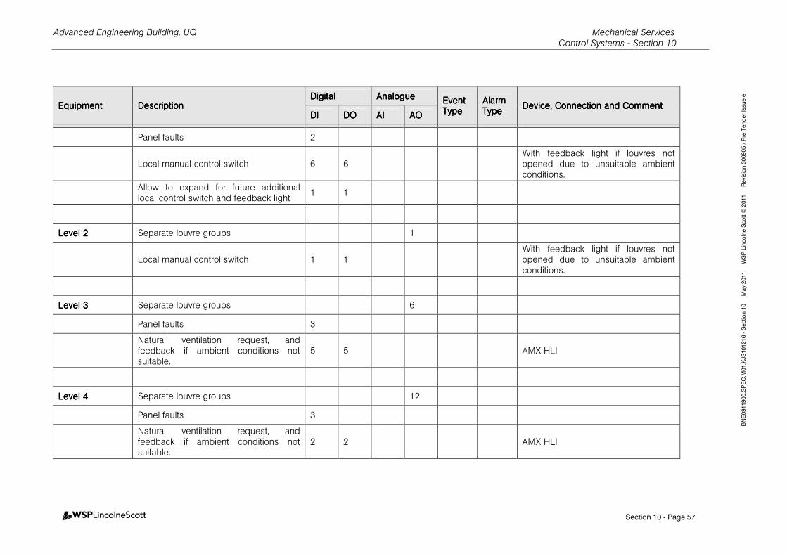
Advanced Engineering Building, UQ Mechanical Services Control Systems - Section 10
Section 10 - Page 57
BNE0911900.SPEC.M01.KJS101216 - Section 10 May 2011 WSP Lincolne Scott © 2011 Revision 300905 / Pre Tender Issue e
EquipmentEquipmentEquipmentEquipment DescriptionDescriptionDescriptionDescription DigitalDigitalDigitalDigital AnalogueAnalogueAnalogueAnalogue Event Event Event Event
TypeTypeTypeType Alarm Alarm Alarm Alarm TypeTypeTypeType
Device, Connection and CommentDevice, Connection and CommentDevice, Connection and CommentDevice, Connection and Comment DIDIDIDI DODODODO AIAIAIAI AOAOAOAO
Panel faults 2
Local manual control switch 6 6 With feedback light if louvres not opened due to unsuitable ambient conditions.
Allow to expand for future additional local control switch and feedback light
1 1
Level 2Level 2Level 2Level 2 Separate louvre groups 1
Local manual control switch 1 1 With feedback light if louvres not opened due to unsuitable ambient conditions.
Level 3Level 3Level 3Level 3 Separate louvre groups 6
Panel faults 3
Natural ventilation request, and feedback if ambient conditions not suitable.
5 5 AMX HLI
Level 4Level 4Level 4Level 4 Separate louvre groups 12
Panel faults 3
Natural ventilation request, and feedback if ambient conditions not suitable.
2 2 AMX HLI
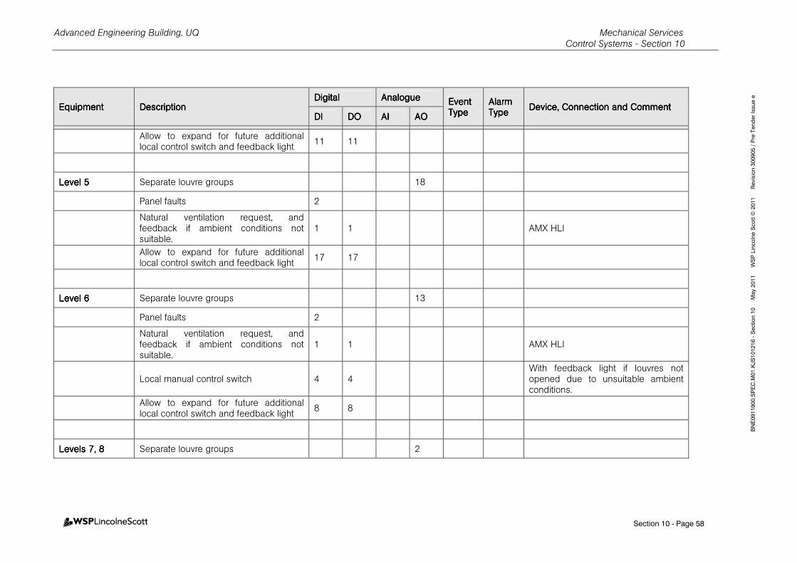
Advanced Engineering Building, UQ Mechanical Services Control Systems - Section 10
Section 10 - Page 58
BNE0911900.SPEC.M01.KJS101216 - Section 10 May 2011 WSP Lincolne Scott © 2011 Revision 300905 / Pre Tender Issue e
EquipmentEquipmentEquipmentEquipment DescriptionDescriptionDescriptionDescription DigitalDigitalDigitalDigital AnalogueAnalogueAnalogueAnalogue Event Event Event Event
TypeTypeTypeType Alarm Alarm Alarm Alarm TypeTypeTypeType
Device, Connection and CommentDevice, Connection and CommentDevice, Connection and CommentDevice, Connection and Comment DIDIDIDI DODODODO AIAIAIAI AOAOAOAO
Allow to expand for future additional local control switch and feedback light
11 11
Level 5Level 5Level 5Level 5 Separate louvre groups 18
Panel faults 2
Natural ventilation request, and feedback if ambient conditions not suitable.
1 1 AMX HLI
Allow to expand for future additional local control switch and feedback light
17 17
Level 6Level 6Level 6Level 6 Separate louvre groups 13
Panel faults 2
Natural ventilation request, and feedback if ambient conditions not suitable.
1 1 AMX HLI
Local manual control switch 4 4 With feedback light if louvres not opened due to unsuitable ambient conditions.
Allow to expand for future additional local control switch and feedback light
8 8
Levels 7, 8Levels 7, 8Levels 7, 8Levels 7, 8 Separate louvre groups 2
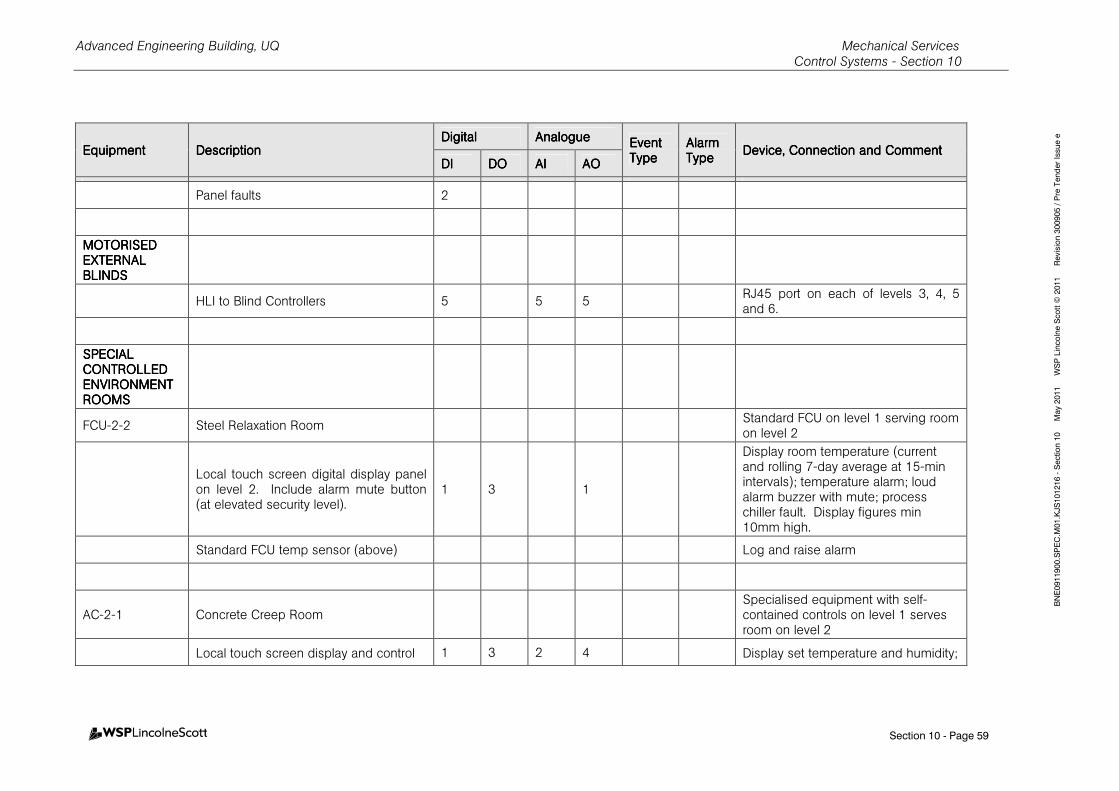
Advanced Engineering Building, UQ Mechanical Services Control Systems - Section 10
Section 10 - Page 59
BNE0911900.SPEC.M01.KJS101216 - Section 10 May 2011 WSP Lincolne Scott © 2011 Revision 300905 / Pre Tender Issue e
EquipmentEquipmentEquipmentEquipment DescriptionDescriptionDescriptionDescription DigitalDigitalDigitalDigital AnalogueAnalogueAnalogueAnalogue Event Event Event Event
TypeTypeTypeType Alarm Alarm Alarm Alarm TypeTypeTypeType
Device, Connection and CommentDevice, Connection and CommentDevice, Connection and CommentDevice, Connection and Comment DIDIDIDI DODODODO AIAIAIAI AOAOAOAO
Panel faults 2
MOTORISED MOTORISED MOTORISED MOTORISED EXTERNAL EXTERNAL EXTERNAL EXTERNAL BLINDSBLINDSBLINDSBLINDS
HLI to Blind Controllers 5 5 5 RJ45 port on each of levels 3, 4, 5 and 6.
SPECIAL SPECIAL SPECIAL SPECIAL CONTROLLED CONTROLLED CONTROLLED CONTROLLED ENVIRONMENT ENVIRONMENT ENVIRONMENT ENVIRONMENT ROOMSROOMSROOMSROOMS
FCU-2-2 Steel Relaxation Room Standard FCU on level 1 serving room on level 2
Local touch screen digital display panel on level 2. Include alarm mute button (at elevated security level).
1 3 1
Display room temperature (current and rolling 7-day average at 15-min intervals); temperature alarm; loud alarm buzzer with mute; process chiller fault. Display figures min 10mm high.
Standard FCU temp sensor (above) Log and raise alarm
AC-2-1 Concrete Creep Room Specialised equipment with self-contained controls on level 1 serves room on level 2
Local touch screen display and control 1 3 2 4 Display set temperature and humidity;
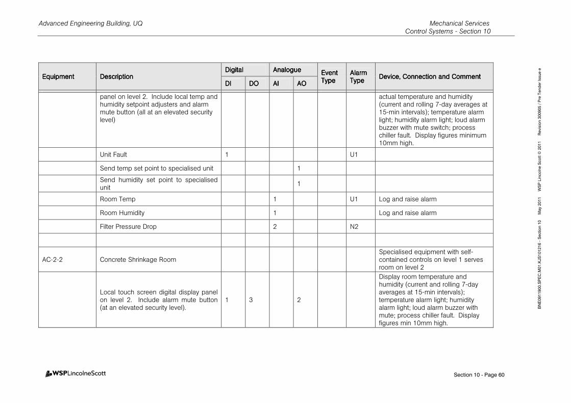
Advanced Engineering Building, UQ Mechanical Services Control Systems - Section 10
Section 10 - Page 60
BNE0911900.SPEC.M01.KJS101216 - Section 10 May 2011 WSP Lincolne Scott © 2011 Revision 300905 / Pre Tender Issue e
EquipmentEquipmentEquipmentEquipment DescriptionDescriptionDescriptionDescription DigitalDigitalDigitalDigital AnalogueAnalogueAnalogueAnalogue Event Event Event Event
TypeTypeTypeType Alarm Alarm Alarm Alarm TypeTypeTypeType
Device, Connection and CommentDevice, Connection and CommentDevice, Connection and CommentDevice, Connection and Comment DIDIDIDI DODODODO AIAIAIAI AOAOAOAO
panel on level 2. Include local temp and humidity setpoint adjusters and alarm mute button (all at an elevated security level)
actual temperature and humidity (current and rolling 7-day averages at 15-min intervals); temperature alarm light; humidity alarm light; loud alarm buzzer with mute switch; process chiller fault. Display figures minimum 10mm high.
Unit Fault 1 U1
Send temp set point to specialised unit 1
Send humidity set point to specialised unit
1
Room Temp 1 U1 Log and raise alarm
Room Humidity 1 Log and raise alarm
Filter Pressure Drop 2 N2
AC-2-2 Concrete Shrinkage Room Specialised equipment with self-contained controls on level 1 serves room on level 2
Local touch screen digital display panel on level 2. Include alarm mute button (at an elevated security level).
1 3 2
Display room temperature and humidity (current and rolling 7-day averages at 15-min intervals); temperature alarm light; humidity alarm light; loud alarm buzzer with mute; process chiller fault. Display figures min 10mm high.
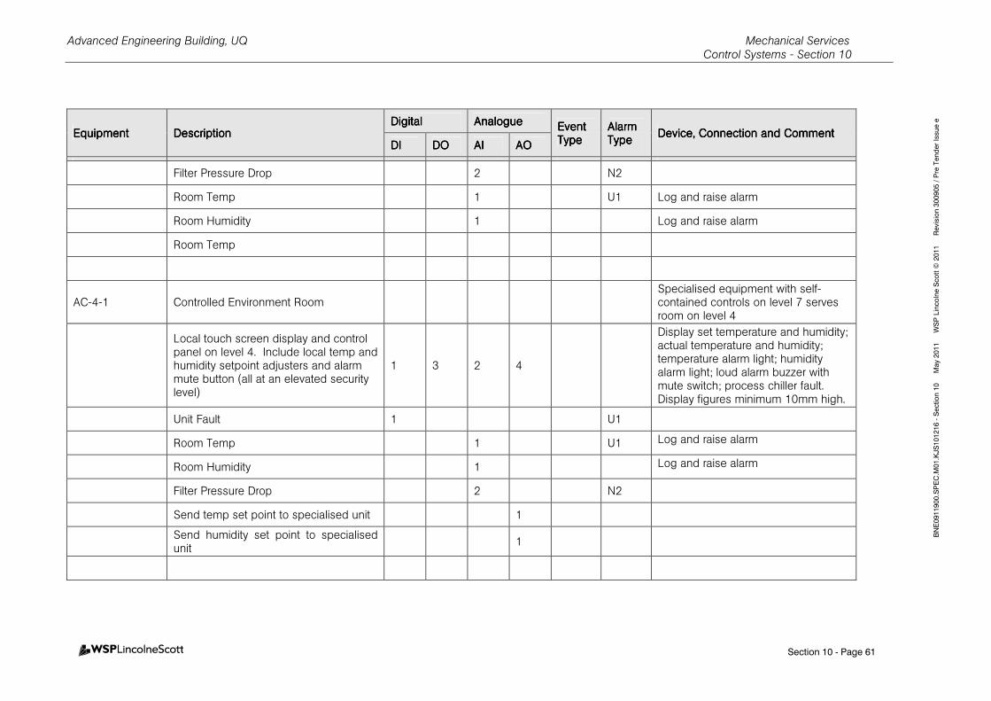
Advanced Engineering Building, UQ Mechanical Services Control Systems - Section 10
Section 10 - Page 61
BNE0911900.SPEC.M01.KJS101216 - Section 10 May 2011 WSP Lincolne Scott © 2011 Revision 300905 / Pre Tender Issue e
EquipmentEquipmentEquipmentEquipment DescriptionDescriptionDescriptionDescription DigitalDigitalDigitalDigital AnalogueAnalogueAnalogueAnalogue Event Event Event Event
TypeTypeTypeType Alarm Alarm Alarm Alarm TypeTypeTypeType
Device, Connection and CommentDevice, Connection and CommentDevice, Connection and CommentDevice, Connection and Comment DIDIDIDI DODODODO AIAIAIAI AOAOAOAO
Filter Pressure Drop 2 N2
Room Temp 1 U1 Log and raise alarm
Room Humidity 1 Log and raise alarm
Room Temp
AC-4-1 Controlled Environment Room Specialised equipment with self-contained controls on level 7 serves room on level 4
Local touch screen display and control panel on level 4. Include local temp and humidity setpoint adjusters and alarm mute button (all at an elevated security level)
1 3 2 4
Display set temperature and humidity; actual temperature and humidity; temperature alarm light; humidity alarm light; loud alarm buzzer with mute switch; process chiller fault. Display figures minimum 10mm high.
Unit Fault 1 U1
Room Temp 1 U1 Log and raise alarm
Room Humidity 1 Log and raise alarm
Filter Pressure Drop 2 N2
Send temp set point to specialised unit 1
Send humidity set point to specialised unit
1
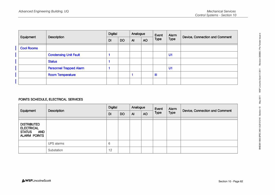
Advanced Engineering Building, UQ Mechanical Services Control Systems - Section 10
Section 10 - Page 62
BNE0911900.SPEC.M01.KJS101216 - Section 10 May 2011 WSP Lincolne Scott © 2011 Revision 300905 / Pre Tender Issue e
EquipmentEquipmentEquipmentEquipment DescriptionDescriptionDescriptionDescription DigitalDigitalDigitalDigital AnalogueAnalogueAnalogueAnalogue Event Event Event Event
TypeTypeTypeType Alarm Alarm Alarm Alarm TypeTypeTypeType
Device, Connection and CommentDevice, Connection and CommentDevice, Connection and CommentDevice, Connection and Comment DIDIDIDI DODODODO AIAIAIAI AOAOAOAO
Cool RoomsCool RoomsCool RoomsCool Rooms
Condensing Unit FaultCondensing Unit FaultCondensing Unit FaultCondensing Unit Fault 1111 U1U1U1U1
StatusStatusStatusStatus 1111
Personnel Trapped AlarmPersonnel Trapped AlarmPersonnel Trapped AlarmPersonnel Trapped Alarm 1111 U1U1U1U1
Room TemperatureRoom TemperatureRoom TemperatureRoom Temperature 1111 IIIIIIIIIIII
POINTS SCHEDULE, ELEPOINTS SCHEDULE, ELEPOINTS SCHEDULE, ELEPOINTS SCHEDULE, ELECTRICAL SERVICESCTRICAL SERVICESCTRICAL SERVICESCTRICAL SERVICES
EquipmentEquipmentEquipmentEquipment DescriptionDescriptionDescriptionDescription DigitalDigitalDigitalDigital AnalogueAnalogueAnalogueAnalogue Event Event Event Event
TypeTypeTypeType Alarm Alarm Alarm Alarm TypeTypeTypeType
Device, Connection and CommentDevice, Connection and CommentDevice, Connection and CommentDevice, Connection and Comment DIDIDIDI DODODODO AIAIAIAI AOAOAOAO
DISTRIBUTED DISTRIBUTED DISTRIBUTED DISTRIBUTED ELECTRICAL ELECTRICAL ELECTRICAL ELECTRICAL STATUS AND STATUS AND STATUS AND STATUS AND ALARM ALARM ALARM ALARM POINTSPOINTSPOINTSPOINTS
UPS alarms 6
Substation 12
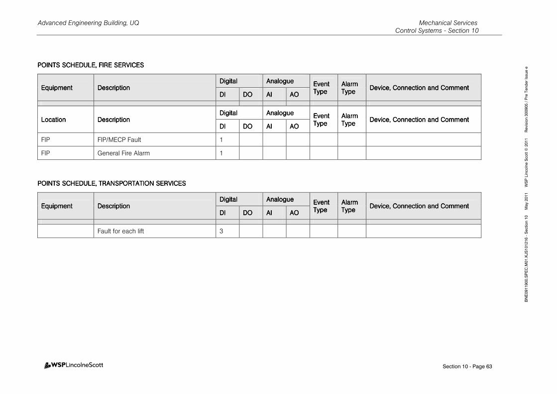
Advanced Engineering Building, UQ Mechanical Services Control Systems - Section 10
Section 10 - Page 63
BNE0911900.SPEC.M01.KJS101216 - Section 10 May 2011 WSP Lincolne Scott © 2011 Revision 300905 / Pre Tender Issue e POINTS SCHEDULE, FIRPOINTS SCHEDULE, FIRPOINTS SCHEDULE, FIRPOINTS SCHEDULE, FIRE SERVICESE SERVICESE SERVICESE SERVICES
EquipmentEquipmentEquipmentEquipment DescriptionDescriptionDescriptionDescription DigitalDigitalDigitalDigital AnalogueAnalogueAnalogueAnalogue Event Event Event Event
TypeTypeTypeType Alarm Alarm Alarm Alarm TypeTypeTypeType
Device, Connection and CommentDevice, Connection and CommentDevice, Connection and CommentDevice, Connection and Comment DIDIDIDI DODODODO AIAIAIAI AOAOAOAO
LocationLocationLocationLocation DescriptionDescriptionDescriptionDescription DigitalDigitalDigitalDigital AnalogueAnalogueAnalogueAnalogue EEEEvent vent vent vent
TypeTypeTypeType Alarm Alarm Alarm Alarm TypeTypeTypeType
Device, Connection and CommentDevice, Connection and CommentDevice, Connection and CommentDevice, Connection and Comment DIDIDIDI DODODODO AIAIAIAI AOAOAOAO
FIP FIP/MECP Fault 1
FIP General Fire Alarm 1
POINTS SCHEDULE, POINTS SCHEDULE, POINTS SCHEDULE, POINTS SCHEDULE, TRANSPORTATION TRANSPORTATION TRANSPORTATION TRANSPORTATION SERVICESSERVICESSERVICESSERVICES
EquipmentEquipmentEquipmentEquipment DescriptionDescriptionDescriptionDescription DigitalDigitalDigitalDigital AnalogueAnalogueAnalogueAnalogue Event Event Event Event
TypeTypeTypeType Alarm Alarm Alarm Alarm TypeTypeTypeType
Device, Connection andDevice, Connection andDevice, Connection andDevice, Connection and CommentCommentCommentComment DIDIDIDI DODODODO AIAIAIAI AOAOAOAO
Fault for each lift 3
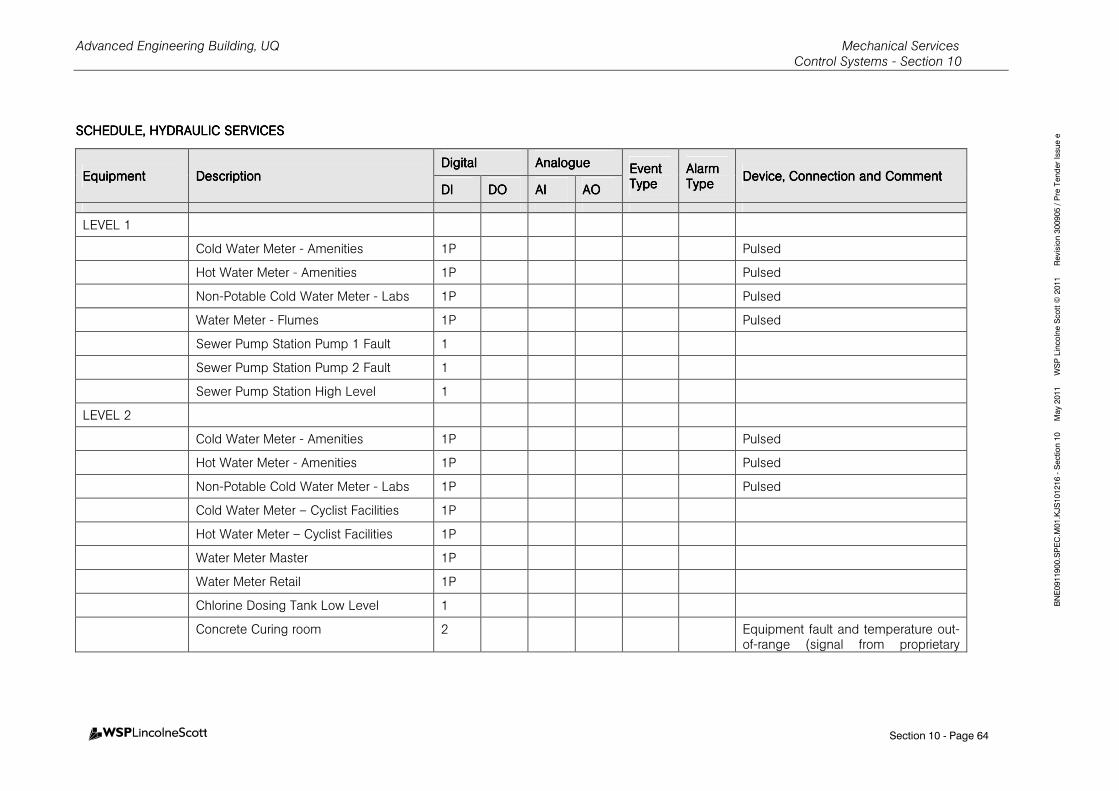
Advanced Engineering Building, UQ Mechanical Services Control Systems - Section 10
Section 10 - Page 64
BNE0911900.SPEC.M01.KJS101216 - Section 10 May 2011 WSP Lincolne Scott © 2011 Revision 300905 / Pre Tender Issue e SCHEDULE, HYDRAULIC SCHEDULE, HYDRAULIC SCHEDULE, HYDRAULIC SCHEDULE, HYDRAULIC SERVICESSERVICESSERVICESSERVICES
EquipmentEquipmentEquipmentEquipment DescriptionDescriptionDescriptionDescription DigitalDigitalDigitalDigital AnalogueAnalogueAnalogueAnalogue Event Event Event Event
TypeTypeTypeType Alarm Alarm Alarm Alarm TypeTypeTypeType
Device, Connection and CommentDevice, Connection and CommentDevice, Connection and CommentDevice, Connection and Comment DIDIDIDI DODODODO AIAIAIAI AOAOAOAO
LEVEL 1
Cold Water Meter - Amenities 1P Pulsed
Hot Water Meter - Amenities 1P Pulsed
Non-Potable Cold Water Meter - Labs 1P Pulsed
Water Meter - Flumes 1P Pulsed
Sewer Pump Station Pump 1 Fault 1
Sewer Pump Station Pump 2 Fault 1
Sewer Pump Station High Level 1
LEVEL 2
Cold Water Meter - Amenities 1P Pulsed
Hot Water Meter - Amenities 1P Pulsed
Non-Potable Cold Water Meter - Labs 1P Pulsed
Cold Water Meter – Cyclist Facilities 1P
Hot Water Meter – Cyclist Facilities 1P
Water Meter Master 1P
Water Meter Retail 1P
Chlorine Dosing Tank Low Level 1
Concrete Curing room 2 Equipment fault and temperature out-of-range (signal from proprietary
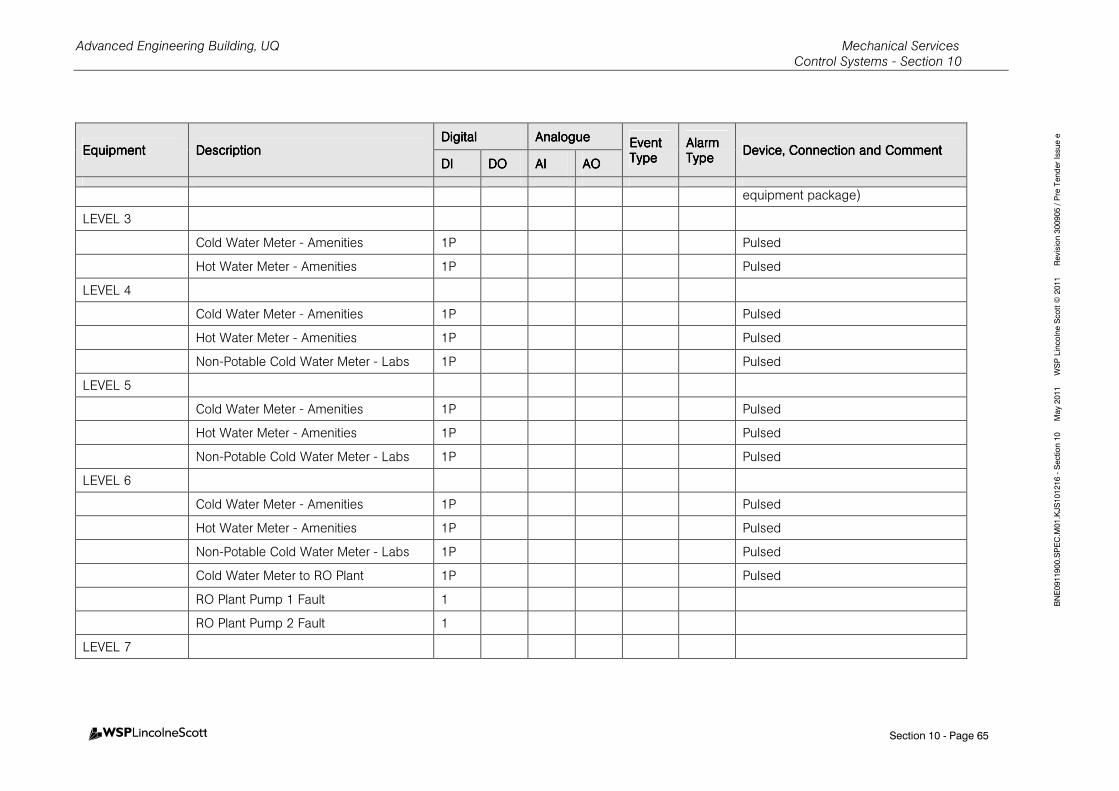
Advanced Engineering Building, UQ Mechanical Services Control Systems - Section 10
Section 10 - Page 65
BNE0911900.SPEC.M01.KJS101216 - Section 10 May 2011 WSP Lincolne Scott © 2011 Revision 300905 / Pre Tender Issue e
EquipmentEquipmentEquipmentEquipment DescriptionDescriptionDescriptionDescription DigitalDigitalDigitalDigital AnalogueAnalogueAnalogueAnalogue Event Event Event Event
TypeTypeTypeType Alarm Alarm Alarm Alarm TypeTypeTypeType
Device, Connection and CommentDevice, Connection and CommentDevice, Connection and CommentDevice, Connection and Comment DIDIDIDI DODODODO AIAIAIAI AOAOAOAO
equipment package)
LEVEL 3
Cold Water Meter - Amenities 1P Pulsed
Hot Water Meter - Amenities 1P Pulsed
LEVEL 4
Cold Water Meter - Amenities 1P Pulsed
Hot Water Meter - Amenities 1P Pulsed
Non-Potable Cold Water Meter - Labs 1P Pulsed
LEVEL 5
Cold Water Meter - Amenities 1P Pulsed
Hot Water Meter - Amenities 1P Pulsed
Non-Potable Cold Water Meter - Labs 1P Pulsed
LEVEL 6
Cold Water Meter - Amenities 1P Pulsed
Hot Water Meter - Amenities 1P Pulsed
Non-Potable Cold Water Meter - Labs 1P Pulsed
Cold Water Meter to RO Plant 1P Pulsed
RO Plant Pump 1 Fault 1
RO Plant Pump 2 Fault 1
LEVEL 7
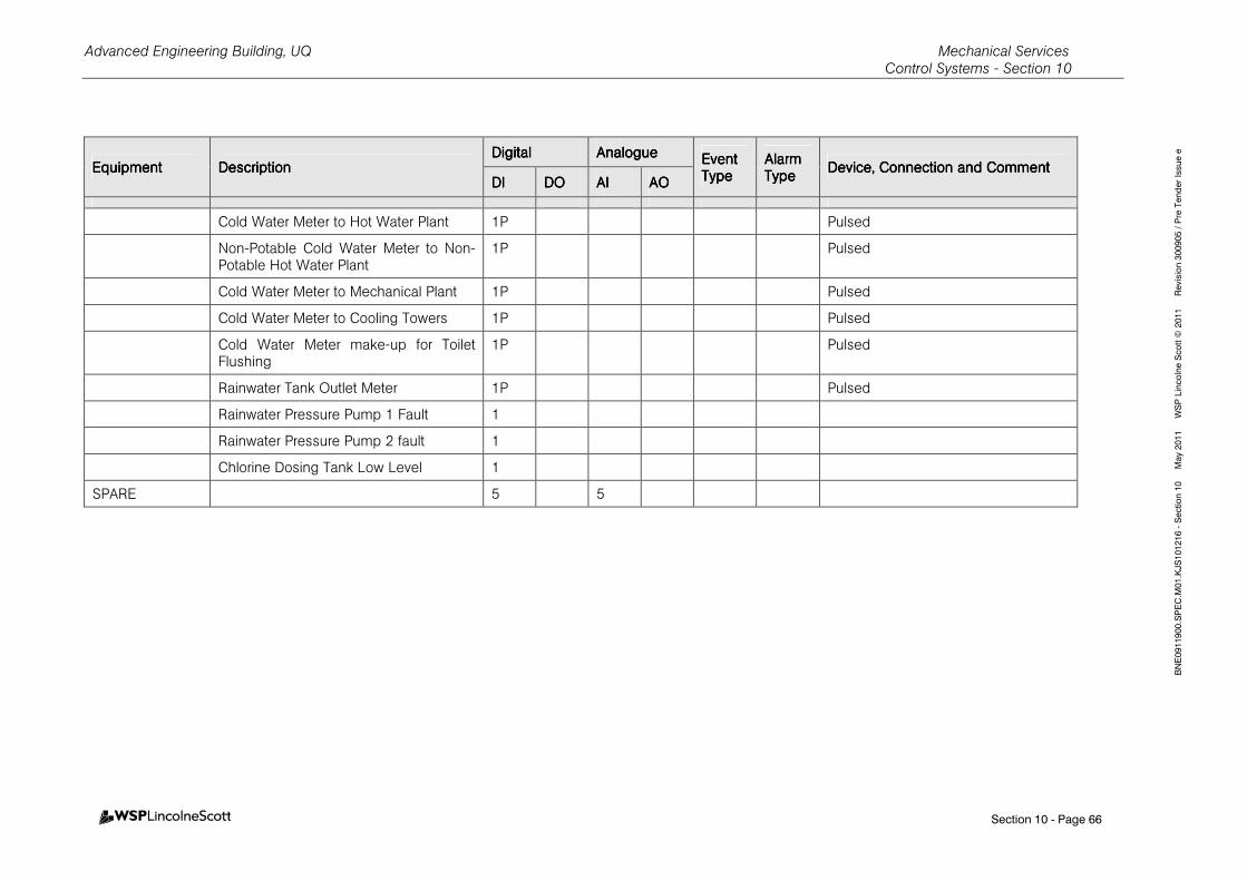
Advanced Engineering Building, UQ Mechanical Services Control Systems - Section 10
Section 10 - Page 66
BNE0911900.SPEC.M01.KJS101216 - Section 10 May 2011 WSP Lincolne Scott © 2011 Revision 300905 / Pre Tender Issue e
EquipmentEquipmentEquipmentEquipment DescriptionDescriptionDescriptionDescription DigitalDigitalDigitalDigital AnalogueAnalogueAnalogueAnalogue Event Event Event Event
TypeTypeTypeType Alarm Alarm Alarm Alarm TypeTypeTypeType
Device, Connection and CommentDevice, Connection and CommentDevice, Connection and CommentDevice, Connection and Comment DIDIDIDI DODODODO AIAIAIAI AOAOAOAO
Cold Water Meter to Hot Water Plant 1P Pulsed
Non-Potable Cold Water Meter to Non-Potable Hot Water Plant
1P Pulsed
Cold Water Meter to Mechanical Plant 1P Pulsed
Cold Water Meter to Cooling Towers 1P Pulsed
Cold Water Meter make-up for Toilet Flushing
1P Pulsed
Rainwater Tank Outlet Meter 1P Pulsed
Rainwater Pressure Pump 1 Fault 1
Rainwater Pressure Pump 2 fault 1
Chlorine Dosing Tank Low Level 1
SPARE 5 5
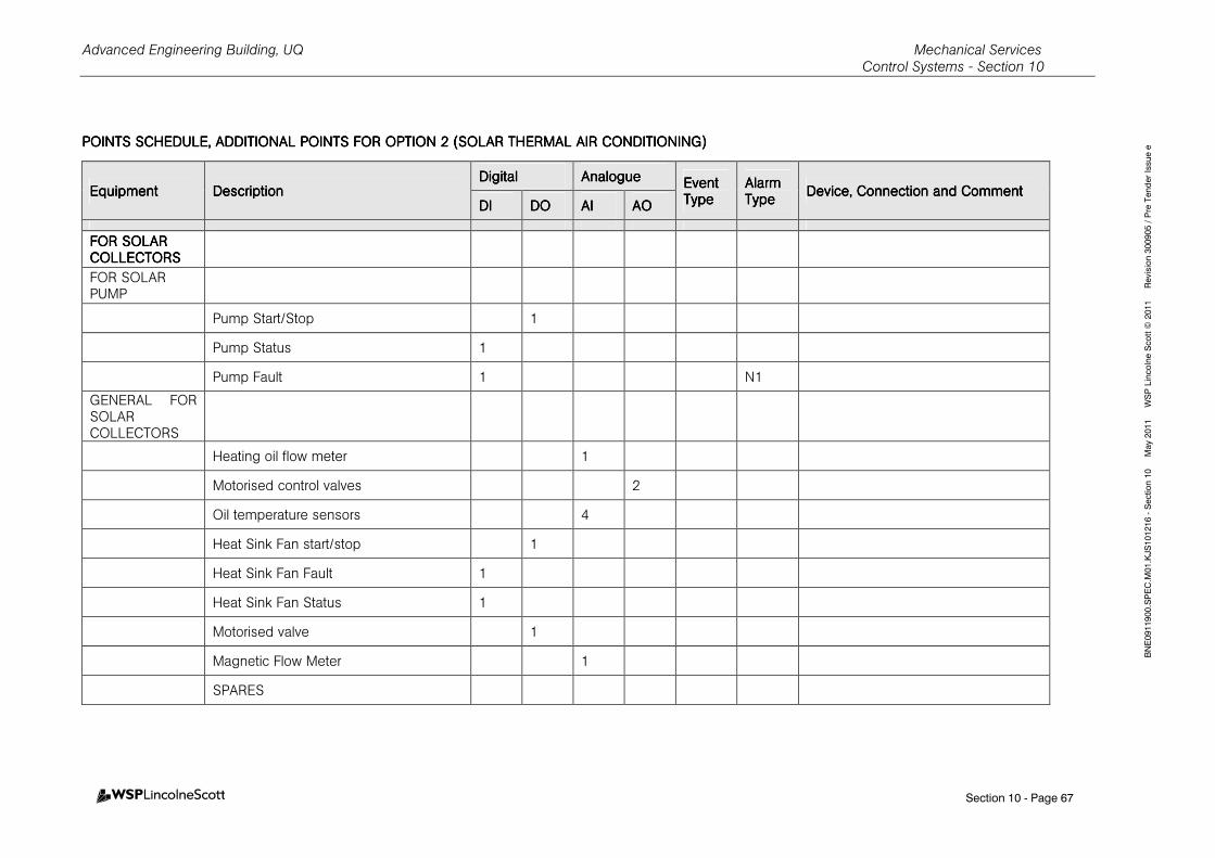
Advanced Engineering Building, UQ Mechanical Services Control Systems - Section 10
Section 10 - Page 67
BNE0911900.SPEC.M01.KJS101216 - Section 10 May 2011 WSP Lincolne Scott © 2011 Revision 300905 / Pre Tender Issue e POINTS SCHEDULE, POINTS SCHEDULE, POINTS SCHEDULE, POINTS SCHEDULE, ADDITIONAL POINTS FOADDITIONAL POINTS FOADDITIONAL POINTS FOADDITIONAL POINTS FOR OPTION R OPTION R OPTION R OPTION 2222 (SOLAR THERMAL AIR C(SOLAR THERMAL AIR C(SOLAR THERMAL AIR C(SOLAR THERMAL AIR CONDITIONINONDITIONINONDITIONINONDITIONING)G)G)G)
EquipmentEquipmentEquipmentEquipment DescriptionDescriptionDescriptionDescription DigitalDigitalDigitalDigital AnalogueAnalogueAnalogueAnalogue Event Event Event Event
TypeTypeTypeType Alarm Alarm Alarm Alarm TypeTypeTypeType
Device, Connection and CommentDevice, Connection and CommentDevice, Connection and CommentDevice, Connection and Comment DIDIDIDI DODODODO AIAIAIAI AOAOAOAO
FOR SOLAR FOR SOLAR FOR SOLAR FOR SOLAR COLLECTORSCOLLECTORSCOLLECTORSCOLLECTORS
FOR SOLAR PUMP
Pump Start/Stop 1
Pump Status 1
Pump Fault 1 N1
GENERAL FOR SOLAR COLLECTORS
Heating oil flow meter 1
Motorised control valves 2
Oil temperature sensors 4
Heat Sink Fan start/stop 1
Heat Sink Fan Fault 1
Heat Sink Fan Status 1
Motorised valve 1
Magnetic Flow Meter 1
SPARES
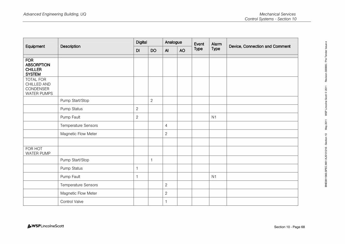
Advanced Engineering Building, UQ Mechanical Services Control Systems - Section 10
Section 10 - Page 68
BNE0911900.SPEC.M01.KJS101216 - Section 10 May 2011 WSP Lincolne Scott © 2011 Revision 300905 / Pre Tender Issue e
EquipmentEquipmentEquipmentEquipment DescriptionDescriptionDescriptionDescription DigitalDigitalDigitalDigital AnalogueAnalogueAnalogueAnalogue Event Event Event Event
TypeTypeTypeType Alarm Alarm Alarm Alarm TypeTypeTypeType
Device, Connection and CommentDevice, Connection and CommentDevice, Connection and CommentDevice, Connection and Comment DIDIDIDI DODODODO AIAIAIAI AOAOAOAO
FOR FOR FOR FOR ABSORPTION ABSORPTION ABSORPTION ABSORPTION CHILLERCHILLERCHILLERCHILLER SYSTEMSYSTEMSYSTEMSYSTEM
TOTAL FOR CHILLED AND CONDENSER WATER PUMPS
Pump Start/Stop 2
Pump Status 2
Pump Fault 2 N1
Temperature Sensors 4
Magnetic Flow Meter 2
FOR HOT WATER PUMP
Pump Start/Stop 1
Pump Status 1
Pump Fault 1 N1
Temperature Sensors 2
Magnetic Flow Meter 2
Control Valve 1
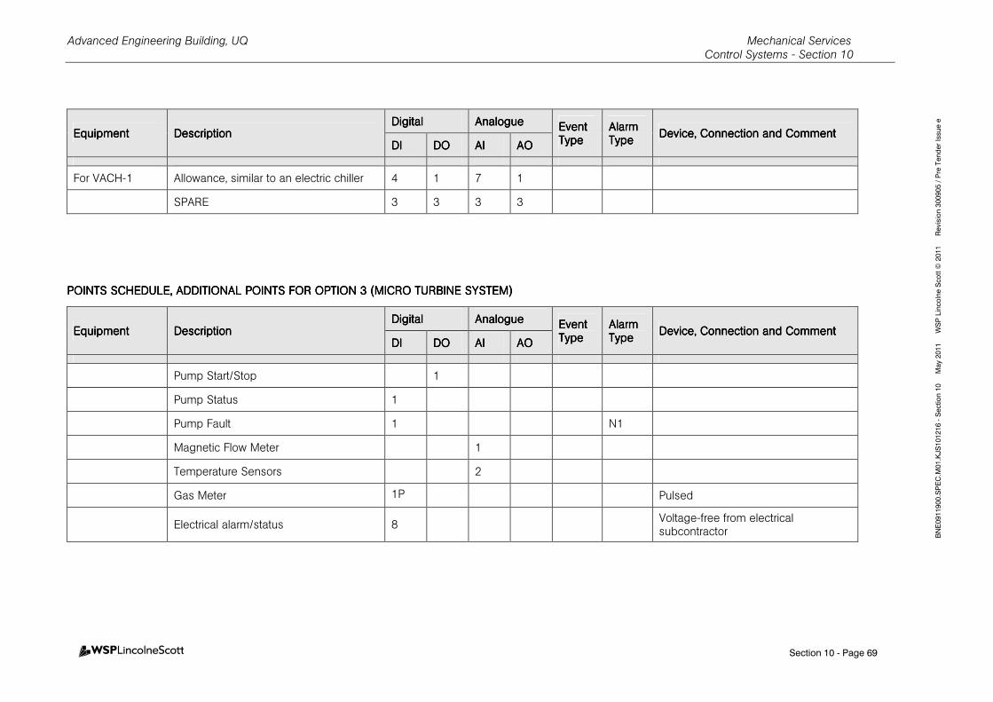
Advanced Engineering Building, UQ Mechanical Services Control Systems - Section 10
Section 10 - Page 69
BNE0911900.SPEC.M01.KJS101216 - Section 10 May 2011 WSP Lincolne Scott © 2011 Revision 300905 / Pre Tender Issue e
EquipmentEquipmentEquipmentEquipment DescriptionDescriptionDescriptionDescription DigitalDigitalDigitalDigital AnalogueAnalogueAnalogueAnalogue Event Event Event Event
TypeTypeTypeType Alarm Alarm Alarm Alarm TypeTypeTypeType
Device, Connection and CommentDevice, Connection and CommentDevice, Connection and CommentDevice, Connection and Comment DIDIDIDI DODODODO AIAIAIAI AOAOAOAO
For VACH-1 Allowance, similar to an electric chiller 4 1 7 1
SPARE 3 3 3 3
POINTS SCHEDULE, POINTS SCHEDULE, POINTS SCHEDULE, POINTS SCHEDULE, ADDITIONAL POINTS FOADDITIONAL POINTS FOADDITIONAL POINTS FOADDITIONAL POINTS FOR OPTION 3R OPTION 3R OPTION 3R OPTION 3 (MICRO TURBINE SYSTE(MICRO TURBINE SYSTE(MICRO TURBINE SYSTE(MICRO TURBINE SYSTEM)M)M)M)
EquipmentEquipmentEquipmentEquipment DescriptionDescriptionDescriptionDescription DigitalDigitalDigitalDigital AnalogueAnalogueAnalogueAnalogue Event Event Event Event
TypeTypeTypeType Alarm Alarm Alarm Alarm TypeTypeTypeType
Device, Connection and CommentDevice, Connection and CommentDevice, Connection and CommentDevice, Connection and Comment DIDIDIDI DODODODO AIAIAIAI AOAOAOAO
Pump Start/Stop 1
Pump Status 1
Pump Fault 1 N1
Magnetic Flow Meter 1
Temperature Sensors 2
Gas Meter 1P Pulsed
Electrical alarm/status 8 Voltage-free from electrical subcontractor
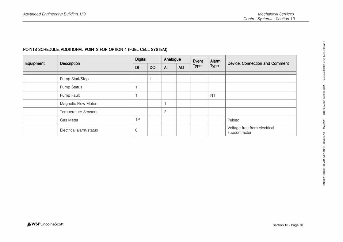
Advanced Engineering Building, UQ Mechanical Services Control Systems - Section 10
Section 10 - Page 70
BNE0911900.SPEC.M01.KJS101216 - Section 10 May 2011 WSP Lincolne Scott © 2011 Revision 300905 / Pre Tender Issue e
POINTS SCHEDULE, POINTS SCHEDULE, POINTS SCHEDULE, POINTS SCHEDULE, ADDITIONAL POINTS FOADDITIONAL POINTS FOADDITIONAL POINTS FOADDITIONAL POINTS FOR OPTION 4R OPTION 4R OPTION 4R OPTION 4 ((((FUEL CELL SYSTEM)FUEL CELL SYSTEM)FUEL CELL SYSTEM)FUEL CELL SYSTEM)
EquipmentEquipmentEquipmentEquipment DescriptionDescriptionDescriptionDescription DigitalDigitalDigitalDigital AnalogueAnalogueAnalogueAnalogue Event Event Event Event
TypeTypeTypeType Alarm Alarm Alarm Alarm TypeTypeTypeType
Device, Connection and CommentDevice, Connection and CommentDevice, Connection and CommentDevice, Connection and Comment DIDIDIDI DODODODO AIAIAIAI AOAOAOAO
Pump Start/Stop 1
Pump Status 1
Pump Fault 1 N1
Magnetic Flow Meter 1
Temperature Sensors 2
Gas Meter 1P Pulsed
Electrical alarm/status 6 Voltage-free from electrical subcontractor
Advanced Engineering Building, UQ Mechanical Services
Noise and Vibration - Section 11
Table of Contents - Page 1
BNE0911900.SPEC.M01.KJS101203- Section 11 May 2011 WSP Lincolne Scott © 2011 Revision 310807/ Construction Issue
11. NOISE AND VIBRATION 1
11.1 GENERAL 1
11.1.1 Scope 1
11.1.2 Referenced Documents 1
11.2 DESIGN 2
11.2.1 General 2
11.2.2 Authority Standards and Codes 2
11.3 SUBMISSIONS 2
11.4 GENERAL REQUIREMENTS 2
11.5 INFORMATION REQUIRED 2
11.6 VIBRATION CONTROL 2
11.6.1 Acceptance Criteria 2
11.6.2 Spring Mounts 3
11.6.3 Neoprene Pads 3
11.6.4 Anti-Vibration Hangers 3
11.7 INERTIA BASES AND PLINTHS 3
11.7.1 Inertia Bases 3
11.7.2 Plinths 3
11.8 NOISE MEASUREMENTS 3

Advanced Engineering Building, UQ Mechanical Services
Noise and Vibration - Section 11
Section 11 - Page 1
BNE0911900.SPEC.M01.KJS101203- Section 11 May 2011 WSP Lincolne Scott © 2011 Revision 310807/ Construction Issue
11. NOISE AND VIBRATION
11.1 GENERAL
11.1.1 Scope
a) This section sets out the engineering and quality assurance requirements for the
completion of the installation design, materials, components, general installation and
testing of the Mechanical Services noise and vibration.
b) Refer to Schedule of Vibration Isolation and Schedule of Sound Levels for design
criteria.
c) This section is to be read in conjunction with all other sections of this specification.
11.1.2 Referenced Documents
Details of documents applicable to this section of the specification include:
Australian/New Zealand Standards
AS 1045–1988 Acoustics - Measurement of sound absorption in a
reverberation room (ISO 354) AS 1055.1-1997 Acoustics - Description and measurement of environmental
noise - General Procedures AS 1081.1-1991 Acoustics - Measurement of airborne noise emitted by rotating
electrical machinery AS 1170.4–1993 Earthquake loads AS 1217.1-1985 Acoustics - Determination of sound power levels of noise
sources AS 1359.0-1998 Acoustics - Sound level meters AS 1469–1983 Acoustics - Methods for the determination of noise rating
numbers AS 2625.1-2003 Rotating and reciprocating machinery - Mechanical vibration AS IEC 61672.1-2004 Electroacoustics - Sound level meters - Specifications
AS IEC 61672.2-2004 Electroacoustics - Sound level meters - Pattern evaluation tests
Advanced Engineering Building, UQ Mechanical Services
Noise and Vibration - Section 11
Section 11 - Page 2
BNE0911900.SPEC.M01.KJS101203- Section 11 May 2011 WSP Lincolne Scott © 2011 Revision 310807/ Construction Issue
11.2 DESIGN
11.2.1 General
Complete the detail design and engineering of the noise and vibration to the specified
requirements.
11.2.2 Authority Standards and Codes
Comply with applicable authority design guidelines and codes of practice and requirements.
11.3 SUBMISSIONS
a) Details of each type of vibration isolation.
11.4 GENERAL REQUIREMENTS
a) Acoustically seal pipe, duct and cable penetrations through plantrooms and noise
rated walls, floors and acoustic enclosures.
b) Statically and dynamically balance rotating machinery.
c) Support rotating and reciprocating equipment on anti-vibration/vibration absorbing
mounts or hangers as specified in schedules and shown on drawings.
d) Inertia bases/ as specified herein and shown on the drawings.
e) All static equipment in plantrooms with suspended floors to be separated from the
structure with double thickness neoprene pads or equal.
f) All connections to rotating equipment or assemblies containing rotating equipment
shall be rendered flexible by anti-vibration hangers supporting ductwork and pipework
and/or by flexible connections as specified.
g) Plinths for all floor mounted equipment.
11.5 INFORMATION REQUIRED
a) Provide the following:
I. Noise measurements.
II. Vibration measurements.
III. Vibration signatures.
IV. Evidence of calibration of testing equipment.
V. Qualifications of person/organisation conducting testing/measurements.
11.6 VIBRATION CONTROL
11.6.1 Acceptance Criteria
a) Complete systems including individual components not to exceed satisfactory levels
as set out in AS 1359.0 and AS 2625.1.
b) Select anti-vibration mounts/hangers for life cycle of building and install in accordance
with the requirements of the Earthquake Code AS 1170.4.
c) Select and install anti-vibration mounts and hangers in locations to prevent
transmission of vibration to adjoining areas and to prevent undue vibration, distortion
or fatigue of equipment and connecting piping and cabling.
Advanced Engineering Building, UQ Mechanical Services
Noise and Vibration - Section 11
Section 11 - Page 3
BNE0911900.SPEC.M01.KJS101203- Section 11 May 2011 WSP Lincolne Scott © 2011 Revision 310807/ Construction Issue
d) Select vibration isolation mounts/hangers to allow for deflections of building structures
and finishes and for minimum static deflection as specified.
11.6.2 Spring Mounts
a) Free standing and positioned for uniform deflection of all springs.
b) Spring mounting plates and frames hot dip galvanised.
c) Ratio of mean coil diameter to compressed length at specified static deflection of 0.8.
d) Minimum additional travel to solid of 50%.
e) Holding down bolts to be provided.
f) Surge frequency to be beyond 30% of predominant machine frequency of vibration.
11.6.3 Neoprene Pads
a) Use up to 9mm static deflection.
b) Loading not greater than 400kPa.
11.6.4 Anti-Vibration Hangers
a) Spring and double neoprene cup type in series.
b) Total hanger deflection 25mm minimum.
c) Provide secondary adjustment to transfer load to spring.
11.7 INERTIA BASES AND PLINTHS
11.7.1 Inertia Bases
a) Rigid fabricated steel frame, concrete filled.
b) Steel frame fabricated from 1.55mm minimum thickness folded steel for equipment up
to 450kg in weight and from rolled steel channels for equipment above 450kg in
weight. Steel base to be rigid and to have reinforcing mesh tack welded inside full
area of frame before concrete poured.
c) Total thickness of inertia base 150mm.
d) Total weight not less than 1.5 times equipment weight.
11.7.2 Plinths
a) Rigid fabricated steel surround and concrete filled.
b) Surround fabricated from 1.15mm thick galvanised steel sheet.
11.8 NOISE MEASUREMENTS
a) Allow to Measure and submit noise measurements in twenty (20) nominated areas
using sound level meter complying with AS IEC 61672.1 and .2 during the noisiest
operating condition. Areas to be identified during commissioning by the
Superintendent
b) Where noise measurements exceed specified criteria, take additional noise readings
in each octave band (125Hz to 4000Hz inclusive) in selected locations with reference
to AS 1045, AS 1055.1, AS 1081.1, AS 1217.1 and AS 1469.
Advanced Engineering Building, UQ Mechanical Services
Painting and Identification - Section 12
Table of Contents - Page 1
BNE0911900.SPEC.M01.KJS101203 - Section 12 May 2011 WSP Lincolne Scott © 2011 Revision 310807 / Construction Issue
12.12.12.12. PPPPAINTING AND AINTING AND AINTING AND AINTING AND IIIIDENTIFICATIONDENTIFICATIONDENTIFICATIONDENTIFICATION 1
12.112.112.112.1 GENERALGENERALGENERALGENERAL 1
12.1.1 Scope 1
12.1.2 Referenced Documents 1
12.212.212.212.2 DESIGNDESIGNDESIGNDESIGN 1
12.2.1 General 1
12.2.2 Authority Standards and Codes 2
12.312.312.312.3 SUBMISSIONSSUBMISSIONSSUBMISSIONSSUBMISSIONS 2
12.412.412.412.4 GENERAL REGENERAL REGENERAL REGENERAL REQUIREMENTSQUIREMENTSQUIREMENTSQUIREMENTS 2
12.512.512.512.5 PAINTINGPAINTINGPAINTINGPAINTING 2
12.5.1 General Requirements 2
12.5.2 Preparation of surfaces 3
12.5.3 Application 3
12.5.4 Finishing 3
12.612.612.612.6 GREEN STAR REQUIREMEGREEN STAR REQUIREMEGREEN STAR REQUIREMEGREEN STAR REQUIREMENTSNTSNTSNTS 3
12.712.712.712.7 COLOURSCOLOURSCOLOURSCOLOURS 4
12.812.812.812.8 IDENTIFICATION AND LIDENTIFICATION AND LIDENTIFICATION AND LIDENTIFICATION AND LABELLINGABELLINGABELLINGABELLING 4
12.8.1 General 4
12.8.2 Labels 4
12.8.3 Pipework and Ductwork 4
12.8.4 Equipment 5
12.8.5 Terminal Units 6
12.8.6 Isolation Valve Boxes 6
12.8.7 Isolation Valve Points 6
12.8.8 Alarm Panels 6
12.8.9 Bottle Store 6
12.8.10 Minimum Lettering Heights 7
12.8.11 Sign Writing Abbreviations 7
Advanced Engineering Building, UQ Mechanical Services
Painting and Identification - Section 12
Section 12 - Page 1
BNE0911900.SPEC.M01.KJS101203 - Section 12 May 2011 WSP Lincolne Scott © 2011 Revision 310807 / Construction Issue
12.12.12.12. PPPPAINTING AND AINTING AND AINTING AND AINTING AND IIIIDENTIFICATIONDENTIFICATIONDENTIFICATIONDENTIFICATION
12.112.112.112.1 GENERALGENERALGENERALGENERAL
12.1.112.1.112.1.112.1.1 ScopeScopeScopeScope
a) This section sets out the engineering and quality assurance requirements for the completion of materials, components and general application for painting, identification and labelling of the Mechanical Services installation. Final finishes selections shall be in accordance with the Superintendent’s approval, and may not comply with the University of Queensland Technical Guideline TG13.
b) Refer to Schedules for design criteria.
c) Provide identification and labelling of all equipment, valves, and control items exposed to view or concealed including:
I. System and equipment designations.
II. Critical Systems labelling.
III. Essential Services labelling.
IV. Plant maintenance and operating and emergency signage.
V. Statutory signage, including occupational health and safety signage, hazardous chemical signage.
d) This section is to be read in conjunction with all other sections of this specification.
12.1.212.1.212.1.212.1.2 Referenced DocumentsReferenced DocumentsReferenced DocumentsReferenced Documents
Details of documents applicable to this section of the specification include:
Australian/New Zealand StandardsAustralian/New Zealand StandardsAustralian/New Zealand StandardsAustralian/New Zealand Standards
AS 1318-1985 Use of colour for the marking of physical hazards and
the identification of certain equipment in industry
AS 1345-1995 Identification of the contents of pipes, conduits and
ducts
AS 2310 Glossary of paint and painting terms
AS/NZS 2311-2000 Guide to the painting of buildings
AS/NZS 2312-2002/Amdt 1-2004 Guide to the protection of iron and steel against
exterior atmospheric corrosion
AS 2700-1996 Colour standards for general purposes
Codes Codes Codes Codes
HB24-1992 Symbols and abbreviations for building and construction
12.212.212.212.2 DESIGNDESIGNDESIGNDESIGN
12.2.112.2.112.2.112.2.1 GeneralGeneralGeneralGeneral
a) Select painting and finishes in accordance with the area environmental conditions.
b) Review the risk assessment and statutory and authority requirements completed as part of the system testing, commissioning and handover requirements and provide labelling and signage as determined.
Advanced Engineering Building, UQ Mechanical Services
Painting and Identification - Section 12
Section 12 - Page 2
BNE0911900.SPEC.M01.KJS101203 - Section 12 May 2011 WSP Lincolne Scott © 2011 Revision 310807 / Construction Issue
12.2.212.2.212.2.212.2.2 Authority Standards and CodesAuthority Standards and CodesAuthority Standards and CodesAuthority Standards and Codes
a) Comply with applicable Federal, State and Territory Authority design guidelines and codes of practice and requirements, including those relating to:
I. BCA Essential Services.
II. Pressure Vessels.
III. Occupational Health and Safety.
IV. Hazardous Materials.
V. Environment Protection.
12.312.312.312.3 SUBMISSIONSSUBMISSIONSSUBMISSIONSSUBMISSIONS
a) Provide the following submissions:
I. Paint Systems and colour schedule to be used, including VOC content.
II. Labelling Systems.
III. Schedule of statutory, maintenance and operating signage.
IV. Material Safety Data Sheets for the products proposed.
12.412.412.412.4 GENERAL REQUIREMENTSGENERAL REQUIREMENTSGENERAL REQUIREMENTSGENERAL REQUIREMENTS
a) Comply with AS/NZS 2311, AS/NZS 2312, AS 1345 and AS 2896.
b) Fabricated pipe and steelwork shall be delivered to site prime coated.
c) All surfaces shall be fully finish painted, except ductwork and pipework concealed in inaccessible risers or if stainless steel.
d) Concealed pipe work to be prime coated.
e) Exclusions: Do not paint chromium, anodised aluminium, GRP, uPVC, stainless steel, hot dipped galvanising, foil faced insulation, non-metallic flexible materials, normally lubricated machine surfaces such as pump shafts and valve stems, and equipment nameplates.
f) Inclusions: Paint supports, brackets and hangers. Prime uncoated steel in all locations
g) Protect all items of work during dispatch and whilst on site during progress of installation.
h) Where ductwork exposed to view is not specified to be painted, all factory and installation markings shall be removed.
i) Undertake a final audit at the end of construction works to ensure the correct products have been used.
12.512.512.512.5 PAINTINGPAINTINGPAINTINGPAINTING
12.5.112.5.112.5.112.5.1 General RequirementsGeneral RequirementsGeneral RequirementsGeneral Requirements
a) Provide suitable systems as recommended by established manufacturers (premium quality lines).
b) Painting System: Do not combine paints from different manufacturers in a paint system.
c) Protection: Remove or protect fixtures, equipment, surfaces and labels before starting to paint, and re-instate after completion of painting.
d) Internal surfaces: all internal surfaces of air outlets and openings exposed to view shall be painted matt black to approval.
e) Repair factory finishes if damaged.
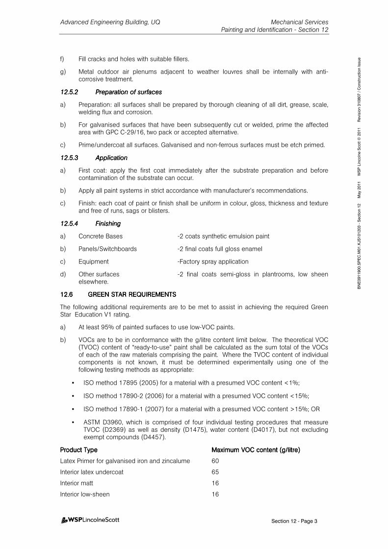
Advanced Engineering Building, UQ Mechanical Services
Painting and Identification - Section 12
Section 12 - Page 3
BNE0911900.SPEC.M01.KJS101203 - Section 12 May 2011 WSP Lincolne Scott © 2011 Revision 310807 / Construction Issue
f) Fill cracks and holes with suitable fillers.
g) Metal outdoor air plenums adjacent to weather louvres shall be internally with anti-corrosive treatment.
12.5.212.5.212.5.212.5.2 Preparation of surfacesPreparation of surfacesPreparation of surfacesPreparation of surfaces
a) Preparation: all surfaces shall be prepared by thorough cleaning of all dirt, grease, scale, welding flux and corrosion.
b) For galvanised surfaces that have been subsequently cut or welded, prime the affected area with GPC C-29/16, two pack or accepted alternative.
c) Prime/undercoat all surfaces. Galvanised and non-ferrous surfaces must be etch primed.
12.5.312.5.312.5.312.5.3 ApplicationApplicationApplicationApplication
a) First coat: apply the first coat immediately after the substrate preparation and before contamination of the substrate can occur.
b) Apply all paint systems in strict accordance with manufacturer’s recommendations.
c) Finish: each coat of paint or finish shall be uniform in colour, gloss, thickness and texture and free of runs, sags or blisters.
12.5.412.5.412.5.412.5.4 FinishingFinishingFinishingFinishing
a) Concrete Bases -2 coats synthetic emulsion paint
b) Panels/Switchboards -2 final coats full gloss enamel
c) Equipment -Factory spray application
d) Other surfaces -2 final coats semi-gloss in plantrooms, low sheen elsewhere.
12.612.612.612.6 GREEN STAR REQUIREMEGREEN STAR REQUIREMEGREEN STAR REQUIREMEGREEN STAR REQUIREMENTSNTSNTSNTS
The following additional requirements are to be met to assist in achieving the required Green Star Education V1 rating.
a) At least 95% of painted surfaces to use low-VOC paints.
b) VOCs are to be in conformance with the g/litre content limit below. The theoretical VOC (TVOC) content of “ready-to-use” paint shall be calculated as the sum total of the VOCs of each of the raw materials comprising the paint. Where the TVOC content of individual components is not known, it must be determined experimentally using one of the following testing methods as appropriate:
• ISO method 17895 (2005) for a material with a presumed VOC content <1%;
• ISO method 17890-2 (2006) for a material with a presumed VOC content <15%;
• ISO method 17890-1 (2007) for a material with a presumed VOC content >15%; OR
• ASTM D3960, which is comprised of four individual testing procedures that measure TVOC (D2369) as well as density (D1475), water content (D4017), but not excluding exempt compounds (D4457).
Product TypeProduct TypeProduct TypeProduct Type Maximum VOC content (g/litre)Maximum VOC content (g/litre)Maximum VOC content (g/litre)Maximum VOC content (g/litre)
Latex Primer for galvanised iron and zincalume 60
Interior latex undercoat 65
Interior matt 16
Interior low-sheen 16
Advanced Engineering Building, UQ Mechanical Services
Painting and Identification - Section 12
Section 12 - Page 4
BNE0911900.SPEC.M01.KJS101203 - Section 12 May 2011 WSP Lincolne Scott © 2011 Revision 310807 / Construction Issue
Interior semi-gloss 16
For solvent-based coatings for purposes not listed above the paint shall not contain VOCs in excess of 200g/litre.
c) The contractor is required to obtain approval from WSPLS or client before substituting the finishes listed in the schedule above.
d) At the end of construction works, it is required that the contractor undertakes a final audit to ensure that the correct products have been used.
12.712.712.712.7 COLOURSCOLOURSCOLOURSCOLOURS
All to be painted a selected “white” – refer to Superintendent for confirmation. Prior to painting any item obtain confirmation of correct colour/labelling scheme.
12.812.812.812.8 IDENTIFICATION AND LIDENTIFICATION AND LIDENTIFICATION AND LIDENTIFICATION AND LABELLINGABELLINGABELLINGABELLING
12.8.112.8.112.8.112.8.1 GeneralGeneralGeneralGeneral
a) Mark all systems and equipment including wiring, piping, ductwork, conduits, controls, gauges and fittings to that they are readily identifiable.
b) Locate labels so that they are easily seen and either attached to, below or next to item referred.
c) Labelling to match installation documentation schedules.
d) Equipment and Service labels shall be in accordance with the Legend Of Symbols nomenclature for the respective service.
e) Refer to Electrical Services for Mechanical Plant for switchboard labelling requirements.
12.8.212.8.212.8.212.8.2 LabelsLabelsLabelsLabels
a) Labels shall be permanent.
b) Labelling generally shall match To UQ Technical Guidelines TG-13 and Architectural Approval.
c) Type: select from the following:
I. Engraved and black filled lettering on stainless steel or brass plate, minimum 1mm thick mechanically fixed.
II. Stencil with black or white lettering contrasting with background.
III. Engraved two-colour laminated plastic mechanically fixed.
IV. Adhesive labelling.
V. Painted.
d) Adhesive labels and laminated plastic labels shall not be used where exposed to the environment.
e) Painted labels shall be in the same finish paint type as the installation.
12.8.312.8.312.8.312.8.3 PipewoPipewoPipewoPipework and Ductworkrk and Ductworkrk and Ductworkrk and Ductwork
GeneralGeneralGeneralGeneral
a) Provide painted or adhesive labelling in accordance with AS 1345.
b) For systems containing hazardous materials provide labelling in accordance with AS 1318.
Advanced Engineering Building, UQ Mechanical Services
Painting and Identification - Section 12
Section 12 - Page 5
BNE0911900.SPEC.M01.KJS101203 - Section 12 May 2011 WSP Lincolne Scott © 2011 Revision 310807 / Construction Issue
c) Labelling shall indicate system, contents and direction of flow.
d) Where a pipe or duct passes through a wall, slab or partition provide labelling each side.
e) Spacing of pipe bands: maximum 3m plant areas, maximum 8m elsewhere and at each level vertically at all branches.
Gas ServicesGas ServicesGas ServicesGas Services
a) Identified at all junctions, terminations, control points, both sides of bulkheads and wall penetrations.
b) Spacing of pipe bands: 3 m throughout pipe length.
c) Indicate direction of flow, each side of a safety band
d) Banding of not less than 70mm width. Coloured as specified for the valve end of medical gas cylinders in AS 1944 and the name of the particular gas distributed.
e) Lettering size not less than 4mm high.
f) Durable to last expected service life.
12.8.412.8.412.8.412.8.4 EquipmentEquipmentEquipmentEquipment
GeneralGeneralGeneralGeneral
a) All items of equipment such as chillers, pumps, fans, air handling units, calorifiers and similar items shall be labelled in accordance with the specification abbreviations, symbols and acronyms scheduled or otherwise approved.
b) Label all equipment, instruments, indicators, gauges switches and valves.
c) Equipment requiring special maintenance procedures or presenting occupational health and safety hazards: provide permanent labels complying with statutory requirements.
d) Equipment requiring consumables including replacement belts, oils, filters and strainers: provide labels indicating consumable component details and quantities and corrective maintenance trigger point such as filter pressure drop.
e) Valves: Labels shall be colour coded laminated labels indicating service, function and normal position, and attached to hand wheels or spindles using a vandal resistant permanent chain/ring.
Gas ServicesGas ServicesGas ServicesGas Services
a) Label all operating equipment, instruments, indicators, gauges switches and valves
b) Compressor and suction pump label “Caution - This machine is remotely controlled and starts without warning”.
c) Labels to be waterproof and permanent
d) Lettering size 32mm minimum
e) Located for easy identification
f) Switchboard labelling may be 6mm subject to approval
g) On valves, labels may be attached to hand wheels or spindles using a vandal free permanent chain/ring.
h) All items of equipment such as compressors, vacuum pumps, air receivers and similar items shall be labelled in accordance with the symbolism and equipment identification used throughout this Specification and Drawings or otherwise to approval.
i) Provide coloured sectors to identify acceptable ranges on all gauges.
Advanced Engineering Building, UQ Mechanical Services
Painting and Identification - Section 12
Section 12 - Page 6
BNE0911900.SPEC.M01.KJS101203 - Section 12 May 2011 WSP Lincolne Scott © 2011 Revision 310807 / Construction Issue
j) Paint yellow safety access clearways on plantroom floor.
12.8.512.8.512.8.512.8.5 Terminal UnitsTerminal UnitsTerminal UnitsTerminal Units
a) Permanent identification with background colour coding and lettering as per AS 2896.
b) Legible at a distance of 4m.
c) 3mm high letters on all gas specific components.
12.8.612.8.612.8.612.8.6 Isolation Valve BoxesIsolation Valve BoxesIsolation Valve BoxesIsolation Valve Boxes
a) Labelled in accordance with the symbolism identification used throughout this Specification and drawings.
b) All valves labelled with the name of the gas and area served.
c) “Do not close”: caution label.
d) Lettering size 6mm minimum.
e) Colour coded to suit medical gas system served.
12.8.712.8.712.8.712.8.7 Isolation Valve PointsIsolation Valve PointsIsolation Valve PointsIsolation Valve Points
a) Identification clearly labelled on ceiling access point.
b) Label attached to valve spindle using a vandal free permanent chain/ring.
12.8.812.8.812.8.812.8.8 Alarm PanelsAlarm PanelsAlarm PanelsAlarm Panels
a) Instruction detailing action required in event of alarm condition prominently displayed next to alarm.
b) Labelled in accordance with the symbolism identification used throughout this Specification and drawings.
12.8.912.8.912.8.912.8.9 Bottle StoreBottle StoreBottle StoreBottle Store
a) Maximum working pressure of each gas manifold on each control panel and on all detachable components.
b) Working pressure and date of test on all cylinder leads.
c) Paint bottle storage shelving.
d) Prominent signs displaying:
e) Danger - compressed gases
f) No smoking or naked light
g) No entry - Authorised persons only
h) No oil or grease
i) No combustible material to be placed within 5m
j) The maximum working pressure of the gas control system
k) Notice containing main safety instructions and list of emergency procedures.
l) External weatherproof sign showing telephone numbers for:
I. Fire Brigade
II. Gas Supplier
III. Police
IV. Appropriate facility personnel
Advanced Engineering Building, UQ Mechanical Services
Painting and Identification - Section 12
Section 12 - Page 7
BNE0911900.SPEC.M01.KJS101203 - Section 12 May 2011 WSP Lincolne Scott © 2011 Revision 310807 / Construction Issue
m) Provide clearly visible engraved panels indicating type of gas to storage compartments and racks. In addition, indicate empty or full for storage compartments.
n) Provide each manifold system with appropriate instructions for operation of the system and replacement of cylinders.
o) Wall mounted simplified schematic diagram indicating key features to assist in emergency. Protect with clear glass or perspex.
p) Paint yellow safety access clearways on the floor.
12.8.1012.8.1012.8.1012.8.10 MinimMinimMinimMinimuuuum Lettering Heightsm Lettering Heightsm Lettering Heightsm Lettering Heights
a) Major equipment nameplates: 40mm.
b) Minor equipment nameplates: 20mm.
c) Main switches: 10mm.
d) Outgoing electrical functional units: 8mm.
e) Danger, warning and caution notices: 10mm for heading, 5mm for test.
f) Warning notices: 7mm.
g) Automatic controls electrical equipment and instruments: 5mm.
h) Rear covers of mechanical services switchboards: 5mm.
i) Components inside electrical enclosures and control panels: 3.5mm.
j) Minor lettering: 3mm.
k) Lettering Style: Helvetica Medium.
l) Location: Locate labels so that they are easily seen from normal access adjacent to the item being marked. Do not install labels on components normally removed or replaced.
m) Exposed locations: Provide durable materials.
n) Fixing: Use mechanical fixings. Do not penetrate isolation vapour barriers.
o) In addition to the above, 80mm minimum length safety bands of golden yellow No. 3E with black vertical stripes shall be provided when the pipe or duct contains:
I. Toxic substances
II. Acids and alkali in dangerous concentrations
p) Equipment requiring special maintenance procedures or presenting occupational health and safety hazards shall be provided with permanent labels; for instance chiller anti-rise spring mount instructions, maintenance isolation procedure, etc.
12.8.1112.8.1112.8.1112.8.11 Sign Writing AbbreviationsSign Writing AbbreviationsSign Writing AbbreviationsSign Writing Abbreviations
The following abbreviations shall be used for sign writing purposes unless otherwise agreed.
Chilled Water CHW
Condenser Water CCW
Heating Water HHW
Domestic Hot Water DHW
Refrigerant R & Number
Drain DRN
Advanced Engineering Building, UQ Mechanical Services
Painting and Identification - Section 12
Section 12 - Page 8
BNE0911900.SPEC.M01.KJS101203 - Section 12 May 2011 WSP Lincolne Scott © 2011 Revision 310807 / Construction Issue
Vent VNT
Nitrogen N
Helium H
Argon Ar
Vacuum V
Advanced Engineering Building, UQ Mechanical Services Testing, Commissioning & Handover – Section 13
Section 13 - Page 1
BNE0911900.SPEC.M
01.KJS101203 - Section 13 M
ay 2011 W
SP Lincolne Scott ©
2011 Revision 310807 / C
onstruction Issue
13.13.13.13. TTTTESTINGESTINGESTINGESTING,,,, CCCCOMMISSIONING OMMISSIONING OMMISSIONING OMMISSIONING &&&& HHHHANDOVERANDOVERANDOVERANDOVER 1
13.113.113.113.1 GENERALGENERALGENERALGENERAL 1
13.1.1 Scope 1
13.213.213.213.2 REFERENCED DOCUMENTSREFERENCED DOCUMENTSREFERENCED DOCUMENTSREFERENCED DOCUMENTS 1
13.313.313.313.3 DESIGNDESIGNDESIGNDESIGN 1
13.3.1 General 1
13.3.2 Authority Standards and Codes 1
13.413.413.413.4 SUBMISSIONSSUBMISSIONSSUBMISSIONSSUBMISSIONS 1
13.513.513.513.5 PRACTIPRACTIPRACTIPRACTICAL COMPLETIONCAL COMPLETIONCAL COMPLETIONCAL COMPLETION 1
13.613.613.613.6 SEQUENCE OF ACTIVITISEQUENCE OF ACTIVITISEQUENCE OF ACTIVITISEQUENCE OF ACTIVITIESESESES 1
13.713.713.713.7 INFORMATION REQUIREDINFORMATION REQUIREDINFORMATION REQUIREDINFORMATION REQUIRED 2
13.813.813.813.8 INSPECTION AND TEST INSPECTION AND TEST INSPECTION AND TEST INSPECTION AND TEST PLANSPLANSPLANSPLANS 2
13.913.913.913.9 COMMISSIONING INSTRUCOMMISSIONING INSTRUCOMMISSIONING INSTRUCOMMISSIONING INSTRUMENTATIONMENTATIONMENTATIONMENTATION 3
13.1013.1013.1013.10 PRELIMINARY COMMISSIPRELIMINARY COMMISSIPRELIMINARY COMMISSIPRELIMINARY COMMISSIONINGONINGONINGONING 3
13.10.1 General 3
13.10.2 Air Systems 3
13.10.3 Water and Condensate Systems 4
13.10.4 Controls and Electrical 4
13.10.5 Gas Systems 4
13.1113.1113.1113.11 COMMISSIONING MANAGECOMMISSIONING MANAGECOMMISSIONING MANAGECOMMISSIONING MANAGEMENTMENTMENTMENT 4
13.1213.1213.1213.12 TESTING OF SMOKE CONTESTING OF SMOKE CONTESTING OF SMOKE CONTESTING OF SMOKE CONTROL SYSTEMSTROL SYSTEMSTROL SYSTEMSTROL SYSTEMS 5
13.1313.1313.1313.13 FINAL COMMISSIONINGFINAL COMMISSIONINGFINAL COMMISSIONINGFINAL COMMISSIONING 5
13.1413.1413.1413.14 PERFORMANCE TESTSPERFORMANCE TESTSPERFORMANCE TESTSPERFORMANCE TESTS 6
13.1513.1513.1513.15 GAS SYSTEMS TESTINGGAS SYSTEMS TESTINGGAS SYSTEMS TESTINGGAS SYSTEMS TESTING 6
13.15.1 General 6
13.15.2 Test Gas 7
13.15.3 Visual Check 7
13.15.4 Initial Pressure Tests 7
13.15.5 Zone Isolation Valve Tests 8
13.15.6 Particulate Matter 8
13.15.7 Test for Cross Connection 8
13.15.8 Total System Pressure 8
13.15.9 Flow-Delivery Pressure Tests (Medical Gases) 8
13.15.10 lant Functions 8
13.15.11 Alarm Systems 9
13.15.12 Gas Purity 9
13.1613.1613.1613.16 COMPLETION DOCUMENTSCOMPLETION DOCUMENTSCOMPLETION DOCUMENTSCOMPLETION DOCUMENTS 9
13.16.1 Submissions 9
13.16.2 As-Built Drawings and REVIT Model 9
13.1713.1713.1713.17 INSTALLATION MANUALSINSTALLATION MANUALSINSTALLATION MANUALSINSTALLATION MANUALS 11
13.17.1 Installation Manual Format 12
13.1813.1813.1813.18 DOCUMENTATION DELIVEDOCUMENTATION DELIVEDOCUMENTATION DELIVEDOCUMENTATION DELIVERY FORMAT REQUIREMENRY FORMAT REQUIREMENRY FORMAT REQUIREMENRY FORMAT REQUIREMENTSTSTSTS 14
13.18.1 Documentation Requirements and Format 14
13.1913.1913.1913.19 CLEANINGCLEANINGCLEANINGCLEANING 14
13.2013.2013.2013.20 PRINCIPAL’S INSTRUCTPRINCIPAL’S INSTRUCTPRINCIPAL’S INSTRUCTPRINCIPAL’S INSTRUCTIONIONIONION 15
13.2113.2113.2113.21 PRACTICAL COMPLETIONPRACTICAL COMPLETIONPRACTICAL COMPLETIONPRACTICAL COMPLETION INSPECTIONS, TESTINGINSPECTIONS, TESTINGINSPECTIONS, TESTINGINSPECTIONS, TESTING, COMMISSIONING AND , COMMISSIONING AND , COMMISSIONING AND , COMMISSIONING AND FAULT FAULT FAULT FAULT FREFREFREFREE PERIODE PERIODE PERIODE PERIOD 15
13.21.1 Operation Mode Testing 15
Advanced Engineering Building, UQ Mechanical Services Testing, Commissioning & Handover – Section 13
Section 13 - Page 2
BNE0911900.SPEC.M
01.KJS101203 - Section 13 M
ay 2011 W
SP Lincolne Scott ©
2011 Revision 310807 / C
onstruction Issue
13.21.2 Spare Parts Schedule 16
13.2213.2213.2213.22 GREEN STAR REQUIREMEGREEN STAR REQUIREMEGREEN STAR REQUIREMEGREEN STAR REQUIREMENTSNTSNTSNTS 16
Advanced Engineering Building, UQ Mechanical Services Testing, Commissioning & Handover – Section 13
Section 13 - Page 1
BNE0911900.SPEC.M
01.KJS101203 - Section 13 M
ay 2011 W
SP Lincolne Scott ©
2011 Revision 310807 / C
onstruction Issue
13. TTTTESTINGESTINGESTINGESTING,,,, CCCCOMMISSIONING OMMISSIONING OMMISSIONING OMMISSIONING &&&& HHHHANDOVERANDOVERANDOVERANDOVER
13.113.113.113.1 GENERALGENERALGENERALGENERAL
13.1.113.1.113.1.113.1.1 ScopeScopeScopeScope
a) This section sets out the engineering and quality assurance requirements for the completion of the installation design, materials, components, general installation and provision of the Mechanical Services testing, commissioning and handover.
b) This section is to be read in conjunction with all other sections of this specification.
13.213.213.213.2 REFERENCED DOCUMENTSREFERENCED DOCUMENTSREFERENCED DOCUMENTSREFERENCED DOCUMENTS
Details of documents referenced and applicable to this section of the specification include:
Australian/New Zealand StandardsAustralian/New Zealand StandardsAustralian/New Zealand StandardsAustralian/New Zealand Standards
AS/NZS ISO 10012:2004 Measurement management systems – Requirements processes and measuring equipment.
AS 1851-2005 Maintenance of fire protection systems and equipment
AS/NZS 3000:2000 (Amended) Electrical installations (known as the Australian/New
Zealand Wiring Rules) SPECIAL REPRINT WITH ALL AMENDMENTS INCLUDED
13.313.313.313.3 DEDEDEDESIGNSIGNSIGNSIGN
13.3.113.3.113.3.113.3.1 GeneralGeneralGeneralGeneral
Complete the detail engineering of the testing commissioning and handover of the works to the specified requirements.
13.3.213.3.213.3.213.3.2 Authority Standards and CodesAuthority Standards and CodesAuthority Standards and CodesAuthority Standards and Codes
Comply with applicable authority design guidelines and codes of practice and requirements:
13.413.413.413.4 SUBMISSIONSSUBMISSIONSSUBMISSIONSSUBMISSIONS
a) Testing and Commissioning program
b) Inspection and Test Plans
c) Operation and Maintenance Manuals
13.513.513.513.5 PRACTICAL COMPLETIONPRACTICAL COMPLETIONPRACTICAL COMPLETIONPRACTICAL COMPLETION
Practical completion of the project will not be granted without the following:
a) Testing and Commissioning finalised.
b) Authority approvals obtained as required.
c) Stable operating conditions of all plant.
d) Preliminary instruction of the Principal or representative in safe operation of the plant.
e) Approved operating instruction manuals and ‘as built’ drawings provided.
13.613.613.613.6 SEQUENCE OF ACTIVITISEQUENCE OF ACTIVITISEQUENCE OF ACTIVITISEQUENCE OF ACTIVITIESESESES
a) Confirmation of commissioning programme allowance in construction programme.
b) Production and submission of Inspection and Test Plan (ITP) at least 6 weeks prior to the planned commencement of testing and commissioning.
Advanced Engineering Building, UQ Mechanical Services Testing, Commissioning & Handover – Section 13
Section 13 - Page 2
BNE0911900.SPEC.M
01.KJS101203 - Section 13 M
ay 2011 W
SP Lincolne Scott ©
2011 Revision 310807 / C
onstruction Issue
c) Amendment to ITP as necessary and re-submission at least 2 weeks prior to planned commencement.
d) Nomination of those to be involved in commissioning including individuals with responsibility for management, engineering and field testing and commissioning.
e) Submission of detailed commissioning procedures for review by the Superintendent at least 2 weeks prior to the commencement of each procedure.
f) Rectification of all defects likely to interfere with testing and commissioning.
g) Liaison with and assurance from the Contractor, that building works have been completed in the areas where air balancing will be undertaken (eg external walls and windows, internal partitions, doors and ceilings all physically complete).
h) Preliminary commissioning including pre-commissioning procedures.
i) Rectification of any defects and deficiencies found during preliminary commissioning.
j) Repeat preliminary commissioning until achievement of correct operation and performance.
k) Testing and commissioning of major plant and equipment, complete systems, interfaces between systems and finally all systems which interact together under normal or emergency conditions.
l) Rectification of any further defects and deficiencies found during testing and commissioning.
m) Provide notification of completion of remedial work in sufficient time to permit re-inspection as necessary before the intended date for re-testing.
n) Repetition of sequence of activities as necessary until works comply with acceptance criteria as set out in the ITPs.
o) Submission of correctly and completely executed ITPs including test results.
p) Certification that works comply with the contract documents and with the Building Code of Australia and are ready for granting of Practical Completion.
13.713.713.713.7 INFORMATION REQUIREDINFORMATION REQUIREDINFORMATION REQUIREDINFORMATION REQUIRED
a) Inspection and Test Plans.
b) Testing and commissioning procedures.
c) Evidence of currency of calibration of equipment to be used in commissioning procedures. Calibration to be in accordance with AS/NZS ISO 10012:2004.
d) Evidence of qualification of all personnel proposed for carrying out any commissioning related activities.
e) Records of all pre-commissioning checks and final commissioning data. All records/data to be certified as being conducted in accordance with agreed and approved procedures.
f) Manufacturers’ certificates for all proprietary items, e.g. pumps, heat exchangers, fans etc. to confirm that the installation complies with their installation and maintenance requirements prior to start up of equipment. Certificates shall also be provided at commencement of equipment installation to confirm their requirements with respect to installation are being provided for.
g) Manufacturers’ test certificates of all capacity/performance verification checks carried out at factory prior to dispatch to site.
13.813.813.813.8 INSPECTION AND TEST INSPECTION AND TEST INSPECTION AND TEST INSPECTION AND TEST PLANSPLANSPLANSPLANS
Inspection and test plans are to be prepared specifically for the project but may be based on or customised from generic ITPs.

Advanced Engineering Building, UQ Mechanical Services Testing, Commissioning & Handover – Section 13
Section 13 - Page 3
BNE0911900.SPEC.M
01.KJS101203 - Section 13 M
ay 2011 W
SP Lincolne Scott ©
2011 Revision 310807 / C
onstruction Issue
a) List acceptance criteria for each element and sub-element of the mechanical installation in ITPs. Acceptance criteria to include:
I. Specification details in regard to materials, construction methods, physical requirements, performance and operational requirements.
II. Schedule of Technical Data in respect of make, model and performance details of equipment.
III. Shop drawings.
IV. Control logic and diagrams.
V. Authority inspection and testing requirements.
b) Format ITPs as follows:
I. A4 single sided.
II. Machine printed.
III. Each page identified with Inspection and Test organisation’s name, project name, ITP record no., mechanical services element or sub-element, signature of inspector, date of sign off, page no. of total pages.
IV. Tick boxes and comment column for record purposes.
c) 4 Copies of ITPs to be supplied, 3 bound into Installation Manuals and 1 bound separately.
13.913.913.913.9 COMMISSIONING INSTRUCOMMISSIONING INSTRUCOMMISSIONING INSTRUCOMMISSIONING INSTRUMENTATIONMENTATIONMENTATIONMENTATION
a) All instrumentation used in the commissioning of the installation shall be managed in accordance with the requirements of AS/NZS ISO 10012:2004 or NEBB.
b) Reference instruments are to be NATA certified.
c) All commissioning results to include instrument calibration documentation.
13.1013.1013.1013.10 PRELIMINARY COMMISSIPRELIMINARY COMMISSIPRELIMINARY COMMISSIPRELIMINARY COMMISSIONINGONINGONINGONING
13.10.113.10.113.10.113.10.1 GeneralGeneralGeneralGeneral
a) Checks: Before starting, verify that each piece of equipment has been checked for proper lubrication, drive rotation, belt tension, control sequence, circuit protection or for other conditions which may cause damage.
b) Tests: Verify that tests, meter readings and specified electrical characteristics agree with those required by the manufacturer.
c) Load tests: Carry out simulated and on-line load tests for any standby generators or UPSs.
d) Wiring: Verify wiring and support components for equipment are complete and tested.
e) Starting up: Execute starting up under supervision of manufacturer’s representative in accordance with manufacturers’ instructions.
f) Electrical load balance: Measure phase currents and balance electrical loads.
g) Insulation resistance: Check that the insulation resistance values are within limits.
h) Report: Submit a report demonstrating that equipment has been properly installed and checked and is functioning correctly.
13.10.213.10.213.10.213.10.2 Air SystemsAir SystemsAir SystemsAir Systems
a) Check all dampers for correct operation.
Advanced Engineering Building, UQ Mechanical Services Testing, Commissioning & Handover – Section 13
Section 13 - Page 4
BNE0911900.SPEC.M
01.KJS101203 - Section 13 M
ay 2011 W
SP Lincolne Scott ©
2011 Revision 310807 / C
onstruction Issue
b) Clean air handling unit interiors and clean or replace air filters as necessary.
c) Check and adjust air diffusers and grilles for direction and throw.
d) Balance and adjust air flows for each system and sub-system so as to achieve air flows within 0% to +10% of specified rates allowing for filters partly obstructed to simulate 50% loaded.
13.10.313.10.313.10.313.10.3 Water and Condensate SystemsWater and Condensate SystemsWater and Condensate SystemsWater and Condensate Systems
a) Follow the procedures set out in ‘Water Treatment’ clauses of this specification prior to commencing balancing.
b) Balance and adjust water flows for each system and sub-system so as to achieve 0% to +5% of the specified flow rates.
c) Check and verify pressure and flow activated controls, relief devices, bleeds, vents, drains etc.
13.10.413.10.413.10.413.10.4 Controls and ElectricalControls and ElectricalControls and ElectricalControls and Electrical
a) Check and verify the correct operation of each item of control equipment and of each control system.
b) Check and verify correct performance of all instrumentation, lights, timers, relays and safeties under all working conditions.
13.10.513.10.513.10.513.10.5 Gas SystemsGas SystemsGas SystemsGas Systems
a) Check and verify pressure and flow activated controls, relief devices, etc.
b) Comply with relevant safety codes for all gas services.
c) Thoroughly clean all piping systems.
13.1113.1113.1113.11 COMMISSIONING MANAGECOMMISSIONING MANAGECOMMISSIONING MANAGECOMMISSIONING MANAGEMENTMENTMENTMENT
a) Testing and commissioning is to be organised and managed so as to test and verify the operation of individual items of plant and equipment, sub-systems, systems and the overall installation including the interfaces with other building services systems provided by others.
b) Management of commissioning to include:
I. Programming and scheduling of commissioning and handover activities in conjunction with the Contractor and in consultation with other relevant parties.
II. Liaison with other services, trades and co-ordination of commissioning activities associated with system interfaces and interaction between systems.
III. Liaison with and briefing of Authorities to ensure that the commissioning procedures and resultant data provided for their approval is consistent with their requirements and records.
IV. Taking a lead role for the mechanical testing and commissioning including attending meetings with Contractor, other services trades with the Superintendent and Authorities as necessary.
V. Preparation of progress reports on testing and commissioning.
c) All commissioning result forms shall be completed, including the following:
Tested By: ………………..…….. Please print Witnessed By: ……………………………
Signed: …………………………………… Signed: ……………………………………
Date: ……………………………………… Date: ………………………………………
Test Device used: ……………………………………………………………………………….
Advanced Engineering Building, UQ Mechanical Services Testing, Commissioning & Handover – Section 13
Section 13 - Page 5
BNE0911900.SPEC.M
01.KJS101203 - Section 13 M
ay 2011 W
SP Lincolne Scott ©
2011 Revision 310807 / C
onstruction Issue
Serial Number: …………………………………………………………………………………..
Date of Calibration: ……………………………………………………………………………..
Method of Testing: ……………………………………………………………………………...
13.1213.1213.1213.12 TESTING OF SMOKE CONTESTING OF SMOKE CONTESTING OF SMOKE CONTESTING OF SMOKE CONTROL SYSTEMSTROL SYSTEMSTROL SYSTEMSTROL SYSTEMS
a) The Mechanical Services Subcontractor shall be responsible for conducting, managing and coordinating the tests (including the coordinating of other services).
b) A written procedure and testing sequence shall be prepared by the Mechanical Services Subcontractor. Once approved it shall be circulated to all participants, including other services.
c) Provision shall be made for a minimum of three (3) tests, although all testing shall be provided to satisfy the local Authorities and the Superintendent.
d) Provide a written report on each stage of testing within 24 hours of the test being carried out.
e) A successful test requires hot smoke generation, detection, operation of fire mode controls, movement of smoke towards exhaust grilles and removal of smoke.
f) A hot smoke generator shall be provided by the Mechanical Services Subcontractor.
g) All testing shall be done out of normal construction hours.
h) The minimum required personnel shall be as follows:
I. Mechanical - 2
II. Fire - 2
III. Electrical - 1
i) All personnel shall be supplied with two way radios by the Mechanical services Subcontractor.
j) The following testing shall be carried out for each zone to confirm the operation of the Smoke Control Systems:
Confirm Correct Installation (Contractor Test)Confirm Correct Installation (Contractor Test)Confirm Correct Installation (Contractor Test)Confirm Correct Installation (Contractor Test)
I. Conduct a dry run interface test (no smoke) to confirm that controls and interlocks/interfaces perform as specified/required. Physically check the operation of all controls positions.
Preliminary Test (Preliminary Test (Preliminary Test (Preliminary Test (Superintendent Superintendent Superintendent Superintendent Test)Test)Test)Test)
I. Conduct preliminary tests using hot smoke.
II. The preliminary test shall be repeated until the system operates to the satisfaction of the Superintendent.
Formal Test (Authority Test)Formal Test (Authority Test)Formal Test (Authority Test)Formal Test (Authority Test)
I. Conduct a formal test demonstrating the satisfactory operation of the smoke control systems to the Building Surveyor and the Fire Brigade, the Superintendent and the Contractor.
AcAcAcAcceptance Test (Client)ceptance Test (Client)ceptance Test (Client)ceptance Test (Client)
I. Conduct a formal test demonstrated in the satisfactory operation of the smoke control systems for Principal acceptance.
13.1313.1313.1313.13 FINAL COMMISSIONINGFINAL COMMISSIONINGFINAL COMMISSIONINGFINAL COMMISSIONING
a) Undertake final commissioning in 3 stages:

Advanced Engineering Building, UQ Mechanical Services Testing, Commissioning & Handover – Section 13
Section 13 - Page 6
BNE0911900.SPEC.M
01.KJS101203 - Section 13 M
ay 2011 W
SP Lincolne Scott ©
2011 Revision 310807 / C
onstruction Issue
I. Major items of plant and equipment and components.
II. Systems and sub-systems.
III. Inter-system operation and interfaces.
b) Final commissioning to include:
I. Testing of performance of individual plant items and components.
II. Testing of operating sequences, interlocks and safeties.
III. Final air and water balancing.
IV. Electrical testing and verification to AS/NZS 3000
V. Final controls calibration.
VI. System operation under all operating modes and under all conditions of load.
VII. Inter-system operation and correct interfacing connections under all operating conditions and under simulated fire conditions.
VIII. Noise and vibration tests.
IX. Thermographic survey of mechanical switchboards.
X. Water treatment tests and water analysis.
XI. Rectification and correction of any defects and deficiencies.
13.1413.1413.1413.14 PERFORMANCE TESTSPERFORMANCE TESTSPERFORMANCE TESTSPERFORMANCE TESTS
a) Conduct air conditioning performance tests over 2 periods of up to 5 consecutive days each period in Summer and Winter. During each testing period, log the following at hourly intervals:
I. Ambient dry and wet bulb temperatures in a shaded location.
II. Internal dry and wet bulb temperatures in representative locations.
III. Estimated number of persons in each area.
IV. Estimated kW of lighting and heat producing appliances.
V. Any other factors effecting cooling loads.
b) Calculate the plant thermal capacity at peak operating conditions obtained from the test results.
c) Undertake any adjustments to controls or to air and water quantities as may be required to correct any deficiencies found during the performance testing.
13.1513.1513.1513.15 GAS SYSTEMS TESTINGGAS SYSTEMS TESTINGGAS SYSTEMS TESTINGGAS SYSTEMS TESTING
13.15.113.15.113.15.113.15.1 GeneralGeneralGeneralGeneral
a) Testing shall be done using dry carbon dioxide gas.
b) Each completed piping system shall be subjected to the following tests:
I. Visual check
II. Initial pressure tests
III. Valve tightness and correct zoning tests
IV. Particulate matter test
V. Cross connection in pipelines
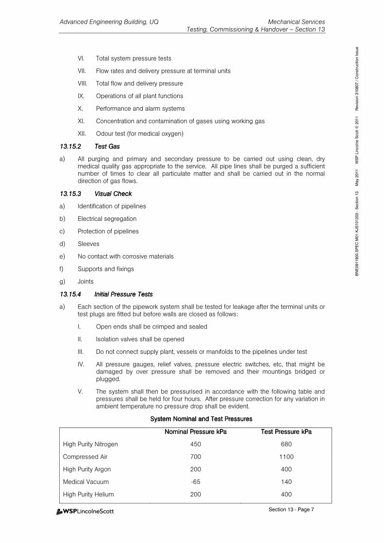
Advanced Engineering Building, UQ Mechanical Services Testing, Commissioning & Handover – Section 13
Section 13 - Page 7
BNE0911900.SPEC.M
01.KJS101203 - Section 13 M
ay 2011 W
SP Lincolne Scott ©
2011 Revision 310807 / C
onstruction Issue
VI. Total system pressure tests
VII. Flow rates and delivery pressure at terminal units
VIII. Total flow and delivery pressure
IX. Operations of all plant functions
X. Performance and alarm systems
XI. Concentration and contamination of gases using working gas
XII. Odour test (for medical oxygen)
13.15.213.15.213.15.213.15.2 Test GasTest GasTest GasTest Gas
a) All purging and primary and secondary pressure to be carried out using clean, dry medical quality gas appropriate to the service. All pipe lines shall be purged a sufficient number of times to clear all particulate matter and shall be carried out in the normal direction of gas flows.
13.15.313.15.313.15.313.15.3 Visual CheckVisual CheckVisual CheckVisual Check
a) Identification of pipelines
b) Electrical segregation
c) Protection of pipelines
d) Sleeves
e) No contact with corrosive materials
f) Supports and fixings
g) Joints
13.15.413.15.413.15.413.15.4 Initial Pressure TestsInitial Pressure TestsInitial Pressure TestsInitial Pressure Tests
a) Each section of the pipework system shall be tested for leakage after the terminal units or test plugs are fitted but before walls are closed as follows:
I. Open ends shall be crimped and sealed
II. Isolation valves shall be opened
III. Do not connect supply plant, vessels or manifolds to the pipelines under test
IV. All pressure gauges, relief valves, pressure electric switches, etc, that might be damaged by over pressure shall be removed and their mountings bridged or plugged.
V. The system shall then be pressurised in accordance with the following table and pressures shall be held for four hours. After pressure correction for any variation in ambient temperature no pressure drop shall be evident.
System Nominal and Test PressuresSystem Nominal and Test PressuresSystem Nominal and Test PressuresSystem Nominal and Test Pressures
Nominal Pressure kPaNominal Pressure kPaNominal Pressure kPaNominal Pressure kPa Test Pressure kPaTest Pressure kPaTest Pressure kPaTest Pressure kPa
High Purity Nitrogen 450 680
Compressed Air 700 1100
High Purity Argon 200 400
Medical Vacuum -65 140
High Purity Helium 200 400
Advanced Engineering Building, UQ Mechanical Services Testing, Commissioning & Handover – Section 13
Section 13 - Page 8
BNE0911900.SPEC.M
01.KJS101203 - Section 13 M
ay 2011 W
SP Lincolne Scott ©
2011 Revision 310807 / C
onstruction Issue
13.15.513.15.513.15.513.15.5 Zone Isolation Valve Tests Zone Isolation Valve Tests Zone Isolation Valve Tests Zone Isolation Valve Tests
a) Test each isolation valve for shut-off.
b) Use test pressures as per initial pressure tests.
c) Pressurise system with valve open then close.
d) Drop downstream pressure to 70kPa.
e) Maintain no pressure increases for 15 minutes.
f) Simultaneously check valve services area defined.
13.15.613.15.613.15.613.15.6 Particulate Matter Particulate Matter Particulate Matter Particulate Matter
a) Test each pipeline system for particulate matter.
13.15.713.15.713.15.713.15.7 Test for Cross Connection Test for Cross Connection Test for Cross Connection Test for Cross Connection
a) Test piping systems installed from source to terminal units.
b) The pressure in all piping systems other than the one under investigation shall be reduced to atmospheric and observed to be so.
c) All zone isolation valves in all systems shall be open.
d) The pressure in the piping systems under test shall be raised to at least 410kPa for gas and 140kPa for vacuum.
e) Each individual terminal unit of all the piping systems shall be checked to determine that the test gas is being dispensed only from the terminal units of the system under investigation.
f) The cross connection test shall be repeated to demonstrate the integrity of each pipework systems to the satisfaction of the Principal and the Superintendent.
g) After the performance of this test no alterations to any pipework shall be undertaken without a written approval from the Superintendent in each case.
13.15.813.15.813.15.813.15.8 Total System PressureTotal System PressureTotal System PressureTotal System Pressure
a) Use nominal design working pressures.
b) Use air quality tested compressed air plant for compressed air system.
c) Use the vacuum plant for the vacuum system
d) Use cylinder high purity nitrogen for the other gas systems.
e) With all terminal outlets fitted, and all pressure switches, safety valved and gauges installed set each system at the nominal working pressure and maintain for 4 hours.
f) Isolate the test gas from the system after pressurising the system.
g) Set vacuum system to –60kPa and maintain a maximum pressure increase of not greater than 10kPa per hour.
13.15.913.15.913.15.913.15.9 FlowFlowFlowFlow----Delivery Pressure Tests (Medical Gases)Delivery Pressure Tests (Medical Gases)Delivery Pressure Tests (Medical Gases)Delivery Pressure Tests (Medical Gases)
13.15.1013.15.1013.15.1013.15.10 lant Functionslant Functionslant Functionslant Functions
a) Test all functions of supply plant in normal and emergency conditions.

Advanced Engineering Building, UQ Mechanical Services Testing, Commissioning & Handover – Section 13
Section 13 - Page 9
BNE0911900.SPEC.M
01.KJS101203 - Section 13 M
ay 2011 W
SP Lincolne Scott ©
2011 Revision 310807 / C
onstruction Issue
b) The gas cylinder automatic changeover manifolds shall be tested for correct operation of changeover valve gauges. This test shall be carried out prior to charging of system with service gas.
c) Check operation of all valves and pressure gauges on manifolds.
d) Check operation of electric and pneumatic switches.
e) Check function of electrical circuits for operation, insulation resistance an effectiveness of earthing.
f) Check all ascertain each item of plant is capable of operating to its designed performance.
g) Check all compressors and pumps against manufacturer’s specifications including all safeties, thermostats and other protection devices.
13.15.1113.15.1113.15.1113.15.11 Alarm SystemsAlarm SystemsAlarm SystemsAlarm Systems
a) Test all alarm conditions on all systems.
b) Test under normal and emergency conditions.
c) Check for correct identification of all components and any subsequent actions.
d) Check that test and remote circuits are functioning.
13.15.1213.15.1213.15.1213.15.12 Gas PurityGas PurityGas PurityGas Purity
a) Conduct after system purge.
b) Check each terminal unit to verify nominal concentration of the gas, and record.
13.1613.1613.1613.16 COMPLETIONCOMPLETIONCOMPLETIONCOMPLETION DOCUMENTSDOCUMENTSDOCUMENTSDOCUMENTS
13.16.113.16.113.16.113.16.1 SubmissionsSubmissionsSubmissionsSubmissions
a) Prior to practical completion, submit 3 copies of designated documents.
b) Include warranties, as-built drawings, operation and maintenance manuals, certificate of training, spare parts schedule, commissioning reports, authorities and utilities approvals and the like.
WarrantiesWarrantiesWarrantiesWarranties
a) General: Name the principal as warrantee. Register with manufacturers as necessary. Retain copies delivered with components and equipment.
b) Approval of subcontractor: If installation is not being manufactured and product warranty is conditional on the manufacturer’s approval of the subcontractor, submit the manufacturer’s written approval of the installing firm.
13.16.213.16.213.16.213.16.2 AsAsAsAs----Built Drawings and REVIT ModelBuilt Drawings and REVIT ModelBuilt Drawings and REVIT ModelBuilt Drawings and REVIT Model
a) Provide the following:
I. Complete ducting layout drawings showing the actual sizes and locations of all ducts, dampers, supply outlets, return inlets, fresh air intakes, exhaust grilles, louvres etc. and the final measured air flow rates at all relevant locations.
II. Complete plant room and/or equipment layout drawings with full identification of each and every item of equipment.
III. Complete piping layout drawings, showing the actual sizes and locations of all refrigerant, water, instrument air, gas and any other lines applicable to the system.
IV. Complete schematic flow and control diagrams of all air, water, refrigerant, instrument air and any other systems incorporated in the installation.
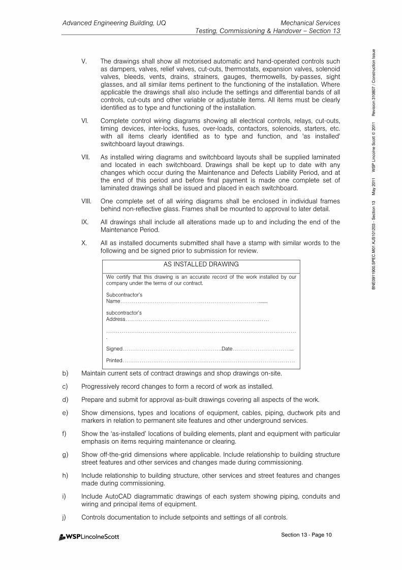
Advanced Engineering Building, UQ Mechanical Services Testing, Commissioning & Handover – Section 13
Section 13 - Page 10
BNE0911900.SPEC.M
01.KJS101203 - Section 13 M
ay 2011 W
SP Lincolne Scott ©
2011 Revision 310807 / C
onstruction Issue
V. The drawings shall show all motorised automatic and hand-operated controls such as dampers, valves, relief valves, cut-outs, thermostats, expansion valves, solenoid valves, bleeds, vents, drains, strainers, gauges, thermowells, by-passes, sight glasses, and all similar items pertinent to the functioning of the installation. Where applicable the drawings shall also include the settings and differential bands of all controls, cut-outs and other variable or adjustable items. All items must be clearly identified as to type and functioning of the installation.
VI. Complete control wiring diagrams showing all electrical controls, relays, cut-outs, timing devices, inter-locks, fuses, over-loads, contactors, solenoids, starters, etc. with all items clearly identified as to type and function, and 'as installed' switchboard layout drawings.
VII. As installed wiring diagrams and switchboard layouts shall be supplied laminated and located in each switchboard. Drawings shall be kept up to date with any changes which occur during the Maintenance and Defects Liability Period, and at the end of this period and before final payment is made one complete set of laminated drawings shall be issued and placed in each switchboard.
VIII. One complete set of all wiring diagrams shall be enclosed in individual frames behind non-reflective glass. Frames shall be mounted to approval to later detail.
IX. All drawings shall include all alterations made up to and including the end of the Maintenance Period.
X. All as installed documents submitted shall have a stamp with similar words to the following and be signed prior to submission for review.
AS INSTALLED DRAWING
We certify that this drawing is an accurate record of the work installed by our company under the terms of our contract.
Subcontractor’s Name………………………………………………………………........
subcontractor’s Address…………………………………………………………………
……………………………………………………………………………………….
Signed…………………………………………….Date…………………………...
Printed………………………………………………………………………………
b) Maintain current sets of contract drawings and shop drawings on-site.
c) Progressively record changes to form a record of work as installed.
d) Prepare and submit for approval as-built drawings covering all aspects of the work.
e) Show dimensions, types and locations of equipment, cables, piping, ductwork pits and markers in relation to permanent site features and other underground services.
f) Show the ‘as-installed’ locations of building elements, plant and equipment with particular emphasis on items requiring maintenance or clearing.
g) Show off-the-grid dimensions where applicable. Include relationship to building structure street features and other services and changes made during commissioning.
h) Include relationship to building structure, other services and street features and changes made during commissioning.
i) Include AutoCAD diagrammatic drawings of each system showing piping, conduits and wiring and principal items of equipment.
j) Controls documentation to include setpoints and settings of all controls.
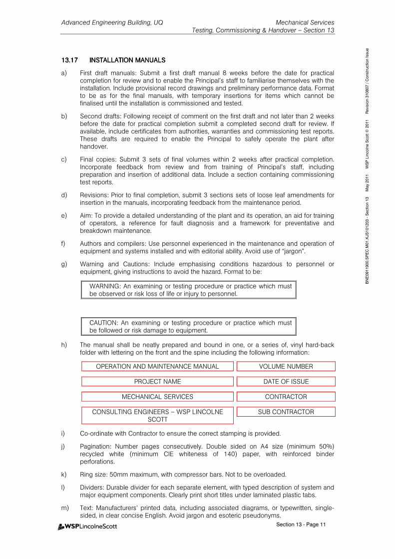
Advanced Engineering Building, UQ Mechanical Services Testing, Commissioning & Handover – Section 13
Section 13 - Page 11
BNE0911900.SPEC.M
01.KJS101203 - Section 13 M
ay 2011 W
SP Lincolne Scott ©
2011 Revision 310807 / C
onstruction Issue
13.1713.1713.1713.17 INSTALLATION MANUALSINSTALLATION MANUALSINSTALLATION MANUALSINSTALLATION MANUALS
a) First draft manuals: Submit a first draft manual 8 weeks before the date for practical completion for review and to enable the Principal’s staff to familiarise themselves with the installation. Include provisional record drawings and preliminary performance data. Format to be as for the final manuals, with temporary insertions for items which cannot be finalised until the installation is commissioned and tested.
b) Second drafts: Following receipt of comment on the first draft and not later than 2 weeks before the date for practical completion submit a completed second draft for review. If available, include certificates from authorities, warranties and commissioning test reports. These drafts are required to enable the Principal to safely operate the plant after handover.
c) Final copies: Submit 3 sets of final volumes within 2 weeks after practical completion. Incorporate feedback from review and from training of Principal’s staff, including preparation and insertion of additional data. Include a section containing commissioning test reports.
d) Revisions: Prior to final completion, submit 3 sections sets of loose leaf amendments for insertion in the manuals, incorporating feedback from the maintenance period.
e) Aim: To provide a detailed understanding of the plant and its operation, an aid for training of operators, a reference for fault diagnosis and a framework for preventative and breakdown maintenance.
f) Authors and compilers: Use personnel experienced in the maintenance and operation of equipment and systems installed and with editorial ability. Avoid use of “jargon”.
g) Warning and Cautions: Include emphasising conditions hazardous to personnel or equipment, giving instructions to avoid the hazard. Format to be:
WARNING: An examining or testing procedure or practice which must be observed or risk loss of life or injury to personnel.
CAUTION: An examining or testing procedure or practice which must be followed or risk damage to equipment.
h) The manual shall be neatly prepared and bound in one, or a series of, vinyl hard-back folder with lettering on the front and the spine including the following information:
OPERATION AND MAINTENANCE MANUAL VOLUME NUMBER
PROJECT NAME DATE OF ISSUE
MECHANICAL SERVICES CONTRACTOR
CONSULTING ENGINEERS – WSP LINCOLNE SCOTT
SUB CONTRACTOR
i) Co-ordinate with Contractor to ensure the correct stamping is provided.
j) Pagination: Number pages consecutively. Double sided on A4 size (minimum 50%) recycled white (minimum CIE whiteness of 140) paper, with reinforced binder perforations.
k) Ring size: 50mm maximum, with compressor bars. Not to be overloaded.
l) Dividers: Durable divider for each separate element, with typed description of system and major equipment components. Clearly print short titles under laminated plastic tabs.
m) Text: Manufacturers’ printed data, including associated diagrams, or typewritten, single-sided, in clear concise English. Avoid jargon and esoteric pseudonyms.
Advanced Engineering Building, UQ Mechanical Services Testing, Commissioning & Handover – Section 13
Section 13 - Page 12
BNE0911900.SPEC.M
01.KJS101203 - Section 13 M
ay 2011 W
SP Lincolne Scott ©
2011 Revision 310807 / C
onstruction Issue
n) Drawings: Fold illustrative drawings to A4 size and accommodate them in plastic pockets in the binder.
o) All aspects of the style and quality of the manual, including folders and contents shall be submitted for approval prior to completion.
p) After the draft copy has been approved, supply 3 copies of the manuals to the Contractor for issue to the Principal and the Superintendent.
13.17.113.17.113.17.113.17.1 Installation ManuaInstallation ManuaInstallation ManuaInstallation Manual Formatl Formatl Formatl Format
a) Section 1 - Index
I. Index all sub-divisions of each section including lists of drawings, equipment, etc. for quick reference.
II. Note: Include index in every volume of the manuals.
b) Section 2 - General Description and Capacities of Installations
I. Divide into sub-sections for general items and for each individual air conditioning, mechanical ventilation or mechanical system as appropriate and include full details of supply, return, exhaust and outdoor air flow rates, dry and wet bulb temperatures, cooling and/or heating duties, etc.
II. Include a directory: Names, addresses and telephone and facsimile numbers of Principal, Consultant, Sub-Consultants, Contractor, Sub-Contractors and names of responsible parties.
III. Include a scope of works: Statement of scope of services and interfacing with other Contracts.
IV. Include an installation description: General description of installation.
V. Systems description: Technical description of the systems installed, written to ensure that the Principal’s staff fully understand the scope and facilities provided. Identify function, normal operating characteristics and limiting conditions. Include schematic diagrams.
VI. System performance: Technical description of the modes of operation of the systems installed.
c) Section 3 - Equipment
I. Sub-divide as for Section 2 and list all major items of equipment installed complete with manufacturer's name, agent's name, contact details, model and/or type No., serial No., size, design ratings and including all relevant data necessary for re-ordering or replacing the equipment or components of same. As far as practicable, all equipment should be broken down to individually identifiable items such as, cooling tower fans, motors, drive belts.
II. Provide manufacturers’ technical literature for equipment installed, assembled specifically for the project, excluding irrelevant matter. Mark each product data sheet to clearly identify specific products and component parts used in the installation and data applicable to the installation. Do not include advertising literature.
d) Section 4 - Installation, Maintenance and Operating Instructions
I. Sub-divide as for Section 2 and include manufacturer's installation, maintenance and operating instructions for each item of equipment such as air filters, compressors, controls, cooling towers, fans, motors, etc.
II. Emergency maintenance procedures, including telephone numbers for emergency services and after hours contact for suppliers and Contractors and procedures for fault finding.
Advanced Engineering Building, UQ Mechanical Services Testing, Commissioning & Handover – Section 13
Section 13 - Page 13
BNE0911900.SPEC.M
01.KJS101203 - Section 13 M
ay 2011 W
SP Lincolne Scott ©
2011 Revision 310807 / C
onstruction Issue
III. Manufacturer’s technical literature as appropriate. Register with manufacturer as necessary. Retain copies delivered with equipment.
IV. Detailed recommendations for preventative maintenance frequency and procedures which should be adopted by the Principal to ensure the most efficient operation of the systems installed. Include inspection, testing and maintenance programme in tabular form showing frequency and level of routine checks for each item.
V. Safe trouble shooting, disassembly, repair and reassembly, cleaning, alignment and adjustment, balancing and checking procedures. Provide logical step-by-step sequence of instructions for each procedure. Include calibration and recommissioning of controls.
VI. Schedule of spares recommended to be held on site, being those items subject to wear or deterioration and which may involve the Principal in extended deliveries when replacements are required. Include complete nomenclature and model numbers, and local sources of supply. Include sectionalised diagrams of machines identifying component parts.
VII. Schedule of normal consumable items, local sources of supply and expected replacement intervals up to a running time of 40,000 hours. Include lubricant and lubrication schedules for equipment.
VIII. Legend for colour-coded services.
IX. Control and switching sequences and flow diagrams for systems installed, including safety features. Also procedures for operating and adjusting control systems.
X. Testing logging and reporting.
XI. Procedures for seasonal changeovers.
e) Section 5 - Plant Operating Instructions
I. Sub-divide as for Section 2 and provide a complete description and correct sequence of all actions necessary to start-up, operate and shut-down all plant. These instructions shall include full information on such items as normal and abnormal gauge readings, instrument settings and control points, differentials, time delays, oil levels, water temperatures, and all similar relevant variable and adjustable items, to permit checking and adjustments where practicable and identification of hazardous conditions or malfunction of plant. In addition the instructions shall include information on the immediate action to be taken in the event of hazardous conditions arising.
II. Prestart checklist, safe starting up, running-in, operating and shutting down procedures for systems installed. Include logical step-by-step sequence of instructions for each procedure.
f) Section 6 – Commissioning Records
I. Air and water flows, power consumption.
II. Equipment test sheets.
g) Section 7 - Performance Test Results
I. This section shall be sub-divided as for Section 2 and shall include all performance test results as outlined in previous Clauses.
h) Section 8 – Certificates
Statutory Certificates of Compliance for:
I. Electrical Work.
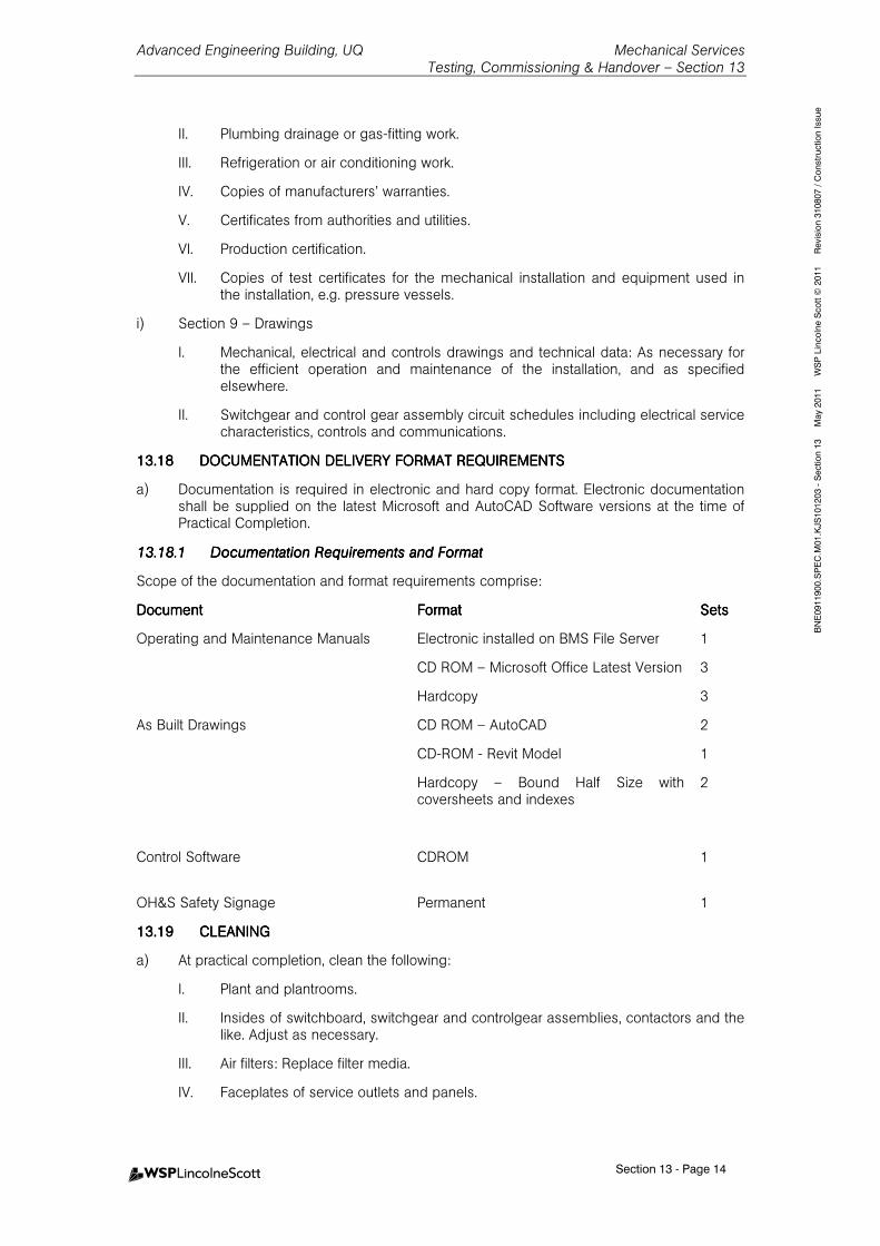
Advanced Engineering Building, UQ Mechanical Services Testing, Commissioning & Handover – Section 13
Section 13 - Page 14
BNE0911900.SPEC.M
01.KJS101203 - Section 13 M
ay 2011 W
SP Lincolne Scott ©
2011 Revision 310807 / C
onstruction Issue
II. Plumbing drainage or gas-fitting work.
III. Refrigeration or air conditioning work.
IV. Copies of manufacturers’ warranties.
V. Certificates from authorities and utilities.
VI. Production certification.
VII. Copies of test certificates for the mechanical installation and equipment used in the installation, e.g. pressure vessels.
i) Section 9 – Drawings
I. Mechanical, electrical and controls drawings and technical data: As necessary for the efficient operation and maintenance of the installation, and as specified elsewhere.
II. Switchgear and control gear assembly circuit schedules including electrical service characteristics, controls and communications.
13.1813.1813.1813.18 DOCUMENTATION DELIVEDOCUMENTATION DELIVEDOCUMENTATION DELIVEDOCUMENTATION DELIVERY FORMAT RY FORMAT RY FORMAT RY FORMAT REQUIREMENTSREQUIREMENTSREQUIREMENTSREQUIREMENTS
a) Documentation is required in electronic and hard copy format. Electronic documentation shall be supplied on the latest Microsoft and AutoCAD Software versions at the time of Practical Completion.
13.18.113.18.113.18.113.18.1 DocumentationDocumentationDocumentationDocumentation Requirements and FormatRequirements and FormatRequirements and FormatRequirements and Format
Scope of the documentation and format requirements comprise:
DocumentDocumentDocumentDocument FormatFormatFormatFormat SetsSetsSetsSets
Operating and Maintenance Manuals Electronic installed on BMS File Server 1
CD ROM – Microsoft Office Latest Version 3
Hardcopy 3
As Built Drawings CD ROM – AutoCAD
CD-ROM - Revit Model
2
1
Hardcopy – Bound Half Size with coversheets and indexes
2
Control Software CDROM
1
OH&S Safety Signage Permanent 1
13.1913.1913.1913.19 CLEANINGCLEANINGCLEANINGCLEANING
a) At practical completion, clean the following:
I. Plant and plantrooms.
II. Insides of switchboard, switchgear and controlgear assemblies, contactors and the like. Adjust as necessary.
III. Air filters: Replace filter media.
IV. Faceplates of service outlets and panels.
Advanced Engineering Building, UQ Mechanical Services Testing, Commissioning & Handover – Section 13
Section 13 - Page 15
BNE0911900.SPEC.M
01.KJS101203 - Section 13 M
ay 2011 W
SP Lincolne Scott ©
2011 Revision 310807 / C
onstruction Issue
13.2013.2013.2013.20 PRINCIPAL’S PRINCIPAL’S PRINCIPAL’S PRINCIPAL’S INSTRUCTIONINSTRUCTIONINSTRUCTIONINSTRUCTION
a) The service of a Commissioning Engineer shall be required for a period of 2 full working weeks to instruct the Principal's nominated representatives in all details of the plant operation.
b) Prior to practical completion, explain and demonstrate to the Principal’s staff the purpose, function, operating and maintenance of the installations.
c) Use items and procedures listed in the final draft operation and maintenance manuals as the basis for detailed instruction of staff nominated by the Principal.
d) Format: Conduct training at agreed time, at each system of equipment location.
e) Documentation: Upon completion, submit certificates of training, signed by trainer and trainees.
f) Demonstrators: Provide qualified manufacturer’s training representatives who are knowledgeable about the installations, e.g. mechanical control system specialist, chiller specialist.
g) During the warranty period, provide assistance and advice to the Principal’s staff regarding the operation and maintenance of the plant.
h) For equipment requiring seasonal operation, demonstrate during the appropriate season and within 6 months of practical completion.
13.2113.2113.2113.21 PRACTICAL COMPLETIONPRACTICAL COMPLETIONPRACTICAL COMPLETIONPRACTICAL COMPLETION INSPECTIONS, TESTINGINSPECTIONS, TESTINGINSPECTIONS, TESTINGINSPECTIONS, TESTING, COMMISSIONING AND , COMMISSIONING AND , COMMISSIONING AND , COMMISSIONING AND FAULT FAULT FAULT FAULT FREE PERIODFREE PERIODFREE PERIODFREE PERIOD
a) The project will have three distinct consecutive stages in the lead up to the achievement of Practical Completion. Each stage is to be successfully completed before the next stage commences and all stages are to be successfully completed before Practical Completion is granted.
Stage 1 shall consist of the following:
I. Joint Inspection and Commissioning by Principal’s Representative of the various trades (except Security and Communications).
II. Testing as listed in the ‘Operation Mode Testing’ section of this Specification.
Stage 2 shall consist of the following:
I. Commissioning of Security and Communications by the Principal’s Representative.
II. Remedial Services Interface testing as a result of Stage 1 testing.
III. Rectification of defects during this period - minor omissions and minor defects are to be corrected.
Stage 3 shall consist of the following:
I. The Five-Day Fault Free Period commences when the Defects Rectification and Services Interface Period described above is satisfactorily completed. During this period, the systems shall be operated and function fault free for a five day period. If a fault occurs then the full five day fault free period shall recommence after the fault has been corrected.
13.21.113.21.113.21.113.21.1 Operation Mode TestingOperation Mode TestingOperation Mode TestingOperation Mode Testing
a) As a minimum requirement, all systems and equipment must be tested to the Principal’s Representative’s satisfaction in the following operational modes and perform to the standards required by the Contract and in particular must prove the effective transition from one mode to the other:
Advanced Engineering Building, UQ Mechanical Services Testing, Commissioning & Handover – Section 13
Section 13 - Page 16
BNE0911900.SPEC.M
01.KJS101203 - Section 13 M
ay 2011 W
SP Lincolne Scott ©
2011 Revision 310807 / C
onstruction Issue
I. Normal automatic modeNormal automatic modeNormal automatic modeNormal automatic mode. The condition the Centre will normally operate in when occupied.
II. Fire Alarm modeFire Alarm modeFire Alarm modeFire Alarm mode. This mode occurs of a Fire Alarm during the ‘normal automatic mode’. This shall be demonstrated by activating a detector as nominated.
III. Ordinary essential modeOrdinary essential modeOrdinary essential modeOrdinary essential mode. This mode occurs on the loss of supply authority power occurs.
IV. Fire essential modeFire essential modeFire essential modeFire essential mode. This mode occurs during a Fire Alarm when the centre is in the ‘ordinary essential mode’ demonstrated activating a detector as nominated.
V. After hours call up operational modeAfter hours call up operational modeAfter hours call up operational modeAfter hours call up operational mode. Specific areas where this is equipment that can be used after hours (e.g. air conditioning and the like).
VI. Manual call modesManual call modesManual call modesManual call modes. The start up of major equipment as a whole on a manual basis. The manual call up of major equipment items shall include (but not be limited to)
• Air handling plant,
• Chiller set or AC plant as appropriate, and
• Standby generator set.
b) The operation of the Building Management System in all of the modes listed above and the interfacing with all other systems nominated in the documents, including (without limitation) all required formats for screens and printouts, and
c) The operation of the Electronic Security and Communications Systems in all of the modes listed above and the interfacing with all other systems nominated in the documents, including (without limitation) all required formats for Security Management System screens, printouts and reports.
d) The above operational modes are to be demonstrated in the order nominated both in normal daylight hours and again at night time after hours.
e) The costs of all fuel, energy, reinspection by the Principal’s Representative or other costs incurred by the Subcontractor in demonstrating that the engineering services perform as required by the Contract are to be borne by the Subcontractor.
13.21.213.21.213.21.213.21.2 Spare Parts ScheduleSpare Parts ScheduleSpare Parts ScheduleSpare Parts Schedule
a) At least 8 weeks before the date for practical completion, submit a schedule of spare parts necessary for maintenance of the installation. State against each item the recommended quantity, and the manufacturer’s current price, including for
b) Packaging and delivery to site;
c) Checking receipt, marking and numbering in accordance wit the spare parts schedule;
d) Referencing equipment schedules in the operation and maintenance manual; and
e) Painting, greasing and packing to prevent deterioration during storage.
13.2213.2213.2213.22 GREEN STAR REQUIREMEGREEN STAR REQUIREMEGREEN STAR REQUIREMEGREEN STAR REQUIREMENTSNTSNTSNTS
The following additional requirements are required.
Comprehensive pre-commissioning, commissioning and quality monitoring are to be performed in accordance with ASHRAE Guideline 1 or CIBSE Commissioning Codes A, C, M, R and W.
a) Provide a complete commissioning report which confirms that all commissioning is in compliance with the contract documents. The report must also include a list of outstanding commissioning issues, records of all functional/commissioning testing undertaken and list any seasonal testing required in the future.

Advanced Engineering Building, UQ Mechanical Services Testing, Commissioning & Handover – Section 13
Section 13 - Page 17
BNE0911900.SPEC.M
01.KJS101203 - Section 13 M
ay 2011 W
SP Lincolne Scott ©
2011 Revision 310807 / C
onstruction Issue
b) Owner instruction to be spread over at least two sessions separated by at least two months. Issues covered must include:
I. Energy and environmental features of the design.
II. Review of the controls set-up, programming, alarms and trouble shooting.
III. Operating and Maintenance manuals.
IV. Building operation including start-up, normal operation, unoccupied operation, seasonal changeover and shutdown.
V. Interactions with other systems.
VI. Optimising energy efficiency.
VII. OH&S issues.
VIII. Maintenance requirements and sourcing replacements.
IX. Occupant satisfaction feedback.
c) Allow to coordinate the above with electrical and hydraulics installers so that a whole-building approach is achieved.
d) Separately from the routine maintenance and servicing, provide detailed formal quarterly reviews of the Mechanical Services of the system and provide written reports detailing the status of the system, changes made, etc. As a minimum, each review shall include:
I. All system set points and timers.
II. Rectification of all BMS alarms and other faults.
III. Full load commissioning tests of both heating and cooling systems in the appropriate season.
IV. Minor adjustments to BMS programmes, set points, air flows, water flows, etc. as found necessary from operating experience or as advised by the Engineer to time the system for optimum performance and energy efficiency.
e) Provide a formal final recommissioning of the mechanical services in the final month before Final Completion (12 months after Practical Completion). As a minimum this is to include:
I. A written report as per the quarterly review.
II. All quarterly issues.
III. Review and reconfirmation or adjustment of all flows and controls relating to cooling (chillers, cooling towers, pumps, etc.), heating (boilers, pumps, etc.), air flows (fan coil unit and air handling unit overall supply/return/outdoor air flows), ventilation (all supply and exhaust systems).
IV. Remeasure and adjust as necessary maximum chilled, heating and condenser water flows to major equipment..
V. Remeasure and adjust as necessary overall air distribution from risers at each floor.
Expanded Detention Centre Capacity Mechanical Services
Routine Maintenance and Servicing - Section 14
Table of Contents - Page 1
BNE0911900.SPEC.M
01.KJS101203 - Section 14 M
ay 2011 W
SP Lincolne Scott ©
2011 Revision 310807 / Construction Issue
14.14.14.14. RRRROUTINE OUTINE OUTINE OUTINE MMMMAINTENANCE AND AINTENANCE AND AINTENANCE AND AINTENANCE AND SSSSERVICINGERVICINGERVICINGERVICING 1
14.114.114.114.1 GENERALGENERALGENERALGENERAL 1
14.1.1 Scope 1
14.1.2 Referenced Documents 1
14.214.214.214.2 DESIGNDESIGNDESIGNDESIGN 1
14.2.1 General 1
14.2.2 Authority Standards and Codes 1
14.314.314.314.3 SUBMISSIONSSUBMISSIONSSUBMISSIONSSUBMISSIONS 1
14.414.414.414.4 GENEGENEGENEGENERAL SCOPERAL SCOPERAL SCOPERAL SCOPE 1
14.514.514.514.5 GENERAL REQUIREMENTSGENERAL REQUIREMENTSGENERAL REQUIREMENTSGENERAL REQUIREMENTS 2
14.614.614.614.6 PREVENTATIVE MAINTENPREVENTATIVE MAINTENPREVENTATIVE MAINTENPREVENTATIVE MAINTENANCE AND TESTINGANCE AND TESTINGANCE AND TESTINGANCE AND TESTING 2
14.6.1 General 2
14.6.2 Monthly 2
14.6.3 Quarterly 3
14.6.4 Six Monthly 3
14.6.5 Last Maintenance Visit 3
14.714.714.714.7 MAINTENANCE RECORDSMAINTENANCE RECORDSMAINTENANCE RECORDSMAINTENANCE RECORDS 4
14.814.814.814.8 DEFECTS, LIABILITY ADEFECTS, LIABILITY ADEFECTS, LIABILITY ADEFECTS, LIABILITY AND WARRANTY PERIODND WARRANTY PERIODND WARRANTY PERIODND WARRANTY PERIOD 4
14.914.914.914.9 FINAL COMPLETIONFINAL COMPLETIONFINAL COMPLETIONFINAL COMPLETION 4
Expanded Detention Centre Capacity Mechanical Services
Routine Maintenance and Servicing - Section 14
Section 14 - Page 1
BNE0911900.SPEC.M
01.KJS101203 - Section 14 M
ay 2011 W
SP Lincolne Scott ©
2011 Revision 310807 / Construction Issue
14.14.14.14. RRRROUTINE OUTINE OUTINE OUTINE MMMMAINTENANCE AND AINTENANCE AND AINTENANCE AND AINTENANCE AND SSSSERVICINGERVICINGERVICINGERVICING
14.114.114.114.1 GENERALGENERALGENERALGENERAL
14.1.114.1.114.1.114.1.1 ScopeScopeScopeScope
a) This section sets out the engineering and quality assurance requirements for the routine maintenance and servicing of the complete Mechanical Services.
b) This section is to be read in conjunction with all other sections of this specification.
14.1.214.1.214.1.214.1.2 Referenced DocumentsReferenced DocumentsReferenced DocumentsReferenced Documents
Details of documents applicable to this section of the specification include:
Australian/New Zealand StandardsAustralian/New Zealand StandardsAustralian/New Zealand StandardsAustralian/New Zealand Standards
AS/NZS 1677.2-1998 Safety requirements for fixed applications
AS 1851-2005 Maintenance of fire protection systems and equipment
AS/NZS 3666.1-2002 Air-handling and water systems of buildings - Microbial
control – Design, installation and commissioning
AS/NZS 3666.2-2002 Air-handling and water systems of buildings – Microbial
control – Operation and maintenance
AS/NZS 3666.3-2000 Air-handling and water systems of buildings – Microbial
control – Performance-based maintenance of cooling
water systems
14.214.214.214.2 DESIGNDESIGNDESIGNDESIGN
14.2.114.2.114.2.114.2.1 GeneralGeneralGeneralGeneral
Complete the detail engineering of the routine maintenance and servicing of the works to the specified requirements.
14.2.214.2.214.2.214.2.2 Authority SAuthority SAuthority SAuthority Standards and Codestandards and Codestandards and Codestandards and Codes
a) Comply with applicable authority design guidelines and codes of practice and requirements:
14.314.314.314.3 SUBMISSIONSSUBMISSIONSSUBMISSIONSSUBMISSIONS
a) Maintenance management plan.
b) Monthly Maintenance reports.
14.414.414.414.4 GENERAL SCOPEGENERAL SCOPEGENERAL SCOPEGENERAL SCOPE
a) Maintenance services shall include:
I. Preparation of a maintenance management plan which includes a detailed maintenance programme, equipment schedules, statutory and preventative maintenance schedules, OH&S risk assessment, inspection and testing schedules, breakdown rectification management and reporting systems.
II. Preventative and corrective maintenance and testing services to assure specified system reliability and availability.
III. Ensure maintenance services clearly indicate on an individual equipment basis a schedule of maintenance routines, inspections, preventative maintenance procedures, test surveys and records conducted on the fire and smoke protections systems installed as outlined in AS1851. Generic type procedures / inspections are not acceptable.
Expanded Detention Centre Capacity Mechanical Services
Routine Maintenance and Servicing - Section 14
Section 14 - Page 2
BNE0911900.SPEC.M
01.KJS101203 - Section 14 M
ay 2011 W
SP Lincolne Scott ©
2011 Revision 310807 / Construction Issue
IV. Statutory maintenance and testing required by the Building Regulations.
V. Breakdown responses.
VI. Annual full system fire and life safety system control and performance verification test to be carried out after hours.
VII. Comply with Building and Occupational Health and Safety Regulations.
VIII. Comply with AS/NZS 3666.2. AS/NZS 3666.3 and AS/NZS 1677.2.
IX. Comply with manufacturer’s recommended maintenance programme and schedules.
X. Submit maintenance plan and schedules prior to Practical Completion.
b) Routine maintenance and servicing is to be carried out on a monthly basis for a period of 12 months from the date of Practical Completion to the end of the Maintenance and Defects Liability Period.
14.514.514.514.5 GENERAL REQUIREMENTSGENERAL REQUIREMENTSGENERAL REQUIREMENTSGENERAL REQUIREMENTS
a) Monthly maintenance and servicing in accordance with maintenance schedules recommended by equipment manufacturers.
b) Maintenance, testing and inspections in accordance with regulatory requirements and relevant Australian Standards.
c) Rectification of defects at Subcontractors cost.
d) Operation and verification in conjunction with other services trades, of all fire and life safety systems, e.g. smoke control, pressurisation systems etc. in emergency mode. Such testing to be undertaken at 6 monthly intervals.
e) Replacement of consumables (e.g. filter media, refrigerant, chemicals, drier cores) at Subcontractors cost during the maintenance period.
f) Submission of monthly reports to the Superintendent on maintenance activities performed including testing and reporting on chemical treatment systems.
g) Provision and filling out log book which must be kept on site, detailing all visits.
h) Service personnel to be available for call out on a 24 hour per day, 7 day per week basis. Response time for emergency and corrective maintenance must not exceed 2 hours.
14.614.614.614.6 PREVENTATIVE MAINTENPREVENTATIVE MAINTENPREVENTATIVE MAINTENPREVENTATIVE MAINTENANCE AND TESTINGANCE AND TESTINGANCE AND TESTINGANCE AND TESTING
14.6.114.6.114.6.114.6.1 GeneralGeneralGeneralGeneral
The following minimum items shall be carried out for applicable equipment, as well as those required by Codes, Standards and the manufacturers.
14.6.214.6.214.6.214.6.2 MonthlyMonthlyMonthlyMonthly
a) Check and adjust all belt drives and couplings.
b) Check and clean all washable filters.
c) Check and report on necessity for replacement of removable filter media and disposable filters.
d) Oil and grease all bearings.
e) Clean as necessary drip trays, strainers and other sediment collecting items, which may become fouled.
f) Adjust and repack as appropriate, glands of all pumps and valves.
Expanded Detention Centre Capacity Mechanical Services
Routine Maintenance and Servicing - Section 14
Section 14 - Page 3
BNE0911900.SPEC.M
01.KJS101203 - Section 14 M
ay 2011 W
SP Lincolne Scott ©
2011 Revision 310807 / Construction Issue
g) Check refrigerant system for leaks and supply replacement refrigerant as necessary to leave the plant tight and fully charged at all times. Drier cores to be replaced as necessary.
h) Test cooling towers for Legionella and carry out tower clean in accordance with AS/NZS 3666.1.
i) Check, test and report on chemical treatment and dose as required.
14.6.314.6.314.6.314.6.3 QuarterlyQuarterlyQuarterlyQuarterly
a) Monthly items, plus the following:
b) Check operation, setting and calibration of all controls.
c) Check all motors for temperature rise, operating current and leakage.
d) Check and record compressor head pressures and operation of HP, LP and oil pressure cut outs.
e) Check and adjust boilers and burners.
14.6.414.6.414.6.414.6.4 Six MonthlySix MonthlySix MonthlySix Monthly
a) Quarterly items, plus the following:
b) Check internal and external vibration isolation.
c) Check, test and report on all fire detection and protection systems including stairwell pressurisation systems and fire shut down controls.
d) Check operation of all electrical switchgear including setting and operation of motor overloads.
14.6.514.6.514.6.514.6.5 Last Maintenance VisitLast Maintenance VisitLast Maintenance VisitLast Maintenance Visit
a) Six-monthly items, plus the following:
b) Complete clean of cooling towers and condenser water systems.
c) Removal of end covers from condensers and evaporators and cleaning of tubes and all internal surfaces.
d) Removal of oil and drier cartridges on compressors and refrigeration systems and replacement of same with new cartridges.
e) Arranging for a testing authority to analyse refrigerant and oil samples for impurities and to submit a thorough report.
f) Check all motor starters and relay controls.
g) Check and megger all electric motors and check overloads.
h) Undertake thermal scanning of switchboards and report thereon.
i) Check all system safeties.
j) Replace all air filter media and disposable filters.
k) Thoroughly check chiller cathodic protection systems.
l) Thoroughly check cooling tower side stream filtration equipment.
m) Check, test and report on a building fire safety control test including testing of fire detection systems, smoke control systems, fire dampers and smoke and heat vents; Certify the correct operation of essential services in accordance with the requirements of the BCA.
Expanded Detention Centre Capacity Mechanical Services
Routine Maintenance and Servicing - Section 14
Section 14 - Page 4
BNE0911900.SPEC.M
01.KJS101203 - Section 14 M
ay 2011 W
SP Lincolne Scott ©
2011 Revision 310807 / Construction Issue
n) The date for the final maintenance visit to be advised 7 days prior to the proposed visit so that the Superintendent may be present to inspect the equipment when end covers are removed.
14.714.714.714.7 MAINTENANCE RECORDSMAINTENANCE RECORDSMAINTENANCE RECORDSMAINTENANCE RECORDS
a) Mandatory maintenance records to include monthly maintenance and service reports, including water treatment reports, reports on all defects and their rectification, certification of the correct operation of essential services and a maintenance log book.
b) Monthly Maintenance and Service Reports to include:
I. Check list of all items serviced and inspected.
II. Description of maintenance performed.
III. Notes on supplementary maintenance required.
IV. Comprehensive water treatment report.
c) Maintenance Log Book to include:
I. Schedule of all equipment.
II. Schedule of all control sensors and control set point values.
III. Register of maintenance visits and cross reference to service reports.
IV. Register of work performed under headings of preventive maintenance, corrective and emergency maintenance and defects rectification.
d) The Maintenance Log Book is to be kept in a locked cabinet provided for the purpose in an agreed location on site.
e) At the conclusion of each maintenance visit the log book is to be duly completed and signed off by an authorised representative of the Principal and service records are to be forwarded to the Principal or his representative within 3 days of each visit.
14.814.814.814.8 DEFECTS, LIABILITY ADEFECTS, LIABILITY ADEFECTS, LIABILITY ADEFECTS, LIABILITY AND WARRANTY PERIODND WARRANTY PERIODND WARRANTY PERIODND WARRANTY PERIOD
a) Defects liability and warranty period covers the same time frame as the Maintenance period, normally 12 months from the date for Practical Completion.
b) Where plant, equipment and systems are delivered to site, or installed, or made operational in advance of the date for Practical Completion, the warranty on such equipment and liability for defects on such equipment and systems, shall be extended to cover the whole of the time to 12 months from the date for Practical Completion.
c) Without exception, the whole of the works covered by this Specification shall be under warranty and subject to rectification of defects, until 12 months from the date for Practical Completion.
d) Callout response time shall be not more than 6 hours.
14.914.914.914.9 FINAL COMPLETIONFINAL COMPLETIONFINAL COMPLETIONFINAL COMPLETION
a) Final Completion will not be granted until maintenance records are complete and signed off and until all defects have been rectified and inspected.
b) The Maintenance and Defects Liability Period may be extended unless maintenance and servicing visits have been made and reported as specified.
Advanced Engineering Building, UQ Mechanical Services Schedules - Section 15
Table of Contents - Page 1
BNE0911900.SPEC.M
01.KJS101216 - Section 15 M
ay 2011 W
SP Lincolne Scott ©
2011 Revision 310807 / Construction Issue
15.15.15.15. SSSSCHEDULESCHEDULESCHEDULESCHEDULES 1
15.115.115.115.1 GENERALGENERALGENERALGENERAL 1
15.215.215.215.2 CHILLER SETS CHILLER SETS CHILLER SETS CHILLER SETS –––– WATER COOLEDWATER COOLEDWATER COOLEDWATER COOLED 2
15.315.315.315.3 LOW TEMPERATURE HOT LOW TEMPERATURE HOT LOW TEMPERATURE HOT LOW TEMPERATURE HOT WATER DRIVEN VAPOR AWATER DRIVEN VAPOR AWATER DRIVEN VAPOR AWATER DRIVEN VAPOR ABSORPTION CHILLERBSORPTION CHILLERBSORPTION CHILLERBSORPTION CHILLER 5
15.415.415.415.4 AIR & DIRT SEPARATORAIR & DIRT SEPARATORAIR & DIRT SEPARATORAIR & DIRT SEPARATORSSSS 6
15.515.515.515.5 COOLING TOWERCOOLING TOWERCOOLING TOWERCOOLING TOWER 7
15.615.615.615.6 COOLING TOWER COOLING TOWER COOLING TOWER COOLING TOWER ---- SIDE STREAM FILTRATISIDE STREAM FILTRATISIDE STREAM FILTRATISIDE STREAM FILTRATIONONONON 8
15.715.715.715.7 HOT WATER HEATER HOT WATER HEATER HOT WATER HEATER HOT WATER HEATER –––– ATMOSPHERICATMOSPHERICATMOSPHERICATMOSPHERIC TYPETYPETYPETYPE 9
15.815.815.815.8 HOT WATER STORAGE TAHOT WATER STORAGE TAHOT WATER STORAGE TAHOT WATER STORAGE TANKNKNKNK 10
15.915.915.915.9 WATER HEAT EXCHANGERWATER HEAT EXCHANGERWATER HEAT EXCHANGERWATER HEAT EXCHANGERS S S S –––– PLATEPLATEPLATEPLATE 10
15.1015.1015.1015.10 HEAT DISSIPATION COIHEAT DISSIPATION COIHEAT DISSIPATION COIHEAT DISSIPATION COILSLSLSLS 11
15.1115.1115.1115.11 WATER PUMPSWATER PUMPSWATER PUMPSWATER PUMPS 12
15.1215.1215.1215.12 THERMAL TRANSFER FLUTHERMAL TRANSFER FLUTHERMAL TRANSFER FLUTHERMAL TRANSFER FLUID PUMPID PUMPID PUMPID PUMP 15
15.1315.1315.1315.13 EXPANSION TANKSEXPANSION TANKSEXPANSION TANKSEXPANSION TANKS–––– CLOSEDCLOSEDCLOSEDCLOSED 16
15.1415.1415.1415.14 COIL COIL COIL COIL –––– CHILLED WATERCHILLED WATERCHILLED WATERCHILLED WATER 17
15.1515.1515.1515.15 AIR FILTERSAIR FILTERSAIR FILTERSAIR FILTERS 18
15.1615.1615.1615.16 AIR HANDLING UNIT / AIR HANDLING UNIT / AIR HANDLING UNIT / AIR HANDLING UNIT / FAN COIL UNITFAN COIL UNITFAN COIL UNITFAN COIL UNIT 21
15.1715.1715.1715.17 SPECIALISED AIRCONDISPECIALISED AIRCONDISPECIALISED AIRCONDISPECIALISED AIRCONDITIONING UNITSTIONING UNITSTIONING UNITSTIONING UNITS 30
15.1815.1815.1815.18 COIL COIL COIL COIL –––– HEATING WATERHEATING WATERHEATING WATERHEATING WATER 31
15.1915.1915.1915.19 FAN TYPE AND ACCESSOFAN TYPE AND ACCESSOFAN TYPE AND ACCESSOFAN TYPE AND ACCESSORIESRIESRIESRIES 36
15.2015.2015.2015.20 FANSFANSFANSFANS 38
15.2115.2115.2115.21 CEILING SWEEP FANSCEILING SWEEP FANSCEILING SWEEP FANSCEILING SWEEP FANS 46
15.2215.2215.2215.22 AIR HEAT EXCHANGERAIR HEAT EXCHANGERAIR HEAT EXCHANGERAIR HEAT EXCHANGER 47
15.2315.2315.2315.23 TERMINAL UNIT TERMINAL UNIT TERMINAL UNIT TERMINAL UNIT –––– VARIABLE VOLUME SINVARIABLE VOLUME SINVARIABLE VOLUME SINVARIABLE VOLUME SINGLE DUCT.GLE DUCT.GLE DUCT.GLE DUCT. 48
15.2415.2415.2415.24 ATTENUATORSATTENUATORSATTENUATORSATTENUATORS 50
15.2515.2515.2515.25 ACOUSTIC LOUVRESACOUSTIC LOUVRESACOUSTIC LOUVRESACOUSTIC LOUVRES 50
15.215.215.215.26666 AIR CONDITIONING UNIAIR CONDITIONING UNIAIR CONDITIONING UNIAIR CONDITIONING UNIT T T T –––– CHILLED WATER, COMPUCHILLED WATER, COMPUCHILLED WATER, COMPUCHILLED WATER, COMPUTER ROOMTER ROOMTER ROOMTER ROOM 51
15.2715.2715.2715.27 AIR CONDITIONING UNIAIR CONDITIONING UNIAIR CONDITIONING UNIAIR CONDITIONING UNIT T T T –––– AIR COOLED, COMPUTERAIR COOLED, COMPUTERAIR COOLED, COMPUTERAIR COOLED, COMPUTER ROOMROOMROOMROOM 54
15.2815.2815.2815.28 FUME FUME FUME FUME CUPBOARDSCUPBOARDSCUPBOARDSCUPBOARDS 55
15.2915.2915.2915.29 EXHAUST HOODSEXHAUST HOODSEXHAUST HOODSEXHAUST HOODS 58
15.3015.3015.3015.30 COMPRESSED AIR STATICOMPRESSED AIR STATICOMPRESSED AIR STATICOMPRESSED AIR STATIONONONON 59
15.3115.3115.3115.31 VACUUM PLANTVACUUM PLANTVACUUM PLANTVACUUM PLANT 60
15.3215.3215.3215.32 GAS ALARM PANELSGAS ALARM PANELSGAS ALARM PANELSGAS ALARM PANELS 60
15.3315.3315.3315.33 WATER TREATMENTWATER TREATMENTWATER TREATMENTWATER TREATMENT 60
15.3415.3415.3415.34 CHILLED WATER BUFFERCHILLED WATER BUFFERCHILLED WATER BUFFERCHILLED WATER BUFFER TANKTANKTANKTANK 60
15.3515.3515.3515.35 COOL/COLD ROOM COOL/COLD ROOM COOL/COLD ROOM COOL/COLD ROOM ---- PREFABRICATEDPREFABRICATEDPREFABRICATEDPREFABRICATED 61
15.3615.3615.3615.36 COOL/COLD ROOM COOL/COLD ROOM COOL/COLD ROOM COOL/COLD ROOM ---- FORCED DRAFT COOLFORCED DRAFT COOLFORCED DRAFT COOLFORCED DRAFT COOLER/CONDENSING SETER/CONDENSING SETER/CONDENSING SETER/CONDENSING SET 61
15.3715.3715.3715.37 SCHEDULE OF PIPING MSCHEDULE OF PIPING MSCHEDULE OF PIPING MSCHEDULE OF PIPING MATERIALSATERIALSATERIALSATERIALS 62
15.3815.3815.3815.38 SCHEDULE OF PIPING SSCHEDULE OF PIPING SSCHEDULE OF PIPING SSCHEDULE OF PIPING SYSTEMS TEST CRITERIAYSTEMS TEST CRITERIAYSTEMS TEST CRITERIAYSTEMS TEST CRITERIA AND PROCEDURESAND PROCEDURESAND PROCEDURESAND PROCEDURES 63
15.3915.3915.3915.39 SCHEDULE OF DUCTWORKSCHEDULE OF DUCTWORKSCHEDULE OF DUCTWORKSCHEDULE OF DUCTWORK CLASSIFICATIONCLASSIFICATIONCLASSIFICATIONCLASSIFICATION 65
15.4015.4015.4015.40 SCHEDULE OF THERMAL SCHEDULE OF THERMAL SCHEDULE OF THERMAL SCHEDULE OF THERMAL INSULATIONINSULATIONINSULATIONINSULATION 66
15.4115.4115.4115.41 SCHEDULE OF SWITCHBOSCHEDULE OF SWITCHBOSCHEDULE OF SWITCHBOSCHEDULE OF SWITCHBOARDSARDSARDSARDS 71
15.4215.4215.4215.42 SCHEDULE OF NOISE LESCHEDULE OF NOISE LESCHEDULE OF NOISE LESCHEDULE OF NOISE LEVELSVELSVELSVELS 93
15.4315.4315.4315.43 SCHEDULE OF VIBRATIOSCHEDULE OF VIBRATIOSCHEDULE OF VIBRATIOSCHEDULE OF VIBRATION ISOLATIONN ISOLATIONN ISOLATIONN ISOLATION 94
15.4415.4415.4415.44 SCHEDULE OF SAMPLESSCHEDULE OF SAMPLESSCHEDULE OF SAMPLESSCHEDULE OF SAMPLES 95
15.4515.4515.4515.45 SCHEDULE OF PROTOTYPSCHEDULE OF PROTOTYPSCHEDULE OF PROTOTYPSCHEDULE OF PROTOTYPESESESES 96
15.4615.4615.4615.46 SCHEDULE OF PAINTINGSCHEDULE OF PAINTINGSCHEDULE OF PAINTINGSCHEDULE OF PAINTING 97
15.4715.4715.4715.47 PROCESS CHILLERPROCESS CHILLERPROCESS CHILLERPROCESS CHILLER 97
Advanced Engineering Building, UQ Mechanical Services Schedules - Section 15
Section 15 - Page 1
BNE0911900.SPEC.M
01.KJS101216 - Section 15 M
ay 2011 W
SP Lincolne Scott ©
2011 Revision 310807 / Pre Tender Issue 15.15.15.15. SSSSCHEDULECHEDULECHEDULECHEDULESSSS
15.115.115.115.1 GENERALGENERALGENERALGENERAL
The following schedules have been prepared for tendering purposes and to convey design intent. They form a summary of the preceding Clauses in the Specification and must be read in conjunction with these Clauses and the Project Drawings.
Where reference Clauses are referred to, they shall be taken as the major Clause, but equipment shall also comply with all other relevant Clauses in the Specification.
Air and water quantities and temperatures may be changed slightly to suit the particular manufacturer’s equipment, however full details shall be submitted for review. Changes shall not be in conflict with any By-Laws, Statutory Requirements (including BCA Section J where applicable), Public Health Requirements or the overall design in general including achievement of any energy compliance and Green Star criteria.
Pump and fan duties have been calculated from typical equipment and have been given as a guide only. Air system external system pressure drops include an allowance for filters. The Contractor must carry out pump and fan duty calculations using pressure drops though the equipment offered, and through the ductwork and pipework layouts prepared as part of the construction and workshop drawings – Contractor to allow for half loaded filters.
The schedules shall not be used directly for ordering of equipment.
The following schedules show details of mechanical equipment only.
THE EQUIPMENT PAGES THE EQUIPMENT PAGES THE EQUIPMENT PAGES THE EQUIPMENT PAGES OF OF OF OF THIS SCHEDULE MUST BTHIS SCHEDULE MUST BTHIS SCHEDULE MUST BTHIS SCHEDULE MUST BE SUBMITTED WITH THEE SUBMITTED WITH THEE SUBMITTED WITH THEE SUBMITTED WITH THE TENDER TENDER TENDER TENDER OFFER IN THE CURRENTOFFER IN THE CURRENTOFFER IN THE CURRENTOFFER IN THE CURRENT TABULISED FORM WITH TABULISED FORM WITH TABULISED FORM WITH TABULISED FORM WITH ‘TENDER’ COLUMNS AND‘TENDER’ COLUMNS AND‘TENDER’ COLUMNS AND‘TENDER’ COLUMNS AND ROWS ROWS ROWS ROWS COMPLETED.COMPLETED.COMPLETED.COMPLETED.
SCHEDULE OF EQUIPMENSCHEDULE OF EQUIPMENSCHEDULE OF EQUIPMENSCHEDULE OF EQUIPMENT SUBMITTED ON ALTERT SUBMITTED ON ALTERT SUBMITTED ON ALTERT SUBMITTED ON ALTERNATE FORMS, MANUFACTNATE FORMS, MANUFACTNATE FORMS, MANUFACTNATE FORMS, MANUFACTURERS’ DATA URERS’ DATA URERS’ DATA URERS’ DATA SHEETS,SHEETS,SHEETS,SHEETS, CONTRACTOR WORK SHEECONTRACTOR WORK SHEECONTRACTOR WORK SHEECONTRACTOR WORK SHEETS, ETC. WILL NOT BETS, ETC. WILL NOT BETS, ETC. WILL NOT BETS, ETC. WILL NOT BE ACCEPTEDACCEPTEDACCEPTEDACCEPTED.
Completion of the technical schedule for tender review does not constitute approval of proposed equipment nor does it absolve the requirement to satisfy the requirements of the specification.
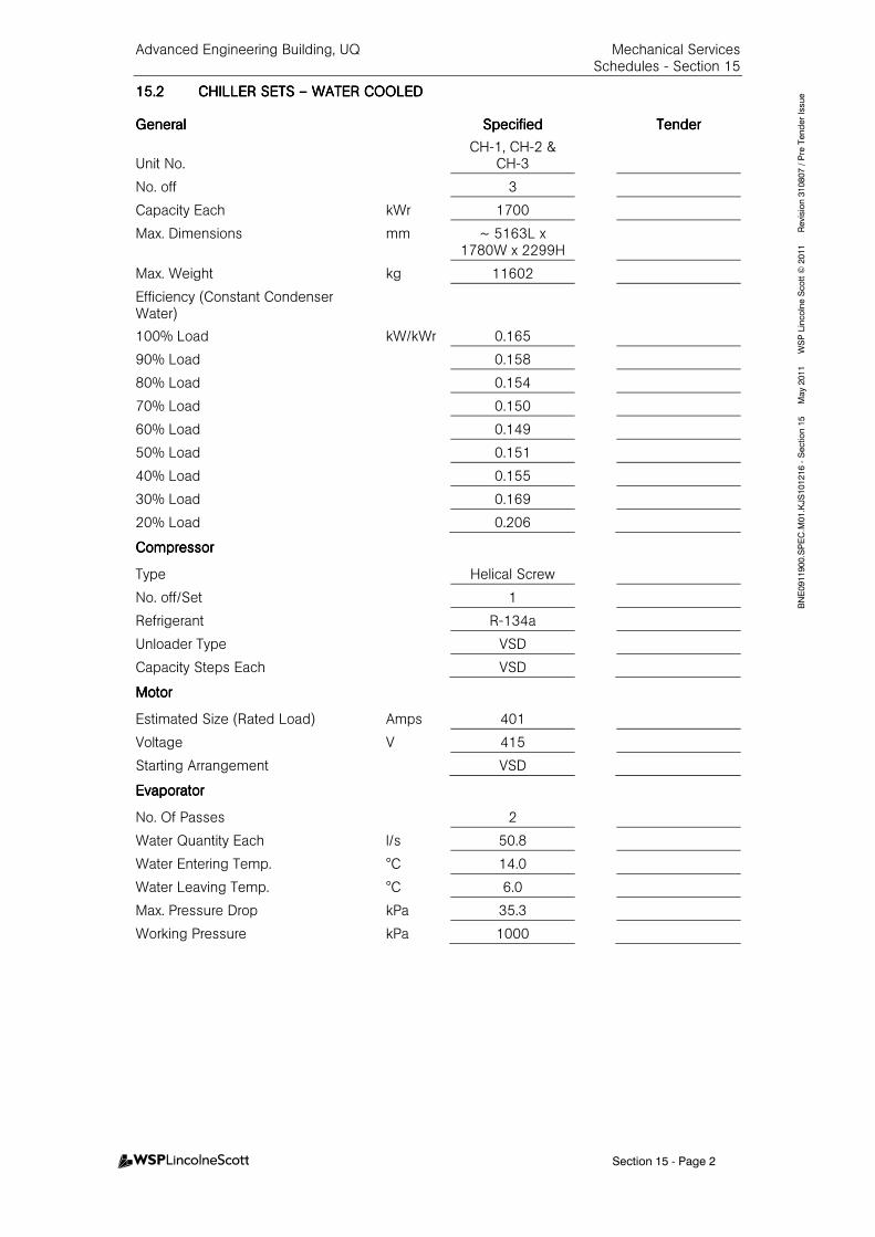
Advanced Engineering Building, UQ Mechanical Services Schedules - Section 15
Section 15 - Page 2
BNE0911900.SPEC.M
01.KJS101216 - Section 15 M
ay 2011 W
SP Lincolne Scott ©
2011 Revision 310807 / Pre Tender Issue 15.215.215.215.2 CHILLER SETCHILLER SETCHILLER SETCHILLER SETSSSS –––– WATER COOLEDWATER COOLEDWATER COOLEDWATER COOLED
GeneralGeneralGeneralGeneral SpecifiedSpecifiedSpecifiedSpecified TenderTenderTenderTender
Unit No. CH-1, CH-2 &
CH-3
No. off 3
Capacity Each kWr 1700
Max. Dimensions mm ~ 5163L x 1780W x 2299H
Max. Weight kg 11602
Efficiency (Constant Condenser Water)
100% Load kW/kWr 0.165
90% Load 0.158
80% Load 0.154
70% Load 0.150
60% Load 0.149
50% Load 0.151
40% Load 0.155
30% Load 0.169
20% Load 0.206
CompressorCompressorCompressorCompressor
Type Helical Screw
No. off/Set 1
Refrigerant R-134a
Unloader Type VSD
Capacity Steps Each VSD
MotorMotorMotorMotor
Estimated Size (Rated Load) Amps 401
Voltage V 415
Starting Arrangement VSD
EvaporatorEvaporatorEvaporatorEvaporator
No. Of Passes 2
Water Quantity Each l/s 50.8
Water Entering Temp. °C 14.0
Water Leaving Temp. °C 6.0
Max. Pressure Drop kPa 35.3
Working Pressure kPa 1000
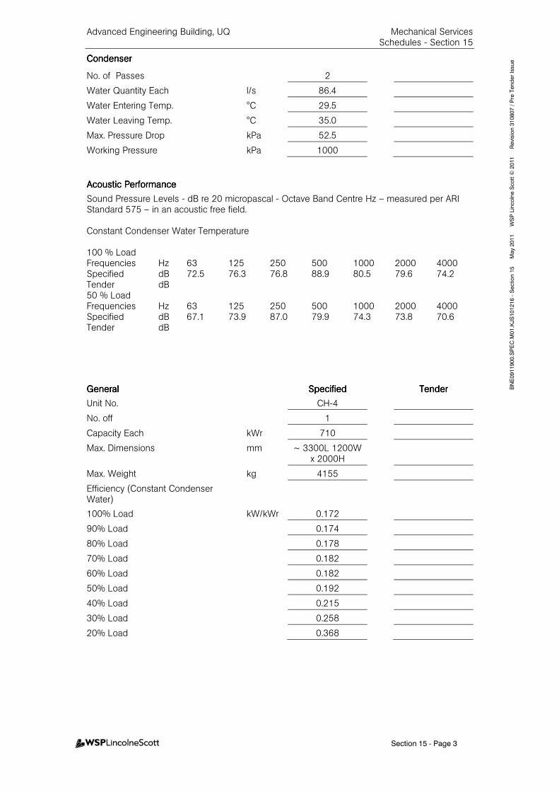
Advanced Engineering Building, UQ Mechanical Services Schedules - Section 15
Section 15 - Page 3
BNE0911900.SPEC.M
01.KJS101216 - Section 15 M
ay 2011 W
SP Lincolne Scott ©
2011 Revision 310807 / Pre Tender Issue CondenserCondenserCondenserCondenser
No. of Passes 2
Water Quantity Each l/s 86.4
Water Entering Temp. °C 29.5
Water Leaving Temp. °C 35.0
Max. Pressure Drop kPa 52.5
Working Pressure kPa 1000
Acoustic PerformanAcoustic PerformanAcoustic PerformanAcoustic Performancececece
Sound Pressure Levels - dB re 20 micropascal - Octave Band Centre Hz – measured per ARI Standard 575 – in an acoustic free field. Constant Condenser Water Temperature 100 % Load Frequencies Hz 63 125 250 500 1000 2000 4000 Specified dB 72.5 76.3 76.8 88.9 80.5 79.6 74.2 Tender dB 50 % Load Frequencies Hz 63 125 250 500 1000 2000 4000 Specified dB 67.1 73.9 87.0 79.9 74.3 73.8 70.6 Tender dB
GeneralGeneralGeneralGeneral SpecifiedSpecifiedSpecifiedSpecified TenderTenderTenderTender
Unit No. CH-4
No. off 1
Capacity Each kWr 710
Max. Dimensions mm ~ 3300L 1200W x 2000H
Max. Weight kg 4155
Efficiency (Constant Condenser Water)
100% Load kW/kWr 0.172
90% Load 0.174
80% Load 0.178
70% Load 0.182
60% Load 0.182
50% Load 0.192
40% Load 0.215
30% Load 0.258
20% Load 0.368
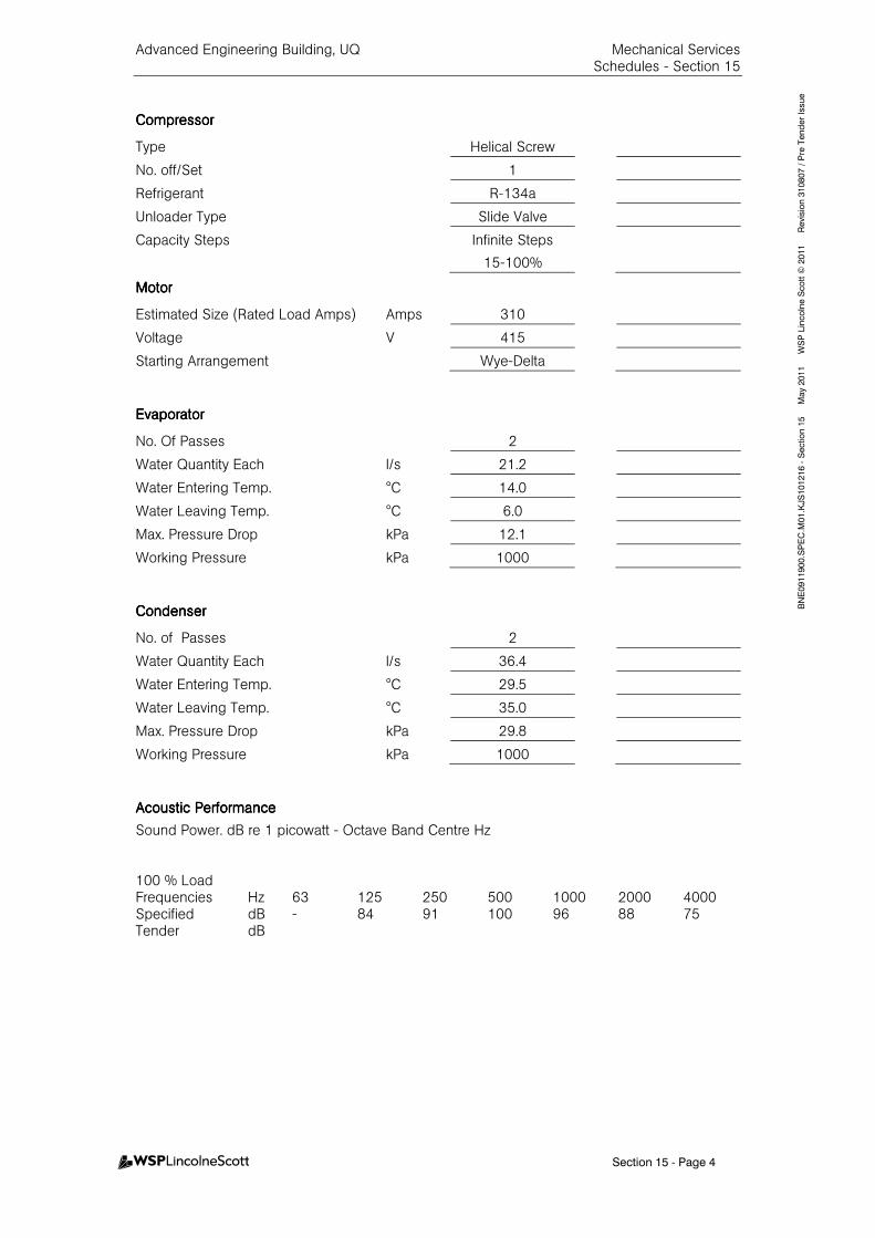
Advanced Engineering Building, UQ Mechanical Services Schedules - Section 15
Section 15 - Page 4
BNE0911900.SPEC.M
01.KJS101216 - Section 15 M
ay 2011 W
SP Lincolne Scott ©
2011 Revision 310807 / Pre Tender Issue
CompressorCompressorCompressorCompressor
Type Helical Screw
No. off/Set 1
Refrigerant R-134a
Unloader Type Slide Valve
Capacity Steps
Infinite Steps
15-100%
MotorMotorMotorMotor
Estimated Size (Rated Load Amps) Amps 310
Voltage V 415
Starting Arrangement Wye-Delta
EvaporatorEvaporatorEvaporatorEvaporator
No. Of Passes 2
Water Quantity Each l/s 21.2
Water Entering Temp. °C 14.0
Water Leaving Temp. °C 6.0
Max. Pressure Drop kPa 12.1
Working Pressure kPa 1000
CondenserCondenserCondenserCondenser
No. of Passes 2
Water Quantity Each l/s 36.4
Water Entering Temp. °C 29.5
Water Leaving Temp. °C 35.0
Max. Pressure Drop kPa 29.8
Working Pressure kPa 1000
Acoustic PerformanceAcoustic PerformanceAcoustic PerformanceAcoustic Performance
Sound Power. dB re 1 picowatt - Octave Band Centre Hz 100 % Load Frequencies Hz 63 125 250 500 1000 2000 4000 Specified dB - 84 91 100 96 88 75 Tender dB
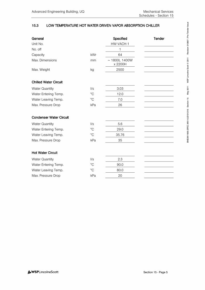
Advanced Engineering Building, UQ Mechanical Services Schedules - Section 15
Section 15 - Page 5
BNE0911900.SPEC.M
01.KJS101216 - Section 15 M
ay 2011 W
SP Lincolne Scott ©
2011 Revision 310807 / Pre Tender Issue
15.315.315.315.3 LOW TEMPERATURE HOT LOW TEMPERATURE HOT LOW TEMPERATURE HOT LOW TEMPERATURE HOT WATER DRIVEN VAPOR AWATER DRIVEN VAPOR AWATER DRIVEN VAPOR AWATER DRIVEN VAPOR ABSORPTION CHILLERBSORPTION CHILLERBSORPTION CHILLERBSORPTION CHILLER
GeneralGeneralGeneralGeneral SpecifiedSpecifiedSpecifiedSpecified TenderTenderTenderTender
Unit No. HW-VACH-1
No. off 1
Capacity kWr 64
Max. Dimensions mm ~ 1800L 1400W x 2200H
Max. Weight kg 2500
Chilled Water CircuitChilled Water CircuitChilled Water CircuitChilled Water Circuit
Water Quantity l/s 3.03
Water Entering Temp. °C 12.0
Water Leaving Temp. °C 7.0
Max. Pressure Drop kPa 26
Condenser Water CircuitCondenser Water CircuitCondenser Water CircuitCondenser Water Circuit
Water Quantity l/s 5.6
Water Entering Temp. °C 29.0
Water Leaving Temp. °C 35.76
Max. Pressure Drop kPa 35
Hot Water CircuitHot Water CircuitHot Water CircuitHot Water Circuit
Water Quantity l/s 2.3
Water Entering Temp. °C 90.0
Water Leaving Temp. °C 80.0
Max. Pressure Drop kPa 20
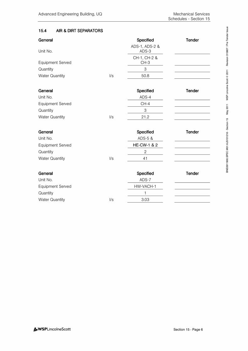
Advanced Engineering Building, UQ Mechanical Services Schedules - Section 15
Section 15 - Page 6
BNE0911900.SPEC.M
01.KJS101216 - Section 15 M
ay 2011 W
SP Lincolne Scott ©
2011 Revision 310807 / Pre Tender Issue
15.415.415.415.4 AIR & DIRT SEPARATORAIR & DIRT SEPARATORAIR & DIRT SEPARATORAIR & DIRT SEPARATORSSSS
GeneralGeneralGeneralGeneral SpecifiedSpecifiedSpecifiedSpecified TenderTenderTenderTender
Unit No. ADS-1, ADS-2 &
ADS-3
Equipment Served CH-1, CH-2 &
CH-3
Quantity 3
Water Quantity l/s 50.8
GeneralGeneralGeneralGeneral SpecifiedSpecifiedSpecifiedSpecified TenderTenderTenderTender
Unit No. ADS-4
Equipment Served CH-4
Quantity 3
Water Quantity l/s 21.2
GeneralGeneralGeneralGeneral SpecifiedSpecifiedSpecifiedSpecified TendTendTendTenderererer
Unit No. ADS-5 &
Equipment Served HE-CW-1 & 2
Quantity 2
Water Quantity l/s 41
GeneralGeneralGeneralGeneral SpecifiedSpecifiedSpecifiedSpecified TenderTenderTenderTender
Unit No. ADS-7
Equipment Served HW-VACH-1
Quantity 1
Water Quantity l/s 3.03
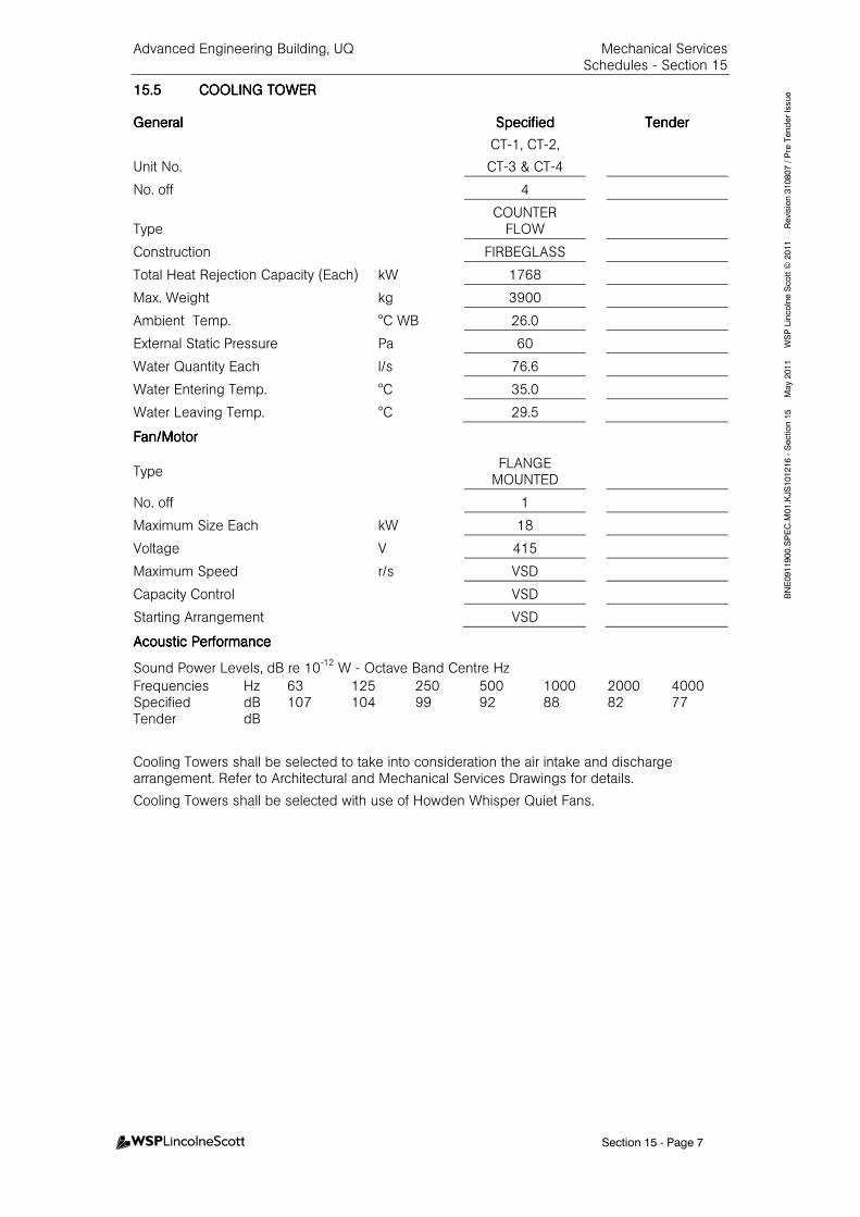
Advanced Engineering Building, UQ Mechanical Services Schedules - Section 15
Section 15 - Page 7
BNE0911900.SPEC.M
01.KJS101216 - Section 15 M
ay 2011 W
SP Lincolne Scott ©
2011 Revision 310807 / Pre Tender Issue 15.515.515.515.5 COOLING TOWERCOOLING TOWERCOOLING TOWERCOOLING TOWER
GeneralGeneralGeneralGeneral SpecifiedSpecifiedSpecifiedSpecified TenderTenderTenderTender
Unit No.
CT-1, CT-2,
CT-3 & CT-4
No. off 4
Type COUNTER
FLOW
Construction FIRBEGLASS
Total Heat Rejection Capacity (Each) kW 1768
Max. Weight kg 3900
Ambient Temp. °C WB 26.0
External Static Pressure Pa 60
Water Quantity Each l/s 76.6
Water Entering Temp. °C 35.0
Water Leaving Temp. °C 29.5
Fan/MotorFan/MotorFan/MotorFan/Motor
Type
FLANGE MOUNTED
No. off 1
Maximum Size Each kW 18
Voltage V 415
Maximum Speed r/s VSD
Capacity Control VSD
Starting Arrangement VSD
AcAcAcAcoustic Performanceoustic Performanceoustic Performanceoustic Performance
Sound Power Levels, dB re 10-12
W - Octave Band Centre Hz
Frequencies Hz 63 125 250 500 1000 2000 4000 Specified dB 107 104 99 92 88 82 77 Tender dB
Cooling Towers shall be selected to take into consideration the air intake and discharge arrangement. Refer to Architectural and Mechanical Services Drawings for details.
Cooling Towers shall be selected with use of Howden Whisper Quiet Fans.
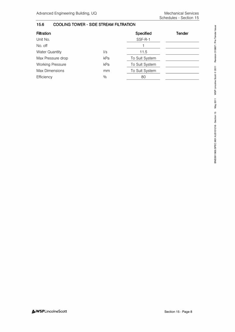
Advanced Engineering Building, UQ Mechanical Services Schedules - Section 15
Section 15 - Page 8
BNE0911900.SPEC.M
01.KJS101216 - Section 15 M
ay 2011 W
SP Lincolne Scott ©
2011 Revision 310807 / Pre Tender Issue 15.615.615.615.6 COOLING TOWER COOLING TOWER COOLING TOWER COOLING TOWER ---- SIDE STREAM FILTRATISIDE STREAM FILTRATISIDE STREAM FILTRATISIDE STREAM FILTRATIONONONON
FiltrationFiltrationFiltrationFiltration SpecifiedSpecifiedSpecifiedSpecified TenderTenderTenderTender
Unit No. SSF-R-1
No. off 1
Water Quantity l/s 11.5
Max Pressure drop kPa To Suit System
Working Pressure kPa To Suit System
Max Dimensions mm To Suit System
Efficiency % 80
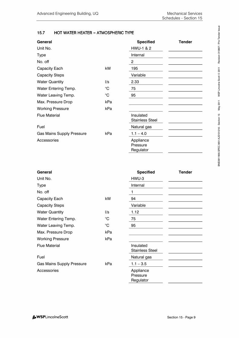
Advanced Engineering Building, UQ Mechanical Services Schedules - Section 15
Section 15 - Page 9
BNE0911900.SPEC.M
01.KJS101216 - Section 15 M
ay 2011 W
SP Lincolne Scott ©
2011 Revision 310807 / Pre Tender Issue
15.715.715.715.7 HOT WATER HEATER HOT WATER HEATER HOT WATER HEATER HOT WATER HEATER –––– ATMOSPHERIC TYPEATMOSPHERIC TYPEATMOSPHERIC TYPEATMOSPHERIC TYPE
General Specified Tender
Unit No. HWU-1 & 2
Type Internal
No. off 2
Capacity Each kW 195
Capacity Steps Variable
Water Quantity l/s 2.33
Water Entering Temp. °C 75
Water Leaving Temp. °C 95
Max. Pressure Drop kPa
Working Pressure kPa
Flue Material
Insulated
Stainless Steel
Fuel Natural gas
Gas Mains Supply Pressure kPa 1.1 – 4.0
Accessories
Appliance
Pressure
Regulator
General Specified Tender
Unit No. HWU-3
Type Internal
No. off 1
Capacity Each kW 94
Capacity Steps Variable
Water Quantity l/s 1.12
Water Entering Temp. °C 75
Water Leaving Temp. °C 95
Max. Pressure Drop kPa
Working Pressure kPa
Flue Material
Insulated
Stainless Steel
Fuel Natural gas
Gas Mains Supply Pressure kPa 1.1 – 3.5
Accessories
Appliance
Pressure
Regulator
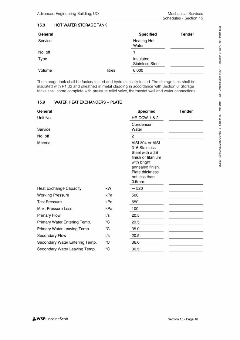
Advanced Engineering Building, UQ Mechanical Services Schedules - Section 15
Section 15 - Page 10
BNE0911900.SPEC.M
01.KJS101216 - Section 15 M
ay 2011 W
SP Lincolne Scott ©
2011 Revision 310807 / Pre Tender Issue 15.815.815.815.8 HOT HOT HOT HOT WATER STORAGE TANKWATER STORAGE TANKWATER STORAGE TANKWATER STORAGE TANK
General Specified Tender
Service
Heating Hot
Water
No. off 1
Type
Insulated
Stainless Steel
Volume litres 6,000
The storage tank shall be factory tested and hydrostatically tested. The storage tank shall be insulated with R1.82 and sheathed in metal cladding in accordance with Section 8. Storage tanks shall come complete with pressure relief valve, thermostat well and water connections.
15.915.915.915.9 WATER HEAT EXCHANGERWATER HEAT EXCHANGERWATER HEAT EXCHANGERWATER HEAT EXCHANGERS S S S –––– PLATEPLATEPLATEPLATE
General Specified Tender
Unit No. HE-CCW-1 & 2
Service
Condenser
Water
No. off 2
Material
AISI 304 or AISI
316 Stainless
Steel with a 2B
finish or titanium
with bright
annealed finish.
Plate thickness
not less than
0.5mm.
Heat Exchange Capacity kW ~ 520
Working Pressure kPa 500
Test Pressure kPa 650
Max. Pressure Loss kPa 100
Primary Flow l/s 20.5
Primary Water Entering Temp. °C 29.5
Primary Water Leaving Temp. °C 35.0
Secondary Flow l/s 20.5
Secondary Water Entering Temp. °C 36.0
Secondary Water Leaving Temp. °C 30.5

Advanced Engineering Building, UQ Mechanical Services Schedules - Section 15
Section 15 - Page 11
BNE0911900.SPEC.M
01.KJS101216 - Section 15 M
ay 2011 W
SP Lincolne Scott ©
2011 Revision 310807 / Pre Tender Issue
15.1015.1015.1015.10 HEAT HEAT HEAT HEAT DISSIPATION COILSDISSIPATION COILSDISSIPATION COILSDISSIPATION COILS
GeneralGeneralGeneralGeneral SpecifiedSpecifiedSpecifiedSpecified TenderTenderTenderTender
Service Gas Fired Turbine
No. off 2
Material
Copper or AISI 316 Stainless Steel
Max. Pressure Loss kPa 100
Primary Flow l/s 3.8
Primary Water Entering Temp. °C 89.5
Primary Water Leaving Temp. °C 82
Tank Temp. °C 80
GeneralGeneralGeneralGeneral SpecifiedSpecifiedSpecifiedSpecified TenderTenderTenderTender
Service Fuel Cell
No. off 2
Material
Copper or AISI 316 Stainless Steel
Max. Pressure Loss kPa 100
Primary Flow l/s 0.33
Primary Water Entering Temp. °C 27.0
Primary Water Leaving Temp. °C 23.0
Tank Temp. °C 21.0
GeneralGeneralGeneralGeneral SpecifiedSpecifiedSpecifiedSpecified TenderTenderTenderTender
Service
Solar Hot Water – Thermal Transfer Fluid
No. off 1
Material
Copper or AISI 316 Stainless Steel
Max. Pressure Loss kPa 100
Primary Flow (Thermal Transfer Oil) l/s 3.0
Primary Water Entering Temp. °C 140
Primary Water Leaving Temp. °C 130
Tank Temp. °C 80
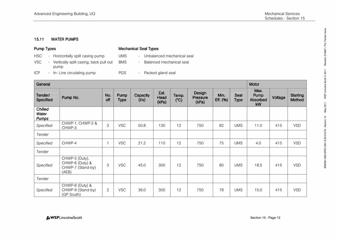
Advanced Engineering Building, UQ Mechanical Services Schedules - Section 15
Section 15 - Page 12
BNE0911900.SPEC.M
01.KJS101216 - Section 15 M
ay 2011 W
SP Lincolne Scott ©
2011 Revision 310807 / Pre Tender Issue
15.1115.1115.1115.11 WATER PUMPWATER PUMPWATER PUMPWATER PUMPSSSS
Pump Types MecPump Types MecPump Types MecPump Types Mechanical Seal Typeshanical Seal Typeshanical Seal Typeshanical Seal Types
HSC - Horizontally split casing pump UMS - Unbalanced mechanical seal
VSC - Vertically split casing, back pull out pump
BMS - Balanced mechanical seal
ICP - In- Line circulating pump PGS - Packed gland seal
GeneralGeneralGeneralGeneral MotorMotorMotorMotor
Tender/Tender/Tender/Tender/ SpeSpeSpeSpecifiedcifiedcifiedcified
Pump No.Pump No.Pump No.Pump No. No. No. No. No. offoffoffoff
Pump Pump Pump Pump TypeTypeTypeType
Capacity Capacity Capacity Capacity (l/s)(l/s)(l/s)(l/s)
Est.Est.Est.Est. Head Head Head Head (kPa)(kPa)(kPa)(kPa)
Temp. Temp. Temp. Temp. (°C)(°C)(°C)(°C)
Design Design Design Design Pressure Pressure Pressure Pressure
(kPa)(kPa)(kPa)(kPa)
MinMinMinMin.... EffEffEffEff.... (%)(%)(%)(%)
SealSealSealSeal TypeTypeTypeType
Max. Max. Max. Max. Pump Pump Pump Pump
Absorbed Absorbed Absorbed Absorbed kWkWkWkW
VoltageVoltageVoltageVoltage Starting Starting Starting Starting MethodMethodMethodMethod
Chilled Chilled Chilled Chilled
Water Water Water Water
PumpsPumpsPumpsPumps
Specified CHWP-1, CHWP-2 & CHWP-3
3 VSC 50.8 130 12 750 82 UMS 11.0 415 VSD
Tender
Specified CHWP-4 1 VSC 21.2 110 12 750 75 UMS 4.0 415 VSD
Tender
Specified
CHWP-5 (Duty), CHWP-6 (Duty) & CHWP-7 (Stand-by) (AEB)
3 VSC 45.0 300 12 750 80 UMS 18.5 415 VSD
Tender
Specified
CHWP-8 (Duty) & CHWP-9 (Stand-by) (GP South)
2 VSC 36.0 300 12 750 78 UMS 15.0 415 VSD
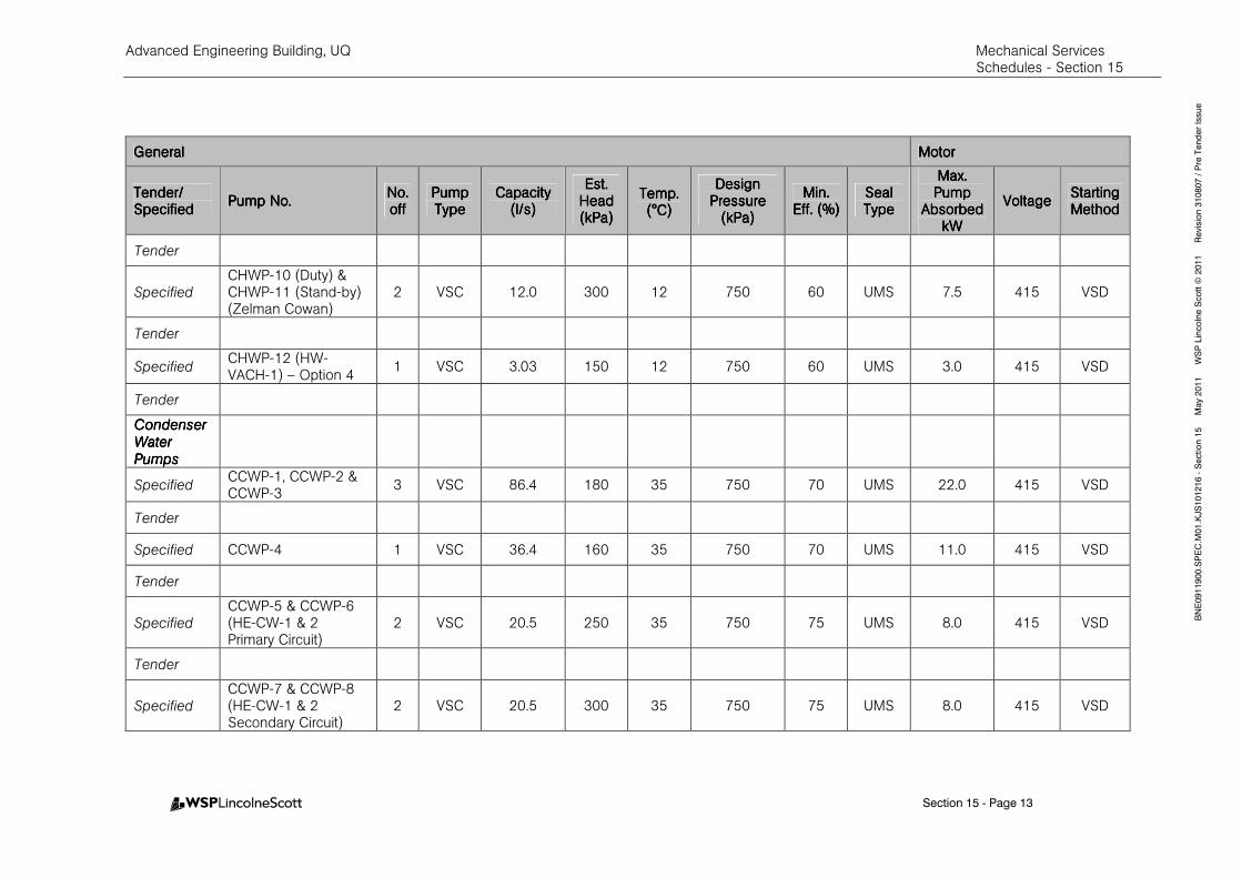
Advanced Engineering Building, UQ Mechanical Services Schedules - Section 15
Section 15 - Page 13
BNE0911900.SPEC.M
01.KJS101216 - Section 15 M
ay 2011 W
SP Lincolne Scott ©
2011 Revision 310807 / Pre Tender Issue
GeneralGeneralGeneralGeneral MotorMotorMotorMotor
Tender/Tender/Tender/Tender/ SpeSpeSpeSpecifiedcifiedcifiedcified
Pump No.Pump No.Pump No.Pump No. No. No. No. No. offoffoffoff
Pump Pump Pump Pump TypeTypeTypeType
Capacity Capacity Capacity Capacity (l/s)(l/s)(l/s)(l/s)
Est.Est.Est.Est. Head Head Head Head (kPa)(kPa)(kPa)(kPa)
Temp. Temp. Temp. Temp. (°C)(°C)(°C)(°C)
Design Design Design Design Pressure Pressure Pressure Pressure
(kPa)(kPa)(kPa)(kPa)
MinMinMinMin.... EffEffEffEff.... (%)(%)(%)(%)
SealSealSealSeal TypeTypeTypeType
Max. Max. Max. Max. Pump Pump Pump Pump
Absorbed Absorbed Absorbed Absorbed kWkWkWkW
VoltageVoltageVoltageVoltage Starting Starting Starting Starting MethodMethodMethodMethod
Tender
Specified
CHWP-10 (Duty) & CHWP-11 (Stand-by) (Zelman Cowan)
2 VSC 12.0 300 12 750 60 UMS 7.5 415 VSD
Tender
Specified CHWP-12 (HW-VACH-1) – Option 4
1 VSC 3.03 150 12 750 60 UMS 3.0 415 VSD
Tender
Condenser Condenser Condenser Condenser
Water Water Water Water
PumpsPumpsPumpsPumps
Specified CCWP-1, CCWP-2 & CCWP-3
3 VSC 86.4 180 35 750 70 UMS 22.0 415 VSD
Tender
Specified CCWP-4 1 VSC 36.4 160 35 750 70 UMS 11.0 415 VSD
Tender
Specified
CCWP-5 & CCWP-6 (HE-CW-1 & 2 Primary Circuit)
2 VSC 20.5 250 35 750 75 UMS 8.0 415 VSD
Tender
Specified
CCWP-7 & CCWP-8 (HE-CW-1 & 2 Secondary Circuit)
2 VSC 20.5 300 35 750 75 UMS 8.0 415 VSD
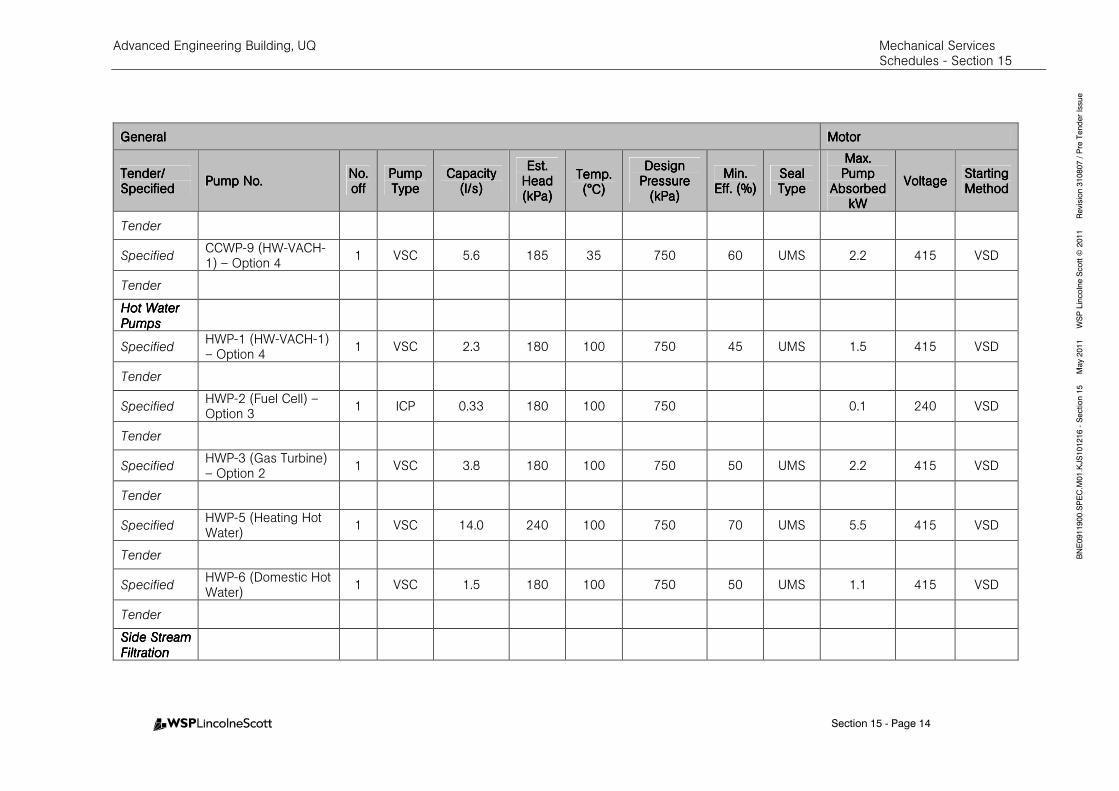
Advanced Engineering Building, UQ Mechanical Services Schedules - Section 15
Section 15 - Page 14
BNE0911900.SPEC.M
01.KJS101216 - Section 15 M
ay 2011 W
SP Lincolne Scott ©
2011 Revision 310807 / Pre Tender Issue
GeneralGeneralGeneralGeneral MotorMotorMotorMotor
Tender/Tender/Tender/Tender/ SpeSpeSpeSpecifiedcifiedcifiedcified
Pump No.Pump No.Pump No.Pump No. No. No. No. No. offoffoffoff
Pump Pump Pump Pump TypeTypeTypeType
Capacity Capacity Capacity Capacity (l/s)(l/s)(l/s)(l/s)
Est.Est.Est.Est. Head Head Head Head (kPa)(kPa)(kPa)(kPa)
Temp. Temp. Temp. Temp. (°C)(°C)(°C)(°C)
Design Design Design Design Pressure Pressure Pressure Pressure
(kPa)(kPa)(kPa)(kPa)
MinMinMinMin.... EffEffEffEff.... (%)(%)(%)(%)
SealSealSealSeal TypeTypeTypeType
Max. Max. Max. Max. Pump Pump Pump Pump
Absorbed Absorbed Absorbed Absorbed kWkWkWkW
VoltageVoltageVoltageVoltage Starting Starting Starting Starting MethodMethodMethodMethod
Tender
Specified CCWP-9 (HW-VACH-1) – Option 4
1 VSC 5.6 185 35 750 60 UMS 2.2 415 VSD
Tender
Hot Water Hot Water Hot Water Hot Water
Pumps Pumps Pumps Pumps
Specified HWP-1 (HW-VACH-1) – Option 4
1 VSC 2.3 180 100 750 45 UMS 1.5 415 VSD
Tender
Specified HWP-2 (Fuel Cell) – Option 3
1 ICP 0.33 180 100 750 0.1 240 VSD
Tender
Specified HWP-3 (Gas Turbine) – Option 2
1 VSC 3.8 180 100 750 50 UMS 2.2 415 VSD
Tender
Specified HWP-5 (Heating Hot Water)
1 VSC 14.0 240 100 750 70 UMS 5.5 415 VSD
Tender
Specified HWP-6 (Domestic Hot Water)
1 VSC 1.5 180 100 750 50 UMS 1.1 415 VSD
Tender
Side StreamSide StreamSide StreamSide Stream
FiltrationFiltrationFiltrationFiltration

Advanced Engineering Building, UQ Mechanical Services Schedules - Section 15
Section 15 - Page 15
BNE0911900.SPEC.M
01.KJS101216 - Section 15 M
ay 2011 W
SP Lincolne Scott ©
2011 Revision 310807 / Pre Tender Issue
GeneralGeneralGeneralGeneral MotorMotorMotorMotor
Tender/Tender/Tender/Tender/ SpeSpeSpeSpecifiedcifiedcifiedcified
Pump No.Pump No.Pump No.Pump No. No. No. No. No. offoffoffoff
Pump Pump Pump Pump TypeTypeTypeType
Capacity Capacity Capacity Capacity (l/s)(l/s)(l/s)(l/s)
Est.Est.Est.Est. Head Head Head Head (kPa)(kPa)(kPa)(kPa)
Temp. Temp. Temp. Temp. (°C)(°C)(°C)(°C)
Design Design Design Design Pressure Pressure Pressure Pressure
(kPa)(kPa)(kPa)(kPa)
MinMinMinMin.... EffEffEffEff.... (%)(%)(%)(%)
SealSealSealSeal TypeTypeTypeType
Max. Max. Max. Max. Pump Pump Pump Pump
Absorbed Absorbed Absorbed Absorbed kWkWkWkW
VoltageVoltageVoltageVoltage Starting Starting Starting Starting MethodMethodMethodMethod
Specified SSFP-R-1 (Duty) & SSFP-R-2 (Standby)
2 VSC 11.5 To Suit System
35 750 80 UMS 7.5 415 VSD
Tender
15.1215.1215.1215.12 THERMAL TRANSFER FLUTHERMAL TRANSFER FLUTHERMAL TRANSFER FLUTHERMAL TRANSFER FLUID PUMPID PUMPID PUMPID PUMP
Refer Section 4.
GeneralGeneralGeneralGeneral MotorMotorMotorMotor
Tender/Tender/Tender/Tender/ SpecifiedSpecifiedSpecifiedSpecified
Pump No.Pump No.Pump No.Pump No. No. No. No. No. offoffoffoff
Capacity Capacity Capacity Capacity (l/s)(l/s)(l/s)(l/s)
Est.Est.Est.Est. Head Head Head Head (kPa)(kPa)(kPa)(kPa)
Temp. Temp. Temp. Temp. (°C)(°C)(°C)(°C)
Design Design Design Design Pressure Pressure Pressure Pressure
(kPa)(kPa)(kPa)(kPa)
Min.Min.Min.Min. Eff. (%)Eff. (%)Eff. (%)Eff. (%)
Max. Max. Max. Max. Pump Pump Pump Pump
Absorbed Absorbed Absorbed Absorbed kWkWkWkW
VoltageVoltageVoltageVoltage Starting Starting Starting Starting MethodMethodMethodMethod
Specified
HWP-4 (Solar Collectors – Thermal Transfer Fluid) – Option 4
1 3.0 200 300 750 50 2.2 415 VSD
Tender
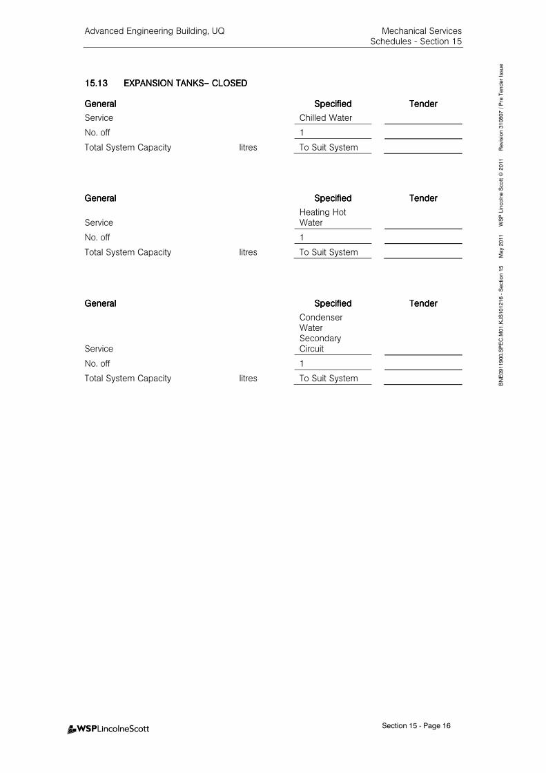
Advanced Engineering Building, UQ Mechanical Services Schedules - Section 15
Section 15 - Page 16
BNE0911900.SPEC.M
01.KJS101216 - Section 15 M
ay 2011 W
SP Lincolne Scott ©
2011 Revision 310807 / Pre Tender Issue
15.1315.1315.1315.13 EXPANSION TANKEXPANSION TANKEXPANSION TANKEXPANSION TANKSSSS–––– CLOSEDCLOSEDCLOSEDCLOSED
GeneralGeneralGeneralGeneral SpecifiedSpecifiedSpecifiedSpecified TenderTenderTenderTender
Service Chilled Water
No. off 1
Total System Capacity litres To Suit System
GeneralGeneralGeneralGeneral SpecifiedSpecifiedSpecifiedSpecified TenderTenderTenderTender
Service Heating Hot Water
No. off 1
Total System Capacity litres To Suit System
GeneralGeneralGeneralGeneral SpecifiedSpecifiedSpecifiedSpecified TenderTenderTenderTender
Service
Condenser Water Secondary Circuit
No. off 1
Total System Capacity litres To Suit System
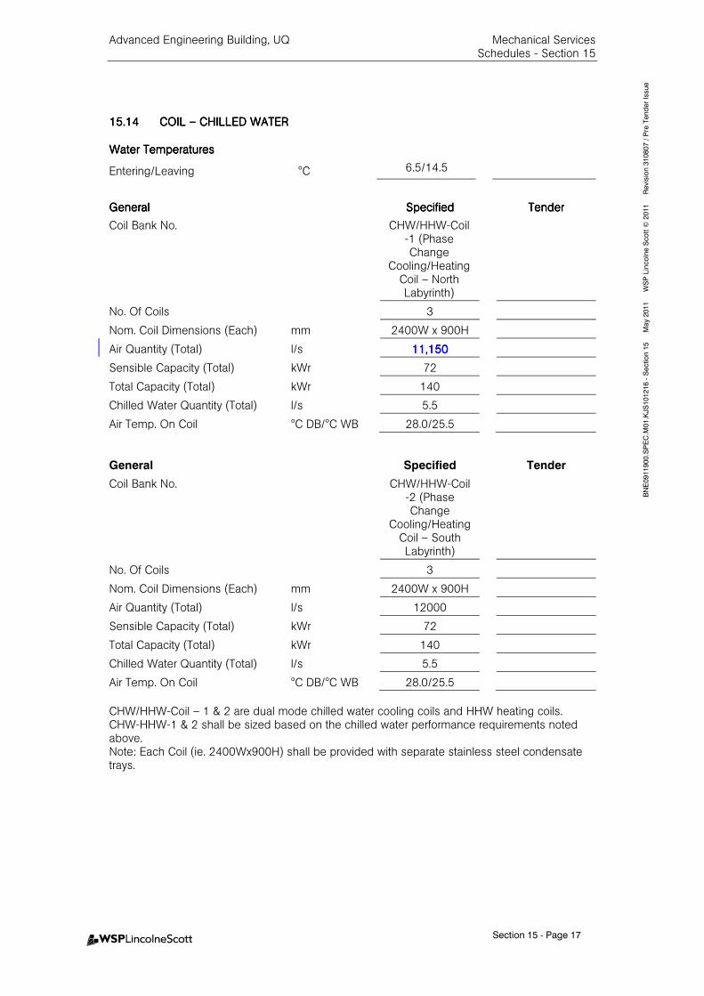
Advanced Engineering Building, UQ Mechanical Services Schedules - Section 15
Section 15 - Page 17
BNE0911900.SPEC.M
01.KJS101216 - Section 15 M
ay 2011 W
SP Lincolne Scott ©
2011 Revision 310807 / Pre Tender Issue
15.1415.1415.1415.14 COIL COIL COIL COIL –––– CHILLED WATERCHILLED WATERCHILLED WATERCHILLED WATER
Water TemperaturesWater TemperaturesWater TemperaturesWater Temperatures
Entering/Leaving °C 6.5/14.5
GeneralGeneralGeneralGeneral SpecifiedSpecifiedSpecifiedSpecified TenderTenderTenderTender
Coil Bank No.
CHW/HHW-Coil -1 (Phase Change
Cooling/Heating Coil – North Labyrinth)
No. Of Coils 3
Nom. Coil Dimensions (Each) mm 2400W x 900H
Air Quantity (Total) l/s 11,15011,15011,15011,150
Sensible Capacity (Total) kWr 72
Total Capacity (Total) kWr 140
Chilled Water Quantity (Total) l/s 5.5
Air Temp. On Coil °C DB/°C WB 28.0/25.5
General Specified Tender
Coil Bank No.
CHW/HHW-Coil -2 (Phase Change
Cooling/Heating Coil – South Labyrinth)
No. Of Coils 3
Nom. Coil Dimensions (Each) mm 2400W x 900H
Air Quantity (Total) l/s 12000
Sensible Capacity (Total) kWr 72
Total Capacity (Total) kWr 140
Chilled Water Quantity (Total) l/s 5.5
Air Temp. On Coil °C DB/°C WB 28.0/25.5
CHW/HHW-Coil – 1 & 2 are dual mode chilled water cooling coils and HHW heating coils. CHW-HHW-1 & 2 shall be sized based on the chilled water performance requirements noted above. Note: Each Coil (ie. 2400Wx900H) shall be provided with separate stainless steel condensate trays.
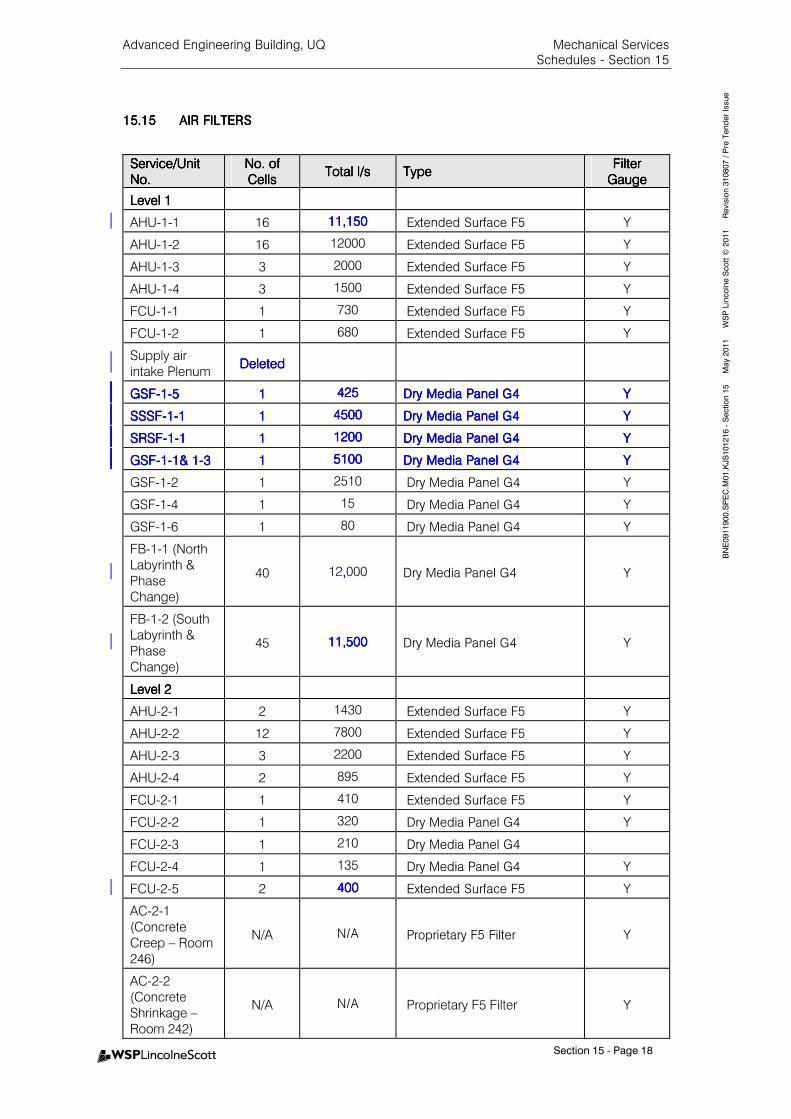
Advanced Engineering Building, UQ Mechanical Services Schedules - Section 15
Section 15 - Page 18
BNE0911900.SPEC.M
01.KJS101216 - Section 15 M
ay 2011 W
SP Lincolne Scott ©
2011 Revision 310807 / Pre Tender Issue
15.1515.1515.1515.15 AIR FILTERSAIR FILTERSAIR FILTERSAIR FILTERS
Service/Unit Service/Unit Service/Unit Service/Unit
No.No.No.No.
No. of No. of No. of No. of
CellsCellsCellsCells Total l/sTotal l/sTotal l/sTotal l/s TypeTypeTypeType
Filter Filter Filter Filter
GaugeGaugeGaugeGauge
Level 1Level 1Level 1Level 1
AHU-1-1 16 11,15011,15011,15011,150 Extended Surface F5 Y
AHU-1-2 16 12000 Extended Surface F5 Y
AHU-1-3 3 2000 Extended Surface F5 Y
AHU-1-4 3 1500 Extended Surface F5 Y
FCU-1-1 1 730 Extended Surface F5 Y
FCU-1-2 1 680 Extended Surface F5 Y
Supply air
intake Plenum DeletedDeletedDeletedDeleted
GSFGSFGSFGSF----1111----5555 1111 425425425425 Dry Media PanelDry Media PanelDry Media PanelDry Media Panel G4G4G4G4 YYYY
SSSFSSSFSSSFSSSF----1111----1111 1111 4500450045004500 DrDrDrDry Media Panely Media Panely Media Panely Media Panel G4G4G4G4 YYYY
SRSFSRSFSRSFSRSF----1111----1111 1111 1200120012001200 Dry Media PanelDry Media PanelDry Media PanelDry Media Panel G4G4G4G4 YYYY
GSFGSFGSFGSF----1111----1& 11& 11& 11& 1----3333 1111 5100510051005100 Dry Media PanelDry Media PanelDry Media PanelDry Media Panel G4G4G4G4 YYYY
GSF-1-2 1 2510 Dry Media Panel G4 Y
GSF-1-4 1 15 Dry Media Panel G4 Y
GSF-1-6 1 80 Dry Media Panel G4 Y
FB-1-1 (North
Labyrinth &
Phase
Change)
40 12,,,,000 Dry Media Panel G4 Y
FB-1-2 (South
Labyrinth &
Phase
Change)
45 11,50011,50011,50011,500 Dry Media Panel G4 Y
Level 2Level 2Level 2Level 2
AHU-2-1 2 1430 Extended Surface F5 Y
AHU-2-2 12 7800 Extended Surface F5 Y
AHU-2-3 3 2200 Extended Surface F5 Y
AHU-2-4 2 895 Extended Surface F5 Y
FCU-2-1 1 410 Extended Surface F5 Y
FCU-2-2 1 320 Dry Media Panel G4 Y
FCU-2-3 1 210 Dry Media Panel G4
FCU-2-4 1 135 Dry Media Panel G4 Y
FCU-2-5 2 400400400400 Extended Surface F5 Y
AC-2-1
(Concrete
Creep – Room
246)
N/A N/A Proprietary F5 Filter Y
AC-2-2
(Concrete
Shrinkage –
Room 242)
N/A N/A Proprietary F5 Filter Y
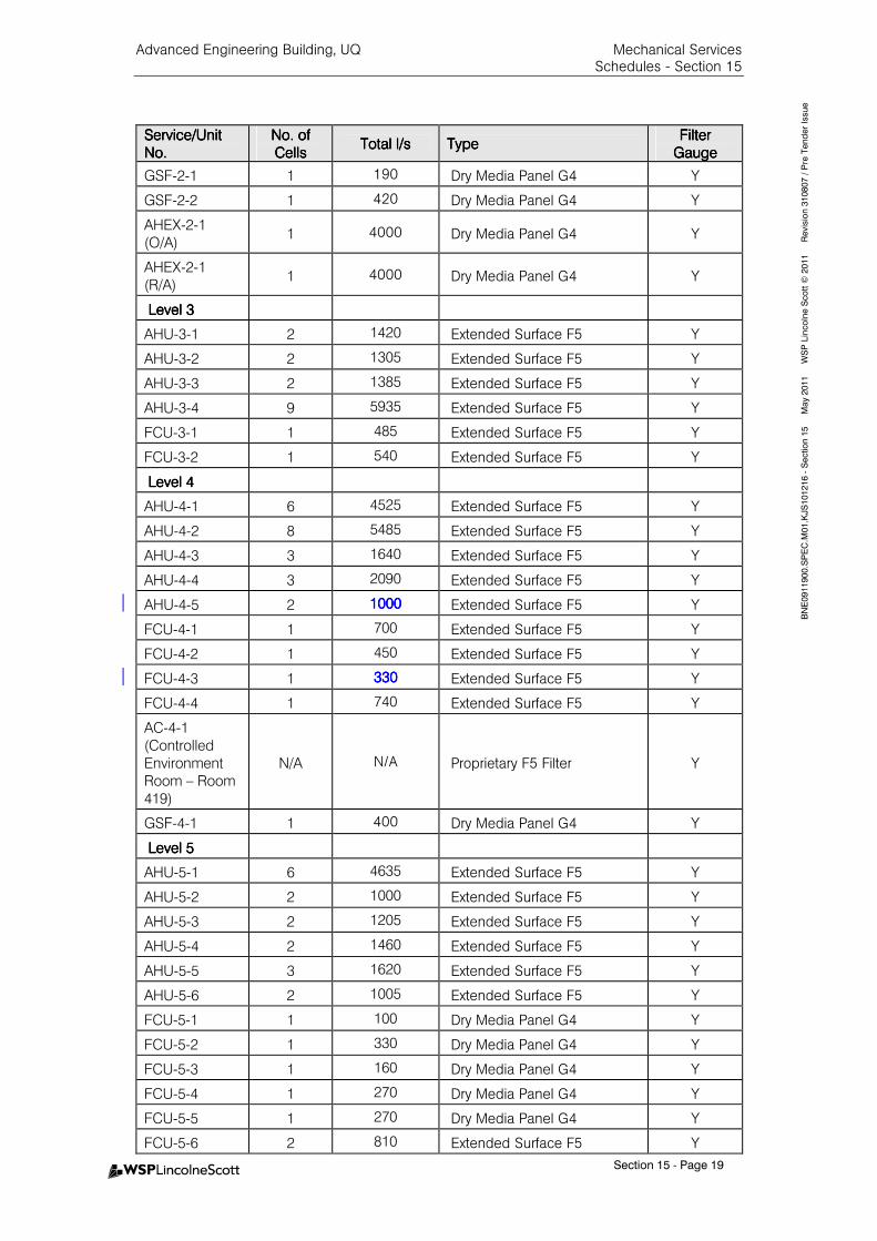
Advanced Engineering Building, UQ Mechanical Services Schedules - Section 15
Section 15 - Page 19
BNE0911900.SPEC.M
01.KJS101216 - Section 15 M
ay 2011 W
SP Lincolne Scott ©
2011 Revision 310807 / Pre Tender Issue
Service/Unit Service/Unit Service/Unit Service/Unit
No.No.No.No.
No. of No. of No. of No. of
CellsCellsCellsCells Total l/sTotal l/sTotal l/sTotal l/s TypeTypeTypeType
Filter Filter Filter Filter
GaugeGaugeGaugeGauge
GSF-2-1 1 190 Dry Media Panel G4 Y
GSF-2-2 1 420 Dry Media Panel G4 Y
AHEX-2-1
(O/A) 1 4000 Dry Media Panel G4 Y
AHEX-2-1
(R/A) 1 4000 Dry Media Panel G4 Y
Level Level Level Level 3333
AHU-3-1 2 1420 Extended Surface F5 Y
AHU-3-2 2 1305 Extended Surface F5 Y
AHU-3-3 2 1385 Extended Surface F5 Y
AHU-3-4 9 5935 Extended Surface F5 Y
FCU-3-1 1 485 Extended Surface F5 Y
FCU-3-2 1 540 Extended Surface F5 Y
Level 4Level 4Level 4Level 4
AHU-4-1 6 4525 Extended Surface F5 Y
AHU-4-2 8 5485 Extended Surface F5 Y
AHU-4-3 3 1640 Extended Surface F5 Y
AHU-4-4 3 2090 Extended Surface F5 Y
AHU-4-5 2 1000100010001000 Extended Surface F5 Y
FCU-4-1 1 700 Extended Surface F5 Y
FCU-4-2 1 450 Extended Surface F5 Y
FCU-4-3 1 330330330330 Extended Surface F5 Y
FCU-4-4 1 740 Extended Surface F5 Y
AC-4-1
(Controlled
Environment
Room – Room
419)
N/A N/A Proprietary F5 Filter Y
GSF-4-1 1 400 Dry Media Panel G4 Y
Level 5Level 5Level 5Level 5
AHU-5-1 6 4635 Extended Surface F5 Y
AHU-5-2 2 1000 Extended Surface F5 Y
AHU-5-3 2 1205 Extended Surface F5 Y
AHU-5-4 2 1460 Extended Surface F5 Y
AHU-5-5 3 1620 Extended Surface F5 Y
AHU-5-6 2 1005 Extended Surface F5 Y
FCU-5-1 1 100 Dry Media Panel G4 Y
FCU-5-2 1 330 Dry Media Panel G4 Y
FCU-5-3 1 160 Dry Media Panel G4 Y
FCU-5-4 1 270 Dry Media Panel G4 Y
FCU-5-5 1 270 Dry Media Panel G4 Y
FCU-5-6 2 810 Extended Surface F5 Y
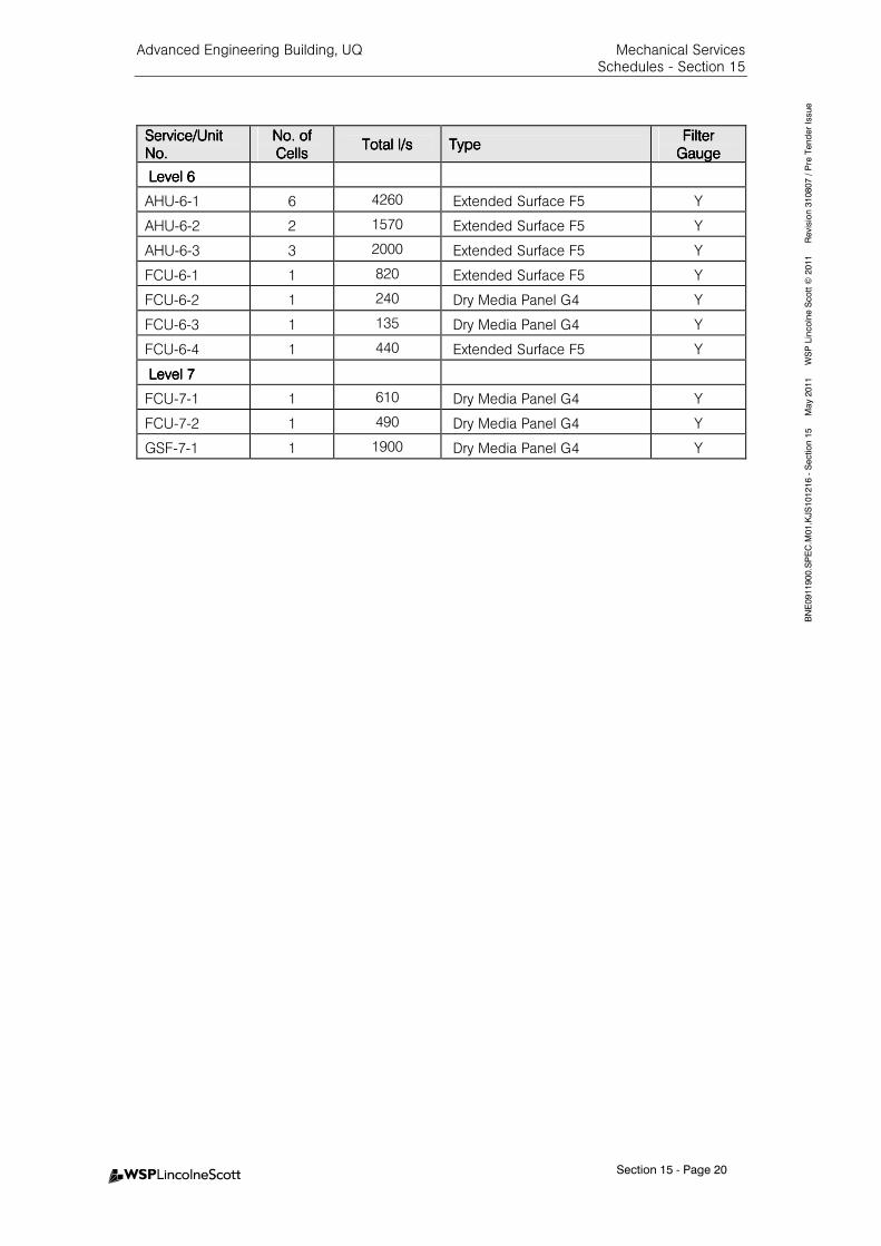
Advanced Engineering Building, UQ Mechanical Services Schedules - Section 15
Section 15 - Page 20
BNE0911900.SPEC.M
01.KJS101216 - Section 15 M
ay 2011 W
SP Lincolne Scott ©
2011 Revision 310807 / Pre Tender Issue
Service/Unit Service/Unit Service/Unit Service/Unit
No.No.No.No.
No. of No. of No. of No. of
CellsCellsCellsCells Total l/sTotal l/sTotal l/sTotal l/s TypeTypeTypeType
Filter Filter Filter Filter
GaugeGaugeGaugeGauge
Level 6Level 6Level 6Level 6
AHU-6-1 6 4260 Extended Surface F5 Y
AHU-6-2 2 1570 Extended Surface F5 Y
AHU-6-3 3 2000 Extended Surface F5 Y
FCU-6-1 1 820 Extended Surface F5 Y
FCU-6-2 1 240 Dry Media Panel G4 Y
FCU-6-3 1 135 Dry Media Panel G4 Y
FCU-6-4 1 440 Extended Surface F5 Y
Level 7Level 7Level 7Level 7
FCU-7-1 1 610 Dry Media Panel G4 Y
FCU-7-2 1 490 Dry Media Panel G4 Y
GSF-7-1 1 1900 Dry Media Panel G4 Y

Advanced Engineering Building, UQ Mechanical Services Schedules - Section 15
Section 15 - Page 21
BNE0911900.SPEC.M
01.KJS101216 - Section 15 M
ay 2011 W
SP Lincolne Scott ©
2011 Revision 310807 / Pre Tender Issue
15.1615.1615.1615.16 AIR HANDLING UNIT / AIR HANDLING UNIT / AIR HANDLING UNIT / AIR HANDLING UNIT / FAN COIL UNITFAN COIL UNITFAN COIL UNITFAN COIL UNIT
Unit TypeUnit TypeUnit TypeUnit Type
CAV - Constant Air Volume
VAV - Variable Air Volume
Fan TypeFan TypeFan TypeFan Type
CB - Centrifugal Backward Curved Blades
CF - Centrifugal Forward Curved Blades
VSD - Variable Speed Drive
Note: Some AHU’s with small air quantities may require installation of proprietary AHU fitted with a smaller fan/motor and smaller chilled water cooling coil. Low profile / slim line units typically used for confined ceiling spaces (typically wider) are not suitable for AHU located in plant room / platforms due to space restrictions. Refer to Drawings for further information.
All AHU’s shall be Sandwich Construction.
Refer to Coil – Heating Water for in built heating hot water coils.
Water TemperaturesWater TemperaturesWater TemperaturesWater Temperatures
Entering/Leaving CHW °C 6.5/14.5
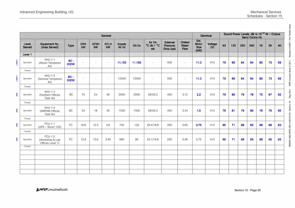
Advanced Engineering Building, UQ Mechanical Services Schedules - Section 15
Section 15 - Page 20
BNE0911900.SPEC.M
01.KJS101216 - Section 15 M
ay 2011 W
SP Lincolne Scott ©
2011 Revision 310807 / Pre Tender Issue
GeneralGeneralGeneralGeneral ElectricalElectricalElectricalElectrical Sound Power Levels, dB re 10Sound Power Levels, dB re 10Sound Power Levels, dB re 10Sound Power Levels, dB re 10
----12121212 W W W W –––– Octave Octave Octave Octave
Band Centre HzBand Centre HzBand Centre HzBand Centre Hz
Level Level Level Level ServedServedServedServed
Equipment No.Equipment No.Equipment No.Equipment No. (Area Served)(Area Served)(Area Served)(Area Served)
TypeTypeTypeType GTHGTHGTHGTH kWkWkWkW
GTSHGTSHGTSHGTSH kWkWkWkW
GTLHGTLHGTLHGTLH kWkWkWkW
SupplySupplySupplySupply Air l/sAir l/sAir l/sAir l/s
OAOAOAOA l/sl/sl/sl/s Air OnAir OnAir OnAir On
ooooC C C C db / db / db / db / ooooC C C C
wbwbwbwb
External External External External Pressure Pressure Pressure Pressure Drop (pa)Drop (pa)Drop (pa)Drop (pa)
Chilled Chilled Chilled Chilled Water Water Water Water FlowFlowFlowFlow
Est. Est. Est. Est. Motor Motor Motor Motor Size Size Size Size (kW)(kW)(kW)(kW)
VoltageVoltageVoltageVoltage (V)(V)(V)(V)
63636363 125125125125 250250250250 500500500500 1K1K1K1K 2K2K2K2K 4K4K4K4K
Level 1Level 1Level 1Level 1
Specified
AHU-1-1 (Atrium Tempered
Air)
BC BC BC BC ----
DIDW - - - 11,15011,15011,15011,150 11,15011,15011,15011,150 - 500 - 11.011.011.011.0 415 79797979 85858585 84848484 84848484 80808080 73737373 69696969
Tender
Specified
AHU-1-2 (General Tempered
Air)
BC -
DIDW - - - 12000 12000 - 500 - 11.011.011.011.0 415 79797979 85858585 84848484 84848484 80808080 73737373 69696969
Tender
Specified
AHU-1-3 (Northern Offices
Task Air)
BC 70 24 46 2000 2000 28/25.3 450 3.12 2.22.22.22.2 415 76767676 80808080 79797979 78787878 75757575 67676767 62626262
Tender
Specified
AHU-1-4 (AMPAM Offices
Task Air)
BC 53 18 35 1500 1500 28/25.3 450 2.34 1.51.51.51.5 415 76767676 81818181 79797979 80808080 78787878 70707070 65656565
Tender
Specified FCU-1-1
(UPS – Room 120) FC 16.8 12.2 4.6 730 120 26.4/18.8 250 0.65 0.750.750.750.75 415 65656565 71717171 68686868 65656565 68686868 66666666 63636363
Tender
Specified
FCU-1-2 (Workshop & Lab Offices Level 1)
FC 12.9 10.0 2.90 680 90 24.1/16.8 250 0.38 0.75 415 66666666 71717171 68686868 65656565 68686868 65656565 63636363
Tender
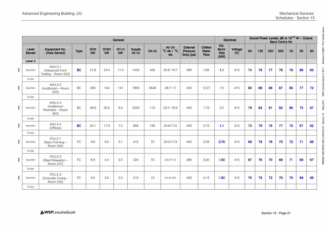
Advanced Engineering Building, UQ Mechanical Services Schedules - Section 15
Section 15 - Page 21
BNE0911900.SPEC.M
01.KJS101216 - Section 15 M
ay 2011 W
SP Lincolne Scott ©
2011 Revision 310807 / Pre Tender Issue
GeneralGeneralGeneralGeneral ElectricalElectricalElectricalElectrical Sound Power Levels, dB re 10Sound Power Levels, dB re 10Sound Power Levels, dB re 10Sound Power Levels, dB re 10
----12121212 W W W W –––– Octave Octave Octave Octave
Band Centre HzBand Centre HzBand Centre HzBand Centre Hz
Level Level Level Level ServedServedServedServed
Equipment No.Equipment No.Equipment No.Equipment No. (Area Served)(Area Served)(Area Served)(Area Served)
TypeTypeTypeType GTHGTHGTHGTH kWkWkWkW
GTSHGTSHGTSHGTSH kWkWkWkW
GTLHGTLHGTLHGTLH kWkWkWkW
SupplySupplySupplySupply Air l/sAir l/sAir l/sAir l/s
OAOAOAOA l/sl/sl/sl/s Air OnAir OnAir OnAir On
ooooC C C C db / db / db / db / ooooC C C C
wbwbwbwb
External External External External Pressure Pressure Pressure Pressure Drop (pa)Drop (pa)Drop (pa)Drop (pa)
Chilled Chilled Chilled Chilled Water Water Water Water FlowFlowFlowFlow
Est. Est. Est. Est. Motor Motor Motor Motor Size Size Size Size (kW)(kW)(kW)(kW)
VoltageVoltageVoltageVoltage (V)(V)(V)(V)
63636363 125125125125 250250250250 500500500500 1K1K1K1K 2K2K2K2K 4K4K4K4K
Level 2Level 2Level 2Level 2
Specified
AHU-2-1 (Advanced Form
Testing – Room 233)
BCBCBCBC 41.8 24.4 17.4 1430 455 25.6/ 19.7 380 1.83 1.11.11.11.1 415 74747474 79797979 77777777 78787878 76767676 68686868 63636363
Tender
Specified
AHU-2-2 (Auditorium – Room
233)
BC 285 144 141 7800 5648 28.7/ 17 450 12.27 7.5 415 83838383 88888888 86868686 87878787 85858585 77777777 72727272
Tender
Specified
AHU-2-3 (Auditorium
Perimeter – Room 303)
BC 38.9 30.5 8.4 2200 115 23.1/ 16.9 450 1.73 2.2 415 78787878 83838383 81818181 82828282 80808080 72727272 67676767
Tender
Specified AHU-2-4 (Offices)
BCBCBCBC 25.1 17.9 7.2 895 195 24.6/17.6 450 0.75 1.11.11.11.1 415 73737373 78787878 76767676 77777777 75757575 67676767 62626262
Tender
Specified
FCU-2-1 (Nano Forming –
Room 234)
FC 9.6 6.5 3.1 410 70 24.4/17.9 450 0.29 0.750.750.750.75 415 69696969 79797979 76767676 75757575 72727272 71717171 68686868
Tender
Specified
FCU-2-2 (Steel Relaxation –
Room 247)
FC 6.9 4.4 2.5 320 70 22.4/17.4 380 0.30 0.50505050 415 67676767 76767676 70707070 68686868 71717171 69696969 67676767
Tender
Specified
FCU-2-3 (Concrete Curing –
Room 243)
FC 5.0 3.0 2.0 210 10 24.4/19.0 450 0.15 0.50505050 415 70707070 79797979 72727272 70707070 70707070 69696969 66666666
Tender
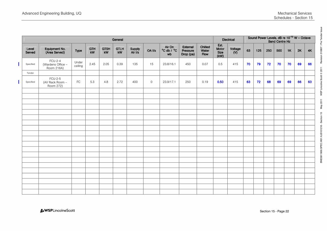
Advanced Engineering Building, UQ Mechanical Services Schedules - Section 15
Section 15 - Page 22
BNE0911900.SPEC.M
01.KJS101216 - Section 15 M
ay 2011 W
SP Lincolne Scott ©
2011 Revision 310807 / Pre Tender Issue
GeneralGeneralGeneralGeneral ElectricalElectricalElectricalElectrical Sound Power Levels, dB re 10Sound Power Levels, dB re 10Sound Power Levels, dB re 10Sound Power Levels, dB re 10
----12121212 W W W W –––– Octave Octave Octave Octave
Band Centre HzBand Centre HzBand Centre HzBand Centre Hz
Level Level Level Level ServedServedServedServed
Equipment No.Equipment No.Equipment No.Equipment No. (Area Served)(Area Served)(Area Served)(Area Served)
TypeTypeTypeType GTHGTHGTHGTH kWkWkWkW
GTSHGTSHGTSHGTSH kWkWkWkW
GTLHGTLHGTLHGTLH kWkWkWkW
SupplySupplySupplySupply Air l/sAir l/sAir l/sAir l/s
OAOAOAOA l/sl/sl/sl/s Air OnAir OnAir OnAir On
ooooC C C C db / db / db / db / ooooC C C C
wbwbwbwb
External External External External Pressure Pressure Pressure Pressure Drop (pa)Drop (pa)Drop (pa)Drop (pa)
Chilled Chilled Chilled Chilled Water Water Water Water FlowFlowFlowFlow
Est. Est. Est. Est. Motor Motor Motor Motor Size Size Size Size (kW)(kW)(kW)(kW)
VoltageVoltageVoltageVoltage (V)(V)(V)(V)
63636363 125125125125 250250250250 500500500500 1K1K1K1K 2K2K2K2K 4K4K4K4K
Specified
FCU-2-4 (Wardens Office –
Room 216A)
Under ceiling
2.45 2.05 0.39 135 15 23.8/16.1 450 0.07 0.5 415 70707070 79797979 72727272 70707070 70707070 69696969 66666666
Tender
Specified
FCU-2-5 (AV Rack Room –
Room 272)
FC 5.3 4.8 2.72 400 0 23.9/17.1 250 0.19 0.0.0.0.50505050 415 63636363 72727272 68686868 69696969 69696969 66666666 63636363
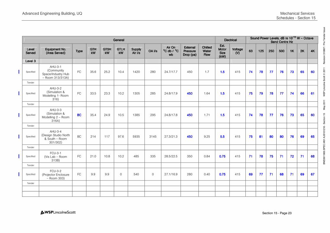
Advanced Engineering Building, UQ Mechanical Services Schedules - Section 15
Section 15 - Page 23
BNE0911900.SPEC.M
01.KJS101216 - Section 15 M
ay 2011 W
SP Lincolne Scott ©
2011 Revision 310807 / Pre Tender Issue
GeneralGeneralGeneralGeneral ElectricalElectricalElectricalElectrical Sound Power Levels, dB re 10Sound Power Levels, dB re 10Sound Power Levels, dB re 10Sound Power Levels, dB re 10
----12121212 W W W W –––– Octave Octave Octave Octave
Band Centre HzBand Centre HzBand Centre HzBand Centre Hz
Level Level Level Level ServedServedServedServed
Equipment No.Equipment No.Equipment No.Equipment No. (Area Served)(Area Served)(Area Served)(Area Served)
TypeTypeTypeType GTHGTHGTHGTH kWkWkWkW
GTSHGTSHGTSHGTSH kWkWkWkW
GTLHGTLHGTLHGTLH kWkWkWkW
SupplySupplySupplySupply Air l/sAir l/sAir l/sAir l/s
OAOAOAOA l/sl/sl/sl/s Air OnAir OnAir OnAir On
ooooC C C C db / db / db / db / ooooC C C C
wbwbwbwb
External External External External Pressure Pressure Pressure Pressure Drop (pa)Drop (pa)Drop (pa)Drop (pa)
Chilled Chilled Chilled Chilled Water Water Water Water FlowFlowFlowFlow
Est. Est. Est. Est. Motor Motor Motor Motor Size Size Size Size (kW)(kW)(kW)(kW)
VoltageVoltageVoltageVoltage (V)(V)(V)(V)
63636363 125125125125 250250250250 500500500500 1K1K1K1K 2K2K2K2K 4K4K4K4K
Level 3Level 3Level 3Level 3
Specified
AHU-3-1 (Community
Space/Industry Hub – Room 313/313A)
FC 35.6 25.2 10.4 1420 280 24.7/17.7 450 1.7 1.51.51.51.5 415 74747474 78787878 77777777 76767676 73737373 65656565 60606060
Tender
Specified
AHU-3-2 (Simulation &
Modelling 1- Room 316)
FC 33.5 23.3 10.2 1305 285 24.8/17.9 450450450450 1.64 1.51.51.51.5 415 75757575 79797979 78787878 77777777 74747474 66666666 61616161
Tender
Specified
AHU-3-3 (Simulation &
Modelling 2 – Room 316A)
BCBCBCBC 35.4 24.9 10.5 1385 295 24.8/17.8 450450450450 1.71 1.51.51.51.5 415 74747474 78787878 77777777 76767676 73737373 65656565 60606060
Tender
Specified
AHU-3-4 (Design Studio North
& South – Room 301/302)
BC 214 117 97.6 5935 3145 27.3/21.3 450450450450 9.25 5.55.55.55.5 415 75757575 81818181 80808080 80808080 76767676 69696969 65656565
Tender
Specified
FCU-3-1 (Vis Lab – Room
313B)
FC 21.0 10.8 10.2 485 335 28.5/22.5 350 0.84 0.750.750.750.75 415 71717171 78787878 75757575 71717171 72727272 71717171 68686868
Tender
Specified
FCU-3-2 (Projector Enclosure
– Room 303)
FC 9.9 9.9 0 540 0 27.1/16.9 280 0.40 0.750.750.750.75 415 69696969 77777777 71717171 68686868 71717171 69696969 67676767
Tender
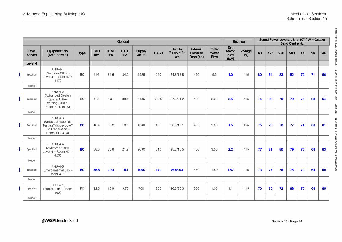
Advanced Engineering Building, UQ Mechanical Services Schedules - Section 15
Section 15 - Page 24
BNE0911900.SPEC.M
01.KJS101216 - Section 15 M
ay 2011 W
SP Lincolne Scott ©
2011 Revision 310807 / Pre Tender Issue
GeneralGeneralGeneralGeneral ElectricalElectricalElectricalElectrical Sound Power Levels, dB re 10Sound Power Levels, dB re 10Sound Power Levels, dB re 10Sound Power Levels, dB re 10
----12121212 W W W W –––– Octave Octave Octave Octave
Band Centre HzBand Centre HzBand Centre HzBand Centre Hz
Level Level Level Level ServedServedServedServed
Equipment No.Equipment No.Equipment No.Equipment No. (Area Served)(Area Served)(Area Served)(Area Served)
TypeTypeTypeType GTHGTHGTHGTH kWkWkWkW
GTSHGTSHGTSHGTSH kWkWkWkW
GTLHGTLHGTLHGTLH kWkWkWkW
SupplySupplySupplySupply Air l/sAir l/sAir l/sAir l/s
OAOAOAOA l/sl/sl/sl/s Air OnAir OnAir OnAir On
ooooC C C C db / db / db / db / ooooC C C C
wbwbwbwb
External External External External Pressure Pressure Pressure Pressure Drop (pa)Drop (pa)Drop (pa)Drop (pa)
Chilled Chilled Chilled Chilled Water Water Water Water FlowFlowFlowFlow
Est. Est. Est. Est. Motor Motor Motor Motor Size Size Size Size (kW)(kW)(kW)(kW)
VoltageVoltageVoltageVoltage (V)(V)(V)(V)
63636363 125125125125 250250250250 500500500500 1K1K1K1K 2K2K2K2K 4K4K4K4K
Level 4Level 4Level 4Level 4
Specified
AHU-4-1 (Northern Offices
Level 4 – Room 429-447)
BC 116 81.6 34.9 4525 960 24.8/17.8 450 5.5 4.04.04.04.0 415 80808080 84848484 83838383 82828282 79797979 71717171 66666666
Tender
Specified
AHU-4-2 (Advanced Design
Space/Active Learning Studio – Room 401/401A)
BC 195 106 88.4 5485 2860 27.2/21.2 480 8.06 5.55.55.55.5 415 74747474 80808080 79797979 79797979 75757575 68686868 64646464
Tender
Specified
AHU-4-3 (Universal Materials
Testing/Microscopy/TEM Preparation – Room 412-414)
BCBCBCBC 48.4 30.2 18.2 1640 485 25.5/19.1 450 2.55 1.51.51.51.5 415 75757575 79797979 78787878 77777777 74747474 66666666 61616161
Tender
Specified
AHU-4-4 (AMPAM Offices
Level 4 – Room 421-425)
BCBCBCBC 58.6 36.6 21.9 2090 610 25.2/18.5 450 3.56 2.22.22.22.2 415 77777777 81818181 80808080 79797979 76767676 68686868 63636363
Tender
Specified
AHU-4-5 (Environmental Lab –
Room 418)
BCBCBCBC 35.535.535.535.5 20.420.420.420.4 15.115.115.115.1 1000100010001000 470470470470 26.8/20.426.8/20.426.8/20.426.8/20.4 450 1.80 1.871.871.871.87 415 73737373 77777777 76767676 75757575 72727272 64646464 59595959
Tender
Specified
FCU-4-1 (Statics Lab – Room
402)
FC 22.6 12.9 9.76 700 285 26.3/20.3 330 1.03 1.1 415 70707070 75757575 72727272 68686868 70707070 68686868 65656565
Tender
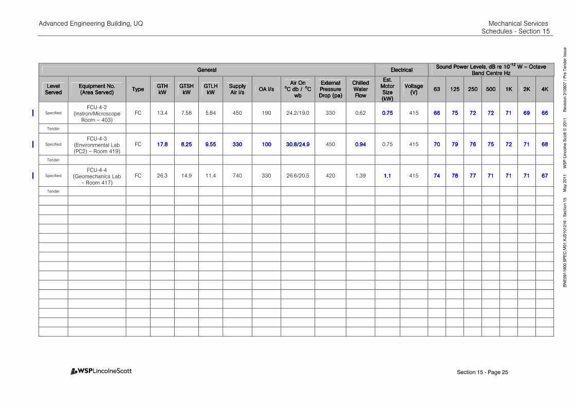
Advanced Engineering Building, UQ Mechanical Services Schedules - Section 15
Section 15 - Page 25
BNE0911900.SPEC.M
01.KJS101216 - Section 15 M
ay 2011 W
SP Lincolne Scott ©
2011 Revision 310807 / Pre Tender Issue
GeneralGeneralGeneralGeneral ElectricalElectricalElectricalElectrical Sound Power Levels, dB re 10Sound Power Levels, dB re 10Sound Power Levels, dB re 10Sound Power Levels, dB re 10
----12121212 W W W W –––– Octave Octave Octave Octave
Band Centre HzBand Centre HzBand Centre HzBand Centre Hz
Level Level Level Level ServedServedServedServed
Equipment No.Equipment No.Equipment No.Equipment No. (Area Served)(Area Served)(Area Served)(Area Served)
TypeTypeTypeType GTHGTHGTHGTH kWkWkWkW
GTSHGTSHGTSHGTSH kWkWkWkW
GTLHGTLHGTLHGTLH kWkWkWkW
SupplySupplySupplySupply Air l/sAir l/sAir l/sAir l/s
OAOAOAOA l/sl/sl/sl/s Air OnAir OnAir OnAir On
ooooC C C C db / db / db / db / ooooC C C C
wbwbwbwb
External External External External Pressure Pressure Pressure Pressure Drop (pa)Drop (pa)Drop (pa)Drop (pa)
Chilled Chilled Chilled Chilled Water Water Water Water FlowFlowFlowFlow
Est. Est. Est. Est. Motor Motor Motor Motor Size Size Size Size (kW)(kW)(kW)(kW)
VoltageVoltageVoltageVoltage (V)(V)(V)(V)
63636363 125125125125 250250250250 500500500500 1K1K1K1K 2K2K2K2K 4K4K4K4K
Specified
FCU-4-2 (Instron/Microscope
Room – 403)
FC 13.4 7.58 5.84 450 190 24.2/19.0 330 0.62 0.750.750.750.75 415 66666666 75757575 72727272 72727272 71717171 69696969 66666666
Tender
Specified
FCU-4-3 (Environmental Lab (PC2) – Room 419)
FC 17.817.817.817.8 8.258.258.258.25 9.559.559.559.55 330330330330 100100100100 30.8/24.930.8/24.930.8/24.930.8/24.9 450 0.940.940.940.94 0.75 415 70707070 79797979 76767676 75757575 72727272 71717171 68686868
Tender
Specified
FCU-4-4 (Geomechanics Lab
– Room 417)
FC 26.3 14.9 11.4 740 330 26.6/20.5 420 1.39 1.11.11.11.1 415 74747474 78787878 77777777 71717171 71717171 71717171 67676767
Tender
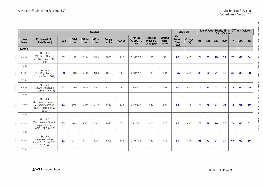
Advanced Engineering Building, UQ Mechanical Services Schedules - Section 15
Section 15 - Page 26
BNE0911900.SPEC.M
01.KJS101216 - Section 15 M
ay 2011 W
SP Lincolne Scott ©
2011 Revision 310807 / Pre Tender Issue
GeneralGeneralGeneralGeneral ElectricalElectricalElectricalElectrical Sound Power Levels, dB re 10Sound Power Levels, dB re 10Sound Power Levels, dB re 10Sound Power Levels, dB re 10
----12121212 W W W W –––– Octave Octave Octave Octave
Band Centre HzBand Centre HzBand Centre HzBand Centre Hz
Level Level Level Level ServedServedServedServed
Equipment No.Equipment No.Equipment No.Equipment No. (Area Served)(Area Served)(Area Served)(Area Served)
TypeTypeTypeType GTHGTHGTHGTH kWkWkWkW
GTSHGTSHGTSHGTSH kWkWkWkW
GTLHGTLHGTLHGTLH kWkWkWkW
SupplySupplySupplySupply Air l/sAir l/sAir l/sAir l/s
OAOAOAOA l/sl/sl/sl/s Air OnAir OnAir OnAir On
ooooC C C C db / db / db / db / ooooC C C C
wbwbwbwb
External External External External Pressure Pressure Pressure Pressure Drop (pa)Drop (pa)Drop (pa)Drop (pa)
Chilled Chilled Chilled Chilled Water Water Water Water FlowFlowFlowFlow
Est. Est. Est. Est. Motor Motor Motor Motor Size Size Size Size (kW)(kW)(kW)(kW)
VoltageVoltageVoltageVoltage (V)(V)(V)(V)
63636363 125125125125 250250250250 500500500500 1K1K1K1K 2K2K2K2K 4K4K4K4K
Level 5Level 5Level 5Level 5
Specified
AHU-5-1 (Northern Offices
Level 5 – Room 535-561)
BC 116 81.6 34.9 4635 955 24.8/17.8 450 5.5 4.04.04.04.0 415 74747474 80808080 79797979 79797979 75757575 68686868 64646464
Tender
Specified
AHU-5-2 (Civil Eng Seminar
Room – Room 502)
BCBCBCBC 39.8 21.0 18.8 1000 585 27.8/21.8 330 1.41 0.750.750.750.75 415 66666666 72727272 71717171 71717171 67676767 60606060 56565656
Tender
Specified
AHU-5-3 (Kinetic Metalization – Room 513-517A)
BCBCBCBC 43.6 24.5 19.1 1205 585 26.9/20.7 420 1.97 1.11.11.11.1 415 73737373 77777777 67676767 75757575 72727272 64646464 59595959
Tender
Specified
AHU-5-4 (Polymer Processing & Characterisation Lab – Room 518 &
520)
BCBCBCBC 50.8 28.9 21.9 1460 625 26.5/20.4 420 2.51 1.51.51.51.5 415 74747474 78787878 77777777 76767676 73737373 65656565 60606060
Tender
Specified
AHU-5-5 (Composites, Fibre &
Polymer Labs – Room 521 & 525A)
BCBCBCBC 48.9 29.7 19.2 1620 570 25.2/19.1 420 2.28 1.51.51.51.5 415 75757575 79797979 78787878 77777777 74747474 66666666 61616161
Tender
Specified
AHU-5-6 (AMPAM Offices
Level 5 – Room 529 & 531A)
BCBCBCBC 24.1 17.3 6.76 1005 185 24.6/17.5 420 1.16 1.11.11.11.1 415 66666666 72727272 71717171 71717171 67676767 60606060 56565656
Tender
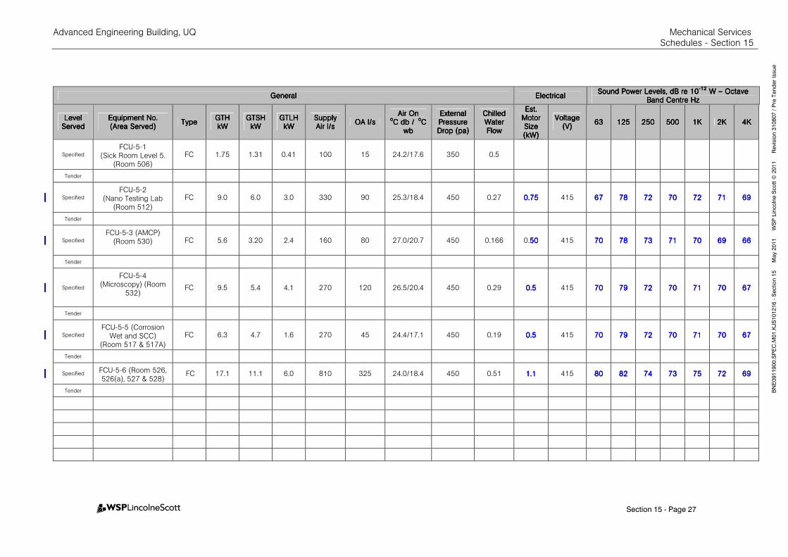
Advanced Engineering Building, UQ Mechanical Services Schedules - Section 15
Section 15 - Page 27
BNE0911900.SPEC.M
01.KJS101216 - Section 15 M
ay 2011 W
SP Lincolne Scott ©
2011 Revision 310807 / Pre Tender Issue
GeneralGeneralGeneralGeneral ElectricalElectricalElectricalElectrical Sound Power Levels, dB re 10Sound Power Levels, dB re 10Sound Power Levels, dB re 10Sound Power Levels, dB re 10
----12121212 W W W W –––– Octave Octave Octave Octave
Band Centre HzBand Centre HzBand Centre HzBand Centre Hz
Level Level Level Level ServedServedServedServed
Equipment No.Equipment No.Equipment No.Equipment No. (Area Served)(Area Served)(Area Served)(Area Served)
TypeTypeTypeType GTHGTHGTHGTH kWkWkWkW
GTSHGTSHGTSHGTSH kWkWkWkW
GTLHGTLHGTLHGTLH kWkWkWkW
SupplySupplySupplySupply Air l/sAir l/sAir l/sAir l/s
OAOAOAOA l/sl/sl/sl/s Air OnAir OnAir OnAir On
ooooC C C C db / db / db / db / ooooC C C C
wbwbwbwb
External External External External Pressure Pressure Pressure Pressure Drop (pa)Drop (pa)Drop (pa)Drop (pa)
Chilled Chilled Chilled Chilled Water Water Water Water FlowFlowFlowFlow
Est. Est. Est. Est. Motor Motor Motor Motor Size Size Size Size (kW)(kW)(kW)(kW)
VoltageVoltageVoltageVoltage (V)(V)(V)(V)
63636363 125125125125 250250250250 500500500500 1K1K1K1K 2K2K2K2K 4K4K4K4K
Specified
FCU-5-1 (Sick Room Level 5.
(Room 506)
FC 1.75 1.31 0.41 100 15 24.2/17.6 350 0.5
Tender
Specified
FCU-5-2 (Nano Testing Lab
(Room 512)
FC 9.0 6.0 3.0 330 90 25.3/18.4 450 0.27 0.750.750.750.75 415 67676767 78787878 72727272 70707070 72727272 71717171 69696969
Tender
Specified
FCU-5-3 (AMCP) (Room 530)
FC 5.6 3.20 2.4 160 80 27.0/20.7 450 0.166 0.50505050 415 70707070 78787878 73737373 71717171 70707070 69696969 66666666
Tender
Specified
FCU-5-4 (Microscopy) (Room
532)
FC 9.5 5.4 4.1 270 120 26.5/20.4 450 0.29 0.50.50.50.5 415 70707070 79797979 72727272 70707070 71717171 70707070 67676767
Tender
Specified
FCU-5-5 (Corrosion Wet and SCC)
(Room 517 & 517A)
FC 6.3 4.7 1.6 270 45 24.4/17.1 450 0.19 0.50.50.50.5 415 70707070 79797979 72727272 70707070 71717171 70707070 67676767
Tender
Specified FCU-5-6 (Room 526, 526(a), 527 & 528)
FC 17.1 11.1 6.0 810 325 24.0/18.4 450 0.51 1.11.11.11.1 415 80808080 82828282 74747474 73737373 75757575 72727272 69696969
Tender

Advanced Engineering Building, UQ Mechanical Services Schedules - Section 15
Section 15 - Page 28
BNE0911900.SPEC.M
01.KJS101216 - Section 15 M
ay 2011 W
SP Lincolne Scott ©
2011 Revision 310807 / Pre Tender Issue
GeneralGeneralGeneralGeneral ElectricalElectricalElectricalElectrical Sound Power Levels, dB re 10Sound Power Levels, dB re 10Sound Power Levels, dB re 10Sound Power Levels, dB re 10
----12121212 W W W W –––– Octave Octave Octave Octave
Band Centre HzBand Centre HzBand Centre HzBand Centre Hz
Level Level Level Level ServedServedServedServed
Equipment No.Equipment No.Equipment No.Equipment No. (Area Served)(Area Served)(Area Served)(Area Served)
TypeTypeTypeType GTHGTHGTHGTH kWkWkWkW
GTSHGTSHGTSHGTSH kWkWkWkW
GTLHGTLHGTLHGTLH kWkWkWkW
SupplySupplySupplySupply Air l/sAir l/sAir l/sAir l/s
OAOAOAOA l/sl/sl/sl/s Air OnAir OnAir OnAir On
ooooC C C C db / db / db / db / ooooC C C C
wbwbwbwb
External External External External Pressure Pressure Pressure Pressure Drop (pa)Drop (pa)Drop (pa)Drop (pa)
Chilled Chilled Chilled Chilled Water Water Water Water FlowFlowFlowFlow
Est. Est. Est. Est. Motor Motor Motor Motor Size Size Size Size (kW)(kW)(kW)(kW)
VoltageVoltageVoltageVoltage (V)(V)(V)(V)
63636363 125125125125 250250250250 500500500500 1K1K1K1K 2K2K2K2K 4K4K4K4K
Level 6Level 6Level 6Level 6
Specified AHU-6-1 (Civil
Offices) BC 111 76.7 34.3 4260 955 24.9/18.0 450 3.3 4.04.04.04.0 415 73737373 79797979 78787878 78787878 74747474 67676767 63636363
Tender
Specified AHU-6-2 BC 54.954.954.954.9 32.732.732.732.7 22.222.222.222.2 1616161660606060 670670670670 26.3/19.926.3/19.926.3/19.926.3/19.9 450 1.651.651.651.65 1.51.51.51.5 415 75757575 79797979 78787878 77777777 74747474 66666666 61616161
Tender
Specified AHU-6-3 (AMPAM) (Room 627-631)
BC 53.7 36.2 17.5 2000 430 24.8/18.1 450 1.6 2.22.22.22.2 415 76767676 80808080 79797979 78787878 75757575 67676767 62626262
Tender
Specified FCU-6-1 (Board
Room) (Room 601) FC 27.5 15.3 12.2 820 370 27.0/20.9 450 0.82 1.11.11.11.1 415 80808080 82828282 74747474 73737373 75757575 72727272 70707070
Tender
Specified FCU-6-2 Executive)
(Room 602) FC 6.0 4.25 1.75 240 45 24.4/17.6 450 0.18 0.50.50.50.5 415415415415 70707070 79797979 72727272 70707070 70707070 69696969 66666666
Tender
Specified FCU-6-3 (Parents)
(Room 606) FC 2.1 1.7 0.40 135 15 23.9/17.3 450 0.06 0.50.50.50.5 415415415415 70707070 79797979 72727272 70707070 70707070 69696969 66666666
Tender
Specified
FCU-6-4 (Molten Metals) (Room 619 &
621)
FC 13.8 8.0 5.8 440 195 26.6/20.5 450 0.41 0.750.750.750.75 415 70707070 78787878 76767676 75757575 73737373 71717171 69696969
Tender

Advanced Engineering Building, UQ Mechanical Services Schedules - Section 15
Section 15 - Page 29
BNE0911900.SPEC.M
01.KJS101216 - Section 15 M
ay 2011 W
SP Lincolne Scott ©
2011 Revision 310807 / Pre Tender Issue
GeneralGeneralGeneralGeneral ElectricalElectricalElectricalElectrical Sound Power Levels, dB re 10Sound Power Levels, dB re 10Sound Power Levels, dB re 10Sound Power Levels, dB re 10
----12121212 W W W W –––– Octave Octave Octave Octave
Band Centre HzBand Centre HzBand Centre HzBand Centre Hz
Level Level Level Level ServedServedServedServed
Equipment No.Equipment No.Equipment No.Equipment No. (Area Served)(Area Served)(Area Served)(Area Served)
TypeTypeTypeType GTHGTHGTHGTH kWkWkWkW
GTSHGTSHGTSHGTSH kWkWkWkW
GTLHGTLHGTLHGTLH kWkWkWkW
SupplySupplySupplySupply Air l/sAir l/sAir l/sAir l/s
OAOAOAOA l/sl/sl/sl/s Air OnAir OnAir OnAir On
ooooC C C C db / db / db / db / ooooC C C C
wbwbwbwb
External External External External Pressure Pressure Pressure Pressure Drop (pa)Drop (pa)Drop (pa)Drop (pa)
Chilled Chilled Chilled Chilled Water Water Water Water FlowFlowFlowFlow
Est. Est. Est. Est. Motor Motor Motor Motor Size Size Size Size (kW)(kW)(kW)(kW)
VoltageVoltageVoltageVoltage (V)(V)(V)(V)
63636363 125125125125 250250250250 500500500500 1K1K1K1K 2K2K2K2K 4K4K4K4K
Level 7Level 7Level 7Level 7
Specified FCU-7-1 (Passenger
Lift Motor Room) FC - 11.3 - 610 - 27.0/16.7 300 0.4 0.750.750.750.75 415 70707070 75757575 71717171 67676767 69696969 67676767 63636363
Tender
Specified FCU-7-2 (Goods Lift
Motor Room) FC - 9.1 - 490 - 27.0/16.7 300 0.27 0.750.750.750.75 415 70707070 77777777 72727272 69696969 71717171 69696969 66666666
Tender
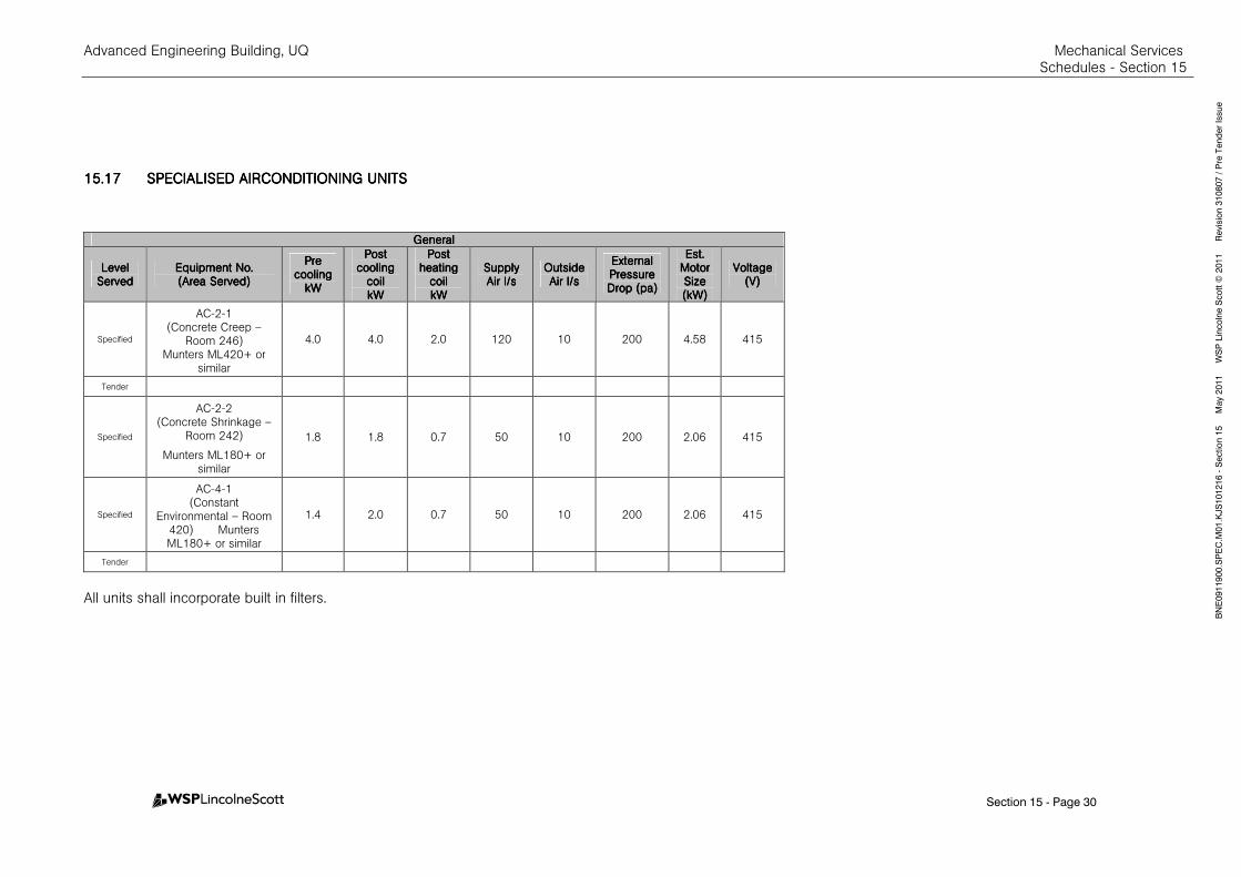
Advanced Engineering Building, UQ Mechanical Services Schedules - Section 15
Section 15 - Page 30
BNE0911900.SPEC.M
01.KJS101216 - Section 15 M
ay 2011 W
SP Lincolne Scott ©
2011 Revision 310807 / Pre Tender Issue
15.1715.1715.1715.17 SPECIALISED AIRCONDISPECIALISED AIRCONDISPECIALISED AIRCONDISPECIALISED AIRCONDITIONING UNITSTIONING UNITSTIONING UNITSTIONING UNITS
GeneralGeneralGeneralGeneral
Level Level Level Level ServedServedServedServed
Equipment No.Equipment No.Equipment No.Equipment No. (Area Served)(Area Served)(Area Served)(Area Served)
Pre Pre Pre Pre coolingcoolingcoolingcooling
kWkWkWkW
Post Post Post Post cooling cooling cooling cooling
coilcoilcoilcoil kWkWkWkW
Post Post Post Post heating heating heating heating
coilcoilcoilcoil kWkWkWkW
SupplySupplySupplySupply Air l/sAir l/sAir l/sAir l/s
Outside Outside Outside Outside Air l/sAir l/sAir l/sAir l/s
External External External External Pressure Pressure Pressure Pressure Drop (pa)Drop (pa)Drop (pa)Drop (pa)
Est. Est. Est. Est. Motor Motor Motor Motor Size Size Size Size (kW)(kW)(kW)(kW)
VoltageVoltageVoltageVoltage (V)(V)(V)(V)
Specified
AC-2-1 (Concrete Creep –
Room 246) Munters ML420+ or
similar
4.0 4.0 2.0 120 10 200 4.58 415
Tender
Specified
AC-2-2 (Concrete Shrinkage –
Room 242)
Munters ML180+ or similar
1.8 1.8 0.7 50 10 200 2.06 415
Specified
AC-4-1 (Constant
Environmental – Room 420) Munters ML180+ or similar
1.4 2.0 0.7 50 10 200 2.06 415
Tender
All units shall incorporate built in filters.
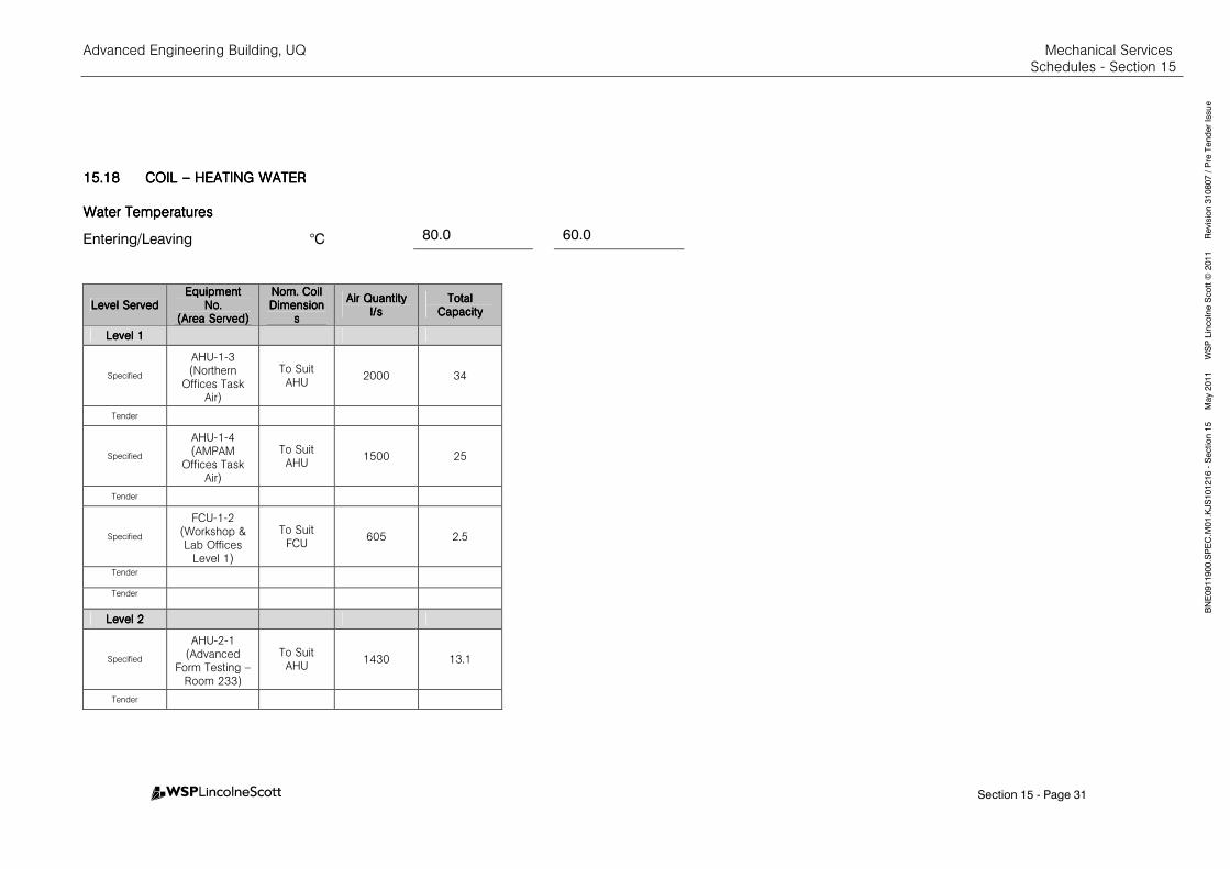
Advanced Engineering Building, UQ Mechanical Services Schedules - Section 15
Section 15 - Page 31
BNE0911900.SPEC.M
01.KJS101216 - Section 15 M
ay 2011 W
SP Lincolne Scott ©
2011 Revision 310807 / Pre Tender Issue
15.1815.1815.1815.18 COIL COIL COIL COIL –––– HEATING WATERHEATING WATERHEATING WATERHEATING WATER
Water TemperaturesWater TemperaturesWater TemperaturesWater Temperatures
Entering/Leaving °C 80.0 60.0
Level ServedLevel ServedLevel ServedLevel Served Equipment Equipment Equipment Equipment
No.No.No.No. (Area Served)(Area Served)(Area Served)(Area Served)
Nom. Coil Nom. Coil Nom. Coil Nom. Coil DimensionDimensionDimensionDimension
ssss
AirAirAirAir QuantityQuantityQuantityQuantity l/sl/sl/sl/s
Total Total Total Total CapacityCapacityCapacityCapacity
Level 1Level 1Level 1Level 1
Specified
AHU-1-3 (Northern
Offices Task Air)
To Suit AHU
2000 34
Tender
Specified
AHU-1-4 (AMPAM
Offices Task Air)
To Suit AHU
1500 25
Tender
Specified
FCU-1-2 (Workshop & Lab Offices
Level 1)
To Suit FCU
605 2.5
Tender
Tender
Level 2Level 2Level 2Level 2
Specified
AHU-2-1 (Advanced
Form Testing – Room 233)
To Suit AHU
1430 13.1
Tender
Advanced Engineering Building, UQ Mechanical Services Schedules - Section 15
Section 15 - Page 32
BNE0911900.SPEC.M
01.KJS101216 - Section 15 M
ay 2011 W
SP Lincolne Scott ©
2011 Revision 310807 / Pre Tender Issue
Level ServedLevel ServedLevel ServedLevel Served Equipment Equipment Equipment Equipment
No.No.No.No. (Area Served)(Area Served)(Area Served)(Area Served)
Nom. Coil Nom. Coil Nom. Coil Nom. Coil DimensionDimensionDimensionDimension
ssss
AirAirAirAir QuantityQuantityQuantityQuantity l/sl/sl/sl/s
Total Total Total Total CapacityCapacityCapacityCapacity
Specified
AHU-2-2 (Auditorium – Room 233)
To Suit AHU
7800 118.0
Tender
Specified
AHU-2-3 (Auditorium Perimeter – Room 303)
To Suit AHU
2200 25.0
Tender
Specified AHU-2-4 (Offices)
To Suit AHU
1115 11.0
Tender
Specified
FCU-2-1 (Nano Forming – Room 234)
To Suit FCU
410 2.8
Tender
Specified
FCU-2-2 (Steel
Relaxation – Room 247)
To Suit FCU
320 1.0
Tender
Specified
FCU-2-3 (Concrete
Curing – Room 243)
To Suit FCU
210 0.25
Tender
Specified
FCU-2-4 (Wardens
Office – Room 216A)
To Suit FCU
135 0
Tender
Level 3Level 3Level 3Level 3
Tender
Advanced Engineering Building, UQ Mechanical Services Schedules - Section 15
Section 15 - Page 33
BNE0911900.SPEC.M
01.KJS101216 - Section 15 M
ay 2011 W
SP Lincolne Scott ©
2011 Revision 310807 / Pre Tender Issue
Level ServedLevel ServedLevel ServedLevel Served Equipment Equipment Equipment Equipment
No.No.No.No. (Area Served)(Area Served)(Area Served)(Area Served)
Nom. Coil Nom. Coil Nom. Coil Nom. Coil DimensionDimensionDimensionDimension
ssss
AirAirAirAir QuantityQuantityQuantityQuantity l/sl/sl/sl/s
Total Total Total Total CapacityCapacityCapacityCapacity
Specified
FCU-3-1 (Vis Lab –
Room 313B)
To Suit FCU
485 6.3
Tender
Specified
FCU-3-2 (Projector
Enclosure – Room 303)
To Suit FCU
540 0
Tender
Level 4Level 4Level 4Level 4
Specified
FCU-4-1 (Statics Lab – Room 402)
To Suit FCU
685 8.1
Tender
Specified
FCU-4-2 (Instron/Microscope Room –
403)
To Suit FCU
450 4.2
Tender
Specified
FCU-4-3 (Environmental Lab (PC2) – Room 420)
To Suit FCU
385 4.2
Tender
Specified
FCU-4-4 (Geomechanics Lab – Room
417)
To Suit FCU
740 9.6
Tender
Level 5Level 5Level 5Level 5
Specified
AHU-5-2 (Civil Eng
Seminar Room – Room 502)
To Suit AHU
978 14.4
Advanced Engineering Building, UQ Mechanical Services Schedules - Section 15
Section 15 - Page 34
BNE0911900.SPEC.M
01.KJS101216 - Section 15 M
ay 2011 W
SP Lincolne Scott ©
2011 Revision 310807 / Pre Tender Issue
Level ServedLevel ServedLevel ServedLevel Served Equipment Equipment Equipment Equipment
No.No.No.No. (Area Served)(Area Served)(Area Served)(Area Served)
Nom. Coil Nom. Coil Nom. Coil Nom. Coil DimensionDimensionDimensionDimension
ssss
AirAirAirAir QuantityQuantityQuantityQuantity l/sl/sl/sl/s
Total Total Total Total CapacityCapacityCapacityCapacity
Tender
Specified
FCU-5-1 (Sick Room
Level 5)
To Suit FCU
100 0.8
Tender
Specified
FCU-5-2 (Nano Testing Lab Level 5)
To Suit FCU
325 3.81
Tender
Specified
FCU-5-3 (AMCP)
To Suit FCU
155 1.9
Tender
Specified
FCU-5-4 (Microscopy)
To Suit FCU
270 3.4
Tender
Specified
FCU-5-5 (Corrosion Wet
and SCC)
To Suit FCU
270 2.5
Tender
Specified FCU-5-6
To Suit FCU
810 5.6
Tender
Level 6Level 6Level 6Level 6
Specified FCU-6-1
(Board Room) To Suit FCU 740 9.8
Tender
Specified FCU-6-2
Executive) To Suit FCU 240 3.2
Tender
Advanced Engineering Building, UQ Mechanical Services Schedules - Section 15
Section 15 - Page 35
BNE0911900.SPEC.M
01.KJS101216 - Section 15 M
ay 2011 W
SP Lincolne Scott ©
2011 Revision 310807 / Pre Tender Issue
Level ServedLevel ServedLevel ServedLevel Served Equipment Equipment Equipment Equipment
No.No.No.No. (Area Served)(Area Served)(Area Served)(Area Served)
Nom. Coil Nom. Coil Nom. Coil Nom. Coil DimensionDimensionDimensionDimension
ssss
AirAirAirAir QuantityQuantityQuantityQuantity l/sl/sl/sl/s
Total Total Total Total CapacityCapacityCapacityCapacity
Specified FCU-6-3 (Parents)
To Suit FCU 135 1.3
Tender
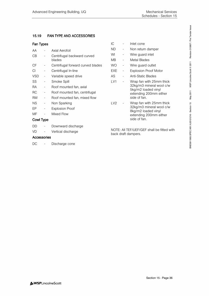
Advanced Engineering Building, UQ Mechanical Services Schedules - Section 15
Section 15 - Page 36
BNE0911900.SPEC.M
01.KJS101216 - Section 15 M
ay 2011 W
SP Lincolne Scott ©
2011 Revision 310807 / Pre Tender Issue
15.1915.1915.1915.19 FAN TYPE AND ACCESSOFAN TYPE AND ACCESSOFAN TYPE AND ACCESSOFAN TYPE AND ACCESSORIESRIESRIESRIES
Fan TypesFan TypesFan TypesFan Types
AA - Axial Aerofoil
CB - Centrifugal backward curved blades
CF - Centrifugal forward curved blades
CI - Centrifugal In-line
VSD - Variable speed drive
SS - Smoke Spill
RA - Roof mounted fan, axial
RC - Roof mounted fan, centrifugal
RM
NS
EP
-
-
-
Roof mounted fan, mixed flow
Non Sparking
Explosion Proof
MF - Mixed Flow
Cowl TypeCowl TypeCowl TypeCowl Type
DD - Downward discharge
VD - Vertical discharge
AccessoriesAccessoriesAccessoriesAccessories
DC - Discharge cone
IC - Inlet cone
ND - Non return damper
WI - Wire guard inlet
MB - Metal Blades
WO - Wire guard outlet
EXE - Explosion Proof Motor
AS - Anti-Static Blades
LV1
LV2
-
-
Wrap fan with 25mm thick 32kg/m3 mineral wool c/w 5kg/m2 loaded vinyl extending 200mm either side of fan.
Wrap fan with 25mm thick 32kg/m3 mineral wool c/w 8kg/m2 loaded vinyl extending 200mm either side of fan.
NOTE: All TEF/UEF/GEF shall be fitted with back draft dampers.

Advanced Engineering Building, UQ Mechanical Services Schedules - Section 15
Section 15 - Page 38
BNE0911900.SPEC.M
01.KJS101216 - Section 15 M
ay 2011 W
SP Lincolne Scott ©
2011 Revision 310807 / Pre Tender Issue
15.2015.2015.2015.20 FANSFANSFANSFANS
GeneralGeneralGeneralGeneral EleEleEleElectricalctricalctricalctrical Sound Power Levels, dB re 10Sound Power Levels, dB re 10Sound Power Levels, dB re 10Sound Power Levels, dB re 10----12121212
W W W W –––– Octave Band Octave Band Octave Band Octave Band Centre HzCentre HzCentre HzCentre Hz
Fan DesignationFan DesignationFan DesignationFan Designation TypeTypeTypeType CowlCowlCowlCowl & & & & AccesAccesAccesAccessoriessoriessoriessories
Air Air Air Air QQQQty.ty.ty.ty. (l/s)(l/s)(l/s)(l/s)
Est. Est. Est. Est. DutyDutyDutyDuty (Pa)(Pa)(Pa)(Pa)
Max Max Max Max SpeedSpeedSpeedSpeed (rps)(rps)(rps)(rps)
Est. Est. Est. Est. Motor Motor Motor Motor Size Size Size Size (kW)(kW)(kW)(kW)
VoltageVoltageVoltageVoltage (V)(V)(V)(V)
StartingStartingStartingStarting Max.Max.Max.Max. fan fan fan fan motor motor motor motor shaft shaft shaft shaft power power power power W/W/W/W/((((L/L/L/L/SSSS))))
63636363 125125125125 250250250250 500500500500 1K1K1K1K 2K2K2K2K 4K4K4K4K
Level 1Level 1Level 1Level 1
Specified SSEF-1-1 Transformer Rm. 125
MF LV1 4500 130 12 2.20 415 DOL 0.55 83 81 81 78 76 72 67
Tender
Specified SSSF-1-1 Transformer Rm. 125
MF LV1 4500 230 12 2.20 415 DOL 0.75 83 81 81 78 76 72 67
Tender
Specified SRSF-1-1 MSB Rm. 123 CI LV2 1200 200 9 0.63 415 DOL 0.55 69 68 64 55 55 50 51
Tender
Specified SREF-1-1 MSB Rm. 123 CI LV2 1200 165 9 0.63 415 DOL 0.55 69 68 64 55 55 50 51
Tender
Specified GSF-1-1 (Hydraulics Lab. Rm. 101)
CI LV1 2100 210 11 0.93 415 DOL 075 76 75 71 62 62 57 58
Tender
Specified GSF-1-2 (Main Workshop Rm. 111a)
MF LV1 2510 240 16 1.50 415 DOL 0.75 81 80 78 76 75 74 69
Tender
Specified GSF-1-3 (Structures Basement 119)
CI LV1 3000 250 15 2.20 415 DOL 0.75 84848484 83838383 81818181 79797979 78787878 77777777 72727272
Tender
Specified GSF-1-4 AV Rack Room OA
A - 15 120 31 0.1 240 DOL n/a - 52 56 65 58 59 54
Tender
Specified GSF-1-5 UQMP Wear Rm. 122
CI - 425425425425 210210210210 15 0.53 240 DOL n/a 80 79 72 66 62 60 58
Tender
Specified GSF-1-6 (FCU-1-2 OA) A - 80 120 35 0.06 240 DOL n/a - 51 63 54 54 54 49
Tender
Specified GEF-1-1 (Hydraulics Lab. Rm. 101)
MF LV1 3540354035403540 250250250250 16 2.20 415 DOL 0.55 82 81 79 77 76 75 70
Tender
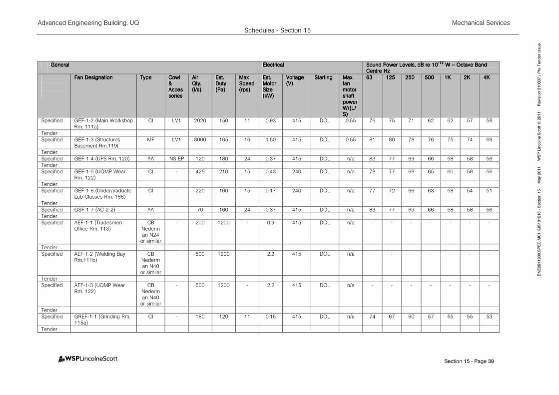
Advanced Engineering Building, UQ Mechanical Services Schedules - Section 15
Section 15 - Page 39
BNE0911900.SPEC.M
01.KJS101216 - Section 15 M
ay 2011 W
SP Lincolne Scott ©
2011 Revision 310807 / Pre Tender Issue
GeneralGeneralGeneralGeneral EleEleEleElectricalctricalctricalctrical Sound Power Levels, dB re 10Sound Power Levels, dB re 10Sound Power Levels, dB re 10Sound Power Levels, dB re 10----12121212
W W W W –––– Octave Band Octave Band Octave Band Octave Band Centre HzCentre HzCentre HzCentre Hz
Fan DesignationFan DesignationFan DesignationFan Designation TypeTypeTypeType CowlCowlCowlCowl & & & & AccesAccesAccesAccessoriessoriessoriessories
Air Air Air Air QQQQty.ty.ty.ty. (l/s)(l/s)(l/s)(l/s)
Est. Est. Est. Est. DutyDutyDutyDuty (Pa)(Pa)(Pa)(Pa)
Max Max Max Max SpeedSpeedSpeedSpeed (rps)(rps)(rps)(rps)
Est. Est. Est. Est. Motor Motor Motor Motor Size Size Size Size (kW)(kW)(kW)(kW)
VoltageVoltageVoltageVoltage (V)(V)(V)(V)
StartingStartingStartingStarting Max.Max.Max.Max. fan fan fan fan motor motor motor motor shaft shaft shaft shaft power power power power W/W/W/W/((((L/L/L/L/SSSS))))
63636363 125125125125 250250250250 500500500500 1K1K1K1K 2K2K2K2K 4K4K4K4K
Specified GEF-1-2 (Main Workshop Rm. 111a)
CI LV1 2020 150 11 0.93 415 DOL 0.55 76 75 71 62 62 57 58
Tender
Specified GEF-1-3 (Structures Basement Rm.119(
MF LV1 3000 165 16 1.50 415 DOL 0.55 81 80 78 76 75 74 69
Tender
Specified GEF-1-4 (UPS Rm. 120) AA NS EP 120 180 24 0.37 415 DOL n/a 83 77 69 66 58 58 56
Tender
Specified GEF-1-5 (UQMP Wear Rm. 122)
CI - 425 210 15 0.43 240 DOL n/a 78 77 68 65 60 58 56
Tender
Specified GEF-1-6 (Undergraduate Lab Classes Rm. 166)
CI - 220 160 15 0.17 240 DOL n/a 77 72 66 63 58 54 51
Tender
Specified GSF-1-7 (AC-2-2) AA 70 160 24 0.37 415 DOL n/a 83 77 69 66 58 58 56
Tender
Specified AEF-1-1 (Tradesmen Office Rm. 113)
CB Nederman N24
or similar
- 200 1200 - 0.9 415 DOL n/a - - - - - - -
Tender
Specified AEF-1-2 (Welding Bay Rm.111b)
CB Nederman N40
or similar
- 500 1200 - 2.2 415 DOL n/a - - - - - - -
Tender
Specified AEF-1-3 (UQMP Wear Rm. 122)
CB Nederman N40
or similar
- 500 1200 - 2.2 415 DOL n/a - - - - - - -
Tender
Specified GREF-1-1 (Grinding Rm. 115a)
CI - 180 120 11 0.15 415 DOL n/a 74 67 60 57 55 55 53
Tender
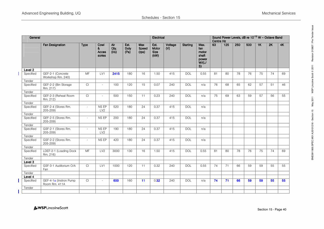
Advanced Engineering Building, UQ Mechanical Services Schedules - Section 15
Section 15 - Page 40
BNE0911900.SPEC.M
01.KJS101216 - Section 15 M
ay 2011 W
SP Lincolne Scott ©
2011 Revision 310807 / Pre Tender Issue
GeneralGeneralGeneralGeneral EleEleEleElectricalctricalctricalctrical Sound Power Levels, dB re 10Sound Power Levels, dB re 10Sound Power Levels, dB re 10Sound Power Levels, dB re 10----12121212
W W W W –––– Octave Band Octave Band Octave Band Octave Band Centre HzCentre HzCentre HzCentre Hz
Fan DesignationFan DesignationFan DesignationFan Designation TypeTypeTypeType CowlCowlCowlCowl & & & & AccesAccesAccesAccessoriessoriessoriessories
Air Air Air Air QQQQty.ty.ty.ty. (l/s)(l/s)(l/s)(l/s)
Est. Est. Est. Est. DutyDutyDutyDuty (Pa)(Pa)(Pa)(Pa)
Max Max Max Max SpeedSpeedSpeedSpeed (rps)(rps)(rps)(rps)
Est. Est. Est. Est. Motor Motor Motor Motor Size Size Size Size (kW)(kW)(kW)(kW)
VoltageVoltageVoltageVoltage (V)(V)(V)(V)
StartingStartingStartingStarting Max.Max.Max.Max. fan fan fan fan motor motor motor motor shaft shaft shaft shaft power power power power W/W/W/W/((((L/L/L/L/SSSS))))
63636363 125125125125 250250250250 500500500500 1K1K1K1K 2K2K2K2K 4K4K4K4K
Level 2Level 2Level 2Level 2
Specified GEF-2-1 (Concrete Workshop Rm. 240)
MF LV1 2415241524152415 180 16 1.50 415 DOL 0.55 81 80 78 76 75 74 69
Tender
Specified GEF-2-2 (Bin Storage Rm. 217)
CI - 100 120 15 0.07 240 DOL n/a 76 68 65 62 57 51 46
Tender
Specified GEF-2-3 (Reheat Room Rm. 212)
CI - 500 150 11 0.23 240 DOL n/a 75 69 63 59 57 56 55
Tender
Specified GEF-2-4 (Stores Rm. 205-209)
- NS EP LV2
520 180 24 0.37 415 DOL n/a
Tender
Specified GEF-2-5 (Stores Rm. 205-209)
- NS EP 200 180 24 0.37 415 DOL n/a
Tender
Specified GSF-2-1 (Stores Rm. 205-209)
- NS EP LV2
190 180 24 0.37 415 DOL n/a
Tender
Specified GSF-2-2 (Stores Rm. 205-209)
- NS EP 420 180 24 0.37 415 DOL n/a
Tender
Specified LDEF-2-1 (Loading Dock Rm. 216)
MF LV2 3000 130 16 1.50 415 DOL 0.55 81 80 78 76 75 74 69
Tender
Level 3Level 3Level 3Level 3
Specified GSF-3-1 Auditorium O/A Fan
CI LV1 1000 120 11 0.32 240 DOL 0.55 74 71 66 59 59 55 55
Tender
Level 4Level 4Level 4Level 4
Specified GEF-4-1a (Instron Pump Room Rm. 411A
CI - 600600600600 160 11111111 0.32323232 240 DOL n/a 74747474 71717171 66666666 59595959 59595959 55555555 55555555
Tender

Advanced Engineering Building, UQ Mechanical Services Schedules - Section 15
Section 15 - Page 41
BNE0911900.SPEC.M
01.KJS101216 - Section 15 M
ay 2011 W
SP Lincolne Scott ©
2011 Revision 310807 / Pre Tender Issue
GeneralGeneralGeneralGeneral EleEleEleElectricalctricalctricalctrical Sound Power Levels, dB re 10Sound Power Levels, dB re 10Sound Power Levels, dB re 10Sound Power Levels, dB re 10----12121212
W W W W –––– Octave Band Octave Band Octave Band Octave Band Centre HzCentre HzCentre HzCentre Hz
Fan DesignationFan DesignationFan DesignationFan Designation TypeTypeTypeType CowlCowlCowlCowl & & & & AccesAccesAccesAccessoriessoriessoriessories
Air Air Air Air QQQQty.ty.ty.ty. (l/s)(l/s)(l/s)(l/s)
Est. Est. Est. Est. DutyDutyDutyDuty (Pa)(Pa)(Pa)(Pa)
Max Max Max Max SpeedSpeedSpeedSpeed (rps)(rps)(rps)(rps)
Est. Est. Est. Est. Motor Motor Motor Motor Size Size Size Size (kW)(kW)(kW)(kW)
VoltageVoltageVoltageVoltage (V)(V)(V)(V)
StartingStartingStartingStarting Max.Max.Max.Max. fan fan fan fan motor motor motor motor shaft shaft shaft shaft power power power power W/W/W/W/((((L/L/L/L/SSSS))))
63636363 125125125125 250250250250 500500500500 1K1K1K1K 2K2K2K2K 4K4K4K4K
Specified GEF-4-1b DELETEDDELETEDDELETEDDELETED
Tender
Specified GEF-4-2 (Heat Treatment Room Rm. 415)
CI LV1 750750750750 155 9 0.28 415 DOL 0.55 69 68 64 55 55 50 51
Tender
Specified GEF-4-3a (Heat Treatment Room Rm. 415 (EH-4-2))
CI LV2 930 210 11 0.68 415 DOL 0.75 74 73 69 60 60 55 56
Tender
Specified GEF-4-3b (Heat Treatment Room Rm. 415 (EH-4-2))
CI LV2 930 210 11 0.68 415 DOL 0.75 74 73 69 60 60 55 56
Tender
Specified GEF-4-4a (Heat Treatment Rm. 415 (EH-4-1)
CI LV1 780 210 11 0.68 415 DOL 0.75 74 73 69 60 60 55 56
Tender
Specified GEF-4-4b (Heat Treatment Rm. 415) (EH-4-1)
CI LV1 780 210 11 0.68 415 DOL 0.75 74 73 69 60 60 55 56
Tender
Specified GEF-4-5a (Environmental Lab Rm 418) (EH-4-3)
CI LV1 570 220 11 0.68 415 DOL 0.75 74 73 69 60 60 55 56
Tender
Specified GEF-4-5b (Environmental Lab Rm 418) (EH-4-3)
CI LV1 570 220 11 0.63 415 DOL 0.75 74 73 69 60 60 55 56
Tender
Specified GSF-4-1 Instron Pump Room Rm 411a)
CI LV1 600 160 11 0.32 240 DOL n/a 74 71 66 59 59 55 55
Tender
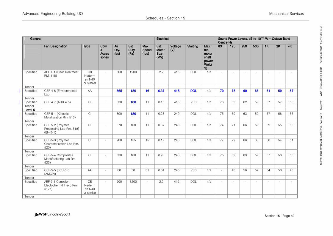
Advanced Engineering Building, UQ Mechanical Services Schedules - Section 15
Section 15 - Page 42
BNE0911900.SPEC.M
01.KJS101216 - Section 15 M
ay 2011 W
SP Lincolne Scott ©
2011 Revision 310807 / Pre Tender Issue
GeneralGeneralGeneralGeneral EleEleEleElectricalctricalctricalctrical Sound Power Levels, dB re 10Sound Power Levels, dB re 10Sound Power Levels, dB re 10Sound Power Levels, dB re 10----12121212
W W W W –––– Octave Band Octave Band Octave Band Octave Band Centre HzCentre HzCentre HzCentre Hz
Fan DesignationFan DesignationFan DesignationFan Designation TypeTypeTypeType CowlCowlCowlCowl & & & & AccesAccesAccesAccessoriessoriessoriessories
Air Air Air Air QQQQty.ty.ty.ty. (l/s)(l/s)(l/s)(l/s)
Est. Est. Est. Est. DutyDutyDutyDuty (Pa)(Pa)(Pa)(Pa)
Max Max Max Max SpeedSpeedSpeedSpeed (rps)(rps)(rps)(rps)
Est. Est. Est. Est. Motor Motor Motor Motor Size Size Size Size (kW)(kW)(kW)(kW)
VoltageVoltageVoltageVoltage (V)(V)(V)(V)
StartingStartingStartingStarting Max.Max.Max.Max. fan fan fan fan motor motor motor motor shaft shaft shaft shaft power power power power W/W/W/W/((((L/L/L/L/SSSS))))
63636363 125125125125 250250250250 500500500500 1K1K1K1K 2K2K2K2K 4K4K4K4K
Specified AEF-4-1 (Heat Treatment RM. 415)
CB Nederman N40
or similar
- 500 1200 - 2.2 415 DOL n/a - - - - - - -
Tender
Specified GEF-4-6 (Environmental Lab)
AA - 365365365365 180180180180 16161616 0.370.370.370.37 415415415415 DOLDOLDOLDOL n/a 79797979 78787878 69696969 66666666 61616161 59595959 57575757
Tender
Specified GEF-4-7 (AHU-4-5) CI - 530 100100100100 11 0.15 415 VSD n/a 76 69 62 59 57 57 55
Tender
Level 5Level 5Level 5Level 5
Specified GEF-5-1 (Kinectic Metaliszation Rm. 513)
CI - 300 180180180180 11 0.23 240 DOL n/a 75 69 63 59 57 56 55
Tender
Specified GEF-5-2 (Polymer Processing Lab Rm. 518) (EH-5-1)
CI - 570 160 11 0.32 240 DOL n/a 74 71 66 59 59 55 55
Tender
Specified GEF-5-3 (Polymer Characterisation Lab Rm. 520)
CI - 200 155 15 0.17 240 DOL n/a 77 72 66 63 58 54 51
Tender
Specified GEF-5-4 Composites Manufacturing Lab Rm. 523)
CI - 330 160 11 0.23 240 DOL n/a 75 69 63 59 57 56 55
Tender
Specified GEF-5-5 (FCU-5-3 (AMCP))
AA - 80 50 31 0.04 240 VSD n/a - 48 56 57 54 53 45
Tender
Specified AEF-5-1 Corrosion Electochem & Hevo Rm. 517a)
CB Nederman N40
or similar
- 500 1200 - 2.2 415 DOL n/a - - - - - - -
Tender
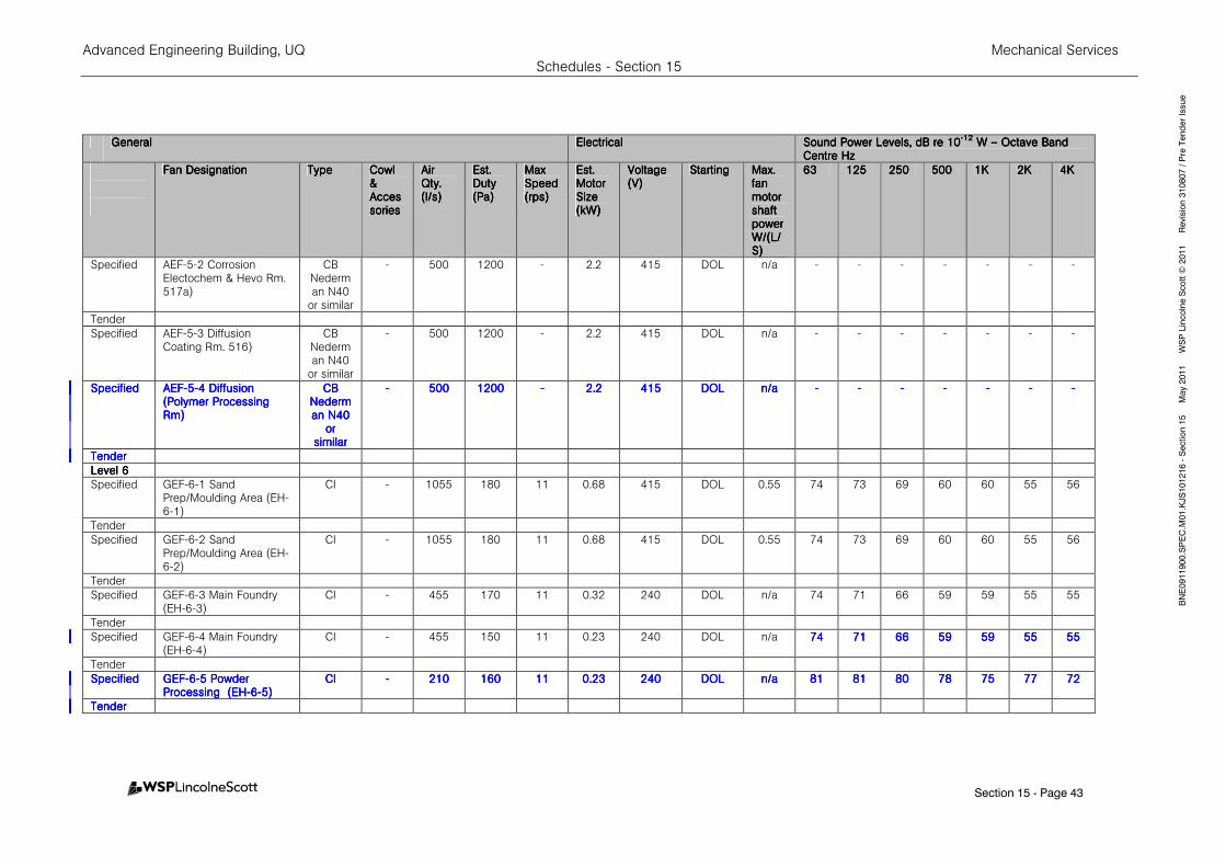
Advanced Engineering Building, UQ Mechanical Services Schedules - Section 15
Section 15 - Page 43
BNE0911900.SPEC.M
01.KJS101216 - Section 15 M
ay 2011 W
SP Lincolne Scott ©
2011 Revision 310807 / Pre Tender Issue
GeneralGeneralGeneralGeneral EleEleEleElectricalctricalctricalctrical Sound Power Levels, dB re 10Sound Power Levels, dB re 10Sound Power Levels, dB re 10Sound Power Levels, dB re 10----12121212
W W W W –––– Octave Band Octave Band Octave Band Octave Band Centre HzCentre HzCentre HzCentre Hz
Fan DesignationFan DesignationFan DesignationFan Designation TypeTypeTypeType CowlCowlCowlCowl & & & & AccesAccesAccesAccessoriessoriessoriessories
Air Air Air Air QQQQty.ty.ty.ty. (l/s)(l/s)(l/s)(l/s)
Est. Est. Est. Est. DutyDutyDutyDuty (Pa)(Pa)(Pa)(Pa)
Max Max Max Max SpeedSpeedSpeedSpeed (rps)(rps)(rps)(rps)
Est. Est. Est. Est. Motor Motor Motor Motor Size Size Size Size (kW)(kW)(kW)(kW)
VoltageVoltageVoltageVoltage (V)(V)(V)(V)
StartingStartingStartingStarting Max.Max.Max.Max. fan fan fan fan motor motor motor motor shaft shaft shaft shaft power power power power W/W/W/W/((((L/L/L/L/SSSS))))
63636363 125125125125 250250250250 500500500500 1K1K1K1K 2K2K2K2K 4K4K4K4K
Specified AEF-5-2 Corrosion Electochem & Hevo Rm. 517a)
CB Nederman N40
or similar
- 500 1200 - 2.2 415 DOL n/a - - - - - - -
Tender
Specified AEF-5-3 Diffusion Coating Rm. 516)
CB Nederman N40
or similar
- 500 1200 - 2.2 415 DOL n/a - - - - - - -
SpecifiedSpecifiedSpecifiedSpecified AEFAEFAEFAEF----5555----4 Diffusion 4 Diffusion 4 Diffusion 4 Diffusion (Polymer Processing (Polymer Processing (Polymer Processing (Polymer Processing Rm)Rm)Rm)Rm)
CB CB CB CB NedermNedermNedermNederman N40 an N40 an N40 an N40
or or or or similarsimilarsimilarsimilar
---- 500500500500 1200120012001200 ---- 2.22.22.22.2 415415415415 DOLDOLDOLDOL n/an/an/an/a ---- ---- ---- ---- ---- ---- ----
TendTendTendTenderererer
Level 6Level 6Level 6Level 6
Specified GEF-6-1 Sand Prep/Moulding Area (EH-6-1)
CI - 1055 180 11 0.68 415 DOL 0.55 74 73 69 60 60 55 56
Tender
Specified GEF-6-2 Sand Prep/Moulding Area (EH-6-2)
CI - 1055 180 11 0.68 415 DOL 0.55 74 73 69 60 60 55 56
Tender
Specified GEF-6-3 Main Foundry (EH-6-3)
CI - 455 170 11 0.32 240 DOL n/a 74 71 66 59 59 55 55
Tender
Specified GEF-6-4 Main Foundry (EH-6-4)
CI - 455 150 11 0.23 240 DOL n/a 74747474 71717171 66666666 59595959 59595959 55555555 55555555
Tender
SpecifiedSpecifiedSpecifiedSpecified GEFGEFGEFGEF----6666----5 5 5 5 Powder Powder Powder Powder Processing Processing Processing Processing (EH(EH(EH(EH----6666----5)5)5)5)
CICICICI ---- 210210210210 160160160160 11111111 0.230.230.230.23 240240240240 DOLDOLDOLDOL n/an/an/an/a 81818181 81818181 80808080 78787878 75757575 77777777 72727272
TenderTenderTenderTender
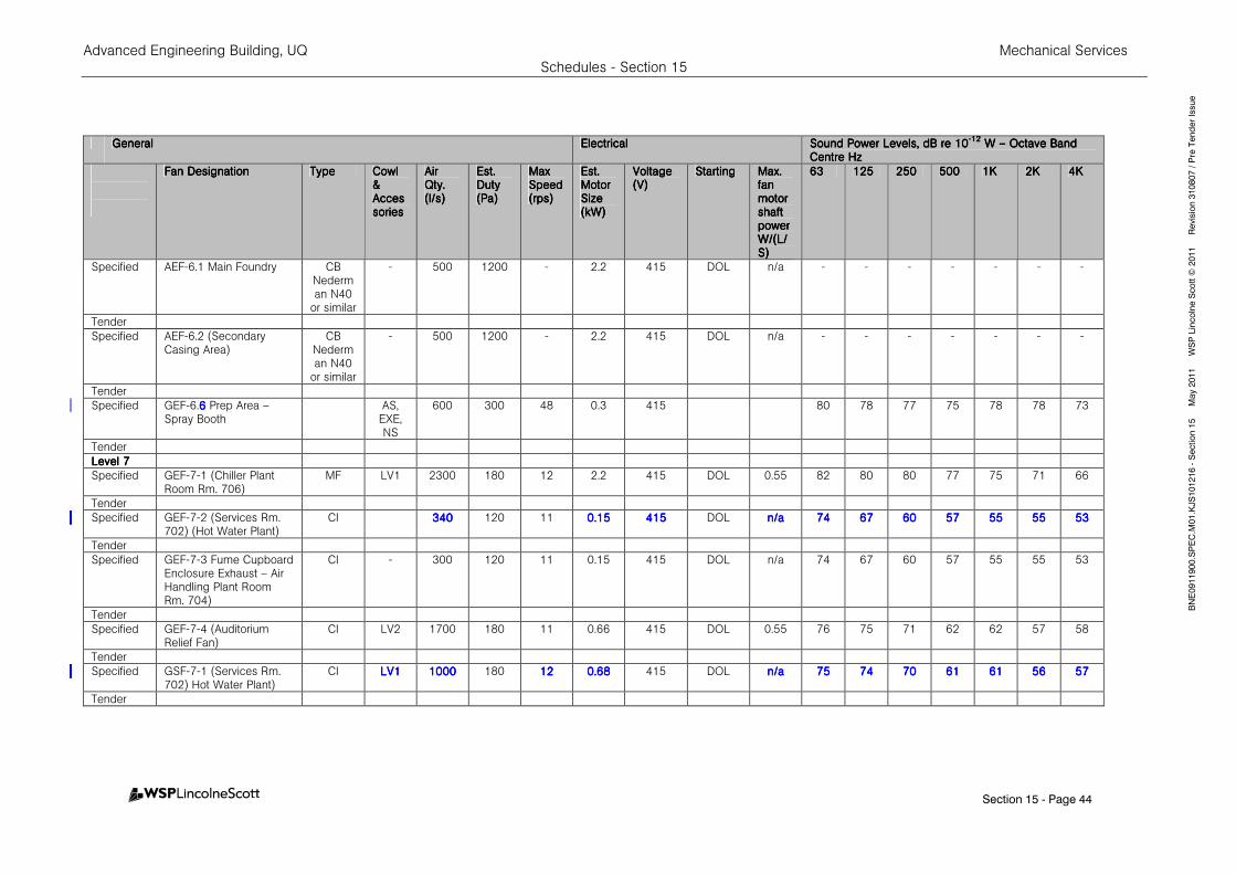
Advanced Engineering Building, UQ Mechanical Services Schedules - Section 15
Section 15 - Page 44
BNE0911900.SPEC.M
01.KJS101216 - Section 15 M
ay 2011 W
SP Lincolne Scott ©
2011 Revision 310807 / Pre Tender Issue
GeneralGeneralGeneralGeneral EleEleEleElectricalctricalctricalctrical Sound Power Levels, dB re 10Sound Power Levels, dB re 10Sound Power Levels, dB re 10Sound Power Levels, dB re 10----12121212
W W W W –––– Octave Band Octave Band Octave Band Octave Band Centre HzCentre HzCentre HzCentre Hz
Fan DesignationFan DesignationFan DesignationFan Designation TypeTypeTypeType CowlCowlCowlCowl & & & & AccesAccesAccesAccessoriessoriessoriessories
Air Air Air Air QQQQty.ty.ty.ty. (l/s)(l/s)(l/s)(l/s)
Est. Est. Est. Est. DutyDutyDutyDuty (Pa)(Pa)(Pa)(Pa)
Max Max Max Max SpeedSpeedSpeedSpeed (rps)(rps)(rps)(rps)
Est. Est. Est. Est. Motor Motor Motor Motor Size Size Size Size (kW)(kW)(kW)(kW)
VoltageVoltageVoltageVoltage (V)(V)(V)(V)
StartingStartingStartingStarting Max.Max.Max.Max. fan fan fan fan motor motor motor motor shaft shaft shaft shaft power power power power W/W/W/W/((((L/L/L/L/SSSS))))
63636363 125125125125 250250250250 500500500500 1K1K1K1K 2K2K2K2K 4K4K4K4K
Specified AEF-6.1 Main Foundry CB Nederman N40
or similar
- 500 1200 - 2.2 415 DOL n/a - - - - - - -
Tender
Specified AEF-6.2 (Secondary Casing Area)
CB Nederman N40
or similar
- 500 1200 - 2.2 415 DOL n/a - - - - - - -
Tender
Specified GEF-6.6666 Prep Area – Spray Booth
AS, EXE, NS
600 300 48 0.3 415 80 78 77 75 78 78 73
Tender
Level 7Level 7Level 7Level 7
Specified GEF-7-1 (Chiller Plant Room Rm. 706)
MF LV1 2300 180 12 2.2 415 DOL 0.55 82 80 80 77 75 71 66
Tender
Specified GEF-7-2 (Services Rm. 702) (Hot Water Plant)
CI 340340340340 120 11 0.150.150.150.15 415415415415 DOL n/an/an/an/a 74747474 67676767 60606060 57575757 55555555 55555555 53535353
Tender
Specified GEF-7-3 Fume Cupboard Enclosure Exhaust – Air Handling Plant Room Rm. 704)
CI - 300 120 11 0.15 415 DOL n/a 74 67 60 57 55 55 53
Tender
Specified GEF-7-4 (Auditorium Relief Fan)
CI LV2 1700 180 11 0.66 415 DOL 0.55 76 75 71 62 62 57 58
Tender
Specified GSF-7-1 (Services Rm. 702) Hot Water Plant)
CI LV1LV1LV1LV1 1000100010001000 180 12121212 0.680.680.680.68 415 DOL n/an/an/an/a 75757575 74747474 70707070 61616161 61616161 56565656 57575757
Tender
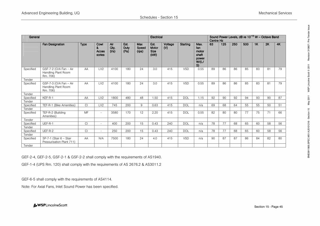
Advanced Engineering Building, UQ Mechanical Services Schedules - Section 15
Section 15 - Page 45
BNE0911900.SPEC.M
01.KJS101216 - Section 15 M
ay 2011 W
SP Lincolne Scott ©
2011 Revision 310807 / Pre Tender Issue
GeneralGeneralGeneralGeneral EleEleEleElectricalctricalctricalctrical Sound Power Levels, dB re 10Sound Power Levels, dB re 10Sound Power Levels, dB re 10Sound Power Levels, dB re 10----12121212
W W W W –––– Octave Band Octave Band Octave Band Octave Band Centre HzCentre HzCentre HzCentre Hz
Fan DesignationFan DesignationFan DesignationFan Designation TypeTypeTypeType CowlCowlCowlCowl & & & & AccesAccesAccesAccessoriessoriessoriessories
Air Air Air Air QQQQty.ty.ty.ty. (l/s)(l/s)(l/s)(l/s)
Est. Est. Est. Est. DutyDutyDutyDuty (Pa)(Pa)(Pa)(Pa)
Max Max Max Max SpeedSpeedSpeedSpeed (rps)(rps)(rps)(rps)
Est. Est. Est. Est. Motor Motor Motor Motor Size Size Size Size (kW)(kW)(kW)(kW)
VoltageVoltageVoltageVoltage (V)(V)(V)(V)
StartingStartingStartingStarting Max.Max.Max.Max. fan fan fan fan motor motor motor motor shaft shaft shaft shaft power power power power W/W/W/W/((((L/L/L/L/SSSS))))
63636363 125125125125 250250250250 500500500500 1K1K1K1K 2K2K2K2K 4K4K4K4K
Specified GSF-7-2 (O/A Fan – Air Handling Plant Room Rm. 706)
AA LV2 4100 180 24 3.0 415 VSD 0.55 89 86 86 85 83 81 79
Tender
Specified GSF-7-3 (O/A Fan – Air Handling Plant Room Rm. 706)
AA LV2 4100 180 24 3.0 415 VSD 0.55 89 86 86 85 83 81 79
Tender
Specified KEF-R-1 AA LV2 1800 480 48 1.50 415 DOL 1.15 92 90 92 94 93 90 87
Tender
Specified TEF-R-1 (Bike Amenities) CI LV2 745 200 9 0.63 415 DOL n/a 69 68 64 55 55 50 51
Tender
Specified TEF-R-2 (Building Amenities)
MF - 3580 170 12 2.20 415 DOL 0.55 82 80 80 77 75 71 66
Tender
Specified UEF-R-1 CI - 400 200 15 0.43 240 DOL n/a 78 77 68 65 60 58 56
Tender
Specified UEF-R-2 CI - 250 200 15 0.43 240 DOL n/a 78 77 68 65 60 58 56
Tender
Specified SP-7-1 (Stair 6 – Stair Pressurisation Plant 711)
AA N/A 7500 180 24 4.0 415 VSD n/a 90 87 87 86 84 82 80
Tender
GEF-2-4, GEF-2-5, GSF-2-1 & GSF-2-2 shall comply with the requirements of AS1940.
GEF-1-4 (UPS Rm. 120) shall comply with the requirements of AS 2676.2 & AS3011.2
GEF-6-5 shall comply with the requirements of AS4114.
Note: For Axial Fans, Inlet Sound Power has been specified.

Advanced Engineering Building, UQ Mechanical Services Schedules - Section 15
Section 15 - Page 46
BNE0911900.SPEC.M
01.KJS101216 - Section 15 M
ay 2011 W
SP Lincolne Scott ©
2011 Revision 310807 / Pre Tender Issue
15.2115.2115.2115.21 CEILING SWEEP FANSCEILING SWEEP FANSCEILING SWEEP FANSCEILING SWEEP FANS
GeneralGeneralGeneralGeneral
Level Level Level Level ServeServeServeServedddd
Equipment No.Equipment No.Equipment No.Equipment No. (Area Served)(Area Served)(Area Served)(Area Served)
Fan Fan Fan Fan Diameter Diameter Diameter Diameter
(mm)(mm)(mm)(mm)
Fan Fan Fan Fan Weight Weight Weight Weight
(kg)(kg)(kg)(kg)
Max Max Max Max SpeedSpeedSpeedSpeed (RPM)(RPM)(RPM)(RPM)
Prime Prime Prime Prime MoverMoverMoverMover
Fan Fan Fan Fan SpeedsSpeedsSpeedsSpeeds
FLAFLAFLAFLA (Amps)(Amps)(Amps)(Amps)
Specified
CF-3-1 – CF-3-4
(Structures lab level 2)
Big Ass Isis or similar
2843 45 80 Gearless
direct drive
Unlimited (to max RPM)
3.9
Tender
Specified
CF-4-1, 4-2, 5-1, 5-2 (West Atrium)
Big Ass Isis or similar
2843 45 80 Gearless
direct drive
Unlimited (to max RPM)
3.9
Tender
Specified
CF-6-1
(West Atrium)
Big Ass Isis or similar
3150 50 60 Gearless
direct drive
Unlimited (to max RPM)
3.9
Tender

Advanced Engineering Building, UQ Mechanical Services Schedules - Section 15
Section 15 - Page 47
BNE0911900.SPEC.M
01.KJS101216 - Section 15 M
ay 2011 W
SP Lincolne Scott ©
2011 Revision 310807 / Pre Tender Issue
15.2215.2215.2215.22 AIR AIR AIR AIR HEAT EXHEAT EXHEAT EXHEAT EXCCCCHANGERHANGERHANGERHANGER
Specified / Specified / Specified / Specified / TenderTenderTenderTender
No.No.No.No. Outside Air Outside Air Outside Air Outside Air –––– Air Qty l/sAir Qty l/sAir Qty l/sAir Qty l/s
Extract Air Extract Air Extract Air Extract Air –––– Air Qty l/sAir Qty l/sAir Qty l/sAir Qty l/s
Minimum EfficiencyMinimum EfficiencyMinimum EfficiencyMinimum Efficiency
Level Level Level Level 2222
Specified AHEX-2-1 4000 4000
75 % Sensible / 75
% Latent
Tender
Fans shall be selected to meet system resistance and located within Heat Exchanger Unit.
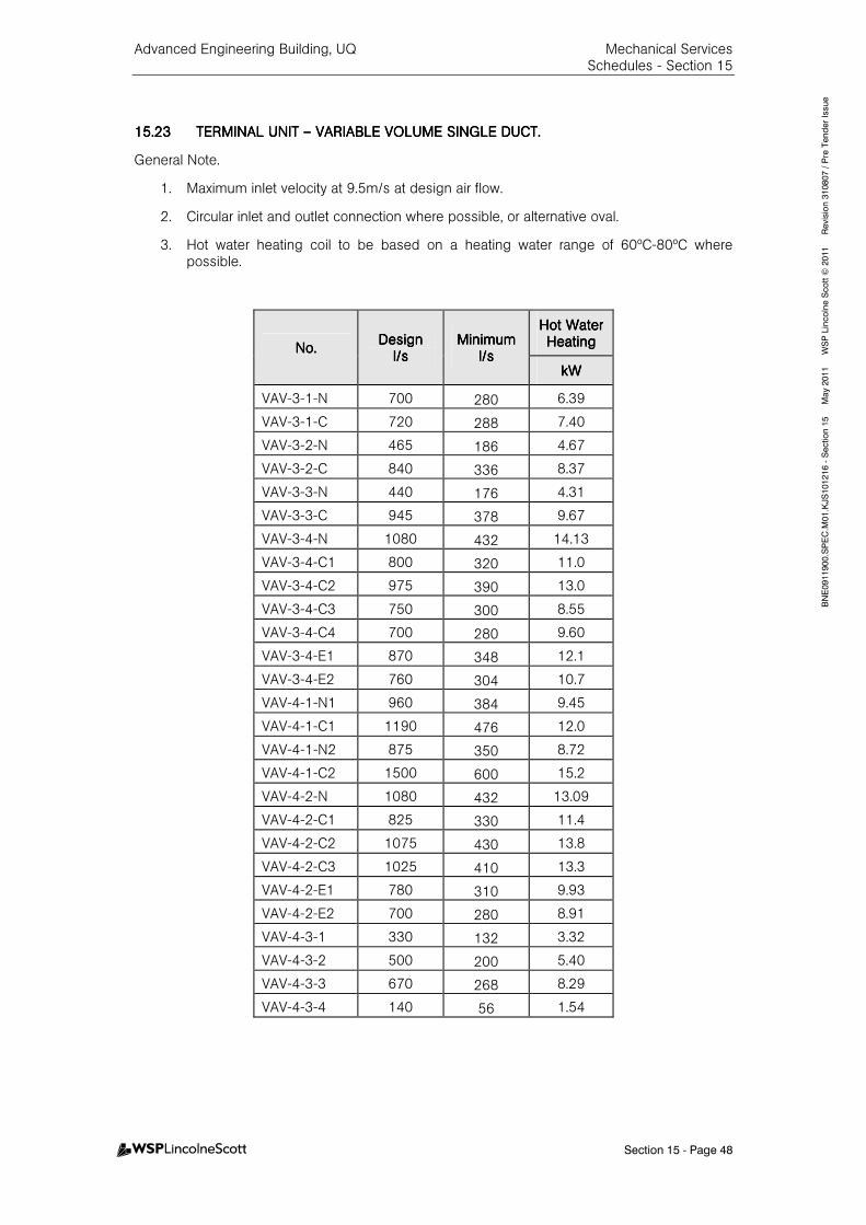
Advanced Engineering Building, UQ Mechanical Services Schedules - Section 15
Section 15 - Page 48
BNE0911900.SPEC.M
01.KJS101216 - Section 15 M
ay 2011 W
SP Lincolne Scott ©
2011 Revision 310807 / Pre Tender Issue
15.2315.2315.2315.23 TERMINAL UNIT TERMINAL UNIT TERMINAL UNIT TERMINAL UNIT –––– VARIABLE VOLUME SINGVARIABLE VOLUME SINGVARIABLE VOLUME SINGVARIABLE VOLUME SINGLE DUCT.LE DUCT.LE DUCT.LE DUCT.
General Note.
1. Maximum inlet velocity at 9.5m/s at design air flow.
2. Circular inlet and outlet connection where possible, or alternative oval.
3. Hot water heating coil to be based on a heating water range of 60ºC-80ºC where possible.
No.No.No.No. DesignDesignDesignDesign
l/sl/sl/sl/s MinimumMinimumMinimumMinimum
l/sl/sl/sl/s
Hot Water Hot Water Hot Water Hot Water HeatingHeatingHeatingHeating
kWkWkWkW
VAV-3-1-N 700 280 6.39
VAV-3-1-C 720 288 7.40
VAV-3-2-N 465 186 4.67
VAV-3-2-C 840 336 8.37
VAV-3-3-N 440 176 4.31
VAV-3-3-C 945 378 9.67
VAV-3-4-N 1080 432 14.13
VAV-3-4-C1 800 320 11.0
VAV-3-4-C2 975 390 13.0
VAV-3-4-C3 750 300 8.55
VAV-3-4-C4 700 280 9.60
VAV-3-4-E1 870 348 12.1
VAV-3-4-E2 760 304 10.7
VAV-4-1-N1 960 384 9.45
VAV-4-1-C1 1190 476 12.0
VAV-4-1-N2 875 350 8.72
VAV-4-1-C2 1500 600 15.2
VAV-4-2-N 1080 432 13.09
VAV-4-2-C1 825 330 11.4
VAV-4-2-C2 1075 430 13.8
VAV-4-2-C3 1025 410 13.3
VAV-4-2-E1 780 310 9.93
VAV-4-2-E2 700 280 8.91
VAV-4-3-1 330 132 3.32
VAV-4-3-2 500 200 5.40
VAV-4-3-3 670 268 8.29
VAV-4-3-4 140 56 1.54
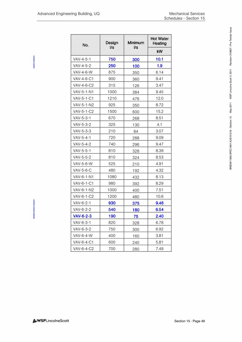
Advanced Engineering Building, UQ Mechanical Services Schedules - Section 15
Section 15 - Page 49
BNE0911900.SPEC.M
01.KJS101216 - Section 15 M
ay 2011 W
SP Lincolne Scott ©
2011 Revision 310807 / Pre Tender Issue
No.No.No.No. DesignDesignDesignDesign
l/sl/sl/sl/s MinimumMinimumMinimumMinimum
l/sl/sl/sl/s
Hot Water Hot Water Hot Water Hot Water HeatingHeatingHeatingHeating
kWkWkWkW
VAV-4-5-1 750750750750 300300300300 10.110.110.110.1
VAV-4-5-2 250250250250 100100100100 1.91.91.91.9
VAV-4-6-W 875 350 6.14
VAV-4-6-C1 900 360 9.41
VAV-4-6-C2 315 126 3.47
VAV-5-1-N1 1000 384 9.45
VAV-5-1-C1 1210 476 12.0
VAV-5-1-N2 925 350 8.72
VAV-5-1-C2 1500 600 15.2
VAV-5-3-1 670 268 8.51
VAV-5-3-2 325 130 4.1
VAV-5-3-3 210 84 3.07
VAV-5-4-1 720 288 9.09
VAV-5-4-2 740 296 9.47
VAV-5-5-1 810 328 8.39
VAV-5-5-2 810 324 8.53
VAV-5-6-W 525 210 4.91
VAV-5-6-C 480 192 4.32
VAV-6-1-N1 1080 432 8.13
VAV-6-1-C1 980 392 8.29
VAV-6-1-N2 1000 400 7.51
VAV-6-1-C2 1200 480 10.6
VAV-6-2-1 930930930930 375375375375 9.469.469.469.46
VAV-6-2-2 540540540540 180180180180 6.546.546.546.54
VAVVAVVAVVAV----6666----2222----3333 190190190190 75757575 2.402.402.402.40
VAV-6-3-1 820 328 6.78
VAV-6-3-2 750 300 6.92
VAV-6-4-W 400 160 3.81
VAV-6-4-C1 600 240 5.81
VAV-6-4-C2 700 280 7.49
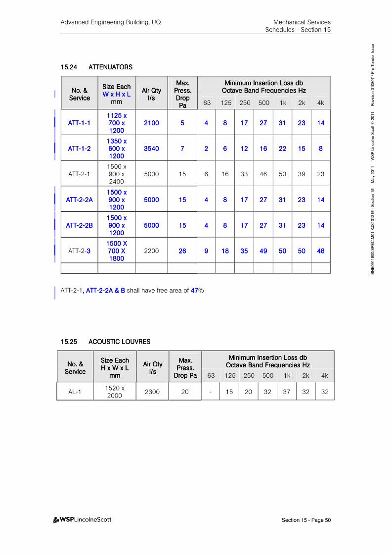
Advanced Engineering Building, UQ Mechanical Services Schedules - Section 15
Section 15 - Page 50
BNE0911900.SPEC.M
01.KJS101216 - Section 15 M
ay 2011 W
SP Lincolne Scott ©
2011 Revision 310807 / Pre Tender Issue
15.2415.2415.2415.24 ATTENUATORSATTENUATORSATTENUATORSATTENUATORS
No. &No. &No. &No. & ServiceServiceServiceService
Size EachSize EachSize EachSize Each W x H x LW x H x LW x H x LW x H x L
mmmmmmmm
Air QAir QAir QAir Qtytytyty l/sl/sl/sl/s
MaxMaxMaxMax.... PresPresPresPress. s. s. s. Drop Drop Drop Drop PaPaPaPa
Minimum Insertion Loss dbMinimum Insertion Loss dbMinimum Insertion Loss dbMinimum Insertion Loss db Octave Band Frequencies HzOctave Band Frequencies HzOctave Band Frequencies HzOctave Band Frequencies Hz
63 125 250 500 1k 2k 4k
ATTATTATTATT----1111----1111 1125 x 1125 x 1125 x 1125 x 700 x 700 x 700 x 700 x 1212121200000000
2102102102100000 5555 4444 8888 17171717 27272727 31313131 23232323 14141414
ATTATTATTATT----1111----2222 1350 x 1350 x 1350 x 1350 x 600 x 600 x 600 x 600 x 1200120012001200
3540354035403540 7777 2222 6666 12121212 16161616 22222222 15151515 8888
ATT-2-1 1500 x 900 x 2400
5000 15 6 16 33 46 50 39 23
ATTATTATTATT----2222----2A2A2A2A 1500 x 1500 x 1500 x 1500 x 900 x 900 x 900 x 900 x 1200120012001200
5000500050005000 15151515 4444 8888 17171717 27272727 31313131 23232323 14141414
ATTATTATTATT----2222----2B2B2B2B 1500 x 1500 x 1500 x 1500 x 900 x 900 x 900 x 900 x 1200120012001200
5000500050005000 15151515 4444 8888 17171717 27272727 31313131 23232323 14141414
ATT-2-3333 1515151500 X 00 X 00 X 00 X 700 X 700 X 700 X 700 X 1800180018001800
2200 26262626 9999 18181818 35353535 49494949 50505050 50505050 48484848
ATT-2-1, ATT, ATT, ATT, ATT----2222----2A & B2A & B2A & B2A & B shall have free area of 47474747%
15.2515.2515.2515.25 ACOUSTIC LOUVRESACOUSTIC LOUVRESACOUSTIC LOUVRESACOUSTIC LOUVRES
No. &No. &No. &No. & ServiceServiceServiceService
Size EachSize EachSize EachSize Each H x W x L H x W x L H x W x L H x W x L
mmmmmmmm
Air QtyAir QtyAir QtyAir Qty l/sl/sl/sl/s
Max. Max. Max. Max. Press. Press. Press. Press.
Drop PaDrop PaDrop PaDrop Pa
Minimum Insertion Loss dbMinimum Insertion Loss dbMinimum Insertion Loss dbMinimum Insertion Loss db Octave Band Frequencies HzOctave Band Frequencies HzOctave Band Frequencies HzOctave Band Frequencies Hz
63 125 250 500 1k 2k 4k
AL-1 1520 x 2000
2300 20 - 15 20 32 37 32 32

Advanced Engineering Building, UQ Mechanical Services Schedules - Section 15
Section 15 - Page 51
BNE0911900.SPEC.M
01.KJS101216 - Section 15 M
ay 2011 W
SP Lincolne Scott ©
2011 Revision 310807 / Pre Tender Issue
15.2615.2615.2615.26 AIR CONDITIONING UNIAIR CONDITIONING UNIAIR CONDITIONING UNIAIR CONDITIONING UNIT T T T –––– CHILLED WATER, COMPUCHILLED WATER, COMPUCHILLED WATER, COMPUCHILLED WATER, COMPUTER ROOMTER ROOMTER ROOMTER ROOM
GeneralGeneralGeneralGeneral SpecifiedSpecifiedSpecifiedSpecified TenderTenderTenderTender
Unit No.
CRAC-1-1a (Duty) & CRAC-1-1b (Standby)
Area Served
Level 1 Comms Room
No. off 2
Type
Ducted Top Discharge
Supply Air Quantity l/s 3200
Net Sensible Cooling Capacity Each kWr 46.8
Total Cooling Capacity Each kWr 61
Entering/Leaving Ch.W °C 6.5/12.5
Chilled Water Quantity Each l/s 2.47
Air Temp. on Cooling Coil °C DB/°C WB 24.0/17.1
External System Air Pressure Drop Pa 120
Maximum Ch.W. Pressure Drop kPa 60.0
Humidifier Capacity kg/hr 10 (Infrared)
Heater Capacity kW 9.0
Evaporator MotorEvaporator MotorEvaporator MotorEvaporator Motor
Estimated Size kW 2 @ 2.3 kW
Evaporator Fan shall be backward curve, corrosion resistant aluminium fan wheel with high efficiency external rotor Electronically Communicated motor.
Each unit has a duct-mounted motorised damper which is to open when the unit is on line. Each CRAC is to provide the signal to operate the motorised damper.
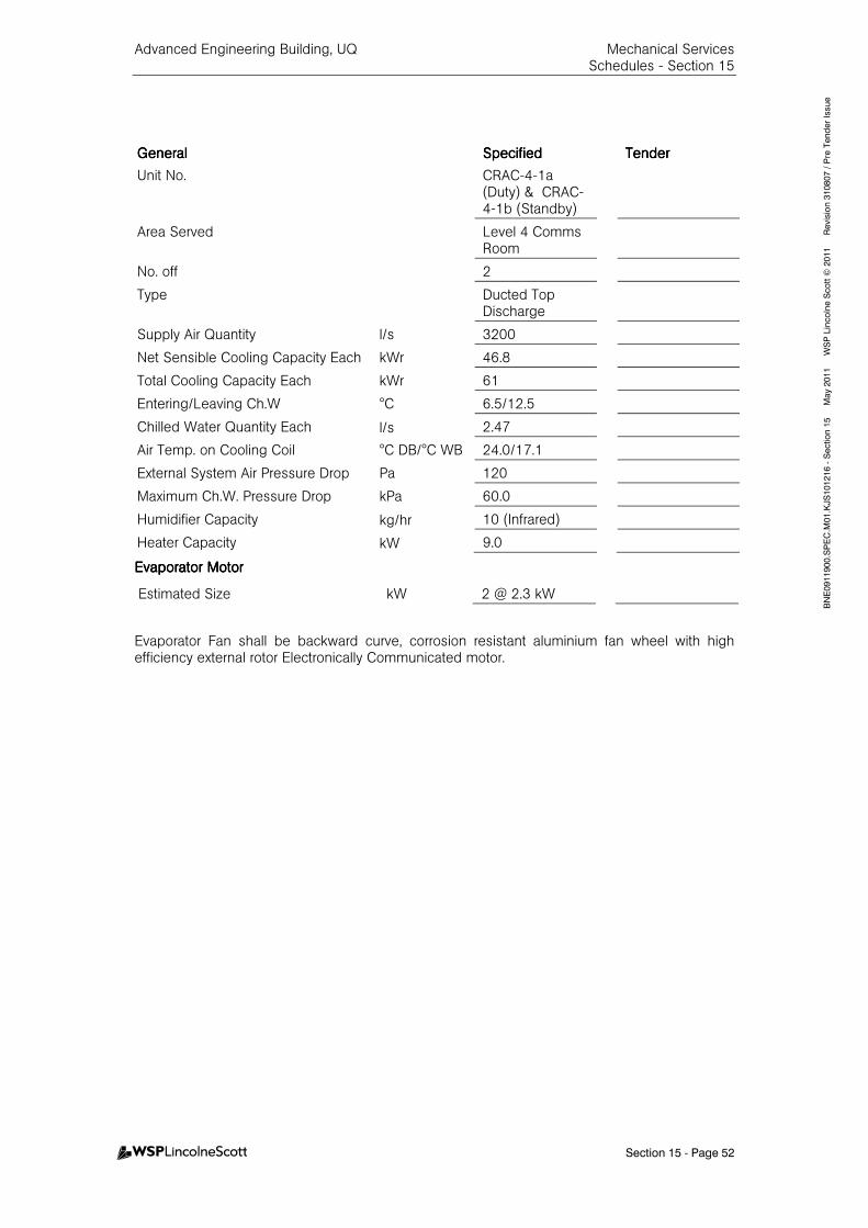
Advanced Engineering Building, UQ Mechanical Services Schedules - Section 15
Section 15 - Page 52
BNE0911900.SPEC.M
01.KJS101216 - Section 15 M
ay 2011 W
SP Lincolne Scott ©
2011 Revision 310807 / Pre Tender Issue
GeneralGeneralGeneralGeneral SpecifiedSpecifiedSpecifiedSpecified TenderTenderTenderTender
Unit No.
CRAC-4-1a (Duty) & CRAC-4-1b (Standby)
Area Served
Level 4 Comms Room
No. off 2
Type
Ducted Top Discharge
Supply Air Quantity l/s 3200
Net Sensible Cooling Capacity Each kWr 46.8
Total Cooling Capacity Each kWr 61
Entering/Leaving Ch.W °C 6.5/12.5
Chilled Water Quantity Each l/s 2.47
Air Temp. on Cooling Coil °C DB/°C WB 24.0/17.1
External System Air Pressure Drop Pa 120
Maximum Ch.W. Pressure Drop kPa 60.0
Humidifier Capacity kg/hr 10 (Infrared)
Heater Capacity kW 9.0
Evaporator MotorEvaporator MotorEvaporator MotorEvaporator Motor
Estimated Size kW 2 @ 2.3 kW
Evaporator Fan shall be backward curve, corrosion resistant aluminium fan wheel with high efficiency external rotor Electronically Communicated motor.
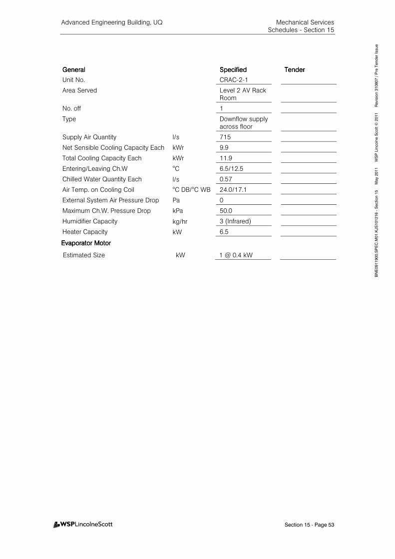
Advanced Engineering Building, UQ Mechanical Services Schedules - Section 15
Section 15 - Page 53
BNE0911900.SPEC.M
01.KJS101216 - Section 15 M
ay 2011 W
SP Lincolne Scott ©
2011 Revision 310807 / Pre Tender Issue
GeneralGeneralGeneralGeneral SpecifiedSpecifiedSpecifiedSpecified TenderTenderTenderTender
Unit No. CRAC-2-1
Area Served
Level 2 AV Rack Room
No. off 1
Type
Downflow supply across floor
Supply Air Quantity l/s 715
Net Sensible Cooling Capacity Each kWr 9.9
Total Cooling Capacity Each kWr 11.9
Entering/Leaving Ch.W °C 6.5/12.5
Chilled Water Quantity Each l/s 0.57
Air Temp. on Cooling Coil °C DB/°C WB 24.0/17.1
External System Air Pressure Drop Pa 0
Maximum Ch.W. Pressure Drop kPa 50.0
Humidifier Capacity kg/hr 3 (Infrared)
Heater Capacity kW 6.5
Evaporator MotorEvaporator MotorEvaporator MotorEvaporator Motor
Estimated Size kW 1 @ 0.4 kW
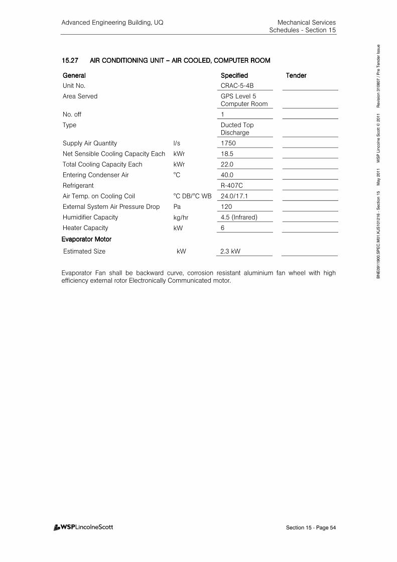
Advanced Engineering Building, UQ Mechanical Services Schedules - Section 15
Section 15 - Page 54
BNE0911900.SPEC.M
01.KJS101216 - Section 15 M
ay 2011 W
SP Lincolne Scott ©
2011 Revision 310807 / Pre Tender Issue
15.2715.2715.2715.27 AIR CONDITIONING UNIAIR CONDITIONING UNIAIR CONDITIONING UNIAIR CONDITIONING UNIT T T T –––– AIR COOLED, COMPUTERAIR COOLED, COMPUTERAIR COOLED, COMPUTERAIR COOLED, COMPUTER ROOMROOMROOMROOM
GeneralGeneralGeneralGeneral SpecifiedSpecifiedSpecifiedSpecified TenderTenderTenderTender
Unit No. CRAC-5-4B
Area Served
GPS Level 5 Computer Room
No. off 1
Type
Ducted Top Discharge
Supply Air Quantity l/s 1750
Net Sensible Cooling Capacity Each kWr 18.5
Total Cooling Capacity Each kWr 22.0
Entering Condenser Air °C 40.0
Refrigerant R-407C
Air Temp. on Cooling Coil °C DB/°C WB 24.0/17.1
External System Air Pressure Drop Pa 120
Humidifier Capacity kg/hr 4.5 (Infrared)
Heater Capacity kW 6
Evaporator MotorEvaporator MotorEvaporator MotorEvaporator Motor
Estimated Size kW 2.3 kW
Evaporator Fan shall be backward curve, corrosion resistant aluminium fan wheel with high efficiency external rotor Electronically Communicated motor.
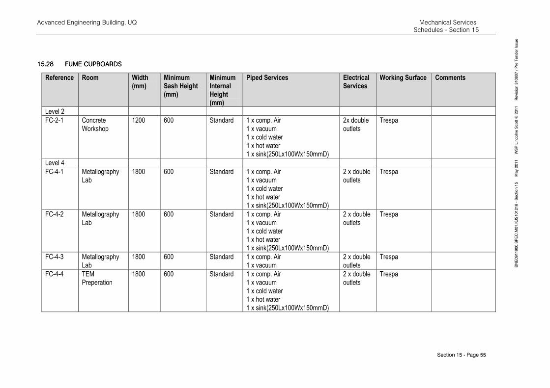
Advanced Engineering Building, UQ Mechanical Services Schedules - Section 15
Section 15 - Page 55
BNE0911900.SPEC.M
01.KJS101216 - Section 15 M
ay 2011 W
SP Lincolne Scott ©
2011 Revision 310807 / Pre Tender Issue
15.2815.2815.2815.28 FUME CUPBOARDSFUME CUPBOARDSFUME CUPBOARDSFUME CUPBOARDS
Reference Room Width (mm)
Minimum Sash Height (mm)
Minimum Internal Height (mm)
Piped Services Electrical Services
Working Surface Comments
Level 2
FC-2-1 Concrete
Workshop
1200 600 Standard 1 x comp. Air
1 x vacuum
1 x cold water
1 x hot water
1 x sink(250Lx100Wx150mmD)
2x double
outlets
Trespa
Level 4
FC-4-1 Metallography
Lab
1800 600 Standard 1 x comp. Air
1 x vacuum
1 x cold water
1 x hot water
1 x sink(250Lx100Wx150mmD)
2 x double
outlets
Trespa
FC-4-2 Metallography
Lab
1800 600 Standard 1 x comp. Air
1 x vacuum
1 x cold water
1 x hot water
1 x sink(250Lx100Wx150mmD)
2 x double
outlets
Trespa
FC-4-3 Metallography
Lab
1800 600 Standard 1 x comp. Air
1 x vacuum
2 x double
outlets
Trespa
FC-4-4 TEM
Preperation
1800 600 Standard 1 x comp. Air
1 x vacuum
1 x cold water
1 x hot water
1 x sink(250Lx100Wx150mmD)
2 x double
outlets
Trespa
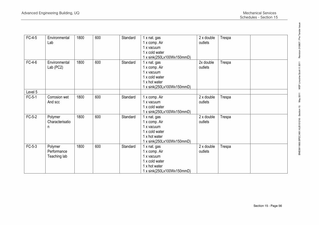
Advanced Engineering Building, UQ Mechanical Services Schedules - Section 15
Section 15 - Page 56
BNE0911900.SPEC.M
01.KJS101216 - Section 15 M
ay 2011 W
SP Lincolne Scott ©
2011 Revision 310807 / Pre Tender Issue
FC-4-5 Environmental
Lab
1800 600 Standard 1 x nat. gas
1 x comp. Air
1 x vacuum
1 x cold water
1 x sink(250Lx100Wx150mmD)
2 x double
outlets
Trespa
FC-4-6 Environmental
Lab (PC2)
1800 600 Standard 1 x nat. gas
1 x comp. Air
1 x vacuum
1 x cold water
1 x hot water
1 x sink(250Lx100Wx150mmD)
2x double
outlets
Trespa
Level 5
FC-5-1 Corrosion wet
And scc
1800 600 Standard 1 x comp. Air
1 x vacuum
1 x cold water
1 x sink(250Lx100Wx150mmD)
2 x double
outlets
Trespa
FC-5-2 Polymer
Characterisatio
n
1800 600 Standard 1 x nat. gas
1 x comp. Air
1 x vacuum
1 x cold water
1 x hot water
1 x sink(250Lx100Wx150mmD)
2 x double
outlets
Trespa
FC-5-3 Polymer
Performance
Teaching lab
1800 600 Standard 1 x nat. gas
1 x comp. Air
1 x vacuum
1 x cold water
1 x hot water
1 x sink(250Lx100Wx150mmD)
2 x double
outlets
Trespa
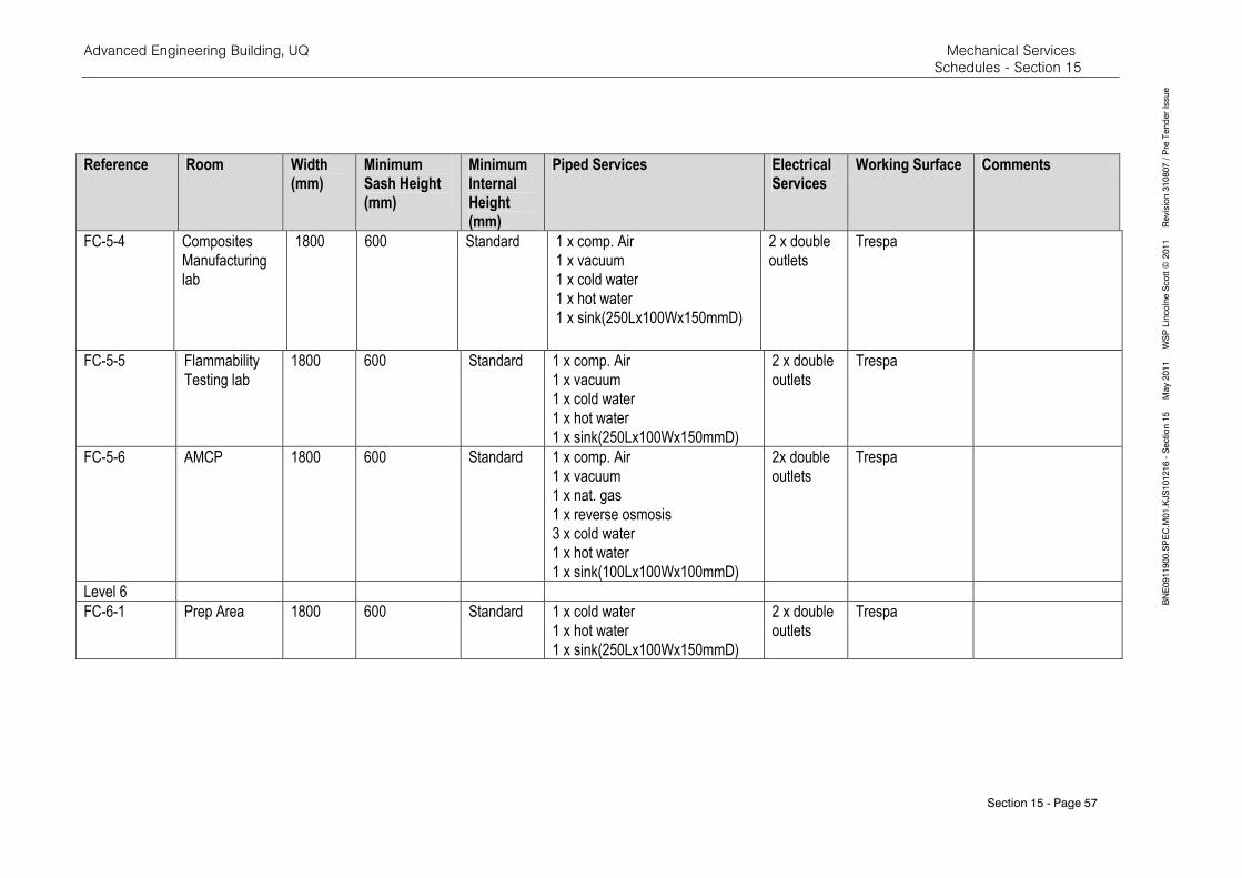
Advanced Engineering Building, UQ Mechanical Services Schedules - Section 15
Section 15 - Page 57
BNE0911900.SPEC.M
01.KJS101216 - Section 15 M
ay 2011 W
SP Lincolne Scott ©
2011 Revision 310807 / Pre Tender Issue
Reference Room Width (mm)
Minimum Sash Height (mm)
Minimum Internal Height (mm)
Piped Services Electrical Services
Working Surface Comments
FC-5-4 Composites
Manufacturing
lab
1800 600 Standard 1 x comp. Air
1 x vacuum
1 x cold water
1 x hot water
1 x sink(250Lx100Wx150mmD)
2 x double
outlets
Trespa
FC-5-5 Flammability
Testing lab
1800 600 Standard 1 x comp. Air
1 x vacuum
1 x cold water
1 x hot water
1 x sink(250Lx100Wx150mmD)
2 x double
outlets
Trespa
FC-5-6 AMCP 1800 600 Standard 1 x comp. Air
1 x vacuum
1 x nat. gas
1 x reverse osmosis
3 x cold water
1 x hot water
1 x sink(100Lx100Wx100mmD)
2x double
outlets
Trespa
Level 6
FC-6-1 Prep Area 1800 600 Standard 1 x cold water
1 x hot water
1 x sink(250Lx100Wx150mmD)
2 x double
outlets
Trespa
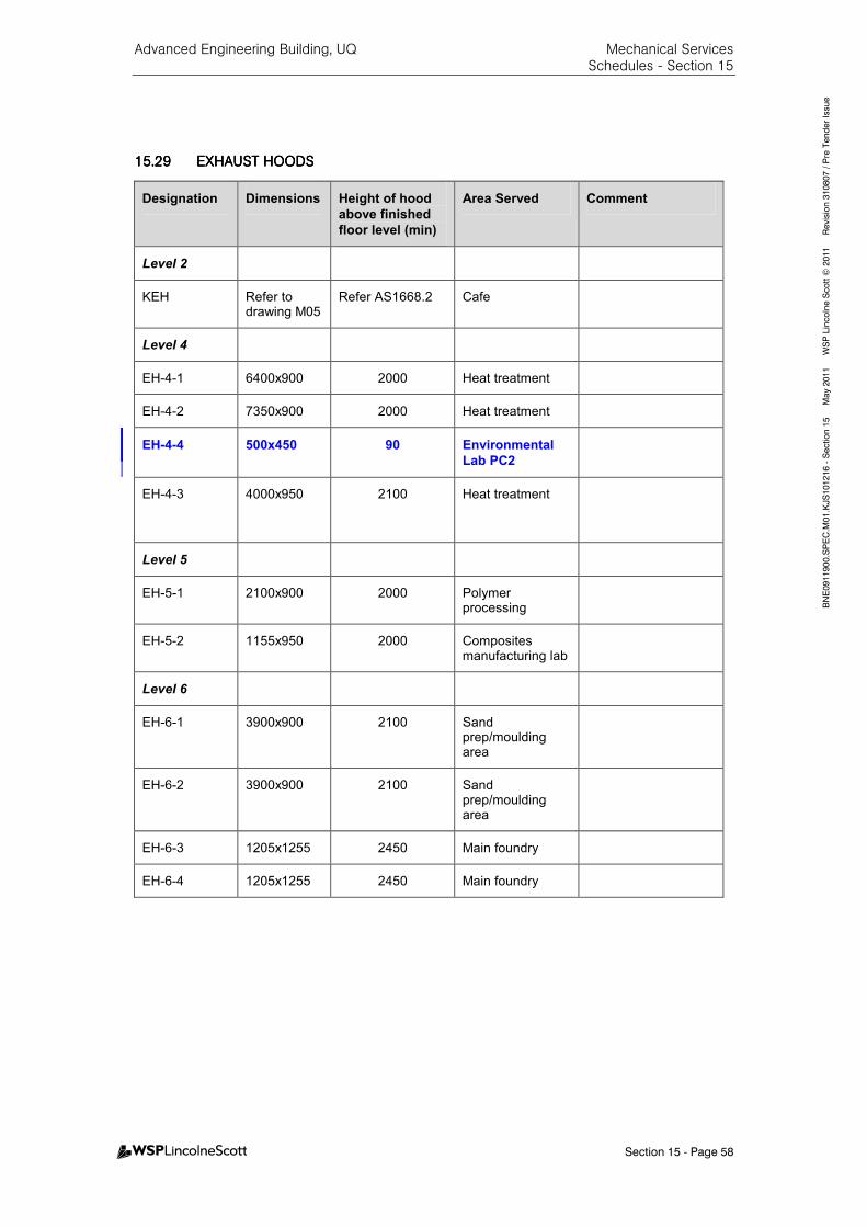
Advanced Engineering Building, UQ Mechanical Services Schedules - Section 15
Section 15 - Page 58
BNE0911900.SPEC.M
01.KJS101216 - Section 15 M
ay 2011 W
SP Lincolne Scott ©
2011 Revision 310807 / Pre Tender Issue
15.2915.2915.2915.29 EXHAUST EXHAUST EXHAUST EXHAUST HOODSHOODSHOODSHOODS
Designation Dimensions Height of hood
above finished
floor level (min)
Area Served Comment
Level 2
KEH Refer to drawing M05
Refer AS1668.2 Cafe
Level 4
EH-4-1 6400x900 2000 Heat treatment
EH-4-2 7350x900 2000 Heat treatment
EH-4-4 500x450 90 Environmental
Lab PC2
EH-4-3 4000x950 2100 Heat treatment
Level 5
EH-5-1 2100x900 2000 Polymer processing
EH-5-2 1155x950 2000 Composites manufacturing lab
Level 6
EH-6-1 3900x900 2100 Sand prep/moulding area
EH-6-2 3900x900 2100 Sand prep/moulding area
EH-6-3 1205x1255 2450 Main foundry
EH-6-4 1205x1255 2450 Main foundry
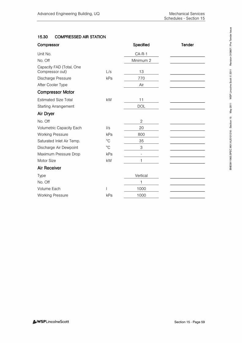
Advanced Engineering Building, UQ Mechanical Services Schedules - Section 15
Section 15 - Page 59
BNE0911900.SPEC.M
01.KJS101216 - Section 15 M
ay 2011 W
SP Lincolne Scott ©
2011 Revision 310807 / Pre Tender Issue
15.3015.3015.3015.30 COMPRESSED AIR STATICOMPRESSED AIR STATICOMPRESSED AIR STATICOMPRESSED AIR STATIONONONON
CompressorCompressorCompressorCompressor SpecifiedSpecifiedSpecifiedSpecified TenderTenderTenderTender
Unit No. CA-R-1
No. Off Minimum 2
Capacity FAD (Total, One Compressor out) L/s 13
Discharge Pressure kPa 770
After Cooler Type Air
Compressor MotorCompressor MotorCompressor MotorCompressor Motor
Estimated Size Total kW 11
Starting Arrangement DOL
Air DryerAir DryerAir DryerAir Dryer
No. Off 2
Volumetric Capacity Each l/s 20
Working Pressure kPa 800
Saturated Inlet Air Temp. °C 35
Discharge Air Dewpoint °C 3
Maximum Pressure Drop kPa -
Motor Size kW 1
Air ReceiverAir ReceiverAir ReceiverAir Receiver
Type Vertical
No. Off 1
Volume Each l 1000
Working Pressure kPa 1000

Advanced Engineering Building, UQ Mechanical Services Schedules - Section 15
Section 15 - Page 60
BNE0911900.SPEC.M
01.KJS101216 - Section 15 M
ay 2011 W
SP Lincolne Scott ©
2011 Revision 310807 / Pre Tender Issue
15.3115.3115.3115.31 VACUUM PLANTVACUUM PLANTVACUUM PLANTVACUUM PLANT
Vacuum PumpVacuum PumpVacuum PumpVacuum Pump SpecifiedSpecifiedSpecifiedSpecified TenderTenderTenderTender
Unit No. VP-R-1
No. Off Pumps on Plant 2
Rarified Air Displacement, each at 50 mbar m3/hr 130
Motor kW 4
Vacuum ReceiverVacuum ReceiverVacuum ReceiverVacuum Receiver
Volume L 1200
SeparatorSeparatorSeparatorSeparator
No. Off 2
Bacterial FilterBacterial FilterBacterial FilterBacterial Filter
No. Off 2
15.3215.3215.3215.32 GAS ALARM PANELSGAS ALARM PANELSGAS ALARM PANELSGAS ALARM PANELS
Gas AlarmGas AlarmGas AlarmGas Alarm
Panel Location Level 2, Facilities Manager
Standby and failure alarms Nitrogen, Argon, Helium, Vacuum and Compressed Air
General Alarm Vacuum plant, compressed air plant.
15.3315.3315.3315.33 WATER TREATMENTWATER TREATMENTWATER TREATMENTWATER TREATMENT
The water treatment systems to be provided under this Specification shall be for the following piped services.
Cooling Tower System
Chilled Water System
Heating Hot Water System
Condenser water secondary circuit
15.3415.3415.3415.34 CHILLED CHILLED CHILLED CHILLED WATER WATER WATER WATER BUFFERBUFFERBUFFERBUFFER TANKTANKTANKTANK
GeneralGeneralGeneralGeneral SpecifiedSpecifiedSpecifiedSpecified TenderTenderTenderTender
Service Chilled Water Storage
Type Vertical Storage
Effective Volume litres 8,000
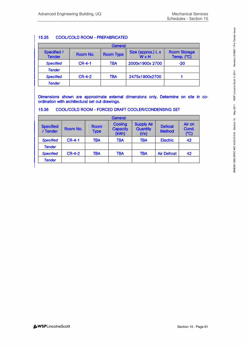
Advanced Engineering Building, UQ Mechanical Services Schedules - Section 15
Section 15 - Page 61
BNE0911900.SPEC.M
01.KJS101216 - Section 15 M
ay 2011 W
SP Lincolne Scott ©
2011 Revision 310807 / Pre Tender Issue
15.3515.3515.3515.35 COOL/COLD RCOOL/COLD RCOOL/COLD RCOOL/COLD ROOM OOM OOM OOM ---- PREFABRICATEDPREFABRICATEDPREFABRICATEDPREFABRICATED
GeneralGeneralGeneralGeneral
Specified / Specified / Specified / Specified / TenderTenderTenderTender
Room No.Room No.Room No.Room No. Room TypeRoom TypeRoom TypeRoom Type Size (approx.) Size (approx.) Size (approx.) Size (approx.) L L L L x x x x
WWWW x x x x HHHH Room Storage Room Storage Room Storage Room Storage
Temp. (°C)Temp. (°C)Temp. (°C)Temp. (°C)
SpecifiedSpecifiedSpecifiedSpecified CRCRCRCR----4444----1111 TBATBATBATBA 2000200020002000xxxx1901901901900000x x x x 2222777700000000 ----20202020
TenderTenderTenderTender
SpecifiedSpecifiedSpecifiedSpecified CRCRCRCR----4444----2222 TBATBATBATBA 2475247524752475xxxx1111900900900900xxxx2222777700000000 1111
TenderTenderTenderTender
Dimensions shown are approximate Dimensions shown are approximate Dimensions shown are approximate Dimensions shown are approximate external dimensions only. Determine on site in coexternal dimensions only. Determine on site in coexternal dimensions only. Determine on site in coexternal dimensions only. Determine on site in co----ordination with architectural set out drawings.ordination with architectural set out drawings.ordination with architectural set out drawings.ordination with architectural set out drawings.
15.3615.3615.3615.36 COOL/COLD ROOM COOL/COLD ROOM COOL/COLD ROOM COOL/COLD ROOM ---- FORCED DRAFT COOLER/FORCED DRAFT COOLER/FORCED DRAFT COOLER/FORCED DRAFT COOLER/CONDENSING SETCONDENSING SETCONDENSING SETCONDENSING SET
GeneralGeneralGeneralGeneral
Specified Specified Specified Specified / Tender/ Tender/ Tender/ Tender
Room No.Room No.Room No.Room No. Room Room Room Room TypeTypeTypeType
Cooling Cooling Cooling Cooling Capacity Capacity Capacity Capacity
(kWr)(kWr)(kWr)(kWr)
Supply Air Supply Air Supply Air Supply Air Quantity Quantity Quantity Quantity
(l/s)(l/s)(l/s)(l/s)
Defrost Defrost Defrost Defrost MeMeMeMethodthodthodthod
Air on Air on Air on Air on Cond. Cond. Cond. Cond. (°C)(°C)(°C)(°C)
SpecifiedSpecifiedSpecifiedSpecified CRCRCRCR----4444----1111 TBATBATBATBA TBATBATBATBA TBATBATBATBA ElectricElectricElectricElectric 42424242
TenderTenderTenderTender
SpecifiedSpecifiedSpecifiedSpecified CRCRCRCR----4444----2222 TBATBATBATBA TBATBATBATBA TBATBATBATBA Air DefrostAir DefrostAir DefrostAir Defrost 42424242
TenderTenderTenderTender
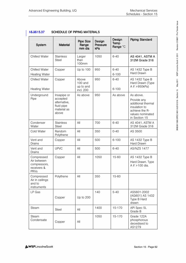
Advanced Engineering Building, UQ Mechanical Services Schedules - Section 15
Section 15 - Page 62
BNE0911900.SPEC.M
01.KJS101216 - Section 15 M
ay 2011 W
SP Lincolne Scott ©
2011 Revision 310807 / Pre Tender Issue
15.3515.3515.3515.3515.3715.3715.3715.37 SCHEDULE OF PIPING MSCHEDULE OF PIPING MSCHEDULE OF PIPING MSCHEDULE OF PIPING MATERIALSATERIALSATERIALSATERIALS
SystemSystemSystemSystem MaterialMaterialMaterialMaterial Pipe Size Pipe Size Pipe Size Pipe Size
Range Range Range Range mm diamm diamm diamm dia
Design Design Design Design Pressure Pressure Pressure Pressure kPakPakPakPa
Design Design Design Design Temp Temp Temp Temp Range Range Range Range °C
PipinPipinPipinPiping Standardg Standardg Standardg Standard
Chilled Water
Stainless Steel
Larger than 100mm
1050
6-40
AS 4041, ASTM A
312M Grade 316
Chilled Water
Heating Water
Copper Up to 100 950 6-40
6-100
AS 1432 Type B Hard Drawn
Chilled Water
Heating Water
Copper Above 100 and up to and incl. 200
950 6-40
6-100
AS 1432 Type B Hard Drawn (Type A if >950kPa)
Underground Pipe
Insapipe or accepted alternative, fluid pipe material as above
As above 950 As above As above.
Provide any additional thermal insulation to achieve the R-values nominated in Section 15
Condenser Water
Stainless Steel
All 700 6-40 AS 4041, ASTM A 312M Grade 316
Cold Water Random Polythene
All 350 0-40 AS 3500
Vent and Drains
Copper All 500 6-100 AS 1432 Type B Hard Drawn
Vent and Drains
UPVC All 500 6-40 AS/NZS 1477
Compressed Air between compressors, receivers & PRVs
Copper All 1050 15-60 AS 1432 Type B
Hard Drawn. Type A if >100 dia.
Compressed Air in ceilings and to instruments
Polythene All 350 15-60
LP Gas
Copper Up to 200
140 5-40 AS5601-2002 (AG601) AS 1432 Type B Hard drawn
Steam Steel All
1400 15-170 API Spec 5L Grade B
Steam Condensate
Copper All
1050 15-170 Grade 122A phosphorous deoxidised to AS1279
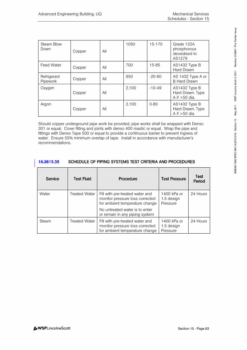
Advanced Engineering Building, UQ Mechanical Services Schedules - Section 15
Section 15 - Page 63
BNE0911900.SPEC.M
01.KJS101216 - Section 15 M
ay 2011 W
SP Lincolne Scott ©
2011 Revision 310807 / Pre Tender Issue
Steam Blow Down
Copper All
1050 15-170 Grade 122A phosphorous deoxidised to AS1279
Feed Water Copper All
700 15-85 AS1432 Type B Hard Drawn
Refrigerant Pipework
Copper All 950 -20-60 AS 1432 Type A or
B Hard Drawn
Oxygen Copper All
2,100 -10-49 AS1432 Type B Hard Drawn. Type A if >50 dia.
Argon Copper All
2,100 0-80 AS1432 Type B Hard Drawn. Type A if >50 dia.
Should copper underground pipe work be provided, pipe works shall be wrapped with Denso 301 or equal. Cover fitting and joints with denso 400 mastic or equal. Wrap the pipe and fittings with Denso Tape 500 or equal to provide a continuous barrier to prevent ingress of water. Ensure 55% minimum overlap of tape. Install in accordance with manufacturer’s recommendations. 15.3615.3615.3615.3615.3815.3815.3815.38 SCHEDULE OF PIPING SSCHEDULE OF PIPING SSCHEDULE OF PIPING SSCHEDULE OF PIPING SYSTEMS TEST CRITERIAYSTEMS TEST CRITERIAYSTEMS TEST CRITERIAYSTEMS TEST CRITERIA AND PROCEDURESAND PROCEDURESAND PROCEDURESAND PROCEDURES
ServiceServiceServiceService Test FluidTest FluidTest FluidTest Fluid ProcedureProcedureProcedureProcedure Test PressureTest PressureTest PressureTest Pressure Test Test Test Test
PeriodPeriodPeriodPeriod
Water Treated Water Fill with pre-treated water and monitor pressure loss corrected for ambient temperature change
No untreated water is to enter or remain in any piping system
1400 kPa or 1.5 design Pressure
24 Hours
Steam Treated Water Fill with pre-treated water and monitor pressure loss corrected for ambient temperature change
1400 kPa or 1.5 design Pressure
24 Hours
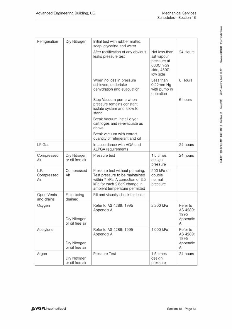
Advanced Engineering Building, UQ Mechanical Services Schedules - Section 15
Section 15 - Page 64
BNE0911900.SPEC.M
01.KJS101216 - Section 15 M
ay 2011 W
SP Lincolne Scott ©
2011 Revision 310807 / Pre Tender Issue
Refrigeration Dry Nitrogen Initial test with rubber mallet, soap, glycerine and water
After rectification of any obvious leaks pressure test
Not less than sat vapour pressure at 660C high side, 450C low side
24 Hours
When no loss in pressure achieved, undertake dehydration and evacuation
Less than 0.22mm Hg with pump in operation
6 Hours
Stop Vacuum pump when pressure remains constant, isolate system and allow to stand
6 hours
Break Vacuum install dryer cartridges and re-evacuate as above
Break vacuum with correct quantity of refrigerant and oil
LP Gas
In accordance with AGA and ALPGA requirements
24 hours
Compressed Air
Dry Nitrogen or oil free air
Pressure test 1.5 times design pressure
24 hours
L.P. Compressed Air
Compressed Air
Pressure test without pumping. Test pressure to be maintained within 7 kPa. A correction of 3.5 kPa for each 2.8oK change in ambient temperature permitted
200 kPa or double normal pressure
Open Vents and drains
Fluid being drained
Fill and visually check for leaks
Oxygen
Dry Nitrogen or oil free air
Refer to AS 4289: 1995 Appendix A
2,200 kPa Refer to AS 4289: 1995 Appendix A
Acetylene
Dry Nitrogen or oil free air
Refer to AS 4289: 1995 Appendix A
1,000 kPa Refer to AS 4289: 1995 Appendix A
Argon Dry Nitrogen or oil free air
Pressure Test 1.5 times design pressure
24 hours
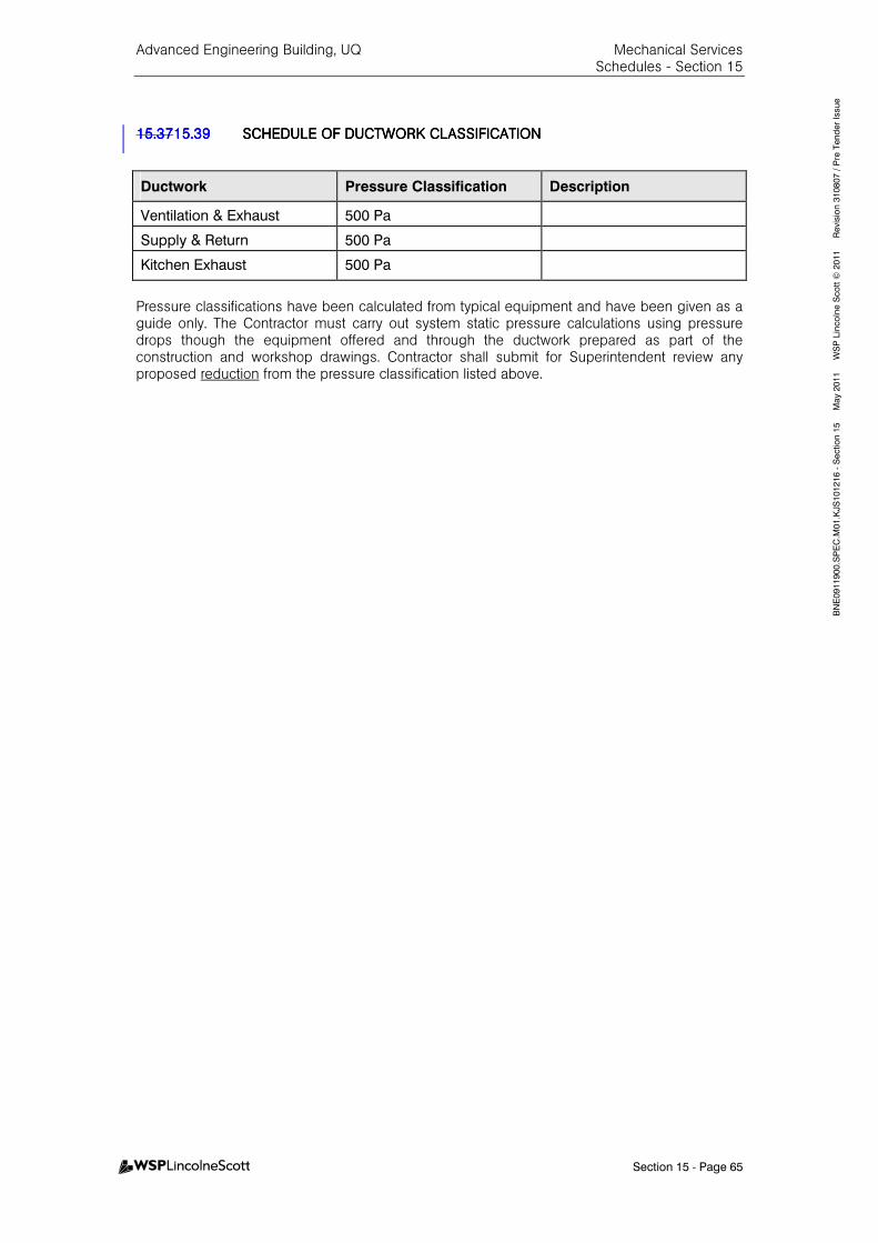
Advanced Engineering Building, UQ Mechanical Services Schedules - Section 15
Section 15 - Page 65
BNE0911900.SPEC.M
01.KJS101216 - Section 15 M
ay 2011 W
SP Lincolne Scott ©
2011 Revision 310807 / Pre Tender Issue
15.3715.3715.3715.3715.3915.3915.3915.39 SCHEDULE OF DUCTWORKSCHEDULE OF DUCTWORKSCHEDULE OF DUCTWORKSCHEDULE OF DUCTWORK CLASSIFICATIONCLASSIFICATIONCLASSIFICATIONCLASSIFICATION
Ductwork Pressure Classification Description
Ventilation & Exhaust 500 Pa
Supply & Return 500 Pa
Kitchen Exhaust 500 Pa
Pressure classifications have been calculated from typical equipment and have been given as a guide only. The Contractor must carry out system static pressure calculations using pressure drops though the equipment offered and through the ductwork prepared as part of the construction and workshop drawings. Contractor shall submit for Superintendent review any proposed reduction from the pressure classification listed above.
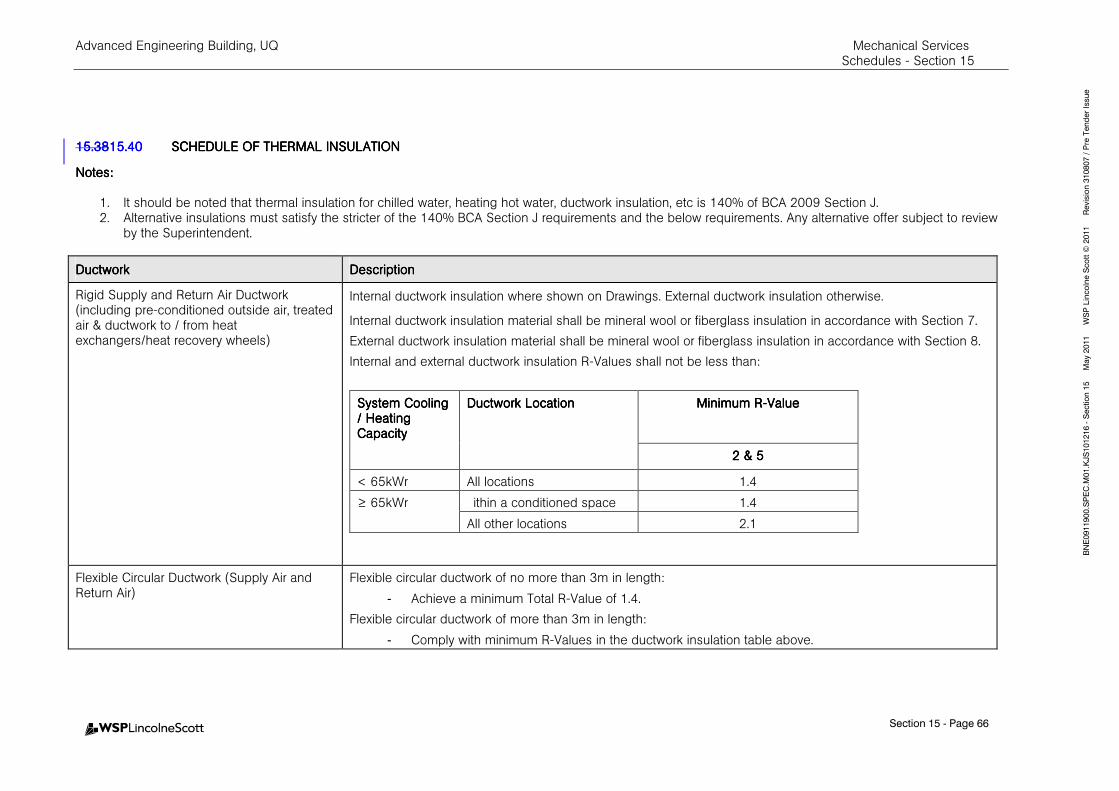
Advanced Engineering Building, UQ Mechanical Services Schedules - Section 15
Section 15 - Page 66
BNE0911900.SPEC.M
01.KJS101216 - Section 15 M
ay 2011 W
SP Lincolne Scott ©
2011 Revision 310807 / Pre Tender Issue
15.3815.3815.3815.3815.4015.4015.4015.40 SCHEDULE OF THERMAL SCHEDULE OF THERMAL SCHEDULE OF THERMAL SCHEDULE OF THERMAL INSULATIONINSULATIONINSULATIONINSULATION
Notes:Notes:Notes:Notes:
1. It should be noted that thermal insulation for chilled water, heating hot water, ductwork insulation, etc is 140% of BCA 2009 Section J. 2. Alternative insulations must satisfy the stricter of the 140% BCA Section J requirements and the below requirements. Any alternative offer subject to review
by the Superintendent.
DuctworkDuctworkDuctworkDuctwork DescriptionDescriptionDescriptionDescription
Rigid Supply and Return Air Ductwork (including pre-conditioned outside air, treated air & ductwork to / from heat exchangers/heat recovery wheels)
Internal ductwork insulation where shown on Drawings. External ductwork insulation otherwise.
Internal ductwork insulation material shall be mineral wool or fiberglass insulation in accordance with Section 7.
External ductwork insulation material shall be mineral wool or fiberglass insulation in accordance with Section 8.
Internal and external ductwork insulation R-Values shall not be less than:
System Cooling System Cooling System Cooling System Cooling / Heating / Heating / Heating / Heating CapacityCapacityCapacityCapacity
Ductwork LocationDuctwork LocationDuctwork LocationDuctwork Location Minimum RMinimum RMinimum RMinimum R----ValueValueValueValue
2 & 52 & 52 & 52 & 5
< 65kWr All locations 1.4
≥ 65kWr ithin a conditioned space 1.4
All other locations 2.1
Flexible Circular Ductwork (Supply Air and Return Air)
Flexible circular ductwork of no more than 3m in length:
- Achieve a minimum Total R-Value of 1.4.
Flexible circular ductwork of more than 3m in length:
- Comply with minimum R-Values in the ductwork insulation table above.

Advanced Engineering Building, UQ Mechanical Services Schedules - Section 15
Section 15 - Page 67
BNE0911900.SPEC.M
01.KJS101216 - Section 15 M
ay 2011 W
SP Lincolne Scott ©
2011 Revision 310807 / Pre Tender Issue
DuctworkDuctworkDuctworkDuctwork DescriptionDescriptionDescriptionDescription
Flexible Circular Ductwork (Evaporative Cooling)
Flexible circular ductwork of no more than 3m in length:
- Achieve a minimum Total R-Value of 1.4.
Flexible circular ductwork of more than 3m in length:
- Comply with table below
System Cooling System Cooling System Cooling System Cooling / Heating / Heating / Heating / Heating CapacityCapacityCapacityCapacity
Flexible Circular Ductwork Flexible Circular Ductwork Flexible Circular Ductwork Flexible Circular Ductwork LocationLocationLocationLocation
Minimum RMinimum RMinimum RMinimum R----ValueValueValueValue
< 65kWr All locations 0.84
≥ 65kWr Within a conditioned space 0..84
All other locations 1.26
Flexible Circular Ductwork not forming part of a supply or return air system or an evaporative cooling system (i.e. ductwork drawing/transferring conditioned air / tempered air through an unconditioned / untempered space OR drawing / transferring un-conditioned / un-tempered air through a conditioned / tempered space)
Achieve a minimum Total R-Value of 0.6.
Flexible Circular Ductwork
(unless noted above) (ventilation only)
Uninsulated
Ventilation / Exhaust Ductwork (unless noted above)
Internal ductwork insulation where shown on Drawings. Un-insulated otherwise.
Internal ductwork insulation material shall be mineral wool or fiberglass insulation in accordance with Section 7 with thickness as noted on Drawings.
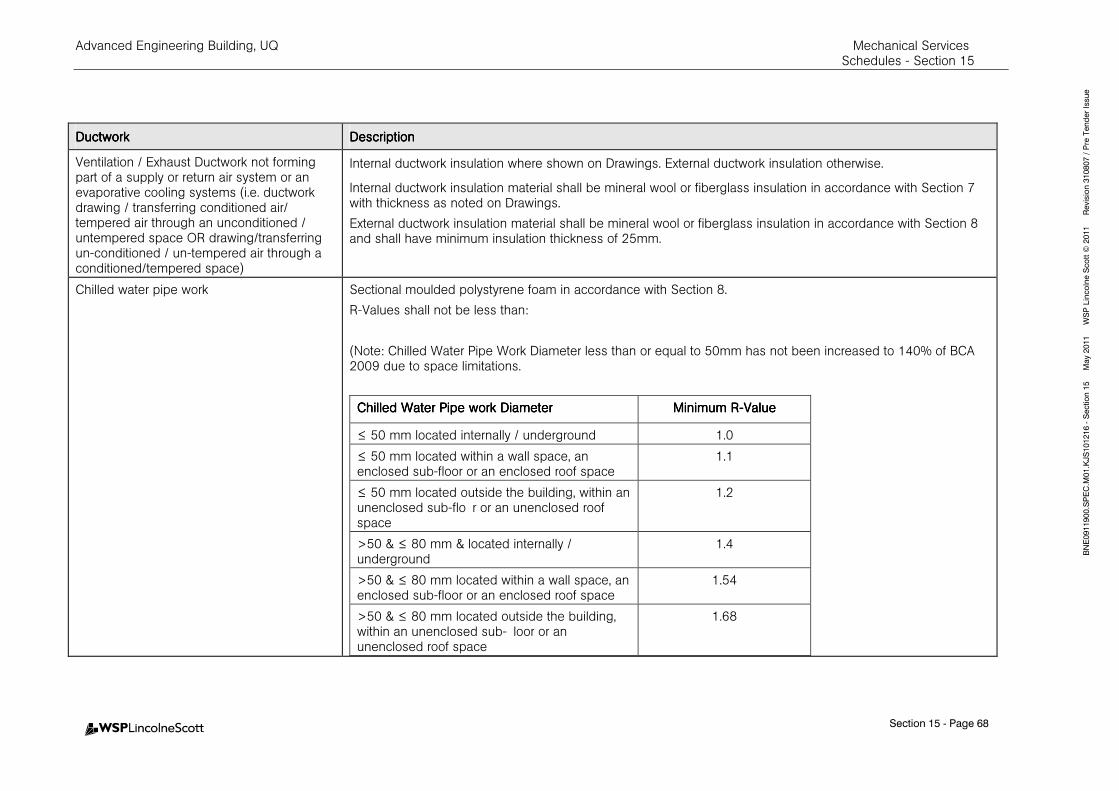
Advanced Engineering Building, UQ Mechanical Services Schedules - Section 15
Section 15 - Page 68
BNE0911900.SPEC.M
01.KJS101216 - Section 15 M
ay 2011 W
SP Lincolne Scott ©
2011 Revision 310807 / Pre Tender Issue
DuctworkDuctworkDuctworkDuctwork DescriptionDescriptionDescriptionDescription
Ventilation / Exhaust Ductwork not forming part of a supply or return air system or an evaporative cooling systems (i.e. ductwork drawing / transferring conditioned air/ tempered air through an unconditioned / untempered space OR drawing/transferring un-conditioned / un-tempered air through a conditioned/tempered space)
Internal ductwork insulation where shown on Drawings. External ductwork insulation otherwise.
Internal ductwork insulation material shall be mineral wool or fiberglass insulation in accordance with Section 7 with thickness as noted on Drawings.
External ductwork insulation material shall be mineral wool or fiberglass insulation in accordance with Section 8 and shall have minimum insulation thickness of 25mm.
Chilled water pipe work Sectional moulded polystyrene foam in accordance with Section 8.
R-Values shall not be less than:
(Note: Chilled Water Pipe Work Diameter less than or equal to 50mm has not been increased to 140% of BCA 2009 due to space limitations.
Chilled Water Pipe work DiameterChilled Water Pipe work DiameterChilled Water Pipe work DiameterChilled Water Pipe work Diameter Minimum RMinimum RMinimum RMinimum R----ValueValueValueValue
≤ 50 mm located internally / underground 1.0
≤ 50 mm located within a wall space, an enclosed sub-floor or an enclosed roof space
1.1
≤ 50 mm located outside the building, within an unenclosed sub-flo r or an unenclosed roof space
1.2
>50 & ≤ 80 mm & located internally / underground
1.4
>50 & ≤ 80 mm located within a wall space, an enclosed sub-floor or an enclosed roof space
1.54
>50 & ≤ 80 mm located outside the building, within an unenclosed sub- loor or an unenclosed roof space
1.68
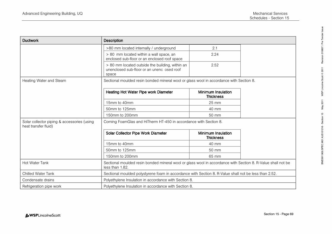
Advanced Engineering Building, UQ Mechanical Services Schedules - Section 15
Section 15 - Page 69
BNE0911900.SPEC.M
01.KJS101216 - Section 15 M
ay 2011 W
SP Lincolne Scott ©
2011 Revision 310807 / Pre Tender Issue
DuctworkDuctworkDuctworkDuctwork DescriptionDescriptionDescriptionDescription
>80 mm located internally / underground 2.1
> 80 mm located within a wall space, an enclosed sub-floor or an enclosed roof space
2.24
> 80 mm located outside the building, within an unenclosed sub-floor or an unenc osed roof space
2.52
Heating Water and Steam Sectional moulded resin bonded mineral wool or glass wool in accordance with Section 8.
Heating Hot Water Pipe work DiameterHeating Hot Water Pipe work DiameterHeating Hot Water Pipe work DiameterHeating Hot Water Pipe work Diameter Minimum Minimum Minimum Minimum Insulation Insulation Insulation Insulation ThicknessThicknessThicknessThickness
15mm to 40mm 25 mm
50mm to 125mm 40 mm
150mm to 200mm 50 mm
Solar collector piping & accessories (using heat transfer fluid)
Corning FoamGlas and HiTherm HT-450 in accordance with Section 8.
Solar Collector Pipe Work DiameterSolar Collector Pipe Work DiameterSolar Collector Pipe Work DiameterSolar Collector Pipe Work Diameter Minimum Insulation Minimum Insulation Minimum Insulation Minimum Insulation ThicknessThicknessThicknessThickness
15mm to 40mm 40 mm
50mm to 125mm 50 mm
150mm to 200mm 65 mm
Hot Water Tank Sectional moulded resin bonded mineral wool or glass wool in accordance with Section 8. R-Value shall not be less than 1.82.
Chilled Water Tank Sectional moulded polystyrene foam in accordance with Section 8. R-Value shall not be less than 2.52.
Condensate drains Polyethylene Insulation in accordance with Section 8.
Refrigeration pipe work Polyethylene Insulation in accordance with Section 8.
Advanced Engineering Building, UQ Mechanical Services Schedules - Section 15
Section 15 - Page 70
BNE0911900.SPEC.M
01.KJS101216 - Section 15 M
ay 2011 W
SP Lincolne Scott ©
2011 Revision 310807 / Pre Tender Issue
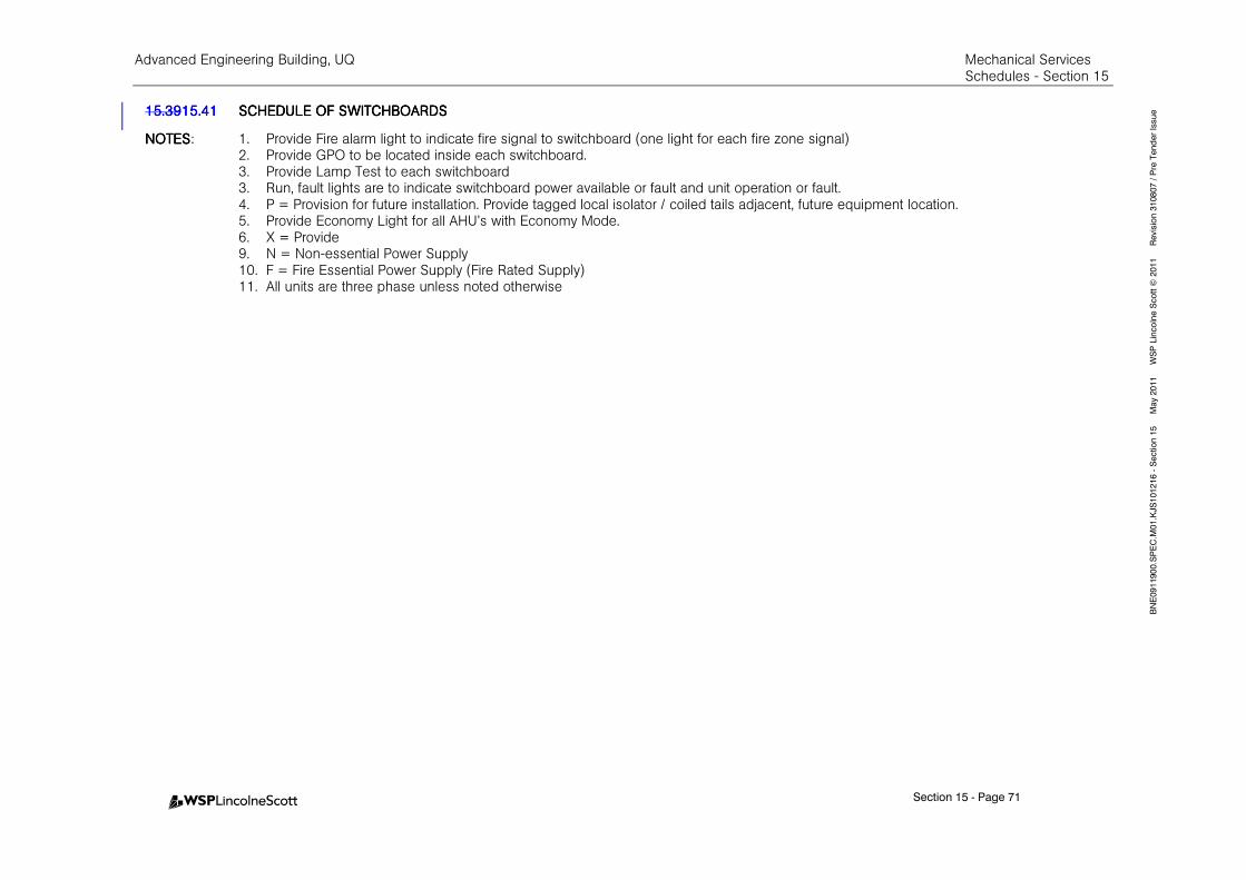
Advanced Engineering Building, UQ Mechanical Services Schedules - Section 15
Section 15 - Page 71
BNE0911900.SPEC.M
01.KJS101216 - Section 15 M
ay 2011 W
SP Lincolne Scott ©
2011 Revision 310807 / Pre Tender Issue 15.3915.3915.3915.3915.4115.4115.4115.41 SCHEDULE OF SWITCHBOSCHEDULE OF SWITCHBOSCHEDULE OF SWITCHBOSCHEDULE OF SWITCHBOARDSARDSARDSARDS
NOTESNOTESNOTESNOTES: 1. Provide Fire alarm light to indicate fire signal to switchboard (one light for each fire zone signal) 2. Provide GPO to be located inside each switchboard. 3. Provide Lamp Test to each switchboard 3. Run, fault lights are to indicate switchboard power available or fault and unit operation or fault. 4. P = Provision for future installation. Provide tagged local isolator / coiled tails adjacent, future equipment location. 5. Provide Economy Light for all AHU’s with Economy Mode. 6. X = Provide
9. N = Non-essential Power Supply 10. F = Fire Essential Power Supply (Fire Rated Supply) 11. All units are three phase unless noted otherwise

Advanced Engineering Building, UQ Mechanical Services Schedules - Section 15
Section 15 - Page 72
BNE0911900.SPEC.M
01.KJS101216 - Section 15 M
ay 2011 W
SP Lincolne Scott ©
2011 Revision 310807 / Pre Tender Issue
SwitchboardSwitchboardSwitchboardSwitchboard :::: MSSB-1-1
LocationLocationLocationLocation :::: AC Plant Room 129 (A5/AB)
TypeTypeTypeType :::: Non essential
Fault LevelFault LevelFault LevelFault Level : 30.63
PlantPlantPlantPlant Min. Load Est.Min. Load Est.Min. Load Est.Min. Load Est.
((((kW)kW)kW)kW) Power SupplyPower SupplyPower SupplyPower Supply Starting ArrangementStarting ArrangementStarting ArrangementStarting Arrangement Auto / Off / OnAuto / Off / OnAuto / Off / OnAuto / Off / On
Run/Fault, Run/Fault, Run/Fault, Run/Fault, Open/Closed LightsOpen/Closed LightsOpen/Closed LightsOpen/Closed Lights
AHU-1-1 11.011.011.011.0 N VSD X X
AHU-1-2 11.011.011.011.0 N VSD X X
AHU-1-3 2.22.22.22.2 N VSD X X
AHU-1-4 1.51.51.51.5 N VSD X X
FCU-1-1 0.750.750.750.75 N DOL X X
AHU-2-1 1.11.11.11.1 N DOL X X
AHU-2-4 1.11.11.11.1 N VSD X X
FCU-2-1 0.750.750.750.75 N DOL X X
FCU-2-2 0.50.50.50.5 N DOL X X
FCU-2-3 0.50.50.50.5 N DOL X X
AC-2-1 4.58 N DOL X X
AC-2-2 2.06 N DOL X X
AHU-3-1 1.51.51.51.5 N VSD X X
AHU-3-2 1.51.51.51.5 N VSD X X
AHU-3-3 1.51.51.51.5 N VSD X X
FCU-3-1 0.750.750.750.75 N DOL X X
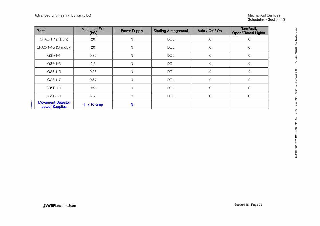
Advanced Engineering Building, UQ Mechanical Services Schedules - Section 15
Section 15 - Page 73
BNE0911900.SPEC.M
01.KJS101216 - Section 15 M
ay 2011 W
SP Lincolne Scott ©
2011 Revision 310807 / Pre Tender Issue
PlantPlantPlantPlant Min. Load Est.Min. Load Est.Min. Load Est.Min. Load Est.
((((kW)kW)kW)kW) Power SupplyPower SupplyPower SupplyPower Supply Starting ArrangementStarting ArrangementStarting ArrangementStarting Arrangement Auto / Off / OnAuto / Off / OnAuto / Off / OnAuto / Off / On
Run/Fault, Run/Fault, Run/Fault, Run/Fault, Open/Closed LightsOpen/Closed LightsOpen/Closed LightsOpen/Closed Lights
CRAC-1-1a (Duty) 20 N DOL X X
CRAC-1-1b (Standby) 20 N DOL X X
GSF-1-1 0.93 N DOL X X
GSF-1-3 2.2 N DOL X X
GSF-1-5 0.53 N DOL X X
GSF-1-7 0.37 N DOL X X
SRSF-1-1 0.63 N DOL X X
SSSF-1-1 2.2 N DOL X X
Movement Detector Movement Detector Movement Detector Movement Detector power Suppliespower Suppliespower Suppliespower Supplies
1 x 101 x 101 x 101 x 10----ampampampamp NNNN
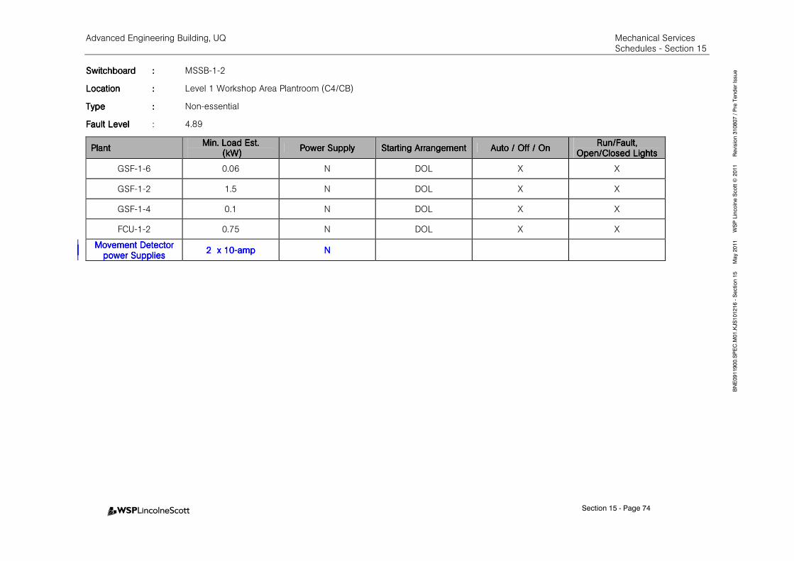
Advanced Engineering Building, UQ Mechanical Services Schedules - Section 15
Section 15 - Page 74
BNE0911900.SPEC.M
01.KJS101216 - Section 15 M
ay 2011 W
SP Lincolne Scott ©
2011 Revision 310807 / Pre Tender Issue SwitchboardSwitchboardSwitchboardSwitchboard :::: MSSB-1-2
LocationLocationLocationLocation :::: Level 1 Workshop Area Plantroom (C4/CB)
TypeTypeTypeType :::: Non-essential
Fault LevelFault LevelFault LevelFault Level : 4.89
PlantPlantPlantPlant Min. Load Est.Min. Load Est.Min. Load Est.Min. Load Est.
(kW)(kW)(kW)(kW) Power SupplyPower SupplyPower SupplyPower Supply Starting ArrangementStarting ArrangementStarting ArrangementStarting Arrangement Auto / Off / OnAuto / Off / OnAuto / Off / OnAuto / Off / On
Run/Fault, Run/Fault, Run/Fault, Run/Fault, Open/Closed LightsOpen/Closed LightsOpen/Closed LightsOpen/Closed Lights
GSF-1-6 0.06 N DOL X X
GSF-1-2 1.5 N DOL X X
GSF-1-4 0.1 N DOL X X
FCU-1-2 0.75 N DOL X X
Movement Detector Movement Detector Movement Detector Movement Detector power Suppliespower Suppliespower Suppliespower Supplies
2 2 2 2 xxxx 10101010----ampampampamp NNNN
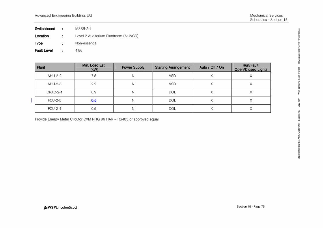
Advanced Engineering Building, UQ Mechanical Services Schedules - Section 15
Section 15 - Page 75
BNE0911900.SPEC.M
01.KJS101216 - Section 15 M
ay 2011 W
SP Lincolne Scott ©
2011 Revision 310807 / Pre Tender Issue SwitchboardSwitchboardSwitchboardSwitchboard :::: MSSB-2-1
LocationLocationLocationLocation :::: Level 2 Auditorium Plantroom (A12/CD)
TypeTypeTypeType :::: Non-essential
Fault LevelFault LevelFault LevelFault Level : 4.86
PlantPlantPlantPlant Min. Load Est.Min. Load Est.Min. Load Est.Min. Load Est.
(kW)(kW)(kW)(kW) Power SupplyPower SupplyPower SupplyPower Supply Starting ArrangementStarting ArrangementStarting ArrangementStarting Arrangement Auto / Off / OAuto / Off / OAuto / Off / OAuto / Off / Onnnn
Run/Fault, Run/Fault, Run/Fault, Run/Fault, Open/Closed LightsOpen/Closed LightsOpen/Closed LightsOpen/Closed Lights
AHU-2-2 7.5 N VSD X X
AHU-2-3 2.2 N VSD X X
CRAC-2-1 6.9 N DOL X X
FCU-2-5 0.50.50.50.5 N DOL X X
FCU-2-4 0.5 N DOL X X
Provide Energy Meter Circutor CVM NRG 96 HAR – RS485 or approved equal.
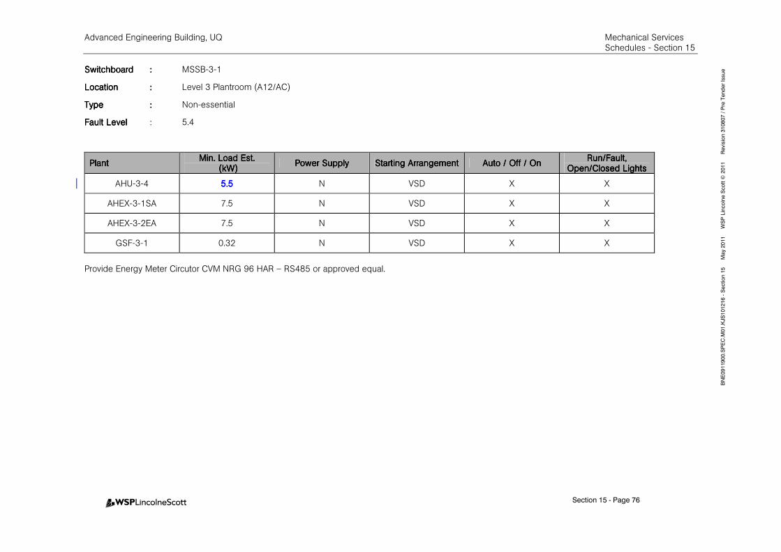
Advanced Engineering Building, UQ Mechanical Services Schedules - Section 15
Section 15 - Page 76
BNE0911900.SPEC.M
01.KJS101216 - Section 15 M
ay 2011 W
SP Lincolne Scott ©
2011 Revision 310807 / Pre Tender Issue SwitchboardSwitchboardSwitchboardSwitchboard :::: MSSB-3-1
LocationLocationLocationLocation :::: Level 3 Plantroom (A12/AC)
TypeTypeTypeType :::: Non-essential
Fault LevelFault LevelFault LevelFault Level : 5.4
PlantPlantPlantPlant Min. Load Est.Min. Load Est.Min. Load Est.Min. Load Est.
(kW)(kW)(kW)(kW) Power SupplyPower SupplyPower SupplyPower Supply Starting ArrangementStarting ArrangementStarting ArrangementStarting Arrangement Auto / Off / OnAuto / Off / OnAuto / Off / OnAuto / Off / On
Run/Fault, Run/Fault, Run/Fault, Run/Fault, Open/Closed LightsOpen/Closed LightsOpen/Closed LightsOpen/Closed Lights
AHU-3-4 5.55.55.55.5 N VSD X X
AHEX-3-1SA 7.5 N VSD X X
AHEX-3-2EA 7.5 N VSD X X
GSF-3-1 0.32 N VSD X X
Provide Energy Meter Circutor CVM NRG 96 HAR – RS485 or approved equal.

Advanced Engineering Building, UQ Mechanical Services Schedules - Section 15
Section 15 - Page 77
BNE0911900.SPEC.M
01.KJS101216 - Section 15 M
ay 2011 W
SP Lincolne Scott ©
2011 Revision 310807 / Pre Tender Issue SwitchboardSwitchboardSwitchboardSwitchboard :::: MSSB-4-1
LocationLocationLocationLocation :::: Level 4 Plantroom (A12/AC)
TypeTypeTypeType :::: Non-essential
Fault LevelFault LevelFault LevelFault Level : 5.17
PlantPlantPlantPlant Min. Load Est.Min. Load Est.Min. Load Est.Min. Load Est.
(kW)(kW)(kW)(kW) Power SupplyPower SupplyPower SupplyPower Supply Starting ArrangeStarting ArrangeStarting ArrangeStarting Arrangementmentmentment Auto / Off / OnAuto / Off / OnAuto / Off / OnAuto / Off / On
Run/Fault, Run/Fault, Run/Fault, Run/Fault, Open/Closed LightsOpen/Closed LightsOpen/Closed LightsOpen/Closed Lights
AHU-4-2 5.55.55.55.5 N VSD X X
FCU-4-1 1.1 N DOL X X
CRAC-4-1a (Duty) 20 N DOL X X
CRAC-4-1b (Standby) 20 N DOL X X
FCU-3-2 0.750.750.750.75 N DOL X X
GSF-4-1 0.32 N DOL X X
Provide Energy Meter Circutor CVM NRG 96 HAR – RS485 or approved equal.
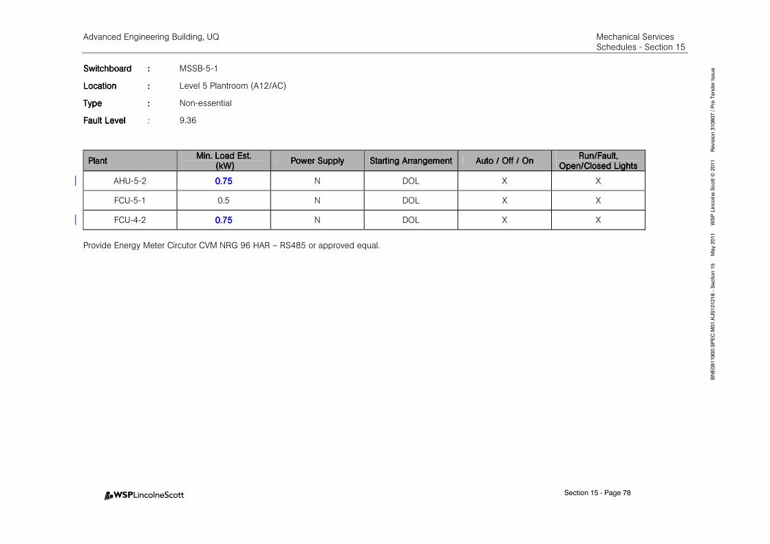
Advanced Engineering Building, UQ Mechanical Services Schedules - Section 15
Section 15 - Page 78
BNE0911900.SPEC.M
01.KJS101216 - Section 15 M
ay 2011 W
SP Lincolne Scott ©
2011 Revision 310807 / Pre Tender Issue SwitchboardSwitchboardSwitchboardSwitchboard :::: MSSB-5-1
LocationLocationLocationLocation :::: Level 5 Plantroom (A12/AC)
TypeTypeTypeType :::: Non-essential
Fault LevelFault LevelFault LevelFault Level : 9.36
PlantPlantPlantPlant Min. Load Est.Min. Load Est.Min. Load Est.Min. Load Est.
(kW)(kW)(kW)(kW) Power SupplyPower SupplyPower SupplyPower Supply Starting ArrangementStarting ArrangementStarting ArrangementStarting Arrangement Auto / Off / OnAuto / Off / OnAuto / Off / OnAuto / Off / On
Run/Fault, Run/Fault, Run/Fault, Run/Fault, Open/Closed LightsOpen/Closed LightsOpen/Closed LightsOpen/Closed Lights
AHU-5-2 0.750.750.750.75 N DOL X X
FCU-5-1 0.5 N DOL X X
FCU-4-2 0.750.750.750.75 N DOL X X
Provide Energy Meter Circutor CVM NRG 96 HAR – RS485 or approved equal.
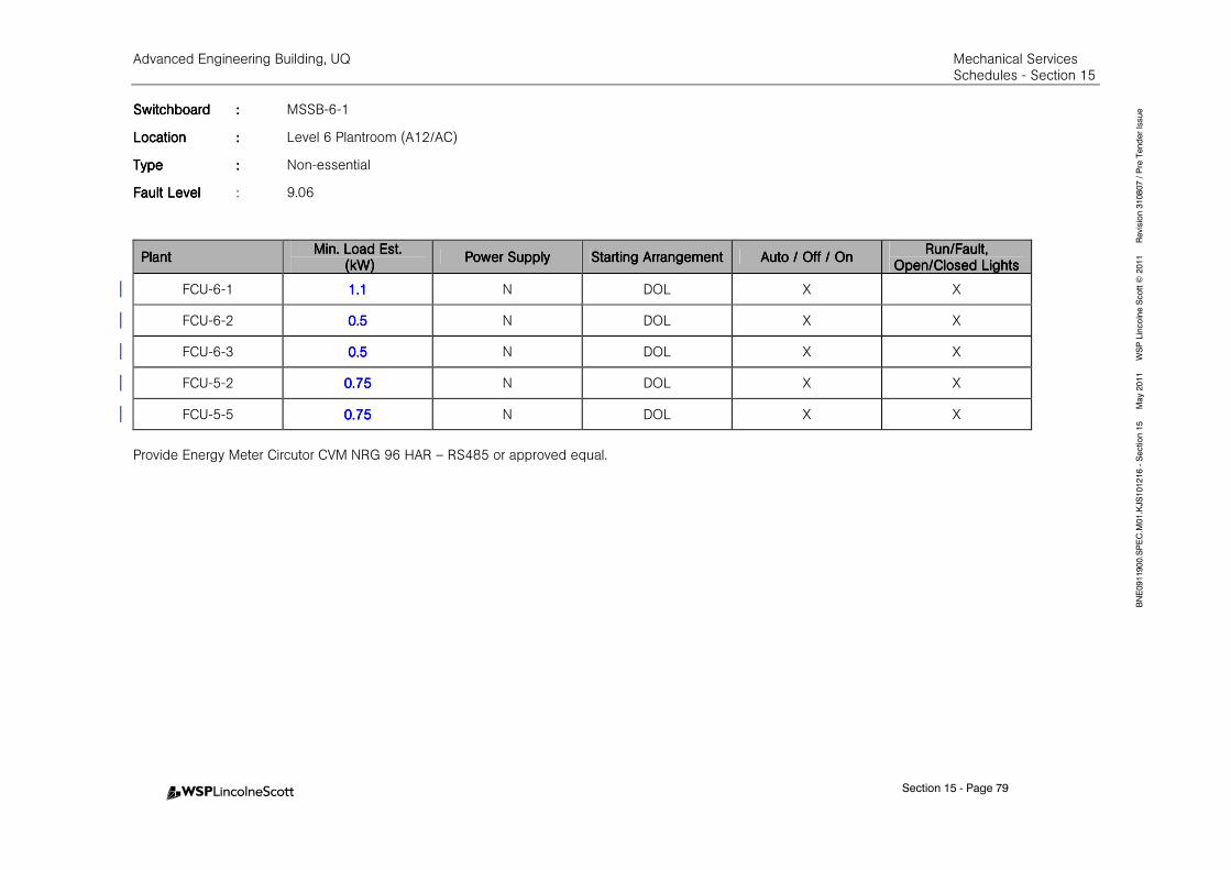
Advanced Engineering Building, UQ Mechanical Services Schedules - Section 15
Section 15 - Page 79
BNE0911900.SPEC.M
01.KJS101216 - Section 15 M
ay 2011 W
SP Lincolne Scott ©
2011 Revision 310807 / Pre Tender Issue SwitchboardSwitchboardSwitchboardSwitchboard :::: MSSB-6-1
LocationLocationLocationLocation :::: Level 6 Plantroom (A12/AC)
TypeTypeTypeType :::: Non-essential
Fault LevelFault LevelFault LevelFault Level : 9.06
PlantPlantPlantPlant Min. Load Est.Min. Load Est.Min. Load Est.Min. Load Est.
(kW)(kW)(kW)(kW) Power SupplyPower SupplyPower SupplyPower Supply Starting ArrangementStarting ArrangementStarting ArrangementStarting Arrangement Auto / Off / OnAuto / Off / OnAuto / Off / OnAuto / Off / On
Run/Fault, Run/Fault, Run/Fault, Run/Fault, Open/Closed LightsOpen/Closed LightsOpen/Closed LightsOpen/Closed Lights
FCU-6-1 1.11.11.11.1 N DOL X X
FCU-6-2 0.50.50.50.5 N DOL X X
FCU-6-3 0.50.50.50.5 N DOL X X
FCU-5-2 0.750.750.750.75 N DOL X X
FCU-5-5 0.750.750.750.75 N DOL X X
Provide Energy Meter Circutor CVM NRG 96 HAR – RS485 or approved equal.
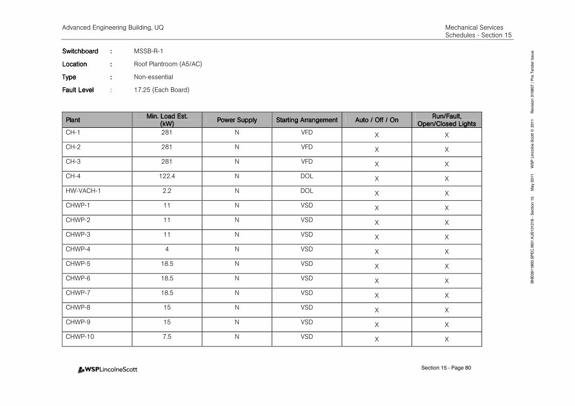
Advanced Engineering Building, UQ Mechanical Services Schedules - Section 15
Section 15 - Page 80
BNE0911900.SPEC.M
01.KJS101216 - Section 15 M
ay 2011 W
SP Lincolne Scott ©
2011 Revision 310807 / Pre Tender Issue SwitchboardSwitchboardSwitchboardSwitchboard :::: MSSB-R-1
LocationLocationLocationLocation :::: Roof Plantroom (A5/AC)
TypeTypeTypeType :::: Non-essential
Fault LevelFault LevelFault LevelFault Level : 17.25 (Each Board)
PlantPlantPlantPlant Min. Load Est.Min. Load Est.Min. Load Est.Min. Load Est.
(kW)(kW)(kW)(kW) Power SupplyPower SupplyPower SupplyPower Supply Starting ArrangementStarting ArrangementStarting ArrangementStarting Arrangement Auto / Off / OnAuto / Off / OnAuto / Off / OnAuto / Off / On
Run/Fault, Run/Fault, Run/Fault, Run/Fault, Open/Closed LightsOpen/Closed LightsOpen/Closed LightsOpen/Closed Lights
CH-1 281 N VFD X X
CH-2 281 N VFD X X
CH-3 281 N VFD X X
CH-4 122.4 N DOL X X
HW-VACH-1 2.2 N DOL X X
CHWP-1 11 N VSD X X
CHWP-2 11 N VSD X X
CHWP-3 11 N VSD X X
CHWP-4 4 N VSD X X
CHWP-5 18.5 N VSD X X
CHWP-6 18.5 N VSD X X
CHWP-7 18.5 N VSD X X
CHWP-8 15 N VSD X X
CHWP-9 15 N VSD X X
CHWP-10 7.5 N VSD X X
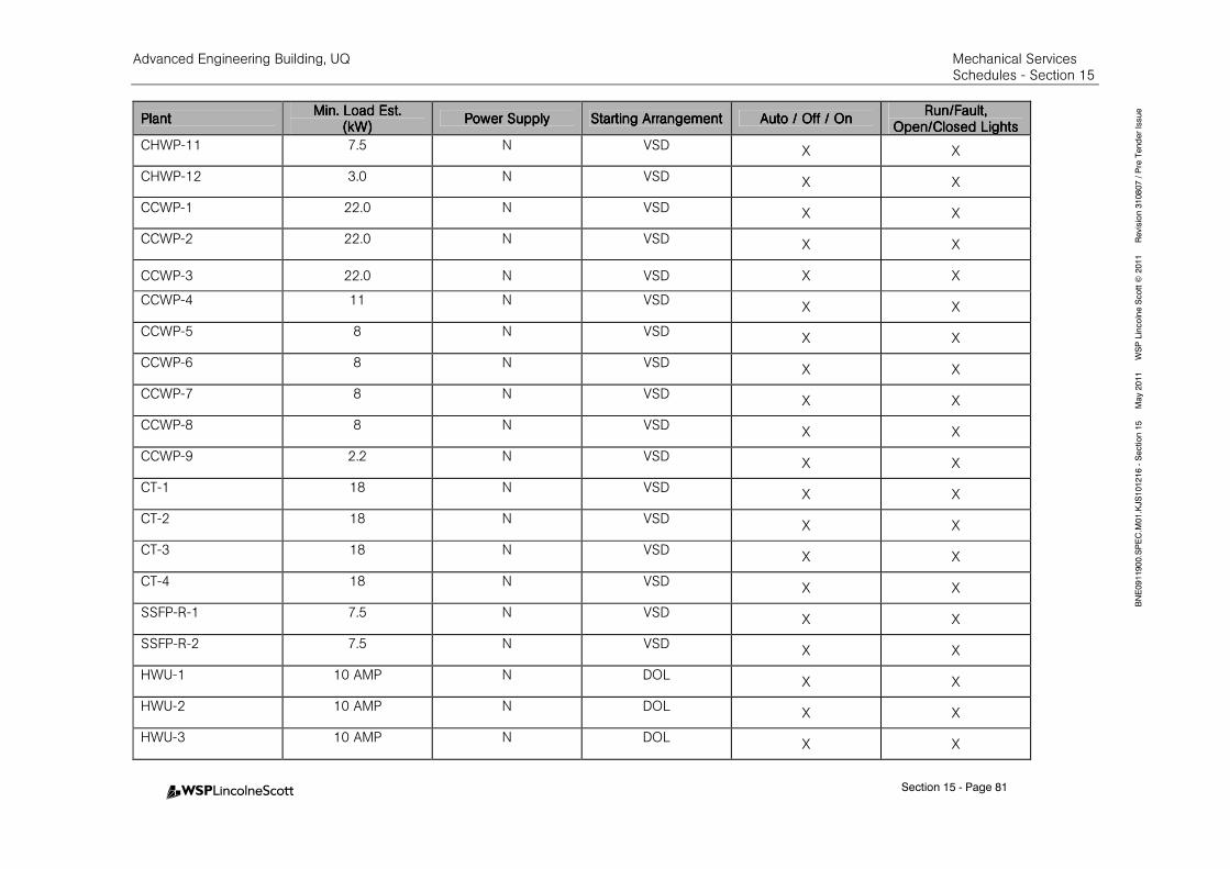
Advanced Engineering Building, UQ Mechanical Services Schedules - Section 15
Section 15 - Page 81
BNE0911900.SPEC.M
01.KJS101216 - Section 15 M
ay 2011 W
SP Lincolne Scott ©
2011 Revision 310807 / Pre Tender Issue
PlantPlantPlantPlant Min. Load Est.Min. Load Est.Min. Load Est.Min. Load Est.
(kW)(kW)(kW)(kW) Power SupplyPower SupplyPower SupplyPower Supply Starting ArrangementStarting ArrangementStarting ArrangementStarting Arrangement Auto / Off / OnAuto / Off / OnAuto / Off / OnAuto / Off / On
Run/Fault, Run/Fault, Run/Fault, Run/Fault, Open/Closed LightsOpen/Closed LightsOpen/Closed LightsOpen/Closed Lights
CHWP-11 7.5 N VSD X X
CHWP-12 3.0 N VSD X X
CCWP-1 22.0 N VSD X X
CCWP-2 22.0 N VSD X X
CCWP-3 22.0 N VSD X X
CCWP-4 11 N VSD X X
CCWP-5 8 N VSD X X
CCWP-6 8 N VSD X X
CCWP-7 8 N VSD X X
CCWP-8 8 N VSD X X
CCWP-9 2.2 N VSD X X
CT-1 18 N VSD X X
CT-2 18 N VSD X X
CT-3 18 N VSD X X
CT-4 18 N VSD X X
SSFP-R-1 7.5 N VSD X X
SSFP-R-2 7.5 N VSD X X
HWU-1 10 AMP N DOL X X
HWU-2 10 AMP N DOL X X
HWU-3 10 AMP N DOL X X
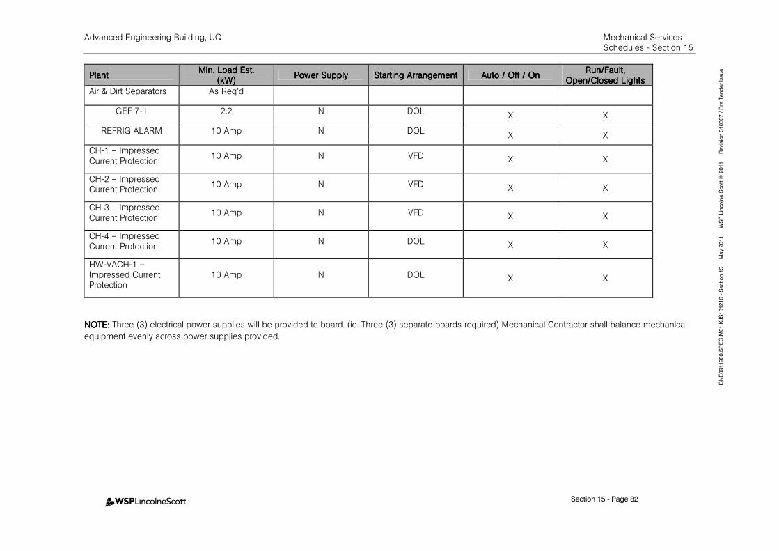
Advanced Engineering Building, UQ Mechanical Services Schedules - Section 15
Section 15 - Page 82
BNE0911900.SPEC.M
01.KJS101216 - Section 15 M
ay 2011 W
SP Lincolne Scott ©
2011 Revision 310807 / Pre Tender Issue
PlantPlantPlantPlant Min. Load Est.Min. Load Est.Min. Load Est.Min. Load Est.
(kW)(kW)(kW)(kW) Power SupplyPower SupplyPower SupplyPower Supply Starting ArrangementStarting ArrangementStarting ArrangementStarting Arrangement Auto / Off / OnAuto / Off / OnAuto / Off / OnAuto / Off / On
Run/Fault, Run/Fault, Run/Fault, Run/Fault, Open/Closed LightsOpen/Closed LightsOpen/Closed LightsOpen/Closed Lights
Air & Dirt Separators As Req’d
GEF 7-1 2.2 N DOL X X
REFRIG ALARM 10 Amp N DOL X X
CH-1 – Impressed Current Protection
10 Amp N VFD X X
CH-2 – Impressed Current Protection
10 Amp N VFD X X
CH-3 – Impressed Current Protection
10 Amp N VFD X X
CH-4 – Impressed Current Protection
10 Amp N DOL X X
HW-VACH-1 –Impressed Current Protection
10 Amp N DOL X X
NOTE: NOTE: NOTE: NOTE: Three (3) electrical power supplies will be provided to board. (ie. Three (3) separate boards required) Mechanical Contractor shall balance mechanical
equipment evenly across power supplies provided.
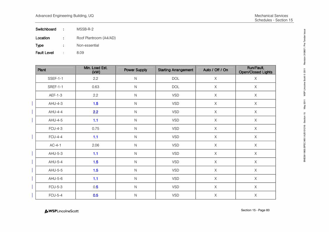
Advanced Engineering Building, UQ Mechanical Services Schedules - Section 15
Section 15 - Page 83
BNE0911900.SPEC.M
01.KJS101216 - Section 15 M
ay 2011 W
SP Lincolne Scott ©
2011 Revision 310807 / Pre Tender Issue SwitchboardSwitchboardSwitchboardSwitchboard :::: MSSB-R-2
LocationLocationLocationLocation :::: Roof Plantroom (A4/AD)
TypeTypeTypeType :::: Non-essential
Fault LevelFault LevelFault LevelFault Level : 8.09
PlantPlantPlantPlant Min. Load Est.Min. Load Est.Min. Load Est.Min. Load Est.
(kW)(kW)(kW)(kW) Power SupplyPower SupplyPower SupplyPower Supply Starting ArrangementStarting ArrangementStarting ArrangementStarting Arrangement Auto / Off / OnAuto / Off / OnAuto / Off / OnAuto / Off / On
Run/Fault, Run/Fault, Run/Fault, Run/Fault, Open/Closed LightsOpen/Closed LightsOpen/Closed LightsOpen/Closed Lights
SSEF-1-1 2.2 N DOL X X
SREF-1-1 0.63 N DOL X X
AEF-1-3 2.2 N VSD X X
AHU-4-3 1.51.51.51.5 N VSD X X
AHU-4-4 2.22.22.22.2 N VSD X X
AHU-4-5 1.11.11.11.1 N VSD X X
FCU-4-3 0.75 N VSD X X
FCU-4-4 1.11.11.11.1 N VSD X X
AC-4-1 2.06 N VSD X X
AHU-5-3 1.11.11.11.1 N VSD X X
AHU-5-4 1.51.51.51.5 N VSD X X
AHU-5-5 1.51.51.51.5 N VSD X X
AHU-5-6 1.11.11.11.1 N VSD X X
FCU-5-3 0.5555 N VSD X X
FCU-5-4 0.50.50.50.5 N VSD X X
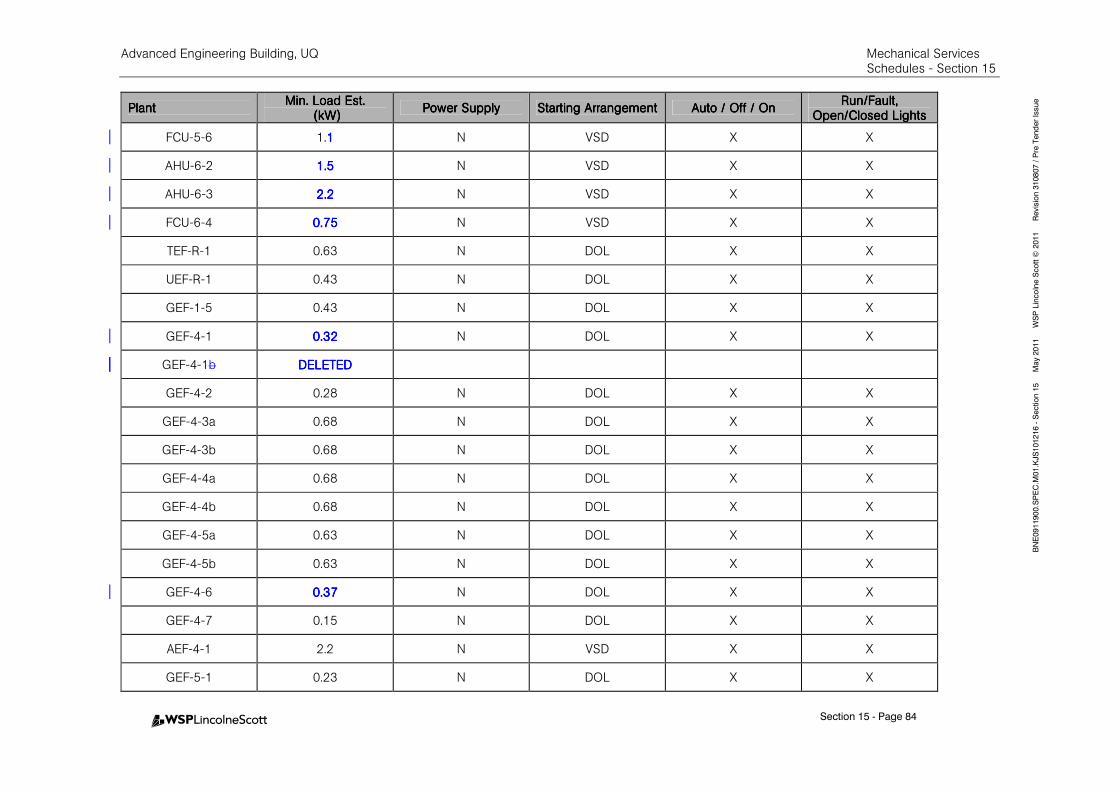
Advanced Engineering Building, UQ Mechanical Services Schedules - Section 15
Section 15 - Page 84
BNE0911900.SPEC.M
01.KJS101216 - Section 15 M
ay 2011 W
SP Lincolne Scott ©
2011 Revision 310807 / Pre Tender Issue
PlantPlantPlantPlant Min. Load Est.Min. Load Est.Min. Load Est.Min. Load Est.
(kW)(kW)(kW)(kW) Power SupplyPower SupplyPower SupplyPower Supply Starting ArrangementStarting ArrangementStarting ArrangementStarting Arrangement Auto / Off / OnAuto / Off / OnAuto / Off / OnAuto / Off / On
Run/Fault, Run/Fault, Run/Fault, Run/Fault, Open/Closed LightsOpen/Closed LightsOpen/Closed LightsOpen/Closed Lights
FCU-5-6 1.1111 N VSD X X
AHU-6-2 1.51.51.51.5 N VSD X X
AHU-6-3 2.22.22.22.2 N VSD X X
FCU-6-4 0.750.750.750.75 N VSD X X
TEF-R-1 0.63 N DOL X X
UEF-R-1 0.43 N DOL X X
GEF-1-5 0.43 N DOL X X
GEF-4-1 0.320.320.320.32 N DOL X X
GEF-4-1b DELETEDDELETEDDELETEDDELETED
GEF-4-2 0.28 N DOL X X
GEF-4-3a 0.68 N DOL X X
GEF-4-3b 0.68 N DOL X X
GEF-4-4a 0.68 N DOL X X
GEF-4-4b 0.68 N DOL X X
GEF-4-5a 0.63 N DOL X X
GEF-4-5b 0.63 N DOL X X
GEF-4-6 0.370.370.370.37 N DOL X X
GEF-4-7 0.15 N DOL X X
AEF-4-1 2.2 N VSD X X
GEF-5-1 0.23 N DOL X X
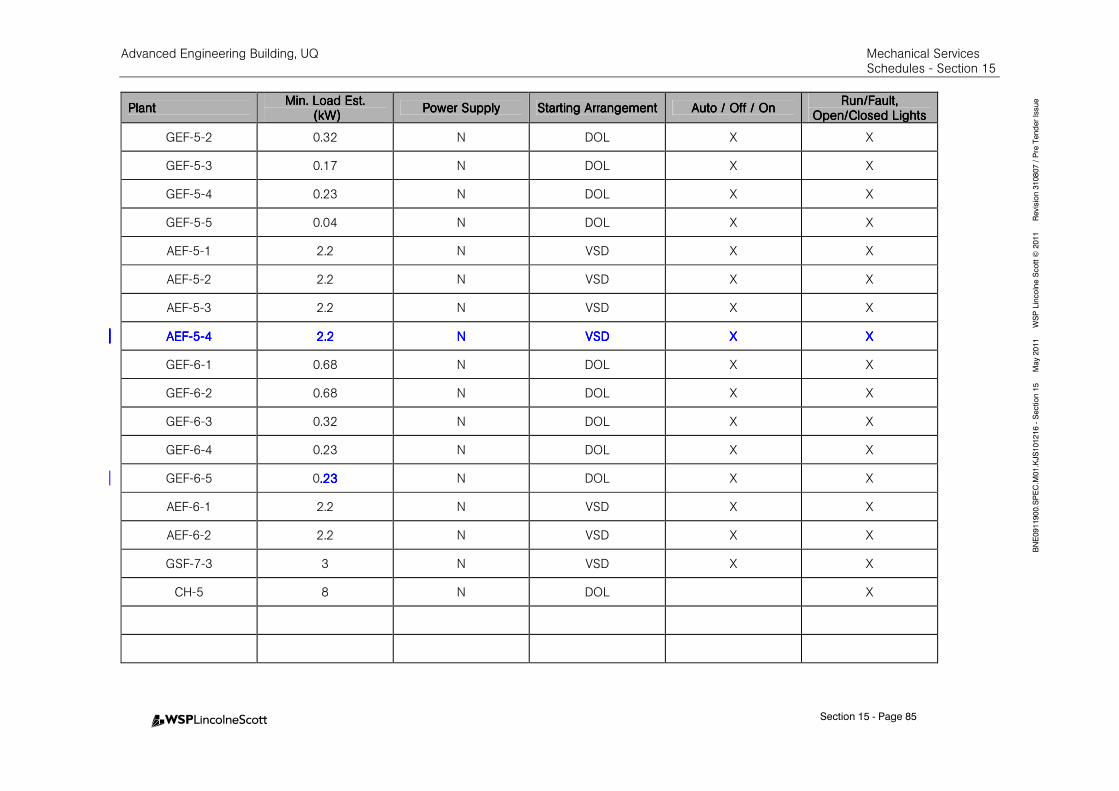
Advanced Engineering Building, UQ Mechanical Services Schedules - Section 15
Section 15 - Page 85
BNE0911900.SPEC.M
01.KJS101216 - Section 15 M
ay 2011 W
SP Lincolne Scott ©
2011 Revision 310807 / Pre Tender Issue
PlantPlantPlantPlant Min. Load Est.Min. Load Est.Min. Load Est.Min. Load Est.
(kW)(kW)(kW)(kW) Power SupplyPower SupplyPower SupplyPower Supply Starting ArrangementStarting ArrangementStarting ArrangementStarting Arrangement Auto / Off / OnAuto / Off / OnAuto / Off / OnAuto / Off / On
Run/Fault, Run/Fault, Run/Fault, Run/Fault, Open/Closed LightsOpen/Closed LightsOpen/Closed LightsOpen/Closed Lights
GEF-5-2 0.32 N DOL X X
GEF-5-3 0.17 N DOL X X
GEF-5-4 0.23 N DOL X X
GEF-5-5 0.04 N DOL X X
AEF-5-1 2.2 N VSD X X
AEF-5-2 2.2 N VSD X X
AEF-5-3 2.2 N VSD X X
AEFAEFAEFAEF----5555----4444 2.22.22.22.2 NNNN VSDVSDVSDVSD XXXX XXXX
GEF-6-1 0.68 N DOL X X
GEF-6-2 0.68 N DOL X X
GEF-6-3 0.32 N DOL X X
GEF-6-4 0.23 N DOL X X
GEF-6-5 0.23.23.23.23 N DOL X X
AEF-6-1 2.2 N VSD X X
AEF-6-2 2.2 N VSD X X
GSF-7-3 3 N VSD X X
CH-5 8 N DOL X

Adva
nced E
ngin
eerin
g B
uild
ing, U
Q
M
echanic
al S
ervic
es
Schedule
s - Sectio
n 1
5
Sectio
n 15 - P
age 86
BNE0911900.SPEC.M01.KJS101216 - Section 15 May 2011 WSP Lincolne Scott © 2011 Revision 310807 / Pre Tender Issue
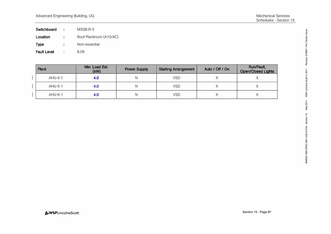
Advanced Engineering Building, UQ Mechanical Services Schedules - Section 15
Section 15 - Page 87
BNE0911900.SPEC.M
01.KJS101216 - Section 15 M
ay 2011 W
SP Lincolne Scott ©
2011 Revision 310807 / Pre Tender Issue SwitchboardSwitchboardSwitchboardSwitchboard :::: MSSB-R-3
LocationLocationLocationLocation :::: Roof Plantroom (A10/AC)
TypeTypeTypeType :::: Non-essential
Fault LevelFault LevelFault LevelFault Level : 8.09
PlantPlantPlantPlant Min. Load Est.Min. Load Est.Min. Load Est.Min. Load Est.
(kW)(kW)(kW)(kW) Power SupplyPower SupplyPower SupplyPower Supply Starting ArrangementStarting ArrangementStarting ArrangementStarting Arrangement Auto / Off / OnAuto / Off / OnAuto / Off / OnAuto / Off / On
Run/Fault, Run/Fault, Run/Fault, Run/Fault, Open/Closed LightsOpen/Closed LightsOpen/Closed LightsOpen/Closed Lights
AHU-4-1 4.04.04.04.0 N VSD X X
AHU-5-1 4.04.04.04.0 N VSD X X
AHU-6-1 4.04.04.04.0 N VSD X X
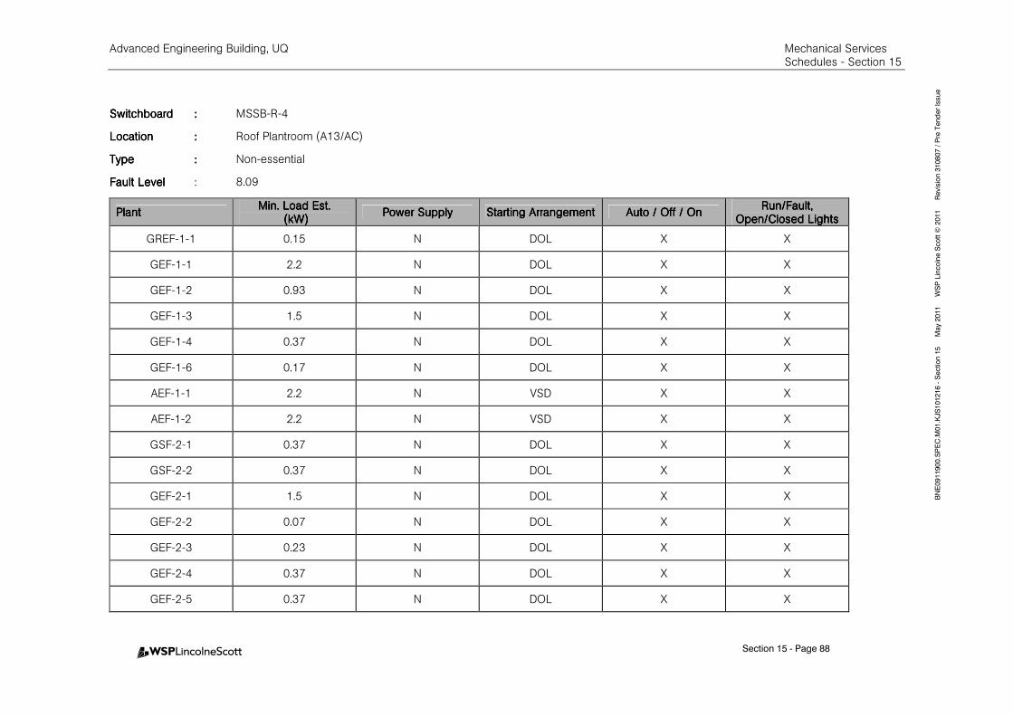
Advanced Engineering Building, UQ Mechanical Services Schedules - Section 15
Section 15 - Page 88
BNE0911900.SPEC.M
01.KJS101216 - Section 15 M
ay 2011 W
SP Lincolne Scott ©
2011 Revision 310807 / Pre Tender Issue
SwitchboardSwitchboardSwitchboardSwitchboard :::: MSSB-R-4
LocationLocationLocationLocation :::: Roof Plantroom (A13/AC)
TypeTypeTypeType :::: Non-essential
Fault LevelFault LevelFault LevelFault Level : 8.09
PlantPlantPlantPlant Min. Load Est.Min. Load Est.Min. Load Est.Min. Load Est.
(kW)(kW)(kW)(kW) Power SupplyPower SupplyPower SupplyPower Supply Starting ArrangementStarting ArrangementStarting ArrangementStarting Arrangement Auto / Off / OnAuto / Off / OnAuto / Off / OnAuto / Off / On
Run/Fault, Run/Fault, Run/Fault, Run/Fault, Open/Closed LightsOpen/Closed LightsOpen/Closed LightsOpen/Closed Lights
GREF-1-1 0.15 N DOL X X
GEF-1-1 2.2 N DOL X X
GEF-1-2 0.93 N DOL X X
GEF-1-3 1.5 N DOL X X
GEF-1-4 0.37 N DOL X X
GEF-1-6 0.17 N DOL X X
AEF-1-1 2.2 N VSD X X
AEF-1-2 2.2 N VSD X X
GSF-2-1 0.37 N DOL X X
GSF-2-2 0.37 N DOL X X
GEF-2-1 1.5 N DOL X X
GEF-2-2 0.07 N DOL X X
GEF-2-3 0.23 N DOL X X
GEF-2-4 0.37 N DOL X X
GEF-2-5 0.37 N DOL X X
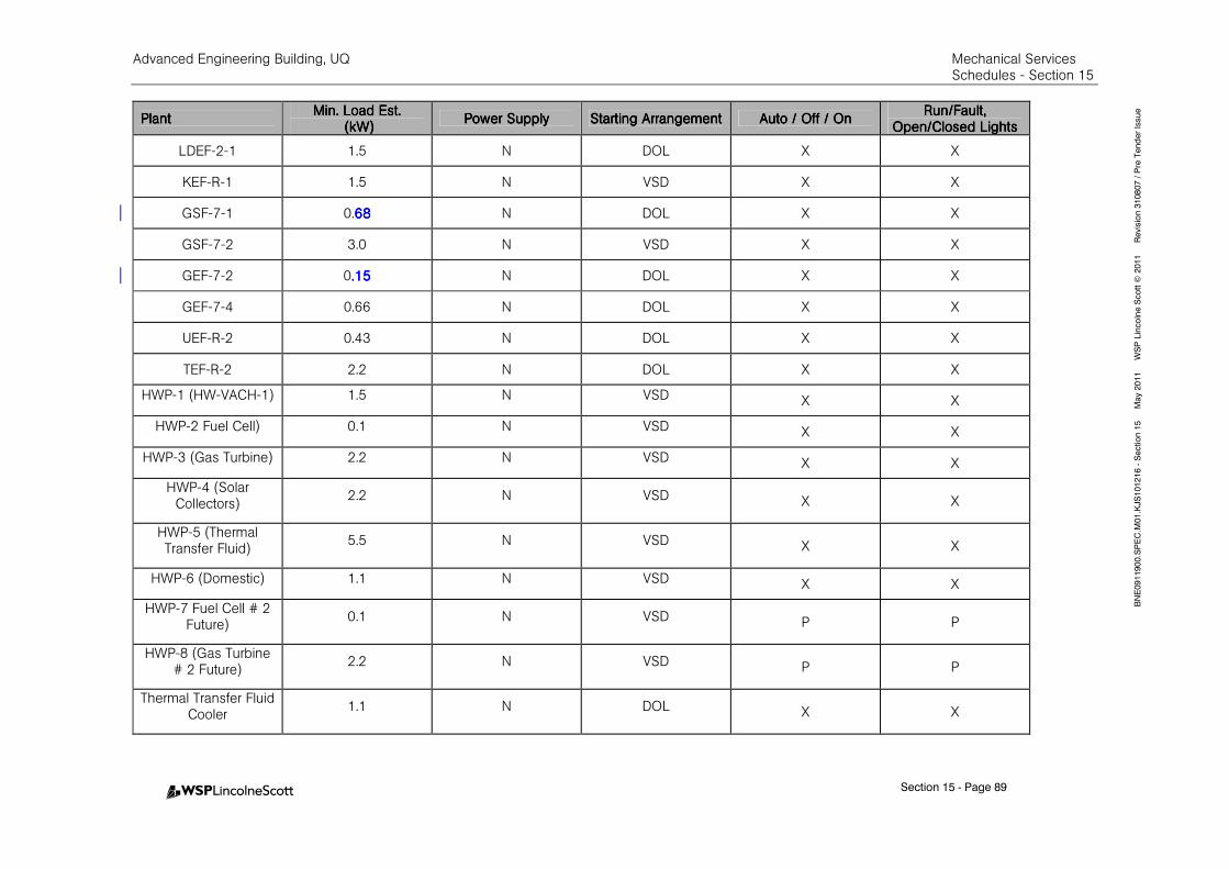
Advanced Engineering Building, UQ Mechanical Services Schedules - Section 15
Section 15 - Page 89
BNE0911900.SPEC.M
01.KJS101216 - Section 15 M
ay 2011 W
SP Lincolne Scott ©
2011 Revision 310807 / Pre Tender Issue
PlantPlantPlantPlant Min. Load Est.Min. Load Est.Min. Load Est.Min. Load Est.
(kW)(kW)(kW)(kW) Power SupplyPower SupplyPower SupplyPower Supply Starting ArrangementStarting ArrangementStarting ArrangementStarting Arrangement Auto / Off / OnAuto / Off / OnAuto / Off / OnAuto / Off / On
Run/Fault, Run/Fault, Run/Fault, Run/Fault, Open/Closed LightsOpen/Closed LightsOpen/Closed LightsOpen/Closed Lights
LDEF-2-1 1.5 N DOL X X
KEF-R-1 1.5 N VSD X X
GSF-7-1 0.68686868 N DOL X X
GSF-7-2 3.0 N VSD X X
GEF-7-2 0.15.15.15.15 N DOL X X
GEF-7-4 0.66 N DOL X X
UEF-R-2 0.43 N DOL X X
TEF-R-2 2.2 N DOL X X
HWP-1 (HW-VACH-1) 1.5 N VSD X X
HWP-2 Fuel Cell) 0.1 N VSD X X
HWP-3 (Gas Turbine) 2.2 N VSD X X
HWP-4 (Solar Collectors)
2.2 N VSD X X
HWP-5 (Thermal Transfer Fluid)
5.5 N VSD X X
HWP-6 (Domestic) 1.1 N VSD X X
HWP-7 Fuel Cell # 2 Future)
0.1 N VSD P P
HWP-8 (Gas Turbine # 2 Future)
2.2 N VSD P P
Thermal Transfer Fluid Cooler
1.1 N DOL X X
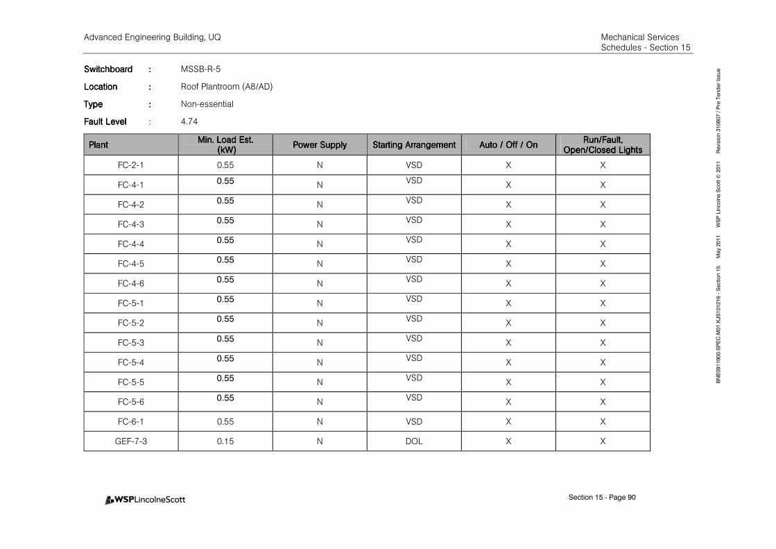
Advanced Engineering Building, UQ Mechanical Services Schedules - Section 15
Section 15 - Page 90
BNE0911900.SPEC.M
01.KJS101216 - Section 15 M
ay 2011 W
SP Lincolne Scott ©
2011 Revision 310807 / Pre Tender Issue SwitchboardSwitchboardSwitchboardSwitchboard :::: MSSB-R-5
LocationLocationLocationLocation :::: Roof Plantroom (A8/AD)
TypeTypeTypeType :::: Non-essential
Fault LevelFault LevelFault LevelFault Level : 4.74
PlantPlantPlantPlant Min. Load Est.Min. Load Est.Min. Load Est.Min. Load Est.
(kW)(kW)(kW)(kW) Power SupplyPower SupplyPower SupplyPower Supply Starting ArrangementStarting ArrangementStarting ArrangementStarting Arrangement Auto / Off / OnAuto / Off / OnAuto / Off / OnAuto / Off / On
Run/Fault, Run/Fault, Run/Fault, Run/Fault, Open/Closed LightsOpen/Closed LightsOpen/Closed LightsOpen/Closed Lights
FC-2-1 0.55 N VSD X X
FC-4-1 0.55 N VSD
X X
FC-4-2 0.55 N VSD
X X
FC-4-3 0.55 N VSD
X X
FC-4-4 0.55 N VSD
X X
FC-4-5 0.55 N VSD
X X
FC-4-6 0.55 N VSD
X X
FC-5-1 0.55 N VSD
X X
FC-5-2 0.55 N VSD
X X
FC-5-3 0.55 N VSD
X X
FC-5-4 0.55 N VSD
X X
FC-5-5 0.55 N VSD
X X
FC-5-6 0.55 N VSD
X X
FC-6-1 0.55 N VSD X X
GEF-7-3 0.15 N DOL X X
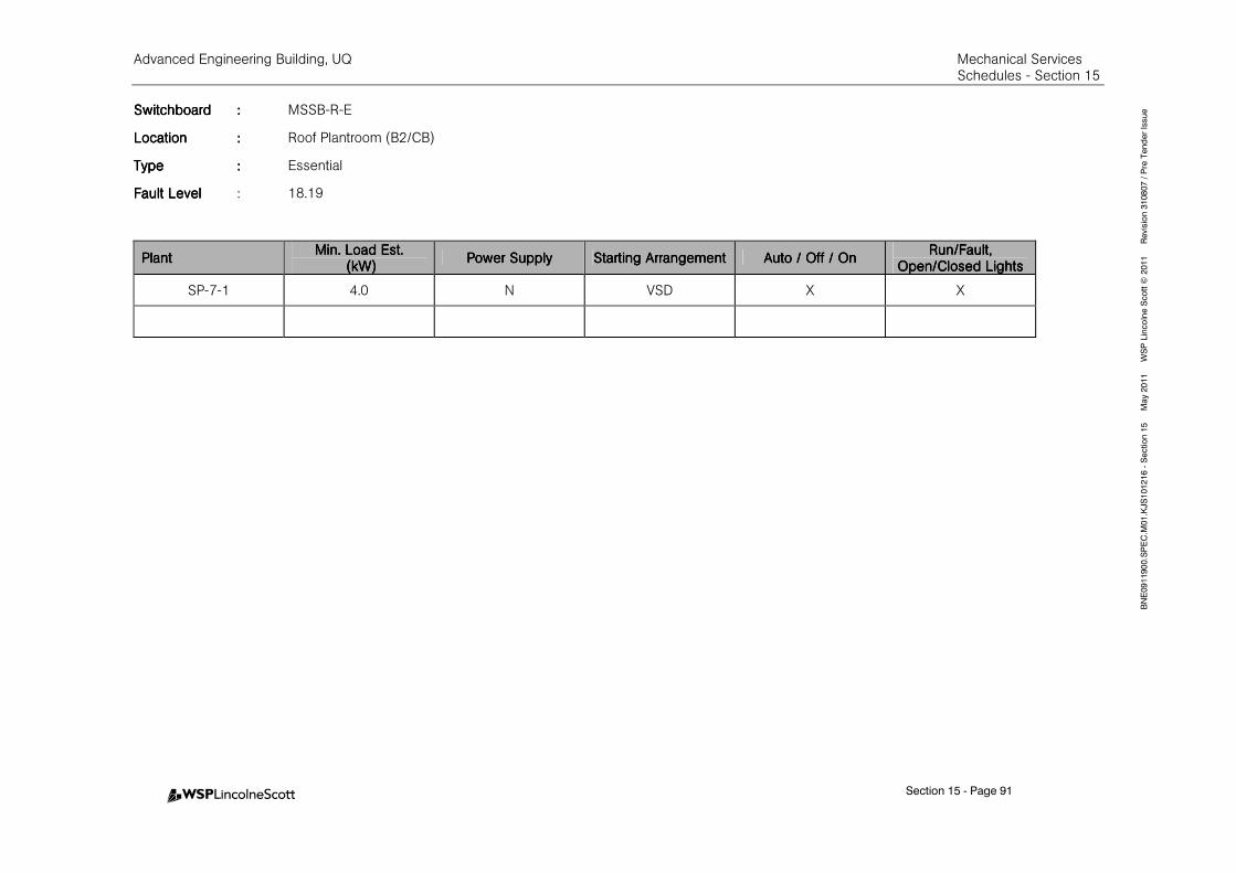
Advanced Engineering Building, UQ Mechanical Services Schedules - Section 15
Section 15 - Page 91
BNE0911900.SPEC.M
01.KJS101216 - Section 15 M
ay 2011 W
SP Lincolne Scott ©
2011 Revision 310807 / Pre Tender Issue SwitchboardSwitchboardSwitchboardSwitchboard :::: MSSB-R-E
LocationLocationLocationLocation :::: Roof Plantroom (B2/CB)
TypeTypeTypeType :::: Essential
Fault LevelFault LevelFault LevelFault Level : 18.19
PlantPlantPlantPlant Min. Load Est.Min. Load Est.Min. Load Est.Min. Load Est.
(kW)(kW)(kW)(kW) Power SupplyPower SupplyPower SupplyPower Supply Starting ArrangementStarting ArrangementStarting ArrangementStarting Arrangement Auto / OAuto / OAuto / OAuto / Off / Onff / Onff / Onff / On
Run/Fault, Run/Fault, Run/Fault, Run/Fault, Open/Closed LightsOpen/Closed LightsOpen/Closed LightsOpen/Closed Lights
SP-7-1 4.0 N VSD X X
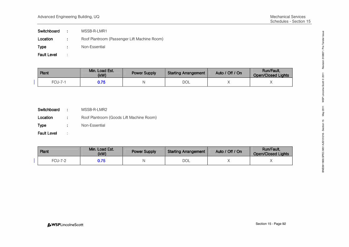
Advanced Engineering Building, UQ Mechanical Services Schedules - Section 15
Section 15 - Page 92
BNE0911900.SPEC.M
01.KJS101216 - Section 15 M
ay 2011 W
SP Lincolne Scott ©
2011 Revision 310807 / Pre Tender Issue SwitchboardSwitchboardSwitchboardSwitchboard :::: MSSB-R-LMR1
LocationLocationLocationLocation :::: Roof Plantroom (Passenger Lift Machine Room)
TypeTypeTypeType :::: Non-Essential
Fault LevelFault LevelFault LevelFault Level :
PlantPlantPlantPlant Min. Load Est.Min. Load Est.Min. Load Est.Min. Load Est.
(kW)(kW)(kW)(kW) Power SupplyPower SupplyPower SupplyPower Supply Starting ArrangementStarting ArrangementStarting ArrangementStarting Arrangement Auto Auto Auto Auto / Off / On/ Off / On/ Off / On/ Off / On
Run/Fault, Run/Fault, Run/Fault, Run/Fault, Open/Closed LightsOpen/Closed LightsOpen/Closed LightsOpen/Closed Lights
FCU-7-1 0.750.750.750.75 N DOL X X
SwitchboardSwitchboardSwitchboardSwitchboard :::: MSSB-R-LMR2
LocationLocationLocationLocation :::: Roof Plantroom (Goods Lift Machine Room)
TypeTypeTypeType :::: Non-Essential
Fault LevelFault LevelFault LevelFault Level :
PlantPlantPlantPlant Min. Load Est.Min. Load Est.Min. Load Est.Min. Load Est.
(kW)(kW)(kW)(kW) Power SupplyPower SupplyPower SupplyPower Supply Starting ArrangementStarting ArrangementStarting ArrangementStarting Arrangement Auto / OffAuto / OffAuto / OffAuto / Off / On/ On/ On/ On
Run/Fault, Run/Fault, Run/Fault, Run/Fault, Open/Closed LightsOpen/Closed LightsOpen/Closed LightsOpen/Closed Lights
FCU-7-2 0.750.750.750.75 N DOL X X
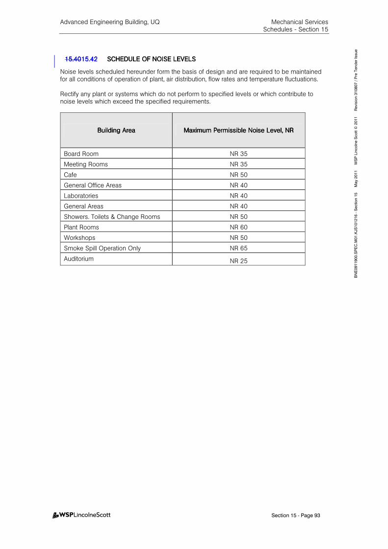
Advanced Engineering Building, UQ Mechanical Services Schedules - Section 15
Section 15 - Page 93
BNE0911900.SPEC.M
01.KJS101216 - Section 15 M
ay 2011 W
SP Lincolne Scott ©
2011 Revision 310807 / Pre Tender Issue
15.4015.4015.4015.4015.4215.4215.4215.42 SCHEDULE OF NOISE LESCHEDULE OF NOISE LESCHEDULE OF NOISE LESCHEDULE OF NOISE LEVELSVELSVELSVELS
Noise levels scheduled hereunder form the basis of design and are required to be maintained for all conditions of operation of plant, air distribution, flow rates and temperature fluctuations. Rectify any plant or systems which do not perform to specified levels or which contribute to noise levels which exceed the specified requirements.
Building AreaBuilding AreaBuilding AreaBuilding Area Maximum Permissible Noise Level, NRMaximum Permissible Noise Level, NRMaximum Permissible Noise Level, NRMaximum Permissible Noise Level, NR
Board Room NR 35
Meeting Rooms NR 35
Cafe NR 50
General Office Areas NR 40
Laboratories NR 40
General Areas NR 40
Showers. Toilets & Change Rooms NR 50
Plant Rooms NR 60
Workshops NR 50
Smoke Spill Operation Only NR 65
Auditorium NR 25
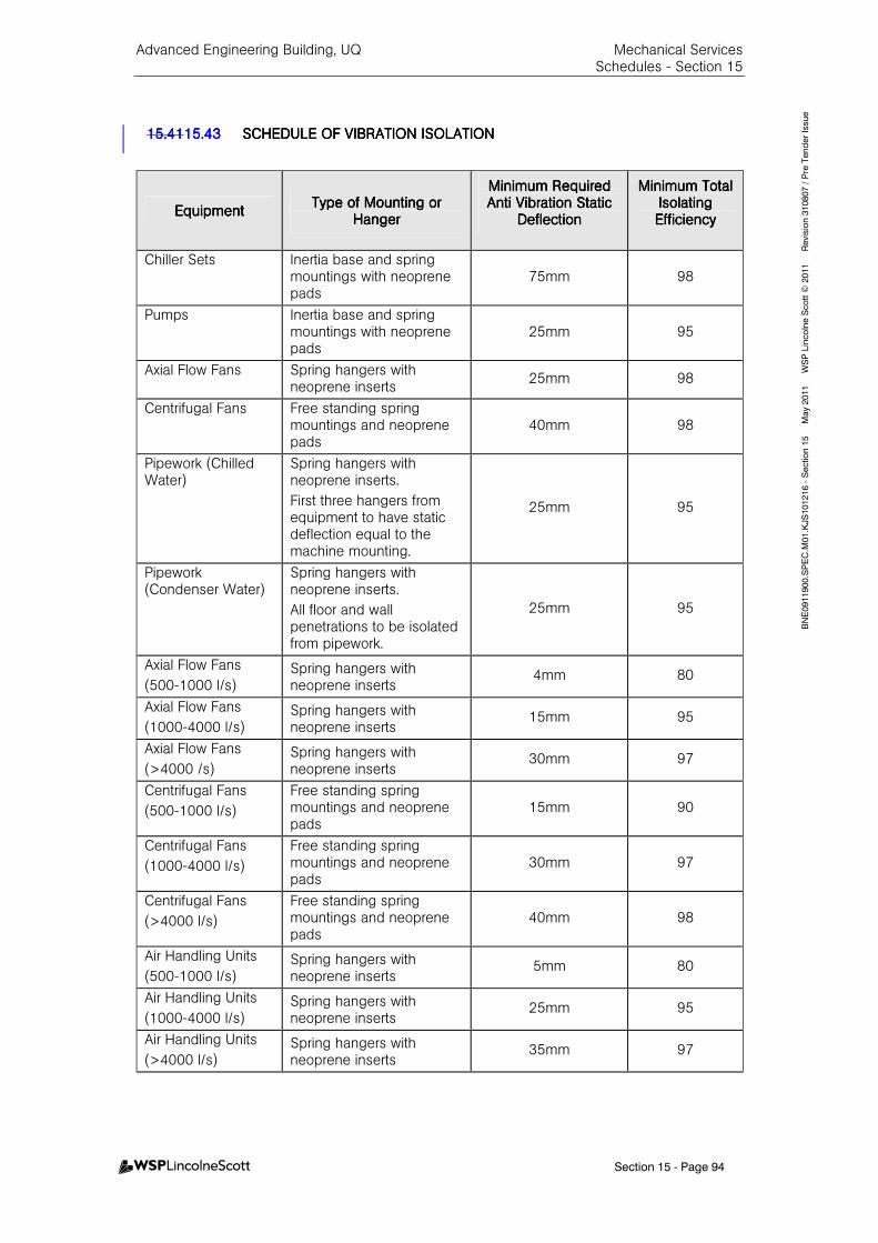
Advanced Engineering Building, UQ Mechanical Services Schedules - Section 15
Section 15 - Page 94
BNE0911900.SPEC.M
01.KJS101216 - Section 15 M
ay 2011 W
SP Lincolne Scott ©
2011 Revision 310807 / Pre Tender Issue
15.4115.4115.4115.4115.4315.4315.4315.43 SCHEDULE OF VIBRATIOSCHEDULE OF VIBRATIOSCHEDULE OF VIBRATIOSCHEDULE OF VIBRATION ISOLATIONN ISOLATIONN ISOLATIONN ISOLATION
EEEEquipmentquipmentquipmentquipment Type of Mounting or Type of Mounting or Type of Mounting or Type of Mounting or
HangerHangerHangerHanger
Minimum Required Minimum Required Minimum Required Minimum Required Anti Vibration Static Anti Vibration Static Anti Vibration Static Anti Vibration Static
DeflectionDeflectionDeflectionDeflection
Minimum Total Minimum Total Minimum Total Minimum Total Isolating Isolating Isolating Isolating EfficiencyEfficiencyEfficiencyEfficiency
Chiller Sets Inertia base and spring mountings with neoprene pads
75mm 98
Pumps Inertia base and spring mountings with neoprene pads
25mm 95
Axial Flow Fans Spring hangers with neoprene inserts
25mm 98
Centrifugal Fans Free standing spring mountings and neoprene pads
40mm 98
Pipework (Chilled Water)
Spring hangers with neoprene inserts.
First three hangers from equipment to have static deflection equal to the machine mounting.
25mm 95
Pipework (Condenser Water)
Spring hangers with neoprene inserts.
All floor and wall penetrations to be isolated from pipework.
25mm 95
Axial Flow Fans
(500-1000 l/s) Spring hangers with neoprene inserts
4mm 80
Axial Flow Fans
(1000-4000 l/s) Spring hangers with neoprene inserts
15mm 95
Axial Flow Fans
(>4000 /s) Spring hangers with neoprene inserts
30mm 97
Centrifugal Fans
(500-1000 l/s)
Free standing spring mountings and neoprene pads
15mm 90
Centrifugal Fans
(1000-4000 l/s)
Free standing spring mountings and neoprene pads
30mm 97
Centrifugal Fans
(>4000 l/s)
Free standing spring mountings and neoprene pads
40mm 98
Air Handling Units
(500-1000 l/s) Spring hangers with neoprene inserts
5mm 80
Air Handling Units
(1000-4000 l/s) Spring hangers with neoprene inserts
25mm 95
Air Handling Units
(>4000 l/s) Spring hangers with neoprene inserts
35mm 97

Advanced Engineering Building, UQ Mechanical Services Schedules - Section 15
Section 15 - Page 95
BNE0911900.SPEC.M
01.KJS101216 - Section 15 M
ay 2011 W
SP Lincolne Scott ©
2011 Revision 310807 / Pre Tender Issue
15.4215.4215.4215.4215.4415.4415.4415.44 SCHEDULE OF SAMPLESSCHEDULE OF SAMPLESSCHEDULE OF SAMPLESSCHEDULE OF SAMPLES
Item of EquipmentItem of EquipmentItem of EquipmentItem of Equipment
Each supply, return and exhaust diffuser and grille
Section of each size of internally insulated spirally wound stainless steel ductwork
Exposed duct supports
Duct joints for all exposed ductwork
Duct joints for all concealed ductwork
Exposed supply air diffuser including circular cushion box and duct extension to main duct with volume control damper (Northern Offices and AMPAM)
Exposed (behind grid mesh ceiling) supply air diffuser including cushion box, duct extension and flex duct connection to main duct with volume control damper (Labs)
Duct section with curved supply air register
Flexible ductwork
Flexible ductwork spigot and damper including flex duct connection to spigot
Desk Supply Air Outlet (Wall mounted)
Desk Supply Air Outlet (Desk mounted including duct extension)
Flexible duct
Duct Joining method (concealed and exposed)
Duct supports (Concealed and exposed)
Pipe insulation (each type)
Pipe wall penetration sleeve (exposed) (general and acoustic)
Pipe insulation sheathing
Pipe labelling
Pipework mounting sample (insulated and non-insulated pipes, concealed and exposed )
Duct insulation (each type)
Duct wall penetration sleeve (exposed) (general and acoustic)
Duct labelling
Cooling tower finishes
Solar thermal panels including mounting arrangement
Control panels
Temperature sensor (Standard wall mounted)
Temperature sensor (Circular stainless steel type curved for concrete column mounting)
Humidity sensor
CO2 Sensor
Compressed air outlets (each type)
Vacuum outlets (each type)
Digital temperature gauges
Digital pressure gauges
Clear polycarbonate VAV box
Duct access panel (general ductwork)
Duct access panel (stainless steel ductwork)
Exposed cable trays including proposed support arrangement.
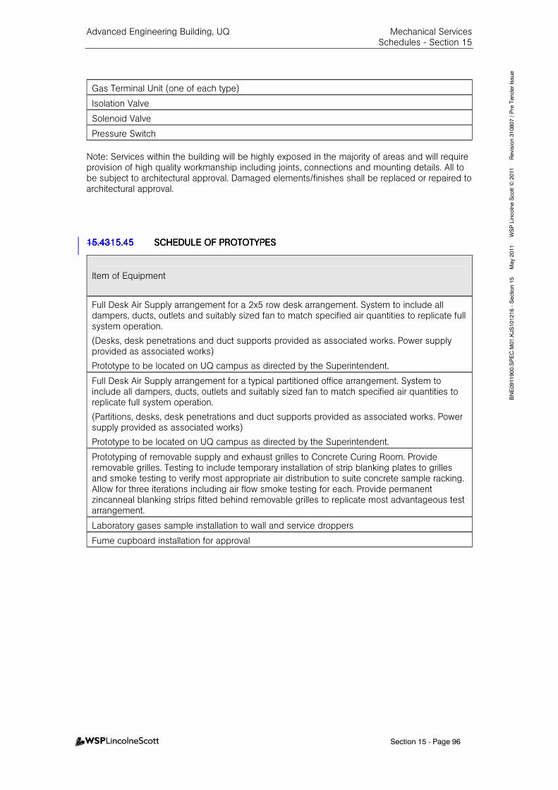
Advanced Engineering Building, UQ Mechanical Services Schedules - Section 15
Section 15 - Page 96
BNE0911900.SPEC.M
01.KJS101216 - Section 15 M
ay 2011 W
SP Lincolne Scott ©
2011 Revision 310807 / Pre Tender Issue
Gas Terminal Unit (one of each type)
Isolation Valve
Solenoid Valve
Pressure Switch
Note: Services within the building will be highly exposed in the majority of areas and will require provision of high quality workmanship including joints, connections and mounting details. All to be subject to architectural approval. Damaged elements/finishes shall be replaced or repaired to architectural approval. 15.4315.4315.4315.4315.4515.4515.4515.45 SCHEDULE OF PROTOTYPSCHEDULE OF PROTOTYPSCHEDULE OF PROTOTYPSCHEDULE OF PROTOTYPESESESES
Item of Equipment
Full Desk Air Supply arrangement for a 2x5 row desk arrangement. System to include all dampers, ducts, outlets and suitably sized fan to match specified air quantities to replicate full system operation.
(Desks, desk penetrations and duct supports provided as associated works. Power supply provided as associated works)
Prototype to be located on UQ campus as directed by the Superintendent.
Full Desk Air Supply arrangement for a typical partitioned office arrangement. System to include all dampers, ducts, outlets and suitably sized fan to match specified air quantities to replicate full system operation.
(Partitions, desks, desk penetrations and duct supports provided as associated works. Power supply provided as associated works)
Prototype to be located on UQ campus as directed by the Superintendent.
Prototyping of removable supply and exhaust grilles to Concrete Curing Room. Provide removable grilles. Testing to include temporary installation of strip blanking plates to grilles and smoke testing to verify most appropriate air distribution to suite concrete sample racking. Allow for three iterations including air flow smoke testing for each. Provide permanent zincanneal blanking strips fitted behind removable grilles to replicate most advantageous test arrangement.
Laboratory gases sample installation to wall and service droppers
Fume cupboard installation for approval

Advanced Engineering Building, UQ Mechanical Services Schedules - Section 15
Section 15 - Page 97
BNE0911900.SPEC.M
01.KJS101216 - Section 15 M
ay 2011 W
SP Lincolne Scott ©
2011 Revision 310807 / Pre Tender Issue
15.4415.4415.4415.4415.4615.4615.4615.46 SCHEDULE OF PAINTINSCHEDULE OF PAINTINSCHEDULE OF PAINTINSCHEDULE OF PAINTINGGGG
Paint the complete systems listed below, except normally bright and polished metal components, bearing surfaces, adjusting screws, foil faced insulation and similar items
Item of EquipmentItem of EquipmentItem of EquipmentItem of Equipment NotesNotesNotesNotes
Switchboards and control panels
Equipment such as chillers, boilers, pumps, heat exchangers
Manufacturers’ Standard
Internal surfaces of air outlets and openings exposed to view
Matt Black
Ductwork, piping and related fittings and supports exposed to public view
Ductwork, piping and related fittings and supports within plant rooms
Air handling units
Bases and plinths
Conduits exposed to view
Cable-trays and electrical ducts exposed to view
15.4515.4515.4515.4515.4715.4715.4715.47 PROCESS CHILLERPROCESS CHILLERPROCESS CHILLERPROCESS CHILLER
GeneralGeneralGeneralGeneral SpecifiedSpecifiedSpecifiedSpecified TenderTenderTenderTender
Unit No. CH-5
No. off 1
Capacity Each kWr 14
ElectrElectrElectrElectricalicalicalical
Estimated Size (Rated Load) Amps 15-amp
Voltage V 415
EvaporatorEvaporatorEvaporatorEvaporator (external(external(external(external circuit)circuit)circuit)circuit)
Water Quantity Each (varies) Max l/s 0.45
Water Entering Temp. °C 6.5
Water Leaving Temp. °C 14.0
CondenserCondenserCondenserCondenser
Entering Air Temperature °C 40
PumpPumpPumpPump
Indicative External Pressure kPa 200
BNE0911900.SPEC.M
01.KJS 101215 - TENDER FORM M
ay 2011 W
SP Lincolne Scott ©
2011 Revision 310807 / Pre Tender Issue
MECHANICALMECHANICALMECHANICALMECHANICAL
TENDER FORMTENDER FORMTENDER FORMTENDER FORM
PLEASE COMPLETE AND PLEASE COMPLETE AND PLEASE COMPLETE AND PLEASE COMPLETE AND RETURN WITH TENDERRETURN WITH TENDERRETURN WITH TENDERRETURN WITH TENDER
ALSO RETURN A COMPLEALSO RETURN A COMPLEALSO RETURN A COMPLEALSO RETURN A COMPLETED SCHEDULE OF EQUITED SCHEDULE OF EQUITED SCHEDULE OF EQUITED SCHEDULE OF EQUIPMENT WITH TENDER, PMENT WITH TENDER, PMENT WITH TENDER, PMENT WITH TENDER, OR PROMPTLY ON REQUEOR PROMPTLY ON REQUEOR PROMPTLY ON REQUEOR PROMPTLY ON REQUESTSTSTST
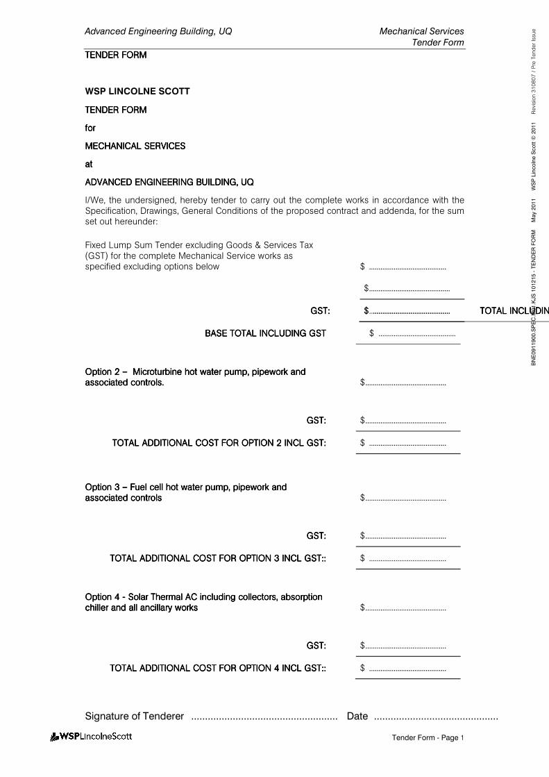
Advanced Engineering Building, UQ Mechanical Services
Tender Form
TENDER FORMTENDER FORMTENDER FORMTENDER FORM
Signature of Tenderer ..................................................... Date .............................................
Tender Form - Page 1
BNE0911900.SPEC.M
01.KJS 101215 - TENDER FORM M
ay 2011 W
SP Lincolne Scott ©
2011 Revision 310807 / Pre Tender Issue
WSP LINCOLNE SCOTT
TENDER FORMTENDER FORMTENDER FORMTENDER FORM
forforforfor
MECHANICAL SERVICESMECHANICAL SERVICESMECHANICAL SERVICESMECHANICAL SERVICES
atatatat
ADVANCED ENGINEERINGADVANCED ENGINEERINGADVANCED ENGINEERINGADVANCED ENGINEERING BUILDING, UQBUILDING, UQBUILDING, UQBUILDING, UQ
I/We, the undersigned, hereby tender to carry out the complete works in accordance with the Specification, Drawings, General Conditions of the proposed contract and addenda, for the sum set out hereunder:
Fixed Lump Sum Tender excluding Goods & Services Tax (GST) for the complete Mechanical Service works as specified excluding options below
$ .........................................
$ ...........................................
GST:GST:GST:GST: $ .........................................
TOTAL INCLUDING GST:TOTAL INCLUDING GST:TOTAL INCLUDING GST:TOTAL INCLUDING GST:
$ ...........................................
BASE BASE BASE BASE TOTAL INCLUDING GSTTOTAL INCLUDING GSTTOTAL INCLUDING GSTTOTAL INCLUDING GST $ .........................................
Option Option Option Option 2222 –––– Microturbine hot water pump, pipework and Microturbine hot water pump, pipework and Microturbine hot water pump, pipework and Microturbine hot water pump, pipework and associated controls.associated controls.associated controls.associated controls.
$ ...........................................
GST:GST:GST:GST: $ ...........................................
TOTAL TOTAL TOTAL TOTAL ADDITIONAL COST FOR OPTION 2ADDITIONAL COST FOR OPTION 2ADDITIONAL COST FOR OPTION 2ADDITIONAL COST FOR OPTION 2 INCLINCLINCLINCL GST:GST:GST:GST: $ .........................................
Option Option Option Option 3 3 3 3 –––– Fuel cell hot water pump, pipework and Fuel cell hot water pump, pipework and Fuel cell hot water pump, pipework and Fuel cell hot water pump, pipework and associated controlsassociated controlsassociated controlsassociated controls
$ ...........................................
GST:GST:GST:GST: $ ...........................................
TOTOTOTOTAL ADDITIONAL COST FOR OPTION 3TAL ADDITIONAL COST FOR OPTION 3TAL ADDITIONAL COST FOR OPTION 3TAL ADDITIONAL COST FOR OPTION 3 INCLINCLINCLINCL GST::GST::GST::GST:: $ .........................................
Option Option Option Option 4 4 4 4 ---- Solar Thermal AC including coSolar Thermal AC including coSolar Thermal AC including coSolar Thermal AC including collectors, absorption llectors, absorption llectors, absorption llectors, absorption chiller and all ancillary workschiller and all ancillary workschiller and all ancillary workschiller and all ancillary works
$ ...........................................
GST:GST:GST:GST: $ ...........................................
TOTOTOTOTAL ADDITIONAL COST FOR OPTION 4TAL ADDITIONAL COST FOR OPTION 4TAL ADDITIONAL COST FOR OPTION 4TAL ADDITIONAL COST FOR OPTION 4 INCLINCLINCLINCL GST::GST::GST::GST:: $ .........................................
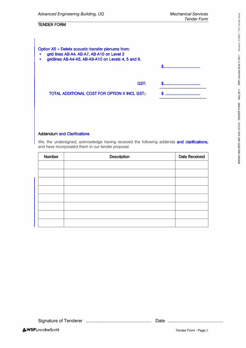
Advanced Engineering Building, UQ Mechanical Services
Tender Form
TENDER FORMTENDER FORMTENDER FORMTENDER FORM
Signature of Tenderer ..................................................... Date .............................................
Tender Form - Page 2
BNE0911900.SPEC.M
01.KJS 101215 - TENDER FORM M
ay 2011 W
SP Lincolne Scott ©
2011 Revision 310807 / Pre Tender Issue
Option Option Option Option XXXX5555 –––– Delete aDelete aDelete aDelete acoustic coustic coustic coustic transfer plenumstransfer plenumstransfer plenumstransfer plenums fromfromfromfrom::::
•••• grid lines grid lines grid lines grid lines ABABABAB----A4, ABA4, ABA4, ABA4, AB----A7, ABA7, ABA7, ABA7, AB----A10 on Level 3A10 on Level 3A10 on Level 3A10 on Level 3
•••• gridlines gridlines gridlines gridlines ABABABAB----A4A4A4A4----A5, ABA5, ABA5, ABA5, AB----A9A9A9A9----A10 on LevelA10 on LevelA10 on LevelA10 on Levelssss 4, 5 and 6. 4, 5 and 6. 4, 5 and 6. 4, 5 and 6.
$$$$....................................................................................................................................................................
GST:GST:GST:GST: $$$$....................................................................................................................................................................
TOTAL ADDITIONAL COST FOR OPTION TOTAL ADDITIONAL COST FOR OPTION TOTAL ADDITIONAL COST FOR OPTION TOTAL ADDITIONAL COST FOR OPTION XXXX INCLINCLINCLINCL GST::GST::GST::GST:: $ $ $ $ ............................................................................................................................................................
AddendumAddendumAddendumAddendum and Clarificationsand Clarificationsand Clarificationsand Clarifications
We, the undersigned, acknowledge having received the following addenda and clarifications, and clarifications, and clarifications, and clarifications, and have incorporated them in our tender proposal.
NumberNumberNumberNumber DescriptionDescriptionDescriptionDescription Date ReceivedDate ReceivedDate ReceivedDate Received
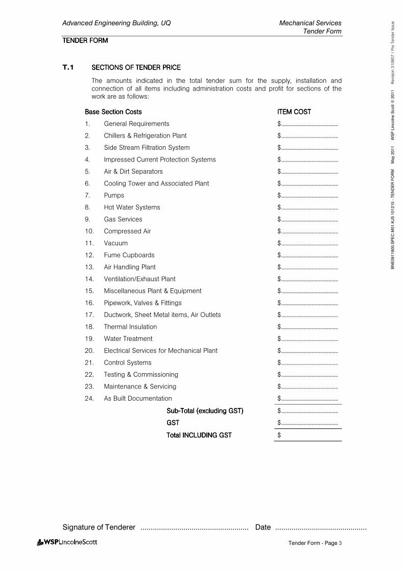
Advanced Engineering Building, UQ Mechanical Services
Tender Form
TENDER FORMTENDER FORMTENDER FORMTENDER FORM
Signature of Tenderer ..................................................... Date .............................................
Tender Form - Page 3
BNE0911900.SPEC.M
01.KJS 101215 - TENDER FORM M
ay 2011 W
SP Lincolne Scott ©
2011 Revision 310807 / Pre Tender Issue
T.1 SECTIONS OF TENDER PSECTIONS OF TENDER PSECTIONS OF TENDER PSECTIONS OF TENDER PRICERICERICERICE
The amounts indicated in the total tender sum for the supply, installation and connection of all items including administration costs and profit for sections of the work are as follows:
Base Base Base Base Section CostsSection CostsSection CostsSection Costs ITEM COSTITEM COSTITEM COSTITEM COST
1. General Requirements $ .........................................
2. Chillers & Refrigeration Plant $ .........................................
3. Side Stream Filtration System $ .........................................
4. Impressed Current Protection Systems $ .........................................
5. Air & Dirt Separators $ .........................................
6. Cooling Tower and Associated Plant $ .........................................
7. Pumps $ .........................................
8. Hot Water Systems $ .........................................
9. Gas Services $ .........................................
10. Compressed Air $ .........................................
11. Vacuum $ .........................................
12. Fume Cupboards $ .........................................
13. Air Handling Plant $ .........................................
14. Ventilation/Exhaust Plant $ .........................................
15. Miscellaneous Plant & Equipment $ .........................................
16. Pipework, Valves & Fittings $ .........................................
17. Ductwork, Sheet Metal items, Air Outlets $ .........................................
18. Thermal Insulation $ .........................................
19. Water Treatment $ .........................................
20. Electrical Services for Mechanical Plant $ .........................................
21. Control Systems $ .........................................
22. Testing & Commissioning $ .........................................
23. Maintenance & Servicing $ .........................................
24. As Built Documentation $ .........................................
SubSubSubSub----Total (excluding GST)Total (excluding GST)Total (excluding GST)Total (excluding GST) $ .........................................
GSTGSTGSTGST $ .........................................
Total INCLUDING GSTTotal INCLUDING GSTTotal INCLUDING GSTTotal INCLUDING GST $
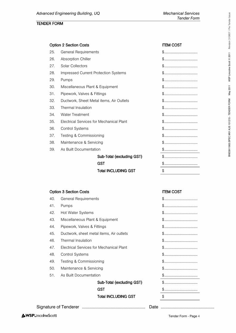
Advanced Engineering Building, UQ Mechanical Services
Tender Form
TENDER FORMTENDER FORMTENDER FORMTENDER FORM
Signature of Tenderer ..................................................... Date .............................................
Tender Form - Page 4
BNE0911900.SPEC.M
01.KJS 101215 - TENDER FORM M
ay 2011 W
SP Lincolne Scott ©
2011 Revision 310807 / Pre Tender Issue
Option 2Option 2Option 2Option 2 Section CostsSection CostsSection CostsSection Costs ITEM COSTITEM COSTITEM COSTITEM COST
25. General Requirements $ .........................................
26. Absorption Chiller $ .........................................
27. Solar Collectors $ .........................................
28. Impressed Current Protection Systems $ .........................................
29. Pumps $ .........................................
30. Miscellaneous Plant & Equipment $ .........................................
31. Pipework, Valves & Fittings $ .........................................
32. Ductwork, Sheet Metal items, Air Outlets $ .........................................
33. Thermal Insulation $ .........................................
34. Water Treatment $ .........................................
35. Electrical Services for Mechanical Plant $ .........................................
36. Control Systems $ .........................................
37. Testing & Commissioning $ .........................................
38. Maintenance & Servicing $ .........................................
39. As Built Documentation $ .........................................
SubSubSubSub----Total (excluding GST)Total (excluding GST)Total (excluding GST)Total (excluding GST) $ .........................................
GSTGSTGSTGST $ .........................................
Total INCLUDING GSTTotal INCLUDING GSTTotal INCLUDING GSTTotal INCLUDING GST $
Option 3Option 3Option 3Option 3 Section CostsSection CostsSection CostsSection Costs ITEM COSTITEM COSTITEM COSTITEM COST
40. General Requirements $ .........................................
41. Pumps $ .........................................
42. Hot Water Systems $ .........................................
43. Miscellaneous Plant & Equipment $ .........................................
44. Pipework, Valves & Fittings $ .........................................
45. Ductwork, sheet metal items, Air outlets $ .........................................
46. Thermal Insulation $ .........................................
47. Electrical Services for Mechanical Plant $ .........................................
48. Control Systems $ .........................................
49. Testing & Commissioning $ .........................................
50. Maintenance & Servicing $ .........................................
51. As Built Documentation $ .........................................
SubSubSubSub----Total (excluding GST)Total (excluding GST)Total (excluding GST)Total (excluding GST) $ .........................................
GSTGSTGSTGST $ .........................................
Total INCLUDTotal INCLUDTotal INCLUDTotal INCLUDING GSTING GSTING GSTING GST $

Advanced Engineering Building, UQ Mechanical Services
Tender Form
TENDER FORMTENDER FORMTENDER FORMTENDER FORM
Signature of Tenderer ..................................................... Date .............................................
Tender Form - Page 5
BNE0911900.SPEC.M
01.KJS 101215 - TENDER FORM M
ay 2011 W
SP Lincolne Scott ©
2011 Revision 310807 / Pre Tender Issue
OptionOptionOptionOption 4444 Section CostsSection CostsSection CostsSection Costs ITEM COSTITEM COSTITEM COSTITEM COST
52. General Requirements $ .........................................
53. Pumps $ .........................................
54. Hot Water Systems $ .........................................
55. Ventilation/Exhaust Plant $ .........................................
56. Miscellaneous Plant & Equipment $ .........................................
57. Pipework, Valves & Fittings $ .........................................
58. Ductwork, Sheet Metal items, Air Outlets $ .........................................
59. Thermal Insulation $ .........................................
60. Electrical Services for Mechanical Plant $ .........................................
61. Control Systems $ .........................................
62. Testing & Commissioning $ .........................................
63. Maintenance & Servicing $ .........................................
64. As Built Documentation $ .........................................
SubSubSubSub----Total (excluding GST)Total (excluding GST)Total (excluding GST)Total (excluding GST) $ .........................................
GSTGSTGSTGST $ .........................................
Total INCLUDING GSTTotal INCLUDING GSTTotal INCLUDING GSTTotal INCLUDING GST $
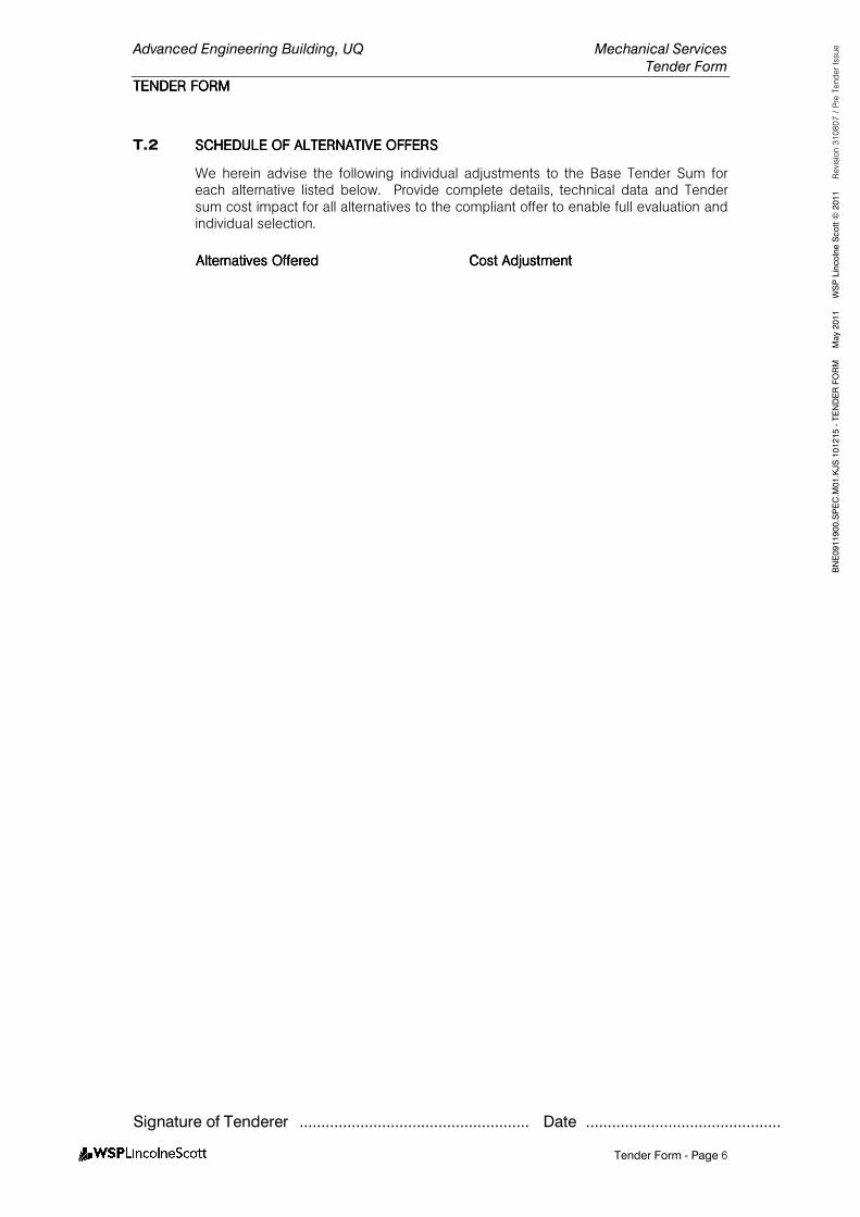
Advanced Engineering Building, UQ Mechanical Services
Tender Form
TENDER FORMTENDER FORMTENDER FORMTENDER FORM
Signature of Tenderer ..................................................... Date .............................................
Tender Form - Page 6
BNE0911900.SPEC.M
01.KJS 101215 - TENDER FORM M
ay 2011 W
SP Lincolne Scott ©
2011 Revision 310807 / Pre Tender Issue
T.2 SCHEDULSCHEDULSCHEDULSCHEDULE OF E OF E OF E OF ALTERNATIVEALTERNATIVEALTERNATIVEALTERNATIVE OFFERSOFFERSOFFERSOFFERS
We herein advise the following individual adjustments to the Base Tender Sum for each alternative listed below. Provide complete details, technical data and Tender sum cost impact for all alternatives to the compliant offer to enable full evaluation and individual selection.
Alternatives OfferedAlternatives OfferedAlternatives OfferedAlternatives Offered Cost AdjustmentCost AdjustmentCost AdjustmentCost Adjustment
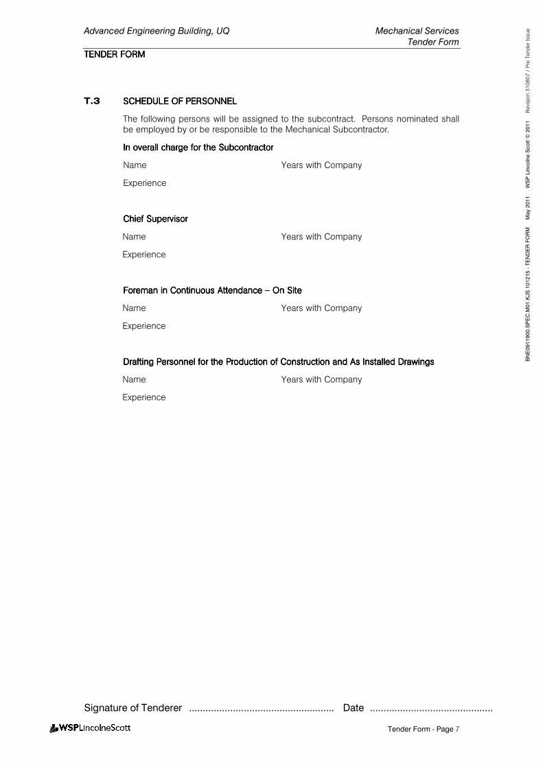
Advanced Engineering Building, UQ Mechanical Services
Tender Form
TENDER FORMTENDER FORMTENDER FORMTENDER FORM
Signature of Tenderer ..................................................... Date .............................................
Tender Form - Page 7
BNE0911900.SPEC.M
01.KJS 101215 - TENDER FORM M
ay 2011 W
SP Lincolne Scott ©
2011 Revision 310807 / Pre Tender Issue
T.3 SCHEDULE OF PERSONNESCHEDULE OF PERSONNESCHEDULE OF PERSONNESCHEDULE OF PERSONNELLLL
The following persons will be assigned to the subcontract. Persons nominated shall be employed by or be responsible to the Mechanical Subcontractor.
In overall charge for the In overall charge for the In overall charge for the In overall charge for the SubcSubcSubcSubcontractorontractorontractorontractor
Name Years with Company
Experience
Chief SupervisorChief SupervisorChief SupervisorChief Supervisor
Name Years with Company
Experience
Foreman in Continuous Attendance Foreman in Continuous Attendance Foreman in Continuous Attendance Foreman in Continuous Attendance –––– On SiteOn SiteOn SiteOn Site
Name Years with Company
Experience
Drafting Personnel Drafting Personnel Drafting Personnel Drafting Personnel for the Production of Construction and As Installed Drawingsfor the Production of Construction and As Installed Drawingsfor the Production of Construction and As Installed Drawingsfor the Production of Construction and As Installed Drawings
Name Years with Company
Experience
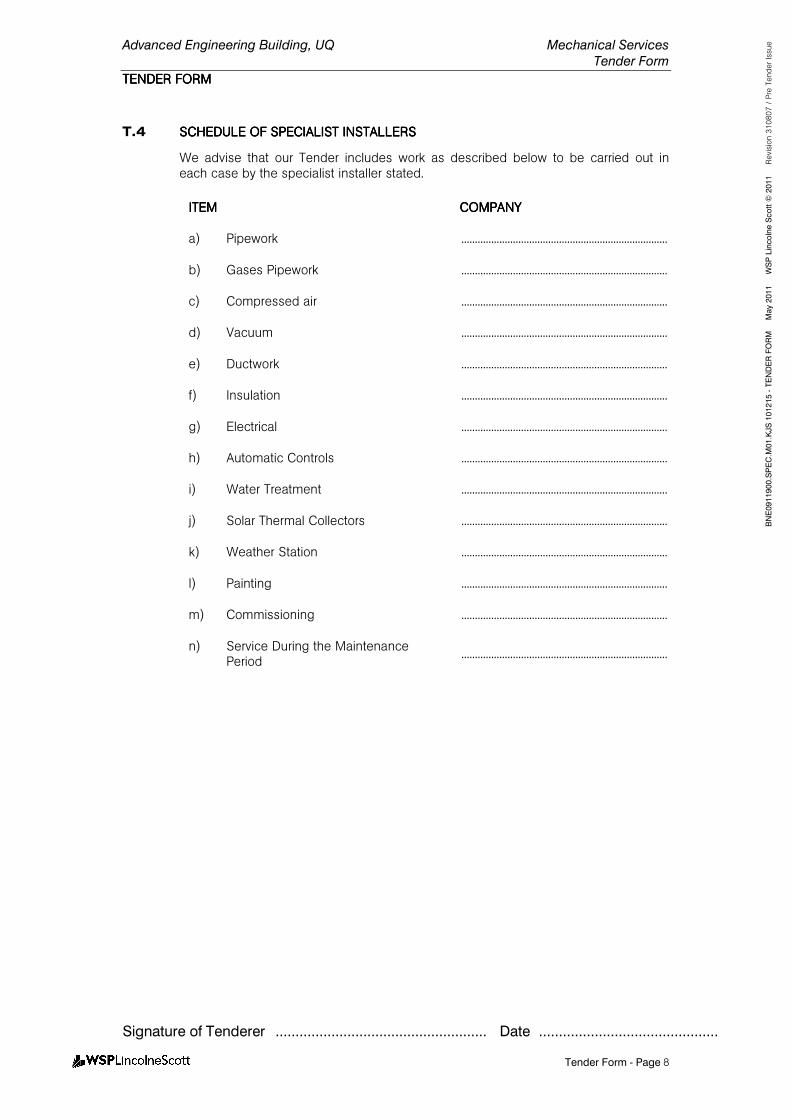
Advanced Engineering Building, UQ Mechanical Services
Tender Form
TENDER FORMTENDER FORMTENDER FORMTENDER FORM
Signature of Tenderer ..................................................... Date .............................................
Tender Form - Page 8
BNE0911900.SPEC.M
01.KJS 101215 - TENDER FORM M
ay 2011 W
SP Lincolne Scott ©
2011 Revision 310807 / Pre Tender Issue
T.4 SCHEDULE SCHEDULE SCHEDULE SCHEDULE OF OF OF OF SPECIALIST INSTALLERSPECIALIST INSTALLERSPECIALIST INSTALLERSPECIALIST INSTALLERSSSS
We advise that our Tender includes work as described below to be carried out in each case by the specialist installer stated.
ITEMITEMITEMITEM COMPANYCOMPANYCOMPANYCOMPANY
a) Pipework ............................................................................
b) Gases Pipework ............................................................................
c) Compressed air ............................................................................
d) Vacuum ............................................................................
e) Ductwork ............................................................................
f) Insulation ............................................................................
g) Electrical ............................................................................
h) Automatic Controls ............................................................................
i) Water Treatment ............................................................................
j) Solar Thermal Collectors ............................................................................
k) Weather Station ............................................................................
l) Painting ............................................................................
m) Commissioning ............................................................................
n) Service During the Maintenance Period
............................................................................
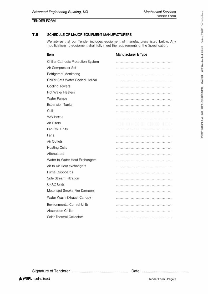
Advanced Engineering Building, UQ Mechanical Services
Tender Form
TENDER FORMTENDER FORMTENDER FORMTENDER FORM
Signature of Tenderer ..................................................... Date .............................................
Tender Form - Page 9
BNE0911900.SPEC.M
01.KJS 101215 - TENDER FORM M
ay 2011 W
SP Lincolne Scott ©
2011 Revision 310807 / Pre Tender Issue
T.5 SCHEDULE OF MAJOR EQSCHEDULE OF MAJOR EQSCHEDULE OF MAJOR EQSCHEDULE OF MAJOR EQUIPMENT MANUFACTURERUIPMENT MANUFACTURERUIPMENT MANUFACTURERUIPMENT MANUFACTURERSSSS
We advise that our Tender includes equipment of manufacturers listed below. Any modifications to equipment shall fully meet the requirements of the Specification.
ItemItemItemItem ManufacturerManufacturerManufacturerManufacturer & Typ& Typ& Typ& Typeeee
Chiller Cathodic Protection System ………………………………………
Air Compressor Set ………………………………………
Refrigerant Monitoring ………………………………………
Chiller Sets Water Cooled Helical ………………………………………
Cooling Towers ………………………………………
Hot Water Heaters ………………………………………
Water Pumps ………………………………………
Expansion Tanks ………………………………………
Coils ………………………………………
VAV boxes ………………………………………
Air Filters ………………………………………
Fan Coil Units ………………………………………
Fans ………………………………………
Air Outlets ………………………………………
Heating Coils ………………………………………
Attenuators ………………………………………
Water-to Water Heat Exchangers ………………………………………
Air-to Air Heat exchangers ………………………………………
Fume Cupboards ………………………………………
Side Stream Filtration ………………………………………
CRAC Units ………………………………………
Motorised Smoke Fire Dampers ………………………………………
Water Wash Exhaust Canopy ………………………………………
Environmental Control Units ………………………………………
Absorption Chiller ………………………………………
Solar Thermal Collectors ………………………………………
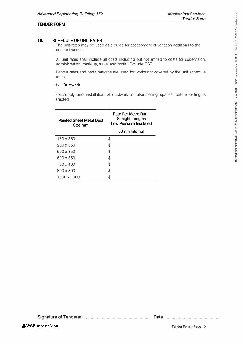
Advanced Engineering Building, UQ Mechanical Services
Tender Form
TENDER FORMTENDER FORMTENDER FORMTENDER FORM
Signature of Tenderer ..................................................... Date .............................................
Tender Form - Page 10
BNE0911900.SPEC.M
01.KJS 101215 - TENDER FORM M
ay 2011 W
SP Lincolne Scott ©
2011 Revision 310807 / Pre Tender Issue
T6.T6.T6.T6. SCHEDULE OF UNIT RATSCHEDULE OF UNIT RATSCHEDULE OF UNIT RATSCHEDULE OF UNIT RATESESESES The unit rates may be used as a guide for assessment of variation additions to the contract works. All unit rates shall include all costs including but not limited to costs for supervision, administration, mark-up, travel and profit. Exclude GST.
Labour rates and profit margins are used for works not covered by the unit schedule rates.
1. DuctworkDuctworkDuctworkDuctwork
For supply and installation of ductwork in false ceiling spaces, before ceiling is erected.
Painted Painted Painted Painted Sheet Metal Duct Sheet Metal Duct Sheet Metal Duct Sheet Metal Duct Size mmSize mmSize mmSize mm
Rate Per Metre Run Rate Per Metre Run Rate Per Metre Run Rate Per Metre Run ---- Straight LengthsStraight LengthsStraight LengthsStraight Lengths
Low Pressure InsulatedLow Pressure InsulatedLow Pressure InsulatedLow Pressure Insulated
50mm 50mm 50mm 50mm InternalInternalInternalInternal
150 x 350 $
200 x 350 $
500 x 350 $
600 x 350 $
700 x 400 $
800 x 800 $
1000 x 1000 $
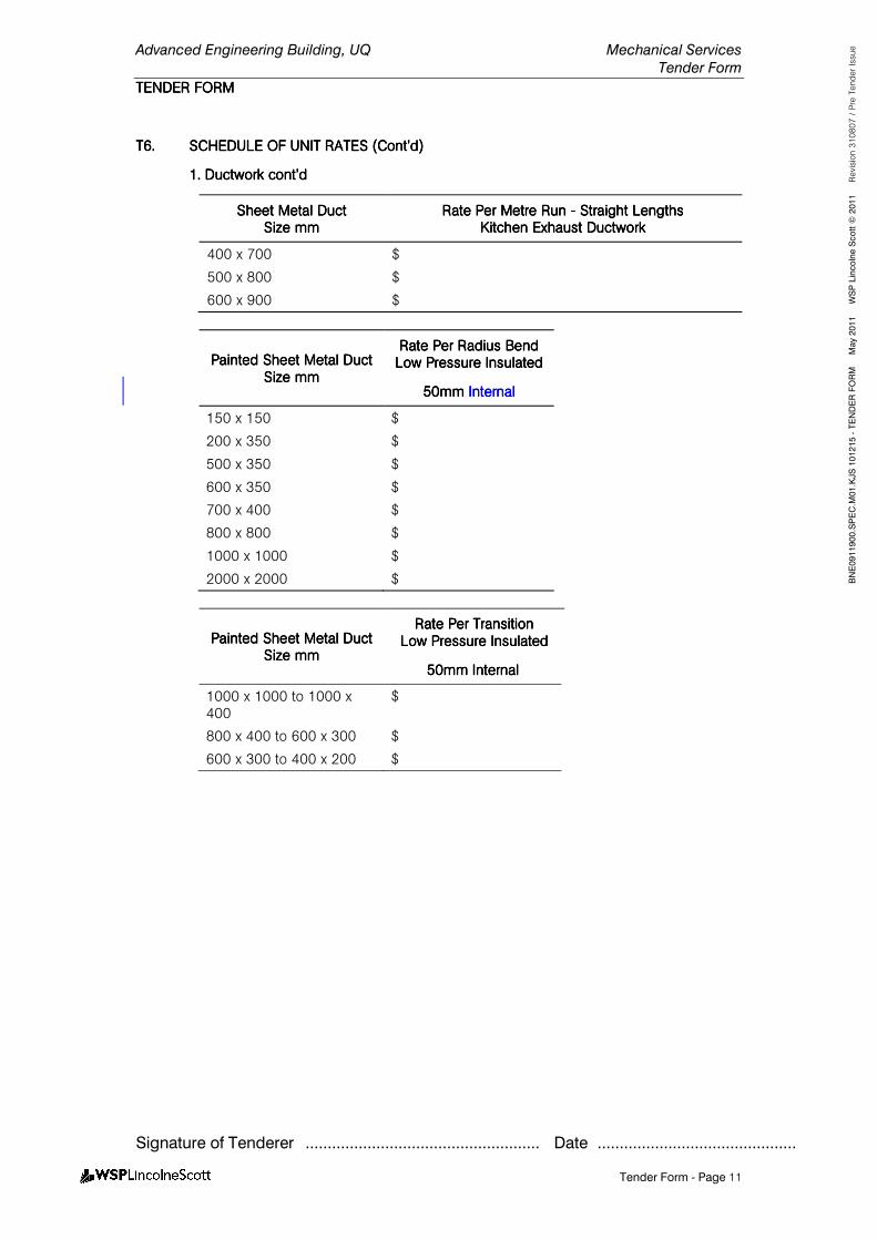
Advanced Engineering Building, UQ Mechanical Services
Tender Form
TENDER FORMTENDER FORMTENDER FORMTENDER FORM
Signature of Tenderer ..................................................... Date .............................................
Tender Form - Page 11
BNE0911900.SPEC.M
01.KJS 101215 - TENDER FORM M
ay 2011 W
SP Lincolne Scott ©
2011 Revision 310807 / Pre Tender Issue
T6.T6.T6.T6. SSSSCHEDULE OF UNIT RATECHEDULE OF UNIT RATECHEDULE OF UNIT RATECHEDULE OF UNIT RATESSSS (C(C(C(Cont’dont’dont’dont’d))))
1. Ductwork cont’d1. Ductwork cont’d1. Ductwork cont’d1. Ductwork cont’d
Sheet Metal DuctSheet Metal DuctSheet Metal DuctSheet Metal Duct Size mmSize mmSize mmSize mm
Rate Per Metre Run Rate Per Metre Run Rate Per Metre Run Rate Per Metre Run ---- Straight LengthsStraight LengthsStraight LengthsStraight Lengths Kitchen Exhaust DuctworkKitchen Exhaust DuctworkKitchen Exhaust DuctworkKitchen Exhaust Ductwork
400 x 700 $
500 x 800 $
600 x 900 $
Painted Painted Painted Painted Sheet Metal Duct Sheet Metal Duct Sheet Metal Duct Sheet Metal Duct Size mmSize mmSize mmSize mm
Rate Per Radius BendRate Per Radius BendRate Per Radius BendRate Per Radius Bend Low Pressure InsulatedLow Pressure InsulatedLow Pressure InsulatedLow Pressure Insulated
50mm 50mm 50mm 50mm InternalInternalInternalInternal
150 x 150 $
200 x 350 $
500 x 350 $
600 x 350 $
700 x 400 $
800 x 800 $
1000 x 1000 $
2000 x 2000 $
Painted Painted Painted Painted Sheet Metal Duct Sheet Metal Duct Sheet Metal Duct Sheet Metal Duct Size Size Size Size mmmmmmmm
Rate Per Rate Per Rate Per Rate Per TransitionTransitionTransitionTransition Low Pressure InsulatedLow Pressure InsulatedLow Pressure InsulatedLow Pressure Insulated
50mm Internal50mm Internal50mm Internal50mm Internal
1000 x 1000 to 1000 x 400
$
800 x 400 to 600 x 300 $
600 x 300 to 400 x 200 $
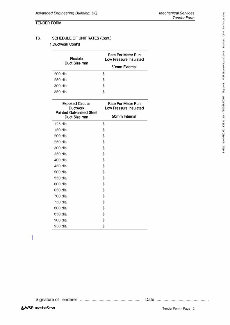
Advanced Engineering Building, UQ Mechanical Services
Tender Form
TENDER FORMTENDER FORMTENDER FORMTENDER FORM
Signature of Tenderer ..................................................... Date .............................................
Tender Form - Page 12
BNE0911900.SPEC.M
01.KJS 101215 - TENDER FORM M
ay 2011 W
SP Lincolne Scott ©
2011 Revision 310807 / Pre Tender Issue
T6.T6.T6.T6. SCHEDULE OF UNIT RATES SCHEDULE OF UNIT RATES SCHEDULE OF UNIT RATES SCHEDULE OF UNIT RATES (Cont.)(Cont.)(Cont.)(Cont.)
1.Ductwork Cont’d1.Ductwork Cont’d1.Ductwork Cont’d1.Ductwork Cont’d
FlexibleFlexibleFlexibleFlexible Duct Size mmDuct Size mmDuct Size mmDuct Size mm
Rate Per Meter RunRate Per Meter RunRate Per Meter RunRate Per Meter Run LLLLow Pressure Insulatedow Pressure Insulatedow Pressure Insulatedow Pressure Insulated
50mm External50mm External50mm External50mm External
200 dia. $
250 dia. $
300 dia. $
350 dia. $
Exposed Exposed Exposed Exposed Circular Circular Circular Circular DuctworkDuctworkDuctworkDuctwork
Painted Galvanized SteelPainted Galvanized SteelPainted Galvanized SteelPainted Galvanized Steel Duct Size mmDuct Size mmDuct Size mmDuct Size mm
Rate Per Meter RunRate Per Meter RunRate Per Meter RunRate Per Meter Run Low Pressure InsulatedLow Pressure InsulatedLow Pressure InsulatedLow Pressure Insulated
50mm Internal50mm Internal50mm Internal50mm Internal
125 dia. $
150 dia $
200 dia. $
250 dia. $
300 dia. $
350 dia. $
400 dia. $
450 dia. $
500 dia. $
550 dia. $
600 dia. $
650 dia. $
700 dia. $
750 dia. $
800 dia. $
850 dia. $
900 dia $
950 dia. $
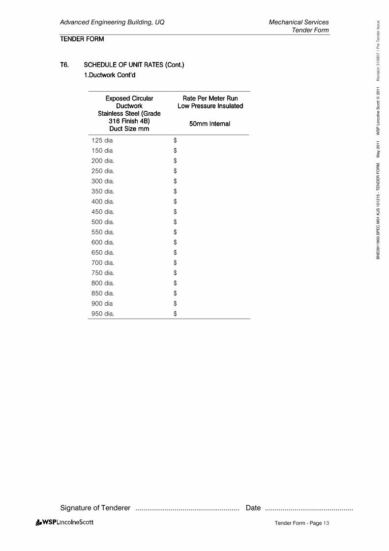
Advanced Engineering Building, UQ Mechanical Services
Tender Form
TENDER FORMTENDER FORMTENDER FORMTENDER FORM
Signature of Tenderer ..................................................... Date .............................................
Tender Form - Page 13
BNE0911900.SPEC.M
01.KJS 101215 - TENDER FORM M
ay 2011 W
SP Lincolne Scott ©
2011 Revision 310807 / Pre Tender Issue
T6.T6.T6.T6. SCHEDULE OF UNIT RATES (Cont.)SCHEDULE OF UNIT RATES (Cont.)SCHEDULE OF UNIT RATES (Cont.)SCHEDULE OF UNIT RATES (Cont.)
1.Ductwork Cont’d1.Ductwork Cont’d1.Ductwork Cont’d1.Ductwork Cont’d
Exposed Exposed Exposed Exposed Circular Circular Circular Circular DuctworkDuctworkDuctworkDuctwork
StaiStaiStaiStainless Steel (Grade nless Steel (Grade nless Steel (Grade nless Steel (Grade 316 Finish 4B)316 Finish 4B)316 Finish 4B)316 Finish 4B) Duct Size mmDuct Size mmDuct Size mmDuct Size mm
Rate Per Meter RunRate Per Meter RunRate Per Meter RunRate Per Meter Run Low Pressure InsulatedLow Pressure InsulatedLow Pressure InsulatedLow Pressure Insulated
50mm Internal50mm Internal50mm Internal50mm Internal
125 dia $
150 dia $
200 dia. $
250 dia. $
300 dia. $
350 dia. $
400 dia. $
450 dia. $
500 dia. $
550 dia. $
600 dia. $
650 dia. $
700 dia. $
750 dia. $
800 dia. $
850 dia. $
900 dia $
950 dia. $
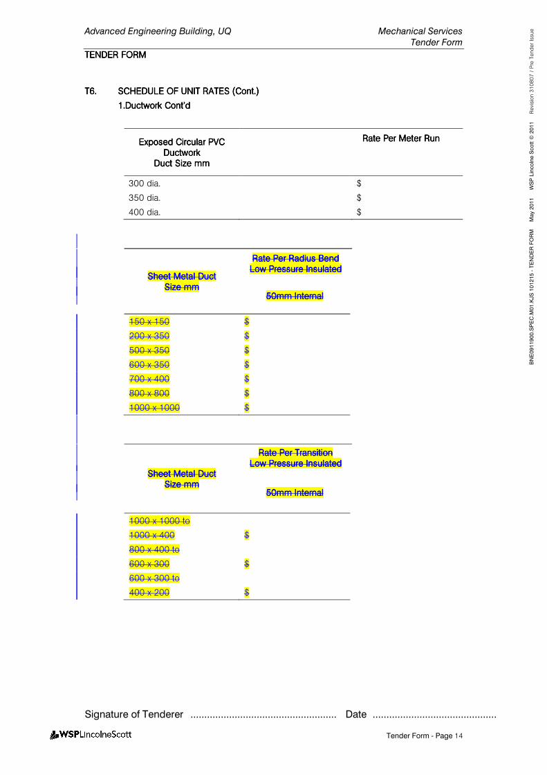
Advanced Engineering Building, UQ Mechanical Services
Tender Form
TENDER FORMTENDER FORMTENDER FORMTENDER FORM
Signature of Tenderer ..................................................... Date .............................................
Tender Form - Page 14
BNE0911900.SPEC.M
01.KJS 101215 - TENDER FORM M
ay 2011 W
SP Lincolne Scott ©
2011 Revision 310807 / Pre Tender Issue
T6.T6.T6.T6. SCHEDULE OF UNIT RATES (Cont.)SCHEDULE OF UNIT RATES (Cont.)SCHEDULE OF UNIT RATES (Cont.)SCHEDULE OF UNIT RATES (Cont.)
1.Ductwork Cont’d1.Ductwork Cont’d1.Ductwork Cont’d1.Ductwork Cont’d
Exposed Circular PVC Exposed Circular PVC Exposed Circular PVC Exposed Circular PVC DuctworkDuctworkDuctworkDuctwork
Duct Size mmDuct Size mmDuct Size mmDuct Size mm
Rate Per Meter RunRate Per Meter RunRate Per Meter RunRate Per Meter Run
300 dia. $
350 dia. $
400 dia. $
Sheet Metal DuctSheet Metal DuctSheet Metal DuctSheet Metal Duct Size mmSize mmSize mmSize mm
Rate Per Radius BendRate Per Radius BendRate Per Radius BendRate Per Radius Bend Low Pressure InsulatedLow Pressure InsulatedLow Pressure InsulatedLow Pressure Insulated
50mm 50mm 50mm 50mm InternalInternalInternalInternal
150 x 150 $
200 x 350 $
500 x 350 $
600 x 350 $
700 x 400 $
800 x 800 $
1000 x 1000 $
Sheet Metal DuctSheet Metal DuctSheet Metal DuctSheet Metal Duct Size mmSize mmSize mmSize mm
Rate Per TransitionRate Per TransitionRate Per TransitionRate Per Transition LowLowLowLow Pressure InsulatedPressure InsulatedPressure InsulatedPressure Insulated
50mm 50mm 50mm 50mm InternalInternalInternalInternal
1000 x 1000 to
1000 x 400 $
800 x 400 to
600 x 300 $
600 x 300 to
400 x 200 $
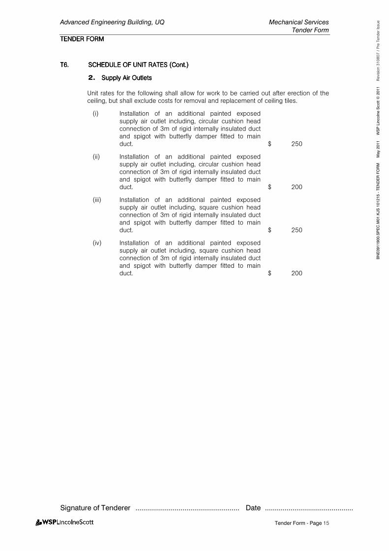
Advanced Engineering Building, UQ Mechanical Services
Tender Form
TENDER FORMTENDER FORMTENDER FORMTENDER FORM
Signature of Tenderer ..................................................... Date .............................................
Tender Form - Page 15
BNE0911900.SPEC.M
01.KJS 101215 - TENDER FORM M
ay 2011 W
SP Lincolne Scott ©
2011 Revision 310807 / Pre Tender Issue
T6.T6.T6.T6. SCHEDULE OF UNIT RATESSCHEDULE OF UNIT RATESSCHEDULE OF UNIT RATESSCHEDULE OF UNIT RATES (Cont.)(Cont.)(Cont.)(Cont.)
2. Supply Air OutletsSupply Air OutletsSupply Air OutletsSupply Air Outlets
Unit rates for the following shall allow for work to be carried out after erection of the ceiling, but shall exclude costs for removal and replacement of ceiling tiles.
(i) Installation of an additional painted exposed supply air outlet including, circular cushion head connection of 3m of rigid internally insulated duct and spigot with butterfly damper fitted to main duct. $ 250
(ii) Installation of an additional painted exposed supply air outlet including, circular cushion head connection of 3m of rigid internally insulated duct and spigot with butterfly damper fitted to main duct.
$ 200
(iii) Installation of an additional painted exposed supply air outlet including, square cushion head connection of 3m of rigid internally insulated duct and spigot with butterfly damper fitted to main duct. $ 250
(iv) Installation of an additional painted exposed supply air outlet including, square cushion head connection of 3m of rigid internally insulated duct and spigot with butterfly damper fitted to main duct. $ 200
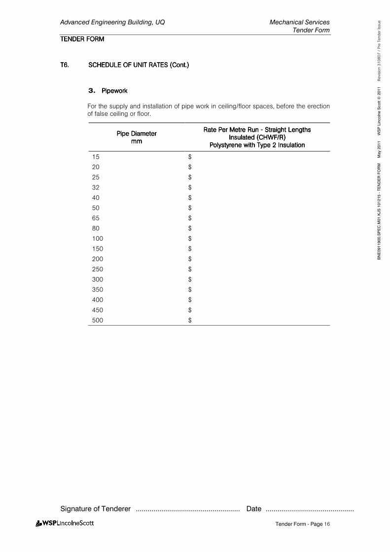
Advanced Engineering Building, UQ Mechanical Services
Tender Form
TENDER FORMTENDER FORMTENDER FORMTENDER FORM
Signature of Tenderer ..................................................... Date .............................................
Tender Form - Page 16
BNE0911900.SPEC.M
01.KJS 101215 - TENDER FORM M
ay 2011 W
SP Lincolne Scott ©
2011 Revision 310807 / Pre Tender Issue
T6.T6.T6.T6. SCHEDULE OF UNIT RATES (Cont.)SCHEDULE OF UNIT RATES (Cont.)SCHEDULE OF UNIT RATES (Cont.)SCHEDULE OF UNIT RATES (Cont.)
3. PipeworkPipeworkPipeworkPipework
For the supply and installation of pipe work in ceiling/floor spaces, before the erection of false ceiling or floor.
Pipe DiameterPipe DiameterPipe DiameterPipe Diameter mmmmmmmm
Rate Per Metre Run Rate Per Metre Run Rate Per Metre Run Rate Per Metre Run ---- Straight LengthsStraight LengthsStraight LengthsStraight Lengths Insulated (CHWF/R)Insulated (CHWF/R)Insulated (CHWF/R)Insulated (CHWF/R)
Polystyrene withPolystyrene withPolystyrene withPolystyrene with Type 2 InsulationType 2 InsulationType 2 InsulationType 2 Insulation
15 $
20 $
25 $
32 $
40 $
50 $
65 $
80 $
100 $
150 $
200 $
250 $
300 $
350 $
400 $
450 $
500 $
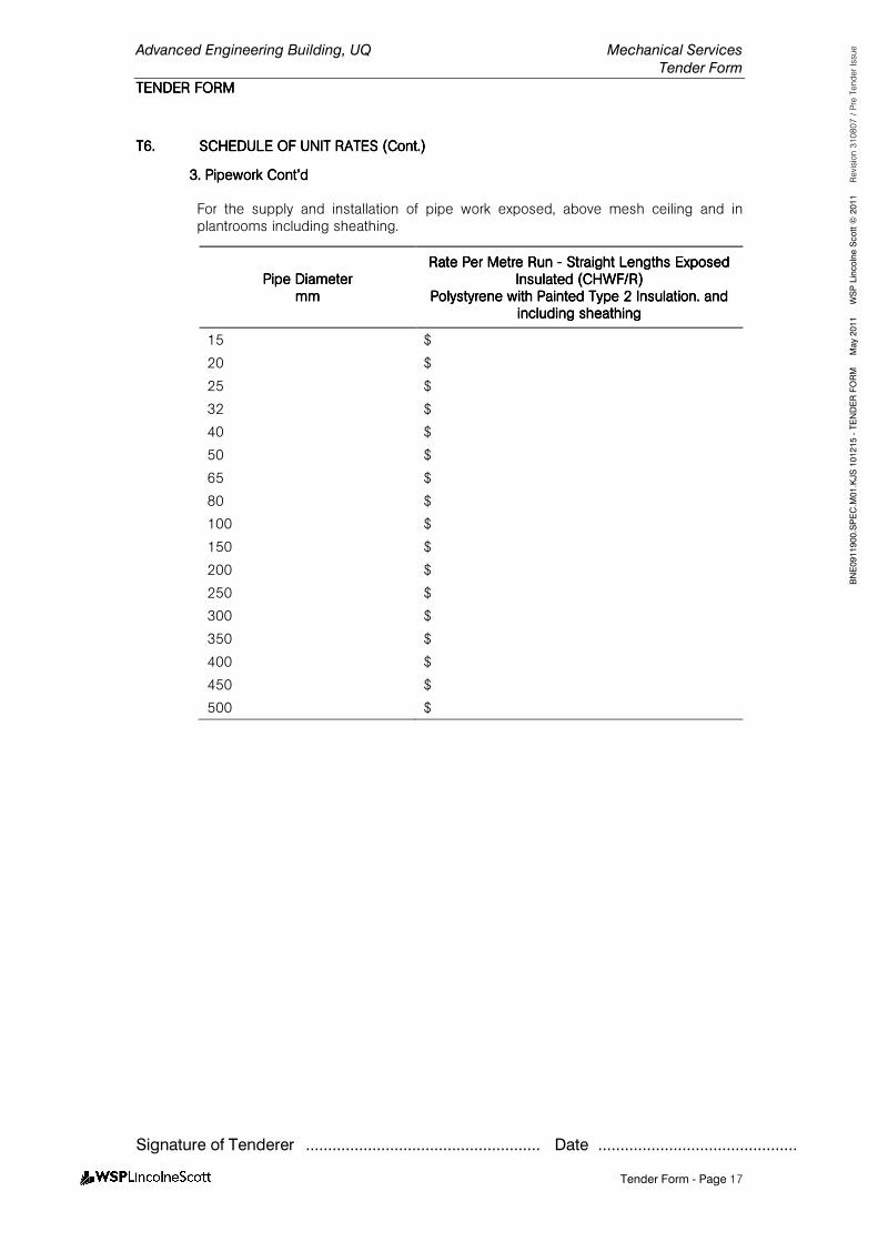
Advanced Engineering Building, UQ Mechanical Services
Tender Form
TENDER FORMTENDER FORMTENDER FORMTENDER FORM
Signature of Tenderer ..................................................... Date .............................................
Tender Form - Page 17
BNE0911900.SPEC.M
01.KJS 101215 - TENDER FORM M
ay 2011 W
SP Lincolne Scott ©
2011 Revision 310807 / Pre Tender Issue
T6.T6.T6.T6. SCHEDULE OF UNIT RATES SCHEDULE OF UNIT RATES SCHEDULE OF UNIT RATES SCHEDULE OF UNIT RATES (Cont.)(Cont.)(Cont.)(Cont.)
3. Pipework Cont’d3. Pipework Cont’d3. Pipework Cont’d3. Pipework Cont’d
For the supply and installation of pipe work exposed, above mesh ceiling and in plantrooms including sheathing.
Pipe DiameterPipe DiameterPipe DiameterPipe Diameter mmmmmmmm
Rate Per Rate Per Rate Per Rate Per Metre Run Metre Run Metre Run Metre Run ---- Straight Lengths ExposedStraight Lengths ExposedStraight Lengths ExposedStraight Lengths Exposed Insulated (CHWF/R)Insulated (CHWF/R)Insulated (CHWF/R)Insulated (CHWF/R)
Polystyrene with Polystyrene with Polystyrene with Polystyrene with Painted Type 2 InsulationPainted Type 2 InsulationPainted Type 2 InsulationPainted Type 2 Insulation. and . and . and . and including sheathingincluding sheathingincluding sheathingincluding sheathing
15 $
20 $
25 $
32 $
40 $
50 $
65 $
80 $
100 $
150 $
200 $
250 $
300 $
350 $
400 $
450 $
500 $
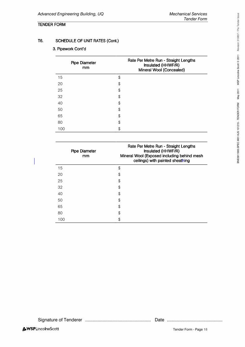
Advanced Engineering Building, UQ Mechanical Services
Tender Form
TENDER FORMTENDER FORMTENDER FORMTENDER FORM
Signature of Tenderer ..................................................... Date .............................................
Tender Form - Page 18
BNE0911900.SPEC.M
01.KJS 101215 - TENDER FORM M
ay 2011 W
SP Lincolne Scott ©
2011 Revision 310807 / Pre Tender Issue
T6.T6.T6.T6. SCHEDULE OF UNSCHEDULE OF UNSCHEDULE OF UNSCHEDULE OF UNIT RATES (Cont.)IT RATES (Cont.)IT RATES (Cont.)IT RATES (Cont.)
3. Pipework Cont’d3. Pipework Cont’d3. Pipework Cont’d3. Pipework Cont’d
Pipe DiameterPipe DiameterPipe DiameterPipe Diameter mmmmmmmm
Rate Per Metre Run Rate Per Metre Run Rate Per Metre Run Rate Per Metre Run ---- Straight LengthsStraight LengthsStraight LengthsStraight Lengths Insulated (HHWF/R)Insulated (HHWF/R)Insulated (HHWF/R)Insulated (HHWF/R)
Mineral WoolMineral WoolMineral WoolMineral Wool (Concealed)(Concealed)(Concealed)(Concealed)
15 $
20 $
25 $
32 $
40 $
50 $
65 $
80 $
100 $
Pipe DiameterPipe DiameterPipe DiameterPipe Diameter mmmmmmmm
Rate Per Metre Run Rate Per Metre Run Rate Per Metre Run Rate Per Metre Run ---- Straight LengthsStraight LengthsStraight LengthsStraight Lengths InsuInsuInsuInsulated (HHWF/R)lated (HHWF/R)lated (HHWF/R)lated (HHWF/R)
Mineral WoolMineral WoolMineral WoolMineral Wool (Exposed including behind mesh (Exposed including behind mesh (Exposed including behind mesh (Exposed including behind mesh ceilings)ceilings)ceilings)ceilings) with painted sheatwith painted sheatwith painted sheatwith painted sheathhhhinginginging
15 $
20 $
25 $
32 $
40 $
50 $
65 $
80 $
100 $
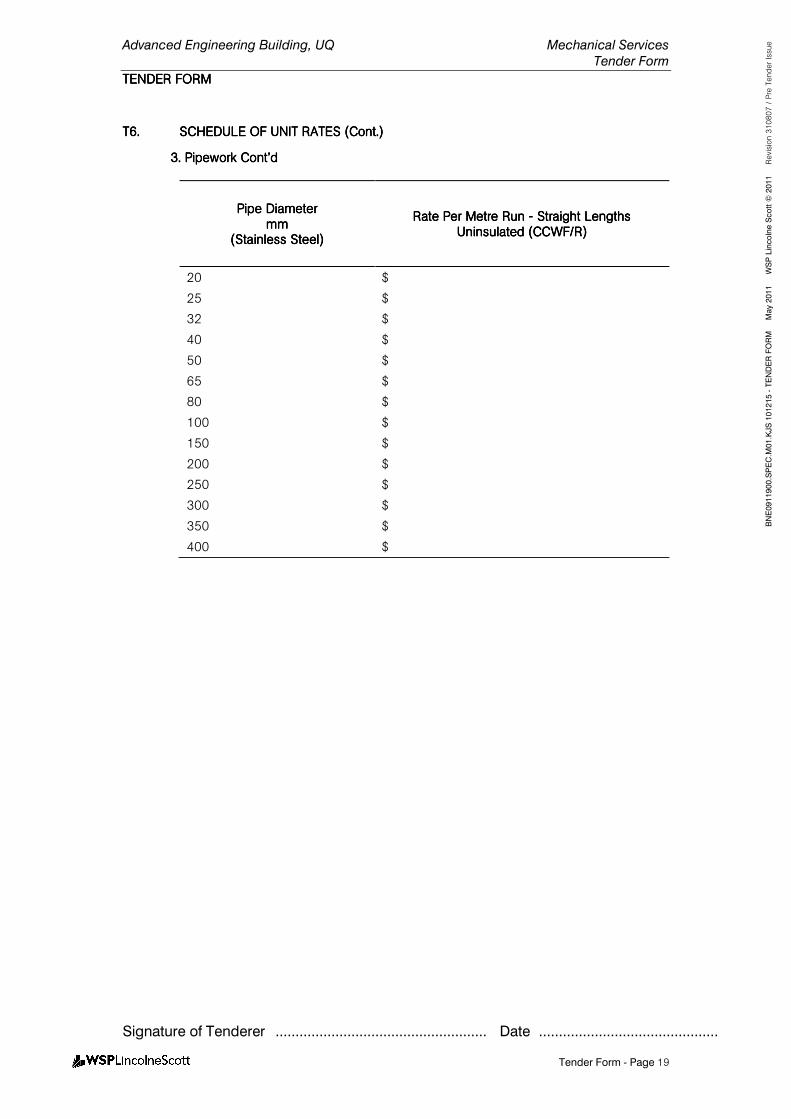
Advanced Engineering Building, UQ Mechanical Services
Tender Form
TENDER FORMTENDER FORMTENDER FORMTENDER FORM
Signature of Tenderer ..................................................... Date .............................................
Tender Form - Page 19
BNE0911900.SPEC.M
01.KJS 101215 - TENDER FORM M
ay 2011 W
SP Lincolne Scott ©
2011 Revision 310807 / Pre Tender Issue
T6.T6.T6.T6. SCHEDULE OF UNIT RATES (Cont.)SCHEDULE OF UNIT RATES (Cont.)SCHEDULE OF UNIT RATES (Cont.)SCHEDULE OF UNIT RATES (Cont.)
3. Pipework Cont’d3. Pipework Cont’d3. Pipework Cont’d3. Pipework Cont’d
Pipe DiameterPipe DiameterPipe DiameterPipe Diameter mmmmmmmm
(Stainless Steel)(Stainless Steel)(Stainless Steel)(Stainless Steel)
Rate Per Metre Rate Per Metre Rate Per Metre Rate Per Metre Run Run Run Run ---- Straight LengthsStraight LengthsStraight LengthsStraight Lengths Uninsulated (CCWF/R)Uninsulated (CCWF/R)Uninsulated (CCWF/R)Uninsulated (CCWF/R)
20 $
25 $
32 $
40 $
50 $
65 $
80 $
100 $
150 $
200 $
250 $
300 $
350 $
400 $
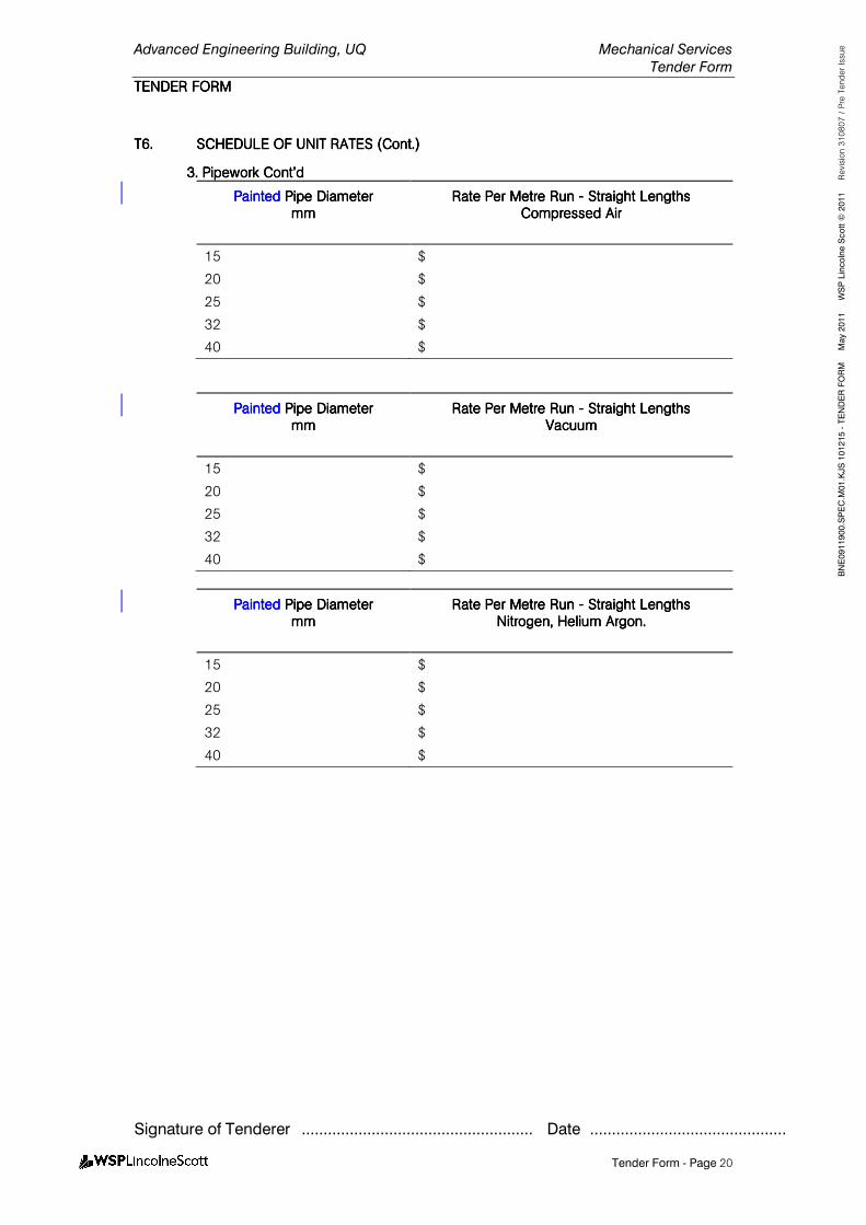
Advanced Engineering Building, UQ Mechanical Services
Tender Form
TENDER FORMTENDER FORMTENDER FORMTENDER FORM
Signature of Tenderer ..................................................... Date .............................................
Tender Form - Page 20
BNE0911900.SPEC.M
01.KJS 101215 - TENDER FORM M
ay 2011 W
SP Lincolne Scott ©
2011 Revision 310807 / Pre Tender Issue
T6.T6.T6.T6. SCHEDULE OF UNIT RATES (Cont.)SCHEDULE OF UNIT RATES (Cont.)SCHEDULE OF UNIT RATES (Cont.)SCHEDULE OF UNIT RATES (Cont.)
3. Pipework Cont’d3. Pipework Cont’d3. Pipework Cont’d3. Pipework Cont’d
Painted Painted Painted Painted Pipe DiameterPipe DiameterPipe DiameterPipe Diameter mmmmmmmm
Rate Per Metre Run Rate Per Metre Run Rate Per Metre Run Rate Per Metre Run ---- Straight LengthStraight LengthStraight LengthStraight Lengthssss Compressed AirCompressed AirCompressed AirCompressed Air
15 $
20 $
25 $
32 $
40 $
Painted Painted Painted Painted Pipe DiameterPipe DiameterPipe DiameterPipe Diameter mmmmmmmm
Rate Per Metre Run Rate Per Metre Run Rate Per Metre Run Rate Per Metre Run ---- Straight LengthsStraight LengthsStraight LengthsStraight Lengths VacuumVacuumVacuumVacuum
15 $
20 $
25 $
32 $
40 $
Painted Painted Painted Painted Pipe DiameterPipe DiameterPipe DiameterPipe Diameter mmmmmmmm
Rate Per Metre Run Rate Per Metre Run Rate Per Metre Run Rate Per Metre Run ---- Straight LengthsStraight LengthsStraight LengthsStraight Lengths NitrogenNitrogenNitrogenNitrogen, Helium Argon., Helium Argon., Helium Argon., Helium Argon.
15 $
20 $
25 $
32 $
40 $

Advanced Engineering Building, UQ Mechanical Services
Tender Form
TENDER FORMTENDER FORMTENDER FORMTENDER FORM
Signature of Tenderer ..................................................... Date .............................................
Tender Form - Page 21
BNE0911900.SPEC.M
01.KJS 101215 - TENDER FORM M
ay 2011 W
SP Lincolne Scott ©
2011 Revision 310807 / Pre Tender Issue
T6.T6.T6.T6. SCHEDULE OF UNIT RATES (Cont.)SCHEDULE OF UNIT RATES (Cont.)SCHEDULE OF UNIT RATES (Cont.)SCHEDULE OF UNIT RATES (Cont.)
4. Motorised 4. Motorised 4. Motorised 4. Motorised Opposed BladeOpposed BladeOpposed BladeOpposed Blade DampersDampersDampersDampers
Damper SizeDamper SizeDamper SizeDamper Size H x W (mm)H x W (mm)H x W (mm)H x W (mm)
Rate Per UnitRate Per UnitRate Per UnitRate Per Unit
200x200 $
400x400 $
600x600 $
800x800 $
5555. Variable Speed Drive . Variable Speed Drive . Variable Speed Drive . Variable Speed Drive
Motor SizeMotor SizeMotor SizeMotor Size Rate Per Unit Rate Per Unit Rate Per Unit Rate Per Unit (Supply, Installation, integrati(Supply, Installation, integrati(Supply, Installation, integrati(Supply, Installation, integration on on on
with DDC (allow 5 meters of cabling)with DDC (allow 5 meters of cabling)with DDC (allow 5 meters of cabling)with DDC (allow 5 meters of cabling)
2.22225 kW $
4.0 kW4.0 kW4.0 kW4.0 kW $$$$
5.5555 kW $
7.5 kW $
11111 kW $
15151515 kW $
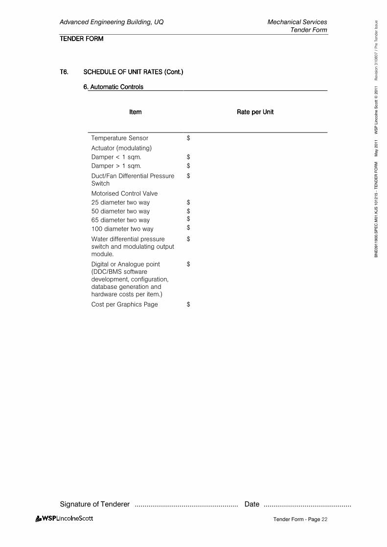
Advanced Engineering Building, UQ Mechanical Services
Tender Form
TENDER FORMTENDER FORMTENDER FORMTENDER FORM
Signature of Tenderer ..................................................... Date .............................................
Tender Form - Page 22
BNE0911900.SPEC.M
01.KJS 101215 - TENDER FORM M
ay 2011 W
SP Lincolne Scott ©
2011 Revision 310807 / Pre Tender Issue
T6.T6.T6.T6. SCHEDULE OF UNIT RATES (Cont.)SCHEDULE OF UNIT RATES (Cont.)SCHEDULE OF UNIT RATES (Cont.)SCHEDULE OF UNIT RATES (Cont.)
6666. Automatic Controls . Automatic Controls . Automatic Controls . Automatic Controls
ItemItemItemItem Rate per UnitRate per UnitRate per UnitRate per Unit
Temperature Sensor $
Actuator (modulating)
Damper < 1 sqm.
Damper > 1 sqm.
$
$
Duct/Fan Differential Pressure Switch
$
Motorised Control Valve
25 diameter two way
50 diameter two way
65 diameter two way
100 diameter two way
$
$ $
$
Water differential pressure switch and modulating output module.
$
Digital or Analogue point (DDC/BMS software development, configuration, database generation and hardware costs per item.)
$
Cost per Graphics Page $
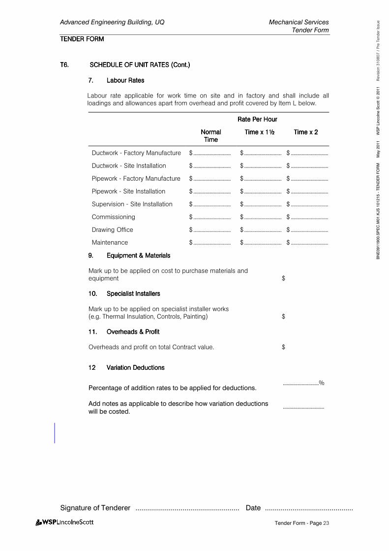
Advanced Engineering Building, UQ Mechanical Services
Tender Form
TENDER FORMTENDER FORMTENDER FORMTENDER FORM
Signature of Tenderer ..................................................... Date .............................................
Tender Form - Page 23
BNE0911900.SPEC.M
01.KJS 101215 - TENDER FORM M
ay 2011 W
SP Lincolne Scott ©
2011 Revision 310807 / Pre Tender Issue
T6.T6.T6.T6. SCHEDULE OF UNIT RATESSCHEDULE OF UNIT RATESSCHEDULE OF UNIT RATESSCHEDULE OF UNIT RATES (Cont.)(Cont.)(Cont.)(Cont.)
7777.... Labour RatesLabour RatesLabour RatesLabour Rates
Labour rate applicable for work time on site and in factory and shall include all loadings and allowances apart from overhead and profit covered by Item L below.
Rate Per HourRate Per HourRate Per HourRate Per Hour
NormalNormalNormalNormal TimeTimeTimeTime
Time xTime xTime xTime x 1½1½1½1½ Time x 2Time x 2Time x 2Time x 2
Ductwork - Factory Manufacture $ ............................ $ ............................ $ ............................
Ductwork - Site Installation $ ............................ $ ............................ $ ............................
Pipework - Factory Manufacture $ ............................ $ ............................ $ ............................
Pipework - Site Installation $ ............................ $ ............................ $ ............................
Supervision - Site Installation $ ............................ $ ............................ $ ............................
Commissioning $ ............................ $ ............................ $ ............................
Drawing Office $ ............................ $ ............................ $ ............................
Maintenance $ ............................ $ ............................ $ ............................
9.9.9.9. Equipment & MaterialsEquipment & MaterialsEquipment & MaterialsEquipment & Materials
Mark up to be applied on cost to purchase materials and equipment $ 10.10.10.10. Specialist InstallersSpecialist InstallersSpecialist InstallersSpecialist Installers
Mark up to be applied on specialist installer works (e.g. Thermal Insulation, Controls, Painting) $ 11.11.11.11. Overheads & ProfitOverheads & ProfitOverheads & ProfitOverheads & Profit
Overheads and profit on total Contract value. $
12121212 VVVVariation Deductionsariation Deductionsariation Deductionsariation Deductions
Percentage of addition rates to be applied for deductions. ...........................%
Add notes as applicable to describe how variation deductions
will be costed. ...............................
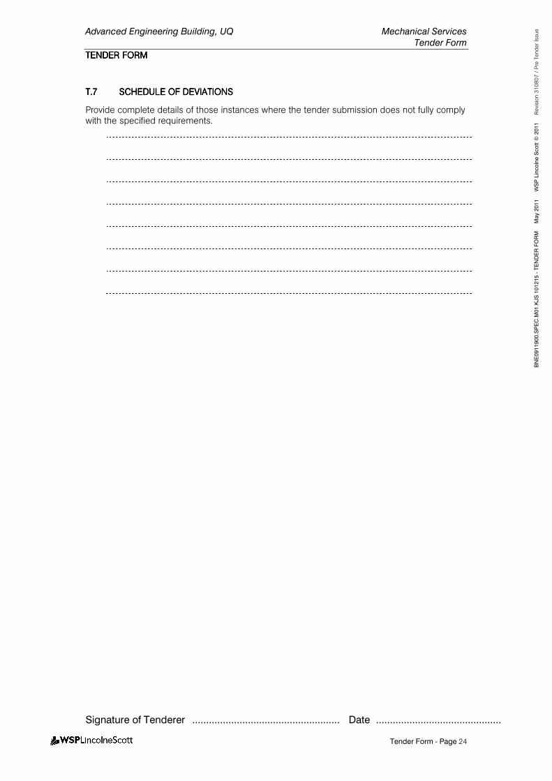
Advanced Engineering Building, UQ Mechanical Services
Tender Form
TENDER FORMTENDER FORMTENDER FORMTENDER FORM
Signature of Tenderer ..................................................... Date .............................................
Tender Form - Page 24
BNE0911900.SPEC.M
01.KJS 101215 - TENDER FORM M
ay 2011 W
SP Lincolne Scott ©
2011 Revision 310807 / Pre Tender Issue
T.7T.7T.7T.7 SCHEDULE OF DEVIATIOSCHEDULE OF DEVIATIOSCHEDULE OF DEVIATIOSCHEDULE OF DEVIATIONSNSNSNS
Provide complete details of those instances where the tender submission does not fully comply with the specified requirements.