Measurements and Analysis of Secondary User Device Effects on Digital Television Receivers
13
Hindawi Publishing Corporation EURASIP Journal on Advances in Signal Processing Volume 2009, Article ID 510867, 13 pages doi:10.1155/2009/510867 Research Article Measurements and Analysis of Secondary User Device Effects on Digital Television Receivers Timothy R. Newman, 1 Daniel DePardo, 2 Alexander M. Wyglinski, 3 Joseph B. Evans, 2 Rakesh Rajbanshi, 2 Victor R. Petty, 2 Dinesh Datla, 1 Frederick Weidling, 2 Paul J. Kolodzy, 4 Michael J. Marcus, 5 Gary J. Minden, 2 and James A. Roberts 2 1 Electrical and Computer Engineering, Virginia Tech, Blacksburg, VA 24061, USA 2 ITTC, University of Kansas, Lawrence, KS 66044, USA 3 Worcester Polytechnic Institute, Worcester, MA 01609, USA 4 Kolodzy Consulting, P.O. Box 1443, Centreville, VA 20120, USA 5 Marcus Spectrum Solutions LLC, 8026 Cypress Grove Lane, Cabin John, MD 20818, USA Correspondence should be addressed to Joseph B. Evans, [email protected] Received 7 July 2009; Accepted 12 August 2009 Recommended by K. Subbalakshmi This article presents results from a study of the potential effects of secondary users operating in unoccupied television spectrum. Television spectrum is known within the wireless communications community as being underutilized, making it a prime candidate for dynamic spectrum access. The proposed use of this open spectrum has prompted questions concerning the quantity of available channel space that could be used without negative impact on consumers who view digital television broadcasts and the viability of secondary use of open channels immediately adjacent to a digital television broadcast channel. In this work, we investigate secondary device operation in the channels directly adjacent to a desired television channel, and the effects upon a selection of consumer digital television (DTV) receivers. Our observations strongly suggest that secondary users could operate “White Space Devices” (WSDs) in unoccupied channel bandwidth directly adjacent to a desired digital television (DTV) channel, with no observable adverse impact upon the reception of the desired channel content. Copyright © 2009 Timothy R. Newman et al. This is an open access article distributed under the Creative Commons Attribution License, which permits unrestricted use, distribution, and reproduction in any medium, provided the original work is properly cited. 1. Introduction The growing demand for wireless services and applica- tions shows no sign of slowing down. However, the cur- rent command-and-control regulatory structure for licensing spectrum has been unable to cope with the dramatic growth of the wireless industry. This has given rise to an “artificial scarcity” with regard to spectrum, resulting in prices for spectrum licenses becoming so cost prohibitive that many small to medium size businesses are prevented from entering the wireless market. Numerous studies have begun to examine how licensed spectrum is actually used, with the goal of not only rethinking the spectrum licensing regime, but also opening certain underutilized “prime” spectrum to unlicensed and licensed secondary usage. It has been shown that several spectral bands, including the television spectrum, are underutilized [1]. There have been regulatory and legislative efforts to allow new wireless devices access to television (TV) band white space on a per market basis. This approach, referred to as dynamic spectrum access (DSA), allows unlicensed devices to transmit in parts of the spectrum unoccupied by the licensed signals. In June 28, 2006, the Senate Commerce Committee adopted “The Advanced Telecommunications and Opportunity Reform Act of 2006” (S. 2686), which built upon the May 2004 Federal Communications Commission (FCC) Notice of Proposed Rulemaking (NPRM) [2] allowing unlicensed devices to utilize unused spectrum in the TV band. This legislation required the FCC to continue with rule making procedures governing the opening of TV channels
-
Upload
independent -
Category
Documents
-
view
2 -
download
0
Transcript of Measurements and Analysis of Secondary User Device Effects on Digital Television Receivers
Hindawi Publishing CorporationEURASIP Journal on Advances in Signal ProcessingVolume 2009, Article ID 510867, 13 pagesdoi:10.1155/2009/510867
Research Article
Measurements and Analysis of Secondary User Device Effects onDigital Television Receivers
Timothy R. Newman,1 Daniel DePardo,2 Alexander M. Wyglinski,3 Joseph B. Evans,2
Rakesh Rajbanshi,2 Victor R. Petty,2 Dinesh Datla,1 Frederick Weidling,2 Paul J. Kolodzy,4
Michael J. Marcus,5 Gary J. Minden,2 and James A. Roberts2
1 Electrical and Computer Engineering, Virginia Tech, Blacksburg, VA 24061, USA2 ITTC, University of Kansas, Lawrence, KS 66044, USA3 Worcester Polytechnic Institute, Worcester, MA 01609, USA4 Kolodzy Consulting, P.O. Box 1443, Centreville, VA 20120, USA5 Marcus Spectrum Solutions LLC, 8026 Cypress Grove Lane, Cabin John, MD 20818, USA
Correspondence should be addressed to Joseph B. Evans, [email protected]
Received 7 July 2009; Accepted 12 August 2009
Recommended by K. Subbalakshmi
This article presents results from a study of the potential effects of secondary users operating in unoccupied television spectrum.Television spectrum is known within the wireless communications community as being underutilized, making it a prime candidatefor dynamic spectrum access. The proposed use of this open spectrum has prompted questions concerning the quantity of availablechannel space that could be used without negative impact on consumers who view digital television broadcasts and the viabilityof secondary use of open channels immediately adjacent to a digital television broadcast channel. In this work, we investigatesecondary device operation in the channels directly adjacent to a desired television channel, and the effects upon a selectionof consumer digital television (DTV) receivers. Our observations strongly suggest that secondary users could operate “WhiteSpace Devices” (WSDs) in unoccupied channel bandwidth directly adjacent to a desired digital television (DTV) channel, with noobservable adverse impact upon the reception of the desired channel content.
Copyright © 2009 Timothy R. Newman et al. This is an open access article distributed under the Creative Commons AttributionLicense, which permits unrestricted use, distribution, and reproduction in any medium, provided the original work is properlycited.
1. Introduction
The growing demand for wireless services and applica-tions shows no sign of slowing down. However, the cur-rent command-and-control regulatory structure for licensingspectrum has been unable to cope with the dramatic growthof the wireless industry. This has given rise to an “artificialscarcity” with regard to spectrum, resulting in prices forspectrum licenses becoming so cost prohibitive that manysmall to medium size businesses are prevented from enteringthe wireless market. Numerous studies have begun toexamine how licensed spectrum is actually used, with thegoal of not only rethinking the spectrum licensing regime,but also opening certain underutilized “prime” spectrumto unlicensed and licensed secondary usage. It has been
shown that several spectral bands, including the televisionspectrum, are underutilized [1].
There have been regulatory and legislative efforts to allownew wireless devices access to television (TV) band whitespace on a per market basis. This approach, referred to asdynamic spectrum access (DSA), allows unlicensed devicesto transmit in parts of the spectrum unoccupied by thelicensed signals. In June 28, 2006, the Senate CommerceCommittee adopted “The Advanced Telecommunicationsand Opportunity Reform Act of 2006” (S. 2686), which builtupon the May 2004 Federal Communications Commission(FCC) Notice of Proposed Rulemaking (NPRM) [2] allowingunlicensed devices to utilize unused spectrum in the TVband. This legislation required the FCC to continue with rulemaking procedures governing the opening of TV channels
2 EURASIP Journal on Advances in Signal Processing
DTV broadcast
“Sideband splatter”
6 MHz
n− 1 Channel n n + 1
Figure 1: Adjacent Channel Interference.
Table 1: Adjacent channel measurements.
Channel Receiver 1 Receiver 2 Receiver 3
Offset (set top) (LCD DTV) (set top)
−1 −34 dBm −30 dBm −29 dBm
−1.5 −24 dBm −18 dBm −26 dBm
−2 −15 dBm −16 dBm −22 dBm
−6 N/A −15 dBm N/A
−8 N/A −14 dBm N/A
Table 2: Co-channel desired/undesired ratio measurements.
ATSC Receiver 1 Receiver 2 Receiver 3
(set top) (LCD) (set top)
Threshold20 15 17
(−102 dBm) (−96 dBm) (−97 dBm)
−68 dBm13 11 12
(−81 dBm) (−79 dBm) (−80 dBm)
−61 dBm12 11 11
(−73 dBm) (−72 dBm) (−72 dBm)
2–51 (54 MHz–698 MHz) for use by wireless broadband ser-vices and other DSA-enabled devices. The FCC proposal alsoincludes the reallocation of TV channels 52–69 (698 MHzto 806 MHz) to public safety communications as well asfor auction. The NPRM specifies that any devices certifiedto use TV spectrum white spaces should employ eitheragile or cognitive radio technology in a dynamic spectrumaccess configuration, such that these devices would notinterfere with primary rights holders, for example, televisionbroadcasters. Further legislative direction was provided inthe Balanced Budget Act of 1997 (H.R.2015), Title III - Com-munications and Spectrum Allocation Provisions [15]. InNovember 3, 2008, FCC commissioners voted unanimouslyto officially approve the use of these bands by white spacedevices (WSDs).
In a DSA approach, the “secondary” users must notcause any “harmful interference” to the primary users aswell as the other secondary users sharing the same portionof the spectrum. The definition of “harmful” is outsidethe scope of this article, but is typically associated withthe affected applications and their hardware characteristics.Since primary users hold exclusive rights to the spectrum,it is not their responsibility to mitigate any additionalinterference caused by secondary device operation. Thesedevices will need to periodically sense spectrum in orderto detect primary and secondary user transmissions, andhave the capability of adapting to the varying spectrumconditions for mutual interference avoidance [3]. Groupsrepresenting traditional incumbent users, such as televisionbroadcasters, feel that opening up the white space to DSA-enabled secondary users will cause unneeded interferenceand disrupt communications for television broadcasters andpublic safety communication systems. Recently the NationalAssociation of Broadcasters and Association for MaximumService Television went so far as to sue the FCC over itsdecision to authorize the operation of WSDs in the unusedtelevision channels. The availability of the underutilizedtelevision spectrum is not disputed. However, there are tworemaining technical issues that the regulatory and businesscommunities must address. The regulatory communitymust determine the technical rules that devices must usewhen accessing this spectrum in order to prevent harmfulinterference to the primary devices (i.e. DTV receivers).Additionally, the device manufacturing community mustdetermine if cost effective devices can be created that meetthe technical rules for operation.
The technical rules that are of particular interest tothe FCC involve device in-band and out-of-band emissions(OOBEs). The device manufacturers must comply withthese rules through the selection of appropriate modulation,amplifier, and filter characteristics in both the transmitterand receiver chains of WSDs. The expected RF environmentalso has a direct impact on the receiver characteristics andthus must be well understood.
In this effort, we present a feasibility study of devicesperforming DSA in underutilized television bands when tele-vision signals are present. The study is divided into two parts.In the first part, the impact of transmissions on the videoquality of digital television signals is determined for severalscenarios. This will provide the basis in determining theemission levels that can be tolerated by DTV receivers. In thesecond part, we focus on adjacent channel interference, andmeasure the affects of a single adjacent channel secondarytransmission on a selection of DTV receivers.
2. Dynamic Spectrum Access Background
Substantial research efforts have been aimed at the utilizationof vacant portions of FCC allocated television spectrumusing DSA techniques. IEEE 802.22 is a wireless standard thatfocuses on reuse of the vacant TV spectrum without causingany harmful interference to the primary users [4]. Some ofthe important issues that have been addressed include the

EURASIP Journal on Advances in Signal Processing 3
3 dBcoupler
OFDM modulatorQPSK/16 QAM/64 QAM
6 MHz BW2 K/8 K carriers
PC
Spectrum analyzer
75–50 Ohmbroadband
matching network
MPEG-2 analysissoftware
ATSC receiver under test
Video monitor
MPEG-2 streamIEEE-1394 (FireWire/i.Link)
Figure 2: KU White Space Device Emulator and Testbed (KUWSDET).
feature detection of TV signals [5], collaborative sensing forimproved detection capabilities [6], detection of the presenceof receivers in the vicinity of a secondary device [7], andeffective methods for unoccupied TV spectrum access [8].Our previous work explored the feasibility of secondary usercommunication from the side of the secondary users [9].
Although it has been demonstrated that DSA methodsare effective in avoiding harmful interference to televisionreceivers, there is still debate regarding whether devices canoperate in underutilized spectrum without simultaneouslycausing interference. There are many who claim that WSDswill cause harmful interference to primary users [10], whileothers argue that DSA can be done in a transparent manner[11] and can be safely implemented using the latest radiotechnology communications techniques [12]. Proponents ofthe DSA approach have investigated the use of open televi-sion spectrum for several reasons. First, there is a substantialamount of unused spectrum available for DSA. Furthermore,the propagation properties in these frequency ranges, such aslow propagation attenuation, are beneficial for long range,mobile, and non-line-of-sight (NLOS) communications [8].Finally, the fixed channel allocations result in deterministicusage patterns that are favorable for accurate spectrumsensing [13].
There are several challenges that must be addressedin order to enable white space device operation in openTV spectrum. The presence of strong TV signals near thesecondary user can lead to the generation of spurious signals,intermodulation products, and saturation effects [14]. Theseproblems might occur at the transmission source, at theDTV receiver, or at the secondary-use receiver. In addition,the secondary device could potentially cause interferenceto primary users if the spectrum sensing mechanism ofthe device fails to identify the presence of primary users,
or if there is significant out-of-band power leakage fromsecondary transmissions into the primary user channels.
In previous studies, we presented related results concern-ing on the impact of TV transmissions on secondary usersat varying distances from a transmission tower, and we alsoprovided results that indicated typical current generationconsumer DTV receivers were capable of error-free receptionof adjacent channel DTV broadcasts. These results, whilenot comprehensive, provide incentive to further explore theinterference relationships between secondary users and DTVreceivers.
In this study, we provide a brief review of our secondaryuser interference feasibility analysis and expand upon theresults by focusing on adjacent channel DTV interference.An undesired interfering signal, transmitted in a channeladjacent to a desired signal channel, can introduce third-order intermodulation (IM3) products generated by trans-mitter nonlinearities into the desired channel bandwidth,resulting in interference to the desired channel content. Inthe case of a DTV broadcast, the noise-like characteristicsof an 8VSB-modulated digital television signal create IM3
products with the same noise-like properties. These productsare often referred to as “sideband splatter” or “shoulders”and result in what is essentially co-channel interferenceto other signals occupying directly adjacent channels, asillustrated in Figure 1. The threshold for harmful interference(interference levels that impact the operation of the DTVreceivers to such an extent that the signal content is severelydegraded) varies considerably, and is dependent upon thetechnical characteristics of the TV receiver and the secondaryuser device. Therefore, standardized procedures for testingthe interference-limiting capabilities of devices should bedevised for various spectrum environments and scenarios.Ideally, these techniques and procedures would be based
4 EURASIP Journal on Advances in Signal Processing
n
DTV signal White Space Device
Adjacent Channelinterference
2nd adjacent channel interference
n + 1
Desensitizationinterference
Co-channelinterference
n
n
n
n n + x
n
In termodulation interference
n + 2
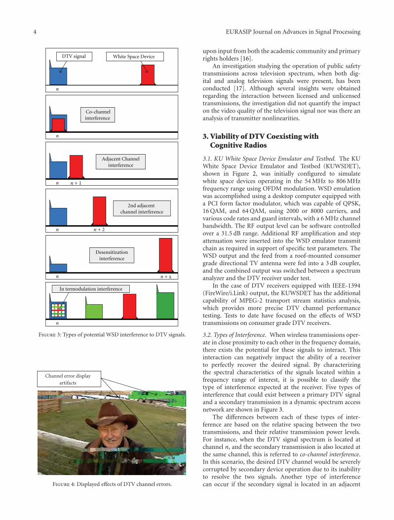
Figure 3: Types of potential WSD interference to DTV signals.
Channel error displayartifacts
Figure 4: Displayed effects of DTV channel errors.
upon input from both the academic community and primaryrights holders [16].
An investigation studying the operation of public safetytransmissions across television spectrum, when both dig-ital and analog television signals were present, has beenconducted [17]. Although several insights were obtainedregarding the interaction between licensed and unlicensedtransmissions, the investigation did not quantify the impacton the video quality of the television signal nor was there ananalysis of transmitter nonlinearities.
3. Viability of DTV Coexisting withCognitive Radios
3.1. KU White Space Device Emulator and Testbed. The KUWhite Space Device Emulator and Testbed (KUWSDET),shown in Figure 2, was initially configured to simulatewhite space devices operating in the 54 MHz to 806 MHzfrequency range using OFDM modulation. WSD emulationwas accomplished using a desktop computer equipped witha PCI form factor modulator, which was capable of QPSK,16 QAM, and 64 QAM, using 2000 or 8000 carriers, andvarious code rates and guard intervals, with a 6 MHz channelbandwidth. The RF output level can be software controlledover a 31.5 dB range. Additional RF amplification and stepattenuation were inserted into the WSD emulator transmitchain as required in support of specific test parameters. TheWSD output and the feed from a roof-mounted consumergrade directional TV antenna were fed into a 3 dB coupler,and the combined output was switched between a spectrumanalyzer and the DTV receiver under test.
In the case of DTV receivers equipped with IEEE-1394(FireWire/i.Link) output, the KUWSDET has the additionalcapability of MPEG-2 transport stream statistics analysis,which provides more precise DTV channel performancetesting. Tests to date have focused on the effects of WSDtransmissions on consumer grade DTV receivers.
3.2. Types of Interference. When wireless transmissions oper-ate in close proximity to each other in the frequency domain,there exists the potential for these signals to interact. Thisinteraction can negatively impact the ability of a receiverto perfectly recover the desired signal. By characterizingthe spectral characteristics of the signals located within afrequency range of interest, it is possible to classify thetype of interference expected at the receiver. Five types ofinterference that could exist between a primary DTV signaland a secondary transmission in a dynamic spectrum accessnetwork are shown in Figure 3.
The differences between each of these types of inter-ference are based on the relative spacing between the twotransmissions, and their relative transmission power levels.For instance, when the DTV signal spectrum is located atchannel n, and the secondary transmission is also located atthe same channel, this is referred to co-channel interference.In this scenario, the desired DTV channel would be severelycorrupted by secondary device operation due to its inabilityto resolve the two signals. Another type of interferencecan occur if the secondary signal is located in an adjacent

EURASIP Journal on Advances in Signal Processing 5
KTWU
KTKA
KCTV
KSMO
356 meters1000 kWCH 47/668−674 MHzKSMO-DT
319 meters1000 kWCH 24/530−536 MHzKCTV-DT
281 meters960 kWCH 23/524−530 MHz
CH 48/674−680 MHz
Channel/frequencyAntenna height above
average terrain Effective
radiated power
451 meters55 kW KTKA-DT
KTWU-DT
Figure 5: Adjacent channel DTV broadcast reception in Lawrence, KS.
KTWU CH 23 (524–530 MHz)−40 dBm/5.38 MHz
KCTV CH 24(530–536 MHz)
−54 dBm/5.38 MHz
Figure 6: KTWU and KCTV Adjacent channel broadcasts.
channel, such as channel n + 1. In this case, the DTVsignal may experience adjacent channel interference fromthe secondary signal since the transmitted spectrum of thelatter may not be totally confined to its allocated band. Notethat as the amplitude level of the secondary transmission isincreased, so does the amount of out-of-band energy thatcould interfere with the DTV signal.
If the secondary signal is located further away from theDTV signal, such as the second adjacent channel, the impactof adjacent channel interference is substantially reduced,relative to secondary signals operating closer to the DTVsignal, given the same power levels. However, if the powerlevel of the secondary signal is increased, it is possible thatout-of-band signal energy may interfere with the DTV signal.
In fact, when the secondary signal is substantially strongerthan the DTV signal and is located within the geographicalvicinity of a desired frequency, desensitization interferencecan potentially occur. In this scenario, the secondary signaloverloads the receiver, inhibiting its ability to fully recoverthe desired DTV signal.
Receiver intermodulation interference occurs when twoor more signals are present within the same frequencyrange, and are mixed in a receiver RF amplifier or mixerstage during nonlinear operation, producing a signal thatinterferes with a desired signal. Consequently, these receiver-generated signals could prevent the display of the content ofa desired DTV channel.
The visible effects of DTV receiver interference can rangefrom mild error artifacts to complete loss of channel content.Figure 4 is an example of moderate display errors.
3.3. Preliminary DTV Adjacent Broadcast Channel Observa-tions. As previously discussed, television broadcasters haveexpressed the concern that secondary use of open spectrumimmediately adjacent to an operational digital televisionchannel could create interference for viewers of the DTVchannel content. It is interesting to note that despite the bestefforts of the FCC to allocate adjacent channel frequencies totransmitters with sufficient geographic separation, it is notparticularly unusual for viewers to be located in areas wheretelevision markets overlap, allowing adjacent broadcast DTVchannel situations to occur.
The Information and Telecommunications TechnologyCenter (ITTC) at the University of Kansas is located approxi-mately halfway between Kansas City and Topeka, with access
6 EURASIP Journal on Advances in Signal Processing
3 dBcombiner
OFDM modulator6 MHz BW
PC1
PC2
A1 A2
R1 R2
8VSB modulator6 MHz BW
Spectrum analyzer
75–50 Ohmbroadband
matching network
MPEG-2 analysissoftware
ATSC receiver under test
Video monitor
MPEG-2 transport stream
IEEE-1394 (FireWire/i.Link)
Undesired signal
Desired signal
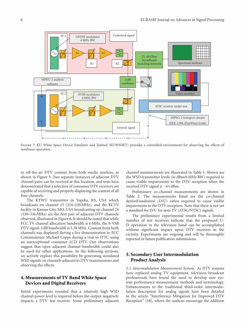
Figure 7: KU White Space Device Emulator and Testbed (KUWSDET) provides a controlled environment for observing the effects ofnonlinear operation.
to off-the-air DTV content from both media markets, asshown in Figure 5. Two separate instances of adjacent DTVchannel pairs can be received at this location, and tests havedemonstrated that a selection of consumer DTV receivers arecapable of receiving and properly displaying the content of allfour channels.
The KTWU transmitter in Topeka, KS, USA whichbroadcasts on channel 23 (524–530 MHz), and the KCTVfacility in Kansas City, MO, USA broadcasting on channel 24(530–536 MHz) are the first pair of adjacent DTV channelsobserved, illustrated in Figure 6. It should be noted that whileFCC TV channel allocation bandwidth is 6 MHz, the 8-VSBDTV signal-3 dB bandwidth is 5.38 MHz. Content from bothchannels was displayed during a live demonstration to FCCCommissioner Michael Copps during a visit to ITTC usingan unexceptional consumer LCD DTV. Our observationssuggest that open adjacent channel bandwidth could alsobe used for other applications. In the following sections,we actively explore this possibility by generating simulatedWSD signals on channels adjacent to DTV transmissions andobserving the effects.
4. Measurements of TV Band White SpaceDevices and Digital Receivers
Initial experiments revealed that a relatively high WSDchannel power level is required before the output negativelyimpacts a DTV test receiver. Some preliminary adjacent
channel measurements are illustrated in Table 1. Shown arethe WSD transmitter levels (in dBm/6 MHz BW) required tocause visible impairments to the DTV reception when thereceived DTV signal is −61 dBm.
Preliminary co-channel measurements are shown inTable 2. The measurements listed are the co-channeldesired/undesired (D/U) ratios required to cause visibleimpairments to the DTV reception. Note that there is not yeta standard for D/U for non-TV (ATSC/NTSC) signals.
The preliminary experimental results from a limitednumber of test receivers indicate that the proposed U-D operation in the television band can be accomplishedwithout significant impact upon DTV receivers in thevicinity. Experiments are ongoing and will be thoroughlyreported in future publication submissions.
5. Secondary User IntermodulationProduct Analysis
5.1. Intermodulation Measurement System. As DTV systemshave replaced analog TV equipment, television broadcastprofessionals have found the need to develop new sys-tem performance measurement methods and terminology.Enhancements to the traditional third-order intermodu-lation description for analog signals have been detailedin the article “Interference Mitigation for Improved DTVReception” [18], where the authors encourage the addition
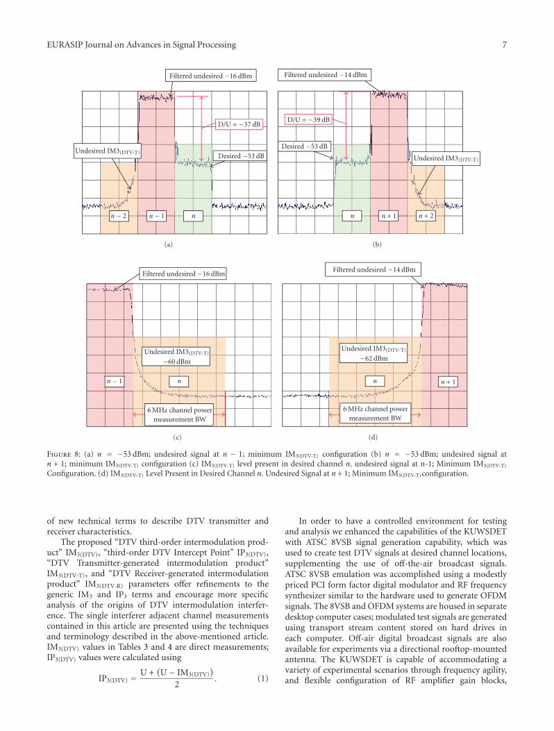
EURASIP Journal on Advances in Signal Processing 7
Filtered undesired −16 dBm
D/U = −37 dB
Undesired IM3(DTV-T)Desired −53 dB
n− 2 n− 1 n
(a)
Filtered undesired −14 dBm
D/U = −39 dB
Undesired IM3(DTV-T)
Desired −53 dB
n + 2n + 1n
(b)
Filtered undesired −16 dBm
Undesired IM3(DTV-T)
−60 dBm
n− 1 n
6 MHz channel powermeasurement BW
(c)
Filtered undesired −14 dBm
Undesired IM3(DTV-T)
−62 dBm
n + 1n
6 MHz channel powermeasurement BW
(d)
Figure 8: (a) n = −53 dBm; undesired signal at n − 1; minimum IM3(DTV-T) configuration (b) n = −53 dBm; undesired signal atn + 1; minimum IM3(DTV-T) configuration (c) IM3(DTV-T) level present in desired channel n. undesired signal at n-1; Minimum IM3(DTV-T)
Configuration. (d) IM3(DTV-T) Level Present in Desired Channel n. Undesired Signal at n + 1; Minimum IM3(DTV-T)configuration.
of new technical terms to describe DTV transmitter andreceiver characteristics.
The proposed “DTV third-order intermodulation prod-uct” IM3(DTV), “third-order DTV Intercept Point” IP3(DTV),“DTV Transmitter-generated intermodulation product”IM3(DTV-T), and “DTV Receiver-generated intermodulationproduct” IM3(DTV-R) parameters offer refinements to thegeneric IM3 and IP3 terms and encourage more specificanalysis of the origins of DTV intermodulation interfer-ence. The single interferer adjacent channel measurementscontained in this article are presented using the techniquesand terminology described in the above-mentioned article.IM3(DTV) values in Tables 3 and 4 are direct measurements;IP3(DTV) values were calculated using
IP3(DTV) =U +
(U− IM3(DTV)
)
2. (1)
In order to have a controlled environment for testingand analysis we enhanced the capabilities of the KUWSDETwith ATSC 8VSB signal generation capability, which wasused to create test DTV signals at desired channel locations,supplementing the use of off-the-air broadcast signals.ATSC 8VSB emulation was accomplished using a modestlypriced PCI form factor digital modulator and RF frequencysynthesizer similar to the hardware used to generate OFDMsignals. The 8VSB and OFDM systems are housed in separatedesktop computer cases; modulated test signals are generatedusing transport stream content stored on hard drives ineach computer. Off-air digital broadcast signals are alsoavailable for experiments via a directional rooftop-mountedantenna. The KUWSDET is capable of accommodating avariety of experimental scenarios through frequency agility,and flexible configuration of RF amplifier gain blocks,
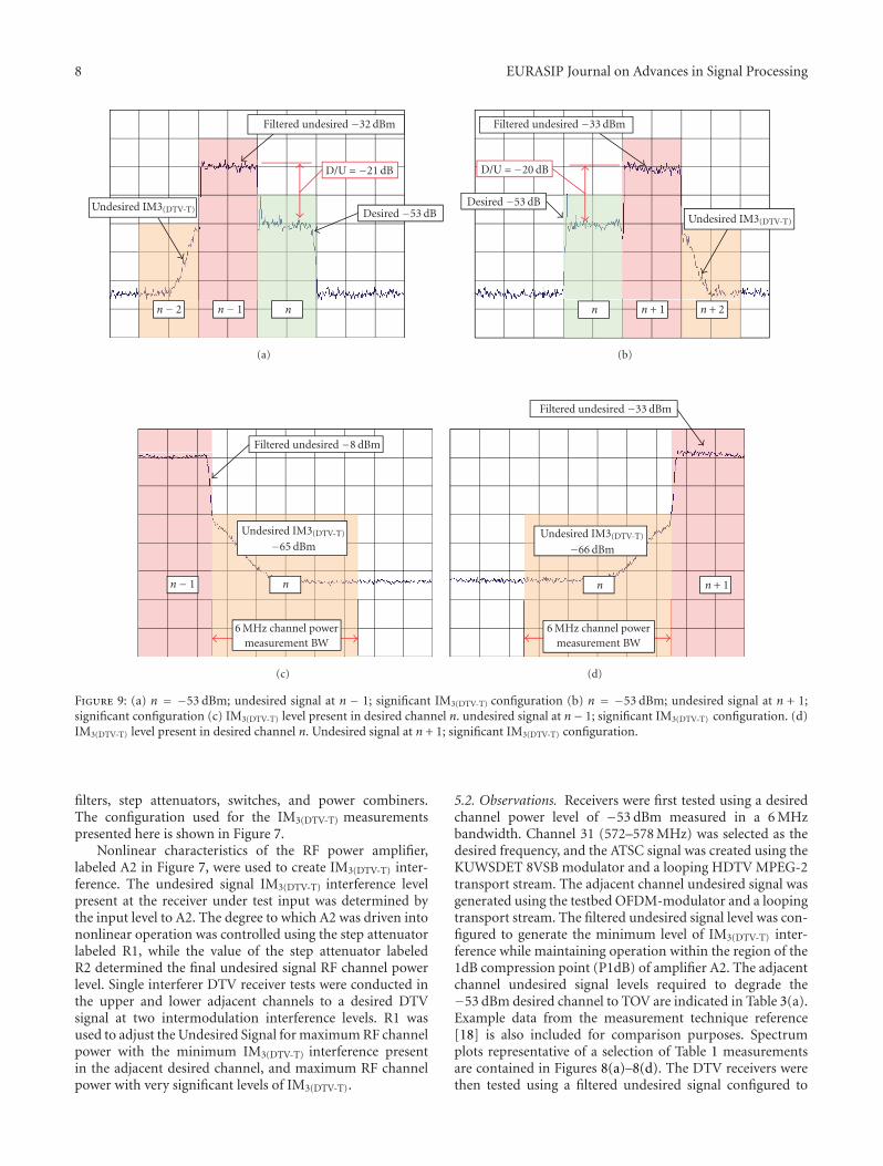
8 EURASIP Journal on Advances in Signal Processing
Filtered undesired −32 dBm
D/U = −21 dB
Undesired IM3(DTV-T) Desired −53 dB
n− 2 n− 1 n
(a)
Filtered undesired −33 dBm
D/U = −20 dB
Undesired IM3(DTV-T)
Desired −53 dB
n + 2n + 1n
(b)
Filtered undesired −8 dBm
Undesired IM3(DTV-T)
−65 dBm
n− 1 n
6 MHz channel powermeasurement BW
(c)
Filtered undesired −33 dBm
Undesired IM3(DTV-T)
−66 dBm
n + 1n
6 MHz channel powermeasurement BW
(d)
Figure 9: (a) n = −53 dBm; undesired signal at n − 1; significant IM3(DTV-T) configuration (b) n = −53 dBm; undesired signal at n + 1;significant configuration (c) IM3(DTV-T) level present in desired channel n. undesired signal at n− 1; significant IM3(DTV-T) configuration. (d)IM3(DTV-T) level present in desired channel n. Undesired signal at n + 1; significant IM3(DTV-T) configuration.
filters, step attenuators, switches, and power combiners.The configuration used for the IM3(DTV-T) measurementspresented here is shown in Figure 7.
Nonlinear characteristics of the RF power amplifier,labeled A2 in Figure 7, were used to create IM3(DTV-T) inter-ference. The undesired signal IM3(DTV-T) interference levelpresent at the receiver under test input was determined bythe input level to A2. The degree to which A2 was driven intononlinear operation was controlled using the step attenuatorlabeled R1, while the value of the step attenuator labeledR2 determined the final undesired signal RF channel powerlevel. Single interferer DTV receiver tests were conducted inthe upper and lower adjacent channels to a desired DTVsignal at two intermodulation interference levels. R1 wasused to adjust the Undesired Signal for maximum RF channelpower with the minimum IM3(DTV-T) interference presentin the adjacent desired channel, and maximum RF channelpower with very significant levels of IM3(DTV-T).
5.2. Observations. Receivers were first tested using a desiredchannel power level of −53 dBm measured in a 6 MHzbandwidth. Channel 31 (572–578 MHz) was selected as thedesired frequency, and the ATSC signal was created using theKUWSDET 8VSB modulator and a looping HDTV MPEG-2transport stream. The adjacent channel undesired signal wasgenerated using the testbed OFDM-modulator and a loopingtransport stream. The filtered undesired signal level was con-figured to generate the minimum level of IM3(DTV-T) inter-ference while maintaining operation within the region of the1dB compression point (P1dB) of amplifier A2. The adjacentchannel undesired signal levels required to degrade the−53 dBm desired channel to TOV are indicated in Table 3(a).Example data from the measurement technique reference[18] is also included for comparison purposes. Spectrumplots representative of a selection of Table 1 measurementsare contained in Figures 8(a)–8(d). The DTV receivers werethen tested using a filtered undesired signal configured to
EURASIP Journal on Advances in Signal Processing 9
Filtered undesired −1 dBm
D/U = −27 dB
Undesired IM3(DTV-T)
Desired −28 dB
n− 2 n− 1 n
(a)
Filtered undesired −4 dBm
D/U = −24 dB
Undesired IM3(DTV-T)
Desired −28 dB
n + 2n + 1n
(b)
Filtered undesired −1 dBm
Undesired IM3(DTV-T)
−46 dBm
n− 1 n
6 MHz channel powermeasurement BW
(c)
Filtered undesired −4 dBm
Undesired IM3(DTV-T)
−53 dBm
n + 1n
6 MHz channel powermeasurement BW
(d)
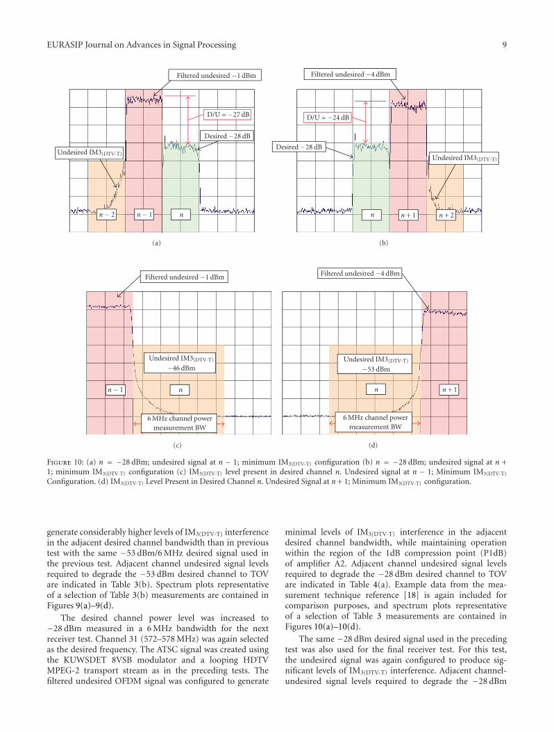
Figure 10: (a) n = −28 dBm; undesired signal at n − 1; minimum IM3(DTV-T) configuration (b) n = −28 dBm; undesired signal at n +1; minimum IM3(DTV-T) configuration (c) IM3(DTV-T) level present in desired channel n. Undesired signal at n − 1; Minimum IM3(DTV-T)
Configuration. (d) IM3(DTV-T) Level Present in Desired Channel n. Undesired Signal at n + 1; Minimum IM3(DTV-T) configuration.
generate considerably higher levels of IM3(DTV-T) interferencein the adjacent desired channel bandwidth than in previoustest with the same −53 dBm/6 MHz desired signal used inthe previous test. Adjacent channel undesired signal levelsrequired to degrade the −53 dBm desired channel to TOVare indicated in Table 3(b). Spectrum plots representativeof a selection of Table 3(b) measurements are contained inFigures 9(a)–9(d).
The desired channel power level was increased to−28 dBm measured in a 6 MHz bandwidth for the nextreceiver test. Channel 31 (572–578 MHz) was again selectedas the desired frequency. The ATSC signal was created usingthe KUWSDET 8VSB modulator and a looping HDTVMPEG-2 transport stream as in the preceding tests. Thefiltered undesired OFDM signal was configured to generate
minimal levels of IM3(DTV-T) interference in the adjacentdesired channel bandwidth, while maintaining operationwithin the region of the 1dB compression point (P1dB)of amplifier A2. Adjacent channel undesired signal levelsrequired to degrade the −28 dBm desired channel to TOVare indicated in Table 4(a). Example data from the mea-surement technique reference [18] is again included forcomparison purposes, and spectrum plots representativeof a selection of Table 3 measurements are contained inFigures 10(a)–10(d).
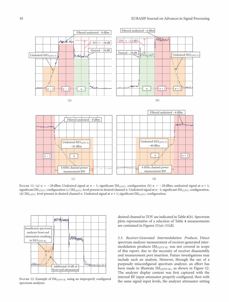
The same −28 dBm desired signal used in the precedingtest was also used for the final receiver test. For this test,the undesired signal was again configured to produce sig-nificant levels of IM3(DTV-T) interference. Adjacent channel-undesired signal levels required to degrade the −28 dBm
10 EURASIP Journal on Advances in Signal Processing
Filtered undesired −8 dBm
D/U = −20 dB
Undesired IM3(DTV-T)
Desired −28 dB
n− 2 n− 1 n
(a)
Filtered undesired −6 dBm
D/U = −22 dB
Undesired IM3(DTV-T)Desired −28 dB
n + 2n + 1n
(b)
Filtered undesired −8 dBm
Undesired IM3(DTV-T)
−41 dBm
n− 1 n
6 MHz channel powermeasurement BW
(c)
Filtered undesired −6 dBm
Undesired IM3(DTV-T)
−40 dBm
n + 1n
6 MHz channel powermeasurement BW
(d)
Figure 11: (a) n = −28 dBm; Undesired signal at n − 1; significant IM3(DTV) configuration (b) n = −28 dBm; undesired signal at n + 1;significant IM3(DTV) configuration (c) IM3(DTV) level present in desired channel n. Undesired signal at n−1; significant IM3(DTV) configuration.(d) IM3(DTV) level present in desired channel n. Undesired signal at n + 1; significant IM3(DTV) configuration.
Insufficient spectrumanalyzer front end
attenuation resultingin IM3(DTV-R)
Additional 10 dB offront end attenuation
Figure 12: Example of IM3(DTV-R) using an improperly configuredspectrum analyzer.
desired channel to TOV are indicated in Table 4(b). Spectrumplots representative of a selection of Table 4 measurementsare contained in Figures 11(a)–11(d).
5.3. Receiver-Generated Intermodulation Products. Directspectrum analyzer measurement of receiver-generated inter-modulation products IM3(DTV-R) was not covered in scopeof this report, due to the necessity of receiver disassemblyand measurement port insertion. Future investigations mayinclude such an analysis. However, through the use of apurposely misconfigured spectrum analyzer, an effort hasbeen made to illustrate IM3(DTV-R), as shown in Figure 12.The analyzer display content was first captured with theinternal RF input attenuator properly configured, then withthe same signal input levels, the analyzer attenuator setting
EURASIP Journal on Advances in Signal Processing 11
Table 3: (a) Desired channel power = −53 dBm/6 MHz; undesired signal with minimum IM3(DTV); (b) desired channel power =−53 dBm/6 MHz; undesired signal with significant IM3(DTV).
(a)
−20 −33−20−33ATSC A/74
−0.5−57.8−19.6
n + 1Rhodes-sgrignoliIM3(DT V) example(Figure 4; “Interference Mitigation for Improved DTV Reception”)
−34
−39
−34
5
10
4.5
−67
−62
−66
IM3(DT V)
CH 31IM3(DT V)
CH 31
−36
−37
−29
D/U(dB)
−61
−60
−67
IM3(DT V)
n−1 filtered undesired(dBm/6 MHz)
n + 1 filtered undesired(dBm/6 MHz)
−19
−14
−19
n + 1CH 32
5
6
−2.5
IP3DT V
−17
−16
−24
n−1CH 30
Receiver
3 (Low cost set-top)
2 (32” LCD DTV)
1 (1999 model year set-top)
Levels required to degradedesired channel to TOV
IP3(DTV)
IP3(DT V)
D/U(dB)
(b)
Levels required to degradedesired channel to TOV
IM3(DT V)
CH 31IM3(DT V)
CH 31D/U(dB)
n−1 filtered undesired(dBm/6 MHz)
n + 1 filtered undesired(dBm/6 MHz)
n + 1CH 32
IP3(DT V)n−1
CH 30 IP3(DT V)
D/U(dB)
ATSC A/74
Receiver
3 (Low cost set-top)
2 (32” LCD DTV)
1 (1999 model year set-top)
−20
−33
−32
−38
−66
−65
−70
−16.5
−16.5
−16
−17
−15.5
−22
−33
−33
−34
−33
−33
−66
−68
−67−20
−20
−20
−20
−19
−21
−15
was manually reduced 10 dB, resulting in the overload ofone or more analyzer front end components. The goalof this simple demonstration is to show that not onlycan transmiter nonlinearities causes interference but animproperly configured receiver can also result in significantinterference.
6. Conclusion
In this article, we have presented a feasibility study ofsecondary transmissions into the unused TV spectrum andhave presented the observed effects of a single interferingsecondary transmission on a selection of digital televisionreceivers. The results indicate that carefully implementedsecondary use of open channel bandwidth immediatelyadjacent to a licensed digital television transmission is a
viable practice, given the expectation that WSD designswill place an emphasis on the protection of televisionbroadcasts.
Device design challenges specific to white space oper-ation include RF power amplifier linearity, signal filteringimplementation, development of suitable cognitive prop-erties, and refinement of adaptive capabilities to providethe maximum amount of protection to DTV broadcasts.Focusing research and development on these challenges willhelp to ensure the successful coexistence of primary andsecondary users in the television spectrum.
Acknowledgments
The authors dedicate this work to the memory of their col-league and mentor, James A. “Jim” Roberts. His impressive
12 EURASIP Journal on Advances in Signal Processing
Table 4: (a) Desired channel power = −28 dBm/6 MHz; minimum undesired signal IM3(DTV-T); (b) desired channel power =−28 dBm/6 MHz; significant undesired signal IM3(DTV-T).
(a)
−20ATSC A/74
−0.5−57.8−19.6
n + 1Rhodes-sgrignoliIM3(DT V) example(Figure 4; “Interference Mitigation forImproved DTV Reception”)
IM3(DT V)
CH 31IM3(DT V)
CH 31D/U(dB)
IM3(DT V)
n−1 filtered undesired(dBm/6 MHz)
n + 1 filtered undesired(dBm/6 MHz)
n + 1CH 32 IP3(DT V)
−2
−1
−11
−33 −33−20
−50
−53
−59
−27
−26
−14 −14
−4
−3
−17
−24
−25
−58
−46
−46
8
21.5
20
13
20.5
20.5
n−1CH 30
Receiver
3 (Low cost set-top)
2 (32” LCD DTV)
1 (1999 model year set-top)
Levels required to degradedesired channel to TOV
IP3DTV
IP3(DT V)
D/U(dB)
(b)
Levels required to degradedesired channel to TOV
IM3(DT V)
CH 31IM3(DT V)
CH 31D/U(dB)
n−1 filtered undesired(dBm/6 MHz)
n + 1 filtered undesired(dBm/6 MHz)
n + 1CH 32
IP3(DT V)n−1
CH 30 IP3DTV
D/U(dB)
ATSC A/74
Receiver
3 (Low cost set-top)
2 (32” LCD DTV)
1 (1999 model year set-top)
−20
−8
−8
−15
−41
−41
−48
8.5
11
8
6
8.5
1.5
−33
−6
−11
−9
−33
−40
−45
−43−20
−20
−19
−22
−17
−20
−13
career encompassed an array of accomplishments rangingfrom early work for the NASA Apollo program to Pres-ident and Chief Operating Officer of the University ofKansas Center for Research. During his tenure at theUniversity of Kansas, Jim’s outstanding leadership andresearch skills touched all of them at KU; his directionand support served to elevate their individual efforts,resulting in numerous collective achievements. The workpresented here is but one small example. Jim’s legacyof talent, dedication, and friendship, combined with themanner in which he lived his tragically shortened lifeand bravely faced the end, stands as a shining exampleto follow. This work was supported by NSF grants ANI-0230786, ANI-0335272, and grants from the New AmericaFoundation.
References
[1] M. A. McHenry, “NSF spectrum occupancy measurements—project summary,” Shared Spectrum Company, August 2005.
[2] Federal Communications Commission, “Unlicensed opera-tion in the TV broadcast bands,” ET Docket No. 04-113, May2004.
[3] “The XG Vision: Request For Comments, version 2.0,” Tech.Rep., BBN Technologies.
[4] C. Cordeiro, K. Challapali, D. Birru, and N. Sai Shankar,“IEEE 802.22: the first worldwide wireless standard based oncognitive radios,” in Proceedings of the 1st IEEE InternationalSymposium on New Frontiers in Dynamic Spectrum AccessNetworks (DySPAN ’05), pp. 328–337, Baltimore, Md, USA,November 2005.
[5] A. E. Leu, K. Steadman, M. McHenry, and J. Bates, “Ultrasensitive TV detector measurements,” in Proceedings of the 1st
EURASIP Journal on Advances in Signal Processing 13
IEEE International Symposium on New Frontiers in DynamicSpectrum Access Networks (DySPAN ’05), pp. 30–36, Balti-more, Md, USA, November 2005.
[6] E. Visotsky, S. Kuffher, and R. Peterson, “On collaborativedetection of TV transmissions in support of dynamic spec-trum sharing,” in Proceedings of the 1st IEEE InternationalSymposium on New Frontiers in Dynamic Spectrum AccessNetworks (DySPAN ’05), pp. 338–345, Baltimore, Md, USA,November 2005.
[7] B. Wild and K. Ramchandran, “Detecting primary receiversfor cognitive radio applications,” in Proceedings of the 1st IEEEInternational Symposium on New Frontiers in Dynamic Spec-trum Access Networks (DySPAN ’05), pp. 124–130, Baltimore,Md, USA, November 2005.
[8] M. McHenry, “The probe spectrum access method,” inProceedings of the 1st IEEE International Symposium on NewFrontiers in Dynamic Spectrum Access Networks (DySPAN ’05),pp. 346–351, Baltimore, Md, USA, November 2005.
[9] V. R. Petty, R. Rajbanshi, D. Datla, et al., “Feasibility ofdynamic spectrum access in underutilized television bands,”in Proceedings of the 2nd IEEE International Symposium on NewFrontiers in Dynamic Spectrum Access Networks (DySPAN ’07),pp. 331–339, Dublin, Ireland, April 2007.
[10] American Federation of Musicians, “Comments in response toET docket no. 04-186,” October 2006.
[11] Wireless Internet Service Provider’s Association, “Commentsin response to ET docket no. 04-186,” March 2006.
[12] R. Rajbanshi, A. M. Wyglinski, and G. J. Minden, “Adaptive-mode peak-to-average power ratio reduction algorithm forOFDM-based cognitive radio,” in Proceedings of the 64th IEEEVehicular Technology Conference (VTC ’06), pp. 1350–1354,Montreal, Canada, September 2006.
[13] S. B. R. Cabric and D. Mishra, “Implementation issues inspectrum sensing for cognitive radios,” in Proceedings of the38th Asilomar Conference on Signals, Systems and Computers,vol. 1, pp. 772–776, Pacific Grove, Calif, USA, November 2004.
[14] C. W. Rhodes, “Interference between television signals due tointermodulation in receiver front-ends,” IEEE Transactions onBroadcasting, vol. 51, no. 1, pp. 31–37, 2005.
[15] “H.R.2015-Balanced Budget Act of 1997, Title III-Communi-cations and Spectrum Allocations Provisions,” http://thomas.loc.gov/cgi-bin/query/F?c105:1:./temp/∼c105LvLWHQ:e21719:.
[16] T. X. Brown, “An analysis of unlicensed device operation inlicensed broadcast service bands,” in Proceedings of the 1st IEEEInternational Symposium on New Frontiers in Dynamic Spec-trum Access Networks (DySPAN ’05), pp. 11–29, Baltimore,Md, USA, November 2005.
[17] D. Prendergast, M. Guillet, B. Caron, et al., “The effectsof public safety mobile systems operations (in TV channels63/68) on DTV and NTSC broadcasting,” IEEE Transactionson Broadcasting, vol. 51, no. 1, pp. 43–50, 2005.
[18] C. W. Rhodes and G. J. Sgrignoli, “Interference mitigationfor improved DTV reception,” IEEE Transactions on ConsumerElectronics, vol. 51, no. 2, pp. 463–470, 2005.