Measurement of field-saturated hydraulic conductivity on fractured rock outcrops near Altamura...
8
ORIGINAL ARTICLE Measurement of field-saturated hydraulic conductivity on fractured rock outcrops near Altamura (Southern Italy) with an adjustable large ring infiltrometer Maria Clementina Caputo Lorenzo De Carlo Costantino Masciopinto John Robert Nimmo Received: 4 November 2008 / Accepted: 23 May 2009 Ó Springer-Verlag 2009 Abstract Up to now, field studies set up to measure field- saturated hydraulic conductivity to evaluate contamination risks, have employed small cylinders that may not be representative of the scale of measurements in heteroge- neous media. In this study, a large adjustable ring infil- trometer was designed to be installed on-site directly on rock to measure its field-saturated hydraulic conductivity. The proposed device is inexpensive and simple to imple- ment, yet also very versatile, due to its large adjustable diameter that can be fixed on-site. It thus allows an improved representation of the natural system’s heteroge- neity, while also taking into consideration irregularities in the soil/rock surface. The new apparatus was tested on an outcrop of karstic fractured limestone overlying the deep Murge aquifer in the South of Italy, which has recently been affected by untreated sludge disposal, derived from municipal and industrial wastewater treatment plants. The quasi-steady vertical flow into the unsaturated fractures was investigated by measuring water levels during infil- trometer tests. Simultaneously, subsurface electrical resis- tivity measurements were used to visualize the infiltration of water in the subsoil, due to unsaturated water flow in the fractures. The proposed experimental apparatus works well on rock outcrops, and allows the repetition of infiltration tests at many locations in order to reduce model uncer- tainties in heterogeneous media. Keywords Large ring infiltrometer Fractured limestone Field-saturated hydraulic conductivity Introduction The measurement and monitoring of hydrological pro- cesses within the vadose zone is difficult and expensive (Castiglione et al. 2005). When the vadose zone consists of rock, rather than soil or regolith, the difficulties are greater in several ways. Indeed, up to now infiltrometer tests have rarely been performed directly on-site on fractured rock outcrops. Castiglione et al. (2005) developed in laboratory a tension infiltrometer ring (height 4 cm, diameter 27.5 cm) suitable for accurate measurements of infiltration into fractured tuff at very low flow rates, over long equil- ibration times. In fact, most field infiltrometer tests employ cylinders of the order of 1–50 cm in diameter. However, such small cylinders only allow a poor representation of heterogeneous fractured rock materials, in which hydrau- lically important fractures may typically be spaced further apart than the cylinder’s diameter. In this study, a ring infiltrometer with a large (*2 m) adjustable diameter was developed and adapted for mea- suring quasi-steady infiltration rates on outcrops of frac- tured rock. Moreover, certain practical problems related to the installation of the cylindrical ring on the rock surface were solved in order to achieve a continuous and imper- meable joint surface between the rock and the ring wall. The infiltrometer tests were coupled with subsurface elec- trical resistivity measurements to monitor, qualitatively, the water infiltration depth and to ensure that the decrease in the water level in the ring was caused mainly by vertical water infiltration and not by lateral diversion of water flow. M. C. Caputo (&) L. De Carlo C. Masciopinto Water Research Institute, IRSA-CNR, via F. De Blasio, 5, 70123 Bari, Italy e-mail: [email protected] J. R. Nimmo USGS, 345 Middlefield Rd., Menlo Park, CA 94025, USA 123 Environ Earth Sci DOI 10.1007/s12665-009-0198-y
-
Upload
independent -
Category
Documents
-
view
0 -
download
0
Transcript of Measurement of field-saturated hydraulic conductivity on fractured rock outcrops near Altamura...
ORIGINAL ARTICLE
Measurement of field-saturated hydraulic conductivityon fractured rock outcrops near Altamura (Southern Italy)with an adjustable large ring infiltrometer
Maria Clementina Caputo Æ Lorenzo De Carlo ÆCostantino Masciopinto Æ John Robert Nimmo
Received: 4 November 2008 / Accepted: 23 May 2009
� Springer-Verlag 2009
Abstract Up to now, field studies set up to measure field-
saturated hydraulic conductivity to evaluate contamination
risks, have employed small cylinders that may not be
representative of the scale of measurements in heteroge-
neous media. In this study, a large adjustable ring infil-
trometer was designed to be installed on-site directly on
rock to measure its field-saturated hydraulic conductivity.
The proposed device is inexpensive and simple to imple-
ment, yet also very versatile, due to its large adjustable
diameter that can be fixed on-site. It thus allows an
improved representation of the natural system’s heteroge-
neity, while also taking into consideration irregularities in
the soil/rock surface. The new apparatus was tested on an
outcrop of karstic fractured limestone overlying the deep
Murge aquifer in the South of Italy, which has recently
been affected by untreated sludge disposal, derived from
municipal and industrial wastewater treatment plants. The
quasi-steady vertical flow into the unsaturated fractures
was investigated by measuring water levels during infil-
trometer tests. Simultaneously, subsurface electrical resis-
tivity measurements were used to visualize the infiltration
of water in the subsoil, due to unsaturated water flow in the
fractures. The proposed experimental apparatus works well
on rock outcrops, and allows the repetition of infiltration
tests at many locations in order to reduce model uncer-
tainties in heterogeneous media.
Keywords Large ring infiltrometer �Fractured limestone � Field-saturated hydraulic
conductivity
Introduction
The measurement and monitoring of hydrological pro-
cesses within the vadose zone is difficult and expensive
(Castiglione et al. 2005). When the vadose zone consists of
rock, rather than soil or regolith, the difficulties are greater
in several ways. Indeed, up to now infiltrometer tests have
rarely been performed directly on-site on fractured rock
outcrops. Castiglione et al. (2005) developed in laboratory
a tension infiltrometer ring (height 4 cm, diameter
27.5 cm) suitable for accurate measurements of infiltration
into fractured tuff at very low flow rates, over long equil-
ibration times. In fact, most field infiltrometer tests employ
cylinders of the order of 1–50 cm in diameter. However,
such small cylinders only allow a poor representation of
heterogeneous fractured rock materials, in which hydrau-
lically important fractures may typically be spaced further
apart than the cylinder’s diameter.
In this study, a ring infiltrometer with a large (*2 m)
adjustable diameter was developed and adapted for mea-
suring quasi-steady infiltration rates on outcrops of frac-
tured rock. Moreover, certain practical problems related to
the installation of the cylindrical ring on the rock surface
were solved in order to achieve a continuous and imper-
meable joint surface between the rock and the ring wall.
The infiltrometer tests were coupled with subsurface elec-
trical resistivity measurements to monitor, qualitatively,
the water infiltration depth and to ensure that the decrease
in the water level in the ring was caused mainly by vertical
water infiltration and not by lateral diversion of water flow.
M. C. Caputo (&) � L. De Carlo � C. Masciopinto
Water Research Institute, IRSA-CNR, via F. De Blasio, 5,
70123 Bari, Italy
e-mail: [email protected]
J. R. Nimmo
USGS, 345 Middlefield Rd., Menlo Park, CA 94025, USA
123
Environ Earth Sci
DOI 10.1007/s12665-009-0198-y

Usually, different kinds of probes are used to monitor the
field water infiltration in soils, such as time-domain
reflectometry (TDR) or time-domain transmissiometry
(TDT) sensors to measure water content, together with
tensiometers to measure water pressure (Masbrucha and
Ferre 2003). In this study, electrical time-lapse resistivity
measurements (e.g., Binley et al. 2002; Deiana et al. 2007),
which allow a rapid visualization of the change in water
content in the subsurface, were preferred to the above-
mentioned probes, due to sidestep the difficulty of inserting
the latter in the rock.
Materials and methods
Large ring infiltrometer
A ring infiltrometer for studying water flow in fractured
rock formations needs to be made from a tough material,
suitable for installation on the rock surface. At the same
time the material must be both flexible, to allow a cylinder
to be built that is adjustable to the field conditions, and
light, to facilitate transport and set up. Where the ground
surface is very irregular, small adjustments to the ring
diameter ensure efficient sealing, thus facilitating the set-
ting up of the device. If electrical methods are to be used
for the detection of water content or salinity, the ring must
also be made of a non-metallic material. The large ring
infiltrometer was therefore designed in a light and flexible
plastic material to allow easy installation on the rock sur-
face, and adaptation of its size to the field conditions. Strips
of flexible plastic 30 cm wide and 0.2 cm thick were used
to build two in situ rings of internal diameter 2 and 1.8 m
for tests #1 and #2, respectively, by sealing the two ends of
the strip with impermeable adhesive tape to form the
cylinder.
Among a variety of materials tested both in the labo-
ratory and in the field, gypsum was shown to be the most
suitable because it is cheap, easy to prepare in situ and to
apply on the ground in a previously hollowed furrow,
ensuring good sealing. Clay, instead, needed to be worked
for a long time in order to obtain a consistency that would
allow the ring to be sealed to the ground. It nevertheless
gave poor results, because the clay did not firmly grip the
ring wall on the ground. Moreover, tests carried out with
clay at the IRSA laboratory showed water losses from
cracks in the clay due to its characteristics of swelling and
shrinking. Silicon was also tested, although using it for
sealing a large-diameter infiltrometer would be expensive.
However, it was also discarded, as it did not seal well due
to the dissimilarity of the soil, rock, and plastic materials
being sealed. Polyurethane foam was easy to apply and
proved impermeable, but was also discarded because it
would be expensive and did not grip well on the rock and/
or soil.
Field tests
The infiltration experiments were performed in the
study area located in Southern Italy (Fig. 1) on the Murge
plateau formed from Cretaceous limestone during the
Paleogene and Neogene periods. The limestones are part of
Fig. 1 Schematic geological
map of the study area
(Altamura, Southern Italy)
Environ Earth Sci
123

a sedimentary sequence of a carbonatic platform some
thousands (up to 3,000) meters thick. The main rock units
consist in calcilutites, which in the study area constitute a
unit known as ‘‘Calcare di Altamura’’ and ‘‘Calcare di
Bari’’ (Ciaranfi et al. 1988). During a large part of the
Neogene, the area was uplifted and affected by tectonic
stress and karst morphogenesis. The experimental tests
were conducted on the top of a karstic fractured limestone
formation constituting the deep Murge aquifer, which has a
water table ranging from 400 to 500 m depth below ground
surface. The fractured limestone studied is characterized by
a low effective matrix porosity with respect to fracture
porosity. Borgia et al. (2002) measured the effective matrix
porosity of the limestone, at field scale, and found values
up to 0.1%, together with a permeability lower than 24 mD
(millidarcy) and a hydraulic conductivity of 2.1 9
10-2 m day-1 (for water at 20�C), on average. These
values indicate a conductivity 1,000 times lower than that
of the fracture network (8–77 m day-1) of the same
limestone formation (Masciopinto 2005), which is char-
acterized by an effective fracture porosity at field scale up
to 0.4% (Borgia et al. 2002). In light of these results, it is
clear that the water flow rate component in the rock matrix
can be considered negligible as compared to the water flow
rate component in the network of fractures.
The site for testing the newly developed large ring in-
filtrometers was chosen because it has recently been
affected by untreated sludge waste deposits that have
contaminated the soil and subsoil.
The infiltrometer tests were carried out at two locations,
300 m apart, to evaluate the quasi-steady vertical flow rates
in outcrops of limestone that showed different fracture
frequencies and sizes at a visual inspection. Specifically,
the site of test #1 showed prominent visible fractures of
about 5 cm spacing and about 1 mm aperture, whereas the
site of test #2 showed no visible fractures. A 2 m diameter
ring coupled with an external ring was used in test #1. In
this case, the infiltration area consisted of a central part
with numerous visible fractures (Fig. 2a), while the rest
was partially covered by soil, 5–10 cm thick, on average.
For this reason, in this site a second ring with a larger
diameter (2.2 m) was positioned (Fig. 2b) in order to
improve the hydraulic packing during the water infiltration
test. Continuity between the ring infiltrometer wall and the
rock–soil surface was obtained by filling the space between
the external and internal rings with gypsum up to a height
of about 2.0 cm to create a seal. As a result, the second ring
improved the gypsum sealing of the first ring to the ground,
overcoming the challenge presented by the presence of
different media (rock and soil) along the edge of the ring.
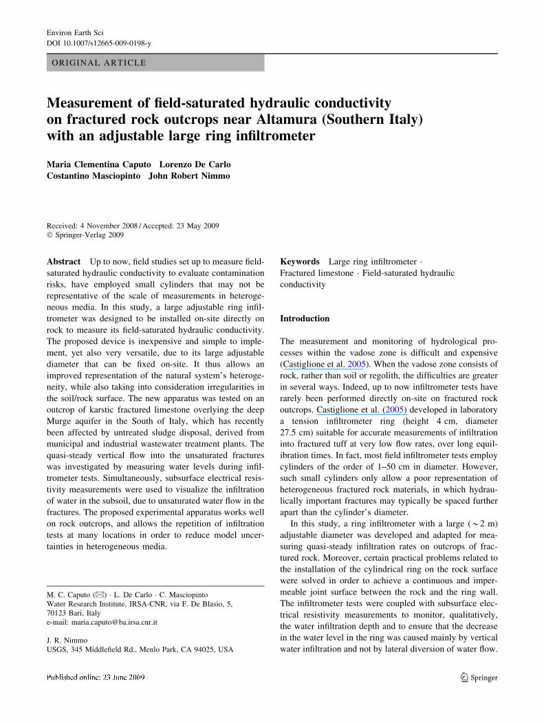
In the second test (#2), located in an area with an outcrop
of limestone characterized by no visible fractures, a 1.8 m
diameter ring was inserted into a thin furrow 2 cm deep,
previously hollowed into the rock (Fig. 3) which was then
also sealed with gypsum. The difference in size of the rings
used in the two tests was simply due to the local field
conditions; in fact, the device is designed to allow the
diameter to be adjusted easily when the irregularity of the
surface at the test site so requires.
In both cases the water used for the infiltration test had
moderate salinity (electrical conductivity of 2.39 mS/cm)
to enhance subsurface electrical resistivity measurements,
which were carried out simultaneously with the monitoring
of water infiltration/redistribution in the rock.
In test #1, the resistivity data were collected using a 7.5 m
long straight-line array of 16 steel electrodes with 0.5 m
spacing, oriented in the parallel direction as the visible
fractures. In test #2, two similar linear arrays were set up,
perpendicular to each other, with the same length and elec-
trode spacing, crossing at the centre of the ring infiltrometer.
Fig. 2 Test #1. a Fractured
limestone with visible fractures
of about 5 cm of spacing (s). bPlastic ring infiltrometer resting
directly on the ground and
sealed with gypsum by using a
second plastic ring
Environ Earth Sci
123
The water in the ring reached a maximum level of
0.13 m above the ground surface in both tests. During the
falling-head infiltrometer tests, the specific lateral water
leakage fluxes were about 8% (0.1 m day-1) and 3%
(0.007 m day-1) of the infiltrate water fluxes in the rings
for the first and second tests, respectively. The specific (i.e.,
per unit of ring area) leakage rates, due not to the water flux
from the edge of the ring (i.e., losses) but to the amount of
infiltrated water which flowed laterally within the subsur-
face, was estimated by dividing the total water volume of
the lateral diverted water flow by the duration of the
infiltration (2 and 3.2 h for tests #1 and #2, respectively).
This estimation was performed on the basis of the areas of
the wetted surfaces (1.6 and 1.5 m2 for tests 1# and 2#,
respectively), which were observed around the rings at the
end of each test, and multiplying them by the average
thickness of the wetted layers (5 and 3 cm, respectively)
and by their porosities (0.29 and 0.03) (Borgia et al. 2002).
The thickness of the wetted layers was derived from
measurements on core samples drilled at the tested sites.
During the experiments, water levels in the infiltrometer
ring were monitored using a submersible pressure probe.
Results and discussion
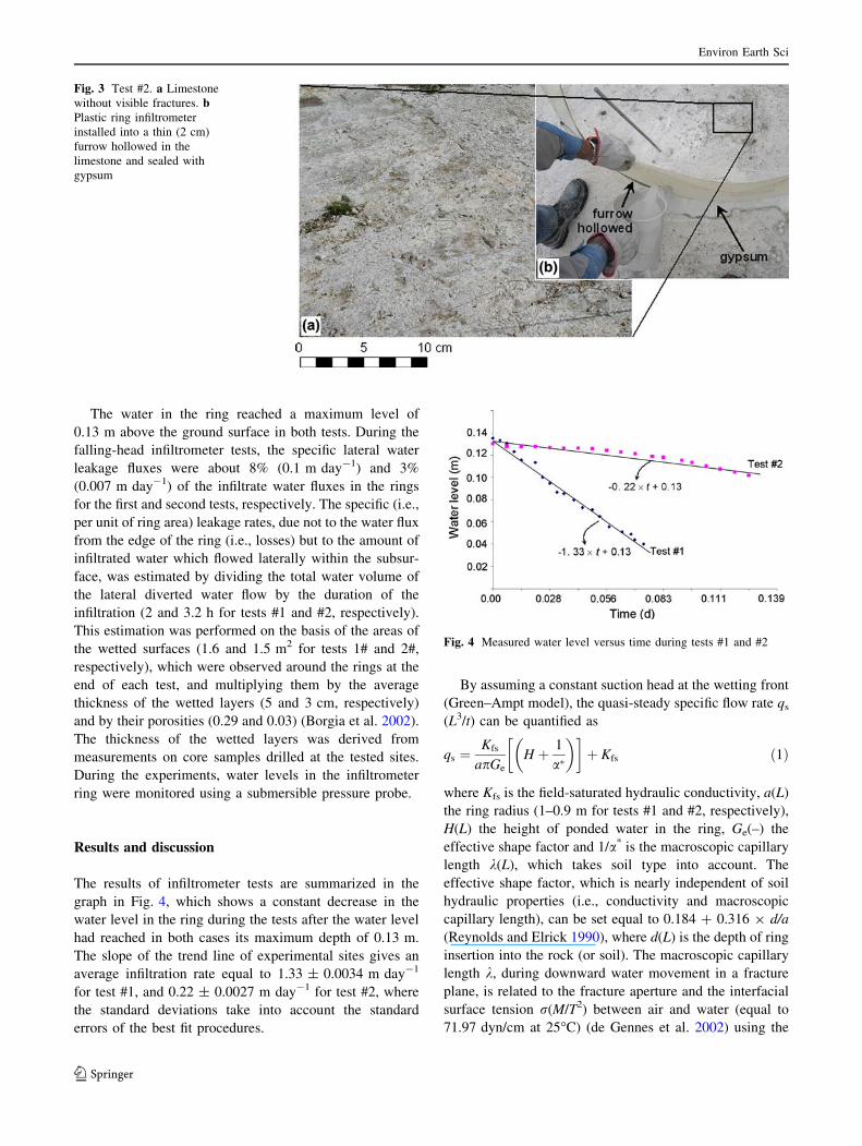
The results of infiltrometer tests are summarized in the
graph in Fig. 4, which shows a constant decrease in the
water level in the ring during the tests after the water level
had reached in both cases its maximum depth of 0.13 m.
The slope of the trend line of experimental sites gives an
average infiltration rate equal to 1.33 ± 0.0034 m day-1
for test #1, and 0.22 ± 0.0027 m day-1 for test #2, where
the standard deviations take into account the standard
errors of the best fit procedures.
By assuming a constant suction head at the wetting front
(Green–Ampt model), the quasi-steady specific flow rate qs
(L3/t) can be quantified as
qs ¼Kfs
apGe
H þ 1
a�
� �� �þ Kfs ð1Þ
where Kfs is the field-saturated hydraulic conductivity, a(L)
the ring radius (1–0.9 m for tests #1 and #2, respectively),
H(L) the height of ponded water in the ring, Ge(–) the
effective shape factor and 1/a* is the macroscopic capillary
length k(L), which takes soil type into account. The
effective shape factor, which is nearly independent of soil
hydraulic properties (i.e., conductivity and macroscopic
capillary length), can be set equal to 0.184 ? 0.316 9 d/a
(Reynolds and Elrick 1990), where d(L) is the depth of ring
insertion into the rock (or soil). The macroscopic capillary
length k, during downward water movement in a fracture
plane, is related to the fracture aperture and the interfacial
surface tension r(M/T2) between air and water (equal to
71.97 dyn/cm at 25�C) (de Gennes et al. 2002) using the
Fig. 3 Test #2. a Limestone
without visible fractures. bPlastic ring infiltrometer
installed into a thin (2 cm)
furrow hollowed in the
limestone and sealed with
gypsum
Fig. 4 Measured water level versus time during tests #1 and #2
Environ Earth Sci
123
following Young–Laplace equation (Pruess and Tsang
1990):
k ¼ 1
a�¼ 2
r
qg� �bc
ð2Þ
assuming the water–air contact angle equals zero, and that
the cutoff apertures, �bc, equals the fracture aperture which
delimits the region occupied only by the non-wetting
phase; g(L/t2) is the gravity acceleration and q(M/L3) is the
water density.
It should be noted that during the tests the depth of
ponded water was not steady. For the falling-head case
Nimmo et al. (2009) developed a modification of the
Reynolds and Elrick (1990) analytical formula:
Kfs ¼LG
tln
LG þ kþ H0
LG þ kþ H
� �ð3Þ
where LG ¼ pGea ¼ 0:993d þ 0:578a is the ring-installa-
tion scaling length and H0(L) is the falling ponded depth at
the initial instant t = 0. It should be noted that Eq. 3,
which is derived by integration of Eq. 1, compensates both
for the non-constant falling head and for the subsurface
radial spreading. Assuming that the infiltration rate
obtained in test #2 of the Altamura site is independent of k,
Eq. 3 was utilized to carry out a sensitivity analysis of
field-saturated conductivity. The results, which are repor-
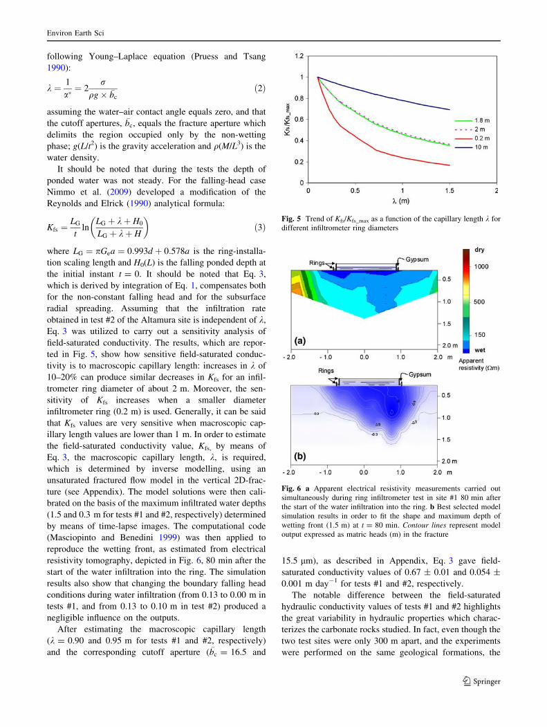
ted in Fig. 5, show how sensitive field-saturated conduc-
tivity is to macroscopic capillary length: increases in k of
10–20% can produce similar decreases in Kfs for an infil-
trometer ring diameter of about 2 m. Moreover, the sen-
sitivity of Kfs increases when a smaller diameter
infiltrometer ring (0.2 m) is used. Generally, it can be said
that Kfs values are very sensitive when macroscopic cap-
illary length values are lower than 1 m. In order to estimate
the field-saturated conductivity value, Kfs, by means of
Eq. 3, the macroscopic capillary length, k, is required,
which is determined by inverse modelling, using an
unsaturated fractured flow model in the vertical 2D-frac-
ture (see Appendix). The model solutions were then cali-
brated on the basis of the maximum infiltrated water depths
(1.5 and 0.3 m for tests #1 and #2, respectively) determined
by means of time-lapse images. The computational code
(Masciopinto and Benedini 1999) was then applied to
reproduce the wetting front, as estimated from electrical
resistivity tomography, depicted in Fig. 6, 80 min after the
start of the water infiltration into the ring. The simulation
results also show that changing the boundary falling head
conditions during water infiltration (from 0.13 to 0.00 m in
tests #1, and from 0.13 to 0.10 m in test #2) produced a
negligible influence on the outputs.
After estimating the macroscopic capillary length
(k = 0.90 and 0.95 m for tests #1 and #2, respectively)
and the corresponding cutoff aperture (�bc = 16.5 and
15.5 lm), as described in Appendix, Eq. 3 gave field-
saturated conductivity values of 0.67 ± 0.01 and 0.054 ±
0.001 m day-1 for tests #1 and #2, respectively.
The notable difference between the field-saturated
hydraulic conductivity values of tests #1 and #2 highlights
the great variability in hydraulic properties which charac-
terizes the carbonate rocks studied. In fact, even though the
two test sites were only 300 m apart, and the experiments
were performed on the same geological formations, the
Fig. 5 Trend of Kfs/Kfs_max as a function of the capillary length k for
different infiltrometer ring diameters
Fig. 6 a Apparent electrical resistivity measurements carried out
simultaneously during ring infiltrometer test in site #1 80 min after
the start of the water infiltration into the ring. b Best selected model
simulation results in order to fit the shape and maximum depth of
wetting front (1.5 m) at t = 80 min. Contour lines represent model
output expressed as matric heads (m) in the fracture
Environ Earth Sci
123
infiltration rates observed in the areas tested were very
different. Quarto and Schiavone (1994), with laboratory
measurements on saturated fractured limestone cores
derived from the Murge carbonate platform, showed the
applicability of Archie’s first law (using F = 2.06 9
U-1.77, where F(–) is the formation factor and U is the
porosity), which provides a rock porosity \2%, by
including matrix and fracture porosities. For the Altamura
fractured limestone, the modified Kozeny–Carman equa-
tion (Pape et al. 1999) leads to outcrop saturated conduc-
tivity values ranging from 0.6 to 12 m day-1, considering a
rock outcrop porosity from 1–2%. It should be noted that
the former conductivity value is very similar to the field-
saturated conductivity obtained by the ring infiltrometer in
test #1 (0.67 m day-1). On the contrary, the field-saturated
conductivity (0.054 m day-1) derived from test #2, where
the limestone outcrop had no visible fractures, is close to
the value (0.02 m day-1) obtained by laboratory tests on
the rock matrix of the Murge limestone (Borgia et al.
2002). The above comparison supports the field-saturated
hydraulic conductivity values obtained using the large ring
infiltrometers.
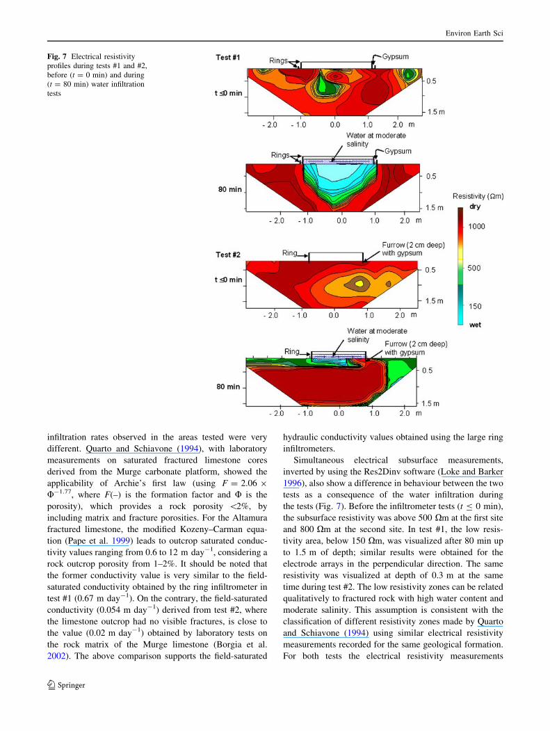
Simultaneous electrical subsurface measurements,
inverted by using the Res2Dinv software (Loke and Barker
1996), also show a difference in behaviour between the two
tests as a consequence of the water infiltration during
the tests (Fig. 7). Before the infiltrometer tests (t B 0 min),
the subsurface resistivity was above 500 Xm at the first site
and 800 Xm at the second site. In test #1, the low resis-
tivity area, below 150 Xm, was visualized after 80 min up
to 1.5 m of depth; similar results were obtained for the
electrode arrays in the perpendicular direction. The same
resistivity was visualized at depth of 0.3 m at the same
time during test #2. The low resistivity zones can be related
qualitatively to fractured rock with high water content and
moderate salinity. This assumption is consistent with the
classification of different resistivity zones made by Quarto
and Schiavone (1994) using similar electrical resistivity
measurements recorded for the same geological formation.
For both tests the electrical resistivity measurements
Fig. 7 Electrical resistivity
profiles during tests #1 and #2,
before (t = 0 min) and during
(t = 80 min) water infiltration
tests
Environ Earth Sci
123
confirmed the effectiveness of the ring sealing, showing that
the water infiltrated from within the ring and not from
outside (Fig. 7) to a maximum depth of 1.5 m in test #1 and
0.3 m in test #2. Additionally, electrical resistivity imaging
highlights not only that the water reached different depths in
the two infiltrometer tests, but also that its variable redis-
tribution within the investigated vertical plane results from
the structural characteristics of the limestone outcrop. As
expected, in test #1 the deepening of the level of the low-
resistivity anomaly associated with the infiltration of mod-
erately saline water was much greater than in test #2, and
was, in fact, consistent with the different number and size of
the fractures observed visually in the limestone.
Conclusions
The large ring infiltrometer coupled with subsurface elec-
trical resistivity measurements, described in this work, has
proved to be a simple and inexpensive field tool, capable of
evaluating the field-saturated hydraulic conductivity of
fractured rock formations even if it requires numerical
elaboration supported by mathematical models. It is
designed to be installed directly on an outcrop of fractured
rock, easily constructed on-site with inexpensive, light-
weight materials and with an adjustable diameter. These
characteristics improve the versatility of the infiltrometer
method and its adaptability to various geological condi-
tions. Thus, it expands the potential for exploring hydraulic
conductivity of fractured rock, which until now has been
more frequently investigated in laboratories, mainly
because of the practical difficulties involved in field
investigations. Simultaneous electrical resistivity mea-
surements are used to monitor the subsurface water infil-
tration instead of TDR and TDT sensors or tensiometers,
thus sidestepping the difficulty of inserting probes into the
rock. Further technical difficulties related to the installation
in the field of the large ring infiltrometer, were solved using
non-commercially available equipment during the on-site
installation procedure. Specifically, the set up of the
experimental apparatus requires the hollowing out of a
furrow in which to install the ring and seal it to the rock
surface with gypsum. The efficacy of the seal of ring in-
filtrometer with soil/rock surfaces was confirmed by the
simultaneous electrical resistivity measurements that show
the deepening and spreading of the water during the infil-
tration tests. The time required for the installation was
about 2 h and the water volume used for each infiltration
test was about 0.5 m3, depending on the local rock per-
meability. On the whole, the field data obtained from the
infiltrometer tests (0.67 and 0.054 m day-1, for tests #1
and #2, respectively), and the range of electrical resistivity
measurements are consistent with the nature of the rocks
tested and are corroborated by laboratory measurements
carried out by other authors (Quarto and Schiavone 1994;
Borgia et al. 2002). The difference between the field-sat-
urated hydraulic conductivity values obtained for tests #1
and #2 highlights the heterogeneity of the outcrop studied,
due to differences in both the number and the size of the
fractures at the different locations.
The possibility of building a ring with a large adjustable
diameter on-site has the advantage of including fractures
and other features of the rock in order to obtain field-sat-
urated hydraulic conductivity data at a more representative
scale of measurements, with negligible border effects. The
proposed installation procedure of a large ring infiltrometer
on limestone outcrops extends the possibility of performing
field infiltrometer tests on rocks that would previously have
been very difficult to test.
Acknowledgments This research was supported by the Italian
Government (Regional Authority) under the 2007 Toxicological
Data-Base studies.
Appendix
The unsaturated water flow in a vertical section can be
described by the Richards’ equation:
ohow
owot¼ � o
oxKfrðwÞ
owox
� �� o
ozKfrðwÞ
owoz� 1
� �� �ð4Þ
where Kfr(L/t) is the variable hydraulic conductivity as in
the vertical fracture plane with variable apertures. It should
be noted that, following Hestir and Long (1990), the
fracture network in a vertical section xz (or yz) of a
fractured rock can be assumed equivalent to a fracture
lattice, as in a fracture with variable aperture.
Consequently, Kfr can be defined using the following
equation (Bear 1993, p. 15)
Kfr wð Þ ¼ k wð Þkfr x; zð Þqg
lð5Þ
where g(L/t2) is the gravity acceleration; q(M/L3) the water
density; l(N/L2, centipoises) the dynamic water viscosity;
kfr ¼ hsbðx;zÞ2
12the saturated fracture permeability within
which b(x, z) is the nodal aperture of the vertical fracture
and hs the saturated water content; k(w)(–) the relative
permeability coefficient and w(L) is the suction head. The
coefficient k(w) is related to the water suction head (or to
the water content, h) by means of an unsaturated hydraulic
conductivity function (Reitsma and Kueper 1994; Abdel-
Salam and Chrysikopoulos 1996; Bockgard and Niemi
2004, p. 789) and it can be calculated using:
kðwÞ ¼ kfrðwÞkfr
ð6Þ
Environ Earth Sci
123
The field-saturated hydraulic conductivity, Kfs is related to
fracture hydraulic conductivity, Kfr(w), at saturation and to
the mean aperture of vertical fracture, by means of the
permeability of the rock matrix and mean spacing between
fractures of the outcrop (Hestir and Long 1990).
Equation 4 was solved by applying a finite difference
grid in x and z. An iterative numerical method was used to
solve the above equation and an infiltrated water mass
balance check was carried out at every instant of simulation.
Some numerical improvements of the Crank–Nicholson
implicit method (Bear 1979) allowed an automatic increase
(i.e., adjustment) of the temporal discretization step during
numerical iterations in order to reduce the total computa-
tional time. A computational code calibrated in a previous
work (Masciopinto and Benedini 1999) was then applied to
reproduce the pressure head distributions during infiltration
tests at the Altamura site. As boundary conditions at the
topsoil, a variable pressure head versus time was imposed to
simulate the water ring infiltration. The van Genucthen
parameters for the retention curves considered for test #1
were a* = 1.11 m-1, m = 0.65, hr = 0.01 and hs = 0.99,
respectively. It should be noted that a* was reassigned at the
end of the simulation, when the output of the simulation
fitted the real infiltrated water depth (about 1.5 m). The
parameters for nodal aperture generation in the fracture
plane (x, z) were mean of aperture 102.1 lm in x, 102.47 lm
in z; standard deviations of Log aperture 0.34 in x and 0.49
in z, nugget 0.02 (in x and z), sill 0.10 (in x and z) and spatial
correlation length 3 m in x and 2 m in z. The details
describing the geo-statistical and computational methods
used for fracture aperture generation in the vertical outcrop
section are reported in other works (Masciopinto 2005;
Pruess and Tsang 1990). Several simulations were carried
out by considering different mean fracture apertures (i.e.,
the model parameters) in x and z. The best model solution
(see Fig. 6b) was determined when the maximum simulated
depth of infiltrated water was equal to 1.5 m, 80 min after
the start of the infiltration into the ring. Thus, the corre-
sponding model output, in terms of matric head distribution
also enhanced the macroscopic capillary length of 0.90 m
(or a* = 1.11 m-1) and the corresponding cutoff apertures
bc(16.5 lm) defined by the Young–Laplace equation. This
pressure head is clearly visible in Fig. 6b, as the contour
line -0.90 m divides the zone of fracture filled only by air
from that with larger apertures filled by water and air.
References
Abdel-Salam A, Chrysikopoulos VC (1996) Unsaturated flow in a
quasi three-dimensional fractured medium with spatially vari-
able aperture. Water Resour Res 32:1531–1540
Bear J (1979) Hydraulics of groundwater. McGraw-Hill, New York
Bear J (1993) Modeling flow and contaminant transport in fractured
rocks. In: Bear J, Tsang CF, de Marsily G (eds) Flow and
contaminant transport in fractured rock, vol 1. Academic Press,
San Diego, pp 67–272
Binley AM, Cassiani G, Middleton R, Winship P (2002) Vadose zone
flow model parameterisation using cross-borehole radar and
resistivity imaging. J Hydrol 267(3–4):147–159
Bockgard N, Niemi A (2004) Role of rock heterogeneity on lateral
diversion of water flow at the soil–rock interface. Vadose Zone J
3:786–795
Borgia GC, Bortolotti V, Masciopinto C (2002) Valutazione del
contributo della porosita effettiva alla trasmissivita di acquiferi
fratturati con tecniche di laboratorio e di campo (Evaluation of
effective porosity contribution to the transmissivity of fractured
aquifer using laboratory and field techniques). IGEA Groundw
Geoeng 17:31–43
Castiglione P, Shouse PJ, Mohanty B, Hudson D, van Genucthen
MTh (2005) Improved tension infiltrometer for measuring low
flow rates in unsaturated fractured rock. Vadose Zone J 4:885–
890
Ciaranfi N, Pieri P, Ricchetti G (1988) Note alla Carta Geologica
delle Murge e del Salento (Puglia Centro-Meridionale) (Notes on
the geological map of Murge and Salento—Center-Southern
Apulia). Mem Soc Geol It 41:449–460
de Gennes PG, Brochard-Wyart F, Quere D (2002) Capillary and
wetting phenomena—drops, bubbles, pearls, waves. Springer,
New York (ISBN 0-387-00592-7)
Deiana R, Cassiani G, Kemna A, Villa A, Bruno V, Bagliani A (2007)
An experiment of non invasive characterization of the vadose
zone via water injection and cross-hole time-lapse geophysical
monitoring. Near Surf Geophys 5:183–194
Hestir K, Long JCS (1990) Analytical expressions for the permeabil-
ity of random two-dimensional Poisson fracture networks based
on regular lattice percolation and equivalent media theories. J
Geophys Res 95(B13):21565–21581
Loke MH, Barker RD (1996) Rapid least-squares inversion of
apparent resistivity pseudosections using a quasi-Newton
method. Geophys Prospect 44:131–152
Masbrucha K, Ferre TPA (2003) A time domain transmission method
for determining the dependence of the dielectric permittivity on
volumetric water content. An application to municipal landfills.
Vadose Zone J 2:186–192
Masciopinto C (2005) Pumping-well data for conditioning the
realization of the fracture aperture field in groundwater flow
models. J Hydrol 309(1-4):210–228
Masciopinto C, Benedini M (1999) Unsaturated flow in fractures with
anisotropic variable apertures. In: Proceedings of XXVIII
IAHR—AIRH congress, 23–27 August, Graz, Austria
Nimmo JR, Schmidt KM, Perkins KS, Stock JD (2009) Rapid
measurement of field-saturated hydraulic conductivity for areal
characterization. Vadose Zone J 8(2):1–8
Pape H, Clauser C, Iffland J (1999) Permeability prediction based on
fractal pore-space geometry. Geophysics 64(5):1447–1460
Pruess K, Tsang YW (1990) On two-phase relative permeability and
capillary pressure on rough-walled rock fractures. Water Resour
Res 26(9):1915–1926
Quarto R, Schiavone D (1994) Hydrogeological implications of the
resistivity distribution inferred from electrical prospecting data
from the Apulian carbonate platform. J Hydrol 154:219–244
Reitsma S, Kueper BH (1994) Laboratory measurement of capillary
pressure-saturation relationships in a rock fracture. Water Resour
Res 30(4):865–878
Reynolds WD, Elrick DE (1990) Ponded infiltration from a single
ring: I. Analysis of steady flow. Soil Sci Soc Am J 54:1233–1241
Environ Earth Sci
123