
Continuous versus discrete single species population models with adjustable reproductive strategies
Upload
khangminh22Category
view
0download
0
Crank Height-Adjustable Base Installation Instructions
Rev 1016

USER MANUAL
Series CR – Crank, Stroke 420

2
Contents
1 Important Information. SAFETY FIRST! ........................................................................................................................................ 2
1.1 Important safety instructions. .............................................................................................................................................. 3
1.2 User Information ................................................................................................................................................................ 3
1.3 Before you start: ................................................................................................................................................................. 4
2 Assembly & Adjustment ................................................................................................................................................................. 4
2.1 Assembly Instruction .......................................................................................................................................................... 4
2.2 System configuration (example) ......................................................................................................................................... 4
2.3 Adjustments ....................................................................................................................................................................... 4
3 Operation Instructions.................................................................................................................................................................... 5
3.1 Basic functions ................................................................................................................................................................... 5
3.1.1 Upward desktop movement ................................................................................................................................................ 5
3.1.2 Downward desktop movement ........................................................................................................................................... 5
4 Maintenance & Repairs .................................................................................................................................................................. 5
4.1 Cleaning, Inspection and Storage....................................................................................................................................... 5
4.2 User Maintenance Instructions ........................................................................................................................................... 5
4.3 Repairs .............................................................................................................................................................................. 5
5 Appendix ........................................................................................................................................................................................ 6
5.1 Dimensions column system: series CR with 420 stroke ..................................................................................................... 6
1 Important Information. SAFETY FIRST!
Your safety and the safety of others are very important. Please familiarize yourself with all instructions and safety warnings before operating the table. Please keep this manual for future reference. To help you make informed decisions about safety, we have provided operating procedures and other information on labels and in this user’s manual. This information alerts you to potential hazards that could hurt you or others. It is not practical or possible to warn you about all the hazards associated with operating or maintaining a table. Please use your own good judgment.
You will find important safety information in a variety of forms. Safety Messages are preceded by a safety alert symbol and one of three signal words: DANGER, WARNING, or CAUTION. These safety messages are listed in order of severity, identify the general risks and what actions you are to take to avoid the risks. These signal words mean:
DANGER - Indicates an imminent hazardous with a high risk of serious injury or death.
WARNING - Indicates a potentially hazardous situation that if not avoided may could result in serious injury or death.
CAUTION - Indicates a potential hazardous, which may result in minor or moderate injury. It may also be used to alert against
unsafe practices.
NOTICE - Indicates an alert to call attention to proper assembly instructions or particular operation procedures to assure correct equipment function and to avoid equipment damage or wear. The information and specifications included in this manual were in effect at the time of approval for printing. Enwork reserves the right todiscontinue or change specifications or design at anytime without notice and without incurring any obligation whatever

Important information
3
1.1 Important safety instructions.
Read all instructions before using table. Please save these instructions.
WARNING - To reduce the risk of injury to persons:
1. This table is not intended for use by children or individuals with a physical or other impairment that may affect the ability to safely operateequipment. ,
2. Use this table only for its intended use as described in these instructions. Do not use attachments not recommended by the manufacturer.3. Never operate this table if it has a damaged part, if it is not working properly, if it has been dropped or damaged. In the event of any such
event please return the table to a service center for examination and repair.4. Never drop or insert any object into any opening.5. Do not use outdoors.
WARNING - Risk of Injury to Persons:
1. Do not use this table to lift people and do not use the table to lift heavy part or use this table as a platform for storage.2. Maximum intended load is 130 pounds uniformly distributed (60 kilograms) including the tabletop when adjusting up and down.3. Maximum intended load is 265 pounds uniformly distributed (120 kilograms) including the tabletop when stationary load.
DANGER - Risk of injury, or death:
1. Do not use the desk if it has been dropped or damaged. Contact the manufacturer for examination or repair.
2. It is not allowed to connect self-constructed products or other mechanical device. To prevent damage, use only components
recommended by the manufacturing company.
WARNING - Risk of injury, or death:
1. During the raising or lowering of the table there exists a risk of squeezing or pinching between the moving desktop and fixed objects.
2. The necessary safety margins depend on the greatest type of injury risk that can be predicted. Where possible small pinch points exist
(i.e. fingers) use at least a one inches (2,5 cm) safety margin and for body or head (especially where children may be present) use a
minimum of 16 inches (41 cm) count from the floor or from their top of the table feet if that is relevant
3. During the lowering or rising of the desktop, the operator must ensure that
no person or object risk being harmed by the operation.
4. This tag should (at right) be located on the table during the initial
installation.
5. Keep children away from moving parts and underneath the table.
6. The intended use of the table is adjusting a work surface between sitting
and a standing position. The table is not designed for other uses.
7. The table must only be operated while in an upright position and must
under no circumstances be operated while upside down.
8. The table must not be overloaded.
9. The table must be operated in a dry, enclosed space, such as an office or
similar, Do not operate outdoors.
10. This table is not intended for use by individuals (including children) with
limited physical, sensory or mental abilities or with a lack of experience
and/or lack of expertise, unless they are supervised by a person
responsible for their safety or have received instructions from that person
on how to use the control unit.
11. Children must be supervised at all times to ensure that they do not play
with the control unit.
12. The table may not be used to lift people. Do not sit or stand on a table while
it is be raised or lowered.
13. The table must not be structurally or technically altered or modified in any
way.
1.2 User Information
This column system is rated for commercial use only and is rated for a
maximum load of 130 pounds uniformly distributed (60kg) including the
tabletop, when adjusting and 265 pounds uniformly distributed (120kg) for
stationary load.
.

4
1.3 Before you start:
Make sure that there is nothing blocking the travel of the desk in the space where it will operate
2 Assembly & Adjustment
2.1 Assembly Instruction
The official assembly instruction will be found with the base components.
Make sure to ask your desk vendor for an approved combination of desktop and frame.
2.2 System configuration (example)
The figure below shows the driving assignment for a configuration example. This configuration consists of:
1 Crank
2 Drive shaft
3 Gears
2.3 Adjustments
The table columns, gears and crank are sealed units and have no parts that can be serviced or adjusted by the user. In case of failure or unexpected operation or from maintenance control your vendor and arrange for service by a qualified technician.
Control system
5
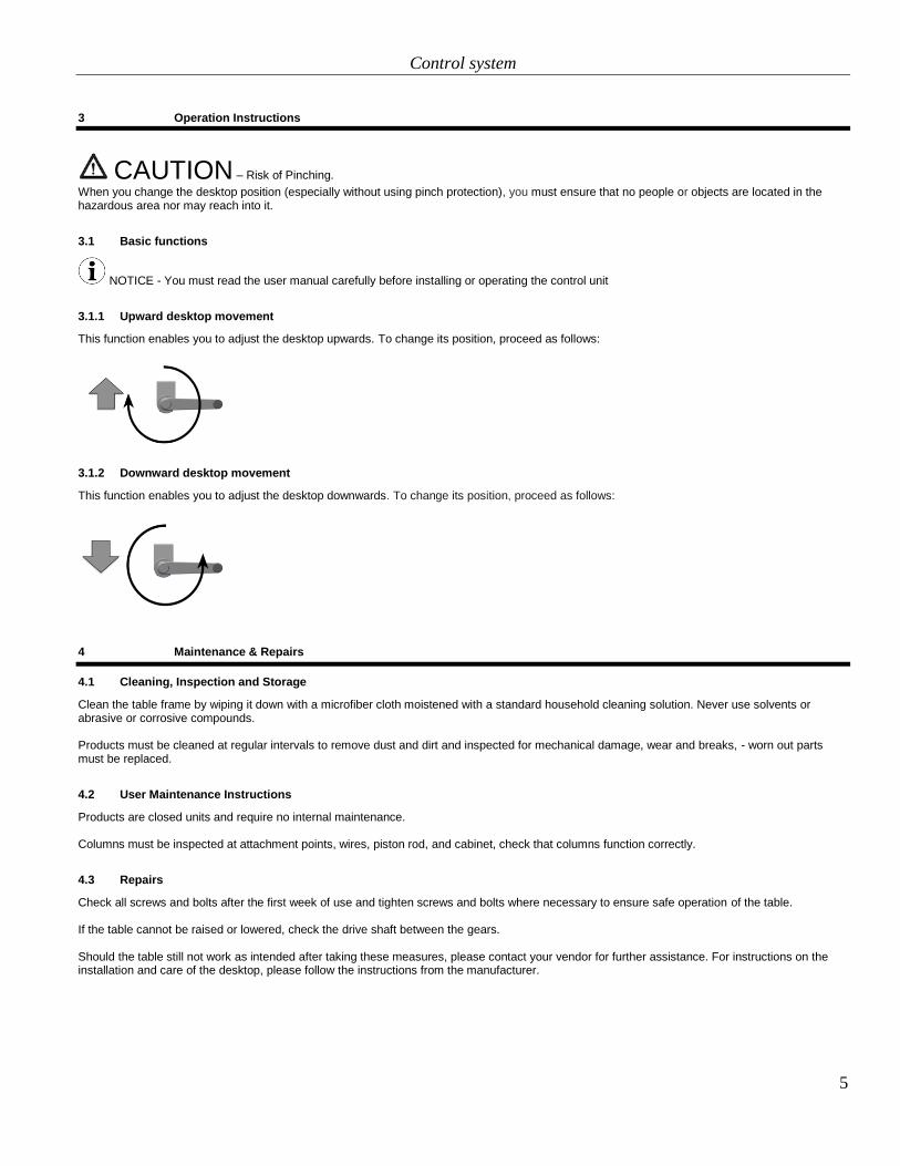
3 Operation Instructions
CAUTION – Risk of Pinching.
When you change the desktop position (especially without using pinch protection), you must ensure that no people or objects are located in the hazardous area nor may reach into it.
3.1 Basic functions
NOTICE - You must read the user manual carefully before installing or operating the control unit
3.1.1 Upward desktop movement
This function enables you to adjust the desktop upwards. To change its position, proceed as follows:
3.1.2 Downward desktop movement
This function enables you to adjust the desktop downwards. To change its position, proceed as follows:
4 Maintenance & Repairs
4.1 Cleaning, Inspection and Storage
Clean the table frame by wiping it down with a microfiber cloth moistened with a standard household cleaning solution. Never use solvents or abrasive or corrosive compounds.
Products must be cleaned at regular intervals to remove dust and dirt and inspected for mechanical damage, wear and breaks, - worn out parts must be replaced.
4.2 User Maintenance Instructions
Products are closed units and require no internal maintenance.
Columns must be inspected at attachment points, wires, piston rod, and cabinet, check that columns function correctly.
4.3 Repairs
Check all screws and bolts after the first week of use and tighten screws and bolts where necessary to ensure safe operation of the table.
If the table cannot be raised or lowered, check the drive shaft between the gears.
Should the table still not work as intended after taking these measures, please contact your vendor for further assistance. For instructions on the installation and care of the desktop, please follow the instructions from the manufacturer.

6
5 Appendix
5.1 Dimensions column system: series CR with 420 stroke
1
ASSEMBLY INSTRUCTION
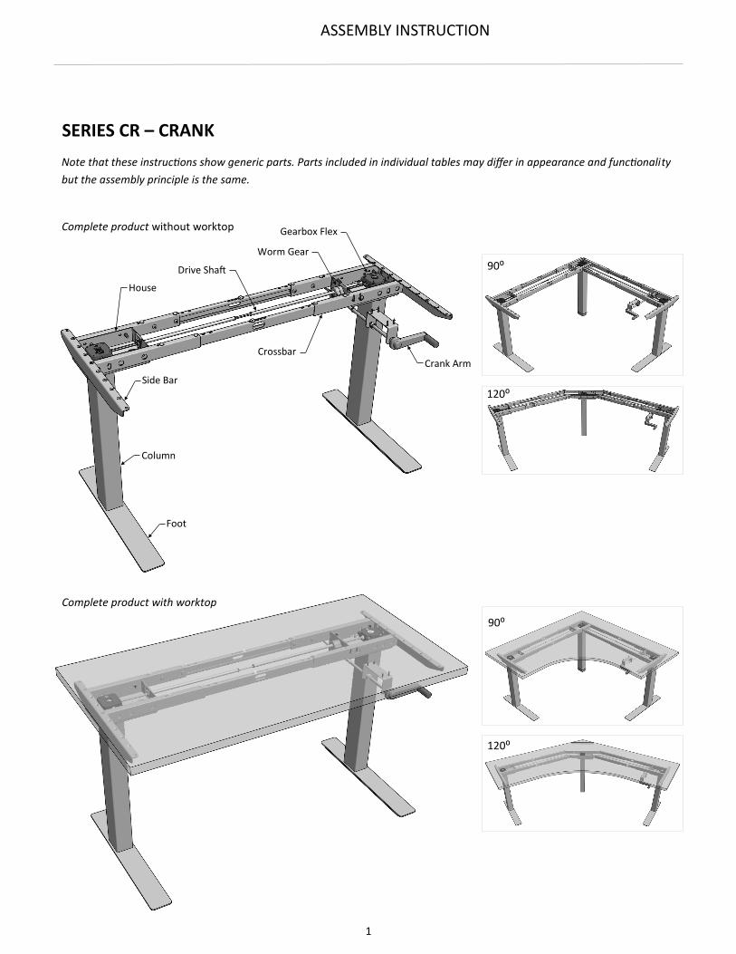
Side Bar
Column
Foot
Drive Shaft
House
Gearbox Flex
Worm Gear
Crossbar Crank Arm
Note that these instructions show generic parts. Parts included in individual tables may differ in appearance and functionality
but the assembly principle is the same.
SERIES CR – CRANK
Complete product without worktop
Complete product with worktop
120⁰
90⁰
90⁰
120⁰

2
ASSEMBLY INSTRUCTION
(Fig. 1) Feet
(Fig. 2) Crossbars
Alternative foot types.
On-Foot / OnC (for 2-stage columns)
On-Foot / OffC (for 2-stage columns)
In-Foot / OnC (for 3-stage columns)
In-Foot / OffC (for 3-stage columns)
Adjustable crossbar (Crossbar T)
Fixed crossbar (Crossbar TF)
68003496
Screw Socket Button head UNC 5/16-18x5/8” Zn
Holes used for mounting of
crossbars on the short side
of the house
(For 3-Leg tables only)
Holes used for mounting of
crossbars on the long side
of the house
Oval hole is only used for drive
shaft on 3-leg tables
68003490
Screw Socket Flat head UNC 5/16-18x1" Zn
Loosen screws to adjust crossbar length
3
ASSEMBLY INSTRUCTION
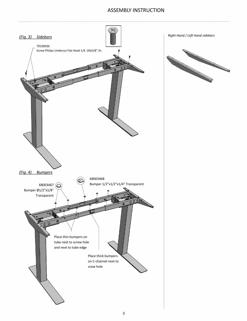
(Fig. 3) Sidebars
(Fig. 4) Bumpers
Right Hand / Left Hand sidebars
79100036
Screw Philips Undercut Flat Head 1/4 -20x5/8” Zn
68003468
Bumper 1/2"x1/2"x1/4" Transparent 68003467
Bumper Ø1/2"x1/8"
Transparent
Place thin bumpers on
tube next to screw hole
and next to tube edge
Place thick bumpers
on C-channel next to
scew hole

4
ASSEMBLY INSTRUCTION
Adjustable crossbars for 3-column 90⁰ table.
3 regular adjustable crossbars
1 special adjustable crossbar
No additional assembly kit
Fixed crossbars for 3-column 90⁰ table.
3 regular fixed crossbars
1 regular fixed crossbar, 6” shorter than
the other three crossbars.
1 additional assembly kit
(Fig. 6) 3-Column 90⁰ Fixed Crossbars
68003491 Screw Socket Flat head UNC 5/16-18x1-1/2" Zn
Alternative foot
Special telescopic crossbar
(Fig. 5) 3-Column 90⁰ Adjustable Crossbars
Alternative foot
68003491 Screw Socket Flat head UNC 5/16-18x1-1/2" Zn
68004127
Assembly Kit PR25 90⁰ Angle
Regular fixed crossbar Regular fixed crossbar
Regular fixed crossbar 6" shorter than the other three crossbars

5
ASSEMBLY INSTRUCTION
Adjustable crossbars for 3-column
120⁰ table.
4 regular adjustable crossbars
2 Brackets
68005095 Bracket 120⁰ Outer
68005096 Bracket 120⁰ Inner 68003490 Screw Socket Flat head UNC 5/16-18x1" Zn
68005205 Hex Nut UNC 5/16-18 Zn
(Fig. 7) 3-Column 120⁰ Adjustable Crossbars
(Fig. 8) 3-Column 120⁰ Fixed Crossbars
Fixed crossbars for 3-column 120⁰ table.
4 regular fixed crossbars
2 Brackets
68005095 Bracket 120⁰ Outer
68005096 Bracket 120⁰ Inner
68005205 Hex Nut UNC 5/16-18 Zn
68003490 Screw Socket Flat head UNC 5/16-18x1" Zn
6
ASSEMBLY INSTRUCTION
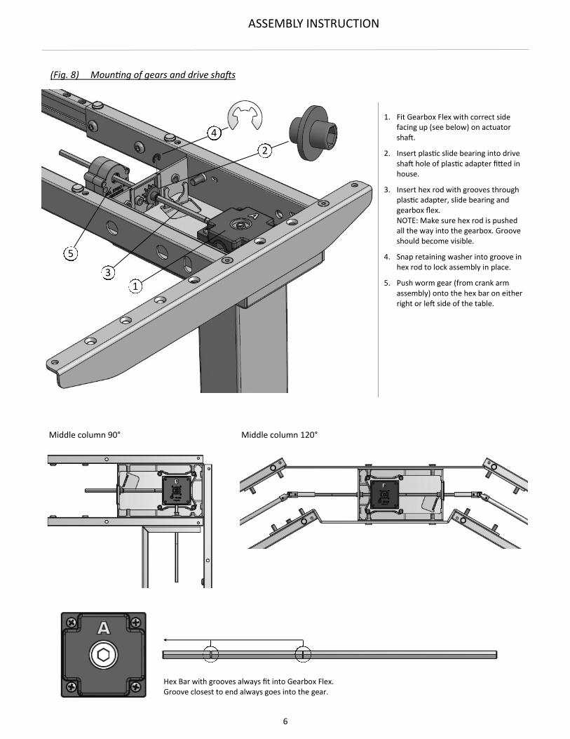
Hex Bar with grooves always fit into Gearbox Flex. Groove closest to end always goes into the gear.
1. Fit Gearbox Flex with correct sidefacing up (see below) on actuatorshaft.
2. Insert plastic slide bearing into driveshaft hole of plastic adapter fitted in house.
3. Insert hex rod with grooves through plastic adapter, slide bearing andgearbox flex.NOTE: Make sure hex rod is pushed all the way into the gearbox. Grooveshould become visible.
4. Snap retaining washer into groove in hex rod to lock assembly in place.
5. Push worm gear (from crank armassembly) onto the hex bar on eitherright or left side of the table.
(Fig. 8) Mounting of gears and drive shafts
Middle column 90° Middle column 120°
5
3 1
4
2

7
ASSEMBLY INSTRUCTION
When two aluminum tubes are used, push tubes as far as possible towards houses.
Push O-rings toward inside edges to fix aluminum tubes in place
When one aluminum tube is used, push O-ring toward outside edges to fix aluminum tube in place.
Drive shaft alternative with one
aluminum tube.
68004170
Drive shaft alternative with two
aluminum tubes.
68004171
68004172
68004173
(Fig. 9) Mounting of gears and drive shafts
8
ASSEMBLY INSTRUCTION
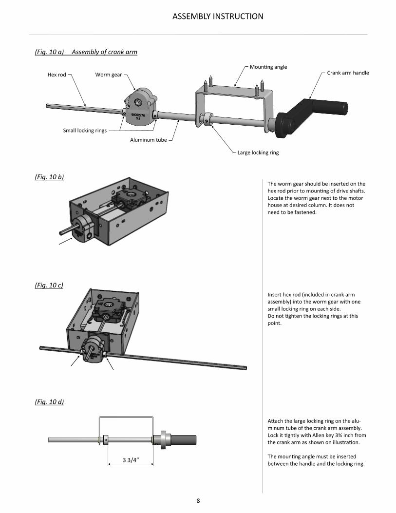
(Fig. 10 a) Assembly of crank arm
Small locking rings
(Fig. 10 b)
(Fig. 10 c)
The worm gear should be inserted on the hex rod prior to mounting of drive shafts. Locate the worm gear next to the motor house at desired column. It does not need to be fastened.
Insert hex rod (included in crank arm assembly) into the worm gear with one small locking ring on each side. Do not tighten the locking rings at this point.
Attach the large locking ring on the alu-minum tube of the crank arm assembly. Lock it tightly with Allen key 3¾ inch from the crank arm as shown on illustration.
The mounting angle must be inserted between the handle and the locking ring.
Worm gear
Mounting angle Crank arm handle
Large locking ring
Aluminum tube
Hex rod
(Fig. 10 d)
3 3/4”
9
ASSEMBLY INSTRUCTION
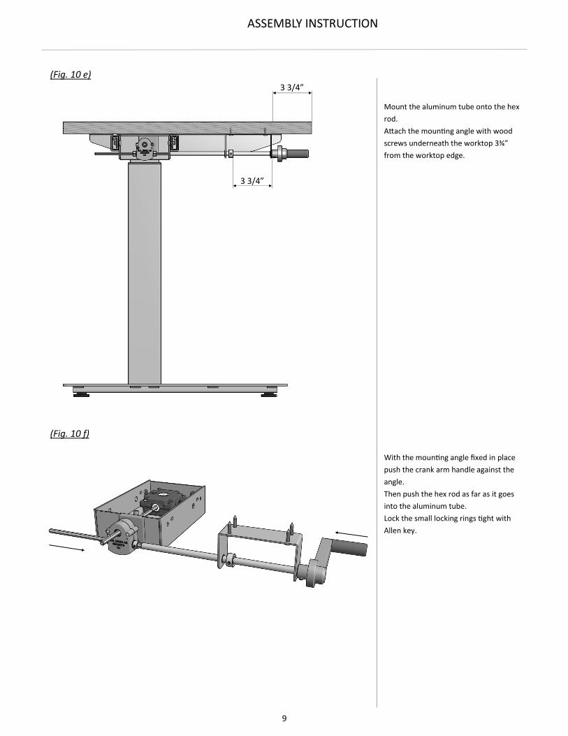
(Fig. 10 e)
(Fig. 10 f)
Mount the aluminum tube onto the hex
rod.
Attach the mounting angle with wood
screws underneath the worktop 3¾”
from the worktop edge.
With the mounting angle fixed in place
push the crank arm handle against the
angle.
Then push the hex rod as far as it goes
into the aluminum tube.
Lock the small locking rings tight with
Allen key.
3 3/4”
3 3/4”

10
ASSEMBLY INSTRUCTION
Three different gear boxes are used:
The Gearbox Flex AC has one drive shaft
outlet. The two sides are named A & C.
The vertical rotation is reversed when the
gearbox is turned upside down.
The A-side is the side with screws. The C-
side is the side without screws.
2-column tables only use Gearbox Flex AC
The Gearbox Flex BD has two drive shaft
outlets placed in 90°. The two sides are
named B & D. The vertical rotation is re-
versed when the gearbox is turned upside
down.
The B-side is the side with screws. The D-
side is the side without screws.
The Gearbox Flex BD is used on the
middle column of a 3-column 90° table.
The Gearbox Flex EF has two drive shaft
outlets placed in 180°. The two sides are
named E & F. The vertical rotation is rever-
sed when the gearbox is turned upside
down.
The E-side is the side with screws. The F-
side is the side without screws.
The Gearbox Flex EF is used on the middle
column of a 3-column 120° table.
The actuators always go DOWN at a CW
rotation.
The actuators always go UP at a CCW ro-
tation.
Hence must all gearboxes (Gearbox Flex)
connected to a table frame turn in a uni-
son direction.
Gearbox Flex Placement
SUPPLEMENTARY INFORMATION

11
ASSEMBLY INSTRUCTION
The worm gear is placed on the side of the
table where the crank handle should be.
It is placed on the hex bar that is attached
to the Gearbox Flex. The worm gear
should be placed immediately outside the
house. It does not need to be fastened.
The worm gear can be placed either way
on the hex bar. The action remains the
same.
Worm Gear
2-Column Table
C A
C A
Crank arm on the left side
Crank arm on the right side
Normally, the action of the crank arm
should operate in the following manner:
CW turn = table going UP
CCW turn = table going DOWN
To achieve this on a 2-column table the
Gearbox Flex must be placed with the A-
side facing up on the right column and the
C-side facing up on the left column.
The crank arm can then be placed on pre-
ferred side of the table (right or left).

12
ASSEMBLY INSTRUCTION
3-Column Table 90°
3-Column Table 120°
Normally, the action of the crank arm
should operate in the following manner:
CW turn = table going UP
CCW turn = table going DOWN
On a 3-column table every other Gearbox
Flex must be placed with the ”opposite”
side up. That is, every other gear must
have the side with the screws facing up.
This means that the gears on both outer
column will be facing the same way.
As a gear with two drive shaft outlets is
needed on the middle column, the Gear-
box Flex BD must be used here.
As opposed to a 2-column table, the side
on which the crank arm is placed has im-
portance on a 3-column table.
The correct placement is as follows:
Crank arm on the left side = CBC
Crank arm on the right side = ADA
C
B C
A
D A
E
F
Same principle as for a 3-column 90° table
apply also for a 3-column 120° table.

13
ASSEMBLY INSTRUCTION
Drive Shaft Kits
Part Number Description
68004170 Drive Shaft Kit c/c 26"-40" / OH 31"-45"
68004171 Drive Shaft Kit c/c 38"-64" / OH 43"-69"
68004172 Drive Shaft Kit c/c 58"-84" / OH 63"-89"
68004173 Drive Shaft Kit 120° c/c 26"-40" / OH 31"-45"
Drive Shaft Kit 68004172 Complete kit is used
Drive Shaft Kit 68004172 Complete kit is used
Drive Shaft Kit 68004171
Used for OH 43” - OH 57”
Used for OH 57” - OH 69”
Drive Shaft Kit 68004170
Used for OH 31” - OH 38”
Used for OH 39” - OH 45”
14
ASSEMBLY INSTRUCTION
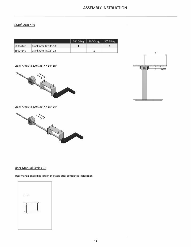
24" C-Leg 30" C-Leg 30" T-Leg
68004148 Crank Arm Kit 14"-18" 1 1
68004149 Crank Arm Kit 15"-24" 1
Crank Arm Kits
Crank Arm Kit 68004148 X = 14”-18”
Crank Arm Kit 68004149 X = 15”-24”
User manual should be left on the table after completed installation.
User Manual Series CR
X

15
ASSEMBLY INSTRUCTION
Fig. 1 FEET
Assemble the feet on the columns.
Tighten screws firmly.
IMPORTANT:
Make sure the correct screws are used. Using too
long screws may destroy internal parts in the
column.
Fig. 2 CROSSBARS
Attach the crossbars on the long side of the houses. Tighten screws firmly.
Loosen the button head screws on the crossbars and
adjust the frame to desired width.
Fasten the screws on the crossbars.
Fig. 3 SIDEBARS
Fasten sidebars in threaded holes on top of crossbars
with flathead screws.
Two types of sidebars exist, symmetrical for T-leg tables
and right/left-handed for C-leg tables.
Fig. 4 BUMPERS
The worktop is resting on the sidebars and on self-
adhesive rubber bumpers placed on the crossbars. The
bumpers should be placed as close to the fixing screws
for the worktop as possible to keep the worktop from
bending.
The rubber bumpers come in two thicknesses. The
thicker ones are used on the C-channel.
On fixed crossbars the thick bumpers are not used.
WORKTOP
Two sizes of wood screws for the worktop are included
in the assembly kit.
68005206 Wood Screw Button head 8x3/4” Zn
68005207 Wood screw Flathead 10x2-3/8” Zn
The shorter screws through sidebars.
The longer screws through crossbars.
IMPORTANT:
These wood screws require a minimum of 1”
thick worktop.
Fig. 5 3-COLUMN 90⁰ TABLE, ADJUSTABLE CROSSBARS
3 regular adjustable crossbars and 1 special adjustable
crossbar with an angled C-channel are used.
ASSEMBLY PROCEDURE
Fig. 6 3-COLUMN 90⁰ TABLE, FIXED CROSSBARS
3 regular fixed crossbars together with 1 regular fixed crossbar
6” shorter than the other three are used.
The assembly procedure is the same as for a 2-column table
with the exception that the angled C-channel mounts to the
middle house with one extra-long screw 1-3/8”.
An alternative foot, shaped as a spacer, may be used on the
middle column.
Fig. 7-8 3-COLUMN 120⁰ TABLE
4 regular adjustable or fixed crossbars are used together with
two 120⁰ brackets that attaches to the middle column.
The assembly procedure is the same as for a 2-column table.
The 120⁰ brackets are attached with bolts and nuts.
Copyright © 2022 FDOKUMEN