ComTrac® Adjustable Speed Drives Electric Remote Control
19
The STOBER Electric Remote Control (ERC) is a compact double reduction gearmotor which is pinion mounted to the motor slide track in place of the handwheel. A mechanical clutch within the unit indicates the end of vertical motor travel in both directions by making a clicking noise. The ERC can be operated by push button or other type of control (not included) to adjust the drive's speed. In many applications it is advisable to use a limit switch with the ERC to prevent overspeed or underspeed conditions. Features: • Speed changes can be made when the unit is stationary or running. • STOBER ERC can be quickly and easily added to existing ComTrac drives without special tools. • All STOBER ERC units are designed for washdown/severe duty applications and are available from stock. • Available voltages: – 115V, single phase, 60 Hz – 230/460V, three phase, 60 Hz ERC for ComTrac sizes: TD27, TD37, and TD47. ComTrac ® Adjustable Speed Drives Electric Remote Control 1.85 9.96 2.72 B A C 2.28 2.09 4.92 ERC for ComTrac sizes: TD57, TD67, and TD76. 1.85 9.96 2.72 B A C 2.28 2.09 4.92 Table No. 1 ERC – Dimensions (Inches) ComTrac Model Number Size Single Phase Three Phase A B C TD27 ERC27-1 ERC27-2 6.18 7.09 9.72 TD37 ERC37-1 ERC37-3 6.14 7.05 9.68 TD47 ERC47-1 ERC47-3 7.12 8.03 10.67 TD57 ERC57-1 ERC57-3 7.56 9.06 11.10 TD67 ERC67-1 ERC67-3 8.42 10.04 11.97 TD76 ERC76-1 ERC76-3 8.98 10.43 14.69 Motor dimensions may vary slightly from values shown. Reference point for handwheel center.
-
Upload
khangminh22 -
Category
Documents
-
view
1 -
download
0
Transcript of ComTrac® Adjustable Speed Drives Electric Remote Control

The STOBER Electric Remote Control (ERC) is a compactdouble reduction gearmotor which is pinion mounted to themotor slide track in place of the handwheel. A mechanicalclutch within the unit indicates the end of vertical motor travel inboth directions by making a clicking noise.
The ERC can be operated by push button or other type ofcontrol (not included) to adjust the drive's speed. In manyapplications it is advisable to use a limit switch with the ERC toprevent overspeed or underspeed conditions.
Features:• Speed changes can be made when the unit is stationary or
running.
• STOBER ERC can be quickly and easily added to existingComTrac drives without special tools.
• All STOBER ERC units are designed for washdown/severeduty applications and are available from stock.
• Available voltages:
– 115V, single phase, 60 Hz
– 230/460V, three phase, 60 Hz
ERC for ComTrac sizes: TD27, TD37, and TD47.
ComTrac® Adjustable Speed DrivesElectric Remote Control
1.85
9.96
2.72B
A
C
2.28
2.094.92
ERC for ComTrac sizes: TD57, TD67, and TD76.
1.85
9.96
2.72
B
A
C
2.282.09
4.92
Table No. 1 ERC – Dimensions (Inches)
ComTrac Model Number
Size Single Phase Three Phase A B C
TD27 ERC27-1 ERC27-2 6.18 7.09 9.72TD37 ERC37-1 ERC37-3 6.14 7.05 9.68TD47 ERC47-1 ERC47-3 7.12 8.03 10.67
TD57 ERC57-1 ERC57-3 7.56 9.06 11.10TD67 ERC67-1 ERC67-3 8.42 10.04 11.97TD76 ERC76-1 ERC76-3 8.98 10.43 14.69
Motor dimensions may vary slightly from values shown.Reference point for handwheel center.

ComTrac® Adjustable Speed DrivesLimit Switch
Limit Switches are available for use with STOBER ElectricRemote Controls to turn current off to the motor shouldpredetermined high or low speed limits be reached.Potentiometers (not included) can be installed with the limitswitch to indicate speed settings.
Maximum rating is 230V, 60 Hz.
Table No. 2 LS – Dimensions (Inches)
ComTrac Model
Size Number A B C D
TD27 LS27 6.18 7.01 9.72 9.45TD37 LS37 6.14 6.97 9.68 9.41TD47 LS47 7.12 7.95 10.67 10.39
TD57 LS57 7.56 8.98 11.10 11.22TD67 LS67 8.42 9.84 11.97 12.09TD76 LS76 8.98 10.35 14.69 12.64
Motor dimensions may vary slightly from values shown.Reference point for handwheel center.
Motor ClearanceOn some ComTrac units (TD270N, TD27-1, TD27-2) the motor can be lower than the base of the unit when adjusted to the slowestsetting. The following formula will determine a value based on the length of the motor to be installed.
XX = .055 x B (When "B" = motor length)
LS for ComTrac sizes: TD27, TD37, and TD47.
2.72
4.61
BA
D3.19
0.71
4.92
C
9.96
LS for ComTrac sizes: TD57, TD67, and TD76.
116.2
2.72
4.61
BA
D3.19
0.71
4.92C
9.96
XX
B

Selection:The ComTrac drives shown in the selection tables are rated forconstant torque operation – where required horsepower variesdirectly in proportion to the speed of the driven machine.
All ratings shown are based upon standard NEMA C-face motordesigns with 1750 RPM input speed. Contact STOBERtechnical support for selection assistance for motor speedsother than 1750 RPM.
Basic selection procedure is as follows:
1. Establish the maximum horsepower required by the drivenmachine at maximum speed.
If only the driven equipment's maximum torque (T) require-ment is known, use the following formula to convert thetorque value to horsepower:
T x RPMHP =
63,0252. Select the drive which meets or exceeds the maximum HP
rating of the driven machine at maximum speed.
Since the typical ComTrac application requires constant torqueover the entire speed range, there will be an adequate servicefactor to protect the traction ring from damage.
Use the output speed ratings shown in the tables to select anoutput speed which meets or exceeds the requirement of thedriven machine. Read across the table to determine if thedrive's actual minimum and maximum speed, torque, andhorsepower ratings meet the requirements of the drivenequipment.
If the maximum output speed shown in the table is too low, goto the next higher speed. Should the torque or horsepowerratings shown be below the driven equipment's requirements,consult the next higher horsepower rating in the selection data.
Motor PerformanceThe ratings shown in the ComTrac selection tables are basedon standard NEMA motors with the following specifications:
• 1750 RPM speed
• 60 Hz operation
Application Matched OptionsSeveral options for ComTrac drives, such as remote controls,are included in this catalog. In addition, the following optionsare also available:
• 50 Hz operation for export
• Motor enclosures
For application and selection assistance for these options andothers, contact your local STOBER distributor.
Non-Standard Application ConditionsFor constant horsepower applications, or any of the nonstand-ard application conditions shown below, contact STOBERtechnical support.
Unusual Loading Conditions:
• Heavy shock load
• High inertia load
• Load reversals or overhauling loads
• More than ten starts per hour
Unusual Environmental Conditions:
• High altitudes – above 5000 feet
• Corrosive chemicals
• Excessively dusty or abrasive environments
• Ambient temperatures below 25° F or above 125° F
Nonstandard Motors:
• Motor frame sizes other than those shown in the tables
Nonstandard Mounting:
• Output shaft up or down (V5 or V6 mounting)
Not Recommended for Mounting:
• Explosive environment of any type
Performance CharacteristicsBecause of its mechanical operation, the ComTrac drivegenerally produces constant output torque. While the inductionmotor produces constant horsepower and constant speed, thetwo are combined in a manner that provides optimum utility andeconomy.
As the ComTrac Performance Chart shows, the drive has twooperating regions.
1. Constant torque between the drive's absolute minimumspeed and transition speed.
2. Constant horsepower between the transition speed andmaximum speed.
When selecting a ComTrac drive, it is important to choose aunit which will not allow the cone and ring system to be overpowered by the motor. As shown in the ComTrac PerformanceChart, ComTrac drives should always be selected so that theoutput torque required is well below the torque capability of thecone and the ring system.
Graph No. 1 ComTrac Performance Chart
ComTrac® Adjustable Speed DrivesSelection and Performance Chacteristics
TR
AN
SIT
ION
SP
EE
D
Ou
tpu
t T
orq
ue
(in
.lbs.
)
Min. Trans. Max.Output Speed (RPM)
Torque Capacity of the Cone/Ring System
Constant TorqueOperating Range
Constant MotorOutput HP
Constant HPOperating Range
Torque Rating atMaximum Speed

ComTrac® Adjustable Speed DrivesSelection and Performance Chacteristics
Overhung LoadsWhen a belt, chain, or gear is mounted on the output shaft of aComTrac drive, the overhung load effect of the drive must notexceed the ratings shown in the Overhung Load Capacity tableshown below.
To calculate the overhung load of the drive mounted on theoutput shaft, use the following formula:
126,000 x HP x KOHL =
D x RPMOHL = Overhung Load (lbs.)
HP = Horsepower
D = Pitch Diameter (inches) of sprocket, gear, sheave or pulley
K = 1.00 Chain Drive
1.25 Gear Drive or Gearbelt Pulley Drive
1.50 V-belt Drive
2.50 Flat Belt Drive
RPM = Maximum Speed (Revolutions per Minute)
No overhung loads are encountered when the ComTrac drive isdirect coupled to a C-face speed reducer or when the ComTracdrive is connected by a coupling to the driven machine.However, care should be taken to properly align the shafts toprevent pre-loading of the bearings.
Table No. 2ComTrac Series 0F Specifications
Output C-Face Output SpeedMotor NEMA Torque Model Output Speed Range (RPM)HP Frame in.lbs. Number Flange Range Max. Min
.50 56C 16 TD270F 56C 7:1 2180 311
.75 56C 24 TD270F 56C 7:1 2180 3111.00 143TC 32 TD270F 56C 7:1 2180 311
1.50 145TC 48 TD370F 143/145TC 5:1 2100 4202.00 145TC 64 TD370F 143/145TC 5:1 2100 420
3.00 182TC 99 TD470F 143/145TC 5:1 2100 420
5.00 184TC 168 TD570F 182/184TC 5:1 2100 420
7.50 213TC 250 TD670F 182/184TC 5:1 2100 420
10.00 215TC 340 TD760F 213/215TC 5:1 2100 420
Minimum output torque rating based on 1750 RPM maximum inputspeed,
Table No. 1
ComTrac Overhung Load Capacities (lbs) (1)
ComTrac Series ON, Non-Gear
Output Shaft Speed (RPM)
Size 2100 1800 1600 1400 1200 1000 800 600 450 300
TD27-0 152 158 166 174 182 191 202 219 238 270TD37-0 242 248 258 270 284 300 316 338 371 411TD47-0 302 312 324 338 353 371 393 425 461 517TD57-0 382 393 405 416 430 450 483 517 562 629TD67-0 494 500 510 528 550 584 630 675 730 810TD76-0 650 660 680 700 735 770 820 880 950 1080
ComTrac Series 1, Single Reduction
Output Shaft Speed (RPM)
Size 1350 1050 800 590 440 310 210 130 70 30
TD27-1 150 160 172 190 210 235 255 290 350 440TD37-1 275 295 315 340 370 405 450 520 610 760TD47-1 350 370 400 430 460 515 580 650 770 955TD57-1 495 525 560 610 670 730 810 900 1080 1350TD67-1 495 525 560 610 670 730 810 900 1080 1350TD76-1 730 775 820 880 950 1080 1200 1400 1600 2000
ComTrac Series 2, Double Reduction
Output Shaft Speed (RPM)
Size 280 215 150 110 75 50 32 26 16 8
TD27-2 335 360 395 430 465 505 555 610 675 830TD37-2 560 585 625 675 730 800 880 960 1040 1190TD47-2 720 775 830 890 950 1030 1120 1210 1320 1520TD57-2 1800 1910 2025 2150 2300 2475 2650 2700 2700 2700(1) Load applied evenly at the center of the shaft extension.
0 2 4 6 8 10 12 14 16 18 20 22 24 26
Output Speed (RPM x 10)
Ou
tpu
t H
ors
epo
wer
(H
P)
Rat
ing
9
8
7
6
5
4
3
2
1
Graph No. 2 ComTrac Series 0F Output HP
TD76, 10 HP motor
TD67, 7.5 HP motor
TD57, 5 HP motor
TD47, 3 HP motor
TD37, 2 HP motor
TD37, 1.5 HP motor
TD27, 1.0 HP motor
TD27, .5 HP motor
TD27.75 HP motor
ComTrac® Adjustable Speed DrivesInstallation Instructions
In order to obtain long life and trouble-free operation from yourComTrac® drive, it is essential that proper installation andoperating procedures be followed.
The torque required by the application must not exceed thereducer torque capacity shown on the nameplate. For safetypurposes a safety coupling should be installed between thereducer and the driven load. Otherwise, overload may causedamage to the interior parts of the reducer which may result inbreaking the reducer housing. As a result, persons could beinjured by flying parts or splashing hot gear oil.
This catalog includes basic directions for mounting and start-upof the ComTrac® drive, as well as lubrication information.Failure to follow these instructions will void the drive's warranty.
If you have questions about the installation, operation ormaintenance of your ComTrac® drive, please contact your localSTOBER distributor for assistance.
WARNING:Safety is the most important consideration when operating anytype of drive. Through proper application, safe handlingmethods, and wearing appropriate clothing, you can preventaccidents and injury to yourself and fellow workers.
The shafts of ComTrac® drives rotateat very high speeds and can cut offor severely injure hands, fingers, andarms. Use appropriate guards forshafts and other rotating parts at alltimes. Follow all directions in theservice instruction manual. Obey all federal, state and localsafety regulations when operating the drive.
• Always be sure electrical power is off while making electricalconnections and during installation and maintenance of theunit.
• Keep clothing, hands, and tools away from ventilationopenings on motors and from all rotating parts duringoperation.
• Lift drive with a double rope sling or other proper liftingequipment of adequate strength. Make sure load is securedand balanced to prevent shifting when unit is being moved.Lifting heavy drives by hand may be dangerous and shouldbe avoided.
• The intended use of lifting lugs is to handle the weight of theunit only. Never use a lifting lug to lift attached assemblies.
• Never operate drive at speeds higher than those shown onthe nameplate, or personal injury may result. ContactSTOBER Drives Inc., if there is any change of operatingconditions from those for which the unit was originally sold(as stamped on the nameplate). Failure to comply couldresult in personal injury and or machinery damage.
• Always follow good safety practices at all times.
Each drive is tested before delivery. Before installation,however, it is advisable to examine the unit for possible damagewhich might have occurred during transit. If damage is discov-ered, it should be immediately reported to the transport agent.
If installation is delayed after receipt of the MGS speed reducer,the drive should be stored in a clean, dry place until put intoservice. Long term storage requires special procedures. If notkept in a heated, dry area, consult STOBER Drives, Inc. forstorage instructions.
NOTE: If it is necessary to clean drive shafts, take care toprotect the oil seals.
IMPORTANT: Do not use any device to hammer the unit ontothe output shaft during installation since the bearing races couldbe damaged.
WARNING
Cover rotatingparts with safetyguard beforeturning onpower.
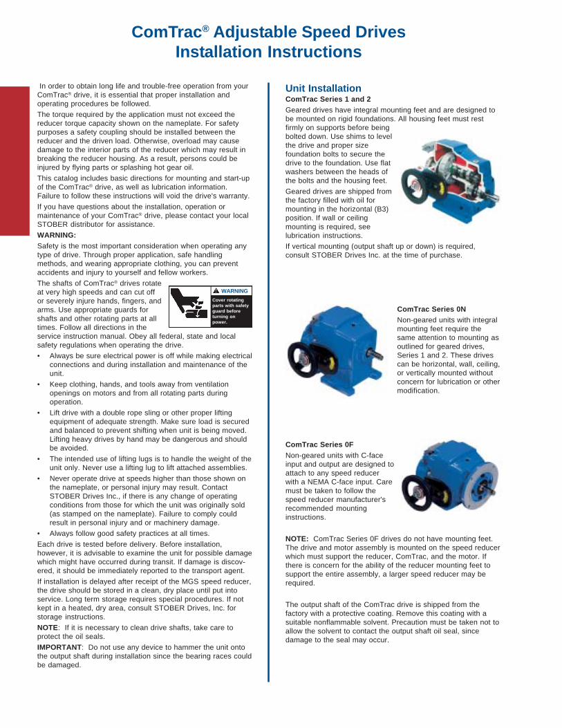
Unit InstallationComTrac Series 1 and 2Geared drives have integral mounting feet and are designed tobe mounted on rigid foundations. All housing feet must restfirmly on supports before beingbolted down. Use shims to levelthe drive and proper sizefoundation bolts to secure thedrive to the foundation. Use flatwashers between the heads ofthe bolts and the housing feet.
Geared drives are shipped fromthe factory filled with oil formounting in the horizontal (B3)position. If wall or ceilingmounting is required, seelubrication instructions.
If vertical mounting (output shaft up or down) is required,consult STOBER Drives Inc. at the time of purchase.
ComTrac Series 0NNon-geared units with integralmounting feet require thesame attention to mounting asoutlined for geared drives,Series 1 and 2. These drivescan be horizontal, wall, ceiling,or vertically mounted withoutconcern for lubrication or othermodification.
ComTrac Series 0FNon-geared units with C-faceinput and output are designed toattach to any speed reducerwith a NEMA C-face input. Caremust be taken to follow thespeed reducer manufacturer'srecommended mountinginstructions.
NOTE: ComTrac Series 0F drives do not have mounting feet.The drive and motor assembly is mounted on the speed reducerwhich must support the reducer, ComTrac, and the motor. Ifthere is concern for the ability of the reducer mounting feet tosupport the entire assembly, a larger speed reducer may berequired.
The output shaft of the ComTrac drive is shipped from thefactory with a protective coating. Remove this coating with asuitable nonflammable solvent. Precaution must be taken not toallow the solvent to contact the output shaft oil seal, sincedamage to the seal may occur.

Motor Installation
Step 1Remove the access cover.
Step 2Lubricate and insert keyed motor shaft into the slotted bore ofthe drive cone shaft.
NOTE: For ease of installation, secure the key to the motorshaft. (Staking near the end of the keyway or a temporaryadhesive works well.)
Step 3Tighten the four motor flange bolts.
IMPORTANT: Jog the motor several revolutions beforetightening the motor clamp to assure proper positionof the drive cone on the motor shaft.See Page 5 for an illustration.
ComTrac® Adjustable Speed DrivesInstallation Instructions
Step 4Through the access hole, tighten the hex socket screw on themotor clamp hub to the tightening torque shown in the tablebelow. The correct size hex wrench is provided. DO NOTOVERTIGHTEN.
SHOWN WITHOUT MOTOR FORDEMONSTATION PURPOSE.
Step 5Reattach access cover.
When couplings, gears, sprockets or pulleys are mounted onthe output shaft, be sure to mount them as close as possible tothe housing to minimize the effects of overhung loads on shaftsand bearings.
CAUTION: Do not drive couplings, sprockets, gears or pulleysonto the output shaft with hard hammer blows, since damage tointernal gears or bearings will result. All output shafts have ametric centering thread for attachment of transmission devices.They can be pulled on gently with a bolt and plate.
Table No. 1Clamp Ring Setscrew Tightening Torque
ComTrac Size in. lbs. ComTrac Size in. lbs.
TD27 88.5 TD57 434TD37 88.5 TD67 434TD47 221 TD76 434
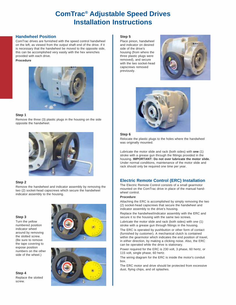
Handwheel PositionComTrac drives are furnished with the speed control handwheelon the left, as viewed from the output shaft end of the drive. if itis necessary that the handwheel be moved to the opposite side,this can be accomplished very easily with the hex wrenchesprovided with each drive.
Procedure
Step 1Remove the three (3) plastic plugs in the housing on the sideopposite the handwheel.
Step 2Remove the handwheel and indicator assembly by removing thetwo (2) socket-head capscrews which secure the handwheelindicator assembly to the housing.
Step 3Turn the yellownumbered positionindicator wheelaround by removingthe slotted screw.(Be sure to removethe tape covering toexpose positionnumbers on the otherside of the wheel.)
Step 4Replace the slottedscrew.
Step 5Place pinion, handwheeland indicator on desiredside of the drive'shousing (from where thethree plastic plugs wereremoved), and securewith the two socket-headcapscrews removedpreviously.
Step 6Relocate the plastic plugs to the holes where the handwheelwas originally mounted.
Lubricate the motor slide and rack (both sides) with one (1)stroke with a grease gun through the fittings provided in thehousing. IMPORTANT: Do not over lubricate the motor slide.Under normal conditions, maintenance of the motor slide andrack should only be required one time per year.
Electric Remote Control (ERC) InstallationThe Electric Remote Control consists of a small gearmotormounted on the ComTrac drive in place of the manual hand-wheel control.
ProcedureAttaching the ERC is accomplished by simply removing the two(2) socket-head capscrews that secure the handwheel andindicator assembly to the drive's housing.
Replace the handwheel/indicator assembly with the ERC andsecure it to the housing with the same two screws.
Lubricate the motor slide and rack (both sides) with one (1)stroke with a grease gun through fittings in the housing.
The ERC is operated by pushbutton or other form of contact(furnished by customer). A mechanical clutch is containedwithin the gearmotor which indicates the end position of travel,in either direction, by making a clicking noise. Also, the ERCcan be operated while the drive is stationary.
Power required for the ERC is 230 volt, 3 phase, 60 hertz, or115 volt, single phase, 60 hertz.
The wiring diagram for the ERC is inside the motor's conduitbox.
The ERC motor and drive should be protected from excessivedust, flying chips, and oil splashes.
ComTrac® Adjustable Speed DrivesInstallation Instructions
ComTrac® Adjustable Speed DrivesMaintenance and Lubrication Instructions
Maintenance and LubricationWARNING: Before beginning any work on the ComTracdrive system, disconnect the power source (lock-out themotor starter, and unload breakers, backstops, etc.).Failure to do so may cause serious personal injury and/ormachinery damage.
Non-geared drives – Series 0N and 0FThese units require lubricant only in the cam and bearingchamber and are shipped with the lubricant in them. There is asufficient quantity of lubricant to allow mounting the non-gearedComTrac Drive in any position.
For normal indoor installations the handwheel or ERC controlpinion and motor slide rack should be lubricated through thegrease fitting every six months using NLGI No. 2 grease. Onestroke of a grease gun is sufficient. When the drive is operatingunder wet conditions, increase the frequency of lubrication toonce a month.
Under normal operating conditions the synthetic oil in the camand bearing chamber does not need to be replaced. If for anyreason some quantity of lubricant is lost, remove the rest of thelubricant from the cam and bearing chamber and replace it withthe type and quantity of oil listed in the lubrication table shown.
For installations in the food, dairy, beverage and bakingindustries, where special lubricants are required, a suitablegrease of the user's preference should be used.
When a ComTrac Drive with C-face output (Series 0F) isattached to a speed reducer, follow the manufacturer'slubrication instructions for the reducer mounting before start-up.
ComTrac Drives – Series 1 and 2These drives are shipped with the correct amount of No. 4 EPoil for horizontal mounting. If the drive is to be mounted inanother position (wall or ceiling) it will be necessary to drain theoil and refill the drive with the correct amount of lubricant beforestart-up.
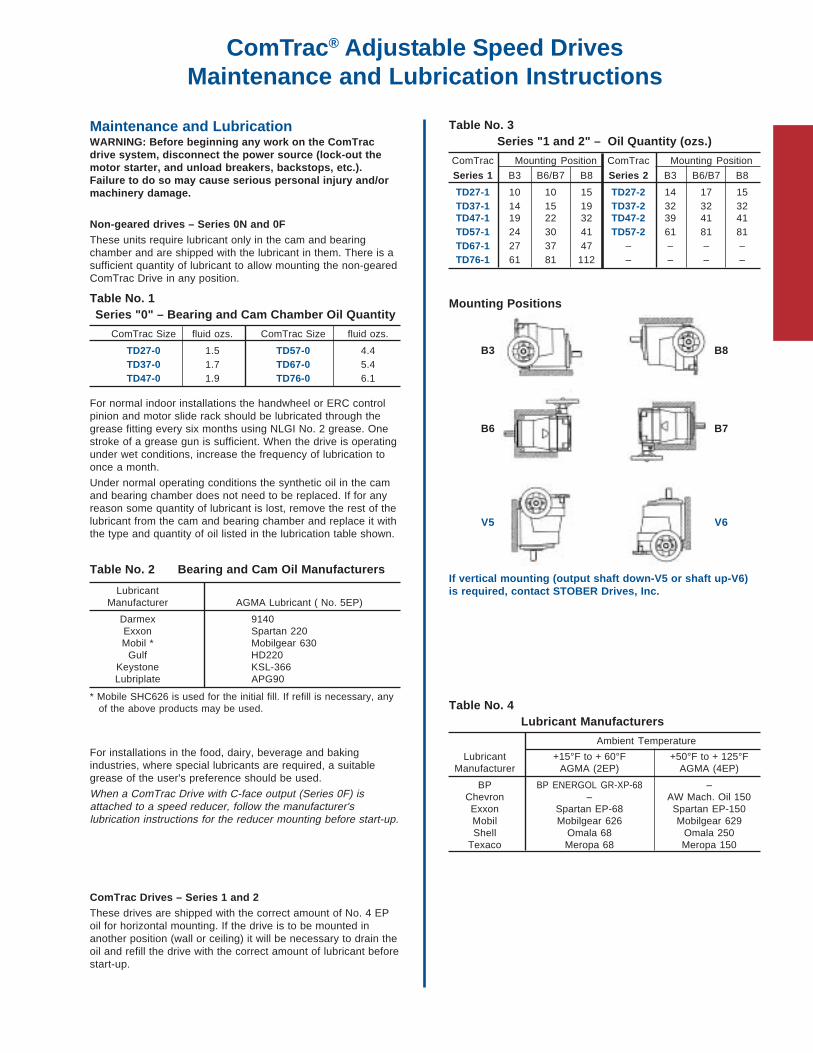
Table No. 1Series "0" – Bearing and Cam Chamber Oil Quantity
ComTrac Size fluid ozs. ComTrac Size fluid ozs.
TD27-0 1.5 TD57-0 4.4TD37-0 1.7 TD67-0 5.4TD47-0 1.9 TD76-0 6.1
Table No. 3Series "1 and 2" – Oil Quantity (ozs.)
ComTrac Mounting Position ComTrac Mounting Position
Series 1 B3 B6/B7 B8 Series 2 B3 B6/B7 B8
TD27-1 10 10 15 TD27-2 14 17 15TD37-1 14 15 19 TD37-2 32 32 32TD47-1 19 22 32 TD47-2 39 41 41TD57-1 24 30 41 TD57-2 61 81 81TD67-1 27 37 47 – – – –TD76-1 61 81 112 – – – –
Mounting Positions
B3 B8
B6 B7
V5 V6
If vertical mounting (output shaft down-V5 or shaft up-V6)is required, contact STOBER Drives, Inc.
Table No. 4Lubricant Manufacturers
Ambient Temperature
Lubricant +15°F to + 60°F +50°F to + 125°FManufacturer AGMA (2EP) AGMA (4EP)
BP BP ENERGOL GR-XP-68 –Chevron – AW Mach. Oil 150Exxon Spartan EP-68 Spartan EP-150Mobil Mobilgear 626 Mobilgear 629Shell Omala 68 Omala 250
Texaco Meropa 68 Meropa 150
Table No. 2 Bearing and Cam Oil Manufacturers
LubricantManufacturer AGMA Lubricant ( No. 5EP)
Darmex 9140Exxon Spartan 220Mobil * Mobilgear 630
Gulf HD220Keystone KSL-366Lubriplate APG90
* Mobile SHC626 is used for the initial fill. If refill is necessary, anyof the above products may be used.

"C" Series – MGS® Adjustable Speed DrivesDimensional Data
Drawing for UnitsC002N — C503N
See the MGS catalog for dimensions not shown.
Z
YYH
D
M
F I
L
U
V
E
Table No. 3 "C" Series Foot Mounting – "N" Housing Style – Approximate Weight (lbs.)
Part Number C002 C102 C202 C203 C302 C303 C402 C403 C502 C503 C612 C613 C712 C713 C812 C813 C912 C913
TD270K050(2) 51 62 71 78 82 89 — 111 128 144 — 148 — — — — — —TD370K140 69 80 89 — 100 — 122 129 146 162 — 210 — — — — — —TD470K180 — 88 97 — 108 — 130 — 154 — 174 218 — 280 — 401 — —TD570K180 — — 126 — 137 — 159 — 183 — 203 247 287 309 — 430 — —TD670K210 — — — — 179 — 201 — 225 — 245 — 329 — 452 472 — 808TD760K210 — — — — — — — — 289 — 309 — 393 — 516 — 790 —
(2) Also available as TD270K140 for a NEMA 143TC frame motor.
Table No. 1"C" Series – "N" Housing Style
Dimensions (Inches)
Base Module H U V
C002 3.23 .7500 1.57C102 4.02 1.0000 1.97
C202/C203 4.53 1.2500 2.36
C302/C303 5.12 (1) 1.2500 2.36C402/C403 5.71 1.6250 3.15C502/C503 6.69 1.6250 3.15
C612/C613 7.87 2.1250 3.94C712/C713 9.25 2.3750 4.72C812/C813 11.42 2.8750 5.51
C912/C913 13.39 3.6250 6.69(1) "H" dimension on the input side of a C303with an TD27 and TD37 will be 3.66.
Table No. 2"C" Series Foot Mounting Unit Dimensions (Inches) – "N" Housing Style
ComTrac NEMAPart No. C-Flange D F L X Y Z
TD270K050 56C 4.92 5.67 7.87 2.09 5.55 4.41TD270K140 143/145TC 4.92 5.67 7.87 2.09 5.55 4.41
TD370K140 143/145TC 4.92 5.91 8.50 2.17 5.67 4.37
TD470K180 182/184TC 6.30 6.81 8.94 2.80 7.20 5.59
TD570K180 182/184TC 7.87 8.31 11.89 3.11 8.11 6.30
TD670K210 213/215TC 7.87 9.17 12.17 3.86 9.02 7.13
TD760K210 213/215TC 9.84 9.72 14.25 4.29 9.37 7.68
X

"C" Series – MGS® Adjustable Speed DrivesDimensional Data
Part No. ExampleFoot Mounting with ComTrac
C302N0620 TD270K050-075
D
F
U
I
Z
Y
VX
LM
E
H
Drawing for UnitsC612N — C913N
Table No. 4 "C" Series – Foot Mounting Unit Dimensions (Inches) – "N" Housing Style
Base TD270K050 (2) TD370K140 TD470K180 TD570K180 TD670K210 TD760K210
Module E I M E I M E I M E I M E I M E I M
C002 1.65 12.40 6.22 1.18 13.07 6.22 — — — — — — — — — — — —
C102 2.44 13.70 7.52 1.97 14.37 7.52 1.42 14.49 7.60 — — — — — — — — —
C202 2.95 14.80 8.62 2.48 15.47 8.62 1.93 15.59 8.70 1.18 18.23 8.70 — — — — — —C203 2.01 16.50 10.31 — — — — — — — — — — — — — — —
C302 2.80 15.55 9.37 2.56 16.22 9.37 1.65 16.34 9.45 .16 18.98 9.45 -.71 19.29 9.57 — — —C303(1) 2.09 17.24 11.06 — — — — — — — — — — — — — — —C402 — — — 3.66 18.11 11.26 3.11 18.23 11.34 2.36 20.87 11.34 2.17 21.18 11.46 — — —C403 4.13 19.13 12.95 3.66 19.80 12.95 — — — — — — — — — — — —
C502 — — — 4.65 18.94 12.09 4.09 19.06 12.17 3.35 21.69 12.17 3.15 22.01 12.28 3.15 24.45 12.83C503 5.12 19.96 13.78 4.65 20.63 13.78 — — — — — — — — — — — —C612 — — — — — — 5.28 20.00 13.11 4.53 22.64 13.11 4.33 22.95 13.23 4.33 25.35 13.74C613 6.30 20.94 14.76 5.83 21.61 14.76 5.28 22.44 15.55 4.53 25.08 15.55 — — — — — —
C712 — — — — — — — — — 5.91 24.72 15.20 5.71 25.00 15.28 5.71 27.40 15.79C713 — — — — — — 6.65 24.49 17.60 5.91 27.13 17.60 — — — — — —C812 — — — — — — — — — — — — 7.87 27.64 17.91 7.87 29.65 18.03C813 — — — — — — 8.82 27.13 20.24 8.07 29.76 20.24 7.87 30.43 20.71 — — —
C912 — — — — — — — — — — — — — — — 9.84 32.68 21.06C913 — — — — — — — — — — — — 9.84 32.28 22.56 — — —
(1) "H" dimension on the input side of a C303 with an TD27 or TD37 is 3.66.(2) Also available for a NEMA 143TC frame motor.

"K" Series – Right Angle Helical/BevelMGS® Adjustable Speed Drives
Performance Specifications:• Horsepower ratings – from 1/2 to 10• Output speeds – available from 569 to .9 RPM• Speed range – 5:1 to 7:1• Output torques – up to 99,227 in.lbs.• NEMA frames – from 56C to 215TC
With the many mounting options available, ComTrac AdjustableSpeed Drives and MGS Helical/Bevel Speed Reducers offerconsistent, higher input-to-output efficiencies and a configura-tions for almost any application situation. This added efficiencyreduces your costs today through smaller gear drive and motorsizing. Tomorrow, you'll benefit through optimum energy savings.

Table No. 2Quantity of Lubricant
Module Quantityozs. liters
F102 27 .8F202 61 1.8F203 74 2.2F302 84 2.5F303 105 3.1F402 122 3.6F403 132 3.9F602 203 6.0F603 237 7.0
"F" Series – MGS® Adjustable Speed DrivesLubrication and Mounting Position
Position EL1 Position EL2
Position EL3 Position EL4
Position EL5 Position EL6
Table No. 3 Quantity of Lubricant
Module Quantity Module Quantity
ozs. liters ozs. liters
F102 24 .7 F402 95 2.8F202 41 1.2 F403 101 3.0F203 47 1.4 F602 162 4.8F302 68 2.0 F603 182 5.4F303 78 2.3
Table No. 4 Quantity of Lubricant
Module Quantity Module Quantity
ozs. liters ozs. liters
F102 24 .7 F402 95 2.8F202 41 1.2 F403 101 3.0F203 47 1.4 F602 162 4.8F302 68 2.0 F603 182 5.4F303 78 2.3
Table No. 6Quantity of Lubricant
Module Quantityozs. liters
F102 24 .7F202 54 1.6F203 64 1.9F302 68 2.0F303 78 2.3F402 101 3.0F403 118 3.5F602 186 5.5F603 220 6.5
Table No. 1Quantity of Lubricant
Module Quantityozs. liters
F102 24 .7F202 47 1.4F203 68 2.0F302 74 2.2F303 95 2.8F402 101 3.0F403 139 4.1F602 179 5.3F603 250 7.4
23
1
5
4
6
1
6
4
2
3
5
1
6
3
2
5
4
Table No. 5Quantity of Lubricant
"A" – Hollow OutputModule ozs. liters
F102 30 .90F202 71 2.10F203 76 2.25F302 101 3.00F303 117 3.45F402 155 4.60F403 169 5.00F602 257 7.60F603 274 8.10
"V" – Solid OutputModule ozs. liters
F102 30 .90F202 73 2.15F203 81 2.40F302 113 3.35F303 122 3.50F402 155 4.70F403 179 5.30F602 257 7.70F603 291 8.20
5
3
6
4
1
2
3
1
5
4
2
6
6
3
1
5
4
2

2
5
4
1
6
3 4
1
5
3
2
6
1
24
6
5
3
Position EL1K1 — K4
Position EL2K1 — K4
Position EL5K1 — K4
Position EL3K1 — K4
Position EL4K1 — K4
Position EL6K1 — K4
5 3
42
1
6
"K" Series – MGS® Adjustable Speed DrivesLubrication and Mounting Position
The unit shown has the shaft on Side 4 (left) in all drawings. Mounting position is not a description of shaft side extension.
Table No. 1Quantity of Lubricant
Module Quantityozs. liters
K102 14 .4K202 27 .8K203 51 1.5K302 41 1.2K303 61 1.8K402 84 2.5K403 118 3.5
Table No. 3Quantity of Lubricant
Module Quantityozs. liters
K102 24 .7K202 54 1.6K203 64 1.9K302 78 2.3K303 91 2.7K402 118 3.5K403 135 4.0
Table No. 5Quantity of Lubricant
Module Quantityozs. liters
K102 46 1.36K202 75 2.25K203 84 2.50K302 118 3.50K303 135 4.00K402 179 5.30K403 191 5.65
Table No. 6Quantity of Lubricant
Module Quantityozs. liters
K102 31 .9K203 68 2.0K203 81 2.4K302 101 3.0K303 118 3.5K402 135 4.0K403 152 4.5
Table No. 4Quantity of Lubricant
Module Quantityozs. liters
K102 24 .7K202 54 1.6K203 64 1.9K302 78 2.3K303 91 2.7K402 118 3.5K403 135 4.0
Table No. 2Quantity of Lubricant
Module Quantityozs. liters
K102 37 1.1K202 61 1.8K203 74 2.2K302 84 2.5K303 101 3.0K402 135 4.0K403 152 4.5
6
4
1
5
3
2
5
6
3
1
4
2

Table No. 1 Quantity of Lubricant
Module Quantity Module Quantity
ozs. liters ozs. liters
K513 101 3.0 K813 270 8.0K514 135 4.0 K814 439 13.0K613 132 3.9 K913 473 14.0K614 182 5.4 K914 777 23.0K713 170 5.0 K1013 1014 30.0K714 270 8.0 K1014 1115 33.0
Table No. 2 Quantity of Lubricant
Module Quantity Module Quantity
ozs. liters ozs. liters
K513 135 4.0 K813 406 12.0K514 152 4.5 K814 439 13.0K613 169 5.0 K913 676 20.0K614 186 5.5 K914 710 21.0K713 237 7.0 K1013 1588 47.0K714 253 7.5 K1014 1723 51.0
Position EL1K5 — K10
Position EL2K5 — K10
Position EL5K5 — K10
Position EL3K5 — K10
Position EL4K5 — K10
Position EL6K5 — K10
"K" Series – MGS® Adjustable Speed DrivesLubrication and Mounting Position
The unit shown has the shaft on Side 4 (left) in all drawings. Mounting position is not a description of shaft side extension.
Table No. 3 Quantity of Lubricant
Module Quantity Module Quantity
ozs. liters ozs. liters
K513 118 3.5 K813 406 12.0K514 135 4.0 K814 439 13.0K613 169 5.0 K913 713 21.1K614 186 5.5 K914 743 22.0K713 220 6.5 K1013 1690 50.0K714 237 7.0 K1014 1858 55.0
Table No. 5Quantity of Lubricant
"A" Hollow Output
Module ozs. liters Module ozs. liters
K513 193 5.7 K813 676 20.0K514 220 6.5 K814 727 21.5K613 280 8.3 K913 1250 37.0K614 304 9.0 K914 1301 38.5K713 372 11.0 K1013 1960 58.0K714 416 12.3 K1014 2129 63.0
"V" Solid OutputModule ozs. liters Module ozs. liters
K513 196 5.8 K813 710 21.0K514 223 6.6 K814 760 22.5K613 284 8.4 K913 1284 38.0K614 311 9.2 K914 1362 40.3K713 382 11.3 K1013 1960 58.0K714 426 12.6 K1014 2129 63.0
Table No. 6Quantity of Lubricant
Module Quantityozs. liters
K513 135 4.0K514 152 4.5K613 169 5.0K614 203 6.0K713 270 8.0K714 287 8.5K813 406 12.0K814 439 13.0K913 710 21.0K914 743 22.0K1013 1453 43.0K1014 1656 49.0
Table No. 4 Quantity of Lubricant
Module Quantity Module Quantity
ozs. liters ozs. liters
K513 118 3.5 K813 406 12.0K514 135 4.0 K814 439 13.0K613 169 5.0 K913 713 21.1K614 186 5.5 K914 743 22.0K713 220 6.5 K1013 1690 50.0K714 237 7.0 K1014 1858 55.0
24
63
5
1
1
3
4
5
62
3
2
6
4
1
5
3
4
5
2 6
1
6
4
1
5
2
3
54
2
6
3
1

"K" Series – MGS® Adjustable Speed DrivesDimensional Data
Drawing for UnitsK102AB — K403AB
See the MGS catalog for dimensions not shown.
U
D
F
B S
CD
M L
H
Y
X
Z
I
E
Table No. 1"K" Series – Basic Unit Dimensions (Inches)
"B" Housing StyleBase Module B H S U
K102 4.72 2.36 2.36 1.0000K202 5.83 2.56 2.56 1.1875
K302/K303 6.30 2.95 2.95 1.3750K402/K403 7.40 3.54 3.54 1.5000
K513/K514 7.87 6.30 3.94 2.0000K613/K614 8.46 7.48 4.72 2.0000
K713/K714 9.53 8.35 4.92 2.3750K813/K814 11.81 10.43 5.71 2.7500
K913/K914 13.78 12.40 7.09 3.2500K1013/K1014 16.14 14.76 8.86 4.0000
Table No. 2"K" Series – Basic Unit Dimensions (Inches) "B" Housing Style
ComTrac NEMAPart No. C-Flange D F L X Y Z
TD270K050 56C 4.92 5.67 7.87 2.09 5.55 4.41TD270K140 143/145TC 4.92 5.67 7.87 2.09 5.55 4.41
TD370K140 143/145TC 4.92 5.91 8.50 2.17 5.67 4.37
TD470K180 182/184TC 6.30 6.81 8.94 2.80 7.20 5.59
TD570K180 182/184TC 7.87 8.31 11.89 3.11 8.11 6.30
TD670K210 213/215TC 7.87 9.17 12.17 3.86 9.02 7.13
TD760K210 213/215TC 9.84 9.72 14.25 4.29 9.37 7.68
Table No. 3 "K" Series – "B" Housing Style – Approximate Weight (lbs.)
Part Number K102 K202 K302 K303 K402 K403 K513 K514 K613 K614 K713 K714 K813 K814 K913 K914 K1013 K1014
TD270K050(2) 64 73 100 106 — 133 — 142 — 210 — 267 — — — — — —TD370K140 82 91 118 124 144 151 157 160 — 228 — 285 — — — — — —TD470K180 — 99 126 — 152 — 165 — 229 — 280 293 — 390 — 589 — —TD570K180 — — 155 — 181 — 184 — 258 — 309 322 397 410 — 618 — —TD670K210 — — — — 223 — 236 — 300 — 351 — 439 — 638 660 — 1123TD760K210 — — — — — — — — 364 — 415 — 503 — 702 — 1107 1187
(2)Also available as TD270K140 for a NEMA 143TC frame motor.

Table No. 3 "K" Series – Basic Unit Dimensions (Inches) – "B" Housing Style
Base TD270K050(1) TD370K140 TD470K180 TD570K180 TD670K210 TD760K210
Module CD E I M E I M E I M E I M E I M E I M
K102 1.42 2.20 7.87 5.04 1.73 8.50 5.04 — — — — — — — — — — — —
K202 1.81 2.80 11.97 5.79 2.32 12.64 5.79 1.17 12.76 5.87 — — — — — — — — —K203 1.81 — — — — — — — — — — — — — — — — — —
K302 2.07 3.44 12.76 6.57 2.97 13.43 6.57 2.42 13.54 6.65 1.67 16.18 6.65 — — — — — —K303 .63 2.01 14.45 8.27 1.54 15.12 8.27 — — — — — — — — — — — —
K402 2.36 — — — 3.86 14.21 7.36 3.31 14.33 7.44 2.56 16.97 7.44 2.36 17.28 7.56 — — —K403 .91 2.87 15.24 9.06 2.40 15.91 9.06 — — — — — — — — — — — —
K513 .59 — — — 3.66 13.62 6.77 3.11 13.74 6.85 2.36 16.38 6.85 2.17 16.69 6.97 — — —K514 .59 4.13 14.65 8.46 3.66 15.31 8.46 — — — — — — — — — — — —
K613 .71 — — — — — — 4.17 14.49 7.60 3.43 17.13 7.60 3.23 17.44 7.72 3.23 19.88 8.27K614 .71 5.20 15.39 9.21 4.72 16.06 9.21 — — — — — — — — — — — —
K713 .79 — — — — — — 4.96 15.59 8.70 4.21 18.23 8.70 4.02 18.54 8.82 4.02 20.94 9.33K714 .79 5.98 16.54 10.35 5.51 17.20 10.35 4.96 18.03 11.14 4.21 20.67 11.14 — — — — — —
K813 .94 — — — — — — — — — 6.14 19.25 9.72 5.94 19.53 9.80 5.94 21.93 10.31K814 .94 — — — — — — 6.89 19.02 12.13 6.14 21.65 12.13 — — — — — —
K913 .98 — — — — — — — — — — — — 7.87 21.30 11.57 7.87 23.70 12.09K914 .98 — — — — — — 8.82 20.79 13.90 8.07 23.43 13.90 7.87 24.09 14.37 — — —
K1013 1.10 — — — — — — — — — — — — — — — 10.11 14.25 15.43K1014 1.10 — — — — — — — — — — — — 10.11 12.16 17.72 10.11 14.25 18.70
(1) Also available for a NEMA 143TC frame motor.
"K" Series – MGS® Adjustable Speed DrivesDimensional Data
Part No. Example
Basic Unit with ComTrac
K402AB0350 TD470K180-300
Drawing for UnitsK513AB — K1014AB
XLMS
U CD
H
I
Z
F
B
E
D Y
"K" Series – MGS® Adjustable Speed DrivesDimensional Data
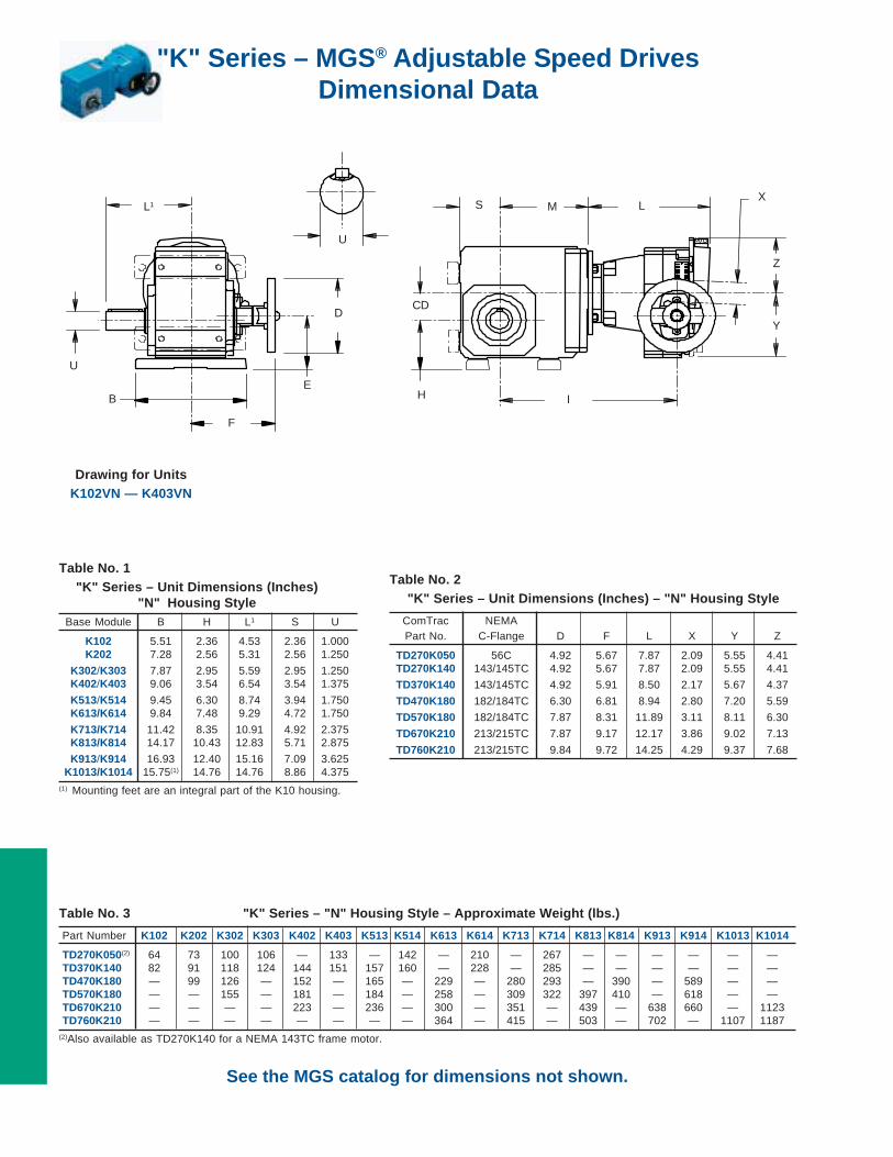
Drawing for UnitsK102VN — K403VN
See the MGS catalog for dimensions not shown.
Table No. 2"K" Series – Unit Dimensions (Inches) – "N" Housing Style
ComTrac NEMAPart No. C-Flange D F L X Y Z
TD270K050 56C 4.92 5.67 7.87 2.09 5.55 4.41TD270K140 143/145TC 4.92 5.67 7.87 2.09 5.55 4.41
TD370K140 143/145TC 4.92 5.91 8.50 2.17 5.67 4.37
TD470K180 182/184TC 6.30 6.81 8.94 2.80 7.20 5.59
TD570K180 182/184TC 7.87 8.31 11.89 3.11 8.11 6.30
TD670K210 213/215TC 7.87 9.17 12.17 3.86 9.02 7.13
TD760K210 213/215TC 9.84 9.72 14.25 4.29 9.37 7.68
Table No. 3 "K" Series – "N" Housing Style – Approximate Weight (lbs.)
Part Number K102 K202 K302 K303 K402 K403 K513 K514 K613 K614 K713 K714 K813 K814 K913 K914 K1013 K1014
TD270K050(2) 64 73 100 106 — 133 — 142 — 210 — 267 — — — — — —TD370K140 82 91 118 124 144 151 157 160 — 228 — 285 — — — — — —TD470K180 — 99 126 — 152 — 165 — 229 — 280 293 — 390 — 589 — —TD570K180 — — 155 — 181 — 184 — 258 — 309 322 397 410 — 618 — —TD670K210 — — — — 223 — 236 — 300 — 351 — 439 — 638 660 — 1123TD760K210 — — — — — — — — 364 — 415 — 503 — 702 — 1107 1187
(2)Also available as TD270K140 for a NEMA 143TC frame motor.
Table No. 1"K" Series – Unit Dimensions (Inches)
"N" Housing StyleBase Module B H L1 S U
K102 5.51 2.36 4.53 2.36 1.000K202 7.28 2.56 5.31 2.56 1.250
K302/K303 7.87 2.95 5.59 2.95 1.250K402/K403 9.06 3.54 6.54 3.54 1.375
K513/K514 9.45 6.30 8.74 3.94 1.750K613/K614 9.84 7.48 9.29 4.72 1.750
K713/K714 11.42 8.35 10.91 4.92 2.375K813/K814 14.17 10.43 12.83 5.71 2.875
K913/K914 16.93 12.40 15.16 7.09 3.625K1013/K1014 15.75(1) 14.76 14.76 8.86 4.375
(1) Mounting feet are an integral part of the K10 housing.
U
D
F
L1 S
CD
M L
H
Y
X
Z
IE
U
B

"K" Series – MGS® Adjustable Speed DrivesDimensional Data
Table No. 3 "K" Series – Unit Dimensions (Inches) – "N" Housing Style
Base TD270K050(3) TD370K140 TD470K180 TD570K180 TD670K210 TD760K210
Module CD E I M E I M E I M E I M E I M E I M
K102 1.42 2.20 7.87 5.04 1.73 8.50 5.04 — — — — — — — — — — — —
K202 1.81 2.80 11.97 5.79 2.32 12.64 5.79 1.17 12.76 5.87 — — — — — — — — —K203 1.81 — — — — — — — — — — — — — — — — — —
K302 2.07 3.44 12.76 6.57 2.97 13.43 6.57 2.42 13.54 6.65 1.67 16.18 6.65 — — — — — —K303 .63 2.01 14.45 8.27 1.54 15.12 8.27 — — — — — — — — — — — —
K402 2.36 — — — 3.86 14.21 7.36 3.31 14.33 7.44 2.56 16.97 7.44 2.36 17.28 7.56 — — —K403 .91 2.87 15.24 9.06 2.40 15.91 9.06 — — — — — — — — — — — —
K513 .59 — — — 3.66 13.62 6.77 3.11 13.74 6.85 2.36 16.38 6.85 2.17 16.69 6.97 — — —K514 .59 4.13 14.65 8.46 3.66 15.31 8.46 — — — — — — — — — — — —
K613 .71 — — — — — — 4.17 14.49 7.60 3.43 17.13 7.60 3.23 17.44 7.72 3.23 19.88 8.27K614 .71 5.20 15.39 9.21 4.72 16.06 9.21 — — — — — — — — — — — —
K713 .79 — — — — — — 4.96 15.59 8.70 4.21 18.23 8.70 4.02 18.54 8.82 4.02 20.94 9.33K714 .79 5.98 16.54 10.35 5.51 17.20 10.35 4.96 18.03 11.14 4.21 20.67 11.14 — — — — — —
K813 .94 — — — — — — — — — 6.14 19.25 9.72 5.94 19.53 9.80 5.94 21.93 10.31K814 .94 — — — — — — 6.89 19.02 12.13 6.14 21.65 12.13 — — — — — —
K913 .98 — — — — — — — — — — — — 7.87 21.30 11.57 7.87 23.70 12.09K914 .98 — — — — — — 8.82 20.79 13.90 8.07 23.43 13.90 7.87 24.09 14.37 — — —
K1013 1.10 — — — — — — — — — — — — — — — 10.11 14.25 15.43K1014 1.10 — — — — — — — — — — — — 10.11 12.16 17.72 10.11 14.25 18.70
(3) Also available for a NEMA 143TC frame motor.
Part No. Example
Foot Mounting Unit with ComTrac
K402VN0350 TD470K180-300
Drawing for UnitsK513VN — K1014VN
XLMS
UCD
H
I
Z
F
B
E
D YU
L1

MGS® Adjustable Speed DrivesOutput Options
Output Bore or Shaft Diameters
Table No. 1 "C"Series – Output Shaft Diameter
Base Inches
Module Standard Stainless Steel Metric (1)
C002 .750 .750 20C102/C103 1.000 1.000 25
C202/C203 1.250 1.250 30C302/C303 1.250 1.250 40
C402/C403 1.625 1.625 40C512/C513 1.625 1.625 40
C612/C613 2.125 2.125 50C712/C713 2.375 – 60
C812/C813 2.875 – 70C912/C913 3.625 – 90
Table No. 2 "F" Series – Output Diameters Options
Base Stainless Bushing Bores Sizes – inches Hollow Shaft
Module 3/4 1 13/16 11/4 13/8 17/16 11/2 15/8 111/16 13/4 17/8 115/16 2 Standard Stainless Metric (1) Standard Metric (1)
F102 x — — — — — — — — — — — — .750 – 20 1.000 25
F202/F203 — x x — — — — — — — — — — 1.000 1.000 25 1.250 30
F302/F303 — x x x x x x — — — — — — 1.250 1.250 30 1.375 35
F402/F403 — x x x x x x — — — — — — 1.500 – 40 1.625 40
F602/F603 — — x — — x x x x x x x x 2.000 – 50 2.125 50
Table No. 4 "K" Series – Stainless Steel Bushing Bores
Base Stainless Steel Bushing Bores – inches Metric
Module 1 13/16 11/4 13/8 17/16 11/2 15/8 111/16 13/4 17/8 115/16 2 23/16 23/8 27/16 23/4 40
K102 x — — — — — — — — — — — — — — — —
K202/K203 x x — — — — — — — — — — — — — — —K302/K303 x x x x x x — — — — — — — — — — —K402/K403 x x x x x x — — — — — — — — — — x
K513/K514 — — — — x x x x x x x x — — — — xK613/K614 — — — — x x x x x — x x x — — — x
K713/K714 — — — — — — — — — — x x x x — — —K813/K814 — — — — — — — — — — — — x x x x —
(1) Contact STOBER Drives for availability.(2 "K" Series stainless steel shaft are single side ONLY.
Table No. 3 "K" Series Output Shaft and Bore Diameters
Base Hollow Shaft
Module Standard Stainless Metric (1) Standard Stainless (2) Metric (1)
K102 1.000 1.000 25 1.000 1.000 25K202/K203 1.187 1.250 30 1.250 1.250 30
K302/K303 1.375 1.250 & 1.375 30 1.250 1.250 30K402/K403 1.500 — 40 1.375 1.375 40
K513/K514 2.000 — 50 1.750 1.750 45K613/K614 2.000 — 50 1.750 1.750 50
K713/K714 2.375 — 60 2.375 2.375 60K813/K814 2.750 — 70 2.875 2.875 70
K913/K914 3.250 — 90 3.625 — 90K1013/K1014 4.000 — 100 4.375 — 110