MEASUREMENT - Chauvin Arnoux
224
chauvin-arnoux.com TEST & MEASUREMENT 20 22
-
Upload
khangminh22 -
Category
Documents
-
view
0 -
download
0
Transcript of MEASUREMENT - Chauvin Arnoux
2022
TES
T &
MES
UR
EMEN
T CA
TALO
GU
E
9061
3115
3 -
Ed. 1
- 0
2/20
22 -
Non
-con
tract
ual d
ocum
ent.
Spec
ifica
tions
sub
ject
to m
odifi
catio
n du
e to
tech
nolo
gica
l dev
elop
men
ts.
chauvin-arnoux.comGB
TEST
&
MEASUREMENT20
22
10 SUBSIDIARIES WORLDWIDEAUSTRIACHAUVIN ARNOUX GES.M.B.HSlamastrasse 29/2/4par Gastgegasse 27Tel.: +43 1 61 61 9 61Fax: +43 1 61 61 9 [email protected]
CHINASHANGHAI PU-JIANGENERDIS INSTRUMENTS CO., LTD.3 Floor, 23 BuildingGemdale Viseen Minhang Technology& Industrial Park Project1288 lane, Zhongchun Road MinhangDistrict, SHANGHAI City.Tel.: +86 21 65 21 51 96Fax: +86 21 65 21 61 [email protected]
GERMANYCHAUVIN ARNOUX GMBHOhmstraße 177694 KEHL / RHEINTel.: +49 07851 99 26-0Fax: +49 07851 99 [email protected]
ITALYAMRA SPAVia Sant’Ambrogio, 2320846 MACHERIO (MB)Tel.: +39 039 245 75 45Fax: +39 039 481 [email protected]
MIDDLE EASTCHAUVIN ARNOUX MIDDLE EASTPO Box 60-1541241 2020 JAL EL DIB(Beirut) - LEBANONTel.: +961 1 890 425Fax: +961 1 890 [email protected]
SCANDINAVIACA MÄTSYSTEM ABSjöflygvägen 35SE-183 62 TABYTel.: +46 8 50 52 68 00Fax: +46 8 50 52 68 [email protected]
SPAINCHAUVIN ARNOUX IBÉRICA SAC/ Roger de Flor N°293 1a Planta08025 BARCELONATel.: +34 902 20 22 26Fax: +34 934 59 14 [email protected]
SWITZERLANDCHAUVIN ARNOUX AGMoosacherstrasse 158804 AU / ZHTel.: +41 44 727 75 55Fax: +41 44 727 75 [email protected]
USACHAUVIN ARNOUX INCd.b.a AEMC Instruments15 Faraday DriveDover - NH 03820Tel. : +1 (800) 945-2362Fax : +1 (603) [email protected]
FRANCECHAUVIN ARNOUX12-16 Rue Sarah Bernhardt92600 Asnières-Sur-SeineTel.: +33 1 44 85 44 85Fax: +33 1 46 27 73 [email protected]
INTERNATIONAL CHAUVIN ARNOUX12-16 Rue Sarah Bernhardt92600 Asnières-Sur-SeineTel.: +33 1 44 85 44 38Fax: +33 1 46 27 95 [email protected]
SWITZERLANDCHAUVIN ARNOUX AGMoosacherstrasse 158804 AU / ZHTel.: 044 727 75 55Fax: 044 727 75 [email protected]
2 CATALOGUE TEST & MESURE 2021 www.chauvin-arnoux.com2
TITRE > CATÉGORIE > NOM PRODUIT
TEST & MEASUREMENT CATALOGUE 2022 www.chauvin-arnoux.com
3CATALOGUE TEST & MESURE 2021 www.chauvin-arnoux.com 3
TITRE > CATÉGORIE > NOM PRODUIT
TEST & MEASUREMENT CATALOGUE 2022 www.chauvin-arnoux.com
ACCESSORIES _______________________________ 150
Cables & measurement probes with Ø4 banana connections ________________________ 150Accessories for Voltage Absence Testers or product-specific accessories ______________ 152Other accessories ______________________________________________________ 153Protection, storage and transport ___________________________________________ 154Fuses _______________________________________________________________ 156
UNIVERSAL TEST AND MEASUREMENT _______________ 14
Testers _______________________________________________________________ 16Voltage detectors ________________________________________________________ 18Analogue multimeters _____________________________________________________ 21Digital multimeters _______________________________________________________ 23Digital ammeters ________________________________________________________ 28Digital clamps __________________________________________________________ 29
PHYSICAL & ENVIRONMENTAL MEASUREMENTS ________ 106
Calibrators ___________________________________________________________ 108Thermal cameras _______________________________________________________ 111Thermometers _________________________________________________________ 116PH-meters ____________________________________________________________ 132Conductimètre _________________________________________________________ 133Other physical and environmental measuring equipment ___________________________ 123
ELECTRICAL SAFETY ___________________________ 34
Installation testers _______________________________________________________ 39Insulation testers ________________________________________________________ 45Multimeter clamps for leakage current ________________________________________ 55 Earth and resistivity testers ________________________________________________ 56Electrical equipment testers ________________________________________________ 63Other testers ___________________________________________________________ 68Data processing software __________________________________________________ 74Accessories ____________________________________________________________ 76
CURRENT MEASUREMENT _______________________ 138
Current clamps AC ______________________________________________________ 139Current clamps AC/DC ___________________________________________________ 141Flexible sensors and probes _______________________________________________ 142
ENERGY QUALITY & INSTALLATION MONITORING ________ 84
Power and harmonics clamps _______________________________________________ 86Power and energy quality analysers ___________________________________________ 88
SOLAR POWER ANALYSERS ________________________ 93
Loggers _______________________________________________________________ 94Data processing software _________________________________________________ 102
LABORATORY & EDUCATIONAL INSTRUMENTATION ______ 144
Training benches _______________________________________________________ 146Training cases _________________________________________________________ 147
METRIX ___________________________________________________________ 158Analogue testers & multimeters _____________________________________________ 160 On-site multimeters _____________________________________________________ 164 Digital multimeters ______________________________________________________ 170 Pocket clamp multimeters ________________________________________________ 174 On-site electrical safety tester _____________________________________________ 178 Benchtop oscilloscopes __________________________________________________ 181 Portable digital oscilloscopes ______________________________________________ 187 Spectrum analyser ______________________________________________________ 198 Generators ___________________________________________________________ 200 Power supplies _________________________________________________________ 206 Multifunction calibrators __________________________________________________ 208 Training cases and shunts _________________________________________________ 210 Accessories for oscilloscopes ______________________________________________ 211 Fuses _______________________________________________________________ 219
THE CHAUVIN ARNOUX GROUPAbout the Chauvin Arnoux Group ______________________________________________ 4
2 CATALOGUE TEST & MESURE 2021 www.chauvin-arnoux.com4 TEST & MEASUREMENT CATALOGUE 2022 www.chauvin-arnoux.com
CHAUVIN ARNOUX GROUP > ABOUT THE CHAUVIN ARNOUX GROUP
This calibration potentiometer dating from 1900 was used with a standard battery and a galvanometer like the one shown above. Its price was 195 francs!
The Monoc L On both the French MICA multimeter in 1985 and the ANAGRAF American version available the same year, the yellow of Chauvin Arnoux is clearly in evidence.
CDA 600 Polyclamp (1982)
MX 511895 reflection galvanometer
neoprene, first designed and patented by Metrix® and Chauvin Arnoux in 1958. These shockproof sheaths later became widely used on the handheld instrument market.
With the 1970s came plastics technology. This was when Chauvin Arnoux launched worldwide its first innovative products made of black and yellow plastic: the CDA 8 tester in 1979, the CDA 600 multimeter clamp in 1982, followed by the whole range. Some earth testers, such as the Terca in 1985 and the Prowatt wattmeters in 1989, also had a yellow casing..
The combination of yellow and black for on-site equipment began to spread with its use for safety signage and for identifying hazardous areas on site. This encouraged Chauvin Arnoux to launch the well-known IMEG 500 or ISOL1000 series in Europe andthen in the United States with the company’s two colours.
The MAN’X 500 series launched by Chauvin Arnoux, the very first multimeters made of a flexible material, further strengthened the company’s visual identity.At about the same time, Metrix launched several products with yellow casings and black platens, including the instruments in its MX 44 series (1988) followed by the MX 51 series.Over the years, Chauvin Arnoux has developed its visual identity across all its product ranges: its multimeters, wattmeters, megohmmeters and installation testers all bear the company’s colours.
One last remark about colours: while yellow is always seen as the colour of the sun and of certain kings or emperors in Asia, it is not so widely known that in physics, black is the symbol of a “black body”, meaning a system which absorbs all the light it receives. Black and yellow? A historic tandem for Chauvin Arnoux which was the first company to use this pairing for its corporate visual identity in the early 20th century when it first designed its logo in 1927.
Axel Arnoux
It is often said that at the root of knowledge is language, or that the origin of an innovation was an idea,… yet it is the individual, the person, who is really the source of knowledge and discoveries. This also applies to electricity, which was not invented in the 19th century, but discovered in the 6th century BCE by a Greek philosopher and scientist named Thales, the first person to note the electrostatic properties of amber.
From the beginning of the 19th century, there was the yellow of amber. Then manufactured goods began to include the yellow of brass and copper, materials used in measurement instruments, either for the casings of galvanometers or for the connections of electrical measurement instruments. Beige was also introduced with the use of varnished wood in the casings, while black was reserved for the instruments’ dials. Right from the start in 1893, the contrast between black and the yellow of varnished wood soon became the norm for the measurement instruments produced by Chauvin Arnoux.
In a relatively short time, between 1900 and 1936, with the development of new technologies and new techniques for working materials, yellow brass began to be used with black Bakelite, eventually spreading to nearly all our instruments.Already known for its sense of design and the combination of its original colours yellow brass and black, in its measurement instruments, Chauvin Arnoux reproduced these colours in its first corporate logo in 1927.
In the 1940s, many measurement instruments only used black or black and the silver-grey of ferrous metals, sometimes painted. Chauvin Arnoux adapted its original visual identity to suit the fashions of the time, which also corresponded to technical criteria for safety, life-span extension or weight considerations linked to the metal and the manufacturing process used.
The 1950s saw the arrival of rubber-like materials, used for the bases of portable instruments, and subsequently for the shockproof sheaths made of black
Every story starts somewhere. The story of the Chauvin Arnoux company as an inventor and manufacturer of measuring instruments since 1893 is rich in developments and innovations. Today, its products bear witness to and reflect the sociological and technological changes and the industrial innovations which marked the previous century. A fascinating story that explains why and how Chauvin Arnoux’s image and personality evolved... in two colours.
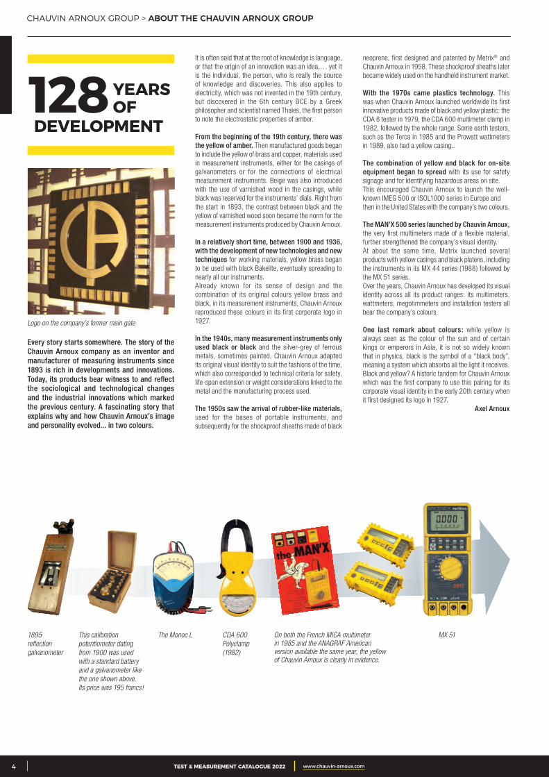
Logo on the company’s former main gate
YEARS OF128
DEVELOPMENT

3CATALOGUE TEST & MESURE 2021 www.chauvin-arnoux.com 5TEST & MEASUREMENT CATALOGUE 2022 www.chauvin-arnoux.com
MEASUREMENT EXPERTS
The French electrical measurement specialist and international Group CHAUVIN ARNOUX relies on its Chauvin Arnoux® brand to propose a wide range of portable measuring instruments.
Its offering covers the following sectors:
• electrical measurement (testers, multimeters and current clamps)
• electrical safety testing ( insulation testers, ohmmeters, earth/ground testers)
• recording and analysis of the power values (wattmeters and network quality analysers)
• measurement of physical quantities (thermal cameras, luxmeters, sound level meters)
Laboratory and educational instruments (training benches and cases) complete the scope of its expertise.
In our laboratories, we carry out strict quality inspections and tests at each stage in the design and manufacturing processes: functional and metrological testing, mechanical and climatic testing, electromagnetic compatibility testing, electrical safety testing, ageing tests, etc.
eco-design label for product development based on an eco-friendly approach
The Group’s ISO 9001 certification for the design processes and ISO 14001 certification for the manufacturing and sales processes demonstrate its determination to reconcile business and protection of the environment.
QUALITY, STANDARDS AND ECO-RESPONSIBLE APPROACH • Portable testers and multimeters• Current clamps & multimeter clamps• Insulation, earth and continuity testers• Installation and electrical equipment testers• Wattmeter-energy meters & electrical disturbance analysers• Thermal cameras, thermometers, tachometers, field meters, luxmeters, etc.• Loggers• Training benches
A FEW FIGURES
100 millions euros of sales revenues
128 years in business 10 subsidiaries
across the world
11%of revenues invested in R&D
6 R&D departments worldwide
1,000employees 8
production sites3 in Normandy (France)1 in Lyon (France)1 in Montpellier (France)1 in Milan (Italy)1 in Dover (USA)1 in Shanghai (China)
Electrical generation, transmission, distribution, installation & maintenance
Tertiary and industrial maintenance, diagnostics & testing
Improvement of energy efficiency
R&D and laboratory work Education
KNOW-HOW ACKNOWLEDGED IN ALL SECTORS OF ACTIVITY
CHAUVIN ARNOUX GROUP > ABOUT THE CHAUVIN ARNOUX GROUP
Metering,control &supervision
6 expert measurementcompanies
Design of optical sensors for quality control in the laboratory and in-line processes
Temperaturesensors
Metrology& regulatorytesting
Expert in measuring agri-foodproduct quality in real time byuorescence and infrared
Portable test& measurementinstrumentationChauvin Arnoux®,Metrix® andMultimetrix®
brands
1893-2022

CHAUVIN ARNOUX GROUP > ALWAYS AT YOUR SERVICE > WWW.CHAUVIN-ARNOUX.COM
PRINT & DIGITAL MEDIA FOR COMPLEMENTARY COMMUNICATION WHILE KEEPING IN CONTACT
every day. Chauvin Arnoux, Chauvin Arnoux Energy, Pyrocontrole, Indatech and Manumesure: each of these entities presents the full extent of its offering through its products, its skills, its applications and its publications, backed by a common visual identity giving a structured image of the Group.
ONLINE SALESThe Group proposes online sales of its main products. With just a few clicks, you can order the products and accessories you need, which then be delivered directly to you or to a pick-up location.
Electrical, climatic, dimensional, force, weighing…Let us calibrate your measuring instruments!
• 12 agencies all over France• Operations on site and in the laboratory• Maintenance, fleet management, repair, etc.
CONTACT US [email protected] Tel.: + 33 231 64 51 35 www.manumesure.fr
METROLOGY & REGULATORY ENVIRONMENTAL TESTING
Save time by using our
online quotation request form
PRESENT ON SOCIAL MEDIAFollow all Chauvin Arnoux’s news on the three main social media and our YouTube channel.
Facebook www.facebook.com/ChauvinArnouxFranceTwitter twitter.com/ChauvinArnouxFrLinkedin www.linkedin.com/company/99353Youtube www.youtube.com/c/chauvinarnouxgroup
Whatever the device used, whether it is a smartphone, tablet or computer, Chauvin Arnoux offers users a website which guides them as they browse. It is simple to find, share and com-bine information, and offering more relevant information is an obvious target which the Group strives to achieve every day.
A STRUCTURED WEBSITE Whatever the device used, whether it is a smartphone, tablet or computer, Chauvin Arnoux offers users a website which guides them as they browse. It is simple to find, share and combine information, and offering more relevant information is an obvious target which the Group strives to achieve
Drawing on its long history of close, privileged links with the French National Education system, the Chauvin Arnoux Group supports the players in education by participating in a large number of events, publishing the review “Les Cahiers de l’Instrumentation” and offering measuring instru-mentation suited to the teaching requirements. A Measurement Certification and a dedicated web-site for students and teachers are also proposed to deal with the new constraints and to accompany tomorrow’s professionals as closely as possible.
THE “MEASUREMENT CLUB”: A GENUINE FORUM FOR EXPERTISE!The “Club du Mesurage” (Measurement Club) is a genuine think-tank bringing together experts from business and educa-tion in order to generate a constant flow of informa-tion about the evolution of the standards, the new market requirements, ap-plications and particularly new applications… Open
CHAUVIN ARNOUX, A LONG-TERM PARTNER FOR EDUCATION
to all members of the Education sector, this Club allows genuine theoretical debate as well as creating a forum of expertise between two communities brought together by common objectives , leading every year to publication of Chauvin Arnoux’s magazine for Education, “Les Cahiers de l’Instrumentation”.
“LES CAHIERS DE L’INSTRUMENTATION”: THE MAGAZINE FOR EDUCATIONThe magazine “Les Cahiers de l’instrumentation” is a collection of practical exercises published annually for teachers and their students, providing concrete illustra-tions of solutions or the use of measuring, testing and energy control instruments.
A PRODUCT OFFERING DEDICATED TO THE EDUCATION SECTORThe Chauvin Arnoux Group proposes a special dedicated offering for the world of education which is presented every year in the “Selection for Education” catalogue.
PARTNER OF MANY EDUCATIONAL EVENTSEvery year, the Chauvin Arnoux Group acts as a partner
and sponsor for a large number of events linked to the educational sector, intended to promote technical and scientific education by measuring equipment loans, the participation of Chauvin Arnoux managers in the judging panels or the provision of prizes for competitions.
MEASUREMENT CERTIFICATION DEDICATED TO STUDENTS AND TEACHERSTo deal with the new constraints and to support tomorrow’s professionals as closely as possible, CHAUVIN ARNOUX has set up a measurement certification programme, in cooperation with the French national education system. The aim of this certification is to confirm students’ knowledge of the use of measuring instruments by means of an online multiple-choice ques-tionnaire.
• La méthode d’identification paramétrique• Un mode « SMART »
– Véhicules électriques et bornes de charge– TP : La nécessité des mesures
dans un monde « Smart »
• La méthode d’identification paramétrique• Un mode « SMART »
– Véhicules électriques et bornes de charge– TP : La nécessité des mesures
dans un monde « Smart »
• Une évolution du mesurage, quand les capteurs deviennent virtuels
• TP : Capteurs logiciels• Concours général des métiers
de l’automobile
• Une évolution du mesurage, quand les capteurs deviennent virtuels
• TP : Capteurs logiciels• Concours général des métiers
de l’automobile
de l ' inst rumentat ionLe journal d'information pour l'enseignement de Chauvin Arnoux et Metrix
Les CahiersCahiersDécembre 2018 n° 18
L’ÉVOLUTIONDE LA MESURE ÉLECTRIQUE
L’ÉVOLUTION DE LA MESURE ÉLECTRIQUE
Les Cahiers N°18_Mise en page 1 30/11/2018 11:10 Page1
CER
T I F I CAT I ON
IIIIII I I I I I M E S U R E I
I II I
IIIII
CERTIFICATIONMESURE
CERTIFICATION MESURE
CERTIFICATIONMESURE
DÉCOUVREZ LE SITE CERTIFICATION MESUREhttp://certification-mesure.chauvin-arnoux.com
ELEEC ELEC FEDTMSECTFCA TISEC MSMEI
et un nouveau site web dédiés aux étudiants et enseignants
BTS
BAC
PRO
2 CATALOGUE TEST & MESURE 2021 www.chauvin-arnoux.com6
Discover Measurement Certification:certification-mesure.chauvin-arnoux.com
TEST & MEASUREMENT CATALOGUE 2022 www.chauvin-arnoux.com

CHAUVIN ARNOUX GROUP > TRAINING
CHAUVIN ARNOUX, A CERTIFIED TRAINING ORGANIZATION SINCE 1993
The Chauvin Arnoux Group proposes six one-day training modules. Whether you need theoretical training or practical experience based around a product, choose the market leader to train you and your staff. A training course dedicated to energy auditing has been set up specially to help you perform the right measurements.
ENERGY AUDITS: CHOOSE THE RIGHT MEASUREMENTS• The advantages of energy auditing
• Economical, environmental and regulatory constraints
• People authorized to perform an energy audit
• Towards a continuous improvement process: the ISO 50001 standard
• Choosing the right measuring tool
• Defining the potential sources of energy savings and the related measurements
• Implementing appropriate solutions
ELECTRICAL INSTALLATIONS AND ENERGY QUALITY• Excessive consumption of reactive energy
leading to penalty payments.
• Loss of service continuity at the first fault on an IT system.
• Untimely tripping of the circuit-breakers protecting industrial electrical equipment.
• Untimely tripping of RCDs.
• Random fault on an electricity distribution system.
UNDERSTANDING AND OVERCOMING HARMONICS• The basics of harmonic phenomena.
• Identifying and characterizing the sources of disturbances.
• Measuring and detecting the phenomena in experimental conditions using a harmonic analyser.
• The applicable standards and labels.
• Understanding the effect of harmonics on the electrical components using real cases.
• How to deal with harmonic disturbances.
ELECTRICAL INSTALLATIONS AND IEC 60364-6• Properties and objectives of the earth/ground connection systems
• Behaviour of the earth/ground connection systems with regard to harmonics
• Insulation resistance measurement
• Electrical continuity measurements on protective conductors
• Resistance measurements on earth/ground electrodes
• Residual Current Device (RCD) testing
THERMOGRAPHY• Understanding heat exchange phenomena.
• Measuring with an infrared thermographic camera.
• Interpreting the measurements.
• Overview of all the applications of thermography and the present obligations.
CA 8336 NETWORK ANALYSER• Setup and connections
• Presentation of the various measurements and functions: waveforms, harmonics, transients, alarms, etc.
• Recording and measurement campaigns
• Analysis of the measurement results
• Simulation exercise with the instrument on an electrical model
• Expert training instructors acknowledged in their fields
• Innovative demonstration equipment to understand and operate
• Limited number of participants for high-quality discussions
Training courses provided at the Chauvin Arnoux Group’s new headquarters in Asnières, at the gates of Paris.
TRAINING IS AN ESSENTIAL ADVANTAGE IN ANYONE’S CAREER.• Favouring skills development
• Gaining access to the different levels of qualification
• Obtaining authorizations
Detailed training schedule and registration form available from www.chauvin-arnoux.com or by sending a simple request to [email protected]
3CATALOGUE TEST & MESURE 2021 www.chauvin-arnoux.com 7TEST & MEASUREMENT CATALOGUE 2022 www.chauvin-arnoux.com
2 CATALOGUE TEST & MESURE 2021 www.chauvin-arnoux.com8 TEST & MEASUREMENT CATALOGUE 2022 www.chauvin-arnoux.com
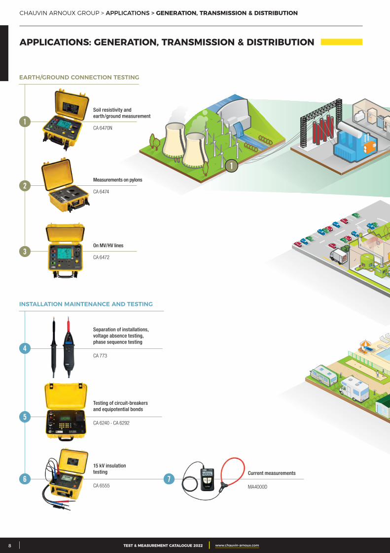
CHAUVIN ARNOUX GROUP > APPLICATIONS > GENERATION, TRANSMISSION & DISTRIBUTION
Separation of installations, voltage absence testing, phase sequence testing
CA 773
Testing of circuit-breakers and equipotential bonds
CA 6240 - CA 6292
15 kV insulation testing
CA 6555
Current measurements
MA4000D
INSTALLATION MAINTENANCE AND TESTING
Measurements on pylons
CA 6474
On MV/HV lines
CA 6472
Soil resistivity and earth/ground measurement
CA 6470N
EARTH/GROUND CONNECTION TESTING
1
2
3
1
APPLICATIONS: GENERATION, TRANSMISSION & DISTRIBUTION
4
5
6 7
3CATALOGUE TEST & MESURE 2021 www.chauvin-arnoux.com 9TEST & MEASUREMENT CATALOGUE 2022 www.chauvin-arnoux.com
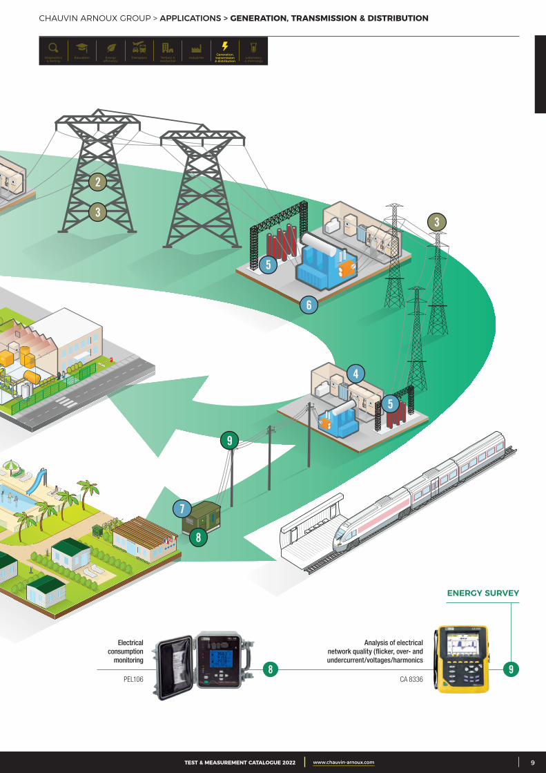
CHAUVIN ARNOUX GROUP > APPLICATIONS > GENERATION, TRANSMISSION & DISTRIBUTION
2
33
4
5
5
7
6
8
9
Analysis of electrical network quality (flicker, over- and undercurrent/voltages/harmonics
CA 8336
ENERGY SURVEY
Electrical consumption
monitoring
PEL1068 9
Generation, transmission & distribution
IndustriesTertiary & residential
Education TransportsDiagnostics & testing
Energy efficiency
Laboratory & metrology
2 CATALOGUE TEST & MESURE 2021 www.chauvin-arnoux.com10 TEST & MEASUREMENT CATALOGUE 2022 www.chauvin-arnoux.com
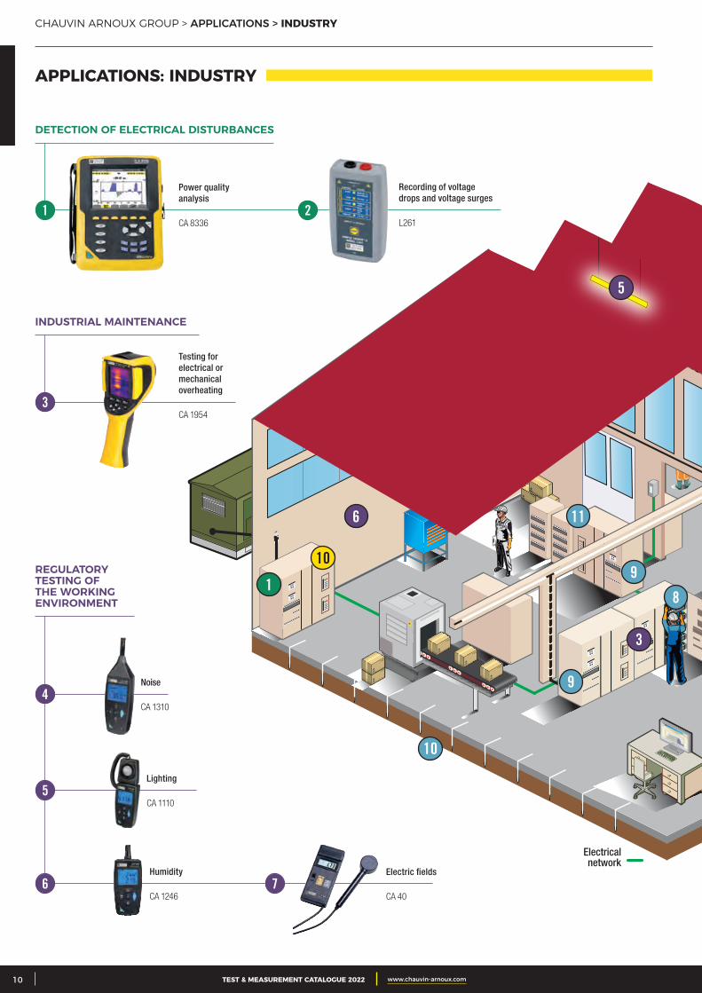
CHAUVIN ARNOUX GROUP > APPLICATIONS > INDUSTRY
APPLICATIONS: INDUSTRY
1
10
10
9
11
8
9
3
5
6
Electrical network
Power quality analysis
CA 8336
Testing for electrical or mechanical overheating
CA 1954
Noise
CA 1310
Lighting
CA 1110
Humidity
CA 1246
Electric fields
CA 40
Recording of voltage drops and voltage surges
L261
DETECTION OF ELECTRICAL DISTURBANCES
INDUSTRIAL MAINTENANCE
REGULATORY TESTING OF THE WORKING ENVIRONMENT
1
3
4
5
6 7
2
3CATALOGUE TEST & MESURE 2021 www.chauvin-arnoux.com 11TEST & MEASUREMENT CATALOGUE 2022 www.chauvin-arnoux.com
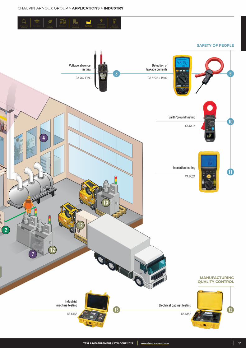
CHAUVIN ARNOUX GROUP > APPLICATIONS > INDUSTRY
2
4
7
13
12
12
SAFETY OF PEOPLE
Detection of leakage currents
CA 5275 + B102
Earth/ground testing
CA 6417
Insulation testing
CA 6524
Electrical cabinet testing
CA 6155
MANUFACTURING QUALITY CONTROL
Industrial machine testing
CA 616513 12
9
Voltage absence testing
CA 762 IP2X 8
10
11
Generation, transmission & distribution
IndustriesTertiary & residential
Education TransportsDiagnostics & testing
Energy efficiency
Laboratory & metrology
2 CATALOGUE TEST & MESURE 2021 www.chauvin-arnoux.com12 TEST & MEASUREMENT CATALOGUE 2022 www.chauvin-arnoux.com
CHAUVIN ARNOUX GROUP > APPLICATIONS > HOUSING & TERTIARY
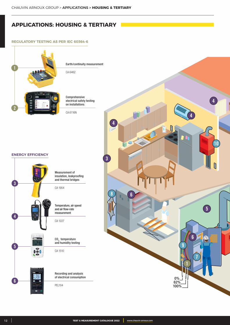
APPLICATIONS: HOUSING & TERTIARY
1
3
44
4
5
6
6
7
10
8
9
0%62%
100%
Earth/continuity measurement
CA 6462
Comprehensive electrical safety testing on installations
CA 6116N
REGULATORY TESTING AS PER IEC 60364-6
Measurement of insulation, leakproofing and thermal bridges
CA 1954
Temperature, air speed and air flow-rate measurement
CA 1227
CO2 temperature and humidity testing
CA 1510
Recording and analysis of electrical consumption
PEL104
ENERGY EFFICIENCY
1
2
3
4
5
6
3CATALOGUE TEST & MESURE 2021 www.chauvin-arnoux.com 13TEST & MEASUREMENT CATALOGUE 2022 www.chauvin-arnoux.com
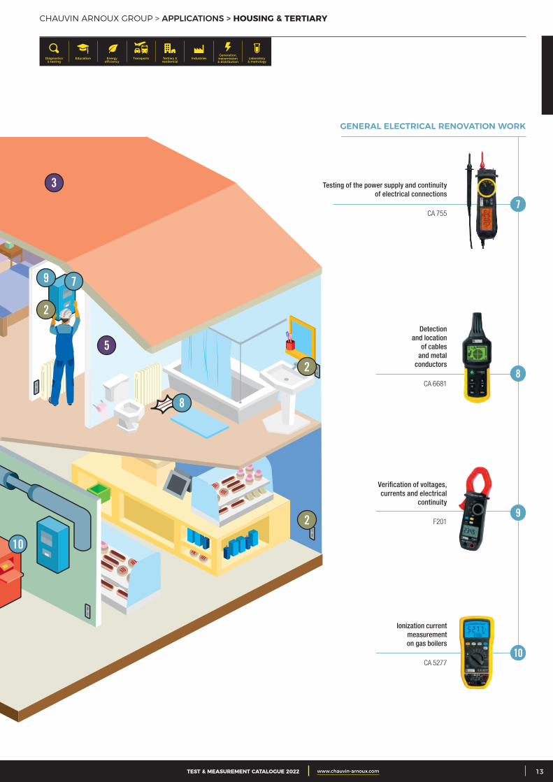
CHAUVIN ARNOUX GROUP > APPLICATIONS > HOUSING & TERTIARY
2
2
2
3
5
7
10
8
9
GENERAL ELECTRICAL RENOVATION WORK
Detection and location
of cables and metal
conductors
CA 6681
Verification of voltages, currents and electrical
continuity
F201
Ionization current measurement on gas boilers
CA 5277
Testing of the power supply and continuity of electrical connections
CA 755
8
9
10
7
Generation, transmission & distribution
IndustriesTertiary & residential
Education TransportsDiagnostics & testing
Energy efficiency
Laboratory & metrology
UNIVERSAL TEST & MEASUREMENT > INFO AND ADVICE > THE STANDARDS
THE STANDARDS 14TESTERS 16VOLTAGE ABSENCE TESTERS 18ANALOGUE MULTIMETERS 21
DIGITAL MULTIMETERS 23DIGITAL AMMETERS 32DIGITAL CLAMP METERS 29ACCESSORIES 32
EN 60529 The EN 60529 standard defines the level of tightness (leakproofing) of an instrument against penetration by solids or water. The IP rating corresponds to the instru-ment’s level of protection against penetration by solids (1st digit) and by water (2nd digit). The higher the rating, the more effective the protection. A product without pro-tection corresponds to a rating of IP00 (minimum rating), whereas a product totally protected against penetration by solids and liquids would have a rating of IP68 (maxi-mum rating).
IEC 61010This international standard defines the safety rules for electrical measuring, control and laborato-ry instruments. It helps to ensure that the design and construction of the instruments protect users and their environment against electric shocks, burns, mechanical hazards, the spread of fire from these instruments, ex-cessive temperatures, etc.For some types of instrument, this standard is completed by specific instructions.The development of industrial and domestic equipment is increasing the hazards which may be encountered on an electrical installation, notably in terms of ever-higher voltage surges. On LV installations, where the voltages are limited to 1,000 VAC and 1,500 VDC, the hazard levels depend the type of installation and the voltage level.
THE STANDARDS
Les normes internationales de la famille CEI 61010 concernent les règles de sécurité pour appareils électriques dThe international standards in the IEC 61010 family concern the safety rules for electrical measuring, control and laboratory instruments and their uses. More specifically, the IEC 61010-031 standard and its amendment A1 which define the safety rules for measuring instruments and accessories used with them. In the new edition which came into force on 1st March 2011, this standard has been completed with Chapter 13 covering “prevention of hazards linked to short-cir-cuits and electric arcs”.This addition stipulates the following rules for work on CAT III and CAT IV installations:
The conductive part of test probes must not exceed 4 mm in length
The external surfaces of the jaws of crocodile clips must be non-conductive and the conductive parts must not be accessible when the clip is closed.
The IEC 61010-2-033 standard, first published on 09/02/2013, has brought changes concerning multi-meters, clamp multimeters, etc. Since 9th March 2015, these instruments have had to guarantee a minimum safety level corresponding at least to CAT III 300 V.
SAFETY RULES AND GOOD PRACTICES Use measuring instruments and accessories which are suitable for the application and the measuring conditions.
Prefer CAT IV instruments:
• They can withstand voltage surges which are up to 50 % greater than a CAT III product
• CAT IV 1000 V provides protection against electric shocks up to 12,000 V, while CAT IV 600 V instruments protect up to 8,000 V.
• Using a lower-category instrument means checking that the installation is equipped with protective systems (disconnecting switch, circuit- breaker, etc.) which are functional and in good condition. This is often the case… but not always!
• For outdoor or temporary installations or for installations upstream of the protective systems, CAT IV instruments must be used.
It is the weakest element which defines your level of protection. If you use accessories of a lower category or with a lower voltage than your measuring instrument, the global level of safety offered by your measuring system will be reduced.
Use accessories in perfect condition. Any accessory which is faulty, however slightly, must be replaced immediately as it can no longer guarantee your safety.
The fuses are protective elements. If you replace them with cheaper models or, even worse, with a metal element (copper wire, aluminium foil, etc.), you will no longer be protected against possible voltage surges on your installation.
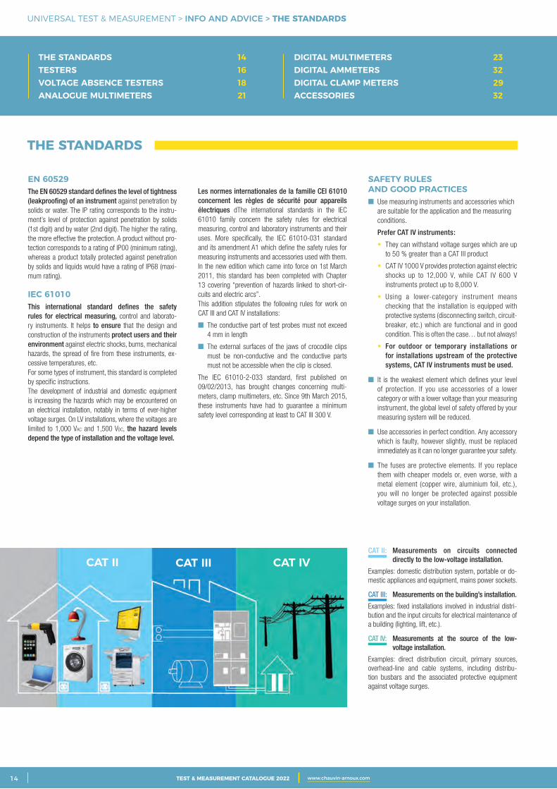
CAT II: Measurements on circuits connected directly to the low-voltage installation.
Examples: domestic distribution system, portable or do-mestic appliances and equipment, mains power sockets.
CAT III: Measurements on the building’s installation.
Examples: fixed installations involved in industrial distri-bution and the input circuits for electrical maintenance of a building (lighting, lift, etc.).
CAT IV: Measurements at the source of the low- voltage installation.
Examples: direct distribution circuit, primary sources, overhead-line and cable systems, including distribu-tion busbars and the associated protective equipment against voltage surges.
CAT II CAT III CAT IVCAT II CAT III CAT IVCAT II CAT III CAT IV
2 CATALOGUE TEST & MESURE 2021 www.chauvin-arnoux.com14 TEST & MEASUREMENT CATALOGUE 2022 www.chauvin-arnoux.com
UNIVERSAL TEST & MEASUREMENT > INFO AND ADVICE > TECHNICAL REMINDERS
UNIVERSAL TEST & MEASUREMENT
3CATALOGUE TEST & MESURE 2021 www.chauvin-arnoux.com 15
TECHNICAL REMINDERS
NUMBER OF COUNTS (FOR MEASUREMENT)This is one of the fundamental specifications of instruments using analogue-digital conversion. It is usually used to define the measurement range and the resolution, on the basis of the value chosen as the rated calibre.
MEASUREMENT RANGEThis indicates the limits within which a digital ins-trument maintains its specified characteristics. The measurements obtained are not subject to an error greater than the maximum tolerated error. It is defined by a minimum measurable value and a maximum measurable value.
RATED CALIBREThe calibre of an instrument is the value of the quan-tity to be measured which corresponds to the upper limit of the measurement range. For example, for an ammeter, if this upper limit is 5 A, its calibre is said to be 5 A.
RESOLUTIONThis is the smallest measurable value difference. It is also the value of one measurement count or unit of quantification which is usually termed the “unit”.
MINIMUM MEASURABLE VALUE (OR THRESHOLD)This is the smallest measurable value. For an instru-ment with excellent conversion linearity, it may be the same as the resolution. This is not always the case and the manufacturer should indicate it clearly, because this minimum value also depends on the accuracy, and particularly on the constant error. When the constant error is too high, it becomes impossible to obtain valid measurements of very low values.
RMS: ROOT MEAN SQUAREThe term RMS (Root Mean Square) refers to the effective value. By definition, the effective value of any current is the value of the DC current which would produce the same heating when flowing through a resistor
In the specific case of a sinusoidal quantity, application of the relation above gives:
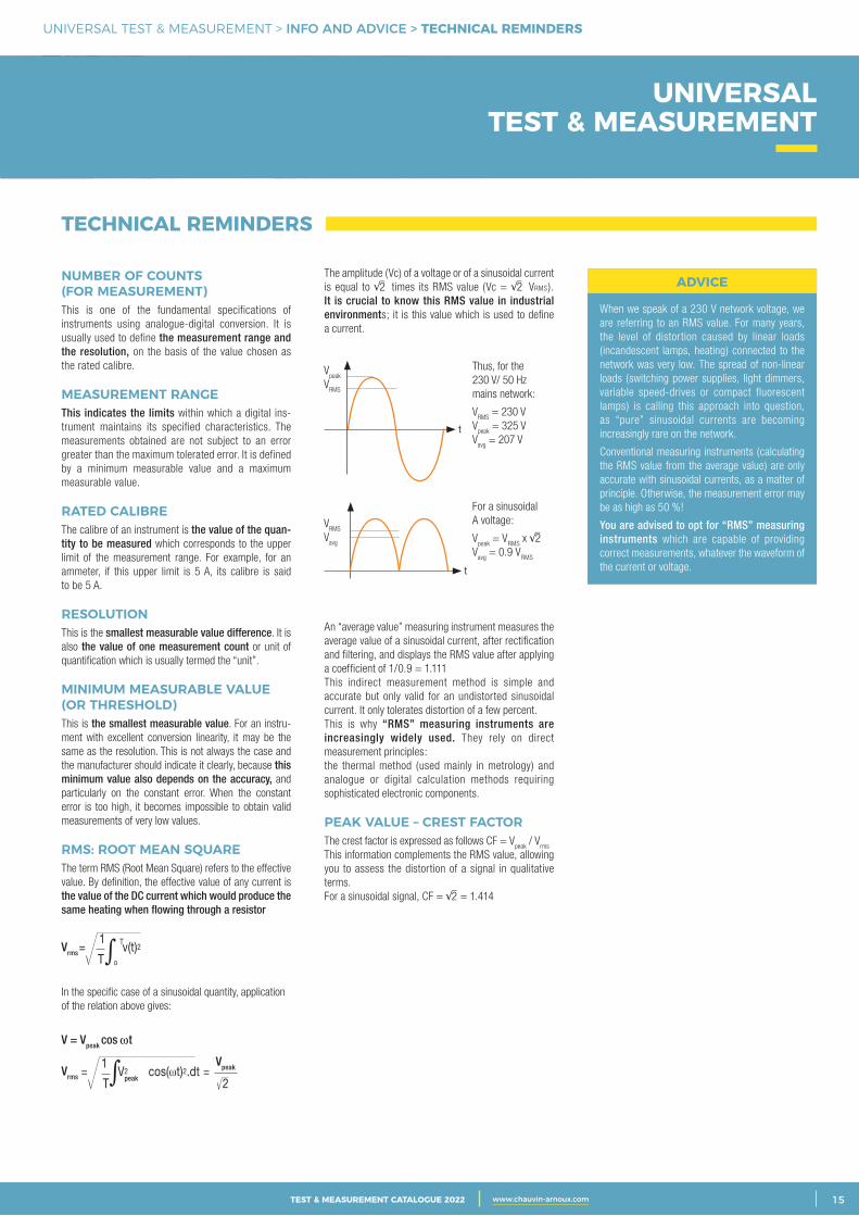
The amplitude (Vc) of a voltage or of a sinusoidal current is equal to 2 times its RMS value (Vc = 2 VRMS). It is crucial to know this RMS value in industrial environments; it is this value which is used to define a current.
An “average value” measuring instrument measures the average value of a sinusoidal current, after rectification and filtering, and displays the RMS value after applying a coefficient of 1/0.9 = 1.111This indirect measurement method is simple and accurate but only valid for an undistorted sinusoidal current. It only tolerates distortion of a few percent.This is why “RMS” measuring instruments are increasingly widely used. They rely on direct measurement principles:the thermal method (used mainly in metrology) and analogue or digital calculation methods requiring sophisticated electronic components.
PEAK VALUE – CREST FACTORThe crest factor is expressed as follows CF = V
peak / V
rms
This information complements the RMS value, allowing you to assess the distortion of a signal in qualitative terms.For a sinusoidal signal, CF = 2 = 1.414
Thus, for the 230 V/ 50 Hz mains network:
VRMS
= 230 VV
peak = 325 V
Vavg
= 207 V
For a sinusoidal A voltage:
Vpeak
= VRMS
x 2V
avg = 0.9 V
RMS
ADVICE
When we speak of a 230 V network voltage, we are referring to an RMS value. For many years, the level of distortion caused by linear loads (incandescent lamps, heating) connected to the network was very low. The spread of non-linear loads (switching power supplies, light dimmers, variable speed-drives or compact fluorescent lamps) is calling this approach into question, as “pure” sinusoidal currents are becoming increasingly rare on the network.
Conventional measuring instruments (calculating the RMS value from the average value) are only accurate with sinusoidal currents, as a matter of principle. Otherwise, the measurement error may be as high as 50 %!
You are advised to opt for “RMS” measuring instruments which are capable of providing correct measurements, whatever the waveform of the current or voltage.
Vpeak
VRMS
VRMS
V
avg
TEST & MEASUREMENT CATALOGUE 2022 www.chauvin-arnoux.com
Vrms
Vrms
Vpeak
V = Vpeak cos wt
peak
2 CATALOGUE TEST & MESURE 2021 www.chauvin-arnoux.com16 TEST & MEASUREMENT CATALOGUE 2022 www.chauvin-arnoux.com
UNIVERSAL TEST & MEASUREMENT > TESTERS > SELECTION GUIDE | CA 732
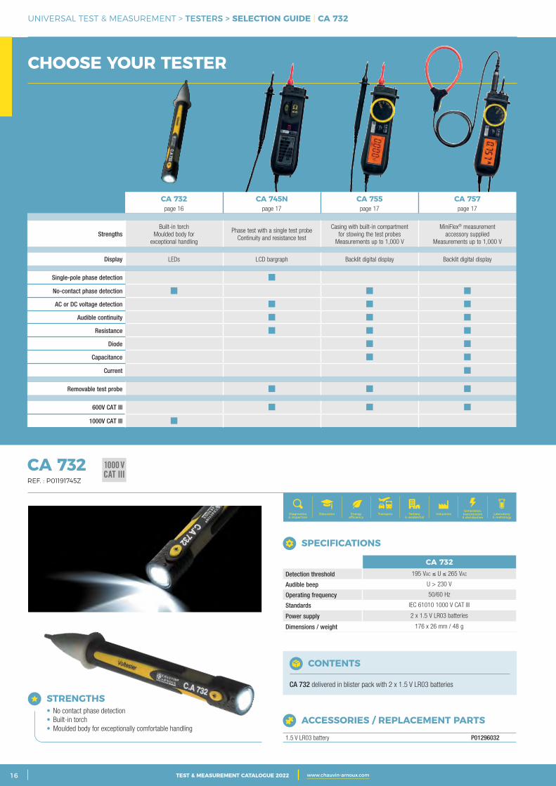
CHOOSE YOUR TESTER
1000 VCAT III
CA 732Detection threshold 195 Vac ≤ U ≤ 265 Vac
Audible beep U > 230 V
Operating frequency 50/60 Hz
Standards IEC 61010 1000 V CAT III
Power supply 2 x 1.5 V LR03 batteries
Dimensions / weight 176 x 26 mm / 48 g
SPECIFICATIONS
ACCESSORIES / REPLACEMENT PARTS
1.5 V LR03 battery P01296032
CONTENTS
CA 732 delivered in blister pack with 2 x 1.5 V LR03 batteries
CA 732 REF. : P01191745Z
Generation, transmission & distribution
IndustriesTertiary & residential
Education TransportDiagnostics & inspection
Energy efficiency
Laboratory & metrology
STRENGTHS • No contact phase detection • Built-in torch • Moulded body for exceptionally comfortable handling
CA 732page 16
CA 745Npage 17
CA 755page 17
CA 757page 17
Strengths Built-in torch
Moulded body for exceptional handling
Phase test with a single test probeContinuity and resistance test
Casing with built-in compartment for stowing the test probes
Measurements up to 1,000 V
MiniFlex® measurement accessory supplied
Measurements up to 1,000 V
Display LEDs LCD bargraph Backlit digital display Backlit digital display
Single-pole phase detection
No-contact phase detection
AC or DC voltage detection
Audible continuity
Resistance
Diode
Capacitance
Current
Removable test probe
600V CAT III
1000V CAT III
3CATALOGUE TEST & MESURE 2021 www.chauvin-arnoux.com 17TEST & MEASUREMENT CATALOGUE 2022 www.chauvin-arnoux.com
UNIVERSAL TEST & MEASUREMENT > TESTERS > CA 745N | CA 755 - CA 757
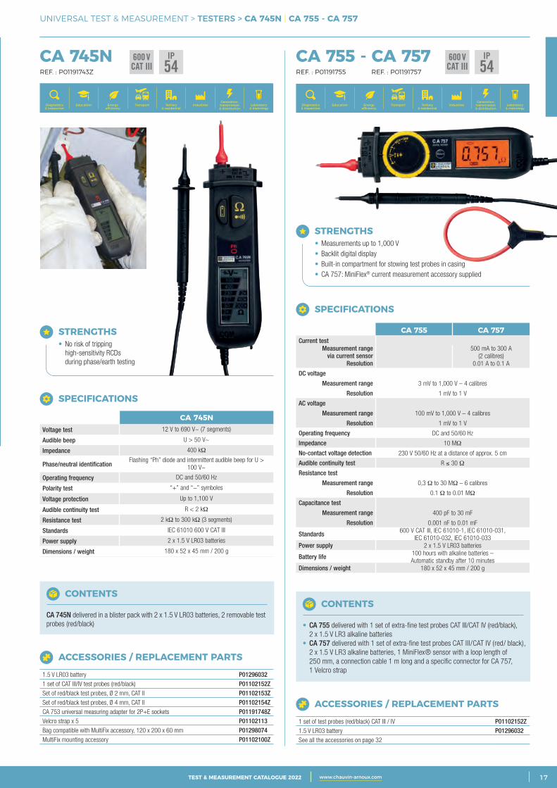
CA 755 - CA 757 REF. : P01191755 REF. : P01191757
600 VCAT III
IP54
STRENGTHS • Measurements up to 1,000 V • Backlit digital display • Built-in compartment for stowing test probes in casing • CA 757: MiniFlex® current measurement accessory supplied
CONTENTS
• CA 755 delivered with 1 set of extra-fine test probes CAT III/CAT IV (red/black), 2 x 1.5 V LR3 alkaline batteries • CA 757 delivered with 1 set of extra-fine test probes CAT III/CAT IV (red/ black), 2 x 1.5 V LR3 alkaline batteries, 1 MiniFlex® sensor with a loop length of 250 mm, a connection cable 1 m long and a specific connector for CA 757, 1 Velcro strap
SPECIFICATIONS
CA 755 CA 757Current test
Measurement range via current sensor
500 mA to 300 A (2 calibres)
Resolution 0.01 A to 0.1 A
DC voltage
Measurement range 3 mV to 1,000 V – 4 calibres
Resolution 1 mV to 1 V
AC voltage
Measurement range 100 mV to 1,000 V – 4 calibres
Resolution 1 mV to 1 V
Operating frequency DC and 50/60 Hz
Impedance 10 MΩ
No-contact voltage detection 230 V 50/60 Hz at a distance of approx. 5 cm
Audible continuity test R ≤ 30 Ω
Resistance test
Measurement range 0,3 Ω to 30 MΩ – 6 calibres
Resolution 0.1 Ω to 0.01 MΩ
Capacitance test
Measurement range 400 pF to 30 mF
Resolution 0.001 nF to 0.01 mF
Standards 600 V CAT III, IEC 61010-1, IEC 61010-031, IEC 61010-032, IEC 61010-033
Power supply 2 x 1.5 V LR03 batteries
Battery life 100 hours with alkaline batteries – Automatic standby after 10 minutes
Dimensions / weight 180 x 52 x 45 mm / 200 g
ACCESSORIES / REPLACEMENT PARTS
1 set of test probes (red/black) CAT III / IV P01102152Z1.5 V LR03 battery P01296032See all the accessories on page 32
CA 745N REF. : P01191743Z
600 VCAT III
IP54
STRENGTHS • No risk of tripping high-sensitivity RCDs during phase/earth testing
CA 745NVoltage test 12 V to 690 V~ (7 segments)
Audible beep U > 50 V~
Impedance 400 kΩ
Phase/neutral identificationFlashing “Ph” diode and intermittent audible beep for U >
100 V~
Operating frequency DC and 50/60 Hz
Polarity test “+” and “−” symboles
Voltage protection Up to 1,100 V
Audible continuity test R < 2 kΩ
Resistance test 2 kΩ to 300 kΩ (3 segments)
Standards IEC 61010 600 V CAT III
Power supply 2 x 1.5 V LR03 batteries
Dimensions / weight 180 x 52 x 45 mm / 200 g
SPECIFICATIONS
ACCESSORIES / REPLACEMENT PARTS
1.5 V LR03 battery P012960321 set of CAT III/IV test probes (red/black) P01102152ZSet of red/black test probes, Ø 2 mm, CAT II P01102153ZSet of red/black test probes, Ø 4 mm, CAT II P01102154ZCA 753 universal measuring adapter for 2P+E sockets P01191748ZVelcro strap x 5 P01102113Bag compatible with MultiFix accessory, 120 x 200 x 60 mm P01298074MultiFix mounting accessory P01102100Z
CONTENTS
CA 745N delivered in a blister pack with 2 x 1.5 V LR03 batteries, 2 removable test probes (red/black)
Generation, transmission & distribution
IndustriesTertiary & residential
Education TransportDiagnostics & inspection
Energy efficiency
Laboratory & metrology
Generation, transmission & distribution
IndustriesTertiary & residential
Education TransportDiagnostics & inspection
Energy efficiency
Laboratory & metrology
2 CATALOGUE TEST & MESURE 2021 www.chauvin-arnoux.com18 TEST & MEASUREMENT CATALOGUE 2022 www.chauvin-arnoux.com
UNIVERSAL TEST & MEASUREMENT > VOLTAGE DETECTORS / VOLTAGE ABSENCE TESTERS > SELECTION GUIDE
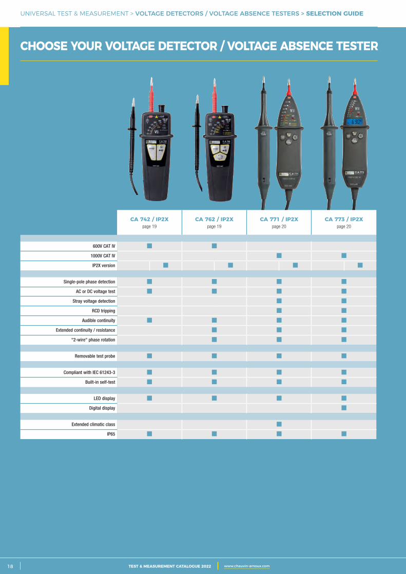
CHOOSE YOUR VOLTAGE DETECTOR / VOLTAGE ABSENCE TESTER
CA 742 / IP2Xpage 19
CA 762 / IP2Xpage 19
CA 771 / IP2Xpage 20
CA 773 / IP2Xpage 20
600V CAT IV
1000V CAT IV
IP2X version
Single-pole phase detection
AC or DC voltage test
Stray voltage detection
RCD tripping
Audible continuity
Extended continuity / resistance
"2-wire" phase rotation
Removable test probe
Compliant with IEC 61243-3
Built-in self-test
LED display
Digital display
Extended climatic class
IP65
3CATALOGUE TEST & MESURE 2021 www.chauvin-arnoux.com 19TEST & MEASUREMENT CATALOGUE 2022 www.chauvin-arnoux.com
UNIVERSAL TEST & MEASUREMENT > VOLTAGE DETECTORS > CA 742 - CA 742 IP2X | CA 762 - CA 762 IP2X
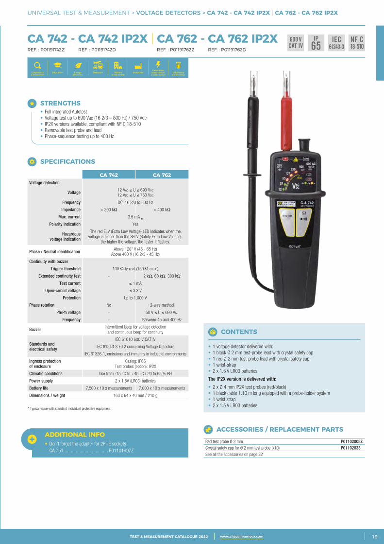
CA 742 - CA 742 IP2X | CA 762 - CA 762 IP2X REF. : P01191742Z REF. : P01191742D REF. : P01191762Z REF. : P01191762D
CHOOSE YOUR VOLTAGE DETECTOR / VOLTAGE ABSENCE TESTER
ACCESSORIES / REPLACEMENT PARTS
Red test probe Ø 2 mm P01102008ZCrystal safety cap for Ø 2 mm test probe (x10) P01102033See all the accessories on page 32
CONTENTS
• 1 voltage detector delivered with:• 1 black Ø 2 mm test-probe lead with crystal safety cap• 1 red Ø 2 mm test-probe lead with crystal safety cap• 1 wrist-strap• 2 x 1.5 V LR03 batteries
The IP2X version is delivered with:
• 2 x Ø 4 mm IP2X test probes (red/black) • 1 black cable 1.10 m long equipped with a probe-holder system• 1 wrist strap• 2 x 1.5 V LR03 batteries
STRENGTHS • Full integrated Autotest • Voltage test up to 690 Vac (16 2/3 – 800 Hz) / 750 Vdc • IP2X versions available, compliant with NF C 18-510 • Removable test probe and lead • Phase-sequence testing up to 400 Hz
ADDITIONAL INFO• Don’t forget the adapter for 2P+E sockets CA 751 .................................... P01101997Z
SPECIFICATIONS
CA 742 CA 762Voltage detection
Voltage 12 Vac ≤ U ≤ 690 Vac 12 Vdc ≤ U ≤ 750 Vdc
Frequency DC, 16 2/3 to 800 Hz
Impedance > 300 kΩ > 400 kΩ
Max. current 3.5 mARMS
Polarity indication Yes
Hazardous voltage indication
The red ELV (Extra Low Voltage) LED indicates when the voltage is higher than the SELV (Safety Extra Low Voltage);
the higher the voltage, the faster it flashes.
Phase / Neutral identification Above 120* V (45 - 65 Hz) Above 400 V (16 2/3 - 45 Hz)
Continuity with buzzer
Trigger threshold 100 Ω typical (150 Ω max.)
Extended continuity test - 2 kΩ, 60 kΩ, 300 kΩ
Test current ≤ 1 mA
Open-circuit voltage ≤ 3.3 V
Protection Up to 1,000 V
Phase rotation No 2-wire method
Ph/Ph voltage - 50 V ≤ U ≤ 690 Vac
Frequency - Between 45 and 400 Hz
Buzzer Intermittent beep for voltage detection and continuous beep for continuity
Standards and electrical safety
IEC 61010 600 V CAT IV
IEC 61243-3 Ed.2 concerning Voltage Detectors
IEC 61326-1, emissions and immunity in industrial environments
Ingress protection of enclosure
Casing: IP65 Test probes (option): IP2X
Climatic conditions Use from -15 °C to +45 °C / 20 to 95 % RH
Power supply 2 x 1.5V (LR03) batteries
Battery life 7,500 x 10 s measurements 7,000 x 10 s measurements
Dimensions / weight 163 x 64 x 40 mm / 210 g
* Typical value with standard individual protective equipment
600 VCAT IV
IP65
IEC61243-3
NF C18-510
Generation, transmission & distribution
IndustriesTertiary & residential
Education TransportDiagnostics & inspection
Energy efficiency
Laboratory & metrology
2 CATALOGUE TEST & MESURE 2021 www.chauvin-arnoux.com20 TEST & MEASUREMENT CATALOGUE 2022 www.chauvin-arnoux.com
UNIVERSAL TEST & MEASUREMENT > VOLTAGE DETECTORS / VOLTAGE ABSENCE TESTERS > CA 771 - CA 771 IP2X | CA 773 - CA 773 IP2X
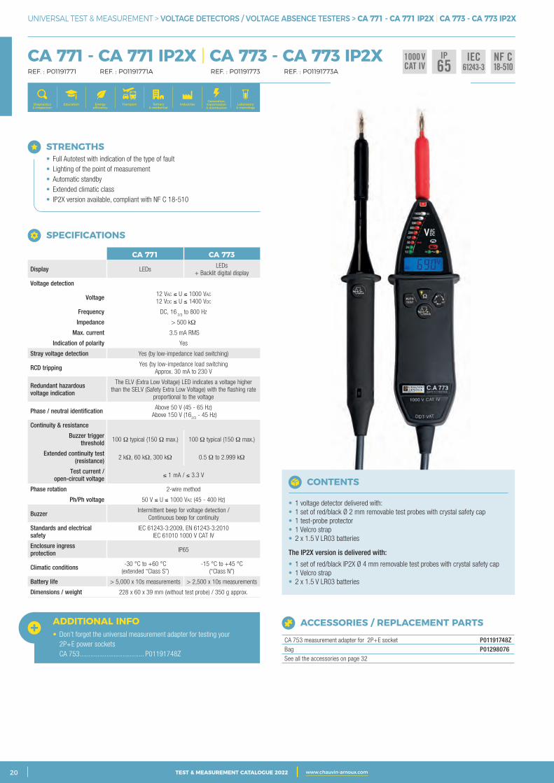
CA 771 - CA 771 IP2X | CA 773 - CA 773 IP2X REF. : P01191771 REF. : P01191771A REF. : P01191773 REF. : P01191773A
STRENGTHS • Full Autotest with indication of the type of fault • Lighting of the point of measurement • Automatic standby • Extended climatic class • IP2X version available, compliant with NF C 18-510
ADDITIONAL INFO• Don’t forget the universal measurement adapter for testing your 2P+E power sockets CA 753 .................................... P01191748Z
IEC61243-3
NF C18-510
1000 VCAT IV
IP65
SPECIFICATIONS
CA 771 CA 773
Display LEDsLEDs
+ Backlit digital display
Voltage detection
Voltage 12 Vac ≤ U ≤ 1000 Vac 12 Vdc ≤ U ≤ 1400 Vdc
Frequency DC, 16 2/3
to 800 Hz
Impedance > 500 kΩ
Max. current 3.5 mA RMS
Indication of polarity Yes
Stray voltage detection Yes (by low-impedance load switching)
RCD tripping Yes (by low-impedance load switching Approx. 30 mA to 230 V
Redundant hazardous voltage indication
The ELV (Extra Low Voltage) LED indicates a voltage higher than the SELV (Safety Extra Low Voltage) with the flashing rate
proportional to the voltage
Phase / neutral identification Above 50 V (45 - 65 Hz) Above 150 V (16
2/3 - 45 Hz)
Continuity & resistance
Buzzer trigger threshold 100 Ω typical (150 Ω max.) 100 Ω typical (150 Ω max.)
Extended continuity test (resistance) 2 kΩ, 60 kΩ, 300 kΩ 0.5 Ω to 2.999 kΩ
Test current / open-circuit voltage ≤ 1 mA / ≤ 3.3 V
Phase rotation 2-wire method
Ph/Ph voltage 50 V ≤ U ≤ 1000 Vac (45 - 400 Hz)
Buzzer Intermittent beep for voltage detection / Continuous beep for continuity
Standards and electrical safety
IEC 61243-3:2009, EN 61243-3:2010 IEC 61010 1000 V CAT IV
Enclosure ingress protection IP65
Climatic conditions -30 °C to +60 °C (extended “Class S”)
-15 °C to +45 °C (“Class N”)
Battery life > 5,000 x 10s measurements > 2,500 x 10s measurements
Dimensions / weight 228 x 60 x 39 mm (without test probe) / 350 g approx.
Generation, transmission & distribution
IndustriesTertiary & residential
Education TransportDiagnostics & inspection
Energy efficiency
Laboratory & metrology
ACCESSORIES / REPLACEMENT PARTS
CA 753 measurement adapter for 2P+E socket P01191748ZBag P01298076See all the accessories on page 32
CONTENTS
• 1 voltage detector delivered with:• 1 set of red/black Ø 2 mm removable test probes with crystal safety cap• 1 test-probe protector• 1 Velcro strap• 2 x 1.5 V LR03 batteries
The IP2X version is delivered with:
• 1 set of red/black IP2X Ø 4 mm removable test probes with crystal safety cap• 1 Velcro strap• 2 x 1.5 V LR03 batteries
3CATALOGUE TEST & MESURE 2021 www.chauvin-arnoux.com 21TEST & MEASUREMENT CATALOGUE 2022 www.chauvin-arnoux.com
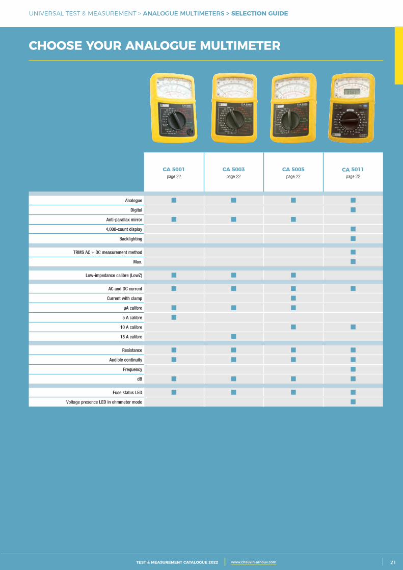
UNIVERSAL TEST & MEASUREMENT > ANALOGUE MULTIMETERS > SELECTION GUIDE
CA 5001page 22
CA 5003page 22
CA 5005page 22
CA 5011page 22
Analogue
Digital
Anti-parallax mirror
4,000-count display
Backlighting
TRMS AC + DC measurement method
Max.
Low-impedance calibre (LowZ)
AC and DC current
Current with clamp
μA calibre
5 A calibre
10 A calibre
15 A calibre
Resistance
Audible continuity
Frequency
dB
Fuse status LED
Voltage presence LED in ohmmeter mode
CHOOSE YOUR ANALOGUE MULTIMETER
2 CATALOGUE TEST & MESURE 2021 www.chauvin-arnoux.com22 TEST & MEASUREMENT CATALOGUE 2022 www.chauvin-arnoux.com
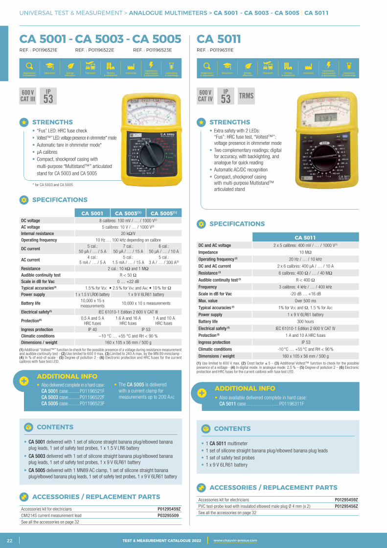
UNIVERSAL TEST & MEASUREMENT > ANALOGUE MULTIMETERS > CA 5001 - CA 5003 - CA 5005 | CA 5011
CA 5001 - CA 5003 - CA 5005 REF. : P01196521E REF. : P01196522E REF. : P01196523E
CA 5011 REF. : P01196311E
600 VCAT III
IP53
600 VCAT IV
IP53 TRMS
STRENGTHS • Extra safety with 2 LEDs: “Fus”: HRC fuse test, “Voltest™”: voltage presence in ohmmeter mode • Two complementary readings: digital for accuracy, with backlighting, and analogue for quick reading • Automatic AC/DC recognition • Compact, shockproof casing with multi-purpose Multistand™ articulated stand
ADDITIONAL INFO• Also available delivered complete in hard case: CA 5011 case .......................... P01196311F
ACCESSORIES / REPLACEMENT PARTS
Accessories kit for electricians P01295459ZPVC test-probe lead with insulated elbowed male plug Ø 4 mm (x 2) P01295456ZSee all the accessories on page 32
CONTENTS
• 1 CA 5011 multimeter• 1 set of silicone straight banana plug/elbowed banana plug leads• 1 set of safety test probes• 1 x 9 V 6LR61 battery
SPECIFICATIONS
CA 5011DC and AC voltage 2 x 5 calibres: 400 mV / … / 1000 V(1)
Impedance 10 MΩ
Operating frequency (2) 20 Hz / … / 10 kHz
DC and AC current 2 x 6 calibres: 400 µA / … / 10 A
Resistance (3) 6 calibres: 400 Ω / … / 40 MΩ
Audible continuity test (3) R < 400 Ω
Frequency 3 calibres: 4 kHz / … / 400 kHz
Scale in dB for Vac -20 dB … +16 dB
Max. value Over 500 ms
Typical accuracies (4) 1% for Vdc and Ω, 1.5 % for adc
Power supply 1 x 9 V 6LR61 battery
Battery life 300 hours
Electrical safety (5) IEC 61010-1 Edition 2 600 V CAT IV
Protection (6) 1 A and 10 A HRC fuses
Ingress protection IP 53
Climatic conditions -10 °C … +55 °C and RH < 90 %
Dimensions / weight 160 x 105 x 56 mm / 500 g
(1) Use limited to 600 V max. (2) Crest factor ≤ 5 – (3) Additional Voltest™ function to check for the possible presence of a voltage - (4) In digital mode. In analogue mode: 2.5 % – (5) Degree of pollution 2 – (6) Electronic protection and HRC fuses for the current calibres with fuse test LED.
ACCESSORIES / REPLACEMENT PARTS
Accessories kit for electricians P01295459ZCMI214S current measurement lead P03295509See all the accessories on page 32
CONTENTS
• CA 5001 delivered with 1 set of silicone straight banana plug/elbowed banana plug leads, 1 set of safety test probes, 1 x 1.5 V LR6 battery
• CA 5003 delivered with 1 set of silicone straight banana plug/elbowed banana plug leads, 1 set of safety test probes, 1 x 9 V 6LR61 battery
• CA 5005 delivered with 1 MN89 AC clamp, 1 set of silicone straight banana plug/elbowed banana plug leads, 1 set of safety test probes, 1 x 9 V 6LR61 battery
ADDITIONAL INFO• Also delivered complete in a hard case: CA 5001 case .........P01196521F CA 5003 case .........P01196522F CA 5005 case .........P01196523F
• The CA 5005 is delivered with a current clamp for measurements up to 200 AAC
SPECIFICATIONS
CA 5001 CA 5003(1) CA 5005(1)
DC voltage 8 calibres: 100 mV / … / 1000 V(2)
AC voltage 5 calibres: 10 V / … / 1000 V(2)
Internal resistance 20 kΩ/VOperating frequency 10 Hz … 100 kHz depending on calibre
DC current 5 cal.: 50 µA / … / 5 A
7 cal.: 50 µA / … / 15 A
6 cal.: 50 µA / … / 10 A
AC current 4 cal.: 5 mA / … / 5 A
5 cal.: 1.5 mA / … / 15 A
5 cal.: 3 A / … / 300 A(3)
Resistance 2 cal.: 10 kΩ and 1 MΩ
Audible continuity test R < 50 ΩScale in dB for Vac 0 … +22 dBTypical accuracies(4) 1.5 % for Vdc • 2.5 % for Vac and Aac • 10 % for ΩPower supply 1 x 1.5 V LR06 battery 1 x 9 V 6LR61 battery
Battery life 10,000 x 15 s measurements
10,000 x 10 s measurements
Electrical safety(5) IEC 61010-1 Edition 2 600 V CAT III
Protection(6) 0.5 A and 5 A HRC fuses
1.6 A and 16 A HRC fuses
1 A and 10 A HRC fuses
Ingress protection IP 40 IP 53Climatic conditions −10 °C … +55 °C and RH < 90 %Dimensions / weight 160 x 105 x 56 mm / 500 g
(1) Additional “Voltest™” function to check for the possible presence of a voltage during resistance measurement and audible continuity test - (2) Use limited to 600 V max. (3) Limited to 240 A max. by the MN 89 miniclamp - (4) In % of end-of-scale - (5) Degree of pollution 2 - (6) Electronic protection and HRC fuses for the current calibres with fuse test LED.
STRENGTHS • “Fus” LED: HRC fuse check • Voltest™” LED: voltage presence in ohmmeter* mode • Automatic tare in ohmmeter mode* • µA calibres • Compact, shockproof casing with multi-purpose “Multistand™” articulated stand for CA 5003 and CA 5005
* for CA 5003 and CA 5005
Generation, transmission & distribution
IndustriesTertiary & residential
Education TransportDiagnostics & inspection
Energy efficiency
Laboratory & metrology
Generation, transmission & distribution
IndustriesTertiary & residential
Education TransportDiagnostics & inspection
Energy efficiency
Laboratory & metrology
3CATALOGUE TEST & MESURE 2021 www.chauvin-arnoux.com 23TEST & MEASUREMENT CATALOGUE 2022 www.chauvin-arnoux.com
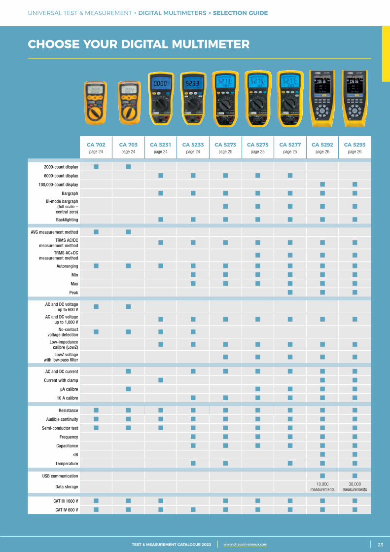
UNIVERSAL TEST & MEASUREMENT > DIGITAL MULTIMETERS > SELECTION GUIDE
CHOOSE YOUR DIGITAL MULTIMETER
CA 702page 24
CA 703page 24
CA 5231page 24
CA 5233page 24
CA 5273page 25
CA 5275page 25
CA 5277page 25
CA 5292page 26
CA 5293page 26
2000-count display
6000-count display
100,000-count display
Bargraph
Bi-mode bargraph (full scale –
central zero)
Backlighting
AVG measurement method
TRMS AC/DC measurement method
TRMS AC+DC measurement method
Autoranging
Min
Max
Peak
AC and DC voltage up to 600 V
AC and DC voltage up to 1,000 V
No-contact voltage detection
Low-impedance calibre (LowZ)
LowZ voltage with low-pass filter
AC and DC current
Current with clamp
μA calibre
10 A calibre
Resistance
Audible continuity
Semi-conductor test
Frequency
Capacitance
dB
Temperature
USB communication
Data storage 10,000 measurements
30,000 measurements
CAT III 1000 V
CAT IV 600 V
2 CATALOGUE TEST & MESURE 2021 www.chauvin-arnoux.com24 TEST & MEASUREMENT CATALOGUE 2022 www.chauvin-arnoux.com
UNIVERSAL TEST & MEASUREMENT > DIGITAL MULTIMETERS > CA 702 - CA 703 | CA 5231 - CA 5233
CA 702 - CA 703 REF. : P01191739Z REF. : P01191740Z
CA 5231 - CA 5233 REF. : P01196731 REF. : P01196733
600 VCAT IV
IEC61010-2-033
1000 VCAT III
600 VCAT IV
IEC61010-2-033
IP54 TRMS
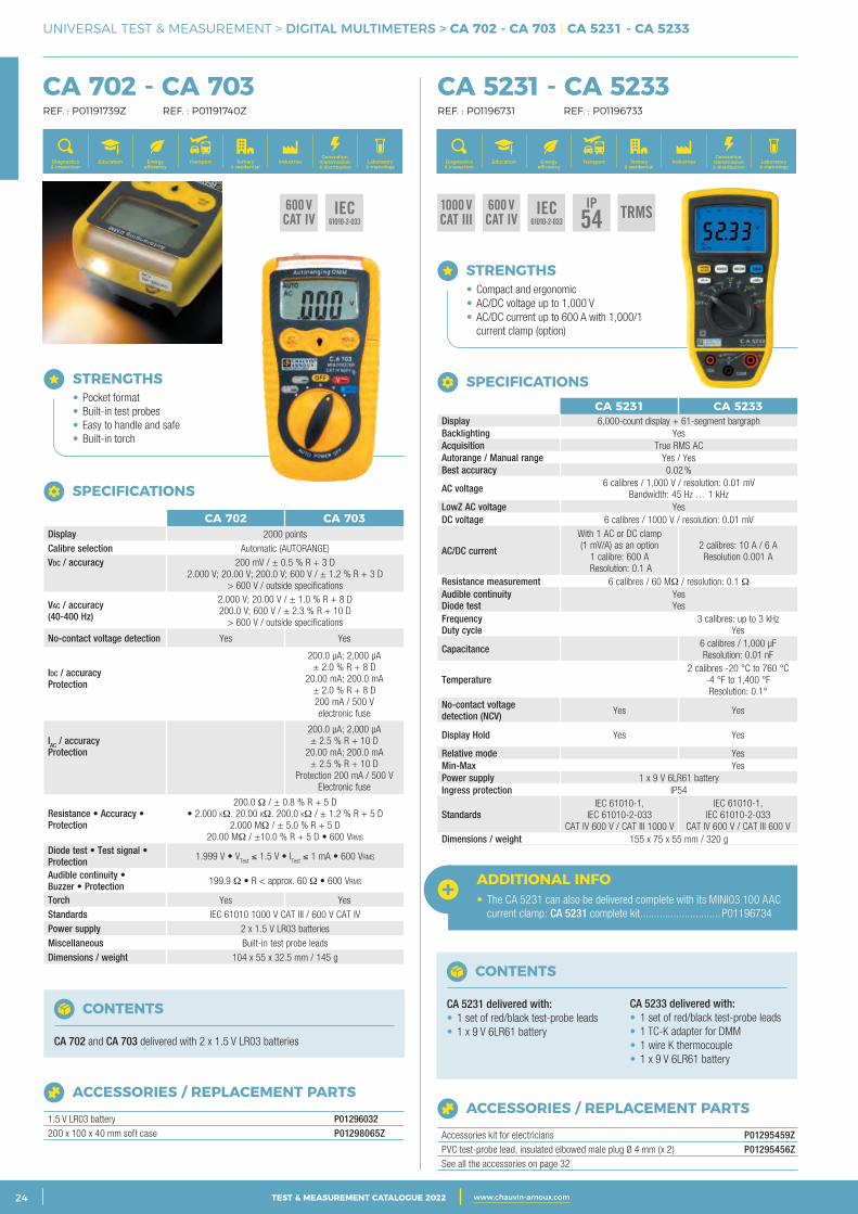
STRENGTHS • Pocket format • Built-in test probes • Easy to handle and safe • Built-in torch
SPECIFICATIONS
CA 702 CA 703Display 2000 pointsCalibre selection Automatic (AUTORANGE)Vdc / accuracy
200 mV / ± 0.5 % R + 3 D2.000 V; 20.00 V; 200.0 V; 600 V / ± 1.2 % R + 3 D
> 600 V / outside specifications
Vac / accuracy (40-400 Hz)
2.000 V; 20.00 V / ± 1.0 % R + 8 D200.0 V; 600 V / ± 2.3 % R + 10 D
> 600 V / outside specifications
No-contact voltage detection Yes Yes
Idc / accuracy Protection
200.0 µA; 2,000 µA ± 2.0 % R + 8 D
20.00 mA; 200.0 mA ± 2.0 % R + 8 D200 mA / 500 V electronic fuse
IAC / accuracy Protection
200.0 µA; 2,000 µA± 2.5 % R + 10 D
20.00 mA; 200.0 mA± 2.5 % R + 10 D
Protection 200 mA / 500 VElectronic fuse
Resistance • Accuracy • Protection
200.0 Ω / ± 0.8 % R + 5 d• 2.000 kΩ. 20.00 kΩ. 200.0 kΩ / ± 1.2 % R + 5 d
2.000 MΩ / ± 5.0 % R + 5 d20.00 MΩ / ±10.0 % R + 5 d • 600 VRMs
Diode test • Test signal • Protection 1.999 V • V
Test ≤ 1.5 V • I
Test ≤ 1 mA • 600 VRMs
Audible continuity • Buzzer • Protection 199.9 Ω • R < approx. 60 Ω • 600 VRMs
Torch Yes YesStandards IEC 61010 1000 V CAT III / 600 V CAT IV Power supply 2 x 1.5 V LR03 batteriesMiscellaneous Built-in test probe leads Dimensions / weight 104 x 55 x 32.5 mm / 145 g
CONTENTS
CA 702 and CA 703 delivered with 2 x 1.5 V LR03 batteries
ACCESSORIES / REPLACEMENT PARTS
1.5 V LR03 battery P01296032200 x 100 x 40 mm soft case P01298065Z
STRENGTHS • Compact and ergonomic • AC/DC voltage up to 1,000 V • AC/DC current up to 600 A with 1,000/1 current clamp (option)
ACCESSORIES / REPLACEMENT PARTS
Accessories kit for electricians P01295459ZPVC test-probe lead, insulated elbowed male plug Ø 4 mm (x 2) P01295456ZSee all the accessories on page 32
CONTENTS
CA 5231 delivered with:• 1 set of red/black test-probe leads• 1 x 9 V 6LR61 battery
CA 5233 delivered with:• 1 set of red/black test-probe leads• 1 TC-K adapter for DMM• 1 wire K thermocouple• 1 x 9 V 6LR61 battery
SPECIFICATIONSCA 5231 CA 5233
Display 6,000-count display + 61-segment bargraphBacklighting YesAcquisition True RMS AC Autorange / Manual range Yes / YesBest accuracy 0.02 %
AC voltage 6 calibres / 1,000 V / resolution: 0.01 mV Bandwidth: 45 Hz … 1 kHz
LowZ AC voltage YesDC voltage 6 calibres / 1000 V / resolution: 0.01 mV
AC/DC current
With 1 AC or DC clamp (1 mV/A) as an option
1 calibre: 600 A Resolution: 0.1 A
2 calibres: 10 A / 6 AResolution 0.001 A
Resistance measurement 6 calibres / 60 MΩ / resolution: 0.1 Ω Audible continuity Diode test
Yes Yes
Frequency Duty cycle
3 calibres: up to 3 kHzYes
Capacitance 6 calibres / 1,000 µFResolution: 0.01 nF
Temperature2 calibres -20 °C to 760 °C
-4 °F to 1,400 °F Resolution: 0.1°
No-contact voltage detection (NCV) Yes Yes
Display Hold Yes Yes
Relative mode YesMin-Max YesPower supply 1 x 9 V 6LR61 batteryIngress protection IP54
StandardsIEC 61010-1,
IEC 61010-2-033 CAT IV 600 V / CAT III 1000 V
IEC 61010-1, IEC 61010-2-033
CAT IV 600 V / CAT III 600 V Dimensions / weight 155 x 75 x 55 mm / 320 g
ADDITIONAL INFO• The CA 5231 can also be delivered complete with its MINI03 100 AAC current clamp: CA 5231 complete kit ............................. P01196734
Generation, transmission & distribution
IndustriesTertiary & residential
Education TransportDiagnostics & inspection
Energy efficiency
Laboratory & metrology
Generation, transmission & distribution
IndustriesTertiary & residential
Education TransportDiagnostics & inspection
Energy efficiency
Laboratory & metrology
3CATALOGUE TEST & MESURE 2021 www.chauvin-arnoux.com 25TEST & MEASUREMENT CATALOGUE 2022 www.chauvin-arnoux.com
UNIVERSAL TEST & MEASUREMENT > DIGITAL MULTIMETERS > CA 5273 | CA 5275 - CA 5277
CA 5273 REF. : P01196773
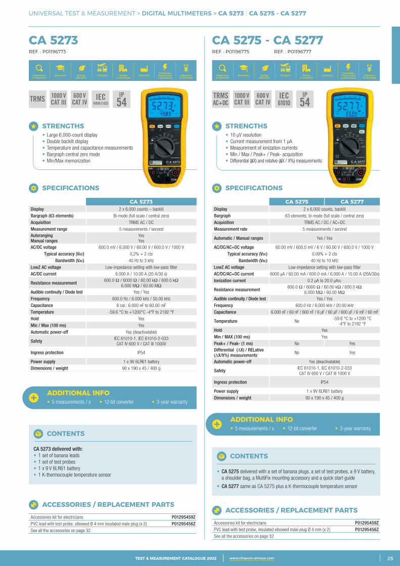
STRENGTHS • Large 6,000-count display • Double backlit display • Temperature and capacitance measurements • Bargraph central zero mode • Min/Max memorization
ACCESSORIES / REPLACEMENT PARTS
Accessories kit for electricians P01295459ZPVC lead with test probe, elbowed Ø 4 mm insulated male plug (x 2) P01295456ZSee all the accessories on page 32
CONTENTS
CA 5273 delivered with:• 1 set of banana leads• 1 set of test probes• 1 x 9 V 6LR61 battery• 1 K-thermocouple temperature sensor
SPECIFICATIONS
CA 5273Display 2 x 6,000 counts – backlitBargraph (63 elements) Bi-mode (full scale / central zero)Acquisition TRMS AC / DCMeasurement range 5 measurements / secondAutorangingManual ranges
YesYes
AC/DC voltage 600.0 mV / 6.000 V / 60.00 V / 600.0 V / 1000 VTypical accuracy (VDC) 0,2% + 2 cts
Bandwidth (VAC) 40 Hz to 3 kHzLowZ AC voltage Low-impedance setting with low-pass filter AC/DC current 6.000 A / 10.00 A (20 A/30 s)
Resistance measurement 600.0 Ω / 6000 Ω / 60.00 kΩ / 600.0 kΩ 6.000 MΩ / 60.00 MΩ
Audible continuity / Diode test Yes / Yes Frequency 600.0 Hz / 6.000 kHz / 50.00 kHz Capacitance 8 cal.: 6.000 nF to 60.00 mF Temperature -59.6 °C to +1200°C -4°F to 2192 °F Hold YesMin / Max (100 ms) YesAutomatic power-off Yes (deactivatable)
Safety IEC 61010-1, IEC 61010-2-033 CAT IV 600 V / CAT III 1000V
Ingress protection IP54
Power supply 1 x 9V 6LR61 batteryDimensions / weight 90 x 190 x 45 / 400 g
CA 5275 - CA 5277 REF. : P01196775 REF. : P01196777
ACCESSORIES / REPLACEMENT PARTS
Accessories kit for electricians P01295459ZPVC lead with test probe, insulated elbowed male plug Ø 4 mm (x 2) P01295456ZSee all the accessories on page 32
STRENGTHS • 10 µV resolution • Current measurement from 1 µA • Measurement of ionization currents • Min / Max / Peak+ / Peak- acquisition • Differential (ΔX) and relative (ΔX / X%) measurements
CONTENTS
• CA 5275 delivered with a set of banana plugs, a set of test probes, a 9 V battery, a shoulder bag, a MultiFix mounting accessory and a quick start guide
• CA 5277 same as CA 5275 plus a K-thermocouple temperature sensor
SPECIFICATIONS
CA 5275 CA 5277Display 2 x 6,000 counts, backlitBargraph 63 elements, bi-mode (full scale / central zero) Acquisition TRMS AC / DC / AC+DCMeasurement rate 5 measurements / second
Automatic / Manual ranges Yes / Yes
AC/DC/AC+DC voltage 60.00 mV / 600.0 mV / 6 V / 60.00 V / 600.0 V / 1000 VTypical accuracy (Vdc) 0.09% + 2 cts
Bandwidth (Vac) 40 Hz to 10 kHzLowZ AC voltage Low-impedance setting with low-pass filter AC/DC/AC+DC current 6000 µA / 60.00 mA / 600.0 mA / 6.000 A / 10.00 A (20A/30s)Ionization current 0.2 µA to 20.0 µadc
Resistance measurement 600.0 Ω / 6000 Ω / 60.00 kΩ / 600.0 kΩ 6.000 MΩ / 60.00 MΩ
Audible continuity / Diode test Yes / YesFrequency 600.0 Hz / 6.000 kHz / 20.00 kHzCapacitance 6.000 nF / 60 nF / 600 nF / 6 µF / 60 µF / 600 µF / 6 mF / 60 mF
Temperature No -59.6 °C to +1200 °C
-4°F to 2192 °FHold Yes Min / MAX (100 ms) Yes Peak+ / Peak- (1 ms) No Yes Differential (∆X) / RELative (∆X/X%) measurements No Yes
Automatic power-off Yes (deactivatable)
Safety IEC 61010-1, IEC 61010-2-033 CAT IV 600 V / CAT III 1000 V
Ingress protection IP54
Power supply 1 x 9V 6LR61 batteryDimensions / weight 90 x 190 x 45 / 400 g
ADDITIONAL INFO• 5 measurements / s • 12-bit converter • 3-year warranty
ADDITIONAL INFO• 5 measurements / s • 12-bit converter • 3-year warranty
TRMS 1000 VCAT III
600 VCAT IV
IEC61010-2-033
IP54
TRMSAC+DC
1000 VCAT III
600 VCAT IV
IEC61010
IP54
Generation, transmission & distribution
IndustriesTertiary & residential
Education TransportDiagnostics & inspection
Energy efficiency
Laboratory & metrology
Generation, transmission & distribution
IndustriesTertiary & residential
Education TransportDiagnostics & inspection
Energy efficiency
Laboratory & metrology
2 CATALOGUE TEST & MESURE 2021 www.chauvin-arnoux.com26 TEST & MEASUREMENT CATALOGUE 2022 www.chauvin-arnoux.com
UNIVERSAL TEST & MEASUREMENT > GRAPHICAL DIGITAL MULTIMETERS > CA 5292 - CA 5293 | CA 5292BT - CA 5293BT
CA 5292 - CA 5293 | CA 5292BT - CA 5293BT REF. : P01196802 REF. : P01196803 REF. : P01196812 REF. : P01196813
Generation, transmission & distribution
IndustriesTertiary & residential
Education TransportDiagnostics & inspection
Energy efficiency
Laboratory & metrology
IEC61010-2-033
IP67
1000 VCAT III
600 VCAT IV
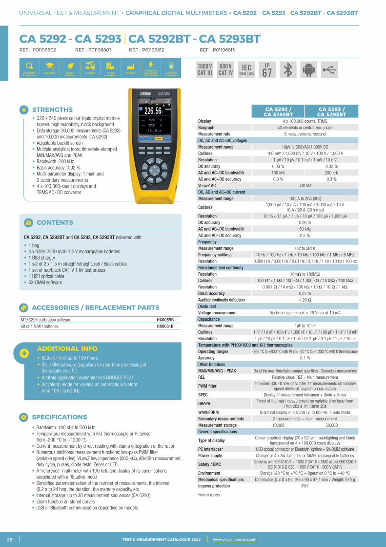
STRENGTHS • 320 x 240 pixels colour liquid crystal matrice screen, high readability, black background • Data storage: 30,000 measurements (CA 5293) and 10,000 measurements (CA 5292) • Adjustable backlit screen • Multiple analytical tools: time/date-stamped MIN/MAX/AVG and PEAK • Bandwidth: 200 kHz • Basic accuracy: 0.02 % • Multi-parameter display: 1 main and 3 secondary measurements • 4 x 100,000-count displays and TRMS AC+DC converter
ADDITIONAL INFO• Battery life of up to 100 hours• SX-DMM software (supplied) for real-time processing of the results on a PC• Android application available from GOOGLE PLAY• Waveform mode for viewing an automatic waveform from 10Hz to 600Hz
ACCESSORIES / REPLACEMENT PARTS
MTX329X calibration software HX0059BKit of 4 NiMH batteries HX0051B
CONTENTS
CA 5292, CA 5292BT and CA 5293, CA 5293BT delivered with:
• 1 bag• 4 x NiMH 2400 mAH 1.5 V rechargeable batteries• 1 USB charger• 1 set of 2 x 1.5 m straight/straight, red / black cables• 1 set of red/black CAT IV 1 kV test probes• 1 USB optical cable• SX-DMM software
SPECIFICATIONS • Bandwidth: 100 kHz to 200 kHz • Temperature measurement with K/J thermocouple or Pt sensor from -200 °C to +1200 °C • Current measurement by direct reading with clamp (integration of the ratio) • Numerous additional measurement functions: low-pass PWM filter (variable speed drive), VLowZ low impedance (500 kΩ), dB/dBm measurement, duty cycle, pulses, diode tests: Zener or LED... • A “reference” multimeter with 100 kcts and display of its specifications associated with a RELative mode • Simplified parameterization of the number of measurements, the interval (0.2 s to 24 hrs), the duration, the memory capacity, etc. • Internal storage: up to 30 measurement sequences (CA 5293) • Zoom function on stored curves • USB or Bluetooth communication depending on models
CA 5292 / CA 5292BT
CA 5293 / CA 5293BT
Display 4 x 100,000 counts, TRMSBargraph 40 elements or central zero modeMeasurement rate 5 measurements /secondDC, AC and AC+DC voltagesMeasurement range 10µV to 600VAC/1,000V DCCalibres 100 mV* / 1,000 mV / 10 V / 100 V / 1,000 VResolution 1 µV / 10 µV / 0.1 mV / 1 mV / 10 mV DC accuracy 0.03 % 0.02 %AC and AC+DC bandwidth 100 kHz 200 kHzAC and AC+DC accuracy 0.3 % 0.3 %VLowZ AC 500 kΩDC, AC and AC+DC currentMeasurement range 100µA to 20A (30s)
Calibres 1,000 µA / 10 mA / 100 mA / 1,000 mA / 10 A 10 A / 20 A (30 s max)
Resolution 10 nA / 0.1 µA / 1 µA / 10 µA / 100 µA / 1,000 µADC accuracy 0.08 %AC and AC+DC bandwidth 50 kHzAC and AC+DC accuracy 0.3 %FrequencyMeasurement range 1Hz to 5MHz Frequency calibres 10 Hz / 100 Hz / 1 kHz / 10 kHz / 100 kHz / 1 MHz / 5 MHz Resolution 0.0001 Hz / 0.001 Hz / 0.01 Hz / 0.1 Hz / 1 Hz / 10 Hz / 100 Hz Resistance and continuityResolution 10mΩ to 100MΩ
Calibres 100 Ω* / 1 kΩ / 100 kΩ / 1,000 kΩ / 10 MΩ / 100 MΩ
Resolution 0,001 Ω / 10 mΩ / 100 kΩ / 10 Ω / 10 Ω / 1 kΩBasic accuracy 0.07 %Audible continuity detection < 20 ΩDiode testVoltage measurement Diodes in open circuit < 26 Vmax at 10 mA CapacitanceMeasurement range 1pF to 10mF Calibres 1 nF / 10 nF / 100 nF / 1,000 nF / 10 µF / 100 µF / 1 mF / 10 mF Resolution 1 pF / 10 pF / 0.1 nF / 1 nF / 0.01 µF / 0.1 µF / 1 µF / 10 µF Temperature with Pt100/1000 and K/J thermocouplesOperating ranges -200 °C to +800 °C with Pt and -40 °C to +1200 °C with K thermocoupleAccuracy 0.1 %Other functionsMAX/MIN/AVG - PEAK On all the main time/date-stamped quantities - Secondary measurementREL Relative value: REF - Main measurement
PWM filter 4th-order 300 Hz low-pass filter for measurements on variable speed drives of asynchronous motors
SPEC Display of measurement tolerance + Smin + Smax
GRAPH Trend of the main measurement on variable time base from 1min 28s à 1h 13min 20s
WAVEFORM Graphical display of a signal up to 600 Hz in auto modeSecondary measurements 3 measurements + main measurementMeasurement storage 10,000 30,000General specifications
Type of display Colour graphical display (70 x 52) with backlighting and black background on 4 x 100,000 count displays
PC interfaces* USB optical connector or Bluetooth (option) – SX-DMM softwarePower supply Charger or 4 x AA batteries or NiMH rechargeable batteries
Safety / EMC Safety as per IEC61010-1 – 1000 V CAT III – EMC as per EN61326-1 IEC 61010-2-033 - 1000 V CAT III - 600 V CAT IV
Environment Storage -20 °C to +70 °C – Operation 0 °C to +40 °C Mechanical specifications Dimensions (L x D x H): 196 x 90 x 47.1 mm / Weight: 570 gIngress protection IP67
* Manual access
3CATALOGUE TEST & MESURE 2021 www.chauvin-arnoux.com 27TEST & MEASUREMENT CATALOGUE 2022 www.chauvin-arnoux.com
UNIVERSAL TEST & MEASUREMENT > PORTABLE DIGITAL OSCILLOSCOPES WITH 2 ISOLATED CHANNELS > CA 922 - CA 942
CA 922 - CA 942 REF. : P01192200 REF. : P01194200
Generation, transmission & distribution
IndustriesTertiary & residential
Education TransportDiagnostics & inspection
Energy efficiency
Laboratory & metrology
TRMS TRMSAC+DC
IEC61010
600 VCAT III
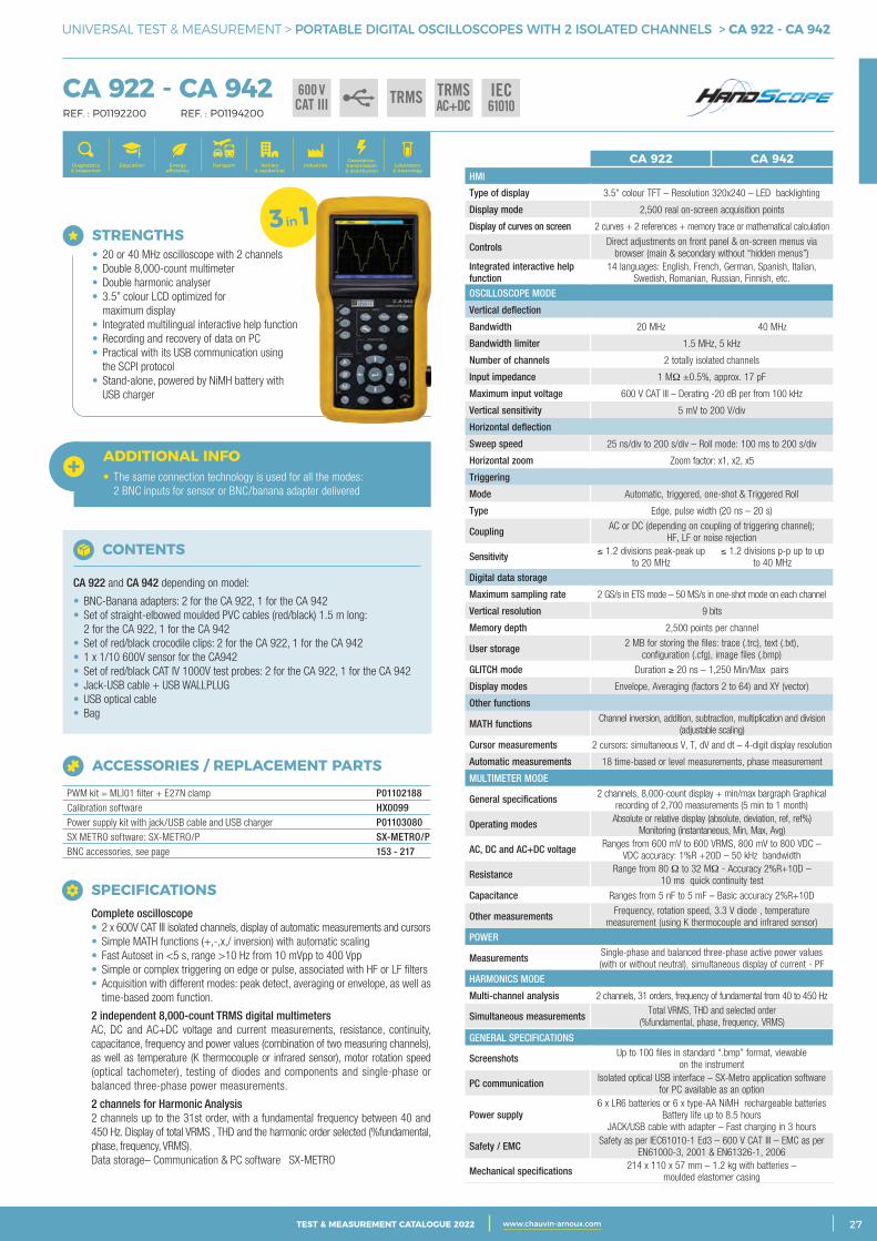
STRENGTHS • 20 or 40 MHz oscilloscope with 2 channels • Double 8,000-count multimeter • Double harmonic analyser • 3.5” colour LCD optimized for maximum display • Integrated multilingual interactive help function • Recording and recovery of data on PC • Practical with its USB communication using the SCPI protocol • Stand-alone, powered by NiMH battery with USB charger
ADDITIONAL INFO• The same connection technology is used for all the modes: 2 BNC inputs for sensor or BNC/banana adapter delivered
ACCESSORIES / REPLACEMENT PARTS
PWM kit = MLI01 filter + E27N clamp P01102188Calibration software HX0099Power supply kit with jack/USB cable and USB charger P01103080SX METRO software: SX-METRO/P SX-METRO/PBNC accessories, see page 153 - 217
CONTENTS
CA 922 and CA 942 depending on model:
• BNC-Banana adapters: 2 for the CA 922, 1 for the CA 942• Set of straight-elbowed moulded PVC cables (red/black) 1.5 m long: 2 for the CA 922, 1 for the CA 942• Set of red/black crocodile clips: 2 for the CA 922, 1 for the CA 942• 1 x 1/10 600V sensor for the CA942• Set of red/black CAT IV 1000V test probes: 2 for the CA 922, 1 for the CA 942• Jack-USB cable + USB WALLPLUG • USB optical cable• Bag
SPECIFICATIONS Complete oscilloscope • 2 x 600V CAT III isolated channels, display of automatic measurements and cursors • Simple MATH functions (+,-,x,/ inversion) with automatic scaling • Fast Autoset in <5 s, range >10 Hz from 10 mVpp to 400 Vpp • Simple or complex triggering on edge or pulse, associated with HF or LF filters • Acquisition with different modes: peak detect, averaging or envelope, as well as time-based zoom function.
2 independent 8,000-count TRMS digital multimeters AC, DC and AC+DC voltage and current measurements, resistance, continuity, capacitance, frequency and power values (combination of two measuring channels), as well as temperature (K thermocouple or infrared sensor), motor rotation speed (optical tachometer), testing of diodes and components and single-phase or balanced three-phase power measurements.
2 channels for Harmonic Analysis 2 channels up to the 31st order, with a fundamental frequency between 40 and 450 Hz. Display of total VRMS , THD and the harmonic order selected (%fundamental, phase, frequency, VRMS). Data storage– Communication & PC software SX-METRO
CA 922 CA 942HMI
Type of display 3.5” colour TFT – Resolution 320x240 – LED backlighting
Display mode 2,500 real on-screen acquisition points
Display of curves on screen 2 curves + 2 references + memory trace or mathematical calculation
Controls Direct adjustments on front panel & on-screen menus via browser (main & secondary without “hidden menus”)
Integrated interactive help function
14 languages: English, French, German, Spanish, Italian, Swedish, Romanian, Russian, Finnish, etc.
OSCILLOSCOPE MODE
Vertical deflection
Bandwidth 20 MHz 40 MHz
Bandwidth limiter 1.5 MHz, 5 kHz
Number of channels 2 totally isolated channels
Input impedance 1 MΩ ±0.5%, approx. 17 pF
Maximum input voltage 600 V CAT III – Derating -20 dB per from 100 kHz
Vertical sensitivity 5 mV to 200 V/div
Horizontal deflection
Sweep speed 25 ns/div to 200 s/div – Roll mode: 100 ms to 200 s/div
Horizontal zoom Zoom factor: x1, x2, x5
Triggering
Mode Automatic, triggered, one-shot & Triggered Roll
Type Edge, pulse width (20 ns – 20 s)
Coupling AC or DC (depending on coupling of triggering channel);HF, LF or noise rejection
Sensitivity ≤ 1.2 divisions peak-peak up to 20 MHz
≤ 1.2 divisions p-p up to up to 40 MHz
Digital data storage
Maximum sampling rate 2 GS/s in ETS mode – 50 MS/s in one-shot mode on each channel
Vertical resolution 9 bits
Memory depth 2,500 points per channel
User storage 2 MB for storing the files: trace (.trc), text (.txt), configuration (.cfg), image files (.bmp)
GLITCH mode Duration ≥ 20 ns – 1,250 Min/Max pairs
Display modes Envelope, Averaging (factors 2 to 64) and XY (vector)
Other functions
MATH functions Channel inversion, addition, subtraction, multiplication and division (adjustable scaling)
Cursor measurements 2 cursors: simultaneous V, T, dV and dt – 4-digit display resolution
Automatic measurements 18 time-based or level measurements, phase measurement
MULTIMETER MODE
General specifications 2 channels, 8,000-count display + min/max bargraph Graphical recording of 2,700 measurements (5 min to 1 month)
Operating modes Absolute or relative display (absolute, deviation, ref, ref%) Monitoring (instantaneous, Min, Max, Avg)
AC, DC and AC+DC voltage Ranges from 600 mV to 600 VRMS, 800 mV to 800 VDC – VDC accuracy: 1%R +20D – 50 kHz bandwidth
Resistance Range from 80 Ω to 32 MΩ - Accuracy 2%R+10D –10 ms quick continuity test
Capacitance Ranges from 5 nF to 5 mF – Basic accuracy 2%R+10D
Other measurements Frequency, rotation speed, 3.3 V diode , temperature measurement (using K thermocouple and infrared sensor)
POWER
Measurements Single-phase and balanced three-phase active power values (with or without neutral), simultaneous display of current - PF
HARMONICS MODE
Multi-channel analysis 2 channels, 31 orders, frequency of fundamental from 40 to 450 Hz
Simultaneous measurements Total VRMS, THD and selected order (%fundamental, phase, frequency, VRMS)
GENERAL SPECIFICATIONS
Screenshots Up to 100 files in standard “.bmp” format, viewable on the instrument
PC communication Isolated optical USB interface – SX-Metro application software for PC available as an option
Power supply 6 x LR6 batteries or 6 x type-AA NiMH rechargeable batteries
Battery life up to 8.5 hoursJACK/USB cable with adapter – Fast charging in 3 hours
Safety / EMC Safety as per IEC61010-1 Ed3 – 600 V CAT III – EMC as per EN61000-3, 2001 & EN61326-1, 2006
Mechanical specifications 214 x 110 x 57 mm – 1.2 kg with batteries – moulded elastomer casing
3 in 1
2 CATALOGUE TEST & MESURE 2021 www.chauvin-arnoux.com28 TEST & MEASUREMENT CATALOGUE 2022 www.chauvin-arnoux.com
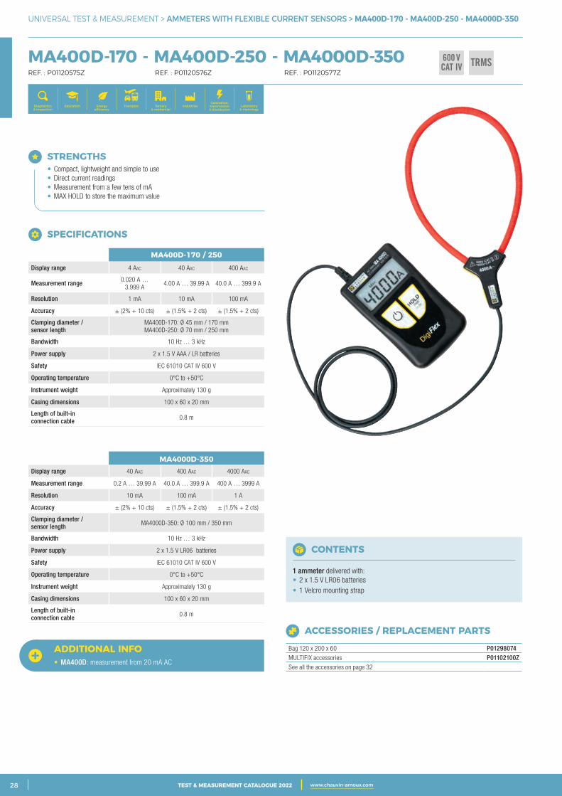
UNIVERSAL TEST & MEASUREMENT > AMMETERS WITH FLEXIBLE CURRENT SENSORS > MA400D-170 - MA400D-250 - MA4000D-350
STRENGTHS • Compact, lightweight and simple to use • Direct current readings • Measurement from a few tens of mA • MAX HOLD to store the maximum value
MA400D-170 - MA400D-250 - MA4000D-350 REF. : P01120575Z REF. : P01120576Z REF. : P01120577Z
600 VCAT IV TRMS
ACCESSORIES / REPLACEMENT PARTS
Bag 120 x 200 x 60 P01298074MULTIFIX accessories P01102100ZSee all the accessories on page 32
CONTENTS
1 ammeter delivered with:• 2 x 1.5 V LR06 batteries• 1 Velcro mounting strap
MA400D-170 / 250Display range 4 aac 40 aac 400 aac
Measurement range 0.020 A … 3.999 A
4.00 A … 39.99 A 40.0 A … 399.9 A
Resolution 1 mA 10 mA 100 mA
Accuracy ± (2% + 10 cts) ± (1.5% + 2 cts) ± (1.5% + 2 cts)
Clamping diameter / sensor length
MA400D-170: Ø 45 mm / 170 mm MA400D-250: Ø 70 mm / 250 mm
Bandwidth 10 Hz … 3 kHz
Power supply 2 x 1.5 V AAA / LR batteries
Safety IEC 61010 CAT IV 600 V
Operating temperature 0°C to +50°C
Instrument weight Approximately 130 g
Casing dimensions 100 x 60 x 20 mm
Length of built-in connection cable 0.8 m
MA4000D-350Display range 40 Aac 400 Aac 4000 Aac
Measurement range 0.2 A … 39.99 A 40.0 A … 399.9 A 400 A … 3999 A
Resolution 10 mA 100 mA 1 A
Accuracy ± (2% + 10 cts) ± (1.5% + 2 cts) ± (1.5% + 2 cts)
Clamping diameter / sensor length MA4000D-350: Ø 100 mm / 350 mm
Bandwidth 10 Hz … 3 kHz
Power supply 2 x 1.5 V LR06 batteries
Safety IEC 61010 CAT IV 600 V
Operating temperature 0°C to +50°C
Instrument weight Approximately 130 g
Casing dimensions 100 x 60 x 20 mm
Length of built-in connection cable 0.8 m
SPECIFICATIONS
Generation, transmission & distribution
IndustriesTertiary & residential
Education TransportDiagnostics & inspection
Energy efficiency
Laboratory & metrology
ADDITIONAL INFO• MA400D: measurement from 20 mA AC
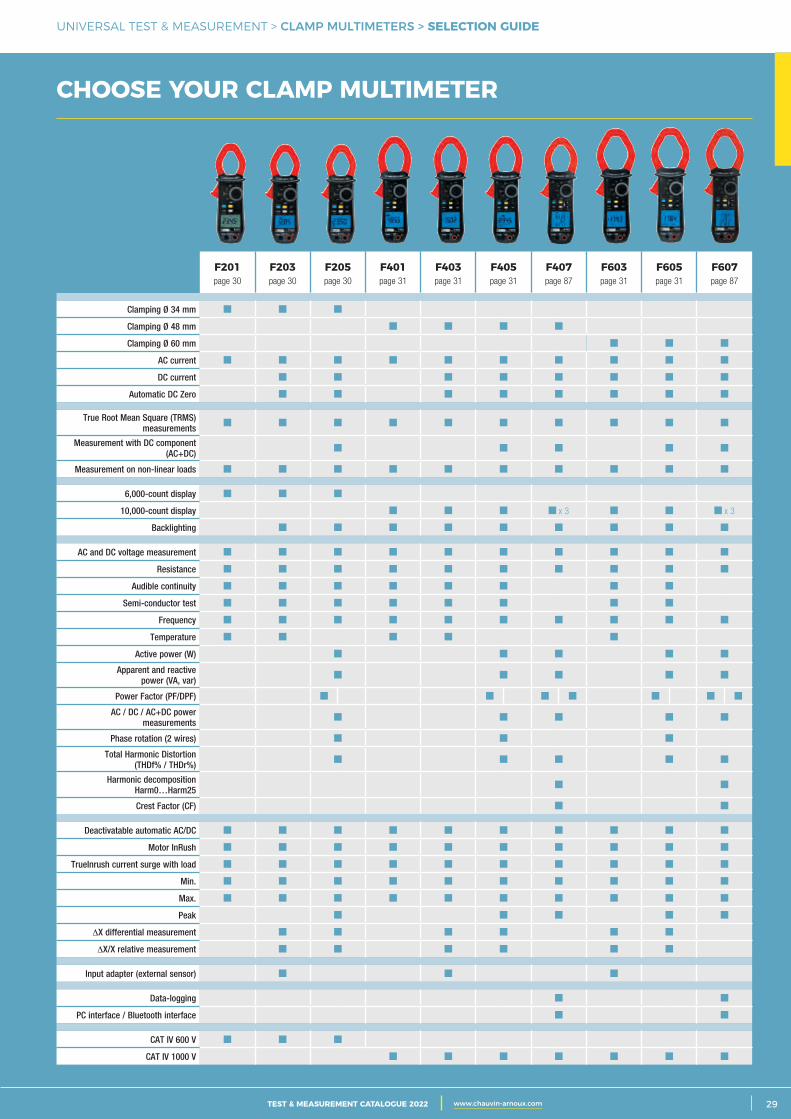
3CATALOGUE TEST & MESURE 2021 www.chauvin-arnoux.com 29TEST & MEASUREMENT CATALOGUE 2022 www.chauvin-arnoux.com
UNIVERSAL TEST & MEASUREMENT > CLAMP MULTIMETERS > SELECTION GUIDE
CHOOSE YOUR CLAMP MULTIMETER
F201page 30
F203page 30
F205page 30
F401page 31
F403page 31
F405page 31
F407page 87
F603page 31
F605page 31
F607page 87
Clamping Ø 34 mm
Clamping Ø 48 mm
Clamping Ø 60 mm
AC current
DC current
Automatic DC Zero
True Root Mean Square (TRMS) measurements
Measurement with DC component (AC+DC)
Measurement on non-linear loads
6,000-count display
10,000-count display x 3 x 3
Backlighting
AC and DC voltage measurement
Resistance
Audible continuity
Semi-conductor test
Frequency
Temperature
Active power (W)
Apparent and reactive power (VA, var)
Power Factor (PF/DPF)
AC / DC / AC+DC power measurements
Phase rotation (2 wires)
Total Harmonic Distortion (THDf% / THDr%)
Harmonic decomposition Harm0…Harm25
Crest Factor (CF)
Deactivatable automatic AC/DC
Motor InRush
TrueInrush current surge with load
Min.
Max.
Peak
∆X differential measurement
∆X/X relative measurement
Input adapter (external sensor)
Data-logging
PC interface / Bluetooth interface
CAT IV 600 V
CAT IV 1000 V
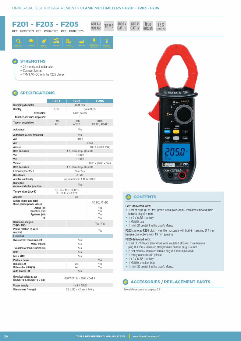
2 CATALOGUE TEST & MESURE 2021 www.chauvin-arnoux.com30 TEST & MEASUREMENT CATALOGUE 2022 www.chauvin-arnoux.com
UNIVERSAL TEST & MEASUREMENT > CLAMP MULTIMETERS > F201 - F203 - F205
F201 - F203 - F205 REF. : P01120921 REF. : P01120923 REF. : P01120925
F201 F203 F205Clamping diameter Ø 34 mm
Display LCD Backlit LCDResolution 6,000 counts
Number of values displayed 1
Type of acquisition TRMS AC
TRMS AC/DC
TRMS AC, DC, AC+DC
Autorange Yes
Automatic AC/DC detection Yesaac 600 Aadc 900 Aaac+dc 600 A (900 A peak)Best accuracy 1 % of reading+ 3 countsVac 1000 VVdc 1000 VVac+dc 1000 V (1400 V peak) Best accuracy 1 % of reading+ 3 countsFrequency for V / I Yes / YesResistance 60 kΩAudible continuity Adjustable from 1 Ω to 599 ΩDiode test (semi-conductor junction) Yes
Temperature (type K) °C: -60.0 to +1,000 °C °F: -76 to +1,832 °F
Adapter YesSingle phase and total three-phase power values AC, DC, AC+DC
Active (W) Reactive (var) Apparent (VA)
Yes Yes Yes
PF YesHarmonic analysisTHDf / THDr Yes / Yes
Phase rotation (2-wire method) Yes
FunctionsOvercurrent measurement Yes
Motor InRush YesEvolution of load (TrueInrush) Yes
Hold YesMin / MAX YesPeak+ / Peak- YesRELative ΔX Differential ΔX/X(%)
Yes Yes
Yes Yes
Auto Power Off Yes
Electrical safety as per IEC 61010-1, IEC 61010-2-032 600 V CAT IV - 1000 V CAT III
Power supply 1 x 9 V 6LR61Dimensions / weight 78 x 222 x 42 mm / 340 g
STRENGTHS • 34 mm clamping diameter • Compact format • TRMS AC+DC with the F205 clamp
CONTENTS
F201 delivered with:• 1 set of built-in PVC test-probe leads (black/red) / insulated elbowed male banana plug Ø 4 mm• 1 x 9 V 6LR61 battery• 1 Multifix bag• 1 mini-CD containing the User’s Manual
F203 same as F201 plus 1 wire thermocouple with built-in insulated Ø 4 mmbanana connections with 19 mm spacing
F205 delivered with:• 1 set of PVC leads (black/red) with insulated elbowed male banana plug Ø 4 mm / insulated straight male banana plug Ø 4 mm• 2 test probes / insulated female plug Ø 4 mm (black/red)• 1 safety crocodile clip (black)• 1 x 9 V 6LR61 battery• 1 Multifix shoulder bag• 1 mini-CD containing the User’s Manual
SPECIFICATIONS
1000 VCAT III
600 VCAT IV
600 AAC
900 ADCTRMS True
InRushIEC
61010-2-032
Generation, transmission & distribution
IndustriesTertiary & residential
Education TransportDiagnostics & inspection
Energy efficiency
Laboratory & metrology
ACCESSORIES / REPLACEMENT PARTS
See all the accessories on page 32
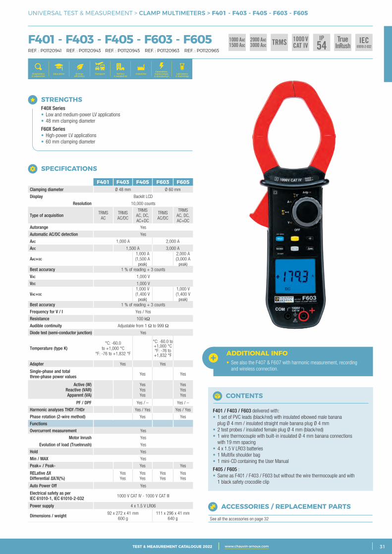
3CATALOGUE TEST & MESURE 2021 www.chauvin-arnoux.com 31TEST & MEASUREMENT CATALOGUE 2022 www.chauvin-arnoux.com
UNIVERSAL TEST & MEASUREMENT > CLAMP MULTIMETERS > F401 - F403 - F405 - F603 - F605
F401 - F403 - F405 - F603 - F605 REF. : P01120941 REF. : P01120943 REF. : P01120945 REF. : P01120963 REF. : P01120965
STRENGTHS F40X Series • Low and medium-power LV applications • 48 mm clamping diameter
F60X Series • High-power LV applications • 60 mm clamping diameter
SPECIFICATIONS
F401 F403 F405 F603 F605Clamping diameter Ø 48 mm Ø 60 mm
Display Backlit LCD
Resolution 10,000 counts
Type of acquisition TRMS AC
TRMS AC/DC
TRMSAC, DC, AC+DC
TRMS AC/DC
TRMSAC, DC, AC+DC
Autorange Yes
Automatic AC/DC detection Yes
aac 1,000 A 2,000 A
adc 1,500 A 3,000 A
aac+dc
1,000 A (1,500 A
peak)
2,000 A (3,000 A
peak)Best accuracy 1 % of reading + 3 counts
Vac 1,000 V
Vdc 1,000 V
Vac+dc
1,000 V (1,400 V
peak)
1,000 V (1,400 V
peak)Best accuracy 1 % of reading + 3 counts
Frequency for V / I Yes / Yes
Resistance 100 kΩ
Audible continuity Adjustable from 1 Ω to 999 Ω
Diode test (semi-conductor junction) Yes
Temperature (type K)°C: -60.0
to +1,000 °C °F: -76 to +1,832 °F
°C: -60.0 to +1,000 °C °F: -76 to +1,832 °F
Adapter Yes Yes
Single-phase and total three-phase power values Yes Yes
Active (W) Reactive (VAR) Apparent (VA)
Yes YesYes
Yes YesYes
PF / DPF Yes / – Yes / –
Harmonic analyses THDf /THDr Yes / Yes Yes / Yes
Phase rotation (2-wire method) Yes Yes
Functions
Overcurrent measurement Yes
Motor Inrush Yes
Evolution of load (TrueInrush) Yes
Hold Yes
Min / MAX Yes
Peak+ / Peak- Yes Yes
RELative ΔX Differential ΔX/X(%)
YesYes
YesYes
YesYes
YesYes
Auto Power Off Yes
Electrical safety as per IEC 61010-1, IEC 61010-2-032 1000 V CAT IV - 1000 V CAT III
Power supply 4 x 1.5 V LR06
Dimensions / weight 92 x 272 x 41 mm600 g
111 x 296 x 41 mm 640 g
Generation, transmission & distribution
IndustriesTertiary & residential
Education TransportDiagnostics & inspection
Energy efficiency
Laboratory & metrology
ADDITIONAL INFO• See also the F407 & F607 with harmonic measurement, recording and wireless connection.
CONTENTS
F401 / F403 / F603 delivered with:• 1 set of PVC leads (black/red) with insulated elbowed male banana plug Ø 4 mm / insulated straight male banana plug Ø 4 mm• 2 test probes / insulated female plug Ø 4 mm (black/red)• 1 wire thermocouple with built-in insulated Ø 4 mm banana connections with 19 mm spacing• 4 x 1.5 V LR03 batteries• 1 Multifix shoulder bag• 1 mini-CD containing the User Manual
F405 / F605 :• Same as F401 / F403 / F603 but without the wire thermocouple and with 1 black safety crocodile clip
ACCESSORIES / REPLACEMENT PARTS
See all the accessories on page 32
1000 VCAT IV
IP54
2 000 AAC3 000 ADC TRMS True
InRushIEC
61010-2-032
1 000 AAC1 500 ADC
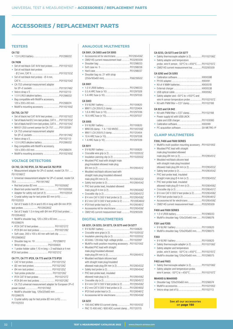
2 CATALOGUE TEST & MESURE 2021 www.chauvin-arnoux.com32 TEST & MEASUREMENT CATALOGUE 2022 www.chauvin-arnoux.com
UNIVERSAL TEST & MEASUREMENT > ACCESSORIES / REPLACEMENT PARTS
TESTERSCA 732• 1.5 V LR03 battery ....................................... P01296032
CA 745N• Set of red/black CAT III/IV test probes .......... P01102152Z• Set of red/black test probes - Ø 2 mm, CAT II .......................................... P01102153Z• Set of red/black test probes - Ø 4 mm, CAT II........................................................... P01102154Z• CA 753 universal measurement adapter for 2P+E sockets ......................................... P01191748Z• Velcro strap x 5 ............................................ P01102113• 1.5 V LR03 alkaline battery .......................... P01296032• Bag compatible with MultiFix accessory, 120 x 200 x 60 mm ..................................... P01298074• MultiFix mounting accessory ........................ P01102100Z
CA 755, CA 757 • Set of black/red CAT III/IV test probes .......... P01102152Z• Set of black/red Ø 2 mm test probes, CAT II ......P01102153Z• Set of black/red Ø 4 mm test probes, CAT II ......P01102154Z• MA101-250 current sensor for CA 757 ......... P01120591• CA 753 universal measurement adapter for 2P+E sockets ......................................... P01191748Z• Velcro strap x 5 ............................................ P01102113• 1.5 V LR03 alkaline battery .......................... P01296032• Bag compatible with MultiFix accessory, 120 x 200 x 60 mm ..................................... P01298074• MultiFix mounting accessory ........................ P01102100Z
VOLTAGE DETECTORS CA 742, CA 742 IP2X, CA 762 and CA 762 IP2X • Measurement adapter for 2P+E socket, model CA 751 ..... P01101997Z• Universal measurement adapter for 2P+E socket, model CA 753 .............................. P01191748Z• Red test probe Ø2 mm .......................... P01102008Z• Black test-probe lead Ø2 mm ..................... P01102009Z• Adapter for safety rod (set of 2) .................... P01102034• Crystal safety cap for test probe Ø2 mm (x10) .......... P01102033• Set of 2 leads 0.25 m and 0.85 m long with Ø4 mm IP2X test probes ..................... P01295285Z• Set of 2 leads 1.5 m long with Ø4 mm IP2X test probes .... P01295462Z• MultiFix shoulder bag, 120 x 200 x 60 mm ............. P01298074• IP2X CAT IV test probes ........................ P01102127Z• IP2X Ø4 mm test probes ....................... P01102128Z• Soft case, 200 x 100 x 40 mm with belt clip ............ P01298065Z• Shoulder bag no. 10 ........................... P01298012• Wrist-strap ................................. P03100824• 1 probe-holder cable 1.10 m long + 2 red/black ø 4 mm IP2X test probes ............................. P01102121Z
CA 771, CA 771 IP2X, CA 773 and CA 773 IP2X • CAT IV test probes ............................ P01102123Z• Ø2 mm test probes ........................... P01102124Z• Ø4 mm test probes ........................... P01102125Z• Test-probe protector .......................... P01102126Z• IP2X CAT IV test probes ........................ P01102127Z• IP2X Ø4 mm test probes ....................... P01102128Z• CA 753 universal measurement adapter for European 2P+E power socket .................. P01191748Z• MultiFix shoulder bag, 120x320x60 mm ............. P01298076• Crystal safety cap for test probe Ø2 mm (x10) ......... P01102033
ANALOGUE MULTIMETERS CA 5001, CA 5003 and CA 5005 • Accessories kit for electricians ................... P01295459Z• CMI214S current measurement lead ............ P03295509• Shoulder bag ............................................... P01298033• Soft case no. 5 ............................................ P01298036• Hard case .................................................... P01298037• Shoulder bag no. 21 with strap (250x165x60 mm)....................................... P06239502
CA 5001 • 1.5 V LR06 battery ....................................... P01296033• 0.5 A HRC fuse (x 10) .................................. P01297028• 5 A HRC fuse (x 10) ..................................... P01297035
CA 5003 • 9 V 6LR61 battery ....................................... P01100620• MN11 LCA 200/0.2 clamp ........................... P01120404• 1.6 A HRC fuse (x 10)................................... P01297036• 16 A HRC fuse (x 10).................................... P01297037
CA 5005 • 9 V 6LR61 battery ....................................... P01100620• MINI 09 clamp - 1 A / 100 MVDC ................. P01105109Z• MN11 LCA 200/0.2 clamp ........................... P01120404• 10 A HRC fuse (x 10).................................... P01297038• 1 A HRC fuse (x 10) ..................................... P01297039
CA 5011 • 9 V 6LR61 battery ....................................... P01100620• Crocodile wire grip (x 2) ............................... P01102053Z• Insulation-piercing clip (x 2) ......................... P01102055Z• Moulded PVC lead with straight male plug/insulated elbowed male plug Ø4 mm (x 2) ................................................ P01295451Z• Moulded red/black silicone lead with straight male plug/insulated elbowed male plug Ø4 mm (x 2) ................................. P01295453Z• Safety test probe (x 2) .................................. P01295454Z• PVC test-probe lead, insulated elbowed male plug Ø 4 mm (x 2) ................................ P01295456Z• Crocodile clip (x 2) ....................................... P01295457Z• Ø 4 mm CAT II 300 V test probe (x 2) ........... P01295458Z• Ø 2 mm CAT II 300 V test probe (x 2) ........... P01295460Z• IP2X test-probe lead (x 2) ............................ P01295461Z• Accessories kit for electricians ..................... P01295459Z• CMI214S current measurement lead ............ P03295509
DIGITAL MULTIMETERS CA 5231, CA 5233, CA 5273, CA 5275 and CA 5277 • 9 V 6LR61 battery ....................................... P01100620• Crocodile wire grips (x 2) .............................. P01102053Z• Insulation-piercing clip (x 2) ......................... P01102055Z• 40 kVdc / 28 kVac high-voltage probe .......... P01102097• MultiFix multi-position mounting accessory .. P01102100Z• Moulded PVC lead with straight male plug/insulated elbowed male plug Ø4 mm (x 2) ................................. P01295451Z• Moulded red/black silicone lead with straight male plug/insulated elbowed male plug Ø4 mm (x 2) ................... P01295453Z• Safety test probe (x 2) .................................. P01295454Z• PVC test-probe lead, insulated elbowed male plug (x 2) ............................... P01295456Z• Crocodile clip (x 2) ....................................... P01295457Z• Ø 4 mm CAT II 300 V test probe (x 2) ........... P01295458Z• Ø 2 mm CAT II 300 V test probe (x 2) ........... P01295460Z• IP2X test-probe lead (x 2) ............................ P01295461Z• Accessories kit for electricians ..................... P01295459Z
CA 5231 • 100 AAC MINI 03 current clamp................... P01105103Z • PAC 15 400 AAC / 600 ADC current clamp .... P01120115
CA 5233, CA 5273 and CA 5277 • Safety thermocouple adapter (x 2) ................ P01102106Z• Safety adapter and temperature probe, wire K sensor, -50°C to +450°C ....... P01102107Z• CMI214S current measurement lea .............. P03295509
CA 5292 and CA 5293 • Calibration software ..................................... HX0059B• Pt100 adapter.............................................. HX0091• Kit of 4 NiMH batteries ................................. HX0051B• External charger .......................................... HX0053B• USB optical cable ......................................... HX0056Z• Safety adapter and –50°C to +450°C and wire K-sensor temperature probe ................. P01102107Z• Kit with PWM filter + E27 clamp................... P01102188
CA 922 and CA 942 • Kit with PWM filter + E27 clamp................... P01102188 • Power supply kit with USB/JACK cable and USB charger ................................. P01103080 • Calibration software ..................................... HX0099 • PC acquisition software ................................ SX-METRO /P
CLAMP MULTIMETERSF200, F400 and F600 SERIES• MultiFix multi-position mounting accessory .. P01102100Z• Moulded PVC lead with straight male plug/insulated elbowed male plug Ø4 mm (x 2) ................................. P01295451Z• Moulded red/black silicone lead with straight male plug/insulated elbowed male plug Ø4 mm (x 2) ................... P01295453Z• Safety test probe (x 2) .................................. P01295454Z• PVC test-probe lead, insulated straight male plug Ø 4 mm (x 2) ................... P01295455Z• PVC test-probe lead, insulated elbowed male plug Ø 4 mm (x 2) .................. P01295456Z• Crocodile clip (x 2) ....................................... P01295457Z• Ø 4 mm CAT II 300 V test probe (x 2) ........... P01295458Z• IP2X test-probe lead (x 2) ............................ P01295461Z• Accessories kit for electricians ..................... P01295459Z• CMI214S current measurement lead ............ P03295509
F400 and F600 SERIES• 1.5 V LR06 battery ....................................... P01296033• MultiFix shoulder bag 120x320x60 mm ....... P01298076
F201 and F205 • 9 V 6LR61 battery ....................................... P01100620• MultiFix shoulder bag 120x245x60 mm ........ P01298075
F203 • 9 V 6LR61 battery ....................................... P01100620• Safety thermocouple adapter (x 2) ................ P01102106Z• Safety adapter and temperature probe, wire K sensor, -50°C to +450°C ....... P01102107Z• MultiFix shoulder bag 120x245x60 mm ........ P01298075
F403 and F603 • Safety thermocouple adapter (x 2) ................ P01102106Z• Safety adapter and temperature probe, wire K sensor, -50°C to +450°C .................. P01102107Z
MA400D & MA4000D • Shoulder bag 120x200x60 mm .................... P01298074• MultiFix accessories ..................................... P01102100Z• Velcro strap (set of 5) ................................... P01102113
ACCESSORIES / REPLACEMENT PARTS
See all our accessories on page 150

3CATALOGUE TEST & MESURE 2021 www.chauvin-arnoux.com 33TEST & MEASUREMENT CATALOGUE 2022 www.chauvin-arnoux.com
UNIVERSAL TEST & MEASUREMENT > NOTES
NOTES
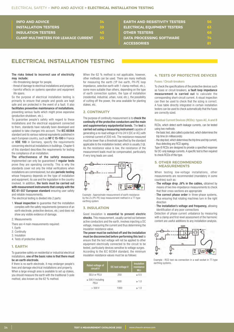
2 CATALOGUE TEST & MESURE 2021 www.chauvin-arnoux.com34 TEST & MEASUREMENT CATALOGUE 2022 www.chauvin-arnoux.com
ELECTRICAL SAFETY > INFO AND ADVICE > ELECTRICAL INSTALLATION TESTING
INFO AND ADVICE 34INSTALLATION TESTERS 39INSULATION TESTERS 45CLAMP MULTIMETERS FOR LEAKAGE CURRENT 55
EARTH AND RESISTIVITY TESTERS 56ELECTRICAL EQUIPMENT TESTERS 63OTHER TESTERS 68DATA PROCESSING SOFTWARE 74ACCESSORIES 81
The risks linked to incorrect use of electricity may include:- life-threatening danger for people,- threat of damage to electrical installations and property,- harmful effects on systems operation and equipment
life spans.So the purpose of electrical installation testing is primarily to ensure that people and goods are kept safe and are protected in the event of a fault. It also facilitates preventive maintenance of installations, preventing serious faults which might prove expensive (production shutdown, etc.).To guarantee people’s safety with regard to these installations and the electrical equipment connected to them, standards have naturally been developed and updated to take changes into account. The IEC 60364 standard and its various national equivalents published in each European country, such as NF C 15-100 in France or VDE 100 in Germany, specify the requirements concerning electrical installations in buildings. Chapter 6 of this standard describes the requirements for testing the compliance of an installation.The effectiveness of the safety measures implemented can only be guaranteed if regular tests prove they are operating correctly. This is why the standards cover not only the initial verifications when installations are commissioned, but also periodic testing whose frequency depends on the type of installation and equipment, its use and the legislation in the country involved. In addition, the tests must be carried out with measurement instruments that comply with the IEC 61-557 European standard ensuring user safety and reliable measurements.The electrical testing is divided into 2 parts:
1. Visual inspection to guarantee that the installation complies with the safety requirements (presence of an earth electrode, protective devices, etc.) and does not show any visible evidence of damage.
2. Measurements
There are 4 main measurements required:1. Earth2. Continuity3. Insulation4. Tests of protective devices
1. EARTH To guarantee safety on residential or industrial electrical installations, one of the basic rules is that there must be an earth electrode.If there is no earth electrode, it may endanger people’s lives and damage electrical installations and property.When a large enough area is available to set up stakes, you should measure the earth with the traditional 3-pole method, also known as the 62 % method.
ELECTRICAL INSTALLATION TESTING
When the 62 % method is not applicable, however, other methods can be used. There are many methods for measuring the earth (1P live earth, PH-PE loop impedance, selective earth with 1-clamp method, etc.), some more suitable than others, depending on the type of earth connection system, the type of installation (residential, industrial, urban, rural, etc.), the possibility of cutting off the power, the area available for planting stakes, etc.
2. CONTINUITY The purpose of continuity measurement is to check the continuity of the protective conductors and the main and supplementary equipotential bonds. The test is carried out using a measuring instrument capable of generating a no-load voltage of 4 to 24 V (DC or AC) with a minimal current of 200 mA. The resistance measured must be lower than a threshold specified by the standard applicable to the installation tested, which is usually 2 Ω. As the resistance value is low, the resistance of the measurement leads must be compensated, particularly if very long leads are used.
3. INSULATION Good insulation is essential to prevent electric shocks. This measurement, usually carried out between active conductors and the earth, involves injecting a DC voltage, measuring the current and thus determining the insulation resistance value.The power must be switched off and the installation must be disconnected before performing this test to ensure that the test voltage will not be applied to other equipment electrically connected to the circuit to be tested, particularly devices sensitive to voltage surges.According to the IEC 60364 standard, the minimum insulation resistance values must be as follows:
Rated voltage of circuit V DC test voltage V
Insulation resistance
MΩ
SELV or PELV 250 ≥ 0.5
≤ 500 V including PELV
500 ≥ 1.0
> 500 V 1000 ≥ 1.0
4. TESTS OF PROTECTIVE DEVICES Fuses / Circuit-breakers
To check the specifications of the protective devices such as fuses or circuit-breakers, a fault loop impedance measurement is carried out to calculate the corresponding short-circuit current. A visual inspection can then be used to check that the sizing is correct. A fuse table directly integrated in certain installation testers can be used to check automatically that the fuses are correctly sized.
Residual Current Devices (RCDs): types AC, A and B
RCDs, which detect earth leakage currents, can be tested using two methods:- the basic test, also called a pulse test, which determines the
trip time (in milliseconds)- the step test, which determines the trip time and trip current,
thus detecting any RCD ageing.Type-B RCDs are designed to provide a specified response for DC-only leakage currents. A specific test is then required to check RCDs of this type.
5. OTHER RECOMMENDED MEASUREMENTS
When testing low-voltage installations, other measurements are recommended (mandatory in some countries) such as:- The voltage drop DV% in the cables, obtained by
means of two line-impedance measurements to check that their cross-sections are appropriate
- The correct phase order in three-phase systems, thus ensuring that rotating machines turn in the right direction
- The installation’s voltage and frequency, allowing identification of any poor connections
Detection of phase current unbalance by measuring with a clamp and first-level assessment of the harmonic content are useful additions to any installation analysis.
Example : Approximate measurement of earth resistance by the Zs (Ph-PE) loop measurement method in a TT-type earthing system
Example : RCD test via connection in a wall socket in TT-type earthing systems..
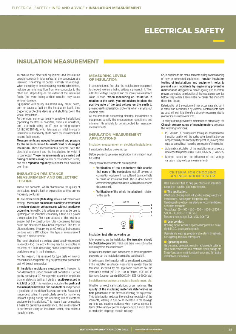
3CATALOGUE TEST & MESURE 2021 www.chauvin-arnoux.com 35TEST & MEASUREMENT CATALOGUE 2022 www.chauvin-arnoux.com
ELECTRICAL SAFETY > INFO AND ADVICE > INSULATION MEASUREMENT
ELECTRICAL SAFETY
INSULATION MEASUREMENT
To ensure that electrical equipment and installation operate correctly in total safety, all the conductors are insulated: sheathing for cables, varnish for windings. When the quality of these insulating materials diminishes, leakage currents may flow from one conductor to the other and, depending on the extent of the insulation faults (the worst being a short-circuit), may cause serious damage.Equipment with faulty insulation may break down, burn or cause a fault on the installation itself, thus triggering protective devices and shutting down the whole installation...Furthermore, some particularly sensitive installations (operating theatres in hospitals, chemical Industries, etc.) are built using an IT-type earthing system (cf. IEC 60364-6), which tolerates an initial line-earth insulation fault and only shuts down the installation if a second fault occurs.Measurements are needed to prevent and prepare for the hazards linked to insufficient or damaged insulation. These measurements concern both the electrical equipment and the installations to which it is connected. These measurements are carried out during commissioning on new or reconditioned items, and then repeated regularly to monitor their evolution over time.
INSULATION RESISTANCE MEASUREMENT AND DIELECTRIC TESTINGThese two concepts, which characterize the quality of an insulant, require further explanation as they are too frequently confused.
Dielectric strength testing, also called “breakdown testing”, measures an insulant’s ability to withstand a medium-duration voltage surge without sparkover occurring. In reality, this voltage surge may be due to lightning or the induction caused by a fault on a power transmission line. The main purpose of this test is to ensure that the construction rules concerning leakage paths and clearances have been respected. This test is often performed by applying an AC voltage but can also be done with a DC voltage. This type of measurement requires a dielectrometer.
The result obtained is a voltage value usually expressed in kilovolts (kV). Dielectric testing may be destructive in the event of a fault, depending on the test levels and the available energy in the instrument.
For this reason, it is reserved for type tests on new or reconditioned equipment: only equipment that passes the test will be put into service.
Insulation resistance measurement, however, is non-destructive under normal test conditions. Carried out by applying a DC voltage with a smaller amplitude than for dielectric testing, it yields a result expressed in kΩ, MΩ or GΩ. This resistance indicates the quality of the insulation between two conductors and provides a good idea of the risks of leakage currents. Because it is non-destructive, it is particularly useful for monitoring insulant ageing during the operating life of electrical equipment or installations. This means it can be used as a basis for preventive maintenance. This measurement is performed using an insulation tester, also called a megohmmeter.
So, in addition to the measurements during commissioning of new or renovated equipment, regular insulation testing of installations and equipment helps to prevent such incidents by organizing preventive maintenance designed to detect ageing and therefore prevent premature deterioration of the insulation properties before they reach a level liable to cause the incidents described above.
Deterioration of the equipment may occur naturally, but it is often also accelerated by external contaminants such as dust, oil, etc. It is therefore strongly recommended to monitor its insulation over time.
To carry out this preventive maintenance effectively, the Chauvin Arnoux range of megohmmeters proposes the following functions:
• PI, DAR and DD quality ratios for a quick assessment of insulation quality, with the added advantage that they are not particularly influenced by temperature, making them easy to use without requiring correction of the results
• Automatic calculation of the insulation resistance at a reference temperature (CA 6549, CA 6550, CA 6555)
• Method based on the influence of test voltage variation (step voltage measurement)
MEASURING LEVELS OF INSULATIONIn concrete terms, first of all the installation or equipment is checked to ensure that no voltage is present in it. Then a DC test voltage is applied and the insulation resistance value is read. When measuring an insulation in relation to the earth, you are advised to place the positive pole of the test voltage on the earth to prevent earth polarization problems when carrying out multiple tests.All the standards concerning electrical installations or equipment specify the measurement conditions and minimum thresholds to be respected for insulation measurements.
INSULATION MEASUREMENT APPLICATIONS Insulation measurement on electrical installations
Insulation test before powering up
Before powering up a new installation, its insulation must be tested.
Two types of measurements are required:
• Verification of the conductors: this checks that none of the conductors, cut-off devices or connection equipment has suffered damage liable to cause an insulation fault. This is done before commissioning the installation, with all the receivers disconnected..
• Verification of the whole installation in relation to the earth.
Insulation test after powering up
After powering up the installation, the insulation should be checked regularly to make sure there is no substantial drift away from the initial values.
Because the method used is the same as for testing before powering up, the installations must be switched off.
In both cases, the insulation will be considered acceptable if the insulation resistance measured is greater than the threshold specified by the applicable standard for the installation tested (NF C 15-100 in France, VDE 100 in Germany, European standard IEC 60364, IEEE 43-2000, etc.)
Insulation measurement on motors, transformers, etc.
Whether on electrical installations or on machines, the quality of the insulating materials deteriorates as time passes due to the stresses affecting the equipment. This deterioration reduces the electrical resistivity of the insulants, leading in turn to an increase in the leakage currents and causing incidents which may be serious in terms of the safety of people and property, but also in terms of production stoppage costs in industry.
3
2
1
N
M
+
100 m
Here are a few tips to help you choose an insulation tester that matches your requirements.
The application.What type of equipment will you be testing: electrical installations, switchgear, telephony, etc.Rated operating voltage, manufacturer recommendations, dedicated standardsTest voltage: 50 – 100 – 250 – 500 – 1,000 – 2,500 – 5,000 – 10,000 – 15,000 Vdc
Measurement range: kΩ, MΩ, GΩ, TΩ
User comfort.Reading mode: needle display with logarithmic scale, digital LCD, analogue bargraph
User-friendly features: programmable alarm thresholds, backlighting, remote control probe
Operating mode.Hand-cranked generator, normal or rechargeable batteriesOther measurements required: continuity, current, voltage, etc.Single-function or multi-function instrument, for testing installations or machines
CRITERIA FOR CHOOSING AN INSULATION TESTER
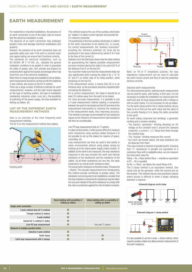
2 CATALOGUE TEST & MESURE 2021 www.chauvin-arnoux.com36 TEST & MEASUREMENT CATALOGUE 2022 www.chauvin-arnoux.com
ELECTRICAL SAFETY > INFO AND ADVICE > EARTH MEASUREMENT
For residential or industrial installations, the presence of an earth connection is one of the basic rules to ensure that the electrical installation is safe.The absence of an earth connection may endanger people’s lives and damage electrical installations and property.However, the presence of an earth connection does not guarantee safety and, even if the earth is correctly sized, only regular testing can ensure that it functions correctly.The standards for electrical installations, such as IEC 60364, NF C 15-100, etc., stipulate the general installation conditions to be applied in order to guarantee the safety of people, pets, farm animals and property by protecting them against the hazards and damage which may result from use of the electrical installations.When there is a large enough area available to set up stakes, earth measurement should be carried out with the traditional 3-pole method, also known as the 62 % method. There are a large number of different methods for earth measurements, however, and the right choice depends on the type of earthing system, the type of installation (residential, industrial, urban, rural, etc.), the possibility of switching off the power supply, the area available for setting up stakes, etc.
LIST OF THE DIFFERENT EARTH MEASUREMENT METHODS
Here is an overview of the most frequently-used measurement methods:The 62 % in-line measurement method (two stakes)
Existing earth
EARTH MEASUREMENT
This method requires the use of two auxiliary electrodes (or “stakes”) to allow current injection and provide the0 V reference potential.The positioning of the two auxiliary electrodes in relation to the earth connection to be tested E(X), is crucial. For correct measurements, the “auxiliary connection” providing the reference potential (S ) must not be positioned in the areas influenced by earths E & H due to the flow of the current (i).Statistics from the field have shown that the ideal method for guaranteeing the highest possible measurement accuracy involves placing the stake S at a point 62 % of the distance from E on the line EH.You must then make sure that the measurement does not vary significantly when moving the stake S by ± 10 % (S’ and S”) on either side of its initial position, while remaining on the line EH.If the measurement varies, it means that (S) is in an influence area, so the procedure should be repeated afterincreasing the distances.For a correct measurement, the stake H should be at least 25 metres away from the earth to be tested.For more accurate measurement, it is possible to use a 4-pole measurement method (adding a connection between the earth to be tested and the ES terminal of the measurement instruments) to minimize the resistance of the measurement leads, thus improving accuracy. This method is strongly recommended for low resistance values as the influence of measurement-lead resistance will then be considerable..
Line-PE loop measurement (only on TT system)In urban environments, it often proves difficult to measure earth resistances using auxiliary stakes because it is not possible to set up the stakes for reasons of space, concreting, etc.Loop measurement can then be used to test earths in urban environments without using stakes simply by hooking up to the mains power supply (mains socket). In addition to the earth to be measured, the loop resistance measured in this way includes the earth and internal resistance of the transformer and the resistance of the cables. As all these resistances are very low, the value measured is an overall earth resistance value.The actual earth resistance is therefore lower: Rmeasured > Rearth. The (overall) measurement error introduced by this method actually contributes to greater safety. The standards concerning electrical installations consider that the loop resistance (overall earth resistance) may be taken into account instead of the earth resistance to comply with the rules on protection against the risk of indirect contacts.
PE
321N
RCD
Fuses/circuit-breaker
RearthRtransfo
Note: on TN or IT ( impedant) systems, the loop impedance measurement can be used to calculate the short-circuit current and thus to size the protective devices correctly.
Selective earth measurementsFor interconnected earths, selective earth measurement can be used for quick, safe testing. In this case, it is not necessary to isolate the installation (no need to open the earth bar) and, for loop measurements with 2 clamps or with an earth clamp, it is not necessary to set up stakes.For the earth clamp and for the 2-clamp method, all you have to do to find out the earth value and the value of the currents flowing in it is clamp the cable connected to the earth.An earth clamp comprises two windings: a generator winding and a receiver winding:- The clamp’s “generator” winding develops an AC
voltage at the constant level E around the clamped conductor; a current I = E / Rloop then flows through the resistive loop.
- The “receiver” winding measures this current. - As E and I are known values, the loop resistance can
be deduced from them.This case involves a network of parallel earths. Knowing that “n” resistances in parallel are equivalent to a resistance Raux with a negligible value, we can measure the local earth value Rx: Rloop = Rx + Raux (where Raux = resistance equivalent to R1…Rn in parallel)As Rx >> Raux’, we obtain the result Rloop # RxThe 2-clamp method is an equivalent method. One clamp acts as the generator, while the second acts as the receiver. This method may be more practical in places where access is difficult or when a larger clamping diameter is required.
Earth electrodeto be tested
R1 R2 Rn-1 Rn
Schematic diagram: earth clamp
E
S
H
ES
C.A 6472RE
Schematic diagram: 2-clamp method
It is also possible to use the 4-pole + clamp method, which requires auxiliary stakes but allows precise measurement of the earth resistance.
Rural building with possibility of setting up stakes
Urban building with no possibility of setting up stakes
Single earth connection
3-pole method alias 62 % method
Triangle method (2 stakes)
4-pole method
Variant 62 % method (1 stake)
Line-PE loop measurement Only with TT system
Network of multiple parallel earths
Selective 4-pole method
Earth clamp
Earth loop measurement with 2 clamps
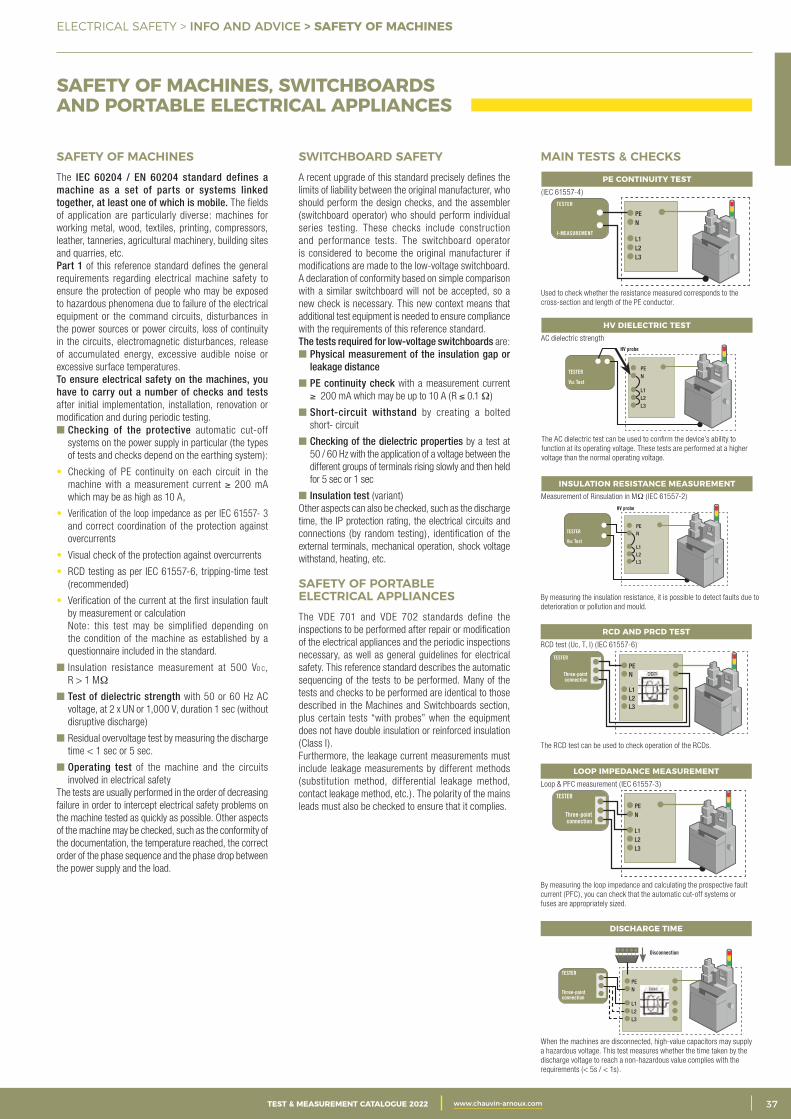
3CATALOGUE TEST & MESURE 2021 www.chauvin-arnoux.com 37TEST & MEASUREMENT CATALOGUE 2022 www.chauvin-arnoux.com
ELECTRICAL SAFETY > INFO AND ADVICE > SAFETY OF MACHINES
SAFETY OF MACHINES, SWITCHBOARDS AND PORTABLE ELECTRICAL APPLIANCES
SAFETY OF MACHINES The IEC 60204 / EN 60204 standard defines a machine as a set of parts or systems linked together, at least one of which is mobile. The fields of application are particularly diverse: machines for working metal, wood, textiles, printing, compressors, leather, tanneries, agricultural machinery, building sites and quarries, etc.Part 1 of this reference standard defines the general requirements regarding electrical machine safety to ensure the protection of people who may be exposed to hazardous phenomena due to failure of the electrical equipment or the command circuits, disturbances in the power sources or power circuits, loss of continuity in the circuits, electromagnetic disturbances, release of accumulated energy, excessive audible noise or excessive surface temperatures.To ensure electrical safety on the machines, you have to carry out a number of checks and tests after initial implementation, installation, renovation or modification and during periodic testing. Checking of the protective automatic cut-off
systems on the power supply in particular (the types of tests and checks depend on the earthing system):
• Checking of PE continuity on each circuit in the machine with a measurement current ≥ 200 mA which may be as high as 10 A,
• Verification of the loop impedance as per IEC 61557- 3 and correct coordination of the protection against overcurrents
• Visual check of the protection against overcurrents
• RCD testing as per IEC 61557-6, tripping-time test (recommended)
• Verification of the current at the first insulation fault by measurement or calculationNote: this test may be simplified depending on the condition of the machine as established by a questionnaire included in the standard.
Insulation resistance measurement at 500 Vd c, R > 1 MΩ
Test of dielectric strength with 50 or 60 Hz AC voltage, at 2 x UN or 1,000 V, duration 1 sec (without disruptive discharge)
Residual overvoltage test by measuring the discharge time < 1 sec or 5 sec.
Operating test of the machine and the circuits involved in electrical safety
The tests are usually performed in the order of decreasing failure in order to intercept electrical safety problems on the machine tested as quickly as possible. Other aspects of the machine may be checked, such as the conformity of the documentation, the temperature reached, the correct order of the phase sequence and the phase drop between the power supply and the load.
SWITCHBOARD SAFETYA recent upgrade of this standard precisely defines the limits of liability between the original manufacturer, who should perform the design checks, and the assembler (switchboard operator) who should perform individual series testing. These checks include construction and performance tests. The switchboard operator is considered to become the original manufacturer if modifications are made to the low-voltage switchboard. A declaration of conformity based on simple comparison with a similar switchboard will not be accepted, so a new check is necessary. This new context means that additional test equipment is needed to ensure compliance with the requirements of this reference standard. The tests required for low-voltage switchboards are: Physical measurement of the insulation gap or
leakage distance
PE continuity check with a measurement current ≥ 200 mA which may be up to 10 A (R ≤ 0.1 Ω)
Short-circuit withstand by creating a bolted short- circuit
Checking of the dielectric properties by a test at 50 / 60 Hz with the application of a voltage between the different groups of terminals rising slowly and then held for 5 sec or 1 sec
Insulation test (variant)Other aspects can also be checked, such as the discharge time, the IP protection rating, the electrical circuits and connections (by random testing), identification of the external terminals, mechanical operation, shock voltage withstand, heating, etc.
SAFETY OF PORTABLE ELECTRICAL APPLIANCESThe VDE 701 and VDE 702 standards define the inspections to be performed after repair or modification of the electrical appliances and the periodic inspections necessary, as well as general guidelines for electrical safety. This reference standard describes the automatic sequencing of the tests to be performed. Many of the tests and checks to be performed are identical to those described in the Machines and Switchboards section, plus certain tests “with probes” when the equipment does not have double insulation or reinforced insulation (Class I).Furthermore, the leakage current measurements must include leakage measurements by different methods (substitution method, differential leakage method, contact leakage method, etc.). The polarity of the mains leads must also be checked to ensure that it complies.
MAIN TESTS & CHECKS
PE CONTINUITY TEST
Used to check whether the resistance measured corresponds to the cross-section and length of the PE conductor.
( IEC 61557-4)TESTER
I-MEASUREMENT
PE N
L1 L2 L3
HV DIELECTRIC TEST
The AC dielectric test can be used to confirm the device’s ability to function at its operating voltage. These tests are performed at a higher voltage than the normal operating voltage.
AC dielectric strengthHV probe
TESTER
Vac Test
PE N
L1 L2 L3
INSULATION RESISTANCE MEASUREMENT
By measuring the insulation resistance, it is possible to detect faults due to deterioration or pollution and mould.
Measurement of Rinsulation in MΩ ( IEC 61557-2)HV probe
TESTER
Vdc Test
PE N
L1 L2 L3
RCD AND PRCD TEST
The RCD test can be used to check operation of the RCDs.
RCD test (Uc, T, I ) ( IEC 61557-6)
TESTER
Three-point connection
PE N
L1 L2 L3
DISCHARGE TIME
When the machines are disconnected, high-value capacitors may supply a hazardous voltage. This test measures whether the time taken by the discharge voltage to reach a non-hazardous value complies with the requirements (< 5s / < 1s).
Disconnection
TESTER
Three-point connection
PE N
L1 L2 L3
LOOP IMPEDANCE MEASUREMENT
By measuring the loop impedance and calculating the prospective fault current (PFC), you can check that the automatic cut-off systems or fuses are appropriately sized.
Loop & PFC measurement ( IEC 61557-3)
TESTER
Three-point connection
PE N
L1 L2 L3
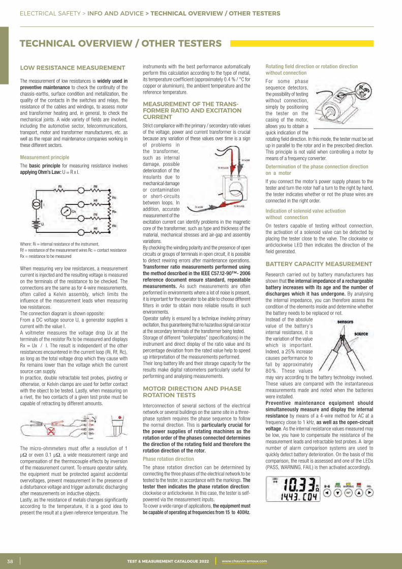
2 CATALOGUE TEST & MESURE 2021 www.chauvin-arnoux.com38 TEST & MEASUREMENT CATALOGUE 2022 www.chauvin-arnoux.com
instruments with the best performance automatically perform this calculation according to the type of metal, its temperature coefficient (approximately 0.4 % / °C for copper or aluminium), the ambient temperature and the reference temperature.
MEASUREMENT OF THE TRANS-FORMER RATIO AND EXCITATION CURRENTStrict compliance with the primary / secondary ratio values of the voltage, power and current transformer is crucial because any variation of these values over time is a sign of problems in the transformer, such as internal damage, possible deterioration of the insulants due to mechanical damage or contamination or short-circuits between loops. In addition, accurate measurement of the excitation current can identify problems in the magnetic core of the transformer, such as type and thickness of the material, mechanical stresses and air-gap and assembly variations. By checking the winding polarity and the presence of open circuits or groups of terminals in open circuit, it is possible to detect rewiring errors after maintenance operations. Transformer ratio measurements performed using the method described in the IEEE C57.12-90™- 2006 reference document ensure standard, repeatable measurements. As such measurements are often performed in environments where a lot of noise is present, it is important for the operator to be able to choose different filters in order to obtain more reliable results in such environments.Operator safety is ensured by a technique involving primary excitation, thus guaranteeing that no hazardous signal can occur at the secondary terminals of the transformer being tested. Storage of different “boilerplates” (specifications) in the instrument and direct display of the ratio value and its percentage deviation from the rated value help to speed up interpretation of the measurements performed.Their long battery life and their storage capacity for the results make digital ratiometers particularly useful for performing and analysing measurements.
MOTOR DIRECTION AND PHASE ROTATION TESTS Interconnection of several sections of the electrical network or several buildings on the same site in a three-phase system requires the phase sequence to follow the normal direction. This is particularly crucial for the power supplies of rotating machines as the rotation order of the phases connected determines the direction of the rotating field and therefore the rotation direction of the rotor.
Phase rotation direction
The phase rotation direction can be determined by connecting the three phases of the electrical network to be tested to the tester, in accordance with the markings. The tester then indicates the phase rotation direction: clockwise or anticlockwise. In this case, the tester is self-powered via the measurement inputs.To cover a wide range of applications, the equipment must be capable of operating at frequencies from 15 to 400Hz.
ELECTRICAL SAFETY > INFO AND ADVICE > TECHNICAL OVERVIEW / OTHER TESTERS
LOW RESISTANCE MEASUREMENT
The measurement of low resistances is widely used in preventive maintenance to check the continuity of the chassis-earths, surface condition and metallization, the quality of the contacts in the switches and relays, the resistance of the cables and windings, to assess motor and transformer heating and, in general, to check the mechanical joints. A wide variety of fields are involved, including the automotive sector, telecommunications, transport, motor and transformer manufacturers, etc. as well as the repair and maintenance companies working in these different sectors.
Measurement principle
The basic principle for measuring resistance involves applying Ohm’s Law: U = R x I.
Where: Ri = internal resistance of the instrument, Rf = resistance of the measurement wires Rc = contact resistanceRx = resistance to be measured
When measuring very low resistances, a measurement current is injected and the resulting voltage is measured on the terminals of the resistance to be checked. The connections are the same as for 4-wire measurements, often called a Kelvin assembly, which limits the influence of the measurement leads when measuring low resistances. The connection diagram is shown opposite: From a DC voltage source U, a generator supplies a current with the value I.A voltmeter measures the voltage drop Ux at the terminals of the resistor Rx to be measured and displays Rx = Ux / I. The result is independent of the other resistances encountered in the current loop (Ri, Rf, Rc), as long as the total voltage drop which they cause with Rx remains lower than the voltage which the current source can supply.In practice, double retractable test probes, pivoting or otherwise, or Kelvin clamps are used for better contact with the object to be tested. Lastly, when measuring on a rivet, the two contacts of a given test probe must be capable of retracting by different amounts.
The micro-ohmmeters must offer a resolution of 1 μΩ or even 0.1 μΩ, a wide measurement range and compensation of the thermocouple effects by inversion of the measurement current. To ensure operator safety, the equipment must be protected against accidental overvoltages, prevent measurement in the presence of a disturbance voltage and trigger automatic discharging after measurements on inductive objects. Lastly, as the resistance of metals changes significantly according to the temperature, it is a good idea to present the result at a given reference temperature. The
TECHNICAL OVERVIEW / OTHER TESTERS
Rotating field direction or rotation direction without connection
For some phase sequence detectors, the possibility of testing without connection, simply by positioning the tester on the casing of the motor, allows you to obtain a quick indication of the rotating field direction. In this mode, the tester must be set up in parallel to the rotor and in the prescribed direction. This principle is not valid when controlling a motor by means of a frequency converter.
Determination of the phase connection direction on a motor
If you connect the motor’s power supply phases to the tester and turn the rotor half a turn to the right by hand, the tester indicates whether or not the phase wires are connected in the right order.
Indication of solenoid valve activation without connection
On testers capable of testing without connection, the activation of a solenoid valve can be detected by placing the tester close to the valve. The clockwise or anticlockwise LED then indicates the direction of the field generated.
BATTERY CAPACITY MEASUREMENTResearch carried out by battery manufacturers has shown that the internal impedance of a rechargeable battery increases with its age and the number of discharges which it has undergone. By analysing the internal impedance, you can therefore assess the condition of the elements inside and determine whether the battery needs to be replaced or not. Instead of the absolute value of the battery’s internal resistance, it is the variation of the value which is impor tant. Indeed, a 25% increase causes performance to fall by approximately 80%. These values may vary according to the battery technology involved. These values are compared with the instantaneous measurements made and noted when the batteries were installed. Preventive maintenance equipment should simultaneously measure and display the internal resistance by means of a 4-wire method for AC at a frequency close to 1 kHz, as well as the open-circuit voltage. As the internal resistance values measured may be low, you have to compensate the resistance of the measurement leads and retractable test probes. A large number of alarm comparison systems are used to quickly detect battery deterioration. On the basis of this comparison, the result is assessed and one of the LEDs (PASS, WARNING, FAIL) is then activated accordingly.
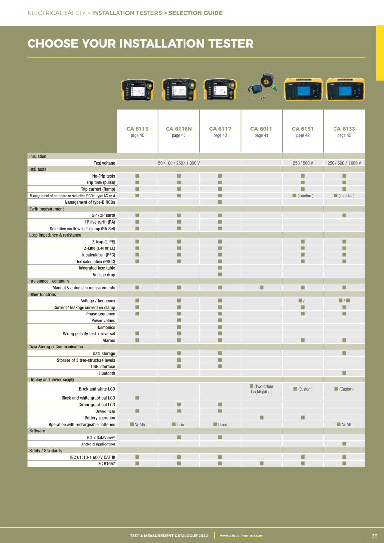
3CATALOGUE TEST & MESURE 2021 www.chauvin-arnoux.com 39TEST & MEASUREMENT CATALOGUE 2022 www.chauvin-arnoux.com
ELECTRICAL SAFETY > INSTALLATION TESTERS > SELECTION GUIDE
CHOOSE YOUR INSTALLATION TESTER
CA 6113page 40
CA 6116Npage 40
CA 6117page 40
CA 6011page 43
CA 6131page 42
CA 6133page 42
InsulationTest voltage 50 / 100 / 250 / 1,000 V 250 / 500 V 250 / 500 / 1,000 V
RCD tests No-Trip tests
Trip time (pulse) Trip current (Ramp)
Management of standard or selective RCDs, type AC or A (standard) (standard)
Management of type-B RCDs Earth measurement
2P / 3P earth1P live earth (RA)
Selective earth with 1 clamp (RA Sel)Loop impedance & resistance
Z-loop (L-PE) Z-Line (L-N or LL)
Ik calculation (PFC) Icc calculation (PSCC) Integrated fuse table
Voltage dropResistance / Continuity
Manual & automatic measurementsOther functions
Voltage / frequency / - /
Current / leakage current on clampPhase sequence
Power values Harmonics
Wiring polarity test + reversalAlarms
Data Storage / Communication Data storage
Storage of 3 tree-structure levelsUSB interface
Bluetooth Display and power supply
Black and white LCD (Two-colour backlighting)
(Custom) (Custom)
Black and white graphical LCDColour graphical LCD
Online helpBattery operation
Operation with rechargeable batteries Ni-Mh Li-ion Li-ion Ni-Mh
SoftwareICT / DataView®
Android applicationSafety / Standards
IEC 61010-1 600 V CAT III IEC 61557

2 CATALOGUE TEST & MESURE 2021 www.chauvin-arnoux.com40 TEST & MEASUREMENT CATALOGUE 2022 www.chauvin-arnoux.com
ELECTRICAL SAFETY > INSTALLATION TESTERS > CA 6113 - CA 6116N - CA 6117
CA 6113 - CA 6116N - CA 6117 REF.: P01145445 REF.: P01145455 REF.: P01145460
Generation, transmission & distribution
IndustriesTertiary & residential
Education TransportDiagnostics & inspection
Energy efficiency
Laboratory & metrology
600 VCAT III
IP53
STRENGTHS• Tests on RCDs (types AC, A and B)• Battery life of up to 30 hours• Testing according to IEC 60364-6, NF C 15-100, VDE 100, FD C 16-600…• Automatic continuity measurement• Colour screen (except CA 6113)• Measurements: voltage, current via clamp, power, waveforms and harmonics• Loop measurement with 1 mΩ resolution
CONTENTS
CA 6113 delivered in a shoulder bag with:• 1 x PA 30 W power pack• 1 Euro 3-point lead - 3 safety leads (red, blue, green)• 3 test probes Ø 4 mm (red, blue, green)• 3 crocodile clips (red, blue, green)• 2 elbowed-straight safety leads (red and black) 3 m long• 1 three-point Euro mains lead• 1 remote-control probe• 1 anti-scratch film mounted on the instrument• 1 wrist-strap• 1 x 4-point hands-free strap• 1 CD-ROM containing the user’s manual
CA 6116N and CA 6117 delivered in a shoulder bag with:• 1 mains power / charger pack (type 2)• 1 Li-Ion rechargeable battery pack mounted on the instrument• 1 USB A / B cable 1.80 m long with ferrite• 1 three-point lead - 3 safety leads (red, green and blue)• 3 test probes Ø 4 mm (red, green and blue)• 3 crocodile clips (red, green and blue)• 2 elbowed-straight safety leads 3 m long (red and black)• 1 three-point EURO mains lead• 1 two-point EURO mains lead• 1 remote-control probe• 1 anti-scratch film mounted on the instrument• 1 wrist-strap• 1 x 4-point hands-free strap• ICT data export software on CD-ROM• 1 CD-ROM containing the user manual
ACCESSORIES / REPLACEMENT PARTS
Three-point lead with separated wires 2.5 m P01295398Three-point lead for testing European mains sockets P01295393See all the accessories on page 81
ADDITIONAL INFO• Integrated fuse table for quick result readings on the instrument
• User-friendly interface
• Extra-wide graphical screen
• Integrated contextual help for each function
• ICT data export software provided
• Compatible with the DataView® software
• Delivered as standard with a three-point European mains lead
These testers are equipped with clear, detailed contextual help. This makes them suitable for both experts and less-experienced users.There is dedicated help for each measurement, including a guide to the connections to be set up and help for interpreting the results. For greater safety, if it is incorrectly connected or if a hazardous voltage is present, the instrument displays an error message in order to warn the user.
EFFECTIVE CONTEXTUAL HELP AND GUARANTEED SAFETY
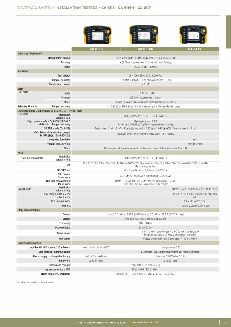
3CATALOGUE TEST & MESURE 2021 www.chauvin-arnoux.com 41TEST & MEASUREMENT CATALOGUE 2022 www.chauvin-arnoux.com
ELECTRICAL SAFETY > INSTALLATION TESTERS > CA 6113 - CA 6116N - CA 6117
CA 6113 CA 6116N CA 6117Continuity / Resistance
Measurement current I > 200 mA up to 39.99 Ω and approx. 12 mA up to 400 Ω
Accuracy ± (1.5% of measurement + 2 cts), with audible beep
Range 4 kΩ / 40 kΩ - 400 kΩ
Insulation
Test voltage 50 / 100 / 250 / 500 / 1,000 Vdc
Range / accuracy 0.01 MΩ to 2 GΩ / ±(5 % of measurement + 3 cts)
Short-circuit current ≤ 3 mA
Earth 3P earth Range 0.50 Ω to 15 kΩ
Accuracy ±(2 % of measurement + 2 cts )
Others RH & RS auxiliary-stake resistance measurement (up to 40 kΩ)
Selective 1P earth Range / accuracy 0.20 Ω to 399.9 Ω ±(10 % of measurement + 10 cts) (ISel via clamp)
Loop impedance (Zs (L-PE) and Zi (L-N or L-L)) – 1P live earthLive earth Installation
voltage / freq. 90 to 500 V / 15.8 to 17.5 Hz - 45 to 65 Hz
High current mode - Zs (L-PE) (TRIP) & Zi (L-N or L-L) Range / accuracy
Max. test current: 7.5 A 0.100 Ω to 399.99 Ω / ±(5% of measurement + 2 cts)
NO TRIP mode (Zs (L-PE)) Test current: 6 mA – 9 mA – 12 mA (as required) - 0.20 Ω to 3,999 Ω ±(5% of measurement + 2 cts)
Calculation of short-circuit currentIk (PFC (Zs)) , I Sc (PSCC (Zi)) Fault and short-circuit current: display range 0.1 A to 6 kA
Integrated fuse table Yes
Voltage drop DU% (Zi) -40% to + 40%
Others Measurement of the resistive and inductive components of the impedances Zs and Zi
RCDs
Type AC and A RCDs Installation voltage / freq. 90 to 500 V / 15.8 to 17.5 Hz - 45 to 65 Hz
IDn 10 / 30 / 100 / 300 / 500 / 650 / 1,000 mA (90 V – 280 V) or variable - 10 / 30 / 100 / 300 / 500 mA (280-550 V) or variable Ramp and pulse test
NO TRIP test at ½ IDn – Duration: 1,000 ms or 2,000 ms
Trip currentRamp mode 0.3 x IDn to 1.06 x IDn in increments of 3.3% x IDn
Trip time measurement Pulse mode
0.2 to 0.5 x IDn (Uf) / 0.5 x IDn / 2 x IDn (selective) / 5 x IDn. Pulse: 0 to 500 ms, Ramp mode: 0 to 200 ms
Type B RCDs Installation voltage / freq. 90 V to 275 V / 15.8 to 17.5 Hz - 45 to 65 Hz
IDn: ramp / pulse 2 x IDn pulse 4 x IDn
10 / 30 / 100 / 300 / 500 mA 10 / 30 / 100 mA
Test in ramp mode 0.2 x IDn to 2.2 x IDn
Trip test 1.1x2 or 2.2x2 or 2.2x4 x IDn
Other measurements
Current (1 mA*) 5.0 mA to 19.99 A (MN77 clamp) / 5.0 mA to 199.9 A (C177 A clamp)
Voltage 0 to 550 Vac / dc / dc and 15.8 to 500 Hz
Frequency 10 to 500 Hz
Phase rotation 20 to 500 Vac
Active power 0 to 110 kW in single-phase - 0 to 330 kW in three-phaseSimultaneous display of voltage and current waveform
Harmonics Voltage and current / up to 50th order / THD-F / THD-R
General specifications
Large backlit LCD screen, 320 x 240 cts monochrome graphical 5.7‘’ colour graphical 5.7’’
Data storage / Communication 1,000 tests / via USB for data transfer and report generation
Power supply: rechargeable battery NiMH 9.6 V rated 4 Ah. Lithium-ion 10.8 V rated 5.8 Ah
Battery life up to 24 hours up to 30 hours
Dimensions / weight 280 x 190 x 128 mm / 2.2 kg
Ingress protection / EMC IP 53 / IK04 / IEC 61326-1
Electrical safety / Standards IEC 61010 -1 – 600 V CAT III – 300 V CAT IV – IEC 61557
*if a voltage is connected to the instrument
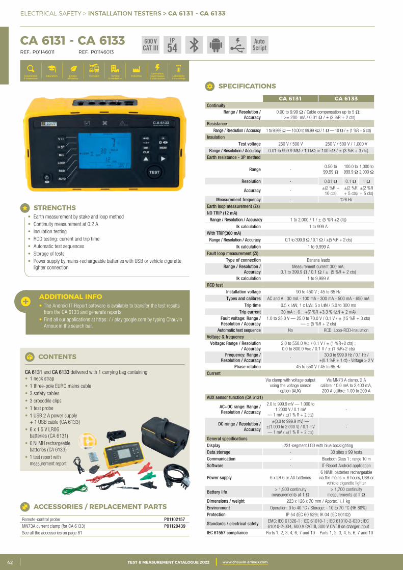
2 CATALOGUE TEST & MESURE 2021 www.chauvin-arnoux.com42 TEST & MEASUREMENT CATALOGUE 2022 www.chauvin-arnoux.com
ELECTRICAL SAFETY > INSTALLATION TESTERS > CA 6131 - CA 6133
CA 6131 - CA 6133 REF.: P01146011 REF.: P01146013
Generation, transmission & distribution
IndustriesTertiary & residential
Education TransportDiagnostics & inspection
Energy efficiency
Laboratory & metrology
CA 6131 CA 6133Continuity
Range / Resolution / Accuracy
0.00 to 9.99 Ω / Cable compensation up to 5 Ω; I >= 200 mA / 0.01 Ω / ± (2 %R + 2 cts)
Resistance Range / Resolution / Accuracy 1 to 9,999 Ω — 10.00 to 99.99 kΩ / 1 Ω — 10 Ω / ± (1 %R + 5 cts)
InsulationTest voltage 250 V / 500 V 250 V / 500 V / 1,000 V
Range / Resolution / Accuracy 0.01 to 999.9 MΩ / 10 kΩ or 100 kΩ / ± (3 %R + 3 cts) Earth resistance - 3P method
Range -0.50 to
99.99 Ω 100.0 to 999.9 Ω
1,000 to 2,000 Ω
Resolution - 0.01 Ω 0.1 Ω 1 Ω
Accuracy - ±(2 %R + 10 cts)
±(2 %R + 5 cts)
±(2 %R + 5 cts)
Measurement frequency - 128 Hz Earth loop measurement (Zs) NO TRIP (12 mA)
Range / Resolution / Accuracy 1 to 2,000 / 1 / ± (5 %R +2 cts)
Ik calculation 1 to 999 A With TRIP(300 mA)
Range / Resolution / Accuracy 0.1 to 399.9 Ω / 0.1 Ω / ±(5 %R + 2 cts)
Ik calculation 1 to 9,999 A Fault loop measurement (Zi)
Type of connection Banana leadsRange / Resolution /
Accuracy Measurement current 300 mA;
0.1 to 399.9 Ω / 0.1 Ω / ± (5 %R + 2 cts) Ik calculation 1 to 9,999 A
RCD testInstallation voltage 90 to 450 V ; 45 to 65 Hz Types and calibres AC and A ; 30 mA - 100 mA - 300 mA - 500 mA - 650 mA
Trip time 0.5 x IDN; 1 x IDN; 5 x IDN / 5.0 to 300 ms Trip current 30 mA : -0 .. +(7 %R +3.3 % IDN + 2 mA)
Fault voltage: Range / Resolution / Accuracy
1.0 to 25.0 V — 25.0 to 70.0 V / 0.1 V / ± (15 %R + 3 cts) — ± (5 %R + 2 cts)
Automatic test sequence No RCD, Loop-RCD-InsulationVoltage & frequency
Voltage: Range / Resolution / Accuracy
2.0 to 550.0 Vac / 0.1 V / ± (1 %R+2 cts) ; 0.0 to 800.0 Vdc / 0.1 V / ± (1 %R+2 cts)
Frequency: Range / Resolution / Accuracy -
30.0 to 999.9 Hz / 0.1 Hz / ±(0.1 %R + 1 ct) - Voltage > 2 V
Phase rotation 45 to 550 V / 45 to 65 HzCurrent
Via clamp with voltage output using the voltage sensor
option (AUX)
Via MN73 A clamp, 2 A calibre: 10.0 mA to 2,400 mA, 200 A calibre: 1.00 to 200 A
AUX sensor function (CA 6131)
AC+DC range: Range / Resolution / Accuracy
2.0 to 999.9 mV — 1.000 to 1.2000 V / 0.1 mV
— 1 mV / ±(1 % R + 2 cts)-
DC range / Resolution / Accuracy
±(0.0 to 999.9 mV) — ±(1.000 to 2.000 V) / 0.1 mV— 1 mV / ±(1 % R + 2 cts)
-
General specificationsDisplay 231-segment LCD with blue backlighting Data storage - 30 sites x 99 tests Communication - Bluetooth Class 1 ; range 10 m Software - IT-Report Android application
Power supply 6 x LR 6 or AA batteries6 NiMH batteries rechargeable
via the mains < 6 hours, USB or vehicle cigarette lighter
Battery life > 1,900 continuity measurements at 1 Ω
> 1,700 continuity measurements at 1 Ω
Dimensions / weight 223 x 126 x 70 mm / Approx. 1.1 kgEnvironment Operation: 0 to 40 °C / Storage: - 10 to 70 °C (RH 80%) Protection IP 54 (IEC 60 529); IK 04 (IEC 50102)
Standards / electrical safety EMC: IEC 61326-1 ; IEC 61010-1 ; IEC 61010-2-030 ; IEC 61010-2-034, 600 V CAT III, 300 V CAT II on charger input
IEC 61557 compliance Parts 1, 2, 3, 4, 6, 7 and 10 Parts 1, 2, 3, 4, 5, 6, 7 and 10
SPECIFICATIONS
STRENGTHS• Earth measurement by stake and loop method• Continuity measurement at 0.2 A• Insulation testing• RCD testing: current and trip time• Automatic test sequences• Storage of tests• Power supply by mains-rechargeable batteries with USB or vehicle cigarette
lighter connection
ACCESSORIES / REPLACEMENT PARTS
Remote-control probe P01102157MN73A current clamp (for CA 6133) P01120439See all the accessories on page 81
CONTENTS
CA 6131 and CA 6133 delivered with 1 carrying bag containing: • 1 neck strap• 1 three-pole EURO mains cable• 3 safety cables• 3 crocodile clips• 1 test probe• 1 USB 2 A power supply
+ 1 USB cable (CA 6133)• 6 x 1.5 V LR06
batteries (CA 6131)• 6 Ni MH rechargeable
batteries (CA 6133)• 1 test report with
measurement report
ADDITIONAL INFO• The Android IT-Report software is available to transfer the test results
from the CA 6133 and generate reports.• Find all our applications at https: / / play.google.com by typing Chauvin
Arnoux in the search bar.
600 VCAT III
IP54
AutoScript
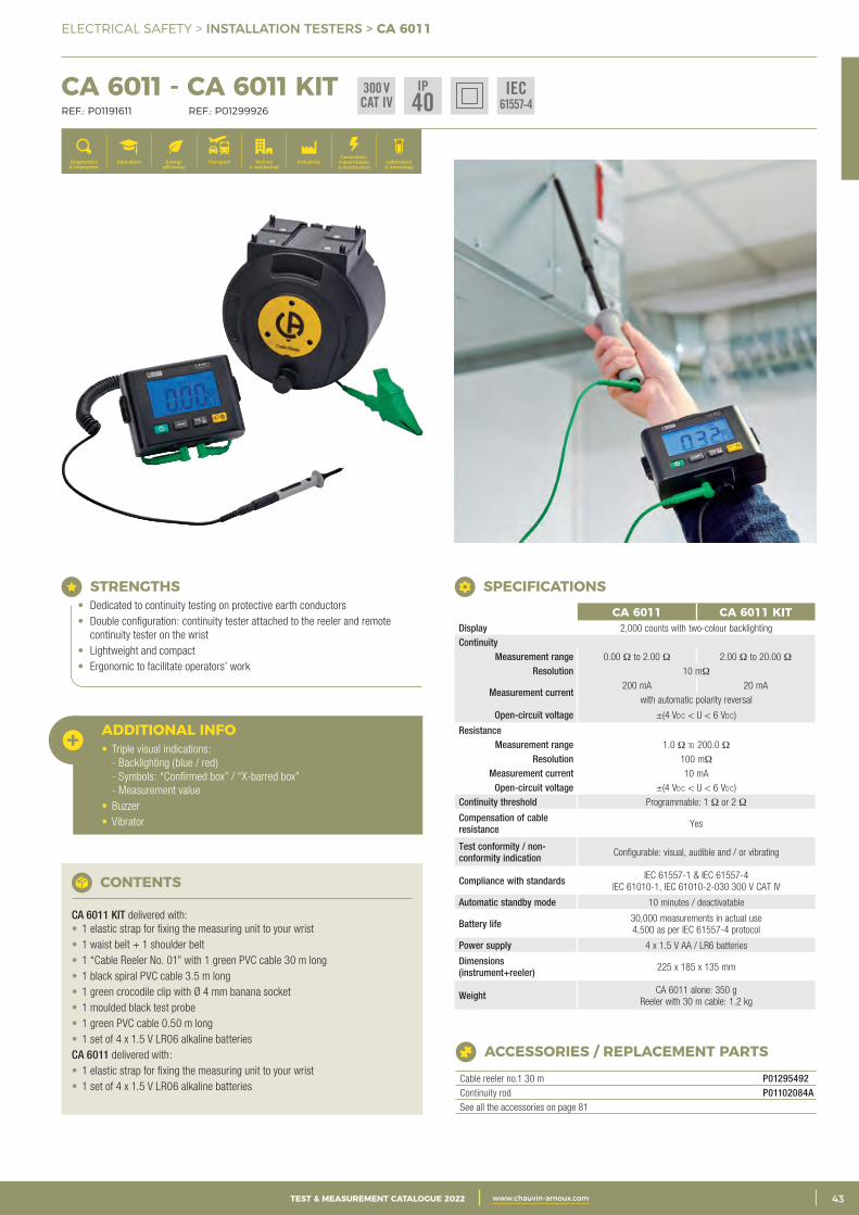
3CATALOGUE TEST & MESURE 2021 www.chauvin-arnoux.com 43TEST & MEASUREMENT CATALOGUE 2022 www.chauvin-arnoux.com
ELECTRICAL SAFETY > INSTALLATION TESTERS > CA 6011
Generation, transmission & distribution
IndustriesTertiary & residential
Education TransportDiagnostics & inspection
Energy efficiency
Laboratory & metrology
CONTENTS
CA 6011 KIT delivered with:• 1 elastic strap for fixing the measuring unit to your wrist• 1 waist belt + 1 shoulder belt• 1 “Cable Reeler No. 01” with 1 green PVC cable 30 m long• 1 black spiral PVC cable 3.5 m long• 1 green crocodile clip with Ø 4 mm banana socket• 1 moulded black test probe• 1 green PVC cable 0.50 m long• 1 set of 4 x 1.5 V LR06 alkaline batteriesCA 6011 delivered with:• 1 elastic strap for fixing the measuring unit to your wrist• 1 set of 4 x 1.5 V LR06 alkaline batteries
CA 6011 CA 6011 KITDisplay 2,000 counts with two-colour backlighting Continuity
Measurement range 0.00 Ω to 2.00 Ω 2.00 Ω to 20.00 Ω Resolution 10 mΩ
Measurement current200 mA 20 mA
with automatic polarity reversal
Open-circuit voltage ±(4 Vdc < U < 6 Vdc)
ResistanceMeasurement range 1.0 Ω to 200.0 Ω
Resolution 100 mΩ Measurement current 10 mA
Open-circuit voltage ±(4 Vdc < U < 6 Vdc) Continuity threshold Programmable: 1 Ω or 2 Ω
Compensation of cable resistance Yes
Test conformity / non-conformity indication Configurable: visual, audible and / or vibrating
Compliance with standards IEC 61557-1 & IEC 61557-4 IEC 61010-1, IEC 61010-2-030 300 V CAT IV
Automatic standby mode 10 minutes / deactivatable
Battery life 30,000 measurements in actual use4,500 as per IEC 61557-4 protocol
Power supply 4 x 1.5 V AA / LR6 batteries
Dimensions (instrument+reeler) 225 x 185 x 135 mm
Weight CA 6011 alone: 350 g Reeler with 30 m cable: 1.2 kg
SPECIFICATIONS
ACCESSORIES / REPLACEMENT PARTS
Cable reeler no.1 30 m P01295492Continuity rod P01102084ASee all the accessories on page 81
STRENGTHS• Dedicated to continuity testing on protective earth conductors• Double configuration: continuity tester attached to the reeler and remote
continuity tester on the wrist• Lightweight and compact• Ergonomic to facilitate operators’ work
CA 6011 - CA 6011 KIT REF.: P01191611 REF.: P01299926
ADDITIONAL INFO• Triple visual indications:
- Backlighting (blue / red) - Symbols: “Confirmed box” / “X-barred box” - Measurement value
• Buzzer• Vibrator
300 VCAT IV
IP40
IEC61557-4
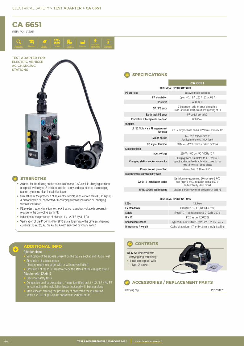
2 CATALOGUE TEST & MESURE 2021 www.chauvin-arnoux.com44 TEST & MEASUREMENT CATALOGUE 2022 www.chauvin-arnoux.com
ELECTRICAL SAFETY > TEST ADAPTER > CA 6651
CA 6651 REF.: P01191306
Generation, transmission & distribution
IndustriesTertiary & residential
Education TransportDiagnostics & inspection
Energy efficiency
Laboratory & metrology
STRENGTHS• Adapter for interfacing on the sockets of mode-3 AC vehicle charging stations
equipped with a type-2 cable to test the safety and operation of the charging station by means of an installation tester
• Simulation of the presence of an electric vehicle in its various states (CP signal) : A disconnected / B connected / C charging without ventilation / D charging without ventilation
• PE pre-test: safety function to check that no hazardous voltage is present in relation to the protective earth PE
• Indication of the presence of phases L1 / L2 / L3 by 3 LEDs• Verification of the Proximity Pilot (PP) signal to simulate the different charging
currents: 13 A / 20 A / 32 A / 63 A with selection by rotary switch
ADDITIONAL INFOAdapter alone • Verification of the signals present on the type 2 socket and PE pre-test• Simulation of vehicle status
( battery ready to charge, with or without ventilation)• Simulation of the PP current to check the status of the charging statusAdapter with CA 6117 • Electrical safety tests• Connection on 5 sockets, diam. 4 mm, identified as L1 / L2 / L3 / N / PE
for connecting the installation tester equipped with banana plugs• Mains socket offering the possibility of connected the installation
tester’s 2P+E plug: Schuko socket with 2 metal studs
ACCESSORIES / REPLACEMENT PARTS
Carrying bag P01298078
CONTENTS
CA 6651 delivered with 1 carrying bag containing: • 1 cable equipped with
a type-2 socket
CA 6651TECHNICAL SPECIFICATIONS
PE pre-test Yes with touch electrode
PP simulation Open NC, 13 A , 20 A, 32 A, 63 A
CP status A, B, C, D
CP / PE error 3 buttons on side for error simulation; CP/PE or diode short-circuit and opening of PE
Earth fault PE error PP switch set to NC
Protection / Acceptable overload 600 Vrms
Outputs
L1 / L2 / L3 / N and PE measurement terminals 230 V single-phase and 400 V three-phase 50Hz
Mains socket Max 250 V Cat II 300 V Admissible current: 10 A (fuse)
CP signal terminal PWM + / -12 V communication protocol
Specifications
Input voltage 230 V / 400 Vac 50 / 60Hz 10 A
Charging station socket connector Charging mode 3 adapted to IEC 62196-2
type 2 socket or fixed cable with connector for type 2 vehicle, three-phase
Power socket protection Internal fuse: T 10 A / 250 V
Measurement compatibility with
CA 6117 installation testerEarth loop measurement, 30 mA type-B RCD
test (from 6 mA), insulation test at 500 V and continuity –test report
HANDSCOPE oscilloscope Display of PMW waveform between CP and PE
TECHNICAL SPECIFICATIONS
LEDs X3, blue
EV standards IEC 61851-1 / IEC 60364-7-722
Safety EN61010-1, pollution degree 2, CATII-300 V
IP / IK IP 20 as per IEC60529
Connection socket Type 2 32 A 3PH+N+PE type E2201 200 / 346 V
Dimensions / weight Casing dimensions: 174x43x43 mm / Weight: 850 g
SPECIFICATIONS
TEST ADAPTER FOR ELECTRIC VEHICLEAC CHARGING STATIONS
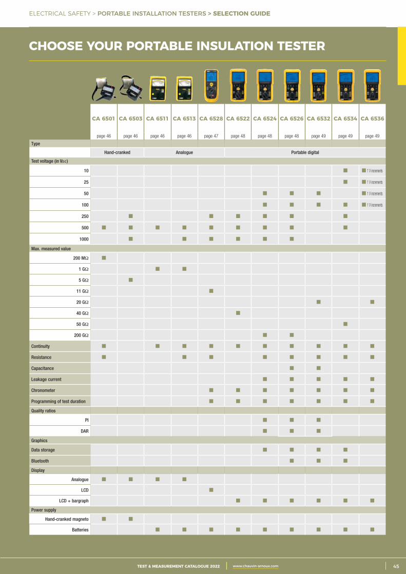
3CATALOGUE TEST & MESURE 2021 www.chauvin-arnoux.com 45TEST & MEASUREMENT CATALOGUE 2022 www.chauvin-arnoux.com
ELECTRICAL SAFETY > PORTABLE INSTALLATION TESTERS > SELECTION GUIDE
CHOOSE YOUR PORTABLE INSULATION TESTER
CA 6501 CA 6503 CA 6511 CA 6513 CA 6528 CA 6522 CA 6524 CA 6526 CA 6532 CA 6534 CA 6536
page 46 page 46 page 46 page 46 page 47 page 48 page 48 page 48 page 49 page 49 page 49
Type
Hand-cranked Analogue Portable digital
Test voltage (in Vd c )
10 1 V increments
25 1 V increments
50 1 V increments
100 1 V increments
250
500
1000
Max. measured value
200 MΩ
1 GΩ
5 GΩ
11 GΩ
20 GΩ
40 GΩ
50 GΩ
200 GΩ
Continuity
Resistance
Capacitance
Leakage current
Chronometer
Programming of test duration
Quality ratios
PI
DAR
Graphics
Data storage
Bluetooth
Display
Analogue
LCD
LCD + bargraph
Power supply
Hand-cranked magneto
Batteries
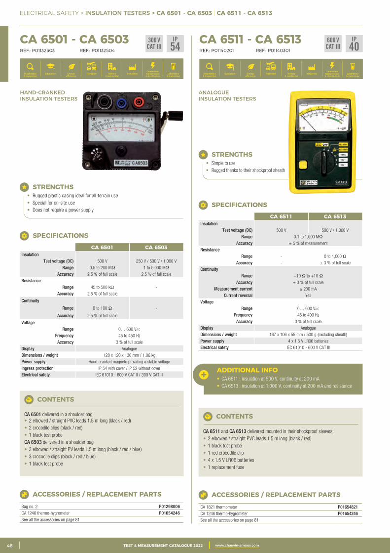
2 CATALOGUE TEST & MESURE 2021 www.chauvin-arnoux.com46 TEST & MEASUREMENT CATALOGUE 2022 www.chauvin-arnoux.com
ELECTRICAL SAFETY > INSULATION TESTERS > CA 6501 - CA 6503 | CA 6511 - CA 6513
CHOISIR SON CONTRÔLEUR D’ISOLEMENT PORTATIF
ANALOGUE INSULATION TESTERS
HAND-CRANKED INSULATION TESTERS
CA 6511 - CA 6513 REF.: P01140201 REF.: P01140301
Generation, transmission & distribution
IndustriesTertiary & residential
Education TransportDiagnostics & inspection
Energy efficiency
Laboratory & metrology
CA 6501 - CA 6503 REF.: P01132503 REF.: P01132504
Generation, transmission & distribution
IndustriesTertiary & residential
Education TransportDiagnostics & inspection
Energy efficiency
Laboratory & metrology
STRENGTHS• Rugged plastic casing ideal for all-terrain use• Special for on-site use• Does not require a power supply
STRENGTHS• Simple to use• Rugged thanks to their shockproof sheath
ACCESSORIES / REPLACEMENT PARTS
CA 1821 thermometer P01654821CA 1246 thermo-hygrometer P01654246See all the accessories on page 81
CONTENTS
CA 6501 delivered in a shoulder bag• 2 elbowed / straight PVC leads 1.5 m long (black / red)• 2 crocodile clips (black / red)• 1 black test probeCA 6503 delivered in a shoulder bag• 3 elbowed / straight PV leads 1.5 m long (black / red / blue)• 3 crocodile clips (black / red / blue)• 1 black test probe
CONTENTS
CA 6511 and CA 6513 delivered mounted in their shockproof sleeves• 2 elbowed / straight PVC leads 1.5 m long (black / red)• 1 black test probe• 1 red crocodile clip• 4 x 1.5 V LR06 batteries• 1 replacement fuse
ADDITIONAL INFO• CA 6511 : insulation at 500 V, continuity at 200 mA• CA 6513 : insulation at 1,000 V, continuity at 200 mA and resistance
CA 6501 CA 6503Insulation
Test voltage (DC) 500 V 250 V / 500 V / 1,000 V Range 0.5 to 200 MΩ 1 to 5,000 MΩ
Accuracy 2.5 % of full scale 2.5 % of full scaleResistance
-Range 45 to 500 kΩ Accuracy 2.5 % of full scale
Continuity
-Range 0 to 100 Ω
Accuracy 2.5 % of full scale
VoltageRange 0… 600 Vac
Frequency 45 to 450 Hz Accuracy 3 % of full scale
Display Analogue Dimensions / weight 120 x 120 x 130 mm / 1.06 kg Power supply Hand-cranked magneto providing a stable voltageIngress protection IP 54 with cover / IP 52 without cover Electrical safety IEC 61010 - 600 V CAT II / 300 V CAT III
SPECIFICATIONS
CA 6511 CA 6513Insulation
Test voltage (DC) 500 V 500 V / 1,000 V Range 0.1 to 1,000 MΩ
Accuracy ± 5 % of measurement Resistance
Range - 0 to 1,000 Ω Accuracy - ± 3 % of full scale
Continuity Range −10 Ω to +10 Ω
Accuracy ± 3 % of full scaleMeasurement current ≥ 200 mA
Current reversal Yes Voltage
Range 0… 600 Vac Frequency 45 to 400 Hz
Accuracy 3 % of full scaleDisplay Analogue Dimensions / weight 167 x 106 x 55 mm / 500 g (excluding sheath) Power supply 4 x 1.5 V LR06 batteriesElectrical safety IEC 61010 - 600 V CAT III
SPECIFICATIONS
ACCESSORIES / REPLACEMENT PARTS
Bag no. 2 P01298006CA 1246 thermo-hygrometer P01654246See all the accessories on page 81
300 VCAT III
IP54
600 VCAT III
IP40
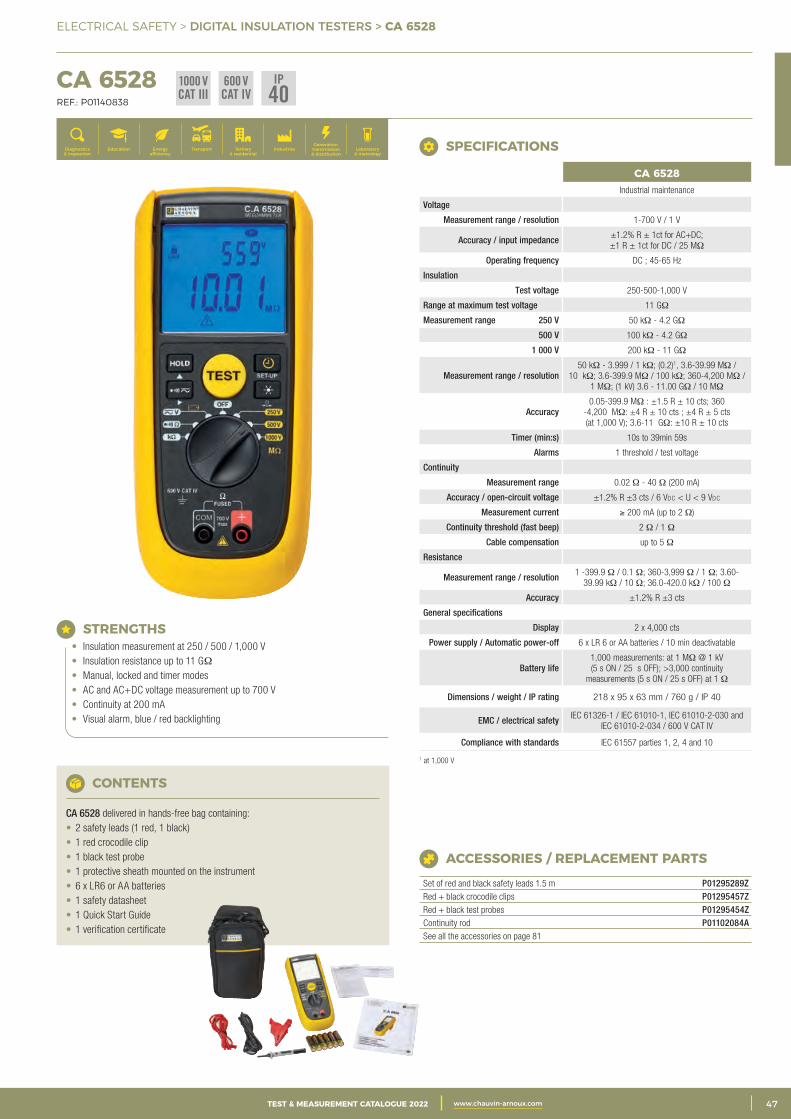
3CATALOGUE TEST & MESURE 2021 www.chauvin-arnoux.com 47TEST & MEASUREMENT CATALOGUE 2022 www.chauvin-arnoux.com
ELECTRICAL SAFETY > DIGITAL INSULATION TESTERS > CA 6528
CHOISIR SON CONTRÔLEUR D’ISOLEMENT PORTATIF CA 6528 REF.: P01140838
Generation, transmission & distribution
IndustriesTertiary & residential
Education TransportDiagnostics & inspection
Energy efficiency
Laboratory & metrology
STRENGTHS• Insulation measurement at 250 / 500 / 1,000 V• Insulation resistance up to 11 GΩ• Manual, locked and timer modes• AC and AC+DC voltage measurement up to 700 V• Continuity at 200 mA• Visual alarm, blue / red backlighting
ACCESSORIES / REPLACEMENT PARTS
Set of red and black safety leads 1.5 m P01295289ZRed + black crocodile clips P01295457ZRed + black test probes P01295454ZContinuity rod P01102084ASee all the accessories on page 81
CONTENTS
CA 6528 delivered in hands-free bag containing:• 2 safety leads (1 red, 1 black)• 1 red crocodile clip• 1 black test probe• 1 protective sheath mounted on the instrument• 6 x LR6 or AA batteries• 1 safety datasheet• 1 Quick Start Guide• 1 verification certificate
CA 6528Industrial maintenance
Voltage
Measurement range / resolution 1-700 V / 1 V
Accuracy / input impedance ±1.2% R ± 1ct for AC+DC; ±1 R ± 1ct for DC / 25 MΩ
Operating frequency DC ; 45-65 Hz
Insulation
Test voltage 250-500-1,000 V
Range at maximum test voltage 11 GΩ
Measurement range 250 V 50 kΩ - 4.2 GΩ
500 V 100 kΩ - 4.2 GΩ
1 000 V 200 kΩ - 11 GΩ
Measurement range / resolution50 kΩ - 3.999 / 1 kΩ; (0.2)1, 3.6-39.99 MΩ /
10 kΩ; 3.6-399.9 MΩ / 100 kΩ; 360-4,200 MΩ / 1 MΩ; (1 kV) 3.6 - 11.00 GΩ / 10 MΩ
Accuracy0.05-399.9 MΩ : ±1.5 R ± 10 cts; 360
-4,200 MΩ: ±4 R ± 10 cts ; ±4 R ± 5 cts (at 1,000 V); 3.6-11 GΩ: ±10 R ± 10 cts
Timer (min:s) 10s to 39min 59s
Alarms 1 threshold / test voltage
Continuity
Measurement range 0.02 Ω - 40 Ω (200 mA)
Accuracy / open-circuit voltage ±1.2% R ±3 cts / 6 Vdc < U < 9 Vdc
Measurement current ≥ 200 mA (up to 2 Ω)
Continuity threshold (fast beep) 2 Ω / 1 Ω
Cable compensation up to 5 Ω
Resistance
Measurement range / resolution 1 -399.9 Ω / 0.1 Ω; 360-3,999 Ω / 1 Ω; 3.60-39.99 kΩ / 10 Ω; 36.0-420.0 kΩ / 100 Ω
Accuracy ±1.2% R ±3 cts
General specifications
Display 2 x 4,000 cts
Power supply / Automatic power-off 6 x LR 6 or AA batteries / 10 min deactivatable
Battery life1,000 measurements: at 1 MΩ @ 1 kV (5 s ON / 25 s OFF); >3,000 continuity
measurements (5 s ON / 25 s OFF) at 1 Ω
Dimensions / weight / IP rating 218 x 95 x 63 mm / 760 g / IP 40
EMC / electrical safety IEC 61326-1 / IEC 61010-1, IEC 61010-2-030 and IEC 61010-2-034 / 600 V CAT IV
Compliance with standards IEC 61557 parties 1, 2, 4 and 10
1 at 1,000 V
SPECIFICATIONS
IP40
1000 VCAT III
600 VCAT IV
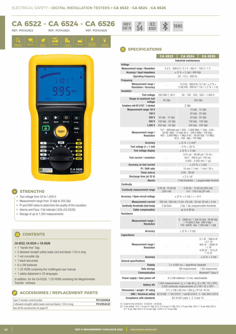
2 CATALOGUE TEST & MESURE 2021 www.chauvin-arnoux.com48 TEST & MEASUREMENT CATALOGUE 2022 www.chauvin-arnoux.com
ELECTRICAL SAFETY > DIGITAL INSTALLATION TESTERS > CA 6522 - CA 6524 - CA 6526
CA 6522 - CA 6524 - CA 6526 REF.: P01140822 REF.: P01140824 REF.: P01140826
Generation, transmission & distribution
IndustriesTertiary & residential
Education TransportDiagnostics & inspection
Energy efficiency
Laboratory & metrology
STRENGTHS• Test voltage from 50 to 1,000 V• Measurement range from 10 kΩ to 200 GΩ• PI and DAR ratios to determine the quality of the insulation• Alarms and Pass / Fail indicator LEDs (CA 6526)• Storage of up to 1,300 measurements
ACCESSORIES / REPLACEMENT PARTS
Type-3 remote-control probe P01102092A2 elbowed-straight safety leads (red and black) 1.50 m long P01295453ZSee all the accessories on page 81
CONTENTS
CA 6522, CA 6524 or CA 6526• 1 “hands-free” bag• 2 elbowed-straight safety leads (red and black) 1.50 m long• 1 red crocodile clip• 1 black test probe• 6 x LR6 batteries• 1 CD-ROM containing the multilingual user manual• 1 safety datasheet in 20 languages
In addition, for the CA 6526: 1 CD-ROM containing the Megohmmeter Transfer software
(1): 2 kΩ for the CA 6532 - CA 6534 - CA 6536.(2): To be added: 10 V: 1 % per 0.1 GΩ; 25 V: 0.4 % per 0.1 GΩ, 50 V: 2 % per GΩ, 100 V: 1 % per GΩ; 250 V;
0.4 % per GΩ; 500 V: 0.2 % per GΩ; 1,000 V: 0.1 % per GΩ.
CA 6522 CA 6524 CA 6526Industrial maintenance
Voltage Measurement range / Resolution 0.3 V - 399.9 V / 0.1 V ; 400 V - 700 V / 1 V
Accuracy / Input impedance ± (3 % + 2 cts) / 400 KΩ Operating frequency DC ; 15.3 - 800 Hz
FrequencyMeasurement range / Resolution / Accuracy - 15.3 Hz - 399.9 Hz / 0.1 Hz / ± (1 % +
2 cts) 400 - 800 Hz / 1 Hz / ± (1 % + 1 ct)
InsulationTest voltage 250-500-1 ,00 V 50 - 100 - 250 - 500 – 1,000 V
Range at maximum test voltage 40 GΩ 200 GΩ
Compliance with IEC 61557 - 2 standard 2 GΩ Measurement range: 50 V - 10 kΩ - 10 GΩ
100 V - 20 kΩ - 20 GΩ 250 V 50 kΩ - 10 GΩ 50 kΩ - 50 GΩ 500 V 100 kΩ - 20 GΩ 100 kΩ - 100 GΩ
1,000 V 200 kΩ - 40 GΩ 200 kΩ - 200 GΩ
Measurement range / Resolution
10(1) - 999 kΩ and 1.000 - 3.999 MΩ / 1 KΩ ; 4.00 - 39.99 MΩ / 10 kΩ 40.0 - 399.9 MΩ / 100 KΩ ;
400 - 3,999 MΩ / 1 MΩ 4.00 - 39.99 GΩ / 10 MΩ ; 40.0 - 200 GΩ / 100 MΩ
Accuracy ± (3 % + 2 cts)(2) Test voltage (I < 1 mA) - 0 % + 20 %
Test voltage display ± (3 % + 3 cts)
Test current / resolution -0.01 μA - 39.99 μA / 10 nA ; 40.0 - 399.9 μA / 100 nA ; 0.400 - 2.000 mA / 1 μA
Accuracy on test current - ± (10 % + 3 cts) PI / DAR ratio - 10 min / 1 min - 1 min / 30 s Timer (min:s) 0:00 - 39:59
Discharge time (at 25 V) < 2 s / μF Alarms - 2 fixed thresholds + 1 programmable threshold
Continuity
Continuity measurement range 0.00 Ω -10.00 Ω (200 mA)
0.00 Ω - 10.00 Ω (200 mA) 0.0 - 100.0 Ω (20 mA)
Accuracy / Open-circuit voltage ± (2 % + 2 cts) / > = 6 V
Measurement current 200 mA : 200 mA (- 0 mA +20 mA) - 20 mA: 20 mA ± 5 mA Continuity thresholds (fast beep) 2 Ω fixed 2 Ω, 1 Ω, programmable threshold
Cable compensation up to 9.99 Ω Resistance
Measurement range / Resolution -
0 - 3999 Ω / 1 Ω4.00 kΩ- 39.99 kΩ / 10 Ω40.0 kΩ- 399.9 kΩ /
100 Ω400 kΩ- 1,000 kΩ / 1 kΩ
Accuracy ± (3 % + 2 cts) Capacitance
Measurement range / Resolution - -
0.1 nF - 399.9 nF / 0.1 nF
400 nF – 3999 nF / 1 nF
4.00 μF - 10.0 μF / 10 nF
Accuracy - - ± (3 % + 2 cts) General specifications
Display 2 x 4,000 cts + logarithmic bargraphData storage - 300 measurements 1,300 measurements
Communication - - Bluetooth® Class II
Power supply / Auto power-off 6 x LR6 batteries / 5 min, deactivatable
Battery life 1,500 measurements: UN x 1 kΩ @ U
N (5 s ON / 55 s OFF)
3,000 continuity measurements (5 s ON / 55 s OFF)Dimensions / weight / IP rating 211 x 108 x 60 mm / 850 g / IP 54 / IK 04
EMC / Electrical safety IEC 61326 - 1 / IEC 61010 - 1 and IEC 61010 - 2 - 030, 600 V CAT IV Compliance with standards IEC 61557 parts 1, 2, 4 and 10
SPECIFICATIONS
IEC61557
600 VCAT IV
IP54 TRMS
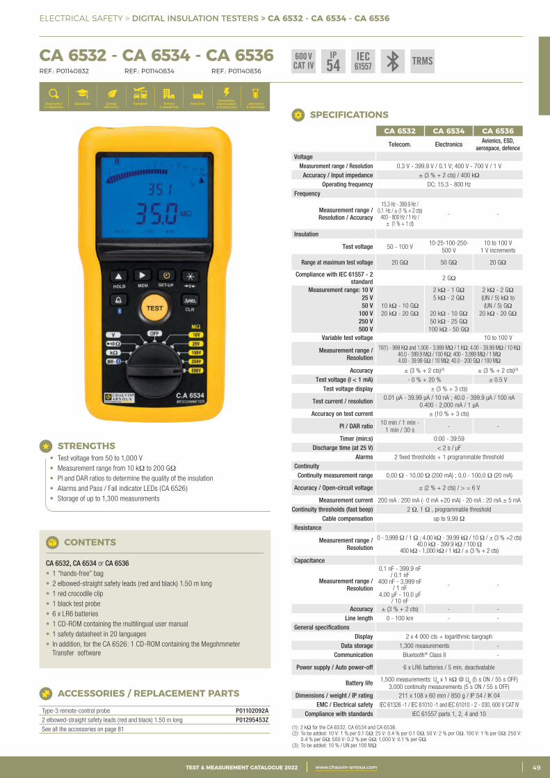
3CATALOGUE TEST & MESURE 2021 www.chauvin-arnoux.com 49TEST & MEASUREMENT CATALOGUE 2022 www.chauvin-arnoux.com
ELECTRICAL SAFETY > DIGITAL INSULATION TESTERS > CA 6532 - CA 6534 - CA 6536
CA 6532 - CA 6534 - CA 6536 REF.: P01140832 REF.: P01140834 REF.: P01140836
Generation, transmission & distribution
IndustriesTertiary & residential
Education TransportDiagnostics & inspection
Energy efficiency
Laboratory & metrology
STRENGTHS• Test voltage from 50 to 1,000 V• Measurement range from 10 kΩ to 200 GΩ• PI and DAR ratios to determine the quality of the insulation• Alarms and Pass / Fail indicator LEDs (CA 6526)• Storage of up to 1,300 measurements
ACCESSORIES / REPLACEMENT PARTS
Type-3 remote-control probe P01102092A2 elbowed-straight safety leads (red and black) 1.50 m long P01295453ZSee all the accessories on page 81
CONTENTS
CA 6532, CA 6534 or CA 6536• 1 “hands-free” bag• 2 elbowed-straight safety leads (red and black) 1.50 m long• 1 red crocodile clip• 1 black test probe• 6 x LR6 batteries• 1 CD-ROM containing the multilingual user manual• 1 safety datasheet in 20 languages• In addition, for the CA 6526: 1 CD-ROM containing the Megohmmeter
Transfer software
CA 6532 CA 6534 CA 6536
Telecom. Electronics Avionics, ESD, aerospace, defence
VoltageMeasurement range / Resolution 0.3 V - 399.9 V / 0.1 V; 400 V - 700 V / 1 V
Accuracy / Input impedance ± (3 % + 2 cts) / 400 kΩ Operating frequency DC; 15.3 - 800 Hz
Frequency
Measurement range / Resolution / Accuracy
15.3 Hz - 399.9 Hz / 0.1 Hz / ± (1 % + 2 cts)
400 - 800 Hz / 1 Hz / ± (1 % + 1 ct)
- -
Insulation
Test voltage 50 - 100 V 10-25-100-250-
500 V 10 to 100 V
1 V increments
Range at maximum test voltage 20 GΩ 50 GΩ 20 GΩ
Compliance with IEC 61557 - 2 standard 2 GΩ
Measurement range: 10 V 2 kΩ - 1 GΩ 2 kΩ - 2 GΩ 25 V 5 kΩ - 2 GΩ (UN / 5) kΩ to 50 V 10 kΩ - 10 GΩ (UN / 5) GΩ
100 V 20 kΩ - 20 GΩ 20 kΩ - 10 GΩ 20 kΩ - 20 GΩ 250 V 50 kΩ - 25 GΩ 500 V 100 kΩ - 50 GΩ
Variable test voltage 10 to 100 V
Measurement range / Resolution
10(1) - 999 KΩ and 1,000 - 3.999 MΩ / 1 KΩ; 4.00 - 39.99 MΩ / 10 KΩ40.0 - 399.9 MΩ / 100 KΩ; 400 - 3,999 MΩ / 1 MΩ4.00 - 39.99 GΩ / 10 MΩ; 40.0 - 200 GΩ / 100 MΩ
Accuracy ± (3 % + 2 cts)(2) ± (3 % + 2 cts)(3)
Test voltage (I < 1 mA) - 0 % + 20 % ± 0.5 V Test voltage display ± (3 % + 3 cts)
Test current / resolution 0.01 μA - 39.99 μA / 10 nA ; 40.0 - 399.9 μA / 100 nA 0.400 - 2,000 mA / 1 μA
Accuracy on test current ± (10 % + 3 cts)
PI / DAR ratio 10 min / 1 min - 1 min / 30 s
- -
Timer (min:s) 0:00 - 39:59 Discharge time (at 25 V) < 2 s / μF
Alarms 2 fixed thresholds + 1 programmable thresholdContinuity
Continuity measurement range 0,00 Ω - 10,00 Ω (200 mA) ; 0,0 - 100,0 Ω (20 mA)
Accuracy / Open-circuit voltage ± (2 % + 2 cts) / > = 6 V
Measurement current 200 mA : 200 mA (- 0 mA +20 mA) - 20 mA : 20 mA ± 5 mA Continuity thresholds (fast beep) 2 Ω, 1 Ω , programmable threshold
Cable compensation up to 9,99 Ω Resistance
Measurement range / Resolution
0 - 3,999 Ω / 1 Ω ; 4.00 kΩ - 39.99 kΩ / 10 Ω / ± (3 % +2 cts)40.0 kΩ - 399.9 kΩ / 100 Ω
400 kΩ - 1,000 kΩ / 1 kΩ / ± (3 % + 2 cts)
Capacitance
Measurement range / Resolution
0.1 nF - 399.9 nF / 0.1 nF
400 nF - 3,999 nF / 1 nF
4.00 μF - 10.0 μF / 10 nF
- -
Accuracy ± (3 % + 2 cts) - -Line length 0 - 100 km - -
General specificationsDisplay 2 x 4 000 cts + logarithmic bargraph
Data storage 1,300 measurements -Communication Bluetooth® Class II -
Power supply / Auto power-off 6 x LR6 batteries / 5 min, deactivatable
Battery life 1,500 measurements: UN x 1 kΩ @ U
N (5 s ON / 55 s OFF)
3,000 continuity measurements (5 s ON / 55 s OFF)Dimensions / weight / IP rating 211 x 108 x 60 mm / 850 g / IP 54 / IK 04
EMC / Electrical safety IEC 61326 -1 / IEC 61010 -1 and IEC 61010 - 2 - 030, 600 V CAT IV Compliance with standards IEC 61557 parts 1, 2, 4 and 10
(1): 2 kΩ for the CA 6532, CA 6534 and CA 6536.(2): To be added: 10 V: 1 % per 0.1 GΩ; 25 V: 0.4 % per 0.1 GΩ, 50 V: 2 % per GΩ, 100 V: 1 % per GΩ; 250 V:
0.4 % per GΩ; 500 V: 0.2 % per GΩ; 1,000 V: 0.1 % per GΩ.(3): To be added: 10 % / UN per 100 MΩ
SPECIFICATIONS
IEC61557
600 VCAT IV
IP54 TRMS
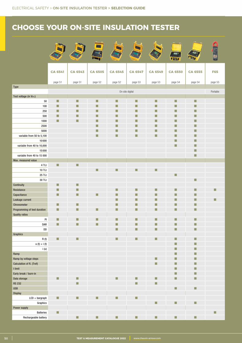
2 CATALOGUE TEST & MESURE 2021 www.chauvin-arnoux.com50 TEST & MEASUREMENT CATALOGUE 2022 www.chauvin-arnoux.com
ELECTRICAL SAFETY > ON-SITE INSULATION TESTER > SELECTION GUIDE
CHOOSE YOUR ON-SITE INSULATION TESTER
CA 6541 CA 6543 CA 6505 CA 6545 CA 6547 CA 6549 CA 6550 CA 6555 F65
page 51 page 51 page 52 page 52 page 53 page 53 page 54 page 54 page 55
Type
On-site digital Portable
Test voltage (in Vd c )
50
100
250
500
1000
2500
5000
variable from 50 to 5,100
10 000
variable from 40 to 10,000
15 000
variable from 40 to 15 000
Max. measured value
4 TΩ
10 TΩ
25 TΩ
30 TΩ
Continuity
Resistance
Capacitance
Leakage current
Chronometer
Programming of test duration
Quality ratios
PI
DAR
DD
Graphics
R (t)
u (t) + i (t)
i (u)
Ramp
Ramp by voltage steps
Calculation of R. (Tref)
I limit
Early break / burn-in
Data storage
RS 232
USB
Display
LCD + bargraph
Graphics
Power supply
Batteries
Rechargeable battery
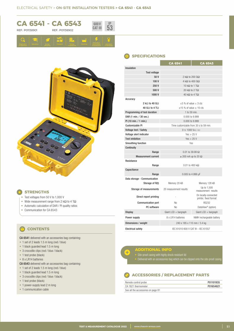
3CATALOGUE TEST & MESURE 2021 www.chauvin-arnoux.com 51TEST & MEASUREMENT CATALOGUE 2022 www.chauvin-arnoux.com
ELECTRICAL SAFETY > ON-SITE INSTALLATION TESTERS > CA 6541 - CA 6543
CHOOSE YOUR ON-SITE INSULATION TESTER CA 6541 - CA 6543 REF.: P01138901 REF.: P01138902
Generation, transmission & distribution
IndustriesTertiary & residential
Education TransportDiagnostics & inspection
Energy efficiency
Laboratory & metrology
ACCESSORIES / REPLACEMENT PARTS
Remote control probe P01101935CA 1821 thermometer P01654821See all the accessories on page 81
STRENGTHS• Test voltages from 50 V to 1,000 V• Wide measurement range from 2 kΩ to 4 TΩ• Automatic calculation of DAR / PI quality ratios• Communication for CA 6543
CONTENTS
CA 6541 delivered with an accessories bag containing:• 1 set of 2 leads 1.5 m long (red / blue)• 1 black guarded lead 1.5 m long• 3 crocodile clips (red / blue / black)• 1 test probe (black)• 8 x LR14 batteries CA 6543 delivered with an accessories bag containing:• 1 set of 2 leads 1.5 m long (red / blue)• 1 black guarded lead 1.5 m long• 3 crocodile clips (red / blue / black)• 1 test probe (black)• 1 power-supply lead 2 m long• 1 communication cable
ADDITIONAL INFO• Site-proof casing with highly shock-resistant lid• Delivered with an accessories bag which can be clipped onto the site-proof casing
CA 6541 CA 6543Insulation
Test voltage
50 V 2 kΩ to 200 GΩ
100 V 4 kΩ to 400 GΩ
250 V 10 kΩ to 1 TΩ
500 V 20 kΩ to 2 TΩ
1000 V 40 kΩ to 4 TΩ
Accuracy
2 kΩ to 40 GΩ ±5 % of value ± 3 cts
40 GΩ to 4 TΩ ±15 % of value ± 10 cts
Programming of test duration 1 to 59 min.
DAR (1 min. / 30 sec.) 0.000 to 9.999
PI (10 min. / 1 min.) 0.000 to 9.999
Customizable PI Time customizable from 30 s to 59 min.
Voltage test / Safety 0 to 1000 Vac / dc
Voltage alert indicator Yes > 25 V
Test inhibition Yes > 25 V
Smoothing function Yes
Continuity
Range 0.01 to 39.99 Ω
Measurement current ≥ 200 mA up to 20 Ω
Resistance
Range 0.01 to 400 kΩ
Capacitance
Range 0.005 to 4.999 μF
Data storage - Communication
Storage of R(t) Memory 20 kB Memory 128 kB
Storage of measurements 20 measurement results Up to 1,500
measurement results
Direct report printing -On locally-connectedprinter, fixed format
Communication port No RS232
PC software No DataView® (option)
Display Giant LCD + bargraph Giant LCD + bargraph
Power supply 8 x LR14 batteries NiMH rechargeable battery
Dimensions / weight 240 x 185 x 110 mm / 3.4 kg
Electrical safety IEC 61010 600 V CAT III – IEC 61557
SPECIFICATIONS
600 VCAT III
IP53
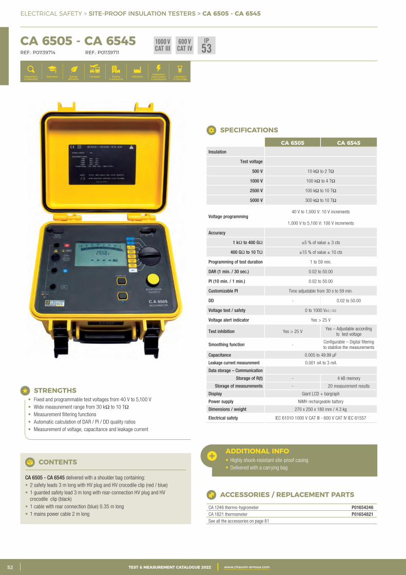
2 CATALOGUE TEST & MESURE 2021 www.chauvin-arnoux.com52 TEST & MEASUREMENT CATALOGUE 2022 www.chauvin-arnoux.com
ELECTRICAL SAFETY > SITE-PROOF INSULATION TESTERS > CA 6505 - CA 6545
CA 6505 - CA 6545 REF.: P01139714 REF.: P01139711
Generation, transmission & distribution
IndustriesTertiary & residential
Education TransportDiagnostics & inspection
Energy efficiency
Laboratory & metrology
STRENGTHS• Fixed and programmable test voltages from 40 V to 5,100 V• Wide measurement range from 30 kΩ to 10 TΩ• Measurement filtering functions• Automatic calculation of DAR / PI / DD quality ratios• Measurement of voltage, capacitance and leakage current
CONTENTS
CA 6505 - CA 6545 delivered with a shoulder bag containing:• 2 safety leads 3 m long with HV plug and HV crocodile clip (red / blue)• 1 guarded safety lead 3 m long with rear-connection HV plug and HV
crocodile clip (black)• 1 cable with rear connection (blue) 0.35 m long• 1 mains power cable 2 m long
ACCESSORIES / REPLACEMENT PARTS
CA 1246 thermo-hygrometer P01654246CA 1821 thermometer P01654821See all the accessories on page 81
ADDITIONAL INFO• Highly shock-resistant site-proof casing• Delivered with a carrying bag
CA 6505 CA 6545Insulation
Test voltage
500 V 10 kΩ to 2 TΩ
1000 V 100 kΩ to 4 TΩ
2500 V 100 kΩ to 10 TΩ
5000 V 300 kΩ to 10 TΩ
Voltage programming 40 V to 1,000 V: 10 V increments
1,000 V to 5,100 V: 100 V increments
Accuracy
1 kΩ to 400 GΩ ±5 % of value ± 3 cts
400 GΩ to 10 TΩ ±15 % of value ± 10 cts
Programming of test duration 1 to 59 min.
DAR (1 min. / 30 sec.) 0.02 to 50.00
PI (10 min. / 1 min.) 0.02 to 50.00
Customizable PI Time adjustable from 30 s to 59 min.
DD - 0.02 to 50.00
Voltage test / safety 0 to 1000 Vac / dc
Voltage alert indicator Yes > 25 V
Test inhibition Yes > 25 V Yes – Adjustable according
to test voltage
Smoothing function -Configurable – Digital filtering to stabilize the measurements
Capacitance 0.005 to 49.99 μF
Leakage current measurement 0.001 nA to 3 mA
Data storage – Communication
Storage of R(t) - 4 kB memory
Storage of measurements - 20 measurement results
Display Giant LCD + bargraph
Power supply NiMH rechargeable battery
Dimensions / weight 270 x 250 x 180 mm / 4.3 kg
Electrical safety IEC 61010 1000 V CAT III - 600 V CAT IV IEC 61557
SPECIFICATIONS
IP53
1000 VCAT III
600 VCAT IV
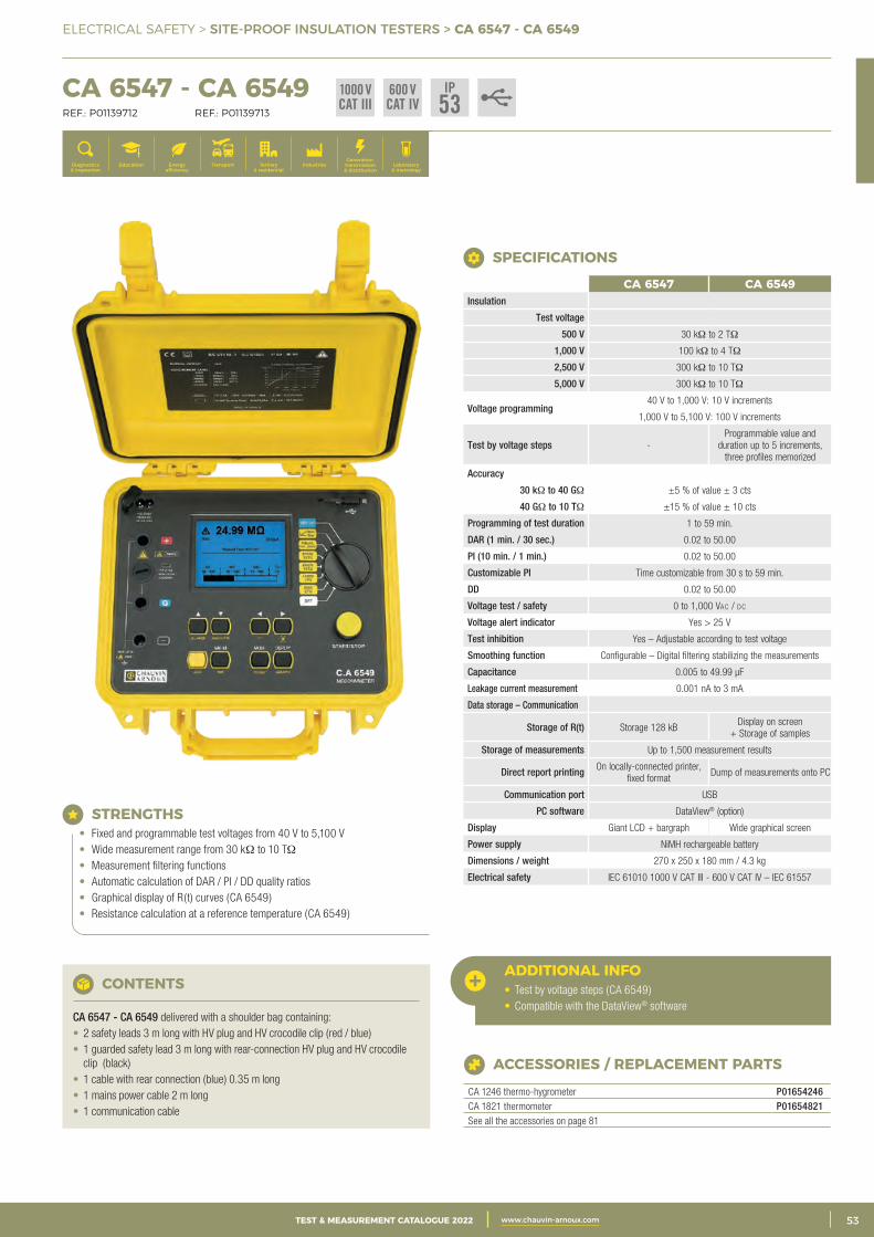
3CATALOGUE TEST & MESURE 2021 www.chauvin-arnoux.com 53TEST & MEASUREMENT CATALOGUE 2022 www.chauvin-arnoux.com
ELECTRICAL SAFETY > SITE-PROOF INSULATION TESTERS > CA 6547 - CA 6549
CA 6547 - CA 6549 REF.: P01139712 REF.: P01139713
Generation, transmission & distribution
IndustriesTertiary & residential
Education TransportDiagnostics & inspection
Energy efficiency
Laboratory & metrology
STRENGTHS• Fixed and programmable test voltages from 40 V to 5,100 V• Wide measurement range from 30 kΩ to 10 TΩ• Measurement filtering functions• Automatic calculation of DAR / PI / DD quality ratios• Graphical display of R(t) curves (CA 6549)• Resistance calculation at a reference temperature (CA 6549)
CONTENTS
CA 6547 - CA 6549 delivered with a shoulder bag containing:• 2 safety leads 3 m long with HV plug and HV crocodile clip (red / blue)• 1 guarded safety lead 3 m long with rear-connection HV plug and HV crocodile
clip (black)• 1 cable with rear connection (blue) 0.35 m long• 1 mains power cable 2 m long• 1 communication cable
ACCESSORIES / REPLACEMENT PARTS
CA 1246 thermo-hygrometer P01654246CA 1821 thermometer P01654821See all the accessories on page 81
ADDITIONAL INFO• Test by voltage steps (CA 6549)• Compatible with the DataView® software
CA 6547 CA 6549Insulation
Test voltage
500 V 30 kΩ to 2 TΩ
1,000 V 100 kΩ to 4 TΩ
2,500 V 300 kΩ to 10 TΩ
5,000 V 300 kΩ to 10 TΩ
Voltage programming 40 V to 1,000 V: 10 V increments
1,000 V to 5,100 V: 100 V increments
Test by voltage steps -Programmable value and
duration up to 5 increments, three profiles memorized
Accuracy
30 kΩ to 40 GΩ ±5 % of value ± 3 cts
40 GΩ to 10 TΩ ±15 % of value ± 10 cts
Programming of test duration 1 to 59 min.
DAR (1 min. / 30 sec.) 0.02 to 50.00
PI (10 min. / 1 min.) 0.02 to 50.00
Customizable PI Time customizable from 30 s to 59 min.
DD 0.02 to 50.00
Voltage test / safety 0 to 1,000 Vac / dc
Voltage alert indicator Yes > 25 V
Test inhibition Yes – Adjustable according to test voltage
Smoothing function Configurable – Digital filtering stabilizing the measurements
Capacitance 0.005 to 49.99 μF
Leakage current measurement 0.001 nA to 3 mA
Data storage – Communication
Storage of R(t) Storage 128 kB Display on screen
+ Storage of samples
Storage of measurements Up to 1,500 measurement results
Direct report printing On locally-connected printer, fixed format
Dump of measurements onto PC
Communication port USB
PC software DataView® (option)
Display Giant LCD + bargraph Wide graphical screen
Power supply NiMH rechargeable battery
Dimensions / weight 270 x 250 x 180 mm / 4.3 kg
Electrical safety IEC 61010 1000 V CAT III - 600 V CAT IV – IEC 61557
SPECIFICATIONS
IP53
1000 VCAT III
600 VCAT IV
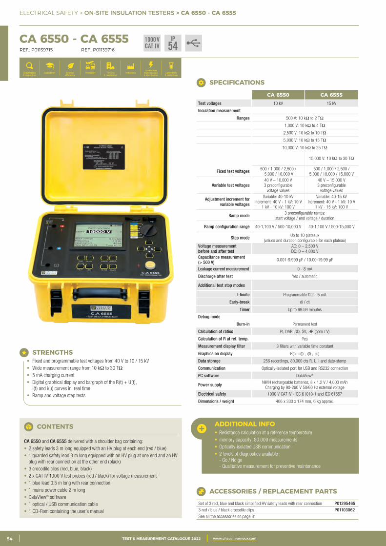
2 CATALOGUE TEST & MESURE 2021 www.chauvin-arnoux.com54 TEST & MEASUREMENT CATALOGUE 2022 www.chauvin-arnoux.com
ELECTRICAL SAFETY > ON-SITE INSULATION TESTERS > CA 6550 - CA 6555
CA 6550 - CA 6555 REF.: P01139715 REF.: P01139716
Generation, transmission & distribution
IndustriesTertiary & residential
Education TransportDiagnostics & inspection
Energy efficiency
Laboratory & metrology
SPECIFICATIONS
CA 6550 CA 6555Test voltages 10 kV 15 kV
Insulation measurement
Ranges 500 V: 10 kΩ to 2 TΩ
1,000 V: 10 kΩ to 4 TΩ
2,500 V: 10 kΩ to 10 TΩ
5,000 V: 10 kΩ to 15 TΩ
10,000 V: 10 kΩ to 25 TΩ
15,000 V: 10 kΩ to 30 TΩ
Fixed test voltages 500 / 1,000 / 2,500 / 5,000 / 10,000 V
500 / 1,000 / 2,500 / 5,000 / 10,000 / 15,000 V
Variable test voltages40 V – 10,000 V 3 preconfigurable
voltage values
40 V – 15,000 V 3 preconfigurable
voltage values
Adjustment increment for variable voltages
Variable: 40-10 kV Increment: 40 V - 1 kV: 10 V
1 kV - 10 kV: 100 V
Variable: 40-15 kV Increment: 40 V - 1 kV: 10 V
1 kV - 15 kV: 100 V
Ramp mode 3 preconfigurable ramps: start voltage / end voltage / duration
Ramp configuration range 40-1,100 V / 500-10,000 V 40-1,100 V / 500-15,000 V
Step mode Up to 10 plateaux(values and duration configurable for each plateau)
Voltage measurement before and after test
AC: 0 – 2,500 V DC: 0 – 4,000 V
Capacitance measurement (> 500 V) 0.001-9.999 μF / 10.00-19.99 μF
Leakage current measurement 0 - 8 mA
Discharge after test Yes / automatic
Additional test stop modes
I-limite Programmable 0.2 - 5 mA
Early-break di / dt
Timer Up to 99:59 minutes
Debug mode
Burn-in Permanent test
Calculation of ratios PI, DAR, DD, SV, DR (ppm / V)
Calculation of R at ref. temp. Yes
Measurement display filter 3 filters with variable time constant
Graphics on display R(t)+u(t) ; i(t) ; i(u)
Data storage 256 recordings, 80,000 cts R, U, I and date-stamp
Communication Optically-isolated port for USB and RS232 connection
PC software DataView®
Power supply NiMH rechargeable batteries, 8 x 1.2 V / 4,000 mAhCharging by 90-260 V 50/60 Hz external voltage
Electrical safety 1000 V CAT IV - IEC 61010-1 and IEC 61557
Dimensions / weight 406 x 330 x 174 mm, 6 kg approx.
STRENGTHS• Fixed and programmable test voltages from 40 V to 10 / 15 kV• Wide measurement range from 10 kΩ to 30 TΩ• 5 mA charging current• Digital graphical display and bargraph of the R(t) + U(t),
i(t) and i(u) curves in real time• Ramp and voltage step tests
CONTENTS
CA 6550 and CA 6555 delivered with a shoulder bag containing:• 2 safety leads 3 m long equipped with an HV plug at each end (red / blue)• 1 guarded safety lead 3 m long equipped with an HV plug at one end and an HV
plug with rear connection at the other end (black)• 3 crocodile clips (red, blue, black)• 2 x CAT IV 1000 V test probes (red / black) for voltage measurement• 1 blue lead 0.5 m long with rear connection• 1 mains power cable 2 m long• DataView® software• 1 optical / USB communication cable• 1 CD-Rom containing the user’s manual
ACCESSORIES / REPLACEMENT PARTS
Set of 3 red, blue and black simplified HV safety leads with rear connection P012954653 red / blue / black crocodile clips P01103062See all the accessories on page 81
ADDITIONAL INFO• Resistance calculation at a reference temperature• memory capacity: 80.000 measurements• Optically-isolated USB communication• 2 levels of diagnostics available :
- Go / No go - Qualitative measurement for preventive maintenance
1000 VCAT IV
IP54
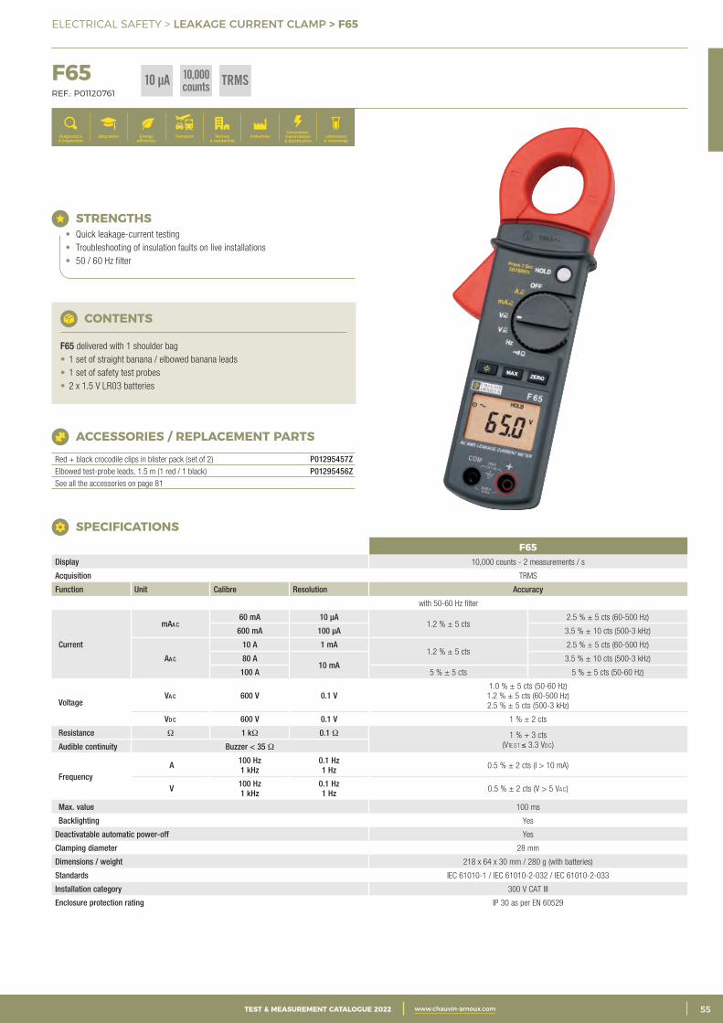
3CATALOGUE TEST & MESURE 2021 www.chauvin-arnoux.com 55TEST & MEASUREMENT CATALOGUE 2022 www.chauvin-arnoux.com
ELECTRICAL SAFETY > LEAKAGE CURRENT CLAMP > F65
F65 REF.: P01120761
Generation, transmission & distribution
IndustriesTertiary & residential
Education TransportDiagnostics & inspection
Energy efficiency
Laboratory & metrology
F65Display 10,000 counts - 2 measurements / s
Acquisition TRMS
Function Unit Calibre Resolution Accuracy
with 50-60 Hz filter
Current
mAa c 60 mA 10 μA
1.2 % ± 5 cts 2.5 % ± 5 cts (60-500 Hz)
600 mA 100 μA 3.5 % ± 10 cts (500-3 kHz)
Aa c
10 A 1 mA 1.2 % ± 5 cts
2.5 % ± 5 cts (60-500 Hz)
80 A 10 mA
3.5 % ± 10 cts (500-3 kHz)
100 A 5 % ± 5 cts 5 % ± 5 cts (50-60 Hz)
Voltage Va c 600 V 0.1 V
1.0 % ± 5 cts (50-60 Hz) 1.2 % ± 5 cts (60-500 Hz) 2.5 % ± 5 cts (500-3 kHz)
Vd c 600 V 0.1 V 1 % ± 2 cts
Resistance Ω 1 kΩ 0.1 Ω 1 % + 3 cts (Vte st ≤ 3.3 Vdc) Audible continuity Buzzer < 35 Ω
Frequency A 100 Hz
1 kHz 0.1 Hz 1 Hz 0.5 % ± 2 cts (I > 10 mA)
V 100 Hz 1 kHz
0.1 Hz 1 Hz 0.5 % ± 2 cts (V > 5 Vac)
Max. value 100 ms
Backlighting Yes
Deactivatable automatic power-off Yes
Clamping diameter 28 mm
Dimensions / weight 218 x 64 x 30 mm / 280 g (with batteries)
Standards IEC 61010-1 / IEC 61010-2-032 / IEC 61010-2-033
Installation category 300 V CAT III
Enclosure protection rating IP 30 as per EN 60529
SPECIFICATIONS
ACCESSORIES / REPLACEMENT PARTS
Red + black crocodile clips in blister pack (set of 2) P01295457ZElbowed test-probe leads, 1.5 m (1 red / 1 black) P01295456ZSee all the accessories on page 81
STRENGTHS• Quick leakage-current testing• Troubleshooting of insulation faults on live installations• 50 / 60 Hz filter
CONTENTS
F65 delivered with 1 shoulder bag• 1 set of straight banana / elbowed banana leads• 1 set of safety test probes• 2 x 1.5 V LR03 batteries
TRMS10 µA 10,000counts
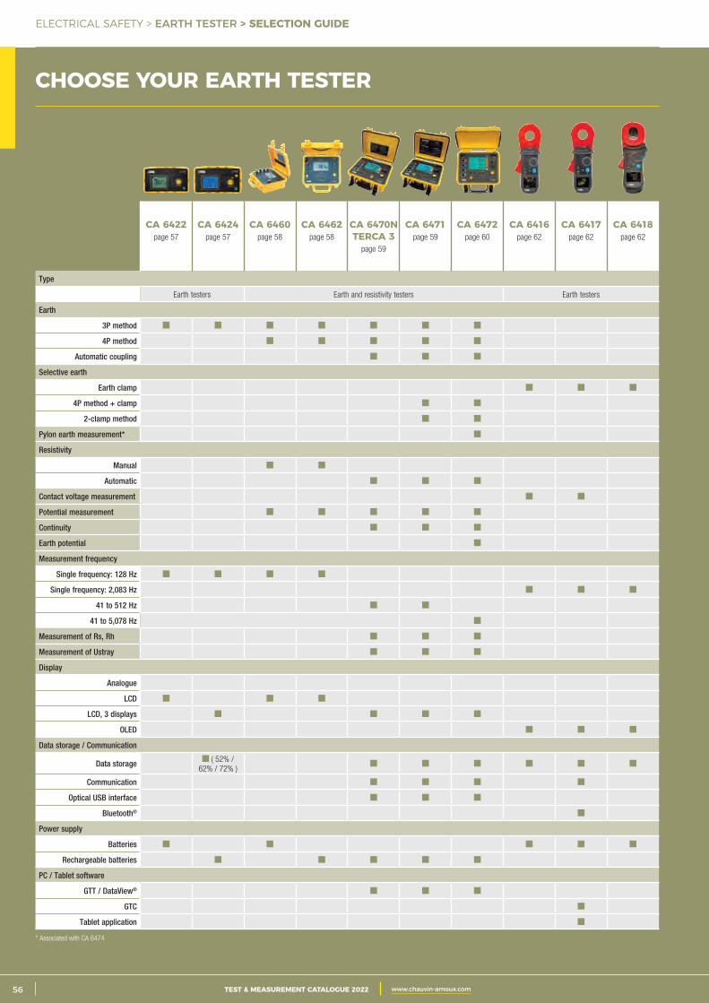
2 CATALOGUE TEST & MESURE 2021 www.chauvin-arnoux.com56 TEST & MEASUREMENT CATALOGUE 2022 www.chauvin-arnoux.com
ELECTRICAL SAFETY > EARTH TESTER > SELECTION GUIDE
CHOOSE YOUR EARTH TESTER
CA 6422page 57
CA 6424page 57
CA 6460page 58
CA 6462page 58
CA 6470NTERCA 3
page 59
CA 6471page 59
CA 6472page 60
CA 6416page 62
CA 6417page 62
CA 6418page 62
Type
Earth testers Earth and resistivity testers Earth testers
Earth
3P method
4P method
Automatic coupling
Selective earth
Earth clamp
4P method + clamp
2-clamp method
Pylon earth measurement*
Resistivity
Manual
Automatic
Contact voltage measurement
Potential measurement
Continuity
Earth potential
Measurement frequency
Single frequency: 128 Hz
Single frequency: 2,083 Hz
41 to 512 Hz
41 to 5,078 Hz
Measurement of Rs, Rh
Measurement of Ustray
Display
Analogue
LCD
LCD, 3 displays
OLED
Data storage / Communication
Data storage ( 52% / 62% / 72% )
Communication
Optical USB interface
Bluetooth®
Power supply
Batteries
Rechargeable batteries
PC / Tablet software
GTT / DataView®
GTC
Tablet application
* Associated with CA 6474
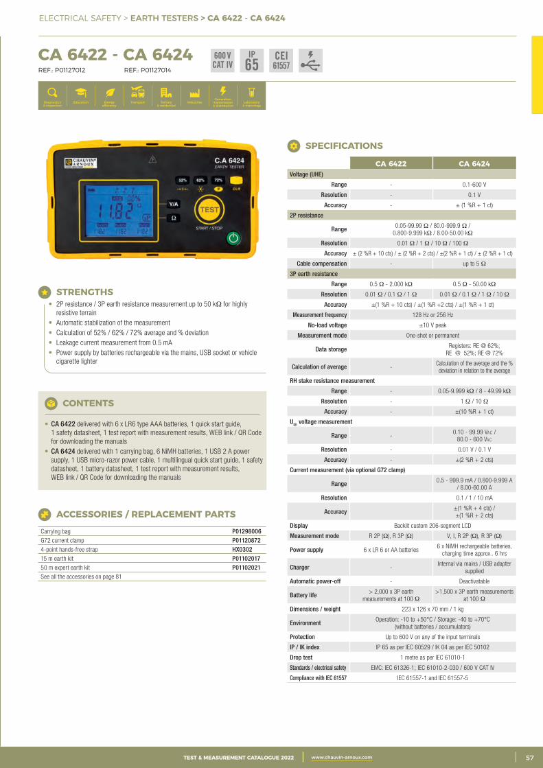
3CATALOGUE TEST & MESURE 2021 www.chauvin-arnoux.com 57TEST & MEASUREMENT CATALOGUE 2022 www.chauvin-arnoux.com
ELECTRICAL SAFETY > EARTH TESTERS > CA 6422 - CA 6424
CHOOSE YOUR EARTH TESTER CA 6422 - CA 6424 REF.: P01127012 REF.: P01127014
Generation, transmission & distribution
IndustriesTertiary & residential
Education TransportDiagnostics & inspection
Energy efficiency
Laboratory & metrology
CONTENTS
• CA 6422 delivered with 6 x LR6 type AAA batteries, 1 quick start guide, 1 safety datasheet, 1 test report with measurement results, WEB link / QR Code for downloading the manuals
• CA 6424 delivered with 1 carrying bag, 6 NiMH batteries, 1 USB 2 A power supply, 1 USB micro-razor power cable, 1 multilingual quick start guide, 1 safety datasheet, 1 battery datasheet, 1 test report with measurement results, WEB link / QR Code for downloading the manuals
ACCESSORIES / REPLACEMENT PARTS
Carrying bag P01298006G72 current clamp P011208724-point hands-free strap HX030215 m earth kit P0110201750 m expert earth kit P01102021See all the accessories on page 81
STRENGTHS• 2P resistance / 3P earth resistance measurement up to 50 kΩ for highly
resistive terrain • Automatic stabilization of the measurement• Calculation of 52% / 62% / 72% average and % deviation• Leakage current measurement from 0.5 mA • Power supply by batteries rechargeable via the mains, USB socket or vehicle
cigarette lighter
SPECIFICATIONS
CA 6422 CA 6424Voltage (UHE)
Range - 0.1-600 V
Resolution - 0.1 V
Accuracy - ± (1 %R + 1 ct)
2P resistance
Range 0.05-99.99 Ω / 80.0-999.9 Ω / 0.800-9.999 kΩ / 8.00-50.00 kΩ
Resolution 0.01 Ω / 1 Ω / 10 Ω / 100 Ω
Accuracy ± (2 %R + 10 cts) / ± (2 %R + 2 cts) / ±(2 %R + 1 ct) / ± (2 %R + 1 ct)
Cable compensation - up to 5 Ω
3P earth resistance
Range 0.5 Ω - 2.000 kΩ 0.5 Ω - 50.00 kΩ
Resolution 0.01 Ω / 0.1 Ω / 1 Ω 0.01 Ω / 0.1 Ω / 1 Ω / 10 Ω
Accuracy ±(1 %R + 10 cts) / ±(1 %R +2 cts) / ±(1 %R + 1 ct)
Measurement frequency 128 Hz or 256 Hz
No-load voltage ±10 V peak
Measurement mode One-shot or permanent
Data storage Registers: RE @ 62%; RE @ 52%; RE @ 72%
Calculation of average -Calculation of the average and the % deviation in relation to the average
RH stake resistance measurement
Range - 0.05-9.999 kΩ / 8 - 49.99 kΩ
Resolution - 1 Ω / 10 Ω
Accuracy - ±(10 %R + 1 ct)
USE voltage measurement
Range -0.10 - 99.99 Vac /
80.0 - 600 Vac
Resolution - 0.01 V / 0.1 V
Accuracy - ±(2 %R + 2 cts)
Current measurement (via optional G72 clamp)
Range 0.5 - 999.9 mA / 0.800-9.999 A / 8.00-60.00 A
Resolution 0.1 / 1 / 10 mA
Accuracy ±(1 %R + 4 cts) / ±(1 %R + 2 cts)
Display Backlit custom 206-segment LCD
Measurement mode R 2P (Ω), R 3P (Ω) V, I, R 2P (Ω), R 3P (Ω)
Power supply 6 x LR 6 or AA batteries6 x NiMH rechargeable batteries,
charging time approx.. 6 hrs
Charger -Internal via mains / USB adapter
supplied
Automatic power-off - Deactivatable
Battery life > 2,000 x 3P earth measurements at 100 Ω
>1,500 x 3P earth measurements at 100 Ω
Dimensions / weight 223 x 126 x 70 mm / 1 kg
Environment Operation: -10 to +50°C / Storage: -40 to +70°C (without batteries / accumulators)
Protection Up to 600 V on any of the input terminals
IP / IK index IP 65 as per IEC 60529 / IK 04 as per IEC 50102
Drop test 1 metre as per IEC 61010-1
Standards / electrical safety EMC: IEC 61326-1; IEC 61010-2-030 / 600 V CAT IV
Compliance with IEC 61557 IEC 61557-1 and IEC 61557-5
CEI61557
600 VCAT IV
IP65
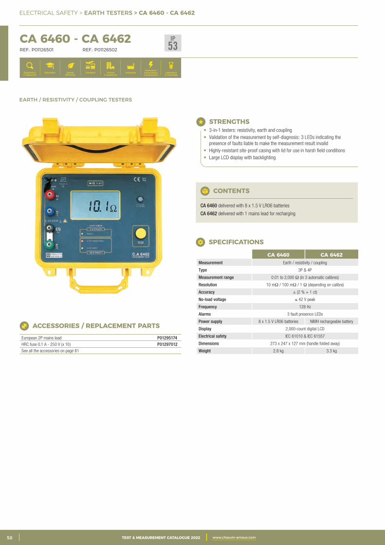
2 CATALOGUE TEST & MESURE 2021 www.chauvin-arnoux.com58 TEST & MEASUREMENT CATALOGUE 2022 www.chauvin-arnoux.com
ELECTRICAL SAFETY > EARTH TESTERS > CA 6460 - CA 6462
CA 6460 - CA 6462 REF.: P01126501 REF.: P01126502
Generation, transmission & distribution
IndustriesTertiary & residential
Education TransportDiagnostics & inspection
Energy efficiency
Laboratory & metrology
EARTH / RESISTIVITY / COUPLING TESTERS
CA 6460 CA 6462Measurement Earth / resistivity / coupling
Type 3P & 4P
Measurement range 0.01 to 2,000 Ω (in 3 automatic calibres)
Resolution 10 mΩ / 100 mΩ / 1 Ω (depending on calibre)
Accuracy ± (2 % + 1 ct)
No-load voltage ≤ 42 V peak
Frequency 128 Hz
Alarms 3 fault presence LEDs
Power supply 8 x 1.5 V LR06 batteries NiMH rechargeable battery
Display 2,000-count digital LCD
Electrical safety IEC 61010 & IEC 61557
Dimensions 273 x 247 x 127 mm (handle folded away)
Weight 2.8 kg 3.3 kg
SPECIFICATIONS
ACCESSORIES / REPLACEMENT PARTS
European 2P mains lead P01295174HRC fuse 0.1 A - 250 V (x 10) P01297012See all the accessories on page 81
CONTENTS
CA 6460 delivered with 8 x 1.5 V LR06 batteries
CA 6462 delivered with 1 mains lead for recharging
STRENGTHS• 3-in-1 testers: resistivity, earth and coupling• Validation of the measurement by self-diagnosis: 3 LEDs indicating the
presence of faults liable to make the measurement result invalid• Highly-resistant site-proof casing with lid for use in harsh field conditions• Large LCD display with backlighting
IP53
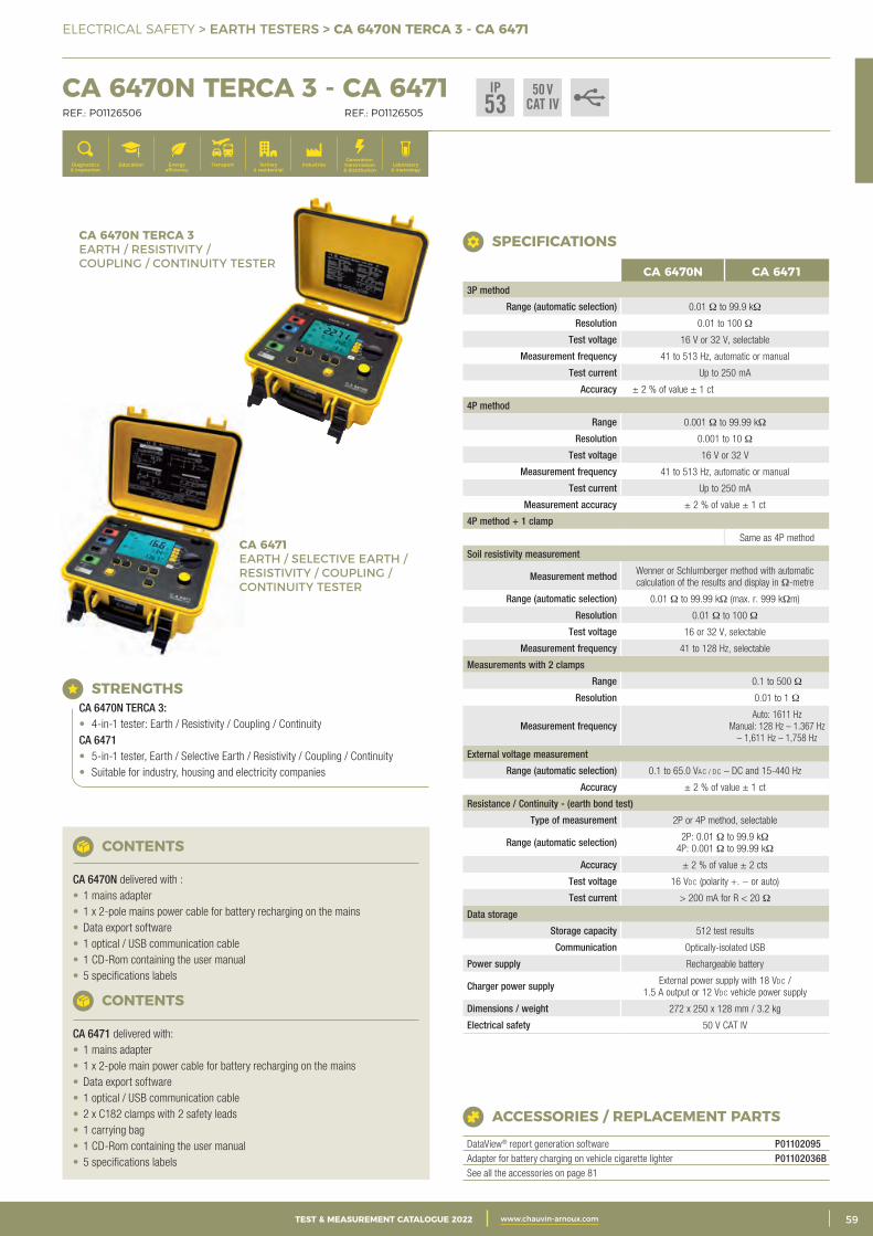
3CATALOGUE TEST & MESURE 2021 www.chauvin-arnoux.com 59TEST & MEASUREMENT CATALOGUE 2022 www.chauvin-arnoux.com
ELECTRICAL SAFETY > EARTH TESTERS > CA 6470N TERCA 3 - CA 6471
CA 6470N TERCA 3 - CA 6471 REF.: P01126506 REF.: P01126505
Generation, transmission & distribution
IndustriesTertiary & residential
Education TransportDiagnostics & inspection
Energy efficiency
Laboratory & metrology
CA 6470N CA 64713P method
Range (automatic selection) 0.01 Ω to 99.9 kΩ
Resolution 0.01 to 100 Ω
Test voltage 16 V or 32 V, selectable
Measurement frequency 41 to 513 Hz, automatic or manual
Test current Up to 250 mA
Accuracy ± 2 % of value ± 1 ct
4P method
Range 0.001 Ω to 99.99 kΩ
Resolution 0.001 to 10 Ω
Test voltage 16 V or 32 V
Measurement frequency 41 to 513 Hz, automatic or manual
Test current Up to 250 mA
Measurement accuracy ± 2 % of value ± 1 ct
4P method + 1 clamp
Same as 4P method
Soil resistivity measurement
Measurement method Wenner or Schlumberger method with automatic calculation of the results and display in Ω-metre
Range (automatic selection) 0.01 Ω to 99.99 kΩ (max. r. 999 kΩm)
Resolution 0.01 Ω to 100 Ω
Test voltage 16 or 32 V, selectable
Measurement frequency 41 to 128 Hz, selectable
Measurements with 2 clamps
Range 0.1 to 500 Ω
Resolution 0.01 to 1 Ω
Measurement frequency Auto: 1611 Hz
Manual: 128 Hz – 1.367 Hz – 1,611 Hz – 1,758 Hz
External voltage measurement
Range (automatic selection) 0.1 to 65.0 Vac / dc – DC and 15-440 Hz
Accuracy ± 2 % of value ± 1 ct
Resistance / Continuity - (earth bond test)
Type of measurement 2P or 4P method, selectable
Range (automatic selection) 2P: 0.01 Ω to 99.9 kΩ 4P: 0.001 Ω to 99.99 kΩ
Accuracy ± 2 % of value ± 2 cts
Test voltage 16 Vdc (polarity +. − or auto)
Test current > 200 mA for R < 20 Ω
Data storage
Storage capacity 512 test results
Communication Optically-isolated USB
Power supply Rechargeable battery
Charger power supply External power supply with 18 Vdc / 1.5 A output or 12 Vdc vehicle power supply
Dimensions / weight 272 x 250 x 128 mm / 3.2 kg
Electrical safety 50 V CAT IV
SPECIFICATIONS
STRENGTHS CA 6470N TERCA 3:
• 4-in-1 tester: Earth / Resistivity / Coupling / Continuity CA 6471
• 5-in-1 tester, Earth / Selective Earth / Resistivity / Coupling / Continuity• Suitable for industry, housing and electricity companies
CONTENTS
CA 6470N delivered with :• 1 mains adapter• 1 x 2-pole mains power cable for battery recharging on the mains• Data export software• 1 optical / USB communication cable• 1 CD-Rom containing the user manual• 5 specifications labels
CONTENTS
CA 6471 delivered with:• 1 mains adapter• 1 x 2-pole main power cable for battery recharging on the mains• Data export software• 1 optical / USB communication cable• 2 x C182 clamps with 2 safety leads• 1 carrying bag• 1 CD-Rom containing the user manual• 5 specifications labels
ACCESSORIES / REPLACEMENT PARTS
DataView® report generation software P01102095Adapter for battery charging on vehicle cigarette lighter P01102036BSee all the accessories on page 81
IP53
50 VCAT IV
CA 6470N TERCA 3 EARTH / RESISTIVITY / COUPLING / CONTINUITY TESTER
CA 6471EARTH / SELECTIVE EARTH / RESISTIVITY / COUPLING / CONTINUITY TESTER
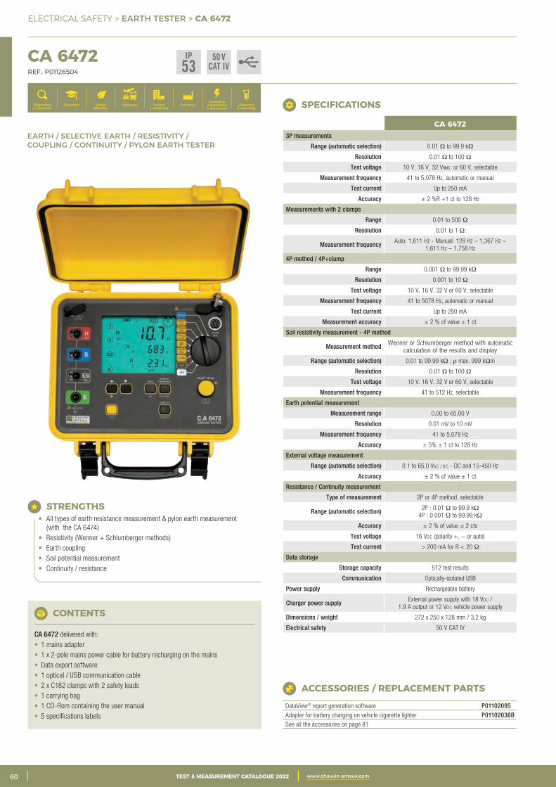
2 CATALOGUE TEST & MESURE 2021 www.chauvin-arnoux.com60 TEST & MEASUREMENT CATALOGUE 2022 www.chauvin-arnoux.com
ELECTRICAL SAFETY > EARTH TESTER > CA 6472
CA 6472 REF.: P01126504
Generation, transmission & distribution
IndustriesTertiary & residential
Education TransportDiagnostics & inspection
Energy efficiency
Laboratory & metrology
EARTH / SELECTIVE EARTH / RESISTIVITY / COUPLING / CONTINUITY / PYLON EARTH TESTER
CA 64723P measurements
Range (automatic selection) 0.01 Ω to 99.9 kΩ
Resolution 0.01 Ω to 100 Ω
Test voltage 10 V, 16 V, 32 Vrms or 60 V, selectable
Measurement frequency 41 to 5,078 Hz, automatic or manual
Test current Up to 250 mA
Accuracy ± 2 %R +1 ct to 128 Hz
Measurements with 2 clamps
Range 0.01 to 500 Ω
Resolution 0.01 to 1 Ω
Measurement frequency Auto: 1,611 Hz - Manual: 128 Hz – 1,367 Hz – 1,611 Hz – 1,758 Hz
4P method / 4P+clamp
Range 0.001 Ω to 99.99 kΩ
Resolution 0.001 to 10 Ω
Test voltage 10 V. 16 V. 32 V or 60 V, selectable
Measurement frequency 41 to 5078 Hz, automatic or manual
Test current Up to 250 mA
Measurement accuracy ± 2 % of value ± 1 ct
Soil resistivity measurement - 4P method
Measurement method Wenner or Schlumberger method with automatic calculation of the results and display
Range (automatic selection) 0.01 to 99.99 kΩ ; r max. 999 kΩm
Resolution 0.01 Ω to 100 Ω
Test voltage 10 V. 16 V. 32 V or 60 V, selectable
Measurement frequency 41 to 512 Hz, selectable
Earth potential measurement
Measurement range 0.00 to 65.00 V
Resolution 0.01 mV to 10 mV
Measurement frequency 41 to 5,078 Hz
Accuracy ± 5% ± 1 ct to 128 Hz
External voltage measurement
Range (automatic selection) 0.1 to 65.0 Vac / dc - DC and 15-450 Hz
Accuracy ± 2 % of value ± 1 ct
Resistance / Continuity measurement
Type of measurement 2P or 4P method. selectable
Range (automatic selection) 2P : 0.01 Ω to 99.9 kΩ 4P : 0.001 Ω to 99.99 kΩ
Accuracy ± 2 % of value ± 2 cts
Test voltage 16 Vdc (polarity +. − or auto)
Test current > 200 mA for R < 20 Ω
Data storage
Storage capacity 512 test results
Communication Optically-isolated USB
Power supply Rechargeable battery
Charger power supply External power supply with 18 Vdc / 1.9 A output or 12 Vdc vehicle power supply
Dimensions / weight 272 x 250 x 128 mm / 3.2 kg
Electrical safety 50 V CAT IV
SPECIFICATIONS
STRENGTHS• All types of earth resistance measurement & pylon earth measurement
(with the CA 6474)• Resistivity (Wenner + Schlumberger methods)• Earth coupling• Soil potential measurement• Continuity / resistance
CONTENTS
CA 6472 delivered with:• 1 mains adapter• 1 x 2-pole mains power cable for battery recharging on the mains• Data export software• 1 optical / USB communication cable• 2 x C182 clamps with 2 safety leads• 1 carrying bag• 1 CD-Rom containing the user manual• 5 specifications labels
ACCESSORIES / REPLACEMENT PARTS
DataView® report generation software P01102095Adapter for battery charging on vehicle cigarette lighter P01102036BSee all the accessories on page 81
IP53
50 VCAT IV
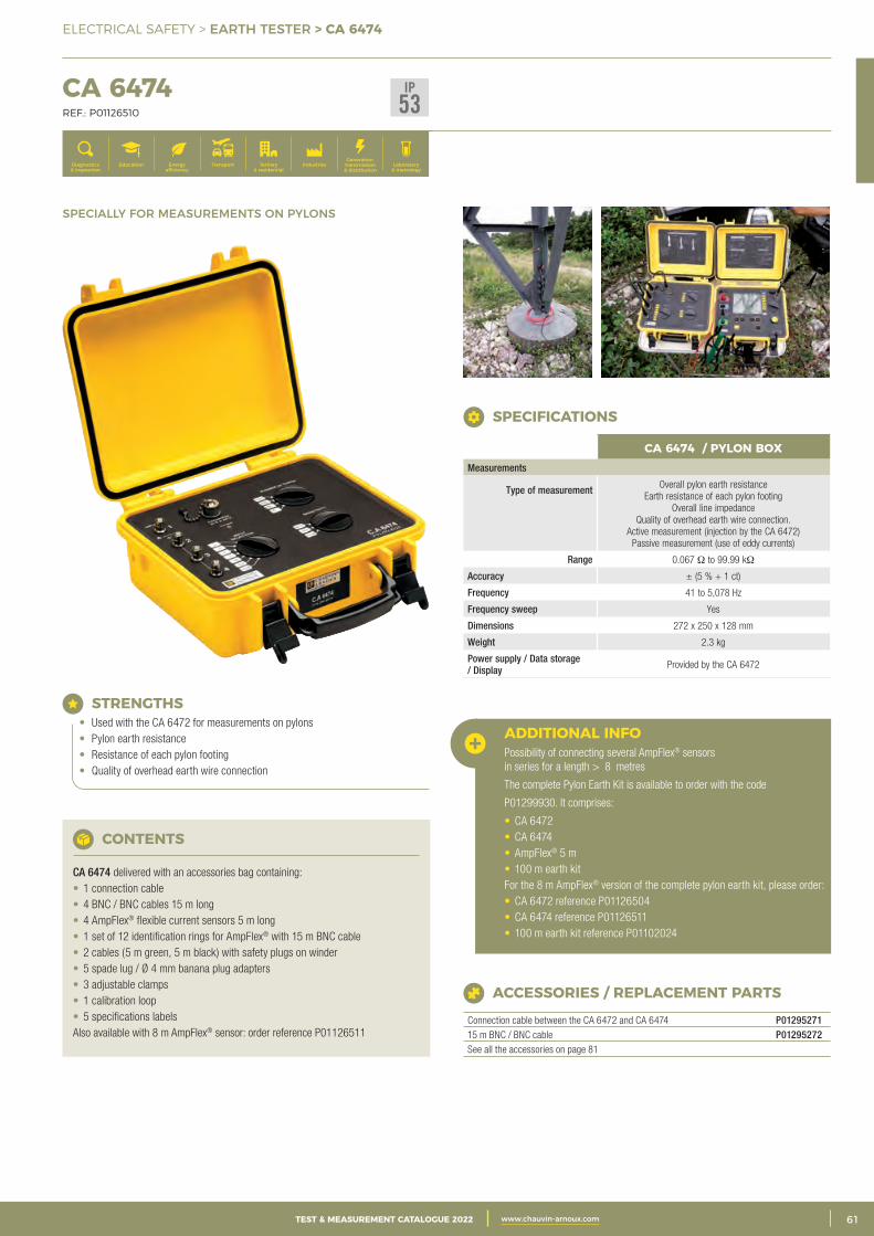
3CATALOGUE TEST & MESURE 2021 www.chauvin-arnoux.com 61TEST & MEASUREMENT CATALOGUE 2022 www.chauvin-arnoux.com
ELECTRICAL SAFETY > EARTH TESTER > CA 6474
CA 6474 REF.: P01126510
Generation, transmission & distribution
IndustriesTertiary & residential
Education TransportDiagnostics & inspection
Energy efficiency
Laboratory & metrology
SPECIALLY FOR MEASUREMENTS ON PYLONS
STRENGTHS• Used with the CA 6472 for measurements on pylons• Pylon earth resistance• Resistance of each pylon footing• Quality of overhead earth wire connection
CONTENTS
CA 6474 delivered with an accessories bag containing:• 1 connection cable• 4 BNC / BNC cables 15 m long• 4 AmpFlex® flexible current sensors 5 m long• 1 set of 12 identification rings for AmpFlex® with 15 m BNC cable• 2 cables (5 m green, 5 m black) with safety plugs on winder• 5 spade lug / Ø 4 mm banana plug adapters• 3 adjustable clamps• 1 calibration loop• 5 specifications labelsAlso available with 8 m AmpFlex® sensor: order reference P01126511
ACCESSORIES / REPLACEMENT PARTS
Connection cable between the CA 6472 and CA 6474 P0129527115 m BNC / BNC cable P01295272See all the accessories on page 81
ADDITIONAL INFO Possibility of connecting several AmpFlex® sensors in series for a length > 8 metres
The complete Pylon Earth Kit is available to order with the code
P01299930. It comprises:
• CA 6472• CA 6474• AmpFlex® 5 m• 100 m earth kitFor the 8 m AmpFlex® version of the complete pylon earth kit, please order:• CA 6472 reference P01126504• CA 6474 reference P01126511• 100 m earth kit reference P01102024
CA 6474 / PYLON BOXMeasurements
Type of measurement
Overall pylon earth resistanceEarth resistance of each pylon footing
Overall line impedanceQuality of overhead earth wire connection.
Active measurement (injection by the CA 6472)Passive measurement (use of eddy currents)
Range 0.067 Ω to 99.99 kΩ
Accuracy ± (5 % + 1 ct)
Frequency 41 to 5,078 Hz
Frequency sweep Yes
Dimensions 272 x 250 x 128 mm
Weight 2.3 kg
Power supply / Data storage / Display Provided by the CA 6472
SPECIFICATIONS
IP53
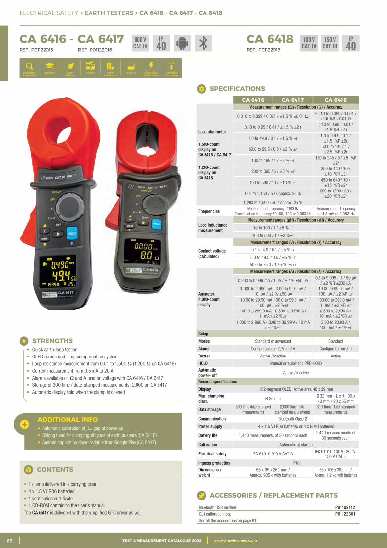
2 CATALOGUE TEST & MESURE 2021 www.chauvin-arnoux.com62 TEST & MEASUREMENT CATALOGUE 2022 www.chauvin-arnoux.com
ELECTRICAL SAFETY > EARTH TESTERS > CA 6416 - CA 6417 - CA 6418
CA 6416 - CA 6417 CA 6418 REF.: P01122015 REF.: P01122016 REF.: P01122018
Generation, transmission & distribution
IndustriesTertiary & residential
Education TransportDiagnostics & inspection
Energy efficiency
Laboratory & metrology
ACCESSORIES / REPLACEMENT PARTS
Bluetooth USB modem P01102112CL1 calibration loop P01122301See all the accessories on page 81
STRENGTHS• Quick earth-loop testing• OLED screen and force compensation system• Loop resistance measurement from 0.01 to 1,500 Ω (1,200 Ω on CA 6418)• Current measurement from 0.5 mA to 20 A• Alarms available on Ω and A, and on voltage with CA 6416 / CA 6417• Storage of 300 time / date-stamped measurements; 2,000 on CA 6417• Automatic display hold when the clamp is opened
CONTENTS
• 1 clamp delivered in a carrying case• 4 x 1.5 V LR06 batteries• 1 verification certificate• 1 CD-ROM containing the user’s manualThe CA 6417 is delivered with the simplified GTC driver as well.
ADDITIONAL INFO• Automatic calibration of jaw gap at power-up• Oblong head for clamping all types of earth busbars (CA 6418)• Android application downloadable from Google Play (CA 6417)
CA 6416 CA 6417 CA 6418
Loop ohmmeter
1,500-count display on CA 6416 / CA 6417
1,200-count display on CA 6418
Measurement ranges (Ω) / Resolution (Ω) / Accuracy
0.010 to 0.099 / 0.001 / ±1.5 % ±0.01 Ω0.010 to 0.099 / 0.001 /
±1.5 %R ±0.01 Ω
0.10 to 0.99 / 0.01 / ±1.5 % ±2 r 0.10 to 0.99 / 0.01 /
±1.5 %R ±2 r
1.0 to 49.9 / 0.1 / ±1.5 % ±r 1.0 to 49.9 / 0.1 /
±1.5 %R ±2r
50.0 to 99.5 / 0.5 / ±2 % ±r 50.0 to 149 / 1 /
±2.5 %R ±2r
100 to 199 / 1 / ±3 % ±r 150 to 245 / 5 / ±5 %R
±2r
200 to 395 / 5 / ±5 % ±r 250 to 440 / 10 /
±10 %R ±2r
400 to 590 / 10 / ±10 % ±r 450 to 640 / 10 /
±15 %R ±2r
600 to 1,150 / 50 / Approx. 20 % 650 to 1200 / 50 /
±20 %R ±2r 1,200 to 1,500 / 50 / Approx. 25 %
Frequencies Measurement frequency 2083 Hz Transposition frequency 50, 60, 128 or 2,083 Hz
Measurement frequency ≤ 4.5 mV at 2,083 Hz
Loop inductance measurement
Measurement ranges (μH) / Resolution (μH) / Accuracy
10 to 100 / 1 / ±5 %±r
100 to 500 / 1 / ±3 %±r
Contact voltage (calculated)
Measurement ranges (V) / Resolution (V) / Accuracy
0.1 to 4.9 / 0.1 / ±5 %+r
5.0 to 49.5 / 0.5 / ±5 %+r
50.0 to 75.0 / 1 / ±10 %+r
Ammeter4,000-count display
Measurement ranges (A) / Resolution (A) / Accuracy
0.200 to 0.999 mA / 1 μA / ±2 % ±50 μA 0.5 to 9.995 mA / 50 μA
/ ±2 %R ±200 μA 1,000 to 2,990 mA - 3.00 to 9.99 mA /
10 μA / ±2 % ±50 μA 10.00 to 99.90 mA / 100 μA / ±2 %R ±r
10.00 to 29.90 mA - 30.0 to 99.9 mA / 100 μA / ±2 %±r
100.00 to 299.0 mA / 1 mA / ±2 %R ±r
100.0 to 299.0 mA - 0.300 to 0.990 A / 1 mA / ±2 %±r
0.300 to 2,990 A / 10 mA / ±2 %R ±r
1,000 to 2,990 A - 3.00 to 39.99 A / 10 mA / ±2 %±r
3.00 to 20.00 A / 100 mA / ±2 %±r
Setup
Modes Standard or advanced Standard
Alarms Configurable on Z, V and A Configurable on Z, I
Buzzer Active / Inactive Active
HOLD Manual or automatic PRE-HOLD
Automatic power- off Active / Inactive
General specifications
Display 152-segment OLED. Active area 48 x 39 mm
Max. clamping diam. Ø 35 mm
Ø 32 mm - L x H : 30 x 40 mm / 20 x 55 mm
Data storage 300 time-date-stamped measurements
2,000 time-date-stamped measurements
300 time-date-stamped measurements
Communication Bluetooth Class 2
Power supply 4 x 1.5 V LR06 batteries or 4 x NiMH batteries
Battery life 1,440 measurements of 30 seconds each2,440 measurements of
30 seconds each
Calibration Automatic at startup
Electrical safety IEC 61010 600 V CAT IV IEC 61010 100 V CAT IV,
150 V CAT III
Ingress protection IP40
Dimensions / weight
55 x 95 x 262 mm / Approx. 935 g with batteries
56 x 106 x 300 mm / Approx. 1.2 kg with batteries
SPECIFICATIONS
600 VCAT IV
IP40
IP40
150 VCAT III
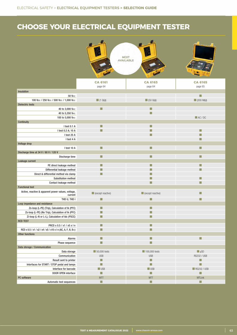
3CATALOGUE TEST & MESURE 2021 www.chauvin-arnoux.com 63TEST & MEASUREMENT CATALOGUE 2022 www.chauvin-arnoux.com
ELECTRICAL SAFETY > ELECTRICAL EQUIPMENT TESTERS > SELECTION GUIDE
CHOOSE YOUR ELECTRICAL EQUIPMENT TESTER
CA 6161page 64
CA 6163page 64
CA 6165page 65
Insulation
50 Vd c
100 Vd c / 250 Vd c / 500 Vd c / 1,000 Vd c (1 GΩ) (50 GΩ) (200 MΩ)
Dielectric tests
40 to 3,000 Va c
40 to 5,350 Va c
100 to 5,000 Va c AC / DC
Continuity
I test 0.1 A
I test 0.2 A; 10 A
I test 25 A
I test 4 A
Voltage drop
I test 10 A
Discharge time at 34 V / 60 V / 120 V
Discharge time
Leakage current
PE direct leakage method
Differential leakage method
Direct & differential method via clamp
Substitution method
Contact leakage method
Functional test
Active, reactive & apparent power values, voltage, current (except reactive) (except reactive)
THD U, THD I
Loop impedance and resistance
Zs-loop (L-PE) (Trip), Calculation of Ik (PFC)
Zs-loop (L-PE) (No Trip), Calculation of Ik (PFC)
Zi-loop (L-N or L-L), Calculation of Idc (PSCC)
RCD TEST
PRCD x 0.5 / x1 / x5 x IΔn
RCD x 0.5 / x1 / x2 / x4 / x5 / x10 x IΔn (AC, A, F, B, B+)
Other functions
Alarms
Phase sequence
Data storage / Communication
Data storage 50,000 tests 100,000 tests μSD
Communication USB USB RS232 / USB
Result sent to printer
Interfaces for START / STOP pedal and lamps
Interface for barcode USB USB RS232 / USB
DOOR OPEN interface
PC software MTT MTT MTLink
Automatic test sequences
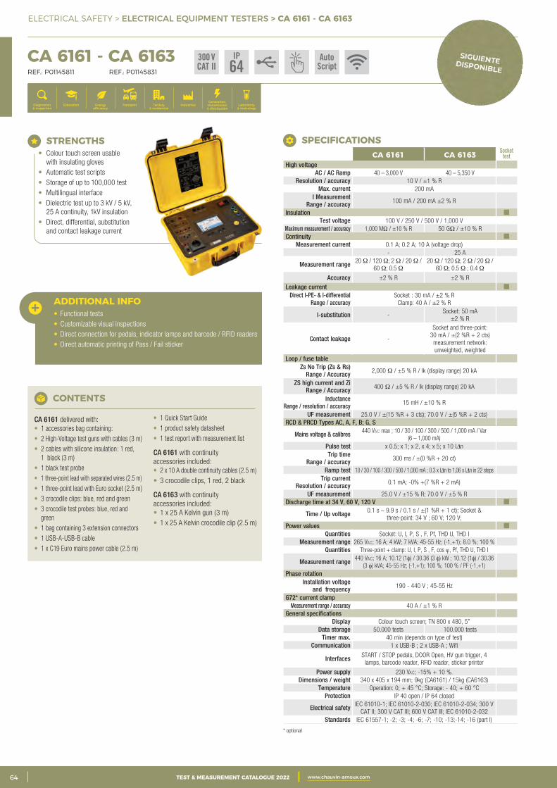
2 CATALOGUE TEST & MESURE 2021 www.chauvin-arnoux.com64 TEST & MEASUREMENT CATALOGUE 2022 www.chauvin-arnoux.com
ELECTRICAL SAFETY > ELECTRICAL EQUIPMENT TESTERS > CA 6161 - CA 6163
CA 6161 - CA 6163 REF.: P01145811 REF.: P01145831
Generation, transmission & distribution
IndustriesTertiary & residential
Education TransportDiagnostics & inspection
Energy efficiency
Laboratory & metrology
ADDITIONAL INFO• Functional tests• Customizable visual inspections• Direct connection for pedals, indicator lamps and barcode / RFID readers• Direct automatic printing of Pass / Fail sticker
CONTENTS
CA 6161 delivered with:• 1 accessories bag containing:• 2 High-Voltage test guns with cables (3 m)• 2 cables with silicone insulation: 1 red,
1 black (3 m)• 1 black test probe• 1 three-point lead with separated wires (2.5 m)• 1 three-point lead with Euro socket (2.5 m)• 3 crocodile clips: blue, red and green• 3 crocodile test probes: blue, red and
green• 1 bag containing 3 extension connectors• 1 USB-A-USB-B cable• 1 x C19 Euro mains power cable (2.5 m)
• 1 Quick Start Guide• 1 product safety datasheet• 1 test report with measurement list
CA 6161 with continuity accessories included:• 2 x 10 A double continuity cables (2.5 m)• 3 crocodile clips, 1 red, 2 black
CA 6163 with continuity accessories included:• 1 x 25 A Kelvin gun (3 m)• 1 x 25 A Kelvin crocodile clip (2.5 m)
CA 6161 CA 6163 Socket test
High voltage AC / AC Ramp 40 – 3,000 V 40 – 5,350 V
Resolution / accuracy 10 V / ±1 % RMax. current 200 mA
I MeasurementRange / accuracy 100 mA / 200 mA ±2 % R
Insulation Test voltage 100 V / 250 V / 500 V / 1,000 V
Maximum measurement / accuracy 1,000 MΩ / ±10 % R 50 GΩ / ±10 % R Continuity
Measurement current 0.1 A; 0.2 A; 10 A (voltage drop) - 25 A
Measurement range 20 Ω / 120 Ω; 2 Ω / 20 Ω / 60 Ω; 0.5 Ω
20 Ω / 120 Ω; 2 Ω / 20 Ω / 60 Ω; 0.5 Ω ; 0.4 Ω
Accuracy ±2 % R ±2 % RLeakage current
Direct I-PE- & I-differentialRange / accuracy
Socket : 30 mA / ±2 % RClamp: 40 A / ±2 % R
I-substitution -Socket: 50 mA
±2 % R
Contact leakage -
Socket and three-point: 30 mA / ±(2 %R + 2 cts) measurement network: unweighted, weighted
Loop / fuse table Zs No Trip (Zs & Rs)
Range / Accuracy 2,000 Ω / ±5 % R / Ik (display range) 20 kA
ZS high current and ZiRange / Accuracy 400 Ω / ±5 % R / Ik (display range) 20 kA
InductanceRange / resolution / accuracy 15 mH / ±10 % R
UF measurement 25.0 V / ±(15 %R + 3 cts); 70.0 V / ±(5 %R + 2 cts) RCD & PRCD Types AC, A, F, B; G, S
Mains voltage & calibres 440 Vac max ; 10 / 30 / 100 / 300 / 500 / 1,000 mA / Var (6 – 1,000 mA)
Pulse test x 0.5; x 1; x 2, x 4; x 5; x 10 IDn Trip time
Range / accuracy 300 ms / ±(0 %R + 20 ct)
Ramp test 10 / 30 / 100 / 300 / 500 / 1,000 mA ; 0.3 x IDn to 1,06 x IDn in 22 stepsTrip current
Resolution / accuracy 0.1 mA; -0% +(7 %R + 2 mA)
UF measurement 25.0 V / ±15 % R; 70.0 V / ±5 % RDischarge time at 34 V, 60 V, 120 V
Time / Up voltage 0.1 s – 9.9 s / 0.1 s / ±(1 %R + 1 ct); Socket & three-point: 34 V ; 60 V; 120 V;
Power valuesQuantities Socket: U, I, P, S , F, Pf, THD U, THD I
Measurement range 265 Vac; 16 A; 4 kW; 7 kVA; 45-55 Hz; (-1,+1); 8.0 %; 100 % Quantities Three-point + clamp: U, I, P, S , F, cos ϕ, Pf, THD U, THD I
Measurement range 440 Vac; 16 A; 10.12 (1φ) / 30.36 (3 φ) kW ; 10.12 (1φ) / 30.36 (3 φ) kVA; 45-55 Hz; (-1,+1); 100 %; 100 % / PF (-1,+1)
Phase rotation Installation voltage
and frequency 190 - 440 V ; 45-55 Hz
G72* current clampMeasurement range / accuracy 40 A / ±1 % R
General specifications Display Colour touch screen; TN 800 x 480, 5”
Data storage 50.000 tests 100.000 testsTimer max. 40 min (depends on type of test)
Communication 1 x USB-B ; 2 x USB-A ; Wifi
Interfaces START / STOP pedals, DOOR Open, HV gun trigger, 4 lamps, barcode reader, RFID reader, sticker printer
Power supply 230 Vac; -15% + 10 %. Dimensions / weight 340 x 405 x 194 mm; 9kg (CA6161) / 15kg (CA6163)
Temperature Operation: 0; + 45 °C; Storage: - 40; + 60 °C Protection IP 40 open / IP 64 closed
Electrical safety IEC 61010-1; IEC 61010-2-030; IEC 61010-2-034; 300 V CAT II; 300 V CAT III; 600 V CAT III; IEC 61010-2-032
Standards IEC 61557-1; -2; -3; -4; -6; -7; -10; -13;-14; -16 (part l)
300 VCAT II
IP64
AutoScript
STRENGTHS• Colour touch screen usable
with insulating gloves• Automatic test scripts• Storage of up to 100,000 test• Multilingual interface• Dielectric test up to 3 kV / 5 kV,
25 A continuity, 1kV insulation• Direct, differential, substitution
and contact leakage current
* optional
SPECIFICATIONS
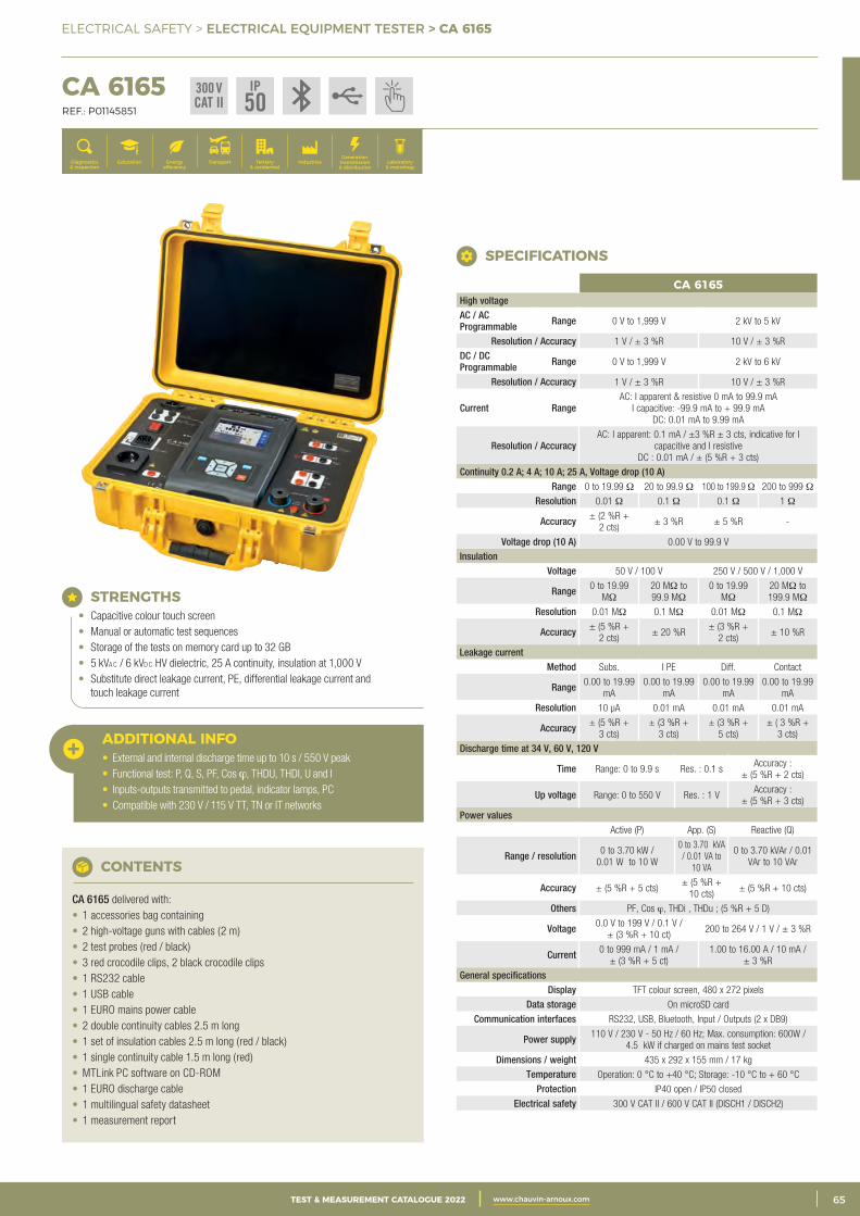
3CATALOGUE TEST & MESURE 2021 www.chauvin-arnoux.com 65TEST & MEASUREMENT CATALOGUE 2022 www.chauvin-arnoux.com
ELECTRICAL SAFETY > ELECTRICAL EQUIPMENT TESTER > CA 6165
CA 6165 REF.: P01145851
Generation, transmission & distribution
IndustriesTertiary & residential
Education TransportDiagnostics & inspection
Energy efficiency
Laboratory & metrology
STRENGTHS• Capacitive colour touch screen• Manual or automatic test sequences• Storage of the tests on memory card up to 32 GB• 5 kVa c / 6 kVd c HV dielectric, 25 A continuity, insulation at 1,000 V• Substitute direct leakage current, PE, differential leakage current and
touch leakage current
ADDITIONAL INFO• External and internal discharge time up to 10 s / 550 V peak• Functional test: P, Q, S, PF, Cos ϕ, THDU, THDI, U and I• Inputs-outputs transmitted to pedal, indicator lamps, PC• Compatible with 230 V / 115 V TT, TN or IT networks
CONTENTS
CA 6165 delivered with:• 1 accessories bag containing• 2 high-voltage guns with cables (2 m)• 2 test probes (red / black)• 3 red crocodile clips, 2 black crocodile clips• 1 RS232 cable• 1 USB cable• 1 EURO mains power cable• 2 double continuity cables 2.5 m long• 1 set of insulation cables 2.5 m long (red / black)• 1 single continuity cable 1.5 m long (red)• MTLink PC software on CD-ROM• 1 EURO discharge cable• 1 multilingual safety datasheet• 1 measurement report
CA 6165High voltage AC / AC Programmable Range 0 V to 1,999 V 2 kV to 5 kV
Resolution / Accuracy 1 V / ± 3 %R 10 V / ± 3 %R
DC / DC Programmable Range 0 V to 1,999 V 2 kV to 6 kV
Resolution / Accuracy 1 V / ± 3 %R 10 V / ± 3 %R
Current Range AC: I apparent & resistive 0 mA to 99.9 mA
I capacitive: -99.9 mA to + 99.9 mA DC: 0.01 mA to 9.99 mA
Resolution / Accuracy AC: I apparent: 0.1 mA / ±3 %R ± 3 cts, indicative for I
capacitive and I resistiveDC : 0.01 mA / ± (5 %R + 3 cts)
Continuity 0.2 A; 4 A; 10 A; 25 A, Voltage drop (10 A) Range 0 to 19.99 Ω 20 to 99.9 Ω 100 to 199.9 Ω 200 to 999 Ω
Resolution 0.01 Ω 0.1 Ω 0.1 Ω 1 Ω
Accuracy ± (2 %R + 2 cts)
± 3 %R ± 5 %R -
Voltage drop (10 A) 0.00 V to 99.9 V
Insulation Voltage 50 V / 100 V 250 V / 500 V / 1,000 V
Range 0 to 19.99 MΩ
20 MΩ to 99.9 MΩ
0 to 19.99 MΩ
20 MΩ to 199.9 MΩ
Resolution 0.01 MΩ 0.1 MΩ 0.01 MΩ 0.1 MΩ
Accuracy ± (5 %R + 2 cts)
± 20 %R ± (3 %R +
2 cts) ± 10 %R
Leakage currentMethod Subs. I PE Diff. Contact
Range 0.00 to 19.99 mA
0.00 to 19.99 mA
0.00 to 19.99 mA
0.00 to 19.99 mA
Resolution 10 μA 0.01 mA 0.01 mA 0.01 mA
Accuracy ± (5 %R + 3 cts)
± (3 %R + 3 cts)
± (3 %R + 5 cts)
± ( 3 %R + 3 cts)
Discharge time at 34 V, 60 V, 120 V
Time Range: 0 to 9.9 s Res. : 0.1 s Accuracy :
± (5 %R + 2 cts)
Up voltage Range: 0 to 550 V Res. : 1 V Accuracy :
± (5 %R + 3 cts)
Power values Active (P) App. (S) Reactive (Q)
Range / resolution 0 to 3.70 kW / 0.01 W to 10 W
0 to 3.70 kVA / 0.01 VA to
10 VA
0 to 3.70 kVAr / 0.01 VAr to 10 VAr
Accuracy ± (5 %R + 5 cts) ± (5 %R +
10 cts) ± (5 %R + 10 cts)
Others PF, Cos ϕ, THDi , THDu ; (5 %R + 5 D)
Voltage 0.0 V to 199 V / 0.1 V / ± (3 %R + 10 ct)
200 to 264 V / 1 V / ± 3 %R
Current 0 to 999 mA / 1 mA / ± (3 %R + 5 ct)
1.00 to 16.00 A / 10 mA / ± 3 %R
General specificationsDisplay TFT colour screen, 480 x 272 pixels
Data storage On microSD card
Communication interfaces RS232, USB, Bluetooth, Input / Outputs (2 x DB9)
Power supply 110 V / 230 V - 50 Hz / 60 Hz; Max. consumption: 600W / 4.5 kW if charged on mains test socket
Dimensions / weight 435 x 292 x 155 mm / 17 kg
Temperature Operation: 0 °C to +40 °C; Storage: -10 °C to + 60 °C
Protection IP40 open / IP50 closed
Electrical safety 300 V CAT II / 600 V CAT II (DISCH1 / DISCH2)
SPECIFICATIONS
300 VCAT II
IP50

2 CATALOGUE TEST & MESURE 2021 www.chauvin-arnoux.com66 TEST & MEASUREMENT CATALOGUE 2022 www.chauvin-arnoux.com
ELECTRICAL SAFETY > NOTES
NOTES

3CATALOGUE TEST & MESURE 2021 www.chauvin-arnoux.com 67TEST & MEASUREMENT CATALOGUE 2022 www.chauvin-arnoux.com
NOTES
ELECTRICAL SAFETY > NOTES
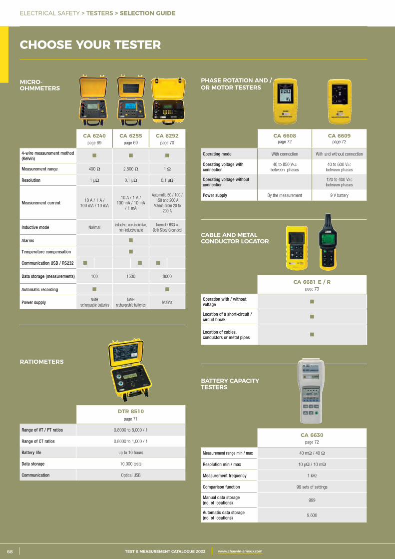
2 CATALOGUE TEST & MESURE 2021 www.chauvin-arnoux.com68 TEST & MEASUREMENT CATALOGUE 2022 www.chauvin-arnoux.com
ELECTRICAL SAFETY > TESTERS > SELECTION GUIDE
CHOOSE YOUR TESTER
DTR 8510page 71
Range of VT / PT ratios 0.8000 to 8,000 / 1
Range of CT ratios 0.8000 to 1,000 / 1
Battery life up to 10 hours
Data storage 10,000 tests
Communication Optical USB
RATIOMETERS
CA 6608page 72
CA 6609page 72
Operating mode With connection With and without connection
Operating voltage with connection
40 to 850 Vac between phases
40 to 600 Vac between phases
Operating voltage without connection
120 to 400 Vac between phases
Power supply By the measurement 9 V battery
PHASE ROTATION AND / OR MOTOR TESTERS
CA 6681 E / Rpage 73
Operation with / without voltage
Location of a short-circuit / circuit break
Location of cables, conductors or metal pipes
CABLE AND METAL CONDUCTOR LOCATOR
CA 6630page 72
Measurement range min / max 40 mΩ / 40 Ω
Resolution min / max 10 μΩ / 10 mΩ
Measurement frequency 1 kHz
Comparison function 99 sets of settings
Manual data storage (no. of locations) 999
Automatic data storage (no. of locations) 9,600
BATTERY CAPACITY TESTERS
*BSG = 2 côtés à la terre
CA 6240page 69
CA 6255page 69
CA 6292page 70
4-wire measurement method (Kelvin)
Measurement range 400 Ω 2,500 Ω 1 Ω
Resolution 1 μΩ 0.1 μΩ 0.1 μΩ
Measurement current 10 A / 1 A / 100 mA / 10 mA
10 A / 1 A / 100 mA / 10 mA
/ 1 mA
Automatic 50 / 100 / 150 and 200 A
Manual from 20 to 200 A
Inductive mode Normal Inductive, non-inductive,
non-inductive auto Normal / BSG =
Both Sides Grounded
Alarms
Temperature compensation
Communication USB / RS232
Data storage (measurements) 100 1500 8000
Automatic recording
Power supply NiMH rechargeable batteries
NiMH rechargeable batteries
Mains
MICRO- OHMMETERS
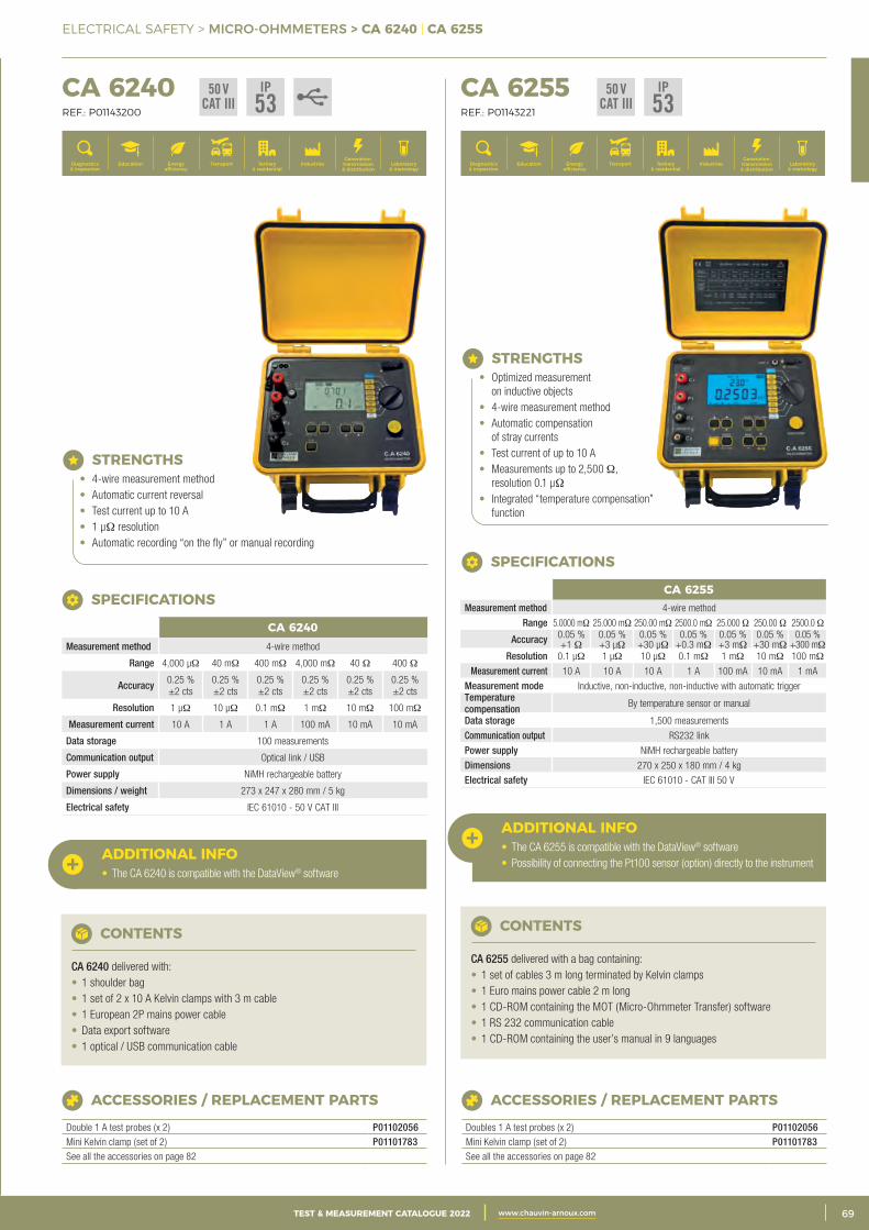
3CATALOGUE TEST & MESURE 2021 www.chauvin-arnoux.com 69TEST & MEASUREMENT CATALOGUE 2022 www.chauvin-arnoux.com
ELECTRICAL SAFETY > MICRO-OHMMETERS > CA 6240 | CA 6255
CHOOSE YOUR TESTER CA 6240 REF.: P01143200
CA 6255 REF.: P01143221
Generation, transmission & distribution
IndustriesTertiary & residential
Education TransportDiagnostics & inspection
Energy efficiency
Laboratory & metrology
Generation, transmission & distribution
IndustriesTertiary & residential
Education TransportDiagnostics & inspection
Energy efficiency
Laboratory & metrology
STRENGTHS• 4-wire measurement method• Automatic current reversal• Test current up to 10 A• 1 μΩ resolution• Automatic recording “on the fly” or manual recording
ADDITIONAL INFO• The CA 6240 is compatible with the DataView® software
CONTENTS
CA 6240 delivered with:• 1 shoulder bag• 1 set of 2 x 10 A Kelvin clamps with 3 m cable• 1 European 2P mains power cable• Data export software• 1 optical / USB communication cable
ACCESSORIES / REPLACEMENT PARTS
Double 1 A test probes (x 2) P01102056Mini Kelvin clamp (set of 2) P01101783See all the accessories on page 82
CA 6240Measurement method 4-wire method
Range 4,000 μΩ 40 mΩ 400 mΩ 4,000 mΩ 40 Ω 400 Ω
Accuracy 0.25 % ±2 cts
0.25 % ±2 cts
0.25 % ±2 cts
0.25 % ±2 cts
0.25 % ±2 cts
0.25 % ±2 cts
Resolution 1 μΩ 10 μΩ 0.1 mΩ 1 mΩ 10 mΩ 100 mΩ
Measurement current 10 A 1 A 1 A 100 mA 10 mA 10 mA
Data storage 100 measurements
Communication output Optical link / USB
Power supply NiMH rechargeable battery
Dimensions / weight 273 x 247 x 280 mm / 5 kg
Electrical safety IEC 61010 - 50 V CAT III
SPECIFICATIONS
STRENGTHS• Optimized measurement
on inductive objects• 4-wire measurement method• Automatic compensation
of stray currents• Test current of up to 10 A• Measurements up to 2,500 Ω,
resolution 0.1 μΩ• Integrated “temperature compensation”
function
ACCESSORIES / REPLACEMENT PARTS
Doubles 1 A test probes (x 2) P01102056Mini Kelvin clamp (set of 2) P01101783See all the accessories on page 82
SPECIFICATIONS
50 VCAT III
IP53
50 VCAT III
IP53
CA 6255Measurement method 4-wire method
Range 5.0000 mΩ 25.000 mΩ 250.00 mΩ 2500.0 mΩ 25.000 Ω 250.00 Ω 2500.0 Ω
Accuracy 0.05 % +1 Ω
0.05 % +3 μΩ
0.05 % +30 μΩ
0.05 % +0.3 mΩ
0.05 % +3 mΩ
0.05 % +30 mΩ
0.05 % +300 mΩ
Resolution 0.1 μΩ 1 μΩ 10 μΩ 0.1 mΩ 1 mΩ 10 mΩ 100 mΩ
Measurement current 10 A 10 A 10 A 1 A 100 mA 10 mA 1 mA
Measurement mode Inductive, non-inductive, non-inductive with automatic triggerTemperature compensation By temperature sensor or manual
Data storage 1,500 measurements
Communication output RS232 link
Power supply NiMH rechargeable battery
Dimensions 270 x 250 x 180 mm / 4 kg
Electrical safety IEC 61010 - CAT III 50 V
ADDITIONAL INFO• The CA 6255 is compatible with the DataView® software• Possibility of connecting the Pt100 sensor (option) directly to the instrument
CONTENTS
CA 6255 delivered with a bag containing:• 1 set of cables 3 m long terminated by Kelvin clamps• 1 Euro mains power cable 2 m long• 1 CD-ROM containing the MOT (Micro-Ohmmeter Transfer) software• 1 RS 232 communication cable• 1 CD-ROM containing the user’s manual in 9 languages
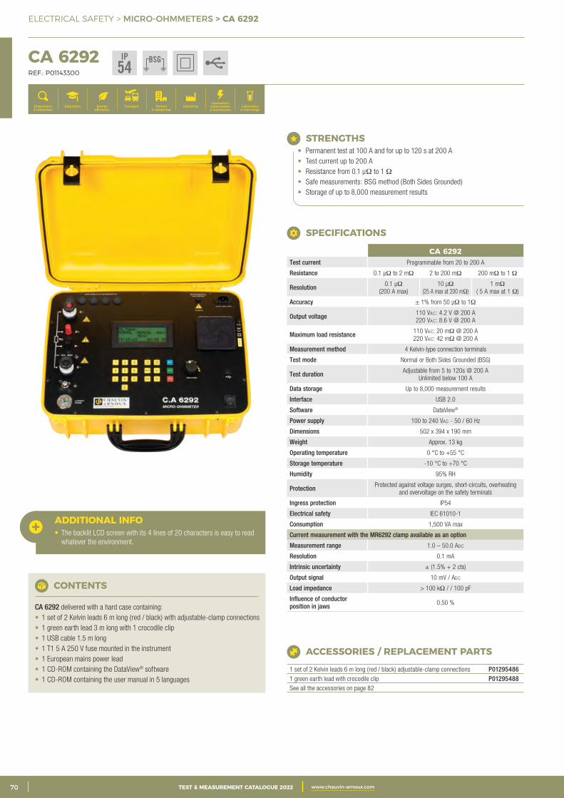
2 CATALOGUE TEST & MESURE 2021 www.chauvin-arnoux.com70 TEST & MEASUREMENT CATALOGUE 2022 www.chauvin-arnoux.com
ELECTRICAL SAFETY > MICRO-OHMMETERS > CA 6292
CA 6292 REF.: P01143300
Generation, transmission & distribution
IndustriesTertiary & residential
Education TransportDiagnostics & inspection
Energy efficiency
Laboratory & metrology
STRENGTHS• Permanent test at 100 A and for up to 120 s at 200 A• Test current up to 200 A• Resistance from 0.1 μΩ to 1 Ω• Safe measurements: BSG method (Both Sides Grounded)• Storage of up to 8,000 measurement results
CA 6292Test current Programmable from 20 to 200 A
Resistance 0.1 μΩ to 2 mΩ 2 to 200 mΩ 200 mΩ to 1 Ω
Resolution 0.1 μΩ (200 A max)
10 μΩ (25 A max at 200 mΩ)
1 mΩ ( 5 A max at 1 Ω)
Accuracy ± 1% from 50 μΩ to 1Ω
Output voltage 110 Vac: 4.2 V @ 200 A 220 Vac: 8.6 V @ 200 A
Maximum load resistance 110 Vac: 20 mΩ @ 200 A 220 Vac: 42 mΩ @ 200 A
Measurement method 4 Kelvin-type connection terminals
Test mode Normal or Both Sides Grounded (BSG)
Test duration Adjustable from 5 to 120s @ 200 A Unlimited below 100 A
Data storage Up to 8,000 measurement results
Interface USB 2.0
Software DataView®
Power supply 100 to 240 Vac - 50 / 60 Hz
Dimensions 502 x 394 x 190 mm
Weight Approx. 13 kg
Operating temperature 0 °C to +55 °C
Storage temperature -10 °C to +70 °C
Humidity 95% RH
Protection Protected against voltage surges, short-circuits, overheating and overvoltage on the safety terminals
Ingress protection IP54
Electrical safety IEC 61010-1
Consumption 1,500 VA max
Current measurement with the MR6292 clamp available as an option
Measurement range 1.0 – 50.0 Adc
Resolution 0.1 mA
Intrinsic uncertainty ± (1.5% + 2 cts)
Output signal 10 mV / Adc
Load impedance > 100 kΩ / / 100 pF
Influence of conductor position in jaws 0.50 %
SPECIFICATIONS
ACCESSORIES / REPLACEMENT PARTS
1 set of 2 Kelvin leads 6 m long (red / black) adjustable-clamp connections P012954861 green earth lead with crocodile clip P01295488See all the accessories on page 82
CONTENTS
CA 6292 delivered with a hard case containing:• 1 set of 2 Kelvin leads 6 m long (red / black) with adjustable-clamp connections• 1 green earth lead 3 m long with 1 crocodile clip• 1 USB cable 1.5 m long• 1 T1 5 A 250 V fuse mounted in the instrument• 1 European mains power lead• 1 CD-ROM containing the DataView® software• 1 CD-ROM containing the user manual in 5 languages
ADDITIONAL INFO• The backlit LCD screen with its 4 lines of 20 characters is easy to read
whatever the environment.
IP54
BSG
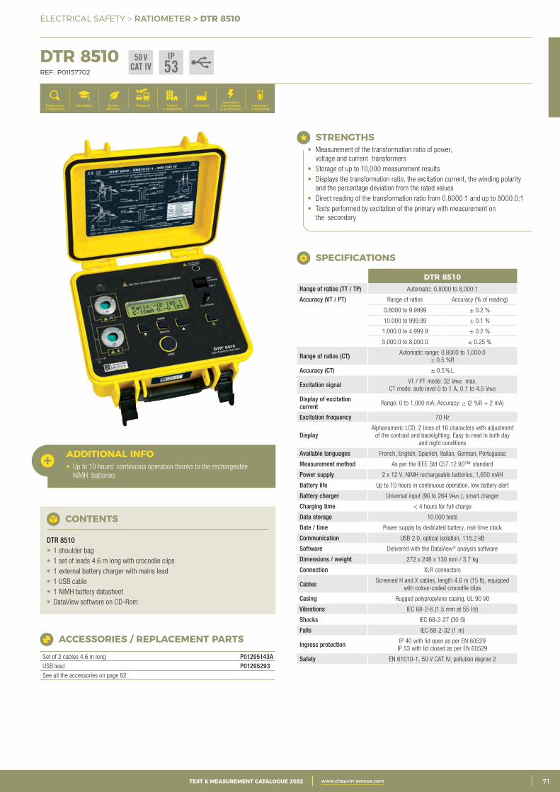
3CATALOGUE TEST & MESURE 2021 www.chauvin-arnoux.com 71TEST & MEASUREMENT CATALOGUE 2022 www.chauvin-arnoux.com
ELECTRICAL SAFETY > RATIOMETER > DTR 8510
DTR 8510 REF.: P01157702
Generation, transmission & distribution
IndustriesTertiary & residential
Education TransportDiagnostics & inspection
Energy efficiency
Laboratory & metrology
ACCESSORIES / REPLACEMENT PARTS
Set of 2 cables 4.6 m long P01295143AUSB lead P01295293See all the accessories on page 82
CONTENTS
DTR 8510• 1 shoulder bag• 1 set of leads 4.6 m long with crocodile clips• 1 external battery charger with mains lead• 1 USB cable• 1 NiMH battery datasheet• DataView software on CD-Rom
ADDITIONAL INFO• Up to 10 hours’ continuous operation thanks to the rechargeable
NiMH batteries
STRENGTHS• Measurement of the transformation ratio of power,
voltage and current transformers• Storage of up to 10,000 measurement results• Displays the transformation ratio, the excitation current, the winding polarity
and the percentage deviation from the rated values• Direct reading of the transformation ratio from 0.8000:1 and up to 8000.0:1• Tests performed by excitation of the primary with measurement on
the secondary
DTR 8510Range of ratios (TT / TP) Automatic: 0.8000 to 8,000:1
Accuracy (VT / PT) Range of ratios Accuracy (% of reading)
0.8000 to 9.9999 ± 0.2 %
10.000 to 999.99 ± 0.1 %
1,000.0 to 4,999.9 ± 0.2 %
5,000.0 to 8,000.0 ± 0.25 %
Range of ratios (CT) Automatic range: 0.8000 to 1,000.0 ± 0.5 %R
Accuracy (CT) ± 0.5 % L
Excitation signal VT / PT mode: 32 Vrms max. CT mode: auto level 0 to 1 A, 0.1 to 4.5 Vrms
Display of excitation current Range: 0 to 1,000 mA; Accuracy: ± (2 %R + 2 mA)
Excitation frequency 70 Hz
Display Alphanumeric LCD, 2 lines of 16 characters with adjustment
of the contrast and backlighting. Easy to read in both day and night conditions
Available languages French, English, Spanish, Italian, German, Portuguese
Measurement method As per the IEEE Std C57.12.90™ standard
Power supply 2 x 12 V, NiMH rechargeable batteries, 1,650 mAH
Battery life Up to 10 hours in continuous operation, low battery alert
Battery charger Universal input (90 to 264 Vrms ), smart charger
Charging time < 4 hours for full charge
Data storage 10.000 tests
Date / time Power supply by dedicated battery, real-time clock
Communication USB 2.0, optical isolation, 115.2 kB
Software Delivered with the DataView® analysis software
Dimensions / weight 272 x 248 x 130 mm / 3.7 kg
Connection XLR connectors
Cables Screened H and X cables, length 4.6 m (15 ft), equipped with colour-coded crocodile clips
Casing Rugged polypropylene casing, UL 90 V0
Vibrations IEC 68-2-6 (1.5 mm at 55 Hz)
Shocks IEC 68-2-27 (30 G)
Falls IEC 68-2-32 (1 m)
Ingress protection IP 40 with lid open as per EN 60529 IP 53 with lid closed as per EN 60529
Safety EN 61010-1, 50 V CAT IV; pollution degree 2
SPECIFICATIONS
50 VCAT IV
IP53
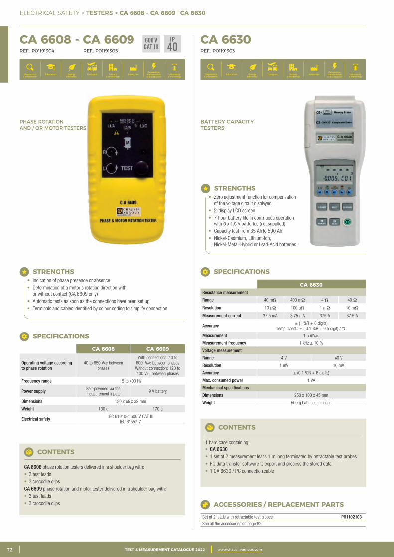
2 CATALOGUE TEST & MESURE 2021 www.chauvin-arnoux.com72 TEST & MEASUREMENT CATALOGUE 2022 www.chauvin-arnoux.com
ELECTRICAL SAFETY > TESTERS > CA 6608 - CA 6609 | CA 6630
CA 6608 - CA 6609 REF.: P01191304 REF.: P01191305
CA 6630 REF.: P01191303
Generation, transmission & distribution
IndustriesTertiary & residential
Education TransportDiagnostics & inspection
Energy efficiency
Laboratory & metrology
Generation, transmission & distribution
IndustriesTertiary & residential
Education TransportDiagnostics & inspection
Energy efficiency
Laboratory & metrology
BATTERY CAPACITY TESTERS
PHASE ROTATION AND / OR MOTOR TESTERS
STRENGTHS• Indication of phase presence or absence• Determination of a motor’s rotation direction with
or without contact (CA 6609 only)• Automatic tests as soon as the connections have been set up• Terminals and cables identified by colour coding to simplify connection
CA 6608 CA 6609
Operating voltage according to phase rotation
40 to 850 Vac between phases
With connections: 40 to 600 Vac between phases Without connection: 120 to 400 Vac between phases
Frequency range 15 to 400 Hz
Power supply Self-powered via the measurement inputs
9 V battery
Dimensions 130 x 69 x 32 mm
Weight 130 g 170 g
Electrical safety IEC 61010-1 600 V CAT III IEC 61557-7
SPECIFICATIONS
CONTENTS
CA 6608 phase rotation testers delivered in a shoulder bag with:• 3 test leads• 3 crocodile clipsCA 6609 phase rotation and motor tester delivered in a shoulder bag with:• 3 test leads• 3 crocodile clips
STRENGTHS• Zero adjustment function for compensation
of the voltage circuit displayed• 2-display LCD screen• 7-hour battery life in continuous operation
with 6 x 1.5 V batteries (not supplied)• Capacity test from 35 Ah to 500 Ah• Nickel-Cadmium, Lithium-Ion,
Nickel-Metal-Hybrid or Lead-Acid batteries
CONTENTS
1 hard case containing:• CA 6630• 1 set of 2 measurement leads 1 m long terminated by retractable test probes• PC data transfer software to export and process the stored data• 1 CA 6630 / PC connection cable
ACCESSORIES / REPLACEMENT PARTS
Set of 2 leads with retractable test probes P01102103See all the accessories on page 82
CA 6630Resistance measurement
Range 40 mΩ 400 mΩ 4 Ω 40 Ω
Resolution 10 μΩ 100 μΩ 1 mΩ 10 mΩ
Measurement current 37.5 mA 3.75 mA 375 A 37.5 A
Accuracy ± (1 %R + 8 digits) Temp. coeff.: ± ( 0.1 %R + 0.5 digit) / °C
Measurement 1.5 mVac
Measurement frequency 1 kHz ± 10 %
Voltage measurement
Range 4 V 40 V
Resolution 1 mV 10 mV
Accuracy ± (0.1 %R + 6 digits)
Max. consumed power 1 VA
Mechanical specifications
Dimensions 250 x 100 x 45 mm
Weight 500 g batteries included
SPECIFICATIONS
600 VCAT III
IP40
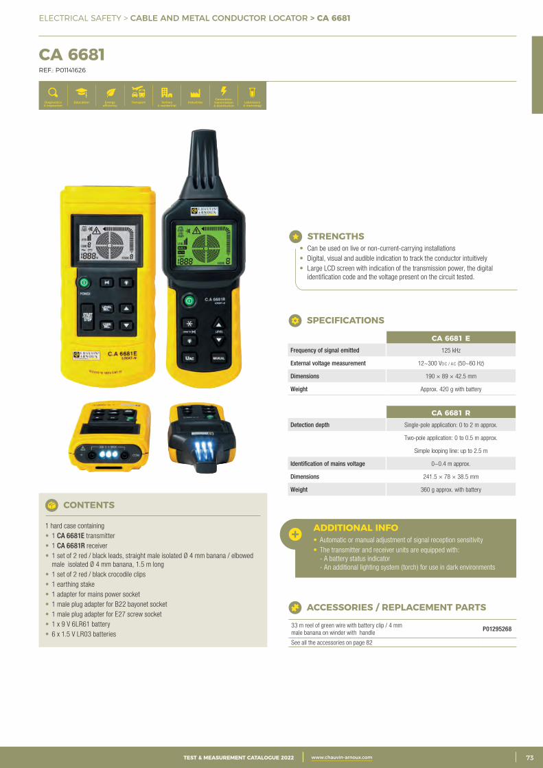
3CATALOGUE TEST & MESURE 2021 www.chauvin-arnoux.com 73TEST & MEASUREMENT CATALOGUE 2022 www.chauvin-arnoux.com
ELECTRICAL SAFETY > CABLE AND METAL CONDUCTOR LOCATOR > CA 6681
CA 6681 REF.: P01141626
Generation, transmission & distribution
IndustriesTertiary & residential
Education TransportDiagnostics & inspection
Energy efficiency
Laboratory & metrology
STRENGTHS• Can be used on live or non-current-carrying installations• Digital, visual and audible indication to track the conductor intuitively• Large LCD screen with indication of the transmission power, the digital
identification code and the voltage present on the circuit tested.
SPECIFICATIONS
CA 6681 RDetection depth Single-pole application: 0 to 2 m approx.
Two-pole application: 0 to 0.5 m approx.
Simple looping line: up to 2.5 m
Identification of mains voltage 0~0.4 m approx.
Dimensions 241.5 × 78 × 38.5 mm
Weight 360 g approx. with battery
CA 6681 EFrequency of signal emitted 125 kHz
External voltage measurement 12~300 Vdc / ac (50~60 Hz)
Dimensions 190 × 89 × 42.5 mm
Weight Approx. 420 g with battery
CONTENTS
1 hard case containing • 1 CA 6681E transmitter• 1 CA 6681R receiver• 1 set of 2 red / black leads, straight male isolated Ø 4 mm banana / elbowed
male isolated Ø 4 mm banana, 1.5 m long• 1 set of 2 red / black crocodile clips• 1 earthing stake• 1 adapter for mains power socket• 1 male plug adapter for B22 bayonet socket• 1 male plug adapter for E27 screw socket• 1 x 9 V 6LR61 battery• 6 x 1.5 V LR03 batteries
ACCESSORIES / REPLACEMENT PARTS
33 m reel of green wire with battery clip / 4 mm male banana on winder with handle
P01295268
See all the accessories on page 82
ADDITIONAL INFO• Automatic or manual adjustment of signal reception sensitivity• The transmitter and receiver units are equipped with:
- A battery status indicator - An additional lighting system (torch) for use in dark environments
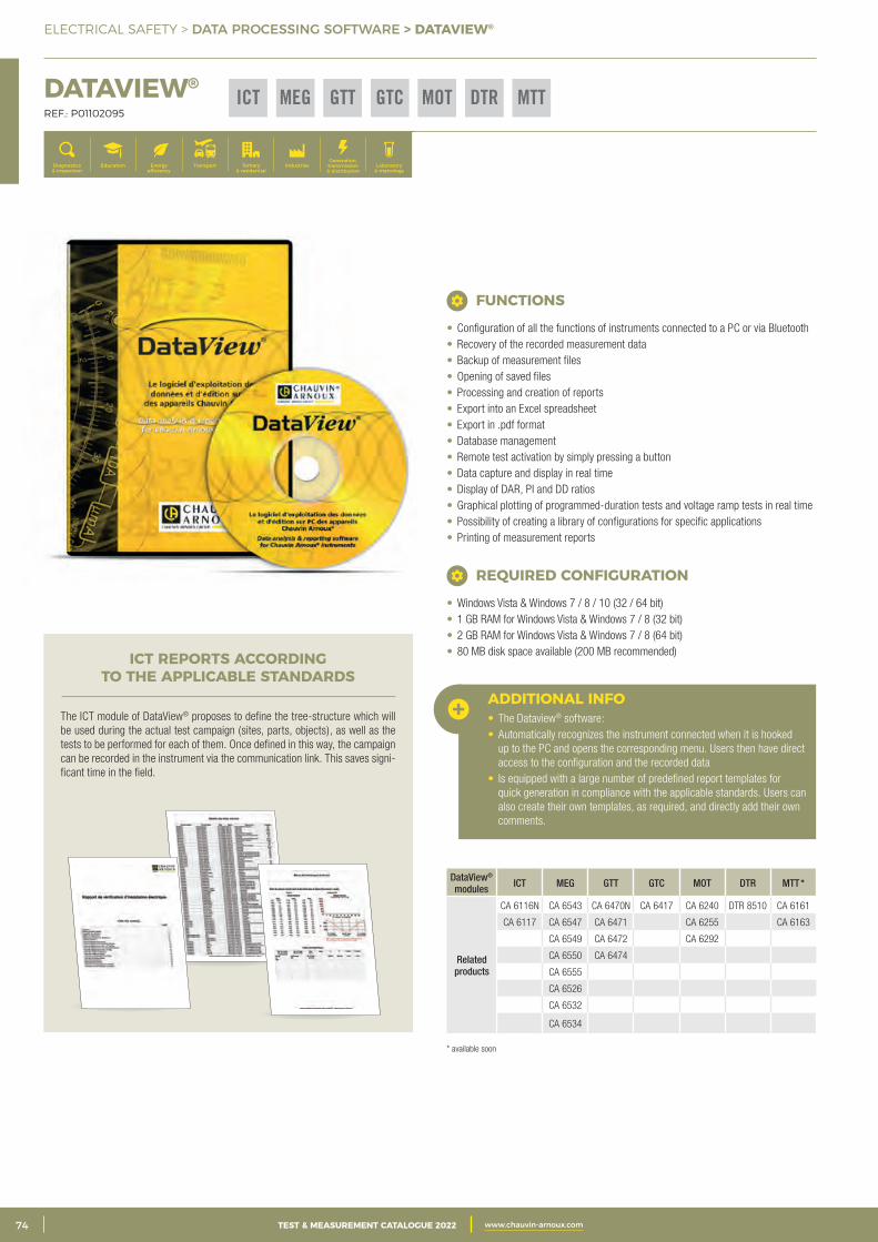
2 CATALOGUE TEST & MESURE 2021 www.chauvin-arnoux.com74 TEST & MEASUREMENT CATALOGUE 2022 www.chauvin-arnoux.com
ELECTRICAL SAFETY > DATA PROCESSING SOFTWARE > DATAVIEW®
DATAVIEW® REF.: P01102095
Generation, transmission & distribution
IndustriesTertiary & residential
Education TransportDiagnostics & inspection
Energy efficiency
Laboratory & metrology
DataView® modules ICT MEG GTT GTC MOT DTR MTT *
Related products
CA 6116N CA 6543 CA 6470N CA 6417 CA 6240 DTR 8510 CA 6161
CA 6117 CA 6547 CA 6471 CA 6255 CA 6163
CA 6549 CA 6472 CA 6292
CA 6550 CA 6474
CA 6555
CA 6526
CA 6532
CA 6534
ADDITIONAL INFO• The Dataview® software:• Automatically recognizes the instrument connected when it is hooked
up to the PC and opens the corresponding menu. Users then have direct access to the configuration and the recorded data
• Is equipped with a large number of predefined report templates for quick generation in compliance with the applicable standards. Users can also create their own templates, as required, and directly add their own comments.
ICT REPORTS ACCORDING TO THE APPLICABLE STANDARDS
The ICT module of DataView® proposes to define the tree-structure which will be used during the actual test campaign (sites, parts, objects), as well as the tests to be performed for each of them. Once defined in this way, the campaign can be recorded in the instrument via the communication link. This saves signi-ficant time in the field.
• Configuration of all the functions of instruments connected to a PC or via Bluetooth• Recovery of the recorded measurement data• Backup of measurement files• Opening of saved files• Processing and creation of reports• Export into an Excel spreadsheet• Export in .pdf format• Database management• Remote test activation by simply pressing a button• Data capture and display in real time• Display of DAR, PI and DD ratios• Graphical plotting of programmed-duration tests and voltage ramp tests in real time• Possibility of creating a library of configurations for specific applications• Printing of measurement reports
FUNCTIONS
• Windows Vista & Windows 7 / 8 / 10 (32 / 64 bit)• 1 GB RAM for Windows Vista & Windows 7 / 8 (32 bit)• 2 GB RAM for Windows Vista & Windows 7 / 8 (64 bit)• 80 MB disk space available (200 MB recommended)
REQUIRED CONFIGURATION
GTTICT MEG DTR MTTMOTGTC
* available soon
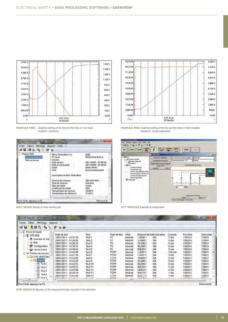
3CATALOGUE TEST & MESURE 2021 www.chauvin-arnoux.com 75TEST & MEASUREMENT CATALOGUE 2022 www.chauvin-arnoux.com
ELECTRICAL SAFETY > DATA PROCESSING SOFTWARE > DATAVIEW®
MODULE MEG Graphical plotting of the V(t) and R(t) tests on fixed insulation resistance (surge suppressor)
MODULE MEG Graphical plotting of the V(t) and R(t) tests on non-linear insulation resistance
GTT MODULE Example of configurationMOT MODE Results of motor winding test
DTR MODULE Recovery of the measurement data recorded in the ratiometer
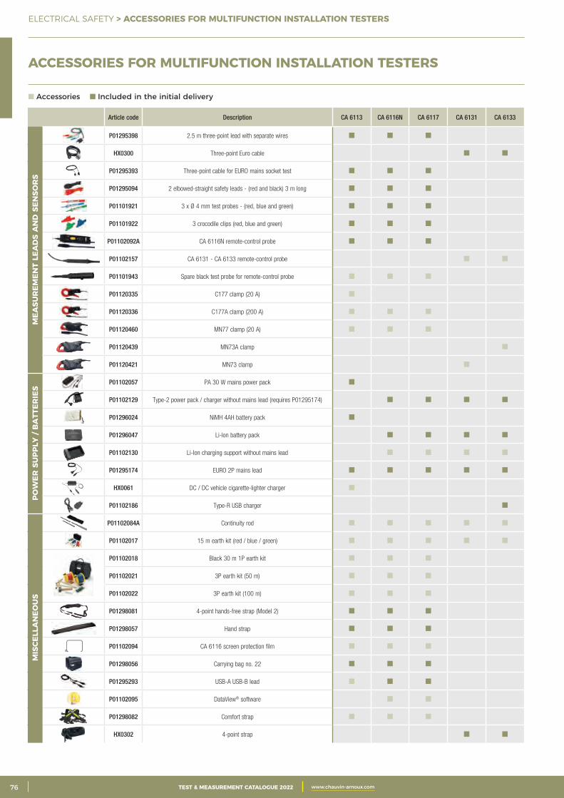
2 CATALOGUE TEST & MESURE 2021 www.chauvin-arnoux.com76 TEST & MEASUREMENT CATALOGUE 2022 www.chauvin-arnoux.com
ELECTRICAL SAFETY > ACCESSORIES FOR MULTIFUNCTION INSTALLATION TESTERS
ACCESSORIES FOR MULTIFUNCTION INSTALLATION TESTERS
Article code Description CA 6113 CA 6116N CA 6117 CA 6131 CA 6133
P01295398 2.5 m three-point lead with separate wires
HX0300 Three-point Euro cable
P01295393 Three-point cable for EURO mains socket test
P01295094 2 elbowed-straight safety leads - (red and black) 3 m long
P01101921 3 x Ø 4 mm test probes - (red, blue and green)
P01101922 3 crocodile clips (red, blue and green)
P01102092A CA 6116N remote-control probe
P01102157 CA 6131 - CA 6133 remote-control probe
P01101943 Spare black test probe for remote-control probe
P01120335 C177 clamp (20 A)
P01120336 C177A clamp (200 A)
P01120460 MN77 clamp (20 A)
P01120439 MN73A clamp
P01120421 MN73 clamp
P01102057 PA 30 W mains power pack
P01102129 Type-2 power pack / charger without mains lead (requires P01295174)
P01296024 NiMH 4AH battery pack
P01296047 Li-Ion battery pack
P01102130 Li-Ion charging support without mains lead
P01295174 EURO 2P mains lead
HX0061 DC / DC vehicle cigarette-lighter charger
P01102186 Type-R USB charger
P01102084A Continuity rod
P01102017 15 m earth kit (red / blue / green)
P01102018 Black 30 m 1P earth kit
P01102021 3P earth kit (50 m)
P01102022 3P earth kit (100 m)
P01298081 4-point hands-free strap (Model 2)
P01298057 Hand strap
P01102094 CA 6116 screen protection film
P01298056 Carrying bag no. 22
P01295293 USB-A USB-B lead
P01102095 DataView® software
P01298082 Comfort strap
HX0302 4-point strap
POW
ER S
UPP
LY /
BA
TTER
IES
MIS
CELL
AN
EOU
SM
EASU
REM
ENT
LEA
DS
AN
D S
ENSO
RS
Accessories Included in the initial delivery
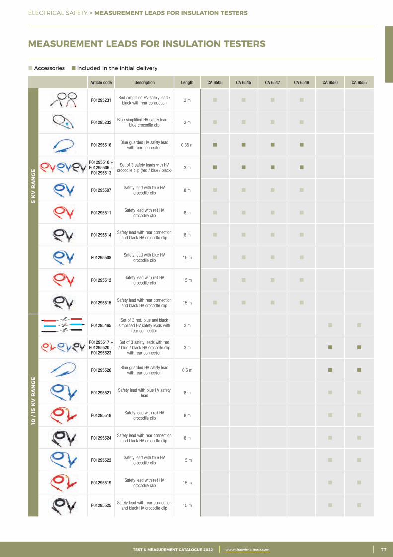
3CATALOGUE TEST & MESURE 2021 www.chauvin-arnoux.com 77TEST & MEASUREMENT CATALOGUE 2022 www.chauvin-arnoux.com
ELECTRICAL SAFETY > MEASUREMENT LEADS FOR INSULATION TESTERS
Article code Description Length CA 6505 CA 6545 CA 6547 CA 6549 CA 6550 CA 6555
P01295231 Red simplified HV safety lead / black with rear connection
3 m
P01295232 Blue simplified HV safety lead + blue crocodile clip
3 m
P01295516 Blue guarded HV safety lead with rear connection
0.35 m
P01295510 + P01295506 + P01295513
Set of 3 safety leads with HV crocodile clip (red / blue / black)
3 m
P01295507 Safety lead with blue HV crocodile clip
8 m
P01295511 Safety lead with red HV crocodile clip
8 m
P01295514 Safety lead with rear connection and black HV crocodile clip
8 m
P01295508 Safety lead with blue HV crocodile clip
15 m
P01295512 Safety lead with red HV crocodile clip
15 m
P01295515 Safety lead with rear connection and black HV crocodile clip
15 m
P01295465Set of 3 red, blue and black
simplified HV safety leads with rear connection
3 m
P01295517 + P01295520 + P01295523
Set of 3 safety leads with red / blue / black HV crocodile clip
with rear connection 3 m
P01295526 Blue guarded HV safety lead with rear connection
0.5 m
P01295521 Safety lead with blue HV safety lead
8 m
P01295518 Safety lead with red HV crocodile clip
8 m
P01295524 Safety lead with rear connection and black HV crocodile clip
8 m
P01295522 Safety lead with blue HV crocodile clip
15 m
P01295519 Safety lead with red HV crocodile clip
15 m
P01295525 Safety lead with rear connection and black HV crocodile clip
15 m
10 /
15 K
V R
AN
GE
5 K
V R
AN
GE
Accessories Included in the initial delivery
MEASUREMENT LEADS FOR INSULATION TESTERS
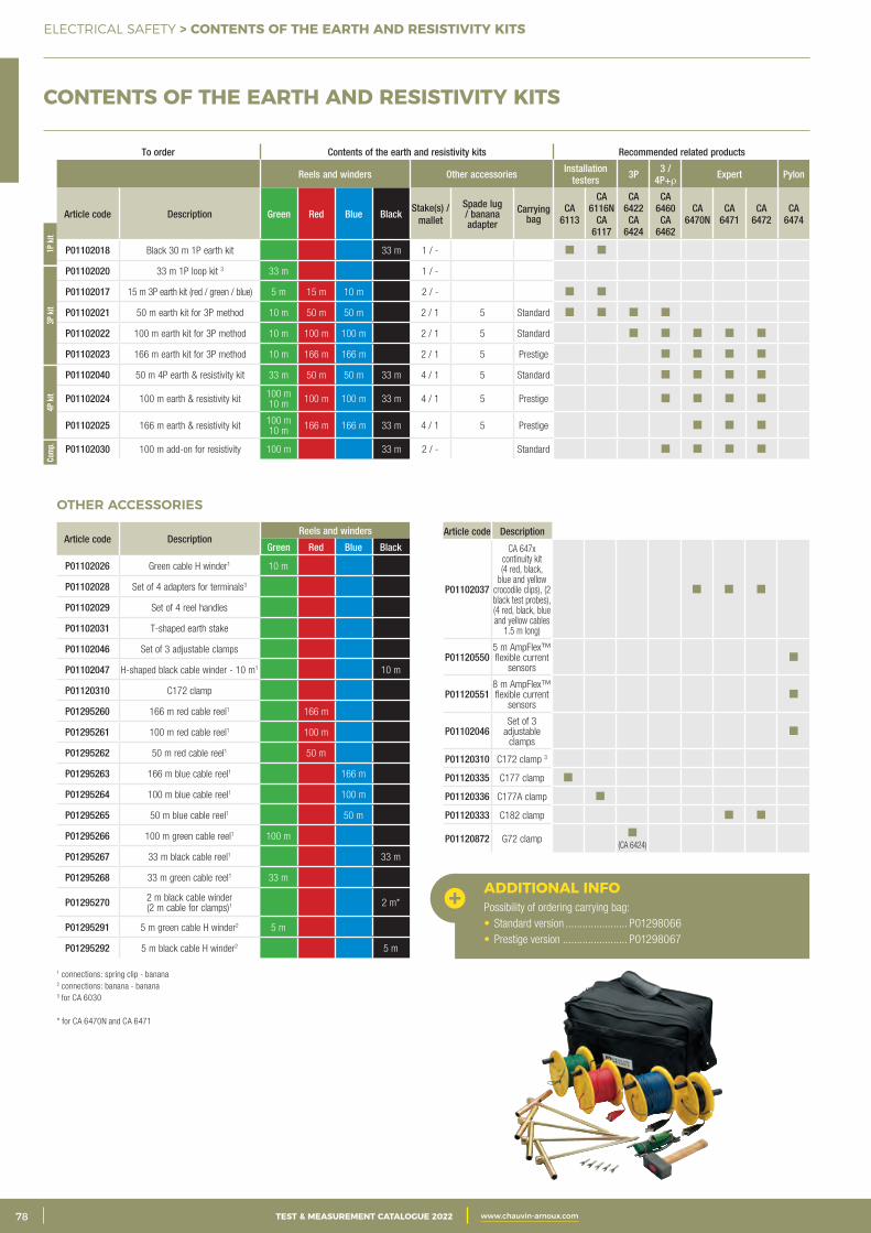
2 CATALOGUE TEST & MESURE 2021 www.chauvin-arnoux.com78 TEST & MEASUREMENT CATALOGUE 2022 www.chauvin-arnoux.com
ELECTRICAL SAFETY > CONTENTS OF THE EARTH AND RESISTIVITY KITS
CONTENTS OF THE EARTH AND RESISTIVITY KITS
To order Contents of the earth and resistivity kits Recommended related products
Reels and winders Other accessories Installation testers 3P 3 /
4P+r Expert Pylon
Article code Description Green Red Blue BlackStake(s) /
mallet
Spade lug / banana adapter
Carrying bag
CA 6113
CA 6116N
CA 6117
CA 6422CA
6424
CA 6460CA
6462
CA 6470N
CA 6471
CA 6472
CA 6474
P01102018 Black 30 m 1P earth kit 33 m 1 / -
P01102020 33 m 1P loop kit 3 33 m 1 / -
P01102017 15 m 3P earth kit (red / green / blue) 5 m 15 m 10 m 2 / -
P01102021 50 m earth kit for 3P method 10 m 50 m 50 m 2 / 1 5 Standard
P01102022 100 m earth kit for 3P method 10 m 100 m 100 m 2 / 1 5 Standard
P01102023 166 m earth kit for 3P method 10 m 166 m 166 m 2 / 1 5 Prestige
P01102040 50 m 4P earth & resistivity kit 33 m 50 m 50 m 33 m 4 / 1 5 Standard
P01102024 100 m earth & resistivity kit 100 m 10 m 100 m 100 m 33 m 4 / 1 5 Prestige
P01102025 166 m earth & resistivity kit 100 m 10 m 166 m 166 m 33 m 4 / 1 5 Prestige
P01102030 100 m add-on for resistivity 100 m 33 m 2 / - Standard
1P k
it3P
kit
4P k
itCo
mp.
1 connections: spring clip - banana 2 connections: banana - banana3 for CA 6030
* for CA 6470N and CA 6471
OTHER ACCESSORIES
Article code DescriptionReels and winders
Green Red Blue Black
P01102026 Green cable H winder1 10 m
P01102028 Set of 4 adapters for terminals3
P01102029 Set of 4 reel handles
P01102031 T-shaped earth stake
P01102046 Set of 3 adjustable clamps
P01102047 H-shaped black cable winder - 10 m1 10 m
P01120310 C172 clamp
P01295260 166 m red cable reel1 166 m
P01295261 100 m red cable reel1 100 m
P01295262 50 m red cable reel1 50 m
P01295263 166 m blue cable reel1 166 m
P01295264 100 m blue cable reel1 100 m
P01295265 50 m blue cable reel1 50 m
P01295266 100 m green cable reel1 100 m
P01295267 33 m black cable reel1 33 m
P01295268 33 m green cable reel1 33 m
P01295270 2 m black cable winder (2 m cable for clamps)1 2 m*
P01295291 5 m green cable H winder2 5 m
P01295292 5 m black cable H winder2 5 m
Article code Description
P01102037
CA 647x continuity kit (4 red, black,
blue and yellow crocodile clips), (2 black test probes), (4 red, black, blue and yellow cables
1.5 m long)
P011205505 m AmpFlex™ flexible current
sensors
P011205518 m AmpFlex™ flexible current
sensors
P01102046Set of 3
adjustable clamps
P01120310 C172 clamp 3
P01120335 C177 clamp
P01120336 C177A clamp
P01120333 C182 clamp
P01120872 G72 clamp (CA 6424)
ADDITIONAL INFOPossibility of ordering carrying bag:• Standard version ...................... P01298066• Prestige version ....................... P01298067
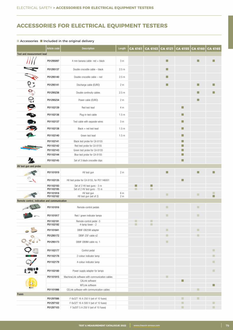
3CATALOGUE TEST & MESURE 2021 www.chauvin-arnoux.com 79TEST & MEASUREMENT CATALOGUE 2022 www.chauvin-arnoux.com
ELECTRICAL SAFETY > ACCESSORIES FOR ELECTRICAL EQUIPMENT TESTERS
ACCESSORIES FOR ELECTRICAL EQUIPMENT TESTERS
Article code Description Length CA 6161 CA 6163 CA 6121 CA 6155 CA 6160 CA 6165Test and measurement lead
P01295097 4 mm banana cable- red + black 3 m
P01295137 Double crocodile cable – black 2.5 m
P01295140 Double crocodile cable – red 2.5 m
P01295141 Discharge cable (EURO) 2 m
P01295236 Double continuity cables 2.5 m
P01295234 Power cable (EURO) 2 m
P01102139 Red test lead 4 m
P01102136 Plug-in test cable 1.5 m
P01102137 Test cable with separate wires 3 m
P01102138 Black + red test lead 1.5 m
P01102140 Green test lead 1.5 m
P01102141 Black test probe for CA 6155
P01102142 Red test probe for CA 6155
P01102143 Green test probe for CA 6155
P01102144 Blue test probe for CA 6155
P01102145 Set of 3 black crocodile clips
HV test gun and probe
P01101919 HV test gun 2 m
P01102135 HV test probe for CA 6155, for P01146001
P01102193 Set of 2 HV test guns - 3 m P01102195 Set of 2 HV test guns - 15 m
P01101918P01102182
HV test gunHV test gun (set of 2)
6 m 2 m
Remote control, indication and communication
P01101916 Remote-control pedals
P01101917 Red / green indicator lamps
P01102191 Remote-control pedal -3 P01102192 4-lamp tower - 2
P01101841 DB9F-DB25M adapter
P01295172 DB9F-25F cable x2
P01295173 DB9F-DB9M cable no. 1
P01102177 Control pedal
P01102178 2-colour indicator lamp
P01102179 4-colour indicator lamp
P01102180 Power supply adapter for lamps
P01101915 MachineLink software with communication cables
CALink software
MTLink software
P01101996 CELink software with communication cables
Fuses
P01297086 F 6x32T 16 A 250 V (set of 10 fuses)
P01297102 F 6x32T 16 A 500 V (set of 10 fuses)
P01297103 F 5x20T 5 A 250 V (set of 10 fuses)
Accessories Included in the original delivery
Article code Description
P01102037
CA 647x continuity kit (4 red, black,
blue and yellow crocodile clips), (2 black test probes), (4 red, black, blue and yellow cables
1.5 m long)
P011205505 m AmpFlex™ flexible current
sensors
P011205518 m AmpFlex™ flexible current
sensors
P01102046Set of 3
adjustable clamps
P01120310 C172 clamp 3
P01120335 C177 clamp
P01120336 C177A clamp
P01120333 C182 clamp
P01120872 G72 clamp (CA 6424)
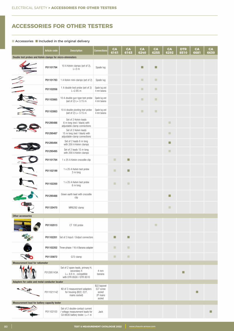
2 CATALOGUE TEST & MESURE 2021 www.chauvin-arnoux.com80 TEST & MEASUREMENT CATALOGUE 2022 www.chauvin-arnoux.com
ELECTRICAL SAFETY > ACCESSORIES FOR OTHER TESTERS
ACCESSORIES FOR OTHER TESTERS
Article code Description Connections CA 6161
CA 6163
CA 6240
CA 6255
CA 6292
DTR 8510
CA 6681
CA 6630
Double test probes and Kelvin clamps for micro-ohmmeters
P01101794 10 A Kelvin clamps (set of 2), L=3 m
Spade lug
P01101783 1 A Kelvin mini-clamps (set of 2) Spade lug
P01102056 1 A double test probe (set of 2) L=2.85 m
Spade lug and 4 mm banana
P01103065 10 A double gun-type test probe (set of 2) L= 3.15 m
Spade lug and 4 mm banana
P01103063 10 A double pivoting test probe (set of 2) L= 3.15 m
Spade lug and 4 mm banana
P01295486Set of 2 Kelvin leads
6 m long (red / black) with adjustable-clamp connections
P01295487Set of 2 Kelvin leads
15 m long (red / black) with adjustable-clamp connections
P01295494 Set of 2 leads 6 m longwith 200 A Kelvin clamps
P01295495 Set of 2 leads 15 m longwith 200 A Kelvin clamps
P01101784 1 x 25 A Kelvin crocodile clip
P01102199 1 x 25 A Kelvin test probe 3 m long
P01102200 1 x 25 A Kelvin test probe 6 m long
P01295488 Green earth lead with crocodile clip
P01120470 MR6292 clamp
Other accessories
P01102013 CT 100 probe
P01102201 Set of 3 Input / Output connectors
P01102202 Three-phase / 16 A Banana adapter
P01120872 G72 clamp
Measurement lead for ratiometer
P01295143A
Set of 2 spare leads, primary H, secondary X
L= 4.6 m , compatible with DTR 8500 / DTR 8510
4 mm banana
Adapters for cable and metal conductor locator
P01102114ZKit of 3 measurement adapters
for housing (B22, E27, mains socket)
B22 bayonetE27 screw
socket2P mains
socket
Measurement lead for battery capacity tester
P01102103Set of 2 double-contact current / voltage measurement leads for CA 6630 battery tester. L=1 m
Jack
Accessories Included in the original delivery
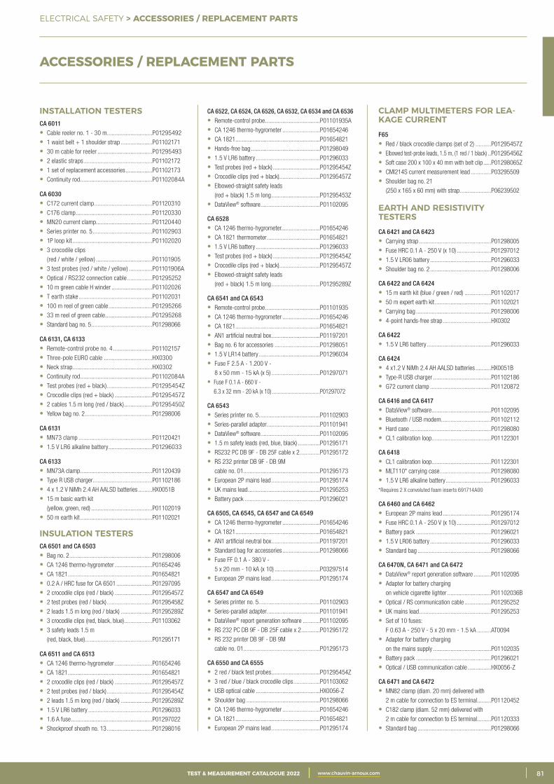
3CATALOGUE TEST & MESURE 2021 www.chauvin-arnoux.com 81TEST & MEASUREMENT CATALOGUE 2022 www.chauvin-arnoux.com
ELECTRICAL SAFETY > ACCESSORIES / REPLACEMENT PARTS
INSTALLATION TESTERS CA 6011• Cable reeler no. 1 - 30 m .............................P01295492
• 1 waist belt + 1 shoulder strap ....................P01102171
• 30 m cable for reeler ...................................P01295493
• 2 elastic straps ............................................P01102172
• 1 set of replacement accessories .................P01102173
• Continuity rod ..............................................P01102084A
CA 6030• C172 current clamp .....................................P01120310
• C176 clamp .................................................P01120330
• MN20 current clamp....................................P01120440
• Series printer no. 5 ......................................P01102903
• 1P loop kit ...................................................P01102020
• 3 crocodile clips
(red / white / yellow) ....................................P01101905
• 3 test probes (red / white / yellow) ...............P01101906A
• Optical / RS232 connection cable ................P01295252
• 10 m green cable H winder ..........................P01102026
• T earth stake ...............................................P01102031
• 100 m reel of green cable ............................P01295266
• 33 m reel of green cable ..............................P01295268
• Standard bag no. 5 .......................................P01298066
CA 6131, CA 6133• Remote-control probe no. 4 .........................P01102157
• Three-pole EURO cable ...............................HX0300
• Neck strap ...................................................HX0302
• Continuity rod ..............................................P01102084A
• Test probes (red + black) .............................P01295454Z
• Crocodile clips (red + black) ........................P01295457Z
• 2 cables 1.5 m long (red / black) ..................P01295450Z
• Yellow bag no. 2 ...........................................P01298006
CA 6131• MN73 clamp ...............................................P01120421
• 1.5 V LR6 alkaline battery ............................P01296033
CA 6133• MN73A clamp ..............................................P01120439
• Type R USB charger ......................................P01102186
• 4 x 1.2 V NiMh 2.4 AH AALSD batteries .........HX0051B
• 15 m basic earth kit
(yellow, green, red) .......................................P01102019
• 50 m earth kit ..............................................P01102021
INSULATION TESTERSCA 6501 and CA 6503• Bag no. 2 .....................................................P01298006
• CA 1246 thermo-hygrometer ........................P01654246
• CA 1821 ......................................................P01654821
• 0.2 A / HRC fuse for CA 6501 .......................P01297095
• 2 crocodile clips (red / black) ........................P01295457Z
• 2 test probes (red / black) .............................P01295458Z
• 2 leads 1.5 m long (red / black) ....................P01295289Z
• 3 crocodile clips (red, black, blue) ..................P01103062
• 3 safety leads 1.5 m
(red, black, blue)...........................................P01295171
CA 6511 and CA 6513• CA 1246 thermo-hygrometer ........................P01654246
• CA 1821 ......................................................P01654821
• 2 crocodile clips (red / black) ........................P01295457Z
• 2 test probes (red / black) .............................P01295454Z
• 2 leads 1.5 m long (red / black) ....................P01295289Z
• 1.5 V LR6 battery .........................................P01296033
• 1.6 A fuse ....................................................P01297022
• Shockproof sheath no. 13 .............................P01298016
CA 6522, CA 6524, CA 6526, CA 6532, CA 6534 and CA 6536• Remote-control probe ...................................P01101935A
• CA 1246 thermo-hygrometer ........................P01654246
• CA 1821 ......................................................P01654821
• Hands-free bag ............................................P01298049
• 1.5 V LR6 battery .........................................P01296033
• Test probes (red + black) ..............................P01295454Z
• Crocodile clips (red + black)..........................P01295457Z
• Elbowed-straight safety leads
(red + black) 1.5 m long ...............................P01295453Z
• DataView® software ......................................P01102095
CA 6528• CA 1246 thermo-hygrometer.........................P01654246
• CA 1821 thermometer ..................................P01654821
• 1.5 V LR6 battery .........................................P01296033
• Test probes (red + black) ..............................P01295454Z
• Crocodile clips (red + black). .........................P01295457Z
• Elbowed-straight safety leads
(red + black) 1.5 m long ...............................P01295289Z
CA 6541 and CA 6543• Remote-control probe ...................................P01101935
• CA 1246 thermo-hygrometer ........................P01654246
• CA 1821 ......................................................P01654821
• AN1 artificial neutral box ...............................P01197201
• Bag no. 6 for accessories .............................P01298051
• 1.5 V LR14 battery .......................................P01296034
• Fuse F 2.5 A - 1.200 V -
8 x 50 mm - 15 kA (x 5) ...............................P01297071
• Fuse F 0.1 A - 660 V -
6.3 x 32 mm - 20 kA (x 10) ..................................P01297072
CA 6543• Series printer no. 5 .......................................P01102903
• Series-parallel adapter ..................................P01101941
• DataView® software ......................................P01102095
• 1.5 m safety leads (red, blue, black) ..............P01295171
• RS232 PC DB 9F - DB 25F cable x 2 .............P01295172
• RS 232 printer DB 9F - DB 9M
cable no. 01.................................................P01295173
• European 2P mains lead ...............................P01295174
• UK mains lead ..............................................P01295253
• Battery pack ................................................P01296021
CA 6505, CA 6545, CA 6547 and CA 6549• CA 1246 thermo-hygrometer ........................P01654246
• CA 1821 ......................................................P01654821
• AN1 artificial neutral box ...............................P01197201
• Standard bag for accessories ........................P01298066
• Fuse FF 0.1 A - 380 V -
5 x 20 mm - 10 kA (x 10) .............................P03297514
• European 2P mains lead ...............................P01295174
CA 6547 and CA 6549• Series printer no. 5 .......................................P01102903
• Series-parallel adapter ..................................P01101941
• DataView® report generation software ...........P01102095
• RS 232 PC DB 9F - DB 25F cable x 2 ............P01295172
• RS 232 printer DB 9F - DB 9M
cable no. 01.................................................P01295173
CA 6550 and CA 6555• 2 red / black test probes ...............................P01295454Z
• 3 red / blue / black crocodile clips .................P01103062
• USB optical cable .........................................HX0056-Z
• Shoulder bag ...............................................P01298066
• CA 1246 thermo-hygrometer ........................P01654246
• CA 1821 ......................................................P01654821
• European 2P mains lead ...............................P01295174
CLAMP MULTIMETERS FOR LEA-KAGE CURRENTF65• Red / black crocodile clamps (set of 2) ..........P01295457Z
• Elbowed test-probe leads, 1.5 m, (1 red / 1 black) ..P01295456Z
• Soft case 200 x 100 x 40 mm with belt clip .....P01298065Z
• CMI214S current measurement lead .............P03295509
• Shoulder bag no. 21
(250 x 165 x 60 mm) with strap ....................P06239502
EARTH AND RESISTIVITY TESTERSCA 6421 and CA 6423• Carrying strap ..............................................P01298005
• Fuse HRC 0.1 A - 250 V (x 10) ......................P01297012
• 1.5 V LR06 battery .......................................P01296033
• Shoulder bag no. 2 .......................................P01298006
CA 6422 and CA 6424• 15 m earth kit (blue / green / red) .................P01102017
• 50 m expert earth kit ....................................P01102021
• Carrying bag ................................................P01298006
• 4-point hands-free strap ...............................HX0302
CA 6422• 1.5 V LR6 battery .........................................P01296033
CA 6424• 4 x1.2 V NiMh 2.4 AH AALSD batteries ..........HX0051B
• Type-R USB charger .....................................P01102186
• G72 current clamp .......................................P01120872
CA 6416 and CA 6417• DataView® software ......................................P01102095
• Bluetooth / USB modem ................................P01102112
• Hard case ....................................................P01298080
• CL1 calibration loop ......................................P01122301
CA 6418• CL1 calibration loop ......................................P01122301
• MLT110* carrying case .................................P01298080
• 1.5 V LR6 alkaline battery .............................P01296033
*Requires 2 X convoluted foam inserts 691714A00
CA 6460 and CA 6462• European 2P mains lead ...............................P01295174
• Fuse HRC 0.1 A - 250 V (x 10) ......................P01297012
• Battery pack ................................................P01296021
• 1.5 V LR06 battery .......................................P01296033
• Standard bag ...............................................P01298066
CA 6470N, CA 6471 and CA 6472• DataView® report generation software ...........P01102095
• Adapter for battery charging
on vehicle cigarette lighter ............................P01102036B
• Optical / RS communication cable .................P01295252
• UK mains lead ..............................................P01295253
• Set of 10 fuses:
F 0.63 A - 250 V - 5 x 20 mm - 1.5 kA .........AT0094
• Adapter for battery charging
on the mains supply .....................................P01102035
• Battery pack ................................................P01296021
• Optical / USB communication cable ...............HX0056-Z
CA 6471 and CA 6472• MN82 clamp (diam. 20 mm) delivered with
2 m cable for connection to ES terminal .........P01120452
• C182 clamp (diam. 52 mm) delivered with
2 m cable for connection to ES terminal .........P01120333
• Standard bag ...............................................P01298066
ACCESSORIES / REPLACEMENT PARTS
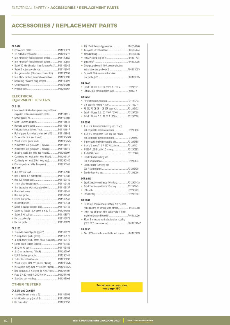
2 CATALOGUE TEST & MESURE 2021 www.chauvin-arnoux.com82 TEST & MEASUREMENT CATALOGUE 2022 www.chauvin-arnoux.com
ELECTRICAL SAFETY > ACCESSORIES / REPLACEMENT PARTS
CA 6474• Connection cable..........................................P01295271
• 15 m BNC / BNC cable .................................P01295272
• 5 m AmpFlex® flexible current sensor ............P01120550
• 8 m AmpFlex® flexible current sensor ............P01120551
• Set of 12 identification rings for AmpFlex® .....P01102045
• Set of 3 adjustable clamps ............................P01102046
• 5 m green cable (E terminal connection) ........P01295291
• 5 m black cable (E terminal connection) .........P01295292
• Spade lug / banana plug adapter ...................P01102028
• Calibration loop ............................................P01295294
• Prestige bag ................................................P01298067
ELECTRICAL EQUIPMENT TESTERSCA 6121• Machine Link Windows processing software
(supplied with communication cable) .............P01101915
• Series printer no. 5 .......................................P01102903
• DB9F-DB25M adapter ..................................P01101841
• Remote-control pedal ...................................P01101916
• Indicator lamps (green / red) .........................P01101917
• Roll of paper for series printer (set of 5) .........P01101842
• 2 crocodile clips (red / black) ........................P01295457Z
• 2 test probes (red / black) .............................P01295458Z
• 2 dielectric test guns with 6 m cable .............P01101918
• 2 dielectric test guns with 2 m cable .............P01101919
• 2 safety leads 3 m long (red / black) ..............P01295097
• Continuity test lead 2.5 m long (black) ...........P01295137
• Continuity test lead 2.5 m long (red) ..............P01295140
• Discharge-time cable (European) ...................P01295141
CA 6155• 4 m red test lead ..........................................P01102139
• Red + black 1.5 m test lead .........................P01102138
• Red 1.5 m test lead ......................................P01102140
• 1.5 m plug-in test cable ...............................P01102136
• 3 m test cable with separate wires ................P01102137
• Black test probe ...........................................P01101141
• Red test probe .............................................P01102142
• Green test probe ..........................................P01102143
• Blue test probe .............................................P01102144
• Set of 3 black crocodile clips .........................P01102145
• Set of 10 fuses: 16 A-250 V 6 x 32 T ............P01297086
• Set of 2 HV cables ........................................P01103071
• HV crocodile clip ..........................................P01103072
• HV test probe ...............................................P01103073
CA 6165• 1 remote-control pedal (type 2) .....................P01102177
• 2-lamp tower (red / green) ............................P01102178
• 4-lamp tower (red / green / blue / orange) .....P01102179
• Lamp power supply adapter ..........................P01102180
• 2 x 2 m HV guns ..........................................P01102182
• 2 x 3 m cables (red / black) ..........................P01295097
• EURO discharge cable ..................................P01295141
• 1 double continuity cable ..............................P01295236
• 2 test probes, CAT IV 1kV (red / black) ...........P01295454Z
• 2 crocodile clips, CAT IV 1kV (red / black) ......P01295457Z
• Time-delay fuse, 6 X 32 mm, 16 A 250 V (x10) .....P01297102
• Fuse 5 X 20 mm 5 A 250 V (x10) ..................P01297103
• Standard carrying bag ..................................P01298066
OTHER TESTERSCA 6240 and CA 6255• 1 A double test probe (x 2) ............................P01102056
• Mini Kelvin clamp (set of 2) ...........................P01101783
• UK mains lead ..............................................P01295253
• CA 1846 thermo-hygrometer ........................P01654246
• European 2P mains lead ...............................P01295174
• Standard bag ...............................................P01298066
• 10 A-P clamp (set of 2) .................................P01101794
• DataView® ...................................................P01102095
• Straight probe with 10 A double pivoting
retractable test probe (x 2) ............................P01103063
• Gun with 10 A double retractable
test probe (x 2) .............................................P01103065
CA 6240• Set of 10 fuses: 6.3 x 32 / 12.5 A / 500 V .............P01297091
• Optical / USB communication cable .......................HX0056-Z
CA 6255• Pt 100 temperature sensor ...................................P01102013
• 2 m cable for remote Pt 100 .................................P01102014
• RS 232 PC DB 9F – DB 25F cable x 2 ...................P01295172
• Set of 10 fuses: 6.3 x 32 / 16 A / 250 V ................P01297089
• Set of 10 fuses: 5.0 x 20 / 2 A / 250 V ..................P01297090
CA 6292• 1 set of 2 Kelvin leads 6 m long (red / black)
with adjustable-clamp connections ........................P01295486
• 1 set of 2 Kelvin leads 15 m long (red / black)
with adjustable-clamp connections ........................P01295487
• 1 green earth lead with crocodile clip ....................P01295488
• 1 set of 5 fuses: T1 5 A 250 V 5x20 mm ...............P01297101
• 1 USB-A USB-B cable 1.5 m long ..........................P01295293
• 1 MR6292 clamp .................................................P01120470
• Set of 2 leads 6 m long with
200 A Kelvin clamps .............................................P01295494
• Set of 2 leads 15 m long with
200 A Kelvin clamps .............................................P01295495
• Standard carrying bag ..........................................P01298066
DTR 8510• Set of 2 replacement leads 4.6 m long ..................P01295143A
• Set of 2 replacement leads 10 m long ...................P01295145
• USB cable ............................................................P01295293
• Shoulder bag .......................................................P01298066
CA 6681• 33 m reel of green wire, battery clip / 4 mm
male banana on winder with handle ...............P01295268
• 10 m reel of green wire, battery clip / 4 mm
male banana on H winder .............................P01102026
• Kit of 3 measurement adapters for housing
(B22, E27, mains socket) ..............................P01102114Z
CA 6630• Set of 2 leads with retractable test probes .....P01102103
ACCESSORIES / REPLACEMENT PARTS
See all our accessories on page 150

3CATALOGUE TEST & MESURE 2021 www.chauvin-arnoux.com 83TEST & MEASUREMENT CATALOGUE 2022 www.chauvin-arnoux.com
NOTES
ELECTRICAL SAFETY > NOTES
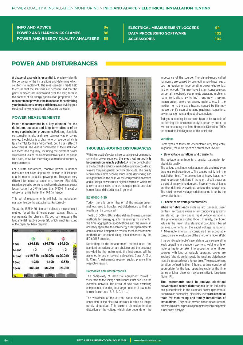
2 CATALOGUE TEST & MESURE 2021 www.chauvin-arnoux.com84 TEST & MEASUREMENT CATALOGUE 2022 www.chauvin-arnoux.com
POWER AND DISTURBANCES
A phase of analysis is essential to precisely identify the behaviour of the installations and determine which solutions to implement. The measurements made help to ensure that the solutions are pertinent and that the gains achieved are maintained over the long term in the context of an energy optimization programme. So measurement provides the foundation for optimizing your installations’ energy efficiency, supervising your electrical networks and fairly allocating the costs.
POWER MEASUREMENTSPower measurement is a key element for the definition, success and long-term effects of an energy optimization programme. Reducing electricity consumption is also a simple, painless way of saving money. Electricity is a clean energy source which is less harmful for the environment, but it does affect it nevertheless. The various parameters of the installation are measured regularly, including the different power values used to size the electrical network and the phase shift data, as well as the voltage, current and frequency measurements.
For private customers, reactive power is neither measured nor billed separately. Instead is it included at a flat rate in the active power price. Things are very different for industrial customers, however. Electricity suppliers penalize consumers whose displacement power factor (cos phi or DPF) is lower than 0.93 (in France) or whose tan phi is higher than 0.4 (in France).
This set of measurements will help the installation manager to size the capacitor banks correctly.
Today, the IEEE1459 standard defines a measurement method for all the different power values. Thus, to compensate the phase shift, you can measure the fundamental reactive power Q1, which simplifies sizing of the capacitor bank required.
TROUBLESHOOTING DISTURBANCESWith the spread of systems incorporating electronics using switching power supplies, the electrical network is becoming increasingly polluted. A further complication is the fact that electricity market deregulation could lead to more frequent general network blackouts. The quality requirements have become much more demanding and stringent than in the past. All the equipment in factories and buildings now includes digital electronics which are known to be sensitive to micro-outages, peaks and dips, harmonics and disturbances in general.
IEC 61000-4-30
Today, there is uniformization of the measurement methods used to troubleshoot disturbances so that the results can be compared.
The IEC 61000-4-30 standard defines the measurement methods for energy quality measuring instruments, the time aggregation specifications and the minimum accuracy applicable to each energy quality parameter to obtain reliable, comparable results. these measurement methods are checked using tests described by the IEC 62586 standard.
Depending on the measurement method used (the standard authorizes certain choices) and the accuracy provided by the instrument, the instrument will be assigned to one of several categories: Class A, S or B. Class A instruments require regular, precise time resynchronization.
Harmonics and interharmonics
The complexity of industrial equipment makes it vulnerable to the voltage disturbances that occur on the electrical network. The arrival of new quick-switching components is leading to a large number of low-order harmonic currents (3, 5, 7, 9, 11, ...).
The waveform of the current consumed by loads connected to the electrical network is often no longer purely sinusoidal. This current distortion implies distortion of the voltage which also depends on the
impedance of the source. The disturbances called harmonics are caused by connecting non-linear loads, such as equipment incorporating power electronics, to the network. This may have instant consequences on certain electronic equipment: operating problems (synchronization, switching), untimely tripping, measurement errors on energy meters, etc. In the medium term, the extra heating caused by this may reduce the life span of rotating machines, capacitors, power transformers and neutral conductors.
Today’s measuring instruments have to be capable of performing this harmonic analysis order by order, as well as measuring the Total Harmonic Distortion (THD) for more detailed diagnosis of the installation.
Variations
Some types of faults are encountered very frequently. In general, the main types of disturbances involve:
• Slow voltage variations and transients
The voltage amplitude is a crucial parameter for electricity quality.The voltage amplitude varies abnormally and may even drop to a level close to zero. The causes mainly lie in the installation itself. The connection of heavy loads may lead to voltage variations if the short-circuit power at a point of supply is undersized. Several types of faults are then defined: overvoltage, voltage dip, outage, etc. The rated network voltage variation range is set by the power distributor.
• Flicker: rapid voltage fluctuations
When variable loads such as arc furnaces, laser printers, microwave ovens or air-conditioning systems are started up, they cause rapid voltage variations. This phenomenon is called flicker. In reality, the flicker value is the result of a statistical calculation based on measurements of the rapid voltage variations. A 10-minute interval is considered an acceptable compromise for evaluation of the short-term flicker (Pst).
If the combined effect of several disturbance-generating loads operating in a random way (e.g. welding units or motors) has to be taken into account or when flicker sources with long or variable operating cycles are involved (electric arc furnace), the resulting disturbance must be assessed over a longer time. The measurement duration defined is then 2 hours, a time considered appropriate for the load operating cycle or the time during which an observer may be sensitive to long-term flicker (Plt).
The instruments used to analyse electrical networks and record disturbances for the industries and processionals in the electrical sector (generators, transmission companies, electricity users) are essential tools for monitoring and timely installation of installations. They must provide direct measurement, allow the maximum possible parameterization and permit subsequent analysis.
POWER QUALITY & INSTALLATION MONITORING > INFO AND ADVICE > ELECTRICAL INSTALLATION TESTING
INFO AND ADVICE 84POWER AND HARMONICS CLAMPS 86POWER AND ENERGY QUALITY ANALYSERS 88
ELECTRICAL MEASUREMENT LOGGERS 94DATA PROCESSING SOFTWARE 102ACCESSORIES 104
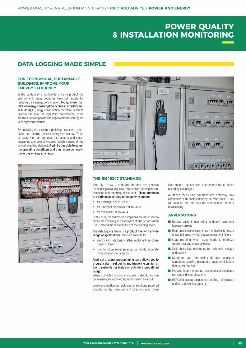
3CATALOGUE TEST & MESURE 2021 www.chauvin-arnoux.com 85TEST & MEASUREMENT CATALOGUE 2022 www.chauvin-arnoux.com
DATA LOGGING MADE SIMPLE
FOR ECONOMICAL, SUSTAINABLE BUILDINGS, IMPROVE YOUR ENERGY EFFICIENCYIn the context of a worldwide drive to protect the environment, many countries have set targets for reducing their energy consumption. Today, more than 50% of energy consumption occurs in industry and in buildings. Energy consumption therefore needs to optimized to meet the regulatory requirements. There are rules imposing tests and improvements with regard to energy consumption.
By analysing the structure (building, insulation, etc.), users can control passive energy efficiency. Then, by using high-performance instruments and smart measuring and control systems (variable speed drives or load-shedding devices), it will be possible to adjust the operating conditions and thus, more generally, the active energy efficiency.
instruments the necessary autonomy for effective recording campaigns.
All these measuring solutions are naturally now compatible with complementary software tools. They will also be the interface for remote tests or data downloading.
APPLICATIONS Neutral current monitoring to detect unwanted
leakage currents
Real-time current harmonics monitoring to locate unwanted energy which causes equipment failure
Load profiling which sizes loads to optimize transformer and meter selection
Split-phase load monitoring for residential voltage and current
Machine load monitoring detects overload conditions causing premature equipment failure due to overheating
Process loop monitoring can detect problematic sensors and control systems
HVAC and general temperature profiling (refrigeration and air-conditioning systems)
THE EN 16247 STANDARDThe EN 16247-1 standard defines the general methodological and quality requirements for preparation, execution and reporting of the audit. These methods are defined according to the activity audited:
• for buildings: EN 16247-2
• for industrial processes: EN 16247-3
• for transport: EN 16247-4
In all cases, measurement campaigns are necessary to check the efficiency of the equipment, the periods when it is used and the real condition of the building shells.
The data loggers family is a product line with a wide range of applications. They are suitable for:
• electrical installations, whether involving three-phase power or lower,
• multifunction requirements, or highly accurate measurements for a sector
A full set of alarm programming tools allows you to program alarm set points and triggering on high or low thresholds, or inside or outside a predefined range. When connected to a communication network, you can be immediately informed about this alarm by email.
Low-consumption technologies or solutions powered directly via the measurement channels give these
POWER QUALITY & INSTALLATION MONITORING > INFO AND ADVICE > POWER AND ENERGY
POWER QUALITY & INSTALLATION MONITORING
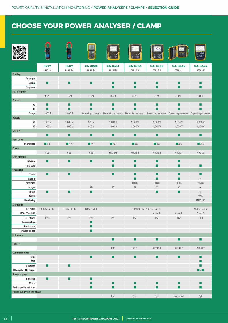
2 CATALOGUE TEST & MESURE 2021 www.chauvin-arnoux.com86 TEST & MEASUREMENT CATALOGUE 2022 www.chauvin-arnoux.com
POWER QUALITY & INSTALLATION MONITORING > POWER ANALYSERS / CLAMPS > SELECTION GUIDE
F407page 87
F607page 87
CA 8220page 87
CA 8331page 88
CA 8333page 89
CA 8336page 90
CA 8436page 91
CA 8345page 92
Display
Analogue
Digital
Graphical
No. of inputs
1U/1I 1U/1I 1U/1I 3U/3I 3U/3I 4U/4I 4U/4I 4U/4I
Current
AC
DC
Range 1,000 A 2,000 A Depending on sensor Depending on sensor Depending on sensor Depending on sensor Depending on sensor Depending on sensor
Voltage
AC 1,000 V 1,000 V 600 V 1,000 V 1,000 V 1,000 V 1,000 V 1,000 V
DC 1,000 V 1,000 V 600 V 1,000 V 1,000 V 1,000 V 1,000 V 1,000 V
DPF PF
Harmonics
THD/orders /25 /25 /50 /50 /50 /50 /50 /63
Power
PQS PQS PQS PNQ1DS PNQ1DS PNQ1DS PNQ1DS PNQ1DS
Data storage
Internal
SD card
Recording
Trend
Alarms ∞
Transients 80 µs 80 µs 80 µs 2.5 µs
Images 99 12 12 50 50 ∞
Inrush ∞
Surge 12kV
Monitoring EN50160
Standards
IEC61010 1000V CAT IV 1000V CAT IV 600V CAT III 600V CAT IV - 1000 V CAT III 1000V CAT IV
IEC61000-4-30 Class B Class B Class A
IEC 60529 IP54 IP54 IP54 IP53 IP53 IP53 IP67 IP54
Temperature
Resistance
Rotation speed
Unbalance
Flicker
PST PST PST/PLT PST/PLT PST/PLT
Communication
USB
Wifi
Bluetooth
Ethernet / IRD server /
Power supply
Batteries
Mains
Rechargeable batteries
Power supply via the phase
Opt. Opt. Opt. Integrated Opt.
CHOOSE YOUR POWER ANALYSER / CLAMP
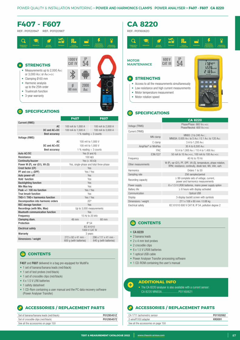
3CATALOGUE TEST & MESURE 2021 www.chauvin-arnoux.com 87TEST & MEASUREMENT CATALOGUE 2022 www.chauvin-arnoux.com
POWER QUALITY & INSTALLATION MONITORING > POWER AND HARMONICS CLAMPS | POWER ANALYSER > F407 - F607 | CA 8220
CHOOSE YOUR POWER ANALYSER / CLAMP F407 - F607 REF.: P01120947 REF.: P01120967
CA 8220 REF.: P01160620
Generation, transmission & distribution
IndustriesTertiary & residential
Education TransportDiagnostics & testing
Energy efficiency
Laboratory & metrology
Generation, transmission & distribution
IndustriesTertiary & residential
Education TransportDiagnostics & testing
Energy efficiency
Laboratory & metrology
MOTOR MAINTENANCE
CONTENTS
F407 and F607 delivered in a bag pre-equipped for MultiFix• 1 set of banana/banana leads (red/black)• 1 set of test probes (red/black)• 1 set of crocodile clips (red/black)• 4 x 1.5 V LR6 batteries• 1 safety datasheet• 1 CD-Rom containing a user manual and the PC data recovery software
(Power Analyser Transfer)
ACCESSORIES / REPLACEMENT PARTS
Set of banana/banana leads (red/black) P01295451ZSet of crocodile clips (red/black) P01295457ZSee all the accessories on page 150
STRENGTHS• Measurements up to 2,000 AAc
or 3,000 Adc or AAc+dc
• Clamping Ø 60 mm• Harmonic analysis
up to the 25th order• TrueInrush function• 3-year warranty
F407 F607Current (RMS)
AC 100 mA to 1,000 A 100 mA to 2,000 ADC and AC+DC 100 mA to 1,500 A 100 mA to 3,000 ABest accuracy 1 % reading + 3 counts
Voltage (RMS) AC 100 mV to 1,000 V
DC and AC+DC 100 mV to 1,000 VBest accuracy 1 % reading + 3 counts
Auto AC/DC Yes (V and A)Resistance 100 kΩContinuity/buzzer Yes (< 40 Ω)Power W (P), var (Q1), VA (S) Yes, single-phase and total three-phase Crest factor (CF) YesPF and cos ϕ (DPF) Yes / YesAuto power-off YesHold function YesBacklighting function YesMin Max key YesPeak +/- 100 ms function Yes / YesTrue Inrush function YesTHD-f / THD-r harmonics function Yes / YesDecomposition into harmonic orders 25th
REC storage function YesRecordings (with Min, Max) Up to 3,000 measurementsBluetooth communication function YesFrequency 15 Hz to 20 kHzClamping diam. 48 mm 60 mmProtection IP 54
Electrical safety IEC 61010 1000 V CAT IV
Warranty 3 years
Dimensions / weight 272 x 92 x 41 mm - 600 g (with batteries)
296 x 111 x 41 mm - 640 g (with batteries)
SPECIFICATIONS
ACCESSORIES / REPLACEMENT PARTS
CA 1711 tachometric sensor P011020822-wirePt100 adapter HX0091See all the accessories on page 150
ADDITIONAL INFO• The CA 8220 analyser is also available with a current sensor: CA 8220 MN93A ..................... P01160621
STRENGTHS• Access to all the measurements simultaneously• Low resistance and high current measurements• Motor temperature measurement• Motor rotation speed
CONTENTS
• CA 8220• 2 banana leads• 2 x 4 mm test probes• 2 crocodile clips• 6 x 1.5 V LR06 batteries• 1 optical USB cable• Power Analyser Transfer processing software• 1 CD-ROM containing the user’s manual
CA 8220
Voltage (TRMS)Phase/Phase: 660 VAc+dc Phase/Neutral: 600 VAc+dc
Current (TRMS)
MN clampMN93: 2 to 240 AAc ;
MN93A: 0.005 AAc to 5 AAc / 0.1 AAc to 120 AAc C clamp 3 A to 1,200 AAc
AmpFlex® or MiniFlex 30 A to 6,500 AAc
PAC 10 A to 1,000 AAc / 10 A to 1,400 Adc
E3N / E27 50 mA to 10 AAc+dc, 100 mA to 100 AAc+dc
Frequency 40 Hz to 70 Hz
Other measurements W (P), var (Q1), PF, DPF, VA (S), temperature, phase rotation,
RPM, resistance, continuity, diode test, Wh, VAh, varh
Harmonics Orders 1 to 50
Sampling rate 256 samples/period
Recording capacity≥ 99 complete sets of voltage, current, power and harmonics measurements
Power supply 6 x 1.5 V LR06 batteries, mains power supply option
Battery life ≥ 8 hours with display activated
Communication Optical USB
Display 3-display backlit screen with symbols
Dimensions / weight 211 x 108 x 60 mm / 0.88 kg Electrical safety IEC 61010 600 V CAT III, IP 54, pollution degree 2
SPECIFICATIONS
600 VCAT III
IP54
1000 VCAT IV
IP54
Ø60 mm
2 000AAC
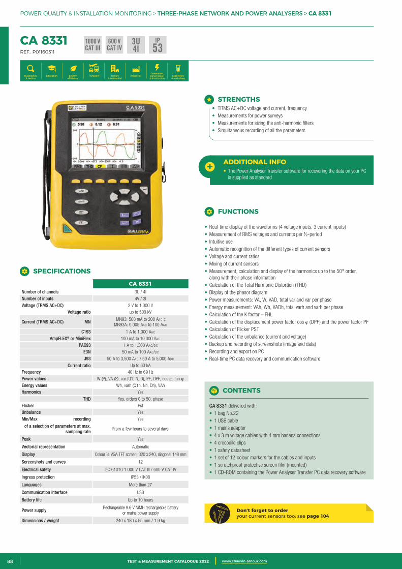
2 CATALOGUE TEST & MESURE 2021 www.chauvin-arnoux.com88 TEST & MEASUREMENT CATALOGUE 2022 www.chauvin-arnoux.com
POWER QUALITY & INSTALLATION MONITORING > THREE-PHASE NETWORK AND POWER ANALYSERS > CA 8331
CA 8331 REF.: P01160511
Generation, transmission & distribution
IndustriesTertiary & residential
Education TransportDiagnostics & testing
Energy efficiency
Laboratory & metrology
STRENGTHS• TRMS AC+DC voltage and current, frequency• Measurements for power surveys• Measurements for sizing the anti-harmonic filters• Simultaneous recording of all the parameters
ADDITIONAL INFO• The Power Analyser Transfer software for recovering the data on your PC
is supplied as standard
CA 8331Number of channels 3U / 4I
Number of inputs 4V / 3I Voltage (TRMS AC+DC) 2 V to 1,000 V
Voltage ratio up to 500 kV
Current (TRMS AC+DC) MN MN93: 500 mA to 200 AAc ; MN93A: 0.005 AAc to 100 AAc
C193 1 A to 1,000 AAc AmpFLEX® or MiniFlex 100 mA to 10,000 AAc
PAC93 1 A to 1,300 AAc/dc E3N 50 mA to 100 AAc/dc J93 50 A to 3,500 AAc / 50 A to 5,000 Adc
Current ratio Up to 60 kA Frequency 40 Hz to 69 Hz Power values W (P), VA (S), var (Q1, N, D), PF, DPF, cos ϕ, tan ϕ Energy values Wh, varh (Q1h, Nh, Dh), VAh Harmonics Yes
THD Yes, orders 0 to 50, phase Flicker Pst Unbalance Yes Min/Max recording Yes
of a selection of parameters at max. sampling rate From a few hours to several days
Peak Yes
Vectorial representation Automatic
Display Colour ¼ VGA TFT screen; 320 x 240, diagonal 148 mm
Screenshots and curves 12
Electrical safety IEC 61010 1 000 V CAT III / 600 V CAT IV
Ingress protection IP53 / IK08
Languages More than 27
Communication interface USB
Battery life Up to 10 hours
Power supply Rechargeable 9.6 V NiMH rechargeable battery or mains power supply
Dimensions / weight 240 x 180 x 55 mm / 1.9 kg
SPECIFICATIONS
CONTENTS
CA 8331 delivered with:• 1 bag No.22• 1 USB cable• 1 mains adapter• 4 x 3 m voltage cables with 4 mm banana connections• 4 crocodile clips• 1 safety datasheet• 1 set of 12-colour markers for the cables and inputs• 1 scratchproof protective screen film (mounted)• 1 CD-ROM containing the Power Analyser Transfer PC data recovery software
Don’t forget to order your current sensors too: see page 104
FUNCTIONS
• Real-time display of the waveforms (4 voltage inputs, 3 current inputs)• Measurement of RMS voltages and currents per ½-period• Intuitive use• Automatic recognition of the different types of current sensors• Voltage and current ratios• Mixing of current sensors• Measurement, calculation and display of the harmonics up to the 50th order,
along with their phase information• Calculation of the Total Harmonic Distortion (THD)• Display of the phasor diagram• Power measurements: VA, W, VAD, total var and var per phase• Energy measurement: VAh, Wh, VADh, total varh and varh per phase• Calculation of the K factor – FHL• Calculation of the displacement power factor cos ϕ (DPF) and the power factor PF• Calculation of Flicker PST• Calculation of the unbalance (current and voltage)• Backup and recording of screenshots (image and data)• Recording and export on PC• Real-time PC data recovery and communication software
3U4I
1000 VCAT III
600 VCAT IV
IP53
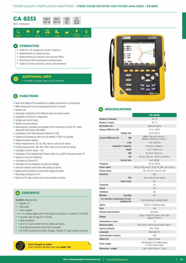
3CATALOGUE TEST & MESURE 2021 www.chauvin-arnoux.com 89TEST & MEASUREMENT CATALOGUE 2022 www.chauvin-arnoux.com
POWER QUALITY & INSTALLATION MONITORING > THREE-PHASE NETWORK AND POWER ANALYSERS > CA 8333
CA 8333 REF.: P01160541
Generation, transmission & distribution
IndustriesTertiary & residential
Education TransportDiagnostics & testing
Energy efficiency
Laboratory & metrology
STRENGTHS• TRMS AC+DC voltage and current, frequency• Measurements for power surveys• Measurements for sizing the anti-harmonic filters• Recording of all the parameters simultaneously• Capture of all the transients, alarms and waveforms
ADDITIONAL INFO• Possibility of Essailec-type current connection
CONTENTS
CA 8333 delivered with:• 1 bag No. 22• 1 USB cable• 1 mains adapter• 4 x 3 m voltage cables with 4 mm banana connections (5 cables for CA 8336)• 4 crocodile clips (5 clips for CA 8336)• 1 safety datasheet• 1 set of 12-colour markers for the cables and inputs• 1 scratchproof protective screen film (mounted)• 1 CD-ROM containing the Power Analyser Transfer PC data recovery software
Don’t forget to order your current sensors too: see page 104
FUNCTIONS
• Real-time display of the waveforms (4 voltage inputs and 4 current inputs)• RMS voltage and current measurements by the ½-period• Intuitive use• Automatic recognition of the different types of current sensors• Integration of all the DC components• Voltage and current ratios• Mixing of current sensors• Measurement, calculation and display of the harmonics up to the 50th order,
along with their phase information• Calculation of the Total Harmonic Distortion (THD)• Capture of transients as short as one sample (1/256th of a period)• Display of phasor diagram• Power measurements: VA, W, VAD, total var and var per phase• Energy measurement: VAh, Wh, VADh, total varh and varh per phase• Calculation of the K factor – FHL• Calculation of the Displacement Power Factor cos ϕ (DPF) and power factor PF• Capture of up to 50 transients• Calculation of Flicker PST• Calculation of the unbalance (current and voltage)• Electrical network supervision with setting of alarms• Backup and recording of screenshots (image and data)• Recording and export on PC• Real-time PC data recovery and communication software
SPECIFICATIONS
CA 8333Number of channels 3U / 4I
Number of inputs 4V / 3I
IEC 61000-4-30 EN50160 reports
Voltage (TRMS AC+DC) 2 V to 1,000 V
Voltage ratio Up to 500 kV
Current (TRMS AC+DC) MN MN93: 500 mA to 200 AAc ; MN93A: 0.005 AAc to 100 AAc
C193 1 A to 1,000 AAc
AmpFLEX® or MiniFlex 100 mA to 10,000 AAc
PAC93 1 A to 1,300 AAc/dc
E3N 50 mA to 100 AAc/dc
J93 50 A to 3,500 AAc / 50 A to 5,000 Adc
Current ratio Up to 60 kA
Frequency 40 Hz to 69 Hz
Power values W (P), VA (S), var (Q1, N, D), PF, DPF, cos ϕ, tan ϕ
Energy values Wh, varh (Q1h, Nh, Dh), VAh
Harmonics Yes
THD Yes, orders 0 to 50, phase
Expert mode Yes
Transients 50
Flicker Pst
Unbalance Yes
Min/Max recording Yes
of a selection of parameters at max. sampling rate From a few days to several weeks
Alarms 4,000 of 10 different types
Peak Yes
Vectorial representation Automatic
Display Colour ¼ VGA TFT screen, 320 x 240, diagonal 148 mm
Screenshots & curves 12
Electrical safety IEC 61010 1 000 V CAT III / 600 V CAT IV
Ingress protection IP53 / IK08
Languages More than 27
Communication interface USB
Battery life Up to 10 hours
Power supply Rechargeable 9.6 V NiMH battery or mains power supply
Dimensions / weight 240 x 180 x 55 mm / 1.9 kg
3U4I
1000 VCAT III
600 VCAT IV
IP53
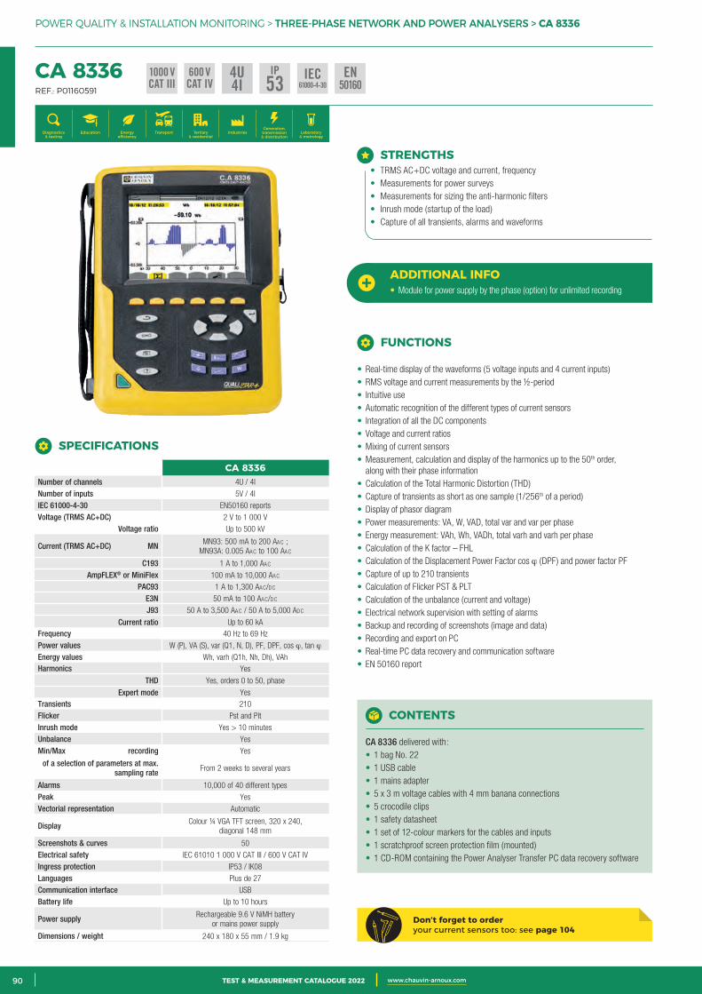
2 CATALOGUE TEST & MESURE 2021 www.chauvin-arnoux.com90 TEST & MEASUREMENT CATALOGUE 2022 www.chauvin-arnoux.com
POWER QUALITY & INSTALLATION MONITORING > THREE-PHASE NETWORK AND POWER ANALYSERS > CA 8336
CA 8336 REF.: P01160591
Generation, transmission & distribution
IndustriesTertiary & residential
Education TransportDiagnostics & testing
Energy efficiency
Laboratory & metrology
STRENGTHS• TRMS AC+DC voltage and current, frequency• Measurements for power surveys• Measurements for sizing the anti-harmonic filters• Inrush mode (startup of the load)• Capture of all transients, alarms and waveforms
ADDITIONAL INFO• Module for power supply by the phase (option) for unlimited recording
FUNCTIONS
• Real-time display of the waveforms (5 voltage inputs and 4 current inputs)• RMS voltage and current measurements by the ½-period• Intuitive use• Automatic recognition of the different types of current sensors• Integration of all the DC components• Voltage and current ratios• Mixing of current sensors• Measurement, calculation and display of the harmonics up to the 50th order,
along with their phase information• Calculation of the Total Harmonic Distortion (THD)• Capture of transients as short as one sample (1/256th of a period)• Display of phasor diagram• Power measurements: VA, W, VAD, total var and var per phase• Energy measurement: VAh, Wh, VADh, total varh and varh per phase• Calculation of the K factor – FHL• Calculation of the Displacement Power Factor cos ϕ (DPF) and power factor PF• Capture of up to 210 transients• Calculation of Flicker PST & PLT• Calculation of the unbalance (current and voltage)• Electrical network supervision with setting of alarms• Backup and recording of screenshots (image and data)• Recording and export on PC• Real-time PC data recovery and communication software• EN 50160 report
CA 8336Number of channels 4U / 4I
Number of inputs 5V / 4I IEC 61000-4-30 EN50160 reportsVoltage (TRMS AC+DC) 2 V to 1 000 V
Voltage ratio Up to 500 kV
Current (TRMS AC+DC) MN MN93: 500 mA to 200 AAc ; MN93A: 0.005 AAc to 100 AAc
C193 1 A to 1,000 AAc AmpFLEX® or MiniFlex 100 mA to 10,000 AAc
PAC93 1 A to 1,300 AAc/dc E3N 50 mA to 100 AAc/dc J93 50 A to 3,500 AAc / 50 A to 5,000 Adc
Current ratio Up to 60 kA Frequency 40 Hz to 69 Hz Power values W (P), VA (S), var (Q1, N, D), PF, DPF, cos ϕ, tan ϕ Energy values Wh, varh (Q1h, Nh, Dh), VAh Harmonics Yes
THD Yes, orders 0 to 50, phase
Expert mode YesTransients 210 Flicker Pst and Plt Inrush mode Yes > 10 minutes Unbalance Yes
Min/Max recording Yes
of a selection of parameters at max. sampling rate From 2 weeks to several years
Alarms 10,000 of 40 different typesPeak Yes Vectorial representation Automatic
Display Colour ¼ VGA TFT screen, 320 x 240, diagonal 148 mm
Screenshots & curves 50 Electrical safety IEC 61010 1 000 V CAT III / 600 V CAT IV Ingress protection IP53 / IK08 Languages Plus de 27 Communication interface USB Battery life Up to 10 hours
Power supply Rechargeable 9.6 V NiMH battery or mains power supply
Dimensions / weight 240 x 180 x 55 mm / 1.9 kg
SPECIFICATIONS
CONTENTS
CA 8336 delivered with:• 1 bag No. 22• 1 USB cable• 1 mains adapter• 5 x 3 m voltage cables with 4 mm banana connections• 5 crocodile clips• 1 safety datasheet• 1 set of 12-colour markers for the cables and inputs• 1 scratchproof screen protection film (mounted)• 1 CD-ROM containing the Power Analyser Transfer PC data recovery software
Don’t forget to order your current sensors too: see page 104
4U4I
1000 VCAT III
600 VCAT IV
IP53 IEC
61000-4-30EN
50160
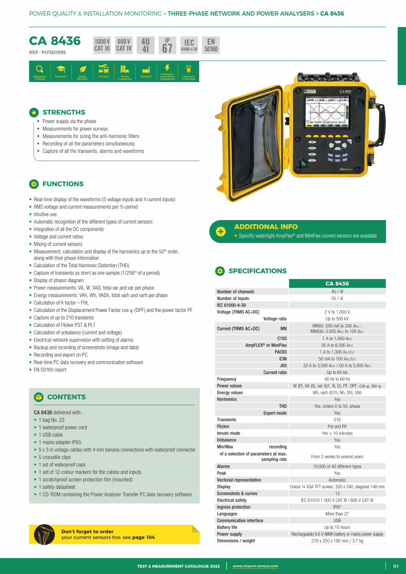
3CATALOGUE TEST & MESURE 2021 www.chauvin-arnoux.com 91TEST & MEASUREMENT CATALOGUE 2022 www.chauvin-arnoux.com
POWER QUALITY & INSTALLATION MONITORING > THREE-PHASE NETWORK AND POWER ANALYSERS > CA 8436
CA 8436 REF.: P01160595
Generation, transmission & distribution
IndustriesTertiary & residential
Education TransportDiagnostics & testing
Energy efficiency
Laboratory & metrology
Don’t forget to order your current sensors too: see page 104
STRENGTHS• Power supply via the phase• Measurements for power surveys• Measurements for sizing the anti-harmonic filters• Recording of all the parameters simultaneously• Capture of all the transients, alarms and waveforms
ADDITIONAL INFO• Specific watertight AmpFlex® and MiniFlex current sensors are available
CONTENTS
CA 8436 delivered with: • 1 bag No. 22• 1 waterproof power cord• 1 USB cable• 1 mains adapter IP65• 5 x 3 m voltage cables with 4 mm banana connections with waterproof connector• 5 crocodile clips• 1 set of waterproof caps• 1 set of 12-colour markers for the cables and inputs• 1 scratchproof screen protection film (mounted)• 1 safety datasheet• 1 CD-ROM containing the Power Analyser Transfer PC data recovery software
Don’t forget to order your current sensors too: see page 104
FUNCTIONS
• Real-time display of the waveforms (5 voltage inputs and 4 current inputs)• RMS voltage and current measurements per ½-period• Intuitive use• Automatic recognition of the different types of current sensors• Integration of all the DC components• Voltage and current ratios• Mixing of current sensors• Measurement, calculation and display of the harmonics up to the 50th order,
along with their phase information• Calculation of the Total Harmonic Distortion (THD)• Capture of transients as short as one sample (1/256th of a period)• Display of phasor diagram• Power measurements: VA, W, VAD, total var and var per phase• Energy measurements: VAh, Wh, VADh, total varh and varh per phase• Calculation of K factor – FHL• Calculation of the Displacement Power Factor cos ϕ (DPF) and the power factor PF• Capture of up to 210 transients• Calculation of Flicker PST & PLT• Calculation of unbalance (current and voltage)• Electrical network supervision with setting of alarms• Backup and recording of screenshots (image and data)• Recording and export on PC• Real-time PC data recovery and communication software• EN 50160 report
SPECIFICATIONS
CA 8436Number of channels 4U / 4I
Number of inputs 5V / 4I IEC 61000-4-30 - Voltage (TRMS AC+DC) 2 V to 1,000 V
Voltage ratio Up to 500 kV
Current (TRMS AC+DC) MN MN93: 500 mA to 200 AAc ; MN93A: 0.005 AAc to 100 AAc
C193 1 A to 1,000 AAc AmpFLEX® or MiniFlex 30 A to 6,500 AAc
PAC93 1 A to 1,300 AAc/dc E3N 50 mA to 100 AAc/dc J93 50 A to 3,500 AAc / 50 A to 5,000 Adc
Current ratio Up to 60 kA Frequency 40 Hz to 69 Hz Power values W (P), VA (S), var (Q1, N, D), PF, DPF, cos ϕ, tan ϕ Energy values Wh, varh (Q1h, Nh, Dh), VAh Harmonics Yes
THD Yes, orders 0 to 50, phase
Expert mode YesTransients 210 Flicker Pst and Plt Inrush mode Yes > 10 minutes Unbalance Yes
Min/Max recording Yes
of a selection of parameters at max. sampling rate From 2 weeks to several years
Alarms 10,000 of 40 different types Peak Yes Vectorial representation Automatic Display Colour ¼ VGA TFT screen, 320 x 240, diagonal 148 mm Screenshots & curves 12 Electrical safety IEC 61010 1 000 V CAT III / 600 V CAT IV Ingress protection IP67 Languages More than 27 Communication interface USB Battery life Up to 10 hoursPower supply Rechargeable 9.6 V NiMH battery or mains power supplyDimensions / weight 270 x 250 x 180 mm / 3.7 kg
4U4I
1000 VCAT III
600 VCAT IV
IP67 IEC
61000-4-30EN
50160
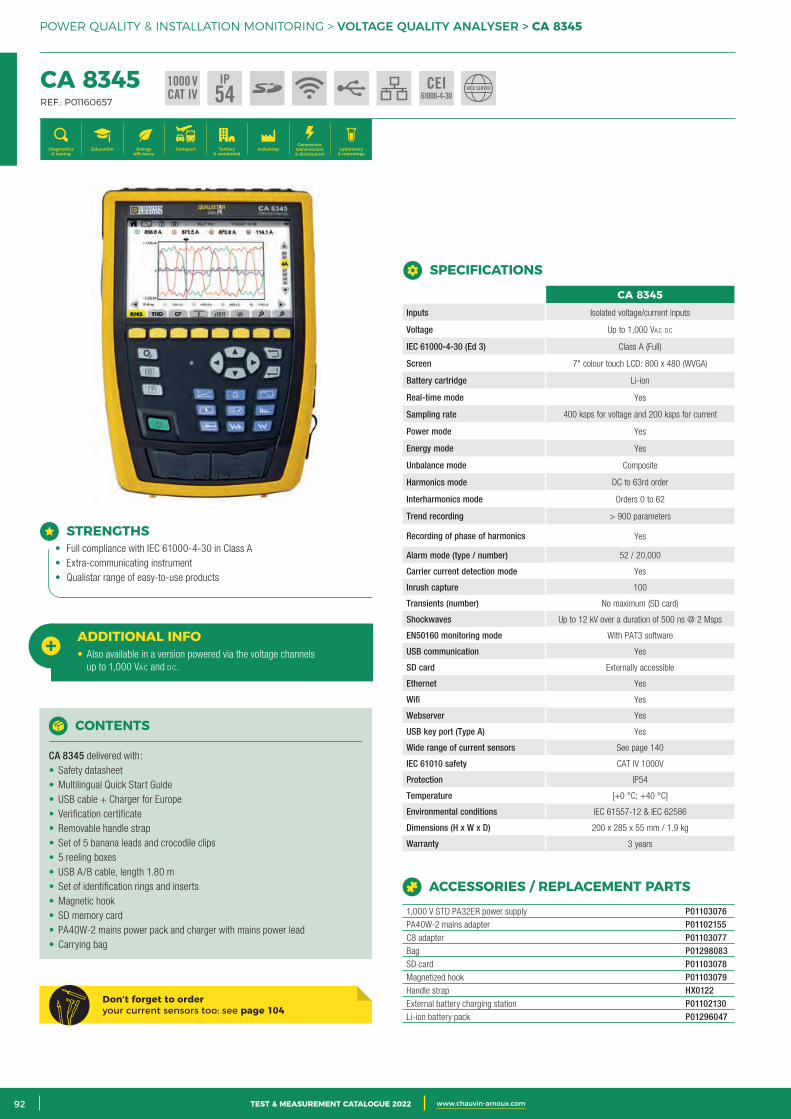
2 CATALOGUE TEST & MESURE 2021 www.chauvin-arnoux.com92 TEST & MEASUREMENT CATALOGUE 2022 www.chauvin-arnoux.com
POWER QUALITY & INSTALLATION MONITORING > VOLTAGE QUALITY ANALYSER > CA 8345
CA 8345 REF.: P01160657
Generation, transmission & distribution
IndustriesTertiary & residential
Education TransportDiagnostics & testing
Energy efficiency
Laboratory & metrology
CA 8345Inputs Isolated voltage/current inputs
Voltage Up to 1,000 VAc dc
IEC 61000-4-30 (Ed 3) Class A (Full)
Screen 7" colour touch LCD: 800 x 480 (WVGA)
Battery cartridge Li-ion
Real-time mode Yes
Sampling rate 400 ksps for voltage and 200 ksps for current
Power mode Yes
Energy mode Yes
Unbalance mode Composite
Harmonics mode DC to 63rd order
Interharmonics mode Orders 0 to 62
Trend recording > 900 parameters
Recording of phase of harmonics Yes
Alarm mode (type / number) 52 / 20,000
Carrier current detection mode Yes
Inrush capture 100
Transients (number) No maximum (SD card)
Shockwaves Up to 12 kV over a duration of 500 ns @ 2 Msps
EN50160 monitoring mode With PAT3 software
USB communication Yes
SD card Externally accessible
Ethernet Yes
Wifi Yes
Webserver Yes
USB key port (Type A) Yes
Wide range of current sensors See page 140
IEC 61010 safety CAT IV 1000V
Protection IP54
Temperature [+0 °C; +40 °C]
Environmental conditions IEC 61557-12 & IEC 62586
Dimensions (H x W x D) 200 x 285 x 55 mm / 1.9 kg
Warranty 3 years
SPECIFICATIONS
STRENGTHS• Full compliance with IEC 61000-4-30 in Class A• Extra-communicating instrument• Qualistar range of easy-to-use products
ADDITIONAL INFO• Also available in a version powered via the voltage channels
up to 1,000 VAc and dc.
CONTENTS
CA 8345 delivered with:• Safety datasheet• Multilingual Quick Start Guide• USB cable + Charger for Europe• Verification certificate• Removable handle strap• Set of 5 banana leads and crocodile clips• 5 reeling boxes• USB A/B cable, length 1.80 m• Set of identification rings and inserts• Magnetic hook• SD memory card• PA40W-2 mains power pack and charger with mains power lead• Carrying bag
ACCESSORIES / REPLACEMENT PARTS
1,000 V STD PA32ER power supply P01103076PA40W-2 mains adapter P01102155C8 adapter P01103077Bag P01298083SD card P01103078Magnetized hook P01103079Handle strap HX0122External battery charging station P01102130Li-ion battery pack P01296047
1000 VCAT IV
IP54 CEI
61000-4-30WEB SERVER
Don’t forget to order your current sensors too: see page 104
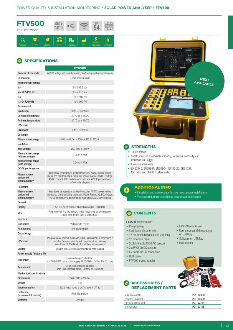
3CATALOGUE TEST & MESURE 2021 www.chauvin-arnoux.com 93TEST & MEASUREMENT CATALOGUE 2022 www.chauvin-arnoux.com
POWER QUALITY & INSTALLATION MONITORING > SOLAR POWER ANALYSER > FTV500
FTV500 REF.: P01129600
Generation, transmission & distribution
IndustriesTertiary & residential
Education TransportDiagnostics & testing
Energy efficiency
Laboratory & metrology
SPECIFICATIONS
FTV500Number of channels 6 (3 DC voltage and current channels, 3 AC voltage and current channels)
Connection 4 mm banana plugs
Measurement ranges
Vd c 3 to 999.9 Vdc
Va c @ 50/60 Hz 3 to 700.0 VAc
Id c 1 to 1,400 Adc
Ia c @ 50/60 Hz 1 to 3,000 AAc
Environment
Irradiation 50 to 2,000 W/m²
Contact temperature -20 °C to + 150°C
Ambient temperature -20 °C to + 150°C
I-V curves
DC power 5 to 9 999 W DC
Continuity
Measurement range 0.01 to 99 Ω, > 200mA (IEC 61557-4)
Insulation
Test voltage 250-500-1,000 V
Measurement range (without voltage) 0.25 to 1 MΩ
Measurement range (with voltage) 0.25 to 1 MΩ
DC-AC performance
Measurements performed simultaneously
Irradiation, temperature (ambient/module), AC/DC power values (measured and theoretical available), Power Factor, AC/DC, voltage,
AC/DC current, PRp performance ratio and AC/DC performance, V-I vectorial diagram
Recording
Measurements performed simultaneously
Irradiation, temperature (ambient/module), AC/DC power values (measured and theoretical available), Power Factor, AC/DC, voltage,
AC/DC current, PRp performance ratio and AC/DC performance
General
Display 5’’ TFT touch screen, 16 million colours, 800x480
Wifi Real-time Wi-Fi transmission, mode / real-time synchronization and recording of data if signal lost
Interface
Instrument VNC remote control
Remote unit Wifi transmission
Data storage
I-V curvesProgrammable internal database: sites / installations / companies /
modules / measurements, with tree-structure. Memory: more than 10,000 blocks for all the measurements.
Logger Logger: 600,000 measurements for data logging
Power supply / Battery life
Instrument Li-ion rechargeable batteries and 100-240V mains power supply @ 50-60Hz / Battery life 15 hours
Remote unit Li-ion rechargeable batteries with USB charging cable / Battery life 15 hours
Mechanical specifications
Dimensions 340 x 300 x 200mm
Weight 6 kg
Electrical safety IEC 61010, 1000 V CAT II, 600 V CAT IV
Protection (instrument & remote) IP54 (IEC 60529)
Warranty 2 years
600 VCAT III
IP54 WEB SERVER
ACCESSORIES / REPLACEMENT PARTS
MiniFlex MA500 P01120080PAC500 DC clamp P01120600FTV500 remote unit P01102184Inclinometer P01102115
STRENGTHS• Touch screen• 5 instruments in 1: converter efficiency, I-V curves, continuity test,
insulation test, logger• Live insulation tests• EN62446, EN60891, EN60904, IEC 82-25, EN61557,
IEC 64-8 and EN61010 standards
ADDITIONAL INFO• Installation and maintenance tests on solar power installations• Verification during installation of solar power installations
CONTENTS
FTV500 delivered with: • Carrying bag• Certificate of conformity• 12 red/black banana leads 2 m long• 12 crocodile clips• 3 x MiniFlex MA500 AC sensors• 3 x PAC500 DC sensors• I-V cable for DC connection• USB cable• FTV500 mains adapter
• FTV500 remote unit• User’s manual (5 languages)
on USB key• Software on USB key• Inclinometer
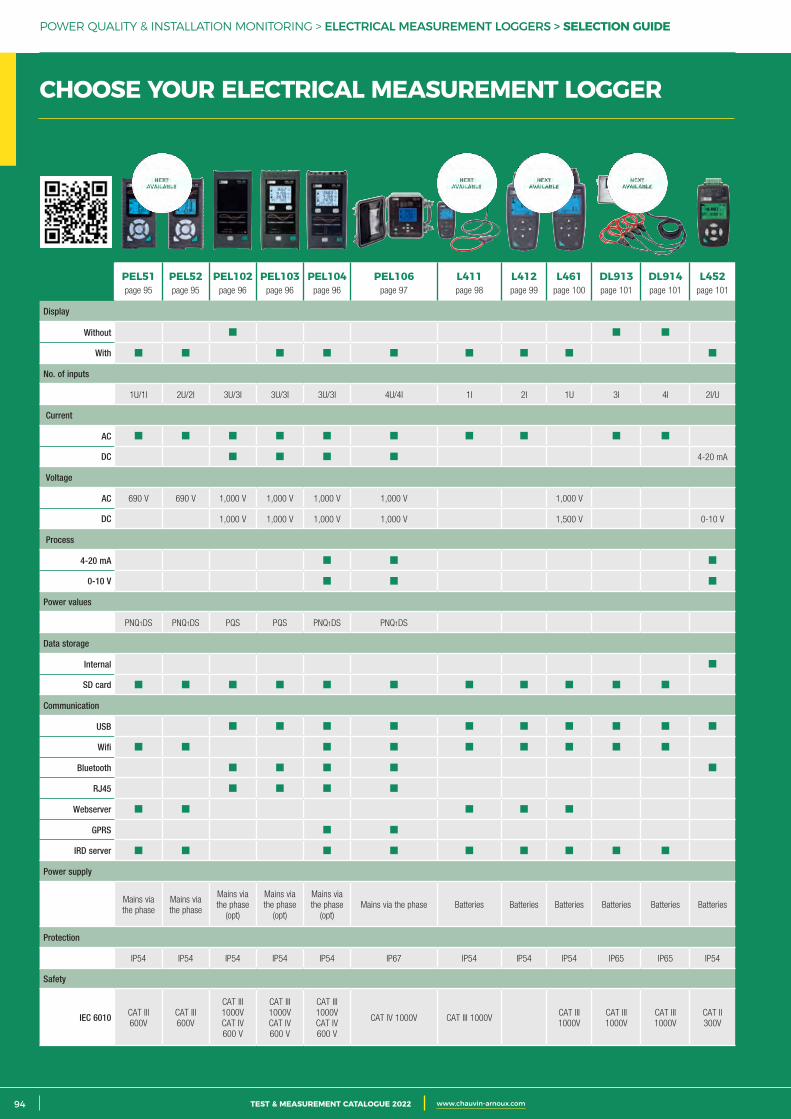
2 CATALOGUE TEST & MESURE 2021 www.chauvin-arnoux.com94 TEST & MEASUREMENT CATALOGUE 2022 www.chauvin-arnoux.com
POWER QUALITY & INSTALLATION MONITORING > ELECTRICAL MEASUREMENT LOGGERS > SELECTION GUIDE
CHOOSE YOUR ELECTRICAL MEASUREMENT LOGGER
PEL51page 95
PEL52page 95
PEL102page 96
PEL103page 96
PEL104page 96
PEL106page 97
L411page 98
L412page 99
L461page 100
DL913page 101
DL914page 101
L452page 101
Display
Without
With
No. of inputs
1U/1I 2U/2I 3U/3I 3U/3I 3U/3I 4U/4I 1I 2I 1U 3I 4I 2I/U
Current
AC
DC 4-20 mA
Voltage
AC 690 V 690 V 1,000 V 1,000 V 1,000 V 1,000 V 1,000 V
DC 1,000 V 1,000 V 1,000 V 1,000 V 1,500 V 0-10 V
Process
4-20 mA
0-10 V
Power values
PNQ1DS PNQ1DS PQS PQS PNQ1DS PNQ1DS
Data storage
Internal
SD card
Communication
USB
Wifi
Bluetooth
RJ45
Webserver
GPRS
IRD server
Power supply
Mains via the phase
Mains via the phase
Mains via the phase
(opt)
Mains via the phase
(opt)
Mains via the phase
(opt)Mains via the phase Batteries Batteries Batteries Batteries Batteries Batteries
Protection
IP54 IP54 IP54 IP54 IP54 IP67 IP54 IP54 IP54 IP65 IP65 IP54
Safety
IEC 6010 CAT III 600V
CAT III 600V
CAT III 1000VCAT IV 600 V
CAT III 1000VCAT IV 600 V
CAT III 1000VCAT IV 600 V
CAT IV 1000V CAT III 1000VCAT III 1000V
CAT III 1000V
CAT III 1000V
CAT II 300V
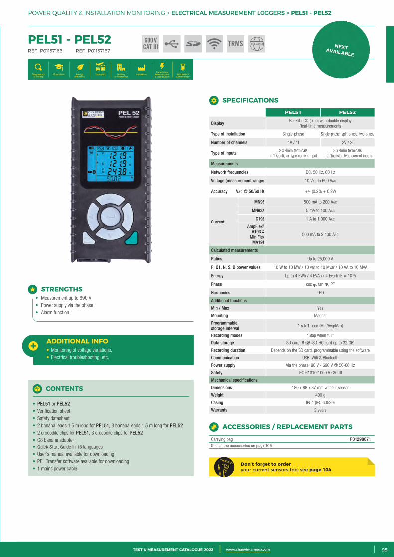
3CATALOGUE TEST & MESURE 2021 www.chauvin-arnoux.com 95TEST & MEASUREMENT CATALOGUE 2022 www.chauvin-arnoux.com
CHOOSE YOUR ELECTRICAL MEASUREMENT LOGGER
POWER QUALITY & INSTALLATION MONITORING > ELECTRICAL MEASUREMENT LOGGERS > PEL51 - PEL52
PEL51 - PEL52 REF.: P01157166 REF.: P01157167
Generation, transmission & distribution
IndustriesTertiary & residential
Education TransportDiagnostics & testing
Energy efficiency
Laboratory & metrology
STRENGTHS• Measurement up to 690 V• Power supply via the phase• Alarm function
ADDITIONAL INFO• Monitoring of voltage variations,• Electrical troubleshooting, etc.
CONTENTS
• PEL51 or PEL52• Verification sheet• Safety datasheet• 2 banana leads 1.5 m long for PEL51, 3 banana leads 1.5 m long for PEL52• 2 crocodile clips for PEL51, 3 crocodile clips for PEL52• C8 banana adapter• Quick Start Guide in 15 languages• User’s manual available for downloading• PEL Transfer software available for downloading• 1 mains power cable
ACCESSORIES / REPLACEMENT PARTS
Carrying bag P01298071See all the accessories on page 105
SPECIFICATIONS
PEL51 PEL52
Display Backlit LCD (blue) with double displayReal-time measurements
Type of installation Single-phase Single-phase, split-phase, two-phase
Number of channels 1V / 1I 2V / 2I
Type of inputs 2 x 4mm terminals + 1 Qualistar-type current input
3 x 4mm terminals + 2 Qualistar-type current inputs
Measurements
Network frequencies DC, 50 Hz, 60 Hz
Voltage (measurement range) 10 VAc to 690 VAc
Accuracy Va c @ 50/60 Hz +/- (0.2% + 0.2V)
Current
MN93 500 mA to 200 AAc
MN93A 5 mA to 100 AAc
C193 1 A to 1,000 AAc
AmpFlex® A193 &
MiniFlex MA194
500 mA to 2,400 AAc
Calculated measurements
Ratios Up to 25,000 A
P, Q1, N, S, D power values 10 W to 10 MW / 10 var to 10 Mvar / 10 VA to 10 MVA
Energy Up to 4 EWh / 4 EVAh / 4 Evarh (E = 1018)
Phase cos ϕ, tan Φ, PF
Harmonics THD
Additional functions
Min / Max Yes
Mounting Magnet
Programmable storage interval 1 s to1 hour (Min/Avg/Max)
Recording modes “Stop when full”
Data storage SD card, 8 GB (SD-HC card up to 32 GB)
Recording duration Depends on the SD card, programmable using the software
Communication USB, Wifi & Bluetooth
Power supply Via the phase, 90 V - 690 V @ 50-60 Hz
Safety IEC 61010 1000 V CAT III
Mechanical specifications
Dimensions 180 x 88 x 37 mm without sensor
Weight 400 g
Casing IP54 (IEC 60529)
Warranty 2 years
600 VCAT III TRMS WEB SERVER
Don’t forget to order your current sensors too: see page 104
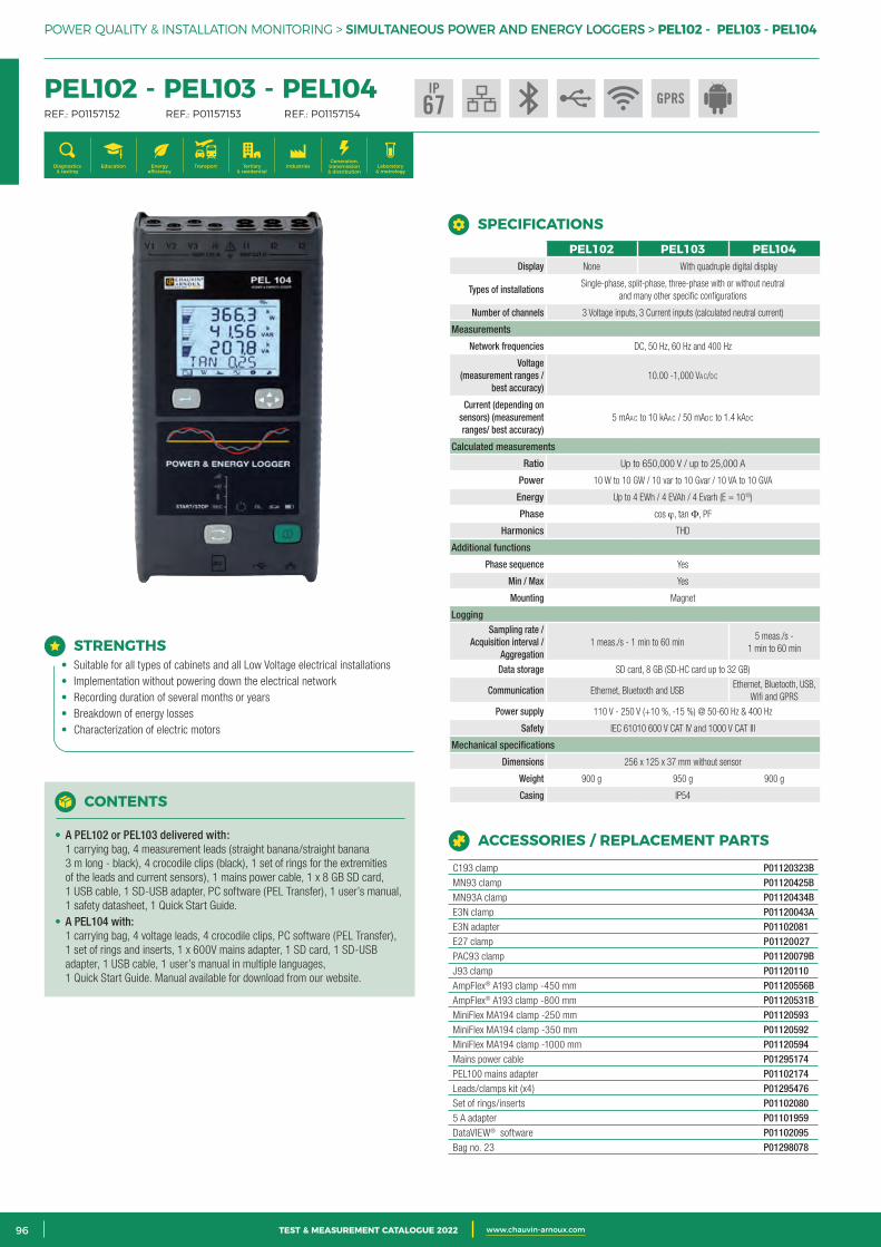
2 CATALOGUE TEST & MESURE 2021 www.chauvin-arnoux.com96 TEST & MEASUREMENT CATALOGUE 2022 www.chauvin-arnoux.com
POWER QUALITY & INSTALLATION MONITORING > SIMULTANEOUS POWER AND ENERGY LOGGERS > PEL102 - PEL103 - PEL104
STRENGTHS• Suitable for all types of cabinets and all Low Voltage electrical installations• Implementation without powering down the electrical network• Recording duration of several months or years• Breakdown of energy losses• Characterization of electric motors
CONTENTS
• A PEL102 or PEL103 delivered with: 1 carrying bag, 4 measurement leads (straight banana/straight banana 3 m long - black), 4 crocodile clips (black), 1 set of rings for the extremities of the leads and current sensors), 1 mains power cable, 1 x 8 GB SD card, 1 USB cable, 1 SD-USB adapter, PC software (PEL Transfer), 1 user’s manual,1 safety datasheet, 1 Quick Start Guide.
• A PEL104 with: 1 carrying bag, 4 voltage leads, 4 crocodile clips, PC software (PEL Transfer), 1 set of rings and inserts, 1 x 600V mains adapter, 1 SD card, 1 SD-USB adapter, 1 USB cable, 1 user’s manual in multiple languages, 1 Quick Start Guide. Manual available for download from our website.
ACCESSORIES / REPLACEMENT PARTS
C193 clamp P01120323BMN93 clamp P01120425BMN93A clamp P01120434BE3N clamp P01120043AE3N adapter P01102081E27 clamp P01120027PAC93 clamp P01120079BJ93 clamp P01120110AmpFlex® A193 clamp -450 mm P01120556BAmpFlex® A193 clamp -800 mm P01120531BMiniFlex MA194 clamp -250 mm P01120593MiniFlex MA194 clamp -350 mm P01120592MiniFlex MA194 clamp -1000 mm P01120594Mains power cable P01295174PEL100 mains adapter P01102174Leads/clamps kit (x4) P01295476Set of rings/inserts P011020805 A adapter P01101959DataVIEW® software P01102095Bag no. 23 P01298078
IP67
PEL102 - PEL103 - PEL104 REF.: P01157152 REF.: P01157153 REF.: P01157154
Generation, transmission & distribution
IndustriesTertiary & residential
Education TransportDiagnostics & testing
Energy efficiency
Laboratory & metrology
PEL102 PEL103 PEL104Display None With quadruple digital display
Types of installations Single-phase, split-phase, three-phase with or without neutral
and many other specific configurations
Number of channels 3 Voltage inputs, 3 Current inputs (calculated neutral current)
Measurements
Network frequencies DC, 50 Hz, 60 Hz and 400 Hz
Voltage (measurement ranges /
best accuracy) 10.00 -1,000 VAc/dc
Current (depending on sensors) (measurement ranges/ best accuracy)
5 mAAc to 10 kAAc / 50 mAdc to 1.4 kAdc
Calculated measurements
Ratio Up to 650,000 V / up to 25,000 A
Power 10 W to 10 GW / 10 var to 10 Gvar / 10 VA to 10 GVA
Energy Up to 4 EWh / 4 EVAh / 4 Evarh (E = 1018)
Phase cos ϕ, tan Φ, PF
Harmonics THD
Additional functions
Phase sequence Yes
Min / Max Yes
Mounting Magnet
LoggingSampling rate /
Acquisition interval / Aggregation
1 meas./s - 1 min to 60 min 5 meas./s -
1 min to 60 min
Data storage SD card, 8 GB (SD-HC card up to 32 GB)
Communication Ethernet, Bluetooth and USB Ethernet, Bluetooth, USB,
Wifi and GPRS
Power supply 110 V - 250 V (+10 %, -15 %) @ 50-60 Hz & 400 Hz
Safety IEC 61010 600 V CAT IV and 1000 V CAT III
Mechanical specifications
Dimensions 256 x 125 x 37 mm without sensor
Weight 900 g 950 g 900 g
Casing IP54
SPECIFICATIONS
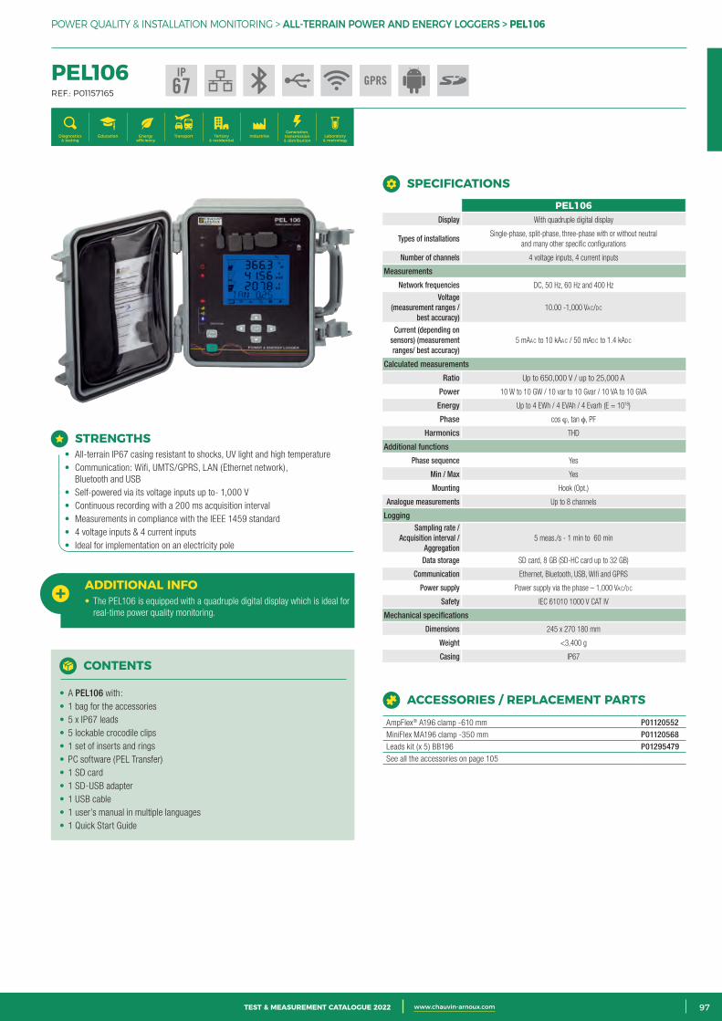
3CATALOGUE TEST & MESURE 2021 www.chauvin-arnoux.com 97TEST & MEASUREMENT CATALOGUE 2022 www.chauvin-arnoux.com
POWER QUALITY & INSTALLATION MONITORING > ALL-TERRAIN POWER AND ENERGY LOGGERS > PEL106
STRENGTHS• All-terrain IP67 casing resistant to shocks, UV light and high temperature• Communication: Wifi, UMTS/GPRS, LAN (Ethernet network),
Bluetooth and USB• Self-powered via its voltage inputs up to- 1,000 V• Continuous recording with a 200 ms acquisition interval• Measurements in compliance with the IEEE 1459 standard• 4 voltage inputs & 4 current inputs• Ideal for implementation on an electricity pole
ADDITIONAL INFO• The PEL106 is equipped with a quadruple digital display which is ideal for
real-time power quality monitoring.
CONTENTS
• A PEL106 with:• 1 bag for the accessories• 5 x IP67 leads• 5 lockable crocodile clips• 1 set of inserts and rings• PC software (PEL Transfer)• 1 SD card• 1 SD-USB adapter• 1 USB cable• 1 user’s manual in multiple languages• 1 Quick Start Guide
ACCESSORIES / REPLACEMENT PARTS
AmpFlex® A196 clamp -610 mm P01120552MiniFlex MA196 clamp -350 mm P01120568Leads kit (x 5) BB196 P01295479See all the accessories on page 105
SPECIFICATIONS
PEL106 REF.: P01157165
Generation, transmission & distribution
IndustriesTertiary & residential
Education TransportDiagnostics & testing
Energy efficiency
Laboratory & metrology
IP67
PEL106Display With quadruple digital display
Types of installations Single-phase, split-phase, three-phase with or without neutral
and many other specific configurations
Number of channels 4 voltage inputs, 4 current inputs
Measurements
Network frequencies DC, 50 Hz, 60 Hz and 400 Hz
Voltage (measurement ranges /
best accuracy) 10.00 -1,000 VAc/dc
Current (depending on sensors) (measurement ranges/ best accuracy)
5 mAAc to 10 kAAc / 50 mAdc to 1.4 kAdc
Calculated measurements
Ratio Up to 650,000 V / up to 25,000 A
Power 10 W to 10 GW / 10 var to 10 Gvar / 10 VA to 10 GVA
Energy Up to 4 EWh / 4 EVAh / 4 Evarh (E = 1018)
Phase cos ϕ, tan φ, PF
Harmonics THD
Additional functions
Phase sequence Yes
Min / Max Yes
Mounting Hook (Opt.)
Analogue measurements Up to 8 channels
LoggingSampling rate /
Acquisition interval / Aggregation
5 meas./s - 1 min to 60 min
Data storage SD card, 8 GB (SD-HC card up to 32 GB)
Communication Ethernet, Bluetooth, USB, Wifi and GPRS
Power supply Power supply via the phase – 1,000 VAc/dc
Safety IEC 61010 1000 V CAT IV
Mechanical specifications
Dimensions 245 x 270 180 mm
Weight <3,400 g
Casing IP67
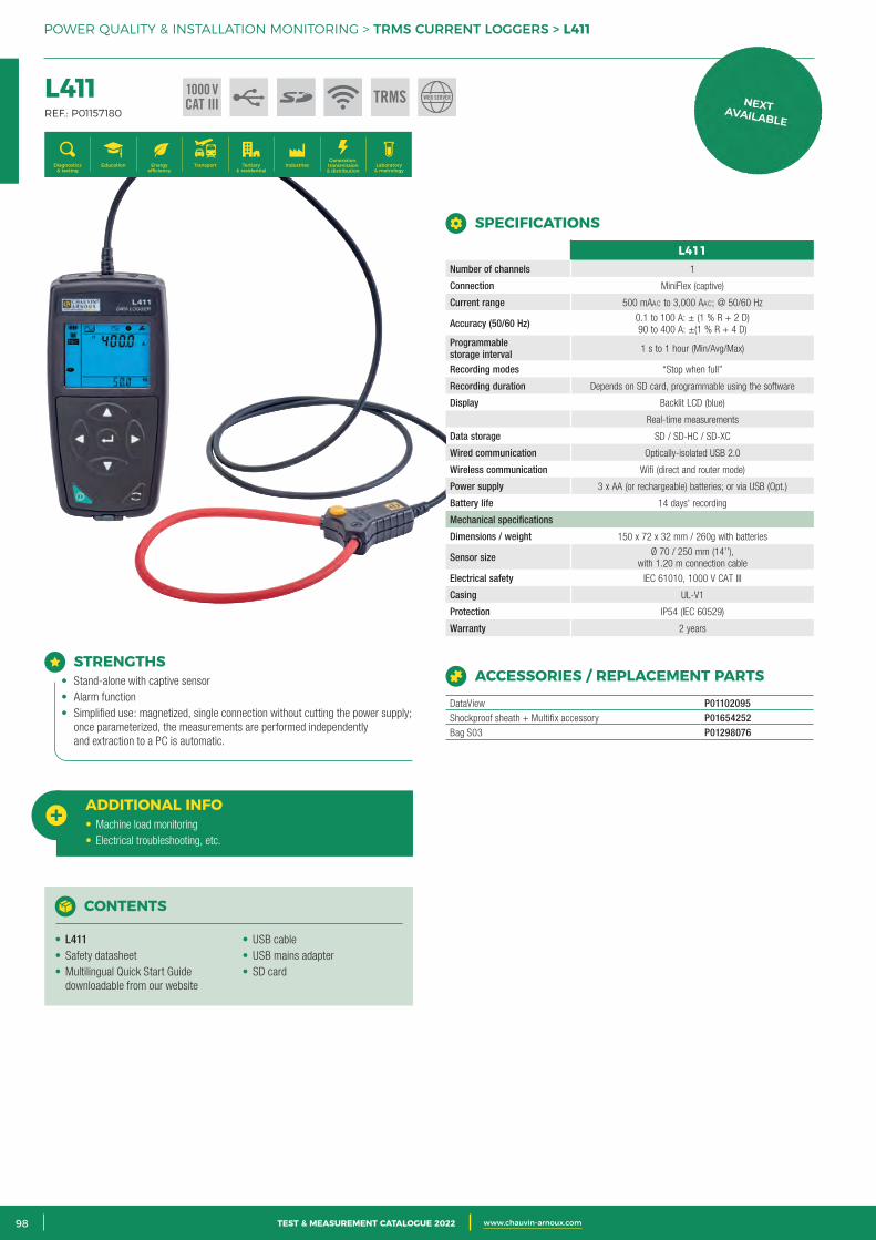
2 CATALOGUE TEST & MESURE 2021 www.chauvin-arnoux.com98 TEST & MEASUREMENT CATALOGUE 2022 www.chauvin-arnoux.com
POWER QUALITY & INSTALLATION MONITORING > TRMS CURRENT LOGGERS > L411
L411 REF.: P01157180
Generation, transmission & distribution
IndustriesTertiary & residential
Education TransportDiagnostics & testing
Energy efficiency
Laboratory & metrology
STRENGTHS• Stand-alone with captive sensor• Alarm function• Simplified use: magnetized, single connection without cutting the power supply;
once parameterized, the measurements are performed independently and extraction to a PC is automatic.
1000 VCAT III TRMS
ADDITIONAL INFO• Machine load monitoring• Electrical troubleshooting, etc.
L411Number of channels 1
Connection MiniFlex (captive)
Current range 500 mAAc to 3,000 AAc; @ 50/60 Hz
Accuracy (50/60 Hz) 0.1 to 100 A: ± (1 % R + 2 D) 90 to 400 A: ±(1 % R + 4 D)
Programmable storage interval 1 s to 1 hour (Min/Avg/Max)
Recording modes “Stop when full”
Recording duration Depends on SD card, programmable using the software
Display Backlit LCD (blue)
Real-time measurements
Data storage SD / SD-HC / SD-XC
Wired communication Optically-isolated USB 2.0
Wireless communication Wifi (direct and router mode)
Power supply 3 x AA (or rechargeable) batteries; or via USB (Opt.)
Battery life 14 days' recording
Mechanical specifications
Dimensions / weight 150 x 72 x 32 mm / 260g with batteries
Sensor size Ø 70 / 250 mm (14’’), with 1.20 m connection cable
Electrical safety IEC 61010, 1000 V CAT III
Casing UL-V1
Protection IP54 (IEC 60529)
Warranty 2 years
SPECIFICATIONS
ACCESSORIES / REPLACEMENT PARTS
DataView P01102095Shockproof sheath + Multifix accessory P01654252Bag S03 P01298076
CONTENTS
• L411• Safety datasheet• Multilingual Quick Start Guide
downloadable from our website
• USB cable• USB mains adapter• SD card
WEB SERVER
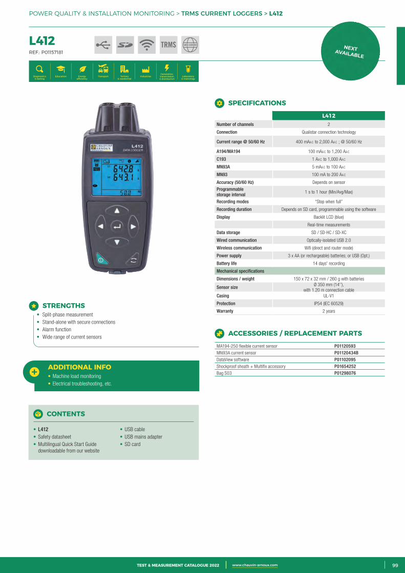
3CATALOGUE TEST & MESURE 2021 www.chauvin-arnoux.com 99TEST & MEASUREMENT CATALOGUE 2022 www.chauvin-arnoux.com
POWER QUALITY & INSTALLATION MONITORING > TRMS CURRENT LOGGERS > L412
L412 REF.: P01157181
Generation, transmission & distribution
IndustriesTertiary & residential
Education TransportDiagnostics & testing
Energy efficiency
Laboratory & metrology
L412Number of channels 2
Connection Qualistar connection technology
Current range @ 50/60 Hz 400 mAAc to 2,000 AAc ; @ 50/60 Hz
A194/MA194 100 mAAc to 1,200 AAc
C193 1 AAc to 1,000 AAc
MN93A 5 mAAc to 100 AAc
MN93 100 mA to 200 AAc
Accuracy (50/60 Hz) Depends on sensor
Programmable storage interval 1 s to 1 hour (Min/Avg/Max)
Recording modes “Stop when full”
Recording duration Depends on SD card, programmable using the software
Display Backlit LCD (blue)
Real-time measurements
Data storage SD / SD-HC / SD-XC
Wired communication Optically-isolated USB 2.0
Wireless communication Wifi (direct and router mode)
Power supply 3 x AA (or rechargeable) batteries; or USB (Opt.)
Battery life 14 days' recording
Mechanical specifications
Dimensions / weight 150 x 72 x 32 mm / 260 g with batteries
Sensor size Ø 350 mm (14’’), with 1.20 m connection cable
Casing UL-V1
Protection IP54 (IEC 60529)
Warranty 2 years
SPECIFICATIONS
ACCESSORIES / REPLACEMENT PARTS
MA194-250 flexible current sensor P01120593MN93A current sensor P01120434BDataView software P01102095Shockproof sheath + Multifix accessory P01654252Bag S03 P01298076
TRMS
STRENGTHS• Split-phase measurement• Stand-alone with secure connections• Alarm function• Wide range of current sensors
ADDITIONAL INFO• Machine load monitoring• Electrical troubleshooting, etc.
CONTENTS
• L412• Safety datasheet• Multilingual Quick Start Guide
downloadable from our website
• USB cable• USB mains adapter• SD card
WEB SERVER
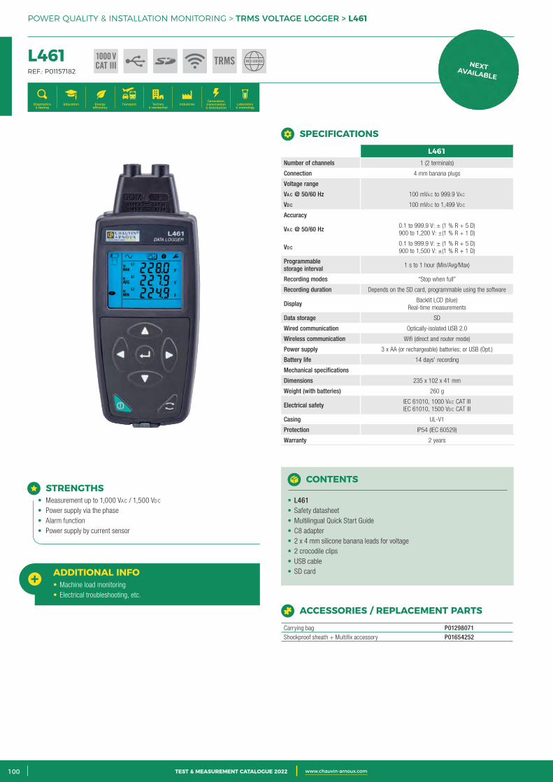
2 CATALOGUE TEST & MESURE 2021 www.chauvin-arnoux.com100 TEST & MEASUREMENT CATALOGUE 2022 www.chauvin-arnoux.com
POWER QUALITY & INSTALLATION MONITORING > TRMS VOLTAGE LOGGER > L461
L461 REF.: P01157182
Generation, transmission & distribution
IndustriesTertiary & residential
Education TransportDiagnostics & testing
Energy efficiency
Laboratory & metrology
STRENGTHS• Measurement up to 1,000 VAc / 1,500 Vdc
• Power supply via the phase• Alarm function• Power supply by current sensor
ADDITIONAL INFO• Machine load monitoring• Electrical troubleshooting, etc.
CONTENTS
• L461• Safety datasheet• Multilingual Quick Start Guide• C8 adapter• 2 x 4 mm silicone banana leads for voltage• 2 crocodile clips• USB cable• SD card
ACCESSORIES / REPLACEMENT PARTS
Carrying bag P01298071Shockproof sheath + Multifix accessory P01654252
SPECIFICATIONS
L461Number of channels 1 (2 terminals)
Connection 4 mm banana plugs
Voltage range
Va c @ 50/60 Hz 100 mVAc to 999.9 VAc
Vd c 100 mVdc to 1,499 Vdc
Accuracy
Va c @ 50/60 Hz 0.1 to 999.9 V: ± (1 % R + 5 D) 900 to 1,200 V: ±(1 % R + 1 D)
Vd c0.1 to 999.9 V: ± (1 % R + 5 D) 900 to 1,500 V: ±(1 % R + 1 D)
Programmable storage interval 1 s to 1 hour (Min/Avg/Max)
Recording modes “Stop when full”
Recording duration Depends on the SD card, programmable using the software
Display Backlit LCD (blue) Real-time measurements
Data storage SD
Wired communication Optically-isolated USB 2.0
Wireless communication Wifi (direct and router mode)
Power supply 3 x AA (or rechargeable) batteries; or USB (Opt.)
Battery life 14 days' recording
Mechanical specifications
Dimensions 235 x 102 x 41 mm
Weight (with batteries) 260 g
Electrical safety IEC 61010, 1000 VAc CAT III IEC 61010, 1500 Vdc CAT III
Casing UL-V1
Protection IP54 (IEC 60529)
Warranty 2 years
1000 VCAT III TRMS WEB SERVER
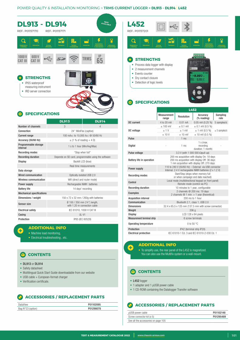
3CATALOGUE TEST & MESURE 2021 www.chauvin-arnoux.com 101TEST & MEASUREMENT CATALOGUE 2022 www.chauvin-arnoux.com
POWER QUALITY & INSTALLATION MONITORING > TRMS CURRENT LOGGER > DL913 - DL914 | L452
L452 REF.: P01157201
Generation, transmission & distribution
IndustriesTertiary & residential
Education TransportDiagnostics & testing
Energy efficiency
Laboratory & metrology
STRENGTHS• Process data logger with display• 2 measurement channels• Events counter• Dry contact closure• Detection of logic levels
CONTENTS
• L452 logger• 1 adapter and 1 µUSB power cable• 1 CD-ROM containing the Datalogger Transfer software
SPECIFICATIONS
L452Measurement
range Resolution Accuracy (% reading)
Sampling rate
DC current 4 to 20 mA 0.01 mA 0.05 mA (0.25 %) 5 samples/s
DC voltage± 100 mV ± 0.1 mV ± 0.1 mV (0.5 %)
± 5 samples/s ± 1 V ± 1 mV ± 1 mV (0.5 %)
± 10 V ± 10 mV ± 10 mV (0.5 %) Pulse - 1 ms - -
Digital - 1 ms 1 s (max. recording
duration: 1 month) -
Pulse voltage 3.3 V (with 1 000 000 Ωpull-up)
Battery life in operation200 ms acquisition with display On: 18 days200 ms acquisition with display Off: 36 days1 min acquisition with display Off: 270 days
Power supply 110 to 240 V (50/60 Hz) – External: via USB connectorInternal: 2.4 V rechargeable NiMH batteries (2 x 1.2 V)
Recording modes Start/Stop (stops when memory full or when campaign end date reached)
Control Local mode (multidirectional keypad on front panel) Remote mode (control via PC)
Recording duration 10 minutes to 1 year, configurable
Examples 2 channels @ 200 ms: 19 days2 channels @ 1 min: > 1 year (theoretical)
Acquisition interval 200 ms to 1 hourCommunication Bluetooth 2.1, class 1, USB 2.0 Dimensions 32.4 x 65.5 x 125 mm (137.5 mm with screw connector) Weight 206 g Display LCD 128 x 64 pixels Measurement terminal strip 6 screw terminals
Operating temperature 0 to 50 °C
Protection IP42 (terminal strip IP20) Electrical protection IEC 61010-1 Ed. 3 and IEC 61010-2-030 Ed. 1
ACCESSORIES / REPLACEMENT PARTS
µUSB power cable P01102148Screw connector kit (x 5) P01295489See all the accessories on page 105
ADDITIONAL INFO• To simplify use, the rear panel of the L452 is magnetized.
You can also use the Multifix system or a wall-mount.
DL913 - DL914 REF.: P01157170 REF.: P01157171
Generation, transmission & distribution
IndustriesTertiary & residential
Education TransportDiagnostics & testing
Energy efficiency
Laboratory & metrology
STRENGTHS• IP65 waterproof
measuring instrument• IRD server connection
SPECIFICATIONS
DL913 DL914Number of channels 3 4
Connection 24’’ MiniFlex (captive)
Current range 100 mAAc to 10,000 AAc @ 50/60 Hz
Accuracy (50/60 Hz) ± (1 % of reading + 4 D)
Programmable storage interval 1 s to 1 hour (Min/Avg/Max)
Recording modes “Stop when full”
Recording duration Depends on SD card, programmable using the software
Display Backlit LCD (blue)
Real-time measurements
Data storage SD
Wired communication Optically-isolated USB 2.0
Wireless communication Wifi (direct and router mode)
Power supply Rechargeable NiMH batteries
Battery life 14 days' recording
Mechanical specifications
Dimensions / weight 150 x 72 x 32 mm / 260g with batteries
Sensor size Ø 100 / 350 mm (14’’) length, with 1.20 m connection cable
Electrical safety IEC 61010, 1000 V CAT III
Casing UL-V1
Protection IP65 (IEC 60529)
ADDITIONAL INFO• Machine load monitoring,• Electrical troubleshooting , etc.
CONTENTS
• DL913 or DL914• Safety datasheet• Multilingual Quick Start Guide downloadable from our website• USB cable + European-format charger• Verification certificate.
ACCESSORIES / REPLACEMENT PARTS
DataView P01102095Bag N°23 (option) P01298078
1000 VCAT III
600 VCAT IV TRMS
IP65
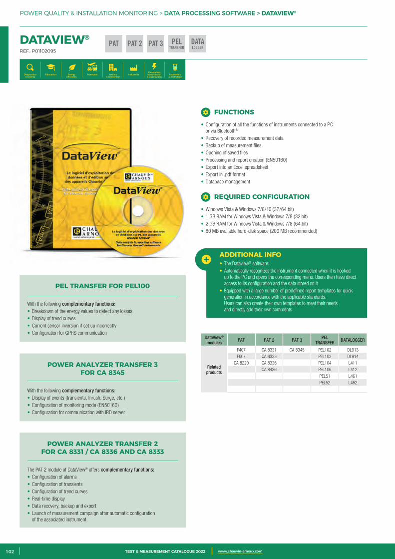
2 CATALOGUE TEST & MESURE 2021 www.chauvin-arnoux.com102 TEST & MEASUREMENT CATALOGUE 2022 www.chauvin-arnoux.com
POWER QUALITY & INSTALLATION MONITORING > DATA PROCESSING SOFTWARE > DATAVIEW®
DATAVIEW® REF.: P01102095
Generation, transmission & distribution
IndustriesTertiary & residential
Education TransportDiagnostics & testing
Energy efficiency
Laboratory & metrology
DataView® modules PAT PAT 2 PAT 3 PEL
TRANSFER DATALOGGER
Related products
F407 CA 8331 CA 8345 PEL102 DL913F607 CA 8333 PEL103 DL914
CA 8220 CA 8336 PEL104 L411
CA 8436 PEL106 L412
PEL51 L461
PEL52 L452
ADDITIONAL INFO• The Dataview® software:• Automatically recognizes the instrument connected when it is hooked
up to the PC and opens the corresponding menu. Users then have direct access to its configuration and the data stored on it
• Equipped with a large number of predefined report templates for quick generation in accordance with the applicable standards. Users can also create their own templates to meet their needs and directly add their own comments
PEL TRANSFER FOR PEL100
With the following complementary functions:• Breakdown of the energy values to detect any losses• Display of trend curves• Current sensor inversion if set up incorrectly• Configuration for GPRS communication
POWER ANALYZER TRANSFER 3 FOR CA 8345
With the following complementary functions:• Display of events (transients, Inrush, Surge, etc.)• Configuration of monitoring mode (EN50160)• Configuration for communication with IRD server
POWER ANALYZER TRANSFER 2 FOR CA 8331 / CA 8336 AND CA 8333
The PAT 2 module of DataView® offers complementary functions:• Configuration of alarms• Configuration of transients• Configuration of trend curves• Real-time display• Data recovery, backup and export• Launch of measurement campaign after automatic configuration
of the associated instrument.
• Configuration of all the functions of instruments connected to a PC or via Bluetooth®
• Recovery of recorded measurement data• Backup of measurement files• Opening of saved files• Processing and report creation (EN50160)• Export into an Excel spreadsheet• Export in .pdf format• Database management
FUNCTIONS
• Windows Vista & Windows 7/8/10 (32/64 bit)• 1 GB RAM for Windows Vista & Windows 7/8 (32 bit)• 2 GB RAM for Windows Vista & Windows 7/8 (64 bit)• 80 MB available hard-disk space (200 MB recommended)
REQUIRED CONFIGURATION
PELTRANSFER
PAT PAT 2 DATALOGGER
PAT 3
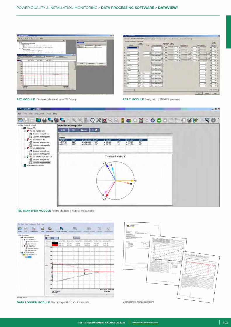
3CATALOGUE TEST & MESURE 2021 www.chauvin-arnoux.com 103TEST & MEASUREMENT CATALOGUE 2022 www.chauvin-arnoux.com
POWER QUALITY & INSTALLATION MONITORING > DATA PROCESSING SOFTWARE > DATAVIEW®
PAT 2 MODULE Configuration of EN 50160 parametersPAT MODULE Display of data stored by an F407 clamp
PEL TRANSFER MODULE Remote display of a vectorial representation
DATA LOGGER MODULE Recording of 0 -10 V - 2 channels Measurement campaign reports
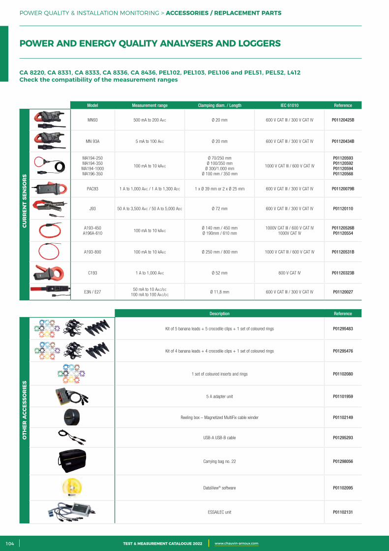
2 CATALOGUE TEST & MESURE 2021 www.chauvin-arnoux.com104 TEST & MEASUREMENT CATALOGUE 2022 www.chauvin-arnoux.com
POWER QUALITY & INSTALLATION MONITORING > ACCESSORIES / REPLACEMENT PARTS
Model Measurement range Clamping diam. / Length IEC 61010 Reference
MN93 500 mA to 200 AAc Ø 20 mm 600 V CAT III / 300 V CAT IV P01120425B
MN 93A 5 mA to 100 AAc Ø 20 mm 600 V CAT III / 300 V CAT IV P01120434B
MA194-250MA194-350
MA194-1000 MA196-350
100 mA to 10 kAAc
Ø 70/250 mmØ 100/350 mm
Ø 300/1.000 mmØ 100 mm / 350 mm
1000 V CAT III / 600 V CAT IV
P01120593P01120592P01120594P01120568
PAC93 1 A to 1,000 AAc / 1 A to 1,300 Adc 1 x Ø 39 mm or 2 x Ø 25 mm 600 V CAT III / 300 V CAT IV P01120079B
J93 50 A to 3,500 AAc / 50 A to 5,000 Adc Ø 72 mm 600 V CAT III / 300 V CAT IV P01120110
A193-450A196A-610
100 mA to 10 kAAc Ø 140 mm / 450 mmØ 190mm / 610 mm
1000V CAT III / 600 V CAT IV1000V CAT IV
P01120526BP01120554
A193-800 100 mA to 10 kAAc Ø 250 mm / 800 mm 1000 V CAT III / 600 V CAT IV P01120531B
C193 1 A to 1,000 AAc Ø 52 mm 600 V CAT IV P01120323B
E3N / E2750 mA to 10 AAc/dc
100 mA to 100 AAc/dc Ø 11,8 mm 600 V CAT III / 300 V CAT IV P01120027
Description Reference
Kit of 5 banana leads + 5 crocodile clips + 1 set of coloured rings P01295483
Kit of 4 banana leads + 4 crocodile clips + 1 set of coloured rings P01295476
1 set of coloured inserts and rings P01102080
5 A adapter unit P01101959
Reeling box – Magnetized MultiFix cable winder P01102149
USB-A USB-B cable P01295293
Carrying bag no. 22 P01298056
DataView® software P01102095
ESSAILEC unit P01102131
CUR
REN
T SE
NSO
RS
OTH
ER A
CCES
SOR
IES
CA 8220, CA 8331, CA 8333, CA 8336, CA 8436, PEL102, PEL103, PEL106 and PEL51, PEL52, L412 Check the compatibility of the measurement ranges
POWER AND ENERGY QUALITY ANALYSERS AND LOGGERS
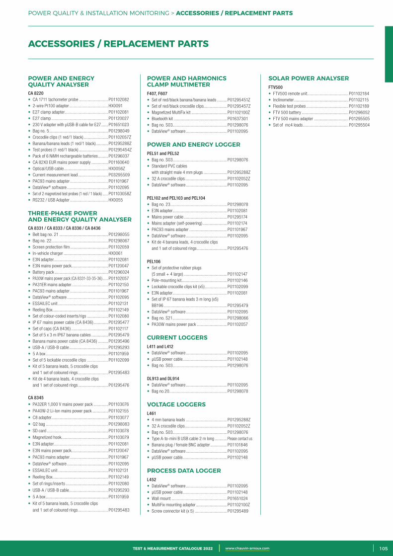
3CATALOGUE TEST & MESURE 2021 www.chauvin-arnoux.com 105TEST & MEASUREMENT CATALOGUE 2022 www.chauvin-arnoux.com
SOR
TIE
VO
LTA
GE
POWER QUALITY & INSTALLATION MONITORING > ACCESSORIES / REPLACEMENT PARTS
POWER AND ENERGY QUALITY ANALYSER CA 8220• CA 1711 tachometer probe .......................... P01102082• 2-wire Pt100 adapter ................................... HX0091• E27 clamp adapter ....................................... P01102081• E27 clamp ................................................... P01120027• 230 V adapter with µUSB-B cable for E27 ...... P01651023• Bag no. 5 ..................................................... P01298049• Crocodile clips (1 red/1 black) ...................... P01102057Z• Banana/banana leads (1 red/1 black) ........... P01295288Z• Test probes (1 red/1 black) .......................... P01295454Z• Pack of 6 NiMH rechargeable batteries ......... P01296037• CA 82X0 EUR mains power supply ............... P01160640• Optical/USB cable........................................ HX0056Z• Current measurement lead ........................... P03295509• PAC93 mains adapter .................................. P01101967• DataView® software ..................................... P01102095• Set of 2 magnetized test probes (1 red / 1 black) ..... P01103058Z• RS232 / USB Adapter .................................. HX0055
THREE-PHASE POWER AND ENERGY QUALITY ANALYSERCA 8331 / CA 8333 / CA 8336 / CA 8436 • Belt bag no. 21 ............................................ P01298055• Bag no. 22 ................................................... P01298067• Screen protection film .................................. P01102059• In-vehicle charger ........................................ HX0061• E3N adapter................................................. P01102081• E3N mains power pack ................................. P01120047• Battery pack ................................................ P01296024• PA30W mains power pack (CA 8331-33-35-36) ..... P01102057• PA31ER mains adapter ................................. P01102150• PAC93 mains adapter .................................. P01101967• DataView® software ..................................... P01102095• ESSAILEC unit ............................................. P01102131• Reeling Box .................................................. P01102149• Set of colour-coded inserts/rigs ................... P01102080• IP 67 mains power cable (CA 8436) ............. P01295477• Set of caps (CA 8436) ................................. P01102117• Set of 5 x 3 m IP67 banana cables ............... P01295479• Banana mains power cable (CA 8436) ......... P01295496• USB-A / USB-B cable ................................... P01295293• 5 A box ........................................................ P01101959• Set of 5 lockable crocodile clips ................... P01102099• Kit of 5 banana leads, 5 crocodile clips
and 1 set of coloured rings ........................... P01295483• Kit de 4 banana leads, 4 crocodile clips
and 1 set of coloured rings ........................... P01295476
CA 8345• PA32ER 1,000 V mains power pack ............. P01103076
• PA40W-2 Li-Ion mains power pack .............. P01102155
• C8 adapter................................................... P01103077
• Q2 bag ........................................................ P01298083
• SD card ....................................................... P01103078
• Magnetized hook .......................................... P01103079
• E3N adapter................................................. P01102081
• E3N mains power pack ................................. P01120047
• PAC93 mains adapter .................................. P01101967
• DataView® software ..................................... P01102095
• ESSAILEC unit ............................................. P01102131
• Reeling Box .................................................. P01102149
• Set of rings/inserts ...................................... P01102080
• USB-A / USB-B cable ................................... P01295293
• 5 A box ........................................................ P01101959
• Kit of 5 banana leads, 5 crocodile clips
and 1 set of coloured rings ........................... P01295483
POWER AND HARMONICS CLAMP MULTIMETERF407, F607 • Set of red/black banana/banana leads ......... P01295451Z• Set of red/black crocodile clips ..................... P01295457Z• Magnetized MultiFix kit ................................ P01102100Z• Bluetooth kit ................................................ P01637301• Bag no. S03................................................. P01298076• DataView® software ..................................... P01102095
POWER AND ENERGY LOGGERPEL51 and PEL52• Bag no. S03................................................. P01298076• Standard PVC cables
with straight male 4 mm plugs ..................... P01295288Z• 32 A crocodile clips ...................................... P01102052Z• DataView® software ..................................... P01102095
PEL102 and PEL103 and PEL104• Bag no. 23 ................................................... P01298078• E3N adapter................................................. P01102081• Mains power cable ....................................... P01295174• Mains adapter (self-powering) ...................... P01102174• PAC93 mains adapter .................................. P01101967• DataView® software ..................................... P01102095• Kit de 4 banana leads, 4 crocodile clips
and 1 set of coloured rings ........................... P01295476
PEL106 • Set of protective rubber plugs
(5 small + 4 large) ....................................... P01102147• Pole-mounting kit......................................... P01102146• Lockable crocodile clips kit (x5) .................... P01102099• E3N adapter................................................. P01102081• Set of IP 67 banana leads 3 m long (x5)
BB196 ......................................................... P01295479• DataView® software ..................................... P01102095• Bag no. S21 ................................................. P01298066• PA30W mains power pack ........................... P01102057
CURRENT LOGGERSL411 and L412• DataView® software ..................................... P01102095• µUSB power cable........................................ P01102148• Bag no. S03................................................. P01298076
DL913 and DL914 • DataView® software ..................................... P01102095• Bag no.20 .................................................... P01298078
VOLTAGE LOGGERSL461 • 4 mm banana leads ..................................... P01295288Z• 32 A crocodile clips ...................................... P01102052Z• Bag no. S03................................................. P01298076• Type A-to-mini B USB cable 2 m long ........... Please contact us• Banana plug / female BNC adapter ............... P01101846• DataView® software ..................................... P01102095• µUSB power cable........................................ P01102148
PROCESS DATA LOGGERL452 • DataView® software ..................................... P01102095• µUSB power cable........................................ P01102148• Wall mount .................................................. P01651024• MultiFix mounting adapter ............................ P01102100Z• Screw connector kit (x 5) ............................. P01295489
SOLAR POWER ANALYSERFTV500• FTV500 remote unit ..................................... P01102184• Inclinometer ................................................. P01102115• Flexible test probes ...................................... P01102189• FTV 500 battery .......................................... P01296052• FTV 500 mains adapter ............................... P01295505• Set of mc4 leads ......................................... P01295504
ACCESSORIES / REPLACEMENT PARTS
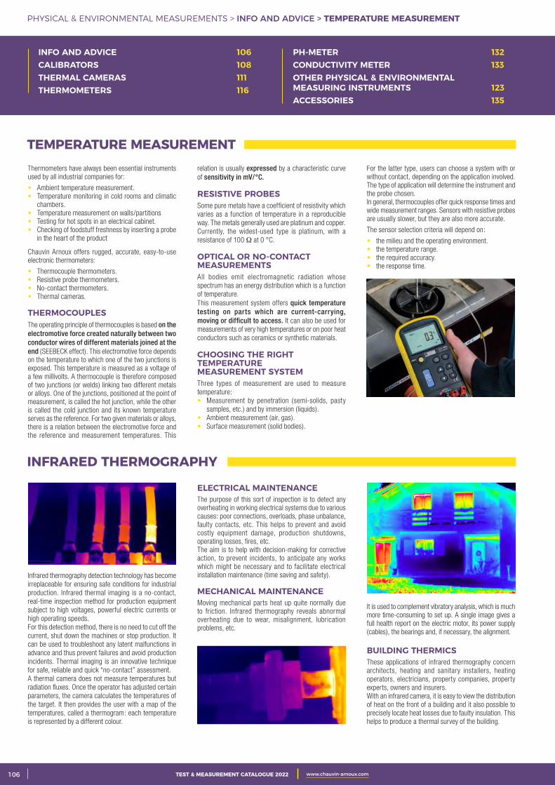
2 CATALOGUE TEST & MESURE 2021 www.chauvin-arnoux.com106 TEST & MEASUREMENT CATALOGUE 2022 www.chauvin-arnoux.com
PHYSICAL & ENVIRONMENTAL MEASUREMENTS > INFO AND ADVICE > TEMPERATURE MEASUREMENT
Thermometers have always been essential instruments used by all industrial companies for:
• Ambient temperature measurement. • Temperature monitoring in cold rooms and climatic chambers. • Temperature measurement on walls/partitions • Testing for hot spots in an electrical cabinet. • Checking of foodstuff freshness by inserting a probe in the heart of the product
Chauvin Arnoux offers rugged, accurate, easy-to-use electronic thermometers:
• Thermocouple thermometers. • Resistive probe thermometers. • No-contact thermometers. • Thermal cameras.
THERMOCOUPLESThe operating principle of thermocouples is based on the electromotive force created naturally between two conductor wires of different materials joined at the end (SEEBECK effect). This electromotive force depends on the temperature to which one of the two junctions is exposed. This temperature is measured as a voltage of a few millivolts. A thermocouple is therefore composed of two junctions (or welds) linking two different metals or alloys. One of the junctions, positioned at the point of measurement, is called the hot junction, while the other is called the cold junction and its known temperature serves as the reference. For two given materials or alloys, there is a relation between the electromotive force and the reference and measurement temperatures. This
relation is usually expressed by a characteristic curve of sensitivity in mV/°C.
RESISTIVE PROBESSome pure metals have a coefficient of resistivity which varies as a function of temperature in a reproducible way. The metals generally used are platinum and copper. Currently, the widest-used type is platinum, with a resistance of 100 Ω at 0 °C. OPTICAL OR NO-CONTACT MEASUREMENTS All bodies emit electromagnetic radiation whose spectrum has an energy distribution which is a function of temperature.This measurement system offers quick temperature testing on parts which are current-carrying, moving or difficult to access. It can also be used for measurements of very high temperatures or on poor heat conductors such as ceramics or synthetic materials.
CHOOSING THE RIGHT TEMPERATURE MEASUREMENT SYSTEMThree types of measurement are used to measure temperature:• Measurement by penetration (semi-solids, pasty samples, etc.) and by immersion (liquids).• Ambient measurement (air, gas). • Surface measurement (solid bodies).
For the latter type, users can choose a system with or without contact, depending on the application involved. The type of application will determine the instrument and the probe chosen. In general, thermocouples offer quick response times and wide measurement ranges. Sensors with resistive probes are usually slower, but they are also more accurate.
The sensor selection criteria will depend on:
• the milieu and the operating environment.• the temperature range.• the required accuracy.• the response time.
INFO AND ADVICE 106CALIBRATORS 108THERMAL CAMERAS 111THERMOMETERS 116
PH-METER 132CONDUCTIVITY METER 133OTHER PHYSICAL & ENVIRONMENTAL MEASURING INSTRUMENTS 123ACCESSORIES 135
TEMPERATURE MEASUREMENT
Infrared thermography detection technology has become irreplaceable for ensuring safe conditions for industrial production. Infrared thermal imaging is a no-contact, real-time inspection method for production equipment subject to high voltages, powerful electric currents or high operating speeds.For this detection method, there is no need to cut off the current, shut down the machines or stop production. It can be used to troubleshoot any latent malfunctions in advance and thus prevent failures and avoid production incidents. Thermal imaging is an innovative technique for safe, reliable and quick “no-contact” assessment.A thermal camera does not measure temperatures but radiation fluxes. Once the operator has adjusted certain parameters, the camera calculates the temperatures of the target. It then provides the user with a map of the temperatures, called a thermogram: each temperature is represented by a different colour.
ELECTRICAL MAINTENANCEThe purpose of this sort of inspection is to detect any overheating in working electrical systems due to various causes: poor connections, overloads, phase unbalance, faulty contacts, etc. This helps to prevent and avoid costly equipment damage, production shutdowns, operating losses, fires, etc.The aim is to help with decision-making for corrective action, to prevent incidents, to anticipate any works which might be necessary and to facilitate electrical installation maintenance (time saving and safety).
MECHANICAL MAINTENANCEMoving mechanical parts heat up quite normally due to friction. Infrared thermography reveals abnormal overheating due to wear, misalignment, lubrication problems, etc.
It is used to complement vibratory analysis, which is much more time-consuming to set up. A single image gives a full health report on the electric motor, its power supply (cables), the bearings and, if necessary, the alignment.
BUILDING THERMICSThese applications of infrared thermography concern architects, heating and sanitary installers, heating operators, electricians, property companies, property experts, owners and insurers. With an infrared camera, it is easy to view the distribution of heat on the front of a building and it also possible to precisely locate heat losses due to faulty insulation. This helps to produce a thermal survey of the building.
INFRARED THERMOGRAPHY
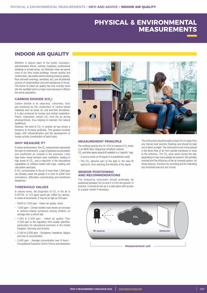
3CATALOGUE TEST & MESURE 2021 www.chauvin-arnoux.com 107TEST & MEASUREMENT CATALOGUE 2022 www.chauvin-arnoux.com
PHYSICAL & ENVIRONMENTAL MEASUREMENTS > INFO AND ADVICE > INDOOR AIR QUALITY
PHYSICAL & ENVIRONMENTAL MEASUREMENTS
INDOOR AIR QUALITYWhether in places open to the public (transport, administrative offices, schools, hospitals), professional buildings or private areas, our lifestyles mean we spend most of our time inside buildings. Human activity and construction, decoration and furnishing products (paints, floor and wall coverings, varnishes, etc.) are all potential sources of contamination and emit substances in the air. The theme of indoor air quality has only recently come into the spotlight and is a major issue because it affects the whole population.
CARBON DIOXIDE (CO2)Carbon dioxide is an odourless, colourless, toxic gas produced by the combustion of carbon-based materials such as wood, oil, coal and their derivatives. It is also produced by human and animal respiration. Plants, meanwhile, extract CO
2 from the air during
photosynthesis, thus helping to maintain the natural equilibrium. However, the level of CO
2 in outdoor air has shown a
tendency to increase gradually. This gradual increase began with industrialization and the development of human activity (combustion of fossil fuels).
WHY MEASURE IT?In indoor environments, the CO
2 measurement represents
the level of confinement, a sign of pollutant accumulation and insufficient air renewal in the premises. Links have been reveal between poor ventilation, leading to high levels of CO
2, and a reduction in the educational
capabilities of children tested with logic, reading and calculation exercises. A CO
2 concentration in the air of more than 1,000 ppm
can already cause the people in a room to suffer from somnolence, difficulties concentrating and sometimes headaches.
THRESHOLD VALUESIn volume terms, the proportion of CO
2 in the air is
0.0375%, or 375 ppmv (parts per million by volume). In urban environments, it may be as high as 500 ppm.
• 5500 to 1,000 ppm - Indoor air quality: Good
• 1,000 ppm - Certain studies have shown an increase in asthma-related symptoms among children on average over a school day
• 1,500 to 2,500 ppm - Indoor air quality: Poor (1,500 ppm is the regulatory limit usually specified, particularly for educational premises in the United Kingdom, Germany and Austria)
• 2,500 to 5,000 ppm - Symptoms: headache, fatigue and loss of concentration
• 5,000 ppm - Average concentration over 8 hours - Occupational Exposure Limit in France and elsewhere
The instrument should be kept at least 50 cm away from any intense heat sources (heating) and should be kept out of direct sunlight. The instrument must not be placed in the direct flow of air from outside (windows) or close to the entrance. The CO
2 level varies during the day,
depending on how many people are present, the activities involved and the efficiency of the air renewal system; for these reasons, functions for recording and for indicating any threshold overruns are crucial.
MEASUREMENT PRINCIPLE The method used by the CA 1510 to measure CO
2 levels
is an NDIR (Non-Dispersive InfraRed) method.CO
2 and other gases absorb IR radiation in a “specific” way.
• A source emits an IR signal in a predefined cavity
• The CO2 absorbs part of the light in the near-IR
spectrum, thus reducing the intensity of the signal
SENSOR POSITIONING AND RECOMMENDATIONS The measuring instrument should preferably be positioned between 50 cm and 2 m from the ground. In practice, it should be set up in a safe place with access to a power socket if necessary.
IR source
Measurement cell
Detector
CO2
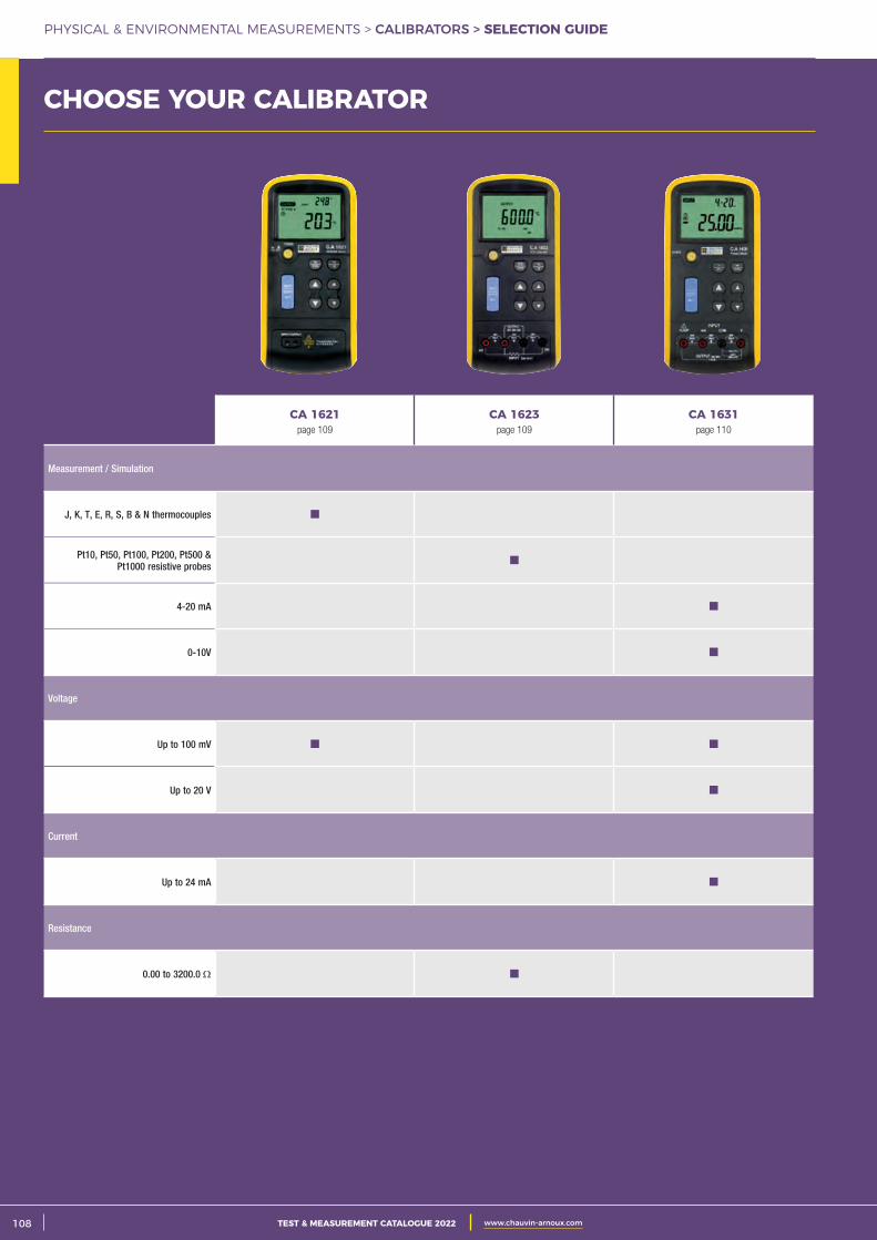
2 CATALOGUE TEST & MESURE 2021 www.chauvin-arnoux.com108 TEST & MEASUREMENT CATALOGUE 2022 www.chauvin-arnoux.com
PHYSICAL & ENVIRONMENTAL MEASUREMENTS > CALIBRATORS > SELECTION GUIDE
CHOOSE YOUR CALIBRATOR
CA 1621page 109
CA 1623page 109
CA 1631page 110
Measurement / Simulation
J, K, T, E, R, S, B & N thermocouples
Pt10, Pt50, Pt100, Pt200, Pt500 & Pt1000 resistive probes
4-20 mA
0-10V
Voltage
Up to 100 mV
Up to 20 V
Current
Up to 24 mA
Resistance
0.00 to 3200.0 Ω
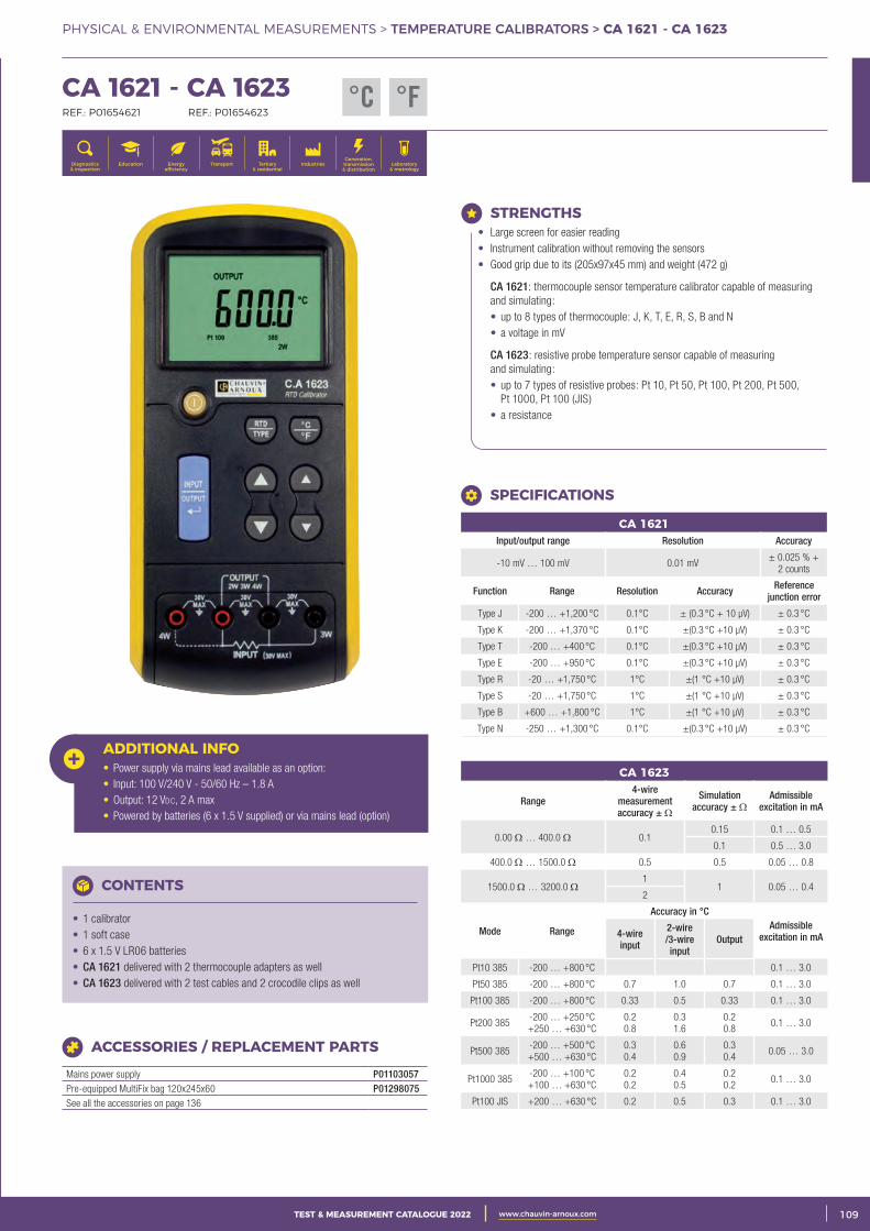
3CATALOGUE TEST & MESURE 2021 www.chauvin-arnoux.com 109TEST & MEASUREMENT CATALOGUE 2022 www.chauvin-arnoux.com
PHYSICAL & ENVIRONMENTAL MEASUREMENTS > TEMPERATURE CALIBRATORS > CA 1621 - CA 1623
CHOOSE YOUR CALIBRATOR CA 1621 - CA 1623 REF.: P01654621 REF.: P01654623
Generation, transmission & distribution
IndustriesTertiary & residential
Education TransportDiagnostics & inspection
Energy efficiency
Laboratory & metrology
STRENGTHS • Large screen for easier reading • Instrument calibration without removing the sensors • Good grip due to its (205x97x45 mm) and weight (472 g)
CA 1621: thermocouple sensor temperature calibrator capable of measuring and simulating:
• up to 8 types of thermocouple: J, K, T, E, R, S, B and N • a voltage in mV
CA 1623: resistive probe temperature sensor capable of measuring and simulating:
• up to 7 types of resistive probes: Pt 10, Pt 50, Pt 100, Pt 200, Pt 500, Pt 1000, Pt 100 (JIS)
• a resistance
CA 1621Input/output range Resolution Accuracy
-10 mV … 100 mV 0.01 mV± 0.025 % +
2 counts
Function Range Resolution Accuracy Reference junction error
Type J -200 … +1,200 °C 0.1°C ± (0.3 °C + 10 μV) ± 0.3 °C
Type K -200 … +1,370 °C 0.1°C ±(0.3 °C +10 μV) ± 0.3 °C
Type T -200 … +400 °C 0.1°C ±(0.3 °C +10 μV) ± 0.3 °C
Type E -200 … +950 °C 0.1°C ±(0.3 °C +10 μV) ± 0.3 °C
Type R -20 … +1,750 °C 1°C ±(1 °C +10 μV) ± 0.3 °C
Type S -20 … +1,750 °C 1°C ±(1 °C +10 μV) ± 0.3 °C
Type B +600 … +1,800 °C 1°C ±(1 °C +10 μV) ± 0.3 °C
Type N -250 … +1,300 °C 0.1°C ±(0.3 °C +10 μV) ± 0.3 °C
CA 1623
Range4-wire
measurement accuracy ± Ω
Simulation accuracy ± Ω
Admissible excitation in mA
0.00 Ω … 400.0 Ω 0.10.15 0.1 … 0.5
0.1 0.5 … 3.0
400.0 Ω … 1500.0 Ω 0.5 0.5 0.05 … 0.8
1500.0 Ω … 3200.0 Ω1
1 0.05 … 0.42
Mode Range
Accuracy in °CAdmissible
excitation in mA 4-wire input
2-wire /3-wire input
Output
Pt10 385 -200 … +800 °C 0.1 … 3.0
Pt50 385 -200 … +800 °C 0.7 1.0 0.7 0.1 … 3.0
Pt100 385 -200 … +800 °C 0.33 0.5 0.33 0.1 … 3.0
Pt200 385-200 … +250 °C +250 … +630 °C
0.20.8
0.31.6
0.20.8
0.1 … 3.0
Pt500 385-200 … +500 °C +500 … +630 °C
0.30.4
0.60.9
0.30.4
0.05 … 3.0
Pt1000 385-200 … +100 °C +100 … +630 °C
0.20.2
0.40.5
0.20.2
0.1 … 3.0
Pt100 JIS +200 … +630 °C 0.2 0.5 0.3 0.1 … 3.0
SPECIFICATIONS
ADDITIONAL INFO• Power supply via mains lead available as an option: • Input: 100 V/240 V - 50/60 Hz – 1.8 A • Output: 12 Vdc, 2 A max • Powered by batteries (6 x 1.5 V supplied) or via mains lead (option)
CONTENTS
• 1 calibrator • 1 soft case • 6 x 1.5 V LR06 batteries • CA 1621 delivered with 2 thermocouple adapters as well • CA 1623 delivered with 2 test cables and 2 crocodile clips as well
ACCESSORIES / REPLACEMENT PARTS
Mains power supply P01103057Pre-equipped MultiFix bag 120x245x60 P01298075See all the accessories on page 136
°C °F
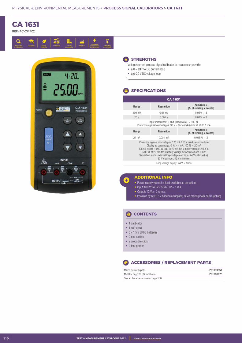
2 CATALOGUE TEST & MESURE 2021 www.chauvin-arnoux.com110 TEST & MEASUREMENT CATALOGUE 2022 www.chauvin-arnoux.com
PHYSICAL & ENVIRONMENTAL MEASUREMENTS > PROCESS SIGNAL CALIBRATORS > CA 1631
CA 1631 REF.: P01654402
Generation, transmission & distribution
IndustriesTertiary & residential
Education TransportDiagnostics & inspection
Energy efficiency
Laboratory & metrology
STRENGTHS Voltage/current process signal calibrator to measure or provide: • a 0 – 24 mA DC current loop • a 0-20 V DC voltage loop
ADDITIONAL INFO• Power supply via mains lead available as an option: • Input:100 V/240 V - 50/60 Hz – 1.8 A • Output: 12 Vdc, 2 A max • Powered by 6 x 1.5 V batteries (supplied) or via mains power cable (option)
CONTENTS
• 1 calibrator • 1 soft case • 6 x 1.5 V LR06 batteries • 2 test cables • 2 crocodile clips • 2 test probes
ACCESSORIES / REPLACEMENT PARTS
Mains power supply P01103057MultiFix bag 120x245x60 mm P01298075See all the accessories on page 136
SPECIFICATIONS
CA 1631
Range Resolution Accuracy ±(% of reading + counts)
100 mV 0.01 mV 0.02 % + 3
20 V 0.001 V 0.02 % + 3
Input impedance: 2 MΩ (rated value), < 100 pF Protection against overvoltages: 30 V – Current delivered at 20 V: 1 mA
Range Resolution Accuracy ± (% of reading + counts)
24 mA 0.001 mA 0.015 % + 3
Protection against overvoltages: 125 mA 250 V quick-response fuseDisplay as percentage: 0 % = 4 mA 100 % = 20 mA
Source mode: 1,000 Ω load at 20 mA for a battery voltage ≥ 6.8 V, (700 Ω at 20 mA for a battery voltage between 5.8 and 6.8 V
Simulation mode: external loop voltage condition: 24 V (rated value), 30 V maximum, 12 V minimum.
Loop voltage supply: 24 V ± 10 %
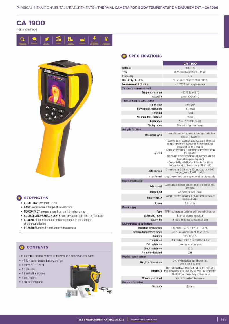
3CATALOGUE TEST & MESURE 2021 www.chauvin-arnoux.com 111TEST & MEASUREMENT CATALOGUE 2022 www.chauvin-arnoux.com
PHYSICAL & ENVIRONMENTAL MEASUREMENTS > THERMAL CAMERA FOR BODY TEMPERATURE MEASUREMENT > CA 1900
CA 1900 REF.: P01651902
Generation, transmission & distribution
IndustriesTertiary & residential
Education TransportDiagnostics & inspection
Energy efficiency
Laboratory & metrology
CONTENTS
The CA 1900 thermal camera is delivered in a site-proof case with:
• 4 NiMH batteries and battery charger • 1 micro SD HD card • 1 USB cable • 1 Bluetooth earpiece • 1 test report • 1 quick start guide
STRENGTHS • ACCURACY: less than 0.5 °C • FAST: instantaneous temperature detection • NO CONTACT: measurement from up 1.5 metres away • AUDIBLE AND VISUAL ALERTS: doe any abnormally high temperature • ALARMS: fixed threshold or threshold based on the average of the people tested • PRACTICAL: tripod insert beneath the camera
CA 1900Detector 160 x 120
Type UFPA microbolometer, 8 ~14 μm
Frequency 9 Hz
Sensitivity (N.E.T.D) 60 mK @ 30 °C (0.06 °C @ 30 °C)
Measurement fluctuation < 0.02 °C (with adaptive alarm)
Temperature measurement
Temperature range +30 °C to +45 °C
Accuracy ± 0.5 °C @ 37 °C
Thermal imaging performance
Field of view 38° x 28°
IFOV (spatial resolution) 4.1 mrad
Focusing Fixed
Minimum focal distance 30 cm
Real image Yes (320 x 240 pixels)
Display mode Thermal image, real image
Analysis functions
Measuring tools 1 manual cursor + 1 automatic host spot detection function + Isotherm
Alarms
- Adaptive alarm based on a temperature difference compared with the average of the temperatures
measured (up to 6 people) - Alarm on overrun of a temperature threshold set by
the operator - Visual and audible indications of overruns (via the
Bluetooth earpiece supplied) - Compatibility with Bluetooth hands-free kits or
loudspeakers (profiles supported: HSP, HFP)
Data storage On removable 2 GB micro SD card (approx. 4,000 images), up to 32 GB possible
Image format .png (thermal and real images saved simultaneously)
Image presentation
Adjustment Automatic or manual adjustment of the palette min. and max.
Image hold Animated or fixed image
Image display Multiple palettes including high-contrast rainbow or black and white
Screen 2.8 inches
Power supply
Type NiMH rechargeable batteries with low self-discharge
Recharging mode External (charger supplied)
Battery life 9 hours (in normal conditions of use)
Environmental specifications
Operating temperature -15 °C to +50 °C (-4 °F to +122 °F)
Storage temperature range -40 °C to +70 °C (-40 °F to +158 °F)
Humidity 10 % to 95 %
Compliance EN 61326-1: 2006 / EN 61010-1 Ed. 2
Fall resistance 2 metres on all surfaces
Shock resistance 25 G
Vibration withstand 2 G
Physical specifications
Weight / Dimensions 700 g with rechargeable batteries / 225 x 125 x 83 mm
Interfaces - USB link and Mass Storage function: the product is then recognized as a USB key for easy image transfer
- Bluetooth for connectivity with earpiece
Mounting on tripod Yes, ¼’’ insert on the camera
General information
Warranty 2 years
SPECIFICATIONS
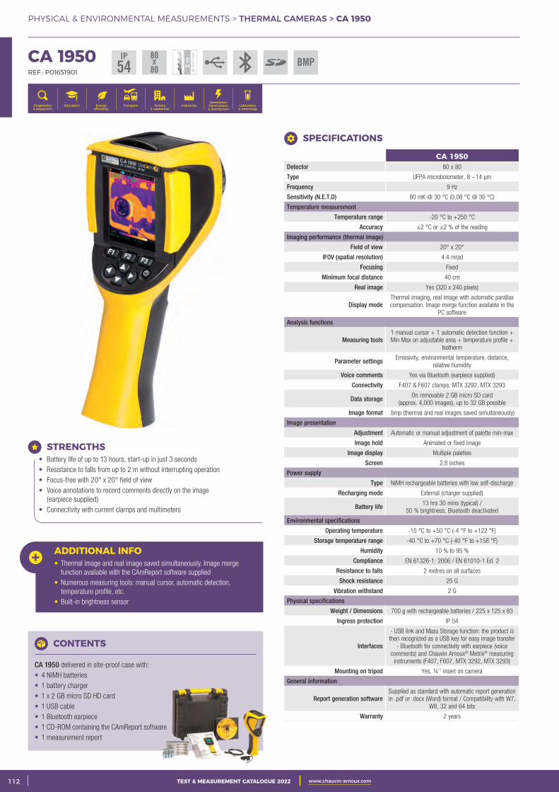
2 CATALOGUE TEST & MESURE 2021 www.chauvin-arnoux.com112 TEST & MEASUREMENT CATALOGUE 2022 www.chauvin-arnoux.com
PHYSICAL & ENVIRONMENTAL MEASUREMENTS > THERMAL CAMERAS > CA 1950
CA 1950Detector 80 x 80
Type UFPA microbolometer, 8 ~14 μm
Frequency 9 Hz
Sensitivity (N.E.T.D) 80 mK @ 30 °C (0.08 °C @ 30 °C)
Temperature measurement
Temperature range -20 °C to +250 °C
Accuracy ±2 °C or ±2 % of the reading
Imaging performance (thermal image)
Field of view 20° x 20°
IFOV (spatial resolution) 4.4 mrad
Focusing Fixed
Minimum focal distance 40 cm
Real image Yes (320 x 240 pixels)
Display modeThermal imaging, real image with automatic parallax compensation. Image merge function available in the
PC software
Analysis functions
Measuring tools1 manual cursor + 1 automatic detection function + Min Max on adjustable area + temperature profile +
Isotherm
Parameter settings Emissivity, environmental temperature, distance, relative humidity
Voice comments Yes via Bluetooth (earpiece supplied)
Connectivity F407 & F607 clamps, MTX 3292, MTX 3293
Data storage On removable 2 GB micro SD card (approx. 4,000 images), up to 32 GB possible
Image format .bmp (thermal and real images saved simultaneously)
Image presentation
Adjustment Automatic or manual adjustment of palette min-max
Image hold Animated or fixed image
Image display Multiple palettes
Screen 2.8 inches
Power supply
Type NiMH rechargeable batteries with low self-discharge
Recharging mode External (charger supplied)
Battery life 13 hrs 30 mins (typical) / 50 % brightness, Bluetooth deactivated
Environmental specifications
Operating temperature -15 °C to +50 °C (-4 °F to +122 °F)
Storage temperature range -40 °C to +70 °C (-40 °F to +158 °F)
Humidity 10 % to 95 %
Compliance EN 61326-1: 2006 / EN 61010-1 Ed. 2
Resistance to falls 2 metres on all surfaces
Shock resistance 25 G
Vibration withstand 2 G
Physical specifications
Weight / Dimensions 700 g with rechargeable batteries / 225 x 125 x 83
Ingress protection IP 54
Interfaces
- USB link and Mass Storage function: the product is then recognized as a USB key for easy image transfer
- Bluetooth for connectivity with earpiece (voice comments) and Chauvin Arnoux® Metrix® measuring
instruments (F407, F607, MTX 3292, MTX 3293)
Mounting on tripod Yes, ¼’’ insert on camera
General information
Report generation softwareSupplied as standard with automatic report generation in .pdf or .docx (Word) format / Compatibility with W7,
W8, 32 and 64 bits
Warranty 2 years
CA 1950 REF.: P01651901
Generation, transmission & distribution
IndustriesTertiary & residential
Education TransportDiagnostics & inspection
Energy efficiency
Laboratory & metrology
SPECIFICATIONS
ADDITIONAL INFO• Thermal image and real image saved simultaneously. Image merge function available with the CAmReport software supplied• Numerous measuring tools: manual cursor, automatic detection, temperature profile, etc. • Built-in brightness sensor
CONTENTS
CA 1950 delivered in site-proof case with: • 4 NiMH batteries • 1 battery charger • 1 x 2 GB micro SD HD card • 1 USB cable • 1 Bluetooth earpiece • 1 CD-ROM containing the CAmReport software • 1 measurement report
STRENGTHS • Battery life of up to 13 hours, start-up in just 3 seconds • Resistance to falls from up to 2 m without interrupting operation • Focus-free with 20° x 20° field of view • Voice annotations to record comments directly on the image (earpiece supplied) • Connectivity with current clamps and multimeters
IP54
80x
80BMP
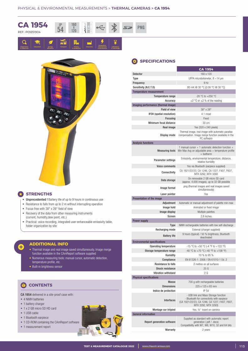
3CATALOGUE TEST & MESURE 2021 www.chauvin-arnoux.com 113TEST & MEASUREMENT CATALOGUE 2022 www.chauvin-arnoux.com
PHYSICAL & ENVIRONMENTAL MEASUREMENTS > THERMAL CAMERAS > CA 1954
CA 1954 REF.: P01651904
Generation, transmission & distribution
IndustriesTertiary & residential
Education TransportDiagnostics & inspection
Energy efficiency
Laboratory & metrology
CA 1954Detector 160 x 120
Type UFPA microbolometer, 8 ~14 μm
Frequency 9 Hz
Sensitivity (N.E.T.D) 80 mK @ 30 °C (0.08 °C @ 30 °C)
Temperature measurement
Temperature range -20 °C to +250 °C
Accuracy ±2 °C or ±2 % of the reading
Imaging performance (thermal image)
Field of view 38° x 28°
IFOV (spatial resolution) 4.1 mrad
Focusing Fixed
Minimum focal distance 30 cm
Real image Yes (320 x 240 pixels)
Display modeThermal image, real image with automatic parallax
compensation. Image merge function available in the PC software
Analysis functions
Measuring tools1 manual cursor + 1 automatic detection function +
Min Max Avg on adjustable area + temperature profile + Isotherm
Parameter settings Emissivity, environmental temperature, distance, relative humidity
Voice comments Yes via Bluetooth (earpiece supplied)
Connectivity CA 1821/22/23, CA 1246, CA 1227, F407, F607, MTX 3292, MTX 3293
Data storage On removable 2 GB micro SD card (approx. 4,000 images), up to 32 GB possible
Image format .png (thermal images and real images saved simultaneously)
Laser pointer Yes
Presentation of the image
Adjustment Automatic or manual adjustment of palette min-max
Image hold Animated or fixed image
Image display Multiple palettes
Screen 2.8 inches
Power supply
Type NiMH rechargeable batteries with low self-discharge
Recharging mode External (charger supplied)
Battery life 9 hours (typical) / 50 % brightness, Bluetooth deactivated
Environmental specifications
Operating temperature -15 °C to +50 °C (-4 °F to +122 °F)
Storage temperature range -40 °C to +70 °C (-40 °F to +158 °F)
Humidity 10 % to 95 %
Compliance EN 61326-1: 2006 / EN 61010-1 Ed. 2
Resistance to falls 2 metres on all surfaces
Shock resistance 25 G
Vibration withstand 2 G
Physical specifications
Masse 700 g with rechargeable batteries
Dimensions 225 x 125 x 83 mm
Indice de protection IP 54
Interfaces
- USB link and Mass Storage function- Bluetooth for connectivity with earpiece
(CA 1821/22/23, CA 1246, CA 1227, F407, F607, MTX 3292, MTX 3293)
Montage sur trépied Yes, ¼’’ insert on camera
General information
Report generation softwareSupplied as standard with automatic report
generation (.pdf / .docx)Compatibility with W7, W8, W10, 32 and 64 bits
Warranty 2 years
SPECIFICATIONS
ADDITIONAL INFO• Thermal image and real image saved simultaneously. Image merge function available in the CAmReport software supplied• Numerous measuring tools: manual cursor, automatic detection, temperature profile, etc. • Built-in brightness sensor
CONTENTS
CA 1954 delivered in a site-proof case with: • 4 NiMH batteries • 1 battery charger • 1 x 2 GB micro SD HD card • 1 USB cable • 1 Bluetooth earpiece • 1 CD-ROM containing the CAmReport software • 1 measurement report
STRENGTHS • Unprecedented ! Battery life of up to 9 hours in continuous use • Resistance to falls from up to 2 m without interrupting operation • Focus-free with 38° x 28° field of view • Recovery of the data from other measuring instruments (current, humidity,dew point, etc.) • Practical: voice recording, integrated user-enhanceable emissivity table, folder organization by site
IP54
160x
120PNG
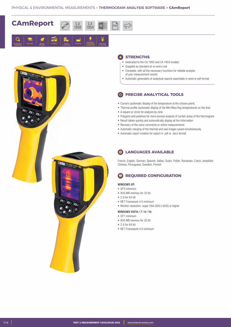
2 CATALOGUE TEST & MESURE 2021 www.chauvin-arnoux.com114 TEST & MEASUREMENT CATALOGUE 2022 www.chauvin-arnoux.com
PHYSICAL & ENVIRONMENTAL MEASUREMENTS > THERMOGRAM ANALYSIS SOFTWARE > CAmReport
Generation, transmission & distribution
IndustriesTertiary & residential
Education TransportDiagnostics & inspection
Energy efficiency
Laboratory & metrology
CAmReport
STRENGTHS • Dedicated to the CA 1950 and CA 1954 models • Supplied as standard at no extra cost • Complete, with all the necessary functions for reliable analysis of your measurement results • Automatic generation of analytical reports exportable in word or pdf format
PRECISE ANALYTICAL TOOLS
• Cursors (automatic display of the temperature at the chosen point) • Thermal profile (automatic display of the Min/Max/Avg temperatures on the line) • A square or circle for analysis by zone • Polygons and polylines for more precise analysis of certain areas of the thermogram • Result tables quickly and automatically display all the information • Recovery of the voice comments or online measurements • Automatic merging of the thermal and real images saved simultaneously • Automatic report creation for export in .pdf or .docx format
REQUIRED CONFIGURATION
WINDOWS XP: • SP3 minimum • 850 MB memory for 32 bit • 2 G for 64 bit • NET Framework 4.0 minimum • Monitor resolution: super VGA (800 x 600) or higher
WINDOWS VISTA / 7 / 8 / 10: • SP1 minimum • 850 MB memory for 32 bit • 2 G for 64 bit • NET Framework 4.0 minimum
LANGUAGES AVAILABLE
French, English, German, Spanish, Italian, Dutch, Polish, Romanian, Czech, simplified Chinese, Portuguese, Swedish, Finnish
C.A1950 PDF
C.A1954
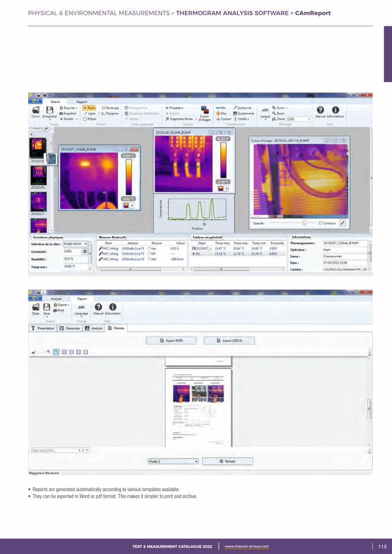
3CATALOGUE TEST & MESURE 2021 www.chauvin-arnoux.com 115TEST & MEASUREMENT CATALOGUE 2022 www.chauvin-arnoux.com
PHYSICAL & ENVIRONMENTAL MEASUREMENTS > THERMOGRAM ANALYSIS SOFTWARE > CAmReport
• Reports are generated automatically according to various templates available. • They can be exported in Word or pdf format. This makes it simpler to print and archive.

2 CATALOGUE TEST & MESURE 2021 www.chauvin-arnoux.com116 TEST & MEASUREMENT CATALOGUE 2022 www.chauvin-arnoux.com
PHYSICAL & ENVIRONMENTAL MEASUREMENTS > THERMOMETERS > SELECTION GUIDE
CHOOSING YOUR THERMOMETER
CA 1
871
CA 1
860
CA 1
862
CA 1
864
CA 1
866
CA 8
76
CA 1
821
CA 1
822
CA 1
823
TK 2
000
TK 2
002
page 118 page 117 page 117 page 117 page 117 page 118 page 120 page 120 page 121 page 119 page 119
Infrared measurement
Field of view
8/1
10/1
12/1
30/1
50/1
Emissivity
Fixed: 0.95
Variable: 0.1 to 1
Laser sightDouble
Contact measurement
1-input thermocouple
sensor
J, K, T, N, E, R, S
J, K, T, N, E, R, S
K K
2-input thermocouple
sensor
J, K, T, N, E, R, S
K
1-input resistive probe
Pt100Pt1000
General functions
HOLD
Max
Min
Avgvia
Data Logger Transfer
via Data Logger
Transfer
via Data Logger
Transfer
Alarm
Choice of units
Backlighting
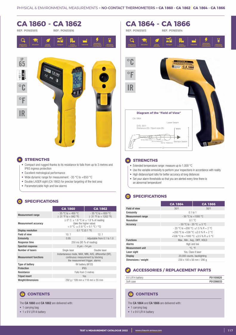
3CATALOGUE TEST & MESURE 2021 www.chauvin-arnoux.com 117TEST & MEASUREMENT CATALOGUE 2022 www.chauvin-arnoux.com
PHYSICAL & ENVIRONMENTAL MEASUREMENTS > NO-CONTACT THERMOMETERS > CA 1860 - CA 1862 | CA 1864 - CA 1866
CA 1860 - CA 1862 REF.: P01651815 REF.: P01651816
Generation, transmission & distribution
IndustriesTertiary & residential
Education TransportDiagnostics & inspection
Energy efficiency
Laboratory & metrology
CHOOSING YOUR THERMOMETER CA 1864 - CA 1866 REF.: P01651813 REF.: P01651814
Generation, transmission & distribution
IndustriesTertiary & residential
Education TransportDiagnostics & inspection
Energy efficiency
Laboratory & metrology
STRENGTHS• Compact and rugged thanks to its resistance to falls from up to 3 metres and
IP65 ingress protection• Excellent metrological performance• Wide dynamic range for measurement: -35 °C to +650 °C • Double LASER sight (CA 1862) for precise targeting of the test area• Parameterizable high and low alarms
SPECIFICATIONS
CA 1860 CA 1862
Measurement range - 35 °C to + 450 °C (- 31 °F to + 842 °F)
- 35 °C to + 650 °C (- 31 °F to + 1202 °F)
Measurement accuracy ≥ 0° C: ± 1.8 °C or ± 1.8 % of reading
(take the higher value) < 0 °C: ± (1.8 °C + 0.1 °C / °C)
Display resolution 0.1 °C (0.1 °F) Field of view 10: 1 12: 1Emissivity 0.95 Adjustable from 0.1 to 1.0 Response time 250 ms (95 % of reading) Spectral response 8 μm ~14 μm Number of lasers Single laser Double laser
Measurement functionsInstantaneous mode, MAX, MIN, AVG, differential (DIF),
continuous measurement by blocking the measurement trigger, alarms
Type of battery 9V battery (6F22) Protection IP65 Resistance Falls from 3 metres Tripod insert YesWeight/dimensions 292 g / 189 mm x 118 mm x 55 mm
CONTENTS
The CA 1860 and CA 1862 are delivered with: • 1 carrying bag • 1 x 9 V LR14 battery
STRENGTHS• Extended temperature range: measure up to 1,000 °C• Use the variable emissivity to perform your inspections in accordance with reality• High distance/spot ratio for better accuracy at long distances• Set your alarm thresholds so that you are alerted every time there is
an abnormal temperature!
CONTENTS
The CA 1864 and CA 1866 are delivered with: • 1 carrying bag • 1 x 9 V LR14 battery
ACCESSORIES / REPLACEMENT PARTS
9 V LR14 battery P01100620Soft case P01298033
Diagram of the “Field of View”
SPECIFICATIONS
CA 1864 CA 1866Field of view 30/1 50/1Emissivity 0.1 to 1 Measurement range - 50 °C to +1000 °C Resolution 0.1 °C Accuracy - 50 °C to - 20 °C: ± 5 °C
- 20 °C to +200 °C: ±1.5 % R + 2 °C
+200 °C to +538 °C: ±2.0 % R + 2 °C
+538 °C to +1000 °C: ±3.5 % R ± 5 °C Functions Max., Min., Avg., DIFF, HOLD Alarms High and lowMeasurement unit °C, °F Laser sight Yes, Class II laserDisplay 20,000 counts, backlightingDimensions / weight 230 x 100 x 56 mm / 290 g
°C
°F
IR
IP65
°F
IR
°C
CA 1864
Laser beam
Sensor beam
D/S: 30/1Distance (D) / Spot size (S)
50 to 1500mm30 to 900mm
10 to 300 mm
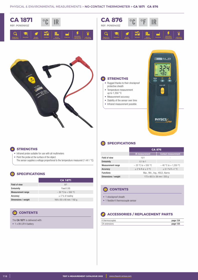
2 CATALOGUE TEST & MESURE 2021 www.chauvin-arnoux.com118 TEST & MEASUREMENT CATALOGUE 2022 www.chauvin-arnoux.com
PHYSICAL & ENVIRONMENTAL MEASUREMENTS > NO-CONTACT THERMOMETER > CA 1871 | CA 876
CA 1871 REF.: P01651610Z
Generation, transmission & distribution
IndustriesTertiary & residential
Education TransportDiagnostics & inspection
Energy efficiency
Laboratory & metrology
STRENGTHS• Infrared probe suitable for use with all multimeters• Point the probe at the surface of the object.
The sensor supplies a voltage proportional to the temperature measured (1 mV / °C)
CA 1871Field of view 8/1
Emissivity Fixed 0.95
Measurement range − 30 °C to + 550 °C
Accuracy ± 2 % of reading
Dimensions / weight 164 x 50 x 40 mm / 182 g
SPECIFICATIONS
CONTENTS
The CA 1871 is delivered with: • 1 x 9V LR14 battery
°C IR CA 876 REF.: P01651403Z
Generation, transmission & distribution
IndustriesTertiary & residential
Education TransportDiagnostics & inspection
Energy efficiency
Laboratory & metrology
STRENGTHS• Rugged thanks to their shockproof
protective sheath• Temperature measurement
up to 1,350 °C• Measurement accuracy• Stability of the sensor over time• Infrared measurement possible
CONTENTS
• 1 shockproof sheath • 1 flexible K thermocouple sensor
SPECIFICATIONS
CA 876IR measurement Contact measurement
Field of view 10/1 -
Emissivity 0.1 to 1 -
Measurement range − 20 °C to + 550 °C − 40 °C to + 1,350 °C
Accuracy ± 2 % R or ± 3 °C ± 0.1 % R +1 °C
Functions Max., Min., Avg., HOLD, Alarms
Dimensions / weight 173 x 60.5 x 38 mm / 255 g
ACCESSORIES / REPLACEMENT PARTS
K thermocouples page 134CK extensions page 135
°C °F IR
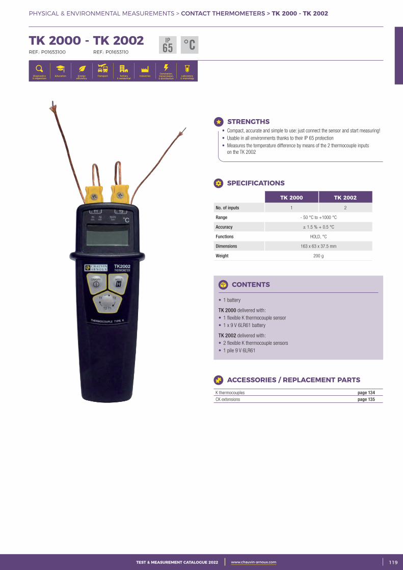
3CATALOGUE TEST & MESURE 2021 www.chauvin-arnoux.com 119TEST & MEASUREMENT CATALOGUE 2022 www.chauvin-arnoux.com
PHYSICAL & ENVIRONMENTAL MEASUREMENTS > CONTACT THERMOMETERS > TK 2000 - TK 2002
TK 2000 - TK 2002 REF.: P01653100 REF.: P01653110
Generation, transmission & distribution
IndustriesTertiary & residential
Education TransportDiagnostics & inspection
Energy efficiency
Laboratory & metrology
STRENGTHS• Compact, accurate and simple to use: just connect the sensor and start measuring! • Usable in all environments thanks to their IP 65 protection• Measures the temperature difference by means of the 2 thermocouple inputs
on the TK 2002
CONTENTS
• 1 battery
TK 2000 delivered with: • 1 flexible K thermocouple sensor • 1 x 9 V 6LR61 battery
TK 2002 delivered with: • 2 flexible K thermocouple sensors • 1 pile 9 V 6LR61
ACCESSORIES / REPLACEMENT PARTS
K thermocouples page 134CK extensions page 135
SPECIFICATIONS
TK 2000 TK 2002
No. of inputs 1 2
Range - 50 °C to +1000 °C
Accuracy ± 1.5 % + 0.5 °C
Functions HOLD, °C
Dimensions 163 x 63 x 37.5 mm
Weight 200 g
IP65 °C
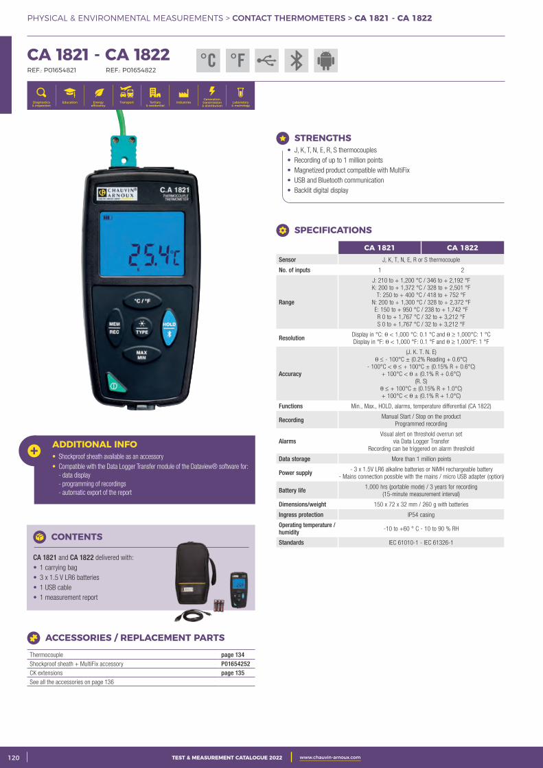
2 CATALOGUE TEST & MESURE 2021 www.chauvin-arnoux.com120 TEST & MEASUREMENT CATALOGUE 2022 www.chauvin-arnoux.com
PHYSICAL & ENVIRONMENTAL MEASUREMENTS > CONTACT THERMOMETERS > CA 1821 - CA 1822
CA 1821 - CA 1822 REF.: P01654821 REF.: P01654822
Generation, transmission & distribution
IndustriesTertiary & residential
Education TransportDiagnostics & inspection
Energy efficiency
Laboratory & metrology
STRENGTHS• J, K, T, N, E, R, S thermocouples• Recording of up to 1 million points• Magnetized product compatible with MultiFix• USB and Bluetooth communication• Backlit digital display
ADDITIONAL INFO• Shockproof sheath available as an accessory• Compatible with the Data Logger Transfer module of the Dataview® software for: - data display - programming of recordings - automatic export of the report
CONTENTS
CA 1821 and CA 1822 delivered with: • 1 carrying bag• 3 x 1.5 V LR6 batteries• 1 USB cable• 1 measurement report
ACCESSORIES / REPLACEMENT PARTS
Thermocouple page 134Shockproof sheath + MultiFix accessory P01654252CK extensions page 135See all the accessories on page 136
SPECIFICATIONS
CA 1821 CA 1822Sensor J, K, T, N, E, R or S thermocouple
No. of inputs 1 2
Range
J: 210 to + 1,200 °C / 346 to + 2,192 °FK: 200 to + 1,372 °C / 328 to + 2,501 °F
T: 250 to + 400 °C / 418 to + 752 °FN: 200 to + 1,300 °C / 328 to + 2,372 °FE: 150 to + 950 °C / 238 to + 1,742 °FR 0 to + 1,767 °C / 32 to + 3,212 °FS 0 to + 1,767 °C / 32 to + 3,212 °F
Resolution Display in °C: θ < 1,000 °C: 0.1 °C and θ ≥ 1,000°C: 1 °CDisplay in °F: θ < 1,000 °F: 0.1 °F and θ ≥ 1,000°F: 1 °F
Accuracy
(J. K. T. N. E)θ ≤ - 100°C ± (0.2% Reading + 0.6°C)
- 100°C < θ ≤ + 100°C ± (0.15% R + 0.6°C)+ 100°C < θ ± (0.1% R + 0.6°C)
(R. S)θ ≤ + 100°C ± (0.15% R + 1.0°C)+ 100°C < θ ± (0.1% R + 1.0°C)
Functions Min., Max., HOLD, alarms, temperature differential (CA 1822)
Recording Manual Start / Stop on the productProgrammed recording
Alarms Visual alert on threshold overrun set
via Data Logger TransferRecording can be triggered on alarm threshold
Data storage More than 1 million points
Power supply - 3 x 1.5V LR6 alkaline batteries or NiMH rechargeable battery- Mains connection possible with the mains / micro USB adapter (option)
Battery life 1,000 hrs (portable mode) / 3 years for recording (15-minute measurement interval)
Dimensions/weight 150 x 72 x 32 mm / 260 g with batteries
Ingress protection IP54 casing
Operating temperature / humidity -10 to +60 ° C - 10 to 90 % RH
Standards IEC 61010-1 - IEC 61326-1
°C °F
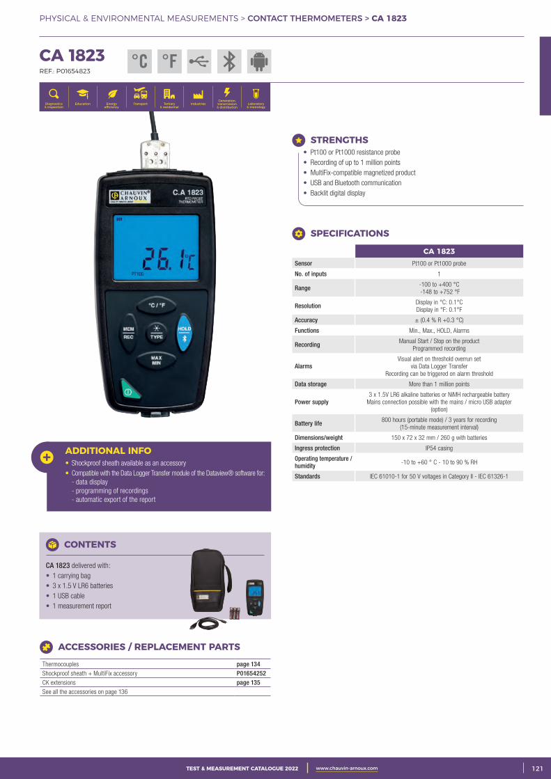
3CATALOGUE TEST & MESURE 2021 www.chauvin-arnoux.com 121TEST & MEASUREMENT CATALOGUE 2022 www.chauvin-arnoux.com
PHYSICAL & ENVIRONMENTAL MEASUREMENTS > CONTACT THERMOMETERS > CA 1823
CA 1823 REF.: P01654823
Generation, transmission & distribution
IndustriesTertiary & residential
Education TransportDiagnostics & inspection
Energy efficiency
Laboratory & metrology
STRENGTHS• Pt100 or Pt1000 resistance probe• Recording of up to 1 million points• MultiFix-compatible magnetized product• USB and Bluetooth communication• Backlit digital display
ADDITIONAL INFO• Shockproof sheath available as an accessory• Compatible with the Data Logger Transfer module of the Dataview® software for: - data display - programming of recordings - automatic export of the report
CONTENTS
CA 1823 delivered with: • 1 carrying bag • 3 x 1.5 V LR6 batteries• 1 USB cable• 1 measurement report
ACCESSORIES / REPLACEMENT PARTS
Thermocouples page 134Shockproof sheath + MultiFix accessory P01654252CK extensions page 135See all the accessories on page 136
CA 1823Sensor Pt100 or Pt1000 probe
No. of inputs 1
Range -100 to +400 °C -148 to +752 °F
Resolution Display in °C: 0.1°C Display in °F: 0.1°F
Accuracy ± (0.4 % R +0.3 °C)
Functions Min., Max., HOLD, Alarms
Recording Manual Start / Stop on the productProgrammed recording
Alarms Visual alert on threshold overrun set
via Data Logger TransferRecording can be triggered on alarm threshold
Data storage More than 1 million points
Power supply 3 x 1.5V LR6 alkaline batteries or NiMH rechargeable battery
Mains connection possible with the mains / micro USB adapter (option)
Battery life 800 hours (portable mode) / 3 years for recording (15-minute measurement interval)
Dimensions/weight 150 x 72 x 32 mm / 260 g with batteries
Ingress protection IP54 casing
Operating temperature / humidity -10 to +60 ° C - 10 to 90 % RH
Standards IEC 61010-1 for 50 V voltages in Category II - IEC 61326-1
SPECIFICATIONS
°C °F
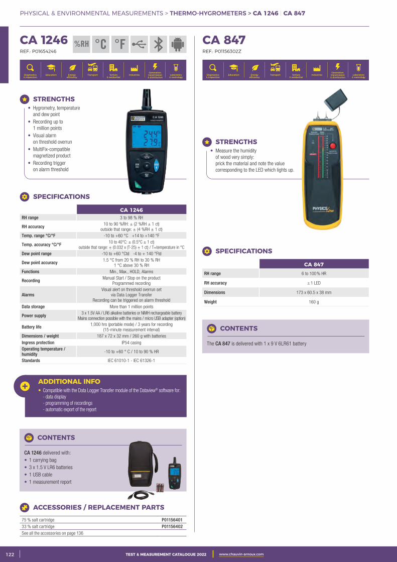
2 CATALOGUE TEST & MESURE 2021 www.chauvin-arnoux.com122 TEST & MEASUREMENT CATALOGUE 2022 www.chauvin-arnoux.com
PHYSICAL & ENVIRONMENTAL MEASUREMENTS > THERMO-HYGROMETERS > CA 1246 | CA 847
CA 1246 REF.: P01654246
Generation, transmission & distribution
IndustriesTertiary & residential
Education TransportDiagnostics & inspection
Energy efficiency
Laboratory & metrology
CA 847 REF.: P01156302Z
Generation, transmission & distribution
IndustriesTertiary & residential
Education TransportDiagnostics & inspection
Energy efficiency
Laboratory & metrology
STRENGTHS• Hygrometry, temperature
and dew point• Recording up to
1 million points• Visual alarm
on threshold overrun• MultiFix-compatible
magnetized product• Recording trigger
on alarm threshold
ADDITIONAL INFO• Compatible with the Data Logger Transfer module of the Dataview® software for: - data display - programming of recordings - automatic export of the report
CONTENTS
CA 1246 delivered with: • 1 carrying bag • 3 x 1.5 V LR6 batteries• 1 USB cable• 1 measurement report
ACCESSORIES / REPLACEMENT PARTS
75 % salt cartridge P0115640133 % salt cartridge P01156402See all the accessories on page 136
SPECIFICATIONS
CA 1246RH range 3 to 98 % RH
RH accuracy 10 to 90 %RH: ± (2 %RH ± 1 ct)outside that range: ± (4 %RH ± 1 ct)
Temp. range °C/°F -10 to +60 °C +14 to +140 °F
Temp. accuracy °C/°F 10 to 40°C: ± (0.5°C ± 1 ct)outside that range: ± (0.032 x (T-25) ± 1 ct) / T=temperature in °C
Dew point range -10 to +60 °Ctd -4 to + 140 °Ftd
Dew point accuracy 1.5 °C from 20 % RH to 30 % RH1 °C above 30 % RH
Functions Min., Max., HOLD, Alarms
Recording Manual Start / Stop on the productProgrammed recording
Alarms Visual alert on threshold overrun set
via Data Logger TransferRecording can be triggered on alarm threshold
Data storage More than 1 million points
Power supply 3 x 1.5V AA / LR6 alkaline batteries or NiMH rechargeable batteryMains connection possible with the mains / micro USB adapter (option)
Battery life 1,000 hrs (portable mode) / 3 years for recording (15-minute measurement interval)
Dimensions / weight 187 x 72 x 32 mm / 260 g with batteriesIngress protection IP54 casingOperating temperature / humidity -10 to +60 ° C / 10 to 90 % HR
Standards IEC 61010-1 - IEC 61326-1
STRENGTHS• Measure the humidity
of wood very simply: prick the material and note the value corresponding to the LED which lights up.
SPECIFICATIONS
CA 847RH range 6 to 100 % HR
RH accuracy ± 1 LED
Dimensions 173 x 60.5 x 38 mm
Weight 160 g
CONTENTS
The CA 847 is delivered with 1 x 9 V 6LR61 battery
%RH °C °F
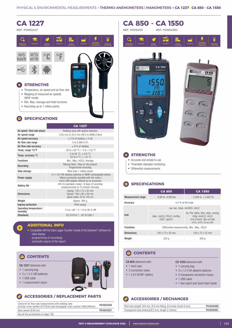
3CATALOGUE TEST & MESURE 2021 www.chauvin-arnoux.com 123TEST & MEASUREMENT CATALOGUE 2022 www.chauvin-arnoux.com
PHYSICAL & ENVIRONMENTAL MEASUREMENTS > THERMO-ANEMOMETERS | MANOMETERS > CA 1227 | CA 850 - CA 1550
CA 1227 REF.: P01654227
Generation, transmission & distribution
IndustriesTertiary & residential
Education TransportDiagnostics & inspection
Energy efficiency
Laboratory & metrology
ADDITIONAL INFO• Compatible with the Data Logger Transfer module of the Dataview® software for: - data display - programming of recordings - automatic export of the report
CONTENTS
CA 1227 delivered with: • 1 carrying bag• 3 x 1.5 V LR6 batteries• 1 USB cable• 1 measurement report
ACCESSORIES / REPLACEMENT PARTS
Cones kit for flow-rate measurement with rotating vane (circular cross-section Ø 210mm and rectangular cross-section 346x346mm) P01654250
Vane sensor Ø 80 mm P01654251See all the accessories on page 136
STRENGTHS• Temperature, air speed and air flow rate• Mapping of measured air speeds
(MAP mode)• Min, Max, Average and Hold functions• Recording up to 1 million points
CA 1227Air speed / flow rate sensor Rotating vane with optical detection Air speed range 0.25 m/s to 35.0 m/s (49.0 to 6890.0 fpm) Air speed accuracy ± 3 % of reading ± 4 ctsAir flow rate range 0 to 2,999 m3/h Air flow rate accuracy ± 8 % of reading Temp. range °C/°F - 20 to +50 °C / -4 to +122 °F
Temp. accuracy °C 0 to 50 °C: ± 0.8 °C -20 to 0 °C: ± 1.6 °C
Functions Min., Max., HOLD, Average
Recording Manual Start / Stop on the product Programmed recording
Data storage More than 1 million points
Power supply - 3 x 1.5V LR6 alkaline batteries or NiMH rechargeable battery
- Mains connection possible with the mains / micro-USB adapter offered as an accessory
Battery life 200 hrs (portable mode) / 8 days of recording (measurements at 15-minute intervals)
Dimensions Casing: 150 x 72 x 32 mmSensor: 160 x 80 x 38 mmSpiral cable: 24 to 120 cm
Weight Approx. 400 g Ingress protection IP40 casingOperating temperature / humidity -10 to +60 ° C / 10 to 90 % HR
Standards IEC 61010-1 - IEC 61326-1
SPECIFICATIONS
CA 850 - CA 1550 REF.: P01184101 REF.: P01654550
Generation, transmission & distribution
IndustriesTertiary & residential
Education TransportDiagnostics & inspection
Energy efficiency
Laboratory & metrology
STRENGTHS• Accurate and simple to use• Time/date-stamped monitoring• Differential measurements
CONTENTS
CA 850 delivered with: • 1 hard case• 2 connection tubes• 1 x 9 V 6LR61 battery
CA 1550 delivered with: • 1 carrying bag• 3 x 1.5 V AA alkaline batteries• 2 transparent connection hoses, • 1 USB cable• 1 test report and Quick Start Guide
SPECIFICATIONS
CA 850 CA 1550
Measurement range -6.89 to +6.89 bar - 2,450 to + 2,450 Pa
Accuracy 0.5 % at full scale
Unit
psi, bar, mbar, mmH2O, inH2O
kbar, cmH2O, FtH
2O, mmHg,
OZin2, kg/cm2
Pa, PSI, DaPa, hPa, mbar, mmHg, inHg, mmH
2O, inH
2O
m/s et km/h, fpm et mph m3/s, m3/h, l/s ou cfm
Functions Differential measurements, Min., Max., HOLD
Dimensions 182 x 72 x 30 mm 150 x 72 x 32 mm
Weight 220 g 260 g
m/skm/h
m3/sm3/h °C °F
ACCESSOIRES / RECHANGES
Pitot tube (length 324 mm, Ø 6 mm fitting, Ø at tube mouth 8 mm) P01654560Transparent hose ( Internal Ø 5 mm, length 2 metres) P01654561
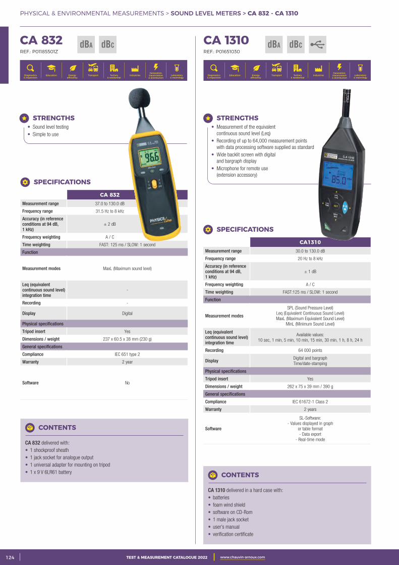
2 CATALOGUE TEST & MESURE 2021 www.chauvin-arnoux.com124 TEST & MEASUREMENT CATALOGUE 2022 www.chauvin-arnoux.com
PHYSICAL & ENVIRONMENTAL MEASUREMENTS > SOUND LEVEL METERS > CA 832 - CA 1310
CA 832 REF.: P01185501Z
Generation, transmission & distribution
IndustriesTertiary & residential
Education TransportDiagnostics & inspection
Energy efficiency
Laboratory & metrology
dBA dBC CA 1310 REF.: P01651030
Generation, transmission & distribution
IndustriesTertiary & residential
Education TransportDiagnostics & inspection
Energy efficiency
Laboratory & metrology
CONTENTS
CA 1310 delivered in a hard case with:• batteries• foam wind shield• software on CD-Rom • 1 male jack socket• user’s manual • verification certificate
CONTENTS
CA 832 delivered with: • 1 shockproof sheath • 1 jack socket for analogue output• 1 universal adapter for mounting on tripod• 1 x 9 V 6LR61 battery
SPECIFICATIONS
CA 832Measurement range 37.0 to 130.0 dB
Frequency range 31.5 Hz to 8 kHz
Accuracy (in reference conditions at 94 dB, 1 kHz)
± 2 dB
Frequency weighting A / C
Time weighting FAST: 125 ms / SLOW: 1 second
Function
Measurement modes MaxL (Maximum sound level)
Leq (equivalent continuous sound level) integration time
-
Recording -
Display Digital
Physical specifications
Tripod insert Yes
Dimensions / weight 237 x 60.5 x 38 mm (230 g)
General specifications
Compliance IEC 651 type 2
Warranty 2 year
Software No
SPECIFICATIONS
CA1310Measurement range 30.0 to 130.0 dB
Frequency range 20 Hz to 8 kHz
Accuracy (in reference conditions at 94 dB, 1 kHz)
± 1 dB
Frequency weighting A / C
Time weighting FAST:125 ms / SLOW: 1 second
Function
Measurement modes
SPL (Sound Pressure Level) Leq (Equivalent Continuous Sound Level) MaxL (Maximum Equivalent Sound Level)
MinL (Minimum Sound Level)
Leq (equivalent continuous sound level) integration time
Available values: 10 sec, 1 min, 5 min, 10 min, 15 min, 30 min, 1 h, 8 h, 24 h
Recording 64 000 points
Display Digital and bargraph Time/date-stamping
Physical specifications
Tripod insert Yes
Dimensions / weight 262 x 75 x 39 mm / 390 g
General specifications
Compliance IEC 61672-1 Class 2
Warranty 2 years
Software
SL-Software: - Values displayed in graph
or table format- Data export
- Real-time mode
STRENGTHS• Measurement of the equivalent
continuous sound level (Leq)• Recording of up to 64,000 measurement points
with data processing software supplied as standard• Wide backlit screen with digital
and bargraph display• Microphone for remote use
(extension accessory)
STRENGTHS• Sound level testing • Simple to use
dBA dBC
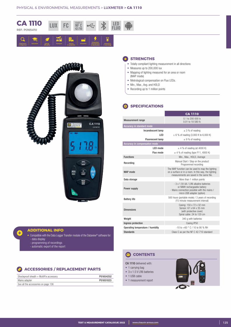
3CATALOGUE TEST & MESURE 2021 www.chauvin-arnoux.com 125TEST & MEASUREMENT CATALOGUE 2022 www.chauvin-arnoux.com
PHYSICAL & ENVIRONMENTAL MEASUREMENTS > LUXMETER > CA 1110
CA 1110 REF.: P01654110
Generation, transmission & distribution
IndustriesTertiary & residential
Education TransportDiagnostics & inspection
Energy efficiency
Laboratory & metrology
ADDITIONAL INFO• Compatible with the Data Logger Transfer module of the Dataview® software for: - data display - programming of recordings - automatic export of the report
CONTENTS
CA 1110 delivered with: • 1 carrying bag• 3 x 1.5 V LR6 batteries• 1 USB cable• 1 measurement report
ACCESSORIES / REPLACEMENT PARTS
Shockproof sheath + MultiFix accessory P01654252Mains adapter P01651023See all the accessories on page 136
STRENGTHS• Totally compliant lighting measurement in all directions• Measures up to 200,000 lux• Mapping of lighting measured for an area or room
(MAP mode)• Metrological compensation on Fluo LEDs.• Min., Max., Avg. and HOLD• Recording up to 1 million points
CA 1110
Measurement range 0.1 to 200 000 lx0.01 to 18 580 fc
Accuracy in standard mode
Incandescent lamp ± 3 % of reading
LED ± 6 % of reading (3,000 K to 6,000 K)
Fluorescent lamp ± 9 % of reading
Accuracy in compensation mode
LED mode ± 4 % of reading (at 4000 K)
Fluo mode ± 4 % of reading (type F11, 4000 K)
Functions Min., Max., HOLD, Average
Recording Manual Start / Stop on the product Programmed recording
MAP modeThe MAP function can be used to map the lighting on a surface or in a room. In this way, the lighting
measurements are saved in the same file.
Data storage More than 1 million points
Power supply
- 3 x 1.5V AA / LR6 alkaline batteries or NiMH rechargeable battery
- Mains connection possible with the mains / micro USB adapter (option)
Battery life 500 hours (portable mode) / 3 years of recording (15-minute measurement interval)
Dimensions
Casing: 150 x 72 x 32 mmSensor: 67 x 64 x 35 mm
(with protective cover)Spiral cable: 24 to 120 cm
Weight 345 g with batteries
Ingress protection Casing IP50
Operating temperature / humidity -10 to +60 ° C / 10 to 90 % RH
Standards Class C as per the NF C 42-710 standard
SPECIFICATIONS
LUX FC LEDFLUO
CLASS C
NF C42-710
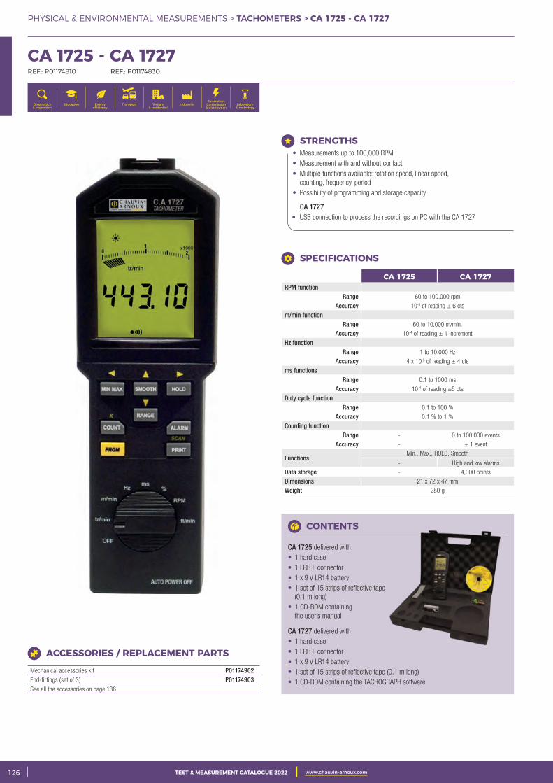
2 CATALOGUE TEST & MESURE 2021 www.chauvin-arnoux.com126 TEST & MEASUREMENT CATALOGUE 2022 www.chauvin-arnoux.com
PHYSICAL & ENVIRONMENTAL MEASUREMENTS > TACHOMETERS > CA 1725 - CA 1727
CA 1725 - CA 1727 REF.: P01174810 REF.: P01174830
Generation, transmission & distribution
IndustriesTertiary & residential
Education TransportDiagnostics & inspection
Energy efficiency
Laboratory & metrology
CONTENTS
CA 1725 delivered with: • 1 hard case • 1 FRB F connector• 1 x 9 V LR14 battery• 1 set of 15 strips of reflective tape
(0.1 m long) • 1 CD-ROM containing
the user’s manual
CA 1727 delivered with: • 1 hard case• 1 FRB F connector• 1 x 9 V LR14 battery• 1 set of 15 strips of reflective tape (0.1 m long) • 1 CD-ROM containing the TACHOGRAPH software
ACCESSORIES / REPLACEMENT PARTS
Mechanical accessories kit P01174902End-fittings (set of 3) P01174903See all the accessories on page 136
STRENGTHS• Measurements up to 100,000 RPM• Measurement with and without contact• Multiple functions available: rotation speed, linear speed,
counting, frequency, period• Possibility of programming and storage capacity
CA 1727 • USB connection to process the recordings on PC with the CA 1727
CA 1725 CA 1727RPM function
Range 60 to 100,000 rpmAccuracy 10-4 of reading ± 6 cts
m/min functionRange 60 to 10,000 m/min.
Accuracy 10-4 of reading ± 1 increment Hz function
Range 1 to 10,000 Hz Accuracy 4 x 10⁻⁵ of reading ± 4 cts
ms functionsRange 0.1 to 1000 ms
Accuracy 10-4 of reading ±5 cts Duty cycle function
Range 0.1 to 100 % Accuracy 0.1 % to 1 %
Counting function Range - 0 to 100,000 events
Accuracy - ± 1 event
FunctionsMin., Max., HOLD, Smooth
- High and low alarmsData storage - 4,000 points Dimensions 21 x 72 x 47 mmWeight 250 g
SPECIFICATIONS
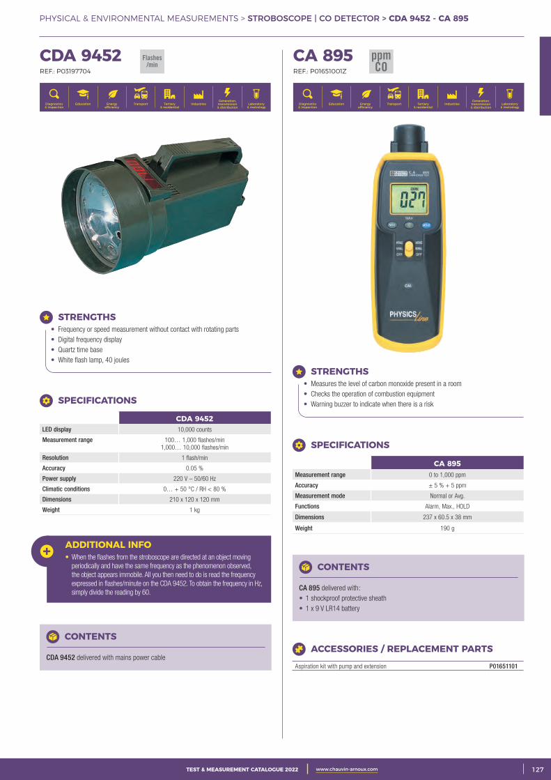
3CATALOGUE TEST & MESURE 2021 www.chauvin-arnoux.com 127TEST & MEASUREMENT CATALOGUE 2022 www.chauvin-arnoux.com
PHYSICAL & ENVIRONMENTAL MEASUREMENTS > STROBOSCOPE | CO DETECTOR > CDA 9452 - CA 895
CDA 9452 REF.: P03197704
Generation, transmission & distribution
IndustriesTertiary & residential
Education TransportDiagnostics & inspection
Energy efficiency
Laboratory & metrology
CA 895 REF.: P01651001Z
Generation, transmission & distribution
IndustriesTertiary & residential
Education TransportDiagnostics & inspection
Energy efficiency
Laboratory & metrology
ADDITIONAL INFO• When the flashes from the stroboscope are directed at an object moving
periodically and have the same frequency as the phenomenon observed, the object appears immobile. All you then need to do is read the frequency expressed in flashes/minute on the CDA 9452. To obtain the frequency in Hz, simply divide the reading by 60.
CONTENTS
CDA 9452 delivered with mains power cable
STRENGTHS• Frequency or speed measurement without contact with rotating parts• Digital frequency display• Quartz time base• White flash lamp, 40 joules
SPECIFICATIONS
CDA 9452LED display 10,000 counts
Measurement range 100… 1,000 flashes/min 1,000… 10,000 flashes/min
Resolution 1 flash/min
Accuracy 0.05 %
Power supply 220 V – 50/60 Hz
Climatic conditions 0… + 50 °C / RH < 80 %
Dimensions 210 x 120 x 120 mm
Weight 1 kg
CONTENTS
CA 895 delivered with: • 1 shockproof protective sheath • 1 x 9 V LR14 battery
STRENGTHS• Measures the level of carbon monoxide present in a room• Checks the operation of combustion equipment• Warning buzzer to indicate when there is a risk
SPECIFICATIONS
CA 895Measurement range 0 to 1,000 ppm
Accuracy ± 5 % + 5 ppm
Measurement mode Normal or Avg.
Functions Alarm, Max., HOLD
Dimensions 237 x 60.5 x 38 mm
Weight 190 g
ACCESSORIES / REPLACEMENT PARTS
Aspiration kit with pump and extension P01651101
Flashes/min
ppmCO
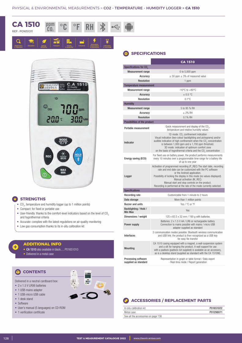
2 CATALOGUE TEST & MESURE 2021 www.chauvin-arnoux.com128 TEST & MEASUREMENT CATALOGUE 2022 www.chauvin-arnoux.com
PHYSICAL & ENVIRONMENTAL MEASUREMENTS > CO2 - TEMPERATURE - HUMIDITY LOGGER > CA 1510
CA 1510 REF.: P01651011
Generation, transmission & distribution
IndustriesTertiary & residential
Education TransportDiagnostics & inspection
Energy efficiency
Laboratory & metrology
CONTENTS
Delivered in a neutral cardboard box: • 2 x 1.5 V LR06 batteries• 1 USB mains adapter• 1 USB-micro USB cable• 1 desk stand• Software• User’s manual (5 languages) on CD-ROM • 1 verification certificate
STRENGTHS• CO
2, temperature and humidity logger (up to 1 million points)
• Compact: for fixed or portable use• User-friendly: thanks to the comfort-level indicators based on the level of CO
2
and hygrothermal criteria• Accurate: complies with the latest regulations on air-quality monitoring• Low gas consumption thanks to its in-situ calibration kit
ACCESSORIES / REPLACEMENT PARTS
In-situ calibration kit P01651022Metal case P01298071See all the accessories on page 136
CA 1510Specifications for CO2
Measurement range 0 to 5,000 ppm
Accuracy ± 50 ppm ± 3% of measured value
Resolution 1 ppm
Temperature measurement
Measurement range -10°C to +60°C
Accuracy ± 0.5 °C
Resolution 0.1°C
Humidity
Measurement range 5 to 95 % RH
Accuracy ± 2% RH
Resolution 0.1% RH
Possibilities of the product
Portable measurement Quick measurement and display of the CO2,
temperature and relative humidity values
Indicator
1D mode: CO2 confinement indication
Visual indication (two-colour backlighting and pictograms) and/or audible indication of high confinement when the CO
2 concentration
is between 1,000 ppm and a 1,700 ppm threshold.3D mode: indication of optimum comfort zone
on the basis of hygrothermal criteria and the CO2 concentration
Energy saving (ECO) For fixed use on battery power, the product performs measurements every 10 minutes over a programmable time range for a battery life
of up to one year
Logger
Activation of programmed recording (P_REC) The start date, recording rate and end date can be customized with the PC software
or the Android application.Possibility of locking the display in this mode (no values displayed).
Manual activation (M_REC)Manual start and stop controls on the product.
Recording is performed at the rate of the mode currently selected.
Specifications
Recording rate Customizable from 1 minute to 2 hours
Data storage More than 1 million points
Buzzer and units Yes / °C or °F
Backlighting / Hold / Min Max Yes
Dimensions / weight 125 x 65.5 x 32 mm / 190 g with batteries
Power supplyBatteries: 2 x 1.5 V AA / LR6 or rechargeable batteryConnection to mains possible with mains / micro USB
adapter supplied as standard
Interfaces 2 communication modes possible: Bluetooth wireless communication
and USB link; the product is then recognized as a USB key for easy file transfer
Mounting
CA 1510 casing equipped with a magnet, a wall-suspension system and a slit for hanging the product. A wall support for use
with a padlock (padlock not supplied) is available as an accessory, as is a desktop stand (supplied as standard with the CA 1510W).
Processing software supplied as standard
Representation in graph or table format / Data export - Real-time mode / Report generation
SPECIFICATIONS
ADDITIONAL INFO• CA 1510 also available in black..... P01651010 • Delivered in a metal case
ppmCO2
°C RH°F
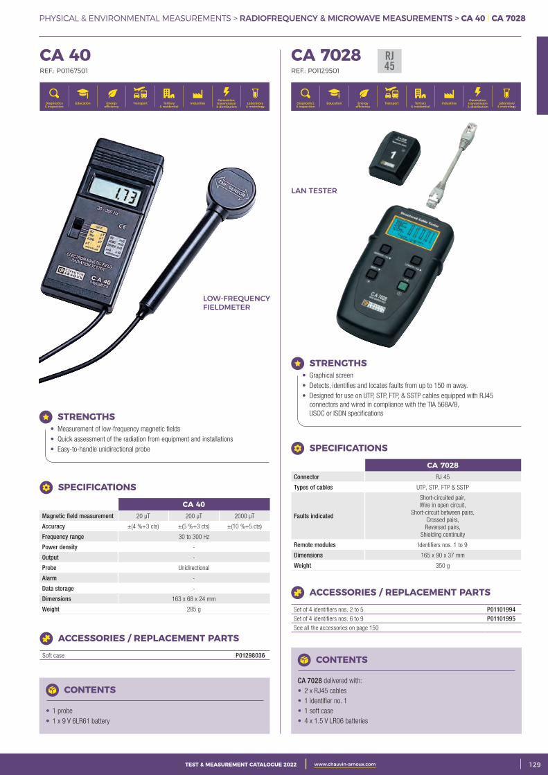
3CATALOGUE TEST & MESURE 2021 www.chauvin-arnoux.com 129TEST & MEASUREMENT CATALOGUE 2022 www.chauvin-arnoux.com
PHYSICAL & ENVIRONMENTAL MEASUREMENTS > RADIOFREQUENCY & MICROWAVE MEASUREMENTS > CA 40 | CA 7028
CA 40 REF.: P01167501
Generation, transmission & distribution
IndustriesTertiary & residential
Education TransportDiagnostics & inspection
Energy efficiency
Laboratory & metrology
CA 7028 REF.: P01129501
Generation, transmission & distribution
IndustriesTertiary & residential
Education TransportDiagnostics & inspection
Energy efficiency
Laboratory & metrology
CA 40Magnetic field measurement 20 μT 200 μT 2000 μT
Accuracy ±(4 %+3 cts) ±(5 %+3 cts) ±(10 %+5 cts)
Frequency range 30 to 300 Hz
Power density -
Output -
Probe Unidirectional
Alarm -
Data storage -
Dimensions 163 x 68 x 24 mm
Weight 285 g
STRENGTHS• Measurement of low-frequency magnetic fields• Quick assessment of the radiation from equipment and installations• Easy-to-handle unidirectional probe
CONTENTS
• 1 probe • 1 x 9 V 6LR61 battery
ACCESSORIES / REPLACEMENT PARTS
Soft case P01298036
SPECIFICATIONS
CONTENTS
CA 7028 delivered with: • 2 x RJ45 cables• 1 identifier no. 1 • 1 soft case• 4 x 1.5 V LR06 batteries
STRENGTHS• Graphical screen• Detects, identifies and locates faults from up to 150 m away.• Designed for use on UTP, STP, FTP, & SSTP cables equipped with RJ45
connectors and wired in compliance with the TIA 568A/B, USOC or ISDN specifications
CA 7028Connector RJ 45
Types of cables UTP, STP, FTP & SSTP
Faults indicated
Short-circuited pair,Wire in open circuit,
Short-circuit between pairs,Crossed pairs,Reversed pairs,
Shielding continuity
Remote modules Identifiers nos. 1 to 9
Dimensions 165 x 90 x 37 mm
Weight 350 g
SPECIFICATIONS
ACCESSORIES / REPLACEMENT PARTS
Set of 4 identifiers nos. 2 to 5 P01101994Set of 4 identifiers nos. 6 to 9 P01101995See all the accessories on page 150
LOW-FREQUENCY FIELDMETER
LAN TESTER
RJ45
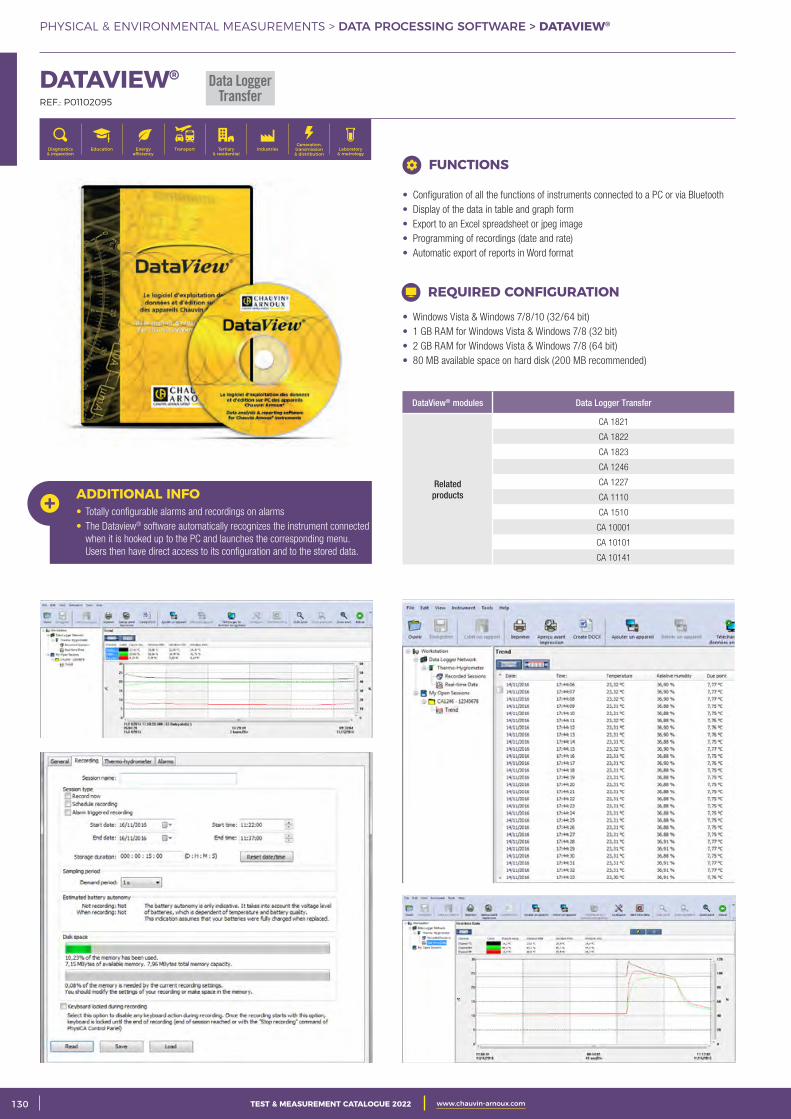
2 CATALOGUE TEST & MESURE 2021 www.chauvin-arnoux.com130 TEST & MEASUREMENT CATALOGUE 2022 www.chauvin-arnoux.com
PHYSICAL & ENVIRONMENTAL MEASUREMENTS > DATA PROCESSING SOFTWARE > DATAVIEW®
DATAVIEW® REF.: P01102095
Generation, transmission & distribution
IndustriesTertiary & residential
Education TransportDiagnostics & inspection
Energy efficiency
Laboratory & metrology
DataView® modules Data Logger Transfer
Related products
CA 1821
CA 1822
CA 1823
CA 1246
CA 1227
CA 1110
CA 1510
CA 10001
CA 10101
CA 10141
• Windows Vista & Windows 7/8/10 (32/64 bit)• 1 GB RAM for Windows Vista & Windows 7/8 (32 bit)• 2 GB RAM for Windows Vista & Windows 7/8 (64 bit)• 80 MB available space on hard disk (200 MB recommended)
REQUIRED CONFIGURATION
FUNCTIONS
• Configuration of all the functions of instruments connected to a PC or via Bluetooth• Display of the data in table and graph form• Export to an Excel spreadsheet or jpeg image• Programming of recordings (date and rate)• Automatic export of reports in Word format
ADDITIONAL INFO• Totally configurable alarms and recordings on alarms• The Dataview® software automatically recognizes the instrument connected
when it is hooked up to the PC and launches the corresponding menu. Users then have direct access to its configuration and to the stored data.
Data LoggerTransfer
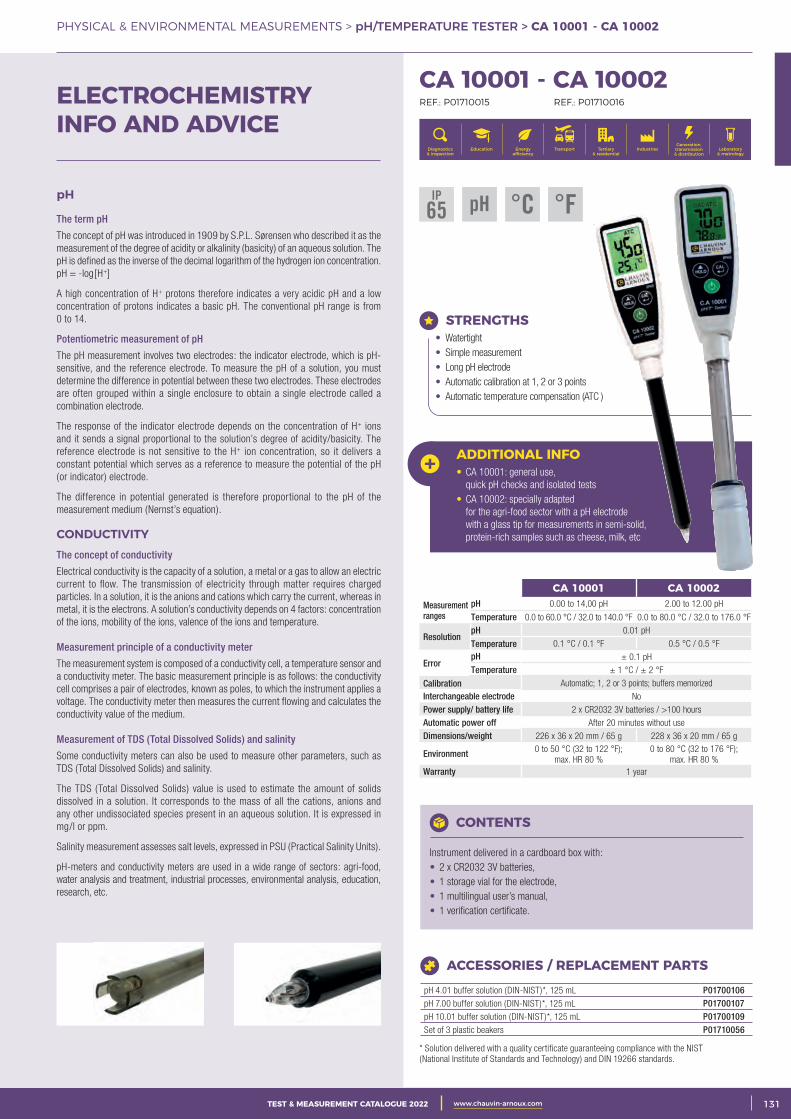
3CATALOGUE TEST & MESURE 2021 www.chauvin-arnoux.com 131TEST & MEASUREMENT CATALOGUE 2022 www.chauvin-arnoux.com
PHYSICAL & ENVIRONMENTAL MEASUREMENTS > pH/TEMPERATURE TESTER > CA 10001 - CA 10002
pH
The term pH
The concept of pH was introduced in 1909 by S.P.L. Sørensen who described it as the measurement of the degree of acidity or alkalinity (basicity) of an aqueous solution. The pH is defined as the inverse of the decimal logarithm of the hydrogen ion concentration. pH = -log[H+]
A high concentration of H+ protons therefore indicates a very acidic pH and a low concentration of protons indicates a basic pH. The conventional pH range is from 0 to 14.
Potentiometric measurement of pH
The pH measurement involves two electrodes: the indicator electrode, which is pH-sensitive, and the reference electrode. To measure the pH of a solution, you must determine the difference in potential between these two electrodes. These electrodes are often grouped within a single enclosure to obtain a single electrode called a combination electrode.
The response of the indicator electrode depends on the concentration of H+ ions and it sends a signal proportional to the solution’s degree of acidity/basicity. The reference electrode is not sensitive to the H+ ion concentration, so it delivers a constant potential which serves as a reference to measure the potential of the pH (or indicator) electrode.
The difference in potential generated is therefore proportional to the pH of the measurement medium (Nernst’s equation).
CONDUCTIVITY The concept of conductivity
Electrical conductivity is the capacity of a solution, a metal or a gas to allow an electric current to flow. The transmission of electricity through matter requires charged particles. In a solution, it is the anions and cations which carry the current, whereas in metal, it is the electrons. A solution’s conductivity depends on 4 factors: concentration of the ions, mobility of the ions, valence of the ions and temperature.
Measurement principle of a conductivity meter
The measurement system is composed of a conductivity cell, a temperature sensor and a conductivity meter. The basic measurement principle is as follows: the conductivity cell comprises a pair of electrodes, known as poles, to which the instrument applies a voltage. The conductivity meter then measures the current flowing and calculates the conductivity value of the medium.
Measurement of TDS (Total Dissolved Solids) and salinity
Some conductivity meters can also be used to measure other parameters, such as TDS (Total Dissolved Solids) and salinity.
The TDS (Total Dissolved Solids) value is used to estimate the amount of solids dissolved in a solution. It corresponds to the mass of all the cations, anions and any other undissociated species present in an aqueous solution. It is expressed in mg/l or ppm.
Salinity measurement assesses salt levels, expressed in PSU (Practical Salinity Units).
pH-meters and conductivity meters are used in a wide range of sectors: agri-food, water analysis and treatment, industrial processes, environmental analysis, education, research, etc.
ELECTROCHEMISTRY INFO AND ADVICE
CA 10001 - CA 10002 REF.: P01710015 REF.: P01710016
Generation, transmission & distribution
IndustriesTertiary & residential
Education TransportDiagnostics & inspection
Energy efficiency
Laboratory & metrology
ADDITIONAL INFO• CA 10001: general use,
quick pH checks and isolated tests• CA 10002: specially adapted
for the agri-food sector with a pH electrode with a glass tip for measurements in semi-solid, protein-rich samples such as cheese, milk, etc
STRENGTHS• Watertight• Simple measurement• Long pH electrode• Automatic calibration at 1, 2 or 3 points • Automatic temperature compensation (ATC )
CA 10001 CA 10002Measurement ranges
pH 0.00 to 14,00 pH 2.00 to 12.00 pH
Temperature 0.0 to 60.0 °C / 32.0 to 140.0 °F 0.0 to 80.0 °C / 32.0 to 176.0 °F
Resolution pH 0.01 pH
Temperature 0.1 °C / 0.1 °F 0.5 °C / 0.5 °F
Error pH ± 0.1 pH Temperature ± 1 °C / ± 2 °F
Calibration Automatic; 1, 2 or 3 points; buffers memorized Interchangeable electrode NoPower supply/ battery life 2 x CR2032 3V batteries / >100 hoursAutomatic power off After 20 minutes without useDimensions/weight 226 x 36 x 20 mm / 65 g 228 x 36 x 20 mm / 65 g
Environment 0 to 50 °C (32 to 122 °F); max. HR 80 %
0 to 80 °C (32 to 176 °F); max. HR 80 %
Warranty 1 year
CONTENTS
Instrument delivered in a cardboard box with:• 2 x CR2032 3V batteries, • 1 storage vial for the electrode, • 1 multilingual user’s manual, • 1 verification certificate.
ACCESSORIES / REPLACEMENT PARTS
pH 4.01 buffer solution (DIN-NIST)*, 125 mL P01700106pH 7.00 buffer solution (DIN-NIST)*, 125 mL P01700107pH 10.01 buffer solution (DIN-NIST)*, 125 mL P01700109Set of 3 plastic beakers P01710056
* Solution delivered with a quality certificate guaranteeing compliance with the NIST (National Institute of Standards and Technology) and DIN 19266 standards.
IP65 pH °C °F
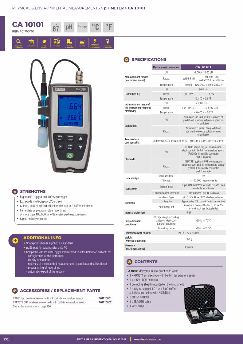
2 CATALOGUE TEST & MESURE 2021 www.chauvin-arnoux.com132 TEST & MEASUREMENT CATALOGUE 2022 www.chauvin-arnoux.com
PHYSICAL & ENVIRONMENTAL MEASUREMENTS > pH-METER > CA 10101
CA 10101 REF.: P01710010
Generation, transmission & distribution
IndustriesTertiary & residential
Education TransportDiagnostics & inspection
Energy efficiency
Laboratory & metrology
Measurement parameters CA 10101
Measurement ranges (instrument alone)
pH -2.00 to 16.00 pH
Redox ±199.9 mV -1999 to -200
and +200 to +1999 mV
Temperature -10.0 to +120.0°C / 14.0 to 248.0°F
Resolution (R)
pH 0.01 pH
Redox 0.1 mV 1 mV
Temperature 0.1 °C / 0.1 °F
Intrinsic uncertainty of the instrument (without electrode)
pH ± 0.01 pH ± R
Redox ± 0.1 mV ± R ± 1 mV ± R
Temperature < 0.4°C / < 0.7°F
Calibration
pHAutomatic, up to 3 points, 3 groups of
predefined standard reference solutions (modifiable)
RedoxAutomatic, 1 point, two predefined standard reference solution values
(modifiable)
Temperature compensation Automatic (ATC) or manual (MTC), -10°C to +120°C (14°F to 248°F)
Electrode
pH
XRGST1 (supplied), pH combination electrode with built-in temperature sensor
(Pt1000), 8-pin DIN connector and 1 m cable
Redox
XRPTST1 (option), ORP combination electrode with built-in temperature sensor
(Pt1000), 8-pin DIN connector and 1 m cable
Data storageDate and time Yes
Storage > 100,000 measurements
Connectors Sensor input
8-pin DIN (adapters for BNC, S7 and Jack available as options)
Communication interface Type-B micro USB (USB device)
Batteries
Number - Type 4 x 1.5 V AA or LR06 alkaline batteries
Battery life Approximately 300 hours of continuous operation
Auto power-off Automatic power-off after 3, 10 or 15
min without use (adjustable)
Ingress protection IP67
Environmental conditions
Storage range (excluding batteries, electrodes & buffer solutions)
-20 to + 70°C
Operating range -10 to +55 °C
Dimensions (with sheath) 211 x 127 x 54 mm
Weight (without electrode) 600 g
Warranty (instrument alone) 2 years
SPECIFICATIONS
CONTENTS
CA 10101 delivered in site-proof case with: • 1 x XRGST1 pH electrode with built-in temperature sensor• 4 x 1.5 V LR06 batteries• 1 protective sheath mounted on the instrument• 2 ready-to-use pH 4.01 and 7.00 buffer
solutions (compliant with NIST/DIN)• 2 plastic beakers• 1 USB/μUSB cable• 1 wrist strap
ACCESSORIES / REPLACEMENT PARTS
XRGST1 pH combination electrode with built-in temperature sensor P01710051XRPTST1 ORP combination electrode with built-in temperature sensor P01710052See all the accessories on page 136
STRENGTHS• Ergonomic, rugged and 100% watertight• Extra-wide multi-display LCD screen• Guided, ultra-simplified pH calibration (up to 3 buffer solutions) • Immediate or programmable recordings
of more than 100,000 time/date-stamped measurements• Signal stability indicator
ADDITIONAL INFO• Shockproof sheath supplied as standard• μUSB port for data transfer onto PC • Compatible with the Data Logger Transfer module of the Dataview® software for: - configuration of the instrument - display of the data - recovery of the recorded measurements (samples and calibrations) - programming of recordings - automatic export of the reports
IP67 pH °C °FRedox
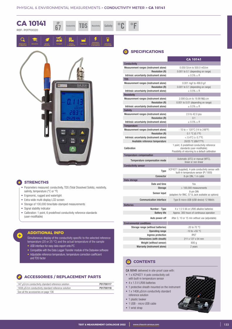
3CATALOGUE TEST & MESURE 2021 www.chauvin-arnoux.com 133TEST & MEASUREMENT CATALOGUE 2022 www.chauvin-arnoux.com
PHYSICAL & ENVIRONMENTAL MEASUREMENTS > CONDUCTIVITY METER > CA 10141
CA 10141 REF.: P01710020
Generation, transmission & distribution
IndustriesTertiary & residential
Education TransportDiagnostics & inspection
Energy efficiency
Laboratory & metrology
CONTENTS
CA 10141 delivered in site-proof case with: • 1 x XCP4ST1 4-pole conductivity cell
with built-in temperature sensor • 4 x 1.5 V LR06 batteries• 1 protective sheath mounted on the instrument• 1 x 1408 μS/cm conductivity standard
reference solution• 1 plastic beaker• 1 USB - micro USB cable• 1 wrist strap
CA 10141ConductivityMeasurement ranges (instrument alone) 0.050 S/cm to 500.0 mS/cm
Resolution (R) 0.001 to 0.1 (depending on range) Intrinsic uncertainty (instrument alone) ± 0.5% ± R
TDSMeasurement ranges (instrument alone) 0.001 mg/l to 499.9 g/l
Resolution (R) 0.001 to 0.1 (depending on range) Intrinsic uncertainty (instrument alone) ± 0.5% ± R
Resistivity Measurement ranges (instrument alone) 2.000 Ω.cm to 19.99 MΩ.cm
Resolution (R) 0.001 to 0.01 (depending on range) Intrinsic uncertainty (instrument alone) ± 0.5% ± R
SalinityMeasurement ranges (instrument alone) 2.0 to 42.0 psu
Resolution (R) 0.1 Intrinsic uncertainty (instrument alone) ± 0.5% ± R
TemperatureMeasurement ranges (instrument alone) - 10 to + 120°C (14 to 248°F)
Resolution (R) 0.1 °C (0.1°F) Intrinsic uncertainty (instrument alone) < 0.4°C (< 0.7°F)
Available reference temperature 20/25 °C (68/77°F)
Calibration1 point, 6 predefined conductivity reference
standards (user-modifiable); Possibility of returning to a default calibration
Temperature compensation
Temperature compensation mode Automatic (ATC) or manual (MTC), linear or non-linear
Conductivity sensor
Type XCP4ST1 (supplied), 4-pole conductivity sensor with built-in temperature sensor (Pt 1000)
Connector 8-pin DIN, 1 m cableData storage
Date and time YesStorage > 100,000 measurements
Sensor input 8-pin DIN (adapters for BNC, S7 & Jack available as options)
Communication interface Type B micro-USB (USB device) 12 Mbit/s
BatteriesNumber - Type 4 x 1.5 V AA or LR06 alkaline batteries
Battery life Approx. 300 hours of continuous operation
Auto power-off After 3, 10 or 15 min without use (adjustable)
Environmental conditions Storage range (without batteries) -20 to 70 °C
Operating range -10 to +55 °C Ingress protection IP67
Dimensions (with sheath) 211 x 127 x 54 mm Weight (without sensor) 600 g
Warranty (instrument alone) 2 years
SPECIFICATIONS
STRENGTHS• Parameters measured: conductivity, TDS (Total Dissolved Solids), resistivity,
salinity, temperature (°C or °F)• Ergonomic, rugged and watertight• Extra-wide multi-display LCD screen• Storage of 100,000 time/date-stamped measurements• Signal stability indicator• Calibration: 1 point, 6 predefined conductivity reference standards
(user-modifiable)
ADDITIONAL INFO Simultaneous display of the conductivity specific to the selected reference temperature (20 or 25 °C) and the actual temperature of the sample• USB interface for easy data export onto PC• Compatible with the Data Logger Transfer module of the Dataview software• Adjustable reference temperature, temperature correction coefficient
and TDS factor
ACCESSORIES / REPLACEMENT PARTS
147 μS/cm conductivity standard reference solution P017001171408 μS/cm conductivity standard reference solution P01700118See all the accessories on page 136
IP67 Conductivity Resistivity Salinity °CTDS °F
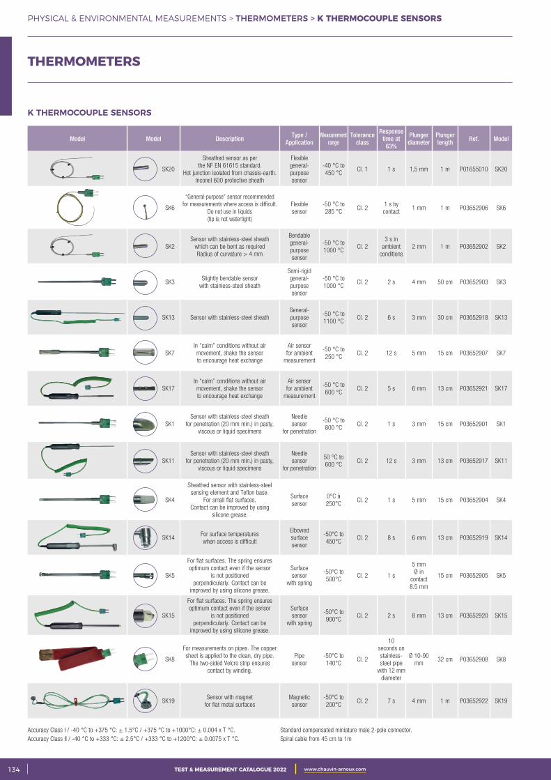
2 CATALOGUE TEST & MESURE 2021 www.chauvin-arnoux.com134 TEST & MEASUREMENT CATALOGUE 2022 www.chauvin-arnoux.com
PHYSICAL & ENVIRONMENTAL MEASUREMENTS > THERMOMETERS > K THERMOCOUPLE SENSORS
K THERMOCOUPLE SENSORS
Model Model Description Type / Application
Measurement range
Tolerance class
Response time at
63%
Plunger diameter
Plunger length Ref. Model
SK20
Sheathed sensor as per the NF EN 61615 standard.
Hot junction isolated from chassis-earth.Inconel 600 protective sheath
Flexible general- purpose sensor
-40 °C to 450 °C
Cl. 1 1 s 1,5 mm 1 m P01655010 SK20
SK6
“General-purpose” sensor recommended for measurements where access is difficult.
Do not use in liquids (tip is not watertight)
Flexible sensor
-50 °C to 285 °C
Cl. 2 1 s by contact
1 mm 1 m P03652906 SK6
SK2Sensor with stainless-steel sheath
which can be bent as requiredRadius of curvature > 4 mm
Bendable general- purpose sensor
-50 °C to 1000 °C
Cl. 2 3 s in
ambient conditions
2 mm 1 m P03652902 SK2
SK3Slightly bendable sensor
with stainless-steel sheath
Semi-rigid general- purpose sensor
-50 °C to 1000 °C
Cl. 2 2 s 4 mm 50 cm P03652903 SK3
SK13 Sensor with stainless-steel sheath General- purpose sensor
-50 °C to 1100 °C
Cl. 2 6 s 3 mm 30 cm P03652918 SK13
SK7In “calm” conditions without air movement, shake the sensor to encourage heat exchange
Air sensor for ambient
measurement
-50 °C to 250 °C
Cl. 2 12 s 5 mm 15 cm P03652907 SK7
SK17In “calm” conditions without air movement, shake the sensor to encourage heat exchange
Air sensor for ambient
measurement
-50 °C to 600 °C
Cl. 2 5 s 6 mm 13 cm P03652921 SK17
SK1Sensor with stainless-steel sheath
for penetration (20 mm min.) in pasty, viscous or liquid specimens
Needle sensor
for penetration
-50 °C to 800 °C
Cl. 2 1 s 3 mm 15 cm P03652901 SK1
SK11Sensor with stainless-steel sheath
for penetration (20 mm min.) in pasty, viscous or liquid specimens
Needle sensor
for penetration
50 °C to 600 °C
Cl. 2 12 s 3 mm 13 cm P03652917 SK11
SK4
Sheathed sensor with stainless-steel sensing element and Teflon base.
For small flat surfaces.Contact can be improved by using
silicone grease.
Surface sensor
0°C à 250°C
Cl. 2 1 s 5 mm 15 cm P03652904 SK4
SK14For surface temperatures when access is difficult
Elbowed surface sensor
-50°C to 450°C
Cl. 2 8 s 6 mm 13 cm P03652919 SK14
SK5
For flat surfaces. The spring ensures optimum contact even if the sensor
is not positionedperpendicularly. Contact can be
improved by using silicone grease.
Surface sensor
with spring
-50°C to 500°C
Cl. 2 1 s
5 mmØ in
contact8.5 mm
15 cm P03652905 SK5
SK15
For flat surfaces. The spring ensures optimum contact even if the sensor
is not positionedperpendicularly. Contact can be
improved by using silicone grease.
Surface sensor
with spring
-50°C to 900°C
Cl. 2 2 s 8 mm 13 cm P03652920 SK15
SK8
For measurements on pipes. The copper sheet is applied to the clean, dry pipe.
The two-sided Velcro strip ensures contact by winding.
Pipe sensor
-50°C to 140°C
Cl. 2
10 seconds on stainless-steel pipe
with 12 mm diameter
Ø 10-90 mm
32 cm P03652908 SK8
SK19Sensor with magnet
for flat metal surfacesMagnetic sensor
-50°C to 200°C
Cl. 2 7 s 4 mm 1 m P03652922 SK19
THERMOMETERS
Accuracy Class I / -40 °C to +375 °C: ± 1.5°C / +375 °C to +1000°C: ± 0.004 x T °C. Accuracy Class II / -40 °C to +333 °C: ± 2.5°C / +333 °C to +1200°C: ± 0.0075 x T °C.
Standard compensated miniature male 2-pole connector. Spiral cable from 45 cm to 1m
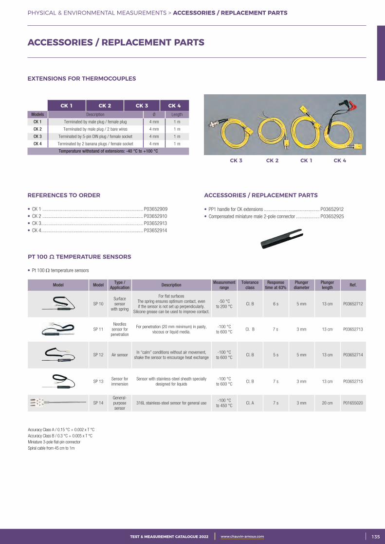
3CATALOGUE TEST & MESURE 2021 www.chauvin-arnoux.com 135TEST & MEASUREMENT CATALOGUE 2022 www.chauvin-arnoux.com
PHYSICAL & ENVIRONMENTAL MEASUREMENTS > ACCESSORIES / REPLACEMENT PARTS
• CK 1 ................................................................................. P03652909• CK 2 ................................................................................. P03652910• CK 3 .................................................................................. P03652913• CK 4 .................................................................................. P03652914
REFERENCES TO ORDER
• PP1 handle for CK extensions ............................................. P03652912• Compensated miniature male 2-pole connector ................... P03652925
ACCESSORIES / REPLACEMENT PARTS
CK 3 CK 2 CK 1 CK 4
CK 1 CK 2 CK 3 CK 4Models Description Ø Length
CK 1 Terminated by male plug / female plug 4 mm 1 m
CK 2 Terminated by male plug / 2 bare wires 4 mm 1 m
CK 3 Terminated by 5-pin DIN plug / female socket 4 mm 1 m
CK 4 Terminated by 2 banana plugs / female socket 4 mm 1 m
Temperature withstand of extensions: -40 °C to +100 °C
EXTENSIONS FOR THERMOCOUPLES
• Pt 100 Ω temperature sensors
Model Model Type / Application Description Measurement
range Tolerance
class Response
time at 63% Plunger
diameterPlunger length Ref.
SP 10Surface sensor
with spring
For flat surfacesThe spring ensures optimum contact, even if the sensor is not set up perpendicularly.
Silicone grease can be used to improve contact.
-50 °C to 200 °C
Cl. B 6 s 5 mm 13 cm P03652712
SP 11 Needles
sensor for penetration
For penetration (20 mm minimum) in pasty, viscous or liquid media.
-100 °C to 600 °C
Cl. B 7 s 3 mm 13 cm P03652713
SP 12 Air sensorIn “calm” conditions without air movement,
shake the sensor to encourage heat exchange -100 °C
to 600 °C Cl. B 5 s 5 mm 13 cm P03652714
SP 13Sensor for immersion
Sensor with stainless-steel sheath specially designed for liquids
-100 °C to 600 °C
Cl. B 7 s 3 mm 13 cm P03652715
SP 14General-purpose sensor
316L stainless-steel sensor for general use-100 °C
to 450 °C Cl. A 7 s 3 mm 20 cm P01655020
PT 100 Ω TEMPERATURE SENSORS
Accuracy Class A / 0.15 °C + 0.002 x T °C Accuracy Class B / 0.3 °C + 0.005 x T °C Miniature 3-pole flat-pin connectorSpiral cable from 45 cm to 1m
ACCESSORIES / REPLACEMENT PARTS
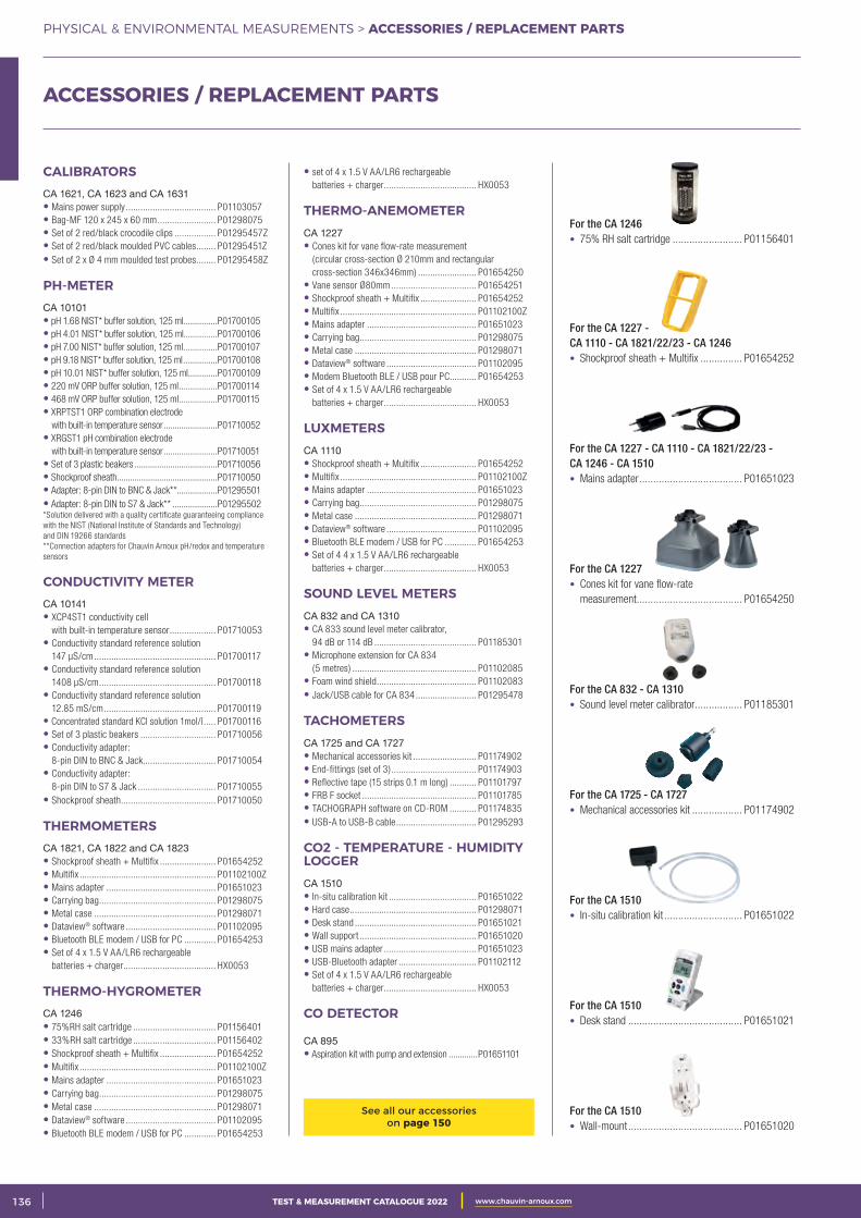
2 CATALOGUE TEST & MESURE 2021 www.chauvin-arnoux.com136 TEST & MEASUREMENT CATALOGUE 2022 www.chauvin-arnoux.com
PHYSICAL & ENVIRONMENTAL MEASUREMENTS > ACCESSORIES / REPLACEMENT PARTS
ACCESSORIES / REPLACEMENT PARTS
CALIBRATORSCA 1621, CA 1623 and CA 1631• Mains power supply ..................................... P01103057 • Bag-MF 120 x 245 x 60 mm ........................ P01298075 • Set of 2 red/black crocodile clips ................. P01295457Z • Set of 2 red/black moulded PVC cables ........ P01295451Z • Set of 2 x Ø 4 mm moulded test probes ........ P01295458Z
PH-METERCA 10101 • pH 1.68 NIST* buffer solution, 125 ml ...............P01700105 • pH 4.01 NIST* buffer solution, 125 ml ...............P01700106 • pH 7.00 NIST* buffer solution, 125 ml ...............P01700107 • pH 9.18 NIST* buffer solution, 125 ml ...............P01700108 • pH 10.01 NIST* buffer solution, 125 ml .............P01700109 • 220 mV ORP buffer solution, 125 ml .................P01700114 • 468 mV ORP buffer solution, 125 ml .................P01700115 • XRPTST1 ORP combination electrode
with built-in temperature sensor ........................P01710052 • XRGST1 pH combination electrode
with built-in temperature sensor ........................P01710051 • Set of 3 plastic beakers .....................................P01710056 • Shockproof sheath.............................................P01710050 • Adapter: 8-pin DIN to BNC & Jack** ..................P01295501 • Adapter: 8-pin DIN to S7 & Jack** ....................P01295502 *Solution delivered with a quality certificate guaranteeing compliance with the NIST (National Institute of Standards and Technology) and DIN 19266 standards**Connection adapters for Chauvin Arnoux pH/redox and temperature sensors
CONDUCTIVITY METERCA 10141 • XCP4ST1 conductivity cell
with built-in temperature sensor ................... P01710053 • Conductivity standard reference solution
147 μS/cm .................................................. P01700117 • Conductivity standard reference solution
1408 μS/cm ................................................ P01700118 • Conductivity standard reference solution
12.85 mS/cm .............................................. P01700119 • Concentrated standard KCl solution 1mol/l ..... P01700116 • Set of 3 plastic beakers ............................... P01710056 • Conductivity adapter:
8-pin DIN to BNC & Jack.............................. P01710054 • Conductivity adapter:
8-pin DIN to S7 & Jack ................................ P01710055 • Shockproof sheath ....................................... P01710050
THERMOMETERSCA 1821, CA 1822 and CA 1823 • Shockproof sheath + Multifix ....................... P01654252 • Multifix ........................................................ P01102100Z • Mains adapter ............................................. P01651023 • Carrying bag ................................................ P01298075 • Metal case .................................................. P01298071 • Dataview® software ..................................... P01102095 • Bluetooth BLE modem / USB for PC ............. P01654253 • Set of 4 x 1.5 V AA/LR6 rechargeable
batteries + charger ...................................... HX0053
THERMO-HYGROMETERCA 1246 • 75%RH salt cartridge .................................. P01156401 • 33%RH salt cartridge .................................. P01156402 • Shockproof sheath + Multifix ....................... P01654252 • Multifix ........................................................ P01102100Z • Mains adapter ............................................. P01651023 • Carrying bag ................................................ P01298075 • Metal case .................................................. P01298071 • Dataview® software ..................................... P01102095 • Bluetooth BLE modem / USB for PC ............. P01654253
• set of 4 x 1.5 V AA/LR6 rechargeable batteries + charger ...................................... HX0053
THERMO-ANEMOMETER CA 1227• Cones kit for vane flow-rate measurement
(circular cross-section Ø 210mm and rectangular cross-section 346x346mm) ........................ P01654250
• Vane sensor Ø80mm ................................... P01654251 • Shockproof sheath + Multifix ....................... P01654252 • Multifix ........................................................ P01102100Z • Mains adapter ............................................. P01651023 • Carrying bag ................................................ P01298075 • Metal case .................................................. P01298071 • Dataview® software ..................................... P01102095 • Modem Bluetooth BLE / USB pour PC ........... P01654253 • Set of 4 x 1.5 V AA/LR6 rechargeable
batteries + charger ...................................... HX0053
LUXMETERS CA 1110 • Shockproof sheath + Multifix ....................... P01654252 • Multifix ........................................................ P01102100Z • Mains adapter ............................................. P01651023 • Carrying bag ................................................ P01298075 • Metal case .................................................. P01298071 • Dataview® software ..................................... P01102095 • Bluetooth BLE modem / USB for PC ............. P01654253 • Set of 4 4 x 1.5 V AA/LR6 rechargeable
batteries + charger ...................................... HX0053
SOUND LEVEL METERS CA 832 and CA 1310• CA 833 sound level meter calibrator,
94 dB or 114 dB .......................................... P01185301 • Microphone extension for CA 834
(5 metres) ................................................... P01102085 • Foam wind shield ......................................... P01102083 • Jack/USB cable for CA 834 ......................... P01295478
TACHOMETERSCA 1725 and CA 1727• Mechanical accessories kit .......................... P01174902 • End-fittings (set of 3) ................................... P01174903 • Reflective tape (15 strips 0.1 m long) ........... P01101797 • FRB F socket ............................................... P01101785 • TACHOGRAPH software on CD-ROM ........... P01174835 • USB-A to USB-B cable ................................. P01295293
CO2 - TEMPERATURE - HUMIDITY LOGGER CA 1510• In-situ calibration kit .................................... P01651022• Hard case .................................................... P01298071• Desk stand .................................................. P01651021• Wall support ................................................ P01651020• USB mains adapter ...................................... P01651023• USB-Bluetooth adapter ................................ P01102112• Set of 4 x 1.5 V AA/LR6 rechargeable
batteries + charger ...................................... HX0053
CO DETECTOR
CA 895• Aspiration kit with pump and extension .............P01651101
See all our accessories on page 150
For the CA 1246• 75% RH salt cartridge ......................... P01156401
For the CA 1227 - CA 1110 - CA 1821/22/23 - CA 1246• Shockproof sheath + Multifix ............... P01654252
For the CA 1227 - CA 1110 - CA 1821/22/23 - CA 1246 - CA 1510• Mains adapter ..................................... P01651023
For the CA 1227• Cones kit for vane flow-rate
measurement ...................................... P01654250
For the CA 832 - CA 1310• Sound level meter calibrator ................. P01185301
For the CA 1725 - CA 1727• Mechanical accessories kit .................. P01174902
For the CA 1510• In-situ calibration kit ............................ P01651022
For the CA 1510• Desk stand ......................................... P01651021
For the CA 1510• Wall-mount ......................................... P01651020

3CATALOGUE TEST & MESURE 2021 www.chauvin-arnoux.com 137TEST & MEASUREMENT CATALOGUE 2022 www.chauvin-arnoux.com
PHYSICAL & ENVIRONMENTAL MEASUREMENTS > NOTES
NOTES
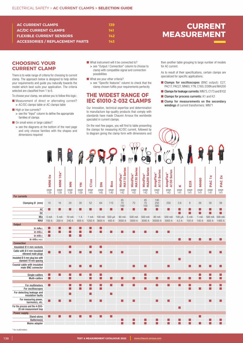
2 CATALOGUE TEST & MESURE 2021 www.chauvin-arnoux.com138 TEST & MEASUREMENT CATALOGUE 2022 www.chauvin-arnoux.com
ELECTRICAL SAFETY > AC CURRENT CLAMPS > SELECTION GUIDE
CHOOSING YOUR CURRENT CLAMPThere is to wide range of criteria for choosing to current clamp. The approach below is designed to help define your requirements and guide you naturally towards the model which best suits your application. The criteria selected are classified from 1 to 6.
To choose your clamp, we advise you to follow this logic:
Measurement of direct or alternating current? > AC/DC clamps table or AC clamps table
High or low currents? > see the “Input” column to define the appropriate
families of clamps
On small wires or large cables? > see the diagrams at the bottom of the next page
and only choose families with the shapes and dimensions required
then another table grouping to large number of models for AC current.
As to result of their specifications, certain clamps are specialized for specific applications:
Clamps for oscilloscopes (BNC output): E27, PAC17, PAC27, MN60, Y7N, C160, D38N and MA200
Clamps for leakage currents: MN73, C173 and B102
Clamps for process currents: K1 and K2
Clamp for measurements on the secondary windings of current transformers: MN71
What instrument will it be connected to? > see “Output / Connection” column to choose to
clamp with compatible signal and connection possibilities
What are your other criteria? > see “Specific features” column to check that the
clamp chosen fulfils your requirements perfectly
THE WIDEST RANGE OF IEC 61010-2-032 CLAMPSOur innovation, technical expertise and determination to manufacture top-quality products that comply with standards have made Chauvin Arnoux the worldwide specialist in current clamps.
On the next few pages, you will find to table presenting the clamps for measuring AC/DC current, followed by to diagram giving the clamp form with dimensions and
AC CURRENT CLAMPS 139AC/DC CURRENT CLAMPS 141FLEXIBLE CURRENT SENSORS 142ACCESSORIES / REPLACEMENT PARTS 143
CURRENT MEASUREMENT
* for multimeters
MIN
I 0x
MIN
I 10x
*
MN
YN C1xx
DN
Bxx
Min
iFle
x®
MA1
10 S
erie
s
Min
iFle
x®
MA1
30 S
erie
s
Min
iFle
x®
MA2
00 S
erie
s
AmpF
lex®
A110
Ser
ies
AmpF
lex®
A130
Ser
ies
K E2X
MH
60
PAC
1x
PAC
2x
page 139
page 139
page 139
page 139
page 140
page 140
page 140
page 142
page 142
page 142
page 142
page 142
page 141
page 141
page 141
page 141
page 141
For currents
Clamping Ø (mm) 10 16 20 30 52 64 1154570100
704570100
140250380
250 3,9 8 26 30 39
ACDC
Min 5 mA 5 mA 10 mA 1 A 1 mA 100 mA 500 µA 80 mA 500 mA 500 mA 80 mA 500 mA 100 µA 5 mA 1 mA 500 mA 500 mAMAX 150 A 200 A 240 A 600 A 1200 A 3600 A 400 A 3000 A 3000 A 3000 A 30000 A 3000 A 4,5 A 150 A 140 A 600 A 1400 A
Output in mAA c in mVA c in mVd c
in mVA c+d c ConnectionInsulated Ø 4 mm socketsCable with Ø 4 mm insulated
elbowed male plugsInsulated Ø 4 mm plug box with
standard 19 mm spacingCoaxial cable with insulated
male BNC connector
Single-calibre Multi-calibre
For multimetersFor oscilloscopes
For detecting leakage and insulation faults
For measuring power, harmonics, etc.
For the process and the 4-20/0-20 mA measurement loop
Power supply Stand-aloneBatteries(s)
Mains adapter
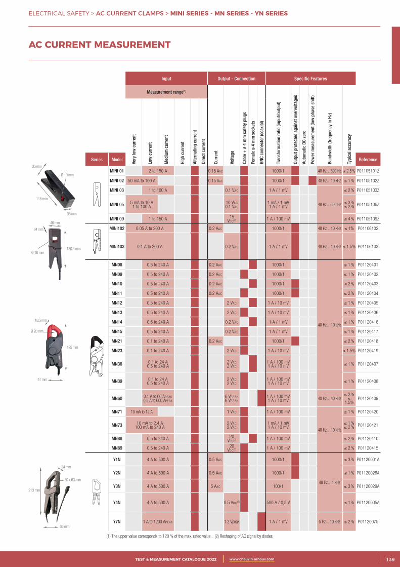
3CATALOGUE TEST & MESURE 2021 www.chauvin-arnoux.com 139TEST & MEASUREMENT CATALOGUE 2022 www.chauvin-arnoux.com
ELECTRICAL SAFETY > AC CURRENT CLAMPS > MINI SERIES - MN SERIES - YN SERIES
MIN
I 0x
MIN
I 10x
*
MN
YN C1xx
DN
Bxx
Min
iFle
x®
MA1
10 S
erie
s
Min
iFle
x®
MA1
30 S
erie
s
Min
iFle
x®
MA2
00 S
erie
s
AmpF
lex®
A110
Ser
ies
AmpF
lex®
A130
Ser
ies
K E2X
MH
60
PAC
1x
PAC
2x
page 139
page 139
page 139
page 139
page 140
page 140
page 140
page 142
page 142
page 142
page 142
page 142
page 141
page 141
page 141
page 141
page 141
For currents
Clamping Ø (mm) 10 16 20 30 52 64 1154570100
704570100
140250380
250 3,9 8 26 30 39
ACDC
Min 5 mA 5 mA 10 mA 1 A 1 mA 100 mA 500 µA 80 mA 500 mA 500 mA 80 mA 500 mA 100 µA 5 mA 1 mA 500 mA 500 mAMAX 150 A 200 A 240 A 600 A 1200 A 3600 A 400 A 3000 A 3000 A 3000 A 30000 A 3000 A 4,5 A 150 A 140 A 600 A 1400 A
Output in mAA c in mVA c in mVd c
in mVA c+d c ConnectionInsulated Ø 4 mm socketsCable with Ø 4 mm insulated
elbowed male plugsInsulated Ø 4 mm plug box with
standard 19 mm spacingCoaxial cable with insulated
male BNC connector
Single-calibre Multi-calibre
For multimetersFor oscilloscopes
For detecting leakage and insulation faults
For measuring power, harmonics, etc.
For the process and the 4-20/0-20 mA measurement loop
Power supply Stand-aloneBatteries(s)
Mains adapter
AC CURRENT MEASUREMENT
Input Output - Connection Specific Features
Measurement range(1)
Curr
ent
Volta
ge
Cabl
e +
ø 4
mm
saf
ety
plug
s
Fem
ale
ø 4
mm
soc
kets
BNC
conn
ecto
r (co
axia
l)
Tran
sfor
mat
ion
ratio
(inp
ut/o
utpu
t)
Outp
ut p
rote
cted
aga
inst
ove
rvol
tage
s
Auto
mat
ic D
C ze
ro
Pow
er m
easu
rem
ent (
low
pha
se s
hift)
Band
wid
th (f
requ
ency
in H
z)
Typi
cal a
ccur
acy
Very
low
cur
rent
Low
cur
rent
Med
ium
cur
rent
High
cur
rent
Alte
rnat
ing
curr
ent
Dire
ct c
urre
nt
Series Model Reference
MINI 01 2 to 150 A 0.15 AAc 1000/1 48 Hz…500 Hz ≤ 2.5 % P01105101Z
MINI 02 50 mA to 100 A 0.15 AAc 1000/1 48 Hz…10 kHz ≤ 1 % P01105102Z
MINI 03 1 to 100 A 0.1 VAc 1 A / 1 mV
48 Hz…500 Hz
≤ 2 % P01105103Z
MINI 05 5 mA to 10 A 1 to 100 A
10 VAc 0.1 VAc
1 mA / 1 mV 1 A / 1 mV
≤ 3 % ≤ 2 % P01105105Z
MINI 09 1 to 150 A 15 Vdc (2) 1 A / 100 mV ≤ 4 % P01105109Z
MINI102 0.05 A to 200 A 0.2 AAc 1000/1 48 Hz .. 10 kHz ≤ 1% P01106102
MINI103 0.1 A to 200 A 0.2 VAc 1 A / 1 mV 48 Hz .. 10 kHz ≤ 1.5% P01106103
MN08 0.5 to 240 A 0.2 AAc 1000/1
40 Hz…10 kHz
≤ 1 % P01120401
MN09 0.5 to 240 A 0.2 AAc 1000/1 ≤ 1 % P01120402
MN10 0.5 to 240 A 0.2 AAc 1000/1 ≤ 2 % P01120403
MN11 0.5 to 240 A 0.2 AAc 1000/1 ≤ 2 % P01120404
MN12 0.5 to 240 A 2 VAc 1 A / 10 mV ≤ 1 % P01120405
MN13 0.5 to 240 A 2 VAc 1 A / 10 mV ≤ 1 % P01120406
MN14 0.5 to 240 A 0.2 VAc 1 A / 1 mV ≤ 1 % P01120416
MN15 0.5 to 240 A 0.2 VAc 1 A / 1 mV ≤ 1 % P01120417
MN21 0.1 to 240 A 0.2 AAc 1000/1 ≤ 2 % P01120418
MN23 0.1 to 240 A 2 VAc 1 A / 10 mV ≤ 1.5% P01120419
MN38 0.1 to 24 A 0.5 to 240 A
2 VAc 2 VAc
1 A / 100 mV 1 A / 10 mV ≤ 1 % P01120407
MN39 0.1 to 24 A 0.5 to 240 A
2 VAc 2 VAc
1 A / 100 mV 1 A / 10 mV ≤ 1 % P01120408
MN60 0.1 A to 60 Ap e Ak 0.5 A to 600 Ap e Ak
6 Vp e Ak 6 Vp e Ak
1 A / 100 mV 1 A / 10 mV 40 Hz…40 kHz
≤ 2 % ≤
1.5%P01120409
MN71 10 mA to 12 A 1 VAc 1 A / 100 mV
40 Hz…10 kHz
≤ 1 % P01120420
MN73 10 mA to 2.4 A 100 mA to 240 A
2 VAc 2 VAc
1 mA / 1 mV 1 A / 10 mV
≤ 1 % ≤ 2 % P01120421
MN88 0.5 to 240 A 20 Vdc (2) 1 A / 100 mV ≤ 2 % P01120410
MN89 0.5 to 240 A 20 Vdc (2) 1 A / 100 mV ≤ 2 % P01120415
Y1N 4 A to 500 A 0.5 AAc 1000/1
48 Hz…1 kHz
≤ 3 % P01120001A
Y2N 4 A to 500 A 0.5 AAc 1000/1 ≤ 1 % P01120028A
Y3N 4 A to 500 A 5 AAc 100/1 ≤ 3 % P01120029A
Y4N 4 A to 500 A 0.5 Vdc (2) 500 A / 0,5 V ≤ 1 % P01120005A
Y7N 1 A to 1200 Ape Ak 1.2 Vpeak 1 A / 1 mV 5 Hz…10 kHz ≤ 2 % P01120075
(1) The upper value corresponds to 120 % of the max. rated value.. (2) Reshaping of AC signal by diodes
35 mm
35 mm
Ø 10 mm
115 mm
18.5 mm
51 mm
135 mm
Ø 20 mm
34 mm
66 mm
213 mm
30 x 63 mm
130.4 mm
46 mm
34 mm
Ø 16 mm
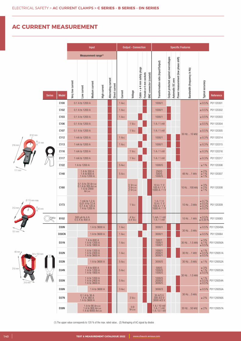
2 CATALOGUE TEST & MESURE 2021 www.chauvin-arnoux.com140 TEST & MEASUREMENT CATALOGUE 2022 www.chauvin-arnoux.com
ELECTRICAL SAFETY > AC CURRENT CLAMPS > C SERIES - B SERIES - DN SERIES
(1) The upper value corresponds to 120 % of the max. rated value.. (2) Reshaping of AC signal by diodes
Input Output - Connection Specific Features
Measurement range(1)
Curr
ent
Volta
ge
Cabl
e +
ø 4
mm
saf
ety
plug
s
Fem
ale
ø 4
mm
soc
kets
BNC
conn
ecto
r (co
axia
l)
Tran
sfor
mat
ion
ratio
(Inp
ut/O
utpu
t)
Outp
ut p
rote
cted
aga
inst
ove
rvol
tage
s
Auto
mat
ic D
C ze
ro
Pow
er m
easu
rem
ent (
low
pha
se s
hift)
Band
wid
th (f
requ
ency
in H
z)
Typi
cal a
ccur
acy
Very
low
cur
rent
Low
cur
rent
Med
ium
cur
rent
High
cur
rent
Alte
rnat
ing
curr
ent
Dire
ct c
urre
nt
Series Model Reference
C100 0.1 A to 1200 A 1 AAc 1000/1
30 Hz…10 kHz
≤ 0.5 % P01120301
C102 0.1 A to 1200 A 1 AAc 1000/1 ≤ 0.5 % P01120302
C103 0.1 A to 1200 A 1 AAc 1000/1 ≤ 0.5 % P01120303
C106 0.1 A to 1200 A 1 VAc 1 A / 1 mV ≤ 0.5 % P01120304
C107 0.1 A to 1200 A 1 VAc 1 A / 1 mV ≤ 0.5 % P01120305
C112 1 mA to 1200 A 1 AAc 1000/1 ≤ 0.3 % P01120314
C113 1 mA to 1200 A 1 AAc 1000/1 ≤ 0.3 % P01120315
C116 1 mA to 1200 A 1 VAc 1 A / 1 mV ≤ 0.3 % P01120316
C117 1 mA to 1200 A 1 VAc 1 A / 1 mV ≤ 0.3 % P01120317
C122 1 A to 1200 A 5 AAc 1000/5 ≤ 1 % P01120306
C1481 A to 300 A 1 A to 600 A 1 A to 1200 A
5 AAc250/5 500/5 1000/5
48 Hz…1 kHz≤ 2 % ≤ 1 % ≤ 1 %
P01120307
C1600.1 A to 30 Ap e Ak 0.1 A to 300 Ap e Ak
1 A to 2000 Ap e Ak
3 Vp e Ak 3 Vp e Ak 2 Vp e Ak
10 A / 1 V 100 A / 1 V 1000 A / 1 V
10 Hz…100 kHz≤ 3 % ≤ 2 % ≤ 1 %
P01120308
C1731 mA to 1,2 A 0,01 A to 12 A 0,1 A to 120 A 1 A to 1200 A
1 VAc
1 A / 1 V 10 A / 1 V 100 A / 1 V 1000 A / 1 V
10 Hz…3 kHz≤ 0.7 % ≤ 0.5 % ≤ 0.3 % ≤ 0.2 %
P01120309
B102 500 µA to 4 A 0.5 A to 400 A
4 VAc 0.4 VAc
1 mA / 1 mV 1 A / 1 mV 10 Hz…1 kHz ≤ 0.5 %
≤ 0.35 % P01120083
D30N 1 A to 3600 A 1 AAc 3000/130 Hz…5 kHz
≤ 0.5 % P01120049A
D30CN 1 A to 3600 A 1 AAc 3000/1 ≤ 0.5 % P01120064
D31N1 A to 600 A 1 A to 1200 A 1 A to 1800 A
1 AAc500/1
1000/1 1500/1
30 Hz…1.5 kHz≤ 3 % ≤ 1 % ≤ 0.5 %
P01120050A
D32N1 A to 1200 A 1 A to 2400 A 1 A to 3600 A
1 AAc1000/1 2000/1 3000/1
30 Hz…1 kHz≤ 1 % ≤ 0.5 % ≤ 0.5 %
P01120051A
D33N 1 A to 3600 A 5 AAc 3000/5 30 Hz…5 kHz ≤ 1 % P01120052A
D34N1 A to 600 A 1 A to 1200 A 1 A to 1800 A
5 AAc500/5
1000/5 1500/5
30 Hz…1.5 kHz
≤ 3 % ≤ 1 % ≤ 0.5 %
P01120053A
D35N1 A to 1200 A 1 A to 2400 A 1 A to 3600 A
5 AAc1000/5 2000/5 3000/5
≤ 1 % ≤ 0.5 % ≤ 0.5 %
P01120054A
D36N 1 A to 3600 A 3 AAc 3000/3
30 Hz…5 kHz
≤ 0.5 % P01120055A
D37N0.1 A to 36 A 1 A to 360 A 1 A to 3600 A
3 VAc30 A/3 V
300 A/3 V 3000 A/3 V
≤ 2 % P01120056A
D38N1 A to 90 Ap e Ak 1 A to 900 Ap e Ak
1 A to 9000 Ap e Ak
0.9 Vp e Ak
1 A / 10 mV 1 A / 1 mV
1 A / 0.1 mV30 Hz…50 kHz ≤ 2 % P01120057A
31 mm
111 mm
216 mm
Ø 52 mm
310 mm
310 mm
48 mm64 x 150 mm
43 mm
151 mm
312 mm
Ø 115 mm max.
AC CURRENT MEASUREMENT
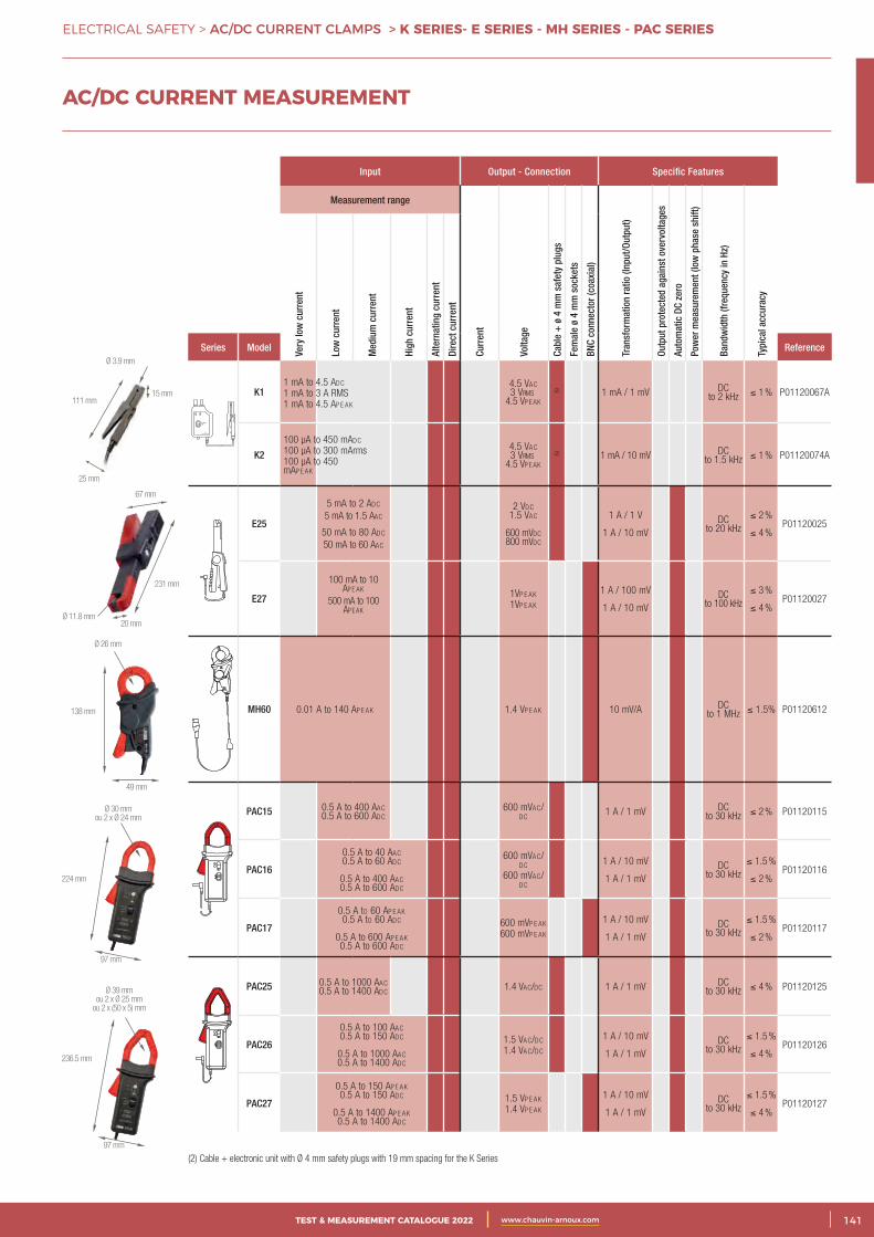
3CATALOGUE TEST & MESURE 2021 www.chauvin-arnoux.com 141TEST & MEASUREMENT CATALOGUE 2022 www.chauvin-arnoux.com
ELECTRICAL SAFETY > AC/DC CURRENT CLAMPS > K SERIES- E SERIES - MH SERIES - PAC SERIES
AC/DC CURRENT MEASUREMENT
Input Output - Connection Specific Features
Measurement range
Curr
ent
Volta
ge
Cabl
e +
ø 4
mm
saf
ety
plug
s
Fem
ale
ø 4
mm
soc
kets
BNC
conn
ecto
r (co
axia
l)
Tran
sfor
mat
ion
ratio
(Inp
ut/O
utpu
t)
Outp
ut p
rote
cted
aga
inst
ove
rvol
tage
s
Auto
mat
ic D
C ze
ro
Pow
er m
easu
rem
ent (
low
pha
se s
hift)
Band
wid
th (f
requ
ency
in H
z)
Typi
cal a
ccur
acy
Very
low
cur
rent
Low
cur
rent
Med
ium
cur
rent
High
cur
rent
Alte
rnat
ing
curr
ent
Dire
ct c
urre
nt
Series Model Reference
K14.5 VAc 3 Vrms
4.5 Vp e Ak
(2) 1 mA / 1 mV DC to 2 kHz ≤ 1 % P01120067A
K24.5 VAc 3 Vrms
4.5 Vp e Ak
(2) 1 mA / 10 mV DC to 1.5 kHz ≤ 1 % P01120074A
E25
5 mA to 2 Adc
5 mA to 1.5 AAc
50 mA to 80 Adc
50 mA to 60 AAc
2 Vdc 1.5 VAc
600 mVdc800 mVdc
1 A / 1 V
1 A / 10 mVDC
to 20 kHz≤ 2 %
≤ 4 %P01120025
E27
100 mA to 10 Ap e Ak
500 mA to 100 Ap e Ak
1Vp e Ak
1Vp e Ak
1 A / 100 mV
1 A / 10 mVDC
to 100 kHz≤ 3 %
≤ 4 %P01120027
MH60 0.01 A to 140 Ap e Ak 1.4 Vp e Ak 10 mV/A DC to 1 MHz ≤ 1.5% P01120612
PAC15 0.5 A to 400 AAc 0.5 A to 600 Adc
600 mVAc/dc
1 A / 1 mV DC to 30 kHz ≤ 2 % P01120115
PAC16
0.5 A to 40 AAc 0.5 A to 60 Adc
0.5 A to 400 AAc 0.5 A to 600 Adc
600 mVAc/dc
600 mVAc/dc
1 A / 10 mV
1 A / 1 mVDC
to 30 kHz≤ 1.5 %
≤ 2 %P01120116
PAC17
0.5 A to 60 Ap e Ak0.5 A to 60 Adc
0.5 A to 600 Ap e Ak0.5 A to 600 Adc
600 mVp e Ak
600 mVp e Ak
1 A / 10 mV
1 A / 1 mVDC
to 30 kHz≤ 1.5 %
≤ 2 %P01120117
PAC25 0.5 A to 1000 AAc 0.5 A to 1400 Adc
1.4 VAc/dc 1 A / 1 mV DC to 30 kHz ≤ 4 % P01120125
PAC26
0.5 A to 100 AAc 0.5 A to 150 Adc
0.5 A to 1000 AAc 0.5 A to 1400 Adc
1.5 VAc/dc
1.4 VAc/dc
1 A / 10 mV
1 A / 1 mVDC
to 30 kHz≤ 1.5 %
≤ 4 %P01120126
PAC27
0.5 A to 150 Ap e Ak0.5 A to 150 Adc
0.5 A to 1400 Ap e Ak0.5 A to 1400 Adc
1.5 Vp e Ak
1.4 Vp e Ak
1 A / 10 mV
1 A / 1 mVDC
to 30 kHz≤ 1.5 %
≤ 4 %P01120127
(2) Cable + electronic unit with Ø 4 mm safety plugs with 19 mm spacing for the K Series
97 mm
224 mm
Ø 30 mmou 2 x Ø 24 mm
97 mm
236.5 mm
Ø 39 mmou 2 x Ø 25 mm
ou 2 x (50 x 5) mm
15 mm111 mm
25 mm
Ø 3.9 mm
20 mm
67 mm
231 mm
Ø 11.8 mm
49 mm
138 mm
Ø 26 mm
1 mA to 4.5 Adc
1 mA to 3 A RMS1 mA to 4.5 Ap e Ak
100 µA to 450 mAdc
100 µA to 300 mArms100 µA to 450 mAp e Ak
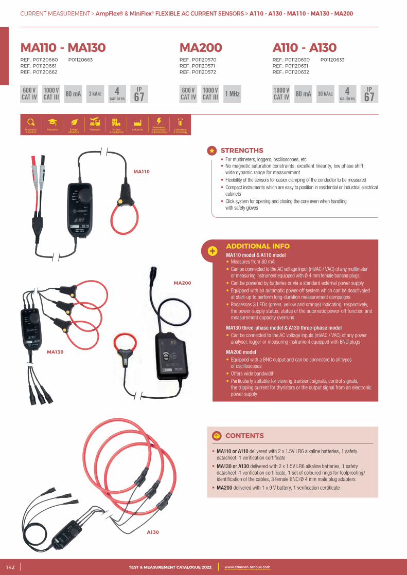
2 CATALOGUE TEST & MESURE 2021 www.chauvin-arnoux.com142 TEST & MEASUREMENT CATALOGUE 2022 www.chauvin-arnoux.com
CURRENT MEASUREMENT > AmpFlex® & MiniFlex® FLEXIBLE AC CURRENT SENSORS > A110 - A130 - MA110 - MA130 - MA200
MA110 - MA130REF.: P01120660 P01120663REF.: P01120661 REF.: P01120662
Generation, transmission & distribution
IndustriesTertiary & residential
Education TransportDiagnostic & control
Energy efficiency
Laboratory & metrology
80 mA600 VCAT IV
1000 VCAT III
IP673 kAAC 4
calibres
A110 - A130REF.: P01120630 P01120633REF.: P01120631REF.: P01120632
1000 VCAT IV80 mA600 V
CAT IV1000 VCAT III 1 MHz600 V
CAT IV1000 VCAT III
MA200REF.: P01120570REF.: P01120571REF.: P01120572
STRENGTHS • For multimeters, loggers, oscilloscopes, etc. • No magnetic saturation constraints: excellent linearity, low phase shift,
wide dynamic range for measurement • Flexibility of the sensors for easier clamping of the conductor to be measured • Compact instruments which are easy to position in residential or industrial electrical
cabinets • Click system for opening and closing the core even when handling
with safety gloves
ADDITIONAL INFOMA110 model & A110 model• Measures from 80 mA• Can be connected to the AC voltage input (mVAC / VAC) of any multimeter
or measuring instrument equipped with Ø 4 mm female banana plugs• Can be powered by batteries or via a standard external power supply• Equipped with an automatic power-off system which can be deactivated
at start-up to perform long-duration measurement campaigns• Possesses 3 LEDs (green, yellow and orange) indicating, respectively,
the power-supply status, status of the automatic power-off function and measurement capacity overruns
MA130 three-phase model & A130 three-phase model• Can be connected to the AC voltage inputs (mVAC / VAC) of any power
analyser, logger or measuring instrument equipped with BNC plugs
MA200 model• Equipped with a BNC output and can be connected to all types
of oscilloscopes• Offers wide bandwidth• Particularly suitable for viewing transient signals, control signals,
the tripping current for thyristors or the output signal from an electronic power supply
CONTENTS
• MA110 or A110 delivered with 2 x 1.5V LR6 alkaline batteries, 1 safety datasheet, 1 verification certificate
• MA130 or A130 delivered with 2 x 1.5V LR6 alkaline batteries, 1 safety datasheet, 1 verification certificate, 1 set of coloured rings for foolproofing/identification of the cables, 3 female BNC/Ø 4 mm male plug adapters
• MA200 delivered with 1 x 9 V battery, 1 verification certificate
MA200
MA130
MA110
A130
80 mA 30 kAACIP
674calibres
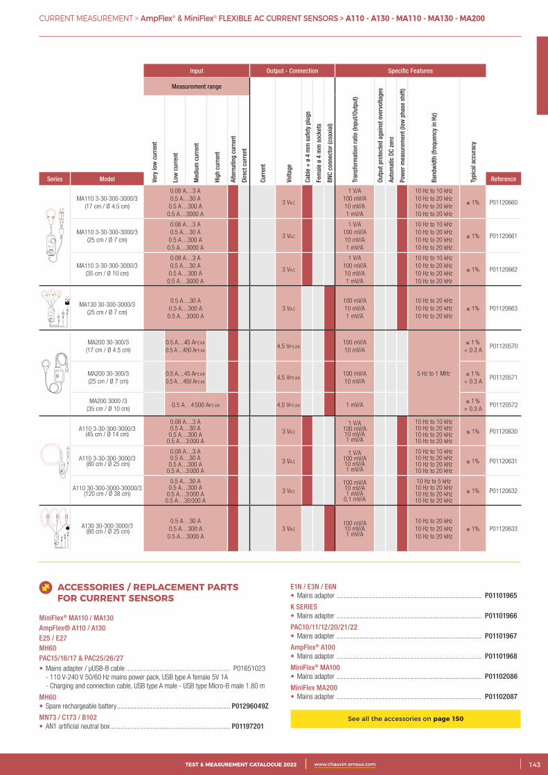
3CATALOGUE TEST & MESURE 2021 www.chauvin-arnoux.com 143TEST & MEASUREMENT CATALOGUE 2022 www.chauvin-arnoux.com
CURRENT MEASUREMENT > AmpFlex® & MiniFlex® FLEXIBLE AC CURRENT SENSORS > A110 - A130 - MA110 - MA130 - MA200
Input Output - Connection Specific Features
Measurement range
Curr
ent
Volta
ge
Cabl
e +
ø 4
mm
saf
ety
plug
s
Fem
ale
ø 4
mm
soc
kets
BNC
conn
ecto
r (co
axia
l)
Tran
sfor
mat
ion
ratio
(Inp
ut/O
utpu
t)
Outp
ut p
rote
cted
aga
inst
ove
rvol
tage
s
Auto
mat
ic D
C ze
ro
Pow
er m
easu
rem
ent (
low
pha
se s
hift)
Band
wid
th (f
requ
ency
in H
z)
Typi
cal a
ccur
acy
Very
low
cur
rent
Low
cur
rent
Med
ium
cur
rent
High
cur
rent
Alte
rnat
ing
curr
ent
Dire
ct c
urre
nt
Series Model Reference
OFF
3 A
30 A
300 A
3000 A
3 A : 1000 mV / A30 A : 100 mV / A300 A : 10 mV / A3000 A : 1 mV / A
AC CURRENT PROBEMA 110
600 V CAT IV1000 V CAT III
On
Auto Power Off
OL
P
MA110 3-30-300-3000/3(17 cm / Ø 4.5 cm)
0.08 A…3 A0.5 A…30 A0.5 A…300 A0.5 A…3000 A
3 VAc
1 V/A100 mV/A10 mV/A1 mV/A
10 Hz to 10 kHz10 Hz to 20 kHz10 Hz to 20 kHz10 Hz to 20 kHz
≤ 1% P01120660
MA110 3-30-300-3000/3(25 cm / Ø 7 cm)
0.08 A…3 A0.5 A…30 A0.5 A…300 A0.5 A…3000 A
3 VAc
1 V/A100 mV/A10 mV/A1 mV/A
10 Hz to 10 kHz10 Hz to 20 kHz10 Hz to 20 kHz10 Hz to 20 kHz
≤ 1% P01120661
MA110 3-30-300-3000/3(35 cm / Ø 10 cm)
0.08 A…3 A0.5 A…30 A0.5 A…300 A0.5 A…3000 A
3 VAc
1 V/A100 mV/A10 mV/A1 mV/A
10 Hz to 10 kHz10 Hz to 20 kHz10 Hz to 20 kHz10 Hz to 20 kHz
≤ 1% P01120662
OFF
30 A
300 A
3000 A
30 A : 100 mV / A300 A : 10 mV / A3000 A : 1 mV / A
AC CURRENT PROBEMA 130
On
Auto Power Off
OL
L1 L2 L3
L1 L3L2 600 V CAT III
L1L2
L3
L1
L2
L3P
MA130 30-300-3000/3(25 cm / Ø 7 cm)
0.5 A…30 A0.5 A…300 A0.5 A…3000 A
3 VAc
100 mV/A10 mV/A1 mV/A
10 Hz to 20 kHz10 Hz to 20 kHz10 Hz to 20 kHz
≤ 1% P01120663
MA200 30-300/3 (17 cm / Ø 4.5 cm)
0.5 A…45 Ap e Ak 0.5 A…450 Ap e Ak
4.5 Vp e Ak100 mV/A10 mV/A
5 Hz to 1 MHz
≤ 1 % + 0.3 A
P01120570
MA200 30-300/3 (25 cm / Ø 7 cm)
0.5 A…45 Ap e Ak 0.5 A…450 Ap e Ak
4.5 Vp e Ak100 mV/A10 mV/A
≤ 1 % + 0.3 A
P01120571
MA200 3000 /3 (35 cm / Ø 10 cm)
0.5 A…4 500 Ap e Ak 4.5 Vp e Ak 1 mV/A≤ 1 %
+ 0.3 AP01120572
OFF
3 A
30 A
300 A
3000 A
3 A : 1000 mV / A30 A : 100 mV / A300 A : 10 mV / A3000 A : 1 mV / A
AC CURRENT PROBEA 110
600 V CAT IV1000 V CAT III
On
Auto Power Off
OL
P
A110 3-30-300-3000/3(45 cm / Ø 14 cm)
0.08 A…3 A0.5 A…30 A0.5 A…300 A
0.5 A…3 000 A
3 VAc
1 V/A100 mV/A10 mV/A1 mV/A
10 Hz to 10 kHz10 Hz to 20 kHz10 Hz to 20 kHz10 Hz to 20 kHz
≤ 1% P01120630
A110 3-30-300-3000/3 (80 cm / Ø 25 cm)
0.08 A…3 A0.5 A…30 A0.5 A…300 A
0.5 A…3 000 A
3 VAc
1 V/A100 mV/A10 mV/A1 mV/A
10 Hz to 10 kHz10 Hz to 20 kHz10 Hz to 20 kHz10 Hz to 20 kHz
≤ 1% P01120631
A110 30-300-3000-30000/3(120 cm / Ø 38 cm)
0.5 A…30 A0.5 A…300 A
0.5 A…3 000 A0.5 A…30 000 A
3 VAc
100 mV/A10 mV/A1 mV/A
0,1 mV/A
10 Hz to 5 kHz10 Hz to 20 kHz10 Hz to 20 kHz10 Hz to 20 kHz
≤ 1% P01120632
OFF
30 A
300 A
3000 A
30 A : 100 mV / A300 A : 10 mV / A3000 A : 1 mV / A
AC CURRENT PROBEA 130
On
Auto Power Off
OL
L1 L2 L3
L1 L3L2
600 V CAT III
L1
L2
L3
L1 L2 L3
P
A130 30-300-3000/3 (80 cm / Ø 25 cm)
0.5 A…30 A0.5 A…300 A0.5 A…3000 A
3 VAc100 mV/A10 mV/A1 mV/A
10 Hz to 20 kHz10 Hz to 20 kHz10 Hz to 20 kHz
≤ 1% P01120633
ACCESSORIES / REPLACEMENT PARTS FOR CURRENT SENSORS
MiniFlex® MA110 / MA130AmpFlex® A110 / A130E25 / E27MH60PAC15/16/17 & PAC25/26/27• Mains adapter / µUSB-B cable ........................................................... P01651023
- 110 V-240 V 50/60 Hz mains power pack, USB type A female 5V 1A - Charging and connection cable, USB type A male - USB type Micro-B male 1.80 m
MH60• Spare rechargeable battery ................................................................ P01296049Z
MN73 / C173 / B102• AN1 artificial neutral box .................................................................... P01197201
E1N / E3N / E6N• Mains adapter .................................................................................. P01101965
K SERIES• Mains adapter .................................................................................. P01101966
PAC10/11/12/20/21/22• Mains adapter .................................................................................. P01101967
AmpFlex® A100• Mains adapter .................................................................................. P01101968
MiniFlex® MA100• Mains adapter .................................................................................. P01102086
MiniFlex MA200• Mains adapter .................................................................................. P01102087
See all the accessories on page 150
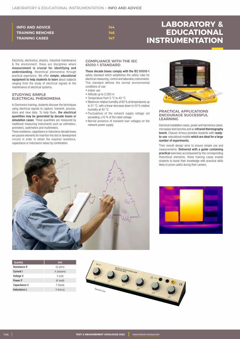
2 CATALOGUE TEST & MESURE 2021 www.chauvin-arnoux.com144 TEST & MEASUREMENT CATALOGUE 2022 www.chauvin-arnoux.com
LABORATORY & EDUCATIONAL INSTRUMENTATION > INFO AND ADVICE
INFO AND ADVICE 144TRAINING BENCHES 146TRAINING CASES 147
LABORATORY & EDUCATIONAL
INSTRUMENTATION
Electricity, electronics, physics, industrial maintenance & the environment: these are disciplines where measurement is crucial for identifying and understanding, theoretical phenomena through practical experience. We offer simple, educational equipment to help students to learn about subjects ranging from the study of electrical signals to the maintenance of electrical systems.
STUDYING SIMPLE ELECTRICAL PHENOMENAIn Electronics training, students discover the techniques using electrical signals to capture, transmit, process, store and view data. To help them, the electrical quantities may be generated by decade boxes or simulation cases. These quantities are measured by traditional measuring instruments such as voltmeters, ammeters, wattmeters and multimeters.These resistance, capacitance or inductance decade boxes are passive elements for insertion into test or development circuits in order to obtain the required resistance, capacitance or inductance values by combination.
COMPLIANCE WITH THE IEC 61010-1 STANDARD These decade boxes comply with the IEC 61010-1 safety standard which establishes the safety rules for electrical measuring, control and laboratory instruments.This standard defines the normal environmental conditions of use:• Indoor use• Altitude up to 2,000 m• Temperature from 5 °C to 40 °C• Maximum relative humidity of 80 % at temperatures up
to 31 °C, with a linear decrease down to 50 % relative humidity at 40 °C
• Fluctuations of the network supply voltage not exceeding ±10 % of the rated voltage
• Normal presence of transient over voltages on the network power supply
PRACTICAL APPLICATIONS ENCOURAGE SUCCESSFUL LEARNING Electrical installation cases, power and harmonics cases, microwave test benches and an infrared thermography bench, Chauvin Arnoux provides students with ready-to-use educational models which are ideal for a large number of experiments.
Their overall design aims to ensure simple use and measurements. Delivered with a guide containing practical exercises accompanied by the corresponding theoretical elements, these training cases enable students to boost their knowledge with practical skills likely to prove useful during their careers.
Quantity Unit
Resistance R Ω (ohm)
Current I A (ampere)
Voltage V V (volt)
Power P W (watt)
Capacitance C F (farad)
Inductance L H (henry) Resistor box
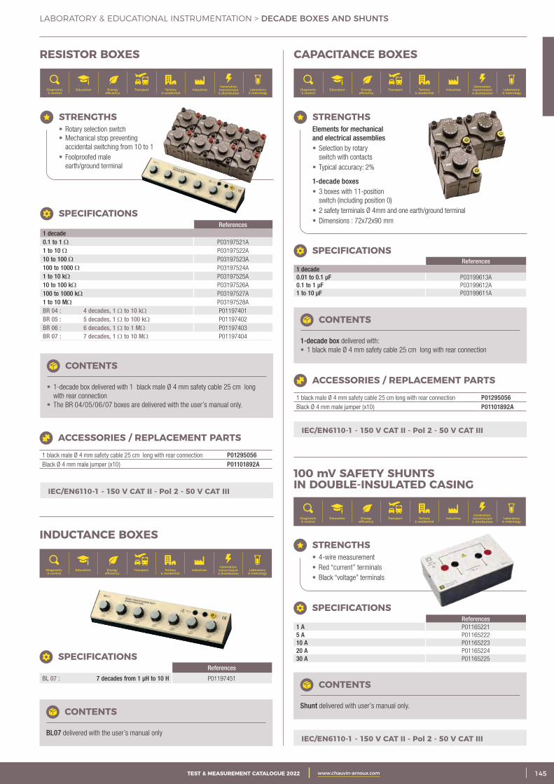
3CATALOGUE TEST & MESURE 2021 www.chauvin-arnoux.com 145TEST & MEASUREMENT CATALOGUE 2022 www.chauvin-arnoux.com
LABORATORY & EDUCATIONAL INSTRUMENTATION > DECADE BOXES AND SHUNTS
CONTENTS
BL07 delivered with the user’s manual only
References
BL 07 : 7 decades from 1 μH to 10 H P01197451
SPECIFICATIONS
CAPACITANCE BOXES
IEC/EN6110-1 - 150 V CAT II - Pol 2 - 50 V CAT III
CONTENTS
1-decade box delivered with: • 1 black male Ø 4 mm safety cable 25 cm long with rear connection
References 1 decade 0.01 to 0.1 μF P03199613A0.1 to 1 μF P03199612A1 to 10 μF P03199611A
SPECIFICATIONS
ACCESSORIES / REPLACEMENT PARTS
1 black male Ø 4 mm safety cable 25 cm long with rear connection P01295056Black Ø 4 mm male jumper (x10) P01101892A
STRENGTHS Elements for mechanical
and electrical assemblies • Selection by rotary
switch with contacts • Typical accuracy: 2%
1-decade boxes • 3 boxes with 11-position
switch (including position 0) • 2 safety terminals Ø 4mm and one earth/ground terminal • Dimensions : 72x72x90 mm
Generation, transmission & distribution
IndustriesTertiary & residential
Education TransportDiagnostic & control
Energy efficiency
Laboratory & metrology
RESISTOR BOXES
ACCESSORIES / REPLACEMENT PARTS
1 black male Ø 4 mm safety cable 25 cm long with rear connection P01295056Black Ø 4 mm male jumper (x10) P01101892A
CONTENTS
• 1-decade box delivered with 1 black male Ø 4 mm safety cable 25 cm long with rear connection
• The BR 04/05/06/07 boxes are delivered with the user’s manual only.
STRENGTHS • Rotary selection switch • Mechanical stop preventing
accidental switching from 10 to 1 • Foolproofed male
earth/ground terminal
References1 decade 0.1 to 1 Ω P03197521A1 to 10 Ω P03197522A10 to 100 Ω P03197523A100 to 1000 Ω P03197524A1 to 10 kΩ P03197525A10 to 100 kΩ P03197526A100 to 1000 kΩ P03197527A1 to 10 MΩ P03197528ABR 04 : 4 decades, 1 Ω to 10 kΩ P01197401BR 05 : 5 decades, 1 Ω to 100 kΩ P01197402BR 06 : 6 decades, 1 Ω to 1 MΩ P01197403BR 07 : 7 decades, 1 Ω to 10 MΩ P01197404
SPECIFICATIONS
IEC/EN6110-1 - 150 V CAT II - Pol 2 - 50 V CAT III
INDUCTANCE BOXES
IEC/EN6110-1 - 150 V CAT II - Pol 2 - 50 V CAT III
CONTENTS
Shunt delivered with user’s manual only.
STRENGTHS • 4-wire measurement • Red “current” terminals • Black “voltage” terminals
References 1 A P011652215 A P0116522210 A P0116522320 A P0116522430 A P01165225
SPECIFICATIONS
100 mV SAFETY SHUNTS IN DOUBLE-INSULATED CASING
Generation, transmission & distribution
IndustriesTertiary & residential
Education TransportDiagnostic & control
Energy efficiency
Laboratory & metrology
Generation, transmission & distribution
IndustriesTertiary & residential
Education TransportDiagnostic & control
Energy efficiency
Laboratory & metrology
Generation, transmission & distribution
IndustriesTertiary & residential
Education TransportDiagnostic & control
Energy efficiency
Laboratory & metrology
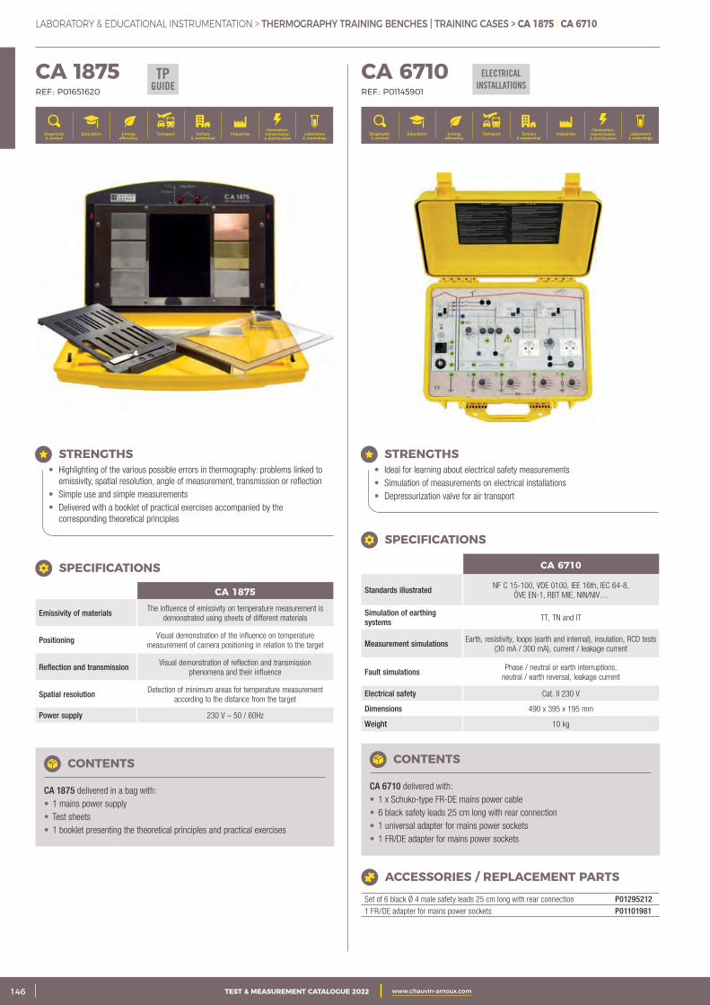
2 CATALOGUE TEST & MESURE 2021 www.chauvin-arnoux.com146 TEST & MEASUREMENT CATALOGUE 2022 www.chauvin-arnoux.com
LABORATORY & EDUCATIONAL INSTRUMENTATION > THERMOGRAPHY TRAINING BENCHES | TRAINING CASES > CA 1875 | CA 6710
CA 1875 REF.: P01651620
CA 6710 REF.: P01145901
STRENGTHS • Highlighting of the various possible errors in thermography: problems linked to
emissivity, spatial resolution, angle of measurement, transmission or reflection • Simple use and simple measurements • Delivered with a booklet of practical exercises accompanied by the
corresponding theoretical principles
CONTENTS
CA 1875 delivered in a bag with: • 1 mains power supply • Test sheets • 1 booklet presenting the theoretical principles and practical exercises
SPECIFICATIONS
CA 1875
Emissivity of materials The influence of emissivity on temperature measurement is demonstrated using sheets of different materials
Positioning Visual demonstration of the influence on temperature measurement of camera positioning in relation to the target
Reflection and transmission Visual demonstration of reflection and transmission phenomena and their influence
Spatial resolution Detection of minimum areas for temperature measurement according to the distance from the target
Power supply 230 V – 50 / 60Hz
STRENGTHS • Ideal for learning about electrical safety measurements • Simulation of measurements on electrical installations • Depressurization valve for air transport
CONTENTS
CA 6710 delivered with: • 1 x Schuko-type FR-DE mains power cable • 6 black safety leads 25 cm long with rear connection • 1 universal adapter for mains power sockets • 1 FR/DE adapter for mains power sockets
ELECTRICAL INSTALLATIONS
SPECIFICATIONS
CA 6710
Standards illustrated NF C 15-100, VDE 0100, IEE 16th, IEC 64-8, ÖVE EN-1, RBT MIE, NIN/NIV…
Simulation of earthing systems TT, TN and IT
Measurement simulations Earth, resistivity, loops (earth and internal), insulation, RCD tests (30 mA / 300 mA), current / leakage current
Fault simulations Phase / neutral or earth interruptions, neutral / earth reversal, leakage current
Electrical safety Cat. II 230 V
Dimensions 490 x 395 x 195 mm
Weight 10 kg
ACCESSORIES / REPLACEMENT PARTS
Set of 6 black Ø 4 male safety leads 25 cm long with rear connection P012952121 FR/DE adapter for mains power sockets P01101981
TPGUIDE
Generation, transmission & distribution
IndustriesTertiary & residential
Education TransportDiagnostic & control
Energy efficiency
Laboratory & metrology
Generation, transmission & distribution
IndustriesTertiary & residential
Education TransportDiagnostic & control
Energy efficiency
Laboratory & metrology
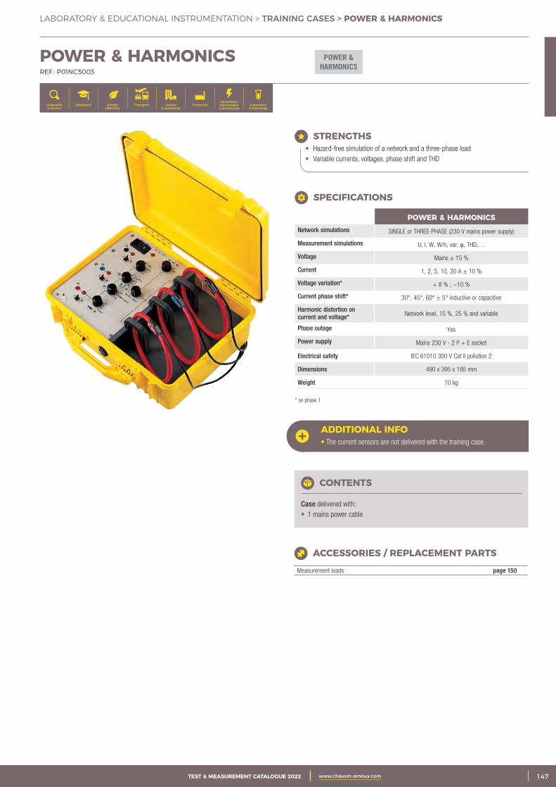
3CATALOGUE TEST & MESURE 2021 www.chauvin-arnoux.com 147TEST & MEASUREMENT CATALOGUE 2022 www.chauvin-arnoux.com
LABORATORY & EDUCATIONAL INSTRUMENTATION > TRAINING CASES > POWER & HARMONICS
POWER & HARMONICS
POWER & HARMONICS REF.: P01NC5003
STRENGTHS • Hazard-free simulation of a network and a three-phase load • Variable currents, voltages, phase shift and THD
ADDITIONAL INFO• The current sensors are not delivered with the training case.
CONTENTS
Case delivered with: • 1 mains power cable
ACCESSORIES / REPLACEMENT PARTS
Measurement leads page 150
POWER & HARMONICSNetwork simulations SINGLE or THREE-PHASE (230 V mains power supply)
Measurement simulations U, I, W, W/h, var, φ, THD,…
Voltage Mains ± 15 %
Current 1, 2, 5, 10, 20 A ± 10 %
Voltage variation* + 8 % ; −10 %
Current phase shift* 30°, 45°, 60° ± 5° inductive or capacitive
Harmonic distortion on current and voltage* Network level, 15 %, 25 % and variable
Phase outage Yes
Power supply Mains 230 V - 2 P + E socket
Electrical safety IEC 61010 300 V Cat II pollution 2
Dimensions 490 x 395 x 195 mm
Weight 10 kg
* on phase 1
SPECIFICATIONS
Generation, transmission & distribution
IndustriesTertiary & residential
Education TransportDiagnostic & control
Energy efficiency
Laboratory & metrology
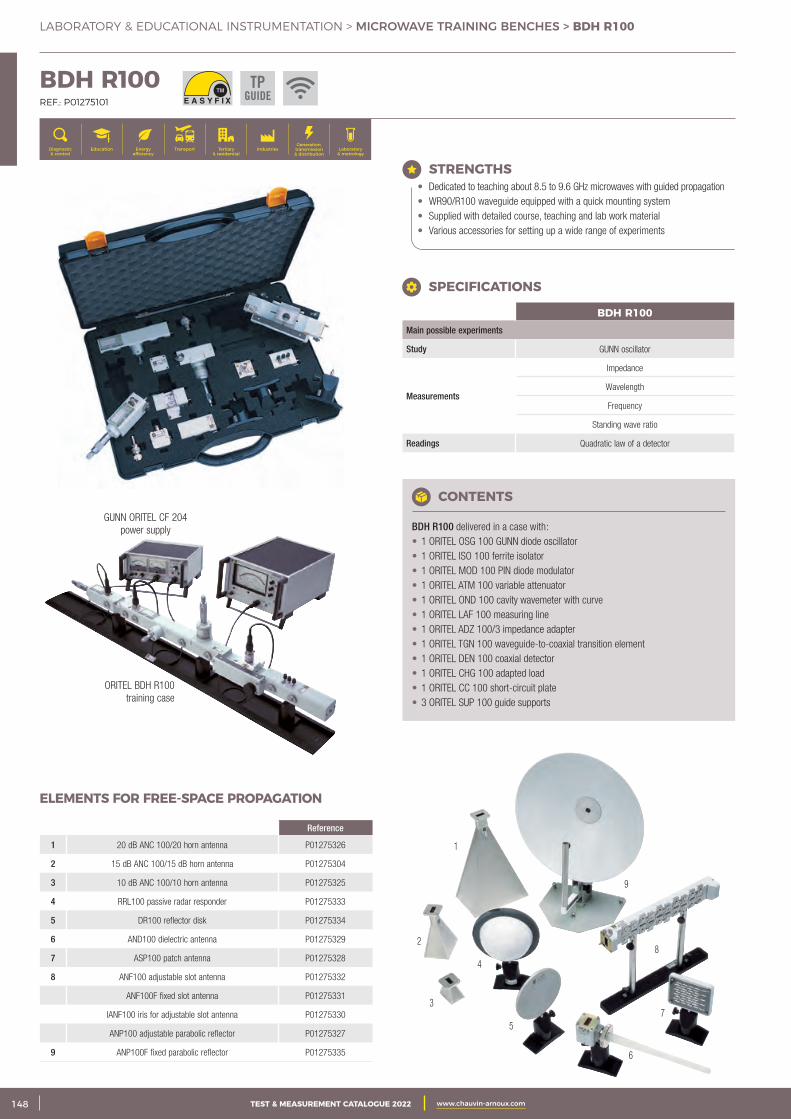
2 CATALOGUE TEST & MESURE 2021 www.chauvin-arnoux.com148 TEST & MEASUREMENT CATALOGUE 2022 www.chauvin-arnoux.com
LABORATORY & EDUCATIONAL INSTRUMENTATION > MICROWAVE TRAINING BENCHES > BDH R100
GUNN ORITEL CF 204 power supply
ORITEL BDH R100 training case
5
8
7
9
6
4
1
2
3
BDH R100 REF.: P01275101
STRENGTHS • Dedicated to teaching about 8.5 to 9.6 GHz microwaves with guided propagation • WR90/R100 waveguide equipped with a quick mounting system • Supplied with detailed course, teaching and lab work material • Various accessories for setting up a wide range of experiments
BDH R100Main possible experiments
Study GUNN oscillator
Measurements
Impedance
Wavelength
Frequency
Standing wave ratio
Readings Quadratic law of a detector
SPECIFICATIONS
CONTENTS
BDH R100 delivered in a case with: • 1 ORITEL OSG 100 GUNN diode oscillator • 1 ORITEL ISO 100 ferrite isolator • 1 ORITEL MOD 100 PIN diode modulator • 1 ORITEL ATM 100 variable attenuator • 1 ORITEL OND 100 cavity wavemeter with curve • 1 ORITEL LAF 100 measuring line • 1 ORITEL ADZ 100/3 impedance adapter • 1 ORITEL TGN 100 waveguide-to-coaxial transition element • 1 ORITEL DEN 100 coaxial detector • 1 ORITEL CHG 100 adapted load • 1 ORITEL CC 100 short-circuit plate • 3 ORITEL SUP 100 guide supports
Reference
1 20 dB ANC 100/20 horn antenna P01275326
2 15 dB ANC 100/15 dB horn antenna P01275304
3 10 dB ANC 100/10 horn antenna P01275325
4 RRL100 passive radar responder P01275333
5 DR100 reflector disk P01275334
6 AND100 dielectric antenna P01275329
7 ASP100 patch antenna P01275328
8 ANF100 adjustable slot antenna P01275332
ANF100F fixed slot antenna P01275331
IANF100 iris for adjustable slot antenna P01275330
ANP100 adjustable parabolic reflector P01275327
9 ANP100F fixed parabolic reflector P01275335
ELEMENTS FOR FREE-SPACE PROPAGATION
TPGUIDE
Generation, transmission & distribution
IndustriesTertiary & residential
Education TransportDiagnostic & control
Energy efficiency
Laboratory & metrology
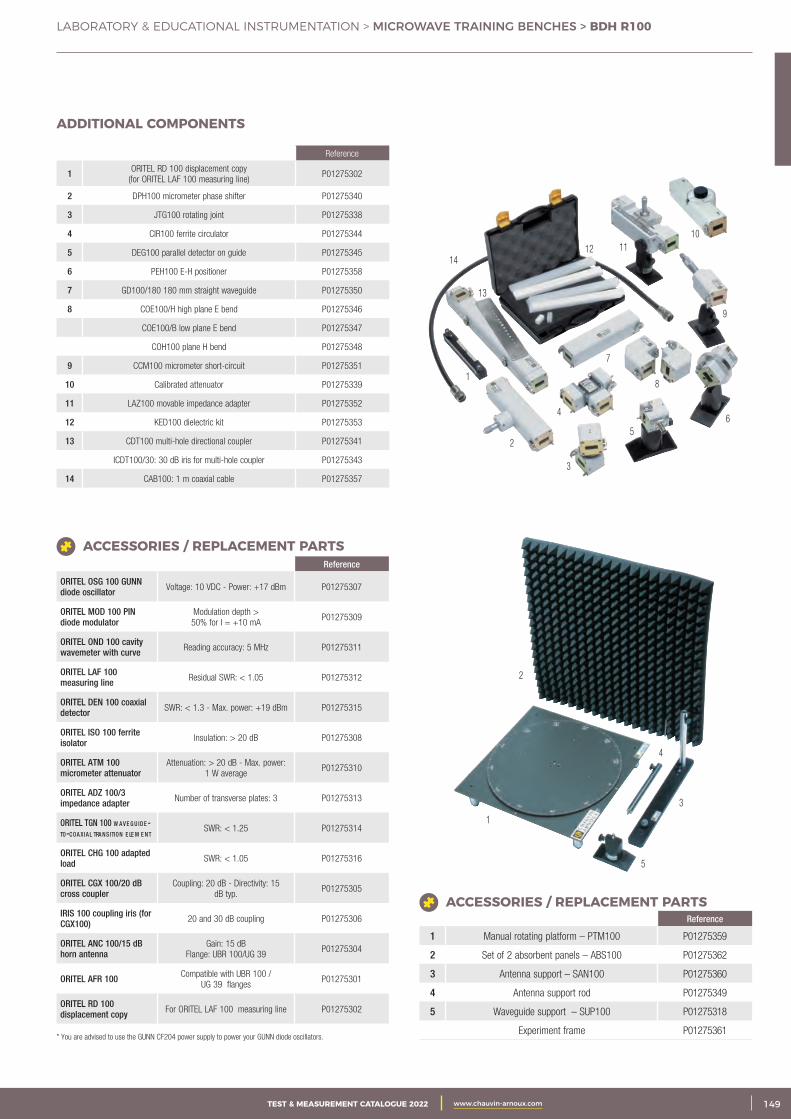
3CATALOGUE TEST & MESURE 2021 www.chauvin-arnoux.com 149TEST & MEASUREMENT CATALOGUE 2022 www.chauvin-arnoux.com
LABORATORY & EDUCATIONAL INSTRUMENTATION > MICROWAVE TRAINING BENCHES > BDH R100
1
2
3
4
56
7
8
9
101112
13
14
1
2
3
5
4
Reference
1 ORITEL RD 100 displacement copy(for ORITEL LAF 100 measuring line)
P01275302
2 DPH100 micrometer phase shifter P01275340
3 JTG100 rotating joint P01275338
4 CIR100 ferrite circulator P01275344
5 DEG100 parallel detector on guide P01275345
6 PEH100 E-H positioner P01275358
7 GD100/180 180 mm straight waveguide P01275350
8 COE100/H high plane E bend P01275346
COE100/B low plane E bend P01275347
COH100 plane H bend P01275348
9 CCM100 micrometer short-circuit P01275351
10 Calibrated attenuator P01275339
11 LAZ100 movable impedance adapter P01275352
12 KED100 dielectric kit P01275353
13 CDT100 multi-hole directional coupler P01275341
ICDT100/30: 30 dB iris for multi-hole coupler P01275343
14 CAB100: 1 m coaxial cable P01275357
ADDITIONAL COMPONENTS
Reference
ORITEL OSG 100 GUNN diode oscillator Voltage: 10 VDC - Power: +17 dBm P01275307
ORITEL MOD 100 PIN diode modulator
Modulation depth > 50% for I = +10 mA
P01275309
ORITEL OND 100 cavity wavemeter with curve Reading accuracy: 5 MHz P01275311
ORITEL LAF 100 measuring line Residual SWR: < 1.05 P01275312
ORITEL DEN 100 coaxial detector SWR: < 1.3 - Max. power: +19 dBm P01275315
ORITEL ISO 100 ferrite isolator Insulation: > 20 dB P01275308
ORITEL ATM 100 micrometer attenuator
Attenuation: > 20 dB - Max. power: 1 W average
P01275310
ORITEL ADZ 100/3 impedance adapter Number of transverse plates: 3 P01275313
ORITEL TGN 100 w a v E G u Id E -TO-cOa xIa L TRa NsITION E LE m E NT SWR: < 1.25 P01275314
ORITEL CHG 100 adapted load SWR: < 1.05 P01275316
ORITEL CGX 100/20 dB cross coupler
Coupling: 20 dB - Directivity: 15 dB typ.
P01275305
IRIS 100 coupling iris (for CGX100) 20 and 30 dB coupling P01275306
ORITEL ANC 100/15 dB horn antenna
Gain: 15 dB Flange: UBR 100/UG 39
P01275304
ORITEL AFR 100 Compatible with UBR 100 / UG 39 flanges
P01275301
ORITEL RD 100 displacement copy For ORITEL LAF 100 measuring line P01275302
* You are advised to use the GUNN CF204 power supply to power your GUNN diode oscillators.
ACCESSORIES / REPLACEMENT PARTS
Reference
1 Manual rotating platform – PTM100 P01275359
2 Set of 2 absorbent panels – ABS100 P01275362
3 Antenna support – SAN100 P01275360
4 Antenna support rod P01275349
5 Waveguide support – SUP100 P01275318
Experiment frame P01275361
ACCESSORIES / REPLACEMENT PARTS
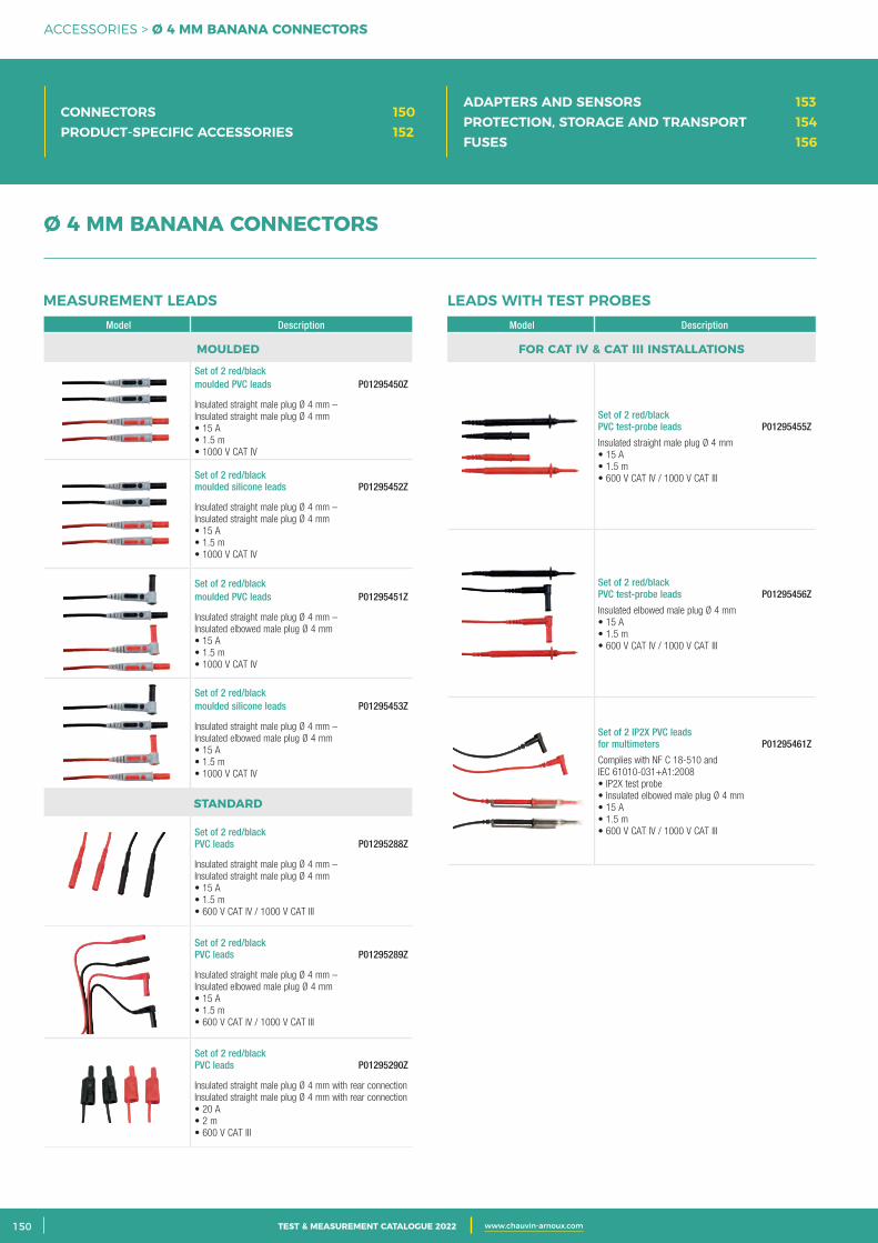
2 CATALOGUE TEST & MESURE 2021 www.chauvin-arnoux.com150 TEST & MEASUREMENT CATALOGUE 2022 www.chauvin-arnoux.com
ACCESSORIES > Ø 4 MM BANANA CONNECTORS
CONNECTORS 150PRODUCT-SPECIFIC ACCESSORIES 152
ADAPTERS AND SENSORS 153PROTECTION, STORAGE AND TRANSPORT 154FUSES 156
Model Description
MOULDED
Set of 2 red/black moulded PVC leads P01295450Z
Insulated straight male plug Ø 4 mm –Insulated straight male plug Ø 4 mm• 15 A• 1.5 m• 1000 V CAT IV
Set of 2 red/black moulded silicone leads P01295452Z
Insulated straight male plug Ø 4 mm –Insulated straight male plug Ø 4 mm• 15 A• 1.5 m• 1000 V CAT IV
Set of 2 red/black moulded PVC leads P01295451Z
Insulated straight male plug Ø 4 mm –Insulated elbowed male plug Ø 4 mm• 15 A• 1.5 m• 1000 V CAT IV
Set of 2 red/black moulded silicone leads P01295453Z
Insulated straight male plug Ø 4 mm –Insulated elbowed male plug Ø 4 mm• 15 A• 1.5 m• 1000 V CAT IV
STANDARD
Set of 2 red/black PVC leads P01295288Z
Insulated straight male plug Ø 4 mm –Insulated straight male plug Ø 4 mm• 15 A• 1.5 m• 600 V CAT IV / 1000 V CAT III
Set of 2 red/black PVC leads P01295289Z
Insulated straight male plug Ø 4 mm –Insulated elbowed male plug Ø 4 mm• 15 A• 1.5 m• 600 V CAT IV / 1000 V CAT III
Set of 2 red/black PVC leads P01295290Z
Insulated straight male plug Ø 4 mm with rear connection Insulated straight male plug Ø 4 mm with rear connection• 20 A• 2 m• 600 V CAT III
Model Description
FOR CAT IV & CAT III INSTALLATIONS
Set of 2 red/black PVC test-probe leads P01295455Z
Insulated straight male plug Ø 4 mm• 15 A• 1.5 m• 600 V CAT IV / 1000 V CAT III
Set of 2 red/black PVC test-probe leads P01295456Z
Insulated elbowed male plug Ø 4 mm• 15 A• 1.5 m• 600 V CAT IV / 1000 V CAT III
Set of 2 IP2X PVC leads for multimeters P01295461Z
Complies with NF C 18-510 and IEC 61010-031+A1:2008• IP2X test probe• Insulated elbowed male plug Ø 4 mm• 15 A• 1.5 m• 600 V CAT IV / 1000 V CAT III
MEASUREMENT LEADS LEADS WITH TEST PROBES
Ø 4 MM BANANA CONNECTORS
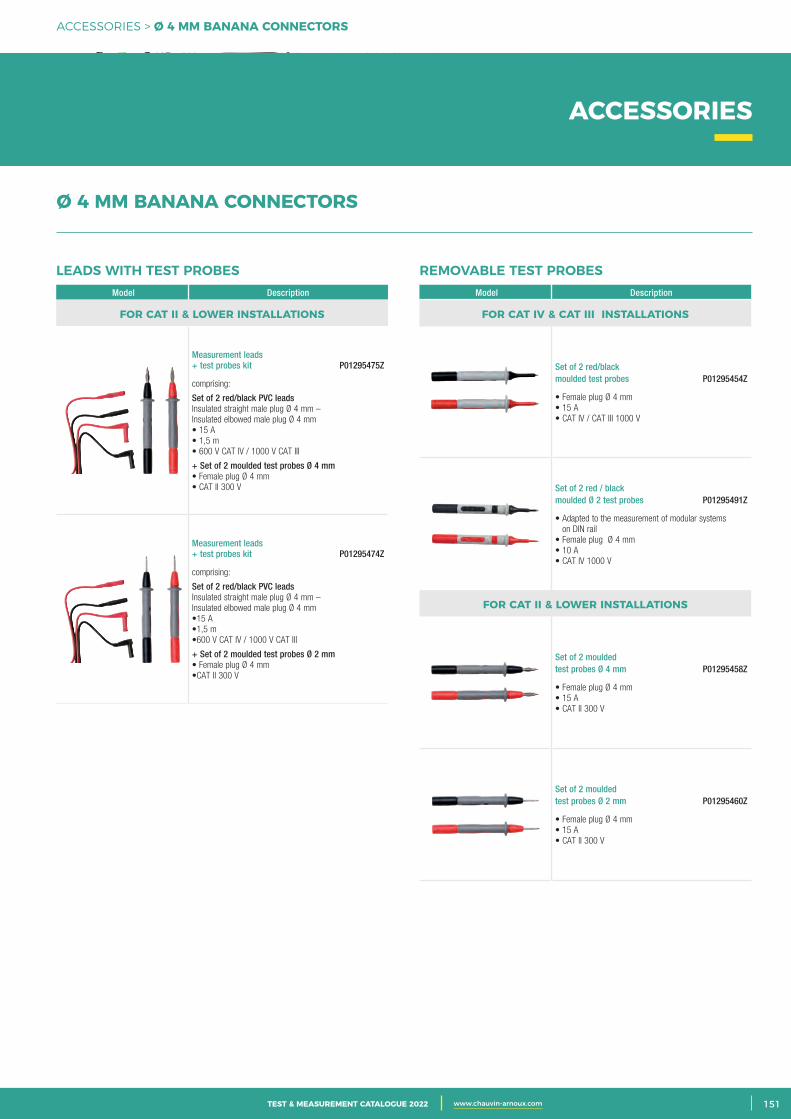
3CATALOGUE TEST & MESURE 2021 www.chauvin-arnoux.com 151TEST & MEASUREMENT CATALOGUE 2022 www.chauvin-arnoux.com
ACCESSORIES > Ø 4 MM BANANA CONNECTORS
ACCESSORIES
Model Description
FOR CAT II & LOWER INSTALLATIONS
Measurement leads + test probes kit P01295475Z
comprising:
Set of 2 red/black PVC leadsInsulated straight male plug Ø 4 mm – Insulated elbowed male plug Ø 4 mm• 15 A• 1,5 m• 600 V CAT IV / 1000 V CAT III
+ Set of 2 moulded test probes Ø 4 mm• Female plug Ø 4 mm• CAT II 300 V
Measurement leads + test probes kit P01295474Z
comprising:
Set of 2 red/black PVC leadsInsulated straight male plug Ø 4 mm – Insulated elbowed male plug Ø 4 mm•15 A•1,5 m•600 V CAT IV / 1000 V CAT III
+ Set of 2 moulded test probes Ø 2 mm• Female plug Ø 4 mm•CAT II 300 V
Model Description
FOR CAT IV & CAT III INSTALLATIONS
Set of 2 red/black moulded test probes P01295454Z
• Female plug Ø 4 mm • 15 A• CAT IV / CAT III 1000 V
Set of 2 red / black moulded Ø 2 test probes P01295491Z
• Adapted to the measurement of modular systems on DIN rail
• Female plug Ø 4 mm • 10 A• CAT IV 1000 V
FOR CAT II & LOWER INSTALLATIONS
Set of 2 moulded test probes Ø 4 mm P01295458Z
• Female plug Ø 4 mm • 15 A• CAT II 300 V
Set of 2 moulded test probes Ø 2 mm P01295460Z
• Female plug Ø 4 mm • 15 A• CAT II 300 V
LEADS WITH TEST PROBES REMOVABLE TEST PROBES
Ø 4 MM BANANA CONNECTORS
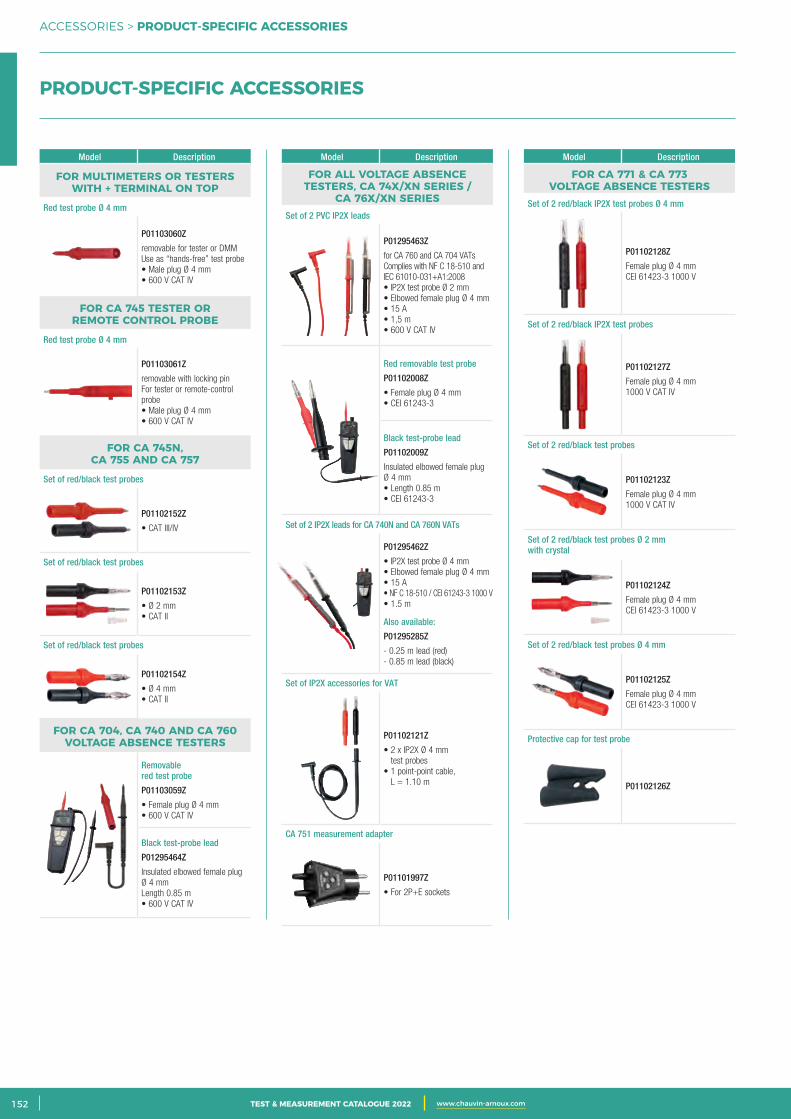
2 CATALOGUE TEST & MESURE 2021 www.chauvin-arnoux.com152 TEST & MEASUREMENT CATALOGUE 2022 www.chauvin-arnoux.com
ACCESSORIES > PRODUCT-SPECIFIC ACCESSORIES
PRODUCT-SPECIFIC ACCESSORIES
Model Description
FOR MULTIMETERS OR TESTERS WITH + TERMINAL ON TOP
Red test probe Ø 4 mm
P01103060Z
removable for tester or DMMUse as “hands-free” test probe• Male plug Ø 4 mm• 600 V CAT IV
FOR CA 745 TESTER OR REMOTE CONTROL PROBE
Red test probe Ø 4 mm
P01103061Z
removable with locking pinFor tester or remote-control probe • Male plug Ø 4 mm• 600 V CAT IV
FOR CA 745N, CA 755 AND CA 757
Set of red/black test probes
P01102152Z
• CAT III/IV
Set of red/black test probes
P01102153Z
• Ø 2 mm• CAT II
Set of red/black test probes
P01102154Z
• Ø 4 mm• CAT II
FOR CA 704, CA 740 AND CA 760 VOLTAGE ABSENCE TESTERS
Removable red test probe
P01103059Z
• Female plug Ø 4 mm• 600 V CAT IV
Black test-probe lead
P01295464Z
Insulated elbowed female plug Ø 4 mmLength 0.85 m • 600 V CAT IV
Model Description
FOR CA 771 & CA 773 VOLTAGE ABSENCE TESTERS
Set of 2 red/black IP2X test probes Ø 4 mm
P01102128Z
Female plug Ø 4 mmCEI 61423-3 1000 V
Set of 2 red/black IP2X test probes
P01102127Z
Female plug Ø 4 mm1000 V CAT IV
Set of 2 red/black test probes
P01102123Z
Female plug Ø 4 mm1000 V CAT IV
Set of 2 red/black test probes Ø 2 mm with crystal
P01102124Z
Female plug Ø 4 mmCEI 61423-3 1000 V
Set of 2 red/black test probes Ø 4 mm
P01102125Z
Female plug Ø 4 mmCEI 61423-3 1000 V
Protective cap for test probe
P01102126Z
Model Description
FOR ALL VOLTAGE ABSENCE TESTERS, CA 74X/XN SERIES /
CA 76X/XN SERIESSet of 2 PVC IP2X leads
P01295463Z
for CA 760 and CA 704 VATsComplies with NF C 18-510 and IEC 61010-031+A1:2008• IP2X test probe Ø 2 mm• Elbowed female plug Ø 4 mm• 15 A• 1,5 m• 600 V CAT IV
Red removable test probe
P01102008Z
• Female plug Ø 4 mm• CEI 61243-3
Black test-probe lead
P01102009Z
Insulated elbowed female plug Ø 4 mm• Length 0.85 m• CEI 61243-3
Set of 2 IP2X leads for CA 740N and CA 760N VATs
P01295462Z
• IP2X test probe Ø 4 mm• Elbowed female plug Ø 4 mm• 15 A• NF C 18-510 / CEI 61243-3 1000 V• 1.5 m
Also available:
P01295285Z
- 0.25 m lead (red)- 0.85 m lead (black)
Set of IP2X accessories for VAT
P01102121Z
• 2 x IP2X Ø 4 mm test probes
• 1 point-point cable, L = 1.10 m
CA 751 measurement adapter
P01101997Z
• For 2P+E sockets
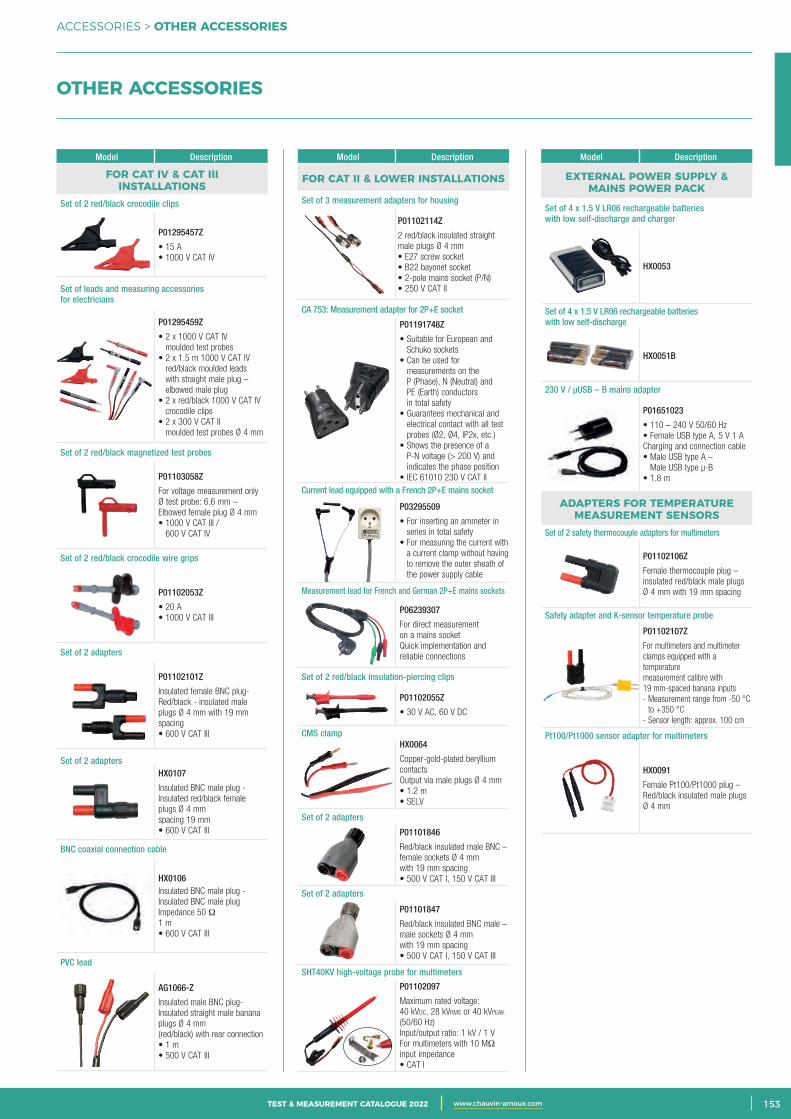
3CATALOGUE TEST & MESURE 2021 www.chauvin-arnoux.com 153TEST & MEASUREMENT CATALOGUE 2022 www.chauvin-arnoux.com
ACCESSORIES > OTHER ACCESSORIES
OTHER ACCESSORIES
Model Description
FOR CAT IV & CAT III INSTALLATIONS
Set of 2 red/black crocodile clips
P01295457Z
• 15 A• 1000 V CAT IV
Set of leads and measuring accessories for electricians
P01295459Z
• 2 x 1000 V CAT IV moulded test probes
• 2 x 1.5 m 1000 V CAT IV red/black moulded leads with straight male plug – elbowed male plug
• 2 x red/black 1000 V CAT IV crocodile clips
• 2 x 300 V CAT II moulded test probes Ø 4 mm
Set of 2 red/black magnetized test probes
P01103058Z
For voltage measurement only Ø test probe: 6.6 mm – Elbowed female plug Ø 4 mm• 1000 V CAT III /
600 V CAT IV
Set of 2 red/black crocodile wire grips
P01102053Z
• 20 A• 1000 V CAT III
Set of 2 adapters
P01102101Z
Insulated female BNC plug-Red/black - insulated male plugs Ø 4 mm with 19 mm spacing• 600 V CAT III
Set of 2 adaptersHX0107
Insulated BNC male plug -Insulated red/black female plugs Ø 4 mm spacing 19 mm• 600 V CAT III
BNC coaxial connection cable
HX0106Insulated BNC male plug -Insulated BNC male plugImpedance 50 Ω1 m• 600 V CAT III
PVC lead
AG1066-Z
Insulated male BNC plug-Insulated straight male banana plugs Ø 4 mm(red/black) with rear connection• 1 m• 500 V CAT III
Model Description
EXTERNAL POWER SUPPLY & MAINS POWER PACK
Set of 4 x 1.5 V LR06 rechargeable batteries with low self-discharge and charger
HX0053
Set of 4 x 1.5 V LR06 rechargeable batteries with low self-discharge
HX0051B
230 V / μUSB – B mains adapter
P01651023
• 110 – 240 V 50/60 Hz• Female USB type A, 5 V 1 ACharging and connection cable• Male USB type A –
Male USB type μ-B• 1.8 m
ADAPTERS FOR TEMPERATURE MEASUREMENT SENSORS
Set of 2 safety thermocouple adapters for multimeters
P01102106Z
Female thermocouple plug – insulated red/black male plugs Ø 4 mm with 19 mm spacing
Safety adapter and K-sensor temperature probe
P01102107Z
For multimeters and multimeter clamps equipped with a temperaturemeasurement calibre with 19 mm-spaced banana inputs- Measurement range from -50 °C
to +350 °C- Sensor length: approx. 100 cm
Pt100/Pt1000 sensor adapter for multimeters
HX0091
Female Pt100/Pt1000 plug – Red/black insulated male plugs Ø 4 mm
Model Description
FOR CAT II & LOWER INSTALLATIONS
Set of 3 measurement adapters for housing
P01102114Z
2 red/black insulated straight male plugs Ø 4 mm• E27 screw socket• B22 bayonet socket• 2-pole mains socket (P/N)• 250 V CAT II
CA 753: Measurement adapter for 2P+E socket
P01191748Z
• Suitable for European and Schuko sockets
• Can be used for measurements on the P (Phase), N (Neutral) and PE (Earth) conductors in total safety
• Guarantees mechanical and electrical contact with all test probes (Ø2, Ø4, IP2x, etc.)
• Shows the presence of a P-N voltage (> 200 V) and indicates the phase position
• IEC 61010 230 V CAT IICurrent lead equipped with a French 2P+E mains socket
P03295509
• For inserting an ammeter in series in total safety
• For measuring the current with a current clamp without having to remove the outer sheath of the power supply cable
Measurement lead for French and German 2P+E mains sockets
P06239307
For direct measurement on a mains socketQuick implementation and reliable connections
Set of 2 red/black insulation-piercing clips
P01102055Z
• 30 V AC, 60 V DC
CMS clampHX0064
Copper-gold-plated beryllium contactsOutput via male plugs Ø 4 mm• 1.2 m• SELV
Set of 2 adapters
P01101846
Red/black insulated male BNC – female sockets Ø 4 mm with 19 mm spacing• 500 V CAT I, 150 V CAT III
Set of 2 adapters
P01101847
Red/black insulated BNC male – male sockets Ø 4 mm with 19 mm spacing• 500 V CAT I, 150 V CAT III
SHT40KV high-voltage probe for multimeters
P01102097
Maximum rated voltage:40 kVdc, 28 kVrms or 40 kVpeak (50/60 Hz)Input/output ratio: 1 kV / 1 VFor multimeters with 10 MΩ input impedance• CAT I
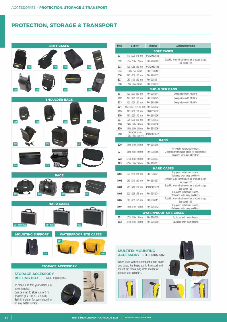
2 CATALOGUE TEST & MESURE 2021 www.chauvin-arnoux.com154 TEST & MEASUREMENT CATALOGUE 2022 www.chauvin-arnoux.com
ACCESSORIES > PROTECTION, STORAGE & TRANSPORT
Photo L x H x P Reference Additional information
SOFT CASESE01 110 x 220 x 45 mm P01298065Z
E02 125 x 210 x 120 mm P01298049Specific to one instrument or product range.
See page 155
E03 125 x 265 x 60 mm P01298043Z
E04 180 x 75 x 45 mm P01298012
E06 190 x 250 x 60 mm P01298055
E07 250 x 190 x 80 mm P01298051
E08 70 x 185 x 30 mm P01298007
SHOULDER BAGSS01 120 x 200 x 60 mm P01298074 Compatible with MultiFix
S02 120 x 245 x 60 mm P01298075 Compatible with MultiFix
S03 120 x 320 x 60 mm P01298076 Compatible with MultiFix
S04 150 x 230 x (40+40) mm P01298032
S05 165 x 250 x 60 mm P06239502
S06 180 x 220 x 75 mm P01298036
S07 225 x 270 x 70 mm P01298033
S08 240 x 140 x 130 mm P01298006
S09 355 x 255 x 235 mm P01298056
S10360 x 200 x 140
+ 360 x 160 x 35 mmP01298061A
BAGSS20 330 x 240 x 240 mm P01298078
S21 380 x 280 x 200 mm P01298066All-terrain waterproof bottom.
2 compartments and space for documents. Supplied with shoulder strap
S22 575 x 320 x 200 mm P01298067
S23 475 x 180 x 250 mm P01298031
HARD CASES
M01 270 x 195 x 65 mm P01298071Equipped with foam inserts.
Delivered with strap and keys
M02 285 x 210 x 80 mm P01298037Specific to one instrument or product range.
See page 155
M03 285 x 210 x 80 mm P01298037ASpecific to one instrument or product range.
See page 155
M04 320 x 255 x 75 mm P01298004Equipped with foam inserts.
Delivered with strap and keys
M05 320 x 255 x 75 mm P01298011Specific to one instrument or product range.
See page 155
M07 440 x 310 x 135 mm P01298072Equipped with foam inserts.
Delivered with strap and keys
WATERPROOF SITE CASESB01 272 x 248 x 130 mm P01298068 Equipped with foam inserts
B02 272 x 248 x 182 mm P01298069 Equipped with foam inserts
PROTECTION, STORAGE & TRANSPORT
SOFT CASES
BAGS
HARD CASES
WATERPROOF SITE CASESMOUNTING SUPPORT
SHOULDER BAGS
When used with the compatible soft cases and bags, this helps you to transport and mount the measuring instruments for greater user comfort..
MULTIFIX MOUNTING ACCESSORY .....RÉF.: P01102100Z
E01
E05
S01
S05
S08
S20
M01-M02-M03 M04-M05 M07
F01
B01
B02
S21 S22 S23
S02
S06
S09
S03 S04
S07
S10
E06 E07 E08
E02 E03 E04
To make sure that your cables are never tangled. Can be used to store up to 3 m of cable (1 x 3 m / 2 x 1.5 m). Built-in magnet for easy mounting on any metal surface.
STORAGE ACCESSORY REELING BOX .............REF.: P01102149
STORAGE ACCESSORY
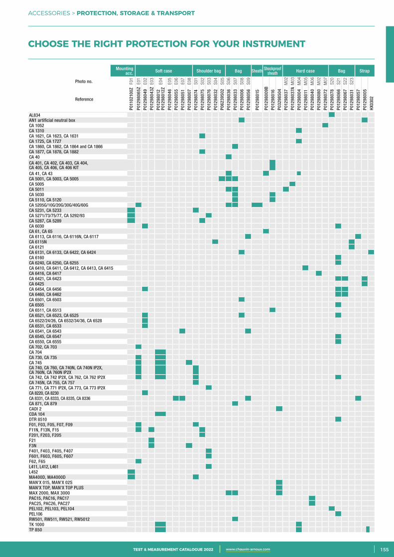
3CATALOGUE TEST & MESURE 2021 www.chauvin-arnoux.com 155TEST & MEASUREMENT CATALOGUE 2022 www.chauvin-arnoux.com
ACCESSORIES > PROTECTION, STORAGE & TRANSPORT
Mounting acc. Soft case Shoulder bag Bag Sheath Shockproof
sheath Hard case Bag Strap
Photo no. F01
E01
E02
E03
E04
E05
E06
E07
E08
S01
S02
S03
S04
S05
S06
S07
S08
S09
M02
M03
M04
M05
M06
M02
M07
S20
S21
S22
S23
Reference
P011
0210
0Z
P012
9806
5ZP0
1298
049
P012
9804
3ZP0
1298
012
P012
9801
2ZP0
1298
046
P012
9805
5P0
1298
051
P012
9800
7P0
1298
074
P012
9807
5P0
1298
076
P012
9803
2P0
6239
502
P012
9803
6P0
1298
033
P012
9800
6P0
1298
056
P012
9801
5
P012
9800
9BP0
1298
016
P032
9850
4P0
1298
037
P012
9803
7AP0
1298
004
P012
9801
1P0
1298
040
P012
9808
0P0
1298
072
P012
9807
8P0
1298
066
P012
9806
7P0
1298
031
P012
9805
7P0
1298
005
HX03
02
AL834 AN1 artificial neutral boxCA 1052 CA 1310 CA 1621, CA 1623, CA 1631 CA 1725, CA 1727 CA 1860, CA 1862, CA 1864 and CA 1866 CA 1877, CA 1878, CA 1882 CA 40 CA 401, CA 402, CA 403, CA 404, CA 405, CA 406, CA 406 KIT CA 41, CA 43 CA 5001, CA 5003, CA 5005 CA 5005 CA 5011 CA 5030 CA 5110, CA 5120 CA 5205G/10G/20G/30G/40G/60G CA 5231, CA 5233 CA 5271/73/75/77, CA 5292/93 CA 5287, CA 5289 CA 6030 CA 61, CA 65 CA 6113, CA 6116, CA 6116N, CA 6117 CA 6115N CA 6121 CA 6131, CA 6133, CA 6422, CA 6424 CA 6160 CA 6240, CA 6250, CA 6255 CA 6410, CA 6411, CA 6412, CA 6413, CA 6415 CA 6416, CA 6417 CA 6421, CA 6423 CA 6425 CA 6454, CA 6456 CA 6460, CA 6462 CA 6501, CA 6503 CA 6505 CA 6511, CA 6513 CA 6521, CA 6523, CA 6525 CA 6522/24/26, CA 6532/34/36, CA 6528 CA 6531, CA 6533 CA 6541, CA 6543 CA 6545, CA 6547 CA 6550, CA 6555 CA 702, CA 703 CA 704 CA 730, CA 735 CA 745 CA 740, CA 760, CA 740N, CA 740N IP2X, CA 760N, CA 760N IP2X CA 742, CA 742 IP2X, CA 762, CA 762 IP2X CA 745N, CA 755, CA 757 CA 771, CA 771 IP2X, CA 773, CA 773 IP2X CA 8220, CA 8230 CA 8331, CA 8333, CA 8335, CA 8336 CA 871, CA 879 CADI 2 CDA 104 DTR 8510 F01, F03, F05, F07, F09 F11N, F13N, F15 F201, F203, F205 F21 F3N F401, F403, F405, F407 F601, F603, F605, F607 F62, F65 L411, L412, L461 L452 MA400D, MA4000D MAN'X 015, MAN'X 02S MAN'X TOP, MAN'X TOP PLUS MAX 2000, MAX 3000 PAC15, PAC16, PAC17 PAC25, PAC26, PAC27 PEL102, PEL103, PEL104 PEL106 RW501, RW511, RW521, RW5012 TK 1000 TP 850
CHOOSE THE RIGHT PROTECTION FOR YOUR INSTRUMENT
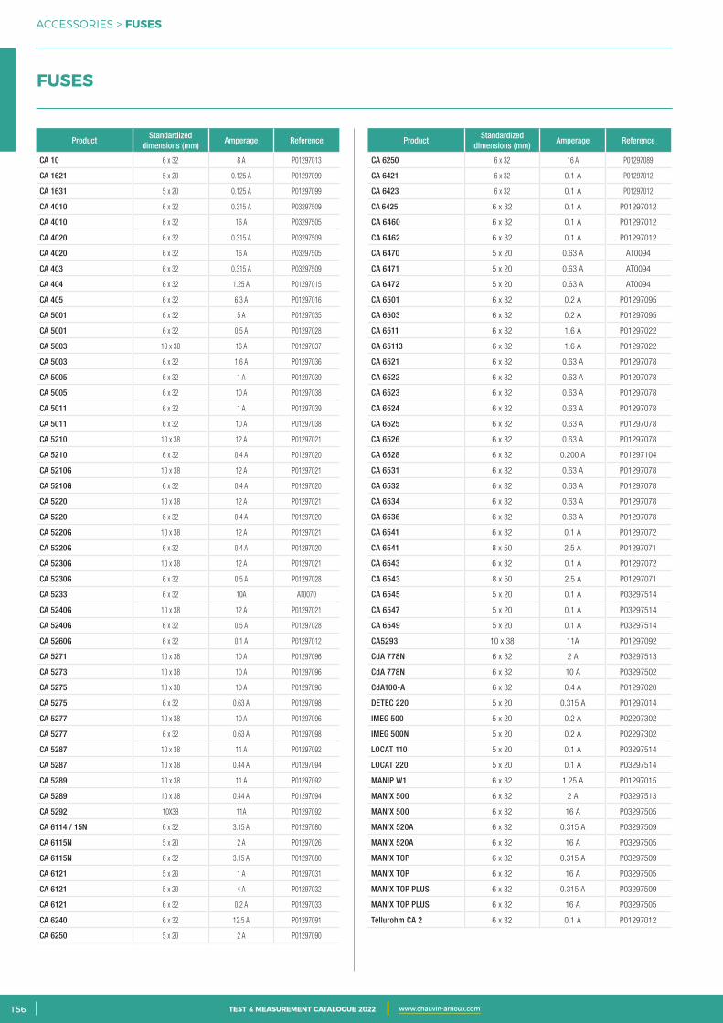
2 CATALOGUE TEST & MESURE 2021 www.chauvin-arnoux.com156 TEST & MEASUREMENT CATALOGUE 2022 www.chauvin-arnoux.com
ACCESSORIES > FUSES
FUSES
ProductStandardized
dimensions (mm)Amperage Reference
CA 10 6 x 32 8 A P01297013
CA 1621 5 x 20 0.125 A P01297099
CA 1631 5 x 20 0.125 A P01297099
CA 4010 6 x 32 0.315 A P03297509
CA 4010 6 x 32 16 A P03297505
CA 4020 6 x 32 0.315 A P03297509
CA 4020 6 x 32 16 A P03297505
CA 403 6 x 32 0.315 A P03297509
CA 404 6 x 32 1.25 A P01297015
CA 405 6 x 32 6.3 A P01297016
CA 5001 6 x 32 5 A P01297035
CA 5001 6 x 32 0.5 A P01297028
CA 5003 10 x 38 16 A P01297037
CA 5003 6 x 32 1.6 A P01297036
CA 5005 6 x 32 1 A P01297039
CA 5005 6 x 32 10 A P01297038
CA 5011 6 x 32 1 A P01297039
CA 5011 6 x 32 10 A P01297038
CA 5210 10 x 38 12 A P01297021
CA 5210 6 x 32 0.4 A P01297020
CA 5210G 10 x 38 12 A P01297021
CA 5210G 6 x 32 0,4 A P01297020
CA 5220 10 x 38 12 A P01297021
CA 5220 6 x 32 0.4 A P01297020
CA 5220G 10 x 38 12 A P01297021
CA 5220G 6 x 32 0.4 A P01297020
CA 5230G 10 x 38 12 A P01297021
CA 5230G 6 x 32 0.5 A P01297028
CA 5233 6 x 32 10A AT0070
CA 5240G 10 x 38 12 A P01297021
CA 5240G 6 x 32 0.5 A P01297028
CA 5260G 6 x 32 0.1 A P01297012
CA 5271 10 x 38 10 A P01297096
CA 5273 10 x 38 10 A P01297096
CA 5275 10 x 38 10 A P01297096
CA 5275 6 x 32 0.63 A P01297098
CA 5277 10 x 38 10 A P01297096
CA 5277 6 x 32 0.63 A P01297098
CA 5287 10 x 38 11 A P01297092
CA 5287 10 x 38 0.44 A P01297094
CA 5289 10 x 38 11 A P01297092
CA 5289 10 x 38 0.44 A P01297094
CA 5292 10X38 11A P01297092
CA 6114 / 15N 6 x 32 3.15 A P01297080
CA 6115N 5 x 20 2 A P01297026
CA 6115N 6 x 32 3.15 A P01297080
CA 6121 5 x 20 1 A P01297031
CA 6121 5 x 20 4 A P01297032
CA 6121 6 x 32 0.2 A P01297033
CA 6240 6 x 32 12.5 A P01297091
CA 6250 5 x 20 2 A P01297090
ProductStandardized
dimensions (mm)Amperage Reference
CA 6250 6 x 32 16 A P01297089
CA 6421 6 x 32 0.1 A P01297012
CA 6423 6 x 32 0.1 A P01297012
CA 6425 6 x 32 0.1 A P01297012
CA 6460 6 x 32 0.1 A P01297012
CA 6462 6 x 32 0.1 A P01297012
CA 6470 5 x 20 0.63 A AT0094
CA 6471 5 x 20 0.63 A AT0094
CA 6472 5 x 20 0.63 A AT0094
CA 6501 6 x 32 0.2 A P01297095
CA 6503 6 x 32 0.2 A P01297095
CA 6511 6 x 32 1.6 A P01297022
CA 65113 6 x 32 1.6 A P01297022
CA 6521 6 x 32 0.63 A P01297078
CA 6522 6 x 32 0.63 A P01297078
CA 6523 6 x 32 0.63 A P01297078
CA 6524 6 x 32 0.63 A P01297078
CA 6525 6 x 32 0.63 A P01297078
CA 6526 6 x 32 0.63 A P01297078
CA 6528 6 x 32 0.200 A P01297104
CA 6531 6 x 32 0.63 A P01297078
CA 6532 6 x 32 0.63 A P01297078
CA 6534 6 x 32 0.63 A P01297078
CA 6536 6 x 32 0.63 A P01297078
CA 6541 6 x 32 0.1 A P01297072
CA 6541 8 x 50 2.5 A P01297071
CA 6543 6 x 32 0.1 A P01297072
CA 6543 8 x 50 2.5 A P01297071
CA 6545 5 x 20 0.1 A P03297514
CA 6547 5 x 20 0.1 A P03297514
CA 6549 5 x 20 0.1 A P03297514
CA5293 10 x 38 11A P01297092
CdA 778N 6 x 32 2 A P03297513
CdA 778N 6 x 32 10 A P03297502
CdA100-A 6 x 32 0.4 A P01297020
DETEC 220 5 x 20 0.315 A P01297014
IMEG 500 5 x 20 0.2 A P02297302
IMEG 500N 5 x 20 0.2 A P02297302
LOCAT 110 5 x 20 0.1 A P03297514
LOCAT 220 5 x 20 0.1 A P03297514
MANIP W1 6 x 32 1.25 A P01297015
MAN'X 500 6 x 32 2 A P03297513
MAN'X 500 6 x 32 16 A P03297505
MAN'X 520A 6 x 32 0.315 A P03297509
MAN'X 520A 6 x 32 16 A P03297505
MAN'X TOP 6 x 32 0.315 A P03297509
MAN'X TOP 6 x 32 16 A P03297505
MAN'X TOP PLUS 6 x 32 0.315 A P03297509
MAN'X TOP PLUS 6 x 32 16 A P03297505
Tellurohm CA 2 6 x 32 0.1 A P01297012

3CATALOGUE TEST & MESURE 2021 www.chauvin-arnoux.com 157TEST & MEASUREMENT CATALOGUE 2022 www.chauvin-arnoux.com
ACCESSORIES > NOTES
NOTES
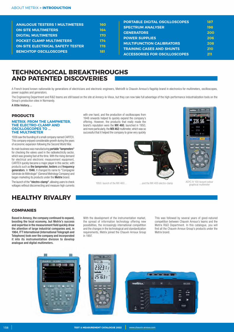
2 CATALOGUE TEST & MESURE 2021 www.chauvin-arnoux.com158 TEST & MEASUREMENT CATALOGUE 2022 www.chauvin-arnoux.com
ABOUT METRIX > INTRODUCTION
ANALOGUE TESTERS 1 MULTIMETERS 160ON-SITE MULTIMETERS 164DIGITAL MULTIMETERS 170POCKET CLAMP MULTIMETERS 174ON-SITE ELECTRICAL SAFETY TESTER 178BENCHTOP OSCILLOSCOPES 181
TECHNOLOGICAL BREAKTHROUGHS AND PATENTED DISCOVERIES
1950: launch of the MX 460… …and the MX 400 electro-clamp ASYC IV 100-kcount colour graphical multimeter
A French brand known nationwide by generations of electricians and electronic engineers, Metrix® is Chauvin Arnoux’s flagship brand in electronics for multimeters, oscilloscopes, power supplies and generators.
The Engineering Department and R&D teams are still based on the site at Annecy-le-Vieux, but they can now take full advantage of the high-performance industrialization tools on the Group’s production sites in Normandy.
A little history…
PRODUCTSMETRIX: FROM THE LAMPMETER, THE ELECTRO-CLAMP AND OSCILLOSCOPES TO ... THE MULTIMETER1936 saw the founding of a small company named CARTEX. This company enjoyed considerable growth during the years of economic expansion following the Second World War.
Its main business was manufacturing portable "lampmeters" for checking the valves used in the radioelectricity sector, which was growing fast at the time. With the rising demand for electrical and electronic measurement equipment, CARTEX quickly became a major player in this sector, with products such as the lampmeter, testers and frequency generators. In 1946, it changed its name to "Compagnie Générale de Métrologie" (General Metrology Company) and began marketing its products under the Metrix brand.
The launch of the "electro-clamp", allowing users to check voltages without disconnecting and measure high currents
with one hand, and the production of oscilloscopes from 1948 onwards helped to quickly expand the company’s offering. However, the products that really made the brand’s reputation were the MX 460, launched in 1950, and more particularly, the MX 462 multimeter, which was so successful that it helped the company to grow very quickly
HEALTHY RIVALRY
COMPANIES
With the development of the instrumentation market, the spread of information technology offering new possibilities, the increasingly international competition and the changes in the technological and standardization requirements, Metrix joined the Chauvin Arnoux Group in 1997.
This was followed by several years of good-natured competition between Chauvin Arnoux’s teams and the Metrix R&D Department. In this catalogue, you will find all the Chauvin Arnoux Group's products under the Metrix brand.
Based in Annecy, the company continued to expand, boosting the local economy, but Metrix’s success and expertise in the measurement field quickly drew the attention of large industrial companies and, in 1964, ITT International (International Telegraph and Telephone) took over the company and incorporated it into its instrumentation division to develop analogue and digital multimeters.
PORTABLE DIGITAL OSCILLOSCOPES 187SPECTRUM ANALYSER 198GENERATORS 200POWER SUPPLIES 206MULTIFUNCTION CALIBRATORS 208TRAINING CASES AND SHUNTS 210ACCESSORIES FOR OSCILLOSCOPES 211
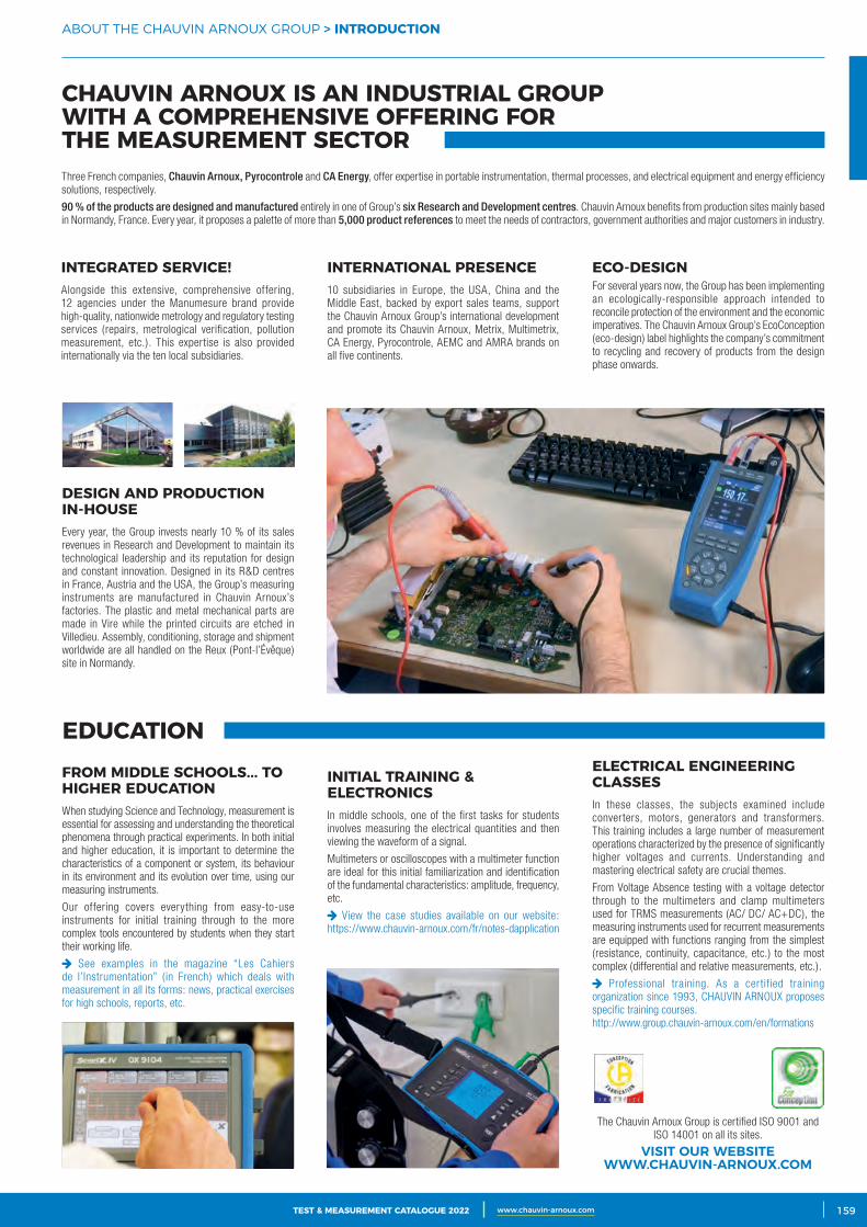
3CATALOGUE TEST & MESURE 2021 www.chauvin-arnoux.com 159TEST & MEASUREMENT CATALOGUE 2022 www.chauvin-arnoux.com
ABOUT THE CHAUVIN ARNOUX GROUP > INTRODUCTION
EDUCATION
INTEGRATED SERVICE!Alongside this extensive, comprehensive offering, 12 agencies under the Manumesure brand provide high-quality, nationwide metrology and regulatory testing services (repairs, metrological verification, pollution measurement, etc.). This expertise is also provided internationally via the ten local subsidiaries.
DESIGN AND PRODUCTION IN‑HOUSEEvery year, the Group invests nearly 10 % of its sales revenues in Research and Development to maintain its technological leadership and its reputation for design and constant innovation. Designed in its R&D centres in France, Austria and the USA, the Group’s measuring instruments are manufactured in Chauvin Arnoux’s factories. The plastic and metal mechanical parts are made in Vire while the printed circuits are etched in Villedieu. Assembly, conditioning, storage and shipment worldwide are all handled on the Reux (Pont-l’Évêque) site in Normandy.
ECO‑DESIGN For several years now, the Group has been implementing an ecologically-responsible approach intended to reconcile protection of the environment and the economic imperatives. The Chauvin Arnoux Group’s EcoConception (eco-design) label highlights the company’s commitment to recycling and recovery of products from the design phase onwards.
INTERNATIONAL PRESENCE10 subsidiaries in Europe, the USA, China and the Middle East, backed by export sales teams, support the Chauvin Arnoux Group’s international development and promote its Chauvin Arnoux, Metrix, Multimetrix, CA Energy, Pyrocontrole, AEMC and AMRA brands on all five continents.
CHAUVIN ARNOUX IS AN INDUSTRIAL GROUP WITH A COMPREHENSIVE OFFERING FOR THE MEASUREMENT SECTORThree French companies, Chauvin Arnoux, Pyrocontrole and CA Energy, offer expertise in portable instrumentation, thermal processes, and electrical equipment and energy efficiency solutions, respectively.
90 % of the products are designed and manufactured entirely in one of Group’s six Research and Development centres. Chauvin Arnoux benefits from production sites mainly based in Normandy, France. Every year, it proposes a palette of more than 5,000 product references to meet the needs of contractors, government authorities and major customers in industry.
The Chauvin Arnoux Group is certified ISO 9001 and ISO 14001 on all its sites.
VISIT OUR WEBSITEWWW.CHAUVIN-ARNOUX.COM
FROM MIDDLE SCHOOLS... TO HIGHER EDUCATIONWhen studying Science and Technology, measurement is essential for assessing and understanding the theoretical phenomena through practical experiments. In both initial and higher education, it is important to determine the characteristics of a component or system, its behaviour in its environment and its evolution over time, using our measuring instruments.
Our offering covers everything from easy-to-use instruments for initial training through to the more complex tools encountered by students when they start their working life.
See examples in the magazine “Les Cahiers de l’Instrumentation” ( in French) which deals with measurement in all its forms: news, practical exercises for high schools, reports, etc.
INITIAL TRAINING & ELECTRONICSIn middle schools, one of the first tasks for students involves measuring the electrical quantities and then viewing the waveform of a signal.
Multimeters or oscilloscopes with a multimeter function are ideal for this initial familiarization and identification of the fundamental characteristics: amplitude, frequency, etc.
View the case studies available on our website: https://www.chauvin-arnoux.com/fr/notes-dapplication
ELECTRICAL ENGINEERING CLASSESIn these classes, the subjects examined include converters, motors, generators and transformers. This training includes a large number of measurement operations characterized by the presence of significantly higher voltages and currents. Understanding and mastering electrical safety are crucial themes.
From Voltage Absence testing with a voltage detector through to the multimeters and clamp multimeters used for TRMS measurements (AC/ DC/ AC+DC), the measuring instruments used for recurrent measurements are equipped with functions ranging from the simplest (resistance, continuity, capacitance, etc.) to the most complex (differential and relative measurements, etc.).
Professional training. As a certified training organization since 1993, CHAUVIN ARNOUX proposes specific training courses.http://www.group.chauvin-arnoux.com/en/formations
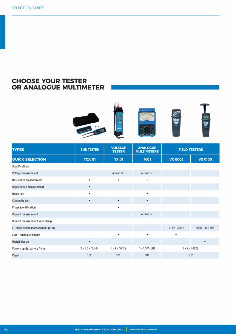
2 CATALOGUE TEST & MESURE 2021 www.chauvin-arnoux.com160 TEST & MEASUREMENT CATALOGUE 2022 www.chauvin-arnoux.com
SELECTION GUIDE
TYPES SMD TESTER VOLTAGE TESTER
ANALOGUE MULTIMETERS FIELD TESTERS
QUICK SELECTION TCX 01 TX 01 MX 1 VX 0003 VX 0100
Specifications
Voltage measurement AC and DC AC and DC
Resistance measurement • • •
Capacitance measurement •
Diode test • •
Continuity test • • •
Phase identification •
Current measurement AC and DC
Current measurement with clamp
LF electric field measurement (V/m) 10 Hz - 3 kHz 10 Hz - 100 kHz
LED – Analogue display • • •
Digital display • •
Power supply: battery / type 2 x 1.5 V / LR44 1 x 9 V / 6F22 1 x 1.5 V / LR6 1 x 9 V / 6F22
Pages 162 161 161 162
CHOOSE YOUR TESTER OR ANALOGUE MULTIMETER
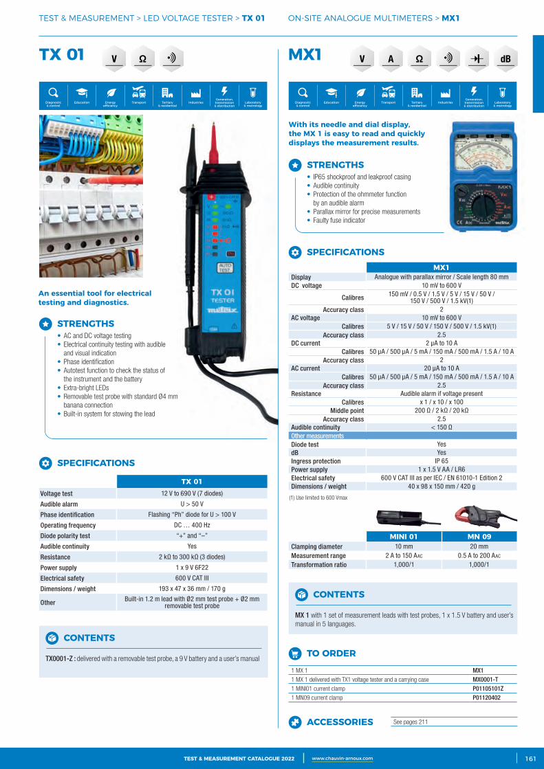
3CATALOGUE TEST & MESURE 2021 www.chauvin-arnoux.com 161TEST & MEASUREMENT CATALOGUE 2022 www.chauvin-arnoux.com
TEST & MEASUREMENT > LED VOLTAGE TESTER > TX 01 ON-SITE ANALOGUE MULTIMETERS > MX1
TX 01 MX1
TX 01Voltage test 12 V to 690 V (7 diodes)
Audible alarm U > 50 V
Phase identification Flashing “Ph” diode for U > 100 V
Operating frequency DC … 400 Hz
Diode polarity test “+” and “–”
Audible continuity Yes
Resistance 2 kΩ to 300 kΩ (3 diodes)
Power supply 1 x 9 V 6F22
Electrical safety 600 V CAT III
Dimensions / weight 193 x 47 x 36 mm / 170 g
Other Built-in 1.2 m lead with Ø2 mm test probe + Ø2 mm removable test probe
SPECIFICATIONS
CONTENTS
TX0001-Z : delivered with a removable test probe, a 9 V battery and a user’s manual
STRENGTHS• AC and DC voltage testing• Electrical continuity testing with audible
and visual indication• Phase identification • Autotest function to check the status of
the instrument and the battery• Extra-bright LEDs• Removable test probe with standard Ø4 mm
banana connection• Built-in system for stowing the lead
SPECIFICATIONSMX1
Display Analogue with parallax mirror / Scale length 80 mmDC voltage 10 mV to 600 V
Calibres 150 mV / 0.5 V / 1.5 V / 5 V / 15 V / 50 V / 150 V / 500 V / 1.5 kV(1)
Accuracy class 2AC voltage 10 mV to 600 V
Calibres 5 V / 15 V / 50 V / 150 V / 500 V / 1.5 kV(1)Accuracy class 2.5
DC current 2 μA to 10 ACalibres 50 μA / 500 μA / 5 mA / 150 mA / 500 mA / 1.5 A / 10 A
Accuracy class 2AC current 20 μA to 10 A
Calibres 50 μA / 500 μA / 5 mA / 150 mA / 500 mA / 1.5 A / 10 AAccuracy class 2.5
Resistance Audible alarm if voltage presentCalibres x 1 / x 10 / x 100
Middle point 200 Ω / 2 kΩ / 20 kΩAccuracy class 2.5
Audible continuity < 150 ΩOther measurementsDiode test YesdB YesIngress protection IP 65Power supply 1 x 1.5 V AA / LR6Electrical safety 600 V CAT III as per IEC / EN 61010-1 Edition 2Dimensions / weight 40 x 98 x 150 mm / 420 g
(1) Use limited to 600 Vmax
CONTENTS
MX 1 with 1 set of measurement leads with test probes, 1 x 1.5 V battery and user’s manual in 5 languages.
TO ORDER
1 MX 1 MX11 MX 1 delivered with TX1 voltage tester and a carrying case MX0001-T1 MINI01 current clamp P01105101Z1 MN09 current clamp P01120402
ACCESSORIES See pages 211
With its needle and dial display, the MX 1 is easy to read and quickly displays the measurement results.
MINI 01 MN 09Clamping diameter 10 mm 20 mmMeasurement range 2 A to 150 AAc 0.5 A to 200 AAc
Transformation ratio 1,000/1 1,000/1
An essential tool for electrical testing and diagnostics.
STRENGTHS• IP65 shockproof and leakproof casing• Audible continuity• Protection of the ohmmeter function
by an audible alarm• Parallax mirror for precise measurements• Faulty fuse indicator
Generation, transmission & distribution
IndustriesTertiary & residential
Education TransportDiagnostic & control
Energy efficiency
Laboratory & metrology
Generation, transmission & distribution
IndustriesTertiary & residential
Education TransportDiagnostic & control
Energy efficiency
Laboratory & metrology
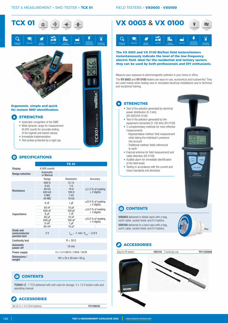
2 CATALOGUE TEST & MESURE 2021 www.chauvin-arnoux.com162 TEST & MEASUREMENT CATALOGUE 2022 www.chauvin-arnoux.com
TEST & MEASUREMENT > SMD TESTER > TCX 01 FIELD TESTERS > VX0003 ‑ VX0100
TCX 01 VX 0003 & VX 0100
TX 01Display 6,000 counts
Range selection Automatic or Manual
Range Resolution Accuracy
Resistance
600 Ω 0,1 Ω
±(1.2 % of reading + 2 digits)
6 kΩ 1 Ω60 kΩ 10 Ω
600 kΩ 100 Ω6 MΩ 1 kΩ
60 MΩ 10 kΩ
Capacitance
6 nF 1 pF ±(5.0 % of reading + 5 digits)
60 nF 10 pF±(3.0 % of reading
+ 3 digits)600 nF 100 pF6 µF 1 nF
60 µF 10 nF±(5.0 % of reading
+ 5 digits)600 µF 100 nF6 mF 1 µF
60 mF 10 µF -Diode and semiconductor junction test
2 V Itest : ~1 mA / Vtest : ~2.8 V
Continuity test R < 30 Ω
Automatic power-off 10 min
Power supply 2 x 1.5 V AG13 / LR44 / 357A
Dimensions / weight 181 x 35 x 20 mm / 65 g
SPECIFICATIONS
CONTENTS
TCX001-Z : 1 TCX delivered with soft case for storage, 2 x 1.5 V button cells and operating manual
CONTENTS
VX0003 delivered in blister pack with a bag, earth cable, socket tester and 9 V battery
VX0100 delivered in a hard case with a bag, earth cable, socket tester and 9 V battery
STRENGTHS• Automatic recognition of the SMD• Wide dynamic range for measurement
(6,000 counts for accurate testing of the highest and lowest values)
• Immediate implementation• Test probes protected by a rigid cap
ACCESSORIES
Set of 2 x 1.5 V LR44 batteries P01296036
ACCESSORIES
Bag for VX testers HX0104 Continuity rod P01102084A
The VX 0003 and VX 0100 BioTest field testers/meters instantaneously indicate the level of the low‑frequency electric field. Ideal for the residential and tertiary sectors, they can be used by both professionals and DIY enthusiasts.
Ergonomic, simple and quick for instant SMD identification.
STRENGTHS• Test of the pollution generated by electrical
power distribution (0-3 kHz) (VX 0003/VX 0100)
• Test of the pollution generated by the equipment connected (3-100 kHz) (VX 0100)
• 2 complementary methods for more effective measurements - Representative method: field measurement
while taking the individual's presence into account
- Traditional method: fields referenced to earth
• External antenna for field measurement and cable detection (VX 0100)
• Audible alarm for immediate identification of the field levels
• Testing in accordance with the current and future standards and directives
Generation, transmission & distribution
IndustriesTertiary & residential
Education TransportDiagnostic & control
Energy efficiency
Laboratory & metrology
Generation, transmission & distribution
IndustriesTertiary & residential
Education TransportDiagnostic & control
Energy efficiency
Laboratory & metrology
Measure your exposure to electromagnetic pollution in your home or office.
The VX 0003 and VX 0100 testers are easy-to-use, economical and trustworthy! They are used mainly when testing new or renovated electrical installations and in technical and vocational training.
HzV
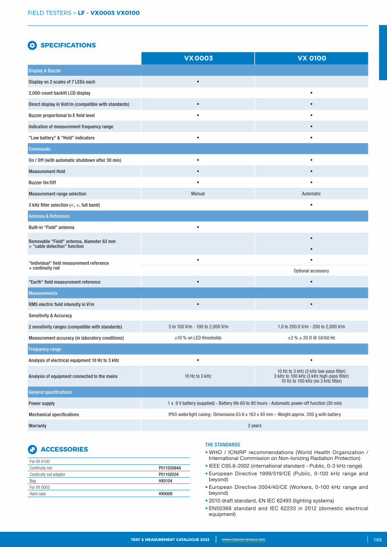
3CATALOGUE TEST & MESURE 2021 www.chauvin-arnoux.com 163TEST & MEASUREMENT CATALOGUE 2022 www.chauvin-arnoux.com
FIELD TESTERS > LF ‑ VX0003 VX0100
ACCESSORIES
For VX 0100
Continuity rod P01102084AContinuity rod adapter P01102034Bag HX0104For VX 0003
Hard case HX0009
THE STANDARDS
• WHO / ICNIRP recommendations (World Health Organization / International Commission on Non-Ionizing Radiation Protection)
• IEEE C95.6-2002 (international standard - Public, 0-3 kHz range)• European Directive 1999/519/CE (Public, 0-100 kHz range and
beyond)• European Directive 2004/40/CE (Workers, 0-100 kHz range and
beyond)• 2010 draft standard, EN IEC 62493 (lighting systems)• EN50366 standard and IEC 62233 in 2012 (domestic electrical
equipment)
VX 0003 VX 0100
Display & Buzzer
Display on 2 scales of 7 LEDs each •
2,000-count backlit LCD display •
Direct display in Volt/m (compatible with standards) • •
Buzzer proportional to E field level • •
Indication of measurement frequency range •
"Low battery" & "Hold" indicators • •
Commands
On / Off (with automatic shutdown after 30 min) • •
Measurement Hold • •
Buzzer On/Off • •
Measurement range selection Manual Automatic
3 kHz filter selection (<, >, full band) •
Antenna & Reference
Built-in "Field" antenna •
Removable "Field" antenna, diameter 62 mm + "cable detection" function
•
•
"Individual" field measurement reference + continuity rod
• •
Optional accessory
"Earth" field measurement reference • •
Measurements
RMS electric field intensity in V/m • •
Sensitivity & Accuracy
2 sensitivity ranges (compatible with standards) 5 to 100 V/m - 100 to 2,000 V/m 1.0 to 200.0 V/m - 200 to 2,000 V/m
Measurement accuracy (in laboratory conditions) ±10 % on LED thresholds ±3 % ± 20 D @ 50/60 Hz
Frequency range
Analysis of electrical equipment 10 Hz to 3 kHz • •
Analysis of equipment connected to the mains 10 Hz to 3 kHz10 Hz to 3 kHz (3 kHz low-pass filter)
3 kHz to 100 kHz (3 kHz high-pass filter)10 Hz to 100 kHz (no 3 kHz filter)
General specifications
Power supply 1 x 9 V battery (supplied) - Battery life 60 to 80 hours - Automatic power-off function (30 min)
Mechanical specifications IP65 watertight casing- Dimensions 63.6 x 163 x 40 mm – Weight approx. 200 g with battery
Warranty 2 years
SPECIFICATIONS
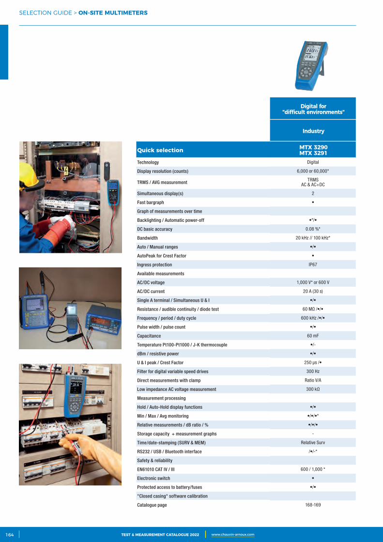
2 CATALOGUE TEST & MESURE 2021 www.chauvin-arnoux.com164 TEST & MEASUREMENT CATALOGUE 2022 www.chauvin-arnoux.com
SELECTION GUIDE > ON‑SITE MULTIMETERS
Digital for "difficult environments"
Industry
Quick selection MTX 3290MTX 3291
Technology Digital
Display resolution (counts) 6,000 or 60,000*
TRMS / AVG measurement TRMSAC & AC+DC
Simultaneous display(s) 2
Fast bargraph •
Graph of measurements over time
Backlighting / Automatic power-off •*/•
DC basic accuracy 0.08 %*
Bandwidth 20 kHz // 100 kHz*
Auto / Manual ranges •/•
AutoPeak for Crest Factor •
Ingress protection IP67
Available measurements
AC/DC voltage 1,000 V* or 600 V
AC/DC current 20 A (30 s)
Single A terminal / Simultaneous U & I •/•
Resistance / audible continuity / diode test 60 MΩ /•/•
Frequency / period / duty cycle 600 kHz /•/•
Pulse width / pulse count •/•
Capacitance 60 mF
Temperature Pt100-Pt1000 / J-K thermocouple •/-
dBm / resistive power •/•
U & I peak / Crest Factor 250 µs /•
Filter for digital variable speed drives 300 Hz
Direct measurements with clamp Ratio V/A
Low impedance AC voltage measurement 300 kΩ
Measurement processing
Hold / Auto-Hold display functions •/•
Min / Max / Avg monitoring •/•/•*
Relative measurements / dB ratio / % •/•/•
Storage capacity + measurement graphs -
Time/date-stamping (SURV & MEM) Relative Surv
RS232 / USB / Bluetooth interface /•/-*
Safety & reliability
EN61010 CAT IV / III 600 / 1,000 *
Electronic switch •
Protected access to battery/fuses •/•
"Closed casing" software calibration
Catalogue page 168-169
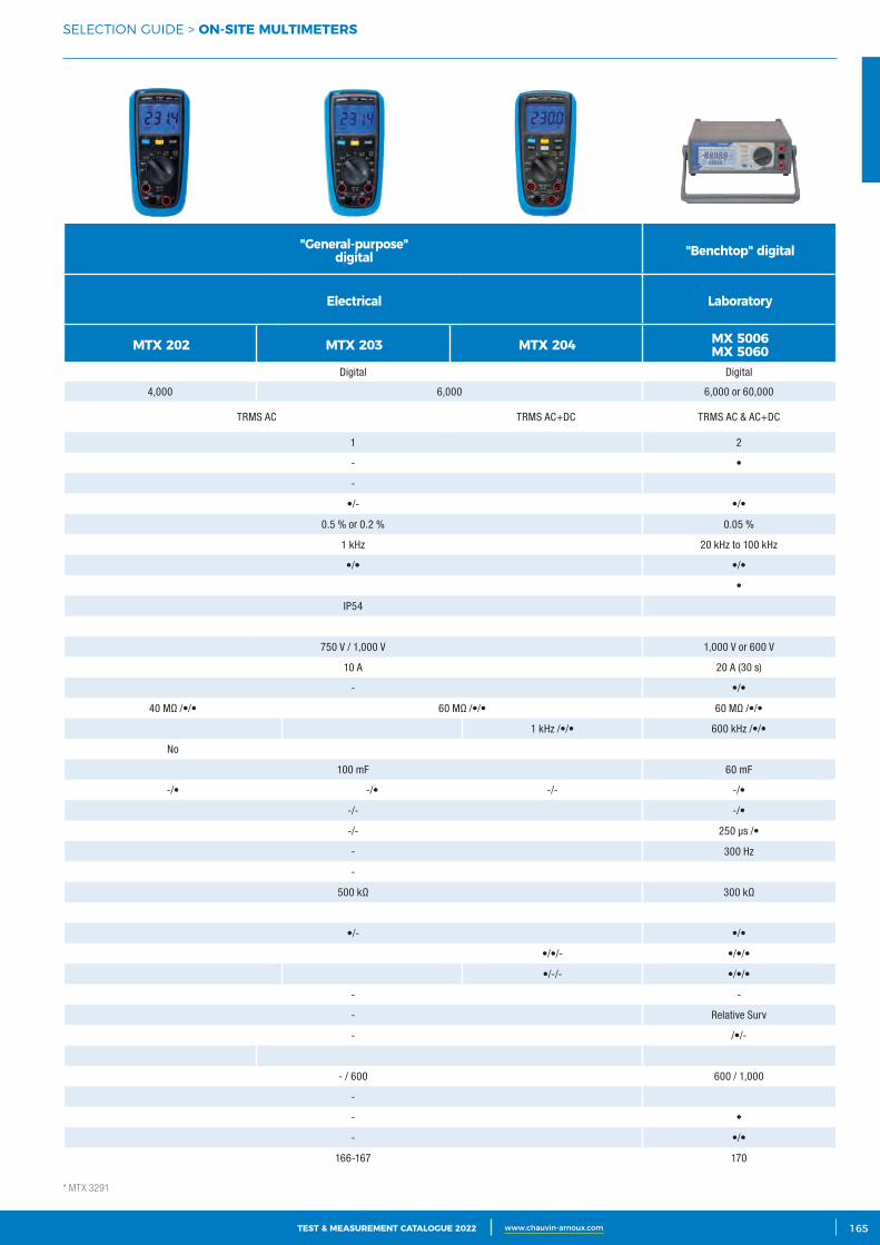
3CATALOGUE TEST & MESURE 2021 www.chauvin-arnoux.com 165TEST & MEASUREMENT CATALOGUE 2022 www.chauvin-arnoux.com
SELECTION GUIDE > ON‑SITE MULTIMETERS
"General‑purpose"digital "Benchtop" digital
Electrical Laboratory
MTX 202 MTX 203 MTX 204 MX 5006MX 5060
Digital Digital
4,000 6,000 6,000 or 60,000
TRMS AC TRMS AC+DC TRMS AC & AC+DC
1 2
- •
-
•/- •/•
0.5 % or 0.2 % 0.05 %
1 kHz 20 kHz to 100 kHz
•/• •/•
•
IP54
750 V / 1,000 V 1,000 V or 600 V
10 A 20 A (30 s)
- •/•
40 MΩ /•/• 60 MΩ /•/• 60 MΩ /•/•
1 kHz /•/• 600 kHz /•/•
No
100 mF 60 mF
-/• -/• -/- -/•
-/- -/•
-/- 250 µs /•
- 300 Hz
-
500 kΩ 300 kΩ
•/- •/•
•/•/- •/•/•
•/-/- •/•/•
- -
- Relative Surv
- /•/-
- / 600 600 / 1,000
-
- •
- •/•
166-167 170
* MTX 3291
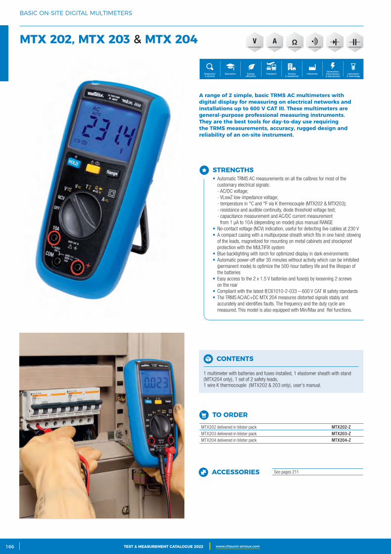
2 CATALOGUE TEST & MESURE 2021 www.chauvin-arnoux.com166 TEST & MEASUREMENT CATALOGUE 2022 www.chauvin-arnoux.com
BASIC ON-SITE DIGITAL MULTIMETERS
MTX 202, MTX 203 & MTX 204
CONTENTS
1 multimeter with batteries and fuses installed, 1 elastomer sheath with stand (MTX204 only), 1 set of 2 safety leads, 1 wire K thermocouple (MTX202 & 203 only), user's manual.
STRENGTHS• Automatic TRMS AC measurements on all the calibres for most of the
customary electrical signals:- AC/DC voltage;- VLowZ low-impedance voltage;- temperature in °C and °F via K thermocouple (MTX202 & MTX203);- resistance and audible continuity, diode threshold voltage test;- capacitance measurement and AC/DC current measurement
from 1 μA to 10 A (depending on model) plus manual RANGE• No-contact voltage (NCV) indication, useful for detecting live cables at 230 V• A compact casing with a multipurpose sheath which fits in one hand: stowing
of the leads, magnetized for mounting on metal cabinets and shockproof protection with the MULTIFIX system
• Blue backlighting with torch for optimized display in dark environments• Automatic power-off after 30 minutes without activity which can be inhibited
(permanent mode) to optimize the 500-hour battery life and the lifespan of the batteries
• Easy access to the 2 x 1.5 V batteries and fuse(s) by loosening 2 screws on the rear
• Compliant with the latest IEC61010-2-033 – 600 V CAT III safety standards• The TRMS AC/AC+DC MTX 204 measures distorted signals stably and
accurately and identifies faults. The frequency and the duty cycle are measured. This model is also equipped with Min/Max and ΔRel functions.
A range of 2 simple, basic TRMS AC multimeters with digital display for measuring on electrical networks and installations up to 600 V CAT III. These multimeters are general‑purpose professional measuring instruments.They are the best tools for day‑to‑day use requiring the TRMS measurements, accuracy, rugged design and reliability of an on‑site instrument.
Generation, transmission & distribution
IndustriesTertiary & residential
Education TransportDiagnostic & control
Energy efficiency
Laboratory & metrology
V A
TO ORDER
MTX202 delivered in blister pack MTX202-ZMTX203 delivered in blister pack MTX203-ZMTX204 delivered in blister pack MTX204-Z
ACCESSORIES See pages 211
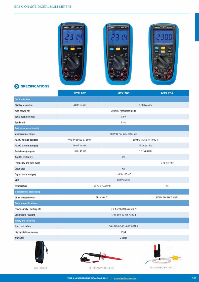
3CATALOGUE TEST & MESURE 2021 www.chauvin-arnoux.com 167TEST & MEASUREMENT CATALOGUE 2022 www.chauvin-arnoux.com
BASIC ON-SITE DIGITAL MULTIMETERS
Bag: HX0052B K thermocouple: P01102107ZSHT 40kV probe: P01102097
MTX 202 MTX 203 MTX 204
Quick selection
Display resolution 4,000 counts 6,000 counts
Auto power-off 30 min / Permanent mode
Basic accuracy(Vd c ) 0.2 %
Bandwidth 1 kHz
Available measurements
Measurement range 10mV to 750 VAc / 1,000 Vdc
AC/DC voltage (ranges) 400 mV to 600 V / 600 V 600 mV to 750 V / 1,000 V
AC/DC current (ranges) 20 mA to 10 A 10 µA to 10 A
Resistance (ranges) 1 Ω to 40 MΩ 1 Ω to 60 MΩ
Audible continuity Yes
Frequency and duty cycle 2 Hz to 1 kHz
Diode test Yes
Capacitance (ranges) 1 nF to 100 mF
NCV 230 V / 50 Hz
Temperature -55 °C to 1,200 °C No
Measurement processing
Other measurements Mode HOLD HOLD, Min/MAX, ∆REL
General specifications
Power supply / Battery life 2 x 1.5 V batteries / 500 h
Dimensions / weight 170 x 80 x 50 mm / 320 g
Safety and reliability
Electrical safety EN61010-02-33 - 600 V CAT III
High-resistance casing IP 54
Warranty 2 years
SPECIFICATIONS
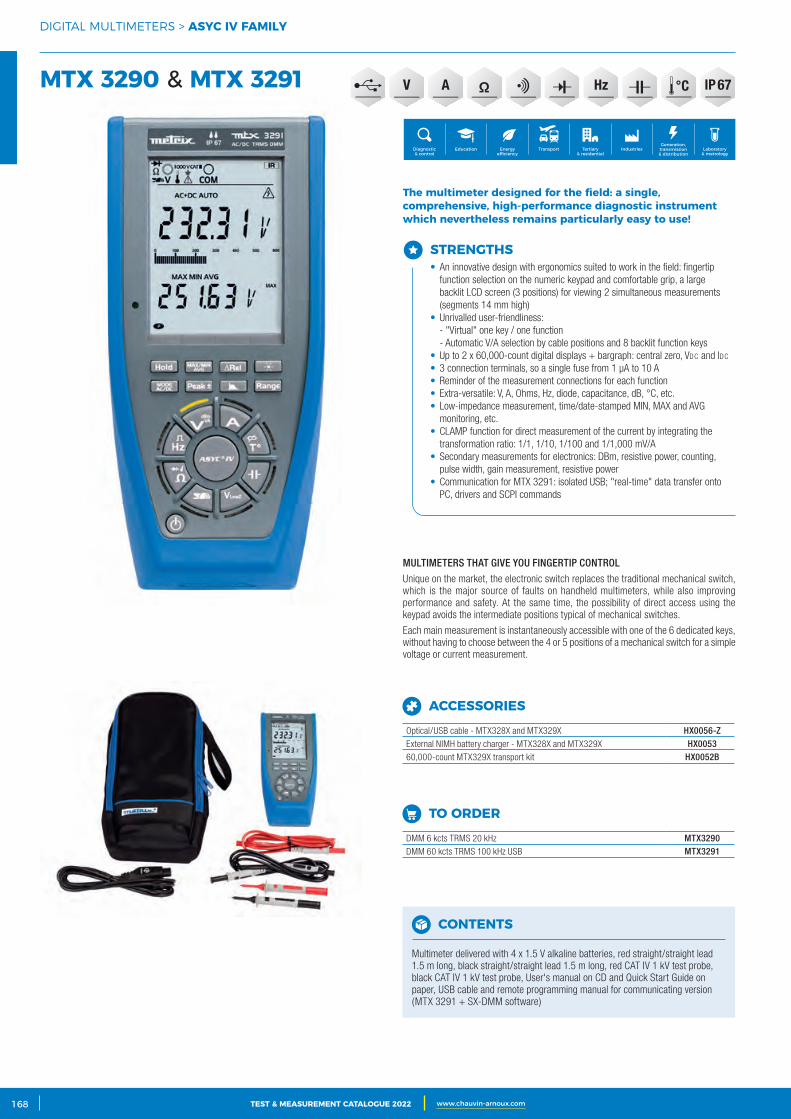
2 CATALOGUE TEST & MESURE 2021 www.chauvin-arnoux.com168 TEST & MEASUREMENT CATALOGUE 2022 www.chauvin-arnoux.com
DIGITAL MULTIMETERS > ASYC IV FAMILY
MTX 3290 & MTX 3291
STRENGTHS• An innovative design with ergonomics suited to work in the field: fingertip
function selection on the numeric keypad and comfortable grip, a large backlit LCD screen (3 positions) for viewing 2 simultaneous measurements (segments 14 mm high)
• Unrivalled user-friendliness:- "Virtual" one key / one function- Automatic V/A selection by cable positions and 8 backlit function keys
• Up to 2 x 60,000-count digital displays + bargraph: central zero, Vdc and Idc
• 3 connection terminals, so a single fuse from 1 μA to 10 A• Reminder of the measurement connections for each function• Extra-versatile: V, A, Ohms, Hz, diode, capacitance, dB, °C, etc.• Low-impedance measurement, time/date-stamped MIN, MAX and AVG
monitoring, etc.• CLAMP function for direct measurement of the current by integrating the
transformation ratio: 1/1, 1/10, 1/100 and 1/1,000 mV/A• Secondary measurements for electronics: DBm, resistive power, counting,
pulse width, gain measurement, resistive power• Communication for MTX 3291: isolated USB; "real-time" data transfer onto
PC, drivers and SCPI commands
The multimeter designed for the field: a single, comprehensive, high‑performance diagnostic instrument which nevertheless remains particularly easy to use!
MULTIMETERS THAT GIVE YOU FINGERTIP CONTROL
Unique on the market, the electronic switch replaces the traditional mechanical switch, which is the major source of faults on handheld multimeters, while also improving performance and safety. At the same time, the possibility of direct access using the keypad avoids the intermediate positions typical of mechanical switches.
Each main measurement is instantaneously accessible with one of the 6 dedicated keys, without having to choose between the 4 or 5 positions of a mechanical switch for a simple voltage or current measurement.
Generation, transmission & distribution
IndustriesTertiary & residential
Education TransportDiagnostic & control
Energy efficiency
Laboratory & metrology
HzV A IP 67
CONTENTS
Multimeter delivered with 4 x 1.5 V alkaline batteries, red straight/straight lead 1.5 m long, black straight/straight lead 1.5 m long, red CAT IV 1 kV test probe, black CAT IV 1 kV test probe, User's manual on CD and Quick Start Guide on paper, USB cable and remote programming manual for communicating version (MTX 3291 + SX-DMM software)
TO ORDER
DMM 6 kcts TRMS 20 kHz MTX3290DMM 60 kcts TRMS 100 kHz USB MTX3291
ACCESSORIES
Optical/USB cable - MTX328X and MTX329X HX0056-ZExternal NIMH battery charger - MTX328X and MTX329X HX005360,000-count MTX329X transport kit HX0052B
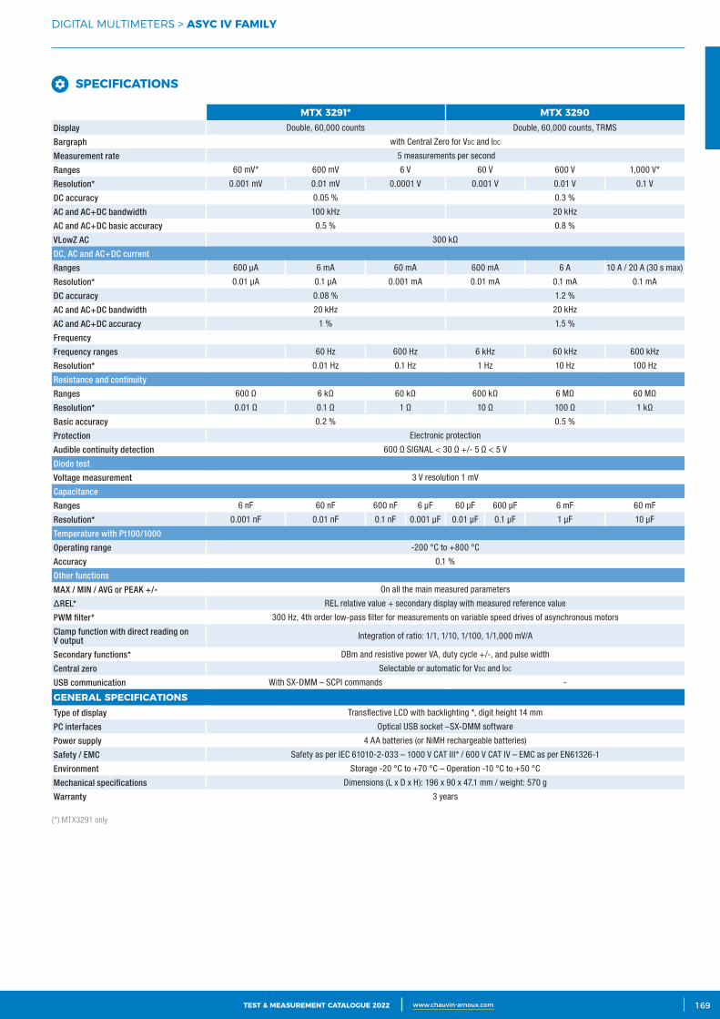
3CATALOGUE TEST & MESURE 2021 www.chauvin-arnoux.com 169TEST & MEASUREMENT CATALOGUE 2022 www.chauvin-arnoux.com
DIGITAL MULTIMETERS > ASYC IV FAMILY
MTX 3291* MTX 3290Display Double, 60,000 counts Double, 60,000 counts, TRMS
Bargraph with Central Zero for Vdc and Idc
Measurement rate 5 measurements per second
Ranges 60 mV* 600 mV 6 V 60 V 600 V 1,000 V*
Resolution* 0.001 mV 0.01 mV 0.0001 V 0.001 V 0.01 V 0.1 V
DC accuracy 0.05 % 0.3 %
AC and AC+DC bandwidth 100 kHz 20 kHz
AC and AC+DC basic accuracy 0.5 % 0.8 %
VLowZ AC 300 kΩ
DC, AC and AC+DC current
Ranges 600 µA 6 mA 60 mA 600 mA 6 A 10 A / 20 A (30 s max)
Resolution* 0.01 µA 0.1 µA 0.001 mA 0.01 mA 0.1 mA 0.1 mA
DC accuracy 0.08 % 1.2 %
AC and AC+DC bandwidth 20 kHz 20 kHz
AC and AC+DC accuracy 1 % 1.5 %
Frequency
Frequency ranges 60 Hz 600 Hz 6 kHz 60 kHz 600 kHz
Resolution* 0.01 Hz 0.1 Hz 1 Hz 10 Hz 100 Hz
Resistance and continuity
Ranges 600 Ω 6 kΩ 60 kΩ 600 kΩ 6 MΩ 60 MΩ
Resolution* 0.01 Ω 0.1 Ω 1 Ω 10 Ω 100 Ω 1 kΩ
Basic accuracy 0.2 % 0.5 %
Protection Electronic protection
Audible continuity detection 600 Ω SIGNAL < 30 Ω +/- 5 Ω < 5 V
Diode test
Voltage measurement 3 V resolution 1 mV
Capacitance
Ranges 6 nF 60 nF 600 nF 6 µF 60 µF 600 µF 6 mF 60 mF
Resolution* 0.001 nF 0.01 nF 0.1 nF 0.001 µF 0.01 µF 0.1 µF 1 µF 10 µF
Temperature with Pt100/1000
Operating range -200 °C to +800 °C
Accuracy 0.1 %
Other functions
MAX / MIN / AVG or PEAK +/- On all the main measured parameters
∆REL* REL relative value + secondary display with measured reference value
PWM filter* 300 Hz, 4th order low-pass filter for measurements on variable speed drives of asynchronous motors
Clamp function with direct reading on V output Integration of ratio: 1/1, 1/10, 1/100, 1/1,000 mV/A
Secondary functions* DBm and resistive power VA, duty cycle +/-, and pulse width
Central zero Selectable or automatic for Vdc and Idc
USB communication With SX-DMM – SCPI commands -
GENERAL SPECIFICATIONSType of display Transflective LCD with backlighting *, digit height 14 mm
PC interfaces Optical USB socket –SX-DMM software
Power supply 4 AA batteries (or NiMH rechargeable batteries)
Safety / EMC Safety as per IEC 61010-2-033 – 1000 V CAT III* / 600 V CAT IV – EMC as per EN61326-1
Environment Storage -20 °C to +70 °C – Operation -10 °C to +50 °C
Mechanical specifications Dimensions (L x D x H): 196 x 90 x 47.1 mm / weight: 570 g
Warranty 3 years
(*) MTX3291 only
SPECIFICATIONS
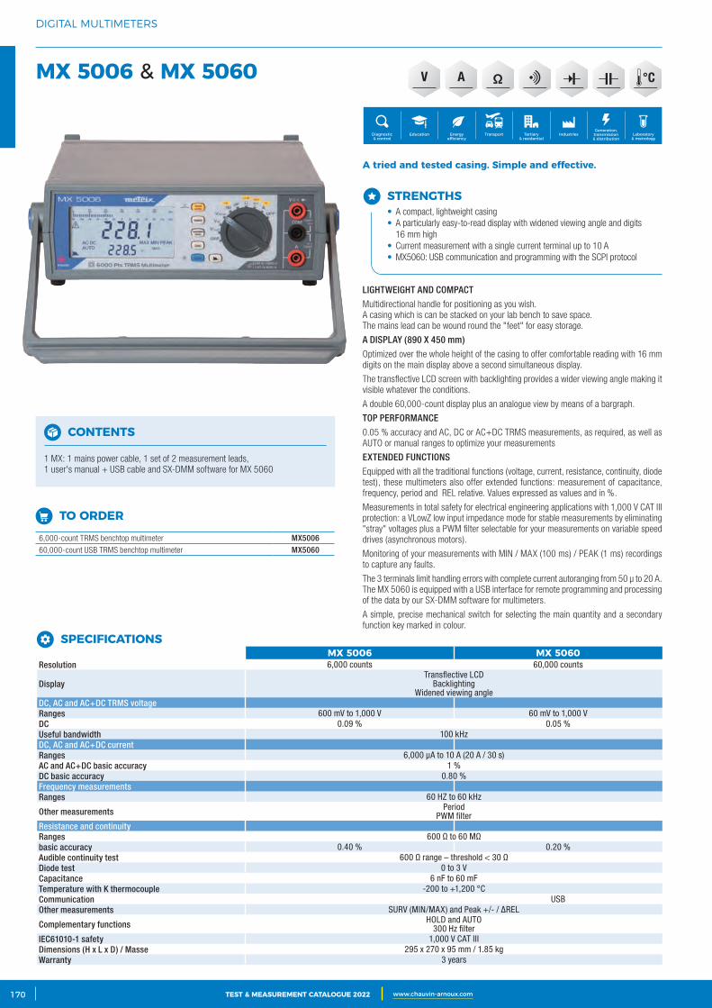
2 CATALOGUE TEST & MESURE 2021 www.chauvin-arnoux.com170 TEST & MEASUREMENT CATALOGUE 2022 www.chauvin-arnoux.com
DIGITAL MULTIMETERS
MX 5006 & MX 5060
STRENGTHS• A compact, lightweight casing• A particularly easy-to-read display with widened viewing angle and digits
16 mm high• Current measurement with a single current terminal up to 10 A • MX5060: USB communication and programming with the SCPI protocol
A tried and tested casing. Simple and effective.
LIGHTWEIGHT AND COMPACT
Multidirectional handle for positioning as you wish.A casing which is can be stacked on your lab bench to save space.The mains lead can be wound round the "feet" for easy storage.
A DISPLAY (890 X 450 mm)
Optimized over the whole height of the casing to offer comfortable reading with 16 mm digits on the main display above a second simultaneous display.
The transflective LCD screen with backlighting provides a wider viewing angle making it visible whatever the conditions.
A double 60,000-count display plus an analogue view by means of a bargraph.
TOP PERFORMANCE
0.05 % accuracy and AC, DC or AC+DC TRMS measurements, as required, as well as AUTO or manual ranges to optimize your measurements
EXTENDED FUNCTIONS
Equipped with all the traditional functions (voltage, current, resistance, continuity, diode test), these multimeters also offer extended functions: measurement of capacitance, frequency, period and ΔREL relative. Values expressed as values and in %.
Measurements in total safety for electrical engineering applications with 1,000 V CAT III protection: a VLowZ low input impedance mode for stable measurements by eliminating "stray" voltages plus a PWM filter selectable for your measurements on variable speed drives (asynchronous motors).
Monitoring of your measurements with MIN / MAX (100 ms) / PEAK (1 ms) recordings to capture any faults.
The 3 terminals limit handling errors with complete current autoranging from 50 μ to 20 A. The MX 5060 is equipped with a USB interface for remote programming and processing of the data by our SX-DMM software for multimeters.
A simple, precise mechanical switch for selecting the main quantity and a secondary function key marked in colour.
Generation, transmission & distribution
IndustriesTertiary & residential
Education TransportDiagnostic & control
Energy efficiency
Laboratory & metrology
CONTENTS
1 MX: 1 mains power cable, 1 set of 2 measurement leads, 1 user's manual + USB cable and SX-DMM software for MX 5060
TO ORDER
6,000-count TRMS benchtop multimeter MX500660,000-count USB TRMS benchtop multimeter MX5060
V A
MX 5006 MX 5060Resolution 6,000 counts 60,000 counts
Display Transflective LCD
BacklightingWidened viewing angle
DC, AC and AC+DC TRMS voltageRanges 600 mV to 1,000 V 60 mV to 1,000 VDC 0.09 % 0.05 %Useful bandwidth 100 kHzDC, AC and AC+DC currentRanges 6,000 μA to 10 A (20 A / 30 s)AC and AC+DC basic accuracy 1 %DC basic accuracy 0.80 %Frequency measurementsRanges 60 HZ to 60 kHz
Other measurements PeriodPWM filter
Resistance and continuityRanges 600 Ω to 60 MΩbasic accuracy 0.40 % 0.20 %Audible continuity test 600 Ω range – threshold < 30 ΩDiode test 0 to 3 VCapacitance 6 nF to 60 mFTemperature with K thermocouple -200 to +1,200 °CCommunication USBOther measurements SURV (MIN/MAX) and Peak +/- / ΔREL
Complementary functions HOLD and AUTO 300 Hz filter
IEC61010-1 safety 1,000 V CAT IIIDimensions (H x L x D) / Masse 295 x 270 x 95 mm / 1.85 kgWarranty 3 years
SPECIFICATIONS
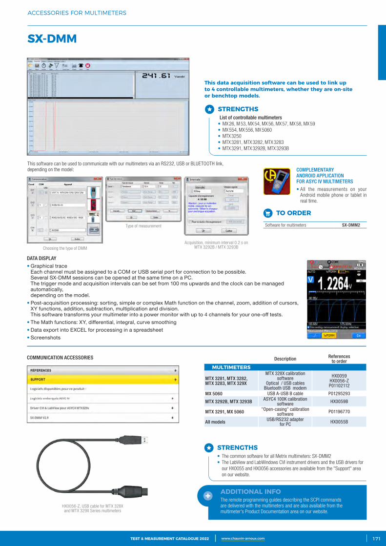
3CATALOGUE TEST & MESURE 2021 www.chauvin-arnoux.com 171TEST & MEASUREMENT CATALOGUE 2022 www.chauvin-arnoux.com
ACCESSORIES FOR MULTIMETERS
SX‑DMM
STRENGTHS List of controllable multimeters • MX 26, M 53, MX 54, MX 56, MX 57, MX 58, MX 59• MX 554, MX 556, MX 5060• MTX 3250• MTX 3281, MTX 3282, MTX 3283• MTX 3291, MTX 3292B, MTX 3293B
This data acquisition software can be used to link up to 4 controllable multimeters, whether they are on‑site or benchtop models.
This software can be used to communicate with our multimeters via an RS232, USB or BLUETOOTH link, depending on the model:
DATA DISPLAY
• Graphical trace Each channel must be assigned to a COM or USB serial port for connection to be possible. Several SX-DMM sessions can be opened at the same time on a PC. The trigger mode and acquisition intervals can be set from 100 ms upwards and the clock can be managed automatically, depending on the model.
• Post-acquisition processing: sorting, simple or complex Math function on the channel, zoom, addition of cursors, XY functions, addition, subtraction, multiplication and division. This software transforms your multimeter into a power monitor with up to 4 channels for your one-off tests.
• The Math functions: XY, differential, integral, curve smoothing• Data export into EXCEL for processing in a spreadsheet• Screenshots
COMMUNICATION ACCESSORIES
Choosing the type of DMM
Type of measurement
Acquisition, minimum interval 0.2 s on MTX 3292B / MTX 3293B
COMPLEMENTARY ANDROID APPLICATION FOR ASYC IV MULTIMETERS
• All the measurements on your Android mobile phone or tablet in real time.
TO ORDER
Software for multimeters SX-DMM2
STRENGTHS• The common software for all Metrix multimeters: SX-DMM2• The LabView and LabWindows CVI instrument drivers and the USB drivers for
our HX0055 and HX0056 accessories are available from the "Support" area on our website.
HX0056-Z, USB cable for MTX 328X and MTX 329X Series multimeters
Description References to order
MULTIMETERS
MTX 3281, MTX 3282, MTX 3283, MTX 329X
MTX 328X calibration software
Optical / USB cablesBluetooth USB modem
HX0059HX0056-ZP01102112
MX 5060 USB A-USB B cable P01295293
MTX 3292B, MTX 3293B ASYC4 100K calibration software HX0059B
MTX 3291, MX 5060 "Open-casing" calibration software P01196770
All models USB/RS232 adapter for PC HX0055B
ADDITIONAL INFOThe remote programming guides describing the SCPI commands are delivered with the multimeters and are also available from the multimeter's Product Documentation area on our website.
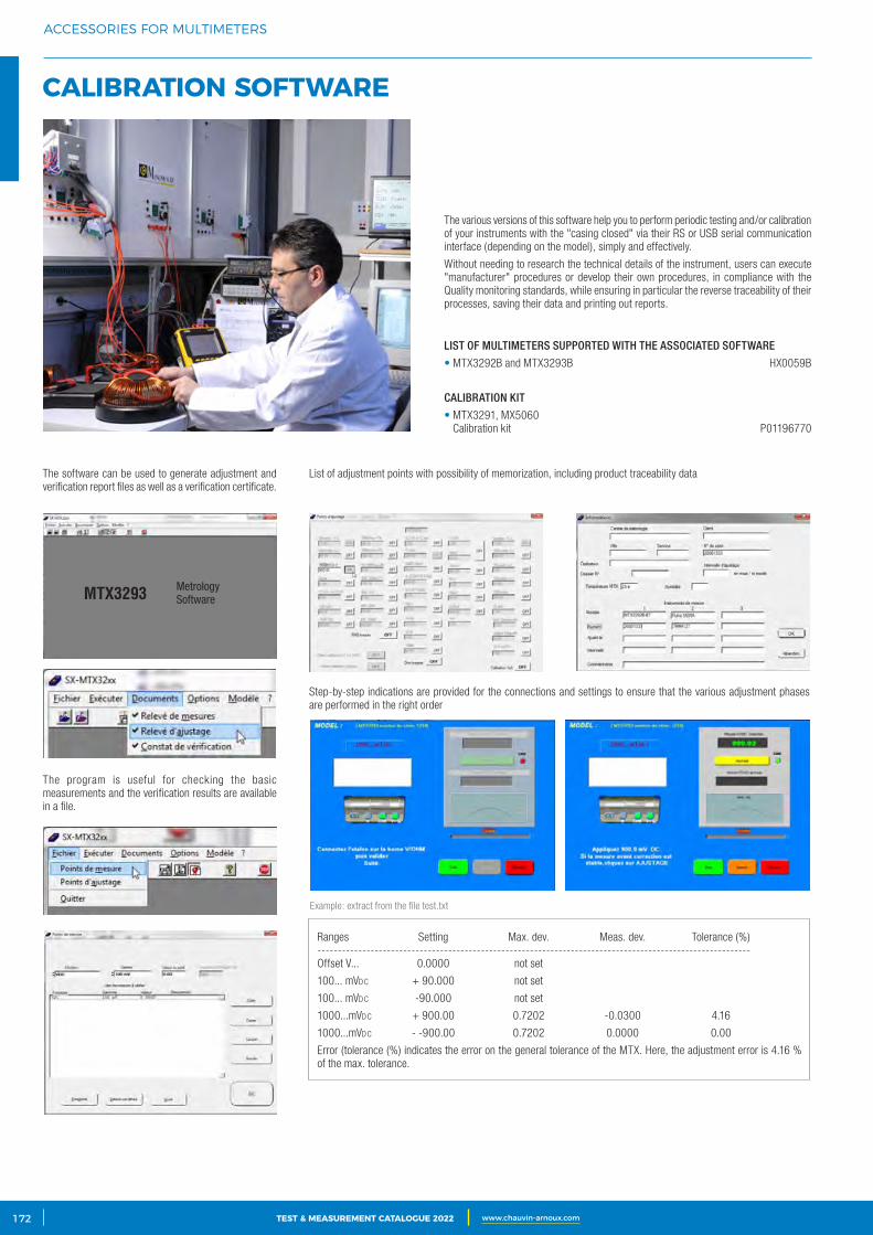
2 CATALOGUE TEST & MESURE 2021 www.chauvin-arnoux.com172 TEST & MEASUREMENT CATALOGUE 2022 www.chauvin-arnoux.com
ACCESSORIES FOR MULTIMETERS
CALIBRATION SOFTWARE
The various versions of this software help you to perform periodic testing and/or calibration of your instruments with the "casing closed" via their RS or USB serial communication interface (depending on the model), simply and effectively.
Without needing to research the technical details of the instrument, users can execute "manufacturer" procedures or develop their own procedures, in compliance with the Quality monitoring standards, while ensuring in particular the reverse traceability of their processes, saving their data and printing out reports.
LIST OF MULTIMETERS SUPPORTED WITH THE ASSOCIATED SOFTWARE
• MTX3292B and MTX3293B HX0059B
CALIBRATION KIT
• MTX3291, MX5060 Calibration kit P01196770
List of adjustment points with possibility of memorization, including product traceability dataThe software can be used to generate adjustment and verification report files as well as a verification certificate.
The program is useful for checking the basic measurements and the verification results are available in a file.
Step-by-step indications are provided for the connections and settings to ensure that the various adjustment phases are performed in the right order
Example: extract from the file test.txt
Ranges Setting Max. dev. Meas. dev. Tolerance (%)----------------------------------------------------------------------------------------------------------Offset V... 0.0000 not set
100... mVdc + 90.000 not set
100... mVdc -90.000 not set
1000...mVdc + 900.00 0.7202 -0.0300 4.16
1000...mVdc - -900.00 0.7202 0.0000 0.00
Error (tolerance (%) indicates the error on the general tolerance of the MTX. Here, the adjustment error is 4.16 % of the max. tolerance.
MTX3293 Metrology Software
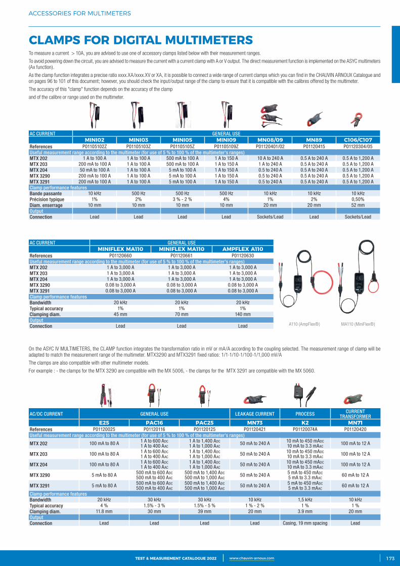
3CATALOGUE TEST & MESURE 2021 www.chauvin-arnoux.com 173TEST & MEASUREMENT CATALOGUE 2022 www.chauvin-arnoux.com
ACCESSORIES FOR MULTIMETERS
CLAMPS FOR DIGITAL MULTIMETERSTo measure a current > 10A, you are advised to use one of accessory clamps listed below with their measurement ranges.
To avoid powering down the circuit, you are advised to measure the current with a current clamp with A or V output. The direct measurement function is implemented on the ASYC multimeters (Ax function).
As the clamp function integrates a precise ratio xxxx.XA/xxxx.XV or XA, it is possible to connect a wide range of current clamps which you can find in the CHAUVIN ARNOUX Catalogue and on pages 96 to 101 of this document; however, you should check the input/output range of the clamp to ensure that it is compatible with the calibres offered by the multimeter.
The accuracy of this "clamp" function depends on the accuracy of the clamp
and of the calibre or range used on the multimeter.
A110 (AmpFlex®) MA110 (MiniFlex®)
AC CURRENT GENERAL USEMINI02 MINI03 MINI05 MINI09 MN08/09 MN89 C106/C107
References P01105102Z P01105103Z P01105105Z P01105109Z P01120401/02 P01120415 P01120304/05Useful measurement range according to the multimeter (for use of 5 % to 100 % of the multimeter's ranges)MTX 202 1 A to 100 A 1 A to 100 A 500 mA to 100 A 1 A to 150 A 10 A to 240 A 0.5 A to 240 A 0.5 A to 1,200 A MTX 203 200 mA to 100 A 1 A to 100 A 500 mA to 100 A 1 A to 150 A 1 A to 240 A 0.5 A to 240 A 0.5 A to 1,200 A MTX 204 50 mA to 100 A 1 A to 100 A 5 mA to 100 A 1 A to 150 A 0.5 to 240 A 0.5 A to 240 A 0.5 A to 1,200 A MTX 3290 200 mA to 100 A 1 A to 100 A 5 mA to 100 A 1 A to 150 A 0.5 to 240 A 0.5 A to 240 A 0.5 A to 1,200 A MTX 3291 200 mA to 100 A 1 A to 100 A 5 mA to 100 A 1 A to 150 A 0.5 to 240 A 0.5 A to 240 A 0.5 A to 1,200 A Clamp performance featuresBande passante 10 kHz 500 Hz 500 Hz 500 Hz 10 kHz 10 kHz 10 kHzPrécision typique 1% 2% 3 % - 2 % 4% 1% 2% 0,50%Diam. enserrage 10 mm 10 mm 10 mm 10 mm 20 mm 20 mm 52 mmOutputConnection Lead Lead Lead Lead Sockets/Lead Lead Sockets/Lead
AC CURRENT GENERAL USEMINIFLEX MA110 MINIFLEX MA110 AMPFLEX A110
References P01120660 P01120661 P01120630Useful measurement range according to the multimeter (for use of 5 % to 100 % of the multimeter's ranges)MTX 202 1 A to 3,000 A 1 A to 3,000 A 1 A to 3,000 A MTX 203 1 A to 3,000 A 1 A to 3,000 A 1 A to 3,000 A MTX 204 1 A to 3,000 A 1 A to 3,000 A 1 A to 3,000 A MTX 3290 0.08 to 3,000 A 0.08 to 3,000 A 0.08 to 3,000 A MTX 3291 0.08 to 3,000 A 0.08 to 3,000 A 0.08 to 3,000 A Clamp performance featuresBandwidth 20 kHz 20 kHz 20 kHzTypical accuracy 1% 1% 1%Clamping diam. 45 mm 70 mm 140 mmOutputConnection Lead Lead Lead
AC/DC CURRENT GENERAL USE LEAKAGE CURRENT PROCESS CURRENT TRANSFORMER
E25 PAC16 PAC25 MN73 K2 MN71References P01120025 P01120116 P01120125 P01120421 P01120074A P01120420Useful measurement range according to the multimeter (for use of 5 % to 100 % of the multimeter's ranges)
MTX 202 100 mA to 80 A 1 A to 600 Adc 1 A to 400 AAc
1 A to 1,400 Adc 1 A to 1,000 AAc 50 mA to 240 A 10 mA to 450 mAdc
10 mA to 3.3 mAAc 100 mA to 12 A
MTX 203 100 mA to 80 A 1 A to 600 Adc 1 A to 400 AAc
1 A to 1,400 Adc1 A to 1,000 AAc 50 mA to 240 A 10 mA to 450 mAdc
10 mA to 3.3 mAAc 100 mA to 12 A
MTX 204 100 mA to 80 A 1 A to 600 Adc 1 A to 400 AAc
1 A to 1,400 Adc1 A to 1,000 AAc 50 mA to 240 A 10 mA to 450 mAdc
10 mA to 3.3 mAAc 100 mA to 12 A
MTX 3290 5 mA to 80 A 500 mA to 600 Adc500 mA to 400 AAc
500 mA to 1,400 Adc500 mA to 1,000 AAc 50 mA to 240 A 5 mA to 450 mAdc
5 mA to 3.3 mAAc 60 mA to 12 A
MTX 3291 5 mA to 80 A 500 mA to 600 Adc500 mA to 400 AAc
500 mA to 1,400 Adc500 mA to 1,000 AAc 50 mA to 240 A 5 mA to 450 mAdc
5 mA to 3.3 mAAc 60 mA to 12 A
Clamp performance featuresBandwidth 20 kHz 30 kHz 30 kHz 10 kHz 1,5 kHz 10 kHz Typical accuracy 4 % 1.5% - 3 % 1.5% - 5 % 1 % - 2 % 1 % 1 %Clamping diam. 11.8 mm 30 mm 39 mm 20 mm 3.9 mm 20 mm OutputConnection Lead Lead Lead Lead Casing, 19 mm spacing Lead
On the ASYC IV MULTIMETERS, the CLAMP function integrates the transformation ratio in mV or mA/A according to the coupling selected. The measurement range of clamp will be adapted to match the measurement range of the multimeter. MTX3290 and MTX3291 fixed ratios: 1/1-1/10-1/100-1/1,000 mV/A
The clamps are also compatible with other multimeter models.
For example : - the clamps for the MTX 3290 are compatible with the MX 5006, - the clamps for the MTX 3291 are compatible with the MX 5060.
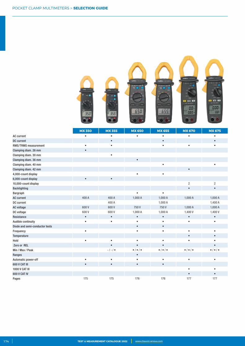
2 CATALOGUE TEST & MESURE 2021 www.chauvin-arnoux.com174 TEST & MEASUREMENT CATALOGUE 2022 www.chauvin-arnoux.com
POCKET CLAMP MULTIMETERS > SELECTION GUIDE
MX 350 MX 355 MX 650 MX 655 MX 670 MX 675AC current • • • • • •
DC current • • •
RMS/TRMS measurement • • • • •
Clamping diam. 26 mm •
Clamping diam. 30 mm •
Clamping diam. 36 mm •
Clamping diam. 40 mm • •
Clamping diam. 42 mm •
4,000-count display • •
6,000-count display • •
10,000-count display 2 2
Backlighting • •
Bargraph • •
AC current 400 A 400 A 1,000 A 1,000 A 1,000 A 1,000 A
DC current 400 A 1,000 A 1,400 A
AC voltage 600 V 600 V 750 V 750 V 1,000 A 1,000 A
DC voltage 600 V 600 V 1,000 A 1,000 A 1,400 V 1,400 V
Resistance • • • • • •
Audible continuity • • • • • •
Diode and semi-conductor tests • •
Frequency • • • • •
Temperature • •
Hold • • • • • •
ΔZero or ΔREL • • • •
Min / Max / Peak - / - / • • / • / • • / • / • • / • / • • / • / •
Ranges •
Automatic power-off • • • • • •
600 V CAT III • • • •
1000 V CAT III • •
600 V CAT IV • •
Pages 175 175 176 176 177 177
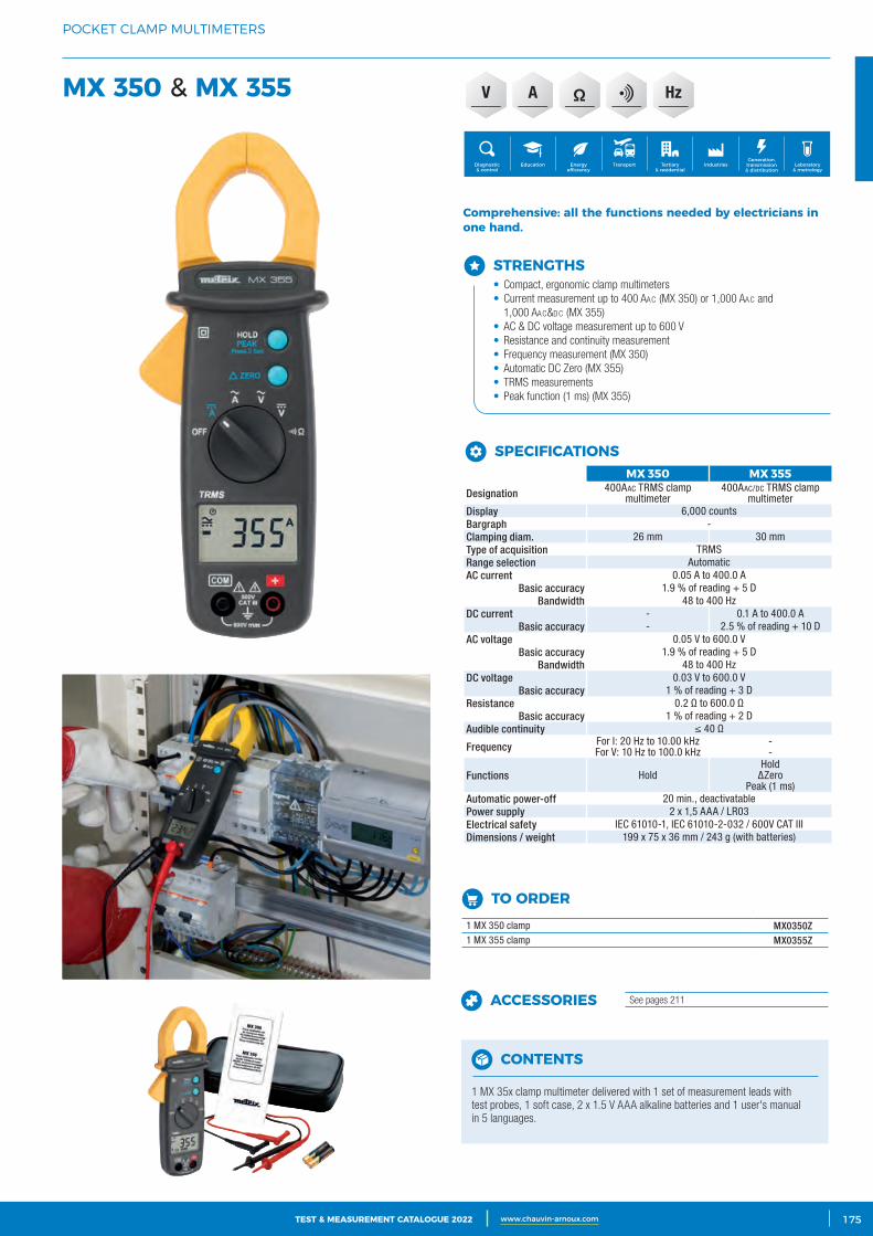
3CATALOGUE TEST & MESURE 2021 www.chauvin-arnoux.com 175TEST & MEASUREMENT CATALOGUE 2022 www.chauvin-arnoux.com
POCKET CLAMP MULTIMETERS
HzV AMX 350 & MX 355
STRENGTHS• Compact, ergonomic clamp multimeters• Current measurement up to 400 AAc (MX 350) or 1,000 AAc and
1,000 AAc&dc (MX 355) • AC & DC voltage measurement up to 600 V• Resistance and continuity measurement• Frequency measurement (MX 350)• Automatic DC Zero (MX 355)• TRMS measurements• Peak function (1 ms) (MX 355)
Comprehensive: all the functions needed by electricians in one hand.
Generation, transmission & distribution
IndustriesTertiary & residential
Education TransportDiagnostic & control
Energy efficiency
Laboratory & metrology
CONTENTS
1 MX 35x clamp multimeter delivered with 1 set of measurement leads with test probes, 1 soft case, 2 x 1.5 V AAA alkaline batteries and 1 user's manual in 5 languages.
TO ORDER1 MX 350 clamp MX0350Z1 MX 355 clamp MX0355Z
ACCESSORIES See pages 211
MX 350 MX 355Designation 400AAc TRMS clamp
multimeter400AAc/dc TRMS clamp
multimeterDisplay 6,000 countsBargraph -Clamping diam. 26 mm 30 mmType of acquisition TRMSRange selection AutomaticAC current 0.05 A to 400.0 A
Basic accuracy 1.9 % of reading + 5 DBandwidth 48 to 400 Hz
DC current - 0.1 A to 400.0 ABasic accuracy - 2.5 % of reading + 10 D
AC voltage 0.05 V to 600.0 VBasic accuracy 1.9 % of reading + 5 D
Bandwidth 48 to 400 HzDC voltage 0.03 V to 600.0 V
Basic accuracy 1 % of reading + 3 DResistance 0.2 Ω to 600.0 Ω
Basic accuracy 1 % of reading + 2 DAudible continuity ≤ 40 Ω
Frequency For I: 20 Hz to 10.00 kHz For V: 10 Hz to 100.0 kHz
--
Functions HoldHold
∆ZeroPeak (1 ms)
Automatic power-off 20 min., deactivatablePower supply 2 x 1,5 AAA / LR03Electrical safety IEC 61010-1, IEC 61010-2-032 / 600V CAT IIIDimensions / weight 199 x 75 x 36 mm / 243 g (with batteries)
SPECIFICATIONS
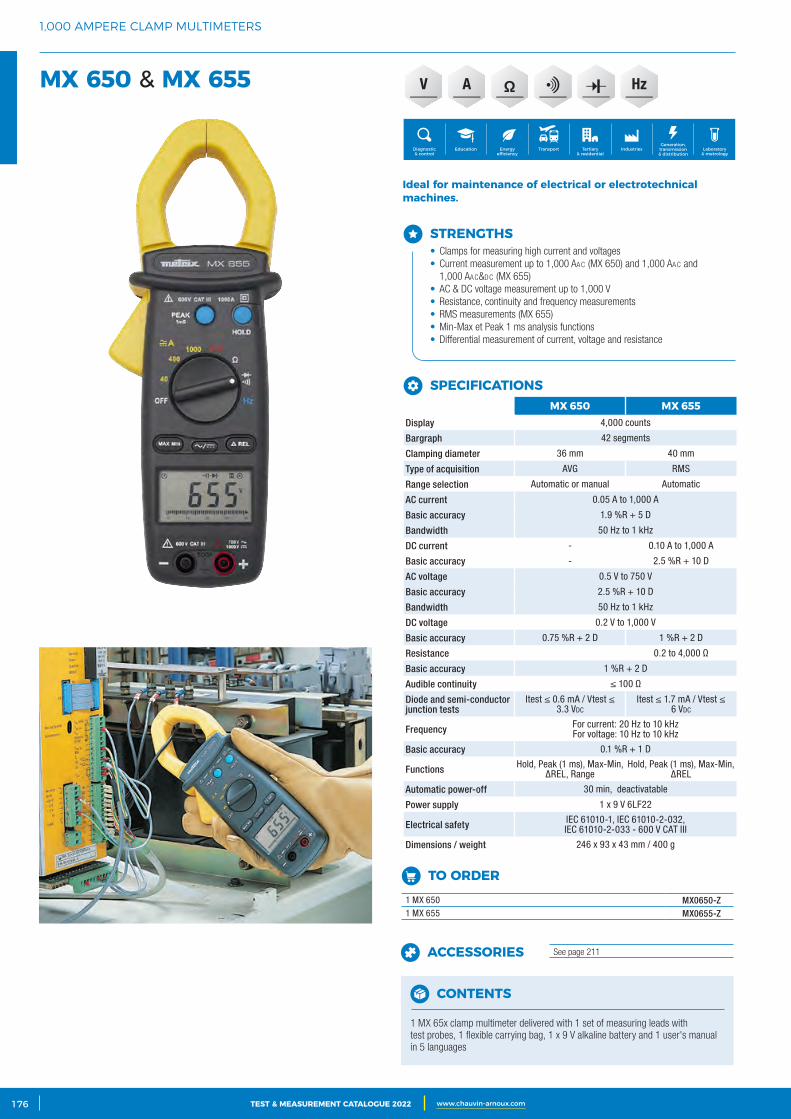
2 CATALOGUE TEST & MESURE 2021 www.chauvin-arnoux.com176 TEST & MEASUREMENT CATALOGUE 2022 www.chauvin-arnoux.com
1,000 AMPERE CLAMP MULTIMETERS
MX 650 & MX 655
STRENGTHS• Clamps for measuring high current and voltages• Current measurement up to 1,000 AAc (MX 650) and 1,000 AAc and
1,000 AAc&dc (MX 655)• AC & DC voltage measurement up to 1,000 V• Resistance, continuity and frequency measurements• RMS measurements (MX 655)• Min-Max et Peak 1 ms analysis functions• Differential measurement of current, voltage and resistance
Ideal for maintenance of electrical or electrotechnical machines.
Generation, transmission & distribution
IndustriesTertiary & residential
Education TransportDiagnostic & control
Energy efficiency
Laboratory & metrology
CONTENTS
1 MX 65x clamp multimeter delivered with 1 set of measuring leads with test probes, 1 flexible carrying bag, 1 x 9 V alkaline battery and 1 user's manual in 5 languages
TO ORDER1 MX 650 MX0650-Z1 MX 655 MX0655-Z
ACCESSORIES See page 211
MX 650 MX 655Display 4,000 counts
Bargraph 42 segments
Clamping diameter 36 mm 40 mm
Type of acquisition AVG RMS
Range selection Automatic or manual Automatic
AC current 0.05 A to 1,000 A
Basic accuracy 1.9 %R + 5 D
Bandwidth 50 Hz to 1 kHz
DC current - 0.10 A to 1,000 A
Basic accuracy - 2.5 %R + 10 D
AC voltage 0.5 V to 750 V
Basic accuracy 2.5 %R + 10 D
Bandwidth 50 Hz to 1 kHz
DC voltage 0.2 V to 1,000 V
Basic accuracy 0.75 %R + 2 D 1 %R + 2 D
Resistance 0.2 to 4,000 Ω
Basic accuracy 1 %R + 2 D
Audible continuity ≤ 100 Ω
Diode and semi-conductor junction tests
Itest ≤ 0.6 mA / Vtest ≤ 3.3 Vdc
Itest ≤ 1.7 mA / Vtest ≤ 6 Vdc
Frequency For current: 20 Hz to 10 kHz For voltage: 10 Hz to 10 kHz
Basic accuracy 0.1 %R + 1 D
Functions Hold, Peak (1 ms), Max-Min, ∆REL, Range
Hold, Peak (1 ms), Max-Min, ∆REL
Automatic power-off 30 min, deactivatable
Power supply 1 x 9 V 6LF22
Electrical safety IEC 61010-1, IEC 61010-2-032, IEC 61010-2-033 - 600 V CAT III
Dimensions / weight 246 x 93 x 43 mm / 400 g
SPECIFICATIONS
HzV A
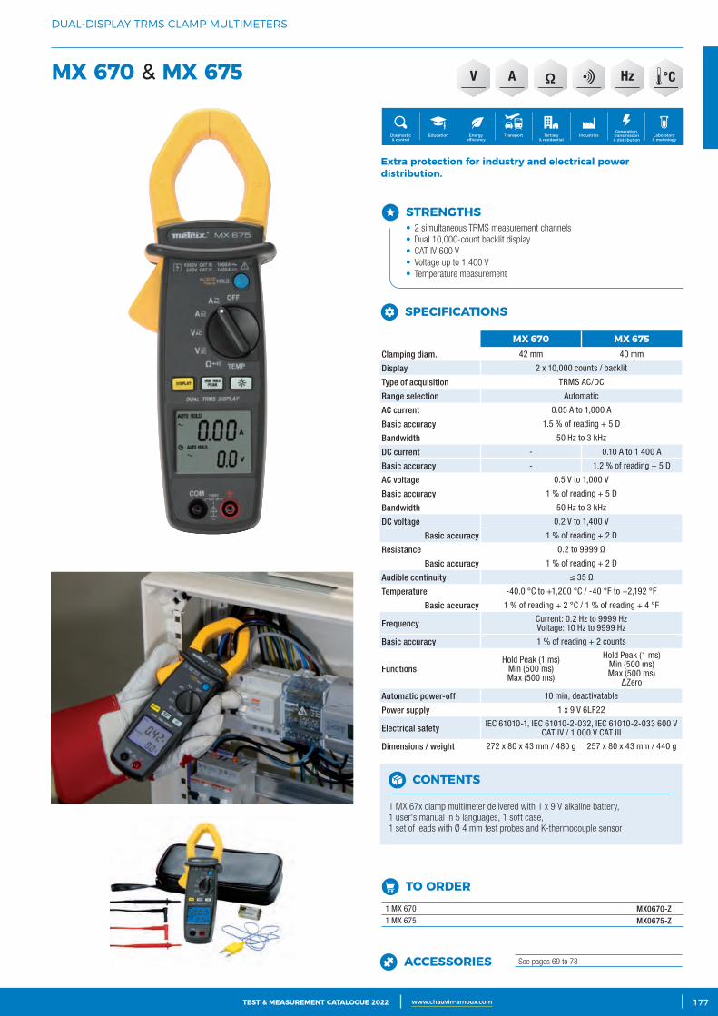
3CATALOGUE TEST & MESURE 2021 www.chauvin-arnoux.com 177TEST & MEASUREMENT CATALOGUE 2022 www.chauvin-arnoux.com
DUAL-DISPLAY TRMS CLAMP MULTIMETERS
MX 670 & MX 675
STRENGTHS• 2 simultaneous TRMS measurement channels• Dual 10,000-count backlit display• CAT IV 600 V• Voltage up to 1,400 V• Temperature measurement
Extra protection for industry and electrical power distribution.
Generation, transmission & distribution
IndustriesTertiary & residential
Education TransportDiagnostic & control
Energy efficiency
Laboratory & metrology
CONTENTS
1 MX 67x clamp multimeter delivered with 1 x 9 V alkaline battery, 1 user's manual in 5 languages, 1 soft case, 1 set of leads with Ø 4 mm test probes and K-thermocouple sensor
TO ORDER 1 MX 670 MX0670-Z1 MX 675 MX0675-Z
ACCESSORIES See pages 69 to 78
MX 670 MX 675Clamping diam. 42 mm 40 mm
Display 2 x 10,000 counts / backlit
Type of acquisition TRMS AC/DC
Range selection Automatic
AC current 0.05 A to 1,000 A
Basic accuracy 1.5 % of reading + 5 D
Bandwidth 50 Hz to 3 kHz
DC current - 0.10 A to 1 400 A
Basic accuracy - 1.2 % of reading + 5 D
AC voltage 0.5 V to 1,000 V
Basic accuracy 1 % of reading + 5 D
Bandwidth 50 Hz to 3 kHz
DC voltage 0.2 V to 1,400 V
Basic accuracy 1 % of reading + 2 D
Resistance 0.2 to 9999 Ω
Basic accuracy 1 % of reading + 2 D
Audible continuity ≤ 35 Ω
Temperature -40.0 °C to +1,200 °C / -40 °F to +2,192 °F
Basic accuracy 1 % of reading + 2 °C / 1 % of reading + 4 °F
Frequency Current: 0.2 Hz to 9999 Hz Voltage: 10 Hz to 9999 Hz
Basic accuracy 1 % of reading + 2 counts
Functions Hold Peak (1 ms)
Min (500 ms) Max (500 ms)
Hold Peak (1 ms)Min (500 ms) Max (500 ms)
ΔZero
Automatic power-off 10 min, deactivatable
Power supply 1 x 9 V 6LF22
Electrical safety IEC 61010-1, IEC 61010-2-032, IEC 61010-2-033 600 V CAT IV / 1 000 V CAT III
Dimensions / weight 272 x 80 x 43 mm / 480 g 257 x 80 x 43 mm / 440 g
SPECIFICATIONS
HzV A
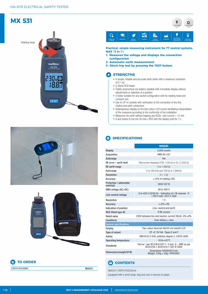
2 CATALOGUE TEST & MESURE 2021 www.chauvin-arnoux.com178 TEST & MEASUREMENT CATALOGUE 2022 www.chauvin-arnoux.com
ON-SITE ELECTRICAL SAFETY TESTER
MX 531
STRENGTHS• A simple, reliable and accurate earth tester with a maximum resolution
of 0.1 Ω.• A 30mA RCD tester• Totally autonomous (no battery needed) with immediate display without
adjustments or selection of a position• A tester suitable for any socket configuration with its rotating head and
compact size• Use on 2P+E sockets with verification of the connection of the line,
neutral and earth conductors.• Instantaneous display on the two-colour LCD screen facilitating interpretation
of the measures according to the conformity of the installation • Measures the earth without tripping any RCDs : test current < 12 mA.• A test button to trip the 30 mAAc RCD with the display held for 7 s.
Practical, simple measuring instrument for TT neutral systems.MX5 "3 in 1":1‑ Measures the voltage and displays the connection
configuration2‑ Automatic earth measurement3‑ 30mA trip test by pressing the TEST button
Generation, transmission & distribution
IndustriesTertiary & residential
Education TransportDiagnostic & control
Energy efficiency
Laboratory & metrology
CONTENTS
MX0531 EARTH RCD30mA
Equipped with a wrist-strap, bag and user's manual on paper.
MX531Display 2,000 counts
Acquisition RMS AC+DC
Autorange Yes
RE error / earth fault Red screen displayed if RE >100 Ω or OL>2,000 Ω
RE earth range 0 to 1,999 Ω
Autorange 0 to 199.9 Ω and 180 Ω to 1,999 Ω
Resolution 0.1, 1 Ω
Accuracy ± (3% of reading+5D)
Protection / admissible overload 300V CAT III
RMS voltage (AC+DC) 90 to 400 V
Line-neutral voltage O to 420 V 50/60 Hz - Indication of L/N reversal - If <195 V and >253 V: fault
Resolution 1 V
Accuracy ± (2%+1D)
Indication of position Line, neutral and earth
RCD 30mA type AC If RE correct
Rated value 230V between line and neutral, current 30mA -0%+6%
Conditions Time 200ms ± 4ms
General specifications
Display Two-colour blue/red 46x50 mm backlit LCD
Type of socket 2P +E 10/16A -Types E and F
Safety EN61010-2-030, pollution degree 2, CATIII-300V
Operating temperature -10 to+45°C
Standards Test as ^per IEC/EN 61557-1 -3 and -6 – EMC as per IEC61236-1 IEC61010-1 CAT III 300V
Dimensions/weight/IP/IK Dimensions 185X65X53 mmWeight: 230g ± 50g / IP40/IK07
SPECIFICATIONS
V
TO ORDER EARTH RCD30MA MX0531
Rotating head
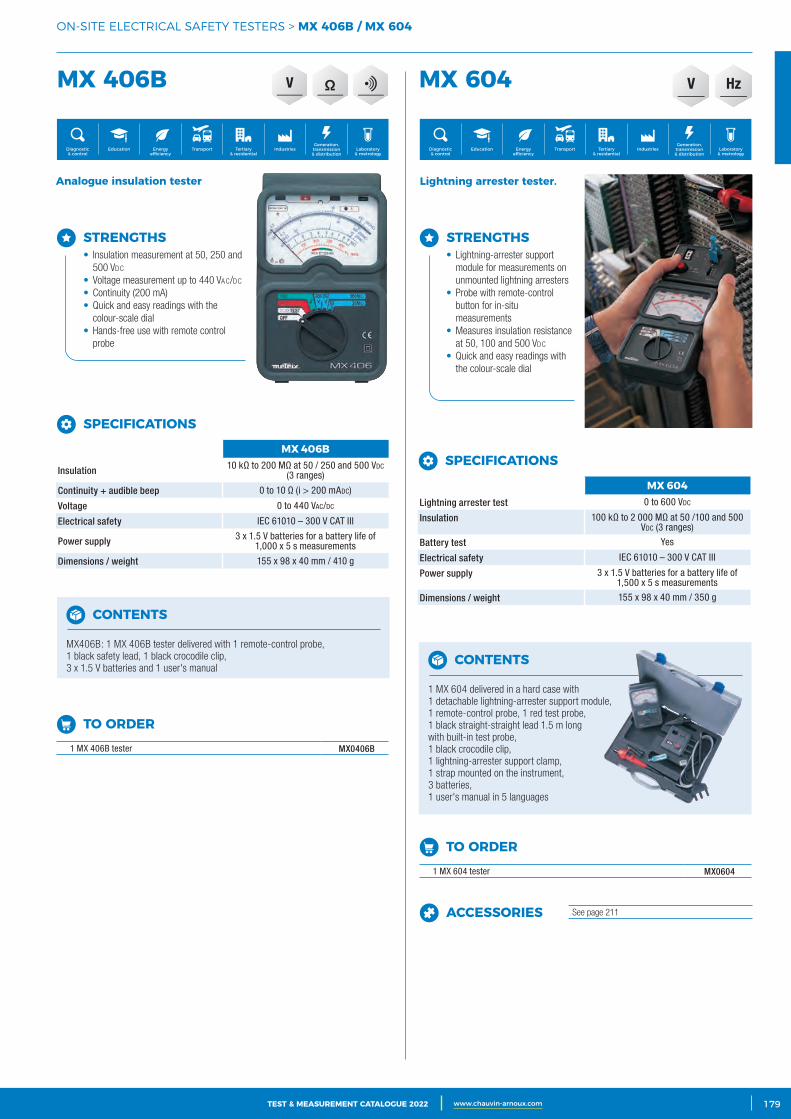
3CATALOGUE TEST & MESURE 2021 www.chauvin-arnoux.com 179TEST & MEASUREMENT CATALOGUE 2022 www.chauvin-arnoux.com
TO ORDER 1 MX 406B tester MX0406B
TO ORDER 1 MX 604 tester MX0604
ACCESSORIES See page 211
V
ON-SITE ELECTRICAL SAFETY TESTERS > MX 406B / MX 604
MX 406B MX 604
MX 406B
Insulation 10 kΩ to 200 MΩ at 50 / 250 and 500 Vdc (3 ranges)
Continuity + audible beep 0 to 10 Ω (i > 200 mAdc)
Voltage 0 to 440 VAc/dc
Electrical safety IEC 61010 – 300 V CAT III
Power supply 3 x 1.5 V batteries for a battery life of 1,000 x 5 s measurements
Dimensions / weight 155 x 98 x 40 mm / 410 g
SPECIFICATIONS MX 604Lightning arrester test 0 to 600 Vdc
Insulation 100 kΩ to 2 000 MΩ at 50 /100 and 500 Vdc (3 ranges)
Battery test Yes
Electrical safety IEC 61010 – 300 V CAT III
Power supply 3 x 1.5 V batteries for a battery life of 1,500 x 5 s measurements
Dimensions / weight 155 x 98 x 40 mm / 350 g
SPECIFICATIONS
SPECIFICATIONS
CONTENTS
MX406B: 1 MX 406B tester delivered with 1 remote-control probe, 1 black safety lead, 1 black crocodile clip, 3 x 1.5 V batteries and 1 user's manual CONTENTS
1 MX 604 delivered in a hard case with 1 detachable lightning-arrester support module, 1 remote-control probe, 1 red test probe, 1 black straight-straight lead 1.5 m long with built-in test probe, 1 black crocodile clip, 1 lightning-arrester support clamp, 1 strap mounted on the instrument, 3 batteries, 1 user's manual in 5 languages
STRENGTHS• Insulation measurement at 50, 250 and
500 Vdc
• Voltage measurement up to 440 VAc/dc
• Continuity (200 mA)• Quick and easy readings with the
colour-scale dial• Hands-free use with remote control
probe
Lightning arrester tester.Analogue insulation tester
STRENGTHS• Lightning-arrester support
module for measurements on unmounted lightning arresters
• Probe with remote-control button for in-situ measurements
• Measures insulation resistance at 50, 100 and 500 Vdc
• Quick and easy readings with the colour-scale dial
Generation, transmission & distribution
IndustriesTertiary & residential
Education TransportDiagnostic & control
Energy efficiency
Laboratory & metrology
Generation, transmission & distribution
IndustriesTertiary & residential
Education TransportDiagnostic & control
Energy efficiency
Laboratory & metrology
HzV
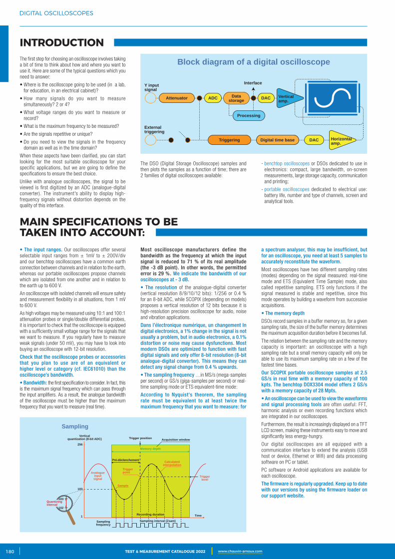
2 CATALOGUE TEST & MESURE 2021 www.chauvin-arnoux.com180 TEST & MEASUREMENT CATALOGUE 2022 www.chauvin-arnoux.com
DIGITAL OSCILLOSCOPES
INTRODUCTION
MAIN SPECIFICATIONS TO BE TAKEN INTO ACCOUNT:
The first step for choosing an oscilloscope involves taking a bit of time to think about how and where you want to use it. Here are some of the typical questions which you need to answer:
• Where is the oscilloscope going to be used (in a lab, for education, in an electrical cabinet)?
• How many signals do you want to measure simultaneously? 2 or 4?
• What voltage ranges do you want to measure or record?
• What is the maximum frequency to be measured?
• Are the signals repetitive or unique?
• Do you need to view the signals in the frequency domain as well as in the time domain?
When these aspects have been clarified, you can start looking for the most suitable oscilloscope for your specific applications, but we are going to define the specifications to ensure the best choice.
Unlike with analogue oscilloscopes, the signal to be viewed is first digitized by an ADC (analogue-digital converter). The instrument's ability to display high-frequency signals without distortion depends on the quality of this interface.
• The input ranges. Our oscilloscopes offer several selectable input ranges from ± 1mV to ± 200V/div and our benchtop oscilloscopes have a common earth connection between channels and in relation to the earth, whereas our portable oscilloscopes propose channels which are isolated from one another and in relation to the earth up to 600 V.
An oscilloscope with isolated channels will ensure safety and measurement flexibility in all situations, from 1 mV to 600 V.
As high voltages may be measured using 10:1 and 100:1 attenuation probes or single/double differential probes, it is important to check that the oscilloscope is equipped with a sufficiently small voltage range for the signals that we want to measure. If you regularly have to measure weak signals (under 50 mV), you may have to look into buying an oscilloscope with 12-bit resolution.
Check that the oscilloscope probes or accessories that you plan to use are of an equivalent or higher level or category (cf. IEC61010) than the oscilloscope's bandwidth.
• Bandwidth: the first specification to consider. In fact, this is the maximum signal frequency which can pass through the input amplifiers. As a result, the analogue bandwidth of the oscilloscope must be higher than the maximum frequency that you want to measure (real time).
The DSO (Digital Storage Oscilloscope) samples and then plots the samples as a function of time; there are 2 families of digital oscilloscopes available:
Most oscilloscope manufacturers define the bandwidth as the frequency at which the input signal is reduced to 71 % of its real amplitude (the -3 dB point). In other words, the permitted error is 29 %. We indicate the bandwidth of our oscilloscopes at - 3 dB.
• The resolution of the analogue-digital converter (vertical resolution 8/9/10/12 bits): 1/256 or 0.4 % for an 8-bit ADC, while SCOPIX (depending on models) proposes a vertical resolution of 12 bits because it is high-resolution precision oscilloscope for audio, noise and vibration applications.
Dans l’électronique numérique, un changement In digital electronics, a 1% change in the signal is not usually a problem, but in audio electronics, a 0.1% distortion or noise may cause dysfunctions. Most modern DSOs are optimized to function with fast digital signals and only offer 8-bit resolution (8-bit analogue-digital converter). This means they can detect any signal change from 0.4 % upwards.
• The sampling frequency …in MS/s (mega-samples per second) or GS/s (giga-samples per second) or real-time sampling mode or ETS equivalent-time mode:
According to Nyquist's theorem, the sampling rate must be equivalent to at least twice the maximum frequency that you want to measure: for
- benchtop oscilloscopes or DSOs dedicated to use in electronics: compact, large bandwidth, on-screen measurements, large storage capacity, communication and printing;
- portable oscilloscopes dedicated to electrical use: battery life, number and type of channels, screen and analytical tools.
a spectrum analyser, this may be insufficient, but for an oscilloscope, you need at least 5 samples to accurately reconstitute the waveform.
Most oscilloscopes have two different sampling rates (modes) depending on the signal measured: real-time mode and ETS (Equivalent Time Sample) mode, also called repetitive sampling. ETS only functions if the signal measured is stable and repetitive, since this mode operates by building a waveform from successive acquisitions.
• The memory depth
DSOs record samples in a buffer memory so, for a given sampling rate, the size of the buffer memory determines the maximum acquisition duration before it becomes full.
The relation between the sampling rate and the memory capacity is important: an oscilloscope with a high sampling rate but a small memory capacity will only be able to use its maximum sampling rate on a few of the fastest time bases.
Our SCOPIX portable oscilloscope samples at 2.5 GS/s in real time with a memory capacity of 100 kpts. The benchtop DOX3304 model offers 2 GS/s with a memory capacity of 28 Mpts.
• An oscilloscope can be used to view the waveforms and signal processing tools are often useful: FFT, harmonic analysis or even recording functions which are integrated in our oscilloscopes.
Furthermore, the result is increasingly displayed on a TFT LCD screen, making these instruments easy to move and significantly less energy-hungry.
Our digital oscilloscopes are all equipped with a communication interface to extend the analysis (USB host or device, Ethernet or Wifi) and data processing software on PC or tablet.
PC software or Android applications are available for each oscilloscope.
The firmware is regularly upgraded. Keep up to date with our versions by using the firmware loader on our support website.
Block diagram of a digital oscilloscope
DAC
Verticalamp.
Horizontalamp.
Y inputsignal
Interface
Attenuator
Digital time base
ADC DAC
Externaltriggering
Processing
Triggering
Datastorage
SamplingVertical
quantization (8-bit ADC)
Samplingfrequency
Time
Trigger position
Triggerlevel
Pré-déclenchement
Triggerpoint
Quantizinginterval
Analogueinputsignal
256
103
103
102
1
Acquisition window
Calculatedinterpolation
Sample
Memory depth
Sampling interval (Zsam)
Recording duration
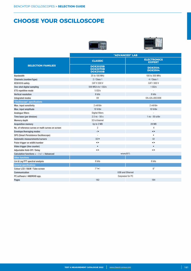
3CATALOGUE TEST & MESURE 2021 www.chauvin-arnoux.com 181TEST & MEASUREMENT CATALOGUE 2022 www.chauvin-arnoux.com
BENCHTOP OSCILLOSCOPES > SELECTION GUIDE
CHOOSE YOUR OSCILLOSCOPE
"ADVANCED" LAB
SELECTION FAMILIES
CLASSIC ELECTRONICS EXPERT
DOX2025B DOX2070B DOX2100B
DOX3104 DOX3304
Bandwidth 25 to 100 MHz 100 to 300 MHz
Channels (number/type) 2 / Class 1 4 / Class 1
IEC61010 safety CAT II 300 V CAT I 300 V
One-shot digital sampling 500 MS/s to 1 GS/s 1 GS/s
ETS repetitive mode 5 GS/s -
Vertical resolution 8 bits 8 bits
Integrated modes OX OX+GX+DECODE
"Oscilloscope" specifications
Max. input sensitivity 2 mV/div 2 mV/div
Max. input amplitude 10 V/div 10 V/div
Analogue filters Digital filters -
Time base (per division) 2.5 ns - 50 s 1 ns - 50 s/div
Memory depth 32 k/channel -
Acquisition memory Up to 2 MB 28 MB
No. of reference curves or math curves on screen 2 4
Envelope/Averaging modes -/• •/•
SPO (Smart Persistence Oscilloscope) - •
Automatic measurements/cursors 32/• 32
Pulse trigger on width/number •/• •/•
Video trigger (line counter) • •
Adjustable Hold-Off / Delay •/• •/•
Calculation functions + - / x / : / Advanced •/•/•/FFT-
Other functions
Lin & Log FFT spectral analysis 8 bits 8 bits
General specifications
Colour LCD / B&W / Tube screen 7"/•/- 8"
Communication USB and Ethernet
PC software / ANDROID app. Easywave for PC
Pages 182 184
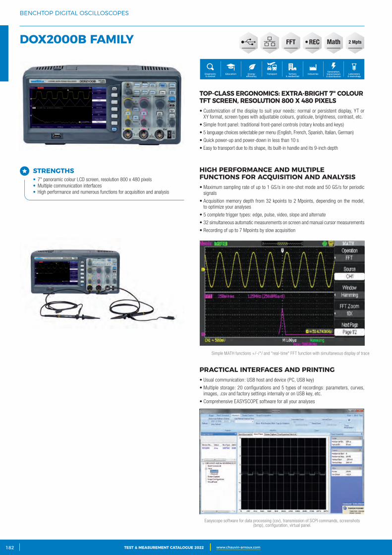
2 CATALOGUE TEST & MESURE 2021 www.chauvin-arnoux.com182 TEST & MEASUREMENT CATALOGUE 2022 www.chauvin-arnoux.com
BENCHTOP DIGITAL OSCILLOSCOPES
DOX2000B FAMILY
TOP‑CLASS ERGONOMICS: EXTRA‑BRIGHT 7" COLOUR TFT SCREEN, RESOLUTION 800 X 480 PIXELS• Customization of the display to suit your needs: normal or persistent display, YT or
XY format, screen types with adjustable colours, graticule, brightness, contrast, etc.
• Simple front panel: traditional front-panel controls (rotary knobs and keys)
• 5 language choices selectable per menu (English, French, Spanish, Italian, German)
• Quick power-up and power-down in less than 10 s
• Easy to transport due to its shape, its built-in handle and its 9-inch depth
HIGH PERFORMANCE AND MULTIPLE FUNCTIONS FOR ACQUISITION AND ANALYSIS• Maximum sampling rate of up to 1 GS/s in one-shot mode and 50 GS/s for periodic
signals
• Acquisition memory depth from 32 kpoints to 2 Mpoints, depending on the model, to optimize your analyses
• 5 complete trigger types: edge, pulse, video, slope and alternate
• 32 simultaneous automatic measurements on screen and manual cursor measurements
• Recording of up to 7 Mpoints by slow acquisition
PRACTICAL INTERFACES AND PRINTING• Usual communication: USB host and device (PC, USB key)
• Multiple storage: 20 configurations and 5 types of recordings: parameters, curves, images, .csv and factory settings internally or on USB key, etc.
• Comprehensive EASYSCOPE software for all your analyses
Generation, transmission & distribution
IndustriesTertiary & residential
Education TransportDiagnostic & control
Energy efficiency
Laboratory & metrology
Simple MATH functions +/-/*/ and "real-time" FFT function with simultaneous display of trace
Easyscope software for data processing (csv), transmission of SCPI commands, screenshots (bmp), configuration, virtual panel.
• RECFFT 2 MptsMath
STRENGTHS• 7" panoramic colour LCD screen, resolution 800 x 480 pixels• Multiple communication interfaces• High performance and numerous functions for acquisition and analysis
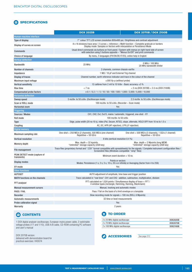
3CATALOGUE TEST & MESURE 2021 www.chauvin-arnoux.com 183TEST & MEASUREMENT CATALOGUE 2022 www.chauvin-arnoux.com
BENCHTOP DIGITAL OSCILLOSCOPES
SPECIFICATIONS
DOX 2025B DOX 2070B / DOX 2100BHuman-machine interface
Type of display 7" colour TFT LCD screen (resolution 800x480 px) / Brightness and contrast adjustment
Display of curves on screen 8 x 16 divisions trace area / 2 curves + reference + Math function – Complete graticule or bordersDisplay mode: Samples or Vectors with interpolation or Persistence Mode
Commands Usual direct commands via buttons on front panel / System with menus on right-hand side of screenwith selection using 5 buttons opposite – "Menus On/Off" and print commands
Choice of language By menu, 5 languages (FR/EN/DE/IT/ES), online help in English
Vertical deflection
Bandwidth 25 MHz 0 MHz / 100 MHz 20 MHz bandwidth limiter
Number of channels 2 channels, common chassis-earths
Impedance 1 MΩ / 18 pF and External Trig channel
Display of traces Channel number, earth reference indicator and trace in the colour of the channel
Maximum input voltage ±300 Vp-p (without probe)
Vertical sensitivity 12 calibres from 2 mV to 10 V/div - Basic accuracy ±3 %
Rise time < 7 ns < 5 ns (DOX 2070B) < 3.5 ns (DOX 2100B)
Compensated probe factors x 0.1 / 0.2 / 1 / 5 / 10 / 50 / 100 / 500 / 1,000 / 2,000 / 5,000 / 10,000
Horizontal deflection
Sweep speed 5 ns/div. to 50 s/div. (Oscilloscope mode) 2.5 ns/div. to 50 s/div. (Oscilloscope mode)
Scan or ROLL mode 100 ms/div. to 50 s/div. (Recorder – Scan mode)
Horizontal zoom Yes
Triggering
Sources / Modes CH1, CH2, Ext, Ext/5, mains / automatic, triggered, one-shot - XY
Roll mode 100 ms/div. to 50 s/div.
Type Edge, pulse width (20 ns-10 s), video (Pal, Secam, NTSC), slope, alternate, HOLD OFF from 10 ns to 1.5 s
Coupling AC, DC, HFR (HF rejection), LFR (LF rejection)
Digital memory
Maximum sampling rate One-shot = 250 MS/s (2 channels), 500 MS/s (one channel) Repetitive = 50 GS/s
One-shot = 500 MS/s (2 channels), 1 GS/s (1 channel) Repetitive = 50 GS/s
Vertical resolution 8 bits (vertical resolution 0.4 %)
Memory depth Max. depth = 32 kpoints "Unlimited" storage capacity (USB key)
Max. depth = 2 Mpoints (long MEM) "Unlimited" storage capacity (USB key)
File management Trace files (proprietary format and ".CSV" format compatible with spreadsheets) for the signals / Complete instrument configuration files / Screenshot files (Windows-compatible ".bmp" files)
PEAK DETECT mode (capture of transients) Minimum event duration = 10 ns
Display modes Points or vectors Modes: Persistence (1 s, 2 s, 5 s, 10 s, 20 s or infinite) or Averaging (factor from 4 to 256)
XY mode Yes
Other functions
AUTOSET AUTO adjustment of amplitude, time base and trigger position
MATH functions on the channels Trace calculated in "real time": CH1 and CH2 : addition, subtraction, multiplication, division
FFT analyser FFT calculated on 1,024 points / Simultaneous display of trace + FFT / 4 window types (rectangle, Hamming, Hanning, Blackmann)
Manual measurement cursors Manual, tracking and automatic modes
PASS / FAIL Pass / Fail on the basis of a limit envelope or a template
Recorder Slow recording mode for signals > 100 ms (ROLL 6 Mpoints)
Automatic measurements 32 time or level measurements
Probe calibration signal Yes
Warranty 2 years
CONTENTS
1 DOX digital analyser-oscilloscope, European mains power cable, 2 switchable voltage probes (1/1 and 1/10), USB A/B cable, CD-ROM containing PC software and user's manual
DOX 2070B version: delivered with demonstration board for practical exercises: HX0074
TO ORDER 2 x 25 MHz digital oscilloscope DOX2025B 2 x 70 MHz digital oscilloscope DOX2070B 2 x 100 MHz digital oscilloscope DOX2100B
ACCESSORIES See page 212
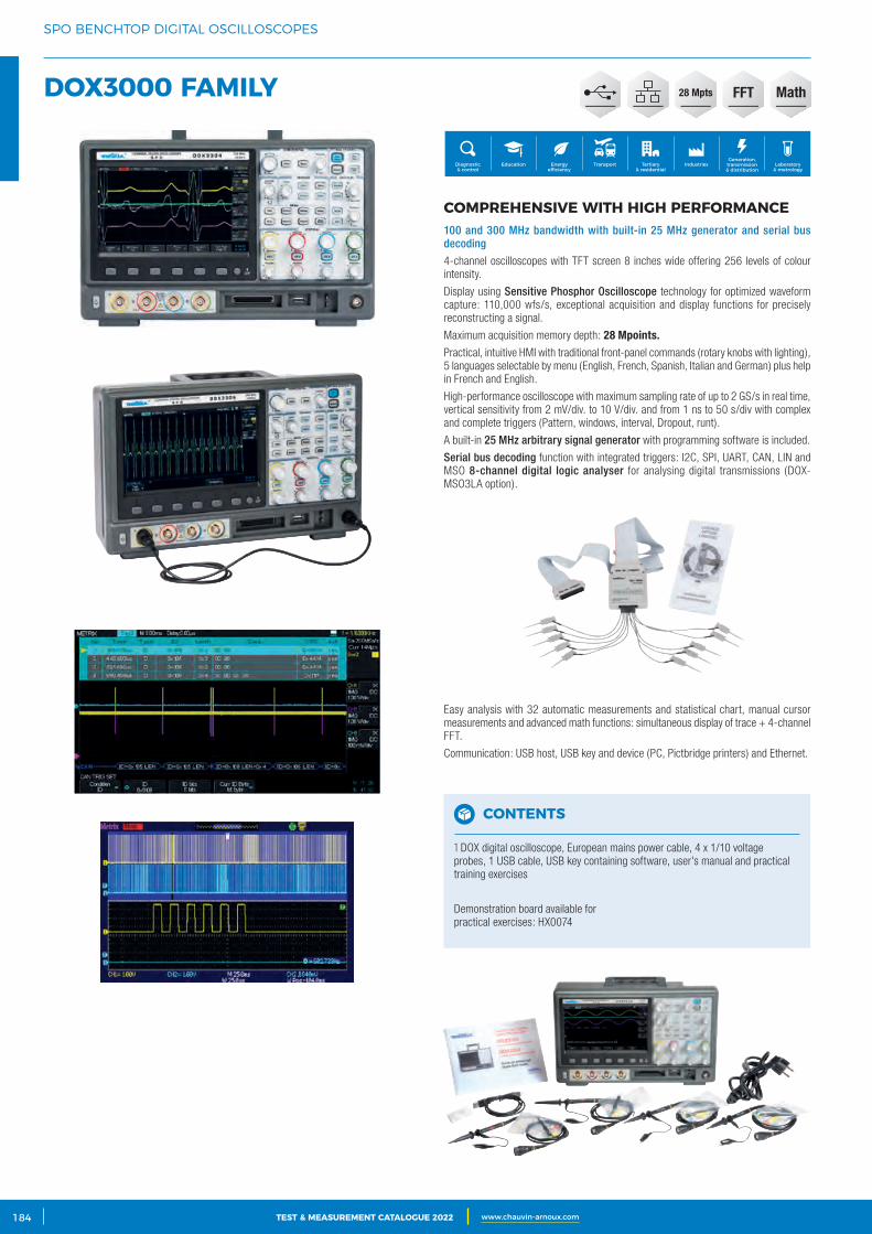
2 CATALOGUE TEST & MESURE 2021 www.chauvin-arnoux.com184 TEST & MEASUREMENT CATALOGUE 2022 www.chauvin-arnoux.com
SPO BENCHTOP DIGITAL OSCILLOSCOPES
DOX3000 FAMILY
COMPREHENSIVE WITH HIGH PERFORMANCE100 and 300 MHz bandwidth with built-in 25 MHz generator and serial bus decoding
4-channel oscilloscopes with TFT screen 8 inches wide offering 256 levels of colour intensity.
Display using Sensitive Phosphor Oscilloscope technology for optimized waveform capture: 110,000 wfs/s, exceptional acquisition and display functions for precisely reconstructing a signal.
Maximum acquisition memory depth: 28 Mpoints.Practical, intuitive HMI with traditional front-panel commands (rotary knobs with lighting), 5 languages selectable by menu (English, French, Spanish, Italian and German) plus help in French and English.
High-performance oscilloscope with maximum sampling rate of up to 2 GS/s in real time, vertical sensitivity from 2 mV/div. to 10 V/div. and from 1 ns to 50 s/div with complex and complete triggers (Pattern, windows, interval, Dropout, runt).
A built-in 25 MHz arbitrary signal generator with programming software is included.
Serial bus decoding function with integrated triggers: I2C, SPI, UART, CAN, LIN and MSO 8-channel digital logic analyser for analysing digital transmissions (DOX-MSO3LA option).
Easy analysis with 32 automatic measurements and statistical chart, manual cursor measurements and advanced math functions: simultaneous display of trace + 4-channel FFT.
Communication: USB host, USB key and device (PC, Pictbridge printers) and Ethernet.
Generation, transmission & distribution
IndustriesTertiary & residential
Education TransportDiagnostic & control
Energy efficiency
Laboratory & metrology
CONTENTS
1 DOX digital oscilloscope, European mains power cable, 4 x 1/10 voltage probes, 1 USB cable, USB key containing software, user's manual and practical training exercises
Demonstration board available for practical exercises: HX0074
FFT28 Mpts Math
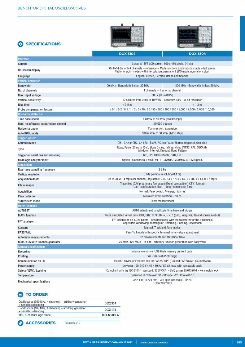
3CATALOGUE TEST & MESURE 2021 www.chauvin-arnoux.com 185TEST & MEASUREMENT CATALOGUE 2022 www.chauvin-arnoux.com
BENCHTOP DIGITAL OSCILLOSCOPES
SPECIFICATIONS
TO ORDER Oscilloscope (300 MHz, 4 channels) + arbitrary generator + serial bus decoding DOX3304
Oscilloscope (100 MHz, 4 channels) + arbitrary generator + serial bus decoding DOX3104
MSO 8-channel logic probe DOX-MSO3LA
ACCESSORIES See pages 212
DOX 3104 DOX 3304Interface
Screen Colour 8" TFT LCD screen, 800 x 480 pixels, 24 bits
On-screen display On 8x14 div with 4 channels + reference + Math functions and statistics table – full screenVector or point modes with interpolation, permanent SPO mode: normal or colour
Language English, French, German, Italian and Spanish
Vertical deflection
Bandwidth 100 MHz - Bandwidth limiter: 20 MHz 300 MHz - Bandwidth limiter: 20 MHz
No. of channels 4 channels + 1 external channel
Max. input voltage 300 V (DC+AC Pk)
Vertical sensitivity 12 calibres from 2 mV to 10 V/div – Accuracy ±3% – 8-bit resolution
Rise time < 3.5 ns < 1.2 ns
Probe compensation factors x 0.1 / 0.2 / 0.5 / 1 / 2 / 5 / 10 / 20 / 50 / 100 / 200 / 500 / 1,000 / 2,000 / 5,000 / 10,000
Horizontal deflection
Time base speed 1 ns/div to 50 s/div (oscilloscope)
Max. no. of traces captured per second 110,000 traces/s
Horizontal zoom Compression, expansion
Auto ROLL mode 100 ms/div to 50 s/div (1-2-5 step)
Trigger system
Sources/Mode CH1, CH2 or CH3. CH4 Ext, Ext/5, AC line / Auto, Normal triggered, One-shot
Type Edge, Pulse (20 ns to 10 s), Slope (rising, falling), Video (NTSC, PAL, SECAM), Windows, Interval, Dropout, Runt, Pattern
Trigger on serial bus and decoding I2C, SPI, UART/RS232, CAN, LIN
MSO logic analyser input Option : 8 channels + clock for TTL/CMOS/LVCOM/CUSTOM signals
Acquisition
Real-time sampling frequency 2 GS/s
Vertical resolution 8 bits (vertical resolution 0.4 %)
Acquisition depth Up to 28 M: 14 Mpts per channel, adjustable: 7 k / 14 k / 70 k / 140 k / 700 k / 1.4 M / 7 Mpts
File manager Trace files (DAV proprietary format and Excel-compatible ".CSV" format)".set" configuration files – ".bmp" screenshot files
Acquisition Normal, Peak detect, Average, High res
Peak detection Minimum event duration = 10 ns
"Statistics" mode Event measurement
Other functions
AUTOSET AUTO adjustment: amplitude, time base and trigger
MATH function Trace calculated in real time: CH1, CH2, CH3 CH4 +, -, x, /, (d/dt), integral (∫dt) and square root (√)
FFT analyser FFT calculated on 1,024 points - simultaneously with the waveform for the 4 channelsAdjustable windowing: rectangular, Hamming, Hanning, Blackmann
Cursors Manuel, Track and Auto modes
PASS/FAIL Pass/Fail mode with specific terminal for envelope adjustment
Automatic measurements 32 measurements and statistical table
Built-in 25 MHz function generator 25 MHz- 125 MS/s - 14 bits - arbitrary function generation with EasyWave
General specifications
Recording Internal memory or USB flash memory on front panel
Printing Via USB Host (PictBridge)
Communication on PC Via USB device or Ethernet link for EASYSCOPE (OX) and EASYWAVE (GX) software
Power supply Universal 100-240 V / 45-440 Hz/ 50 VA max. with removable cable
Safety / EMC / Locking Compliant with the IEC 6101-1 standard, 300V CAT I - EMC as per EN61326-1 - Kensington lock
Temperature Operation: 0 °C to +40 °C - Storage: -20 °C to +60 °C
Mechanical specifications 352 x 111 x 224 mm – 3.6 kg (4 channels) – IP 20 3-year warranty
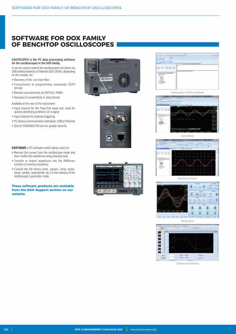
2 CATALOGUE TEST & MESURE 2021 www.chauvin-arnoux.com186 TEST & MEASUREMENT CATALOGUE 2022 www.chauvin-arnoux.com
SOFTWARE FOR DOX FAMILY OF BENCHTOP OSCILLOSCOPES
EASYSCOPEX is the PC data processing software for the oscilloscopes in the DOX family.
It can be used to extend the oscilloscope's functions via USB (without drivers) or Ethernet (DOX 3000), depending on the models, for:
• Recovery of the .csv trace files
• Transmission of programming commands (SCPI format)
• Remote command test via VIRTUAL PANEL
• Recovery of screenshots in .bmp format
EASYWAVE is PC software which allows users to:
• Recover the curves from the oscilloscope mode and then modify the waveforms using drawing tools
• Transfer or import waveforms into the ARBitrary function (4 memory locations)
• Consult the file library (sine, square, ramp, pulse, noise, cardiac, exponential, etc.) in the memory of the oscilloscope's generator mode
These software products are available from the DOX Support section on our website.
Recovery of traces
Screenshots
Transmission of SCPI commands
Virtual panel
Creation of waveforms
Available at the rear of the instrument:
• Input channel for the Pass/Fail mask test, ideal for quickly identifying problems on a signal
• Input channel for external triggering
• PC/device communication interfaces: USB or Ethernet
• Slot for KENSINGTON lock for greater security
SOFTWARE FOR DOX FAMILY OF BENCHTOP OSCILLOSCOPES
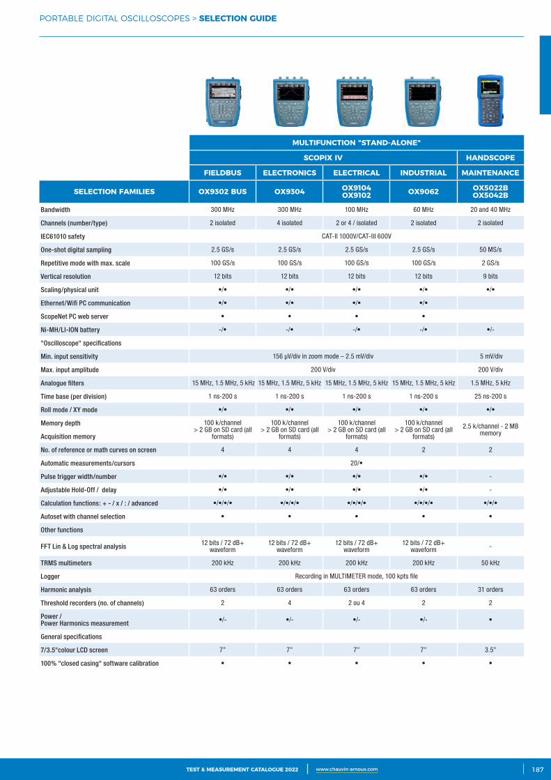
3CATALOGUE TEST & MESURE 2021 www.chauvin-arnoux.com 187TEST & MEASUREMENT CATALOGUE 2022 www.chauvin-arnoux.com
PORTABLE DIGITAL OSCILLOSCOPES > SELECTION GUIDE
MULTIFUNCTION "STAND‑ALONE"
SCOPIX IV HANDSCOPE
FIELDBUS ELECTRONICS ELECTRICAL INDUSTRIAL MAINTENANCE
SELECTION FAMILIES OX9302 BUS OX9304 OX9104OX9102 OX9062 OX5022B
OX5042B
Bandwidth 300 MHz 300 MHz 100 MHz 60 MHz 20 and 40 MHz
Channels (number/type) 2 isolated 4 isolated 2 or 4 / isolated 2 isolated 2 isolated
IEC61010 safety CAT-II 1000V/CAT-III 600V
One-shot digital sampling 2.5 GS/s 2.5 GS/s 2.5 GS/s 2.5 GS/s 50 MS/s
Repetitive mode with max. scale 100 GS/s 100 GS/s 100 GS/s 100 GS/s 2 GS/s
Vertical resolution 12 bits 12 bits 12 bits 12 bits 9 bits
Scaling/physical unit •/• •/• •/• •/• •/•
Ethernet/Wifi PC communication •/• •/• •/• •/•
ScopeNet PC web server • • • •
Ni-MH/LI-ION battery -/• -/• -/• -/• •/-
"Oscilloscope" specifications
Min. input sensitivity 156 μV/div in zoom mode – 2.5 mV/div 5 mV/div
Max. input amplitude 200 V/div 200 V/div
Analogue filters 15 MHz, 1.5 MHz, 5 kHz 15 MHz, 1.5 MHz, 5 kHz 15 MHz, 1.5 MHz, 5 kHz 15 MHz, 1.5 MHz, 5 kHz 1.5 MHz, 5 kHz
Time base (per division) 1 ns-200 s 1 ns-200 s 1 ns-200 s 1 ns-200 s 25 ns-200 s
Roll mode / XY mode •/• •/• •/• •/• •/•
Memory depth 100 k/channel> 2 GB on SD card (all
formats)
100 k/channel> 2 GB on SD card (all
formats)
100 k/channel> 2 GB on SD card (all
formats)
100 k/channel> 2 GB on SD card (all
formats)
2.5 k/channel - 2 MB memoryAcquisition memory
No. of reference or math curves on screen 4 4 4 2 2
Automatic measurements/cursors 20/•
Pulse trigger width/number •/• •/• •/• •/• -
Adjustable Hold-Off / delay •/• •/• •/• •/• -
Calculation functions: + - / x / : / advanced •/•/•/• •/•/•/• •/•/•/• •/•/•/• •/•/•
Autoset with channel selection • • • • •
Other functions
FFT Lin & Log spectral analysis 12 bits / 72 dB+ waveform
12 bits / 72 dB+ waveform
12 bits / 72 dB+ waveform
12 bits / 72 dB+ waveform -
TRMS multimeters 200 kHz 200 kHz 200 kHz 200 kHz 50 kHz
Logger Recording in MULTIMETER mode, 100 kpts file
Harmonic analysis 63 orders 63 orders 63 orders 63 orders 31 orders
Threshold recorders (no. of channels) 2 4 2 ou 4 2 2
Power / Power Harmonics measurement •/- •/- •/- •/- •
General specifications
7/3.5"colour LCD screen 7" 7" 7" 7" 3.5"
100% "closed casing" software calibration • • • • •
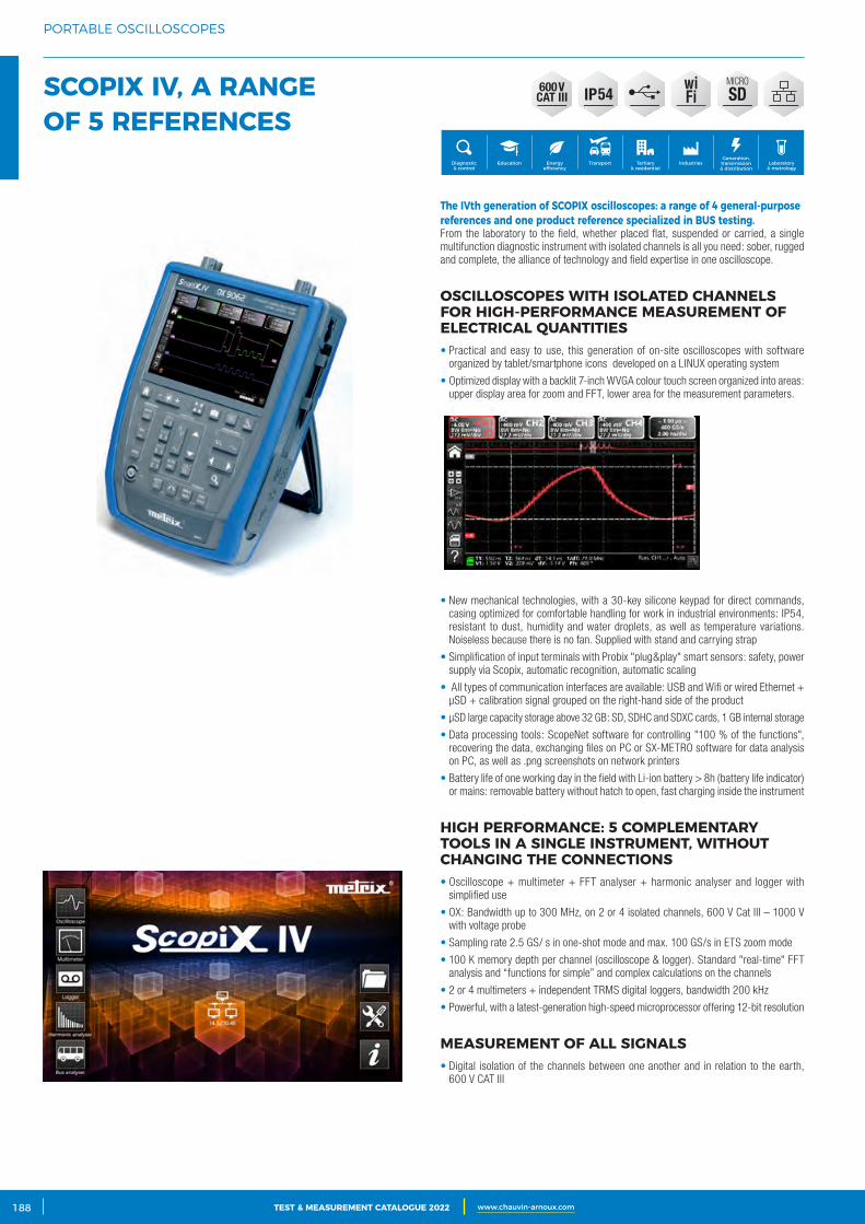
2 CATALOGUE TEST & MESURE 2021 www.chauvin-arnoux.com188 TEST & MEASUREMENT CATALOGUE 2022 www.chauvin-arnoux.com
PORTABLE OSCILLOSCOPES
SCOPIX IV, A RANGE OF 5 REFERENCES
OSCILLOSCOPES WITH ISOLATED CHANNELS FOR HIGH‑PERFORMANCE MEASUREMENT OF ELECTRICAL QUANTITIES• Practical and easy to use, this generation of on-site oscilloscopes with software
organized by tablet/smartphone icons developed on a LINUX operating system
• Optimized display with a backlit 7-inch WVGA colour touch screen organized into areas: upper display area for zoom and FFT, lower area for the measurement parameters.
• New mechanical technologies, with a 30-key silicone keypad for direct commands, casing optimized for comfortable handling for work in industrial environments: IP54, resistant to dust, humidity and water droplets, as well as temperature variations. Noiseless because there is no fan. Supplied with stand and carrying strap
• Simplification of input terminals with Probix "plug&play" smart sensors: safety, power supply via Scopix, automatic recognition, automatic scaling
• All types of communication interfaces are available: USB and Wifi or wired Ethernet + μSD + calibration signal grouped on the right-hand side of the product
• μSD large capacity storage above 32 GB: SD, SDHC and SDXC cards, 1 GB internal storage
• Data processing tools: ScopeNet software for controlling "100 % of the functions", recovering the data, exchanging files on PC or SX-METRO software for data analysis on PC, as well as .png screenshots on network printers
• Battery life of one working day in the field with Li-ion battery > 8h (battery life indicator) or mains: removable battery without hatch to open, fast charging inside the instrument
HIGH PERFORMANCE: 5 COMPLEMENTARY TOOLS IN A SINGLE INSTRUMENT, WITHOUT CHANGING THE CONNECTIONS • Oscilloscope + multimeter + FFT analyser + harmonic analyser and logger with
simplified use
• OX: Bandwidth up to 300 MHz, on 2 or 4 isolated channels, 600 V Cat III – 1000 V with voltage probe
• Sampling rate 2.5 GS/ s in one-shot mode and max. 100 GS/s in ETS zoom mode
• 100 K memory depth per channel (oscilloscope & logger). Standard "real-time" FFT analysis and “functions for simple” and complex calculations on the channels
• 2 or 4 multimeters + independent TRMS digital loggers, bandwidth 200 kHz
• Powerful, with a latest-generation high-speed microprocessor offering 12-bit resolution
MEASUREMENT OF ALL SIGNALS• Digital isolation of the channels between one another and in relation to the earth,
600 V CAT III
The IVth generation of SCOPIX oscilloscopes: a range of 4 general‑purpose references and one product reference specialized in BUS testing.From the laboratory to the field, whether placed flat, suspended or carried, a single multifunction diagnostic instrument with isolated channels is all you need: sober, rugged and complete, the alliance of technology and field expertise in one oscilloscope.
Generation, transmission & distribution
IndustriesTertiary & residential
Education TransportDiagnostic & control
Energy efficiency
Laboratory & metrology
MICRO
SDwiFi54
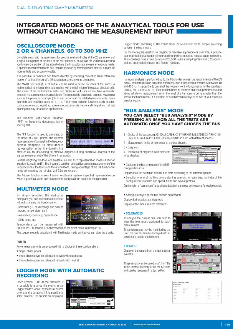
3CATALOGUE TEST & MESURE 2021 www.chauvin-arnoux.com 189TEST & MEASUREMENT CATALOGUE 2022 www.chauvin-arnoux.com
DUAL-DISPLAY TRMS CLAMP MULTIMETERS
OSCILLOSCOPE MODE: 2 OR 4 CHANNELS, 60 TO 300 MHZComplete automatic measurements for precise analysis display all the 20 parameters of a signal all together or for each of the four channels, as well as the 2 markers allowing you to view the portion of the signal where the first automatic measurement was made. A specific measurement area can then be selected by framing it with manual cursors for more reliable and accurate results.
It is possible to compare two traces directly by checking "deviation from reference memory" so that the signal's 20 parameters are shown as deviations.
The MATH functions (1, 2, 3 and 4) can be used to define, for each of the traces, a mathematical function and vertical scaling with the definition of the actual physical unit. The screen of the mathematical editor can display up to 4 traces in real time. Automatic or cursor measurements remain available. This means it is possible to examine waveforms such as the power, for example (U x I), and perform all the related measurements. many operators are available, such as +, -, x, /, but more complex functions such as sine, cosine, exponential, logarithm, square root and even derivative and integral, etc., at last opening the way for specific applications.
The real-time Fast Fourier Transform (FFT) for frequency decomposition of your signals.
The FFT function is used to calculate, on the basis of 2,500 points, the discrete representation of a signal in the frequency domain alongside its simultaneous representation in the time domain. It is often crucial for developing an effective diagnosis during qualitative analysis of the signals measurement of the different harmonics.
Several weighting windows are available, as well as 2 representation modes (linear or logarithmic, scale in dB). The 2 cursors can then be used for precise measurement of the frequency lines, the levels and the attenuations, taking advantage of the 80 dB dynamic range permitted by the 12 bits / 2.5 GS/s conversion.
The Autoset function makes it easier to obtain an optimum spectral representation on which a graphical zoom can be applied to analyse all the details of the spectrum.
MULTIMETER MODEBy simply selecting the dedicated pictogram, you can access the multimeter without changing the input channel:
- amplitude (DC or AC voltage and current, power, temperature, etc.)
- resistance, continuity, capacitance
- SMD tests, etc.
Temperature can be measured with PROBIX Pt 100 sensors or K thermocouples for direct measurements in °C.
The Logger mode is associated with Multimeter mode so that you can view the trends.
POWER
Power measurements are proposed with a choice of three configurations:
• single-phase power
• three-phase power on balanced network without neutral
• three-phase power on balanced network with neutral
LOGGER MODE WITH AUTOMATIC RECORDINGSince version 1.05 of the firmware, it is possible to analyse the events in the Logger mode's Viewer by means of search criteria and a duration; if it is possible to select an event, the cursors are displayed.
Logger mode: recording of the trends from the Multimeter mode, simple switching between the two modes.
For monitoring the variations of physical or mechanical phenomena over time, a genuine fast graphical digital logger is integrated into the instrument to replace paper recorders. The recordings have a fixed duration of 20,000 s with a sampling interval of 0.2 seconds and are automatically saved in N files of 100 kpts.
HARMONICS MODEHarmonic analysis is performed up to the 63rd order to meet the requirements of the EN 50160 standard (THD on 50 orders minimum), with a fundamental frequency between 40 and 450 Hz. It is possible to preselect the frequency of the fundamental for the standards (50 Hz, 60 Hz and 400 Hz). This function helps to improve analytical performance and above all allows measurement when the level of a harmonic order is greater than the level of the fundamental. It is possible to view harmonic analyses on two or four channels simultaneously.
"BUS ANALYSIS" MODE YOU CAN SELECT "BUS ANALYSIS" MODE BY PRESSING AN IMAGE; ALL THE TESTS ARE AUTOMATIC ONCE YOU HAVE CHOSEN THE BUS.
1 - Choice of the bus among ASI-DALI-CAN-KNX-ETHERNET-MIL STD1553-ARINC159-USBFLEXRAY-LIN-PROFIBUS-RS232/RS485 in a list with different speeds,
2 - Measurement limits or tolerances of the bus chosen,
3 - Diagnosis,
4 - Indication of diagnosis with elements to be checked.
• Choice of the bus by means of the BUS: configuration icon
Display of all the definition files for bus tests according to the different speeds.
• Selection of one of the files before starting analysis; for each bus: reminder of the configuration: standard and speed, limits and type of protocol.
On the right, a "connection" area shows details of the probe connections for each channel.
• Analogue analysis of the bus chosen beforehand.
Display during automatic diagnosis
Display of the measurement tolerances
• TOLERANCES
To analyse the current bus, you need to view the tolerances assigned to each measurement.
These tolerances may be modified by the user; the bus will then be displayed with an asterisk (*) beside the filename.
• RESULTS
Display of the results from the last analysis available.
These results can be saved in a ".htm" file in the internal memory or on the SD card and can be reopened in a text editor.
INTEGRATED MODES OF THE ANALYTICAL TOOLS FOR USE WITHOUT CHANGING THE MEASUREMENT INPUT
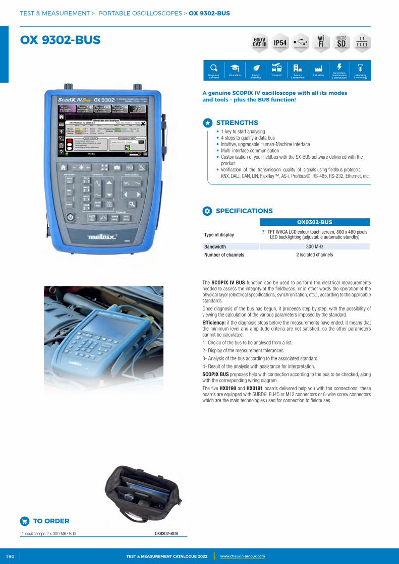
2 CATALOGUE TEST & MESURE 2021 www.chauvin-arnoux.com190 TEST & MEASUREMENT CATALOGUE 2022 www.chauvin-arnoux.com
TEST & MEASUREMENT > PORTABLE OSCILLOSCOPES > OX 9302‑BUS
OX 9302‑BUS
STRENGTHS• 1 key to start analysing• 4 steps to qualify a data bus• Intuitive, upgradable Human-Machine Interface• Multi-interface communication• Customization of your fieldbus with the SX-BUS software delivered with the
product• Verification of the transmission quality of signals using fieldbus protocols:
KNX, DALI, CAN, LIN, FlexRay™, AS-i, Profibus®, RS-485, RS-232, Ethernet, etc.
Generation, transmission & distribution
IndustriesTertiary & residential
Education TransportDiagnostic & control
Energy efficiency
Laboratory & metrology
MICRO
SD54wiFi
A genuine SCOPIX IV oscilloscope with all its modes and tools – plus the BUS function!
SPECIFICATIONSOX9302‑BUS
Type of display 7" TFT WVGA LCD colour touch screen, 800 x 480 pixels LED backlighting (adjustable automatic standby)
Bandwidth 300 MHz
Number of channels 2 isolated channels
TO ORDER
1 oscilloscope 2 x 300 MHz BUS OX9302-BUS
The SCOPIX IV BUS function can be used to perform the electrical measurements needed to assess the integrity of the fieldbuses, or in other words the operation of the physical layer (electrical specifications, synchronization, etc.), according to the applicable standards.
Once diagnosis of the bus has begun, it proceeds step by step, with the possibility of viewing the calculation of the various parameters imposed by the standard.
Efficiency: if the diagnosis stops before the measurements have ended, it means that the minimum level and amplitude criteria are not satisfied, so the other parameters cannot be calculated.
1- Choice of the bus to be analysed from a list.
2- Display of the measurement tolerances.
3- Analysis of the bus according to the associated standard.
4- Result of the analysis with assistance for interpretation.
SCOPIX BUS proposes help with connection according to the bus to be checked, along with the corresponding wiring diagram.
The five HX0190 and HX0191 boards delivered help you with the connections: these boards are equipped with SUBD9, RJ45 or M12 connectors or 8-wire screw connectors which are the main technologies used for connection to fieldbuses.
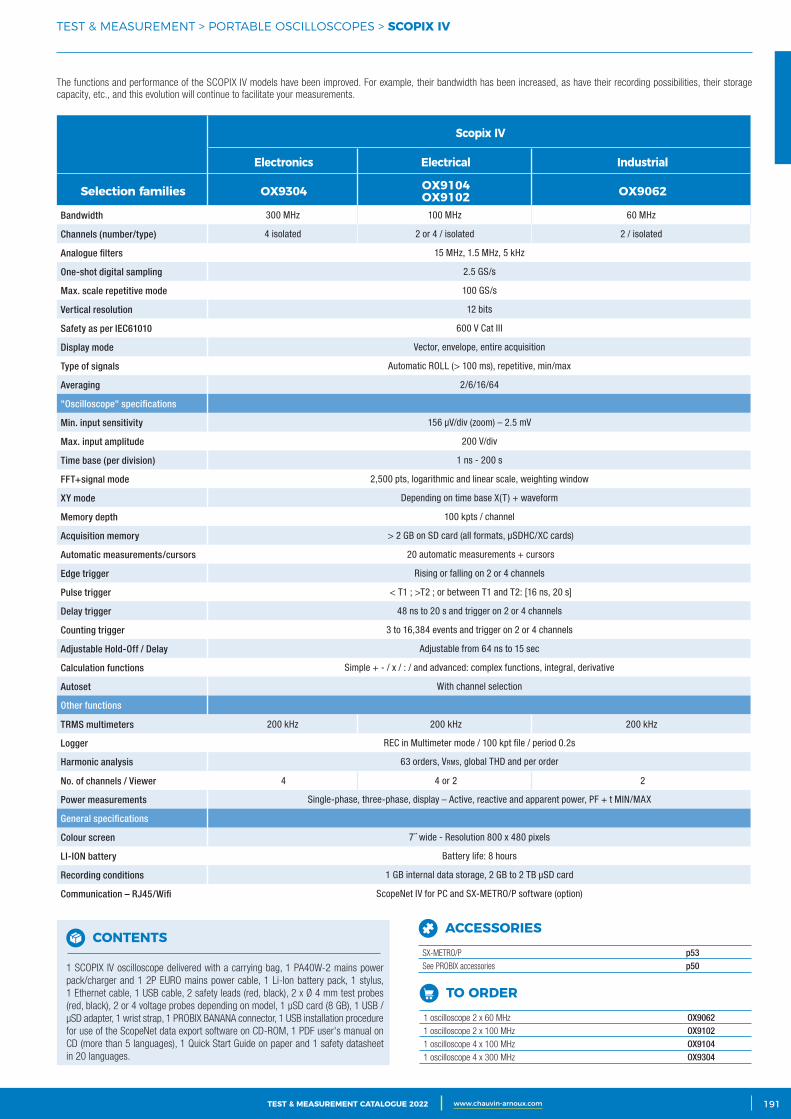
3CATALOGUE TEST & MESURE 2021 www.chauvin-arnoux.com 191TEST & MEASUREMENT CATALOGUE 2022 www.chauvin-arnoux.com
TEST & MEASUREMENT > PORTABLE OSCILLOSCOPES > SCOPIX IV
TO ORDER
1 oscilloscope 2 x 60 MHz OX90621 oscilloscope 2 x 100 MHz OX91021 oscilloscope 4 x 100 MHz OX91041 oscilloscope 4 x 300 MHz OX9304
CONTENTS
1 SCOPIX IV oscilloscope delivered with a carrying bag, 1 PA40W-2 mains power pack/charger and 1 2P EURO mains power cable, 1 Li-Ion battery pack, 1 stylus, 1 Ethernet cable, 1 USB cable, 2 safety leads (red, black), 2 x Ø 4 mm test probes (red, black), 2 or 4 voltage probes depending on model, 1 μSD card (8 GB), 1 USB / μSD adapter, 1 wrist strap, 1 PROBIX BANANA connector, 1 USB installation procedure for use of the ScopeNet data export software on CD-ROM, 1 PDF user's manual on CD (more than 5 languages), 1 Quick Start Guide on paper and 1 safety datasheet in 20 languages.
The functions and performance of the SCOPIX IV models have been improved. For example, their bandwidth has been increased, as have their recording possibilities, their storage capacity, etc., and this evolution will continue to facilitate your measurements.
Scopix IV
Electronics Electrical Industrial
Selection families OX9304 OX9104OX9102 OX9062
Bandwidth 300 MHz 100 MHz 60 MHz
Channels (number/type) 4 isolated 2 or 4 / isolated 2 / isolated
Analogue filters 15 MHz, 1.5 MHz, 5 kHz
One-shot digital sampling 2.5 GS/s
Max. scale repetitive mode 100 GS/s
Vertical resolution 12 bits
Safety as per IEC61010 600 V Cat III
Display mode Vector, envelope, entire acquisition
Type of signals Automatic ROLL (> 100 ms), repetitive, min/max
Averaging 2/6/16/64
"Oscilloscope" specifications
Min. input sensitivity 156 μV/div (zoom) – 2.5 mV
Max. input amplitude 200 V/div
Time base (per division) 1 ns - 200 s
FFT+signal mode 2,500 pts, logarithmic and linear scale, weighting window
XY mode Depending on time base X(T) + waveform
Memory depth 100 kpts / channel
Acquisition memory > 2 GB on SD card (all formats, μSDHC/XC cards)
Automatic measurements/cursors 20 automatic measurements + cursors
Edge trigger Rising or falling on 2 or 4 channels
Pulse trigger < T1 ; >T2 ; or between T1 and T2: [16 ns, 20 s]
Delay trigger 48 ns to 20 s and trigger on 2 or 4 channels
Counting trigger 3 to 16,384 events and trigger on 2 or 4 channels
Adjustable Hold-Off / Delay Adjustable from 64 ns to 15 sec
Calculation functions Simple + - / x / : / and advanced: complex functions, integral, derivative
Autoset With channel selection
Other functions
TRMS multimeters 200 kHz 200 kHz 200 kHz
Logger REC in Multimeter mode / 100 kpt file / period 0.2s
Harmonic analysis 63 orders, Vrms, global THD and per order
No. of channels / Viewer 4 4 or 2 2
Power measurements Single-phase, three-phase, display – Active, reactive and apparent power, PF + t MIN/MAX
General specifications
Colour screen 7˝ wide - Resolution 800 x 480 pixels
LI-ION battery Battery life: 8 hours
Recording conditions 1 GB internal data storage, 2 GB to 2 TB μSD card
Communication – RJ45/Wifi ScopeNet IV for PC and SX-METRO/P software (option)
ACCESSORIES
SX-METRO/P p53See PROBIX accessories p50
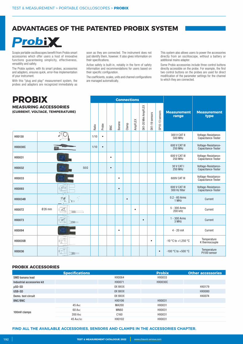
2 CATALOGUE TEST & MESURE 2021 www.chauvin-arnoux.com192 TEST & MEASUREMENT CATALOGUE 2022 www.chauvin-arnoux.com
Scopix portable oscilloscopes benefit from Probix smart accessories which offer users a host of innovative functions guaranteeing simplicity, effectiveness, versatility and safety.
The Probix system, with its smart probes, accessories and adapters, ensures quick, error-free implementation of your instrument.
With this "plug and play" measurement system, the probes and adapters are recognized immediately as
soon as they are connected. The instrument does not just identify them, however. It also gives information on their specifications.
Active safety is built-in, notably in the form of safety information and recommendations for users based on their specific configuration.
The coefficients, scales, units and channel configurations are managed automatically.
This system also allows users to power the accessories directly from an oscilloscope, without a battery or additional mains adapter.
Some Probix accessories include three control buttons directly accessible on the probe. For example, the first two control buttons on the probes are used for direct modification of the parameter settings for the channel to which they are connected.
FIND ALL THE AVAILABLE ACCESSORIES, SENSORS AND CLAMPS IN THE ACCESSORIES CHAPTER.
PROBIX ACCESSORIESSpecifications Probix Other accessories
SMD banana lead HX0064 HX0033
Industrial accessories kit HX0071 HX0030C
μSD-SD 0X 9XXX HX0179
USB-SD 0X 9XXX HX0080
Demo. test circuit 0X 9XXX HX0074
BNC/BNC HX0106 HX0031
100mV clamps
45 AAc MA200 HX0031
60 AAc MN60 HX0031
200 AAc C160 HX0031
45 AAc/dc HX0102 HX0031
Connections
Measurement range
Measurement type
HX0130 1/10 • 300 V CAT II500 MHz
Voltage-Resistance-Capacitance-Tester
HX0030C 1/10 • 600 V CAT III250 MHz
Voltage-Resistance-Capacitance-Tester
HX0031 • 600 V CAT III250 MHz
Voltage-Resistance-Capacitance-Tester
HX0032 50 Ω • 30 V CAT I250 MHz
Voltage-Resistance-Capacitance-Tester
HX0033 • 600V CAT III Voltage-Resistance-Capacitance-Tester
HX0093 • 600 V CAT III300 Hz filter
Voltage-Resistance-Capacitance-Tester
HX0034B • 0.2 - 60 Arms1 MHz Current
HX0072 • 5 - 300 Arms200 kHz Current
HX0073 • 1 - 300 Arms3 MHz Current
HX0094 • 4 - 20 mA Current
HX0035B • -10 °C to +1,250 °C TemperatureK thermocouple
HX0036 • -100 °C to +500 °C TemperaturePt100 sensor
Ø 26 mm
Prob
e
Ratio
AmpF
LEX
BNC
SK1-
20 M
ini A
mpF
LEX
Bana
na
SK1-
19 s
enso
rs
Clam
p
SP10
-13
sens
ors
PROBIX MEASURING ACCESSORIES (CURRENT, VOLTAGE, TEMPERATURE)
ADVANTAGES OF THE PATENTED PROBIX SYSTEM
TEST & MEASUREMENT > PORTABLE OSCILLOSCOPES > PROBIX
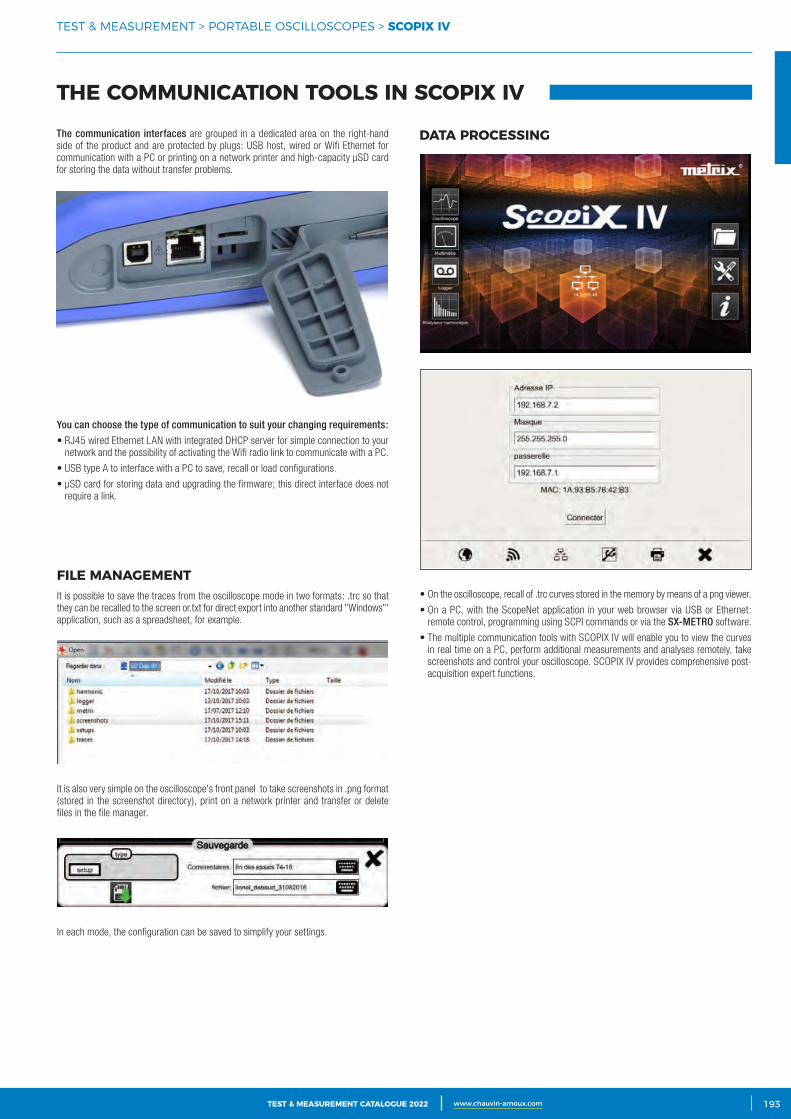
3CATALOGUE TEST & MESURE 2021 www.chauvin-arnoux.com 193TEST & MEASUREMENT CATALOGUE 2022 www.chauvin-arnoux.com
The communication interfaces are grouped in a dedicated area on the right-hand side of the product and are protected by plugs: USB host, wired or Wifi Ethernet for communication with a PC or printing on a network printer and high-capacity μSD card for storing the data without transfer problems.
FILE MANAGEMENTIt is possible to save the traces from the oscilloscope mode in two formats: .trc so that they can be recalled to the screen or.txt for direct export into another standard "Windows"' application, such as a spreadsheet, for example.
It is also very simple on the oscilloscope's front panel to take screenshots in .png format (stored in the screenshot directory), print on a network printer and transfer or delete files in the file manager.
In each mode, the configuration can be saved to simplify your settings.
DATA PROCESSING
• On the oscilloscope, recall of .trc curves stored in the memory by means of a png viewer.
• On a PC, with the ScopeNet application in your web browser via USB or Ethernet: remote control, programming using SCPI commands or via the SX-METRO software.
• The multiple communication tools with SCOPIX IV will enable you to view the curves in real time on a PC, perform additional measurements and analyses remotely, take screenshots and control your oscilloscope. SCOPIX IV provides comprehensive post-acquisition expert functions.
THE COMMUNICATION TOOLS IN SCOPIX IV
You can choose the type of communication to suit your changing requirements:
• RJ45 wired Ethernet LAN with integrated DHCP server for simple connection to your network and the possibility of activating the Wifi radio link to communicate with a PC.
• USB type A to interface with a PC to save, recall or load configurations.
• μSD card for storing data and upgrading the firmware; this direct interface does not require a link.
TEST & MEASUREMENT > PORTABLE OSCILLOSCOPES > SCOPIX IV

2 CATALOGUE TEST & MESURE 2021 www.chauvin-arnoux.com194 TEST & MEASUREMENT CATALOGUE 2022 www.chauvin-arnoux.com
PracticalNo need to install Scopenet on the PC. The application opens directly with most web browsers.
File manager
Multimeter
Logger
Oscilloscope
Harmonics
APPLICATION FOR SCOPIX IV
TEST & MEASUREMENT > SOFTWARE FOR OSCILLOSCOPES > SCOPENET
ScopeNet IV• ScopeNet IV is a PC application which uses Ethernet communication (wired RJ45
and Wifi)
The ScopeNet IV PC application for SCOPIX IV can be used to:
• control and configure the oscilloscope remotely
• display the acquisitions as curves in all the modes
• recall or save instrument configurations,
• make and recall screenshots in .png file format.
It can also be used to :
• recover files from the SCOPIX IV remotely,
• take screenshots which are then placed in the clipboard.
There is no function for exporting the data into Excel because a.txt text editor is available on the instrument; it converts .rec and .trc files into .txt files so that the points can be used in a spreadsheet such as Excel:
The memory card appears in the tree-structure as "sdcard-p1"
Android applicationScopeNet for Scopix III(available from Google Store)
ScopeNet for remote dialogue and configuration using a tablet or smartphone.
This can be used to view the curves in real time, perform measurements and analyses, capture screens and control METRIX oscilloscopes METRIX with your tablet or smartphone.
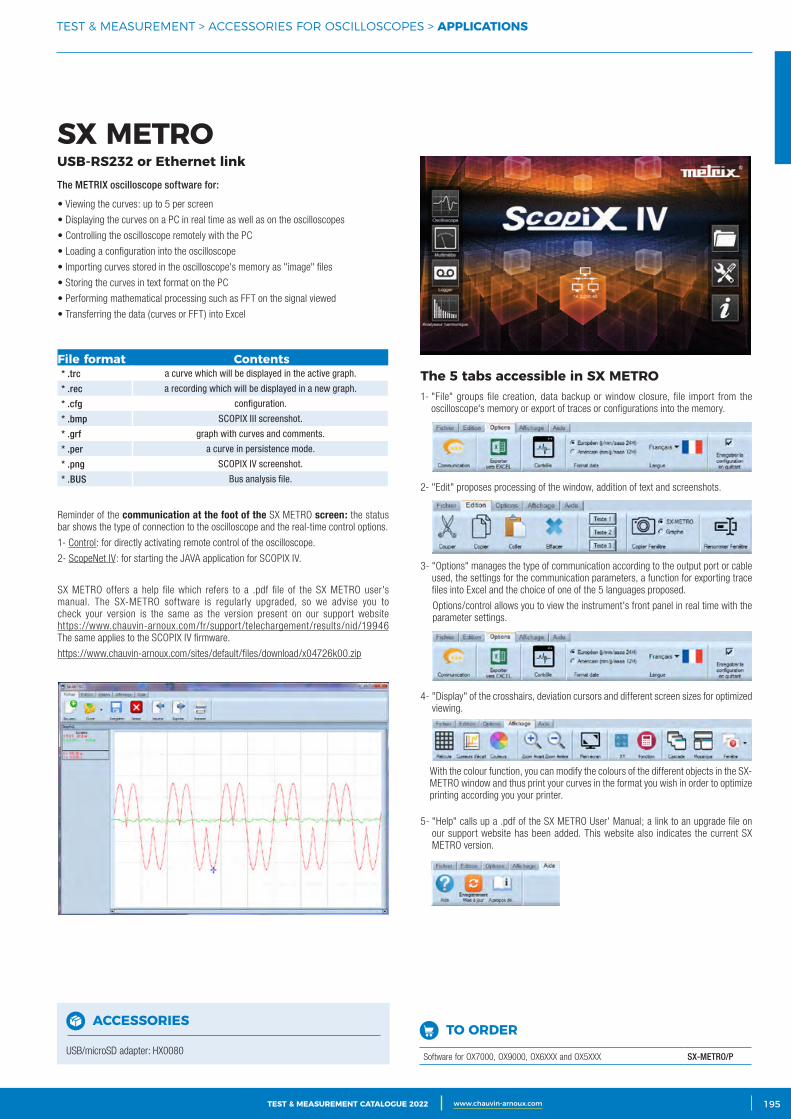
3CATALOGUE TEST & MESURE 2021 www.chauvin-arnoux.com 195TEST & MEASUREMENT CATALOGUE 2022 www.chauvin-arnoux.com
TEST & MEASUREMENT > ACCESSORIES FOR OSCILLOSCOPES > APPLICATIONS
SX METROUSB‑RS232 or Ethernet link
The 5 tabs accessible in SX METRO1- "File" groups file creation, data backup or window closure, file import from the
oscilloscope's memory or export of traces or configurations into the memory.
2- "Edit" proposes processing of the window, addition of text and screenshots.
3- "Options" manages the type of communication according to the output port or cable used, the settings for the communication parameters, a function for exporting trace files into Excel and the choice of one of the 5 languages proposed.
Options/control allows you to view the instrument's front panel in real time with the parameter settings.
4- "Display" of the crosshairs, deviation cursors and different screen sizes for optimized viewing.
With the colour function, you can modify the colours of the different objects in the SX-METRO window and thus print your curves in the format you wish in order to optimize printing according you your printer.
5- "Help" calls up a .pdf of the SX METRO User' Manual; a link to an upgrade file on our support website has been added. This website also indicates the current SX METRO version.
• Viewing the curves: up to 5 per screen
• Displaying the curves on a PC in real time as well as on the oscilloscopes
• Controlling the oscilloscope remotely with the PC
• Loading a configuration into the oscilloscope
• Importing curves stored in the oscilloscope's memory as "image" files
• Storing the curves in text format on the PC
• Performing mathematical processing such as FFT on the signal viewed
• Transferring the data (curves or FFT) into Excel
Reminder of the communication at the foot of the SX METRO screen: the status bar shows the type of connection to the oscilloscope and the real-time control options.
1- Control: for directly activating remote control of the oscilloscope.
2- ScopeNet IV: for starting the JAVA application for SCOPIX IV.
SX METRO offers a help file which refers to a .pdf file of the SX METRO user's manual. The SX-METRO software is regularly upgraded, so we advise you to check your version is the same as the version present on our support website https://www.chauvin-arnoux.com/fr/support/telechargement/results/nid/19946 The same applies to the SCOPIX IV firmware.
https://www.chauvin-arnoux.com/sites/default/files/download/x04726k00.zip
The METRIX oscilloscope software for:
File format Contents* .trc a curve which will be displayed in the active graph.
* .rec a recording which will be displayed in a new graph.
* .cfg configuration.
* .bmp SCOPIX III screenshot.
* .grf graph with curves and comments.
* .per a curve in persistence mode.
* .png SCOPIX IV screenshot.
* .BUS Bus analysis file.
TO ORDER
Software for OX7000, OX9000, OX6XXX and OX5XXX SX-METRO/P
ACCESSORIES
USB/microSD adapter: HX0080
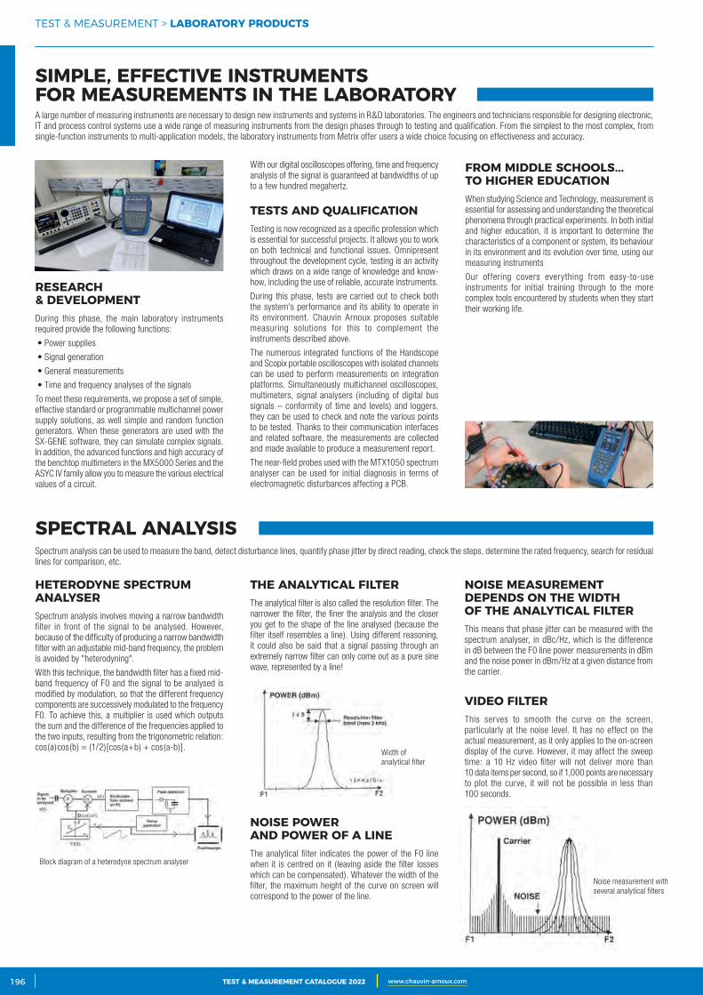
2 CATALOGUE TEST & MESURE 2021 www.chauvin-arnoux.com196 TEST & MEASUREMENT CATALOGUE 2022 www.chauvin-arnoux.com196
TEST & MEASUREMENT > LABORATORY PRODUCTS
SIMPLE, EFFECTIVE INSTRUMENTS FOR MEASUREMENTS IN THE LABORATORY
SPECTRAL ANALYSIS
A large number of measuring instruments are necessary to design new instruments and systems in R&D laboratories. The engineers and technicians responsible for designing electronic, IT and process control systems use a wide range of measuring instruments from the design phases through to testing and qualification. From the simplest to the most complex, from single-function instruments to multi-application models, the laboratory instruments from Metrix offer users a wide choice focusing on effectiveness and accuracy.
Spectrum analysis can be used to measure the band, detect disturbance lines, quantify phase jitter by direct reading, check the steps, determine the rated frequency, search for residual lines for comparison, etc.
RESEARCH & DEVELOPMENTDuring this phase, the main laboratory instruments required provide the following functions:
• Power supplies
• Signal generation
• General measurements
• Time and frequency analyses of the signals
To meet these requirements, we propose a set of simple, effective standard or programmable multichannel power supply solutions, as well simple and random function generators. When these generators are used with the SX-GENE software, they can simulate complex signals. In addition, the advanced functions and high accuracy of the benchtop multimeters in the MX5000 Series and the ASYC IV family allow you to measure the various electrical values of a circuit.
HETERODYNE SPECTRUM ANALYSERSpectrum analysis involves moving a narrow bandwidth filter in front of the signal to be analysed. However, because of the difficulty of producing a narrow bandwidth filter with an adjustable mid-band frequency, the problem is avoided by "heterodyning".
With this technique, the bandwidth filter has a fixed mid-band frequency of F0 and the signal to be analysed is modified by modulation, so that the different frequency components are successively modulated to the frequency F0. To achieve this, a multiplier is used which outputs the sum and the difference of the frequencies applied to the two inputs, resulting from the trigonometric relation: cos(a)cos(b) = (1/2)[cos(a+b) + cos(a-b)].
THE ANALYTICAL FILTERThe analytical filter is also called the resolution filter. The narrower the filter, the finer the analysis and the closer you get to the shape of the line analysed (because the filter itself resembles a line). Using different reasoning, it could also be said that a signal passing through an extremely narrow filter can only come out as a pure sine wave, represented by a line!
NOISE POWER AND POWER OF A LINEThe analytical filter indicates the power of the F0 line when it is centred on it (leaving aside the filter losses which can be compensated). Whatever the width of the filter, the maximum height of the curve on screen will correspond to the power of the line.
NOISE MEASUREMENT DEPENDS ON THE WIDTH OF THE ANALYTICAL FILTERThis means that phase jitter can be measured with the spectrum analyser, in dBc/Hz, which is the difference in dB between the F0 line power measurements in dBm and the noise power in dBm/Hz at a given distance from the carrier.
VIDEO FILTERThis serves to smooth the curve on the screen, particularly at the noise level. It has no effect on the actual measurement, as it only applies to the on-screen display of the curve. However, it may affect the sweep time: a 10 Hz video filter will not deliver more than 10 data items per second, so if 1,000 points are necessary to plot the curve, it will not be possible in less than 100 seconds.
With our digital oscilloscopes offering, time and frequency analysis of the signal is guaranteed at bandwidths of up to a few hundred megahertz.
TESTS AND QUALIFICATION Testing is now recognized as a specific profession which is essential for successful projects. It allows you to work on both technical and functional issues. Omnipresent throughout the development cycle, testing is an activity which draws on a wide range of knowledge and know-how, including the use of reliable, accurate instruments.
During this phase, tests are carried out to check both the system's performance and its ability to operate in its environment. Chauvin Arnoux proposes suitable measuring solutions for this to complement the instruments described above.
The numerous integrated functions of the Handscope and Scopix portable oscilloscopes with isolated channels can be used to perform measurements on integration platforms. Simultaneously multichannel oscilloscopes, multimeters, signal analysers (including of digital bus signals – conformity of time and levels) and loggers, they can be used to check and note the various points to be tested. Thanks to their communication interfaces and related software, the measurements are collected and made available to produce a measurement report.
The near-field probes used with the MTX1050 spectrum analyser can be used for initial diagnosis in terms of electromagnetic disturbances affecting a PCB.
FROM MIDDLE SCHOOLS... TO HIGHER EDUCATIONWhen studying Science and Technology, measurement is essential for assessing and understanding the theoretical phenomena through practical experiments. In both initial and higher education, it is important to determine the characteristics of a component or system, its behaviour in its environment and its evolution over time, using our measuring instruments
Our offering covers everything from easy-to-use instruments for initial training through to the more complex tools encountered by students when they start their working life.
Noise measurement with several analytical filters
Block diagram of a heterodyne spectrum analyser
Width of analytical filter
TEST & MEASUREMENT CATALOGUE 2022 www.chauvin-arnoux.com
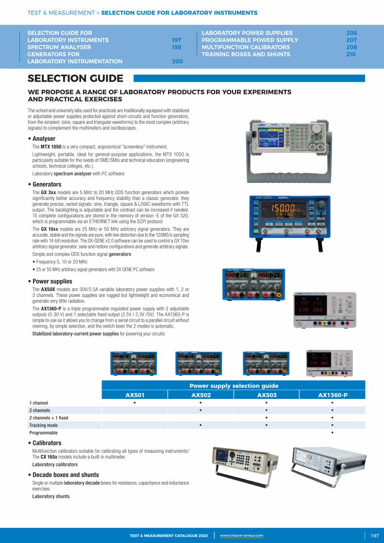
3CATALOGUE TEST & MESURE 2021 www.chauvin-arnoux.com 197TEST & MEASUREMENT CATALOGUE 2022 www.chauvin-arnoux.com 197
WE PROPOSE A RANGE OF LABORATORY PRODUCTS FOR YOUR EXPERIMENTS AND PRACTICAL EXERCISES
• GeneratorsThe GX 3xx models are 5 MHz to 20 MHz DDS function generators which provide significantly better accuracy and frequency stability than a classic generator. they generate precise, varied signals: sine, triangle, square & LOGIC waveforms with TTL output. The backlighting is adjustable and the contrast can be increased if needed. 15 complete configurations are stored in the memory of version -E of the GX 320, which is programmable via an ETHERNET link using the SCPI protocol.
The GX 10xx models are 25 MHz or 50 MHz arbitrary signal generators. They are accurate, stable and the signals are pure, with low distortion due to the 125MS/s sampling rate with 14-bit resolution. The SX-GENE v2.0 software can be used to control a GX 10xx arbitrary signal generator, save and restore configurations and generate arbitrary signals.
Simple and complex DDS function signal generators
• Frequency 5, 10 or 20 MHz
• 25 or 50 MHz arbitrary signal generators with SX GENE PC software
The school and university labs used for practicals are traditionally equipped with stabilized or adjustable power supplies protected against short-circuits and function generators, from the simplest (sine, square and triangular waveforms) to the most complex (arbitrary signals) to complement the multimeters and oscilloscopes.
• AnalyserThe MTX 1050 is a very compact, ergonomical "screenless" instrument.
Lightweight, portable, ideal for general-purpose applications, the MTX 1050 is particularly suitable for the needs of SME/SMIs and technical education (engineering schools, technical colleges, etc.).
Laboratory spectrum analyser with PC software
• Power supplies The AX50X models are 30V/2.5A variable laboratory power supplies with 1, 2 or
3 channels. These power supplies are rugged but lightweight and economical and generate very little radiation.
The AX1360-P is a triple programmable regulated power supply with 2 adjustable outputs (0-30 V) and 1 selectable fixed output (2.5V / 3.3V /5V). The AX1360-P is simple to use as it allows you to change from a serial circuit to a parallel circuit without rewiring, by simple selection, and the switch been the 2 modes is automatic.
Stabilized laboratory-current power supplies for powering your circuits
• Calibrators Multifunction calibrators suitable for calibrating all types of measuring instruments/
The CX 165x models include a built-in multimeter.
Laboratory calibrators
• Decade boxes and shunts Single or multiple laboratory decade boxes for resistance, capacitance and inductance
exercises
Laboratory shunts
SELECTION GUIDE
TEST & MEASUREMENT > SELECTION GUIDE FOR LABORATORY INSTRUMENTS
Power supply selection guideAX501 AX502 AX503 AX1360‑P
1 channel • • • •
2 channels • • •
2 channels + 1 fixed • •
Tracking mode • • •
Programmable •
SELECTION GUIDE FOR LABORATORY INSTRUMENTS 197SPECTRUM ANALYSER 198GENERATORS FOR LABORATORY INSTRUMENTATION 200
LABORATORY POWER SUPPLIES 206PROGRAMMABLE POWER SUPPLY 207MULTIFUNCTION CALIBRATORS 208TRAINING BOXES AND SHUNTS 210
TEST & MEASUREMENT CATALOGUE 2022 www.chauvin-arnoux.com
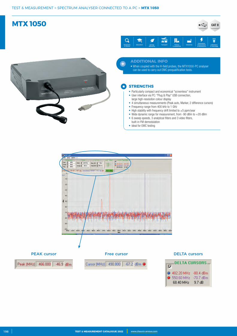
2 CATALOGUE TEST & MESURE 2021 www.chauvin-arnoux.com198 TEST & MEASUREMENT CATALOGUE 2022 www.chauvin-arnoux.com
PEAK cursor Free cursor DELTA cursors
TEST & MEASUREMENT > SPECTRUM ANALYSER CONNECTED TO A PC > MTX 1050
MTX 1050
Generation, transmission & distribution
IndustriesTertiary & residential
Education TransportDiagnostic & control
Energy efficiency
Laboratory & metrology
CAT II
STRENGTHS• Particularly compact and economical "screenless" instrument• User interface via PC: "Plug & Play" USB connection,
large high-resolution colour display• 4 simultaneous measurements (Peak auto, Marker, 2 difference cursors)• Frequency range from 400 kHz to 1 GHz• High stability with frequency drift limited to ±5 ppm/year• Wide dynamic range for measurement, from -90 dBm to +20 dBm• 6 sweep speeds, 3 analytical filters and 3 video filters,
built-in FM demodulation• Ideal for EMC testing
ADDITIONAL INFO• When coupled with the H-field probes, the MTX1050-PC analyser
can be used to carry out EMC prequalification tests.
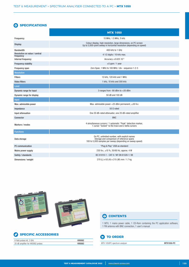
3CATALOGUE TEST & MESURE 2021 www.chauvin-arnoux.com 199TEST & MEASUREMENT CATALOGUE 2022 www.chauvin-arnoux.com
TEST & MEASUREMENT > SPECTRUM ANALYSER CONNECTED TO A PC > MTX 1050
MTX 1050
Frequency 15 MHz, 1.5 MHz, 5 kHz
Display Colour display, high resolution, large dimensions, on PC screenUp to 5,000-point sweep in horizontal resolution (depending on speed)
Bandwidth 400 kHz to 1 GHzResolution on value / central frequency 4 1/2 digits / 10 kHz max.
Internal frequency Accuracy ±0.625 10-6
Frequency stability ±5 ppm / 1 year
Frequency span Zero Span, 1 MHz to 100 MHz / div - sequence 1-2-5
Resolution
Filters 12 kHz, 120 kHz and 1 MHz
Video filters 1 kHz, 10 kHz and 300 kHz
Level
Dynamic range for input 3 ranges from -90 dBm to +20 dBm
Dynamic range for display 50 dB and 100 dB
Input
Max. admissible power Max. admissible power +25 dBm permanent, ±30 Vdc
Impedance 50 Ω rated
Input attenuation One 20 dB-rated attenuator, one 20 dB-rated amplifier
Connector BNC
Markers / modes 4 simultaneous cursors / 1 automatic "Peak" detection marker, 1 cursor "locked" to the trace and 2 delta cursors
Functions
Data storageOn PC, unlimited number, with explicit namesStorage and comparison of reference spans
100 to 5,000 samples per sweep (depending on sweep speed)
PC communication "Plug & Play" USB as standard
Mains power supply 230 VAc, ±10 %, 50/60 Hz, approx. 4 W
Safety / standards IEC 61010-1 - CAT II / NF EN 61326-1: 98
Dimensions / weight 270 (L) x 63 (H) x 215 (W) mm / 1.7 kg
TO ORDER
MTX 1050PC spectrum analyser MTX1050-PC
CONTENTS
1 MTX, 1 mains power cable, 1 CD-Rom containing the PC application software, 1 FM antenna with BNC connection, 1 user's manual
SPECIFIC ACCESSORIES
H field probes kit, 3 GHz HX008220 dB amplifier for HX0082 probes HX0083
SPECIFICATIONS
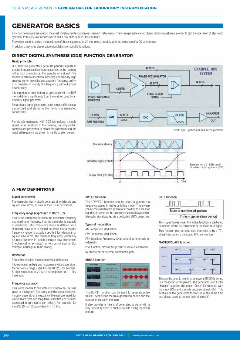
2 CATALOGUE TEST & MESURE 2021 www.chauvin-arnoux.com200 TEST & MEASUREMENT CATALOGUE 2022 www.chauvin-arnoux.com
TEST & MEASUREMENT > GENERATORS FOR LABORATORY INSTRUMENTATION
GENERATOR BASICSFunction generators are among the most widely-used test and measurement instruments. They can generate varied characteristic waveforms in order to test the operation of electronic systems, from very low frequencies of just a few mHz up to 20 MHz or more.
They allow users to adjust the amplitude of these signals up to 20 V or more, possibly with the presence of a DC component.
In addition, they may also provide modulations or specific functions.
DIRECT DIGITAL SYNTHESIS (DDS) FUNCTION GENERATORBasic principle:DDS function generators generate periodic signals at precise frequencies by choosing samples in the memory rather than producing all the samples of a signal. This technique offers exceptional accuracy and stability, high spectral purity, low noise and excellent frequency agility. It is possible to modify the frequency without phase discontinuity.
It is important to note that signal generation with the DDS method differs significantly from the method used by an arbitrary signal generator.
For arbitrary signal generation, each sample of the signal period built and stored in the memory is generated sequentially.
For signals generated with DDS technology, a single signal period is stored in the memory, but only certain samples are generated to create the waveform and the required frequency, as shown in the illustration below:
A FEW DEFINITIONS
Signal waveforms
The generator can typically generate sine, triangle and square waveforms, as well as their usual derivatives.
Frequency range (expressed in Hertz (Hz)
This is the difference between the minimum frequency and maximum frequency that the generator is capable of producing. This frequency range is defined for a sinusoidal waveform. It should be noted that a smaller frequency range is usually specified for triangular or square waveforms. The minimum frequency, which may be just a few mHz, is used to simulate slow phenomena (mechanical or physical) or to control slaving (for example, a triangular ramp profile).
Resolution
This is the smallest measurable value difference.
It is expressed in digits and its absolute value depends on the frequency range used. For the GX320, for example: 5-digit resolution at 20 MHz corresponds to a 1 kHz increment.
Frequency accuracy
This corresponds to the difference between the true value of the signal's frequency and the value displayed. It mainly depends on the quality of the oscillator used, for which short-term and long-term stabilities are defined, expressed in ppm (parts per million). For example, for the GX320: +/- 20ppm when F > 10 kHz.
SWEEP function
The "SWEEP" function can be used to generate a frequency sweep in rising or falling mode. This sweep can be controlled by the generator according to a linear or logarithmic law or on the basis of an external sawtooth or triangular signal applied via a dedicated BNC connection.
Types of modulation
AM: Amplitude Modulation
FM: Frequency Modulation
FSK function: Frequency SKip controlled internally or externally.
PSK function: "Phase SKip" whose value is controlled
by an internal or external command signal.
BURST function
The BURST function can be used to generate pulse trains: users define the train generation period and the number of pulses in the train.
It also provides a means of generating a signal with a very large duty cycle (1 brief pulse with a long repetition period).
GATE function
This superimposes over the active function a start/stop command for the AC component of the MAIN OUT signal.
This function can be controlled internally or by a TTL signal injected on a dedicated BNC connection.
MASTER/SLAVE function
This can be used to synchronize several GX 320s set up in a "cascade" arrangement. The generator used as the "Master" supplies the other "Slave" instruments with the clock (Clk) and a synchronization signal (Ctrl). This enables all the generators to start up at the same time and allows users to control their phase shift.
Direct Digital Synthesis (DDS) function generator
Generation of a 21 MHz signal with direct digital synthesis (DDS)
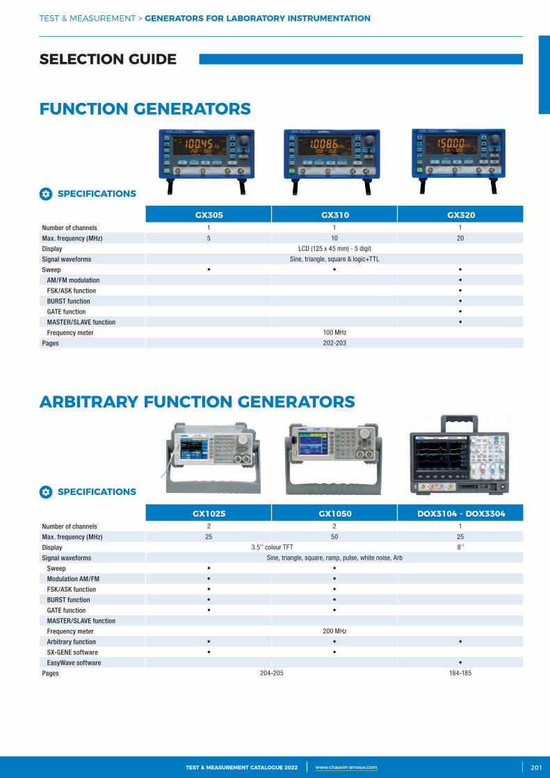
3CATALOGUE TEST & MESURE 2021 www.chauvin-arnoux.com 201TEST & MEASUREMENT CATALOGUE 2022 www.chauvin-arnoux.com
SELECTION GUIDE
TEST & MEASUREMENT > GENERATORS FOR LABORATORY INSTRUMENTATION
SPECIFICATIONS GX305 GX310 GX320Number of channels 1 1 1
Max. frequency (MHz) 5 10 20
Display LCD (125 x 45 mm) - 5 digit
Signal waveforms Sine, triangle, square & logic+TTL
Sweep • • •
AM/FM modulation •
FSK/ASK function •
BURST function •
GATE function •
MASTER/SLAVE function •
Frequency meter 100 MHz
Pages 202-203
SPECIFICATIONS GX1025 GX1050 DOX3104 ‑ DOX3304Number of channels 2 2 1
Max. frequency (MHz) 25 50 25
Display 3.5’’ colour TFT 8’’
Signal waveforms Sine, triangle, square, ramp, pulse, white noise, Arb
Sweep • •
Modulation AM/FM • •
FSK/ASK function • •
BURST function • •
GATE function • •
MASTER/SLAVE function
Frequency meter 200 MHz
Arbitrary function • • •
SX-GENE software • •
EasyWave software •
Pages 204-205 184-185
FUNCTION GENERATORS
ARBITRARY FUNCTION GENERATORS
SPECIFICATIONS
SPECIFICATIONS
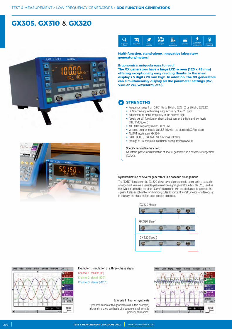
2 CATALOGUE TEST & MESURE 2021 www.chauvin-arnoux.com202 TEST & MEASUREMENT CATALOGUE 2022 www.chauvin-arnoux.com
Synchronization of several generators in a cascade arrangement
The "SYNC" function on the GX 320 allows several generators to be set up in a cascade arrangement to make a variable-phase multiple-signal generator. A first GX 320, used as the "Master", provides the other "Slave" instruments with the clock used to generate the signals. It also supplies the synchronizing pulse to start all the instruments simultaneously. In this way, the phase shift of each signal is controlled.
Example 1: simulation of a three-phase signal
Channel 1: master (0°)
Channel 2: slave1 (120°)
Channel 3: slave2 (-120°)
Example 2: Fourier synthesis
Synchronization of the generators (3 in this example) allows simulated synthesis of a square signal from its
primary harmonics.
GX 320 Master
GX 320 Slave 1
GX 320 Slave 2
GX305, GX310 & GX320
TEST & MEASUREMENT > LOW FREQUENCY GENERATORS > DDS FUNCTION GENERATORS
Multi‑function, stand‑alone, innovative laboratory generators/meters!
Ergonomics: uniquely easy to read!The GX generators have a large LCD screen (125 x 45 mm) offering exceptionally easy reading thanks to the main display's 5 digits 20 mm high. In addition, the GX generators can simultaneously display all the parameter settings (Vdc, Vrms or Vpp, waveform, etc.).
STRENGTHS• Frequency range from 0.001 Hz to 10 MHz (GX310) or 20 MHz (GX320)• DDS technology with a frequency accuracy of +/-20 ppm • Adjustment of stable frequency to the nearest digit• "Logic signal" function for direct adjustment of the high and low levels
(TTL, CMOS, etc.)• 100 MHz frequency meter, 300V CAT I• Versions programmable via USB link with the standard SCPI protocol• AM/FM modulation (GX320)• GATE, BURST, FSK and PSK functions (GX320)• Storage of 15 complete instrument configurations (GX320)
Specific innovative function:Adjustable-phase synchronisation of several generators in a cascade arrangement (GX320).
Generation, transmission & distribution
IndustriesTertiary & residential
Education TransportDiagnostic & control
Energy efficiency
Laboratory & metrology
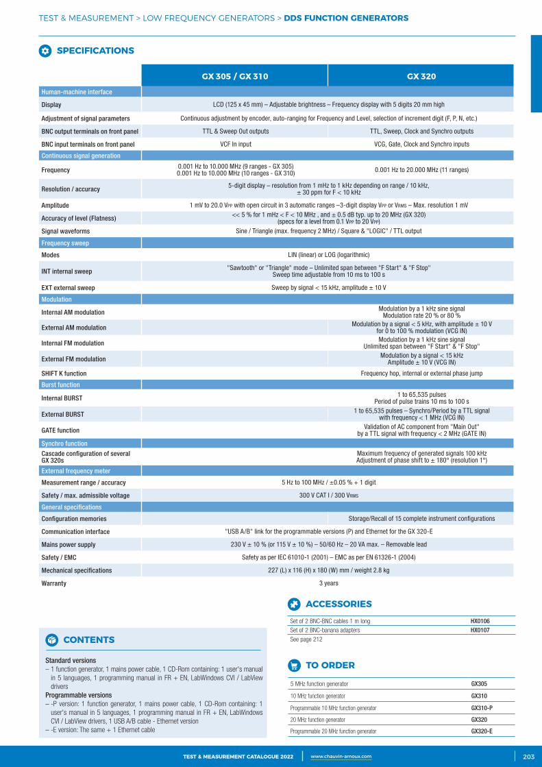
3CATALOGUE TEST & MESURE 2021 www.chauvin-arnoux.com 203TEST & MEASUREMENT CATALOGUE 2022 www.chauvin-arnoux.com
TEST & MEASUREMENT > LOW FREQUENCY GENERATORS > DDS FUNCTION GENERATORS
SPECIFICATIONS GX 305 / GX 310 GX 320
Human-machine interface
Display LCD (125 x 45 mm) – Adjustable brightness – Frequency display with 5 digits 20 mm high
Adjustment of signal parameters Continuous adjustment by encoder, auto-ranging for Frequency and Level, selection of increment digit (F, P, N, etc.)
BNC output terminals on front panel TTL & Sweep Out outputs TTL, Sweep, Clock and Synchro outputs
BNC input terminals on front panel VCF In input VCG, Gate, Clock and Synchro inputs
Continuous signal generation
Frequency 0.001 Hz to 10.000 MHz (9 ranges - GX 305) 0.001 Hz to 10.000 MHz (10 ranges - GX 310) 0.001 Hz to 20.000 MHz (11 ranges)
Resolution / accuracy 5-digit display – resolution from 1 mHz to 1 kHz depending on range / 10 kHz, ± 30 ppm for F < 10 kHz
Amplitude 1 mV to 20.0 Vpp with open circuit in 3 automatic ranges –3-digit display Vpp or Vrms – Max. resolution 1 mV
Accuracy of level (Flatness) << 5 % for 1 mHz < F < 10 MHz , and ± 0.5 dB typ. up to 20 MHz (GX 320) (specs for a level from 0.1 Vpp to 20 Vpp)
Signal waveforms Sine / Triangle (max. frequency 2 MHz) / Square & "LOGIC" / TTL output
Frequency sweep
Modes LIN (linear) or LOG (logarithmic)
INT internal sweep "Sawtooth" or "Triangle" mode – Unlimited span between "F Start" & "F Stop"Sweep time adjustable from 10 ms to 100 s
EXT external sweep Sweep by signal < 15 kHz, amplitude ± 10 V
Modulation
Internal AM modulation Modulation by a 1 kHz sine signalModulation rate 20 % or 80 %
External AM modulation Modulation by a signal < 5 kHz, with amplitude ± 10 Vfor 0 to 100 % modulation (VCG IN)
Internal FM modulation Modulation by a 1 kHz sine signalUnlimited span between "F Start" & "F Stop"
External FM modulation Modulation by a signal < 15 kHzAmplitude ± 10 V (VCG IN)
SHIFT K function Frequency hop, internal or external phase jump
Burst function
Internal BURST 1 to 65,535 pulsesPeriod of pulse trains 10 ms to 100 s
External BURST 1 to 65,535 pulses – Synchro/Period by a TTL signal with frequency < 1 MHz (VCG IN)
GATE function Validation of AC component from "Main Out"by a TTL signal with frequency < 2 MHz (GATE IN)
Synchro function
Cascade configuration of several GX 320s
Maximum frequency of generated signals 100 kHzAdjustment of phase shift to ± 180° (resolution 1°)
External frequency meter
Measurement range / accuracy 5 Hz to 100 MHz / ±0.05 % + 1 digit
Safety / max. admissible voltage 300 V CAT I / 300 Vrms
General specifications
Configuration memories Storage/Recall of 15 complete instrument configurations
Communication interface "USB A/B" link for the programmable versions (P) and Ethernet for the GX 320-E
Mains power supply 230 V ± 10 % (or 115 V ± 10 %) – 50/60 Hz – 20 VA max. – Removable lead
Safety / EMC Safety as per IEC 61010-1 (2001) – EMC as per EN 61326-1 (2004)
Mechanical specifications 227 (L) x 116 (H) x 180 (W) mm / weight 2.8 kg
Warranty 3 years
CONTENTS
Standard versions– 1 function generator, 1 mains power cable, 1 CD-Rom containing: 1 user's manual
in 5 languages, 1 programming manual in FR + EN, LabWindows CVI / LabView drivers
Programmable versions– -P version: 1 function generator, 1 mains power cable, 1 CD-Rom containing: 1
user's manual in 5 languages, 1 programming manual in FR + EN, LabWindows CVI / LabView drivers, 1 USB A/B cable - Ethernet version
– -E version: The same + 1 Ethernet cable
TO ORDER
5 MHz function generator GX305
10 MHz function generator GX310
Programmable 10 MHz function generator GX310-P
20 MHz function generator GX320
Programmable 20 MHz function generator GX320-E
ACCESSORIES
Set of 2 BNC-BNC cables 1 m long HX0106Set of 2 BNC-banana adapters HX0107See page 212
SPECIFICATIONS
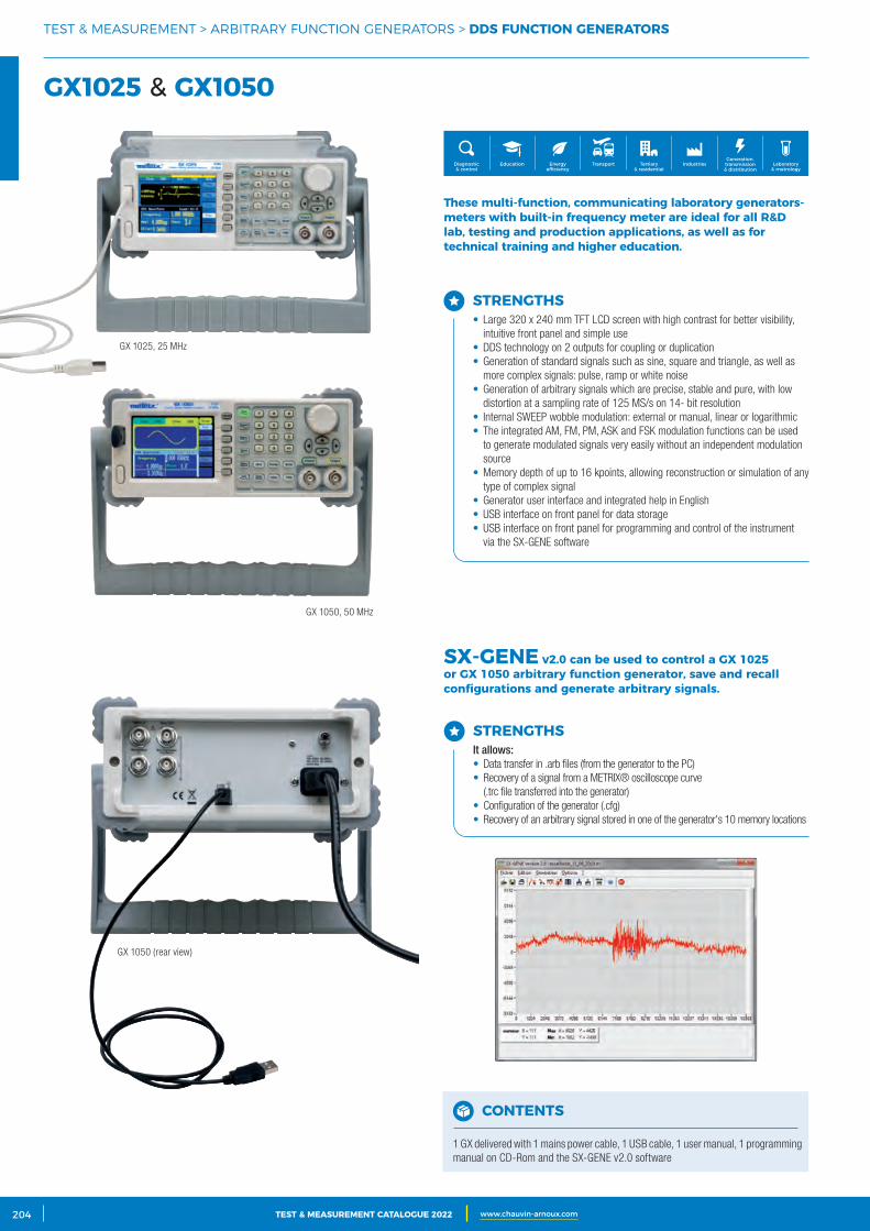
2 CATALOGUE TEST & MESURE 2021 www.chauvin-arnoux.com204 TEST & MEASUREMENT CATALOGUE 2022 www.chauvin-arnoux.com
GX1025 & GX1050
TEST & MEASUREMENT > ARBITRARY FUNCTION GENERATORS > DDS FUNCTION GENERATORS
These multi‑function, communicating laboratory generators‑meters with built‑in frequency meter are ideal for all R&D lab, testing and production applications, as well as for technical training and higher education.
SX‑GENE v2.0 can be used to control a GX 1025 or GX 1050 arbitrary function generator, save and recall configurations and generate arbitrary signals.
STRENGTHS• Large 320 x 240 mm TFT LCD screen with high contrast for better visibility,
intuitive front panel and simple use• DDS technology on 2 outputs for coupling or duplication• Generation of standard signals such as sine, square and triangle, as well as
more complex signals: pulse, ramp or white noise• Generation of arbitrary signals which are precise, stable and pure, with low
distortion at a sampling rate of 125 MS/s on 14- bit resolution• Internal SWEEP wobble modulation: external or manual, linear or logarithmic• The integrated AM, FM, PM, ASK and FSK modulation functions can be used
to generate modulated signals very easily without an independent modulation source
• Memory depth of up to 16 kpoints, allowing reconstruction or simulation of any type of complex signal
• Generator user interface and integrated help in English• USB interface on front panel for data storage• USB interface on front panel for programming and control of the instrument
via the SX-GENE software
STRENGTHSIt allows:• Data transfer in .arb files (from the generator to the PC)• Recovery of a signal from a METRIX® oscilloscope curve
(.trc file transferred into the generator)• Configuration of the generator (.cfg)• Recovery of an arbitrary signal stored in one of the generator's 10 memory locations
GX 1050 (rear view)
CONTENTS
1 GX delivered with 1 mains power cable, 1 USB cable, 1 user manual, 1 programming manual on CD-Rom and the SX-GENE v2.0 software
Generation, transmission & distribution
IndustriesTertiary & residential
Education TransportDiagnostic & control
Energy efficiency
Laboratory & metrology
GX 1025, 25 MHz
GX 1050, 50 MHz
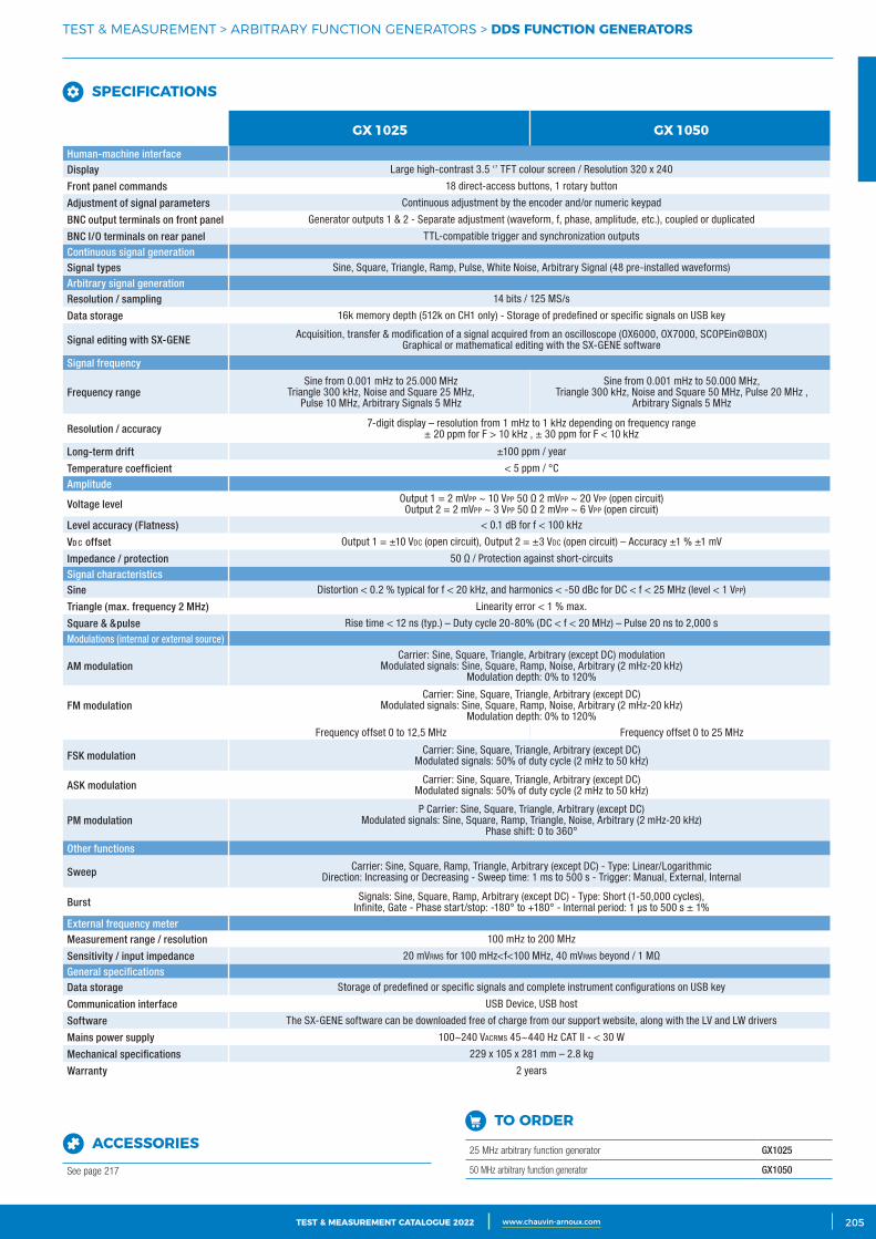
3CATALOGUE TEST & MESURE 2021 www.chauvin-arnoux.com 205TEST & MEASUREMENT CATALOGUE 2022 www.chauvin-arnoux.com
TEST & MEASUREMENT > ARBITRARY FUNCTION GENERATORS > DDS FUNCTION GENERATORS
SPECIFICATIONS GX 1025 GX 1050Human-machine interfaceDisplay Large high-contrast 3.5 ‘’ TFT colour screen / Resolution 320 x 240
Front panel commands 18 direct-access buttons, 1 rotary button
Adjustment of signal parameters Continuous adjustment by the encoder and/or numeric keypad
BNC output terminals on front panel Generator outputs 1 & 2 - Separate adjustment (waveform, f, phase, amplitude, etc.), coupled or duplicated
BNC I/O terminals on rear panel TTL-compatible trigger and synchronization outputs
Continuous signal generationSignal types Sine, Square, Triangle, Ramp, Pulse, White Noise, Arbitrary Signal (48 pre-installed waveforms)
Arbitrary signal generationResolution / sampling 14 bits / 125 MS/s
Data storage 16k memory depth (512k on CH1 only) - Storage of predefined or specific signals on USB key
Signal editing with SX-GENE Acquisition, transfer & modification of a signal acquired from an oscilloscope (OX6000, OX7000, SCOPEin@BOX) Graphical or mathematical editing with the SX-GENE software
Signal frequency
Frequency rangeSine from 0.001 mHz to 25.000 MHz
Triangle 300 kHz, Noise and Square 25 MHz, Pulse 10 MHz, Arbitrary Signals 5 MHz
Sine from 0.001 mHz to 50.000 MHz,Triangle 300 kHz, Noise and Square 50 MHz, Pulse 20 MHz ,
Arbitrary Signals 5 MHz
Resolution / accuracy 7-digit display – resolution from 1 mHz to 1 kHz depending on frequency range± 20 ppm for F > 10 kHz , ± 30 ppm for F < 10 kHz
Long-term drift ±100 ppm / year
Temperature coefficient < 5 ppm / °C
Amplitude
Voltage level Output 1 = 2 mVpp ~ 10 Vpp 50 Ω 2 mVpp ~ 20 Vpp (open circuit)Output 2 = 2 mVpp ~ 3 Vpp 50 Ω 2 mVpp ~ 6 Vpp (open circuit)
Level accuracy (Flatness) < 0.1 dB for f < 100 kHz
Vd c offset Output 1 = ±10 Vdc (open circuit), Output 2 = ±3 Vdc (open circuit) – Accuracy ±1 % ±1 mV
Impedance / protection 50 Ω / Protection against short-circuits
Signal characteristicsSine Distortion < 0.2 % typical for f < 20 kHz, and harmonics < -50 dBc for DC < f < 25 MHz (level < 1 Vpp)
Triangle (max. frequency 2 MHz) Linearity error < 1 % max.
Square & &pulse Rise time < 12 ns (typ.) – Duty cycle 20-80% (DC < f < 20 MHz) – Pulse 20 ns to 2,000 s
Modulations (internal or external source)
AM modulationCarrier: Sine, Square, Triangle, Arbitrary (except DC) modulation
Modulated signals: Sine, Square, Ramp, Noise, Arbitrary (2 mHz-20 kHz)Modulation depth: 0% to 120%
FM modulationCarrier: Sine, Square, Triangle, Arbitrary (except DC)
Modulated signals: Sine, Square, Ramp, Noise, Arbitrary (2 mHz-20 kHz)Modulation depth: 0% to 120%
Frequency offset 0 to 12,5 MHz Frequency offset 0 to 25 MHz
FSK modulation Carrier: Sine, Square, Triangle, Arbitrary (except DC)Modulated signals: 50% of duty cycle (2 mHz to 50 kHz)
ASK modulation Carrier: Sine, Square, Triangle, Arbitrary (except DC)Modulated signals: 50% of duty cycle (2 mHz to 50 kHz)
PM modulationP Carrier: Sine, Square, Triangle, Arbitrary (except DC)
Modulated signals: Sine, Square, Ramp, Triangle, Noise, Arbitrary (2 mHz-20 kHz) Phase shift: 0 to 360°
Other functions
Sweep Carrier: Sine, Square, Ramp, Triangle, Arbitrary (except DC) - Type: Linear/LogarithmicDirection: Increasing or Decreasing - Sweep time: 1 ms to 500 s - Trigger: Manual, External, Internal
Burst Signals: Sine, Square, Ramp, Arbitrary (except DC) - Type: Short (1-50,000 cycles),Infinite, Gate - Phase start/stop: -180° to +180° - Internal period: 1 μs to 500 s ± 1%
External frequency meterMeasurement range / resolution 100 mHz to 200 MHz
Sensitivity / input impedance 20 mVrms for 100 mHz<f<100 MHz, 40 mVrms beyond / 1 MΩ
General specificationsData storage Storage of predefined or specific signals and complete instrument configurations on USB key
Communication interface USB Device, USB host
Software The SX-GENE software can be downloaded free of charge from our support website, along with the LV and LW drivers
Mains power supply 100~240 VAcrms 45~440 Hz CAT II - < 30 W
Mechanical specifications 229 x 105 x 281 mm – 2.8 kg
Warranty 2 years
TO ORDER
25 MHz arbitrary function generator GX1025
50 MHz arbitrary function generator GX1050
ACCESSORIES
See page 217
SPECIFICATIONS
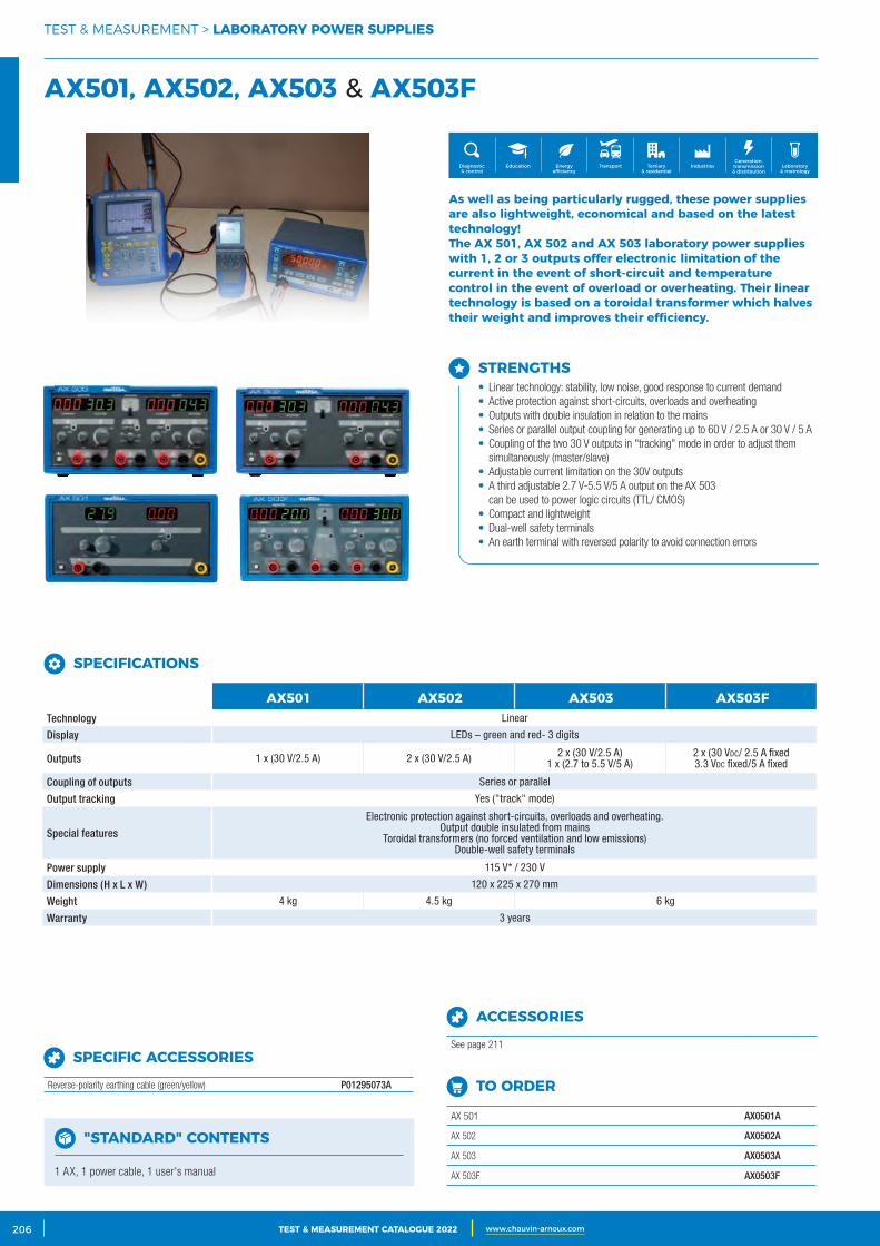
2 CATALOGUE TEST & MESURE 2021 www.chauvin-arnoux.com206 TEST & MEASUREMENT CATALOGUE 2022 www.chauvin-arnoux.com
AX501, AX502, AX503 & AX503F
TEST & MEASUREMENT > LABORATORY POWER SUPPLIES
As well as being particularly rugged, these power supplies are also lightweight, economical and based on the latest technology!The AX 501, AX 502 and AX 503 laboratory power supplies with 1, 2 or 3 outputs offer electronic limitation of the current in the event of short‑circuit and temperature control in the event of overload or overheating. Their linear technology is based on a toroidal transformer which halves their weight and improves their efficiency.
STRENGTHS• Linear technology: stability, low noise, good response to current demand• Active protection against short-circuits, overloads and overheating• Outputs with double insulation in relation to the mains• Series or parallel output coupling for generating up to 60 V / 2.5 A or 30 V / 5 A• Coupling of the two 30 V outputs in "tracking" mode in order to adjust them
simultaneously (master/slave)• Adjustable current limitation on the 30V outputs• A third adjustable 2.7 V-5.5 V/5 A output on the AX 503
can be used to power logic circuits (TTL/ CMOS)• Compact and lightweight• Dual-well safety terminals• An earth terminal with reversed polarity to avoid connection errors
"STANDARD" CONTENTS
1 AX, 1 power cable, 1 user's manual
TO ORDER
AX 501 AX0501A
AX 502 AX0502A
AX 503 AX0503A
AX 503F AX0503F
SPECIFIC ACCESSORIES
Reverse-polarity earthing cable (green/yellow) P01295073A
ACCESSORIES
See page 211
SPECIFICATIONS AX501 AX502 AX503 AX503FTechnology Linear
Display LEDs – green and red- 3 digits
Outputs 1 x (30 V/2.5 A) 2 x (30 V/2.5 A) 2 x (30 V/2.5 A)1 x (2.7 to 5.5 V/5 A)
2 x (30 Vdc/ 2.5 A fixed3.3 Vdc fixed/5 A fixed
Coupling of outputs Series or parallel
Output tracking Yes ("track" mode)
Special features
Electronic protection against short-circuits, overloads and overheating.Output double insulated from mains
Toroidal transformers (no forced ventilation and low emissions)Double-well safety terminals
Power supply 115 V* / 230 V
Dimensions (H x L x W) 120 x 225 x 270 mm
Weight 4 kg 4.5 kg 6 kg
Warranty 3 years
Generation, transmission & distribution
IndustriesTertiary & residential
Education TransportDiagnostic & control
Energy efficiency
Laboratory & metrology
SPECIFICATIONS
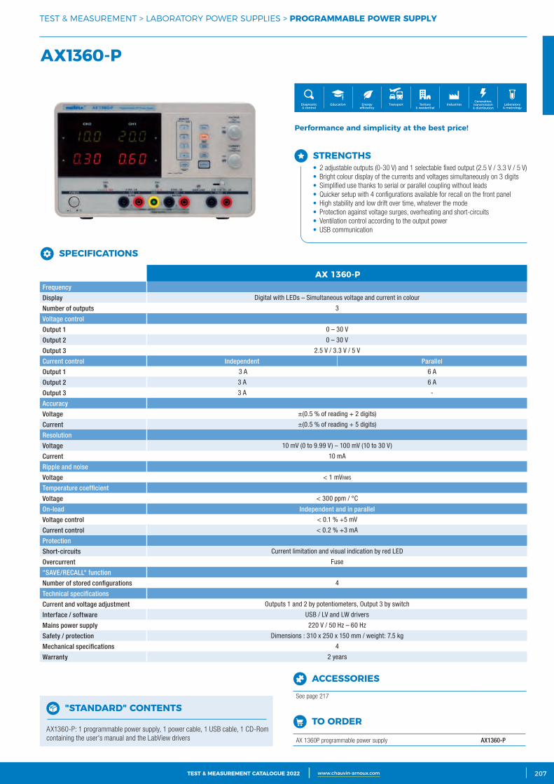
3CATALOGUE TEST & MESURE 2021 www.chauvin-arnoux.com 207TEST & MEASUREMENT CATALOGUE 2022 www.chauvin-arnoux.com
AX1360‑P
TEST & MEASUREMENT > LABORATORY POWER SUPPLIES > PROGRAMMABLE POWER SUPPLY
Performance and simplicity at the best price!
SPECIFICATIONS AX 1360‑PFrequency
Display Digital with LEDs – Simultaneous voltage and current in colour
Number of outputs 3
Voltage control
Output 1 0 – 30 V
Output 2 0 – 30 V
Output 3 2.5 V / 3.3 V / 5 V
Current control Independent Parallel
Output 1 3 A 6 A
Output 2 3 A 6 A
Output 3 3 A -
Accuracy
Voltage ±(0.5 % of reading + 2 digits)
Current ±(0.5 % of reading + 5 digits)
Resolution
Voltage 10 mV (0 to 9.99 V) – 100 mV (10 to 30 V)
Current 10 mA
Ripple and noise
Voltage < 1 mVrms
Temperature coefficient
Voltage < 300 ppm / °C
On-load Independent and in parallel
Voltage control < 0.1 % +5 mV
Current control < 0.2 % +3 mA
Protection
Short-circuits Current limitation and visual indication by red LED
Overcurrent Fuse
"SAVE/RECALL" function
Number of stored configurations 4
Technical specifications
Current and voltage adjustment Outputs 1 and 2 by potentiometers, Output 3 by switch
Interface / software USB / LV and LW drivers
Mains power supply 220 V / 50 Hz – 60 Hz
Safety / protection Dimensions : 310 x 250 x 150 mm / weight: 7.5 kg
Mechanical specifications 4
Warranty 2 years
ACCESSORIES
See page 217
"STANDARD" CONTENTS
AX1360-P: 1 programmable power supply, 1 power cable, 1 USB cable, 1 CD-Rom containing the user's manual and the LabView drivers
TO ORDER
AX 1360P programmable power supply AX1360-P
Generation, transmission & distribution
IndustriesTertiary & residential
Education TransportDiagnostic & control
Energy efficiency
Laboratory & metrology
SPECIFICATIONS
STRENGTHS• 2 adjustable outputs (0-30 V) and 1 selectable fixed output (2.5 V / 3.3 V / 5 V)• Bright colour display of the currents and voltages simultaneously on 3 digits• Simplified use thanks to serial or parallel coupling without leads• Quicker setup with 4 configurations available for recall on the front panel• High stability and low drift over time, whatever the mode• Protection against voltage surges, overheating and short-circuits• Ventilation control according to the output power • USB communication
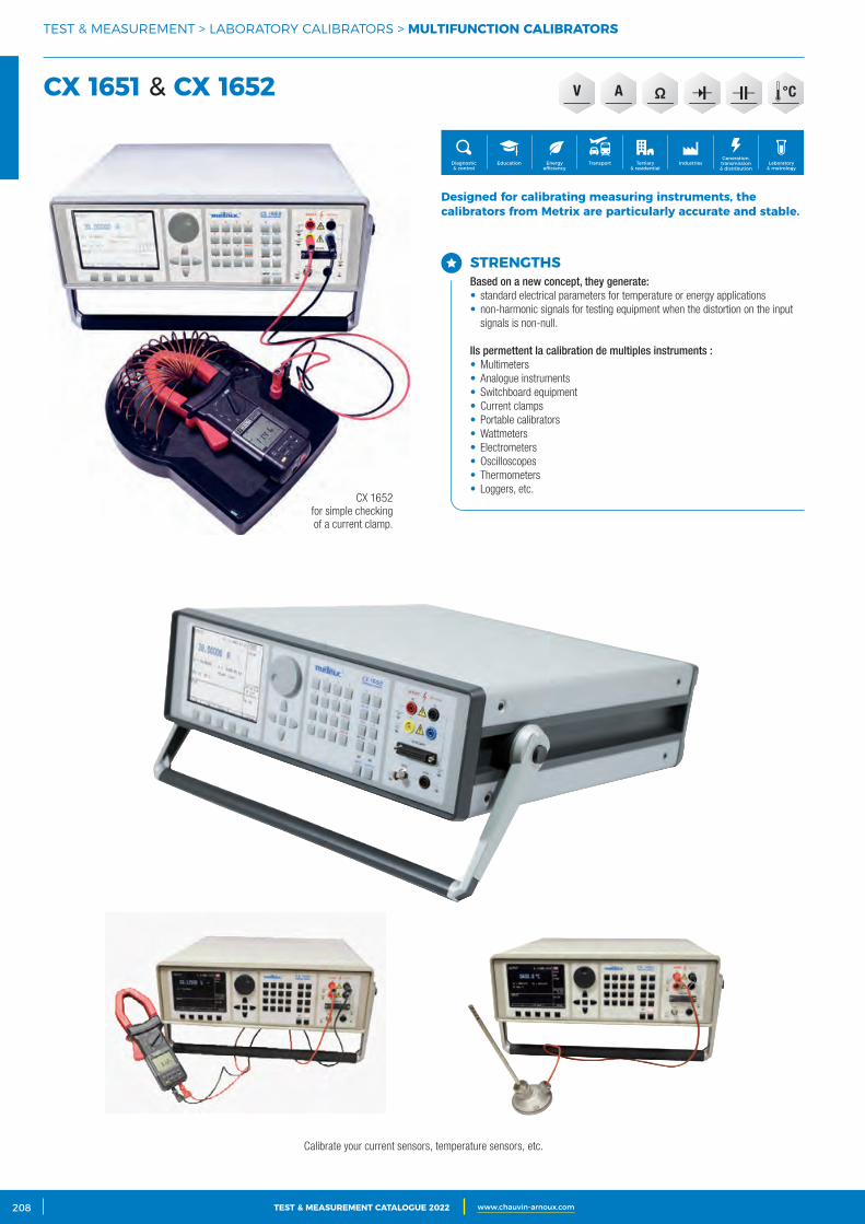
2 CATALOGUE TEST & MESURE 2021 www.chauvin-arnoux.com208 TEST & MEASUREMENT CATALOGUE 2022 www.chauvin-arnoux.com
V A
CX 1652 for simple checking of a current clamp.
Calibrate your current sensors, temperature sensors, etc.
TEST & MEASUREMENT > LABORATORY CALIBRATORS > MULTIFUNCTION CALIBRATORS
CX 1651 & CX 1652
Generation, transmission & distribution
IndustriesTertiary & residential
Education TransportDiagnostic & control
Energy efficiency
Laboratory & metrology
STRENGTHSBased on a new concept, they generate:• standard electrical parameters for temperature or energy applications• non-harmonic signals for testing equipment when the distortion on the input
signals is non-null.
Ils permettent la calibration de multiples instruments :• Multimeters• Analogue instruments• Switchboard equipment• Current clamps• Portable calibrators• Wattmeters• Electrometers• Oscilloscopes• Thermometers• Loggers, etc.
Designed for calibrating measuring instruments, the calibrators from Metrix are particularly accurate and stable.

3CATALOGUE TEST & MESURE 2021 www.chauvin-arnoux.com 209TEST & MEASUREMENT CATALOGUE 2022 www.chauvin-arnoux.com
TEST & MEASUREMENT > LABORATORY CALIBRATORS > MULTIFUNCTION CALIBRATORS
SPECIFICATIONS CX1651 CX1652Best accuracy*
VoltageDC 6 ranges from 0 to 1,000 V 0.003 %R + 16 μV 0.0015 %R + 8 μV
AC 6 ranges from 0 to 1,000 V 0.025 %R + 100 μV 0.018 %R + 100 μV
Current
DC6 ranges from 0 to 20 A (CX1651)
0.01 %R + 60 μA 0.01 %R + 0.6 μA6 ranges from 0 to 30 A (CX1652)
AC6 ranges from 0 to 20 A (CX1651)
0.05 %R + 100 μA 0.05 %R + 1 μA6 ranges from 0 to 30 A (CX1652)
Resistance 4-wire configuration10 ranges from 0 Ω to 50 MΩ (CX1651)
0.015 %R 0.01 %R16 ranges from 0 Ω to 1GΩ (CX1652)
Capacitance9 ranges from 0.9 nF to 50 μF (CX1651)
0.5 %R 0.5 %R10 ranges from 0.7 nF to 100 μF (CX1652)
Frequency Square wave, duty cycle and amplitude calibrated 0.1 Hz to 20 MHz 0.005 %R 0.005 %R
Power 0.0004 to 2.4 kVA (CX1651) Depends on the voltage, current and time values
Energy 0.0004 to 4.8 kVA (CX1652) The best uncertainty is 0.016 % for DC and 0.07 % for AC
TemperatureThermocouple K, N, R, S, B, J, T, E
from -250 to +1,820 °C 0,4 °C 0,4 °C
Resistance sensor Pt100, Pt200, Pt1000, Ni100 from -200 °C to 850 °C 0,1 °C 0,1 °C
CX1651 CX1652Function Range Accuracy Range AccuracyVd c (DC voltage) 0 - ±12 V 0.01 % + 300 μV 0 to ±20 V 0.01 % + 500 μV
mVd c (DC voltage) 0 - ±2,000 mV 0.2 % + 7 μV 0 to ±2 V 0.02 % + 7 μV
mAd c (DC current) 0 - ±25 mA 0.02 % + 1 μA 0 to ±25 mA 0.015 % + 300 nA
FREQ (Frequency) 1 Hz – 15 kHz 0.005 % 1 Hz to 15 kHz 0.005 %
R4W (Resistance) 0 - 2 kΩ 0.02 % + 100 mΩ 0 to 2.5 kΩ 0.02 % + 10 mΩ
TRTD (RTD sensors) -150 °C – +600 °C 0.1 °C -200 to +850 °C* 0.1 °C
TTC (TC sensors) -250 °C – +1,820 °C 0.4 to 2.5 °C -250 to +1,820 °C 0.4 to 2.5 °C
SGS (Deformation) Depending on sensor 0.01 % + 10 μV + sensor accuracy
* Depending on measurement range. Please refer to the user's manual for further details.
* Measurement current 1 mA.
MULTIMETER
"STANDARD" CONTENTS
CX1651 : 1 multifunction calibrator delivered with 1,000 V / 20 A test cables (x 2), 1 Option 40 cable adapter (Canon 25/2 x banana cable adapter, 1 m), 1 Option 60 cable adapter (Canon 25/4 x banana cable adapter, 1 m), 1 Option 70 cable adapter (adapter for resistances on four terminals), 1 RS 232 cable, 1 power cable, 2 spare fuses, 1 test report and 1 user's manual.
CX1652 : 1 multifunction calibrator delivered with 1 mains power cable, 1 user's manual (CD), 2 x red/black 1,000 V / 20 A test cables 1 m long, 1 SUB-D25 / 2 x banana adapter cable 1 m long (DC voltage/current), 1 SUB-D25 / 4 x banana adapter cable 1 m long (4-wire resistance), 1 SUB-D25 / 4 x banana adapter cable 1 m long (4-wire resistance simulation), SUB-D25 / 2 x banana adapter cable 1 m long (mVdc and TC), spare fuse(s), 1 RS232 cable 1 m long, 1 test report.
ACCESSORIES
See page 217
TO ORDER
CX 1651 multifunction calibrator CX1651
CX 1652 multifunction calibrator CX1652
SPECIFICATIONS
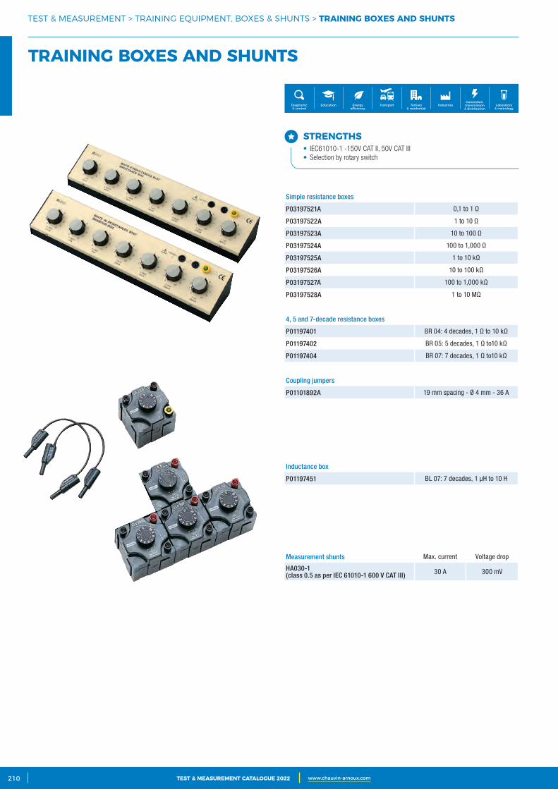
2 CATALOGUE TEST & MESURE 2021 www.chauvin-arnoux.com210 TEST & MEASUREMENT CATALOGUE 2022 www.chauvin-arnoux.com
TEST & MEASUREMENT > TRAINING EQUIPMENT, BOXES & SHUNTS > TRAINING BOXES AND SHUNTS
TRAINING BOXES AND SHUNTS
Generation, transmission & distribution
IndustriesTertiary & residential
Education TransportDiagnostic & control
Energy efficiency
Laboratory & metrology
STRENGTHS• IEC61010-1 -150V CAT II, 50V CAT III• Selection by rotary switch
Simple resistance boxes
P03197521A 0,1 to 1 Ω
P03197522A 1 to 10 Ω
P03197523A 10 to 100 Ω
P03197524A 100 to 1,000 Ω
P03197525A 1 to 10 kΩ
P03197526A 10 to 100 kΩ
P03197527A 100 to 1,000 kΩ
P03197528A 1 to 10 MΩ
4, 5 and 7-decade resistance boxes
P01197401 BR 04: 4 decades, 1 Ω to 10 kΩ
P01197402 BR 05: 5 decades, 1 Ω to10 kΩ
P01197404 BR 07: 7 decades, 1 Ω to10 kΩ
Coupling jumpers
P01101892A 19 mm spacing - Ø 4 mm - 36 A
Measurement shunts Max. current Voltage drop
HA030-1 (class 0.5 as per IEC 61010-1 600 V CAT III) 30 A 300 mV
Inductance box
P01197451 BL 07: 7 decades, 1 μH to 10 H
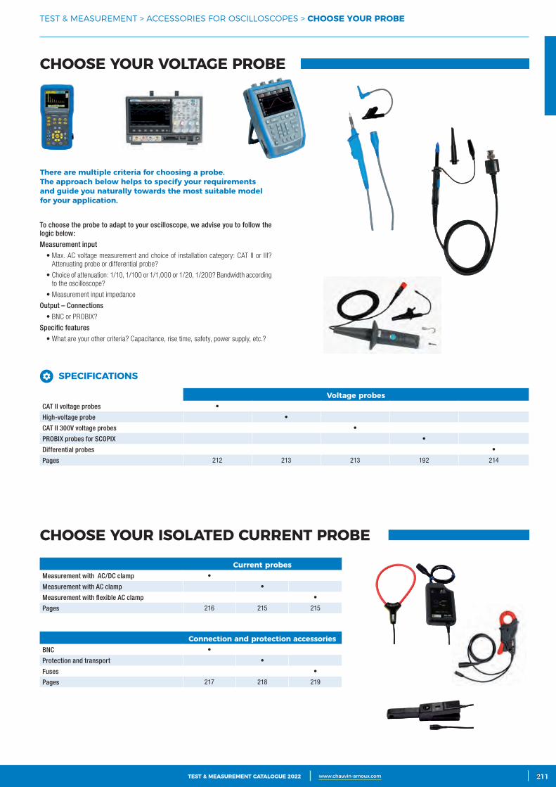
3CATALOGUE TEST & MESURE 2021 www.chauvin-arnoux.com 211TEST & MEASUREMENT CATALOGUE 2022 www.chauvin-arnoux.com 3211
TEST & MEASUREMENT > ACCESSORIES FOR OSCILLOSCOPES > CHOOSE YOUR PROBE
CHOOSE YOUR VOLTAGE PROBE
CHOOSE YOUR ISOLATED CURRENT PROBE
There are multiple criteria for choosing a probe. The approach below helps to specify your requirements and guide you naturally towards the most suitable model for your application.
To choose the probe to adapt to your oscilloscope, we advise you to follow the logic below:
Measurement input
• Max. AC voltage measurement and choice of installation category: CAT II or III? Attenuating probe or differential probe?
• Choice of attenuation: 1/10, 1/100 or 1/1,000 or 1/20, 1/200? Bandwidth according to the oscilloscope?
• Measurement input impedance
Output – Connections
• BNC or PROBIX?
Specific features
• What are your other criteria? Capacitance, rise time, safety, power supply, etc.?
SPECIFICATIONS
Voltage probesCAT II voltage probes •
High-voltage probe •
CAT II 300V voltage probes •
PROBIX probes for SCOPIX •
Differential probes •
Pages 212 213 213 192 214
Connection and protection accessoriesBNC •
Protection and transport •
Fuses •
Pages 217 218 219
Current probesMeasurement with AC/DC clamp •
Measurement with AC clamp •
Measurement with flexible AC clamp •
Pages 216 215 215
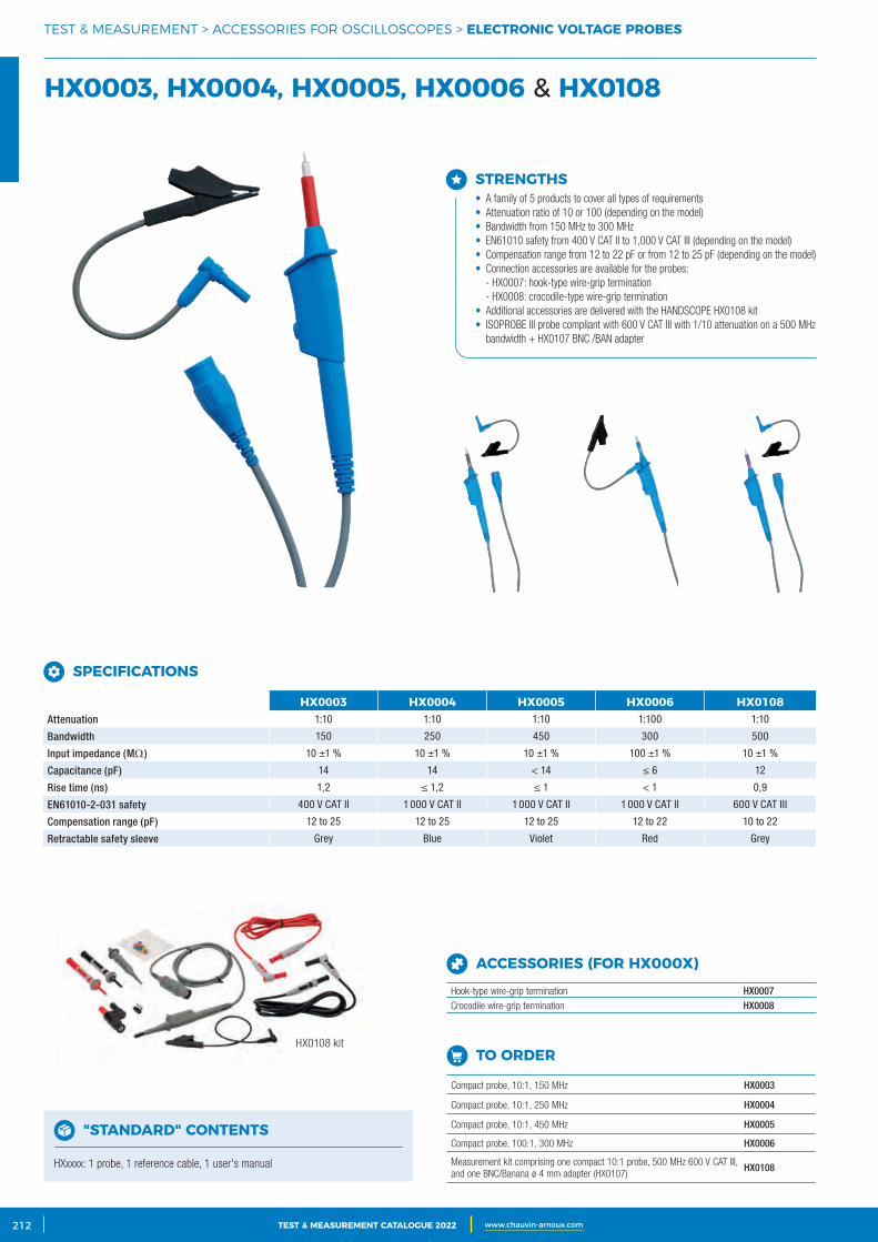
2 CATALOGUE TEST & MESURE 2021 www.chauvin-arnoux.com212 TEST & MEASUREMENT CATALOGUE 2022 www.chauvin-arnoux.com
HX0108 kit
TEST & MEASUREMENT > ACCESSORIES FOR OSCILLOSCOPES > ELECTRONIC VOLTAGE PROBES
HX0003, HX0004, HX0005, HX0006 & HX0108
STRENGTHS• A family of 5 products to cover all types of requirements• Attenuation ratio of 10 or 100 (depending on the model)• Bandwidth from 150 MHz to 300 MHz• EN61010 safety from 400 V CAT II to 1,000 V CAT III (depending on the model)• Compensation range from 12 to 22 pF or from 12 to 25 pF (depending on the model)• Connection accessories are available for the probes:
- HX0007: hook-type wire-grip termination - HX0008: crocodile-type wire-grip termination
• Additional accessories are delivered with the HANDSCOPE HX0108 kit• ISOPROBE III probe compliant with 600 V CAT III with 1/10 attenuation on a 500 MHz
bandwidth + HX0107 BNC /BAN adapter
SPECIFICATIONS
HX0003 HX0004 HX0005 HX0006 HX0108Attenuation 1:10 1:10 1:10 1:100 1:10
Bandwidth 150 250 450 300 500
Input impedance (MΩ) 10 ±1 % 10 ±1 % 10 ±1 % 100 ±1 % 10 ±1 %
Capacitance (pF) 14 14 < 14 ≤ 6 12
Rise time (ns) 1,2 ≤ 1,2 ≤ 1 < 1 0,9
EN61010-2-031 safety 400 V CAT II 1 000 V CAT II 1 000 V CAT II 1 000 V CAT II 600 V CAT III
Compensation range (pF) 12 to 25 12 to 25 12 to 25 12 to 22 10 to 22
Retractable safety sleeve Grey Blue Violet Red Grey
"STANDARD" CONTENTS
HXxxxx: 1 probe, 1 reference cable, 1 user's manual
TO ORDER
Compact probe, 10:1, 150 MHz HX0003
Compact probe, 10:1, 250 MHz HX0004
Compact probe, 10:1, 450 MHz HX0005
Compact probe, 100:1, 300 MHz HX0006
Measurement kit comprising one compact 10:1 probe, 500 MHz 600 V CAT III, and one BNC/Banana ø 4 mm adapter (HX0107)
HX0108
ACCESSORIES (FOR HX000X)
Hook-type wire-grip termination HX0007Crocodile wire-grip termination HX0008
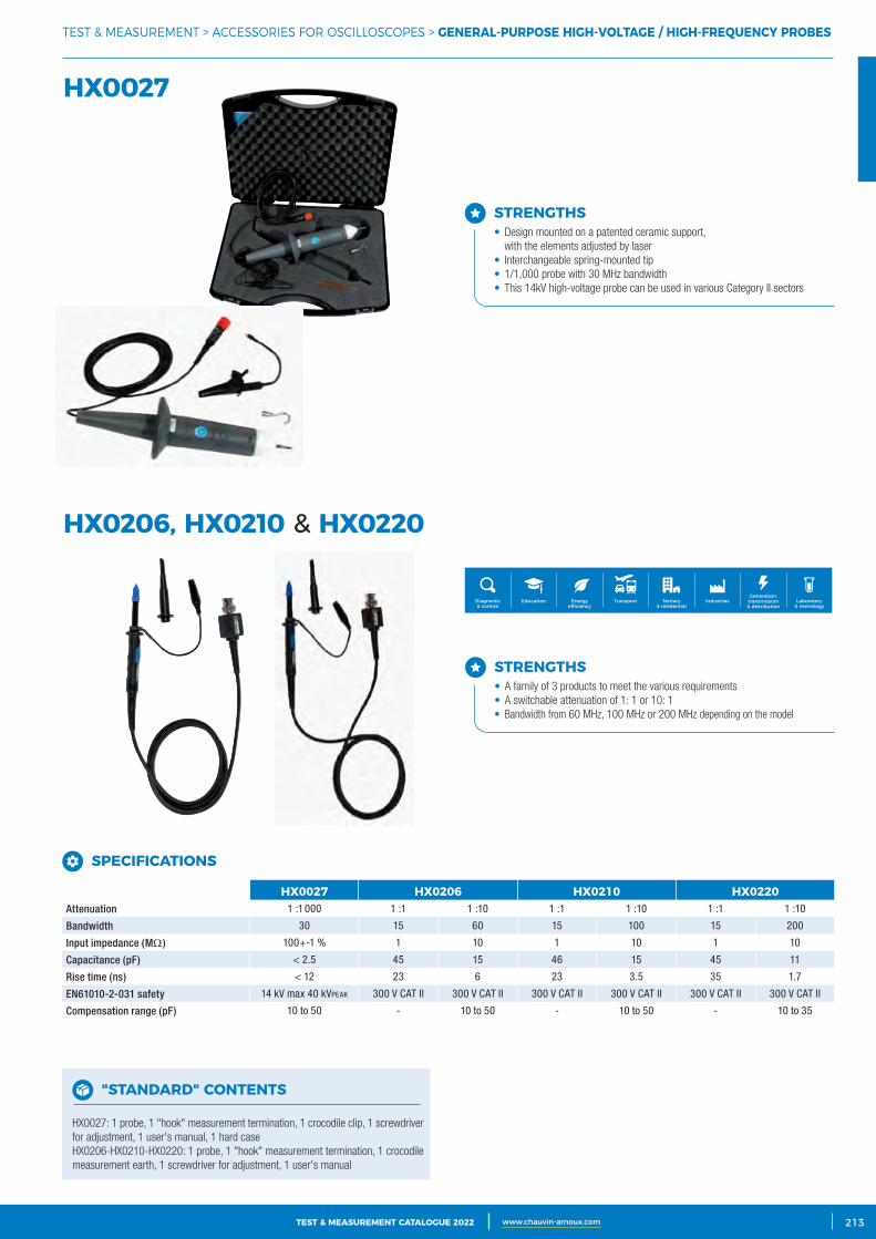
3CATALOGUE TEST & MESURE 2021 www.chauvin-arnoux.com 213TEST & MEASUREMENT CATALOGUE 2022 www.chauvin-arnoux.com
TEST & MEASUREMENT > ACCESSORIES FOR OSCILLOSCOPES > GENERAL‑PURPOSE HIGH‑VOLTAGE / HIGH‑FREQUENCY PROBES
HX0027
HX0206, HX0210 & HX0220
Generation, transmission & distribution
IndustriesTertiary & residential
Education TransportDiagnostic & control
Energy efficiency
Laboratory & metrology
STRENGTHS• Design mounted on a patented ceramic support,
with the elements adjusted by laser• Interchangeable spring-mounted tip• 1/1,000 probe with 30 MHz bandwidth• This 14kV high-voltage probe can be used in various Category II sectors
STRENGTHS• A family of 3 products to meet the various requirements• A switchable attenuation of 1: 1 or 10: 1• Bandwidth from 60 MHz, 100 MHz or 200 MHz depending on the model
SPECIFICATIONS
HX0027 HX0206 HX0210 HX0220Attenuation 1 :1 000 1 :1 1 :10 1 :1 1 :10 1 :1 1 :10
Bandwidth 30 15 60 15 100 15 200
Input impedance (MΩ) 100+-1 % 1 10 1 10 1 10
Capacitance (pF) < 2.5 45 15 46 15 45 11
Rise time (ns) < 12 23 6 23 3.5 35 1.7
EN61010-2-031 safety 14 kV max 40 kVpeAk 300 V CAT II 300 V CAT II 300 V CAT II 300 V CAT II 300 V CAT II 300 V CAT II
Compensation range (pF) 10 to 50 - 10 to 50 - 10 to 50 - 10 to 35
"STANDARD" CONTENTS
HX0027: 1 probe, 1 "hook" measurement termination, 1 crocodile clip, 1 screwdriver for adjustment, 1 user's manual, 1 hard caseHX0206-HX0210-HX0220: 1 probe, 1 "hook" measurement termination, 1 crocodile measurement earth, 1 screwdriver for adjustment, 1 user's manual
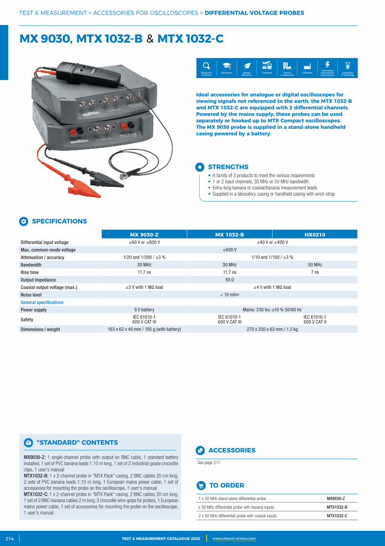
2 CATALOGUE TEST & MESURE 2021 www.chauvin-arnoux.com214 TEST & MEASUREMENT CATALOGUE 2022 www.chauvin-arnoux.com
TEST & MEASUREMENT > ACCESSORIES FOR OSCILLOSCOPES > DIFFERENTIAL VOLTAGE PROBES
MX 9030, MTX 1032‑B & MTX 1032‑C
Generation, transmission & distribution
IndustriesTertiary & residential
Education TransportDiagnostic & control
Energy efficiency
Laboratory & metrology
Ideal accessories for analogue or digital oscilloscopes for viewing signals not referenced to the earth, the MTX 1032‑B and MTX 1032‑C are equipped with 2 differential channels.Powered by the mains supply, these probes can be used separately or hooked up to MTX Compact oscilloscopes. The MX 9030 probe is supplied in a stand‑alone handheld casing powered by a battery.
STRENGTHS• A family of 3 products to meet the various requirements• 1 or 2 input channels, 30 MHz or 50 MHz bandwidth• Extra-long banana or coaxial/banana measurement leads• Supplied in a laboratory casing or handheld casing with wrist-strap
SPECIFICATIONS
MX 9030‑Z MX 1032‑B HX0210Differential input voltage ±60 V or ±600 V ±40 V or ±400 V
Max. common-mode voltage ±600 V
Attenuation / accuracy 1/20 and 1/200 / ±3 % 1/10 and 1/100 / ±3 %
Bandwidth 30 MHz 30 MHz 50 MHz
Rise time 11.7 ns 11.7 ns 7 ns
Output impedance 50 Ω
Coaxial output voltage (max.) ±3 V with 1 MΩ load ±4 V with 1 MΩ load
Noise level < 10 mVpp
General specifications
Power supply 9 V battery Mains: 230 VAc ±10 % 50/60 Hz
Safety IEC 61010-1600 V CAT IV
IEC 61010-1600 V CAT III
IEC 61010-1 600 V CAT II
Dimensions / weight 163 x 62 x 40 mm / 195 g (with battery) 270 x 250 x 63 mm / 1.2 kg
"STANDARD" CONTENTS
MX9030-Z: 1 single-channel probe with output on BNC cable, 1 standard battery installed, 1 set of PVC banana leads 1.10 m long, 1 set of 2 industrial-grade crocodileclips, 1 user's manualMTX1032-B: 1 x 2-channel probe in "MTX Pack" casing, 2 BNC cables 20 cm long, 2 sets of PVC banana leads 1.10 m long, 1 European mains power cable, 1 set of accessories for mounting the probe on the oscilloscope, 1 user's manualMTX1032-C: 1 x 2-channel probe in "MTX Pack" casing, 2 BNC cables 20 cm long, 1 set of 2 BNC-banana cables 2 m long, 2 crocodile wire-grips for probes, 1 European mains power cable, 1 set of accessories for mounting the probe on the oscilloscope, 1 user's manual
TO ORDER
1 x 30 MHz stand-alone differential probe MX9030-Z
x 30 MHz differential probe with banana inputs MTX1032-B
2 x 50 MHz differential probe with coaxial inputs MTX1032-C
ACCESSORIES
See page 217
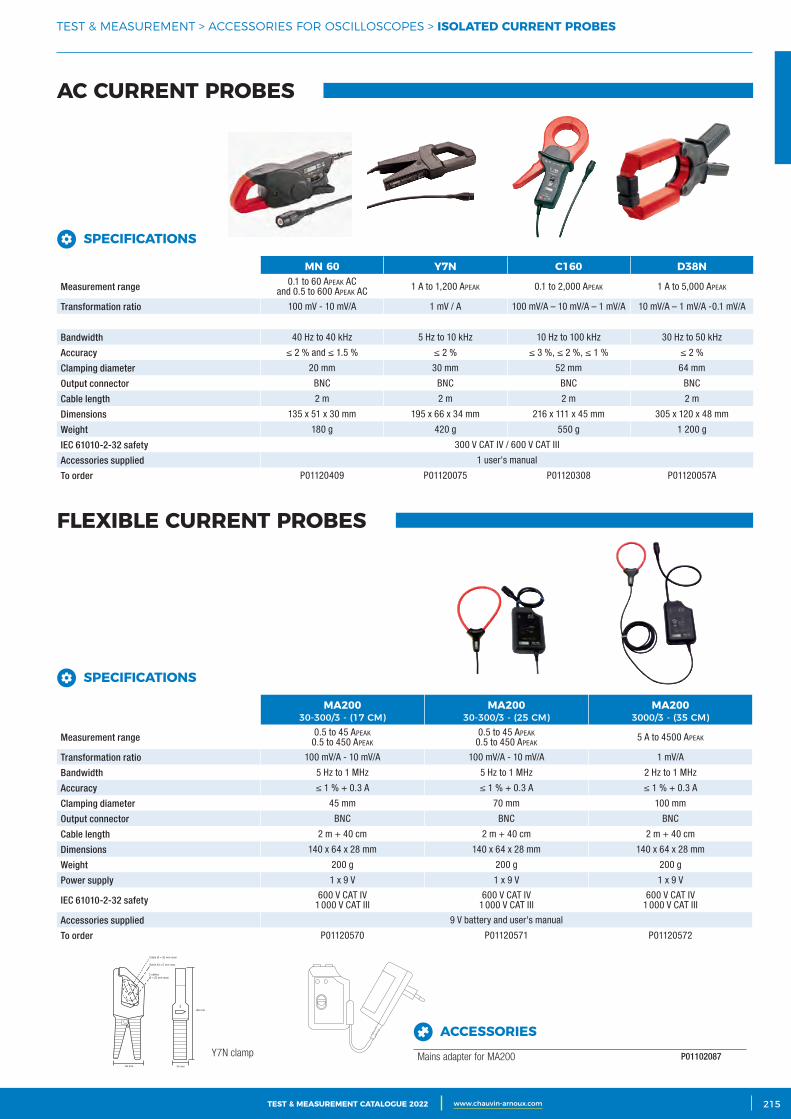
3CATALOGUE TEST & MESURE 2021 www.chauvin-arnoux.com 215TEST & MEASUREMENT CATALOGUE 2022 www.chauvin-arnoux.com
TEST & MEASUREMENT > ACCESSORIES FOR OSCILLOSCOPES > ISOLATED CURRENT PROBES
66 mm
195 mm
Câble Ø = 30 mm maxi
Barre 63 x 5 mm max.
2 câblesØ = 25 mm maxi
I
34 mm
Y7N clamp
AC CURRENT PROBES
FLEXIBLE CURRENT PROBES
SPECIFICATIONS
MN 60 Y7N C160 D38N
Measurement range 0.1 to 60 ApeAk AC and 0.5 to 600 ApeAk AC 1 A to 1,200 ApeAk 0.1 to 2,000 ApeAk 1 A to 5,000 ApeAk
Transformation ratio 100 mV - 10 mV/A 1 mV / A 100 mV/A – 10 mV/A – 1 mV/A 10 mV/A – 1 mV/A -0.1 mV/A
Bandwidth 40 Hz to 40 kHz 5 Hz to 10 kHz 10 Hz to 100 kHz 30 Hz to 50 kHz
Accuracy ≤ 2 % and ≤ 1.5 % ≤ 2 % ≤ 3 %, ≤ 2 %, ≤ 1 % ≤ 2 %
Clamping diameter 20 mm 30 mm 52 mm 64 mm
Output connector BNC BNC BNC BNC
Cable length 2 m 2 m 2 m 2 m
Dimensions 135 x 51 x 30 mm 195 x 66 x 34 mm 216 x 111 x 45 mm 305 x 120 x 48 mm
Weight 180 g 420 g 550 g 1 200 g
IEC 61010-2-32 safety 300 V CAT IV / 600 V CAT III
Accessories supplied 1 user's manual
To order P01120409 P01120075 P01120308 P01120057A
SPECIFICATIONS
MA20030-300/3 - (17 CM)
MA20030-300/3 - (25 CM)
MA2003000/3 - (35 CM)
Measurement range 0.5 to 45 ApeAk0.5 to 450 ApeAk
0.5 to 45 ApeAk0.5 to 450 ApeAk
5 A to 4500 ApeAk
Transformation ratio 100 mV/A - 10 mV/A 100 mV/A - 10 mV/A 1 mV/A
Bandwidth 5 Hz to 1 MHz 5 Hz to 1 MHz 2 Hz to 1 MHz
Accuracy ≤ 1 % + 0.3 A ≤ 1 % + 0.3 A ≤ 1 % + 0.3 A
Clamping diameter 45 mm 70 mm 100 mm
Output connector BNC BNC BNC
Cable length 2 m + 40 cm 2 m + 40 cm 2 m + 40 cm
Dimensions 140 x 64 x 28 mm 140 x 64 x 28 mm 140 x 64 x 28 mm
Weight 200 g 200 g 200 g
Power supply 1 x 9 V 1 x 9 V 1 x 9 V
IEC 61010-2-32 safety 600 V CAT IV1 000 V CAT III
600 V CAT IV1 000 V CAT III
600 V CAT IV1 000 V CAT III
Accessories supplied 9 V battery and user's manual
To order P01120570 P01120571 P01120572
ACCESSORIES
Mains adapter for MA200 P01102087
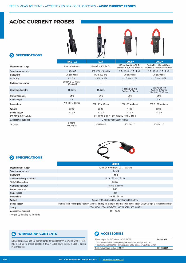
2 CATALOGUE TEST & MESURE 2021 www.chauvin-arnoux.com216 TEST & MEASUREMENT CATALOGUE 2022 www.chauvin-arnoux.com
*Frequency derating from 60 kHz
TEST & MEASUREMENT > ACCESSORIES FOR OSCILLOSCOPES > AC/DC CURRENT PROBES
AC/DC CURRENT PROBES
SPECIFICATIONS
HX0102 E27 PAC17 PAC27
Measurement range 3 mA to 20 AAc/dc 100 mA to 100 AAc/dc500 mA to 40 AAc/60 Adc
500 mA to 400 AAc /600 Adc500 mA to 100 AAc/140Adc
500 mA to 1,000 AAc/1,400 Adc
Transformation ratio 100 mV/A 100 mV/A - 10 mV/A 1 A / 10 mV - 1 A / 1 mV 1 A / 10 mV - 1 A / 1 mV
Bandwidth DC to 60 kHz DC to 100 kHz DC to 30 kHz DC to 30 kHz
Accuracy < 1.5 % ≤ 3 % - ≤ 4% ≤ 1.5 % - ≤ 2 % ≤ 1.5 % - ≤ 4 %
RMS analogue output 30 mA to 20 AAc/dc100 mVdc/A - - -
Clamping diameter 11.8 mm 11.8 mm 1 cable Ø 30 mm2 cables Ø 24 mm
1 cable Ø 39 mm2 cables Ø 25 mm
2 busbars 50 x5 mm
Output connector BNC BNC BNC BNC
Cable length 2 m 2 m 2 m 2 m
Dimensions 231 x 67 x 36 mm 231 x 67 x 36 mm 224 x 97 x 44 mm 236,5 x 97 x 44 mm
Weight 330 g 330 g 440 g 520 g
Power supply 1 x 9 V 1 x 9 V 1 x 9 V 1 x 9 V
IEC 61010-2-32 safety IEC 61010-2-032 - 300 V CAT IV / 600 V CAT III
Accessories supplied 9 V battery and user's manual
To order HX0102HX0102-K* P01120027 P01120117 P01120127
SPECIFICATIONS
MH60Measurement range* 10 mA to 100 Arms or DC (140 ApeAk)
Transformation ratio 10 mV/A
Bandwidth 1 MHz
Switchable low-pass filters None / 30 kHz / 3 kHz
10 to 90% rise time 350 ns
Clamping diameter 1 cable Ø 26 mm
Output connector BNC
Cable length 2 m
Dimensions 138 x 49 x 28 mm
Weight Approx. 200 g (with cable and rechargeable battery)
Power supply Internal NiMh rechargeable battery (approx. battery life 8 hrs) or external 5 Vdc power supply via μUSB type B female connection
Safety IEC 61010-1, IEC 61010-2-032, 300 V CAT III / 600 V CAT II
Accessories supplied P01120612
"STANDARD" CONTENTS
MH60 isolated AC and DC current probe for oscilloscopes, delivered with 1 100V-240 V 50/60 Hz mains adapter, 1 USB / μUSB power cable, 1 user's manual in 5 languages
ACCESSORIES
Mains adapter for E27, MH60, PAC17, PAC27 P016510231 x 110/240V 50/60 Hz mains power pack with female USB type A 5V 1A + 1 charging/connection cable 1.80m long, USB type A male/USB type Micro-B male
NiMh rechargeable battery for MH60 P01296049Z
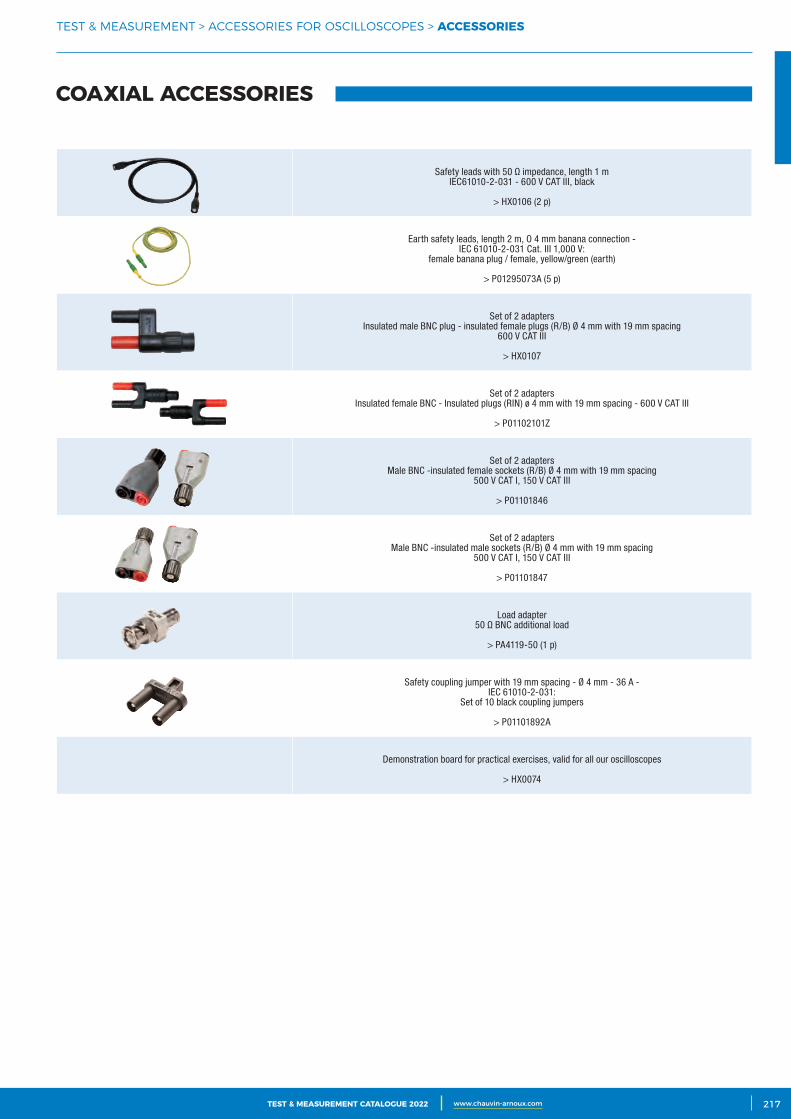
3CATALOGUE TEST & MESURE 2021 www.chauvin-arnoux.com 217TEST & MEASUREMENT CATALOGUE 2022 www.chauvin-arnoux.com
TEST & MEASUREMENT > ACCESSORIES FOR OSCILLOSCOPES > ACCESSORIES
Safety leads with 50 Ω impedance, length 1 m IEC61010-2-031 - 600 V CAT III, black
> HX0106 (2 p)
Earth safety leads, length 2 m, O 4 mm banana connection - IEC 61010-2-031 Cat. III 1,000 V:
female banana plug / female, yellow/green (earth)
> P01295073A (5 p)
Set of 2 adaptersInsulated male BNC plug - insulated female plugs (R/B) Ø 4 mm with 19 mm spacing
600 V CAT III
> HX0107
Set of 2 adaptersInsulated female BNC - Insulated plugs (RIN) ø 4 mm with 19 mm spacing - 600 V CAT III
> P01102101Z
Set of 2 adaptersMale BNC -insulated female sockets (R/B) Ø 4 mm with 19 mm spacing
500 V CAT I, 150 V CAT III
> P01101846
Set of 2 adaptersMale BNC -insulated male sockets (R/B) Ø 4 mm with 19 mm spacing
500 V CAT I, 150 V CAT III
> P01101847
Load adapter50 Ω BNC additional load
> PA4119-50 (1 p)
Safety coupling jumper with 19 mm spacing - Ø 4 mm - 36 A - IEC 61010-2-031:
Set of 10 black coupling jumpers
> P01101892A
Demonstration board for practical exercises, valid for all our oscilloscopes
> HX0074
COAXIAL ACCESSORIES

2 CATALOGUE TEST & MESURE 2021 www.chauvin-arnoux.com218 TEST & MEASUREMENT CATALOGUE 2022 www.chauvin-arnoux.com
TEST & MEASUREMENT > ACCESSORIES FOR OSCILLOSCOPES
PROTECTION AND TRANSPORT ACCESSORIES, MECHANICAL ADAPTATIONS
MTX-family bag for MTX 3240, MTX 3250, MTX 3252, MTX 3352 and MTX 3354 models. The mouse can be stored in the side pocket.
HX0024
Empty hard case for Scopix equipped with precut foam inserts for stowing documents and accessories (power supply, Probix accessories, communication cables, etc.).
HX0038
Battery for SCOPIX IV: 5.8AH LI-ION battery pack P01296047
External charger for LI-ION battery P01102130
SCOPIX IV bag comprising an all-terrain bag with waterproof bottom and shoulder strap (380x280x200 mm) and an internal compartmented bag for stowing the SCOPIX and its accessories
HX0120
Protective hands-free bag for HANDSCOPE portable oscilloscopes (OX5022B and OX5042B)
HX0105
Charger unit for 12 Vdc vehicle cigarette lighter HX0061
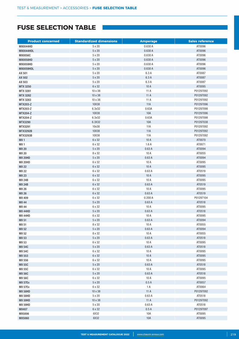
3CATALOGUE TEST & MESURE 2021 www.chauvin-arnoux.com 219TEST & MEASUREMENT CATALOGUE 2022 www.chauvin-arnoux.com
TEST & MEASUREMENT > ACCESSORIES > FUSE SELECTION TABLE
FUSE SELECTION TABLE
Product concerned Standardized dimensions Amperage Sales referenceMX0044HD 5 x 20 0.630 A AT0096
MX0044HDL 5 x 20 0.630 A AT0096
MX0056C 5 x 20 0.630 A AT0096
MX0058HD 5 x 20 0.630 A AT0096
MX0059HD 5 x 20 0.630 A AT0096
MX0059HDL 5 x 20 0.630 A AT0096
AX 501 5 x 20 6.3 A AT0087
AX 502 5 x 20 6.3 A AT0087
AX 503 5 x 20 6.3 A AT0087
MTX 3250 6 x 32 10 A AT0095
MTX 3281 10 x 38 11 A P01297092
MTX 3282 10 x 38 11 A P01297092
MTX 3283 10 x 38 11 A P01297092
MTX203-Z 10X38 11A P01297096
MTX203-Z 6.3x32 0.63A P01297098
MTX204-Z 10X38 10A P01297096
MTX204-Z 6.3x32 0.63A P01297098
MTX3290 6.3X32 10A P01297038
MTX3291 10x38 11A P01297092
MTX3292B 10X38 11A P01297092
MTX3293B 10X38 11A P01297092
MX 1 6 x 32 10 A AT0070
MX 1 6 x 32 1.6 A AT0071
MX 20 5 x 20 0.63 A AT0094
MX 20 8 x 32 10 A AT0055
MX 20HD 5 x 20 0.63 A AT0094
MX 20HD 6 x 32 10 A AT0095
MX 22 6 x 32 10 A AT0095
MX 22 6 x 32 0.63 A AT0519
MX 23 6 x 32 10 A AT0095
MX 24B 6 x 32 10 A AT0095
MX 24B 6 x 32 0.63 A AT0519
MX 26 6 x 32 10 A AT0095
MX 26 6 x 32 0.63 A AT0519
MX 409 6 x 32 0.200 A P01297104
MX 44 5 x 20 0.63 A AT0518
MX 44 6 x 32 10 A AT0095
MX 44HD 5 x 20 0.63 A AT0518
MX 44HD 6 x 32 10 A AT0095
MX 51 5 x 20 0.63 A AT0094
MX 51 8 x 32 10 A AT0055
MX 52 5 x 20 0.63 A AT0094
MX 52 8 x 32 10 A AT0055
MX 53 5 x 20 0.63 A AT0518
MX 53 6 x 32 10 A AT0095
MX 54C 5 x 20 0.63 A AT0518
MX 54C 6 x 32 10 A AT0095
MX 553 6 x 32 10 A AT0095
MX 556 6 x 32 10 A AT0095
MX 55C 5 x 20 0.63 A AT0518
MX 55C 6 x 32 10 A AT0095
MX 56C 5 x 20 0.63 A AT0518
MX 56C 6 x 32 10 A AT0095
MX 57Ex 5 x 20 0.5 A AT0057
MX 57Ex 6 x 32 1 A AT0064
MX 58HD 10 x 38 11 A P01297092
MX 58HD 5 x 20 0.63 A AT0518
MX 59HD 10 x 38 11 A P01297092
MX 59HD 5 x 20 0.63 A AT0518
MX407 6 x 32 0.5 A P01297097
MX5006 6X32 10A AT0095
MX5060 6X32 10A AT0095
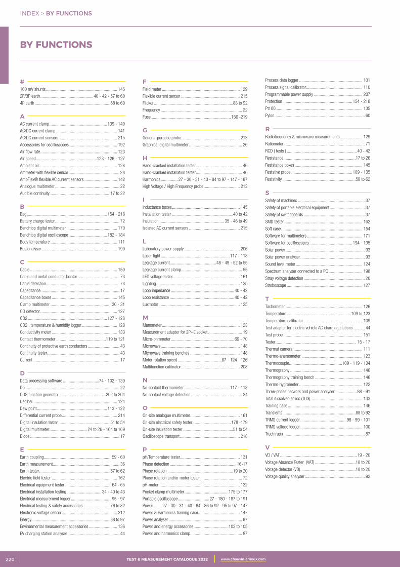
2 CATALOGUE TEST & MESURE 2021 www.chauvin-arnoux.com220 TEST & MEASUREMENT CATALOGUE 2022 www.chauvin-arnoux.com
INDEX > BY FUNCTIONS
BY FUNCTIONS
#100 mV shunts ............................................................... 145
2P/3P earth ...............................................40 - 42 - 57 to 60
4P earth ...................................................................58 to 60
AAC current clamp ...................................................139 - 140
AC/DC current clamp ...................................................... 141
AC/DC current sensors .................................................... 215
Accessories for oscilloscopes........................................... 192
Air flow rate .................................................................... 123
Air speed ......................................................123 - 126 - 127
Ambient air ..................................................................... 128
Ammeter with flexible sensor ............................................. 28
AmpFlex® flexible AC current sensors ............................. 142
Analogue multimeter ......................................................... 22
Audible continuity......................................................17 to 22
BBag .......................................................................154 - 218
Battery charge tester ......................................................... 72
Benchtop digital multimeter ............................................. 170
Benchtop digital oscilloscope ..................................182 - 184
Body temperature ........................................................... 111
Bus analyser ................................................................... 190
CCable ............................................................................. 150
Cable and metal conductor locator ..................................... 73
Cable detection ................................................................. 73
Capacitance ..................................................................... 17
Capacitance boxes .......................................................... 145
Clamp multimeter ......................................................30 - 31
CO detector .................................................................... 127
CO2 ......................................................................127 - 128
CO2 , temperature & humidity logger ............................... 128
Conductivity meter .......................................................... 133
Contact thermometer ............................................119 to 121
Continuity of protective earth conductors ............................ 43
Continuity tester ................................................................ 43
Current ............................................................................. 17
DData processing software ................................74 - 102 - 130
Db ................................................................................... 22
DDS function generator .........................................202 to 204
Decibel ........................................................................... 124
Dew point ..............................................................113 - 122
Differential current probe ................................................. 214
Digital insulation tester ..............................................51 to 54
Digital multimeter................................. 24 to 26 - 164 to 169
Diode ............................................................................... 17
EEarth coupling........................................................... 59 - 60
Earth measurement ........................................................... 36
Earth tester ...............................................................57 to 62
Electric field tester .......................................................... 162
Electrical equipment tester ........................................ 64 - 65
Electrical installation testing ............................... 34 - 40 to 43
Electrical measurement logger ....................................95 - 97
Electrical testing & safety accessories ........................76 to 82
Electronic voltage sensor ................................................. 212
Energy......................................................................88 to 97
Environmental measurement accessories ......................... 136
EV charging station analyser .............................................. 44
FField meter ..................................................................... 129
Flexible current sensor .................................................... 215
Flicker ......................................................................88 to 92
Frequency ........................................................................ 22
Fuse.......................................................................156 -219
GGeneral-purpose probe.................................................... 213
Graphical digital multimeter ............................................... 26
HHand-cranked installation tester ......................................... 46
Hand-cranked installation tester ......................................... 46
Harmonics ............... 27 - 30 - 31 - 40 - 84 to 97 - 147 - 187
High Voltage / High Frequency probe ................................ 213
IInductance boxes ............................................................ 145
Installation tester ......................................................40 to 42
Insulation.......................................................... 35 - 46 to 49
Isolated AC current sensors ............................................. 215
LLaboratory power supply ................................................. 206
Laser tight .............................................................117 - 118
Leakage current .........................................48 - 49 - 52 to 55
Leakage current clamp ...................................................... 55
LED voltage tester ........................................................... 161
Lighting .......................................................................... 125
Loop impedance ........................................................40 - 42
Loop resistance .........................................................40 - 42
Luxmeter ........................................................................ 125
MManometer ..................................................................... 123
Measurement adapter for 2P+E socket .............................. 19
Micro-ohmmeter ........................................................69 - 70
Microwave ...................................................................... 148
Microwave training benches ............................................ 148
Motor rotation speed .......................................87 - 124 - 126
Multifunction calibrator .................................................... 208
NNo-contact thermometer ........................................117 - 118
No-contact voltage detection ............................................. 24
OOn-site analogue multimeter ............................................ 161
On-site electrical safety tester ..................................178 -179
On-site insulation tester ............................................51 to 54
Oscilloscope transport ..................................................... 218
PpH/Temperature tester..................................................... 131
Phase detection ...........................................................16-17
Phase rotation ..........................................................19 to 20
Phase rotation and/or motor tester ..................................... 72
pH-meter ........................................................................ 132
Pocket clamp multimeter .......................................175 to 177
Portable oscilloscope............................27 - 180 - 187 to 191
Power ....... 27 - 30 - 31 - 40 - 64 - 86 to 92 - 95 to 97 - 147
Power & Harmonics training case ..................................... 147
Power analyser ................................................................. 87
Power and energy accessories ...............................103 to 105
Power and harmonics clamp .............................................. 87
Process data logger ........................................................ 101
Process signal calibrator.................................................. 110
Programmable power supply ........................................... 207
Protection ..............................................................154 - 218
Pt100............................................................................. 135
Pylon ................................................................................ 60
RRadiofrequency & microwave measurements .................... 129
Ratiometer ........................................................................ 71
RCD ( tests ) ..............................................................40 - 42
Resistance ................................................................17 to 26
Resistance boxes ............................................................ 145
Resistive probe ......................................................109 - 135
Resistivity .................................................................58 to 62
SSafety of machines ........................................................... 37
Safety of portable electrical equipment ............................... 37
Safety of switchboards ...................................................... 37
SMD tester ..................................................................... 162
Soft case ........................................................................ 154
Software for multimeters ................................................. 171
Software for oscilloscopes ......................................194 - 195
Solar power ...................................................................... 93
Solar power analyser ......................................................... 93
Sound level meter ........................................................... 124
Spectrum analyser connected to a PC .............................. 198
Stray voltage detection ...................................................... 20
Stroboscope ................................................................... 127
TTachometer .................................................................... 126
Temperature .........................................................109 to 123
Temperature calibrator .................................................... 109
Test adapter for electric vehicle AC charging stations .......... 44
Test probe ...................................................................... 151
Tester ....................................................................... 15 - 17
Thermal camera ............................................................. 111
Thermo-anemometer ...................................................... 123
Thermocouple ...............................................109 - 119 - 134
Thermography ................................................................ 146
Thermography training bench .......................................... 146
Thermo-hygrometer ........................................................ 122
Three-phase network and power analyser ...................88 - 91
Total dissolved solids (TDS) .............................................. 133
Training case .................................................................. 146
Transients .................................................................88 to 92
TRMS current logger .........................................98 - 99 - 101
TRMS voltage logger ....................................................... 100
TrueInrush ........................................................................ 87
VVD / VAT ....................................................................19 - 20
Voltage Absence Tester (VAT) ....................................18 to 20
Voltage detector (VD) .................................................18 to 20
Voltage quality analyser ..................................................... 92
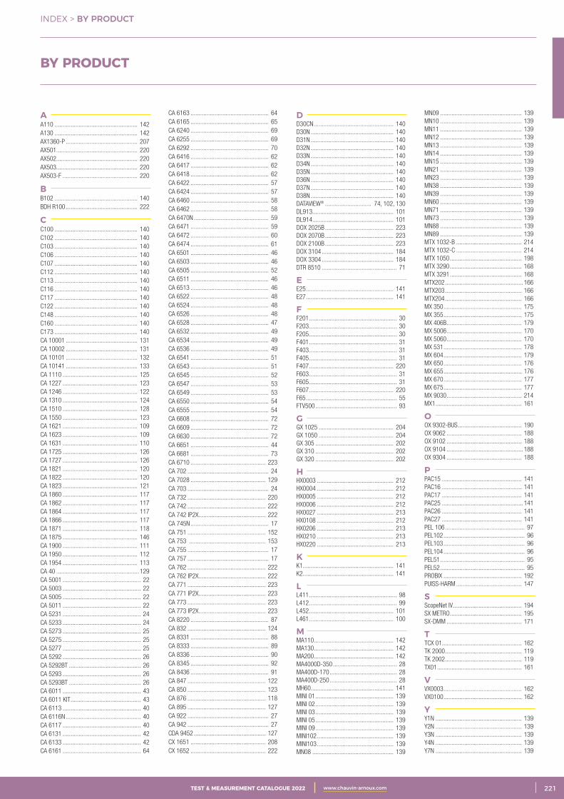
3CATALOGUE TEST & MESURE 2021 www.chauvin-arnoux.com 221TEST & MEASUREMENT CATALOGUE 2022 www.chauvin-arnoux.com
AA110 .................................................... 142A130 .................................................... 142AX1360-P ............................................. 207AX501................................................... 220AX502................................................... 220AX503................................................... 220AX503-F ............................................... 220
BB102 .................................................... 140BDH R100 ............................................. 222
CC100 .................................................... 140C102 .................................................... 140C103 .................................................... 140C106 .................................................... 140C107 .................................................... 140C112 .................................................... 140C113 .................................................... 140C116 .................................................... 140C117 .................................................... 140C122 .................................................... 140C148 .................................................... 140C160 .................................................... 140C173 .................................................... 140CA 10001 ............................................. 131CA 10002 ............................................. 131CA 10101 ............................................. 132CA 10141 ............................................. 133CA 1110 ............................................... 125CA 1227 ............................................... 123CA 1246 ............................................... 122CA 1310 ............................................... 124CA 1510 ............................................... 128CA 1550 ............................................... 123CA 1621 ............................................... 109CA 1623 ............................................... 109CA 1631 ............................................... 110CA 1725 ............................................... 126CA 1727 ............................................... 126CA 1821 ............................................... 120CA 1822 ............................................... 120CA 1823 ............................................... 121CA 1860 ............................................... 117CA 1862 ............................................... 117CA 1864 ............................................... 117CA 1866 ............................................... 117CA 1871 ............................................... 118CA 1875 ............................................... 146CA 1900 ............................................... 111CA 1950 ............................................... 112CA 1954 ............................................... 113CA 40 .................................................... 129CA 5001 ................................................. 22CA 5003 ................................................. 22CA 5005 ................................................. 22CA 5011 ................................................. 22CA 5231 ................................................. 24CA 5233 ................................................. 24CA 5273 ................................................. 25CA 5275 ................................................. 25CA 5277 ................................................. 25CA 5292 ................................................. 26CA 5292BT ............................................. 26CA 5293 ................................................. 26CA 5293BT ............................................. 26CA 6011 ................................................. 43CA 6011 KIT ............................................ 43CA 6113 ................................................. 40CA 6116N ............................................... 40CA 6117 ................................................. 40CA 6131 ................................................. 42CA 6133 ................................................. 42CA 6161 ................................................. 64
CA 6163 ................................................. 64CA 6165 ................................................. 65CA 6240 ................................................. 69CA 6255 ................................................. 69CA 6292 ................................................. 70CA 6416 ................................................. 62 CA 6417 ................................................. 62CA 6418 ................................................. 62CA 6422 ................................................. 57CA 6424 ................................................. 57CA 6460 ................................................. 58CA 6462 ................................................. 58CA 6470N ............................................... 59CA 6471 ................................................. 59CA 6472 ................................................. 60CA 6474 ................................................. 61CA 6501 ................................................. 46CA 6503 ................................................. 46CA 6505 ................................................. 52CA 6511 ................................................. 46 CA 6513 ................................................. 46CA 6522 ................................................. 48CA 6524 ................................................. 48CA 6526 ................................................. 48CA 6528 ................................................. 47CA 6532 ................................................. 49CA 6534 ................................................. 49CA 6536 ................................................. 49CA 6541 ................................................. 51CA 6543 ................................................. 51CA 6545 ................................................. 52CA 6547 ................................................. 53CA 6549 ................................................. 53CA 6550 ................................................. 54CA 6555 ................................................. 54CA 6608 ................................................. 72CA 6609 ................................................. 72CA 6630 ................................................. 72CA 6651 ................................................. 44CA 6681 ................................................. 73CA 6710 ............................................... 223CA 702 ................................................... 24CA 7028 ............................................... 129CA 703 ................................................... 24CA 732 ................................................. 220CA 742 ................................................. 222CA 742 IP2X .......................................... 222CA 745N ................................................. 17CA 751 ................................................. 152CA 753 ................................................ 153CA 755 ................................................... 17CA 757 ................................................... 17CA 762 ................................................. 222CA 762 IP2X .......................................... 222CA 771 ................................................. 223CA 771 IP2X .......................................... 223CA 773 ................................................. 223CA 773 IP2X .......................................... 223CA 8220 ................................................. 87CA 832 ................................................. 124CA 8331 ................................................. 88CA 8333 ................................................. 89CA 8336 ................................................. 90CA 8345 ................................................. 92CA 8436 ................................................. 91CA 847 ................................................. 122CA 850 ................................................. 123CA 876 ................................................. 118CA 895 ................................................. 127CA 922 ................................................... 27CA 942 ................................................... 27CDA 9452 ............................................. 127CX 1651 ............................................... 208CX 1652 ............................................... 222
DD30CN .................................................. 140D30N .................................................... 140D31N .................................................... 140D32N .................................................... 140D33N .................................................... 140D34N .................................................... 140D35N .................................................... 140D36N .................................................... 140D37N .................................................... 140D38N .................................................... 140DATAVIEW® ............................. 74, 102, 130DL913................................................... 101DL914................................................... 101DOX 2025B ........................................... 223DOX 2070B ........................................... 223DOX 2100B ........................................... 223DOX 3104 ............................................. 184DOX 3304 ............................................. 184DTR 8510 ............................................... 71
EE25 ....................................................... 141E27 ....................................................... 141
FF201 ....................................................... 30F203 ....................................................... 30F205 ....................................................... 30F401 ....................................................... 31F403 ....................................................... 31F405 ....................................................... 31F407 ..................................................... 220F603 ....................................................... 31F605 ....................................................... 31F607 ..................................................... 220F65 ......................................................... 55FTV500 ................................................... 93
GGX 1025 ............................................... 204GX 1050 ............................................... 204GX 305 ................................................. 202GX 310 ................................................. 202GX 320 ................................................. 202
HHX0003 ................................................ 212HX0004 ................................................ 212HX0005 ................................................ 212HX0006 ................................................ 212HX0027 ................................................ 213HX0108 ................................................ 212HX0206 ................................................ 213HX0210 ................................................ 213HX0220 ................................................ 213
KK1......................................................... 141K2......................................................... 141
LL411 ....................................................... 98L412 ....................................................... 99L452 ..................................................... 101L461 ..................................................... 100
MMA110 .................................................. 142MA130 .................................................. 142MA200 .................................................. 142MA4000D-350 ........................................ 28MA400D-170 .......................................... 28MA400D-250 .......................................... 28MH60.................................................... 141MINI 01 ................................................. 139MINI 02 ................................................. 139MINI 03 ................................................. 139MINI 05 ................................................. 139MINI 09 ................................................. 139MINI102 ................................................ 139MINI103 ................................................ 139MN08 ................................................... 139
MN09 ................................................... 139MN10 ................................................... 139MN11 ................................................... 139MN12 ................................................... 139MN13 ................................................... 139MN14 ................................................... 139MN15 ................................................... 139MN21 ................................................... 139MN23 ................................................... 139MN38 ................................................... 139MN39 ................................................... 139MN60 ................................................... 139MN71 ................................................... 139MN73 ................................................... 139MN88 ................................................... 139MN89 ................................................... 139MTX 1032-B ......................................... 214MTX 1032-C ......................................... 214 MTX 1050 ............................................. 198 MTX 3290 ............................................. 168 MTX 3291 ............................................. 168 MTX202 ................................................. 166 MTX203 ................................................ 166 MTX204 ................................................ 166MX 350 ................................................. 175MX 355 ................................................. 175MX 406B ............................................... 179 MX 5006 ............................................... 170 MX 5060 ............................................... 170 MX 531 ................................................. 178 MX 604 ................................................. 179 MX 650 ................................................. 176 MX 655 ................................................. 176MX 670 ................................................. 177MX 675 ................................................. 177MX 9030 ............................................... 214 MX1 ...................................................... 161
OOX 9302-BUS ........................................ 190OX 9062 ............................................... 188OX 9102 ............................................... 188OX 9104 ................................................ 188OX 9304 ............................................... 188
PPAC15 .................................................. 141PAC16 .................................................. 141PAC17 .................................................. 141PAC25 ................................................... 141PAC26 .................................................. 141PAC27 .................................................. 141PEL 106 .................................................. 97PEL102 ................................................... 96PEL103 ................................................... 96PEL104 ................................................... 96PEL51 ..................................................... 95PEL52 ..................................................... 95PROBIX ................................................. 192PUISS-HARM ......................................... 147
SScopeNet IV ........................................... 194SX METRO ............................................. 195SX-DMM ............................................... 171
TTCX 01 .................................................. 162TK 2000 ................................................ 119TK 2002 ................................................ 119TX01 ..................................................... 161
VVX0003 ................................................. 162VX0100 ................................................. 162
YY1N ...................................................... 139Y2N ...................................................... 139Y3N ...................................................... 139Y4N ...................................................... 139Y7N ...................................................... 139
INDEX > BY PRODUCT
BY PRODUCT

2 CATALOGUE TEST & MESURE 2021 www.chauvin-arnoux.com222 TEST & MEASUREMENT CATALOGUE 2022 www.chauvin-arnoux.com
INDEX > BY REFERENCE
AG1066-Z ...............................................155AT0094 .....................................................81AX1360-P ...............................................207CX1651 ..................................................209CX1652 ..................................................209DOX-MSO3LA ..........................................185DOX2025B ..............................................183DOX2070B ..............................................183DOX2100B ..............................................183DOX3104 ................................................185DOX3304 ................................................185GX1025 ..................................................205GX1050 ..................................................205GX305 ....................................................203GX310 ....................................................203GX310-P .................................................203GX320 ....................................................203GX320-E .................................................203HA030-1 .................................................210HX0003 ..................................................212HX0004 ..................................................212HX0005 ..................................................212HX0006 ..................................................212HX0027 ..................................................213HX0029B .......................................... 26-172HX0030C ................................................192HX0031 ..................................................192HX0032 ..................................................192HX0033 ..................................................192HX0034B ................................................192HX0035B ................................................192HX0036 ..................................................192HX0051B ..................................................26HX0051B ..................................................81HX0051B ................................................155HX0053 ..................................................138HX0053 ..................................................155HX0055B ................................................107HX0056-Z .................................................81HX0056-Z .................................................82HX0056Z.................................................107HX0059B .......................................... 26-172HX0061 ....................................................76HX0061 ..................................................107HX0064 ..................................................155HX0072 ..................................................192HX0073 ..................................................192HX0074 ..................................................192HX0080 ..................................................192HX0082 ..................................................199HX0083 ..................................................199HX0091 ....................................................83HX0091 ..................................................107HX0091 ..................................................155HX0093 ..................................................192HX0094 ..................................................192HX0099 ....................................................27HX0106 ..................................................155HX0106 ..................................................203HX0107 ..................................................155HX0107 ..................................................203HX0108 ..................................................212HX0122 ....................................................94HX0130 .................................................192HX0179 ..................................................192HX0206 ..................................................213HX0210 ..................................................213HX0220 ..................................................213HX0300 ....................................................76HX0300 ....................................................81HX0302 ....................................................76HX0302 ....................................................81HX0302 ..................................................157MTX 1032-B ...........................................214MTX 1032-C ...........................................214MTX1050-PC ..........................................199MTX202-Z ...............................................166MTX203-Z ...............................................166MTX204-Z ...............................................166MTX3290 ................................................168MTX3291 ................................................168MX 9030 .................................................214MX0001-T...............................................161MX0350Z ................................................175MX0355Z ................................................175MX0406B ................................................179MX0531 ..................................................178MX0604 ..................................................179MX0650-Z ..............................................176MX0655-Z ..............................................176MX0670-Z ..............................................177MX0675-Z ..............................................177MX1 ........................................................161OX9062 ..................................................191OX9102 ..................................................191OX9104 ..................................................191OX9302-BUS ...........................................190OX9304 ..................................................191P01101141...............................................82P01101783...............................................80P01101783...............................................82P01101784...............................................80P01101785.............................................138P01101794...............................................82P01101797.............................................138P01101841...............................................79P01101841...............................................82P01101842...............................................82P01101846.............................................155
P01101847.............................................155P01101892A ..........................................147P01101892A ..........................................210P01101905...............................................81P01101906A ............................................81P01101915...............................................79P01101915...............................................82P01101916...............................................79P01101916...............................................82P01101917...............................................79P01101917...............................................82P01101918...............................................82P01102182...............................................79P01101919...............................................79P01101919...............................................82P01101921...............................................76P01101922...............................................76P01101935...............................................51P01101935...............................................81P01101941...............................................81P01101943...............................................76P01101959...............................................98P01101959.............................................106P01101959.............................................107P01101959.............................................107P01101967.............................................107P01101967.............................................107P01101981.............................................148P01101994.............................................131P01101995.............................................131P01101996...............................................79P01101997Z .............................................19P01101997Z ...........................................154P01102008Z ...........................................154P01102009Z ...........................................154P01102013...............................................80P01102013...............................................82P01102014...............................................82P01102017...............................................76P01102017...............................................78P01102017...............................................81P01102018...............................................76P01102018...............................................78P01102019...............................................81P01102020...............................................78P01102020...............................................81P01102021...............................................76P01102021...............................................78P01102021...............................................81P01102022...............................................76P01102022...............................................78P01102023...............................................78P01102024...............................................78P01102025...............................................78P01102026...............................................78P01102026...............................................81P01102026...............................................82P01102028...............................................78P01102028...............................................82P01102029...............................................78P01102030...............................................78P01102031...............................................78P01102031...............................................81P01102035...............................................81P01102036B ............................................81P01102037...............................................78P01102040...............................................78P01102045...............................................82P01102046...............................................78P01102046...............................................78P01102046...............................................82P01102047...............................................78P01102052Z ...........................................107P01102053Z ...........................................155P01102055Z ...........................................155P01102056...............................................80P01102056...............................................82P01102057...............................................76P01102057.............................................107P01102057Z ...........................................107P01102059.............................................107P01102080...............................................98P01102080.............................................106P01102080.............................................107P01102081...............................................98P01102081.............................................107P01102082...............................................83P01102082.............................................107P01102083.............................................138P01102084A ............................................43P01102084A ............................................76P01102084A ............................................81P01102092...............................................81P01102092A ............................................76P01102094...............................................76P01102095...............................................74P01102095...............................................76P01102095...............................................81P01102095.............................................104P01102095.............................................106P01102095.............................................107P01102095.............................................107P01102095.............................................111P01102095.............................................132P01102095.............................................138P01102097.............................................155P01102099.............................................107P01102100Z .............................................17P01102100Z ...........................................138
P01102100Z ...........................................156P01102100Z ...........................................157P01102101Z ...........................................155P01102103...............................................80P01102103...............................................82P01102106Z ...........................................155P01102107Z ...........................................155P01102112...............................................81P01102112.............................................138P01102113...............................................17P01102114Z .............................................80P01102114Z .............................................82P01102114Z ...........................................155P01102115...............................................95P01102117.............................................107P01102121Z ...........................................154P01102123Z ...........................................154P01102124Z ...........................................154P01102125Z ...........................................154P01102126Z ...........................................154P01102127Z ...........................................154P01102128Z ...........................................154P01102129...............................................76P01102130...............................................76P01102130...............................................94 P01102131.............................................106P01102131.............................................107P01102135...............................................79P01102136...............................................79P01102136...............................................82P01102137...............................................79P01102137...............................................82P01102138...............................................79P01102138...............................................82P01102139...............................................79P01102139...............................................82P01102140...............................................79P01102140...............................................82P01102141...............................................79P01102142...............................................79P01102142...............................................82P01102143...............................................79P01102143...............................................82P01102144...............................................79P01102144...............................................82P01102145...............................................79P01102145...............................................82P01102146.............................................107P01102147.............................................107P01102148.............................................103P01102148.............................................107P01102149.............................................106P01102149.............................................107P01102149.............................................156P01102150.............................................107P01102152Z .............................................17P01102152Z .............................................17P01102152Z ...........................................154P01102153Z .............................................17P01102153Z ...........................................154P01102154Z .............................................17P01102154Z ...........................................154P01102155...............................................94P01102155.............................................107P01102157...............................................42P01102157...............................................76P01102157...............................................81P01102171...............................................81P01102172...............................................81P01102173...............................................81P01102174...............................................98P01102174.............................................107P01102177...............................................79P01102177...............................................82P01102178...............................................79P01102178...............................................82P01102179...............................................79P01102179...............................................82P01102180...............................................79P01102180...............................................82P01102182...............................................82P01102184...............................................95P01102186...............................................76P01102186...............................................81 P01102188...............................................27P01102190.............................................138P01102191...............................................79P01102192...............................................79P01102193...............................................79P01102195...............................................79 P01102199...............................................80P01102200...............................................80P01102201...............................................80P01102202...............................................80P01102903...............................................81P01102903...............................................82P01103057.............................................138P01103058Z ...........................................107P01103058Z ...........................................155P01103059Z ...........................................154P01103060Z ...........................................154P01103061Z ...........................................154P01103062...............................................81P01103063...............................................80P01103063...............................................82P01103065...............................................80P01103065...............................................82P01103071...............................................82P01103072...............................................82
P01103073...............................................82 P01103076...............................................94P01103076.............................................107P01103077...............................................94P01103077.............................................107P01103078...............................................94 P01103078.............................................107P01103079...............................................94P01103079.............................................107P01103080...............................................27P01105101Z ...........................................141P01105102Z ...........................................141P01105102Z ..........................................173P01105103Z ...........................................141P01105103Z ..........................................173P01105105Z ...........................................141P01105105Z ...........................................173P01105109Z ...........................................141P01105109Z ...........................................173P01106102.............................................141P01106103.............................................141P01120001A ..........................................141P01120005A ..........................................141P01120025.............................................143P01120025.............................................173P01120027.............................................106P01120027.............................................107P01120027.............................................143P01120028A ..........................................141P01120029A ..........................................141P01120043A ............................................98P01120049A ..........................................142P01120050A ..........................................142P01120051A ..........................................142P01120052A ..........................................142P01120053A ..........................................142P01120054A ..........................................142P01120055A ..........................................142P01120056A ..........................................142P01120057A ..........................................142P01120064.............................................142P01120067A ..........................................143P01120074A ..........................................143P01120074A .........................................173P01120075 ..........................................141P01120079B ............................................98P01120079B ..........................................106P01120080...............................................95P01120083.............................................142P01120110...............................................98P01120110.............................................106P01120115.............................................143P01120116.............................................143P01120116 ............................................173P01120117.............................................143P01120125.............................................143P01120125.............................................173P01120126.............................................143P01120127.............................................143P01120301.............................................142P01120302.............................................142P01120303.............................................142P01120304.............................................142P01120304.............................................173P01120305.............................................142P01120305.............................................173P01120306.............................................142P01120307.............................................142P01120308.............................................142P01120309.............................................142P01120310...............................................78P01120310...............................................78P01120310...............................................81P01120314.............................................142P01120315.............................................142P01120316.............................................142P01120317.............................................142P01120323B ............................................98P01120323B ..........................................106P01120330...............................................81P01120333...............................................78P01120333...............................................81P01120335...............................................76P01120335...............................................78P01120336...............................................76P01120336...............................................78P01120401.............................................173P01120401 .........................................141P01120402.............................................173P01120402 ..........................................141P01120403.............................................141P01120404.............................................141P01120405.............................................141P01120406.............................................141P01120407.............................................141P01120408.............................................141P01120409.............................................141P01120410.............................................141P01120415.............................................141P01120415.............................................173P01120416.............................................141P01120417.............................................141P01120418.............................................141P01120419.............................................141P01120420.............................................141P01120420.............................................173P01120421...............................................76P01120421...............................................81P01120421.............................................141
P01120421 ............................................173P01120425B ............................................98P01120425B ..........................................106P01120434B ............................................98P01120434B ..........................................106P01120439...............................................42P01120439...............................................76P01120439...............................................81P01120440...............................................81P01120452...............................................81P01120460...............................................76P01120470...............................................80P01120470...............................................82P01120526B .........................................106P01120531B ............................................98P01120531B ..........................................106P01120550...............................................78P01120550...............................................82P01120551...............................................78P01120551...............................................82P01120552...............................................98P01120552...............................................99P01120554.............................................106P01120556B ............................................98P01120568...............................................98P01120568...............................................99P01120568.............................................106P01120570.............................................144P01120571.............................................144P01120572.............................................144P01120575Z .............................................28P01120576Z .............................................28P01120577Z .............................................28P01120592...............................................98P01120592 ............................................106P01120593...............................................98P01120593.............................................106P01120594...............................................98P01120594.............................................106P01120600...............................................95P01120612.............................................143P01120630.............................................144P01120630.............................................173P01120631.............................................144P01120632.............................................144P01120633.............................................144P01120660.............................................144P01120660 ............................................173P01120661.............................................144P01120661 ............................................173P01120662.............................................144P01120663.............................................144P01120761...............................................55P01120872...............................................80P01120872...............................................81P01120921...............................................30P01120923...............................................30P01120925...............................................30P01120941...............................................31P01120943...............................................31P01120945...............................................31P01120947...............................................89P01120963...............................................31P01120965...............................................31P01120967...............................................89P01122015...............................................62P01122016...............................................62P01122018...............................................62P01122301...............................................81P01126501...............................................58P01126502...............................................58P01126504...............................................60P01126505...............................................59P01126506...............................................59P01126510...............................................61P01127012...............................................57P01127014...............................................57P01129501.............................................131P01129600...............................................95P01132503...............................................46P01132504...............................................46P01138901...............................................51P01138902...............................................51P01139711...............................................52P01139712...............................................53P01139713...............................................53P01139714...............................................52P01139715...............................................54P01139716...............................................54P01140201...............................................46P01140301...............................................46P01140822...............................................48P01140824...............................................48P01140826...............................................48P01140832...............................................49P01140834...............................................49P01140836...............................................49P01140838...............................................47P01141626...............................................73P01143200...............................................69P01143221...............................................69P01143300...............................................70P01145445...............................................40P01145455...............................................40P01145460...............................................40P01145811...............................................64P01145831...............................................64P01145851...............................................65P01145901.............................................148
BY REFERENCE
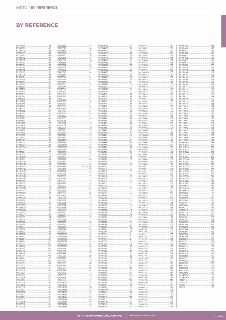
3CATALOGUE TEST & MESURE 2021 www.chauvin-arnoux.com 223TEST & MEASUREMENT CATALOGUE 2022 www.chauvin-arnoux.com
INDEX > BY REFERENCE
P01146011...............................................42P01146013...............................................42P01156302Z ...........................................124P01156401.............................................138P01156401.............................................138P01156402.............................................138P01157152...............................................98P01157153...............................................98P01157154...............................................98P01157165...............................................99P01157166...............................................97P01157167...............................................97P01157170.............................................103P01157171.............................................103P01157180.............................................100P01157181.............................................101P01157182.............................................102P01157201.............................................103P01157702...............................................71P01160511...............................................90P01160541...............................................91P01160591...............................................92P01160595...............................................93P01160620...............................................89P01160640.............................................107P01160657...............................................94P01165221.............................................147P01165222.............................................147P01165223.............................................147P01165224.............................................147P01165225.............................................147P01167501.............................................131P01174810.............................................128P01174830.............................................128P01174835.............................................138P01174902.............................................128P01174902.............................................138P01174903.............................................128P01174903.............................................138P01184101.............................................125P01184102.............................................125P01185301.............................................138P01185501Z ...........................................126P01191303...............................................72P01191304...............................................72P01191305...............................................72P01191306...............................................44P01191611...............................................43P01191739Z .............................................24P01191740Z .............................................24P01191742D ............................................19P01191742Z .............................................19P01191745Z .............................................16P01191748Z .............................................17P01191748Z .............................................20P01191748Z ...........................................155P01191755...............................................17P01191757...............................................17P01191762D ............................................19P01191762Z .............................................19P01191771...............................................20P01191771A ............................................20P01191773...............................................20P01191773A ............................................20P01192200...............................................27P01194200...............................................27P01196311E .............................................22P01196521E .............................................22P01196522E .............................................22P01196523E .............................................22 P01196731...............................................24P01196733...............................................24P01196734...............................................24P01196773.................................................5P01196775...............................................25P01196777...............................................25P01196802...............................................26P01196803...............................................26P01196812...............................................26P01196813...............................................26P01197201...............................................81P01197401.............................................147P01197401.............................................210P01197402.............................................147P01197402.............................................210P01197403.............................................147P01197404.............................................147P01197404.............................................210P01197451.............................................147P01197451.............................................210P01275101.............................................150P01275301.............................................151P01275302.............................................151P01275304.............................................150P01275304.............................................151P01275305.............................................151P01275306.............................................151P01275307.............................................151P01275308.............................................151P01275309.............................................151P01275310.............................................151P01275311.............................................151P01275312.............................................151P01275313.............................................151P01275314.............................................151P01275315.............................................151P01275316.............................................151P01275318.............................................151P01275325.............................................150
P01275326.............................................150P01275327.............................................150P01275328.............................................150P01275329.............................................150P01275330.............................................150P01275331.............................................150P01275332.............................................150P01275333.............................................150P01275334.............................................150P01275335.............................................150P01275339.............................................151P01275340.............................................151P01275341.............................................151P01275343.............................................151P01275344.............................................151P01275345.............................................151P01275346.............................................151P01275347.............................................151P01275348.............................................151P01275349.............................................151P01275350.............................................151P01275351.............................................151P01275352.............................................151P01275353.............................................151P01275357.............................................151P01275358.............................................151P01275359.............................................151P01275360.............................................151P01275361.............................................151P01275362.............................................151P01295056.............................................147P01295056.............................................147P01295094...............................................76P01295097...............................................79P01295097...............................................82P01295137...............................................79P01295137...............................................82P01295140...............................................79P01295140...............................................82P01295141...............................................79P01295141...............................................82P01295143A ............................................80P01295143A ............................................82P01295145...............................................82P01295171...............................................81P01295172...............................................79P01295172...............................................81P01295172...............................................82P01295173...............................................79P01295173...............................................81P01295174................................76 - 81 - 98P01295174.............................................107P01295212.............................................148P01295231...............................................77P01295232...............................................77P01295234...............................................79P01295236...............................................79P01295236...............................................82P01295252...............................................81P01295252...............................................81P01295253...............................................81P01295253...............................................82P01295260...............................................78P01295261...............................................78P01295262...............................................78P01295263...............................................78P01295264...............................................78P01295265...............................................78P01295266...............................................78P01295266...............................................81P01295267...............................................78P01295268...............................................78P01295268...............................................81P01295268...............................................82P01295270...............................................78P01295271...............................................61P01295271...............................................82P01295272...............................................82P01295285Z ...........................................154P01295288Z ...........................................107P01295288Z ...........................................152P01295289Z .............................................81P01295289Z ...........................................152P01295290Z ...........................................152P01295291...............................................78P01295291...............................................82P01295292...............................................78P01295292...............................................82P01295293...............................................76P01295293...............................................82P01295293.............................................106P01295293.............................................107 P01295293.............................................138P01295294...............................................82P01295393...............................................40P01295393...............................................76P01295398...............................................40P01295398...............................................76P01295450Z .............................................81P01295450Z ...........................................152P01295451Z ...........................................138P01295451Z ...........................................152P01295452Z ...........................................152P01295453Z .............................................81P01295453Z ...........................................152P01295454Z .............................................81P01295454Z ...........................................107P01295454Z ...........................................153P01295455Z ...........................................152
P01295456Z .............................................81P01295456Z ...........................................152P01295457Z .............................................81P01295457Z .............................................82P01295457Z ...........................................138P01295457Z ...........................................155P01295458Z .............................................81P01295458Z .............................................82P01295458Z ...........................................138P01295458Z ...........................................153P01295459Z .............................................22P01295459Z ...........................................155P01295460Z ...........................................153P01295461Z ...........................................152P01295462Z ...........................................154P01295463Z ...........................................154P01295464Z ...........................................154P01295465...............................................77P01295474Z ...........................................153P01295475Z ...........................................153P01295476...............................................98P01295476.............................................106P01295476.............................................107P01295477.............................................107P01295479...............................................98P01295479...............................................99P01295479.............................................107P01295483.............................................106P01295483.............................................107P01295486...............................................80P01295486...............................................82P01295487...............................................80P01295487...............................................82P01295488...............................................80P01295488...............................................82P01295489.............................................103P01295491Z ...........................................153P01295492...............................................43P01295492...............................................81P01295493...............................................81P01295494...............................................80P01295494...............................................82P01295495...............................................80P01295495...............................................82P01295496.............................................107P01295501.............................................138P01295502.............................................138P01295506...............................................77P01295507...............................................77P01295508...............................................77P01295510...............................................77P01295511...............................................77P01295512...............................................77P01295513...............................................77P01295514...............................................77P01295515...............................................77P01295516...............................................77P01295517...............................................77P01295518...............................................77P01295519...............................................77P01295520...............................................77P01295521...............................................77P01295522...............................................77P01295523...............................................77P01295524...............................................77P01295525...............................................77P01295526...............................................77P01296021...............................................81P01296024...............................................76P01296024.............................................107P01296032...............................................16P01296032...............................................17P01296032...............................................17P01296033...............................................81P01296034...............................................81P01296037.............................................107P01296047...............................................76P01296047...............................................94P01297012...............................................81P01297022...............................................81P01297071...............................................81P01297072...............................................81P01297086...............................................79P01297086...............................................82P01297089...............................................82P01297090...............................................82P01297095...............................................81P01297101...............................................82P01297102...............................................79P01297102...............................................82P01297103...............................................79P01297103...............................................82P01298004.............................................156P01298004.............................................157P01298005...............................................81P01298005.............................................157P01298006...............................................81P01298006.............................................156P01298006.............................................157P01298007.............................................156P01298007.............................................157P01298009B ..........................................157P01298011.............................................156P01298011.............................................157P01298012.............................................156P01298012.............................................157P01298012Z ...........................................157P01298015.............................................157P01298016...............................................81
P01298016.............................................157P01298031.............................................156P01298031.............................................157P01298032.............................................156P01298032.............................................157P01298033.............................................156P01298033.............................................157P01298036.............................................156P01298036.............................................157P01298037.............................................156P01298037.............................................157P01298037A ..........................................156P01298037A ..........................................157P01298040.............................................157P01298043Z ...........................................156P01298043Z ...........................................157P01298046.............................................157P01298049...............................................81P01298049.............................................107P01298049.............................................156P01298049.............................................157P01298051...............................................81P01298051.............................................156P01298051.............................................157P01298055.............................................107P01298055.............................................156P01298055.............................................157P01298056...............................................76P01298056.............................................106P01298056.............................................156P01298056.............................................157P01298057...............................................76P01298057.............................................157P01298061A ..........................................156P01298065Z .............................................24P01298065Z .............................................81P01298065Z ...........................................156P01298065Z ...........................................157P01298066...............................................81P01298066...............................................82P01298066...............................................82P01298066.............................................107P01298066.............................................156P01298066.............................................157P01298067...............................................82P01298067.............................................107P01298067.............................................156P01298067.............................................157P01298068.............................................156P01298069.............................................156P01298071...............................................97P01298071.............................................138P01298071.............................................156P01298072.............................................156P01298072.............................................157P01298074...............................................17P01298074.............................................156P01298074.............................................157P01298075.............................................138P01298075.............................................156P01298075.............................................157P01298076.............................................101P01298076.............................................107P01298076.............................................156P01298076.............................................157P01298078...............................................98P01298078.............................................107P01298078.............................................156P01298078.............................................157P01298080...............................................81P01298080.............................................157P01298081...............................................76P01298082...............................................76P01298083...............................................94P01298083.............................................107P01299926...............................................43P01637301.............................................107P01651001Z ...........................................129P01651011.............................................130P01651020.............................................138P01651021.............................................138P01651022.............................................138P01651023.............................................107P01651023.............................................138P01651023.............................................155P01651030.............................................126P01651101.............................................129P01651101.............................................138P01651403Z ...........................................120P01651610Z ...........................................120P01651620.............................................148P01651813.............................................119P01651814.............................................119P01651815.............................................119P01651816.............................................119P01651901.............................................114P01651902.............................................113P01651904.............................................115P01653100.............................................121P01653110.............................................121P01654110.............................................127P01654227.............................................125P01654246...............................................81P01654246...............................................82P01654246.............................................124P01654250.............................................138P01654251.............................................138P01654252.............................................101P01654252.............................................138
P01654253.............................................138P01654402.............................................112P01654621.............................................111P01654623.............................................111P01654821.............................................122P01654822.............................................122P01654823.............................................123P01655010.............................................136P01655020.............................................137P01700105.............................................138P01700106.............................................133P01700106.............................................138P01700107.............................................133P01700107.............................................138P01700108.............................................138P01700109.............................................133P01700109.............................................138P01700114.............................................138P01700115.............................................138P01700116.............................................138P01700117.............................................135P01700117.............................................138P01700118.............................................135P01700118.............................................138P01700119.............................................138P01710010.............................................134P01710015.............................................133P01710016.............................................133P01710020.............................................135P01710050.............................................138P01710050.............................................138P01710051.............................................134P01710051.............................................138P01710052.............................................134P01710052.............................................138P01710053.............................................138P01710054.............................................138P01710055.............................................138P01710056.............................................133P01710056.............................................138P01NC5003 ............................................149P03197521A ..........................................147P03197521A .........................................210P03197522A ..........................................147P03197522A .........................................210P03197523A ..........................................147P03197523A ..........................................210P03197524A ..........................................147P03197524A ..........................................210P03197525A ..........................................147P03197525A ..........................................210P03197526A ..........................................147P03197526A ..........................................210P03197527A ..........................................147P03197527A ..........................................210P03197528A ..........................................147P03197528A ..........................................210P03197704.............................................129P03199611A ..........................................147P03199612A ..........................................147P03199613A ..........................................147P03295509...............................................22P03295509...............................................81P03295509.............................................107P03295509.............................................155P03297514...............................................81P03298504.............................................157P03652712.............................................137P03652713.............................................137P03652714.............................................137P03652715.............................................137P03652901.............................................136P03652902.............................................136P03652903.............................................136P03652904.............................................136P03652905.............................................136P03652906.............................................136P03652907.............................................136P03652908.............................................136P03652909.............................................137P03652910.............................................137P03652912.............................................137P03652913.............................................137P03652914.............................................137P03652917.............................................136P03652918.............................................136P03652919.............................................136P03652920.............................................136P03652921.............................................136P03652922.............................................136P03652925.............................................137P06239307.............................................155P06239502...............................................81P06239502.............................................156P06239502.............................................157SX-METRO/P .............................................27SX-METRO/P ...........................................195TCX001-Z ...............................................162TX0001-Z ...............................................161VX0003 ...................................................162VX0100 ...................................................162
BY REFERENCE

2022
TES
T &
MES
UR
EMEN
T CA
TALO
GU
E
9061
3115
3 -
Ed. 1
- 0
2/20
22 -
Non
-con
tract
ual d
ocum
ent.
Spec
ifica
tions
sub
ject
to m
odifi
catio
n du
e to
tech
nolo
gica
l dev
elop
men
ts.
chauvin-arnoux.comGB
TEST
&
MEASUREMENT20
22
10 SUBSIDIARIES WORLDWIDEAUSTRIACHAUVIN ARNOUX GES.M.B.HSlamastrasse 29/2/4par Gastgegasse 27Tel.: +43 1 61 61 9 61Fax: +43 1 61 61 9 [email protected]
CHINASHANGHAI PU-JIANGENERDIS INSTRUMENTS CO., LTD.3 Floor, 23 BuildingGemdale Viseen Minhang Technology& Industrial Park Project1288 lane, Zhongchun Road MinhangDistrict, SHANGHAI City.Tel.: +86 21 65 21 51 96Fax: +86 21 65 21 61 [email protected]
GERMANYCHAUVIN ARNOUX GMBHOhmstraße 177694 KEHL / RHEINTel.: +49 07851 99 26-0Fax: +49 07851 99 [email protected]
ITALYAMRA SPAVia Sant’Ambrogio, 2320846 MACHERIO (MB)Tel.: +39 039 245 75 45Fax: +39 039 481 [email protected]
MIDDLE EASTCHAUVIN ARNOUX MIDDLE EASTPO Box 60-1541241 2020 JAL EL DIB(Beirut) - LEBANONTel.: +961 1 890 425Fax: +961 1 890 [email protected]
SCANDINAVIACA MÄTSYSTEM ABSjöflygvägen 35SE-183 62 TABYTel.: +46 8 50 52 68 00Fax: +46 8 50 52 68 [email protected]
SPAINCHAUVIN ARNOUX IBÉRICA SAC/ Roger de Flor N°293 1a Planta08025 BARCELONATel.: +34 902 20 22 26Fax: +34 934 59 14 [email protected]
SWITZERLANDCHAUVIN ARNOUX AGMoosacherstrasse 158804 AU / ZHTel.: +41 44 727 75 55Fax: +41 44 727 75 [email protected]
USACHAUVIN ARNOUX INCd.b.a AEMC Instruments15 Faraday DriveDover - NH 03820Tel. : +1 (800) 945-2362Fax : +1 (603) [email protected]
FRANCECHAUVIN ARNOUX12-16 Rue Sarah Bernhardt92600 Asnières-Sur-SeineTel.: +33 1 44 85 44 85Fax: +33 1 46 27 73 [email protected]
INTERNATIONAL CHAUVIN ARNOUX12-16 Rue Sarah Bernhardt92600 Asnières-Sur-SeineTel.: +33 1 44 85 44 38Fax: +33 1 46 27 95 [email protected]
SWITZERLANDCHAUVIN ARNOUX AGMoosacherstrasse 158804 AU / ZHTel.: 044 727 75 55Fax: 044 727 75 [email protected]