the measurement of thickness
90
Rational. Bureau ol Libra.."/ » i* • • JUL 2 4 1958 S;.anda-rds Bids The Measurement of Thickness MBS CIRCULAR SSS UNITED STATES DEPARTMENT DF CDMMERCE NATIONAL BUREAU OF STANDARDS
-
Upload
khangminh22 -
Category
Documents
-
view
2 -
download
0
Transcript of the measurement of thickness
Rational. Bureau ol
Libra.."/ » i* • •
JUL 2 4 1958
S;.anda-rds
Bids
The Measurement of Thickness
MBS CIRCULAR SSS
UNITED STATES DEPARTMENT DF CDMMERCE
NATIONAL BUREAU OF STANDARDS

The National Bureau of Standards
Functions and Activities
The functions of the National Bureau of Standards are set forth in the
Act of Congress, March 3, 1901, as amended by Congress in Public Law 619,
1950. These include the development and maintenance of the national
standards of measurement and the provision of means and methods for
making measurements consistent with these standards ;the determination
of physical constants and properties of materials ; the development of meth-
ods and instruments for testing materials, devices, and structures ; advisory
services to Government Agencies on scientific and technical problems', in-
vention and development of devices to serve special needs of the Govern-
ment ; and the development of standard practices, codes, and specifications.
The work includes basic and applied research, development, engineering, in-
strumentation, testing, evaluation, calibration services, and various consul-
tation and information services. A major portion of the Bureau’s work is
performed for other Government agencies, particularly the Department of
Defense and the Atomic Energy Commission. The scope of activities is
suggested by the listing of divisions and sections on the inside of the back
cover.
Publications
The results of the Bureau’s work take the form of either actual equip-
ment and devices or published papers. These papers appear either in the
Bureau’s own series of publications or in the journals of professional and
scientific societies. The Bureau itself publishes three monthly periodicals,
available from the Government Printing Office: The Journal of Research,
which presents complete papers reporting technical investigations; the
Technical News Bulletin, which presents summary and preliminary reports
on work in progress;and Basic Radio Propagation Predictions, which pro-
vides data for determining the best frequencies to use for radio communi-cations throughout the world. There are also five series of nonperiodical
publications : The Applied Mathematics Series, Circulars, Handbooks, Build-
ing Materials and Structures Reports, and Miscellaneous Publications.
Information on the Bureau’s publications can be found in NBS Circular
460, Publications of the National Bureau of Standards ($1.25) and its Sup-
plement ($0.75), available from the Superintendent of Documents, Govern-
ment Printing Office, Washington 25, D. C.

To AccompanyNational Bureau of Standards Circular 585
THE MEASUREMENT OF THICKNESS
NOTE
The survey on which this Circular is based was completed in 1955.More recent developments are not included. Since no other comoarablecompilation has appeared in the meantime, it is considered that thecontents will be of value even though incomplete.
ERRATA
Page Section
13 1.152 The illustrations of figures 33 and34 are transposed
17 1.203 (3d par.
last line)should read d<I>/4
22 1.234 penultimate line should be deleted
a 4.41 transpose last five lines of left-handcolumn to top of page
43 4.53 caption omitted on last figure: Fig.
105, Circuit of sheet metal thicknesscomparator
52 5.4 McNlcholas and Curtis reference shouldbe numbered (143a)
52 5.4 Ref. (126) does not apply to this section
54 6.3 Ref. (66) does not apply to this section
Reference
72 (120) should read Instruments in Industry, London(now called Automation in Industry)
72 (126) second citation should read; Engrs. Digest(Amer. Ed.) 6, 156-7, (1945)
73 (161) title should read: Elektrische Messungmechanischer Groessen
73 (165) Citation should read: Revue Generale de1 'Electricite (Paris), 44, 265-268(1938)
March 25, 1958USCOilM-NES-I/C

Vf>5'rvr:'^^;-.orV
i‘j’X;
'r-i" -vi . r-
•»’*’
V
2fci;4'.r ^r vseT
..':r;
"‘f. 1 .; -'A;:-. r'v -xi 'ft -s'^;' .:•.
,/„ Ev^ ,=X , J'
• X^:'' '.,•» '^'.. '•',
•.
,. . . .
.•
'
'
.
r. i"
:•, .,'. -• r
'• • '
'?: f-" : ^: „..
E::E- ..' •• -E ,... ::.' ;
. ::i.'''*%(• '
.
' /
'•
: T'. E '‘l A
'„ •'
/ -y
^
-;' X,,;
'-'‘f
-'' "^ , • '.'
.' 'VEVAj:;. .E. oX'"" ^
^ .-X.,
/'
:K--,
E"'. -'u-EE^ E'-' v,
.
-' '
. ; i'I
._
... }.•
>7,.
\.,X
A . 7 ^., ^V '.V. ;•,
.•• 'e a. E-'.E-' .E
Eat .; aE'-t-;.' 7; E'- aE '' -
'.AlE'-X-.EE'Tr...,, . : :
UNITED STATES DEPARTMENT OF COMMERCE • Sinclair Weeks, Secretary
NATIONAL BUREAU OF STANDARDS • A. V. Astin, Director
The Measurement of Thickness
George Keinath
National Bureau of Standards Circular 585
Issued January 20, 1958
For sale by the Superintendent of Documents, U.S. Government Printing Office, Washington 25, D. C.
Price .... 50 cents

Foreword
Preparation of this monograph on thickness measurement was under-
taken to bring together available information on the various methods andproblems of measuring thickness that are frequently encountered in scien-
tific and industrial fields. The usefulness of this survey to scientists andengineers is expected to be enhanced by the inclusion of discussion of ranges,
accuracy, advantages, and limitations. No attempt has been made to de-
scribe methods and instruments in detail. Such detailed information should
be sought in the literature references that are appended to the text. Adiscussion of the bounds that have been set on the scope of the work will be
found in the introduction.
Names and descriptions of specific proprietary instruments are included
for the convenience of the user, but completeness in this respect is recog-
nized to be impossible. The omission of any method or device does not imply
that it is considered unsuitable or unsatisfactory. Conversely, inclusion of
descriptive material on any proprietary instrument, product, or process,
does not constitute endorsement.
Some of the information included in this report was obtained from the
open literature. The assistance obtained from American instrument manu-facturers who furnished catalogs and other information descriptive of their
products was vitally necessary to the work and is gratefully acknowledged.
The survey of the field of thickness measurement and the preparation
of this Circular were carried on as a project of the NBS Office of Basic
Instrumentation, which administers a Bureau-wide program of research,
development, and dissemination of information relating to measurementsand instruments. This program is cooperatively supported in part by the
Office of Naval Research, the Office of Scientific Research of the Air Re-
search and Development Command, and the Atomic Energy Commission.
A. V. Astin, Director.

Contents
Page
oreword ii
•itroduction 1
lethods of measurement 2.00. Mechanical methods 21.01. Weight - 21.02. Volume 2
1.03. Oblique cut 2
1.031. Vitreous enamel 21.032. Case depth (hardness traverse) .— 2
1.04. Chord cut 21.05. Manual roller gages 3
1.051. Euverard gage for wet films 31.052. Euverard gage for dry films 3
1.06. Sphere penetration gage 41.10. Mechanical gages, direct reading 41.11. Slide calipers 51.12. Joint calipers 51.13. Screw micrometers 5
1.131. Micrometer caliper 51.132. Screw micrometer with optical
indication of pressure 61.133. Screw micrometer with electrical
indication of contact 71.134. Penetrating needle 8
1.14. Dial micrometers 81.141. Simple dial micrometers
(medium sensitivity) 81.142. Dial gage micrometer with screw
micrometer 91.143. Dial gage micrometer with joint
caliper 91.144. Dead-weight and spring-loaded gages 91.145. Special designs 111.146. Roller gages 111.147. Averaging gages 12
1.15. Dial gages, high mechanicalmagnifications 12
1.151. Parallel reeds 121.152. Twisted ribbon 121.153. Tilting block 13
1.16. Dial gages, optical lever 131.161. Mirror principle 131.162. Roller gage with optical magnification 141.163. “Projectometer” 141.164. “Visual gage” 15
1.20. Pneumatic gages 151.201. Back-pressure gage 161.202. Continuous gage for threads and wires .. 171.203. Continuous gage for moving strips 171.204. Rate-of-fiow gage 17
1.21. Defiection 181.22. Vibration 19
1.221. Sonic 191.222. Ultrasonic 19
1.23. Displacement with resistive pickup 201.231. Slide contact 201.232. Resistive strain gages 211.233. Variable-resistance spring 211.234. Linear-motion potentiometer 22
1.24. Displacement with inductive pickup 221.241. Mutual inductance 221.242. Double-airgap reactance ratio 22
Page
1.2421. “Electrolimit” gage 221.2422. “Electrigage” 231.2423. “Metron” gage 231.2424. “Pacific” evenness tester 24
1.243. Differential transformers 241.2431. “Atcotran” and Schaevitz designs 241.2432. Stevens-Arnold portable
instrument 251.2433. “Lyn-A-Syn” transducer 26
1.244. “Metrisite” transducer 261.25. Displacement with capacitive pickup 26
1.251. Change of capacitance 261.252. Change of capacitance ratio 27
1.26. Displacement with thermal converter 271.27. Displacement with electronic converter 281.28. Displacement with photoelectric pickup 28
2.00. Chemical methods 29
2.1.
Stripping and weighing 292.2 Optical projection with stripping 292.3. Spectrophotometry 292.4. Spectrochemical analysis 292.5. Color change 29
2.51. Spot test 302.52. Dropping test 302.53. BNF jet test 30
2.62. Electrical potential 303.00. Electrical methods 30
3.1. Insulation breakdown 303.11. Aluminum oxide testers 303.12. Enameled wire 31
3.2. Resistance 323.21. Resistance method for wires and ribbons - 323.22. Resistance method for metal sheets
from one side 323.23. Resistance method for intricate castings — 333.24. Resistance method for silver plating 33
3.3. Heating 333.4. Electrochemical method 33
3.41. Coulomb-counting 333.42. Potential change 33
3.5. Capacitance 343.51. Fielden-Walker evenness tester 343.52. Noncontacting capacitors 343.53. Textile uniformity analyzer 353.54. Decker model 103 comparator
micrometer 353.6. Thermoelectricity 35
3.61. Thermoelectric thickness gage 354.00. Magnetic methods 36
4.1. Attractive force 364.11. Magnetic gages 364.12. Magnetic gages for glass bulbs 374.13. Modified magnetic gage for nickel and
copper on steel 374.14. Solenoid pull gage 37
4.2. Parallel magnetic flux 384.21. Moore-Williamson instrument 384.22. “Elcometer” dry-film thickness gage 384.23. Magnaflux Corp. meter 39
4.3. Magnetic saturation . 394.31. GE magnetic saturation gage 39
iii

Page
4.4. Coil reactance 404.41. GE reactance gage for nonmagnetic
coatings on magnetic base 404.42. Haskins Turner Co. gage for scale
inside boiler tubes 414.43. “Hurletron” for paper production 424.44. “Coatingage” 42
4.5. Transformers 434.51. Transformer method for nonmagnetic
coatings on steel (one side) 434.52. Transformer method for ferromagnetic
materials (one side) 434.53. Sheet-iron tester, d-c operated 434.54. Nonmagnetic coatings, differential
voltage 444.6. Eddy-currents, inductance change 44
4.61. “Filmeter” 454.62. Nash and Thompson eddy-current gage — . 454.63. GE eddy-current gage for hollow
propellers 454.64. Eddy-current gages for moving metal
sheets — 454.65. Gages for lead sheath on a cable 464.66. “Probolog” 464.67. Gage for ceramic coatings on metal 474.68. Gages for metal coatings on metal 47
4.7. Mutual inductance with air core 474.71. Measurement of bearing eccentricity 474.72. Phase-angle thickness gage for silver
coating on stainless steel 48
4.8.
Wattage absorbed 48
5.00.
Optical methods 485.1. Measuring microscope 485.2. Change of focus 485.3. Interference 50
5.31. GE spectrophotometer 505.32. Michelson interferometer 515.33. Interference microscope 515.34. Color comparison 515.35. Donaldson-Khamsavi method 51
Pago5.36.
Fizeau method 525.4. Diffraction — 525.5. Light beam to photocell - 52
5.51. “Evenometer” 525.52. “Filometer” 525.53. “Sere” evenness tester, electron
micrometer, and “diamatrol” 535.54. “Visi-Limit” gage 53
5.6. Electron microscope 54
^6.00. X-ray methods - 546.1. Shadow geometry 546.2. Absorption, photographic comparison 546.3. Absorption, radiation detectors 54
6.31. Single tube and beam 556.32. Absorption differential 566.33. Special varieties of X-ray gages 57
6.4. Diffraction 576.5. Backscattering, secondary radiation 586.6. Spectrometry, for depth of cold-working 59
y 7.00. Radioactivity 59‘ 7.1. Beta-ray absorption - 62
7.11. Tracerlab gage 627.12. “Accuray” gage 637.13. GE gage 637.14. Pratt and Whitney gage 647.15. “Betameter” 647.16. “EKCO” gage 647.17. Goodyear Corp. film gage 64
7.2. Beta-ray backscattering 647.3. Neutron bombardment, measurement of
beta-ray emission 667.4. Gamma-ray absorption and backscattering 667.5. Reduction of thickness by wear,
autoradiography 678.00. Thickness meters for the blind 689.00. ASTM acceptance tests 68Literature references 69Patents 75List of manufacturers 75Index of gages, methods, and applications 77
coatings, films sheets plates
Conversion table.
Conversions among a number of units in which thickness is expressed.
ii
!l
IV

The Measurement of Thickness
George Keinath^
The numerous methods for the measurement of thickness in laboratory or shop aretreated in seven groups according to physical operating principles: Mechanical
—
weight/dimension relationships, acoustics, vibration, displacement with various con-
versions; chemical—stripping, spectrochemical analysis; electrical—dielectric break-1 down, resistance, electrochemical, capacitance, thermoelectricity; magnetic—attractive
1
' force, reluctance, saturation, inductance, eddy currents; optical—microscopy (also elec-
1 tron microscopyK interferometry, diffraction, shadow; X-ray—absorption, diffraction,
I
I backscatter, spectrometry; radioactive radiation—absorption, backscatter, tracers.
Ranges, accuracies, advantages, and limitations are discussed. A bibliography of refer-
ences, a limited list of suppliers, and a detailed index of the gages, methods, applications,
and trade names covered are appended.
5 I The measurement of thickness is the meas-2
i urement of the distance from a point on one
j
I bounding surface of a material body, through
3r the body, to the opposite bounding surface. If
1 fthe surfaces of a body are parallel, as the two
1i sides of a sheet of metal or the inner and outer
II
surfaces of a pipe, the thickness is obviously the
II distance between the bounding surfaces meas-r ured along a normal. However, if the surfaces
8 ! are not parallel the direction in which the thick-*
: ness is to be measured must be defined. Some-
j
times the measuring instrument itself deter-
jgI
mines the direction along which the thickness18 1 is measured.19 Further complications in measuring thickness1“ i are introduced by the lack of definition of the
l bounding surfaces of a body. For example, thethickness of a textile material is rather indefi-
i nite. Here, also, the measuring instrument im-;
portantly influences the “measured” thickness.I Thickness measurements as above described
^
deal with the measurement of a distance be-tween two points. However, for some purposesthe measurement of the average thickness of a
I
body is of more significance.This survey is intended to assemble for con-
I venient reference as many of the methods of! dealing with the problems of thickness measure-
jj ;
ment as possible. It is not limited to direct
I
measurement of thickness, but gives sufficientbackground information on the types and prin-
Iciples of operation of the devices to reduce the
I
need to seek the basic information elsewhere.The survey includes information on the meas-
i urement of physical parameters involved in the
{
practical measurement of thickness, such asdisplacement, for example. It also deals withsome more general aspects of the measurement,such as dynamic response. The extent to whichthese are treated is determined in general,by the principles and makeup of existinginstruments.
Considering only industrial problems, themaximum thickness is about 10 million times
1 Larchmont, N. Y.
the minimum. The low limit is 0.01 microinch,as found in very thin coatings on glass. Thehigh limit may be one or more inches, as in
rolled or cast metals. This discussion will beprimarily concerned with the measurement of
the thickness of walls, sheets, and coatings of
all kinds. Thickness of wires and threads is
also included, although “diameter” is the termmore generally used if the sample has a circularor an elliptical cross section. Distance measure-ment (as in spark gaps) is omitted, though the“feeler gages” for such measurements are called
thickness gages.The methods of thickness measurements may
be destructive or nondestructive, contacting ornoncontacting, with relation to the sample. It is
very difficult to establish clear definitions ofthese terms for methods of measurement. Forinstance, the use of a needle to penetrate aninsulating coat on a metallic base is a destruc-tive method at the point of measurement. How-ever, the manufacturer of the gage may considerhis method nondestructive, because the tiny holein a paint coating is practically invisible andunimportant in the use of the product. In thesimplest problems the object of measurement is
a small specimen accessible from both sides.
Difficulties arise when the object is accessiblefrom only one side. Such an object might be amoving sheet coming from a steel mill red hot,vibrating violently, covered with water orgrease, and made almost invisible by a cloud ofsteam. In such a case the use of noncontactingthickness meters would be necessary.
Units of thickness: In this compilation, thick-ness has usually been expressed in “mils,” i.e.,
thousandths of an inch, so that values of thick-ness will be easy to compare. It should be noted,however, that although this practice of statingthicknesses of flat metal sheets and plates anddiameters of wires in mils is increasing, thespecification of such sizes by numbers in one ofseveral gage systems is still widely prevalent.In these systems, a given number is used todesignate different thicknesses depending onthe material under consideration, e.g., steel.
1

brass, or aluminum. Since 1941 the AmericanStandards Association has issued Standards forPreferred Thicknesses for uncoated thin flat
metals under one-half inch, covering in thelatest issue the range from 4 to 236 mils in 40steps by values progressing in accordance withthe 40- series of preferred numbers, each stepbeing 3 percent higher than the preceding one.The 1941 issue has only 20 steps, with a differ-
ence of 6 percent from step to step.
Conversions among a number of units inwhich thickness is expressed are presented inthe accompanying table on preceding page IV.
References to the literature and to patents areindicated by numbers, in brackets and paren-theses, respectively, referring to the biblio-
graphic listings on pages 69 and 75.
In writing this mono^aph the author hasreceived a variety of assistance from the staff
of the Office of Basic Instrumentation. Thisassistance is gratefully acknowledged. Deserv-ing particular mention are the extensive edi-torial review and the contributions to the sec-tions on application of interferometry, radio-graphic, and nuclear radiation methods.
Methods of Measurement1.00.
Mechanical Methods
In this section are assembled methods inwhich the first measurement action is mechani-cal. The mechanical displacement, which is afunction of the thickness, may in turn be meas-ured by optical, pneumatic, electric, or othermeans, generally with the purpose of increasingthe accuracy.
1.01. Weight [147; 190, p. 7].^ If a materialis homogeneous and of known density, a sampleof controlled size can be weighed, and its thick-ness calculated from its weight. It is possiblewith sheet materials to cut samples of a speci-fied size at each measurement and thus facilitatethe determination of thickness. Wires are meas-ured in standard lengths. Balances that indicatethickness directly are available or can be cali-
brated according to need.
1.02. Volume [168]. The thickness of non-porous insulation of wires may be determinedin the following way : A length of wire of about8 inches is cut off and put in a narrow cylin-drical measuring vessel, filled with alcohol. Therise of the level gives the total volume. Afterstripping and dissolving the insulation, themeasurement is repeated. From the volumedifference the average thickness may be calcu-lated. This method has been used successfullyfor several years by the Physikalisch-TechnischeReichsanstalt in Berlin, for wires from 0.75- tolO-mm^ section (AWG No. 18 to No. 7) with anaccuracy of about 2 percent.
1.03. Oblique Cut.1.031. Vitreous Enamel [111] (fig. 1). A
method has been developed to measure the thick-ness of acid-resistant enamel coatings on ironplumbing fixtures (fig. 1). From a section ofsuitable size, along a new-cut edge, the enamelis ground off in a plane at an angle of approxi-mately 5 degrees to the surface, exposing anoblique section of the enamel coating and partof the underlying metal. The lines (aag, aidj,a2d2 , and a^d.^) shown in figure 1 are markedwith a ceramic underglaze pencil. The specimen
- Figures in brackets indicate the literature references on page 69.
is refired just enough to obtain a fire polish onthe oblique section of the enamel. After cooling,
the specimen is immersed in 10-percent citric
acid and dried. Colored wax pencil is applied to
the whole surface, which is then rubbed with acloth. The colored wax is readily removed fromthe acid-resistant section, which will have re-
tained its fire polish. This section is now clearly
bounded by the line aas, and the colored waxdeposit. From measurements made along theparallel lines andn of the thickness of the total
coating and lengths along the cut, the thicknessof the acid-resistant coating is computed. Themethod is accurate to about 0.5 mil in a total
acid-resistant thickness of 2.5 to 8 mils.
Figure 1. Sketch of specimen showing cross section andoblique section of enamel applied in three coats over iron.
1.032. Case Depth (Hardness Traverse) [10,
157, 172, 175]. Effective case depth in steel is
defined as a distance measured perpendicularlyfrom the surface of a hardened case to a pointof hardness equivalent to Rockwell “C” 50.
Total case depth is defined as a distance meas-ured perpendicularly from the surface down to
the point where carbon enrichment ceases. Thespecimen is cut, ground, and polished in either
steps, taper, or perpendicular section. The ex-
posed surface is tested for hardness until theeffective case depth is reached.
1.04.
Chord Cut [35] (fig. 2). Mesle’s chordmethod for measuring the thickness of coatingsdepends on barely cutting through the coating
—
on a plane surface, with a grinding wheel of
2

e
!
IS
ff
is
]•
c-
0-
Figure 2. Chord method to determine thickness ofcoating on a spherical surface.
it known radius fed perpendicularly; on a curved
to surface, by a chordal cut. In either case thea thickness can be computed from the chord andID
^
the radius of the segment removed. The refer-e-K ence cited [35] gives the formula for calculat-
lyf! ing thickness for a number of different inter-
ax secting shapes: Plane surface and grindinghe wheel
;
convex spherical surface and flat file
;
convex spherical surface and grinding wheel;,js i
: and concave spherical surface and small-radius
he t'+ grinding wheel. The curvature of spherical sur-faces is determined with a spherometer. The
ij measurement is difficult when coating and base
j
have about the same color, in which case the cutw i surface is treated with chemicals that cause a
Icolor change.
I With a grinding wheel radius of 3 to 4 inchessi the least thickness measurable is 0.05 mil, the
chord length being about 40 mils. The accuracy
Iis about 5 percent for nickel or composite coat-
/jon steel plates, and about 10 percent for
Inickel coatings on copper or brass plates. For
Ivery thin coatings of chromium (about 0.02
Imil) used for decorating purposes, a very small
Igrinding wheel is recommended to produce a
f| narrow but well-defined cut which can be meas-ured with a microscope.
Dif 1.05. Manual Roller Gages.- 1.051. Euverard Gage for Wet Films (figs.
gage, developed for the measure-isffi ment of wet film thicknesses, is essentially alj| graduated eccentric wheel supported by twootl concentric wheels (fig. 4), all machined to an0,1 accuracy of 0.008 mil. When rolled over a planes.)' surface, there is a clearance ranging from 0 tolol! 4 mils (fig. 3) between the inner eccentric wheellej
and the surface upon which the outer two con-;t|, centric wheels rest. When the gage is placed on
-a wet surface in the position of the greatestifw clearance, and rolled until the clearance is elim-' mated, the eccentric wheel will at some inter-
7 contact and “pick up” the wetrj film. The measurement is usually performed in
'!perpendicular directions and the average
if!of the readings taken as the true wet-filmthickness.
Figure 3. Roller thickness gage.
Figure 4. Roller thickness gage.
The standard instrument with a wheel 2 in.
in diameter has a measuring range of 0 to 4
mils. Each scale division on the eccentric wheelrepresents 0.2 mil and readings to the nearest0.1 mil are possible. The following instrumentranges are also available : 0 to 0.4 mil, 0 to 1 mil,
0 to 2 mils, 0 to 12 mils, 10 to 30 mils, and 20 to
60 mils; and the scale graduations, 0.02, 0.05,
0.1, 0.5, 1.0, and 2.0 mils.
Manufacturer: Henry A. Gardner Labora-tory, Bethesda, Md.
1.052. Euverard Gage for Dry Films (figs.
5, 6). An adaptation of the wet-film gage de-
scribed above makes it suitable for measuringthe thickness of coatings, especially paint coat-
ings, on a nonconducting base like wood orglass. The same wheel is used, but the film is
removed from the base along two suitablyspaced strips, to permit the outside concentricwheels of the gage to rest on the uncoated base.
By the use of a suitably adjusted mirror or lens,
the degree of clearance between the measuringsurface of the gage and the film coating can beseen with the aid of a diffused-light source di-
rected toward the gage. As long as there is agap between the measuring surface of the eccen-tric wheel and the coating, it is possible to ob-serve a brightly illuminated area which has the
'L
3
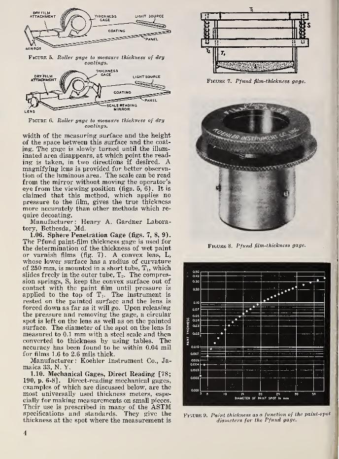
Figure 5. Roller gage to measure thickness of drycoatings.
Figure 6. Roller gage to measure thiekness of drycoatings.
width of the measuring surface and the heightof the space between this surface and the coat-
ing. The gage is slowly turned until the illum-
inated area disappears, at which point the read-
ing is taken, in two directions if desired. Amagnifying lens is provided for better observa-tion of the luminous area. The scale can be readfrom the mirror without moving the operator’s
eye from the viewing position (figs. 5, 6). It is
claimed that this method, which applies nopressure to the film, gives the true thicknessmore accurately than other methods which re-
quire decoating.Manufacturer: Henry A. Gardner Labora-
tory, Bethesda, Md.1.06. Sphere Penetration Gage (figs. 7, 8, 9).
The Pfund paint-film thickness gage is used forthe determination of the thickness of wet paintor varnish films (fig. 7). A convex lens, L,
whose lower surface has a radius of curvatureof 250 mm, is mounted in a short tube, Ti, whichslides freely in the outer tube, T2 . The compres-sion springs, S, keep the convex surface out of
contact with the paint film until pressure is
applied to the top of T,. The instrument is
rested on the painted surface and the lens is
forced down as far as it will go. Upon releasingthe pressure and removing the gage, a circular
spot is left on the lens as well as on the paintedsurface. The diameter of the spot on the lens is
measured to 0.1 mm with a steel scale and thenconverted to thickness by using tables. Theaccuracy has been found to be within 0.04 milfor films 1.6 to 2.6 mils thick.
Manufacturer : Koehler Instrument Co., Ja-maica 33, N. Y.
1.10. Mechanical Gages, Direct Reading [78;190, p. 6-8] . Direct-reading mechanical gages,examples of which are discussed below, are themost universally used thickness meters, espe-cially for making measurements on small pieces.
Their use is prescribed in many of the ASTMspecifications and standards. They give thethickness at the spot where the measurement is
Figure 7. Pfund film-thickness gage.
Figure 9. Paint thickness as a function of the paint-spot
diameters for the Pfund gage.
4

I
Figure 10. Slide caliper with vernier attachment.
made. For large objects one must determine
jthe average thickness by making a number of
' measurements at a number of evenly distributed
spots and calculating the arithmetic mean. Thethickness of very fine paper, such as that usedfor capacitors, is often measured by stacking anassembly of 10 sheets and using a parallel-plate
gage. With paper about 0.25 mil thick, usingdial gages or screw micrometers, the thickness
^! of one sheet might be measured as 0.34 mil,
' whereas the average thickness based on 10stacked sheets might be only 0.24 mil. The dif-
ference in values between measurements on asingle sheet and measurements on stacked sheetsdepends on the “packing fraction” (the extentto which the thicker areas of one sheet coincidewith the thinner areas of another sheet) . Thestacked thickness values are preferred as a prac-tical matter because they tend to be more nearlyuniform.
1.11. Slide Calipers [27] (fig. 10). Slide cali-
_ pers are among the simplest devices for thick-
J ness measurement. The reading accuracy is
Iabout 0.1 mm (4 mils) for direct reading, be-
M cause the smallest discernible distance is aboutji 0.07 mm for the average human eye [27]. With
^ a vernier attachment the accuracy can be muchincreased, with 0.018 mm as the possible limit.
In view of the thickness of the graduation linesa practically feasible value is 0.050 mm (2mils). By using a magnifying lens, a vernier
- with 50 divisions, and a line thickness of notmore than 0.07 to 0.1 mm, a least reading of
> 0.02 mm may be obtained.
,1.12. Joint Calipers (fig. 11). There are three
I types of joint calipers (fig. 11) which are cus-
,
tomarily used as comparators to transfer a' dimension to a steel scale for measurement:1 (a) Firm-joint calipers with legs that hold.. their position by friction, giving the advantage
of very quick adjustment.(b) Screw-adjusted firm-joint calipers, simi-
.! lar to (a), but with fine adjustment.!:
(c) Spring calipers, the most widely used: type.
,1.13. Screw Micrometers [15, 20, 27, 118,
' 206] (fig. 12).1.131. Micrometer Caliper [27]. The mi-
s)»T crometer is essentially a calibrated screw. Byturning the thimble the screw revolves in a
Figure 11.
a» Firm-joint caliper ; b, firm-joint caliper with screw adjustment;c, spring caliper.
fixed nut in the frame, and the spindle, which is
the unthreaded portion of the screw, moves upor down relative to the anvil. The spindle movesthrough a definite distance depending on the
pitch of the screw. As a rule, there are 40threads to the inch
;hence one turn of the thim-
ble moves the spindle ’/4o = 0.025 in. ^ 25
mils. The major divisions of 25 mils are markedon the hub and 25 subdivisions are marked onthe beveled portion of the thimble attached to
the screw.Othe'' micrometers of greater precision are
also m.ade. It should be noted, though, with the
more finely divided screw and the more precise
5

instrument, greater care must be taken in its
use. Accuracy of measurement depends largelyon the pressure exerted on the work and on thecompressibility of the material. The more com-pressible the material, the greater the error.Many types of screw micrometers use a frictionclutch or ratchet for rotating the screw in orderto obtain constant and correct pressure. Gen-erally the accuracy obtained is ±0.1 to ±0.5mils.
One design of micrometer caliper with a non-rotating sleeve reads by vernier down to 0.025mil. Optical magnification with a simple 5 orlOX hand lens is often used with such instru-ments. In the most elaborate designs [27] thereading error is reduced to 1 /x (0.04 mil) andeven 0.1 The total accuracy of measurementis, of course, less than the reading accuracy.
Procedure and permissible errors of microm-eter calipers with and without ratchets arediscussed in ASTM standard D374.
Spindle
Frame
Ratchet Screw
Ratchet Spring'
Ratchet Plunger
Ratchet Thimble
Cap with Ratchet
Cap Only
Tension Nut
Tension Adj. Sleeve
Retaining Spring
Screw Tension Spring
Thimble
Screw Nut
Hub
Lock Nut
Lock Nut Shoe
Figure 12. Micrometer caliper.
1.132. Screw Micrometer With Optical Indi-
cation of Pressure [206] (figs. 13, 14). Thismicrometer (figs. 13, 14), which utilizes optical
pressure indication, has been developed to pro-
vide the highest accuracy of screw micrometers[206]. The micrometer screw, machined -with
great precision, carries a 6-in.-diameter alumi-num wheel with 0.1-mil graduations about 100mils apart, a magnification of 1,000. This per-
mits readings of 0.01 mil. Comliined with this
mechanical-screw micrometer is an optical indi-
cator of pressure, which enables the operator to
apply exactly the same pressure on the objectfor each measurement. This pressure indicator
is a combination of an optical flat, a chromium-plated steel flat, and a red selenium-glass screen,
so arranged that the slightest upward pressureon the micrometer spindle causes interferencebands to move past a reference line. Each inter-
ference band is a measuring unit of 0.01 mil.
The bands are spaced about Vs in. apart. Anymeasuring load from 0 to 2.5 lb can be applied.
When in proper adjustment, two or three bandswill show, from the left-hand edge of the steel
flat up to the cross-reference line, when thespindle is not touching the anvil. Each addi-
tional band that is moved up to this referenceline corresponds to an increase of measuringload of 6 oz. The load is selected to suit thematerial under test. The ranges of this light-
wave screw micrometer are 0 to 1, 0 to 2, or 0 to
3 in. The threshold sensitivity of measurement
Figures 13 and 14. Pressure indication on light-wavescrew micrometer.
6

is 0.005 mil, and of load, V2 oz. Readings can beduplicated to 0.01 mil.
A special design has a range of 0 to 3 in. anda number of features that insure still higheraccuracy and convenience in use.
Manufacturer: The Van Keuren Co., Water-town 72, Mass.
1.133. Screw Micrometer With Electrical In~
dication of Contact [15, 118] (figs. 15, 16).Most mechanical gages for thickness measure-ment impose a load on the object. For com-pressible materials any load interferes withmaking precise measurements, unless controlledin some way, such as that described in 1.132.For metallic specimens, another solution of theproblem is the use of a low-voltage signal lampto indicate contact of the metal tip. This is notfully satisfactory, because the current over thecontact points may cause pitting.
Carson Electronic Micrometer
:
The circuit ofthe Carson Electronic Micrometer [15, 118] is
shown in figures 15 and 16. The circuit adopteduses a negligible current to light an indicatorlamp by means of a relay at the moment of con-tact. A displacement of 0.005 mil is sufficient totrigger the relay. Electrical contact is estab-lished through the work piece itself, when meas-uring metallic materials. For nonconductors,electrical contact is made within the gage headwhen mechanical contact with the work closesthe small gap between two elements in the gagehead. It was found that the presence of appreci-able current at the contact surfaces tended tobuild up carbonized layers which soon reducedaccuracy.The dial diameter is 3 in., with 250 divisions
about 40 mils wide, each representing 0.1 mil,corresponding to a screw pitch of 25 mils. Themagnification is about 400. The accuracy of theinstrument is given as 0.02 mil. For the meas-urement of compressible materials the standardanvil pressure (supplied by a spring in theupper anvil) is Vs oz (3.4 g), but with inter-changeable springs it can be increased to 2, 4,or 8 oz.
Figure 15. Si)nplificcl circuit of the Carson gage.
Manufacturer : J. W. Dice Co., Englewood,N. J.
ASTM standard D374 covers the measure-ment of the thickness of solid electrical insula-
tion with machinist’s micrometers and dead-weight dial micrometers
;it allows tolerances
considerably wider than those obtainable withthe Carson micrometers.
Wall Thickness Meter for Tubes: A mechan-ical micrometer with electrical contact is usedto test the wall thickness of hollow propellers
and of tubes up to 6 ft long. The gage consists
of two long arms mounted on a base. Contactpoints at the ends of the arms are connected to
an electronic control box, giving both optical
and acoustical signals when contact is estab-lished between the micrometer screw and theobject under test. After a preliminary adjust-ment of the equipment, two readings on thevernier dial of the micrometer screw are taken,one with the tubing under test in place, the
Figure 16. ^Carson gage to measure thickness.
7

other with it removed and the upper contactpoint touching the lower contact point. Differ-
ences in wall thickness of 1 mil can be deter-
mined in this way.Manufacturer: Fairchild Aircraft Co., Ha-
gerstown, Md.1.134. Penetrating Needle (figs. 17, 18). A
penetrating-needle-type gage is used for themeasurement of the coating on either flat orcurved metallic surfaces. The body of the gagerests with three points on the surface to betested. The dial screw, 4, moves the needle, 8,
Figure 17. Cross section through measuring head ofGardner gage.
Figure 18. Gardner thickness gage with stand.
downward until it has penetrated the film of
insulation, and makes contact with the metallic
base. This lights signal lamp C. The dial makesone full revolution for 2 mils movement of the
needle and the scale can be read with an accu-
racy of 0.01 mil. The instrument is generally
used in a gage stand, which holds the gage ver-
tical. A pressure of 0 to 10 lb is applied on the
large foot that carries the needle;this pressure
is adjusted according to the hardness of thesurface film. For zeroing, the gage is placed onan uncoated plane metal surface.
Manufacturer: Gardner Laboratories, Beth-esda, Md.A gage, operating on the same principle, with
an electronic relay circuit to light the lamp, is
manufactured under the trade name “Bathy-trol.”
Manufacturer : Electronic Control Corp., De-troit 7, Mich.
1.14. Dial Micrometers [20]
.
1.141. Simple Dial Micrometers (MediumSensitivity) (figs. 19, 20). Even a simple dial
micrometer provides much higher magnificationthan is possible with the standard screw mi-crometer, thus facilitating the reading of smallchanges of thickness. The movement of theanvil is magnified by mechanical means, thesimplest using the lever principle. Mechanicalgears are often used (fig. 19). Very sensitive
gages of this type make one full revolution ofthe pointer for 4 mils displacement of the anvil,
with graduations of 0.05 mil. For greater thick-ness, the pointer makes up to 10 revolutions,which are read on a smaller dial (fig. 20). Inthis device, the magnification of the anvil move-ment is about 2,500. Generally the magnificationof dial micrometers is 500 to 1,000.An instrument with a fan-shaped housing and
±45° deflection, “Micronar,” has a range of
Figure 19. Principle of a dial micrometer'.
8

1
[
'I
1
j
d*
if
Figure 20. Dial micrometer with revolution counter anda range of ±15 mils in divisions of 0.5 mils.
dzl.8 mils, other divisions of 0.1 mil are spaced
150 mils apart, whereas divisions near the scale
center are subdivided to 0.02 mil. The magnifi-
cation is 1,500.
Manufacturer: Standard Gage Co., Pough-keepsie, N. Y.
1.142. Dial Gage Micrometer With Screw Mi-crometer (fig. 21). This instrument can beused either by reading the dimension on the bar-
rel or by setting the barrel to the desired valueand reading the deviation on the dial. The rangeof the dial indicator is ±1 mil, with each divi-
sion 0.1 mil.
Manufacturer: Federal Products Corp.,
Providence, R. I.
1.143. Dial Gage Micrometer With Joint Cali-
per (figs. 22, 23). This meter is used to deter-
mine the thickness of walls, sheets, and sections
of castings and forgings. It is trigger-operatedand the dial micrometer has a revolutioncounter. One mil is represented by 2 in. on thedial, corresponding to a magnification of 2,000.The maximum jaw opening is 4 in.
1.144. Dead-Weight and Spring-Loaded Gages[20, 116a] (figs. 24, 25, 26, 27). For exactmeasurements of objects that are not perfectlyflat or that have a fibrous structure, the meas-ured thickness depends very much on the ap-plied pressure. For the measurement of paper agage foot between 14.3 and 16.5 mm in diameteris used, so that local variations of thickness areeliminated, and the maximum thickness of thesheet is read. For special applications, e.g., tomeasure the thickness of capacitor paper 0.2 to0.4 mil thick, mechanical gages with ball andanvil have been used by the Bell TelephoneLaboratories. The balls used were 10 or 20 milsin diameter and the load 30 to 200 grams, giv-ing, despite the light load, a relatively highpressure.
For highly compressible materials, specialmechanical dead-weight gages have to be used.Examples are knitted, woven, and pile fabrics
;
blankets, felts, rug underlays; sheet rubber(foam or solid)
;paper, etc. The following defi-
Figure 21. Combined screw micrometer and dial
indicator.
Figure 23. Combined joint caliper and dial gage to
measure the wall thickness of elbow tubes.
Figure 22. Combined joint caliper and dial gage.
9

Figure 24. Compressometer, thickness gage forcompressible material.
nitions for the thickness of compressible ma-terials have been given: (1) The thickness of aspecimen is the distance between the foot andthe anvil when the pressure has reached aspecified level. (2) The standard thickness is
the thickness when the pressure has been in-
creased to 1 lb/in.“, all other conditions beingstandard.ASTM Standard D1056 provides that in
measuring the thickness of cellular rubber adead weight of 25 grams on a circular area II4,
in. in diameter be used.
Typical instruments are following:(a) “Compressometer” [179] (fig. 24). In
this instrument the specimen is placed on theanvil and the knob turned until the circular footis resting on the fabric. The upper dial, bymeasuring the extension of the calibratedspring, indicates the amount of pressure beingexerted on the material under test. The distancebetween the anvil and the foot, i.e., the thick-ness, is indicated on the lower dial. The com-pressibility of a material can also be determinedwith this instrument by taking a series of read-ings with alternately increasing and decreasingpressures.
Manufacturer: American Instrument Co.,
Silver Spring, Md.(b) Amthor Dead-Weight Thickness Gage
(fig. 25). The handle on the top is used to lift
the weight before the material is put in place.The 6-in. scale of the instrument has 0.1-mildivisions, with a maximum range of 40 mils forone full revolution.
Figure 25. Dead-weight thickness gage.
Figure 26. “Pileometer” to measure thickness of plush.^
Manufacturer : Amthor Testing Instrument
Co., Brooklyn, N. Y. ;
(c) “Pileometer” (fig. 26). This instrument
is used to measure the thickness of plush, car- |'
pets, etc. Capacities of the standard types arv'^
500, 750, and 1,000 mils. The disk has a di- ,
ameter of 4 in. One revolution of the dial gage
pointer represents 100 mils, with graduations
of 1 mil.
Manufacturer : F. F. Metzger & Son, Phila-
delphia, Pa., ;
(d) “Measure-Matic Gage” (fig. 27). This i
gage is used to measure mats and blankets of
loosely associated fibrous materials such as jute, <
wool, or glass fibers. The platen covers an areaj
1 ft- under a load of approximately 2 g/in.%
which requires a total weight of 0.635 lb, with
10

Figure 27. “Measure-Matic” gage to measure thickness
of fibrous materials.
the material extending to or beyond the platen
on all sides. Before the measurement is made,the platen is balanced by adjusting the counter-
weight on a threaded rod behind the uprights.
The movement of the platen relative to the table
is transmitted to a dial indicator giving thedistance between table and platen with an accu-
racy of 10 mils up to 5 in. total distance.
Manufacturer: Gustin-Bacon ManufacturingCo., Kansas City, Mo.
1.145. Special Designs (figs. 28, 29). Manyspecial designs of dial thickness gages have beendeveloped. A few examples follow : The FederalProducts Corp. portable dial gage (fig. 28) haswide-face spring-loaded upper and lower anvilsto hold the gage perpendicular to the sheet sur-face. The ring thickness gage (fig. 29), ofFederal Products Corp., has a movable gage sys-tem which alines itself radially. The Guyergage, used for rapidly checking the thickness oflarge sheets, clamps on the sheet just longenough to read the dial, and then is automatic-ally released for removal to the next point to bemeasured. Up to 38 measurements per minuteare possible.
(e) Holt Gage for Rubber Specimens [116a].Screw micrometers combined with a very sensi-tive electrical-contact indicating device havebeen adapted to measuring the dimensions ofsoft rubber parts. Two vertical gages have beenbuilt for thickness measurements, and a hori-zontal gage for the diameter of cylindrical orspherical parts. The measurements agree closelywith those computed from the volume becausethe specimens are compressed only very slightlyin -making the electrical contact.
1.146. Roller Gages [177] (figs. 30, 31).Roller gages are used for the continuous meas-urement of moving strips, as in drawing wiresor in coating wires with insulating material.The anvils are replaced by balls or rollers. Thiscan be done in various ways. In a “single rollergage” (fig. 30) (Federal Products Corp.) the Figure 30. Single-roller gage.
Figure 28. Sheet-metal dial micrometer.
Figure 29. Ring-thickness dial micrometer.
11

TO BE MEASURED
Figure 31. Differential-roller gage.
roller on the gage bears against one side of thestock while the other side is in contact with areference surface, a ground roller, or a platenover which the strip can be passed.When the material is passing over a calender
roll, a “differential roller gage” (fig. 31) is
used, in which a cylindrical roller rides on thestock and a barrel-shaped roller rides on thecalender roll. Such double roller gages carrytheir own reference roll as well as a measuringroll, and are particularly suited to measure thethickness of wet paper stock before it enters thecalender rolls.
“Floating gages” permit the gaging head to
follow variations in the pass line of the workwhile keeping the reference roll in contact withthe underside. They are used to measure rodsthat are not perfectly straight.
Manufacturer : Federal Products Corp.,Providence, R. I.
1.147. Averaging Gages. In many cases it is
sufficient to maintain an average thickness. Tomeasure the average, it is necessary to intro-
duce a lag or damping into the indications (upto 100 seconds for slow moving material). Thiscan be done most simply by using mechanical-electrical gages and damping the moving-coilindicator.
Figure 32. Reed gage for mechanical magnification ofdisplacement.
1.15. Dial Gages, High Mechanical Magnifi-
cations.
1.151. Parallel Reeds [7] (fig. 32). Two ver-
tical reeds of thin steel are used to measure andmagnify displacement by mechanical means(fig. 32). They move parallel to one another,
one being held by a fixed block, the other by afree-moving block. The relative movements of
the reeds are magnified so that the pointer
swings through a much wider arc. The amountof its swing is proportional to the distance the
floating block is moved. These reed gages areordinarily used with additional optical mag-nification (see 1.164).
1.152. Twisted Ribbon [1] (fig. 33). Thebasic design of the twisted ribbon gage for themechanical magnification of displacement is
shown in figure 33. It is generally known as the
“Swedish Gage” and by the trade name “Mikro-kator.” The pointer is mounted on the middle of
a twisted strip of phosphor bronze. The twist
of the strip is left-handed on one side of thepointer and right-handed on the other side.
When such a strip is stretched, the center por-tion carrying the indicator pointer will rotate
about an axis through the center line of thestrip, i.e., unwind. The sensitivity is increased
12

by perforating the central portion of the strip.
The diaphragm that supports the spindle at thelower end is cut out as shown in “A” to permitfree vertical movement of the spindle. Theupper end of the spindle is fastened to a plate
spring. A coil spring, which is adjusted by acollar on a spindle, furnishes the required forcebetween feeler and specimen.The standard instrument uses a strip of phos-
phor bronze 0.06 by 0.0025 mm, 40 mm long,
twisted 4,000 degrees, and has a tapered glasspointer 30 mm long. The magnification is about5,200. Magnification about 10 times higher is
obtained with the leverage of a “spring knee.”The force required to produce a 90° rotation is
as low as 0.3 gram.Using only mechanical means, the manufac-
turer claims as much stable magnification as200,000. Using a mirror and a light beam 900mm long, the magnification can be brought upto 12 million. The least sensitive standard in-
strument has a measuring range of ±3 mils, themost sensitive, a range of ±0.1 mil (2.5 /x ) . Thelatter is graduated to 0.1 Special designshave a range of ±1 and graduations of 0.01 /x,
with an operating force of 0.3 gram. The instru-ments are automatically protected against over-load and possible damage by shoulders on the
Figure S3. Twif^ted ribbon gage for mechanicalmagnification of displacement.
spindle which engage corresponding shoulderson the body.
Manufacturer: C. E. Johansson Gage Co.,
Eskilstuna, Sweden, and Swedish Gage Co. of
America, Detroit, Mich.1.153. Tilting Block (fig. 34). A lever con-
struction for mechanical magnification is shownin figure 34. The “Comparitrol” (trade namefor this design) uses a V-notch block, which is
tilted by the feeler point, a steel ball, or a dia-mond or tungsten-carbide point (the lower pivotin the figure). The magnification obtained in
this way is 500 for a standard model, 1,000 forspecial instruments. The scale length is ±1.5 in.
It was manufactured by George Scherr Co.,New York, N. Y., but production has beendiscontinued.
Figure 34. Lever magnification of movement.
1.16. Dial Gages, Optical Lever.1.161. Mirror Principle (fig. 35). Optical
magnification of angular movement caused bythe displacement of an anvil brings a number ofadvantages
:
(a) The reflecting mirror adds very little
weight and moment of inertia to the movingsystem, and such systems generally withstandshocks and overload better than instrumentswith long pointers.
(b) Reflection on the mirror provides mag-nification of 2, which means that an opticalsystem with 4-in. radius is effectively an 8-in.
mechanical pointer.(c) Very long scales can be obtained with
several designs. Figure 35 shows the principle
13

Figure 35. Optical magnification of displacements.
Figure 36. Optical magnification of roller movement.
of optical magnification. The feeler (a) rests
on the piece under test and is connected withthe short end (b) of the two-arm lever (b-c).
At the end of the long lever is the mirror (d)
reflecting a light beam coming from the small
lamp (e). Indication is given on the scale by abright circle with a dark diameter line.
1.162. Roller Gage with Optical Magnification(fig. 36). Detail of the optical arrangement,u‘'ed in a steel mill to indicate the movementsof a roller gage, is shown in figure 36. The lowerroll (it may be a drum) is fixed, and the upperroll swings in a fixed support, positioned accord-ing to the thickness of the material. The con-cave mirror is illuminated by a low-voltage, 50-
watt lamp. The scale is at a distance of 10 ft
and has a length of 40 in., which corresponds to
a thickness of 90 mils. The magnification in
this example is 450.1.163.
“Projectometer” (figs. 37, 38). A
portable instrument for the measurement of
thickness of individual test pieces uses a tilting
mirror and an optical magnification system(figs. 37 and 38). An important measuring ele-
ment of this instrument is a master glass scale
of high accuracy. When the tested piece is putunder the contact tip, a greatly magnified imageof both scale and index is thrown against ascreen so that a distance of 0.1 mil is enlargedto 125 mils, a magnification of 1,250. This imageis further enlarged by a 1.5x magnifying lens.
A 6v-5a lamp is used for illumination. Themeasuring accuracy is given as 0.005 mils.A more recent development, known as the
“Ultra-Projectometer,” has a magnification of10,000. The scale divisions are directly in 0.005mil, which, with the 400 divisions of the stand-ard projectometer scale, give a total range of:+-l mil.
A direct-reading thickness meter, the “LeitzVertical Measuring Machine,” has a masterscale 4 in. long and gives measurements in 0.05
1
1 lamp Attadiimiit
2 Illuminating Priim3 Unlay Sytinm4 Plan# of Scoln
5 Tolnrancn Marii*
6 nral Surfocn MIrmr7 VInwIng InniS Scrnnn
9 ObincHun10 Tilting Mlrrof
11 Contact Tip
Figure 37. “Frojectometer,” optical magnification.
14

IFigure 38. “Projectomete7',” 7'eading scale and
j
7neasu7'ing head.
' mil. The magnification of this instrument is
I
2,700, and the tolerance is given as ±0.008 mil.
I
Manufacturer: Leitz, Wetzlar (Germany).I 1.164. “Visuci/ Gage” (figs. 32, 39, 40). Thisr instrument (fig. 39) uses the reed magnifierI (fig. 32) (see 1.151) to get a pointer displace-
j
ment proportional to the anvil movement. InI
one of the two designs, the end of the pointerbearing a flag is projected optically onto a
f curved scale, which has a length of 4 in. at the^
bottom of the opening in the gage housing. Thismeter is built for magnifications of 500, 1,000,
,
and 2,000, the highest magnification showing 1' mil as 2 in. With a different design of the' optical magnification (fig. 40) using a longer;
beam of light, magnifications of 5,000 and
j
10,000 are obtained on a scale 5 in. long. Here,\
0.1 mil is represented by a deflection of 1 in.' Manufacturer : Sheffield Corp., Dayton, Ohio.
Figure 39. “Visual gage,” using both mechanical andoptical magnification.
Figure 40. “Visual gage” /or 7nagnifications of 5,000a7id 10,000.
1.20. Pneumatic Gages [3, 4, 6, 7, 67, 85, 104,
123, 176, 187, 213] (pats. 3, 4).'’ In pneumaticgages the flow of compressed air is influenced
by the mechanical dimensions of the work undertest. With increasing distance of the jets fromthe piece under test, the air flow to the gaginghead increases and an indicator may be directly
calibrated in units of thickness.There are two basic types of pneumatic
gages : Back-pressure and rate-of-flow gages.
A list of patents is given on page 75.
.f
15

1.201. Back-Pressure Gage [4, 67, 104, 116](figs. 41, 42, 43, 44). The fundamental form of
the back-pressure gage for measuring thick-
nesses of individual pieces (fig. 41) consists ofan air supply of constant pressure entering anorifice of predetermined size, with a pressure-regulator valve and an indicator on the constantpressure supply. A filter removes excess mois-ture and other foreign materials, which mightspoil the parts tested or foul the small orifice
through which all the air must pass. The pres-sure at the entrance of the restrictor orifice is
identical with that in the large-bore tube whoseopen lower end is submerged in a tank of water.The constant pressure in the tube can bechanged only by changing the water level in thetank. A small vertical sight-glass has one end
Figure 41. Water’-column back-pressure air gage.
connected to the conduit of the gaging head, theother end to the lower portion of the watertank. When conduit and gaging head are openthis indicator will show, under atmosphericpressure, the height of the water level in thetank. Increasing back pressure, with increasingresistance to the fiow of air out of the gaginghead, depresses the water level in the indicatortube. Because of the necessary height of thewater tank, this type of gage seldom operatesat more than 1 psi (1 Ib/in.-) air pressure.Higher pressures can be used with mechanicalpressure gages which measure the constant sup-ply pressure and the working pressure belowthe restricting orifice.
Figure 42 shows the principle of the “C” typeof gage using an adjustable compensator. Bymeans of its automatic orifice the compensatormaintains a constant fiow of air regardless ofthe gaging pressure. This allows approximatelytwice the nozzle clearance and twice the wearallowance of gages with a simple orifice. Themaximum magnification of these gages is 8,200,which means that a deviation of 0.1 mil fromthe standard value is indicated by a pointerdefiection of 0.82 in.
Manufacturer: Moore Products Co., Phila-delphia, Pa.Another type of back-pressure pneumatic
thickness meter is the “Dimensionair” (figs. 43,
44). Pressure indication is given either by adial manometer for high pressure (40 to 100psi), or by a glass tube manometer for low
Figure 42. Pneumatic back-pressure gage with adjustable compensator.
16

Figure 43. “Dimensionair” pneumatic gage.
Figure 44. “Dimensionair" pneumatic gage.
pressure (1 to 2 psi) . The magnification is 2,500with the high-pressure type, 4,000 with the low-pressure instruments. The range is ±1.5 mils,the scale length 7.5 in.
Manufacturer: Federal Products Corp., Prov-idence, R. I.
A pneumatic micrometer [176] gives a mag-nification of 32,000 with a measuring range of10 g (0.4 mils). The 300° indicator scale hasonly 10 divisions, each 32 mm (1.25 in.), and isequipped with contacts for make-and-breakcontrol.
1.202. Continuous Gage for Threads andWires [25, 85]. The National Physical Labora-tory in London developed a pneumatic gage forthe wool industry in England [25, 85] formeasuring the diameter of threads or wires inthe range 7 to 10 mils, with continuous indi-cating and recording. The measuring head con-sists of a small box with entrance and exitorifices through which the filament is run atspeeds up to 1,000 ft/min. Air blown into thehead through a tube at the top escapes throughthe two orifices. The material fills the orificesalmost completely, and the closer the fit, thehigher the sensitivity. The pressure measure-ment is made by a spring-loaded piston whichdisplaces ’Ae for 1 in. of water pressure.
The displacement is measured with a pneumaticamplifier so that pressures from 2 to 14 psi are
obtained over the range of the instrument.
The indicating instrument has a 3-in. dial andthe pointer makes one revolution for a piston
movement of 100 mils. The scale has a length
of 6 in., and because the piston has alreadymagnified the change of the measuring jet 1,000
times, the total magnification is 60,000. Onescale division of 10 mils represents jet displace-
ment of 0.001 mil.
1.203. C ontinuous Gage for Moving Strips
[67, 104] (pat. 3) (fig. 41). Solex. Instru-
ments have been developed for use in rolling
mills by the Societe d’ Application de MetrologieIndustrielle in Courbevoie (Seine), France,under the name “Solex.” In the simplest design(fig. 41) compressed air fiows under constantpressure from a tank into a chamber, fromthere through the measuring orifices. The backpressure behind the two orifices, one on eachside of the strip, indicates the thickness. Thedifferential pressure is read on a manometer.The magnification of this instrument is 4,800,
so that a thickness change of Ig is indicated bya scale deflection of 4.8 mm. For a total measur-ing gap of 35 fjL the range of the instrument is
±5 p. and the resolution 0.5 g.
The French company is represented in theUnited States by Arnolt Corp., Warsaw, 111.
Etamic. Another continuous gage for movingstrips, Etamic (pat. 5), uses air flowing at
critical (sonic) speed in nozzles under highpressure (about 50 Ib/in.-). The strip to bemeasured passes between two orifices located oneither side of the strip. Both of these orifices
are located at the downstream end of a measur-ing tube which has a calibrated nozzle at theupstream end. The change in absolute pressurein the region between the upstream nozzle andthe gaging nozzle, formed by the orifice and thestrip, is a linear function of the distance, d, if
each orifice is circular, has a diameter D, and is
a distance d<cD-4 from the strip.
The gage can be set to operate at any stand-ard capacity from 0 to 10 mm thickness. Theaccuracy is given as ±1 p. for a measuring rangeup to 80 p. The sensitivity is given as 0.1/x.
Maximum and minimum tolerance limits can beset to any value between 1 and 100 p. The clear-ance between orifice and strip must not be less
than 170 p.
Manufacturer: Ateliers de Normandie, Paris,France.
1.204. Rate-of-Flow Gage [6, 7] (figs. 45, 46,
47). In this type of gage, the restrictor orifice
is completely eliminated. Air is supplied atconstant pressure (through filter and regulator)and the rate of air flow escaping through thegage head is measured. The rate-of-flow meterused consists of an internally tapered trans-parent tube, vertically positioned, with the wide
17

Figure 45. Pneumatic gage operating with constantpressure and indicating dimensions with a rate-of-fiow
air gage.
Figure 46. “Precisionaire” thickness meter andmeasuring head.
end upward, generally called a rotameter. Alight-weight metal float positions itself in thetaper according to the velocity of the air passingthrough the tube, so that the position of the float
is a direct indicator of rate-of-flow and henceof thickness. Figure 46 shows a complete in-
strument, the “Precisionaire” of the Sheffield
Corp. To measure thickness, special gages havebeen developed with two sets of directly opposedjets (fig. 47), so that perfect contact betweenthe piece under test and the reference surfaceis not necessary.The sensitivity of these pneumatic gages is
very high. Standard magnifications range from1,000 to 40,000, representing a dimensional dif-
ference of 1 mil as a float movement in the
Figure 47. “Precisionaire” thickness meter andmeasuring head.
indicator tube of 1 to 40 in. For the maximummagnification, with a scale length of 8 in., a
deviation of ±0.1 mil is ±4 in. As far as ac-
curacy is concerned, it must be noted that all '
pneumatic gages, like most other mechanical
gages, depend on calibration with a sample of
known standard thickness, for which the float
is set to zero by adjustment of a bleeder valve.
In general the deviation from this standard
thickness is not magnified more than 10,000
times. The indication of this deviation is af- j
fected by changes of the supply pressure, -which,
however, can be kept within very small limits.
Manufacturer : Sheffield Corp., Dayton, Ohio.
There are other ways of measuring the rate
of flow to the gaging head. An electrically
heated wire may be placed in a tube and the
cooling effect of the escaping air measured in
the conventional way, for instance with a
Wheatstone bridge arrangement. The device de-!
scribed in [164] may be used for measuring the
thickness of wires and threads. This introduces
the advantages of electric indicating, control-
ling, and recording to pneumatic thickness
meters.To measure the fineness of textile fibers a 1
fiber grader (“Micronaire”) has been developed i
by the Sheffield Corp. Air is forced through a 1
plug of fibers and the air flow is greater forj
coarse than for fine fibers. The repeatability
for cotton fibers is given as 0.1 ^g/in., or 0.36
mg per 100 yards. !
1.21. Deflection. An instrument known as 1
“Bondimeter” has been used to measure theJ
thickness of metal sheets in airplane structures '
with only one side accessible. The gage consists
of an inverted cup or shell with a top wall of
transparent material and the bottom edge faced
with a rubber gasket. Mounted inside the shell
is a dial indicator, graduated in mils, equipped ,
with a stem reaching to a spherical foot which,j
when the instrument is in use, rests against the'
test surface. A valve in the top of the case is
18

connected to an external pump so that the device
can be partially or completely evacuated.
When in use, the gage is placed on the area to
be inspected, the valve opened, and the air in-
side the instrument allowed to reach normalatmospheric pressure. A reading is then takenwhich serves as a reference standard for the
test. With the valve again closed, the air is
evacuated and the sheet metal deflected upward? into the cup. A new reading of the dial is
taken, and the difference of the two is comparedwith precalibrations on samples of the samemetal, with the same mechanical properties anda known thickness.
Manufacturer : American Instrument Co.,
Silver Spring, Md.
1.22. Vibration [38, 50, 71, 79, 81, 82, 89, 94].
If the material under test is in the form of sheet
or strip and if it has good elastic properties, the® thickness may be determined by the vibration*
,frequency of a reed of known width and lengthcut from the material. A thickness change of 1
“ ^ percent causes a frequency change of 3 percent.
)f 1.221. Sonic. The time of reflection of aat sound signal from the bottom of the sea givest the thickness of the layer of water under thefJ sound emitter mounted in the bottom of a ship.
I The speed of sound in water is 1,450 m/sec,i- . hence a depth of 725 m is indicated by a timeL ^ delay of 1 sec. In metals the speed of sound is
several times higher. In a piece of steel, 0.32 in.
io.' thick, the echo will return in about 1 /tsec.
te Sound-reflection methods are also used in geo-Ij physical exploration to determine the thicknesslie of different subsurface layers.
'J
> 1.222. Ultrasonic [38, 39, 50, 71, 81, 82, 89]
j.(figs. 48, 49, 50, 51, 52, 53). Sonigage (fig. 48).
I(
This is one of a number of industrial thickness
jj
1 meters using the reflection of ultrasonic waves.
il
The measurement is made by bringing the work
jj
piece into resonant vibration in the test direc-tion and measuring the resonance frequency,
j' Driving energy is provided by an electronic
j ^oscillator and a small quartz crystal which is
j
pressed against the work piece. The frequency' of the oscillator is changed until the indicator
gives a maximum deflection and, for any given
j
material, the frequency dial may be calibratedin units of thickness. The frequencies employed
, » for thickness measurement of steel are in the( I
range of 1.4 to 2.8 megacycles per second for af thickness range from 0.125 to 12 in. By switch-
ing several inductance coils into the oscillating
I
circuit and by interchanging crystals, a wider, variety of measurements can be handled by a
I
single instrument. One quartz crystal may be.
• used over a frequency range of about 2:1. The1 natural frequency of the crystal is always much
’
• higher than the frequency used for themeasurement.
5
Figure 48 . Circuit of the “Sonigage.”
Figure 49 . “Audigage" thickness meter.
Audigage. Another instrument of this type
[38, 39], the “Audigage” (fig. 49), uses a head-
phone in place of the indicating meter, taking
advantage of the fact that the ear is faster in
response than sensitive moving-coil instru-
ments. The operator is free to use his eyes for
other duties, e.g., best placement of the trans-
ducer probe.Manufacturer : Branson Instrument Co.,
Stamford, Conn.In another design [81, 82], the tuning capa-
citor is rotated continuously by a_ small motor.
The indicator is a cathode-ray oscilloscope. Thehorizontal deflection plates are connected with
the sweep voltage, and the plates for the vertical
deflection represent the output of the oscillator.
When the oscillator frequency is equal to the
resonance frequency of the object, a vertical
deflection is obtained, as shown in figure 50.
Thickness scales are printed on transparent
slides and changed with the range of the
instrument.
19

Figure 50. Block diagram showing the majorcomponents of the “Reflectogage.”
Figure 51. Crystal transducer searching unit.
Reflectogage. The design of the “Reflecto-gage” [50, 71, 89] (figs. 50, 51, 52) has the fourranges, 25 to 50 mils, 45 to 90 mils, 80 to 160mils, and 150 to 300 mils.
Manufacturer : Sperry Products Corp., Dan-bury, Connecticut.
Sonizon. The “Sonizon” ultrasonic thicknessgage, under license of General Motors Corp.,has the ranges 12.5 to 25 mils, 25 to 50 mils, 45to 90 mils, 80 to 160 mils, 150 to 300 mils, and250 to 500 mils. It is possible to measure thick-ness above the nominal maximum by readingthe indications from higher harmonics. If therange up to 90 mils is selected and a piece of240 mils tested, there will be two readings of80 and 60 mils on the scale. The general rela-tion is
T = Rr/{R-r)(eg., 80X60/80-60=240)
where T is the actual thickness, R the higherreading, and ? the lower reading on the scale ofthe oscilloscope.
Manufacturer : Magnaflux Corp., Chicago, 111.
Figure 52. Typical application of the “Reflectogage.”
Testing a hollow propeller blade for thickness.
Figure 53. ''Metroscope” thickness meter.
Metroscope. A similar instrument (fig. 53),
based on the same patents, is manufacturedunder the trade name “Metroscope” by Photo-con Research Products, Pasadena, Calif.
Mechanical-Electric Methods. The operatingprinciple of all mechanical-electrical gages is amechanical feeler element which is in contact
with the work and follows all changes of thick-
ness with a variable displacement of the feeler.
This displacement is transformed by resistive,
inductive, or capacitive devices into propor-tional electrical signals, which are used for
indicating, recording, or controlling at adistance.
1.23. Displacement With Resistive Pickup.1.231. Slide Contact [62]. Basically a dial-
gage mechanism moves a slide contact on a
resistive voltage divider, which is fed by aconstant voltage supply, and operates a volt-
20

meter calibrated in displacement of the dial-
gage spindle or thickness of the specimen undertest. In a British design [62] a conventionaldial micrometer was equipped with a bare re-sistance wire of 3 ohms resistance around thescale, and a small contact was mounted at theend of the pointer. The pointer contacts theresistance wire every 2 seconds (for recording)
,
and is free to rotate normally for the rest ofthe time.
1.232. Resistive Strain Gages [99] (figs. 54,55, 56). Small movements, representing thick-ness or change or difference of thickness, can be
Figure 54. Bonded wire strain gage, as used formeasuring thickness.
I
Figure 55. Cartridge-type displacement transducer withbonded wire strain gage.
Figure 56. Brown & Sharpe “electronic thickness gage.”The SR4 strain gages are in the head of the “external comparator"
at right : the 1,000-cps oscillator, amplifier, and indicator are in themeasuring unit at left.
transformed into resistance change by resistive
strain gages. Wire strain gages, which arealmost exclusively the type used in this country,may be of either the bonded or the unbondedtype. The bonded SR4 strain gage (BaldwinLocomotive Works) consists of a fine resistance
wire, with a diameter of 1 mil or less and gen-erally a resistance of 120 ohms, wound in
meander shape, pasted on paper and cementedto the test object. When the gage is stretched
0.1 percent of its length, the resistance of thewire increases 0.2 percent or more, dependingon the gage factor of the material, defined asthe proportional change of resistance to length.
For a gage length of 10 mm we get an elonga-
tion of 0.01 mm (0.4 mils),and about 0.24 ohms
resistance change, which, with a gage current of
10 ma, gives a signal of 2.4 mv. Usually four of
these gages are connected in a d-c Wheatstonebridge in such a way that two gages arestretched, two others compressed, and the sensi-
tivity (millivolts/elongation) is increased four-
fold.
A commercial application of strain gages formeasuring thickness is the Brown & Sharpeelectronic thickness gage [99], built with SR4gages which are mounted in a flat spring held at
both ends (figs. 54, 55, 56). The power supplyis 2.8 V, 1,000 cps ac. Motion of the feeler pro-duced by the varying thickness of the specimendeflects the spring gage element and therebychanges the resistance of the attached resist-
ance wire gages. The scale of the indicatinginstrument has a length of 3.6 in. and 20 divi-
sions. At the highest sensitivity one division of
180 mils represents a displacement of 0.01 mil,
giving a magnification of 18,000. The instru-
ment indicator has five sensitivities, 0.01, 0.02,
0.025, 0.05, and 0.1 mil corresponding to theranges 0.1, 0.2, 0.25, 0.5, and 1.0 mil.
Manufacturer: Brown & Sharpe Mfg. Co.,
Providence, R. I.
1.233. Variable-Resistance Spring Thevariable-resistance spring transducer can beused to measure small displacements. The active
element of the device is a helical or conical
spring with a corrosion-free surface, wound in
such a way that the initial tension variesslightly along its length. Thus, when the endsof the spring are pulled apart, the turns sepa-rate one by one, not all at the same time as withan ordinary helix. The entirely closed springhas the resistance of a cylindrical tube, and thecompletely opened spring has the resistance of
the total length of the coiled wire. Displace-ments (or thickness changes) of 0.01 mil can bemeasured without the use of amplifiers. Theaccuracy of this gage is given as ±10 percent of
the indicated deviation from the standard thick-ness. The “gage factor” may be 100 and evenhigher, which means that a displacement of 0.1
percent of the spring length may cause a resist-
ance change of 10 percent or more.
21
1.234. Linear-Motion Potentiometer. Pre-
cision wire-wound linear-motion potentiometersare available with displacement ranges of 0.5
to 20 in. Maximum departure from line-
arity may be as low as ±0.5 percent. Operatingforce may be as low as ±0.5 percent. Operatingforce may be as low as 0.5 oz.
1.24. Displacement With Inductive Pickup.In this type of instrument the thickness of thesample, frequently a moving sheet, causes amechanical displacement which in turn causesthe unbalance of an electric-inductive circuit
and generates a voltage in proportion to therelative movement of a coil.
1.241. Mutual Inductance [113, 114, 144].One design of mutual-inductance gage, appliedto measure the thickness of nonmagnetic mov-ing sheets, consists of a standard head, a meas-uring head, and a 1,000-cps oscillator to energizeboth heads, which are continuously balancedagainst each other in a bridge circuit. Standardand measuring heads comprise the primary andsecondary windings of special audiofrequencytransformers. Changes in the spacing betweenprimary and secondary vary the degree ofcoupling and hence the secondary voltage. Therelationship between displacement and outputof the bridge is linear for displacements be-tween 125 and 1,000 mils. The sensitivity ofthe system is high enough to give full scale read-ings on the d-c meter with as little as 0.5-mildeviation from the standard thickness. Theusable range of the instrument is approximately1 to 1,000 mils. Production of this thicknessmeter has been discontinued as a more universalsystem (see 1.243) is now used.The Foote-Pierson electronic gage [113] also
operates by change of mutual inductance. Thegage head contains two coils, one fixed and con-nected to a 100-kc oscillator, the other mountedon a spindle which is actuated by the work piece.The second coil is coaxial with the fixed coil and,as it moves in accordance with the thickness ofthe material, a varying voltage is induced whichincreases linearly with the spindle displacement.The output is rectified and indicated by a d-cinstrument. Four magnifications are possible,the highest approximately 14,000, with a 0.2-milmovement of the spindle head producing full-scale defiection on the meter. Other ranges are0.6 mil, 2 mils, and 6 mils, the correspondingmagnifications 4,650, 1,400, and 465.
Manufacturer: Federal Products Corp., Prov-idence, R. L
1.242. Double-Airgap Reactance Ratio [45,113, 130, 170] (figs. 57, 58, 59). This principleis used for many designs of electromagneticthickness gages (fig. 58). Gages operating onthe double-airgap reactance ratio consist of twoelectromagnets with a movable armature be-tween them. The armature is made of a mag-netic material. As its position shifts from
center, the airgap increases on one side and de-
creases on the other, introducing correspondinginductance changes in the two circuits. Theinductance is increased as the armature is
brought close to an electromagnet, decreased as
it moves in the opposite direction. Compensa-tion for the change is made with a voltage
divider. The amount of compensation necessaryto balance the circuit is directly measurable andcan be calibrated in units of thickness. The cir-
cuit can also be adjusted with a standard so that
deviation rather than actual thickness is shownon the indicator.
1.2421. “Electrolimit” Gage. The “Elec-
trolimit’ gage (fig. 57) is representative of thedouble-airgap reactance ratio. The circuit is
shown in figure 58. As the central core movesfrom the point of perfect balance, the outputvoltage is, within wide limits, proportional to
the movement of the core. Resistor R adjuststhe amplitude to compensate for change in sup-ply voltage; voltage divider S is used to adjustthe point of zero deflection to any desired value.
With sensitive moving-coil instruments for indi-
cation, the sensitivity can be adjusted to almostany value. Gages of this type can be built to
multiply the actual thickness or thicknesschange as much as 20,000:1, to read down to
0.005 mil on the dial. In one special design, the“Electrolimit Millionth Comparator,” the full
scale of 10-in. recorder is 0.1 mil, each of the100 divisions is one millionth of an inch, andthe magnification is 100,000.
Figure 57. “Electrolimit” gage, equipped with a roller
gage to measure thickness of 35-mm film.
22

There are several designs for productionsupervision (some with the trade name “Mag-netic Gage”) that use the same measuring prin-ciple. One of the designs has an indicator witha 3-in. scale on the top of the measuring head,giving magnifications of 1,000 to 5,000. Anotherinstrument with a separate light beam gives amagnification up to 10,000 on a 5~in. scale.
Manufacturer: Pratt & Whitney, Inc., WestHartford, Conn.
It must be kept in mind that for all thicknessmeters that transform a displacement into anelectrical signal, these figures mean sensitivityrather than accuracy. Accuracy must alwaysbe established by inserting dimensional stand-ards into the measuring system and adjustingthe electric circuit accordingly.
Figure 58. “Electrolimit” gage, equipped ivith a rollergage to measure thickness of 35-mm film.
Schuster Gage (fig. 59). This is a special de-
sign of the “Electrolimit” gage to measure thethickness of sheet materials such as paper, rub-
ber, film, or asbestos, during production. Thegaging head consists of a roll carriage, accu-
rately ground rolls, and the Electrolimit coil
assembly.Manufacturer : Pratt & Whitney, Inc., Hart-
ford, Conn.1.2422. “Electrigage.” This instrument also
operates on the principle of the double-airgapreactance ratio. The range of the standard in-
dicating instrument is 1.2 mils and the scale has24 divisions of 0.05 mil each. The magnifica-tion is 2,500. Interpolated readings of about0.01 mil are possible.
Manufacturer : The Sheffield Corp., Dayton,Ohio.
1.2423. “Metron” Gage (fig. 60). Two sets
of circular coils, which are connected to theindicating unit by a cable, are embedded andsealed into the core, L, of the measuring head(fig. 60). The coils with the core are induct-ances which produce a magnetic flux. The fluxlinks the coils, and passes across two airgapsand through the iron armature on the spindle.The airgaps are only a few mils in len^h, sothat with the displacement of the spindle bythe thickness of the test object, the flux thatlinks the coils changes by a relatively large per-centage, as does the inductance of the coils. Thefour coils are part of a 60-cycle a-c bridge, fedwith constant voltage, the output of which is
measured with a sensitive moving-coil instru-ment across a dry-disk rectifier. The spindleassembly is held in the housing by two circulardiaphragms so that there is no friction of thegage pin in its bearings.
In its most sensitive design, this instrumentwill give full-scale deflection for 0.02 mil. Eachdivision is 0.001 mil, equivalent to a magnifica-tion of 100,000. The least sensitive instrument
KiURE 59. Tiansinittc)' assembly of a “Schuste^' gage”to measure the thickness of paper oil a calender roll.
Figure 69. Measuring head and circuit of the “Metron”comparator gage (double airgap reactance ratio system.)
23

Figure 61. Measuring system of the “Pacific’’ evennesstester for yarn.
of this type has full scale with 20~mil displace-ment, 1 division equal to 1 mil, and a magnifica-tion of 100.
Manufacturer: Metron Instrument Co., Den-ver, Colo.
1.2424. “Pacific” Evenness Tester [125,136] (fig. 61). This instrument has been de-veloped by Pacific Mills, Lawrence, Mass., andthe General Electric Co., to measure the thick-ness of yarn and sliver in the textile industry.The twisted material, with uneven surface, is
led through a guide with tension controls intothe nip of a pair of tongued and grooved rolls,
at a speed of 12 yards per minute. The grooveis square, so that the material is compressedinto a rectangular shape. The bottom roll estab-lishes three fixed sides. Variations of the thick-ness cause the top roll, whose force is constant,to move up and down. This, in turn, changesthe position of the middle core of a GE double-airgap-ratio meter (fig. 61) . The output of thiselectric micrometer may drive the pen of a re-cording instrument, or may be used for analysisdevices. For testing yarn the rolls have threesets of grooves, 6, 9, and 12 mils wide. The rollsfor testing sliver have groove widths of 3, 125,and 312 mils. One head for extra heavy sliverhas a groove 625 mils wide.
In the strict sense, this instrument is not athickness meter, but a volume meter
;for given
density of the compressed sliver, it measures theweight of the material per unit length.
Manufacturer : Anderson Machine Shop, Inc.,Needham Heights, Mass.
1.243. Differential Transformers [76, 138,170, 178, 191, 195] (fig. 62). The arrangementof an assembly of one fixed-primary coil andtwo fixed-secondary coils with a moving ironcore is being used more and more to measure
Figure 62. Differential transformer system to measuresmall displacements.
displacements. Figure 62 shows one of the manypossible arrangements of the coils. With properdimensions and proper spacing of the coils thevoltage unbalance is, with high accuracy, pro-portional to the displacement of the movingcore. The source of power may be a 60-cps sup-ply line or it may be an oscillator operating atfrequencies up to 100,000 cps. Operation at 60cps makes it possible to avoid the necessity foramplification of the output signal. It is onlynecessary to rectify the output to operate asensitive moving-coil indicator. Highest sensi-
tivity is possible with the higher frequenciesand amplified output. For portable thicknessmeters to be used where no line supply is
available, battery-operated systems have beendeveloped.
1.2431. “Atcotran” and Schaevitz Designs[138, 178] (figs. 63, 64, 65) . These devices areused in many designs of displacement meters. ASchaevitz design gives, with an input of 2,500mv and 21,000 cps, an output of 25 mv for a coredisplacement of 1.6 mils, with a linear charac-teristic. Standard designs of differential trans-formers of the “Atcotran” type have a full
range of ±10 mils. Without step-up trans-
former, the output is given as 0.25 mv per inputvolt per mil armature displacement. With a22:1 step-up transformer the output is 5.2 mvper input volt per mil displacement. Deflection
systems with indicating instruments are de-
pendent on fluctuations of line voltage and fre-
quency, at all points other than the balancepoint. With bridge circuits, it is possible to beindependent of voltage fluctuations over the full
range, but the output varies widely with thefrequency. However, it is possible to select anoperating frequency that allows wide frequencyvariations. The accuracy of the “Atcotran”thickness meters is given as ±0.25 percent forthe total system, including reasonable varia-tions of temperature, voltage, and humidity.
Manufacturer : Automatic Temperature Con-trol Co., Philadelphia, Pa.A system that automatically balances and
records is shown in figure 63. In this circuit,
the primaries of two transformers, one in the
24

Figure 64. Application of differential transformersystems to measure thickness.
Figure 65. Micrometer with floating anvils anddifferential transformer.
pickup device, the other in the indicator orrecorder, are connected in series to the sourceof voltage. The secondaries are also connectedin series, but opposing. When the position ofthe core in the indicator is the same as the corein the pickup, the voltage fed to the detector is
zero. If the pickup core is moved, voltage is fed
to the detector and the indicator shows a needfor movement of the balance core to achieve
correspondence between the two cores. This re-
balancing motion is accomplished automatically,
and a recording pen is positioned to indicate the
thickness on a chart.
Manufacturer : Schaevitz Engineering Co.,
Camden, N. J.
There are many arrangements of the coils
and the circuits used in differential transform-ers. Figure 64 shows the use of differential
transformers to measure the thickness of wireor ribbon. A micrometer with floating anvils is
shown in figure 65. The two transformers areconnected so that no voltage output is presentwhen the two anvils are together, even thoughthey are in motion. However, should their posi-
tion differ due to material between the anvils,
the output will be a measure of the materialthickness. Slight movements of the material in
the vertical direction will not affect theaccuracy.
“Dyna-Myke” Micrometers. These instru-
ments, developed to measure the thickness of
moving sheets, use a pickup with a differential
transformer of the Schaevitz type OlOOLC andreplace an older device described in [96]. TheDyna-Myke is operated at 8,000 cps and theindicator has a plus-minus scale 4.5 in. long. If
the material to be measured is flexible enoughto be held in contact with a base which acts asa reference point, thickness can be measuredwith a single gage head. For more rigid ma-terials, such as glass, sheet metals, or solid
plastics, two gage heads are required. These aremounted on either side of the material and elec-
trically connected in such a manner that anylateral motion of the material is without influ-
ence, the gages indicating only the relative
distance between the two points of contact. TheDyna-Myke, used for indicating and recording,may have the following five ranges: ±100 mils,22.5 amplification; ±10 mils, 225 amplification;±1 mil, 2,250 amplification; ±0.1 mil, 22,500amplification
;±0.01 mil, 225,000 amplification.
With the maximum sensitivity, one scale divi-
sion of 112 mils corresponds to a thicknessdifference of 0.02 /^in. The over-all accuracy is
given as ±2 percent of the scale range.A similar device with the same pickup, the
“Myke-A-Trol,” is used for control in rangesfrom 0.1 to 100 mils.
Manufacturer: Industrial Electronics, Inc.,
Detroit, Mich.
1.2432. Stevens-Arnold Portable Instru-ment. (fig. 66). For portable instruments, tobe used in places where ac is not available, abattery and a dc-ac converter may be used tofeed the coils. A device of this type is shown infigure 66. The plunger moving the iron core hasa travel of ±10 mils or 0 to 20 mils. The d-cindicator has a scale length of 4 in., giving a
25

Figure 66. Transmitter for electric micrometer.
magnification of 200. The accuracy is given as0.25 mil. The pressure on the plunger can beadjusted between 3.5 and 10 oz.
Manufacturer : Stevens-Arnold, Inc., SouthBoston, Mass.
1.2433. “Lyn-A-Syn” Transducer. A re-cently announced transducer for sensing smallmotions is available in 32 models, with lineardisplacement ranges from 3 mils to 2,000 mils,under the trade name “Lyn-A-Syn.” Operationis based on the linear change in coupling be-tween the primary coil and secondary coils as aresult of the displacement of the high perme-ability metal core. The smallest unit for the3-mil range has an outer diameter of 14 in. Totallength of this unit is also about 14 in.
Manufacturer : Minatron Corporation, BelleMead, N. J.
1.244. “Metrisite” Transducer. The “Metri-site” is a position-sensitive transducer capableof measuring very small displacements. Thebasic structure of this device consists of threecoils on the three legs of a laminated magnet.In the center leg of the three there is an airgapcontaining a loop of conducting material aroundthe yoke. The loop is free to move along thebase and mechanically connected with the feelerto indicate displacements.The coil on the center core is connected with
a constant 60-cps a-c voltage. With the shortcircuit loop exactly in the middle of the centerleg the magnetic fiux spreads in equal partsover the outer legs, which carry two coils soconnected that the signal output is zero. If theloop is displaced, the balance of the two fiuxhalves is disturbed. The side to which the loopmoves has a higher magnetic resistance and theresulting output from the secondary coils is,within certain limits, in proportion to the dis-
placements of the loop. The output signal is in
phase with the input on one side of zero and180° out of phase on the other.
The total travel of the loop is 860 mils. Fordz200 mils the output is linear within 0.1 per-
cent of the maximum, which is obtained with300 mils movement.The amplifier of standard instruments pro-
vides four ranges giving full scale on the indi-
cator for 0.1, 1, 10, and 100 mils movement.Without amplifier the full range is obtainedwith 5 mils. With a special amplifier, full-scale
response has been obtained with armaturemovements of only 0.001 mil (1 /xin.) and thesensitivity of such an instrument (not accu-racy) corresponds to 0.1 ;uin.
Manufacturer : Graydon Smith ProductsCorp., Boston 14, Mass.
1.25. Displacement With Capacitive Pickup.
1.251. Change of Capacitance [5, 17, 61, 66,
70, 91, 96, 103, 110, 124, 133, 134, 135, 141, 149,
151, 154, 155, 169, 183, 191, 215]. The capaci-
tance of an air capacitor consisting of twoparallel plates changes inversely as the distanceof separation of the plates following a hyper-bolic law. Reducing the distance to one-halfgives twice the capacitance. The dimensions for
such capacitors are rather limited. The useful
diameter is no more than 3 to 4 in., the initial
distance not less than 10 to 20 mils, which givesan initial capacitance of about 100 to 200 /t/uf.
To keep the change of capacitance fairly linear
with the change of distance, the change of dis-
tance can only be from 3 to 10 percent of theinitial value, which gives deflection ranges from0.3 to 2 mils and capacitance changes in theorder of 2 to 20 /x/xf, which have to be measuredwith a precision of better than 1 percent. Noneof these devices can be operated at line fre-
quency, because the required insulation cannotbe attained. They are all operated with fre-
quencies from 1,000 to 100,000 cps.
Ultramicrometer. The “Ultramicrometer” is
described in [215].Dowling Micrometer. The Dowling microm-
eter [70, 154] obtained a maximum stable sensi-
tivity of 1-mm galvanometer deflection per 20-
/xin. displacement, or a magnification of 2,000.Gerdien Micrometer. The Gerdien capacitive
micrometer [103, 124, 149], used in connectionwith electromagnetic oscillographs to measurevery high pressures by the deflection of a capa-citor plate, gave magnifications of 10'"’ and even10". A displacement of 1 /xin. was representedby a deflection of 1 in. on the chart of the oscillo-
graph. The accuracy of the best mechanical de-signs of capacitive micrometers is limited to adistance of about 0.2 /x, or 8 /xin.
Manubel. A capacitive micrometer, the“Manubel” comparator [91], is manufacturedin France and Switzerland. The fixed capacitorplate consists of a ground and metallized
26

steatite disk. The movable anvil is in the shape
of a piston, whose upper face forms the second
plate of the capacitor. The change of capaci-
tance is measured by change of frequency, as
with most capacitive micrometers. The indicat-
ing instrument, with a scale length of about 50
mm, has two ranges, ±5 and ±10 /a (±0.2 and±0.4 mil). This corresponds to a magnifica-
tion of 10,000 for the lower range. The accuracy
is given as 0.2 /x (0.008 mil).
Manufacturer : Establissements Edouard Ber-
lin, Paris; also Manufacture de Machines duHaut-Rhin, Mulhouse.
Cornelius Co. Meter. Another mechanical-
electrical capacitive meter [17] uses a quartz
crystal as a frequency standard. The full-scale
deflection of 100 mm on the indicator can bereached with a displacement of only 1 ju, corre-
sponding to an amplification of 100,000. Theinstrument is described as highly stable withconstant temperature and full-scale deflection.
The indicator deviation is less than 0.02 /x or 2
percent of full scale.
Manufacturer: Cornelius Electronic Instru-
ment Co., Ltd., England.1.252. Change of Capacitance Ratio [135,
149, 185] (fig. 67). This method (fig. 67) re-
sembles the double-airgap inductance ratio
meter used, for instance, in the Electrolimit
gage. The use of a single capacitor has, as al-
ready mentioned, the disadvantage that the
capacitance change follows a hyperbolic law andis proportional to the thickness for only a smallpercentage of the initial value. Measuring the
ratio of two capacitances, formed by two elec-
trodes and one moving member, gives linearity
over a wide range of displacement of the mov-able electrode. Here, too, the low capacitances
make it necessary to use higher frequencies.
Magnifications up to 1 million are possible. Thelimit of sensitivity is given as 0.0025 /x (0.1 /xin)
.
There are other ways of obtaining a linear
change of capacitance with the displacement of
an electrode [149], such as the axial displace-
ment of one cylinder into another. A thicknessgage of this kind is described in British Patent629,648 (G. Jacot and J. Monti), the scale read-ing in fractions of a micron.
Recently a much simpler thermal device hasbeen developed, moving a vane in vertical posi-
tion between two heated nickel helixes whichare part of a Wheatstone bridge. No air cur-rent is used. Displacement of the vane causesheat-radiation losses of the helixes to changeand a differential voltage is generated in the di-
agonal of the bridge. The sensitivity, measuredin vane displacement and millivolt output, is
about the same as with the previously describedbolometer. With 0.1-mm displacement, 20 mvare generated in the diagonal.
Manufacturer: Ferngteuergeraete OHG, Ber-lin-Zehlendorf.
1.26. Displacement With Thermal Converter[160, 191] (fig. 68). A schematic diagram for
an electric-thermal device for measuring thick-
ness (“Bolometer gage”) is shown in figure 68.
The feeler, a, is positioned without friction bythe reed springs, b. The movements of the feeler
are transmitted by the spring, c, to the movingcoil, d, swinging in the field of the magnet, h,
part of a bolometric amplifier system. This con-sists of four heated nickel helixes. The a-c mag-net, 1, vibrates a reed, m, to produce a flow ofair, going through the slots n past the two edges
Figure 68. Electric bolometer system to measure small
displacements.
Figure 67. Displacement measuring system, using the
principle of change of ratio of the capacitance of adouble airgap capacitor.
27

of the vane, i, moved by the galvanometer coil.
In the center position, the air flow on both sides
of the vane is the same and the bridge with thefour heated arms is balanced. When the feeler
is moved, the flow of air strikes one pair ofhelixes more than the other and a current is
generated in the diagonal of the bridge in pro-portion to the displacement. This unbalancecontrols current to coil d to maintain the posi-
tion of vane i in the neutral or zero position,while the current necessary to do so is a measureof the thickness. The spring e balances thespring c, while f and g are used for the zeroadjustment of the gage. With the range of 50to 150 IX. (2 or 6 mils) the output of the bridgeis about 100 mw, sufficient to operate controlelements or ink recorders. The accuracy is
given as dzl ^ mil). With a 120-mm scalewidth on a recorder chart, the magnification is
120,000/50=2,400.Manufacturer : Siemens & Halske, Berlin.1.27. Displacement With Electronic Converter
[108] (fig. 69). This micrometer employs aspecies of vacuum tube whose electrical con-stants are changed by a mechanical displace-ment applied to the end of a short rod. Figure69 shows the tube in its simplest form. A hotfilament provides a stream of electrons whichflows to insulated plates 3 and 5. These platesare carried on a short rod, 13, with motion per-rnitted through the deformation of the vacuum-tight diaphragm 25. In this manner the resist-ance of one plate-filament circuit is increasedwhile the other is correspondingly decreased.Because of the instability of emission in vacuumtubes the two plate-filament circuits are incorpo-rated in a bridge arrangement. Resistances 17and 19 are nearly equal when the filament is
centered between the plates. Thus, the readingof microammeter 31 normally measures themechanical departure of the plate system fromits midpoint and is only slightly dependent uponirregular emission or plate potential.The sensitivity is given as approximately 6
ina//x (0.04 mil) deflection. Using a conven-tional portable microammeter, with a deflectionof 4,000 mils per 5 ma, a magnification factor of120,000 is obtained. The torque necessary todeflect the rod 1 is about 1 gram-centimeter.
Figure 69. Principle of a mechanical-electronicmicrometer.
1.28. Displacement With Photoelectric Pick-
up [73, 126, 181, 204, 207] (figs. 70, 71).
Principle: A beam of light (fig. 70) passesthrough a condenser lens, a slot, c, and a secondlens system, to a photoelectric cell. Betweenthe cell and the light source a knife edge, b, cuts
off a part of the light beam going to the cell.
This knife edge is moved by a mechanical feeler,
a, in proportion to the thickness of a sheet or
the diameter of a wire, thus changing the light
quantity falling on the photocell. The current of
the photocell varies in proportion to the move-ment of the knife edge, in other words with the
thickness of the specimen. In this arrangementthe indications are dependent on variation of
lamp voltage as well as of photocell sensitivity,
and frequent recalibration is necessary.Figure 71 shows a more satisfactory device.
Light source LS emits either two beams or onethat is split. One is directed through the con-
denser lens system, CL, to the photocell, Pj, just
as in figure 70. The other beam is sent over themirror, M, and the grey wedge, W, to a secondphotocell, P2 ,
identical with Pi. The difference
of illumination of the photocells is in propor-tion to the movement of the knife edge of themicrometer head, which measures the sample of
unknown thickness. The zero of the scale is ad-
justed by placing a standard thickness underthe knife edge and adjusting the comparisonbeam by moving the grey wedge W. The outputof the two photocells is amplified in a conven-tional way and the moving-coil indicator maygive either thickness or deviation of thicknessfrom a standard value (see also section 4.53 andfig. 123).
Figure 70. Mechanical-optical method of thicknessmeasurement.
a, Feeler ; b, knife edge ; c, slot.
Figure 71. Thickness measurement with two photocells
in differential arrangement.
28

2.00. Chemical Methods
2.1. Stripping and Weighing [16, 30, 36, 145]Destructive stripping is often used to determinethe thickness of the metallic coating of sheets oi
wires. A measured and weighed area of coated
metal sheet (or length of wire) is put in a solu-
tion that dissolves the coating. The averagethickness is calculated from the loss of weight.By dissolution of the base metal, the weight of
the coating may be obtained directly. For meas-uring the thickness of the tin coating on sheetiron, specimens 4 by 8 in. are used and the ironis dissolved in hydrochloric acid.
The stripping method is also applied for thedetermination of the thickness of gold coatingson fine wires of silver, tungsten (wolfram), ormolybdenum 3 to 10 mils in diameter. The basemetal is dissolved, and the remaining metallicgold is weighed.
See ASTM Standard A90, Weight of coatingon zinc-coated (galvanized) iron and steelarticles.
2.2. Optical Projection With Stripping [80](figs. 72, 73a, b). Coating thickness of corro-sion-protected iron screw threads: The highlymagnified contour of the finished screw is pro-jected by means of an optical contour projectoron photographic paper through a graphscreenwhich provides reference lines along with thecontour of the thread. Next, the coating is
chemically removed by the stripping solution,which is applied to the thread with a dropper,without disturbing its position. After this, thescrew is carefully washed with distilled waterand dried by a stream of hot air. A secondexposure is made on the same photographicpaper. The resulting picture shows the dis-solved coating as a halftone, clearly demarcatedfrom the base metal.
2.3. Spectrophotometry [54]. Applicable tometallic gold-plated sheet with a total thicknessof 30 mils or less, this scheme uses a disk of1 mm-, cut out with a punch and treated withdiluted nitric acid, which dissolves the basemetal and leaves a small piece of gold. This iswashed in water and then dissolved in a fewdrops of aqua regia, after which it is evaporatedto dryness by impinging a jet of purified air onthe surface of the solution. The quantity of goldis determined with a spectrophotometer fromthe intensity of yellow color produced when ameasured volume of a solution of o-toluidine(3-3'-dimethylbenzidine)
, dissolved in normalsulfuric acid, is added to the air-dried residue.Quantities of gold up to 10 /xg, corresponding to0.5
fj. (0.02 mil), of gold on 1 mm- of surfacecan be determined accurately.
2.4. Spectrochemical Analysis [145, 156].To measure thickness of a metal coating by^ectrochemical analysis, the coating is sparked.The actual thickness is determined in one of
Figure 72. Optical contour projector, used to determinethickness of coating on screw threads.
Figure 73. Shadowgraphs of plated screws.it, A satisfactorily plated screw: b. an unsatisfactory plate—the
deposit is almost entirely on the outside of the thread.
two ways. The intensities of specific lines in
the spark spectrum are compared with thoseobtained with standard specimens, or the timerequired for the spark to reach a given intensity
is measured. This principle is not useful for
metals with low melting points, such as tin. It
is applicable, however, not only to sheet metals,
but also to pipes, rods, and other such shapes.2.5. Color Change [16]. The coating, gen-
erally of a different color than the base material.
29

is destroyed by the application of a chemicalsolvent, usually an acid, in a standardized in-
tensity of application. The time needed to see achange of color is an indication of the thicknessof the coating,
2.51. Spot Test (ASTM A219) [18] (fig. 74).This is used for chromium coatings 0.03 to 0.05mil thick. One drop of hydrochloric acid of1.180 specific gravity at 60°F is placed "with adropper within a wax ring 250 mils in diameteron the cleaned chromium surface. The time re-
quired from the beginning of gas evolution untilthe first appearance of nickel is measured to±0.5 second with a stop watch.The temperature must be carefully observed.
A change of ±1°C at 20 °C changes the time(and apparent thickness) ±3.7 percent (fig.
74).
Figure 74. Time to dissolve a chromium coating 0.01mil thick as a function of temperature.
From ASTM Standard A219.
Figure 75. Thickyiess of zinc platings as a function ofpcnetratioyi time for three temperatures (dropping test).
2.52. Dropping Test [41, 46] (fig. 75). Todetermine thickness of coatings of lead, zinc, or
cadmium on steel, plane or curved, the corrosive
test solution is dropped from a funnel at a rate
of 100 ±5 drops per minute onto the specimen,which is held at a 45° angle about 0.5 in. belowthe tip. The time for the solution to penetratethrough the coating is measured.The test solutions for lead on steel are 3.5
percent by volume of glacial acetic acid, or 3.5
percent of 30-percent hydrogen peroxide; for
zinc and cadmium on steel, chromic acid, 200g/liter, or sulfuric acid, 50 g/liter. Figure 75shows the thickness of zinc plating as deter-
mined with the standard corrosive solution at
temperatures of 60, 80, and 100 °F. The accu-racy of the method is 5 to 10 percent, the tem-perature influence 1.5 to 2 percent per degree C.
2.53. BNF Jet Test [60] . The BNF (British
Non-Ferrous Metals Research Association) JetTest is similar in principle to the spot or drop-ping test, the difference being that here thecorrosive liquid is delivered to the test surfacein a stream or jet. The increased speed withwhich the liquid is delivered results in a corre-
sponding decrease in testing time. The methodis applicable for either plane or curved surfaces.
The apparatus is easily portable and the accu-racy is about ± 15 percent.
2.6. Electric Potential [117]. The followingis a procedure for measuring the thickness of
inhibiting films on glass electrode surfaces. Theglass electrode of a pH meter is an extremelysensitive indicator of the presence of inhibitingfilms, thinner than 0.06 g, on the outer surfaceof the electrode.
The pH response (millivolts per pH) of glasselectrodes is changed considerably by films of
either conductive materials like silver, or non-conductive like petrolatum. It is possible to
detect films with a thickness of only 0.003 g(30 A) by the voltage deviation from standardvalues.
3.00. Electrical Methods
3.1. Insulation Breakdown. The breakdownvoltage of thin insulating coatings on metal is
approximately proportional to the thickness.
This method is generally applied to determinethe thickness of electrochemically depositedoxide on pure aluminum.
3.11. Aluminum Oxide Testers [11, 19, 122](fig. 76). Bell Laboratory Testers. The Bell
Telephone Laboratories, Inc. [11], have used achromium-plated steel sphere electrode of aboutVs-in. diameter under a spring force of 2 to 4 lb.
The 60-cps voltage is increased in steps of 25volts up to breakdown voltage, which is gen-erally less than 1,500 volts. The thickness is
proportional to the breakdown voltage within
30

Figure 76. Thickness of aluminum oxide coatings as afunction of breakdown voltage.
1, Tests of the Bell Laboratories, 1942 ; 2, tests by Herengruel andSegond, without Cu Si; 3, tests by Herenguel and Segond, with Cuand Si.
about ±10 percent (about 1 mil for 1,000 volts)(fig. 76).French Method. In a French study of this
method [122], not only aluminum but aluminumalloys with copper, silicon, magnesium, andother metals were tested. These tests gave alower breakdown voltage for alloys with copperand silicon than for pure aluminum and alloyswith other metals, as shown in figure 76. Thebreakdown voltages for a given thickness arelower than the values given by the Bell Labora-tories.
GE Tester. A commercial tester for anodizedaluminum is manufactured by the General Elec-tric Co. It is not called a thickness meter, andis used only to determine the dielectric strength(breakdown voltage) of anodized coatings. Theinstrument has three voltage ranges for thedifferent types of coatings. The lowest range,with 0 to 20 volts 60 cps ac, is for chromic-acid-type coatings; the other ranges, 0 to 100 and0 to 600 volts, are for sulphuric-acid-type coat-ings. The test voltage is gradually increasedfrom zero until a drop in the voltmeter readingindicates breakdown. The maximum voltage isa measure of the quality of the coating as insula-tion (see GE Bui. 894, Anodized aluminumtesters)
.
ASTM “Standard Method of Test.” TheStandard Method of Test for Dielectric
Strength of Anodically Coated Aluminum”(ASTM BllO) gives only the test procedure.
Permissible breakdown values are left to agree-
ment between purchaser and seller. If it is suffi-
cient to test only the continuity of the oxide film,
a solution of 2-percent crystalline copper sulfate
and 2-percent hydrochloric acid of 22 degBaume is spread over the coating. It leaves
black copper deposits on any areas that are notcovered by the oxide film. Size and number of
such spots after 5-min reaction give the degreeof continuity. Testing of rubber gloves by elec-
trical breakdown is described in ASTM D120(Book of Standards, part 6, p. 34-41, 1952).
3.12. Enameled Wire [109, 150] (fig. 77).
A method of counting electric breakdowns is
used for production testing of film-insulated
magnet wire to indicate thickness uniformity(fig. 77). Immediately after the last coat of
enamel is applied, the wire passes through amercury bath. A d-c voltage of approximately50 volts is maintained between the mercury andthe wire. The electrodes are a pair of 1-in.-
diameter metal disks, bolted together with asemicircular 10-mil spacer between them. Thecentral portion of each disk is hollowed some-what to provide a reservoir for the mercury.Six of these elements are joined in a gang elec-
trode, and two such gang electrodes are con-nected to a machine with 16 heads of wire.The test voltage can be set to a minimum of
48 volts dc for singlecoated wire, up to 270 volts
for multicoated wire. An electronic relay will
trip when a fault of 0.2 megohms or less appearsfor the lowest setting, or 10 megohms for thehighest setting. Whenever a fault occurs, asignal lamp flashes and the corresponding penon a multipen recorder with 20 pens for 20 ma-chines is deflected. A certain number of breaksper minute is allowed, depending on the type ofwire.
This method does not provide a direct thick-ness measurement, but is a means of countingthe spots with less than minimum thicknessalong the wire.
Figure 77. Layout of equipment for fine wire coatingthickness-continuity test.
31

3.2. Resistance. The principle of all electricresistive methods is to pass an electric current,generally dc, through a known conductinglength. Measurement of the resistance thenpermits calculation of the average cross section.
3.21. Resistance Method for Wires and Rib-bons [63] (figs. 78, 79). For some annlications
Figure 78. Testing of wire diameter by the electric-resistance method.
a. Wire lenRth under test: b, bridge resistors; c, galvanometer; d.battery ; e, mercury contacts.
Figure 79. Mercury contact for figure 78.a. Glass tube : b, mercury; c, iron (or molybdenum) rod; d. brass
sleeve: e, positioning’ screw.
the mechanical dimensions of a product must bemaintained within very narrow limits, e.g., in
suspension wires and ribbons for galvanome-ters. If the resistivity is known, the averagecross-sectional area is given by the electrical
resistance. In other cases, as in filaments forlamps, the electrical resistance per unit of
length must be held within narrow limits, theactual thickness or diameter being of only sec-
ondary importance and not necessarily uniform.Generally, the average thickness over the lengthto be used in the finished product is desired.
There, resistance should not be measured over ashorter length. Average thickness is often de-
sirable in nonelectric objects, and again elec-
trical resistance measurements can often beused to advantage.One company has used the method shown in
figure 78, with the electrode of figure 79. Aglass tube, a, is placed on top of a rod of iron ormolybdenum, c, to which the current connec-tions are made. The glass tube has two diamet-rically opposed holes, b, of 0.5-mm diameter,through which the wire is pulled. The tube is
filled with mercury. For lamp-filament wire acurrent of about 2 ma is sent through the wire,the measurement being made with a Wheatstonebridge. The distance between the electrodes is
from 12 to 40 in., the wire diameter between 0.4
and 4 mils. The wire travels between 10 and 17ft/min. The unbalance current is recorded withan ink recorder by means of a thermal ampli-fier; length of 1,000 ft. of wire is recorded on1 ft of chart length. The chart range is ±2.5percent resistance change from normal, andchanges of 0.1 percent in resistance are repre-sented by a deflection of 10 mils. This corre-
sponds to a thickness variation of 0.01 y. for awire with 1-/^ (0.04-mil) diameter.
3.22. Resistance Method for Metal rSheetsFrom One Side [200, 211]. If a direct currentfrom two distant points is passed through asheet, and the voltage drop measured at twopoints in the path of the current, this voltagedrop is an indication of the thickness of thesheet. Four point electrodes are used, two forcurrent, two for voltage, preferably all in astraight line. For steel plates 1 in. thick, withpotential points 6 in. apart, the resistance is
about 8 microohms, and the potential drop with10 amp is 80 microvolts. Up to about one-halfin., the conductivity is about proportional to
the thickness, but for thicker plates the con-ductivity increases more slowly. One type oflow-range ohmmeter gives the resistance inde-pendent of current variations, with a linear
scale of 0 to 100 microohms. It is recommendedthat the relation of resistance to thickness bedetermined by making measurements on sheets
with known thickness of the same material.
The accuracy of this method is given as ±5percent.
32

If the specific resistivity of the material is not
known and if it is not possible to calibrate the
instrument with objects of known thickness,
another method can be used, arranging the four
electrodes not in one line but in a square. Twosets of such electrodes have to be used for eachmeasurement, both spaced at distances larger
than the expected thickness. From the ratio of
the two readings the thickness of the plate canbe computed, independent of permeability andconductivity of the material under test. For all
measurements, two readings with reversed po-
larity have to be made to exclude errors fromparasitic thermoelectric currents.
An instrument of this type, the Electroflux
thickness gage, was manufactured by the Scott
Electroflux Co., which is no longer in business.
The thickness range for this instrument wasgiven as 0.125 to 2.25 in., the accuracy as 3 per-
cent of the actual thickness. The instrumentwas battery operated.
3.23. Resistance Method for Intricate Cast-
ings [201] (fig. 80). This method is used as ahigh-speed test procedure in production. Forintricate castings, current is applied to twofixed points of the casting. The potential dropsare measured between contacts which aremoved over the surface independently of thefixed current contacts. The movable contactpoints are about apart, and the maxi-mum current for this test is 300 amp. The in-
strument must be calibrated with a perfect test
piece as a reference. It is essential that theelectrodes for one type of casting always beplaced in the same spot. To do this, templates ofplastic material are used with holes for the dif-
ferent test positions (fig. 80). To avoid the useof a battery with high discharge current, thetest can also be made with 60-cps ac. Anomaliesare detected by the unbalanced emf in two op-posed pickup coils connected to a dry-diskrectifier system.
Manufacturer: Record Electrical Co., Ltd.,England.
Figure 80. Measuring the thickness of intricatecastings by the voltage-drop method.
3.24. Resistance Method for Silver Plating
[9, 65]. A waveguide plating quantity indi-
cator based on electrical conductance has beendeveloped to measure the thickness of silver
plate on the inside of a stainless-steel waveguide from the outside. A known amount ofdirect current is passed through a portion ofthe waveguide wall and the electric potentialat two other points is measured. The potentialis a function of thickness alone if the current is
laminar throughout the material and if thelinear dimensions of the material are severaltimes greater than the probe spacing.
3.3. Heating (pat. 8). If an electric currentis sent through a conductive sheet or tube,ferrous or nonferrous, in such intensity thatthe conductor heats up to 100 to 200° C, and thesurface is coated with a substance having amelting point just above the temperaturereached by a tube with normal thickness, thinspots or flaws that increase the resistance willshow up because the substance will melt atsuch points. Painting the objects under testwith a color-changing coating will give evenbetter results.
3.4. Electrochemical Method.3.41. Coulomb-Counting. In electroplating,
the weight of the deposited material is propor-tional to the ampere-seconds (coulombs) usedin the process. For a given test area on theplated object, the thickness of the coating is
proportional to time, when the current is con-stant. This process can be reversed, taking thecoating off by electrolysis.
3.42. Potential Change [8, 210]. A smallarea of a metallic coating, approximately Vs in.
in diameter, inside a small rubber gasket, is
anodically deplated. This tester is a miniaturereverse-current plating cell in which the article
to be tested is the anode and the cell itself is
the cathode.At the start of the test and until the base
metal is exposed, a voltage characteristic of theplating exists across the cell. When all of theplating has been removed from the test spot,
and the liquid touches the base, this voltagechanges sharply and assumes a new value whichis now characteristic for the base metal. Thissudden voltage change is the “end point” of thetest and is amplified to operate a relay whichturns off the instrument and the flow of liquid.
The time required to dissolve the plating onthe test spot is proportional to the thickness ofthe coating. By correlating the area of the test
spot with the current used to strip the plating,
the counter can be made to read directly in unitsof thickness.The solution, which is in contact with the
coating, does not attack the plating chemically,but serves only to carry the current and to re-
ceive the dissolved metal. The method can beused for all metallic coating, either pure metals
33

or alloys, but not for insulating oxide and othercoatings. The standard instrument has a rangefrom 0.05 to 5 mils, except with chromiumcoatings, for which the range is 0.005 to 0.1 mil.
If an accessory is used, the minimum chromiumthickness measurable is 0.5 /xin., for other metals
5 ^in. The instrument is not designed for heavychromium deposits, but for light, decorativechromium coatings. The average test requiresabout one minute at 115 v 60 cps and the accu-racy is 5 to 10 percent, depending on thethickness.
3.5. Capacitance. If the material to be testedfor thickness (sheets as well as coatings) hasvery high resistivity, the measurement of thecapacitance of a well-defined area under metallicelectrodes can be used to determine the thick-ness. There is wide variety of possible arrange-ments of the electrodes, and they may be of thecontacting or noncontacting type. The instru-ments have to be calibrated with samples ofknown thickness and of the same dielectricconstant as the material.
Capacitive methods cannot be used for ma-terials with variable water content, because thehigh dielectric constant of water (10 to 50 timesthat of most materials) would cause enormouserrors. For accurate measurements it is neces-sary that the water content either be kept con-stant by using a controlled atmosphere, or thatthe standard of thickness have the same watercontent as the test specimen. One percent mois-ture in the material may cause an error of 40percent. Capacitance gages can be used withline frequency, but generally higher frequenciesare used to get higher currents and to be lessdependent bn the insulation. There is a widevariety of methods for measuring capacitance,and a variety of electrodes have been used [100,142,143] (fig. 81).
Figure 81 . Film-thickness gage using mercuryelectrodes.
Mercury electrodes [100] (fig. 81) have beenused by the General Electric Co. to measure film
thickness of a molecular order of magnitude. Amercury point electrode is used which covers anarea of 0.003 in.^, corresponding to a circle 60mils in diameter. The capacitance is measuredbetween the electrode and the metallic baseplate, and from this the film thickness can becalculated within an accuracy of two molecules.
Hand electrodes [142], to be placed on oneside of the sheet to be measured, are either twoside-by-side half circles, or two concentric elec-
trodes, the diameters between 10 and 30 mm.They are made of metallized sponge rubber to
assure good contact.
Liquid electrodes may be used to test objects
like rubber gloves for thickness or dielectric
strength. The objects are filled with a conduc-tive liquid and immersed in the same liquid in avessel.
The most straightforward method of measur-ing capacitance is to use ac of known frequencyand voltage and measure the current per unit of
area. Some instruments use beat-frequency cir-
cuits with either an earphone for tuning or amoving-coil instrument with a rectifier for di-
rect indication of the thickness. Portable,
battery-operated instruments are also available.
Very high sensitivities appear possible, espe-
cially with beat-frequency methods. Limits of
sensitivity with capacitive methods are given as
0.01 jx. The accuracy generally depends more onthe uniformity of the object than on the meas-uring method. For very thin coatings or sheets,
an uncertainty of ±5 percent is usually per-missible.
3.51. Fielden-Walker Evenness Tester. Inthis instrument the yarn or sliver is passedcontinuously at a speed of 5 to 50 fpm throughan electric capacitor with an effective field
length of 1 centimeter. Three different capaci-tor heads are available, to cover all materialsfrom the heaviest jute sliver to a single strandof 15-denier nylon filament (15 denier means aweight of 15 grams for 9,000 meters of thread)
.
The capacitor head is one leg of an electric
bridge, operated with high frequency. The de-
viation from zero is proportional to the massinserted into the capacitor. As already men-tioned, moisture of the yarn influences the indi-
cation to a very considerable extent. If,
however, the material has been stored for areasonable length of time under constant tem-perature and humidity, the results indicate theirregularities of the material under test in afully satisfactory way. The instrument gen-erally works with fixed electrodes, but onespecial design has portable electrodes.
Manufacturer : Fielden Instrument Division,Philadelphia 33, Pa.
3.52. Noncontacting Capacitors [53] (figs. 82,
83). Verigraph. For sticky sheet materials,
34

Figure 82. Installation of a “Verigrapk” on the con-veyor of a calender producing sheet stock for rubber
footwear.
\Figure 83. Measuring head of the Foxboro
“Verigraph.”
contact methods cannot be used. In this case thesheet is passed between two fixed air-capacitorplates (figs. 82, 83). If the dielectric constantof the sheet material is higher than unity, thecapacitance between the plates will be increased.The deflection of the galvanometer in a bridgecircuit can be calibrated in terms of thicknessfor material with a given dielectric constant.This method has been used for “weighing”rubber-coated sheets—cord fabrics for tires,gum stocks for aprons, raincoats, and otherarticles of rubber—with substantial increase inuniformity and saving of rubber. The capacitorplates are about 2 by 11 in. and spaced 150 milsapart. A frequency of approximately 1,600 to1,900 kc is used. The diameter of the uncoatedthreads is about 20 mils. The rubber coating oneach side is 10 mils, so that the total thickness isabout 40 mils. The travel of the indicator
pointer is about 2 in. for a change of 1 mil, amagnification of about 2,000. A thickness
change of 1 percent gives a deflection of 800mils. The accuracy (constancy of calibration)
is given as 0.1 mil.
Trade name: “Verigraph,” Foxboro Co., Fox-boro, Mass.
Idometer. The same basic method hasbeen used in Europe under the trade name“Idometer” (Siemens & Halske, Berlin) [53].
3.53. Textile Uniformity Analyzer. A non-contact capacitive method is also used in the“Textile Uniformity Analyzer.” The thread is
passed between the plates of an air capacitor.
The capacitance, measured in a high-frequencybridge, changes in proportion to the weight of
the material per unit length. Indications arenot affected by the shape of the material,
whether it is twisted or not, whether compactor loose.
3.54. Decker Model 103 Comparator Microm-eter [77]. In the Decker Model 103 Compara-tor Micrometer, capacitance variation is con-verted to electrical signal by means of atransducer element called the T-42 IonizationTransducer. This consists of a glass envelopecontaining two internal probe electrodes andfilled with stable gases under reduced pressure.Under these conditions, a d-c output appearsacross the internal electrodes. Capacitancechanges of farad or motions of 10“® in. canbe measured. The d-c signal developed by thetransducer is applied to a differential circuit,
which provides an output to the indicatingmeter of 400 /la per volt of input signal. Sensi-
tivities from 0.02 to 0.2 mil for full-scale deflec-
tion are given.Manufacturer : Decker Aviation Corp., Phila-
delphia 25, Pa.
3.6. Thermoelectric.
3.61. Thermoelectric Thickness Gage [115].The thermoelectric thickness gage is useful forthe measurement of the thickness of electro-
deposited or other thin metallic coatings. It
consists essentially of two probes, one hot andone cold, a power source, a voltage stabilizer to
insure uniform heating, a d-c amplifier, and amilliammeter or other indicator of the amplifier
output. In the simplest case where the coatingand probe tips are of the same metal, heat flowsfrom the hot probe as a result of contact andraises the temperature of the area under it. Athermoelectric potential difference then exists
between the base and the coating metals, caus-ing small electric currents to circulate betweenthem. There is a consequent potential differencebetween any two points on the coating surface,which can be measured by suitable means. Thispotential difference is dependent on the natureof the two metals, the temperature differencebetween the hot probe and the work, the pres-sure with which the hot probe is applied, and
35

the shape of the probe. When these conditions
are controlled, the measured potential is related
to the coating thickness. Using standard sam-ples, calibration curves are made for each com-bination of metals that is of interest. Thestandard deviation of the instrument is about10 percent for coatings that are 0.5 mil andthicker
;it is slightly higher for coatings on the
order of 0.2 mil. (General Motors Corp. is
thought to be doing some Avork on an instrumentsimilar to the one described here.)
4.00. Magnetic Methods
4.1. Attractive Force.4.11. Magnetic Gages [18, 31, 37, 40] (figs.
84, 85, 86). One type of magnetic gage dependson the attraction between a small permanentmagnet and the magnetic base under the non-magnetic coating (figs. 84, 85). The maximumforce is obtained when the coating thickness is
zero. Any material between the base and themagnet decreases the attraction, which of
course is also dependent on the magnetic prop-erties of the base metal. The choice of the mag-net, which has to be constant over long periodsof time, depends on the problem. For testing
plated coatings, for example, a magnet of 36percent cobalt steel, 30 mm long and 1 mm in
diameter, is used.The attractive force is measured with a
spring balance. To make a measurement, themagnet is brought in contact with the coatingand the dial is turned until the magnet is de-
tached. The force necessary to do this indicatesthe thickness. The principle can be applied to
measure the thickness of a magnetic coatinglike nickel on nonmagnetic base metals such ascopper and brass.The following instruments which operate on
this method are manufactured by American In-
strument Company under the trade name“Magne-Gage”
;
There are also special designs of “Magne-Gages,” e.g., with extended arm to measurecoating thickness on inside surface of objects.
The British Standards Association has de-veloped a pocket-sized thickness gage based onmagnetic attraction. It consists of a light mag-
Figure 84. Brenner magnetic-attraction thickness gage.
Spring balance with cover and false bottom removed.
Figure 85. Aminco-Brenner “Magnegage,” commercialdesign, with extended arm.
net attached to a spring contained within a
pencil-shaped tube (fig. 86) . To make a meas-urement, the magnet is placed on the test sur-
face and the body of the gage is drawn away,thus stretching the spring. The spring exten-
sion is observed on the scale and is proportional
to the force required to detach the magnet fromthe surface, providing a measure of the thick-
ness of the nonmagnetic layer. The range of the
instrument is from 0.2 to 10 mils; accuracy is
given as ±15 percent.
An instrument working with the same prin-
ciple is offered in this country by Platers Re-
search Corp., New York City. The range is
given as 0.1 to 15 mils.
Application Range MagnetMils
Type A: Nonmagnetic material ( 0 to 2 M-1backed by iron or steel ) 2 to 7 M-2
)7 to 25 M-3
(25 to 80 M-4Nickel, which is or can bebacked by iron and steel ... i 0 to 0.75 M-1
(0.5 to 2 M-2Nickel, which is or can be
backed by a nonmagneticmaterial 0 to 1 M-3
36

Figure 86. BSA /Tinsley pencil thickness gage.
4.12. Magnetic Gages for Glass Bulbs [68].
To measure the wall thickness of a bulb by the
magnetic force method, it is necessary to pro-
vide a magnetic base. This is accomplished byfilling the bulb with carbonyl iron powder. Amechanical vibrator must be run up and downthe bulb to settle the powder. A particle size
of 20 /X (0.8 mil) requires about 1.5 minutes. Amodified “Magne-Gage” is used and calibrated
through aluminum foil cemented over someholes in a test bulb. This is necessary becausethe readings will depend on the nature and de-
gree of compaction of the iron powder. Sensi-tivity decreases with the thickness (distance)
and also with the size of the particles. With a3-/X diameter the sensitivity is about twice ashigh as with a 20-/x diameter, but the necessarytime of vibration is about 6 minutes.The test magnet of the Magne-Gage has to be
selected for maximum sensitivity. For a thick-ness range from 0.4 to 7 mils, magnet M-2 is
preferred; for the range 4 to 16 mils, M-3 is
better. The accuracy obtained is 2 to 3 percentfor thicknesses down to 1.2 mils. For thinnerwalls the accuracy increases, and measurementsaccurate to 1 /x (0.04 mil) are easily obtainable.
4.13. Modified Magnetic Gage for Nickel andCopper on Steel [40, 43] (fig. 87). A modifica-tion of the original Brenner gage [40] is usedto measure the attractive force between thespecimen and two permanent magnets of differ-ent strength. In order to compensate for thedifference in the attractive force of the twomagnets, they are hung at different distancesfrom the pivot on the balance arm. The gage is
calibrated for each magnet and for all-nickel,for 50-Ni-50-Cu, and for all-copper. The per-centage of copper or nickel is defined by thepoint where the thickness readings for the twomagnets coincide. A graphical method is used,as indicated in figure 87. Here the thicknessfalls on the calibration curve for half copperand half nickel, and no interpolation is neces-sary. Using an interpolation method, the gageis found to be accurate within 10 percent of the
Figure 87. Graph to determine ratio of copper andnickel in a composite coating of steel plate.
total thickness and 15 percent of the copperpercentage, for a total coating thickness of 0.5
to 3 mils.
Manufacturer : American Instrument Co.,
Silver Spring, Md.4.14. Solenoid Pull Gage [133] (figs. 88, a, b).
This instrument for the measurement of thick-
ness of nonmagnetic coatings on steel consists
of a solenoid about 4 in. long with a central hole
to admit a -Xg
-
in.-diameter glass tube, on whicha scale is engraved. A core of iron wire fits
loosely inside the glass tube and carries on oneend a cellulose acetate rod to act as a mark for
the scale. In the equilibrium position, with the
coil energized, the location of the core can benoted by reading the position of the indicator
with reference to the scale. To use the instru-
ment, the coil is energized by a-c voltage andheld vertically over a coated steel article, andlowered, so that the lower end of the core in theglass tube contacts the coated surface. Thenthe solenoid is raised slowly. At first the corewill stick to the magnetic surface. When chat-
37
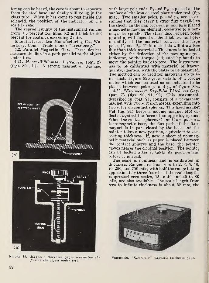
tering can be heard, the core is about to separatefrom the steel base and finally will go up in theglass tube. When it has come to rest inside thesolenoid, the position of the indicator on thescale is read.The reproducibility of the instrument ranges
from ±5 percent for films 0.2 mil thick to ±3percent for coatings exceeding 2 mils.
Manufacturer: Lea Manufacturing Co., Wa-terbury. Conn. Trade name: “Lectromag.”
4.2. Parallel Magnetic Flux. These devicesmeasure the flux in a path parallel to the objectunder test.
4.21. Moore-Williamson Instrument (pat. 2)(figs. 89a, b). A strong magnet of U-shape,
Figure 89. Magnetic thickness gages measuring theflux in the object under test.
with large pole ends. Pi and P2 ,is placed on the
surface of the iron or steel plate under test (fig.
89a). Two smaller poles, Pi and P2 ,are so ar-
ranged that they carry a stray flux parallel to
the sheet. In the gap between pi and P2 is placed
a magnetic moving element, eccentric to a non-magnetic spindle. The stray flux between poles
Pi and P2 will depend on the thickness and per-
meability of the material between the large
poles. Pi and P2 . Thin materials will draw less
flux than thick materials. Thickness is indicated
either by the deflection of the moving-magnetindicator, or the torque (adjusted by hand) to
move the pointer back to zero. The instrumenthas to be calibrated with material of knownquality, identical with the plates to be measured.The method can be used for materials up to i/o
in. thick. Figure 89b gives details of a torquemeter which can be used as an inductor to beplaced between poles pi and P2 of figure 89a.
4.22. “Elcometer” Dry-Film Thickness Gage(pat. 7) (figs. 90, 91, 92). This instrument,described in (pat. 7), consists of a permanentmagnet with two soft iron pieces, extending into
two soft iron contact spheres. This fixed magnetFM (fig. 91) keeps a moving magnet MM de-
flected against the force of an opposing spring.When the contact spheres C and C are put on aferromagnetic base, the flux-path of the fixed
magnet is in part closed by the base and thepointer takes a new position, equivalent to zerocoating thickness. If, now, a sheet of nonmag-netic material such as paper is placed betweenthe contact spheres and the base, the pointermoves nearer the original position. The pointercan be locked after it takes its position andbefore it is read.The scale is nonlinear and is calibrated in
thickness. Ranges are from zero to 2, 3, 5, 10,
20, 250, and 750 mils, with half the range takingapproximately three-fourths of the scale length
;
suppressed zero scales, 15 to 40 and 40 to 80mils, are also available. The scale length fromzero to infinite thickness is about 32 mm, the
Figure 90. “Elcometer” magnetic thickness gage.
38

Figure 91. “Elcometer” magnetic thickness gage.
Figure 92. “Elcometer" magnetic thickness gage.
useful part of it about 28 mm. The accuracyis given as ±5 percent or ±0.1 mil, whichever is
greater.
Manufacturer : Henry A. Gardner, Bethesda,Md.
4.23. Magnaflux C orporation Meter. This in-strument is a small portable meter consisting ofa permanent magnet and a galvanometer. Thepermanent magnet probe is placed on the sam-ple to be measured and the thickness read di-rectly in thousandths of an inch on the meter.
Accuracy is within ±0.0005 in. when used onvitreous enameled steel, and hot-rolled, cold-
rolled, and deep-drawing steel sheet. Typicalapplications include the measurement of thick-
ness prior to deep-drawing so that the dies maybe set for the proper thickness of material, andmeasurement of thickness of tin-can stock to
assure the proper bending to form good seams.
This instrument is designed to measure sheet
thicknesses from 0 to 0.050 in. Its advantagesare its speed, its lack of any power supply suchas line voltages or batteries, and its ability to
measure sheet from one side only at anylocation.
Manufacturer : Magnaflux Corp., Chicago 31,
111 .
4.3. Magnetic Saturation. The saturationmagnetic flux density (maximum number of
flux lines per unit area) of a ferromagneticmaterial is a property characteristic of the
material. When material of flxed compositionis included in a magnetic fleld, strong enoughto magnetize the material to saturation flux
density, the total flux producing this flux
density is a function of the thickness at thearea under observation.
Mechanical working, and temperature to alesser extent, affect the magnetic properties of
some materials. For this reason, the reliability
of the instrument chosen is somewhat depend-ent on calibration for the conditions underwhich measurements are to be made, as well asfor the composition of the material.
4.31. GE Magnetic Saturation Gage [52, 188](figs. 93, 94). A gage based on magnetic satu-
ration has been developed by the General Elec-
tric Co. especially to measure the thickness of
common grades of sheet steel from 10 to 45 milsthick, measuring from one side. The principleis the following: The steel sheet with knownmagnetic properties is magnetized by means of
a permanent magnet to saturation. A strongring-shaped Alnico magnet is used in the meas-uring head, together with a central pole of soft
iron (fig. 94) . The flux from the Alnico magnetenters the sheet and flows radially to the centralpole, which, together with the yoke (also of soft
iron), completes the flux path. The sheet itself
must have higher reluctance than any otherpart of the magnetic circuit; it must be the“bottleneck” for the flux.
The flux in the center pole is determined bymeasuring incremental permeability. To do this,
a laminated transformer core with primary andsecondary windings is placed in the central pole(fig. 93). The primary winding carries alter-
nating current, which produces an alternatingflux which flows in the laminated core, as shownby the dotted lines. The alternating flux linkingthe secondary coil is a function of the magni-tude of the steady flux supplied by the perma-nent magnet through the center pole. The
39

average secondary voltage is measured by thevoltmeter, V, and is proportional to the peaka-c flux. This flux is a measure of the d-c flux
and therefore of the thickness of the sheet.
The bucking transformer, T, suppresses thevoltage induced in the secondary winding, S,
when the gage is placed on a sheet of infinite
effective thickness. The instrument has tworanges, one from 10 to 25 mils for magneticsheets of medium silicon content
; the otherfrom 20 to 45 mils, for low-carbon steel eitherhot- or cold-rolled. The accuracy is given as 0.5
Figure 93. Thickness meter for sheet iron, using themagnetic saturation method.
Figure 94. Thiekness meter for sheet iron, using themagnetic saturation method.
mil when comparing one part of a sheet withanother part of the same sheet, or in comparingsheets of the same grade, provided that the
gage is more than one-half in. from the edge of
the sheet and that the sheet is not backed upby other magnetic material. The measuringhead must make close contact with the sheet.
Manufacturer : General Electric Co., Schenec-tady, N. Y.
Another steel plate thickness meter operatingwith dc has been developed by the British Ironand Steel Research Association [52] . It can beused for steel plates up to 250 mils thick. Onnormally machined surfaces the error is givenas less than 3.5 percent or 3 mils, whichever is
4.4. Coil Reactance [5, 102, 129, 174, 199].
Principle: The ferromagnetic material to betested, or the ferromagnetic base on which asheet of the material under test is placed, is partof an otherwise fixed magnetic circuit of soft
iron, magnetized by an a-c current of knownconstant frequency supplied from a known andpreferably constant a-c voltage. The total mag-netic reluctance, and therefore the reactance ofthe circuit and the current in the coil, is changedby changes of thickness of the ferromagneticbase, or of the nonmagnetic material acting asan air gap between the ferromagnetic base andthe rest of the magnetic system. This principlecan be applied in many ways. A large percent-age of electromagnetic thickness meters fornonmagnetic sheets or coatings use it.
4.41. GE Reactance Gage for NonmagneticCoatings on Magnetic Base (figs. 95, 96, 97).In using this gage, the sheet under test is placedunder a measuring head (fig. 95) on a flat ironplate at least 1.4 in. thick, with negligible mag-netic reluctance. There is, for zero thickness, amaximum of reactance and a minimum of cur-
Figure 95. Measuring head of a thickness meter of thereactance type.
L
40

scale length of the ammeter. A better method is
to place the a-c magnet system in one arm of ana-c bridge (fig. 96). This compares the variablereactance with a constant reactance with aboutthe same power factor in the opposite arm,which is balanced so that for average thicknessthere is zero current in the diagonal. Thediagonal current is rectified with dry-diskrectifiers.
Use of the bridge method has the followingadvantages
:(a) Independence of voltage varia-
tions, (b) independence of frequency variationsand waveform of the voltage, (c) an approxi-mately linear scale for thickness, and (d) muchhigher sensitivity than is obtainable by simplymeasuring the current with an ammeter. Figure96 shows the circuit of one of these thicknessmeters. Such instruments in portable form canbe used to measure sheets and coatings down to0.1 mil thick, and up to 750 mils. To suit typicalrent. A nonmagnetic coating or sheet increasesthe current. In principle, any a-c ammeter canbe calibrated in thickness, but it requires con-stant voltage, and the thickness scale is eithervery nonuniform or covers only part of the total
Figure 96. Basic circuit of the GE reactance-typethickness meter.
"COATINGAGE" (BRANSON)
O.l 1 10 100 1000
THICKNESS, mils
Figure 97. Measuring ranges of different types of GEand Branson thickness gages.
application problems, GE manufactures threetypes of such electromagnetic gages to measurethe thickness of nonmagnetic sheets and coat-
ings. Type A has the smallest measuring area,
about 1.8 in.- Next is type B, with 3 in.^ ;type
C has an area of about 7 in.- Figure 97 gives
the ranges for these three types and that of afourth instrument, described in 4.44, the“Coatingage.”
All these gages are generally used to checkdeviations from a standard thickness. To obtainhighest accuracy, it is usual to calibrate theinstruments with thickness standards, and if amagnetic base is necessary to make the measure-ment, to calibrate with the base actually used.
The accuracy obtained with this type of gage is
generally 5 to 10 percent of the thickness of the
standard. The error is a minimum for equal
thickness, and increases with the deviation. If
a null method is used the accuracy is better,
around 1.5 percent of the thickness of the refer-
ence standard.
Manufacturer : General Electric Co., Schenec-tady, N. Y.
Another instrument in this group is the
“Magnatest FT-300” of the Magnaflux Corp. It
is operated from a 60-cps power supply. A small
electromagnet in the detector induces a flux in
the part under test. The indicator responds to
the reluctance of the path offered to the mag-netic flux between the detector pole pieces. Thisinstrument is generally used to measure the
thickness of paint or plating. The indicator hasa dual range of 0 to 4 and 0 to 20 mils. Theaccuracy is given as ±2 percent.
Manufacturer : Magnaflux Corp., Chicago 31,
111 .
4.42. Haskins Turner Co. Gage for Scale In-
side Boiler Tubes [112]. This gage measuresthe thickness of, scale inside boiler tubes. Forno scale deposit, the inductance of the search-
magnet is highest and the current is a minimum,marked as zero scale thickness on the instru-
ment dial. The current increases rapidly withscale thickness, so that even a scale thickness of
1 mil gives a deflection of about 7 percent of the
length of the meter scale. The search unit con-
sists of a cylindrical electromagnet which is
held against the inside wall of the tube by meansof a spring and guide wheels. The head is
simultaneously rotated and pulled through the
tube. The scale deposit on the inner side of the
tube represents an airgap in the magnetic cir-
cuit formed by the electromagnet and the tube.
The range of the meter is 0 to 100 mils, with 20mils in the middle of the scale. The head is
connected with a 50-ft graduated steel tape.
One operator lowers the probe head down theboiler tube from the upper header or drum
;the
other operator notes the scale thickness for
each foot of travel. Two sizes of probe headsare used, one for tubes with less than 2-in. di-
41

ameter, the other for tubes over 2-in. diameter.The thickness of the ferrous tube wall has nobearing on the indications. The instrument is
operated from a 115-v 60-cps power supply.Manufacturer: Haskins Turner Co., Jackson,
Mich.4.43. “Hurletron” for Paper Production [75]
(figs. 98, 99). Figure 98 shows the gaginghead of the “Hurletron” gage, a roller gage ofthe reactance type which has been developed tomeasure the thickness of paper board andheavy-weight paper as it comes from the cal-ender. The wet paper is passed over a dryer oridler roll, and the gage measures the distancebetween the roll and the idler. Measurement is
not distorted by the water content of the paper.The current represents the thickness of the
Figure 98. Closeup of a “Hurletron" gaging head.
Figure 99. Typical installation showing three gagingheads in operating position.
paper. The accuracy is given as ±3 percent.'
Figure 99 shows an installation with threegaging heads.
Manufacturer: Electric Eye & EquipmentCo., Danville, 111.
4.44. “Coatingage” (figs. 100, 101). The in-
struments described so far operate on 60 cpsfrom the power line. To use thickness meters
i
of this type, where no a-c power is available,,
the “Coatingage” has been developed. It oper-!
ates from a built-in battery and a low-frequencyoscillator. The a-c unbalance current of thebridge is rectified and indicated by a microam-meter. The gage coil of the instrument is
j
wound on a chromium-plated steel spool, theflanges of which are placed in contact with thesurface being tested. Figures 100 and 101 showcircuit and scales of the two-range instrument.The low range is fromi 0 to 12 mils, usable be-tween 1 and 12 mils, the high range from 10mils to 500 mils. The tolerance is given as 0.1
mil up to 1 mil thickness of the coating. Above1 mil the tolerance is 10 percent, provided themagnetic base is at least 125 mils thick and theinstrument head is not placed closer than 1 in.
from the edge of the sheet.
Manufacturer : Branson Instrument Co.,
Stamford. Conn. ^
Figure 100. Circuit of the “Coatingage" thicknessmeter.
Figure 101. Scale character of the “Coatingage.”
42

4.5. Transformers.4.51.
Transformer Method for NonmagneticCoatings on Steel (One Side) (fig. 102). In its
simplest form, figure 102, a small U-shapediron core is used, and the primary winding is
Figure 102. Simplest transformer.
Figure 103. Cylinder-wall thickness meter.
Figure 104. Cylinder-wall thickness meter.
connected with the 60-cps power line. Both pole
ends touch the coated surface, the magneticcircuit being closed by ferromagnetic basemetal of sufficient thickness and high perme-ability. The voltage of the secondary coil is
measured with a rectifier voltmeter. Increasingthe thickness of the nonmagnetic coating de-
creases the secondary voltage. The scale is re-
versed; maximum deflection corresponds to
minimum thickness. The readings are sensitive
to voltage and frequency variations.
4.52.
Transformer Method for FerromagneticMaterials (One Side) (figs. 102, 103, 104).When this principle is applied to measuringthickness of ferromagnetic materials withoutcoatings, the magnetic reluctance of the ma-terial is measured. With the arrangement of
figure 102, without a coating, a minimum volt-
age is produced when the instrument is not in
contact with ferromagnetic material. The volt-
age, measured with a moving-coil rectifier in-
strument, increases approximately in proportionto thickness until saturation of the yoke is
reached. This principle is used in a gage de-
signed to measure the wall thickness of auto-mobile cylinders after rough boring. Twomeasurements are made, one at the top, the
other at the bottom of the cylinder. The mag-netic system (fig. 103) is a long, U-shaped mag-net with a primary coil connected to the line
and with secondary coils on each leg. The wholemagnet system is built into a cylinder whichfits into the cylinders to be tested. Figure 104shows the entire assembly. The adjustment ofthe instrument is made so that with the normalminimum thickness the pointer deflects to 50percent of the scale length. A thickness changeof 10 percent changes the deflection about 5
percent of the scale length. The magnetic prop-erties of the alloy influence the deflection less
than about 10 percent.Manufacturer : Commercial Engineering Lab-
oratories, Detroit, Mich.
4.53.
Sheet-Iron Tester, d-c Operated [161](fig. 105). This device measures the thicknessof sheet iron by comparing it with a standardthickness. The transformer core, figure 105,
43

has the shape of an H, with one primary wind-ing, P, and two secondary windings in opposi-tion. On one side is the sheet N of standardthickness, on the other the material X undertest. One practical design has a core of about2.4 by 2.4 in., the yokes being 0.8 by 0.8 in. andthe poles 0.8 by 0.4 in. Because it is not possiblewith any sizable pole area to make perfect con-tact with the magnetic body, this instrumentdoes not attempt full contact, but provides air-gaps 1 mil thick under each head. The corerests on three hard points of nonmagnetic ma-terial, which penetrate layers of rust or paint.
This device can be operated with ac as well asdc. In using d-c excitation the primary voltagefurnished by a battery is reversed and the bal-listic deflection of the galvanometer observed.This instrument has been used for measuringferromagnetic boiler tubes, using curved poleends.
An instrument based on this principle is
manufactured by the Magnaflux Corp., underthe trade name “Magnatest Series FT-100.”The thickness range is 0 to 80 mils
; the accuracyis given as ±2 percent. One design has a port-able measuring head with a small indicator for“go” and “not-go” limits.
4.54. Nonmagnetic Coatings, DifferentialVoltage [76] (fig. 106). This instrument meas-ures the thickness of nonmagnetic coatings ona ferromagnetic base, using the differentialvoltage in the two secondary coils of figure 106.The deflection is zero for zero thickness, thedifference increasing roughly in proportion tothe thickness of the coating. Here the test speci-men is clamped between and is a common partof two magnetic circuits, each having a primary
Figure 106. Coating-thickness meter.
and a secondary. The nonmagnetic coating in-
troduces a gap in one of these and produces anunbalance. The output may be indicated directly
with a rectifier voltmeter of sufficient sensi-
tivity, or a null galvanometer may be broughtto zero reading by restoring balance with ad-
justment of the resistor R.
Such devices can be made very sensitive andindicate thickness changes dovm to 0.01 mil.
4.6. Eddy Currents, Inductance Change. Prin-
ciple: The inductance of a coil fed with a-c
current decreases when the magnetic field of thecoil induces eddy currents in a nonferrous con-
ductor near the coil. Generally, two coils are
used, connected in such a way that they formtwo legs of an electrical bridge circuit. Theunbalance of the bridge is a measure of the
thickness of the material in the vicinity of thecoil, provided its distance from the coil is fixed.
To measure the thickness of nonconductingmaterial, a thick conducting base is provided,and eddy currents are i-iduced in it. Underthese conditions the intensity of the eddy cur-
rents depends on the distance of the coil fromthe base metal. The minimum base thicknessnecessary depends on frequency and conduc-tivity; the higher the frequency, the thinnerthe base may be.
Any of the meter designs and circuits usedto measure a change of inductance may be used.
The frequencies used vary from 60 cps up to
1,000 kc; the design of the equipment dependsupon frequency. The inductance-change effect
depends very much on the frequency; for eachobject thickness there is a frequency that givesmaximum sensitivity.
To measure the thickness of coatings or
sheets from one side, two inductance coils aregenerally arranged in one head, the search coil
being small and so built that it can be broughtvery close to the surface to be tested. Proximityto the metal base decreases the inductance of
the test coil. To measure the thickness of me-tallic foils with both sides accessible, the searchinductance is split into two halves and the me-tallic foil is passed between them, increasingthe eddy-current loss and decreasing the induct-ance with increasing thickness of the material.When used to determine the thickness of non-conductive, nonmetallic coating on a nonmag-netic metal base, the zero position of the scale
must be determined first by placing the searchcoil on a part of the metal free of any coatingand perfectly smooth. In this condition themeter is adjusted, generally by a variable in-
ductance. The calibration is established byplacing sheets of nonconducting material ofknown thickness between the search coil andthe base.
Magnaflux FT-UOO. The Magnaflux Corpmanufactures an instrument of this kind, the“Magnatest FT-400,” with a bridge circuit and
44

a hand detector. Scale ranges are 0 to 2, 0 to 4,
and 0 to 20 mils. The instrument operates at60 cps and the accuracy is given as ±2 percentof the coating thickness. The measured area hasto be flat, with a diameter of more than % in.
4.61. “Filmeter” [142] (fig. 107). This port-able battery-operated instrument, “Filmeter,”developed to measure the thickness of oxidecoatings on aluminum, contains two oscillators,
one of them with a constant standard fre-
quency, the other with adjustable frequency.The search coil is at the end of an insulatedpiston which can be moved against the pressureof a spring in an aluminum cylinder. The eddy-currents in the specimen, under the coating,change the frequency. The frequency is read-justed to the frequency of the standard oscil-
lator by turning the dial of a variable air capa-citor until the earphone detector finds frequencybalance. The indications are practically inde-pendent of the conductivity of the aluminumbase, but the base has to have a thickness of atleast 11 mils. Surface roughness, under prac-tical conditions, changes the indications lessthan 2 percent. The method could, of course,also be used to get a pointer indication of thethickness with a rectifier and a moving-coilinstrument.
Figure 107. “Filmeter" with measuring head andearphone.
The accuracy of the Filmeter is given as ±3percent of full scale for the range 0 to 5 milsand ±5 percent for the range 0 to 3 mils.
Manufacturer: American Instrument Co.,Silver Spring, Md.
4.62.
Nash & Thompson Eddy~Current Gage[120]. A British company has applied theeddy-current principle to the measurement ofnonconducting coatings (paint, varnish, etc.)on nonferrous bases. The instrument consistsof a coil which in conjunction with a variablecapacitor forms the tuned circuit of an oscil-mtor. The frequency of this is compared withthat of an incorporated reference oscillator bymeans of a mixer circuit. The test coil, mountedin a housing and supported on three ball feet, isplaced on the specimen. The variable capacitor
is adjusted until the null point is indicated. Thecoating thickness can be read from a dial fitted
to the shaft of the capacitor. Variations in the
base metal are compensated by the initial ad-
j ustment on an uncoated sample. A flat area onthe test piece of 114-in. diameter is required for
the head. The range of coating thickness cov-
ered is 0 to 0.03 in.
Manufacturer; Nash & Thompson, Ltd.,
England.4.63. GE Eddy-Current Gage for Hollow
Propellers. The General Electric (io. has usedthe eddy-current method to measure the thick-
ness of propeller walls. The search coil is cali-
brated by holding it in contact with walls of thesame material and of known thickness. Themeasuring range decreases with increasing con-ductivity of the material under test. While therange is 0.25 in. for copper, it is 1.5 in. forbrass. The accuracy was given as 5 percent.Production has been discontinued.
4.64. Eddy-Current Gages for Moving MetalSheets (figs. 108, 109, 110). For this type ofgage the material runs freely through an airgapbetween high-frequency coils. A meter, manu-factured by GE but now discontinued, had anairgap of 375 mils for the material and wasaccurate to 0.01 mil.
Salford Gage. An instrument made by Sal-
ford Electrical Co., Ltd., England, is built forthe following ranges
;1 to 5 mils, 2 to 10 mils,
5 to 25 mils, and 10 to 50 mils. The calibration,as with all these instruments, has to be madefor the specific metal. Figure 108 shows themeasuring head of the Salford foil-thicknessmeter.
Figure 108. Measuring head of the Salford foil
thickness gage.
Pratt & Whitney Gage. The foil gage of Pratt& Whitney, to be used directly with rolling mills,
is shown in figures 109, 110. The gaging headconsists of two parts ; The lower part is underthe coil in a fixed position, the upper partswings up out of the way while the mill is beingthreaded. The material passes between theupper and lower parts of the gage head. Thisgage can be used to measure foils from 0.25 to
45

Figures 109 and 110. Pratt & Whitney foil gage.Gaging head. Power unit (adjustment of zero, coarse and fine
sensitivity, thickness range). Indicator.
10 mils thick. The indicating meter, calibratedfor the deviation from standard thickness, hastwo scales, 0 to 0.2 mil and 0 to 2 mils.
Magnatest FT-200. Another eddy-currentgage to measure thickness of moving sheets andfoils of copper, brass, or aluminum in continu-ous production, is manufactured by the Magna-flux Corp. under the trade name “MagnatestFT-200.” It is operated on 60 cps. The thick-ness range may be from 30 to 80 mils. The rangeof the zero-centered indicator can be made ±10percent of any nominal value between theselimits. The measuring area has a diameter of4 in.; the accuracy is given as ±0.1 percent ofthe nominal value.
4.65. Gages for Lead Sheath on a Cable [131].Eddy-currents have been used for measuringthe thickness of the lead sheath applied tocables by an extrusion process in the BritishCallender Cable & Construction Works in Lon-don. The method was later adopted by theOkonite-Callender Cable Company in Passaic,N. J. Here the influence of frequency is im-portant. At 50 cps, it was found that the mag-netic flux passed freely through the lead andlittle change of inductance took place. Up toabout 500 cps a linear change of inductancetook place, approximately 2.5 percent per 100cps. The maximum change of inductance wasat 1,400 cps; for higher frequencies the effectdecreased and became almost negligible formore than 2,200 cps. For this reason the meas-urements were made at 1,400 cps. The flux wasinduced with four electromagnet coils mountedaround the cable sheath, as it came from thepress, using roller bearings to contact the sheathsurface. The output after rectification wasmeasured with a d-c instrument. Thicknessmeasurement in this application corresponds to
determination of concentricity. The trade speci-
fications allow 18 percent eccentricity. With thegaging device it was possible to keep eccentric-
ity within about 5 percent, or 7.5 mils for 150-
mil average thickness.
4.66. “Probolog” (fig. 111). Corrosion ofcondenser tubing presents a problem to manypower plants. The tubes have outer diametersfrom 0.625 to 1.250 in. and a wall thicknessfrom 28 to 165 mils. They are of nonmagneticmetals (copper, brass, stainless steel) and theyare used in bundles up to 5,000 tubes. Testequipment for this problem, called a “Probolog,”has been developed by the Shell DevelopmentCo., Emeryville, Calif. The probes, with di-
ameters of 0.313 to 1.005 in., have interchange-able Mumetal cores with an axial length of 900mils, figure 111. Two search coils are mountedon the core, each about 300 mils long, the coil
centers about 370 mils apart. The clearance be-
tween probe and tube ranges from 40 to 152mils. The probe is first driven by compressedair to the far end of the tube, and then slowlywithdrawn with a power winch at a speed of1 or 2 fpm through the tube length, which is
generally about 20 ft. As long as the tube undertest is uniform in thickness, the eddy-currentsinduced in the tube by the two coils (the tubeacting like a short-circuited winding over thecoil) are identical and the balance of the bridgecircuit is not disturbed. If there is, however, athinned area (“pool”) caused by corrosion, oneither inner or outer surface of the tube, thebridge becomes unbalanced. The unbalancevoltage is converted into a current which ener-gizes a solenoid to rebalance the circuit. Therebalance current is recorded on a strip chartwhich moves in synchronism with the pullingof the probe. With proper interpretation andcalibration with test pieces of the same tubeshaving thickness differences along their lengthand also holes of known diameter, the size anddepth of corrosion pools and other defects canbe determined with fair accuracy, reaching ±5percent as far as the wall thickness is concerned.
For the different tube diameters, seven probediameters are available. Recommended practiceis not to test all tubes, but to make a hydrostatictest first to find defective tubes that fail under
mumetol core •
3 - conductor
coblestainless steel shell
Figure 111. Search-coil assembly for the “Probolog’’condenser-tube tester.
46

the test pressure, and after this to test all tubes
in the vicinity with the electromagnetic method,
as described.Manufacturer: Shell Development Co., Em-
eryville, Calif.
4.67. Gage for Ceramic Coatings on Metal[106]. A ceramic-coating thickness gage hasbeen developed to measure the thickness of pro-
tective coatings of metals and alloys in hightemperature service. The range of this instru-
ment is from 20 to 100 mils, with an accuracy of
about ±0.2 mil for 20 mils and ±1 mil for 100mils, i.e., about 1 percent of the indication of
the moving-coil meter within this range. Forthis application a frequency of 500 kc is used.
4.68. Gages for Metal Coatings on Metal [44,
49, 209]. Conductive metallic coatings on abase of different electric conductivity can bemeasured by using the eddy-current principle.
One device employing this principle [44] usesa commercial type of oscillator with a high-frequency output. Two germanium diodes in
opposite phase cause current to flow alterna-tively through the two legs of a bridge circuit,
one leg including the test probe coil, the other,a variable resistance. A direct-current micro-ammeter in series with the bridge circuit re-ceives first the current through the test probe,then the current through the variable resistor,and registers the current difference.The probe is first placed on a reference (un-
coated) surface and the meter adjusted to readzero. It is then placed on the surface to betested and the current change noted. In prac-tice, this current change is a direct indicationof the thickness of the coating in question. Themagnitude of the induced eddy current, depend-ent on both difference in conductivity betweenthe base and coating metals and the thickness ofthe coating, in turn determines the strength ofits own magnetic field. The field of the eddycurrent opposes the field of the inducing cur-rent, thus lowering the impedance of the probecoil and allowing proportionately more currentto flow through the probe. The recorded testcurrents are interpreted by comparison with acalibration curve prepared by measuring sam-ples of known thickness.The sensitivity range and accuracy of the
eddy-current instrument are dependent on suchvariables as the frequency used (e.g., a fre-quency of 2 Me is found effective for coatingsup to 1.5 mils thick, and 100 kc for coatings upto 6 mils), circuit resonance, and the differencesin conductivity of the two metals.The Boonton Radio Corp. Gage, manufac-
tured by the Boonton Radio Corp., Boonton,N. J., and the “Dermitron” gage, manufacturedby Unit Process Assemblies, N. Y., are two ex-amples of this type of gage.Magnatest FT-600. Magnaflux Corp. has a
commercial type [49] “Magnatest FT-600 Se-
ries” with a very small contact head whichforms one arm of a bridge circuit. A typical
unit has a scale graduated in mils to 10 mils.
4.7. Mutual Inductance With Air Core [42,
107,141] (fig. 112). Principle: The mutual in-
ductance transducer consists of a primary anda secondary coil wound on the same coil form,but at separate positions on the form. A metalsurface lies near the secondary coil (fig. 112).When the primary coil is excited with rf, eddy-currents are induced in the metal surface. If
the metal were an ideal conductor the field of
the primary coil at the surface would be just
canceled by the field of the eddy-currents. Whenthe mutual inductance transducer is placed so
that the secondary coil is adjacent to the metalsurface, there will be no voltage induced in it.
As the transducer is moved away from themetal an increasing voltage will be picked upby the secondary coil.
COIL FORM
% (PRIMARY)
EXCITING COIL
PROBE COIL (SECONDARY)“* OUTPUT
METAL SURFACE
Figure 112. Basic structure of distance-measuringeleinent.
Mutual inductance between two coils is varied by proximity of
metallic surface.
4.71. Measurement of Bearing Eccentricity
[107, 141, 185] (fig. 113). This instrumentmeasures the displacement of a turbine shaft in
its journal bearing. The problem is to measurethe thickness of the oil film in a 6-in.-diameter
bearing with a radial clearance of only about 6
mils, while running at more than 10,000 rpmsubmerged in lubricating oil at200°F.Four distance-sensitive elements are used,
mounted around the shaft, immediately beyondthe bearing in positions 90° apart. Each con-
sists of two concentric coplanar coils, woundon a single bakelite form, 1 in. in diameter (fig.
113), the inner coil having a diameter of 70
percent of that of the outer coil. For such a coil
system the output is linear up to a distance of
about 50 mils. The shaft is electroplated with
47

j;."
I':'. ‘jl
INNER•'r
P SLOT OUTER SLOT
with thin walls, the eddy-current energy at
times is lower than the power consumed in the
potential circuit of the wattmeter used. Changes
of permeability, conductivity, or thermal his-
tory of the tubes have little influence. The aver-
age error for boiler tubes is reported as not
exceeding ± 5 mils.
Figure 113. Probe coil form used in oil-p,tm, thickness
indicator.
copper, 1 mil thick, in a band immediately underthe distance-sensing coil assemblies. A fre-
quency of 2,500 kc is used. The output fromthe four pick-ups is connected with the four
plates of a cathode-ray oscillograph and in this
way a picture of the eccentricity of the shaft in
the bearing is obtained. The range is ± 13 mils.
One mil is represented by two lines 150 mils
apart, giving a magnification of the eccentricity
of 150. The over-all accuracy of the method is
estimated as better than 0.5 mil.
The same principle has been used to measureand indicate the longitudinal movement of high-
speed rotating shafts, such as might be causedby failure or wear of a thrust bearing [185].
A brass disk, which forms part of the electrical
system, is fastened on the end of the turbine
shaft. Motion of the disk towards or away fromthe probe changes the mutual inductance be-
tween two windings. The output voltage, indi-
cated on a meter, shows shaft position in units
of mils on a d-c instrument.4.72. Phase-Angle Thickness Gage for Silver
Coating on Stainless Steel [9, 220]. The phase-angle thickness gage is useful only when theresistivities of the base material differ ma-terially from that of the coatings. The probeconsists of a mutual inductance transducerwhich is held in proximity to the sample. Abuckout transformer shielded from the sampleis also located in probe head. The two elementsare electrically connected and excited with rf
current in opposition, producing output volt-
ages whose phase difference is responsive to theconductance of the sample. A phasemeter is
calibrated for the desired frequency ranges. Theapplication of this device given in the referencesis for silver on steel. For direct reading ofthickness, the phasemeter output is indicated ona meter calibrated in mils of silver which hasbeen applied to a base of 37 mils of stainlesssteel. The probe is brought within i/g in. of thespecimen in order to make a reading.
4.8. Wattage Absorbed. This method hasbeen used to measure the thickness of ferro-magnetic sheets or tubes (boiler tubes) fromone side. Devices of this type have a pole areaof 1 by 0.5 in. ; they are connected to the powerline, and the wattage absorbed in eddy-currentlosses is measured by a wattmeter. The methodis reportedly satisfactory with larger tubes ofconsiderable wall thickness. For small tubes
5.00.
Optical Methods|
I
5.1. Measuring Microscope [18, 167, 190]. *
The standard ASTM method of determining the (
thickness of coatings requires the use of the
measuring microscope. The chemical dropping
test and magnetic tests are alternatives. In
ASTM 219, rules for use of the measuringmicroscope have been established by the Ameri-
|
can Electroplating Society cooperating with the ;
National Bureau of Standards and the Ameri- ;
can Society for Testing Materials. This test is
used for electrodeposited coatings of copper,j
nickel, chromium, lead, zinc, or cadmium thicker;
than 0.05 mil. The surface of the specimen is
protected either by mounting in a plastic ma- I
terial such as phenolic or acrylic resin, or by :1
electroplating it with a relatively thick coatingj
of copper. A section produced by cutting per-
pendicular to the flat surface is ground andpolished by regular metallographic methods,
treated chemically, and/or illuminated in such
a manner as to obtain maximum contrast be-
tween the coating and the adjacent materials.
The thickness is measured with a filar microm-eter ocular that has been selected and calibrated
so that the error will not exceed 2 percent. Asan example, the scale may be graduated to 0.01
mm (0.4 mil)
.
Alternatively, the image of the specimen maybe projected at a known magnification on a
ground-glass focusing plane in the camera of a
metallographic microscope, where the width ofJ
the projected edge of the coating is measuredwith a graduated linear scale. Magnifications
of 500 are feasible.
When measuring the thickness of soft ma-terials, like paper, with a micrometer micro-
scope, the material must be embedded in resin
or a similar substance [190, p, 4, 5]. Althoughthe micrometer microscope discloses details of
the cross section, it is very difficult to get accu-
rate results because only the edge is measured,and not anything like the average thickness or
;
the local thickness of a well-defined area of the;
shGGt.
5.2. Change of Focus [64, 196, 208] (figs.
114, 115, 116, 117, 118, 119, 120). This methodis used to measure the thickness of large sheets
of transparent material at the middle of the
sheet, where mechanical micrometers cannot be
used, or to measure the wall thickness of glass
bulbs, accessible from only one side. Sometransparent materials are so soft that the pres-
48

sure of the anvil of the conventional mechanicalmicrometer deforms or damages them. Themethod is also used to measure the thickness oftransparent coatings on an opaque base.
A microscope is used that can be adjustedwith a micrometer screw to focus successivelyon the bottom and top surface of the sheet undertest. With this method a focus discriminationof 0.2 mil is possible. The lower end of themicroscope tube is held to the surface of thesheet. This is the zero mark on the micrometerscale. The transparent sheet is marked on theside away from the microscope with a soft pen-cil which leaves graphite particles that can befocused sharply in the microscope.The readings on the barrel and thimble of
this optical micrometer give the thickness of thesheet directly if the scale is calibrated for acertain refractive index n of the material undertest. If the displacement of the microscope lensis h, the thickness is x=n’h. Because most op-tical materials in common use have refractiveindices of 1.520 ±0.015 (a variation of about 1
percent), such instruments are generally cali-
brated for this value. Figures 114 and 115 showmicrometers of this type.
Figure 114. Aireon optical micrometer.
Figure 115. “Opti-Mike.”Instrument Development Labs.
“Optimike.” The “Optimike,” figure 115, hasa built-in lamp, connected with two flashlight
cells. The measuring range of this instrumentis 400 mils
;the accuracy is given as ±1 mil.
Manufacturer; Instrument DevelopmentLabs., Needham Heights, Mass.
Schneider instrument. The principle is usedin an instrument built in Germany to measurethe wall thickness of inaccessible but hollowtransparent bodies. For measuring rough andoptically bad surfaces, an immersion attach-
ment is supplied with the instrument.Manufacturer : Dr. Schneider Instrument
Works, Bad Kreuznach, Germany.The method has also been used to measure
the thickness of transparent coatings of alum-inum oxide, or to determine the thickness of
glass mirrors. In this case the upper surface is
marked with a graphite or grease pencil; thebase metal of the mirror or the coating is easily
recognizable from its texture by using a mag-nification of 500 to 1,000.
Thicknesses of very thin metal coatings onglass have also been determined in this way(fig. 116). The metal film is removed from apart of the glass plate. A beam of light fromthe lamp, B, (fig. 118) going through the lenses
Li and Lo and the filter F, projects a virtual
image G' of the grid G very near to the surfaceOi under test. The virtual reflections G'l andG'o are photographed through the miscroscopeMl. The method has been used to determine
Figure 117. Mirrorimages of a line.
Figure 118. Arrangement to measure film thickness.
49

silver coatings 0.10 to 0.15 /x (4 to 6 /xin.) thick.The average error of 160 measurements was±0.008 /X.
Bausch & Lomb instrument. Bausch & LombOptical Co. has also used this principle in athickness meter for glass (figs. 119, 120). Thelight source L projects an image of the gradu-ated glass scale by means of the lens M on thefirst surface A' of the object (such as the glassbulb shown) when held against the small elon-gated aperture 0, which is at an angle of 45° tothe beam of light. The outer surface A' willrefiect the image of the graduated scale Sthrough the lens B and the prism P to thefrosted screen Z. Only part of the light is re-flected by the outer surface. The balance is
refracted into the transparent material and willfall on the second surface A^, be partially re-
Figure 119. The two scales as reflected in the eyepiecewhen measuring glass approximately 18 mils thick.
p z
Figure 120. Optical system of Bausch & Lombthickness meter.
fleeted to A and from there refracted into the '
air, giving finally a second picture of the scale Son the screen Z. The pictures are of almost ,
equal light intensity, but the separation of thetwo images is proportional to the separation of
the two glass surfaces, and can be measureddirectly by counting the divisions displacement.In the illustration the thickness is 0.018 in. The
i
instrument is calibrated for the standard refrac-
tion index of glass, A=1.522. Readings on other;
glasses have to be corrected according to the‘
refractive index.5.3. Interference [128, 159]. The thickness
of extremely thin reflecting metallic films is dif-
ficult to measure. The older methods of deter-
mining film thickness of the order of 1 to 0.01
wavelength of light have usually involvedweighing or chemical determination of thequantity of material on a known area. These '
methods are difficult to apply because of the|
small quantities involved, and they suffer fromthe defect that the density of tenuous films (of
J
atomic or molecular dimension) must be as- "\
sumed to be that of solid metal. The interfer- ,
ence methods described in this section provide i
measurements free from assumptions of densitywith precision of the order of 10 A (approxi-
|
mately 0.04 /xin.).
5.31. GE Spectrophotometer [2] (fig. 121).Spectrophotometers are used to measure the
|
thickness of transparent films, e.g., electrolytic
oxide coatings on aluminum. The recordingspectrophotometer (General Electric Co.) pro-jects progressively a series of monochromaticpolarized beams of light, ranging from 400 to h700 m/x, onto a sample coated with the film under
j
|
test, placed over an aperture of 1 in. diameter in i
a small sphere. The reflectance or transmission ^
'
of the sample is automatically recorded as afunction of the wavelength. The reflected light
||
obeys the laws of interference (fringes of equalchromatic order), and the curve traced by therecording spectrophotometer has variations re- !
lated to the thickness and refractive index of thei
film (fig. 121). The refractive index must be|
400 500 600 700WAVELENGTH, MILLIMICRONS
Figure 121. Reflectance curve for "Alzak” reflectorsheet ivith commercially thin oxide coating.
50

thet
eSi
ost I
the;
at,
:he
ac-
tier
the
ess
iif-
:er-
.01
red
the
ese
the
om
(of
as-
'er-
1
ide 1
lityy
)xi-
:i).
the
die
ing
iro-i
itic
to >
der
"
’in
ion
i a
?ht
ual
the i
re-
the
be
m
w
determined separately. The thickness of the
film is determined by the number of maximabetween two wavelengths.
5.32. Michelson Interferometer [58]. Thiswell-known instrument can be used to measurethickness of thin metallic films. One of the total
reflecting plates of the interferometer is first
coated with an opaque film of the metal by theusual evaporation process. Then, a central re-
gion, approximately one-third of the total re-
flecting area, is covered with a mica strip andthe remaining unobstructed area is given anadditional deposit of the same metal, when thefilm is evaporated in production. The mica strip
has to be thin and in very close contact with theinterferometer plate. The plate, with the micastrip removed, is placed in the interferometerand the instrument adjusted for white light
fringes. A monochromatic source is then sub-stituted, and the two fringe patterns compared.In the central region the fringes are displacedrelative to the fringes in the outer portions.
For a displacement of one fringe the thicknessof the film deposited during the second evapora-tion is half the wavelength of the light used ;
forfractional displacements, corresponding frac-tions of the half wavelength. When thecustomary green mercury line is used formeasurements, the fringe displacements for afilm 20 m/x thick is less than one-thirteenth ofa fringe. The fringes are sharp enough, how-ever, for comparator measurements of displace-ment, or even for projection on a screen withsubsequent measurement. Both methods havebeen used with considerable accuracy.
5.33. Interference Microscope [198]. Theinterference microscope has been found usefulin measuring the thickness of decorative chrom-ium plating. In order to use this method, a partof the coating must be stripped from the pieceto be tested by suitable means leaving a distinctboundary between the coated and stripped por-tions. It is then placed under the interferencemicroscope and brought into focus. Focusing inthe interference microscope is much like anordinary microscope. When the enlarged, fo-cused image of the surface is visible in theeyepiece, a shutter is opened which allows aseries of parallel light and dark bands to besuperimposed on the image of the surface. Thespacing and direction of the fringes can be ad-justed according to need. In boundary measure-ments such as the one under consideration, thefringes should be perpendicular to the boundary.A-fringe shift results from any surface irregu-larity, the amount of the shift being determinedby the depth of the irregularity. A shift of onebandwidth is equal to a depth of one-half thewavelength of the light used, usually the 5460-Agreen line of mercury. The range of the instru-ment is from 2 to 100 /xin. The method is con-sidered to be extremely accurate.
Figure 122 . Step gage to measure thickness of
molecular films.
5.34. Color Comparison [33, 34] (fig. 122).
This method is based on the comparison of in-
terference colors reflected from white light bythe film under test [33] and colors reflected
from a glass surface coated with films of vari-
ous thickness.
The GE step gage [34] is a plate of special
glass enclosed in a plastic case (fig. 122). Afilm of barium stearate is deposited on the glass
in a series of monomolecular layers, deposited
in such a way as to build a series of steps each
1 fxin. thicker than the preceding one. Whenilluminated by white light, each step reflects a
color determined by its thickness. The steps
appear as a series of colored strips. The range
is from 2 to 16 /xin. The readings have to be
corrected for the refractive index of the plate
on which the unknown film is deposited. Theprocedure of correction is diiferent from ma-terials with lower or higher refractive index
than the film.
The many uses of the step gage are described
in the GE instruction book, GEJ-2329 “BariumStearate Stepgauge.”
5.35. Donaldson-Khamsavi Method [69, 202]
(fig. 123). (The material presented here is
taken from the book, “Multiple beam inter-
ferometry,” by S. Tolansky [202]). In the
multiple-beam method of W. K. Donaldson andA. Khamsavi, the thin film to be measured (ABin fig. 123) is deposited on part of a flat glass
surface, ABC. A fairly thick opaque coating of
silver, PQRS, is then deposited by evaporation
over both film and flat. The height, QR, then
equals that of the silver film AB. A silvered
flat, DE (reflectivity=0.90) , is brought close to
the combination of AC. When illuminated from
51

Figure 123. Donaldson-Khamsavi method for very thinreflecting metallic film.
the right, back-reflected Fizeau fringes areformed which exhibit the sharpness characteris-tic of multiple beam interference. The step dis-
placement, RQ, can thus be determined with aprecision down to the order of 10 A (10^*^ mm).
It should be noted that the true metricalthickness of the film is obtained. The opacity ofthe silver coating PQRS automatically elimi-nates phase-change effects that would vitiateresults if transmission fringes were used. It is
not sound practice to make the coating filmPQRS sufficiently thin to permit of transmissionobservations, for then the phase-change effectat the combination PQ may differ in an un-known manner from that at the simple film RS.The film AB must be capable of withstanding
the vacuum necessary for evaporation of thesuperposed coating of silver.
5.36. Fizeau Method [101]. This method,devised by Fizeau, is used to determine thethickness of silver film on glass, e.g., on mirrors.The film in question is supported 1 or 2 mmabove a small iodine crystal. After a few min-utes, the iodine vapor will react with the silver,thus forming a spot of transparent silver iodide.The area surrounding the transparent spot willbe partially converted to silver iodide and willappear, when viewed by reflected light, as aseries of concentric, colored rings. The numberof these rings is a measure of the thickness ofthe silver iodide, hence of the silver film. A tableis available which correlates the number ofrings with the film thickness [101]. It is essen-tial that the film be exposed to the iodine untiltransparency results. A longer exposure willenlarge the pattern, but will not increase thenumber of rings. The range of thickness usuallyvaries from about 0.03 ^ to approximately 0.2
5.4. Diffraction [126, 171, 173, 143a]. Thismethod has been used to measure the diameterof fine wires. If a narrow beam of light isdirected against an obstacle, the dimensions ofwhich are not much more than the wave lengthof the light, interference fringes develop in the
space behind the object. For example, diffrac- t
tion patterns from a needle are parallel bright|
and dark lines, visible under magnification,|
which broaden towards the tip of the needle.|
The smaller the object, the wider the spacing of
these lines. On this principle, a “diffraction r
micrometer” has been developed by the Dr. Carl -
Leiss Co. in Berlin-Steglitz in cooperation with ,
the Osram Lamp Co. The method can be usedfor wires from 0.01 to 0.08 mm in diameter; theaccuracy is given as about ±0.3 percent of theactual diameter (not of the maximum range).The diffraction of light by a bundle of parallel
fibers was employed by Thomas Young in 1824 I
in a simple, ingenious device (the eriometer) I
for the rapid, direct measurement of averagediameter. McNicholas and Curtis [138a] madea new construction of Young’s instrument andapplied the method to textile fibers. The eriom-
|
eter average diameter is in excellent agreement;
with comparable data obtained with the micro-scope.
5.5. Light Beam to Photocell [88, 118, 165,
181, 194, 218] (figs. 121, 124, 125). Optical-
photoelectric thickness meters do not directly
contact the object to be measured. Instead, a i||
thickness or diameter influences the light quan-tity falling on a photocell. The method is not
;
ordinarily used to measure the thickness ofj
sheets during the process of production, butrather to measure the thickness of fine wires or,
in the textile industry, fibers, threads, yarns,|
and slivers. In all such devices care is taken to|
see that variations in the light source do notj
influence the reading.
5.51. “Evenometer” [88]. This instrumentis used primarily to determine unevenness(variation of diameter) of raw silk threadwhich is wound at a spacing of 100 threads perinch around a slotted board. A beam of light is
directed to the space where the silk is over theslot and its intensity is measured in a differen-
tial arrangement. Two recordings are made,i
one of the average diameter, the other (byi
means of an integration circuit) of the devia- !
tion from the standard diameter. I
5.52. “Filometer” [194]. This instrument Ideveloped by the Deering Milliken Research ,
Trust in Pendleton, S. C., is similar in principle
to the Evenometer, but does not use the shadowmethod, which may give erroneous results whenthe material has a tendency to band, ribbon, or
twist, causing an apparent change of diameter.The Filometer employs a high-intensity beamof light, so arranged that light is actually trans-
mitted through the material. In this way thechange of light is a measure of the density ofthe material and not of its thickness alone,
i
Different standards are required for coloredyarn. The recorder has two pens, one recordingthe momentary thickness, the other recordinglong-term variations of average thickness.
52

5.53. “Sere” Evenness Tester ElectronMicrometer, and “Diamatrol” (fig. 124). Theseinstruments are all operated on the optical-
photoelectric principle. A beam of light fromone source is split into two balanced equalhalves, M and R (fig. 124) . These beams fall ontwo matched photocells, Pi and Po, whose ampli-fied outputs are opposed to each other, so thatthe total output will be zero. The yarn or wireof known diameter, say 20 mils, is placed inbeam R and the corresponding photocell Po will
receive less light. An indicating meter con-nected to the difference voltage will now registera certain unbalance. With a knife edge, adjust-able with a micrometer screw, the amount oflight in the second beam M is reduced until it
equals the intensity of the beam obstructed bythe 20-mil yarn and the indicator or recorderreads zero again. This position of the microm-eter is marked “20 mils.”When production yarn uniformly 20 mils in
diameter runs through the meter the indicatorwill read zero. It will show a plus indication if
the yarn is larger than 20 mils, minus forthinner yarn. The electrical meter can be cali-brated in mils deviation, plus or minus, from20 mils normal diameter. The scale of the mi-crometer, which adjusts the knife edge in beamM, measures the base diameter, while the elec-tric indicator indicates the deviation from thebase diameter. The scale of the indicator has alength of ±4 in. and can be calibrated to read±4 mils, to give a magnification of 1,000. Spe-cial designs of the instrument have full scaledeflection for ±0.5 mils, equivalent to a magni-fication of 8,000. To prolong its age, the 6-vlamp is operated at only 3.2 v. Change of thelight intensity caused by voltage fluctuationswill cause the same percentage change of read-ing of deviation from base diameter. A methodof compensating for changes in either amplifieror photocell is to use only one amplifier and onephotocell to which both light intensities are
Figure 124. Principle of the yarn-diameter indicator ofStandard Electronics Research Corp.
alternately directed. A rotating disk scans thetwo light beams alternately and generates twoalternating voltages with 180 degrees phasedisplacement. The difference of these voltages
is indicated by the meter.Line-voltage fluctuations up to ±5 percent,
which cause light fluctuations of about ±15percent, can be compensated by another elec-
tronic circuit. For wider line changes, constantvoltage transformers have to be used. The read-ings of these optical-electrical thickness metersare unaffected by the composition or specific
gravity of the filament under test, or by its
water content.Manufacturer : Standard Electronic Research
Corp., New York City.
5.54. “Visi-Limit” Gage [118,218] (fig. 125).This instrument operates with a differential
system, using only one beam of light, whichcompares the photoelectric effects generated bythe sample with the effects of specimens repre-senting high and low limits.
Figure 125 shows the basic principle, appliedto measuring the thickness of a wire. There is
one light source, a scanning disk of special
design, a frame with three apertures, a photo-cell, and an amplifier. The three apertures areilluminated in sequence by the rotating disk.
The wire under test is behind the middle aper-ture. The light coming through the middleaperture is reduced with increasing thicknessof the wire, the illuminated area of the photo-cell becomes smaller and with it the photocur-rent. The other two apertures are adjusted toreproduce production limits, the high-limitaperture corresponding to a test wire of maxi-mum diameter, the low limit aperture to one ofminimum diameter.The scanning disk illuminates the three aper-
tures in such a way that the total area uncov-ered at any time is constant. Three a-c voltagesare generated, fed to an a-c amplifier, and fromthere to the vertical deflection plates of a 5-in.
cathode-ray oscilloscope. All three voltages ap-pear at once in the oscilloscope as threehorizontal lines. Although the voltage is con-nected only for one-third of each revolution ofthe scanning disk, the picture is persistent forthe observer. The thickness indicated by thelength of the middle line has to be within the
Figure 125a. Schematic diagram of the “Visi-limit”gage.

MEASURING HEAD
6.00. X-ray Methods
Figure 125b. "Visi-limit” micrometer, measuring head,and indicator unit, as used to measure wire thickness.
limits given by the lengths of top and bottomlines.
The magnification of the deviation fromstandard thickness can be adjusted up to 4,000,so that one-half mil is represented by 2 in. Theresolution is constant and is given as 0.1 mil,independent of the total dimensions of the testobject. The wire may vibrate as much as 400mils. In the absence of vibration the accuracyis given as ±0.1 mil.
An adaptation of the “Visi-Limit” gage tomeasure the thickness of sheets belongs withthe mechanical-optical-photoelectric methods.The sheet is passed over a roller, and under astraightedge placed at a known distance abovethe roller. The light beam passes through thespace between the top of the sheet and thestraightedge, forming the test aperture. Thelimit apertures are adjusted to the allowedtolerances.
Manufacturer: Raymond Wilmotte Co.,Washington, D. C.
5.6. Electron Microscope [139]. The elec-tron microscope has been widely used since1939, to measure the thickness of very fine fibersor films of the order of 0.1 g (4 /^in.). Newmethods of measurement and of calibration withobjects of known diameter have been developedhere and abroad. Mahl [139] gives 36 litera-ture references. By way of stating the limits ofthe electron microscope, it may be said that anobject 0.02 fx thick (0.8 ^in.) can be measuredwith an accuracy of about 0.005 g (0.2 ;u,in.).
6.1.
Shadow Geometry [90] (pat. 1) (fig.
126). This method is used to determine thethickness of the walls of large vessels, especially
the hulls of ships, where both sides are accessi-
ble but not in such a way that a gaging tool
could be used. One of several test procedures is
the following [90] (fig. 126) : Two straight
tungsten wires are cemented on the outside of
the hull, about 4 in. apart. An X-ray tube witha very sharp focus is located on the same side
about 8 in. from the surface. On the inside of
the hull a photographic film is placed in close
contact with the wall, the correct location beingdetermined by means of an electromagnet onthe outside and a compass needle on the inside.
When the focal distance a and the spacing b of
the wires are known, the unknown thickness of
the wall may be calculated as d={ac/b)—a,where c=the spacing of the shadows. Instead of
using two wires at spacing b, two images of onewire may be secured by moving the X-ray tubeparallel to the surface for two exposures.
c
Figure 126. X-ray shadow method, using two tungstenwires in the distance “b".
6.2. Absorption, Photographic Comparison[148]. A set of blocks of known thickness of
the same material as the test object, ground in
steps of 20 mils over the full range of thickness i
likely to be encountered, is photographed simul-taneously with the test object on X-ray film
with fine grain and high contrast. In order to
get the maximum contrast in the film, the mini-mum voltage capable of penetrating the object
should be used. One application is the measure-ment of the thickness of hollow steel propellerblades. One-half of a film 7 by 17 in. is pressedby an infiated rubber bladder inside the pro-peller, the other half is placed under the test
blocks.
6.3. Absorption, Radiation Detectors [55, 57,
66, 213, 219] (fig. 127, 128). This type of in-
dustrial thickness meter has received increasinguse in the past 10 years, especially for measur-ing the thickness of continuously runningsheets. With the advent of radioactive isotopes.
54

Figure 127. Ionization current as a function of materialthickness and X-ray voltage.
Figure 128. Current change for a thickness change of±10 percent for steel plates 10, 20, and 30 mm thick,
as a function of voltage.
however, it has lost some ground. The basicprinciple is the following: When material ofunknown thickness (of any kind, but generallymetallic) is placed between an X-ray tube anda radiation indicator, a part of the radiation is
absorbed. The decrease of intensity is an indi-cation of the energy absorbed and depends onboth material and thickness.Two different effects are used for measuring
radiation: (a) gas ionization in ionizationchambers or (ieiger-Mueller counters, (b) flu-
orescence of a screen, measured by a light-intensity meter. The first X-ray thickness me-ters used ionization chambers of old design,measuring intensity with slow moving-coilinstruments of high sensitivity. When suitableamplifiers were developed it became possible touse for low-intensity radiation the newer ioniza-tion chamber and Geiger counters with high-speed response needed for measurements onsheets moving with a speed up to 30 mph.When a fluorescent screen is exposed to
X-rays, high-speed photoelectrons are liberated.Since the invention of the photomultiplier tube,this detector is used more and more. Its glassenvelope is mounted near a fluorescent screenof zinc-cadmium sulfide or other materials with
high response speed, and is covered with black
paper to exclude undesired light.
Radiation thickness meters have the great
advantage that the material is not in contact
with any mechanical member. They can be usedwhen the strips are not only moving fast in a
longitudinal direction, but also vibrating trans-
versely. One design allows a transverse move-ment of the strip up to 18 in. In contrast to
absorption meters using visible light, X-raymeters are not affected by steam or dust de-
veloped in rolling mills. Even layers of cooling
water 1/16 in. thick give not more than ±1 per-
cent error. These meters do not give absolute
measurements ;they have to be calibrated with
standard samples. The purpose of the different
designs is to eliminate as far as possible the
effects of variable voltage and of changes in the
emission of the X-ray tube.
In principle. X-ray thickness gages are verysensitive, 1-percent thickness change corre-
sponding to 5- to 10-percent change of trans-
mitted energy. It is necessary, however, to use
the proper type of X-rays for each test: Soft
rays for thin or slightly absorbent material like
paper, plastics, or foils, and hard rays generatedwith high-voltage tubes for thick material. Fig-ure 127 shows ionization current in the detector
as a function of material thickness and X-rayvoltage. If we plot from this the sensitivity
(percentage current change for 10-percent
thickness change) we get figure 128. From this
it is evident that the lower the voltage thehigher the sensitivity, but of course there arelimits to the sensitivity of the detectors andthe stability of the circuits. Low X-ray voltageis also desirable for reasons of safety and cost.
It is important to bring both the tube and theradiation receiver as close as possible to theobject under test, though it may be desirable to
allow the material, if coming from a rolling
mill, to vibrate transversely as already men-tioned. When testing unevenness of the wallthickness of containers, tubes, or bottles, it is
of the greatest importance to keep the areaunder test as small as possible, in order to find
minor flaws at the same time. On the otherhand, for measuring thickness of sheets in pro-duction, an averaging effect is desirable.
6.31. Single Tube and Beam [203, 213]. Inan early use of this method [203] steel sheets2 in. thick were tested with 200 kv in a 2-in.2
area, using a Geiger-Mueller counter as thepickup. At the maximum sensitivity the re-
sponse time was 0.1 sec for an instrument usedwith an active area of about 0.3 in.-
The modern “Measuray” [213] also uses onlyone tube and one beam. The X-ray tube is con-tained within a grounded housing in the lowerpart of the unit, and the pickup, a photocell,may be as much as 30 in. above the base.
Manufacturer: Sheffield Corp., Dayton, Ohio.
55

6.32. Absorption Differential [83, 84, 98, 137,
140, 219] (fig. 129, 130). The purpose of all
differential methods is to obtain higher accu-racy, independent of fluctuations of the supplyvoltage. This is done by comparing the absorp-tion of two beams of X-rays in a specimen of
standard thickness and in the sample under test.
Three schemes are possible: (a) one tube alter-
nately irradiating the standard and the un-known, (b) one tube with a double window to
split the emission into two parts, one directed
to a standard thickness, the other to the test
object, and (c) two tubes, operating underidentical conditions. All these instruments ap-ply mainly to the measurement of the deviationfrom the standard value. The accuracy at thecenter of the scale is almost the same as theaccuracy to which the thickness of the standardhas been determined.For the first method [137] one X-ray tube is
used with two ports. Two fluorescent screensare mounted so as to receive the transmittedradiation from the test and the reference ob-ject. Visible light from the fluorescent material
Figure 129. Westinghouse X-ray thickness gage forcold-rolled steel strip.
is interrupted by a rotating shutter which al-
lows the two beams to impinge alternately upona photocell. A commutator mounted on the ro-tating shutter provides phasing information foran algebraic rectifier.
The second method [137, 98] involves the useof two pickup devices. The radiation pulsesappear simultaneously at the output of bothpickups. The difference indicates the thicknessdifference between reference and test material.Measuring ranges of this type of thicknessmeter are given by GE as follows
:
Material 50 kv 100 kv
LeadMils
1 to 6Mils
6 to 31Copper 3 to 25 25 to 115Mild steel “5 to 40 "40 to 190Brass . 5 to 25 25 to 110Glass (hot) 60 to 500Aluminum 80 to 500 200 to 1,000Rubber 187 to 1,000
“Cold strip. "Hot strip.
The third method [140, 219] uses two sourcesof X-rays and one pickup device. The two tubesare so connected that they operate 180 deg outof phase, so that pulses from each source arrivealternately at the common pickup. This methodis used for the Westinghouse cold-rolled-strip-
steel thickness gage (figs. 129, 130). The workX-ray tube, shown above the pass line, directs
its beam downward through the material to betested. The standard X-ray tube, shown belowand to the left of the pass line, directs its beamhorizontally through a standard sample. Thetransmitted radiation in both instances strikes
the pickup unit. The indicator has a scale lengthof ±3 in. with ±10 divisions on each side ofcenter, to give the deviation of the rolled sheetfrom the thickness of the standard sample. Thisis part of a calibration device, and it can be
56

adjusted in steps of 1 mil from 5 to 119 mils
total thickness. One range of the instrumentindicates ±1 mil for all standard thicknesses
from 5 to 49.9 mils. In this way the full deflec-
tion of 3 in. on the meter corresponds to ±20percent deviation in 5 mils, and one division 300mils wide corresponds to ±2 percent or 0.1-mil
deviation, a magniflcation of 3,000. For a stand-ard thickness of 49.9 mils, the full scale of ±1mil gives ±2 percent or 0.1 mil, the magnifica-tion being 300. The second range of the instru-
ment is ±3 mils, for standard thicknesses from50 to 119 mils, so that one division of the scale
corresponds to 0.3-mil thickness difference,
which is ±0.6 percent of the low limit of 50 milsand ±0.25 percent of the high limit of 119 milsfor sheet thickness.
In the X-ray absorption gage of the StandardElectronics Research Corp. in New York City,
developed to detect voids in artillery shells,
[83, 84] , the X-rays, after passing through thepart under test, strike a pair of potassiumiodide scintillation crystals one-eighth in.
square, which emit visible light approximatelyproportional to X-ray intensity. The light fromthe crystals goes to the cathodes of secondaryemission phototubes, whose output is amplifiedand applied to a d-c meter to indicate the differ-
ence of thickness. The device is very sensitive
;
a thickness difference of 0.5 mil in a sheet 250mils thick, or a change of one part in 500, canbe detected. The X-ray beams, obtained with180 peak kv and 4 ma, have a diameter of three-sixteenths in. (190 mils).
Manufacturers of X-ray gages : General Elec-tric Co., Schenectady, N. Y.
; Industrial GagesCorp., Englewood, N. J. ; Sheffield Corp., Day-ton, Ohio ; Standard Electric Research Corp.,New York, N. Y. ; and Westinghouse Co., Pitts-burgh, Pa.
6.33. Special Varieties of X-ray Gages [127,214]. In the manufacture of steel bottles forhighly compressed gases, uniformity of wallthickness and freedom from flaws are very im-portant. In testing the bottles the detector isinserted inside the bottle or tube by means of acable or rod of appropriate length; the X-raysource is outside. The tube or bottle is rotated.At the same time, either the X-ray tube with thedetector or the bottle alone is moved longi-tudinally so that the whole surface is inspected.The thickness is read on an indicating instru-ment. High speed is very important for thiskind of testing. For large objects it may bedesirable to have a recording of the uniformityof thickness, providing legal evidence of thetest and saving the operator’s time. A facsimilerecorder [127] can be used with the intensity ofthe stylus marks proportional to the signalpicked up by the detector. The bottle and thedrum of the recorder are rotated in synchron-ism
; likewise, the axial movement of the bottle
Figure 131. Measuring the thickness of glass bottles in
a production line with a Westinghouse X-ray gage.
is synchronized with the axial movement of
recorder pen or chart.
An X-ray gage to be inserted in glass con-tainers [214] is shown in figure 131. Thepickup consists of a photocell whose housingcarries a small-diameter brass tube which canpass through the neck of the bottle. A fluores-
cent screen, mounted at the tube end at a 60°
angle, is excited by the X-ray source and thepattern is sensed by the photocell. The effect of
the bottle motion is that a point on the con-tainer describes a helix and the entire surfaceof the bottle wall is scanned. If the wall thick-
ness is less than a predetermined value, thegaging circuits operate a mechanism to discard
the defective container.Manufacturer: Westinghouse Electric Corp.,
Pittsburgh 30, Pa.6.4. Diffraction [32, 74, 95]. This method
has been used to measure the thickness of elec-
trodeposited crystalline films. Diffraction pat-
terns of thin surface films are composed of
diffraction lines from both the underlying basematerial and the surface layer. A comparisonof the integrated intensities of the two sets of
diffraction lines with a microphotometer can beused as a measure of the surface-film thickness.
The theoretical investigation, made for both flat
and cylindrical surfaces, was confirmed experi-mentally on nickel wires of 3-mm diameter,coated with barium carbonate and strontiumcarbonate. The usable range of the method is
indicated as 0.01 to 500 g. The experimental in-
vestigation covered the range from 1 to 60 ;a
[74].In another system of measuring thin films on
thick crystalline or polycrystalline backings,characteristic X-rays are reflected from thebase material at one of the Bragg diffractionangles and the diffracted intensity is measuredby a Geiger counter system [32, 95] . When thebase material is covered by a thin coating, the
57

X-rays are reduced in intensity according to anexponential law. From the measured ratio of
the coated and uncoated intensities, the geom-etry of the arrangement, and the known absorp-tion coefficient for the coating, it is possible to
compute the thickness of the coating. Measure-ments are made with a powder-diffraction spec-
trometer utilizing the focusing principle. Thearea tested is between 1 and 100 mm^. Thicknesswas measured between 0.1 and 100 /x. Themethod is applicable to coatings of any materialor combination of materials whose X-ray ab-
sorption coefficients are known.The method has also been used to identify
contaminating films less than 0.01 /x thick onelectrical contacts without measuring their
thickness.6.5. Backscattering, Secondary Radiation [28,
29, 158, 205] (figs. 132, 133, 134). This tech-nique measures the thickness of metallic coat-
ings on a base metal. A device used by thecanning industry to measure the thickness of atin coating on hot dipped steel is used here as anexample [158, 205]. A 20-kev X-ray beam is
directed at an angle of 70 deg upon the surfaceof the sheet (figs. 132, 133), penetrating thetin coating and causing the underlying metal to
emit secondary fluorescent radiation in all di-
rections. The intensities are measured withGeiger counters during a 30-sec interval. Themaximum thickness measurable is 3 lb per basebox, which means 3 lb of tin on both sides of112 sheets, each 12 by 20 in. With a count of500 impulses per interval for uncoated sheets,the count was reduced to 200 for sheets with a1-lb coating, 60 for sheets with a 2-lb coating,and 20 for sheets with a 3-lb coating.
The design shown in figure 134 uses twoX-ray heads to measure the thickness of the
Secondary fluorescent emission at the iron-tin boundary is measuredfrom an acute angle ; absorption by the tin coating reduces the in-
tensity in proportion to the thickness of the tin coating.
plating on both sides of the sheet at the sametime. The test area is 4 in.^ ;
the sheet is meas-
ured in 12 spots by moving it by hand under the
detector assembly. The equipment is also used
for checking the plating thickness in continuous
production, using averaging circuits for the 30-
sec measuring period. The count can be indi-
cated (usually scaled down in multiples of 2)
or recorded either graphically or digitally. Therange for tin coatings is from 0 to 200 /xin., too
small for magnetic or electromagnetic methods.
The accuracy is given as 2 percent of the meas-
ured thickness, which is about the same as is
Figure 133.
Measuring head consists of the X-ray tube (at top) and a lead-lined
brass collimating tube designed to produce uniform radiation over a
circular area of 4 in.2 The Geiger tube at right measures the secondary
emission after it has been reflected back through the tin coating at anoblique angle.
Figure 134. X-ray tin coating thickness meter^
Twin equipment, to measure the thickness of the coatings on both
sides of the plate.
58

obtainable with the chemical method used forcalibration [29].The method can also be used to determine the
thickness of metallic coatings on metals otherthan steel. It is, however, necessary that thecoating material have an appreciably higheratomic number than the base metal. There arelimits for both the maximum and the minimumthickness measurable: Very thick layers absorball radiation before it can enter the counter,very thin coatings cause too little change com-pared with unplated material.A similar method has been developed by H. F.
Beegley, Jones & Laughlin Corp. [28].Manufacturer: North American Philips Co.,
Mount Vernon, N. Y.6.6, Spectrometry, For Depth of Cold-Work-
ing [87] (fig. 135). When the surface of ametal is cold-worked, as by sandblasting, thecrystal structure of a thin layer is altered [87]
.
Figure 135 shows a special fixture, used to posi-tion a flat specimen at the Bragg angle and alsoto rotate the specimen about an axis normal toits flat surface, so that the entire surface is
scanned. The output of the Geiger countervaries as the specimen is rotated. The variationof intensity recorded by the potentiometer is afunction of the grain size of the specimen. Smallgrain gives small intensity variation, largegrain gives large intensity variation. Themethod is most sensitive to grain sizes largerthan 1 fj..
After a first recording of the X-ray spectro-gram under slow rotation of the specimenj thesurface is etched to remove a known thicknessof the cold-worked layer, after which a newspectrogram is taken. This is repeated untilthe variation of the intensity from the Geigercounter becomes negligible.The advantage of this method is said to be in
the higher speed of testing. Using five etchingsteps, only II/2 hours were needed, comparedwith 10 hours when determining cold-workthickness by X-ray diffraction photographs.
Figure 135. Measuring cold-work thickness with theX-ray spectrometer.
7.00. Radioactivity
Nuclear radiations useful for measurement of
thickness include alpha rays, beta rays, gammarays, and neutrons [24, 48, 67, 93, 163, 184,
193]. The different radiations vary in ability
to penetrate materials. Many devices are nowavailable to measure the amount of radiationtransmitted, absorbed, or reflected. These meas-urements can be interpreted in terms of thethickness of the material irradiated.
At this writing alpha rays are not known to
have been employed in thickness gages. Theirlimited penetration power restricts their use to
only the thinnest of materials. (Their maximumrange in air is only about 4 in. ; a sheet of papercan stop them.)
Nuclear radiations find extensive use in ap-plications where contact with the material beingmeasured is undesirable; they are especially
useful in measuring the thickness of sheet ma-terial, either metallic or nonmetallic, in produc-tion. Electrostatic charges on the moving sheetsdo not affect thickness measurements made withgamma radiation or neutrons.
Radioactive materials which are sources ofnuclear radiations are either naturally occur-ring radioactive isotopes such as radium,thorium, uranium, and actinium, or artificially
produced radioactive isotopes. The many arti-
ficially produced radioactive isotopes, whichhave recently become available through the ex-
tensive operation of nuclear reactors, have givenimpetus to many industrial measurement tech-
niques based on their use.
Selection of Radioactive Material [48, 86, 152,
182, 193]. The choice of a radioactive sourcefor a particular application is based on its half
life and the type and energy of the emittedradiation. Half life is defined as the time re-
quired for the activity of the source to fall froman initial value to half that value. It is desirable
that a radioactive source have a sufficiently longhalf life so that frequent recalibration of theinstrument will not be necessary. On the otherhand, long half life means a lower particle emis-sion rate and consequently slower measure-ments.
Correction for emission loss is made in somemodern industrial instruments by periodic
standardization with a sample of known thick-
ness. Other instruments avoid this by using asplit beam of radiation and passing one partthrough air or a calibrated sample, the otherthrough the material under test and comparingoutputs.Of the naturally occurring radioactive ele-
ments useful as sources of radiation for thick-
ness measurement, radium has the longest halflife, 1,600 years. This means that only 1 per-cent of its atoms will decay in 20 years. Of theartificially produced isotopes only carbon-14 has
59

a comparable half life, actually greater, of about6,000 years. For industrial purposes, cobalt-60
is most widely used as a source of gamma rays.
The emission of cobalt-60 corresponds veryclosely to the effective energy of a 2,000-kvX-ray machine. This isotope has a half life of
5.2 years and a specific activity of approxi-mately 20 curies/cm^, 10 times that of the usualradium sources. As a result, the dimensions of
a cobalt-60 source can be very small, thus givingvery clear radiographic pictures. The cost is
also lower than that of radium.
The type of radiation and its energy deter-
mine the nature of the reaction with matter.Alpha particles, being ionized helium atoms,consist of two protons and two neutrons. Theyhave a positive charge equal numerically totwice the change of a beta particle (high speedelectron) and a mass 7,400 times that of a betaparticle. Because of their relatively great massand charge, alphas have very low powers of
penetration.
The depth to which either an alpha or betaparticle will penetrate a substance depends notonly on the mass, charge, and energy of theincident particle, but also on the density of themedium. For a given path length, a medium’sstopping power is given by the mass per unitarea presented to the incident beam. As theincident particles pass through a medium, theycollide and interact with its atoms causing pairsof ions to form. At each such ionization the in-
cident particle loses energy. If the density andthickness of the medium are great enough, theparticle will lose all of its energy and come toa stop.
Because of their lack of charge, gamma raysand neutrons do not interact with matter in
the same way as do alpha and beta particles.
Gamma rays are high-energy photons akin toX-rays but of shorter wavelength. In matter,they lose energy by producing secondary betaparticles. They do this in any of three ways:(1) The photoelectric effect, where the gammaphoton completely transfers its energy to asingle existing electron which is then ejected.
(2) The Compton effect, which is the result ofan elastic collision. Part of the photon’s energyis lost to an existing electron, and the photon ofreduced energy and frequency bounces off at an'ingle, much like a particle. (3) Pair formationvhere the energy of the gamma photon must:)e greater than about 1 million electron volts
(1 Mev) in order to penetrate the cloud ofelectrons surrounding the nucleus. In the field
of the nucleus it loses all of its energy in theproduction of a “pair,” one positive and onenegative electron.
Neutrons react only with the nuclei of atoms.They effect their energy transfer either by elas-tic collision or by absorption. The result of an
elastic collision is direct transferal of energy.,
The result of neutron absorption is either (a)
the emission of high energy alpha particles, (b)|
fission, (c) the emission of beta or gamma rays,
or (d) some combination of a, b, and c.,
For a given application, greatest sensitivity
is attained when the range of the radiation ;
most nearly approximates the thickness of the|1
material to be measured. For example, if a steel
beam 4 in. thick were to be measured, alpha and i
beta radiation would be useless since in. of
steel stops all such radiation. Gamma rays, on
the other hand, will penetrate as much as 12 in.
of steel. A high energy gamma ray of 1.2 Mev ,
is reduced to only one-sixteenth of its original'
intensity by 4 in. of steel whereas a low-energy
gamma ray, 0.3 Mev, is reduced to one-two-
hundred-fiftieth by the same thickness. Thelatter would be preferable in this case.
Unlike the other types of radiative absorption,
there is no simple relationship between neutronabsorption and the density of the medium. Neu-trons are absorbed in a selective fashion, de-
pending not only on the density of the absorber,
but also on its composition. What may other-
wise be a drawback proves useful in determin-
ing relative proportions in a mixture of
substances. In some cases, irradiation with neu-
trons causes the elements in the absorber to
develop reaction products by which their rela-
tive proportions can be determined. Thus, if
the absorber consists of a coating and a base, it
may be possible to determine the proportion of
coating to base and hence the coating thickness.
Instrument Types. Thickness-meapring in-
struments are of three types, transmission, re-
flection, or absorption-activation, according to
specific needs. Transmission instruments are,
on the whole, the simplest and most commontype. The source and detector are on opposite
sides of the material to be measured. 'The at-
tenuation of the detected rays is a direct indica-
tion of the thickness of the measured material.
A reflection instrument has the source anddetector on the same side and measures the radi-
ation reflected back through the material. It is
inherently a less sensitive instrument than the
transmission gage due to difficulties in shielding
the detector from the direct rays from the
source, but is invaluable in the measurement of
materials accessible from one side only, such as
closed tanks and pipes or paper or rubber onthe roll during calendering. A shield is used in
these gages to prevent the detector from “see-
ing” the direct rays from the source. This is a
simple matter with beta gages, but the gammaray’s greater penetration requires very heavyshielding.
Absorption-activation instruments make use
of the behavior of neutrons. The sample is
bombarded, then measured for induced radio-
60

activityas previously described. The nature andintensity of the Resulting radiation is a goodindication of the kinds and amounts of materialinvolved.
Radiation Detectors [22, 24, 93, 153, 171, 182,186]. The detector chosen for any measuringinstrument employing radiation is as vital tothe success of the instrument as the source andmethod used. Three types of radiation detectorsare commonly used in industrial gages. Theyare the scintillation counter, the Geiger-Muellercounter, and the ionization chamber. Photo-graphic emulsions are also employed to a muchlesser extent.
The first type, the scintillation counter,usually consists of a phosphor and a photo-multiplier combination in conjunction with acounting circuit. The particles to be detectedstrike the phosphor and expend their energy toproduce photons. These are, in turn, detectedby the photomultiplier and counted.
The choice of phosphor (organic, inorganic)and its form (shape, thickness, etc.) depend onthe particle to be detected. The short-rangealpha particle, for example, requires only a thinlayer of material for energy absorption. Betaparticles require thicker layers. Large blocks ofphosphor of high stopping power may be usedfor gamma rays.
A photomultiplier tube consists of a photo-sensitive surface, the photocathode, a number ofdynodes, and an anode. Photons, which aresmall bundles of light energy, strike the photo-cathode, causing electrons to be emitted. Theseelectrons are directed toward the dynodes wherethey cause further emission. The process is re-peated many times. Each time the electronsstrike a new surface, multiplication takes place,i.e., each electron causes two or more electronsto be emitted. After striking a series of dy-nodes, the final stream of electrons is collectedby the anode. The output current from theanode is, for a given photomultiplier, an indica-tion of the photon input.
The photomultiplier varies according to pros-pective source and use. The variants in thiscase are the photocathode, which determinesthe eificiency of light collection from an ex-tended source
; the signal/noise ratio, whichdetermines the particle energies to be detected;and the multiplication factor, which deter-mines the amount of subsequent amplificationnecessary.
The scintillation counter is noted for its highsensitivity (ability to detect very low energyradiations) and counting efficiency (ratio ofthe number of ions counted to the total numberproduced). It is about 50 times more sensitiveto gamma radiations than ion chamber instru-
capable of speeds approximately400 times as great as the Geiger-Mueller
counter. It also has the advantage of not suf-
fering from the limited lifetimes due to gasdissociation of ion chamber instruments. Thechief disadvantage of the scintillation counteris its need for a highly stable power supply for
the photomultiplier tube. The scintillation
counter is most commonly used in rapid scan-
ning devices or for picking up low radiationfields such as those found in some reflection-
type gages.
The other two main types of radiation de-
tectors, known generally as ion chambers, areessentially two electrodes in the presence of agas. Should the gas be ionized by radiations
when the electrodes are uncharged, most of theions will recombine to form neutral atoms andvery few will strike the electrodes. If a poten-tial difference is introduced, the electrons will
be accelerated in the direction of the anode, thepositive ions toward the cathode. As the poten-tial difference is increased, the number of ions
collected per unit time will increase until theyare being collected at a maximum rate. Thispotential difference is called the saturationvoltage.
The Geiger-Mueller (G-M) tube is a special
form of ion chamber in which the applied volt-
age is higher than saturation voltage, and ac-
celerates the electrons to such an extent thatthey cause further ionization of the gas mole-cules they strike. These ions in turn ionize othermolecules, etc. The result is an avalanche effect
and is called gas amplification. This multiplica-
tion of the initial ions causes a discharge alongthe length of the anode.
The G-M tube has three important properties.
They are: ( 1 ) The output pulse at a given ap-
plied voltage is constant in amplitude and inde-
pendent of primary ionization, i.e., an alpha anda beta particle of any energy would give a pulse
of the same amplitude. (2) The output pulse is
sufficiently large to be shown with little or noamplification. (3) The sensitivity is such that acount is obtained when a single ion is producedin the chamber.
The ionization chamber is a form of ion
chamber operated at saturation voltage. It is
essentially a central collecting electrode encasedin a cylinder which acts as the second electrode.
The kind of gas and amount of pressure used in
the cylinder are determined by the particle to
be detected. A hydrogen-filled chamber, forexample, will be sensitive to fast neutrons, aboron trifiuoride-filled chamber, to slow neu-trons. Other gases are sensitive in varying de-
grees to different forms of radiation.
For saturation conditions it is necessary tohave as high an electric field as possible. Thusthe electrodes should be closely spaced to avoidthe need for high voltages and the subsequentstrain on the insulation. On the other hand.
61

sensitivity is increased by allowing for a large
gas volume around the collecting electrode in
which the particles may dissipate much of their
energy. This requires that the electrodes bewidely spaced, fn some instances, high-pressureionization chambers as well as some liquid andsolid chambers have been found to be effective.
Guard rings are often used to avoid fringingfields and to help in defining the sensitive
volume.If alpha and beta particles are to be measured,
their lower penetrating power requires that awindow be provided in the ionization chamber.The properties of the ionization chamber are
:
( 1 ) The size of the output current varies with ahigh degree of linearity as the energy of theincoming radiation. (2) Because the gas ampli-fication is unity, the signal usually requires con-siderable amplification before it is useful. (3)
The recovery time is negligible compared withthat of a G-M tube, hence much higher activity
can be successfully recorded. (4) The design of
the ionization chamber is varied according to
the particle type to be measured and the sensi-
tivity desired.
Because of its adaptability and sensitivity,
the ionization chamber is used in most modernradiation thickness gages.
Photographic emulsions are made developableby the passage of charged particles. The densityof the image varies with the intensity of inci-
dent radiation and therefore the thickness of theobject.^
Radiation Hazards [163]. Should one of theradiation methods of thickness measurement beadopted, care should be taken to protect theworkers from the radiation. The shielding ofany instrument should be checked with the man-ufacturer and, in cases where a certain amountof exposure is unavoidable, badges or personalcounters should be worn by the workers in-
volved and periodically checked.The following isotopes have been used for
thickness measurement; data from [48, 193] :
Bismuth, Bi-210 Half life, 5.0 days; beta radia-tion, 1.17 Mev; gamma radia-tion, none (to study thedeposition of thin films ofbismuth)
.
Carbon, C-14 Half life, 5,740 years; beta radi-ation, 0.154 Mev; gamma radi-ation, none (measuring thick-ness of plastic films).
Cerium, Ce-144 Half life, 290 days; beta radia-tion, 3.0 Mev; gamma radia-tion, 0.085 Mev (thin sheets ofintermediate grade steel).
Cesium, Cs-137 Half life, 33 years; low-energybeta rays (for gaging lightmaterials).
4 For the most recent developments in the use of radiation, seeNucleonics 13, 76, 77, 82-88 (1956).
Cobalt, Co-60 Half life, 5.2 years; beta radia-
tion, 0.31 Mev; gamma radia-
tion, 1.17 and 1.33 Mev(measuring thickness of thickportions of metal; equivalentto 2,000-kv X-rays)
.
Gold, Au-198 Half life, 2.69 days; beta radia-
tion, 0.97 Mev; gamma radia-
tion 0.411 Mev (measuringthickness of films deposited byhigh temperature vaporizationof gold).
Gold, Au-199 Properties similar to Au~198.
Iodine, 1-131 Half life, 8.0 days; beta radia-
tion, 0.60 Mgv; plus gammaradiation (measuring rubberfilms of onfit micron thickness)
.
Iridium, Ir-192 Half life, 75 d&ys; gamma radia-
tion, 0.35, Mev (plate, pipe,
and tank wall thickness).
Phosphorus, P-32 Half life, 14.3 days; beta radia-
tion, 1.712 Mev; gamma radia-
tion, none (measuring film
thickness of printing ink).
Platinum, Pt-197 Half life, 18 days; beta radia-
tion, 0.66 Mev; gamma radia-
tion, none, (measuring thick-
ness of platinum plating onceramic ware).
Radium, Ra-226.____ Half life, 1,600 years; gammaradiation, 0.8 Mev (pipe wall
thickness)
.
Ruthenium, Ru-106 Half life, 1.0 years; beta radia-
tion 0.041 Mev; gamma radia-
tion, none.
Strontium, Sr-90 Half life, 25 years; beta radia-
tion, 0.537 Mev; gamma radia-
tion, none (for a number of
thickness gages).
Thallium, Tl-204 Half life, 2.7 years; beta radia-
tion, 0.8 Mev; gamma radia-
tion, none (for thickness gagesin general)
.
Yttrium, Y-90 Half life, 62 hours; beta radia-
tion, 2.16 Mev; gamma radia-
tion, none (decay product of
strontium-90)
.
Yttrium, Y-91 Half life, 57 days; beta radia-
tion, 1.537 Mev; gamma radia-
tion, none (for thickness gagesin general).
7.1. Beta-Ray Absorption [51, 56, 57, 92, 119,
132, 182, 189].
7.11. Tracerlab Gage [182] (figs. 136, 137).
Radioactive strontium-90, with a half life of 25
years, is enclosed with proper safety devices in
a hermetically sealed capsule in a cast-aluminum
mount, at the end of a C-frame with a 19.25-in.
throat and an opening of 2 in. between source
and ionization chamber. The latter, with the
preamplifier, is located above the material. Theindicator, max 20 /xa, is so set that normal
thickness appears at the center of the scale with
plus-minus indication of thickness, weight per
unit area, or percent deviation from unit weight.
The possible ranges of weight and thickness
with this meter run from 0.1 to 2,000 mg/cm\i.e., from 0.015 mil in aluminum to 100 mils in
steel. Standard maximum ranges are: Paper,
62

iia-
*
dij. '
j)
\hj
lick I
lent
I
lia-
dia-
dug :
Ibyi
iion I
i, !
dia-i
ffla
ik
iS),
iia-
ipe,
j
Iia-
lia-,
ilm
lia-
lia-
lia-
lia-
lia-
of
lia-
lia-
ges
ia-
ia-
of
lia-
ia-
0 .
25
in
im
in,
'ce
he
he
lal
,th
ler
nt.
!SS
a-,
in
er,
Figure 136. Typical application of absorption gage.
Figure 137. “Tracerlab” absorption gage.
600 mg/cm2 ; steel, 30 mils;aluminum, 90 mils
;
plastics, 200 mils; rubber, 250 mils. The accu-
racy is given as ±2 percent; in special cases
±0.5 percent is obtainable. For moving sheets
measurements have been made at 3,000 fpm,which is about 30 mph. Generally it is desirable
to get the average thickness of the sheet byadjusting the time-constant of the indicating
circuits by electrical means.
Tracerlab has also developed a beta-ray thick-
ness meter to measure the wall thickness (or
eccentricity) of vertically mounted tubes of
small or large diameter, beginning with 0.1-in.
inner diameter. A source of strontium-90 is
mounted inside at the tip of a long rod. Twodetector units (ionization chambers) aremounted 180° apart near the source, which is
held fixed inside the tubing while the tubing is
moved past the source. Then the tubing is
rotated 90° and returned to its original posi-tion. The wall thickness is recorded with twopens on a recorder. The response time of thegaging units can be made as short as 0.1 sec,
and wall thicknesses up to 30 mils of steel or 80mils of aluminum can be measured. Tubings ofgreater wall thickness can be measured withgamma radiation. The average tube speed is
about 30 in./min. With higher testing speed theaveraging of peaks and depressions would bemore pronounced.
Manufacturer : Tracerlab, Inc., Boston, Mass.7.12. “Accuray” Gage [92, 119]. The radiat-
ing source, strontium-90, and the operatingprinciple are the same as in 7.11. The standard-ization is automatic, compensating for decay ofsource, change of characteristics of electroniccomponents, accumulation of dirt on the hous-ings, or changes in the density of the air pathbetween source and receiver because of varia-
tion in temperature, pressure, or humidity. This
gage is mainly used in metal, rubber, textile, andplastics industries. Four throat openings of the
mount are available : 24, 36, 48, 60 in. ;the posi-
tion of the source is adjustable across the sheet.
A special design has been developed to meas-ure the thickness of abrasive-coated sheets
running at 350 fpm. Five beta-ray gages are
used for this application, each one feeding a
strip chart recorder: (1) weight of the backing
material, (2) weight of the backing material
plus adhesive, (3) weight of the backing ma-terial plus adhesive plus abrasive after oventreatment (curing), (4) total weight after par-
tial cure, and (5) final weight including final
adhesive.Manufacturer: Industrial Nucleonics Corp.,
Columbus, Ohio.
7.13. GE Gage [56, 57] (fig. 138). In this
gage a beam of beta rays (emitted by 2.5 milli-
curies of ruthenium-106 or 10 millicuries of
strontium-90) is chopped 90 times per second
by a motor-driven rotating disk before it passes
through the material. An ionization chamberreceives the energy of the beam and producesa 90-cps signal which is compared with a 90-cps
reference signal from a small generator on the
same shaft as the chopper disk. Any difference
between the beta-ray signal and the reference
signal indicates a deviation of the thickness
from the standard value. To adjust the nominalthickness reading, the reference signal is ad-
justable by a voltage divider. The applications
of this gage are the same as for others of the
same principle. Under normal conditions a re-
calibration is recommended every 4 hours. Thenormal time constant of these gages is 1.5 sec,
but by changing one resistor in the control cabi-
net, the minimum may be made as low as 0.3
sec. Ranges are 5 to 150 oz/yd^ with a stron-
tium source and 50 to 300 oz/yd^ with aruthenium source. The accuracy is given as
±1 percent with strontium, ±2 percent withruthenium.Manufacturer : General Electric Co., Schenec-
tady, N. Y.
Figure 138. Block diagram of beta-ray thickness gage,GE.
63

t r---
Figure 139. Scanning beta-ray gage, Pratt & Whitney.
7.14. Pratt & Whitney Gage (fig. 139). This
company manufactures two designs of beta-ray
gages, one in the usual arrangement of a deep-
throated narrow C-frame (like fig. 137), and a
special design of a scanning gage as shown in
figure 139. In the latter, there are two boxes,
one containing the radiating source, strontium-
90, and the other the ionization chamber andpreamplifier. These are oscillated automatically
at the rate of 20 in./min across the width of the
material, up to 54 in. One of the applications of
this gage is the measurement of the entire thick-
ness of tinplated sheets. The output can be used
in the usual way to feed an indicator, a recorder,
or alarm or control signals. The thickness
(weight) range is approximately 2 to 200
oz/yd^.Manufacturer: Pratt & Whitney, Hartford,
Conn.7.15. “Betameter” [132]. In this beta-ray
gage, errors caused by the decay of the radia-
tion source are eliminated by using a second
source of radiation and a second ionization de-
tector. The second chamber is mounted in a boxattached to one arm of the frame, and is knownas the balance chamber. It is also used to adjust
the instrument to any weight-range of the ma-terial under test. The calibration operation is
the following: When the instrument is set to
“operate,” the signals from the two chambersare fed to the input. They are of opposite
polarity, and by adjustment of the balance con-
trols they can be made of equal magnitude.Then, with the material in the gap and thebalance chamber correctly adjusted, there will
again be zero signal on the input, and the meterand recorder will remain in the center of their
scales. Changes in weight of the material in
the gap will cause a signal and a deviation of
the pointer from the scale center. As the twosources are similar, they both decay at the samerate, which gives equal signal changes in the
two chambers, preventing any error in standard
weight due to source decay.
As a source, 20 millicuries of either stron-
tium-90 or thallium-204 are used. The weight
ranges of this instrument are
:
SR-90 Tl-204
oz/yd? oz/yd?
0 to 60 0 to 12
50 to 120 10 to 24
110 to 190 22 to 38
The time constant is 10 sec. The influence of a
10 deg F change in temperature is 0.025 oz/yd , j
and the influence of atmospheric pressure is ,1|
0.06 oz/yd^ per inch Hg.
Manufacturer: Isotope Products, Ltd., Oak-;
ville, Ont.
7.16. “EKCO” Gage [155, 197]. There are
two different designs of this instrument. One|
has a single channel, comparing the output of
the detecting head with an adjustable voltage)
derived from a stable d-c source. In the other
design there, are two radioactive sources and
two detecting heads connected in opposition in
a bridge circuit. One set is applied to a sample
of known constant absorption, the other to the
material under test. The indicator is a nieter
with zero in the center. For this instruinent the
ionization current is measured with a vibrating
capacitor electrometer [155, 197] across a high
resistance of IQi^" ohms. The oscillation fre-
quency of the capacitor is 550 cps. An a-c volt-
age of the same frequency, representing the
unbalance, is generated, amplified, and rectified
for indication on a d-c instrument with a scale
length of 6 in.
Radiation sources are either strontium-90 or
thallium-204. The ranges of measurement are
from 5.8 to 160 oz/yd^ for strontium, and from
0.29 to 43 oz/yd^ for thallium. The accuracy is
given as ± 1 percent when using the instrument
for time constants of sufficient length, adjust-
able from 0.25 to 60 sec.
Manufacturer : E. K. Cole, Ltd., London.
Representative for United States : American
Tradair Corp., New York, N. Y.
l.n. Goodyear C orp. Film Gage [105]. This
gage, developed by the Goodyear Research Lab-
oratories, uses carbon-14 as a source of beta
radiation, which presents no shielding problem
on account of its softness. It has a half life of
about 5,700 years. Measurement is made during
production, on plastic films with a weight of
only 20 mg/cm- (5.8 oz/yd"). For material
with a specific gravity of 1.0 (like Pliofilm and
vinyl films) this corresponds to a thickness of
0.2 mm (8 mils) . Such a film thickness is gaged
to an accuracy of ±1 percent.
7.2. Beta-Ray Backscattering [59] (figs. 140,
141a, b, 142, 143, 144). To measure the thick-
ness of sheets with the foregoing absorption
64

Ian
iglit
of a
e is
)at-
are
Oit
tof
tage
ther
aoii
methods, the sample has to be accessible fromboth sides and the measurement of coatingthickness is not practicable. To measure fromone side only, a method using beta-radiationbackscattering has been developed by Tracerlab.
In this case (fig. 140), the radiation source is
located in the same instrument head as theradiation detector, but it is outside the Avindowand shielded in such a way that radiationemitted from it cannot directly reach the de-tector. When a layer of the material under testis placed in or passed through the measuringposition, the radiation detector (here an ioniza-tion chamber) is actuated by the beta rays dif-
fusely reflected from the material, and the re-sulting chamber current indicates the thickness.The window is thin, to permit the entrance ofbeta particles. The ability of a material tobackscatter beta rays is a function of the atomicnumber. Increasing thickness of the materialproduces lessening increments of detector re-sponse until an asymptotic value of chambercurrent is reached. Figure 141a is a typical
nii
nplt
the
eter
;tlie
ting
tiigt
fre-
folt-
the
ifiei
icale
Dm
are
'rod
:yis
neat
/////////, ‘ f///,
^
f f ///////
COATING UNDER TES1
Figure 140. Source and chamber mounting.Thickness measurement through backscattering of beta rays.
just-
[IdjI Figure 141. Backscattering absorption curves for two
IjIj.
h types of material, each absorber of higher atomie
jljj
;
number than the backing material.• Thickness measurement through backscattering of beta rays.
i
curve obtained when the maximum beta-rayenergy can no longer penetrate to the far sur-
face of the material, and still return by scatter-
ing to the chamber. The thickness at which this
saturation occurs is frequently referred to as
“infinite thickness” and depends on the maxi-mum beta-ray energy emitted by the source.
The saturation value of detector response is afunction of the scattering properties of thematerial under test.
If now a layer of another material of differ-
ent atomic number is present on the scatteringsurface of the base material, the detector re-
sponse decreases or increases accordingly, asthe change is to lower or higher atomic number.Figure 141b shows an increase, indicating achange to a higher atomic number. The chambercurrent continues to increase with additionalthickness of the coating material until a newsaturation value is reached, depending on theatomic number of the coating. To make usefulmeasurements of the thickness of a coating, thethickness of the base material has to be “in-
finite” so that its variation in weight per unitarea does not affect the readings, while thethickness of the coating has to be such that it
lies in the initial approximately linear regionof the characteristic curve. This requires theproper selection of isotopes, and of course it is
necessary that the atomic number of coatingand base be sufficiently far apart.
In figure 140 the distance d of the detectorfrom the surface of the material under test is
very important. For distance zero, no reflected
beta particles can enter the chamber. As thedistance increases, more and more radiationenters until a maximum is reached (at a dis-
tance of 400 mils for the design, fig. 142). Forlarger distances the radiation falls again. Thecurve is a function only of design; it is inde-pendent of the material under test and of the
0 500 1000
DISTftf'JCE, mils
Figure 142.
Thickness measurement through backscattering of beta rays.
65
I

Figure 143. Typical application of backscatter gage.
Thickness measurement through backscattering of beta rays.
Figure 144. Backscatter beta gage measuring thethickness of rubber film on demonstration calender roll.
isotopes used. A typical application of the back-scatter gage is given in figure 143. Figure 144shows an installation to measure the thicknessof rubber film on a calender roll.
The reading error for these gages has beenfound practically to be dzO.3 mg/cm^, dividedby the difference of atomic number units, or±1 percent of full-scale meter reading. For adifference of 30 between the atomic numbers(tin or steel), measurements can thus be madeto ±0.01 mg/cm^.
7.3. Neutron Bombardment, Measurement ofBeta-Ray Emission [212]. This method hasbeen developed by Armour Research Founda-tion to replace destructive methods of measur-ing silver coatings about 1 mil thick on theinternal surface of 50-mil brass (90 Cu, 10 Zn)waveguides. The entire waveguide is bombardedfor about 140 sec with neutrons emitted by a200-millicurie Ra-Be fast-neutron source in acylindrical steel water tank. After this the ob-ject is immediately brought to the countingstation with a special handling tool. Beta raysare emitted by the base metal as well as by thesilver coating; however, the nuclear cross sec-tions, half lives, and beta-ray energies of theindividual elements involved are such that theresulting emission is largely due to the silvercoating. Further, in the range of interest (0.1
to 1 mil) the net counting rate is proportionalto the amount of silver on the surface underexamination. The total time for one thicknessmeasurement over an area of 1 cm^ is about 5minutes, and the result is accurate to better than±0.01 mil.
7.4. Gamma-Ray Absorption and Backscat-tering [12, 13] (figs. 145, 146, 147, 148). Themain application of gamma rays, which are farmore penetrating than beta rays or X-rays, in
thickness measurement, is in the measurementof thickness of heavy steel objects. Where X-rayequipment using 1,000 kv or more would beneeded to penetrate 8 in. of steel, 200 mg ofradium furnishes sufficient gamma-radiation.Thus, the gamma-ray instrument is not onlysmaller (more mobile), but is also less ex-
pensive.To measure the thickness of very heavy steel
plates or coatings the same photographic meth-ods for measuring the absorption can be usedas with X-rays. The radium pill corresponds to
the focus of the X-ray tube. The amount ofradium needed depends on the thickness of theobject.
The Penetron (fig. 145) is used for measuringthe thickness of the walls of pipes, containers,
or vessels, from one side only and is based onthe backscattering of gamma rays. The source)f gamma radiation is 1 mg of radium in theform of a commercially available salt, sur-
rounded with a shield containing a window,which directs the beam of gamma rays as de-
sired. The shaded layers 1-2-3 represent ad-jacent layers of a homogeneous wall. Gammarays emerge from the source S, impinge on thewall, and penetrate into it. Rays emerging onthe other side serve no useful purpose, as it is
the backscattered portion of the radiationwhich is utilized for measuring wall thicknessfrom one side. The intensity of this backscat-tered radiation is a function of the wall thick-
ness. To prevent radiation from falling di-
rectly on the detector D, the block SH is used asa shield. Figure 146 shows the calibration of
the instrument for a fiat iron plate. Up to 0.2
in. thick, the defiection of the gamma meter is
approximately linear with the thickness.
Another device using reflected gamma raysfor the indication of the thickness of metalsheets is described in (pat. 6). Radioactivecobalt is positioned in a body of lead a prede-termined distance from the surface of the ma-terial under test, so that the rays are directedtowards the face of the sheet. A detector, whichis shielded from the direct radiation from thecobalt source, is positioned in the same block oflead. It receives only reflected radiation fromthe material.
Special heads are used in the measurement oftubes from both the outside and the inside. Formeasuring straight tubes from the outside, the
66

Figure 147. Principle of measurement, “Penetron”tangential head.
0 0.2 0.4 0.6
thickness, inches steel thickness, inches steel
Figure 146. Calibration curve of the “Penetron” for aflat iron plate or a tube measured from the outside.
'
standard head, a steel tube 2.5 in. in diameter^ and 13 in. long is placed in a holder with perma-;nent magnets, which serve both to support thehead and to hold it onto the surface of the metal
: object. To measure the inside of tubes, a pneu-matic holder is used.The tangential head (fig. 147) is a special
auxiliary device which was developed to meas-ure boiler tubes. With this instrument, tubes upto 12.75 in. in diameter with a wall thickness upto 2.5 in. can be measured. The calibration curve
I
of this instrument (fig. 148) is different fromfigure 146. The meter gives maximum readingwith zero thickness of the tube under test. The
. accuracy of these meters is given as ±3 percent.
Manufacturers: (a) United Engineers, Inc.,[ Tulsa, Okla., with the trade name “Penetron”
;
(b) Instruments, Inc., Tulsa, Okla., with the: trade name “Rad-O-Thik.”
Figure 148. Calibration curve for the tangential headof the “Penetron.”
7.5. Reduction of Thickness By Wear, Auto-radiography [121, 162] (pat. 9). Some difficult
problems in measuring the removal of material
by wear have been solved by the use of radio-
active tracers. Typical examples are: Piston
rings, bearings, gears, rubber tires, cutting
tools, polishes, automotive finishes, floor waxes.To measure the wear of piston rings or bear-
ings, the metal is first exposed to neutrons in a
reactor and the radioactivity is measured before
the part is placed in a testing engine. The quan-tity of metal worn off is determined by measur-ing the radioactivity in the lubricating oil.
Actual transfer of the radioactive metal canbe detected by autoradiographing the part that
has been in contact with the activated com-ponent. Tracerlab, Inc., and the MassachusettsInstitute of Technology have worked on this
method.
67

8.00. Thickness Meters For The Blind
To make it possible to employ blind people in
production, a number of thickness meters, es-
pecially of the mechanical type, have beenadapted for nonvisual use. Devices such as dial
micrometers and other pointer instruments andwatches have been modified to be read by touch.
The standard Starrett micrometer, for example,has been modified for fingernail reading. All
graduations on the sleeve have been deepened;the barrel graduations have been deepened andvarigated raised indications attached. The oper-
ator can quickly determine in which 25-mil divi-
sion the measurement falls and, according to
instruction, can determine the final measure-ment within mil.
Auditory devices for thickness indication
vary either the intensity or the frequency(pitch) of sound. The hearing ability of theblind operator being more highly developedthan in others, these devices often provide thesame speed of operation as the conventionaldevices.
The catalog “Aids for the Blind,” publishedby the American Foundation for the Blind, NewYork 11, N. Y., lists many of the adaptationsdeveloped by manufacturers for thickness meas-urement. The Foundation will assist in dupli-
cating earlier designs of such meters or in
developing new ones.
9.00. ASTM Acceptance Tests
Thickness measurements for acceptance tests
on many different objects have been standard-ized by the American Society for Testing Ma-terials; the methods are listed by number be-low. In all these specifications, which can befound in the ASTM Standard or its periodicalrevision, thickness is only one of a number ofproperties of the objects under test. The thick-ness meter in most cases is a mechanical mi-crometer, but the preparation of the sample is
different.A. Ferrous Materials
90. Weight of zinc coatings.166. Electrodeposited coatings of Ni and Cr.
219.
Local thickness of electrodeposited coatings.239. Uniformity of Zn coating.267. Lead alloy coating.309. Weight and composition of coatings, spot test.361. Zn coating roofing sheets.363. Zn coating ground wire strand.
B. Nonferrous Metals33. Tinned electric copper wire.
101. Lead-coated copper sheets.110. Dielectric method for anodically coated aluminum.128. Sleeves and tubing for radio tube cathodes.136. Sealing of anodically coated aluminum.
137. Weight of coating on anodically coated aluminum.141. Electrodeposited coating of Ni and Cr on Cu.
142. Electrodeposited coating of Ni and Cr on Zu.
189. Lead-coated electric copper wire.
200. Lead coat on steel by electrodeposition.
205. Weighing method for fine wires.
219. Testing fine round and flat wire.
244. Thickness of anodic coatings measured with“Filmeter.”
246. Hard-drawn electric copper wire.
C. Ceramics, Concrete, etc.
167. Thermal insulating materials.
220. Flat asbestos cement sheets.
221. Corrugated asbestos cement sheets.
222. Roofing shingles.
223. Siding shingles.
D. Miscellaneous Materials27. Rubber-insulated wire and cable.
39. Woven fabrics.
69. Electric friction tape.
76. Textile testing.
119. Rubber insulating tape.
120. Rubber insulating gloves.
146. Felted and woven fabrics for roofing.
178. Rubber matting, 3,000 v.
202. Paper for electric insulation.
229. Sheets and plates for electric insulation.
295. Varnished cloth and tape for electric insulation.
351. Mica testing.
353. Rubber cn wire and cable.
354. Tubular sleeving and braids.
374. Solid electric insulation.
376. Holland cloth.
378. Flat rubber belting.
380. Rubber hose.
395. Vulcanized rubber.414. Cotton fibers.
418. Pile floor covering.
419. Fineness of wool.
461. Felt.
468. Lime-glass insulators.
527. Bulking thickness of paper.
545. Expansion-joint fillers.
574. Ozone-resistant wire insulation.
578. Glass yarn.580. Woven glass tape.
634. Laminated sheets, uniformity.
645. Paper and paper products.
652. Mica stampings.668. Rigid tubes for electric insulation.
733. Compressed asbestos sheet packing.
734. Insulated wires and cables.
751. Rubber-coated fabrics.
754. Heat-resisting rubber-insulated wires and cables.
755. Synthetic rubber-insulated wires and cables.
823. Paint films on test panels.
898. Weight per unit area of adhesive solids.
899. Weight per unit area of liquid adhesives.
902. Varnished glass fabrics and tape.
1000. Pressure-sensitive adhesive tape for electric
insulation.
1005. Dry film thickness of paint, etc.
1048. Rubber insulating blankets, 16,000 v.
1049. Rubber insulator hoods, 20,000 v.
1050. Rubber-insulated line hose, 20,000 v.
1051. Rubber insulating sleeves, 10,000 v.
1055. Latex foam rubber.1056. Sponge and cellular rubber products.
1186. Dry-film thickness of nonmagnetic coatings.
1212. Wet-film thickness of nonmagnetic coatings.
1233. Twine made from bast and leaf fibers.
68

Literature References
The following items cover a wide variety of
methods for thickness measurement. However,completeness cannot be expected, since articles
on the subject are scattered over a tremendousnumber of technical magazines.
Where the method described is not adequatelyindicated by the title of the article, this infor-
mation has been added. As far as possible thecompany affiliation of the author has been given.
References are indicated thus [ ] in the text.
In the following list, italicized figures arevolume numbers of journals.
[1] H. Abramson (C. E. Johansson Co., Sweden),The Mikrokator amplifying mechanism and its
use in measuring lengths and loads. Instrum.Pract. 3 , 397-400 (1949).
[2] E. Q. Adams and L. S. Ickis, Jr. (General Elec-tric Co.), Determining film thickness with therecording spectrophotometer, Gen Elec. Rev.42 , 540-51 (1939). Transparent coatings onaluminum. Interference method.
[3] Albrecht, R., Elektrische Dickenmesser, DieMesstech. (Halle) 10, 165-169 (1934). Variousmethods of thickness measurements using elec-
trical methods and the combination of electricand pneumatic.
[4] Albrecht, R., Die Bestimmung linearer Abmes-sungen mittels Druckluft, Die Messtech.(Halle) 10
, 81-85 (1934). Early disclosure ofpneumatic measurements.
[5] Albrecht, R., Elektrische Laengenmesser, Helios(Leipzig) 38th year, 209-10 (July 1932). Me-chanical - electrical - inductive, mechanical - elec-trical-capacitance, and electric-magnetic react-ance methods.
[6] W. F. Aller (Sheffield Corp.), Essentials of airgaging. Amer. Mach. 91 , 69-72 (1947). De-scribes basic principles of air gages.
[7] W. F. Aller (Sheffield Corp.), Theory of gaging,Mech. Eng. 75 , 199-204 (1953). A review ofmechanical, electrical, electronic and pneumaticsystems.
[8] S. Anderson and R. W. Manuel (Crane ResearchLabs.), An electrolytic chromium plate thick-ness tester, Trans. Electrochem. Soc. 78 , 373(1940).
[9] Anon., Three electronic thickness gages for me-tallic coatings, NBS Tech. News Bui. 38 , 127-132 (Sept. 1954).
[10] Anon., Methods of measuring case depth of steel,SAE Journal 58 , 51-54 (1950). See also SAEHandbook, Methods of measuring case depth.
[11] Anon., Thickness of aluminum oxide coatings.Bell Lab. Record 21 , 278 (1942). Breakdowntest.
[12] Anon., “Penetron” measures thickness and den-sity with gamma rays. Electronics 18 , 154(Aug. 1945), also Electronic Inds. 36 , 101(1945).
[13] Anon., Measuring wall thickness by gamma rays.Iron Age 156
, No. 9, 36N (1945). “Penetron”gage.
[14] Anon., Sigma electro-pneumatic gage. Instrum.Pract. 2 , 202-203 (1948). Rate of fiow is meas-ured by cooling a heated wire and measuringresistance change.
[15] Anon., Measuring to 0.025 mils without pressure.Elec. Mfg. 27, 80-84 (1941). Describes Carsongage.
[16] Anon., Thickness of tin coatings. Sheet Metal.Inds. 17, 625-627 (1943). Chemical-mechanical
and chemical-visual method. Action of diversechemicals.
[17] Anon., The Cornelius Scalimit Dimensional Com-parator, Instrum. Pract. J, 148 (1950). Me-chanical-electric-capacitive meter.
[18] ASTM Standard A219, Local thickness of electro-deposited coatings. Describes microscopic test,
spot test, dropping test, magnetic method.[19] ASTM Standard BllO, Dielectric strength of
anodically coated aluminum. Method of test forthickness by measuring the dielectric strength.
[20] ASTM Standard D374, Thickness of solid elec-
trical insulation. Covers electric insulation ex-cept insulating rubber tape and friction tape.Permissible errors. Procedures: (a) ratchetmicrometer, (b) “feel micrometer” withoutratchet, (c) dead-weight dial micrometer.
[21] ASTM Standard DIOOO, Thickness of pressure-sensitive adhesives used for electrical insula-tion.
[22] ASTM Special Technical Publication No. 159,Symposium on radioactivity, an introduction.
[23] E. M. Baker (Univ. Michigan), Factors underly-ing specifications for electrodeposited metalliccoatings, Proc. ASTM 43 ,
191-193 (1943).Methods to measure coating thickness.
[24] E. H. W. Banner, Electronic Measuring instru-ments (The Macmillan Co., New YorK, 1955).
[25] H. Barrel! and W. L. Buxton (Nat. Phys. Lab.),Pneumatic measurement of cross-sectional vari-
ations in textile slivers and insulated wire, J.
Sci. Instr. 26 , 105-9 (1949); Instrum. Pract. 5 ,
213-215 (1951); Product Eng. 22 , 265 (1951).
[26] R. R. Batcher, Process control methods for indus-trial uses. Electronic Inds. 3 , 94-95 (1944).Survey of mechanical-inductive devices to
measure small displacements.
[27] H. Becker (Leitz Co., Wetzlar, Germany),Micrometer eyepieces, Microtecnic 5, 59-65, 108-
113 (1951). Detailed discussion of the limits of
reading accuracy of micrometer scales and of
optical amplifiers.
[28] H. F. Beegly (Jones & Laughlin Steel Corp.),An X-ray method for determining tin coatingthickness on steel, J. Electrochem. Soc. 97 ,
152-157, 472-474 (1950) (discussion). X-raybackscattering method, using a commercialX-ray spectrograph for calibration and theapplication for production supervision. Com-parison with the similar method used by NorthAmerican Philips Corp.
[29] A. Behr (North American Philips Corp.), NewX-ray gage checks tin plate thickness. Non-Destructive Testing 11 , 33-36 (1953). Absorp-tion of necessary X-rays by the coating.
[30] C. H. Bendix, W. C. Stammer, and A. H. Carle,
Determination of tin coating weights, Ind. Eng.Chem., Anal. ed. 15
, 501 (1943). Electrical-
chemical method (titration).
[31] B. S. Bennet (B.S.A. Croup Research Centre,Sheffield), A review of methods for coating-thickness determination, J. Sci. Instr. Phys.Ind. (now J. Sci. Instr.) (London) 26
,208-216
(1949); Instrum. Pract. 5, 44 (1950). Tinsleypencil thickness gage.
[32] L. S. Birks and H. h'riedman (U. S. Naval Re-search Lab.), Thickness measurement of thincoatings by X-ray absorption.
[33] Katharine B. Blodgett (General Electric Co.),
Films built by depositing successive mono-molecular layers on a solid surface, J. Am.Chem. Soc. 57 , 1007-1022 (1935).
[34] Katharine B. Blodgett (General Electric Co.),
The stepgage, Mech. Eng. 73 , 584 (1951). Seealso GE Bui. GEC 837 (1950).
69

[35] W. Blum and A. Brenner (NBS), Mesle’s chordmethod for measuring the thickness of metalcoatings, J. Research NBS 16, 171-184 (1936)RP866. See also F. C. Mesle, Metal Inds. 33,
283 (1935).
[36] Blum and Hogaboom, Principles of Electroplatingand Electroforming, 3d ed., p. 104 (McGraw-Hill Book Co., Inc., New York, N. Y., 1949).
[37] R. A. Bowman (Pittsburgh Gage Lab., U. S.
Army), Ordnance production gaging. Instru-ments 16, 343-351 (1943). Describes severalmechanical-electric-magnetic gages of variouscompanies.
[38] N. G. Branson (Branson Instruments, Inc.),
Portable ultrasonic thickness gage. Electronics21, 88-91 (1948).
[39] N. G. Branson (Branson Instruments, Inc.),
Metal wall thickness measurement from oneside by the ultrasonic method. Elec. Eng. 70,619-623 (1951).
[40] A Brenner (NBS), Magnetic method for measur-ing the thickness of nonmagnetic coatings oniron and steel, J. Research NBS 20, 357 (1938),RP1081; see also 18, 565 (1937), RP994. Mag-netic attraction.
[41] A. Brenner (NBS), Dropping tests for measur-ing the thickness of zinc and cadmium coatingson steel, J. Research NBS 23, 387-403 (1939),RP1240. Comparison with other test methods.
[42] A. Brenner and E. Kellog (NBS), An electric
gage for measuring the inside diameter oftub^es, J. Research NBS U2, 461-4 (1949),RP1986. Measuring the bores and wall thick-ness of small guns of about %-in. diam. Mu-tual inductance of two coils.
[43] A. Brenner and E. Kellog (NBS), Magneticmeasurement of the thickness of composite cop-per and nickel coatings on steel, J. ResearchNBS 38, 295 (1947), RP1875. Magnetic attrac-tion, using two magnets.
[44] A. Brenner and Jean Garcia-Rivera (NBS), Anelectronic thickness gage. Plating, Nov. 1953(Proceedings of the 40th annual convention ofthe American Electroplaters’ Society, June1953). Eddy-current method for metal coatingson metal.
[45] P. Bricout, Appareil magnetique pour la deter-mination des epaisseurs. Rev. Gen. Elec. 33,664-5 (1933). Double airgap method with awattmeter for indicator.
[46] W. E. Buck (Continental Steel Corp.), Report ondropping tests for zinc and cadmium coatings,Bui. 115, 33-4 (1942).
[47] J. T. Burwell and C. D. Strang (MIT), Furtherstudy of metal transfer between sliding sur-faces, Natl. Advisory Comm. Aeronaut. Tech.Note 2271 (Jan. 1951).
[48] G. D. Calkins and R. L. Belcher (Battelle Me-morial Inst.), A primer on radioisotopes. Prod-uct Eng. 23, 177-184 (1952). Glossary ofnuclear terms, applications for thickness meas-urements, list of about 70 isotopes and theirproperties.
[49] W. A. Cannon, Jr. (Magnaflux Corp.), Industrialuse of eddy-current testing. Non-DestructiveTesting, p. 30 (May 1953); based, on F.Foerster (Reutlingen, Germany) Metall 7, 320(1953). Both publications refer to the sameinstrument, developed by Foerster and licensedto Magnaflux.
[50] B. Carlin (Sperry Products), Ultrasonic thicknessindicator. Electronics 21, 76-79 (1948).
[51] J. R. Carlin (Tracerlab), Radioactive thicknessgage for moving materials. Electronics 22, 110-113 (1949). Beta-ray gages.
[52] S. S. Carlisle and R. B. Sims (Brit. Iron andSteel Research Assoc.), A steel plate thickness
[53]
[54]
[55]
[56]
[57]
[58]
[59]
[60]
[61]
[62]
[63]
[64]
[65]
[66 ]
[67]
[68 ]
meter. Instruments 26, 1880 (1953). Saturationmethod.
H. Carsten and C. H. Walter (Siemens & Halske),Das Idometer and seine Anwendung in derGummi-Industrie, Siemens-Z. 11, 156 (1931).Electrical-capacitive, measuring thickness ofrubber coating of textiles.
W. Clabaugh (NBS), A method for determiningsmall amounts of gold and its use in ascertain-ing the thickness of electro-deposited goldcoatings, J. Research NBS 36, 119 (1946)RP1694. Chemical-mechanical-optical methodto determine gold coatings down to 0.02 milsthick.
C. W. Clapp and R. V. Pohl (General ElectricCo.), An X-ray thickness gage for hot strip
rolling mills, Trans. Am. Inst. Elec. Engrs. 67,
620-6 (1948); Elec. Eng. 67, 441-444 (1948).C. W. Clapp and S. Bernstein (General Electric
Co.), Noncontacting thickness gages using betarays, Proc. Am. Inst. Elec. Engrs. 69, 488-90
(1950); Gen. Elec. Rev. 53, 31-34 (1950).C. W. Clapp and S. Bernstein (General Electric
Co.), Thickness gages by radiation absorptionmethods, Gen. Elec. Rev. 53, 39-42 (1950). UsesX-rays, beta rays, and gamma rays.
J. C. Clark and N. L. Fritz (Michigan State Col-
lege), Use of ultraviolet source for inter-
ferometer measurements of thickness of thinmetallic films. Rev. Sci. Instr. 12, 483-484(1941). Optical interference.
Eric Clarke, J. R. Carlin, W. E. Barbour, Jr.
(Tracerlab), Measuring the thickness of thincoatings with radiation backscattering. Elec.
Eng. 70, 35-37 (1951). Beta rays.
S. G. Clarke, J. Electrodepositor’s Tech. Soc. 12,
1, 157 (1937). The BNF jet test for local
thickness measurement of nickel and othercoatings.
G. W. Cook (David Taylor Model Basin), Measur-ing minute capacitance changes. Electronics 26,105-107 (1953). Resonant bridge carrier systemmeasures minute motions which produce capa-citance changes as small as 0.001 and less.
Frequencies used: from 0 to 20,000 cps. Cir-
cuits, arrangements.M. B. Coyle and F. G. Haynes, A remote reading
dial micrometer, J. Sci. Instr. Phys. Ind. (Lon-don) 25, 275-276 (1948). Conventional dial
micrometer equipped with slide-wire resistor.
K. Dahl and J. Kern, Ein schreibendes Messgeraetzur Messung der Querschnittschwankungenfeiner Draehte, Elektrotech. Z. 57, 1423-25
(1936). Electrical-resistive, testing wires downto 0.5 mil diameter.
0. Dahl and E. Kaepernik, Nondestructive meas-urement of the thickness of anodic aluminumoxide coatings (in German), Z. Metalkunde 31,
145-146 (1939); Aluminum 21, 307-308 (1939).Change of focus.
M. Davidson and W. Rahal, Plating quantityindicator for use on stainless steel wave guides,
Tele-Tech 13 (Sept. 1954).R. W. Dayton and G. M. Foley (Battelle Memorial
Institute, Leeds and Northrop Co.), Capacitivemicrometer. Electronics 19, 106-111 (1946).Mechanical-capacitive. Variation of capacitancechanges oscillator frequency. Measures downto 0.3 microinches.
N. da Ball (Allgemeine Elektrizitaets Ges., Ger-many), Blechdicken-Messgeraete zur Messungder Banddicke beim Walzen. Arch. tech. Mes-sen. No. 213, 219-222 (in German) (Dec. 1953).Methods covered: mechanical-electrical. X-raygages, beta ray gages, pneumatic gages. De-velopments in Europe and in the United States.
J. J. Diamond and D. Hubbard (NBS), Thickness
70

of glass electrodes, J. Research NBS Ji.7, 443-48
(1951) RP2270. Magnetic attraction, uses .iron
powder.[69] W. K. Donaldson and A. Khamsavi, Interfero-
metric determination of apparent thickness of
coatings. Nature 159, 228-229 (1947).
[70] J. Dowling, The ultramicrometer, Phil. Mag. i6,
81 (1923). Mechanical-capacitive method.[71] H. C. Drake and E. W. Moore (Sperry Products),
Supersonic pulses probe metals to hunt flaws,
check thickness. Aviation Week ,^8, 21-3 (1948).
[72] E. J. Dunn, Jr. (National Lead Co.), Film thick-
ness measurements. ASTM Bui. 172, 35-39
(1951). Describes test with eight different in-
struments to measure thickness of paint films.
See also ASTM method D1005.[73] A. Edelman ( Liquidometer Corp.), Photoelectric
dimension gage. Electronic Inds. 3, 96-99(1944). Mechanical-optical.
[74] A. Eisenstein (MIT), An X-ray method formeasuring the thickness of thin crystalline
films, J. Appl. Phys. 17, 874-878 (1946). X-raydiffraction.
[75] Electric Eye and Equipment Co., Hurletron auto-matic control. Paper Mill News 74, 70 (Oct.
1951).
[76] W. B. Ellwood (Bell Labs.), Magnetic ultra-micrometer, Bell Labs. Record 19, 37-38 (1940).Electric-magnetic differential transformer.Measures thickness of paint films on magneticbase.
[77] K. S. Lion, Mechanic-electric transducer. Rev.Sci. Instr. 27, 222-5 (1956).
[78] M. Erb (E.C.P.), Mechanisme amplificateur depetits deplacements, Bui. soc. franc, elec. 2(5th series), 657-663 (1932). Amplifiers ofmechanical movements.
[79] D. C. Erdman (Triplett & Barton, Inc.), Designand application of supersonic flaw detectors,Trans. AIEE 66, 1271 (1947); Elec. Eng. 67,181-5 (1948). General discussion and bibli-
ography.[80] E. C. Erickson (Bell Labs.), Measuring the plat-
ing thickness on screw threads. Bell Labs.Record 15, 187-189 (1937). Chemical-mechanical.
[81] W. S. Erwin and G. M. Rassweiler (GeneralMotors), The automatic sonigage. Iron Age160, 48-55 (July 24, 1947). Ultrasonic gage.
[82] W. S. Erwin (General Motors), The Sonigage, asupersonic contact instrument for thicknessmeasurement. SAE Journal 53, 25-27 (1945).
[83] George M. Ettinger (Standard Electronics Re-search Corp.), X-ray absorption gage checksartillery shells, Electronics 26, 142-145 (1953).The instrument described is used mainly forfault detection, but it can also be used forthickness gaging, comparing with a referencepiece. A discrimination of 0.5 mil in steel 250mils ( ]4 in.) thick is claimed, or one part in 500parts.
[84] George M. Ettinger (Standard Electronics Re-search Corp.), A differential X-ray absorptiongage of high sensitivity, Proc. Natl. ElectronicsConf. 8, 113-120 (1953).
[85] J. C. Evans, M. Graneek, H. G. Loe (Natl. Physi-cal Lab.), Continuous pneumatic gaging ofmaterial in thread or wire form. Instrum.Pract. 5, 213-215 (1951). Development of theNational Physical Laboratory for the Britishtextile industry. See also Trans. Soc. Instr.Techn. 2, 34-47 (1950), and Product Eng. 22,265-270 (1951).
[86] K. Fearnside and E. N. Shaw (Atomic EnergyResearch Establ., Harwell, England), Applica-tions of radioactive isotopes in the paper in-dustry, Instrum. Pract. 4, 192-196 (1950).
[87] M. Field (Cincinnati Milling Machine Co.),
Measurement of depth of cold work on X-rayspectrometer. Rev. Sci. Instr. 18, 451-53 (1947).
[88] R. Finlay (U. S. Testing Co.), Photometering rawsilk. Electronics 9, 12 (1936). Optical-photo-electric; describes the “Evenometer.”
[89] F. A. Firestone (Sperry Products), Tricks withthe supersonic reflectoscope, Non-DestructiveTesting 7, 5-19 (1948). Special applications of
the supersonic thickness meter.
[90] 0. Fischer (C.H.F. Mueller Co., Hamburg),Bestimmung der Dicke von Schiffsplatten undKesselwaenden mit Roentgenstrahlen, Z. Ver.deut. Ing. 76, 1158 (1932). X-ray shadowmethod.
[91] H. Forey, The “Manubel,” high precision elec-
tronic gage, Microtechic 4, 288-89 (1950). Me-chanical-capacitive method.
[92] George B. Foster (Industrial Nucleonic Corp.),Beta-radiation gaging methods. Radio Tele-
vision News 3, 5 (1953).
[93] J. G. Fox, R. B. Sutton, Radioactivity, Instru-
ments & Automation 27, 137-142 (1954). Mc-Graw-Hill Book Co., Inc., New York, Toronto,London.
[94] R. H. Frank (Sperry Products Inc.), Ultrasonics:Inspection applications grow. Steel 130, 99-102
(1952).
[95] R. Friedman and L. S. Birke (U. S. Naval Re-search Lab.), Thickness measurement of thin
coatings by X-ray absorption. Rev. Sci. Instr.
17, 99 (1946).
[96] V. Fritsch, Hochfrequenztechnische Bestimmungkleiner Wege, Arch. tech. Messen, No. 159, p.
T4-5 (1949); No. 162, p. T47-48 (1949). Meas-uring small displacements with mechanical-electric-capacitive methods. Application to anumber of different problems. Circuits.
[97] Joseph C. Frommer (Rolling and EngravingMills), Detecting small mechanical movements,Electronics 16, 104-105 (1943). Mechanical-electrical. Measures down to 1 microinch. Usedfor recording blood pressure.
[98] Frederic A. Fua and R. C. Woods (X-ray Elec-
tronics Corp.), Continuous gaging with X-raymicrometer. Iron Age 156, 50-1 (1945). X-rayabsorption.
[99] R. J. Fyffe and A. Arobone (M. W. Kellog Co.),
Strain gage transducers for measurement andcontrol. Product Eng. 23, 145-46 (1952).
[100] General Electric Co., Electronics 12, 60, 62
(1939). Work at General Electric ResearchLaboratories, using mercury electrodes.
[101] 1. C. Gardner and F. A. Case, NBS Circ. 389, p.
11, 12 (1931). The making of mirrors by thedeposition of metal on glass.
[102] General Electric Co., Reactance type gages. Elec-
tronics 15, 158 (1942). A survey.
[103] H. Gerdien (Siemens & Halske, Berlin), Capaci-tor-micrometer, Wiss. Veroffentl. Siemens-Konzerne 8, 126 (1929).
[104] E. Goethel (Technical College, Dresden), Pneu-matisches Laengenmessverfahren, Arch. tech.
Messen, No. 151, p. T3 (1947); Deut. Kraft-fahrt Forschung, No. 80 (1944). Numerousliterature references.
[105] Goodyear Tire & Rubber Co., Radioactive thick-
ness gage (press release. Sept. 1948). Usescarbon-14.
[106] C. Gordon and J. C. Richmond (NBS), Ceramicthickness gage. Instruments 24, 692-4 (1951).Electrical-mutual inductance principle. Meas-ures thickness of ceramic coatings. See also
J. Am. Ceram. Soc. 33, 295-300 (1950).
[107] M. L. Greenough (NBS), Oil film indicator for
journal bearings, Trans. Am. Inst. Elec. Engrs.67, 589-95 (1948) section T896. Electric-
mutual-inductance principle.
71

[108] R. Gunn (U. S. Naval Res. Lab.), A convenientelectrical micrometer, J. Appl Mech. 7, A-49-52(1940); abstracted Rev. Sci. Instr. 11 , 204(1940). Mechanical-electronic.
[109] E. F. Hansen (General Electric Co.), Concen-tricity, Gen. Elec. Rev. 45 , 615-16 (1942).Concentricity of enamel film on round wire.Electric-capacitive method.
[110] V. Hardung, Mikrometrische Messungen mitelektrischen Wellen, Bui. Schweiz. Elektrotech.Ver. 30 , 188-190 (1939). Electric-capacitivemethod.
[111] W. N. Harrison and L. Shartsis (NBS), Deter-mination of thickness of acid-resistant portionof vitreous enamel coatings, J. Research NBS25 , 71-4 (1940), RP1315.
[112] Haskins, Turner Co., How to find scale thicknessin tubes. Power 93
, 154 (1952). A probe operat-ing on the electromagnetic principle is pulledthrough the tube.
[113] W. H. Hayman (Foote, Pierson Co.), Electroniccomparator gage. Electronics 19 ,
134-136(1946). Mechanical - electromagnetic device,
based on the change of inductance of a circuit
at low radiofrequency.[114] J. W. Head (Industrial Nucleonics, Inc.), Thick-
ness gage for moving sheets, Electronics 21,
90-92 (1948). Electrical-magnetic-transformerprinciple.
[115] A. R. Heath, Metal Finish Journal 1 , 145-50,(April 1955). A simple nondestructive thick-ness gage for electrodeposits.
[116] M. Hennenson, Pneumatic measurements oflength, Compt. rend. Acad. Sci. (Paris) 194 ,
1459 (1932). Instrument “Solex” of the Societed’application de Metrologie Industrielle,Neuilly-sur Seine, France.
[116a] W. L. Holt, Screw micrometer gages for rubberspecimens, BS J. Research 10
, 575 (1933)RP549.
[117] D. Hubbard and G. F. Rynders (NBS), Thicknessof inhibiting films on glass electrode surfaces,J. Research NBS 41 , 163-168 (1948) RP1915.Electric-chemical.
[118] P. H. Hunter, Electronic gaging. Electronic Inds.52 , 68-70 (1946). Carson gage and Wilmottegage.
[119] Industrial Nucleonics Corp., Nuclear gaging con-trols abrasive coating thickness. Steel 130
,96-
102 (June 1952) ;also Bus. Week, June 7, 1952.
[120] Instruments & Industry 2 , No. 15 (August 1955).[121] H. R. Jackson, F. C. Burt, L. J. Test and A. T.
Cowell, Some phenomena of engine wear asrevealed by the radioactive-tracer technique,SAE National Fuels and Lubricants Meeting,Chicago, 111., Oct. 1951.
[122] J. Jerenguel and R. Segond, Control methods foranodic oxide films, Metaux, corrosion, usure 20 ,
1-4 (1945). Breakdown test for thickness.[123] C. Johnson (Bailey Meter Co.), A new “instru-
mentation-type” air gaging method for auto-matic control of machine tools. Instruments 17 ,
256-257 (1944).[124] G. Keinath, Measurement of pressure with the
capacitive pickup. Arch. tech. Messen, No. 17,132-5 (July 1932) (in German).
[125] J. H. Kennedy, Jr., and M. J. Koroskys (LowellTextile Inst.), How mills are using the Pacificevenness tester. World 101
, 138-41 (1951);also R. F. Casby (Pacific Mills), Mills cooperateto set tentative unevenness standards. World102
, 98-101 (1952).[126] P. U. Knudsen, Analysis of small motions by
means of tbe photoelectric cell, Ingenioren(Copenhagen), E22-26 (1945); also Engrs. Di-gest (Amer. ed.) 2 , 399-400 (1945). Mechanical-optical, using a CRO for indication.
[127] R. D. Kodis and R. Shaw (Transducer Corp. andGraydon Smith Products Corp.), Crawler de- !
tects gun barrel cracks. Electronics 24 ,92-95
(1951); see also U. S. Pat. 2,447,018 (G.|
Keinath).|
[128] H. Kreusler (Osram Works), Optischer Dicken-messer, Z. tech. Phys. 13 ,
241-243 (1932). Inter-^
ference method. '|
[129] H. P. Kuehni (General Electric Co.), Electric
gages, Gen. Elec. Rev. 45 , 533-536 (1942). Sur- I
vey of electric and electromagnetic methods ^
used in GE thickness meters. i
[130] B. F. Danger (Westinghouse), An instrument forj
measuring small displacements. Rev. Sci. Instr. ^
2 , 336-342 (1931). Double-airgap reactance|
ratio.'
[131] W. E. Laycock (British Callendar Cable Co.),
An electrical method of determining cable ,
sheath uniformity, J. Inst. Elec. Engrs. (Lon-\
don) 82 ,101-104 (1938). Electric-mutual in-
;
ductance.
[132] G. J. Leighton (Isotope Products, Ltd.), Radio-active thickness gage controls paper weight.Electronics 25 , 112-113 (1952). Beta-ray gage.
[133] S. Lipson (Frankford Arsenal), A new coatingthickness gage, ASTM Bui. 135, 20-23 (1945).
^
Magnetic attraction.j
[134] W. W. Loebe and C. Samson (Osram Co. Berlin),i
Beobachtung und Registrierung von Durcb-messer-Schwankungen duenner Draehte, Z. i
tech. Phys. 9 , 414-419 (1928). Mechanical-elec-j
tric-capacitive; sensitivity 0.1 micron. ^
[135] K. Leoffler, Capacitive transmitter of movementswith linear change of capacitance over a widerange. Die Messtech. (Halle) 13 , 61 (1937).
[136] D. M. Longenecker (General Electric Co.), In-
tegrating instruments for simplified quality-'
control measurements, AIEE Tech. Paper 72,
53-205 (1953). Thickness measurement in thetextile industry. Pacific Mills evenness tester.
[137] W. N. Lundahl (Westinghouse), X-ray thicknessi
gage for cold-rolled strip steel output, Elec. ,
Eng. 67 , 349-53 (1948); also Electronics 21 ,I
154 (1948).
[138] W. D. MacGeorge (Automatic Temp. Control
Co.), (a) The differential transformer. ProductEng. Annual Handbook, p. 116-121 (1953) ;
’
(b) The differential transformer, as applied to
the measurement of substantially straight-line i
motions. Instruments 23 , 610-4 (J. Inst. Soc.
Amer., 1950).
[139] H. Mahl, Laengen und Dickenmessungen imElektronenmikroskop, Arch. tech. Messen, No.
156, p. T81 (1948). With 36 references.
[140] J. Manuele (Westinghouse), Use of electric gagesin quality control, AIEE paper No. 47-46
(1946); abstr. in Elec. Eng. 66 ,441-444 (1947).
Survey of mechanical and electrical gages.
X-ray gages.;
[141] L. A. Marzetta (NBS), Noncontacting distance
gage measures shaft displacement. Elec. Eng. .
7J, 477 (1954).
[142] R. B. Mason and W. C. Cochran (ALCOA), Meas-urement of thickness of oxide coatings onaluminum alloys, ASTM Bui. 148, 47-51 (1947).Describing the “Filmeter,” electric-induction
method.
[143] F. H. Mayer, Messung von Farb-film-Dicken, DieMesstech. (Halle) 9 , 193 (1933). Electric-
capacitive method, twin-electrode gamma rays.
[143a] H. J. McNicholas and H. J. Curtis, Measurementof Fiber Diameters by the Diffraction Method,BS J. Research 6 , 717 (1931) RP300.
[144] A. V. Mershon (General Electric Co.), Precision
measurements of mechanical dimensions byelectrical measuring devices, Gen. Elec. Rev.
72

35 ,139-145 (1932). Mechanical-electric-induc-
tive.
[145] Metal Finishing Guidebook and Directory (any
ed.).
[146] Metallwirtschaft 19 , 667 (1940) ; 20 , 209 and 990
(1941). Intensity of lines of spark spectrum as
a measure of coating thickness.
[147] F. C. Morey (NBS), Thickness of a liquid film
adhering to a surface slowly withdrawn fromthe liquid, J. Research NBS 25 , 385-93 (1940)
RP1332.[148] H. P. Moyer and P. I. Kline (Amer. Propeller
Corp.), Measuring metal thicknesses radio-
graphically, Ind. Radiography 3 ,34-40 (1944).
[149] 0. Mueller, Electrical measurement of pressurewith capacitive micrometers. Arch. tech. Mes-sen. No. 98, p. T99-100 (1939); No. 103; p.
T3-5 (1940).
[150] B. Mulvey (General Electric Co.), Process testing
of film continuity on Formax wire, Gen. Elec.
Rev. 49 ,46-48 (1946).
[151] J. L. Murphy (Armour Research Foundation),Electronic instruments for mechanical meas-urements, Product Eng. 22 , 153-159 (195^.Devices to measure small displacements in dif-
ferent ways.[152] National Bureau of Standards, nuclear data
(with 3 supplements), NBS Circ. 499 (Sept.
1950). Collection of experimental values of
half lives of isotopes, radiation energies, etc.
[153] R. T. Nieset, Applications of radioactive isotopes
to measurements. Science 122 , 742-745 (1955).
[154] H. Olken, The ultra-micrometer; measurement byradio. Instruments 5, 33-36 (1932). Mechanical-capacitive, with initial air gap of 0.06 mm;magnification 50,000.
[155] H. Palevsky, R. K. Swank and R. Grenchik (U. of
111., Cal. Inst. Tech., U. of New Mexico), Vi-brating condenser electrometer. Rev. Sci. Instr.
18, 298 (1947).
[156] M. Passer and A. Lauenstein, Korrosion u.
Metallschutz 17 , 380 (1941). Determination of
the thickness of galvanic platings by a spectral-
analytical method.[157] P. Payson and C. H. Savage (Crucible Steel Co.
of Amer.), Martensite reactions in alloy steels,
Trans. ASM 33 , 261 (1944).
[158] G. E. Pellissier, and E. E. Wicker (U. S. SteelCo.), X-ray tin coating gage. Elec. Mfg. 49 ,
124-127 (1952). X-ray beam produces second-ary emission at the iron surface; absorption in
passing back through the tin coating is meas-ured by a Geiger counter.
[159] C. G. Peters and H. S. Boyd (NBS), Interferencemethod for standardizing and testing precisiongage blocks, NBS Bui. 17, p. 677 (1922).
[160] P. M. Pflier (Siemens & Halske), ElektrischeMessung Mechanischer Groessen, 2d ed., p. 92-
95 (Springer-Verlag, 1943). Mechanical gagewith electric-thermal transmission. See alsoL. Merz and H. N. Eppel, Messung kleinerLangenanderungen mit dem bolometrischenKompensator, Wissenschaftl. Veroff. der Siem-enswerke 18
, 148 (1939).[161] P. M. Pflier, Elektrische Messung mechanischer
Goressen (book) 3d ed., 1948, See p. 103. Sheetiron tester with differential transformer.
[162] P. L. Pinotti, D. E. Hull, and E. J. McLaughlin,SAE Quart. Trans. 3 , 634-8 (1949). Applica-tion of radioactive tracers to improvements offuels, lubricants and engines.
[163] F. C. Pollard and W. L. Davidson, Appliednuclear physics (John Wiley & Sons, Inc., NewYork, 2d ed., 1949).
[164] R. Quarendon, Paint coating thickness meters.Paint Mfg. (London) 21 , 357-362 (1951) and22 , 5-9 (1952).
[165] L. Quevron, Emploi des flux de lumiere dans les
mesures, Gen. Elec. Rev. 44 ,265-268 (1938).
[166] W. T. Reid and P. Cohen (Bureau of Mines),Factors affecting the thickness of coal-ash slag
on furnace wall tubes, Trans. ASME 44 >685-
690 (1944). Describes methods of predicting
the relative thickness of slag deposits on heat-
absorbing surfaces.
[167] G. G. Richey, E. H. McKenna, and R. B. Hobbs(NBS), Methods and equipment for testing
printed-enamel felt-base floor covering, NBSBldg. Matls. and Struct. Rep. 130 (May 1952).Using the measuring microscope.
[168] E. F. Richter, Verfahren zur Ermittlung derGummiquerschnitte an isolierten Leitngen in
Starkstromanlagen, Elektrizitaetswirtschaft
38 , 767-768 (1939). Determines volume andthickness of rubber coating of electric wires.
[169] P. Santo Rini, The Absorbomicrometer (in
French), Le Constructeur de Ciment-arme(December 1930/Jan. 1931). Measuring verysmall displacements of the order of 10 ’ milli-
meter by change of capacitance of an air
capacitor.
[170] H. C. Roberts (Univ. of Illinois), Electric gagingmethods for strain, movement, pressure andvibration. Instruments 17 , 192 (1944). Laterissued as book. Mechanical Measurements byElectrical Methods (Instruments PublishingCo., 1946).
[171] B. B. Rossi, H. H. Staub, Ionization chambers andcounters, 1st ed. (McGraw-Hill Book Co., Inc.,
New York, Toronto, London, 1949).
[172] E. S. Rowland and S. R. Lyle (Timken Roller
Bearing Co.), The application of Ms points to
case depth measurement, Trans. ASM 37 , 27
(1946). Discusses thickness of hardened sur-
face.
[173] I. Runge (Osram Werke, Berlin), Ein optisches
Mikrometer, Z. tech. Phys. 9 , 484-486 (1928).
Optical diffraction method.[174] M. A. Rusher (General Electric Co.), Varied
applications of thickness gages for thin non-metallic layers, Gen. Elec. Rev. 42 , 486 (1939).
Electric-magnetic-reactance type.
[175] SAE Handbook, Methods of measuring case-
depth, See also SAE Journal 58 ,51-54 (1950).
[176] Sandvik Steel Works, Pneumatic micrometer of
the Sandvik Steel Works (magnification up to
32,000, total range 0.01 mm), Engrs. Digest10 , 213 (1949).
[177] A. C. Sanford (Federal Products Corp.), Con-tinuous gaging determines average stock thick-
ness, Am. Machinist 93,100 (1949). Describes
roller gages and averaging gages.
[178] H. Schaevitz (Schaevitz Engineering Co.), Thelinear variable differential transformer, Exper.Stress Anal. 4 , 79-88 (1947).
[179] H. F. Schiefer (NBS), The compressometer, aninstrument for evaluating the thickness, com-pressibility, and compressional resilience of
textiles and similar materials, BS J. Research10
, 705 (1933) RP561.[180] W. Schirp (Reichs-Roentgenstelle, Berlin), Die
magnet-induktive Pruefung von Rohren, Elek-trotech. Z. 60
,857-860 (1939). General survey
of electrical test methods for tubes of magneticand nonmagnetic material.
[181] R. C. Schmidt (Vogel Draht-Werke), Dielichtelektrische Messung des Durchmessersfeiner Draehte, Elektrotech. Z. 55, 785-786
(1934). Optical-photoelectric method; applied
to wires from 1 mil to 20 mils diameter, accu-
racy 0.04 mil.
[182] A. P. Schreiber (Tracerlab), Radioisotopes for
industry. Electronics 22 , 90-95 (1949). Applica-tions: oil level, thickness of pulp layers, thick-
73

ness of printing ink on paper, thickness of
metallic film deposits.
[183] O. H. Schuck (Univ. Penna.), Electrical measure-ment of silk thread diameter, Elec. Eng. 55,
991-996 (1936). Mechanical-electric-capacitive,
accuracy ±0.03 mil.
[184] Emilio Segre, ed.. Experimental Nuclear Physics,
vol. 2 (John Wiley & Sons, Inc., New York,1953).
[185] H. M. Sharaf (Laboratory for Electronics, Inc.),
Noncontacting gage for microdisplacements.Electronics 27, 172 (1954).
[186] J. Sharpe and D. Taylor, Nuclear particle andradiation counters, Proc. lEE 62, pt. II, 209-30
(1951).
[187] Sigma Instrument Co. electro-pneumatic gauge.Instrum. Pract. 2, 202-203 (1948). Electrical
measurement of flow rate. Heated filamentsform arms of a Wheatstone bridge, cooled bythe air flow.
[188] B. M. Smith and W. E. Abbot (General ElectricCo.), A gage for measuring the thickness ofsheet steel, Gen. Elec. Co. Rev. Uh, 125-127(1941).
[189] 0. J. M. Smith (Univ. of Calif.), Beta-ray thick-ness-gage for sheet steel. Electronics 20, 106-
112 (1947).[190] W. Souder and S. B. Newman (NBS), Measure-
ment of the thickness of capacitor paper, NBSCirc. 532, July 1962. Several methods.
[191] K. Staiger (Forschungsinstitut fuer Kraftahr-wesen und Fahrzengmotoren, Stuttgart-Unter-tuerkheim). Measurement of small motions.Arch. tech. Messen, No. 132, T51-42 (1942).Survey of methods applicable for the measure-ment of thickness.
[192] Standard Electronic Research Corp., SERC elec-
tron micrometer, yarn analyzer, technicaldescription and instruction notice, Dec. 1, 1952.
[193] P. J. Stewart and G. J. Leighton (Isotope Prod-ucts Ltd.), Use radioactive instruments —they’re versatile noncontacting primary ele-
ments, Control Eng. 2, 50-66 (1955).
[194] F. P. Strother (West Point Mfg. Co.), Industrialyarn classifier. Electronics 25, 110-112 (1952).Photoelectric device, the Filometer to measurediameters of threads.
[195] W. H. Tait (International Tin Res. and Dev.Council, London), An instrument for measuringthe thickness of coatings on metals, J. Sci.Instr. lU, 341-43 (1937). Transformer methodto measure thickness of magnetic coatings onferromagnetic bases.
[196] S. Tanaka (Tokyo Imperial Univ.), A newmethod of thickness measurement of metalfilms. Aeronautical Research Institute, TokyoImperial University, Report No. 7, 233 (1933).Change of focus method.
[197] D. G. A. Thomas and H. W. Finch (A.E.R.E.,Harwell, and E. K. Cole, Ltd.), A simple vibrat-ing condenser electrometer. Electronic Eng.(London) 22, 395-8 (1960). Null detector forradiation measurement.
[198] J. D. Thomas and S. R. Rouse, Plating U2, 55(1955). Using the interference microscope forthickness measurements of decorative chrom-ium platings.
[199] B. M. Thornton and W. M. Thornton (ImperialChem. Industries and Elec. Eng. Dept., KingsCollege), An electromagnetic method of meas-uring the thickness of boiler tubes in situ, Proc.Inst. Mech. Engrs. (London) 12S, 745-760(1932). Electric-magnetic reactance method.
[200] B. M. Thornton and W. M. Thornton (ImperialChem. Industries and Elec. Eng. Dept., KingsCollege), Measuring the thickness of metal
walls from one surface only, by an electric
method, Proc. Inst. Mech. Engrs. (London) lUO,349-392 (1938); 1U6, 715-717 (1938). Electric-resistive.
[201] B. M. Thornton, Testing the thickness of non-ferrous castings. Engineering (London) 159,81-83 (1945); see also 155, 361 (1943). Elec-tric-resistive.
[202] S. Tolansky, Multiple-beam interferometry of sur-faces and films, p. 147-150 (Clarendon Press,Oxford, 1948).
[203] Adolf Trost (Material-Pruef-Amt, Berlin),Betriebsmaessige Wanddicken-Measung mitRoentgendurchstrahlung and Zaehlrohr, Stahlu. Eisen 58, 668-670 (1938). Using Geiger-Mueller counter.
[204] C. Tuttle and W. Bornemann (Eastman Kodak),A method of dimensional gaging with photo-electric cells. Instruments 12, 67-70 (1939).Mechanical-optical.
[205] H. C. Vacher (NBS), X-ray measurement of thethickness of the cold-worked surface layer re-
sulting from metallographic polishing, J. Re-search NBS 29, 177-81 (1942) RP1494. X-raypatterns produced by the back-reflection
method.[206] Van Keuren Co., Am. Mach. 76, 920 (1932). Van
Keuren light-wave micrometer.[207] J. Vivie (Ingenieur Civil des Mines), Mesure et
repirage des faibles changements de longueur,Mesures (Paris) 23, 13-17 (1937). Mechanical-optical, mechanical-electrical methods.
[208] L. Wagner, Measuring wall thickness of glassbulbs, etc. (in German), Elektrotech. u.
Maschinenbau 56, 564-65 (1938). Change of
focus.
[209] Donald Waidelich, Determination of plating thick-
ness with pulsed eddy-currents, Elektronics 28,146-147 (1955).
[210] C. F. White (King-Seeley Corp.), Thickness ofelectrodeposited coatings by the Anodic Solu-tion method, Proc. Am. Electroplaters’ Soc.,
p. 113-117 (1953 Convention).[211] A. G. Warren (Woolwich Arsenal, England),
Measurement of the thickness of metal platesfrom one side, J. Inst. Elec. Engrs. (London)8U, 91-95 (1938). Electric-resistive method.
[212] H. V. Watts, C. A. Stone and L. Reifel (ArmourResarch Foundation), Nondestructive nuclearmeasurements of waveguide plating thickness,Proc. Natl. Electronics Conf. 8, 134-143 (1953).
[213] J. T. Welch (Sheffield Corp.), Noncontact gages.Instruments 2U, 652-654 (1951). Pneumaticgages and X-ray gages.
[214] Westinghouse Co., Measuring wall thickness ofglass bottles with X-rays, Electronics 21, 152(1948).
[215] W. Whiddington (Univ. of Leeds), The Ultra-micrometer, Phil. Mag. UO, 634 (1920). Me-chanical-electric method.
[216] W. A. Wildhack (NBS), Variable resistancespring transducer, NBS Tech. Rep. 1286; ab-stract in Instruments 21, 880 (1948).
[217] H. H. Willard, L. L. Merritt, Jr., and J. A. Dean,Instrument Methods of Analysis (D. VanNostrand Co. Inc., New York, 1951).
[218] Wilmotte, Raymond Co., Electronic micrometerfor thin materials. Electronics 19, 100 (1946).Optical-photoelectric; Wilmotte instrument.
[219] R. C. Woods and F. Fua (X-ray ElectronicsCorp.), Industrial applications seen for newX-ray gaging device, Elec. Mfg. 36, 138, 140,
212 (1945). Comparator principle.
[220] W. A. Yates and J. L. Queen, Sheet and plated-metal measurements with a phase-angle-typeprobe, Trans. AIEE 73, 138-142 (May 1954).
74

Patents
1. Austrian Patent 133,092 (1935), C.H.F. Mueller andA. G. Hamburg. X-ray shadow method.
2. British Patent 378,983 (1932), H. Moore and G.Williamson. Measuring the thickness of iron
plates. Parallel magnetic flux method.3. British Patent 620,062, Niles-Bement-Pond Co. (now
Pratt & Whitney, Inc.). Pneumatic gages to meas-ure the thickness of moving metal strips.
4. British Patent 601,523, Sigma Instrument Co. andJ. Loxham. Pneumatic gages for internal dimen-sion measurements.
5. Swiss Patent 241,935 (1942). Pneumatic measuringinstruments.
6. U. S. Patent 2,675,482, Donald C. Brunton.7. U. S. Patent 2,469,476, J. C. Sellars. Magnetic test-
ing apparatus. “Elcometer” using magnetic at-
traction.
8. U. S. Patent 1,869,336, A. V. DeForest. Electrical-thermal-visual method.
9. U. S. Patent 2,315,845 (April 6, 1943), Atlantic Re-flning Co. Wear-test method and composition(Tracer method).
List of Manufacturers
An attempt was made to effect a completesurvey of thickness meters built in the UnitedStates. Unfortunately, completeness is next toimpossible, as a number of our letters request-ing information were not answered, althoughmany manufacturers were extremely coopera-tive. No attempt has been made to list the manysources of simple thickness meters like slide
calipers or screw micrometers.In many cases only a prototype thickness
meter has been built. In clear cases of this sortno “manufacturer” is mentioned. Some devicesthat are not now manufactured are includedbecause many times an old method is taken upagain years later, either for a special problemor with components that had not been originallyavailable.
Aireon Mfg. Co., Burbank,Calif.
American Instrument Co.,Silver Spring, Md.
American Tradair Corp.,New York, N. Y.
Ames Co., B. C., Waltham,Mass.
Amthor Testing Instr. Co.,Brooklyn, N. Y.
Anderson Machine Shop,Inc., Needham Heights94, Mass.
Ateliers de Normandie,Paris 8e, France.
Automatic TemperatureControl Co., Phila-delphia, Pa.
Bausch & Lomb OpticalCo., Rochester, N. Y.
James G. Biddle Co., 1316Arch St., Philadelphia 7,Pa.
Boeckler Instrument Co.,Tulsa, Okla.
Boonton Radio Corp.,Boonton, N. J.
Branson Instrument Co.,Stamford, Conn.
Optical micrometer.
Capacitive thickness me-ters — Filmeter, Com-pressometer,Magne-Gage, Magne-Probe.
EKCO nucleonic gages.
Caliper gages; compara-tor gages; dial gages,micrometers; dead-weight gages; screwmicrometers.
Dead-weight gages ; dial
micrometers.Pacific evenness testers.
Etamic pneumatic gagesfor rolling mills.
Thickness meters with dif-
ferential transformers.
Optical thickness meters.
Tinsley thickness gage(for metallic coatings).
Screw micrometers.
Metal film gauge.
Audigage (ultrasonic);Vidigage (ultrasonic)
;
Coatingage (electromag-netic)
; Sonigage (ultra-sonic).
Browne & Sharpe Mfg. Co.,
Providence, R. I.
Brush Development Co.,
Cleveland, Ohio.Cleveland Trust Co.,
Cleveland, Ohio.Commercial Research
Laboratories, Detroit,Mich.
Decker Aviation Corp.,Philadelphia 25, Pa.
Dice, J. W. Co.,
Englewood, N. J.
DoAll Co., Des Plaines,Mich.
Eastman Kodak Co.,
Rochester, N. Y.Electric Eye & Equipment
Co., Danville, 111.
Electronic Control Corp.,Detroit, Mich.
Federal Products Corp.,Providence, R. I.
Fielden InstrumentsDivision, Philadelphia,Pa.
Foxboro Co., Foxboro,Mass.
Gardner, Henry A., Inc.
Bethesda, Md.
General Electric Co.,
Schenectady, N. Y.
Graydon Smith Prod.Corp., West Concord,Mass.
Gustin-Bacon Manufactur-ing Co., Kansas City,Mo.
Haskins Turner Co.,Jackson, Mich.
Comparator gages; dial
micrometers ;electronic
calipers; screw microm-eters.
Textile uniformity ana-lyzer.
Half-millionth microcom-parator.
Cylinder - wall thicknessgage.
Comparator micrometer
;
ionization transducer.Carson electronic thick-
ness gage ; ultrasonicthickness gages.
Comparator gages, electro-
magnetic; dial microm-
eters; Mauser verniercalipers, slide calipers;Tumico screw microm-eters.
Optical comparators.
Hurletron gage.
Bathytrol paint thicknessgage.
Calipers; comparatorgages; dial gages; Di-mensionaire pneumaticgages; Electricator me-chanical-electric gages
;
electronic gages; record-ing gage; ring thicknessgages; roller gages;screw micrometers.
Capacitive thickness gage;evenness recorder fortextiles.
Verigraph thickness re-
corder.Elcometer
;
“Interchemi-cal” roller gages; pene-trating needle gages.
Beta-ray thickness meters;eddy-current thicknessmeters
; electromagneticthickness meters ; stepgage ; X-ray thicknessmeters.
Metrisite thickness gages.
Measurematic gage.
Scale thickness meter forboiler tubes.
75

0. Hommel Co., 209-213Fourth Ave.,Pittsburgh, Pa.
Industrial Electronics Inc.,
Detroit, Mich.Industrial Gauges Corp.,
Engelwood, N. J.
Industrial NucleonicsCorp., Columbus, Ohio.
Instrument DevelopmentLaboratories, NeedhamHeights, Mass.
Instruments, Inc., Tulsa,Okla.
Isotope Products, Ltd.,
Oakville, Ont.Johansson, C. E., Gage Co.,
Detroit, Mich.
Koehler Instrument Co.,
Jamaica 33, N. Y.Kokour Co., Chicago, 111.
Krouse Testing MachineCo., 573 East EleventhAve., Columbus 3, Ohio.
Lea Manufacturing Co.,
Waterbury 20, Conn.Lufkin Rule Co., Saginaw,
Mich.
Magnaflux Corp., Chicago31, 111.
McGlynn Hays Industries,Inc., Belleville 9, N. J.
Merz Engineering Co.,
Indianapolis, Ind.Metron Instrument Co.,
Denver, Colo.Metzger, F. F., & Son,
Philadelphia, Pa.Micrometer Pneumatique,SOLEX, Courbevoie,Seine (France).
Moore Products Co.,
Philadelphia, Pa.North American Philips
Co., Mt. Vernon, N. Y.Photoconn Research
Products, Pasadena,Calif.
Platers Research Corp.,59 East Fourth St.,
New York 3, N. Y.Poole Instruments, Inc.,
Dallas, Texas.Pratt & Whitney, Inc.,
Hartford, Conn.
Precision Thermometer &Instrument Co.,Philadelphia, Pa.
Radium Elecktrizitats-gesellschaft m.b.H inWippenfiith, Germany.
OHCO miniature layerthickness meter (prob-ably similar to the El-cometer).
Electromagnetic thicknessmeters, Dyna-Myke.
X-ray gages.
Abrasive coating gages
;
Accuray (beta ray)thickness gages.
Optimike for flat surfaces.
Rad-O-T hik gamma-raygage.
Betameter beta-ray thick-
ness gage.Dial micrometers; Mikro-
kator, Minikator gages;screw micrometers.
Pfund paint film thicknessgage.
Dropping testers ; elec-
tronic thickness testers.
Krouse magnifying mi-crometer (permanentmagnet type for platedcoatings).
Lectromag (Lipson) thick-ness gage.
Calipers ; dial microm-eters ; screw microm-eters.
Ultrasonic thickness gages(Sonizon); electromag-netic thickness gages(Magnatest).
Optimike for internalmeasuring.
Electromagnetic compara-tor gages.
Electromagnetic compara-tor gages.
Pileometer thickness gage.
Continuous pneumatic mi-crometers.
Pneumatic comparatorgages.
X-ray coating thicknessgage.
Metroscope ultrasonicthickness gage.
Pocket Handigage (per-manent magnet type forplated coatings).
Beta-ray gages ; eddy-current foil gages, Elec-trolimit gages; Magneticgages; magnetic Schus-ter gage; millionth com-parator gages.
Calender micrometers,Princo.
Record Electrical Co. Ltd.,
England.Rimat Machine Tool Co.,
Glendale, Calif.
Salford Electrical Co.,
Ltd., England.Schaevitz Engineering Co.,
Camden, N. J.
Scherr, George, New York,N. Y.
Shefiield Corp., Dayton,Ohio.
Shell Development Co.,
Emeryville, Calif.
Siemens & HalskeSiemens New York, Inc.,
350 Fifth Ave., NewYork 1, N. Y. (distrib.)
Sigma Instrument Co.,
Letchworth, Hertford-shire, England.
Sperry Products, Inc.,
Danbury, Conn.Standard Electronic
Research Corp.,New York, N. Y.
Standard Gage Co.,
Poughkeepsie, N. Y.
Starrett, L. S. Co.,
Athol, Mass.
Stevens Arnold, Inc.,
Boston, Mass.Streeter Amet Co.,
Chicago, 111.
Swedish Gage Co. ofAmerica. SeeJohannsson Gage Co.
Tinsley Industrial Instr.
Ltd., London NW 10,England
Ti-Pi Co., Kansas City, Mo.
Tracerlab, Inc., Boston,Mass.
Tubular Micrometer Co.,
St. James, Minn.Union Tool Co., Orange,
Mass.Unit Process Assemblies,
75 East 4th St.,
New York, N. Y.United Engineers, Tulsa,
Okla.Van Keuren Co.,
Watertown 72, Mass.Westinghouse Co.,
Pittsburgh, Pa.Wilmotte Raymond Co.,
Washington, D. C.
Resistance method for in-
tricate castings.Dial gages.
Eddy-current gage.
Thickness meters with dif-
ferential transformer.Projectometer.
Electrigage; Measuray X-ray gages; Precisionairpneumatic gages ; reedgage ; Visual gage.
Probolog tube thicknessmeter.
Pneumatic comparators;foil thickness meters.
Reflectogage ultrasonicthickness meters.
Diamatrol photoelectricthickness gages ; elec-
tron micrometer; X-raythickness gage.
Comparator gages ; dial
micrometers ; Micronarindicator.
Calipers ; dial microm-eters, comparators, indi-
cators ; portable gages
;
sheet gages.Electronic micrometer.
Dial gages; Guyer gages;micrometers.
Pencil thickness gage.
Ti-Pi floating-caliper gage.
Beta-ray thickness gages;isotopes.
Tumico screw micrometers.
Calipers; dial gages.
Dermitron.
Penetron gamma-raythickness gages.
Light-wave screw microm-eters.
X-ray thickness gages.
Visi-Limit thickness gages.
WASHINGTON, January 23, 1957.
76
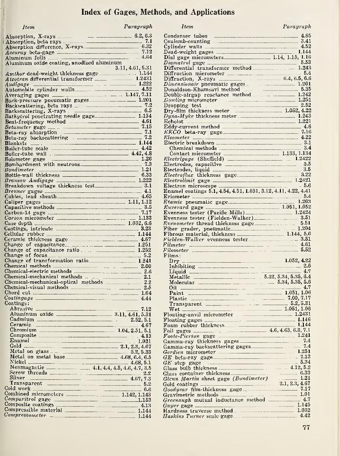
Index of Gages, Methods, and Applications
Item Paragraph
Absorption, X-rays 6.2, 6.3
Absorption, beta rays — - 7.1
Absorption difference. X-rays 6.32
Accuray beta-gage 7.12
Aluminum foils 4.64
Aluminum oxide coating, anodized aluminum3.11,4.61,5.31
Amthor dead-weight thickness gage 1.144
Atcotran differential transformer 1.2431
Audigage 1.222
Automobile cylinder walls 4.52
Averaging gages 1.147, 7.11
Back-pressure pneumatic gages 1.201
Backscattering, beta rays 7.2
Backscattering, X-rays 6.5
Bathytrol penetrating needle gage 1.134
Beat-frequency method 4.61
Betameter gage 7.15
Beta-ray absorption 7.1
Beta-ray backscattering 7.2
Blankets 1.144
Boiler-tube scale 4.42
Boiler-tube wall 4.42, 4.8
Bolometer gage 1.26
Bombardment with neutrons 7.3
Bondimeter 1.21
Bottle-wall thickness 6.33
Branson Audigage 1.222Breakdown voltage thickness test. 3.1
Brenner gages 4.1
Cables, lead sheath 4.65
Caliper gages 1.11, 1.12
Capacitive methods 3.5
Carbon-14 gage 7.17Carson micrometer 1.133Case depth 1.032, 6.6
Castings, intricate 3.23Cellular rubber 1.144Ceramic thickness gage 4.67Change of capacitance 1.251Change of capacitance ratio 1.252Change of focus 5.2
Change of transformation ratio 1.241Chemical methods 2.00Chemical-electric methods 2.6Chemical-mechanical methods 2.1Chemical-mechanical-optical methods 2.2Chemical-visual methods 2.5Chord cut 1.04Coatingage 4.44Coatings
:
Abrasive 7.12Aluminum oxide 3.11, 4.61, 5.31Cadmium 2.52, 5.1Ceramic 4.67Chromium 1.04, 2.51, 5.1Composite 4.13Enamel 1.031Gold 2.i, 2.3, 4.67Metal on glass 5.2, 5.33Metal on metal base 4.68, 6.4, 6.5Nickel 4.68, 5.1Nonmagnetic 4.1, 4.4, 4.5, 4.6, 4.7, 3.5Screw threads 2.2Silver ’4.’67, 7.3Transparent 5.2
Cold work 6.6Combined micrometers 1.142, 1.143Comparitrol gage 1.153Composite coatings 4.13Compressible material 1.144Compressometer 1.144
Item Paragraph
Condenser tubes 4.65
Coulomb-counting 3.41
Cylinder walls 4.52
Dead-weight gages 1.144
Dial gage micrometers 1.14, 1.15, 1.16
Diamatrol gage 5.53
Differential transformer method 1.243
Diffraction micrometer 5.4
Diffraction, X-rays 6.4, 6.5, 6.6
Dimensionair pneumatic gages 1.201
Donaldson-Khamsavi method 5.35
Double-airgap reactance method - 1.242
Dowling micrometer 1.251
Dropping test — 2.52
Dry-film thickness meter 1.052, 4.22
Dyna-Myke thickness meter 1.243
Echolot 1.221
Eddy-current method 4.6
EKCO beta-ray gage 7.16
Elcometer 4.22
Electric breakdown 3.1
Chemical methods 3.4
Contact micrometer 1.133, 1.134
Electrigage (Sheffield) 1.2422
Electrodes, capacitive 3.5
Electrodes, liquid 3.5
Electroflux thickness gage 3.22
Electrolimit gage 1.2421
Electron microscope 5.6
Enamel coatings 5.1, 4.54, 4.51, 1.031, 3.12, 4.11, 4.22, 4.41
Eriometer 5.4
Etamic pneumatic gage 1.203
Euverard gage 1.051, 1.052
Evenness tester (Pacific Mills) 1.2424
Evenness tester (Fielden-Walker) 3.51
Evenometer thread thickness gage 5.51
Fiber grader, pneumatic 1.204
Fibrous material, thickness 1.144, 5.6
Fielden-Walker evenness tester 3.51
Filmeter - 4.61
Filometer 5.52
Films:Dry 1.052, 4.22
Inhibiting 2.6
Liquid 4.7
Metallic 5.32, 5.34, 5.35, 6.4
Molecular 5.34, 5.35, 5.6
Oil 4.7
Paint 1.051,1.06
Plastic - 7.00, 7.17
Transparent 5.2, 5.31
Wet 1.051, 1.06
Floating-anvil micrometer 1.2431
Floating gages — 1.146
Foam rubber thickness 1.144
Foil gages 4.6, 4.63, 6.3, 7.1
Foote-Pierson gage 1.241
Gamma-ray thickness gages 7.4
Gamma-ray backscattering gages 7.4
Gerdien micrometer 1.251
GE beta-ray gage 7.13
GE step gage 5.34
Glass bulb thickness — 4.12, 5.2
Glass container thickness — 6.33
Glenn Martin sheet gage (Bondimeter)— — 1.21
Gold coatings 2.1, 2.3, 4.67
Goodyear film-thickness gage 7.17
Gravimetric methods — 1-01
Greenough mutual inductance method 4.7
Guyer gage 1.145
Hardness traverse method 1.032
Haskins Turner scale gage - 4.42
77

Item Paragraph Item Paragraph
Holt gage - 1.144
Hull of ships, thickness - 1.222, 6.1
Hurletron gage - 4.43
Idometer 3.52
Inhibiting films, thickness 2.6
Insulation on wires 1.02, 3.12
Interchemical thickness gage 1.051, 1.052
Intricate castings 3.23
Isotopes 7.00
Joint calipers 1.12
Kocour chemical gage. 3.42
Lead sheath thickness on cables 4.65Lectromag (Lipson) gage 4.14
Lever amplification 1.153Light Wave Micrometer 1.132Liquid electrodes 3.5
Liquid film thickness 4.7
Machinist’s micrometer 1.131Magnatest gages 4.41, 4.53, 4.67Magnegage 4.11, 4.12, 4.13
Magnetic attraction 4.1
Magnetic Gage 1.2421Magnetic saturation principle 4.3
Magnetic Schuster gage 1.2421Manubel micrometer 1.251Measuray gage 6.31Measurematic gage 1.144Measuring microscope 5.1, 5.6
Mechanical amplification 1.15Mechanical gages 1.10Mechanical-electric-capacitive method 1.25Mechanical-electric-inductive method 1.24Mechanical-electric-resistive method 1.23Mechanical-electric-thermal method 1.26Mechanical-electronic transmission 1.27Mechanical force deformation 1.21Mechanical-optical-photoelectric method 1.28Mechanical-pneumatic method 1.20Mechanical-vibration method 1.22Mercury electrodes 3.5
Mesle’s chord method 1.04Metal coatings (see “coatings”)Metal coatings on metal base... 4.68, 6.4, 6.5
Metallic films 5.2, 5.34, 6.4, 6.5Metrisite gage 1.244Metron thickness meters 1.2423Metroscope 1.222Michelson interferometer 5.32Micrometers 1.13, 1.14Micrometer microscope 5.1
Micronaire gage 1.204Mikrokator (“Swedish gage”) 1.152Molecular film thickness 5.34Moore-Williamson gage 4.21Moving strips 1.162, 1.204, 6.3, 7.1
Mutual inductance method 4.7Myke-A-Trol gage 1.2431Neutron bombardment method 7.3Noncontact thickness gages 3.5, 6.3, 7.1
Nonmagnetic coatings 1.05, 1.06, 4.1, 4.4, 4.5, 4.6, 4.7, 3.5Oblique cut method 1.03Oil film thickness.___ 4.7Optical amplification 1.16Optical diffraction method 5.4Optical interference method 5.3Optical-photoelectric method 5.5Optical methods in general l 5.0Optimike 5.2Oxide coatings on aluminum 3.11, 4.61, 5.31Pacific Mills evenness tester..,. 1.2424Paint film thickness 1.05,1.06,4.4,4.5Paper thickness 1.10, 4.22, 4.43Paper thickness in production ... 4.43,7.1Parallel magnetic flux method 4.2Pencil-type thickness meter 4.14
Penetrating-needle method 1.134
Penetron thickness gage 7.4
Pfund paint-film thickness gage 1.06
Photographic comparison. X-rays ... 6.2
Pileometer 1.144
Plastic films — 5.2, 7.0, 7.1
Pneumatic gages 1.20
Pratt & Whitney beta-ray gage 7.14
Precisionaire gage 1.204
Probolog gage 4.65
Projectometer gage 1.163
Propeller walls 1.22, 4.62, 6.2
Puncture method 3.1
Radiation methods 6.3, 7.0
Radioactive isotopes 7.0
Rad-O-Thik gamma-ray gage.,.. 7.4
Rate-of-flow pneumatic gages 1.204
Reactance method 4.4
Reed gage 1.151
Reflectogage 1.222
Ribbon thickness 3.21
Roller gages 1.05, 1.146, 1.162, 4.43
Rubber gloves 3.5
Rubber sheets in production 7.1, 3.52
Sandvik pneumatic gage 1.201
Saturation, magnetic 4.3
Scale thickness boiler tubes 4.42
Schaevitz differential transformer. 1.243
Screw micrometer 1.13
Screw micrometer with electrical contact 1.133
Screw thread coating 2.2
Selection of radioactive materials 7.0
Sere yarn tester 5.53
Shadow method X-ray 6.1
Sheet thickness in general 1.162, 4.3, 4.4, 4.5, 5.2, 6.3, 7.1
Sheets from one side.. 1.21, 3.22, 4.2, 4.3, 4.4, 4.8, 7.2, 4.6
Sheets in production, moving1.162, 1.203, 6.3, 7.0, 7.1, 7.2, 6.3
Sheets, stacked 1.10
Sheets, transparent 5.2, 6.3, 7.1
Sheet iron testers 4.3, 4.53
Ships, hull thickness 6.1, 7.4
Silver coating 4.67, 5.1, 7.3, 4.72
Slide calipers 1.11
Soft materials 1.144, 5.1
Solex pneumatic gage 1.203
Sonigage 1.222
Sonizon gage 1.222
Spectrophotometry 5.31
Sphere penetration method 1.06
Spot test, chemical 2.51
Spring caliper gage 1.12
Stacked sheets 1.10
Steel tubes and bottles 6.33
Step gage, GE 5.34
Strain gage displacement meter 1.232
Stripping method 2.1
Supersonic thickness meters 1.222
Surface condenser tube thickness 4.66Swedish gage 1.152Textile uniformity tester 3.53
Thermoelectricity 3.6
Thermoelectric thickness gage 3.61
Thread thickness 1.202, 3.53, 5.5
Tin coatings 6.5, 7.1
Tracerlab beta gages 7.11
Transformer principle 4.5
Transparent films 5.2, 7.1
Traverse method 1.032Tube walls . 1.133, 4.66, 6.33, 7.4
Van Keuren light-wave micrometer 1.132Variable resistance spring 1.233Verigraph 3.52Vernier attachment 1.11, 1.131Vessels from one side - 4.4, 6.1, 7.4
78

I.IJI
- 11,
i.d
-Si
«,ii
-II
Item
Vibration methods —Vibrating capacitive electrometer-
Paragraph
..... 1.22
7.16
Visi-Limit gage - 5.54
Visual gage (Sheffield) 1.164
Vitreous enamel thickness 1.031
Volumetric methods 1.02
Walls from one side 4.52, 6.1, 7.4
Wall-thickness boiler tubes 4.42,4.8
Wall-thickness condenser tubes 4.66
Wall-thickness glass containers 5.2, 6.33
Wall-thickness hollow propellers 4.62, 1.221, 6.3
Wall-thickness steel tubes and bottles.. 6.3, 6.31, 6.33, 7.4
Wall-thickness micrometer 1.133
Wattmeter method 4.8
Item Paragraph
Wear 7.5
Weighing method 1.01
Wet film thickness 1.051,1.06,4.7Whiddington ultramicrometer 1.251
Wildhack transducer 1.233Wire insulation 1.02, 3.12
Wire thickness 1.202, 3.21, 5.4
X-ray absorption 6.2, 6.3
X-ray backscattering 6.5
X-ray diffraction 6.4
X-ray shadow method 6.1
X-ray spectrometric method 6.6
Yarn evenness tester. 1.2424, 3.53, 5.51, 5.52, 5.53
3,21
Ul
.3,5
3.52
.,2«1
.U
4.12
,213
1.13
.133
2,2
M5,5!
6,1
,7.1
,4.6
6,3
1 , 1)
7.1
1.531
7 .4,
1,72
1
,11[
5.1.1
203,
222.1
>22'
,31
,66I
,51I
2.1
53
:,6
il
.5
u. S GOVERNMENT PRINTING OFFICE ; 1958 0—420727
79


THE NATIONAL BUREAU OF STANDARDS
The scope of activities of the National Bureau of Standards at its headquarters in
Washington, D. C., and its major field laboratories in Boulder, Colo., is suggested in the
following listing of the divisions and sections engaged in technical work. In general, each
section carries out specialized research, development, and engineering in the field indicated
by its title. A brief description of the activities, and of the resultant publications, appears
on the inside front cover.
WASHINGTON, D. C.
Electricity and Electronics. Resistance and Reactance. Electron Devices. Electrical Instru-
ments. Magnetic Measurements. Dielectrics. Engineering Electronics. Electronic Instru-
mentation. Electrochemistry.
Optics and Metrology. Photometry and Colorimetry. Optical Instruments. Photographic
Technology. Length. Engineering Metrology.
Heat. Temperature Physics. Thermodynamics. Cryogenic Physics. Rheology. Engine Fuels.
Free Radicals Research.
Atomic and Radiation Physics. Spectroscopy. Radiometry. Mass Spectrometry. Solid State
Physics. Electron Physics. Atomic Physics. Neutron Physics. Nuclear Physics. Radioac-
tivity. X-rays. Betatron. Nucleonic Instrumentation. Radiological Equipment. AEC Radia-
tion Instruments.
Chemistry. Organic Coatings. Surface Chemistry. Organic Chemistry. Analytical Chemis-
try. Inorganic Chemistry. Electrodeposition. Molecular Structure and Properties of Gases.
Physical Chemistry. Thermochemistry. Spectrochemistry. Pure Substances.
Mechanics. Sound. Mechanical Instruments. Fluid Mechanics. Engineering Mechanics.
Mass and Scale. Capacity, Density, and Fluid Meters. Combustion Controls.
Organic and Fibrous Materials. Rubber. Textiles. Paper. Leather. Testing and Specifica-
tions. Polymer Structure. Organic Plastics. Dental Research.
Metallurgy. Thermal Metallurgy. Chemical Metallurgy. Mechanical Metallurgy. Corrosion.
Metal Physics.
Mineral Products. Engineering Ceramics. Glass. Refractories. Enameled Metals. Con-
creting Materials. Constitution and Microstructure.
Building Technology. Structural Engineering. Fire Protection. Air Conditioning, Heat-
ing, and Refrigeration. Floor, Roof, and Wall Coverings. Codes and Specifications. HeatTransfer.
Applied Mathematics. Numerical Analysis. Computation. Statistical Engineering. Mathe-
matical Physics.
Data Processing Systems. SEAC Engineering Group. Components and Techniques. Digital
Circuitry. Digital Systems. Analog Systems. Application Engineering.
• Office of Basic Instrumentation • Office of Weights and Measures
BOULDER, COLO.
Cryogenic Engineering. Cryogenic Equipment. Cryogenic Processes. Properties of Materi-
als. Gas Liquefaction.
Radio and Propagation Physics. Upper Atmosphere Research. Ionospheric Research. Reg-
ular Propagation Services. Sun-Earth Relationships.
Radio Propagation Engineering. Data Reduction Instrumentation. Modulation Systems.
Navigation Systems. Radio Noise. Tropospheric Measurements. Tropospheric Analysis.
Radio Systems Application Engineering.
Radio Standards. High Frequency Electrical Standards. Radio Broadcast Service. High
Frequency Impedance Standards. Calibration Center. Microwave Physics. Microwave Cir-
cuit Standards.