Maximization of injected power and efficiency based optimal ...
18
ARCHIVES OF ELECTRICAL ENGINEERING VOL. 71(1), pp. 91 –108 (2022) DOI 10.24425/aee.2022.140199 Maximization of injected power and efficiency based optimal location of DPFC using iterative procedure SANTOSH KUMAR GUPTA 1 B ,JAYANT MANI TRIPATHI 2 ,MRINAL RANJAN 3 , RAVI KUMAR GUPTA 4 ,DHEERAJ KUMAR 5 1 Sitamarhi Institute of Technology Sitamarhi – 843301, Bihar, India 2 Rajkiya Engineering College Mainpuri – 205001, Uttar Pradesh, India 3 Gaya College of Engineering Gaya – 823003, Bihar, India 4 Madan Mohan Malaviya University of Technology Gorakhpur – 273008, Uttar Pradesh, India 5 Shri Ramwaroop Memorial College of Engineering and Management Lucknow, U.P, India e-mail: { B santoshgupta1990/jayant023/mrinal10m255/ravikumareco/229007dk}@gmail.com (Received: 13.05.2021, revised: 30.09.2021) Abstract: Among the FACTS device, the distributed power flow controller (DPFC) is a superior device. This can be evaluated after eliminating the dc capacitor between shunt and series convertors of the unified power flow controller (UPFC) and placing a number of low rating single phase type distributed series convertors in the line instant of using single large rating three phase series convertors as in the UPFC. The power flow through this dc capacitor as in the UPFC now takes place through the transmission line at a third harmonic frequency in the DPFC. The DPFC uses the D-FACTS that allows the replacement of a large three-phase converter as in the UPFC by several small-size series convertors present in the DPFC. The redundancy of several series convertors increases the system’s reliability of the power system. Also, there is no requirement for high voltage isolation as series convertors of the DPFC are hanging as well as single-phase types. Consequently, the DPFC system has a lower cost than the UPFC system. In this paper, the equivalent ABCD parameters of the latest FACTS device DPFC have been formulated with the help of an equivalent circuit model of the DPFC at the fundamental frequency component. Further, the optimal location in the transmission line and maximum efficiency of the DPFC along with Thyristor Controlled Series Compensator (TCSC), Static Synchronous Shunt Compensator (STATCOM) and © 2022. The Author(s). This is an open-access article distributed under the terms of the Creative Commons Attribution- NonCommercial-NoDerivatives License (CC BY-NC-ND 4.0, https://creativecommons.org/licenses/by-nc-nd/4.0/), which per- mits use, distribution, and reproduction in any medium, provided that the Article is properly cited, the use is non-commercial, and no modifications or adaptations are made.
-
Upload
khangminh22 -
Category
Documents
-
view
2 -
download
0
Transcript of Maximization of injected power and efficiency based optimal ...

ARCHIVES OF ELECTRICAL ENGINEERING VOL. 71(1), pp. 91 –108 (2022)
DOI 10.24425/aee.2022.140199
Maximization of injected power and efficiency basedoptimal location of DPFC using iterative procedure
SANTOSH KUMAR GUPTA1 B, JAYANT MANI TRIPATHI2, MRINAL RANJAN3,RAVI KUMAR GUPTA4, DHEERAJ KUMAR5
1Sitamarhi Institute of TechnologySitamarhi – 843301, Bihar, India
2Rajkiya Engineering CollegeMainpuri – 205001, Uttar Pradesh, India
3Gaya College of EngineeringGaya – 823003, Bihar, India
4Madan Mohan Malaviya University of TechnologyGorakhpur – 273008, Uttar Pradesh, India
5Shri Ramwaroop Memorial College of Engineering and ManagementLucknow, U.P, India
e-mail: {Bsantoshgupta1990/jayant023/mrinal10m255/ravikumareco/229007dk}@gmail.com
(Received: 13.05.2021, revised: 30.09.2021)
Abstract: Among the FACTS device, the distributed power flow controller (DPFC) isa superior device. This can be evaluated after eliminating the dc capacitor between shuntand series convertors of the unified power flow controller (UPFC) and placing a number oflow rating single phase type distributed series convertors in the line instant of using singlelarge rating three phase series convertors as in the UPFC. The power flow through this dccapacitor as in the UPFC now takes place through the transmission line at a third harmonicfrequency in the DPFC. The DPFC uses the D-FACTS that allows the replacement of a largethree-phase converter as in the UPFC by several small-size series convertors present in theDPFC. The redundancy of several series convertors increases the system’s reliability of thepower system. Also, there is no requirement for high voltage isolation as series convertorsof the DPFC are hanging as well as single-phase types. Consequently, the DPFC system hasa lower cost than the UPFC system. In this paper, the equivalent ABCD parameters of thelatest FACTS device DPFC have been formulated with the help of an equivalent circuit modelof the DPFC at the fundamental frequency component. Further, the optimal location in thetransmission line and maximum efficiency of the DPFC along with Thyristor ControlledSeries Compensator (TCSC), Static Synchronous Shunt Compensator (STATCOM) and
0
© 2022. The Author(s). This is an open-access article distributed under the terms of the Creative Commons Attribution-NonCommercial-NoDerivatives License (CC BY-NC-ND 4.0, https://creativecommons.org/licenses/by-nc-nd/4.0/), which per-mits use, distribution, and reproduction in any medium, provided that the Article is properly cited, the use is non-commercial,and no modifications or adaptations are made.

92 Santosh Kumar Gupta et al. Arch. Elect. Eng.
UPFC FACTS devices have been investigated using an iteration program developed inMATLAB under steady-state conditions. The results obtained depict that the DPFC whenplaced slightly off-center at 0.33 fraction distance from the sending end comes up withhigher performance. Whereas, when the TCSC, STATCOM and UPFC are placed at 0.16,0.2815, 0.32 fraction distances from sending end respectively give their best performance.
Key words: distributed power flow controller, efficiency, FACTS, maximum power transfercapability, optimal location
1. Introduction
The increase in consumption of electrical energy needs additional generating units as well asan extension of power system networks. However, this requires more investment and increasesenvironmental issues. Generally, the load centers are far away from the power generating stations.The generating power is utilized by loads via power export-import schemes. The line impedancesof lines decide the power flow in individual lines and there is no restriction of power flow to thepreferred power corridors. Consequently, there is a chance of overloading of some lines with theoverall effect of deteriorating voltage profiles and decreased system stability [1]. The cost anddifficulties forbid the construction of new lines. There is therefore an urgent need to find means ofutilizing the existing transmission facilities to a great extent. To enhance the transmissible powerin AC power systems, it is a well-founded practice to utilize reactive power compensation. Forenhancing the voltage profile as well as power flow in a transmission line fixed or mechanicallyswitched capacitors and reactors are employed. It has been convincingly stated that both thetransient and dynamic stability of the interconnected power system can be enhanced, and voltagedisruption can be interrupted if the reactive power settlement of the transmission line is madespeedily fluctuating with the help of the solid-state, thyristor switches, and electronic control. Tocontrol the voltage, power flow, and stability in a transmission line of a multi-area system a highcurrent power electronics device is used that is known as the flexible AC transmission system(FACTS) [2]. The connection of various FACTS devices in a transmission line is described indifferent ways, such as in series connection, shunt connection, or a combination of series and shuntcombination [3]. The FACTS devices, such as static synchronous series compensator (SSSC) andthyristor-controlled series capacitor (TCSC), are connected in series to the transmission lines toimprove the power flow. To control the voltage profile of the transmission line by connecting inshunt the static VAR compensator (SVC) and static synchronous compensator (STATCOM) areused [4]. A flexible AC transmission system that is connected in combination of series and shunt tothe transmission line to improve real and reactive power is the thyristor-controlled phase-shiftingtransformer (TCPST) and unified power flow controller (UPFC) [5]. The distributed FACTS wasinvented to reduce the cost and to increase the reliability of the system. In the distributed flexibleAC transmission system device (D-FACTS) multiple low-power converters are connected to thetransmission line by transformers consist of a single turn. The D-FACTS has several advantagesin comparison to conventional FACTS devices, such as due to its lower cost it is easy to maintainthe installation and enhance the system reliability because failure of one device will not shutdown the entire system [6]. Presently, the distributed static series compensator (DSSC), whichworks as a D-FACTS device acts like a controlled variable conductor [7]. Due to the inability of

Vol. 71 (2022) Maximization of injected power and efficiency 93
power sources in the DSSC, it can only control the line impedance and is not most as powerful asthe UPFC [8,9].
Among all FACTS devices the DPFC is the latest device which has powerful capability tocontrol the power flow in the transmission line because it has a large number of distributedseries convertors and has no dc link between shunt and series convertors, like in the UPFCwhich provides high redundancy to the electrical system. Serval works have been presented tofind out the optimal placement of conventional FACTS devices like the TCSC, STATCOM andUPFC [24]. It is important to find out the optimal placement of the latest FACTS device DPFC.
This paper describes the optimal location of the distributed flexible AC transmission systemin a transmission line under a steady state. To study the transmission line, a mathematical modelis developed, in which it has been characterized by a two-port four-terminal model. The line andFACTS device parameters are represented by ABCD parameters. Finally, using the concept ofABCD parameters the exact optimal location of the TCSC, STATCOM, UPFC and DPFC havebeen evaluated with their maximum efficiency for a 500 KV system.
2. ABCD model of long transmission line
It is considered that the transmission network has four terminals, the distribution of theline parameters is uniform and there is two-port network modelling. Capacitors, resistors, andinductors are the main elements of any electrical system. In the transmission line, these threeelements are uniformly present throughout the whole length. The line inductance has a veryimportant role due to the facts that the inductive reactance of the line is directly proportionalto the supply frequency and line inductance, and the inverse of this reactance is related to thepower handling capability of the transmission line [10]. As the length of the transmission lineincreases, the line inductive reactance becomes high which results in lowering the power handlingcapabilities of the transmission line conductors [11]. Oppositely, the decrement in line reactancewill increase the power handling capability of the transmission line. To decrease the value ofinductive reactance a parallel inductive reactance circuit should be connected. To achieve this,the number of transmission lines should be increased which will increase the overall cost ofthe system. To solve these problems, the concept of FACTS devices was invented which canregulate the system parameters in dynamic as well as steady-state conditions. Several emergingissues like enhancement of system security, loss minimization, congestion management, andavailable transferability of the system and transmission pricing can be overcome using series-shunt compensating devices like the DPFC [12]. After removing dc capacitor from the UPFC andplacing distributed series convertors, the DPFC can be evolved as shown Fig. 1 [13, 14].
Fig. 1. Steps of growth of DFPC from the unified power flow controller [14]

94 Santosh Kumar Gupta et al. Arch. Elect. Eng.
There are certain locations of these FACTS devices at which benefits can be maximized [15].Power angle, impedance and grid voltage are the parameters which affects the regulation of flowof power, and these are controlled by the DPFC controller simultaneously. When a FACTS deviceis configured as a series-shunt compensating device, it is located at a particular distance of 𝑥 kmfrom the sending end then a common general circuit constant of the regulated transmission line,having shunt reactance 𝑋𝑠ℎ and series reactance 𝑋𝑠𝑒 respectively is derived [16]. For a real inter-connected transmission line containing impedance and admittance, depending upon the length ofthe line (short, medium, and long transmission line) the parameters can be represented in terms ofABCD parameters [17]. Once the line parameters are represented in terms of the ABCD parameter,a mathematical model can be developed easily for analyzing the circuit in various aspects required.A transmission system can be characterized by the two-port four-terminal system shown in Fig. 2.
Fig. 2. Transmission system two port network [17]
The power in a transmission system flows from the sending end to the receiving end. In thecase of a lossless transmission line, the sending end power should be equal to the receiving endpower but in real practice due to the presence of admittance and impedance in the interconnectedline, some energy is wasted in the transmission line [18]. If a system has 𝑌 mho/km admittancein a shunt, 𝑍 ohm/km impedance in series and 𝐿 length of the transmission line, then the ABCDconstant of the transmission network should be:
𝐴 = 𝐷 = cosh(𝛾𝐿), 𝐵 = 𝑍𝑐 sinh(_𝐿), 𝐶 = sinh(𝛾𝐿)/𝑍𝑐 , (1)
where the propagation constant is _ =√𝑍 · 𝑌 and the characteristics impedance is 𝑍𝑐 =
√︂𝑍
𝑌.
For convenience, all the four constants may be represented simultaneously in matrix form then,[𝐴 𝐵
𝐶 𝐷
]=
cosh(_𝐿) 𝑍𝑐 · sinh(_𝐿)sinh(_𝐿)𝑍𝑐
cosh(_𝐿)
. (2)
Here all the ABCD parameters are in the polar quantities, so each of them has magnitude aswell as an angle, 𝐴 = 𝐴∠\𝐴, 𝐵 = 𝐵∠\𝐵, 𝐶 = 𝐶∠\𝐶 , 𝐷 = 𝐷∠\𝐷 .
Then we simplified the model of the transmission line, by neglecting the resistance andcapacitance. In that case the ABCD parameter constant of the transmission line model becomes:
𝐴 = 𝐷 = 1∠0◦, 𝐵 = 𝑥 · 𝐿∠90◦, 𝐶 = 0. (3)
So, for a simplified model of the transmission line[𝐴 𝐵
𝐶 𝐷
]=
[1 𝑥 · 𝐿∠90◦0 1
]. (4)
Vol. 71 (2022) Maximization of injected power and efficiency 95
3. Efficiency of the line
From Fig. 2, sending end current 𝐼𝑆 and voltage 𝑉𝑆 can be expressed in terms of receivingend current 𝐼𝑅 and voltage 𝑉𝑅 as [23]:
𝑉𝑆 = 𝐴𝑉𝑅 + 𝐵𝐼𝑅 and 𝐼𝑆 = 𝐶𝑉𝑅 + 𝐷𝐼𝑅 . (5)
The sending end real and reactive power can be written as:
𝑃𝑆 =|𝐴| |𝑉𝑆 |2
|𝐵 | cos(𝛽 − 𝛼) − |𝐴| |𝑉𝑆 | |𝑉𝑅 ||𝐵 | cos(𝛽 − 𝛿 + 180◦), (6)
where 𝛿 is the power angle.
𝑄𝑆 =|𝐴| |𝑉𝑆 |2
|𝐵 | sin(𝛽 − 𝛼) − |𝐴| |𝑉𝑆 | |𝑉𝑅 ||𝐵 | sin(𝛽 − 𝛿 + 180◦). (7)
The receiving end real and reactive power can be written as:
𝑃𝑅 =|𝑉𝑆 | |𝑉𝑅 |
|𝐵 | cos(𝛽 − 𝛿) − |𝐴| |𝑉𝑅 |2
|𝐵 | cos(𝛽 − 𝛼), (8)
𝑄𝑅 =|𝑉𝑆 | |𝑉𝑅 |
|𝐵 | sin(𝛽 − 𝛿) − |𝐴| |𝑉𝑅 |2
|𝐵 | sin(𝛽 − 𝛼). (9)
The efficiency of the transmission line can be expressed as:
[ =𝑃𝑅
𝑃𝑆
× 100% . (10)
4. ABCD model of transmission line with FACTS device
Theoretically, the FACTS device can be connected at any position between the generating endand the infinite bus. A general block diagram showing the FACTS device among sending end andreceiving end is presented in Fig. 3.
Fig. 3. General block diagram showing FACTS device in the transmission line [23]
The complete line can be divided into three parts, the line before the FACTS device towardsthe sending end, the FACTS device, and the line after the FACTS device towards the receiving

96 Santosh Kumar Gupta et al. Arch. Elect. Eng.
end [19]. The three parts are in cascading form as shown in Fig. 4, the overall ABCD parametersin such case are the multiplication of the ABCD constant of individual parts.[
𝐴 𝐵
𝐶 𝐷
]=
[𝐴 𝐵
𝐶 𝐷
]𝐿,𝑥
[𝐴 𝐵
𝐶 𝐷
]𝐹
[𝐴 𝐵
𝐶 𝐷
]𝐿 (𝑙−𝑥)
. (11)
Fig. 4. Representation of ABCD parameters in cascading with FACTS device [23]
As shown in Fig. 4, if the FACTS devices are placed on a transmission line, then the sendingend voltage and sending end current can be expressed by the equation:[
𝑉𝑆
𝐼𝑆
]=
[𝐴 𝐵
𝐶 𝐷
]𝐿,𝑥
[𝐴 𝐵
𝐶 𝐷
]𝐹
[𝐴 𝐵
𝐶 𝐷
]𝐿 (𝑙−𝑥)
[𝑉𝑅
𝐼𝑅
], (12)[
𝑉𝑆
𝐼𝑆
]=
[𝐴 𝐵
𝐶 𝐷
] [𝑉𝑅
𝐼𝑅
], (13)
𝐴 = 𝑓 (𝑥), 𝐵 = 𝑓 (𝑥), 𝐶 = 𝑓 (𝑥), 𝐷 = 𝑓 (𝑥),where ∀𝑥 ∈
[0 1
].
5. ABCD constant model FACTS devices
5.1. ABCD model of TCSCThe TCSC is the FACTS device that can regulate the impedance of desire lines and quickly
controls the power flow of that lines. It has a parallel combination of a fixed capacitor and a rectorcontrolled by a thyristor, as shown in Fig. 5(a).
(a) (b)
Fig. 5. Equivalent representation of TCSC (a); TCSC connected in the transmission line (b) [23]
The TCSC model consists of the offered variable reactance (both inductive and capacitive)𝑋net, which is dependent upon the firing angle of the thyristors and expressed as:
𝑋1 =𝜋𝑋𝐿
2𝜋 − 2𝛼 + sin 2𝛼, (14)

Vol. 71 (2022) Maximization of injected power and efficiency 97
where: 𝛼 is the firing angle of the thyristor, 𝑋𝐿 is the inductive reactance, 𝑋1 is the variablereactance with the thyristor. Now 𝑋1 and 𝑋𝑐 are in parallel connection. So, in a steady statesituation, 𝑋net is represented as:
𝑋net =𝑋1𝑋𝐶𝑋𝐶 − 𝑋1
. (15)
For Fig. 5(b), the relationship between voltages and currents at the sending end and receivingend terminals in steady state conditions is written as:
𝑉 ′𝑆 = 𝑉 ′
𝑅 + 𝑗 𝑋net𝐼′𝑅 and 𝐼 ′𝑠 = 𝐼
′𝑟 . (16)
From Eqs. (16) the ABCD parameters of the TCSC are obtained as [23]:[𝐴 𝐵
𝐶 𝐷
]TCSC
=
[1 𝑗 𝑋net0 1
]. (17)
5.2. ABCD model of STATCOMThe basic model of a STATCOM is depicted in Fig. 6(a). The reactive power generation and
absorption is controlled by capacitor voltage. Based on the model of the STATCOM, the convertorvoltage 𝑉𝑠ℎ is formulated as [23]:
𝑉𝑠ℎ = 𝐾𝑣𝐸𝑑𝑐 cos𝛽12, (18)
where, 𝐸𝑑𝑐 is the terminal voltage of the capacitor, 𝐾𝑣 is the coefficient for the multi-pulsewaveform, 𝛽1 is the firing angle of the thyristor of the convertor.
(a) (b)
Fig. 6. Model of STATCOM (a); model of UPFC (b) [23]
At the operational point, 𝐾1 is the operation parameter and from Fig. 6(a) we have thefollowing:
𝐾𝑣𝐸𝑑𝑐 = 𝐾1𝑉′𝑅 and 𝐼 ′𝑆 = 𝐼𝑠ℎ + 𝐼 ′𝑅 . (19)
From Eqs. (18) and (19) the ABCD parameters of the ABCD are obtained as:[𝐴 𝐵
𝐶 𝐷
]STATCOM
=
[1 0𝐾 1
], (20)

98 Santosh Kumar Gupta et al. Arch. Elect. Eng.
where
𝐾 = 1 +1 − 𝐾1 cos
𝛽12
𝑍𝑠ℎ
and 𝐾1 = 1.1, taken for the capacitive mode of operation.
5.3. ABCD model of UPFCThe UPFC model consists of two voltage sources as depicted in Fig. 6(b). One is connected
in series with the line and other is connected in parallel with the line via a coupling transformer.In addition, both are linked via a dc capacitor. The model has a powerful capability to regulatesystem parameters like line impedance, power angle as well bus voltages resulting in powerfulcontrol over active and reactive powers. From the model of the UPFC it can be expressed as [23]:
𝑉𝑠𝑒 = 𝛾𝑒𝑗 \𝑉 ′
𝑆 and 𝑉 ′𝑆 = 𝐶𝑃𝑉
′𝑅 , (21)
where𝐶𝑃 =
11 + _𝑒 𝑗 \ , 𝛾 =
𝑉𝑠𝑒
𝑉𝑆
and \ varies from 0 to 2𝜋 radians.
𝐼𝑠ℎ =𝑉 ′𝑆(1 − 𝐾𝑠ℎ)𝑍𝑠ℎ
, (22)
where𝐾𝑠ℎ =
𝑉𝑠ℎ
𝑉𝑆
and from the basic principle of the UPFC we have the following:
Re[𝑉 ′𝑆 𝐼
∗𝑠ℎ
]= Re
[𝑉𝑆𝑒 𝐼
∗𝑅
]. (23)
By solving the above three equations we get:
𝐼 ′𝑆 =𝐶𝑃 · Re (1 − 𝐶𝑃) 𝐼 ′∗𝑅
𝑍𝑠ℎ𝐶2𝑃
(1𝑍𝑠ℎ
) + 𝐼 ′𝑅 . (24)
Or the above equation can be simplified as:
𝐼 ′𝑆 = 𝐾𝐼 ′𝑅 . (25)
Therefore, the steady-state expression for this place of the UPFC will be
𝑉 ′𝑆 = 𝐶𝑃𝑉
′𝑅 and 𝐼 ′𝑆 = 𝐾𝐼 ′𝑅 . (26)
In matrix form, the steady state equation taken from Eq (26) as follows:[𝑉 ′𝑆
𝐼 ′𝑆
]=
[𝐶𝑃 00 𝐾
] [𝑉 ′𝑅
𝐼 ′𝑅
]. (27)
Therefore, the ABCD parameters for the UPFC are[𝐴 𝐵
𝐶 𝐷
]UPFC
=
[𝐶𝑃 00 𝐾
]. (28)

Vol. 71 (2022) Maximization of injected power and efficiency 99
5.4. Formulation of ABCD parameters of the DPFCIn the group of FACTS, the DPFC is a multipurpose device that can regulate real and reactive
power. There are two voltage sources in the modelling of the DPFC. There are two convertorsin the DPFC. One is a single-turn transformer one connected in series with the transmissionconductor and the other is connected in parallel with the transmission conductor [20]. Both theconvertors have a dc capacitor for storing energy. The injection of voltage with variable phasesand magnitude into the line conductor is possible by the series convertor [21]. The real powerexchange occurs among the line conductor and series convertor by the parallel convertor [22]. Theproposed model of the DPFC with the transmission system at fundamental frequency is shownin Fig. 7. The series convertors of the UPFC and DPFC can be placed anywhere between twobuses, whereas the shunt convertor of UPFC can also placed at anywhere in the line, but the shuntconvertor of the DPFC must be placed at the sending end of the line as shown in Fig. 8. This is thebasic difference between mathematical calculations of the UPFC and DPFC, at the fundamentalfrequency component.
(a) (b)
Fig. 7. DPFC circuit diagram with the transmission line (a); mathematical model of DPFC at fundamentalfrequency component (b)
Fig. 8. Separation of series and shunt convertors of the DPFC for the evaluation of ABCD parameters
From the above model of the DPFC, as the series and shunt convertors of the DPFC are nottogether, it is necessary to evaluate the ABCD parameters of series and shunt convertors separately.

100 Santosh Kumar Gupta et al. Arch. Elect. Eng.
From Fig. 8, the ABCD parameters of the shunt convertor of the DPFC can be calculated like theABCD parameters calculated for the STATCOM from Eqs. (18) and (19).[
𝑉𝑆
𝐼𝑆
]=
[1 0
𝐾SHUNT 1
] [𝑉 ′𝑅
𝐼 ′𝑅
], (29)
where
𝐾SHUNT = 1 +1 − 𝐾1 cos
𝛽12
𝑍𝑠ℎ
is the operating parameter for the DPFC, shunt convertor.Therefore, the ABCD parameters of the shunt convertor of the DPFC which is placed at the
sending end, are as follows: [𝐴 𝐵
𝐶 𝐷
]DPFCSHUNT
=
[1 0
𝐾SHUNT 1
]. (30)
From Fig. 8, the ABCD parameters of the series convertor of the DPFC can be calculated as:
𝑉𝑠𝑒 = 𝛾𝑒𝑗 \𝑉 ′
𝑆 and 𝑉 ′𝑆 = 𝐶𝑃𝑉
′′𝑅 , (31)
where𝐶𝑃SERIES =
11 + _𝑒 𝑗 \ , 𝛾 =
𝑉𝑠𝑒
𝑉𝑆
and \ varies from 0 to 2𝜋 radians.𝐼 ′𝑆 = 𝐼 ′′𝑅 . (32)
From Eqs. (31) and (32) we get[𝑉 ′𝑆
𝐼 ′𝑆
]=
[𝐶𝑃SERIES 0
0 1
] [𝑉 ′𝑅
𝐼 ′𝑅
]. (33)
Therefore, the ABCD parameters of the series convertor of the DPFC is given:[𝐴 𝐵
𝐶 𝐷
]DPFCSSERIES
=
[𝐶𝑃SERIES 0
0 1
]. (34)
Fig. 9. Block representation of ABCD parameters in cascading with series and shunt convertorsof the DPFC FACTS device

Vol. 71 (2022) Maximization of injected power and efficiency 101
6. Results and discussion
To study the behaviour of different FACTS devices on the transmission line connectinga generating station with an infinite bus, a set of input data is required. In this work, a set of inputdata is used for analyzing the system provided in Table 1 [23]. The intersection points of the powerreceived, and power delivered by the DPFC is important as this gives the optimal location of theDPFC on the transmission line as the power received and delivered by the FACTS devices at thatpoint are equal. The exact locations of the TCSC, STATCOM, UPFC and DPFC are investigatedwith the help of an iteration program developed in MATLAB. Figure 10 and Fig. 11 are showing
(a) (b)
Fig. 10. Optimal location of TCSC in the transmission line (a); optimal location of STATCOMin the transmission line (b)
(a) (b)
Fig. 11. Optimal location of UPFC in the transmission line (a); optimal location of DPFCin the transmission line (b)

102 Santosh Kumar Gupta et al. Arch. Elect. Eng.
how the TCSC, STATCOM, UPFC and DPFC receive and deliverer power when it is placed atdifferent locations.
Table 1. Set of input data used [23]
S. No. Parameters Data Unit
1 Impedance of the line 0.03808 + j0.7616 ohm/km
2 Admittance of the line 0.0 + j5.5 μS/km
3 Length of the line 483 (300 miles) km
4 Rating of the load 100 MVA
5 Receiving end voltage 500 kV
6 Power factor angle of the load 85 degree
7 Firing angle of the thyristor (𝛼) 150 (for 60% compensation) degree
8 𝛾 (for series convertor) 0.01 –
9 \ (for series convertor) 90 degree
The optimal location of any FACTS device in the transmission line is that location where thepower received and power delivered by that FCATS device are the same. At that point the systemefficiency will be maximum. With the help of the iteration program developed in MATLAB, theoptimal locations of the TCSC, STATCOM, UPFC and DPFC are investigated as: 0.16, 0.2815,0.32 and 0.33 fractions of the transmission line from the sending end, respectively. These pointsare also found to be the same on the curves between power receievd and delivered by the FACTSdevices and different locations of the FACTS devices in the transmission line as depicted fromFig. 10 and Fig. 11. As the power angle, line impedance and bus voltage magnitude controlcapabilities of the UPFC and DPFC are the same, the optimal location found for both are nearlyequal.
By using the input given in Table 1 from [23], the optimal location of the TCSC, STATCOM,UPFC and DPFC in the line are found. With the help of the input data, variations of the receivedand delivered power by FACTS devices: the TCSC, STATCOM, UPFC and DPFC are obtainedas in Table 2 when these devices are placed at different locations in the line.
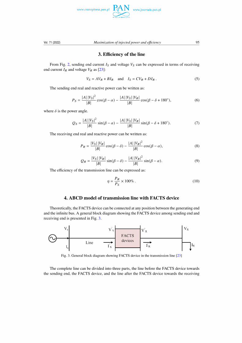
Further calculations for the maximum efficiency of the power transfer on the bus have beendone when the DPFC is placed at different locations. In this case, the calculation has been donefor maximum efficiency when it is placed at 25 percent, 50 percent, and 75 percent from thegenerating (sending) end and exactly at the calculated optimal point. Figures 12–15 are showingthe efficiency of the power delivered from the sending end to the receiving end vs the fractionof MVAR transferred for the TCSC, STATCOM, UPFC and DPFC, respectively. It is observedthat maximum efficiency found is 93.221% corresponding to 50% MVAR transferred for theTCSC placed at the optimal location, 90.31% corresponding to 50% MVAR transferred for theSTATCOM placed at the optimal location, 91.58% corresponding to 50% MVAR transferred forthe UPFC placed at the optimal location and 92.101% corresponding to 50% MVAR transferredfor the DPFC placed at the optimal place.

Vol. 71 (2022) Maximization of injected power and efficiency 103
Table 2. Optimum locations of FACTS devices to deliver maximum power
Fractionallength of
line X
Powerreceived
byTCSC
(MVAR)
Powerdelivered
byTCSC
(MVAR)
Powerreceived
bySTATCOM
(MVAR)
Powerdelivered
bySTATCOM
(MVAR)
Powerreceived
byUPFC
(MVAR)
Powerdelivered
byUPFC
(MVAR)
Powerreceived
byDPFC
(MVAR)
Powerdelivered
byDPFC
(MVAR)
0.1 137.9 101 2190.4 563.5 2340.5 565.2 2341.1 565.3
0.2 143 165 1136.8 688.8 1296.4 690.2 1297.7 690.4
0.3 170.6 235 761.2 841.9 943 842.9 943.4 843.4
0.4 205.7 312 556.2 1037 761 1037.9 761.4 1039
0.5 243.7 397 421.2 1300 647.8 1300.9 648.2 1302
0.6 281.5 492 323.2 1682 568.7 1682.8 569.3 1683
0.7 316.7 601 248.5 2300 509 2301.6 509.8 2302
0.8 347.2 731 190.4 3513 461.8 3514 462.3 3515
0.9 370.6 890 144.9 7098 422.1 7101.9 422.4 7102
Fig. 12. Line maximum efficiency with different locations of TCSC
Figure 16 and Fig. 17 give maximum efficiency variations with fractional power for differentfraction locations of the DPFC. The different fraction of load as well as load power factor of twodifferent parameters has been plotted to find the maximum efficiency by keeping one parameter

104 Santosh Kumar Gupta et al. Arch. Elect. Eng.
Fig. 13. Line maximum efficiency with different locations of STATCOM
Fig. 14. Line maximum efficiency with different locations of UPFC
constant at a time. The left graph in Fig. 16 shows the variation of efficiency vs load power factorwith constant load applied at the receiving end bus for the UPFC while the right graph in Fig. 16shows the variation of maximum efficiency vs load with constant power factor for the UPFC.
Vol. 71 (2022) Maximization of injected power and efficiency 105
Fig. 15. Line maximum efficiency with different locations of DPFC
Similarly, the left graph in Fig. 17 shows the variation of maximum efficiency vs load powerfactor with constant load applied at the receiving end bus for the DPFC, while the right graph inFig. 17 shows the variation of maximum efficiency vs load with constant power factor.
Fig. 16. Maximum efficiency of the system at different MVAR transferred with constant MVA and differentMVA transferred with constant MVAR for UPFC

106 Santosh Kumar Gupta et al. Arch. Elect. Eng.
Fig. 17. Maximum efficiency of the system at different MVAR transferred with constant MVA and differentMVA transferred with constant MVAR for DPFC
7. Conclusions
The paper presents a study of the performance of the transmission line by connecting theDPFC and other series as well as shunt FACTS device in a long transmission line with a gener-ating end and an infinite bus. The programs developed in MATLAB depict apparent power andreactive power change in line with the change in the position of FACTS devices. The ABCDparameters of the DPFC have been developed by evaluating a DPFC model at the fundamentalcomponent, and implemented in the long transmission line. The optimal location of the DPFCon a 483 km transmission line has been investigated with the help of an iterative program de-veloped in MATLAB under steady-state conditions. It is observed that for the selected set ofinputs the optimal position of the DPFC in a transmission system is at 0.33 fraction of the linefrom the sending end. For the purpose of a comparative analysis, the optimal locations of otherFACTS devices the TCSC, STATCOM and UPFC have been investigated in the same manner asinvestigated in the case of the DPFC. For the same input parameters, the optimal locations of theTCSC, STATCOM and UPFC are found to be of 0.16, 0.2815 and 0.32 fractions of the line fromthe sending end respectively. It is observed that the obtaioned optimal location of the UPFC andDPFC are nearly same, it is due to the same power control capabilities of both devices. This helpsin finding the optimal location of the DPFC for maximum power transferred and efficiency.
References
[1] Edris A.A., Aapa R., Baker M.H., Bohman L., Clark K., Proposed terms and definitions for flexible actransmission system (FACTS), IEEE Trans. on Power Delivery, vol. 12, no. 4, pp. 1848–1853 (1997),DOI: 10.1109/61.634216.
[2] Das D., Divan D.M., Harley R.G., Power flow control in networks using controllable networktransformers, IEEE Trans. Power Electron., vol. 25, no. 7, pp. 1753–1760 (2010), DOI: 10.1109/TPEL.2010.2042076.
Vol. 71 (2022) Maximization of injected power and efficiency 107
[3] Ooi B.T., Kazerrani M., Marcean R., Wolanski Z., Galiana F.D., Megillis D., Jms G., Midpoint sitingof FACTS devices in transmission lines, IEEE Trans. on power delivery, vo1. 12, no. 4, pp. 1717–1722(1997), DOI: 10.1109/61.634196.
[4] Hingorani N.G., Gyugyi L., Understanding FACTS: Concepts and Technology of Flexible AC Trans-mission Systems, New York: IEEE Press (2000).
[5] Nabavi-Niak A., Iravani M.R., Steady-State and Dynamic Models of Unified Power Flow Con-troller (UPFC) for Power System Studies, IEEE Trans. Power Systems, vol. 11, no. 4 (1996),DOI: 10.1109/59.544667.
[6] Harjeet Johal, Deepak Divan, Design Considerations for Series-Connected Distributed FACTSConverters, IEEE Transactions on Industry Applications, vol. 43, iss. 6, pp. 1609–1618 (2007),DOI: 10.1109/TIA.2007.908174.
[7] Amir Hamidi, Sajjad Golshannavaz, Daryoush Nazarpour, D-FACTS Cooperation in Renewable Inte-gratedMicrogrid A LinearMultiobjective Approach, IEEE Transactions on Sustainable Energy, vol. 10,iss. 1, pp. 355–363 (2019), DOI: 10.1109/TSTE.2017.2723163.
[8] Narasimha Rao D., Srinivasa Varma P., Comparison of UPFC and DPFC, Journal of Critical Reviews,vol. 7, iss. 6 (2020), DOI: 10.31838/jcr.07.06.153.
[9] Abhilash Sen, Atanu Banerjee, Haricharan Nannam, A Comparative Analysis between UPFC andDPFC in a Grid Connected Photovoltaic System, IEEE International Conference on IntelligentTechniques in Control, Optimization and Signal Processing (INCOS) (2019), DOI: 10.1109/IN-COS45849.2019.8951352.
[10] Song W., Zhou X., Zhigang Liang, Subhashish Bhattacharya, Huang Alex Q., Modeling and ControlDesign of Distributed Power Flow Controller based-on Per-phase control, IEEE Energy ConversionCongress and Exposition (2009), DOI: 10.1109/ECCE.2009.5316307.
[11] Chandrakar V.K., Kothari A.G., Optimal Location for Line Compensation by Shunt Connected FACTSController, IEEE Power Electronics and Drive Systems Conference, vol. 1, pp. 151–156 (2003),DOI: 10.1109/PEDS.2003.1282736.
[12] Vikash Anand, Sanjeev Kumar Mallik, Power flow analysis and control of distributed FACTS de-vices in power system, Archives of Electrical Engineering, vol. 67, no. 3, pp. 545–561 (2018),DOI: 10.24425/123662.
[13] Zhihui Yuan, de Haan Sjoerd W.H., Ferreira Jan A., Construction and first result of a scaled transmis-sion system with the Distributed Power Flow Controller (DPFC), 13th European Conference on PowerElectronics and Applications (2009).
[14] Zhihui Yuan, de Haan Sjoerd W.H., Braham Frreira, Dalibor Cevoric, A FACTS Device: Dis-tributed Power Flow Controller (DPFC), IEEE Trans. Power Electronics, vol. 25, no. 10 (2010),DOI: 10.1109/TPEL.2010.2050494.
[15] Syona Chawla, Sheetal Garg, Bhawna Ahuja, Optimal Location of Series-Shunt FACTS Device forTransmission Line Compensation, IEEE Control, Automation, Communication and Energy Conserva-tion Conference, pp. 1–6 (2009).
[16] Shehata Ahmed A., Refaat Ahmed, Mamdouh K. Ahmed, Korovkin Nikolay V., Optimal placementand sizing of FACTS devices based on Autonomous Groups Particle Swarm Optimization technique,AEE, vol. 70, no. 1, pp. 161–172 (2021), DOI: 10.24425/aee.2021.136059.
[17] Riadh Essaadali, Anwar Jarndal, Ammar B. Kouki, Fadhel M. Ghannouch, Conversion Rules BetweenX-Parameters and Linearized Two-Port Network Parameters for Large-Signal Operating Conditions,IEEE Transactions on Microwave Theory and Techniques, vol. 66, no. 11, pp. 4745−4756 (2018),DOI: 10.1109/TMTT.2018.2863227.
108 Santosh Kumar Gupta et al. Arch. Elect. Eng.
[18] Divya S., Shyamala U., Power quality improvement in transmission systems using DPFC, IEEE 2ndInternational Conference on Electronics and Communication Systems (ICECS) (2015), DOI: 10.1109/ECS.2015.7125035.
[19] Apolinar Reynoso-Hernández J., Pulido-Gaytán M.A., Cuesta R., Loo-Yau J.R., Maya-Sánchez M.C.,Transmission Line Impedance Characterization Using an Uncalibrated Vector Network Analyzer,IEEE Microwave and Wireless Components Letters, vol. 30, no. 5, pp. 528–530 (2020), DOI: 10.1109/LMWC.2020.2984377.
[20] Monika Sharma, Annapurna Bhargava, Pinky Yadav, Oscillation Damping with DPFC Using Opti-mization Techniques, IEEE International Conference on Micro-Electronics and TelecommunicationEngineering (ICMETE) (2017), DOI: 10.1109/ICMETE.2016.73.
[21] Mengmeng Xiao, Shaorong Wang, Yong Huang, Chao Zheng, Qiushi Xu, Hongsheng Zhao, AihongTang, Dichen Liu, Two-Level Control Method for DPFC Series Units Based on PLC Communication,2nd IEEE Conference on Energy Internet and Energy System Integration (EI2), pp. 20–22 (2018),DOI: 10.1109/EI2.2018.8582109.
[22] Zhai X., Tang A., Zou X., Xu Zheng, Qiushi Xu, Research on DPFC Capacity and ParameterDesign Method, IEEE International Conference on Information Technology, Big Data and ArtificialIntelligence (ICIBA) (2020), DOI: 10.1109/ICIBA50161.2020.9277315.
[23] Pradhan A.K., Routray A., Banaja Mohanty, Maximum efficiency of flexible AC transmission systems,Electrical Power and Energy Systems, vol. 28, pp. 581–588 (2006), DOI: 10.1016/j.ijepes.2006.03.014.
[24] Seyed Abbas Taher, Muhammad Karim Amooshahi, New approach for optimal UPFC placementusing hybrid immune algorithm in electric power systems, International Journal of Electrical Powerand Energy Systems, vol. 43, iss. 1, pp. 899–909 (2012), DOI: 10.1016/j.ijepes.2012.05.064.