Matrix 410N Reference Manual - Diamond Technologies
192
Matrix 410N™ PRODUCT REFERENCE GUIDE Image Based Reader
-
Upload
khangminh22 -
Category
Documents
-
view
0 -
download
0
Transcript of Matrix 410N Reference Manual - Diamond Technologies

Matrix 410N™
PRODUCT REFERENCE GUIDE
Image Based Reader

Datalogic S.r.l.Via S. Vitalino, 13 40012 Calderara di Reno (BO)ItalyTel. +39 051 3147011Fax +39 051 3147205
© 2015-2020 Datalogic S.p.A. and /or its affiliates
All rights reserved. Without limiting the rights under copyright, no part of this documentation may be repro-duced, stored in or introduced into a retrieval system, or transmitted in any form or by any means, or for any purpose, without the express written permission of Datalogic S.p.A. and/or its affiliates.Owners of Datalogic products are hereby granted a non-exclusive, revocable license to reproduce and transmit this documentation for the purchaser's own internal business purposes. Purchaser shall not remove or alter any proprietary notices, including copyright notices, contained in this documentation and shall ensure that all notices appear on any reproductions of the documentation.Electronic versions of this document may be downloaded from the Datalogic website (www.datalogic.com). If you visit our website and would like to make comments or suggestions about this or other Datalogic pub-lications, please let us know via the "Contact" page.Disclaimer
Datalogic has taken reasonable measures to provide information in this manual that is complete and accu-rate, however, Datalogic shall not be liable for technical or editorial errors or omissions contained herein, nor for incidental or consequential damages resulting from the use of this material. Datalogic reserves the right to change any specification at any time without prior notice.Trademarks
Datalogic and the Datalogic logo are registered trademarks of Datalogic S.p.A. in many countries, including the U.S.A. and the E.U.Matrix 410N, ID-NET, DL.CODE, X-PRESS and Blue Diamonds are trademarks of Datalogic S.p.A. and/or its affiliates. All other trademarks and brands are property of their respective owners.
PatentsSee www.patents.datalogic.com for patent list.

PRODUCT REFERENCE GUIDE iii
CONTENTS
PREFACE .................................................................................................................VIIAbout this Manual .......................................................................................................... vii
Manual Conventions .......................................................................................................................... viiTechnical Support .......................................................................................................... vii
Support Through the Website ........................................................................................................... viiReseller Technical Support .............................................................................................................. viii
COMPLIANCE ............................................................................................................IXGeneral .......................................................................................................................... ixPower Supply ................................................................................................................. ixEMC Compliance ............................................................................................................. ixCE Compliance ................................................................................................................ ixFCC Compliance ............................................................................................................... xEAC Compliance ............................................................................................................... xLaser Safety ................................................................................................................... xiLED Safety ..................................................................................................................... xi
HANDLING ...............................................................................................................XIIGENERAL VIEW .......................................................................................................XIVRAPID CONFIGURATION..............................................................................................1
Step 1 - Assemble the Reader .......................................................................................... 1Required Accessories .........................................................................................................................3
Internal Lighting Mode Limitations ............................................................................................4DL.CODE Illuminator Management Procedure ..................................................................................4
Step 2 - Connect the System ............................................................................................ 4CBX100/CBX500 Pinout for Matrix 410N ...........................................................................................5
Step 3 - Mount and Position the Reader ............................................................................ 6Step 4 - Focus the Reader ................................................................................................ 8Step 5 - Calibrate Image Density ...................................................................................... 9
Locate ..........................................................................................................................................9Setup ..........................................................................................................................................10Learn ..........................................................................................................................................10
Step 6 - X-PRESS Configuration ..................................................................................... 11Locate ........................................................................................................................................11Setup ..........................................................................................................................................11Learn ..........................................................................................................................................12
Reset Reader to Factory Default Environment (Optional) ...............................................................13Step 7 - Installing DL.CODE Configuration Program ......................................................... 14
Device Discovery ...............................................................................................................................15Step 8 - Device Configuration ......................................................................................... 18
Automatic or Advanced Setup ..........................................................................................................18Automatic Setup .......................................................................................................................19Advanced Setup .........................................................................................................................21Reading Phase ...........................................................................................................................28Good Read Setup .......................................................................................................................29Data Formatting ........................................................................................................................30Output Setup .............................................................................................................................31
Step 9 - Test Mode ......................................................................................................... 32Advanced Reader Configuration ...................................................................................... 33

CONTENTS
iv MATRIX 410N
Host Mode Programming ................................................................................................................. 33
INTRODUCTION ........................................................................................................ 34Product Description ........................................................................................................34
Standard Application Program ......................................................................................................... 35Programmability ............................................................................................................................... 35Excellent Performance ..................................................................................................................... 35Ease of Setup ..................................................................................................................................... 35Ease of Use ........................................................................................................................................36Flexible Solution ................................................................................................................................ 36Versatility ...........................................................................................................................................36Industrial Strength ............................................................................................................................36
Indicator and Keypad Button ...........................................................................................37ID-NET ..........................................................................................................................38X-PRESS Human Machine Interface ................................................................................40
X-PRESS Functions ........................................................................................................................... 41Test Mode .................................................................................................................................. 41Focus/Locate ............................................................................................................................42Setup ......................................................................................................................................... 42Learn ......................................................................................................................................... 42
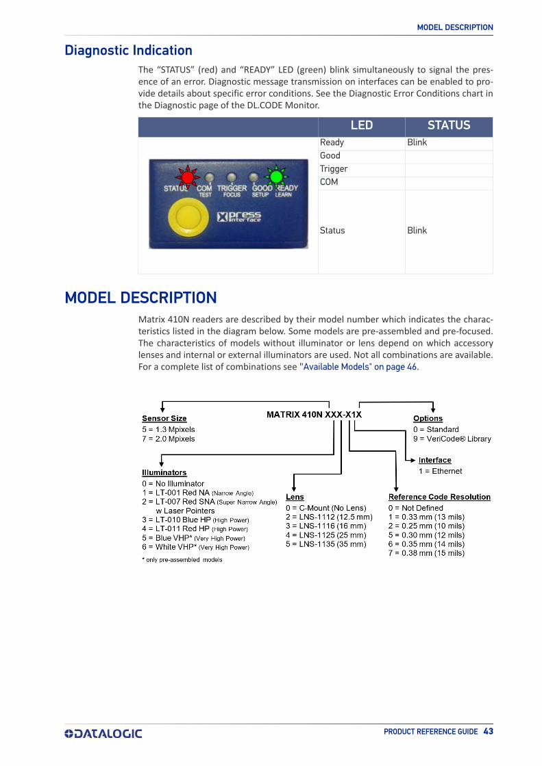
Diagnostic Indication .........................................................................................................................43Model Description ...........................................................................................................43
Lighting System Notes ..................................................................................................................... 44Internal Lighting Mode Limitations .......................................................................................... 45DL.CODE Illuminator Management Procedure .......................................................................45
Available Models ............................................................................................................46Accessories ....................................................................................................................47Application Examples .....................................................................................................50
Document Handling .......................................................................................................................... 50Multiple Reading in a Single Image .................................................................................................. 50Deformed or Overprinted Code Reading .......................................................................................... 50Direct Part Marking ........................................................................................................................... 51Ink-Jet Printing Technology .............................................................................................................52Laser Marking/Etching Technology ................................................................................................. 52
External Lighting Systems ..............................................................................................53
INSTALLATION......................................................................................................... 55Package Contents ...........................................................................................................55Mechanical Dimensions ...................................................................................................56Mounting And Positioning Matrix 410N ............................................................................58
CBX ELECTRICAL CONNECTIONS.............................................................................. 60CBX Connection Box Pinout .............................................................................................61Power Supply .................................................................................................................62
Very High Power Illuminator Models ............................................................................................... 62Main Serial Interface ......................................................................................................63
RS232 Interface .................................................................................................................................63RS422 Full Duplex Interface .............................................................................................................64
ID-NET Interface ............................................................................................................65ID-NET Cables ...................................................................................................................................65ID-NET Response Time ..................................................................................................................... 66ID-NET Network Termination ..........................................................................................................67ID-NET Connection Diagrams ..........................................................................................................67
Auxiliary RS232 Interface ...............................................................................................70Inputs ............................................................................................................................71
External Trigger Input Connections Using Matrix 410N Power ......................................................72External Trigger Input Connections Using External Power ............................................................ 74Input 2 Connections Using Matrix 410N Power ...............................................................................75Input 2 Connections Using External Power ..................................................................................... 76Input 3 Connections (CBX500 Only) .................................................................................................. 76
Outputs ..........................................................................................................................77Output 1 and 2 Connections Using Matrix 410N Power ..................................................................78Output 1 and 2 Connections Using External Power ........................................................................ 79

CONTENTS
PRODUCT REFERENCE GUIDE v
Output 3 Connections Using Matrix 410N Power (CBX500 Only) ....................................................80Output 3 Connections Using External Power (CBX500 Only) ..........................................................80
External Lighting Systems .............................................................................................. 81On-Board Ethernet Interface ........................................................................................... 82User Interface - Serial Host ............................................................................................ 82
TYPICAL LAYOUTS ................................................................................................... 83Ethernet Connection ....................................................................................................... 84Serial Connection ........................................................................................................... 86Fieldbus Connection ....................................................................................................... 87Pass-Through ................................................................................................................ 88ID-NET Multidata Network (Pass-Through) ..................................................................... 89ID-NET Synchronized Network ....................................................................................... 90
READING FEATURES ................................................................................................ 93FOV Calculation ............................................................................................................. 93Global FOV Diagrams ..................................................................................................... 95
Global FOV for Matrix 410N 500-0x0 (1.3 MP) .................................................................................96Matrix 410N 500-0x0 (1.3 MP) with LNS-1006 (6 mm lens) ..................................................96Matrix 410N 500-0x0 (1.3 MP) with LNS-1109 (9 mm lens) ..................................................97
Global FOV for Matrix 410N 700-0x0 (2.0 MP) ...............................................................................103Reading Characteristics for Pre-Assembled Pre-Focused Models ................................... 110Maximum Line Speed and Exposure Time Calculations .................................................. 111
SOFTWARE CONFIGURATION .................................................................................. 113DL.CODE System Requirements .................................................................................... 113Reader Configuration ................................................................................................... 113
Auto-Calibration ..............................................................................................................................114Manual Calibration ..........................................................................................................................115
Under-exposure ......................................................................................................................115Over-exposure ........................................................................................................................116Moving code out of the Field of View .....................................................................................117
Multi Image Acquisition Settings ................................................................................... 118Automatic Image Settings Selection ..............................................................................................119External Image Settings Selection .................................................................................................120
Image Cropping ............................................................................................................ 122Direct Part Marking Applications ................................................................................... 125
Image Filter .....................................................................................................................................126Pass-Through Configurations ........................................................................................ 130Internal Network Configurations ................................................................................... 132
Master Configuration ......................................................................................................................133Multidata ID-NET Network Configurations ....................................................................................135Synchronized ID-NET Network Configurations .............................................................................140Verify Master/Slave Synchronized Configuration ..........................................................................144
Backup and Restore Through DL.CODE ......................................................................... 147Backup .............................................................................................................................................148Restore ............................................................................................................................................149Replacement ....................................................................................................................................149
Restore Defaults .......................................................................................................... 150Restore Default Startup Configuration ...........................................................................................150Restore Default Environment .........................................................................................................151Restore Factory Defaults ................................................................................................................151
Diagnostic Alarms ........................................................................................................ 152Statistics ..................................................................................................................... 153BM150 Display Module Configuration and Messages ...................................................... 154
Configuration Through DL.CODE ....................................................................................................154Accessing the HMI Interface Through Keypad and Display Menu .................................................155Display Messages ............................................................................................................................157BM150 Backup and Restore Procedure .........................................................................................160
MAINTENANCE....................................................................................................... 161Cleaning ...................................................................................................................... 161

CONTENTS
vi MATRIX 410N
TROUBLESHOOTING ............................................................................................... 162General Guidelines ....................................................................................................... 162
TECHNICAL FEATURES .......................................................................................... 165ALTERNATIVE CONNECTIONS................................................................................. 168
Power, Com and I/O Connector for Standard Models ....................................................... 168On-Board Ethernet Connector ....................................................................................... 169VHP Illuminator Power Connector ................................................................................. 170ID-NET Network Termination ........................................................................................ 170Inputs .......................................................................................................................... 171Outputs ........................................................................................................................ 171User Interface - Serial Host .......................................................................................... 173
GLOSSARY............................................................................................................. 174

PRODUCT REFERENCE GUIDE vii
PREFACE
ABOUT THIS MANUALThis Product Reference Guide (PRG) is provided for users seeking advanced technical information, including connection, programming, maintenance and specifications. The Quick Reference Guide (QRG) and other publications associated with this product can be downloaded free of charge from the website listed on the back cover of this manual.
Manual ConventionsThe following conventions are used in this document:
The symbols listed below are used in this manual to notify the reader of key issues or procedures that must be observed when using the reader:
NOTE
TECHNICAL SUPPORT
Support Through the WebsiteDatalogic provides several services as well as technical support through its website. Logon to (www.datalogic.com).
For quick access, from the home page click on the search icon , and type in the name of the product you’re looking for. This allows you access to download Data Sheets, Manu-als, Software & Utilities, and Drawings.
Hover over the Support & Service menu for access to Services and Technical Support.
Notes contain information necessary for properly diagnosing, repairing and operating the reader.
CAUTION
The CAUTION symbol advises you of actions that could damage equipment or property.
WARNING
The WARNING symbol advises you of actions that could result in harm or injury to the person performing the task.

PREFACE
viii MATRIX 410N
Reseller Technical SupportAn excellent source for technical assistance and information is an authorized Datalogic reseller. A reseller is acquainted with specific types of businesses, application software, and computer systems and can provide individualized assistance.

PRODUCT REFERENCE GUIDE ix
COMPLIANCE
GENERALFor installation, use and maintenance it is not necessary to open the reader.
Only connect Ethernet and dataport connections to a network which has routing only within the plant or building and no routing outside the plant or building.
POWER SUPPLYATTENTION: READ THIS INFORMATION BEFORE INSTALLING THE PRODUCT
This product is intended to be installed by Qualified Personnel only.
This product is intended to be connected to a UL Listed Direct Plug-in Power Unit marked LPS or “Class 2”.
EMC COMPLIANCEIn order to meet the EMC requirements:
• connect reader chassis to the plant earth ground by means of a flat copper braid shorter than 100 mm;
• for CBX connections, connect pin "Earth" to a good Earth Ground;
• for direct connections, connect your cable shield to the locking ring nut of the con-nector.
CE COMPLIANCECE marking states the compliance of the product with essential requirements listed in the applicable European directive. Since the directives and applicable standards are subject to continuous updates, and since Datalogic promptly adopts these updates, therefore the EU declaration of conformity is a living document. The EU declaration of conformity is available for competent authorities and customers through Datalogic commercial reference contacts. Since April 20th, 2016 the main European directives applicable to Datalogic products require inclusion of an adequate analysis and assess-ment of the risk(s). This evaluation was carried out in relation to the applicable points of the standards listed in the Declaration of Conformity. Datalogic products are mainly designed for integration purposes into more complex systems. For this reason it is under the responsibility of the system integrator to do a new risk assessment regarding the final installation.
Warning: This is a Class A product. In a domestic environment this product may cause radio interference in which case the user may be required to take adequate measures.

COMPLIANCE
x MATRIX 410N
FCC COMPLIANCEModifications or changes to this equipment without the expressed written approval of Datalogic could void the authority to use the equipment.
This device complies with PART 15 of the FCC Rules. Operation is subject to the follow-ing two conditions: (1) This device may not cause harmful interference, and (2) this device must accept any interference received, including interference which may cause undesired operation.
This equipment has been tested and found to comply with the limits for a Class A digital device, pursuant to part 15 of the FCC Rules. These limits are designed to provide rea-sonable protection against harmful interference when the equipment is operated in a commercial environment. This equipment generates, uses, and can radiate radio fre-quency energy and, if not installed and used in accordance with the instruction manual, may cause harmful interference to radio communications. Operation of this equipment in a residential area is likely to cause harmful interference in which case the user will be required to correct the interference at his/her own expense.
EAC COMPLIANCECustoms Union:
The CU Conformity certification has been achieved; this allows the Product to bear the Eurasian Mark of conformity.

LASER SAFETY
PRODUCT REFERENCE GUIDE xi
LASER SAFETYMatrix 410N with the LT-007 illuminator accessory contains two aiming Laser LEDs used to position the reader.
This product conforms to the applicable requirements of IEC 60825-1 and complies with 21 CFR 1040.10 except for deviations pursuant to Laser Notice N° 50, date June 24, 2007. This product is classified as a Class 2 laser product according to IEC 60825-1 regu-lations.
Disconnect the power supply when opening the device during maintenance or installa-tion to avoid exposure to hazardous laser light. The laser beam can be switched on or off through a software command.
The following warning label content is applied to each of the laser equipped products indicated in the General View illustration (Figure 1).
Example Laser Warning Labels
Produit(s) conforme selon 21CFR 1040.10 sauf des dérogations relatives à la Laser Notice N° 50, data Juin 24, 2007.
Dans le paquet il y a l’étiquette(s) pour les pays où le texte d’avertissement en français est obligatoire. Le(s) mettre sur le produit à la place de la version anglaise.
Exemple d’étiquettes d’avertissement laser
LED SAFETYFor all DatalogicMatrix 410N compatible internal illuminators, LED emission according to EN 62471.
CAUTION
Use of controls or adjustments or performance of procedures other than those specified herein may result in exposure to hazardous visible laser light.

xii MATRIX 410N
HANDLING
The Matrix 410N is designed to be used in an industrial environment and is built to with-stand vibration and shock when correctly installed, however it is also a precision prod-uct and therefore before and during installation it must be handled correctly to avoid damage.
• avoid that the readers are dropped (exceeding shock limits)
• do not fine tune the positioning by striking the reader or bracket.

PRODUCT REFERENCE GUIDE xiii
• do not weld the reader into position which can cause electrostatic, heat or reading window damage.
• do not spray paint near the reader which can cause reading window damage.

1
3
1
4
2
25
2
2
6
10 7
9 8
xiv MATRIX 410N
GENERAL VIEW
Figure 1 - Matrix 410N (shown with Lens and Illuminator accessories)
1. Device Class and Warning Labels 6. HMI X-PRESS Interface2. Mounting Holes (2) 7. Power On LED3. Lens Cover 8. Power - Serial - I/O Connector4. Lens (separate accessory) 9. Ethernet Connector5. Internal Illuminator (separate accessory) 10. Ethernet Connection LED

PRODUCT REFERENCE GUIDE 1
CHAPTER 1RAPID CONFIGURATION
STEP 1 - ASSEMBLE THE READERThe first step to perform is to assemble the accessories that make up the Matrix 410N reader1
. The lens and either an internal or an external illuminator must be used. This procedure shows an internal illuminator.
1. In a dust-free environment, remove the Matrix 410N Lens Cover by unscrewing it.
2. Remove the sensor protection label by pulling it off of the base.
3. Install the anti-vibration O-ring onto the threaded base of the lens.
4. Mount the lens by screwing it tightly onto the base.If the Locking Lobs on the lens are obstructed because they are aligned behind an illuminator spacer base and illuminator spacer, insert the Lens Spacer between the anti-vibration O-ring and the lens so that the Locking Knobs will be unob-structed.
5. If using an internal illuminator:a. Mount the four internal illuminator spacers onto the illuminator spacer bases provided on the Matrix 410N body.b. Align and mount the illuminator tightly onto the spacers using the four screws and washers provided in the illuminator package. The spacers are positioned asymmetrically to avoid incorrect alignment.
1. XRF models are pre-assembled at the factory.
CAUTION
Matrix 410N must be disconnected from the power supply during this pro-cedure.
CAUTION
Do not touch the sensor aperture, lens glass or lens cover glass. These areas must be kept clean. Avoid any abrasive substances that might dam-age these surfaces during cleaning.

RAPID CONFIGURATION
2 MATRIX 410N
6. To keep dust and dirt off of the lens during mounting, temporarily replace the lens cover.
Anti-vibration O-ring Lens Spacer
(optional)
Internal
IlluminatorLens Cover
Illuminator Spacer Base
Lens Locking Knobs
Illuminator Spacers Protective Film (remove
before calibration)
Figure 2 - Assembling Matrix 410N Accessories

STEP 1 - ASSEMBLE THE READER
PRODUCT REFERENCE GUIDE 3
Required AccessoriesThe following table shows the correct lens/illuminator combinations to be used for Matrix 410N imager assembly. For more information see the Application Note on illumi-nator selection on the DL.CODE mini-DVD (download .zip or mini-DVD accessory).
Part Number Name C-Mount Lens Type Part Number Name LEDs Type
93ACC1793 LNS-1006a
a. LNS-1006 produces a slight vignetting effect at the corners of the FOV at short focal lengths.
6 mm93A40102093A401022
LT-002LT-004
88
Red Wide AngleWhite Wide Angle
93ACC1794 LNS-1109 9 mm93A40102093A40102293A401023
LT-002LT-004LT-005
8832
Red Wide AngleWhite Wide AngleBlue 8x4 LED chain for DPM
93ACC1795 LNS-1112 12.5 mm93A40102093A40102293A401023
LT-002LT-004LT-005
8832
Red Wide AngleWhite Wide AngleBlue 8x4 LED chain for DPM
93ACC1796 LNS-1116 16 mm93A40101993A40102193A401023
LT-001LT-003LT-005
8832
Red Narrow AngleWhite Narrow AngleBlue 8x4 LED chain for DPM
93ACC1797 LNS-1125 25 mm
93A40101993A40102193A40102493A40103093A40102693A401031
LT-001LT-003LT-006LT-007LT-010LT-011
88881515
Red Narrow AngleWhite Narrow AngleRed Super Narrow AngleRed Super Narrow AngleHigh Power Blue Super Narrow AngleHigh Power Red Super Narrow Angle
93ACC1798 LNS-1135 35 mm
93A40102493A40103093A40102693A401031
LT-006LT-007LT-010LT-011
881515
Red Super Narrow AngleRed Super Narrow AngleHigh Power Blue Super Narrow AngleHigh Power Red Super Narrow Angle
93ACC1799 LNS-1150 50 mm
93A40102493A40103093A40102693A401031
LT-006LT-007LT-010LT-011
881515
Red Super Narrow AngleRed Super Narrow AngleHigh Power Blue Super Narrow AngleHigh Power Red Super Narrow Angle
When using a 25 mm focal length lens (LNS-1125), it is possible to use Super Narrow Angle Illuminators (LT-006, LT-007, LT-010 or LT-011) as well as the Narrow Angle Illumi-nators LT- 001 or LT-003. It is suggested to use the Narrow Angle Illuminators in applica-tions with very low contrast codes and in all cases where the higher lighting power of the LT-006, LT-007, LT-010 or LT-011 isn't necessary. LT-010 and LT-011 Illuminators are especially effective in high speed code movement applications.
LENSES INTERNAL ILLUMINATORS
CAUTION
LT-005: In order to function properly, DL.CODE must correctly manage the illuminator parameters. Follow the DL.CODE Illuminator Management Pro-cedure below.
LT-010 and LT-011: To avoid damage to the devices, DL.CODE must cor-rectly manage the illuminator parameters. Follow the DL.CODE Illuminator Management Procedure below.
RAPID CONFIGURATION
4 MATRIX 410N
Internal Lighting Mode Limitations• For all illuminators the application program imposes protective limits on the frame
rate to avoid overheating.
• LT-010 and LT-011 illuminators do not work in Continuous High-Power mode.
See the Help On Line for more details on the Internal Lighting Mode parameter.
DL.CODE Illuminator Management Procedure
1. Connect the reader to DL.CODE as described in this chapter.
2. In the DL.CODE Device menu click the Settings > Settings > Maintenance Settings > Current Illuminator Model item and select the Illuminator being used from the list.
3. Click OK and at the device reset prompt click Yes and wait until the device resets. You can confirm by reopening this item from the same menu.
The above procedure must also be per-formed before any attempt to use the X-PRESS configuration on readers mounting the LT-005, LT-007, LT-010 or LT-011 illumi-nators.
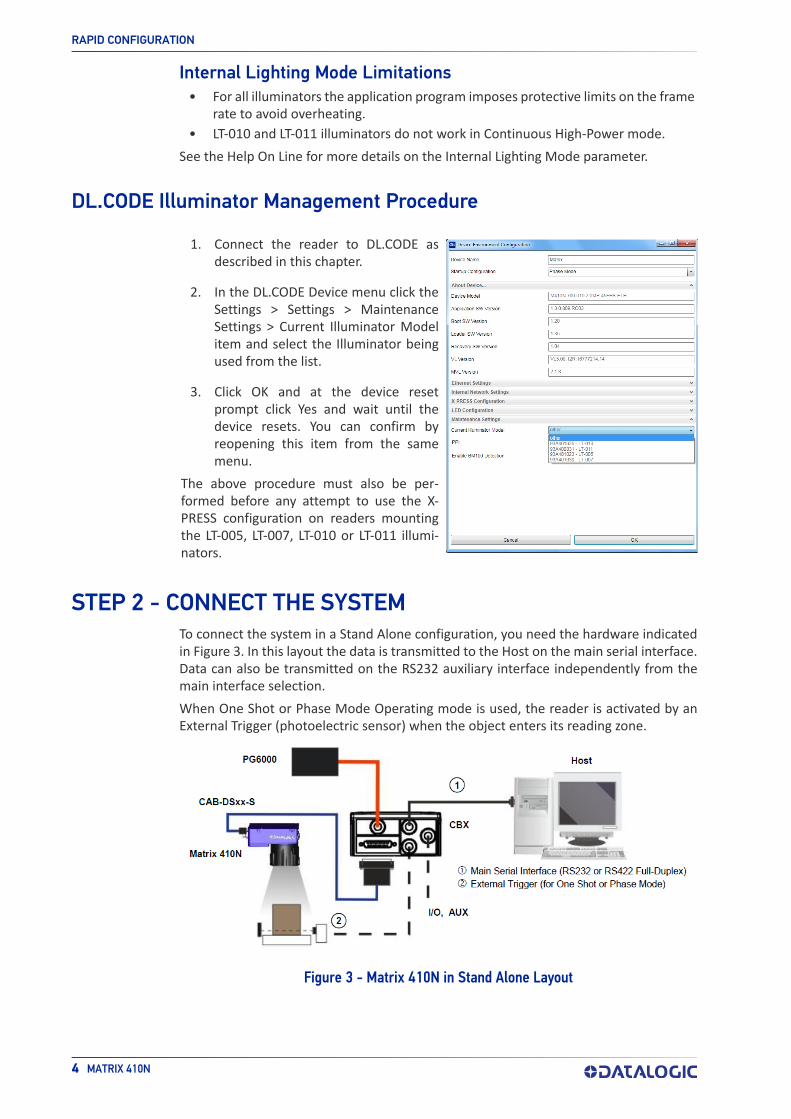
STEP 2 - CONNECT THE SYSTEMTo connect the system in a Stand Alone configuration, you need the hardware indicated in Figure 3. In this layout the data is transmitted to the Host on the main serial interface. Data can also be transmitted on the RS232 auxiliary interface independently from the main interface selection.
When One Shot or Phase Mode Operating mode is used, the reader is activated by an External Trigger (photoelectric sensor) when the object enters its reading zone.
Figure 3 - Matrix 410N in Stand Alone Layout

STEP 2 - CONNECT THE SYSTEM
PRODUCT REFERENCE GUIDE 5
CBX100/CBX500 Pinout for Matrix 410NThe table below gives the pinout of the CBX100/CBX500 terminal block connectors. Use this pinout when the Matrix 410N reader is connected by means of the CBX100/CBX500:
Input PowerVdc Power Supply Input Voltage +GND Power Supply Input Voltage -Earth Protection Earth Ground
Inputs
+V Power Source - External TriggerI1A External Trigger A (polarity insensitive)I1B External Trigger B (polarity insensitive)-V Power Reference - External Trigger+V Power Source - InputsI2A Input 2 A (polarity insensitive)I2B Input 2 B (polarity insensitive)-V Power Reference - Inputs
Outputs
+V Power Source - Outputs-V Power Reference - OutputsO1+ Output 1 + O1- Output 1 - O2+ Output 2 + O2- Output 2 - O3A Output 3 - (CBX500 only)
Auxiliary Interface
TX Auxiliary Interface TXRX Auxiliary Interface RXSGND Auxiliary Interface Reference
ID-NET™REF Network ReferenceID+ ID-NET network data +ID- ID-NET network data -
Main Interface
RS232 RS422 Full Duplex
TX TX+- TX-RX *RX+- *RX-SGND SGND
* Do not leave floating, see "RS422 Full Duplex Interface" on page 64 for connection details.
GROUP LABEL DESCRIPTION
CAUTION
Do not connect GND, SGND and REF to different (external) ground refer-ences. GND, SGND and REF are internally connected through filtering circuitry which can be permanently damaged if subjected to voltage drops over 0.8 Vdc.

RAPID CONFIGURATION
6 MATRIX 410N
STEP 3 - MOUNT AND POSITION THE READER1. To mount the Matrix 410N, use the mounting brackets to obtain the most suitable
position for the reader. Two of the most common mounting configurations are shown in the figure below. Other mounting solutions are provided in "Mounting And Positioning Matrix 410N" on page 58.
Figure 4 - Positioning with Mounting Bracket (back)
Figure 5 - Positioning with Mounting Bracket (side)

STEP 3 - MOUNT AND POSITION THE READER
PRODUCT REFERENCE GUIDE 7
2. When mounting the Matrix 410N take into consideration these three ideal label position angles: Pitch or Skew 10° to 20° and Tilt 0°, although the reader can read a code at any tilt angle provided the code fits into the Field Of View (FOV).
No Pitch,Tilt or Skew
PitchMinimize
Tiltany angleinside FOV
Skewassure at least 10°
Figure 6 - Pitch, Skew and Tilt Angles
3. Refer to the reading diagrams in Chapter 6, Reading Features for FOV calculation and minimum distance requirements according to the base/lens combination used for your application.
NOTE
Rapid Configuration of the Matrix 410N reader can be made either through the X-PRESS interface (steps 4-6) which requires no PC con-nection, or by using the DL.CODE Configuration Program (steps 7-8). Select the procedure according to your needs.

RAPID CONFIGURATION
8 MATRIX 410N
STEP 4 - FOCUS THE READERMatrix 410N provides a built-in tool called Blue Diamonds™ to aid focusing the reader. The Blue Diamonds are accessed through the X-PRESS Interface.
1. Remove the lens cover in order to focus the reader.
2. Prepare the correct accessory lens for your application:a. Loosen the two Locking Knobs on the lens.
b. Adjust the Focus ring to the “Far position” and the Diaphragm ring to the “F4”1
number setting which is the preferred setting for installation.
3. Power the reader on. During the reader startup (reset or restart phase), all the LEDs blink for one second. On the connector side of the reader near the cable, the “POWER ON” LED (blue) indicates the reader is correctly powered.
4. Enter the Focus function by pressing and holding the X-PRESS push button until the Focus LED is on.
5. Release the button to enter the Focus function. The Blue Diamonds turn on.
The procedure is as follows:a. Adjust the Focus ring towards the “Near position” until the Blue Diamonds are perfectly in focus, see Figure 8. At long focal distances, a “skew” angle may cause a noticeable difference in focus between the two diamonds, in this case select the best possible focus (both diamonds slightly out of focus). Tighten the Diaphragm Locking Knob.
Figure 7 - X-PRESS Interface: Focus Function
b. Tighten the Diaphragm Locking Knob.
NOTE
Figure 8 - Focus Function Using Blue Diamonds
1. For far reading distances, the Diaphragm ring can be set to values between F2 and F4 to increase image lighting and Blue Diamond visibility.
If necessary you can use the Focusing Tool in the DL.CODE Image Settings step for fine focusing. See Step 8.

STEP 5 - CALIBRATE IMAGE DENSITY
PRODUCT REFERENCE GUIDE 9
6. Exit the Focus function by pressing the X-PRESS push button once. The Blue Dia-monds turn off.
7. Replace the lens cover, screwing it tightly to the base.
STEP 5 - CALIBRATE IMAGE DENSITYIn order to function correctly to the fullest extent of its capabilities, Matrix 410N must acquire information regarding image density or PPI (pixels per inch). This calibration takes place through the X-PRESS Interface and the Grade A Barcode Test Chart included in the package. This procedure is necessary for the first time installation, if the lens type is changed or if the focal distance is changed.
Locate
Figure 9 - X-PRESS Interface: Locate Function
1. Enter the Focus function by pressing and holding the X-PRESS push button until the Focus LED is on.
2. Release the button to enter the Focus function. The Blue Diamonds turn on.
3. From the Grade A Barcode Test Chart, select the longest code whose length fits between the two Blue Diamonds. Rotate the code 90 degrees and position the code at the center of the FOV (equidistant from the Blue Diamonds).
4. Exit the Focus function by pressing the X-PRESS push button once. The Blue Dia-monds turn off.

RAPID CONFIGURATION
10 MATRIX 410N
Setup
Figure 10 - X-PRESS Interface: Setup Function
5. Enter the Setup function by pressing and holding the X-PRESS push button until the Setup LED is on.
6. Release the button to enter the Setup function. The Setup LED will blink until the procedure is completed.The Setup procedure ends when the Image Acquisition parameters are success-fully saved in the reader memory, the Setup LED will stop blinking and Matrix 410N emits 3 high pitched beeps.If the calibration cannot be reached after a timeout of about 5 (five) seconds Matrix 410N will exit without saving the parameters to memory, the Setup LED will stop blinking and in this case Matrix 410N emits a long low pitched beep.
Learn
Figure 11 - X-PRESS Interface: Learn Function
7. Enter the Learn function by pressing and holding the X-PRESS push button until the Learn LED is on.
8. Release the button to enter the Learn function. The Learn LED will blink until the procedure is completed.The Learn procedure ends when the Image Density value is successfully saved in the reader memory, the Learn LED will stop blinking and Matrix 410N emits 3 high pitched beeps.If the calibration cannot be reached after a timeout of about 3 (three) minutes Matrix 410N will exit without saving the parameters to memory, the Learn LED willstop blinking and in this case Matrix 410N emits a long low pitched beep.
NOTE
You can always exit form any X-PRESS function at any time by pressing the X-PRESS push button once. After a short delay the procedure is canceled.

STEP 6 - X-PRESS CONFIGURATION
PRODUCT REFERENCE GUIDE 11
STEP 6 - X-PRESS CONFIGURATIONOnce Matrix 410N has calibrated image density, you can configure it for optimal code reading relative to your application. This configuration can be performed either through the X-PRESS Interface or the DL.CODE configuration program.
Locate
Figure 12 - X-PRESS Interface: Locate Function
1. Enter the Focus function by pressing and holding the X-PRESS push button until the Focus LED is on.
2. Release the button to enter the Focus function. The Blue Diamonds turn on.
3. Select a code from your application. Position the code at the center of the FOV (equidistant from the Blue Diamonds).
4. Exit the Focus function by pressing the X-PRESS push button once. The Diamonds turn off.
Setup
Figure 13 - X-PRESS Interface: Setup Function
5. Enter the Setup function by pressing and holding the X-PRESS push button until the Setup LED is on.
6. Release the button to enter the Setup function. The Setup LED will blink until the procedure is completed.The Setup procedure ends when the Image Acquisition parameters are successfully saved in the reader memory, the Setup LED will stop blinking and Matrix 410N emits 3 high pitched beeps.If the calibration cannot be reached after a timeout of about 5 (five) seconds Matrix 410N will exit without saving the parameters to memory, the Setup LED will stop blinking and in this case Matrix 410N emits a long low pitched beep.

RAPID CONFIGURATION
12 MATRIX 410N
Learn
Figure 14 - X-PRESS Interface: Learn Function
7. Enter the Learn function by pressing and holding the X-PRESS push button until the Learn LED is on.
8. Release the button to enter the Learn function. The Learn LED will blink until the procedure is completed.The Learn procedure ends when the Image Processing and Decoding parameters for a single code are successfully saved in the reader memory, the Green Spot is acti-vated, the Learn LED will stop blinking and Matrix 410N emits 3 high pitched
beeps1.If the autolearning cannot be reached after a timeout of about 3 (three) minutes Matrix 410N will exit without saving the parameters to memory, the Learn LED will stop blinking and in this case Matrix 410N emits a long low pitched beep.
NOTE
NOTE
NOTE
NOTE
1. The Learn procedure will not recognize the following symbologies: Postal Codes, Pharmacode, MSI, Standard 2 of 5, Matrix 2 of 5.
The Grade A Barcode Test Chart cannot be used to set the Code 128 sym-bology (even though the reader successfully reads the code). Use the application specific code if you need to set this symbology.
When using X-PRESS or the BM150 menu to perform Auto-Learn, only a single code can be configured (successive Learns will substitute the current code). To configure multiple codes, use the DL.CODE Auto-Learn procedure.
You can always exit from any X-PRESS function at any time by pressing the X-PRESS push button once. After a short delay the procedure is can-celled.
If you have used this procedure to configure Matrix 410N, go to step 9.

STEP 6 - X-PRESS CONFIGURATION
PRODUCT REFERENCE GUIDE 13
Reset Reader to Factory Default Environment (Optional)If it ever becomes necessary to reset the reader’s Environment parameters to their fac-tory default values, you can perform this procedure by holding the X-PRESS push button pressed while powering up the reader. You must keep the X-PRESS push button pressed until all LEDs blink simultaneously for about 3 seconds. Release and re-press the but-ton during this LED blinking sequence.
All the device’s Environment parameters are reset including the default IP Address. The Matrix 410N emits 3 high pitched beeps and after a few seconds enters run mode.
Any previously saved configurations on the device will remain in memory, but the Default configuration is set as the startup configuration.
NOTE
If you release the button while the LEDs are all on continuously (after the blinking phase), the reader will enter the Loader program sequence and the LEDs will begin to cycle through various patterns. Just cycle power to return to run mode.

RAPID CONFIGURATION
14 MATRIX 410N
STEP 7 - INSTALLING DL.CODE CONFIGURATION PROGRAM
DL.CODE is a Datalogic reader configuration tool providing several important advan-tages:
• Intuitive Graphical User Interface for rapid configuration
• Defined configuration directly stored in the reader
• Discovery and IP address setting features to facilitate remote configuration
• Device Monitoring
To install DL.CODE
1. On the PC that will be used for configuration, (running Windows 7, 8.1, or 10), down-load the DL.CODE mini-DVD.zip file. Extract the files maintaining the folder structure and run the start.hta file to access the installation pop-up. Click on the Install DL.CODE link to run the installation program and follow the installation procedure.
NOTE
2. When the installation is complete the DL.CODE entry is created in the Start>Pro-grams bar under “Datalogic” as well as a desktop icon. Double-click the desktop icon to run it.
This configuration procedure assumes a laptop computer, running DL.CODE, is con-nected to a factory default reader through the Ethernet port.
CAUTION
DL.CODE does not currently support Windows Embedded (often used in industrial PCs and/or PLCs).
To perform a “silent” installation (without user input), see the DL.CODE User’s Guide.

STEP 7 - INSTALLING DL.CODE CONFIGURATION PROGRAM
PRODUCT REFERENCE GUIDE 15
Device DiscoveryThe User Interface opens and displays a list of all the devices belonging to the Local Area Network. DL.CODE has a discovery feature to accomplish this task.
Figure 15 - Device Discovery
The discovery feature will also show devices not belonging to the LAN and display them in gray (see Figure 15).
3. First the device must be added to the LAN by aligning its IP Address to the net-work. The network administrator should provide valid LAN address(es).
4. Find your device in the list by matching its serial number (SN) then click on the device wrench icon to open the Device Environment Configuration window.
5. Change the Ethernet Settings (IP Address, Subnet Mask, Gateway Address etc.) according to the network requirements.

RAPID CONFIGURATION
16 MATRIX 410N
Figure 16 - Device Environment Configuration Window
6. Click OK; the device will reappear in the list of Online Devices (in color) meaning it is now part of the LAN and can be configured. The new IP address will also be dis-played.
STEP 7 - INSTALLING DL.CODE CONFIGURATION PROGRAM
PRODUCT REFERENCE GUIDE 17
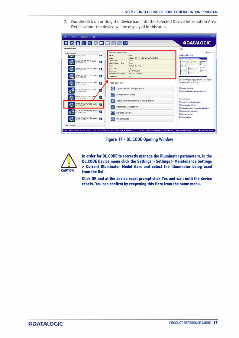
7. Double-click on or drag the device icon into the Selected Device Information Area. Details about the device will be displayed in this area.
Figure 17 - DL.CODE Opening Window
CAUTION
In order for DL.CODE to correctly manage the illuminator parameters, in the DL.CODE Device menu click the Settings > Settings > Maintenance Settings > Current Illuminator Model item and select the Illuminator being used from the list.
Click OK and at the device reset prompt click Yes and wait until the device resets. You can confirm by reopening this item from the same menu.

RAPID CONFIGURATION
18 MATRIX 410N
STEP 8 - DEVICE CONFIGURATION
Automatic or Advanced SetupAutomatic Setup provides an automatic procedure for setting: optical/illumination, reading distance, and code definition parameters to obtain the most stable decoding conditions for a single code symbology based on the images presented to the reader. It can be set to include Image Filters if necessary. See the table below for codes and filters managed by Automatic Setup. Automatic Setup is especially useful for DPM applica-tions.
CODE 128EAN 128CODE 39CODE 93CODABARPDF417MICRO PDF417GS1 DATABARGS1 DATABAR STACKEDGS1 DATABAR LIMITEDGS1 DATABAR EXPANDEDGS1 DATABAR EXPANDED STACKEDUPCEAN FAMILY EAN13UPCEAN FAMILY EAN8UPCEAN FAMILY UPCAUPCEAN FAMILY UPCE
DATAMATRIX ECC 200QRMICRO QRAZTECMAXICODEDOTCODE
ERODE 3x3, 5x5 and 7x7DILATE 3x3, 5x5 and 7x7SMOOTHING
Advanced Setup provides access to the complete array of optical/illumination, focusing adjustment, and code definition parameters that can be fine-tuned semi-automatically and manually to obtain the best results for applications of any complexity.
NOTE
ENABLED 1D CODES ENABLED 2D CODES
ENABLED FILTERS
If your application requires multiple code symbologies, multiple image settings, Code Grading or other parameter settings for decoding, then use the Advanced Setup, see page 21.

STEP 8 - DEVICE CONFIGURATION
PRODUCT REFERENCE GUIDE 19
Automatic SetupTo begin configuration, the reader must be correctly mounted so that its Field of View covers the application reading area.
1. From the Task Area select Open Device Configuration.
2. The Open Device Configuration window opens showing the list of currently saved configurations (jobs) saved on the device. For new devices, the only saved job is the Default configuration. Click OK. The device enters run mode and begins acquir-ing images.
3. Place the application code in front of the reader at the correct application reading distance.
4. Click on the Pause button to stop image acquisition.
NOTE
If the image display area is too dark to see the images being captured, you can drag the Gain and Exposure Time sliders (circled in red in the figure above) to the right to increase visibility. This will not affect Auto-matic Setup.

RAPID CONFIGURATION
20 MATRIX 410N
5. Click on the Start Automatic Setup button. The following window is displayed:
6. Select the correct reading conditions: Static or Dynamic Tuning, 1D or 2D code, Include Image Filtering (to find the best decoding condition).
7. Click Start to begin the procedure. The reader begins acquiring images. At the end of the procedure the Status: Completed message appears. You can Close the Automatic Setup window.
Your reader is now optimized for decoding. Continue with the Reading Phase configura-tion described on page 28.

STEP 8 - DEVICE CONFIGURATION
PRODUCT REFERENCE GUIDE 21
Advanced SetupTo begin configuration, the reader must be correctly mounted at the correct reading dis-tance for your application so that its Field of View covers the application reading area.
1. From the Task Area select Open Device Configuration.
2. The Open Device Configuration window opens showing the list of currently saved configurations (jobs) saved on the device. For new devices, the only saved job is the Default configuration. Click OK. The device enters run mode and begins acquir-ing images.
3. Click on the Advanced Setup button and press the Play icon.
4. Place the Grade A Barcode Test Chart in the reading area. Once positioned, stop image acquisition by clicking on the Pause button.

RAPID CONFIGURATION
22 MATRIX 410N
5. Click the Image Settings branch and then click the Image Auto-Setup button to automatically acquire the best exposure time and gain values.

STEP 8 - DEVICE CONFIGURATION
PRODUCT REFERENCE GUIDE 23
6. Select the Static or Dynamic Self-Tuning option; Start the Image Auto Setup and Apply to the Image Settings.
NOTE
For applications having multiple lighting or code reading conditions, up to 10 different Image Settings can be configured by adding them with the
icon.

RAPID CONFIGURATION
24 MATRIX 410N
For the next step you need to enable the Focus Calibration Tool from the Options > UI Settings Configuration tab if not already enabled.
7. Now click on the Focus Calibration tab at the bottom of the window. The oscillo-scope view is shown in the bottom panel and can be used for manual focus adjust-ment.
The red line in the image panel above the oscilloscope must pass through the code. You can click and drag the red line vertically to reposition it over the code.
NOTE
To enlarge the visual image of the code and the oscilloscope views, you can drag the Focus Calibration window up and click on the zoom image icon repositioning it on the code.
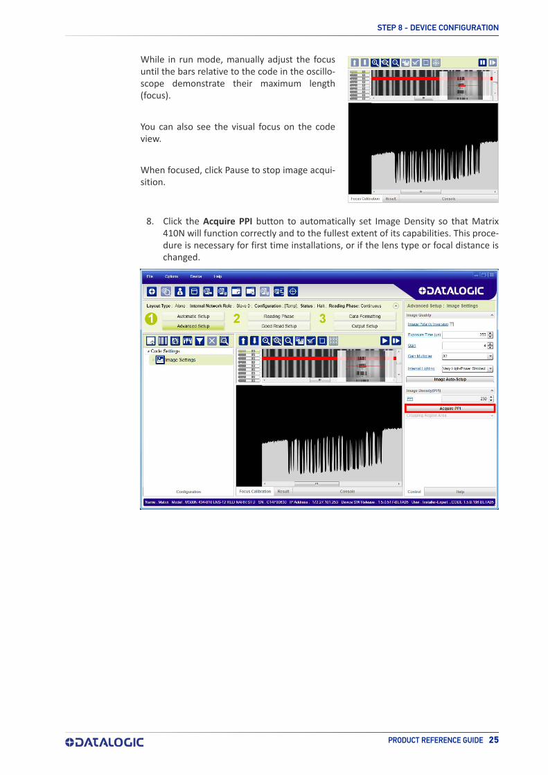
While in run mode, manually adjust the focus until the bars relative to the code in the oscillo-scope demonstrate their maximum length (focus).
You can also see the visual focus on the code view.
When focused, click Pause to stop image acqui-sition.
STEP 8 - DEVICE CONFIGURATION
PRODUCT REFERENCE GUIDE 25
8. Click the Acquire PPI button to automatically set Image Density so that Matrix 410N will function correctly and to the fullest extent of its capabilities. This proce-dure is necessary for first time installations, or if the lens type or focal distance is changed.

NOTE
RAPID CONFIGURATION
26 MATRIX 410N
9. Now place an application specific code in front of the reader and repeat only the Image Auto-Setup to register any changes in lighting or code surface contrast. Do not repeat Focus Calibration or PPI.
At this point it is probably a good idea to save the configuration from temporary memory to permanent memory giving it a specific name.
STEP 8 - DEVICE CONFIGURATION
PRODUCT REFERENCE GUIDE 27
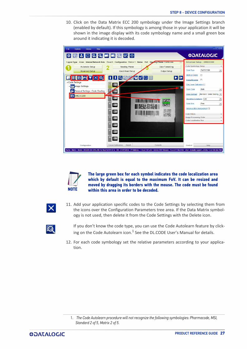
10. Click on the Data Matrix ECC 200 symbology under the Image Settings branch (enabled by default). If this symbology is among those in your application it will be shown in the image display with its code symbology name and a small green box around it indicating it is decoded.
NOTE
11. Add your application specific codes to the Code Settings by selecting them from the icons over the Configuration Parameters tree area. If the Data Matrix symbol-ogy is not used, then delete it from the Code Settings with the Delete icon.
If you don’t know the code type, you can use the Code Autolearn feature by click-
ing on the Code Autolearn icon.1 See the DL.CODE User’s Manual for details.
12. For each code symbology set the relative parameters according to your applica-tion.
The large green box for each symbol indicates the code localization area which by default is equal to the maximum FoV. It can be resized and moved by dragging its borders with the mouse. The code must be found within this area in order to be decoded.
1. The Code Autolearn procedure will not recognize the following symbologies: Pharmacode, MSI, Standard 2 of 5, Matrix 2 of 5.

RAPID CONFIGURATION
28 MATRIX 410N
Reading Phase
1. Select your application specific Operating Mode from the icons over the Configu-ration Parameters tree area: Continuous, One Shot, Phase Mode or PackTrack.
2. Configure the relative Operating Mode parameters from the Reading Phase parameters panel. Different groups will appear in the panel depending on the selected icons over the Configuration Parameters tree area.

STEP 8 - DEVICE CONFIGURATION
PRODUCT REFERENCE GUIDE 29
Good Read Setup
1. Select your specific data collection type from the icons over the Configuration Parameters tree area: Code Collection, Code Combination, Presentation or Match Code. Not all data collection types are available for all Operating Modes; for exam-ple PackTrack Operating Mode only supports Code Combination. Incompatible data collection types will be shown in gray and cannot be selected.The following example shows Code Combination. By default, the Expected Codes (when more than one code type is selected), are in logical AND, which means that all codes are required to be decoded to produce a Good Read condition.
2. If a Good Read condition should be produced when any single code is decoded, independent from the others, then they need to be combined in logical XOR. To do this, drag the code icon(s) from their relative Expected Code box into the Expected Code box of the XOR combination you wish to create. Then delete the empty box by selecting it with the mouse (highlighted) and pressing the delete key on your keyboard.

RAPID CONFIGURATION
30 MATRIX 410N
To create a logical AND condition from a logical XOR, create a new Expected Code box using the Add icon. Then drag the desired code icon from one box to the other.
Data Formatting
1. Configure your application specific Data Formatting Message(s) from the Configu-ration Parameters tree area: Message 1, Message 2, etc.
You can add fields to the output message by clicking on the icons above the Message Field area. They will be appended to the message. You can drag them to position them between other fields in the message so that the output message is ordered according to your application requirements.
Each field has its own relative configuration parameters in the parameters panel.

STEP 8 - DEVICE CONFIGURATION
PRODUCT REFERENCE GUIDE 31
Output Setup
1. Configure your application specific Digital Output(s) and Green/Red Spots (if used) from the Configuration Parameters tree area: Output 1, Output 2, etc.
NOTE
Save the configuration from temporary memory to permanent memory, overwriting the previously saved configuration.

RAPID CONFIGURATION
32 MATRIX 410N
STEP 9 - TEST MODEUse a code suitable to your application to test the reading performance of the system.
1. Enter the Test function by pressing and holding the X-PRESS push button until the Test LED is on.
2. Release the button to enter the Test function.Once entered, the Bar Graph on the five LEDs is activated and if the reader starts reading codes the Bar-Graph shows the Good Read Rate.
Figure 18 - X-PRESS Interface: Test Function
3. To exit the Test, press the X-PRESS push button once.
NOTE
The Bar Graph has the following meaning:
20
%
40
%
60
%
75
%
95
%
In case of No Read condition, only the STATUS LED (red) is on and blinks.
By default, the Test exits automatically after three minutes.

ADVANCED READER CONFIGURATION
PRODUCT REFERENCE GUIDE 33
ADVANCED READER CONFIGURATIONFor further details on advanced product configuration, refer to the DL.CODE User’s Guide available in the DL.CODE Help menu.
Host Mode ProgrammingThe reader can also be partially configured from a host computer using the Host Mode programming procedure.

34 MATRIX 410N
CHAPTER 2INTRODUCTION
PRODUCT DESCRIPTIONMatrix 410N is a Datalogic industrial compact 2D imager designed and produced to be a high performance affordable solution for both linear and two-dimensional code reading applications.
Matrix 410N uses imaging technology and provides complete reading system functions by integrating image capturing, decoding and communicating in a single compact and versatile product.
Matrix 410N sets a new standard in 2D imager technology offering high performance with improved reading flexibility thanks to its intrinsic modularity.
Matrix 410N features excellent reading and verifying performance thanks to 1.3 and 2.0 Mega pixel sensors and smart proprietary decoding libraries.
The modular combination of Mega pixels sensors, powerful lighting and adjustable C-Mount lenses provide high flexibility in covering applications with various requirements.
Innovative X-PRESS interface, combined with Blue Diamonds aiming and focusing sys-tem and a Good Read Spot, enhance the ease of setup and use.
Rugged construction, IP67 protection and max 50°C operative temperature make the Matrix 410N the ideal product for industrial applications.
Matrix 410N has been developed for use in numerous industries like:
Automotive• DPM (Direct Part Marked) reading
• Tires Sorting
Electronics• Large PCB board tracking
• Electronic products tracking
Distribution & Retail Industry• Presentation Scanner
• Small Objects Tracking & Sorting
• Warehouse applications
Medical & Pharmaceutical• Medical Devices Traceability
• Pharmaceutical and Medicine Manufacturing

PRODUCT DESCRIPTION
PRODUCT REFERENCE GUIDE 35
• Chemical & Biomedical Analysis
Food & Beverage• Work in Progress Traceability
• Code Quality Control
This technology intrinsically provides omni-directional reading.
Standard Application ProgramA Standard Application Program is factory-loaded onto Matrix 410N. This program con-trols code reading, data formatting, serial port and Ethernet interfacing, and many other operating and control parameters. It is completely user configurable from a Lap-top or PC using the dedicated configuration software program DL.CODE, provided on the DL.CODE mini-DVD (downloaded .zip file or mini-DVD accessory).
There are different programmable operating modes to suit various code reading system requirements.
Quick, focus, positioning, calibration and code setting of the imager can be accom-plished using the X-PRESS button and LEDs on top of the reader without the necessity of a PC.
The previous functions can also be performed through DL.CODE which includes visual feedback from the reader. This allows verification of the exact positioning of the reader and to maximize its reading performance.
Statistics on the reading performance can also be visualized through a dedicated win-dow in DL.CODE.
ProgrammabilityIf your requirements are not met by the Standard Application Program, Custom Applica-tion Programs can be requested at your local Datalogic distributor.
Some of the main features of this reader are given below:
Excellent Performance• 1.2 MPixel & 2 MPixel models
• Electronic Adjustable Focus through software control
• Powerful Internal Lighting Systems
• Outstanding decoding capability on 1D, 2D, Stacked, Postal symbologies
• Excellent performance on DPM applications
• Omni-directional reading
• Frame Rate up to 60 frames/sec for 1.3 MPixel models and 43 frames/sec for 2 Mpixel models
• Image Cropping for higher frame rate
• Up to 100 readable codes in a single frame
Ease of Setup• Quick installation without PC by using X-PRESS interface for easy and intuitive
setup
• Blue Diamonds aiming and focusing system
• Automatic Imager calibration and Code Settings

INTRODUCTION
36 MATRIX 410N
• Visual Feedback to verify exact code positioning in the Field of View and to maxi-mize the reading performance
• Windows-based DL.CODE software to configure the reader parameters via PC Ethernet interface
• User-defined database of Image Acquisition Settings (parameter sets)
Ease of Use• X-PRESS interface LEDs provide operational and performance feedback
• Green Spot and beeper for immediate Good Read feedback
• Different operating modes to suit various application requirements
• Multi Image Acquisition Settings for higher reader flexibility
• Image saving and storage with buffering capability
• Diagnostic software tools
Flexible Solution• Modular design
• Adjustable C-Mount lenses
• Complete set of Accessories like external lighting systems, light filters, mounting brackets, connection boxes, cables and photocells
• Ethernet Connectivity with TCP/IP socket for reader parameter configuration, data and image transfer, FTP client, etc.
• On-board Ethernet supports EtherNet/IP (explicit messaging), PROFINET I/O and Modbus TCP protocols
• 3 serial communication interfaces (Main, Auxiliary, ID-NET)
• 2 General purpose optocoupled Inputs
• 3 General purpose optocoupled Outputs (when using the CBX connection box)
Versatility• Excellent reading performance on Direct Part Marked (DPM) symbols
• Code Quality Metrics reporting according to ISO/IEC 16022, ISO/IEC 18004, ISO/IEC 15416 and AIM DPM standards.
• Match Code option with a user-defined match code database
Industrial Strength• Industrial compact 2D reader
• Rugged metal construction
• Sealed circular M12 connectors
• IP67 protection class
• 50 °C max operating temperature
• Supply voltage ranges from 10 to 30 Vdc
The reader is particularly suitable for industrial environments where protection against harsh external conditions is required.
The reader is contained in an aluminum housing; with its internal illuminator, C-Mount lens and protective cover, the mechanical dimensions are 123 x 60.5 x 87 mm and it weighs about 482 g.
Electrical connection of Power, Host interfaces and I/O signals is provided through an M12 (IP67) 17-pin connector (Figure 1, 8). A standard M12 D-Coded (IP67) Ethernet connector is present for TCP/IP connections (Figure 1, 9).

INDICATOR AND KEYPAD BUTTON
PRODUCT REFERENCE GUIDE 37
INDICATOR AND KEYPAD BUTTON
Figure 19 - Indicators
The following LED indicators are located on the reader:
NET yellow LED indicates connection to the on-board Ethernet network (Figure 19, 1)
PWR blue LED indicates that the reader is connected to the power supply (Figure 19, 2)
In normal operating mode the colors and meaning of the five LEDs are illustrated in the following table:
STATUS red LED indicates a NO READ result (Figure 19, 3)
COM yellow LED indicates active communication on the main serial port * (Figure 19, 4)
TRIGGER yellow LED indicates the status of the reading phase (Figure 19, 5)
GOOD green LED confirms successful reading (Figure 19, 6)
READY green LED indicates that the reader is ready to operate (Figure 19, 7)
* When connected to a Fieldbus network through the CBX500, the COM LED is always active, even in the absence of data transmission, because of polling activity on the Fieldbus network.
During the reader startup (reset or restart phase), these five LEDs blink for one second.
In X-PRESS Configuration mode the colors and meaning of these five LEDs are described in X-PRESS Human Machine Interface.
The keypad button (Figure 19, 8) is software programmable. By default it starts the X-PRESS interface for quick installation without using a PC (see "Step 4 - Focus the Reader" on page 8).

INTRODUCTION
38 MATRIX 410N
ID-NETThe ID-NET™ network is a built-in high-speed interface dedicated for high-speed reader interconnection. ID-NET is in addition to the Main and Auxiliary serial interfaces.
The following network configurations are available:
• ID-NET Synchronized: Single station – multiple readers
ID-NET interface allows local connection of multiple readers reading different sides of the same target. All readers share a single presence sensor and activate/deactivate simultaneously.
At the end of each reading phase a single data message is transmitted to the host. Thanks to ID-NET, data communication among readers is highly efficient so that an immediate result will be available.
See "ID-NET Interface" on page 65 for connection details and "Internal Network Configura-tions" on page 132 for configuration details.

ID-NET
PRODUCT REFERENCE GUIDE 39
• ID-NET Multidata: Multiple stations – single reader
ID-NET interface allows connection of readers reading objects placed on independent conveyors. All readers are typically located far away from each other and they can have different operating modes from each other.
At the end of each reading phase, each reader transmits its own data message to the host. Thanks to ID-NET, data collection among readers is accomplished at a high speed without the need of an external multiplexing device. This leads to an overall cost reduc-tion and to simple system wiring.
See "ID-NET Interface" on page 65 for connection details and "Internal Network Configura-tions" on page 132 for configuration details.

INTRODUCTION
40 MATRIX 410N
X-PRESS HUMAN MACHINE INTERFACEX-PRESS is the intuitive Human Machine Interface designed to improve ease of installa-tion and maintenance.
Status information is clearly presented by means of the five colored LEDs, whereas the single push button gives immediate access to the following relevant functions:
• Test with bar graph visualization to check static reading performance
• Focus/Locate to turn on the Blue Diamonds to aid focusing and positioning
• Setup to perform Exposure Time and Gain calibration
• Learn to self-detect and auto-configure for reading unknown codes

X-PRESS HUMAN MACHINE INTERFACE
PRODUCT REFERENCE GUIDE 41
X-PRESS FunctionsQuick access to the following functions is provided by an easy procedure using the push button:
1. Press the button (the Status LED will give a visual feedback).
2. Hold the button until the specific function LED is on (Test, Focus, Setup or Learn).
3. Release the button to enter the specific function.
Once button is pressed, the cycle of LEDs activation is as follows:
Release button to Exit
Release button to enter Test Mode
Release button to enter Focus/Locate Mode
Release button to enter Setup Mode
Release button to enter Learn Mode
Release button to Exit
Test ModeOnce entered, the Bar Graph on the five LEDs is activated and if the imager starts read-ing codes the Bar-Graph shows the Good Read Rate. The Bar Graph has the following meaning:
20
%
40%
60
%
75%
95
%
In case of a NO READ condition, only the Status LED is on and blinks.
To exit the Test Mode, press the X-PRESS push button once.
NOTE
By default, the Test exits automatically after three minutes.

INTRODUCTION
42 MATRIX 410N
Focus/LocateThis function causes the LED indicators to turn on. The aiming pattern is centered on the FOV vertically and horizontally. It can be used to position the imager on the code. The Aim LED blinks to indicate this state.
You can exit the Focus/Locate Mode, press the X-PRESS push button once. The Blue Dia-monds turn off.
SetupOnce entered, the imager automatically performs Image Acquisition parameter calibra-tion for the specific code presented to it.
The Setup LED will blink until the procedure is completed.
The Setup procedure ends when the Image Acquisition parameters are successfully saved in the reader memory, the Setup LED will stop blinking and Matrix 410N emits 3 high pitched beeps.
If the calibration cannot be reached after a timeout of about 5 (five) seconds Matrix 410N will exit without saving the parameters to memory, the Setup LED will not remain on continuously but it will stop blinking. In this case Matrix 410N emits a long low pitched beep.
LearnOnce entered, the imager starts a procedure to automatically detect and recognize a single code which is presented to it. Successive Learns will substitute the current code.
The Learn LED will blink until the procedure is completed.
The Learn procedure ends when the Image Processing and Decoding parameters are suc-cessfully saved in the reader memory, the Green Spot is activated, the Learn LED will remain on continuously and Matrix 410N emits 3 high pitched beeps.
If the calibration cannot be reached after a timeout of about 3 (three) minutes, Matrix 410N will exit without saving the parameters to memory, the Learn LED will not remain on continuously but it will stop blinking. In this case Matrix 410N emits a long low pitched beep.
MODEL DESCRIPTION
PRODUCT REFERENCE GUIDE 43
Diagnostic IndicationThe “STATUS” (red) and “READY” LED (green) blink simultaneously to signal the pres-ence of an error. Diagnostic message transmission on interfaces can be enabled to pro-vide details about specific error conditions. See the Diagnostic Error Conditions chart in the Diagnostic page of the DL.CODE Monitor.
Ready BlinkGoodTriggerCOM
Status Blink
MODEL DESCRIPTIONMatrix 410N readers are described by their model number which indicates the charac-teristics listed in the diagram below. Some models are pre-assembled and pre-focused. The characteristics of models without illuminator or lens depend on which accessory lenses and internal or external illuminators are used. Not all combinations are available. For a complete list of combinations see "Available Models" on page 46.
LED STATUS

INTRODUCTION
44 MATRIX 410N
Lighting System NotesFor Matrix 410N models without Illuminator or lens, the following table shows the cor-rect accessory lens/illuminator combinations that can be used for imager assembly. See also the Application Note on illuminator selection for DPM on the DL.CODE mini-DVD (downloaded .zip file or mini-DVD accessory).
Part Number Name C-Mount Lens Type Part Number Name LEDs Type
93ACC1793 LNS-1006a
a. LNS-1006 produces a slight vignetting effect at the corners of the FOV at short focal lengths.
6 mm93A40102093A401022
LT-002LT-004
88
Red Wide AngleWhite Wide Angle
93ACC1794 LNS-1109 9 mm93A40102093A40102293A401023
LT-002LT-004LT-005
8832
Red Wide AngleWhite Wide AngleBlue 8x4 LED chain for DPM
93ACC1795 LNS-1112 12.5 mm93A40102093A40102293A401023
LT-002LT-004LT-005
8832
Red Wide AngleWhite Wide AngleBlue 8x4 LED chain for DPM
93ACC1796 LNS-1116 16 mm93A40101993A40102193A401023
LT-001LT-003LT-005
8832
Red Narrow AngleWhite Narrow AngleBlue 8x4 LED chain for DPM
93ACC1797 LNS-1125 25 mm
93A40101993A40102193A40102493A40103093A40102693A401031
LT-001LT-003LT-006LT-007LT-010LT-011
88881515
Red Narrow AngleWhite Narrow AngleRed Super Narrow AngleRed Super Narrow AngleHigh Power Blue Super Narrow AngleHigh Power Red Super Narrow Angle
93ACC1798 LNS-1135 35 mm
93A40102493A40103093A40102693A401031
LT-006LT-007LT-010LT-011
881515
Red Super Narrow AngleRed Super Narrow AngleHigh Power Blue Super Narrow AngleHigh Power Red Super Narrow Angle
93ACC1799 LNS-1150 50 mm
93A40102493A40103093A40102693A401031
LT-006LT-007LT-010LT-011
881515
Red Super Narrow AngleRed Super Narrow AngleHigh Power Blue Super Narrow AngleHigh Power Red Super Narrow Angle
When using a 25 mm focal length lens (LNS-1125), it is possible to use Super Narrow Angle Illuminators (LT-006, LT-007, LT-010 or LT-011) as well as the Narrow Angle Illumi-nators LT- 001 or LT-003. It is suggested to use the Narrow Angle Illuminators in applica-tions with very low contrast codes and in all cases where the higher lighting power of the LT-006, LT-007, LT-010 or LT-011 isn't necessary. LT-010 and LT-011 Illuminators are especially effective in high speed code movement applications.
LENSES INTERNAL ILLUMINATORS
CAUTION
LT-005: In order to function properly, DL.CODE must correctly manage the illuminator parameters. Follow the DL.CODE Illuminator Management Pro-cedure below.
LT-010 and LT-011: To avoid damage to the devices, DL.CODE must cor-rectly manage the illuminator parameters. Follow the DL.CODE Illuminator Management Procedure below.

MODEL DESCRIPTION
PRODUCT REFERENCE GUIDE 45
Internal Lighting Mode Limitations• For all illuminators the application program imposes protective limits on the frame
rate to avoid overheating.
• LT-010 and LT-011 illuminators do not work in Continuous High-Power mode.
See the Help On Line for more details on the Internal Lighting Mode parameter.
DL.CODE Illuminator Management Procedure
1. Connect the reader to DL.CODE as described in this chapter.
2. In the DL.CODE Device menu click the Settings > Settings > Maintenance Settings > Current Illuminator Model item and select the Illuminator being used from the list.
3. Click OK and at the device reset prompt click Yes and wait until the device resets. You can confirm by reopening this item from the same menu.
The above procedure must also be per-formed before any attempt to use the X-PRESS configuration on readers mounting the LT-005, LT-007, LT-010 or LT-011 illumi-nators.

INTRODUCTION
46 MATRIX 410N
AVAILABLE MODELS
Part Number Description
937401090 MATRIX 410N 734-710 LNS25-BLUE HP-0.38
937401091 MATRIX 410N 734-110 LNS25-BLUE HP-0.33
937401092 MATRIX 410N 734-210 LNS25-BLUE HP-0.25
937401093 MATRIX 410N 754-710 LNS25-BLUE VHP-0.38
937401094 MATRIX 410N 754-110 LNS25-BLUE VHP-0.33
937401095 MATRIX 410N 754-210 LNS25-BLUE VHP-0.25
937401096 MATRIX 410N 755-210 LNS35-BLUE VHP-0.25
937401097 MATRIX 410N 712-510 LNS12-RED ST-0.30
937401098 MATRIX 410N 713-210 LNS16-RED ST-0.30
937401099 MATRIX 410N 724-110 LN25-RED ST PT-0.33
937401100 MATRIX 410N 744-710 LNS25-RED HP-0.38
937401101 MATRIX 410N 744-110 LNS25-RED HP-0.33
937401102 MATRIX 410N 744-210 LNS25-RED HP-0.25
937401103 MATRIX 410N 764-710 LNS25-WHT VHP-0.38
937401104 MATRIX 410N 764-110 LNS25-WHT VHP-0.33
937401105 MATRIX 410N 764-210 LNS25-WHT VHP-0.25
937401107 MATRIX 410N 754-610 LNS25-BLUE VHP-0.35

ACCESSORIES
PRODUCT REFERENCE GUIDE 47
ACCESSORIESThe following accessories can be used with the Matrix 410N reader.
Accessory Description Order No.
Bodiesa
MATRIX 410N 500-010 1.3MP-60FPS-ETH 937401082
MATRIX 410N 700-010 2.0MP-45FPS-ETH 937401083
Lenses
LNS-1006 6 mm C-Mount Lens 93ACC1793
LNS-1109 9 mm C-Mount Lens 93ACC1794
LNS-1112 12.5 mm C-Mount Lens 93ACC1795
LNS-1116 16 mm C-Mount Lens 93ACC1796
LNS-1125 25 mm C-Mount Lens 93ACC1797
LNS-1135 35 mm C-Mount Lens 93ACC1798
LNS-1150 50 mm C-Mount Lens 93ACC1799
Internal Illuminators
LT-001 Internal Illuminator Red Narrow Angle 93A401019
LT-002 Internal Illuminator Red Wide Angle 93A401020
LT-003 Internal Illuminator White Narrow Angle 93A401021
LT-004 Internal Illuminator White Wide Angle 93A401022
LT-005 Internal Illuminator Blue 8x4 LED Chain for DPM 93A401023
LT-006 Internal Illuminator Red Super Narrow Angle 93A401024
LT-007 Internal Illuminator Red Super Narrow Angle w Laser Pointers 93A401030
LT-010 Internal Illuminator High Power Blue Super Narrow Angle 93A401026
LT-011 Internal Illuminator High Power Red Super Narrow Angle 93A400031
External Illuminators
LT-410 Coaxial Lighting System 93A401015
LT-510 Mini-Dome Lighting System 93A401016
LT-511 Dome Lighting System 93A401017
LT-700 Linear Array Lighting System 93A401028
Filters
FLT-111 IR Cut Filter (d 27 mm) 93ACC1800
FLT-112 IR Cut Filter (d 25.5 mm) 93ACC1801
FLT-121 Linear Polarizer (d 27 mm) 93ACC1802
FLT-122 Linear Polarizer (d 25.5 mm) 93ACC1803

INTRODUCTION
48 MATRIX 410N
Cables
CAB-DS01-S M12-IP67 Cable To CBX or QL (1M) 93A050058
CAB-DS03-S M12-IP67 Cable To CBX or QL (3M) 93A050059
CAB-DS05-S M12-IP67 Cable To CBX or QL (5M) 93A050060
CAB-ETH-M01 M12-IP67 Ethernet Cable (1M) 93A051346
CAB-ETH-M03 M12-IP67 Ethernet Cable (3M) 93A051347
CAB-ETH-M05 M12-IP67 Ethernet Cable (5M) 93A051348
CBL-1534.02 Adapter Cable Ethernet M12 to RJ45 93A050057
CBL-1480-01 Thin M12/5P Male/Female (1M) 93A050049
CBL-1480-02 Thin M12/5P Male/Female (2M) 93A050050
CBL-1490 Term. Resist. Thin M12/5P/Male 93A050046
CBL-1496 Term. Resist. Thin M12/5P/Female 93A050047
CAB-LP-03 M12 VHP Illuminator Lighting Power Cable (3M) to 24 Vdc 93A050033
CAB-LP-05 M12 VHP Illuminator Lighting Power Cable (5M) to 24 Vdc 93A050037
CAB-M12-19P-17P Adapter Matrix 410 to Matrix 410N 93A050132
Connectivity
CBX100 Compact Connection Box 93A301067
CBX500 Modular Connection Box 93A301068
BM100 Backup Module for CBX100/500 93ACC1808
BM150 Display Module for CBX500 93ACC1809
Various Fieldbus Host Interface Modules and All-In-One Connection Box Kits are available
BA100 DIN Rail Adapters 93ACC1821
BA200 Bosch and 80/20 Profile Adapters 93ACC1822
Various M12 Panel Connectors for CBX Connection Boxes are available
BA900 Two Cable Glands Panel 93ACC1847
QL100 Quick Link Slave ID-NET T-Connector 93ACC1860
QL150 Quick Link Slave ID-NET + Service T-Connector 93ACC1868
QL200 Quick Link Slave ID-NET + Power T-Connector 93ACC1861
QL300 Quick Link Master ID-NET - Serial Host Connector 93ACC1862
QLM500 Quick Link Metal Master ID-NET - Ethernet/IP Gateway 93ACC0037
QLM600 Quick Link Metal Master ID-NET - Profibus Gateway 93ACC0033
QLM700 Quick Link Metal Master ID-NET - Profinet I/O Gateway 93ACC0038
Accessory Description Order No.

ACCESSORIES
PRODUCT REFERENCE GUIDE 49
Various M12 Service Cables and Field Mount Connectors are available forQuick Link Series Connectors
Power Supplies
PG6002 AC/DC Power Supply Unit (US) 93ACC1718
PG6001 AC/DC Power Supply Unit (UK) 93ACC1719
PG6000 AC/DC Power Supply Unit (EU) 93ACC1720
Sensors
MEP-593 Photocell Kit PNP (PH-1) 93ACC1791
MEP-543 Photocell Kit-NPN 93ACC1728
Bracket
USX-60 Adjustable Bracket 93ACC1729
BK-21-000 LT-700 Fixing Bracket 93ACC0052
BK-4410 Coaxial LT Bracket for Matrix 410N 93ACC1804
BK-4990 Generic LT Bracket for Matrix 410N 93ACC1805
BK-41-010 Matrix 410N Fixing Bracket Kit 93ACC0202
BK-90-040 Alternative Fixing Brackets for External Mirror (2 pcs) 93A201208
External Mirrors
EMK-MTX-380 External Mirror - 380 mm 93ACC0086
EMK-TMX-600 External Mirror XRF410N - 600 mm 93ACC0116
ESD Safe Lens Cover ESD Safe Lens Cover for Matrix 410N 93ACC1858
a. Both 1.3MPixel and 2.0MPixel bodies are compatible with all lenses and internal illuminators.
Accessory Description Order No.

INTRODUCTION
50 MATRIX 410N
APPLICATION EXAMPLES
Document HandlingMatrix 410N is profitably used in the omnidirectional reading of 2D, stacked, linear and postal codes for example in automated document handling and mail processing sys-tems.
Figure 20 - Address Coded in Data Matrix Symbology for Automated Mail Processing
Multiple Reading in a Single ImageThe Matrix 410N high resolution image sensors allow the reading of many small codes in a single image.
Figure 21 - 96-Vial Rack
Deformed or Overprinted Code ReadingMatrix 410N assures the reading of deformed and/or overprinted codes, even though damaged or printed on high reflective surfaces.
Figure 22 - Unidose Flow-Pack with PDF417 Code
Figure 23 - Overprinted Barcode Readable by Matrix 410N also Through the Envelope
Window Film

APPLICATION EXAMPLES
PRODUCT REFERENCE GUIDE 51
Figure 24 - Barcode Printed on Curved Surface Readable by Matrix 300N in spite of
Image Optical Distortion
Direct Part MarkingMatrix 410N is also very powerful in reading low-contrast direct part marked codes.
Figure 25 - Dot Matrix Code Directly Marked on Metal Surface by Using Dot Peening
Technology
Figure 26 - Dot Peening Marking on Metal Surface with Multi-dot per Code Element
Figure 27 - Directly Marked Dot Matrix Code Characterized by Outstanding Separation
Distance between Adjacent Code Elements
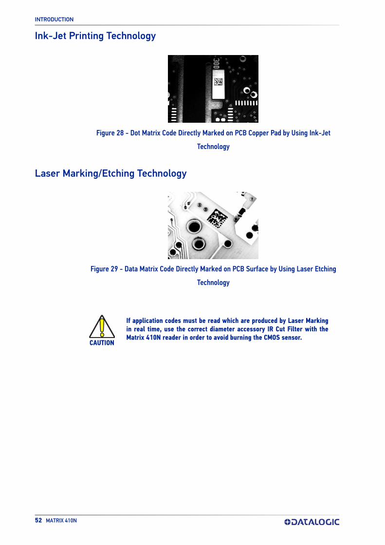
INTRODUCTION
52 MATRIX 410N
Ink-Jet Printing Technology
Figure 28 - Dot Matrix Code Directly Marked on PCB Copper Pad by Using Ink-Jet
Technology
Laser Marking/Etching Technology
Figure 29 - Data Matrix Code Directly Marked on PCB Surface by Using Laser Etching
Technology
CAUTION
If application codes must be read which are produced by Laser Marking in real time, use the correct diameter accessory IR Cut Filter with the Matrix 410N reader in order to avoid burning the CMOS sensor.

EXTERNAL LIGHTING SYSTEMS
PRODUCT REFERENCE GUIDE 53
EXTERNAL LIGHTING SYSTEMSIn some direct part marking applications best reading results are obtained by using an external lighting system. A series of accessory illuminators are available which cover a variety of applications.
The LT-410 Coaxial Lighting System is an axial diffuse illuminator designed for reading codes produced by Dot Peening or Laser Etching on flat parts having a matte, specular or mixed surface reflectivity.
Figure 30 - LT-410 Coaxial Lighting System
The LT-510 Mini Dome Lighting System is a diffuse mini dome light designed for reading printed label or Direct Marking codes on small parts with a curved or specular surface.
Figure 31 - LT-510 Mini Dome Lighting System
The LT-511 Dome Lighting System is a diffuse dome light designed for reading printed label or Direct Marking codes on parts with a curved surface.
Figure 32 - LT-511 Dome Lighting System

INTRODUCTION
54 MATRIX 410N
The LT-700 Linear Array Lighting System provides a high intensity light source designed for the following applications:
• with uneven, noisy and scratched surfaces;
• where dot peening or laser etching codes are directly marked onto metal surfaces or PCBs and need to be highlighted. Here the use of more than one LT-700 at dif-ferent positions can remove any shadowing effect;
• in the presence of highly reflective surfaces (metal, glass, etc.) causing direct reflections. Low light path to surface angles strongly reduce direct reflections.
Figure 33 - LT-700 Linear Array Lighting System

PRODUCT REFERENCE GUIDE 55
CHAPTER 3INSTALLATION
PACKAGE CONTENTSVerify that the Matrix 410N reader and all the parts supplied with the equipment are present and intact when opening the packaging; the list of parts includes:
• Matrix 410N reader
• Quick Reference Guide
• Test Charts (2)
• Mounting Kit
- Mounting Screws (4+3)
- Washers (2)
- Mounting Brackets (2)
Figure 34 - Package Contents

INSTALLATION
56 MATRIX 410N
MECHANICAL DIMENSIONSMatrix 410N can be installed to operate in different positions. The twelve screw holes (M4 x 5) on the body of the reader are for mechanical fixture.
The diagram below gives the overall dimensions of the reader and may be used for its installation.
Refer to page 58 for various mounting solutions and correct positioning, and Chapter 6, Reading Features for FOV vs. Reading Distance considerations.
Figure 35 - Overall Dimensions

mm
[inch]
MECHANICAL DIMENSIONS
PRODUCT REFERENCE GUIDE 57
Figure 36 - Mounting Bracket Overall Dimensions

INSTALLATION
58 MATRIX 410N
MOUNTING AND POSITIONING MATRIX 410NUsing the Matrix 410N mounting brackets you can obtain rotation on the various axes of the reader as shown in the diagram below:
Figure 37 - Positioning with Mounting Bracket (Back)
Figure 38 - Positioning with Mounting Bracket (Side)
Figure 39 - Positioning with Mounting Bracket (Front)

MOUNTING AND POSITIONING MATRIX 410N
PRODUCT REFERENCE GUIDE 59
Matrix 410N is able to decode code labels at a variety of angles; however significant angular distortion may degrade reading performance.
When mounting Matrix 410N, take into consideration these ideal label position angles: Pitch or Skew 10° to 20° and Tilt 0°.
NOTE
The Pitch, Skew and Tilt angles are represented in Figure 40. Follow the suggestions below for the best orientation:
Position the reader in order to avoid the direct reflection of the light emitted by the Matrix 410N reader; it is advised to assure at least 10° for the Skew angle.
No Pitch,Tilt or Skew
PitchMinimize
Tiltany angleinside FOV
Skewassure at least 10°
Figure 40 - Pitch, Tilt, and Skew Angles
In some cases, such as low contrast or low illumination, it can be useful to use a Pitch or Skew angle = 0°.
The Tilt angle is also represented in Figure 40. Matrix 410N can read labels with any tilt angle. Keep in mind however, that since linear barcodes are rectangular, the reader should be aligned to fit them into the horizontal FOV.
See Chapter 6, Reading Features for FOV vs. Reading Distance considerations.
Since Matrix 410N is omni-directional on the code plane, the Pitch and Skew angles have the same significance with respect to the code plane. However in some advanced code reading applications performance can be improved by modifying the Skew angle.

60 MATRIX 410N
CHAPTER 4CBX ELECTRICAL CONNECTIONS
All Matrix 410N models can be connected to a CBX connection box through one of the available CAB-DSxx-S accessory cables. These accessory cables terminate in a 17-pin connector on the Matrix 410N side and in a 25-pin male D-sub connector on the CBX side.
We recommend making system connections through one of the CBX connection boxes since they offer the advantages of easy connection, easy device replacement, opto-iso-lated output signals, and filtered reference signals.
NOTE
NOTE
If you require direct wiring to the reader the connections are the same as shown in this chapter with the exception of the digital Outputs. Direct wiring details are indicated in Appendix A.
To avoid electromagnetic interference when the reader is connected to a CBX connection box, verify the jumper positions in the CBX as indicated in its Installation Manual.

CBX CONNECTION BOX PINOUT
PRODUCT REFERENCE GUIDE 61
CBX CONNECTION BOX PINOUTThe table below gives the pinout of the CBX100/500 terminal block connectors. Use this pinout when the Matrix 410N reader is connected by means of the CBX100/500:
Group Label Description
Input Power
Vdc Power Supply Input Voltage +
GND Power Supply Input Voltage -
Earth Protection Earth Ground
Inputs +V Power Source - External Trigger
I1A External Trigger A (polarity insensitive)
I1B External Trigger B (polarity insensitive)
-V Power Reference - External Trigger
+V Power Source - Inputs
I2A Input 2 A (polarity insensitive)
I2B Input 2 B (polarity insensitive)
-V Power Reference - Inputs
Outputs +V Power Source - Outputs
-V Power Reference - Outputs
O1+ Output 1 + opto-isolated and polarity sensitive
O1- Output 1 - opto-isolated and polarity sensitive
O2+ Output 2 + opto-isolated and polarity sensitive
O2- Output 2 - opto-isolated and polarity sensitive
O3A Output 3 - non opto-isolated (only available through CBX500)
AuxiliaryInterface
TX Transmit Data
RX Receive Data
SGND Auxiliary Interface Signal Ground
ID-NET REF Network Reference
ID+ ID-NET network data +
ID- ID-NET network data -
Shield Network Cable Shield
Main Interface
RS232 RS422 Full Duplex
TX TX+
RX *RX+
- TX-
- *RX-
SGND SGND
* Do not leave floating, see "RS422 Full Duplex Interface" on page 64 for connection details.
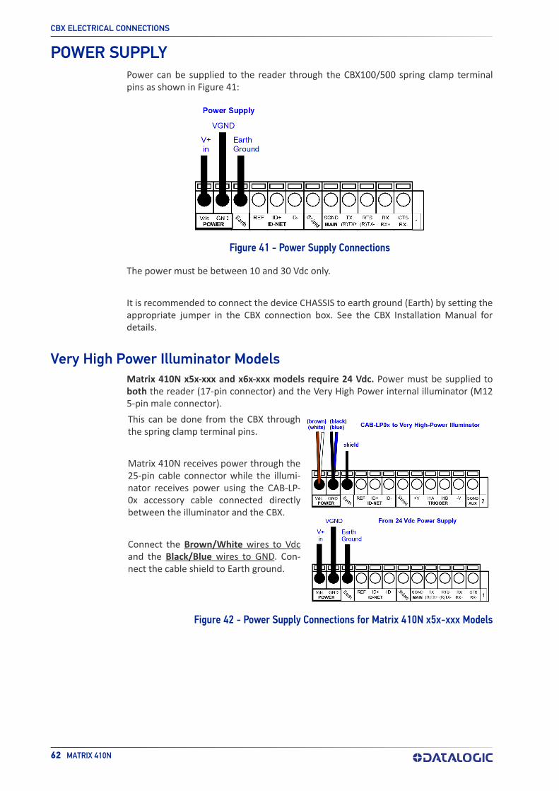
CBX ELECTRICAL CONNECTIONS
62 MATRIX 410N
POWER SUPPLYPower can be supplied to the reader through the CBX100/500 spring clamp terminal pins as shown in Figure 41:
Figure 41 - Power Supply Connections
The power must be between 10 and 30 Vdc only.
It is recommended to connect the device CHASSIS to earth ground (Earth) by setting the appropriate jumper in the CBX connection box. See the CBX Installation Manual for details.
Very High Power Illuminator ModelsMatrix 410N x5x-xxx and x6x-xxx models require 24 Vdc. Power must be supplied to both the reader (17-pin connector) and the Very High Power internal illuminator (M12 5-pin male connector).
This can be done from the CBX through the spring clamp terminal pins.
Matrix 410N receives power through the 25-pin cable connector while the illumi-nator receives power using the CAB-LP-0x accessory cable connected directly between the illuminator and the CBX.
Connect the Brown/White wires to Vdcand the Black/Blue wires to GND. Con-nect the cable shield to Earth ground.
Figure 42 - Power Supply Connections for Matrix 410N x5x-xxx Models

MAIN SERIAL INTERFACE
PRODUCT REFERENCE GUIDE 63
MAIN SERIAL INTERFACE
The signals relative to the following serial interface types are available on the CBX spring clamp terminal blocks.
The main serial interface type and its parameters (baud rate, data bits, etc.) can be defined by the user via DL.CODE software. For more details refer to the Help On Line page of the Reading Phase step (Channels) in DL.CODE.
Details regarding the connections and use of the interfaces are given in the next para-graphs.
RS232 InterfaceThe RS232 interface is generally used for Point-to-Point connections. When it is con-nected to the host computer it allows transmission of code data.
The following pins are used for RS232 interface connection:
CBX100/500 Description
TX Transmit Data
RX Receive Data
SGND Signal Ground
It is always advisable to use shielded cables. The overall maximum cable length must be less than 15 m (49.2 ft).
Figure 43 - RS232 Main Interface Connections
CAUTION
Do not connect to the Main Interface spring clamp terminals if using Host Interface Modules (Fieldbus) with the CBX500.
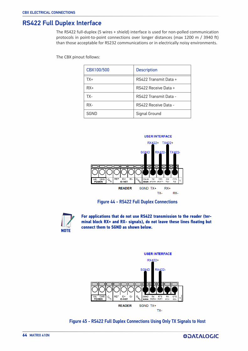
CBX ELECTRICAL CONNECTIONS
64 MATRIX 410N
RS422 Full Duplex InterfaceThe RS422 full-duplex (5 wires + shield) interface is used for non-polled communication protocols in point-to-point connections over longer distances (max 1200 m / 3940 ft) than those acceptable for RS232 communications or in electrically noisy environments.
The CBX pinout follows:
CBX100/500 Description
TX+ RS422 Transmit Data +
RX+ RS422 Receive Data +
TX- RS422 Transmit Data -
RX- RS422 Receive Data -
SGND Signal Ground
Figure 44 - RS422 Full Duplex Connections
NOTE
Figure 45 - RS422 Full Duplex Connections Using Only TX Signals to Host
For applications that do not use RS422 transmission to the reader (ter-minal block RX+ and RX- signals), do not leave these lines floating but connect them to SGND as shown below.

ID-NET INTERFACE
PRODUCT REFERENCE GUIDE 65
ID-NET INTERFACE
CBX100/500 Description
Shield Network Cable Shield
ID+ ID-NET Network Data +
ID- ID-NET Network Data -
REF Network Reference
ID-NET CablesThe following instructions are referred to Figure 47, Figure 48 and Figure 49.
• The general cable type specifications are: CAT5 twisted pair + additional CAT5 twisted pair, shielded cable AWG 24 (or AWG 22) stranded flexible.We recommend using DeviceNet cables (drop or trunk type) to the following refer-ence standards:AN50325 – IEC 62026UL STYLE 2502 80°C 30V
• Cable Shield MUST be connected to earth ground ONLY at the Master.
• NEVER use ID-NET cable shield as common reference.
• The ID-NET max cable length depends on the baudrate used (see the Baudrate Table below).
• For Common Power Connections use only 2 wires (ID+ and ID-).
- DC Voltage Power cable (Vdc – GND) should be handled as a signal cable (i.e. do not put it together with AC cable):
- Wire dimensioning must be checked in order to avoid voltage drops greater than 0.8 Volts.
- Cable should lie down as near as possible to the ID-NET cable (avoiding wide loops between them).
• Reader's chassis may be connected to earth.
• Network inside the same building.
Baudrate Table
Baudrate 125 kbps 250 kbps 500 kbps 1 Mbps
Cable Length 1200 m 900 m 700 m *
* Application dependent, contact your Datalogic representative for details.
NOTE
The default ID-NET baudrate is 500 kbps. Lower ID-NET baudrates allow longer cable lengths.

CBX ELECTRICAL CONNECTIONS
66 MATRIX 410N
ID-NET Response TimeThe following figure shows the response time of the ID-NET network. This time is defined as the period between the Trigger activation and the beginning of data trans-mission to the Host.
Figure 46 - ID-NET Response Time
Conditions• ID-NET M/S Synchronized layout
• message length = 50 bytes per node

ID-NET INTERFACE
PRODUCT REFERENCE GUIDE 67
ID-NET Network TerminationThe network must be properly terminated in the first and last reader of the network. This is done by setting the ID-NET Termination Resistance Switch in the CBX100/500 to ON.
ID-NET Connection Diagrams
Figure 47 - ID-NET Network Connections with isolated power blocks

CBX ELECTRICAL CONNECTIONS
68 MATRIX 410N
Figure 48 - ID-NET Network Connections with Common Power Branch Network
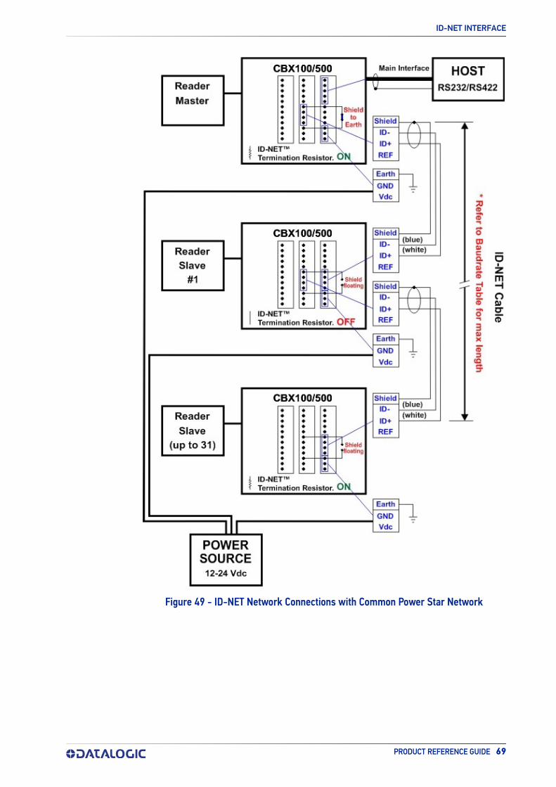
ID-NET INTERFACE
PRODUCT REFERENCE GUIDE 69
Figure 49 - ID-NET Network Connections with Common Power Star Network

CBX ELECTRICAL CONNECTIONS
70 MATRIX 410N
AUXILIARY RS232 INTERFACEThe RS232 auxiliary interface is available for Point-to-Point connections. When it is con-nected to the host computer it allows transmission of code data.
The parameters relative to the aux interface (baud rate, data bits, etc.) can be defined through the Reading Phase step (Channels) in DL.CODE.
The 9-pin female Auxiliary Interface connector inside the CBX is the preferred connector for temporary communication monitoring.
Figure 50 - 9-pin female connector
If permanent system wiring is required, the following pins are used to connect the RS232 auxiliary interface:
CBX100/500 Description
TX Auxiliary Interface Transmit Data
RX Auxiliary Interface Receive Data
SGND Auxiliary Interface Reference
Figure 51 - RS232 Auxiliary Interface Connections
NOTE
Do not connect the Aux Interface to the CBX spring clamp connectors and the 9-pin connector simultaneously.

INPUTS
PRODUCT REFERENCE GUIDE 71
INPUTSThere are two optocoupled polarity insensitive inputs available on the reader: Input 1 (External Trigger) and Input 2, a generic input:
The External Trigger can be used in One Shot Mode or in Phase Mode. Its main functions are:
• acquisition trigger in One Shot Mode
• reading phase-ON/reading phase-OFF command in Phase Mode
The main functions of the general purpose Input 2 are:
• second external trigger in Phase Mode
• match code storage command when the Match Code option is enabled
The electrical features of both inputs are:
VAB = 30 Vdc max.
IIN = 10 mA (reader) + 12 mA (CBX) max.
The active state of these inputs are selected in software.
An anti-disturbance filter, by default, is implemented in software on both inputs. The value can be changed through the software parameter Debounce Filter. See the Help On Line page of the Reading Phase step (Inputs) in DL.CODE for further details on these parameters.
These inputs are optocoupled and can be driven by both NPN and PNP type commands.
NOTE
The connections are indicated in the following diagrams:
CBX100/500 Description
+V Power Source - External Trigger
I1A External Trigger A (polarity insensitive)
I1B External Trigger B (polarity insensitive)
-V Power Reference - External Trigger
The yellow Trigger LED (Figure 13, 5) is on when the active state of the External Trigger corresponds to ON.
Polarity insensitive inputs assure full functionality even if pins A and B are exchanged.

CBX ELECTRICAL CONNECTIONS
72 MATRIX 410N
External Trigger Input Connections Using Matrix 410N Power
Figure 52 - PNP External Trigger Using Matrix 410N Power
CAUTION
Power from the Vdc/GND spring clamps is available directly to the Input Device on the +V/-V spring clamps, and does not pass through the Power Switch (ON/OFF) inside the CBX. Disconnect the power supply when working inside the CBX.
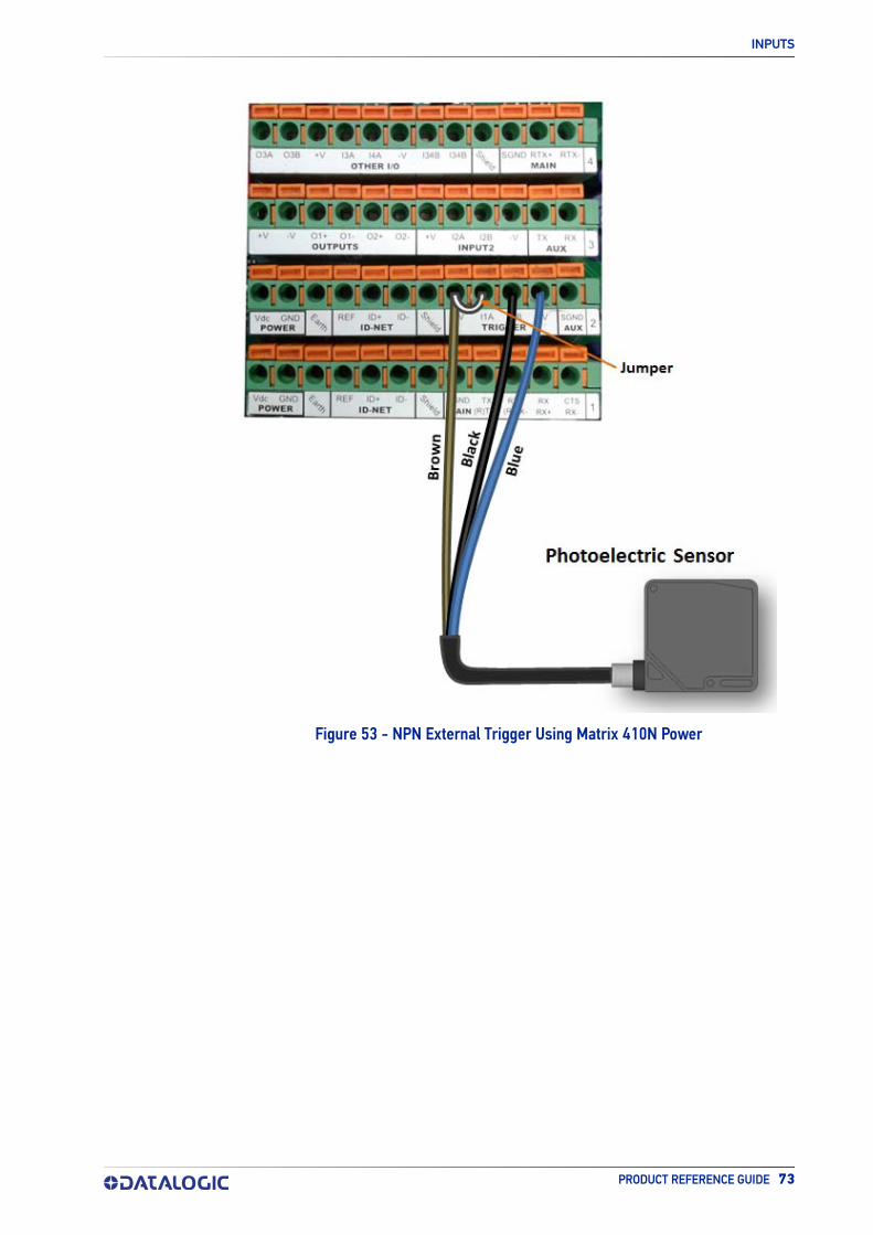
INPUTS
PRODUCT REFERENCE GUIDE 73
Figure 53 - NPN External Trigger Using Matrix 410N Power

CBX ELECTRICAL CONNECTIONS
74 MATRIX 410N
External Trigger Input Connections Using External Power
Figure 54 - PNP External Trigger Using External Power
Figure 55 - NPN External Trigger Using External Power
CBX100/500 Description
+V Power Source - External Trigger
I2A Input 2 A (polarity insensitive)
I2B Input 2 B (polarity insensitive)
-V Power Reference - External Trigger

INPUTS
PRODUCT REFERENCE GUIDE 75
Input 2 Connections Using Matrix 410N Power
Figure 56 - PNP Input 2 Using Matrix 410N Power
Figure 57 - NPN Input 2 Using Matrix 410N Power
CAUTION
Power from the Vdc/GND spring clamps is available directly to the Input Device on the +V/-V spring clamps, and does not pass through the Power Switch (ON/OFF) inside the CBX. Disconnect the power supply when working inside the CBX.

CBX ELECTRICAL CONNECTIONS
76 MATRIX 410N
Input 2 Connections Using External Power
Figure 58 - PNP Input 2 Using External Power
Figure 59 - NPN Input 2 Using External Power
Input 3 Connections (CBX500 Only)
Figure 60 - Input 3 Using External Power
CAUTION
Do not connect to I3A or I34B signals, they are reserved.
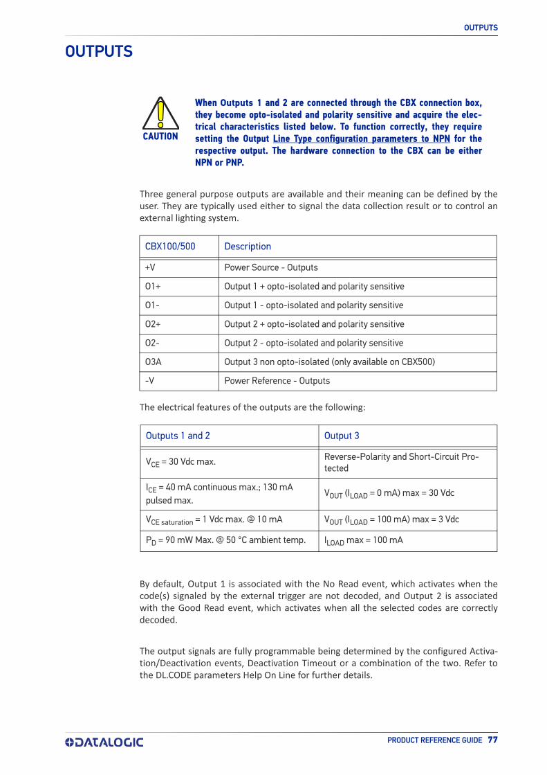
OUTPUTS
PRODUCT REFERENCE GUIDE 77
OUTPUTS
Three general purpose outputs are available and their meaning can be defined by the user. They are typically used either to signal the data collection result or to control an external lighting system.
CBX100/500 Description
+V Power Source - Outputs
O1+ Output 1 + opto-isolated and polarity sensitive
O1- Output 1 - opto-isolated and polarity sensitive
O2+ Output 2 + opto-isolated and polarity sensitive
O2- Output 2 - opto-isolated and polarity sensitive
O3A Output 3 non opto-isolated (only available on CBX500)
-V Power Reference - Outputs
The electrical features of the outputs are the following:
Outputs 1 and 2 Output 3
VCE = 30 Vdc max. Reverse-Polarity and Short-Circuit Pro-tected
ICE = 40 mA continuous max.; 130 mA pulsed max.
VOUT (ILOAD = 0 mA) max = 30 Vdc
VCE saturation = 1 Vdc max. @ 10 mA VOUT (ILOAD = 100 mA) max = 3 Vdc
PD = 90 mW Max. @ 50 °C ambient temp. ILOAD max = 100 mA
By default, Output 1 is associated with the No Read event, which activates when the code(s) signaled by the external trigger are not decoded, and Output 2 is associated with the Good Read event, which activates when all the selected codes are correctly decoded.
The output signals are fully programmable being determined by the configured Activa-tion/Deactivation events, Deactivation Timeout or a combination of the two. Refer to the DL.CODE parameters Help On Line for further details.
CAUTION
When Outputs 1 and 2 are connected through the CBX connection box, they become opto-isolated and polarity sensitive and acquire the elec-trical characteristics listed below. To function correctly, they require setting the Output Line Type configuration parameters to NPN for the respective output. The hardware connection to the CBX can be either NPN or PNP.

CBX ELECTRICAL CONNECTIONS
78 MATRIX 410N
Output 1 and 2 Connections Using Matrix 410N Power
Figure 61 - PNP/Open Emitter Output Using Matrix 410N Power
Figure 62 - NPN/Open Collector Output Using Matrix 410N Power
CAUTION
Power from the Vdc/GND spring clamps is available directly to the Out-put Device on the +V/-V spring clamps, and does not pass through the Power Switch (ON/OFF) inside the CBX. Disconnect the power supply when working inside the CBX.

OUTPUTS
PRODUCT REFERENCE GUIDE 79
Output 1 and 2 Connections Using External Power
Figure 63 - PNP/Open Emitter Output Using External Power
Figure 64 - NPN/Open Collector Output Using External Power
Output 3 is not opto-isolated but can be assigned to the same events. By default it is not assigned to any event. The CBX500 must be used to connect this output.
NOTE
For Output 3, set the Line Type configuration parameter according to the hardware connection to the CBX: NPN, PNP or Push-Pull.

CBX ELECTRICAL CONNECTIONS
80 MATRIX 410N
Output 3 Connections Using Matrix 410N Power (CBX500 Only)
Figure 65 - Output 3 Using Matrix 410N Power
Output 3 Connections Using External Power (CBX500 Only)
Figure 66 - Output 3 Using External Power
CAUTION
Do not connect to I3A or I34B signals, they are reserved.

EXTERNAL LIGHTING SYSTEMS
PRODUCT REFERENCE GUIDE 81
EXTERNAL LIGHTING SYSTEMSIf an External Illuminator is used, it can be powered from the CBX connection box. It must be connected to the Vdc and GND terminal clamps.
In the case of the LT-700 illuminators, one of the available digital outputs must be con-nected as the control signal. In DL.CODE, configure the Output Line Function parameter to one of the External Illuminator selections: Always On or Strobed.
Figure 67 - External Lighting System Connections
Below is a table summarizing the various External Illuminator wiring and power require-ments:
Illuminator Wire Color CBX/Matrix Signal Meaning
LT-410LT-510, LT-511
White Vdc 24 Vdc
Black GND Ground
Shield Earth Shield/Earth Ground
LT-700
Red Vdc 10 to 30 Vdc
Black GND Ground
White Earth Shield/Earth Ground
Green O1- or O2- Control Signal -
Yellow O1+ or O2+ Control Signal +
CAUTION
Power is available directly to the Illuminator, independently from the Power Supply Switch inside the CBX.

CBX ELECTRICAL CONNECTIONS
82 MATRIX 410N
ON-BOARD ETHERNET INTERFACEThe on-board Ethernet Interface can be used for TCP/IP communication with a remote or local host computer by connecting the reader to either a LAN or directly to a host PC. There is no need to use a crossover adapter since Matrix 410N incorporates an auto-cross function.
A CAB-ETH-X-M0x cable can be used to connect to a LAN.
On the Matrix 410N on-board Ethernet interface the following communication channels are available:
• TCP Client
• TCP Server
• UDP Channel
• FTP Client
The following Fieldbus protocols are also available over the on-board Ethernet inter-face:
• EtherNet/IP
• PROFINET IO
• Modbus TCP Client
For further details refer to the Help On Line page of the Reading Phase step (Channels) and (Fieldbuses) in DL.CODE.
USER INTERFACE - SERIAL HOSTThe following table contains the pinout for standard RS232 PC Host interface. For other user interface types please refer to their own manual.
RS232 PC-side Connections
9-pin male connector 25-pin male connector
Pin Name Pin Name
2 RX 3 RX
3 TX 2 TX
5 GND 7 GND

PRODUCT REFERENCE GUIDE 83
CHAPTER 5TYPICAL LAYOUTS
The following typical layouts refer to system hardware configurations. However, they also require the correct setup of the software configuration parameters. Dotted lines in the figures refer to optional hardware configurations within the particular layout.
NOTE
NOTE
NOTE
All software configurations are made through DL.CODE which connects to the reader through the on-board Ethernet interface.
DL.CODE now supports several different multi device configuration types using the PASS-THROUGH configuration. In particular this feature allows MULTIDATA ID-NET network configurations to be made. Master/Slave SYNCHRONIZED ID-NET network configurations are also configurable as before.
The Master/Slave Role is only significant for the Internal ID-NET Net-work. If your layout doesn’t use the ID-NET network then the device’s Role is not significant and can be ignored.

TYPICAL LAYOUTS
84 MATRIX 410N
ETHERNET CONNECTIONThe Ethernet connection is possible in two different layouts.
In a Point-to-Point layout the reader is connected to a local host by using a CAB-ETH-X-M0x cable. There is no need to use a crossover adapter since Matrix 410N incorporates an autocross function.
PG6000
Host
CAB-DSxx-S
Matrix 410N
CAB-ETH-X-M0x
CBX
Ethernet Interface
Auxiliary Serial Interface (RS232 - Data Monitor)
External Trigger (for One Shot or Phase Mode)
Alone
Figure 68 - Ethernet Point-to-Point Layout
All devices always support multiple output channels (i.e. for data monitoring).

ETHERNET CONNECTION
PRODUCT REFERENCE GUIDE 85
When using a Local Area Network (LAN), one or more Matrix 410N readers can be con-nected to the network by using CAB-ETH-X-M0x cables:
Host
CAB-
DSxx
-S
Matrix 410N
CAB-
ETH-
X-M
0x
Ethernet Interface
Auxiliary Serial Interface (RS232 - Data Monitor)
External Trigger (for One Shot or Phase Mode)
Alone
Alone Alone
CBX
CBX
Switch
Power
Figure 69 - Ethernet Network Layout

TYPICAL LAYOUTS
86 MATRIX 410N
SERIAL CONNECTIONIn this layout the data is transmitted to the Host on the main serial interface. The Ether-net interface can be used for reader configuration by connecting a laptop computer run-ning DL.CODE.
Data can be transmitted on the RS232 auxiliary interface independently from the main interface selection to monitor data.
When One Shot or Phase Mode operating mode is used, the reader can be activated by an External Trigger (for example a pulse from a photoelectric sensor) when the object enters its reading zone.
PG6000 Host
CAB-DSxx-S
Matrix 410N
CBX
Main Serial Interface (RS232 or RS422 Full-Duplex)
Auxiliary Serial Interface (RS232 - Data Monitor)
External Trigger (for One Shot or Phase Mode)
Alone
Terminal
Figure 70 - Serial Interface Point-to-Point Layout
All devices always support multiple output channels (i.e. for data monitoring).

FIELDBUS CONNECTION
PRODUCT REFERENCE GUIDE 87
FIELDBUS CONNECTIONIn this layout a single reader functions as a Slave node on a Fieldbus network. The data is transmitted to the Host through an accessory Fieldbus interface board installed inside the CBX500 connection box.
Reader configuration can be accomplished through the Ethernet interface using the DL.CODE configuration program.
Data can be transmitted on the RS232 auxiliary interface independently from the Field-bus interface selection to monitor data.
When One Shot or Phase Mode operating mode is used, the reader can be activated by an External Trigger (photoelectric sensor) when the object enters its reading zone.
Host
CAB-DSxx-S
Matrix 410N
CBX500
Fieldbus Interface (Profibus, DeviceNet, etc.)
Auxiliary Serial Interface (RS232 - Data Monitor)
External Trigger (for One Shot or Phase Mode)
Alone
Power
Figure 71 - Fieldbus Interface Point-to-Point Layout
All devices always support multiple output channels (i.e. for data monitoring).

TYPICAL LAYOUTS
88 MATRIX 410N
PASS-THROUGHThe pass-through layout allows each device working Alone, to collect data from one or more pass-through input channels and send this data plus its own on one or more dif-ferent output channels.
In this way independent devices can be connected together in combinations to create multi device networks. Many devices reading independently can send their messages through a common output channel which instead of being directed at a Host can be col-lected by another device on its pass-through input channel and sent to a Host on a dif-ferent output channel.
Host
CAB-
DSxx
-S
Phase
CAB-
ETH-
X-M
0x
Ethernet TCP/IP Server 1
Ethernet TCP/IP Server 2
Main Serial Interface (RS232 or RS422 Full-Duplex)
Auxiliary Serial Interface (RS232)
Pass-through Input Channel
Output Channel
Alone
Alone Alone
CBX
Switch
Power
ModeContinuous
Mode
ExternalTrigger
Figure 72 - Pass-Through Layout
In a Pass-through layout each device supports multiple pass-through configurations to accept input from different devices on different channels (i.e. middle reader above). How-ever, readers are not required to have a pass-through configuration if they don’t need to receive data from an input channel (i.e. right reader above). The overall data collection device always has at least one pass-through configuration to collect the input data from the other devices and send it to the Host (i.e. left reader above).
All devices always support multiple output channels (i.e. for data monitoring).
In a Pass-through layout each device can have a different operating mode: Continuous, One Shot, Phase Mode, etc.

ID-NET MULTIDATA NETWORK (PASS-THROUGH)
PRODUCT REFERENCE GUIDE 89
ID-NET MULTIDATA NETWORK (PASS-THROUGH)A special case of the pass-through layout allows each Slave device working Alone, to collect data from one or more pass-through input channels and send this data plus its own on the ID-NET output channel to the Master.
The Slave readers are connected together using the ID-NET interface. Every Slave reader must have an ID-NET address in the range 1-31.
The Master collects the data from its pass-through ID-NET input channel and sends it to the Host on a different output channel.
Host
CAB-
DSxx
-S
Phase
CAB-ETH-X-M0x
Ethernet TCP/IP Server 1
ID-NET (up to 32 devices, max network extension of 1000 m)
Main Serial Interface (RS232 or RS422 Full-Duplex)
Auxiliary Serial Interface (RS232)
Pass-through Input Channel
Output Channel
Alone
Alone Alone
Switch
Power
ModeContinuous
Mode
ExternalTrigger
ID-NETMaster
ID-NETSlave#1
ID-NETSlave#2
Figure 73 - ID-NET Multidata Layout (Pass-through)
In a Pass-through layout each device supports multiple pass-through configurations to accept input from different devices on different channels (i.e. Master reader above). How-ever, ID-NET Slave readers are not required to have a pass-through configuration if they don’t need to receive data from an input channel (i.e. right reader above). The ID-NET Master always has at least one pass-through configuration to collect the ID-NET Slaves data and send it to the Host.
NOTE
All devices always support multiple output channels (i.e. for data monitoring).
In a Pass-through layout each device can have a different operating mode: Continuous, One Shot, Phase Mode, etc.
Slave devices cannot receive data from a pass-through ID-NET input channel and Master devices cannot send data on an ID-NET output chan-nel.

TYPICAL LAYOUTS
90 MATRIX 410N
ID-NET SYNCHRONIZED NETWORKWhen the device is working Synchronized, the ID-NET connection is used to collect data from several readers to build a multi-point or a multi-sided reading system; there can be one Master and up to 31 Slaves connected together.
The Slave readers are connected together using the ID-NET interface. Every slave reader must have an ID-NET address in the range 1-31.
The Master reader is also connected to the Host on one of its communication channels. In the following examples the RS232/RS422 main serial interface is used.
For a Master/Slave Synchronized layout the External Trigger signal is unique to the sys-tem; there is a single reading phase and a single message from the Master reader to the Host computer. It is not necessary to bring the External Trigger signal to all the read-ers.
In the Master/Slave Synchronized layout the Master operating mode can only be set to PackTrack or Phase Mode.
The Main and ID-NET interfaces are connected as shown in the following figures.
Host
Power
ID-NET
MasterSynchronized
ID-NET
Slave#1Synchronized
ID-NET
Slave#nSynchronized
Main Serial Interface (RS232 or RS422 Full-Duplex)
External Trigger
ID-NET (up to 16 devices - practical limit)
Figure 74 - ID-NET Synchronized Layout
The Master reader can be connected to the CBX series connection box with the advan-tage of the Backup and Restore configuration function (CBX + BM100 module).

ID-NET SYNCHRONIZED NETWORK
PRODUCT REFERENCE GUIDE 91
All devices always support multiple output channels (i.e. for data monitoring).
Figure 75 - ID-NET Synchronized Layout Matrix 410N Master with CBX500 + Matrix
410N Slaves with QL100
If the Backup and Restore function is not required, then a QL300 can be used to connect the master reader.
Figure 76 - ID-NET Synchronized Layout Matrix 410N Master with QL300+ Matrix 410N
Slaves with QL100

TYPICAL LAYOUTS
92 MATRIX 410N
The same configuration can be made to a Host using the on-board Ethernet interface to the Master. The TCP/IP Ethernet and ID-NET interfaces are connected as shown in the figure below.
Host
Power
ID-NET
MasterSynchronized
ID-NET
Slave#1Synchronized
ID-NET
Slave#nSynchronized
TCP/IP on-board Ethernet Interface
External Trigger
ID-NET (up to 16 devices - practical limit)
CBX100
Figure 77 - ID-NET Synchronized Layout with Master on-board TCP/IP Ethernet
Interface to Host
Alternatively, the Master reader can communicate to the Host as a Slave node on a Fieldbus network. This requires using an accessory Fieldbus interface board installed inside the CBX500 connection box. System configuration can be accomplished through the Ethernet interface of each individual reader using the DL.CODE configuration pro-gram.
Host
Power
ID-NET
MasterSynchronized
ID-NET
Slave#1Synchronized
ID-NET
Slave#nSynchronized
Fieldbus Interface
External Trigger
ID-NET (up to 16 devices - practical limit)
CBX500
Figure 78 - ID-NET Synchronized Layout with Master CBX500 Fieldbus Interface to Host

NOTE
PRODUCT REFERENCE GUIDE 93
CHAPTER 6READING FEATURES
FOV CALCULATIONUse the data in the following table to calculate the FOV for your application, referring to Figure 79 and the formula below.
Model Lensd0
Offset
Viewing Angle
Horizontal
Viewing Angle
Vertical
Viewing Angle
Diagonal
Min Focus Distance
(mm)
Matrix 410N 500-0x0 (1.3MP)
LNS-1006 6 mm 20 61° 50° 74° 85
LNS-1109 9 mm 30 41° 34° 51° 85
LNS-1112 12.5 mm 30 30° 24° 38° 85
LNS-1116 16 mm 30 23° 19° 30° 85
LNS-1125 25 mm 15 15° 12° 19° 135
LNS-1135 35 mm 15 11° 9° 14° 235
LNS-1150 50 mm 15 7° 6° 10° 500
Matrix 410N 700-0x0 (2.0MP)
LNS-1006 6 mm 20 64° 50° 76° 85
LNS-1109 9 mm 26 43° 33° 53° 85
LNS-1112 12.5 mm 26 32° 24° 39° 85
LNS-1116 16 mm 26 25° 19° 31° 85
LNS-1125 25 mm 26 16° 12° 20° 135
LNS-1135 35 mm 10 12° 9° 15° 235
LNS-1150 50 mm 10 8° 6° 11° 500
The FOV calculations and diagrams can be used for various combinations of Matrix 410N base models with accessory lenses. For pre-assembled pre-focused models, see "Reading Characteristics for Pre-Assembled Pre-Focused Models" on page 110.

READING FEATURES
94 MATRIX 410N
The viewing angle has a tolerance of ± 1° depending on the reading distance.
FOVx = 2 [ (d + d0) * tan (αx/2) ]where:
FOVx = horizontal, vertical or diagonal FOV
x = horizontal, vertical or diagonal viewing angles.
d = reading distance (in mm) from window surface to code surface
d0 = offset (in mm) from center of lens to external window surface
Figure 79 - Reading Distance ReferencesExample:
The FOV for a Matrix 410N 700-0x0 base using the 16 mm lens at a reading distance of 600 mm is:
FOVH = 2 [(600 mm + 26 mm) * tan (25°/2)] 278 mm
FOVV = 2 [(600 mm + 26 mm) * tan (16°/2)] 210 mm

GLOBAL FOV DIAGRAMS
PRODUCT REFERENCE GUIDE 95
GLOBAL FOV DIAGRAMS
NOTE
The following diagrams show the maximum obtainable Field of View for 1D and 2D codes. Depending on the code resolution, symbology, and number of characters in the code, the Reading Area can be different from the FOV.
The following diagrams are given for typical performance at 25°C using high quality grade A symbols according to ISO/IEC 15416 (1D code) and ISO/IEC 15415 (2D code) print quality test specifications. Testing should be performed with actual application codes in order to maximize the application performance.

READING FEATURES
96 MATRIX 410N
Global FOV for Matrix 410N 500-0x0 (1.3 MP)
1D
Horiz
onta
l FoV
Reading Distance mm
Codes f = 6 mm
Matrix 410N 500-0x0 (1.3 MP) with LNS-1006 (6 mm lens)2D Codes
Horiz
onta
l FoV
Reading Distance mm
f = 6 mm

GLOBAL FOV DIAGRAMS
PRODUCT REFERENCE GUIDE 97
1D Codes f = 9 mm
Reading Distance
Horiz
onta
l FoV
mm
Matrix 410N 500-0x0 (1.3 MP) with LNS-1109 (9 mm lens)
Horiz
onta
l FoV
Reading Distance mm
2D Codes f = 9 mm

Horiz
onta
l FoV
Reading Distance mm
READING FEATURES
98 MATRIX 410N
1D Codes f = 12.5 mm
Matrix 410N 500-0x0 (1.3 MP) with LNS-1112 (12.5 mm lens)2D Codes f = 12.5 mm
Reading Distance
Horiz
onta
l FoV

Horiz
onta
l FoV
Reading Distance mm
GLOBAL FOV DIAGRAMS
PRODUCT REFERENCE GUIDE 99
1D Codes f = 16 mm
Matrix 410N 500-0x0 (1.3 MP) with LNS-1116 (16 mm lens)2D Codes f = 16 mm
Reading Distance
Horiz
onta
l FoV

Horiz
onta
l FoV
Reading Distance mm
READING FEATURES
100 MATRIX 410N
1D Codes f = 25 mm
Matrix 410N 500-0x0 (1.3 MP) with LNS-1125 (25 mm lens)2D Codes f = 25 mm
Reading Distance
Horiz
onta
l FoV

Horiz
onta
l FoV
Reading Distance mm
GLOBAL FOV DIAGRAMS
PRODUCT REFERENCE GUIDE 101
1D Codes f = 35 mm
Matrix 410N 500-0x0 (1.3 MP) with LNS-1135 (35 mm lens)2D Codes f = 35 mm
Reading Distance
Horiz
onta
l FoV

Horiz
onta
l FoV
Reading Distance mm
READING FEATURES
102 MATRIX 410N
1D Codes f = 50 mm
Matrix 410N 500-0x0 (1.3 MP) with LNS-1150 (50 mm lens)2D Codes f = 50 mm
Reading Distance
Horiz
onta
l FoV

GLOBAL FOV DIAGRAMS
PRODUCT REFERENCE GUIDE 103
Global FOV for Matrix 410N 700-0x0 (2.0 MP)
Horiz
onta
l FoV
Reading Distance mm
1D Codes f = 6 mm
Matrix 410N 700-0x0 (1.3 MP) with LNS-1006 (6 mm lens)2D Codes f = 6 mm
Reading Distance
Horiz
onta
l FoV
mm

Horiz
onta
l FoV
Reading Distance mm
READING FEATURES
104 MATRIX 410N
1D Codes f = 9 mm
Matrix 410N 700-0x0 (1.3 MP) with LNS-1009 (9 mm lens)2D Codes f = 9 mm
Reading Distance
Horiz
onta
l FoV
mm

Horiz
onta
l FoV
Reading Distance mm
GLOBAL FOV DIAGRAMS
PRODUCT REFERENCE GUIDE 105
1D Codes f = 12.5 mm
Matrix 410N 700-0x0 (1.3 MP) with LNS-1112 (12.5 mm lens)2D Codes f = 12.5 mm
Reading Distance
Horiz
onta
l FoV
mm

Horiz
onta
l FoV
Reading Distance mm
READING FEATURES
106 MATRIX 410N
1D Codes f = 16 mm
Matrix 410N 700-0x0 (1.3 MP) with LNS-1116 (16 mm lens)2D Codes f = 16 mm
Reading Distance
Horiz
onta
l FoV
mm

Horiz
onta
l FoV
Reading Distance mm
GLOBAL FOV DIAGRAMS
PRODUCT REFERENCE GUIDE 107
1D Codes f = 25 mm
Matrix 410N 700-0x0 (1.3 MP) with LNS-1125 (25 mm lens)2D Codes f = 25 mm
Reading Distance
Horiz
onta
l FoV
mm

Horiz
onta
l FoV
Reading Distance mm
READING FEATURES
108 MATRIX 410N
1D Codes f = 35 mm
Matrix 410N 700-0x0 (1.3 MP) with LNS-1135 (35 mm lens)2D Codes f = 35 mm
Reading Distance
Horiz
onta
l FoV
mm

Horiz
onta
l FoV
Reading Distance mm
GLOBAL FOV DIAGRAMS
PRODUCT REFERENCE GUIDE 109
1D Codes f = 50 mm
Matrix 410N 700-0x0 (1.3 MP) with LNS-1150 (50 mm lens)2D Codes f = 50 mm
Reading Distance
Horiz
onta
l FoV
mm

READING FEATURES
110 MATRIX 410N
READING CHARACTERISTICS FOR PRE-ASSEMBLED PRE-FOCUSED MODELS
RED 8 LEDs
937401097 712-510 LNS12-RED ST-0.30 0.30 (12) 380 (15.0) 140 (5.5)317 - 457(12.5 - 18)
197 - 146(7.6 - 5.7)
937401098 713-510 LNS16-RED ST-0.30 0.30 (12) 483 (19.0) 155 (6.1)405 - 560(15.9 - 22)
191 - 144(7.5 - 5.7)
937401099 724-110 LNS25-RED ST PT-0.33 0.33 (13) 1000 (39.4) 380 (15)750 - 1130(29.5-44.5)
215 - 162(8.5 - 6.4)
RED 15 LEDs
937401100 744-710 LNS25-RED HP-0.38 0.38 (15) 1570 (61.8) 400 (15.7)1270 - 1670(50 - 65.7)
360 x 270(14.2 x 10.6)
937401101 744-110 LNS25-RED HP-0.33 0.33 (13) 1300 (51.2) 400 (15.7)1050 - 1450(41.3-57.1)
300 x 224(11.8 - 8.8)
937401102 744-210 LNS25-RED HP-0.25 0.25 (10) 788 (31.0) 200 (10)710 - 910(28 - 35.8)
204 - 153(8 x6)
BLUE 15 LEDs
937401090 734-710 LNS25-BLUE HP-0.38 0.38 (15) 1570 (61.8) 400 (15.7)1270 - 1670(50 - 65.7)
360 x 270(14.2 x 10.6)
937401091 734-110 LNS25-BLUE HP-0.33 0.33 (13) 1300 (51.2) 400 (15.7)1050 - 1450(41.3-57.1)
300 x 224(11.8 - 8.8)
937401092 734-210 LNS25-BLUE HP-0.25 0.25 (10) 788 (31.0) 200 (10)710 - 910(28 - 35.8)
204 - 153(8 x6)
BLUE 40 LEDs
937401093 754-710 LNS25-BLUE VHP-0.38 0.38 (15) 1570 (61.8) 400 (15.7)1270 - 1670(50 - 65.7)
360 x 270(14.2 x 10.6)
937401107 754-610 LNS25-BLUE VHP-0.35 0.35 (14) 1065 (41.9) 400 (15.7)880 - 1280(34.6-50.4)
251 x 189(9.9 x 7.4)
937401094 754-110 LNS25-BLUE VHP-0.33 0.33 (13) 1300 (51.2) 400 (15.7)1050 - 1450(41.3-57.1)
300 x 224(11.8 x 8.8)
937401095 754-210 LNS25-BLUE VHP-0.25 0.25 (10) 960 (37.8) 250 (10)860 - 1110(33.9-43.7)
246 x 185(9.7 x 7.3)
937401096 755-210 LNS35-BLUE VHP-0.25 0.25 (10) 1080 (42.5) 380 (15)930 - 1310(36.6-51.6)
198 x 148(7.8 x 5.8)
WHITE 40 LEDs
937401103 764-710 LNS25-WHT VHP-0.38 0.38 (15) 1570 (61.8) 400 (15.7)1270 - 1670(50 - 65.7)
360 x 270(14.2 x 10.6)
937401104 764-110 LNS25-WHT VHP-0.33 0.33 (13) 1300 (51.2) 400 (15.7)1050 - 1450(41.3-57.1)
300 x 224(11.8 - 8.8)
937401105 764-210 LNS25-WHT VHP-0.25 0.25 (10) 960 (37.8) 250 (10)860 - 1110(33.9-43.7)
246 - 185(9.7 - 7.3)
Part number Model description
Reference code
resolution (1D)
mm (mils)
Focal distancemm (in)
DOFmm (in)
Reading distance min-maxmm (in)
FOV H x V @ min
Reading distancemm (in)

MAXIMUM LINE SPEED AND EXPOSURE TIME CALCULATIONS
PRODUCT REFERENCE GUIDE 111
MAXIMUM LINE SPEED AND EXPOSURE TIME CALCULATIONS
The Exposure Time parameter defines the time during which the image will be exposed to the reader sensor to be acquired. This parameter depends heavily on the environ-mental conditions (external lighting system, image contrast etc.).
In general, a longer time corresponds to a lighter image but is susceptible to blurring due to the code movement; a shorter exposure time corresponds to a darker image.
NOTE
Assuming:
• X: Code Resolution (mm)
• Texp: Exposure Time (s)
• LS: Line Speed (mm/s)
The essential condition to avoid blurring effects between two adjacent elements in a dynamic reading application is:
LS Texp X
The maximum (theoretical) line speed LS can be calculated as follows:
X / Texp (min) = LS (max)
Texp (min) is the minimum Exposure Time value obtainable for the specific application. It can be evaluated in static reading conditions and depends on the Matrix reader model selected for the application (internal lighting system, optical lens, reading distance) and on any external lighting system. It may also depend on code printing quality, and reader position.
ExampleA Matrix 410N 700-010 using:
Internal Lighting Mode = Very High Power Strobe
Exposure Time (s) = 100 s
Code Resolution (X) = 0.254 mm (10 mils)
has a maximum line speed of:
0.254 (mm) / 0.0001 (s) = 2540 mm/s
Likewise, Texp (max) is the maximum Exposure Time value that can be used without blur-ring for the given application line speed and code resolution. Therefore:
X / LS = Texp (max)
The following considerations must be applied only when the internal lighting system and 2D codes are used. The Maximum line speed allowed for linear codes or postal code reading applications heavily depends on the direction of symbol movement. When the direction of movement is parallel to the elements of the code, the maximum speed is greater

READING FEATURES
112 MATRIX 410N
Texp (max) and LS (max) are represented in the graph below as the curved line for X (code resolution). Values above the curve result in blurring. In practice, the application values are somewhere below the theoretical line, (in the green area), due to environmental and other conditions.
For example, the maximum target speed in the application is also affected by these con-ditions:
• Code/Background Contrast: maximum speed decreases when decreasing image contrast (poor quality codes, reflective transparent coverings, different supports and printing techniques).
• Code Resolution: maximum speed increases when decreasing code resolution, (i.e. 2X). There is a decrement of overlapping effects between two adjacent ele-ments.
• Tilt Angle: maximum speed decreases when increasing Tilt angle (from 0 to 45 degrees).
The Internal Lighting parameter allows setting the operating mode of the internal light-ing system. The possible values are:
• Disabled: the built-in LED array is turned off all the time. This option can be useful if using an external lighting system;
• Always ON: the built-in LED array is turned on all the time at the lowest power level. This option is useful if the LED-array blinking (Strobed operating mode) dis-turbs the operator.
• -Power Strobed: the built-in LED array is on only during the image exposure time. Different Power Strobed lighting levels can be set.
NOTE
• Continuous High-Power: the internal lighting system is turned on continuously at the highest power level. This option is useful if the LED-array blinking (Strobed lighting mode) disturbs the operator.
• Continuous High-Power mode is not allowed;• When using Power Strobed modes, the application program
imposes protective limits on the frame rate to avoid overheating.
To avoid LED array overheating, for Power Strobed settings, the program automatically limits the range of allowed values for the Exposure Time parameter. Therefore, after changes to Internal Lighting, recheck Expo-sure Time.
CAUTION
To avoid damage to the devices, for LT-010 and LT-011 illuminators you must correctly associate the illuminator to the Matrix 410N through the Current Illuminator Model item in the DL.CODE Device menu (Settings > Settings > Maintenance Settings). DL.CODE will correctly manage the following settings for these illuminators:
PRODUCT REFERENCE GUIDE 113
CHAPTER 7SOFTWARE CONFIGURATION
Software configuration of your Matrix 410N for static reading or simple code reading applications can be accomplished by the Rapid Configuration procedure using the X-PRESS HMI (which requires no external configuration program). This procedure is described in Chapter 1, Rapid Configuration Steps 4-6.
For the majority of applications however you will use DL.CODE, connecting to the reader through the on-board Ethernet interface. See Chapter 1, Rapid Configuration Steps 7-8.
DL.CODE SYSTEM REQUIREMENTS
To install and run DL.CODE you should have a Laptop or PC that meets or exceeds the following:
• 2.00 GHz or faster microprocessor
• Windows: 7, 8.1, or 10
• 1 GB RAM
• 2 GB hard disk for 64-bit machines; 1 GB hard disk for 32-bit machines
• 100 Base-T Ethernet
• One 19" or larger monitor (optimized for 1280x1024 resolution)
READER CONFIGURATIONFor an example of Matrix device configuration see the example in Chapter 1, Rapid Con-figurationSteps 7-8.
NOTE
CAUTION
DL.CODE does not currently support Windows Embedded (often used in industrial PCs and/or PLCs).
Especially for lengthy configurations, it is always good practice to peri-odically save the configuration to permanent memory (Save on Device) to avoid losing the configuration in Temporary Memory. You must give a name to the new configuration or overwrite an existing one (except for Default which cannot be modified).

SOFTWARE CONFIGURATION
114 MATRIX 410N
When all the configuration parameters are set correctly and saved to the device, you can perform a Backup to File and/or to an External storage device (BM100, etc.). See "Backup and Restore Through DL.CODE" on page 147.
NOTE
Auto-CalibrationDL.CODE provides the Image Auto-Setup tool to maximize the reading performance by tuning the acquisition parameters (photometry) automatically. By selecting the Image Auto-Setup tool from the Image Settings branch in the Advanced Setup step, the follow-ing window appears:Select the Static or Dynamic Self-Tuning option; Start Image Auto-
Setup and Apply to the Image Settings. The Advanced Setup window works interactively so that you can see the results of the parameter setting changes as well as the decoding results (Results panel).
Figure 80 - Decoding Results OK
An improvement in the Matrix N Family readers allows them to contain several configurations or jobs in permanent memory.
This means that in addition to your application configuration(s), the Default configuration is always present on the reader and in fact it is not modifiable and cannot be deleted.

READER CONFIGURATION
PRODUCT REFERENCE GUIDE 115
Manual CalibrationThe following examples show some of the typical conditions occurring during the instal-lation and how they can be tuned manually:
Under-exposureTo correct this result it is recommended to change the following parameters in their order of appearance:
1. increase the Exposure Time
2. increase the Gain
NOTE
Figure 81 - Example Under Exposure: Too Dark
In general, a longer exposure time corresponds to a lighter image but is susceptible to blurring due to code movement. Exposure time is also limited by the Internal Lighting mode parameter. Longer exposure times can be set if the power strobe level is lowered.
High gain settings may produce a grainy image that may affect the decoding process.

SOFTWARE CONFIGURATION
116 MATRIX 410N
Over-exposureTo correct this result it is recommended to change the following parameters in their order of appearance:
1. decrease the Gain
2. decrease the Exposure Time
Figure 82 - Example Over Exposure: Too Light

READER CONFIGURATION
PRODUCT REFERENCE GUIDE 117
Moving code out of the Field of ViewTo correct this result and have the code completely visible in FOV, it is possible to follow one or both the procedures listed below:
• reposition the reader
• use the Delay on Trigger and set the Time or Space values.
Figure 83 - Example Out of FOV
Figure 84 - Add Delay on Trigger to Correct Out of FOV

SOFTWARE CONFIGURATION
118 MATRIX 410N
MULTI IMAGE ACQUISITION SETTINGSWhen controlled variable conditions occur in the application, Multiple Image Acquisi-tion Settings can be defined to create a database of parameter groups that handle each specific application condition. This database of pre-defined settings improves system flexibility and readiness by being applied either automatically or selectively by an activa-tion event.
For example, an application may have several stable but different lighting conditionswhich require different lighting options. One Image Acquisition Setting could enable and use an internal illuminator and another setting could enable and use an external lighting system.
This feature is available for all Operating Modes.
Image Settings are found in the DL.CODE Advanced Setup step. Up to 10 different Image Settings can be configured by adding them with the icon.
For each Image Setting condition start Image Auto-Setup, select the Static or Dynamic Self-Tuning option; and Apply it.

MULTI IMAGE ACQUISITION SETTINGS
PRODUCT REFERENCE GUIDE 119
Automatic Image Settings SelectionIf we don’t know from one item to the next which reading condition will be presented, we will cycle through the pre-defined database of Image Settings (one per acquisition) in order to automatically capture the correctly lighted image over the course of several acquisitions. When the correct condition is matched, the result should be able to pro-duce a Good Read.
When the Image Settings Selection is Automatic (default), then these Image Settings groups will be used cyclically.
NOTE
If items to be read having the same lighting conditions are grouped together, then we can improve the read rate through the Start Acquisition From parameter. By choosing the Last Successful value, we will start with the Image Setting that last produced a Good Read. For this group of items the last Image Setting used will be correct for the next item and so we start each cycle with the acquisition that will potentially produce a Good Read.
Applications typically require more than one acquisition to obtain suffi-cient Good Read percentages. This means that for N acquisitions we will surely have captured the correct lighting condition but we will also have captured some acquisitions with the wrong lighting condition. A conse-quence then is that we cannot run these types of applications at the maximum speed because not all the acquisitions are useful to us. We must wait for a sufficient number of acquisitions that will guarantee a Good Read result.

SOFTWARE CONFIGURATION
120 MATRIX 410N
External Image Settings SelectionThere are some applications where the lighting conditions are known before each item is read and therefore we can pre-select the correct Image Setting from an external source.
When the Image Settings Selection is External, Acquisition Sequences are created and by default each Image Setting has its own Acquisition Sequence.
Each Acquisition Sequence can be activated exclusively by a single event, either through a string from an available communication channel or by a digital input.

MULTI IMAGE ACQUISITION SETTINGS
PRODUCT REFERENCE GUIDE 121
Alternatively a hybrid configuration can be made where more than one Image Settingcan be grouped into an Acquisition Sequence by dragging it into the desired Sequence box. Select the empty Sequence box and delete it with the delete key.
Each Acquisition Sequence can be activated exclusively by a single event, either through a string from an available communication channel or by a digital input.
In this case the Start Acquisition From parameter can improve the read rate for that Sequence. It has no meaning for a Sequence containing only one Image Setting.

SOFTWARE CONFIGURATION
122 MATRIX 410N
IMAGE CROPPINGIn some applications, the Image Cropping feature in DL.CODE can help to increase decoding and result performance. Image cropping is performed from the Advanced Setup tab by clicking on the Add Cropping Region icon as shown below.
In Matrix 410N the frame rate is dependent on the number of rows and columns in the defined window. Image cropping allows reducing the Image processing area from the full FoV to a smaller area where codes are present. By excluding portions of the FoV, processing time is reduced.
After clicking the Add Cropping Region icon, a blue border appears which by default is equal to the FoV.

IMAGE CROPPING
PRODUCT REFERENCE GUIDE 123
By dragging the edges with the mouse (resizing) you can crop the image to a specific location where codes are present. The numbers in the blue boxes refer to pixel refer-ences.
x,y coordinates of
upper left corner of
Cropping Region
number of pixels in
vertical Cropping
Region (Height)
The cropped area can be moved by dragging the center.

SOFTWARE CONFIGURATION
124 MATRIX 410N
You can also set the cropped image size and position through the Cropping Region Area group of parameters; size = Width and Height, position = Left, Top (x,y) coordinates.

DIRECT PART MARKING APPLICATIONS
PRODUCT REFERENCE GUIDE 125
DIRECT PART MARKING APPLICATIONSFor Data Matrix family codes the Decoding Complexity parameter is available when Processing Mode is set to Standard and selects the decoding algorithm according to the printing/marking technique used to create the symbol and on the overall printing/marking quality.
The possible selections progress from Low to Very High where Low can improve decod-ing time for good print/mark quality and/or relatively normal size codes. This is the default setting. Very High can improve the decode rate for low print/mark quality and/or small size codes. This algorithm is much more aggressive but in general it may have longer decoding times than the lower complexity algorithms. To minimize decoding time it is better to select the lowest value that still guarantees good decoding.
Figure 85 - Problematic Direct Part Marking Examples
For QR code the Decoding Method parameter allows the Dot Peen Decoding algorithm to be selected which improves the decode rate for low quality Direct Part Mark codes and in general for Direct Part Mark codes with dot peening type module shapes.

SOFTWARE CONFIGURATION
126 MATRIX 410N
Image FilterSets the filter to be applied to the image before being processed. This parameter can be used to successfully decode particular ink-spread printed codes (e.g. direct part mark codes).
Different filters can be applied to a single code or group of codes in one or more Image Settings. See the DL.CODE User’s Manual for examples of Image Filter application.
The Erode Filter enlarges the image dark zones to increase readability.
Before - No Read After - Readable
The Dilate Filter enlarges the image white zones to increase readability.
Before - No Read After - Readable
The Close filter eliminates dark areas (defects) in the white zones of the image.
Before - No Read After - Readable

The Open filter eliminates white areas (defects) in the dark zones of the image.
Before - No Read After - Readable
The Contrast Stretching filter maximizes image contrast.
Before - No Read After - Readable
DIRECT PART MARKING APPLICATIONS
PRODUCT REFERENCE GUIDE 127

The Histogram Equalization filter makes the gray level distribution uniform.
Before - No Read After - Readable
The Smoothing filter deletes small (insignificant) details in the center of the image.
Before - No Read After - Readable
The Sharpening filter improves out of focus images.
Before - No Read After - Readable
SOFTWARE CONFIGURATION
128 MATRIX 410N

The Deblurring filter improves blurred images.
Before - No Read After - Readable
The Black Enhancement filter produces a nonlinear increase in the black level for light images.
Before - No Read After - Readable
DIRECT PART MARKING APPLICATIONS
PRODUCT REFERENCE GUIDE 129

The White Enhancement filter produces a nonlinear increase in the white level for dark images.
Before - No Read After - Readable
SOFTWARE CONFIGURATION
130 MATRIX 410N
PASS-THROUGH CONFIGURATIONSStarting from software version 1.3.0, DL.CODE and Matrix N familiy readers support pass-through multi device configurations.
The pass-through configuration allows individually working devices (Alone), to collect data from other devices (also working Alone), and pass this data to a third device through a different communication channel.
The following screenshots show the pass-through configuration settings for the three devices in the example in "Pass-Through" on page 88.
Reader #1

Reader #2
Reader #3
PASS-THROUGH CONFIGURATIONS
PRODUCT REFERENCE GUIDE 131

SOFTWARE CONFIGURATION
132 MATRIX 410N
INTERNAL NETWORK CONFIGURATIONSInternal Network configurations (also called Master/Slave configurations), are designed to collect data from several devices connected together in an ID-NET™ network and send data output to the Host system.
DL.CODE has a Net Autoset feature for the Internal ID-NET Network which automatically recognizes and assigns addresses to all connected Slave readers.
In order to automatically recognize the ID-NET Slaves, all devices must be physically installed and electrically connected (including ID-NET network wiring).
The general procedure (also detailed in the following paragraphs) is to:
1. Mount all the readers mechanically (refer to "Mechanical Dimensions" on page 56 and "Mounting And Positioning Matrix 410N" on page 58) and electrically (refer to "ID-NET Interface" on page 65) with factory default settings (Layout Type = Alone, Internal Network Role = Slave).
2. Run DL.CODE and verify that all the devices are discovered and shown in the device list area.
3. Connect to the designated Master device in DL.CODE and open the Setup Internal Network Configuration. You will be prompted to change the device to Master. Click OK. The Slave units will automatically be recognized. See "Master Configura-tion" on page 133.
4. Depending on the application, select Set Default Multidata Configuration or Set Default Synchronized Phase Mode Configuration.
5. Connect to each Slave reader via Ethernet and set the Slave specific parameters depending on the application type. Save each Slave specific configuration. See "Multidata ID-NET Network Configurations" on page 135 or "Synchronized ID-NETNetwork Configurations" on page 140.
6. For Synchronized networks Verify/Test network performance. See "Verify Master/Slave Synchronized Configuration" on page 144.
7. Perform the Backup current Internal Network configurations procedure. See "Backup" on page 148.

INTERNAL NETWORK CONFIGURATIONS
PRODUCT REFERENCE GUIDE 133
Master ConfigurationFirst start with the desired device to assign as ID-NET Master (current default setting is Slave). Click on Setup Internal Network Configuration from the Task area.
You will be advised that the device role will be changed to Master.
Click OK. The Net Autoset feature automatically starts to find Slave devices connected to the ID-NET network of the Master.
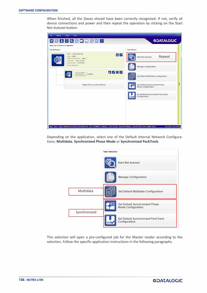
SOFTWARE CONFIGURATION
134 MATRIX 410N
When finished, all the Slaves should have been correctly recognized. If not, verify all device connections and power and then repeat the operation by clicking on the Start Net Autoset button.
Repeat
Depending on the application, select one of the Default Internal Network Configura-tions: Multidata, Synchronized Phase Mode or Synchronized PackTrack.
Multidata
Synchronized
This selection will open a pre-configured job for the Master reader according to the selection. Follow the specific application instructions in the following paragraphs.

INTERNAL NETWORK CONFIGURATIONS
PRODUCT REFERENCE GUIDE 135
Multidata ID-NET Network ConfigurationsThe Multidata ID-NET network communications between Master and Slave are man-aged by the application job (configuration) using the pass-through feature. A pre-config-ured job is loaded with the correct pass-through settings for both the Master and Slaves when the Default Multidata Configuration is selected from the Internal Network Setting feature.
1. Complete the configuration of all the application parameters (including Image Set-tings) and save them to the Master with an application specific name.
Optionally, checking the Save on Slave Device box can be helpful to save all the current individual Slave configurations with the new configuration name. This does not clone any parameters. If not checked, Slave configurations will remain as Temp configurations and you will be warned that changes to the Master have not been saved to the Cluster.
For Multidata configurations, the option to Clone Master configuration on Slaves must not be checked.
Figure 86 - Saving Multidata Configuration to Master
The jobs must not be cloned because the Master and Slaves have different input/output communication channels. The readers are also working independently from each other, often on separate stations with different code reading requirements, different operating modes, etc.
2. Connect to each Slave reader via Ethernet (see note below), and set all the config-uration parameters of each Slave device.
NOTE
If necessary, Slave device photometric (Image Settings) parameters must be configured separately through DL.CODE. This is preferably done through each device’s Ethernet TCP/IP channel. If Slave devices are not connected to Ethernet you must temporarily (manually) connect them one by one to perform Image Settings.

SOFTWARE CONFIGURATION
136 MATRIX 410N
Open the Slave specific application job, (it will either have the new name saved from the Master or Temp depending on the Save on Slave Device selection).

INTERNAL NETWORK CONFIGURATIONS
PRODUCT REFERENCE GUIDE 137
When the configuration opens, pause run mode and set all the application specific con-figuration parameters (including Image Settings).
Verify the focus and decoding with the capture image button.

SOFTWARE CONFIGURATION
138 MATRIX 410N
3. Now save them to a new Slave specific application job1.
Figure 87 - Saving Multidata Configuration to Slave 1
Repeat this procedure for each Slave device until the entire network is configured.
The following screenshots show the pass-through configuration settings.
1. If Save on Slave Device was selected when saving the Master configuration, an application job with the same name (but with all Slave specific configuration parameters), has been saved to the Slaves. No parameters have been cloned from the Master. There are no common param-eters managed by the Master for Multidata configurations.

INTERNAL NETWORK CONFIGURATIONS
PRODUCT REFERENCE GUIDE 139

SOFTWARE CONFIGURATION
140 MATRIX 410N
Synchronized ID-NET Network ConfigurationsThe Synchronized ID-NET network communications between Master and Slave are inter-nally managed by the application software. A pre-configured job is loaded with the Syn-chronized Layout Type and the correct Operating Mode for both the Master and Slaves when either the Phase Mode or PackTrack Configuration is selected from the Internal Network Setting feature.
1. Complete the configuration of all the application parameters (including Image Set-tings) and save them to the Master with an application relative name and with the option to Clone Master configuration on Slaves.
Figure 88 - Saving Synchronized Phase Mode Configuration to Master
2. Connect to each Slave reader via Ethernet (see note below), and set the Slave spe-cific parameters.
NOTE
If necessary, Slave device photometric (Image Settings) parameters must be configured separately through DL.CODE. This is preferably done through each device’s Ethernet TCP/IP channel. If Slave devices are not connected to Ethernet you must temporarily (manually) connect them one by one to perform Image Settings.

INTERNAL NETWORK CONFIGURATIONS
PRODUCT REFERENCE GUIDE 141
Open the cloned application job.
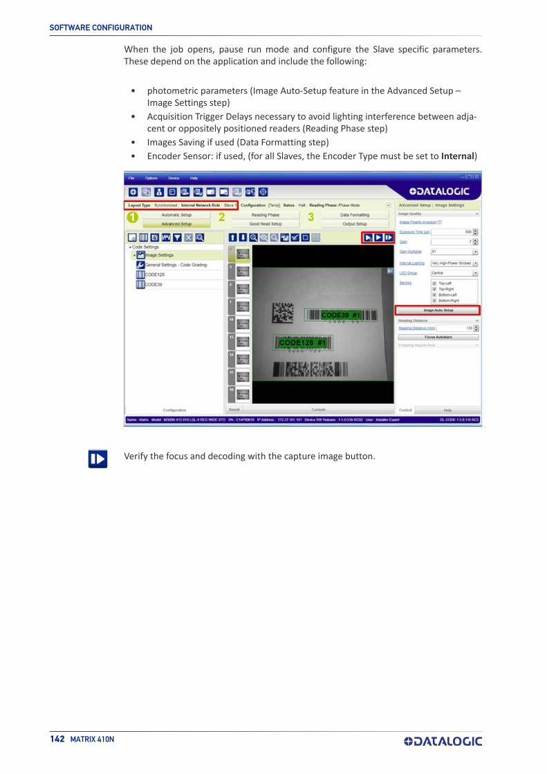
SOFTWARE CONFIGURATION
142 MATRIX 410N
When the job opens, pause run mode and configure the Slave specific parameters. These depend on the application and include the following:
• photometric parameters (Image Auto-Setup feature in the Advanced Setup – Image Settings step)
• Acquisition Trigger Delays necessary to avoid lighting interference between adja-cent or oppositely positioned readers (Reading Phase step)
• Images Saving if used (Data Formatting step)
• Encoder Sensor: if used, (for all Slaves, the Encoder Type must be set to Internal)
Verify the focus and decoding with the capture image button.

INTERNAL NETWORK CONFIGURATIONS
PRODUCT REFERENCE GUIDE 143
3. Now save them, overwriting the cloned application job1.
Figure 89 - Saving Synchronized Phase Mode Configuration to Slave
Repeat this procedure for each Slave device until the entire network is configured.
See "ID-NET Synchronized Network" on page 90 for an example.
1. An application job with the same name as the Master’s has been cloned to the Slaves. Each Slave can have its own Image Settings parameters saved in its own copy of the application job. Common parameters managed by the Master such as Operating Mode cannot be modified in the Slave jobs and are shown in dark gray.

SOFTWARE CONFIGURATION
144 MATRIX 410N
Verify Master/Slave Synchronized ConfigurationFrom the Master configuration, run the application and monitor the output data from the DL.CODE Console or a configured channel terminal.
If necessary, as a troubleshooting tip, you can temporarily apply the Reading Mask field in place of each Code Content field to verify if all devices are reading. To do this:
1. Connect to the Master device via Ethernet and from the Data Formatting step, change each Expected Code Field Type from Code Content to Reading Mask.
2. Run the application and monitor the output data from the DL.CODE Console or a configured channel terminal.

INTERNAL NETWORK CONFIGURATIONS
PRODUCT REFERENCE GUIDE 145
The Reading Mask shows which device reads which Expected Code. The mask is com-posed of a fixed 32-character string (0=No Read or 1=Read) representing the 32 possible readers in an ID-NET network. By default the Master is the last character in the string (Master on Right) but this can be changed. The Slaves are shown adjacent to the Master in order (1 to 31), by default from right to left.
Example: Master + Slave 1 = 00000000000000000000000000000011
The figure above shows that both the Master and Slave 1 are reading Code 128 while only the Master is reading Code 39.
3. After verifying correct functioning of the reading devices, return the Expected Code fields from Reading Mask to Code Content.
4. If you haven’t made any other changes you can exit without saving. Otherwise, save the Master device configuration overwriting its previous one, making sure to save without Clone Master Configuration on Slaves, otherwise the Slave configu-rations will be overwritten.

SOFTWARE CONFIGURATION
146 MATRIX 410N
To view the connected Slave configurations:
1. Click on the Internal Network View tab at the bottom of the screen.
2. Open the Master branch by clicking on the arrow to the left of the Master icon.
3. Select any slave. Wait for the configuration to load.
4. Click The Configuration tab at the bottom of the screen.
By selecting the various configuration steps above you can visualize the slave configura-tion.
NOTE
You can modify some Slave Synchronized parameters from this view but you cannot save them here.
To save changed slave parameters here, you must click on the Master and Save the configuration overwriting it, making sure to select Save on Slave Device but without Clone Master Configuration on Slaves, other-wise all the Slave configuration parameters will be overwritten by the Master configuration.

BACKUP AND RESTORE THROUGH DL.CODE
PRODUCT REFERENCE GUIDE 147
BACKUP AND RESTORE THROUGH DL.CODEDL.CODE allows Backup and Restore to be performed to/from the configuration PC via file or to an external storage device such as BM100/BM150.
DL.CODE provides complete backup and restore functions (Configuration and Environ-mental parameters) with the following difference:
For Single Readers or individual ID-NET Slaves:
• Backup and Restore functions provide parameter storage including all configura-tion jobs present on the reader.For Master Readers in ID-NET Master/Slave networks:
• Backup and Restore functions provide parameter storage of only the Startup Con-figuration for the Master and all Slaves present in the network.
Slave devices must always be configured with the same network baudrate as the Mas-ter device for correct functioning including performing Backup and Restore proce-dures.
When performing Backup and Restore to/from file, device firmware can be included.
Regardless of the reader network configuration, Backup to and Restore from external device is supported by DL.CODE for all reading devices when connected to:
• CBX + BM100
• QLM-Series Gateways
NOTE
CAUTION
For Master/Slave networks any other configurations (jobs) stored in the device memory will not be backed up. Therefore, all jobs other than the startup configuration will be overwritten (erased) upon a restore. It is strongly recommended to save all configurations to backup files.
Before executing a Backup to a BM100 backup module make sure the Write Protection switch is set to Unlocked.

SOFTWARE CONFIGURATION
148 MATRIX 410N
BackupTo perform a Backup:
1. From the DL.CODE Device menu, select either Single Reader Backup (to file on PC); or Backup to external storage device.
NOTE
You will be reminded that configuration in temporary memory will not be saved so you should save the configuration to the reader before performing Backup.
If you are performing a backup to a file you will be asked whether to include the firm-ware or not.
At the end of the backup, DL.CODE shows a message indicating successful completion.
For ID-NET network Backup, select the Backup current Internal Network configurations selection.

BACKUP AND RESTORE THROUGH DL.CODE
PRODUCT REFERENCE GUIDE 149
RestoreTo perform a Restore:
1. From the DL.CODE Device menu, select either Single Reader Restore (from file on PC); or Restore from external storage device.
NOTE
If restoring an ID-NET network though the Master, this may take a few minutes.
At the end of the restore, DL.CODE shows a message indicating successful completion.
Replacement
The Restore function also provides easy and secure Single Device Replacement:
1. Remove the device to be replaced.
2. Connect the new device (make sure the new device has been previously set to fac-tory default).
3. Run the Restore procedure by selecting either Single Reader Restore (from file on PC) or Restore from external storage device item (see: Restore procedure).
NOTE
For ID-NET network Restore, select the Internal Network replacement selection.
CAUTION
The replacement device must be the exact same model as the device it is replacing.
In case of Backup or Restore operation failures, error messages will be displayed in the Monitor Diagnostic page.

SOFTWARE CONFIGURATION
150 MATRIX 410N
RESTORE DEFAULTSThe device parameters are divided into two main classes, Configuration and Environ-ment which are affected differently by the Restore Defaults commands.
• The Configuration parameters are the ones set in the various steps of the configu-ration process and are specific to each application. When multiple configurations (jobs) are saved on a single device, these parameters can be different from one configuration to the next.
• Environment parameters regard the device Identity and Position in a Network (Ethernet, ID-NET, etc.) and are not influenced by the Default (or any other) Con-figuration present in memory.
Restore Default Startup ConfigurationThe Default configuration is always present on the reader and in fact it is not modifiable and cannot be deleted. It can always be restored by simply selecting it from the Open from Device configuration list.
The same action can be performed from the Device menu >Backup/Restore > Restore Defaults > Restore Default Startup Configuration. The Default Configuration will be set to run at startup and the reader will be reset.
Any previously saved configurations on the device will remain in memory, but the Default configuration is set as the startup configuration.

RESTORE DEFAULTS
PRODUCT REFERENCE GUIDE 151
Restore Default EnvironmentRestore Default Environment returns all Environment parameters to their factory default settings. The default IP address will be restored as well as all the parameters managed in the Device Environment Configuration window.
The Factory Default static IP address for all Matrix N Family readers is:
IP Address = 192.168.3.100
Any previously saved configurations on the device will remain in memory, but the Default configuration is set as the startup configuration.
Restore Factory DefaultsIn order to return a device to its absolute Factory default parameters (for example device replacement) it is necessary to use the Restore Factory Defaults command. You will be prompted to confirm.
All Environment parameters will be restored to Factory default values and any existing configurations stored on the device will be erased. The device will be reset and there-fore start in run mode with the factory default configuration.

SOFTWARE CONFIGURATION
152 MATRIX 410N
DIAGNOSTIC ALARMSBy using the DL.CODE Monitor functions from the File menu (or Monitor icon), you can get information about diagnostic alarms. Any alarms will show up as warning lights on the alarm panel.
Figure 90 - Diagnostic Alarms

STATISTICS
PRODUCT REFERENCE GUIDE 153
STATISTICSStatistics on the reading performance can be viewed by enabling the Statistics panel from the DL.CODE Monitor item selected from the File menu (or Monitor icon).
Figure 91 - Reading Statistics
The enabled Statistical Counters can be selected from the Device>Settings>Configura-tion Settings menu.

SOFTWARE CONFIGURATION
154 MATRIX 410N
BM150 DISPLAY MODULE CONFIGURATION AND MESSAGESThe BM150 display module is an optional accessory for the CBX500 connection box. Although independent, it is an extension of the reader's HMI Interface, so through its keypad it provides execution of HMI features such as Test, Focus/Locate, Calibration and Code Setting. It also displays device status information, reading results, diagnostic and network messages. Since it connects through the BM100 backup memory module, it provides access to Backup and Restore features through its Extended menu.
Configuration Through DL.CODEBM150 must be detected through the BM100 backup memory module at power-up/reset and this is done through a command setting in DL.CODE. By connecting the reader to DL.CODE the following parameters can be managed.
In the Device>Settings>Settings>Maintenance window:
• Enable BM100 DetectionChecked (Enabled): the BM100 backup memory module will be detected on power-up/reset; therefore the BM150 display module (if present), will also be enabled.Unchecked (Disabled): the BM100 backup memory module will not be detected on power-up/reset; therefore the BM150 display module (if present), will also notbe enabled.
• BM150 Display Layout (Master Only)Reading Mask Only: the Reading Mask screen is sent to the BM150 display.Reading Mask/Device State: the Reading Mask/Device State screen is sent to the BM150 display.

BM150 DISPLAY MODULE CONFIGURATION AND MESSAGES
PRODUCT REFERENCE GUIDE 155
Accessing the HMI Interface Through Keypad and Display MenuThrough its keypad and display, the BM150 provides a remote extension of the reader's HMI Interface. The HMI default menu items can be accessed as well as the View menu for Master devices and the Extended menu for Backup and Restore functions.
Up Enter Down
Figure 92 - BM150 Keypad
To enter the Main Menu press the Up and Down buttons simultaneously.
The menu structure is shown below.
Main Menu• [Exit] (exits HMI Interface menu)
• Test Mode (performs Test mode)
• Focus/Locate (performs Focus function: turns on LED pointers)
• Calibration (performs Setup function)
• Code Setting (performs Learn function)
• Match Code Tra... (Training: allows to read a code and store it as the Match code)
View Menu (Master Only)• [Exit] (returns to Main menu)
• Standard (displays the Standard Reading Results screen during run mode)
• Reading Mask (displays the Reading Mask or Reading Mask/Device State screen during run mode) depends on the selection in DL.CODE see par. Configuration Through DL.CODE.
• Network State (displays the Network State screen during run mode)
Extended Menu• [Exit] (returns to Main menu)
• Backup (performs Backup - uninterruptible)
• Restore (performs Restore - uninterruptible)
• Erase (erases the backup configuration in external memory - uninterruptible)
To move through the list press and release the Up or Down key.
To select an item or enter a submenu, press and release the Enter key. After executing an HMI function the display shows a result message and then automatically exits from the menu structure.
To exit a menu manually, press and release the Enter key at the [Exit] item or press the Up and Down buttons simultaneously.

SOFTWARE CONFIGURATION
156 MATRIX 410N
To exit from a running HMI function, press the Up and Down buttons simultaneously. These functions will also exit upon their configured timeout.
NOTE
NOTE
NOTE
When the HMI Interface is entered from either the Local Device (reader) or Remote Device (BM150), the key(s) on the other device are disabled.
When the reader is connected to DL.CODE, access to the BM150 HMI Interface is disabled.
The "Reset Reader to Factory Default Environment" function of the HMI Interface is only available on the local device (reader), and not on the BM150.

BM150 DISPLAY MODULE CONFIGURATION AND MESSAGES
PRODUCT REFERENCE GUIDE 157
Display MessagesThe following examples of Remote Display messages are given to help interpret the information reported. The content of these messages depends on the connected reader.
Welcome Message
M = scanner model
K = software – STD=Standard, SS =Special
V = software version
R = Device Network Type – MUL=Multidata, SYN=Synchronized, ALN=Alone
N = Device Network Setting – M00=ID-NET Network Master, Sxx= ID-NET Network Slave address, Null string= Alone (no network)
D = device serial number
A = Ethernet IP Address
Test Mode Results
A = reading percentage from 000 to 100%.
Z = code content.
Calibration (Setup) Results
X = exposure value (in s).
G = gain value
Code Setting (Learn) Results
X = recognized code symbology.

SOFTWARE CONFIGURATION
158 MATRIX 410N
Diagnostic AlarmsDiagnostic error messages are sent to the BM150 display as numeric Alarm Codes (even if Failure Messages are selected for data transmission the numeric Alarm Code is sent to the display).
X = numeric Alarm Code (see below for the list of Alarm Codes)
R = Device Network Type – MUL=Multidata, SYN=Synchronized, ALN=Alone
N = Device Network Setting – M00=ID-NET Network Master, Sxx= ID-NET Network Slave address, Null string= Alone (no network)
Alarm Code Description
1 Slave No Reply
64 Slave Address Duplication
171 Protocol Index Failure
185 Backup Memory Communication Failure
187 Wrong Rotary Switch Selection
189 Fieldbus Communication Failure
191 Fieldbus Type Mismatch
193 Fieldbus Configuration Error
195 Fieldbus DHCP Problem
201 No XRF Slave(s) Detected
Slave Node Alarms (Master only)
X = slave node number (1-31)
R = Device Network Type – MUL=Multidata, SYN=Synchronized
Network State (Master only)
M = Master diagnostic condition; S = Slave diagnostic condition:
* = scanner OK
- =scanner not detected at startup
? =scanner detected at startup but not responding to diagnostic polling
! = scanner diagnostic error

BM150 DISPLAY MODULE CONFIGURATION AND MESSAGES
PRODUCT REFERENCE GUIDE 159
Standard Reading Results
A = reading result – Good Read, Partial Read, Multiple Read
X = code content
Y = number of codes read
Reading Mask Only (Master Only)
X = code content (or "No Read" or "Multiple Read")
Y = Good Read, No Read, Multiple Read and Partial Read counters on the last 100 codes read (%)
S = Reading Mask for Stand Alone or Master plus Slave readers 1 - 15
(0 = No Read, 1 = Good Read, M = Multiple Read)
T = Reading Mask for Slave readers 16 - 31
(0 = No Read, 1 = Good Read, M = Multiple Read)
Reading Mask/Device State (Master Only)
X = Recognized code label data (or "No Read" or "Multiple Read")
Y = Phase Counter (range: 0000000 to 9999999)
Z = Good Read or Multiple Read counters (%)
S = Reading Mask for Stand Alone or Master plus Slave readers 1 - 15
(0 = No Read, 1 = Good Read, M = Multiple Read)
U = Diagnostic condition for Stand Alone or Master plus Slave readers 1 - 15:
* = reader OK
- = reader not detected at startup
? = reader detected at startup but not responding to diagnostic polling
! = reader diagnostic error
SOFTWARE CONFIGURATION
160 MATRIX 410N
BM150 Backup and Restore ProcedureThe Backup and Restore functions are valid for any application layout type (point-to-point, network, etc.) using CBX500 connection boxes through the BM100 Backup mod-ule (required accessory for BM150 installation).
The Backup and Restore functions are managed through the BM150 display and keypad and therefore are disabled at the BM100 Backup/Restore button.
If it ever becomes necessary to replace the reading device, it can be quickly configured through the restore procedure.
BM150 provides complete backup and restore functions (Configuration and Environ-mental parameters) with the following difference:
For Single Readers or individual ID-NET Slaves:
• Backup and Restore functions provide parameter storage including all configura-tion jobs present on the reader.
For Master Readers in ID-NET Master/Slave networks:
• Backup and Restore functions provide parameter storage of only the Startup Con-figuration for the Master and all Slaves present in the network.
The Slaves must always be configured with the same network baudrate as the Master for correct functioning including performing Backup and Restore procedures.
Backup and Restore functions cannot be interrupted once started.
To perform Backup
1. Make sure the Write Protection switch on the BM100 is unlocked.
2. Select the Backup item from the Extended menu and press the Enter key.
3. When the procedure is complete a message appears on the display showing the results (Backup OK 1 File Saved or an error message).
4. Set the Write Protection switch to locked.
To perform Restore
1. Select the Restore item from the Extended menu and press the Enter key.
2. When the procedure is complete a message appears on the display showing the results (Restore OK 1 File Restored or an error message).
CAUTION
For Master/Slave networks any other configurations (jobs) stored in the device memory will not be backed up. Therefore upon a restore, all jobs other than the startup configuration will be overwritten (erased). It is strongly recommended to save all configurations to backup files.

PRODUCT REFERENCE GUIDE 161
CHAPTER 8MAINTENANCE
CLEANINGClean the lens cover periodically for continued correct operation of the reader. See "General View" on page xiv.
Dust, dirt, etc. on the lens cover may alter the reading performance.
Repeat the operation frequently in particularly dirty environments.
Use soft material and alcohol to clean the lens cover and avoid any abrasive substances.

162 MATRIX 410N
CHAPTER 9TROUBLESHOOTING
GENERAL GUIDELINES• When wiring the device, pay careful attention to the signal name (acronym) on the
CBX100/500 spring clamp connectors (Chapter 4, CBX Electrical Connections). If you are connecting directly to the Matrix 410N M12 17-pin connector, pay attention to the pin number of the signals (Appendix A, ).
• If you need information about a certain reader parameter you can refer to the DL.CODE help on line. Connect the device and click on the link to the parameter you’re interested in.
• If you’re unable to fix the problem and you’re going to contact your local Datalogic office or Datalogic Partner or ARC, we suggest providing (if possible): Application Program version, Parameter Configuration file, Serial Number and Order Number of your reader. You can get most of this information while DL.CODE is connected to the reader.
Troubleshooting Guide
Problem Suggestion
DL.CODEInstallation:Autorun or Start.hta doesn’t run
Check Windows settings to see if Autorun is disabled.Associate the file type .hta with the Microsoft HTML Application host mshta.exe in Windows\System32.
Power ON:the “POWER” LED is not lit.
Is power connected?If using a power adapter (like PG6000), is it connected to wall outlet?If using rail power, does rail have power?If using CBX, does it have power (check switch and LED)?Check if you are referring to the M12 17-pin connector or to the CBX spring clamp connectors.Measure Voltage either at pin 1 and pin 2 (for 17-pin connector) or at spring clamp Vdc and GND (for CBX).

GENERAL GUIDELINES
PRODUCT REFERENCE GUIDE 163
One Shot or Phase Mode using the Input 1 (External Trigger) or Input 2:the ”TRIGGER” LED is not blinking while the External Trigger is switching.
Check if you are referring to the 17-pin connector or to the CBX spring clamp connectors.Is the sensor connected to Input 1 or Input 2?Is power supplied to the photo sensor?For NPN configuration, is power supplied to one of the two I1 or I2 signals (A or B)?For PNP configuration, is one of the two I1 or I2 signals grounded (A or B)?Are the photo sensor LEDS (if any) working correctly?Is the sensor/reflector system aligned (if present)?On the Reading Phase step check the Input 1 or Input 2 Deboun-cing Time parameter setting.On the Reading Phase step check the settings for Acquisition Trigger, Reading Phase-ON, and Reading Phase-OFF parame-ters.
One Shot or Phase Mode using serial trigger source:the ”TRIGGER” LED is not blinking.
On the Reading Phase step check the settings for Acquisition Trigger, Reading Phase-ON, and Reading Phase-OFF parame-ters.Are the COM port parameters (Baud Rate, Parity, Data Bits, Stop Bits) correctly assigned?On the Reading Phase step check the settings of Acquisition Trigger String, Reading Phase-ON String, and Reading Phase-OFF String parameters.Is the serial trigger source correctly connected?
Phase Mode:the ”TRIGGER” LED is correctly blinking but no image is displayed in the DL.CODE win-dow.
Is the Phase frequency lower than the maximum frame rate?
Continuous Mode:the ”TRIGGER” LED is not blinking.
Verify the correct software configuration settings.
Any Operating Mode:the ”TRIGGER” LED is correctly blinking but no result is transmit-ted by the reader at the end of the reading phase collection.
Check the Code Collection parameters on the Reading Phase step and the Data Formatting parameters on the Data Format-ting step.
Image not clear: verify the Focus procedure
Image focused but not decoded: verify the Calibrate Image Density procedure.
Troubleshooting Guide
Problem Suggestion

TROUBLESHOOTING
164 MATRIX 410N
Reading:the reader always transmits the No Read Message
Run the Rapid Configuration procedure in Chapter 1, Rapid Con-figuration.Position the reader as described in "Mounting And Positioning Matrix 410N" on page 58 and through DL.CODE:Tune the Acquisition Delay on Trigger, if the moving code is out of the reader field of view;Set the Continuous Operating Mode if no external trigger source is available;Tune the Image Settings to improve the code image quality;Check the parameter settings in the Advanced Setup step: 2D Codes, 1D Codes, and Postal Codes;View the full resolution code image to check the printing or marking quality.
Communication:reader is not trans-mitting anything to the host.
Is the serial cable wiring correct?If using CBX, be sure the RS422 termination switch is OFF.Are the host serial port settings the same as the reader serial port settings?In DL.CODE Device menu > Settings > Settings > LED Configu-ration, the COM LED Function can be configured to indicate Main Serial Port TX or Main Serial Port RX.
Communication:data transferred to the host are incorrect, corrupted or incom-plete.
Are the host serial port settings the same as the reader serial port settings?In the DL.CODE Data Formatting step check the settings of Header and Terminator String parameters.In the DL.CODE Data Formatting step, check the various Mes-sage Field parameter settings.
Configuration:cannot access envi-ronment parameters in DL.CODE (Device>Settings>Set-tings menu item is gray)
Are you using the Installer - Expert User level? If not change it in the Options>Change User menu.
How do I obtain my reader Serial Num-ber?
The reader Serial Number consists of 9 characters: one letter, 2 numbers, another letter followed by 5 numbers.The reader Serial Number is printed on a label that is affixed to the case or connector block of the reader.The Serial Number is also visible from the DL.CODE Device List Area.
How do I obtain my reader Order Num-ber?
The reader Order Number consists of 9 numbers.The reader Order Number can be obtained by comparing the Device Model (in DL.CODE Device Menu > Settings > Settings > About Device) with the product models page on the Datalogic website.
Troubleshooting Guide
Problem Suggestion

Power Standard Models
Supply Voltage 10 to 30 VdcConsumption(including accessory internal illuminator)
0.8 - 0.27 A, 8 W max.;0.5 to 0.17 A, 5 W typical
Communication Interfaces
Main: RS232, RS422 Full-duplex 2400 to 115200 bit/sAuxiliary: RS232 2400 to 115200 bit/s
ID-NET Up to 1 Mbaud
Ethernet (Built-in)supported application protocols
10/100 Mbit/sTCP/IP, UDP, FTP, EtherNet/IP, Modbus TCP,
PROFINET-IO
InputsInput 1(External Trigger) and Input 2 Opto-isolated and polarity insensitive
Max. Voltage 30 VdcMax. Input Current 10 mA
Outputs a
a. when connected to the CBX connection boxes the electrical features for Output 1 and 2 become the following:Opto-isolated; VCE = 30 Vdc max.; ICE = 40 mA continuous max.; 130 mA pulsed max.;VCE saturation = 1 Vdc max. @ 10 mA; PD = 90 mW Max. @ 50 °C ambient temp.
Output 1, 2 and 3 NPN or PNP short circuit protected;
VOUT (ILOAD = 0 mA) Max. 30 Vdc
VOUT (ILOAD = 100 mA) Max. 3 Vdc
ILOAD Max. 100 mA
PRODUCT REFERENCE GUIDE 165
APPENDIX ATECHNICAL FEATURES
ELECTRICAL FEATURES

5xx-0x0 7xx-0x0
Image Sensor CMOS CMOS
Image Format 1.3 Mpixel 2.0 Mpixel
Frame Rate 60 frames/s 43 frames/s
Pitch ± 35°
Tilt 0° - 360°
LED Safety to EN 62471
Lenses LNS (accessories)
Lighting System Internal or External Illuminator (accessories)
Operating Temperature a
a. high ambient temperature applications should use metal mounting bracket for heat dissipa-tion.
0 to 50 C (32 to 122 °F)
Storage Temperature -20 to 70 C (-4 to 158 °F)
Max. Humidity 90% non condensing
Vibration ResistanceEN 60068-2-6
14 mm @ 2 to 10 Hz; 1.5 mm @ 13 to 55 Hz;2 g @ 70 to 500 Hz; 2 hours on each axis
Bump ResistanceEN 60068-2-29
30g; 6 ms;5000 shocks on each axis
Shock ResistanceEN 60068-2-27
30g; 11 ms;3 shocks on each axis
Protection Class b
b. when correctly connected to IP67 cables with seals and the Lens Cover is correctly mounted.
EN 60529IP65 and IP67
Dimensions(with lens cover)
H x W x L125 x 65 x 87 mm (4.9 x 2.6 x 3.4 in)
Weight(with lens and internal illuminator)
482 g (17 oz)
Material Aluminum
TECHNICAL FEATURES
166 MATRIX 410N
OPTICAL FEATURES
ENVIRONMENTAL FEATURES
PHYSICAL FEATURES

Readable Code Symbologies
1D and Stacked 2Da
a. VeriCode® licenced models available.
Postal
PDF417 Standard and Micro PDF417Code 128 (GS1-128)Code 39 (Standard and Full ASCII)Code 32MSIStandard 2 of 5Matrix 2 of 5Interleaved 2 of 5CodabarCode 93PharmacodeEAN-8/13 - UPC-A/E(including Addon 2 and Addon 5)GS1 DataBar FamilyComposite Symbologies
Data Matrix ECC 200(Standard, GS1 and Direct Marking)QR Code (Standard and Direct Marking)Micro QR CodeMAXICODEAztec Code
Australia PostRoyal Mail 4 State CustomerKix CodeJapan PostPLANETPOSTNETPOSTNET (+BB)Intelligent MailSwedish Post
Operating Mode Continuous, One Shot, Phase Mode, PackTrack
Configuration MethodsX-PRESS Human Machine InterfaceWindows-based SW (DL.CODE) via Ethernet linkSerial Host Mode Programming sequences
Parameter Storage Permanent memory (Flash)
Standard Supported Symbologies
ISO/IEC 16022 (always enabled) Data Matrix ECC 200ISO/IEC 18004 (always enabled) QR CodeAIM DPM Data Matrix ECC 200, QR Code
ISO/IEC 15416 Code 128, Code 39, Interleaved 2 of 5, Codabar, Code 93, EAN-8-13, UPC-A/E
LED IndicatorsPower, Ready, Good; Trigger; Com, Status, (Ethernet Network); Good Read (Green Spot)
Keypad Button Configurable via DL.CODE
PRODUCT REFERENCE GUIDE 167
SOFTWARE FEATURES
CODE QUALITY METRICS
USER INTERFACE

168 MATRIX 410N
APPENDIX BALTERNATIVE CONNECTIONS
The connector pinouts and notes given in this appendix are for custom cabling applica-tions.
POWER, COM AND I/O CONNECTOR FOR STANDARD MODELSThe Matrix 410N reader is equipped with an M12 17-pin male connector for connection to the power supply, serial interfaces, and input/output signals. The details of the con-nector pins are indicated in the following table:
Figure 1 - M12 17-pin male Power, COM and I/O Connector
POWER, COM AND I/O CONNECTOR PINOUTPIN NAME DESCRIPTION
1 Vdc Power supply input voltage +2 GND Power supply input voltage -
Connector case CHASSIS Connector case provides electrical connection to the chassis
6 I1A External Trigger A (polarity insensitive)5 I1B External Trigger B (polarity insensitive)
13 I2A Input 2 A (polarity insensitive)3 I2B Input 2 B (polarity insensitive)9 O1 Output 1 (NPN or PNP short cir-
cuit protected and soft-ware programmable)
8 O2 Output 216 O3 Output 314 RX Auxiliary RS232 RX4 TX Auxiliary RS232 TX7 ID+ ID-NET network data +
15 ID- ID-NET network data -
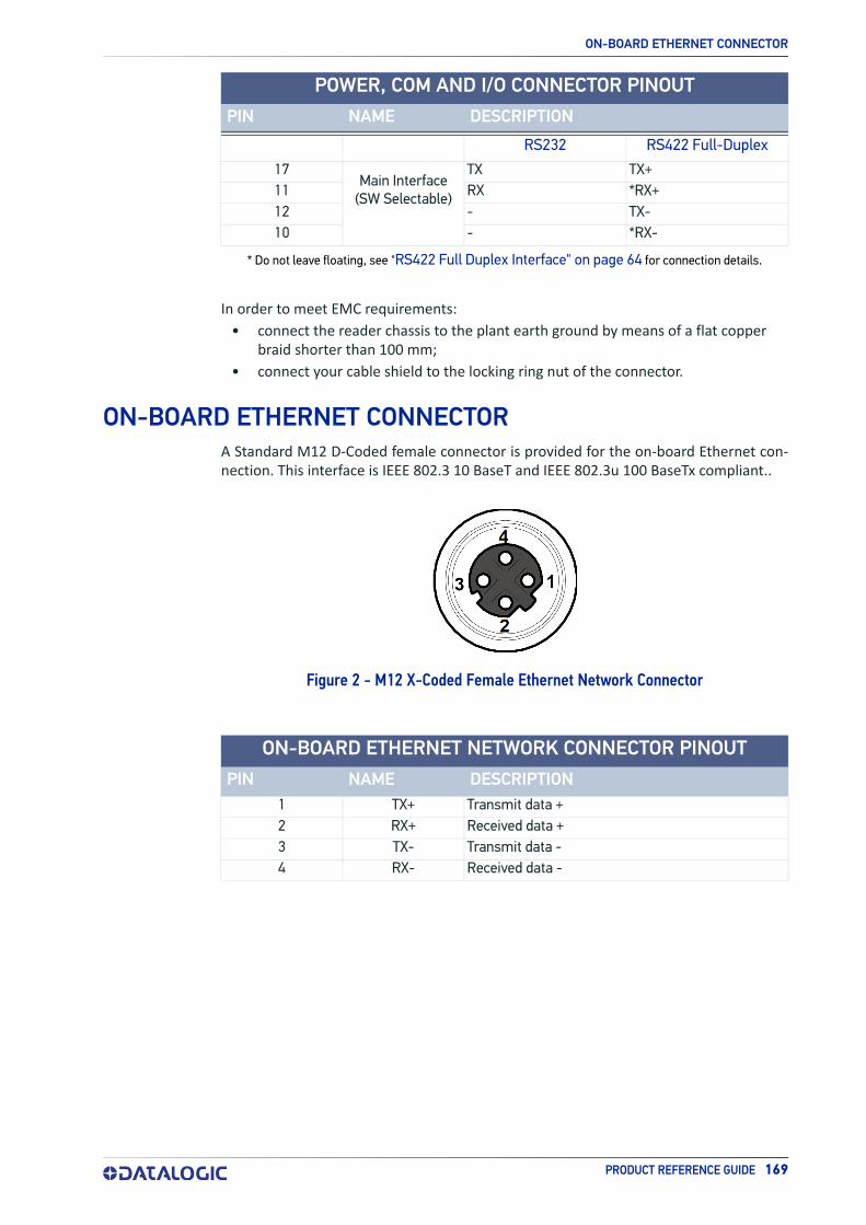
ON-BOARD ETHERNET CONNECTOR
PRODUCT REFERENCE GUIDE 169
* Do not leave floating, see "RS422 Full Duplex Interface" on page 64 for connection details.
In order to meet EMC requirements:
• connect the reader chassis to the plant earth ground by means of a flat copper braid shorter than 100 mm;
• connect your cable shield to the locking ring nut of the connector.
ON-BOARD ETHERNET CONNECTORA Standard M12 D-Coded female connector is provided for the on-board Ethernet con-nection. This interface is IEEE 802.3 10 BaseT and IEEE 802.3u 100 BaseTx compliant..
Figure 2 - M12 X-Coded Female Ethernet Network Connector
1 TX+ Transmit data +2 RX+ Received data +3 TX- Transmit data -4 RX- Received data -
RS232 RS422 Full-Duplex
17Main Interface
(SW Selectable)
TX TX+11 RX *RX+12 - TX-10 - *RX-
POWER, COM AND I/O CONNECTOR PINOUTPIN NAME DESCRIPTION
ON-BOARD ETHERNET NETWORK CONNECTOR PINOUTPIN NAME DESCRIPTION

ALTERNATIVE CONNECTIONS
170 MATRIX 410N
VHP ILLUMINATOR POWER CONNECTORMatrix 410N x5x-xxx and x6x-xxx models require 24 Vdc. Power must be supplied to both the reader (17-pin connector) and the Very High Power internal illuminator (M12 5-pin male connector). The details of the VHP connector pins are indicated in the fol-lowing table:
Figure 3 - M12 X-Coded Female Ethernet Network Connector
1 Vdc Power supply input voltage +2 Reserved3 GND Power supply input voltage -4 Reserved5 Reserved
ID-NET NETWORK TERMINATIONThe network must be properly terminated by a 120 Ohm resistor at the first and last reader of the network.
VHP ILLUMINATOR POWER CONNECTOR PINOUTPIN NAME DESCRIPTION

INPUTS
PRODUCT REFERENCE GUIDE 171
INPUTSThere are two optocoupled polarity insensitive inputs available on the M12 17-pin con-nector of the reader: Input 1 (External Trigger) and Input 2, a generic input. See "Inputs" on page 71 for more details.
The electrical features of both inputs are:
Open 0 V 2 V 0 mAClosed 4.5 V 30 V 10 mA
The relative pins on the M12 17-pin connector are:
1 Vdc Power Supply input voltage +6 I1A External Trigger A (polarity insensitive)5 I1B External Trigger B (polarity insensitive)
13 I2A Input 2 A (polarity insensitive)3 I2B Input 2 B (polarity insensitive)2 GND Power Supply input voltage -
OUTPUTSThree general purpose non opto-isolated but short circuit protected outputs are avail-able on the M12 17-pin connector.
The pinout is the following:
9 O1 Configurable digital output 18 O2 Configurable digital output 2
16 O3 Configurable digital output 32 GND Ouptut reference signal
The electrical features of the three outputs are the following:
Reverse-Polarity and Short-Circuit Protected
VOUT (ILOAD = 0 mA) max = 30 Vdc
VOUT (ILOAD = 100 mA) max = 3 Vdc
ILOAD max = 100 mA
The output signals are fully programmable being determined by the configured Activa-tion/Deactivation events, Deactivation Timeout or a combination of the two. For further details refer to the Help On Line page for the Output Setup step in DL.CODE.
INPUT | V AB | MIN. | V AB | MAX. I IN MAX.
INPUT PINOUTPIN NAME DESCRIPTION
OUTPUT PINOUTPIN NAME DESCRIPTION

ALTERNATIVE CONNECTIONS
172 MATRIX 410N
Figure 4 - PNP Output Connection
Figure 5 - NPN Output Connection
Figure 6 - Push-Pull Output Connection
CAUTION
For NPN output connections, the external interface voltage (Vext) must not exceed the Matrix 410N power supply source voltage (Vdc) other-wise correct output functioning cannot be guaranteed.

USER INTERFACE - SERIAL HOST
PRODUCT REFERENCE GUIDE 173
USER INTERFACE - SERIAL HOST
9-pin male connector 25-pin male connector
Pin Name Pin Name2 RX 3 RX3 TX 2 TX5 GND 7 GND
How To Build A Simple Interface Test CableThe following wiring diagram shows a simple test cable including power, external (push-button) trigger and PC RS232 COM port connections.
Figure 7 - Test Cable
RS232 PC-SIDE CONNECTIONS

174 MATRIX 410N
GLOSSARY
AIM(Association for Automatic Identification and Mobility): AIM Global is the international trade association representing automatic identification and mobility technology solu-tion providers.
AIM DPM Quality GuidelineStandard applicable to the symbol quality assessment of direct part marking (DPM) per-formed in using two-dimensional bar code symbols. It defines modifications to the mea-surement and grading of several symbol quality parameters.
Barcodes (1D Codes)A pattern of variable-width bars and spaces which represents numeric or alphanumeric data in machine-readable form. The general format of a barcode symbol consists of a leading margin, start character, data or message character, check character (if any), stop character, and trailing margin. Within this framework, each recognizable symbology uses its own unique format.
BIOSBasic Input Output System. A collection of ROM-based code with a standard API used to interface with standard PC hardware.
BitBinary digit. One bit is the basic unit of binary information. Generally, eight consecutive bits compose one byte of data. The pattern of 0 and 1 values within the byte determines its meaning.
Bits per Second (bps)Number of bits transmitted or received per second.
Bright Field IlluminationLighting of surfaces at high (narrow) angles used to provide maximum reflection of the light to the reader’s lens. This is effective on surfaces that absorb light or are not highly reflective and also on low contrast codes.
ByteOn an addressable boundary, eight adjacent binary digits (0 and 1) combined in a pat-tern to represent a specific character or numeric value. Bits are numbered from the right, 0 through 7, with bit 0 the low-order bit. One byte in memory can be used to store one ASCII character.
Composite SymbologiesConsist of a linear component, which encodes the item's primary data, and an adjacent 2D composite component, which encodes supplementary data to the linear component.

PRODUCT REFERENCE GUIDE 175
Dark Field IlluminationLighting of surfaces at wide angles used to avoid direct reflection of the light into the reader’s lens. Typically this type of lighting is used in DPM solutions to enhance reflec-tance of the uneven surface do to the symbol marking technique. It is also used with very reflective surfaces.
DecodeTo recognize a barcode symbology (e.g., Codabar, Code 128, Code 3 of 9, UPC/EAN, etc.) and analyze the content of the barcode scanned.
Depth of FieldThe difference between the minimum and the maximum distance of the object in the field of view that appears to be in focus.
Diffused IlluminationDistributed soft lighting from a wide variety of angles used to eliminate shadows and direct reflection effects from highly reflective surfaces.
Direct Part Mark (DPM)A symbol marked on an object using specific techniques like dot peening, laser etching, chemical etching, etc.
EEPROMElectrically Erasable Programmable Read-Only Memory. An on-board non-volatile mem-ory chip.
ElementThe basic unit of data encoding in a 1D or 2D symbol. A single bar, space, cell, dot.
Exposure TimeFor digital cameras based on image sensors equipped with an electronic shutter, it defines the time during which the image will be exposed to the sensor to be acquired.
FlashNon-volatile memory for storing application and configuration files.
HostA computer that serves other terminals in a network, providing services such as net-work control, database access, special programs, supervisory programs, or program-ming languages.
Image ProcessingAny form of information processing for which the input is an image and the output is for instance a set of features of the image.
Image ResolutionThe number of rows and columns of pixels in an image. The total number of pixels of an image sensor.
Image SensorDevice converting a visual image to an electric signal. It is usually an array of CCD (Charge Coupled Devices) or CMOS (Complementary Metal Oxide Semiconductor) pixel sensors.

GLOSSARY
176 MATRIX 410N
IEC(International Electrotechnical Commission): Global organization that publishes interna-tional standards for electrical, electronic, and other technologies.
IP AddressThe terminal’s network address. Networks use IP addresses to determine where to send data that is being transmitted over a network. An IP address is a 32-bit number referred to as a series of 8-bit numbers in decimal dot notation (e.g., 130.24.34.03). The highest 8-bit number you can use is 254.
ISO(International Organization for Standardization): A network of the national standards institutes of several countries producing world-wide industrial and commercial stan-dards.
LED (Light Emitting Diode)A low power electronic light source commonly used as an indicator light. It uses less power than an incandescent light bulb but more than a Liquid Crystal Display (LCD).
LED IlluminatorLED technology used as an extended lighting source in which extra optics added to the chip allow it to emit a complex radiated light pattern.
Matrix Symbologies (2D Codes)An arrangement of regular polygon shaped cells where the center-to-center distance of adjacent elements is uniform. Matrix symbols may include recognition patterns which do not follow the same rules as the other elements within the symbol.
Multi-row (or Stacked) SymbologiesSymbologies where a long symbol is broken into sections and stacked one upon another similar to sentences in a paragraph.
RAMRandom Access Memory. Data in RAM can be accessed in random order, and quickly written and read.
Symbol VerificationThe act of processing a code to determine whether or not it meets specific require-ments.
Transmission Control Protocol/Internet Protocol (TCP/IP)A suite of standard network protocols that were originally used in UNIX environments but are now used in many others. The TCP governs sequenced data; the IP governs packet forwarding. TCP/IP is the primary protocol that defines the Internet.


Datalogic S.r.l.Via S. Vitalino, 13 | 40012 Calderara di Reno | Bologna - ItalyTel. +39 051 3147011 | Fax +39 051 3147205
© 2015-2020 Datalogic S.p.A. and /or its affiliates • All rights reserved • Without limiting the rights under copyright, no part of this documentation may be repro-duced, stored in or introduced into a retrieval system, or transmitted in any form or by any means, or for any purpose, without the express written permission of Data-logic S.p.A. and/or its affiliates • Datalogic and the Datalogic logo are registered trademarks of Datalogic S.p.A. in many countries, including the U.S. and the E.U.
www.datalogic.com
821006620 (Rev A) February 2020