Matlab Simulation And Comparison Of Single Phase To Three Phase Converter Fed Induction Motor Drive...
11
International OPEN ACCESS Journal Of Modern Engineering Research (IJMER) | IJMER | ISSN: 2249–6645 | www.ijmer.com | Vol. 4 | Iss. 5| May. 2014 | 43 | Matlab Simulation And Comparison Of Single Phase To Three Phase Converter Fed Induction Motor Drive Using One And Two Rectifier Ashish Dongre 1 , Sanjay Dhamse 2 1, 2 (Electrical Engineering Department, Government College of Engineering Aurangabad, India) I. INTRODUCTION In many villages only single phase supply is available. Farming, residential appliances require motors of different type for various operations such as pumping, grinding, material movement etc. Motors used in such operations may be rated in kilo watt power range and single phase motor is not suitable for such higher power ratings. Further three phase motors have many advantages over single phase motors in terms of machine efficiency, power factor, and torque ripples. The idea of operating a three phase motors from single phase supply is not new [1]-[3]. Conventionally a three phase induction motor drive consists of a front end full bridge controlled rectifier, dc link capacitor and an inverter as shown in figure 1. It consists of maximum ten switches. This type of configuration requires higher power rating switches in rectifier compared to inverter side [4]. Whereas a parallel connected system consists of a parallel connected full bridge front end controlled rectifier, dc link capacitor bank and a regular six-switch pulse width modulated (PWM) inverter to power a three-phase induction motor from a single-phase ac mains. The block diagram of parallel rectifier system is shown in figure 2. This parallel connected rectifier configuration in all consists of 14 switches. Due to parallel connection the power rating of the rectifier switches is reduced. There has been a considerable increase in the use of parallel converters to improve the power capability, reliability, efficiency, redundancy, and to decrease the cost. Figure 1: Conventional single phase to three phase induction motor drive New regulations impose more strict limits on current harmonics injected by power converters [5]. These limits can be achieved with the help of pulse width-modulated rectifiers. These PWM converters, consists of power switches like insulated gate bipolar transistors (IGBTs), gate-turn-off thyristors (GTOs), or integrated gate Abstract: This paper presents MATLAB simulation and comparison of three phase induction motor drive supplied from single phase supply with one rectifier and two rectifiers systems. To meet the new harmonic regulation produced by converters both system incorporates an active input current shaping feature that results in sinusoidal input current at close to unity power factor. Even with the increase in the number of switches, the total harmonic distortion in supply current of the parallel connected two rectifier system is lower than that of a conventional one. The model of the system is developed in MATLAB software. All simulation results and comparison are presented as well. Keywords: AC to DC to AC converter, high power factor converters, parallel converter, Vector control.
-
Upload
independent -
Category
Documents
-
view
4 -
download
0
Transcript of Matlab Simulation And Comparison Of Single Phase To Three Phase Converter Fed Induction Motor Drive...
International
OPEN ACCESS Journal
Of Modern Engineering Research (IJMER)
| IJMER | ISSN: 2249–6645 | www.ijmer.com | Vol. 4 | Iss. 5| May. 2014 | 43 |
Matlab Simulation And Comparison Of Single Phase To Three
Phase Converter Fed Induction Motor Drive Using One And Two
Rectifier
Ashish Dongre1, Sanjay Dhamse2 1, 2 (Electrical Engineering Department, Government College of Engineering Aurangabad, India)
I. INTRODUCTION In many villages only single phase supply is available. Farming, residential appliances require motors
of different type for various operations such as pumping, grinding, material movement etc. Motors used in
such operations may be rated in kilo watt power range and single phase motor is not suitable for such higher
power ratings. Further three phase motors have many advantages over single phase motors in terms of machine
efficiency, power factor, and torque ripples. The idea of operating a three phase motors from single phase
supply is not new [1]-[3].
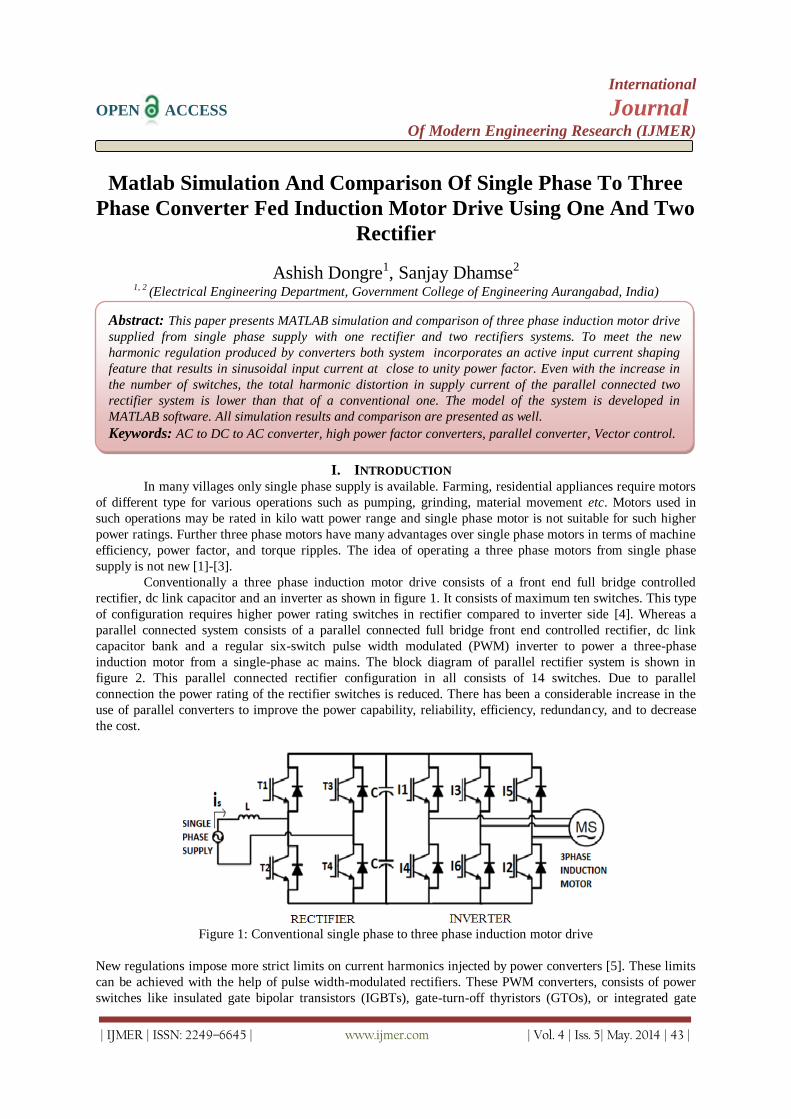
Conventionally a three phase induction motor drive consists of a front end full bridge controlled
rectifier, dc link capacitor and an inverter as shown in figure 1. It consists of maximum ten switches. This type
of configuration requires higher power rating switches in rectifier compared to inverter side [4]. Whereas a
parallel connected system consists of a parallel connected full bridge front end controlled rectifier, dc link
capacitor bank and a regular six-switch pulse width modulated (PWM) inverter to power a three-phase
induction motor from a single-phase ac mains. The block diagram of parallel rectifier system is shown in
figure 2. This parallel connected rectifier configuration in all consists of 14 switches. Due to parallel
connection the power rating of the rectifier switches is reduced. There has been a considerable increase in the
use of parallel converters to improve the power capability, reliability, efficiency, redundancy, and to decrease
the cost.
Figure 1: Conventional single phase to three phase induction motor drive
New regulations impose more strict limits on current harmonics injected by power converters [5]. These limits
can be achieved with the help of pulse width-modulated rectifiers. These PWM converters, consists of power
switches like insulated gate bipolar transistors (IGBTs), gate-turn-off thyristors (GTOs), or integrated gate
Abstract: This paper presents MATLAB simulation and comparison of three phase induction motor drive
supplied from single phase supply with one rectifier and two rectifiers systems. To meet the new
harmonic regulation produced by converters both system incorporates an active input current shaping
feature that results in sinusoidal input current at close to unity power factor. Even with the increase in
the number of switches, the total harmonic distortion in supply current of the parallel connected two
rectifier system is lower than that of a conventional one. The model of the system is developed in
MATLAB software. All simulation results and comparison are presented as well.
Keywords: AC to DC to AC converter, high power factor converters, parallel converter, Vector control.

Matlab Simulation And Comparison Of Single Phase To Three Phase Converter Fed Induction
| IJMER | ISSN: 2249–6645 | www.ijmer.com | Vol. 4 | Iss. 5| May. 2014 | 44 |
controlled thyristors (IGCTs) in the power circuit of the rectifier to change actively the waveform of the input
current, reducing the distortion [6]-[7].
Figure 2: Parallel rectifier connected single phase to three phase induction motor drive
II. Two Rectifier System The two rectifier system as shown in figure 2 (control circuit for rectifier and inverter is not shown)
consist of parallel connected front end rectifier supplied from single phase supply, input inductors, dc link
capacitor bank and an inverter whose control signals are generated from vector control method which is
discussed later in this paper. Upper rectifier is made up of switches T1, T2, T3 and T4 and lower rectifier is
made up of switches T5, T6, T7 and T8. These two rectifiers are connected in parallel. The three phase inverter
is composed of three legs having switches I1, I2, I3, I4, I5, and I6. The dc link capacitor banks which are
connected between rectifiers and inverter helps in removing the ripple content of rectifier output. All switches
are IGBT switches. Three phase induction motor is supplied from the three phase inverter output. Considering
all the supply inductor equal the equations of the parallel connected configuration can be given as
Supply current (2.1)
Output voltage (2.2)
Rectifier A voltage (2.3)
Rectifier B Voltage (2.4)
Where & r & l represents resistance and inductance of the inductor
III. Rectifier Circuit Working Principle and MATLAB Implementation.
3.1. Working Principle of PWM rectifier To understand the working, consider the conventional circuit of fully controlled single phase PWM
rectifier as shown in figure 3 below. It consists of four controlled power switches with anti-parallel diode. For
the proper working of this rectifier the output voltage must be greater than input voltage any time
[7].This rectifier can work in two or three levels. The possible combination is as follows.
1. T1=T4=ON
T2=T3=OFF Fig3.2(a)
2. T1=T4=OFF
T2=T3=ON
Fig3.2(b)
3. T1=T3=ON
T2=T4=OFF Fig 3.2(c)
And the voltage across inductor can be given as

Matlab Simulation And Comparison Of Single Phase To Three Phase Converter Fed Induction
| IJMER | ISSN: 2249–6645 | www.ijmer.com | Vol. 4 | Iss. 5| May. 2014 | 45 |
(3.1)
(3.2)
Where K= 1, - 1 or 0.
If k=1 then the inductor voltage will be negative, so the input current will decrease its value.
If K=-1 then the inductor voltage will be positive, so the input current will increase its value.
If K=0 the input current increase or decrease its value depending on . This allows for a complete control of
the input current [7].
Figure 3.1: Single-phase PWM rectifier power circuit
Figure 3.2: Single-phase PWM rectifier power circuit
a) T1=T4=ON b) T1=T4=OFF c) T1=T3=ON
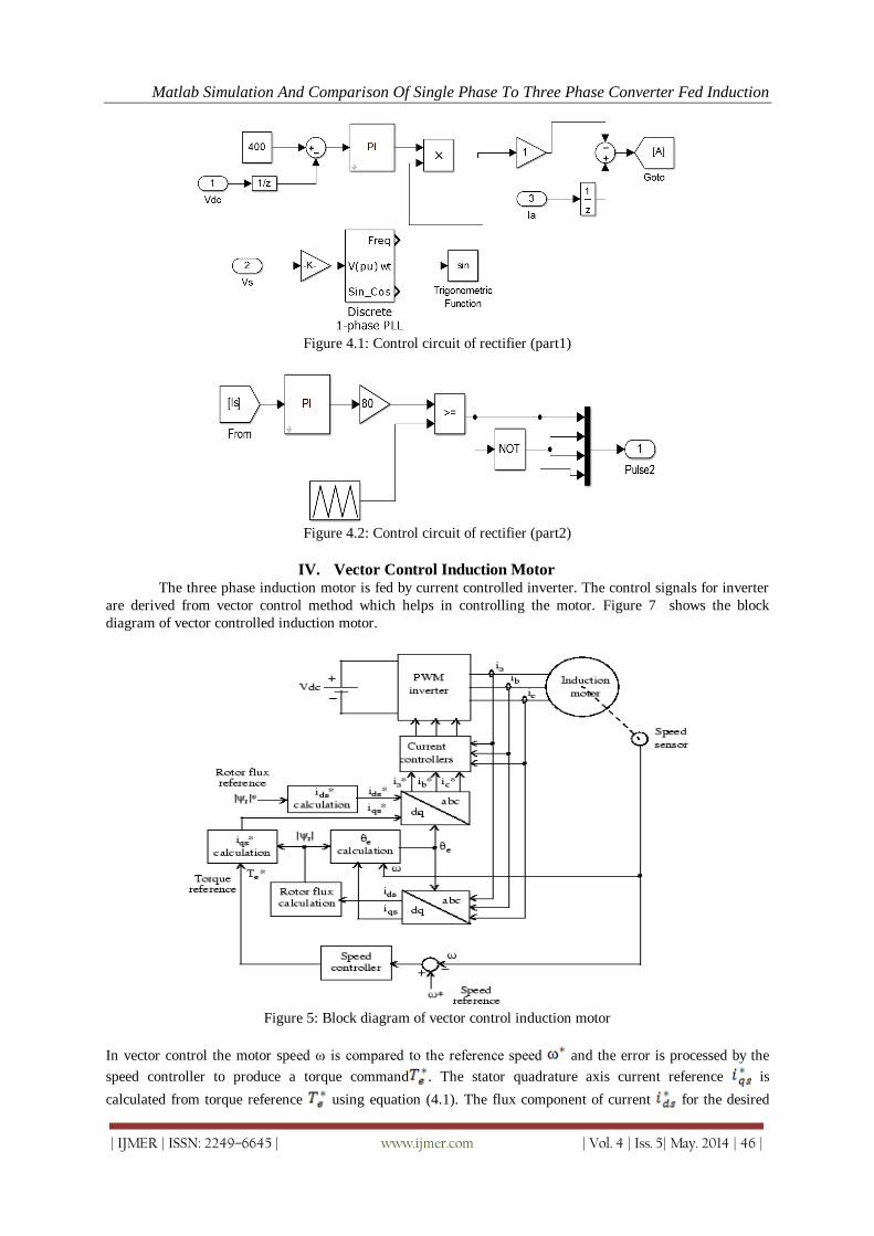
3.2. Control Scheme in MATLAB The main objective of PWM rectifier is to maintain dc link voltage constant and to maintain input
power factor close to unity. The dc-link voltage is adjusted to its reference value using the standard PI
controller. This controller provides the amplitude of the reference supply current as shown in figure 4.1. To
control the power factor and harmonics in the supply side, the instantaneous reference current is
synchronized with voltage , as given in the voltage-oriented control (VOC) for three-phase system [8]-
[9].This synchronization is obtained by a phased locked loop (PLL) scheme in MATLAB. The reference
currents is again given to the controller which defines the input reference voltages and then it is
compared with the triangular wave to obtain the gating signals for rectifier as shown in figure 4.2. This
scheme can be further extended to two rectifiers system. The only thing which needs to be done in two rectifier
system is to divide grid current equally to obtain pulses for both the rectifiers.
Matlab Simulation And Comparison Of Single Phase To Three Phase Converter Fed Induction
| IJMER | ISSN: 2249–6645 | www.ijmer.com | Vol. 4 | Iss. 5| May. 2014 | 46 |
Figure 4.1: Control circuit of rectifier (part1)
Figure 4.2: Control circuit of rectifier (part2)
IV. Vector Control Induction Motor The three phase induction motor is fed by current controlled inverter. The control signals for inverter
are derived from vector control method which helps in controlling the motor. Figure 7 shows the block
diagram of vector controlled induction motor.
Figure 5: Block diagram of vector control induction motor
In vector control the motor speed ω is compared to the reference speed and the error is processed by the
speed controller to produce a torque command . The stator quadrature axis current reference is
calculated from torque reference using equation (4.1). The flux component of current for the desired

Matlab Simulation And Comparison Of Single Phase To Three Phase Converter Fed Induction
| IJMER | ISSN: 2249–6645 | www.ijmer.com | Vol. 4 | Iss. 5| May. 2014 | 47 |
rotor flux is calculated from equation (4.4). The rotor flux position required for coordinates transformation
is generated by integrating the rotor speed and slip frequency given by equation (4.5). The reference
quadrature axis and direct axis current are converted into three reference currents , for the
current regulators by two phase to three phase transformation [10]. The regulators process the measured actual
and reference currents to produce the inverter gating signals.
Where
And
Rotor time constant is given by
The slip frequency can be calculated by
Figure 6 shows the block diagram of vector control method implementation in MATLAB. Internal structure of
each block of vector control is shown in figure 7.
Figure 6: Block diagram of vector control in MATLAB

Matlab Simulation And Comparison Of Single Phase To Three Phase Converter Fed Induction
| IJMER | ISSN: 2249–6645 | www.ijmer.com | Vol. 4 | Iss. 5| May. 2014 | 48 |
Figure 7.1: Calculation
Figure 7.2: Theta or ϴe Calculation
.
Figure 7.3: Three phase to two phase
Transformation
Figure 7.4: Calculation
Figure 7.5: or Phir Estimation
Figure 7.6: Two phase to three phase
transformation
Figure 7.7: Hysteresis current controller
Matlab Simulation And Comparison Of Single Phase To Three Phase Converter Fed Induction
| IJMER | ISSN: 2249–6645 | www.ijmer.com | Vol. 4 | Iss. 5| May. 2014 | 49 |
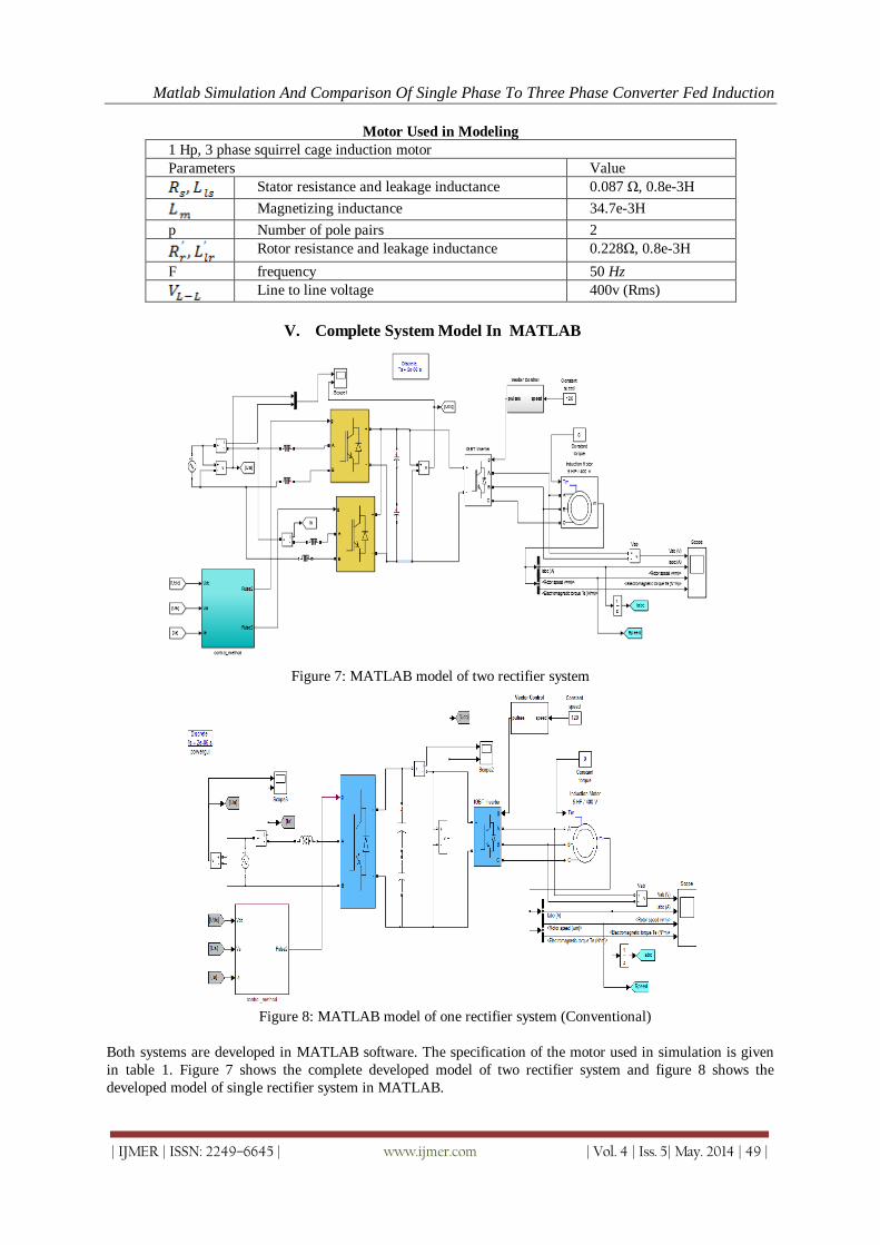
Motor Used in Modeling
1 Hp, 3 phase squirrel cage induction motor
Parameters Value
Stator resistance and leakage inductance 0.087 Ω, 0.8e-3H
Magnetizing inductance 34.7e-3H
p Number of pole pairs 2
Rotor resistance and leakage inductance 0.228Ω, 0.8e-3H
F frequency 50 Hz
Line to line voltage 400v (Rms)
V. Complete System Model In MATLAB
Figure 7: MATLAB model of two rectifier system
Figure 8: MATLAB model of one rectifier system (Conventional)
Both systems are developed in MATLAB software. The specification of the motor used in simulation is given
in table 1. Figure 7 shows the complete developed model of two rectifier system and figure 8 shows the
developed model of single rectifier system in MATLAB.
Matlab Simulation And Comparison Of Single Phase To Three Phase Converter Fed Induction
| IJMER | ISSN: 2249–6645 | www.ijmer.com | Vol. 4 | Iss. 5| May. 2014 | 50 |
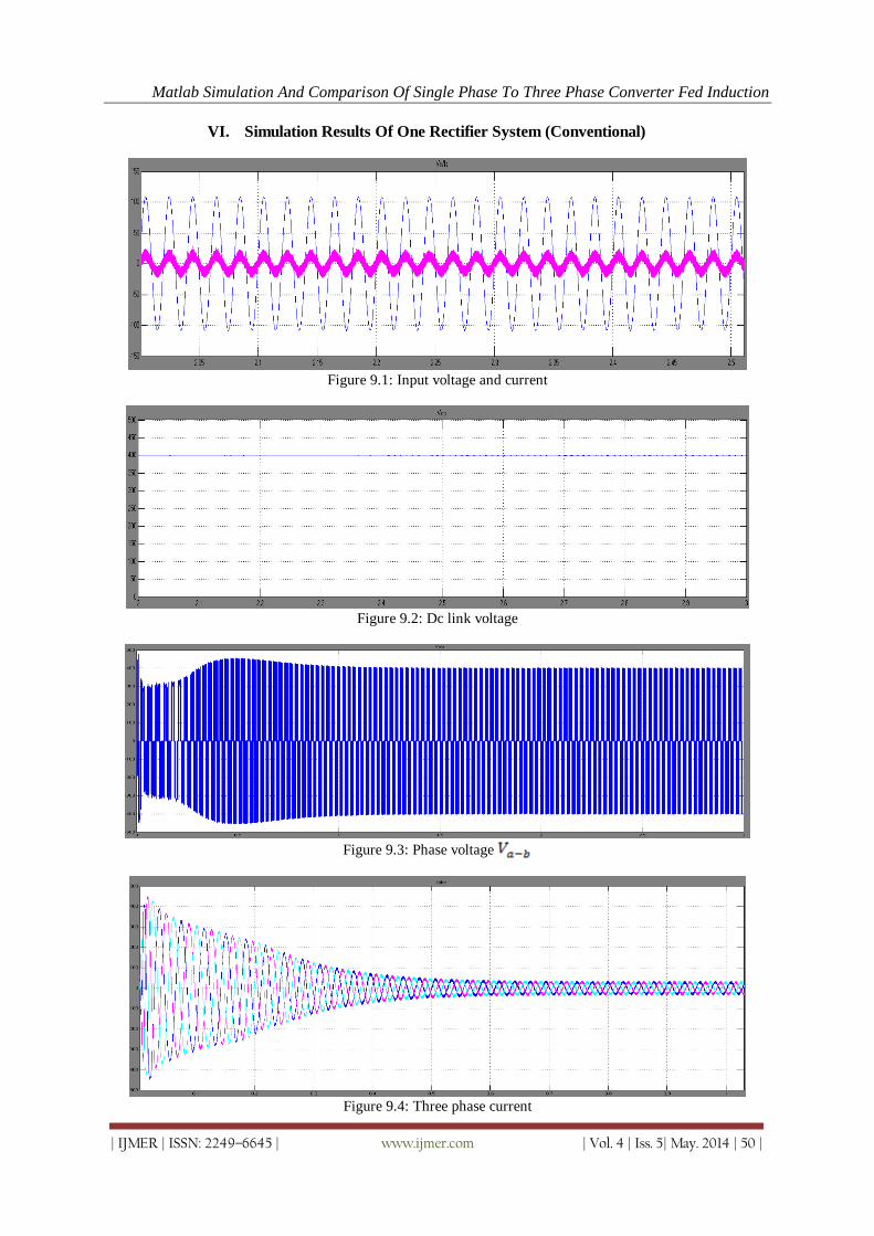
VI. Simulation Results Of One Rectifier System (Conventional)
Figure 9.1: Input voltage and current
Figure 9.2: Dc link voltage
Figure 9.3: Phase voltage
Figure 9.4: Three phase current

Matlab Simulation And Comparison Of Single Phase To Three Phase Converter Fed Induction
| IJMER | ISSN: 2249–6645 | www.ijmer.com | Vol. 4 | Iss. 5| May. 2014 | 51 |
Figure 9.5: Speed and Electromagnetic torque (Free acceleration )
Figure 9 Simulation result of one rectifier system
Figure 9 shows the simulation results of one rectifier system. Where figure 9.1 shows input voltage and current
of supply. Figure 9.2 shows the dc link voltage whereas figure 9.3 phase voltage between phase a and b of the
inverter output. The three phase current motor current is shown in figure 9.4. Speed and electromagnetic
torque of motor for free acceleration is given in figure 9.5 similarly the simulation results of two rectifier
system are given figure 10.
VII. Simulation Results Of Two Rectifier System
Figure 10. Simulation result of two rectifier system
Figure 10.1: Input voltage and current
Figure 10.2: Dc link voltage
Matlab Simulation And Comparison Of Single Phase To Three Phase Converter Fed Induction
| IJMER | ISSN: 2249–6645 | www.ijmer.com | Vol. 4 | Iss. 5| May. 2014 | 52 |
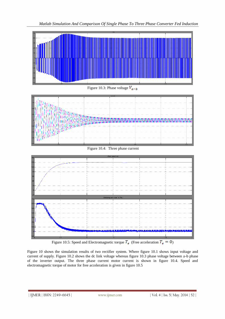
Figure 10.3: Phase voltage
Figure 10.4: Three phase current
Figure 10.5: Speed and Electromagnetic torque (Free acceleration )
Figure 10 shows the simulation results of two rectifier system. Where figure 10.1 shows input voltage and
current of supply. Figure 10.2 shows the dc link voltage whereas figure 10.3 phase voltage between a-b phase
of the inverter output. The three phase current motor current is shown in figure 10.4. Speed and
electromagnetic torque of motor for free acceleration is given in figure 10.5
Matlab Simulation And Comparison Of Single Phase To Three Phase Converter Fed Induction
| IJMER | ISSN: 2249–6645 | www.ijmer.com | Vol. 4 | Iss. 5| May. 2014 | 53 |
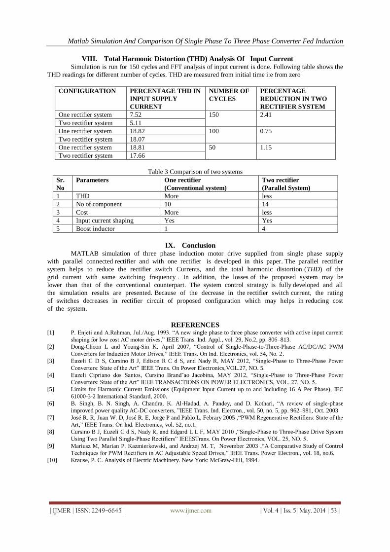
VIII. Total Harmonic Distortion (THD) Analysis Of Input Current Simulation is run for 150 cycles and FFT analysis of input current is done. Following table shows the
THD readings for different number of cycles. THD are measured from initial time i:e from zero
CONFIGURATION PERCENTAGE THD IN
INPUT SUPPLY
CURRENT
NUMBER OF
CYCLES
PERCENTAGE
REDUCTION IN TWO
RECTIFIER SYSTEM
One rectifier system 7.52 150 2.41
Two rectifier system 5.11
One rectifier system 18.82 100 0.75
Two rectifier system 18.07
One rectifier system 18.81 50 1.15
Two rectifier system 17.66
Table 3 Comparison of two systems
Sr.
No
Parameters One rectifier
(Conventional system)
Two rectifier
(Parallel System)
1 THD More less
2 No of component 10 14
3 Cost More less
4 Input current shaping Yes Yes
5 Boost inductor 1 4
IX. Conclusion MATLAB simulation of three phase induction motor drive supplied from single phase supply
with parallel connected rectifier and with one rectifier is developed in this paper. The parallel rectifier
system helps to reduce the rectifier switch Currents, and the total harmonic distortion (THD) of the
grid current with same switching frequency . In addition, the losses of the proposed system may be
lower than that of the conventional counterpart. The system control strategy is fully developed and all
the simulation results are presented. Because of the decrease in the rectifier switch current, the rating
of switches decreases in rectifier circuit of proposed configuration which may helps in reducing cost
of the system.
REFERENCES [1] P. Enjeti and A.Rahman, Jul./Aug. 1993. “A new single phase to three phase converter with active input current
shaping for low cost AC motor drives,” IEEE Trans. Ind. Appl., vol. 29, No.2, pp. 806–813.
[2] Dong-Choon L and Young-Sin K, April 2007, “Control of Single-Phase-to-Three-Phase AC/DC/AC PWM
Converters for Induction Motor Drives,” IEEE Trans. On Ind. Electronics, vol. 54, No. 2.
[3] Euzeli C D S, Cursino B J, Edison R C d S, and Nady R, MAY 2012, “Single-Phase to Three-Phase Power
Converters: State of the Art” IEEE Trans. On Power Electronics,VOL.27, NO. 5.
[4] Euzeli Cipriano dos Santos, Cursino Brand˜ao Jacobina, MAY 2012, “Single-Phase to Three-Phase Power
Converters: State of the Art” IEEE TRANSACTIONS ON POWER ELECTRONICS, VOL. 27, NO. 5.
[5] Limits for Harmonic Current Emissions (Equipment Input Current up to and Including 16 A Per Phase), IEC
61000-3-2 International Standard, 2000.
[6] B. Singh, B. N. Singh, A. Chandra, K. Al-Hadad, A. Pandey, and D. Kothari, “A review of single-phase
improved power quality AC-DC converters, ”IEEE Trans. Ind. Electron., vol. 50, no. 5, pp. 962–981, Oct. 2003
[7] José R. R, Juan W. D, José R. E, Jorge P and Pablo L, Febrary 2005 ,“PWM Regenerative Rectifiers: State of the
Art,” IEEE Trans. On Ind. Electronics, vol. 52, no.1.
[8] Cursino B J, Euzeli C d S, Nady R, and Edgard L L F, MAY 2010 ,“Single-Phase to Three-Phase Drive System
Using Two Parallel Single-Phase Rectifiers” IEEESTrans. On Power Electronics, VOL. 25, NO. 5.
[9] Mariusz M, Marian P. Kazmierkowski, and Andrzej M. T, November 2003 ,“A Comparative Study of Control
Techniques for PWM Rectifiers in AC Adjustable Speed Drives,” IEEE Trans. Power Electron., vol. 18, no.6.
[10] Krause, P. C. Analysis of Electric Machinery. New York: McGraw-Hill, 1994.