MATERIAL RESISTANCE FOR CRACK PROPAGATION IN PLATES UNDER TENSILE LOADING WHEN USING DRILLING-HOLE...
14
MATERIAL RESISTANCE FOR CRACK PROPAGATION IN PLATES UNDER TENSILE LOADING WHEN USING DRILLING-HOLE TECHNIQUE El-Shennawy, M. * and Fouad, H.* * *Assistant Professor, Industrial Engineering Department, Faculty of Engineering, Cairo University-Fayoum Branch, El-Fayoum 63111 e-mail : [email protected] **Assistant Professor, Biomedical Engineering Department, Faculty of Engineering, Helwan University, Cairo, Egypt. e-mail : [email protected] ABSTRACT The operational life of a structure or a component is often limited by the initiation and subsequent growth of cracks. The presence of cracks may result in a loss of performance or even in a total failure of the structure therefore, it is recommended to -at least- delay the crack propagation if its total prevention should be impossible. This delaying could be achieved by removing the highly- stressed area in front of the crack tip us ing a drilling- hole technique. In this study finite element analysis has been carried out to investigate the stress and strain behavior at crack-tip region for double edge notched tension specimens, DENT. The results of this finite element models have been compared with the previous forms –proposed in the literatures- which describe the nature of the plastic zone at the crack tip. Specimens with and without hole have been used with different diameters and positions apart from the notch tip to determine the optimum condition for hole existence. A set of experimental tests were carried out based on the present FE results. Good agreement was found between both results of FE-analysis and experimental tests. This work could conclude that the existence of a hole in front of a notch tip delayed the crack propagation with different degrees depending on hole diameter and position. Optimum condition was obtained when hole diameter equals plastic zone size, r p, and its center is located at a distance equals to 2r p from the notch tip. The method developed in this work can serve as a quick remedy in situations where unexpected crack is initiated. This will definitely minimize the losses until further corrective steps are available. KEYWORDS Crack propagation, FE-Analysis, drilling technique, DENT specimen, experimental analysis, stress-strain behavior. 8 th International Conference on Production Engineering Design and Control, PEDAC’2004 December 2004, Alexandria, Egypt
-
Upload
helwanuniversity -
Category
Documents
-
view
0 -
download
0
Transcript of MATERIAL RESISTANCE FOR CRACK PROPAGATION IN PLATES UNDER TENSILE LOADING WHEN USING DRILLING-HOLE...
MATERIAL RESISTANCE FOR CRACK PROPAGATION IN PLATES UNDER TENSILE LOADING WHEN
USING DRILLING-HOLE TECHNIQUE
El-Shennawy, M. * and Fouad, H.* *
*Assistant Professor, Industrial Engineering Department, Faculty of Engineering, Cairo University-Fayoum Branch, El-Fayoum 63111
e-mail : [email protected] **Assistant Professor, Biomedical Engineering Department, Faculty of Engineering, Helwan
University, Cairo, Egypt. e-mail : [email protected]
ABSTRACT The operational life of a structure or a component is often limited by the initiation and subsequent growth of cracks. The presence of cracks may result in a loss of performance or even in a total failure of the structure therefore, it is recommended to -at least- delay the crack propagation if its total prevention should be impossible. This delaying could be achieved by removing the highly-stressed area in front of the crack tip us ing a drilling-hole technique. In this study finite element analysis has been carried out to investigate the stress and strain behavior at crack-tip region for double edge notched tension specimens, DENT. The results of this finite element models have been compared with the previous forms –proposed in the literatures- which describe the nature of the plastic zone at the crack tip. Specimens with and without hole have been used with different diameters and positions apart from the notch tip to determine the optimum condition for hole existence. A set of experimental tests were carried out based on the present FE results. Good agreement was found between both results of FE-analysis and experimental tests. This work could conclude that the existence of a hole in front of a notch tip delayed the crack propagation with different degrees depending on hole diameter and position. Optimum condition was obtained when hole diameter equals plastic zone size, rp, and its center is located at a distance equals to 2rp from the notch tip. The method developed in this work can serve as a quick remedy in situations where unexpected crack is initiated. This will definitely minimize the losses until further corrective steps are available. KEYWORDS Crack propagation, FE-Analysis, drilling technique, DENT specimen, experimental analysis, stress-strain behavior.
8th International Conference on Production Engineering Design and Control,
PEDAC’2004 December 2004, Alexandria, Egypt

1. INTRODUCTION The presence of a crack in a component of a machine, vehicle, or structure may weaken it, so that it fails by fracturing into two or more pieces. This can occur at stresses below the material’s yield strength, where failure would not normally be expected. The fast remedy of such problem can obviously be important in preventing dangerous and/or expensive damage in the component. This paper reviews the previous mathematical models which describe the nature of the elastic and plastic stresses and strains in the vicinity of crack tip. FE calculations using ANSYS code [1] have been carried out for determining the stress and strain condition at the crack-tip region. Plastic zone size in the vicinity of the crack tip has also been calculated. Mathematical models’ results have been compared in the light of FE analysis. Based on such a comparison a proper form has been suggested to determine the plastic zone size in front of the crack tip. Stopping the crack propagation technique will be based mainly on removing the highly-stressed area in front of the crack tip elevated due to stress concentration. Inserting a hole in front of the crack tip is a method industrial people may know and apply in the field when they suffer cracking of a member. But, the specifications of such a hole like its diameter and location ahead of the crack need to be studied to determine the most effective hole that can be inserted to stop the crack or delay it in the worst condition. Studying the notched specimen was the method for cracking propagation at the edge of the notch based on the assumption that the stress in a tensile member having a notch will increase linearly until the breaking stress of the material is reached [2]. Double-edge notched tensile specimen, DENT, was chosen for this study for its symmetry and higher constraint condition compared with other configurations like single-edge notched tensile specimen, SENT, or center-notched tensile specimen, CNT .Cracking due to notch existence is expected to increase the stress concentration in front of the crack tip and work to propagate rapidly up to final failure for the specimen due to reduction in the effective cross section of the tested specimens. Brief review for the mathematical models -which describe the nature of the elastic and plastic stresses and strains in the vicinity of the crack tip- is presented in the following section. Both of experimental and numerical studies are then conducted to investigate the tendency for crack propagation when highly-stressed area was removed by inserting a hole. The optimum condition for holing technique; the hole diameter and position, is then determined for most effective use of this method to stop the crack or delay it. 1.1. Mathematical models/forms The stress distribution across a notched specimen subjected to tensile loading up to crack formation is important when considering the failure of materials. As the load increases the resultant elastic stresses produced at the crack tip are gradually converted to plastic stresses and then the crack is formed and fracture occurs. Stress intensity factor, K is used as a similitude parameter of the material under specific condition; namely linear elastic fracture mechanics condition, LEFM. Under this condition, same thicknesses of a specific material can be compared under same loading level using the factor K. Under the LEFM condition, the relative size of the plastic zone compared to crack length and specimen dimensions must be small. Thus, when plastic zone size, rp becomes too large the condition can not be considered LEFM any more.

The interest of this paper is concerned with specific specimen configuration which is double-edge notched tensile specimen, DENT. Therefore, the various forms for K calculations proposed in the literatures [3-8] for such specific configuration are summarized below.
1.
+
−
+=
32
42.312.236.098.1Wa
Wa
Wa
aK I σ [3] (1)
2. ( )
+
+
−
−
−=
432
190.0471.0205.0561.0222.1
1
2Wa
Wa
Wa
Wa
Wa
Wa
WK I
π
σ [4-5](2)
3. 2
tan2
2cos122.01 4
+= Wa
Wa
Wa
aK I
π
π
ππσ [4] (3)
4.
−
−
+
−
−
=21
432
1
190.0471.0205.0561.012.1
Wa
Wa
Wa
Wa
Wa
aK I πσ [6] (4)
5.
+
−
+=
32
36.2748.876.099.1Wa
Wa
Wa
aK I σ [7] (5)
Plastic zone size calculations have various forms derived based on different theories [7-14] for determining the behavior of crack opening phenomenon and stress field ahead of the crack tip. Summary for those forms are listed below.
1. Ewalds and Wanhill [7] proposed this form: 2
21
=
y
Ip
kr
σπ (6)
2. Irwin [8-9] proposed a correction for the plastic zone calculation to be: 2
1
=
y
Ip
kr
σπ (7)
3. Different approach was followed by Dugdale [10], it takes the form: 2
2
8
=
yp
ar
σσπ
(8)

which can be rewritten in the form of Eq. (9) when considering ak πσ= :
4. 2
8
=
yp
kr
σπ
[10] (9)
The above equations (8) and (9) both give almost identical results with Irwin expression [8-9] at low σ/σy. But for high values of σ/σy another equation has to be used and the differences with Irwin plastic zone become larger. It follows Eq. (10) shown below:
5.
−
= 1
2cos
1
y
p ar
σσπ
[10] (10)
6. Barenblatt [11] and Bilby and Cottrel [12] provided other approaches which give nearly similar results to Dugdale model [10]. Applying Von Mises yield criterion for plane stress condition, we get:
( )
++
= θθ
σπθ 2
2
sin23
cos141
y
Iy
kr [13-14] (11)
Opening stress distribution with plastic zone existence is shown for simplicity in Fig. 1, while the shape of the plastic zone derived from Eq. (11) is shown in Fig. 2. From last equation (11), it is possible to determine the maximum permissible plastic zone size for plane stress condition -based on LEFM- from the following equation. rp = (1/2π) (KI/σy)2 plane stress (12) A set of experimental and numerical tests were conducted in order to estimate the shape and nature of the plastic zone in the vicinity of the crack using different forms of the correction factors and also using the FE modeling as explained below. The optimum hole size and position at which the hole can be drilled in the vicinity of the crack tip to delay the crack propagation are investigated. 2. NUMERICAL ANALYSIS 2.1. FE-modeling Two-dimensional FE- model was created using the FE-code ANSIS. In the FE analysis, the tested material was modeled as an elastic strain hardening material. The model was examined under the condition of plane-stress condition. Specimens with and without hole were subjected to tension at various loading levels, σ/σy. The analysis matrix is presented in Table 1 and schematic for the notched specimen derived from the ASTM E338-81 [15] is shown in Fig. 3(a). Close up

rp/(k1/πσy)2
70o
0.5
0.5
Plastic zone shape according to Von Mises criterion for plane stress condition
rp(θ)=(k2/4πσy2)(1+1.5sin 2θ+cosθ)
for the hole existence in a notched specimen is shown in Fig. 3(b). The notched specimen with this configuration recently showed the highest stress condition at notch tip; namely when notch angle = 60o provided that the V-notches are sharp and plasticity is contained [16-20]. Therefore, The material with grade 36(250) of the ASTM standard was chosen for the analysis. For mesh generation, the mesh was concentrated at critical locations like crack-tip region and ligament area as shown in Fig. 4. In the FE-model the crack to width ratio, a/W was also investigated. Fig. 1. Plastic zone at crack tip. Fig. 2. Plastic zone shape according to Von Mises.
DIM. IN MM.
(a) (b)
Fig. 3. Specimen design showing (a) specimen configuration used for the analysis and (b)
close-up for the hole existence in front of the crack tip.
Opening stress, σ
Distance, r
Notch, a Plastic zone, rp
σy
Hole diameter, φ
Hole distance, d
Notch, a
60o
50
12.5
12.5 300 6

Fig. 4. Mesh generation for notched specimen with and without hole showing notch opening behavior and plastic zone due to applied tensile forces.
Table 1. Analysis matrix for FE-calculations
With Hole
diameter, φφ Center hole distance from notch tip, d Applied load level, σσ/σσy Notched
specimen
No hole, NH rp 2rp 0 rp/2 rp 1.5rp 2rp 2.5rp 0.2 0.4 0.6 0.8
0.20 � � --- --- � � � � --- � � � �
0.33 � � � � � � � � � � � � � a/W
0.50 � � --- --- � � � � --- � � � �
� Used combination for analysis when φ = rp. � Used twice when φ=rp and φ=2rp. 2.2. Analytical results The values of plastic zone sizes calculated from the mathematical model of Dugdale [10] in the
form: 2
8
=
yp
kr
σπ
shows good agreement with those similar values obtained from FE-
calculations. Referring to the values of the plastic zone sizes, it is important to notice that those values of rp can be accepted up to certain limit of applied load; namely σ/σy=0.4. When load increases over this limit, the plastic zone greatly spread ahead of the crack tip and the condition can not be considered linear elastic fracture mechanics, LEFM any more on which the equations used are based. At σ/σy=0.6 or 0.8, the condition is no longer governed by LEFM but elastic-plastic fracture mechanics, EPFM. Table 2 summarizes the FE results: maximum opening stress, σmax and plastic zone size, rp at various loading levels, σ/σy from FE-calculations.Interrelationships between plastic zone size, rp, hole diameter, φ, hole distance from the crack/notch tip, d, and maximum stress, σmax, were investigated for various loading levels, σ/σy, and crack to width ratios, a/W. Plastic zone size increases with load increase as depicted in Fig. 5. It is noticed from the figure also that the plastic constraint condition of cracked specimens varies with the crack length as well known

from various researches [21-26]. With a/W=0.2, plastic constraint is fairly low while a/W=0.5 represents high constraint condition. The a/W=0.33 shows a reasonable degree of plastic constraint ahead of the crack tip. Plastic zone size should be kept in the range where elastic condition for fracture mechanics can be applied. Up to σ/σy=0.4, the various crack lengths represent small plastic zone sizes.
Table 2 Summary for the FE-results for DENT specimens with and without hole
Distance from center hole to notch tip, d No hole, NH
0.0 rp/2 rp 1.5rp 2rp 2.5rp Hole diameter, φφ
a/W σσ/σσy rp, mm
σσmax, MPa rp 2rp rp rp 2rp rp 2rp rp rp 2rp
0.2 0.00 235 --- --- 190 149 --- 140 --- 131 --- --- 0.4 1.96 273 --- --- 224 228 --- 222 --- 226 --- --- 0.6 5.25 279 --- --- 239 242 --- 240 --- 238 --- ---
0.20
0.8 28.0 289 --- --- 248 250 --- 244 --- 240 --- --- 0.2 1.06 252 --- --- --- --- --- --- --- 140 --- --- 0.4 3.80 247 257 238 237 232 234 229 234 225 226 231 0.6 8.75 283 --- --- --- --- --- --- --- 240 --- ---
0.33
0.8 50.0 345 --- --- --- --- --- --- --- 322 --- --- 0.2 0.70 256 --- --- 221 199 --- 166 --- 164 --- --- 0.4 6.00 275 --- --- 248 245 --- 236 --- 232 --- --- 0.6 37.5 298 --- --- 413 387 --- 370 --- 374 --- ---
0.50
0.8 37.5 511 --- --- × 439 --- 449 --- 458 --- --- Figure 6 shows the effect of loading level, σ/σy and notch length on the maximum stress ahead of the crack tip. Up to σ/σy=0.4, the maximum stress still fall in the elastic region. These two figures; Figs. 5-6 suggest the proper levels of loading and notch length at which the analysis could be done based on the elastic fracture mechanics, EFM condition.
0
10
20
30
40
50
60
70
0.1 0.2 0.3 0.4 0.5 0.6 0.7 0.8 0.9
0.200.330.50
σ/σy
a/w
100
200
300
400
500
600
0.1 0.2 0.3 0.4 0.5 0.6 0.7 0.8 0.9
0.200.33
0.50
σ/σy
a/w
Yield strength foe St 37
Fig. 5. Effect of σσ/σσy on rp. Fig. 6. Effect of σσ/σσy on σσmax. When hole is to be inserted, the questions arise are: how is the diameter of the hole? and how far it should be located from the crack tip? To answer these questions -which is the aim of this

paper-, effects of these two factors on the maximum stress ahead of the crack tip should be studied. Maximum stress is considered as the driving force for crack opening and therefore, its propagation. Figure 7 illustrates the condition of maximum stress in front of the crack tip when crack to width ratio a/W=0.2. Effect of hole distance from crack tip, d, on maximum stress is shown in the figure and compared with specimen without hole at various loading levels, σ/σy. Maximum stress values decreased when hole was inserted. Stress shows values below yield strength of the material. For loading level σ/σy=0.2 the values was originally below yield strength and hole dramatically decreased it to very low levels near to half of the yield strength. For loading level σ/σy>0.2, the reduction in maximum stress has not been affected by the hole distance, d. It is important to notice that the hole diameter was fixed at φ=rp, where rp is the plastic zone size related to loading level σ/σy=0.4. Relations of the same variables have been drawn for higher notch length to width ratio, namely; a/W=0.5 as shown in Fig. 8. Here, the maximum stress in front of the crack tip records higher values due to the higher constraint resulted from the greater crack to width ratio, a/W=0.5. The reduction in maximum stress from magnitudes above yield strength to values less than yield point is obvious at loading levels up to σ/σy=0.4. Above this ratio, the condition is governed by the plastic mode behavior and existence of the hole plays no role in stress reduction which may lead to serious condition for the crack which will not stop and shall propagate.
100
150
200
250
300
0.5 1.0 1.5 2.0 2.5 3.0
0.20.40.60.8
d/rp
σ/σy
Yield strength for St 37
No-Hole
d
φ
NotchHole
a/W=0.2, φ=rp
100
200
300
400
500
600
0.5 1.0 1.5 2.0 2.5 3.0
0.20.4
0.60.8
d/rp
σ/σy
Yield strength for St 37
No-Hole
d
φ
NotchHole
a/W=0.5, φ =rp
Fig. 7. Effect of d on σσmax for a/W=0.2. Fig. 8. Effect of d on σσmax for a/W=0.5
Comparison between various notch to width ratios, a/W for detecting the effect of hole distance to plastic zone size, d/rp on maximum stress, σmax at specific loading level σ/σy=0.4 is shown in Fig. 9. As mentioned above the load level of σ/σy=0.4 contributes to the condition of LEFM which explains the reason for using this level of loading for comparison. From Fig. 9, the reduction in maximum opening stress is obvious for a/W=0.33 and a/W=0.5 and they are much greater than that obtained for a/W=0.2. The unstable behavior observed with a/W=0.2 where increase and decrease in maximum stress values occurred with increasing d values can be referred to the very low constraint condition in this configuration and the low loading level makes the stress distribution ahead of the crack tip

changes in different manners with hole existence at various distances. In the same time, it is important to notice that this change is so slight compared with other configurations and the values swing about 5MPa at a very low level compared with yield strength of the material. This change can be ignored and maximum stress is considered almost fixed without change regardless the change in d. Reduction percentage for each condition was derived from last figure and drawn in Fig. 10. Hole existence can reduce maximum stress ahead of the crack tip up to 16% with a/W=0.5 and 9% with a/W=0.33. For a/W=0.2, the reduction is much less and reaches 3%. It is noticeable that reduction percentage increases with d increase. The optimum condition can be obtained at d/rp=2.
220
230
240
250
260
270
280
0.0 0.5 1.0 1.5 2.0 2.5 3.0
0.20.330.5
d/rp
Yield Strength for Steel 37
a/Wd
φ
NotchHole
No-Hole
σ/σy = 0.4, φ = r p
-5
0
5
10
15
20
0.0 0.5 1.0 1.5 2.0 2.5 3.0
0.20.330.5
d/rp
a/W
d
φ
NotchHole
σ/σy = 0.4, φ = rp
Fig. 9. Effect of d on σσmax for various a/W. Fig. 10. Reduction% in σσmax as an effect of d. At a/W=0.33 the effect of hole diameter was investigated through the relation shown in Fig. 11. Hole diameter corresponding to plastic zone size recorded great effect on stress reduction with bigger values of d. When hole diameter equals plastic zone size and be located in a distance equals double of this value, the biggest reduction in stresses is expected. These reduction ratios are shown in Fig. 12. The reduction in maximum stress in front of the crack tip for the specimen tested at load level σ/σy=0.4 and having crack to width ratio a/W=0.33 is maximum when hole with a diameter φ=rp and located in a distance d=2rp. The reduction may reach up to 9% in this case as previously explained in Fig. 10.
220
225
230
235
240
245
250
255
260
0.0 0.5 1.0 1.5 2.0 2.5 3.0d/rp
Yield Strength for Steel 37
φ = rp
φ = 2rp
a/w = 0.33, σ/σy = 0.4
d
φ
NotchHole
No-Hole
-4
-2
0
2
4
6
8
10
0.0 0.5 1.0 1.5 2.0 2.5 3.0d/rp
φ = rp
φ = 2rp
a/w = 0.33, σ/σ y = 0.4
d
φ
NotchHole
Fig. 11. Effect of φφ on σσmax. Fig. 12. Reduction% in σσmax as an effect of φφ.

3. EXPERIMENTAL WORK 3.1. Test Specimen The specimen used for evaluating holing technique is derived from the ASTM E338-81 standard. Specimen design is shown in Fig. 3(a). Notch has been created so that it can be considered as a sharp notch and hole has been inserted at various positions with different diameters as shown in Fig. 3(b). Combinations for hole diameters and positions are indicated in Table 3 and some examples are photographed in Fig. 13 for specimen before testing. Testing machine and specimen under test are photographed and shown in Fig. 14.
Table 3. Experimental test specimens with various hole diameters and distances combinations
Center hole distance from notch tip, d Notched
specimen No hole,
NH With Hole
diameter, φφ 0 rp/2 rp 1.5rp 2rp 2.5rp
rp � � �� �� � --- a/W 0.33 ��
2rp --- --- �� � --- ---
Fig. 13. DENT specimens before testing, NH: specimen without hole, φφ8d4 & φφ4d8:
specimens with holes; φφ=8, 4mm and d=4, 8mm.
Fig. 14. Specimens during tensile testing and the machine used.
3.2. Experimental test results Results for tensile test specimens are summarized in Fig. 15 where ultimate tensile strength for each specimen has been recorded for different hole diameter and position. The relation shown in

this figure strongly support the analytical results obtained by the FE model. The maximum resistance for the material is gained through the application of holing technique where higher ultimate strength has been detected approximately at all conditions of hole diameters and positions.
410
420
430
440
450
460
470
480
490
0.0 2.0 4.0 6.0 8.0 10.0
Distance from hole center to notch tip, d, mm
φ=8mm
φ=4mm
No-Hole
a/W = 0.33
Fig. 15. Experimental results showing the effect of hole existence and position on maximum
tensile strength for DENT specimens . Specimens without hole showed the normal values for tensile strength for the material used in the analysis. When hole was inserted the tensile strength or in other words the resistance of the material started to show higher values. Those values depend upon the location and size of the hole. From Fig. 15 it can be noticed that the tensile strength for the specimen tested, DENT, increased gradually with hole distance, d, up to certain value of d=2rp when the hole size is φ=rp. For the specimens having hole size of φ=2rp, the strength did not show much change in values compared with those specimens without hole. Except when the hole was placed at distance d=rp. Those findings are in great agreement with FE results previously shown in the last section. Examining the stress-strain curves obtained from the tensile tests for all specimens with and without hole, a peculiar phenomenon has been recorded with specimens having holes. As a normal behavior for the material the specimens without hole; NH, showed stress increase up to certain limit and then went down to failure. But, the peculiar phenomenon occurred when hole is inserted ahead of the notch tip. The strength of the material increased and its resistance to failure is obviously noticed as shown in Fig. 16. The crack propagated easily through the material up to certain position where hole is located, at this point the required stress for failure increased again due to hole resistance which improved the material tensile strength. hole starts No hole (a) (b) Fig. 16. Schematic representation for the general trend of stress-strain curve in both cases
of specimen with and without hole, the peculiar phenomenon is clear in graph (a)

4. CONCLUSION Based on theoretical model for plastic zone location, shape, and size the FE-model and experimental analysis were carried out. The holing technique is mainly a method for removing the highly-stressed region which precedes the crack tip and carries the moving force for crack extension. Hole resistance for crack propagation is the key answer for increasing the material strength which in turn delays the crack propagation or in some cases –at low stress conditions- prevent it. The point here is when the hole should be placed? How much diameter is needed to be effective? And where this hole should be located? The answers for these three questions are presented in the following paragraphs.From the FE calculations and experimental analysis, it was found that the hole diameter should not be less or greater than the size of the plastic zone; namely φ should be equal to rp. This is due to removing the highly-stressed region in front of the crack tip which represents the driving force for the crack. The location of the hole is also important. The crack propagation will be continued as far as the way is clear and open for it which means that no resistance in its way. Therefore, the hole should be located at a distance not longer than twice of the plastic zone size, namely d should be equal to 2rp. It must be noticed that rp is a function of applied load, σ/σy, for a specific material. For the case material considered in this study, Steel 37, the plastic zone is considered under the condition of LEFM at σ/σy = 0.4, rp in this case was 4mm. The hole then had a diameter of φ=4mm and located at a distance d=8mm from the crack tip. This condition could prove a reduction in maximum opening stress ahead of the crack tip for about 10%. And raise the tensile strength of the material to about 10% over its normal value. Using Eq. (5) for K calculations, we can substitute the values for the applied force σ by 0,4σy and for the values of a/W by 0.33. K can be obtained and it yields: K=0.92σy�a. By substituting the in Eq. (9) we get rp which yields: rp=0.33a. Here we can put it in another form: rp/a = a/W = 0.33 when σ/σy = 0.4 and d = 2 rp. This relation assure the best and optimum usage of holing technique for increasing material strength and delaying the crack propagation by decreasing the opening stress ahead of the crack tip in the same time. That relation is considered valid for the steel studied (St. 37) and is needed to be verified for other materials. ACKNOWLEDGEMENT The authors would like to express their gratitude to El Nasr Automotive Manufacturing Company, NASCO, Egypt, for its kind support by providing materials for the study and specimen preparations.

REFERENCES
1. ANSYS software, ver. 5.4, Swanson, Analysis System (1998). 2. Duggan, T. and Byrne, J., "Fatigue as a Design Criterion, " The Gresham Press, Surrey,
(1977). 3. Brown, Jr. W. F. and srawley, J. E., "Plane strain crack toughness testing of high strength
metallic materials," ASTM STP 410 (1966), p. 1. 4. Tada, H., Paris, P. C. and Irwin, G. R., "The stress analysis of cracks Handbook," 2nd. Ed.,
Paris Production, Inc., St. Louis (1985). 5. ASTM Standard E399-90, "Standard test method for plan-strain fracture toughness of
metallic materials," American Society for Testing and Materials, Philadelphia (1990). 6. Ewalds, H. L. and Wanhill, J. H., "Fracture Mechanics," Edward Arnold (London) and
Delftse Uitgevers Maatschappij (Delft) (1984). 7. Burdekin, F. M. and Stone, D. E. W., "the crack opening displacement approach to
fracture mechanics in yielding materials," J. Strain Analysis, Vol. 1 (1966), pp: 145-153. 8. Irwin, G. R., "Fracture, Handbuch der Physik, VI," pp: 551-590, Flugge Ed., Springer
(1958). 9. Irwin, G. R., "Plastic zone near a crack and fracture toughness," Proc. 7th sagamore Conf.,
(1960), p. IV-63. 10. Dugdale, D. S., "Yielding of steel sheets containing slits," J. Mech. Phys. Sol., Vol. 8
(1960), pp: 100-108. 11. Barenblatt, G. I., "The mathematical theory of equilibrium of cracks in brittle fracture,"
Advances in Appl. Mech., Vol. 7 (1962), pp: 55-129. 12. Bilby, B. A., cottrel, A. H. and Swinden, K. H., "The spread of plastic yield from a
notch," Proc. Roy. Soc. A 272, (1963), pp: 304-310. 13. Duffy, A. R. et al., "Fracture design practice for pressure piping, Fracture I," pp: 159-232,
Liebowitz ed., academic Press (1969). 14. Rooke, D. P., "Elastic yield zone round a crack tip," Royal Aircr. Est., Farnborough,
Tech. Note CPM 29 (1963). 15. ASTM Standard E338-81, "Standard method for sharp-notch tension testing of high-
strength sheet materials," American society for Testing and Materials, Philadelphia (1981).
16. Carpentri, A., “Stress-singularity and generalized fracture toughness at the vertex of re-entrant corners,” Engng. Fract. Mech., Vol. 26 (1987), pp: 143-155.
17. Seweryn, A., “Brittle fracture criterion for structures with sharp notches,” Engng. Fract. Mech., Vol. 47 (1994), pp: 673-681.
18. Dunn, ML., Sunito, W., and Cunningham, S., “Fracture initiation at sharp notches: correlation using critical stress intensities,” Int. J. Solids Struct., Vol. 34 (1997), pp: 3873-3883.
19. Standberg, M., “Fracture at V-notches with contained plasticity,” Engng. Fract. Mech., Vol. 69 (2002), pp: 403-415.
20. Gómez, F. J. and Elices, M., “Fracture of components with V-shaped notches,” Engng. Fract. Mech., Vol. 70 (2003), pp: 1913-1927.
21. Miline, I. and Worthington, P. G., “The fracture toughness of a low pressure vessel steel in the post yield regime,” Mat. Sci. Engng. Vol. 26 (1976), pp: 185-193.
22. Miline, I., “Fracture toughness testing of a quenched and tempered medium strength steel in the ductile-brittle transition range,” Mat. Sci. Engng. Vol. 30 (1977), pp: 243-251.
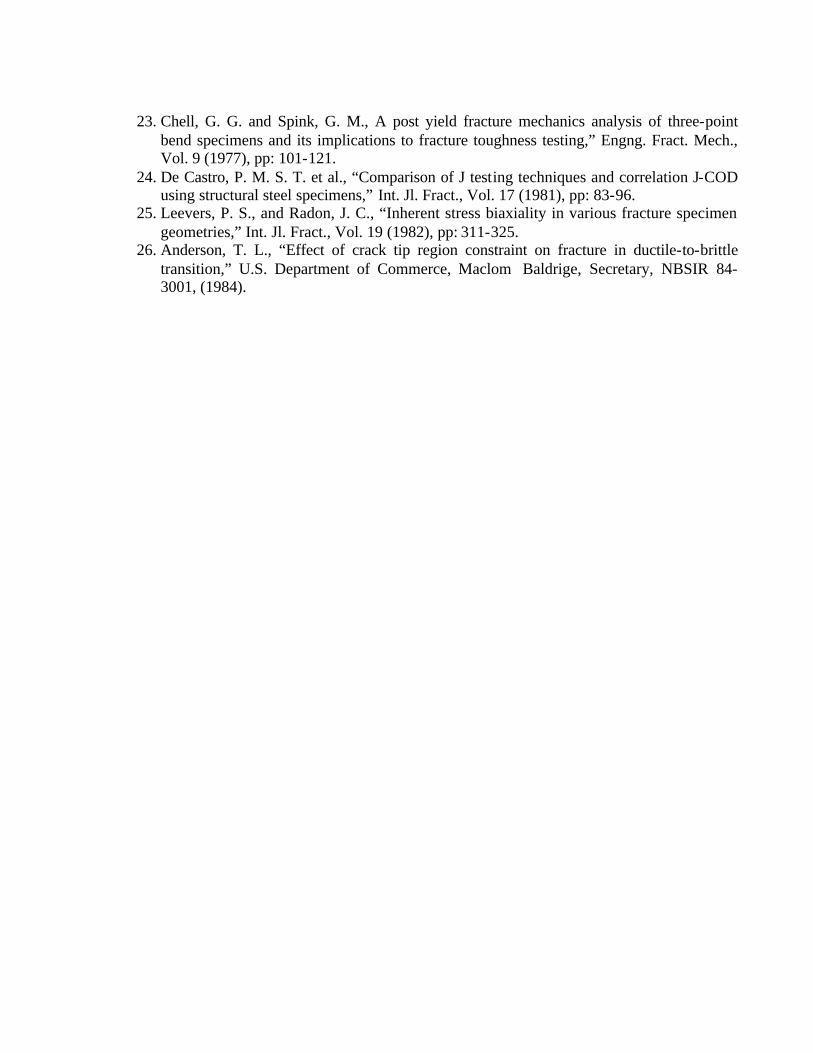
23. Chell, G. G. and Spink, G. M., A post yield fracture mechanics analysis of three-point bend specimens and its implications to fracture toughness testing,” Engng. Fract. Mech., Vol. 9 (1977), pp: 101-121.
24. De Castro, P. M. S. T. et al., “Comparison of J testing techniques and correlation J-COD using structural steel specimens,” Int. Jl. Fract., Vol. 17 (1981), pp: 83-96.
25. Leevers, P. S., and Radon, J. C., “Inherent stress biaxiality in various fracture specimen geometries,” Int. Jl. Fract., Vol. 19 (1982), pp: 311-325.
26. Anderson, T. L., “Effect of crack tip region constraint on fracture in ductile-to-brittle transition,” U.S. Department of Commerce, Maclom Baldrige, Secretary, NBSIR 84-3001, (1984).