MarcoPolo-R Mission Requirements Document - ESA Science ...
41
Prepared by David Agnolon Reference SRE-PA/2011.076/MarcoPolo-R Issue 3 Revision 2 Date of Issue 17/09/2012 Status Authorised Document Type RQ Distribution SRE-F, MP-R Science Study Team ESA UNCLASSIFIED – For Official Use estec European Space Research and Technology Centre Keplerlaan 1 2201 AZ Noordwijk The Netherlands T +31 (0)71 565 6565 F +31 (0)71 565 6040 www.esa.int MarcoPolo-R Mission Requirements Document
-
Upload
khangminh22 -
Category
Documents
-
view
8 -
download
0
Transcript of MarcoPolo-R Mission Requirements Document - ESA Science ...
Prepared by David Agnolon Reference SRE-PA/2011.076/MarcoPolo-R Issue 3 Revision 2 Date of Issue 17/09/2012 Status Authorised Document Type RQ Distribution SRE-F, MP-R Science Study Team
ESA UNCLASSIFIED – For Official Use
estec European Space Research
and Technology Centre Keplerlaan 1
2201 AZ Noordwijk The Netherlands
T +31 (0)71 565 6565 F +31 (0)71 565 6040
www.esa.int
MarcoPolo-R Mission Requirements Document
Page 2/41
MarcoPolo-R MRD
Date 17/09/2012 Issue 3 Rev 2
ESA UNCLASSIFIED – For Official Use
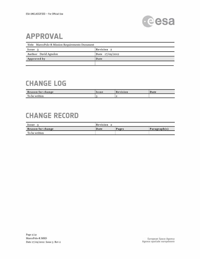
Title MarcoPolo-R Mission Requirements Document
Issue 3 Revision 2
Author David Agnolon Date 17/09/2012
Approved by Date
Reason for change Issue Revision Date
To be written 3 2
Issue 3 Revision 2
Reason for change Date Pages Paragraph(s)
To be written
Page 3/41
MarcoPolo-R MRD
Date 17/09/2012 Issue 3 Rev 2
ESA UNCLASSIFIED – For Official Use
Table of Contents 1 INTRODUCTION ................................................................................................................................ 5 1.1 Background ........................................................................................................................................................................ 5 1.2 Scope of Document ............................................................................................................................................................ 6 1.3 Documentation architecture .............................................................................................................................................. 6 The mission document tree is given here below for information and lists the envisaged documentation (to be confirmed) available by the time of the Preliminary Requirements Review. ............................................................................................... 7 1.4 Issue schedule .................................................................................................................................................................... 7 1.5 Requirements nomenclature ............................................................................................................................................. 7 1.5.1 Requirements and goals .................................................................................................................................................. 7 1.5.2 Requirement ID ............................................................................................................................................................... 8 2 MISSION OVERVIEW ........................................................................................................................ 9 2.1 Mission Profile ................................................................................................................................................................... 9 2.1.1 System definition ............................................................................................................................................................. 9 2.1.2 Mission overview ............................................................................................................................................................. 9 2.1.3 Mission phases and operations ..................................................................................................................................... 10 2.1.4 Asteroid proximity operations ...................................................................................................................................... 12 3 MISSION REQUIREMENTS ............................................................................................................. 13 4 PROGRAMMATICS REQUIREMENTS ............................................................................................. 13 5 PLANETARY PROTECTION AND SAMPLE CONTAMINATION REQUIREMENTS ........................... 14 5.1 Planetary Protection requirements ................................................................................................................................. 14 5.1.1 Science contamination requirements ........................................................................................................................... 14 6 PAYLOAD DESCRIPTION AND REQUIREMENTS ........................................................................... 15 6.1 Model payload instruments ............................................................................................................................................. 15 6.2 Payload requirements ...................................................................................................................................................... 15 7 TECHNOLOGY REQUIREMENTS .................................................................................................... 16 8 LAUNCH SEGMENT REQUIREMENTS ............................................................................................ 17 9 OPERATIONS AND MISSION ANALYSIS REQUIREMENTS ............................................................ 18 10 SPACE SEGMENT REQUIREMENTS ................................................................................................ 21 10.1 Spacecraft system requirements ...................................................................................................................................... 21 10.2 Platform sub-system requirements ................................................................................................................................. 24 10.2.1 Thermal requirements ................................................................................................................................................... 24 10.2.2 Power requirements ...................................................................................................................................................... 25 10.2.3 GNC/AOCS requirements ............................................................................................................................................. 25 10.2.4 DHS requirements ......................................................................................................................................................... 26 10.2.5 Propulsion requirements ............................................................................................................................................... 27 10.2.6 Communications requirements .................................................................................................................................... 27 10.2.7 Structure requirements ................................................................................................................................................ 28 10.2.8 Mechanism requirements .............................................................................................................................................. 29 10.3 Autonomy and FDIR requirements ................................................................................................................................ 30 10.4 Environmental requirements .......................................................................................................................................... 31 10.5 AIV and testing requirements ......................................................................................................................................... 32 10.6 Ground segment ............................................................................................................................................................... 32 10.7 Product assurance and RAMS requirements .................................................................................................................. 34 11 COORDINATE SYSTEM ................................................................................................................... 35 12 APPLICABLE AND REFERENCE DOCUMENTS ............................................................................... 36 12.1 Applicable documents ...................................................................................................................................................... 36 12.2 Reference document ........................................................................................................................................................ 37 13 ACRONYMS AND TERMINOLOGY .................................................................................................. 38 13.1 Acronyms ......................................................................................................................................................................... 38 13.2 Terminology .................................................................................................................................................................... 40 14 LIST OF TBC AND TBD .................................................................................................................... 41
Page 4/41
MarcoPolo-R MRD
Date 17/09/2012 Issue 3 Rev 2
ESA UNCLASSIFIED – For Official Use
14.1 List of TBC ........................................................................................................................................................................ 41 14.2 List of TBD ........................................................................................................................................................................ 41
Index of Figures and Tables
Figure 1-1: Mission development planning (indicative only and if JUICE launch is 2024) ... 5 Figure 1-2: MarcoPolo-R Phase A/B1 schedule, major milestones for spacecraft and
payload development (indicative only) .................................................................................. 6 Figure 1-3: Preliminary MarcoPolo-R mission document tree ................................................... 7 Figure 2-1: Block diagram of the MarcoPolo-R mission .............................................................. 9 Figure 2-2: Asteroid proximity operations for the 2022 mission scenario (indicative only) 12 Figure 11-1: Main spacecraft reference frame ............................................................................. 35 Figure 11-2: Local orbital reference frame ................................................................................... 35 Figure 13-1: Baseline spacecraft architecture (note that the sealing function of the SATCS
might also be performed within the ERC) ........................................................................... 40
Table 2-1: Overview of baseline mission phases ......................................................................... 12 Table 3-1: Resolution requirements for global characterisation, local characterisation, and
context measurements ............................................................................................................ 13 Table 6-1: List of instruments, all located on the sampling spacecraft ................................... 15 Table 7-1: Definition of ESA Technology Readiness Levels and TRL scale ............................ 17 Table 14-1: List of TBC .................................................................................................................... 41 Table 14-2: List of TBD ................................................................................................................... 41
ESA Unclassified – For official use
Page 5/41
MarcoPolo-R MRD
Date 17/09/2012 Issue 3 Rev 2
5
1 INTRODUCTION
1.1 Background
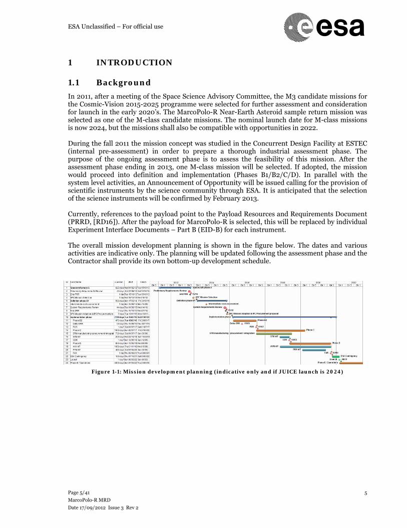
In 2011, after a meeting of the Space Science Advisory Committee, the M3 candidate missions for the Cosmic-Vision 2015-2025 programme were selected for further assessment and consideration for launch in the early 2020’s. The MarcoPolo-R Near-Earth Asteroid sample return mission was selected as one of the M-class candidate missions. The nominal launch date for M-class missions is now 2024, but the missions shall also be compatible with opportunities in 2022. During the fall 2011 the mission concept was studied in the Concurrent Design Facility at ESTEC (internal pre-assessment) in order to prepare a thorough industrial assessment phase. The purpose of the ongoing assessment phase is to assess the feasibility of this mission. After the assessment phase ending in 2013, one M-class mission will be selected. If adopted, the mission would proceed into definition and implementation (Phases B1/B2/C/D). In parallel with the system level activities, an Announcement of Opportunity will be issued calling for the provision of scientific instruments by the science community through ESA. It is anticipated that the selection of the science instruments will be confirmed by February 2013. Currently, references to the payload point to the Payload Resources and Requirements Document (PRRD, [RD16]). After the payload for MarcoPolo-R is selected, this will be replaced by individual Experiment Interface Documents – Part B (EID-B) for each instrument. The overall mission development planning is shown in the figure below. The dates and various activities are indicative only. The planning will be updated following the assessment phase and the Contractor shall provide its own bottom-up development schedule.
Figure 1-1: Mission development planning (indicative only and if JUICE launch is 2024)
ESA Unclassified – For official use
Page 6/41
MarcoPolo-R MRD
Date 17/09/2012 Issue 3 Rev 2
6
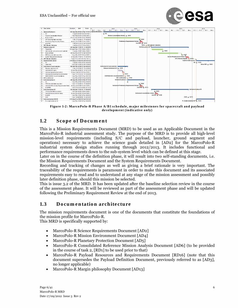
Figure 1-2: MarcoPolo-R Phase A/B1 schedule, major milestones for spacecraft and payload development (indicative only)
1.2 Scope of Document
This is a Mission Requirements Document (MRD) to be used as an Applicable Document in the MarcoPolo-R industrial assessment study. The purpose of the MRD is to provide all high-level mission-level requirements (including S/C and payload, launcher, ground segment and operations) necessary to achieve the science goals detailed in [AD2] for the MarcoPolo-R industrial system design studies running through 2012/2013. It includes functional and performance requirements down to the sub-system level which can be defined at this stage. Later on in the course of the definition phase, it will result into two self-standing documents, i.e. the Mission Requirements Document and the System Requirements Document. Recording and tracking of changes as well as giving a brief rationale is very important. The traceability of the requirements is paramount in order to make this document and its associated requirements easy to read and to understand at any stage of the mission assessment and possibly later definition phase, should this mission be selected. This is issue 3.2 of the MRD. It has been updated after the baseline selection review in the course of the assessment phase. It will be reviewed as part of the assessment phase and will be updated following the Preliminary Requirement Review at the end of 2013.
1.3 Documentation architecture
The mission requirements document is one of the documents that constitute the foundations of the mission profile for MarcoPolo-R. This MRD is specifically supported by:
MarcoPolo-R Science Requirements Document [AD2] MarcoPolo-R Mission Environment Document [AD4] MarcoPolo-R Planetary Protection Document [AD5] MarcoPolo-R Consolidated Reference Mission Analysis Document [AD6] (to be provided
in the course of task 2, [RD1] to be used prior to that) MarcoPolo-R Payload Resources and Requirements Document [RD16] (note that this
document supersedes the Payload Definition Document, previously referred to as [AD3], no longer applicable)
MarcoPolo-R Margin philosophy Document [AD13]
ESA Unclassified – For official use
Page 7/41
MarcoPolo-R MRD
Date 17/09/2012 Issue 3 Rev 2
7
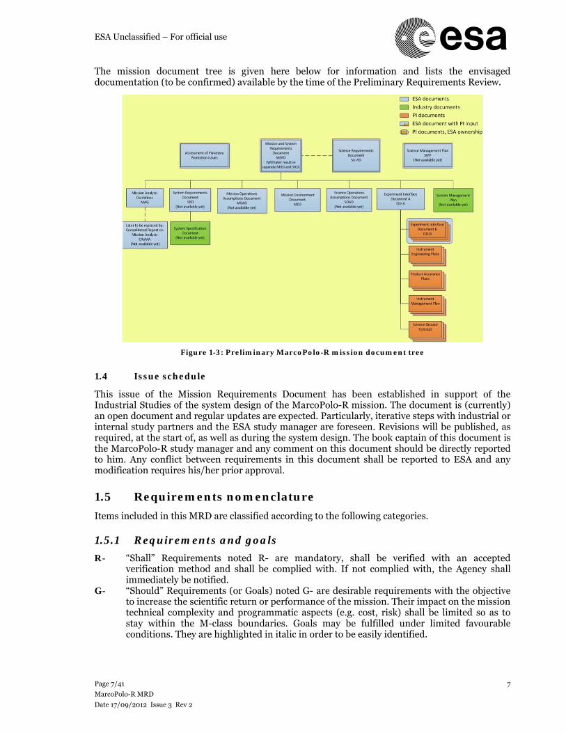
The mission document tree is given here below for information and lists the envisaged documentation (to be confirmed) available by the time of the Preliminary Requirements Review.
Figure 1-3: Preliminary MarcoPolo-R mission document tree
1.4 Issue schedule
This issue of the Mission Requirements Document has been established in support of the Industrial Studies of the system design of the MarcoPolo-R mission. The document is (currently) an open document and regular updates are expected. Particularly, iterative steps with industrial or internal study partners and the ESA study manager are foreseen. Revisions will be published, as required, at the start of, as well as during the system design. The book captain of this document is the MarcoPolo-R study manager and any comment on this document should be directly reported to him. Any conflict between requirements in this document shall be reported to ESA and any modification requires his/her prior approval.
1.5 Requirements nomenclature
Items included in this MRD are classified according to the following categories.
1.5.1 Requirements and goals
R- “Shall” Requirements noted R- are mandatory, shall be verified with an accepted verification method and shall be complied with. If not complied with, the Agency shall immediately be notified.
G- “Should” Requirements (or Goals) noted G- are desirable requirements with the objective to increase the scientific return or performance of the mission. Their impact on the mission technical complexity and programmatic aspects (e.g. cost, risk) shall be limited so as to stay within the M-class boundaries. Goals may be fulfilled under limited favourable conditions. They are highlighted in italic in order to be easily identified.

ESA Unclassified – For official use
Page 8/41
MarcoPolo-R MRD
Date 17/09/2012 Issue 3 Rev 2
8
A requirement may need an explanation. Such an explanation can be found in italic below the requirement itself. This is intended only to assist the understanding of the requirement or its origin (the Parent requirement ID might be sometimes included wherever applicable).
1.5.2 Requirement ID
The requirement ID, preceded by R- or G-, belongs to the following category:
AIV: AIV AUT: Autonomy and FDIR COM: Communication sub-system CON: Contamination DHS: DHS sub-system ENV: Environmental GNC: GNC/AOCS sub-system GRS: Ground Segment LAS: Launch Segment MEC: Mechanism sub-system MIS: Mission OPS: Operational PLD: Payload POW: Power sub-system PPR: Planetary Protection PRM: Programmatic PRO: Propulsion sub-system PQA: Product/Quality Assurance, RAMS SCI: Science STD: Study STR: Structure/Mechanical sub-system SYS: Space Segment System TEC: Technology THE: Thermal sub-system
Should a requirement be deleted in a later update of this document, its number will not be reused and should a requirement be introduced in between other requirements, the last digit will be used (e.g. R-YYY-115 between R-YYY-110 and R-YYY-120).
ESA Unclassified – For official use
Page 9/41
MarcoPolo-R MRD
Date 17/09/2012 Issue 3 Rev 2
9
2 MISSION OVERVIEW
2.1 Mission Profile
This paragraph describes the baseline MarcoPolo-R system and its mission profile selected at the Baseline Selection Review of the assessment phase in June 2012, in consultation with the European Science Study Team, the industrial teams and through an ESA internal review process.
2.1.1 System definition
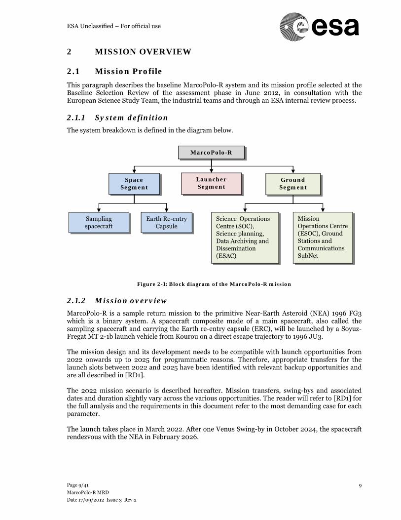
The system breakdown is defined in the diagram below.
Figure 2-1: Block diagram of the MarcoPolo-R mission
2.1.2 Mission overview
MarcoPolo-R is a sample return mission to the primitive Near-Earth Asteroid (NEA) 1996 FG3 which is a binary system. A spacecraft composite made of a main spacecraft, also called the sampling spacecraft and carrying the Earth re-entry capsule (ERC), will be launched by a Soyuz-Fregat MT 2-1b launch vehicle from Kourou on a direct escape trajectory to 1996 JU3. The mission design and its development needs to be compatible with launch opportunities from 2022 onwards up to 2025 for programmatic reasons. Therefore, appropriate transfers for the launch slots between 2022 and 2025 have been identified with relevant backup opportunities and are all described in [RD1]. The 2022 mission scenario is described hereafter. Mission transfers, swing-bys and associated dates and duration slightly vary across the various opportunities. The reader will refer to [RD1] for the full analysis and the requirements in this document refer to the most demanding case for each parameter. The launch takes place in March 2022. After one Venus Swing-by in October 2024, the spacecraft rendezvous with the NEA in February 2026.
MarcoPolo-R
Launcher Segment
Ground Segment
Space Segment
Earth Re-entry Capsule
Sampling spacecraft
Mission Operations Centre (ESOC), Ground Stations and Communications SubNet
Science Operations Centre (SOC), Science planning, Data Archiving and Dissemination (ESAC)
ESA Unclassified – For official use
Page 10/41
MarcoPolo-R MRD
Date 17/09/2012 Issue 3 Rev 2
10
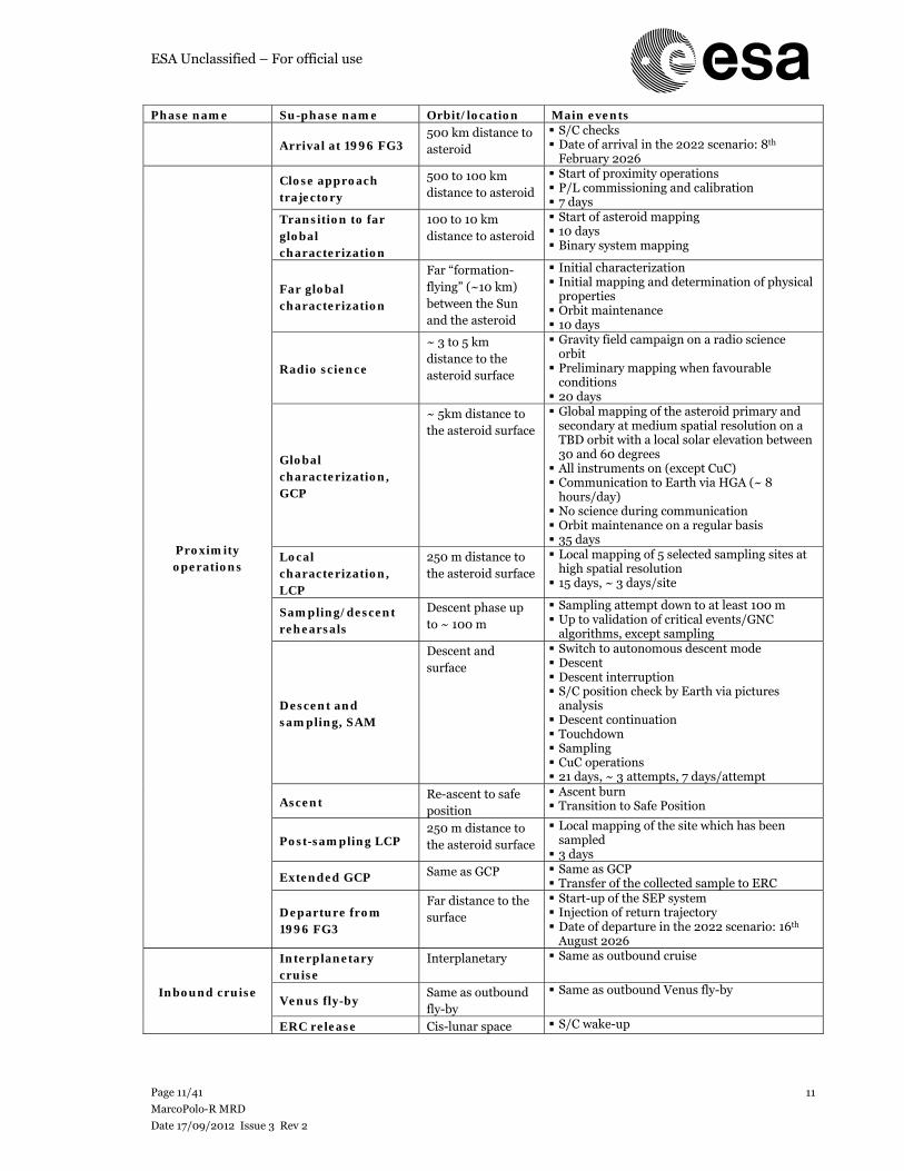
In the 2022 scenario the proximity operations last for ~ 190 days (but for other opportunities it ranges from 180 through 390 days). The proximity/science operations are described in 2.1.4. In a nutshell, this phase will include instrument calibration, far and close observations of the binary system with the various science instruments, gravity field determination and hazard mapping above roughly 5 km altitude. Five sampling site candidates are then characterized at high resolution at about 250 m (TBC) distance to the surface during a few minutes in order to determine the most suitable sampling site (i.e. yielding the best compromise between science return and risk-mitigation). After one successful sampling rehearsal, the spacecraft, which will be designed to cope with surface hazards (e.g. large clearance to the surface), navigates towards the finally selected touchdown/sampling site and collects hundreds of g of surface material. The sampling strategy is based on a touch and go approach to lower cost and risk. Therefore the spacecraft performs a soft touchdown of the surface for a few seconds (in the order of 2-5 seconds) and then takes-off immediately after that to move into a safe position away from the surface. If it is confirmed, via a reliable verification technique, that a scientifically meaningful sample has been collected, the sample is transferred to the re-entry capsule and sealed. The spacecraft is then ready for departure back to Earth or can carry on orbital science if desired. If the sampling operation was not successful, the spacecraft can undertake 2 more attempts (3 attempts in total). The spacecraft departs from the asteroid in August 2026 and returns to Earth in April 2029 after one Venus swing-by in November 2027. The re-entry capsule is then released and undertakes a high-speed Earth re-entry at Ventry of maximum ~ 13 km.s-1 (in other scenarios the re-entry velocity is lower ~ 11-12.6 km.s-1). The capsule will be retrieved on the ground at the Woomera test range which has already been used for Hayabusa landing.
2.1.3 Mission phases and operations
Phase name Su-phase name Orbit/location Main events
Launch
Pre-launch Launch pad L-8 hours to launch
Launch and escape (LEOP)
Ascent trajectory and direct escape
Duration: Launch + 3 days Launch into direct escape orbit by Fregat MT
S/C Acquisition (LEOP + S/C commissioning).
Interplanetary Separation from Fregat MT upper stage Deployment of solar panels S/C and P/L commissioning Electric propulsion sub-system
commissioning 1st determination of S/C trajectory 1st launcher dispersion correction manoeuvre
Outbound cruise
Interplanetary cruise
Interplanetary Various electric propulsion thrust and coast phases 1st year: daily contact with S/C to monitor
health status of electric propulsion system After one year, only weekly coverage of the
S/C System and P/L check-out
Venus (x0 or x1 or x2) or Earth fly-by (x0 or x1) (generic)
Venus/Earth fly-by Interruption of electric propulsion Possible targeting manoeuvres with chemical
propulsion Determination of post fly-by S/C trajectory Possible recovery manoeuvre
Asteroid rendezvous
Rendezvous with 1996 FG3
Approach trajectory, from ~ 2000000 km (TBC) to 500 km
SEP and far approach Far range imaging (both for science and
navigation) Asteroid localization Targeting manoeuvres
ESA Unclassified – For official use
Page 11/41
MarcoPolo-R MRD
Date 17/09/2012 Issue 3 Rev 2
11
Phase name Su-phase name Orbit/location Main events
Arrival at 1996 FG3 500 km distance to asteroid
S/C checks Date of arrival in the 2022 scenario: 8th
February 2026
Proximity operations
Close approach trajectory
500 to 100 km distance to asteroid
Start of proximity operations P/L commissioning and calibration 7 days
Transition to far global characterization
100 to 10 km distance to asteroid
Start of asteroid mapping 10 days Binary system mapping
Far global characterization
Far “formation-flying” (~10 km) between the Sun and the asteroid
Initial characterization Initial mapping and determination of physical
properties Orbit maintenance 10 days
Radio science
~ 3 to 5 km distance to the asteroid surface
Gravity field campaign on a radio science orbit Preliminary mapping when favourable
conditions 20 days
Global characterization, GCP
~ 5km distance to the asteroid surface
Global mapping of the asteroid primary and secondary at medium spatial resolution on a TBD orbit with a local solar elevation between 30 and 60 degrees All instruments on (except CuC) Communication to Earth via HGA (~ 8
hours/day) No science during communication Orbit maintenance on a regular basis 35 days
Local characterization, LCP
250 m distance to the asteroid surface
Local mapping of 5 selected sampling sites at high spatial resolution 15 days, ~ 3 days/site
Sampling/descent rehearsals
Descent phase up to ~ 100 m
Sampling attempt down to at least 100 m Up to validation of critical events/GNC
algorithms, except sampling
Descent and sampling, SAM
Descent and surface
Switch to autonomous descent mode Descent Descent interruption S/C position check by Earth via pictures
analysis Descent continuation Touchdown Sampling CuC operations 21 days, ~ 3 attempts, 7 days/attempt
Ascent Re-ascent to safe position
Ascent burn Transition to Safe Position
Post-sampling LCP 250 m distance to the asteroid surface
Local mapping of the site which has been sampled 3 days
Extended GCP Same as GCP Same as GCP Transfer of the collected sample to ERC
Departure from 1996 FG3
Far distance to the surface
Start-up of the SEP system Injection of return trajectory Date of departure in the 2022 scenario: 16th
August 2026
Inbound cruise
Interplanetary cruise
Interplanetary Same as outbound cruise
Venus fly-by Same as outbound fly-by
Same as outbound Venus fly-by
ERC release Cis-lunar space S/C wake-up
ESA Unclassified – For official use
Page 12/41
MarcoPolo-R MRD
Date 17/09/2012 Issue 3 Rev 2
12
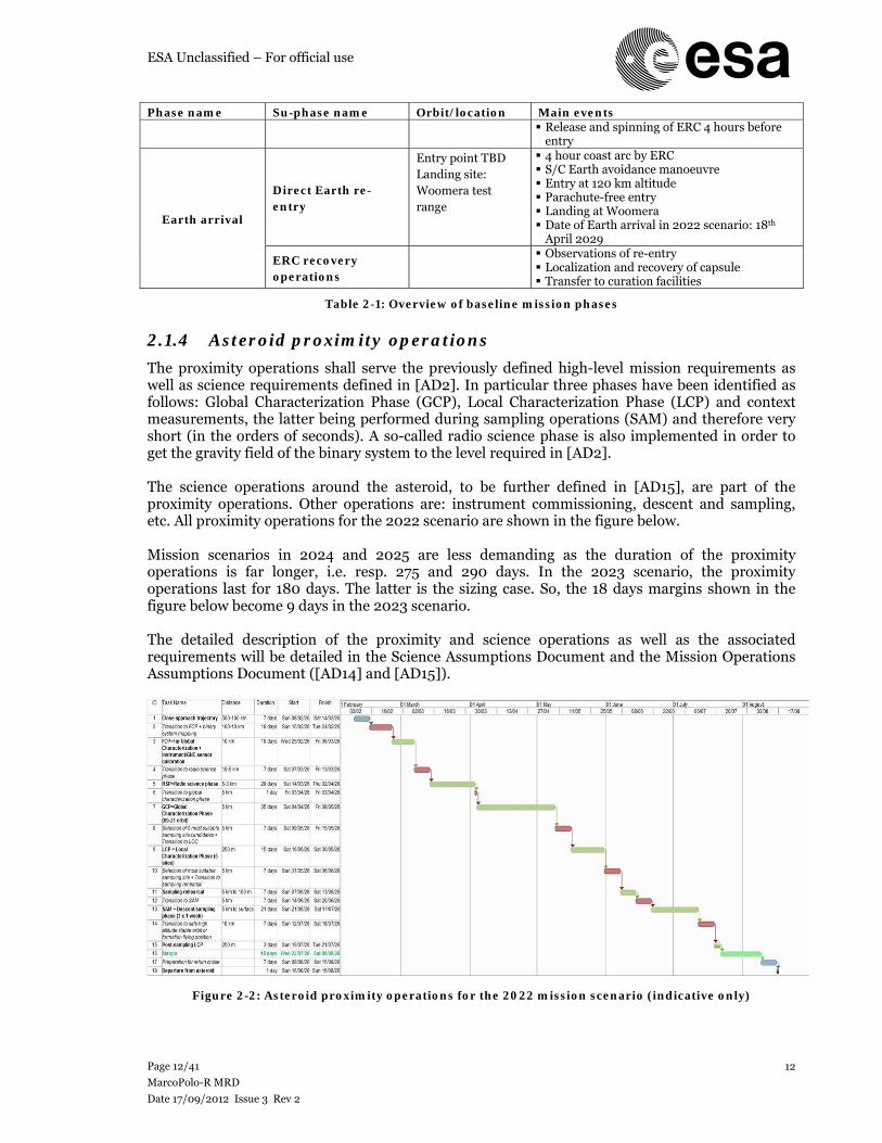
Phase name Su-phase name Orbit/location Main events Release and spinning of ERC 4 hours before
entry
Earth arrival
Direct Earth re-entry
Entry point TBD Landing site: Woomera test range
4 hour coast arc by ERC S/C Earth avoidance manoeuvre Entry at 120 km altitude Parachute-free entry Landing at Woomera Date of Earth arrival in 2022 scenario: 18th
April 2029
ERC recovery operations
Observations of re-entry Localization and recovery of capsule Transfer to curation facilities
Table 2-1: Overview of baseline mission phases
2.1.4 Asteroid proximity operations
The proximity operations shall serve the previously defined high-level mission requirements as well as science requirements defined in [AD2]. In particular three phases have been identified as follows: Global Characterization Phase (GCP), Local Characterization Phase (LCP) and context measurements, the latter being performed during sampling operations (SAM) and therefore very short (in the orders of seconds). A so-called radio science phase is also implemented in order to get the gravity field of the binary system to the level required in [AD2]. The science operations around the asteroid, to be further defined in [AD15], are part of the proximity operations. Other operations are: instrument commissioning, descent and sampling, etc. All proximity operations for the 2022 scenario are shown in the figure below. Mission scenarios in 2024 and 2025 are less demanding as the duration of the proximity operations is far longer, i.e. resp. 275 and 290 days. In the 2023 scenario, the proximity operations last for 180 days. The latter is the sizing case. So, the 18 days margins shown in the figure below become 9 days in the 2023 scenario. The detailed description of the proximity and science operations as well as the associated requirements will be detailed in the Science Assumptions Document and the Mission Operations Assumptions Document ([AD14] and [AD15]).
Figure 2-2: Asteroid proximity operations for the 2022 mission scenario (indicative only)
ESA Unclassified – For official use
Page 13/41
MarcoPolo-R MRD
Date 17/09/2012 Issue 3 Rev 2
13
3 MISSION REQUIREMENTS
The MarcoPolo-R mission has two main top-level objectives which relate to its science objectives: R-MIS-010 MarcoPolo-R shall safely return to Earth a sample from the primitive Near-Earth
Asteroid 1996 FG3. Main objective of the mission. R-MIS-020 The mission shall perform global and local characterization of the Near-Earth
Asteroid to retrieve the sample context information at the resolutions defined below.
Spatial resolution
for imaging in the visual range
Spatial resolution for VIS/IR spectrometer
Spatial resolution for mid-IR instrument
Global characterisation
Order of dm Order of m Order of 10 m
Local characterisation
Order of mm Order of dm Order of dm
Context measurements
1 mm - -
Table 3-1: Resolution requirements for global characterisation, local characterisation, and context measurements
‘Global characterisation’ means to measure the properties of the complete NEA, on a global scale;
‘Local characterisation’ is the high-resolution characterisation of up to 5 dedicated areas which are identified as potential sampling sites;
‘Sample context’ are measurements being performed at the actual sampling site.
Besides the science objectives, in-situ investigations defined in R-MIS-020 are meant to support the safe operation of the S/C in close proximity to the NEA and the safe collection of the sample(s).
4 PROGRAMMATICS REQUIREMENTS
The following requirements are related to the schedule, planning and development of the mission as a whole. R-PRM-010 The launch of the MarcoPolo-R baseline mission to the binary asteroid 1996 FG3
shall nominally occur by 2022.
Note: The M3 mission is intended as a backup candidate for the 2022 launch slot, depending on JUICE schedule. Although in the science programme the baseline launch slot for M3 is 2024, all current study planning should remain compatible with a 2022 launch. The final decision on the nominal launch date will be made following JUICE mission adoption.
R-PRM-020 The MarcoPolo-R mission shall also be compatible, in all ways, with launch
opportunities in 2024 and 2025.
ESA Unclassified – For official use
Page 14/41
MarcoPolo-R MRD
Date 17/09/2012 Issue 3 Rev 2
14
“All ways”: Launch mass; Sizing of: propellant tanks, thermal control, power, data downlink, etc.
G-PRM-030 The MarcoPolo-R mission should also be compatible, in all ways, with launch
opportunities in 2023. R-PRM-040 The total mission duration shall not exceed 8 years.
Mission duration is defined as the time between launch and landing of the Earth re-entry capsule at the end of mission.
R-PRM-050 Deleted. R-PRM-060 Deleted. R-PRM-070 Deleted.
R-PRM-080 Deleted. R-PRM-090 Deleted.
5 PLANETARY PROTECTION AND SAMPLE CONTAMINATION REQUIREMENTS
5.1 Planetary Protection requirements These are the high-level requirements related to planetary protection and sample contamination (e.g. PP category, S/C cleanliness, contaminant tracking, etc.). The engineering requirements related to it will be specified in the relevant category requirements (e.g. AIV for clean room environment, spacecraft for level of sterilization, etc.). R-PPR-010 The MarcoPolo-R mission shall comply with all planetary protection measures
listed in [AD5]. R-PPR-020 The MarcoPolo-R mission shall fulfil the requirements of planetary protection
category II. R-PPR-030 The return leg of the MarcoPolo-R mission shall be classified as planetary
protection category V unrestricted return. R-PPR-040 Deleted.
5.1.1 Science contamination requirements
R-CON-010 Contaminants or undesired particles (TBD) generated by the spacecraft (e.g. propellant plume, outgassing, etc.) shall have a density lower than 1014 (1013 as a goal) molecules/cm2 on the asteroid surface and/or on the collected sample.
Typical unwanted contaminants TBD by the science team. See [AD2]
R-CON-020 The potential contaminants shall be identified, controlled, tracked, documented
and readily identifiable from the asteroid sample material. The tracking of these contaminants shall start as of the S/C manufacturing process.
ESA Unclassified – For official use
Page 15/41
MarcoPolo-R MRD
Date 17/09/2012 Issue 3 Rev 2
15
Ref. [AD2] & [AD5]. Relates to the science contamination.
R-CON-030 Witness plates shall be implemented in order to track the possible contaminants
throughout the AIV/AIT and various mission phases and shall be returned to Earth.
E.g. propellant, S/C outgassing, etc. See [AD2].
R-CON-040 The spacecraft elements shall cope with the following sterilization and cleaning procedures in order to keep low-levels of forward contamination: Alcohol cleaning, TBD.
Ref. [AD2].
6 PAYLOAD DESCRIPTION AND REQUIREMENTS
6.1 Model payload instruments
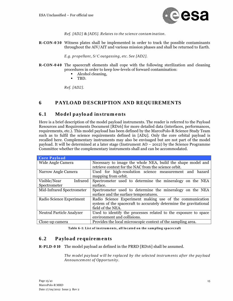
Here is a brief description of the model payload instruments. The reader is referred to the Payload Resources and Requirements Document [RD16] for more detailed data (interfaces, performances, requirements, etc.). This model payload has been defined by the MarcoPolo-R Science Study Team such as to fulfil the science requirements defined in [AD2]. Only the core orbital payload is recalled here. Complementary instruments may also be envisaged but are not part of the model payload. It will be determined at a later stage (Instrument AO – 2012) by the Science Programme Committee whether the complementary instruments shall and can be accommodated. Core Payload Wide Angle Camera Necessary to image the whole NEA, build the shape model and
retrieve context for the NAC from the science orbit. Narrow Angle Camera Used for high-resolution science measurement and hazard
mapping from orbit. Visible/Near Infrared Spectrometer
Spectrometer used to determine the mineralogy on the NEA surface.
Mid-Infrared Spectrometer Spectrometer used to determine the mineralogy on the NEA surface and the surface temperatures.
Radio Science Experiment Radio Science Experiment making use of the communication system of the spacecraft to accurately determine the gravitational field of the NEA.
Neutral Particle Analyzer Used to identify the processes related to the exposure to space environment and collisions.
Close-up camera Provides the local microscopic context of the sampling area.
Table 6-1: List of instruments, all located on the sampling spacecraft
6.2 Payload requirements
R-PLD-010 The model payload as defined in the PRRD [RD16] shall be assumed. The model payload will be replaced by the selected instruments after the payload
Announcement of Opportunity.
ESA Unclassified – For official use
Page 16/41
MarcoPolo-R MRD
Date 17/09/2012 Issue 3 Rev 2
16
R-PLD-020 Science instruments shall not be used as baseline GNC sensors. R-PLD-030 Deleted.
R-PLD-040 Deleted. R-PLD-050 The Absolute Pointing Error (APE) of the payload, during data acquisition, shall be
less than 0.1 mrad 3-σ, for the yaw, roll and pitch angles (TBC). R-PLD-060 The Relative Pointing Error (RPE) of the payload shall be less than 0.03 mrad over
1 s 3-σ, deg for the yaw, roll and pitch angles (TBC). R-PLD-070 The sampling spacecraft shall provide a payload mass allocation of 36 kg (TBC).
Including maturity margins, but no systems margin. R-PLD-080 During science operations in orbit around the asteroid, the spacecraft shall provide
an operating payload power allocation of 76.8 W (TBC).
Including maturity margins, but no systems margin. R-PLD-090 During non-science operations in orbit around the asteroid, the spacecraft shall
provide a stand-by payload power allocation of 28.8 W (TBC).
Including maturity margins, but no systems margin. R-PLD-100 During descent and sampling operations the spacecraft shall provide a power
allocation of 15 W (TBC) to the close-up camera. All other instruments are in off (if allowed by their thermal requirements) or stand-by mode.
Including maturity margins, but no systems margin. CuC only.
R-PLD-110 The spacecraft shall provide 10.8 W (TBC) of power to the close-up camera when it
is in stand-by mode. 10.8 W is the power consumption of the camera set CCSU, no systems margin.
This power is common to WAC, NAC and CuC and should always only be counted once.
R-PLD-120 Deleted. R-PLD-130 Deleted. R-PLD-140 Deleted. R-PLD-150 Deleted. .
7 TECHNOLOGY REQUIREMENTS
R-TEC-010 Only technologies at a minimum of TRL 5 by the time of the SPC Mission selection
(right after PRR) shall be implemented in the mission design.
ESA Unclassified – For official use
Page 17/41
MarcoPolo-R MRD
Date 17/09/2012 Issue 3 Rev 2
17
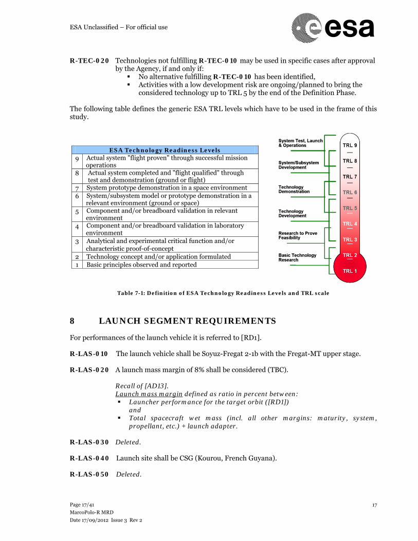
R-TEC-020 Technologies not fulfilling R-TEC-010 may be used in specific cases after approval
by the Agency, if and only if: No alternative fulfilling R-TEC-010 has been identified, Activities with a low development risk are ongoing/planned to bring the
considered technology up to TRL 5 by the end of the Definition Phase. The following table defines the generic ESA TRL levels which have to be used in the frame of this study.
ESA Technology Readiness Levels 9 Actual system "flight proven" through successful mission
operations 8 Actual system completed and "flight qualified" through
test and demonstration (ground or flight) 7 System prototype demonstration in a space environment 6 System/subsystem model or prototype demonstration in a
relevant environment (ground or space) 5 Component and/or breadboard validation in relevant
environment 4 Component and/or breadboard validation in laboratory
environment 3 Analytical and experimental critical function and/or
characteristic proof-of-concept 2 Technology concept and/or application formulated 1 Basic principles observed and reported
Table 7-1: Definition of ESA Technology Readiness Levels and TRL scale
8 LAUNCH SEGMENT REQUIREMENTS
For performances of the launch vehicle it is referred to [RD1]. R-LAS-010 The launch vehicle shall be Soyuz-Fregat 2-1b with the Fregat-MT upper stage. R-LAS-020 A launch mass margin of 8% shall be considered (TBC).
Recall of [AD13]. Launch mass margin defined as ratio in percent between: Launcher performance for the target orbit ([RD1])
and Total spacecraft wet mass (incl. all other margins: maturity, system,
propellant, etc.) + launch adapter. R-LAS-030 Deleted. R-LAS-040 Launch site shall be CSG (Kourou, French Guyana). R-LAS-050 Deleted.
ESA Unclassified – For official use
Page 18/41
MarcoPolo-R MRD
Date 17/09/2012 Issue 3 Rev 2
18
9 OPERATIONS AND MISSION ANALYSIS REQUIREMENTS
This chapter defines the mission operations requirements. The following phases are covered in this chapter: post-launch or LEOP, cruise (outbound/inbound), DSM, GA, rendezvous, proximity operations, cislunar and re-entry. R-OPS-010 The jettisoning strategy of any element shall ensure collision avoidance with the
sampling spacecraft and the ERC or the asteroid at any stage of the mission with a TBD margin.
E.g. Soyuz-Fregat stage, ERC, P/L cover, etc.
R-OPS-020 No critical S/C operations shall be performed if the Sun-Earth-S/C angle is lower
than 5o.
e.g. descent, sampling, local characterization, etc. Data downlink is not considered to be a critical operation and therefore can be envisaged down to 3o.
R-OPS-030 No standard S/C operations shall be performed if the Sun-Earth-S/C angle is lower than 2o.
R-OPS-040 The ERC shall be released by the sampling spacecraft from the return hyperbolic trajectory and directly enter the Earth atmosphere.
R-OPS-050 The mission design shall cope with the minimum distances to the Sun during all
mission phases, i.e. coast and thrust arcs and asteroid proximity operations as specified in [RD1].
R-OPS-060 The mission design shall cope with the maximum distances to the Sun during all
mission phases, i.e. coast and thrust arcs and asteroid proximity operations as specified in [RD1].
R-OPS-070 The mission design shall cope with the maximum distances to Earth during all
mission phases, cruise and asteroid proximity operations as specified in [RD1]. R-OPS-080 The duration of a Solar conjunction or when the Sun-Earth-S/C angle is lower than
2o during the transfer to and from the asteroid and during proximity operations shall be limited to 50 days.
R-OPS-090 Mission analysis shall ensure ERC re-entry velocity and flight path angle such that
heat fluxes during re-entry do not exceed 15 MW/m2 (incl. margins as defined in [AD13]) and total pressure at stagnation point does not exceed 80 kPa.
Re-entry conditions to be defined at 120 km altitude. To remain within a feasible domain for plasma testing of thermal protection system.
G-OPS-100 Mission analysis should ensure a night re-entry of the ERC.
To ensure good observations of the chemical species involved in re-entry and limit temperature increase after ERC landing.
ESA Unclassified – For official use
Page 19/41
MarcoPolo-R MRD
Date 17/09/2012 Issue 3 Rev 2
19
R-OPS-110 The duration of the proximity operations about the asteroid shall be at least 180 days.
Mitigation of risk, feasibility of science operations, maximizing rehearsals, etc.
R-OPS-120 The proximity operations shall allow 5 local characterization phases (LCP) before
the first sampling attempt to image the 5 candidate sampling sites at high resolution and one LCP after a successful sampling attempt above the sampled site. 3 days (TBC) shall be allocated to each LCP.
R-OPS-130 The global characterization orbit or position shall be such that all surface features
(rocks, boulders, steep slopes, crater rims, etc.) larger than 1 meter (TBC) can be identified and located with a 20 meter (TBC) absolute precision on the asteroid global scale.
Global mapping of features (+ global shape model).
R-OPS-140 The local characterization campaign shall be such that all surface features larger
than 20 cm (TBC) can be identified and located within a 10 meter (TBC) absolute precision on the 5 sampling site candidates.
Mapping of features on the sampling site candidates (+ local digital elevation model for slope estimation).
R-OPS-150 A minimum of 3 sampling attempts shall be foreseen throughout the whole
proximity operations phase. R-OPS-160 Proximity operations shall be planned so as to avoid collision with the primary
asteroid and its secondary in case of temporary failures of the S/C or the ground segment.
See also, R-AUT-030 through R-AUT-070, R-PQA-080. R-OPS-170 The proximity operations shall be such as to fulfil the resolution requirements listed
in [AD2]. R-OPS-180 At least 2 weeks shall be included at the end of the proximity operations for margin
purposes. R-OPS-190 Deleted. R-OPS-200 The minimum duration of the global characterization phase before sampling shall
be 35 days (TBC). R-OPS-210 The proximity operations shall be compatible with a binary body as defined in R-
ENV-070/090/120/130/140/150. G-OPS-220 Between two sampling attempts one week should be dedicated to review of the first
sampling/attempt operations.
In order to evaluate the science interest of the first acquired sample and analyse telemetry data from the previous sampling phase.
ESA Unclassified – For official use
Page 20/41
MarcoPolo-R MRD
Date 17/09/2012 Issue 3 Rev 2
20
R-OPS-230 During descent a minimum of 5 pictures of the surface shall be taken and shall be stored in the spacecraft onboard memory for later transmission.
Complementary to minimum TM + outreach.
R-OPS-240 A full sampling attempt shall be preceded by at least one successful descent
rehearsal. A descent rehearsal does not need to involve surface touchdown. Its aim is to
validate the convergence of the navigation filter. Details TBD. R-OPS-250 The mission analysis and overall design shall enable asteroid surface touchdown
and sampling operations at any latitude and longitude. R-OPS-260 The sampling operations on the asteroid shall occur on a fully illuminated location. In order to get context information in the visible range (close-up camera). R-OPS-270 The sampling operations shall be based on a touch and go approach (a few seconds
touchdown, see definition of “touch and go” in 13.2). R-OPS-280 The descent/touchdown operations shall be such as to prevent the creation of dust
before sampling operations. R-OPS-290 Deleted. R-OPS-300 Deleted. R-OPS-310 The Earth Re-entry Capsule shall be released by the sampling spacecraft TBD hours
before Earth re-entry. R-OPS-320 The measurements in the visible range shall be performed with a local solar
elevation angle between 30 and 60 degrees. Visible range instruments shall nevertheless be on even during observations at other Sun aspect angles.
R-OPS-330 The radio science experiment shall be conducted from a “Radio-science” orbit and
allow to fulfil gravity-related science requirements defined in [AD2].
See definition of “Radio-science” orbit in chapter 13.2. Note that, if possible and of compatible with the instrument measurement requirements, other science measurements can be performed in parallel.
R-OPS-340 The selected sampling site shall be at least ~ 50 m diameter (TBC) (assuming that the asteroid surface has at least one such a site).
See definition of sampling site in chapter 13.2. For such a large km-sized body, a 50 m area safe of hazards for a touch and go approach is very likely, see [RD13]
G-OPS-350 The selected sampling site should be free of features larger than TBD cm.
Sampling site minimizing risk. Operational requirement on the sampling site selection
ESA Unclassified – For official use
Page 21/41
MarcoPolo-R MRD
Date 17/09/2012 Issue 3 Rev 2
21
10 SPACE SEGMENT REQUIREMENTS
10.1 Spacecraft system requirements This chapter defines the general system requirements applicable to the sampling spacecraft and the ERC or the space segment as a whole (general, margin, etc.). They are derived from the science requirements, the mission safety, the general space design standards or more specific aspects of the mission applicable at system-level. R-SYS-010 The spacecraft lifetime shall be 8 years in space and 2 years for pre-launch ground
activities (AIT/AIV/storage) in a controlled environment and all space-based elements shall be designed and sized for this duration.
R-SYS-020 Deleted. R-SYS-030 The space segment shall be sized for the mission scenario which is most demanding
(i.e. worst case ΔV, launch mass, thermal and sun illumination environment) as defined in [RD1], covering the full launch window as defined in [AD13]/R-DV-4.
R-SYS-040 In this assessment study, the mission design shall follow the margin philosophy
defined in [AD13]. The margin philosophy and margin depletion scheme will be firmly defined at a later stage.
R-SYS-050 The space segment shall cope with the integration procedures on a Soyuz-Fregat 2-1
b from CSG in Kourou.
e.g. vertical integration atop the Soyuz third stage on the launch pad, etc. R-SYS-060 Deleted. R-SYS-070 The space segment shall be composed of 2 modules: Sampling spacecraft + Earth
Re-entry Capsule (ERC).
See Figure 13-1. R-SYS-080 All spacecraft shall be designed according to [RD4], [RD5], [RD6] and [RD7] unless
otherwise specified in this document.
Any conflict between the requirements in this document and the ECSS standards shall be reported to ESA.
R-SYS-090 The spacecraft system shall accommodate all necessary equipments and sub-
systems, including mass and volume margins as defined in [AD13] and compatible with launch windows as defined in [RD1].
R-SYS-095 The maximum spacecraft dry mass, respectively wet mass shall be TBD kg, TBD kg. R-SYS-100 The sampling spacecraft shall accommodate the science payload and enable
fulfilling all primary science measurements.
See [AD2] and payload as defined in [RD16]. R-SYS-110 A design-to-cost and risk minimization mission design approach shall be followed.
ESA Unclassified – For official use
Page 22/41
MarcoPolo-R MRD
Date 17/09/2012 Issue 3 Rev 2
22
R-SYS-120 The sampling spacecraft shall accommodate and transport the ERC throughout the
whole mission until release upon arrival at Earth. G-SYS-130 The sampling spacecraft should take images of the separated ERC after release. R-SYS-140 The design of the sampling spacecraft and ERC shall be robust against damage due
to debris and dust encountered during all proximity operations.
E.g. in-orbit dust/debris, touchdown/sampling on asteroid, etc. R-SYS-150 The S/C shall be designed to withstand the predicted micro-meteorite environment
throughout the mission with a probability larger than 0.998.
The micro-meteorite environment is as defined in [AD4]. R-SYS-160 The main spacecraft shall allow for commissioning and calibration of the orbital
science instruments during the transfer to the NEA, including during fly-bys. R-SYS-170 Deleted. R-SYS-180 Deleted. R-SYS-190 During the touch and go sampling operations, the sampling spacecraft shall
approach the surface with a maximum horizontal velocity of 5 cm.s-1 (TBC) at touchdown.
To limit the magnitude of forces on the touchdown/sampling system and to mitigate toppling.
R-SYS-200 During the touch and go sampling operations, the sampling spacecraft shall
approach the surface with a maximum vertical velocity of 10 cm.s-1 (TBC) at touchdown.
R-SYS-210 The sampling spacecraft shall have a maximum attitude of +/-10o with respect to
the local surface at touchdown (TBC).
To mitigate toppling and to limit constraints on spacecraft geometry (e.g. solar panels).
R-SYS-220 Deleted. R-SYS-230 Deleted.
R-SYS-240 The touchdown accuracy of the sampling spacecraft with respect to the targeted sampling site shall be better than 50 meters, 3-σ value (TBC).
R-SYS-250 The sampling spacecraft shall accommodate the ERC in a safe location such that the
risk of collision of the ERC Thermal Protection System with the asteroid surface is minimized.
R-SYS-260 After touchdown the full set of telemetry data acquired during descent shall be
protected from overwriting until receipt on Earth is confirmed.
ESA Unclassified – For official use
Page 23/41
MarcoPolo-R MRD
Date 17/09/2012 Issue 3 Rev 2
23
R-SYS-270 The ERC shall be designed such as to limit the total heat flux to 15 MW/m2 and
total pressure at stagnation point to 80 kPa.
To remain within a feasible domain for plasma testing of thermal protection system. Heat fluxes including margins as per [AD13].
R-SYS-280 The ERC shall perform a fully passive re-entry (i.e. no parachute, no propulsion, no
active control). R-SYS-290 Deleted.
R-SYS-300 The ERC and its sub-systems shall be designed such that the shock loads on the sample are lower than 2000 g quasi-static load (TBC) for any angle of attack up to 20 degrees (TBC).
Limit adequate for the sample. See [AD2].
G-SYS-310 The ERC and its sub-systems should be designed such that the shock loads on the
sample are lower than 800 g quasi-static load (TBC) for any angle of attack up to 20 degrees (TBC).
R-SYS-320 The ERC shall allow simple access to and recovery of the sample within the capsule
without damaging the sample container seal. R-SYS-330 The ERC shall be statically stable and its dynamic instabilities, if any, shall be such
that angle of attack variations are limited to 20 degrees (TBC) at all aerodynamic regimes after the peak of dynamic pressure.
ERC dimensions, inertia, mass and CoM, CoP location. Before peak of dynamic pressure, angle of attack variations are less critical.
R-SYS-340 The maximum deceleration of the ERC through re-entry shall be 80 g, quasi-static
load (TBC).
To ensure integrity of the ERC up to (excluded) landing. G-SYS-350 The ERC design should ensure that the sample is never exposed to temperatures
higher than +40oC. For less than one minute, +80oC is acceptable.
See [AD2]. G-SYS-360 The ERC should be equipped with a flight instrumentation package to perform the
following measurements during entry and descent: heat flux, temperature and pressure on both front and back shields at a frequency of 0.5 Hz (TBC).
This information will be stored. If implemented, the maximum allowable shocks on the memory shall be defined and included in R-SYS-300.
R-SYS-370 The sample sealing system shall prevent:
Less than 0.1 ppm of terrestrial water, Dust or liquid particles larger than 0.3 μm,
ESA Unclassified – For official use
Page 24/41
MarcoPolo-R MRD
Date 17/09/2012 Issue 3 Rev 2
24
to contaminate the sample up to storage of the capsule in the suitable sample curation facility after return.
See [AD2].
R-SYS-380 The sample sealing system shall withstand a shock load up to 2000 g quasi-static
load (TBC).
See R-SYS-300 and [AD2].
G-SYS-390 The sample sealing system should withstand a shock load up to 800 g quasi-static load (TBC).
See G-SYS-310 and [AD2].
R-SYS-400 Deleted. R-SYS-410 The spacecraft design and operations shall transmit back to Earth a minimum total
payload data volume of 122.35 GBit (TBC) before the end of the asteroid proximity operations.
Without any margins ([AD13] guidelines to be implemented), compressed data volume.
R-SYS-420 110.8 Gbit (TBC) of science data shall be transmitted back to Earth 2 weeks before
the start of sampling operations (SAM).
Without any margins ([AD13] guidelines to be implemented) , compressed data volume. Includes data from all phases, including GCP and LCP.
R-SYS-430 TBD Gbit of science data shall be transmitted back to Earth 2 weeks before the start
of LCP operations.
10.2 Platform sub-system requirements This chapter defines all key S/C sub-system requirements (pointing, thermal, power, data handling, telecommunications, etc.). They are derived from the system requirements or are requirements specific to a sub-system derived from space design standards or mission-specific need.
10.2.1 Thermal requirements
R-THE-010 The spacecraft thermal control system shall cope with the thermal needs of the
various spacecraft sub-systems as required, including P/L, at any stage of the mission as a function of the spacecraft thermal modes, including safe mode.
R-THE-020 The spacecraft thermal control system shall cope with the space environment
throughout the mission (incl. asteroid surface operations).
See [AD4]. Specific attention to be given to asteroid IR flux and closest distance to the Sun during transfer.
ESA Unclassified – For official use
Page 25/41
MarcoPolo-R MRD
Date 17/09/2012 Issue 3 Rev 2
25
R-THE-030 Sufficient telemetry and housekeeping information shall be provided for monitoring of thermal equipment (e.g. radiators, heaters, etc.).
Lessons learns from Rosetta (e.g. need to thoroughly monitor the effect of
pointing/solar aspect angle for the radiators). R-THE-040 The ERC heat shield thermal protection system material shall be able to withstand
entry conditions defined in R-SYS-270. Qualification margins for the TPS material are TBD.
10.2.2 Power requirements
R-POW-010 The spacecraft power system shall be made of solar arrays and batteries and shall
cope with the power needs of the various spacecraft sub-systems as required, including P/L, at any stage of the mission as a function of the spacecraft power modes, including safe mode.
I.e. power generation, storage, conditioning and distribution.
R-POW-020 The spacecraft battery shall be sized for worst case eclipses and the
descent/touchdown/re-ascent phase.
Eclipses due to the asteroid will be avoided for nominal operations but may be encountered if control of the spacecraft is lost or Earth eclipses during LEOP.
R-POW-030 The sizing of the solar arrays shall allow the S/C to stay on a ”Radio-science” orbit
and safe position as defined in 13.2.
To avoid asteroid escape via solar radiation pressure.
R-POW-040 Deleted. R-POW-050 The electrical design shall comply with the requirements of [RD6]. Tailoring of
these requirements may be proposed and need to be justified.
10.2.3 GNC/AOCS requirements
R-GNC-010 Deleted. R-GNC-020 Deleted. R-GNC-030 Deleted. R-GNC-040 Asteroid acquisition (i.e. identification of the target) shall be performed one week
(TBC) before the start of proximity operations.
Start of proximity operations defined in chapter 13.2. R-GNC-050 During sampling operations, the AOCS/GNC system shall prevent total attitude
excursions larger than 30 degrees (TBC) (with respect to the local vertical) and attitude rates larger than 5 deg/s (TBC).
ESA Unclassified – For official use
Page 26/41
MarcoPolo-R MRD
Date 17/09/2012 Issue 3 Rev 2
26
For instance to avoid the solar panels to hit the surface and further re-ascent with a safe attitude.
R-GNC-060 The AOCS system shall be able to maintain during safe mode the composite in a
Sun-pointing attitude using a minimum of the onboard resources while ensuring power generation, a survivable thermal environment and ground communication for vital equipment.
R-GNC-070 In the event of unavailability of the star trackers, the AOCS/GNC shall have the
capability to maintain and propagate attitude estimation whilst meeting the relevant pointing requirements.
R-GNC-080 Deleted. R-GNC-090 Deleted. G-GNC-100 Asteroid acquisition (i.e. identification of the target) should be performed two
weeks (TBC) before the start of proximity operations..
R-GNC-040 guarantees a minimum detection time.
R-GNC-110 After separation from the launcher upper stage, the AOCS shall: Damp out the residual angular rates, Bring the S/C into a power safe pointing attitude within a time compatible
with the S/C internal electrical energy capability, Maintain the S/C attitude to allow communications with the ground as
planned for LEOP operations. R-GNC-120 Deleted.
10.2.4 DHS requirements
R-DHS-010 The spacecraft data handling system shall cope with the data transfer and storage
requirements of the various spacecraft sub-systems, including payload, at any stage of the mission.
R-DHS-020 The DHS shall be able to receive TC and send TM from/to ground at the same time. R-DHS-030 The DHS shall be able to command the instruments and equipment onboard. R-DHS-040 The DHS shall provide reconfiguration capabilities in case of failure detection. R-DHS-050 The DHS shall manage the redundancy for the relevant sub-systems. R-DHS-060 During touchdown/sampling operations, the DHS shall provide the capability to
store the scientific and housekeeping data generated by the complete close-up camera and sampling operations cycle.
R-DHS-070 The DHS system shall support uplink and downlink file transfer.
ESA Unclassified – For official use
Page 27/41
MarcoPolo-R MRD
Date 17/09/2012 Issue 3 Rev 2
27
R-DHS-080 The DHS shall provide the storage capability such that all science data can be downlinked (R-SYS-410/420/430) during proximity operations and assuming 2 consecutive downlink windows (i.e. 2 consecutive daily windows) are missed.
R-DHS-090 The DHS system shall be compatible with the maximum data rates of each
instrument as specified in [RD16]. R-DHS-100 The DHS system shall implement system-level failure FDIR of the P/L and
platform.
10.2.5 Propulsion requirements
R-PRO-010 Deleted. R-PRO-020 The propulsion system shall cope with all operations and associated Delta-V/thrust
requirements incl.: transfer (MCC, DSM, etc.), asteroid proximity operations, initial fly-bys, gravity field campaign, controlled orbits, local characterization phase, sampling rehearsals, descent/touchdown and re-ascent phases, etc.
R-PRO-030 The by-products of the propulsion system shall be characterized and reported at
ppb level prior to the mission. R-PRO-040 The propulsion sub-system shall be designed to be compatible with any operational
S/C attitude. The main engine and any reaction control thruster shall be thermally qualified for such environmental conditions.
Particularly for the asteroid surface environment.
R-PRO-050 The propulsion sub-system thermal design shall assure that the minimum
predicted temperatures of any wetted component or surface contacting the propellant remain at least 10oC above the maximum freezing point of the onboard propellant.
R-PRO-060 The performances of the propulsion system in terms of total impulse and margin
shall satisfy the requirements imposed by the mission, the trajectory analysis and the overall system requirements.
10.2.6 Communications requirements
R-COM-010 Deleted. R-COM-020 Real-time data shall be provided directly to Earth during descent and sampling
allowing monitoring of the major events. A data rate of 100 bit/s shall be possible (TBC).
Beagle 2 recommendations: get a minimum health status of the S/C throughout descent. 100 bit/s in line with MER data.
R-COM-030 The mission design shall comply with ESA ECSS telecommunication standards
([RD14]).
ESA Unclassified – For official use
Page 28/41
MarcoPolo-R MRD
Date 17/09/2012 Issue 3 Rev 2
28
R-COM-040 The communication system shall support the two-way Ranging and Doppler measurements of the S/C throughout all mission phases and ΔDOR if high-precision navigation is required (e.g. RSE campaign) TBC.
R-COM-050 The link budgets of the spacecraft to ground shall be calculated for a weather
availability of 95%. R-COM-060 Science data shall be downlinked by the spacecraft in X-band. R-COM-070 The maximum bit error rate during data downlink shall be better than 10-5.
R-COM-080 Deleted. R-COM-090 The telecommunication system shall be capable of simultaneously handling
telemetry, ranging and telecommands. R-COM-100 Deleted.
R-COM-110 The telecommunication equipment shall support the RSE as specified in [RD16].
If Ka-band is required for science, this shall be considered as a science instrument.
R-COM-120 The telecommunications system shall be able to downlink all science data as per R-SYS-410/420/430.
R-COM-130 All images taken by navigation cameras and required to be sent to ground (e.g.
asteroid shape model, local slopes around sampling sites, etc.), if any, shall be downloaded.
10.2.7 Structure requirements
R-STR-010 The spacecraft structure shall support the launch environment [AD8] with MOS as
defined in [RD5] which will be agreed with the agency. R-STR-020 The spacecraft structure shall support the mechanical static and dynamic loads
encountered during its entire lifetime, including: manufacturing, handling, transportation, testing, launch and in-orbit operations (incl. touchdown on the asteroid).
R-STR-030 The structure directly containing the sample (sample container) shall be able to
withstand the loads (i.e. still fulfilling R-SYS-380) as defined in R-SYS-300. R-STR-040 The structural stiffness shall guarantee fundamental frequencies of the S/C within
the requirements of the LV to avoid dynamic coupling. R-STR-050 The structural design shall be based on simple load paths. R-STR-060 The structural design shall provide a minimum margin of 15% over the minimum
frequencies specified by the Launcher User Manual [AD8] before verification of S/C dynamic properties by test.
ESA Unclassified – For official use
Page 29/41
MarcoPolo-R MRD
Date 17/09/2012 Issue 3 Rev 2
29
10.2.8 Mechanism requirements
R-MEC-010 The sampling mechanism shall have the capability to collect hundreds of grams of
material.
See [AD2]. R-MEC-020 The sampling mechanism shall have the capability to collect cm-sized fragments,
plus a large amount (minimum several grams) of small particles (100s of μm-sized to mms-sized).
See [AD2].
R-MEC-030 The sampling mechanism shall be compatible with asteroid material having the
properties defined in R-ENV-100 and [AD2]. R-MEC-040 The sampling device (or any other part of the spacecraft) shall be equipped with
autonomous means of verifying suitable sampling with a 95% probability (TBC).
Determine whether the sampling operation was successful or not. G-MEC-050 The sampling device (or any other part of the spacecraft) should have the capability
to provide a rough estimate of the collected sample mass and volume. R-MEC-060 All mechanisms involved in the SATCS chain shall be cleaned so as to fulfil levels
specified in R-CON-010/R-SYS-370 and according to the standards defined in R-CON-040.
R-MEC-070 Deleted. R-MEC-080 All mechanisms shall be protected against debris generated by touchdown and
sampling on the asteroid. R-MEC-090 The SATCS system shall be able to monitor its torque, thrust and penetration depth
(if applicable). R-MEC-100 It shall be possible to detect blockage of a sampling unit and release it before re-
ascent in case it gets stuck during the touchdown/sampling operations. R-MEC-110 Deleted. G-MEC-120 The design of the sample collection and distribution unit (incl. container) should
ensure that the sample, after collection, is never exposed to temperatures higher than +40oC. For less than one minute +80oC is acceptable.
Sample temperature and collection process. See [AD2].
G-MEC-130 Through the monitoring of its various sensors’ information as a function of
penetration progress, the SATCS should support the determination/estimation of the soil’s mechanical properties.
Soil properties: density, porosity/compaction, hardness/cohesion, cementation, etc. To be coupled with R-MEC-090.

ESA Unclassified – For official use
Page 30/41
MarcoPolo-R MRD
Date 17/09/2012 Issue 3 Rev 2
30
R-MEC-140 The design of the touchdown mechanism system as well as the sampling
mechanism shall be such that total attitude excursions are lower than 30 degrees (TBC) (with respect to the local vertical) and attitude rates lower than 5 deg/s (TBC).
See R-GNC-050.
10.3 Autonomy and FDIR requirements
R-AUT-010 Operations of the spacecraft shall be possible during all mission phases via the
execution of pre-programmed sequence, or via onboard autonomy during the descent and sampling phase. Level of autonomy and detailed spacecraft operations throughout the various spacecraft operations are TBD.
R-AUT-020 S/C autonomy shall ensure achievement of all mission goals. R-AUT-030 During asteroid proximity operations, if a ground TC is expected for the S/C to
proceed with its nominal manoeuvre and this TC is not received within a TBD time, the S/C shall be able to perform a valid transition into an asteroid Collision Avoidance Mode.
R-AUT-040 During descent/sampling operations on the asteroid, in case of any failure or non-
nominal S/C equipment TM (sub-system or system) the spacecraft shall autonomously be able to perform a valid transition into an asteroid Collision Avoidance Mode.
R-AUT-050 After TBD minutes in Collision Avoidance Mode and no ground feedback the
spacecraft shall be able to perform a valid transition into Safe Mode. R-AUT-060 The S/C shall be able to receive a TC from the ground to switch from Collision
Avoidance Mode to Safe Mode. R-AUT-070 In any operations other than descent/sampling, in case of major system failure (or
non-recoverable single failure) the spacecraft shall be able to survive in Safe Mode without the need for ground contact in: A “safe position” if during asteroid proximity operations phase, On its transfer trajectory in case of LEOP or interplanetary cruise phase.
R-AUT-080 The spacecraft operating modes shall include a system-level Safe Mode that ensures
the following properties are fulfilled: Uninterrupted power supply, Safe thermal conditions, Continuous communication with ground, Predictable configuration minimising the onboard power demand and data
traffic. R-AUT-090 The spacecraft operating modes shall include a system-level Collision Avoidance
Mode that ensures the following properties are fulfilled: Autonomously go into a “safe position”, Guarantee of no collision with the asteroid before switching to Safe Mode, Uninterrupted power supply,
ESA Unclassified – For official use
Page 31/41
MarcoPolo-R MRD
Date 17/09/2012 Issue 3 Rev 2
31
Safe thermal conditions, Predictable configuration minimising the onboard power demand and data
traffic. R-AUT-100 When in Safe Mode the spacecraft shall have the capability to transmit a predefined
set of data parameters at a rate of up to TBD b.s-1. R-AUT-110 The spacecraft shall be able to perform a valid mode transition upon receipt of a
telecommand at all times and in all spacecraft modes. R-AUT-120 The fault management systems shall be intrinsically fail-safe. R-AUT-130 The spacecraft shall function autonomously throughout any solar conjunctions on
cruise to and back from the asteroid. R-AUT-140 The system (or FDIR) shall provide the capability for automatic detection, isolation
and recovery of any credible system or subsystem anomaly. R-AUT-150 Sampling site targeting and last go/no-go decision during actual descent and
sampling shall be ground-based. Autonomous sampling site re-targeting shall not be allowed (see R-AUT-040 instead).
10.4 Environmental requirements
The following defines the environment-related requirements that the spacecraft has to comply with throughout the mission, whether that is the launch, interplanetary, spacecraft, asteroid or Earth re-entry environment. R-ENV-010 The spacecraft composite and all its sub-systems, including payload, shall be
compatible with the launch environment as defined in ([AD8]). R-ENV-020 The mission design shall be compliant with the general space environment (cruise)
requirements defined in [RD4] and the mission-specific (e.g. asteroid) environment requirements defined in [AD4].
R-ENV-030 Deleted. R-ENV-040 The sample shall never be exposed to magnetic field larger than 200 µT. R-ENV-050 The spacecraft shall satisfy the electric and magnetic cleanliness (EMC)
requirements specified by the payload (TBD reference). R-ENV-060 Deleted. R-ENV-070 The maximum surface temperature of the sampling site to be considered for the
design of the spacecraft shall be 500 K (TBC). G-ENV-080 Deleted. R-ENV-090 The mission design shall be compatible with the rotation period of the primary
asteroid of ~ 3.6 hours +/- 0.1%.
ESA Unclassified – For official use
Page 32/41
MarcoPolo-R MRD
Date 17/09/2012 Issue 3 Rev 2
32
R-ENV-100 The surface properties which shall be assumed for the design of the sampling mechanism are as follows: No solid rock. Only loose material shall be assumed, Grain Size: µm up to 3 cm, Shape: any (rounded, tabular, elongated, etc.), Cohesion: 0.1 – 5 kPa, Compressive strength: Up to 30 MPa, Bulk density: <1 – 2.2 g.cm-3, Angle of internal friction: 20 - 40.
R-ENV-110 Deleted. R-ENV-120 The asteroid body density shall be assumed to be 1300 ± 600 kg.m-3. This also
applies to the secondary body.
See [AD4]. R-ENV-130 A diameter of 1550 m – 2110 m shall be assumed for the primary body.
See [AD4]. R-ENV-140 A diameter of 430 m – 590 m shall be assumed for the secondary body.
See [AD4]. R-ENV-150 A binary with the following properties shall be assumed:
Secondary orbital semi-major axis: 2.8 + 1.7/-0.7 km, Secondary orbital eccentricity: 0.05 ± 0.05, Secondary orbital period around primary: 16.15 ± 0.02 hours.
See [AD4].
10.5 AIV and testing requirements
R-AIV-010 The AIV activities of the S/C shall be compliant with the integration requirements of a Soyuz-Fregat 2-1 b in CSG Kourou.
R-AIV-020 The AIV facilities shall enable the implementation of sterilization and cleaning
procedures as defined in R-CON-040.
10.6 Ground segment
R-GRS-010 The mission shall use and be compatible with the standards of the ESA deep space network as well as the NASA deep space network.
R-GRS-020 The MarcoPolo-R mission shall be operated by ESA/ESOC. R-GRS-030 During LEOP, TBD ESA ground stations shall be used for contact with the
spacecraft. LEOP is defined as the first 72 hours (TBC) after the separation of the spacecraft
from the Fregat upper stage.

ESA Unclassified – For official use
Page 33/41
MarcoPolo-R MRD
Date 17/09/2012 Issue 3 Rev 2
33
R-GRS-040 After LEOP, the ESA station at TBD location shall be the primary station used for contact with the spacecraft, with TBD location as backup.
R-GRS-050 The ground segment shall provide for a 24 hour coverage capability for asteroid
descent, touchdown, sampling and local characterization operations. R-GRS-060 The ground segment shall cope with the data volume defined in R-SYS-
410/420/430. R-GRS-070 It shall be possible to retrieve the ERC within 4 hours (TBC) after landing on Earth
without the aid of tracking devices onboard the ERC. Also to be taken into account for ERC landing site selection. R-GRS-080 It shall be possible to track the ERC re-entry during the whole re-entry operation. G-GRS-090 It shall be possible to retrieve the ERC within 2 hours (TBC) after landing on Earth
without the aid of tracking devices onboard the ERC.
To limit thermal excursion on the sample. R-GRS-100 The ground segment shall support the on-orbit calibration of the satellite
autonomous pointing capabilities. R-GRS-110 The ground segment shall elaborate an operational concept based on multiple
uplink and downlink attempts and a respective timing for the preparation of the orbit timeline to enable standard operations under superior solar conjunction conditions with a Sun-Earth-Spacecraft angle as low as 2° (TBC). The required success rate sets of commands (number of commands in set: 50 TBC) and for telemetry packets is TBD.
Probability to be calculated for space weather conditions typical for the solar cycle at the time of the conjunction.
R-GRS-120 The ground segment shall be able to support at least 4 (including rehearsals)
touchdown and sampling attempts during the asteroid proximity phase. R-GRS-130 The ground segment shall be able to support at least the 5 local characterization
phases before sampling and the last one after sampling (above the sampled site). R-GRS-140 The ground segment shall provide for a flexible re-planning capability during the
asteroid phase. The manoeuvre planning for new asteroid proximity orbits and new sampling site targets shall be available within 4 days (TBC) after reception of the respective request.
R-GRS-150 The ground segment shall construct a global asteroid map and a global Digital
Elevation Model with a 1-m spatial resolution (TBC) of the whole asteroid during the GCP phase primarily based on the navigation sensor information.
See R-OPS-130.
ESA Unclassified – For official use
Page 34/41
MarcoPolo-R MRD
Date 17/09/2012 Issue 3 Rev 2
34
R-GRS-160 The ground segment shall construct a local map and a local Digital Elevation Model with a 20-cm spatial resolution (TBC) of the sampling site candidates during the LCP phase primarily based on the navigation sensor information.
See R-OPS-140.
R-GRS-170 The ground segment shall be able to obtain the position information relative to the targeted sampling site sent by the spacecraft as a package of “images” and AOCS housekeeping data, process this data and upload an appropriate “guidance” telecommand within one hour (TBC) of reception of the images in order to either reach the sampling site or to abort the descent.
10.7 Product assurance and RAMS requirements
R-PQA-010 Deleted. R-PQA-020 Deleted. R-PQA-030 The mission design shall be free of Single Point Failures, shall be one-failure
tolerant and shall ensure avoidance of failure propagation. . R-PQA-040 Instrument failures shall not cause failure or damage to other instruments or other
spacecraft subsystems. R-PQA-050 Instrument failures shall not cause the spacecraft to enter a Collision Avoidance or
Safe Mode. R-PQA-060 Deleted. R-PQA-070 Where redundancy is employed, the design shall allow operation and verification of
the redundant item/function independent of nominal use. R-PQA-080 In case of anomalies or failures from which the spacecraft cannot recover
autonomously, the spacecraft shall be able to autonomously perform a valid transition into: Collision Avoidance Mode and later on Safe Mode if during
descent/sampling operation, Safe Mode if during any other phase than descent/sampling operations.
R-PQA-090 The overall mission reliability shall be better than 90% (TBC). R-PQA-100 The design philosophy for all mechanisms shall be as defined in [RD5]. R-PQA-110 The risk of casualty resulting from the ERC re-entry shall be 1:10000 (TBC). R-PQA-120 Deleted. R-PQA-130 The communication system shall implement full redundancy except for the main
antenna dishes (e.g. HGA). R-PQA-140 A highly reliable backup sampling method shall be implemented to ensure a sample
can be collected should the main sampling mechanism fail.
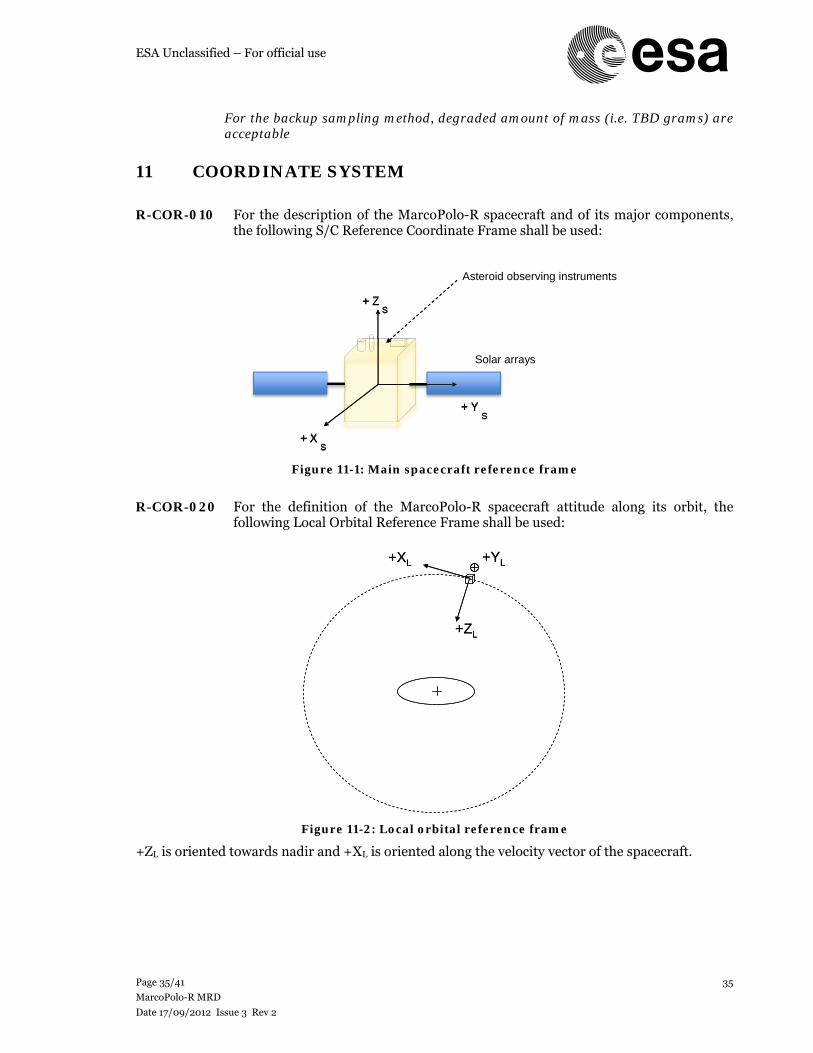
ESA Unclassified – For official use
Page 35/41
MarcoPolo-R MRD
Date 17/09/2012 Issue 3 Rev 2
35
For the backup sampling method, degraded amount of mass (i.e. TBD grams) are acceptable
11 COORDINATE SYSTEM
R-COR-010 For the description of the MarcoPolo-R spacecraft and of its major components,
the following S/C Reference Coordinate Frame shall be used:
Figure 11-1: Main spacecraft reference frame
R-COR-020 For the definition of the MarcoPolo-R spacecraft attitude along its orbit, the
following Local Orbital Reference Frame shall be used:
Figure 11-2: Local orbital reference frame
+ZL is oriented towards nadir and +XL is oriented along the velocity vector of the spacecraft.
+ZL
+XL +YL
+ZL
+XL +YL
+ ZS
+ Y S
+ X S
Solar arrays
+ ZS
+ Y S
+ X S
Asteroid observing instruments
ESA Unclassified – For official use
Page 36/41
MarcoPolo-R MRD
Date 17/09/2012 Issue 3 Rev 2
36
12 APPLICABLE AND REFERENCE DOCUMENTS
The Applicable Documents (AD’s) listed below shall be complied with, unless conflicting with the mission MSRD itself or where specifically stated. Their contents shall be considered as parts of the requirements of this document. A conflict between these documents and the MSRD shall be brought to the attention of ESA for clarification. The published ECSS (European Cooperation for Space Standardisation) space standards documents quoted in the MSRD shall be used as design references throughout the MarcoPolo-R assessment phase and are available on the Internet at: www.ecss.nl.
12.1 Applicable documents
[AD1] Deleted
[AD2] MarcoPolo-R Science Requirements Document, [MPR-RSSD-RS-001], issue 1.4, Document providing Science objectives and science requirements, including measurement specifications
[AD3] Deleted
[AD4] MarcoPolo-R Environment Document, [SRE-PA/2011.077], issue 1.2
[AD5] MarcoPolo-R – Assessment of Planetary Protection issues, [SRE-PA/2011.078], issue 1.0, Document providing recommendations on Planetary Protection issues relating to the potential NEA targets
[AD6] MarcoPolo-R Consolidated Report on Mission Analysis, [Reference TBD], issue 1.0, ESOC, document describing the detailed reference transfers and orbits as well as navigation analysis to be used in task 2. Note: will be provided by ESA in the course of task 2
[AD7] Deleted
[AD8] Soyuz-Fregat 2-1b from the Guiana Space Centre User’s Manual, issue 2.0, March 2012. Note: The launch vehicle performances to be used in this study are defined in [AD6] (or [RD1] if [AD6] is not available)
[AD9] Deleted
[AD10] Technology Readiness levels handbook, [TEC-SHS/5551/MG/ap], issue 1.6, September 2008
[AD11] Deleted
[AD12] Deleted
[AD13] MarcoPolo-R margin philosophy document, v1.1, [SRE-F/2012.088]
[AD14] MarcoPolo-R Mission Operations Assumptions Document, [TBD]
[AD15] MarcoPolo-R Science Operations Assumptions Document, [TBD]
ESA Unclassified – For official use
Page 37/41
MarcoPolo-R MRD
Date 17/09/2012 Issue 3 Rev 2
37
12.2 Reference document
The Reference Documents (RD’s) listed below are given as complementary information and background data related to the MarcoPolo-R Mission or the ESA standards.
[RD1] MarcoPolo-R Mission Analysis Guidelines (MAG), SRE-F/2012.041, issue 2.0
[RD2] MarcoPolo-R CDF IFP material
[RD3] MarcoPolo-R CDF study report, CDF-123(A)
[RD4] ECSS-E-ST-10 series, available from http://www.ecss.nl
[RD5] ECSS-E-ST-30, 31, 32, 33 and 35 series, available from http://www.ecss.nl
[RD6] ECSS-E-ST-20 series, available from http://www.ecss.nl
[RD7] ECSS-M-ST-10, available from http://www.ecss.nl
[RD8] MarcoPolo-R: NEA Sample Return Mission proposal, M.A. Barucci et al.
[RD9] Marco Polo Assessment Study Report, ESA/SRE(2009)3, Dec. 2009
[RD10] The Marco Polo executive summary report, MP.ASU.ES, issue 1
[RD11] Marco Polo executive summary, MPL-OHB-TN-014, issue 1
[RD12] Marco Polo mission executive summary, SD-RP-AI-0673, issue 1
[RD13] Marco Polo – Technical and programmatic review report, SRE-PA/2009.069/Marco-Polo, issue 1.0
[RD14] ECSS-E-ST-50 series, available from http://www.ecss.nl
[RD15] MarcoPolo-R cost estimate template, Excel file
[RD16] MarcoPolo-R Payload Resources and Requirements Document, [SRE-F/2012.089], issue 1.3, July 2012
[RD17] CDF Model Input Specification, [CDF-IFS-001], issue 3.1, and associated Excel workbooks 'Mission Input Issue 3 rev 1.xls' and 'data exchange.xls'
ESA Unclassified – For official use
Page 38/41
MarcoPolo-R MRD
Date 17/09/2012 Issue 3 Rev 2
38
13 ACRONYMS AND TERMINOLOGY
13.1 Acronyms
AD Applicable Document AIV (AV) Assembly, Integration and Verification AME Absolute Measurement Error AO Announcement of Opportunity AOCS Attitude and Orbit Control System APE Absolute Pointing Error AUT Autonomy requirement BSR Baseline Selection Review CAM Collision Avoidance Mode CDF Concurrent Design Facility CoG Centre of Gravity CoM Centre of Mass COM Communication Requirement CoP Centre of Pressure COTS Commercial Off-The-Shelf CSG Centre Spatial Guyanais (Kourou, French Guyana) CuC Close-up Camera DEM Digital Elevation Model DHS Data Handling System DOR Differential One-way Ranging DSM Deep Space Manoeuvre ECSS European Cooperation for Space Standardisation ENV Environment requirement ERC Earth Re-entry Capsule ESA European Space Agency ESTEC European Space research and TEchnology Center FCP Far global Characterization Phase FEM Finite Element Model FMECA Failure Modes, Effects and Criticality Analysis GA Gravity Assist GCP Global Characterization Phase GNC Guidance, Navigation and Control GRS Ground Segment Requirement HGA High Gain Antenna IR Infrared ITT Invitation To Tender LAS Launch Segment Requirement LCP Local Characterization Phase LEOP Low Earth Orbit Phase MCC Mid-Course Correction M-class Medium Class MCR Mission Consolidate Review MEC Mechanism Requirement MIS Mission Requirement MOS Margin Of Safety MSRD Mission Requirements Document NEA Near Earth Asteroid (also sometimes referred to as Near-Earth Objects) NPA Neutral Particle Analyser
ESA Unclassified – For official use
Page 39/41
MarcoPolo-R MRD
Date 17/09/2012 Issue 3 Rev 2
39
OPS Operational requirement P/L Payload PLD Payload Requirement POW Power Requirement PP Planetary Protection PPR Planetary protection Requirement ppb particle per billion (10-9) ppm particle per million PRM Programmatic Requirement PRO Propulsion System Requirement PQA Product/Quality Assurance Requirement RAMS Reliability, Availability, Maintainability and Safety RD Reference Document RF Radio Frequency RPE Relative Pointing Error RSE Radio Science Experiment RSP Radio Science Phase SAM Descent/Sampling Phase SATCS Sample Acquisition, Transfer and Containment System SRE-F Advanced Studies and Technology Preparation Office S/C Spacecraft SCI Science Requirement STD Study requirement SEP Solar Electric Propulsion SPF Single Point Failure SRP Solar Radiation Pressure SS Sub-System SSAC Space Science Advisory Committee STD Study Requirement STR Star Tracker STR Structure and Mechanical Requirement SYS System Requirement TBC To Be Confirmed TBD To Be Determined THE Thermal Requirement TPS Thermal Protection System TRL Technology Readiness Level TRS Technology Reference Study VIS Visible
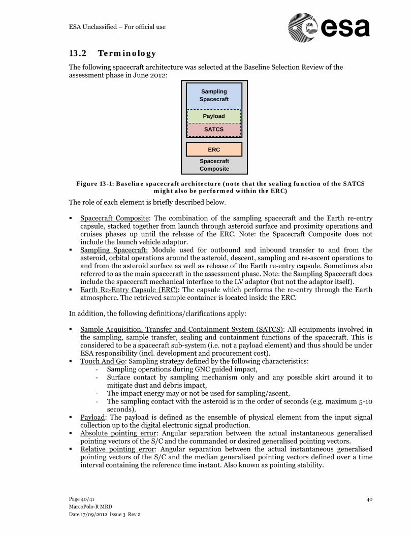
ESA Unclassified – For official use
Page 40/41
MarcoPolo-R MRD
Date 17/09/2012 Issue 3 Rev 2
40
13.2 Terminology
The following spacecraft architecture was selected at the Baseline Selection Review of the assessment phase in June 2012:
Figure 13-1: Baseline spacecraft architecture (note that the sealing function of the SATCS might also be performed within the ERC)
The role of each element is briefly described below. Spacecraft Composite: The combination of the sampling spacecraft and the Earth re-entry
capsule, stacked together from launch through asteroid surface and proximity operations and cruises phases up until the release of the ERC. Note: the Spacecraft Composite does not include the launch vehicle adaptor.
Sampling Spacecraft: Module used for outbound and inbound transfer to and from the asteroid, orbital operations around the asteroid, descent, sampling and re-ascent operations to and from the asteroid surface as well as release of the Earth re-entry capsule. Sometimes also referred to as the main spacecraft in the assessment phase. Note: the Sampling Spacecraft does include the spacecraft mechanical interface to the LV adaptor (but not the adaptor itself).
Earth Re-Entry Capsule (ERC): The capsule which performs the re-entry through the Earth atmosphere. The retrieved sample container is located inside the ERC.
In addition, the following definitions/clarifications apply: Sample Acquisition, Transfer and Containment System (SATCS): All equipments involved in
the sampling, sample transfer, sealing and containment functions of the spacecraft. This is considered to be a spacecraft sub-system (i.e. not a payload element) and thus should be under ESA responsibility (incl. development and procurement cost).
Touch And Go: Sampling strategy defined by the following characteristics: - Sampling operations during GNC guided impact, - Surface contact by sampling mechanism only and any possible skirt around it to
mitigate dust and debris impact, - The impact energy may or not be used for sampling/ascent, - The sampling contact with the asteroid is in the order of seconds (e.g. maximum 5-10
seconds). Payload: The payload is defined as the ensemble of physical element from the input signal
collection up to the digital electronic signal production. Absolute pointing error: Angular separation between the actual instantaneous generalised
pointing vectors of the S/C and the commanded or desired generalised pointing vectors. Relative pointing error: Angular separation between the actual instantaneous generalised
pointing vectors of the S/C and the median generalised pointing vectors defined over a time interval containing the reference time instant. Also known as pointing stability.
Spacecraft Composite
Sampling Spacecraft
ERC
SATCS
Payload
ESA Unclassified – For official use
Page 41/41
MarcoPolo-R MRD
Date 17/09/2012 Issue 3 Rev 2
41
Absolute measurement error: Angular separation between the actual and measured generalised pointing vectors of the S/C.
Horizontal or Lateral touchdown velocity: The component of the touchdown velocity parallel to the average local slope at the asteroid sampling site.
Vertical touchdown velocity: The component of the touchdown velocity perpendicular to the average local slope at the asteroid sampling site.
Sampling site (candidate): Safe area operationally (on an illuminated part such as to enable vision-based navigation and with hazards compatible with the S/C capability) and scientifically suitable for sample collection, defined on the asteroid surface by the ground teams.
Touchdown accuracy: Downrange major axis of the touchdown ellipse. Touchdown ellipse: Ellipse centred on the sampling site which envelops all possible
touchdown locations reachable by the spacecraft at 3-σ confidence level taking into account the variation/error of input parameters: navigation (sensors, filter, etc.), gravity model and physical property (rotation axis, period, etc.), solar radiation pressure, control (thruster), S/C modelling (thruster alignment, etc.), etc.
Proximity operations: The asteroid proximity operations are arbitrarily defined at the start of the close asteroid approach, i.e. at a distance of 500 km from the asteroid and end when the SEP system is switched on and the S/C leaves the asteroid system. See Figure 2-2.
Radio-science orbit: In the context of MarcoPolo-R, a Radio-science orbit is an asteroid-bound orbit, favourable to radio science measurements, where the S/C does not require any orbit and attitude manoeuvres in order to remain above 3 km distance to the surface at any time, during four consecutive communication windows of 8 hours.
Safe position: In the context of MarcoPolo-R, a safe position is an eclipse-free location where the spacecraft does not require any orbit and attitude manoeuvres during at least one week in order to remain at least 1 km distance away from the surface of the asteroid surface (and its secondary if applicable). Such a position can be either an asteroid-bound orbit or formation flying point or a heliocentric orbit, out of the asteroid influence (however close enough to allow return to asteroid in limited time and manoeuvre budget).
Failure: The termination of the ability of an item to perform a required function (e.g. solar arrays not producing electric current following string failure, sampling mechanism stuck and not able to perform sampling).
14 LIST OF TBC AND TBD
14.1 List of TBC
To be written
Table 14-1: List of TBC
14.2 List of TBD
To be written
Table 14-2: List of TBD