
MAR 3 02012 - Department of Energy
17
U.S. Department of Energy P.O. Box 450, MSIN H6-60 ~TESc~ Richland, Washington, 99352 1 2-WTP-0 124 MAR 3 02012 The Honorable Peter S. Winokur Chairman Defense Nuclear Facilities Safety Board 625 Indiana Avenue, NW, Suite 700 Washington, DC 20004-290 1 TRANSMITTAL OF DEFENSE NUCLEAR FACILITIES SAFETY BOARD (DNFSB) RECOMMENDATION 20 10-2 IMPLEMENTATION PLAN (IP) DELIVERABLE 5.6.3.1 Dear Mr. Chairman: This letter provides you the deliverable responsive to Commitment 5.6.3.1 of the U.S. Department of Energy plan to address Waste Treatment and Immobilization Plant (WTP) Vessels Mixing Issues; IP for DNFSB 2010-2. The attached document defines the preliminary design criteria for a heel management system. The design criteria establish performance capabilities for heel dilution, heel pump-out, and use of the access ports associated with the heel management system. This document updates requirements to include specific solids removal objectives relevant to particle size/density and across the range of imitial waste rheology conditions that will exist in pulse jet mixer mixed vessels. Specific testing performance ranges will be contained in Test Specifications for tests assessing heel management system performance capability. Heel management performance test objectives implemented in test planning documentation (including Test Specifications and Test Plans) will be documented in Requests for Technology Development. Tests to define limits of heel management system capability will consider input from the following documents: " PNNL-2 0646 ESMP-RTP-006, Hanford Waste Physical and Rheological Properties:~ Data and Gaps; " Tank farms evaluations of the most limiting particle that their delivery system is capable of retrieving and sending to WTP (Commitment 5. 5.3.2); and * Results from RPP-RPT-50941 - Rev 00, Review of Plutonium Oxide Receipts into Hanford Tank Farms Results from testing performed to define limits of heel management system capability (Commitment 5.6.3.6) will be used to support development of the final hazards analysis, functional criteria, and update to the Waste Acceptance Criteria (WAC) (Commitment 5.5.3.3). The updated WAC will be used in the gap analysis (Commitment 5.5.3.9). Gaps will be addressed to ensure waste is safely transferred from tank farms and processed in the WTP.
-
Upload
khangminh22 -
Category
Documents
-
view
1 -
download
0
Transcript of MAR 3 02012 - Department of Energy
U.S. Department of EnergyP.O. Box 450, MSIN H6-60
~TESc~ Richland, Washington, 99352
1 2-WTP-0 124 MAR 3 02012
The Honorable Peter S. WinokurChairmanDefense Nuclear Facilities Safety Board625 Indiana Avenue, NW, Suite 700Washington, DC 20004-290 1
TRANSMITTAL OF DEFENSE NUCLEAR FACILITIES SAFETY BOARD (DNFSB)RECOMMENDATION 20 10-2 IMPLEMENTATION PLAN (IP) DELIVERABLE 5.6.3.1
Dear Mr. Chairman:
This letter provides you the deliverable responsive to Commitment 5.6.3.1 of the U.S. Department ofEnergy plan to address Waste Treatment and Immobilization Plant (WTP) Vessels Mixing Issues; IP forDNFSB 2010-2.
The attached document defines the preliminary design criteria for a heel management system. Thedesign criteria establish performance capabilities for heel dilution, heel pump-out, and use of the accessports associated with the heel management system. This document updates requirements to includespecific solids removal objectives relevant to particle size/density and across the range of imitial wasterheology conditions that will exist in pulse jet mixer mixed vessels.
Specific testing performance ranges will be contained in Test Specifications for tests assessing heelmanagement system performance capability. Heel management performance test objectivesimplemented in test planning documentation (including Test Specifications and Test Plans) will bedocumented in Requests for Technology Development. Tests to define limits of heel managementsystem capability will consider input from the following documents:
" PNNL-2 0646 ESMP-RTP-006, Hanford Waste Physical and Rheological Properties:~ Data andGaps;
" Tank farms evaluations of the most limiting particle that their delivery system is capable ofretrieving and sending to WTP (Commitment 5. 5.3.2); and
* Results from RPP-RPT-50941 - Rev 00, Review of Plutonium Oxide Receipts into Hanford TankFarms
Results from testing performed to define limits of heel management system capability (Commitment5.6.3.6) will be used to support development of the final hazards analysis, functional criteria, and updateto the Waste Acceptance Criteria (WAC) (Commitment 5.5.3.3). The updated WAC will be used in thegap analysis (Commitment 5.5.3.9). Gaps will be addressed to ensure waste is safely transferred fromtank farms and processed in the WTP.

Hon. Peter S. Winokur -2- MAR 3 0201212-WTP-0124
If you have any questions, please contact me at (509) 376-6727 or your staff may contact Ben Harp,WTP Start-up and Commissioning Integration Manager at (509) 376-1462.
Sincerely,
Dale E. Knutson, FeA ral Proje pirectorWTP:W~RW Waste Treatment an Immobiliz tion Plant
Attachment
cc w/attach:D. M. Busche, BNIW. W. Gay, BNJF. M. Russo, BNIR. G. Skwarek, BNIC. G. Spencer, BNID. McDonald, EcologyD. G. Huizenga, EM- IM. B. Moury, EM-lIT. P Mustin, EM-iK. G. Picha, EM- IC. S. Trummell, EMOlIA. C. Williams, EM-2.lM. N. Camapagnone, HS-1.1R. H. Lagdon, Jr., USBNJ Correspondence
Attachmentto
1 2-WTP-O0124TRANSMITTAL OF DEFENSE NUCLEAR FACILITIES SAFETY
BOARD (DKFSB) RECOMMENDATION 2010-2 IMPLEMENTATIONPLAN (IP) DELIVERABLE 5.6.3.1
24590-WTP-DC-ENG-12-001,, Rev A,Pulse Jet Mixed Vessel Heel Management System
Functional Design Criteria
(Total No. of Pages: 14)

Document title: Pulse Jet Mixed Vessel HeelManagement System FunctionalDesign Criteria
Contract number: DE-AC27-OIRVI4136Department: Mechanical, Process, anrd Controls & InstrumentationAuthor(s): Theresa Campbell
Principal authorPsignature: ________________________________________
Document number: 24590-WTP-DC-ENGI 12-00 1, Rev B
Checked by: John Julyk
Checker signature: _______________________________Date of issue: 29 March 2012
Issue status: ApprovedApproved by: Russell Daniel Robert Voke Wayne Underhill
Approver's position: VCT Technical M&PE Discipline C&I DisciplineManager Functional Lead Functional Lead
Approver signature: l' 1viM ./ e~~~& - ~ ~ Z
E&MS Screening
E&NS Preliminary Input Included E&NS Screening Not Required for Alpha Revision_Print/Type Name Signature Date
River Protection ProjectWaste Treatment Plant2435 Stevens Center PlaceRichland, WA 99354united States of AmericaTel: 509 371 2000
24590-ENG-F00043 Rcv 1 (1/12/2009) Ref: 24590-WTP-3DP-GO4B-00001
24590-WVTP-DC-ENG-12-OO1, Rev BPulse Jet Mixed Vessel Heel Management System
Functional Design Criteria
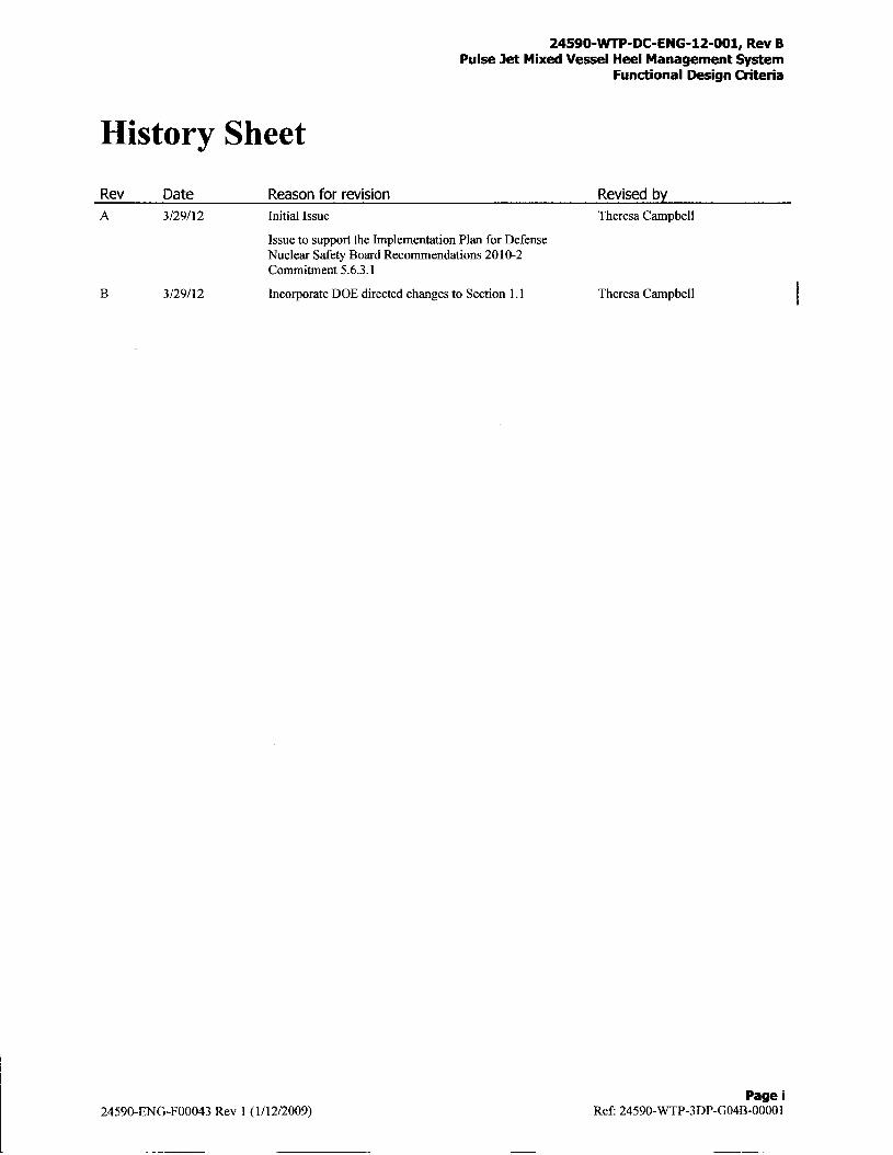
History Sheet
Rev Date Reason for revision Revised byA 3/29/12 Initial Issue Theresa Campbell
Issue to support the Implementation Plan for DefenseNuclear Safety Board Recommendations 20 10-2Commitment 5.6.3.1
B 3/29/12 Incorporate DOE directed changes to Section 1. 1 Theresa Campbell
Page24590-ENG-F00043 Rev 1 (1/12/2009) Ref. 24590-WTP-3DP-GO4B-00001

24590-WP-DC-ENG-12-OO1, Rev BPulse Jet Mixed Vessel Heel Management System
Functional Design Criteria
Contents
Acronyms.................................................................................................
1 Introduction ........................................................................................... 1
1.1 Purpose ........................................................................................................ 2
1.2 Background ................................................................................................... 2
1.3 Scope........................................................................................................... 3
1.4 Definitions..................................................................................................... 3
2 Design Criteria ........................................................................................... 4
2.1 Design Codes and Standards................................................................................ 4
2.2 Process Design................................................................................................ 4
2.3 Mechanical Design.............................................................................................. 5
2.4 Access Ports.................................................................................................. 6
2.5 Controls and Instrumentation Design ....................................................................... 7
3 Safety Criteria............................................................................................ 7
3.1 Heel Management Pump(s) and Associated Equipment Safety Requirements ...................... 7
3.2 Access Ports Safety Requirements ........................................................................... 8
4 References ............................................................................................. 9
Tables
Table 1-1 Vessels with Heel Management System...................................................... 3
Table 2-1 Heel Management System Routes ............................................................ 5
Page ii24590-ENG-F00043 Rev 1 (1/12/2009) Ref- 24590-WTP-3DP-GO4B-OOO 1
24590-WTP-DC-ENG-12-OO1, Rev BPulse Jet Mixed Vessel Heel Management System
Functional Design Criteria
Acronyms
BOD Basis of Design
CCN Correspondence Control Number
DCD Design Criteria Database
EFRT External Flowsheet Review Team
FEP Waste Feed Evaporation Process System
HLP HLW Lag Storage and Feed Blending Process System
HIW High-Level Waste
HIPAV Hydrogen in Piping and Ancillary Vessels
IRP Issue Response Plan
ITS Important to Safety
LAW Low Activity Waste
LSIT Large Scale Integrated Testing
NPSI~r Net Positive Suction Head Required
PDSA Preliminary Documented Safety Analysis
PIBOD Process Inputs Basis of Design
PJM Pulse Jet Mixer
PTF Pretreatment Facility
SC-I Seismic Category I
SC-Ill Seismic Category III
SRD Safety Requirements Document
SS Safety Significant
SSC structure, system, and component
Q Quality
UFP Ultrafiltration Process System
WTP Hanford Tank Waste Treatment and Immobilization Plant
Page iii24590-ENG-F00043 Rev 1 (1/ 12/2009) Ref. 24590-WTP-3DP-GO4B-00001

24590-WTP-DC-ENG-12-OO1, Rev BPulse Jet Mixed Vessel Heel Management System Functional
Design Criteria
1 IntroductionThis document presents the preliminary functional design criteria for the Waste Treatment Plant (WTP) heelmanagement system. Heel management was created to provide the selected pulse-jet-mixed (PJM) vessels (seeTable 1 -1) with an alternative way to remove slurries..
Contract Modification Number 221 (Ref. 4.16) requires WTP to define and detail the heel management systemcapability. Heel management was first evaluated in Pretreatment Vessel Heel Dilution/Cleanout Feasibility Study(Reference 4. 1) and the Pretreatment Vessel Heel Dilution/Cleanout Functional Requirements report (Reference4.3). The studies were performed as part of the PJM evaluation program to resolve open PJM issues (24590-WTP-PL-ENG-06-00 13, Issue Response Plan (JRP) for Implementations of External Flow sheet Review Team (EFRT)Recommendations - M3, Inadequate Mixing System Design) (Ref. 4.12).
At the time of issuing this document, the heel management system has undergone a preliminary hazard analysis perCCN 244874 (Ref. 4.8). CCN 244874 provides the preliminary functional design criteria prior to issuance of theHazard Analysis Report for the preliminary hazard analysis of the heel management system. The preliminaryfunctional design criteria will be used as part of the basis information for the hazard analysis, which will confirmthe safety functions for PJM vessel heel management. The hazard analysis will feed into an update of theCriticality Safety Evaluation Report (Ref. 4.4). This document will be updated to identify safety criteria from thehazard analysis.
Following heel management testing in Large Scale Integrated Testing (LSIT), this document will be updated, asrequired, to reflect additional information and controls that may be required. Other vessels (e.g., Waste FeedReceipt Process System, Plant Wash and Disposal System, and Radioactive Liquid Waste Disposal System) will bere-evaluated following LSIT testing and the Hazard Analysis development to determine if there is a need to add theheel management system to these vessels in accordance with the required response to the Implementation Plan forDefense Nuclear Safety Board Recommendation 2010-2 Commitment 5.6.3.9 (Ref. 4.13). In addition, the LSITtesting will confirm the performance capabilities of the Heel Management System. The Design Criteria Database(DCD) for beyond normal / non-routine operations will be updated as required to define the performance objectivesbased on waste feed analysis and LSIT testing results.
This document provides the required update to 24590-PTF-RPT-ENG- 10-004 for the response to Commitment5.6.3.1 of the Implementation Plan for Defense Nuclear Safety Board Recommuendation 2010-2 (Ref. 4.13). Thecommitment states:
"Functional design criteria and performance capabilities of the heel dilution, heel pump-out, and use of theaccess ports will be established WTP has completed an initial evaluation of a heel management system forselected vessels in 24590-WTP-RPT-PET-J0-013, Pretreatment Vessel Heel Dilution/Cleanout FeasibilityStudy. The initial functional specifications were provided in 24590-P TF-RPT-ENG-1 0-004, PretreatmentVessel Heel Dilution/Cleanout Functional Requirements. These requirements will be updated to includespecific solids removal objectives relevant to particle size/density and across the range of initial wasterheology conditions that will exist in PJM-mixed vessels. "
The preliminary requirements contained in this document are in sections 2 and 3. All other information is notconsidered requirements but additional information. Deviations from the criteria called out in this document willbe coordinated with and approved by the appropriate Functional Lead.
Page 124590-ENG-F00043 Rev 1 (1/12/2009) Ref: 24590-WTP-3DP-GO4B-OOO1
24590-WP-DC-ENG-12-OO1, Rev BPulse Jet Mixed Vessel Heel Management System Functional
Design Criteria
1.1 Purpose
The purpose of this document is to define the preliminary functional design criteria for the heel managementsystem. This document presents initial functional design criteria to support initial development of the heelmanagement design, system descriptions and hazards analysis. The design will be compliant with the DesignCriteria Database and address additional safety functional requirements specified in Section 3 of this document.
Updates to this document will consider inputs from:" Review of PNNL-20646, ESMP-RTP-006, "Hanford Waste Physical and Rheological Properties: Data and
Gaps" (Ref. 4.22)* Review of RPP-RPT-50941, "Review of Plutonium Oxide Receipts into Hanford Tank Farms" (Ref. 4.21),
and* Completion of DNFSB 2010-2, IP Commitment 5.5.3.2, "Evaluation of Waste Transferred to WTP".
The heel management system is designed to remove most of the remaining solids and liquid slurry (i.e., the heel)from specific vessels as part of normal process operations. The heel management system will be used to removesolids from a vessel to preclude the accumulation of solids over time. Because heel management allows removalof more material from a vessel than during normal operations, it also can be used for heel removal at the end of theplant life.
The tank farms may have the capability to transfer particles that exceed the current WTP design basis. The heeltransfer capabilities require fuirther testing to define performance capability as compared to the functionalrequirements. Accordingly, the preliminary heel removal system design shall use the DCD specified particle sizeand density for the preliminary equipment design.
1.2 Background
The heel management system is the result of a study performed in 2010, Pretreatment Vessel HeelDilution/Cleanout Feasibility Study (Ref. 4. 1). The study was in response to the External Flowsheet Review Team(EFRT) Recommendation M3, Inadequate Mixing System Design. The purpose of the study was to determine amethod of removing solids from vessel heels with a potential for high solids content and a potential solidsaccumulation risk. The vessel's heel is defined as the slurry of solids and liquids in a vessel below the lowoperating level. In that study, heel management was subdivided into two operations: heel dilution and heelcleanout. Because heel dilution and heel cleanout performed essentially the same operations (with only the materialadded and the destination of the removed material being different), this document refers to both operations as heelmanagement.
The WTP project has committed to testing the heel management system in LSIT to demonstrate a range ofperformance factors. The specific testing performance ranges will be contained in the testing plan which will testbeyond the preliminary design criteria.
IJFP-VSL-0OOO2AIB is not included in Table 2-1 because the UFP-VSL-00002A/B uses reagent cleaning with alowered pump suction and progressive cavity pump as a part of normal operation. Additionally PretreatmentEngineering Platform testing documented this capability in 24590-QL-HC9-WA49-00001-02-00010, Rev A (Ref.4.20). This will also be performance tested in LSIT.
1.3 Scope
The vessels chosen for heel management are PJM vessels with the highest potential for solids accumulation (i.e.,highest solids concentrations [both Newtonian and non-Newtonian] or lowest mixing power [see Table I1-I]).
Page 224590-ENG-FOO043 Rev 1 (1/12/2009) Ref. 24590-WTP-3DP-GO4B-00001
24590-WTP-DC-ENG-12-OO1, Rev BPulse Jet Mixed Vessel Heel Management System Functional
Design Criteria
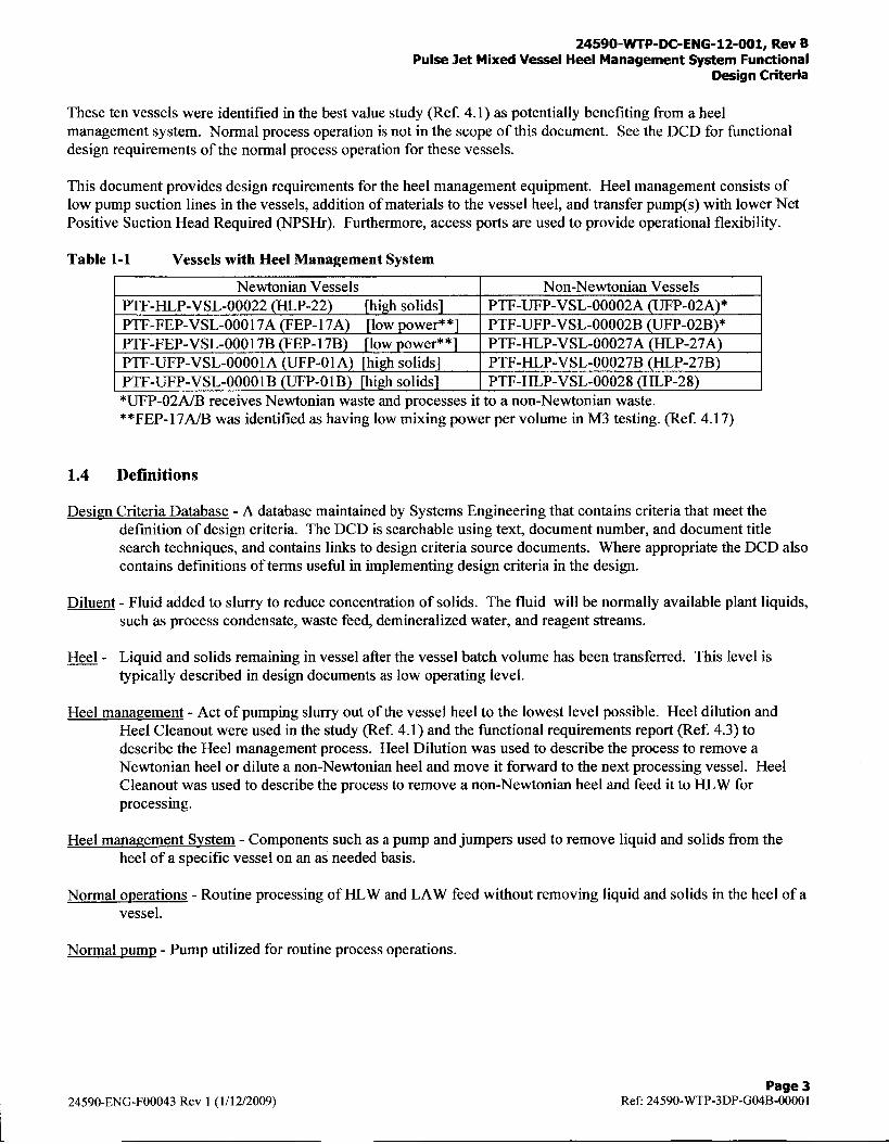
These ten vessels were identified in the best value study (Ref. 4. 1) as potentially benefiting from a heelmanagement system. Normal process operation is not in the scope of this document. See the DCD for functionaldesign requirements of the normal process operation for these vessels.
This document provides design requirements for the heel management equipment. Heel management consists oflow pump suction lines in the vessels, addition of materials to the vessel heel, and transfer pump(s) with lower NetPositive Suction Head Required (NPSHr). Furthermore, access ports are used to provide operational flexibility.
Table 1-1 Vessels with Heel Management System
Newtonian Vessels Non-Newtonian VesselsPTF-HILP-VSL-00022 (HLP-22) [high solids] PTF-UFP-VSL-00002A (UFP-02A)*PT-FEP-VSL-OO 1 7A (FEP- 1 7A) [low power* *] PTF-UFP-VSL-00002B (UFP-02B)*PTF-FEP-VSL-000 1 7B (FEP- 1 7B) [low power* *] PTF-HLP-VSL-00027A (HLP-27A)PTF-UFP-VSL-OOOOI1A (UFP-OI1A) [high solids] PTF-HLP-VSL-00027B (BLP-27B)PTF-UFP-VSL-OOOOlB (UFP-OlB) [high solids] IPTF-HLP-VSL-00028 (HLP-28)*UFP..O2MB receives Newtonian waste and processes it to a non-Newtonian waste.* *FEP.. 1 7A/B was identified as having low mixing power per volume in M3 testing. (Ref. 4.17)
1.4 Definitions
Design Criteria Database - A database maintained by Systems Engineering that contains criteria that meet thedefinition of design criteria. The DCD is searchable using text, document number, and document titlesearch techniques, and contains links to design criteria source documents. Where appropriate the DCD alsocontains definitions of terms useful in implementing design criteria in the design.
Diluent - Fluid added to slurry to reduce concentration of solids. The fluid will be normally available plant liquids,such as process condensate, waste feed, demineralized water, and reagent streams.
Heel - Liquid and solids remaining in vessel after the vessel batch volume has been transferred. This level istypically described in design documents as low operating level.
Heel manaaement - Act of pumping slurry out of the vessel heel to the lowest level possible. Heel dilution andHeel Cleanout were used in the study (Ref. 4. 1) and the functional requirements report (Ref. 4.3) todescribe the Heel management process. Heel Dilution was used to describe the process to remove aNewtonian heel or dilute a non-Newtonian heel and move it forward to the next processing vessel. HeelCleanout was used to describe the process to remove a non-Newtonian heel and feed it to HLW forprocessing.
Heel management System - Components such as a pump and jumpers used to remove liquid and solids from theheel of a specific vessel on an as needed basis.
Normal operations - Routine processing of HLW and LAW feed without removing liquid and solids in the heel of avessel.
Normal pump - Pump utilized for routine process operations.
Page 324590-ENG-F00043 Rev 1 (1/12/2009) Ref. 24590-WTP-3DP-GO4B-OOO1

24590-WTfP-DC-ENG-12-OO1, Rev BPulse Jet Mixed Vessel Heel Management System Functional
Design Criteria
2 Design Criteria
The following sections present the access port, process, mechanical, and controls and instrumentation preliminarydesign criteria for the heel management system. These design elements are based on the heel managementconceptual design provided by representatives from Mechanical, Process, and Operations. Subsequent reviews ofthe basic concepts were completed to ensure that the concepts were sound and workable (Ref. 4.1 and 4.3). Theheel management system design shall follow the WTP engineering process, including applicable projectprocedures and design guides.
2.1 Design Codes and Standards
The WTP is designed in accordance with national codes and standards, except where project specific requirementsare not covered by consensus standards. Identification of applicable codes and standards is accomplished inaccordance with engineering procedures and documented in the safety basis, Basis of Design (BOD), and applicabledesign documents. Components that are important to safety (ITS) are identified through process hazards and safetyanalyses as safety significant or safety class. Codes and standards applicable to the safety function of ITScomponents are selected through the hazard analysis and control selection process and are documented in the safetybasis. The specific version of a standard (such as year of revision) that is identified for ITS components in thesafety basis must be implemented unless revised through the hazard analysis process, with the safety basis revisedas necessary. In addition, implementation in design documents of codes and standards invoked in the safety basismust incorporate the project-specific tailoring of Safety Requirements Document (SRD) Appendix C, if applicable.
Many codes and standards identified in the safety basis in turn reference additional codes and standards ("daughtercodes and standards"). Changes to the versions of daughter codes and standards directly referenced by SRD-implementing codes and standards shall be made in accordance with the process described in 24590-WTP-3DP-GO4B-OOOO1, Design Criteria.
Standards are also identified in the Basis of Design (24590-WTP-DB-ENG-Ol-OO1). Where a specific version isidentified, that version should be implemented unless the BOD is changed or an exception is approved. In case of aconflict between the BOD and the safety basis, the safety basis takes precedence for ITS structures, systems andcomponents (SSCs). Exceptions to the BOD are addressed in procedure 24590-WTP-3DP-GO4B-OOO 1, DesignCriteria.
When a specific version of a code or standard is not called out in the safety basis or BOD, the determination of theappropriate version should be reflected in design documents. (In cases where multiple versions are acceptable, aspecific version may not be called out. An example is ASTM material standards, which typically do not change ina way that affects chemical and physical properties of interest to WTP applications.)
The following is a list of additional codes and standards that may be used as applicable for the design of the Heelmanagement System SSCs:
API STD 676, Positive Displacement Pumps - Rotary
2.2 Process Design
The heel management system shall use the Basis of Design (Ref. 4.2) for initial equipment design. The slurryproperties for critical velocity and pump design shall be in accordance with the Basis of Design, Section 6 (Ref.4.2) and the Process Inputs Basis of Design (PIBOD), Appendix A (Ref. 4.15). Any updates to the Basis of Designshall be incorporated into the design. The heel management system performance capabilities shall meet thefollowing requirements.
Page 424590-ENG-F00043 Rev 1 (1/12/2009) Ref: 24590-WTP-3DP-GO4B-00001
24590-WTP-DC-ENG-12-OO1, Rev BPulse Jet Mixed Vessel Heel Management System Functional
Design Criteria
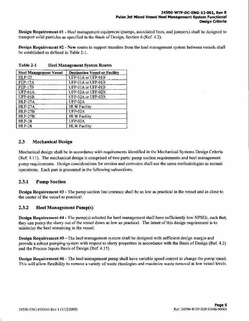
Design Requirement #1 - Heel management equipment (pumps, associated lines, and jumpers) shall be designed totransport solid particles as specified in the Basis of Design, Section 6 (Ref. 4.2).
Design Requirement #2 - New routes to support transfers from the heel management system between vessels shallbe established as defined in Table 2-1.
Table 2-1 Heel Management System Routes
Heel Management Vessel Destination Vessel or FacilityHLP-22 UFP-OIA or UFP-O1BFEP-17A IJFP-O1IA or IJFP- I BFEP-17B UFP-O1IA or IJFP-O1IBUFP-OlA UFP-02A or UJFP-02BUFP-OIB UFP-02A or UFP-02BHLP-27A UFP-02AHLP-27A HIW FacilityI-LP-27B UFP-02ABHLP-27B HIW FacilityHLP-28 UFP-02AHLP-28 HLW Facility
2.3 Mechanical Design
Mechanical design shall be in accordance with requirements identified in the Mechanical Systems Design Criteria(Ref. 4.11). The mechanical design is comprised of two parts: pump suction requirements and heel managementpump requirements. Design considerations for erosion and corrosion shall use the same methodologies as normaloperations. Each part is presented in the following subsections.
2.3.1 Pump Suction
Design Requirement #3 - The pump suction line entrance shall be as low as practical in the vessel and as close to
the center of the vessel as practical.
2.3.2 Heel Management Pump(s)
Design Requirement #4 - The pump(s) selected for heel management shall have sufficiently low NPSHr, such that,they can pump the slurry out of the vessel down as low as practical. The intent of this design requirement is tominimize the heel remaining in the vessel.
Design Requirement #5 - The heel management system shall be designed with sufficient design margin andprovide a robust pumping system with respect to slurry properties in accordance with the Basis of Design (Ref. 4.2)and the Process Inputs Basis of Design (Ref. 4.15).
Design Requirement #6 - The heel management pump shall have variable speed control to change the pump speed.This will allow flexibility to remove a variety of waste rheologies and maximize waste removal at low vessel levels.
Page 524590-ENG-F00043 Rev 1 (1/12/2009) Ref. 24590-WTP-3DP-G04B-00001

24590-WTP-DC-ENG-12-OO1, Rev BPulse Jet Mixed Vessel Heel Management System Functional
Design Criteria
2.4 Access Ports
Access ports are provided to allow operations to access the vessel's internals once the WTP has initiated radioactiveoperations. The access ports will be used by operations on an as needed basis. The access ports may be used toinsert remotable equipment into the vessel headspace.
Manned access ports shall be located in rooms above the vessels that are accessible to personnel in accordance withthe area classifications. Remote access ports shall be located in the C5 Filter Cave above the vessels.
Design Requirement #7 -Two access ports per vessel (FEP- I7AIB, HLP-22, HLP-27A1B, HLP-28, UJFP-O1IAIB,and UTFP-02A/B) shall be supplied from an accessible location above the vessels.
Design Requirement #8 - The access ports shall be placed in the vessel such that a camera lowered through one ofthem can view both the pump suction and the point where the vessel wall meets the vessel bottom (i.e., knuckle).
Design Requirement #9 - The access ports shall be designed to allow camera or other equipment access. Theseaccess ports should have an un-obstructed path that extends from the vessel vapor space to the vessel floor to allowaccess.
Design Requirement #10 - The manned-access ports shall not exceed 300 degrees of total bends from the vessel tothe point of origin. Manned-access ports shall be sloped in accordance with WTP sloping requirements, andprovide a five diameter minimum bend for all bends. The preferred piping configuration for remote access is asstraight and vertical run as possible while accounting for thermal expansion, shine, and piping interferences.Horizontal runs shall be minimized and avoided where possible. Spatial constraints shall be considered for themanned-access port shield plug or cap removal with respect to its location (i.e., around racks and other major piecesof equipment).
Design Requirement #11 - The remote-access ports shall not exceed 180 degrees of total bends. Remote-accessports shall be sloped in accordance with WTP sloping requirements and provide a five diameter minimum bend forall bends. The preferred piping configuration for remote access is as straight and vertical run as possible whileaccounting for thermal expansion, shine, and piping interferences. Spatial constraints shall be considered for theremote-access port shield plug or cap removal with respect to its location (i.e., around major pieces of equipment).
Design Requirement #12 - The access port shield plugs or caps shall be designed to meet the appropriateinterfacing ventilation system(s) requirements.
Design Requirement #13 - The access ports in remote accessible areas shall be designed to allow for remoteremoval and installation of the shield plugs or caps. A single shield plug or cap per access port with guides shall beprovided for access points in the filter cave. This cover shall meet ventilation requirements and be removed by thefilter cell crane/manipulator setup.
Design Requirement #14 - Shield plugs shall be designed for lifting ease and designed for use with a mechanicaldevice for access ports in remotely accessible areas and personnel accessible areas. Design of the shield plugs forremoval shall consider constraints due to nearby equipment and room layout.
Design Requirement #15 - The access ports plugs/caps shall provide shielding in accordance with 24590-WTP-DC-M-06-001, Mechanical System Design Criteria, Section 6.1 (Ref. 4.11).
Design Requirement #16 - The access ports shall be part of the vessel headspace and shall be maintained at 25%of the lower flammability limit of hydrogen.
Page 624590-ENG-F00043 Rev 1 (1/12/2009) Ref. 24590-WTP-3DP-GO4B-OOO1
24590-WP-DC-ENG-12-OO1, Rev BPulse Jet Mixed Vessel Heel Management System Functional
Design Criteria
2.5 Controls and Instrumentation Design
This section contains both controls and instrumentation preliminary design criteria and electrical preliminary designcriteria in addition to the following documents. Controls and instrumentation design shall be in accordance withthe Basis of Design (Ref. 4.2). Electrical design shall also be in accordance with the Electrical Design Criteria(Ref. 4.18) and Design Criteria for Electrical Jumpers (Ref. 4.19).
Design Requirement #17 - Power for the heel management pumps shall be provided via a jumper designed toprevent reverse hook up.
Design Requirement #18 - All heel management pump controls will be temporarily located in an accessiblemanned area near the pump location. The heel management pump controls will not be accessible from the controlroom. The heel management pump controls will not have Integrated Control Network interface and are onlymanually controlled.
Design Requirement #19 - A dedicated power source shall be provided for each of the heel management pumpoperation locations to meet pump load and power requirements.
Design Requirement #20 - All heel management pump controls will be provided by a local Operator Console tobe wheeled to the respective power sources that will be used to operate the pump. The Console will be plugged into the respective power sources. Standard control features such as Start, Stop, and Speed Control shall be located onthe Local Operator Console.
3 Safety Criteria
The safety requirements presented in this section are preliminary based on a preliminary hazard analysis (Ref. 4.7and 4.8) being performed to support preliminary design. The preliminary Safety Requirements listed below areunique to heel management equipment and the access ports. A reference to an issued Hazard Analysis Report withControl Selection or Preliminary Documented Safety Analysis (PDSA) update will replace the CCNs when thatbecomes available for the heel management equipment and access ports. Refer to the PDSA (Ref. 4.5 and 4.6) forgeneral safety basis requirements for PTF operations.
3.1 Heel Management Pump(s) and Associated Equipment Safety Requirements
The primary function of the heel management system (i.e., to remove heels from certain vessels in PTF) does notrequire the heel management system to be Safety Significant or Safety Class. The preliminary safety functions thatrequire the heel management system to be Safety Significant is confinement. The preliminary safety functionsidentified below are subject to change with issuance of the Hazard Analysis Report and PDSA updates.
Safety Basis Requirement #1 - Heel management system pump and jumpers shall be designed and maintained tomeet SC-HI1 criteria for confinement during and after a seismic event. The confinement boundary must bedesigned, procured, installed and operated as a Quality system.
Safety Basis Requirement #2 - Heel management system jumpers shall be designed to be resistant to corrosionand erosion under design basis conditions expected in the process slurry vessel systems for which the heelmanagement system could be used. Heel management system jumpers are not required to be designed for a 40 yearlife.
Safety Basis Requirement #3 - Heel management system jumpers shall be inspected prior to initial use and eitherinspected or tested prior to each new deployment (e.g., through a leak test).
Page 724590-ENG-FO0043 Rev 1 (1/12/2009) Ref: 24590-WTP-3DP-GO4B-00001

24590-WTP-DC-ENG-12-OO1, Rev BPulse Jet Mixed Vessel Heel Management System Functional
Design Criteria
Safety Basis Requirement #4 - The heel management system confinement boundary must be constructed ofmaterial shown to provide resistance to generation of high energy missiles in an HPAV event. The specificmaterial of construction will be determined (and justified) in the detailed design.
Safety Basis Requirement #5 - The heel management system confinement boundary must be constructed ofmaterial shown to retain its integrity during and after explosions that could occur during detonation of hydrogenthat could accumulate during a slurry transfer.
Safety Basis Requirement #6 - Dead legs in the heel management system transfer path shall be eliminated to themaximum extent practical. If a dead leg can not be eliminated, it shall meet one of the following requirements:
* Dead legs shall be too small to accumulate hydrogen in sufficient quantities to compromise theconfinement boundary
* Dead legs shall be capable of being purged, flushed, or vented at an interval sufficient to removehydrogen before it can accumulate in quantities that can compromise the transfer path confinementboundary.
Safety Basis Requirement #7 - Pressure pulses in the pump discharge shall not challenge the actuation of thepressure relief device.
Safety Basis Requirement #8 - Pressure relief device shall protect pump discharge line components from pressuresthat could cause the components to fail.
Safety Basis Requirement #9 - Jumpers shall be designed to accommodate leak testing after each connection.Jumpers shall also be designed to accommodate leak tests that will be performed remotely.
Safety Basis Requirement #10 - The heel management system transfer path is to be flushed after each transfer.
Safety Basis Requirement #11 - Prior to transfers from vessels typically used for processing Newtonian slurr ies,non-safety interlocks in all potential receipt vessels shall be disabled to prevent a valve in the discharge line fromclosing during a transfer.
3.2 Access Ports Safety Requirements
Safety Basis Requirement #12 - To ensure confinement, the access ports shall have the same seismic and qualityrequirements as the vessel (i.e., Q and SC-I).
Safety Basis Requirement #13 - The access port piping shall connect to the vessel headspace to mitigate HPAV bythe active ventilation in the vessel headspace.
Safety Basis Requirement #14 - The access ports shall remain closed/plugged when not in use.
Safety Basis Requirement #15 - Shielding of the access ports in the manned C3 areas is required to preventradiation exposure to facility workers during normal operations.
Safety Basis Requirement #16 - The access port piping shall be constructed of austenitic stainless steel to preventfragmentation in the event of hydrogen deflagration.
Page 824590-ENG-F00043 Rev 1 (1/12/2009) Ref- 24590-WTP-3DP-GO4B-00001

24590-WVTP-DC-ENG-12-OO1, Rev BPulse Jet Mixed Vessel Heel Management System Functional
Design Criteria
4 References
4.1 24590-WTP-RPT-PET-10-013, Rev. 0, Pretreatment Vessel Heel Dilution/Cleanout Feasibility Study
4.2 24590-WTP-DB-ENG-0 1-001, Basis of Design
4.3 24590-PTF-RPT-ENG- 10-004, Rev. 0, Pretreatment Vessel Heel Dilution/Cleanout FunctionalRequirements
4.4 24590-WTP-CSER-ENS-08-0001, Preliminary Criticality Safety Evaluation Report for the WTP
4.5 24590-WTP-PSAR-ESH-0 1 -002-02, Preliminary Documented Safety Analysis to Support ConstructionAuthorization; PT Facility Specific Information
4.6 24590-WTP-PSARA-ENS-09-001, Preliminary Documented Safety Analysis - Control Strategy Changes
for the PT Facility
4.7 CCN 223268, ISM III PTF - M3 Vessel Access Ports (cameras
4.8 CCN 244874, Results from the Heel Management System Hazards Analysis2
4.9 24590-WTP-3DP-GO4B-00001, Design Criteria
4.10 24590-WTP-SRD-ESH-0 1-00 1-02, Safety Requirements Document, Volume II
4.11 24590-WTP-DC-M-06-00 1, Mechanical Systems Design Criteria
4.12 24590-WTP-PL-ENG-06-00 13, Rev. 3, Issue Response Plan for Implementation of External FlowsheetReview Team (EFRT) Recommendations - M3, Inadequate Mixing System Design
4.13 CCN 2425 10, Implementation Plan 'for Defense Nuclear Facilities Safety Board (DNFSB) Recommendation2010-2, Pulse Jet Mixing at the Waste Treatment and Immobilization Plant (WTP)3
4.14 API STD-676, Positive Displacement Pumps - Rotary, API Standard 676, Third Edition, November 2009,American Petroleum Institute, Washington, DC.
4.15 24590-WTP-DB-PET-09-00 1, Rev. 1, Process Inputs Basis of Design (PIBOD)
4.16 Contract Modification Number 22 1, Modification of Contract Number DE-AC27-01RV14136
4.17 24590-PTF-ES-ENG- 10-002, Rev. 0, FEP- VSL-0001 7A/B - Waste Feed Evaporator Engineering Study for
M3 (Closure Criterion 3)
4.18 24590-WTP-DC-E-0 1 -00 1, Electrical Design Criteria
4.19 24590-WTP-DC-E-07-001, Design Criteria for Electrical Jumpers
CCN 223268 is cited with preliminary information pending issuance of the Hazard Analysis Report with Control Selection orPDSA update..
2 CCN 244874 is cited with preliminary information pending issuance of the Hazard Analysis Report with Control Selection orPDSA update.
SCCN 2425 10 is a letter from DOE providing direction to perform the work in the Implementation Plan attached to the CCN.
Page 924590-ENG-F00043 Rev 1 (1/12/2009) Ref: 24590-WTP-3DP-GO4B-OOO1
24590-WTP-DC-ENG-12-OO1, Rev BPulse Jet Mixed Vessel Heel Management System Functional
Design Criteria
4.20 24590-QL-HC9-WA49-00001-02-0001 0, Rev A, Test Plan - Pretreatment Engineering Platform (PEP)
Testing (Phase 1)
4.21 RPP-RPT--5094 1, Rev. 0, Review of Plutonium Oxide Receipts into Hanford Tank Farms
4.22 PNNL-20646, EMSP-RPT-006, August 2011, Hanford Waste Physical and Rheological Properties: Dataand Gaps
Page 1024590-ENG-F00043 Rev 1 (1/12/2009) Ref. 24590-WTP-3DP-G4B-OOO1