
Manufacturing and Modeling of an Extrusion Die Spider Head for the Production of HDPE Tubes
15
Journal of Manufacturing Technology Research ISSN: 1943-8095 Volume 6, Number 1-2, pp. 1-15 © 2015 Nova Science Publishers, Inc. MANUFACTURING AND MODELING OF AN EXTRUSION DIE SPIDER HEAD FOR THE PRODUCTION OF HDPE TUBES Georgios N. Kouzilos, Angelos P. Markopoulos and Dimitrios E. Manolakos Manufacturing Technology Division, School of Mechanical Engineering, National Technical University of Athens, Zografou, Athens Greece ABSTRACT A spider extrusion die was designed and manufactured with the aid of a three- dimensional polymer flow analysis. The methods used were the computer fluid dynamics analysis and the arbitrary Lagrangian Eulerian method, both realized with a commercial Finite Element software. The aim of the computer fluid dynamics analysis was to investigate the non-isothermal, non-Newtonian flow in the extrusion die. In addition, the arbitrary Lagrangian Eulerian method was used to examine the mechanical stresses exerted on the spider leg, which is the weakest part of the extrusion die. The experimental results of pressure drop and temperature distribution in the die were compared with analytical and numerical results, indicating good agreement. The validated finite element model was then used to examine whether the manufactured die can successfully withstand the applied stresses during operation. Keywords: Finite Elements Analysis, Pressure flow, HDPE, Spider extrusion die 1. INTRODUCTION Polymer extrusion has been a major industrial process for the production of films, rods, tubes and pipes employed mainly in fluid transport in several industrial sectors. The extrusion die design process can become very difficult to execute and its cost can increase up to prohibitive levels, when complex geometries are concerned. The process itself and the extrusion dies used have been the subject of investigations over many years (Zhu, Xie and Yuan, 2007; Kaiyuan et al, 2009; Matin et al, 2012). The design of extrusion dies for the production of complex geometries requires vast experience, which is usually based on Corresponding author, E-mail [email protected]
Transcript of Manufacturing and Modeling of an Extrusion Die Spider Head for the Production of HDPE Tubes
Journal of Manufacturing Technology Research ISSN: 1943-8095
Volume 6, Number 1-2, pp. 1-15 © 2015 Nova Science Publishers, Inc.
MANUFACTURING AND MODELING
OF AN EXTRUSION DIE SPIDER HEAD
FOR THE PRODUCTION OF HDPE TUBES
Georgios N. Kouzilos, Angelos P. Markopoulos
and Dimitrios E. Manolakos Manufacturing Technology Division, School of Mechanical Engineering,
National Technical University of Athens,
Zografou, Athens Greece
ABSTRACT
A spider extrusion die was designed and manufactured with the aid of a three-
dimensional polymer flow analysis. The methods used were the computer fluid dynamics
analysis and the arbitrary Lagrangian Eulerian method, both realized with a commercial
Finite Element software. The aim of the computer fluid dynamics analysis was to
investigate the non-isothermal, non-Newtonian flow in the extrusion die. In addition, the
arbitrary Lagrangian Eulerian method was used to examine the mechanical stresses
exerted on the spider leg, which is the weakest part of the extrusion die. The experimental
results of pressure drop and temperature distribution in the die were compared with
analytical and numerical results, indicating good agreement. The validated finite element
model was then used to examine whether the manufactured die can successfully
withstand the applied stresses during operation.
Keywords: Finite Elements Analysis, Pressure flow, HDPE, Spider extrusion die
1. INTRODUCTION
Polymer extrusion has been a major industrial process for the production of films, rods,
tubes and pipes employed mainly in fluid transport in several industrial sectors. The extrusion
die design process can become very difficult to execute and its cost can increase up to
prohibitive levels, when complex geometries are concerned. The process itself and the
extrusion dies used have been the subject of investigations over many years (Zhu, Xie and
Yuan, 2007; Kaiyuan et al, 2009; Matin et al, 2012). The design of extrusion dies for the
production of complex geometries requires vast experience, which is usually based on
Corresponding author, E-mail [email protected]

Georgios N. Kouzilos, Angelos P. Markopoulos and Dimitrios E. Manolakos 2
experimental trial-and-error approaches, involving, therefore, the use of huge amounts of time
and material resources. According to manufacturers, 10 to 15 iterations are required to
optimize complex profile geometries while the cost of the preliminary tests and corrections of
a profile die may be as much as 10–50% of the total cost (Michaeli, 2003).
The process of extrusion die design can be considerably simplified when modeling
techniques are considered. Huang and Huang (2007) optimized parison thickness for
extrusion blow molding using a hybrid modeling method consisting of finite elements,
artificial neural networks and genetic algorithms. Choudhary and Kulkarni (2008) developed
a three-dimensional mathematical model based on a Computational Fluid Dynamics (CFD)
code to investigate the non-isothermal, non-Newtonian polymer flow through the dies used in
the polystyrene foam extrusion process. Lebaal, Schmidt and Puissant (2009) designed and
optimized a 3D extrusion flat die using the constraint optimization algorithm. Despite all the
available tools, the main decisions are still left to the designer’s intervention and knowledge
(Shahreza et al, 2010). However, in order to automate the extrusion die design process,
numerical codes have been developed, aiming to transfer critical decisions to the code;
Gonçalves, Carneiro and Nóbrega (2013) developed a numerical modeling code and utilized
it in a case study that involves the design of a medical catheter extrusion die, focused on the
search of a balanced flow distribution.
In an effort to test the characteristics of the extrusion die in industrial use, an actual die is
manufactured. The geometrical characteristics of the extrusion die are based on a design
optimization procedure; a CFD based model using the generalized Newtonian approach was
employed, to investigate pressure drop, flow and temperature uniformity in the die.
Numerical and analytical results are compared to experimental data indicating very good
agreement. Furthermore, numerical analysis of the stresses exerted on the spider legs of
extrusion dies, using the Arbitrary Lagrangian-Eulerian (ALE) technique was performed. The
ALE technique revealed that the maximum stresses developed on the die during the extrusion
process, even at the spider legs, which are the weakest members of the die, can withstand the
applied stresses during die operation.
2. DESIGN OF EXTRUSION DIE AND MANUFACTURING
OF THE SPIDER HEAD
The extrusion die is initially modeled with SolidWorks®; Figure 1 illustrates the
assembled die in 135o cut section view in order to show all the parts that constitute it.
A 3D heat transfer model is developed for non-Newtonian materials being processed in
the extrusion die based on the configuration of Figure 1. The numerical solution assumes that
a homogeneous and isotropic High Density Polyethylene (HDPE) melt with a uniform
temperature is flowing into the spider die. The temperature of the die wall is kept constant
and the volumetric flow rate of the polymer melt is fixed. Polymer properties critically affect
the analysis of the entire processing operation and thus reliable quantitative models are
essential. However, in many polymer processes, the elastic memory effects are often
neglected because the melts are subjected to large steady rates of deformation for a relatively
long time. Since this work is concentrated on a qualitative analysis of the flow regime, the
inelastic model is selected as the most appropriate for describing melt flow.

Manufacturing and Modeling of an Extrusion Die Spider Head … 3
Figure 1. Assembled extrusion die in 135o cut view, (1) die housing, (2) middle ring, (3)
spider head, (4) torpedo, (5) middle mandrel, (6) center pin, (7) outer ring, (8) die ring,
(9) outer mandrel, (10) four screws M6x25-12.9 DIN 912, (11) four screws M12x75-
12.9 DIN 912, (12) four screws M12x120-12.9 DIN 912, (13) four screws M12x50-
12.9 DIN 912.
Polymer melts are non-Newtonian fluids and various models have been developed to
describe the dependence of viscosity on shear rate and temperature. Flexibility is provided by
the Carreau–Yasuda model:
(1)
where n0, λ, α and n are the fitting parameters of the model and αT is the shift factor given as:
(2)
The temperature dependence is introduced in equation (2) through the shift factor, αΤ,
while Eο is the activation energy and R is the universal gas constant.
According to the theory of computational fluid dynamics, the governing equations to
solve the melt flow problems can be obtained from the continuity, motion and energy
equations, based on the conservation of mass, momentum and energy, respectively.
Considering the characteristics of the polymer melts flow in the die channel when the steady-
state of the extrusion is achieved, the following assumptions are made:
Incompressible steady laminar flow prevails, i.e. the variation of the system
physical variables versus time can be neglected.
Georgios N. Kouzilos, Angelos P. Markopoulos and Dimitrios E. Manolakos 4
No slip conditions on the wall surface pertain, i.e. the melt flow velocity on the
fluid-die/mold interface is equal to the moving velocity of the die wall.
Inertial and gravitational forces are neglected, since Reynolds number of
polymer melts is relatively low.
Fully developed inlet velocity corresponding to actual volumetric flow rate and
uniform inlet temperature are considered.
Die-wall temperature is uniform.
Based on the above assumptions, the boundary conditions are set. Governing equations
can be written as:
Continuity equation: (3)
Motion equation: (4)
Energy equation: (5)
where is the Hamilton differential operator, u the velocity vector and σ the Cauchy stress
tensor, which is expressed as:
(6)
p is the hydrostatic pressure, S the extra stress tensor, I the Kronecker delta, Cp the heat
capacity, T the temperature and Q the total source term, incorporating the streamline-upwind
Petrov-Galerkin scheme employed to improve the computation stability.
Flow Simulation add-in of SolidWorks® is used to create the fluid domain by deleting
from the extrusion die all the unneeded subparts. Then, governing equations are solved
numerically using the finite element CFD code COMSOL 4.3b that incorporates the Carreau-
Yasuda viscosity model.
This numerical model investigates the effect of viscous dissipation, which causes an
increase in the fluid temperature. Shear heating plays a significant role in the extrusion of
polymeric materials and, therefore, it is taken under consideration in order to optimize the
polymeric material processing.
Due to the complex 3D geometry of the die and the nonlinear relationship between
polymer viscosity and shear rate, an elaborate, functional finite element mesh is developed to
facilitate numerical stability of the solution. The model consists of 95215 tetrahedral elements
with unstructured mesh, with maximum element size 13∙10-3
mm and minimum element size
5.56∙10-4
mm. Fluid domain geometry and the generated mesh is illustrated in Figure 2.
The Taguchi method is used with the numerical model; analysis of variance (ANOVA) is
employed for sensitivity analysis and the quadratic RSM is applied to determine the final
spider die geometry, by optimization performed on the effects of six design parameters of the
spider legs on the flow homogeneity. Optimization procedure is thoroughly described by
Mamalis, Kouzilos and Vortselas (2011). After the optimum geometry is determined,
manufacturing of the required parts and especially the spider die are produced.

Manufacturing and Modeling of an Extrusion Die Spider Head … 5
Figure 2. Fluid domain geometry and mesh for the finite element analysis.
All parts of the extrusion die were manufactured and assembled in the Manufacturing
Technology Division of the National Technical University of Athens. Most of the required
machining processes were performed in an OKUMA MX-45VE CNC mill cutting center and
an OKUMA LB10II CNC lathe; some parts were produced with electrodischarge machining.
The related G-code for each part was created with SolidCAM® and was transmitted to CNC
machine tools with DNC technology. Figure 3 depicts the final design of the spider head.
Figure 3. Final spider head geometry.
The material of the spider head is selected to be IMPAX, a P20 hot work tool steel. This
material is commonly used for dies and its high strength and wear resistance guarantees the
unproblematic, repeated use of the die. Hard materials such as the one used in this extrusion
die require special machining practices in order for the required precision to be attained
(Davim, 2011; Kundrák, Ráczkövi and Gyáni, 2014; Sztankovics and Kundrák, 2014). The
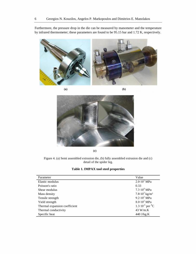
manufactured extrusion die is shown in Figure 4(a) without the housing and outer rings and in
Figure 4(b) fully assembled. Figure 4(c) illustrates a detail of the spider leg.
Mechanical and physical properties of the extruder die material are tabulated in Table 1.
The spider die is mounted on a single screw Johnson Plastics Extruder for the production of
HDPE tubes; extruder characteristics: length/diameter ratio 24:1, screw diameter 38 mm and
compression ratio 2.75. High density polyethylene tubes with external diameter of 32 mm and
wall thickness of 2.4 mm are produced using the above mentioned equipment. The polymeric
material is the SABIC B 5823 with material characteristics presented in Tables 2 and 3.
Georgios N. Kouzilos, Angelos P. Markopoulos and Dimitrios E. Manolakos 6
Furthermore, the pressure drop in the die can be measured by manometer and the temperature
by infrared thermometer; these parameters are found to be 95.15 bar and 1.72 K, respectively.
Figure 4. (a) Semi assembled extrusion die, (b) fully assembled extrusion die and (c)
detail of the spider leg.
Table 1. IMPAX tool steel properties
Parameter Value
Elastic modulus 2.0∙105 MPa
Poisson's ratio 0.33
Shear modulus 7.3∙104 MPa
Mass density 7.8∙103 kg/m³
Tensile strength 9.2∙102 MPa
Yield strength 8.0∙102 MPa
Thermal expansion coefficient 1.3 10-5
per 0C
Thermal conductivity 43 W/m.K
Specific heat 440 J/kg.K

Manufacturing and Modeling of an Extrusion Die Spider Head … 7
Table 2. Density and melt flow rate of HDPE
Parameter Value
Melt Flow Rate (MFR) (ISO 1133)
0.16 dg/min (at 190 0C, 2.16 Kg)
0.89 dg/min (at 190 0C, 5.00 Kg)
23.00 dg/min (at 190 0C, 21.6 Kg)
Density (ISO 1183) 958 kg/m3
Table 3. Shear rate and viscosity of HDPE
Shear Rate (1/s) at 190 °C Viscosity (Pa∙s)
12 4770
23 3426
58 1991
115 1301
230 836
565 443
3. EXTRUSION DIE MODELING AND EXPERIMENTAL RESULTS
In the next paragraphs an analytical and a numerical model, based on the optimized
geometry presented in the previous section, are discussed. The proposed models calculate
pressure drop and temperature rise in the die. Additionally, a stress FEM analysis is provided
for the spider head.
3.1. Analytical Modeling
The power-law exponential model is utilized to determine the pressure drop in the
extrusion die. According to Michaeli (2003), the volumetric flow rate of a non-Newtonian
fluid is described as:
(7)
where, is the die conductance, applicable to the power law model, ΔP is the pressure drop,
φ the fluidity and m the flow exponent. The volumetric flow rate of the Johnson Plastics
extruder is obtained as:
(8)
where and
.
Georgios N. Kouzilos, Angelos P. Markopoulos and Dimitrios E. Manolakos 8
is the volumetric rate, N the screw speed, D the inner barrel diameter, μ the melt
viscosity, H the channel depth, φ the helix angle of flight and L the axial length of the screw.
Therefore, the volumetric flow rate for screw speed 100 rpm is m3/s.
Pressure drop for various cross-sections of the die is calculated using equations by Michaeli
(2003). Total pressure drop through the die zones is ΔPtotal = 92.17 bar.
The analytical approach for determining the mean temperature rise at the outlet of the die
is based on the assumption that adiabatic conditions occur throughout the whole procedure.
This means that there is no heat exchange between the die wall and the material and,
therefore, the whole mechanical energy is converted to heat. The maximum bulk temperature
rise is calculated analytically as (Mamalis et al, 2010):
(9)
where ΔΡ is the total pressure drop in the die, ρ the density and Cp the specific heat and hence
3.2. Numerical Modeling
According to the analysis presented in section 2, the numerical solution assumes a
homogeneous and isotropic HDPE melt with uniform temperature of T=469K flowing into
the spider die. The temperature of the die wall is kept constant at Tw=469K and the
volumetric flow rate of the polymer melt is fixed at m3/s. The various
parameters used in the Carreau–Yasuda model are listed in Table 4 (Mamalis, Kouzilos and
Vortselas, 2011).
Table 4. Carreau–Yasuda model material constants
Parameter Value
n 0.2723
n0 5.43∙103 Pa∙s
λ 0.063 s
Eo 6.5 kcal/mol
TR 190 0C
α 2
An important aspect of the presented models is the ability to accurately predict the
pressure drop in the die. Figure 5(a) shows the pressure distributions in the entire domain of
the die. It can be observed that the pressure decreases continuously from die inlet to outlet.
The pressure distribution throughout the die as calculated by the FE simulation indicates a
total pressure drop of 97.24 bar.
The temperature distribution is obtained by solving the equations describing energy
balance in the die domain. Figure 5(b) illustrates the temperature distribution of the polymer
during extrusion. The polymer enters the die at a temperature of 469 K and the die walls are
considered to have the same constant temperature. The temperature of the polymer fluid
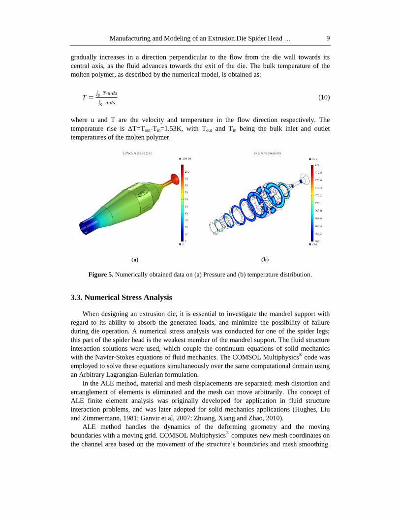
Manufacturing and Modeling of an Extrusion Die Spider Head … 9
gradually increases in a direction perpendicular to the flow from the die wall towards its
central axis, as the fluid advances towards the exit of the die. The bulk temperature of the
molten polymer, as described by the numerical model, is obtained as:
(10)
where u and T are the velocity and temperature in the flow direction respectively. The
temperature rise is ΔT=Tout-Tin=1.53K, with Tout and Tin being the bulk inlet and outlet
temperatures of the molten polymer.
Figure 5. Numerically obtained data on (a) Pressure and (b) temperature distribution.
3.3. Numerical Stress Analysis
When designing an extrusion die, it is essential to investigate the mandrel support with
regard to its ability to absorb the generated loads, and minimize the possibility of failure
during die operation. A numerical stress analysis was conducted for one of the spider legs;
this part of the spider head is the weakest member of the mandrel support. The fluid structure
interaction solutions were used, which couple the continuum equations of solid mechanics
with the Navier-Stokes equations of fluid mechanics. The COMSOL Multiphysics® code was
employed to solve these equations simultaneously over the same computational domain using
an Arbitrary Lagrangian-Eulerian formulation.
In the ALE method, material and mesh displacements are separated; mesh distortion and
entanglement of elements is eliminated and the mesh can move arbitrarily. The concept of
ALE finite element analysis was originally developed for application in fluid structure
interaction problems, and was later adopted for solid mechanics applications (Hughes, Liu
and Zimmermann, 1981; Ganvir et al, 2007; Zhuang, Xiang and Zhao, 2010).
ALE method handles the dynamics of the deforming geometry and the moving
boundaries with a moving grid. COMSOL Multiphysics®
computes new mesh coordinates on
the channel area based on the movement of the structure’s boundaries and mesh smoothing.

Georgios N. Kouzilos, Angelos P. Markopoulos and Dimitrios E. Manolakos 10
The Navier-Stokes equations that solve the flow are formulated for these moving coordinates.
The structural mechanics portion of the model does not require the ALE method, and
COMSOL Multiphysics® solves it in a fixed coordinate system as usual.
The fluid flow in the channel is described by the Navier-Stokes equations, solving for the
velocity field u (u, v) and the pressure, p:
(11)
(12)
where I is the unit diagonal matrix, and F is the volume force affecting the fluid. The model
neglects gravitation and other volume forces affecting the fluid, so F = 0. Navier-Stokes
equations are solved in the spatial, deformed coordinate system. At the inlet, the model uses a
fully developed laminar flow. Zero pressure is applied at the outlet. At all other boundaries,
no-slip conditions are considered, i.e. u = 0. The problem is solved in transient state so the
spider leg commences from an undeformed state. It is worth noticing that the fluid flow
velocity coincides with the velocity of the deforming spider leg.
Structural deformations are solved by using elastic formulation and nonlinear geometry
formulation to allow large deformations. As boundary conditions, the spider leg is fixed to the
lower and upper ring of the spider so that it cannot move in any direction. All other
boundaries experience a load from the fluid, given by:
(13)
where n is the normal vector to the boundary. This load represents a sum of pressure and
viscous forces. In addition, the predefined fluid load takes the area effect between the
reference frame for the solid and the moving ALE frame in the fluid into account. The
Navier-Stokes equations are solved on a freely moving deformed mesh, which constitutes the
fluid domain. The deformation of this mesh relative to the initial shape of the domain is
computed using Winslow smoothing. This is the default smoothing when using the Fluid-
Structure Interaction interface.
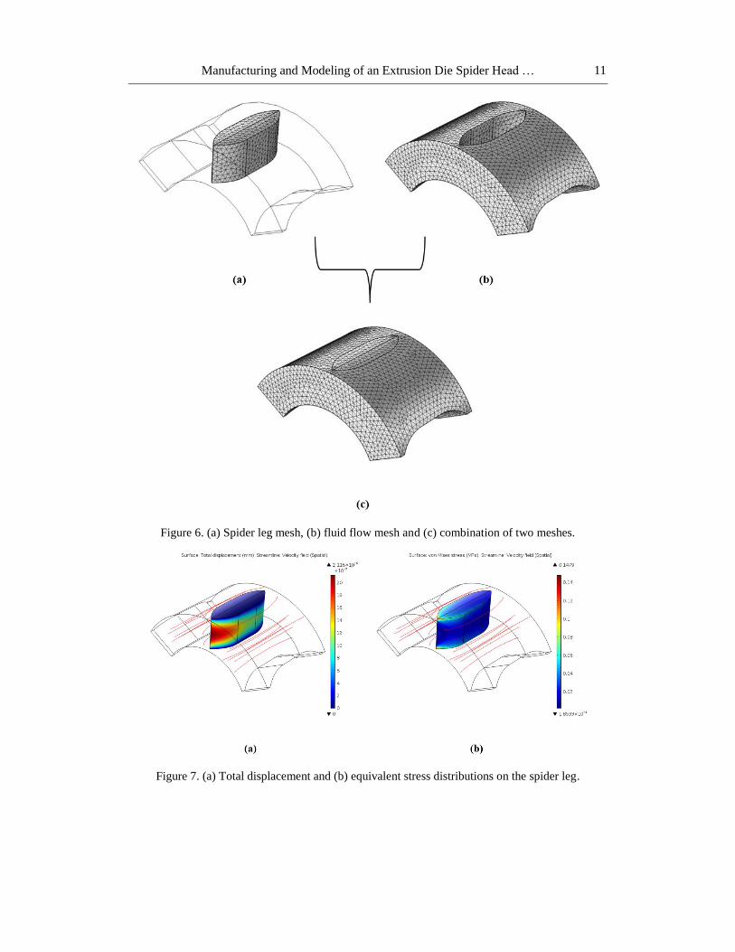
The mesh of the spider leg is illustrated in Figure 6(a) and consists of 8732 tetrahedral
elements with unstructured mesh with maximum element size 2.36∙10-3
mm and minimum
element size 1.01∙10-4
mm; flow mesh is illustrated in Figure 6(b) and consists of 62412
tetrahedral elements with the same element size. The combination of the above two meshes is
illustrated in Figure 6(c).
The results of the analysis are presented in Figures 7(a) and (b). The extrusion die was
manufactured using IMPAX tool steel, with a yield stress of 8∙102
MPa. Based on the
analysis, the maximum stress developed on the spider legs during the extrusion, which
corresponds to maximum flow rate of the molten polymer, is 14.79∙10-2
MPa. The equivalent
stresses obtained using the von Mises yield criterion, are significantly lower than the material
yield stress and, therefore, it may be concluded that the above mentioned tool steel is suitable
for manufacturing spider dies for polymer extrusion applications. The total displacement as
determined by the ALE model is 2.12∙10-6
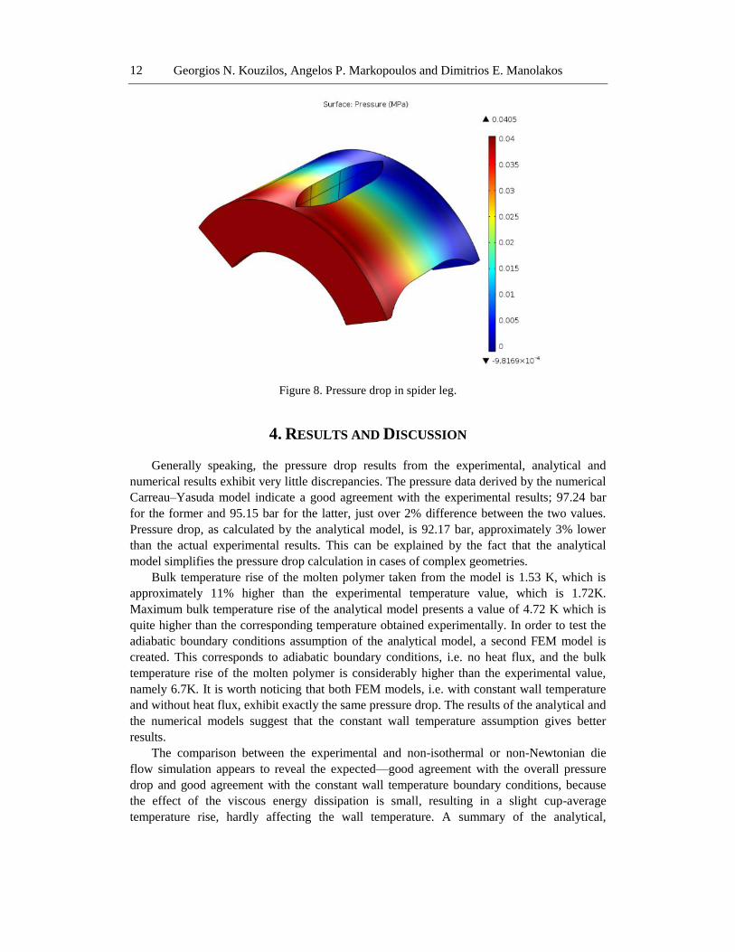
mm. Finally the pressure drop of the flow channel
is computed and illustrated in Figure 8.
Manufacturing and Modeling of an Extrusion Die Spider Head … 11
Figure 6. (a) Spider leg mesh, (b) fluid flow mesh and (c) combination of two meshes.
Figure 7. (a) Total displacement and (b) equivalent stress distributions on the spider leg.
Georgios N. Kouzilos, Angelos P. Markopoulos and Dimitrios E. Manolakos 12
Figure 8. Pressure drop in spider leg.
4. RESULTS AND DISCUSSION
Generally speaking, the pressure drop results from the experimental, analytical and
numerical results exhibit very little discrepancies. The pressure data derived by the numerical
Carreau–Yasuda model indicate a good agreement with the experimental results; 97.24 bar
for the former and 95.15 bar for the latter, just over 2% difference between the two values.
Pressure drop, as calculated by the analytical model, is 92.17 bar, approximately 3% lower
than the actual experimental results. This can be explained by the fact that the analytical
model simplifies the pressure drop calculation in cases of complex geometries.
Bulk temperature rise of the molten polymer taken from the model is 1.53 K, which is
approximately 11% higher than the experimental temperature value, which is 1.72K.
Maximum bulk temperature rise of the analytical model presents a value of 4.72 K which is
quite higher than the corresponding temperature obtained experimentally. In order to test the
adiabatic boundary conditions assumption of the analytical model, a second FEM model is
created. This corresponds to adiabatic boundary conditions, i.e. no heat flux, and the bulk
temperature rise of the molten polymer is considerably higher than the experimental value,
namely 6.7K. It is worth noticing that both FEM models, i.e. with constant wall temperature
and without heat flux, exhibit exactly the same pressure drop. The results of the analytical and
the numerical models suggest that the constant wall temperature assumption gives better
results.
The comparison between the experimental and non-isothermal or non-Newtonian die
flow simulation appears to reveal the expected—good agreement with the overall pressure
drop and good agreement with the constant wall temperature boundary conditions, because
the effect of the viscous energy dissipation is small, resulting in a slight cup-average
temperature rise, hardly affecting the wall temperature. A summary of the analytical,

Manufacturing and Modeling of an Extrusion Die Spider Head … 13
experimental, and numerical results reported in the current work including the pressure drop
and temperature rise in the die, is presented in Table 5.
Table 5. Analytical, Numerical and Experimental Data
Analytical
Carreau – Yasuda
(Numerical)
Constant Wall
Temperature
Carreau – Yasuda
(Numerical)
No Heat
Flux
Experimental
dP (bar) 92.17 97.24 97.24 95.15
dT (K) 4.72 1.53 6.67 1.72
Figure 9 illustrates the pressure drop percentage through the die zones of both the
numerical and the analytical model. It is obvious that the majority of the pressure drop is
observed along the zone V, at the exit of extrusion die.
Figure 9. Analytical and numerical results pertaining to pressure drop percentage through
the die zones.
The equivalent stresses, obtained through the von Mises yield criterion, are significantly
lower than the material yield stress and, therefore, it may be concluded that the above
mentioned tool steel is suitable for manufacturing spider dies for polymer extrusion
applications.
CONCLUSION
Summarizing the main features of the results reported, it may be concluded that the
proposed models can predict the pressure drop in the extruder die with success. Although
there is significant difference comparing the numerical and analytical models with regard to
Georgios N. Kouzilos, Angelos P. Markopoulos and Dimitrios E. Manolakos 14
the temperature rise in the fluid during the extrusion process, this can be explained by the fact
that the analytical model is based on the assumption that adiabatic conditions occur, which
means that there is no heat transfer between the wall and the polymer material as described
above. On the other hand, the numerical analysis assumes constant temperature of the die
wall, which is a boundary condition very close to what actually occurs during the real
extrusion process, thus providing reliable predictions of the conditions within the extrusion
die during polymer processing.
Finally, it was demonstrated by the stress analysis, that the die construction is strong
enough to withstand the pressure developed during the die operation and that the stresses do
not exceed the material yield strength in any case.
REFERENCES
Choudhary M.K and Kulkarni J.A. (2008), “Modeling of three-dimensional flow and heat
transfer in polystyrene foam extrusion dies”, Polymer Engineering and Science, 48(6),
1177-1182.
Davim J.P. (Ed.) (2011), “Machining of Hard Materials”, Springer-Verlag London.
Ganvir V., Lele A., Thaokar R. and Gautham B.P. (2007), “Simulation of visco-elastic flows
of polymer solutions in abrupt contractions using an arbitrary Lagrangian Eulerian (ALE)
based finite element method”, Journal of Non-Newtonian Fluid Mechanics, 143,157–169.
Gonçalves N.D., Carneiro O.S. and Nóbrega J.M. (2013), “Design of complex profile
extrusion dies through numerical modeling”, Journal of Non-Newtonian Fluid
Mechanics, 200, 103-110.
Huang G.-Q and Huang H.-X. (2007), “Optimizing parison thickness for extrusion blow
molding by hybrid method”, Journal of Materials Processing Technology, 182(1-3), 512-
518.
Hughes J.R., Liu W.K. and Zimmermann T.K. (1981), “Lagrangian-Eulerian finite element
formulation for incompressible viscous flows”, Computer Methods in Applied Mechanics
and Engineering, 29, 329-349.
Kaiyuan C., Nanqiao Z., Bin L. and Shengping W. (2009), “Effect of vibration extrusion on
the structure and properties of high-density polyethylene pipes”, Polymer International,
58(2), 117-123.
Kundrák J., Ráczkövi L. and Gyáni, K. (2014), “Machining performance of CBN cutting
tools for hard turning of 100Cr6 bearing steel”, Applied Mechanics and Materials, 474,
333-338.
Lebaal N., Schmidt F and Puissant S. (2009), “Design and optimization of three-dimensional
extrusion dies, using constraint optimization algorithm”, Finite Elements in Analysis and
Design, 45(5), 333-340.
Mamalis A.G., Kouzilos G. and Vortselas A.K. (2011), “Design Feature Sensitivity Analysis
in a Numerical Model of an Extrusion Spider Die”, Journal of Applied Polymer Science,
122, 3537–3543.
Mamalis A.G., Spentzas K.N., Kouzilos G., Theodorakopoulos I. and Pantelelis N.G. (2010),
“On the high-density polyethylene extrusion: Numerical, analytical and experimental
modeling”, Advances in Polymer Technology, 29(3), 173-184.

Manufacturing and Modeling of an Extrusion Die Spider Head … 15
Matin I., Hadzistevic M., Hodolic J., Vukelic D. and Lukic D. (2012), “A CAD/CAE-
integrated injection mold design system for plastic products”, The International Journal
of Advanced Manufacturing Technology, 63(5-8), 595-607.
Michaeli, W. (2003), “Design and Engineering Computation”, 3rd
ed. Hanser Publishers,
Munich.
Shahreza A.R., Behravesh A.H., Jooybari M.B. and Soury E. (2010), “Design, optimization,
and manufacturing of a multiple-thickness profile extrusion die with a cross flow”,
Polymer Engineering and Science, 50(12), 2417-2424.
Sztankovics I. and Kundrák, J. (2014), “Determination of the chip width and the undeformed
chip thickness in rotational turning”, Key Engineering Materials, 581, 131-136.
Zhu X.Z, Xie Y.J and Yuan H.Q (2007), “Numerical Simulation of Extrusion Characteristics
for Co-rotating Tri-Screw Extruder”, Polymer-Plastics Technology and Engineering,
46(4), 401-407.
Zhuang C., Xiang H. and Zhao Z. (2010), “Analysis of Sheet Metal Extrusion Process Using
Finite Element Method”, International Journal of Automation and Computing, 7(3), 295-
302.