Tutorial: Work Plane Creations and Extrusion Types
11
Tutorial: Work Plane Creations and Extrusion Types By: Matthew Jourden Brighton High School Brighton, MI Work Plane (Datums) can be created to help make the geometric features creation of an object more efficient. Work Plane (Datums) Can Be to selected references 1. Offset: Allows user to make a plane parallel to a select plane or surface 2. Plane Point: Allows user to create a plane parallel to a plane through a selected point 3. Point Normal: Allows a user to create a plane perpendicular to a selected point and plane 4. Three Point: Allows the user to create a plane by selecting any 3 points on the part 5. Mid Plane: Allows the user to create a plane by selecting the mid-point of an edge on the part 6. Curve Point: Allows the user to create a plane perpendicular to a point on an arc (Typically 1 of the 2 endpoints) Extrude Types 1. Blind: Extrude in one direction of a plane or surface based on User input 2. Symmetric: Extrude distance typed in will go equidistant on both sides of a plane or surface 3. Up To Next: Extrude will go up to the next surface 4. Up To Face: Extrude will go up to a user select surface or plane 5. Up To Vertex: Extrude will go up to a user selected edge point or datum point 6. 2 nd End Position: User can type in two different distance values to go in relation to a plane or surface
-
Upload
khangminh22 -
Category
Documents
-
view
0 -
download
0
Transcript of Tutorial: Work Plane Creations and Extrusion Types

Tutorial: Work Plane Creations and Extrusion Types
By: Matthew Jourden
Brighton High School
Brighton, MI
Work Plane (Datums) can be created to help make the geometric features creation of an object more efficient.
Work Plane (Datums) Can Be to selected references
1. Offset: Allows user to make a plane parallel to a select plane or surface
2. Plane Point: Allows user to create a plane parallel to a plane through a selected point
3. Point Normal: Allows a user to create a plane perpendicular to a selected point and plane
4. Three Point: Allows the user to create a plane by selecting any 3 points on the part
5. Mid Plane: Allows the user to create a plane by selecting the mid-point of an edge on the part
6. Curve Point: Allows the user to create a plane perpendicular to a point on an arc
(Typically 1 of the 2 endpoints)
Extrude Types
1. Blind: Extrude in one direction of a plane or surface based on User input
2. Symmetric: Extrude distance typed in will go equidistant on both sides of a plane or surface
3. Up To Next: Extrude will go up to the next surface
4. Up To Face: Extrude will go up to a user select surface or plane
5. Up To Vertex: Extrude will go up to a user selected edge point or datum point
6. 2nd End Position: User can type in two different distance values to go in relation to a plane or surface

1. Sketch the Following Profile on the Front Work Plane > Rename Sketch to Main Profile
2. Extrude: 2nd End Position
a. Select Extrude Icon > Rename to Main Extrude > Depth (direction 1) set to 1” > Check Second End Position
Option > Depth (direction 2) 3” > Green Check to Accept
Notice: the yellow outline, which is the profile drawn on the front plan > The profile goes 1” forward and 3” back (user can use
the flip arrows to adjust directions if needed.
3. Offset Work Plane: Allows the user to set create a parallel work plane to a selected surface or existing work plane
a. Select Plane Icon
b. Select the Front Face of the Object
c. Use the Flip Arrow to reverse the direction of the plane into the part > Set Distance to 1.5 > Green Check
Select Front Face
Reverse Direction of
plane in relation to
the selection

d. Select Sketch Icon > Select Plane 1 from the Model Tree or the Workspace > Rename Sketch Bump > Draw the
following Shape
NOTE: While using drawing tools Onshape will ONLY let you snap to edges that are on the same plane. There Is a way
to get geometry to snap to an existing edge.
Option 1: Draw Geometry away from the edge > Set a dimension from drawn geometry to edge of part > Set Value at 0
Example: Geometry will not
be able to snap to this edge
because it is not on the same
plane as Plane 1
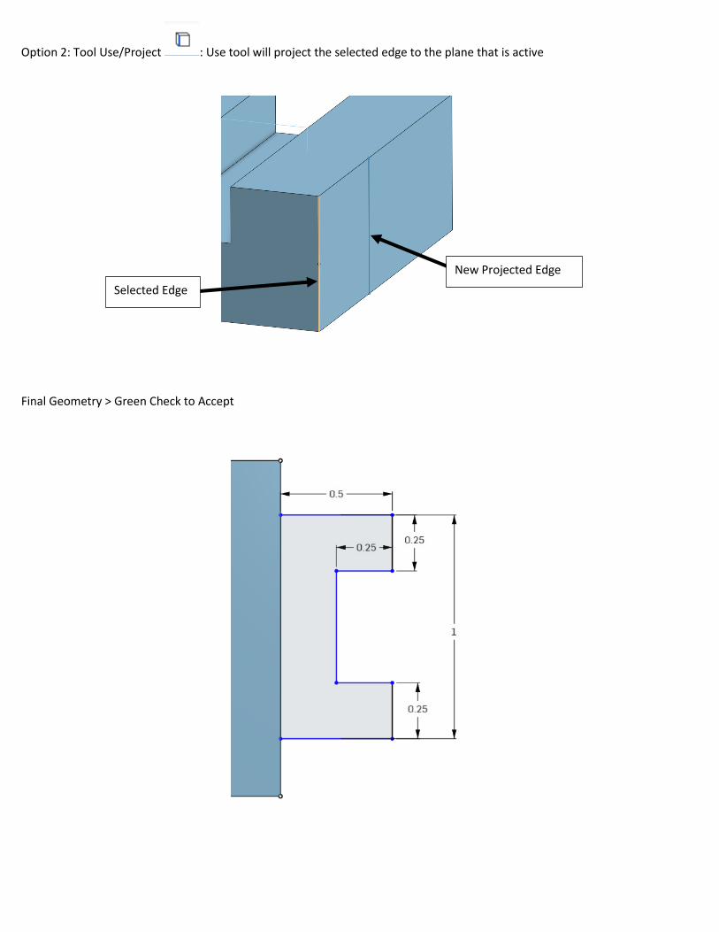
Option 2: Tool Use/Project : Use tool will project the selected edge to the plane that is active
Final Geometry > Green Check to Accept
Selected Edge
New Projected Edge

e. Symmetric Extrude: Select Extrude Icon > Rename to Bump > Select Add Tab > Select Bump Sketch > Change
Extrusion Type to Symmetric > Set Depth 1.25 > Select Merge with All > Green Check
Notice the extrusion
distance is on both sides
equally (.625”)

4. Line Angle Plane: Creates an angled plane based on a selection of edge and a surface/place
a. Select Plane Tool > Select the following
i. Edge
ii. Surface
iii. Set Angle at 45 degrees > Select Green Check
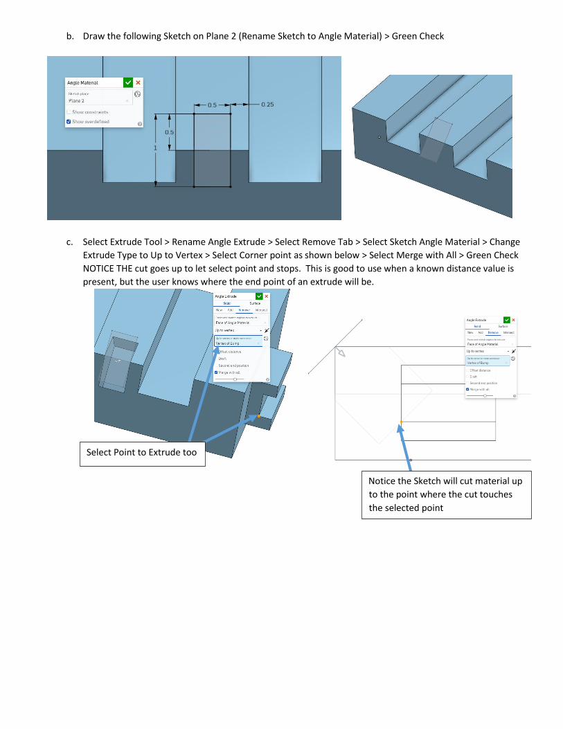
b. Draw the following Sketch on Plane 2 (Rename Sketch to Angle Material) > Green Check
c. Select Extrude Tool > Rename Angle Extrude > Select Remove Tab > Select Sketch Angle Material > Change
Extrude Type to Up to Vertex > Select Corner point as shown below > Select Merge with All > Green Check
NOTICE THE cut goes up to let select point and stops. This is good to use when a known distance value is
present, but the user knows where the end point of an extrude will be.
Select Point to Extrude too
Notice the Sketch will cut material up
to the point where the cut touches
the selected point

d. Create the Following Angled Work plane
e. Draw the Following Sketch on the new plane
Mid-Point
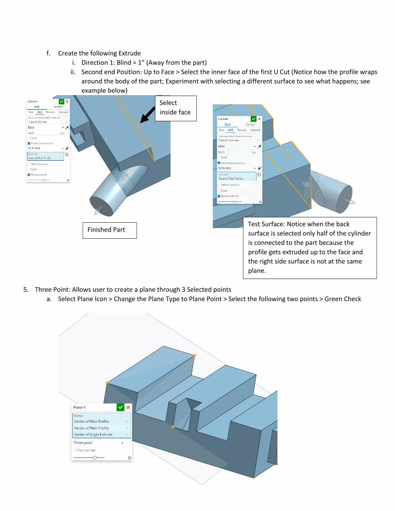
f. Create the following Extrude
i. Direction 1: Blind = 1” (Away from the part)
ii. Second end Position: Up to Face > Select the inner face of the first U Cut (Notice how the profile wraps
around the body of the part; Experiment with selecting a different surface to see what happens; see
example below)
5. Three Point: Allows user to create a plane through 3 Selected points
a. Select Plane Icon > Change the Plane Type to Plane Point > Select the following two points > Green Check
Finished Part Test Surface: Notice when the back
surface is selected only half of the cylinder
is connected to the part because the
profile gets extruded up to the face and
the right side surface is not at the same
plane.
Select
inside face
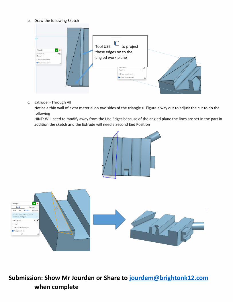
b. Draw the following Sketch
c. Extrude > Through All
Notice a thin wall of extra material on two sides of the triangle > Figure a way out to adjust the cut to do the
following
HINT: Will need to modify away from the Use Edges because of the angled plane the lines are set in the part in
addition the sketch and the Extrude will need a Second End Position
Submission: Show Mr Jourden or Share to [email protected]
when complete
Tool USE to project
these edges on to the
angled work plane