HP iLO 4 User Guide - IT Creations, Inc.
367
HP iLO 4 User Guide Abstract This guide provides information about configuring, updating, and operating HP ProLiant Gen8 and Gen9 servers by using the HP iLO 4 firmware. This document is intended for system administrators, HP representatives, and HP Authorized Channel Partners who are involved in configuring and using iLO 4 and ProLiant Gen8 and Gen9 servers. HP Part Number: 684918-402a Published: October 2015 Edition: 2
-
Upload
khangminh22 -
Category
Documents
-
view
0 -
download
0
Transcript of HP iLO 4 User Guide - IT Creations, Inc.

HP iLO 4 User Guide
AbstractThis guide provides information about configuring, updating, and operating HP ProLiant Gen8 and Gen9 servers by using theHP iLO 4 firmware. This document is intended for system administrators, HP representatives, and HP Authorized ChannelPartners who are involved in configuring and using iLO 4 and ProLiant Gen8 and Gen9 servers.
HP Part Number: 684918-402aPublished: October 2015Edition: 2

© Copyright 2012, 2015 Hewlett-Packard Development Company, L.P.
Confidential computer software. Valid license from HP required for possession, use or copying. Consistent with FAR 12.211 and 12.212, CommercialComputer Software, Computer Software Documentation, and Technical Data for Commercial Items are licensed to the U.S. Government undervendor's standard commercial license.The information contained herein is subject to change without notice. The only warranties for HP products and services are set forth in the expresswarranty statements accompanying such products and services. Nothing herein should be construed as constituting an additional warranty. HP shallnot be liable for technical or editorial errors or omissions contained herein.Links to third-party websites take you outside the HP website. HP has no control over and is not responsible for information outside HP.com.
Acknowledgements
© 2012 Google Inc. All rights reserved. Google and the Google Logo are registered trademarks of Google Inc.
© 2012 Google Inc. All rights reserved. Chrome is a trademark of Google Inc.
Intel® is a trademark of Intel Corporation in the U.S. and other countries.
Java is a registered trademark of Oracle and/or its affiliates.
Linux® is the registered trademark of Linus Torvalds in the U.S. and other countries.
Microsoft® and Windows® are trademarks of the Microsoft group of companies.
Red Hat® is a registered trademark of Red Hat, Inc. in the United States and other countries.
SD is a trademark or registered trademark of SD-3C in the United States, other countries or both.
VMware® is a registered trademark or trademark of VMware, Inc. in the United States and/or other jurisdictions.

Contents1 Introduction to iLO....................................................................................16
iLO features...........................................................................................................................16iLO web interface...................................................................................................................17ROM-based configuration utilities..............................................................................................17iLO mobile app......................................................................................................................17iLO scripting and command line...............................................................................................18HP RESTful API.......................................................................................................................18
2 Setting up iLO..........................................................................................19Overview..............................................................................................................................19Preparing to set up iLO............................................................................................................19Connecting iLO to the network.................................................................................................21Setting up iLO by using iLO RBSU or the iLO 4 Configuration Utility...............................................22
Configuring a static IP address by using iLO RBSU..................................................................22Configuring a static IP address by using the iLO 4 Configuration Utility.....................................23Managing iLO user accounts by using iLO RBSU....................................................................23
Adding user accounts....................................................................................................24Editing user accounts.....................................................................................................24Removing user accounts.................................................................................................25
Managing iLO user accounts by using the iLO 4 Configuration Utility.......................................25Adding user accounts....................................................................................................25Editing or removing user accounts...................................................................................26
Setting up iLO by using the iLO web interface............................................................................26Logging in to iLO for the first time.............................................................................................27Activating iLO licensed features................................................................................................27iLO drivers and utilities............................................................................................................27
Microsoft driver support......................................................................................................27Linux driver and utility support.............................................................................................28VMware driver support.......................................................................................................28
Installing the iLO drivers and utilities..........................................................................................28Loading hp-health for SUSE Linux Enterprise Server and Red Hat Enterprise Linux........................29Removing hp-health for SUSE Linux Enterprise Server and Red Hat Enterprise Linux.....................29Installing hp-health for Ubuntu.............................................................................................29Removing hp-health for Ubuntu............................................................................................29
3 Configuring iLO.......................................................................................30Updating firmware..................................................................................................................30
Updating firmware by using an online method.......................................................................30Performing an in-band firmware update............................................................................30Performing an out-of-band firmware update.......................................................................31
Updating firmware by using an offline method.......................................................................31Obtaining the iLO firmware image file..................................................................................31Obtaining supported server firmware image files...................................................................32Updating firmware by using the iLO web interface.................................................................32
Using language packs............................................................................................................34Installing a language pack..................................................................................................35Selecting a language pack.................................................................................................36Configuring the default language settings..............................................................................36Configuring the current language settings..............................................................................36Uninstalling a language pack..............................................................................................37
iLO licensing..........................................................................................................................37Free iLO 60-day evaluation license.......................................................................................38
Contents 3

Installing an iLO license by using a browser..........................................................................38Viewing installed licenses....................................................................................................39
Managing iLO user accounts by using the iLO web interface........................................................39Viewing local user accounts................................................................................................39Adding local user accounts.................................................................................................40Editing local user accounts..................................................................................................42Password guidelines...........................................................................................................43IPMI/DCMI users...............................................................................................................43Viewing directory groups....................................................................................................44Adding directory groups.....................................................................................................44Editing directory groups......................................................................................................45Deleting a user account or a directory group.........................................................................46
Configuring iLO Federation......................................................................................................46Prerequisites......................................................................................................................46iLO Federation network requirements....................................................................................47Configuring the multicast options for one iLO system at a time..................................................47iLO Federation groups........................................................................................................49
iLO Federation group privileges.......................................................................................50Viewing iLO Federation group memberships (local iLO system).................................................50Adding iLO Federation group memberships (local iLO system)..................................................50Editing iLO Federation groups (local iLO system).....................................................................52Removing a local iLO system from an iLO Federation group.....................................................52Adding iLO Federation group memberships (multiple iLO systems)............................................53
Adding an iLO Federation group based on an existing group.............................................53Creating a group from a filtered set of servers...................................................................54Servers affected by a group membership change..............................................................56Exporting the Affected Systems list...................................................................................56
Configuring enclosure support for iLO Federation...................................................................57Using Onboard Administrator to configure Enclosure iLO Federation Support........................57Verifying server blade support for iLO Federation..............................................................57
Configuring iLO access settings................................................................................................58Configuring service settings.................................................................................................58Configuring IPMI/DCMI settings..........................................................................................60Configuring access options.................................................................................................60Logging in to iLO by using an SSH client...............................................................................63
Configuring iLO security..........................................................................................................64General security guidelines.................................................................................................64
iLO RBSU and iLO 4 Configuration Utility security..............................................................64iLO security with the system maintenance switch................................................................65
TPM and TM.....................................................................................................................66Viewing the TPM or TM status.........................................................................................66
User accounts and access...................................................................................................67User privileges..............................................................................................................67Login security................................................................................................................67
Administering SSH keys......................................................................................................67About SSH keys............................................................................................................68Authorizing a new SSH key............................................................................................69Authorizing a new SSH key by using the CLI.....................................................................69Deleting SSH keys.........................................................................................................70Authorizing SSH keys from an HP SIM server....................................................................70
Administering SSL certificates..............................................................................................70Viewing SSL certificate information..................................................................................71Obtaining and importing an SSL certificate......................................................................71
Directory authentication and authorization.............................................................................73Configuring authentication and directory server settings.....................................................74
4 Contents
Running directory tests...................................................................................................76Directory test results..................................................................................................78Using the directory test controls .................................................................................78About the iLO directory tests......................................................................................79
Using encryption................................................................................................................81Viewing encryption enforcement settings...........................................................................81Modifying the AES/DES encryption setting.......................................................................82
Connecting to iLO by using AES or 3DES encryption.....................................................83Enabling FIPS Mode......................................................................................................83Disabling FIPS Mode.....................................................................................................84
Using HP SSO...................................................................................................................84Configuring iLO for HP SSO...........................................................................................85Adding trusted certificates..............................................................................................86
Extracting the HP SIM server certificate........................................................................87Importing a direct DNS name.........................................................................................87Viewing trusted certificates and records............................................................................88Removing trusted certificates and records.........................................................................88
Configuring the Login Security Banner..................................................................................88Configuring Remote Console security settings.........................................................................90
Configuring Remote Console Computer Lock settings..........................................................90Configuring the Integrated Remote Console Trust setting (.NET IRC)......................................91
Managing the iLO network settings...........................................................................................92Viewing the network configuration summary..........................................................................92Configuring general network settings....................................................................................94
iLO hostname and domain name limitations......................................................................94Configuring the iLO Hostname Settings............................................................................95iLO network port configuration options.............................................................................96Configuring the NIC settings...........................................................................................96
Enabling the iLO Shared Network Port through the iLO web interface..............................97Enabling the iLO Dedicated Network Port through the iLO web interface..........................98
Configuring IPv4 settings....................................................................................................99Configuring IPv6 settings..................................................................................................101
iLO features that support IPv6.......................................................................................103Configuring SNTP settings.................................................................................................104Using iLO NIC auto-selection.............................................................................................106
Configuring iLO NIC auto-selection................................................................................107Viewing iLO systems in the Windows Network folder............................................................107
Configuring iLO Management settings.....................................................................................108AMS and the Insight Management Agents..........................................................................110
Installing AMS or the Insight Management Agents...........................................................110Verifying the AMS installation.......................................................................................110
Verifying AMS status: iLO web interface....................................................................110Verifying AMS status: Windows................................................................................111Verifying AMS status: SUSE and Red Hat Enterprise Linux............................................111Verifying AMS status: VMware.................................................................................111Verifying AMS status: Ubuntu...................................................................................111
Restarting AMS...........................................................................................................111Nagios plug-in for Agentless Management..........................................................................111Configuring SNMP settings...............................................................................................112Configuring SNMPv3 Users...............................................................................................113Configuring the SNMPv3 Engine ID...................................................................................114Configuring SNMP alerts..................................................................................................115
Using the AMS Control Panel to configure SNMP and SNMP alerts (Windows only)............116SNMP traps................................................................................................................116
Configuring Insight Management integration.......................................................................119
Contents 5

Configuring AlertMail settings...........................................................................................120Enabling AlertMail......................................................................................................120Disabling AlertMail.....................................................................................................120
Configuring Remote Syslog settings....................................................................................121Enabling iLO Remote Syslog.........................................................................................121Disabling iLO Remote Syslog........................................................................................121
Embedded remote support.....................................................................................................122HP remote support...........................................................................................................122
Device support............................................................................................................123Software support.........................................................................................................123
Data collected by Insight Remote Support............................................................................123Using HP remote support with HP Proactive Care service.......................................................124Prerequisites for HP remote support registration....................................................................125Registering for Insight Remote Support by using the iLO web interface.....................................126
Registering for Insight Online direct connect...................................................................126Editing the web proxy settings..................................................................................128
Registering for Insight Remote Support central connect.....................................................129Unregistering from Insight Remote Support by using the iLO web interface...............................131
Unregistering from Insight Online direct connect..............................................................131Unregistering from Insight Remote Support central connect................................................131
Working with Insight Remote Support service events.............................................................131Using maintenance mode.............................................................................................131Sending a test service event..........................................................................................132Viewing the Service Event Log.......................................................................................132Clearing the Service Event Log......................................................................................134
Remote Support data collection..........................................................................................134Sending data collection information...............................................................................135Viewing data collection status in iLO..............................................................................135Sending Active Health System reporting information.........................................................136Viewing Active Health System reporting status in iLO........................................................136
Configuring iLO by using the ROM-based utilities......................................................................137Using the iLO RBSU..........................................................................................................137
Accessing the iLO RBSU...............................................................................................137Configuring NIC and TCP/IP settings.............................................................................137Configuring DNS/DHCP settings...................................................................................138Configuring global settings by using iLO RBSU................................................................139Configuring serial CLI options by using iLO RBSU............................................................139
Using the UEFI System Utilities iLO 4 Configuration Utility......................................................140Accessing the iLO 4 Configuration Utility menu...............................................................140Configuring Network Options.......................................................................................140Configuring Advanced Network Options........................................................................141Configuring access settings by using the iLO 4 Configuration Utility...................................142Viewing information about iLO by using the iLO 4 Configuration Utility..............................143
4 Using iLO..............................................................................................145iLO web interface.................................................................................................................145
Browser support...............................................................................................................145Logging in to the iLO web interface....................................................................................145Cookie sharing between browser instances and iLO.............................................................146
Shared instances.........................................................................................................146Cookie order..............................................................................................................146Displaying the current session cookie.............................................................................147Best practices for preventing cookie-related issues............................................................147
Handling an unknown authority.........................................................................................147Using the iLO controls.......................................................................................................147
6 Contents
Starting a remote management tool....................................................................................148Language pack support....................................................................................................148
Viewing iLO overview information...........................................................................................148System information...........................................................................................................148System status details.........................................................................................................149Active sessions list............................................................................................................150
Viewing system information....................................................................................................150Viewing health summary information..................................................................................151
Redundancy status.......................................................................................................151Subsystem and device status.........................................................................................151Subsystem and device status values...............................................................................151
Viewing fan information....................................................................................................152Fans..........................................................................................................................152Fan details.................................................................................................................153
Viewing temperature information .......................................................................................153Viewing the temperature graph.....................................................................................154Viewing temperature sensor data...................................................................................154
Viewing power information...............................................................................................155Power monitoring........................................................................................................156Power Supply Summary details (all nonblade servers)......................................................156Power Supplies list (ML and DL servers)..........................................................................158HP Power Discovery Services iPDU Summary (ML and DL servers only)...............................159Power Readings (blade servers only)..............................................................................160Power Microcontroller (blade servers only)......................................................................160HP Smart Storage Battery details...................................................................................161
Viewing processor information...........................................................................................161Processor details.........................................................................................................161
Viewing memory information.............................................................................................162Advanced Memory Protection details.............................................................................162Memory Summary.......................................................................................................164Memory Details..........................................................................................................164
Viewing network information.............................................................................................166Physical Network Adapters...........................................................................................167Logical Network Adapters............................................................................................168
Viewing the device inventory.............................................................................................168Device Inventory details...............................................................................................168Device status values.....................................................................................................169Viewing PCI slot details................................................................................................169
PCI slot tool tip details.............................................................................................169Viewing storage information..............................................................................................170
Storage components....................................................................................................170Viewing Smart Array storage information.......................................................................171
Controllers.............................................................................................................171Drive Enclosures.....................................................................................................172Logical Drives........................................................................................................172Physical Drives.......................................................................................................172
Viewing direct-attached storage information....................................................................173Controllers.............................................................................................................173Physical Drives.......................................................................................................174
Viewing firmware information............................................................................................174Firmware details..........................................................................................................175
Viewing software information............................................................................................176HP Software List details................................................................................................176Running Software details..............................................................................................176Installed Software details..............................................................................................177
Contents 7

Using the iLO Event Log.........................................................................................................177Viewing the event log.......................................................................................................177
Customizing the event log view.....................................................................................178Saving the event log.........................................................................................................179Clearing the event log......................................................................................................180
Using the Integrated Management Log....................................................................................180Viewing the IML...............................................................................................................181
Customizing the IML view.............................................................................................182Marking an IML entry as repaired......................................................................................183Adding a maintenance note to the IML...............................................................................183Saving the IML................................................................................................................183Clearing the IML..............................................................................................................184IML troubleshooting links...................................................................................................184
HP Active Health System........................................................................................................184Downloading the Active Health System Log for a date range.................................................186Downloading the entire Active Health System Log.................................................................187Extracting the Active Health System Log by using curl............................................................187Clearing the Active Health System Log................................................................................188
Using iLO diagnostics............................................................................................................188Viewing iLO self-test results................................................................................................189Resetting the iLO processor through the web interface ..........................................................190Generating an NMI.........................................................................................................190Configuring redundant ROM.............................................................................................190
Using Location Discovery Services...........................................................................................190Using the HP Insight Management Agents................................................................................192Using iLO Federation.............................................................................................................192
Prerequisites....................................................................................................................193Using the Selected Group list.............................................................................................193
Filtering the Selected Group list.....................................................................................193Using the iLO Federation multi-system view..........................................................................194
Viewing server health and model information..................................................................194Viewing servers with critical and degraded status............................................................194Exporting the Critical and Degraded Systems list to a CSV file..........................................195
Viewing the iLO Federation Multi-System Map......................................................................195Exporting the iLO Peers list to a CSV file.........................................................................196
Using the iLO Federation Group Virtual Media feature..........................................................196Connecting scripted media for groups............................................................................197Viewing scripted media for groups................................................................................198Ejecting a scripted media device...................................................................................198Servers affected by a Group Virtual Media action...........................................................198Exporting the Affected Systems list to a CSV file..............................................................199
Using the iLO Federation Group Power feature.....................................................................199Changing the power state for a group of servers.............................................................199Servers affected by the Virtual Power Button....................................................................201Exporting the Affected Systems list.................................................................................201
Configuring iLO Federation group power settings.................................................................201Configuring group power capping................................................................................203
Using the iLO Federation Group Firmware Update feature.....................................................203Obtaining the iLO firmware image file...........................................................................204Obtaining supported server firmware image files.............................................................204Updating the firmware for multiple servers......................................................................205Servers affected by a Group Firmware Update................................................................206Exporting the Affected Systems list.................................................................................207
Using iLO Federation group licensing.................................................................................207Viewing license information..........................................................................................207
8 Contents

Installing license keys...................................................................................................208Servers affected by a license installation.........................................................................209Exporting the Affected Systems list.................................................................................209
Using the iLO Federation Group Configuration feature..........................................................209Using the Integrated Remote Console......................................................................................210
.NET IRC requirements......................................................................................................211Microsoft .NET Framework............................................................................................211Microsoft ClickOnce....................................................................................................211
Java IRC requirements......................................................................................................212Recommended client settings........................................................................................212Recommended server settings.......................................................................................213
Starting the Remote Console..............................................................................................213Acquiring the Remote Console...........................................................................................214Using the Remote Console power switch.............................................................................214Using iLO Virtual Media from the Remote Console................................................................215Using Shared Remote Console (.NET IRC only)....................................................................215
Joining a Shared Remote Console session......................................................................215Using Console Capture (.NET IRC only)..............................................................................216
Viewing Server Startup and Server Prefailure sequences...................................................216Saving Server Startup and Server Prefailure video files.....................................................217Capturing video files...................................................................................................217Viewing saved video files.............................................................................................217
Using Remote Console hot keys..........................................................................................218Creating a hot key......................................................................................................218Resetting hot keys........................................................................................................219
Using a text-based Remote Console.........................................................................................219Using the iLO Virtual Serial Port.........................................................................................220
Configuring the iLO Virtual Serial Port in the host system RBSU..........................................220Configuring the iLO Virtual Serial Port in the UEFI System Utilities.......................................221Configuring the iLO Virtual Serial Port for Linux...............................................................222Configuring the iLO Virtual Serial Port for the Windows EMS Console................................223Starting an iLO Virtual Serial Port session........................................................................223Viewing the iLO Virtual Serial Port log............................................................................224
Using the Text-based Remote Console (Textcons)..................................................................224Customizing the Text-based Remote Console...................................................................225Using the Text-based Remote Console............................................................................226Using Linux with the Text-based Remote Console..............................................................226
Using iLO Virtual Media........................................................................................................226Virtual Media operating system information.........................................................................227
Operating system USB requirement................................................................................227Using Virtual Media with Windows 7............................................................................228Operating system considerations: Virtual Floppy/USB key................................................228
Changing diskettes.................................................................................................228Operating system considerations: Virtual CD/DVD-ROM..................................................228
Mounting a USB Virtual Media CD/DVD-ROM on Linux systems...................................229Operating system considerations: Virtual Folder .............................................................229
Using Virtual Media from the iLO web interface...................................................................230Viewing and modifying the Virtual Media port................................................................230Viewing local media....................................................................................................230Ejecting a local media device.......................................................................................231Connecting scripted media...........................................................................................231Viewing and ejecting scripted media.............................................................................232
Using Virtual Media from the Remote Console.....................................................................232Using a Virtual Drive...................................................................................................232
Using a physical drive on a client PC........................................................................232
Contents 9

Using an image file................................................................................................232Using an image file through a URL (IIS/Apache).........................................................232
Using the Create Media Image feature (Java IRC only).....................................................233Creating a disk image file.......................................................................................233Copying data from an image file to a physical disk....................................................234
Using a Virtual Folder (.NET IRC only)............................................................................234Setting up IIS for scripted Virtual Media..............................................................................235
Configuring IIS............................................................................................................235Configuring IIS for read/write access.............................................................................235Inserting Virtual Media with a helper application............................................................236Sample Virtual Media helper application.......................................................................236
Configuring Virtual Media Boot Order................................................................................237Changing the server boot mode....................................................................................238Changing the server boot order....................................................................................238Changing the one-time boot status................................................................................239
Changing the one-time boot status in Legacy BIOS mode............................................239Changing the one-time boot status in UEFI mode........................................................240
Using the additional options.........................................................................................240About server power..............................................................................................................240
Powering on the server.....................................................................................................240Brownout recovery...........................................................................................................241Graceful shutdown...........................................................................................................241Power efficiency...............................................................................................................241
Using iLO Power Management...............................................................................................242Managing the server power..............................................................................................242Configuring the System Power Restore Settings.....................................................................243Viewing server power usage..............................................................................................244
Viewing the current power state.....................................................................................246Current power state details......................................................................................246
Viewing the server power history...................................................................................247Power history details...............................................................................................247
Configuring power settings................................................................................................247Configuring Power Regulator settings.............................................................................247Power capping settings................................................................................................249Configuring a power cap.............................................................................................249Configuring SNMP alert settings...................................................................................249Configuring the persistent mouse and keyboard..............................................................250
Using iLO with Onboard Administrator....................................................................................250Using the Active Onboard Administrator.............................................................................250Starting the OA GUI.........................................................................................................251Toggling the enclosure UID LED.........................................................................................251Enclosure bay IP addressing..............................................................................................252Dynamic Power Capping for server blades..........................................................................252iLO virtual fan.................................................................................................................252iLO option.......................................................................................................................252
Viewing chassis information...................................................................................................253Power Supplies list...........................................................................................................254Intelligent Power Distribution Unit details.............................................................................255HP Smart Storage Battery details.......................................................................................255
IPMI server management.......................................................................................................256Advanced IPMI tool usage on Linux....................................................................................257
Using iLO with HP Insight Control server provisioning ...............................................................257Using HP Enterprise Secure Key Manager with iLO....................................................................257
Configuring key manager servers.......................................................................................258Adding key manager configuration details..........................................................................258
10 Contents

Testing the ESKM configuration..........................................................................................259Viewing ESKM events.......................................................................................................260
Viewing remote management tool information..........................................................................260Starting a remote management tool....................................................................................260Deleting a remote manager configuration...........................................................................260Using iLO with HP OneView..............................................................................................261
Using the Embedded User Partition.........................................................................................261Configuring the Embedded User Partition............................................................................262
Configuring the Embedded User Partition (UEFI System Utilities).........................................262Configuring the Embedded User Partition (UEFI Shell)......................................................263Configuring the Embedded User Partition (HP RESTful Interface Tool)..................................263
Configuring the Embedded User Partition boot settings.........................................................263Configuring the Embedded User Partition boot order setting (iLO web interface)..................263Configuring the Embedded User Partition for one-time boot (iLO web interface)...................264Configuring the Embedded User Partition boot order setting (UEFI System Utilities)...............265Configuring the Embedded User Partition for one-time boot (UEFI System Utilities)................266Configuring the Embedded User Partition boot order setting (UEFI Shell).............................266Configuring the Embedded User Partition for one-time boot (UEFI Shell)..............................266Configuring the Embedded User Partition boot order setting (HP RESTful Interface Tool)........266Configuring the Embedded User Partition for one-time boot (HP RESTful Interface Tool).........266
Rebooting (Resetting) iLO.......................................................................................................267Resetting iLO by using the iLO 4 Configuration Utility............................................................267Rebooting iLO with the server UID button............................................................................268
Resetting iLO to the factory default settings...............................................................................268Resetting iLO to the factory default settings by using iLO RBSU...............................................268Resetting iLO to the factory default settings by using the iLO 4 Configuration Utility...................269
5 Integrating HP Systems Insight Manager....................................................270HP SIM features....................................................................................................................270Establishing SSO with HP SIM................................................................................................270iLO identification and association...........................................................................................270
Viewing iLO status in HP SIM.............................................................................................270iLO links in HP SIM..........................................................................................................271Viewing iLO in HP SIM System(s) lists..................................................................................271
Receiving SNMP alerts in HP SIM...........................................................................................271HP SIM port matching...........................................................................................................271Reviewing iLO license information in HP SIM............................................................................272
6 Directory services...................................................................................273Directory integration benefits..................................................................................................273Choosing a directory configuration to use with iLO....................................................................273Kerberos support..................................................................................................................274
Prerequisites....................................................................................................................274Domain controller preparation...........................................................................................275
Realm names..............................................................................................................275Computer accounts......................................................................................................275User accounts.............................................................................................................275Generating a keytab...................................................................................................275
Key version number................................................................................................276Windows Vista.......................................................................................................276
Universal and global user groups (for authorization)........................................................276Configuring iLO for Kerberos login.....................................................................................277
Using the iLO web interface..........................................................................................277Using XML configuration and control scripts....................................................................277Using the CLI, CLP, or SSH interface..............................................................................278
Time requirement.............................................................................................................278
Contents 11
Configuring single sign-on................................................................................................278Internet Explorer..........................................................................................................278Firefox.......................................................................................................................279Chrome.....................................................................................................................279
Verifying single sign-on (HP Zero Sign In) configuration.........................................................279Login by name................................................................................................................279
Schema-free directory integration............................................................................................280Setting up schema-free directory integration.........................................................................280
Active Directory prerequisites........................................................................................280Introduction to Certificate Services............................................................................280Installing Certificate Services....................................................................................281Verifying Certificate Services....................................................................................281Configuring Automatic Certificate Request.................................................................281
Schema-free setup using the iLO web interface................................................................281Schema-free setup using scripts.....................................................................................282Schema-free setup with HP Directories Support for ProLiant Management Processors.............282Schema-free setup options............................................................................................282
Minimum login flexibility.........................................................................................282Better login flexibility..............................................................................................283Maximum login flexibility.........................................................................................283
Schema-free nested groups...........................................................................................283Setting up HP extended schema directory integration................................................................283
Features supported by HP schema directory integration.........................................................283Setting up directory services..............................................................................................284Schema documentation.....................................................................................................285Directory services support.................................................................................................285Schema required software.................................................................................................285
Schema Extender........................................................................................................285Schema Preview window.........................................................................................285Setup window........................................................................................................286Results window......................................................................................................287
Management snap-in installer.......................................................................................287Directory services for Active Directory.................................................................................287
Active Directory installation prerequisites........................................................................287Installing Active Directory.............................................................................................288
For the schema-free configuration.............................................................................288For HP extended schema.........................................................................................288
Snap-in installation and initialization for Active Directory..................................................289Creating and configuring directory objects for use with iLO in Active Directory....................289Directory services objects.............................................................................................290
Active Directory snap-ins.........................................................................................291Role Restrictions tab................................................................................................292
Lights Out Management tab.........................................................................................294User login using directory services..........................................................................................294Directory-enabled remote management....................................................................................295
Creating roles to follow organizational structure...................................................................295Using existing groups..................................................................................................295Using multiple roles.....................................................................................................296
How directory login restrictions are enforced.......................................................................297Restricting roles...........................................................................................................297
Role time restrictions...............................................................................................297Role address restrictions..........................................................................................298
User restrictions...........................................................................................................298User address restrictions..........................................................................................298User time restrictions...............................................................................................299
12 Contents

Creating multiple restrictions and roles...........................................................................299Using bulk import tools.....................................................................................................300
HP Directories Support for ProLiant Management Processors utility...............................................301Compatibility..................................................................................................................301HP Directories Support for ProLiant Management Processors package.....................................302Using HP Directories Support for ProLiant Management Processors.........................................302
Finding management processors...................................................................................302Upgrading firmware on management processors.............................................................304Selecting a directory access method..............................................................................305Naming management processors..................................................................................306Configuring directories when HP extended schema is selected...........................................307Configuring directories when schema-free integration is selected........................................311Setting up management processors for directories............................................................311
7 Troubleshooting......................................................................................313Kernel debugging.................................................................................................................313Using the ProLiant Pre-boot Health Summary............................................................................314
Pre-boot Health Summary details.......................................................................................315Testing the SSL connection to a server......................................................................................315Event log entries...................................................................................................................316Hardware and software link-related issues................................................................................316Login and iLO access issues...................................................................................................316
Login name and password not accepted.............................................................................316A directory connection ends prematurely.............................................................................317iLO management port not accessible by name.....................................................................317iLO RBSU unavailable after iLO and server reset...................................................................318Unable to access the login page........................................................................................318Unable to return to login page after iLO reset......................................................................318Unable to connect to iLO after changing network settings......................................................319A connection error occurs after a firmware update...............................................................319Unable to connect to iLO processor through NIC..................................................................319Unable to log in to iLO after installing iLO certificate............................................................319Unable to connect to iLO IP address...................................................................................320iLO communications fail....................................................................................................320Logging in to iLO with a Kerberos account fails....................................................................320Secure Connection Failed error when using Firefox browser...................................................322Certificate error when navigating to iLO web interface..........................................................322
Directory issues ...................................................................................................................324User contexts do not appear to work..................................................................................324Directory user does not log out after directory timeout has expired.........................................324Problems generating keytab by using ktpass.exe..................................................................325
Remote Console issues..........................................................................................................325Java IRC applet displays red X when Firefox is used to run Java IRC on Linux client ..................325The Java IRC does not start...............................................................................................325Unable to navigate single cursor of Remote Console to corners of Remote Console window.......326Remote Console text window not updated correctly..............................................................326Mouse or keyboard not working in .NET IRC or Java IRC......................................................326.NET IRC sends characters continuously after switching windows ...........................................326Java IRC displays incorrect floppy and USB-key device..........................................................326Caps Lock out of sync between iLO and Java IRC.................................................................327Num Lock out of sync between iLO and Shared Remote Console............................................327Keystrokes repeat unintentionally during Remote Console session............................................327Session leader does not receive connection request when .NET IRC is in replay mode...............328Keyboard LED does not work correctly................................................................................328Inactive .NET IRC.............................................................................................................328
Contents 13

.NET IRC failed to connect to server...................................................................................328File not present after copy from .NET IRC virtual drives to USB key..........................................329.NET IRC takes a long time to verify application requirements................................................329.NET IRC fails to start.......................................................................................................330.NET IRC cannot be shared...............................................................................................330.NET IRC launch is blocked by Firefox.................................................................................330.NET IRC launch is blocked by Google Chrome...................................................................331Unable to boot to DOS using a mounted USB key................................................................331
Text-based Remote Console issues...........................................................................................332Unable to view Linux installer in text-based Remote Console...................................................332Unable to pass data through SSH terminal..........................................................................332VSP-driven selection during the serial timeout window sends output to BIOS redirect instead ofVSP................................................................................................................................332Scrolling and text appear irregular during BIOS redirection...................................................333
SSH issues...........................................................................................................................333Initial PuTTY input slow.....................................................................................................333PuTTY client unresponsive..................................................................................................333SSH text support from text-based Remote Console session......................................................333
Remote Support issues...........................................................................................................333SSL Bio Error during Insight RS registration..........................................................................333Server not identified by server name in Insight Online or Insight RS........................................333Server OS name and version not listed in Insight RS or Insight Online.....................................334Connection error during Insight Online direct connect registration..........................................335iLO session ends unexpectedly during iLO Insight Online direct connect registration..................335
iLO Federation issues............................................................................................................335Query errors occur on iLO Federation pages.......................................................................335A timeout error is displayed on the Multi-System Map page...................................................336A 502 error is displayed on the Multi-System Map page.......................................................337A 403 error is displayed on the Multi-System Map page.......................................................337iLO peers are not displayed..............................................................................................337iLO peers are displayed with IPv6 addresses on IPv4 networks...............................................338
Firmware update issues.........................................................................................................338An iLO firmware update is unsuccessful...............................................................................338An error occurs during an iLO firmware update....................................................................338iLO firmware update does not finish...................................................................................339iLO network Failed Flash Recovery.....................................................................................339
License installation fails.........................................................................................................340Unable to access Virtual Media or graphical Remote Console....................................................341Unable to get SNMP information from HP SIM..........................................................................341Unable to receive HP SIM alarms (SNMP traps) from iLO...........................................................341Server name still present after System Erase Utility is executed....................................................341AMS is installed but unavailable in iLO...................................................................................341
8 Support and other resources....................................................................343Contacting HP......................................................................................................................343Software Technical Support and Update Service.......................................................................343Lost license key recovery........................................................................................................343Subscription service..............................................................................................................343Access to HP support materials...............................................................................................343Websites.............................................................................................................................344
9 Documentation feedback.........................................................................345A iLO license options.................................................................................346B Directory services schema........................................................................348
HP Management Core LDAP OID classes and attributes.............................................................348
14 Contents

Core classes........................................................................................................................348Core attributes.....................................................................................................................348Core class definitions............................................................................................................348
hpqTarget.......................................................................................................................348hpqRole..........................................................................................................................349hpqPolicy........................................................................................................................349
Core attribute definitions........................................................................................................349hpqPolicyDN...................................................................................................................349hpqRoleMembership........................................................................................................349hpqTargetMembership......................................................................................................350hpqRoleIPRestrictionDefault................................................................................................350hpqRoleIPRestrictions........................................................................................................350hpqRoleTimeRestriction......................................................................................................351
Lights-Out Management specific LDAP OID classes and attributes................................................351Lights-Out Management classes..............................................................................................351Lights-Out Management attributes...........................................................................................351Lights-Out Management class definitions..................................................................................351
hpqLOMv100..................................................................................................................351Lights-Out Management attribute definitions.............................................................................352
hpqLOMRightLogin...........................................................................................................352hpqLOMRightRemoteConsole.............................................................................................352hpqLOMRightVirtualMedia................................................................................................352hpqLOMRightServerReset..................................................................................................352hpqLOMRightLocalUserAdmin............................................................................................353hpqLOMRightConfigureSettings..........................................................................................353
Glossary..................................................................................................354Index.......................................................................................................358
Contents 15

1 Introduction to iLOThe iLO subsystem is a standard component of ProLiant servers that simplifies initial server setup,server health monitoring, power and thermal optimization, and remote server administration. TheiLO subsystem includes an intelligent microprocessor, secure memory, and a dedicated networkinterface. This design makes iLO independent of the host server and its operating system.iLO enables and manages the HP Active Health System and also features HP Agentless Management.iLO monitors all key internal subsystems. When enabled, SNMP alerts are sent directly by iLO,regardless of the host operating system or whether a host operating system is installed. Embeddedremote support software is available on ProLiant Gen8 and Gen9 servers with iLO 4, regardlessof the operating system software and without installing OS agents on the server.
iLO featuresUsing iLO, you can do the following:
• Monitor server health. iLO monitors temperatures in the server and sends corrective signals tothe fans to maintain proper server cooling. iLO also monitors firmware versions and the statusof fans, memory, the network, processors, power supplies, and internal storage.
• Download the Active Health System log. You can send the log file to HP when you have anopen support case.
• Manage multiple servers at one time by using the iLO Federation management features.
• Access a high-performance and secure Integrated Remote Console to the server from anywherein the world if you have a network connection to the server.There are two versions of the Integrated Remote Console:
◦ .NET IRC
◦ Java IRC
In this document, general references to the Remote Console apply to both the .NET IRC andJava IRC, unless otherwise specified.
• Use the shared .NET IRC to collaborate with up to four server administrators.
• Remotely mount high-performance Virtual Media devices to the server.
• Use Virtual Power and Virtual Media from the GUI, the CLI, or the iLO scripting toolkit formany tasks, including the automation of deployment and provisioning.
• Securely and remotely control the power state of the managed server.
• Monitor the power consumption and server power settings.
• Implement true Agentless Management with SNMP alerts from iLO, regardless of the state ofthe host server.
• Register a ProLiant Gen8 or Gen9 server for HP remote support.
• Use local or directory-based user accounts to log in to iLO.
• Configure Kerberos authentication, which adds the HP Zero Sign In button to the login screen.
• Use language packs change the iLO web interface from English to a supported language ofyour choice. Language packs provide translations for the iLO web interface, .NET IRC, andJava IRC.
• Control iLO by using a remote management tool.
16 Introduction to iLO
iLO web interfaceThe iLO web interface groups similar tasks for easy navigation and workflow. The interface isorganized in a navigational tree view located on the left side of the page. The top-level branchesare Information, iLO Federation, Remote Console, Virtual Media, Power Management, Network,Remote Support, and Administration. If you have a server blade, the BL c-Class branch is included.When a remote management tool is used with iLO, the <Remote Management Tool Name> branchis included.When using the iLO web interface, note the following:
• Each high-level iLO branch has a submenu that you can display by clicking the + icon to theleft of that branch. Each menu topic displays a page title that describes the information orsettings available on that page. The page title might not reflect the name that is displayed onthe menu option.
• Assistance for all iLO pages is available from the iLO help pages. To access page-specifichelp, click the ? icon on the upper right side of the page.
• Troubleshooting information is available for selected IML events. Supported events are displayedas links in the Description column on the Integrated Management Log page.
• Typical administrator tasks are available from the iLO Federation, Network, Remote Support,Administration, and <Remote Management Tool Name> branches of the iLO web interface.These tasks are described in “Setting up iLO” (page 19) and “Configuring iLO” (page 30).
• Typical user tasks are available from the Information, Remote Console, Virtual Media, PowerManagement, iLO Federation, and BL c-Class branches of the iLO web interface. These tasksare described in “Using iLO” (page 145).
ROM-based configuration utilitiesDepending on your server model, you can use iLO RBSU or the iLO 4 Configuration Utility toconfigure network parameters, global settings, and user accounts. On servers that support UEFI,such as the ProLiant DL580 Gen8 server and ProLiant Gen9 servers, use the iLO 4 ConfigurationUtility in the UEFI System Utilities. On servers that do not support UEFI, use the iLO RBSU.iLO RBSU and the iLO 4 Configuration Utility are designed for the initial iLO setup, and are notintended for continued iLO administration. You can start these utilities when the server is booted,and you can run them remotely with the Remote Console.To determine whether your server supports iLO RBSU or the iLO 4 Configuration Utility, see theserver QuickSpecs at http://www.hp.com/go/qs/.You can configure iLO to require users to log in when they access the ROM-based configurationutilities, or you can disable the utilities for all users. These settings can be configured in the iLOaccess options. Disabling iLO RBSU or the iLO 4 Configuration Utility prevents reconfigurationfrom the host unless the system maintenance switch is set to disable iLO security. For moreinformation, see “Configuring access options” (page 60).
iLO mobile appThe iLO mobile app provides access to your ProLiant servers from a mobile device. The mobileapp interacts directly with the iLO processor, providing total control of the server at all times aslong as the server is plugged in. For example, you can access the server when it is in a healthystate or when it is powered off with a blank hard drive. As an IT administrator, you can troubleshootproblems and perform software deployments from almost anywhere.For more information about the iLO mobile app, see http://www.hp.com/go/ilo/mobileapp.
iLO web interface 17

iLO scripting and command lineYou can use the iLO scripting tools to configure multiple servers, to incorporate a standardconfiguration into the deployment process, and to control servers and subsystems.The iLO scripting and command line guide describes the syntax and tools available for using iLOthrough a command line or scripted interface.
HP RESTful APIiLO 4 2.00 and later includes the HP RESTful API, a management interface that server managementtools can use to perform configuration, inventory, and monitoring of a ProLiant server via iLO. AREST client such as the HP RESTful Interface Tool sends HTTPS operations to the iLO web server toGET and PATCH JSON-formatted data, and to configure supported iLO and server settings, suchas the UEFI BIOS settings.iLO 4 2.30 is Redfish 1.0-conformant while remaining backward compatible with the existing HPRESTful API.Some examples of the supported HTTPS operations include GET, PUT, POST, PATCH, and DELETE.You can use the HP RESTful Interface Tool to access all of the iLO features that are enabled withthe iLO Standard or iLO Standard for BladeSystem license. To access features enabled by the iLOScale-Out, iLO Essentials, iLO Advanced, or iLO Advanced for BladeSystem license, you mustinstall a license. For more information, see “iLO licensing” (page 37).iLO 4 supports the HP RESTful API with ProLiant Gen8 and Gen9 servers. The HP RESTful InterfaceTool is supported only with ProLiant Gen9 servers.You can download the HP RESTful Interface Tool from the following website: http://www.hp.com/go/restfulapi.For more information about the HP RESTful API and the HP RESTful Interface Tool, see the followingwebsite: http://www.hp.com/go/restfulinterface/docs.
18 Introduction to iLO

2 Setting up iLOOverview
The iLO default settings enable you to use most features without additional configuration. However,the configuration flexibility of iLO enables customization for multiple enterprise environments. Thischapter discusses the initial iLO setup steps. For information about additional configuration options,see “Configuring iLO” (page 30).Complete the initial setup steps:1. Decide how you want to handle networking and security.
For more information, see “Preparing to set up iLO” (page 19).2. Connect iLO to the network.
For more information, see “Connecting iLO to the network” (page 21).3. If you are not using dynamic IP addressing, configure a static IP address by using iLO RBSU
or the iLO 4 Configuration Utility.For more information, see “Setting up iLO by using iLO RBSU or the iLO 4 ConfigurationUtility” (page 22).
4. If you are using the local accounts feature, set up your user accounts by using iLO RBSU, theiLO 4 Configuration Utility, or the iLO web interface.For more information, see “Setting up iLO by using iLO RBSU or the iLO 4 ConfigurationUtility” (page 22) or “Setting up iLO by using the iLO web interface” (page 26).
5. Install an iLO license. For more information, see “Activating iLO licensed features” (page 27).6. If required, install the iLO drivers.
For more information, see “iLO drivers and utilities” (page 27).
Preparing to set up iLOBefore setting up an iLO management processor, you must decide how to handle networking andsecurity. The following questions can help you configure iLO:
How should iLO connect to the network?For a graphical representation and explanation of the available connections, see “Connecting iLOto the network” (page 21).Typically, iLO is connected to the network through one of the following:
• A corporate network that both the NIC and the iLO port are connected to. This connectionenables access to iLO from anywhere on the network and reduces the amount of networkinghardware and infrastructure required to support iLO. However, on a corporate network, trafficcan hinder iLO performance.
• A dedicated management network with the iLO port on a separate network. A separatenetwork improves performance and security because you can physically control whichworkstations are connected to the network. A separate network also provides redundant accessto the server if a hardware failure occurs on the corporate network. In this configuration, iLOcannot be accessed directly from the corporate network.
Overview 19
How will iLO acquire an IP address?To access iLO after connecting it to the network, the iLO management processor must acquire anIP address and subnet mask by using either a dynamic or static process.
• A dynamic IP address is set by default. iLO obtains the IP address and subnet mask from DNSor DHCP servers. This method is the simplest.
• A static IP address is used if DNS or DHCP servers are not available on the network. A staticIP address can be configured by using iLO RBSU or the iLO 4 Configuration Utility. For moreinformation, see “Configuring a static IP address by using iLO RBSU” (page 22) or “Configuringa static IP address by using the iLO 4 Configuration Utility” (page 23).
IMPORTANT: If you plan to use a static IP address, you must have the IP address beforestarting the iLO setup process.
What access security is required, and what user accounts and privileges areneeded?iLO provides several options to control user access. Use one of the following methods to preventunauthorized access:
• Local accounts—Up to 12 user accounts can be stored in iLO. This is ideal for smallenvironments such as labs and small-sized or medium-sized businesses.
• Directory services—Use the corporate directory to manage iLO user access. This is ideal forenvironments with a large number of users. If you plan to use directory services, considerenabling at least one local administrator account for alternate access.
For more information about iLO access security, see “Configuring iLO security” (page 64).
How do you want to configure iLO?iLO supports various interfaces for configuration and operation. This guide discusses the followinginterfaces:
• Use iLO RBSU or the iLO 4 Configuration Utility when the system environment does not useDHCP, DNS, or WINS. For more information, see “Setting up iLO by using iLO RBSU or theiLO 4 Configuration Utility” (page 22).
• Use the iLO web interface when you can connect to iLO on the network by using a webbrowser. You can also use this method to reconfigure an iLO management processor. Formore information, see “Setting up iLO by using the iLO web interface” (page 26).
Other configuration options not discussed in this guide follow:
• HP Intelligent Provisioning—Press F10 during POST to start Intelligent Provisioning. Forinformation about the iLO settings you can configure, see the Intelligent Provisioningdocumentation at the following website: http://www.hp.com/go/intelligentprovisioning/docs/.
• HP Scripting Toolkit—This toolkit is a server deployment product for IT experts that providesunattended automated installation for high-volume server deployments. For more information,see the Scripting Toolkit user guide for Windows or Linux.
20 Setting up iLO

• Scripting—You can use scripting for advanced setup of multiple iLO management processors.Scripts are XML files written for a scripting language called RIBCL. You can use RIBCL scriptsto configure iLO on the network during initial deployment or from a deployed host.The following methods are available:
◦ HPQLOCFG—This utility replaces the previously used CPQLOCFG utility. It is a Windowscommand line utility that sends XML configuration and control scripts over the network toiLO.
◦ HPONCFG—A local online scripted setup utility that runs on the host and passes RIBCLscripts to the local iLO. HPONCFG requires the HP ProLiant iLO 3/4 Channel InterfaceDriver.
◦ Custom scripting environments (LOCFG.PL)—The iLO scripting samples include a Perlsample that can be used to send RIBCL scripts to iLO over the network.
◦ SMASH CLP—A command-line protocol that can be used when a command line isaccessible through SSH or the physical serial port.
For more information about these methods, see the iLO scripting and command line guide.iLO sample scripts are available at the following website: http://www.hp.com/support/ilo4.
• HP RESTful API—A management interface that server management tools can use to performconfiguration, inventory, and monitoring of a ProLiant server via iLO.For more information, see http://www.hp.com/go/restfulinterface/docs.
Connecting iLO to the networkYou can connect iLO to the network through a corporate network or a dedicated managementnetwork.
• In a corporate network, the server has two network port types (server NICs and one iLO NIC)connected to the corporate network, as shown in Figure 1 (page 21).
Figure 1 Corporate network diagram
Main NIC
iLO
Main NIC
Hub/Switch
Client PCs
CorporateNetwork
Management Client
iLO
• In a dedicated management network, the iLO port is on a separate network, as shown inFigure 2 (page 22).
Connecting iLO to the network 21

Figure 2 Dedicated management network diagram
Hub/SwitchMain NIC
iLO
iLO
Main NICHub/Switch
Client PCs
CorporateNetwork
DedicatediLO Management
Network
Management Client
Setting up iLO by using iLO RBSU or the iLO 4 Configuration UtilityHP recommends using iLO RBSU or the iLO 4 Configuration Utility to set up iLO for the first timeand to configure iLO network parameters for environments that do not use DHCP, DNS, or WINS.To determine whether your server supports iLO RBSU or the iLO 4 Configuration Utility, see theserver QuickSpecs at http://www.hp.com/go/qs/.To access the ROM-based configuration utilities:
• iLO RBSU—Press F8 during POST.Use the arrow keys and the Enter key to navigate through the iLO RBSU menus. Follow theon-screen instructions to make configuration changes.
• iLO 4 Configuration Utility—Press F9 during POST to enter the UEFI System Utilities, and thenselect System Configuration→iLO 4 Configuration Utility.For more information, see the UEFI System Utilities user guide.
On servers that use the system RBSU and not the UEFI System Utilities, the iLO option ROM liststhe installed license and the firmware version. This information is not listed in the option ROM onUEFI systems.
Configuring a static IP address by using iLO RBSUThis procedure is required only if you are using a static IP address. When you are using dynamicIP addressing, your DHCP server automatically assigns an IP address for iLO.To simplify installation, HP recommends using DNS or DHCP with iLO.1. Optional: If you access the server remotely, start an iLO remote console session.
You can use the .NET IRC or Java IRC.2. Restart or power on the server.3. Press F8 in the ProLiant POST screen to start iLO RBSU.4. Disable DHCP:
a. From the iLO RBSU screen, select Network→DNS/DHCP, and then press Enter.b. Select DHCP Enable.c. Press the spacebar to set DHCP Enable to OFF, and then press F10 to save the changes.
22 Setting up iLO
5. Enter the network settings:a. From the iLO RBSU screen, select Network→NIC and TCP/IP, and then press Enter.b. Enter the appropriate information in the IP Address, Subnet Mask, and Gateway IP Address
fields.c. Press F10 to save the changes.
6. Select File→Exit.The changes take effect when you exit iLO RBSU.
Configuring a static IP address by using the iLO 4 Configuration UtilityThis procedure is required only if you are using a static IP address. When you are using dynamicIP addressing, your DHCP server automatically assigns an IP address for iLO.To simplify installation, HP recommends using DNS or DHCP with iLO.1. Optional: If you access the server remotely, start an iLO remote console session.
You can use the .NET IRC or Java IRC.2. Restart or power on the server.3. Press F9 in the ProLiant POST screen to start the UEFI System Utilities.4. From the System Configuration screen, use the up or down arrow keys and the Enter key to
navigate to the System Configuration→iLO 4 Configuration Utility→Network Options screen.5. Disable DHCP:
a. Select DHCP Enable, and then press Enter.b. Select OFF, and then press Enter.
6. Enter an IP address, subnet mask, and gateway IP address:a. Select IP Address, and then press Enter.b. Type the IP address, and then press Enter.c. Select Subnet Mask, and then press Enter.d. Type the subnet mask address, and then press Enter.e. Select Gateway IP Address, and then press Enter.f. Type the gateway IP address, and then press Enter.
7. Press F10 to save the changes.The iLO 4 Configuration Utility prompts you to confirm that you want to save all pendingconfiguration changes.
8. Press Y to save and exit.The iLO 4 Configuration Utility notifies you that iLO must be reset in order for the changes totake effect.
9. Press Enter.iLO resets, and the iLO session is automatically ended. You can reconnect in approximately30 seconds.
10. Resume the normal boot process:a. Start the iLO remote console.
The iLO 4 Configuration Utility is still open from the previous session.b. Press ESC several times to navigate to the System Configuration page.c. Press ESC to exit the System Utilities and resume the normal boot process.
Managing iLO user accounts by using iLO RBSUYou can use iLO RBSU to add, edit, and remove local iLO user accounts.
Setting up iLO by using iLO RBSU or the iLO 4 Configuration Utility 23

Adding user accounts1. Optional: If you access the server remotely, start an iLO remote console session.
You can use the .NET IRC or Java IRC.2. Restart or power on the server.3. Press F8 in the ProLiant POST screen to start iLO RBSU.4. From the iLO RBSU screen, select User→Add, and then press Enter.5. Enter the following user account details:
• User name appears in the user list on the User Administration page. It does not have tobe the same as the Login name. The maximum length for a user name is 39 characters.The user name must use printable characters. Assigning descriptive user names can helpyou to easily identify the owner of each login name.
• Login name is the name you must use when logging in to iLO. It appears in the user liston the User Administration page, on the iLO Overview page, and in iLO logs. The Loginname does not have to be the same as the User name. The maximum length for a loginname is 39 characters. The login name must use printable characters.
• Password and Verify password set and confirm the password that is used for logging into iLO. The maximum length for a password is 39 characters. Enter the password twicefor verification.
6. Select from the following privileges. To enable a privilege, set it to Yes. To disable a privilege,set it to No.• Administer User Accounts—Enables a user to add, edit, and delete local iLO user accounts.
A user with this privilege can change privileges for all users. If you do not have thisprivilege, you can view your own settings and change your own password.
• Remote Console Access—Enables a user to remotely access the host system RemoteConsole, including video, keyboard, and mouse control.
• Virtual Power and Reset—Enables a user to power-cycle or reset the host system. Theseactivities interrupt the system availability. A user with this privilege can diagnose thesystem by using the Generate NMI to System button.
• Virtual Media—Enables a user to use the Virtual Media feature on the host system.
• Configure Settings—Enables a user to configure most iLO settings, including securitysettings, and to remotely update the iLO firmware. This privilege does not enable localuser account administration.After iLO is configured, revoking this privilege from all users prevents reconfigurationusing the web interface, HPQLOCFG, or the CLI. Users who have access to iLO RBSU,the iLO 4 Configuration Utility, or HPONCFG can still reconfigure iLO. Only a user whohas the Administer User Accounts privilege can enable or disable this privilege.
7. Press F10 to save the new user account.8. Repeat Step 4 through Step 7 until you are done creating user accounts.9. Select File→Exit.
Editing user accounts1. Optional: If you access the server remotely, start an iLO remote console session.
You can use the .NET IRC or Java IRC.2. Restart or power on the server.3. Press F8 in the ProLiant POST screen to start iLO RBSU.4. From the iLO RBSU screen, select User→Edit, and then press Enter.5. Select the user name that you want to edit, and then press Enter.
24 Setting up iLO
6. Update the user name, login name, password, or user privileges, and then press F10 to savethe changes.
7. Select File→Exit.
Removing user accounts1. Optional: If you access the server remotely, start an iLO remote console session.
You can use the .NET IRC or Java IRC.2. Restart or power on the server.3. Press F8 in the ProLiant POST screen to start iLO RBSU.4. From the iLO RBSU screen, select User→Remove, and then press Enter.5. Select the user that you want to remove, and then press Enter.
The iLO RBSU prompts you to confirm the request.6. Press Enter to confirm the request.7. Select File→Exit.
Managing iLO user accounts by using the iLO 4 Configuration UtilityYou can use the iLO 4 Configuration Utility to add, edit, and remove local iLO user accounts.
Adding user accountsUse the iLO 4 Configuration Utility User Management menu to configure local iLO user accounts.1. Optional: If you access the server remotely, start an iLO remote console session.
You can use the .NET IRC or Java IRC.2. Restart or power on the server.3. Press F9 in the ProLiant POST screen to start the UEFI System Utilities.4. From the System Utilities screen, select System Configuration→iLO 4 Configuration Utility→User
Management.5. From the User Management screen, select Add User, and then press Enter.6. From the Add User screen, select from the following privileges.
To enable a privilege, set it to YES. To disable a privilege, set it to NO.
• Administer User Accounts—Enables a user to add, edit, and delete local iLO user accounts.A user with this privilege can change privileges for all users. If you do not have thisprivilege, you can view your own settings and change your own password.
• Remote Console Access—Enables a user to remotely access the host system RemoteConsole, including video, keyboard, and mouse control.
• Virtual Power and Reset—Enables a user to power-cycle or reset the host system. Theseactivities interrupt the system availability. A user with this privilege can diagnose thesystem by using the Generate NMI to System button.
• Virtual Media—Enables a user to use the Virtual Media feature on the host system.
• Configure Settings—Enables a user to configure most iLO settings, including securitysettings, and to remotely update the iLO firmware. This privilege does not enable localuser account administration.After iLO is configured, revoking this privilege from all users prevents reconfigurationusing the web interface, HPQLOCFG, or the CLI. Users who have access to iLO RBSU,the iLO 4 Configuration Utility, or HPONCFG can still reconfigure iLO. Only a user whohas the Administer User Accounts privilege can enable or disable this privilege.
Setting up iLO by using iLO RBSU or the iLO 4 Configuration Utility 25

7. Enter the following user account details:• New User Name appears in the user list on the User Administration page. It does not
have to be the same as the Login Name. The maximum length for a user name is 39characters. The user name must use printable characters. Assigning descriptive user namescan help you to easily identify the owner of each login name.
• Login Name is the name you must use when logging in to iLO. It appears in the user liston the User Administration page, on the iLO Overview page, and in iLO logs. The LoginName does not have to be the same as the User Name. The maximum length for a loginname is 39 characters. The login name must use printable characters.
• Password and Password Confirm set and confirm the password that is used for loggingin to iLO. The maximum length for a password is 39 characters. Enter the password twicefor verification.
8. Create as many user accounts as needed, and then press F10 to save the changes.9. Press Esc until the main menu is displayed.10. Select Exit and Resume Boot in the main menu, and then press Enter.11. When prompted to confirm the request, press Enter to exit the utility and resume the boot
process.
Editing or removing user accountsUse the iLO 4 Configuration Utility User Management menu to edit or remove local iLO user accounts.1. Optional: If you access the server remotely, start an iLO remote console session.
You can use the .NET IRC or Java IRC.2. Restart or power on the server.3. Press F9 in the ProLiant POST screen to start the UEFI System Utilities.4. From the System Utilities screen, select System Configuration→iLO 4 Configuration Utility→User
Management.5. From the User Management screen, select Edit/Remove User, and then press Enter.6. From the Edit/Remove User screen, select the Action menu for the user name you want to edit
or delete, and then press Enter.7. Select one of the following, and then press Enter.
• No Change—Returns you to the main menu.
• Delete—Deletes this user.
• Edit—Edits the user.8. Depending on your selection in Step 7, do one of the following:
• If you selected No Change, no further action is needed.
• If you selected Delete, the user name is marked to be deleted when you save the changeson this page.
• If you selected Edit, update the login name, password, or user permissions.9. Update as many user accounts as needed, and then press F10 to save the changes.10. Press Esc until the main menu is displayed.11. Select Exit and Resume Boot in the main menu, and then press Enter.12. When prompted to confirm the request, press Enter to exit the utility and resume the boot
process.
Setting up iLO by using the iLO web interfaceYou can use the iLO web interface to configure iLO if you can connect to iLO on the network byusing a web browser. You can also use this method to reconfigure an iLO management processor.
26 Setting up iLO
Access iLO from a remote network client by using a supported browser and providing the defaultDNS name, user name, and password. For information about the DNS name and default useraccount credentials, see “Logging in to iLO for the first time” (page 27).For information about the configuration procedures available in the iLO web interface, see“Configuring iLO” (page 30).
Logging in to iLO for the first timeThe iLO firmware is configured with a default user name, password, and DNS name. Default userinformation is located on the serial label pull tab attached to the server that contains the iLOmanagement processor. Use these values to access iLO remotely from a network client by using aweb browser.The default values follow:
• User name—Administrator
• Password—A random eight-character alphanumeric string
• DNS name—ILOXXXXXXXXXXXX, where the Xs represent the serial number of the serverIf you enter an incorrect user name and password, or a login attempt fails, iLO imposes a securitydelay. For more information about login security, see “Login security” (page 67).
IMPORTANT: HP recommends changing the default password after you log in to iLO for the firsttime. For instructions, see “Managing iLO user accounts by using the iLO web interface” (page 39).If you reset iLO to the factory default settings, use the default iLO account information to log inafter the reset.
Activating iLO licensed featuresTo activate iLO licensed features, install an iLO license. iLO licenses activate functionality such asgraphical Remote Console with multi-user collaboration, video record/playback, and many moreadvanced features. For licensing information and installation instructions, see “Installing an iLOlicense by using a browser” (page 38).
iLO drivers and utilitiesiLO is an independent microprocessor running an embedded operating system. The architectureensures that the majority of iLO functionality is available, regardless of the host operating system.The iLO drivers and System Health Application and Command Line Utilities enable software suchas HPONCFG and the Agentless Management Service to communicate with iLO. The installed OSand system configuration determine the installation requirements.
Microsoft driver supportWhen you use Windows with iLO, the following drivers are available:
• HP ProLiant iLO 3/4 Channel Interface Driver for Windows—This driver is required for theoperating system to communicate with iLO. Install this driver in all configurations.
• HP ProLiant iLO 3/4 Management Controller Driver Package for Windows—This packageincludes the following components:
◦ hpqilo3core provides iLO Management Controller Driver support.
◦ hpqilo3service provides the HP ProLiant Health Monitor Service and HP ProLiantSystem Shutdown Service.
◦ hpqilo3whea is a helper service for Windows Hardware Error Architecture, whichpasses information between iLO and the operating system in the event of a hardwarefault.
Logging in to iLO for the first time 27

The Management Controller Driver Package is required to support Automatic Server Recoveryand the Insight Management Agents or Insight Management WBEM Providers (if installed).
Linux driver and utility supportWhen you use Linux with iLO, the following drivers and utilities are available:
• HP System Health Application and Command Line Utilities (hp-health)—A collection ofapplications and tools that enables monitoring of fans, power supplies, temperature sensors,and other management events. This RPM contains the hpasmd, hpasmlited, hpasmpld,and hpasmxld daemons.
• hpilo—This driver manages agent and tool application access to iLO.This driver is part of the Linux kernel for SUSE Linux Enterprise Server 10 SP3 and later andRed Hat Enterprise Linux 5.3 and later, and it is loaded automatically at startup.For servers that support earlier versions of SUSE Linux Enterprise Server and Red Hat EnterpriseLinux, install the hp-ilo RPM package from the SPP.On Ubuntu systems, this driver is loaded automatically at startup after the Linux ManagementComponent Pack package is loaded.
VMware driver supportWhen you use VMware with iLO, the following driver is available:HP ProLiant Channel Interface Driver (hpilo)—This driver manages agent, WBEM provider, andtool application access to iLO. It is included in the customized HP VMware images. For raw VMwareimages, the driver must be installed manually.
Installing the iLO drivers and utilitiesThe iLO drivers and HP System Health Application and Command Line Utilities are available fromthe HP Service Pack for ProLiant (Windows, Red Hat Enterprise Linux, and SUSE Linux EnterpriseServer) and the HP website (Windows, Red Hat Enterprise Linux, SUSE Linux Enterprise Server,VMware, and Ubuntu).
• For Windows, Red Hat Enterprise Linux, and SUSE Linux Enterprise Server—Use the SPP toinstall the iLO drivers or HP System Health Application and Command Line Utilities.For information about downloading and using the SPP, see the following website: http://www.hp.com/go/spp/documentation.
• For Windows, Red Hat Enterprise Linux and SUSE Linux Enterprise Server—Download the iLOdrivers or HP System Health Application and Command Line Utilities from the HP SupportCenter website at http://www.hp.com/go/hpsc.Follow the installation instructions provided with the software, or see “Loading hp-health forSUSE Linux Enterprise Server and Red Hat Enterprise Linux” (page 29).
• For VMware—Download the iLO driver from the vibsdepot section of the Software DeliveryRepository website: http://downloads.linux.hp.com/SDR/index.html.Follow the installation instructions provided with the software.
• For Ubuntu—Subscribe to the Linux Management Component Pack at http://downloads.linux.hp.com/SDR/index.html to obtain the HP System Health Application andCommand Line Utilities.Follow the installation instructions provided with the Linux Management Component Pack, orsee “Installing hp-health for Ubuntu” (page 29).
28 Setting up iLO
Loading hp-health for SUSE Linux Enterprise Server and Red Hat Enterprise LinuxUse the following command to load hp-health:rpm -ivh hp-health-<d.vv.v-pp.Linux_version.arch>.rpm
Where <d> is the Linux distribution and version, <vv.v-pp> are version numbers, and <arch>is the architecture (i386 or x86_64).
Removing hp-health for SUSE Linux Enterprise Server and Red Hat Enterprise LinuxUse the following command to remove hp-health:rpm -e hp-health
Installing hp-health for Ubuntu1. Subscribe to the Linux Management Component Pack.
HP recommends subscribing to the Linux Management Component Pack repository to ensurethat your Ubuntu systems have the latest HP software.For instructions, see the following website: http://downloads.linux.hp.com/SDR/project/mcp/.
2. Enter the following command to update the repository cache: apt-get update.3. Enter the following command to install hp-health:
apt-get install hp-health.
Removing hp-health for UbuntuUse the following command to remove hp-health:apt-get remove hp-health
Installing the iLO drivers and utilities 29
3 Configuring iLOThis chapter includes procedures for configuring iLO by using the iLO web interface and theROM-based setup utilities. You can also use XML configuration and control scripts, SMASH CLP,or the HP RESTful API to configure iLO settings.For more information, see the iLO and HP RESTful API documentation at the following website:http://www.hp.com/go/ilo/docs.
Updating firmwareFirmware updates enhance server and iLO functionality with new features, improvements, andsecurity updates.You can update firmware by using the following methods:
• Online firmware update—When you use an online method to update firmware, you canperform the update without shutting down the server operating system. Online firmware updatescan be performed in-band or out-of-band.
◦ In-band—Firmware is sent to iLO from the server host operating system. The HP ProLiantChannel Interface Driver is required for in-band firmware updates. During a host-basedfirmware update, iLO does not verify login credentials or user privileges because thehost-based utilities require a root login (Linux and VMware) or Administrator login(Windows).
◦ Out-of-band—Firmware is sent to iLO over a network connection. Users with the ConfigureiLO Settings privilege can update firmware by using an out-of-band method. If the systemmaintenance switch is set to disable iLO security, any user can update firmware with anout-of-band method.
For more information, see “Updating firmware by using an online method” (page 30).
• Offline firmware update—When you use an offline method to update the firmware, you mustreboot the server by using an offline utility.For more information, see “Updating firmware by using an offline method” (page 31).
The following firmware types can be updated from the Firmware Update page:
• iLO firmware
• ProLiant System ROM (BIOS)
• Chassis firmware (SL and XL servers)
• Power Management Controller
• System Programmable Logic Device (CPLD)
Updating firmware by using an online method
Performing an in-band firmware updateYou can use the following in-band firmware update methods:
• Online ROM Flash Component—Use an executable file to update firmware while the server isrunning. The executable file contains the installer and the firmware package. You can download
30 Configuring iLO
online ROM flash components for iLO and ProLiant servers at the following website: http://www.hp.com/support/ilo4.
• HPONCFG—Use this utility to update firmware by using XML scripts. Download the iLO orserver firmware image and the Update_Firmware.xml sample script. Edit the sample scriptwith your setup details, and then run the script.Sample scripts are available at http://www.hp.com/support/ilo4. For more information aboutscripting, see the iLO scripting and command line guide.For instructions about obtaining firmware images, see “Obtaining the iLO firmware imagefile” (page 31) and “Obtaining supported server firmware image files” (page 32).
Performing an out-of-band firmware updateYou can use the following out-of-band firmware update methods:
• iLO web interface—Download a supported firmware file and install it by using the iLO webinterface. You can update firmware for a single server or an iLO Federation group. Forinstructions, see “Updating firmware by using the iLO web interface” (page 32) or “Using theiLO Federation Group Firmware Update feature” (page 203).
• HPQLOCFG—Use this utility to update firmware by using XML scripts. Download the iLO orserver firmware image and the Update_Firmware.xml sample script. Edit the sample scriptwith your setup details, and then run the script.Sample scripts are available at http://www.hp.com/support/ilo4. For more information aboutscripting, see the iLO scripting and command line guide.For instructions about obtaining the iLO firmware image, see “Obtaining the iLO firmwareimage file” (page 31).
• HPLOMIG (also called HP Directories Support for ProLiant Management Processors)—You donot need to use directory integration to take advantage of the firmware update capabilitiesin HPLOMIG. This utility can be used to discover multiple iLO processors and update theirfirmware in one step. For more information, see “Upgrading firmware on managementprocessors” (page 304).
• SMASH CLP—Access SMASH CLP through the SSH port, and use standard commands to viewfirmware information and update firmware.For more information about SMASH CLP, see the iLO scripting and command line guide.
• HP RESTful API—Use the HP RESTful API and a REST client to update firmware. For moreinformation, see http://www.hp.com/go/restfulinterface/docs.
Updating firmware by using an offline methodYou can use the following offline firmware update methods:
• SPP—Use the SPP to install firmware. For more information, see the following website: http://www.hp.com/go/spp/documentation.Scripting Toolkit—Use the Scripting Toolkit to configure several settings within the server andupdate firmware. This method is useful for deploying to multiple servers. For instructions, seethe Scripting Toolkit user guide for Windows or Linux.
Obtaining the iLO firmware image fileThe .bin file from the iLO Online ROM Flash Component is required for some of the methods youcan use to update the iLO firmware.To download the iLO Online ROM Flash Component file, and then extract the .bin file:1. Navigate to the HP Support Center website: http://www.hp.com/go/hpsc.
Updating firmware 31

2. Follow the onscreen instructions to locate and download the iLO Online ROM Flash Componentfile.In order to extract the .bin file, download a Windows or Linux component.
3. Extract the .bin file.• For Windows components: Double-click the downloaded file, and then click the Extract
button. Select a location for the extracted files, and then click OK.• For Linux components: Depending on the file format, enter one of the following commands:
◦ #sh ./CP00XXXX.scexe –unpack=/tmp/
◦ #rpm2cpio hp-firmware-ilo4-2.xx-1x1.i386.rpm | cpio -id
The name of the iLO firmware image file is similar to ilo4_<yyy>.bin, where <yyy>represents the firmware version.
Obtaining supported server firmware image filesTo obtain the system ROM, Power Management Controller, and chassis firmware image files:1. Navigate to the HP Support Center website: http://www.hp.com/go/hpsc.2. Follow the onscreen instructions to locate and download an Online ROM Flash Component
file.3. Double-click the downloaded file, and then click the Extract button.4. Select a location for the extracted files, and then click OK.
• The system ROM firmware image file name uses a format similar to the following:CPQJ0123.B18.
• The Power Management Controller and chassis firmware files use the file extension .hex.For example, the file name might be similar to ABCD5S95.hex.
• The System Programmable Logic Device (CPLD) firmware file uses the file extension .vme.
Updating firmware by using the iLO web interfaceYou can update firmware from any network client by using the iLO web interface.To update the server or iLO firmware:1. Obtain the firmware image file.
For instructions, see “Obtaining the iLO firmware image file” (page 31) or “Obtaining supportedserver firmware image files” (page 32).
2. Navigate to the Administration→Firmware page.
32 Configuring iLO
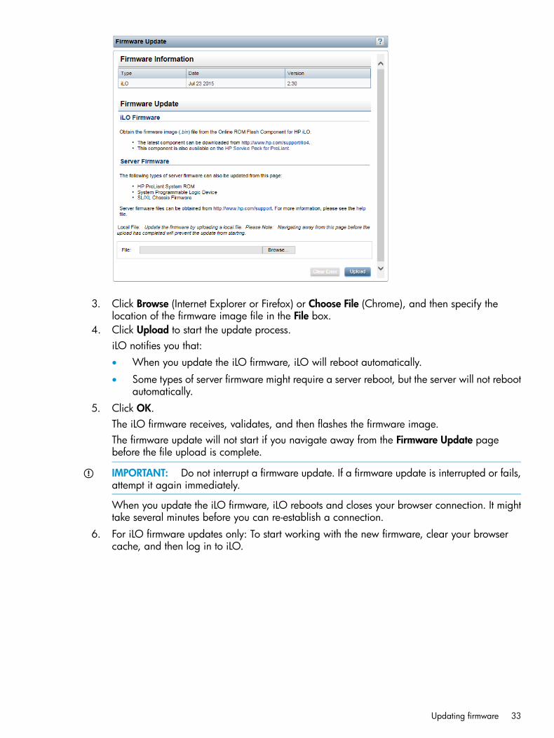
3. Click Browse (Internet Explorer or Firefox) or Choose File (Chrome), and then specify thelocation of the firmware image file in the File box.
4. Click Upload to start the update process.iLO notifies you that:• When you update the iLO firmware, iLO will reboot automatically.
• Some types of server firmware might require a server reboot, but the server will not rebootautomatically.
5. Click OK.The iLO firmware receives, validates, and then flashes the firmware image.The firmware update will not start if you navigate away from the Firmware Update pagebefore the file upload is complete.
IMPORTANT: Do not interrupt a firmware update. If a firmware update is interrupted or fails,attempt it again immediately.
When you update the iLO firmware, iLO reboots and closes your browser connection. It mighttake several minutes before you can re-establish a connection.
6. For iLO firmware updates only: To start working with the new firmware, clear your browsercache, and then log in to iLO.
Updating firmware 33

7. For server firmware updates only: For the new firmware to take effect, some types of firmwareupdates require a system reset or a server reboot. The requirements for each firmware typefollow:• System ROM (BIOS)—Requires a server reboot.
• Chassis firmware (Power Management)—Requires a chassis reset, which is triggeredautomatically.
• System Programmable Logic Device (CPLD)—Requires a server reboot.
• Power Management Controller—Does not require an iLO reset or server reboot.
TIP: To confirm that the new firmware is active, check the version on the SystemInformation→Firmware page.
If an error occurs during an iLO firmware update, see “An iLO firmware update is unsuccessful”(page 338).If an iLO firmware update is corrupted or canceled, and iLO is corrupted, see “iLO network FailedFlash Recovery” (page 339).
Using language packsLanguage packs enable you to change the iLO web interface from English to a supported languageof your choice. Language packs provide translations for the iLO web interface, .NET IRC, and JavaIRC.Consider the following when using language packs:
• You must have the Configure iLO Settings privilege to install a language pack.
• The following language packs are available: Japanese and Simplified Chinese.
• The English language cannot be uninstalled.
• For iLO 4 2.10 and earlier—You can install one language pack.Installing a new language pack replaces the currently installed language pack, regardless ofthe language pack version.
• For iLO 4 2.20 and later—You can install multiple language packs.When version 2.20 or later of a language pack is installed, installing a new language packof the same language (version 2.20 or later) replaces the currently installed language pack.
• iLO 4 2.20 or later requires version 2.20 or later of the iLO language pack.
• For iLO 4 2.20 and later—Language packs are not supported on servers that do not have aNAND.To continue using language packs on servers without a NAND, use iLO 4 2.10 or earlier.
• When you upgrade from an earlier version of iLO 4 to version 2.20 or later, previouslyinstalled language packs are deleted.
• The Java IRC and .NET IRC use the language of the current iLO session.
• For localization support with the Java IRC on Windows systems, you must select the correctlanguage in the Regional and Language Options Control Panel.
• For localization support with the Java IRC on Linux systems, make sure that the fonts for thespecified language are installed and available to the JRE.
• If an installed language pack does not include the translation for a text string, the text isdisplayed in English.
34 Configuring iLO

• When you update the iLO firmware, HP recommends downloading the latest language packto ensure that the language pack contents match the iLO web interface.
• iLO uses the following process to determine the language of your session:1. If you previously logged in to the iLO web interface on the same computer using the same
browser, and you have not cleared the cookies, the language setting of the last sessionwith that iLO processor is used.
2. If there is no cookie, the current browser language is used if it is supported by iLO andthe required language pack is installed.
3. Internet Explorer only: If the browser language is not supported, the OS language is usedif the language is supported by iLO, and the required language pack is installed.
4. If there is no cookie, and the browser or OS language is not supported, iLO uses theconfigured default language. For more information, see “Configuring the default languagesettings” (page 36).
Installing a language pack1. Navigate to the following website: http://www.hp.com/support/ilo4.2. Follow the onscreen instructions to locate and download a language pack.3. Double-click the downloaded file to extract the contents.4. Navigate to the Administration→Access Settings→Language page.
5. Click Browse (Internet Explorer or Firefox) or Choose File (Chrome) in the Install LanguagePack section.
6. Select the language pack (lang_<language>_<version>.lpk), and then click Open.iLO prompts you to confirm the installation.For iLO 4 2.10 and earlier: If you have a previously installed language pack, this languagepack will replace it if you proceed with the installation.
7. Click OK.
Using language packs 35
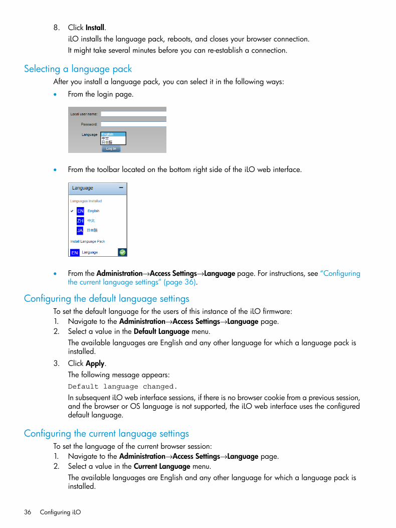
8. Click Install.iLO installs the language pack, reboots, and closes your browser connection.It might take several minutes before you can re-establish a connection.
Selecting a language packAfter you install a language pack, you can select it in the following ways:
• From the login page.
• From the toolbar located on the bottom right side of the iLO web interface.
• From the Administration→Access Settings→Language page. For instructions, see “Configuringthe current language settings” (page 36).
Configuring the default language settingsTo set the default language for the users of this instance of the iLO firmware:1. Navigate to the Administration→Access Settings→Language page.2. Select a value in the Default Language menu.
The available languages are English and any other language for which a language pack isinstalled.
3. Click Apply.The following message appears:Default language changed.
In subsequent iLO web interface sessions, if there is no browser cookie from a previous session,and the browser or OS language is not supported, the iLO web interface uses the configureddefault language.
Configuring the current language settingsTo set the language of the current browser session:1. Navigate to the Administration→Access Settings→Language page.2. Select a value in the Current Language menu.
The available languages are English and any other language for which a language pack isinstalled.
36 Configuring iLO

3. Click Apply.The iLO web interface for the current browser session changes to the language selected inStep 2.
Uninstalling a language pack1. Navigate to the Administration→Access Settings→Language page.2. For iLO 4 2.20 or later: Select the check box next to the language you want to uninstall.3. Click Uninstall.4. When prompted to confirm the request, click OK.
iLO removes the selected language pack, reboots, and closes your browser connection.It might take several minutes before you can re-establish a connection.
iLO licensingiLO standard features are included with every server to simplify server setup, perform healthmonitoring, monitor power and thermal control, and facilitate remote administration.iLO licenses activate functionality such as graphical Remote Console with multiuser collaboration,video record/playback, and many more features.To unlock iLO licensed features, choose and install the license that best suits your company'sinfrastructure.The following license types are available:
• iLO Advanced—Enables the full set of iLO features. This license is available for all ProLiantservers except for BL and WS servers.
• iLO Advanced for BladeSystem—Enables the full set of iLO features. This license is availablefor ProLiant BL and WS servers.
• iLO Essentials—Enables the iLO Integrated Remote Console, Virtual Media through the IntegratedRemote Console, and email alerts. iLO Essentials is available for the following server types:
◦ ProLiant Gen8 e-series
◦ ProLiant Gen8 Microservers
◦ ProLiant Gen9 100 series and lower series
• iLO Scale-Out—Enables the following iLO remote management features: Textcons, PowerManagement, Virtual Serial Port log, email alerts, and Remote Syslog. iLO Scale-Out is availablefor the following server types:
◦ ProLiant Gen8 DL160
◦ ProLiant Gen8 SL, XL, and BL
◦ ProLiant Gen9 XL and BL
◦ ProLiant Gen9 DL 100 series and lower series
Consider the following about iLO licenses:
• For information about license types and purchasing licenses, see the following website: http://www.hp.com/go/ilo/licensing.
• For a list of the features that are included with each license, see “iLO license options” (page346).
• You must have the Configure iLO Settings privilege to install a license.
iLO licensing 37

• iLO licenses are versionless, meaning regardless of the version of iLO you have enabled (iLO2, iLO 3, or iLO 4), an iLO license can be applied. For features that are specific to the versionof iLO on your ProLiant server, see “iLO license options” (page 346).
• One iLO license is required for each server on which the product is installed and used. Licensesare not transferable. You cannot license a nonblade server by using a BladeSystem license.
• If you lose a license key, follow the lost license key instructions. For more information, see“Lost license key recovery” (page 343).
Free iLO 60-day evaluation licenseA free iLO evaluation license is available for download from the following website: http://www.hp.com/go/tryilo.When using an evaluation license, note the following:
• The evaluation license activates and enables access to iLO licensed features.
• The evaluation license key is a 10-seat key, meaning it can be used on 10 different servers.
• When the evaluation period has expired, your iLO system will return to the standardfunctionality.
• Only one evaluation license can be installed for each iLO system. The iLO firmware will notaccept the reapplication of an evaluation license.
• The evaluation license expires 60 days after the installation date. HP will notify you by emailwhen your license is about to expire.
Installing an iLO license by using a browser1. Navigate to the Administration→Licensing page.
The Licensing page opens.
2. Review the license agreement provided with your HP License Pack option kit.3. Enter the license key in the Activation Key box.
Press the Tab key or click inside a segment of the Activation Key box to move betweensegments. The cursor advances automatically when you enter data into the segments of theActivation Key box.
4. Click Install.The EULA confirmation opens. The EULA details are available in the License Pack option kit.
38 Configuring iLO

5. Click OK.The license key is now enabled.
For tips on troubleshooting license installation, see “License installation fails” (page 340).
Viewing installed licensesTo view information about installed licenses, navigate to the Administration→Licensing page.The following information is displayed for each installed license:
• License—The license name
• Status—The license status
• Activation Key—The installed key
Managing iLO user accounts by using the iLO web interfaceiLO enables you to manage user accounts stored locally in secure memory and directory groupaccounts. Use MMC or ConsoleOne to manage directory-based user accounts.You can create up to 12 local user accounts with custom login names and advanced passwordencryption. Privileges control individual user settings, and can be customized to meet user accessrequirements.To support more than 12 users, you must have an iLO license, which enables integration with anunlimited number of directory-based user accounts. For more information, see the following website:http://www.hp.com/go/ilo/licensing.The following privileges are required for user and directory group administration:
• Administer User Accounts—Required for adding, modifying, and deleting users. If you do nothave this privilege, you can view your own settings and change your password.
• Configure iLO Settings—Required for adding, modifying, and deleting directory groups. If youdo not have this privilege, you can view directory groups.
You can also manage users with the iLO RBSU or the iLO 4 Configuration Utility. For moreinformation, see “Managing iLO user accounts by using iLO RBSU” (page 23) or “Managing iLOuser accounts by using the iLO 4 Configuration Utility” (page 25).
Viewing local user accountsTo view local users, navigate to the Administration→User Administration page.
Managing iLO user accounts by using the iLO web interface 39
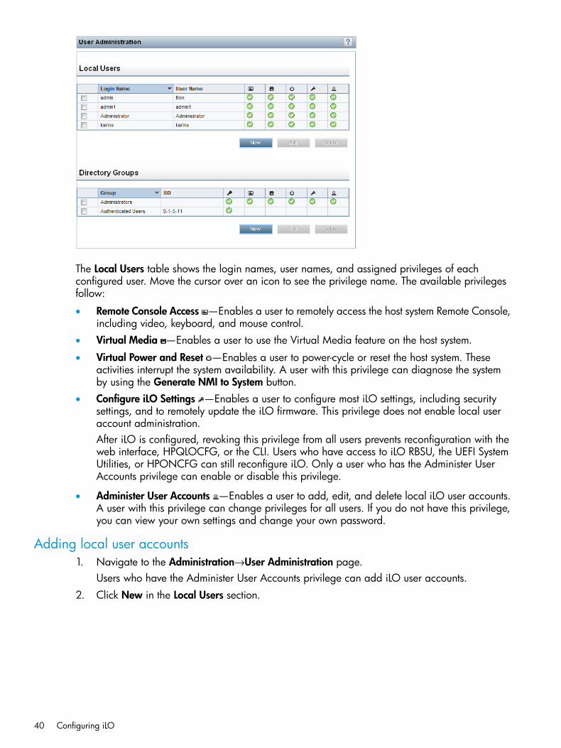
The Local Users table shows the login names, user names, and assigned privileges of eachconfigured user. Move the cursor over an icon to see the privilege name. The available privilegesfollow:
• Remote Console Access —Enables a user to remotely access the host system Remote Console,including video, keyboard, and mouse control.
• Virtual Media —Enables a user to use the Virtual Media feature on the host system.
• Virtual Power and Reset —Enables a user to power-cycle or reset the host system. Theseactivities interrupt the system availability. A user with this privilege can diagnose the systemby using the Generate NMI to System button.
• Configure iLO Settings —Enables a user to configure most iLO settings, including securitysettings, and to remotely update the iLO firmware. This privilege does not enable local useraccount administration.After iLO is configured, revoking this privilege from all users prevents reconfiguration with theweb interface, HPQLOCFG, or the CLI. Users who have access to iLO RBSU, the UEFI SystemUtilities, or HPONCFG can still reconfigure iLO. Only a user who has the Administer UserAccounts privilege can enable or disable this privilege.
• Administer User Accounts —Enables a user to add, edit, and delete local iLO user accounts.A user with this privilege can change privileges for all users. If you do not have this privilege,you can view your own settings and change your own password.
Adding local user accounts1. Navigate to the Administration→User Administration page.
Users who have the Administer User Accounts privilege can add iLO user accounts.2. Click New in the Local Users section.
40 Configuring iLO

3. Provide the following details on the Add/Edit Local User page:• User Name appears in the user list on the User Administration page. It does not have to
be the same as the Login Name. The maximum length for a user name is 39 characters.The User Name must use printable characters. Assigning descriptive user names can helpyou to easily identify the owner of each login name.
• Login Name is the name you use when logging in to iLO. It appears in the user list on theUser Administration page, on the iLO Overview page, and in logs. The Login Name doesnot have to be the same as the User Name. The maximum length for a login name is 39characters. The login name must use printable characters.
• Password and Password Confirm set and confirm the password that is used for loggingin to iLO.Enter the password twice for verification.For more information about passwords, see “Password guidelines” (page 43).
4. Select from the following privileges:• Administer User Accounts
• Remote Console Access
• Virtual Power and Reset
• Virtual Media
• Configure iLO SettingsClick the select all check box to select all of the available user privileges.For information about each privilege, see “Viewing local user accounts” (page 39).
5. Click Add User to save the new user.
Managing iLO user accounts by using the iLO web interface 41
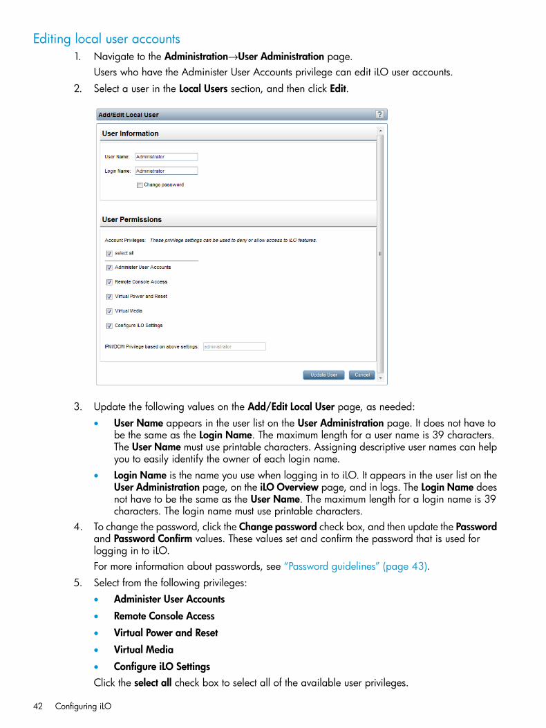
Editing local user accounts1. Navigate to the Administration→User Administration page.
Users who have the Administer User Accounts privilege can edit iLO user accounts.2. Select a user in the Local Users section, and then click Edit.
3. Update the following values on the Add/Edit Local User page, as needed:• User Name appears in the user list on the User Administration page. It does not have to
be the same as the Login Name. The maximum length for a user name is 39 characters.The User Name must use printable characters. Assigning descriptive user names can helpyou to easily identify the owner of each login name.
• Login Name is the name you use when logging in to iLO. It appears in the user list on theUser Administration page, on the iLO Overview page, and in logs. The Login Name doesnot have to be the same as the User Name. The maximum length for a login name is 39characters. The login name must use printable characters.
4. To change the password, click the Change password check box, and then update the Passwordand Password Confirm values. These values set and confirm the password that is used forlogging in to iLO.For more information about passwords, see “Password guidelines” (page 43).
5. Select from the following privileges:• Administer User Accounts
• Remote Console Access
• Virtual Power and Reset
• Virtual Media
• Configure iLO SettingsClick the select all check box to select all of the available user privileges.
42 Configuring iLO

For more information about each privilege, see “Viewing local user accounts” (page 39).6. Click Update User to save the user account changes.
Password guidelinesHP recommends that you follow these password guidelines when you create and edit user accounts.
• Passwords should:
Never be written down or recorded◦◦ Never be shared with others
◦ Not be words found in a dictionary
◦ Not be obvious words, such as the company name, product name, user name, or loginname
• Passwords should have at least three of the following characteristics:
One numeric character◦◦ One special character
◦ One lowercase character
◦ One uppercase character
• The minimum length for an iLO user account password is set on the Access Settings page.Depending on the configured Minimum Password Length value, the password can have aminimum of zero characters (no password) and a maximum of 39 characters. The defaultMinimum Password Length is eight characters.
IMPORTANT: HP does not recommend setting the Minimum Password Length to fewer thaneight characters unless you have a physically secure management network that does not extendoutside the secure data center. For information about setting the Minimum Password Length,see “Configuring access options” (page 60).
IPMI/DCMI usersThe iLO firmware follows the IPMI 2.0 specification. When you add IPMI/DCMI users, the loginname must be a maximum of 16 characters, and the password must be a maximum of 20 characters.When you select iLO user privileges, the equivalent IPMI/DCMI user privilege is displayed in theIPMI/DCMI Privilege based on above settings box.
• User—A user has read-only access. A user cannot configure or write to iLO, or perform systemactions.For IPMI User privileges: Disable all privileges. Any combination of privileges that does notmeet the Operator level is an IPMI User.
• Operator—An operator can perform system actions, but cannot configure iLO or manage useraccounts.For IPMI Operator privileges: Enable Remote Console Access, Virtual Power and Reset, andVirtual Media. Any combination of privileges greater than Operator that does not meet theAdministrator level is an IPMI Operator.
• Administrator—An administrator has read and write access to all features.For IPMI Administrator privileges: Enable all privileges.
Managing iLO user accounts by using the iLO web interface 43

Viewing directory groupsTo view directory groups, navigate to the Administration→User Administration page.The Directory Groups table shows the group DN, group SID, and the assigned privileges for theconfigured groups. Move the cursor over an icon to see the privilege name. The available privilegesfollow:
• Login Privilege —Enables members of a group to log in to iLO.
• Remote Console Access —Enables users to remotely access the host system Remote Console,including video, keyboard, and mouse control.
• Virtual Media —Enables users to use the Virtual Media feature on the host system.
• Virtual Power and Reset —Enables users to power-cycle or reset the host system. Theseactivities interrupt the system availability. Users with this privilege can diagnose the systemby using the Generate NMI to System button.
• Configure iLO Settings —Enables users to configure most iLO settings, including securitysettings, and to remotely update iLO firmware.After iLO is configured, revoking this privilege from all users prevents reconfiguration with theweb interface, HPQLOCFG, or the CLI. Users who have access to iLO RBSU, the UEFI SystemUtilities, or HPONCFG can still reconfigure iLO. Only a user who has the Administer UserAccounts privilege can enable or disable this privilege.
• Administer User Accounts —Enables users to add, edit, and delete local iLO user accounts.
Adding directory groups1. Navigate to the Administration→User Administration page.
Users who have the Configure iLO Settings privilege can add directory groups.2. Click New in the Directory Groups section.
44 Configuring iLO

3. Provide the following details in the Group Information section:• Group DN (Security Group DN)—Members of this group are granted the privileges set
for the group. The specified group must exist in the directory, and users who need accessto iLO must be members of this group. Enter a DN from the directory (for example,CN=Group1, OU=Managed Groups, DC=domain, DC=extension).Shortened DNs are also supported (for example, Group1). The shortened DN is not aunique match. HP recommends using the fully-qualified DN.
• Group SID (Security ID)—Microsoft Security ID is used for Kerberos and LDAP groupauthorization. This is required for Kerberos. The required format is S-1-5-2039349.
4. Select from the following privileges:• Administer User Accounts
• Remote Console Access
• Virtual Power and Reset
• Virtual Media
• Configure iLO Settings
• Login PrivilegeFor more information about each privilege, see “Viewing directory groups” (page 44).
5. Click Add Group to save the new directory group.
Editing directory groups1. Navigate to the Administration→User Administration page.
Users who have the Configure iLO Settings privilege can edit directory groups.2. Select a group in the Directory Groups section, and then click Edit.
3. Provide the following details in the Group Information section:• Group DN (Security Group DN)—Members of this group are granted the privileges set
for the group. The specified group must exist in the directory, and users who need access
Managing iLO user accounts by using the iLO web interface 45

to iLO must be members of this group. Enter a DN from the directory (for example,CN=Group1, OU=Managed Groups, DC=domain, DC=extension).Shortened DNs are also supported (for example, Group1). The shortened DN is not aunique match. HP recommends using the fully-qualified DN.
• Group SID (Security ID)—Microsoft Security ID is used for Kerberos and LDAP groupauthorization. This is required for Kerberos. The required format is S-1-5-2039349.
4. Select from the following privileges :• Administer User Accounts
• Remote Console Access
• Virtual Power and Reset
• Virtual Media
• Configure iLO Settings
• Login PrivilegeFor more information about each privilege, see “Viewing directory groups” (page 44).
5. Click Update Group to save the directory group changes.
Deleting a user account or a directory groupThe privilege required for this procedure depends on the user account type.
• To delete a local user account, the Administer User Accounts privilege is required.
• To delete a directory group, the Configure iLO Settings privilege is required.To delete an existing user account or directory group:1. Navigate to the Administration→User Administration page.2. Select the check box next to the user or group that you want to delete.3. Click Delete.
A pop-up window opens with one of the following messages:
• Local user: Are you sure you want to delete the selected user(s)?Warning: Always leave at least one administrator.
• Directory group: Are you sure you want to delete the selectedgroup(s)?
4. Click OK.
Configuring iLO FederationiLO uses multicast discovery, peer-to-peer communication, and iLO Federation groups tocommunicate with other iLO systems.When data is loaded on an iLO Federation page in the iLO web interface, a request for data issent from the iLO system running the web interface to its peers, and from those peers to other peersuntil all of the data for the selected iLO Federation group is retrieved.
PrerequisitesBefore using the iLO Federation features, verify the following:
• The network configuration meets the iLO Federation requirements.
• The multicast options are configured for each iLO system that will be added to an iLOFederation group.Configuration is not required if you use the default values.
46 Configuring iLO

• iLO Federation group memberships are configured.All iLO systems are automatically added to the DEFAULT group.
• Enclosure support for iLO Federation is configured (server blades only).This setting is enabled by default.
iLO Federation network requirementsWhen you configure iLO Federation, note the following network requirements:
• The iLO Federation features are not supported by the iLO Shared Network Port configuration.
• iLO Federation supports both IPv4 and IPv6.To force an iLO system to use IPv4 instead of IPv6, clear the iLO Client Applications use IPv6first check box on the Network→iLO Dedicated Network Port→IPv6 page.
• You can manage iLO systems in multiple locations if the network is configured to forwardmulticast traffic.
• If the switches in your network include the option to enable or disable multicast traffic, ensurethat multicast traffic is enabled. This is required for iLO Federation and other HP products todiscover the iLO systems on the network.
• For iLO systems that are separated by Layer 3 switches, configure the switches to forwardSSDP multicast traffic between networks.
• You must allow multicast traffic (UDP port 1900) and direct HTTP (TCP default port 80)communication between iLO systems.
• If you want to use server blades in a BladeSystem c-Class enclosure with iLO Federation, theEnable Enclosure iLO Federation Support setting must be enabled in the Onboard Administratorweb interface. This setting is enabled by default.
• For networks with multiple VLANs, configure the switches to allow multicast traffic betweenthe VLANs.
◦ For IPv4 networks: Enable PIM on the switch and configure it for PIM Dense Mode.
◦ For IPv6 networks: Configure the switch for MLD snooping.
More informationConfiguring enclosure support for iLO FederationConfiguring the multicast options for one iLO system at a timeConfiguring IPv6 settings
Configuring the multicast options for one iLO system at a timeUse the following procedure to configure the multicast options for each iLO system that will beadded to an iLO Federation group. Configuration is not required if you use the default values.You can use RIBCL scripts to view and configure multicast options for multiple iLO systems. Formore information, see the iLO Federation user guide.You must have the Configure iLO Settings privilege to configure the multicast options.
Configuring iLO Federation 47
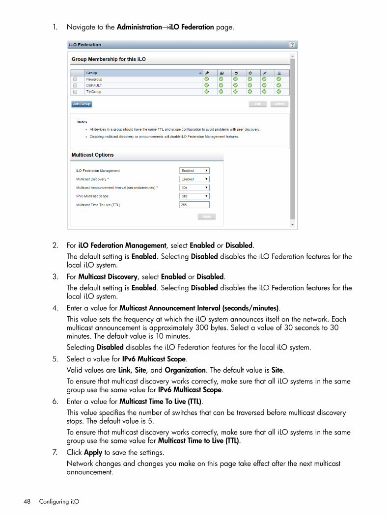
1. Navigate to the Administration→iLO Federation page.
2. For iLO Federation Management, select Enabled or Disabled.The default setting is Enabled. Selecting Disabled disables the iLO Federation features for thelocal iLO system.
3. For Multicast Discovery, select Enabled or Disabled.The default setting is Enabled. Selecting Disabled disables the iLO Federation features for thelocal iLO system.
4. Enter a value for Multicast Announcement Interval (seconds/minutes).This value sets the frequency at which the iLO system announces itself on the network. Eachmulticast announcement is approximately 300 bytes. Select a value of 30 seconds to 30minutes. The default value is 10 minutes.Selecting Disabled disables the iLO Federation features for the local iLO system.
5. Select a value for IPv6 Multicast Scope.Valid values are Link, Site, and Organization. The default value is Site.To ensure that multicast discovery works correctly, make sure that all iLO systems in the samegroup use the same value for IPv6 Multicast Scope.
6. Enter a value for Multicast Time To Live (TTL).This value specifies the number of switches that can be traversed before multicast discoverystops. The default value is 5.To ensure that multicast discovery works correctly, make sure that all iLO systems in the samegroup use the same value for Multicast Time to Live (TTL).
7. Click Apply to save the settings.Network changes and changes you make on this page take effect after the next multicastannouncement.
48 Configuring iLO

More informationiLO Federation network requirements
iLO Federation groupsWhen you configure iLO Federation groups, note the following:
• iLO Federation groups allow iLO systems to encrypt and sign messages to other iLO systemsin the same group.
• All iLO systems are automatically added to the DEFAULT group, which is granted the Loginprivilege for each group member. You can edit or delete the DEFAULT group membership.
• iLO Federation groups can overlap, span racks and data centers, and can be used to createmanagement domains.
• An iLO system can be a member of up to 10 iLO Federation groups.
• There is no limit on the number of iLO systems that can be in a group.
• You must have the Configure iLO Settings privilege to configure group memberships.
• You can use the iLO web interface to configure group memberships for a local iLO system ora group of iLO systems.You can perform the following tasks for a local iLO system:
◦ View group memberships
◦ Add and edit group memberships
◦ Remove group memberships
You can perform the following tasks for a group of iLO systems:
◦ Create a group with the same members as an existing group, but with different privileges.
◦ Create a group with members that you select by using the iLO Federation filters.
• You can use RIBCL XML scripts to view and configure group memberships.For more information, see the iLO Federation user guide.
• You can use the HP RESTful API to configure group memberships.For more information, see the HP RESTful API data model reference for iLO 4.
• HP recommends installing the same version of the iLO firmware on iLO systems that are in thesame iLO Federation group.
• When you configure group memberships for a local iLO system, you specify the privilegesthat members of a group have for configuring the local managed server.For example, if you add the local iLO system to group1 and assign the Virtual Power andReset privilege, the users of other iLO systems in group1 can use the group power controlfeatures to change the power state of the managed server.If the local iLO system does not grant the Virtual Power and Reset privilege to group1, theusers of other iLO systems in group1 cannot use the group power control features to changethe power state of the managed server.
Configuring iLO Federation 49

If the system maintenance switch is set to disable iLO security on the managed server, theusers of other iLO systems in group1 can use any iLO Federation feature to change the stateof the managed server, regardless of the assigned group privileges.
• When you configure group memberships for multiple iLO systems, you specify the privilegesthat members of the group have for configuring the other members of the group.For example, if you configure group2 based on the DEFAULT group, and you assign the VirtualPower and Reset privilege, the users of other iLO systems in group2 can use the group powercontrol features to change the power state of all of the servers in the group.
More informationViewing iLO Federation group memberships (local iLO system)Adding iLO Federation group memberships (multiple iLO systems)
iLO Federation group privilegesThe following privileges can be granted to iLO Federation groups:
• Login Privilege —Enables members of a group to log in to iLO.
• Remote Console Access —Enables members of a group to remotely access the host systemRemote Console, including video, keyboard, and mouse control.
• Virtual Media —Enables members of a group to use scripted Virtual Media with the localiLO system.
• Virtual Power and Reset —Enables members of a group to power-cycle or reset the local iLOsystem.
• Configure iLO Settings —Enables members of a group to configure most iLO settings, includingsecurity settings, and to remotely update firmware.
• Administer User Accounts —Enables members of a group to add, edit, and delete iLO useraccounts.
Viewing iLO Federation group memberships (local iLO system)Use the iLO web interface to view the group memberships of a local iLO system.You can also use RIBCL scripts to view information about groups. For more information, see theiLO Federation user guide.To view the group memberships of a local iLO system, navigate to the Administration→iLOFederation page.The Group Membership for this iLO table lists the name of each group that includes the local iLOsystem, and the privileges granted to the group by the local iLO system.
Adding iLO Federation group memberships (local iLO system)Use the Add/Edit Federation Group page to add group memberships for a local iLO system.You can use the Group Configuration page to add group memberships for multiple systems basedon existing groups and filtered sets of iLO systems.1. Navigate to the Administration→iLO Federation page.2. Click Join Group to add a new group membership.
50 Configuring iLO
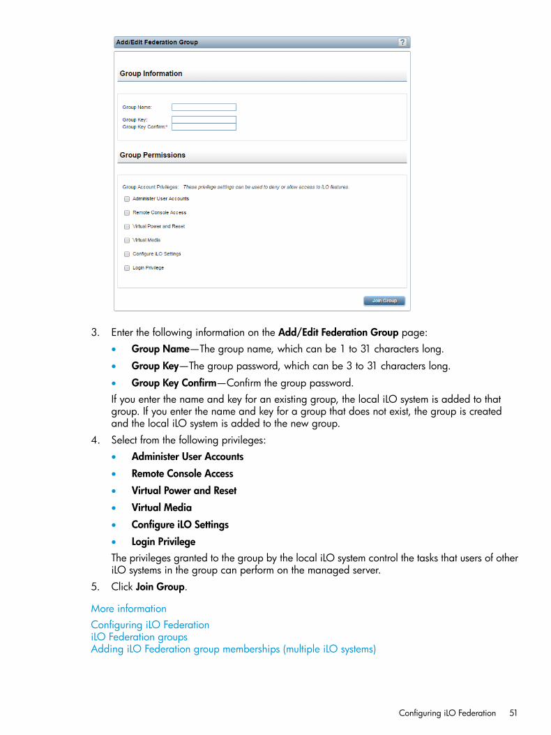
3. Enter the following information on the Add/Edit Federation Group page:• Group Name—The group name, which can be 1 to 31 characters long.
• Group Key—The group password, which can be 3 to 31 characters long.
• Group Key Confirm—Confirm the group password.If you enter the name and key for an existing group, the local iLO system is added to thatgroup. If you enter the name and key for a group that does not exist, the group is createdand the local iLO system is added to the new group.
4. Select from the following privileges:• Administer User Accounts
• Remote Console Access
• Virtual Power and Reset
• Virtual Media
• Configure iLO Settings
• Login PrivilegeThe privileges granted to the group by the local iLO system control the tasks that users of otheriLO systems in the group can perform on the managed server.
5. Click Join Group.
More informationConfiguring iLO FederationiLO Federation groupsAdding iLO Federation group memberships (multiple iLO systems)
Configuring iLO Federation 51
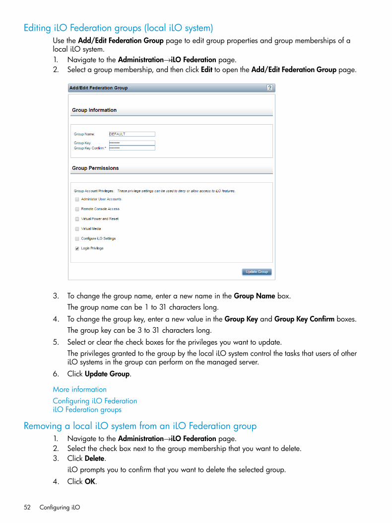
Editing iLO Federation groups (local iLO system)Use the Add/Edit Federation Group page to edit group properties and group memberships of alocal iLO system.1. Navigate to the Administration→iLO Federation page.2. Select a group membership, and then click Edit to open the Add/Edit Federation Group page.
3. To change the group name, enter a new name in the Group Name box.The group name can be 1 to 31 characters long.
4. To change the group key, enter a new value in the Group Key and Group Key Confirm boxes.The group key can be 3 to 31 characters long.
5. Select or clear the check boxes for the privileges you want to update.The privileges granted to the group by the local iLO system control the tasks that users of otheriLO systems in the group can perform on the managed server.
6. Click Update Group.
More informationConfiguring iLO FederationiLO Federation groups
Removing a local iLO system from an iLO Federation group1. Navigate to the Administration→iLO Federation page.2. Select the check box next to the group membership that you want to delete.3. Click Delete.
iLO prompts you to confirm that you want to delete the selected group.4. Click OK.
52 Configuring iLO

More informationiLO Federation groups
Adding iLO Federation group memberships (multiple iLO systems)
Adding an iLO Federation group based on an existing groupUse this procedure to create an iLO Federation group with the same members as an existing group.For example, you might want to create a group that contains the same systems that are in theDEFAULT group, but with additional privileges.1. Navigate to the iLO Federation→Group Configuration page.
If no iLO Federation groups exist, this page displays the following message: There are noconfigured groups. Use the Administration→iLO Federation page to create a group.
2. Select a group from the Selected Group menu.All of the systems in the selected group will be added to the group you create on this page.
Configuring iLO Federation 53
3. Enter the following information:• Group Name—The group name, which can be 1 to 31 characters long.
• Group Key—The group password, which can be 3 to 31 characters long.
• Group Key Confirm—Confirm the group password.If you enter the name of a group that already exists, iLO prompts you to enter a unique groupname.
4. Select from the following privileges:• Administer User Accounts
• Remote Console Access
• Virtual Power and Reset
• Virtual Media
• Configure iLO Settings
• Login PrivilegeThe privileges granted to the group control the tasks that users of other iLO systems in thegroup can perform on them.
5. Optional: Enter the Login Name and Password for a user account on the remote system(s) youwant to manage.This is required if the selected group does not have the Configure iLO Settings privilege onthe remote system(s) you want to manage.
TIP: If you need to enter credentials for multiple remote systems, create a user account withthe same login name and password on each system.
6. Click Create Group.The group creation process takes a few minutes. The group should be fully populated withinthe amount of time configured for the Multicast Announcement Interval.
More informationiLO Federation groups
Creating a group from a filtered set of serversUse this procedure to create an iLO Federation group from a list of filtered servers. For example,you might want to create a group that contains all of the servers with a specific version of the iLO4 firmware.When you create a group from a list of filtered servers, only the servers listed in the AffectedSystems list at the time the group is created are added to the group. If you configure servers thatmeet the filter criteria after the group is created, they are not added to the group.1. Create a set of systems by using the filters on the iLO Federation pages.2. Navigate to the iLO Federation→Group Configuration page.
54 Configuring iLO

If no iLO Federation groups exist, this page displays the following message: There are noconfigured groups. Use the Administration→iLO Federation page to create a group.
3. Select a group from the Selected Group menu.All of the systems in the selected group that meet the selected filter criteria will be added tothe new group.
4. Enter the following information:• Group Name—The group name, which can be 1 to 31 characters long.
• Group Key—The group password, which can be 3 to 31 characters long.
• Group Key Confirm—Confirm the group password.5. Select from the following privileges:
• Administer User Accounts
• Remote Console Access
• Virtual Power and Reset
• Virtual Media
Configuring iLO Federation 55

• Configure iLO Settings
• Login PrivilegeThe privileges granted to the group by each group member control the tasks that users of otheriLO systems in the group can perform on them.
6. Optional: Enter the Login Name and Password for a user account on the remote system(s) youwant to manage.This is required if the selected group does not have the Configure iLO Settings privilege onthe remote system(s) you want to manage.
TIP: If you need to enter credentials for multiple remote systems, create a user account withthe same login name and password on each system.
7. Click Create Group to save the configuration.The group creation process takes a few minutes. The group should be fully populated withinthe amount of time configured for the Multicast Announcement Interval.
More informationiLO Federation groupsFiltering the Selected Group list
Servers affected by a group membership changeThe Affected Systems section on the Group Configuration page provides the following details aboutthe servers that will be affected by a group membership change:
• Server Name—The server name defined by the host operating system.
• Server Power—The server power state (ON or OFF).
• UID Indicator—The state of the UID LED. The UID LED helps you identify and locate a server,especially in high-density rack environments. The possible states are UID ON, UID OFF, andUID BLINK.
• iLO Hostname—The fully qualified network name assigned to the iLO subsystem. Click the linkin the iLO Hostname column to open the iLO web interface for the server.
• IP Address—The network IP address of the iLO subsystem. Click the link in the IP Addresscolumn to open the iLO web interface for the server.
Exporting the Affected Systems list1. Navigate to the iLO Federation→Group Configuration page.2. Click View CSV.3. Do one of the following:
• For Internet Explorer 8 only—Copy the text displayed in the CSV Output window, andsave it in a text editor as a CSV file.
• For all other browsers—In the CSV Output window, click Save, and then follow the browserprompts to save or open the file.
When you export the list, the CSV file contains only the servers displayed on the iLO Federationpage. If multiple pages of servers are included in the list, the CSV file will contain only theservers that are currently displayed on the iLO web interface page.If a query error occurred, the systems that did not respond to the query are excluded from theAffected Systems list and the CSV file.
56 Configuring iLO

Configuring enclosure support for iLO FederationIf you want to use the iLO Federation features with server blades in a BladeSystem c-Class enclosure,the Enclosure iLO Federation Support setting must be enabled in the Onboard Administrator software.This setting is required to allow peer-to-peer communication between the server blades in anenclosure. Enclosure iLO Federation Support is enabled by default. Onboard Administrator 4.11or later is required to use this feature.
Using Onboard Administrator to configure Enclosure iLO Federation Support1. Log in to the Onboard Administrator web interface (https://<OA hostname or IP address>).2. Navigate to the Enclosure Information→Network Access page, and then click the Protocols
tab.
3. Select the Enable Enclosure iLO Federation Support check box, and then click Apply.
TIP: You can also use the CLI to enable or disable the Enable Enclosure iLO Federation Supportsetting. To enable the setting, enter ENABLE ENCLOSURE_ILO_FEDERATION_SUPPORT. Todisable the setting, enter DISABLE ENCLOSURE_ILO_FEDERATION_SUPPORT. For moreinformation, see the Onboard Administrator command line interface user guide.
Verifying server blade support for iLO Federation1. Log in to the Onboard Administrator web interface (https://<OA hostname or IP address>).2. Navigate to the Device Bays→<Device Name>→iLO page.
Configuring iLO Federation 57
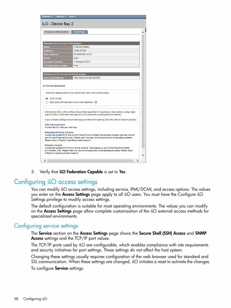
3. Verify that iLO Federation Capable is set to Yes.
Configuring iLO access settingsYou can modify iLO access settings, including service, IPMI/DCMI, and access options. The valuesyou enter on the Access Settings page apply to all iLO users. You must have the Configure iLOSettings privilege to modify access settings.The default configuration is suitable for most operating environments. The values you can modifyon the Access Settings page allow complete customization of the iLO external access methods forspecialized environments.
Configuring service settingsThe Service section on the Access Settings page shows the Secure Shell (SSH) Access and SNMPAccess settings and the TCP/IP port values.The TCP/IP ports used by iLO are configurable, which enables compliance with site requirementsand security initiatives for port settings. These settings do not affect the host system.Changing these settings usually requires configuration of the web browser used for standard andSSL communication. When these settings are changed, iLO initiates a reset to activate the changes.To configure Service settings:
58 Configuring iLO

1. Navigate to the Administration→Access Settings page.
2. Update the following settings as needed:• Secure Shell (SSH) Access—Allows you to enable or disable the SSH feature.
SSH provides encrypted access to the iLO CLP. The default value is Enabled.
• Secure Shell (SSH) Port—The default value is 22.
• Remote Console Port—The default value is 17990.
• Web Server Non-SSL Port (HTTP)—The default value is 80.
• Web Server SSL Port (HTTPS)—The default value is 443.
• Virtual Media Port—The default value is 17988.
• SNMP Access—Specifies whether iLO should respond to external SNMP requests. Thedefault value is Enabled.If you set SNMP Access to Disabled, iLO continues to operate, and the informationdisplayed in the iLO web interface is updated, but no alerts are generated and SNMPaccess is not permitted. When SNMP Access is set to Disabled, most of the boxes on theAdministration→Management→SNMP Settings page are unavailable and will not acceptinput.
• SNMP Port—The industry-standard (default) SNMP port is 161 for SNMP access.If you customize the SNMP Port value, some SNMP clients might not work correctly withiLO unless those clients support the use of a nonstandard SNMP port.
• SNMP Trap Port—The industry-standard (default) SNMP trap port is 162 for SNMP alerts(or traps).If you customize the SNMP Trap Port value, some SNMP monitoring applications (suchas HP SIM) might not work correctly with iLO unless those applications support the useof a nonstandard SNMP trap port.To use SNMP v3 with HP SIM 7.2 or later, change the SNMP Trap Port value to 50005.
Configuring iLO access settings 59

3. Click Apply to end your browser connection and restart iLO.It might take several minutes before you can re-establish a connection.
Configuring IPMI/DCMI settingsiLO enables you to send industry-standard IPMI and DCMI commands over the LAN. The IPMI/DCMIport is set to 623 and is not configurable.To enable or disable IPMI/DCMI, select or clear the Enable IPMI/DCMI over LAN on Port 623check box, and then click Apply.
• Enabled (default)—Enables you to send IPMI/DCMI commands over the LAN by using aclient-side application.
• Disabled—Disables IPMI/DCMI over the LAN. Server-side IPMI/DCMI applications are stillfunctional when IPMI/DCMI over LAN is disabled.
Configuring access optionsThe Access Options section enables you to modify settings that affect all iLO users.You can also configure some of these settings by using iLO RBSU or the iLO 4 Configuration Utility.For instructions, see “Using the iLO RBSU” (page 137) and “Using the UEFI System Utilities iLO 4Configuration Utility” (page 140).To view or modify iLO access options:1. Navigate to the Administration→Access Settings page.2. Click the Access Settings tab and scroll to the Access Options section of the Access Settings
page.
60 Configuring iLO

3. Update the following settings as needed:• Idle Connection Timeout (minutes)—Specifies how long a user can be inactive before an
iLO web interface or Remote Console session ends automatically.The iLO web interface and the Remote Console track idle time separately because eachconnection is a separate session. Remote Console sessions are not affected by this valueif a Virtual Media device is connected.The following settings are valid:
◦ 15, 30, 60, or 120 minutes—The default value is 30 minutes.
◦ Infinite—Inactive users are not logged out.
Failure to log out of iLO by either browsing to a different site or closing the browser alsoresults in an idle connection. The iLO firmware supports a finite number of connections.Misuse of the Infinite timeout option might make iLO inaccessible to other users. Idleconnections are recycled after they time out.This setting applies to local and directory users. Directory server timeouts might preemptthe iLO setting.Changes to the setting might not take effect immediately in current user sessions, but willbe enforced immediately in all new sessions.
• iLO Functionality—Specifies whether iLO functionality is available. The following settingsare valid:
◦ Enabled (default)—The iLO network is available and communications with operatingsystem drivers are active.
◦ Disabled—The iLO network and communications with operating system drivers areterminated when iLO Functionality is disabled.For Gen8 servers only: To re-enable iLO functionality, disable iLO security with thesystem maintenance switch, and then use the iLO RBSU to set iLO Functionality toEnabled. For more information about using the system maintenance switch, see themaintenance and service guide for your server model.For Gen9 servers only: To re-enable iLO functionality, use the iLO 4 ConfigurationUtility (in the UEFI System Utilities) to set iLO Functionality to Enabled. For moreinformation see the UEFI System Utilities user guide.iLO functionality cannot be disabled on server blades.
• iLO ROM-Based Setup Utility—Enables or disables the iLO RBSU or the iLO 4 ConfigurationUtility. The following settings are valid:
◦ Enabled (default)—On servers that support the iLO RBSU, pressing F8 during POSTstarts the iLO RBSU. On servers that support UEFI, the iLO 4 Configuration Utility isavailable when you access the UEFI System Utilities.
◦ Disabled—On servers that support the iLO RBSU, pressing F8 during POST will notstart the iLO RBSU. On servers that support UEFI, the iLO 4 Configuration Utility isnot available when you access the UEFI System Utilities.
• Require Login for iLO RBSU—Determines whether a user-credential prompt is displayedwhen a user accesses the iLO RBSU or the iLO 4 Configuration Utility. The followingsettings are valid:
◦ Enabled—A login dialog box opens when a user accesses the iLO RBSU or the iLO4 Configuration Utility.
◦ Disabled (default)—No login is required when a user accesses the iLO RBSU or theiLO 4 Configuration Utility.
Configuring iLO access settings 61
• Show iLO IP during POST—Enables the display of the iLO network IP address during hostserver POST. The following settings are valid:
◦ Enabled (default)—The iLO IP address is displayed during POST.
◦ Disabled—The iLO IP address is not displayed during POST.
• Serial Command Line Interface Status—Enables you to change the login model of the CLIfeature through the serial port. The following settings are valid:
◦ Enabled-Authentication Required (default)—Enables access to the SMASH CLPcommand line from a terminal connected to the host serial port. Valid iLO usercredentials are required.
◦ Enabled-No Authentication—Enables access to the SMASH CLP command line froma terminal connected to the host serial port. iLO user credentials are not required.
◦ Disabled—Disables access to the SMASH CLP command line from the host serialport. Use this option if you are planning to use physical serial devices.
• Serial Command Line Interface Speed—Enables you to change the speed of the serialport for the CLI feature. The following speeds (in bits per second) are valid:
◦ 9600 (default)
◦ 19200
◦ 38400—This value is not supported by the iLO RBSU or the iLO 4 ConfigurationUtility.
◦ 57600
◦ 115200
The serial port configuration must be set to no parity, 8 data bits, and 1 stop bit (N/8/1)for correct operation.The serial port speed set by this option should match the serial port speed configured inthe iLO RBSU or the iLO 4 Configuration Utility.
• Virtual Serial Port Log—Enables or disables logging of the Virtual Serial Port.The following settings are valid:
◦ Enabled—When enabled, Virtual Serial Port activity is logged to a 150-page circularbuffer in the iLO memory, and can be viewed using the CLI command vsp log.The Virtual Serial Port buffer size is 128 KB.
◦ Disabled (default)—Virtual Serial Port activity is not logged.
This feature is part of an iLO licensing package. For more information, see the followingwebsite: http://www.hp.com/go/ilo/licensing.
• Minimum Password Length—Specifies the minimum number of characters allowed whena user password is set or changed. The character length must be a value from 0 to 39characters long. The default value is 8.
• Server Name—Enables you to specify the host server name. You can assign this valuemanually, but it might be overwritten by the host software when the operating systemloads.
◦ You can enter a server name that is up to 49 bytes.
◦ To force the browser to refresh and display the new value, save this setting, and thenpress F5.
62 Configuring iLO
• Server FQDN/IP Address—Enables you to specify the server FQDN or IP address. Youcan assign this value manually, but it might be overwritten by the host software when theoperating system loads.
◦ You can enter an FQDN or IP address that is up to 255 bytes.
◦ To force the browser to refresh and display the new value, save this setting, and thenpress F5.
• Authentication Failure Logging—Enables you to configure logging criteria for failedauthentications. The following settings are valid:
◦ Enabled-Every Failure—A failed login log entry is recorded after every failed loginattempt.
◦ Enabled-Every 2nd Failure—A failed login log entry is recorded after every secondfailed login attempt.
◦ Enabled-Every 3rd Failure (default)—A failed login log entry is recorded after everythird failed login attempt.
◦ Enabled-Every 5th Failure—A failed login log entry is recorded after every fifth failedlogin attempt.
◦ Disabled—No failed login log entry is recorded.
For information about using this setting with SSH clients, see “Logging in to iLO by usingan SSH client” (page 63).
• Authentication Failure Delay Time—Enables you to configure the duration of the iLO logindelay after a failed login attempt. The following values are valid: 2, 5, 10, and 30seconds.The default value is 10 seconds.This feature is supported in iLO 4 2.20 and later.
• Authentication Failures Before Delay—Enables you to configure the number of failed loginattempts that are allowed before iLO imposes a login delay. The following values arevalid: 1, 3, 5, or every failed login attempt.When you upgrade from an earlier version of the iLO firmware to iLO 4 2.20 or later,the default value is every failed login attempt, which means that a login delay is imposedafter the first failed login attempt.When you use a new server that shipped with iLO 4 2.20 or later installed, or you resetthe iLO 2.20 or later firmware to the factory default settings, the default value is 1, whichmeans that a login delay is not imposed until the second failed login attempt.This feature is supported in iLO 4 2.20 and later.
4. Click Apply to end your browser connection and restart iLO.It might take several minutes before you can re-establish a connection.
Logging in to iLO by using an SSH clientWhen a user logs in to iLO by using an SSH client, the number of login name and passwordprompts displayed by iLO matches the value of the Authentication Failure Logging option (3 if it isdisabled). The number of prompts might also be affected by your SSH client configuration. SSHclients also implement delays after login failure.For example, to generate an SSH authentication failure log with the default value (Enabled-Every3rd Failure), assuming that the SSH client is configured with the number of password prompts setto 3, three consecutive login failures occur as follows:
Configuring iLO access settings 63

1. Run the SSH client and log in with an incorrect login name and password.You receive three password prompts. After the third incorrect password, the connection endsand the first login failure is recorded. The SSH login failure counter is set to 1.
2. Run the SSH client and log in with an incorrect login name and password.You receive three password prompts. After the third incorrect password, the connection endsand the second login failure is recorded. The SSH login failure counter is set to 2.
3. Run the SSH client and log in with an incorrect login name and password.You receive three password prompts. After the third incorrect password, the connection endsand the third login failure is recorded. The SSH login failure counter is set to 3.
The iLO firmware records an SSH failed login log entry, and sets the SSH login failure counter to0.
Configuring iLO securityiLO provides the following security features:
• User-defined TCP/IP ports. For more information, see “Configuring iLO access settings”(page 58).
• User actions logged in the iLO Event Log. For more information, see “Using the iLO Event Log”(page 177).
• Progressive delays for failed login attempts. For more information, see “Login security”(page 67).
• Support for X.509 CA signed certificates. For more information, see “Administering SSLcertificates” (page 70).
• Support for securing iLO RBSU and the iLO 4 Configuration Utility. For more information, see“iLO RBSU and iLO 4 Configuration Utility security” (page 64).
• Encrypted communication that uses SSL certificate administration. For more information, see“Administering SSL certificates” (page 70).
• Support for optional LDAP-based directory services. For more information, see “Directoryservices” (page 273).
Some of these options are licensed features. For more information, see “iLO licensing” (page 37).
General security guidelinesGeneral security guidelines for iLO follow:
• For maximum security, configure iLO on a separate management network. For more information,see “Connecting iLO to the network” (page 21).
• Do not connect iLO directly to the Internet.
• Use a browser that has a 128-bit cipher strength.
iLO RBSU and iLO 4 Configuration Utility securityiLO RBSU and the iLO 4 Configuration Utility enable you to view and modify the iLO configuration.You can configure iLO RBSU and iLO 4 Configuration Utility access settings by using iLO RBSU,the iLO 4 Configuration Utility, the iLO web interface, or RIBCL scripts. If the system maintenance
64 Configuring iLO

switch is set to disable iLO security, any user can access iLO RBSU or the iLO 4 ConfigurationUtility, regardless of the configured access settings.
• For information about using the iLO web interface to configure iLO RBSU or the iLO 4Configuration Utility access settings, see “Configuring access options” (page 60).
• For information about using iLO RBSU or the iLO 4 Configuration Utility to configure iLO RBSUor iLO 4 Configuration Utility access settings, see “Configuring iLO by using the ROM-basedutilities” (page 137).
• For information about using RIBCL scripts to configure iLO RBSU or the iLO 4 ConfigurationUtility, see the iLO scripting and command line guide.
• For information about using the system maintenance switch, see “iLO security with the systemmaintenance switch” (page 65).
iLO RBSU and the iLO 4 Configuration Utility have the following security levels:
• Login Not Required (default)Anyone who has access to the host during POST can enter iLO RBSU or the iLO 4 ConfigurationUtility to view and modify configuration settings. This is an acceptable setting if host accessis controlled. If host access is not controlled, any user can make changes by using the activeconfiguration menus.
• Login Required (more secure)If iLO RBSU or iLO 4 Configuration Utility login is required, the active configuration menusare controlled by the authenticated user access rights.
• Disabled (most secure)If iLO RBSU or the iLO 4 Configuration Utility is disabled, user access is prohibited. Thisprevents modification by using the iLO RBSU or the iLO 4 Configuration Utility.
To change the login requirement:
• Use the iLO web interface to edit the Require Login for iLO RBSU or Require Login for iLO 4Configuration Utility setting. For instructions, see “Configuring access options” (page 60).
• Use the iLO RBSU or the iLO 4 Configuration Utility to edit the Require iLO 4 RBSU Login orRequire Login for iLO 4 Configuration Utility setting. For instructions, see “Configuring iLO byusing the ROM-based utilities” (page 137).
To enable or disable access to iLO RBSU or the iLO 4 Configuration Utility:
• Use the iLO web interface to edit the iLO ROM-Based Setup Utility or iLO 4 ConfigurationUtility setting. For instructions, see “Configuring access options” (page 60).
• Use the iLO RBSU or the iLO 4 Configuration Utility to edit the iLO 4 ROM-Based Setup Utilityor iLO 4 Configuration Utility setting. For instructions, see “Configuring iLO by using theROM-based utilities” (page 137).
iLO security with the system maintenance switchThe iLO security setting on the system maintenance switch provides emergency access to anadministrator who has physical control over the server system board. Disabling iLO security allowslogin access with all privileges, without a user ID and password.The system maintenance switch is located inside the server and cannot be accessed without openingthe server enclosure. When you work with the system maintenance switch, ensure that the serveris powered off and disconnected from the power source. Set the switch to enable or disable iLOsecurity, and then power on the server.The system maintenance switch position that controls iLO security is sometimes called the iLOSecurity Override switch.
Configuring iLO security 65

It might be necessary to disable iLO security for the following reasons:
• iLO Functionality is disabled and must be re-enabled (Gen8 servers only).
• All user accounts that have the Administer User Accounts privilege are locked out.
• An invalid configuration prevents iLO from being displayed on the network, and iLO RBSUor the iLO 4 Configuration Utility is disabled.
• The boot block must be flashed.HP does not anticipate that you will need to update the boot block. If an update is required,you must be physically present at the server to reprogram the boot block and reset iLO. Theboot block is exposed until iLO is reset. For maximum security, HP recommends disconnectingiLO from the network until the reset is complete.
• The iLO NIC is turned off, and it is not possible or convenient to run iLO RBSU or the iLO 4Configuration Utility to turn it back on.
• Only one user name is configured, and the password is forgotten.When you disable iLO security with the system maintenance switch:
• All security authorization verifications are disabled.
• iLO RBSU or the iLO 4 Configuration Utility runs if the host server is reset.
• iLO is not disabled and might be displayed on the network as configured.
• If iLO Functionality disabled, iLO does not log out active users and complete the disableprocess until the power is cycled on the server.
• The boot block is exposed for programming.
• A warning message is displayed on iLO web interface pages, indicating that iLO security isdisabled.
• An iLO log entry is added to record the iLO security change.
• When iLO starts after you use the system maintenance switch to enable or disable iLO security,an SNMP alert is sent if an SNMP Alert Destination is configured.
For information about how to enable and disable iLO security with the system maintenance switch,see the maintenance and service guide for your server.
TPM and TMTrusted Platform Modules and Trusted Modules are computer chips that securely store artifacts usedto authenticate the platform. These artifacts can include passwords, certificates, or encryption keys.You can also use a TPM or TM to store platform measurements to make sure that the platformremains trustworthy.On a supported system, ROM decodes the TPM or TM record and passes the configuration statusto iLO, the HP RESTful API, the CLP, and the XML interface.
Viewing the TPM or TM statusTo view the TPM or TM status, navigate to the Information→Overview page.The possible status values follow:
• Not Supported—A TPM or TM is not supported.
• Not Present—A TPM or TM is not installed.
66 Configuring iLO

• Present (Gen8 servers)—This indicates one of the following statuses:
A TPM or TM is installed and disabled.◦◦ A TPM or TM is installed and enabled.
◦ A TPM or TM is installed and enabled, and Option ROM Measuring is enabled.
• Present-Enabled (Gen9 servers)—A TPM or TM is installed and enabled.
User accounts and accessiLO supports the configuration of up to 12 local user accounts. Each account can be managedthrough the following features:
• Privileges
• Login securityYou can configure iLO to use a directory to authenticate and authorize its users. This configurationenables an unlimited number of users and easily scales to the number of iLO devices in an enterprise.The directory also provides a central point of administration for iLO devices and users, and thedirectory can enforce a stronger password policy. iLO enables you to use local users, directoryusers, or both.The following directory configuration options are available:
• A directory extended with HP schema
• The directory default schemaFor more information about using directory authentication, see “Directory services” (page 273).
User privilegesiLO allows you to control user account access to iLO features through the use of privileges. Whena user attempts to use a feature, iLO verifies that the user has the proper privilege to use thatfeature.For information about the available user account and directory group privileges, see “ManagingiLO user accounts by using the iLO web interface” (page 39).
Login securityiLO provides the following login security features:
• iLO 4 versions earlier than 2.20—After an initial failed login attempt, iLO imposes a delay often seconds. Each subsequent failed attempt increases the delay by ten seconds. A messageis displayed during each delay; this continues until a valid login occurs. This feature helps toprevent dictionary attacks against the browser login port.
• iLO 4 version 2.20 and later—iLO can be configured to impose a delay after a configurednumber of failed login attempts. Each subsequent failed attempt increases the delay by theconfigured number of seconds. A message is displayed during each delay; this continues untila valid login occurs. This feature helps to prevent dictionary attacks against the browser loginport. You can configure the login delay settings on the Administration→Access Settings page.
• iLO saves a detailed log entry for failed login attempts. You can configure the AuthenticationFailure Logging frequency on the Administration→Access Settings page.For more information, see “Configuring access options” (page 60).
Administering SSH keysThe Secure Shell Key page displays the hash of the SSH public key associated with each user.Each user can have only one key assigned. Use this page to view, add, or delete SSH keys.
Configuring iLO security 67
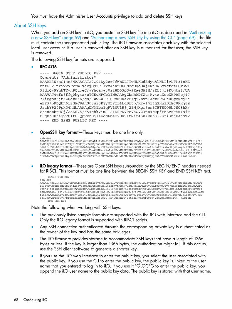
You must have the Administer User Accounts privilege to add and delete SSH keys.
About SSH keysWhen you add an SSH key to iLO, you paste the SSH key file into iLO as described in “Authorizinga new SSH key” (page 69) and “Authorizing a new SSH key by using the CLI” (page 69). The filemust contain the user-generated public key. The iLO firmware associates each key with the selectedlocal user account. If a user is removed after an SSH key is authorized for that user, the SSH keyis removed.The following SSH key formats are supported:
• RFC 4716---- BEGIN SSH2 PUBLIC KEY ---- Comment: "Administrator" AAAAB3NzaC1kc3MAAACAT27C04Dy2zr7fWhUL7TwHDKQdEdyuAlNLIivLFP3IoKZ ZtzF0VInP5x2VFVYmTvdVjD92CTlxxAtarOPON2qUqoOajKRtBWLmxcfqsLCT3wI 3ldxQvPYnhTYyhPQuoeJ/vYhoam+y0zi8D03pDv9KaeNA3H/zEL5mf9Ktgts8/UA AAAVAJ4efo8ffq0hg4a/eTGEuHPCb3INAAAAgCbnhADYXu+Mv4xuXccXWP0Pcj47 7YiZgos3jt/Z0ezFX6/cN/RwwZwPC1HCsMuwsVBIqi7bvn1XczFPKOt06gVWcjFt eBY3/bKpQkn61SGPC8AhSu8ui0KjyUZrxL4LdBrtp/K2+lm1fqXHnzDIEJ0RHg8Z JazhY920PpkD4hNbAAAAgDN3lba1qFVl0UlRjj21MjXgr6em9TETSOO5b7SQ8hX/ Z/axobbrHCj/2s66VA/554chkVimJT2IDRRKVkcV8OVC3nb4ckpfFEZvKkAWYaiF DLqRbHhh4qyRBIfBKQpvvhDj1aecdFbaO2UvZltMir4n8/E0hh19nfi3tjXAtSTV ---- END SSH2 PUBLIC KEY ----
• OpenSSH key format—These keys must be one line only.ssh-dss AAAAB3NzaC1kc3MAAACAYjEd8Rk8HLCLqDIlI+RkA1UXjVS28hNSk8YDljTaJpw1VOlBirrLGPdSt0avNSz0DNQuU7gTPfjj/8c XyHe3y95Oa3Rics1fARyLiNFGqFjr7w2ByQuoYUaXBzzghIYMQcmpc/W/kDMC0dVOf2XnfcLpcVDIm3ahVPRkxFV9WKkAAAAVAI 3J61F+oVKrbNovhoHh8pFfUa9LAAAAgA8pU5/M9F0s5QxqkEWPD6+FVz9cZ0GfwIbiuAI/9ARsizkbwRtpAlxAp6eDZKFvj3ZIy NjcQODeYYqOvVU45AkSkLBMGjpF05cVtnWEGEvrW7mAvtG2zwMEDFSREw/V526/jR9TKzSNXTH/wqRtTc/oLotHeyV2jFZFGpxD OvNWAAAAgFf6pvWaco3CDELmH0jT3yUkRSaDztpqtoo4D7ev7VrNPPjnKKKmpzHPmAKRxz3g5S80SfWSnWM3n/pekBa9QI9lH1r 3Lx4JoOVwTpkbwb0by4eZ2cqDw20KQ0A5J84iQE9TbPNecJ0HJtZH/K8YnFNwwYy2NSJyjLwA0TSmQEOW Administrator
• iLO legacy format—These are OpenSSH keys surrounded by the BEGIN/END headers neededfor RIBCL. This format must be one line between the BEGIN SSH KEY and END SSH KEY text.-----BEGIN SSH KEY----- ssh-dss AAAAB3NzaC1kc3MAAACBANA45qXo9cM1asav6ApuCREt1UvP7qcMbw+sTDrx9lV22XvonwijdFiOM/0VvuzVhM9oKdGMC7sCGQr FV3zWDMJcIb5ZdYQSDt44X6bvlsQcAR0wNGBN9zHL6YsbXvNAsXN7uBM7jXwHwrApWVuGAI0QnwUYvN/dsE8fbEYtGZCRAAAAFQ DofA47q8pIRdr6epnJXSNrwJRvaQAAAIBY7MKa2uH82I0KKYTbNMi0o5mOqmqy+tg5s9GC+HvvYy/S7agpIdfJzqkpHF5EPhm0j KzzVxmsanO+pjju7lrE3xUxojevlokTERSCM xLa+OVVbNcgTe0xpvc/cF6ZvsHs0UWz6gXIMCQ9Pk118VMOw/tyLp42YXOaLZzG fi5pKAAAAIEAl7FsO7sDbPj02a5jO3qFXa762lWvu5iPRZ9cEt5WJEYwMO/ICaJVDWVOpqF9spoNb53Wl1pUARJg1ss8Ruy7YBv 8Z1urWWAF3fYy7R/SlQqrsRYDPLM5eBkkLO28B8C6++HjLuc+hBvj90tsqeNVhpCfO9qrjYomYwnDC4m1IT4= ASmith -----END SSH KEY-----
Note the following when working with SSH keys:
• The previously listed sample formats are supported with the iLO web interface and the CLI.Only the iLO legacy format is supported with RIBCL scripts.
• Any SSH connection authenticated through the corresponding private key is authenticated asthe owner of the key and has the same privileges.
• The iLO firmware provides storage to accommodate SSH keys that have a length of 1366bytes or less. If the key is larger than 1366 bytes, the authorization might fail. If this occurs,use the SSH client software to generate a shorter key.
• If you use the iLO web interface to enter the public key, you select the user associated withthe public key. If you use the CLI to enter the public key, the public key is linked to the username that you entered to log in to iLO. If you use HPQLOCFG to enter the public key, youappend the iLO user name to the public key data. The public key is stored with that user name.
68 Configuring iLO

Authorizing a new SSH key1. Generate a 2,048-bit DSA or RSA key by using ssh-keygen, puttygen.exe, or another
SSH key utility.2. Create the key.pub file.3. Navigate to the Administration→Security page.4. Click the Secure Shell Key tab.
5. Select the check box to the left of the user to which you want to add an SSH key.6. Click Authorize New Key.7. Copy and paste the public key into the Public Key Import Data box.
The key must be a 2,048-bit DSA or RSA key.8. Click Import Public Key.
Authorizing a new SSH key by using the CLI1. Generate a 2,048-bit DSA or RSA SSH key by using ssh-keygen, puttygen.exe, or
another SSH key utility.2. Create the key.pub file.
Configuring iLO security 69

3. Verify that Secure Shell (SSH) Access is enabled on the Access Settings page.For more information, see “Configuring iLO access settings” (page 58).
4. Use Putty.exe to open an SSH session using port 22.5. Change to the cd /Map1/Config1 directory.6. Enter the following command:
load sshkey type "oemhp_loadSSHkey -source<protocol://username:password@hostname:port/filename>"
When you use this command:• The protocol value is required and must be HTTP or HTTPS.
• The hostname and filename values are required.
• The username:password and port values are optional.
• oemhp_loadSSHkey is case-sensitive.
The CLI performs a cursory syntax verification of the values you enter. You must visually verify thatthe URL is valid. The following example shows the command structure:oemhp_loadSSHkey -source http://192.168.1.1/images/path/sshkey.pub
Deleting SSH keys1. Navigate to the Administration→Security page.2. Click the Secure Shell Key tab.3. Select the check box to the left of the user for which you want to delete an SSH key.4. Click Delete Selected Key(s).
The selected SSH key is removed from iLO. When an SSH key is deleted from iLO, an SSHclient cannot authenticate to iLO by using the corresponding private key.
Authorizing SSH keys from an HP SIM serverThe mxagentconfig utility enables you to authorize SSH keys from an HP SIM server.
• SSH must be enabled on iLO before you use mxagentconfig to authorize a key.
• The user name and password entered in mxagentconfig must correspond to an iLO userwho has the Configure iLO Settings privilege. The user can be a directory user or a local user.
• The key is authorized on iLO and corresponds to the user name specified in themxagentconfig command.
For more information about mxagentconfig, see the iLO scripting and command line guide.
Administering SSL certificatesSSL protocol is a standard for encrypting data so that it cannot be viewed or modified while intransit on the network. This protocol uses a key to encrypt and decrypt the data. Generally, thelonger the key, the better the encryption.A certificate is a small data file that connects an SSL key to a server. It contains the name of theserver and the server's public key. Only the server has the corresponding private key, and this ishow it is authenticated.A certificate must be signed to be valid. If it is signed by a CA, and that CA is trusted, all certificatessigned by the CA are also trusted. A self-signed certificate is one in which the owner of the certificateacts as its own CA.By default, iLO creates a self-signed certificate for use in SSL connections. This certificate enablesiLO to work without additional configuration steps. Importing a trusted certificate can enhance the
70 Configuring iLO

iLO security features. Users with the Configure iLO Settings privilege can customize and import atrusted certificate that is signed by a CA.
Viewing SSL certificate informationTo view certificate information, navigate to the Administration→Security→SSL Certificate page.The following certificate details are displayed:
• Issued To—The entity to which the certificate was issued
• Issued By—The CA that issued the certificate
• Valid From—The first date that the certificate is valid
• Valid Until—The date that the certificate expires
• Serial Number—The serial number that the CA assigned to the certificate
Obtaining and importing an SSL certificateUsers who have the Configure iLO Settings privilege can customize and import a trusted certificate.A certificate works only with the keys generated with its corresponding CSR. If iLO is reset to thefactory default settings, or another CSR is generated before the certificate that corresponds to theprevious CSR is imported, the certificate does not work. In that case, a new CSR must be generatedand used to obtain a new certificate from a CA.1. Navigate to the Administration→Security→SSL Certificate page.
2. Click Customize Certificate.
Configuring iLO security 71

3. On the SSL Certificate Customization page, enter the following information in the CertificateSigning Request Information section:• Country (C)—The two-character country code that identifies the country where the company
or organization that owns this iLO subsystem is located. Enter the two-letter abbreviationin capital letters.
• State (ST)—The state where the company or organization that owns this iLO subsystem islocated.
• City or Locality (L)—The city or locality where the company or organization that owns thisiLO subsystem is located.
• Organization Name (O)—The name of the company or organization that owns this iLOsubsystem.
• Organizational Unit (OU)—(Optional) The unit within the company or organization thatowns this iLO subsystem.
• Common Name (CN)—The FQDN of this iLO subsystem.The FQDN is entered automatically in the Common Name (CN) box.You must configure the Domain Name on the Network General Settings page to enableiLO to enter the FQDN into the CSR. For information about configuring the networksettings, see “Configuring general network settings” (page 94).
4. Click Generate CSR.A message notifies you that a certificate is being generated and that the process might takeup to 10 minutes.
5. After a few minutes (up to 10), click Generate CSR again.The CSR is displayed.The CSR contains a public and private key pair that validates communications between theclient browser and iLO. Key sizes up to 2,048 bits are supported. The generated CSR is heldin memory until a new CSR is generated, iLO is reset to the factory default settings, or acertificate is imported.
6. Select and copy the CSR text.7. Open a browser window and navigate to a third-party CA.
72 Configuring iLO
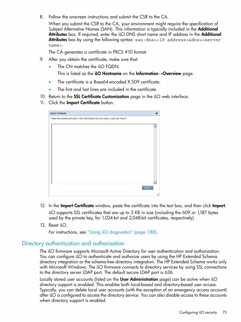
8. Follow the onscreen instructions and submit the CSR to the CA.When you submit the CSR to the CA, your environment might require the specification ofSubject Alternative Names (SAN). This information is typically included in the AdditionalAttributes box. If required, enter the iLO DNS short name and IP address in the AdditionalAttributes box by using the following syntax: san:dns=<IP address>&dns=<servername>.The CA generates a certificate in PKCS #10 format.
9. After you obtain the certificate, make sure that:• The CN matches the iLO FQDN.
This is listed as the iLO Hostname on the Information→Overview page.
• The certificate is a Base64-encoded X.509 certificate.
• The first and last lines are included in the certificate.10. Return to the SSL Certificate Customization page in the iLO web interface.11. Click the Import Certificate button.
12. In the Import Certificate window, paste the certificate into the text box, and then click Import.iLO supports SSL certificates that are up to 3 KB in size (including the 609 or 1,187 bytesused by the private key, for 1,024-bit and 2,048-bit certificates, respectively).
13. Reset iLO.For instructions, see “Using iLO diagnostics” (page 188).
Directory authentication and authorizationThe iLO firmware supports Microsoft Active Directory for user authentication and authorization.You can configure iLO to authenticate and authorize users by using the HP Extended Schemadirectory integration or the schema-free directory integration. The HP Extended Schema works onlywith Microsoft Windows. The iLO firmware connects to directory services by using SSL connectionsto the directory server LDAP port. The default secure LDAP port is 636.Locally stored user accounts (listed on the User Administration page) can be active when iLOdirectory support is enabled. This enables both local-based and directory-based user access.Typically, you can delete local user accounts (with the exception of an emergency access account)after iLO is configured to access the directory service. You can also disable access to these accountswhen directory support is enabled.
Configuring iLO security 73
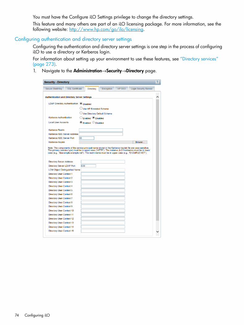
You must have the Configure iLO Settings privilege to change the directory settings.This feature and many others are part of an iLO licensing package. For more information, see thefollowing website: http://www.hp.com/go/ilo/licensing.
Configuring authentication and directory server settingsConfiguring the authentication and directory server settings is one step in the process of configuringiLO to use a directory or Kerberos login.For information about setting up your environment to use these features, see “Directory services”(page 273).1. Navigate to the Administration→Security→Directory page.
74 Configuring iLO

2. Configure the following options:• LDAP Directory Authentication—Enables or disables directory authentication. If directory
authentication is enabled and configured correctly, users can log in by using directorycredentials.Choose from the following options:
◦ Disabled—User credentials are not validated by using a directory.
◦ Use HP Extended Schema—Selects directory authentication and authorization byusing directory objects created with the HP Extended Schema. Select this optionwhen the directory has been extended with the HP Extended Schema.
◦ Use Directory Default Schema—Selects directory authentication and authorizationby using user accounts in the directory. Select this option when the directory is notextended with the HP Extended Schema. User accounts and group memberships areused to authenticate and authorize users. After you enter and save the directorynetwork information, click Administer Groups, and then enter one or more validdirectory DNs and privileges to grant users access to iLO.
• Kerberos Authentication—Enables or disables Kerberos login. If Kerberos login is enabledand configured correctly, the HP Zero Sign In button appears on the login page.
• Local User Accounts—Enables or disables local user account access.
Enabled—A user can log in by using locally stored user credentials. HP recommendsenabling this option and configuring a user account with administrator privileges.This account can be used if iLO cannot communicate with the directory server.
◦
◦ Disabled—User access is limited to valid directory credentials.Do not disable local user access until you have validated access through othermechanisms.
Access through local user accounts is enabled when directory support is disabled or aniLO license is revoked.
• Kerberos Realm—The name of the Kerberos realm in which the iLO processor is operating.This string can be up to 128 characters. A realm name is usually the DNS name convertedto uppercase. Realm names are case sensitive.
• Kerberos KDC Server Address—The IP address or DNS name of the KDC server. Thisstring can be up to 128 characters. Each realm must have at least one KDC that containsan authentication server and a ticket grant server. These servers can be combined.
• Kerberos KDC Server Port—The TCP or UDP port number on which the KDC is listening.The default KDC port is 88.
• Kerberos Keytab—A binary file that contains pairs of service principal names andencrypted passwords. In the Windows environment, the keytab file is generated by thektpass utility. Click Browse (Internet Explorer or Firefox) or Choose File (Chrome), andthen follow the onscreen instructions to select a file.
IMPORTANT: The components of the service principal name stored in the Kerberoskeytab file are case sensitive. The primary (service type) must be in uppercase letters, forexample, (HTTP). The instance (iLO host name) must be in lowercase letters, for example,example.example.net. The realm name must be in uppercase, for example,EXAMPLE.NET.
3. Enter the directory server settings.• Directory Server Address—Specifies the network DNS name or IP address of the directory
server. The directory server address can be up to 127 characters.
Configuring iLO security 75

IMPORTANT: HP recommends using DNS round-robin when you define the directoryserver.
• Directory Server LDAP Port—Specifies the port number for the secure LDAP service on theserver. The default value is 636. You can specify a different value if your directory serviceis configured to use a different port.
• LOMObject Distinguished Name—Specifies where this iLO instance is listed in the directorytree (for example, cn=iLO Mail Server,ou=Management Devices,o=ab). Thisoption is available when Use HP Extended Schema is selected.User search contexts are not applied to the LOM object DN when iLO accesses thedirectory server.
• Directory User Contexts—These boxes enable you to specify common directory subcontextsso that users do not need to enter their full DNs at login. Directory user contexts can beup to 128 characters.You can identify the objects listed in a directory by using unique DNs. However, DNscan be long, and users might not know their DNs or might have accounts in differentdirectory contexts. iLO attempts to contact the directory service by DN, and then appliesthe search contexts in order until successful.
◦ Example 1—If you enter the search context ou=engineering,o=ab, you can login as user instead of logging in as cn=user,ou=engineering,o=ab.
◦ Example 2—If a system is managed by Information Management, Services, andTraining, search contexts such as the following enable users in any of theseorganizations to log in by using their common names:Directory User Context 1:ou=IM,o=abDirectory User Context 2:ou=Services,o=abDirectory User Context 3:ou=Training,o=ab
If a user exists in both the IM organizational unit and the Training organizationalunit, login is first attempted as cn=user,ou=IM,o=ab.
◦ Example 3 (Active Directory only)—Microsoft Active Directory allows an alternateuser credential format. A user can log in as [email protected], in whichcase a search context of @domain.example.com allows the user to log in as user.Only a successful login attempt can test search contexts in this format.
4. Click Apply Settings.5. To test the communication between the directory server and iLO, click Test Settings.
For more information, see “Running directory tests” (page 76).6. Optional: Click Administer Groups to navigate to the User Administration page, where you
can configure directory groups.
Running directory testsDirectory tests enable you to validate the configured directory settings. The directory test resultsare reset when directory settings are saved, or when the directory tests are started.
76 Configuring iLO

1. Click Test Settings on the Security→Directory page.
The Directory Tests page displays the results of a series of simple tests designed to validatethe current directory settings. It also includes a log that shows test results and detected issues.After your directory settings are configured correctly, you do not need to rerun these tests. TheDirectory Tests page does not require you to log in as a directory user.
2. In the Directory Test Controls section, enter the DN and password of a directory administrator.• Directory Administrator Distinguished Name—Searches the directory for iLO objects,
roles, and search contexts. This user must have the right to read the directory.• Directory Administrator Password—Authenticates the directory administrator.HP recommends that you use the same credentials that you used when creating the iLO objectsin the directory. These credentials are not stored by iLO; they are used to verify the iLO objectand user search contexts.
3. In the Directory Test Controls section, enter a test user name and password.• Test User Name—Tests login and access rights to iLO. This name does not need to be
fully distinguished because user search contexts can be applied. This user must beassociated with a role for this iLO.
• Test User Password—Authenticates the test user.Typically, this account is used to access the iLO processor being tested. It can be the directoryadministrator account, but the tests cannot verify user authentication with a superuser account.These credentials are not stored by iLO.
4. Click Start Test.Several tests begin in the background, starting with a network ping of the directory user byestablishing an SSL connection to the server and evaluating user privileges.
Configuring iLO security 77

While the tests are running, the page refreshes periodically. You can stop the tests or manuallyrefresh the page at any time.
Directory test resultsThe Directory Test Results section shows the directory test status with the date and time of the lastupdate.
• Overall Status—Summarizes the results of the tests.
Not Run—No tests were run.◦◦ Inconclusive—No results were reported.
◦ Passed—No failures were reported.
◦ Problem Detected—A problem was reported.
◦ Failed—A specific subtest failed. Check the onscreen log to identify the problem.
◦ Warning—One or more of the directory tests reported a Warning status.
• Test—The name of each test.For more information about the directory tests, see “About the iLO directory tests” (page 79).
• Result—Reports status for a specific directory setting or an operation that uses one or moredirectory settings. These results are generated when a sequence of tests is run. The results stopwhen the tests run to completion, when a test failure prevents further progress, or when thetests are stopped. Test results follow:
◦ Passed—The test ran successfully. If more than one directory server was tested, all serversthat ran this test were successful.
◦ Not Run—The test was not run.
◦ Failed—The test was unsuccessful on one or more directory servers. Directory supportmight not be available on those servers.
◦ Warning—The test ran and reported a warning condition, for example, a certificate error.Check the Notes column for suggested actions to correct the warning condition.
• Notes—Indicates the results of various phases of the directory tests. The data is updated withfailure details and information that is not readily available, like the directory server certificatesubject and which roles were evaluated successfully.
Using the directory test controlsThe Directory Test Controls section enables you to view the current state of the directory tests, adjustthe test parameters, start and stop the tests, and refresh the page contents.
• In Progress—Indicates that directory tests are currently being performed in the background.Click Stop Test to cancel the current tests, or click Refresh to update the contents of the pagewith the latest results. Using the Stop Test button might not stop the tests immediately.
• Not Running—Indicates that directory tests are current, and that you can supply new parametersto run the tests again. Use the Start Test button to start the tests and use the current test controlvalues. Directory tests cannot be started after they are already in progress.
• Stopping—Indicates that directory tests have not yet reached a point where they can stop.You cannot restart tests until the status changes to Not Running. Use the Refresh button todetermine whether the tests are complete.
78 Configuring iLO

About the iLO directory testsDescriptions of the directory tests follow:
• Directory Server DNS Name—If the directory server is defined in FQDN format(directory.company.com), iLO resolves the name from FQDN format to IP format, andqueries the configured DNS server.If the test is successful, iLO obtained an IP address for the configured directory server. If iLOcannot obtain an IP address for the directory server, this test and all subsequent tests fail.If the directory server is configured with an IP address, iLO skips this test.If a failure occurs:1. Verify that the DNS server configured in iLO is correct.2. Verify that the directory server FQDN is correct.3. As a troubleshooting tool, use an IP address instead of the FQDN.4. If the problem persists, check the DNS server records and network routing.
• Ping Directory Server—iLO initiates a ping to the configured directory server.The test is successful if iLO receives the ping response; it is unsuccessful if the directory serverdoes not reply to iLO.If the test fails, iLO will continue with the subsequent tests.If a failure occurs:1. Check to see if a firewall is active on the directory server.2. Check for network routing issues.
• Connect to Directory Server—iLO attempts to negotiate an LDAP connection with the directoryserver.If the test is successful, iLO was able to initiate the connection.If the test fails, iLO was not able to initiate an LDAP connection with the specified directoryserver. Subsequent tests will stop.If a failure occurs:1. Verify that the configured directory server is the correct host.2. Verify that iLO has a clear communication path to the directory server through port 636
(consider any routers or firewalls between iLO and the directory server).3. Verify that any local firewall on the directory server is enabled to allow communications
through port 636.
• Connect using SSL—iLO initiates SSL handshake and negotiation and LDAP communicationswith the directory server through port 636.If the test is successful, the SSL handshake and negotiation between iLO and the directoryserver were successful.If a failure occurs, the directory server is not enabled for SSL negotiations.If you are using Microsoft Active Directory, verify that Active Directory Certificate Services isinstalled.
• Bind to Directory Server—This test binds the connection with the user name specified in thetest boxes. If no user is specified, iLO does an anonymous bind.If the test is successful, the directory server accepted the binding.If a failure occurs:1. Verify that the directory server allows anonymous binding.2. If you entered a user name in the test boxes, verify that the credentials are correct.
Configuring iLO security 79
3. If you verified that the user name is correct, try using other user-name formats; for example,[email protected], DOMAIN\username, username (called Display Name in ActiveDirectory), or userlogin.
4. Verify that the specified user is allowed to log in and is enabled.
• Directory Administrator Login—If Directory Administrator Distinguished Name and DirectoryAdministrator Password were specified, iLO uses these values to log in to the directory serveras an administrator. These boxes are optional.
• User Authentication—iLO authenticates to the directory server with the specified user nameand password.If the test is successful, the supplied user credentials are correct.If the test fails, the user name and/or password is incorrect.If a failure occurs:1. If you verified that the user name is correct, try using other user-name formats; for example,
[email protected], DOMAIN\username, username (called Display Name in ActiveDirectory), or userlogin.
2. Verify that the specified user is allowed to log in and is enabled.3. Check to see if the specified user name is restricted by logon hours or IP-based logging.
• User Authorization—This test verifies that the specified user name is part of the specifieddirectory group, and is part of the directory search context specified during directory servicesconfiguration.If a failure occurs:1. Verify that the specified user name is part of the specified directory group.2. Check to see if the specified user name is restricted by logon hours or IP-based logging.
• Directory User Contexts—If Directory Administrator Distinguished Name was specified, iLOtries to search the specified context.If the test is successful, iLO found the context by using the administrator credentials to searchfor the container in the directory.Contexts that begin with "@" can be tested only by user login.A failure indicates that the container could not be located.
• LOM Object Exists—This test searches for the iLO object in the directory server by using theLOM Object Distinguished Name configured on the Security→Directory page.
NOTE: You can enter a LOM Object Distinguished Name on the Security→Directory pageonly when Use HP Extended Schema is selected. This test is run even if LDAP DirectoryAuthentication is disabled.
If the test is successful, iLO found the object that represents itself.If a failure occurs:1. Verify that the LDAP FQDN of the LOM object is correct.2. Try to update the HP Extended Schema and snap-ins in the directory server by updating
the HPLOMIG software.
80 Configuring iLO

Using encryptioniLO provides enhanced security for remote management in distributed IT environments. SSLencryption protects web browser data. SSL encryption of HTTP data ensures that the data is secureas it is transmitted across the network. iLO supports the following cipher strengths:
• 256-bit AES with RSA, DHE, and a SHA1 MAC
• 256-bit AES with RSA, and a SHA1 MAC
• 128-bit AES with RSA, DHE, and a SHA1 MAC
• 128-bit AES with RSA, and a SHA1 MAC
• 168-bit 3DES with RSA, and a SHA1 MAC
• 168-bit 3DES with RSA, DHE, and a SHA1 MACiLO also provides enhanced encryption through the SSH port for secure CLP transactions. iLOsupports AES256-CBC, AES128-CBC, and 3DESCBC cipher strengths through the SSH port.If enabled, iLO enforces the use of these enhanced ciphers (both AES and 3DES) over the securechannels, including secure HTTP transmissions through the browser, SSH port, and XML port. WhenAES/3DES encryption is enabled, you must use a cipher strength equal to or greater than AES/3DESto connect to iLO through these secure channels. The AES/3DES encryption enforcement settingdoes not affect communications and connections over less-secure channels.By default, Remote Console data uses 128-bit RC4 bidirectional encryption. The HPQLOCFG utilityuses 128-bit RC4 with 160-bit SHA1 and 2048-bit RSAKeyX encryption to securely send RIBCLscripts to iLO over the network.Version 1.20 and later of the iLO 4 firmware supports FIPS Mode.The term FIPS Mode is used in this document and in iLO to describe the feature, not its validationstatus.
• FIPS is a set of standards mandated for use by United States government agencies andcontractors.
• FIPS Mode in iLO 4 1.20 and later is intended to meet the requirements of FIPS 140-2 level1. This version or any other version of the iLO firmware might have this feature but might ormight not be FIPS validated. The FIPS validation process is lengthy, so not all iLO firmwareversions will be validated. For information about the current FIPS status of this or any otherversion of the iLO firmware, see the following website: http://government.hp.com/Certifications.aspx?filter=fips.
Viewing encryption enforcement settingsNavigate to the Administration→Security→Encryption page.
Configuring iLO security 81

The Encryption Settings page displays the current encryption settings for iLO.
• Current Negotiated Cipher—The cipher in use for the current browser session. After you login to iLO through the browser, the browser and iLO negotiate a cipher setting to use duringthe session.
• Encryption Enforcement Settings—The current encryption settings for iLO:
FIPS Mode—Indicates whether FIPS Mode is enabled or disabled for this iLO system.◦◦ Enforce AES/3DES Encryption—Indicates whether AES/3DES encryption is enforced for
this iLO.When enabled, iLO only accepts connections that use the AES or 3DES ciphers.
Modifying the AES/DES encryption settingYou must have the Configure iLO Settings privilege to change the encryption settings.1. Navigate to the Administration→Security→Encryption page.2. Change the Enforce AES/3DES Encryption setting to Enabled or Disabled.
IMPORTANT: Java Runtime Environment 8 or later is required when Enforce AES/3DESEncryption is set to Enabled.
3. Click Apply to end your browser connection and restart iLO.It might take several minutes before you can re-establish a connection.When changing the Enforce AES/3DES Encryption setting to Enabled, close all open browsersafter clicking Apply. Any browsers that remain open might continue to use a non-AES/3DEScipher.
82 Configuring iLO
Connecting to iLO by using AES or 3DES encryptionAfter you enable the Enforce AES/3DES Encryption setting, iLO requires that you connect throughsecure channels (web browser, SSH connection, or XML channel) by using a cipher strength of atleast AES or 3DES.
• Web browser—You must configure the browser with a cipher strength of at least AES or 3DES.If the browser is not using AES or 3DES ciphers, iLO displays an error message. The error textvaries depending on the installed browser.Different browsers use different methods for selecting a negotiated cipher. For more information,see the browser documentation. You must log out of iLO through the current browser beforechanging the browser cipher setting. Any changes made to the browser cipher setting whileyou are logged in to iLO might enable the browser to continue using a non-AES/3DES cipher.
• SSH connection—For instructions on setting the cipher strength, see the SSH utilitydocumentation.
• XML channel—HPQLOCFG uses a secure 3DES cipher by default. For example, HPQLOCFGdisplays the following cipher strength in the XML output:Connecting to Server...Negotiated cipher: 128–bit Rc4 with 160–bit SHA1 and 2048–bit RsaKeyx
Enabling FIPS ModeYou must have the Configure iLO Settings privilege to change the encryption settings.1. Optional: Capture the current iLO configuration by using HPONCFG.
For more information, see the iLO scripting and command line guide.2. Verify that a trusted certificate is installed.
Using iLO in FIPS Mode with the default self-signed certificate is not FIPS-compliant. For moreinformation, see “Obtaining and importing an SSL certificate” (page 71).
IMPORTANT: Some interfaces to iLO, such as supported versions of IPMI and SNMP, arenot FIPS-compliant and cannot be made FIPS-compliant.
3. Power off the server.4. Navigate to the Administration→Security→Encryption page.5. Set FIPS Mode to Enabled.
CAUTION: Enabling FIPS Mode resets iLO to the factory default settings, and clears all userand license data.
6. Click Apply.iLO reboots in FIPS Mode. Wait at least 90 seconds before attempting to re-establish aconnection.
7. Optional: Restore the iLO configuration by using HPONCFG.For more information, see the iLO scripting and command line guide.
TIP: You can use the Login Security Banner feature to notify iLO users that a system is using FIPSMode. For more information, see “Configuring the Login Security Banner” (page 88).You can also use XML configuration and control scripts to enable FIPS mode. For more information,see the iLO scripting and command line guide.
Configuring iLO security 83
Disabling FIPS ModeIf you want to disable FIPS Mode for iLO (for example, if a server is decommissioned), you mustset iLO to the factory default settings. You can perform this task by using RIBCL scripts, iLO RBSU,or the iLO 4 Configuration Utility.For instructions, see “Resetting iLO to the factory default settings by using iLO RBSU” (page 268),“Resetting iLO to the factory default settings by using the iLO 4 Configuration Utility” (page 269),or the iLO scripting and command line guide.When you disable FIPS Mode, all potentially sensitive data is erased, including all logs and settings.
Using HP SSOHP SSO enables you to browse directly from an HP SSO-compliant application (such as HP SIMand HP OneView) to iLO, bypassing an intermediate login step. To use SSO, you must have asupported version of an HP SSO-compliant application, you might need iLO 4 1.20 or later, andyou must configure the iLO processor to trust the SSO-compliant application.iLO contains support for HP SSO applications to determine the minimum SSO certificaterequirements. Some HP SSO-compliant applications automatically import trust certificates whenthey connect to iLO. For applications that do not do this automatically, use the HP SSO page toconfigure the SSO settings through the iLO web interface. You must have the Configure iLO Settingsprivilege to change these settings.This feature and many others are part of an iLO licensing package. For more information, see thefollowing website: http://www.hp.com/go/ilo/licensing.
84 Configuring iLO
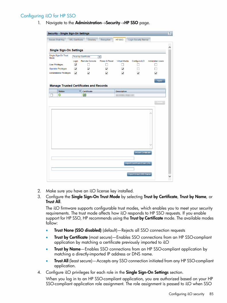
Configuring iLO for HP SSO1. Navigate to the Administration→Security→HP SSO page.
2. Make sure you have an iLO license key installed.3. Configure the Single Sign-On Trust Mode by selecting Trust by Certificate, Trust by Name, or
Trust All.The iLO firmware supports configurable trust modes, which enables you to meet your securityrequirements. The trust mode affects how iLO responds to HP SSO requests. If you enablesupport for HP SSO, HP recommends using the Trust by Certificate mode. The available modesfollow:
• Trust None (SSO disabled) (default)—Rejects all SSO connection requests
• Trust by Certificate (most secure)—Enables SSO connections from an HP SSO-compliantapplication by matching a certificate previously imported to iLO
• Trust by Name—Enables SSO connections from an HP SSO-compliant application bymatching a directly-imported IP address or DNS name.
• Trust All (least secure)—Accepts any SSO connection initiated from any HP SSO-compliantapplication.
4. Configure iLO privileges for each role in the Single Sign-On Settings section.When you log in to an HP SSO-compliant application, you are authorized based on your HPSSO-compliant application role assignment. The role assignment is passed to iLO when SSO
Configuring iLO security 85

is attempted. For more information about each privilege, see “Managing iLO user accountsby using the iLO web interface” (page 39).SSO attempts to receive only the privileges assigned in this section. iLO directory settings donot apply. Default privilege assignments are as follows:
• User—Login only
• Operator—Login, Remote Console, Power and Reset, and Virtual Media
• Administrator—Login, Remote Console, Power and Reset, Virtual Media, Configure iLO,and Administer Users
5. Click Apply to save the SSO settings.6. If you selected Trust by Certificate or Trust by Name, add the trusted certificate or DNS name
to iLO.For information about adding certificates and DNS names, see “Adding trusted certificates”(page 86) and “Importing a direct DNS name” (page 87).
7. After you configure SSO in iLO, log in to an HP SSO-compliant application and browse toiLO. For example, log in to HP SIM, navigate to the System page for the iLO processor, andthen click the iLO link in the More Information section.
NOTE: Although a system might be registered as a trusted server, SSO might be refusedbecause of the current trust mode or certificate status. For example, if an HP SIM server nameis registered, and the trust mode is Trust by Certificate, but the certificate is not imported, SSOis not allowed from that server. Likewise, if an HP SIM server certificate is imported, but thecertificate has expired, SSO is not allowed from that server. The list of trusted servers is notused when SSO is disabled. iLO does not enforce SSO server certificate revocation.
Adding trusted certificatesiLO users who have the Configure iLO Settings privilege can install trusted certificates.The certificate repository can hold five typical certificates. However, if typical certificates are notissued, certificate sizes might vary. When all of the allocated storage is used, no more imports areaccepted.The Base64-encoded X.509 certificate data resembles the following:-----BEGIN CERTIFICATE-----
. . . several lines of encoded data . . .-----END CERTIFICATE-----
To add trusted certificates by using the iLO web interface:1. Navigate to the Administration→Security→HP SSO page.2. Use one of the following methods to add a trusted certificate:
• To directly import a trusted certificate, copy the Base64-encoded certificate X.509 data,paste it into the text box above the Import Certificate button, and then click the button.
• To indirectly import a trusted certificate, type the DNS name or IP address in the text boxabove the Import Certificate from URL button, and then click the button. iLO contacts theHP SSO-compliant application over the network, retrieves the certificate, and then savesit.
For information about how to extract an HP SIM certificate, see “Extracting the HP SIM servercertificate” (page 87).For information about how to extract certificates from other HP SSO-compliant applications, seeyour HP SSO-compliant application documentation.
86 Configuring iLO

Extracting the HP SIM server certificateYou can use the following methods to extract HP SIM certificates.
NOTE: iLO 4 1.20 or later might be required to install the larger certificates used with recentversions of HP SIM.
NOTE: HP SIM 7.3.2 or later supports 2048-bit certificates.
• Enter one of the following links in a web browser:
For HP SIM versions earlier than 7.0:http://<HP SIM name or network address>:280/GetCertificate
◦
https://<HP SIM name or network address>:50000/GetCertificate
◦ For HP SIM 7.0 or later:http://<HP SIM name or networkaddress>:280/GetCertificate?certtype=sso
https://<HP SIM name or networkaddress>:50000/GetCertificate?certtype=sso
NOTE: All request parameters are case-sensitive. If you capitalize the lowercasecerttype parameter, the parameter will not be read, and HP SIM will return the defaultHP SIM server certificate instead of a trusted certificate.
• Export the certificate from HP SIM:
For HP SIM versions earlier than 7.0:Select Options→Security→Certificates→Server Certificate.
◦
◦ For HP SIM 7.0 or later:Select Options→Security→HP Systems Insight Manager Server Certificate, and then clickExport.
• Use the HP SIM command-line tools. For example, using the alias tomcat for the HP SIMcertificate, enter mxcert -l tomcat.
For more information, see the HP SIM documentation.
Importing a direct DNS nameiLO users who have the Configure iLO Settings privilege can import a DNS name.1. Navigate to the Administration→Security→HP SSO page.2. Enter the DNS name or network address in the text box above the Import Direct DNS Name
button, and then click the button.
Configuring iLO security 87
Viewing trusted certificates and recordsThe Manage Trusted Certificates and Records table on the Single Sign-On Settings page displaysthe status of the trusted certificates and records configured to use SSO with the current iLOmanagement processor.
• Status—The status of the record. The possible status values follow:
—The record is valid.◦◦ —There is a problem with the trust settings or the iLO license. Possible reasons follow:
This record contains a DNS name, and the trust mode is set to Trust by Certificate(only certificates are valid).
–
– Trust None (SSO disabled) is selected.
– A valid license key is not installed.
◦ —The record is not valid. Possible reasons follow:– An out-of-date certificate is stored in this record. Check the certificate details for more
information.– The iLO clock is not set or is set incorrectly.
– The iLO clock must be in the Valid from and Valid until range.
• Certificate—Indicates that the record contains a stored certificate. Move the cursor over theicon to view the certificate details, including subject, issuer, and dates.
• Description—The server name (or certificate subject).
Removing trusted certificates and records1. Navigate to the Administration→Security→HP SSO page.2. Select one or more records in the Manage Trusted Certificates and Records table.3. Click Delete.
iLO prompts you to confirm that you want to delete the certificate or record.
IMPORTANT: If you delete the certificate of a remote management system, you mightexperience impaired functionality when using the remote management system with iLO.
4. Click Yes.
Configuring the Login Security BannerThe Login Security Banner feature allows you to configure the security banner displayed on theiLO login page. For example, you could enter a message indicating that an iLO system uses FIPSMode.You must have the Configure iLO Settings privilege to make changes on the Login Security BannerSettings page.
88 Configuring iLO

1. Navigate to the Administration→Security→Login Security Banner page.
2. Select the Enable Login Security Banner check box.iLO uses the following default text for the Login Security Banner:This is a private system. It is to be used solely by authorizedusers and may be monitored for all lawful purposes. By accessingthis system, you are consenting to such monitoring.
3. Optional: To customize the security message, enter a custom message in the Security Messagetext box.The byte counter above the text box indicates the remaining number of bytes allowed for themessage. The maximum is 1,500 bytes.
TIP: Click Use Default Message to restore the default text.
Configuring iLO security 89

4. Click Apply.The security message is displayed at the next login.
Configuring Remote Console security settingsUse the Remote Console security settings to control the Remote Console Computer Lock settingsand the Integrated Remote Console Trust setting. You must have the Configure iLO Settings privilegeto change these settings.
Configuring Remote Console Computer Lock settingsRemote Console Computer Lock enhances the security of an iLO-managed server by automaticallylocking an operating system or logging out a user when a Remote Console session ends or thenetwork link to iLO is lost. This feature is standard and does not require an additional license. Asa result, if you open a .NET IRC or Java IRC window and this feature is already configured, theoperating system will be locked when you close the window, even if an iLO license is not installed.1. Navigate to the Remote Console→Security page.
2. Modify the Remote Console Computer Lock settings as required:• Windows—Use this option to configure iLO to lock a managed server running a Windows
operating system. The server automatically displays the Computer Locked dialog boxwhen a Remote Console session ends or the iLO network link is lost.
• Custom—Use this option to configure iLO to use a custom key sequence to lock a managedserver or log out a user on that server. You can select up to five keys from the list. The
90 Configuring iLO

selected key sequence is sent automatically to the server operating system when a RemoteConsole session ends or the iLO network link is lost.
• Disabled (default)—Use this option to disable the Remote Console Computer Lock feature.Terminating a Remote Console session or losing an iLO network link will not lock theoperating system on the managed server.
You can create a Remote Console Computer Lock key sequence by using the keys listed inTable 1 (page 91):
Table 1 Remote Console Computer Lock keys
g1SCRL LCKESC
h2SYS RQL_ALT
i3F1R_ALT
j4F2L_SHIFT
k5F3R_SHIFT
l6F4L_CTRL
m7F5R_CTRL
n8F6L_GUI
o9F7R_GUI
p;F8INS
q=F9DEL
r[F10HOME
s\F11END
t]F12PG_UP
u'" " (space)PG_DN
va'ENTER
wb,TAB
xc-BREAK
yd.BACKSPACE
ze/NUM PLUS
f0NUM MINUS
3. Click Apply to save the changes.
Configuring the Integrated Remote Console Trust setting (.NET IRC)The .NET IRC is launched through Microsoft ClickOnce, which is part of the Microsoft .NETFramework. ClickOnce requires that any application installed from an SSL connection be from atrusted source. If a browser is not configured to trust an iLO processor, and the Integrated RemoteConsole Trust setting is set to Enabled, ClickOnce displays the following error message:Cannot Start Application – Application download did not succeed...
To specify whether all clients that browse to this iLO require a trusted certificate to run the .NETIRC:
Configuring iLO security 91

1. Navigate to the Remote Console→Security page.
2. Select one of the following in the Integrated Remote Console Trust Setting section:• Enabled—The .NET IRC is launched by using an HTTPS connection if a trusted SSL
certificate has been imported into iLO.• Disabled (default)—The .NET IRC is launched by using a non-SSL connection. SSL is used
after the .NET IRC starts to exchange encryption keys.3. Click Apply.
Managing the iLO network settingsiLO provides the following options for network connection:
• iLO Dedicated Network Port—Uses an independent NIC that is dedicated to iLO networktraffic only. When supported, this port uses an RJ-45 jack (labeled iLO) on the back of theserver.
• Shared Network Port LOM—Uses a permanently-installed NIC that is built into the server. ThisNIC normally handles server network traffic, and it can be configured to handle iLO networktraffic at the same time via a common RJ-45 connector.
• Shared Network Port FlexibleLOM—Uses an optional NIC that plugs into a special slot on theserver. This NIC normally handles server network traffic, and it can be configured to handleiLO network traffic at the same time via a common RJ-45 connector.
To view or configure the network settings in the iLO web interface, select the active NIC in thenavigation tree (Network→iLO Dedicated Network Port or Network→Shared Network Port), andthen view or edit the network settings on the following pages:
• Network Summary—For more information, see “Viewing the network configuration summary”(page 92).
• Network General Settings—For more information, see “Configuring general network settings”(page 94).
• IPv4 Settings—For more information, see “Configuring IPv4 settings” (page 99).
• IPv6 Settings—For more information, see “Configuring IPv6 settings” (page 101).
• SNTP Settings—For more information, see “Configuring SNTP settings” (page 104).If you select the inactive port option, the following message is displayed on the Network Summarypage: iLO is not configured to use this NIC.
Viewing the network configuration summaryTo view a summary of the configured iLO network settings, select Network→iLO Dedicated NetworkPort or Network→Shared Network Port to navigate to the Network Summary page.
92 Configuring iLO

Summary details
• NIC in Use—The name of the active iLO network interface (iLO Dedicated Network Port orShared Network Port).
• iLO Host Name—The fully-qualified network name assigned to the iLO subsystem. By default,the iLO host name is ILO followed by the system serial number and the current domain name.This value is used for the iLO network name and must be unique.
• MAC Address—The MAC address of the selected iLO network interface.
• Link State—The current link speed of the selected iLO network interface. The default value isAuto-Negotiate.
• Duplex Option—The current link duplex setting for the selected iLO network interface. Thedefault value is Auto-Negotiate.
You can configure the iLO host name and NIC settings on the Network General Settings page. Forinstructions, see “Configuring general network settings” (page 94).
IPv4 Summary details
• DHCPv4 Status—Indicates whether DHCP is enabled for IPv4.
• Address—The IPv4 address currently in use. If the value is 0.0.0.0, the IPv4 address is notconfigured.
• Subnet Mask—The subnet mask of the IPv4 address currently in use. If the value is 0.0.0.0,no address is configured.
• Default Gateway—The default gateway address in use for the IPv4 protocol. If the value is0.0.0.0, the gateway is not configured.
Managing the iLO network settings 93

IPv6 Summary detailsThis section is displayed only for the iLO Dedicated Network Port.
• DHCPv6 Status—Indicates whether DHCP is enabled for IPv6. The following values are possible:
Enabled—Stateless and Stateful DHCPv6 are enabled.◦◦ Enabled (Stateless)—Only Stateless DHCPv6 is enabled.
◦ Disabled—DHCPv6 is disabled.
• IPv6 Stateless Address Auto-Configuration (SLAAC)—Indicates whether SLAAC is enabled forIPv6. When SLAAC is disabled, the SLAAC link-local address for iLO is still configured becauseit is required.
• Address list—This table shows the currently configured IPv6 addresses for iLO. It provides thefollowing information:
◦ Source—Indicates whether the address is a static or SLAAC address.
◦ IPv6—The IPv6 address.
◦ Prefix Length—The address prefix length.
◦ Status—The address status: Active (the address is in use by iLO), Pending (DuplicateAddress Detection is in progress for this address), or Failed (Duplicate Address Detectionfailed and the address is not in use by iLO).
For more information about IPv6 support, see “Configuring IPv6 settings” (page 101).
• Default Gateway—The default IPv6 gateway address that is currently in use. For IPv6, iLOkeeps a list of possible default gateway addresses. The addresses in this list originate fromrouter advertisement messages and the IPv6 Static Default Gateway setting.The Static Default Gateway setting is configured on the IPv6 page. For more information, see“Configuring IPv6 settings” (page 101).
Configuring general network settingsUse the iLO Dedicated Network Port or Shared Network Port Network General Settings page toconfigure the iLO Hostname and NIC settings. You must have the Configure iLO Settings privilegeto make changes on this page.
iLO hostname and domain name limitationsWhen you configure the iLO Hostname Settings, note the following:
• Name service limitations—The subsystem name is used as part of the DNS name.
DNS allows alphanumeric characters and hyphens.◦◦ Name service limitations also apply to the Domain Name.
• Namespace issues—To avoid these issues:
Do not use the underscore character.◦◦ Limit subsystem names to 15 characters.
◦ Verify that you can ping the iLO processor by IP address and by DNS/WINS name.
◦ Verify that NSLOOKUP resolves the iLO network address correctly and that no namespaceconflicts exist.
94 Configuring iLO

◦ If you are using both DNS and WINS, verify that they resolve the iLO network addresscorrectly.
◦ Flush the DNS name if you make any namespace changes.
• If you will use Kerberos authentication with an iLO system, ensure that hostname and domainname meet the prerequisites for using Kerberos. For more information, see“Kerberos support”(page 274).
Configuring the iLO Hostname Settings1. Navigate to the Network→iLO Dedicated Network Port or Network→Shared Network Port
page.2. Click the General tab.
3. Enter the following information in the iLO Hostname Settings section:• iLO Subsystem Name (Host Name)—The DNS name of the iLO subsystem (for example,
ilo instead of ilo.example.com). This name can be used only if DHCP and DNSare configured to connect to the iLO subsystem name instead of the IP address.
• Domain Name—The iLO domain name. If DHCP is not used, enter a domain name.
IMPORTANT: When the iLO Dedicated Network port is selected, you must disable thefollowing settings to use a static domain name: Use DHCPv4 Supplied Domain Name andUse DHCPv6 Supplied Domain Name. For information about configuring these settings,see “Configuring IPv4 settings” (page 99) and “Configuring IPv6 settings” (page 101).When the iLO Shared Network port is selected, you must disable the following setting touse a static domain name: Use DHCPv4 Supplied Domain Name. For information aboutconfiguring this setting, see “Configuring IPv4 settings” (page 99).
4. Click Submit to save the changes.5. If you are finished configuring the iLO network settings on the General, IPv4, IPv6, and SNTP
tabs, click Reset to restart the iLO processor.It might take several minutes before you can re-establish a connection.
Managing the iLO network settings 95

iLO network port configuration optionsThe iLO subsystem provides the following options for network connection:
• iLO Dedicated Network Port—Uses an independent NIC that is dedicated to iLO networktraffic only. When supported, this port uses an RJ-45 jack (labeled iLO) on the back of theserver.
• Shared Network Port LOM—Uses a permanently-installed NIC that is built into the server. ThisNIC normally handles server network traffic, and it can be configured to handle iLO networktraffic at the same time via a common RJ-45 connector.
• Shared Network Port FlexibleLOM—Uses an optional NIC that plugs into a special slot on theserver. This NIC normally handles server network traffic, and it can be configured to handleiLO network traffic at the same time via a common RJ-45 connector.
NOTE: For information about the NICs your server supports, see the server QuickSpecs at http://www.hp.com/go/qs/.
When configuring the iLO network connection options, observe the following:
• Only one of the Dedicated Network Port or Shared Network Port options can be enabled ata time because iLO supports only one active NIC connection.
• By default, the iLO Shared Network Port uses port 1 on the server NIC. Depending on theserver configuration, this NIC might be a LOM or FlexibleLOM adapter. The port numbercorresponds to the label on the NIC, which might be different from the numbering in theoperating system. iLO 4 2.00 and later allows you to select a different port if your server andNIC support port selection. If a port other than port 1 is selected for Shared Network Port use,and that configuration is not supported by your server, iLO will switch back to port 1 when itstarts.
• Access to iLO via IPv6 is not currently supported when the Shared Network Port is enabled.
• On servers that do not have an iLO Dedicated Network Port, the standard hardwareconfiguration provides iLO network connectivity only through the iLO Shared Network Portconnection. On these servers, the iLO firmware defaults to the Shared Network Port.
• Due to server auxiliary-power budget limitations, some 1Gb/s copper network adapters usedfor iLO Shared Network Port functionality might run at 10/100 speed when the server ispowered off. To avoid this issue, HP recommends configuring the switch that the iLO SharedNetwork Port is connected to for auto-negotiation.If the switch port that iLO is connected to is configured for 1Gb/s, please be aware that somecopper iLO Shared Network Port adapters might lose connectivity when the server is poweredoff. Connectivity will return when the server is powered back on.
• Disabling the iLO Shared Network Port does not completely disable the system NIC—servernetwork traffic can still pass through the NIC port. When the iLO Shared Network Port isdisabled, any traffic going to or originating from iLO will not pass through the Shared NetworkPort.
• If the Shared Network Port is enabled, you cannot modify the link state or duplex options.When using Shared Network Port configurations, these settings must be managed in theoperating system.
Configuring the NIC settingsUse the NIC Settings section of the Network General Settings tab to enable the iLO Shared NetworkPort or the iLO Dedicated Network Port, and to configure the associated NIC settings.
96 Configuring iLO
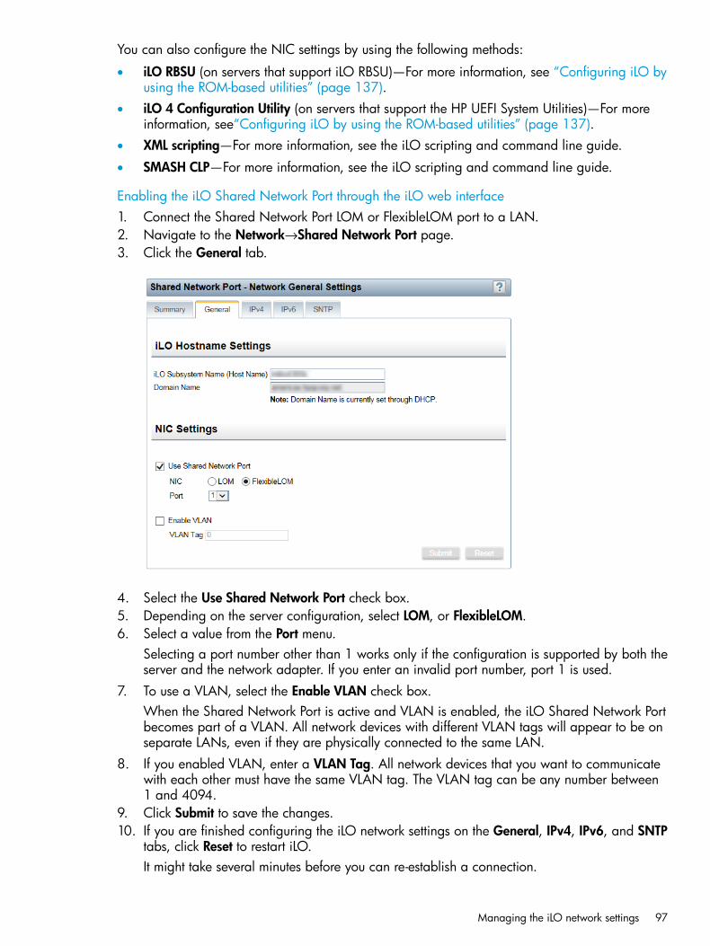
You can also configure the NIC settings by using the following methods:
• iLO RBSU (on servers that support iLO RBSU)—For more information, see “Configuring iLO byusing the ROM-based utilities” (page 137).
• iLO 4 Configuration Utility (on servers that support the HP UEFI System Utilities)—For moreinformation, see“Configuring iLO by using the ROM-based utilities” (page 137).
• XML scripting—For more information, see the iLO scripting and command line guide.
• SMASH CLP—For more information, see the iLO scripting and command line guide.
Enabling the iLO Shared Network Port through the iLO web interface1. Connect the Shared Network Port LOM or FlexibleLOM port to a LAN.2. Navigate to the Network→Shared Network Port page.3. Click the General tab.
4. Select the Use Shared Network Port check box.5. Depending on the server configuration, select LOM, or FlexibleLOM.6. Select a value from the Port menu.
Selecting a port number other than 1 works only if the configuration is supported by both theserver and the network adapter. If you enter an invalid port number, port 1 is used.
7. To use a VLAN, select the Enable VLAN check box.When the Shared Network Port is active and VLAN is enabled, the iLO Shared Network Portbecomes part of a VLAN. All network devices with different VLAN tags will appear to be onseparate LANs, even if they are physically connected to the same LAN.
8. If you enabled VLAN, enter a VLAN Tag. All network devices that you want to communicatewith each other must have the same VLAN tag. The VLAN tag can be any number between1 and 4094.
9. Click Submit to save the changes.10. If you are finished configuring the iLO network settings on the General, IPv4, IPv6, and SNTP
tabs, click Reset to restart iLO.It might take several minutes before you can re-establish a connection.
Managing the iLO network settings 97

After iLO resets, the Shared Network Port is active. Any network traffic going to or originatingfrom iLO is directed through the Shared Network Port LOM or FlexibleLOM port.
Enabling the iLO Dedicated Network Port through the iLO web interface1. Connect the iLO Dedicated Network Port to a LAN from which the server is managed.2. Navigate to the Network→iLO Dedicated Network Port page.3. Click the General tab.
4. Select the Use iLO Dedicated Network Port check box.5. Select a Link State.
The link setting controls the speed and duplex settings of the iLO network transceiver.
NOTE: This setting is not available on server blades.
The available settings follow:
• Automatic (default)—Enables iLO to negotiate the highest supported link speed and duplexsettings when connected to the network
• 1000BaseT, Full-duplex—Forces a 1 Gb connection that uses full duplex (not supportedfor BL c-Class servers)
• 1000BaseT, Half-duplex—Forces a 1 Gb connection that uses half duplex (not supportedfor BL c-Class servers)1000BaseT, Half-duplex is not a standard setting, and few switches support it. If you usethis setting, ensure that the switch is configured to support 1000BaseT, Half-duplex.
• 100BaseT, Full-duplex—Forces a 100 Mb connection using full duplex
• 100BaseT, Half-duplex—Forces a 100 Mb connection using half duplex
• 10BaseT, Full-duplex—Forces a 10 Mb connection using full duplex
• 10BaseT, Half-duplex—Forces a 10 Mb connection using half duplex6. Click Submit to save the changes.
98 Configuring iLO
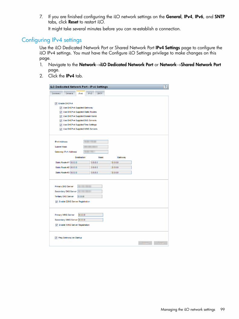
7. If you are finished configuring the iLO network settings on the General, IPv4, IPv6, and SNTPtabs, click Reset to restart iLO.It might take several minutes before you can re-establish a connection.
Configuring IPv4 settingsUse the iLO Dedicated Network Port or Shared Network Port IPv4 Settings page to configure theiLO IPv4 settings. You must have the Configure iLO Settings privilege to make changes on thispage.1. Navigate to the Network→iLO Dedicated Network Port or Network→Shared Network Port
page.2. Click the IPv4 tab.
Managing the iLO network settings 99
3. Configure the following settings:• Enable DHCPv4—Enables iLO to obtain its IP address (and many other settings) from a
DHCP server.
◦ Use DHCPv4 Supplied Gateway—Specifies whether iLO uses the DHCP server-suppliedgateway. If DHCP is not used, enter a gateway address in the Gateway IPv4 Addressbox.
◦ Use DHCPv4 Supplied Static Routes—Specifies whether iLO uses the DHCPserver-supplied static routes. If not, enter the static route destination, mask, andgateway addresses in the Static Route #1, Static Route #2, and Static Route #3 boxes.
◦ Use DHCPv4 Supplied Domain Name—Specifies whether iLO uses the DHCPserver-supplied domain name. If DHCP is not used, enter a domain name in theDomain Name box on the Network General Settings page. For more information,see “Configuring general network settings” (page 94).
◦ Use DHCPv4 Supplied DNS Servers—Specifies whether iLO uses the DHCPserver-supplied DNS server list. If not, enter the DNS server addresses in the PrimaryDNS Server, Secondary DNS Server, and Tertiary DNS Server boxes.
◦ Use DHCPv4 Supplied Time Settings—Specifies whether iLO uses the DHCPv4-suppliedNTP service locations.
◦ Use DHCPv4 Supplied WINS Servers—Specifies whether iLO uses the DHCPserver-supplied WINS server list. If not, enter the WINS server addresses in thePrimary WINS Server and Secondary WINS Server boxes.
• IPv4 Address—The iLO IP address. If DHCP is used, the iLO IP address is suppliedautomatically. If DHCP is not used, enter a static IP address.
• Subnet Mask—The subnet mask of the iLO IP network. If DHCP is used, the subnet maskis supplied automatically. If DHCP is not used, enter a subnet mask for the network.
• Gateway IPv4 Address—The iLO gateway IP address. If DHCP is used, the iLO gatewayIP address is supplied automatically. If DHCP is not used, enter the iLO gateway IP address.
• Static Route #1, Static Route #2, and Static Route #3—The iLO static route destination,mask, and gateway addresses. If Use DHCPv4 Supplied Static Routes is used, these valuesare supplied automatically. If not, enter the static route values.
• DNS server information—Enter the following information:
Primary DNS Server—If Use DHCPv4 Supplied DNS Servers is enabled, this value issupplied automatically. If not, enter the Primary DNS Server address.
◦
◦ Secondary DNS Server—If Use DHCPv4 Supplied DNS Servers is enabled, this valueis supplied automatically. If not, enter the Secondary DNS Server address.
◦ Tertiary DNS Server—If Use DHCPv4 Supplied DNS Servers is enabled, this value issupplied automatically. If not, enter the Tertiary DNS Server address.
◦ Enable DDNS Server Registration—Select or clear this check box to specify whetheriLO registers its IPv4 address and name with a DNS server.
100 Configuring iLO
• WINS server information—Enter the following information:
Primary WINS Server—If Use DHCPv4 Supplied WINS Servers is enabled, this valueis supplied automatically. If not, enter the Primary WINS Server address.
◦
◦ Secondary WINS Server—If Use DHCPv4 Supplied WINS Servers is enabled, thisvalue is supplied automatically. If not, enter the Secondary WINS Server address.
◦ Enable WINS Server Registration—Specifies whether iLO registers its name with aWINS server.
• Ping Gateway on Startup—Causes iLO to send four ICMP echo request packets to thegateway when the iLO processor initializes. This ensures that the ARP cache entry for iLOis up-to-date on the router responsible for routing packets to and from iLO.
4. Click Submit to save the changes you made on the IPv4 Settings page.5. If you are finished configuring the iLO network settings on the General, IPv4, IPv6, and SNTP
tabs, click Reset to restart iLO.It might take several minutes before you can re-establish a connection.
Configuring IPv6 settingsUse the iLO Dedicated Network Port IPv6 Settings page to configure the iLO IPv6 settings. Youmust have the Configure iLO Settings privilege to make changes on this page.When using IPv6, note the following:
• IPv6 is not supported in the Shared Network Port configuration.
• If you downgrade the iLO firmware from version 1.30 or later to version 1.2x, the IPv6 settingswill be reset to the default values.
• For a list of the iLO features that support IPv6, see “iLO features that support IPv6” (page 103).To configure the IPv6 settings:1. Navigate to the Network→iLO Dedicated Network Port page.2. Click the IPv6 tab.
Managing the iLO network settings 101
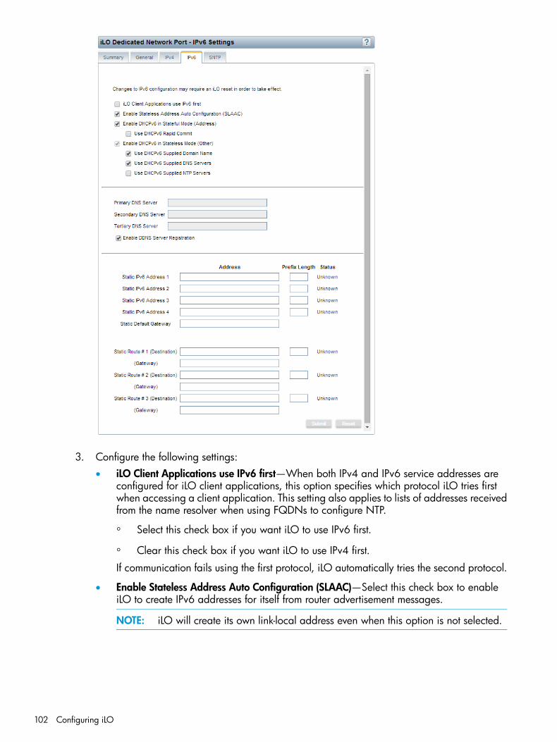
3. Configure the following settings:• iLO Client Applications use IPv6 first—When both IPv4 and IPv6 service addresses are
configured for iLO client applications, this option specifies which protocol iLO tries firstwhen accessing a client application. This setting also applies to lists of addresses receivedfrom the name resolver when using FQDNs to configure NTP.
◦ Select this check box if you want iLO to use IPv6 first.
◦ Clear this check box if you want iLO to use IPv4 first.
If communication fails using the first protocol, iLO automatically tries the second protocol.
• Enable Stateless Address Auto Configuration (SLAAC)—Select this check box to enableiLO to create IPv6 addresses for itself from router advertisement messages.
NOTE: iLO will create its own link-local address even when this option is not selected.
102 Configuring iLO
• Enable DHCPv6 in Stateful Mode (Address)—Select this check box to allow iLO to requestand configure IPv6 addresses provided by a DHCPv6 server.
◦ Use DHCPv6 Rapid Commit—Select this check box to instruct iLO to use the RapidCommit messaging mode with the DHCPv6 server. This mode reduces DHCPv6network traffic, but might cause problems if it is used in networks where more thanone DHCPv6 server can respond and provide addresses.
• Enable DHCPv6 in Stateless Mode (Other)—Select this check box to enable iLO to requestsettings for NTP and DNS service location from the DHCPv6 server.
◦ Use DHCPv6 Supplied Domain Name—Select this check box to use the DHCPv6server-supplied domain name.
◦ Use DHCPv6 Supplied DNS Servers—Select this check box to use IPv6 addressesprovided by the DHCPv6 server for DNS server locations. This setting can be enabledin addition to the IPv4 DNS server location options.
◦ Use DHCPv6 Supplied NTP Servers—Select this check box to use IPv6 addressesprovided by the DHCPv6 server for NTP server locations. This setting can be enabledin addition to the IPv4 NTP server location options.
NOTE: When Enable DHCPv6 in Stateful Mode (Address) is selected, Enable DHCPv6in Stateless Mode (Other) is always selected by default because it is implicit in the DHCPv6Stateful messages that are required between iLO and the DHCPv6 server.
• Primary DNS Server, Secondary DNS Server, and Tertiary DNS Server—Enter the IPv6addresses for the DNS service.When DNS server locations are configured in both IPv4 and IPv6, both sources are used,with preference given according to the iLO Client Applications use IPv6 first configurationoption, primary sources, then secondary, and then tertiary.
• Enable DDNS Server Registration—Specify whether iLO registers its IPv6 address andname with a DNS server.
• Static IPv6 Address 1, Static IPv6 Address 2, Static IPv6 Address 3, and Static IPv6 Address4—Enter up to four static IPv6 addresses and prefix lengths for iLO. Do not enter link-localaddresses.
• Static Default Gateway—Enter a default IPv6 gateway address for cases in which norouter advertisement messages are present in the network.
• Static Route #1, Static Route #2, and Static Route #3—Enter static IPv6 route destinationprefix and gateway address pairs. You must specify the prefix length for the destination.Link-local addresses are not allowed for the destination, but are allowed for the gateway.
4. Click Submit to save the changes you made on the IPv6 Settings page.5. If you are finished configuring the iLO network settings on the General, IPv4, IPv6, and SNTP
tabs, click Reset to restart iLO.It might take several minutes before you can re-establish a connection.
iLO features that support IPv6IPv6 is supported by iLO 4 1.20 and later in the iLO Dedicated Network Port configuration. It isnot supported with the Shared Network Port configuration. The IPv6 protocol was introduced bythe IETF in response to the ongoing depletion of the IPv4 address pool. In IPv6, addresses areincreased to 128 bits in length, to avoid an address shortage problem. iLO supports the simultaneoususe of both protocols through a dual-stack implementation. All previously available iLO featuresare still supported in IPv4.
Managing the iLO network settings 103

The following features support the use of IPv6:
• IPv6 Static Address Assignment
• IPv6 SLAAC Address Assignment
• IPv6 Static Route Assignment
• IPv6 Static Default Gateway Entry
• DHCPv6 Stateful Address Assignment
• DHCPv6 Stateless DNS, Domain Name, and NTP Configuration
• Integrated Remote Console
• Onboard Administrator Single Sign-On
• HP SIM Single Sign-On
• Web Server
• SSH Server
• SNTP Client
• DDNS Client
• RIBCL over IPv6
• SNMP
• AlertMail
• Remote Syslog
• WinDBG Support
• HPQLOCFG/HPLOMIG over an IPv6 connection
• Scriptable Virtual Media
• CLI/RIBCL key import over an IPv6 connection
• Authentication using LDAP and Kerberos over IPv6
• iLO Federation
• IPMIIPv6 support for the iLO scripting interfaces requires the following versions of the iLO utilities:
• HPQLOCFG 1.0 or later
• HP Lights-Out XML Scripting Sample bundle 4.2.0 or later
• HPONCFG 4.2.0 or later
• LOCFG.PL 4.20 or later
• HPLOMIG 4.20 or later
Configuring SNTP settingsSNTP allows iLO to synchronize its clock with an external time source. Configuring SNTP is optionalbecause the iLO date and time can also be synchronized from the following sources:
• System ROM (during POST only)
• Insight Management Agents (in the OS)
• Onboard Administrator server blades only)To configure iLO SNTP settings, you must have at least one NTP server available on yourmanagement network.
104 Configuring iLO

Primary and secondary NTP server addresses can be configured manually or via DHCP servers.If the primary server address cannot be contacted, the secondary address is used. You must havethe Configure iLO Settings privilege to change these settings.
NOTE: IPv6 is not supported in the Shared Network Port configuration.
To configure the SNTP settings:1. Navigate to the Network→iLO Dedicated Network Port or Network→Shared Network Port
page.2. Click the SNTP tab.
3. Do one of the following:• Select the Use DHCPv4 Supplied Time Settings check box, the Use DHCPv6 Supplied Time
Settings check box, or both check boxes to use DHCP-provided NTP server addresses.Note the following configuration prerequisites:
◦ To configure a DHCPv4-provided NTP service configuration, you must first enableDHCPv4 on the IPv4 tab.
◦ To configure a DHCPv6-provided NTP service configuration, DHCPv6 Stateless Modemust be enabled on the IPv6 tab.
When you use DHCP servers to provide NTP server addresses, the iLO Client Applicationsuse IPv6 first setting controls the selection of the primary and secondary NTP values.When iLO Client Applications use IPv6 first is selected on the IPv6 tab, a DHCPv6-providedNTP service address (if available) is used for the primary time server and aDHCPv4-provided address (if available) is used for the secondary time server.To change the protocol-based priority behavior to use DHCPv4 first, clear the iLO ClientApplications use IPv6 first check box.If a DHCPv6 address is not available for the primary or secondary address, a DHCPv4address (if available) is used.
• Enter NTP server addresses in the Primary Time Server and Secondary Time Server boxes.You can enter the server addresses by using the server FQDN, IPv4 address, or IPv6address.
4. If you selected only Use DHCPv6 Supplied Time Settings, or if you entered a primary andsecondary time server, select the server time zone from the Time Zone list.This setting determines how iLO adjusts UTC time to obtain the local time, and how it adjustsfor Daylight Savings Time (Summer Time). In order for the entries in the iLO Event Log and
Managing the iLO network settings 105
IML to display the correct local time, you must specify the time zone in which the server islocated.If you want iLO to use the time the SNTP server provides, without adjustment, configure iLOto use a time zone that does not apply an adjustment to UTC time. In addition, that time zonemust not apply a Daylight Savings Time (Summer Time) adjustment. There are several timezones that fit this requirement. One example is the Atlantic/Reykjavik time zone, which isneither east or west of the Prime Meridian, and in which the time does not change in thespring or fall. If you select the Atlantic/Reykjavik time zone, iLO web interface pages and logentries will display the exact time provided by the SNTP server.
NOTE: Configure the NTP servers to use Coordinated Universal Time (GMT).
5. Configure the NTP time propagation setting by selecting or clearing the Propagate NTP Timeto Host check box (ML, DL, SL, and XL servers) or the Propagate NTP or OA Time to Host checkbox (BL servers).These settings determine whether the server time is synchronized with the iLO time during thefirst POST after AC power is applied, a blade is inserted, or iLO is reset to the default settings.For server blades only: When Propagate NTP or OA Time to Host is enabled, and NTP is notconfigured or functional, the server time is synchronized with the Onboard Administrator time.
6. Click Submit to save the changes you made on the SNTP Settings page.7. If you are finished configuring the iLO network settings on the General, IPv4, IPv6, and SNTP
tabs, click Reset to restart iLO.It might take several minutes before you can re-establish a connection.
TIP: If you notice that iLO Event Log entries have an incorrect date or time, make sure that theNTP server addresses and time zone are correct. The iLO Event Log includes entries that indicatesuccess or failure when contacting the NTP server(s).
Using iLO NIC auto-selectionThe iLO NIC auto-selection feature enables iLO to automatically select between the iLO DedicatedNetwork Port and the iLO Shared Network port. At startup, iLO searches for network activity onthe available ports, and automatically selects one for use based on network activity.This feature enables you to use a common pre-configuration for all of your ProLiant Gen9 servers.For example, if you have several servers, some might be installed into a data center where iLO iscontacted by using the iLO Dedicated Network Port, and others might be installed a data centerwhere iLO is contacted by using the Shared Network Port. When you use iLO NIC auto-selection,you can install a server in either data center and iLO will select the correct network port.ProLiant Gen9 servers with iLO 4 2.00 or later support NIC auto-selection.At iLO startup, when iLO NIC auto-selection is enabled:
• If iLO was just connected to power, it tests the iLO Dedicated Network Port first.
• If iLO was just reset, it tests the last used iLO network port first.
• When testing a network port, if iLO detects network activity, then that port is selected for use.If network activity is not found after approximately 100 seconds, iLO switches to the oppositenetwork port and begins testing there. iLO alternates testing between the iLO Dedicated
106 Configuring iLO
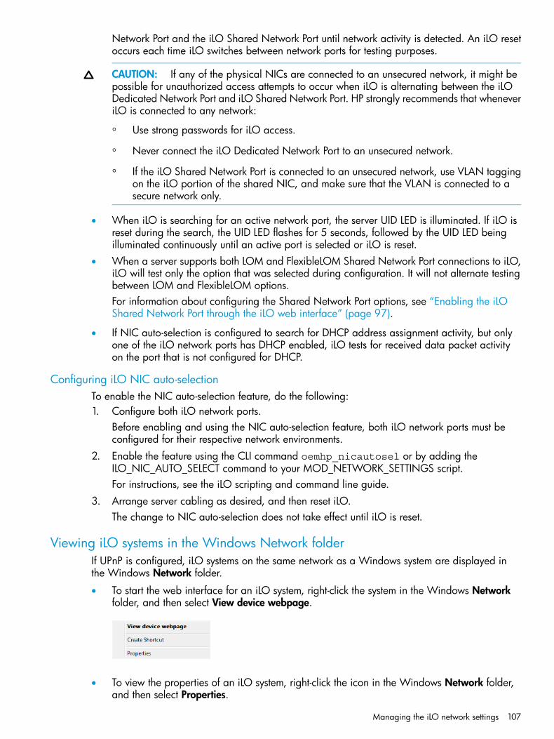
Network Port and the iLO Shared Network Port until network activity is detected. An iLO resetoccurs each time iLO switches between network ports for testing purposes.
CAUTION: If any of the physical NICs are connected to an unsecured network, it might bepossible for unauthorized access attempts to occur when iLO is alternating between the iLODedicated Network Port and iLO Shared Network Port. HP strongly recommends that wheneveriLO is connected to any network:
◦ Use strong passwords for iLO access.
◦ Never connect the iLO Dedicated Network Port to an unsecured network.
◦ If the iLO Shared Network Port is connected to an unsecured network, use VLAN taggingon the iLO portion of the shared NIC, and make sure that the VLAN is connected to asecure network only.
• When iLO is searching for an active network port, the server UID LED is illuminated. If iLO isreset during the search, the UID LED flashes for 5 seconds, followed by the UID LED beingilluminated continuously until an active port is selected or iLO is reset.
• When a server supports both LOM and FlexibleLOM Shared Network Port connections to iLO,iLO will test only the option that was selected during configuration. It will not alternate testingbetween LOM and FlexibleLOM options.For information about configuring the Shared Network Port options, see “Enabling the iLOShared Network Port through the iLO web interface” (page 97).
• If NIC auto-selection is configured to search for DHCP address assignment activity, but onlyone of the iLO network ports has DHCP enabled, iLO tests for received data packet activityon the port that is not configured for DHCP.
Configuring iLO NIC auto-selectionTo enable the NIC auto-selection feature, do the following:1. Configure both iLO network ports.
Before enabling and using the NIC auto-selection feature, both iLO network ports must beconfigured for their respective network environments.
2. Enable the feature using the CLI command oemhp_nicautosel or by adding theILO_NIC_AUTO_SELECT command to your MOD_NETWORK_SETTINGS script.For instructions, see the iLO scripting and command line guide.
3. Arrange server cabling as desired, and then reset iLO.The change to NIC auto-selection does not take effect until iLO is reset.
Viewing iLO systems in the Windows Network folderIf UPnP is configured, iLO systems on the same network as a Windows system are displayed inthe Windows Network folder.
• To start the web interface for an iLO system, right-click the system in the Windows Networkfolder, and then select View device webpage.
• To view the properties of an iLO system, right-click the icon in the Windows Network folder,and then select Properties.
Managing the iLO network settings 107
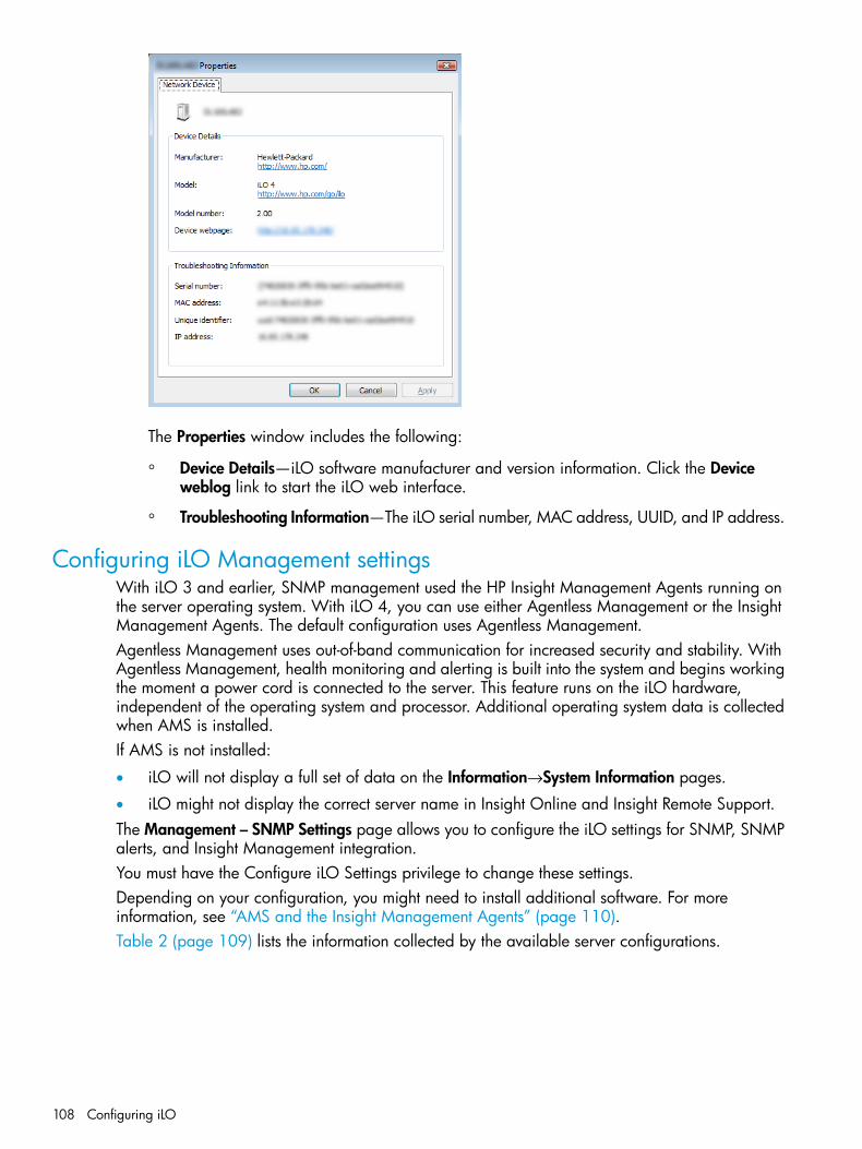
The Properties window includes the following:
◦ Device Details—iLO software manufacturer and version information. Click the Deviceweblog link to start the iLO web interface.
◦ Troubleshooting Information—The iLO serial number, MAC address, UUID, and IP address.
Configuring iLO Management settingsWith iLO 3 and earlier, SNMP management used the HP Insight Management Agents running onthe server operating system. With iLO 4, you can use either Agentless Management or the InsightManagement Agents. The default configuration uses Agentless Management.Agentless Management uses out-of-band communication for increased security and stability. WithAgentless Management, health monitoring and alerting is built into the system and begins workingthe moment a power cord is connected to the server. This feature runs on the iLO hardware,independent of the operating system and processor. Additional operating system data is collectedwhen AMS is installed.If AMS is not installed:
• iLO will not display a full set of data on the Information→System Information pages.
• iLO might not display the correct server name in Insight Online and Insight Remote Support.The Management – SNMP Settings page allows you to configure the iLO settings for SNMP, SNMPalerts, and Insight Management integration.You must have the Configure iLO Settings privilege to change these settings.Depending on your configuration, you might need to install additional software. For moreinformation, see “AMS and the Insight Management Agents” (page 110).Table 2 (page 109) lists the information collected by the available server configurations.
108 Configuring iLO
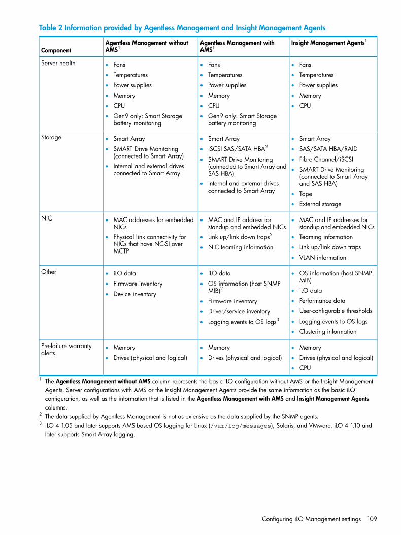
Table 2 Information provided by Agentless Management and Insight Management Agents
Insight Management Agents1Agentless Management withAMS1
Agentless Management withoutAMS1Component
Server health • Fans• Fans• Fans
• ••Temperatures TemperaturesTemperatures
•• •Power suppliesPower supplies Power supplies
••• MemoryMemoryMemory
• ••CPU CPUCPU
•• Gen9 only: Smart Storagebattery monitoring
Gen9 only: Smart Storagebattery monitoring
Storage • Smart Array• Smart Array• Smart Array
• ••SMART Drive Monitoring(connected to Smart Array)
SAS/SATA HBA/RAIDiSCSI SAS/SATA HBA2
• Fibre Channel/iSCSI• SMART Drive Monitoring(connected to Smart Array andSAS HBA)
• Internal and external drivesconnected to Smart Array • SMART Drive Monitoring
(connected to Smart Arrayand SAS HBA)• Internal and external drives
connected to Smart Array • Tape
• External storage
NIC • MAC and IP addresses forstandup and embedded NICs
• MAC and IP address forstandup and embedded NICs
• MAC addresses for embeddedNICs
• ••Physical link connectivity forNICs that have NC-SI overMCTP
Teaming informationLink up/link down traps2
• Link up/link down traps• NIC teaming information
• VLAN information
Other • OS information (host SNMPMIB)
• iLO data• iLO data
• •Firmware inventory OS information (host SNMPMIB)2 • iLO data• Device inventory
• Performance data• Firmware inventory• User-configurable thresholds• Driver/service inventory• Logging events to OS logs• Logging events to OS logs3
• Clustering information
Pre-failure warrantyalerts
• Memory• Memory• Memory
• ••Drives (physical and logical) Drives (physical and logical)Drives (physical and logical)
• CPU
1 The Agentless Management without AMS column represents the basic iLO configuration without AMS or the Insight ManagementAgents. Server configurations with AMS or the Insight Management Agents provide the same information as the basic iLOconfiguration, as well as the information that is listed in the Agentless Management with AMS and Insight Management Agentscolumns.
2 The data supplied by Agentless Management is not as extensive as the data supplied by the SNMP agents.3 iLO 4 1.05 and later supports AMS-based OS logging for Linux (/var/log/messages), Solaris, and VMware. iLO 4 1.10 and
later supports Smart Array logging.
Configuring iLO Management settings 109
AMS and the Insight Management AgentsNote the following when you consider whether to install AMS or the Insight Management Agents:
• AMS is installed automatically if you use the Intelligent Provisioning Recommended installationmethod for Windows installation.
• HP does not recommend installing AMS at the same time as the Insight Management Agentsand WMI Providers.
• When you install AMS on Windows systems, the Agentless Management Service ControlPanel is installed. You can use the Control Panel to configure SNMP settings, to enable ordisable AMS, and to remove AMS.
• AMS writes operating system configuration information and critical events to the Active HealthSystem Log.
• You must install the HP ProLiant iLO 3/4 Channel Interface Driver before installing AMS.For more information, see “iLO drivers and utilities” (page 27).
Installing AMS or the Insight Management Agents1. Obtain AMS or the Insight Management Agents from one of the following sources:
• Download the HP Service Pack for ProLiant (Windows, Red Hat Enterprise Linux, SUSELinux Enterprise Server) from the following website: http://www.hp.com/go/spp.
• Download the software from the HP Support Center (Windows, Red Hat Enterprise Linux,SUSE Linux Enterprise Server, VMware) at http://www.hp.com/go/hpsc.
• Download the software from the vibsdepot section of the Software Delivery Repositorywebsite at http://downloads.linux.hp.com/SDR/index.html (VMware).AMS is also included in the customized HP VMware ISO images that are released on HPSoftware Depot (http://www.hp.com/go/softwaredepot).
• Subscribe to the Linux Management Component Pack (Ubuntu). For more information,see http://downloads.linux.hp.com/SDR/index.html
2. Install the software.For instructions on using the SPP, see the SPP documentation at http://www.hp.com/go/spp/documentation.For other download types, follow the installation instructions provided with the software.
Verifying the AMS installationUse the following procedures to verify the AMS installation on Windows, Linux, and VMwaresystems.
Verifying AMS status: iLO web interfaceTo verify that AMS is enabled on a server:1. Navigate to the Information→System Information page.2. Click the Summary tab.
AMS is listed in the Subsystems and Devices table. The possible values follow:
• Not available—AMS is not available because it was not detected, the server is in POST,or the server is powered off.
• OK—AMS is installed and running.
110 Configuring iLO

Verifying AMS status: Windows1. Open the Windows Control Panel.
If the AMS Control Panel is present, then AMS is installed.2. Open the AMS Control Panel.3. Click the Service tab.
If AMS is enabled, the following message appears:Agentless Management Service (AMS) is enabled.
Verifying AMS status: SUSE and Red Hat Enterprise LinuxTo verify that AMS is installed, enter the following command:rpm –qi hp-ams
To verify that AMS is running, enter the following command:service hp-ams status
Verifying AMS status: VMwareTo verify that AMS is installed:1. Access the VMware host from the VMware vSphere Client.2. Navigate to the server’s Inventory→Configuration→Health Status tab.3. Click the plus sign (+) next to Software Components.
The software installed on the host is listed. The AMS component includes the string hp-ams.
NOTE: The full name of the AMS component is different for each supported version ofESX/ESXi.
To verify that AMS is running, enter the following command:/etc/init.d/hp-ams.sh status
Verifying AMS status: UbuntuTo verify that AMS is installed, enter the following command:dpkg –l hp-ams
To verify that AMS is running, enter the following command:sudo service hp-ams status
Restarting AMSTo restart AMS:
• Windows—Navigate to the Windows Services page and restart AMS.
• SUSE and Red Hat—Enter the following command: service hp-ams restart.
• VMware—Enter the following command: /etc/init.d/hp-ams.sh restart.
• Ubuntu—Enter the following command: sudo service hp-ams restart
Nagios plug-in for Agentless ManagementThe Nagios plug-in for Agentless Management interacts with the Agentless Managementinfrastructure to provide out-of-band monitoring of ProLiant Gen8 and Gen9 servers.Nagios is an open source application that can be used to monitor computer systems, networks,and IT infrastructure.
Configuring iLO Management settings 111
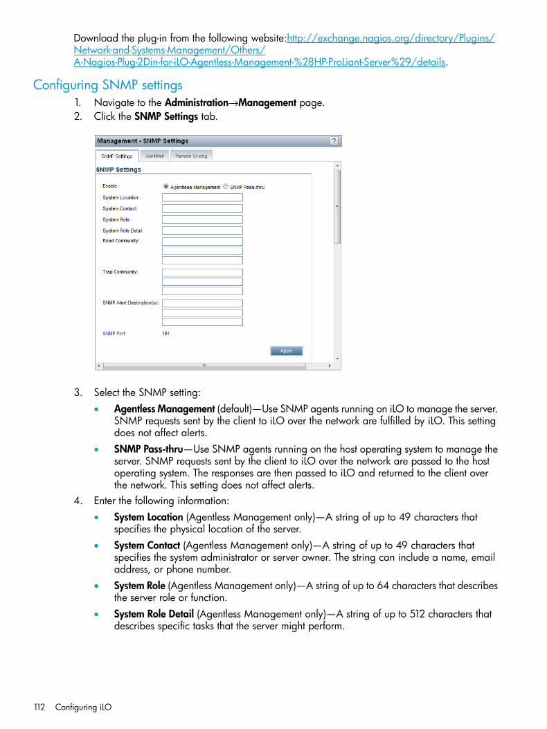
Download the plug-in from the following website:http://exchange.nagios.org/directory/Plugins/Network-and-Systems-Management/Others/A-Nagios-Plug-2Din-for-iLO-Agentless-Management-%28HP-ProLiant-Server%29/details.
Configuring SNMP settings1. Navigate to the Administration→Management page.2. Click the SNMP Settings tab.
3. Select the SNMP setting:• Agentless Management (default)—Use SNMP agents running on iLO to manage the server.
SNMP requests sent by the client to iLO over the network are fulfilled by iLO. This settingdoes not affect alerts.
• SNMP Pass-thru—Use SNMP agents running on the host operating system to manage theserver. SNMP requests sent by the client to iLO over the network are passed to the hostoperating system. The responses are then passed to iLO and returned to the client overthe network. This setting does not affect alerts.
4. Enter the following information:• System Location (Agentless Management only)—A string of up to 49 characters that
specifies the physical location of the server.• System Contact (Agentless Management only)—A string of up to 49 characters that
specifies the system administrator or server owner. The string can include a name, emailaddress, or phone number.
• System Role (Agentless Management only)—A string of up to 64 characters that describesthe server role or function.
• System Role Detail (Agentless Management only)—A string of up to 512 characters thatdescribes specific tasks that the server might perform.
112 Configuring iLO

• Read Community (Agentless Management only)—The configured SNMP read-onlycommunity string.Read Community supports the following formats:
◦ A community string (for example, public).
◦ A community string followed by an IP address or FQDN (for example, public192.168.0.1).Use this option to specify that SNMP access will be allowed from the specified IPaddress or FQDN. For iLO 4 1.10 or later, you can enter an IPv4 address, an IPv6address, or an FQDN.
• Trap Community—The configured SNMP trap community string.
• SNMP Alert Destination(s)—The IP addresses or FQDNs of up to three remote managementsystems that will receive SNMP alerts from iLO.
NOTE: Typically, you enter the HP SIM server console IP address in one of the SNMPAlert Destination(s) boxes.When SNMP Alert Destinations are configured using FQDN, and DNS provides bothIPv4 and IPv6 addresses for those FQDNs, iLO will send traps to the address specifiedby the iLO Client Applications use IPv6 first setting on the network configuration IPv6page. If iLO Client Applications use IPv6 first is selected, traps will be sent to IPv6 addresses(when available). When iLO Client Applications use IPv6 first is not selected, traps willbe sent to IPv4 addresses (when available).
• SNMP Port—The port used for SNMP communications. This value is read-only, but canbe modified on the Administration→Access Settings page.Click the SNMP Port link to navigate to the Administration→Access Settings page. Formore information, see “Configuring iLO access settings” (page 58).
5. Click Apply to save the configuration.
Configuring SNMPv3 UsersiLO 4 1.20 or later supports SNMPv3 authentication when you use Agentless Management.The following security features of SNMPv3 enable secure data collection from SNMP agents:
• Message integrity prevents tampering during packet transmission.
• Encryption prevents packet snooping.
• Authentication ensures that packets are from a valid source.By default, SNMPv3 supports the User-based Security Model. With this model, security parametersare configured at both the agent level and the manager level. Messages exchanged between theagent and the manager are subject to a data integrity check and data origin authentication.iLO supports three user profiles in which you can set the SNMPv3 USM parameters.To edit SNMPv3 user profiles:1. Navigate to the Administration→Management page.2. Click the SNMP Settings tab and scroll to the SNMPv3 Users section.
Configuring iLO Management settings 113
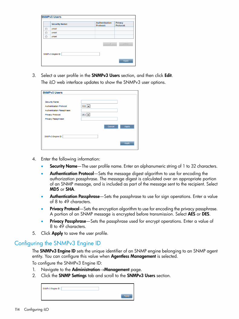
3. Select a user profile in the SNMPv3 Users section, and then click Edit.The iLO web interface updates to show the SNMPv3 user options.
4. Enter the following information:• Security Name—The user profile name. Enter an alphanumeric string of 1 to 32 characters.
• Authentication Protocol—Sets the message digest algorithm to use for encoding theauthorization passphrase. The message digest is calculated over an appropriate portionof an SNMP message, and is included as part of the message sent to the recipient. SelectMD5 or SHA.
• Authentication Passphrase—Sets the passphrase to use for sign operations. Enter a valueof 8 to 49 characters.
• Privacy Protocol—Sets the encryption algorithm to use for encoding the privacy passphrase.A portion of an SNMP message is encrypted before transmission. Select AES or DES.
• Privacy Passphrase—Sets the passphrase used for encrypt operations. Enter a value of8 to 49 characters.
5. Click Apply to save the user profile.
Configuring the SNMPv3 Engine IDThe SNMPv3 Engine ID sets the unique identifier of an SNMP engine belonging to an SNMP agententity. You can configure this value when Agentless Management is selected.To configure the SNMPv3 Engine ID:1. Navigate to the Administration→Management page.2. Click the SNMP Settings tab and scroll to the SNMPv3 Users section.
114 Configuring iLO
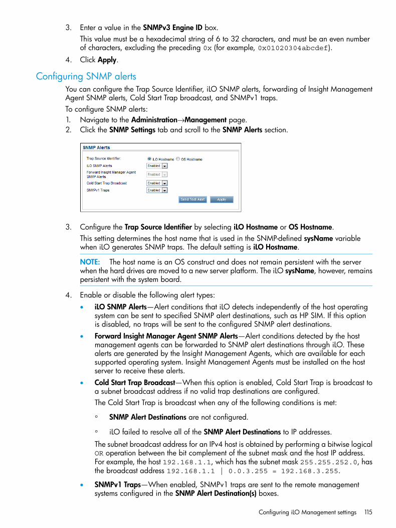
3. Enter a value in the SNMPv3 Engine ID box.This value must be a hexadecimal string of 6 to 32 characters, and must be an even numberof characters, excluding the preceding 0x (for example, 0x01020304abcdef).
4. Click Apply.
Configuring SNMP alertsYou can configure the Trap Source Identifier, iLO SNMP alerts, forwarding of Insight ManagementAgent SNMP alerts, Cold Start Trap broadcast, and SNMPv1 traps.To configure SNMP alerts:1. Navigate to the Administration→Management page.2. Click the SNMP Settings tab and scroll to the SNMP Alerts section.
3. Configure the Trap Source Identifier by selecting iLO Hostname or OS Hostname.This setting determines the host name that is used in the SNMP-defined sysName variablewhen iLO generates SNMP traps. The default setting is iLO Hostname.
NOTE: The host name is an OS construct and does not remain persistent with the serverwhen the hard drives are moved to a new server platform. The iLO sysName, however, remainspersistent with the system board.
4. Enable or disable the following alert types:• iLO SNMP Alerts—Alert conditions that iLO detects independently of the host operating
system can be sent to specified SNMP alert destinations, such as HP SIM. If this optionis disabled, no traps will be sent to the configured SNMP alert destinations.
• Forward Insight Manager Agent SNMP Alerts—Alert conditions detected by the hostmanagement agents can be forwarded to SNMP alert destinations through iLO. Thesealerts are generated by the Insight Management Agents, which are available for eachsupported operating system. Insight Management Agents must be installed on the hostserver to receive these alerts.
• Cold Start Trap Broadcast—When this option is enabled, Cold Start Trap is broadcast toa subnet broadcast address if no valid trap destinations are configured.The Cold Start Trap is broadcast when any of the following conditions is met:
◦ SNMP Alert Destinations are not configured.
◦ iLO failed to resolve all of the SNMP Alert Destinations to IP addresses.
The subnet broadcast address for an IPv4 host is obtained by performing a bitwise logicalOR operation between the bit complement of the subnet mask and the host IP address.For example, the host 192.168.1.1, which has the subnet mask 255.255.252.0, hasthe broadcast address 192.168.1.1 | 0.0.3.255 = 192.168.3.255.
• SNMPv1 Traps—When enabled, SNMPv1 traps are sent to the remote managementsystems configured in the SNMP Alert Destination(s) boxes.
Configuring iLO Management settings 115
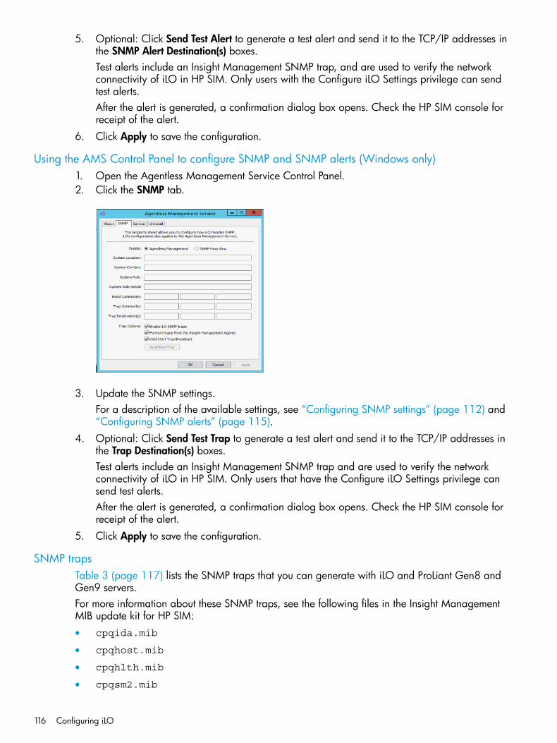
5. Optional: Click Send Test Alert to generate a test alert and send it to the TCP/IP addresses inthe SNMP Alert Destination(s) boxes.Test alerts include an Insight Management SNMP trap, and are used to verify the networkconnectivity of iLO in HP SIM. Only users with the Configure iLO Settings privilege can sendtest alerts.After the alert is generated, a confirmation dialog box opens. Check the HP SIM console forreceipt of the alert.
6. Click Apply to save the configuration.
Using the AMS Control Panel to configure SNMP and SNMP alerts (Windows only)1. Open the Agentless Management Service Control Panel.2. Click the SNMP tab.
3. Update the SNMP settings.For a description of the available settings, see “Configuring SNMP settings” (page 112) and“Configuring SNMP alerts” (page 115).
4. Optional: Click Send Test Trap to generate a test alert and send it to the TCP/IP addresses inthe Trap Destination(s) boxes.Test alerts include an Insight Management SNMP trap and are used to verify the networkconnectivity of iLO in HP SIM. Only users that have the Configure iLO Settings privilege cansend test alerts.After the alert is generated, a confirmation dialog box opens. Check the HP SIM console forreceipt of the alert.
5. Click Apply to save the configuration.
SNMP trapsTable 3 (page 117) lists the SNMP traps that you can generate with iLO and ProLiant Gen8 andGen9 servers.For more information about these SNMP traps, see the following files in the Insight ManagementMIB update kit for HP SIM:• cpqida.mib
• cpqhost.mib
• cpqhlth.mib
• cpqsm2.mib
116 Configuring iLO
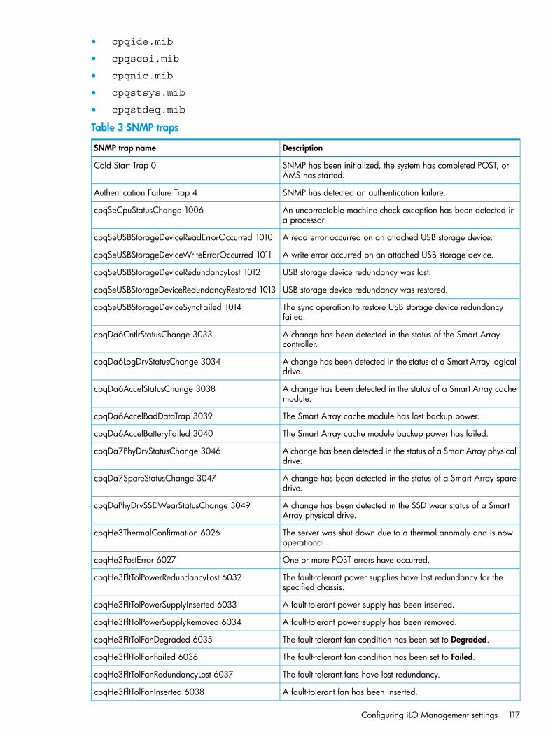
• cpqide.mib
• cpqscsi.mib
• cpqnic.mib
• cpqstsys.mib
• cpqstdeq.mib
Table 3 SNMP traps
DescriptionSNMP trap name
SNMP has been initialized, the system has completed POST, orAMS has started.
Cold Start Trap 0
SNMP has detected an authentication failure.Authentication Failure Trap 4
An uncorrectable machine check exception has been detected ina processor.
cpqSeCpuStatusChange 1006
A read error occurred on an attached USB storage device.cpqSeUSBStorageDeviceReadErrorOccurred 1010
A write error occurred on an attached USB storage device.cpqSeUSBStorageDeviceWriteErrorOccurred 1011
USB storage device redundancy was lost.cpqSeUSBStorageDeviceRedundancyLost 1012
USB storage device redundancy was restored.cpqSeUSBStorageDeviceRedundancyRestored 1013
The sync operation to restore USB storage device redundancyfailed.
cpqSeUSBStorageDeviceSyncFailed 1014
A change has been detected in the status of the Smart Arraycontroller.
cpqDa6CntlrStatusChange 3033
A change has been detected in the status of a Smart Array logicaldrive.
cpqDa6LogDrvStatusChange 3034
A change has been detected in the status of a Smart Array cachemodule.
cpqDa6AccelStatusChange 3038
The Smart Array cache module has lost backup power.cpqDa6AccelBadDataTrap 3039
The Smart Array cache module backup power has failed.cpqDa6AccelBatteryFailed 3040
A change has been detected in the status of a Smart Array physicaldrive.
cpqDa7PhyDrvStatusChange 3046
A change has been detected in the status of a Smart Array sparedrive.
cpqDa7SpareStatusChange 3047
A change has been detected in the SSD wear status of a SmartArray physical drive.
cpqDaPhyDrvSSDWearStatusChange 3049
The server was shut down due to a thermal anomaly and is nowoperational.
cpqHe3ThermalConfirmation 6026
One or more POST errors have occurred.cpqHe3PostError 6027
The fault-tolerant power supplies have lost redundancy for thespecified chassis.
cpqHe3FltTolPowerRedundancyLost 6032
A fault-tolerant power supply has been inserted.cpqHe3FltTolPowerSupplyInserted 6033
A fault-tolerant power supply has been removed.cpqHe3FltTolPowerSupplyRemoved 6034
The fault-tolerant fan condition has been set to Degraded.cpqHe3FltTolFanDegraded 6035
The fault-tolerant fan condition has been set to Failed.cpqHe3FltTolFanFailed 6036
The fault-tolerant fans have lost redundancy.cpqHe3FltTolFanRedundancyLost 6037
A fault-tolerant fan has been inserted.cpqHe3FltTolFanInserted 6038
Configuring iLO Management settings 117
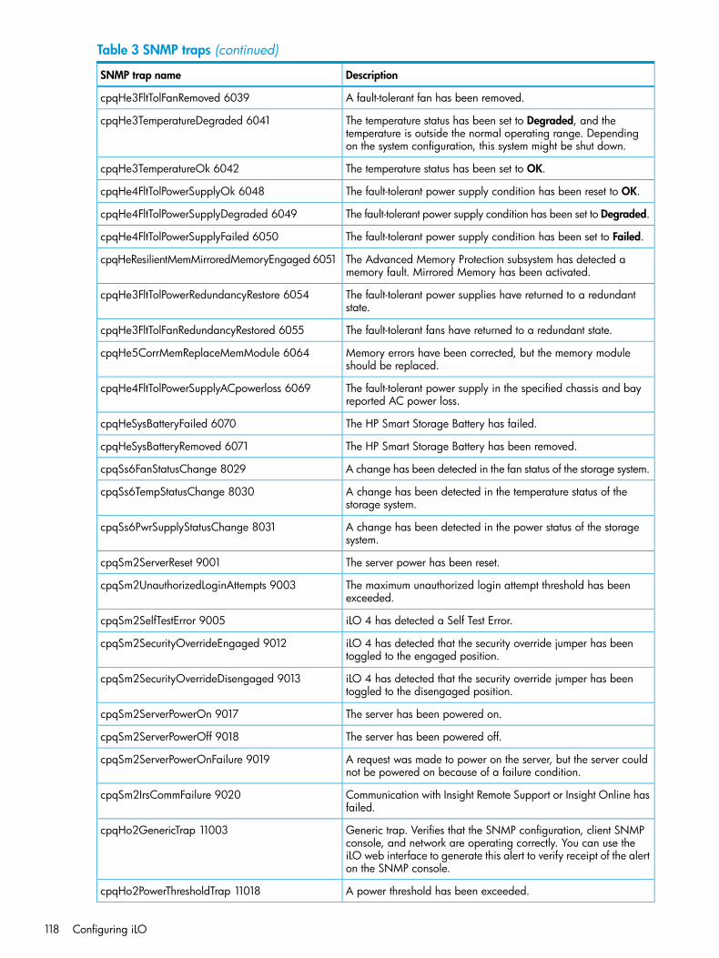
Table 3 SNMP traps (continued)
DescriptionSNMP trap name
A fault-tolerant fan has been removed.cpqHe3FltTolFanRemoved 6039
The temperature status has been set to Degraded, and thetemperature is outside the normal operating range. Dependingon the system configuration, this system might be shut down.
cpqHe3TemperatureDegraded 6041
The temperature status has been set to OK.cpqHe3TemperatureOk 6042
The fault-tolerant power supply condition has been reset to OK.cpqHe4FltTolPowerSupplyOk 6048
The fault-tolerant power supply condition has been set to Degraded.cpqHe4FltTolPowerSupplyDegraded 6049
The fault-tolerant power supply condition has been set to Failed.cpqHe4FltTolPowerSupplyFailed 6050
The Advanced Memory Protection subsystem has detected amemory fault. Mirrored Memory has been activated.
cpqHeResilientMemMirroredMemoryEngaged 6051
The fault-tolerant power supplies have returned to a redundantstate.
cpqHe3FltTolPowerRedundancyRestore 6054
The fault-tolerant fans have returned to a redundant state.cpqHe3FltTolFanRedundancyRestored 6055
Memory errors have been corrected, but the memory moduleshould be replaced.
cpqHe5CorrMemReplaceMemModule 6064
The fault-tolerant power supply in the specified chassis and bayreported AC power loss.
cpqHe4FltTolPowerSupplyACpowerloss 6069
The HP Smart Storage Battery has failed.cpqHeSysBatteryFailed 6070
The HP Smart Storage Battery has been removed.cpqHeSysBatteryRemoved 6071
A change has been detected in the fan status of the storage system.cpqSs6FanStatusChange 8029
A change has been detected in the temperature status of thestorage system.
cpqSs6TempStatusChange 8030
A change has been detected in the power status of the storagesystem.
cpqSs6PwrSupplyStatusChange 8031
The server power has been reset.cpqSm2ServerReset 9001
The maximum unauthorized login attempt threshold has beenexceeded.
cpqSm2UnauthorizedLoginAttempts 9003
iLO 4 has detected a Self Test Error.cpqSm2SelfTestError 9005
iLO 4 has detected that the security override jumper has beentoggled to the engaged position.
cpqSm2SecurityOverrideEngaged 9012
iLO 4 has detected that the security override jumper has beentoggled to the disengaged position.
cpqSm2SecurityOverrideDisengaged 9013
The server has been powered on.cpqSm2ServerPowerOn 9017
The server has been powered off.cpqSm2ServerPowerOff 9018
A request was made to power on the server, but the server couldnot be powered on because of a failure condition.
cpqSm2ServerPowerOnFailure 9019
Communication with Insight Remote Support or Insight Online hasfailed.
cpqSm2IrsCommFailure 9020
Generic trap. Verifies that the SNMP configuration, client SNMPconsole, and network are operating correctly. You can use the
cpqHo2GenericTrap 11003
iLO web interface to generate this alert to verify receipt of the alerton the SNMP console.
A power threshold has been exceeded.cpqHo2PowerThresholdTrap 11018
118 Configuring iLO
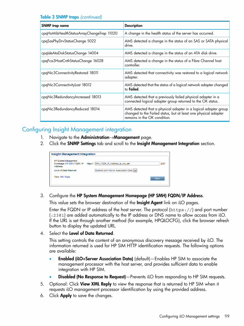
Table 3 SNMP traps (continued)
DescriptionSNMP trap name
A change in the health status of the server has occurred.cpqHoMibHealthStatusArrayChangeTrap 11020
AMS detected a change in the status of an SAS or SATA physicaldrive.
cpqSasPhyDrvStatusChange 5022
AMS detected a change in the status of an ATA disk drive.cpqIdeAtaDiskStatusChange 14004
AMS detected a change in the status of a Fibre Channel hostcontroller.
cpqFca3HostCntlrStatusChange 16028
AMS detected that connectivity was restored to a logical networkadapter.
cpqNic3ConnectivityRestored 18011
AMS detected that the status of a logical network adapter changedto Failed.
cpqNic3ConnectivityLost 18012
AMS detected that a previously failed physical adapter in aconnected logical adapter group returned to the OK status.
cpqNic3RedundancyIncreased 18013
AMS detected that a physical adapter in a logical adapter groupchanged to the Failed status, but at least one physical adapterremains in the OK condition.
cpqNic3RedundancyReduced 18014
Configuring Insight Management integration1. Navigate to the Administration→Management page.2. Click the SNMP Settings tab and scroll to the Insight Management Integration section.
3. Configure the HP System Management Homepage (HP SMH) FQDN/IP Address.This value sets the browser destination of the Insight Agent link on iLO pages.Enter the FQDN or IP address of the host server. The protocol (https://) and port number(:2381) are added automatically to the IP address or DNS name to allow access from iLO.If the URL is set through another method (for example, HPQLOCFG), click the browser refreshbutton to display the updated URL.
4. Select the Level of Data Returned.This setting controls the content of an anonymous discovery message received by iLO. Theinformation returned is used for HP SIM HTTP identification requests. The following optionsare available:
• Enabled (iLO+Server Association Data) (default)—Enables HP SIM to associate themanagement processor with the host server, and provides sufficient data to enableintegration with HP SIM.
• Disabled (No Response to Request)—Prevents iLO from responding to HP SIM requests.5. Optional: Click View XML Reply to view the response that is returned to HP SIM when it
requests iLO management processor identification by using the provided address.6. Click Apply to save the changes.
Configuring iLO Management settings 119

For more information about the Insight Management Agents, navigate to the Information→InsightAgent page.
Configuring AlertMail settingsiLO AlertMail enables you to configure iLO to send alert conditions detected independently of thehost operating system to a specified email address. iLO mail alerts include major host systemevents.You must have the Configure iLO Settings privilege to change these settings.This feature and many others are part of an iLO licensing package. For more information, see thefollowing website: http://www.hp.com/go/ilo/licensing.
Enabling AlertMail1. Navigate to the Administration→Management→AlertMail page.
2. Select the Enable iLO AlertMail check box.3. Enter the following information:
• Email Address—The destination email address for iLO email alerts. This string can be upto 63 characters and should be in standard email address format. You can enter onlyone email address.
• Sender Domain—The domain name specified in the sender (From) email address. Thesender email address is formed by using the iLO name as the host name, and the senderdomain as the domain name. This string can be up to 63 characters.
• SMTP Port—The port that the SMTP server will use for unauthenticated SMTP connections.The default value is 25.
• SMTP Server—The IP address or DNS name of the SMTP server or the MSA. This servercooperates with the MTA to deliver the email. This string can be up to 63 characters.
4. Optional: Click Send Test AlertMail to send a test message to the configured email address.This button is available only when AlertMail is enabled.
5. Click Apply to save the changes.
Disabling AlertMail1. Navigate to the Administration→Management→AlertMail page.2. Clear the Enable iLO AlertMail check box.
120 Configuring iLO
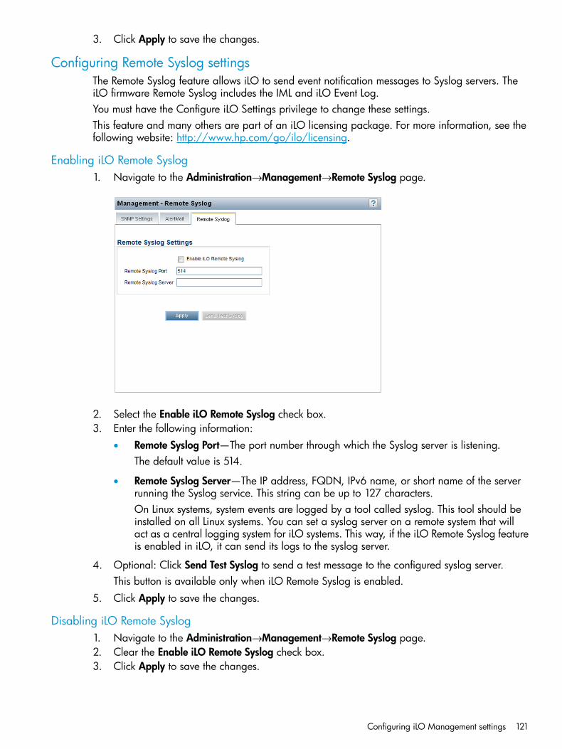
3. Click Apply to save the changes.
Configuring Remote Syslog settingsThe Remote Syslog feature allows iLO to send event notification messages to Syslog servers. TheiLO firmware Remote Syslog includes the IML and iLO Event Log.You must have the Configure iLO Settings privilege to change these settings.This feature and many others are part of an iLO licensing package. For more information, see thefollowing website: http://www.hp.com/go/ilo/licensing.
Enabling iLO Remote Syslog1. Navigate to the Administration→Management→Remote Syslog page.
2. Select the Enable iLO Remote Syslog check box.3. Enter the following information:
• Remote Syslog Port—The port number through which the Syslog server is listening.The default value is 514.
• Remote Syslog Server—The IP address, FQDN, IPv6 name, or short name of the serverrunning the Syslog service. This string can be up to 127 characters.On Linux systems, system events are logged by a tool called syslog. This tool should beinstalled on all Linux systems. You can set a syslog server on a remote system that willact as a central logging system for iLO systems. This way, if the iLO Remote Syslog featureis enabled in iLO, it can send its logs to the syslog server.
4. Optional: Click Send Test Syslog to send a test message to the configured syslog server.This button is available only when iLO Remote Syslog is enabled.
5. Click Apply to save the changes.
Disabling iLO Remote Syslog1. Navigate to the Administration→Management→Remote Syslog page.2. Clear the Enable iLO Remote Syslog check box.3. Click Apply to save the changes.
Configuring iLO Management settings 121

Embedded remote support
HP remote supportiLO 4 includes the embedded remote support feature, which allows you to register supportedservers for HP remote support. You can also use iLO to monitor service events and remote supportdata collections.When you use the embedded remote support feature, choose from the following configurationoptions: Insight Online direct connect and Insight Remote Support central connect.
Insight Online direct connectRegister a server to communicate directly with Insight Online without the need to set up an InsightRemote Support centralized Hosting Device in your local environment. Insight Online will be yourprimary interface for remote support information.Insight Online is an HP Support Center feature that enables you to view your remotely monitoreddevices anywhere, anytime. It provides a personalized dashboard for simplified tracking of IToperations and support information, including a mobile dashboard for monitoring when you areon the go.Figure 3 (page 122) shows the direct connect configuration with a server.
Figure 3 Insight Online direct connect
ProLiant server Firewall
Insight Remote Support central connectRegister a server to communicate with HP through an Insight Remote Support centralized HostingDevice in your local environment. All configuration and service event information is routed throughthe Hosting Device. This information can be viewed using the local Insight RS Console or theweb-based view in Insight Online (if it is enabled in Insight RS).Figure 4 (page 122) shows the central connect configuration with a server.
Figure 4 Insight Remote Support central connect
ProLiantserver
FirewallInsight RSHosting Device
122 Configuring iLO

Device support
Insight Online direct connectThe following device types support direct connect registration:• ProLiant Gen8 servers
• ProLiant Gen9 servers
Insight Remote Support central connectThe following device types support central connect registration:• ProLiant Gen8 servers
• ProLiant Gen9 servers
Software support
iLO firmwareTo address third-party software vulnerabilities, HP recommends using iLO 4 2.03 or later.For ProLiant Gen8 servers:
• Version 1.40 or later is required for Insight Online direct connect registration.
• Version 1.10 or later is required for Insight Remote Support central connect registration.For ProLiant Gen9 servers:
• Version 2.00 or later is required for remote support registration.
Insight Remote Support (central connect only)For Insight RS device support information, see the following website: http://h17007.www1.hp.com/us/en/enterprise/servers/supportmatrix/insight_rs.aspx.
Data collected by Insight Remote SupportBy registering for Insight Remote Support, you agree to send registration, service events,configuration, and Active Health System data to HP. All data collected and sent to HP will be usedto provide remote support and quality improvement. The collected data is managed according tothe HP privacy statement, available at http://www.hp.com/go/privacy.When a server is registered for Insight Remote Support, iLO or the Insight RS Hosting Device sendsActive Health System information to HP every 7 days, and sends configuration information every30 days. The following information is sent to HP:
• Registration—During server registration, iLO collects data to uniquely identify the serverhardware. This data is sent to the Insight RS Hosting Device (Insight Remote Support centralconnect) or directly to HP (Insight Online direct connect).Registration data includes the following:
◦ Server model
◦ Serial number
◦ iLO NIC address
Embedded remote support 123
For more information about registering for Remote Support, see “Registering for Insight RemoteSupport central connect” (page 129) or “Registering for Insight Online direct connect” (page126).
• Service events—When service events are recorded, iLO collects data to uniquely identify therelevant hardware component. This data is sent to the Insight RS Hosting Device (Insight RemoteSupport central connect) or directly to HP (Insight Online direct connect).Service event data includes the following:
◦ Server model
◦ Serial number
◦ Part number of the hardware component
◦ Description, location, and other identifying characteristics of the hardware component
For more information, see “Working with Insight Remote Support service events” (page 131).
• Configuration—During data collection, iLO collects data to enable proactive advice andconsulting. This data is sent to the Insight RS Hosting Device (Insight Remote Support centralconnect) or directly to HP (Insight Online direct connect).Configuration data includes the following:
◦ Server model
◦ Serial number
◦ Processor model, speed, and utilization
◦ Storage capacity, speed, and utilization
◦ Memory capacity, speed, and utilization
◦ Firmware/BIOS
◦ Installed drivers, services, and applications (if AMS is installed)
For more information, see “Remote Support data collection” (page 134).
• Active Health System—During data collection, iLO collects data about the health, configuration,and runtime telemetry of the server. This information is used for troubleshooting issues andclosed-loop quality analysis.For information about the data that is collected, see “HP Active Health System” (page 184).
Using HP remote support with HP Proactive Care serviceHP Proactive Care service customers must register their ProLiant Gen8 and Gen9 servers for InsightRemote Support central connect or Insight Online direct connect in order to receive the followingProactive Care features: Proactive Scan and Firmware/Software Version Report andrecommendations.
• The direct connect option requires the installation of AMS.
• The central connect option requires the installation of AMS or the SNMP/WBEM agents.For more information about the Proactive Care service, see the following website: http://www.hp.com/services/proactivecarecentral.
124 Configuring iLO
Prerequisites for HP remote support registration• The server meets the network requirements for remote support registration.
For more information, see the Insight Remote Support and Insight Online setup guide at thefollowing website: http://www.hp.com/go/ilo/docs.
• A supported version of the iLO firmware is installed.To address third-party software vulnerabilities, HP recommends using iLO 4 2.03 or later. Formore information, see “Software support” (page 123).
• Optional: AMS is installed and the operating system is running on the server that you wantto register.HP recommends installing AMS.For more information, see “AMS and the Insight Management Agents” (page 110).HP Proactive Care services customers only: AMS installation is required in order to receivethe following Proactive Care features: Proactive Scan and Firmware/Software Version Reportand recommendations.AMS is one way in which iLO can obtain the server name. If iLO cannot obtain the servername, the displayed server name in Insight Online and Insight RS is derived from the serverserial number.
• If you do not install AMS, do one of the following to ensure that the server name is displayedcorrectly in Insight Online and Insight RS:
◦ For Windows systems only, start the operating system. Insight Online and Insight RS willuse the Windows computer name to identify the server.
◦ Configure the Server Name on the Administration→Access Settings page in the iLO webinterface.The server name is displayed in Insight Online and Insight RS, and can be viewed by HPSupport and your authorized service provider, reseller/distributor, and installer. To protectyour privacy, do not use sensitive information in the server name.
• The HP ProLiant iLO 3/4 Channel Interface Driver is installed.This driver is standard for SUSE Linux Enterprise Server 11 and 12 and Red Hat EnterpriseLinux 6 and 7.For more information, see “iLO drivers and utilities” (page 27).
• The iLO time zone is set.For instructions, see “Configuring SNTP settings” (page 104).
• For Insight Online direct connect only: A DNS server is configured in iLO.This is required for communication between iLO and Insight Online.For instructions, see “Configuring IPv4 settings” (page 99) and “Configuring IPv6 settings”(page 101).
• For Insight Remote Support central connect only: A supported version of the Insight RS softwareis installed and configured on the Insight RS Hosting Device. For more information, see“Software support” (page 123).
• For Insight Remote Support central connect only: The RIBCL protocol credentials for the serverare configured in the Insight RS Console.For more information about the RIBCL protocol credentials, see the Insight Remote Supportinstallation and configuration guide.
Embedded remote support 125

Registering for Insight Remote Support by using the iLO web interfaceInsight Remote Support provides automatic submission of hardware events to HP to prevent downtimeand enable faster issue resolution. You can register directly to HP or through an Insight RS HostingDevice.
Registering for Insight Online direct connectUse this procedure to register a ProLiant server for Insight Online direct connect. When you registerfor Insight Online direct connect, you must complete steps in both the iLO web interface and theInsight Online portal.You must have the Configure iLO Settings privilege to modify the iLO remote support settings.1. Verify that the server meets the prerequisites described in “Prerequisites for HP remote support
registration” (page 125).2. Navigate to the Remote Support→Registration page.3. Select Register this server directly to HP.
4. Enter your HP Passport credentials in the HP Passport User ID and HP Passport Passwordboxes.
IMPORTANT: In most cases, your HP Passport user ID is the same as the email address youused during the HP Passport registration process. If you changed your user ID in the HP SupportCenter, be sure to enter your user ID and not your email address.
126 Configuring iLO
5. Optional: Enter the following information if the server uses a web proxy server to access theInternet:• Web Proxy Server
• Web Proxy Port
• Web Proxy Username
• Web Proxy Password6. Select the check box I accept the terms and conditions of the HP Software License Agreement
and the HP Insight Management Additional License Authorization.You can view these documents at http://www.hp.com/go/SWLicensing.
7. Click Register.Clicking Register is Step 1 of a two-step registration process. Step 2 is completed in InsightOnline.By registering, you agree to send registration, service events, configuration, and Active HealthSystem data to HP. For more information about the type of data collected, see “Data collectedby Insight Remote Support” (page 123). All data collected and sent to HP will be managedaccording to the HP privacy statement, which you can review at the following website: http://www.hp.com/go/privacy.iLO notifies you that Step 1 of the registration process is completed, and prompts you tocomplete Step 2.Allow up to 5 minutes for your registration request to be fully processed.
8. Navigate to the Insight Online website at http://www.hp.com/go/InsightOnline, and thenlog in with your HP Passport account credentials.
9. Follow the onscreen instructions in Insight Online, and provide your site, contact, and partnerinformation so HP can deliver service for your server.
TIP: To streamline the process when you have multiple servers to register, complete Step 1for all of the servers, and then complete Step 2 for all of the servers during one Insight Onlinesession.
For detailed instructions, see the Insight Remote Support and Insight Online setup guide forProLiant servers and BladeSystem c-Class enclosures.
10. Return to the Remote Support→Registration page in the iLO web interface, select the checkbox Please confirm that you have completed the registration process in HP Insight Online, andthen click Apply.
Embedded remote support 127
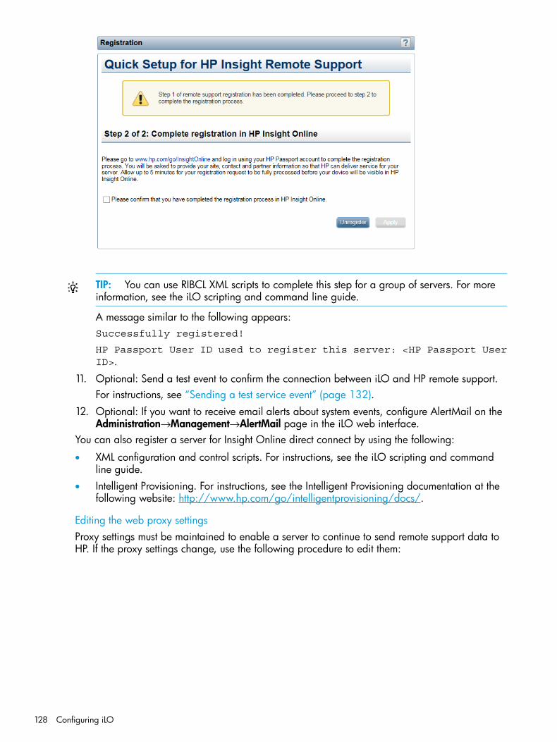
TIP: You can use RIBCL XML scripts to complete this step for a group of servers. For moreinformation, see the iLO scripting and command line guide.
A message similar to the following appears:Successfully registered!
HP Passport User ID used to register this server: <HP Passport UserID>.
11. Optional: Send a test event to confirm the connection between iLO and HP remote support.For instructions, see “Sending a test service event” (page 132).
12. Optional: If you want to receive email alerts about system events, configure AlertMail on theAdministration→Management→AlertMail page in the iLO web interface.
You can also register a server for Insight Online direct connect by using the following:
• XML configuration and control scripts. For instructions, see the iLO scripting and commandline guide.
• Intelligent Provisioning. For instructions, see the Intelligent Provisioning documentation at thefollowing website: http://www.hp.com/go/intelligentprovisioning/docs/.
Editing the web proxy settingsProxy settings must be maintained to enable a server to continue to send remote support data toHP. If the proxy settings change, use the following procedure to edit them:
128 Configuring iLO

1. Navigate to the Remote Support→Registration page.
2. Update the following settings, as needed:• Web Proxy Server
• Web Proxy Port
• Web Proxy Username
• Web Proxy Password3. Click Apply.
Registering for Insight Remote Support central connect1. Verify that the server meets the prerequisites described in “Prerequisites for HP remote support
registration” (page 125).2. Navigate to the Remote Support→Registration page.
You must have the Configure iLO Settings privilege to modify the iLO remote support settings.3. Select Register this server through an HP Insight Remote Support centralized hosting device.
Embedded remote support 129

4. Enter the Insight RS Hosting Device hostname or IP address and Port number.The default port is 7906.
5. Click Register.By registering, you agree to send registration, service events, configuration, and Active HealthSystem data to HP. For more information about the type of data collected, see “Data collectedby Insight Remote Support” (page 123). All data collected and sent to HP will be managedaccording to the HP privacy statement, which you can review at the following website: http://www.hp.com/go/privacy.A message similar to the following appears:Successfully registered! Insight Remote Support hosting server:<cms.mycompany.com:port>.
where <cms.mycompany.com:port> is the Insight RS Hosting Device host name or IPaddress and port number.
6. Optional: Send a test event to confirm the connection between iLO and Insight Remote Support.For instructions, see “Sending a test service event” (page 132).
You can also register a server for Insight Remote Support central connect by using the following:
• XML configuration and control scripts. For instructions, see the iLO scripting and commandline guide.
• Intelligent Provisioning. For instructions, see the Intelligent Provisioning documentation at thefollowing website: http://www.hp.com/go/intelligentprovisioning/docs/.
• Insight RS Console. For instructions, see the Insight Remote Support monitored devicesconfiguration guide.
130 Configuring iLO

Unregistering from Insight Remote Support by using the iLO web interfaceThe process to unregister from remote support depends on whether you used the direct connect orcentral connect registration method.
Unregistering from Insight Online direct connect1. Navigate to the Remote Support→Registration page in the iLO web interface.
You must have the Configure iLO Settings privilege to modify the iLO remote support settings.2. Click Unregister.
iLO prompts you to confirm the request.3. Click OK.
The following message appears:This server is not registered.
Unregistering from Insight Remote Support central connect1. Log in to the Insight RS Console.2. Do one of the following:
• To stop monitoring a server temporarily, select the server on the Devices→Device Summarytab in the Insight RS Console, and then select ACTIONS→DISABLE SELECTED.Unregistering the server directly from the iLO web interface is the same as temporarilydisabling the server in the Insight RS Console.
• To stop monitoring a server permanently, delete the server from the Insight RS Console.To delete the server, select it on the Device Summary tab, and then selectACTIONS→DELETE SELECTED.
3. Navigate to the Remote Support→Registration page in the iLO web interface.4. Verify that the server is unregistered.
Working with Insight Remote Support service eventsUse the Remote Support →Service Events page to monitor service events, send test events, and setmaintenance mode. You must have the Configure iLO Settings privilege to make changes on thispage.When iLO detects a hardware failure—for example, a problem with a memory DIMM or fan—aservice event is generated. When a server is registered for Insight Remote Support, the serviceevent details are recorded in the Service Event Log, and the service event is sent to directly to InsightOnline (direct connect) or to the Insight RS Hosting Device (central connect) which forwards it toHP. When HP receives a service event, a support case is opened (if warranted).
Using maintenance modeUse maintenance mode when you are performing maintenance on a server. In maintenance mode,any events or messages that are sent to Insight RS or Insight Online are flagged to indicate thatthe event requires no action. This helps HP to determine whether to open a support case.1. Navigate to the Remote Support→Service Events page.2. Select the Set Maintenance Mode check box.3. Select a time from the Expires in menu.
Embedded remote support 131

4. Click Apply.iLO displays the following message:Server Maintenance Mode set.
Maintenance mode ends automatically when the specified amount of time has passed. Thefollowing message appears:Server Maintenance Mode cleared.
TIP: To end maintenance mode early, select the Clear Maintenance Mode check box, andthen click Apply.
Sending a test service eventYou can send a test event to verify that your remote support configuration is working correctly.1. Navigate to the Remote Support→Service Events page.2. Click Send Test Event.
The following message appears:Are you sure you want to send a test event?
3. Click OK.When the transmission is completed, the test event is listed in the Service Event Log, the InsightRS Console (central connect only), and Insight Online.If the test is successful, the Submit Status in the Service Event Log displays the text No Error.
The Time Generated column in the Service Event Log shows the date and time based on theconfigured iLO time zone.
Viewing the Service Event LogTo view the Service Event Log, navigate to the Remote Support→Service Events page.
132 Configuring iLO

The Service Event Log displays the following information for each service event:
• Identifier—A unique string that identifies the service event.
• Time Generated—The time the service event was generated. This column shows the date andtime based on the configured iLO time zone.
• Event ID—A unique number for the service event type. Table 4 (page 133) lists the possibleservice events.
Table 4 Service event types
DescriptionEvent ID
Generic Test Service Event1
Fan Failed Service Event100
System Battery Failed Service Event101
Power Supply Failed Service Event200
Physical Disk Drive Service Event300
Smart Array Controller Accelerator Battery Failure Event301
Smart Array Controller Accelerator Board Status Changed Event302
Smart Array Controller Status Changed Event303
SAS Physical Drive Status Changed Event304
Memory Module Failed or Predicted to Fail Event400
Storage System Fan Status Changed Event500
Storage System Power Supply Status Changed Event501
• Perceived Severity—The severity of the event indication (for example, 5-Major, 7-Fatal).
• Submit Status—The status of the event submission. If the status is No error, the event wassubmitted successfully.
Embedded remote support 133

• Destination—For Insight Remote Support central connect configurations, the host name or IPaddress and port of the Insight RS Hosting Device that received the service event. For InsightOnline direct connect configurations, the value HP Insight Online is displayed.
• Event Category—The category of the event that matches the Message ID description in themessage registry.
Clearing the Service Event Log1. Navigate to the Remote Support→Service Events page.2. Click Clear Event Log.
The following message appears:Are you sure you want to clear the Service Event Log?
3. Click OK.The following message appears:Service Event Log has been cleared.
Remote Support data collectionUse the Remote Support→Data Collections page to view information about the data that is sent toHP when a server is registered for remote support. You can also use this page to send data collectioninformation to HP manually if a device configuration changes and you do not want to wait for thenext scheduled data collection transmission.
Data collection informationDepending on whether you use Insight Online direct connect or Insight Remote Support centralconnect, iLO or the Insight RS Hosting Device sends configuration information to HP for analysisand proactive services in accordance with your warranty and service agreements.
• For Insight Online direct connect, this data is transmitted every 30 days. You cannot edit ordelete the data collection schedule.
• For Insight Remote Support central connect, the data transmission frequency is configured inthe Insight RS Console. For information about configuring the data collection schedule, seethe Insight RS online help.
Active Health System reportingDepending on whether you use Insight Online direct connect or Insight Remote Support centralconnect, iLO or the Insight RS Hosting Device sends information about the server’s health,configuration, and run-time telemetry to HP. This information is used for troubleshooting issues andclosed-loop quality analysis.
• For Insight Online direct connect configurations, this data is transmitted every 7 days. Youcannot edit or delete the data collection schedule.
• For Insight Remote Support central connect, this data is transmitted every 7 days. You canchange the day of the week for data collection transmission in the Insight RS Console. Forinformation about configuring the data collection schedule, see the Insight RS online help.
134 Configuring iLO

Sending data collection information1. Navigate to the Remote Support→Data Collections page.
You must have the Configure iLO Settings privilege to send data collection information.
2. Click Send Data Collection.iLO prompts you to confirm the request.
3. Click OK.When the transmission is completed, the Last Data Collection Transmission and Last DataCollection Transmission Status are updated. The date and time are based on the configurediLO time zone.
Viewing data collection status in iLONavigate to the Remote Support→Data Collections page.The Data Collection Information section displays the following information:
• Last Data Collection Transmission—The date and time of the last data collection.
• Last Data Collection Transmission Status—The status of the last data transmission.
• Data Collection Frequency (days) (Insight Online direct connect only)—The frequency (in days)at which data is sent to HP.
• Next Data Collection Scheduled (Insight Online direct connect only)—The next date and timewhen data will be sent to HP.
Embedded remote support 135

Sending Active Health System reporting information1. Navigate to the Remote Support→Data Collections page.
You must have the Configure iLO Settings privilege to send data collection information.
2. Click Send Active Health System Report.iLO prompts you to confirm the request.
3. Click OK.The collected data includes Active Health System information from the last 7 days.When the transmission is completed, the Last Active Health System Reporting Transmissionand Last Active Health System Reporting Transmission Status are updated. The date and timeare based on the configured iLO time zone.
NOTE: You can also download Active Health System information manually and send it to HP.For instructions, see “HP Active Health System” (page 184).
Viewing Active Health System reporting status in iLONavigate to the Remote Support→Data Collections page.The Active Health System Reporting Information section displays the following information:
• Last Active Health System Reporting Transmission—The date and time of the last Active HealthSystem report.
• Last Active Health System Reporting Transmission Status—The status of the last datatransmission.
• Active Health System Reporting Frequency (days) (Insight Online direct connect only)—Thefrequency (in days) at which Active Health System data is sent to HP.
• Next Active Health System Reporting Scheduled (Insight Online direct connect only)—The nextdate and time when Active Health System data will be sent to HP.
136 Configuring iLO

Configuring iLO by using the ROM-based utilitiesYou can use ROM-based utilities to configure iLO. The ROM-based utility embedded in the systemROM of your ProLiant server depends on your server model.
• ProLiant Gen8 servers, except for the DL580 Gen8 server, have the iLO RBSU softwareembedded in the system ROM.For information about using iLO RBSU, see “Using the iLO RBSU” (page 137).
• ProLiant Gen9 servers and the DL580 Gen8 server have the UEFI System Utilities softwareembedded in the system ROM.For information about using the iLO 4 Configuration Utility in the UEFI System Utilities, see“Using the UEFI System Utilities iLO 4 Configuration Utility” (page 140).
Using the iLO RBSUThis section provides general use instructions and instructions for configuring iLO with the iLORBSU. For other iLO setup and troubleshooting procedures that you can perform with the iLO RBSU,see the following:
• “Setting up iLO by using iLO RBSU or the iLO 4 Configuration Utility” (page 22)
• “Troubleshooting” (page 313)
Accessing the iLO RBSUYou can access the iLO RBSU from the physical system console, or by using an iLO remote consolesession.To access iLO RBSU:1. Optional: If you access the server remotely, start an iLO remote console session.
You can use the .NET IRC or Java IRC.2. Restart or power on the server.3. Press F8 in the ProLiant POST screen to start the iLO RBSU.4. Select an option, and then press Enter.
You can use iLO RBSU to perform the following tasks:
• Configuring NIC and TCP/IP settings
• Configuring DNS/DHCP settings
• Configuring global settings by using iLO RBSU
• Configuring serial CLI options by using iLO RBSU
• Resetting iLO to the factory default settings by using iLO RBSU
• Managing iLO user accounts by using iLO RBSU
Configuring NIC and TCP/IP settingsYou can use the iLO RBSU Network menu to configure basic iLO network options, including NICand TCP/IP settings.To configure NIC and TCP/IP settings:1. Optional: If you access the server remotely, start an iLO remote console session.
You can use the .NET IRC or Java IRC.2. Restart or power on the server.3. Press F8 in the ProLiant POST screen to start the iLO RBSU.4. Select Network→NIC and TCP/IP.
Configuring iLO by using the ROM-based utilities 137

5. From the Network Configuration screen, view or update the following values, as needed:• MAC Address (read-only)—The MAC address of the selected iLO network interface.
• Network Interface Adapter—Specifies the iLO network interface adapter to use. SelectON to enable the iLO Dedicated Network Port. Select a Shared Network Port option touse the Shared Network Port. Selecting OFF disables all network interfaces to iLO.The Shared Network Port option is available only on supported servers.For more information about the iLO network interface adapter settings, see “iLO networkport configuration options” (page 96).
• Transceiver Speed Autoselect (iLO Dedicated Network port only)—Enables iLO to negotiatethe highest supported link speed and duplex settings when connected to the network. Thisoption is available only when Network Interface Adapter is set to ON.
• Transceiver Speed Manual Setting (iLO Dedicated Network Port only)—Sets the link speedfor the iLO network interface. This option is available only when Network Interface Adapteris set to ON and Transceiver Speed Autoselect is set to OFF.
• Transceiver Duplex Setting (iLO Dedicated Network Port only)—Sets the link duplex settingfor the iLO network interface. This option is available only when Network Interface Adapteris set to ON and Transceiver Speed Autoselect is set to OFF.
• VLAN Enable (Shared Network Port only)—Enables the VLAN feature.When the Shared Network Port is active and VLAN is enabled, the iLO Shared NetworkPort becomes part of a VLAN. All network devices with different VLAN tags will appearto be on separate LANs, even if they are physically connected to the same LAN. Thisoption is available only when Network Interface Adapter is set to Shared Network Port.
• VLAN ID (Shared Network Port only)—If you enabled VLAN, enter a VLAN tag. All networkdevices that you want to communicate with each other must have the same VLAN tag.The VLAN tag can be any number between 1 and 4094. This option is available onlywhen Network Interface Adapter is set to a Shared Network Port option.
• IP Address—The iLO IP address. If DHCP is used, the iLO IP address is suppliedautomatically. If DHCP is not used, enter a static IP address.
• Subnet Mask—The subnet mask of the iLO IP network. If DHCP is used, the subnet maskis supplied automatically. If DHCP is not used, enter a subnet mask for the network.
• Gateway IP Address—The iLO gateway IP address. If DHCP is used, the iLO gateway IPaddress is supplied automatically. If DHCP is not used, enter the iLO gateway IP address.
6. Press F10 to save your changes.7. Select File→Exit.
Configuring DNS/DHCP settingsYou can use the iLO RBSU Network menu to configure basic iLO network options, including DNSand DHCP settings.To configure DNS and DHCP settings:1. Optional: If you access the server remotely, start an iLO remote console session.
You can use the .NET IRC or Java IRC.2. Restart or power on the server.3. Press F8 in the ProLiant POST screen to start the iLO RBSU.4. Select Network→DNS/DHCP.
138 Configuring iLO

5. From the Network Autoconfiguration screen, view or update the following values, as needed:• DHCP Enable—Configures iLO to obtain its IP address (and many other settings) from a
DHCP server.• DNS Name—The DNS name of the iLO subsystem (for example, subsystem instead of
subsystem.example.com).This name can be used only if DHCP and DNS are configured to connect to the iLOsubsystem name instead of the IP address.
6. Press F10 to save your changes.7. Select File→Exit.
Configuring global settings by using iLO RBSU1. Optional: If you will access the server remotely, start an iLO remote console session.
You can use the .NET IRC or Java IRC.2. Restart or power on the server.3. Press F8 in the ProLiant POST screen to start the iLO RBSU.4. Select Settings→Configure, and then press Enter.5. From the Global iLO 4 Settings screen, select an option and press the spacebar to toggle the
setting to ENABLED or DISABLED. You can change the following values:• iLO Functionality
• iLO 4 ROM-Based Setup Utility
• Require iLO 4 RBSU Login
• Show iLO 4 IP during POST
• Local UsersFor more information about the first four options in the list, see “Configuring access options”(page 60).For more information about the last option in the list, see “Configuring authentication anddirectory server settings” (page 74).
6. Press F10 to save the settings.7. Select File→Exit to close iLO RBSU.
Configuring serial CLI options by using iLO RBSU1. Optional: If you access the server remotely, start an iLO remote console session.
You can use the .NET IRC or Java IRC.2. Restart or power on the server.3. Press F8 in the ProLiant POST screen to start the iLO RBSU.4. Select Settings→CLI, and then press Enter.5. From the Configure iLO Command-Line Interface screen, select an option and press the spacebar
to toggle through the available settings. You can change the following values:• Serial CLI Status
• Serial CLI Speed (bits/second)For more information about these options, see “Configuring iLO access settings” (page 58).
6. Press F10 to save the changed settings.7. Select File→Exit to close iLO RBSU.
Configuring iLO by using the ROM-based utilities 139
Using the UEFI System Utilities iLO 4 Configuration UtilityFor general instructions about using the UEFI System Utilities, see the UEFI System Utilities userguide.This section provides general use instructions and instructions for configuring iLO with the iLO 4Configuration Utility. For other iLO setup and troubleshooting procedures that you can performwith the iLO 4 Configuration Utility, see the following:
• “Setting up iLO by using iLO RBSU or the iLO 4 Configuration Utility” (page 22)
• “Troubleshooting” (page 313)
Accessing the iLO 4 Configuration Utility menuYou can access the iLO 4 Configuration Utility from the physical system console, or by using aniLO remote console session.1. Optional: If you access the server remotely, start an iLO remote console session.
You can use the .NET IRC or Java IRC.2. Restart or power on the server.3. Press F9 in the ProLiant POST screen to start the UEFI System Utilities.4. From the System Utilities screen, select System Configuration→iLO 4 Configuration Utility.5. From the iLO 4 Configuration Utility screen, select an option and press Enter.
Use the iLO 4 Configuration Utility to perform the following tasks:
• Configuring Network Options
• Configuring Advanced Network Options
• Managing iLO user accounts by using the iLO 4 Configuration Utility
• Configuring access settings by using the iLO 4 Configuration Utility
• Viewing information about iLO by using the iLO 4 Configuration Utility
• Resetting iLO to the factory default settings by using the iLO 4 Configuration Utility
• Resetting iLO by using the iLO 4 Configuration Utility
Configuring Network OptionsUse the iLO 4 Configuration Utility Network Options menu to configure basic iLO network options.1. Optional: If you access the server remotely, start an iLO remote console session.
You can use the .NET IRC or Java IRC.2. Restart or power on the server.3. Press F9 in the ProLiant POST screen to start the UEFI System Utilities.4. From the System Utilities screen, select System Configuration→iLO 4 Configuration
Utility→Network Options.5. From the Network Options screen, view or update the following values:
• MAC Address (read-only)—The MAC address of the selected iLO network interface.
• Network Interface Adapter—Specifies the iLO network interface adapter to use. SelectON to enable the iLO Dedicated Network Port. Select Shared Network Port to use theShared Network Port. OFF disables all network interfaces to iLO.The Shared Network Port option is available only on supported servers.For more information about the iLO network interface adapter settings, see“iLO networkport configuration options” (page 96).
140 Configuring iLO

• Transceiver Speed Autoselect (iLO Dedicated Network Port only)—Enables iLO to negotiatethe highest supported link speed and duplex settings when connected to the network. Thisoption is available only when Network Interface Adapter is set to ON.
• Transceiver Speed Manual Setting (iLO Dedicated Network Port only)—Sets the link speedfor the iLO network interface. This option is available only when Network Interface Adapteris set to ON and Transceiver Speed Autoselect is set to OFF.
• Transceiver Duplex Setting (iLO Dedicated Network Port only)—Sets the link duplex settingfor the iLO network interface. This option is available only when Network Interface Adapteris set to ON and Transceiver Speed Autoselect is set to OFF.
• VLAN Enable (Shared Network Port only)—Enables the VLAN feature.When the Shared Network Port is active and VLAN is enabled, the iLO Shared NetworkPort becomes part of a VLAN. All network devices with different VLAN tags will appearto be on separate LANs, even if they are physically connected to the same LAN. Thisoption is available only when Network Interface Adapter is set to Shared Network Port.
• VLAN ID (Shared Network Port only)—If you enabled VLAN, enter a VLAN tag. All networkdevices that you want to communicate with each other must have the same VLAN tag.The VLAN tag can be any number between 1 and 4094. This option is available onlywhen Network Interface Adapter is set to Shared Network Port.
• DHCP Enable—Configures iLO to obtain its IP address (and many other settings) from aDHCP server.
• DNS Name—The DNS name of the iLO subsystem (for example, ilo instead ofilo.example.com).This name can be used only if DHCP and DNS are configured to connect to the iLOsubsystem name instead of the IP address.
• IP Address—The iLO IP address. If DHCP is used, the iLO IP address is suppliedautomatically. If DHCP is not used, enter a static IP address.
• Subnet Mask—The subnet mask of the iLO IP network. If DHCP is used, the subnet maskis supplied automatically. If DHCP is not used, enter a subnet mask for the network.
• Gateway IP Address—The iLO gateway IP address. If DHCP is used, the iLO gateway IPaddress is supplied automatically. If DHCP is not used, enter the iLO gateway IP address.
6. Press F10 to save your changes.7. Press Esc until the main menu is displayed.8. Select Exit and Resume Boot in the main menu, and then press Enter.9. When prompted to confirm the request, press Enter to exit the utility and resume the boot
process.
Configuring Advanced Network OptionsUse the iLO 4 Configuration Utility Advanced Network Options menu to configure advanced iLOnetwork options.1. Optional: If you access the server remotely, start an iLO remote console session.
You can use the .NET IRC or Java IRC.2. Restart or power on the server.3. Press F9 in the ProLiant POST screen to start the UEFI System Utilities.4. From the System Utilities screen, select System Configuration→iLO 4 Configuration
Utility→Advanced Network Options.
Configuring iLO by using the ROM-based utilities 141

5. From the Advanced Network Options screen, view or update the following values, as needed:• Gateway from DHCP—Specifies whether iLO uses a DHCP server-supplied gateway.
• Gateway #1, Gateway #2, and Gateway #3—If Gateway from DHCP is disabled, enterup to three iLO gateway IP addresses.
• DHCP Routes—Specifies whether iLO uses the DHCP server-supplied static routes.
• Route 1, Route 2, and Route 3—If DHCP Routes is disabled, enter the iLO static routedestination, mask, and gateway addresses.
• DNS from DHCP—Specifies whether iLO uses the DHCP server-supplied DNS server list.
• DNS Server 1, DNS Server 2, DNS Server 3—If DNS from DHCP is disabled, enter theprimary, secondary, and tertiary DNS servers.
• WINS from DHCP—Specifies whether iLO uses the DHCP server-supplied WINS serverlist.
• Register with WINS Server—Specifies whether iLO registers its name with a WINS server.
• WINS Server #1 and WINS Server #2—If WINS from DHCP is disabled, enter the primaryand secondary WINS servers.
• Domain Name—The iLO domain name. If DHCP is not used, enter a domain name.6. Press F10 to save the changes.7. Press Esc until the main menu is displayed.8. Select Exit and Resume Boot in the main menu, and then press Enter.9. When prompted to confirm the request, press Enter to exit the utility and resume the normal
boot process.
Configuring access settings by using the iLO 4 Configuration UtilityUse the iLO 4 Configuration Utility Setting Options menu to configure iLO access settings.1. Optional: If you access the server remotely, start an iLO remote console session.
You can use the .NET IRC or Java IRC.2. Restart or power on the server.3. Press F9 in the ProLiant POST screen to start the UEFI System Utilities.4. From the System Utilities screen, select System Configuration→iLO 4 Configuration
Utility→Setting Options.5. From the Setting Options screen, view or update the following values, as needed:
• iLO 4 Functionality—Enables or disables the iLO 4 features. The iLO network andcommunications with operating system drivers are terminated when iLO functionality isdisabled.For ProLiant Gen8 servers only: To re-enable iLO functionality, disable iLO security withthe system maintenance switch, and then set iLO 4 Functionality to Enabled. For moreinformation about using the system maintenance switch, see the maintenance and serviceguide for your server model.For ProLiant Gen9 servers only: To re-enable iLO functionality, set iLO 4 Functionality toEnabled.The iLO functionality cannot be disabled on blade servers.
• iLO 4 Configuration Utility—Enables or disables the iLO 4 Configuration Utility. If thisoption is set to Disabled, the iLO 4 Configuration Utility menu item is not available whenyou access the UEFI System Utilities.
142 Configuring iLO
• Require Login for iLO 4 Configuration—Determines whether a user-credential prompt isdisplayed when a user accesses the iLO 4 Configuration Utility. If this setting is Enabled,a login dialog box opens when you access the iLO 4 Configuration Utility.
• Show iLO 4 IP Address during POST—Enables the display of the iLO network IP addressduring host server POST.
• Local Users—Enables or disables local user account access.
• Serial CLI Status—This setting enables you to change the login model of the CLI featurethrough the serial port. The following settings are valid:
◦ Enabled-Authentication Required—Enables access to the iLO CLP from a terminalconnected to the host serial port. Valid iLO user credentials are required.
◦ Enabled-No Authentication Required—Enables access to the iLO CLP from a terminalconnected to the host serial port. iLO user credentials are not required.
◦ Disabled—Disables access to the iLO CLP from the host serial port. Use this optionif you are planning to use physical serial devices.
• Serial CLI Speed (bits/second)—This setting lets you change the speed of the serial portfor the CLI feature. The following speeds (in bits per second) are valid: 9600, 19200,57600, and 115200. You need to set the serial port configuration to no parity, 8 databits, and 1 stop bit (N/8/1) for correct operation.
NOTE: The 38400 speed is supported in the iLO web interface, but is not currentlysupported by the iLO 4 Configuration Utility.
6. Press F10 to save the changes.7. Press Esc until the main menu is displayed.8. Select Exit and Resume Boot in the main menu, and then press Enter.9. When prompted to confirm the request, press Enter to exit the utility and resume the boot
process.
Viewing information about iLO by using the iLO 4 Configuration UtilityUse the iLO 4 Configuration Utility About menu to view iLO information.1. Optional: If you access the server remotely, start an iLO remote console session.
You can use the .NET IRC or Java IRC.2. Restart or power on the server.3. Press F9 in the ProLiant POST screen to start the UEFI System Utilities.4. From the System Utilities screen, select System Configuration→iLO 4 Configuration
Utility→About.The About screen includes the following information:
• Firmware Date—The iLO firmware revision date.
• Firmware Version—The iLO firmware version.
• iLO CPLD Version—The iLO complex programmable logic device version.
• Host CPLD Version—The ProLiant server complex programmable logic device version.
• Serial Number—The iLO serial number.
• RBSU Date—The iLO 4 Configuration Utility revision date.
• PCI BUS—The PCI bus to which the iLO processer is attached.
• Device—The device number assigned to iLO in the PCI bus.
Configuring iLO by using the ROM-based utilities 143

5. Press Esc until the main menu is displayed.6. Select Exit and Resume Boot in the main menu, and then press Enter.7. When prompted to confirm the request, press Enter to exit the utility and resume the boot
process.
144 Configuring iLO
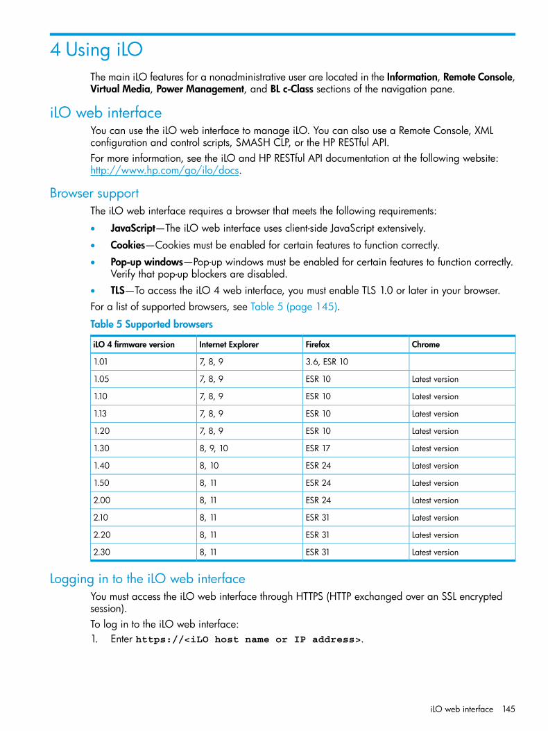
4 Using iLOThe main iLO features for a nonadministrative user are located in the Information, Remote Console,Virtual Media, Power Management, and BL c-Class sections of the navigation pane.
iLO web interfaceYou can use the iLO web interface to manage iLO. You can also use a Remote Console, XMLconfiguration and control scripts, SMASH CLP, or the HP RESTful API.For more information, see the iLO and HP RESTful API documentation at the following website:http://www.hp.com/go/ilo/docs.
Browser supportThe iLO web interface requires a browser that meets the following requirements:
• JavaScript—The iLO web interface uses client-side JavaScript extensively.
• Cookies—Cookies must be enabled for certain features to function correctly.
• Pop-up windows—Pop-up windows must be enabled for certain features to function correctly.Verify that pop-up blockers are disabled.
• TLS—To access the iLO 4 web interface, you must enable TLS 1.0 or later in your browser.For a list of supported browsers, see Table 5 (page 145).
Table 5 Supported browsers
ChromeFirefoxInternet ExploreriLO 4 firmware version
3.6, ESR 107, 8, 91.01
Latest versionESR 107, 8, 91.05
Latest versionESR 107, 8, 91.10
Latest versionESR 107, 8, 91.13
Latest versionESR 107, 8, 91.20
Latest versionESR 178, 9, 101.30
Latest versionESR 248, 101.40
Latest versionESR 248, 111.50
Latest versionESR 248, 112.00
Latest versionESR 318, 112.10
Latest versionESR 318, 112.20
Latest versionESR 318, 112.30
Logging in to the iLO web interfaceYou must access the iLO web interface through HTTPS (HTTP exchanged over an SSL encryptedsession).To log in to the iLO web interface:1. Enter https://<iLO host name or IP address>.
iLO web interface 145

2. Do one of the following:• On the login page, enter a directory or local user account name and password, and then
click Log In.• Click the HP Zero Sign In button.
If iLO is configured for Kerberos network authentication, the HP Zero Sign In button isdisplayed below the Log In button. Clicking the HP Zero Sign In button logs the user into iLO without requiring the user to enter a user name and password.
For information about login security and login issues, see “Login security” (page 67) and “Loginand iLO access issues” (page 316).After an initial failed login attempt, the iLO firmware imposes a login delay. For more informationabout the login delay settings, see “Configuring access options” (page 60).
Cookie sharing between browser instances and iLOWhen you browse to iLO and log in, a single session cookie is shared with all open browserwindows. As a consequence, all open browser windows share one user session. Logging out inone window ends the user session in all of the open windows, and logging in as a different userin a new window replaces the session in the other windows.This behavior is typical of browsers. iLO does not support multiple users logged in from two differentbrowser windows on the same system.
Shared instancesWhen iLO opens another browser window (for example, the Remote Console or a help file), thiswindow shares the same connection to iLO and the session cookie.The iLO web server makes URL decisions based on each request received. For example, if a requestdoes not have access rights, it is redirected to the login page, regardless of the original request.Web server-based redirection, selecting File→New→Window, or pressing Ctrl+N opens a duplicateinstance of the original browser.
Cookie orderDuring login, the login page builds a browser session cookie that links the window to the appropriatesession in the iLO firmware. The firmware tracks browser logins as separate sessions listed in theActive Sessions section of the iLO Overview page.For example, when User1 logs in, the web server builds the initial frames view, with User1 listedin the top pane, menu items in the left pane, and page data in the lower right pane. When User1clicks from link to link, only the menu items and page data are updated.While User1 is logged in, if User2, opens a browser window on the same client and logs in, thesecond login overwrites the cookie generated in the original User1 session. Assuming that User2is a different user account, a different current frame is built, and a new session is granted. Thesecond session appears in the Active Sessions section of the iLO Overview page as User2.The second login has effectively orphaned the first session by overriding the cookie generatedduring the User1 login. This behavior is the same as closing the User1 browser without clickingthe Sign Out button. The User1 orphaned session is reclaimed when the session timeout expires.Because the current user frame is not refreshed unless the browser is forced to refresh the entirepage, User1 can continue navigating by using the browser window. However, the browser is nowoperating by using the User2 session cookie settings, even though it may not be readily apparent.If User1 continues to navigate in this mode (User1 and User2 sharing the same process becauseUser2 logged in and reset the session cookie), the following can occur:
• User1 session behaves consistently with the privileges assigned to User2.
• User1 activity keeps User2 session alive, but User1 session can time out unexpectedly.
146 Using iLO
• Logging out of either window causes both sessions to end. The next activity in the other windowcan redirect the user to the login page as if a session timeout or premature timeout occurred.
• Clicking Sign Out from the second session (User2) results in the following warning message:Logging out: unknown page to display before redirecting the user tothe login page.
• If User2 logs out and then logs back in as User3, User1 assumes the User3 session.
• If User1 is at login, and User2 is logged in, User1 can alter the URL to redirect to the indexpage. It appears as if User1 has accessed iLO without logging in.
These behaviors continue as long as the duplicate windows are open. All activities are attributedto the same user, using the last session cookie set.
Displaying the current session cookieAfter logging in, you can force the browser to display the current session cookie by entering thefollowing in the URL navigation bar:javascript:alert(document.cookie)
The first field visible is the session ID. If the session ID is the same among the different browserwindows, these windows are sharing the same iLO session.You can force the browser to refresh and reveal your true identity by pressing F5, selectingView→Refresh, or clicking the Refresh button.
Best practices for preventing cookie-related issues
• Start a new browser for each login by double-clicking the browser icon or shortcut.
• Click the Sign Out button to close the iLO session before you close the browser window.
Handling an unknown authorityIf the message Website Certified by an Unknown Authority is displayed, take thefollowing action:1. View the certificate to ensure that you are browsing to the correct management server (not an
imposter).• Verify that the Issued To name is your management server. Perform any other steps you
feel necessary to verify the identity of the management server.• If you are not sure that this is the correct management server, do not proceed. You might
be browsing to an imposter and giving your sign-in credentials to that imposter when yousign in. Contact the administrator. Exit the certificate window, and then click No or Cancelto cancel the connection.
2. After verifying the items in Step 1, you have the following options:• Accept the certificate temporarily for this session.
• Accept the certificate permanently.
• Stop now and import the certificate into your browser from a file provided by youradministrator.
Using the iLO controlsWhen you log in to the iLO web interface, the controls at the bottom of the browser window areavailable from any iLO page.
• POWER—Use this menu to access the iLO Virtual Power features.
• UID—Use this button to turn the UID LED on and off.
iLO web interface 147

• Language—Use this menu to select a language or to navigate to the Access Settings→Languagepage, where you can install a language pack and configure other language-related settings.This option is available only if a language pack is installed.
• Health icon—Use this icon to view the overall health status for the server fans, temperaturesensors, and other monitored subsystems. Click the icon to view the status of the monitoredcomponents. Select a component to view more information about the component status.
Starting a remote management toolWhen iLO is under the control of a remote management tool, the iLO web interface displays amessage similar to the following on the iLO login page:Warning! Some iLO settings are managed by <remote management tool name>.Changes made directly in iLO will be out of sync with the centralizedsettings.
The name of the remote management tool is a link. Click the link to start the remote managementtool.
Language pack supportIf a language pack is currently installed in iLO, a language menu is available on the login screenfor you to select the language for the iLO session. This selection is saved in a browser cookie forfuture use.
Viewing iLO overview informationNavigate to the Information→Overview page.
The iLO Overview page displays high-level details about the server and the iLO subsystem, as wellas links to commonly used features.
System information• Server Name—The server name defined by the host operating system. Click the Server Name
link to navigate to the Access Settings page.• Product Name—The product with which this iLO processor is integrated.
148 Using iLO
• UUID—The universally unique identifier that software uses to uniquely identify this host. Thisvalue is assigned when the system is manufactured.
• UUID (Logical)—The system UUID that is presented to host applications. This value is displayedonly when it has been set by other software, such as HP Virtual Connect Enterprise Manager.This value might affect operating system and application licensing. The UUID (Logical) valueis set as part of the logical server profile that is assigned to the system. If the logical serverprofile is removed, the system UUID value reverts from the UUID (Logical) value to the UUIDvalue. If no UUID (Logical) value is set, this item is not displayed.
• Server Serial Number—The server serial number, which is assigned when the system ismanufactured. You can change this value by using the system RBSU or the UEFI System Utilitiesduring POST.
• Serial Number (Logical)—The system serial number that is presented to host applications. Thisvalue is displayed only when it has been set by other software, such as Virtual ConnectEnterprise Manager. This value might affect operating system and application licensing. TheSerial Number (Logical) value is set as part of the logical server profile that is assigned to thesystem. If the logical server profile is removed, the serial number value reverts from the SerialNumber (Logical) value to the Server Serial Number value. If no Serial Number (Logical) valueis set, this item is not displayed.
• Chassis Serial Number—The serial number of the chassis that contains the server node. Thisinformation is displayed for servers with chassis firmware version 6.0 or later.
• Product ID—This value distinguishes between different systems with similar serial numbers.The product ID is assigned when the system is manufactured. You can change this value byusing the system RBSU or the UEFI System Utilities during POST.
• System ROM—The version of the active system ROM.
• System ROM Date—The date of the active system ROM.
• Backup System ROM—The version of the backup system ROM. The backup system ROM isused if a system ROM update fails or is rolled back. This value is displayed only if the systemsupports a backup system ROM.
• Integrated Remote Console—Provides links to start the .NET IRC or Java IRC application forremote, out-of-band communication with the server console.
• License Type—The level of licensed iLO firmware functionality.
• iLO Firmware Version—The version and date of the installed iLO firmware. Click the iLOFirmware Version link to navigate to the Firmware Update page.
• IP Address—The network IP address of the iLO subsystem.
• Link-Local IPv6 Address—The SLAAC link-local address of the iLO subsystem. Click the Link-LocalIPv6 Address link to navigate to the Network Summary page. This value is displayed only foriLO Dedicated Network Port configurations.
• iLO Hostname—The fully-qualified network name assigned to the iLO subsystem. By default,the iLO host name is ILO, followed by the system serial number and the current domain name.This value is used for the network name and must be unique.
System status details• System Health—The server health indicator. This value summarizes the condition of the
monitored subsystems, including overall status and redundancy (ability to handle a failure).Lack of redundancy in any subsystem at startup will not degrade the system health status. Clickthe System Health link to navigate to the Health Summary page.
• Server Power—The server power state (ON or OFF).
Viewing iLO overview information 149
• UID Indicator—The state of the UID LED. The UID LED helps you identify and locate a server,especially in high-density rack environments. The possible states are UID ON, UID OFF, andUID BLINK.You can change the UID LED state to UID ON or UID OFF by using the UID buttons on theserver chassis or the UID control at the bottom of the iLO web interface window.When the UID LED is blinking, the UID Indicator displays the status UID BLINK. When the UIDLED stops blinking, the status reverts to the previous value (UID ON or UID OFF). If a new stateis selected while the UID LED is blinking, that state takes effect when the UID LED stops blinking.
CAUTION: The UID LED blinks automatically to indicate that a critical operation is underwayon the host, such as Remote Console access or a firmware update. Do not remove power froma server when the UID LED is blinking.
• TPM Status or TM Status—The status of the TPM or TM socket or module.
• Module Type—The TPM or TM type and specification version. The possible values are TPM1.2, TPM 2.0, TM 1.0, Not Specified, and Not Supported. This value is displayed when a TPMor TM is present on a server that supports UEFI.
• SD-Card Status—The current status of the internal SD card. If present, the number of blocks inthe SD card is displayed.
• iLO Date/Time—The internal clock of the iLO subsystem. The clock can be synchronizedautomatically with the network.
Active sessions listThe iLO Overview page displays the following information about all users logged in to iLO:
• Login name
• IP address
• Source (for example, HTTPS, Remote Console, or SSH)
Viewing system informationThe iLO System Information page displays the health of the monitored subsystems and devices.The information that you can view depends on whether you are using Agentless Management orSNMP Pass-thru, and whether AMS is installed. For more information, see “Configuring iLOManagement settings” (page 108).The System Information page includes the following embedded health tabs:
• Summary
• Fans
• Temperatures
• Power
• Processors
• Memory
• Network
• Device Inventory
• Storage
• Firmware
• Software
150 Using iLO
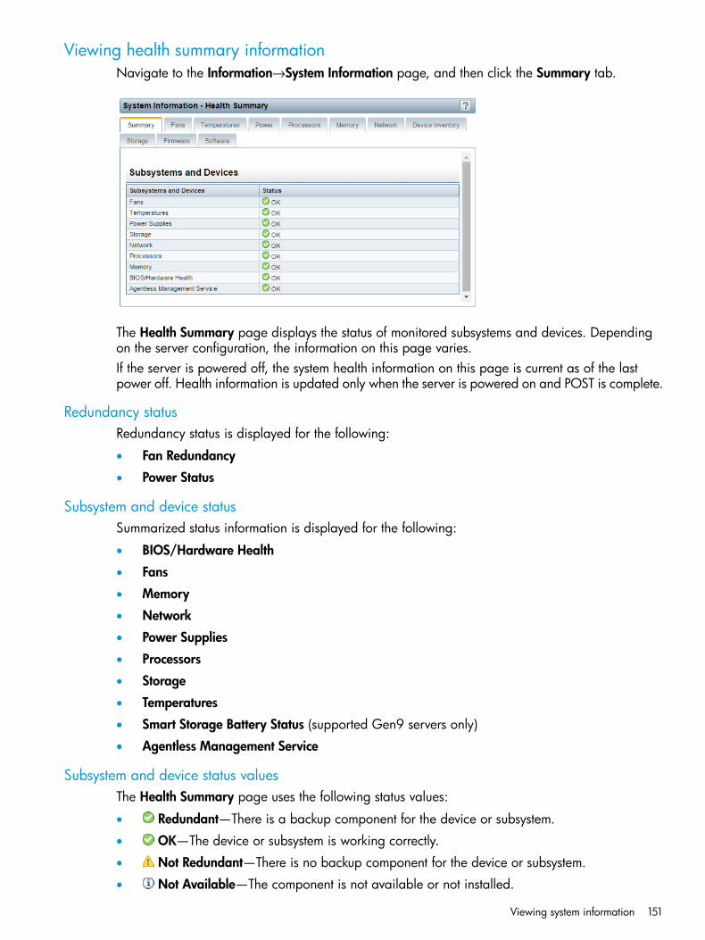
Viewing health summary informationNavigate to the Information→System Information page, and then click the Summary tab.
The Health Summary page displays the status of monitored subsystems and devices. Dependingon the server configuration, the information on this page varies.If the server is powered off, the system health information on this page is current as of the lastpower off. Health information is updated only when the server is powered on and POST is complete.
Redundancy statusRedundancy status is displayed for the following:
• Fan Redundancy
• Power Status
Subsystem and device statusSummarized status information is displayed for the following:
• BIOS/Hardware Health
• Fans
• Memory
• Network
• Power Supplies
• Processors
• Storage
• Temperatures
• Smart Storage Battery Status (supported Gen9 servers only)
• Agentless Management Service
Subsystem and device status valuesThe Health Summary page uses the following status values:
• Redundant—There is a backup component for the device or subsystem.
• OK—The device or subsystem is working correctly.
• Not Redundant—There is no backup component for the device or subsystem.
• Not Available—The component is not available or not installed.
Viewing system information 151

• Degraded—The device or subsystem is operating at a reduced capacity.Previous versions of iLO used a status of Mismatched to indicate the presence of mismatchedpower supplies. iLO 4 displays the power supply status as Degraded when mismatched powersupplies are installed.If you power on a server with nonredundant fans or power supplies, the system health statusis listed as OK. However, if a redundant fan or power supply fails while the system is poweredon, the system health status is listed as Degraded until you replace the fan or power supply.
• Failed Redundant—The device or subsystem is in a nonoperational state.
• Failed—One or more components of the device or subsystem are nonoperational.
• Other—For more information, navigate to the System Information page of the componentthat is reporting this status.
• Link Down—The network link is down.
• Unknown—The iLO firmware has not received data about the device status.If iLO was reset when the server was powered off, some subsystems display the status Unknownbecause the status cannot be updated when the server is powered off.
• Not Installed—The subsystem or device is not installed.
Viewing fan information1. Navigate to the Information→System Information page, and then click the Fans tab.
2. Optional: On servers that support fan redundancy, empty fan bays are hidden. To view theempty fan bays, click show empty bays. When empty fan bays are displayed, click hide emptybays to hide them.
The information displayed on the Fan Information page varies depending on the server configuration.If the server is powered off, the system health information on this page is current as of the lastpower off. Health information is updated only when the server is powered on and POST is complete.
FansThe iLO firmware, in conjunction with the hardware, controls the operation and speed of the fans.Fans provide essential cooling of components to ensure reliability and continued operation. Thefans react to the temperatures monitored throughout the system to provide sufficient cooling withminimal noise.Fan operation policies might differ from server to server based on fan configuration and coolingdemands. Fan control takes into account the internal temperature of the system, increasing the fanspeed to provide more cooling, and decreasing the fan speed if cooling is sufficient. In the eventof a fan failure, some fan operation policies might increase the speed of the other fans, record theevent in the IML, or turn LED indicators on.
152 Using iLO

Monitoring the fan subsystem includes the sufficient, redundant, and nonredundant fanconfigurations. If one or more fans fail, the server still provides sufficient cooling to continueoperation.In nonredundant configurations, or redundant configurations where multiple fan failures occur, thesystem might be incapable of providing sufficient cooling to protect the server from damage andto ensure data integrity. In this case, in addition to the cooling policies, the system might start agraceful shutdown of the operating system and server.Server blades use the enclosure fans to provide cooling because they do not have internal fans.The enclosure fans are called virtual fans on the Fans tab. The Virtual fan reading represents thecooling amount that a server blade is requesting from the enclosure. The server blade calculatesthe amount of required cooling by examining various temperature sensors and calculating anappropriate fan speed. The enclosure uses information from all of the installed server and nonserverblades to adjust the fans to provide the appropriate enclosure cooling.
Fan detailsThe following details are displayed for each fan:
• Fan—The fan name.
• Location—For nonblade servers, the location in the server chassis is listed. For server blades,the virtual fan is listed with the location Virtual.
• Status—The fan health status.For more information, see “Viewing health summary information” (page 151).
• Speed—The fan speed (percent).
Viewing temperature informationThe Temperature Information page includes a temperature graph and a table that displays thelocation, status, temperature, and threshold settings of temperature sensors in the server chassis.If the server is powered off, the system health information on this page is current as of the lastpower off. Health information is updated only when the server is powered on and POST is complete.The following temperature thresholds are monitored:
• Caution—The server is designed to maintain a temperature below the caution threshold.If the temperature exceeds the caution threshold, the fan speeds are increased to maximum.If the temperature exceeds the caution threshold for 60 seconds, a graceful server shutdownis attempted.
• Critical—If temperatures are uncontrollable or rise quickly, the critical temperature thresholdprevents system failure by physically shutting down the server before the high temperaturecauses an electronic component failure.
Monitoring policies differ depending on the server requirements. Policies usually include increasingfan speeds to maximum cooling, logging temperature events in the IML, providing a visual indicationof events by using LED indicators, and starting a graceful shutdown of the operating system toavoid data corruption.Additional policies are implemented after an excessive temperature condition is corrected, includingreturning the fan speed to normal, recording the event in the IML, turning off the LED indicators,and canceling shutdowns in progress (if applicable).
Viewing system information 153

Viewing the temperature graph1. Navigate to the Information→System Information page, and then click the Temperatures tab.
2. Optional: Customize the graph display.• Select the 3D check box to display a three-dimensional graph.
• Clear the 3D check box to display a two-dimensional graph.
• Select Front View or Back View to display the sensors located at the front or back of theserver.
3. Optional: Move the mouse over a circle on the graph to view an individual sensor.The sensor ID, status, and temperature reading are displayed.
When you view the temperature graph, the circles on the graph correspond to the sensors listedin the Sensor Data table.The color on the graph is a gradient that ranges from green to red. Green represents a temperatureof 0°C and red represents the critical threshold. As the temperature of a sensor increases, thegraph color changes from green to amber, and then to red if the temperature approaches thecritical threshold.
Viewing temperature sensor dataTo view temperature sensor data, navigate to the Information→System Information page, and thenclick the Temperatures tab.
154 Using iLO
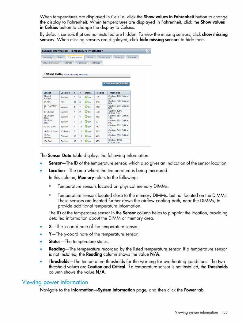
When temperatures are displayed in Celsius, click the Show values in Fahrenheit button to changethe display to Fahrenheit. When temperatures are displayed in Fahrenheit, click the Show valuesin Celsius button to change the display to Celsius.By default, sensors that are not installed are hidden. To view the missing sensors, click show missingsensors. When missing sensors are displayed, click hide missing sensors to hide them.
The Sensor Data table displays the following information:
• Sensor—The ID of the temperature sensor, which also gives an indication of the sensor location.
• Location—The area where the temperature is being measured.In this column, Memory refers to the following:
◦ Temperature sensors located on physical memory DIMMs.
◦ Temperature sensors located close to the memory DIMMs, but not located on the DIMMs.These sensors are located further down the airflow cooling path, near the DIMMs, toprovide additional temperature information.
The ID of the temperature sensor in the Sensor column helps to pinpoint the location, providingdetailed information about the DIMM or memory area.
• X—The x-coordinate of the temperature sensor.
• Y—The y-coordinate of the temperature sensor.
• Status—The temperature status.
• Reading—The temperature recorded by the listed temperature sensor. If a temperature sensoris not installed, the Reading column shows the value N/A.
• Thresholds—The temperature thresholds for the warning for overheating conditions. The twothreshold values are Caution and Critical. If a temperature sensor is not installed, the Thresholdscolumn shows the value N/A.
Viewing power informationNavigate to the Information→System Information page, and then click the Power tab.
Viewing system information 155
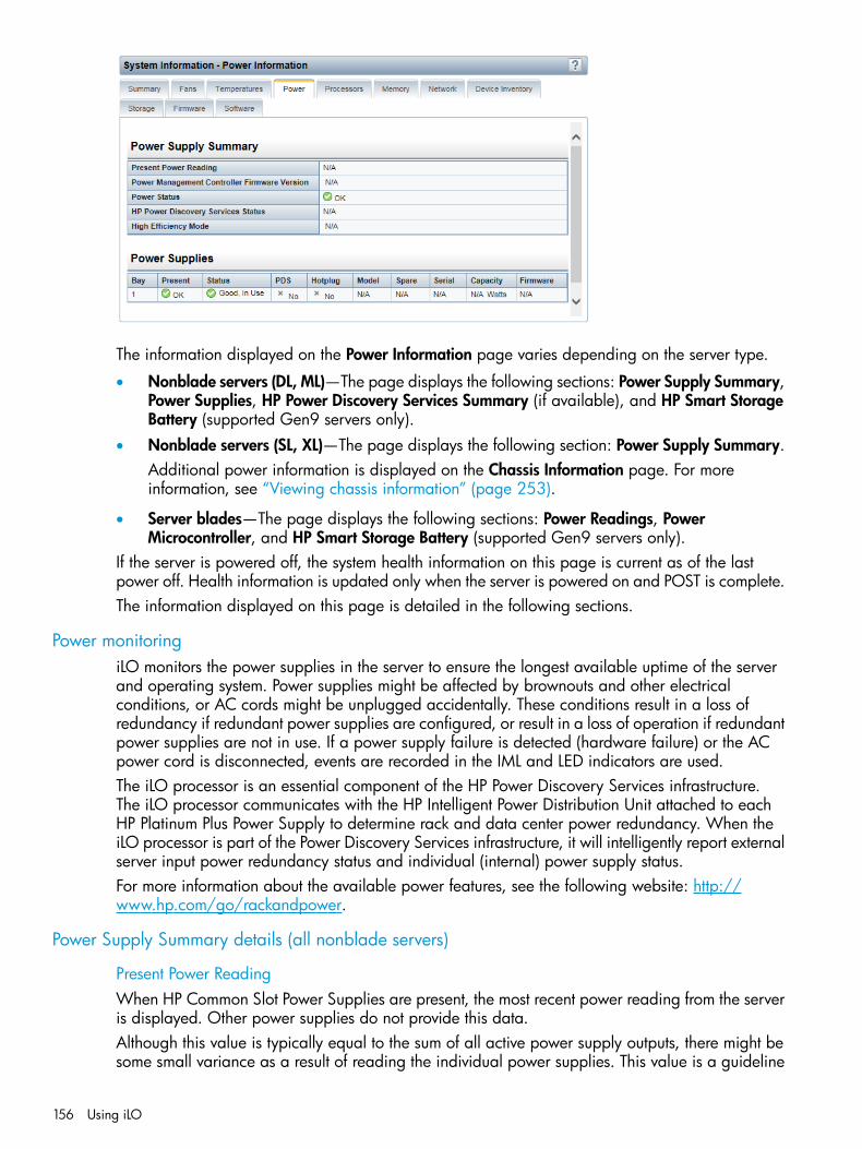
The information displayed on the Power Information page varies depending on the server type.
• Nonblade servers (DL, ML)—The page displays the following sections: Power Supply Summary,Power Supplies, HP Power Discovery Services Summary (if available), and HP Smart StorageBattery (supported Gen9 servers only).
• Nonblade servers (SL, XL)—The page displays the following section: Power Supply Summary.Additional power information is displayed on the Chassis Information page. For moreinformation, see “Viewing chassis information” (page 253).
• Server blades—The page displays the following sections: Power Readings, PowerMicrocontroller, and HP Smart Storage Battery (supported Gen9 servers only).
If the server is powered off, the system health information on this page is current as of the lastpower off. Health information is updated only when the server is powered on and POST is complete.The information displayed on this page is detailed in the following sections.
Power monitoringiLO monitors the power supplies in the server to ensure the longest available uptime of the serverand operating system. Power supplies might be affected by brownouts and other electricalconditions, or AC cords might be unplugged accidentally. These conditions result in a loss ofredundancy if redundant power supplies are configured, or result in a loss of operation if redundantpower supplies are not in use. If a power supply failure is detected (hardware failure) or the ACpower cord is disconnected, events are recorded in the IML and LED indicators are used.The iLO processor is an essential component of the HP Power Discovery Services infrastructure.The iLO processor communicates with the HP Intelligent Power Distribution Unit attached to eachHP Platinum Plus Power Supply to determine rack and data center power redundancy. When theiLO processor is part of the Power Discovery Services infrastructure, it will intelligently report externalserver input power redundancy status and individual (internal) power supply status.For more information about the available power features, see the following website: http://www.hp.com/go/rackandpower.
Power Supply Summary details (all nonblade servers)
Present Power ReadingWhen HP Common Slot Power Supplies are present, the most recent power reading from the serveris displayed. Other power supplies do not provide this data.Although this value is typically equal to the sum of all active power supply outputs, there might besome small variance as a result of reading the individual power supplies. This value is a guideline
156 Using iLO

value and is not as accurate as the values presented on the iLO Power Management pages. Formore information, see “Viewing server power usage” (page 244).
Power Management Controller Firmware VersionThe firmware version of the power management controller. The server must be powered on for theiLO firmware to determine this value. This feature is not available on all servers.
Power StatusThe overall status of the power supplied to the server.
• If the server power supplies are connected to a nonintelligent power source, this sectiondisplays the status of the internal server power supplies.
• If the server power supplies are connected to HP Power Discovery Services through an iPDU,this section displays the status of the power supplied to the internal server power supplies.
Possible Power Status values follow:
• Redundant—Indicates whether the power supplies are in a redundant state. If HP PowerDiscovery Services is integrated into the infrastructure, the Power Status box indicates whetherthe externally supplied power to the internal power supplies is redundant.
• Not Redundant—Indicates that at least one of the power supplies or iPDUs (in the case of HPPower Discovery Services) is not supplying power to the server. The most common reason forthis status is a loss of input power to the power supply. Another reason for this status is aconfiguration with multiple power supplies connected to the same iPDU. In this case, theindividual power supply status is Good, In Use, but the Power Status value is Not Redundantbecause the loss of input power to the iPDU would lead to a total loss of power to the server.
• OK—A Common Slot Power Supply is not installed. The installed power supply is workingcorrectly.
HP Power Discovery Services StatusThe possible values follow:
• Redundant—The server is configured for a redundant iPDU configuration.
• Not Redundant—There are not sufficient iPDUs to support redundancy, or the server’s powersupplies are connected to the same iPDU.
• N/A—No iPDUs were discovered.When the iLO processor or the server is reset, the iPDU discovery process might take a few minutesto complete.
High Efficiency ModeThe redundant power supply mode that will be used if redundant power supplies are configured.High Efficiency Mode improves the power efficiency of the server by placing the secondary powersupplies in standby mode. When the secondary power supplies are in standby mode, primarypower provides all DC power to the system. The power supplies are more efficient (more DC outputwatts for each watt of AC input) at higher output levels, and the overall power efficiency improves.High Efficiency Mode does not affect power redundancy. If the primary power supplies fail, thesecondary power supplies immediately begin supplying DC power to the system, preventing anydowntime. You can configure redundant power supply modes only through the system RBSU orthe UEFI System Utilities. You cannot modify these settings through the iLO firmware.If High Efficiency Mode is configured to use an unsupported mode, you might experience decreasedpower supply efficiency.For more information, see the system RBSU user guide or the UEFI System Utilities user guide.
Viewing system information 157

The redundant power supply modes follow:
• N/A—Not applicable.
• Balanced Mode—Delivers power equally across all installed power supplies.
• High Efficiency Mode (Auto)—Delivers full power to one of the power supplies, and places theother power supplies on standby at a lower power-usage level. A semi-random distribution isachieved because the Auto option chooses between the odd or even power supply based onthe server serial number.
• High Efficiency Mode (Even Supply Standby)—Delivers full power to the odd-numbered powersupplies, and places the even-numbered power supplies on standby at a lower power-usagelevel.
• High Efficiency Mode (Odd Supply Standby)—Delivers full power to the even-numbered powersupplies, and places the odd-numbered power supplies on standby at a lower power-usagelevel.
• Not Supported—The installed power supplies do not support High Efficiency Mode.
Power Supplies list (ML and DL servers)Some power supplies do not provide information for all of the values in this list. If a power supplydoes not provide information for a value, N/A is displayed.
BayThe power supply bay number.
PresentWhether a power supply is installed. The possible values are OK and Not Installed.
StatusThe status of the power supply. The displayed value includes a status icon (OK, Degraded, Failed,or Other), and text that provides more information. The possible values follow:
• Unknown
• Good, In Use
• Good, Standby
• General Failure
• Over Voltage Failure
• Over Current Failure
• Over Temperature Failure
• Input Voltage Lost
• Fan Failure
• High Input A/C Warning
• Low Input A/C Warning
• High Output Warning
• Low Output Warning
• Inlet Temperature Warning
• Internal Temperature Warning
• High Vaux Warning
158 Using iLO

• Low Vaux Warning
• Mismatched Power Supplies
PDSWhether the installed power supply is enabled for HP Power Discovery Services.HP Power Discovery Services is an enhancement to the iPDU technology. If the server power supplyis connected to an iPDU, an additional summary table on this page displays the linked iPDUs.
HotplugWhether the power supply bay supports swapping the power supply when the server is poweredon. If the value is Yes, and the power supplies are redundant, the power supply can be removedor replaced when the server is powered on.
Flex Slot Battery Backup UnitThe following information is displayed for Gen9 servers with an installed Flex Slot Battery BackupUnit:
• Charge—The current battery charge (percent).
• Days Active—The number of calendar days that the battery has been installed in a poweredserver.
• Battery Health—The battery health status (0 to 100 percent).Battery health issues are reported in the IML.
Power capping and power metering are not supported on servers with an installed Flex Slot BatteryBackup Unit.For more information, see the Flex Slot Battery Backup Unit installation instructions.
ModelThe model number of the power supply.
SpareThe part number of the spare power supply.
SerialThe serial number of the power supply.
CapacityThe capacity of the power supply (watts).
FirmwareThe installed power supply firmware.
HP Power Discovery Services iPDU Summary (ML and DL servers only)This section is displayed only if the server power supplies are connected to an iPDU.After iLO is reset, or when an iPDU is attached, it takes approximately 2 minutes for the iLO webinterface to display iPDU summary data. This delay is due to the iPDU discovery process. Thefollowing information is displayed in the table:
BayThe power supply bay number.
Viewing system information 159
StatusThe overall communication-link status and rack input power redundancy, as determined by theiPDU. Possible values follow:
• iPDU Redundant—This Good status indicates that the server is connected to at least two differentiPDUs.
• iPDU Not Redundant—This Caution status indicates that the server is not connected to at leasttwo different iPDUs. Typically, this status is displayed when one of the following conditionsoccurs:
◦ An iPDU link is not established for all power supplies.
◦ Two or more power supplies are connected to the same iPDU.The iPDU MAC address and serial number are identical for power supplies whose inputpower comes from the same iPDU. If one power supply is waiting for a connection to beestablished, the iPDU is listed as Not Redundant.
• Waiting for connection—This Informational status indicates one or more of the followingconditions:
◦ The wrong power cord was used to connect the power supply to the iPDU.
◦ The iPDU and the iLO processor are in the process of connecting. This process can takeup to 2 minutes after the iLO processor or the iPDU is reset.
◦ The iPDU module does not have a network (or IP) address.
Part NumberThe iPDU part number.
SerialThe iPDU serial number.
MAC AddressThe MAC address of the iPDU network port. This value helps you to uniquely identify each connectediPDU because each iPDU has a unique MAC address.
iPDU LinkThe iPDU HTTP address (if available). Click the link in this column to open the HP Intelligent ModularPDU web interface.
Power Readings (blade servers only)Present Power Reading—The most recent power reading from the server.Although this value is typically equal to the sum of all active power supply outputs, there might besome small variance as a result of reading the individual power supplies. This value is a guidelinevalue and is not as accurate as the values presented on the Power Management pages. For moreinformation, see “Viewing server power usage” (page 244).
Power Microcontroller (blade servers only)Firmware Version—The firmware version of the power microcontroller.The server must be powered on for the iLO firmware to determine the power microcontroller firmwareversion.
160 Using iLO
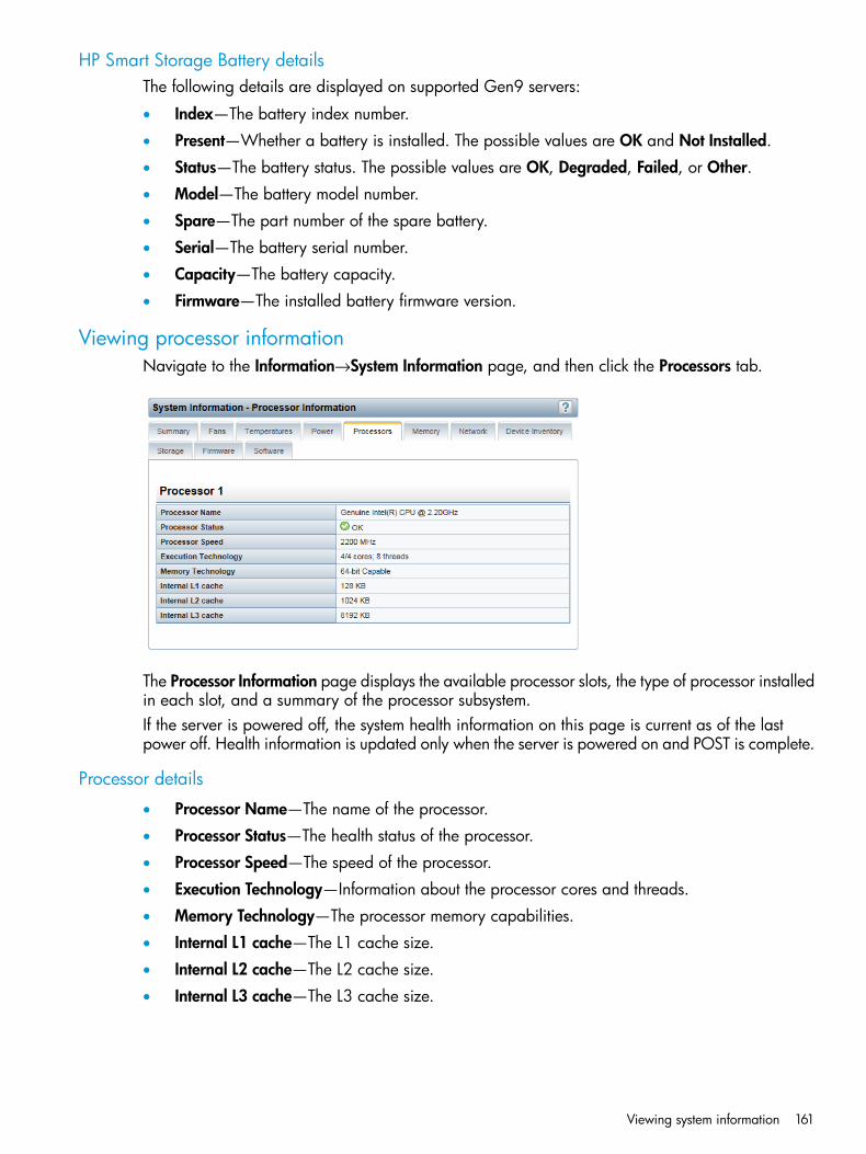
HP Smart Storage Battery detailsThe following details are displayed on supported Gen9 servers:
• Index—The battery index number.
• Present—Whether a battery is installed. The possible values are OK and Not Installed.
• Status—The battery status. The possible values are OK, Degraded, Failed, or Other.
• Model—The battery model number.
• Spare—The part number of the spare battery.
• Serial—The battery serial number.
• Capacity—The battery capacity.
• Firmware—The installed battery firmware version.
Viewing processor informationNavigate to the Information→System Information page, and then click the Processors tab.
The Processor Information page displays the available processor slots, the type of processor installedin each slot, and a summary of the processor subsystem.If the server is powered off, the system health information on this page is current as of the lastpower off. Health information is updated only when the server is powered on and POST is complete.
Processor details
• Processor Name—The name of the processor.
• Processor Status—The health status of the processor.
• Processor Speed—The speed of the processor.
• Execution Technology—Information about the processor cores and threads.
• Memory Technology—The processor memory capabilities.
• Internal L1 cache—The L1 cache size.
• Internal L2 cache—The L2 cache size.
• Internal L3 cache—The L3 cache size.
Viewing system information 161
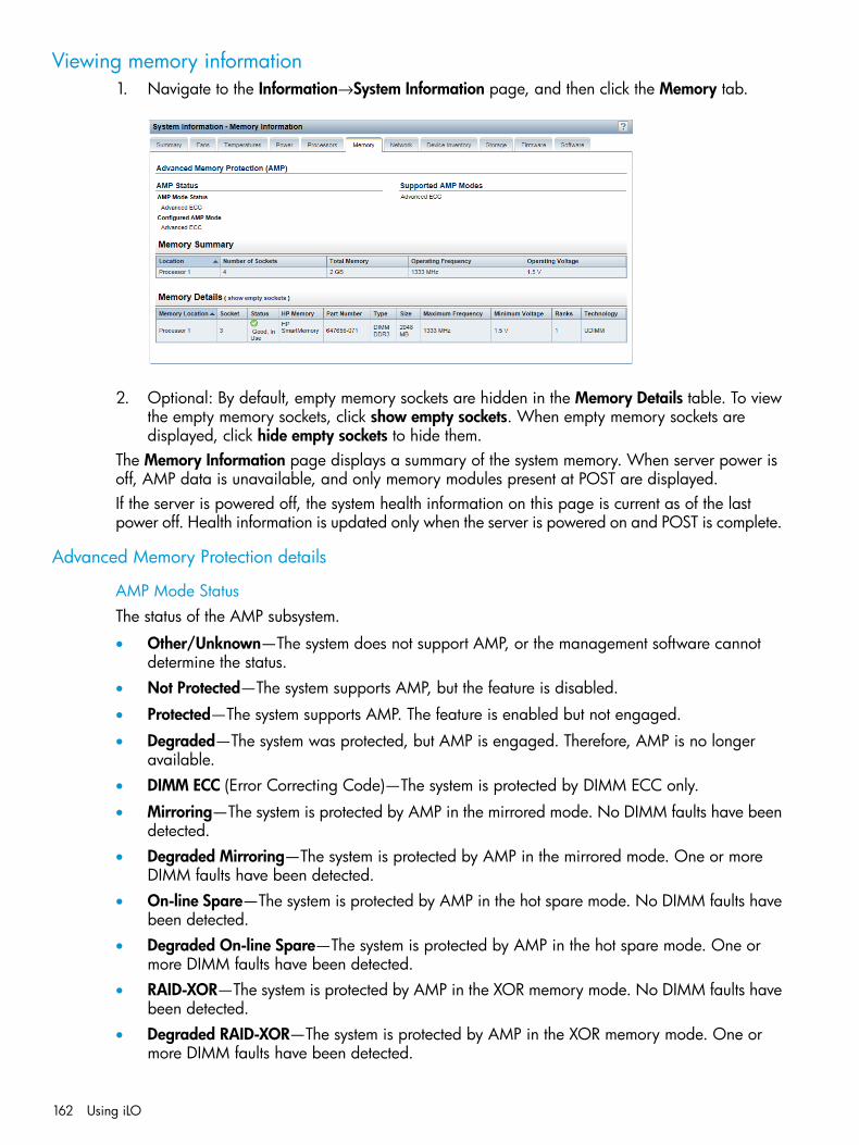
Viewing memory information1. Navigate to the Information→System Information page, and then click the Memory tab.
2. Optional: By default, empty memory sockets are hidden in the Memory Details table. To viewthe empty memory sockets, click show empty sockets. When empty memory sockets aredisplayed, click hide empty sockets to hide them.
The Memory Information page displays a summary of the system memory. When server power isoff, AMP data is unavailable, and only memory modules present at POST are displayed.If the server is powered off, the system health information on this page is current as of the lastpower off. Health information is updated only when the server is powered on and POST is complete.
Advanced Memory Protection details
AMP Mode StatusThe status of the AMP subsystem.
• Other/Unknown—The system does not support AMP, or the management software cannotdetermine the status.
• Not Protected—The system supports AMP, but the feature is disabled.
• Protected—The system supports AMP. The feature is enabled but not engaged.
• Degraded—The system was protected, but AMP is engaged. Therefore, AMP is no longeravailable.
• DIMM ECC (Error Correcting Code)—The system is protected by DIMM ECC only.
• Mirroring—The system is protected by AMP in the mirrored mode. No DIMM faults have beendetected.
• Degraded Mirroring—The system is protected by AMP in the mirrored mode. One or moreDIMM faults have been detected.
• On-line Spare—The system is protected by AMP in the hot spare mode. No DIMM faults havebeen detected.
• Degraded On-line Spare—The system is protected by AMP in the hot spare mode. One ormore DIMM faults have been detected.
• RAID-XOR—The system is protected by AMP in the XOR memory mode. No DIMM faults havebeen detected.
• Degraded RAID-XOR—The system is protected by AMP in the XOR memory mode. One ormore DIMM faults have been detected.
162 Using iLO
• Advanced ECC—The system is protected by AMP in the Advanced ECC mode.
• Degraded Advanced ECC—The system is protected by AMP in the Advanced ECC mode. Oneor more DIMM faults have been detected.
• LockStep—The system is protected by AMP in the LockStep mode.
• Degraded LockStep—The system is protected by AMP in the LockStep mode. One or moreDIMM faults have been detected.
Configured AMP ModeThe active AMP mode. The following modes are supported:• None/Unknown—The management software cannot determine the AMP fault tolerance, or
the system is not configured for AMP.• On-line Spare—A single spare bank of memory is set aside at boot time. If enough ECC errors
occur, the spare memory is activated and the memory that is experiencing the errors is disabled.• Mirroring—The system is configured for mirrored memory protection. All memory banks are
duplicated in mirrored memory, as opposed to only one for online spare memory. If enoughECC errors occur, the spare memory is activated and the memory that is experiencing theerrors is disabled.
• RAID-XOR—The system is configured for AMP with the XOR engine.
• Advanced ECC—The system is configured for AMP with the Advanced ECC engine.
• LockStep—The system is configured for AMP with the LockStep engine.
Online Spare (Rank Sparing)The system is configured for Online Spare Rank AMP.
Online Spare (Channel Sparing)The system is configured for Online Spare Channel AMP.
Intersocket MirroringThe system is configured for mirrored intersocket AMP between the memory of two processors orboards.
Intrasocket MirroringThe system is configured for mirrored intrasocket AMP between the memory of a single processoror board.
Supported AMP ModesThe following modes are supported:
• RAID-XOR—The system can be configured for AMP using the XOR engine.
• Dual Board Mirroring—The system can be configured for mirrored advanced memory protectionin a dual memory board configuration. The mirrored memory can be swapped with memoryon the same memory board or with memory on the second memory board.
• Single Board Mirroring—The system can be configured for mirrored advanced memoryprotection in a single memory board.
• Advanced ECC—The system can be configured for Advanced ECC.
• Mirroring—The system can be configured for mirrored AMP.
• On-line Spare—The system can be configured for online spare AMP.
• LockStep—The system can be configured for LockStep AMP.
Viewing system information 163

• Online Spare (Rank Sparing)—The system can be configured for Online Spare Rank AMP.
• Online Spare (Channel Sparing)—The system can be configured for Online Spare ChannelAMP.
• Intersocket Mirroring—The system can be configured for mirrored intersocket AMP betweenthe memory of two processors or boards.
• Intrasocket Mirroring—The system can be configured for mirrored intrasocket AMP betweenthe memory of a single processor or board.
• None—The system cannot be configured for AMP.
Memory SummaryThis section shows a summary of the memory that was installed and operational at POST.
LocationThe slot or processor on which the memory board, cartridge, or riser is installed. Possible valuesfollow:
• System Board—There is no separate memory board slot. All DIMMs are installed on themotherboard.
• Board Number—There is a memory board slot available. All DIMMs are installed on thememory board.
• Processor Number—The processor on which the memory DIMMs are installed.
• Riser Number—The riser on which the memory DIMMs are installed.
Number of SocketsThe number of present memory module sockets.
Total MemoryThe capacity of the memory, including memory recognized by the operating system and memoryused for spare, mirrored, or XOR configurations.
Operating FrequencyThe frequency at which the memory operates.
Operating VoltageThe voltage at which the memory operates.
Memory DetailsThe Memory Details section shows the memory modules on the host that were installed andoperational at POST. Unpopulated module positions are also listed. Various resilient memoryconfigurations can change the actual memory inventory from what was sampled at POST. In systemsthat have a high number of memory modules, all module positions might not be listed.
Memory LocationThe slot or processor on which the memory module is installed.
SocketThe memory module socket number.
StatusThe memory module status and whether the module is in use.
164 Using iLO

HP MemoryWhether the memory module is HP SmartMemory or HP Standard Memory.If no memory module is installed, the value N/A is displayed. If the value No is displayed, thelisted module is not an HP Memory module. Third-party memory modules will function, but they donot have a warranty, and they might not perform as well as an HP Memory module.For more information, see http://www.hp.com/go/memory.
Part NumberThe memory module part number.This value is displayed only for HP Memory modules.
TypeThe type of memory installed. Possible values follow:
• Other—Memory type cannot be determined.
• Board—Memory module is permanently mounted (not modular) on a system board or memoryexpansion board.
• CPQ single width module
• CPQ double width module
• SIMM
• PCMCIA
• Compaq-specific
• DIMM
• Small outline DIMM
• RIMM
• SRIMM
• FB-DIMM
• DIMM DDR
• DIMM DDR2
• DIMM DDR3
• DIMM DDR4 (Gen9 servers only)
• FB-DIMM DDR2
• FB-DIMM DDR3
• N/A—Memory module is not present.
SizeThe size of the memory module, in MB.
Maximum FrequencyThe maximum frequency at which the memory module can operate.
Minimum VoltageThe minimum voltage at which the memory module can operate.
RanksThe number of ranks in the memory module.
Viewing system information 165

TechnologyThe memory module technology. Possible values follow:
• Unknown—Memory technology cannot be determined.
• N/A—Memory module is not present.
• Fast Page
• EDO
• Burst EDO
• Synchronous
• RDRAM
• RDIMM
• UDIMM
• LRDIMM
Viewing network information1. Navigate to the Information→System Information page, and then click the Network tab.
2. Optional: To expand or collapse the information on this page, click Expand All or CollapseAll, respectively.
166 Using iLO

The NIC Information page includes the following sections:
• The Physical Network Adapters section displays information about the integrated and add-inNICs in the server.
• The Logical Network Adapters section displays information about network adapters that useNIC teaming to combine two or more ports into a single logical network connection.
If the server is powered off, the health status information on this page is current as of the last poweroff. Health information is updated only when the server is powered on and POST is complete.To view a full set of data on this page, ensure that AMS is installed and running. The server IPaddress, add-in network adapters, and the server NIC status are displayed only if AMS is installedand running on the server.
Physical Network AdaptersThe following information is displayed for each physical network adapter:
• Adapter number—The adapter number, for example, Adapter 1 or Adapter 2.
• Device Type—The device type is one of the following:
iLO—This device type is assigned to the iLO Dedicated Network Port or iLO SharedNetwork Port. Users who have the Configure iLO Settings privilege can configure the iLO
◦
NIC settings on the General tab of the Network→iLO Dedicated Network Port orNetwork→Shared Network Port page.
◦ <NIC type>—This device type indicates NIC or LAN adapter components embedded inthe server or added after manufacturing. Because system NICs are directly available tothe server host operating system, the iLO firmware cannot directly obtain current IPaddresses (or other configuration settings) for these devices.
• Description—A description of the physical network adapter, for example, Dedicated NetworkPort or Shared Network Port. This value is displayed for iLO adapters only.
• Location—The location of the adapter on the system board.
• Firmware—The version of the installed adapter firmware, if applicable. This value is displayedfor system NICs (embedded and stand-up) only.
• Status—The NIC status.
If the NIC has never been plugged in to a network, iLO displays the status Unknown.◦◦ If the NIC has been plugged in to a network, and is now unplugged, iLO displays the
status Link Down.
• Port—The configured network port. This value is displayed for system NICs (embedded andstand-up) only.
• MAC Address—The port MAC address.
• IP Address—For iLO adapters, the iLO IP address. For system NICs (embedded and stand-up),the server IP address (if available).
• Status—The port status.
• Team/Bridge—If a port is configured for NIC teaming, the name of the configured link betweenthe physical ports that form a logical network adapter. This value is displayed for system NICs(embedded and stand-up) only.
Viewing system information 167
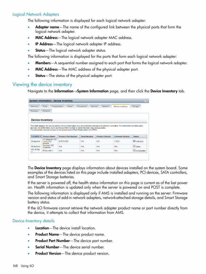
Logical Network AdaptersThe following information is displayed for each logical network adapter:
• Adapter name—The name of the configured link between the physical ports that form thelogical network adapter.
• MAC Address—The logical network adapter MAC address.
• IP Address—The logical network adapter IP address.
• Status—The logical network adapter status.The following information is displayed for the ports that form each logical network adapter:
• Members—A sequential number assigned to each port that forms the logical network adapter.
• MAC Address—The MAC address of the physical adapter port.
• Status—The status of the physical adapter port.
Viewing the device inventoryNavigate to the Information→System Information page, and then click the Device Inventory tab.
The Device Inventory page displays information about devices installed on the system board. Someexamples of the devices listed on this page include installed adapters, PCI devices, SATA controllers,and Smart Storage batteries.If the server is powered off, the health status information on this page is current as of the last poweron. Health information is updated only when the server is powered on and POST is complete.The following information is displayed only if AMS is installed and running on the server: Firmwareversion and status of add-in network adapters, network-attached storage details, and Smart Storagebattery status.If the iLO firmware cannot retrieve the network adapter product name or part number directly fromthe device, it attempts to collect that information from AMS.
Device Inventory details
• Location—The device install location.
• Product Name—The device product name.
• Product Part Number—The device part number.
• Serial Number—The device serial number.
• Product Version—The device product version.
168 Using iLO

• Firmware Version—The installed device firmware version.
• Status—The device status.
Device status valuesThe Device Inventory page uses the following status values:
• OK—The device is working correctly.
• Other—The device status could not be determined.
• Dormant—The device is inactive.
• Not Installed—A device is not installed.
• Link Down—The network link is down.
• Failed—One or more components of the device are nonoperational.
• Degraded—The device is operating at a reduced capacity.
• Unknown—The iLO firmware has not received data about the device status.
Viewing PCI slot details1. Navigate to the Information→System Information page, and then click the Device Inventory
tab.2. Move the cursor over the Location column for a listed PCI slot.
PCI slot tool tip details
• Type—The PCI slot type.
• Bus Width—The PCI slot width.
• Length—The PCI slot length.
• Characteristics 1—Information about the PCI slot, for example, voltage and other supportinformation.
• Characteristics 2—Information about the PCI slot, for example, voltage and other supportinformation.
Viewing system information 169
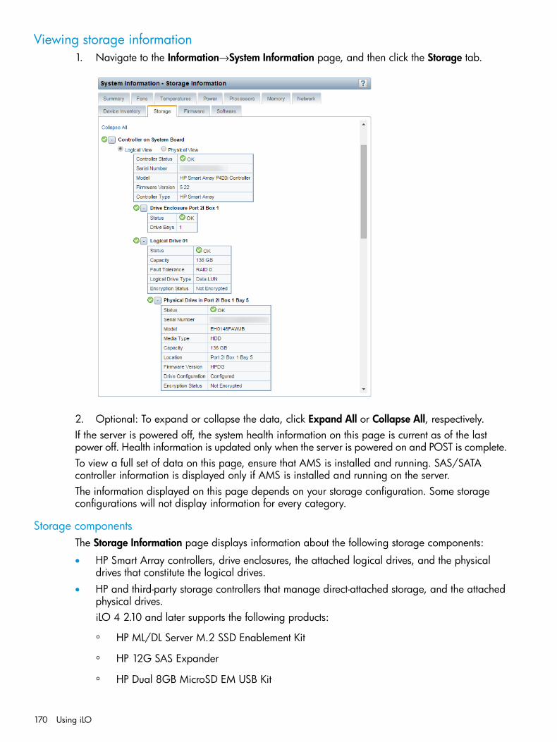
Viewing storage information1. Navigate to the Information→System Information page, and then click the Storage tab.
2. Optional: To expand or collapse the data, click Expand All or Collapse All, respectively.If the server is powered off, the system health information on this page is current as of the lastpower off. Health information is updated only when the server is powered on and POST is complete.To view a full set of data on this page, ensure that AMS is installed and running. SAS/SATAcontroller information is displayed only if AMS is installed and running on the server.The information displayed on this page depends on your storage configuration. Some storageconfigurations will not display information for every category.
Storage componentsThe Storage Information page displays information about the following storage components:
• HP Smart Array controllers, drive enclosures, the attached logical drives, and the physicaldrives that constitute the logical drives.
• HP and third-party storage controllers that manage direct-attached storage, and the attachedphysical drives.iLO 4 2.10 and later supports the following products:
◦ HP ML/DL Server M.2 SSD Enablement Kit
◦ HP 12G SAS Expander
◦ HP Dual 8GB MicroSD EM USB Kit
170 Using iLO

Smart Array controllers are listed first on the page, followed by other HP and third-party storagecontrollers.
Viewing Smart Array storage information1. Navigate to the Information→System Information page, and then click the Storage tab.2. For the controller you want to view, select one of the following options:
• Logical View—View configured logical drives and associated physical drives. This viewdoes not show physical drives that are not configured as part of an array, or spare drives.
• Physical View—View physical drives. This view does not show logical drives.
A description of each section that is displayed for Smart Array storage follows.
ControllersThis section provides information about the Smart Array controller.
The following information is displayed for each Smart Array controller:
• Controller location—Slot number or system board
• Top-level controller status—The top-level controller status (displayed on the left of the controllerlocation) is a combination of the controller hardware status and the status of cache modules,enclosures, and physical, logical, and spare drives associated with the controller. If thecontroller hardware status is OK, and any associated hardware has a failure, the top-levelcontroller status changes to Major Warning or Degraded, depending on the failure type. Ifthe controller hardware has a Failed status, the top-level controller status is Failed.
• Controller Status—Controller hardware status (OK or Failed)
• Serial Number
• Model
• Firmware Version
• Controller Type
• Cache Module Status
• Cache Module Serial Number
• Cache Module Memory• Encryption Status—Indicates whether encryption is enabled in the controller.
The following values are possible:
◦ Enabled
◦ Not Enabled
◦ Enabled—Local Mode—This value is displayed when you do not use a remote keymanagement server.
Viewing system information 171
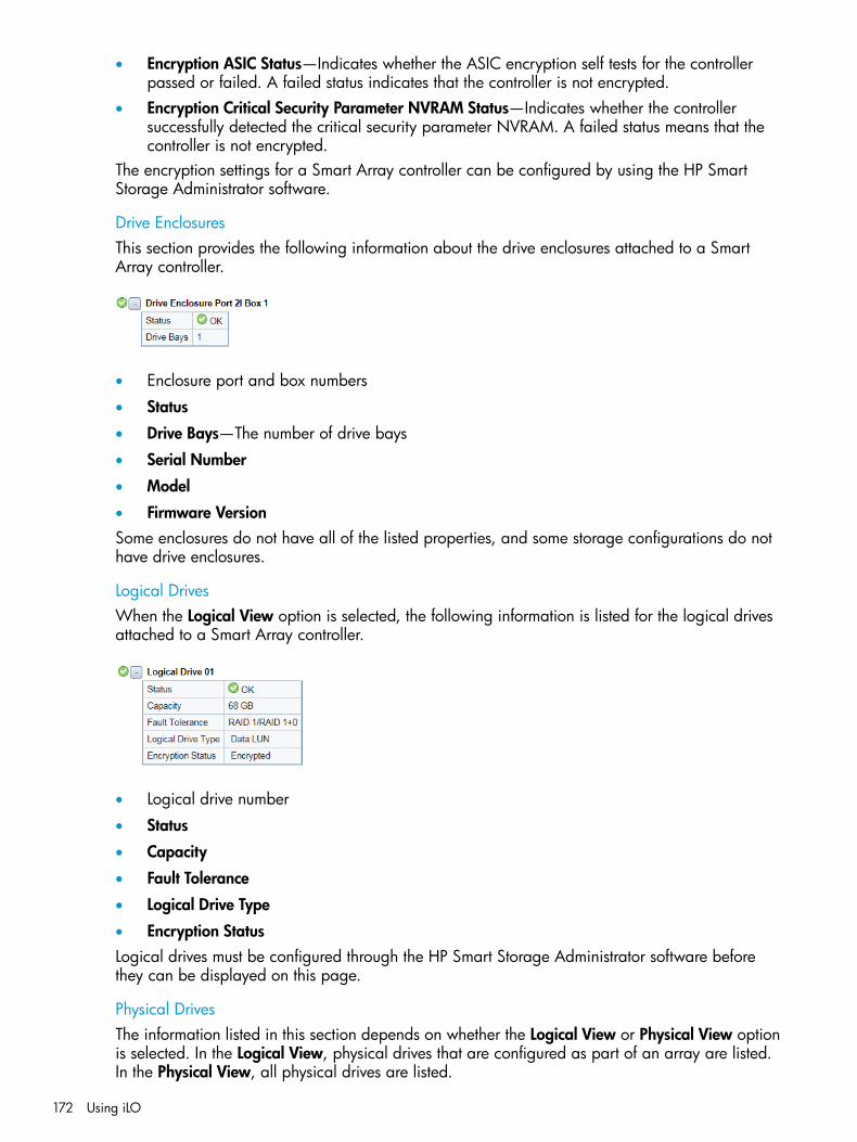
• Encryption ASIC Status—Indicates whether the ASIC encryption self tests for the controllerpassed or failed. A failed status indicates that the controller is not encrypted.
• Encryption Critical Security Parameter NVRAM Status—Indicates whether the controllersuccessfully detected the critical security parameter NVRAM. A failed status means that thecontroller is not encrypted.
The encryption settings for a Smart Array controller can be configured by using the HP SmartStorage Administrator software.
Drive EnclosuresThis section provides the following information about the drive enclosures attached to a SmartArray controller.
• Enclosure port and box numbers
• Status
• Drive Bays—The number of drive bays
• Serial Number
• Model
• Firmware VersionSome enclosures do not have all of the listed properties, and some storage configurations do nothave drive enclosures.
Logical DrivesWhen the Logical View option is selected, the following information is listed for the logical drivesattached to a Smart Array controller.
• Logical drive number
• Status
• Capacity
• Fault Tolerance
• Logical Drive Type
• Encryption StatusLogical drives must be configured through the HP Smart Storage Administrator software beforethey can be displayed on this page.
Physical DrivesThe information listed in this section depends on whether the Logical View or Physical View optionis selected. In the Logical View, physical drives that are configured as part of an array are listed.In the Physical View, all physical drives are listed.
172 Using iLO

iLO might not report all of the physical drives on servers with a large number of physical drivesattached to a single controller.When a physical drive has a Failed status, this status does not affect the overall storage healthstatus. Only logical drives affect the storage health status.The following information is listed for the physical drives attached to a Smart Array controller:
• Physical drive port, box, and bay numbers
• Status
• Serial Number
• Model
• Media Type
• Capacity
• Location
• Firmware Version
• Drive Configuration
• Encryption Status
Viewing direct-attached storage information1. Navigate to the Information→System Information page.2. Click the Storage tab.A description of each section that is displayed for direct-attached storage follows.
ControllersThis section provides the following information about the HP and third-party storage controllersthat manage direct-attached storage.
• Controller location
• Top-level controller status—The top-level controller status (displayed on the left of the controllerlocation) is a combination of the controller hardware status and the status of the enclosures,physical drives, and spare drives associated with the controller. If the controller hardwarestatus is OK, and any associated hardware has a failure, the top-level controller status changesto Major Warning or Degraded, depending on the failure type. If the controller hardware hasa Failed status, the top-level controller status is Failed.
Viewing system information 173

• Controller Status—Controller hardware status (OK or Failed)
• Serial Number
• Model
• Firmware Version
• Drive Type
Physical DrivesThis section provides information about physical drives attached to HP and third-party storagecontrollers.
When a physical drive has a Failed status, this status does not affect the overall storage healthstatus. Only logical drives affect the storage health status.
• Physical drive location
• Status
• Serial Number
• Model
• Media Type
• Capacity
• Location
• Firmware Version
• Drive Configuration
• Encryption Status
Viewing firmware informationNavigate to the Information→System Information page, and then click the Firmware tab.
174 Using iLO
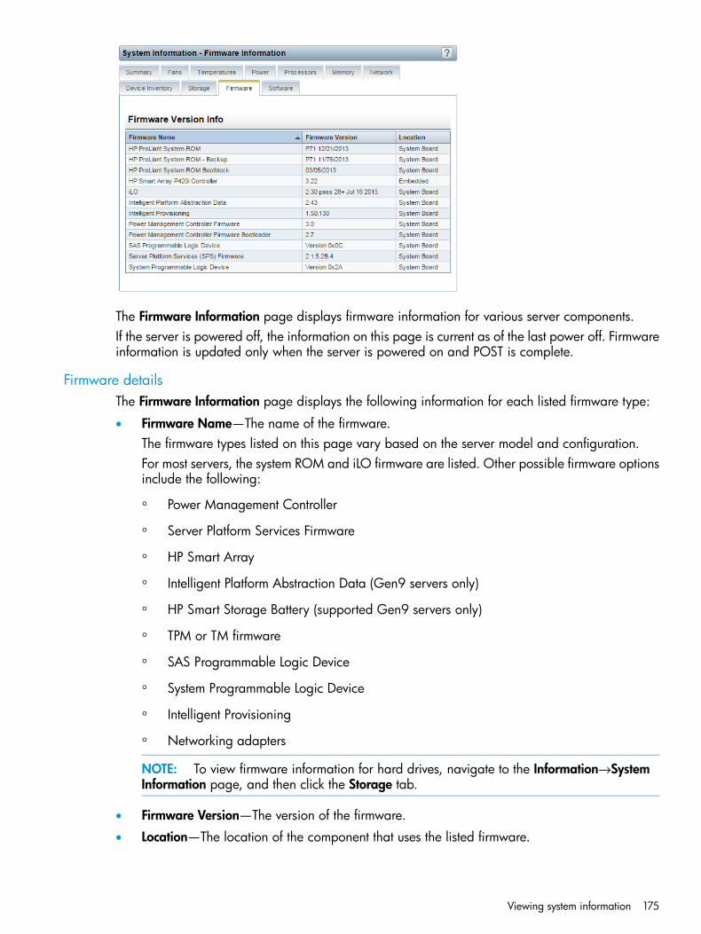
The Firmware Information page displays firmware information for various server components.If the server is powered off, the information on this page is current as of the last power off. Firmwareinformation is updated only when the server is powered on and POST is complete.
Firmware detailsThe Firmware Information page displays the following information for each listed firmware type:
• Firmware Name—The name of the firmware.The firmware types listed on this page vary based on the server model and configuration.For most servers, the system ROM and iLO firmware are listed. Other possible firmware optionsinclude the following:
◦ Power Management Controller
◦ Server Platform Services Firmware
◦ HP Smart Array
◦ Intelligent Platform Abstraction Data (Gen9 servers only)
◦ HP Smart Storage Battery (supported Gen9 servers only)
◦ TPM or TM firmware
◦ SAS Programmable Logic Device
◦ System Programmable Logic Device
◦ Intelligent Provisioning
◦ Networking adapters
NOTE: To view firmware information for hard drives, navigate to the Information→SystemInformation page, and then click the Storage tab.
• Firmware Version—The version of the firmware.
• Location—The location of the component that uses the listed firmware.
Viewing system information 175
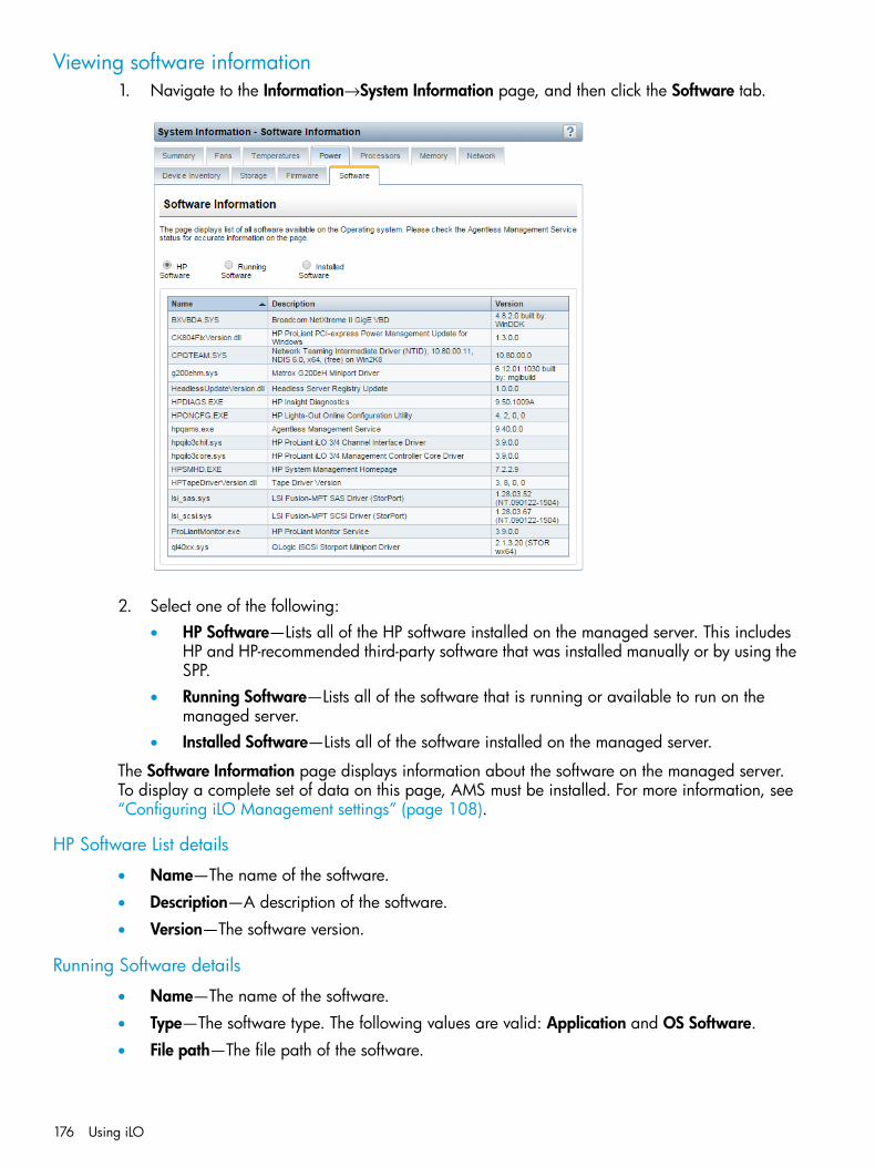
Viewing software information1. Navigate to the Information→System Information page, and then click the Software tab.
2. Select one of the following:• HP Software—Lists all of the HP software installed on the managed server. This includes
HP and HP-recommended third-party software that was installed manually or by using theSPP.
• Running Software—Lists all of the software that is running or available to run on themanaged server.
• Installed Software—Lists all of the software installed on the managed server.
The Software Information page displays information about the software on the managed server.To display a complete set of data on this page, AMS must be installed. For more information, see“Configuring iLO Management settings” (page 108).
HP Software List details
• Name—The name of the software.
• Description—A description of the software.
• Version—The software version.
Running Software details
• Name—The name of the software.
• Type—The software type. The following values are valid: Application and OS Software.
• File path—The file path of the software.
176 Using iLO
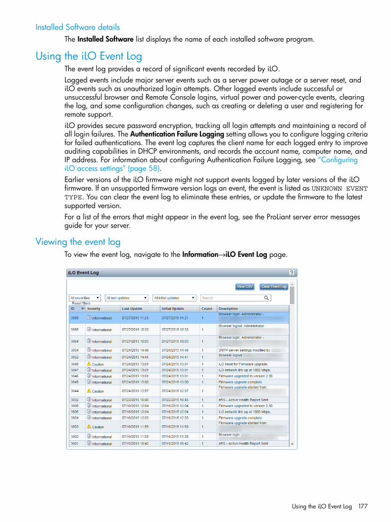
Installed Software detailsThe Installed Software list displays the name of each installed software program.
Using the iLO Event LogThe event log provides a record of significant events recorded by iLO.Logged events include major server events such as a server power outage or a server reset, andiLO events such as unauthorized login attempts. Other logged events include successful orunsuccessful browser and Remote Console logins, virtual power and power-cycle events, clearingthe log, and some configuration changes, such as creating or deleting a user and registering forremote support.iLO provides secure password encryption, tracking all login attempts and maintaining a record ofall login failures. The Authentication Failure Logging setting allows you to configure logging criteriafor failed authentications. The event log captures the client name for each logged entry to improveauditing capabilities in DHCP environments, and records the account name, computer name, andIP address. For information about configuring Authentication Failure Logging, see “ConfiguringiLO access settings” (page 58).Earlier versions of the iLO firmware might not support events logged by later versions of the iLOfirmware. If an unsupported firmware version logs an event, the event is listed as UNKNOWN EVENTTYPE. You can clear the event log to eliminate these entries, or update the firmware to the latestsupported version.For a list of the errors that might appear in the event log, see the ProLiant server error messagesguide for your server.
Viewing the event logTo view the event log, navigate to the Information→iLO Event Log page.
Using the iLO Event Log 177
The log displays the following information:
• ID—The event ID number. Events are numbered in the order in which they are generated.By default, the event log is sorted by the ID, with the most recent event at the top.
• Severity—The importance of the detected event.Possible values follow:
◦ Critical—The event indicates a service loss or imminent service loss. Immediate attentionis needed.
◦ Caution—The event is significant but does not indicate performance degradation.
◦ Informational—The event provides background information.
• Last Update—The date and time when the latest event of this type occurred. This value is basedon the date and time stored by the iLO firmware.The date and time can be synchronized through the following:
◦ System ROM (during POST only)
◦ Insight Management Agents (in the OS)
◦ NTP server (configured in iLO)
◦ Onboard Administrator (server blades only)
If the iLO firmware did not recognize the date and time when an event was updated, [NOTSET] is displayed.
• Initial Update—The date and time when the first event of this type occurred. This value is basedon the date and time stored by the iLO firmware.If the iLO firmware did not recognize the date and time when the event was first created,[NOT SET] is displayed.
• Count—The number of times this event has occurred (if supported).In general, important events generate an event log entry each time they occur. They are notconsolidated into one event log entry.When less important events are repeated, they are consolidated into one event log entry, andthe Count and Last Update values are updated. Each event type has a specific time intervalthat determines whether repeated events are consolidated or a new event is logged.
• Description—The description identifies the component and detailed characteristics of therecorded event.If the iLO firmware is rolled back to an earlier version, the description UNKNOWN EVENTTYPE might be displayed for events recorded by the newer firmware. You can resolve thisissue by updating the firmware to the latest supported version, or by clearing the event log.
Customizing the event log viewYou can customize the event log view by using the controls at the top of the page.
178 Using iLO
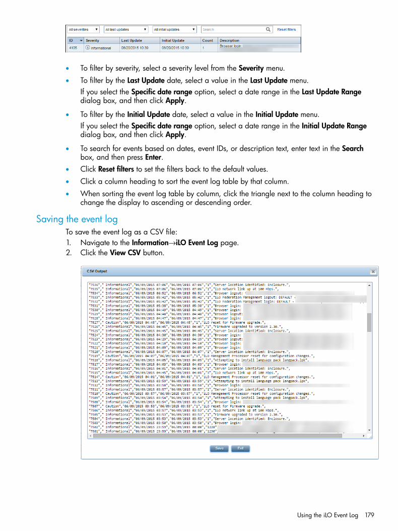
• To filter by severity, select a severity level from the Severity menu.
• To filter by the Last Update date, select a value in the Last Update menu.If you select the Specific date range option, select a date range in the Last Update Rangedialog box, and then click Apply.
• To filter by the Initial Update date, select a value in the Initial Update menu.If you select the Specific date range option, select a date range in the Initial Update Rangedialog box, and then click Apply.
• To search for events based on dates, event IDs, or description text, enter text in the Searchbox, and then press Enter.
• Click Reset filters to set the filters back to the default values.
• Click a column heading to sort the event log table by that column.
• When sorting the event log table by column, click the triangle next to the column heading tochange the display to ascending or descending order.
Saving the event logTo save the event log as a CSV file:1. Navigate to the Information→iLO Event Log page.2. Click the View CSV button.
Using the iLO Event Log 179

3. Do one of the following:• For Internet Explorer 8 only—Copy the text displayed in the CSV Output window, and
save it in a text editor as a CSV file.• For all other browsers—In the CSV Output window, click Save, and then follow the browser
prompts to save or open the file.4. Click Close to close the window.
Clearing the event logUsers with the Configure iLO Settings privilege can clear the event log of all previously loggedinformation.1. Navigate to the Information→iLO Event Log page.2. Click Clear Event Log.3. When prompted to confirm the request, click OK.
The following event is recorded:Event log cleared by <user name>.
Using the Integrated Management LogThe IML provides a record of historical events that have occurred on the server. Events are generatedby the system ROM and by services such as the iLO health driver. Logged events include allserver-specific events recorded by the system health driver, including operating system informationand ROM-based POST codes.Entries in the IML can help you diagnose issues or identify potential issues. Preventative actionmight help to avoid disruption of service.iLO manages the IML, which you can access through a supported browser, even when the serveris off. The ability to view the log when the server is off can be helpful when troubleshooting remotehost server issues.Examples of the types of information recorded in the IML follow:
• Fan inserted
• Fan removed
• Fan failure
• Fan degraded
• Fan repaired
• Fan redundancy lost
• Fans redundant
• Power supply inserted
• Power supply removed
• Power supply failure
• Power supplies redundancy lost
• Power supplies redundant
• Temperature over threshold
• Temperature normal
• Automatic shutdown started
180 Using iLO

• Automatic shutdown canceled
• Drive failure
Viewing the IMLTo view the IML, navigate to the Information→Integrated Management Log page.
The IML displays the following information:
• The first column on the left side of the web interface displays a check box next to each eventwith Critical or Caution status. Use this check box to select an event to mark as repaired.For information about marking events as repaired, see “Marking an IML entry as repaired”(page 183).
• ID—The event ID number. Events are numbered in the order in which they are generated.By default, the IML is sorted by the ID, with the most recent event at the top. A factory resetwill reset the counter.
• Severity—The importance of the detected event.Possible values follow:
◦ Critical—The event indicates a service loss or an imminent service loss. Immediate attentionis needed.
◦ Caution—The event is significant but does not indicate performance degradation.
◦ Informational—The event provides background information.
◦ Repaired—An event has undergone corrective action.
◦ Unknown—The event severity could not be determined.
• Class—Identifies the type of event that occurred, for example, network, maintenance, or systemrevision.
• Last Update—The date and time when the latest event of this type occurred. This value is basedon the date and time stored by the iLO firmware.The date and time can be synchronized through the following:
◦ System ROM (during POST only)
◦ Insight Management Agents (in the OS)
Using the Integrated Management Log 181

◦ NTP server (configured in iLO)
◦ Onboard Administrator (server blades only)
If iLO did not recognize the date and time when an event was updated, [NOT SET] isdisplayed.
• Initial Update—The date and time when the first event of this type occurred. This value is basedon the date and time stored by the iLO firmware.If iLO did not recognize the date and time when the event was first created, [NOT SET] isdisplayed.
• Count—The number of times this event has occurred (if supported).In general, important events generate an IML entry each time they occur. They are notconsolidated into one event log entry.When less important events are repeated, they are consolidated into one IML entry, and theCount and Last Update values are updated. Each event type has a specific time interval thatdetermines whether repeated events are consolidated or a new event is logged.
• Description—The description identifies the component and detailed characteristics of therecorded event.If the iLO firmware is rolled back, the description UNKNOWN EVENT TYPE might be displayedfor events recorded by the newer firmware. You can resolve this issue by updating the firmwareto the latest supported version, or by clearing the log.To access troubleshooting information for selected events, click the link in the Descriptioncolumn.
Customizing the IML viewYou can customize the IML view by using the controls at the top of the page.
• To filter by severity, select a severity level from the Severity menu.
• To filter by class, select a class from the Class menu.
• To filter by the Last Update date, select a value in the Last Update menu.If you select the Specific date range option, select a date range in the Last Update Rangedialog box, and then click Apply.
• To filter by the Initial Update date, select a value in the Initial Update menu.If you select the Specific date range option, select a date range in the Initial Update Rangedialog box, and then click Apply.
• To search for events based on dates, event IDs, or description text, enter text in the Searchbox, and then press Enter.
• Click Reset filters to set the filters back to the default values.
• Click a column heading to sort the IML table by that column.
• When sorting the IML table by column, click the triangle next to the column heading to changethe display to ascending or descending order.
182 Using iLO

Marking an IML entry as repairedUse this feature to change the status of an IML entry from Critical or Caution to Repaired. You musthave the Configure iLO Settings privilege to use this feature.When a Critical or Caution event is reported in the IML:1. Investigate and repair the issue.2. Navigate to the Information→Integrated Management Log page.3. Select the log entry.
To select an IML entry, click the check box next to the entry in the first column of the IML table.If a check box is not displayed next to an IML entry, that entry cannot be marked as repaired.
4. Click Mark as Repaired.The iLO web interface refreshes, and the selected log entry status changes to Repaired.
Adding a maintenance note to the IMLUse the maintenance note feature to create a log entry that logs information about maintenanceactivities such as component upgrades, system backups, periodic system maintenance, or softwareinstallations. You must have the Configure iLO Settings privilege to use this feature.1. Navigate to the Information→Integrated Management Log page.2. Click Add Maintenance Note.
The Enter Maintenance Note window opens.
3. Enter the text that you want to add as a log entry, and then click OK.You can enter up to 227 bytes of text. You cannot submit a maintenance note without enteringsome text.An Informational log entry with the class Maintenance is added to the IML.
Saving the IMLTo save the IML as a CSV file:1. Navigate to the Information→Integrated Management Log page.2. Click the View CSV button.
Using the Integrated Management Log 183
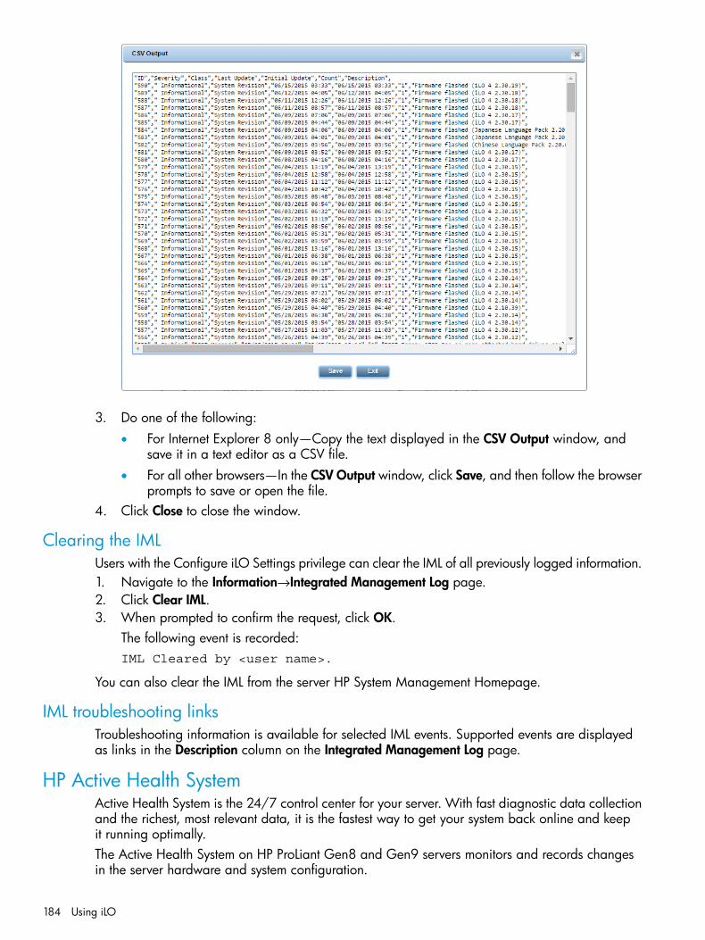
3. Do one of the following:• For Internet Explorer 8 only—Copy the text displayed in the CSV Output window, and
save it in a text editor as a CSV file.• For all other browsers—In the CSV Output window, click Save, and then follow the browser
prompts to save or open the file.4. Click Close to close the window.
Clearing the IMLUsers with the Configure iLO Settings privilege can clear the IML of all previously logged information.1. Navigate to the Information→Integrated Management Log page.2. Click Clear IML.3. When prompted to confirm the request, click OK.
The following event is recorded:IML Cleared by <user name>.
You can also clear the IML from the server HP System Management Homepage.
IML troubleshooting linksTroubleshooting information is available for selected IML events. Supported events are displayedas links in the Description column on the Integrated Management Log page.
HP Active Health SystemActive Health System is the 24/7 control center for your server. With fast diagnostic data collectionand the richest, most relevant data, it is the fastest way to get your system back online and keepit running optimally.The Active Health System on HP ProLiant Gen8 and Gen9 servers monitors and records changesin the server hardware and system configuration.
184 Using iLO

The Active Health System provides:
• Continuous health monitoring of over 1600 system parameters
• Logging of all configuration changes
• Consolidated health and service alerts with precise time stamps
• Agentless monitoring that does not affect application performanceIt takes less than 5 minutes to export the Active Health System Log and send it to an HP Supportprofessional to help you resolve your issue.
Data collectionThe Active Health System does not collect information about your operations, finances, customers,employees, or partners. The data collected by the Active Health System is logged securely, isolatedfrom the operating system, and separate from customer data.By downloading and sending Active Health System data to HP, you agree to have HP use the datafor analysis, technical resolution, and quality improvements. The data that is collected is managedaccording to the HP privacy statement, available at http://www.hp.com/go/privacy.Examples of data that is collected follow:
• Server model and serial number
• Processor model and speed
• Storage capacity and speed
• Memory capacity and speed
• Firmware/BIOS and driver versions and settingsThe Active Health System does not parse or change operating system data from third-party errorevent log activities (for example, content created or passed through the operating system).When the Active Health System Log is full, new data overwrites the oldest data in the log.
Active Health System Log download methodsYou can download the Active Health System Log manually and send it to HP. To download thelog, use iLO, Intelligent Provisioning, curl, or the Active Health System download CLI tool.
• For information about downloading the log with iLO, see “Downloading the Active HealthSystem Log for a date range” (page 186) and “Downloading the entire Active Health SystemLog” (page 187).
• For information about downloading the log with Intelligent Provisioning or the Active HealthSystem download CLI, see the Intelligent Provisioning user guide or the server troubleshootingguide.
HP Active Health System 185
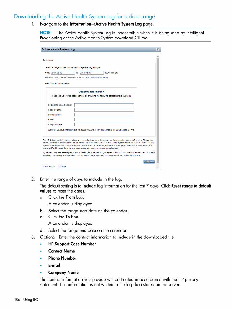
Downloading the Active Health System Log for a date range1. Navigate to the Information→Active Health System Log page.
NOTE: The Active Health System Log is inaccessible when it is being used by IntelligentProvisioning or the Active Health System download CLI tool.
2. Enter the range of days to include in the log.The default setting is to include log information for the last 7 days. Click Reset range to defaultvalues to reset the dates.a. Click the From box.
A calendar is displayed.b. Select the range start date on the calendar.c. Click the To box.
A calendar is displayed.d. Select the range end date on the calendar.
3. Optional: Enter the contact information to include in the downloaded file.• HP Support Case Number
• Contact Name
• Phone Number
• Company NameThe contact information you provide will be treated in accordance with the HP privacystatement. This information is not written to the log data stored on the server.
186 Using iLO
4. Click Download.5. Save the file.
The default file name is HP_<server_serial_number>_<date>.ahs.
6. If you have an open case with HP Support, you can email the log file [email protected] the following convention for the email subject: CASE: <case number>.Files that are larger than 15 MB must be compressed and uploaded to an FTP site. If needed,contact HP Support for FTP site information.
Downloading the entire Active Health System LogIt might take a long time to download the entire Active Health System Log. If you must upload theActive Health System Log for a technical issue, HP recommends downloading the log for the specificrange of dates in which the problem occurred. For instructions, see “Downloading the Active HealthSystem Log for a date range” (page 186).1. Navigate to the Information→Active Health System Log page.
NOTE: The Active Health System Log is inaccessible when it is being used by IntelligentProvisioning or the Active Health System download CLI tool.
2. Click Show Advanced Settings.3. Optional: Enter the contact information to include in the downloaded file.
• HP Support Case Number
• Contact Name
• Phone Number
• Company NameThe contact information that you provide will be treated in accordance with the HP privacystatement. This information is not written to the log data stored on the server.
4. Click Download Entire Log.5. Save the file.
The default file name is HP_<server_serial_number>_<date>.ahs.
6. If you have an open case with HP Support, you can email the log file [email protected] the following convention for the email subject: CASE: <case number>.Files that are larger than 15 MB must be compressed and uploaded to an FTP site. If needed,contact HP Support for FTP site information.
Extracting the Active Health System Log by using curliLO 4 1.30 and later supports extracting the Active Health System log with the curl commandline tool.You can download curl from the following website: http://curl.haxx.se/.To download the Active Health System log by using curl:1. Install curl.2. Open a command window.3. Enter the following command to download the Active Health System log for a range of dates:
curl "https://<iLO IP address>/ahsdata/ahs.ahs?from=<yyyy-mm-dd>&to=<yyyy-mm-dd>" -k -v -u <username>:<password> -o <filename>.ahs
HP Active Health System 187

Where:
• <iLO IP address> is the iLO IP address.
• from=<yyyy-mm-dd>&to=<yyyy-mm-dd> represents the start and end date of therange of dates to include in the log. Enter dates in the format year-month-day, forexample, 2013-07-29 for July 29, 2013.
• –k specifies that HTTPS warnings will be ignored.
• –v specifies verbose output.
• -u <username>:<password> specifies your iLO user account credentials.
• –o <filename> specifies the output file name and path.
NOTE: To download the entire log, omit the from and to parameters and use the followingcommand: curl "https://<iLO IP address>/ahsdata/ahs.ahs" -k -v -u<username>:<password> -o <filename>.ahs
The file is saved to the path you specified.4. Close the command window.
Clearing the Active Health System LogIf the log file is corrupted, or if you want to clear and restart logging, use the following procedureto clear the Active Health System Log. You must have the Configure iLO Settings privilege to performthis procedure.1. Navigate to the Information→Active Health System Log page.
NOTE: The Active Health System Log is inaccessible when it is being used by IntelligentProvisioning or the Active Health System download CLI tool.
2. Click Show Advanced Settings.3. Scroll to the Clear Log section, and then click the Clear button.
The following message appears:Are you sure that you want to clear the entire Active Health Systemlog? This action cannot be undone.
4. Click OK.iLO notifies you that the log is being cleared.
5. Reset iLO.For instructions, see “Using iLO diagnostics” (page 188).Resetting iLO after clearing the Active Health System Log is required because some ActiveHealth System data is recorded to the log only during iLO startup. Performing this step ensuresthat a complete set of data is available in the log.
6. Reboot the server.Rebooting the server after clearing the Active Health System Log is required because someinformation, such as the operating system name and version, is logged at server startup.Performing this step ensures that a complete set of data is available in the log.
Using iLO diagnosticsThe Diagnostics page displays the iLO self-test results and allows you to reset iLO, generate anNMI to the system, or configure redundant ROM.
188 Using iLO

Viewing iLO self-test resultsThe iLO Self-Test Results section displays the results of internal iLO diagnostic tests, including thetest name, status, and notes.To view the self-test results, navigate to the Information→Diagnostics page.
• The test status is listed in the Status column. Move the cursor over a status icon to view a tooltipdescription.
• If a status has not been reported for a test, the test is not listed.
• The tests that are run are system dependent. Not all tests are run on all systems. View the liston the Diagnostics page to see the tests that are performed on your system.
• A test might include additional information in the Notes column. This column displays theversions of other system programmable logic, such as the System Board PAL or the PowerManagement Controller.
• The following information is displayed in the Embedded Flash/SD-CARD test results:
Firmware revision◦◦ SD-CARD size
◦ SD-CARD slot
◦ SD-CARD write counterThe write counter counts data in 512-byte blocks. If the write counter is at zero, no writecounter text is displayed.Write counter information is displayed only when a recognized “Genuine HP” SD-Cardis installed with a retail version of the iLO firmware.
Using iLO diagnostics 189

Resetting the iLO processor through the web interfaceIf iLO is slow to respond, you might need to reset the iLO processor.Using the Reset option does not make any configuration changes, but ends all active connectionsto the iLO firmware. If a firmware file upload is in progress, it is terminated. If a firmware flash isin progress, you cannot reset iLO until the process is finished. You must have the Configure iLOSettings privilege to use this feature.1. Navigate to the Information→Diagnostics page.2. Click Reset.3. When prompted to confirm the request, click OK.
iLO resets and closes your browser connection.
For other reset methods, see “Rebooting (Resetting) iLO” (page 267).
Generating an NMIThe Generate NMI to System button enables you to stop the operating system for debugging.The Virtual Power and Reset privilege is required to generate an NMI.
CAUTION: Generating an NMI as a diagnostic and debugging tool is used primarily when theoperating system is no longer available. NMI is not used during normal operation of the server.Generating an NMI does not gracefully shut down the operating system, but causes the operatingsystem to crash, resulting in lost service and data. Use the Generate NMI to System button only inextreme cases in which the operating system is not functioning correctly and an experienced supportorganization has recommended that you proceed with an NMI.
1. Navigate to the Information→Diagnostics page.2. Click Generate NMI to System.
iLO warns you that generating an NMI to the system might cause data loss.3. Click OK to confirm, or click Cancel.
If you clicked OK, iLO confirms that the NMI was sent.
Configuring redundant ROM1. Navigate to the Information→Diagnostics page.
The Active ROM table shows the version and date of the active system ROM.The Backup ROM table shows the version of the backup ROM and the release date of thebackup ROM bootblock (Gen8 servers only). The backup ROM is typically the previouslyinstalled version.
2. Click Swap ROM to swap the active ROM and the backup ROM.The change will take effect after the next system reboot.
3. When prompted to confirm the request, click OK.
Using Location Discovery ServicesLocation Discovery Services is a component of HP Discovery Services. Location Discovery Servicesautomatically reports server locations to HP SIM and Insight Control, eliminating this manual taskfor server administrators. Administrators can use the location information and system data with HPAsset Manager to obtain more precise and complete asset data.Location Discovery Services is a rack U location discovery solution for G3 and later racks. It enablesiLO, OA, and the chassis firmware to report and display the rack ID and the server U position inthe rack. Supported racks are programmed with unique U values in 7U and/or 8U modules, and
190 Using iLO

are installed with the tag version number, rack identifier, part number, product name, rack height,and U position. Location Discovery Services supports 14U, 22U, 36U, 42U, and 47U racks.The rack device reads the rack U location tag each time iLO receives AC power or iLO is reset.The U position value denotes the U position read by the device. The contact position offset is afixed value for each model that indicates the position of the contact relative to the bottom U positionof the device. It is normally 0, but can be a positive value if the contact cannot be placed at thebottom U position of the device. The bottom-most U position occupied by the device is calculatedby subtracting the U offset from the U position.To view Location Discovery Services information, navigate to the Information→Location DiscoveryServices page.
The Location Discovery Services page lists the following information:
• Platform Type—The server type.
• Discovery Rack Support—Whether the rack supports Location Discovery Services.
• Discovery Data Status—Whether there was an error during discovery.
• Rack Identifier—The rack identifier. If data is not available, the value 0 is displayed.
• Rack Location Discovery Product Part Number—The rack part number. If data is not available,the value 0 is displayed.
• Rack Location Discovery Product Description—The rack product name. If data is not available,the value 0 is displayed.
• Rack U Height—The rack height, in U rack units. Possible values are between 0 and 50. Ifdata is not available, the value 0 is displayed.
• U Location—The side of the rack where the device is installed. Possible values are Back, Front(default), Left, and Right. If data is not available, the value 0 is displayed.
• Server UUID—The universally unique identifier of the server.Additional information is listed, depending on the server type.DL and ML server-specific data:• Server U Height—The server height, in U rack units. Possible values are between 1.00 and
50.00.• Server Rack U Position—The rack U position that aligns with the base of the server. Possible
values are between 1 and 50.
Using Location Discovery Services 191

Blade enclosures and BL server-specific data:
• Bay Number—The server bay in the enclosure.
• Enclosure UUID—The enclosure universally unique identifier.
• Enclosure U Height—The enclosure height, in U rack units. Possible values are between 1.00and 50.00.
• Enclosure Rack U Position—The rack U position that aligns with the base of the enclosure.Possible values are between 1 and 50.
SL and XL server-specific data:
• Bay Number—The server bay in the enclosure.
• Chassis UUID—The chassis universally unique identifier.
• Chassis U Height—The chassis height, in U rack units. Possible values are between 1.00 and50.00.
• Chassis Rack U Position—The rack U position that aligns with the base of the chassis. Possiblevalues are between 1 and 50.
Using the HP Insight Management AgentsThe Insight Management Agents support a browser interface for access to run-time managementdata through the HP System Management Homepage. The System Management Homepage is asecure web-based interface that consolidates and simplifies the management of individual serversand operating systems. By aggregating data from the Insight Management Agents and othermanagement tools, the System Management Homepage provides an intuitive interface to reviewin-depth hardware configuration and status data, performance metrics, system thresholds, andsoftware version control information.The agents can automatically provide the link to iLO, or you can manually enter the link on theAdministration→Management page.To open the System Management Homepage:1. Navigate to the Information→Insight Agent page.
2. Click the Insight Agent button.
Using iLO FederationiLO Federation enables you to manage multiple servers from one system running the iLO webinterface.
192 Using iLO

iLO 4 firmware version 1.40 and later supports the following features:
• Group health status
• Group Virtual Media
• Group power control
• Group power capping
• Group firmware updateiLO 4 firmware version 2.00 and later supports the following features:
• Group license installation
• Group configurationThe iLO Federation features are available from the iLO Federation branch of the iLO web interfacenavigation tree.Any user can view information on iLO Federation pages, but some features require a license. Formore information, see the following website: http://www.hp.com/go/ilo/licensing.
PrerequisitesBefore you use the iLO Federation features, make sure that your environment meets the prerequisites.For more information, see “Prerequisites” (page 46).
Using the Selected Group listWhen you work with the iLO Federation features, use the Selected Group list to control the serversthat will be affected by the actions you take on an iLO Federation page.When you select a group from the Selected Group list on an iLO Federation page:
• The servers that will be affected by a change on the Group Virtual Media, Group Power,Group Firmware Update, Group Licensing, and Group Configuration pages are listed in theAffected Systems table.
• The information displayed on iLO Federation pages applies to all of the servers in the selectedgroup.
• The changes you make on iLO Federation pages apply to all of the servers in the selectedgroup.
• The selected group is saved in a cookie and remains persistent, even when you log out ofiLO.
After you select a group, you can filter the servers in the list in order to view server information orperform actions on a subset of the servers in the group.
Filtering the Selected Group listWhen you filter the list of servers:
• The information displayed on iLO Federation pages applies to all of the servers in the selectedgroup that meet the filter criteria.
• The changes you make on iLO Federation pages apply to all of the servers in the selectedgroup that meet the filter criteria.
• The filter settings are saved in a cookie and remain persistent, even when you log out of iLO.You can use the following criteria to filter the servers in a group:
• Health status—Click a health status link to select servers with a specific health status.
• Model—Click a server model number link to select servers matching the selected model.
• Server name—Click a server name to filter by an individual server.
Using iLO Federation 193
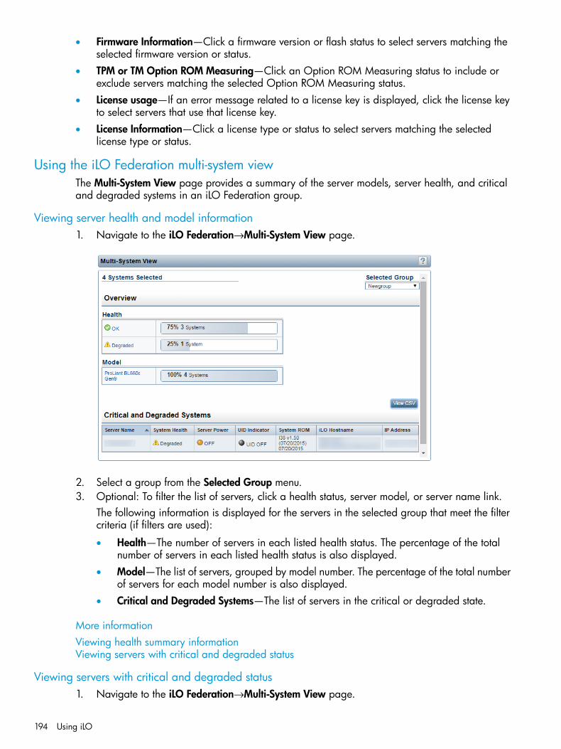
• Firmware Information—Click a firmware version or flash status to select servers matching theselected firmware version or status.
• TPM or TM Option ROM Measuring—Click an Option ROM Measuring status to include orexclude servers matching the selected Option ROM Measuring status.
• License usage—If an error message related to a license key is displayed, click the license keyto select servers that use that license key.
• License Information—Click a license type or status to select servers matching the selectedlicense type or status.
Using the iLO Federation multi-system viewThe Multi-System View page provides a summary of the server models, server health, and criticaland degraded systems in an iLO Federation group.
Viewing server health and model information1. Navigate to the iLO Federation→Multi-System View page.
2. Select a group from the Selected Group menu.3. Optional: To filter the list of servers, click a health status, server model, or server name link.
The following information is displayed for the servers in the selected group that meet the filtercriteria (if filters are used):
• Health—The number of servers in each listed health status. The percentage of the totalnumber of servers in each listed health status is also displayed.
• Model—The list of servers, grouped by model number. The percentage of the total numberof servers for each model number is also displayed.
• Critical and Degraded Systems—The list of servers in the critical or degraded state.
More informationViewing health summary informationViewing servers with critical and degraded status
Viewing servers with critical and degraded status1. Navigate to the iLO Federation→Multi-System View page.
194 Using iLO
2. Select a group from the Selected Group menu.3. Optional: To filter the list of servers, click a health status, server model, or server name link.
The following information is displayed for the critical and degraded servers in the selectedgroup that meet the filter criteria (if filters are used):
• Server Name—The server name defined by the host operating system.
• System Health—The server health status.
• Server Power—The server power status (ON or OFF).
• UID Indicator—The state of the server UID LED. The UID LED helps you identify and locatea server, especially in high-density rack environments. The possible states are UID ON,UID OFF, and UID BLINK.
• System ROM—The installed System ROM.
• iLO Hostname—The fully qualified network name assigned to the iLO subsystem. Clickthe link in the iLO Hostname column to open the iLO web interface for the server.
• IP Address—The network IP address of the iLO subsystem. Click the link in the IP Addresscolumn to open the iLO web interface for the server.
4. Click Next or Previous to view more servers in the list.
Exporting the Critical and Degraded Systems list to a CSV file1. Navigate to the iLO Federation→Multi-System View page.2. Click View CSV.3. Do one of the following:
• For Internet Explorer 8 only—Copy the text displayed in the CSV Output window, andsave it in a text editor as a CSV file.
• For all other browsers—In the CSV Output window, click Save, and then follow the browserprompts to save or open the file.
When you export the list, the CSV file contains only the servers displayed on the iLO Federationpage.If multiple pages of servers are included in the list, the CSV file will contain only the serversthat are currently displayed on the iLO web interface page.If a query error occurred, the systems that did not respond to the query are excluded from theCritical and Degraded Systems list and the CSV file.
Viewing the iLO Federation Multi-System MapThe Multi-System Map page displays information about the peers of the local iLO system. The localiLO system identifies its peers through multicast discovery.When data is loaded on an iLO Federation page, a request for data is sent from the iLO systemrunning the web interface to the iLO system’s peers, and from those peers to other peers until allof the data for the selected iLO Federation group is retrieved.
Using iLO Federation 195
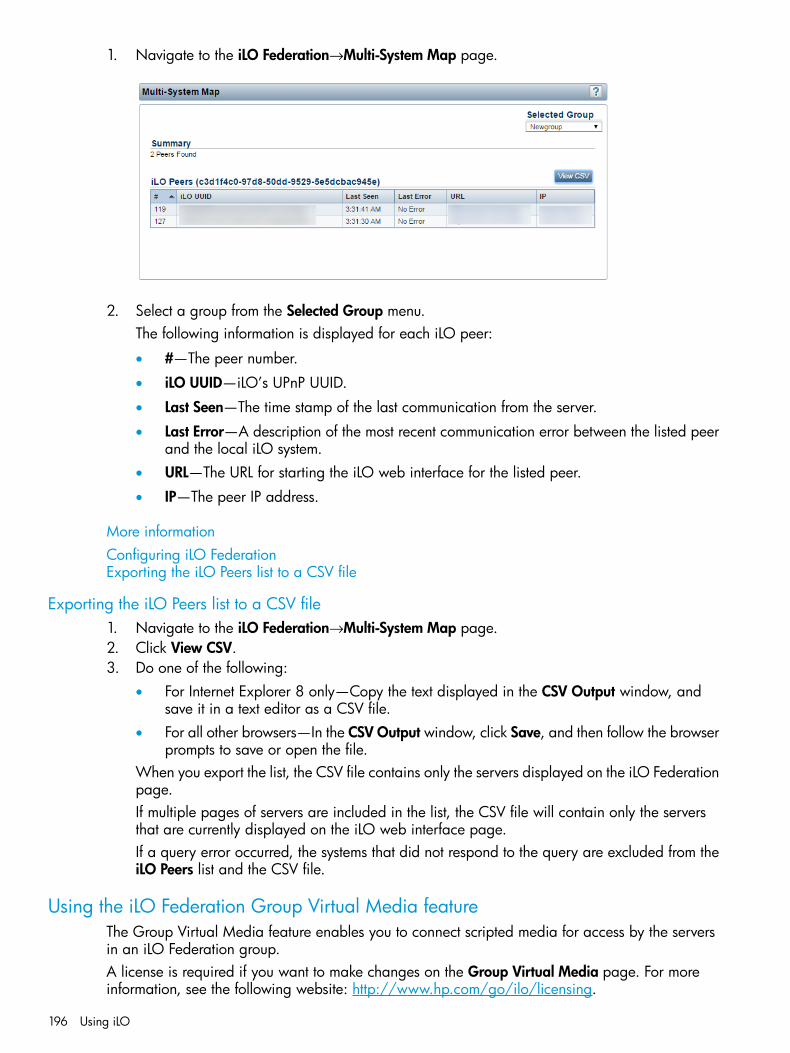
1. Navigate to the iLO Federation→Multi-System Map page.
2. Select a group from the Selected Group menu.The following information is displayed for each iLO peer:
• #—The peer number.
• iLO UUID—iLO’s UPnP UUID.
• Last Seen—The time stamp of the last communication from the server.
• Last Error—A description of the most recent communication error between the listed peerand the local iLO system.
• URL—The URL for starting the iLO web interface for the listed peer.
• IP—The peer IP address.
More informationConfiguring iLO FederationExporting the iLO Peers list to a CSV file
Exporting the iLO Peers list to a CSV file1. Navigate to the iLO Federation→Multi-System Map page.2. Click View CSV.3. Do one of the following:
• For Internet Explorer 8 only—Copy the text displayed in the CSV Output window, andsave it in a text editor as a CSV file.
• For all other browsers—In the CSV Output window, click Save, and then follow the browserprompts to save or open the file.
When you export the list, the CSV file contains only the servers displayed on the iLO Federationpage.If multiple pages of servers are included in the list, the CSV file will contain only the serversthat are currently displayed on the iLO web interface page.If a query error occurred, the systems that did not respond to the query are excluded from theiLO Peers list and the CSV file.
Using the iLO Federation Group Virtual Media featureThe Group Virtual Media feature enables you to connect scripted media for access by the serversin an iLO Federation group.A license is required if you want to make changes on the Group Virtual Media page. For moreinformation, see the following website: http://www.hp.com/go/ilo/licensing.
196 Using iLO
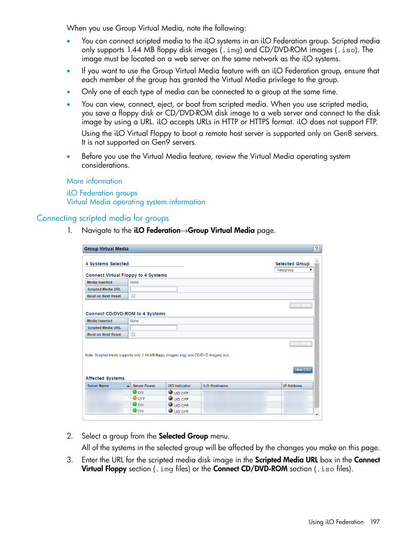
When you use Group Virtual Media, note the following:
• You can connect scripted media to the iLO systems in an iLO Federation group. Scripted mediaonly supports 1.44 MB floppy disk images (.img) and CD/DVD-ROM images (.iso). Theimage must be located on a web server on the same network as the iLO systems.
• If you want to use the Group Virtual Media feature with an iLO Federation group, ensure thateach member of the group has granted the Virtual Media privilege to the group.
• Only one of each type of media can be connected to a group at the same time.
• You can view, connect, eject, or boot from scripted media. When you use scripted media,you save a floppy disk or CD/DVD-ROM disk image to a web server and connect to the diskimage by using a URL. iLO accepts URLs in HTTP or HTTPS format. iLO does not support FTP.Using the iLO Virtual Floppy to boot a remote host server is supported only on Gen8 servers.It is not supported on Gen9 servers.
• Before you use the Virtual Media feature, review the Virtual Media operating systemconsiderations.
More informationiLO Federation groupsVirtual Media operating system information
Connecting scripted media for groups1. Navigate to the iLO Federation→Group Virtual Media page.
2. Select a group from the Selected Group menu.All of the systems in the selected group will be affected by the changes you make on this page.
3. Enter the URL for the scripted media disk image in the Scripted Media URL box in the ConnectVirtual Floppy section (.img files) or the Connect CD/DVD-ROM section (.iso files).
Using iLO Federation 197
4. Select the Boot on Next Reset check box if the servers in the group should boot to this diskimage only on the next server reboot.The disk image will be ejected automatically on the second server reboot so that the serversdo not boot to it twice.If this check box is not selected, the disk image will remain connected until it is ejectedmanually, and the servers will boot to it on all subsequent server resets, if the system bootoptions are configured accordingly.If a server in the group is in POST when you use the Boot on Next Reset check box, an erroroccurs because you cannot modify the server boot order during POST. Wait for POST to finish,and then try again.Using the iLO Virtual Floppy to boot a remote host server is supported only on Gen8 servers.It is not supported on Gen9 servers.
5. Click Insert Media.
Viewing scripted media for groupsTo view the connected scripted media devices, navigate to the iLO Federation→Group VirtualMedia page.When scripted media is connected to the systems in an iLO Federation group, the following detailsare listed in the Virtual Floppy Status section and Virtual CD/DVD-ROM Status section:
• Media Inserted—The Virtual Media type that is connected. Scripted Media is displayed whenscripted media is connected.
• Connected—Indicates whether a Virtual Media device is connected.
• Image URL—The URL that points to the connected scripted media.The Virtual Floppy Status and Virtual CD/DVD-ROM Status sections are displayed only when mediais connected.
Ejecting a scripted media device1. Navigate to the iLO Federation→Group Virtual Media page.2. Select a group from the Selected Group menu.
All of the systems in the selected group will be affected by the changes you make on this page.3. Click Eject Media in the Virtual Floppy Status section or the Virtual CD/DVD-ROM Status
section.
Servers affected by a Group Virtual Media actionThe Affected Systems section provides the following details about the servers that will be affectedby changes you make on the Group Virtual Media page:
• Server Name—The server name defined by the host operating system.
• Server Power—The server power state (ON or OFF).
• UID Indicator—The state of the UID LED. The UID LED helps you identify and locate a server,especially in high-density rack environments. The possible states are UID ON, UID OFF, andUID BLINK.
• iLO Hostname—The fully qualified network name assigned to the iLO subsystem. Click the linkin the iLO Hostname column to open the iLO web interface for the server.
• IP Address—The network IP address of the iLO subsystem. Click the link in the IP Addresscolumn to open the iLO web interface for the server.
198 Using iLO

Exporting the Affected Systems list to a CSV file1. Navigate to the iLO Federation→Group Virtual Media page.2. Click View CSV.3. Do one of the following:
• For Internet Explorer 8 only—Copy the text displayed in the CSV Output window, andsave it in a text editor as a CSV file.
• For all other browsers—In the CSV Output window, click Save, and then follow the browserprompts to save or open the file.
When you export the list, the CSV file contains only the servers displayed on the iLO Federationpage.If multiple pages of servers are included in the list, the CSV file will contain only the serversthat are currently displayed on the iLO web interface page.If a query error occurred, the systems that did not respond to the query are excluded from theAffected Systems list and the CSV file.
Using the iLO Federation Group Power featureThe Group Power feature enables you to manage the power of multiple servers from a systemrunning the iLO web interface. Use this feature to do the following:
• Power off, reset, or power-cycle a group of servers that are in the ON or Reset state.
• Power on a group of servers that are in the OFF state.
• View the list of servers that will be affected when you click a button in the Virtual Power Buttonsection of the Group Power page.
A license is required if you want to make changes on the Group Power page. For more information,see the following website: http://www.hp.com/go/ilo/licensing.If you want to use the Group Power feature with an iLO Federation group, ensure that each memberof the group has granted the Virtual Power and Reset privilege to the group.
More informationConfiguring iLO FederationChanging the power state for a group of serversServers affected by the Virtual Power Button
Changing the power state for a group of serversThe Virtual Power Button section on the Group Power page displays a summary of the currentpower state of the grouped servers, including the total number of servers that are in the ON, OFF,or Reset state. The System Power summary indicates the state of the server power when the pageis first opened. Use the browser refresh feature to update the System Power information.
Using iLO Federation 199
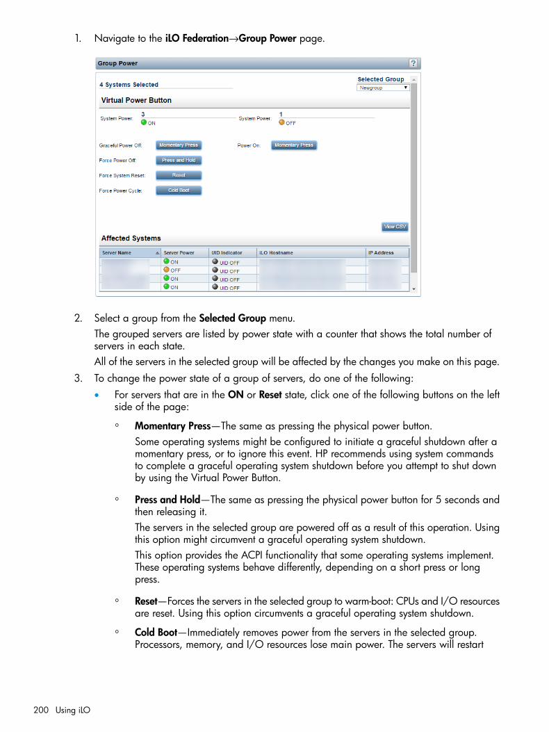
1. Navigate to the iLO Federation→Group Power page.
2. Select a group from the Selected Group menu.The grouped servers are listed by power state with a counter that shows the total number ofservers in each state.All of the servers in the selected group will be affected by the changes you make on this page.
3. To change the power state of a group of servers, do one of the following:• For servers that are in the ON or Reset state, click one of the following buttons on the left
side of the page:
◦ Momentary Press—The same as pressing the physical power button.Some operating systems might be configured to initiate a graceful shutdown after amomentary press, or to ignore this event. HP recommends using system commandsto complete a graceful operating system shutdown before you attempt to shut downby using the Virtual Power Button.
◦ Press and Hold—The same as pressing the physical power button for 5 seconds andthen releasing it.The servers in the selected group are powered off as a result of this operation. Usingthis option might circumvent a graceful operating system shutdown.This option provides the ACPI functionality that some operating systems implement.These operating systems behave differently, depending on a short press or longpress.
◦ Reset—Forces the servers in the selected group to warm-boot: CPUs and I/O resourcesare reset. Using this option circumvents a graceful operating system shutdown.
◦ Cold Boot—Immediately removes power from the servers in the selected group.Processors, memory, and I/O resources lose main power. The servers will restart
200 Using iLO
after approximately 6 seconds. Using this option circumvents a graceful operatingsystem shutdown.
• For servers that are in the OFF state, click the Momentary Press button on the right sideof the page.The Press and Hold, Reset, and Cold Boot options are not available for servers that arein the OFF state.
4. When prompted to confirm the request, click OK.iLO displays a progress bar while the grouped servers respond to the Virtual Power Buttonaction. The progress bar indicates the number of servers that successfully processed thecommand.The Command Results section displays the command status and results, including error messagesrelated to the power state change.
Servers affected by the Virtual Power ButtonThe Affected Systems list provides the following details about the servers that will be affected bya Virtual Power Button action:
• Server Name—The server name defined by the host operating system.
• Server Power—The server power state (ON or OFF).
• UID Indicator—The state of the UID LED. The UID LED helps you identify and locate a server,especially in high-density rack environments. The possible states are UID ON, UID OFF, andUID BLINK.
• iLO Hostname—The fully qualified network name assigned to the iLO subsystem. Click the linkin the iLO Hostname column to open the iLO web interface for the server.
• IP Address—The network IP address of the iLO subsystem. Click the link in the IP Addresscolumn to open the iLO web interface for the server.
Click Next or Previous to view more servers in the list.
Exporting the Affected Systems list1. Navigate to the iLO Federation→Group Power page.2. Click View CSV.3. Do one of the following:
• For Internet Explorer 8 only—Copy the text displayed in the CSV Output window, andsave it in a text editor as a CSV file.
• For all other browsers—In the CSV Output window, click Save, and then follow the browserprompts to save or open the file.
When you export the list, the CSV file contains only the servers displayed on the iLO Federationpage.If multiple pages of servers are included in the list, the CSV file will contain only the serversthat are currently displayed on the iLO web interface page.If a query error occurred, the systems that did not respond to the query are excluded from theAffected Systems list and the CSV file.
Configuring iLO Federation group power settingsThe Group Power Settings feature enables you to set dynamic power caps for multiple servers froma system running the iLO web interface.
Using iLO Federation 201

When using the group power capping feature, note the following:
• When a group power cap is set, the grouped servers share power in order to stay below thepower cap. More power is allocated to busy servers and less power is allocated to serversthat are idle.
• The power caps that you set for a group operate concurrently with the power caps that youcan set on the Power Settings page for an individual server.
• If a server is affected by a power cap configured at the enclosure or individual server level,or by another iLO Federation group, other group power caps might allocate less power tothat server.
• When a power cap is set, the average power reading of the grouped servers must be at orbelow the power cap value.
• If you want to configure power capping settings for an iLO Federation group, ensure that eachmember of the group has granted the Configure iLO Settings privilege to the group.
• A license is required if you want to make changes on the Group Power Settings page. Formore information, see the following website: http://www.hp.com/go/ilo/licensing.
• Power capping is not supported on servers with an installed Flex Slot Battery Backup Unit.
• You cannot use the iLO web interface to configure group power capping settings for SL andXL servers. Use one of the following tools to configure the power capping settings for SL andXL servers:
◦ HP ProLiant Power Interface Control Utility
◦ HP Advanced Power Manager
The HP Automatic Group Power Capping Settings section enables you to view measured powervalues, set a power cap, and disable power capping.
• The Measured Power Values section lists the following:
Maximum Available Power—The total power supply capacity for all servers in a group.◦◦ Peak Observed Power—The maximum observed power for all servers in a group.
◦ Minimum Observed Power—The minimum observed power for all servers in a group.
During POST, the ROM runs two power tests that determine the peak and minimum observedpower values.
• Use the Power Cap Thresholds as guidelines for configuring the power cap value.
Maximum Power Cap—The maximum power available for the servers in a group. Theservers in a group must not exceed this value.
◦
◦ Minimum High-Performance Cap—The maximum power that the servers in a group usein their current configuration. A power cap set to this value does not affect serverperformance.
◦ Minimum Power Cap—The minimum power that the servers in a group use. A power capset to this value reduces the server power usage to the minimum, which results in serverperformance degradation.
• The Power Cap Value section allows you to configure the power capping settings.The Current State section shows the following information:
• Present Power Reading—The current power reading for the selected group.
• Present Power Cap—The total amount of power allocated to the selected group. This value is0 if a power cap is not configured.
202 Using iLO

The Group Power Allocations for this system section lists the group power caps that affect the localiLO system, and the amount of power allocated to the local iLO system by each group power cap.The allocated power value is 0 if a power cap is not configured.
More informationViewing iLO Federation group memberships (local iLO system)Configuring group power capping
Configuring group power capping1. Navigate to the iLO Federation→Group Power Settings page.
2. Select a group from the Selected Group menu.All of the systems in the selected group will be affected by the changes you make on this page.
3. Select the Enable power capping check box.4. Enter the Power Cap Value in watts, BTU/hr, or as a percentage.
The percentage is the difference between the maximum and minimum power values. Thepower cap value cannot be set below the server minimum power value.When values are displayed in watts, click Show values in BTU/hr to change the display toBTU/hr. When values are displayed in BTU/hr, click Show values in Watts to change thedisplay to watts.
5. Click Apply.
Using the iLO Federation Group Firmware Update featureThe Group Firmware Update feature enables you to update the firmware of multiple servers froma system running the iLO web interface.A license is required if you want to make changes on the Group Firmware Update page. For moreinformation, see the following website: http://www.hp.com/go/ilo/licensing.This feature allows you to do the following:
• View the number of servers with each supported firmware version. The percentage of the totalnumber of servers with the listed firmware version is also displayed.
• View the flash status for the grouped servers. The percentage of the total number of serverswith the listed flash status is also displayed.
Using iLO Federation 203

• View the TPM or TM Option ROM Measuring status for the grouped servers. The percentageof the total number of servers with the listed Option ROM Measuring status is also displayed.
• Update the firmware. The following firmware types are supported:
iLO firmware◦◦ System ROM (BIOS)
◦ Chassis firmware (Power Management)
◦ Power Management Controller
◦ System Programmable Logic Device (CPLD)
• View the list of servers that will be affected by a firmware update.
More informationUpdating the firmware for multiple serversServers affected by a Group Firmware Update
Obtaining the iLO firmware image fileThe .bin file from the iLO Online ROM Flash Component is required for updating the iLO firmwareon the Group Firmware Update page.To download the iLO Online ROM Flash Component file, and then extract the .bin file:1. Navigate to the HP Support Center website: http://www.hp.com/go/hpsc.2. Follow the onscreen instructions to locate and download the iLO Online ROM Flash Component
file.In order to extract the .bin file, download a Windows or Linux component.
3. Extract the .bin file.• For Windows components: Double-click the downloaded file, and then click the Extract
button. Select a location for the extracted files, and then click OK.• For Linux components: Depending on the file format, enter one of the following commands:
◦ #sh ./CP00XXXX.scexe –unpack=/tmp/
◦ #rpm2cpio hp-firmware-ilo4-2.xx-1x1.i386.rpm | cpio -id
The name of the iLO firmware image file is similar to ilo4_<yyy>.bin, where <yyy>represents the firmware version.The URL to enter for the iLO firmware image file is similar tohttp://<server.example.com>/<subdir>/ilo4_150.bin.
Obtaining supported server firmware image filesTo obtain the system ROM, Power Management Controller, and chassis firmware image files:1. Navigate to the HP Support Center website: http://www.hp.com/go/hpsc.2. Follow the onscreen instructions to locate and download an Online ROM Flash Component
file.3. Double-click the downloaded file, and then click the Extract button.
204 Using iLO

4. Select a location for the extracted files, and then click OK.• When you update the system ROM, you must use a signed image or the signed ROMPAQ
image:
◦ Signed image example:http://<server.example.com:8080>/<wwwroot>/P79_1.00_10_25_2013.signed.flash
◦ Signed ROMPAQ image example:http://<server.example.com>/<wwwroot>/CPQPJ0612.A48
• The Power Management Controller and chassis firmware files use the file extension .hex.For example, the file name might be similar to ABCD5S95.hex.
• The System Programmable Logic Device (CPLD) firmware file uses the file extension .vme.
Updating the firmware for multiple serversTo update the firmware of servers in an iLO Federation group:1. Download the supported firmware from the HP Support Center website: http://www.hp.com/
go/hpsc.2. Save the firmware file to a web server.3. Navigate to the iLO Federation→Group Firmware Update page.4. Select a group from the Selected Group menu.
All of the systems in the selected group will be affected by the changes you make on this page.5. Optional: Click a firmware version, flash status, or TPM or TM Option ROM Measuring status
link to filter the list of affected systems.
CAUTION: If you attempt to perform a system ROM or option ROM update on a server withOption ROM Measuring enabled, iLO prompts you to cancel the update, verify that you havea recovery key, and suspend BitLocker before the update. Failure to follow these instructionsmight result in losing access to your data.
Using iLO Federation 205
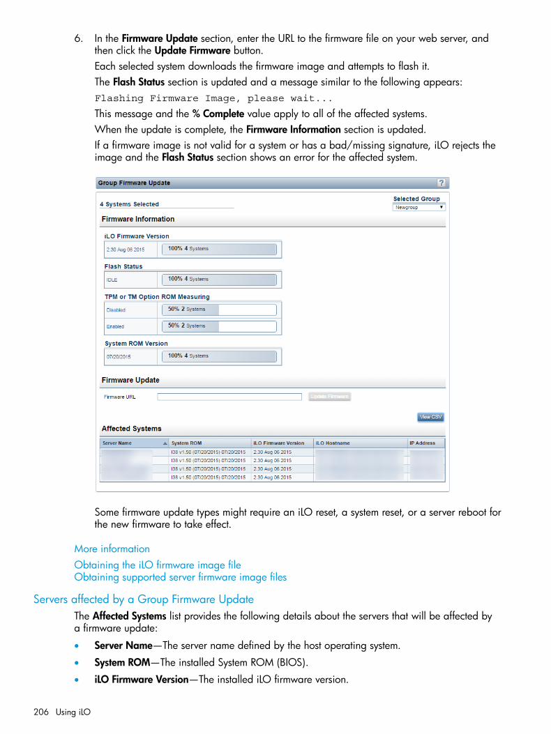
6. In the Firmware Update section, enter the URL to the firmware file on your web server, andthen click the Update Firmware button.Each selected system downloads the firmware image and attempts to flash it.The Flash Status section is updated and a message similar to the following appears:Flashing Firmware Image, please wait...
This message and the % Complete value apply to all of the affected systems.When the update is complete, the Firmware Information section is updated.If a firmware image is not valid for a system or has a bad/missing signature, iLO rejects theimage and the Flash Status section shows an error for the affected system.
Some firmware update types might require an iLO reset, a system reset, or a server reboot forthe new firmware to take effect.
More informationObtaining the iLO firmware image fileObtaining supported server firmware image files
Servers affected by a Group Firmware UpdateThe Affected Systems list provides the following details about the servers that will be affected bya firmware update:
• Server Name—The server name defined by the host operating system.
• System ROM—The installed System ROM (BIOS).
• iLO Firmware Version—The installed iLO firmware version.
206 Using iLO
• iLO Hostname—The fully qualified network name assigned to the iLO subsystem. Click the linkin the iLO Hostname column to open the iLO web interface for the server.
• IP Address—The network IP address of the iLO subsystem. Click the link in the IP Addresscolumn to open the iLO web interface for the server.
Exporting the Affected Systems list1. Navigate to the iLO Federation→Group Firmware Update page.2. Click View CSV.3. Do one of the following:
• For Internet Explorer 8 only—Copy the text displayed in the CSV Output window, andsave it in a text editor as a CSV file.
• For all other browsers—In the CSV Output window, click Save, and then follow the browserprompts to save or open the file.
When you export the list, the CSV file contains only the servers displayed on the iLO Federationpage.If multiple pages of servers are included in the list, the CSV file will contain only the serversthat are currently displayed on the iLO web interface page.If a query error occurred, the systems that did not respond to the query are excluded from theAffected Systems list and the CSV file.
Using iLO Federation group licensingThe Group Licensing page displays the license status for members of a selected iLO Federationgroup. Use this page to enter an optional key to activate iLO licensed features.
More informationiLO licensing
Viewing license informationTo view license information for a group of servers:
Using iLO Federation 207
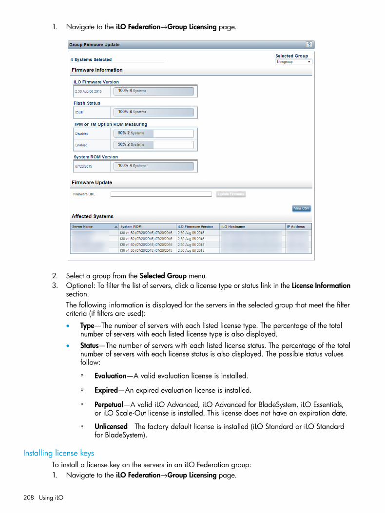
1. Navigate to the iLO Federation→Group Licensing page.
2. Select a group from the Selected Group menu.3. Optional: To filter the list of servers, click a license type or status link in the License Information
section.The following information is displayed for the servers in the selected group that meet the filtercriteria (if filters are used):
• Type—The number of servers with each listed license type. The percentage of the totalnumber of servers with each listed license type is also displayed.
• Status—The number of servers with each listed license status. The percentage of the totalnumber of servers with each license status is also displayed. The possible status valuesfollow:
◦ Evaluation—A valid evaluation license is installed.
◦ Expired—An expired evaluation license is installed.
◦ Perpetual—A valid iLO Advanced, iLO Advanced for BladeSystem, iLO Essentials,or iLO Scale-Out license is installed. This license does not have an expiration date.
◦ Unlicensed—The factory default license is installed (iLO Standard or iLO Standardfor BladeSystem).
Installing license keysTo install a license key on the servers in an iLO Federation group:1. Navigate to the iLO Federation→Group Licensing page.
208 Using iLO
2. Review the license agreement provided with your License Pack option kit.3. Optional: Click a license type or status link to filter the list of affected systems.4. Enter the license key in the Activation Key box.
Press the Tab key or click inside a segment of the Activation Key box to move betweensegments. The cursor advances automatically when you enter data into the segments of theActivation Key box.
5. Click Install.The EULA confirmation dialog box opens. The EULA details are available in the License Packoption kit.
6. Click OK.The License Information section is updated to show the new license details for the selectedgroup.
Servers affected by a license installationThe Affected Systems section provides the following details about the servers that will be affectedwhen you install a license key.The following information is displayed:
• Server Name—The server name defined by the host operating system.
• License—The installed license type.
• iLO Firmware Version—The installed iLO firmware version.
• iLO Hostname—The fully qualified network name assigned to the iLO subsystem. Click the linkin the iLO Hostname column to open the iLO web interface for the server.
• IP Address—The network IP address of the iLO subsystem. Click the link in the IP Addresscolumn to open the iLO web interface for the server.
Exporting the Affected Systems list1. Navigate to the iLO Federation→Group Licensing page.2. Click View CSV.3. Do one of the following:
• For Internet Explorer 8 only—Copy the text displayed in the CSV Output window, andsave it in a text editor as a CSV file.
• For all other browsers—In the CSV Output window, click Save, and then follow the browserprompts to save or open the file.
When you export the list, the CSV file contains only the servers displayed on the iLO Federationpage.If multiple pages of servers are included in the list, the CSV file will contain only the serversthat are currently displayed on the iLO web interface page.If a query error occurred, the systems that did not respond to the query are excluded from theAffected Systems list and the CSV file.
Using the iLO Federation Group Configuration featureFor information about using the features on the iLO Federation→Group Configuration page, see“Adding iLO Federation group memberships (multiple iLO systems)” (page 53).
Using iLO Federation 209

Using the Integrated Remote ConsoleThe iLO Integrated Remote Console is a graphical remote console that turns a supported browserinto a virtual desktop, allowing full control over the display, keyboard, and mouse of the hostserver. Using the Remote Console also provides access to the remote file system and network drives.With Integrated Remote Console access, you can observe POST boot messages as the remote hostserver restarts, and initiate ROM-based setup routines to configure the remote host server hardware.When you are installing operating systems remotely, the Integrated Remote Console (if licensed)enables you to view and control the host server monitor throughout the installation process.iLO provides the following Integrated Remote Console access options:
• .NET IRC—Provides access to the system KVM, allowing control of Virtual Power and VirtualMedia from a single console through a supported browser on a Windows client. In additionto the standard features, the .NET IRC supports Console Capture, Shared Console, VirtualFolder, and Scripted Media.
• Java IRC—Provides access to the system KVM, allowing control of Virtual Power and VirtualMedia from a Java-based console. In addition to the standard features, the Java IRC includesthe iLO disk image tool and Scripted Media.
• Standalone IRC (HPLOCONS)—Provides full iLO Integrated Remote Console functionality directlyfrom your Windows desktop, without going through the iLO web interface. HPLOCONS hasthe same functionality and requirements as the .NET IRC application that is launched from theiLO web interface. Download HPLOCONS from the following website: http://www.hp.com/support/ilo4.
• iLO Mobile Application for iOS and Android devices—Provides Integrated Remote Consoleaccess from your supported mobile phone or tablet. For more information, see http://www.hp.com/go/ilo/mobileapp.
When you use the Remote Console, note the following:
• Users with the Remote Console privilege can use the .NET IRC and the Java IRC.
• On WS and blade servers, the Remote Console is always enabled. On nonblade servers, aniLO license must be installed to use this feature after the OS is started. SelectAdministration→Licensing to determine whether a license is installed. For more information,see the following website: http://www.hp.com/go/ilo/licensing.
• The Java IRC is a signed Java applet. If you do not accept the Java IRC applet certificate, theJava IRC will not start.For more information, see “The Java IRC does not start” (page 325).
• The Java IRC experiences a slight delay when the Java applet first loads in a browser.
• The Java IRC is a Java applet-based console that is launched from the iLO web interface.When you refresh or close the iLO web interface window, the Remote Console connection isclosed, and you will lose access to Virtual Media devices that were connected through theJava IRC, except for devices that were connected by URL (using scripted media).
• The .NET IRC and Java IRC are suitable for high-latency (modem) connections.
• Do not run the .NET IRC or Java IRC from the host operating system on the server that containsthe iLO processor.
• HP recommends that users who log in to a server through the .NET IRC or Java IRC log outbefore closing the .NET IRC or Java IRC.
• Pop-up blockers prevent the .NET IRC or Java IRC from running, so you must disable thembefore starting a .NET IRC or Java IRC session. In some cases, you can Ctrl+click the .NETIRC or Java IRC Launch button to bypass the pop-up blocker and launch the .NET IRC or JavaIRC.
210 Using iLO

• The UID LED blinks when a .NET IRC or Java IRC session is active.
• When you finish using the Remote Console, close the window or click the Close button to exitthe .NET IRC or Java IRC.
• The Idle Connection Timeout specifies how long a user can be inactive before a Remote Consolesession ends automatically. Remote Console sessions are not affected by this value if a virtualmedia device is connected.For more information about the Idle Connection Timeout, see “Configuring iLO access settings”(page 58).
.NET IRC requirementsThis section lists the requirements for using the .NET IRC.
Microsoft .NET FrameworkThe .NET IRC requires one of the following versions of the Microsoft .NET Framework:
• .NET Framework 3.5 Full (SP1 recommended)
• .NET Framework 4.0 Full
• .NET Framework 4.5For Windows 7, 8, or 8.1, a supported version of the .NET Framework is included in your OS.The .NET Framework is also available at the Microsoft Download Center: http://www.microsoft.com/download.The .NET Framework versions 3.5 and 4.0 have two deployment options: Full and Client Profile.The Client Profile is a subset of the Full framework. The .NET IRC is supported with the Full frameworkonly; the Client Profile is not supported. Version 4.5 of the .NET Framework does not have theClient Profile option.For Internet Explorer users only: The .NET Framework Detection table on the iLO Integrated RemoteConsole page lists the compatible .NET versions and indicates whether the installed version iscompatible with the .NET IRC. If the installed version is compatible, the status OK is listed in theStatus column.
Microsoft ClickOnceThe .NET IRC is launched using Microsoft ClickOnce, which is part of the .NET Framework.ClickOnce requires that any application installed from an SSL connection be from a trusted source.If a browser is not configured to trust an iLO system, and the IRC requires a trusted certificate iniLO setting is set to Enabled, ClickOnce displays the following error message:Cannot Start Application - Application download did not succeed...
For more information, see “Configuring the Integrated Remote Console Trust setting (.NET IRC)”(page 91).
• Mozilla Firefox requires an add-on to launch .NET applications. You can launch the .NET IRCfrom a supported version of Firefox by using a ClickOnce add-on such as the Microsoft .NET
Using the Integrated Remote Console 211

Framework Assistant. You can download the .NET Framework Assistant from http://addons.mozilla.org/.
• Previous versions of Google Chrome could run the .NET IRC with an NPAPI plug-in thatsupported ClickOnce. Google Chrome 42 and later does not support NPAPI-based plug-ins.As a workaround, use one of the following:
◦ The .NET IRC with a different browser.
◦ The standalone .NET IRC.
◦ The iLO mobile app.
Java IRC requirementsThe Java IRC requires a supported version of the Java software.
• When you use Java 7 update 45 or later with iLO, you might see a message that states thata permission attribute is missing, and that the Java IRC could stop working in the future. Forcompatibility with future Java versions, the missing attribute is available in iLO 4 1.32 or later.
• Google Chrome version 42 and later does not support the Java plug-in. To use the Java IRC,you must use an alternate web browser such as Firefox or Internet Explorer.
To view the Java requirements or to download the Java software:1. Navigate to the Remote Console page, and then click the Java tab.
2. Click the Download button to navigate to the following website where you can download theJava software: http://www.java.com/en/.
Recommended client settingsIdeally, the remote server display resolution is the same or lower than that of the client computer.Higher resolutions transmit more information, reducing the overall performance.
212 Using iLO

Use the following client and browser settings to optimize performance:
• Display properties
Select an option greater than 256 colors.◦◦ Select a screen resolution higher than that of the remote server.
◦ Linux X Display properties—Set the font size to 12 on the X Preferences screen.
• Mouse properties
Set the mouse pointer speed to the middle setting.◦◦ Set the mouse pointer acceleration to low or disable it.
Recommended server settingsFor all servers, note the following:
• To optimize performance, set the server display properties to use a plain background (nowallpaper pattern), and set the server mouse properties to disable pointer trails.
• To display the entire host server screen in the client Java IRC window, select a server displayresolution that is less than or equal to that of the client.
For SUSE Linux Enterprise Server 11 only: To optimize performance, set the value for server mouseproperties pointer acceleration to 1x.For KDE, access the Control Center, select Peripherals/Mouse, and then click the Advanced tab.To disable mouse acceleration, enter the following command: xset m 1.
Starting the Remote Console1. Navigate to the Remote Console→Remote Console page.
2. Verify that your system meets the requirements for using the .NET IRC or Java IRC.
Using the Integrated Remote Console 213

3. Click the Launch button for the Remote Console that you want to use.If you attempt to open the Remote Console while it is in use, a warning message indicatesthat another user is using it.
• To view the Remote Console session that is in progress, follow the instructions in “UsingShared Remote Console (.NET IRC only)” (page 215).
• To take control of the session, follow the instructions in “Acquiring the Remote Console”(page 214).
Acquiring the Remote ConsoleIf another user is working in the Remote Console, you can acquire it from that user.1. Navigate to the Remote Console→Remote Console page.2. Click the Launch button for the Remote Console that you want to use.
The system notifies you that another user is working in the Remote Console.
3. Click the Acquire button.The other user is prompted to approve or deny permission to acquire the Remote Console.
If there is no response in 10 seconds, permission is granted.
Using the Remote Console power switchTo use the power switch, select one of the following options from the Remote Console Power Switchmenu:
• Momentary Press—The same as pressing the physical power button. If a server is poweredoff, a momentary press will turn the server power on.Some operating systems might be configured to initiate a graceful shutdown after a momentarypress, or to ignore this event. HP recommends using system commands to complete a gracefuloperating system shutdown before you attempt to shut down by using the Virtual Power button.
• Press and Hold—The same as pressing the physical power button for 5 seconds and thenreleasing it.The server is powered off as a result of this operation. Using this option might circumvent thegraceful shutdown features of the operating system.This option provides the ACPI functionality that some operating systems implement. Theseoperating systems behave differently depending on a short press or long press.
214 Using iLO

• Cold Boot—Immediately removes power from the server. Processors, memory, and I/O resourceslose main power. The server will restart after approximately 6 seconds. Using this optioncircumvents the graceful shutdown features of the operating system.
• Reset—Forces the server to warm-boot: CPUs and I/O resources are reset. Using this optioncircumvents the graceful shutdown features of the operating system.
NOTE: The Press and Hold, Reset, and Cold Boot options are not available when the server ispowered off.
Using iLO Virtual Media from the Remote ConsoleFor instructions on using the Virtual Media feature from the Remote Console, see “Using VirtualMedia from the Remote Console” (page 232).
Using Shared Remote Console (.NET IRC only)Shared Remote Console allows the connection of multiple sessions on the same server. This featurecan be used for activities such as training and troubleshooting.This feature and many others are part of an iLO licensing package. For more information, see thefollowing website: http://www.hp.com/go/ilo/licensing.The first user to initiate a Remote Console session connects to the server normally and is designatedas the session leader. Any subsequent user who requests Remote Console access initiates an accessrequest for a satellite client connection. A dialog box for each access request opens on the sessionleader's desktop, identifying the requester's user name and DNS name (if available) or IP address.The session leader can grant or deny access. If there is no response, permission is deniedautomatically.Shared Remote Console does not support passing the session leader designation to another user,or reconnecting a user after a failure. You must restart the Remote Console session to allow useraccess after a failure.During a Shared Remote Console session, the session leader has access to all Remote Consolefeatures, whereas all other users can access only the keyboard and mouse. Satellite clients cannotcontrol Virtual Power or Virtual Media.iLO encrypts Shared Remote Console sessions by authenticating the client first, and then the sessionleader determines whether to allow new connections.
Joining a Shared Remote Console session1. Navigate to the Remote Console→Remote Console page.2. Click Launch to start the .NET IRC.
A message notifies you that the .NET IRC is already in use.
Using the Integrated Remote Console 215

3. Click Share.The session leader receives your request to join the .NET IRC session.
If the session leader clicks Yes, you are granted access to the .NET IRC session with accessto the keyboard and mouse.
Using Console Capture (.NET IRC only)Console Capture allows you to record and play back video streams of events such as startup, ASRevents, and sensed operating system faults. The Server Startup and Server Prefailure sequencesare captured automatically by iLO. You can manually start and stop the recording of console video.This feature and many others are part of an iLO licensing package. For more information, see thefollowing website: http://www.hp.com/go/ilo/licensing.When you are using Console Capture, note the following:
• Console Capture is supported with the .NET IRC; it is not supported with the Java IRC.
• Console Capture is available only through the .NET IRC. It cannot be accessed through XMLscripting or the CLP.
• The Server Startup and Server Prefailure sequences are not captured automatically duringfirmware updates or while the Remote Console is in use.
• Server Startup and Server Prefailure sequences are saved automatically in iLO memory. Theywill be lost during firmware updates, iLO reset, and power loss. You can save the capturedvideo to your local drive by using the .NET IRC.
• The Server Startup file starts capturing when server startup is detected, and stops when it runsout of space. This file is overwritten each time the server starts.
• The Server Prefailure file starts capturing when the Server Startup file is full, and stops wheniLO detects an ASR event. The Server Prefailure file is locked when iLO detects an ASR event.The file is unlocked and can be overwritten after it is downloaded through the .NET IRC.
• The Console Capture control buttons are located on the bottom of the .NET IRC session window.The following playback controls are available:
◦ Skip to Start—Restarts playback from the beginning of the file.
◦ Pause—Pauses the playback.
◦ Play—Starts playback if the currently selected file is not playing or is paused.
◦ Record—Records your .NET IRC session.
◦ Progress Bar—Shows the progress of the video session.
Viewing Server Startup and Server Prefailure sequences1. Start the .NET IRC.2. Press the Play button.
The Playback Source dialog box opens.
216 Using iLO
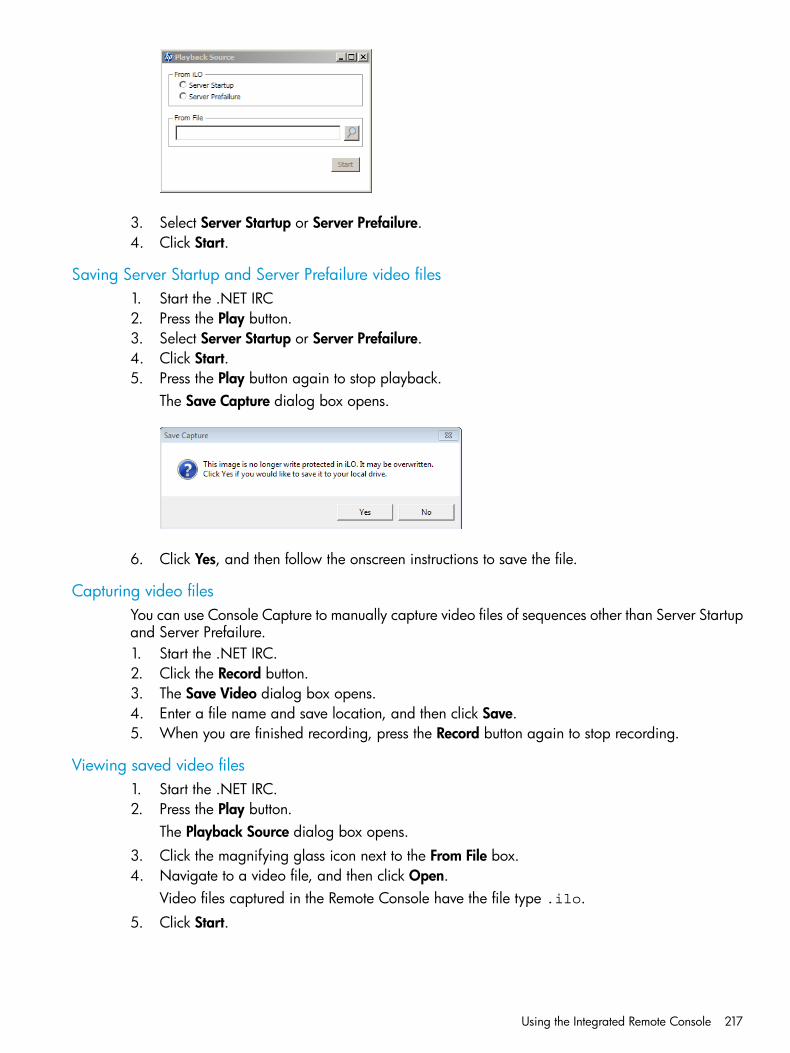
3. Select Server Startup or Server Prefailure.4. Click Start.
Saving Server Startup and Server Prefailure video files1. Start the .NET IRC2. Press the Play button.3. Select Server Startup or Server Prefailure.4. Click Start.5. Press the Play button again to stop playback.
The Save Capture dialog box opens.
6. Click Yes, and then follow the onscreen instructions to save the file.
Capturing video filesYou can use Console Capture to manually capture video files of sequences other than Server Startupand Server Prefailure.1. Start the .NET IRC.2. Click the Record button.3. The Save Video dialog box opens.4. Enter a file name and save location, and then click Save.5. When you are finished recording, press the Record button again to stop recording.
Viewing saved video files1. Start the .NET IRC.2. Press the Play button.
The Playback Source dialog box opens.3. Click the magnifying glass icon next to the From File box.4. Navigate to a video file, and then click Open.
Video files captured in the Remote Console have the file type .ilo.
5. Click Start.
Using the Integrated Remote Console 217

Using Remote Console hot keysThe Program Remote Console Hot Keys page allows you to define up to six hot keys to use duringRemote Console sessions. Each hot key represents a combination of up to five keys that are sentto the host server when the hot key is pressed. Hot keys are active during Remote Console sessionsthat use the .NET IRC, Java IRC, and the text-based Remote Console.If a hot key is not set—for example, Ctrl+V is set to NONE, NONE, NONE, NONE, NONE—thishot key is disabled. The server operating system will interpret Ctrl+V as it usually does (paste, inthis example). If you set Ctrl+V to use another combination of keys, the server operating systemwill use the key combination set in iLO (losing the paste functionality).Example 1: If you want to send Alt+F4 to the remote server, but pressing that key combinationcloses your browser, you can configure the hot key Ctrl+X to send the Alt+F4 key combination tothe remote server. After you configure the hot key, press Ctrl+X in the Remote Console windowwhen you want to send Alt+F4 to the remote server.Example 2: If you want to create a hot key to send the international AltGR key to the remote server,use R_ALT in the key list.
Creating a hot keyYou must have the Configure iLO Settings privilege to create hot keys.1. Navigate to the Remote Console→Hot Keys page.
2. For each hot key that you want to create, select the key combination to send to the remoteserver.To configure hot keys to generate key sequences from international keyboards, select the keyon a U.S. keyboard that is in the same position as the desired key on the internationalkeyboard. Table 6 (page 218) lists the keys you can use when you configure hot keys.
Table 6 Keys for configuring hot keys
g1SCRL LCKESC
h2SYS RQL_ALT
I3F1R_ALT
j4F2L_SHIFT
k5F3R_SHIFT
l6F4L_CTRL
m7F5R_CTRL
218 Using iLO
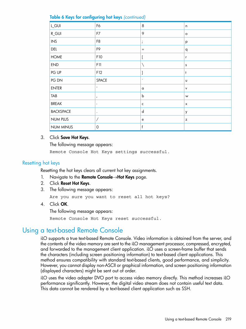
Table 6 Keys for configuring hot keys (continued)
n8F6L_GUI
o9F7R_GUI
p;F8INS
q=F9DEL
r[F10HOME
s\F11END
t]F12PG UP
u`SPACEPG DN
va'ENTER
wb,TAB
xc-BREAK
yd.BACKSPACE
ze/NUM PLUS
f0NUM MINUS
3. Click Save Hot Keys.The following message appears:Remote Console Hot Keys settings successful.
Resetting hot keysResetting the hot keys clears all current hot key assignments.1. Navigate to the Remote Console→Hot Keys page.2. Click Reset Hot Keys.3. The following message appears:
Are you sure you want to reset all hot keys?
4. Click OK.The following message appears:Remote Console Hot Keys reset successful.
Using a text-based Remote ConsoleiLO supports a true text-based Remote Console. Video information is obtained from the server, andthe contents of the video memory are sent to the iLO management processor, compressed, encrypted,and forwarded to the management client application. iLO uses a screen-frame buffer that sendsthe characters (including screen positioning information) to text-based client applications. Thismethod ensures compatibility with standard text-based clients, good performance, and simplicity.However, you cannot display non-ASCII or graphical information, and screen positioning information(displayed characters) might be sent out of order.iLO uses the video adapter DVO port to access video memory directly. This method increases iLOperformance significantly. However, the digital video stream does not contain useful text data.This data cannot be rendered by a text-based client application such as SSH.
Using a text-based Remote Console 219
There are two text-based console options, as described in the following sections:
• “Using the iLO Virtual Serial Port” (page 220)
• “Using the Text-based Remote Console (Textcons)” (page 224)
Using the iLO Virtual Serial PortYou can access a text-based console from iLO using a standard license and the iLO Virtual SerialPort.The iLO Virtual Serial Port is one type of iLO text-based remote console. The iLO Virtual Serial Portgives you a bidirectional data flow with a server serial port. Using the remote console, you canoperate as if a physical serial connection exists on the remote server serial port.The iLO Virtual Serial Port is displayed as a text-based console, but the information is renderedthrough graphical video data. iLO displays this information through an SSH client when the serveris in a pre-operating-system state, enabling a nonlicensed iLO to observe and interact with theserver during POST activities.By using the iLO Virtual Serial Port, the remote user can perform operations such as the following:
• Interact with the server POST sequence and the operating system boot sequence.
IMPORTANT: To start iLO RBSU during a Virtual Serial Port session, enter the key combinationESC+8.To start the UEFI System Utilities during a Virtual Serial Port session, enter the key combinationESC+9.
• Establish a login session with the operating system, interact with the operating system; andexecute and interact with applications on the operating system.
• For an iLO running Linux in a graphical format, you can configure getty() on the serverserial port, and then use the iLO Virtual Serial Port to view a login session to the Linux operatingsystem. For more information, see “Configuring the iLO Virtual Serial Port for Linux” (page 222).
• Use the EMS Console through the iLO Virtual Serial Port. EMS is useful for debugging Windowsboot issues and kernel-level issues. For more information, see “Configuring the iLO VirtualSerial Port for the Windows EMS Console” (page 223).
Configuring the iLO Virtual Serial Port in the host system RBSUThe following procedure describes the settings you must configure before you can use the iLOVirtual Serial Port. This procedure is required for both Windows and Linux systems.This procedure is for systems that support the legacy system RBSU. For systems that support theUEFI System Utilities, see “Configuring the iLO Virtual Serial Port in the UEFI System Utilities” (page221).1. Optional: If you access the server remotely, start an iLO remote console session.
You can use the .NET IRC or Java IRC.2. Restart or power on the server.3. Press F9 in the ProLiant POST screen to start the system RBSU.4. Set the Virtual Serial Port COM port.
a. Select System Options, and then press Enter.b. Select Serial Port Options, and then press Enter.c. Select Virtual Serial Port, and then press Enter.d. Select the COM port you want to use, and then press Enter.e. Press ESC twice to return to the main menu.
220 Using iLO
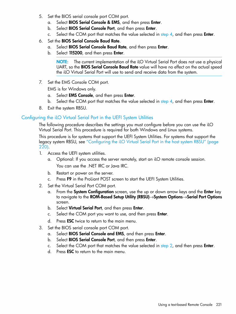
5. Set the BIOS serial console port COM port.a. Select BIOS Serial Console & EMS, and then press Enter.b. Select BIOS Serial Console Port, and then press Enter.c. Select the COM port that matches the value selected in step 4, and then press Enter.
6. Set the BIOS Serial Console Baud Rate.a. Select BIOS Serial Console Baud Rate, and then press Enter.b. Select 115200, and then press Enter.
NOTE: The current implementation of the iLO Virtual Serial Port does not use a physicalUART, so the BIOS Serial Console Baud Rate value will have no effect on the actual speedthe iLO Virtual Serial Port will use to send and receive data from the system.
7. Set the EMS Console COM port.EMS is for Windows only.a. Select EMS Console, and then press Enter.b. Select the COM port that matches the value selected in step 4, and then press Enter.
8. Exit the system RBSU.
Configuring the iLO Virtual Serial Port in the UEFI System UtilitiesThe following procedure describes the settings you must configure before you can use the iLOVirtual Serial Port. This procedure is required for both Windows and Linux systems.This procedure is for systems that support the UEFI System Utilities. For systems that support thelegacy system RBSU, see “Configuring the iLO Virtual Serial Port in the host system RBSU” (page220).1. Access the UEFI system utilities.
a. Optional: If you access the server remotely, start an iLO remote console session.You can use the .NET IRC or Java IRC.
b. Restart or power on the server.c. Press F9 in the ProLiant POST screen to start the UEFI System Utilities.
2. Set the Virtual Serial Port COM port.a. From the System Configuration screen, use the up or down arrow keys and the Enter key
to navigate to the ROM-Based Setup Utility (RBSU)→System Options→Serial Port Optionsscreen.
b. Select Virtual Serial Port, and then press Enter.c. Select the COM port you want to use, and then press Enter.d. Press ESC twice to return to the main menu.
3. Set the BIOS serial console port COM port.a. Select BIOS Serial Console and EMS, and then press Enter.b. Select BIOS Serial Console Port, and then press Enter.c. Select the COM port that matches the value selected in step 2, and then press Enter.d. Press ESC to return to the main menu.
Using a text-based Remote Console 221

4. Set the BIOS Serial Console Baud Rate.a. Select BIOS Serial Console Baud Rate, and then press Enter.b. Select 115200, and then press Enter.
NOTE: The current implementation of the iLO Virtual Serial Port does not use a physicalUART, so the BIOS Serial Console Baud Rate value will have no effect on the actual speedthe iLO Virtual Serial Port will use to send and receive data from the system.
c. Press ESC to return to the main menu.5. Set the EMS Console COM port.
EMS is for Windows only.a. Select EMS Console, and then press Enter.b. Select the COM port that matches the value selected in step 2, and then press Enter.c. Press F10 to save the changes.
6. Resume the boot process.a. Press Esc until the main menu is displayed.b. Select Exit and Resume Boot in the main menu, and then press Enter.c. When prompted to confirm the request, press Enter to exit the utility and resume the boot
process.
Configuring the iLO Virtual Serial Port for LinuxYou can manage Linux servers remotely using console redirection. To configure Linux to use consoleredirection, you must configure the Linux boot loader (GRUB). The boot-loader application loadsfrom the bootable device when the server system ROM finishes POST. Define the serial interface(ttyS0) as the default interface so that if no input arrives from the local keyboard within 10 seconds(the default timeout value), the system will redirect output to the serial interface (iLO Virtual SerialPort).
NOTE: ttyS0 and unit 0 are for com1 and ttyS1 and unit 1 are for com2.
The following configuration example uses Red Hat Enterprise Linux 6 and com1:serial -unit=0 -speed=115200terminal -timeout=10 serial consoledefault=0timeout=10#splashimage=(hd0,2)/grub/splash.xpm.gztitle Red Hat Linux (2. 6.18-164.e15)root (hd0,2)9kernel /vmlinux-2.6.18-164.e15 ro root=/dev/sda9 console=tty0 console=ttyS0,115200initrd /initrd-2.6.18-164.e15.img
If com2 was selected, the configuration example would be as follows:serial -unit=1 -speed=115200terminal -timeout=10 serial consoledefault=0timeout=10#splashimage=(hd0,2)/grub/splash.xpm.gztitle Red Hat Linux (2. 6.18-164.e15)root (hd0,2)9kernel /vmlinux-2.6.18-164.e15 ro root=/dev/sda9 console=tty0 console=ttyS1,115200initrd /initrd-2.6.18-164.e15.img
After Linux is fully booted, a login console can be redirected to the serial port.
• If configured, the /dev/ttyS0 and /dev/ttyS1 devices enable you to obtain serial TTYsessions through the iLO Virtual Serial Port. To begin a shell session on a configured serial
222 Using iLO

port, add the following line to the /etc/inittab file to start the login process automaticallyduring system boot.The following example initiates the login console on /dev/ttyS0:S0:2345:respawn:/sbin/agetty 115200 ttyS0 vt100
The following example initiates the login console on dev/ttys1:
S1:2345:respawn:/sbin/agetty 115200 ttyS1 vt100
• Use SSH to connect to iLO, and then use the iLO CLP command start/system1/oemhp_vsp1 to view a login session to the Linux operating system.
Configuring the iLO Virtual Serial Port for the Windows EMS ConsoleiLO enables you to use the Windows EMS Console over the network through a web browser. EMSenables you to perform emergency management services when video, device drivers, or otheroperating system features prevent normal operation and normal corrective actions from beingperformed.When using the Windows EMS Console with iLO, note the following:
• You must configure the Windows EMS console within the operating system before you canuse the iLO Virtual Serial Port. For information about how to enable the EMS console, seeyour operating system documentation. If the EMS console is not enabled in the operatingsystem, iLO displays an error message when you try to access the iLO Virtual Serial Port.
• The Windows EMS serial port must be enabled through the host system RBSU or the UEFISystem Utilities. The configuration allows you to enable or disable the EMS port, and selectthe COM port. iLO automatically detects whether the EMS port is enabled or disabled, anddetects the selection of the COM port. For more information about enabling the WindowsEMS serial port, see “Configuring the iLO Virtual Serial Port in the host system RBSU” (page 220)or “Configuring the iLO Virtual Serial Port in the UEFI System Utilities” (page 221).
• You can use the Windows EMS Console and the iLO Remote Console at the same time.
• To display the SAC> prompt, you might have to press Enter after connecting through the iLOVirtual Serial Port.
To configure Windows for use with the iLO Virtual Serial Port:1. Open a command window.2. Enter the following command to edit the boot configuration data:
bcdedit /ems on
3. Enter the following command to configure the EMSPORT and EMSBAUDRATE values:bcdedit /emssettings EMSPORT:1 EMSBAUDRATE:115200
NOTE: EMSPORT:1 is COM1, and EMSPORT:2 is COM2.Enter bcdedit /? for syntax help.
4. Reboot the operating system.
Starting an iLO Virtual Serial Port session1. Verify that the iLO Virtual Serial Port settings are configured in the iLO RBSU or UEFI System
Utilities.For more information, see “Configuring the iLO Virtual Serial Port in the host system RBSU”(page 220) or “Configuring the iLO Virtual Serial Port in the UEFI System Utilities” (page 221).
Using a text-based Remote Console 223
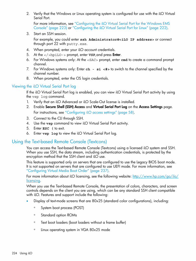
2. Verify that the Windows or Linux operating system is configured for use with the iLO VirtualSerial Port.For more information, see “Configuring the iLO Virtual Serial Port for the Windows EMSConsole” (page 223) or “Configuring the iLO Virtual Serial Port for Linux” (page 222).
3. Start an SSH session.For example, you could enter ssh Administrator@<iLO IP address> or connectthrough port 22 with putty.exe.
4. When prompted, enter your iLO account credentials.5. At the </>hpiLO-> prompt, enter VSP,and press Enter.6. For Windows systems only: At the <SAC> prompt, enter cmd to create a command prompt
channel.7. For Windows systems only: Enter ch - si <#> to switch to the channel specified by the
channel number.8. When prompted, enter the OS login credentials.
Viewing the iLO Virtual Serial Port logIf the iLO Virtual Serial Port log is enabled, you can view iLO Virtual Serial Port activity by usingthe vsp log command.1. Verify that an iLO Advanced or iLO Scale-Out license is installed.2. Enable Secure Shell (SSH) Access and Virtual Serial Port Log on the Access Settings page.
For instructions, see “Configuring iLO access settings” (page 58).3. Connect to the CLI through SSH.4. Use the vsp command to view iLO Virtual Serial Port activity.5. Enter ESC ( to exit.6. Enter vsp log to view the iLO Virtual Serial Port log.
Using the Text-based Remote Console (Textcons)You can access the Text-based Remote Console (Textcons) using a licensed iLO system and SSH.When you use SSH, the data stream, including authentication credentials, is protected by theencryption method that the SSH client and iLO use.This feature is supported only on servers that are configured to use the Legacy BIOS boot mode.It is not supported on servers that are configured to use UEFI mode. For more information, see“Configuring Virtual Media Boot Order” (page 237).For more information about iLO licensing, see the following website: http://www.hp.com/go/ilo/licensing.When you use the Text-based Remote Console, the presentation of colors, characters, and screencontrols depends on the client you are using, which can be any standard SSH client compatiblewith iLO. Features and support include the following:
• Display of text-mode screens that are 80x25 (standard color configurations), including:
System boot process (POST)◦◦ Standard option ROMs
◦ Text boot loaders (boot loaders without a frame buffer)
◦ Linux operating system in VGA 80x25 mode
224 Using iLO
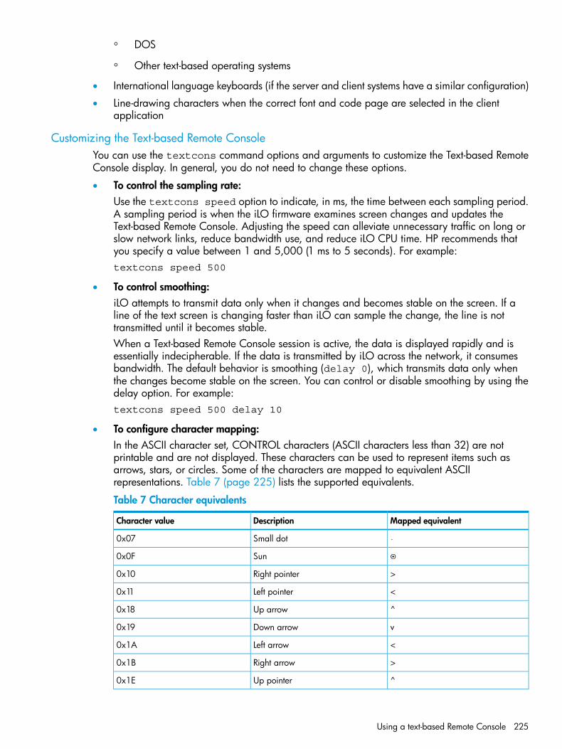
◦ DOS
◦ Other text-based operating systems
• International language keyboards (if the server and client systems have a similar configuration)
• Line-drawing characters when the correct font and code page are selected in the clientapplication
Customizing the Text-based Remote ConsoleYou can use the textcons command options and arguments to customize the Text-based RemoteConsole display. In general, you do not need to change these options.
• To control the sampling rate:Use the textcons speed option to indicate, in ms, the time between each sampling period.A sampling period is when the iLO firmware examines screen changes and updates theText-based Remote Console. Adjusting the speed can alleviate unnecessary traffic on long orslow network links, reduce bandwidth use, and reduce iLO CPU time. HP recommends thatyou specify a value between 1 and 5,000 (1 ms to 5 seconds). For example:textcons speed 500
• To control smoothing:iLO attempts to transmit data only when it changes and becomes stable on the screen. If aline of the text screen is changing faster than iLO can sample the change, the line is nottransmitted until it becomes stable.When a Text-based Remote Console session is active, the data is displayed rapidly and isessentially indecipherable. If the data is transmitted by iLO across the network, it consumesbandwidth. The default behavior is smoothing (delay 0), which transmits data only whenthe changes become stable on the screen. You can control or disable smoothing by using thedelay option. For example:textcons speed 500 delay 10
• To configure character mapping:In the ASCII character set, CONTROL characters (ASCII characters less than 32) are notprintable and are not displayed. These characters can be used to represent items such asarrows, stars, or circles. Some of the characters are mapped to equivalent ASCIIrepresentations. Table 7 (page 225) lists the supported equivalents.
Table 7 Character equivalents
Mapped equivalentDescriptionCharacter value
Small dot0x07
Sun0x0F
>Right pointer0x10
<Left pointer0x11
^Up arrow0x18
vDown arrow0x19
<Left arrow0x1A
>Right arrow0x1B
^Up pointer0x1E
Using a text-based Remote Console 225
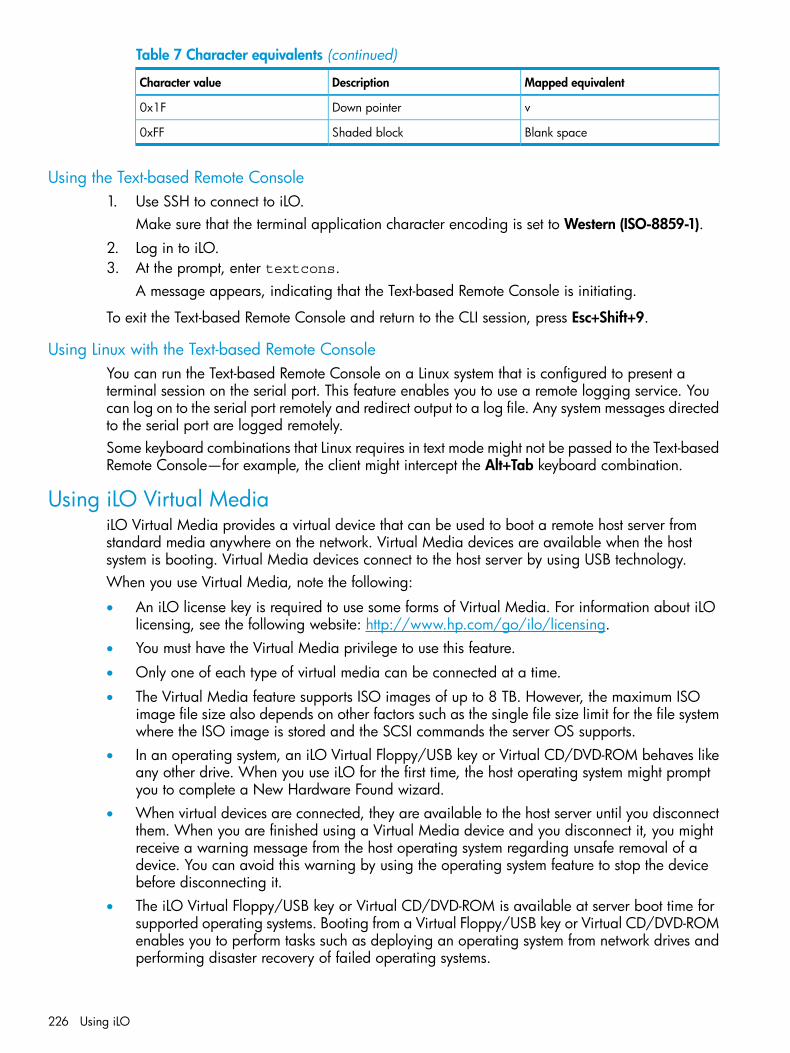
Table 7 Character equivalents (continued)
Mapped equivalentDescriptionCharacter value
vDown pointer0x1F
Blank spaceShaded block0xFF
Using the Text-based Remote Console1. Use SSH to connect to iLO.
Make sure that the terminal application character encoding is set to Western (ISO-8859-1).2. Log in to iLO.3. At the prompt, enter textcons.
A message appears, indicating that the Text-based Remote Console is initiating.
To exit the Text-based Remote Console and return to the CLI session, press Esc+Shift+9.
Using Linux with the Text-based Remote ConsoleYou can run the Text-based Remote Console on a Linux system that is configured to present aterminal session on the serial port. This feature enables you to use a remote logging service. Youcan log on to the serial port remotely and redirect output to a log file. Any system messages directedto the serial port are logged remotely.Some keyboard combinations that Linux requires in text mode might not be passed to the Text-basedRemote Console—for example, the client might intercept the Alt+Tab keyboard combination.
Using iLO Virtual MediaiLO Virtual Media provides a virtual device that can be used to boot a remote host server fromstandard media anywhere on the network. Virtual Media devices are available when the hostsystem is booting. Virtual Media devices connect to the host server by using USB technology.When you use Virtual Media, note the following:
• An iLO license key is required to use some forms of Virtual Media. For information about iLOlicensing, see the following website: http://www.hp.com/go/ilo/licensing.
• You must have the Virtual Media privilege to use this feature.
• Only one of each type of virtual media can be connected at a time.
• The Virtual Media feature supports ISO images of up to 8 TB. However, the maximum ISOimage file size also depends on other factors such as the single file size limit for the file systemwhere the ISO image is stored and the SCSI commands the server OS supports.
• In an operating system, an iLO Virtual Floppy/USB key or Virtual CD/DVD-ROM behaves likeany other drive. When you use iLO for the first time, the host operating system might promptyou to complete a New Hardware Found wizard.
• When virtual devices are connected, they are available to the host server until you disconnectthem. When you are finished using a Virtual Media device and you disconnect it, you mightreceive a warning message from the host operating system regarding unsafe removal of adevice. You can avoid this warning by using the operating system feature to stop the devicebefore disconnecting it.
• The iLO Virtual Floppy/USB key or Virtual CD/DVD-ROM is available at server boot time forsupported operating systems. Booting from a Virtual Floppy/USB key or Virtual CD/DVD-ROMenables you to perform tasks such as deploying an operating system from network drives andperforming disaster recovery of failed operating systems.
226 Using iLO

NOTE: Using the iLO Virtual Floppy to boot a remote host server is supported only on Gen8servers. It is not supported on Gen9 servers.
• If the host server operating system supports USB mass storage devices or secure digital devices,the iLO Virtual Floppy/USB key is available after the host server operating system loads.
◦ You can use the Virtual Floppy/USB key when the host server operating system is runningto upgrade device drivers, create an emergency repair disk, and perform other tasks.
◦ Having the Virtual Floppy/USB key available when the server is running can be useful ifyou must diagnose and repair the NIC driver.
◦ The Virtual Floppy/USB key can be the physical floppy disk, USB key, or secure digitaldrive on which the web browser is running, or an image file stored on a local hard driveor network drive.
◦ For optimal performance, HP recommends using image files stored on the hard drive ofyour client PC or on a network drive accessible through a high-speed network link.
• If the host server operating system supports USB mass storage devices, the iLO VirtualCD/DVD-ROM is available after the host server operating system loads.
◦ You can use the Virtual CD/DVD-ROM when the host server operating system is runningto upgrade device drivers, install software, and perform other tasks.
◦ Having the Virtual CD/DVD-ROM available when the server is running can be useful ifyou must diagnose and repair the NIC driver.
◦ The Virtual CD/DVD-ROM can be the physical CD/DVD-ROM drive on which the webbrowser is running, or an image file stored on your local hard drive or network drive.
◦ For optimal performance, HP recommends using image files stored on the hard drive ofyour client PC or on a network drive accessible through a high-speed network link.
• You can use the .NET IRC to mount a Virtual Folder to access and copy files between a clientand a managed server.
• Before you use the Virtual Media feature, review the operating system considerations in “VirtualMedia operating system information” (page 227).
• You can also access the Virtual Media feature by using the .NET IRC or Java IRC, XMLconfiguration and control scripts, the HP RESTful API, or the SMASH CLP.
• If the Virtual Floppy/USB key or Virtual CD/DVD-ROM capability is enabled, you cannottypically access the floppy drive or CD/DVD-ROM drive from the client operating system.
CAUTION: To prevent file and data corruption, do not try to access the local media whenyou are using it as an iLO Virtual Media device.
Virtual Media operating system informationThis section describes the operating system requirements to consider when you are using the iLOVirtual Media features.
Operating system USB requirementTo use Virtual Media devices, your operating system must support USB devices, including USBmass storage devices. For more information, see your operating system documentation.During system boot, the ROM BIOS provides USB support until the operating system loads. BecauseMS-DOS uses the BIOS to communicate with storage devices, utility diskettes that boot DOS willalso function with Virtual Media.
Using iLO Virtual Media 227

Using Virtual Media with Windows 7By default, Windows 7 powers off the iLO virtual hub when no Virtual Media devices are enabledor connected during boot. To change this setting, use the following procedure:1. Open Device Manager.2. Select View→Devices by connection.3. Expand Standard Universal PCI to USB Host Controller to display the USB devices, including
the Generic USB Hub.The Generic USB Hub option is the iLO virtual USB hub controller.
4. Right-click Generic USB Hub and select Properties.5. Click the Power Management tab.6. Clear the Allow the computer to turn off this device to save power check box.
Operating system considerations: Virtual Floppy/USB key
• Boot process and DOS sessions—During the boot process and DOS sessions, the virtual floppydevice appears as a standard BIOS floppy drive (drive A). If a physically attached floppydrive exists, it is unavailable at this time. You cannot use a physical local floppy drive and avirtual floppy drive simultaneously.
• Windows Server 2008 or later—Virtual Floppy/USB key drives appear automatically afterWindows recognizes the USB device. Use the virtual device as you would use a locally attacheddevice.To use a Virtual Floppy as a driver diskette during a Windows installation, disable theintegrated diskette drive in the host RBSU, which forces the virtual floppy disk to appear asdrive A.To use a virtual USB key as a driver diskette during a Windows installation, change the bootorder of the USB key drive. HP recommends placing the USB key drive first in the boot order.
• Windows Vista—Virtual Media does not work correctly on Windows Vista if you are usingInternet Explorer 7 with Protected Mode enabled. If you attempt to use Virtual Media withProtected Mode enabled, various error messages appear. To use Virtual Media, selectTools→Internet Options→Security, clear Enable Protected Mode, and then click Apply. Afteryou disable Protected Mode, close all open browser instances and restart the browser.
• Red Hat Enterprise Linux and SUSE Linux Enterprise Server—Linux supports the use of USBdiskette and key drives.
Changing diskettesWhen you are using a Virtual Floppy/USB key on a client machine with a physical USB disk drive,disk-change operations are not recognized. For example, if a directory listing is obtained from afloppy disk, and then the disk is changed, a subsequent directory listing shows the directory listingfor the first disk. If disk changes are necessary when you are using a Virtual Floppy/USB key,make sure that the client machine contains a non-USB disk drive.
Operating system considerations: Virtual CD/DVD-ROM
• MS-DOS—The Virtual CD/DVD-ROM is not supported in MS-DOS.
• Windows—The Virtual CD/DVD-ROM appears automatically after Windows recognizes themounting of the device. Use it as you would use a locally attached CD/DVD-ROM device.
• Linux—The requirements for Red Hat Enterprise Linux and SUSE Linux Enterprise Server follow:
Red Hat Enterprise LinuxOn servers that have a locally attached CD/DVD-ROM, the Virtual CD/DVD-ROM deviceis accessible at /dev/cdrom1. However, on servers that do not have a locally attached
◦
228 Using iLO
CD/DVD-ROM, such as BL c-Class blade systems, the Virtual CD/DVD-ROM is the firstCD/DVD-ROM accessible at /dev/cdrom.You can mount the Virtual CD/DVD-ROM as a normal CD/DVD-ROM device by usingthe following command:mount /mnt/cdrom1
◦ SUSE Linux Enterprise ServerThe Virtual CD/DVD-ROM can be found at /dev/scd0, unless a USB-connected localCD/DVD-ROM is present. In that case, the Virtual CD/DVD-ROM uses /dev/scd1.You can mount the Virtual CD/DVD-ROM as a normal CD/DVD-ROM device by usingthe following command:mount /dev/scd0 /media/cdrom1
For instructions, see “Mounting a USB Virtual Media CD/DVD-ROM on Linux systems”(page 229).
Mounting a USB Virtual Media CD/DVD-ROM on Linux systems1. Log in to iLO through the web interface.2. Start the .NET IRC or Java IRC.3. Select the Virtual Drives menu.4. Select the CD/DVD-ROM to use.5. Mount the drive by using the following commands:
For Red Hat Enterprise Linux:mount /dev/cdrom1 /mnt/cdrom1
For SUSE Linux Enterprise Server:mount /dev/scd0 /media/cdrom1
Operating system considerations: Virtual Folder
• Boot process and DOS sessions—The Virtual Folder device appears as a standard BIOS floppydrive (drive A). If a physically attached floppy drive exists, it is unavailable at this time. Youcannot use a physical local floppy drive and the Virtual Folder simultaneously.
• Windows—A Virtual Folder appears automatically after Windows recognizes the mountingof the virtual USB device. You can use the folder the same way that you use a locally attacheddevice. Virtual Folders are nonbootable. Attempting to boot from the Virtual Folder mightprevent the server from starting.
• Red Hat Enterprise Linux and SUSE Linux Enterprise Server—Linux supports the use of theVirtual Folder feature, which uses a FAT 16 file system format.
Using iLO Virtual Media 229

Using Virtual Media from the iLO web interfaceThe Virtual Media page allows you to perform the following tasks:
• View or change the Virtual Media port.You can also change this value on the Administration→Access Settings page.
• View or eject local media, including locally stored image files, floppy disks, USB keys,CDs/DVD-ROMs, and virtual folders.For information about connecting local media devices, see “Using Virtual Media from theRemote Console” (page 232).
• View, connect, eject, or boot from scripted media. Scripted media refers to connecting imageshosted on a web server by using a URL. iLO will accept URLs in HTTP or HTTPS format. FTP isnot supported.
Viewing and modifying the Virtual Media portThe Virtual Media port is the port that iLO uses to listen for incoming local Virtual Media connections.The default value is 17988.You must have the Configure iLO Settings privilege to change the Virtual Media port.To change the Virtual Media port:1. Navigate to the Virtual Media→Virtual Media page.
2. Enter a new port number in the Virtual Media Port box.3. Click Change Port.
The system prompts you to reset iLO.4. Click OK.
Viewing local mediaTo view the connected local media devices, navigate to the Virtual Media→Virtual Media page.
230 Using iLO

When local Virtual Media is connected, the details are listed in the following sections:
• Virtual Floppy/USB Key/Virtual Folder Status
Media Inserted—The Virtual Media type that is connected. Local Media is displayed whenlocal media is connected.
◦
◦ Connected—Indicates whether a Virtual Media device is connected.
• Virtual CD/DVD-ROM Status
Media Inserted—The Virtual Media type that is connected. Local Media is displayed whenlocal media is connected.
◦
◦ Connected—Indicates whether a Virtual Media device is connected.
Ejecting a local media device1. Navigate to the Virtual Media→Virtual Media page.2. Click the Force Eject Media button in the Virtual Floppy/USB Key/Virtual Folder Status or
Virtual CD/DVD-ROM Status section.
Connecting scripted mediaYou can connect scripted media from the Virtual Media page. Use the .NET IRC or Java IRC,RIBCL/XML, or the iLO CLI to connect other types of Virtual Media. The Virtual Media page supportsthe connection of 1.44 MB floppy images (.img) and CD/DVD-ROM images (.iso). The imagemust be located on a web server on the same network as iLO.To connect scripted media:1. Navigate to the Virtual Media→Virtual Media page.2. Enter the URL for the scripted media in the Scripted Media URL box in the Connect Virtual
Floppy (.img files) or Connect CD/DVD-ROM section (.iso files).3. On Gen8 servers only: Select the Boot on Next Reset check box if the server should boot to
this image only on the next server reboot.The image will be ejected automatically on the second server reboot so that the server doesnot boot to this image twice.If this check box is not selected, the image will remain connected until it is manually ejected,and the server will boot to it on all subsequent server resets, if the system boot options areconfigured accordingly.
NOTE: An error occurs if you try to enable the Boot on Next Reset check box when the serveris in POST because you cannot modify the boot order during POST. Wait for POST to finish,and then try again.
NOTE: Using the iLO Virtual Floppy to boot a remote host server is supported only on Gen8servers. It is not supported on Gen9 servers.
4. Click Insert Media.5. Optional: To boot to the connected image now, click Server Reset to initiate a server reset.
Using iLO Virtual Media 231

Viewing and ejecting scripted mediaWhen scripted Virtual Media is connected, the details are listed in the Virtual Floppy/Virtual FolderStatus or Virtual CD/DVD-ROM Status section:
• Media Inserted—The Virtual Media type that is connected. Scripted Media is displayed whenscripted media is connected.
• Connected—Indicates whether a Virtual Media device is connected.
• Image URL—The URL that points to the connected scripted media.To eject scripted media devices, click the Eject Media button in the Virtual Floppy/Virtual FolderStatus or Virtual CD/DVD-ROM Status section.
NOTE: For server blades without an iLO license that grants full Virtual Media privileges, youcannot use the Force Eject Media option with a virtual media image that was mounted via URL. Inthis case, the connection is most likely the Onboard Administrator DVD Drive. This connection mustbe disconnected through the Onboard Administrator software. An iLO reset will also close theconnection.
Using Virtual Media from the Remote ConsoleYou can access Virtual Media on a host server by using the .NET IRC or Java IRC, the iLO webinterface, XML configuration and control scripts, the HP RESTful API, and the CLP. This sectiondescribes how to use the Virtual Media feature with the .NET IRC or Java IRC.
Using a Virtual DriveThe Virtual Drive feature supports the use of a physical floppy disk or CD/DVD-ROM, a USB keydrive, an image file, and an image file through a URL.
Using a physical drive on a client PC1. Start the .NET IRC or Java IRC.2. Click the Virtual Drives menu, and then select the drive letter of a floppy disk, CD/DVD-ROM,
or USB key drive on your client PC.The virtual drive activity LED will show virtual drive activity.
NOTE: When you use the .NET IRC or Java IRC with a version of the Windows operating system,you must have Windows administrator rights in order to mount a physical drive.
Using an image file1. Start the .NET IRC or Java IRC.2. Click the Virtual Drives menu, and then select Image File Removable Media (.img files) or
Image File CD-ROM/DVD (.iso files).The .NET IRC or Java IRC prompts you to select a disk image.
3. Enter the path or file name of the image file in the File name text box, or browse to the imagefile location, and then click Open.The virtual drive activity LED will show virtual drive activity.
Using an image file through a URL (IIS/Apache)You can connect scripted media by using the .NET IRC or Java IRC. Scripted media supports only1.44 MB floppy disk images (.img) and CD/DVD-ROM images (.iso). The image must be locatedon a web server on the same network as iLO.1. Start the .NET IRC or Java IRC.
232 Using iLO
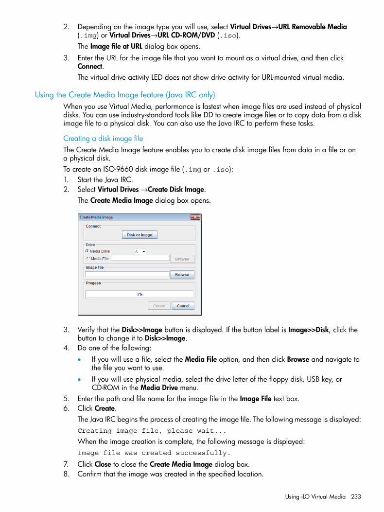
2. Depending on the image type you will use, select Virtual Drives→URL Removable Media(.img) or Virtual Drives→URL CD-ROM/DVD (.iso).The Image file at URL dialog box opens.
3. Enter the URL for the image file that you want to mount as a virtual drive, and then clickConnect.The virtual drive activity LED does not show drive activity for URL-mounted virtual media.
Using the Create Media Image feature (Java IRC only)When you use Virtual Media, performance is fastest when image files are used instead of physicaldisks. You can use industry-standard tools like DD to create image files or to copy data from a diskimage file to a physical disk. You can also use the Java IRC to perform these tasks.
Creating a disk image fileThe Create Media Image feature enables you to create disk image files from data in a file or ona physical disk.To create an ISO-9660 disk image file (.img or .iso):1. Start the Java IRC.2. Select Virtual Drives →Create Disk Image.
The Create Media Image dialog box opens.
3. Verify that the Disk>>Image button is displayed. If the button label is Image>>Disk, click thebutton to change it to Disk>>Image.
4. Do one of the following:• If you will use a file, select the Media File option, and then click Browse and navigate to
the file you want to use.• If you will use physical media, select the drive letter of the floppy disk, USB key, or
CD-ROM in the Media Drive menu.5. Enter the path and file name for the image file in the Image File text box.6. Click Create.
The Java IRC begins the process of creating the image file. The following message is displayed:Creating image file, please wait...
When the image creation is complete, the following message is displayed:Image file was created successfully.
7. Click Close to close the Create Media Image dialog box.8. Confirm that the image was created in the specified location.
Using iLO Virtual Media 233

Copying data from an image file to a physical diskThe Create Media Image feature enables you to copy the data from a disk image file to a floppydisk or USB key. Only .img disk image files are supported. Copying data to a CD-ROM is notsupported.To copy disk image data to a floppy disk or USB key:1. Start the Java IRC.2. Select Virtual Drives →Create Disk Image.
The Create Media Image dialog box opens.3. Click the Disk>>Image button to change the setting to Image>>Disk.4. Select the drive letter of the floppy disk or USB key in the Media Drive menu.5. Enter the path and file name for the existing image file in the Image File text box.
The Java IRC begins the process of copying the data from the image file to the disk. Thefollowing message is displayed:Creating disk, please wait...
When the disk creation is complete, the following message is displayed:Disk was created successfully.
6. Click Close to close the Create Media Image dialog box.7. Confirm that the files were copied to the specified location.
Using a Virtual Folder (.NET IRC only)This feature enables you to access, browse to, and transfer files from a client to a managed server.You can mount and dismount a local or networked directory that is accessible through the client.After you create a virtual image of a folder or directory, the server connects to that image as aUSB storage device, enabling you to browse to the server and transfer the files from theiLO-generated image to any location on the server.This feature and many others are part of an iLO licensing package. For more information, see thefollowing website: http://www.hp.com/go/ilo/licensing.The Virtual Folder is nonbootable and read-only; the mounted folder is static. Changes to the clientfolder are not replicated in the mounted folder.To use a Virtual Folder:1. Start the .NET IRC.2. Select Virtual Drives→Folder.
The Browse For Folder window opens.
234 Using iLO
3. Select the folder you want to use, and then click OK.The Virtual Folder is mounted on the server with the name iLO Folder.
Setting up IIS for scripted Virtual MediaBefore you set up IIS for scripted Virtual Media, verify that IIS is operational. Use IIS to set up asimple website, and then browse to the site to verify that it is working correctly.
Configuring IISTo configure IIS to serve diskette or ISO-9660 CD images for read-only access:1. Add a directory to your website and place your images in the directory.2. Verify that IIS can access the MIME type for the files you are serving.
For example, if your diskette image files use the extension .img, you must add a MIME typefor that extension. Use the IIS Manager to access the Properties dialog box of your website.On the HTTP Headers tab, click MIME Types to add MIME types.HP recommends adding the following types:.img application/octet-stream
.iso application/octet-stream
After you complete these steps, you should be able to navigate to the location of your images byusing a web browser, and then download the images to a client. If you can complete this step,your web server is configured to serve read-only disk images.
Configuring IIS for read/write access1. Install Perl (for example, ActivePerl).2. Customize the Virtual Media helper application as needed.
For a sample helper application, see “Sample Virtual Media helper application” (page 236).3. Create a directory on your website for the Virtual Media helper script, and then copy the script
to that directory.The sample script uses the directory name cgi-bin, but you can use any name.
4. On the Properties page for your directory, under Application Settings, click Create to createan application directory.The icon for your directory in IIS Manager changes from a folder icon to a gear icon.
5. Set the Execute permissions to Scripts only.6. Verify that Perl is set up as a script interpreter. Click Configuration on the Properties page to
view the application associations. Perl must be configured as shown in Figure 5 (page 236).
Using iLO Virtual Media 235

Figure 5 Perl configuration example
7. Verify that Web Service Extensions allows Perl scripts to execute. If not, click Web ServiceExtensions and set Perl CGI Extension to Allowed.
8. Verify that the prefix variable in the helper application is set correctly.To view a sample helper application, see “Sample Virtual Media helper application” (page 236).
Inserting Virtual Media with a helper applicationWhen you are using a helper application with the INSERT_VIRTUAL_MEDIA command, the basicformat of the URL is as follows:protocol://user:password@servername:port/path,helper-script
where:
• protocol—Mandatory. Either HTTP or HTTPS.
• user:password—Optional. When present, HTTP basic authorization is used.
• servername—Mandatory. Either the host name or the IP address of the web server.
• port—Optional. A web server on a nonstandard port.
• path—Mandatory. The image file that is being accessed.
• helper-script—Optional. The location of the helper script on IIS web servers.For detailed information about the INSERT_VIRTUAL_MEDIA command, see the iLO scriptingand command line guide.
Sample Virtual Media helper applicationThe following Perl script is an example of a CGI helper application that allows diskette writes onweb servers that cannot perform partial writes. A helper application can be used in conjunctionwith the INSERT_VIRTUAL_MEDIA command to mount a writable disk.When you are using the helper application, the iLO firmware posts a request to this applicationusing the following parameters:
• The file parameter contains the name of the file provided in the original URL.
• The range parameter contains an inclusive range (in hexadecimal) that designates where towrite the data.
• The data parameter contains a hexadecimal string that represents the data to be written.
236 Using iLO

The helper script must transform the file parameter into a path relative to its working directory.This might involve prefixing it with "../," or transforming an aliased URL path into the true path onthe file system. The helper script requires write access to the target file. Diskette image files musthave the appropriate permissions.Example:#!/usr/bin/perl
use CGI;use Fcntl;
## The prefix is used to get from the current working directory to the# location of the image file that you are trying to write#my ($prefix) = "c:/inetpub/wwwroot";my ($start, $end, $len, $decode);
my $q = new CGI(); # Get CGI data
my $file = $q->param('file'); # File to be writtenmy $range = $q->param('range'); # Byte range to be writtenmy $data = $q->param('data'); # Data to be written
## Change the file name appropriately#$file = $prefix . "/" . $file;
## Decode the range#if ($range =~ m/([0-9A-Fa-f]+)-([0-9A-Fa-f]+)/) { $start = hex($1); $end = hex($2); $len = $end - $start + 1;}
## Decode the data (a big hexadecimal string)#$decode = pack("H*", $data);
## Write it to the target file#sysopen(F, $file, O_RDWR);binmode(F);sysseek(F, $start, SEEK_SET);syswrite(F, $decode, $len);close(F);
print "Content-Length: 0\r\n";print "\r\n";
Configuring Virtual Media Boot OrderThe Virtual Media Boot Order feature enables you to set the server boot options. You must havethe Virtual Media and Configure iLO Settings privileges to change these settings.Changes made to the boot mode, boot order, or one-time boot status might require a server reset.iLO notifies you when a reset is required.
Using iLO Virtual Media 237

An error occurs if you try to change the server boot order when the server is in POST because youcannot modify the boot order during POST. If this occurs, wait for POST to finish, and then tryagain.
Changing the server boot modeServers that support the Unified Extensible Firmware Interface include the HP UEFI System Utilitiessoftware, which is embedded in the system ROM. On servers that support this feature, the iLO webinterface Boot Order page includes the Boot Mode section.Use the Boot Mode setting to define how the server looks for OS boot firmware. You can selectUEFI or the Legacy BIOS.1. Navigate to the Virtual Media→Boot Order page.2. Select Unified Extensible Firmware Interface (UEFI) or Legacy BIOS.
3. Click Apply.iLO prompts you to confirm the change. When you change this setting, you cannot makeadditional changes on the Boot Order page until you reset the server.
4. Click OK to confirm the change.5. Click Server Reset to reset the server.
Changing the server boot order1. Navigate to the Virtual Media→Boot Order page.
When Virtual Media is connected, the iLO web interface displays the Virtual Media type nextto the Virtual Floppy/USB key and Virtual CD/DVD-ROM text at the top of the page.
238 Using iLO
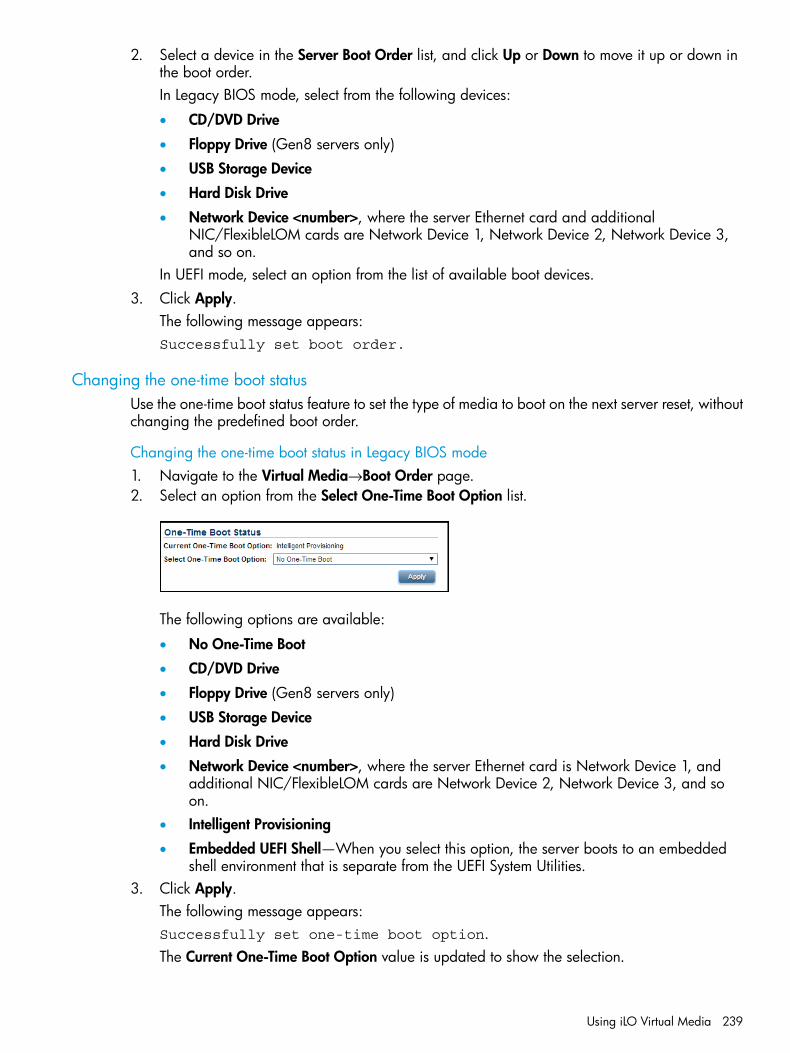
2. Select a device in the Server Boot Order list, and click Up or Down to move it up or down inthe boot order.In Legacy BIOS mode, select from the following devices:
• CD/DVD Drive
• Floppy Drive (Gen8 servers only)
• USB Storage Device
• Hard Disk Drive
• Network Device <number>, where the server Ethernet card and additionalNIC/FlexibleLOM cards are Network Device 1, Network Device 2, Network Device 3,and so on.
In UEFI mode, select an option from the list of available boot devices.3. Click Apply.
The following message appears:Successfully set boot order.
Changing the one-time boot statusUse the one-time boot status feature to set the type of media to boot on the next server reset, withoutchanging the predefined boot order.
Changing the one-time boot status in Legacy BIOS mode1. Navigate to the Virtual Media→Boot Order page.2. Select an option from the Select One-Time Boot Option list.
The following options are available:
• No One-Time Boot
• CD/DVD Drive
• Floppy Drive (Gen8 servers only)
• USB Storage Device
• Hard Disk Drive
• Network Device <number>, where the server Ethernet card is Network Device 1, andadditional NIC/FlexibleLOM cards are Network Device 2, Network Device 3, and soon.
• Intelligent Provisioning
• Embedded UEFI Shell—When you select this option, the server boots to an embeddedshell environment that is separate from the UEFI System Utilities.
3. Click Apply.The following message appears:Successfully set one-time boot option.The Current One-Time Boot Option value is updated to show the selection.
Using iLO Virtual Media 239

Changing the one-time boot status in UEFI mode1. Navigate to the Virtual Media→Boot Order page.2. Select an option from the Select One-Time Boot Option list.
The following options are available:
• No One-Time Boot
• CD/DVD Drive
• Floppy Drive (Gen8 servers only)
• USB Storage Device
• Hard Disk Drive
• Network Device <number>, where the server Ethernet card is Network Device 1, andadditional NIC/FlexibleLOM cards are Network Device 2, Network Device 3, and soon.
• Intelligent Provisioning
• UEFI Target—When you select this option, you can select from the list of available bootdevices in the Select UEFI Target Option list.
• Embedded UEFI Shell—When you select this option, the server boots to an embeddedshell environment that is separate from the UEFI System Utilities.
3. If you selected UEFI Target in the Select One-Time Boot Option list, select a boot device fromthe Select UEFI Target Option list. For example, you might have a hard drive that contains twobootable partitions, and you can use this option to select the bootable partition to use on thenext server reset.
4. Click Apply.The following message appears:Successfully set one-time boot option.The Current One-Time Boot Option value is updated to show the selection.
Using the additional optionsThe Additional Options section on the Boot Order page provides buttons for resetting the serverand booting to the system setup utilities.To use these features, navigate to the Virtual Media→Boot Order page.
• Depending on whether your system supports the legacy system RBSU or the UEFI SystemUtilities, click Boot to System RBSU or Boot to System Setup Utilities to load the ROM-basedsetup utility on the next server reset.
• Click Server Reset to reboot the server. If a one-time boot option is specified, this setting takesprecedence over the Server Boot Order value.
About server power
Powering on the serverBefore the introduction of the ProLiant Gen8 servers, some ProLiant servers (particularly ML andDL) could be powered on through the power button within a few seconds after AC power wasconnected. If an AC power loss occurs on ProLiant Gen8 or Gen9 servers with iLO 4, approximately30 seconds must elapse before the servers can power on again. The power button will blink,indicating a pending request, if it is pressed during that time.This delay is a result of the iLO firmware loading, authenticating, and booting. iLO processespending power-button requests when initialization is complete. If the server does not lose power,
240 Using iLO

there is no delay. A 30-second delay occurs only during an iLO reset. The power button is disableduntil iLO is ready to manage power.A power-button watchdog allows the user to power on the system using the power button wheniLO does not boot successfully.The iLO firmware monitors and configures power thresholds to support managed-power systems(for example, using HP power capping technology). Multiple system brownout, blackout, andthermal overloads might result when systems are allowed to boot before iLO can manage power.The managed-power state is lost because of AC power loss, so iLO must first boot to a restore stateand allow power-on.
Brownout recoveryA brownout condition occurs when power to a running server is lost momentarily. Depending onthe duration of the brownout and the server hardware configuration, a brownout might interruptthe operating system, but does not interrupt the iLO firmware.iLO detects and recovers from power brownouts. If iLO detects that a brownout has occurred,server power is restored after the power-on delay unless Auto-Power On is set to Always RemainOff. After the brownout recovery, iLO firmware records a Brown-out recovery event in theiLO Event Log.
Graceful shutdownThe ability of the iLO processor to perform a graceful shutdown requires cooperation from theoperating system. To perform a graceful shutdown, the iLO health driver must be loaded. iLOcommunicates with the health driver and uses the appropriate operating system method of shuttingdown the system safely to ensure that data integrity is preserved.If the health driver is not loaded, the iLO processor attempts to use the operating system to performa graceful shutdown through the power button. iLO emulates a physical power-button press (iLOmomentary press) in order to prompt the operating system to shut down gracefully. The behaviorof the operating system depends on its configuration and settings for a power-button press.For more information about the iLO drivers, see “iLO drivers and utilities” (page 27).The Thermal Shutdown option in the system RBSU or UEFI System Utilities allows you to disablethe automatic shutdown feature. This configuration allows the disabling of automatic shutdownexcept in the most extreme conditions when physical damage might result.
Power efficiencyiLO enables you to improve power usage by using High Efficiency Mode. HEM improves the powerefficiency of the system by placing the secondary power supplies in step-down mode. When thesecondary supplies are in step-down mode, the primary supplies provide all DC power to thesystem. The power supplies are more efficient because there are more DC output watts for eachwatt of AC input.
NOTE: HEM is available on nonblade servers only.
When the system draws more than 70% of the maximum power output of the primary supplies,the secondary supplies return to normal operation (that is, they exit step-down mode). When poweruse drops below 60% capacity of the primary supplies, the secondary supplies return to step-downmode. HEM enables you to achieve power consumption equal to the maximum power output ofthe primary and secondary power supplies, while maintaining improved efficiency at lowerpower-usage levels.HEM does not affect power redundancy. If the primary supplies fail, the secondary suppliesimmediately begin supplying DC power to the system, preventing any downtime.
About server power 241
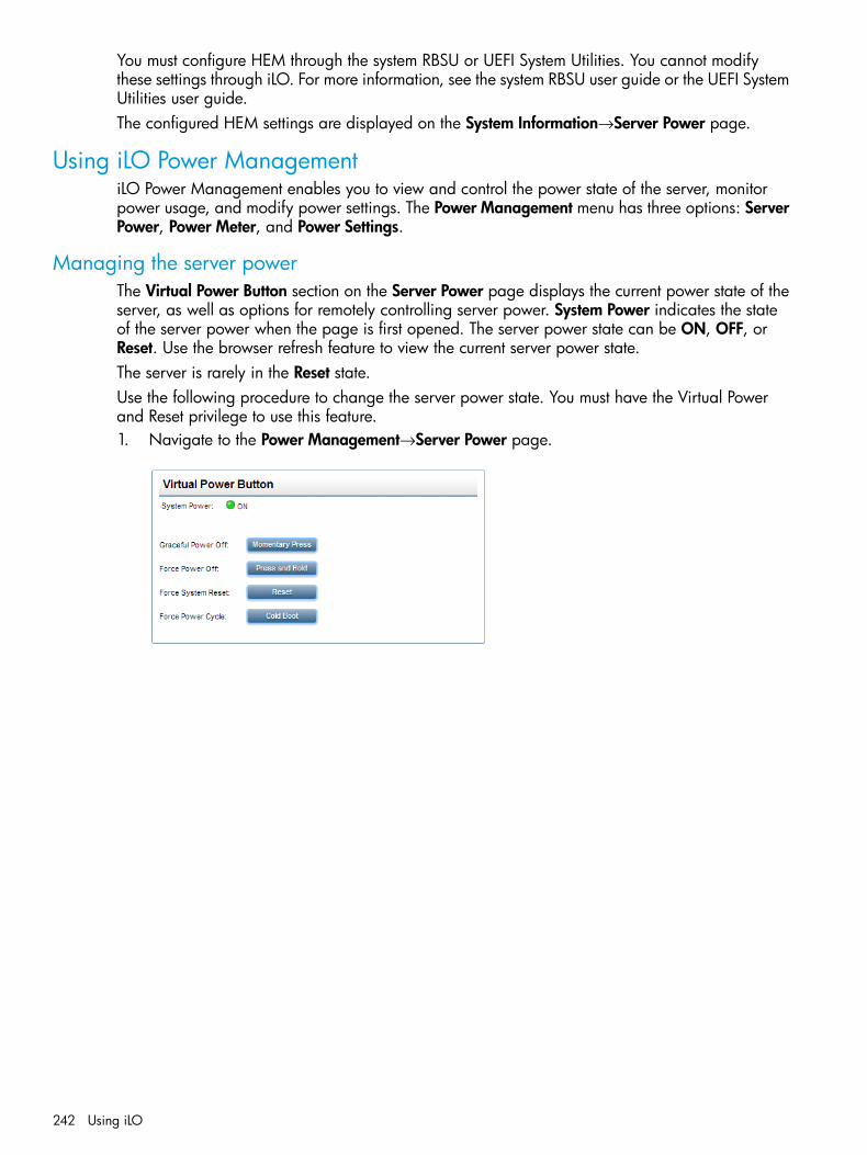
You must configure HEM through the system RBSU or UEFI System Utilities. You cannot modifythese settings through iLO. For more information, see the system RBSU user guide or the UEFI SystemUtilities user guide.The configured HEM settings are displayed on the System Information→Server Power page.
Using iLO Power ManagementiLO Power Management enables you to view and control the power state of the server, monitorpower usage, and modify power settings. The Power Management menu has three options: ServerPower, Power Meter, and Power Settings.
Managing the server powerThe Virtual Power Button section on the Server Power page displays the current power state of theserver, as well as options for remotely controlling server power. System Power indicates the stateof the server power when the page is first opened. The server power state can be ON, OFF, orReset. Use the browser refresh feature to view the current server power state.The server is rarely in the Reset state.Use the following procedure to change the server power state. You must have the Virtual Powerand Reset privilege to use this feature.1. Navigate to the Power Management→Server Power page.
242 Using iLO

2. Click one of the following buttons:• Momentary Press—The same as pressing the physical power button. If the server is
powered off, a momentary press will turn the server power on.Some operating systems might be configured to initiate a graceful shutdown after amomentary press, or to ignore this event. HP recommends using system commands tocomplete a graceful operating system shutdown before you attempt to shut down by usingthe Virtual Power button.
• Press and Hold—The same as pressing the physical power button for 5 seconds and thenreleasing it.The server is powered off as a result of this operation. Using this option might circumventthe graceful shutdown features of the operating system.This option provides the ACPI functionality that some operating systems implement. Theseoperating systems behave differently depending on a short press or long press.
• Reset—Forces the server to warm-boot: CPUs and I/O resources are reset. Using thisoption circumvents the graceful shutdown features of the operating system.
• Cold Boot—Immediately removes power from the server. Processors, memory, and I/Oresources lose main power. The server will restart after approximately 6 seconds. Usingthis option circumvents the graceful shutdown features of the operating system.
NOTE: The Press and Hold, Reset, and Cold Boot options are not available when the serveris powered off.
Configuring the System Power Restore SettingsThe System Power Restore Settings section enables you to control system behavior after power islost. You can also configure these settings by using the system RBSU or UEFI System Utilities duringPOST. You must have the Configure iLO Settings privilege to change the System Power RestoreSettings.To change the System Power Restore Settings:1. Navigate to the Power Management→Server Power page.
2. Select an Auto Power-On value.This setting determines how iLO behaves after power is restored—for example, when theserver is plugged in or when a UPS is activated after a power outage. This setting is notsupported with micro-UPS systems.
Using iLO Power Management 243
The following options are available:
• Always Power On—Power on the server after the power-on delay (default for serverblades).
• Always Remain Off—The server remains off until directed to power on.
• Restore Last Power State—Returns the server to the power state when power was lost. Ifthe server was on, it powers on; if the server was off, it remains off. This option is thedefault setting for nonblade servers. It is not available on server blades.
NOTE: Changes to the Auto Power On value might not take place until after the next serverreboot.
3. Select a Power-On Delay value.This setting staggers server automatic power-on in a data center. It determines the amount oftime iLO delays before powering on a server after iLO startup is complete. This setting is notsupported with micro-UPS systems.On supported servers, the following options are available:
• Minimum Delay—Power-on occurs after iLO startup is complete.
• 15 Second Delay—Power-on is delayed by 15 seconds.
• 30 Second Delay—Power-on is delayed by 30 seconds.
• 45 Second Delay—Power-on is delayed by 45 seconds.
• 60 Second Delay—Power-on is delayed by 60 seconds.
• Random up to 120 seconds—The power-on delay varies and can be up to 120 seconds.If a server does not support this feature, N/A is displayed.
4. Click Submit.
Viewing server power usageThe Power Meter page enables you to view the server power consumption over time.This feature and many others are part of an iLO licensing package. For more information, see thefollowing website: http://www.hp.com/go/ilo/licensing.To access power-meter graphs, navigate to the Power Management→Power Meter page.
244 Using iLO

The power-meter graphs display recent server power usage. The graph data is reset when iLO orthe server is reset. The iLO firmware periodically samples peak power, average power, and powercap. The following graphs are displayed:
• 24-Hour History Graph—Displays the power usage of the server over the previous 24 hours.The iLO firmware collects power usage information from the server every 5 minutes. The bargraph displays the average values in blue and the peak values in red. The graph shows Nocap set during a host power reset.
• 20-Minute History Graph—Displays the power usage of the server over the previous 20minutes. The iLO firmware collects power usage information from the server every 10 seconds.The bar graph displays the average values in blue and the peak values in red.
Power metering is not supported on servers with an installed Flex Slot Battery Backup Unit.
TIP: Move the mouse cursor over the graph to view the power usage for a specific point in time.
When you view the power-meter graphs, use the Display Options to control the displayedinformation. You can view minimum, average, peak, and cap power information.
Using iLO Power Management 245
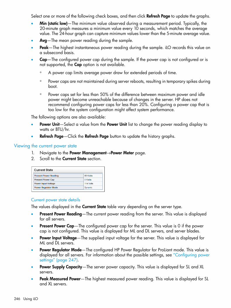
Select one or more of the following check boxes, and then click Refresh Page to update the graphs.
• Min (static low)—The minimum value observed during a measurement period. Typically, the20-minute graph measures a minimum value every 10 seconds, which matches the averagevalue. The 24-hour graph can capture minimum values lower than the 5-minute average value.
• Avg—The mean power reading during the sample.
• Peak—The highest instantaneous power reading during the sample. iLO records this value ona subsecond basis.
• Cap—The configured power cap during the sample. If the power cap is not configured or isnot supported, the Cap option is not available.
◦ A power cap limits average power draw for extended periods of time.
◦ Power caps are not maintained during server reboots, resulting in temporary spikes duringboot.
◦ Power caps set for less than 50% of the difference between maximum power and idlepower might become unreachable because of changes in the server. HP does notrecommend configuring power caps for less than 20%. Configuring a power cap that istoo low for the system configuration might affect system performance.
The following options are also available:
• Power Unit—Select a value from the Power Unit list to change the power reading display towatts or BTU/hr.
• Refresh Page—Click the Refresh Page button to update the history graphs.
Viewing the current power state1. Navigate to the Power Management→Power Meter page.2. Scroll to the Current State section.
Current power state detailsThe values displayed in the Current State table vary depending on the server type.
• Present Power Reading—The current power reading from the server. This value is displayedfor all servers.
• Present Power Cap—The configured power cap for the server. This value is 0 if the powercap is not configured. This value is displayed for ML and DL servers, and server blades.
• Power Input Voltage—The supplied input voltage for the server. This value is displayed forML and DL servers.
• Power Regulator Mode—The configured HP Power Regulator for ProLiant mode. This value isdisplayed for all servers. For information about the possible settings, see “Configuring powersettings” (page 247).
• Power Supply Capacity—The server power capacity. This value is displayed for SL and XLservers.
• Peak Measured Power—The highest measured power reading. This value is displayed for SLand XL servers.
246 Using iLO
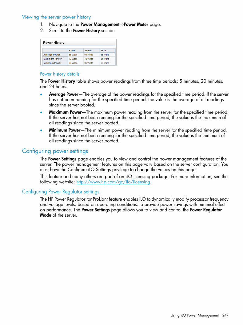
Viewing the server power history1. Navigate to the Power Management→Power Meter page.2. Scroll to the Power History section.
Power history detailsThe Power History table shows power readings from three time periods: 5 minutes, 20 minutes,and 24 hours.
• Average Power—The average of the power readings for the specified time period. If the serverhas not been running for the specified time period, the value is the average of all readingssince the server booted.
• Maximum Power—The maximum power reading from the server for the specified time period.If the server has not been running for the specified time period, the value is the maximum ofall readings since the server booted.
• Minimum Power—The minimum power reading from the server for the specified time period.If the server has not been running for the specified time period, the value is the minimum ofall readings since the server booted.
Configuring power settingsThe Power Settings page enables you to view and control the power management features of theserver. The power management features on this page vary based on the server configuration. Youmust have the Configure iLO Settings privilege to change the values on this page.This feature and many others are part of an iLO licensing package. For more information, see thefollowing website: http://www.hp.com/go/ilo/licensing.
Configuring Power Regulator settingsThe HP Power Regulator for ProLiant feature enables iLO to dynamically modify processor frequencyand voltage levels, based on operating conditions, to provide power savings with minimal effecton performance. The Power Settings page allows you to view and control the Power RegulatorMode of the server.
Using iLO Power Management 247

1. Navigate to the Power Management→Power Settings page.
2. Select one of the following options:• HP Dynamic Power Savings Mode—Automatically varies processor speed and power
usage based on processor utilization. This option allows the reduction of overall powerconsumption with little or no impact to performance. It does not require OS support.
• HP Static Low Power Mode—Reduces processor speed and power usage. This optionguarantees a lower maximum power usage for the system.
• HP Static High Performance Mode—Processors will run at maximum power/performanceat all times, regardless of the OS power management policy.
• OS Control Mode—Processors will run at maximum power/performance at all times,unless the OS enables a power management policy.
3. Click Apply.One of the following messages appears:
• For the HP Dynamic Power Savings Mode, HP Static Low Power Mode, and HP Static HighPerformance Mode settings: Power Regulator Settings changed.
• For the OS Control Mode setting: You must reboot the server to invoke thischange of the Power Regulator Settings.
The Power Regulator settings cannot be changed while the server is in POST. If the settingsdo not change after you click Apply, the server might be in the boot process or requirerebooting. Exit any ROM-based program that is running, allow POST to complete, and thentry the operation again.
4. If iLO notified you that a reboot is required, reboot the server.
248 Using iLO

Power capping settingsThe Power Capping Settings section enables you to view measured power values, set a powercap, and disable power capping.
• The Measured Power Values section lists the following:
Maximum Available Power—The power supply capacity for a nonblade server, or theinitial power-on request value for a server blade.
◦
◦ Peak Observed Power—The maximum observed power for the server
◦ Minimum Observed Power—The minimum observed power for the serverDuring POST, the ROM runs two power tests that determine the peak and minimum observedpower values.
• Use the Power Cap Thresholds as guidelines for configuring a power cap.
Maximum Power Cap—The maximum power available for the server. The server must notexceed this value.
◦
◦ Minimum High-Performance Cap—The maximum power that the server uses in the currentconfiguration. A power cap set to this value does not affect server performance.
◦ Minimum Power Cap—The minimum power that the server uses. A power cap set to thisvalue reduces the server power usage to the minimum, which results in server performancedegradation.
• When a power cap is set, the average power reading of the server must be at or below thepower cap value.
• Power capping settings are disabled when the server is part of an Enclosure Dynamic PowerCap. These values are set and modified by using Onboard Administrator or Insight ControlPower Management.
• Power capping is not supported on servers with an installed Flex Slot Battery Backup Unit.
• You cannot use the iLO web interface to configure the power capping settings for SL and XLservers. Use one of the following tools to configure the power capping settings for SL and XLservers:
◦ HP ProLiant Power Interface Control Utility
◦ HP Advanced Power Manager
Configuring a power cap1. Navigate to the Power Management→Power Settings page.2. Select the Enable power capping check box.3. Enter the Power Cap Value in watts, BTU/hr, or as a percentage.
The percentage is the difference between the maximum and minimum power values. Thepower cap value cannot be set below the server minimum power value.When values are displayed in watts, click Show values in BTU/hr to change the display toBTU/hr. When values are displayed in BTU/hr, click Show values in Watts to change thedisplay to watts.
4. Click Apply.
Configuring SNMP alert settingsThe SNMP Alert on Breach of Power Threshold feature enables the sending of an SNMP alert whenpower consumption exceeds a defined threshold.
Using iLO Power Management 249
1. Navigate to the Power Management→Power Settings page.2. Select a value in the Warning Trigger list.
The warning trigger determines whether warnings are based on peak power consumption,average power consumption, or if they are disabled.
3. If you selected Peak Power Consumption or Average Power Consumption in the WarningTrigger list, enter the following:• Warning Threshold—Sets the power consumption threshold, in watts. If power consumption
exceeds this value for the specified time duration, an SNMP alert is triggered.• Duration—Sets the length of time, in minutes, that power consumption must remain above
the warning threshold before an SNMP alert is triggered. When an SNMP alert isgenerated, it is based on the power consumption data sampled by iLO. It is not basedon the exact date and time that the Duration value was changed. The maximum durationis 240 minutes, and the duration must be a multiple of 5.
4. Click Apply to save the configuration.
Configuring the persistent mouse and keyboardThe Other Settings section on the Power Settings page allows you to enable or disable the persistentkeyboard and mouse feature.When this feature is enabled, the iLO virtual keyboard and mouse are always connected to theiLO UHCI USB controller. When this feature is disabled, the iLO virtual keyboard and mouse areconnected dynamically to the iLO UHCI controller only when a Remote Console application isopen and connected to iLO. Disabling the feature allows some servers to increase power savingsby 15 watts when the server operating system is idle and no virtual USB keyboard and mouse areconnected.For example, the power savings for a 24-hour period might be 15 watts x 24 hours, or 360 watthours (.36 kilowatt-hours).The persistent mouse and keyboard feature is disabled by default.To change the persistent mouse and keyboard setting:1. Navigate to the Power Management→Power Settings page.2. Select or clear the Enable persistent mouse and keyboard check box.3. Click Apply to save the configuration.
Using iLO with Onboard AdministratorOA is the enclosure management processor, subsystem, and firmware base that supports the HPBladeSystem and all managed devices in the enclosure.
Using the Active Onboard AdministratorThe BL c-Class→Active Onboard Administrator page provides general information about the primaryOA in the enclosure in which the iLO processor is located. This page is displayed only when thereis an enclosure.
250 Using iLO

The displayed information and options follow:
• MAC Address—The MAC address of the active OA.
• System Health—The health of the active OA, as reported by the OA.A value of unknown means that the OA health has not been reported to iLO.
• Blade Location—The location (enclosure bay) of the blade that is hosting the current iLO session.
• Enclosure Name—The enclosure that the active OA is managing. You can change this valuethrough the OA.
• Rack Name—The rack that contains the enclosure managed by the active OA. You can changethis value through the OA.
Starting the OA GUI1. Navigate to the BL c-Class→Active Onboard Administrator page.2. If the OA supports multiple addresses, select the address to use from the options in the Onboard
Administrator Address Selection table.Depending on the configuration, the following options might be available:
• IPv4
• IPv6 SLAAC
• IPv6 Static
• IPv6 DHCP3. Click Launch to open the OA web interface in a new browser window.
Toggling the enclosure UID LEDTo change the state of the enclosure UID LED where iLO is located, click the Toggle UID button.The UID LED status on this page represents the enclosure UID LED status when the iLO page loaded.To update the status, refresh the page.
Using iLO with Onboard Administrator 251
Enclosure bay IP addressingThe First Time Setup Wizard prompts you to set up your enclosure bay IP addressing. For moreinformation about the wizard, see the OA user guide.
Dynamic Power Capping for server bladesDynamic Power Capping is an iLO feature available for c-Class server blades, and is accessedthrough OA. Dynamic Power Capping is available only if your system hardware platform, BIOS(ROM), and power microcontroller firmware version support this feature. If your system supportsDynamic Power Capping, iLO automatically runs in Dynamic Power Capping mode.For information about the power setting options for c-Class server blades, see the OA user guide.
iLO virtual fanIn c-Class blade servers, OA controls the enclosure fans (also called virtual fans). The iLO firmwarecannot detect these enclosure fans. Instead, the iLO firmware monitors an ambient temperaturesensor located on the blade server. This information is displayed on the iLO web interface, and isretrieved by OA periodically. OA uses the sensor information collected from all iLO processors inthe enclosure to determine enclosure fan speeds.
iLO optionThe iLO - Device Bay <XX> page in OA provides the following links:• Web Administration—Starts the iLO web interface
• Integrated Remote Console—Starts the .NET IRC
• Remote Console—Starts the Java IRCClicking a link on this page opens the requested iLO session in a new window that uses SSO,which does not require an iLO user name or password. If your browser settings prevent newwindows from opening, these links do not work correctly.
252 Using iLO

Viewing chassis informationNavigate to the Chassis→Chassis Information page.The Chassis Information page is displayed for ProLiant SL and XL servers.
Viewing chassis information 253
Power Supplies listThe Chassis Information page displays the following details about the power supplies in the chassis.Some power supplies do not provide information for all of the values on this page. If a powersupply does not provide information for a value, N/A is displayed.
BayThe chassis power supply bay number.
PresentWhether a power supply is installed. The possible values are OK and Not Installed.
StatusThe status of the power supply. The displayed value includes a status icon (OK, Degraded, Failed,or Other), and text that provides more information. The possible values follow:
• Unknown
• Good, In Use
• Good, Standby
• General Failure
• Over Voltage Failure
• Over Current Failure
• Over Temperature Failure
• Input Voltage Lost
• Fan Failure
• High Input A/C Warning
• Low Input A/C Warning
• High Output Warning
• Low Output Warning
• Inlet Temperature Warning
• Internal Temperature Warning
• High Vaux Warning
• Low Vaux Warning
• Mismatched Power Supplies
PDSWhether the installed power supply is enabled for HP Power Discovery Services.HP Power Discovery Services is an enhancement to the iPDU technology. If the chassis powersupply is connected to an iPDU, an additional summary table on this page displays the linkediPDUs.
HotplugWhether the power supply bay supports swapping the power supply when the chassis is poweredon. If the value is Yes, and the power supplies are redundant, the power supply can be removedor replaced when the chassis is powered on.
254 Using iLO

Flex Slot Battery Backup UnitThe following information is displayed for supported chassis with an installed Flex Slot BatteryBackup Unit:
• Charge—The current battery charge (percent).
• Days Active—The number of calendar days that the battery has been installed.
• Battery Health—The battery health status (0 to 100 percent).Battery health issues are reported in the IML.
Power capping and power metering are not supported on chassis with an installed Flex Slot BatteryBackup Unit.For more information, see the Flex Slot Battery Backup Unit installation instructions.
ModelThe model number of the power supply.
SpareThe part number of the spare power supply.
Serial NumberThe serial number of the power supply.
CapacityThe capacity of the power supply (watts).
FirmwareThe installed power supply firmware.
Intelligent Power Distribution Unit detailsThe Intelligent Power Distribution Units section is displayed only if the chassis power supplies areconnected to an iPDU.After iLO is reset, or when an iPDU is attached, it takes approximately 2 minutes for the iLO webinterface to display the Intelligent Power Distribution Units table. This delay is due to the iPDUdiscovery process. The following information is displayed in the table:
• ID—The power supply bay number.
• Part Number—The iPDU part number.
• Serial Number—The iPDU serial number.
• IP Address—The iPDU IP address.
• SSL Port—The iPDU SSL port.
• MAC Address—The MAC address of the iPDU network port. This value helps you to uniquelyidentify each connected iPDU because each iPDU has a unique MAC address.
HP Smart Storage Battery details• Index—The battery index number.
• Present—Whether a battery is installed. The possible values are OK and Not Installed.
• Status—The battery status. The possible values are OK, Degraded, Failed, or Other.
• Model—The battery model number.
Viewing chassis information 255
• Spare—The part number of the spare battery.
• Serial Number—The battery serial number.
• Capacity—The battery capacity.
• Firmware—The installed battery firmware version.
IPMI server managementServer management through IPMI is a standard method for controlling and monitoring the server.The iLO firmware provides server management based on the IPMI version 2.0 specification, whichdefines the following:
• Monitoring of system information such as fans, temperatures, and power supplies
• Recovery capabilities such as system resets and power on/off operations
• Logging capabilities for abnormal events such as over-temperature readings or fan failures
• Inventory capabilities such as identification of failed hardware componentsIPMI communications depend on the BMC and the SMS. The BMC manages the interface betweenthe SMS and the platform management hardware. The iLO firmware emulates the BMC functionality,and the SMS functionality can be provided by various industry-standard tools. For more information,see the IPMI specification on the Intel website at http://www.intel.com/design/servers/ipmi/tools.htm.The iLO firmware provides the KCS interface, or open interface, for SMS communications. TheKCS interface provides a set of I/O mapped communications registers. The default system baseaddress for the I/O-mapped SMS interface is 0xCA2, and it is byte aligned at this system address.The KCS interface is accessible to the SMS software running on the local system. Examples ofcompatible SMS software applications follow:
• IPMI version 2.0 Command Test Tool—A low-level MS-DOS command-line tool that enableshex-formatted IPMI commands to be sent to an IPMI BMC that implements the KCS interface.You can download this tool from the Intel website at http://www.intel.com/design/servers/ipmi/tools.htm.
• IPMItool—A utility for managing and configuring devices that support the IPMI version 1.5and version 2.0 specifications. IPMItool can be used in a Linux environment. You can downloadthis tool from the IPMItool website at http://ipmitool.sourceforge.net/index.html.
• FreeIPMI—A utility for managing and configuring devices that support the IPMI version 1.5and version 2.0 specifications. You can download FreeIPMI from the following website: http://www.gnu.org/software/freeipmi/.
• IPMIUTIL—A utility for managing and configuring devices that support the IPMI version 1.0,1.5, and version 2.0 specifications. You can download IPMIUTIL from the following website:http://ipmiutil.sourceforge.net/
When emulating a BMC for the IPMI interface, iLO supports all mandatory commands listed in theIPMI version 2.0 specification. The SMS should use the methods described in the specification fordetermining which IPMI features are enabled or disabled in the BMC (for example, using the GetDevice ID command).If the server operating system is running, and the iLO health driver is enabled, any IPMI trafficthrough the KCS interface can affect health driver performance and overall system health. Do notissue any IPMI commands through the KCS interface that might have a negative effect on healthdriver monitoring. This restriction includes any command that sets or changes IPMI parameters,such as Set Watchdog Timer and Set BMC Global Enabled. Any IPMI command thatsimply returns data is safe to use, such as Get Device ID and Get Sensor Reading.
256 Using iLO
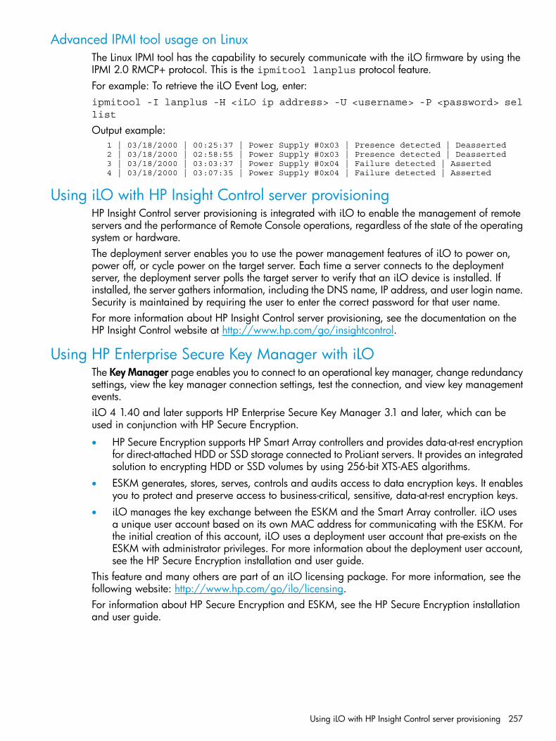
Advanced IPMI tool usage on LinuxThe Linux IPMI tool has the capability to securely communicate with the iLO firmware by using theIPMI 2.0 RMCP+ protocol. This is the ipmitool lanplus protocol feature.For example: To retrieve the iLO Event Log, enter:ipmitool -I lanplus -H <iLO ip address> -U <username> -P <password> sellist
Output example: 1 | 03/18/2000 | 00:25:37 | Power Supply #0x03 | Presence detected | Deasserted 2 | 03/18/2000 | 02:58:55 | Power Supply #0x03 | Presence detected | Deasserted 3 | 03/18/2000 | 03:03:37 | Power Supply #0x04 | Failure detected | Asserted 4 | 03/18/2000 | 03:07:35 | Power Supply #0x04 | Failure detected | Asserted
Using iLO with HP Insight Control server provisioningHP Insight Control server provisioning is integrated with iLO to enable the management of remoteservers and the performance of Remote Console operations, regardless of the state of the operatingsystem or hardware.The deployment server enables you to use the power management features of iLO to power on,power off, or cycle power on the target server. Each time a server connects to the deploymentserver, the deployment server polls the target server to verify that an iLO device is installed. Ifinstalled, the server gathers information, including the DNS name, IP address, and user login name.Security is maintained by requiring the user to enter the correct password for that user name.For more information about HP Insight Control server provisioning, see the documentation on theHP Insight Control website at http://www.hp.com/go/insightcontrol.
Using HP Enterprise Secure Key Manager with iLOThe Key Manager page enables you to connect to an operational key manager, change redundancysettings, view the key manager connection settings, test the connection, and view key managementevents.iLO 4 1.40 and later supports HP Enterprise Secure Key Manager 3.1 and later, which can beused in conjunction with HP Secure Encryption.
• HP Secure Encryption supports HP Smart Array controllers and provides data-at-rest encryptionfor direct-attached HDD or SSD storage connected to ProLiant servers. It provides an integratedsolution to encrypting HDD or SSD volumes by using 256-bit XTS-AES algorithms.
• ESKM generates, stores, serves, controls and audits access to data encryption keys. It enablesyou to protect and preserve access to business-critical, sensitive, data-at-rest encryption keys.
• iLO manages the key exchange between the ESKM and the Smart Array controller. iLO usesa unique user account based on its own MAC address for communicating with the ESKM. Forthe initial creation of this account, iLO uses a deployment user account that pre-exists on theESKM with administrator privileges. For more information about the deployment user account,see the HP Secure Encryption installation and user guide.
This feature and many others are part of an iLO licensing package. For more information, see thefollowing website: http://www.hp.com/go/ilo/licensing.For information about HP Secure Encryption and ESKM, see the HP Secure Encryption installationand user guide.
Using iLO with HP Insight Control server provisioning 257

Configuring key manager servers1. Navigate to the Administration→Key Manager page.
2. Enter the following information:• Primary Key Server—The primary key server IP address or FQDN and port. This string
can be up to 79 characters long.• Secondary Key Server—The secondary key server IP address or FQDN and port. This
string can be up to 79 characters long.3. Optional: For configurations with a primary and secondary key server, select the Require
Redundancy check box to check for server redundancy.HP recommends enabling this option. When this option is disabled, iLO will not verify thatencryption keys are copied to both of the configured key servers.
4. Click Apply.
Adding key manager configuration details1. Navigate to the Administration→Key Manager page.
The listed iLO Account on ESKM account name is ilo-<iLO MAC address>. The account nameis read-only and is used when iLO communicates with the ESKM.
258 Using iLO
2. Enter the following information in the Key Manager Configuration section:• Group—The Local Group created on the ESKM for use with iLO user accounts and the
keys iLO imports into the ESKM. When keys are imported, they are automaticallyaccessible to all devices assigned to the same group.
• ESKM Local CA Certificate Name (optional)—To ensure that iLO is communicating with atrusted ESKM server, enter the name of the local certificate authority certificate in ESKM.It is typically named Local CA and is listed in ESKM under Local CAs. iLO will retrievethe certificate and use it to authenticate the ESKM server(s) for all transactions goingforward.
• Login Name—The Local User name with administrator permissions that is configured onthe ESKM. This is the ESKM deployment user.The deployment user account must be created before you add key manager configurationdetails in iLO.
• Password—The password for the Local User name with administrator permissions that isconfigured on the ESKM.
3. Click Update ESKM.iLO verifies that an iLO account named ilo-<iLO MAC address> exists on the ESKM.If the account exists, iLO verifies that the account password is correct. If the password isincorrect, iLO updates the password. This password is automatically generated by iLO andmight have been changed if iLO was restored to the factory default settings. If the accountdoes not exist, iLO creates it.If iLO is not a member of an ESKM Local Group, it will try to create a group with the requestedname. If iLO is already a member of an ESKM Local Group, it will ignore the group enteredin Step 2, and will use the existing group assignment that is present on the ESKM. Attemptedgroup changes in iLO do not affect current key group permissions that are set on the ESKM.If a new group assignment is needed, you must make the changes on the ESKM before updatingthe iLO settings.If you entered the ESKM Local CA Certificate Name in Step 2, certificate information is listedin the Imported Certificate Details section of the ESKM page.
See the Secure Encryption installation and user guide for more information about groups and theiruse with key management.
Testing the ESKM configurationAfter the key manager configuration is complete in iLO, you can use the Test ESKM Connectionsfeature to verify the configuration settings. The tests confirm that iLO and the ESKM servers are setup to provide key management services for HP Secure Encryption. During the test, iLO attemptsthe following tasks:
• Connects to the primary ESKM server (and secondary ESKM server, if configured) by usingSSL.
• Tries to authenticate to the ESKM by using the configured credentials and account.
• Confirms that the version of the ESKM software is compatible with iLO.To test the ESKM configuration:1. Navigate to the Administration→Key Manager page.2. Click Test ESKM Connections.
The test results are displayed in the Enterprise Secure Key Manager Events table.
Using HP Enterprise Secure Key Manager with iLO 259

Viewing ESKM events1. Navigate to the Administration→Key Manager page.2. Scroll to the Enterprise Secure Key Manager Events section.
Each event is listed with a time stamp and description.
Viewing remote management tool informationiLO 4 1.30 and later allows remote management through supported tools such as HP OneView.The association between iLO and a remote management tool is configured by using the remotemanagement tool. For instructions, see your remote management tool documentation.When iLO is under the control of a remote management tool, the iLO web interface includes thefollowing enhancements:
• A message similar to the following is displayed on the iLO login page:Warning: This system is being managed by <Remote Management ToolName>.
Changes made locally in iLO will be out of sync with the centralizedsettings and could affect the behavior of the remote managementsystem.
• A page called <Remote Management Tool Name> is added to the iLO navigation tree.
Starting a remote management toolWhen iLO is under the control of a remote management tool, use the following procedure to startthe remote manager user interface from iLO.1. Navigate to the <Remote Management Tool Name> page.
2. Click Launch.The remote management tool starts in a separate browser window.
Deleting a remote manager configurationIf you discontinue the use of a remote management tool in your network, you can remove theassociation between the tool and iLO.
IMPORTANT: HP recommends that you remove the server from the remote management toolbefore you delete the remote manager configuration in iLO. Do not delete the remote managerconfiguration for a tool that is still in use on the network and is managing the server that containsthe current iLO system.
1. Navigate to the <Remote Management Tool Name> page.
260 Using iLO

2. Click the Delete button in the Delete this remote manager configuration from this iLO section.A warning message similar to the following appears:Proceed with this deletion only if this iLO is no longer under thecontrol of <Remote Management Tool Name>.
3. Click OK.The <Remote Management Tool Name> page is removed from the iLO navigation tree.
Using iLO with HP OneViewHP OneView interacts with the iLO management processor to configure, monitor, and manageProLiant servers. It configures seamless access to the iLO remote console, enabling you to launchthe iLO remote console from the HP OneView user interface in a single click. Your iLO privilegesare determined by the role assigned to your appliance account.HP OneView manages the following iLO settings:
• The remote management tool
• SNMP v1 trap destination
• SNMP v1 read community
• SSO certificate—A trusted certificate is added to the Administration→Security→HP SSO page.
• NTP (time server) configuration
• User Account—An administrative user account is added to iLO with the name_HPOneViewAdmin.
• Firmware version—When you add a server to HP OneView, if a supported version of the iLOfirmware is not installed, the firmware is updated. For more information, see the HP OneViewsupport matrix.
• The appliance is added as a destination for HP RESTful Interface events.
IMPORTANT: For best performance when using HP OneView with iLO 4, HP recommends thatyou do not delete or change these settings by using the iLO web interface. Making changes to adevice from its iLO or the OA could cause it to become out of synchronization with HP OneView.
For more information about HP OneView, see http://www.hp.com/go/oneview/docs.
Using the Embedded User PartitioniLO 4 stores files such as Active Health System data and the Intelligent Provisioning software innon-volatile flash memory that is embedded on the system board. This flash memory is called theiLO NAND. ProLiant Gen9 servers with a 4 GB iLO NAND allow you to use a 1 GB non-volatileflash memory partition as if it was an SD-card attached to the server. When the Embedded UserPartition is enabled, you can access it through the server operating system.The Embedded User Partition is accessible through the server OS for read and write access whenthe server is configured for Legacy BIOS or UEFI boot mode.To determine whether your server includes a 4 GB iLO NAND, see the server QuickSpecs at http://www.hp.com/go/qs/.You can use the Embedded User Partition for tasks such as:• Storing UEFI Shell scripts and test tools. UEFI scripts can be run automatically when the server
boots to the embedded UEFI Shell. To use this feature, place a startup.nsh shell script filein the root directory of the Embedded User Partition.This feature is supported only when the server is configured for the UEFI boot mode.
Using the Embedded User Partition 261

For more information, see the UEFI Shell user guide on the following website: http://www.hp.com/go/ProLiantUEFI/docs.
• Installing and booting from VMware ESXi (UEFI mode only)To select the Embedded User Partition for an OS or hypervisor installation, select the volumeHP iLO LUN <number>.
• Storing iLO scripts
• Storing iLO language packs
IMPORTANT: Do not use the Embedded User Partition for high-frequency write operations.
For information about configuring access to the Embedded User Partition, see “Configuring theEmbedded User Partition” (page 262).
Configuring the Embedded User PartitionYou can use the UEFI System Utilities, UEFI Shell, and HP RESTful Interface Tool to configure theEmbedded User Partition.
Configuring the Embedded User Partition (UEFI System Utilities)Use the following procedure to enable or disable the Embedded User Partition by using the UEFISystem Utilities.1. Optional: If you access the server remotely, start an iLO remote console session.
You can use the .NET IRC or Java IRC.2. Restart or power on the server.3. Press F9 in the ProLiant POST screen to start the UEFI System Utilities.4. From the System Utilities screen, select System Configuration→BIOS/Platform Configuration
(RBSU)→System Options→USB Options→Embedded User Partition and press Enter.5. Select one of the following options:
• Enabled
• Disabled (default)6. Press F10 to save your selection.7. Restart the server.
262 Using iLO

8. After you enable the Embedded User Partition, format it by using the server operating systemsoftware.Once the partition is formatted, it can be accessed for read and write access from the serveroperating system.
Configuring the Embedded User Partition (UEFI Shell)Use the following procedure to configure the Embedded User Partition by using the UEFI Shell.1. Boot to the UEFI Shell. For instructions, see the UEFI Shell user guide.2. Use the following command to enable the Embedded User Partition:
sysconfig -s embeddeduserpartition=Enabled
3. Restart the server.4. After you enable the Embedded User Partition, format it by using the server operating system
software.Once the partition is formatted, it can be accessed for read and write access from the serveroperating system.
Configuring the Embedded User Partition (HP RESTful Interface Tool)1. Enable or disable the Embedded User Partition.
For information about configuring the Embedded User Partition with the HP RESTful InterfaceTool, see the HP RESTful Interface Tool documentation at the following website: http://www.hp.com/go/restfulinterface/docs.
2. After you enable the Embedded User Partition, format it by using the server operating systemsoftware.Once the partition is formatted, it can be accessed for read and write access from the serveroperating system.
Configuring the Embedded User Partition boot settingsYou can use the UEFI System Utilities, UEFI Shell, HP RESTful Interface Tool, or iLO web interfaceto configure the Embedded User Partition boot settings.
Configuring the Embedded User Partition boot order setting (iLO web interface)Use the following procedure to change the position of the Embedded User Partition in the ServerBoot Order list.
NOTE: This feature is not available when the Legacy BIOS boot mode is selected.
Using the Embedded User Partition 263

1. Navigate to the Virtual Media→Boot Order page.
2. Select the Embedded User Partition device in the Server Boot Order list, and click Up or Downto move it up or down in the boot order.The Embedded User Partition is listed with a name similar to the following:Internal Virtual USB 4 : Embedded User.
3. Click Apply.The following message appears:Successfully set boot order.
Configuring the Embedded User Partition for one-time boot (iLO web interface)Use the following procedure to set the position of the Embedded User Partition in the Server BootOrder list.
NOTE: This feature is not available when the Legacy BIOS boot mode is selected.
1. Navigate to the Virtual Media→Boot Order page.2. Select UEFI Target in the Select One-Time Boot Option list.3. Select the Embedded User Partition from the Select UEFI Target Option list.
The Embedded User Partition is listed with a name similar to the following:Internal Virtual USB 4 : Embedded User.
264 Using iLO

4. Click Apply.The following message appears:Successfully set one-time boot option.The Current One-Time Boot Option value is updated to show the selection.
Configuring the Embedded User Partition boot order setting (UEFI System Utilities)Use the following procedure to change the position of the Embedded User Partition in the UEFIBoot Order list.
NOTE: This feature is not available when the Legacy BIOS boot mode is selected.
1. Optional: If you access the server remotely, start an iLO remote console session.You can use the .NET IRC or Java IRC.
2. Restart or power on the server.3. Press F9 in the ProLiant POST screen to start the UEFI System Utilities.4. From the System Utilities screen, select System Configuration→BIOS/Platform Configuration
(RBSU)→Boot Options→UEFI Boot Order and press Enter.5. From the UEFI Boot Order screen, press Enter to open the UEFI Boot Order list.
The Embedded User Partition is listed with a name similar to the following:Internal Virtual USB 4 : Embedded User Partition.
6. Update the position of the Embedded User Partition in the boot order list, as needed.• Use the arrow keys to navigate within the boot order list.
• Press the + key (plus) to move an entry higher in the boot list.
• Press the - key (minus) to move an entry lower in the list.7. Press F10 to save your selection.
Using the Embedded User Partition 265

8. From the System Utilities screen, select Exit and Resume Boot.For more information about the UEFI Boot Order list, see the UEFI System Utilities user guide.
Configuring the Embedded User Partition for one-time boot (UEFI System Utilities)Use the following procedure to set the position of the Embedded User Partition in the One TimeBoot Menu.
NOTE: This feature is not available when the Legacy BIOS boot mode is selected.
1. Optional: If you access the server remotely, start an iLO remote console session.You can use the .NET IRC or Java IRC.
2. Restart or power on the server.3. Press F9 in the ProLiant POST screen to start the UEFI System Utilities.4. From the System Utilities screen, select One Time Boot Menu, and then press Enter.5. From the One-Time Boot Menu screen, select the Embedded User Partition option, and then
press Enter.The Embedded User Partition is listed with a name similar to the following:Internal Virtual USB 4 : Embedded User Partition.The server resumes the boot process and boots from the Embedded User Partition.
For more information about the One-Time Boot Menu, see the UEFI System Utilities user guide.
Configuring the Embedded User Partition boot order setting (UEFI Shell)Use the following procedure to configure the Embedded User Partition by using the UEFI Shell.1. Boot to the UEFI Shell. For instructions, see the UEFI Shell user guide.2. Use the following command to configure the Embedded User Partition boot order setting:
sysconfig -s uefibootorder=settingvalue
Where settingvalue is a UEFI boot order option.
NOTE: For information about using this command, see the UEFI Shell user guide.
Configuring the Embedded User Partition for one-time boot (UEFI Shell)Use the following procedure to configure the Embedded User Partition by using the UEFI Shell.1. Boot to the UEFI Shell. For instructions, see the UEFI Shell user guide.2. Use the following command to configure the Embedded User Partition for one-time boot:
boot -n settingvalue
Where settingvalue is the boot number of the device to use for one-time boot.
NOTE: For information about using this command, see the UEFI Shell user guide.
Configuring the Embedded User Partition boot order setting (HP RESTful Interface Tool)For information about configuring the Embedded User Partition boot order setting with the HPRESTful Interface Tool, see the HP RESTful Interface Tool documentation at the following website:http://www.hp.com/go/restfulinterface/docs.
Configuring the Embedded User Partition for one-time boot (HP RESTful Interface Tool)For information about configuring the Embedded User Partition one-time boot settings with the HPRESTful Interface Tool, see the RESTful Interface Tool documentation at the following website: http://www.hp.com/go/restfulinterface/docs.
266 Using iLO
Rebooting (Resetting) iLOIn some cases, it might be necessary to reboot iLO; for example, if iLO is not responding to thebrowser.Rebooting iLO does not make any configuration changes, but ends all active connections to iLO.
IMPORTANT: The iLO web interface and the ROM-based setup utilities sometimes uses the termiLO reset to mean an iLO reboot.
To reboot iLO, use one of the following methods:
• Click Reset on the Information→Diagnostics page in the iLO web interface. For moreinformation, see “Using iLO diagnostics” (page 188).
• Use the CLI or HPONCFG. For instructions, see the iLO scripting and command line guide.
• The Insight Management Agents 5.40 and later have the ability to reset iLO. Select the ResetiLO option on the HP Management Agent page in the iLO section.
• Click Apply on the Network→iLO Dedicated Network Port or Shared Network Port→Generalpage to manually force the iLO management processor to reset. If the Apply button is notavailable, change a setting, change it back, and then click Apply to reset iLO without changingthe configuration.
• Use the iLO 4 Configuration Utility. The iLO 4 Configuration Utility is available only on serversthat support UEFI. For instructions, see “Resetting iLO by using the iLO 4 Configuration Utility”(page 267).
• Use the UID button on supported ProLiant Gen9 servers. For instructions, see “Rebooting iLOwith the server UID button” (page 268).
If none of these methods is available or working as expected, you must power down the serverand disconnect the power supplies completely.
Resetting iLO by using the iLO 4 Configuration UtilityIf iLO is slow to respond, you can use the iLO 4 Configuration Utility Reset iLO menu to perform areset.Resetting iLO does not make any configuration changes, but it ends all active connections to iLO.You must have the Configure iLO Settings privilege to reset iLO using this method.1. Optional: If you access the server remotely, start an iLO remote console session.
You can use the .NET IRC or Java IRC.2. Restart or power on the server.3. Press F9 in the ProLiant POST screen to start the UEFI System Utilities.4. From the System Utilities screen, select System Configuration→iLO 4 Configuration Utility→Reset
iLO.The iLO 4 Configuration Utility prompts you to select YES or NO.
5. Select YES, and then press Enter.The iLO 4 Configuration Utility prompts you to confirm the reset request.When you reset iLO, the iLO 4 Configuration Utility is not available again until the next reboot.
6. Press Enter.iLO resets. If you are managing iLO remotely, the remote console session is automaticallyended.
Rebooting (Resetting) iLO 267

7. Resume the boot process:a. Optional: If you are managing iLO remotely, wait for the iLO reset to finish, and then
start the iLO remote console.The UEFI System Utilities are still open from the previous session.
b. Press Esc until the main menu is displayed.c. Select Exit and Resume Boot in the main menu, and then press Enter.d. When prompted to confirm the request, press Enter to exit the utility and resume the
normal boot process.
Rebooting iLO with the server UID buttonThe UID button on ProLiant Gen9 servers (if present) can be used to initiate a manual reboot ofiLO.There are two types of iLO reboots:
• Graceful iLO reboot—An iLO reboot is initiated by the iLO firmware. To use this feature, pressand hold the UID button for 5 to 9 seconds.The UID button/LED flashes blue 4 Hz/cycle per second to indicate that a graceful iLO rebootis in progress.Initiating a graceful iLO reboot does not make any configuration changes, but ends all activeconnections to iLO. If a firmware file upload is in progress, it is terminated. If a firmware flashis in progress, you cannot reboot iLO until the process is finished.
• Hardware iLO reboot—An iLO reboot is initiated by the ProLiant hardware. To use this feature,press and hold the UID button for 10 seconds or longer.The UID button/LED flashes blue 8 Hz/cycle per second to indicate that an iLO hardwarereboot is in progress.
CAUTION: Initiating a hardware iLO reboot does not make any configuration changes, butends all active connections to iLO. If a firmware flash is in progress, it is interrupted, whichmight cause data corruption on the flash device. If this happens, use the recovery methoddescribed in “iLO network Failed Flash Recovery” (page 339).Data loss or NVRAM corruption might occur during a hardware iLO reboot.Do not initiate a hardware reboot if other troubleshooting options are available.
For more information about the UID button, see the user guide for your server at the followingwebsite: http://www.hp.com/support/proliantgen9/docs.
Resetting iLO to the factory default settingsIn some cases, you might need to reset iLO to the factory default settings. For example, you mustreset iLO to the default settings when you disable FIPS mode. You can use the iLO RBSU or theUEFI system utilities to perform this task.
Resetting iLO to the factory default settings by using iLO RBSUTo reset iLO to the factory default settings:
CAUTION: This operation clears all user and license data.
1. Optional: If you access the server remotely, start an iLO remote console session.You can use the .NET IRC or Java IRC.
2. Restart or power on the server.3. Press F8 in the ProLiant POST screen to start the iLO RBSU.
268 Using iLO

4. Select File→Set Defaults.iLO RBSU prompts you to confirm the request.
5. Press F10 to continue.iLO RBSU displays the following message:After setting to factory defaults, iLO 4 will be reset and this utility will exit.
6. Press Enter.iLO resets and the server boot process finishes.
NOTE: If a server has an installed iLO Advanced license when you perform this procedure, theiLO Advanced icon might be selected when the server boot process finishes. The icon will be setcorrectly after POST completes, or after the server is shut down, powered off, and then poweredon again.
Resetting iLO to the factory default settings by using the iLO 4 Configuration UtilityUse the iLO 4 Configuration Utility Set to Factory Defaults menu to reset iLO to the factory defaultsettings.
CAUTION: This operation clears all user and license data.
1. Optional: If you access the server remotely, start an iLO remote console session.You can use the .NET IRC or Java IRC.
2. Restart or power on the server.3. Press F9 in the ProLiant POST screen to start the UEFI System Utilities.4. From the System Utilities screen, select System Configuration→iLO 4 Configuration Utility→Set
to factory defaults.The iLO 4 Configuration Utility prompts you to select YES or NO.
5. Select YES, and then press Enter.The iLO 4 Configuration Utility prompts you to confirm the reset request.The iLO system is reset, and you cannot access the iLO 4 Configuration Utility until after thenext system reboot.You can press Enter to confirm, or press Esc to cancel.
6. Press Enter.iLO resets to the factory default settings. If you are managing iLO remotely, the remote consolesession is automatically ended.
7. Resume the boot process:a. Optional: If you are managing iLO remotely, wait for the iLO reset to finish, and then
start the iLO remote console.The iLO 4 Configuration Utility screen is still open from the previous session.
b. Press Esc until the main menu is displayed.c. Select Exit and Resume Boot in the main menu, and then press Enter.d. When prompted to confirm the request, press Enter to exit the screen and resume the
boot process.
NOTE: If a server has an installed iLO Advanced license when you perform this procedure, theiLO Advanced icon might be selected when the server boot process finishes. The icon will be setcorrectly after POST completes, or after the server is shut down, powered off, and then poweredon again.
Resetting iLO to the factory default settings 269
5 Integrating HP Systems Insight ManagerThe iLO firmware is integrated with HP SIM in key operating environments, providing a singlemanagement console from a standard web browser. While the operating system is running, youcan establish a connection to iLO by using HP SIM.Integration with HP SIM provides the following:
• Support for SNMP trap delivery to an HP SIM console—The HP SIM console can be configuredto forward SNMP traps to a pager or email address.
• Support for management processors—All iLO devices installed in servers on the network arediscovered in HP SIM as management processors.
• Grouping of iLO management processors—All iLO devices can be grouped logically anddisplayed on one page.
• HP Management Agents or Agentless Management—iLO, combined with AgentlessManagement or the HP Management Agents, provides remote access to system managementinformation through the iLO web interface.
• Support for SNMP management—HP SIM can access Insight Management Agent informationthrough iLO.
HP SIM featuresHP SIM enables you to do the following:
• Identify iLO processors.
• Create an association between an iLO processor and its server.
• Create links between an iLO processor and its server.
• View iLO and server information and status.
• Control the amount of information displayed for iLO.The following sections summarize these features. For detailed information, see the HP SIM userguide.
Establishing SSO with HP SIM1. Configure iLO for HP SIM SSO and add HP SIM trusted servers.
For instructions, see “Using HP SSO” (page 84).2. Log in to the HP SIM server that you specified in Step 1, and discover the iLO processor.
After you complete the discovery process, SSO is enabled for iLO.For more information about HP SIM discovery tasks, see the HP SIM user guide.
iLO identification and associationHP SIM can identify an iLO processor and create an association between iLO and a server. Youcan configure iLO to respond to HP SIM identification requests by setting the Level of Data Returnedvalue on the Administration→Management page. For more information, see “Configuring InsightManagement integration” (page 119).
Viewing iLO status in HP SIMHP SIM identifies iLO as a management processor. HP SIM displays the management processorstatus on the All Systems page.
270 Integrating HP Systems Insight Manager

The iLO management processor is displayed as an icon on the same row as its host server. Thecolor of the icon represents the status of the management processor.For a list of device statuses, see the HP SIM user guide.
iLO links in HP SIMFor ease of management, HP SIM creates links to the following:
• iLO and the host server from any System(s) list
• The server from the System page for iLO
• iLO from the System page for the serverThe System(s) list pages display iLO, the server, and the relationship between iLO and the server.
• Click a status icon to display the iLO web interface.
• Click the iLO or server name to display the System page of the device.
Viewing iLO in HP SIM System(s) listsiLO management processors can be viewed in HP SIM. A user who has full configuration rightscan create and use customized system collections to group management processors. For moreinformation, see the HP SIM user guide.
Receiving SNMP alerts in HP SIMYou can configure iLO to forward alerts from the management agents of the host operating systemand to send iLO alerts to HP SIM.HP SIM supports full SNMP management. iLO supports SNMP trap delivery to HP SIM. You canview the event log, select the event, and view additional information about the alert.Configuring the receipt of SNMP alerts in HP SIM:1. To enable iLO to send SNMP traps, navigate to the Administration→Management page and
configure the settings for SNMP, SNMP alerting, and Insight Management Integration. Enterthe IP address of the HP SIM computer in the SNMP Alert Destination(s) box.For more information, see “Configuring SNMP settings” (page 112).
2. To discover iLO in HP SIM, configure iLO as a managed device for HP SIM.This enables the NIC interface on iLO to function as a dedicated management port, isolatingmanagement traffic from the NIC interface for the remote host server. For instructions, see theHP SIM user guide.For major events that are not cleared, iLO traps appear in All Events. To obtain moreinformation about the event, click Event Type.
HP SIM port matchingHP SIM is configured to start an HTTP session to check for iLO at port 80. If you want to changethe port number, you must change it in both iLO and HP SIM.
• To change the port in iLO, navigate to the Administration→Access Settings page, and thenenter the new port number in the Web Server Non-SSL Port box.
• To change the port number in HP SIM, add the port to the config\identification\additionalWsDisc.props file in the HP SIM installation directory. If iLO uses the defaultport (80), you do not need to edit this file.The port entry must be on a single line with the port number first, and with all other itemsidentical to the following example (including capitalization). This example shows the correctentry for discovering iLO at port 55000.
Receiving SNMP alerts in HP SIM 271

55000=iLO 4,,true,false,com.hp.mx.core.tools.identification.mgmtproc.MgmtProcessorParser
Reviewing iLO license information in HP SIMHP SIM displays the license status of the iLO management processors. You can use this informationto determine how many and which iLO devices have an optional license installed.To view license information, select Deploy→License Manager. To ensure that the displayed datais current, run the Identify Systems task for your management processors. For more information,see the HP SIM user guide.
272 Integrating HP Systems Insight Manager

6 Directory servicesThis chapter describes how to configure iLO to use Kerberos login, schema-free directoryauthentication, and HP extended schema directory authentication.
Directory integration benefitsDirectory integration with iLO provides the following benefits:
• Scalability—The directory can be leveraged to support thousands of users on thousands ofiLO processors.
• Security—Robust user-password policies are inherited from the directory. User-passwordcomplexity, rotation frequency, and expiration are policy examples.
• User accountability—In some environments, users share iLO accounts, which makes it difficultto determine who performed an operation.
• Role-based administration—You can create roles (for example, clerical, remote control of thehost, complete control) and associate users or user groups with those roles. A change to asingle role applies to all users and iLO devices associated with that role.
• Single point of administration—You can use native administrative tools like MMC andConsoleOne to administer iLO users.
• Immediacy—A single change in the directory rolls out immediately to associated iLO processors.This eliminates the need to script this process.
• Simpler credentials—You can use existing user accounts and passwords in the directory withouthaving to record a new set of credentials for iLO.
• Flexibility—You can create a single role for a single user on a single iLO processor, a singlerole for multiple users on multiple iLO processors, or a combination of roles as suited to yourenterprise.
• Compatibility—iLO directory integration supports Active Directory.
• Standards—iLO directory support is based on the LDAP 2.0 standard for secure directoryaccess.
Choosing a directory configuration to use with iLOSome directory configuration practices work better with iLO than others. Before you configure iLOfor directories, you must decide whether to use the schema-free directory integration method orthe HP extended schema directory integration method. Answer the following questions to helpevaluate your directory integration requirements:1. Can you apply schema extensions to your directory?
• No—You are using Active Directory, and your company policy prohibits applyingextensions.No—Directory integration does not fit your environment. Consider deploying an evaluationserver to assess the benefits of directory integration.Use group-based schema-free directory integration. For more information, see “Schema-freedirectory integration” (page 280).
• Yes—Proceed to question 2.
Directory integration benefits 273

2. Is your configuration scalable?• No—Deploy an instance of the schema-free directory integration to evaluate whether this
method meets your policy and procedural requirements. If necessary, you can deploy HPschema directory integration later. For more information, see “Schema-free directoryintegration” (page 280).
• Yes—Use HP schema directory integration. For more information, see “Setting up HPextended schema directory integration” (page 283).
The following questions can help you determine whether your configuration is scalable:
• Are you likely to change the rights or privileges for a group of directory users?
• Will you regularly script iLO changes?
• Do you use more than five groups to control iLO privileges?
For more information, see the comprehensive list of benefits in “Directory integration benefits”(page 273). “Directory-enabled remote management” (page 295) explains how roles, groups, andsecurity are enabled and enforced through directories.
Kerberos supportKerberos support enables a user to log in to iLO without supplying a user name and password ifthe client workstation is logged in to the domain and the user is a member of a directory groupfor which iLO is configured. If the workstation is not logged in to the domain, the user can alsolog in to iLO by using the Kerberos user name and domain password. Kerberos support can beconfigured through the web interface, XML (RIBCL), or SSH (partial support for CLI).Because a trust relationship between iLO and the domain is established by a system administratorbefore user sign-on, any form of authentication (including two-factor authentication) is supported.For instructions on configuring a user to support two-factor authentication, see the server operatingsystem documentation.
PrerequisitesBefore preparing the domain controller and configuring iLO for Kerberos login, configure the iLOhost name and domain name.Note the following:
• The iLO domain name value must correspond to the Kerberos realm name. For moreinformation, see “Realm names” (page 275).
• The iLO host name that you use for keytab generation must be identical to the configured iLOhost name. iLO host names are case sensitive. For more information, see “Generating a keytab”(page 275).
This procedure is performed by using the iLO Dedicated Network Port page in the iLO web interface.To complete the prerequisites:1. Navigate to the Administration→Network→iLO Dedicated Network Port page.2. Click the IPv4 tab.3. Clear the following check boxes, and then click Submit.
• Use DHCPv4 Supplied Domain Name
• Use DHCPv4 Supplied DNS Servers4. Click the IPv6 tab.5. Clear the following check boxes, and then click Submit.
• Use DHCPv6 Supplied Domain Name
• Use DHCPv6 Supplied DNS Servers
274 Directory services
6. Click the General tab.7. Update the following values, and then click Submit.
• Optional: Update the iLO Subsystem Name (Host Name) value.The iLO host name is case sensitive, and is used when you create the keytab file.
• Update the Domain Name value.This value must match the Kerberos realm name, which is usually the domain nameconverted to uppercase letters. For more information, see “Realm names” (page 275).
8. Click Reset to restart iLO.
Domain controller preparationIn a Windows Server environment, Kerberos support is part of the domain controller.
Realm namesThe Kerberos realm name for a DNS domain is usually the domain name converted to uppercase.For example:• Parent domain name: example.net
• Kerberos realm name: EXAMPLE.NET
Computer accountsA computer account must be present and enabled in the domain directory for each iLO account.In Windows, create the user account in the Active Directory Users and Computers snap-in. Forexample:• iLO host name: iloname
• Parent domain name: example.net
• iLO domain name (fully qualified): iloname.example.net
User accountsA user account must be present and enabled in the domain directory for each user who is allowedto log in to iLO.
Generating a keytabThis section describes how to generate a keytab file for iLO in a Windows environment.The iLO host name that you use for keytab generation must be identical to the configured iLO hostname. iLO host names are case sensitive.
Kerberos support 275

1. Use the ktpass command to generate a keytab and set the shared secret.The command is case sensitive and has special characters.ktpass -out iloname.keytab +rndPass -ptype KRB5_NT_SRV_HST [email protected] -princ HTTP/[email protected]
The output should be similar to the following:
Targeting domain controller: domaincontroller.example.net Using legacy password setting method Successfully mapped HTTP/iloname.example.net to iloname. WARNING: pType and account type do not match. This might cause problems.Key created. Output keytab to iloname.keytab: Keytab version: 0x502 keysize 69 HTTP/[email protected] ptype 3 (KRB5 _NT_SRV_HST) vno 3 etype 0x17 (RC4-HMAC) keylength 16 (0x5a5c7c18ae23559acc2 9d95e0524bf23)
NOTE: The ktpass command might display a message about not being able to set theUPN. This is acceptable because iLO is a service, not a user. You might be prompted toconfirm the password change on the computer object. Click OK to close the window andcontinue creating the keytab file. Do not use the -kvno option of the ktpass command. Thisoption causes the knvo in the keytab file to be out of sync with the kvno in Active Directory.
2. Use the SetSPN command to assign the Kerberos SPN to the computer object. For example:SetSPN -A HTTP/iloname.example.net iloname
If the SetSPN command displays an error message, do the following:a. Use MMC with the ADSIEdit snap-in and find the computer object for iLO.b. Set the DNSHostName property to the iLO DNS name. For example:
cn=iloname,ou=us,ou=clients,dc=example,dc=net
3. Use the SetSPN -L iloname command to display the SPNs and DN for the iLO.Verify that the HTTP/iloname.example.net service is displayed.
NOTE: The SetSPN command might display a message about not being able to set theUPN. This is acceptable because iLO is a service, not a user. You might be prompted toconfirm the password change on the computer object. Click OK to close the window andcontinue creating the keytab file.
Key version numberIf a domain controller OS is reinstalled, the key version number sequence resets. You must regenerateand reinstall the keytab files that iLO uses for devices associated with that domain controller.
Windows VistaTo generate keytab files on Windows Vista, use Microsoft hotfix KB960830 and ktpass.exeversion 6.0.6001.22331 or later.
Universal and global user groups (for authorization)To set permissions in iLO, you must create a group in the domain directory. Users who log in toiLO are granted the sum of the permissions for all groups of which they are a member. Onlyuniversal and global user groups can be used to set permissions. Domain local groups are notsupported.
276 Directory services
Configuring iLO for Kerberos loginThis section describes the iLO requirements for Kerberos login. You can configure iLO for Kerberoslogin using the iLO web interface, XML configuration and control scripts, or the CLI, CLP, or SSHinterface.
Using the iLO web interfaceTo configure the iLO parameters by using the web interface:1. Verify that your environment meets the requirements for Kerberos login. For more information,
see “Prerequisites” (page 274).2. Navigate to the Administration→Security→Directory page to configure the following
Kerberos-specific parameters:• Kerberos Authentication
• Kerberos Realm
• Kerberos KDC Server Address
• Kerberos KDC Server Port
• Kerberos KeytabFor more information about the Kerberos-specific parameters, see “Directory authenticationand authorization” (page 73).
3. Navigate to the Administration→User Administration page to configure directory groups.Each Directory Group includes a DN, SID, and permissions. For Kerberos login, the SIDs ofgroups of which the user is a member are compared to the SIDs for directory groups for whichiLO is configured. The user is granted the sum of the permissions for all groups of which theuser is a member of.You can only use global and universal groups to set permissions. Domain local groups arenot supported.For more information, see “Managing iLO user accounts by using the iLO web interface”(page 39).
4. Navigate to the Information→Overview page to check the Current iLO Date/Time.For more information, see “Viewing iLO overview information” (page 148).
5. Navigate to the Administration→Network→SNTP Settings page if you want to change thedate and time.For Kerberos authentication to function properly, the date and time must be synchronizedbetween the iLO processor, the KDC, and the client workstation. Set the date and time in iLOwith the server, or obtain the date and time from the network by enabling the SNTP Settingsfeature in iLO.For more information, see “Configuring SNTP settings” (page 104).
Using XML configuration and control scriptsThe following sample scripts show how to set the iLO parameters for directories:
• Set_Server_Name.xml shows how to set the iLO host name.
• Mod_Schemaless_Directory.xml shows how to configure directory groups.
• Mod_Network_Settings.xml shows how to configure SNTP settings.
• Mod_Kerberos_Config.xml shows how to configure Kerberos-specific parameters.
NOTE: You can download sample XML scripts from http://www.hp.com/support/ilo4. For moreinformation, see the iLO scripting and command line guide.
Kerberos support 277

Using the CLI, CLP, or SSH interfaceTo configure the iLO parameters by using the CLI, CLP, or SSH interface:
• iLO Hostname—You can change the iLO host name in the Hostname property of the/map1/dnsendpt1 target.
• Directory groups—You can configure directory group names and permissions in the propertiesof the /map1/oemhp_dircfg1 target. The group SIDs cannot be configured through thisinterface.
• iLO Date/Time, SNTP Settings—The current date and time and the SNTP settings cannot bedisplayed through this interface.
• Kerberos-specific configuration parameters—You can configure Kerberos parameters in theproperties of the oemhp_dircfg1, target.
NOTE: For more information about configuring the iLO parameters by using the CLI, CLP, orSSH, see the iLO scripting and command line guide.
Time requirementTo log in to Kerberos successfully, ensure that the date and time of the following are set to within5 minutes of one another:
• The iLO server
• The client running the web browser
• The servers performing the authentication
Configuring single sign-onUsers who are allowed to log in to iLO must be members of the groups for which permissions areassigned. For Windows clients, locking and unlocking the workstation refreshes the credentialsthat are used to log in to iLO. Home versions of the Windows operating system do not supportKerberos login.
Internet ExplorerThis section describes the procedure for enabling single sign-on with Internet Explorer. The followingsteps enable login if Active Directory is configured correctly for iLO, and iLO is configured correctlyfor Kerberos login.
NOTE: This procedure is based on Internet Explorer 8. Newer browser versions might havedifferent steps.
1. Enable authentication in Internet Explorer:a. Select Tools→Internet Options.b. Click the Advanced tab.c. Scroll to the Security section.d. Verify that the Enable Integrated Windows Authentication option is selected.e. Click OK.
2. Add the iLO domain to the Intranet zone:a. Select Tools→Internet Options.b. Click the Security tab.c. Click the Local intranet icon.d. Click the Sites button.e. Click the Advanced button.
278 Directory services
f. Enter the site to add in the Add this website to the zone box.On a corporate network, *.example.net is sufficient.
g. Click Add.h. Click Close.i. Click OK to close the Local intranet dialog box.j. Click OK to close the Internet Options dialog box.
3. Enable Automatic logon only in Intranet zone:a. Select Tools→Internet Options.b. Click the Security tab.c. Click the Local intranet icon.d. Click Custom level.e. Scroll to the User Authentication section.f. Verify that the Automatic logon only in Intranet zone option is selected.g. Click OK to close the Security Settings — Local Intranet Zone window.h. Click OK to close the Internet Options dialog box.
4. If any options were changed, close and restart Internet Explorer.5. Use the FQDN to browse to iLO (for example, iloname.example.net).6. Click the HP Zero Sign In button.
FirefoxThis section describes the procedure for enabling single sign-on with Firefox. The following stepsenable login if Active Directory is configured correctly for iLO, and iLO is configured correctly forKerberos login:1. Enter about:config in the browser location bar to open the browser configuration page.
If the message This might void your warranty! appears, click the I'll be careful, Ipromise! button.
2. Enter network.negotiate in the Filter box.3. Double-click network.negotiate-auth.trusted-uris.4. Enter the iLO DNS domain name (for example, example.net), and then click OK.5. Use the FQDN to browse to iLO (for example, iloname.example.net).6. Click the HP Zero Sign In button.
ChromeNo special settings are required for the Chrome browser.
Verifying single sign-on (HP Zero Sign In) configurationTo verify that HP Zero Sign In is configured correctly:1. Browse to the iLO login page (for example, http://iloname.example.net).2. Click the HP Zero Sign In button.
If a prompt for credentials appears, Kerberos authentication has failed and the system hasreverted to NTLM authentication. Click Cancel, and then repeat the procedures in “Configuringsingle sign-on” (page 278).
Login by nameTo verify that login by name is working properly:1. Browse to the iLO login page (for example, http://iloname.example.net).2. Enter the user name in the Kerberos SPN format (for example, [email protected]).
Kerberos support 279

3. Enter the associated domain password.If a prompt for credentials appears, Kerberos authentication has failed. Click Cancel to closethe dialog box.Login by name might not work correctly if the computer account for iLO is part of a childdomain, but the Kerberos configuration parameters (Kerberos Realm, Kerberos KDC ServerAddress, and Kerberos KDC Server Port) reference the parent domain.
Schema-free directory integrationWith schema-free directory integration, users and group memberships reside in the directory, butgroup privileges reside in the iLO settings. iLO uses login credentials to read the user object in thedirectory and retrieve the user group memberships, which are compared to those stored in iLO. Ifthe credentials and membership match, authorization is granted, as shown in Figure 6 (page 280).
Figure 6 Schema-free directory integration
User entersuser name
and password
iLOinterface
Credentialstranslatedto a DN
Login script validates user credentials
User found inthe directory
and verified inthe iLO groups
Directory
iLOinterface
Advantages of using schema-free directory integration include the following:
• You do not have to extend the directory schema.
• Minimal setup is required for users in the directory. If no setup exists, the directory uses existingusers and group memberships to access iLO. For example, if you have a domain administratornamed User1, you can copy the DN of the domain administrator security group to iLO andgive it full privileges. User1 would then have access to iLO.
Using schema-free directory integration has the following disadvantage:
• Group privileges are administered on each iLO. However, this disadvantage has minimalimpact because group privileges rarely change, and the task of changing group membershipis administered in the directory and not on each iLO. HP provides tools that enable you tomake changes to a large number of iLOs at the same time.
Setting up schema-free directory integrationIf you want to use the schema-free directory integration method, your system must meet theprerequisites described in “Active Directory prerequisites” (page 280).
Active Directory prerequisitesSSL must be enabled at the directory level. To enable SSL, install a certificate for the domain inActive Directory. iLO communicates with the directory only over a secure SSL connection.To validate the setup, you must have the directory DN of at least one user and the DN of a securitygroup that the user is a member of.
Introduction to Certificate ServicesCertificate Services is used to issue signed digital certificates to network hosts. The certificates areused to establish SSL connections with the host and verify the authenticity of the host.
280 Directory services
Installing Certificate Services enables Active Directory to receive a certificate that allows iLOprocessors to connect to the directory service. Without a certificate, iLO cannot connect to thedirectory service.Each directory service that you want iLO to connect to must be issued a certificate. If you installan Enterprise Certificate Service, Active Directory can automatically request and install certificatesfor all Active Directory controllers on the network.
Installing Certificate ServicesUse the following procedure for Windows Server 2008:1. Navigate to Server Manager.2. Click Roles in the left pane.3. Click Add Roles.4. Select Active Directory Certificate Services.5. Follow the onscreen instructions. If you are not sure what values to use, accept the default
values.
Verifying Certificate ServicesBecause management processors communicate with Active Directory by using SSL, you must createa certificate or install Certificate Services. You must install an enterprise CA because you will issuecertificates to objects in your organizational domain.To verify that Certificate Services is installed, select Start→Programs→AdministrativeTools→Certification Authority. An error message appears if Certificate Services is not installed.
Configuring Automatic Certificate RequestTo specify that a certificate be issued to the server:1. Select Start→Run, and then enter mmc.2. Select File→Add/Remove Snap-in.3. To add the snap-in to MMC, select Group Policy Object, and then click Add.4. Click Browse, and then select the Default Domain Policy object. Click OK.5. Click Finish, and then click Close and OK to close the remaining dialog boxes.6. Expand Computer Configuration→Windows Settings→Security Settings→Public Key.7. Right-click Automatic Certificate Requests Settings, and select New→Automatic Certificate
Request.The Automatic Certificate Request Setup wizard starts.
8. Click Next.9. Select the Domain Controller template, and click Next.10. Select the listed certificate authority (it is the same CA that was defined during the Certificate
Services installation). Click Next.11. Click Finish to close the wizard.
Schema-free setup using the iLO web interfaceYou can set up a schema-free configuration by using the iLO web interface. Only users who havethe Configure iLO Settings privilege can change these settings. Users who do not have the ConfigureiLO Settings privilege can only view the assigned settings.1. Navigate to the Administration→Security→Directory page.2. Select Use Directory Default Schema in the Authentication and Directory Server Settings section.
For more information, see “Schema-free setup options” (page 282).3. Click Apply Settings.4. To test the communication between the directory server and iLO, click Test Settings.
Schema-free directory integration 281

Schema-free setup using scriptsTo set up a schema-free directory configuration by using XML configuration and control scripts:1. Review the iLO scripting and command line guide.2. Write and execute a script that configures iLO for schema-free directory support.
Use the following script as a template:<RIBCL VERSION="2.0"> <LOGIN USER_LOGIN="admin" PASSWORD="admin123"> <DIR_INFO MODE = "write"> <MOD_DIR_CONFIG> <DIR_ENABLE_GRP_ACCT value = "Yes"/>
<DIR_GRPACCT1_NAME value = "test1"/> <DIR_GRPACCT1_PRIV value = "3,4,5"/> <!-- Firmware support information for next tag:--> <!-- iLO 4 - All versions.--> <!-- iLO 3 - Version 1.20 or later only--> <DIR_GRPACCT1_SID value= "S-1-0"/>
<!-- alternative method for iLO 3/4 only--><!-- <DIR_GRPACCT INDEX="1">--><!-- <NAME VALUE="string"/>--><!-- <SID VALUE="S-1-0"/>--><!-- <LOGIN_PRIV VALUE="Y"/>--><!-- </DIR_GRPACCT>-->
</MOD_DIR_CONFIG> </DIR_INFO> </LOGIN></RIBCL>
Schema-free setup with HP Directories Support for ProLiant Management ProcessorsHP recommends using HP Directories Support for ProLiant Management Processors (HPLOMIG)when you are configuring multiple iLO processors for directories.For more information, see “HP Directories Support for ProLiant Management Processors utility”(page 301).
Schema-free setup optionsThe schema-free setup options are the same, regardless of the method you use to configure thedirectory.To review the available methods, see “Schema-free setup using the iLO web interface” (page 281),“Schema-free setup using scripts” (page 282), and “Schema-free setup with HP Directories Supportfor ProLiant Management Processors” (page 282).After you enable directories and select the schema-free option, you have the following options:
Minimum login flexibility
• Enter the directory server DNS name or IP address and LDAP port. Typically, the LDAP portfor an SSL connection is 636.
• Enter the DN for at least one group. This group can be a security group (for example,CN=Administrators,CN=Builtin,DC=HP,DC=com) or any other group as long as theintended iLO users are members of the group.With a minimum configuration, you can log in to iLO by using your full DN and password.You must be a member of a group that iLO recognizes.
282 Directory services

Better login flexibilityIn addition to the minimum settings, enter at least one directory user context.At login time, the login name and user context are combined to make the user DN. For example,if the user logs in as JOHN.SMITH, and a user context is set up as CN=USERS,DC=HP,DC=COM,the DN that iLO tries is CN=JOHN.SMITH,CN=USERS,DC=HP,DC=COM.
Maximum login flexibilityConfigure iLO with a DNS name, and not an IP address, for the directory server network address.The DNS name must be resolvable to an IP address from both iLO and the client system.Configuring iLO with maximum login flexibility enables you to log in using your full DN andpassword, your name as it appears in the directory, NetBIOS format (domain/login_name), oremail format (login_name@domain).In some cases, the maximum login flexibility option might not work. For example, if the client andiLO are in different DNS domains, one of the two might not be able to resolve the directory servername to an IP address.
Schema-free nested groupsMany organizations have users and administrators arranged in groups. This arrangement of existinggroups is convenient because you can associate them with one or more iLO management roleobjects. When iLO devices are associated with the role objects, you can use the administratorcontrols to access the devices associated with the role by adding or deleting members from thegroups.When using Microsoft Active Directory, you can place one group in another group to create anested group. Role objects are considered groups and can include other groups directly. You canadd the existing nested group directly to the role and assign the appropriate rights and restrictions.You can add new users to either the existing group or the role.In schema-free integration, users who are indirect members (a member of a group that is a nestedgroup of the primary group) are allowed to log in to iLO.When you are using trustee or directory rights assignments to extend role membership, users mustbe able to read the object that represents the iLO device. Some environments require that thetrustees of a role also be read trustees of the object to successfully authenticate users.
Setting up HP extended schema directory integrationWhen you use HP schema directory integration, iLO supports Active Directory. This directory servicerequires that the schema be extended.
Features supported by HP schema directory integrationUsing the HP schema enables you to do the following:
• Authenticate users from a shared, consolidated, scalable user database.
• Control user privileges (authorization) by using the directory service.
• Use roles in the directory service for group-level administration of iLO management processorsand iLO users.
A schema administrator must complete the task of extending the schema. The local user databaseis retained. You can decide not to use directories, to use a combination of directories and localaccounts, or to use directories exclusively for authentication.
NOTE: When you are connected through the Diagnostics Port, the directory server is not available.You log in using a local account.
Setting up HP extended schema directory integration 283

Advantages of using the HP extended schema include the following:
• There is more flexibility in controlling access. For example, access can be limited to a time ofday or a certain range of IP addresses.
• Groups are maintained in the directory, not on each iLO.
Setting up directory servicesTo successfully implement directory-enabled management on any iLO management processor:1. Plan
Review the following sections:
• Directory services. For more information, see “Directory services” (page 273).
• Directory-enabled remote management. For more information, see “Directory-enabledremote management” (page 295).
• Directory services schema. For more information, see “Directory services schema”(page 348).
2. Installa. Download the HP Directories Support for ProLiant Management Processors package that
contains the schema installer, the management snap-in installer, and the migration utilitiesfrom http://www.hp.com/support/ilo4.
b. Run the schema installer once to extend the schema.c. Run the management snap-in installer and install the appropriate snap-in for your directory
service on one or more management workstations.3. Update
a. Set directory server settings and the DN of the management processor objects on theDirectory Settings page in the iLO web interface. For more information, see “Directoryauthentication and authorization” (page 73).
b. If you are using the schema-free integration or Kerberos Zero Sign In, configure directorygroups. For more information, see “Managing iLO user accounts by using the iLO webinterface” (page 39).
4. Managea. Create a management device object and a role object by using the snap-in.b. Assign rights to the role object, as necessary, and associate the role with the management
device object.c. Add users to the role object.For more information about managing the directory service, see “Directory-enabled remotemanagement” (page 295). Examples are available in “Directory services for Active Directory”(page 287).
5. Handle exceptionsiLO migration utilities are easier to use with a single role. If you plan to create multiple rolesin the directory, you might need to use directory scripting utilities, like LDIFDE or VBScriptutilities. These utilities create complex role associations. For more information, see “Using bulkimport tools” (page 300).
After the schema has been extended, you can complete the directory services setup by using HPmigration utilities, which are included in the HP Directories Support for ProLiant ManagementProcessors package.
284 Directory services
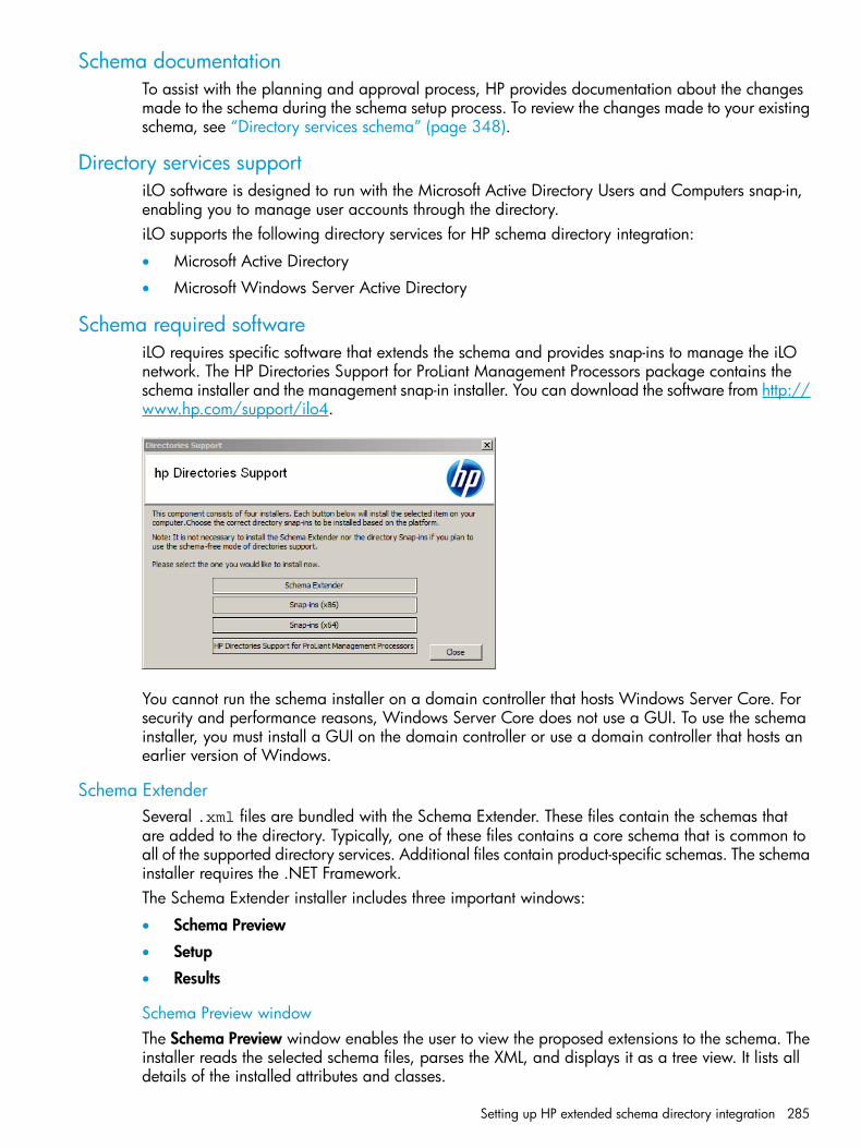
Schema documentationTo assist with the planning and approval process, HP provides documentation about the changesmade to the schema during the schema setup process. To review the changes made to your existingschema, see “Directory services schema” (page 348).
Directory services supportiLO software is designed to run with the Microsoft Active Directory Users and Computers snap-in,enabling you to manage user accounts through the directory.iLO supports the following directory services for HP schema directory integration:
• Microsoft Active Directory
• Microsoft Windows Server Active Directory
Schema required softwareiLO requires specific software that extends the schema and provides snap-ins to manage the iLOnetwork. The HP Directories Support for ProLiant Management Processors package contains theschema installer and the management snap-in installer. You can download the software from http://www.hp.com/support/ilo4.
You cannot run the schema installer on a domain controller that hosts Windows Server Core. Forsecurity and performance reasons, Windows Server Core does not use a GUI. To use the schemainstaller, you must install a GUI on the domain controller or use a domain controller that hosts anearlier version of Windows.
Schema ExtenderSeveral .xml files are bundled with the Schema Extender. These files contain the schemas thatare added to the directory. Typically, one of these files contains a core schema that is common toall of the supported directory services. Additional files contain product-specific schemas. The schemainstaller requires the .NET Framework.The Schema Extender installer includes three important windows:
• Schema Preview
• Setup
• Results
Schema Preview windowThe Schema Preview window enables the user to view the proposed extensions to the schema. Theinstaller reads the selected schema files, parses the XML, and displays it as a tree view. It lists alldetails of the installed attributes and classes.
Setting up HP extended schema directory integration 285

Setup windowYou use the Setup window to enter the appropriate information before extending the schema.
The Directory Server section of the Setup window enables you to select Active Directory, and toset the computer name and the port to be used for LDAP communications.
NOTE: When you are running the Schema Extender tool, you must use the Administratorlogin along with the domain name, for example, [email protected] or domain\Administrator.Extending the schema for Active Directory requires that the user is an authenticated schemaadministrator, that the schema is not write protected, and that the directory is the FSMO role ownerin the tree. The installer attempts to make the target directory server the FSMO schema master ofthe forest.
The Directory Login section of the Setup window enables you to enter your login name andpassword. These might be required to complete the schema extension. The Use SSL for this Sessionoption sets the form of secure authentication to be used. If this option is selected, directoryauthentication through SSL is used. If this option is not selected and Active Directory is selected,Windows NT authentication is used.
286 Directory services

Results windowThe Results window displays the results of the installation, including whether the schema could beextended and what attributes were changed.
Management snap-in installerThe management snap-in installer installs the snap-ins required to manage iLO objects in a MicrosoftActive Directory Users and Computers directory or Novell ConsoleOne directory.iLO snap-ins are used to perform the following tasks in creating an iLO directory:
• Creating and managing the iLO objects and role objects
• Making the associations between the iLO objects and the role objects
Directory services for Active DirectoryThe following sections provide installation prerequisites, preparation instructions, and a workingexample of directory services for Active Directory. HP provides a utility to automate much of thedirectory setup process. You can download HP Directories Support for ProLiant ManagementProcessors from http://www.hp.com/support/ilo4.
Active Directory installation prerequisites
• Active Directory must have a digital certificate installed to enable iLO to connect securely overthe network.
• Active Directory must have the schema extended to describe iLO object classes and properties.
• An iLO license must be installed.For more information about iLO licensing go to http://www.hp.com/go/ilo/licensing.
Setting up HP extended schema directory integration 287
• Installing directory services for iLO requires extending the Active Directory schema. An ActiveDirectory schema administrator must extend the schema.
• directory services for iLO uses LDAP over SSL to communicate with the directory servers. Beforeyou install snap-ins and schema for Active Directory, read and have available the followingdocumentation:
◦ Microsoft Knowledge Base ArticlesThese articles are available at http://support.microsoft.com/.
– 321051 Enabling LDAP over SSL with a Third-Party Certificate Authority
– 299687 MS01-036: Function Exposed By Using LDAP over SSL Could EnablePasswords to Be Changed
◦ iLO requires a secure connection to communicate with the directory service. This connectionrequires the installation of the Microsoft CA. For more information, see the MicrosoftKnowledge Base Article 321051: How to Enable LDAP over SSL with a Third-PartyCertification Authority.
Installing Active Directory
For the schema-free configuration1. Install Active Directory, DNS, and the root CA.2. Log in to iLO and enter the directory settings and directory user contexts on the
Administration→Security→Directory page.For more information, see “Directory authentication and authorization” (page 73).
3. Click Apply Settings to save the changes.4. Click the Administer Groups button, and then create directory groups for the iLO users.
For more information, see “Managing iLO user accounts by using the iLO web interface”(page 39).
5. Navigate to the iLO Dedicated Network Port or Shared Network Port General Settings page,and then enter the environment settings in the Domain Name and Primary DNS server boxes.For more information, see “Configuring IPv4 settings” (page 99).
For HP extended schema1. Install Active Directory, DNS, and the root CA.2. Verify that version 2.0 or later of the .NET Framework is installed. This software is required
by the iLO LDAP component.3. Install the latest HP Directories Support for ProLiant Management Processors software from
http://www.hp.com/support/ilo4.4. Extend the schema by using the Schema Extender.
For more information, see “Schema required software” (page 285).5. Install the HP LDAP component snap-ins.
For more information, see “Schema required software” (page 285).6. Create the HP device and HP role.7. Log in to iLO and enter the directory settings and directory user contexts on the
Administration→Security→Directory page.For more information, see “Directory authentication and authorization” (page 73).
288 Directory services
8. Navigate to the iLO Dedicated Network Port or Shared Network Port General Settings page,and then enter the environment settings in the Domain Name and Primary DNS server boxes.For more information, see “Managing the iLO network settings” (page 92).
NOTE: The LDAP component does not work with a Windows Server Core installation.
Snap-in installation and initialization for Active Directory1. Run the snap-in installation application to install the snap-ins.2. Configure the directory service to have the appropriate objects and relationships for iLO
management.a. Use the management snap-ins from HP to create iLO, policy, admin, and user role objects.b. Use the management snap-ins from HP to build associations between the iLO object, the
policy object, and the role object.c. Point the iLO object to the admin and user role objects. (Admin and user roles automatically
point back to the iLO object.)For more information about iLO objects, see “Directory services objects” (page 290).
At a minimum, you must create the following:
• One role object that contains one or more users and one or more iLO objects
• One iLO object that corresponds to each iLO management processor that uses the directory
Creating and configuring directory objects for use with iLO in Active DirectoryThe following example describes how to set up roles and HP devices in an enterprise directorywith the domain testdomain.local. This domain consists of two organizational units, Rolesand iLOs.
TIP: For more information about using the Active Directory snap-ins, see “Active Directory snap-ins”(page 291).
Create an organizational unit that contains the iLO devices managed by the domain.1. Use the HP-provided Active Directory Users and Computers snap-ins to create Lights-Out
Management objects in the iLOs organizational unit for several iLO devices.a. Right-click the iLOs organizational unit in the testdomain.local domain, and then
select New HP Object.b. Select Device in the create new object dialog box.c. Enter an appropriate name in the Name box.
In this example, the DNS host name of the iLO device, rib-email-server, is used asthe name of the Lights-Out Management object.
d. Click OK.2. Use the HP-provided Active Directory Users and Computers snap-ins to create HP role objects
in the Roles organizational unit.a. Right-click the Roles organizational unit, and then select New HP Object.b. Select Role in the create new management object dialog box.c. Enter an appropriate name in the Name box.
In this example, the role contains users trusted for remote server administration and iscalled remoteAdmins.
d. Click OK.e. Repeat the process, creating a role for remote server monitors called remoteMonitors.
Setting up HP extended schema directory integration 289

3. Use the HP-provided Active Directory Users and Computers snap-ins to assign rights to theroles and associate the roles with users and devices.a. Right-click the remoteAdmins role in the Roles organizational unit in the
testdomain.local domain, and then select Properties.The remoteAdmins Properties dialog box opens.
b. Click the HP Devices tab, and then click Add.The Select Users dialog box opens.
c. Enter the Lights-Out Management object created in step 2, rib-email-server in foldertestdomain.local/iLOs.
d. Click OK to close the dialog box, and then click Apply to save the list.e. Click the Members tab, and add users by using the Add button.f. Click OK to close the dialog box, and then click Apply to save the list.
The devices and users are now associated.g. Click the Lights Out Management tab to set the rights for the role.
All users and groups within a role will have the rights assigned to the role on all of theiLO devices that the role manages. In this example, the users in the remoteAdmins rolewill receive full access to the iLO functionality.
h. Select the check box next to each right, and then click Apply. Click OK to close the dialogbox.
4. By using the procedure in step 3, edit the properties of the remoteMonitors role as follows:a. Add the rib-email-server device to the list on the HP Devices tab.b. Add users to the remoteMonitors role on the Members tab.c. Select the Login right on the Lights Out Management tab.
With this right, members of the remoteMonitors role will be able to authenticate andview the server status.
5. To configure iLO and associate it with a Lights-Out Management object, use settings similarto the following on the Administration→Security→Directory page.LOM Object Distinguished Name =cn=rib-email-server,ou=ILOs,dc=testdomain,dc=local Directory UserContext 1 = cn=Users,dc=testdomain,dc=local
Directory services objectsOne of the keys to directory-based management is proper virtualization of the managed devicesin the directory service. This virtualization allows the administrator to build relationships betweenthe managed device and users or groups within the directory service. User management of iLOrequires the following basic objects in the directory service:
• Lights-Out Management object
• Role object
• User objectsEach object represents a device, user, or relationship that is required for directory-basedmanagement.
290 Directory services

After the snap-ins are installed, iLO objects and iLO roles can be created in the directory. By usingthe Active Directory Users and Computers tool, the user completes the following tasks:
• Creates iLO and role objects
• Adds users to the role objects
• Sets the rights and restrictions of the role objects
NOTE: After the snap-ins are installed, ConsoleOne and MMC must be restarted to show thenew entries.
Active Directory snap-insThe following sections discuss the additional management options available in Active DirectoryUsers and Computers after the HP snap-ins have been installed.
HP Devices tab
This tab enables you to add the HP devices to be managed within a role. Clicking Add enablesyou to navigate to an HP device and add it to the list of member devices. Selecting an existingdevice and clicking Remove removes the device from the list of valid member devices.
Members tab
After user objects are created, the Members tab enables you to manage the users within the role.Clicking Add enables you to navigate to the user you want to add. Highlighting an existing userand clicking Remove removes the user from the list of valid members.
Setting up HP extended schema directory integration 291

Role Restrictions tabThe Role Restrictions tab enables you to set restrictions for a role.
The following restrictions can be configured:
• Time restrictions
• IP network address restrictions:
IP/mask◦◦ IP range
◦ DNS name
Time restrictions
You can manage the hours available for logon by members of the role by clicking Effective Hourson the Role Restrictions tab.
292 Directory services

In the Logon Hours dialog box , you can select the times available for logon for each day of theweek, in half-hour increments. You can change a single square by clicking it, or you can changea section of squares by clicking and holding the mouse button, dragging the cursor across thesquares to be changed, and releasing the mouse button. The default setting is to allow access atall times.
Enforced client IP address or DNS name access
Access can be granted or denied to an IP address, IP address range, or DNS name.1. From the By Default list, select whether to Grant or Deny access from all addresses except the
specified IP addresses, IP address ranges, and DNS names.2. Select the type of restriction, and then click Add.
• DNS Name—Allows you to restrict access based on a single DNS name or a subdomain,entered in the form of host.company.com or *.domain.company.com.
• IP/MASK—Allows you to enter an IP address or network mask.
• IP Range—Allows you to enter an IP address range.3. In the New IP/Mask Restriction window, enter the required information, and then click OK.
Setting up HP extended schema directory integration 293

4. Click OK to save the changes and close the Properties dialog box.To remove any of the entries, highlight the entry in the display list and click Remove.
Lights Out Management tabAfter you create a role, you can select rights for the role. You can make users and group objectsmembers of the role, giving the users or group of users the rights granted by the role. Rights aremanaged on the Lights Out Management tab.
User rights to any iLO are calculated as the sum of all rights assigned by all roles in which the useris a member, and in which the iLO is a managed device. Using the example in “Creating andconfiguring directory objects for use with iLO in Active Directory” (page 289), if a user is in boththe remoteAdmins and remoteMonitors roles, they will have all available rights, because theremoteAdmins role has all rights.The available rights are as follows:
• Login—Controls whether users can log in to the associated devices.
• Remote Console—Enables the user to access the Remote Console.
• Virtual Media—Enables the user to access the iLO Virtual Media functionality.
• Server Reset and Power—Enables the user to access the iLO Virtual Power button to remotelyreset the server or power it down.
• Administer Local User Accounts—Enables the user to administer accounts. Users can modifytheir account settings, modify other user account settings, add users, and delete users.
• Administer Local Device Settings—Enables the user to configure the iLO management processorsettings.
User login using directory servicesThe Login Name box on the iLO login page accepts directory users and local users.The maximum length of the login name is 39 characters for local users and 256 characters fordirectory users.
• Directory users—The following formats are supported:
LDAP fully distinguished namesExample: CN=John Smith,CN=Users,DC=HP,DC=COM, or @HP.com
◦
294 Directory services

The short form of the login name does not notify the directory which domain you aretrying to access. You must provide the domain name or use the LDAP DN of your account.
◦ DOMAIN\user name formExample: HP\jsmith
◦ username@domain formExample: [email protected] users specified using the @ searchable form might be located in one of threesearchable contexts, which are configured on the Security→Directory page.
◦ Username formatExample: John SmithDirectory users specified using the username format might be located in one of threesearchable contexts, which are configured on the Security→Directory page.
• Local users—Enter the Login Name of your iLO local user account.
Directory-enabled remote managementThis section is for administrators who are familiar with directory services and the iLO product andwant to use the HP schema directory integration option for iLO. You must be familiar with directoryservices.Directory-enabled remote management enables you to do the following:
• Create Lights-Out Management objectsYou must create one LOM device object to represent each device that will use the directoryservice to authenticate and authorize users. For information about creating LOM device objects,see “Directory services” (page 273). In general, you can use the snap-ins that HP has providedto create objects. It is useful to give the LOM device objects meaningful names, such as thedevice network address, DNS name, host server name, or serial number.
• Configure Lights-Out management devicesEvery LOM device that uses the directory service to authenticate and authorize users must beconfigured with the appropriate directory settings. For information on the specific directorysettings, see “Configuring authentication and directory server settings” (page 74). In general,you can configure each device with the appropriate directory server address, LOM objectDN, and any user contexts. The server address is the IP address or DNS name of a localdirectory server or, for more redundancy, a multihost DNS name.
Creating roles to follow organizational structureOften, administrators in an organization are placed in a hierarchy in which subordinateadministrators must assign rights independently of ranking administrators. In this case, it is usefulto have one role that represents the rights assigned by higher-level administrators, and to allowsubordinate administrators to create and manage their own roles.
Using existing groupsMany organizations have users and administrators arranged in groups. In many cases, it isconvenient to use the existing groups and associate them with one or more Lights-Out Managementrole objects. When the devices are associated with the role objects, the administrator controlsaccess to the Lights-Out devices associated with the role by adding or deleting members from thegroups.
Directory-enabled remote management 295

When using Microsoft Active Directory, you can place one group within another (that is, use nestedgroups). Role objects are considered groups and can include other groups directly. Add the existingnested group directly to the role, and assign the appropriate rights and restrictions. You can addnew users to either the existing group or the role.When you are using trustee or directory rights assignments to extend role membership, users mustbe able to read the LOM object that represents the LOM device. Some environments require thatthe trustees of a role also be read trustees of the object to successfully authenticate users.
Using multiple rolesMost deployments do not require that the same user be in multiple roles managing the same device.However, these configurations are useful for building complex rights relationships. When usersbuild multiple-role relationships, they receive all rights assigned by every applicable role. Rolescan only grant rights, never revoke them. If one role grants a user a right, then the user has theright, even if the user is in another role that does not grant that right.Typically, a directory administrator creates a base role with the minimum number of rights assigned,and then creates additional roles to add more rights. These additional rights are added underspecific circumstances or to a specific subset of the base role users.For example, an organization can have two types of users: administrators of the LOM device orhost server, and users of the LOM device. In this situation, it makes sense to create two roles, onefor the administrators and one for the users. Both roles include some of the same devices but grantdifferent rights. Sometimes, it is useful to assign generic rights to the lesser role and include theLOM administrators in that role, as well as the administrative role.An Admin user gains the login right from the regular user role. Advanced rights are assignedthrough the Admin role, which assigns the advanced rights Server Reset and Remote Console(Figure 7).
Figure 7 Admin user
Admin User
User
Admin Role
Role
Server
The Admin role assigns all Admin rights: Server Reset, Remote Console, and Login (Figure 8).
Figure 8 Admin role
Admin User
User
Admin Role
Role
Server
296 Directory services

How directory login restrictions are enforcedTwo sets of restrictions can limit a directory user's access to LOM devices (Figure 9).
• User access restrictions limit a user's access to authenticate to the directory.
• Role access restrictions limit an authenticated user's ability to receive LOM privileges basedon rights specified in one or more roles.
Figure 9 Directory login restrictions
User LOMClientWorkstation
DirectoryServer
User restrictions must be met to authenticate to the directory.
Enforced by the directoryserver.
Role restrictions must bemet to receive rightsgranted by 1 or more roles.
Enforced by LOM.
Role accessrestrictions
User accessrestrictions
Restricting rolesRestrictions allow administrators to limit the scope of a role. A role grants rights only to users whosatisfy the role restrictions. Using restricted roles results in users who have dynamic rights that canchange based on the time of day or network address of the client.
NOTE: When directories are enabled, access to a particular iLO is based on whether the userhas read access to a role object that contains the corresponding iLO object. This includes, but isnot limited to, the members listed in the role object. If the role is configured to allow inheritablepermissions to propagate from a parent, members of the parent that have read access privilegeswill also have access to iLO. To view the access control list, navigate to Active Directory Users andComputers, open the Properties page for the role object, and then click the Security tab. TheAdvanced View must be enabled in MMC in order to view the Security tab.
For instructions on how to create network and time restrictions for a role, see “Role Restrictionstab” (page 292).
Role time restrictionsAdministrators can place time restrictions on LOM roles. Users are granted the rights specified forthe LOM devices listed in the role only if they are members of the role and meet the time restrictionsfor the role. LOM devices use local host time to enforce time restrictions. If the LOM device clockis not set, the role time restriction fails unless no time restrictions are specified for the role.Role-based time restrictions can be met only if the time is set on the LOM device. The time is normallyset when the host is booted. The time setting can be maintained by configuring SNTP, which allowsthe LOM device to compensate for leap years and minimize clock drift with respect to the host.Events, such as unexpected power loss or flashing LOM firmware, can cause the LOM device clockto not be set. Also, the host time must be correct for the LOM device to preserve time across firmwareflashes.
Directory-enabled remote management 297
Role address restrictionsRole address restrictions are enforced by the LOM firmware, based on the client IP network address.When the address restrictions are met for a role, the rights granted by the role apply.Address restrictions can be difficult to manage if access is attempted across firewalls or throughnetwork proxies. Either of these mechanisms can change the apparent network address of theclient, causing the address restrictions to be enforced in an unexpected manner.
User restrictionsYou can restrict access using address or time restrictions.
User address restrictionsAdministrators can place network address restrictions on a directory user account, which areenforced by the directory server. For information about the enforcement of address restrictions onLDAP clients, such as a user logging in to a LOM device, see the documentation for the directoryservice.Network address restrictions placed on the user in the directory might not be enforced in theexpected manner if the directory user logs in through a proxy server. When a user logs in to aLOM device as a directory user, the LOM device attempts authentication to the directory as thatuser, which means that address restrictions placed on the user account apply when the user isaccessing the LOM device. However, because the user is proxied at the LOM device, the networkaddress of the authentication attempt is that of the LOM device, not that of the client workstation.
IP address range restrictions
IP address range restrictions enable the administrator to specify network addresses that are grantedor denied access. The address range is typically specified in a low-to-high range format. An addressrange can be specified to grant or deny access to a single address. Addresses that fall within thelow-to-high IP address range meet the IP address restriction.
IP address and subnet mask restrictions
IP address and subnet mask restrictions enable the administrator to specify a range of addressesthat are granted or denied access. This format has similar capabilities as an IP address range, butmight be more native to your networking environment. An IP address and subnet mask range istypically specified through a subnet address and address bit mask that identifies addresses on thesame logical network.In binary math, if the bits of a client machine address, combined with the bits of the subnet mask,match the subnet address in the restriction, the client machine meets the restriction.
DNS-based restrictions
DNS-based restrictions use the network name service to examine the logical name of the clientmachine by looking up machine names assigned to the client IP addresses. DNS restrictions requirea functional name server. If the name service goes down or cannot be reached, DNS restrictionscannot be matched and the client machine fails to meet the restriction.DNS-based restrictions can limit access to a specific machine name or to machines that share acommon domain suffix. For example, the DNS restriction www.example.com matches hosts thatare assigned the domain name www.example.com. However, the DNS restriction *.example.commatches any machine that originates from the example company.DNS restrictions can cause ambiguity because a host can be multi-homed. DNS restrictions do notnecessarily match one to one with a single system.Using DNS-based restrictions can create security complications. Name service protocols are notsecure. Any individual who has malicious intent and access to the network can place a rogue DNSservice on the network and create a fake address restriction criterion. When implementingDNS-based address restrictions, be sure to take organizational security policies into consideration.
298 Directory services

User time restrictionsAdministrators can place a time restriction on directory user accounts (Figure 10). Time restrictionslimit the ability of the user to log in (authenticate) to the directory. Typically, time restrictions areenforced using the time at the directory server. If the directory server is located in a different timezone, or if a replica in a different time zone is accessed, time-zone information from the managedobject can be used to adjust for relative time.The directory server evaluates user time restrictions, but the determination can be complicated bytime-zone changes or the authentication mechanism.
Figure 10 User time restrictions
User LOMClientWorkstation
DirectoryServer
User time restrictions areenforced by the directory server
Creating multiple restrictions and rolesThe most useful application of multiple roles is restricting one or more roles so that rights do notapply in all situations. Other roles provide different rights under different constraints. Using multiplerestrictions and roles enables the administrator to create arbitrary, complex rights relationshipswith a minimum number of roles.For example, an organization might have a security policy in which LOM administrators are allowedto use the LOM device from within the corporate network, but can reset the server only after regularbusiness hours.Directory administrators might be tempted to create two roles to address this situation, but extracaution is required. Creating a role that provides the required server reset rights and restricting itto after hours might allow administrators outside the corporate network to reset the server, whichis contrary to most security policies.In the example shown in Figure 11 (page 299), security policy dictates that general use is restrictedto clients in the corporate subnet, and server reset capability is restricted to after hours.
Figure 11 Creating restrictions and roles
User
General UseRole
Reset Role
Assigns Login RightIP Restrictions:DENY except to corporate subnet
Server Assigns Server Reset RightTime Restriction: Denied Mondaythrough Friday, 8 a.m. to 5 p.m.
Directory-enabled remote management 299

Alternatively, the directory administrator might create a role that grants the login right and restrictit to the corporate network, and then create another role that grants only the server reset right andrestrict it to after-hours operation. This configuration is easier to manage but more dangerousbecause ongoing administration might create another role that grants the login right to users fromaddresses outside the corporate network. This role might unintentionally grant the LOM administratorsin the server Reset role the ability to reset the server from anywhere, if they satisfy the role's timeconstraints.The previous configuration (Figure 11) meets corporate security requirements. However, addinganother role that grants the login right can inadvertently grant server reset privileges from outsidethe corporate subnet after hours. A more manageable solution would be to restrict the Reset roleand the General Use role, as shown in Figure 12 (page 300).
Figure 12 Restricting the Reset and General Use roles
User
General UseRole
Reset Role
Assigns Login RightIP Restrictions: DENY except to corporate subnet
ServerAssigns Server Reset Right AND Login RightTime Restriction: Denied Monday throughFriday, 8 a.m. to 5 p.m.IP Restriction: DENY except to corporatesubnet
Using bulk import toolsAdding and configuring large numbers of LOM objects is time consuming. HP provides severalutilities to assist with these tasks.
HP Lights-Out Migration utilityThe Lights-Out Migration utility imports and configures multiple LOM devices. It includes a GUI thatprovides a step-by-step approach to implementing or upgrading large numbers of managementprocessors. HP recommends using this GUI method when upgrading several management processors.For more information, see “Using HP Directories Support for ProLiant Management Processors”(page 302).
HP SIM utilitiesThe HP SIM utilities enable you to perform the following tasks:
• Manage multiple LOM devices.
• Discover the LOM devices as management processors by using HPQLOCFG to send a RIBCLXML script file to a group of LOM devices. The LOM devices perform the actions designatedby the RIBCL file and send a response to the HPQLOCFG log file. For more information, seethe iLO scripting and command line guide.
Traditional import utilitiesAdministrators familiar with tools such as LDIFDE or the NDS Import/Export Wizard can use theseutilities to import or create many LOM device objects in the directory. Administrators must stillconfigure the devices manually, as described earlier, but can do so at any time. Programmatic orscripting interfaces can also be used to create the LOM device objects in the same way as usersor other objects. For information about attributes and attribute data formats when you are creatingLOM objects, see “Directory services schema” (page 348).
300 Directory services
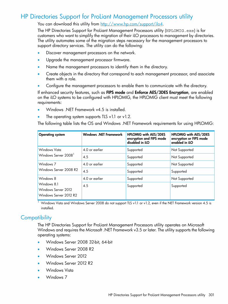
HP Directories Support for ProLiant Management Processors utilityYou can download this utility from http://www.hp.com/support/ilo4.The HP Directories Support for ProLiant Management Processors utility (HPLOMIG.exe) is forcustomers who want to simplify the migration of their iLO processors to management by directories.The utility automates some of the migration steps necessary for the management processors tosupport directory services. The utility can do the following:
• Discover management processors on the network.
• Upgrade the management processor firmware.
• Name the management processors to identify them in the directory.
• Create objects in the directory that correspond to each management processor, and associatethem with a role.
• Configure the management processors to enable them to communicate with the directory.If enhanced security features, such as FIPS mode and Enforce AES/3DES Encryption, are enabledon the iLO systems to be configured with HPLOMIG, the HPLOMIG client must meet the followingrequirements:
• Windows .NET Framework v4.5 is installed.
• The operating system supports TLS v1.1 or v1.2.The following table lists the OS and Windows .NET Framework requirements for using HPLOMIG:
HPLOMIG with AES/3DESencryption or FIPS modeenabled in iLO
HPLOMIG with AES/3DESencryption and FIPS modedisabled in iLO
Windows .NET FrameworkOperating system
Not SupportedSupported4.0 or earlierWindows VistaWindows Server 20081
Not SupportedSupported4.5
Not SupportedSupported4.0 or earlierWindows 7Windows Server 2008 R2 SupportedSupported4.5
Not SupportedSupported4.0 or earlierWindows 8Windows 8.1 SupportedSupported4.5Windows Server 2012Windows Server 2012 R2
1 Windows Vista and Windows Server 2008 do not support TLS v1.1 or v1.2, even if the NET Framework version 4.5 isinstalled.
CompatibilityThe HP Directories Support for ProLiant Management Processors utility operates on MicrosoftWindows and requires the Microsoft .NET Framework v3.5 or later. The utility supports the followingoperating systems:
• Windows Server 2008 32-bit, 64-bit
• Windows Server 2008 R2
• Windows Server 2012
• Windows Server 2012 R2
• Windows Vista
• Windows 7
HP Directories Support for ProLiant Management Processors utility 301
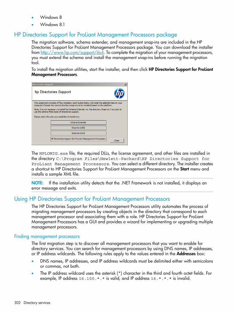
• Windows 8
• Windows 8.1
HP Directories Support for ProLiant Management Processors packageThe migration software, schema extender, and management snap-ins are included in the HPDirectories Support for ProLiant Management Processors package. You can download the installerfrom http://www.hp.com/support/ilo4. To complete the migration of your management processors,you must extend the schema and install the management snap-ins before running the migrationtool.To install the migration utilities, start the installer, and then click HP Directories Support for ProLiantManagement Processors.
The HPLOMIG.exe file, the required DLLs, the license agreement, and other files are installed inthe directory C:\Program Files\Hewlett-Packard\HP Directories Support forProLiant Management Processors. You can select a different directory. The installer createsa shortcut to HP Directories Support for ProLiant Management Processors on the Start menu andinstalls a sample XML file.
NOTE: If the installation utility detects that the .NET Framework is not installed, it displays anerror message and exits.
Using HP Directories Support for ProLiant Management ProcessorsThe HP Directories Support for ProLiant Management Processors utility automates the process ofmigrating management processors by creating objects in the directory that correspond to eachmanagement processor and associating them with a role. HP Directories Support for ProLiantManagement Processors has a GUI and provides a wizard for implementing or upgrading multiplemanagement processors.
Finding management processorsThe first migration step is to discover all management processors that you want to enable fordirectory services. You can search for management processors by using DNS names, IP addresses,or IP address wildcards. The following rules apply to the values entered in the Addresses box:
• DNS names, IP addresses, and IP address wildcards must be delimited either with semicolonsor commas, not both.
• The IP address wildcard uses the asterisk (*) character in the third and fourth octet fields. Forexample, IP address 16.100.*.* is valid, and IP address 16.*.*.* is invalid.
302 Directory services

• Ranges can also be specified using a hyphen. For example, 192.168.0.2-10 is a validrange. A hyphen is supported only in the rightmost octet.
• After you click Find, the utility begins pinging and connecting to port 443 (the default SSLport) to determine whether the target network address is a management processor. If the devicedoes not respond to the ping or connect appropriately on port 443, the utility determines thatit is not a management processor.
If you click Next, click Back, or exit the utility during discovery, operations on the current networkaddress are completed, but those on subsequent network addresses are canceled.To discover your management processors:1. Select Start→All Programs→Hewlett-Packard→HP Directories Support for ProLiant Management
Processors.The Welcome page opens.
2. Click Next.The Find Management Processors window opens.
3. In the Addresses box, enter the values to perform the management processor search.
HP Directories Support for ProLiant Management Processors utility 303
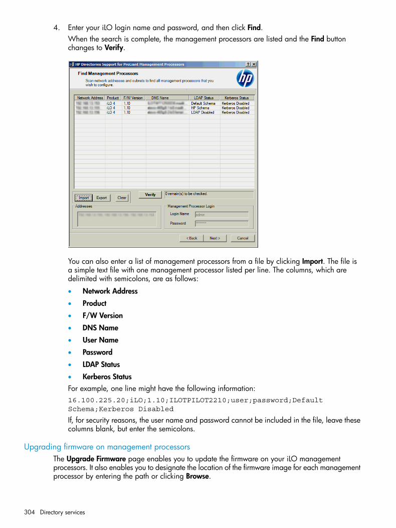
4. Enter your iLO login name and password, and then click Find.When the search is complete, the management processors are listed and the Find buttonchanges to Verify.
You can also enter a list of management processors from a file by clicking Import. The file isa simple text file with one management processor listed per line. The columns, which aredelimited with semicolons, are as follows:
• Network Address
• Product
• F/W Version
• DNS Name
• User Name
• Password
• LDAP Status
• Kerberos StatusFor example, one line might have the following information:16.100.225.20;iLO;1.10;ILOTPILOT2210;user;password;DefaultSchema;Kerberos Disabled
If, for security reasons, the user name and password cannot be included in the file, leave thesecolumns blank, but enter the semicolons.
Upgrading firmware on management processorsThe Upgrade Firmware page enables you to update the firmware on your iLO managementprocessors. It also enables you to designate the location of the firmware image for each managementprocessor by entering the path or clicking Browse.
304 Directory services

NOTE: Binary images of the firmware for the management processors must be accessible fromthe system that is running the migration utility. These binary images can be downloaded fromhttp://www.hp.com/support/ilo4.
The upgrade process might take a long time, depending on the number of management processorsselected. The firmware upgrade of a single management processor can take as long as 5 minutesto complete. If an upgrade fails, a message is displayed in the Results column, and the utilitycontinues to upgrade the other discovered management processors.
IMPORTANT: HP recommends that you test the upgrade process and verify the results in a testenvironment before running the utility on a production network. An incomplete transfer of thefirmware image to a management processor might result in having to locally reprogram themanagement processor.
To upgrade the firmware on your management processors:1. Navigate to the Upgrade Firmware on Management Processors window.
2. Select the management processors to upgrade.3. For each discovered management processor type, enter the correct pathname to the firmware
image or browse to the image.4. Click Upgrade Firmware.
The selected management processors are upgraded. Although this utility enables you toupgrade hundreds of management processors, only 25 management processors are upgradedsimultaneously. Network activity is considerable during this process.
5. After the upgrade is complete, click Next.During the firmware upgrade process, all buttons are deactivated to prevent navigation.
Selecting a directory access methodAfter you click Next in the Upgrade Firmware on Management Processors window, the Select theDesired Configuration window appears.
HP Directories Support for ProLiant Management Processors utility 305

You can select which management processors to configure (with respect to schema usage) andhow to configure them. The Select the Desired Configuration window helps to prevent an accidentaloverwrite of iLOs that are already configured for HP schema, or iLOs that have directories disabled.The selections you make in this window determine the windows that are displayed when you clickNext.To configure the management processor for directory services, see “Configuring directories whenHP extended schema is selected” (page 307). To configure the management processor for Schema-free(default schema) directories support, see “Configuring directories when schema-free integration isselected” (page 311).
NOTE: A user with the Configure iLO Settings privilege can modify the directory settings on anyiLO system, but directory support requires an iLO Advanced or iLO Advanced for BladeSystemlicense. Directory support cannot be enabled until a license is installed. The License Info columndisplays the iLO license status. For more information about licensing, see the iLO user guide.
Naming management processorsThe Name the management processors window enables you to name iLO management deviceobjects in the directory and create corresponding device objects for all management processorsto be managed. You can create names by using one or more of the following:
• The network address
• The DNS name
• An index
• Manual creation of the name
• The addition of a prefix to all
• The addition of a suffix to allTo name the management processors, click the Object Name column and enter the name, or dothe following:1. Select Use iLO Names, Create Name Using Index, or Use Network Address.
306 Directory services
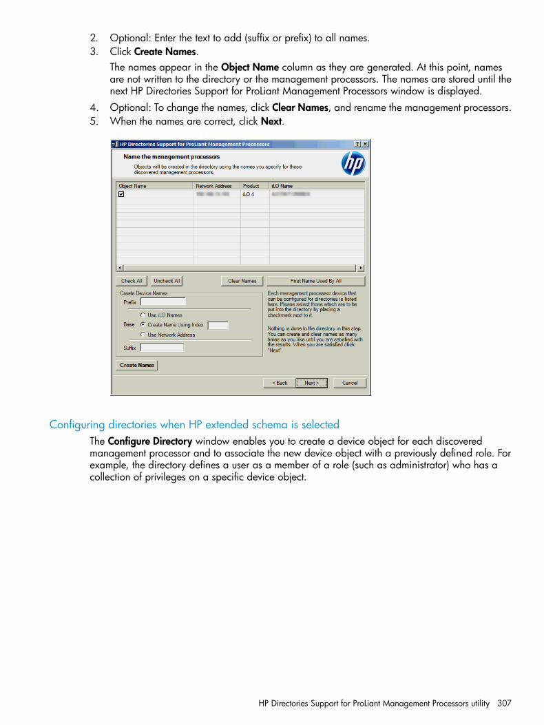
2. Optional: Enter the text to add (suffix or prefix) to all names.3. Click Create Names.
The names appear in the Object Name column as they are generated. At this point, namesare not written to the directory or the management processors. The names are stored until thenext HP Directories Support for ProLiant Management Processors window is displayed.
4. Optional: To change the names, click Clear Names, and rename the management processors.5. When the names are correct, click Next.
Configuring directories when HP extended schema is selectedThe Configure Directory window enables you to create a device object for each discoveredmanagement processor and to associate the new device object with a previously defined role. Forexample, the directory defines a user as a member of a role (such as administrator) who has acollection of privileges on a specific device object.
HP Directories Support for ProLiant Management Processors utility 307

The boxes on the Configure Directory window follow:
• Network Address—The network address of the directory server, which can be a valid DNSname or IP address.
• Port—The SSL port to the directory. The default port is 636. Management processors cancommunicate with the directory only by using SSL.
• Login Name and Password—Enter the login name and password for an account that hasdomain administrator access to the directory.
• Container DN—After you have the network address, port, and login information, you can clickBrowse to search for the container DN. The container is where the migration utility will createthe management processor objects in the directory.
• Role(s) DN—After you have the network address, port, and login information, you can clickBrowse to search for the role DN. The role is where the role to be associated with the deviceobjects resides. The role must be created before you run this utility.
To configure the device objects to be associated with a role:1. Enter the network address, login name, and password for the designated directory server.2. Enter the container DN in the Container DN box, or click Browse to select a container DN.
308 Directory services
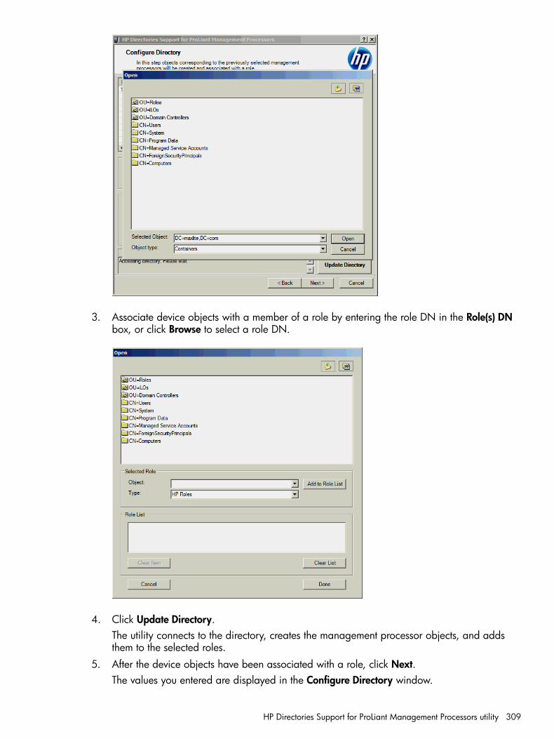
3. Associate device objects with a member of a role by entering the role DN in the Role(s) DNbox, or click Browse to select a role DN.
4. Click Update Directory.The utility connects to the directory, creates the management processor objects, and addsthem to the selected roles.
5. After the device objects have been associated with a role, click Next.The values you entered are displayed in the Configure Directory window.
HP Directories Support for ProLiant Management Processors utility 309
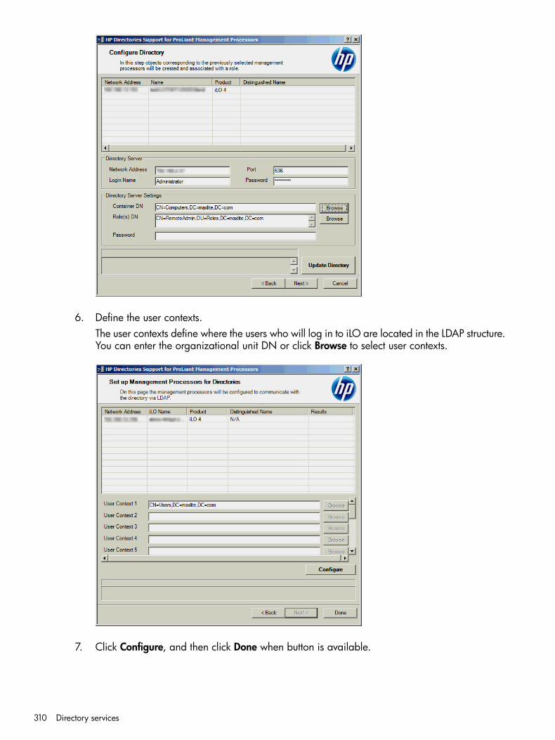
6. Define the user contexts.The user contexts define where the users who will log in to iLO are located in the LDAP structure.You can enter the organizational unit DN or click Browse to select user contexts.
7. Click Configure, and then click Done when button is available.
310 Directory services
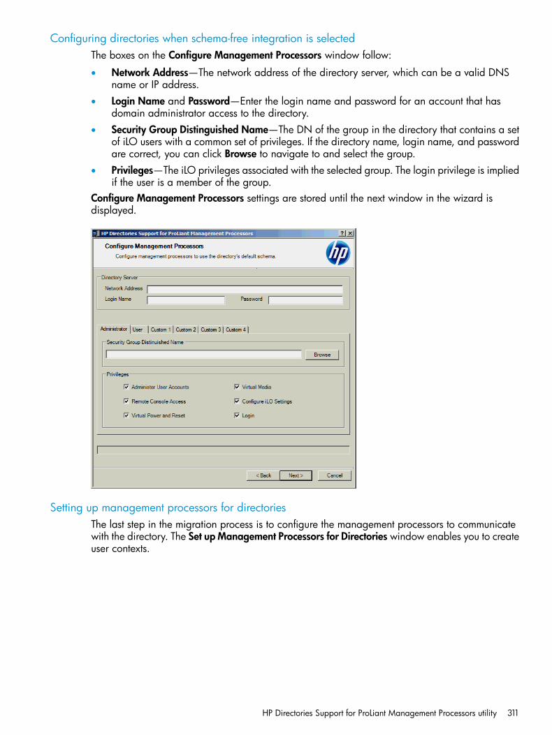
Configuring directories when schema-free integration is selectedThe boxes on the Configure Management Processors window follow:
• Network Address—The network address of the directory server, which can be a valid DNSname or IP address.
• Login Name and Password—Enter the login name and password for an account that hasdomain administrator access to the directory.
• Security Group Distinguished Name—The DN of the group in the directory that contains a setof iLO users with a common set of privileges. If the directory name, login name, and passwordare correct, you can click Browse to navigate to and select the group.
• Privileges—The iLO privileges associated with the selected group. The login privilege is impliedif the user is a member of the group.
Configure Management Processors settings are stored until the next window in the wizard isdisplayed.
Setting up management processors for directoriesThe last step in the migration process is to configure the management processors to communicatewith the directory. The Set up Management Processors for Directories window enables you to createuser contexts.
HP Directories Support for ProLiant Management Processors utility 311

User contexts enable the user to use short names or user object names to log in, rather than thefull DN. For example, having a user context such as CN=Users,DC=iLOTEST2,DC=HP enablesuser Elizabeth Bennett to log in using Elizabeth Bennett rather than CN=ElizabethBennett,CN=Users, DC=iLOTEST2,DC=HP. The @ format is also supported. For example,@iLOTEST2.HP in a context box enables the user to log in using ebennett (assuming thatebennett is the user short name).To configure the management processors to communicate with the directory:1. Enter the user contexts, or click Browse.2. Click Configure.
The migration utility connects to all selected management processors and updates theirconfigurations as specified. The utility supports configuring 15 user contexts. To access theuser context boxes, use the scroll bar.When you click Configure, the utility might display a message similar to the following:
3. Click OK to continue.4. When the process is complete, click Done.
312 Directory services
7 TroubleshootingThis chapter provides troubleshooting solutions for iLO.
Kernel debuggingUse the Windows Windbg kernel debugger from a local test system (usually a laptop) for a hostserver that you want to debug. This method uses the iLO Virtual Serial Port feature, and you musthave PuTTY installed on your test system.You can download PuTTY from the following website: http://www.putty.org/.1. Using the iLO web interface on the host server with kernel issues, navigate to the
Administration→Access Settings page and configure the Serial Command Line Interface Speedsetting.
2. Configure the debug options in Windows (the boot.ini parameters for the serial connection).Use debugport=com2, and set the baud rate to match the configured Serial Command LineInterface Speed in the iLO web interface.
3. Start or restart the server.4. During POST, press F9 to start the system RBSU or UEFI System Utilities.5. Configure the following settings in the system RBSU or UEFI System Utilities:
• Disable EMS and BIOS Serial Console
• Set the Virtual Serial Port to COM 2.For information about using the system RBSU or UEFI System Utilities, see the system RBSUuser guide or the UEFI System Utilities user guide.
6. Reboot the host server to access the selection menu for the Windows debug boot option.7. From the local test system, use PuTTY to connect to iLO and log in.
This is a CLI connection to iLO.8. Enter the IP address for the session host name. Use the default settings for an SSH session.
When the PuTTY iLO CLI session opens, a user login window opens, unless the PuTTY sessionis configured to use private keys. For more information, see “Configuring iLO security”(page 64) and “Administering SSH keys” (page 67).It might take a minute for the prompt to appear.
9. At the </>hpiLO-> prompt, enter the following command:windbg_enable
This opens a socket to the Virtual Serial Port on port 3002.10. Enter the following command to start the Windows debugger:
windbg -k com:port=<IP-address>,ipport=3002
<IP-address> is the iLO IP address, and 3002 is the socket to connect to (the raw serialdata socket for iLO).The ipport parameter is optional. The default port is 3002.You can add other windbg command-line parameters if necessary. HP recommends usingthe -b parameter for the initial breakpoint.
11. Go to the server console (or access the iLO Remote Console), and press Enter to boot thedebug selection on the OS load menu.This might take several minutes.
Kernel debugging 313
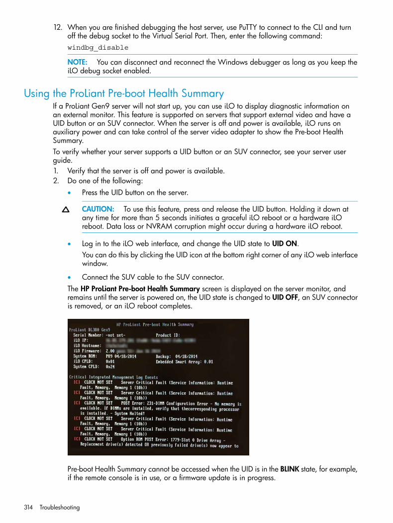
12. When you are finished debugging the host server, use PuTTY to connect to the CLI and turnoff the debug socket to the Virtual Serial Port. Then, enter the following command:windbg_disable
NOTE: You can disconnect and reconnect the Windows debugger as long as you keep theiLO debug socket enabled.
Using the ProLiant Pre-boot Health SummaryIf a ProLiant Gen9 server will not start up, you can use iLO to display diagnostic information onan external monitor. This feature is supported on servers that support external video and have aUID button or an SUV connector. When the server is off and power is available, iLO runs onauxiliary power and can take control of the server video adapter to show the Pre-boot HealthSummary.To verify whether your server supports a UID button or an SUV connector, see your server userguide.1. Verify that the server is off and power is available.2. Do one of the following:
• Press the UID button on the server.
CAUTION: To use this feature, press and release the UID button. Holding it down atany time for more than 5 seconds initiates a graceful iLO reboot or a hardware iLOreboot. Data loss or NVRAM corruption might occur during a hardware iLO reboot.
• Log in to the iLO web interface, and change the UID state to UID ON.You can do this by clicking the UID icon at the bottom right corner of any iLO web interfacewindow.
• Connect the SUV cable to the SUV connector.The HP ProLiant Pre-boot Health Summary screen is displayed on the server monitor, andremains until the server is powered on, the UID state is changed to UID OFF, an SUV connectoris removed, or an iLO reboot completes.
Pre-boot Health Summary cannot be accessed when the UID is in the BLINK state, for example,if the remote console is in use, or a firmware update is in progress.
314 Troubleshooting

Pre-boot Health Summary detailsThe following information is displayed when you view the Pre-boot Health Summary:
• Server model number
• Server serial number
• Product ID
• iLO IP address (IPv4 and IPv6)—This is displayed only if Show iLO IP during POST is set toEnabled on the Administration→Access Settings page in iLO.For more information, see “Configuring access options” (page 60).
• iLO Hostname
• iLO firmware version
• ProLiant System ROM version
• ProLiant System ROM – Backup version
• iLO CPLD version
• System CPLD version
• Embedded Smart Array version number—This value is displayed only if server POST hassuccessfully completed since the last auxiliary power cycle.
• Critical events—The most recent Critical events from the IML are displayed, with the most recentevent displayed first.
Testing the SSL connection to a serverThe following test checks for the correct security prompt. A nonworking server will proceed to aPage cannot be displayed message.If this test fails, your domain controller is not accepting SSL connections and probably has not beenissued a certificate.1. Open a browser and navigate to https://<domain controller>:636.
You can use <domain> instead of <domain controller>, which accesses the DNS anddetermines which domain controller is handling requests for the domain. Test multiple domaincontrollers to verify that all of them have been issued a certificate.
2. If SSL is operating correctly on the domain controller (a certificate has been issued), you areprompted with a security message that asks whether you want to proceed with accessing thesite or view the server certificate. Clicking Yes does not display a weblog, which is normal.This process is automatic, but might require rebooting. To avoid rebooting:a. Open the MMC.b. Add the certificates snap-in.c. When prompted, select Computer Account for the type of certificates you want to view.d. Click OK to return to the certificates snap-in.e. Select the Personal→Certificates folder.f. Right-click the folder and select Request New Certificate.g. Verify that the Type is domain controller, and click Next until a certificate is issued.
You can also use the Microsoft Ldp.exe tool to verify SSL connections. For more information aboutthe LDP tool, see your Microsoft documentation.An old certificate can cause issues with SSL on the domain controller when it points to a previouslytrusted CA with the same name. This situation is rare but might happen if a certificate service isadded and removed, and then added again on the domain controller. To remove old certificatesand issue a new one, follow the instructions in step 2.
Testing the SSL connection to a server 315
Event log entriesFor a list of the errors that might appear in the iLO Event Log, see the ProLiant server error messagesguide for your server at the following website: http://www.hp.com/go/enterprise/docs.
Hardware and software link-related issuesiLO uses standard Ethernet cabling, which includes CAT 5 UTP with RJ-45 connectors.Straight-through cabling is necessary for a hardware link to a standard Ethernet hub. Use a crossovercable for a direct PC connection.The default DNS name is displayed on the serial label pull tab, and can be used to locate iLO ifyou do not know the assigned IP address.If you are using DHCP, the following information applies:
• The iLO management port must be connected to a network that is connected to a DHCP server,and iLO must be on the network before power is applied. DHCP sends a request soon afterpower is applied. If the DHCP request is not answered when iLO first boots, it will reissue therequest at 90-second intervals.
• The DHCP server must be configured to provide DNS and WINS name resolution.
• In the iLO RBSU, you can press F1 on the Network Autoconfiguration page for advancedoptions for viewing the status of iLO DHCP requests.
If you are using a static IP address, the following information applies:
• If you have a direct PC connection then you must use a static IP address because no DHCPserver is present on the link.
• You can configure iLO to work with a static IP address by using iLO RBSU, the iLO 4Configuration Utility, or the iLO web interface. For more information, see “Setting up iLO byusing iLO RBSU or the iLO 4 Configuration Utility” (page 22) or “Setting up iLO by using theiLO web interface” (page 26).
Login and iLO access issues
Login name and password not accepted
SymptomAn iLO login attempt fails.
Solution 1
CauseThe user account information was entered incorrectly.
ActionEnter the correct login information. Note the following:
• Passwords are case sensitive.
• User names are not case sensitive. Uppercase and lowercase characters are treated the same(for example, Administrator is treated as the same user as administrator).
Solution 2
CauseThe user account is invalid.
316 Troubleshooting

ActionTry the following:
• Verify that the user account is configured correctly and has the login privilege.Ask a user with the Administer User Accounts privilege to log in and change the accountpassword. If login still fails, ask the user to delete and re-add the user account.
• Try using the default account information, which is located on the serial label pull tab.
• Verify that the account password was entered correctly. If you forgot the password, it can bereset by a user with the Administer User Accounts privilege.
• If there is only one administrator account, and the password was forgotten, do one of thefollowing:
◦ Use the iLO security setting on the system maintenance switch. Log in and establish anew administrator user account. For more information, see “iLO security with the systemmaintenance switch” (page 65).
◦ Use HPONCFG to establish an administrator account and password. For more information,see the iLO scripting and command line guide.
A directory connection ends prematurely
SymptomAn active directory session ends prematurely.
CauseNetwork errors can cause iLO to conclude that a directory connection is no longer valid. If iLOcannot detect the directory, it ends the directory connection. Any attempt to continue using theterminated connection redirects the browser to the login page.This issue might occur in the following situations:
• The network connection is terminated.
• The directory server is shut down.
ActionLog back in and continue using iLO.If the directory server is unavailable, you must log in with a local user account.
iLO management port not accessible by name
SymptomThe iLO management port is not accessible by name.
CauseThe environment is not configured to support accessing the iLO management port by name.
ActionThe iLO management port can register with a WINS server or DDNS server to provide thename-to-IP-address resolution required to access the iLO management port by name.
Login and iLO access issues 317
Verify that your environment meets the following requirements:
• The WINS or DDNS server must be up and running before the iLO management port ispowered on.
• The iLO management port must have a valid route to the WINS or DDNS server.
• The iLO management port must be configured with the IP address of the WINS or DDNSserver.You can use DHCP to configure the required IP addresses. For more information, see “Settingup iLO by using iLO RBSU or the iLO 4 Configuration Utility” (page 22) or “Managing theiLO network settings” (page 92).
• The clients that are used to access the iLO management port must be configured to use thesame DDNS server where the IP address of the iLO management port is registered.
If you are using a WINS server and a non-dynamic DNS server, access to the iLO managementport might be significantly faster if you configure the DNS server to use the WINS server for nameresolution. For more information, see the Microsoft documentation.
iLO RBSU unavailable after iLO and server reset
SymptomThe iLO RBSU is unavailable after the server is reset immediately after iLO was reset.
CauseThe iLO firmware was not fully initialized when the server performed its initialization and tried tostart the iLO RBSU.
ActionReset the server a second time.
Unable to access the login page
SymptomThe iLO web interface login page will not load.
CauseThe SSL encryption level in the browser is not set to 128-bit or higher.The SSL encryption level in iLO is set to 128-bit or higher and cannot be changed. The browserand iLO encryption levels must be the same.
ActionVerify that the SSL encryption level of your browser is set to 128-bit or higher.
Unable to return to login page after iLO reset
SymptomThe iLO login page will not open after an iLO reset.
ActionClear the browser cache and restart the browser.
318 Troubleshooting
Unable to connect to iLO after changing network settings
SymptomiLO is inaccessible after a network settings update.
CauseThe NIC and the switch settings are not the same.
ActionVerify that both sides of the connection (the NIC and the switch) have the same settings fortransceiver speed autoselect, speed, and duplex.For example, if one side is autoselecting the connection, the other side must use the same setting.For information about configuring the iLO network settings, see “Managing the iLO network settings”(page 92).
A connection error occurs after a firmware update
SymptomYou cannot connect to iLO after updating the firmware by using the web interface.
ActionClear the browser cache and try again.
Unable to connect to iLO processor through NIC
SymptomThe iLO processor is inaccessible through the NIC.
ActionTry the following solutions:
• Confirm that the green LED indicator (link status) on the iLO RJ-45 connector is on. This conditionindicates a good connection between the PCI NIC and the network hub.Look for intermittent flashes of the green LED indicator, which indicates normal network traffic.
• Run the iLO RBSU or the iLO 4 Configuration Utility to confirm that the NIC is enabled, andverify the assigned IP address and subnet mask.
• Run the iLO RBSU, and use the Advanced option on the Network Autoconfiguration page toview the status of DHCP requests.
• Ping the IP address of the NIC from a separate network workstation.
• Attempt to connect with a browser by entering the IP address of the NIC as the URL. You cansee the iLO home page from this address.
• Reset iLO.
NOTE: If a network connection is established, you might have to wait up to 90 seconds forthe DHCP server request.
Unable to log in to iLO after installing iLO certificate
SymptomiLO is inaccessible after the iLO self-signed certificate is installed in the browser certificate store.
Login and iLO access issues 319
CauseWhen you reset iLO to the factory default settings or change the iLO hostname, a new self-signedcertificate is generated. If the self-signed certificate is installed permanently in some browsers, youmight not be able to log back in to iLO after a new self-signed certificate is generated.
ActionDo not install the iLO self-signed certificate in the browser certificate store. If you want to install acertificate, request a permanent certificate from a CA and import it into iLO. For instructions, see“Administering SSL certificates” (page 70).
Unable to connect to iLO IP address
SymptomCannot connect to iLO via the iLO IP address.
CauseThe web browser is configured to use a proxy server.
ActionConfigure the browser to connect to iLO without using the proxy server.For example, in Internet Explorer:1. Select Tools→Internet Options.2. Click Connections.3. Click LAN settings.4. Click Advanced in the Proxy server section.5. Enter the iLO IP address or DNS name in the Exceptions box.6. Click OK to save the changes.
iLO communications fail
SymptomiLO communications fail.
CauseiLO communicates through several configurable TCP/IP ports. One or more of these ports is blockedby a firewall.
ActionConfigure the firewall to allow communications on the ports iLO uses. For information about viewingand changing the iLO port configuration, see “Configuring iLO access settings” (page 58).
Logging in to iLO with a Kerberos account fails
SymptomA Kerberos login attempt fails.
Solution 1
CauseThe client does not have a ticket or has an invalid ticket.
320 Troubleshooting
ActionPress Ctrl+Alt+Del to lock the client PC and get a new ticket.
Solution 2
CauseKerberos login is configured incorrectly. Possible reasons follow:
• The Kerberos realm that the client PC is logged in to does not match the Kerberos realm forwhich iLO is configured.
• The key in the Kerberos keytab stored in iLO does not match the Active Directory key.
• iLO is configured for an incorrect the KDC server address.
• The date and time do not match between the client PC, the KDC server, and iLO. The dateand time on these systems should be set within 5 minutes of one another.
ActionVerify that your environment meets the requirements for Kerberos support. For more information,see “Kerberos support” (page 274).
Solution 3
CauseThere is a problem with the directory user account:
• The computer account in Active Directory for iLO does not exist or is disabled.
• The user logged in to the client PC is not a member of a universal or global directory groupauthorized to access iLO.
ActionVerify that the user account exists and that it is a member of a group that is authorized to accessiLO.
Solution 4
CauseThe DNS server is not working correctly. iLO requires a functioning DNS server for Kerberossupport.
ActionRepair the DNS server.
Solution 5
CauseThe browser is not configured correctly.
ActionVerify that the browser is configured correctly for Kerberos login. For more information, see“Kerberos support” (page 274).
Login and iLO access issues 321

Secure Connection Failed error when using Firefox browser
SymptomWhen you try to connect to iLO using Firefox ESR, the following message appears.
Solution 1
Action1. Click the menu button, and then select Options.2. Click Advanced.3. Click the Certificates tab.4. Click View Certificates.
Click the Servers tab, and then delete any certificates related to iLO.5. Click the Others tab, and then delete any certificates related to iLO.6. Click OK.7. Start Firefox and connect to iLO.
NOTE: The steps in Solution 1 are based on Firefox ESR 24. The procedure to use might varydepending on the installed version of Firefox.
Solution 2
Action1. Close the Firefox application.2. Navigate to the Firefox AppData folder, and then delete all of the *.db files in all of the
Firefox directories.The AppData folder is typically in the following location: C:\\Users\<user name>\AppData\Local\Mozilla\Firefox\
Certificate error when navigating to iLO web interface
SymptomWhen you navigate to the iLO web interface, a certificate error appears.
322 Troubleshooting
Solution 1
ActionIf you are using Internet Explorer, complete the following procedure:1. Click the Continue to this website (not recommended) link.2. Log in to the iLO web interface.3. Navigate to the Administration→Security→SSL Certificate page, and then click Customize
Certificate.The SSL Certificate Customization page opens.
4. Enter the following information in the Certificate Signing Request Information section. Therequired boxes are marked with an asterisk (*).• Country (C)—The two-character country code that identifies the country where the company
or organization that owns this iLO system is located. Enter the two-letter abbreviation incapital letters.
• State (ST)—The state where the company or organization that owns this iLO system islocated.
• City or Locality (L)—The city or locality where the company or organization that owns thisiLO system is located.
• Organization Name (O)—The name of the company or organization that owns this iLOsystem.
• Organizational Unit (OU)—(Optional) The unit within the company or organization thatowns this iLO system.
• Common Name (CN)—The FQDN of this iLO system.The FQDN is entered automatically in the Common Name (CN) box.You must configure the Domain Name on the Network General Settings page to enableiLO to enter the FQDN into the CSR. For information about configuring the networksettings, see “Configuring general network settings” (page 94).
5. Click Generate CSR.A message notifies you that a certificate is being generated and that the process might takeup to 10 minutes.
6. After a few minutes (up to 10), click Generate CSR again.The CSR is displayed.The CSR contains a public and private key pair that validates communications between theclient browser and iLO. Key sizes up to 2,048 bits are supported. The generated CSR is heldin memory until a new CSR is generated, iLO is reset to the factory default settings, or acertificate is imported.
7. Select and copy the CSR text.8. Open a browser window and navigate to a third-party CA.9. Follow the onscreen instructions and submit the CSR to the CA.
When you submit the CSR to the CA, your environment might require the specification ofSubject Alternative Names (SAN). This information is typically included in the AdditionalAttributes box. If required, enter the iLO DNS short name and IP address in the AdditionalAttributes box by using the following syntax:san:dns=10.10.20.95&dns=server1.ilo.example.com.The CA generates a certificate in the PKCS #10 format.
Login and iLO access issues 323

10. After you obtain the certificate, make sure that:• The CN matches the iLO FQDN.
This is listed as the iLO Hostname on the Information→Overview page.
• The certificate is a Base64-encoded X.509 certificate.
• The first and last lines are included in the certificate.11. Return to the SSL Certificate Customization page in the iLO web interface, and then click Import
Certificate.The Import Certificate window opens.
12. Paste the certificate into the text box, and then click Import.iLO supports SSL certificates that are up to 3 KB in size (including the 609 or 1,187 bytesused by the private key, for 1,024-bit and 2,048-bit certificates, respectively).
13. Reset iLO.For instructions, see “Using iLO diagnostics” (page 188).
Solution 2
ActionIf you are using Firefox, complete the following procedure:1. Click the I Understand the Risks link to expand the section, and then click Add Exception.2. In the Add Security Exception dialog box, enter https://<iLO hostname or IP
address> in the Location box.3. Click Confirm Security Exception to resolve the security warning.
The security exception is saved and the iLO login screen appears.4. Log in to iLO.
Solution 3If you are using Chrome, complete the following procedure:1. When the security warning appears, click Advanced.2. Click Proceed to <iLO hostname or IP address> (unsafe).3. Log in to iLO.4. Optional: To prevent the certificate warning from appearing in future iLO web interface
sessions, install an SSL certificate.For instructions, perform Step 2 through Step 13 in Solution 1.
Directory issuesThe following sections provide instructions for troubleshooting directory issues.
User contexts do not appear to workSolution: Check with your network administrator. The full DN of your user object must be in thedirectory. Your login name appears after the first CN=. The remainder of the DN must appear inone of the user context boxes. User contexts are not case sensitive, and any other characters,including spaces, are part of the user context. For information about entering directory user contexts,see “Directory authentication and authorization” (page 73).
Directory user does not log out after directory timeout has expiredSolution: If you set the iLO Idle Connection Timeout to Infinite, the Remote Console periodicallypings the firmware to verify that the connection exists. When the ping occurs, the iLO firmware
324 Troubleshooting
queries the directory for user permissions. This periodic query keeps the directory connection active,preventing a timeout and logging the user.
Problems generating keytab by using ktpass.exe
Solution: If you use ktpass.exe to generate a keytab, you must specify a principal name byusing the -princ argument.Principal names are case sensitive and must be entered as follows:HTTP/[email protected]
• The first part is uppercase (HTTP).
• The middle part is lowercase (myilo.somedomain.net).
• The last part is uppercase (@SOMEDOMAIN.NET).If you do not format the command exactly as shown, it will not work.Here is an example of the full ktpass.exe command:ktpass +rndPass -ptype KRB5_NT_SRV_HST -mapuser [email protected] HTTP/[email protected] -out myilo.keytab
Remote Console issuesThe following sections discuss troubleshooting Remote Console issues.
IMPORTANT: Pop-up blocking applications, which prevent the automatic opening of new windows,prevent the Remote Console from running. Disable any pop-up blocking programs before you startthe Remote Console.
Java IRC applet displays red X when Firefox is used to run Java IRC on Linux clientSolution: Firefox browsers must be configured to accept cookies. For instructions on configuringFirefox, see the Firefox documentation.
The Java IRC does not start
SymptomThe Java IRC fails to start when you launch the application do not accept the Java IRC appletcertificate.
CauseThe Java IRC is a signed Java applet. If you do not accept the Java IRC applet certificate, the JavaIRC will not start.
ActionIf you did not accept the certificate and you want to use the Java IRC:1. Click the Clear button in the Java Console window.2. Click the Close button to close the Java Console window.3. Reset iLO.
For instructions, see “Using iLO diagnostics” (page 188).4. Clear the browser cache.5. Close the browser and open a new browser window.6. Log in to iLO, start the Java IRC, and then accept the certificate.
Remote Console issues 325
Unable to navigate single cursor of Remote Console to corners of Remote Consolewindow
In some cases, you might not be able to navigate the mouse cursor to the corners of the RemoteConsole window.Solution: Right-click and drag the mouse cursor outside the Remote Console window, and thendrag it back inside.
Remote Console text window not updated correctlyWhen you are using the Remote Console to display text windows that scroll at a high rate of speed,the text window might not be updated correctly. This error is caused by video updates occurringfaster than the iLO firmware can detect and display them. Typically, only the upper left corner ofthe text window is updated while the rest of the text window remains static.Solution: After the scrolling is complete, click Refresh to update the text window.
Mouse or keyboard not working in .NET IRC or Java IRCSolution 1: When you open the .NET IRC or Java IRC and notice that the mouse or keyboard isnot working, perform the following steps:1. Close the .NET IRC or Java IRC.2. Navigate to the Power Management→Power Settings page.3. Clear the Enable persistent mouse and keyboard check box, and then click Apply.4. Start the .NET IRC or Java IRC again.Solution 2 (.NET IRC only): Some monitors do not support DirectDraw. For example, some USBVGA device drivers might disable DirectDraw on all monitors for Windows Vista and Windows7 clients.The .NET IRC requires DirectDraw support.Solution 2 (Java IRC only):1. Shut down and exit your browser.2. Open the Java Control Panel.3. Navigate to the Java Runtime Environment Settings dialog box.4. Add the following runtime parameter:
-Dsun.java2d.noddraw=true
5. Click OK and close the Java Runtime Environment Settings window.6. Click Apply, and then click OK to close the Java Control Panel.
NOTE: Viewing your changes before you click Apply might reset the Runtime Parametersdialog box, causing your edits to be lost.
.NET IRC sends characters continuously after switching windowsSolution: If you have a key pressed during a .NET IRC session, and you inadvertently switchwindows, the key can remain pressed in the .NET IRC session, causing the character to repeatcontinuously. To stop the character from repeating, click the .NET IRC session screen to bring it tothe front of your desktop.
Java IRC displays incorrect floppy and USB-key deviceSymptom: When the Firefox browser is used, the Java IRC might display incorrect floppy driveand USB-key device information.Action:1. Make sure that Red Hat Enterprise Linux 5 or later is installed on the local client system.
326 Troubleshooting

2. Install the latest version of Java and configure it to connect through the Firefox browser.3. Log in to the iLO web interface by using Firefox.4. Insert a USB key or floppy disk on the local client system.5. Verify that you can access the USB key or floppy disk.6. Open a Java IRC session.7. Select Virtual Drives→Image File Removable Media.
The Choose Disk Image File dialog box opens.
8. Type or select the path of the USB key/floppy (/dev/disk) inserted in the client.You can also mount the USB key/floppy by label.
9. Click OK.
Caps Lock out of sync between iLO and Java IRCWhen you log in to the Java IRC, the Caps Lock setting might be out of sync between iLO and theJava IRC.Solution: Select Keyboard→Caps Lock in the Java IRC to synchronize the Caps Lock settings.
Num Lock out of sync between iLO and Shared Remote ConsoleWhen you log in to a Shared Remote Console session, the Num Lock setting might be out of syncbetween iLO and some of the Remote Console sessions.Solution: Select Keyboard→Num Lock in the Remote Console to synchronize the Num Lock settings.
Keystrokes repeat unintentionally during Remote Console sessionWhen you are using the .NET IRC or Java IRC, a keystroke might repeat unintentionally during aRemote Console session.Solution 1: Identify and fix problems that might cause network latency.
Remote Console issues 327

Solution 2: Adjust the following settings on the remote machine:
• Increase the typematic delay—This setting controls the delay before a character repeats whenyou press and hold a key on the keyboard.
• Decrease the typematic rate—This setting controls the rate at which a character repeats whenyou press and hold a key on the keyboard.
NOTE: The exact name of the setting varies depending on the OS you are using. For moreinformation about changing the typematic delay and rate, see your OS documentation.
Session leader does not receive connection request when .NET IRC is in replay modeSolution: When a Remote Console session leader plays captured video data, the .NET IRC doesnot display the Deny or Accept message when another user attempts to access or share the .NETIRC. Instead, the new .NET IRC session waits and eventually times out. If you require access to the.NET IRC, and your request times out, contact the other user or use the Remote Console Acquirefeature to take control of the IRC. For instructions, see “Acquiring the Remote Console” (page 214).
Keyboard LED does not work correctlyThe client keyboard LED does not reflect the true state of the keyboard lock keys. The Caps Lock,Num Lock, and Scroll Lock keys are fully functional when you are using the keyboard options inthe Remote Console.
Inactive .NET IRCThe iLO .NET IRC might become inactive or disconnect during periods of high activity. .NET IRCactivity slows before becoming inactive. Symptoms of an affected .NET IRC include the following:
• The .NET IRC display is not updated.
• Keyboard and mouse activity is not recorded.
• Shared Remote Console requests do not register.Although you can replay a captured file on an inactive .NET IRC, the active state of the .NET IRCis not restored.This issue might occur when multiple users are logged in to iLO, a Virtual Media session is connectedand is performing a continuous copy operation, or a .NET IRC session is open. The Virtual Mediacontinuous copy operation takes priority and, consequently, the .NET IRC loses synchronization.Eventually, the Virtual Media connection resets multiple times and causes the USB media drive forthe OS to lose synchronization with the Virtual Media client.Solution: Reconnect to the .NET IRC and the Virtual Media. If possible, reduce the number ofsimultaneous iLO user sessions. If necessary, reset iLO. (The server does not need to be reset.)
.NET IRC failed to connect to serveriLO might display the message Failed to connect to server when it attempts to establisha .NET IRC session.The iLO .NET IRC client waits a specified amount of time for a connection to be established withiLO. If the client server does not receive a response in this amount of time, it displays an errormessage.Possible causes for this message include the following:
• The network response is delayed.
• A Shared Remote Console session is requested, but the session leader delays sending anacceptance or denial message.
Solution 1: Retry the .NET IRC connection.
328 Troubleshooting
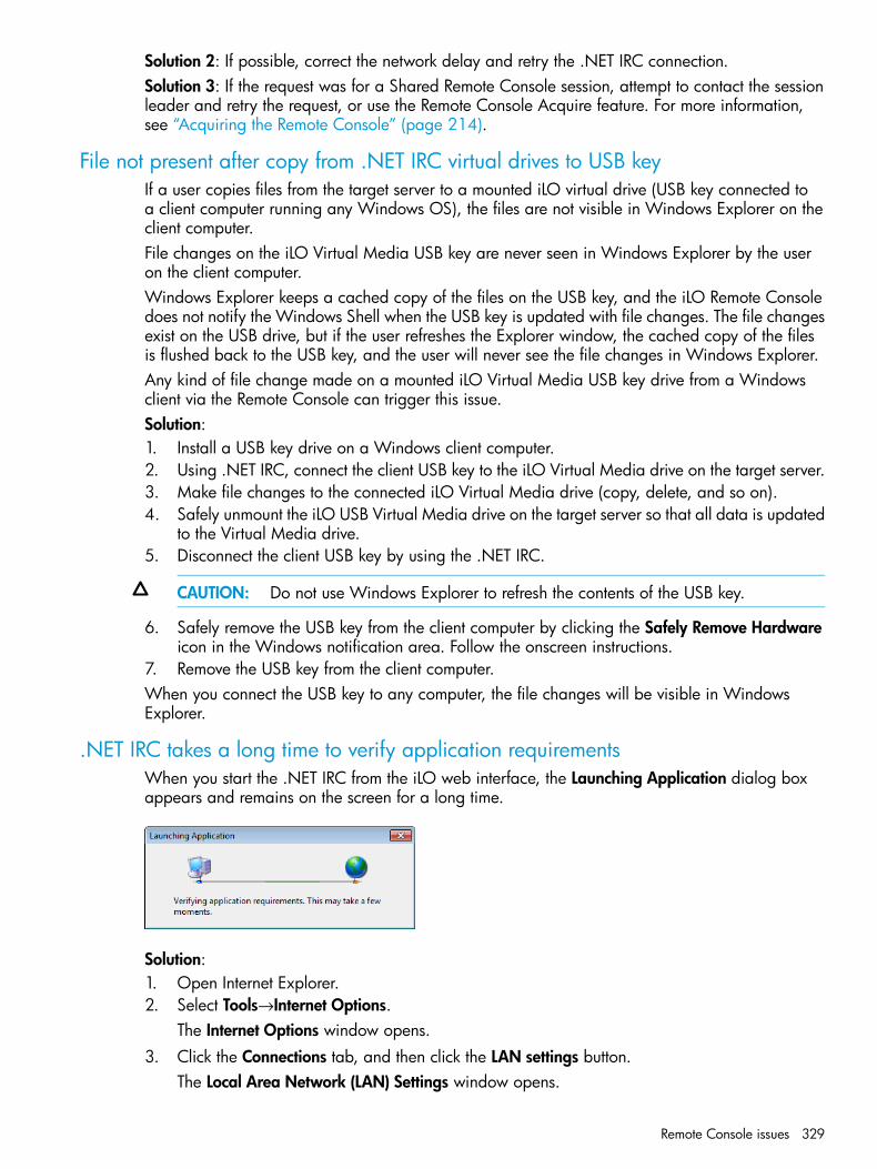
Solution 2: If possible, correct the network delay and retry the .NET IRC connection.Solution 3: If the request was for a Shared Remote Console session, attempt to contact the sessionleader and retry the request, or use the Remote Console Acquire feature. For more information,see “Acquiring the Remote Console” (page 214).
File not present after copy from .NET IRC virtual drives to USB keyIf a user copies files from the target server to a mounted iLO virtual drive (USB key connected toa client computer running any Windows OS), the files are not visible in Windows Explorer on theclient computer.File changes on the iLO Virtual Media USB key are never seen in Windows Explorer by the useron the client computer.Windows Explorer keeps a cached copy of the files on the USB key, and the iLO Remote Consoledoes not notify the Windows Shell when the USB key is updated with file changes. The file changesexist on the USB drive, but if the user refreshes the Explorer window, the cached copy of the filesis flushed back to the USB key, and the user will never see the file changes in Windows Explorer.Any kind of file change made on a mounted iLO Virtual Media USB key drive from a Windowsclient via the Remote Console can trigger this issue.Solution:1. Install a USB key drive on a Windows client computer.2. Using .NET IRC, connect the client USB key to the iLO Virtual Media drive on the target server.3. Make file changes to the connected iLO Virtual Media drive (copy, delete, and so on).4. Safely unmount the iLO USB Virtual Media drive on the target server so that all data is updated
to the Virtual Media drive.5. Disconnect the client USB key by using the .NET IRC.
CAUTION: Do not use Windows Explorer to refresh the contents of the USB key.
6. Safely remove the USB key from the client computer by clicking the Safely Remove Hardwareicon in the Windows notification area. Follow the onscreen instructions.
7. Remove the USB key from the client computer.When you connect the USB key to any computer, the file changes will be visible in WindowsExplorer.
.NET IRC takes a long time to verify application requirementsWhen you start the .NET IRC from the iLO web interface, the Launching Application dialog boxappears and remains on the screen for a long time.
Solution:1. Open Internet Explorer.2. Select Tools→Internet Options.
The Internet Options window opens.3. Click the Connections tab, and then click the LAN settings button.
The Local Area Network (LAN) Settings window opens.
Remote Console issues 329

4. Clear the Automatically detect settings check box.5. Optional: If needed, configure the proxy server settings.6. Close all of the browser windows.7. Restart the browser and start the .NET IRC.
.NET IRC fails to startWhen you start the .NET IRC, the Cannot Start Application dialog box appears.
Solution: Clear the ClickOnce application cache by entering the following command from theWindows Command Prompt: rundll32 %windir%\system32\dfshim.dllCleanOnlineAppCache.
.NET IRC cannot be sharedWhen you try to join a shared .NET IRC session, the Unable to connect dialog box appears.
Solution 1: Make sure there is a communication route between the session leader .NET IRC clientand each shared .NET IRC client.Solution 2: Make sure the firewall settings on all clients allow an inbound connection to the RemoteConsole port (the default port is 17990).
.NET IRC launch is blocked by Firefox
SymptomWhen you launch the .NET IRC in Mozilla Firefox, the application might fail to start.
CauseIf the iLO system is using the default iLO SSL certificate, which is not a trusted certificate that issigned by a certificate authority, the iLO web interface starts the .NET IRC by using HTTP insteadof HTTPS. Since the iLO web interface uses HTTPS, and the web interface starts the IRC by usingHTTP, the browser displays a warning.
ActionTry the following:• Import an SSL certificate into iLO and enable the IRC Requires a Trusted Certificate in iLO
setting on the Administration→Security→Remote Console page. This is the most secure solution.For information about importing certificates, see “Administering SSL certificates” (page 70).
330 Troubleshooting

For information about changing the IRC Requires a Trusted Certificate in iLO setting, see“Configuring the Integrated Remote Console Trust setting (.NET IRC)” (page 91).
• Click the shield icon in the address bar, and then select Options→Disable protection for now.
The warning might vary depending on your browser version.
• Use a different browser.
• Use the Standalone IRC, available at the following website: http://www.hp.com/go/hpsc.
• Use the iLO mobile app. For more information, see http://www.hp.com/go/ilo/mobileapp.
.NET IRC launch is blocked by Google Chrome
SymptomWhen you launch the .NET IRC in Google Chrome the application fails to start.
CausePrevious versions of Google Chrome could run the .NET IRC with an NPAPI plug-in that supportedClickOnce. Google Chrome 42 and later does not support NPAPI-based plug-ins.
Action
• Use a different browser.
• Use the Standalone IRC, available at the following website: http://www.hp.com/go/hpsc.
• Use the iLO mobile app. For more information, see http://www.hp.com/go/ilo/mobileapp.
Unable to boot to DOS using a mounted USB keyIssue: An error occurs when you try to boot to a DOS-bootable USB key that is mounted by usingthe iLO Remote Console.If the USB key is 2 GB or less, the following error is displayed:
If the USB key is larger than 2 GB, the server does not progress beyond following error message:
Remote Console issues 331

This occurs because the Remote Console does not have sufficient privileges to access the bootsector of the USB key.Solution 1: Right-click Internet Explorer, and then select Run as administrator. Start the iLO webinterface, launch the Remote Console, and then boot to the USB key.Solution 2: Plug the USB key directly into the server.
Text-based Remote Console issuesThe following sections discuss items to be aware of when attempting to resolve text-based RemoteConsole issues.
Unable to view Linux installer in text-based Remote ConsoleWhen installing Linux from the text console, the initial installation screen might not appear becausethe screen is in graphics mode.Solution: To correct this and proceed with the installation, do one of the following:
• For most versions of Linux, enter linux text nofb.The characters that you enter do not appear.After you enter the command, the screen changes from graphics mode to text mode, displayingthe screen.
• For SUSE Linux Enterprise Server, press F2 and the down arrow from the text console. The textmode is selected and the screen appears.
Unable to pass data through SSH terminalIf you use an SSH terminal to access the text console, SSH might intercept keystroke data and notpass the action to the text-based Remote Console. When this occurs, it appears as if the keystrokedid not perform its function.Solution: Disable any SSH terminal shortcuts.
VSP-driven selection during the serial timeout window sends output to BIOS redirectinstead of VSP
The /etc/grub.conf file includes an option for a serial timeout window (terminal--timeout=10 serial console). This setting provides a window of time to select a key strokeon the VSP or on the VGA console, and then the menu is output to the corresponding device. TheBIOS serial redirect intercepts VSP keystrokes during this timeout window.Solution: To work around this issue, do not press a key for a VSP-driven selection during the10-second timeout or turn off BIOS redirection to the VSP.
332 Troubleshooting

Scrolling and text appear irregular during BIOS redirectionDuring BIOS redirection, the scrolling might not work properly. When you enter commands inRBSU, the text might overwrite itself on the bottom line of the terminal window.Solution: The BIOS expects and controls a fixed 80x24 character window. When redirected tothe serial port, the BIOS still expects and controls a fixed 80x24 character window. If the VSPclient being used (SSH, HyperTerminal, or other terminal emulator) can resize the window to asize other than 80x24, scrolling becomes confused and the screen output appears garbled. Toavoid this issue, configure the terminal emulator for a window size of exactly 80x24.
SSH issuesThe following sections discuss troubleshooting SSH issues.
Initial PuTTY input slowDuring the initial connection to iLO through a PuTTY client, input is accepted slowly for approximately5 seconds.Solution: Change the configuration options in the client. Clear the Disable Nagle's algorithm checkbox in the low-level TCP connection options.
PuTTY client unresponsiveWhen you are using a PuTTY client with the Shared Network Port, the PuTTY session might becomeunresponsive when a large amount of data is transferred or when you are using a Virtual SerialPort and Remote Console.Solution: Close the PuTTY client and restart the session.
SSH text support from text-based Remote Console sessionSSH access from the text-based Remote Console supports the standard 80 x 25 configuration ofthe text screen. This mode is compatible for the text-based Remote Console for most text-modeinterfaces. Extended text configuration beyond the 80 x 25 configuration is not displayed correctlywhen using SSH. HP recommends configuring the text application in 80 x 25 mode or using thegraphical Remote Console.
Remote Support issues
SSL Bio Error during Insight RS registration
SymptomThe following error occurs when you try to register a server for Insight Remote Support centralconnect: SSL Bio Error.
ActionNavigate to the Information→Diagnostics page in the iLO web interface, and then click Reset iLO.When the reset is finished, log in to the iLO web interface and retry the registration procedure.Clicking Reset iLO does not make any configuration changes, but it terminates any active connectionsto iLO and completes any firmware updates in progress. You must have the Configure iLO Settingsprivilege to reset iLO on the Diagnostics page.
Server not identified by server name in Insight Online or Insight RS
SymptomA server is identified in Insight Online as <product name>_<serial number> and in Insight RS as<serial number> when it should be identified by the server name.
SSH issues 333
CauseThe server was registered for Insight Remote Support before iLO discovered the server name.
Action1. Do one of the following:
• Verify that AMS is enabled and the operating system is running.
• Update the Server Name on the Administration→Access Settings page in the iLO webinterface.
• For Windows systems only, start the operating system. Insight Online and Insight RS willuse the Windows computer name to identify the server.
2. For Insight Remote Support central connect only: Depending on your configuration, do oneof the following:• For configurations with iLO firmware 1.30 or later, no additional action is required. iLO
automatically detects the server name and forwards it to Insight RS and Insight Onlinefor display.
• ProLiant Gen8 servers only: For configurations with iLO firmware versions earlier than1.30, the server name is updated automatically the next time data collection informationis transmitted. Data collection occurs every 30 days and can be initiated immediatelyfrom the Remote Support→Data Collections page in the iLO web interface. For instructions,see “Sending data collection information” (page 135).
3. If you were logged in to Insight Online when you performed Step 1, click the refresh button(labeled Devices) to update the Insight Online view with the server information.
Server OS name and version not listed in Insight RS or Insight Online
SymptomThe server OS name and version are not listed in Insight RS or Insight Online.
CauseThe server was registered for remote support when the OS and AMS were not running (for example,during an Intelligent Provisioning registration). In this situation, iLO cannot determine which OS isinstalled.
ActionTo update the OS information, iLO must acquire the OS information from AMS.1. Verify the following:
• For ProLiant Gen8 servers: iLO firmware 1.20 or later (Insight Remote Support centralconnect) or 1.40 or later (Insight Online direct connect) is installed.
• For ProLiant Gen9 servers: iLO firmware 2.00 or later is installed.
• AMS is enabled and the OS is running.
• For Insight Remote Support central connect only: Verify that a supported version of InsightRS is installed on the Hosting Device. For more information, see http://h17007.www1.hp.com/us/en/enterprise/servers/supportmatrix/insight_rs.aspx.
• For Insight Remote Support central connect only: Verify that the RIBCL credentials for theserver have been entered in the Insight RS Console and are associated with the ProLiantserver.
2. Initiate the data collection process from the Remote Support→Data Collections page in the iLOweb interface. For instructions, see “Sending data collection information” (page 135). The OS
334 Troubleshooting

name and version are forwarded to Insight RS and Insight Online during the data collectionprocess.
3. If you were logged in to Insight Online when you performed Step 2, click the refresh button(labeled Devices) to update the Insight Online view with the server information.When using Insight Online, the OS name and version are listed on the Device ConfigurationDetails page if AMS is installed and the OS was running during the most recent data collectiontransmission.
Connection error during Insight Online direct connect registration
SymptomThe following error occurs when you try to register a server for Insight Online direct connect:Cannot connect to remote host.
CauseThe DNS settings are not configured correctly in iLO.
ActionVerify that the DNS information is configured correctly in iLO.For instructions, see “Managing the iLO network settings” (page 92).
iLO session ends unexpectedly during iLO Insight Online direct connect registration
SymptomThe iLO web interface session ends unexpectedly with the error Session Expired when youtry to register a server for Insight Online direct connect.
CauseThe DNS settings are not configured correctly in iLO.
ActionVerify that the DNS settings are configured correctly. Depending on your network configuration,you can view and change these settings on the following iLO web interface pages:
• Network→iLO Dedicated Network Port→IPv4
• Network→iLO Dedicated Network Port→IPv6
• Network→Shared Network Port→IPv4
• Network→Shared Network Port→IPv6For more information, see the iLO user guide.
iLO Federation issues
Query errors occur on iLO Federation pages
SymptomWhen you open an iLO Federation page, iLO peers and associated data might be missing fromthe page, and the following error is displayed:Errors occurred during query, returned data may be incomplete orinconsistent.
iLO Federation issues 335
CauseThis error might occur when a network communication error, configuration problem, or failed iLOsystem prevents the retrieval of data from all systems in an iLO Federation group.
ActionTry the following:
• Wait for twice the configured Multicast Announcement Interval, and then refresh the iLOFederation page. If an iLO system was reconfigured and can no longer communicate with thelocal iLO system, it will be dropped from its peer relationships after they expire. This shouldeliminate the query error.
• Check the Multi-System Map page for errors. This page can help you identify communicationproblems between iLO peers.
• If you are using server blades in a BladeSystem enclosure, verify that Enclosure iLO FederationSupport is configured on the Enclosure Settings→Network Access→Protocols page in theOnboard Administrator web interface. You must have Onboard Administrator 4.11 or laterto configure this setting. This is required to allow peer-to-peer communication between theserver blades in an enclosure.
• Verify that the switches in the network are configured to allow communication between iLOpeers.
• If you recently changed the network routes, subnet mask, IP address, or HTTP port for an iLOpeer, verify that the iLO peer has a communication path to the local iLO system.
• Ensure that communication between the local iLO system and the peer with the error is notblocked by an intermediate firewall or a change to the iLO network configuration and HTTPport setting.
More informationViewing the iLO Federation Multi-System MapA 502 error is displayed on the Multi-System Map pageA timeout error is displayed on the Multi-System Map pageA 403 error is displayed on the Multi-System Map pageConfiguring enclosure support for iLO FederationiLO Federation network requirements“Managing the iLO network settings” (page 92)Configuring iLO access settings
A timeout error is displayed on the Multi-System Map page
SymptomThe Multi-System Map page displays a Timed Out error for a peer of the local iLO system.
CauseThis error might occur in the following situations:
• A peer of the local iLO system has a peer that has failed.
• An intermediate firewall is preventing communication between the local iLO system and apeer.
• Network configuration changes are preventing communication between the local iLO systemand a peer.
• The enclosure that contains the peer is not configured for iLO Federation support.
336 Troubleshooting

ActionTry one of the following:
• Remove or repair the failed peer.
• Verify that the network is configured to allow communication between the iLO peers.
• Verify that the enclosure that contains an iLO server blade peer is configured for iLO Federationsupport on the Enclosure Settings→Network Access→Protocols page in the OnboardAdministrator web interface. You must have Onboard Administrator 4.11 or later to configurethis setting. This is required to allow peer-to-peer communication between the server bladesin an enclosure.
More informationConfiguring enclosure support for iLO FederationiLO Federation network requirements
A 502 error is displayed on the Multi-System Map page
SymptomThe Multi-System Map page shows a 502 error.
CauseThe listed peer rejected a request from the local iLO system.
ActionEnsure that communication between the local iLO system and the peer with the error is not blockedby an intermediate firewall or a change to the iLO network configuration and HTTP port setting.
A 403 error is displayed on the Multi-System Map page
SymptomThe Multi-System Map page shows a 403 Forbidden/Authorization error.
CauseThe group key on the local iLO system does not match the group key on a peer iLO system.
ActionEnsure that the group key matches for all iLO systems that are members of the selected group.
iLO peers are not displayed
SymptomiLO peers (systems in the same group as the local iLO system) are not displayed on iLO Federationpages.
ActionTry the following:
• Ensure that the group key matches for all iLO systems that are members of the selected group.
• Wait for twice the configured multicast interval, and then refresh the iLO Federation page. Ifan iLO system was reconfigured and can no longer communicate with the local iLO system,it will be dropped from its peer relationships after they expire.
• If you are using server blades in an enclosure, verify that Enclosure iLO Federation Support isconfigured on the Enclosure Settings→Network Access→Protocols page in the Onboard
iLO Federation issues 337
Administrator web interface. You must have Onboard Administrator 4.11 or later to configurethis setting. This is required to allow peer-to-peer communication between the server bladesin an enclosure.
• Verify that the switches in the network are configured to allow communication between iLOpeers.
• Ensure that communication between the local iLO system and the peer with the error is notblocked by an intermediate firewall or a change to the iLO network configuration and HTTPport setting.
More informationConfiguring enclosure support for iLO FederationiLO Federation network requirements
iLO peers are displayed with IPv6 addresses on IPv4 networks
SymptomiLO peers on an IPv4 network are displayed with IPv6 addresses on iLO Federation pages.
ActionIf the network is configured to use IPv4 only, verify that the iLO Client Applications use IPv6 firstcheck box is not selected on the Network→iLO Dedicated Network Port→IPv6 page.
Firmware update issues
An iLO firmware update is unsuccessful
SymptomThe iLO firmware cannot be updated.
Solution 1
CauseA communication or network issue occurred.
ActionIf you attempt to update the iLO firmware by using the iLO web interface, and it does not respond,does not accept the firmware update, or is stopped before a successful update, try reinstalling thefirmware after you complete the following diagnostic steps:1. Attempt to connect to iLO through the web browser. If you cannot connect, there is a
communication issue.2. Attempt to ping iLO. If you are successful, the network is working.
Solution 2
ActionTry a different firmware update method.For more information, see “Updating firmware” (page 30).
An error occurs during an iLO firmware update
SymptomThe following error is displayed during an iLO firmware update:
338 Troubleshooting

The last firmware update attempt was not successful. Ready for the nextupdate.
CauseAn incorrect file was used to update the iLO firmware.
ActionClick Clear Error to reset the flash process, and then try the firmware update again with the correctfirmware file. If you do not clear the error, the same error might occur even when you use thecorrect firmware file.
iLO firmware update does not finish
SymptomAn iLO firmware update remains at 1% complete and does not finish.
Action1. Install the HPONCFG on the server.
You can download HPONCFG from the following website: http://www.hp.com/go/hpsc.2. Open a command window.3. Change to the directory that contains HPONCFG.4. Enter the following command:
• Windows: hponcfg /reset
• Linux: hponcfg -rThe user credentials are not required when you use HPONCFG from the server OS.
5. Retry the iLO firmware update.For information about using HPONCFG, see the iLO scripting and command line guide.
iLO network Failed Flash RecoveryMost firmware upgrades finish successfully. In the unlikely event of server power loss during aniLO firmware upgrade, iLO might be recoverable when power is restored.When the computer is booting, the kernel performs image validation on the main image. If theimage is corrupted or incomplete, the kernel enters Failed Flash Recovery. Failed Flash Recoveryactivates an FTP server within iLO. The FTP server enables you to send an image to iLO forprogramming. The FTP server does not provide any other services.A network client can connect to the FTP server. The user name for the connection is test, and thepassword is flash. To send a firmware image to iLO, use the FTP client PUT command. Afterreceiving the image, iLO validates the image. If the image is a complete, signed, and valid firmwareimage, the kernel begins programming the FLASH partition.After the image is completely programmed into the FLASH partition, reset iLO by issuing the RESETcommand to the iLO FTP server.Example:F:\ilo>ftp 192.168.1.2Connected to 192.168.1.2.220 FTP Recovery server ready.User (192.168.1.2:(none)): ftp331 Password required.Password:231 Logged in.ftp> put iLO.bin200 Ok.
Firmware update issues 339
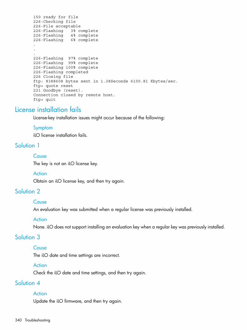
150 ready for file226-Checking file226-File acceptable226-Flashing 3% complete226-Flashing 4% complete226-Flashing 6% complete...226-Flashing 97% complete226-Flashing 99% complete226-Flashing 100% complete226-Flashing completed226 Closing fileftp: 8388608 bytes sent in 1.38Seconds 6100.81 Kbytes/sec.ftp> quote reset221 Goodbye (reset).Connection closed by remote host.ftp> quit
License installation failsLicense-key installation issues might occur because of the following:
SymptomiLO license installation fails.
Solution 1
CauseThe key is not an iLO license key.
ActionObtain an iLO license key, and then try again.
Solution 2
CauseAn evaluation key was submitted when a regular license was previously installed.
ActionNone. iLO does not support installing an evaluation key when a regular key was previously installed.
Solution 3
CauseThe iLO date and time settings are incorrect.
ActionCheck the iLO date and time settings, and then try again.
Solution 4
ActionUpdate the iLO firmware, and then try again.
340 Troubleshooting
Unable to access Virtual Media or graphical Remote ConsoleSolution: You enable the iLO Virtual Media and graphical Remote Console features by installingan optional iLO license. If a license is not installed, a message informs you that these features arenot available without a license.For details on purchasing licenses, and for a list of licensed features, see the following website:http://www.hp.com/go/ilo/licensing.
Unable to get SNMP information from HP SIMSolution: The agents running on the managed server supply SNMP information to HP SIM. Foragents to pass information through iLO, iLO device drivers must be installed. For installationinstructions, see “iLO drivers and utilities” (page 27).If you have installed the drivers and agents for iLO, verify that iLO and the management PC areon the same subnet. You can verify this quickly by pinging iLO from the management PC. Consultyour network administrator for proper routes to access the iLO network interface.
Unable to receive HP SIM alarms (SNMP traps) from iLOSymptomHP SIM does not receive SNMP traps from iLO.
Action1. Log in to iLO with a user account that has the Configure iLO Settings privilege.2. Configure the alert types and SNMP trap parameters on the Administration→Management
page.
Server name still present after System Erase Utility is executedThe server name, as shown on the iLO Overview page, is the installed host operating system name.If the Insight Management Agents are installed on the server, the agents will obtain the host nameand update it on the iLO web interface page.To remove the server name after the redeployment of a server, do one of the following:
• Load the Insight Management Agents to update the server name.
• Set iLO to the factory default settings by using iLO RBSU or the iLO 4 Configuration Utility.
CAUTION: This procedure clears all iLO configuration information, not just the Server Name.For more information, see “Resetting iLO to the factory default settings by using iLO RBSU”(page 268) and “Resetting iLO to the factory default settings by using the iLO 4 ConfigurationUtility” (page 269).
• Change the server name on the Administration→Access Settings→Access Options page in theiLO web interface.
AMS is installed but unavailable in iLOSymptomAMS is installed on a server, but it is listed as Not available in the iLO web interface
Solution 1
ActionVerify that AMS is installed.
Unable to access Virtual Media or graphical Remote Console 341

For more information, see “Verifying the AMS installation” (page 110).
Solution 2
ActionRestart AMS.For more information, see “Restarting AMS” (page 111).
Solution 3
ActionReset iLO.For more information, see “Using iLO diagnostics” (page 188).
342 Troubleshooting

8 Support and other resourcesContacting HP
For worldwide technical support information, see the HP Support Center:http://www.hp.com/go/hpscBefore contacting HP, collect the following information:
• Product model names and numbers
• Technical support registration number (if applicable)
• Product serial numbers
• Error messages
• Operating system type and revision level
• Detailed questions
Software Technical Support and Update ServiceAll HP iLO licenses include one or three years of 24x7 HP Software Technical Support and UpdateService. This service provides access to HP technical resources for help in resolving softwareimplementation or operational problems. The service also provides access to software updatesand reference manuals either in electronic form or on physical media as they are made availablefrom HP.For more information, see the iLO QuickSpecs document at the following website: http://www.hp.com/go/qs.
Lost license key recoveryIf an iLO license key is lost, send a replacement request and your proof of purchase to one of thefollowing email addresses:
• Americas: [email protected]
• Europe, Middle East, and Africa: [email protected]
• Asia-Pacific and Japan: [email protected]
Subscription serviceReceive, by email, support alerts announcing product support communications, driver updates,software releases, firmware updates, and customer-replaceable component information by signingup at http://www.hp.com/go/myadvisory.To change options for support alerts you already receive, click the Sign in link on the right.
Access to HP support materialsAccess to some updates might require product entitlement when accessed through the HP SupportCenter. You must have an HP Passport set up with relevant entitlements. For more information, seethe website:www.hp.com/support/AccessToSupportMaterials
Contacting HP 343
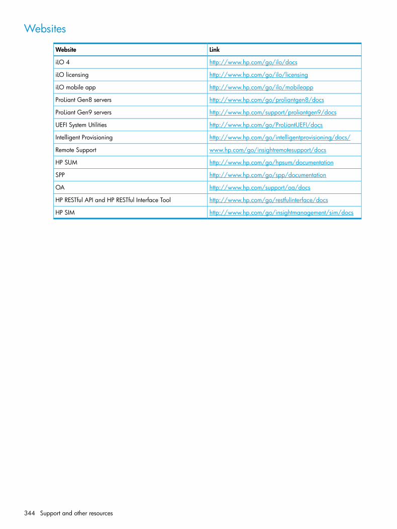
Websites
LinkWebsite
http://www.hp.com/go/ilo/docsiLO 4
http://www.hp.com/go/ilo/licensingiLO licensing
http://www.hp.com/go/ilo/mobileappiLO mobile app
http://www.hp.com/go/proliantgen8/docsProLiant Gen8 servers
http://www.hp.com/support/proliantgen9/docsProLiant Gen9 servers
http://www.hp.com/go/ProLiantUEFI/docsUEFI System Utilities
http://www.hp.com/go/intelligentprovisioning/docs/Intelligent Provisioning
www.hp.com/go/insightremotesupport/docsRemote Support
http://www.hp.com/go/hpsum/documentationHP SUM
http://www.hp.com/go/spp/documentationSPP
http://www.hp.com/support/oa/docsOA
http://www.hp.com/go/restfulinterface/docsHP RESTful API and HP RESTful Interface Tool
http://www.hp.com/go/insightmanagement/sim/docsHP SIM
344 Support and other resources

9 Documentation feedbackHP is committed to providing documentation that meets your needs. To help us improve thedocumentation, send any errors, suggestions, or comments to Documentation Feedback([email protected]). Include the document title and part number, version number, or the URLwhen submitting your feedback.
345

A iLO license optionsTable 8 (page 346) lists the features that are included with each iLO license.
Table 8 iLO 4 license options
iLOAdvanced
iLOAdvanced
iLOEssentials
iLOScale-Out1
iLO StandardforBladeSystem
iLOStandardFeature
forBladeSystem
All (exceptBL)
BLAll ProLiantGen8
All ProLiantGen8 and
BLAll (exceptBL)
Platform Support
e-seriesGen9 SLservers,and BL
servers. Microservers,and Gen9100 seriesand lowerseries.
XXXXXXEmbedded Health System
XXXXXXVirtual Power Buttons
XXXXXXIPMI Over LAN/DCMI
XXXXXXWeb-Based GUI
XXXXXXSSH Command Line Interface
XXXXXXRIBCL
XXXXXXVirtual Serial Port
XXXXXXIPv6
XXXXXXActive Health System
XXXXXXEmbedded Remote Support
XXXXXXAgentless Management
XXXPre-OSonly
XPre-OS onlyIntegrated Remote Console(IRC/Virtual KVM—Supports textand graphics)
XXXXXXiLO Federation Discovery
XXXXXXiLO Federation Group LicenseActivation
XXGlobal Team Collaboration viaIntegrated Remote Console
XXIntegrated Remote ConsoleRecord and Playback
XXXXVirtual Media via IntegratedRemote Console
XXScripted Virtual Media
XXXText-based Remote Console viaSSH (Textcons)2
XXDirectory Service Authentication
XXKerberos Authentication
346 iLO license options
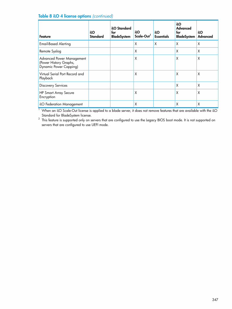
Table 8 iLO 4 license options (continued)
iLOAdvanced
iLOAdvancedforBladeSystem
iLOEssentials
iLOScale-Out1
iLO StandardforBladeSystem
iLOStandardFeature
XXXXEmail-Based Alerting
XXXRemote Syslog
XXXAdvanced Power Management(Power History Graphs,Dynamic Power Capping)
XXXVirtual Serial Port Record andPlayback
XXDiscovery Services
XXXHP Smart Array SecureEncryption
XXXiLO Federation Management1 When an iLO Scale-Out license is applied to a blade server, it does not remove features that are available with the iLO
Standard for BladeSystem license.2 This feature is supported only on servers that are configured to use the Legacy BIOS boot mode. It is not supported on
servers that are configured to use UEFI mode.
347

B Directory services schemaThis appendix describes the classes and attributes that are used to store Lights-Out managementauthorization data in the directory service.
HP Management Core LDAP OID classes and attributesChanges made to the schema during the schema setup process include changes to the following:• Core classes• Core attributes
Core classes
Assigned OIDClass name
1.3.6.1.4.1.232.1001.1.1.1.1hpqTarget
1.3.6.1.4.1.232.1001.1.1.1.2hpqRole
1.3.6.1.4.1.232.1001.1.1.1.3hpqPolicy
Core attributes
Assigned OIDAttribute name
1.3.6.1.4.1.232.1001.1.1.2.1hpqPolicyDN
1.3.6.1.4.1.232.1001.1.1.2.2hpqRoleMembership
1.3.6.1.4.1.232.1001.1.1.2.3hpqTargetMembership
1.3.6.1.4.1.232.1001.1.1.2.4hpqRoleIPRestrictionDefault
1.3.6.1.4.1.232.1001.1.1.2.5hpqRoleIPRestrictions
1.3.6.1.4.1.232.1001.1.1.2.6hpqRoleTimeRestriction
Core class definitionsThe following tables define the HP Management core classes.
hpqTarget
1.3.6.1.4.1.232.1001.1.1.1.1OID
This class defines target objects, providing the basis for HP productsthat use directory-enabled management.
Description
StructuralClass type
userSuperClasses
hpqPolicyDN - 1.3.6.1.4.1.232.1001.1.1.2.1AttributeshpqRoleMembership - 1.3.6.1.4.1.232.1001.1.1.2.2
NoneRemarks
348 Directory services schema

hpqRole
1.3.6.1.4.1.232.1001.1.1.1.2OID
This class defines role objects, providing the basis for HP products thatuse directory-enabled management.
Description
StructuralClass type
groupSuperClasses
hpqRoleIPRestrictions - 1.3.6.1.4.1.232.1001.1.1.2.5AttributeshpqRoleIPRestrictionDefault - 1.3.6.1.4.1.232.1001.1.1.2.4hpqRoleTimeRestriction - 1.3.6.1.4.1.232.1001.1.1.2.6hpqTargetMembership - 1.3.6.1.4.1.232.1001.1.1.2.3
NoneRemarks
hpqPolicy
1.3.6.1.4.1.232.1001.1.1.1.3OID
This class defines policy objects, providing the basis for HP products thatuse directory-enabled management.
Description
StructuralClass Type
topSuperClasses
hpqPolicyDN - 1.3.6.1.4.1.232.1001.1.1.2.1Attributes
NoneRemarks
Core attribute definitionsThe following tables define the HP Management core class attributes.
hpqPolicyDN
1.3.6.1.4.1.232.1001.1.1.2.1OID
Distinguished name of the policy that controls the general configurationof this target
Description
Distinguished Name - 1.3.6.1.4.1.1466.115.121.1.12Syntax
Single valuedOptions
NoneRemarks
hpqRoleMembership
1.3.6.1.4.1.232.1001.1.1.2.2OID
Provides a list of hpqRole objects that belong to this objectDescription
Distinguished Name - 1.3.6.1.4.1.1466.115.121.1.12Syntax
MultivaluedOptions
NoneRemarks
Core attribute definitions 349

hpqTargetMembership
1.3.6.1.4.1.232.1001.1.1.2.3OID
Provides a list of hpqTarget objects that belong to this objectDescription
Distinguished Name - 1.3.6.1.4.1.1466.115.121.1.12Syntax
MultivaluedOptions
NoneRemarks
hpqRoleIPRestrictionDefault
1.3.6.1.4.1.232.1001.1.1.2.4OID
A Boolean that represents access by unspecified clients and that partiallyspecifies rights restrictions under an IP network address constraint
Description
Boolean - 1.3.6.1.4.1.1466.115.121.1.7Syntax
Single valuedOptions
If this attribute is TRUE, IP restrictions will be satisfied for unexceptional networkclients. If this attribute is FALSE, IP restrictions will be unsatisfied forunexceptional network clients.
Remarks
hpqRoleIPRestrictions
1.3.6.1.4.1.232.1001.1.1.2.5OID
Provides a list of IP addresses, DNS names, domains, address ranges, andsubnets that partially specify right restrictions under an IP network addressconstraint
Description
Octet String - 1.3.6.1.4.1.1466.115.121.1.40Syntax
MultivaluedOptions
This attribute is used only on role objects.RemarksIP restrictions are satisfied when the address matches and general access isdenied. They are unsatisfied when the address matches and general accessis allowed.Values are an identifier byte followed by a type-specific number of bytes thatspecify a network address.
• For IP subnets, the identifier is <0x01>, followed by the IP network addressin network order, followed by the IP network subnet mask in networkorder. For example, the IP subnet 127.0.0.1/255.0.0.0 would berepresented as <0x01 0x7F 0x00 0x00 0x01 0xFF 0x00 0x00 0x00>.For IP ranges, the identifier is <0x02>, followed by the lower bound IPaddress, followed by the upper bound IP address. Both are inclusive andin network order. For example, the IP range 10.0.0.1 to 10.0.10.255would be represented as <0x02 0x0A 0x00 0x00 0x01 0x0A 0x000x0A 0xFF>.
• For DNS names or domains, the identifier is <0x03>, followed by theASCII encoded DNS name. DNS names can be prefixed with an * (ASCII0x2A), to indicate they must match all names that end with the specifiedstring. For example, the DNS domain *.acme.com is represented as<0x03 0x2A 0x2E 0x61 0x63 0x6D 0x65 0x2E 0x63 0x6F 0x6D>.General access is allowed.
350 Directory services schema

hpqRoleTimeRestriction
1.3.6.1.4.1.232.1001.1.1.2.6OID
A 7-day time grid, with 30-minute resolution, which specifies rights restrictionsunder a time constraint
Description
Octet String {42} - 1.3.6.1.4.1.1466.115.121.1.40Syntax
Single valuedOptions
This attribute is used only on role objects.RemarksTime restrictions are satisfied when the bit that corresponds to the current localtime of the device is 1 and unsatisfied when the bit is 0.
• The least significant bit of the first byte corresponds to Sunday, frommidnight to 12:30 a.m.
• Each more significant bit and sequential byte corresponds to the nextconsecutive half-hour blocks within the week.
• The most significant (eighth) bit of the 42nd byte corresponds to Saturdayat 11:30 p.m. to Sunday at midnight.
Lights-Out Management specific LDAP OID classes and attributesThe following schema attributes and classes might depend on attributes or classes defined in theHP Management core classes and attributes.
Lights-Out Management classes
Assigned OIDClass name
1.3.6.1.4.1.232.1001.1.8.1.1hpqLOMv100
Lights-Out Management attributes
Assigned OIDClass name
1.3.6.1.4.1.232.1001.1.8.2.3hpqLOMRightLogin
1.3.6.1.4.1.232.1001.1.8.2.4hpqLOMRightRemoteConsole
1.3.6.1.4.1.232.1001.1.8.2.6hpqLOMRightVirtualMedia
1.3.6.1.4.1.232.1001.1.8.2.5hpqLOMRightServerReset
1.3.6.1.4.1.232.1001.1.8.2.2hpqLOMRightLocalUserAdmin
1.3.6.1.4.1.232.1001.1.8.2.1hpqLOMRightConfigureSettings
Lights-Out Management class definitionsThe following table defines the Lights-Out Management core class.
hpqLOMv100
1.3.6.1.4.1.232.1001.1.8.1.1OID
This class defines the rights and settings used with HP Lights-OutManagement products.
Description
AuxiliaryClass Type
NoneSuperClasses
Lights-Out Management specific LDAP OID classes and attributes 351
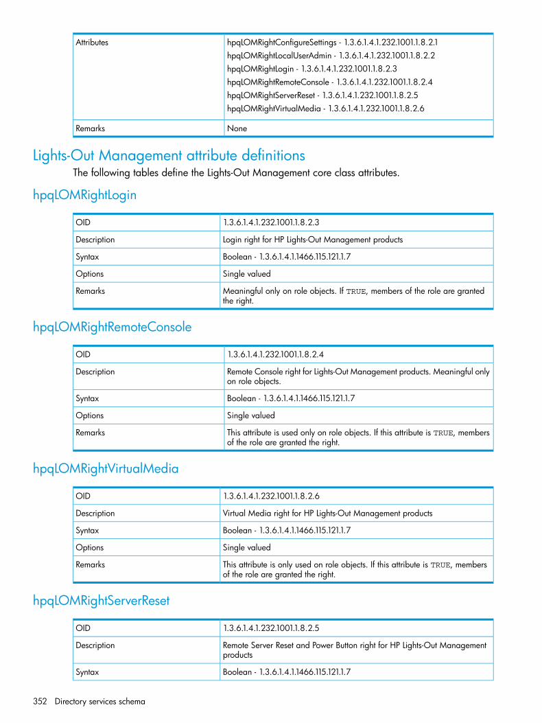
hpqLOMRightConfigureSettings - 1.3.6.1.4.1.232.1001.1.8.2.1AttributeshpqLOMRightLocalUserAdmin - 1.3.6.1.4.1.232.1001.1.8.2.2hpqLOMRightLogin - 1.3.6.1.4.1.232.1001.1.8.2.3hpqLOMRightRemoteConsole - 1.3.6.1.4.1.232.1001.1.8.2.4hpqLOMRightServerReset - 1.3.6.1.4.1.232.1001.1.8.2.5hpqLOMRightVirtualMedia - 1.3.6.1.4.1.232.1001.1.8.2.6
NoneRemarks
Lights-Out Management attribute definitionsThe following tables define the Lights-Out Management core class attributes.
hpqLOMRightLogin
1.3.6.1.4.1.232.1001.1.8.2.3OID
Login right for HP Lights-Out Management productsDescription
Boolean - 1.3.6.1.4.1.1466.115.121.1.7Syntax
Single valuedOptions
Meaningful only on role objects. If TRUE, members of the role are grantedthe right.
Remarks
hpqLOMRightRemoteConsole
1.3.6.1.4.1.232.1001.1.8.2.4OID
Remote Console right for Lights-Out Management products. Meaningful onlyon role objects.
Description
Boolean - 1.3.6.1.4.1.1466.115.121.1.7Syntax
Single valuedOptions
This attribute is used only on role objects. If this attribute is TRUE, membersof the role are granted the right.
Remarks
hpqLOMRightVirtualMedia
1.3.6.1.4.1.232.1001.1.8.2.6OID
Virtual Media right for HP Lights-Out Management productsDescription
Boolean - 1.3.6.1.4.1.1466.115.121.1.7Syntax
Single valuedOptions
This attribute is only used on role objects. If this attribute is TRUE, membersof the role are granted the right.
Remarks
hpqLOMRightServerReset
1.3.6.1.4.1.232.1001.1.8.2.5OID
Remote Server Reset and Power Button right for HP Lights-Out Managementproducts
Description
Boolean - 1.3.6.1.4.1.1466.115.121.1.7Syntax
352 Directory services schema

Single valuedOptions
This attribute is used only on role objects. If this attribute is TRUE, membersof the role are granted the right.
Remarks
hpqLOMRightLocalUserAdmin
1.3.6.1.4.1.232.1001.1.8.2.2OID
Local User Database Administration right for HP Lights-Out Managementproducts.
Description
Boolean - 1.3.6.1.4.1.1466.115.121.1.7Syntax
Single valuedOptions
This attribute is used only on role objects. If this attribute is TRUE, membersof the role are granted the right.
Remarks
hpqLOMRightConfigureSettings
1.3.6.1.4.1.232.1001.1.8.2.1OID
Configure Devices Settings right for HP Lights-Out Management products.Description
Boolean - 1.3.6.1.4.1.1466.115.121.1.7Syntax
Single valuedOptions
This attribute is used only on role objects. If this attribute is TRUE, membersof the role are granted the right.
Remarks
Lights-Out Management attribute definitions 353

Glossary3DES Triple DES, the Data Encryption Standard cipher algorithm.ABEND Abnormal end.ACPI Advanced Configuration and Power Interface.AES Advanced Encryption Standard.ALOM Advanced Lights Out Manager.AMP Advanced Memory Protection.AMS Agentless Management Service.API Application Programming Interface.ARP Address Resolution Protocol.ASR Automatic Server Recovery.BIOS Basic Input/Output System.BMC Baseboard management controller.CA Certificate authority.CLP Command Line Protocol.CN Common Name.COM port Communication port.cookie A small, unscriptable text file placed on your hard drive by a website to preserve specific settings.
When you return to the site, your system opens the cookie with the previously saved settings sothey can be passed along to the site. Cookies are also used to store session data temporarily.
CR Certificate request.CSR Certificate Signing Request.CSV Comma-separated value.DCMI Data Center Manageability Interface.DD A Unix program used to convert and copy a file.DDNS Dynamic Domain Name System.DDR Double data rate.DER Distinguished Encoding Rules.DHCP Dynamic Host Configuration Protocol.DHE Diffie–Hellman key exchange.DIMM Dual in-line memory module. A small circuit board holding memory chips.DLL Dynamic-link library.DMTF Distributed Management Task Force.DN Distinguished Name.DNS Domain Name System.DSA Digital Signature Algorithm.DVO Digital Video Out.ECC Error-correcting code.EDO Extended Data Out.EMS Emergency Management Services.ESKM HP Enterprise Secure Key Manager is a pre-configured security server that provides a unified
service for creating, protecting, and delivering cryptographic keys to data encryption devicesand applications across the distributed enterprise IT infrastructure. You can use ESKM to configureHP Smart Array drive encryption.
354 Glossary
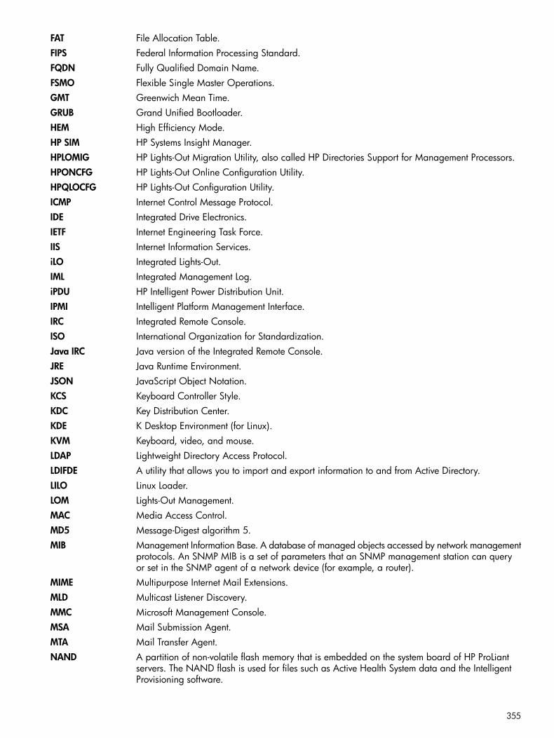
FAT File Allocation Table.FIPS Federal Information Processing Standard.FQDN Fully Qualified Domain Name.FSMO Flexible Single Master Operations.GMT Greenwich Mean Time.GRUB Grand Unified Bootloader.HEM High Efficiency Mode.HP SIM HP Systems Insight Manager.HPLOMIG HP Lights-Out Migration Utility, also called HP Directories Support for Management Processors.HPONCFG HP Lights-Out Online Configuration Utility.HPQLOCFG HP Lights-Out Configuration Utility.ICMP Internet Control Message Protocol.IDE Integrated Drive Electronics.IETF Internet Engineering Task Force.IIS Internet Information Services.iLO Integrated Lights-Out.IML Integrated Management Log.iPDU HP Intelligent Power Distribution Unit.IPMI Intelligent Platform Management Interface.IRC Integrated Remote Console.ISO International Organization for Standardization.Java IRC Java version of the Integrated Remote Console.JRE Java Runtime Environment.JSON JavaScript Object Notation.KCS Keyboard Controller Style.KDC Key Distribution Center.KDE K Desktop Environment (for Linux).KVM Keyboard, video, and mouse.LDAP Lightweight Directory Access Protocol.LDIFDE A utility that allows you to import and export information to and from Active Directory.LILO Linux Loader.LOM Lights-Out Management.MAC Media Access Control.MD5 Message-Digest algorithm 5.MIB Management Information Base. A database of managed objects accessed by network management
protocols. An SNMP MIB is a set of parameters that an SNMP management station can queryor set in the SNMP agent of a network device (for example, a router).
MIME Multipurpose Internet Mail Extensions.MLD Multicast Listener Discovery.MMC Microsoft Management Console.MSA Mail Submission Agent.MTA Mail Transfer Agent.NAND A partition of non-volatile flash memory that is embedded on the system board of HP ProLiant
servers. The NAND flash is used for files such as Active Health System data and the IntelligentProvisioning software.
355
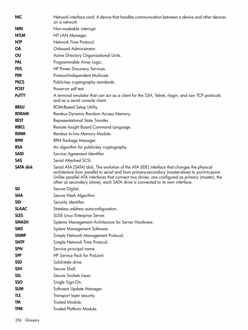
NIC Network interface card. A device that handles communication between a device and other deviceson a network.
NMI Non-maskable interrupt.NTLM NT LAN Manager.NTP Network Time Protocol.OA Onboard Administrator.OU Active Directory Organizational Units.PAL Programmable Array Logic.PDS HP Power Discovery Services.PIM Protocol-Independent Multicast.PKCS Public-key cryptography standards.POST Power-on self test.PuTTY A terminal emulator that can act as a client for the SSH, Telnet, rlogin, and raw TCP protocols
and as a serial console client.RBSU ROM-Based Setup Utility.RDRAM Rambus Dynamic Random Access Memory.REST Representational State Transfer.RIBCL Remote Insight Board Command Language.RIMM Rambus In-line Memory Module.RPM RPM Package Manager.RSA An algorithm for public-key cryptography.SAID Service Agreement Identifier.SAS Serial Attached SCSI.SATA disk Serial ATA (SATA) disk. The evolution of the ATA (IDE) interface that changes the physical
architecture from parallel to serial and from primary-secondary (master-slave) to point-to-point.Unlike parallel ATA interfaces that connect two drives; one configured as primary (master), theother as secondary (slave), each SATA drive is connected to its own interface.
SD Secure Digital.SHA Secure Hash Algorithm.SID Security Identifier.SLAAC Stateless address autoconfiguration.SLES SUSE Linux Enterprise Server.SMASH Systems Management Architecture for Server Hardware.SMS System Management Software.SNMP Simple Network Management Protocol.SNTP Simple Network Time Protocol.SPN Service principal name.SPP HP Service Pack for ProLiant.SSD Solid-state drive.SSH Secure Shell.SSL Secure Sockets Layer.SSO Single Sign-On.SUM Software Update Manager.TLS Transport layer security.TM Trusted Module.TPM Trusted Platform Module.
356 Glossary

UDP User Datagram Protocol.UEFI Unified Extensible Firmware Interface.UHCI Universal Host Controller Interface.UID Unit identification.UPN User principal name.UPnP Universal Plug and Play.UPS Uninterruptible Power Supply.USB Universal serial bus. A serial bus standard used to interface devices.USM User-based Security Model.UTC Coordinated Universal Time.UTP Unshielded twisted pair.UUID Universally unique identifier.VSP Virtual Serial Port.WBEM Web-Based Enterprise Management.WINS Windows Internet Name Service.
357

Index
Symbols.NET IRC see Remote Console
Aaccess options
Authentication Failure Delay Time, 60Authentication Failure Logging, 60, 63Authentication Failures Before Delay, 60configuring, 60configuring with web interface, 60Idle Connection Timeout, 60iLO 4 Configuration Utility, 60iLO Functionality, 60, 139iLO ROM-Based Setup Utility, 60, 139Minimum Password Length, 60Require Login for iLO 4 Configuration Utility, 60Require Login for iLO RBSU, 60, 139Serial Command Line Interface Speed, 60, 139Serial Command Line Interface Status, 60, 139Server FQDN/IP Address, 60Server Name, 60Show iLO IP during POST, 60, 139Virtual Serial Port Log, 60
access settingsaccess options, 60configuring, 58IPMI/DCMI settings, 60service settings, 58
accessing iLOtroubleshooting, 317
Active Directoryautomatic certificate request, 281certificate services, 280, 281directory objects, 289directory services , 287directory services objects, 290installation prerequisites, 287installing, 288integration, 73preparation, 280Snap-in installation and initialization for Active
Directory, 289verifying certificate services, 281
Active Health Systemclearing the log, 188data collection, 123downloading the log, 186, 187overview, 184
Active Health System reportingschedule, 136
active iLO sessionsviewing, 150
AES/3DESconfiguring, 82connecting to iLO, 83
overview, 81viewing, 81
Agentless Managementconfiguring, 112overview, 108
Agentless Management Service, 333, 334control panel, 110, 116downloading, 110guidelines, 110installing, 110Linux, 110restarting, 111troubleshooting, 341Ubuntu, 110verifying installation, 110VMware, 110Windows, 110
AlertMaildisabling, 120enabling, 120overview, 120
alertsAlertMail, 120Remote Syslog, 121SNMP, 115SNMP alert destinations, 112troubleshooting, 341
AMSProactive Care requirement, 124
Authentication Failure Delay Timeconfiguring, 60
Authentication Failure Loggingconfiguring, 60using with SSH clients, 63
Authentication Failures Before Delayconfiguring, 60
Authentication PassphraseSNMPv3, 113
Authentication ProtocolSNMPv3, 113
Automatic Group Power Cappingusing with iLO Federation, 201
Bblocked ports
troubleshooting, 320boot mode
changing, 238boot order
changing, 238brown-out recovery, 241browser support
web interface, 145
Ccertificates see SSL certificates
358 Index
chassis information, 253power supplies, 254smart storage battery, 255
CLIaccess setting, 139authentication, 60serial port speed, 60, 139Virtual Serial Port log, 60
collections see data collectioncompatibility, directory migration, 301configuring
Enclosure iLO Federation Support, 57iLO Federation, 46, 49iLO Federation group memberships, 50, 52, 53multicast options, 47
connecting to iLOtroubleshooting, 319, 320
Console Capture, 216contacting HP, 343control panel, 110
Agentless Management Service, 110, 116cookie behavior
troubleshooting, 146
Ddata collection
Active Health System, 123privacy, 123Remote Support, 123schedule
iLO, 135sending
iLO, 135system configuration, 123
Dedicated Network Portenabling with iLO web interface, 98
DHCPIPv4 settings, 99IPv6 settings, 101
diagnostics, 188iLO self-test results, 189NMI, 190
Directories Support for ProLiant Management Processors,302configuring directories with HP extended schema, 307Configuring directories with schema-free integration,
311installing, 302naming management processors, 306Selecting a directory access method, 305Setting up management processors for directories, 311updating iLO firmware, 304using, 302
directory authentication, 73directory groups
deleting, 46viewing, 44
directory integrationbenefits, 273
Kerberos, 274migration, 301overview, 273setting up schema free directories, 280troubleshooting, 317, 324troubleshooting logout, 324troubleshooting user contexts, 324
directory settingsauthentication, 74configuring, 74directory server settings, 74directory test controls, 78Kerberos, 74test results, 78verifying, 76
directory testsresults, 78running, 76test controls, 78
Directory-enabled remote managementconfiguring, 295overview, 295requirements, 295
DNS namedefault value, 27
DNS serversIPv4, 99IPv6, 101
documentationproviding feedback on, 345
domain nameconfiguring, 95
downloadingActive Health System Log, 187
drivers see iLO drivers
EEmbedded User Partition, 261
configuring, 262, 263, 266using, 261
Emergency Management ServicesWindows EMS Console, 223
enclosurefan control, 252temperature, 252
Enclosure iLO Federation Supportconfiguring, 57verifying, 57
encryptionAES/3DES, 81configuring, 82, 83, 84connecting to iLO, 83FIPS Mode, 81overview, 81viewing, 81
Enterprise Secure Key Manager, 257evaluation license, 38event log
clearing, 180
359
overview, 177saving, 179troubleshooting, 316viewing, 177
Ffactory default settings
restoring, 268, 269fans
iLO Virtual Fan, 252viewing, 152
features, 16iLO Federation, 192
Federation see iLO FederationFIPS Mode
disabling, 84enabling, 83overview, 81viewing, 81
Firefoxtroubleshooting with Remote Console, 325
firmware, 30see also iLO firmwareupdating with iLO Federation, 203viewing installed firmware, 174
FQDNconfiguring, 60
Ggateway IP address
IPv4, 99Global iLO 4 Settings see access optionsgraceful shutdown
power, 241groups
iLO Federation, 49
Hhardware and software links
troubleshooting, 316health status
viewing, 149health summary
redundancy, 151status information, 151status values, 151viewing, 151
helpobtaining, 343
hostnameconfiguring, 95
hot keysRemote Console, 218
HPsubscription service, 343technical support, 343
HP Insight Control softwareintegration, 257
HP schema directory integration
configuring, 284overview, 283requirements, 285
HP Zero Sign InKerberos, 278, 279
HPLOMIG see Directories Support for ProLiantManagement Processors
HPONCFG, 339
IIdle Connection Timeout
configuring, 60iLO
certificate error, 322configuring, 30firmware update error, 339Remote Support prerequisites, 125sending a test event, 132sending Active Health System information, 136sending data collection information, 135updating firmware, 203
iLO 4 Configuration Utility, 341about iLO, 143access setting, 60access settings, 142accessing, 140advanced network options, 141login requirement, 60network settings, 23, 140overview, 17rebooting iLO, 267restoring factory default settings, 269setting up iLO, 22
iLO controlsweb interface, 147
iLO Dedicated Network Port see networklink state, 98
iLO driversdownloading, 27installing, 27Linux, 28VMware, 28Windows, 27
iLO Federationadding group memberships, 50, 53affected servers, 201
firmware update, 206Group Configuration, 56Group Firmware Update, 207Group Licensing, 209group membership, 56Group Power, 201license installation, 209Virtual Media, 199Virtual Power, 201
Automatic Group Power Capping, 201changing server power state, 199configuring, 46configuring multicast options, 47
360 Index

critical and degraded systems, 194, 195editing group memberships, 52features, 192groups, 49managing group memberships, 53Multi-System Map, 195network requirements, 47peers list, exporting, 196power management, 199removing group memberships, 52server blade requirement, 57updating firmware, 203viewing group memberships, 50viewing license status, 207viewing license type, 207viewing server health, 194viewing server models, 194Virtual Media, 196
iLO Federation Managementtroubleshooting, 335
iLO firmwaredownloading, 31, 204offline update, 31online update, 30
in-band update, 30out-of-band update, 31
troubleshooting firmware updates, 338updating, 30, 32, 304
iLO Functionalityconfiguring, 60, 139
iLO mobile appoverview, 17
iLO RBSU, 341access setting, 60, 139configuring local user accounts, 139configuring user accounts, 24Global iLO 4 Settings, 139login requirement, 60, 139network settings, 22overview, 17security, 64setting up iLO, 22troubleshooting, 318
iLO securitysystem maintenance switch, 65
iLO Security Override Switch see system maintenanceswitch
iLO Shared Network Port see networkiLO web interface see web interfaceInsight Management Agents
downloading, 110installing, 110integration, 119overview, 108using, 192
Integrated Management Log, 183clearing, 184maintenance note, 183overview, 180
saving, 183viewing, 181
integrationSystems Insight Manager, 270
IP addressconfiguring, 60configuring a static IP address, 22, 23IP address and subnet mask restrictions, 298IPv4, 99IPv6, 101viewing during POST, 60, 139
IPMI tool usageAdvanced, 257
IPMI/DCMIconfiguring, 60server management, 256user privileges, 43
IPv4, 92see also networkconfiguring, 99DHCP, 99DNS servers, 99gateway address, 99IP address, 99ping gateway on startup, 99static routes, 99subnet mask, 99, 101WINS servers, 99
IPv6, 92see also networkconfiguring, 101DHCP, 101DNS servers, 101gateway address, 101static routes, 101
JJava IRC see Remote Console
KKerberos, 73
computer accounts, 275configuring, 277configuring with CLI, 278configuring with iLO scripts, 277directory integration, 274generating a keytab, 275HP Zero Sign In, 278, 279iLO configuration, 277login by name, 279realm names, 275single sign-on, 278, 279time requirement, 278two-factor authentication, 274user accounts, 275user groups, 276
kernel debuggingtroubleshooting, 313
key manager software
361

Enterprise Secure Key Manager, 257keyboard
configuring persistent mouse and keyboard, 250
Llanguage packs, 148
configuring the current language, 36configuring the default language, 36installing, 35overview, 34selecting, 36uninstalling, 37
legacy BIOSchanging the boot mode, 238changing the boot order, 238changing the one-time boot status, 239
licensingevaluation license, 38installation, 38license types, 37options, 346troubleshooting, 340viewing in Systems Insight Manager, 272
LinuxAgentless Management Service, 110configuring the Virtual Serial Port, 222iLO drivers, 28Text-based Remote Console, 226
login, 145authentication failure, 60authentication failure delay, 60default user account, 27security, 67security banner, 88troubleshooting, 316, 318, 319unknown authority message, 147
logsevent log, 177Remote Syslog, 121Virtual Serial Port, 60
Mmaintenance note
Integrated Management Log, 183memory information
viewing, 162Microsoft ClickOnce
requirement, 91Microsoft software
directory services for Active Directory, 287migration utilities, 301Minimum Password Length
configuring, 60mobile app
overview, 17mouse
configuring persistent mouse and keyboard, 250multicast options
configuring, 47
Nnetwork, 95
configuration summary, 92configuring, 94configuring a VLAN, 97configuring IPv4 settings, 99configuring IPv6 settings, 101configuring NIC settings, 96connecting iLO, 21enabling the Dedicated Network Port with iLO web
interface, 98enabling the Shared Network Port with iLO web
interface, 97IPv4 summary, 92IPv6 Summary, 92link state, 96, 98name service limitations, 94namespace issues, 94SNTP, 104troubleshooting, 319, 320
network failed flash recovery, 339network requirements
iLO Federation, 47NIC auto-selection, 106, 107NIC information
viewing, 166NIC settings
configuring, 96NIC auto-selection, 106, 107
NMIgenerating, 190
OOnboard Administrator
configuring iLO Federation support, 57iLO option, 252using with iLO, 250
one-time boot statuschanging, 239
Option ROM Measuringviewing status, 203
overview, 16
Ppassword
minimum length, 60security, 43
ping gateway on startupIPv4, 99
port matchingSystems Insight Manager, 271
ports, 320IPMI/DCMI, 60SSH, 58Systems Insight Manager, 271
powerAutomatic Group Power Capping, 201brown-out recovery, 241configuring persistent mouse and keyboard, 250
362 Index

configuring threshold alerts, 249Dynamic Power Capping for server blades, 252efficiency, 241graceful shutdown, 241group power, 199iLO power management, 242managing server power, 242overview, 240power capping, 249Power Regulator for ProLiant, 247server, 240system power restore setting, 243usage, 244viewing the current power state, 246viewing the server power history, 247
power cappingconfiguring, 249
power informationviewing, 155
Power Regulator for ProLiantconfiguring, 247Dynamic Power Capping for server blades, 252
power settingsconfiguring, 247
power switchRemote Console, 214
Pre-boot Health Summary, 314prerequisites
Remote Support, 125Privacy Passphrase
SNMPv3, 113Privacy Protocol
SNMPv3, 113Proactive Care
requirements, 124processor information
viewing, 161proxy server
using with iLO, 320
RRBSU see iLO RBSU see system RBSUrebooting
iLO processor, 190rebooting iLO, 267
iLO 4 Configuration Utility, 267UID button, 268
Remote Console.NET IRC requirements, 211acquiring, 214computer lock settings, 90configuring trust settings (.NET IRC), 91Console Capture, 216creating hot keys, 218idle connection timeout, 60Inactive .NET IRC, 328port, 58power switch, 214sharing, 215
starting, 213text-based, 219troubleshooting, 325, 326, 331, 341using .NET IRC and Java IRC, 210using Virtual Media, 215
Remote Console Portconfiguring, 58
remote management tooldeleting the configuration, 260starting, 148, 260viewing, 260
Remote Supportconfiguring web proxy settings, 126data collection, 123direct connect registration, 126editing the web proxy settings, 128iLO connection error, 335iLO session ends during registration, 335overview, 122prerequisites, 125server identification, 333service events, 123SSL Bio Error during registration, 333system configuration, 123troubleshooting server and operating system name, 334
Remote Syslogconfiguring, 121disabling, 121enabling, 121
Require Login for iLO 4 Configuration Utilityconfiguring, 60
Require Login for iLO RBSUconfiguring, 60, 139
requirementsHP schema directory integration, 285Virtual Media, 227
Reset to Factory Defaults, 341resetting
iLO processor, 190resetting iLO see rebooting iLORESTful API
overview, 18RESTful Interface Tool
overview, 18restoring
factory default settings, 268
Sschema documentation, 348
Core attribute definitions, 349hpqPolicyDN, 349hpqRoleIPRestrictionDefault, 350hpqRoleIPRestrictions, 350hpqRoleMembership, 349hpqRoleTimeRestriction, 351hpqTargetMembership, 350
Core attributes, 348Core class definitions, 348
hpqPolicy, 349
363

hpqRole, 349hpqTarget, 348
Core classes, 348Lights-Out Management attributes, LDAP, 351, 352
hpqLOMRightConfigureSettings, 353hpqLOMRightLocalUserAdmin, 353hpqLOMRightLogin, 352hpqLOMRightRemoteConsole, 352hpqLOMRightServerReset, 352hpqLOMRightVirtualMedia, 352
Lights-Out Management classes, LDAP, 351hpqLOMv100, 351
Lights-Out Management specific LDAP OID classes andattributes, 351
Schema Extenderinstaller, 285
schema free directoriesconfiguration options, 282configuring, 281, 282nested groups, 283setting up, 280
scripting and command lineoverview, 18
SD-Cardstatus, 149
Secure Shell (SSH) Accessconfiguring, 58
Secure Shell (SSH) Portconfiguring, 58
securityconfiguring, 64guidelines, 64iLO RBSU, 64login, 67login security banner, 88passwords, 43Remote Console computer lock, 90TM support, 66TPM support, 66user account privileges, 67user accounts, 67
Security NameSNMPv3, 113
Serial Command Line Interface Speedconfiguring, 60, 139
Serial Command Line Interface Statusconfiguring, 60, 139
serial label pull tab, 27server
configuring FQDN/IP Address, 60configuring Server Name, 60managing power, 242managing with IPMI, 256powering on, 240
server bladesverifying iLO Federation capability, 57
server firmwaredownloading, 32, 204
Server FQDN/IP Address
configuring, 60Server Name
clearing, 341configuring, 60
serversAutomatic Group Power Capping, 201connecting Virtual Media, 197ejecting Virtual Media, 198group power, 199health status, 194license status, 207license type, 207updating firmware, 203viewing connected Virtual Media, 198
service eventsRemote Support, 123sending a test event
iLO, 132service settings, 58
Remote Console Port, 58Secure Shell (SSH) Access, 58Secure Shell (SSH) Port, 58SNMP Access, 58SNMP Port, 58SNMP Trap Port, 58Virtual Media Port, 58Web Server Non-SSL Port, 58Web Server SSL Port, 58
setting up iLOnetwork connection, 21overview, 19preparation, 19static IP address, 22, 23user accounts, 24, 67using iLO 4 Configuration Utility, 22using iLO RBSU, 22web interface, 26
Shared Network Portenabling with iLO web interface, 97FlexibleLOM, 96LOM, 96
Show iLO IP during POSTconfiguring, 60, 139
single sign-onconfiguring, 84, 85Kerberos, 278, 279privileges, 85removing trusted certificates, 88trust mode, 85trusted certificates, 86viewing trusted certificates, 88
smart storage battery, 161, 255SNMP, 115
see also SNMP alertsaccess, 58configuring, 112configuring alerts, 115, 116configuring SNMPv3 users, 113overview, 108
364 Index

ports, 58Receiving alerts in Systems Insight Manager, 271trap definitions, 116
SNMP Accessconfiguring, 58
SNMP alertsCold Start Trap Broadcast, 115Forward Insight Manager Agent SNMP Alerts, 115iLO SNMP Alerts, 115sending test alerts, 115SNMPv1 Traps, 115Trap Source Identifier, 115
SNMP Pass-thruconfiguring, 112
SNMP Portconfiguring, 58
SNMP Trap Portconfiguring, 58
SNMPv3Authentication Passphrase, 113Authentication Protocol, 113configuring the engine ID, 114Privacy Passphrase, 113Privacy Protocol, 113Security Name, 113
SNTPconfiguring, 104
softwareHP software, 176installed software, 177running software, 176viewing, 176
SSHauthentication failure logging, 63authorizing keys, 69authorizing keys from Systems Insight Manager, 70configuring access, 58deleting keys, 70key administration, 67key requirements, 68port, 58troubleshooting, 333
SSLcertificates, 70, 147importing certificates, 71troubleshooting, 315troubleshooting certificates, 319viewing certificates, 71
SSL certificatesimporting, 71obtaining, 71
SSOconfiguring with Systems Insight Manager, 270
static routesIPv4, 99IPv6, 101
status informationviewing, 149
subnet mask
IPv4, 99subscription service, HP, 343support, 343system information
viewing, 148, 150system maintenance switch, 60
overview, 65System Management Homepage, 119system RBSU
configuring the Virtual Serial Port, 220Systems Insight Manager
authorizing SSH keys, 70configuring single sign-on, 270iLO identification, 270iLO license, 272iLO links, 271integrating with iLO, 270overview, 270port matching, 271single sign-on, 87SNMP alerts, 271troubleshooting, 341viewing iLO, 271viewing iLO status, 270
Ttechnical support
HP, 343temperature information
temperature graph, 154viewing, 153
Text-based Remote Console, 226customizing, 225Linux sessions, 226overview, 219Textcons, 224troubleshooting, 332
Textcons see Text-based Remote Consoletime zone
SNTP, 104TM
using, 66TPM
using, 66Troubleshooting
Pre-boot health summary, 314troubleshooting, 195, 313
Agentless Management Service, 341blocked ports, 320booting to DOS, 331certificate error, 322cookies, 146directory integration, 317, 324directory logout, 324event log, 316hardware and software links, 316iLO access, 317iLO Federation
403 error, 337
365

502 error, 337peers not displayed, 337query errors, 335timeout error, 336
iLO Federation Management, 335iLO firmware update, 338, 339iLO RBSU, 318Inactive .NET IRC, 328IRC failed to connect to server error message, 328kernel debugging, 313ktpass utility, 325license, 340login, 316, 318, 319network failed flash recovery, 339Remote Console, 325, 326, 331, 341Remote Support, 333, 334, 335SNMP and Systems Insight Manager, 341SSH, 333Systems Insight Manager alarms, 341testing SSL, 315text-based Remote Console, 332unable to connect to iLO, 319, 320Virtual Media, 329, 331, 341
trust settingsRemote Console, 91
Trusted Modulestatus, 149
Trusted Platform Modulestatus, 149
two-factor authenticationKerberos, 274
UUbuntu
Agentless Management Service, 110UEFI
changing the boot mode, 238changing the boot order, 238changing the one-time boot status, 239
UEFI ShellEmbedded User Partition, 263, 266
UEFI System Utilitiesconfiguring the Virtual Serial Port, 221Embedded User Partition, 262iLO 4 Configuration Utility, 140
UID buttonrebooting iLO, 268
unknown authority messagelogging in to iLO, 147
user accountsadding, 24, 25, 40default user account, 27deleting, 46directory authentication, 73editing, 26, 42enabling local accounts, 74, 139IPMI/DCMI, 43overview, 39privileges, 39, 67
removing, 26security, 67viewing, 39
user rolesIP address and subnet mask restrictions, 298
User-based Security ModelSNMPv3, 113
Vvirtual fan, 252Virtual Media
changing the port, 230connecting to groups, 197disconnecting from groups, 198IIS, scripted media, 235local media, 231OS information, 227overview, 226port, 58scripted media, 231scripting, IIS requirements, 235troubleshooting, 329, 331, 341using from web interface, 230using with iLO Federation, 196using with Remote Console, 215
Virtual Media Portconfiguring, 58
Virtual Power buttonusing with iLO Federation, 199viewing affected servers, 201
Virtual Serial Portconfiguring with system RBSU, 220configuring with UEFI System Utilities, 221Linux configuration, 222overview, 220Windows configuration, 223
Virtual Serial Port Logconfiguring, 60
VLANconfiguring, 97
VMwareAgentless Management Service, 110iLO drivers, 28
Wweb interface
browser support, 145enabling the Dedicated Network Port, 98enabling the Shared Network Port, 97idle connection timeout, 60iLO controls, 147overview, 17using, 145
Web Server Non-SSL Portconfiguring, 58port, 58
Web Server SSLport, 58
Web Server SSL Port
366 Index

configuring, 58web sites
HP subscription service, 343Windows
Agentless Management Service, 110enabling EMS Console, 223iLO drivers, 27
WINS serversIPv4, 99
367