MANUEL DE REFERENCE DES PRODUITS
23
DTUS073 rev A1 - September 4, 2017 EmbedAir1000 HARDWARE MANUAL
-
Upload
khangminh22 -
Category
Documents
-
view
0 -
download
0
Transcript of MANUEL DE REFERENCE DES PRODUITS

DTUS073 rev A1 - September 4, 2017
EmbedAir1000 HARDWARE MANUAL
Page 2 / 23
DTUS073 rev A1 - September 4, 2017
EmbedAir1000 HARDWARE MANUAL
COPYRIGHT (©) ACKSYS 2017
This document contains information protected by Copyright. The present document may not be wholly or partially reproduced, transcribed, stored in any computer or other system whatsoever, or translated into any language or computer language whatsoever without prior written consent from ACKSYS Communications & Systems - ZA Val Joyeux – 10, rue des Entrepreneurs - 78450 VILLEPREUX - FRANCE.
REGISTERED TRADEMARKS ®
ACKSYS is a registered trademark of ACKSYS.
DISCLAIMERS
ACKSYS ® gives no guarantee as to the content of the present document and takes no responsibility for the profitability or the suitability of the equipment for the requirements of the user.
ACKSYS ® will in no case be held responsible for any errors that may be contained in this document, nor for any damage, no matter how substantial, occasioned by the provision, operation or use of the equipment.
ACKSYS ® reserves the right to revise this document periodically or change its contents without notice.
REGULATORY INFORMATION AND DISCLAIMERS
Installation and use of this Wireless LAN device must be in strict accordance with local regulation laws and with the instructions included in the user documentation provided with the product. Any changes or modifications (including the antennas) to this device not expressly approved by the manufacturer may void the user’s authority to operate the equipment. The manufacturer is not responsible for any radio or television interference caused by unauthorized modification of this device, or the substitution of the connecting cables and equipment other than manufacturer specified. It is the responsibility of the user to correct any interference caused by such unauthorized modification, substitution or attachment. Manufacturer and any authorized resellers or distributors will assume no liability for any damage or violation of government regulations arising from failing to comply with these guidelines.
10, rue des Entrepreneurs
Z.A. Val Joyeux 78450 VILLEPREUX - France
Phone: +33 (0)1 30 56 46 46
Fax: +33 (0)1 30 56 12 95
Web site: www.acksys.fr
Hotline: [email protected]
Sales: [email protected]
Page 3 / 23
DTUS073 rev A1 - September 4, 2017
TABLE OF CONTENTS
I INTRODUCTION ............................................................................................................................................. 4
II MECHANICAL DIMENSIONS ....................................................................................................................... 6
BOTTOM VIEW ........................................................................................................................................ 6 II.1 FRONT VIEW ........................................................................................................................................... 7 II.2
III LEDS AND BUTTON ...................................................................................................................................... 8
LEDS.......................................................................................................................................................... 8 III.1 SIGNALS RELOCATION ........................................................................................................................ 8 III.2 RESET ..................................................................................................................................................... 10 III.3
IV EVALUATION BOARD ............................................................................................................................ 11
V WIRING CONNECTORS .............................................................................................................................. 12
PINOUT ................................................................................................................................................... 12 V.1 P-GEN (J3) ............................................................................................................................................. 13 V.2 P-USR (J4) .............................................................................................................................................. 13 V.3 RJ CONNECTOR (J10) ........................................................................................................................ 15 V.4 MICRO-USB CONNECTOR (J20) ...................................................................................................... 15 V.5 P-ETH-1G (J11) ..................................................................................................................................... 15 V.6 ANTENNA CONNECTOR .................................................................................................................... 18 V.7 P-ADM (J1) ............................................................................................................................................. 18 V.8
VI MOUNTING OF THE DEVICE ................................................................................................................. 19
STANDARD MOUNTING ..................................................................................................................... 19 VI.1
VII DEFAULT CONFIGURATION ................................................................................................................. 19
VIII TECHNICAL CHARACTERISTICS ........................................................................................................ 20

Page 4 / 23
DTUS073 rev A1 - September 4, 2017
I INTRODUCTION
This hardware documentation applies to the following products:
EmbedAir1000/R2 (RJ version)
EmbedAir1000/T2 (TTL version)
Together with the "WaveOS User Guide (ref DTUS070)", it covers product installation, configuration and usage, and general information about Wi-Fi protocols. This hardware manual describes equipment installation, such as power supplies, dimensions and connectors. The "WaveOS User Guide (DTUS070)" describes the configuration and use of the equipment.

Page 5 / 23
DTUS073 rev A1 - September 4, 2017
Regulatory information / Disclaimers
Installation and use of this Wireless LAN device must be in strict accordance with the instructions included in the user documentation provided with the product. Any changes or modifications (including the antennas) made to this device that are not expressly approved by the manufacturer may void the user’s authority to operate the equipment. The manufacturer is not responsible for any radio or television interference caused by unauthorized modification of this device, or the substitution of the connecting cables and equipment other than manufacturer specified. It is the responsibility of the user to correct any interference caused by such unauthorized modification, substitution or attachment. Manufacturer and any authorized resellers or distributors will assume no liability for any damage or violation of government regulations arising from failing to comply with these guidelines. Information in this document is subject to change without notice and does not represent a commitment on the part of ACKSYS. ACKSYS provides this document “as is”, without warranty of any kind, either expressed or implied, including, but not limited to, its particular purpose. ACKSYS reserves the right to make improvements and/or changes to this manual, or to the products and/or the programs described in this manual, at any time. Information provided in this manual is intended to be accurate and reliable. However, ACKSYS assumes no responsibility for its use, or for any infringements on the rights of third parties that may result from its use. This product might include unintentional technical or typographical errors. Changes are periodically made to the information herein to correct such errors and these changes are incorporated in new editions of the publication.
Page 6 / 23
DTUS073 rev A1 - September 4, 2017
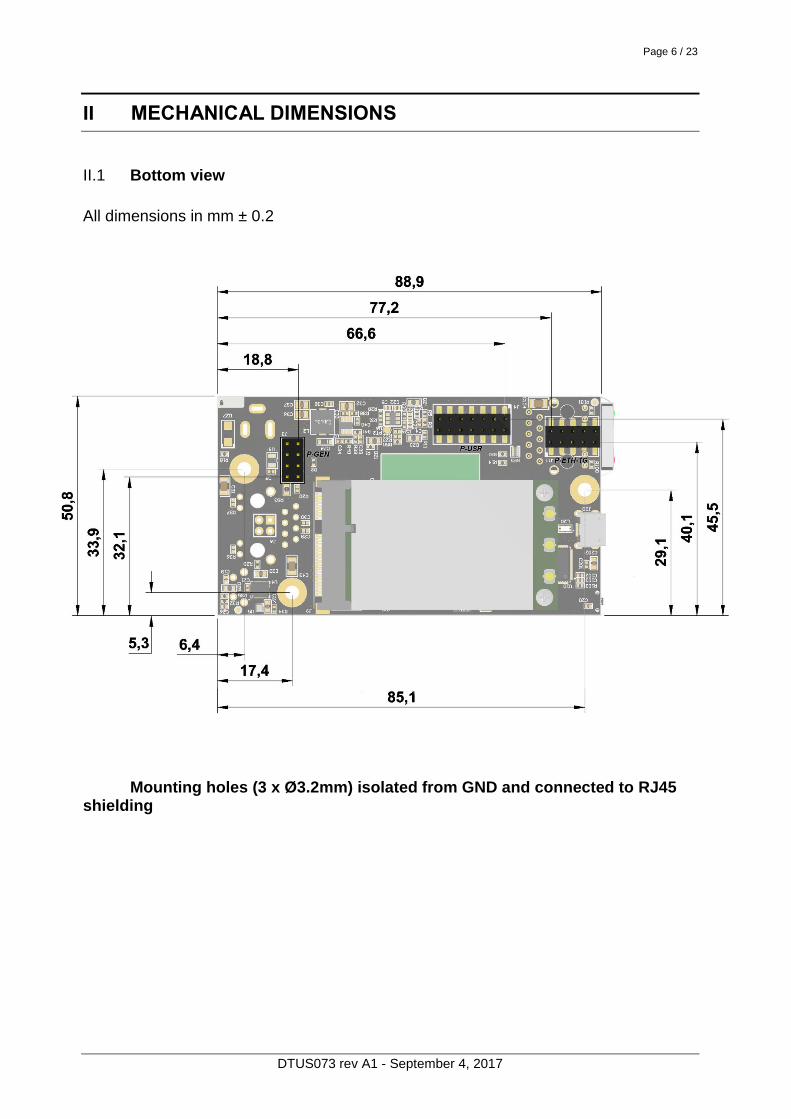
II MECHANICAL DIMENSIONS
Bottom view II.1
All dimensions in mm ± 0.2
Mounting holes (3 x Ø3.2mm) isolated from GND and connected to RJ45 shielding
Page 7 / 23
DTUS073 rev A1 - September 4, 2017
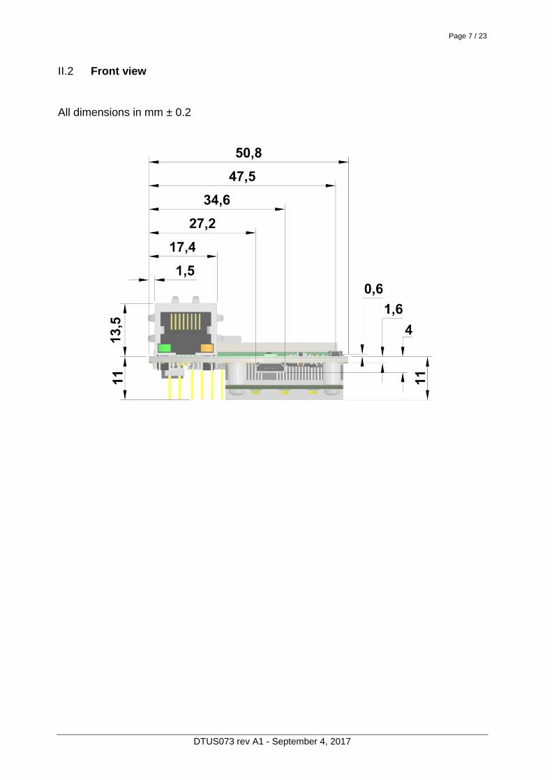
Front view II.2
All dimensions in mm ± 0.2

Page 8 / 23
DTUS073 rev A1 - September 4, 2017
III LEDS AND BUTTON
Leds III.1
The leds are directly available on the EmbedAir1000:
Signals relocation III.2
All the leds and button are also made available to the host motherboard via the P-GEN (J3) & P-USR (J4) connectors (see information in the following chapters) in order to be used in your own way.
III.2.1 Power
GREEN while powered on
Ethernet
Link/Activity
Ethernet
Speed
WLAN1 State WLAN1 Activity
WLAN2 Activity WLAN2 State
GNSS
State
Power Diag

Page 9 / 23
DTUS073 rev A1 - September 4, 2017
III.2.2 Diag
GREEN when product is OK and initialized RED during initialization (~ 40 seconds) Flashing when firmware in flash is not valid OFF or RED for more than 2min: Hardware/Software failure
III.2.3 WLAN (1/2) State
Fixed GREEN when associated with another Wi-Fi product Flashing GREEN when unassociated
III.2.4 WLAN (1/2) Activity
Flashing BLUE when there is activity on WLAN (sending or receiving) or during the search for a Wi-Fi access point (only in "Bridge Mode")
III.2.5 Ethernet Speed
OFF when Ethernet connection is negotiated in 10 or 100 MBit/s YELLOW when Ethernet connection is negotiated in 1000 MBit/s Available at the same location either directly on the board (for TTL version) or on the RJ connector (for RJ version)
III.2.6 Ethernet Link/Activity
Fixed GREEN when link is established with another Ethernet product Flashing GREEN when there is activity on Ethernet (sending or receiving) Available at the same location either directly on the board (for TTL version) or on the RJ connector (for RJ version)
III.2.7 GNSS State (Not yet available)
OFF when GNSS is disabled Fixed GREEN when position is established (3 satellites are viewed at least) Flashing GREEN when position is being searched (less than 3 satellites are viewed)

Page 10 / 23
DTUS073 rev A1 - September 4, 2017
Reset III.3
The Reset button allows you to re-start the product or reconfigure it to default factory settings (see "WaveOS User Guide - DTUS070" for more information)

Page 11 / 23
DTUS073 rev A1 - September 4, 2017
IV EVALUATION BOARD
TBD

Page 12 / 23
DTUS073 rev A1 - September 4, 2017
V WIRING CONNECTORS
Pinout V.1
Top view Bottom view

Page 13 / 23
DTUS073 rev A1 - September 4, 2017
P-GEN (J3) V.2
HE10/HE13/HE14/Strip Male Header 2.54mm pitch, 2x4 pins - Compatible with HE10/HE13/HE14 Female Receptacle (ex: SAMTEC Series BCS, BSW, ESQ, ESW...) (ex: ANTELEC Series APC104, FT2...)
Pin In / Out Function Voltage Max current
1 - Not used, should not be connected - -
2 Out 3V3 (for LEDs or reference only) +3.3V 100 mA
3 - Not used, should not be connected - -
4 Open drain
Out LED WLAN1 Activity active at 0V 15 mA
5 Open drain
Out LED Diag "Green" at 0V 15 mA
6 In Reset active at 3.3V 20 µA
7 In Power +5V +5V ± 0.25 1.1 A 2.4 A peak 8 - Power GND 0V
WARNING : You must take care of the polarity of the power supply source. There is no protection on this product.
P-USR (J4) V.3
HE10/HE13/HE14/Strip Male Header 2.54mm pitch, 2x3 pins - Compatible with HE10/HE13/HE14 Female Receptacle (ex: SAMTEC Series BCS, BSW, ESQ, ESW...) (ex: ANTELEC Series APC104, FT2...) - This connector is not needed for common use of the EmbedAir1000. It only provides some additional functions. I²C and UART1&2 should be only used with ACKSYS authorization. Their incorrect use could irremediably corrupt the product and void all pertaining guaranty.

Page 14 / 23
DTUS073 rev A1 - September 4, 2017
Pin In / Out Function Description Voltage Max current
1 Open drain
Out
SCL For I²C (Address 0x48,
0x62, 0x74 already used and polled regularly. Linux I²C driver, support for /dev/i2c-0, I2C leds and gpios, PCA and PCF algorithms)
0-3.3V -
3 SDA
5 In RX1 For UART1, Reserved for factory testing, do not use
0-3.3V - 7 Out TX1
9 In RX2
User UART2, May be left unconnected if not used
0-3.3V - 11 Out TX2
13 Out RTS2
14 In CTS2
2 Open drain
Out LED WLAN1 State
State of WiFi 1 active at
0V 15 mA
4 Open drain
Out LED WLAN2 State
State of WiFi 2 active at
0V 15 mA
6 Open drain
Out LED WLAN2 Activity
Activity on WiFi 2 active at
0V 15 mA
8 Open drain
Out LED GNSS State
State of GNSS active at
0V 15 mA
10 Out LED Ethernet Link/Activity
active at
0V 2 mA
12 Out LED Ethernet Speed
active at
0V 2 mA
Example of wiring for UART with RS232 transceiver and DB9 male connector (DTE mode):

Page 15 / 23
DTUS073 rev A1 - September 4, 2017
RJ CONNECTOR (J10) V.4
LAN-Transformer RJ45 10/100/1000 Base T Only available on RJ version
It allows connecting a classical Ethernet cable (cat 5e or cat 6 for 1000 BaseT)
Micro-USB CONNECTOR (J20) V.5
Micro-USB 2.0 Type B Connector This connector gives the possibility of electrically powering the module (instead of using P-GEN connector), or connecting a USB device (under ACKSYS authorization for control and driver).
Warning: To use the 11ac WiFi interface of the module, it is
necessary to power the module from a USB source with a minimum current of 2.4A. Consequently, it cannot be powered from a USB hub, limited to 500mA or 900mA, AC/DC power adapter must be used in this case. But 900 mA is enough to only use the built in 11n WiFi interface. In case of failure of the product, always check the voltage level on the module itself, the minimum voltage is 5V-5% = 4,75V. If some cases the resistance of the cable used with the power supply causes a voltage drop, so instead of 5V, the device sees less than 4.75V. This can be avoided by choosing a USB power adapter able to provide 5.25V. By this way, it will happily work at the full current range, no matter what cable you use!
P-ETH-1G (J11) V.6
HE10/HE13/HE14/Strip Male Header 2.54mm pitch, 2x5 pins Only available on TTL version - Compatible with HE10/HE13/HE14 Female Receptacle (ex: SAMTEC Series BCS, BSW, ESQ, ESW... ANTELEC Series APC104, FT2... ) This connector gives directly raw signals from the Ethernet PHY component, without insulation. The PHY used on the EmbedAir1000 is 88E1512 from Marvell.

Page 16 / 23
DTUS073 rev A1 - September 4, 2017
These signals can be used to relocate a RJ45 Plug far away in your system. The signals should be correctly insulated, routed with wires of equal lengths and with 100 ohms differential impedance, especially with long distance. You can see at the next page some examples of insulation for these signals You can also connected two PHY together by using two transformers (using two times "Example 1", for each PHY)

Page 17 / 23
DTUS073 rev A1 - September 4, 2017
Example 1 : with Transformer and RJ separated
Example 2 : with transformer included in RJ

Page 18 / 23
DTUS073 rev A1 - September 4, 2017
ANTENNA CONNECTOR V.7
2 x U.FL male connectors, from Hirose, for WiFi 1 (WLAN1) Antenna connector #1 : Antenna 1 (RF chain 1) Antenna connector #2 : Antenna 2 (RF chain 2) 3 x U.FL male connectors, from Hirose, for WiFi 2 (WLAN2) Antenna connector #1 : Antenna 1 (RF chain 1) Antenna connector #2 : Antenna 2 (RF chain 2) Antenna connector #3 : Antenna 3 (RF chain 3) - Connect them to 2.4/5GHz antennas with 50ohms coaxial cable (with U.FL female connector according to radio card) - 2 antennas must be used for WiFi 1 to achieve max. performance (11n with 2 streams). - 3 antennas must be used for WiFi 2 to achieve max. performance (11 ac with 3 streams). WARNING: Verify that antennas hardware configuration matches with software configuration (see "WaveOS User Guide" ref DTUS070). If not, it may disturb and reduce performances of WiFi module.
P-ADM (J1) V.8
This connector, present on the board, is voluntarily not documented and shouldn't be used/connected.

Page 19 / 23
DTUS073 rev A1 - September 4, 2017
VI MOUNTING OF THE DEVICE
Standard mounting VI.1
Plug the EmbedAir1000 at a height of 12mm minimum from your motherboard, with the previously indicated connectors.
VII DEFAULT CONFIGURATION
- Ethernet : - Auto-negotiation - Auto-crossing - Wi-Fi 1: - Disabled - Mode: Access Point - Wi-Fi: 802.11n, HT20, 5GHz band - Channel: 36 - SSID: acksys (broadcast) - Security: disabled - Wi-Fi 2: - Disabled - Mode: Access Point - Wi-Fi: 802.11ac, HT20, 5GHz band - Channel: 36 - SSID: acksys (broadcast) - Security: disabled - Web Server IP address: http://192.168.1.253 More information about configuration is provided in the document "WaveOS User Guide - DTUS070".

Page 20 / 23
DTUS073 rev A1 - September 4, 2017
VIII TECHNICAL CHARACTERISTICS
Mechanical characteristics
Dimensions (w/o antennas)
EmbedAir1000/R2 (RJ versions) L x l x h = 88.9 x 50.8 x 25 mm L x l x h = 3.50 x 2.00 x 0.98 in EmbedAir1000/T2 (TTL version) L x l x h = 88.9 x 50.8 x 17 mm L x l x h = 3.50 x 2.00 x 0.67 in
Weight RJ version : max 47 g (1.66 oz) TTL version : max 42 g (1.48 oz)
Enclosure None
Operating temperatures ranges
-40 to +70°C
Status indicators 9 LEDs: see LEDs definition section
Push button
Short push, anytime: Reset Long push (> 2 sec.): - while operating: Restore factory settings - while in emergency upgrade mode: Restore factory settings - at startup: Enter emergency upgrade
Power supply Input
Voltage 5V ± 0.25V power supplies, without polarity protection. 5.5W max average (12W peak)
Inrush current 4.5A < 20µs
Software
Device configuration
Automatic device discovery Built in web based utility for easy configuration from any web browser (username/password protection & https)
Firmware upgrade Yes (via web browser)
SNMP SNMP V1, V2C, V3
Operating mode AP (Access Point)/ Repeater, Bridge/Client, Mesh, WDS
AP mode only
Network topology Infrastructure or mesh modes
Security WEP, WPA-PSK/WPA2-PSK, WPA/ WPA2 with 802.1x authenticator, SSID visibility status.

Page 21 / 23
DTUS073 rev A1 - September 4, 2017
Client/Bridge mode only
Network topology infrastructure mode, ad-hoc mode
Security WEP, WPA-PSK, WPA2-PSK. 802.1x supplicant. AES/TKIP/WEP by hardware encryption
Mesh mode only
Network topology mesh mode
Security WEP, WPA-PSK, WPA2-PSK. 802.1x supplicant. AES/TKIP/WEP by hardware encryption
Ethernet interface
Number of ports 1
Type of ports 10 BASE T, 100 BASE Tx or 1000 BASE T automatic negotiation (HDX/FDX,10/100 Mbps), auto MDI/MDI-X
Connector RJ45 for EmbedAir1000/R2 "Free use" for EmbedAir1000/T2
Wi-Fi 1 interface
Radio modes Support for IEEE 802.11a/h, 802.11b, 802.11g and 802.11n.
Chipset Qualcomm QCA95xx
Data rates
802.11n : up to 300 Mbps 802.11a/h : 6 to 54 Mbps 802.11b : 1 to 11 Mbps 802.11g : 1 to 54 Mbps
Frequency band for 802.11a/n
5 GHz; 5.170 to 5.835 GHz
Frequency band for 802.11b/g/n
2.4 GHz; 2.402 to 2.494 GHz
Antennas & Connectors 2 x U.FL male connector Delivered without antennas
Radio specifications for WiFi 1 :
Tx output power (Radio card output per chain)
802.11n HT20 2.4GHz band
20.5 dBm @ 7.2 Mbps (MCS 0) 18 dBm @ 72.2 Mbps (MCS 7)
802.11n HT40 2.4GHz band
20.5 dBm @ 15 Mbps (MCS 0) 18 dBm @ 150 Mbps (MCS 7)
802.11n HT20 5GHz band
18 dBm @ 7.2 Mbps (MCS 0) 15 dBm @ 72.2 Mbps (MCS 7)
802.11n HT40 5GHz band
18 dBm @ 15 Mbps (MCS 0) 15 dBm @ 150 Mbps (MCS 7)
Value for 1 stream, add 3 dBm for 2 streams
Rx sensitivity (Radio card input)
802.11n HT20 2.4GHz band
-92 dBm @ 7.2Mbps (MCS 0) -76 dBm @ 72.2Mbps (MCS 7)
802.11n HT40 2.4GHz band
-90 dBm @ 15 Mbps (MCS 0) -73 dBm @ 150 Mbps (MCS 7)
802.11n HT20 5GHz band
-96 dBm @ 7.2Mbps (MCS 0) -75 dBm @ 72.2Mbps (MCS 7)
802.11n HT40 5GHz band
-91 dBm @ 15 Mbps (MCS 0) -72 dBm @ 150 Mbps (MCS 7)

Page 22 / 23
DTUS073 rev A1 - September 4, 2017
Wi-Fi 2 interface
Radio modes Support for IEEE 802.11a/h, 802.11b, 802.11g, 802.11n and 802.11ac.
Chipset Qualcomm QCA98xx
Data rates
802.11ac : up to 1300Mbps 802.11n : up to 450 Mbps 802.11a/h : 6 to 54 Mbps 802.11b : 1 to 11 Mbps 802.11g : 1 to 54 Mbps
Frequency band for 802.11a/n
5 GHz; 5.170 to 5.835 GHz
Frequency band for 802.11b/g/n
2.4 GHz; 2.402 to 2.494 GHz
Antennas & Connectors 3 x U.FL male connector, delivered without antennas
Radio specifications for WiFi 2 :
Tx output power (Radio card output per chain)
802.11b 2.4GHz band
20 dBm @ 1 Mbps 20 dBm @ 11 Mbps
802.11g 2.4GHz band
21 dBm @ 6 Mbps 18 dBm @ 54 Mbps
802.11a 5GHz band
20 dBm @ 6 Mbps 15 dBm @ 54 Mbps
802.11n HT20 2.4GHz band
21 dBm @ 7.2 Mbps (MCS 0) 16 dBm @ 72.2 Mbps (MCS 7)
802.11n HT40 2.4GHz band
20 dBm @ 15 Mbps (MCS 0) 16 dBm @ 150 Mbps (MCS 7)
802.11n/ac VHT20 5GHz band
19 dBm @ 7.2 Mbps (MCS 0) 14 dBm @ 72.2 Mbps (MCS 7) 13 dBm @ 86.7 Mbps (VHT MCS 8)
802.11n/ac VHT40 5GHz band
18 dBm @ 15 Mbps (MCS 0) 14 dBm @ 150 Mbps (MCS 7) 13 dBm @ 200 Mbps (VHT MCS 9)
802.11ac VHT80 5GHz band
18 dBm @ 32.5 Mbps (MCS 0) 14 dBm @ 325 Mbps (MCS 7) 13 dBm @ 433.3 Mbps (VHT MCS 9)
Value for 1 chain, add 3 dBm for 2 chains, 5 dBm for 3 chains Tolerance ± 2 dB
Rx sensitivity (Radio card input)
Antenna configuration
Typical/max (3 Rx)
802.11b 2.4GHz band
-95 dBm @ 1 Mbps -90 dBm @ 11 Mbps
802.11g 2.4GHz band
-94 dBm @ 6 Mbps -80 dBm @ 54 Mbps
802.11a 5GHz band
-94 dBm @ 6 Mbps -80 dBm @ 54 Mbps
802.11n HT20 2.4GHz band
-94 dBm @ 7.2 Mbps (MCS 0) -77 dBm @ 72.2 Mbps (MCS 7)
802.11n HT40 2.4GHz band
-93 dBm @ 15 Mbps (MCS 0) -75 dBm @ 150 Mbps (MCS 7)
802.11n/ac VHT20 5GHz band
-93 dBm @ 7.2 Mbps (MCS 0) -73 dBm @ 72.2 Mbps (MCS 7) -71 dBm @ 86.7 Mbps (VHT MCS 8)
802.11n/ac VHT40 5GHz band
-90 dBm @ 15 Mbps (MCS 0) -73 dBm @ 150 Mbps (MCS 7) -68 dBm @ 200 Mbps (VHT MCS 9)
802.11ac VHT80 5GHz band
-89 dBm @ 32.5 Mbps (MCS 0) -72 dBm @ 325 Mbps (MCS 7) -68 dBm @ 433.3 Mbps (VHT MCS 9)
Tolerance ± 2 dB

Page 23 / 23
DTUS073 rev A1 - September 4, 2017
Radio & EMC Certificate
€! :
a3(1)(a) : EN 62311, EN 60950-1 a3(1)(b) : ETSI EN 301 489-1, ETSI EN 301 489-17 a3(2) : ETSI EN 300 328, ETSI EN 301 893
CE Warning : Additional testing must be done to establish a DoC according to the RED directive (old R&TTE) of your
whole product (Enclosure, carrier board with the EmbedAir module and its power supply, RF cables and antennas).
$ : FCC CFR Title 47 Part 15 Subpart C Section 15.247
FCC Warning : This device complies with part 15 of the FCC Rules. Operation is subject to the following two conditions: (1) This device may not cause harmful interference, and (2) this device must accept any interference received, including interference that may cause undesired operation. Changes or modifications not expressly approved by the party responsible for compliance could void the user's authority to operate the equipment
If the FCC identification number is not visible when the module is installed inside another device, then the outside of the device into which the module is installed must also display a label referring to the enclosed module. This exterior label can use wording such as the following: “Contains Transmitter Module FCC ID: Z9W-RMB & TK4WLE900VX”, when the module is installed inside another device, the user manual of this device must contain below warning statements; 1. This device complies with Part 15 of the FCC Rules. Operation is subject to the following two conditions: (1) This device may not cause harmful interference. (2) This device must accept any interference received, including interference that may cause undesired operation. 2. Changes or modifications not expressly approved by the party responsible for compliance could void the user's authority to operate the equipment. NOTE: This equipment has been tested and found to comply with the limits for a Class B digital device, pursuant to Part 15 of the FCC Rules. These limits are designed to provide reasonable protection against harmful interference in a residential installation. This equipment generates uses and can radiate radio frequency energy and, if not installed and used in accordance with the instructions, may cause harmful interference to radio communications. However, there is no guarantee that interference will not occur in a particular installation. If this equipment does cause harmful interference to radio or television reception, which can be determined by turning the equipment off and on, the user is encouraged to try to correct the interference by one or more of the following measures: -Reorient or relocate the receiving antenna. -Increase the separation between the equipment and receiver. -Connect the equipment into an outlet on a circuit different from that to which the receiver is connected. -Consult the dealer or an experienced radio/TV technician for help. This modular complies with FCC RF radiation exposure limits for an uncontrolled environment. This transmitter must not be co-located or operating in conjunction with any other antenna or transmitter. This modular must be installed and operated with a minimum distance of 20 cm between the radiator and user body. The device indoor use only for 5150MHz~5250MHz.
IC :
IC Warning: This device complies with Industry Canada’s license-exempt RSSs. Operation is subject to the following two conditions: (1) This device may not cause interference; and (2) This device must accept any interference, including interference that may cause undesired operation of the device. Cet appareil est conforme aux CNR exemptes de licence d'Industrie Canada . Son fonctionnement est soumis aux deux conditions suivantes : ( 1 ) Ce dispositif ne peut causer d'interférences ; et ( 2 ) Ce dispositif doit accepter toute interférence , y compris les interférences qui peuvent causer un mauvais fonctionnement de l'appareil. This modular complies with IC RF radiation exposure limits set forth for an uncontrolled environment. This transmitter must not be co-located or operating in conjunction with any other antenna or transmitter. If the IC number is not visible when the module is installed inside another device, then the outside of the device into which the module is installed must also display a label referring to the enclosed module. This exterior label can use wording such
as the following: “Contains IC: 11468A-RMB & 7849A-WLE900VX”,when the module is installed inside another device,
the user manual of this device must contain below warning statements; 1. This device complies with Industry Canada’s license-exempt RSSs. Operation is subject to the following two conditions: (1) This device may not cause interference; and (2) This device must accept any interference, including interference that may cause undesired operation of the device. 2. Cet appareil est conforme aux CNR exemptes de licence d'Industrie Canada . Son fonctionnement est soumis aux deux conditions suivantes : ( 1 ) Ce dispositif ne peut causer d'interférences ; et ( 2 ) Ce dispositif doit accepter toute interférence , y compris les interférences qui peuvent causer un mauvais fonctionnement de l'appareil. The devices must be installed and used in strict accordance with the manufacturer's instructions as described in the user documentation that comes with the product This modular complies with FCC RF radiation exposure limits for an uncontrolled environment. This transmitter must not be co-located or operating in conjunction with any other antenna or transmitter. This modular must be installed and operated with a minimum distance of 20 cm between the radiator and user body. The device indoor use only for 5150MHz~5250MHz.