Matco A700 AW User Manuel
30
User manual Machine : Semi-automatic pallet wrapper Type : Turntable Model : Matco A700 AW Year of manufacture : 2018 Serial number: Version 1.0 Matco B.V. Hamburgweg 16 7418 ES Deventer The Netherlands T +31 (0)570 52 88 30 F +31 (0)570 52 88 40 E [email protected] I www.matco.nl
-
Upload
khangminh22 -
Category
Documents
-
view
2 -
download
0
Transcript of Matco A700 AW User Manuel

User manual
Machine : Semi-automatic pallet wrapper
Type : Turntable
Model : Matco A700 AW
Year of manufacture : 2018
Serial number:
Version 1.0
Matco B.V. Hamburgweg 16
7418 ES Deventer
The Netherlands
T +31 (0)570 52 88 30
F +31 (0)570 52 88 40
I www.matco.nl

I
Table of contents 1 VEILIGHEID ..............................................................................................................................................1-1
1.1 VEILIG GEBRUIK.......................................................................................................................................... 1-1 1.2 GEKWALIFICEERD PERSONEEL ........................................................................................................................ 1-1 1.3 ONGEVALLEN PREVENTIE ............................................................................................................................. 1-2
2 GEBRUIK ..................................................................................................................................................2-3
2.1 BEDOELD GEBRUIK ...................................................................................................................................... 2-3 2.2 ONEIGENLIJK GEBRUIK ................................................................................................................................. 2-3 2.3 TOEPASSINGSGEBIED ................................................................................................................................... 2-3 2.4 RESTGEVAREN ........................................................................................................................................... 2-3 2.5 TEN AANZIEN VAN DEZE HANDLEIDING ............................................................................................................ 2-4 2.6 AFBEELDINGEN EN ONDERDELEN VAN DE INSTALLATIE ........................................................................................ 2-4
3 TECHNISCHE GEGEVENS...........................................................................................................................3-5
3.1 ESSENTIËLE COMPONENTEN ......................................................................................................................... 3-5 3.2 BESCHRIJVING ........................................................................................................................................... 3-6 3.3 AFMETINGEN ............................................................................................................................................ 3-7
4 INSTALLEREN ...........................................................................................................................................4-8
4.1 UITPAKKEN ............................................................................................................................................... 4-8 4.2 TRANSPORT .............................................................................................................................................. 4-8 4.3 OPSLAG .................................................................................................................................................... 4-8 4.4 AFVALVERWERKING .................................................................................................................................... 4-8 4.5 PLAATSEN ................................................................................................................................................. 4-8 4.6 ELEKTRISCH AANSLUITEN .............................................................................................................................. 4-9 4.7 BEVESTIGING ............................................................................................................................................. 4-9
5 BEDIENING ............................................................................................................................................ 5-10
5.1 INLEGGEN FOLIE ....................................................................................................................................... 5-10 5.2 BEDIENINGSPANEEL .................................................................................................................................. 5-11 5.3 UITLEG BEDIENINGSPANEEL ........................................................................................................................ 5-12 5.4 OPSTARTEN VAN DE MACHINE..................................................................................................................... 5-13 5.5 STOPPEN VAN DE MACHINE ........................................................................................................................ 5-13 5.6 BEDIENINGSSCHERMEN ............................................................................................................................. 5-14
5.6.1 Hoofdmenu ................................................................................................................................. 5-14 5.6.2 Handbediening ........................................................................................................................... 5-15 5.6.3 Programma parameters ............................................................................................................. 5-17 5.6.4 Meldingen ................................................................................................................................... 5-22 5.6.5 Informatie leverancier ................................................................................................................ 5-23 5.6.6 Statistiek ..................................................................................................................................... 5-24 5.6.7 Service / Systeemdata ................................................................................................................ 5-25
6 ONDERHOUD ......................................................................................................................................... 6-26
6.1 ALGEMEEN ............................................................................................................................................. 6-26 6.2 AANBEVOLEN RESERVEONDERDELEN ............................................................................................................ 6-26 6.3 ONDERHOUDSSCHEMA .............................................................................................................................. 6-27 6.4 CONTROLES ............................................................................................................................................ 6-28

1-1
1 Safety
1.1 Safe use
The following symbols are used to warn against dangers and possible sources of danger. Become
familiar with them! Not paying attention to a warning can result in personal injury and/or damage to
the equipment or other equipment.
Watch out:
Not observing this can result in a fatal accident, personal injury or damage to
equipment.
Watch out:
Voltage. Not observing this can result in a fatal accident, personal injury or damage to equipment.
Watch out:
Danger: rotating parts
Watch out:
Danger of entering a hazardous area.
1.2 Qualified personnel
“Qualified personnel” is defined here as personnel with thorough knowledge of equipment and of working safely with and maintaining of the equipment. Qualified personnel is physically capable of
carrying out the required tasks, is familiar with all relevant safety regulations and is trained in the safe
installation, operation and/or maintenance of the equipment. It's the responsibility of the company
that uses the equipment to ensure that the personnel meets these requirements.

1-2
1.3 Accident prevention
• Use of the machine by unauthorised persons is prohibited.
• Personnel under the influence of medicine that influences reaction time or who are
incapable of operating this equipment for physical reasons are not allowed to use the
equipment.
• Protective hoods must be checked before the machine is switched on, they are not allowed to be loose or be removed.
• Turn off the machinery before carrying out cleaning and/or repair work.
• If you have to remove a safety element for installation, maintenance or for repair, then the
safety element must be reapplied immediately after terminating the work.
• Keep parts of the body and clothing away from rotating parts. Do not wear any lose clothing
or ties when using, or carrying out maintenance, to machines with rotating parts. Take off
watches, rings, necklaces and other jewellery. Cover or tie long hair back before doing any
work with or to the machine.
• Before using the machine you must first study the manual.
• In a humid environment you may only use equipment of a specific safety element class.
• Do not use the equipment in an explosive environment.
• Only use the machine in a properly ventilated space.
Dangerous situations can occur if the previous measures aren't
observed.

2-3
2 Use
2.1 Intended use
The winder will from now on simply be referred to as machine and may only be used for winding the
appropriate products that meet the data as mentioned in the description. In case of doubt, ask the
manufacturer for permission.
Any other use of the machine than the described use may result in danger regarding damage to the
machine and/or for the safety of the operator or for those in the proximity of the machine.
Before operating the machine, resolving failures and carrying out maintenance, read the whole manual
with respect to safety.
Before using, storing and installing this machine, you have to at least read chapter 4 installation.
We mainly draw attention to paragraph 1 Safety, which refers to the intended use and to unsafe
situations that could not be avoided in the design and manufacture of the machine.
2.2 Improper use
The machinery may not be used under the following circumstances:
• In imperfect condition.
• In a dangerously explosive environment (unless the machine is intended for this).
• When using unsuitable materials and auxiliaries.
• Without taking account of the values under “Technical data”.
• In a humid environment.
The following materials may not be processed in the machinery:
• Dangerously explosive and inflammable materials.
• Erosive and corrosive materials.
• Food (unless the machine is intended for this).
2.3 Scope
The machinery is intended for industrial use.
2.4 Residual dangers
Everything was done constructively to protect the user against possible dangers. However, several
residual dangers cannot be avoided. The user must take account of the following:

2-4
Danger of a hazardous area
When applying products to the machine it is possible that a hazardous area is entered.
Watch out: No access for unauthorised persons!
Danger of entering a hazardous area.
2.5 Regarding this manual
This manual is only valid in combination with other documentation of the user manual. For special
use, this manual may be supplemented with extra specifications and/or supplements.
The images only show the essential parts of the machinery.
2.6 Images and parts of the machinery
The images on the following pages clarify the operation, installation and maintenance of important
parts. These subjects are individually described in the next chapters or in a separate manual.

3-5
3 Technical details
3.1 Essential components
Please note:
The machine may not be used if protective hoods aren't present

3-6
3.2 Description
The Matco A700 Autowrapper is equipped with a foil carriage with ‘easy foil feed system’ and an automatic ‘cut & clamp unit’. This is the first step to fully automatic wrapping. In addition, this pallet wrapper has an easy to operate touch panel, where five different wrapping programs can be set. This makes this pallet wrapper suitable for wrapping various pallet loads. Due to the powered pre-stretch system and the analogue sensor with angle compensation set-up this machine saves a maximum amount of foil. The Matco A700 Autowrapper has a capacity of 30 pallets per hour.
MACHINE Rotational speed rotation arm, maximum 3 - 12 rpm Clear height minimum 3,000 mm Total weight approx. 600 kg Operational temperature +0 to +45oC Environment clean, dry, non-corrosive ELECTRIC
Connection 1x230 VAC - 50 Hz, with safety ground Operating voltage 24 V DC Installed power approx. 1,4 kW Insulation class IP 22 PALLET Pallet measurements (L x W x H) Max. 1,200 x 1,200 x1 44 mm Loaded height (incl. pallet) min. 500 mm / Max. 2,500 mm Load outside pallet 50 mm maximum per side Weight loaded pallet turntable min. 200 kg / Max. 1,650 kg Loading top flat

3-7
3.3 Measurements

4-8
4 Installing
Watch out:
Only allow qualified personnel to carry out the following tasks. Observe all
safety regulations from this manual and from all other relevant
documentation.
4.1 Unpacking
Unpack carefully and check for transport damage. Store pallet, attachment and material for
possible later transportation or remove as waste in accordance with the applicable
instructions.
Only lift with a suitable floor transport device (pallet jack or fork-lift truck).
4.2 Transport
• For weight, see “Technical data”. Only use suitable lifting devices.
• When moving the machine the present adjustable feet must be off the ground. If the
machine doesn't need to be moved, then the adjustable feet must always provide support
on the ground.
• Protect with suitable packaging against damage, moisture and dust.
• Avoid hitting and bumping.
4.3 Storage
Do not store the machine in the open air! Protect the machine against moisture, dust and strong temperature fluctuations (risk of condensation).
4.4 Waste processing
If the machine has served its purpose and/or there is no longer any use for it, transport the
product as waste in accordance with the applicable regulations.
4.5 Placement
Only place in an environment that meets the instructed safety element classification. Place the
machine in a properly ventilated environment. Do not place in a dangerously explosive
environment!
Protect against vibrations. Remove transport safety elements (if present).
Provide enough space, especially above the machinery. For measurements, see “Technical data”.

4-9
4.6 Plugging in
Watch out:
Harmful Voltage. Not observing these safety regulations can result in a fatal
accident, personal injury or damage to equipment.
Connection to power sources:
• Preferably connect the machine via a power cable with plug on a feed point with wall socket with safety ground, which is secured with a fuse.
• The supply system must in principle meet the applicable regulations, with regard to allowed voltage variations, wrinkling, limiting harmonic content, etc.
4.7 Attachment
The concrete floor must be entirely smooth and horizontal.

5-10
5 Operation
5.1 Filling foil
1 - Place a foil roll (direction of unwinding depends on the side of the cling).
2 - Apply foil according to the illustration below.
CI = CLING INSIDE (adhesive side)
This is how the foil has to be placed in the braking system if the adhesive side is on the inside of the
foil, when unwinding it from the foil roll.
CO = CLING OUTSIDE (adhesive side outside)
This is how the foil has to be placed in the braking system if the adhesive side is on the outside of the
foil, when unwinding it from the foil roll.
Foil
Foil diameter Max. 250 mm
Diameter sleeve 76.4 mm (3 inch)
Foil width Max. 500 mm
Thickness 17 - 30 μm

5-11
5.2 Control panel

5-12
5.3 Control panel explanation
The first thing that catches the eye on the control panel is the operator panel. This includes many functions and options that are explained in paragraph 5.6 Operating screens. The operating panel also
includes several push buttons and potentiometers. These are explained below.
This button starts the automatic winding program.
After pressing the "START" button the green indicator light in the
push button lights up.
This button stops the automatic winding program.
With the main switch / emergency switch the power supply for the whole machinery is
switched on and off.

5-13
5.4 Starting up the machine
The machine starts in the following stages:
1. Switching on the machine
Turn the main switch of the machine from the ‘0 position’ to the ‘I position’. This supplies the machine
with power and switches it on.
2. Resetting the emergency stop and failures
By resetting the emergency stop you put voltage on the electrical circuit. Make sure no emergency
stops are pressed in.
3. Making sure that no failures are indicated
Reset the failures.
4. Press the ‘START’ button
An acoustic signal will sound (± 3 sec.) during which the operator must exit the danger zone. When
this signal ends, the machine starts.
5.5 Stopping the machine
You can interrupt the automatic cycle in the following ways:
1. By pressing the stop push button
This is the most common way of stopping the machine. The machine will stop in a natural way.
2. Through an emergency stop
Operating the emergency off switch results in the machine going to the emergency setting. The
voltage is then taken off the machine and the machine stops as quickly as possible, but not in a natural
way. This way of stopping is only recommended if there is immediate danger.
When you have stopped the machine, you can restart it according to the procedure described above.
The machine resumes its functions the moment it is started.

5-14
5.6 Operating screens
The operator panel is a so-called ‘Touch panel’. The various functions as described in this manual can be operated by touching the screen.
If the voltage is switched on again, the main menu will reappear on the operating panel.
5.6.1 Main menu
This is an example, reality may differ.
The main menu is the first operating screen you see. Via this screen you can switch to all underlying
screens by using the buttons. The main menu includes following functions:
Selection button between manual
and automatic operation. The green
illuminated selection is active.
Programme parameters
(See paragraph 5.6.3)
Manual operation
(See paragraph 5.6.2)
Messages
(See paragraph 5.6.4)
Reset to home position
(hard reset)
Supplier information
(See paragraph 5.6.5)
Program choice, there is a choice of
program 1 to 5
Service / System data
(See paragraph 5.6.7)
Reset messages

5-15
5.6.2 Manual operation
This is an example, reality may differ.
This is the menu for manual operation of the winder. It includes the following functions:
This button is for the manual operation of the rotation arm. The movement stops when
releasing the button.
This button is for the manual operation of the foil carriage. When using this button the
foil carriage goes up. The movement stops when letting go of the button or when the end
position is reached.
This button is for the manual operation of the foil carriage. When using this button the
foil carriage goes down. The movement stops when letting go of the button or when the
end position is reached.
This button is to continue to the next manual operation menu.
(See paragraph 5.6.2.1)
This button sends you back to the main menu.
(See paragraph 5.6.1)

5-16
5.6.2.1 Manual operation cut-clamp unit
This is an example, reality may differ
This is the menu for manual operation of the winder. It includes the following functions:
This button is for the manual forward operation of the levelling unit. This stops in the
central position (cutting position).
This button is for the manual forward operation of the levelling unit. This stops at the
end position (rake position).
This button is for the manual backward operation of the levelling unit. This buttons stops
on the back position (basic position).
This button is used to manually heat the cutting wire. Make sure it doesn't injure anyone!
This button is for the manual operation of the foil clamp. This opens the clamp.
This button is for the manual operation of the foil clamp. This closes the clamp.
This button is for the manual forward operation of the sealing unit. This sends the unit to
the sealing position.
This button is for the manual backward operation of the sealing unit. This sends the unit
to the basic position.
This button is for the manual operation of the foil carriage. When using this button the
foil carriage goes down.
This button is to continue to the manual operation menu.
(See paragraph 5.6.2)
This button sends you back to the main menu.
(See paragraph 5.6.1)

5-17
5.6.3 Program parameters
This is an example, reality may differ.
If the user chooses the second option, then this screen appears. Here you can enter the program
parameters in a winding program. You do need a password for this. This password is only known by
people in your company who are authorised to create or adapt settings.
This menu includes the following functions:
This button is for choosing the program. Choose the program you want to change here by
clicking it.
In total, five standard winding programs can be set. We treat the settings for one winding program.
This winding program includes several parameter settings. What can be set can be found on the
following pages.
This button is for opening parameters of the previously chosen program above.
This button sends you back to the main menu. (See paragraph 5.6.1)

5-18
5.6.3.1 Windings parameters
This is an example, reality may differ.
This is the first screen with adjustable parameters per program. This screen includes the following
functions:
Here you enter how many windings you want to have at the underside of a pallet. With
these extra windings the load can be attached to the pallet tighter. The input field left of
the pallet is for the start of the cycle and at the right for the end. The colour of the input
field refers to the part of the pallet to wind.
Here you indicate how many base windings are required on the pallet. These windings ensure that the base windings are tightly connected with the rest of the pallet. They also
help provide good stability in case of an inside load. The input field left of the pallet is for
the start of the cycle and at the right for the end. The colour of the input field refers to
the part of the pallet to wind.
Here you indicate how many base windings are required at the top of the pallet. These
windings provide extra stability to the top layer of the pallet. The colour of the input field
refers to the part of the pallet to wind.
This button is the option button between single and spiral winding. The green illuminated
selection is active.
This button is the option button between winding with or without top layer. The green
illuminated selection is active.
This button is for saving the parameters. If it is operated, the changes are filed in the
right program and you return to the ‘’Program parameters’’ menu. (See paragraph 5.6.3)
This is a graphic representation to visualise in which program the changes are saved.
This button is to continue to the next parameter menu.
(See paragraph 5.6.3.2)

5-19
5.6.3.2 Parameters foil release
This is an example, reality may differ.
This is the second screen with adjustable parameters per program. This screen includes the following
functions:
Here you enter the required foil release when building up speed (accelerating) or
decreasing speed (decelerating) of the wrapper. Here 0% provides the tightest foil and
100% the loosest foil. The left input field is for acceleration and the right input field is for
deceleration.
Here you enter the required foil release at the underside of the pallet. Here 0% provides the tightest foil and 100% the loosest foil. The input field left of the pallet is for the start
of the cycle and at the right for the end. The colour of the input field refers to the part of
the pallet to wind.
Here you enter the required foil release during the upward or downward stroke of the
foil carriage. Here 0% provides the tightest foil and 100% the loosest foil. The input field
left of the pallet is for the upward stroke and the input field right is for the downward
stroke of the foil carriage.
Here you enter the required foil release at the top of the pallet. Here 0% provides the
tightest foil and 100% the loosest foil. The colour of the input field refers to the part of
the pallet to wind.
This button is for saving the parameters. If it is operated, the changes are filed in the
right program and you return to the ‘’Program parameters’’ menu. (See paragraph 5.6.3)
This is a graphic representation to visualise in which program the changes are saved.
This button is to continue to the previous parameter menu.
(See paragraph 5.6.3.1)
This button is to continue to the next parameter menu.
(See paragraph 5.6.3.3)

5-20
5.6.3.3 Parameter times
This is an example, reality may differ.
This is the third screen with adjustable parameters per program. This screen includes the following
functions:
Here you indicate the required time for the base windings. This adjustable time is to
determine the height at which you want to make the base windings. The foil carriage will
move up the number of set seconds. The input field left of the pallet is for the start of the
cycle and at the right for the end.
Here you indicate the required time for the overlap. This adjustable time is to determine how long the foil carriage has to move over the top of the pallet. The foil carriage will
move up the number of set seconds.
This button is for saving the parameters. If it is operated, the changes are filed in the
right program and you return to the ‘’Program parameters’’ menu. (See paragraph 5.6.3)
This is a graphic representation to visualise in which program the changes are saved.
This button is to continue to the previous parameter menu.
(See paragraph 5.6.3.2)
This button is to continue to the next parameter menu.
(See paragraph 5.6.3.4)
5-21
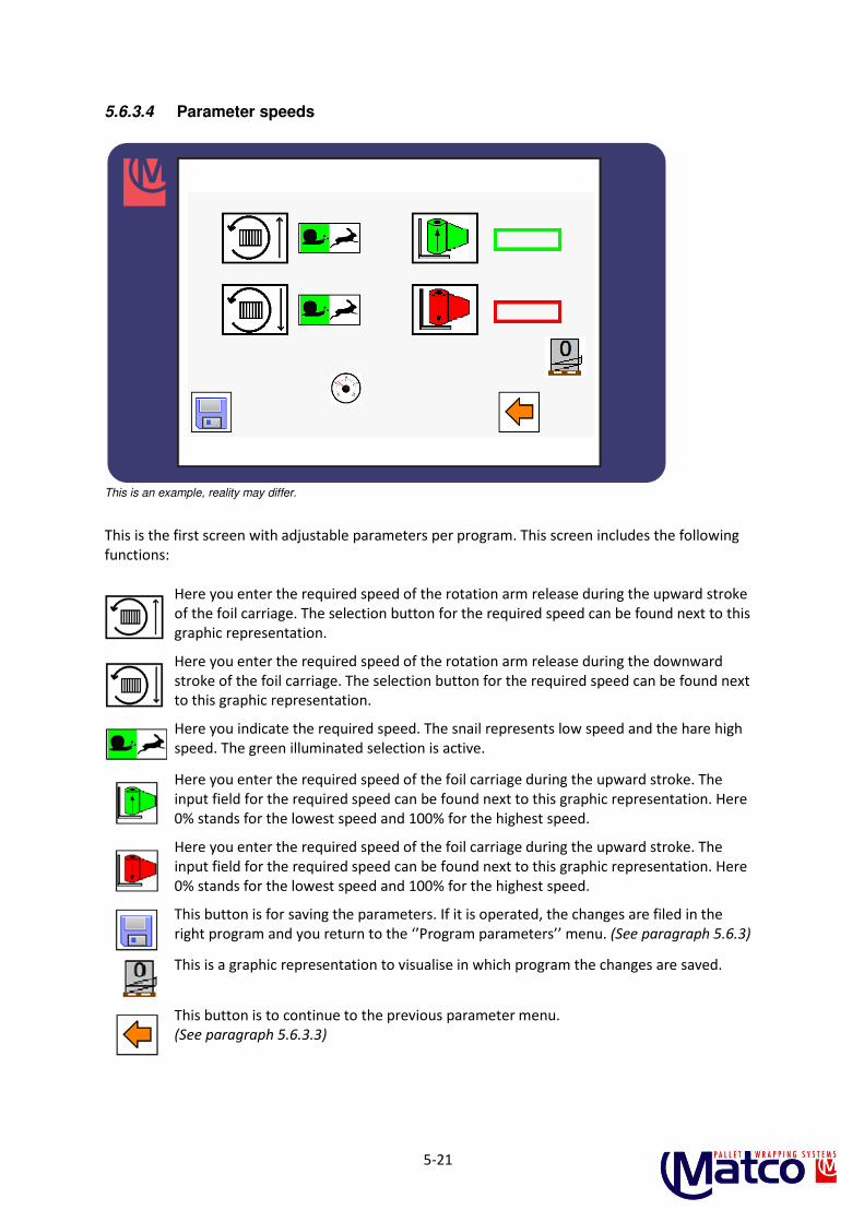
5.6.3.4 Parameter speeds
This is an example, reality may differ.
This is the first screen with adjustable parameters per program. This screen includes the following
functions:
Here you enter the required speed of the rotation arm release during the upward stroke
of the foil carriage. The selection button for the required speed can be found next to this
graphic representation.
Here you enter the required speed of the rotation arm release during the downward
stroke of the foil carriage. The selection button for the required speed can be found next to this graphic representation.
Here you indicate the required speed. The snail represents low speed and the hare high
speed. The green illuminated selection is active.
Here you enter the required speed of the foil carriage during the upward stroke. The
input field for the required speed can be found next to this graphic representation. Here
0% stands for the lowest speed and 100% for the highest speed.
Here you enter the required speed of the foil carriage during the upward stroke. The
input field for the required speed can be found next to this graphic representation. Here
0% stands for the lowest speed and 100% for the highest speed.
This button is for saving the parameters. If it is operated, the changes are filed in the
right program and you return to the ‘’Program parameters’’ menu. (See paragraph 5.6.3)
This is a graphic representation to visualise in which program the changes are saved.
This button is to continue to the previous parameter menu. (See paragraph 5.6.3.3)

5-22
5.6.4 Messages
This is an example, reality may differ.
This screen treats the messages/failures of the machine.
If something interrupts the machine, the message button in the main menu appears (See paragraph
5.6.1 ). When you press this, you see this screen. In this screen you get a message stating what is
wrong with the machinery. This must first be solved before the machine can be started. This screen
includes the following functions:
Here you see a message image. These appear when something is wrong with the
machine. You can find out what all messages mean in the enclosed list.
Here you can see the message table for the frequency regulators. When this appears, this
is in combination with the image of a frequency regulator. This table includes the
regulator in question and the error code. What the error code means can be found in the
frequency regulator manual.
Here you can see the reset button of the frequency regulator. When you have solved the
problem you must reset the frequency regulator.
This button sends you back to the main menu.
(See paragraph 5.6.1)

5-23
5.6.5 Supplier information
This is an example, reality may differ.
In this menu you can find information of the supplier who supplied the machinery. This screen
includes the following functions:
This button is to continue to the next menu.
(See paragraph 5.6.6)
This button sends you back to the main menu.
(See paragraph 5.6.1)

5-24
5.6.6 Statistics
This is an example, reality may differ.
In this menu you can find the various statistics of the machinery. This screen includes the following
functions:
Here you can see the operating hours counter. The field next to this graphic
representation shows how many hours the machinery is in operation.
Here you can see the day counter. The field next to this graphic representation shows
how many pallets have been wound that day.
With this button you can reset the day counter to 0, so you can reset the previously
mentioned pallet per day or at the desired moment.
Here you can see the pallet counter. The fields next to this graphic image show how
many pallets the machinery has wound.
This button sends you back to the main menu.
(See paragraph 5.6.1)

5-25
5.6.7 Service / System data
This is an example, reality may differ.
If you choose this menu, the user first sees the service screens. The various wear parts are described
in these screens. These parts also offer service advice in the form of the number of pallets to service.
This advice depends on the weight of the pallets and the user environment.
It also includes the following functions:
This is the indicator light for the lifespan of a specific component. If just 10% of the
recommended lifespan remains, it will turn orange. It turns red in case of 0%.
When a service has been carried out and a part has been replaced, the counter of the
part can be reset with this button. This button only appears if the authorised member of
staff has logged in with a special code.
This message is not visible on this page, but on the main menu (paragraph 5.6.1). The
message becomes visible when a service needs to be carried out. If this appears, please
contact the service of Matco B.V. so they can help you further.
This button is to continue to the next menu. Here you can also find a page that includes
part of the service.
This button sends you back to the main menu.
(See paragraph 5.6.1)
6-26
6 Maintenance
Watch out:
- Switch off the main switch and lock it with a padlock, before maintenance
work is done to the machine.
- Make sure that others cannot switch on the machine. - Make sure that protective hoods and similar are assembled when switching
on the machine.
6.1 General
The machine will have a longer lifespan due to preventive maintenance. This means that the condition of
the various parts of the machine need to be checked weekly, monthly or annually.
The ambient conditions influence the lifespan. The indicated maintenance frequency applies for normal
operating conditions (eight hours a day, 20°C, clean environment).
In case of harder conditions, you are advised to carry out maintenance more often. Keep rotating parts
free from dirt.
6.2 Recommended spare parts
When ordering parts, note the following:
1 Give the serial number of the machine.
2 For electrical parts, state the position (diagram) number, the description, the article number and the make.
3 For mechanical parts, state the drawing number, the position, the article number and the
description.
RECOMMENDED PARTS
To solve unexpected failures as soon as possible, you are recommended to have certain spare parts in
stock. The machine parts are in exploded view drawings. These can be found at the end of this
manual.

6-27
6.3 Maintenance diagram
Maintenance frequency 8
hours
40
hours
100
hours
200
hours
500
hours
1000
hours
2000
hours
Clean daily X
Clean photocell lens X
Chain under turntable 3
Turntable sprockets X
Geared belt pulley for the benefit of front carrier
Cord for the benefit of carrier
X
Bearings X
Running wheels foil carriage X
Running wheels turntable X
Limit/proximity switch X
Motor reductors X 1
Electrical system X
The numbers in the maintenance diagram refer to the lubricants to be used in the table of lubricants.
Please note:
Check safety stickers/indications. Where damaged/missing, these need to be replaced/placed.
Lubricants
SYMBOL LUBRICANT
SHELL BP ESSO MOBIL OIL TEXACO GLEITMO
1 OMALA 220 ENERGOL GR-XP 220
SPARTAN EP 220
MOBILGEAR 630
MEROPA 220
2
OMALA 680 ENERGOL GR-XP 680
SPARTAN EP 680
MOBILGEAR 636
MEROPA 680
3
TONNA T68 MACCURAT 68 FEBIS K 68 EP220
VACTA.4 WAX LUBRI-CANT X68
4
ALVANIA R ENERGREASE L2 BEACON 2 MOBILUX 2 MULTIFAK EP2
5
TELLUS 46 HPL 46 NUTCO H46 DTE 26 RANDO HD46
6
TORCULA 32 ENERGOL RD-E 80
AROX EP 56 ALMOBIL 1 ARIES 32
7
TELLUS 15 RANDO HDZ 15
8
RETINAX WB STARPLEX PREMIUM 1 (depending on the application)
9
FIN GREASE OG
10
UNIREX EP

6-28
6.4 Inspections
Inspections Activities
Electrical system - Check the switches and other operational buttons for proper functioning.
- Check the signal lights.
- Check the magnet switches and relays for fusion penetration and humming.
- Check the wiring and connections.
- Check the photocells and possible reflectors for operation and adjustment (lenses
must be clean).
- Check the limit and proximity switches for operation and adjustment.
Motors/motor reductors - Check the ventilator.
- Check the ventilator hood for damage.
- Check the oil level of the gear casing (refill if necessary).
- Check if the fixing bolts are fixed and tighten if necessary.
- Check the rotating parts and lubricate if necessary.
Turntable roller - Check the tooth flank wear of cogwheels. - Checking and lubricating the cogwheels. - Check whether the drive sprockets on the motor axle has wound down.
If necessary, align and tighten the locking screws.
Mast - Check the lifting straps for wear. If there is visible wear the replace the belt
Foil carriage - Check whether there are any foil remnants in the braking system. - Check the wiring of the foil carriage in mast via running wheels. - The running wheels must have a maximum play of 2 mm compared to the
wiring. Replace in case of wear if necessary. - The wiring construction for the foil carriage in the mast may NEVER be
lubricated! - Check whether the foil carriage runs parallel. - The foil carriage may sag max. 2 - 3 mm - Check the toothed wheel pulley and the toothed wheels of the pre-stretched
system for wear. Replace if necessary.