
MAN Energy Solutions - Technical Documentation Project Guide
388
MAN Energy Solutions Technical Documentation Project Guide Design Specification: ....................... L27/38-VBS Date ................................................. 2020-02-18 All data provided in this document is non-binding. This data serves informational purposes only and is especially not guaranteed in any way. Depending on the subsequent specific indi- vidual projects, the relevant data may be subject to changes and will be assessed and de- termined individually for each project. This will depend on the particular characteristics of each individual project, especially specific site and operational conditions If this document is delivered in another language than English and doubts arise concerning the translation, the English text shall prevail. 2020-02-18 L27/38 Original instructions
-
Upload
khangminh22 -
Category
Documents
-
view
0 -
download
0
Transcript of MAN Energy Solutions - Technical Documentation Project Guide

MAN Energy Solutions
Technical Documentation
Project Guide
Design Specification: ....................... L27/38-VBSDate ................................................. 2020-02-18
All data provided in this document is non-binding. This data serves informational purposesonly and is especially not guaranteed in any way. Depending on the subsequent specific indi-vidual projects, the relevant data may be subject to changes and will be assessed and de-termined individually for each project. This will depend on the particular characteristics ofeach individual project, especially specific site and operational conditionsIf this document is delivered in another language than English and doubts arise concerningthe translation, the English text shall prevail.
2020
-02-
18
L27/
38
Original instructions

MAN Energy Solutions
MAN Energy SolutionsH. Christoffersensvej 6 4960 HolebyDenmarkPhone +45 54 69 31 00Fax +45 54 69 30 [email protected] © 2020 MAN Energy SolutionsAll rights reserved, including reprinting, copying (Xerox/microfiche) and translation.
2020
-02-
18
L27/
38

MAN Energy Solutions
Tier III 3 (5)
Table of contents
I 00 IntroductionIntroduction to project guide ................................................................................................. I 00 00 0Engine programme IMO Tier III ................................................................................................. I 00 20Key for engine designation .................................................................................................... I 00 05 0Designation of cylinders ........................................................................................................ I 00 15 0Code identification for instruments ........................................................................................ I 00 20 0Symbols for piping ................................................................................................................ I 00 25 0
D 10 General informationList of capacities ................................................................................................................. D 10 05 0List of capacities ................................................................................................................. D 10 05 0Vibration limits and measurements ...................................................................................... D 10 24 0Description of sound measurements ................................................................................... D 10 25 0Description of structure-borne noise ................................................................................... D 10 25 0Exhaust gas components.................................................................................................... D 10 28 0NOx emission...................................................................................................................... D 10 28 0Foundation for engine ......................................................................................................... D 10 30 0Inclination of engines........................................................................................................... D 10 32 0Green Passport................................................................................................................... D 10 33 0Time between overhaul - Expected life time ........................................................................ D 10 35 0Time between overhaul - expected life time......................................................................... D 10 35 0
B 10 Basic diesel engineGeneral description ............................................................................................................. B 10 01 1Main particulars................................................................................................................... B 10 01 1Main dimensions ................................................................................................................. B 10 01 1Weight and centre of gravity................................................................................................ B 10 01 1Space requirements ............................................................................................................ B 10 01 1Firing pressure comparison ................................................................................................. B 10 01 1PTO on engine front ............................................................................................................ B 10 01 1Power, output, speed.......................................................................................................... B 10 01 1
B 11 Fuel oil systemFuel oil system .................................................................................................................... B 11 00 0Fuel oil system - MDO......................................................................................................... B 11 00 0Fuel oil system - HFO.......................................................................................................... B 11 00 0Calculation of specific fuel oil consumption (SFOC) ............................................................. B 11 01 0Fuel oil consumption for emissions standard ....................................................................... B 11 01 0
2020
-02-
18
L27/
38Ta
ble o
f con
tent
s

MAN Energy Solutions
4 (5) Tier III
Automatic back-flush filter ................................................................................................... P 11 02 1Specification of heavy fuel oil (HFO)........................................................................... 010.000.023-05Marine diesel oil (DMB, DFB) specifications ............................................................... 010.000.023-04Diesel fuel (DMA, DFA) specifications ........................................................................ 010.000.023-01Specification of bio fuel ............................................................................................. 010.000.023-02Explanatory notes for biofuel ............................................................................................... B 11 00 0Viscosity-temperature diagram (VT diagram) ............................................................. 010.000.023-06
B 12 Lubricating oil systemLubricating oil system.......................................................................................................... B 12 00 0Crankcase ventilation .......................................................................................................... B 12 00 0Specification of lubricating oil (SAE 40) for heavy fuel operation (HFO) ....................... 010.000.023-11Specification of lubricating oil (SAE 40) for operation with DMA/DMB, DFA, DFB and biofuels................................................................................................................................. 010.000.023-07Specific lubricating oil consumption - SLOC........................................................................ B 12 15 0Separator unit ..................................................................................................................... B 12 15 0Treatment and maintenance of lubricating oil ...................................................................... B 12 15 0Criteria for cleaning/exchange of lubricating oil .................................................................... B 12 15 0
B 13 Cooling water systemCooling water system.......................................................................................................... B 13 00 0Coolant system cleaning ........................................................................................... 010.000.002-04Coolant inspecting .................................................................................................... 010.000.002-03Specification of engine coolant.................................................................................. 010.000.023-13
B 14 Compressed air systemSpecification of compressed air ................................................................................ 010.000.023-21Starting air system .............................................................................................................. B 14 00 0
B 15 Combustion air systemCombustion air system for arctic operation ......................................................................... B 15 00 0Engine ventilation ................................................................................................................ B 15 00 0Specifications of intake air (combustion air) ............................................................... 010.000.023-17Turbocharger ...................................................................................................................... B 15 01 1
B 16 Exhaust gas systemExhaust gas system ............................................................................................................ B 16 00 0Pressure drop in exhaust gas system.................................................................................. B 16 00 0SCR (Selective Catalytic Reduction) .................................................................................... B 16 00 0Exhaust gas velocity............................................................................................................ B 16 01 0Exhaust gas system - position of gas outlet on turbocharger............................................... B 16 02 0Exhaust gas system - exhaust gas compensator ................................................................ E 16 01 2
2020
-02-
18
L27/
38Ta
ble o
f con
tent
s

MAN Energy Solutions
Tier III 5 (5)
B 17 Speed control systemStarting of engine ................................................................................................................ B 17 00 0
B 19 Safety and control systemOperation data and set points ............................................................................................. B 19 00 0System description - SaCoSone ......................................................................................... B 19 00 0Modbus interface - SaCoS.................................................................................................. B 19 00 0
B 20 FoundationFoundation for engine - rigid mounting ................................................................................ B 20 00 0Foundation for engine - resilient mounting ........................................................................... B 20 00 0
B 21 Test running
E 23 Spare partsWeights of main components.............................................................................................. E 23 00 0Weight and dimensions of principal parts ............................................................................ E 23 00 0Spare parts for unrestricted service..................................................................................... P 23 01 1Spare parts for restricted service......................................................................................... P 23 01 1
P 24 ToolsIntroduction to spare part plates for tools ............................................................................ P 24 00 0Standard tools .................................................................................................................... P 24 01 1Standard tools (restricted service) ....................................................................................... P 24 01 1Additional tools ................................................................................................................... P 24 03 9Hand tools .......................................................................................................................... P 24 05 1
B 53 PropellerProject planning data .......................................................................................................... B 53 00 0Propeller layout data ........................................................................................................... B 53 00 0Layout of Fix-Pitch-Propeller ............................................................................................... B 53 00 0Propeller operation.............................................................................................................. B 53 00 0Stern tube ........................................................................................................................... B 53 00 0Propeller clearance.............................................................................................................. B 53 00 0Direction of rotation............................................................................................................. B 53 00 0
B 54 Control systemPropulsion control system ................................................................................................... B 54 00 0
B 98 Preservation and packingLifting instructions ............................................................................................................... P 98 05 1
24676014731
2020
-02-
18
L27/
38Ta
ble o
f con
tent
s

This page is intentionally left blank
2020
-02-
18
MAN Energy Solutions
Tier III
L27/
38Ta
ble o
f con
tent
s

MAN Energy Solutions I 00 00 0
L28/32A;L23/30S-DF;L23/30H-Mk3;L23/30A;L23/30DF;L16/24S;L21/31S;L23/30S;L27/38S;L28/32S;L28/32S-
DF;L28/32DF;V28/32H;V28/32S;L16/24;L21/31;L23/30H;L27/38;L28/32H,100000 1 (2)
Introduction to project guide
IntroductionOur project guides provide customers and consultants with information anddata when planning new plants incorporating four-stroke engines from thecurrent MAN Energy Solutions engine programme. On account of the modific-ations associated with upgrading of our project guides, the contents of thespecific edition hereof will remain valid for a limited time only.Every care is taken to ensure that all information in this project guide ispresent and correct.For actual projects you will receive the latest project guide editions in eachcase together with our quotation specification or together with the documentsfor order processing.All figures, values, measurements and/or other information about performancestated in the project guides are for guidance only and shall not be used fordetailed design purposes or as a substitute for specific drawings and instruc-tions prepared for such purposes. MAN Energy Solutions makes no repres-entations or warranties either express or implied, as to the accuracy, com-pleteness, quality or fitness for any particular purpose of the information con-tained in the project guides.MAN Energy Solutions will issue an Installation Manual with all project relateddrawings and installation instructions when the contract documentation hasbeen completed.The Installation Manual will comprise all necessary drawings, piping diagrams,cable plans and specifications of our supply.
All data provided in this document is non-binding and serves informational purposesonly. Depending on the subsequent specific individual projects, the relevant data maybe subject to changes and will be assessed and determined individually for each pro-ject. This will depend on the particular characteristics of each individual project, espe-cially specific site and operational conditions.
2019
-02-
07 -
en
Intro
duct
ion
to p
rojec
t gui
deDe
scrip
tion
1643
483-
5.6

I 00 00 0 MAN Energy Solutions
2 (2)
L28/32A;L23/30S-DF;L23/30H-Mk3;L23/30A;L23/30DF;L16/24S;L21/31S;L23/30S;L27/38S;L28/32S;L28/32S-
DF;L28/32DF;V28/32H;V28/32S;L16/24;L21/31;L23/30H;L27/38;L28/32H,100000
Code numbers
Code letter: The code letter indicates the contents of the documents:
B : Basic Diesel engine / built-on engine
D : Designation of plant
E : Extra parts per engine
G : Generator
I : Introduction
P : Extra parts per plant36028804210188683
Function/system number: A distinction is made between the various chaptersand systems, e.g.: Fuel oil system, monitoring equipment, foundation, testrunning, etc.Sub-function: This figure occurs in variants from 0-99.Choice number: This figure occurs in variants from 0-9:
0 : General information 1 : Standard
2-8 : Standard optional 9 : Optional36028804210188683
Further, there is a table of contents for each chapter and the pages follow im-mediately afterwards.Drawing No: Each document has a drawing number including revision numberi.e. 1643483-5.5.Release date: The release date of the document Year.Month.Date. This is thedate the document has been created.
When referring to a document, please state both Drawing No includingrevision No and Release date.
Copyright 2011 © MAN Energy Solutions, branch of MAN Energy Solutions SE, Ger-many, registered with the Danish Commerce and Companies Agency under CVR Nr.:31611792, (herein referred to as “MAN Energy Solutions”).
This document is the product and property of MAN Energy Solutions and is protec-ted by applicable copyright laws. Subject to modification in the interest of technicalprogress. Reproduction permitted provided source is given.
3602880421018868336028804210188683
2019
-02-
07 -
en
Intro
duct
ion
to p
rojec
t gui
deDe
scrip
tion
1643
483-
5.6

MAN Energy Solutions I 00 20
L27/38;L28/32A;L23/30A;L21/31, 10000 1 (1)
Engine programme IMO Tier III
34950884491
Figure 1:34950884491
2019
-02-
20 -
en
Engi
ne p
rogr
amm
e IM
O Ti
er II
IDe
scrip
tion
3700
600-
8.0

This page is intentionally left blank3495088449134950884491
2019
-02-
20 -
en
I 00 20 MAN Energy Solutions
L27/38;L28/32A;L23/30A;L21/31, 10000
Engi
ne p
rogr
amm
e IM
O Ti
er II
IDe
scrip
tion
3700
600-
8.0

MAN Energy Solutions I 00 05 0
L28/32S-DF;L28/32A;L23/30S-DF;L23/30H-Mk3;L23/30H-Mk2;L23/30A;L27/38S;L16/24S;L21/31S;L23/30S;L28/32S;L23/30DF;L28/32DF;
V28/32H;V28/32S;L16/24;L21/31;L23/30H;L27/38;L28/32H 1 (1)
Key for engine designation
Key for engine designationThe engine types of the MAN Energy Solutions programme are identified bythe following figures:
5404320271962612354043202719626123
2019
-02-
07 -
en
Key f
or en
gine
des
igna
tion
Desc
riptio
n16
0952
6-0.
9

This page is intentionally left blank5404320271962612354043202719626123
2019
-02-
07 -
en
I 00 05 0 MAN Energy Solutions
L28/32S-DF;L28/32A;L23/30S-DF;L23/30H-Mk3;L23/30H-Mk2;L23/30A;L27/38S;L16/24S;L21/31S;L23/30S;L28/32S;L23/30DF;L28/32DF;
V28/32H;V28/32S;L16/24;L21/31;L23/30H;L27/38;L28/32H
Key f
or en
gine
des
igna
tion
Desc
riptio
n16
0952
6-0.
9

MAN Energy Solutions I 00 15 0
L16/24S;L21/31S;L23/30S;L23/30DF;L28/32S;L27/38S;L28/32DF;L16/24;L21/31;L23/30H;L27/38;L28/32H, 2016.08.24 1 (1)
Designation of cylinders
General
3602880421019700336028804210197003
2016
-08-
24 -
en
Desig
natio
n of
cylin
ders
Desc
riptio
n16
0756
8-0.
2

This page is intentionally left blank3602880421019700336028804210197003
2016
-08-
24 -
en
I 00 15 0 MAN Energy Solutions
L16/24S;L21/31S;L23/30S;L23/30DF;L28/32S;L27/38S;L28/32DF;L16/24;L21/31;L23/30H;L27/38;L28/32H, 2016.08.24
Desig
natio
n of
cylin
ders
Desc
riptio
n16
0756
8-0.
2

MAN Energy Solutions I 00 20 0
L16/24S;L27/38S;L21/31S;L23/30S;L23/30DF;L28/32S;L28/32DF;V28/32H;V28/32S;L16/24;L21/31;L23/30H;L27/38;L28/32H, 2018.03.27 1 (3)
Code identification for instruments
Explanation of symbols
Specification of letter code for measuring devices1st letter Following letters
F
L
P
S
T
U
V
X
Z
Flow
Level
Pressure
Speed, System
Temperature
Voltage
Viscosity
Sound
Position
A
D
E
H
I
L
S
T
X
V
Alarm
Differential
Element
High
Indicating
Low
Switching, Stop
Transmitting
Failure
Valve, Actuator
2018
-03-
28 -
en
Code
iden
tifica
tion
for i
nstru
men
tsDe
scrip
tion
1687
100-
5.6

I 00 20 0 MAN Energy Solutions
2 (3)L16/24S;L27/38S;L21/31S;L23/30S;L23/30DF;L28/32S;L28/32DF;V28/32H;V28/
32S;L16/24;L21/31;L23/30H;L27/38;L28/32H, 2018.03.27
Standard text for instruments
Diesel engine/alternatorLT water system
010203
inlet to air cooleroutlet from air cooleroutlet from lub. oil cooler
040506
inlet to alternatoroutlet from alternatoroutlet from fresh water cooler(SW)
070809
inlet to lub. oil coolerinlet to fresh water cooler
HT water system
1010A111213
inlet to engineFW inlet to engineoutlet from each cylinderoutlet from engineinlet to HT pump
1414A14B1516
inlet to HT air coolerFW inlet to air coolerFW outlet from air cooleroutlet from HT systemoutlet from turbocharger
171819
19A19B
outlet from fresh water coolerinlet to fresh water coolerpreheaterinlet to prechamberoutlet from prechamber
Lubricating oil system
20212223
23B
inlet to cooleroutlet from cooler/inlet to filteroutlet from filter/inlet to engineinlet to turbochargeroutlet from turbocharger
242526
27
sealing oil - inlet engineprelubricatinginlet rocker arms and rollerguidesintermediate bearing/alternatorbearing
2829
level in base framemain bearings
Charging air system
30313233
inlet to cooleroutlet from coolerjet assist systemoutlet from TC filter/inlet to TCcompr.
34353637
charge air conditioningsurplus air inletinlet to turbochargercharge air from mixer
3839
Ambient temperature
Fuel oil system
40414243
inlet to engineoutlet from engineleakageinlet to filter
44454647
outlet from sealing oil pumpfuel-rack positioninlet to prechamber
4849
Nozzle cooling system
50515253
inlet to fuel valvesoutlet from fuel valves
54555657
valve timinginjection timingearth/diff. protection
5859
oil splashalternator load
Exhaust gas system
60616263
outlet from cylinderoutlet from turbochargerinlet to turbochargercombustion chamber
64656667
6869
2018
-03-
28 -
en
Code
iden
tifica
tion
for i
nstru
men
tsDe
scrip
tion
1687
100-
5.6

MAN Energy Solutions I 00 20 0
L16/24S;L27/38S;L21/31S;L23/30S;L23/30DF;L28/32S;L28/32DF;V28/32H;V28/32S;L16/24;L21/31;L23/30H;L27/38;L28/32H, 2018.03.27 3 (3)
Compressed air system
70717273
inlet to engineinlet to stop cylinderinlet to balance arm unitcontrol air
74757677
inlet to reduction valvemicroswitch for turning gearinlet to turning gearwaste gate pressure
7879
inlet to sealing oil system
27021605172614411
Load speed
80818283
overspeed airoverspeedemergency stopengine start
84858687
engine stopmicroswitch for overloadshutdownready to start
888990
index - fuel injection pumpturbocharger speedengine speed
27021605172614411
Miscellaneous
91929394
natural gas - inlet to engineoil mist detectorknocking sensorcylinder lubricating
95969798
voltageswitch for operating locationremotealternator winding
99100101102
common alarminlet to MDO cooleroutlet to MDO cooleralternator cooling air
270216051726144112702160517261441127021605172614411
2018
-03-
28 -
en
Code
iden
tifica
tion
for i
nstru
men
tsDe
scrip
tion
1687
100-
5.6

This page is intentionally left blank2702160517261441127021605172614411270216051726144112702160517261441127021605172614411
2018
-03-
28 -
en
I 00 20 0 MAN Energy Solutions
L16/24S;L27/38S;L21/31S;L23/30S;L23/30DF;L28/32S;L28/32DF;V28/32H;V28/32S;L16/24;L21/31;L23/30H;L27/38;L28/32H, 2018.03.27
Code
iden
tifica
tion
for i
nstru
men
tsDe
scrip
tion
1687
100-
5.6

MAN Energy Solutions I 00 25 0
L27/38S;L16/24;L16/24S;L21/31;L21/31S;L23/30H;L23/30S;L23/30DF;L28/32H;L28/32S;V28/32H;V28/32S;L27/38;L28/32DF, 2015.11.17 1 (12)
Symbols for piping
GeneralNo Symbol Symbol designation No Symbol Symbol designation
1. GENERAL CONVENTIONAL SYMBOLS 2.13 Blank flange
1.1 Pipe 2.14 Spectacle flange
1.2 Pipe with indication of directionflow
2.15 Orifice
1.3 Valves, gate valves, cocks andflaps
2.16 Orifice
1.4 Appliances 2.17 Loop expansion joint
1.5 Indicating and measuring instru-ments
2.18 Snap coupling
1.6 High-pressure pipe 2.19 Pneumatic flow or exhaust to at-mosphere
1.7 Tracing 3. VALVES, GATE VALVES, COCKS AND FLAPS
1.8 Enclosure for several componentsas-sembled in one unit
3.1 Valve, straight through
2. PIPES AND PIPE JOINTS 3.2 Valve, angle
2.1 Crossing pipes, not connected 3.3 Valve, three-way
2.2 Crossing pipes, connected 3.4 Non-return valve (flap), straight
2.3 Tee pipe 3.5 Non-return valve (flap), angle
2.4 Flexible pipe 3.6 Non-return valve (flap), straightscrew down
2.5 Expansion pipe (corrugated) gen-eral
3.7 Non-return valve (flap), angle,screw down
2.6 Joint, screwed 3.8 Safety valve
2.7 Joint, flanged 3.9 Angle safety valve
2.8 Joint, sleeve 3.10 Self-closing valve
2.9 Joint, quick-releasing 3.11 Quick-opening valve
2.10 Expansion joint with gland 3.12 Quick-closing valve
2.11 Expansion pipe 3.13 Regulating valve
2018
-06-
27 -
en
Sym
bols
for p
ipin
gDe
scrip
tion
1655
279-
1.1

I 00 25 0 MAN Energy Solutions
2 (12)L27/38S;L16/24;L16/24S;L21/31;L21/31S;L23/30H;L23/30S;L23/30DF;L28/32H;
L28/32S;V28/32H;V28/32S;L27/38;L28/32DF, 2015.11.17
2.12 Cap nut 3.14 Ball valve (cock)
2018
-06-
27 -
en
Sym
bols
for p
ipin
gDe
scrip
tion
1655
279-
1.1

MAN Energy Solutions I 00 25 0
L27/38S;L16/24;L16/24S;L21/31;L21/31S;L23/30H;L23/30S;L23/30DF;L28/32H;L28/32S;V28/32H;V28/32S;L27/38;L28/32DF, 2015.11.17 3 (12)
No Symbol Symbol designation No Symbol Symbol designation
3.15 Butterfly valve 3.37 3/2 spring return valve contr. bysolenoid
3.16 Gate valve 3.38 Reducing valve (adjustable)
3.17 Double-seated changeover valve 3.39 On/off valve controlled by solenoidand pilot directional valve and withspring return
3.18 Suction valve chest 4. CONTROL AND REGULATION PARTS
3.19 Suction valve chest with non-re-turn valves
4.1 Fan-operated
3.20 Double-seated changeover valve,straight
4.2 Remote control
3.21 Double-seated changeover valve,angle
4.3 Spring
3.22 Cock, straight through 4.4 Mass
3.23 Cock, angle 4.5 Float
3.24 Cock, three-way, L-port in plug 4.6 Piston
3.25 Cock, three-way, T-port in plug 4.7 Membrane
3.26 Cock, four-way, straight through inplug
4.8 Electric motor
3.27 Cock with bottom connection 4.9 Electromagnetic
3.28 Cock, straight through, with bot-tom conn.
4.10 Manual (at pneumatic valves)
3.29 Cock, angle, with bottom connec-tion
4.11 Push button
3.30 Cock, three-way, with bottomconnection
4.12 Spring
3.31 Thermostatic valve 4.13 Solenoid
3.32 Valve with test flange 4.14 Solenoid and pilot directional valve
3.33 3-way valve with remote control(actuator)
4.15 By plunger or tracer
3.34 Non-return valve (air) 5. APPLIANCES
3.35 3/2 spring return valve, normallyclosed
5.1 Mudbox
3.36 2/2 spring return valve, normallyclosed
5.2 Filter or strainer
2018
-06-
27 -
en
Sym
bols
for p
ipin
gDe
scrip
tion
1655
279-
1.1

I 00 25 0 MAN Energy Solutions
4 (12)L27/38S;L16/24;L16/24S;L21/31;L21/31S;L23/30H;L23/30S;L23/30DF;L28/32H;
L28/32S;V28/32H;V28/32S;L27/38;L28/32DF, 2015.11.17
No Symbol Symbol designation No Symbol Symbol designation
5.3 Magnetic filter 6. FITTINGS
5.4 Separator 6.1 Funnel / waste tray
5.5 Steam trap 6.2 Drain
5.6 Centrifugal pump 6.3 Waste tray
5.7 Gear or screw pump 6.4 Waste tray with plug
5.8 Hand pump (bucket) 6.5 Turbocharger
5.9 Ejector 6.6 Fuel oil pump
5.10 Various accessories (text to be ad-ded)
6.7 Bearing
5.11 Piston pump 6.8 Water jacket
5.12 Heat exchanger 6.9 Overspeed device
5.13 Electric preheater 7. READING INSTR. WITH ORDINARY DESIGNATIONS
5.14 Air filter 7.1 Sight flow indicator
5.15 Air filter with manual control 7.2 Observation glass
5.16 Air filter with automatic drain 7.3 Level indicator
5.17 Water trap with manual control 7.4 Distance level indicator
5.18 Air lubricator 7.5 Recorder
5.19 Silencer
5.20 Fixed capacity pneumatic motorwith direction of flow
5.21 Single acting cylinder with springreturned
5.22 Double acting cylinder with springreturned
5.23 Steam trap 2018
-06-
27 -
en
Sym
bols
for p
ipin
gDe
scrip
tion
1655
279-
1.1

MAN Energy Solutions I 00 25 0
L27/38S;L16/24;L16/24S;L21/31;L21/31S;L23/30H;L23/30S;L23/30DF;L28/32H;L28/32S;V28/32H;V28/32S;L27/38;L28/32DF, 2015.11.17 5 (12)
List of SymbolsGeneral
Pipe dimensions and piping signature
Pipe dimenesions
A : Welded or seamless steel pipes. B : Seamless precision steel pipes or Cu-pipes.
Normal Diameter
DN
Outside Diameter
mm
Wall Thickness
mm
Stated: Outside diameter and wall thickness i.e. 18 x 2
Piping
: Built-on engine/Gearbox
: Yard supply
Items connected by thick lines are built-on engine/ gearbox.
152025324050658090
100125150175200
21.326.933.742.448.360.376.188.9
101.6114.3139.7168.3193.7219.1
In accordancewith classifica-tion or otherrules
2018
-06-
27 -
en
Sym
bols
for p
ipin
gDe
scrip
tion
1655
279-
1.1

I 00 25 0 MAN Energy Solutions
6 (12)L27/38S;L16/24;L16/24S;L21/31;L21/31S;L23/30H;L23/30S;L23/30DF;L28/32H;
L28/32S;V28/32H;V28/32S;L27/38;L28/32DF, 2015.11.17
General
Pump, general DIN 2481 Ballcock
Centrifugal pump DIN 2481 Cock, three-way, L-port
Centrifugal pump with electricmotor
DIN 2481 Double-non-return valve DIN 74.253
Gear pump DIN 2481 Spectacle flange DIN 2481
Screw pump DIN 2481 Spectacle flange, open DIN 2481
Screw pump with electricmotor
DIN 2481 Spectacle flange, closed DIN 2481
Compressor ISO 1219 Orifice
Heat exchanger DIN 2481 Flexible pipe
Electric pre-heater DIN 2481 Centrifuge DIN 28.004
Heating coil DIN 8972 Suction bell
Non-return valve Air vent
Butterfly valve Sight glass DIN 28.004
Gate valve Mudbox
Relief valve Filter
Quick-closing valve Filter with water trap ISO 1219
Self-closing valve Typhon DIN 74.253
Back pressure valve Pressure reducing valve (air) ISO 1219
Shut off valve Oil trap DIN 28.004
Thermostatic valve Accumulator
Pneumatic operated valve Pressure reducing valve withpressure gauge
2018
-06-
27 -
en
Sym
bols
for p
ipin
gDe
scrip
tion
1655
279-
1.1

MAN Energy Solutions I 00 25 0
L27/38S;L16/24;L16/24S;L21/31;L21/31S;L23/30H;L23/30S;L23/30DF;L28/32H;L28/32S;V28/32H;V28/32S;L27/38;L28/32DF, 2015.11.17 7 (12)
General
Specification of letter code for measuring devices
1st letter Following letters
D : DensityE : ElectricF : FlowL : LevelM ; MoistureP : PressureS : SpeedT : TemperatureV : ViscosityZ : Position
(ISO 3511/I-1977(E))
A : AlarmD : DifferenceE : TransducerH : HighI : IndicatingL : LowN : ClosedO : OpenS : Switching, shut downT : TransmitterX : FailureC : ControllingZ : Emergency/safety acting
The presence of a measuring device on a schematic diagram does not necessarilyindicate that the device is included in our scope of supply.
For each plant. The total extent of our supply will be stated formally.
2018
-06-
27 -
en
Sym
bols
for p
ipin
gDe
scrip
tion
1655
279-
1.1

I 00 25 0 MAN Energy Solutions
8 (12)L27/38S;L16/24;L16/24S;L21/31;L21/31S;L23/30H;L23/30S;L23/30DF;L28/32H;
L28/32S;V28/32H;V28/32S;L27/38;L28/32DF, 2015.11.17
General
Specification of ID-no code for measuring signals/devices
1st digit 2nd digit
Refers to the main system to which the signal is related. Refers to the auxillary system to which the signal is re-lated.
1xxx : Engine x0xx : LT cooling water
2xxx : Gearbox x1xx : HT cooling water
3xxx : Propeller equipment x2xx : Oil systems (lub. oil, cooling oil, clutch oil, servo oil)
4xxx : Automation equipment x3xx : Air systems (starting air, control air, charging air)
5xxx : Other equipment, not related to the propulsionplant
x4xx : Fuel systems (fuel injection, fuel oil)
x5xx :
x6xx : Exhaust gas system
x7xx : Power control systems (start, stop, clutch, speed,pitch)
x8xx : Sea water
x9xx : Miscellaneous (shaft, stern tube, sealing)
The last two digits are numeric ID for devices referring to the same main and aux. system.
Where dublicated measurements are carried out, i.e. multiple similar devices are measuring the same parameter, theID specification is followed by a letter (A, B, ...etc.), in order to be able to separate the signals from each other.
2018
-06-
27 -
en
Sym
bols
for p
ipin
gDe
scrip
tion
1655
279-
1.1

MAN Energy Solutions I 00 25 0
L27/38S;L16/24;L16/24S;L21/31;L21/31S;L23/30H;L23/30S;L23/30DF;L28/32H;L28/32S;V28/32H;V28/32S;L27/38;L28/32DF, 2015.11.17 9 (12)
Basic symbols for piping2237 Spring operated
safety valve
2238 Mass operated Safetyvalve
2228 Spring actuator
2284 Float actuator
2229 Mass
2231 Membrane actuator
2230 Piston actuator
2232 Fluid actuator
2223 Solenoid actuator
2234 Electric motor actu-ator
2235 Hand operated
Basic Symbol
Valves 584 585 593 588 592 590 591 604 605 579
584: Valve general585: Valve with continuous regulation593: Valve with safety function588:Straight-way valve592: Straight-way valve with continuous regulation590:Angle valve591: Three-way valve604: Straight-way non return valve605: Angle non-return valve579: Non-return valve, ball type
2018
-06-
27 -
en
Sym
bols
for p
ipin
gDe
scrip
tion
1655
279-
1.1

I 00 25 0 MAN Energy Solutions
10 (12)L27/38S;L16/24;L16/24S;L21/31;L21/31S;L23/30H;L23/30S;L23/30DF;L28/32H;
L28/32S;V28/32H;V28/32S;L27/38;L28/32DF, 2015.11.17
I - bored
L - bored
T - bored
2237 Spring operatedsafety valve
2238 Mass operatedSafety valve
2228 Spring actuator
2284 Float actuator
2229 Mass
2231 Membrane actuator
2230 Piston actuator
2232 Fluid actuator
2223 Solenoid actuator
2234 Electric motor actu-ator
2235 Hand operated
Basic Symbol
Valves 594 595 586 587 599 600 601 602 607 608 606
594: Straight-way reduction valve595: Angle reduction valve586: Gate valve587: Gate valve with continuous regulation599: Straight-way cock600: Angle cock601: Three-way cock602: Four-way cock607: Butterfly valve608: Butterfly valve with continuous regulation606: Non-return valve, flap type
2018
-06-
27 -
en
Sym
bols
for p
ipin
gDe
scrip
tion
1655
279-
1.1

MAN Energy Solutions I 00 25 0
L27/38S;L16/24;L16/24S;L21/31;L21/31S;L23/30H;L23/30S;L23/30DF;L28/32H;L28/32S;V28/32H;V28/32S;L27/38;L28/32DF, 2015.11.17 11 (12)
No Symbol Symbol designation No Symbol Symbol designation
Miscellaneous 972 Pipe threaded connection
582 Funnel xxx Blind
581 Atomizer Tanks
583 Air venting 631 Tank with domed ends
6.25 Air venting to the outside 771 Tank with conical ends
299 Normal opening/ closing speed yyy Electrical insert heater
300 Quick opening/ closing speed Heat exchanger
613 Orifice with diffuser 8.03 Electrical preheater
612 Orifice 8.08 Heat exchanger
611 Sight glass 792 Nest of pipes with bends
615 Silencer 798 Plate heat exchanger
617 Berst membrane Separators
629 Condensate relief 761 Separator
580 Reducer 764 Disc separator
589 Measuring point for thermo ele-ment
Filters
1298 Air relief valve 669 Air filter
Couplings/ Flanges 671 Fluid filter
167 Coupling Coolers
955 Flanged connection 16.03 Cooling tower
971 Clamped connection 16.06 Radiator cooler
2018
-06-
27 -
en
Sym
bols
for p
ipin
gDe
scrip
tion
1655
279-
1.1

I 00 25 0 MAN Energy Solutions
12 (12)L27/38S;L16/24;L16/24S;L21/31;L21/31S;L23/30H;L23/30S;L23/30DF;L28/32H;
L28/32S;V28/32H;V28/32S;L27/38;L28/32DF, 2015.11.17
No Symbol Symbol designation No Symbol Symbol designation
Chimney Pumps
838 Chimney 708 Centrifugal pump
Expansion joints 697 Piston pump
2285 Expansion bellow 704 Piston pump - radial
4.1 Expansion pipe 700 Membrane pump
4.1.1.1 Loop expansion joint 702 Gear pump
4.1.1.2 Lyra expansion joint 705 Screw pump
4.1.1.3 Lens expansion joint 706 Mono pump
4.1.1.4 Expansion bellow 703 Hand vane pump
4.1.1.5 Steel tube Motors
4.1.1.6 Expansion joint with gland 13.14 Electrical motor AC
Compressors 13.14 Electrical motor AC
716 Piston compressor 13.14 Electrical motor AC
725 Turbo axial compressor 13.15 Electrical motor DC
726 Turbo dial compressor 13.15 Electrical motor DC
720 Roots compressor 13.15 Electrical motor DC
722 Screw compressors 13.15 Electrical motor DC
Ventilators 13.15 Electrical motor DC
637 Fan general 13.15 Electrical motor DC
638 Fan - radial 632 Turbine
639 Fan - axial 633 Piston engine
270216103859808112702161038598081127021610385980811
2018
-06-
27 -
en
Sym
bols
for p
ipin
gDe
scrip
tion
1655
279-
1.1

MAN Energy Solutions D 10 05 0
L27/38, SCR, 1400000 1 (2)
List of capacities
6-9L27/38: 365 kW/cyl. @ 800 rpm, MGO/MDO*Number of cylinders 6 7 8 9Reference condition : TropicAir temperature LT-water temperature inlet engine (from system) Air pressure Relative humidity
°C °C bar %
45 38 1 50
Temperature basis:Set point HT cooling water engine outlet 1)
Set point LT cooling water engine outlet 2)
Set point Lube oil inlet engine
°C
°C
°C
79°C nominal (Range of mech. thermostatic element 77-85°C)
35°C nominal (Range of mech. thermostatic element 29-41°C)
66°C nominal (Range of mech. thermostatic element 63-72°C)
Engine output Speed
kW rpm
2190800
2555800
2920800
3285800
Heat to be dissipated 3)
Cooling water (C.W.) Cylinder Charge air cooler; cooling water HT Charge air cooler; cooling water LT Lube oil (L.O.) cooler Heat radiation engine
kW kW kW kW kW
32671624929254
38081028234163
43489731739072
48997935343881
Flow rates 4)
Internal (inside engine) HT circuit (cylinder + charge air cooler HT stage) LT circuit (lube oil + charge air cooler LT stage) Lube oil External (from engine to system) HT water flow (at 40°C inlet) LT water flow (at 38°C inlet)
m3/h m3/h m3/h
m3/h m3/h
707080
22.970
7070
115
2670
7070
115
28.870
7070
115
31.570
Air dataTemperature of charge air at charge air cooler outlet Air flow rate
Charge air pressure Air required to dissipate heat radiation (eng.)(t2-t1= 10°C)
°C m3/h 5)
kg/kWh bar m3/h
54135806.794.07
17498
56158446.794.07
20414
57181076.794.07
23330
58203716.794.07
26247
Exhaust gas data 6)
Volume flow (temperature turbocharger outlet) Mass flow Temperature at turbine outlet Heat content (190°C) Permissible exhaust back pressurePermissible exhaust back pressure (SCR)
m3/h 7)
t/h °C kW
mbarmbar
2892115.3385896< 30<50
3374117.9385
1045< 30<50
3856220.4385
1194< 30<50
4338223.0385
1343< 30<50
2019
-01-
08 -
en
List o
f cap
aciti
esDe
scrip
tion
3700
517-
1.1

D 10 05 0 MAN Energy Solutions
2 (2) L27/38, SCR, 1400000
Number of cylinders 6 7 8 9PumpsExternal pumps 8) For MGO/MDO operationDiesel oil pump For HFO operationFuel oil supply pump Fuel oil circulating pumpLube oil pumpLT cooling water pumpHT cooling water pump
3.5 bar at fuel oil inlet B3
4 bar discharge pressure8 bar at fuel oil inlet B34.5 bar2.5 bar2.5 bar
m3/h
m3/hm3/hm3/hm3/hm3/h
1.57
0.761.59606262
1.83
0.891.86606262
2.10
1.012.12606262
2.36
1.142.39756262
Starting air dataAir consumption per start, incl. air for jet assist (IR/TDI) Nm3 2.9 3.3 3.8 4.3
* MDO viscosity must not exceed 6 mm2/s = sCt @ 40°C
1) HT cooling water flows first through HT stage charge air cooler, then through water jacket and cylinder head,water temperature outlet engine regulated by mechanical thermostat.
2) LT cooling water flows first through LT stage charge air cooler, then through lube oil cooler, water temperat-ure outlet engine regulated by mechanical thermostat.
3) Tolerance: + 10% for rating coolers, - 15% for heat recovery.
4) Basic values for layout of the coolers.
5) Under above mentioned reference conditions.
6) Tolerance: quantity +/- 5%, temperature +/- 20°C.
7) Under below mentioned temperature at turbine outlet and pressure according above mentioned referenceconditions.
8) Tolerance of the pumps' delivery capacities must be considered by the manufactures.
High temperature alarms can occur for some engine types running 100%MCR with SCR catalyst (50 mbar exhaust back pressure) and tropicalcondition (ambient air 45°C & LT-water 38°C).
90072335824378999007233582437899
2019
-01-
08 -
en
List o
f cap
aciti
esDe
scrip
tion
3700
517-
1.1

MAN Energy Solutions D 10 05 0
L27/38, SCR, 1400000 1 (2)
List of capacities
6-9L27/38: 340 kW/cyl. @ 800 rpm, HFO/MDO/MGONumber of cylinders 6 7 8 9Reference condition : TropicAir temperature LT-water temperature inlet engine (from system) Air pressure Relative humidity
°C °C bar %
45 38 1 50
Temperature basis:Set point HT cooling water engine outlet 1)
Set point LT cooling water engine outlet 2)
Set point Lube oil inlet engine
°C
°C
°C
79°C nominal (Range of mech. thermostatic element 77-85°C)
35°C nominal (Range of mech. thermostatic element 29-41°C)
66°C nominal (Range of mech. thermostatic element 63-72°C)
Engine output Speed
kW rpm
2040800
2380800
2720800
3060800
Heat to be dissipated 3)
Cooling water (C.W.) Cylinder Charge air cooler; cooling water HT Charge air cooler; cooling water LT Lube oil (L.O.) cooler Heat radiation engine
kW kW kW kW kW
31164023827650
36372526832259
41580429836867
46787833041375
Flow rates 4)
Internal (inside engine) HT circuit (cylinder + charge air cooler HT stage) LT circuit (lube oil + charge air cooler LT stage) Lube oil External (from engine to system) HT water flow (at 40°C inlet) LT water flow (at 38°C inlet)
m3/h m3/h m3/h
m3/h m3/h
707080
2170
7070
115
23.870
7070
115
26.570
7070
115
2970
Air dataTemperature of charge air at charge air cooler outlet Air flow rate
Charge air pressure Air required to dissipate heat radiation (eng.)(t2-t1= 10°C)
°C m3/h 5)
kg/kWh bar m3/h
54130236.994.04
16202
55151936.994.04
19118
57173646.994.04
21710
58195346.994.04
24302
Exhaust gas data 6)
Volume flow (temperature turbocharger outlet) Mass flow Temperature at turbine outlet Heat content (190°C) Permissible exhaust back pressurePermissible exhaust back pressure (SCR)
m3/h 7)
t/h °C kW
mbarmbar
2665814.7360748< 30<50
3110217.1360873< 30<50
3554519.6360997< 30<50
3998822.0360
1122< 30<50
2019
-01-
08 -
en
List o
f cap
aciti
esDe
scrip
tion
3700
518-
3.1

D 10 05 0 MAN Energy Solutions
2 (2) L27/38, SCR, 1400000
Number of cylinders 6 7 8 9PumpsExternal pumps 8) For MGO/MDO operationDiesel oil pump For HFO operationFuel oil supply pump Fuel oil circulating pumpLube oil pumpLT cooling water pumpHT cooling water pump
3.5 bar at fuel oil inlet B3
4 bar discharge pressure8 bar at fuel oil inlet B34.5 bar2.5 bar2.5 bar
m3/h
m3/hm3/hm3/hm3/hm3/h
1.44
0.701.46606262
1.68
0.811.70606262
1.92
0.931.95756262
2.16
1.042.19756262
Starting air dataAir consumption per start, incl. air for jet assist (IR/TDI) Nm3 2.9 3.3 3.8 4.3
1) HT cooling water flows first through HT stage charge air cooler, then through water jacket and cylinder head,water temperature outlet engine regulated by mechanical thermostat.
2) LT cooling water flows first through LT stage charge air cooler, then through lube oil cooler, water temperat-ure outlet engine regulated by mechanical thermostat.
3) Tolerance: + 10% for rating coolers, - 15% for heat recovery.
4) Basic values for layout of the coolers.
5) Under above mentioned reference conditions.
6) Tolerance: quantity +/- 5%, temperature +/- 20°C.
7) Under below mentioned temperature at turbine outlet and pressure according above mentioned referenceconditions.
8) Tolerance of the pumps' delivery capacities must be considered by the manufactures.
High temperature alarms can occur for some engine types running 100%MCR with SCR catalyst (50 mbar exhaust back pressure) and tropicalcondition (ambient air 45°C & LT-water 38°C).
3432770036334327700363
2019
-01-
08 -
en
List o
f cap
aciti
esDe
scrip
tion
3700
518-
3.1

MAN Energy Solutions D 10 24 0
L28/32A;L27/38;L23/30A;L21/31, 108054 1 (2)
Vibration limits and measurements
Propulsion
Measurement point
Description Limit Measurement point
Description Limit
1 Frame uppper edge, Fore 35 5 Frame lower edgeFront A-side
35
2 Frame, Aft 35 6 Frame lower edgeFront B-side
35
3 Frame lower edgeAft A-side
35 7 Turbocharger, foot 35
4 Frame lower edgeAft B-side
35
Date Running Hours
Load %
Vertical (z)
1 2 3 4 5 6 7 8 9 10 11
100
Crosswise (y)
100
Longitudinal (x)
100
2019
-02-
04 -
en
Vibr
atio
n lim
its a
nd m
easu
rem
ents
Desc
riptio
n37
0054
5-7.
1

D 10 24 0 MAN Energy Solutions
2 (2) L28/32A;L27/38;L23/30A;L21/31, 108054
Turbocharger
Vibration acceleration measuring point, see the project guide for turbocharger.
Turbocharger type Recommendation Contact engine builderMeas. pt (1)
Meas. pt (2+3)
Meas. pt (4)
Meas. pt (1)
Meas. pt (2+3)
Meas. pt (4)
f (Hz) mm/s g mm/s g mm/s g mm/s g mm/s g mm/s g
TCR10
3-300 45
2.9
35
2.2
45
2.9
100
6.4
50
3.2
90
5.8
TCR12NR12
2.6 2.0 2.6 5.8 2.9 5.2
TCR14NR14, NR15, NR17 2.0 1.6 2.0 4.5 2.2 4.0
TCR16NR20
1.7 1.4 1.7 3.8 1.9 3.5
TCR18NR20, NR24 1.4 1.1 1.4 3.2 1.6 2.9
TCR20NR24, NR26 1.2 0.9 1.2 2.6 1.3 2.3
TCR22 0.9 0.7 0.9 1.9 1.0 1.734875406731
Turbocharger vibration limit values - measuring point
Date Running Hours
Load %
Vertical (z) (Turbocharger oriented)
1 2 3 4 5 6 7 8 9 10 11 12
Shop test 100
Crosswise (y) (Turbocharger oriented)
100
Longitudinal (x) (Turbocharger oriented)
1003487540673134875406731
2019
-02-
04 -
en
Vibr
atio
n lim
its a
nd m
easu
rem
ents
Desc
riptio
n37
0054
5-7.
1

MAN Energy Solutions D 10 25 0
L28/32S;L23/30DF;L28/32S-DF;L27/38S;L23/30S;L21/31S;L16/24S;L28/32DF;V28/32H;V28/32S;L16/24;L21
/31;L23/30H;L27/38;L28/32H, 2016.02.22 1 (2)
Description of sound measurements
General
PurposeThis should be seen as an easily comprehensible sound analysis of MANGenSets. These measurements can be used in the project phase as a basisfor decisions concerning damping and isolation in buildings, engine roomsand around exhaust systems.
Measuring equipmentAll measurements have been made with Precision Sound Level Meters ac-cording to standard IEC Publication 651or 804, type 1 – with 1/1 or 1/3octave filters according to standard IEC Publication 225. Used sound calibrat-ors are according to standard IEC Publication 942, class 1.
DefinitionsSound Pressure Level: LP = 20 x log P/P0 [dB ]where P is the RMS value of sound pressure in pascals, and P0 is 20 μPa formeasurement in air.Sound Power Level: LW = 10 x log P/P0 [dB]where P is the RMS value of sound power in watts, and P0 is 1 pW.
Measuring conditionsAll measurements are carried out in one of MAN Diesel & Turbo's test bed fa-cilities.During measurements, the exhaust gas is led outside the test bed through asilencer. The GenSet is placed on a resilient bed with generator and engine ona common base frame.Sound Power is normally determined from Sound Pressure measurements.New measurement of exhaust sound is carried out at the test bed, unsi-lenced, directly after turbocharger, with a probe microphone inside the ex-haust pipe.Previously used method for measuring exhaust sound are DS/ISO 2923 andDIN 45635, here is measured on unsilenced exhaust sound, one meter fromthe opening of the exhaust pipe, see fig.1.
Sound measuring "on-site"The Sound Power Level can be directly applied to on-site conditions. It doesnot, however, necessarily result in the same Sound Pressure Level as meas-ured on test bed.Normally the Sound Pressure Level on-site is 3-5 dB higher than the givensurface Sound Pressure Level (Lpf) measured at test bed. However, it dependsstrongly on the acoustical properties of the actual engine room.
StandardsDetermination of Sound Power from Sound Pressure measurements will nor-mally be carried out according to:
2016
-02-
23 -
en
Desc
riptio
n of
soun
d m
easu
rem
ents
Desc
riptio
n16
0951
0-3.
5

D 10 25 0 MAN Energy Solutions
2 (2)
L28/32S;L23/30DF;L28/32S-DF;L27/38S;L23/30S;L21/31S;L16/24S;L28/32DF;V28/32H;V28/32S;L16/24;L21
/31;L23/30H;L27/38;L28/32H, 2016.02.22
ISO 3744 (Measuring method, instruments, background noise, no of micro-phone positions etc) and ISO 3746 (Accuracy due to criterion for suitability oftest environment, K2>2 dB).
Figure 1: .27021605061766667
2016
-02-
23 -
en
Desc
riptio
n of
soun
d m
easu
rem
ents
Desc
riptio
n16
0951
0-3.
5

MAN Energy Solutions D 10 25 0
L27/38;L21/31, 108054 1 (1)
Description of structure-borne noise
IntroductionThis paper describes typical structure-borne noise levels from standard resili-ently mounted MAN propulsion engines. The levels can be used in the projectphase as a reasonable basis for decisions concerning damping and insulation,engine rooms and surroundings in order to avoid noise and vibration prob-lems.
ReferencesReferences and guidelines according to ISO 9611 and ISO 11689.
Operating conditionLevels are valid for standard resilient mounted propulsion engine on flexiblerubber support of 55° sh (A) on relatively stiff and well-supported foundations.
Frequency rangeThe levels are valid in the frequency range 31.5 Hz to 4 kHz.
Figure 1: Structure-borne noise on resiliently mounted propulsion engine.9007227122988043
2018
-09-
03 -
en
Desc
riptio
n of
stru
ctur
e-bo
rne n
oise
Desc
riptio
n37
0049
1-6.
1

This page is intentionally left blank9007227122988043
2018
-09-
03 -
en
D 10 25 0 MAN Energy Solutions
L27/38;L21/31, 108054
Desc
riptio
n of
stru
ctur
e-bo
rne n
oise
Desc
riptio
n37
0049
1-6.
1

MAN Energy Solutions D 10 28 0
L23/30DF;L28/32S-DF;V28/32S;V28/32H;L28/32S;L27/38S;L23/30S;L21/31S;L16/24S;L28/32DF;L1
6/24;L21/31;L23/30H;L27/38;L28/32H, 2016.02.22 1 (2)
Exhaust gas components
Exhaust gas components of medium speed four-stroke diesel enginesThe exhaust gas is composed of numerous constituents which are formedeither from the combustion air, the fuel and lube oil used or which are chem-ical reaction products formed during the combustion process. Only some ofthese are to be considered as harmful substances.For the typical exhaust gas composition of a MAN Diesel & Turbo four-strokeengine without any exhaust gas treatment devices, please see tables below(only for guidance). All engines produced currently fulfil IMO Tier II.
Carbon dioxide CO2
Carbon dioxide (CO2) is a product of combustion of all fossil fuels.Among all internal combustion engines the diesel engine has the lowest spe-cific CO2 emission based on the same fuel quality, due to its superior effi-ciency.
Sulphur oxides SOX
Sulphur oxides (SOX) are formed by the combustion of the sulphur containedin the fuel.Among all propulsion systems the diesel process results in the lowest specificSOx emission based on the same fuel quality, due to its superior efficiency.
Nitrogen oxides NOX
The high temperatures prevailing in the combustion chamber of an internalcombustion engine causes the chemical reaction of nitrogen (contained in thecombustion air as well as in some fuel grades) and oxygen (contained in thecombustion air) to nitrogen oxides (NOX).
Carbon monoxide COCarbon monoxide (CO) is formed during incomplete combustion.In MAN Diesel & Turbo four-stroke diesel engines, optimisation of mixtureformation and turbocharging process successfully reduces the CO content ofthe exhaust gas to a very low level.
Hydrocarbons HCThe hydrocarbons (HC) contained in the exhaust gas are composed of a mul-titude of various organic compounds as a result of incomplete combustion.Due to the efficient combustion process, the HC content of exhaust gas ofMAN Diesel & Turbo fourstroke diesel engines is at a very low level.
Particulate matter PMParticulate matter (PM) consists of soot (elemental carbon) and ash.
2016
-02-
23 -
en
Exha
ust g
as co
mpo
nent
sDe
scrip
tion
1655
210-
7.3

D 10 28 0 MAN Energy Solutions
2 (2)
L23/30DF;L28/32S-DF;V28/32S;V28/32H;L28/32S;L27/38S;L23/30S;L21/31S;L16/24S;L28/32DF;L1
6/24;L21/31;L23/30H;L27/38;L28/32H, 2016.02.22
Main exhaust gas constituents approx. [% by volume] approx. [g/kWh]Nitrogen N2 74.0 - 76.0 5,020 - 5,160
Oxygen O2 11.6 - 13.2 900 - 1,030
Carbon dioxide CO2 5.2 - 5.8 560 - 620
Steam H2O 5.9 - 8.6 260 - 370
Inert gases Ar, Ne, He ... 0.9 75
Total > 99.75 7,00027021605186055051
Additional gaseous exhaust gas constitu-ents considered as pollutants
approx. [% by volume] approx. [g/kWh]
Sulphur oxides SOX1) 0.07 10.0
Nitrogen oxides NOX2) 0.07 - 0.10 8.0 - 10.0
Carbon monoxide CO3) 0.006 - 0.011 0.4 - 0.8
Hydrocarbons HC4) 0.01 - 0.04 0.4 - 1.2
Total < 0.25 2627021605186055051
Additional suspended exhaust gas con-stituents, PM5)
approx. [mg/Nm3] approx. [g/kWh]
operating on operating on
MGO6) HFO7) MGO6) HFO7)
Soot (elemental carbon)8) 50 50 0.3 0.3
Fuel ash 4 40 0.03 0.25
Lube oil ash 3 8 0.02 0.04
Note!At rated power and without exhaust gas treatment.
27021605186055051
1)
2)
3)
4)
5)
6)
7)
8)
SOX, according to ISO-8178 or US EPA method 6C, with a sulphur content in the fuel oil of 2.5% by weight.NOX according to ISO-8178 or US EPA method 7E, total NOX emission calculated as NO2.CO according to ISO-8178 or US EPA method 10.HC according to ISO-8178 or US EPA method 25A.PM according to VDI-2066, EN-13284, ISO-9096 or US EPA method 17; in-stack filtration.Marine gas oil DM-A grade with an ash content of the fuel oil of 0.01% and an ash content of the lube oil of 1.5%.Heavy fuel oil RM-B grade with an ash content of the fuel oil of 0.1% and an ash content of the lube oil of 4.0%.Pure soot, without ash or any other particle-borne constituents.
270216051860550512702160518605505127021605186055051
2016
-02-
23 -
en
Exha
ust g
as co
mpo
nent
sDe
scrip
tion
1655
210-
7.3

MAN Energy Solutions D 10 28 0
L28/32DF;V28/32S;V28/32A;L28/32S;L28/32H;L28/32A;L27/38S;L27/38;L23/30DF;V23/30A;L23/30S;L23/30H-Mk3;L23/30H-
Mk2;L23/30H;L23/30A;L21/31S;L21/31;L16/24S;L16/24 1 (1)
NOx emission
Maximum allowed emission value NOxRelated speed rpm 720 750 800 900 1000 1200IMO Tier II cycle D2/E2/E3
g/kWh 9.69 9.60 9.46 9.20 8.98 8.61
IMO Tier IIIcycle D2/E2/E3
g/kWh 2.41 2.39 2.36 2.31 2.26 2.18
Marine engines are guaranteed to meet the revised International Convention for the Prevention of Pollution fromShips, “Revised MARPOL Annex VI (Regulations for the prevention of air pollution from ships), Regulation 13 as ad-opted by the International Maritime Organization (IMO).
Cycle values as per ISO 8178-4: 2007, operating on ISO 8217 DM grade fuel (marine distillate fuel: MGO or MDO).
Maximum allowed NOX emissions for marine diesel engines according to IMO Tier II: 130 ≤ n ≤ 2000 ➝ 44 x n -0,23 g/kWh (n = rated engine speed in rpm)
Maximum allowed NOX emissions for marine diesel engines according to IMO Tier III: 130 ≤ n ≤ 2000 ➝ 9 x n -0,2 g/kWh (n = rated engine speed in rpm)
Calculated as NO2: D2:Test cycle for “Constant-speed auxiliary engine” application E2: Test cycle for “Constant-speed main propulsion” application including diesel-electric drive and all controllablepitch propeller installations E3: Test cycle for “Propeller-law-operated main and propeller-law operated auxiliary engine” application
Specified reference charge air temperature corresponds to an average value for all cylinders that will be achieved with25°C LT cooling water temperature before charge air cooler (as according to ISO).
Dual-fuel engines (L23/30DF and L28/32DF) comply with IMO Tier III emission rules without exhaust gas after treat-ment.
Liquid fuel engines (HFO, MDO, MGO etc.) can only comply with IMO Tier III emission rules with use of exhaust gasafter treatment (example SCR).
35002590603
The engine´s certification for compliance with the NOX limits will be car-ried out during factory acceptance test, FAT as a single or a group certi-fication.
35002590603
2019
-02-
08 -
en
NOx e
miss
ion
Desc
riptio
n37
0060
2-1.
0

This page is intentionally left blank3500259060335002590603
2019
-02-
08 -
en
D 10 28 0 MAN Energy Solutions
L28/32DF;V28/32S;V28/32A;L28/32S;L28/32H;L28/32A;L27/38S;L27/38;L23/30DF;V23/30A;L23/30S;L23/30H-Mk3;L23/30H-
Mk2;L23/30H;L23/30A;L21/31S;L21/31;L16/24S;L16/24
NOx e
miss
ion
Desc
riptio
n37
0060
2-1.
0

MAN Energy Solutions D 10 30 0
L27/38, 1400000 1 (2)
Foundation for engine
Description
Fig 130832270091
Engine Type
rpm
External forces and moments
Guide pressuremoment
1 order moment 2 order moment Free forces
HorizontalkNm
VerticalkNm
HorizontalkNm
VerticalkNm
HorizontalkN
VerticalkN
kNm Hz
6L27/38 800 0 0 0 0 0 0 22.5214.65
4080
7L27/38 800 0.174 19.381 0 16.495 0 0 51.719.88
46.793.3
8L27/38 800 0 0 0 0 0 0 45.36.42
53.3106.7
9L27/38 800 0.128 14.043 0 8.983 0 0 43.593.74
60120
30832270091
The details given in this chapter are important for dimensioning the engine foundationand the aft structure of the vessel.
The forces and torques, arising due to weight, and operation of the engine must betaken into consideration when designing the engine foundation. For information onforces and torques, see fig 1.
2018
-09-
11 -
en
Foun
datio
n fo
r eng
ine
Desc
riptio
n16
9645
1-4.
3

D 10 30 0 MAN Energy Solutions
2 (2) L27/38, 1400000
We recommend the clearance between the tanktop and oil pan of the engine to bemin 15 mm, when the engine/reduction gear is placed on the top plates withoutchocks.
3083227009130832270091
2018
-09-
11 -
en
Foun
datio
n fo
r eng
ine
Desc
riptio
n16
9645
1-4.
3
MAN Energy Solutions D 10 32 0
L23/30DF;L28/32DF;L16/24;L21/31;L23/30H;L27/38;L28/32H, 1400000 1 (1)
Inclination of engines
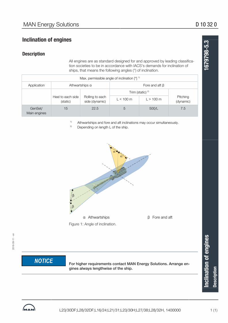
DescriptionAll engines are as standard designed for and approved by leading classifica-tion societies to be in accordance with IACS's demands for inclination ofships, that means the following angles (°) of inclination.
Max. permissible angle of inclination [°] 1)
Application Athwartships α Fore and aft β
Heel to each side(static)
Rolling to eachside (dynamic)
Trim (static) 2)
Pitching(dynamic)L < 100 m L > 100 m
GenSet/Main engines
15 22.5 5 500/L 7.5
27021605236231563
1)
2)Athwartships and fore and aft inclinations may occur simultaneously.Depending on length L of the ship.
27021605236231563
α Athwartships β Fore and aftFigure 1: Angle of inclination.
For higher requirements contact MAN Energy Solutions. Arrange en-gines always lengthwise of the ship.
27021605236231563
2018
-09-
11 -
en
Incli
natio
n of
engi
nes
Desc
riptio
n16
7979
8-5.
3

This page is intentionally left blank270216052362315632702160523623156327021605236231563
2018
-09-
11 -
en
D 10 32 0 MAN Energy Solutions
L23/30DF;L28/32DF;L16/24;L21/31;L23/30H;L27/38;L28/32H, 1400000
Incli
natio
n of
engi
nes
Desc
riptio
n16
7979
8-5.
3

MAN Energy Solutions D 10 33 0
V28/32S;V28/32H;L28/32S;L27/38S;L23/30DF;L23/30S;L16/24S;L21/31S;L28/32DF;L16/24;L21/31;L23/30H;L27/38;L28/32H, 2015.11.26 1 (1)
Green Passport
Green PassportIn 2009 IMO adopted the „Hong Kong International Convention for the Safeand Environmentally Sound Recycling of Ships, 2009“.Until this convention enters into force the recommendatory guidelines “Resol-ution A.962(23)” (adopted 2003) apply. This resolution has been implementedby some classification societies as “Green Passport”.MAN Diesel & Turbo is able to provide a list of hazardous materials complyingwith the requirements of the IMO Convention. This list is accepted by classific-ation societies as a material declaration for “Green Passport”.This material declaration can be provided on request.18014405981566219
2015
-11-
26 -
en
Gree
n Pa
sspo
rtDe
scrip
tion
1699
985-
1.1

This page is intentionally left blank18014405981566219
2015
-11-
26 -
en
D 10 33 0 MAN Energy Solutions
V28/32S;V28/32H;L28/32S;L27/38S;L23/30DF;L23/30S;L16/24S;L21/31S;L28/32DF;L16/24;L21/31;L23/30H;L27/38;L28/32H, 2015.11.26
Gree
n Pa
sspo
rtDe
scrip
tion
1699
985-
1.1

MAN Energy Solutions D 10 35 0
L27/38, 1402000 1 (1)
Time between overhaul - Expected life time
HFO operationComponents Time between overhaull Expected life time
Main pistonPiston ring groovesPiston ring and scraperringFlame ringCylinder liner
20,000As required
20,00020,00020,000
60,000-
20,00020,00060,000
Cylinder headExhaust valve (2 x grinding)Inlet valve (2 x grinding)Valve guideValve rotation device- Check every
20,00020,00020,000
-20,0005,000
80,00040,00040,00040,00020,000
-
Main bearingBig-end bearingConnecting rod
---
60,00040,00080,000
Bearing unit for turbochar-gerTurbine nozzle ring
15,00015,000
15,00015,000
Nozzle for fuel injectionvalveFuel injection pump ele-mentCharging air coolerCamshaft bearingVibration damper (sleevesprings)Air starter
4,000As required
--
30,00020,000
8,00020,00060,00060,00090,00080,000
27868251531
The lower values stated above refer to MAN Energy Solutions maintenanceprogramme and that fuel oil, lubricating oil, water and air is cleaned accordingto instructions. The higher values may be obtained under favourable operatingconditions.
Maintenance intervals and expected service life for main components. Opera-tion on HFO − 380 cSt at 50°C according to Quality Requirements 6680 3.3.32786825153127868251531
2018
-09-
03 -
en
Tim
e bet
ween
ove
rhau
l - E
xpec
ted
life t
ime
Desc
riptio
n16
9493
6-9.
3

This page is intentionally left blank278682515312786825153127868251531
2018
-09-
03 -
en
D 10 35 0 MAN Energy Solutions
L27/38, 1402000
Tim
e bet
ween
ove
rhau
l - E
xpec
ted
life t
ime
Desc
riptio
n16
9493
6-9.
3

MAN Energy Solutions D 10 35 0
L27/38S;L27/38, HFO, 1402000 1 (3)
Time between overhaul - expected life time
Figure 1: Major parts marked with yellow
2019
-05-
06 -
en
Tim
e bet
ween
ove
rhau
l - ex
pect
ed li
fe ti
me
Desc
riptio
n37
0061
1-6.
0

D 10 35 0 MAN Energy Solutions
2 (3) L27/38S;L27/38, HFO, 1402000
Figure 2: Major parts marked with yellow
2019
-05-
06 -
en
Tim
e bet
ween
ove
rhau
l - ex
pect
ed li
fe ti
me
Desc
riptio
n37
0061
1-6.
0

MAN Energy Solutions D 10 35 0
L27/38S;L27/38, HFO, 1402000 3 (3)
9007235770119435
2019
-05-
06 -
en
Tim
e bet
ween
ove
rhau
l - ex
pect
ed li
fe ti
me
Desc
riptio
n37
0061
1-6.
0

This page is intentionally left blank9007235770119435
2019
-05-
06 -
en
D 10 35 0 MAN Energy Solutions
L27/38S;L27/38, HFO, 1402000
Tim
e bet
ween
ove
rhau
l - ex
pect
ed li
fe ti
me
Desc
riptio
n37
0061
1-6.
0

MAN Energy Solutions B 10 01 1
L27/38, 1400000 1 (3)
General description
Design criteria for L27/38Decisive parameters for a propulsion engine are the requirements for a com-pact engine design and long term reliability in operation.
However, other requirements as mentioned below, have been given high pri-ority:
▪ Long time between overhauls (TBO)▪ No unscheduled maintenance and repair work▪ Unrestricted heavy fuel oil operation▪ Low fuel and lub oil consumption rates, fulfilling legal emission limit values▪ High maintenance and operation friendliness▪ Good part load behaviour▪ Easy installation, rigidly or resiliently seated.
Engine frame and crank-shaft
The monobloc nodular cast iron engine frame forms the most vital part of theengine. Through-going main bearing tie rods and the deeply positioned cylin-der head tie rods maintain a static preloading of the casting, thereby absorb-ing dynamic loads attained from gas and mass forces, with a high safety mar-gin.
All tie rods are tightened hydraulically.
Well supported main bearings carry the crankshaft with generously dimen-sioned journals. The combination of a stiff box design and the carefully bal-anced crankshaft ensure that the engine is running smoothly and free of vibra-tions.
Front-end box A unique feature is the introduction of the front-end box, arranged at the freeend of the engine. It contains connecting ducts for cooling water and lubricat-ing oil systems as well as pumps (plug-in units), thermostatic valve elements,lub oil cooler and the automatic back-flushing lub oil filter.In order to reduce the engine length, external pipe connections are arrangedon the sides of the front-end box.
The small optional PTO is located on the forward side.Cylinder unit The cylinder unit incorporating cylinder head, water jacket, piston and con-
necting rod can either be withdrawn/ installed as a complete unit or as indi-vidual components, depending on the available space conditions.The cylinder liner features a flame ring in the top. The purpose is to scrapeaway coke deposits on the piston top land and thereby avoid bore polishingof the cylinder liner. This will ensure optimal ring performance and low lub oilconsumption.The piston is a composite piston with steel crown and a nodular cast ironbody. A wear resistant chrome layer on the piston rings ensures long TBOs.
2019
-01-
08 -
en
Gene
ral d
escr
iptio
nDe
scrip
tion
1696
416-
8.3

B 10 01 1 MAN Energy Solutions
2 (3) L27/38, 1400000
Fig 1 Sectional view of engineThe robust connecting rod is of the marine head type with the joint above themarine head and fitted with hydraulically tightened units. During piston with-drawal, the marine head remains on the journal, saving dismantling space andat the same time protecting the journal.The “cross-flow” cylinder head in nodular cast iron has 2 inlet and 2 exhaustvalves – all rotating to minimize wear and equalize temperatures. Togetherwith the direct cooled exhaust valve seat rings, a reliable operation is ensured.
Turbocharging, charge aircooler
The turbocharging system is based on the constant pressure principle, usingthe newly developed radialflow type MAN Energy Solutions turbochargers.
2019
-01-
08 -
en
Gene
ral d
escr
iptio
nDe
scrip
tion
1696
416-
8.3

MAN Energy Solutions B 10 01 1
L27/38, 1400000 3 (3)
Starting air system The engine is started by means of a built-on air starter, controlled from the in-strument panel on the engine or from the remote control system.
In case of electric power failure, an emergency starting facility can be activ-ated.
A cranking device is fitted on the engine.
Lubricating oil system The engine features an entirely closed lub oil system which ensures easy in-stallation on board and no risk of dirt entering the lub oil circuit.
The helical gear type lub oil pump is mounted in the front-end box and drawsthe oil from the wet sump.
Via a pressure regulator, the oil flows through the lub oil plate cooler and thefull-flow automatic back-flushing lub oil filter. This solution eliminates ex-change of filter cartridges as well as the waste disposal problem.
The back-flush oil is drained to the sump. A purifier is to be connected tomaintain proper condition of the lub oil.
An integrated thermostatic valve ensures a constant lub oil temperature to theengine.
Cooling water system The cooling water system is based on separate low and high temperaturesystems.
Both circuits are cooled by fresh water.
HT system The water is circulated by the HT pump through the first stage of the chargeair cooler, the jacket water collar, cylinder heads and thermostatic valve,through the high temperature cooler, back to the HT pump.
Nearly 100% of the heat removed from the high temperature system can beutilized for heat recovery.
LT system The water is circulated by the LT pump through the second stage of thecharge air cooler, the lub oil coolers for engine and gearbox, the high temper-ature cooler, through the central cooler and back to the LT pump.34341015179
2019
-01-
08 -
en
Gene
ral d
escr
iptio
nDe
scrip
tion
1696
416-
8.3

This page is intentionally left blank34341015179
2019
-01-
08 -
en
B 10 01 1 MAN Energy Solutions
L27/38, 1400000
Gene
ral d
escr
iptio
nDe
scrip
tion
1696
416-
8.3

MAN Energy Solutions B 10 01 1
L27/38, Propulsion 1402151 1 (1)
Main particularsCycle : 4-stroke
Configuration : In-line
Cyl. nos available : 6-7-8-9
Power range : 2040-3060 kW (HFO/MDO)2190-3285 kW (MGO)
Speed : 800 rpm
Bore : 270 mm
Stroke : 380 mm
Stroke/bore ratio : 1.4:1
Piston area per cyl. : 572.6 cm2
Swept volume per cyl. : 21.8 ltr.
Compression ratio : 15.9:1
Turbocharging principle : Constant pressure system and intercool-ing
Fuel quality acceptance : HFO (up to 700 cSt/50° C,RMK700) MDO (DMB) - MGO (DMA,DMZ)according ISO8217-2010
34341020555
Power lay-out MCR version
Speed rpm 800
Mean piston speed
Mean effective pressure:6, 7, 8, 9 cylinder engine (HFO/MDO)6, 7, 8, 9 cyl engine (MGO)
Max. combustion pressure:6, 7, 8, 9 cylinder engine (HFO/MDO)6, 7, 8, 9 cyl engine (MGO)
Power per cylinder:6, 7, 8, 9 cylinder engine (HFO/MDO)6, 7, 8, 9 cyl engine (MGO)
m/sec.
barbar
barbar
kW/cyl.kW/cyl.
10.1
23.525.2
200200
340365
343410205553434102055534341020555
2019
-01-
08 -
en
Mai
n pa
rticu
lars
Desc
riptio
n37
0015
8-7.
1

This page is intentionally left blank34341020555343410205553434102055534341020555
2019
-01-
08 -
en
B 10 01 1 MAN Energy Solutions
L27/38, Propulsion 1402151
Mai
n pa
rticu
lars
Desc
riptio
n37
0015
8-7.
1

MAN Energy Solutions B 10 01 1
L27/38, 1400000 1 (2)
Main dimensions
Dimensions
Fig 1 Engine type 6L27/3834344234379
Fig 2 Engine type 7L27/3834344234379
2019
-01-
08 -
en
Mai
n di
men
sions
Desc
riptio
n37
0008
3-1.
1

B 10 01 1 MAN Energy Solutions
2 (2) L27/38, 1400000
Fig 3 Engine type 8L27/3834344234379
Fig 4 Engine type 9L27/383434423437934344234379
2019
-01-
08 -
en
Mai
n di
men
sions
Desc
riptio
n37
0008
3-1.
1

MAN Energy Solutions B 10 01 1
L27/38, TCR, 1402000 1 (1)
Weight and centre of gravity
Weight and centre of gravity
Engine type X - mm Y - mm* Y - mm** Z Wet weight ofenginetons *
Dry weight of en-gine
tons**
6L27/38 1855 615 645 20 31.4 30.5
7L27/38 2077 615 645 20 35.1 34.0
8L27/38 2300 615 645 20 38.7 37.0
9L27/38 2523 615 645 20 42.7 40.5
* Incl. lubricating oil and water** Excl. lubricating oil and water
3434423975534344239755
2019
-01-
08 -
en
Weig
ht a
nd ce
ntre
of g
ravit
yDe
scrip
tion
1699
862-
8.3

This page is intentionally left blank3434423975534344239755
2019
-01-
08 -
en
B 10 01 1 MAN Energy Solutions
L27/38, TCR, 1402000
Weig
ht a
nd ce
ntre
of g
ravit
yDe
scrip
tion
1699
862-
8.3

MAN Energy Solutions B 10 01 1
L27/38, 1400000 1 (3)
Space requirements
Dismantling SpaceSufficient space for pulling the pistons, cylinder liners, cylinder heads, andcharging air cooler must be available.
Fig 4.20 Lifting height for pistons Fig 4.21 Lifting height for cylinder heads
Fig 4.22 Lifting height for cylinder liners34345768203
2019
-01-
08 -
en
Spac
e req
uire
men
tsDe
scrip
tion
1696
425-
2.2

B 10 01 1 MAN Energy Solutions
2 (3) L27/38, 1400000
Fig 4.23 Dismantling lub oil filter Fig 4.24 Dismantling lub oil pump
Fig 4.25 Dismantling charging air cooler Fig 4.26 Dismantling complete cylinder unit34345768203
2019
-01-
08 -
en
Spac
e req
uire
men
tsDe
scrip
tion
1696
425-
2.2

MAN Energy Solutions B 10 01 1
L27/38, 1400000 3 (3)
Fig 1 Centre distance for twin engine installation3434576820334345768203
2019
-01-
08 -
en
Spac
e req
uire
men
tsDe
scrip
tion
1696
425-
2.2

This page is intentionally left blank34345768203343457682033434576820334345768203
2019
-01-
08 -
en
B 10 01 1 MAN Energy Solutions
L27/38, 1400000
Spac
e req
uire
men
tsDe
scrip
tion
1696
425-
2.2

MAN Energy Solutions B 10 01 1
L27/38S;L27/38 1 (1)
Firing pressure comparison
Firing pressure comparison
9007211673721227
2019
-04-
29 -
en
Firin
g pr
essu
re co
mpa
rison
Desc
riptio
n37
0036
6-0.
1

This page is intentionally left blank9007211673721227
2019
-04-
29 -
en
B 10 01 1 MAN Energy Solutions
L27/38S;L27/38
Firin
g pr
essu
re co
mpa
rison
Desc
riptio
n37
0036
6-0.
1

MAN Energy Solutions B 10 01 1
L27/38, 1485000 1 (2)
PTO on engine front
PTO on forward end of engineThe engine can be supplied with a PTO on the forward end, as an extensionto the crankshaft, see fig 1.The PTO can be dimensioned to transmit the full engine power. If a plant is tobe supplied with PTO it must be planned in co–operation with us. For carryingout the torsional vibration analysis of the complete propulsion system, all ne-cessary information concerning the PTO is needed.Generally, a flexible coupling between the PTO and the generator and/ordriven machinery will be necessary and this coupling must be selected totransmit the PTO requirements, accommodate and absorb any vibrationswhich may be present. Usually a toothed coupling will not be allowed.
Fig. 1 PTO arrangement34345773451
2019
-01-
08 -
en
PTO
on en
gine
fron
tDe
scrip
tion
1696
426-
4.4

B 10 01 1 MAN Energy Solutions
2 (2) L27/38, 1485000
Max axial forceIn principle the PTO must not induce any extra axial forces on the guide bear-ing of the crankshaft. However, a constant force of max 9000 N can be ac-cepted. This includes a contribution from the crankshaft, if the engine has aninclination in relation to horizontal.For a 5° inclination to aft end the contribution will be as stated below.
Engine type Axial force5° inclination
Extension of crankshaft∆t = 65° C
6L27/38 4160 N 2.0 mm
7L27/38 4820 N 2.4 mm
8L27/38 5200 N 2.7 mm
9L27/38 5540 N 3.0 mm34345773451
Furthermore it should be observed that the crankshaft position is fixed by theguide bearing at the aft end of the engine. Crankshaft extension measured atthe forward end with a temperature rise of 65 °C corresponds to the values inthe shown table.This extension may cause the flexible coupling between the PTO shaft and thedriven part to create an additional axial force on the crankshaft guide bearingand this must be taken into consideration.An additional PTO of max 50 kW is available on the engine forward end. It caneither be used for a sea water pump, or for a hydraulic pump for the steeringgear.34345773451
2019
-01-
08 -
en
PTO
on en
gine
fron
tDe
scrip
tion
1696
426-
4.4

MAN Energy Solutions B 10 01 1
L27/38, 1402151 1 (3)
Power, output, speed
Engine ratings
Engine type No of cylinders
800 rpm 800 rpm (MGO)800 rpm Available turning
direction800 rpm Available turning
directionkW CW 1) / CWW 2) kW CW 1) / CWW 2)
6L27/38 2040 Yes / Yes 2190 Yes / Yes
7L27/38 2380 Yes / Yes 2555 Yes / Yes
8L27/38 2720 Yes / Yes 2920 Yes / Yes
9L27/38 3060 Yes / Yes 3285 Yes / Yes1) CW clockwise2) CCW counter clockwise
Table 1: Engine ratings for emission standard - IMO Tier II.
Idling Speed - 500 rpm
Available outputsPApplication
Available output inpercentage from
ISO-Standard-Output
Fuel stop power(Blocking)
Max. allowed speedreduction at max-
imum torque 1)
Tropic conditions
tr/tcr/pr=100 kPa
Remarks
Kind of application (%) (%) (%) (°C)Electricity generation
Marine main engines (with mechanical or diesel electric drive)
Main drive with control-lable pitch propeller
100 100 – 45/38 2)
Main drive with fixed-pitchpropeller
100 100 10 45/38 2)
1) Maximum torque given by available output and nominal speed. 2) According to DIN ISO 3046-1 MAN Energy Solutions has specified a maximum continuous rating for marine en-gines listed in the column PApplication
tr – Air temperature at compressor inlet of turbocharger. tcr – Cooling water temperature before charge air cooler pr – Barometric pressure
Engine fuel: according to ISO 8217 DMA/DMB/DMC-grade fuel or RM-grade fuel, fulfilling the stated quality require-ments
Table 2: Available outputs / related reference conditions.
POperating: Available output under local conditions and dependent on applica-tion.
2018
-10-
31 -
en
Powe
r, ou
tput
, spe
edDe
scrip
tion
3700
0005
-4.3

B 10 01 1 MAN Energy Solutions
2 (3) L27/38, 1402151
Dependent on local conditions or special application demands, a further loadreduction of PApplication, ISO might be needed.
De-rating1) No de-rating due to ambient conditions is needed as long as following
conditions are not exceeded:9007230131952651
No de-rating up to stated ref-erence conditions (Tropic)
Special calculation needed if following values are ex-
ceededAir temperature before turbocharger Tx ≤ 318 K (45 °C) 333 K (60 °C)
Ambient pressure ≥ 100 kPa (1 bar) 90 kPa
Cooling water temperature inlet charge air cooler (LT-stage)
≤ 311 K (38 °C) 316 K (43 °C)
Intake pressure before compressor ≥ -20 mbar 1) -40 mbar 1)
Exhaust gas back pressure after turbocharger ≤ 30 mbar 1) 60 mbar 1)
1) Overpressure
Table 3: De-rating – Limits of ambient conditions.90072301319526519007230131952651
2018
-10-
31 -
en
Powe
r, ou
tput
, spe
edDe
scrip
tion
3700
0005
-4.3

MAN Energy Solutions B 10 01 1
L27/38, 1402151 3 (3)
2) De-rating due to ambient conditions and negative intake pressure be-fore compressor or exhaust gas back pressure after turbocharger.
9007230131952651
aTx
U
U =
O
O =
Tcx
Tt
Correction factor for ambient conditionsAir temperature before turbocharger [K] being considered (Tx = 273 + tx)Increased negative intake pressure before compressor leeds to a de-rat-ing, calculated as increased air temperature before turbocharger
(-20mbar – pAir before compressor [mbar]) x 0.25K/mbar
with U ≥ 0
Increased exhaust gas back pressure after turbocharger leads to a de-rating, calculated as increased air temperature before turbocharger:
(PExhaust after turbine [mbar] – 30mbar) x 0.25K/mbar
with O ≥ 0
Cooling water temperature inlet charge air cooler (LT-stage) [K] beingconsidered (Tcx = 273 + tcx)
Temperature in Kelvin [K]Temperature in degree Celsius [°C]
9007230131952651
3) De-rating due to special conditions or demands. Please contact MANEnergy Solutions, if:
9007230131952651
▪ limits of ambient conditions mentioned in "Table 4 De-rating – Limits ofambient conditions" are exceeded
▪ higher requirements for the emission level exist▪ special requirements of the plant for heat recovery exist▪ special requirements on media temperatures of the engine exist▪ any requirements of MAN Energy Solutions mentioned in the Project
Guide can not be kept
2018
-10-
31 -
en
Powe
r, ou
tput
, spe
edDe
scrip
tion
3700
0005
-4.3

This page is intentionally left blank900723013195265190072301319526519007230131952651900723013195265190072301319526519007230131952651
2018
-10-
31 -
en
B 10 01 1 MAN Energy Solutions
L27/38, 1402151
Powe
r, ou
tput
, spe
edDe
scrip
tion
3700
0005
-4.3

MAN Energy Solutions B 11 00 0
L21/31;L27/38, 1435000 1 (1)
Fuel oil system
GeneralThe engine can be equipped with different equipment depending on fuel oilquality.The standard engine, for operation on MDO (Marine Diesel Oil), is equippedwith built-on:▪ Fuel oil primary pump▪ Double filter with paper inserts▪ Lubrication of fuel oil pumps▪ Fuel oil pumps with leak oil seal▪ Uncooled fuel injection valvesThe MDO built-on equipment is designed for single engine installation. Formulti engine installations it is recommended to have either two separate fuelsupplies or the built-on pumps have to be replaced by electrical pumps.The standard engine, for operation on HFO (Heavy Fuel Oil), is equipped withbuilt-on:
▪ Fuel oil duplex filter▪ Fuel oil back pressure valve▪ Lubrication of fuel oil pumps▪ Fuel oil pumps without leak oil seal▪ Uncooled fuel injection valves▪ Equipment for cleaning of turbocharger turbine side during operationThe built-on equipment is designed for use of fuel oil modules, normally re-ferred to as booster modules. For multi engine installations a common fuel oilfeed system should cover all engines.
Fuel oil quality For fuel oil quality and injection viscosity, see fuel specifications 010.000.023.Velocity recommendations for fuel oil pipes:
Marine Diesel Oil: Suction pipe: 0.5 - 1.0m/s
Delivery pipe: 1.5 - 2.0 m/s
Heavy Fuel Oil: Suction pipe: 0.3 - 0.8 m/s
Delivery pipe: 0.8 - 1.2 m/s90072357980567159007235798056715
2020
-02-
18 -
en
Fuel
oil s
yste
mDe
scrip
tion
1690
730-
9.3

This page is intentionally left blank90072357980567159007235798056715
2020
-02-
18 -
en
B 11 00 0 MAN Energy Solutions
L21/31;L27/38, 1435000
Fuel
oil s
yste
mDe
scrip
tion
1690
730-
9.3

MAN Energy Solutions B 11 00 0
L21/31;L27/38, 1435000 1 (5)
Fuel oil system - MDO
Fuel oil system for operation on gas/diesel oil
Fig 6.1 Fuel oil system – MDO
Item Description
1234567891020
Prefilter for purifierTransfer pumpPurifierMDO service tankSightglass for MDO overflowDuplex filter (magnetic insert)Primary stand-by pumpPrimary pumpDuplex filter (paper insert)MDO/MGO diesel oil coolerPressure regulating valve
2020
-02-
18 -
en
Fuel
oil s
yste
m -
MDO
Desc
riptio
n37
0030
4-9.
4

B 11 00 0 MAN Energy Solutions
2 (5) L21/31;L27/38, 1435000
Connections:
B1B3B4B7B7A
Fuel oil primary pump - suctionFuel oil primary stand-by pump - pressureFuel oil circulation to service tankTo sludge tankClean fuel oil return to service tank (with alarm)
Shut-off valve at B4 is to be placed as close to the connections as possible
Service tank (item 4):Min capacity in m3 for 8 hours operation:
L21/31 With separator orsettling tank
L27/38 With separator orsettling tank
6 cyl engine7 cyl engine8 cyl engine9 cyl engine
2.42.63.23.6
6 cyl engine7 cyl engine8 cyl engine9 cyl engine
3.94.65.25.9
The lowest oil level of the service tank must be min 500 mm above centerline ofcrankshaft.
Fuel oil storageThe storage and handling system comprises of bunker tanks, pipe systemsand transfer systems
Cleaning systemsThe cleaning system normally comprises of a settling tank, pipe system andequipment for cleaning of the MDO prior to use in the engine.The settling tank should be designed to provide the most efficient sludge andwater separation. The tank should be provided with baffles to reduce mixingof sludge with the fuel. The bottom of the tank should have a slope toward thesludge drain valve(s), and the pump suction must not be in the vicinity of thesludge space.We recommend that the capacity of a single settling tank is sufficient to en-sure minimum 24 hours operation.
Prefilter, item 1To protect the purifier pump (item 2), a prefilter should be inserted before thepump.Design data:▪ Capacity: see oil pump, item 2▪ Mesh size: 0.8 - 1.0 mm
Oil pump to separator, item 2The pump can be driven directly by the separator or by an independent mo-tor.
2020
-02-
18 -
en
Fuel
oil s
yste
m -
MDO
Desc
riptio
n37
0030
4-9.
4

MAN Energy Solutions B 11 00 0
L21/31;L27/38, 1435000 3 (5)
Design data:▪ Capacity: According to separator▪ Pressure: Max 2.5 bar▪ Temperature: Max 50°C
Separator, item 3For engines operating on MDO we recommend cleaning of the oil by a separ-ator to remove water. For the blended fuel oil (M3 in accordance to BSMA100 fuel oil specification) which can be expected in some bunker places,the separator is also an important cleaning device. We recommend the auto-matic self-cleaning type.As a guideline for the selection of separator, the following formula can beused:Design data:▪ Capacity: V = C x (24/T)▪ V: The nominal capacity of the separator in litres/hour▪ C: Consumption at MCR in liters/hour▪ T: Daily separating time, depending on separator (20_22 hours)Guidance given by the manufacturer of the separator must be observed.If aux engines are fed from the same fuel oil system, the fuel oil consumptionhas to include all engines.Pre-heating is normally not necessary, but a separation temperature of approx40-50 °C is recommended for better separation. Some Marine Diesel Oilshave a high content of “paraffin” which cloggs up filters and can cause unin-tended engine stopping. To avoid this preheating can be necessary.A heat exchanger and a thermostatic valve using the main engine HT coolingwater as heating media can be installed, if necessary.The fuel oil separator should be installed and constantly circulating the fuelbetween settling tank and service tank. Separator must not be selected toosmall for the purpose. It is recommended to be approximately 4 times biggerthan the requested capacity flow of the supply system to have optimumcleaning efficiency. Correct viscosity/temperature is also important for effi-ciency of separator.The automatic back-flush filter with a change-over cock and bypass simplexfilter and with integrated heating chamber has a mesh size of 10 microns (ab-solute/sphere passing mesh). The automatic back-flush filter permits a con-tinuous operation even during back-flushing without any pressure drops or in-terruptions of flow. If the filter inserts are clogged, an automatic cleaning isstarted. The filter is equipped with a visual differential pressure indication andtwo differential pressure contacts to monitor the clogging of the filter. Back-flushing medium is discharged discontinuously to a sludge tank or back to thesettling tank.Automatic back-flush filter will also extend the cleaning intervals considerablyof the filter elements in the fuel oil filter duplex (safety filter).For more information of separator unit, see B 12 15 0, 3700643-9 Separatorunit.
2020
-02-
18 -
en
Fuel
oil s
yste
m -
MDO
Desc
riptio
n37
0030
4-9.
4

B 11 00 0 MAN Energy Solutions
4 (5) L21/31;L27/38, 1435000
Service tank, item 4The service tank shall be dimensioned to contain purified MDO for operatingminimum 8 hours at MCR.Attention must be paid that the fuel oil inlet pipe is connected to the side ofthe tank in a position to avoid sludge and water contamination of the MDO.A vent pipe from the tank should be led up to the deck level minimum 500mm above the tank. Precaution should be taken that water does not enter thetank through the vent pipe.To ensure satisfactory suction when starting up the main engine, the lowestoil level in the service tank should be at least 500 mm above the suction to theprimary pump.
Duplex suction filter, item 6A duplex suction filter with magnetic inserts should be installed in the suctionline of the fuel oil primary pump to protect the pump. The filter should be de-signed for the capacity of the built-on primary pump with a mesh size of 0.5–0.8 mm.
Stand-by primary pump, item 7Design data:▪ Capacity: 3 x MCR consumption▪ Pressure: 2.5 bar
Duplex filter, item 9Engines are equipped with a fuel oil filter duplex (safety filter) with a fineness ofmaximum 25 microns (absolute/sphere passing mesh). The filter is with star-pleated filter elements and allows change-over during operation without pres-sure loss. The filter is compact and easy to maintain, requiring only manualcleaning when maximum allowable pressure drop is reached. The filter isequipped with a visual differential pressure indication and two differential pres-sure contacts to monitor the clogging of the filter. When maximum pressuredrop is reached, the standby filter chamber is brought on line simultaneouslyas the dirty one is isolated by means of the change-over valve. After venting,the dirty element can be removed, cleaned and refilled to be the standby filterchamber.
Fuel oil consumptionFor calculating the necessary tank size, purifier, stand-by pumps, etc, theconsumption stated in the planning data, based on engine MCR, should beused. These values include an addition for engine driven pumps plus 5% tol-erance in accordance with ISO requirements.
MDO/MGO Diesel oil cooler, item 10Fuel oil temperatures before engine / fuel oil injection pumps (MDO/MGO):
2020
-02-
18 -
en
Fuel
oil s
yste
m -
MDO
Desc
riptio
n37
0030
4-9.
4

MAN Energy Solutions B 11 00 0
L21/31;L27/38, 1435000 5 (5)
▪ If the fuel oil temperature before engine / fuel injection pumps exceeds40° C or the viscosity is below 2,0 cSt cooler must be built-in, in order toensure the lubricating properties for the injection pumps.
Circulation of MDO/MGO over engine will heat up the fuel. In warmer regionswill diesel oil cooler be needed.Diesel cooler can also be installed on inlet string upstream engine.
NotesWe recommend that the total pressure drop in the piping system is calculatedin order to ensure that the pump capacity is sufficient and the flow velocity isas recommended by us.We should be pleased to review your piping diagrams and give our commentsand recommendations. The shipyard is responsible for the choice of method,design and execution.18014432862733963
2020
-02-
18 -
en
Fuel
oil s
yste
m -
MDO
Desc
riptio
n37
0030
4-9.
4

This page is intentionally left blank18014432862733963
2020
-02-
18 -
en
B 11 00 0 MAN Energy Solutions
L21/31;L27/38, 1435000
Fuel
oil s
yste
m -
MDO
Desc
riptio
n37
0030
4-9.
4

MAN Energy Solutions B 11 00 0
L21/31;L27/38, 1435000 1 (11)
Fuel oil system - HFO
Fuel oil system for operation on heavy fuel oil
Figure 1: Fuel oil diagram - HFO
2020
-02-
02 -
en
Fuel
oil s
yste
m -
HFO
Desc
riptio
n37
0036
3-5.
4

B 11 00 0 MAN Energy Solutions
2 (11) L21/31;L27/38, 1435000
Fuel oil systemItem Description Item Description
1 HFO settling tank 14 Supply pressure control valve
2 Prefilter for separator 15 Duplex filter (magnetic insert)
3 Transfer pump for separator 16 Fuel oil booster pump
4 Preheater for separator 17 Final preheater
5 HFO separator 18 Viscosity control equipment
6 HFO separator 19 Fuel oil filter duplex (safety filter)
7 HFO day tank 20 Booster pressure regulating valve
8 Prefilter for HFO supply pump 30 Sight glass, HFO day tank overflow
9 Fuel oil supply pump 31 Prefilter for MDO transfer pump
10 Automatic back-flush filter 32 MDO transfer pump
11 Flow indicator 33 MDO separator
12 Mixing tank 34 MDO separator
13 Automatic de-aeration valve 35 Sight glass, MDO day tank over-flow
ConnectionsB1 Fuel oil inlet engine B7 To sludge tank
B4 Fuel oil circulation to service tank B7A Clean fuel oil return to service tank(with alarm)
All tanks and pipes for heated oil must be insulated.
Shut-off valve at B4 is to be placed as close to the connection as possibleFinal preheater (item 17):▪ Standard
– Steam heated final preheater▪ Optional
– Electrical, thermal oil heated final preheaterMDO-tank (item 34):▪ Min oil level in MDO-tank is to be approx. 500 mm above inlet pipe (item
10)Pressure regulating valve (item 20):▪ The pressure regulating valve is to be adjusted to a pressure of 4 bar. The
relief valve for booster pumps (items 16 and 16A) are adjusted to a pres-sure somewhat higher.
2020
-02-
02 -
en
Fuel
oil s
yste
m -
HFO
Desc
riptio
n37
0036
3-5.
4
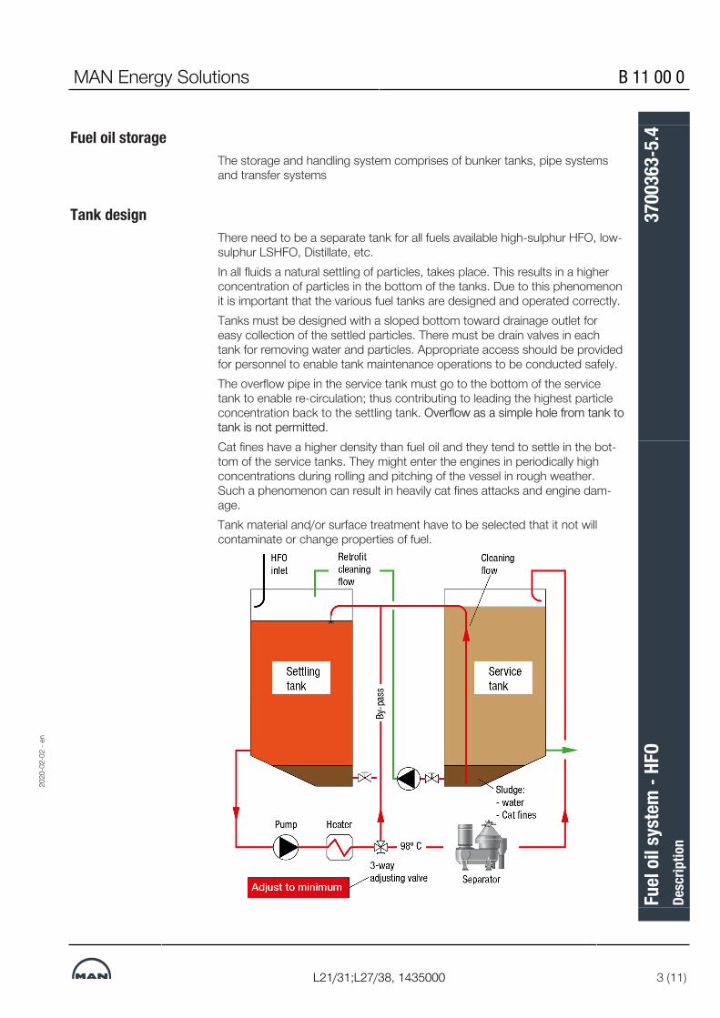
MAN Energy Solutions B 11 00 0
L21/31;L27/38, 1435000 3 (11)
Fuel oil storageThe storage and handling system comprises of bunker tanks, pipe systemsand transfer systems
Tank designThere need to be a separate tank for all fuels available high-sulphur HFO, low-sulphur LSHFO, Distillate, etc.In all fluids a natural settling of particles, takes place. This results in a higherconcentration of particles in the bottom of the tanks. Due to this phenomenonit is important that the various fuel tanks are designed and operated correctly.Tanks must be designed with a sloped bottom toward drainage outlet foreasy collection of the settled particles. There must be drain valves in eachtank for removing water and particles. Appropriate access should be providedfor personnel to enable tank maintenance operations to be conducted safely.The overflow pipe in the service tank must go to the bottom of the servicetank to enable re-circulation; thus contributing to leading the highest particleconcentration back to the settling tank. Overflow as a simple hole from tank totank is not permitted.Cat fines have a higher density than fuel oil and they tend to settle in the bot-tom of the service tanks. They might enter the engines in periodically highconcentrations during rolling and pitching of the vessel in rough weather.Such a phenomenon can result in heavily cat fines attacks and engine dam-age.Tank material and/or surface treatment have to be selected that it not willcontaminate or change properties of fuel.
2020
-02-
02 -
en
Fuel
oil s
yste
m -
HFO
Desc
riptio
n37
0036
3-5.
4

B 11 00 0 MAN Energy Solutions
4 (11) L21/31;L27/38, 1435000
Fuel supply systemThe common fuel supply system is a low pressurized system, consisting of“DIESELswitch”, HFO supply pumps with pressure control valves, ventingtank and de-aerating valve.Pump capacity is minimum fuel consumption for all engines in system running100% load. See “List of capacities” for each engine types.The fuel oil is led from one of the service tanks to one of the electrically drivensupply pumps (with redundancy). It delivers the fuel oil with an adjusted pres-sure of approximately 4 bar to the fuel circulation system.The venting pipe is connected to the service tank via an automatic de-aerationvalve that will release any gases present.
Fuel circulation systemFrom the low-pressure supply fuel system the fuel oil is poured with return fuelfrom engines and led to one of the electrically driven circulating pumps (withredundancy), through preheater, diesel cooler, and equipment for controllingthe viscosity, (e.g. “Viscorator”).Pump capacity is minimum 3 times fuel consumption for all engines in systemrunning 100% load. See “List of capacities” for each engine types.The circulating pumps will always be running; even if the propulsion engineand one or several of the engines are stopped. Circulation of heated heavyfuel oil through the fuel system on all the engine(s) keep them ready to startwith preheated fuel injection pumps.The surplus amount of fuel oil is re-circulated in the engine and back throughthe venting pipe. To have a constant fuel pressure to the fuel injection pumpsduring all engine loads a spring-loaded pressure relief valve is installed (Valve20 "Booster pressure regulating valve")Fuel circulation pressure has to be 8-9 bar at fuel oil inlet. Back-pressure inthe circulation-system is approximately 4 bar (from supply system).Fuel oil pressure for engine must be minimum 8 bars and can be up to 16 bar.It is therefore recommended to distribute fuel to GenSet(s) before main en-gine.Fuel preheater and diesel cooler should safely manage to control temperature.Clogging point, cloud and pour point of the bunkered fuel need to be con-sidered in every operating areas and ambient temperatures.Depending on system layout, viscosity, and volume in the external fuel oil sys-tem, unforeseen pressure fluctuations can be observed. In such cases it couldbe necessary to add pressure dampers to the fuel oil system. For further as-sistance, please contact MAN Energy Solutions.
Settling tank, item 1The settling tanks should be designed to provide the most efficient sludge andwater separation. Each tank should be provided with baffles to reduce mixingof sludge with the fuel. The bottom of the tank should be with a slope towardthe sludge drain valve(s), and the pump suction must not be in the vicinity ofthe sludge space.
2020
-02-
02 -
en
Fuel
oil s
yste
m -
HFO
Desc
riptio
n37
0036
3-5.
4

MAN Energy Solutions B 11 00 0
L21/31;L27/38, 1435000 5 (11)
We recommend that the capacity of each settling tank should be sufficient toensure minimum 24 hours operation.The temperature of the oil settling tanks should be as high as possible to helpthe dirt to settle. The temperature should be below 75°C in order to avoid theformation of asphaltenes, and min 7°C above the pour point of the oil to en-sure pumpability.
Prefilter, items 2 and 2ATo protect the separator pumps, items 3 and 3A, a prefilter should be insertedbefore the pumps.Design data:▪ Capacity: See oil pump, items 3 and 3A▪ Mesh size: 0.8-1.0 mm
Oil pump to separator, items 3The pumps can be driven directly by the purifier or by an independent motor.Design data:▪ Capacity: According to separator▪ Pressure: Max 2.5 bar▪ Temperature: Max 70°C
Preheater before separator, items 4 and 4AThe preheater must be able to raise the temperature of the oil from approx60°C to approx 98°C, which is the temperature of the oil for purifying.Design data:▪ Capacity: P = v × t/1710
▪ P: Capacity of the preheater in kW▪ v: Flow through preheater in litres/hour▪ t: Temperature difference approx 40°C (engine operating)Max pressure: 4 barMax pressure loss: 0.5 barThe specific load on heating surface for an electric preheater is recommendednot to exceed 1.2 W/cm2.
Separator, items 5 and 6The fuel oil separator should be installed and constantly circulating the fuelbetween settling tank and service tank. Separator must not be selected toosmall for the purpose. It is recommended to be approximately 4 times biggerthan the requested capacity flow of the supply system to have optimumcleaning efficiency. Correct viscosity/temperature is also important for effi-ciency of separator.
2020
-02-
02 -
en
Fuel
oil s
yste
m -
HFO
Desc
riptio
n37
0036
3-5.
4

B 11 00 0 MAN Energy Solutions
6 (11) L21/31;L27/38, 1435000
The automatic back-flush filter with a change-over cock and bypass simplexfilter and with integrated heating chamber has a mesh size of 10 microns (ab-solute/sphere passing mesh). The automatic back-flush filter permits a con-tinuous operation even during back-flushing without any pressure drops or in-terruptions of flow. If the filter inserts are clogged, an automatic cleaning isstarted. The filter is equipped with a visual differential pressure indication andtwo differential pressure contacts to monitor the clogging of the filter. Back-flushing medium is discharged discontinuously to a sludge tank or back to thesettling tank.Automatic back-flush filter will also extend the cleaning intervals considerablyof the filter elements in the fuel oil filter duplex (safety filter).If aux engines are supplied from the same fuel oil system, the fuel oil con-sumption has to include all engines.For more information of separator unit, see B 12 15 0, 3700643-9 Separatorunit.
HFO service tank, item 7The service tank should be dimensioned to contain purified HFO for operatingfor at least 12 hours.The tank must be insulated and the oil temperature in the tank should be keptat minimum 60 °C. Depending on separating temperature and tank insulationthe temperature may rise to above 90°C.Attention must be paid that the fuel oil inlet pipe is connected to the side ofthe tank in a position to avoid sludge and water contamination of the HFO.The feed from the service tank to the mixing pipe is to be connected in a suit-able distance above the bottom of the service tank to avoid sludge and watercontamination in the pipe.A vent pipe from the tank should be led up to the deck level minimum 500mm above the tank. Precaution should be taken that water does not enter thetank through the vent pipe.
Prefilters, items 8 and 8AThe pressure pumps (items 9 and 9A) must be protected by prefilters.Design data:▪ Capacity: See capacity for pressure pump▪ Temperature: Max 90°C▪ Mesh size: 0.8-1.0 mm
Pressure pumps, items 9 and 9AThe HFO system must be pressurised to avoid gas separation in the fuel oilpiping. Pressurising is maintained by the pumps installed between the HFOservice tank and the automatic filter.Design data:▪ Type: Screw or gear pump with relief valve▪ Capacity: 1.6 x MCR consumption▪ Pressure: 4 bar
2020
-02-
02 -
en
Fuel
oil s
yste
m -
HFO
Desc
riptio
n37
0036
3-5.
4

MAN Energy Solutions B 11 00 0
L21/31;L27/38, 1435000 7 (11)
▪ Temperature: Max 90°CViscosity at normal operation: Max 140 cSt (corresponding to 70°C)Viscosity for dimensioning of el–motor: 1000 cSt
Pressure regulating valve, item 14The pressure regulating valve is to be adjusted to a pressure of approx 4 barand the relief valve setting for supply pumps, items 9 and 9A, is adjusted to ahigher pressure.If the capacity of the pressure pumps (items 9 and 9A) exceeds the fuel oilconsumption too much, or if the plant often operates at low load, the surplusoil by-passed by the pressure regulating valve has to be cooled down by aby-pass oil radiator, to avoid unintended heating of the fuel supply.
Automatic back-flush filter (hot side), item 10The automatic back-flush filter with a change-over cock and bypass simplexfilter and with integrated heating chamber has a mesh size of 10 microns (ab-solute/sphere passing mesh). The automatic back-flush filter permits a con-tinuous operation even during back-flushing without any pressure drops or in-terruptions of flow. If the filter inserts are clogged, an automatic cleaning isstarted. The filter is equipped with a visual differential pressure indication andtwo differential pressure contacts to monitor the clogging of the filter. Back-flushing medium is discharged discontinuously to a sludge tank or back to thesettling tank.This will also extend the cleaning intervals of the filter elements in the fuel oilfilter duplex (safety filter) considerably.Design data:
Capacity MCR consumption
Pressure 8-16 bar
Temperature Max 150°C
Mesh size 10 µm absolute (main supply)
35 µm absolute (by-pass supply)
Fuel oil consumption measuring, item 11For engines with pressurised HFO system a fuel consumption meter can befitted between the automatic filter (item 10) and the mixing tank (item 12). Aspring loaded valve has to be installed in parallel. In case of the measuringdevice, the valve will open and ensure fuel supply to the engine.
Mixing pipe, item 12The main purpose of the mixing pipe is to ensure good ventilation of gas fromthe hot fuel oil.Furthermore, the mixing pipe ensures a gradual temperature balance by mix-ing the hot returned oil from the engine with the oil from the daily service tankthereby reducing the heat requirements from the final preheater.
2020
-02-
02 -
en
Fuel
oil s
yste
m -
HFO
Desc
riptio
n37
0036
3-5.
4

B 11 00 0 MAN Energy Solutions
8 (11) L21/31;L27/38, 1435000
The mixing pipe should be dimensioned to contain fuel oil for 10-15 minutesoperation at MCR load, and in any case not less than 50 litres.Minimum diameter of mixing pipe: 200 mm.Because the capacity of the fuel oil primary pump is higher than the con-sumption of the engine, the surplus oil from engine flange connection B4 mustbe returned to the mixing pipe and must be adequately insulated.The flange connection B2 must be connected to a drain tank and not to themixing pipe.
Prefilter, item 15To protect the fuel oil circulation pumps a duplex prefilter is recommendedbetween the mixing pipe (item 12) and the circulating pumps (items 16 and16A).Design data (depending on fuel type):▪ Capacity: See the planning data▪ Operating temperature: Max 150°C▪ Pressure: Max 10 bar▪ Pressure drop by clean filter: Max 0.05 bar▪ Pressure drop by dirty filter: Max 0.1 bar▪ Mesh size: 0.5 – 0.8 mm
HFO circulating pump, items 16 and 16AThe pressurised HFO system has a high degree of recirculation.Design data (depending on fuel type):▪ Capacity: Min 3 × MCR consumption▪ Pressure: 8 bar▪ Operating temperature: Max 150°C▪ Viscosity at normal operation:
– 25 cSt (corresponding to 110°C)▪ Viscosity for dimensioning of el-motor:
– 250 cSt (corresponding to 60°C)
Preheater, item 17In order to heat the HFO to the proper viscosity before the injection valves(12±2 cSt), the oil is led through a preheater.The temperature of the HFO is regulated by an automatic viscosity control unitto 85-150 °C (depending on the viscosity).The specific load on heating surface for an electric preheater is recommendednot to exceed 1.2 W/cm2.Based on the minimum temperature of the oil from the HFO service tank to be60 °C and because the fuel must be heated to temperatures indicated in thetable below (corresponding to a viscosity of 12±2 cSt plus an addition of 5°Cto compensate for heat loss before injection) the capacity of the preheater inkW should be minimum:
2020
-02-
02 -
en
Fuel
oil s
yste
m -
HFO
Desc
riptio
n37
0036
3-5.
4

MAN Energy Solutions B 11 00 0
L21/31;L27/38, 1435000 9 (11)
The above capacities include a safety margin of 15% but the necessary capa-city depends on the actual fuel and condition. We will be pleased to carry outcalculations for a specific condition on request.
Fuel typefinal temp
IF 80t= 110 °C
kW
IF 180t=131 °C
kW
IF 380t=147 °C
kW6L27/38 18 25 30
7L27/38 21 29 35
8L27/38 25 33 40
9L27/38 28 38 45
Viscosity control equipment, item 18This equipment is required for all types of fuel to ensure the optimum viscosityof approx 12±2 cSt at the inlet to the fuel injection pump. The viscosimetershould be of a design which is not affected by pressure peaks produced bythe injection pumps. For efficient operation, the pipe length between the HFOpreheater and the viscosity control equipment should be as short as possible(or in accordance with the manufacturer’s instruction).The viscosity control equipment should be able to switch over to thermostaticcontrol in case of malfunctioning.
Fuel oil filter duplex (safety filter), item 19Engine attached fuel oil filter duplex (safety filter), with a fineness of max. 25microns (absolute/sphere passing mesh). The fuel oil filter duplex (safety filter)is with star-pleated filter elements and allows change-over during operationwithout pressure loss. The filter is compact and easy to maintain, requiringonly manual cleaning when maximum allowable pressure drop is reached. Thefilter is equipped with a visual differential pressure indication and two differen-tial pressure contacts to monitor the clogging of the filter. When maximumpressure drop is reached, the standby filter chamber is brought on line simul-taneously as the dirty one is isolated by means of the change-over valve. Afterventing, the dirty element can be removed, cleaned and refilled to be thestandby filter chamber.
Fuel oil consumptionFor calculating the necessary size of tank, separators, stand-by pumps, etc,the consumption stated in the planning data, based on engine MCR, shouldbe used.The consumption includes an addition for engine driven pumps plus 5% toler-ance in accordance with ISO requirements.The conversion from kg/hour to litres/hour is based on a fuel with density of950 kg/m3 for IF 80 and 980 kg/m3 for IF 380.The low calorific heat value of the heavy fuel oil corresponds to 40,225 kJ/kg.See "Calculation of specific fuel oil consumption (SFOC)"
2020
-02-
02 -
en
Fuel
oil s
yste
m -
HFO
Desc
riptio
n37
0036
3-5.
4

B 11 00 0 MAN Energy Solutions
10 (11) L21/31;L27/38, 1435000
Operation on distillateThe distillate to the engine is recommended to be supplied by a separatepipeline from the service tank through a distillate booster pump. The capacityof the distillate booster pump must be minimum three times higher theamount of distillate consumed by the diesel engines at 100% load. See list ofcapacities for each engine type.The system is designed in such a way that the fuel type for the engine can bechanged independently of the fuel supply to the propulsion engine. As an op-tion the engine plant can be delivered with the fuel changing system consist-ing of a set of remotely controlled, pneumatically actuated 3-way fuel chan-ging valves “V1-V2” for each engine and a fuel changing valve control boxcommon for all engines.A separate fuel changing system for each engine gives the advantage of indi-vidually choosing distillate or HFO mode. Such a changeover may be neces-sary if the engine have to be:▪ Entering SECA area▪ Stopped for a prolonged period▪ Stopped for major repair of the fuel system, etc.▪ In case of a blackout / emergency start.With the introduction of stricter fuel sulphur content regulations the propulsionengine as well as the engine increasingly have to be operated on distillatefuels, i.e. marine gas oil (MGO) and marine diesel oil (MDO). To maintain therequired viscosity at the engine inlet, it is necessary to install a cooler in thefuel system. The lowest viscosity suitable for the main engine and theGenSets is 2 cSt at engine inlet.Vessel that constantly will enter/exit SECA area, and has multiple engine in-stallation, it is recommended not to change between fuels, but to select someengine for HFO and some engine for distillate fuels. The change-over proced-ure will then be starting/stopping engine and not changing between fuels.Distillate pump capacity need to be minimum for one engine (see descriptionD 10 05 0 "List of capacities"). If 2 or more engines need to run distillate (ie.entering SECA) then distillate pump capacities must be adjusted accordingly.If the fuel type for complete system both the propulsion engine and GenSethave to be changed from HFO to MDO/MGO/Distillate and vice versa, the 3-way valve (“DIESELswitch”) just after the service tanks has to be activated.The change-over between HFO and MDO/MGO/Distillate needs to be donevery thoroughly with high attention to temperature/viscosity. Incorrect hand-ling can damage the engine.An MDO separator must be installed upstream of the MDO service tank. Sep-aration temperature must be in the range 40 – 50°C. Most solid particles(sand, rust and catalyst particles) and water can be removed, and the clean-ing intervals of the filter elements can be extended considerably.It is possible, however not our standard/recommendation, to install a commonMGO/MDO back-flush filter for all engines.
Emergency startMGO/MDO must be available in emergency situations. If a blackout occurs,the engines can be started up on MGO/MDO in three ways:
2020
-02-
02 -
en
Fuel
oil s
yste
m -
HFO
Desc
riptio
n37
0036
3-5.
4

MAN Energy Solutions B 11 00 0
L21/31;L27/38, 1435000 11 (11)
1. Pneumatic driven MGO/MDO circulation pump with air supply from start-ing air bottles. Air consumption of the pump must be included in calcula-tion of starting air consumption and sizes of starting air bottles accordingto classification rules in this regard.
2. Electrical driven MGO/MDO circulation pump connected to the emer-gency switchboard.
3. MGO gravity tank (100 - 200 litres) can be arranged above the engine.With no pumps available, it is possible to start up the engine if a gravitytank can be installed minimum 8 metres directly above the engine. How-ever, only if the connection to the engine is as directly as possible, mean-ing change-over valve “V1-V2” should be placed as near as possible tothe engine.
Sampling pointsPoints for taking fuel oil samples are recommended in following locations:
1. After the fuel oil service tank. Before any fuel change-over valve.2. Before and after any fuel filters and/or separator to verify the filter effect-
iveness3. Before each engine fuel inlet pipe.
Sampling points should be provided at locations within the fuel system thatenable samples of fuel to be taken in a safe manner.Position of a sampling point should be placed such that the fuel sample isrepresentative of the oil fuel quality passing that location within the system.The sampling points should be located in positions away from any heated sur-face or electrical equipment.18014432862743435
2020
-02-
02 -
en
Fuel
oil s
yste
m -
HFO
Desc
riptio
n37
0036
3-5.
4

This page is intentionally left blank18014432862743435
2020
-02-
02 -
en
B 11 00 0 MAN Energy Solutions
L21/31;L27/38, 1435000
Fuel
oil s
yste
m -
HFO
Desc
riptio
n37
0036
3-5.
4

MAN Energy Solutions B 11 01 0
V28/32S-DF;L28/32S-DF;L28/32DF;L23/30S-DF;L23/30DF;V28/32S;L28/32S;L27/38S;L23/30S;L21/31S;L16/24S;L16/24;L21/
31;L23/30H;L27/38;L28/32H 1 (5)
Calculation of specific fuel oil consumption (SFOC)
GeneralFigure describes the standardized calculation order for conversion of SFOCfrom Reference condition (ISO) to Site/FAT condition, and from Site/FAT con-dition to Reference condition (ISO).
Following description is focussed on how to calculate a conversion from site/FAT condition to reference condition ISO.
2017
-05-
03 -
en
Calcu
latio
n of
spec
ific f
uel o
il co
nsum
ptio
n (S
FOC)
Desc
riptio
n37
0040
5-6.
2

B 11 01 0 MAN Energy Solutions
2 (5)
V28/32S-DF;L28/32S-DF;L28/32DF;L23/30S-DF;L23/30DF;V28/32S;L28/32S;L27/38S;L23/30S;L21/31S;L16/24S;L16/24;L21/
31;L23/30H;L27/38;L28/32H
Fuel consumption (kg/h):Fuel oil consumption is measured by a measuring tank. Recommended is thata recently calibrated electronic weight is measuring the fuel consumption.Measuring time should minimum have duration of 10 minutes. Values arestated in kg/h.The leakage oil (kg/h) is measured over minimum 10 min and subtracted frommeasured fuel consumption.
Leak oilPlease find below diagram for different engine types running on MGO.The mentioned values are measured under controlled condition on a test bedusing new fuel injection pump / fuel injection valve, and taking into considera-tion that temperature, viscosity, clearance, oil condition, oil quality etc can dif-fer and thereby affect the leak oil amount.Tolerance of the values is +/-25%.
Figure 1: Leak oil on full load for MGO operation (for guidance only)
2017
-05-
03 -
en
Calcu
latio
n of
spec
ific f
uel o
il co
nsum
ptio
n (S
FOC)
Desc
riptio
n37
0040
5-6.
2

MAN Energy Solutions B 11 01 0
V28/32S-DF;L28/32S-DF;L28/32DF;L23/30S-DF;L23/30DF;V28/32S;L28/32S;L27/38S;L23/30S;L21/31S;L16/24S;L16/24;L21/
31;L23/30H;L27/38;L28/32H 3 (5)
1) Safety tolerance 5%Safety tolerance 5% is subtracted from fuel consumption
2) Correction for ambient (β-calculation)In accordance to ISO-Standard ISO 3046-1:2002 “Reciprocating internalcombustion engines – Performance, Part 1: Declarations of power, fuel andlubricating oil consumptions, and test methods – Additional requirements forengines for general use” MAN Diesel & Turbo specifies the method for recal-culation of fuel consumption dependent on ambient conditions for 1-stageturbocharged engines as follows:
The formula is valid within the following limits:
+ Ambient air temperature 5°C – 55°C
+ Charge air temperature before cylinder 25°C – 75°C
+ Ambient air pressure 0.885 bar – 1.030 bar
β Fuel consumption factor
tbar Engine type specific reference charge air temperature before cylinder, see »Reference conditions« in »Fuel oil consumption for emissions standard«.
Legend Reference Site/FATSpecific fuel consumption [g/kWh] br bx
Ambient air temperature [°C] tr tx
Charge air temperature before cylinder [°C] tbar tbax
Ambient air pressure [bar] pr px
ExampleReference values:br = 200 g/kWh, tr = 25°C, tbar = 40°C, pr = 1.0 barAt site:tx = 45°C, tbax = 50°C, px = 0.9 barß = 1+ 0.0006 (45 – 25) + 0.0004 (50 – 40) + 0.07 (1.0 – 0.9) = 1.023
2017
-05-
03 -
en
Calcu
latio
n of
spec
ific f
uel o
il co
nsum
ptio
n (S
FOC)
Desc
riptio
n37
0040
5-6.
2

B 11 01 0 MAN Energy Solutions
4 (5)
V28/32S-DF;L28/32S-DF;L28/32DF;L23/30S-DF;L23/30DF;V28/32S;L28/32S;L27/38S;L23/30S;L21/31S;L16/24S;L16/24;L21/
31;L23/30H;L27/38;L28/32H
bx = ß x br = 1.023 x 200 = 204.6 g/kWh
3) Correction for lower calorific value (LCV)Whenever LCV value rise 427 kJ/kg the SFOC will be reduced with 1%
4) Correction for engine mounted pumpsEngine type L16/24/S,L21/31/S, L27/38/S
Engine type L23/30H/S/DF/S-DF, L28/32H/S/DF/S-DF,V28/32S/S-DF
5) Correction for exhaust gas back pressureIncreased negative intake pressure before compressor leads to increased fueloil consumption, calculated as increased air temperature before turbocharger:U = (-20 [mbar] – pAir before compressor [mbar] ) x 0.25 [K/mbar] with U ≥ 0
Increased exhaust gas back pressure after turbine leads to increased fuel oilconsumption, calculated as increased air temperature before turbocharger:O = (pExhaust after turbine [mbar] – 30 [mbar] ) x 0.25 [K/mbar] with O ≥ 0
2017
-05-
03 -
en
Calcu
latio
n of
spec
ific f
uel o
il co
nsum
ptio
n (S
FOC)
Desc
riptio
n37
0040
5-6.
2

MAN Energy Solutions B 11 01 0
V28/32S-DF;L28/32S-DF;L28/32DF;L23/30S-DF;L23/30DF;V28/32S;L28/32S;L27/38S;L23/30S;L21/31S;L16/24S;L16/24;L21/
31;L23/30H;L27/38;L28/32H 5 (5)
Charge air blow-off for exhaust gas temperature control (ex. plants with cata-lyst) leads to increased fuel oil consumption: For every increase of the exhaust gas temperature by 1° C, due to activationof charge air blow-off device, an addition of 0.05 g/kWh to be considered.
6) Correction for MGO (+2 g/kWh)When engine is running MGO the fuel consumption can be increased by up to+2 g/kWh due to lower energy content and longer injection duration.
SFOC can in some case also be reduced by inverted fuel values of MGO.18014413666328971
2017
-05-
03 -
en
Calcu
latio
n of
spec
ific f
uel o
il co
nsum
ptio
n (S
FOC)
Desc
riptio
n37
0040
5-6.
2

This page is intentionally left blank18014413666328971
2017
-05-
03 -
en
B 11 01 0 MAN Energy Solutions
V28/32S-DF;L28/32S-DF;L28/32DF;L23/30S-DF;L23/30DF;V28/32S;L28/32S;L27/38S;L23/30S;L21/31S;L16/24S;L16/24;L21/
31;L23/30H;L27/38;L28/32H
Calcu
latio
n of
spec
ific f
uel o
il co
nsum
ptio
n (S
FOC)
Desc
riptio
n37
0040
5-6.
2

MAN Energy Solutions B 11 01 0
L27/38, SCR, 1402090 1 (3)
Fuel oil consumption for emissions standard
6-9L27/38: 340 kW/cyl. @ 800 rpm, Controllable-Pitch Propeller (CPP)% Load 100 85 75 50 25
Spec. fuel consumption (g/kWh) with HFO/MDO without attached pumps 2) 3)
188 185 185 191 210
2) Tolerance +5%. Please note that the additions to fuel consumption must be considered before the tolerance is taken into account. 3) Based on reference conditions, see "Reference conditions"
6-9L27/38: 365 kW/cyl. @ 800 rpm, Controllable-Pitch Propeller (CPP)% Load 100 85 75 50 25
Spec. fuel consumption (g/kWh) with MDO/MGO 4) without attached pumps 2) 3)
191 186 184 186 206
2) Tolerance +5%. Please note that the additions to fuel consumption must be considered before the tolerance is taken into account. 3) Based on reference conditions, see "Reference conditions" 4) MDO viscosity must not exceed 6 mm2/s = cSt @ 40 °C.
6-9L27/38: 340 kW/cyl. @ 800 rpm, Fixed-Pitch Propeller (FPP)% Load 100 85 75 50 25
Spec. fuel consumption (g/kWh) with HFO/MDO without attached pumps 2) 3)
187 181 180 180 183
2) Tolerance +5%. Please note that the additions to fuel consumption must be considered before the tolerance is taken into account. 3) Based on reference conditions, see "Reference conditions"
6-9L27/38: 365 kW/cyl. @ 800 rpm, Fixed-Pitch Propeller (FPP)% Load 100 85 75 50 25
Spec. fuel consumption (g/kWh) with MDO/MGO 4) without attached pumps 2) 3)
191 185 183 183 188
2) Tolerance +5%. Please note that the additions to fuel consumption must be considered before the tolerance is taken into account. 3) Based on reference conditions, see "Reference conditions" 4) MDO viscosity must not exceed 6 mm2/s = cSt @ 40 °C.
All data provided in this document is non-binding and serves informational purposes only. Depending on the sub-sequent specific individual projects, the relevant data may be subject to changes and will be assessed and determ-ined individually for each project. This will depend on the particular characteristics of each individual project, espe-cially specific site and operational conditions.
2019
-01-
08 -
en
Fuel
oil c
onsu
mpt
ion
for e
miss
ions
stan
dard
Desc
riptio
n37
0052
0-5.
1

B 11 01 0 MAN Energy Solutions
2 (3) L27/38, SCR, 1402090
Fuel oil consumption at idle running (kg/h)No of cylinders 6L 7L 8L 9L
Speed 800 rpm 44 48 52 56
IMO Tier II requirements:IMO: International Maritime Organization MARPOL 73/78; Revised AnnexVI-2008, Regulation 13.Tier II: NOx technical code on control of emission of nitrogen oxides fromdiesel engines.Note! Operating pressure data without further specification are given below/above atmospheric pressure.For calculation of fuel consumption, see "14 02 000 Calculation of specific fueloil consumption (SFOC)".
Reference conditionReference conditions (according to ISO 3046-1: 2002; ISO 1550: 2002)Air temperature before turbocharger tr °C 25
Ambient pressure pr bar 1
Relative humidity Φr % 30
Engine type specific reference charge air temperature before cylinder tbar 1) °C 40
Net calorific value NCV kJ/kg 42,7001) Specified reference charge air temperature corresponds to a mean value for all cylinder numbers that will beachieved with 25°C LT cooling water temperature before charge air cooler (according to ISO)
Increased negative intake pressure before compressor leads to increased fueloil consumption, calculated as increased air temperature before turbocharger:U = (-20 [mbar] – pAir before compressor [mbar]) x 0.25 [K/mbar] with U ≥ 0
2019
-01-
08 -
en
Fuel
oil c
onsu
mpt
ion
for e
miss
ions
stan
dard
Desc
riptio
n37
0052
0-5.
1

MAN Energy Solutions B 11 01 0
L27/38, SCR, 1402090 3 (3)
Increased exhaust gas back pressure after turbine leads to increased fuel oilconsumption, calculated as increased air temperature before turbocharger:O = (pExhaust after turbine [mbar] – 30 [mbar]) x 0.25 [K/mbar] with O ≥ 0
Charge air blow-off for exhaust gas temperature control (plants with catalyst)leads to increased fuel oil consumption: For every increase of the exhaust gas temperature by 1° C, due to activationof charge air blow-off device, an addition of 0.05 g/kWh to be considered.
High temperature alarms can occur for some engine types running 100%MCR with SCR catalyst (50 mbar exhaust back pressure) and tropicalcondition (ambient air 45°C & LT-water 38°C).
All data provided in this document is non-binding and serves informational purposes only. Depending on the sub-sequent specific individual projects, the relevant data may be subject to changes and will be assessed and determ-ined individually for each project. This will depend on the particular characteristics of each individual project, espe-cially specific site and operational conditions.
3435691994734356919947
2019
-01-
08 -
en
Fuel
oil c
onsu
mpt
ion
for e
miss
ions
stan
dard
Desc
riptio
n37
0052
0-5.
1

This page is intentionally left blank3435691994734356919947
2019
-01-
08 -
en
B 11 01 0 MAN Energy Solutions
L27/38, SCR, 1402090
Fuel
oil c
onsu
mpt
ion
for e
miss
ions
stan
dard
Desc
riptio
n37
0052
0-5.
1
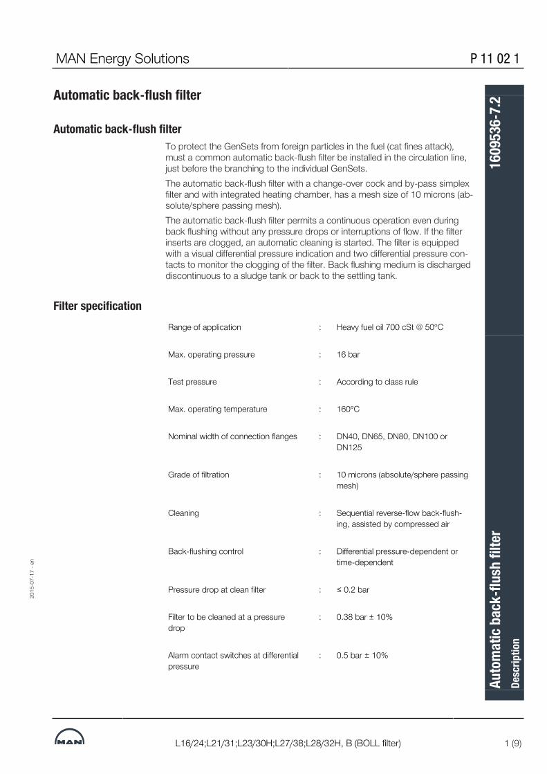
MAN Energy Solutions P 11 02 1
L16/24;L21/31;L23/30H;L27/38;L28/32H, B (BOLL filter) 1 (9)
Automatic back-flush filter
Automatic back-flush filterTo protect the GenSets from foreign particles in the fuel (cat fines attack),must a common automatic back-flush filter be installed in the circulation line,just before the branching to the individual GenSets.The automatic back-flush filter with a change-over cock and by-pass simplexfilter and with integrated heating chamber, has a mesh size of 10 microns (ab-solute/sphere passing mesh).The automatic back-flush filter permits a continuous operation even duringback flushing without any pressure drops or interruptions of flow. If the filterinserts are clogged, an automatic cleaning is started. The filter is equippedwith a visual differential pressure indication and two differential pressure con-tacts to monitor the clogging of the filter. Back flushing medium is dischargeddiscontinuous to a sludge tank or back to the settling tank.
Filter specificationRange of application : Heavy fuel oil 700 cSt @ 50°C
Max. operating pressure : 16 bar
Test pressure : According to class rule
Max. operating temperature : 160°C
Nominal width of connection flanges : DN40, DN65, DN80, DN100 orDN125
Grade of filtration : 10 microns (absolute/sphere passingmesh)
Cleaning : Sequential reverse-flow back-flush-ing, assisted by compressed air
Back-flushing control : Differential pressure-dependent ortime-dependent
Pressure drop at clean filter : ≤ 0.2 bar
Filter to be cleaned at a pressuredrop
: 0.38 bar ± 10%
Alarm contact switches at differentialpressure
: 0.5 bar ± 10%
2015
-07-
17 -
en
Auto
mat
ic ba
ck-fl
ush
filte
rDe
scrip
tion
1609
536-
7.2

P 11 02 1 MAN Energy Solutions
2 (9) L16/24;L21/31;L23/30H;L27/38;L28/32H, B (BOLL filter)
Compressed air : 4-10 bar
2015
-07-
17 -
en
Auto
mat
ic ba
ck-fl
ush
filte
rDe
scrip
tion
1609
536-
7.2

MAN Energy Solutions P 11 02 1
L16/24;L21/31;L23/30H;L27/38;L28/32H, B (BOLL filter) 3 (9)
Specification L16/241000 rpm Booster circuit
Qty. engines 5L16/24 6L16/24 7L16/24 8L16/24 9L16/241 DN40 DN40 DN40 DN40 DN40
2 DN40 DN40 DN40 DN40 DN40
3 DN40 DN40 DN40 DN65 DN65
4 DN40 DN65 DN65 DN65 DN65
1200 rpm Booster circuitQty. engines 5L16/24 6L16/24 7L16/24 8L16/24 9L16/24
1 DN40 DN40 DN40 DN40 DN40
2 DN40 DN40 DN40 DN40 DN40
3 DN40 DN40 DN65 DN65 DN65
4 DN40 DN65 DN65 DN65 DN65
Specification L21/31900 rpm Booster circuit
Qty. engines 5L21/31 6L21/31 7L21/31 8L21/31 9L21/311 DN40 DN40 DN40 DN40 DN65
2 DN65 DN65 DN65 DN65 DN65
3 DN65 DN65 DN65 DN65 DN80
4 DN65 DN65 DN80 DN80 DN80
1000 rpm Booster circuitQty. engines 5L21/31 6L21/31 7L21/31 8L21/31 9L21/31
1 DN40 DN40 DN40 DN40 DN65
2 DN65 DN65 DN65 DN65 DN65
3 DN65 DN65 DN65 DN65 DN80
4 DN65 DN65 DN80 DN80 DN802015
-07-
17 -
en
Auto
mat
ic ba
ck-fl
ush
filte
rDe
scrip
tion
1609
536-
7.2

P 11 02 1 MAN Energy Solutions
4 (9) L16/24;L21/31;L23/30H;L27/38;L28/32H, B (BOLL filter)
Specification L27/38720 rpm Booster circuit
Qty. engines 5L27/38 6L27/38 7L27/38 8L27/38 9L27/381 DN40 DN40 DN65 DN65 DN65
2 DN65 DN65 DN65 DN65 DN65
3 DN65 DN65 DN65 DN80 DN80
4 DN65 DN80 DN80 DN80 DN100
750 rpm Booster circuitQty. engines 5L27/38 6L27/38 7L27/38 8L27/38 9L27/38
1 DN40 DN40 DN65 DN65 DN65
2 DN65 DN65 DN65 DN65 DN65
3 DN65 DN65 DN65 DN80 DN80
4 DN65 DN80 DN80 DN80 DN100
Specification L23/30H720/750 rpm Booster circuitQty. engines 5L23/30H 6L23/30H 7L23/30H 8L23/30H
1 DN40 DN40 DN40 DN40
2 DN40 DN40 DN40 DN65
3 DN40 DN65 DN65 DN65
4 DN65 DN65 DN65 DN65
900 rpm Booster circuitQty. engines 6L23/30H 7L23/30H 8L23/30H
1 DN40 DN40 DN40
2 DN40 DN65 DN65
3 DN65 DN65 DN65
4 DN65 DN65 DN65 2015
-07-
17 -
en
Auto
mat
ic ba
ck-fl
ush
filte
rDe
scrip
tion
1609
536-
7.2

MAN Energy Solutions P 11 02 1
L16/24;L21/31;L23/30H;L27/38;L28/32H, B (BOLL filter) 5 (9)
Specification L28/32H720 rpm Booster circuit
Qty. engines 5L28/32H 6L28/32H 7L28/32H 8L28/32H 9L28/32H1 DN40 DN40 DN40 DN40 DN40
2 DN40 DN65 DN65 DN65 DN65
3 DN65 DN65 DN65 DN65 DN65
4 DN65 DN65 DN65 DN65 DN80
750 rpm Booster circuitQty. engines 5L28/32H 6L28/32H 7L28/32H 8L28/32H 9L28/32H
1 DN40 DN40 DN40 DN40 DN40
2 DN40 DN65 DN65 DN65 DN65
3 DN65 DN65 DN65 DN65 DN65
4 DN65 DN65 DN65 DN65 DN80
2015
-07-
17 -
en
Auto
mat
ic ba
ck-fl
ush
filte
rDe
scrip
tion
1609
536-
7.2

P 11 02 1 MAN Energy Solutions
6 (9) L16/24;L21/31;L23/30H;L27/38;L28/32H, B (BOLL filter)
DN40 - Typ 6.72.1
DN65 - Typ 6.72.1
2015
-07-
17 -
en
Auto
mat
ic ba
ck-fl
ush
filte
rDe
scrip
tion
1609
536-
7.2

MAN Energy Solutions P 11 02 1
L16/24;L21/31;L23/30H;L27/38;L28/32H, B (BOLL filter) 7 (9)
DN80 - Typ 6.72.12015
-07-
17 -
en
Auto
mat
ic ba
ck-fl
ush
filte
rDe
scrip
tion
1609
536-
7.2

P 11 02 1 MAN Energy Solutions
8 (9) L16/24;L21/31;L23/30H;L27/38;L28/32H, B (BOLL filter)
DN100 - Typ 6.64.1 2015
-07-
17 -
en
Auto
mat
ic ba
ck-fl
ush
filte
rDe
scrip
tion
1609
536-
7.2

MAN Energy Solutions P 11 02 1
L16/24;L21/31;L23/30H;L27/38;L28/32H, B (BOLL filter) 9 (9)
2702160379849562727021603798495627
2015
-07-
17 -
en
Auto
mat
ic ba
ck-fl
ush
filte
rDe
scrip
tion
1609
536-
7.2

This page is intentionally left blank2702160379849562727021603798495627
2015
-07-
17 -
en
P 11 02 1 MAN Energy Solutions
L16/24;L21/31;L23/30H;L27/38;L28/32H, B (BOLL filter)
Auto
mat
ic ba
ck-fl
ush
filte
rDe
scrip
tion
1609
536-
7.2

MAN Energy Solutions 010.000.023-05
General, D010.000.023-05-0001 1 (10)
Specification of heavy fuel oil (HFO)
PrerequisitesFour-stroke diesel engines from can be powered with any heavy fuel oil re-covered from crude oil that fulfils the requirements specified in the table Prop-erties of heavy fuel oil, provided that the engine and the fuel management sys-tem are designed accordingly. In order to ensure a favourable ratio betweenfuel costs, spare parts and also repair and maintenance expenditure, we re-commend observing the following points.
Heavy fuel oil (HFO)Origin/Refinery process The quality of the heavy fuel oil largely depends on the quality of crude oil and
on the refining process used. This is why the properties of heavy fuel oils withthe same viscosity may vary considerably depending on the bunker positions.Heavy fuel oil is normally a mixture of residual oil and distillates. The compon-ents of the mixture are normally obtained from modern refinery processes,such as Catcracker or Visbreaker. These processes can adversely affect thestability of the fuel as well as its ignition and combustion properties. The pro-cessing of the heavy fuel oil and the operating result of the engine also de-pend heavily on these factors.Bunker positions with standardised heavy fuel oil qualities should preferablybe used. If oils need to be purchased from independent dealers, also ensurethat these also comply with the international specifications. The engine oper-ator is responsible for ensuring that suitable heavy fuel oils are chosen.
Specifications Fuels that can be used in an engine must satisfy the specifications to ensureadequate quality. The limit values for heavy fuel oils are specified in the tableSpecifications for heavy fuel oils. The entries in the last column of this tablecontain important background information and must therefore be observed.The relevant international specification is ISO 8217 in the respectively applic-able version. The fuel may only be used if it fully complies with the standard.All qualities in these specifications up to K700 can be used, provided the fuelmanagement system has been designed for these fuels. To use fuels that donot comply with these specifications (e.g. crude oil), consultation with thetechnical service from Augsburg is required. Heavy fuel oils with a maximumdensity of 1,010 kg/m3 may only be used if up-to-date separators are in-stalled.
Important Even if they fulfil the aforementioned specifications, the fuel properties spe-cified in the table Specifications for heavy fuel oils may possibly not be ad-equate to determine the ignition and combustion properties and also the sta-bility of the fuel. This means that the operating behaviour of the engine candepend on properties that are not defined in the specification. This particularlyapplies to the oil property that causes formation of deposits in the combustionchamber, injection system, gas ducts and exhaust system. A number of fuelshave a tendency towards incompatibility with lubricating oil which leads to de-posits being formed in the fuel pumps that can cause a blockage of thepumps. It may therefore be necessary to exclude specific fuels that couldcause problems.
Blends The addition of engine oils (old lubricating oil, ULO – used lubricating oil) andadditives that are not manufactured from mineral oils, (coal-tar oil, for ex-ample), and residual products of chemical or other processes such as
2020
-02-
10 -
de
Spec
ifica
tion
of h
eavy
fuel
oil (
HFO)

010.000.023-05 MAN Energy Solutions
2 (10) General, D010.000.023-05-0001
solvents (polymers or chemical waste) is not permitted. Some of the reasonsfor this are as follows: abrasive and corrosive effects, unfavourable combus-tion characteristics, poor compatibility with mineral oils and, last but not least,adverse effects on the environment. The order for the fuel must expresslystate what is not permitted as the fuel specifications that generally apply donot include this limitation.If engine oils (old lubricating oil, ULO – used lubricating oil) are added to fuel,this poses a particular danger as the additives in the lubricating oil act asemulsifiers that cause dirt, water and catfines to be transported as fine sus-pension. They therefore prevent the necessary cleaning of the fuel. In our ex-perience (and this has also been the experience of other manufacturers), thiscan severely damage the engine and turbocharger components.The addition of chemical waste products (solvents, for example) to the fuel isprohibited for environmental protection reasons according to the resolution ofthe IMO Marine Environment Protection Committee passed on 1st January1992.
Leak oil collector Leak oil collectors that act as receptacles for leak oil, and also return andoverflow pipes in the lube oil system, must not be connected to the fuel tank.Leak oil lines should be emptied into sludge tanks.
Characteristic Unit Limit value1) Standard2)
Viscosity (at 50 °C)3) mm2/s (cSt) Max. 700 ISO 3104, ASTM D7042;ASTM D445, DIN EN 16896Viscosity (at 100 °C)3) mm2/s (cSt) Max. 55
Density (at 15 °C) kg/m3 Max. 1010 ISO 3675, ISO 12185,
DIN 51757
Flashpoint4) °C Min. 60 ISO 2719
Pour point5) °C Max. 30 ISO 3016
Acid value mg KOH/g Max. 2.5 ASTM D664
Aluminium and silicon mg/kg max. 156) IP 501, IP 470, ISO 10478
Total sediment (aged) % (m/m) max. 0.10 ISO 10307-2
Coke residue (Conradson) % (m/m) max. 20 DIN EN ISO 10370
Sulphur % (m/m) max. 5.07) ISO 8754, ISO 14596
Ash % (m/m) max. 0.15 ISO 6245
Vanadium mg/kg max. 450 IP 501, IP 470, ISO 14597,DIN 51790-4
Water % (v/v) max. 0.208) DIN 51777; ASTM D6304
CCAI 870 ISO 8217
Asphaltene content % (m/m) Max. 2/3 of the coke residue(Conradson)
factory standard, DIN 51595
Sodium mg/kg max. Na < 1/3 Vn, Na < 100 IP 501, IP 470, DIN 51399-1
Used oil9) mg/kg max. Ca < 30 and Zn < 15 orCa < 30 and P < 15
IP 501, IP 470, IP 500,
DIN 51399-1
Hydrogen sulphide mg/kg max. 2 IP 570
2020
-02-
10 -
de
Spec
ifica
tion
of h
eavy
fuel
oil (
HFO)
MAN Energy Solutions 010.000.023-05
General, D010.000.023-05-0001 3 (10)
Characteristic Unit Limit value1) Standard2)
1) Requirement at motor inlet: Additional parameters to ISO 8217. The entire document ISO 8217 in its current ver-sion is binding. The fuel must be homogeneous at engine inlet. A homogeneous fuel is present if the p-value is min.1.20 according to ASTM D7060. Other methods (i.e. ASTM D7112 or ASTM D7157) may also be used proofing thehomogeneity of the fuel. Furthermore, the fuel must be fir for purpose and must not contain any substance at a con-centration contributing overall to additional air pollution and/or jeopardizing the safety of the personnel and/or ad-versely affects the performance of the machinery.2) Always consult the latest version.3) Follow specific requirements for the injection system.4) SOLAS standard: Applications not regulated by the SOLAS standard may have a lower flashpoint.5) The operator must set the pour point according to the specifications of the fuel system and usage conditions.6) The maximum Al and Si content in the bunker product (before purification) must not exceed 60 mg/kg.7) Local laws and regulations supersede the maximum allowed sulphur content.8) The maximum water content in the bunker product (before purification) must not exceed 0.50%.9) The fuel must generally not contain used oil. If thresholds are exceeded, this indicates used oil contamination.
Table 1: Characteristics of heavy fuel oil
Additional informationThe following information will clarify the correlation between the quality of theheavy fuel oil, heavy fuel oil preparation, engine operation and the operatingresults.
Selection of heavy fuel oil Economical operation with heavy fuel oil within the limit values specified in thetable Specifications for heavy fuel oil is possible under normal operating con-ditions provided the system is working properly and regular maintenance iscarried out. If these requirements are not satisfied, shorter maintenance inter-vals, higher wear and increased spare parts requirement is to be expected.The required maintenance intervals and operating results determine whichquality of heavy fuel oil should be used.It is an established fact that the price advantage decreases as viscosity in-creases. It is therefore not always economical to use the fuel with the highestviscosity as in many cases the quality of this fuel will not be the best.
Viscosity/injection viscosity Heavy fuel oils with a high viscosity may be of an inferior quality. The max-imum permissible viscosity depends on the preheating system installed andthe capacity (flow rate) of the separator.The prescribed injection viscosity of 12 – 14 mm2/s (for GenSets, L16/24,L21/31, L23/30H, L27/38, L28/32H: 12 – 18 cSt) and corresponding fueltemperature upstream of the engine must be observed. This is the only way toensure efficient atomisation and mixture formation and therefore low-residuecombustion. This also prevents mechanical overloading of the injection sys-tem. For the prescribed injection viscosity and/or the required fuel oil temper-ature upstream of the engine, refer to the viscosity temperature diagram.
Heavy fuel oil processing Whether or not problems occur with the engine in operation depends on howcarefully the heavy fuel oil has been processed. Particular care should betaken to ensure that highly-abrasive inorganic foreign matter (catalystparticles, rust, sand) are effectively removed. It has been shown in practicethat wear as a result of abrasion in the engine increases considerably if thealuminum and silicium content is higher than 15 mg/kg.
2020
-02-
10 -
de
Spec
ifica
tion
of h
eavy
fuel
oil (
HFO)

010.000.023-05 MAN Energy Solutions
4 (10) General, D010.000.023-05-0001
Viscosity and density influence the cleaning effect. This must be taken into ac-count when designing and making adjustments to the cleaning system.
Settling tank The heavy fuel oil is pre-cleaned in the settling tank. This pre-cleaning is moreeffective the longer the fuel remains in the tank and the lower the viscosity ofthe heavy fuel oil (maximum preheating temperature 75 °C in order to preventthe formation of asphalt in the heavy fuel oil). One settling tank is suitable forheavy fuel oils with a viscosity below 380 mm2/s at 50 °C. If the heavy fuel oilhas high concentrations of foreign material or if fuels according to ISO-F-RM,G/K380 or K700 are used, two settling tanks are necessary, one of whichmust be designed for operation over 24 hours. Before transferring the con-tents into the service tank, water and sludge must be drained from the settlingtank.
Separators A separator is particularly suitable for separating material with a higher specificdensity – such as water, foreign matter and sludge. The separators must beself-cleaning (i.e. the cleaning intervals must be triggered automatically).Only new generation separators should be used. They are extremely effectivethroughout a wide density range with no changeover required, and can separ-ate water from heavy fuel oils with a density of up to 1.01 g/ml at 15 °C.Table Achievable contents of foreign matter and water (after separation)shows the prerequisites that must be met by the separator. These limit valuesare used by manufacturers as the basis for dimensioning the separator andensure compliance.The manufacturer's specifications must be complied with to maximize thecleaning effect.
Application in ships and stationary use: parallel installationOne separator for 100% flow rate One separator (reserve) for 100%
flow rateFigure 1: Arrangement of heavy fuel oil cleaning equipment and/or separator
The separators must be arranged according to the manufacturers' current re-commendations (Alfa Laval and Westphalia). The density and viscosity of theheavy fuel oil in particular must be taken into account. If separators by othermanufacturers are used, should be consulted.If the treatment is in accordance with the specifications and the correct separ-ators are chosen, it may be assumed that the results stated in the table en-titled Achievable contents of foreign matter and water for inorganic foreignmatter and water in heavy fuel oil will be achieved at the engine inlet.
2020
-02-
10 -
de
Spec
ifica
tion
of h
eavy
fuel
oil (
HFO)

MAN Energy Solutions 010.000.023-05
General, D010.000.023-05-0001 5 (10)
Results obtained during operation in practice show that the wear occurs as aresult of abrasion in the injection system and the engine will remain within ac-ceptable limits if these values are complied with. In addition, an optimum lubeoil treatment process must be ensured.
Definition Particle size QuantityInorganic foreign matterincluding catalyst particles
< 5 µm < 20 mg/kg
Al+Si content – < 15 mg/kg
Water content – < 0.2 vol.%
Table 2: Achievable contents of foreign matter and water (after separation)
Water It is particularly important to ensure that the water separation process is asthorough as possible as the water takes the form of large droplets, and not afinely distributed emulsion. In this form, water also promotes corrosion andsludge formation in the fuel system and therefore impairs the supply, atomisa-tion and combustion of the heavy fuel oil. If the water absorbed in the fuel isseawater, harmful sodium chloride and other salts dissolved in this water willenter the engine.Water-containing sludge must be removed from the settling tank before theseparation process starts, and must also be removed from the service tank atregular intervals. The tank's ventilation system must be designed in such away that condensate cannot flow back into the tank.
Vanadium/Sodium If the vanadium/sodium ratio is unfavourable, the melting point of the heavyfuel oil ash may fall in the operating area of the exhaust-gas valve which canlead to high-temperature corrosion. Most of the water and water-soluble so-dium compounds it contains can be removed by pretreating the heavy fuel oilin the settling tank and in the separators.The risk of high-temperature corrosion is low if the sodium content is one thirdof the vanadium content or less. It must also be ensured that sodium doesnot enter the engine in the form of seawater in the intake air.If the sodium content is higher than 100 mg/kg, this is likely to result in ahigher quantity of salt deposits in the combustion chamber and exhaust-gassystem. This will impair the function of the engine (including the suction func-tion of the turbocharger).Under certain conditions, high-temperature corrosion can be prevented by us-ing a fuel additive that increases the melting point of heavy fuel oil ash (alsosee Additives for heavy fuel oils).
Ash Fuel ash consists for the greater part of vanadium oxide and nickel sulphate(see above section for more information). Heavy fuel oils containing a highproportion of ash in the form of foreign matter, e.g. sand, corrosion com-pounds and catalyst particles, accelerate the mechanical wear in the engine.Catalyst particles produced as a result of the catalytic cracking process maybe present in the heavy fuel oils. In most cases, these catalyst particles arealuminium silicates causing a high degree of wear in the injection system andthe engine. The aluminium content determined, multiplied by a factor ofbetween 5 and 8 (depending on the catalytic bond), is roughly the same asthe proportion of catalyst remnants in the heavy fuel oil.
Homogeniser If a homogeniser is used, it must never be installed between the settling tankand separator as otherwise it will not be possible to ensure satisfactory separ-ation of harmful contaminants, particularly seawater.
2020
-02-
10 -
de
Spec
ifica
tion
of h
eavy
fuel
oil (
HFO)

010.000.023-05 MAN Energy Solutions
6 (10) General, D010.000.023-05-0001
Flash point (ASTM D 93) National and international transportation and storage regulations governingthe use of fuels must be complied with in relation to the flash point. In general,a flash point of above 60 °C is prescribed for diesel engine fuels.
Low-temperature behaviour(ASTM D 97)
The pour point is the temperature at which the fuel is no longer flowable(pumpable). As the pour point of many low-viscosity heavy fuel oils is higherthan 0 °C, the bunker facility must be preheated, unless fuel in accordancewith RMA or RMB is used. The entire bunker facility must be designed in sucha way that the heavy fuel oil can be preheated to around 10 °C above thepour point.
Pump characteristics If the viscosity of the fuel is higher than 1000 mm2/s (cSt), or the temperatureis not at least 10 °C above the pour point, pump problems will occur. Formore information, also refer to paragraph Low-temperature behaviour (ASTMD 97.
Combustion properties If the proportion of asphalt is more than two thirds of the coke residue (Con-radson), combustion may be delayed which in turn may increase the forma-tion of combustion residues, leading to such as deposits on and in the injec-tion nozzles, large amounts of smoke, low output, increased fuel consumptionand a rapid rise in ignition pressure as well as combustion close to the cylin-der wall (thermal overloading of lubricating oil film). If the ratio of asphalt tocoke residues reaches the limit 0.66, and if the asphalt content exceeds 8%,the risk of deposits forming in the combustion chamber and injection systemis higher. These problems can also occur when using unstable heavy fuel oils,or if incompatible heavy fuel oils are mixed. This would lead to an increaseddeposition of asphalt (see paragraph Compatibility).
Ignition quality Nowadays, to achieve the prescribed reference viscosity, cracking-processproducts are used as the low viscosity ingredients of heavy fuel oils althoughthe ignition characteristics of these oils may also be poor. The cetane numberof these compounds should be > 35. If the proportion of aromatic hydrocar-bons is high (more than 35 %), this also adversely affects the ignition quality.The ignition delay in heavy fuel oils with poor ignition characteristics is longer;the combustion is also delayed which can lead to thermal overloading of theoil film at the cylinder liner and also high cylinder pressures. The ignition delayand accompanying increase in pressure in the cylinder are also influenced bythe end temperature and compression pressure, i.e. by the compression ratio,the charge-air pressure and charge-air temperature.The disadvantages of using fuels with poor ignition characteristics can be lim-ited by preheating the charge air in partial load operation and reducing theoutput for a limited period. However, a more effective solution is a high com-pression ratio and operational adjustment of the injection system to the igni-tion characteristics of the fuel used, as is the case with piston engines.The ignition quality is one of the most important properties of the fuel. Thisvalue appears as CCAI in ISO 8217. This method is only applicable to"straight run" residual oils. The increasing complexity of refinery processes hasthe effect that the CCAI method does not correctly reflect the ignition beha-viour for all residual oils.A testing instrument has been developed based on the constant volume com-bustion method (fuel combustion analyser FCA), which is used in some fueltesting laboratories (FCA) in conformity with IP 541.The instrument measures the ignition delay to determine the ignition quality ofa fuel and this measurement is converted into an instrument-specific cetane
2020
-02-
10 -
de
Spec
ifica
tion
of h
eavy
fuel
oil (
HFO)

MAN Energy Solutions 010.000.023-05
General, D010.000.023-05-0001 7 (10)
number (ECN: Estimated Cetane Number). It has been determined that heavyfuel oils with a low ECN number cause operating problems and may even leadto damage to the engine. An ECN >20 can be considered acceptable.As the liquid components of the heavy fuel oil decisively influence the ignitionquality, flow properties and combustion quality, the bunker operator is re-sponsible for ensuring that the quality of heavy fuel oil delivered is suitable forthe diesel engine. Also see illustration entitled Nomogram for determining theCCAI – assigning the CCAI ranges to engine types.
2020
-02-
10 -
de
Spec
ifica
tion
of h
eavy
fuel
oil (
HFO)

010.000.023-05 MAN Energy Solutions
8 (10) General, D010.000.023-05-0001
V Viscosity in mm2/s (cSt) at50° C
A Normal operating condi-tions
D Density [in kg/m3] at 15° C B The ignition characterist-ics can be poor and re-quire adapting the engineor the operating condi-tions.
CCAI Calculated Carbon Aro-maticity Index
C Problems identified maylead to engine damage,even after a short periodof operation.
1 Engine type 2 The CCAI is obtained fromthe straight line throughthe density and viscosityof the heavy fuel oils.
The CCAI can be calculated using the following formula:CCAI = D - 141 log log (V+0.85) - 81
Figure 2: Nomogram for determining the CCAI and assigning the CCAI rangesto engine types
2020
-02-
10 -
de
Spec
ifica
tion
of h
eavy
fuel
oil (
HFO)

MAN Energy Solutions 010.000.023-05
General, D010.000.023-05-0001 9 (10)
Sulphuric acid corrosion The engine should be operated at the coolant temperatures prescribed in theoperating handbook for the relevant load. If the temperature of the compon-ents that are exposed to acidic combustion products is below the acid dewpoint, acid corrosion can no longer be effectively prevented, even if alkalinelube oil is used.If the lubrication oil quality and the engine cooling system fulfil the specified re-quirements, the BN values stated in section 010.005 Engine - OperatingManual 010.000.023-11 are sufficient.
Stability The fuel must be a homogeneous mixture when entering the engine. Precipit-ation of any fuel components is not permissible! Experiences have shown thatthe stability decreases with length of the storage period and the present con-ditions. It is therefore of utmost interest of the operator having a fuel with thehighest stability reserve possible ensuring a homogeneous fuel anytime at en-gine inlet (sea table Characteristics of heavy fuel oil).
Compatibility The supplier must guarantee that the heavy fuel oil is homogeneous and re-mains stable, even after the standard storage period. If different bunker oilsare mixed, this can lead to separation and the associated sludge formation inthe fuel system during which large quantities of sludge accumulate in the sep-arator that block filters, prevent atomisation and a large amount of residue asa result of combustion.This is due to incompatibility or instability of the oils. Therefore heavy fuel oil asmuch as possible should be removed in the storage tank before bunkeringagain to prevent incompatibility.
Blending the heavy fuel oil If heavy fuel oil for the main engine is blended with gas oil (MGO) or other re-sidual fuels (e.g. LSFO or ULSFO) to obtain the required quality or viscosity ofheavy fuel oil, it is extremely important that the components are compatible(see section Compatibility). The compatibility of the resulting mixture must betested over the entire mixing range. Reduced long-term stability due to con-sumption of the stability reserve can be a result. If blending of different fuels isplanned or unavoidable, the stability reserve of the residual fuel must be suffi-cient ensuring a blending without the occurrence of inhomogeneous fuel.
Additives for heavy fuel oils engines can be operated economically without additives. It is up to the cus-tomer to decide whether or not the use of additives is beneficial. The supplierof the additive must guarantee that the engine operation will not be impairedby using the product.The use of heavy fuel oil additives during the warranty period must be avoidedas a basic principle.Additives that are currently used for diesel engines, as well as their probableeffects on the engine's operation, are summarised in the table below Additivesfor heavy fuel oils and their effects on the engine operation.
Precombustion additives ▪ Dispersing agents/stabilisers▪ Emulsion breakers▪ Biocides
Combustion additives ▪ Combustion catalysts(fuel savings, emissions)
Post-combustion additives ▪ Ash modifiers (hot corrosion)▪ Soot removers (exhaust-gas system)
Table 3: Additives for heavy fuel oils and their effects on the engine operation
2020
-02-
10 -
de
Spec
ifica
tion
of h
eavy
fuel
oil (
HFO)

010.000.023-05 MAN Energy Solutions
10 (10) General, D010.000.023-05-0001
Heavy fuel oils with low sul-phur content
From the point of view of an engine manufacturer, a lower limit for the sulphurcontent of heavy fuel oils does not exist. We have not identified any problemswith the low-sulphur heavy fuel oils currently available on the market that canbe traced back to their sulphur content. This situation may change in future ifnew methods are used for the production of low-sulphur heavy fuel oil (desul-phurisation, new blending components). will monitor developments and informits customers if required.If the engine is not always operated with low-sulphur heavy fuel oil, corres-ponding lubricating oil for the fuel with the highest sulphur content must beselected.
Handling of operating fluidsHandling of operating fluids can cause serious injury and damage to theenvironment.• Observe safety data sheets of the operating fluid supplier.
TestsSampling In order to check whether the stated specifications and/or required delivery
conditions have been met, we recommend keeping at least one sample ofeach bunker oil (at least for the warranty period of the engine). In order to en-sure that the sample is a representative sample of the bunkered oil, thesample should be taken from the transfer line during start-up, after half theoperating time, as well as at the end of the bunkering period.
Analysis of samples To ensure sufficient cleaning of the fuel via the separator, perform regularfunctional check by sampling up- and downstream of the separator.Analysis of HFO samples is very important for safe engine operation. We cananalyse fuel for customers at laboratory PrimeServLab.
180143986853480331
2020
-02-
10 -
de
Spec
ifica
tion
of h
eavy
fuel
oil (
HFO)

MAN Energy Solutions 010.000.023-04
General, D010.000.023-04-0001 1 (3)
Marine diesel oil (DMB, DFB) specifications
General informationMarine diesel oil as a heavy distillate is available for marine applications only.Alternative designation: marine diesel fuel oil (MDO). It is made from crude oiland may contain synthetic components (e.g. BtL, CtL, GtL and HVO). The fuelis treated the same as residual fuel/heavy fuel oil in the supply chain. Thismeans that it is possible for the fuel to be mixed with high-viscosity heavy fueloil residue, e.g. in a bunker vessel, and it might therefore contain residue fromcrude oil processing. This can affect the properties of the fuel.
Selection of suitable diesel fuelUnsuitable or adulterated fuel generally results in a shortening of the servicelife of engine parts/components, damage to these and to catastrophic enginefailure. It is therefore important to select the fuel with care in terms of its suit-ability for the engine and the intended application. Through its combustion,the fuel influences the emissions behaviour of the engine.
Specifications and approvalsThe fuel quality varies regionally and is dependent on climatic conditions. Allrequirements specified in the current edition of ISO 8217 apply.The following values must be maintained at the engine inlet:
Property Unit Limit value Standard1)
Kinematic viscosity at 40 °C2) mm2/s Max. 11.0 ISO 3104, ASTM D7042, ASTM D445,
DIN EN 16896Min. 2.000
Density at 15 °C kg/m3 Max. 900.0 ISO 3675, ISO 12185
Min. 820.0
Cetane index & cetane number Min. 35 ISO 4264 & ISO 5165
Sulphur content3) % (m/m) Max. 1.50 ISO 8754, ISO 14596, ASTM D 4294,DIN 51400-10
Flash point4) °C Min. 60.0 ISO 2719
Hydrogen sulphide mg/kg Max. 2.0 IP 570
Acid number mg KOH/g Max. 0.5 ASTM D664
Corrosion on copper Class Max. 1 ISO 2160
Oxidation stability5 g/m3
h
Max. 25 ISO 12205, EN 15751
Min. 20
Fatty acid methyl ester (FAME)content6)
% (V/V) Max. 7.0 ASTM D7963, IP 579, EN 14078
Carbon residue7) % (m/m) Max. 0.30 ISO 10370
Appearance8) – – Free from con-tamination
visually
2019
-10-
01 -
de
Mar
ine d
iesel
oil (
DMB,
DFB
) spe
cifica
tions

010.000.023-04 MAN Energy Solutions
2 (3) General, D010.000.023-04-0001
Property Unit Limit value Standard1)
Water content % (m/m) Max. 0.02 DIN 51777, DIN EN 12937, ASTM D6304
Ash content % (m/m) Max. 0.010 ISO 6245
Lubricity9) μm Max. 520 ISO 12156-1, ASTM D6079
Table 1: Requirements for diesel fuel
Remarks:1) Always in relation to the currently applicable edition.2) Specific requirements of the injection system must be taken into account.3) Independent of the maximum permissible sulphur content, local laws and regulations must be adhered to.4) SOLAS specification. A lower flash point is possible for non-SOLAS-regulated applications.5) If there is more than 2% (V/V) FAME, an analysis as per EN15751 must additionally be performed6) The FAME must either be in accordance with EN 14214 or with ASTM D6751.7) Determined on 10% distillation residue.8) Only possible with clear samples. If the sample is not clear or contains visible contamination, the check must becompleted mandatorily for the entire sediment.9) Diameter of the corrected wear scar (WSD).
The following fuels are approved for use:▪ Class ISO F-DMB according to ISO 8217 in the current edition.▪ Class ISO F-DFB as per ISO 8217 in the current edition with additional re-
quirements regarding oxidation stability.
ViscosityIn order to ensure sufficient lubrication, a minimum level of viscosity must beensured at the fuel injection pump. The specified maximum temperature re-quired to maintain a viscosity of more than 1.9 mm2/s upstream of the fuel in-jection pump depends on the fuel viscosity. The temperature of the fuel up-stream of the fuel injection pump must not exceed 45 °C in any case. The lub-ricity requirements of the fuel upstream of the engine is a maximum of 520 µmWSD in each case.
Cold suitabilityThe cold suitability of the fuel is determined by the climatic requirements atthe place of installation. It is the responsibility of the operating company tochoose a fuel with sufficient cold suitability.The cold suitability of a fuel may be determined and assessed using the fol-lowing standards:▪ Limit of filterability (CFPP) as per EN 116▪ Pour point as per ISO 3016▪ Cloud point as per EN 23015To be able to draw a reliable conclusion, it is recommended to perform allthree stated procedures.
2019
-10-
01 -
de
Mar
ine d
iesel
oil (
DMB,
DFB
) spe
cifica
tions

MAN Energy Solutions 010.000.023-04
General, D010.000.023-04-0001 3 (3)
ContaminationThe fuel must be free from contamination and used oil residues. Fuel is con-sidered free from used oil residues if the following requirements are fulfilled:▪ Calcium < 30 mg/kg and zinc < 15 mg/kg or calcium < 30 mg/kg and
phosphorus < 15 mg/kg (specification according to ASTM D5185 or DIN51399-1).
Sea water causes corrosion of the fuel system and hot corrosion of the outletvalves and/or parts of the turbocharger. Sea water is also the reason for insuf-ficient atomisation, thus causing poor mixture formation and combustion withhigh levels of residue. Solid foreign objects increase mechanical wear and theformation of ash in the combustion chamber.We therefore recommend installing a separator upstream of the fuel filter.Separation temperature 40 – 50 °C. Most solid particles (sand, corrosion andcatalytic converter fragments) and water can thus be removed and the clean-ing intervals for the filter elements can be significantly extended.Non-ferrous metals such as e.g. copper and zinc cause sooting of the injec-tion valves. This affects mixture formation, fuel consumption, power build-up/output and the service life of the components. The fuel must therefore be freefrom non-ferrous metals.
Bio-fuel admixtureThe DFA fuel may contain up to 7.0% of bio-fuel based on fatty acid methylester (FAME). The FAME to be added must comply with either EN14214 orASTM D 6751. Compared to fuels on mineral oil basis only, fuels containingFAME have an increased tendency to oxidise and age and are more vulner-able to microbiological contamination. Furthermore, the fuel may contain anincreased quantity of water. This why it is necessary to check the ageing sta-bility at regular intervals when using this type of fuel. In addition, it is importantto regularly check the water content of the fuel.To minimise microbiological contamination, the tanks must be drained on aregular basis. During standstill periods this is required daily, otherwise weekly.When first using fuels containing bio-diesel, deposits that have accumulatedover a longer period of time may become detached. These deposits canblock filters or even cause immediate damage.Using bio-diesel blends in emergency power generators should be avoided.Bio-diesel fuel should be stored in separate reservoirs. Storing fuel containingbio-diesel for more than 6 months is generally not recommended. is not liablefor damage and any possible consequences resulting from the use of fuelcontaining bio-diesel.
AnalysesAnalysis of fuel oil samples is very important for safe engine operation. We cananalyse fuel for customers at laboratory PrimeServLab.135107990579701131135107990579701131
2019
-10-
01 -
de
Mar
ine d
iesel
oil (
DMB,
DFB
) spe
cifica
tions

This page is intentionally left blank135107990579701131135107990579701131
2019
-10-
01 -
de
010.000.023-04 MAN Energy Solutions
General, D010.000.023-04-0001
Mar
ine d
iesel
oil (
DMB,
DFB
) spe
cifica
tions

MAN Energy Solutions 010.000.023-01
General, D010.000.023-01-0001 1 (3)
Diesel fuel (DMA, DFA) specifications
General informationDiesel fuel is a middle distillate from crude oil processing. Other designationsare: gas oil, marine gas oil (MGO), diesel oil. It must not contain any residuefrom crude oil processing. The fuel is permitted to contain synthetically pro-duced components (e.g. BtL, CtL, GtL, & HVO).
Selection of suitable diesel fuelUnsuitable or adulterated fuel generally results in a shortening of the servicelife of engine parts/ components, damage to these and to catastrophic enginefailure. It is therefore important to select the fuel with care in terms of its suit-ability for the engine and the intended application. Through its combustion,the fuel also influences the emissions behaviour of the engine.
Specifications and approvalsThe fuel quality varies regionally and is dependent on climatic conditions. Allrequirements specified in the current edition of ISO 8217 apply.The following values must be maintained at the engine inlet:
Property Unit Limit value Standard1)
Kinematic viscosity at 40 °C2) mm2/s Max. 6.000 ISO 3104, ASTM D7042, ASTM D445,
DIN EN 16896Min. 2.000
Density at 15 °C kg/m3 Max. 890.0 ISO 3675, ISO 12185
Min. 820.0
Cetane index & cetane number Min. 40 ISO 4264 & ISO 5165
Sulphur content3) % (m/m) Max. 1.0 ISO 8754, ISO 14596, ASTM D 4294,DIN 51400-10
Flash point4) °C Min. 60.0 ISO 2719
Hydrogen sulphide mg/kg Max. 2.0 IP 570
Acid number mg KOH/g Max. 0.5 ASTM D664
Corrosion on copper Class Max. 1 ISO 2160
Oxidation stability5 g/m3 Max. 25 ISO 12205, EN 15751
h Min. 20
Fatty acid methyl ester (FAME)content6)
% (V/V) Max. 7.0 ASTM D7963, IP 579, EN 14078
Carbon residue7) %(m/m) Max. 0.30 ISO 10370
Appearance – – Clear & haze free
visually
Water content % (m/m) Max. 0.02 DIN 51777, DIN EN 12937, ASTM D6304
Ash content % (m/m) Max. 0.010 ISO 6245
2019
-10-
01 -
de
Dies
el fu
el (D
MA,
DFA
) spe
cifica
tions

010.000.023-01 MAN Energy Solutions
2 (3) General, D010.000.023-01-0001
Property Unit Limit value Standard1)
Lubricity8) μm Max. 520 ISO 12156-1, ASTM D6079
Table 1: Requirements for diesel fuel
Remarks:1) Always in relation to the currently applicable edition.2) Specific requirements of the injection system must be taken into account.3) Independent of the maximum permissible sulphur content, local laws and regulations must be adhered to.4) SOLAS specification. A lower flash point is possible for non-SOLAS-regulated applications.5) If there is more than 2% (V/V) FAME, an analysis as per EN15751 must additionally be performed6) The FAME must either be in accordance with EN 14214 or with ASTM D6751.7) Determined on 10% distillation residue.8) Diameter of the corrected wear scar (WS).
The following fuels are approved for use:▪ Classes ISO F-DMA & DMZ as per ISO 8217 in the current edition.▪ Class ISO F-DFA & DFZ as per ISO 8217 in the current edition with addi-
tional requirements regarding oxidation stability.▪ Diesel fuel as per EN 590 in the current edition with additional requirement
regarding flash point >60 °C in SOLAS regulated areas.▪ Diesel fuel no. 2-D as per ASTM D975-15 with additional requirement re-
garding flash point >60 °C in SOLAS regulated areas▪ Synthetic diesel fuel as per EN 15940 in the current edition with additional
requirement regarding flash point >60 °C in SOLAS regulated areas. Toobtain the full power output from engines with conventional injection sys-tems, the minimum density in the table Requirements for the diesel fuelmust be strictly adhered to.
ViscosityIn order to ensure sufficient lubrication, a minimum level of viscosity must beensured at the fuel injection pump. The specified maximum temperature re-quired to maintain a viscosity of more than 1.9 mm2/s upstream of the fuel in-jection pump depends on the fuel viscosity. The temperature of the fuel up-stream of the fuel injection pump must not exceed 45 °C in any case. The lub-ricity requirements of the fuel upstream of the engine is a maximum of 520 µmWSD in each case.
Military fuel specificationThe fuel types F-75 or F-76 as per NATO STANAG 1385 may be used. Thefollowing must be observed when doing so:▪ According to the specification, the minimum permissible fuel viscosity for
F-75 & F-76 is 1.7 mm²/s at 40 °C. This corresponds to a minimum fuelviscosity of 1.5 mm²/s at 45 °C (upstream of the engine).
▪ Use of a low-viscosity fuel (1.7 cSt at 40 °C) does not immediately causethe injection system to fail.
▪ A more severe leakage can trigger a variety of alarms!
2019
-10-
01 -
de
Dies
el fu
el (D
MA,
DFA
) spe
cifica
tions

MAN Energy Solutions 010.000.023-01
General, D010.000.023-01-0001 3 (3)
▪ Extended operation of the engine with low-viscosity fuel leads toshortened maintenance intervals for the components of the injection sys-tem!
▪ If permanent operation with low-viscosity fuel is intended, a fuel coolingsystem should be installed. Contact for further information.
▪ The lubricity requirements of the fuel for the engine are always max. 520µm WSD as per ISO 12156-1.
Cold suitabilityThe cold suitability of the fuel is determined by the climatic requirements atthe place of installation. It is the responsibility of the operating company tochoose a fuel with sufficient cold suitability.The cold suitability of a fuel may be determined and assessed using the fol-lowing standards:▪ Limit of filterability (CFPP) as per EN 116▪ Pour point as per ISO 3016▪ Cloud point as per EN 23015To be able to draw a reliable conclusion, it is recommended to perform allthree stated procedures.
Bio-fuel admixtureThe DFA fuel may contain up to 7.0% of bio-fuel based on fatty acid methylester (FAME). The FAME to be added must comply with either EN14214 orASTM D 6751. Compared to fuels on mineral oil basis only, fuels containingFAME have an increased tendency to oxidise and age and are more vulner-able to microbiological contamination. Furthermore, the fuel may contain anincreased quantity of water. This why it is necessary to check the ageing sta-bility at regular intervals when using this type of fuel. In addition, it is importantto regularly check the water content of the fuel.To minimise microbiological contamination, the tanks must be drained on aregular basis. During standstill periods this is required daily, otherwise weekly.When first using fuels containing bio-diesel, deposits that have accumulatedover a longer period of time may become detached. These deposits canblock filters or even cause immediate damage.Using bio-diesel blends in emergency power generators should be avoided.Bio-diesel fuel should be stored in separate reservoirs. Storing fuel containingbio-diesel for more than 6 months is generally not recommended. is not liablefor damage and any possible consequences resulting from the use of fuelcontaining bio-diesel.
AnalysesAnalysis of fuel oil samples is very important for safe engine operation. We cananalyse fuel for customers at laboratory PrimeServLab.162129588343450635162129588343450635
2019
-10-
01 -
de
Dies
el fu
el (D
MA,
DFA
) spe
cifica
tions

This page is intentionally left blank162129588343450635162129588343450635
2019
-10-
01 -
de
010.000.023-01 MAN Energy Solutions
General, D010.000.023-01-0001
Dies
el fu
el (D
MA,
DFA
) spe
cifica
tions

MAN Energy Solutions 010.000.023-02
General, D010.000.023-02-0001 1 (2)
Specification of bio fuel
BiofuelOther designations Biodiesel, FAME, vegetable oil, rapeseed oil, palm oil, frying fat.Origin Biofuel is derived from oil plants or old cooking oil.
ProvisionTransesterified and non-transesterified vegetable oils can be used.Transesterified biofuels (biodiesel, FAME) must comply with the standard EN14214.Non-transesterified biofuels must comply with the specifications listed in tableSpecification of non-transesterified bio fuel.These specifications are based on experience to date. As this experience islimited, these must be regarded as recommended specifications that can beadapted if necessary. If future experience shows that these specifications aretoo strict, or not strict enough, they can be modified accordingly to ensuresafe and reliable operation.When operating with bio-fuels, lubricating oil that would also be suitable foroperation with diesel oil.See 010.005 Engine - Operating Instructions section 010.000.023-07.
Properties/features Properties/unit Testing methodDensity at 15 °C 900–930 kg/m3 DIN EN ISO 3675,
EN ISO 12185
Flash point > 60 °C DIN EN 22719
Lower calorific value > 35 MJ/kg(typically: 37 MJ/kg)
DIN 51900-3
Viscosity/50 °C < 40 cSt (corresponds to viscos-ity/40 °C< 60 cSt)
DIN EN ISO 3104ASTM D7042
Estimated cetane number > 40 IP 541
Coke residue < 0.4% DIN EN ISO 10370
Sediment content < 200 ppm DIN EN 12662
Oxidation resistance (110 °C) > 5 h EN ISO 6886, EN 14112
Monoglyceride content < 0.70% (m/m) EN14105
Diglyceride content < 0.20% (m/m) EN14105
Triglyceride content < 0.20% (m/m) EN14105
Free glycerol content < 0.02% (m/m) EN14105
Phosphorus content < 15 ppm ASTM D3231
Na and K content < 15 ppm DIN 51797-3
Ash content < 0.01% DIN EN ISO 6245
Water content < 0.5% EN ISO 12537
2019
-07-
08 -
de
Spec
ifica
tion
of b
io fu
el

010.000.023-02 MAN Energy Solutions
2 (2) General, D010.000.023-02-0001
Properties/features Properties/unit Testing methodIodine number < 125g/100g DIN EN 14111
TAN (total acid number) < 5 mg KOH/g DIN EN ISO 660
Cold filter plugging point 10 °C below the lowest temperat-ure in the fuel system
EN 116
Table 1: Specifications for non-interesterified bio fuel
Handling of operating fluidsHandling of operating fluids can cause serious injury and damage to theenvironment.• Observe safety data sheets of the operating fluid supplier.
AnalysesAnalysis of fuel oil samples is very important for safe engine operation. We cananalyse fuel for customers at laboratory PrimeServLab.9907919356063271599079193560632715
2019
-07-
08 -
de
Spec
ifica
tion
of b
io fu
el

MAN Energy Solutions B 11 00 0
L28/32A;L23/30H-Mk3;L23/30A;L28/32S;L27/38S;L23/30S;L21/31S;L16/24S;V28/32H;V28/32S;L1
6/24;L21/31;L23/30H;L27/38;L28/32H 1 (2)
Explanatory notes for biofuel
Operation with biofuelPlease contact MAN Energy Solutions at an early stage of project.
Requirements on plant sideBiofuel has to be divided into 3 categories.
Category 1 – transesterified biofuelFor example:▪ Biodiesel (FAME)Esterified biofuel is comparable to MDO (ISO-F-DMB/ ISO-F-DMC), thereforestandard layout of fuel oil system for MDO-operation to be used.
Category 2 – not transesterified biofuel and pour point below 20°CFor example:▪ Vegetable oil▪ Rape-seed oilNot transesterified biofuel with pour point below 20°C is comparable to HFO(ISO-F-RM), therefore standard layout of fuel oil system for HFO-operation tobe used.
Category 3 – not transesterified biofuel and pour point above 20° CFor example:▪ Palm oil▪ Stearin▪ Animal fat▪ Frying fat
Not transesterified biofuel with a pour point above 20° C carries a risk offlocculation and may clog up pipes and filters unless special precautionsare taken.
Therefore the standard layout of fuel oil system for HFO-operation has to bemodified concerning following aspects:▪ In general no part of the fuel oil system must be cooled down below pour
point of the used biofuel.▪ Fuel cooler for circulation fuel oil feeding part => to be modified.
In this circuit a temperature above pour point of the biofuel is neededwithout overheating of the supply pumps.
▪ Sensor pipes to be isolated or heated and located near to main pipes.▪ To prevent injection nozzles from clogging indicator filter size 0.010 mm
has to be used instead of 0.034 mm.
2018
-09-
07 -
en
Expl
anat
ory n
otes
for b
iofu
elDe
scrip
tion
3700
063-
9.1

B 11 00 0 MAN Energy Solutions
2 (2)
L28/32A;L23/30H-Mk3;L23/30A;L28/32S;L27/38S;L23/30S;L21/31S;L16/24S;V28/32H;V28/32S;L1
6/24;L21/31;L23/30H;L27/38;L28/32H
Additionally:▪ Fuel oil module to be located inside plant (to be protected against rain and
cold wind).▪ A second fuel type has to be provided of category 1 or 2.
Due to the risk of clogging it is needed before each stop of the engine, tochange over to a second fuel type of category 1 or 2 and to operate theengine until the danger of clogging of the fuel oil system no longer exists.
Requirements on engine▪ Injection pumps with special coating and with sealing oil system.▪ Fuel pipes and leak fuel pipes must be equipped with heattracing (not to
be applied for biofuel category 1). Heattracing to be applied for biofuelcategory 2 outside covers of injection pump area and for biofuel category3 also inside injection pump area.
▪ Inlet valve lubrication (L32/40)▪ Nozzle cooling to be applied for biofuel category 2 and 3. (L32/40)▪ Charge air temperature before cylinder 55° C to minimize ignition delay.
Please be aware▪ Depending on the quality of the biofuel, it may be necessary to carry out
one oil change per year (this is not taken into account in the details con-cerning lubricating oil consumption).
▪ An addition to the fuel oil consumption is necessary:2 g/kWh addition to fuel oil consumption (see chapter fuel oil consump-tion)
▪ Engine operation with fuels of low calorific value like biofuel, requires anoutput reduction:– LCV ≥ 38 MJ/kg Power reduction 0%– LCV ≥ 36 MJ/kg Power reduction 5%– LCV ≥ 35 MJ/kg Power reduction 10%
18014405320183179
2018
-09-
07 -
en
Expl
anat
ory n
otes
for b
iofu
elDe
scrip
tion
3700
063-
9.1

MAN Energy Solutions 010.000.023-06
General, D010.000.023-06-0001 1 (2)
Viscosity-temperature diagram (VT diagram)
Explanations of viscosity-temperature diagram
Figure 1: Viscosity-temperature diagram (VT diagram)
In the diagram, the fuel temperatures are shown on the horizontal axis and theviscosity is shown on the vertical axis.The diagonal lines correspond to viscosity-temperature curves of fuels withdifferent reference viscosities. The vertical viscosity axis in mm2/s (cSt) appliesfor 40, 50 or 100 °C.
Determining the viscosity-temperature curve and the required preheating temperatureExample: Heavy fuel oil with180 mm²/s at 50 °C
Prescribed injection viscosityin mm²/s
Required temperature of heavy fuel oil at engine inlet1) in °C
≥ 12 126 (line c)
≤ 14 119 (line d)
2019
-07-
08 -
de
Visc
osity
-tem
pera
ture
dia
gram
(VT
diag
ram
)

010.000.023-06 MAN Energy Solutions
2 (2) General, D010.000.023-06-0001
Prescribed injection viscosityin mm²/s
Required temperature of heavy fuel oil at engine inlet1) in °C
1) With these figures, the temperature drop between the last preheating device andthe fuel injection pump is not taken into account.
Table 1: Determining the viscosity-temperature curve and the required pre-heating temperature
A heavy fuel oil with a viscosity of 180 mm2/s at 50 °C can reach a viscosity of1,000 mm2/s at 24 °C (line e) – this is the maximum permissible viscosity offuel that the pump can deliver.A heavy fuel oil discharge temperature of 152 °C is reached when using a re-cent state-of-the-art preheating device with 8 bar saturated steam. At highertemperatures there is a risk of residues forming in the preheating system –this leads to a reduction in heating output and thermal overloading of theheavy fuel oil. Asphalt is also formed in this case, i.e. quality deterioration.The heavy fuel oil lines between the outlet of the last preheating system andthe injection valve must be suitably insulated to limit the maximum drop intemperature to 4 °C. This is the only way to achieve the necessary injectionviscosity of 14 mm2/s for heavy fuel oils with a reference viscosity of 700 mm2/s at 50 °C (the maximum viscosity as defined in the international specificationssuch as ISO CIMAC or British Standard). If heavy fuel oil with a low referenceviscosity is used, the injection viscosity should ideally be 12 mm2/s in order toachieve more effective atomisation to reduce the combustion residue.The delivery pump must be designed for heavy fuel oil with a viscosity of up to1,000 mm2/s. The pour point also determines whether the pump is capable oftransporting the heavy fuel oil. The bunker facility must be designed so as toallow the heavy fuel oil to be heated to roughly 10 °C above the pour point.
ViscosityThe viscosity of gas oil or diesel oil (marine diesel oil) upstream of theengine must be at least 1.9 mm2/s. If the viscosity is too low, this maycause seizing of the pump plunger or nozzle needle valves as a result ofinsufficient lubrication.
This can be avoided by monitoring the temperature of the fuel. Although themaximum permissible temperature depends on the viscosity of the fuel, itmust never exceed the following values:▪ 45 °C at the most with MGO (DMA) and MDO (DMB)A fuel cooler must therefore be installed.If the viscosity of the fuel is < 2 cSt at 40 °C, consult the technical service ofMAN Energy Solutions in Augsburg.5404319728723431554043197287234315
2019
-07-
08 -
de
Visc
osity
-tem
pera
ture
dia
gram
(VT
diag
ram
)

MAN Energy Solutions B 12 00 0
L21/31;L27/38, 1440000 1 (5)
Lubricating oil system
GeneralThe engine features an entirely closed wet sump lub oil system, ensuring easyinstallation and no risk of dirt entering the lub oil circuit.The helical gear type lub oil pump is installed in the front-end box and drawsthe oil from the sump.Via a double check valve with connection for stand-by pump, the oil flows tothe pressure regulator, through the built-on lub oil plate cooler and the integ-rated automatic lub oil filter to the engine.The back-flush oil from the filter is drained to the sump. A separator must beconnected to maintain proper condition of the lub oil.Integrated thermostatic elements ensure a constant lub oil temperature to theengine.
Lubricating oil requirementsOnly lub oils meeting the requirements in the “List of Lubricating Oils” may beused.Within the guarantee period, only lub oils approved by us should be used, un-less a written statement has been given.
Lubricating oil systemThe lub oil system is the same for both MDO and HFO operation.
2020
-02-
18 -
en
Lubr
icatin
g oi
l sys
tem
Desc
riptio
n37
0029
1-5.
6

B 12 00 0 MAN Energy Solutions
2 (5) L21/31;L27/38, 1440000
Item Description Item Description1 Engine driven lub oil pump, attached 7 Strainer (magnetic insert)
2 Electrical lub oil pump, stand-by 20 Prefilter for lub. oil separator
3 Lub oil cooler 21 Lub oil separator pump
4 Thermostatic valve 22 Preheater for lub. oil separator
5 Automatic backflush filter 23 Lub oil separator
6 Lub oil presure control valve
ConnectionsD4 Lub oil stand-by pump, suction D8 Lub oil from separator
D5 Lub oil stand-by pump, pressure D12 Filling of lub oil
D7 Lub oil to separator H Venting of crankcase
Automatic backflush filter (ITem 5:5A Backflush filter unit, 30 µm
5B Pressure controlled by-pass valve
5C Back-up filter in line, 50 µm
2020
-02-
18 -
en
Lubr
icatin
g oi
l sys
tem
Desc
riptio
n37
0029
1-5.
6

MAN Energy Solutions B 12 00 0
L21/31;L27/38, 1440000 3 (5)
Lub oil stand–by pump, item 2To ensure good suction conditions for the lub oil pump, the pump should beplaced as low as possible.The suction pipe should be as short and with as few bends as possible in or-der to prevent cavitation of the pump.The lub oil stand-by pump also acts as a priming pump for the engine prior tostart.
Design data Capacity▪ See list of capacityViscosity at normal operation:▪ 40 cSt (corresponding to 70 °C)Max viscosity for dimensioning of el-motor:▪ 150 cSt (corresponding to 40 °C for SAE 40 oil)The turbocharger is connected into the same piping system and must not beprimed for more than 5 minutes. The motor starter for the stand-by pumpmust be fitted with time and auxiliary relays limiting the stand-by pump to runfor 5 minutes only or frequent converter for adjustment of flow.For multi-engine installation a smaller prelubricating pump similar to GenSetcan be installed.When we are to supply the motor starter, the function described is built-in.When the motor starter is not included in our scope of supply, a drawingshowing the components and connections required will be forwarded.
Lub oil cooler, item 3The lub oil cooler with stainless steel plates is built-on to the engine. All con-nections are integrated in cooler/front-end box.The heat dissipation appears from the planning data.
Lub oil thermostatic valve, item 4The integrated thermostatic valve has 4 elements and controls the inlet tem-perature to the engine. The nominal set-point is 66 °C. Manual override is fea-tured when required by the classification society concerned.
Automatic lub oil, back-flushing filter, item 5The built-on automatic lub oil filter has 2 filtering stages:
Primary filter Contains several filter candles with a filter mesh of 25 microns correspondingto a nominal filtration degree of 20 microns.The back-flushing facility operates continuously by means of the oil pressure.The back flushing oil is led to the oil sump.The pressure drop across the filter candles is approx 0.2 bar with clean filter.In case the pressure drop exceeds 2 bar, by-pass valves in the filter will open.
Secondary filter The filtered oil is always passing the secondary filter with a filter mesh of 50microns. This filter also acts as a safety filter in case the by-pass valves areopen.
2020
-02-
18 -
en
Lubr
icatin
g oi
l sys
tem
Desc
riptio
n37
0029
1-5.
6

B 12 00 0 MAN Energy Solutions
4 (5) L21/31;L27/38, 1440000
Lub oil pressure control valve, item 6The control valve ensures a correct lub oil pressure also in case of operationwith the lub oil stand-by pump.
Strainer with magnetic insert, item 7The strainer is part of the suction pipe in the oil sump.
Prefilter, item 20To protect the separator pump, item 21, a prefilter should be inserted beforethe pump.Design data:▪ Capacity: See oil pump, item 21▪ Mesh size: 0.8-1.0 mm
Lub oil pump to separator, item 21The pump can be driven directly by the separator or by an independent mo-tor.Design data:▪ Capacity: V = F x P
V: Pump capacity in litres/hourF: MDO/MGO : 0.21 / HFO : 0.29 / LSFO : 0.21 - 0.29P: Power of the engine in kW at MCR
▪ Pressure: Max 2.5 bar▪ Temperature: Max 95°C
Preheater before lub oil separator, item 22The preheater must be able to raise the temperature of the oil from approx65°C to approx 95°C, which is the temperature of the oil for separation.▪ Capacity: C = V x t/1800
C: Capacity of the preheater in kWV: Flow through preheater in litres/hour - defined from the capacity of the separator.t: Temperature difference 35°C (engine operating)
▪ Max pressure 4 bar▪ Max pressure loss 0.5 barSpecific load on heating surface for an electric preheater must not exceed 0.8W/cm2 .
Lub oil preheatingIn case engine stopped for a larger period it can be required to install a pre-heater which can maintain at least 40 °C in case engine has a longer standstill period.
2020
-02-
18 -
en
Lubr
icatin
g oi
l sys
tem
Desc
riptio
n37
0029
1-5.
6

MAN Energy Solutions B 12 00 0
L21/31;L27/38, 1440000 5 (5)
Slow circulation over lub oil cooler on preheated engine should be sufficient.Preheating the lub oil to 40 °C is effected by the preheater of the separator viathe free-standing pump.The preheater must be enlarged in size if necessary, so that it can heat thecontent of the service tank to 40 °C within 4 hours.
Bypass cleaning equipmentBypass cleaning equipment is mandatory when running on HFO and recom-mend when running distillate.In diagram is shown separator, but there are other options, please see "B 1215 0, Treatment and maintenance of lubricating oil".27021632151772299
2020
-02-
18 -
en
Lubr
icatin
g oi
l sys
tem
Desc
riptio
n37
0029
1-5.
6

This page is intentionally left blank27021632151772299
2020
-02-
18 -
en
B 12 00 0 MAN Energy Solutions
L21/31;L27/38, 1440000
Lubr
icatin
g oi
l sys
tem
Desc
riptio
n37
0029
1-5.
6

MAN Energy Solutions B 12 00 0
L28/32S;L27/38S;L23/30S;L21/31S;L16/24S;L23/30DF;V28/32S-DF;L28/32DF;V28/32H;V28/32S;L16/24;L21/31;L23/30H;L27/38;L28/32H,
2015.04.15 - (* Mk2) 1 (2)
Crankcase ventilation
Crankcase ventilationThe crankcase ventilation is not to be directly connected with any other pipingsystem. It is preferable that the crankcase ventilation pipe from each engine isled independently to the open air. The outlet is to be fitted with corrosion res-istant flame screen separately for each engine.
Figure 1: Crankcase ventilation
However, if a manifold arrangement is used, its arrangements are to be as fol-lows:
1) The vent pipe from each engine is to run independently to the manifoldand be fitted with corrosion resistant flame screen within the manifold.
2016
-09-
29 -
en
Cran
kcas
e ven
tilat
ion
Desc
riptio
n16
9927
0-8.
7

B 12 00 0 MAN Energy Solutions
2 (2)
L28/32S;L27/38S;L23/30S;L21/31S;L16/24S;L23/30DF;V28/32S-DF;L28/32DF;V28/32H;V28/32S;L16/24;L21/31;L23/30H;L27/38;L28/32H,
2015.04.15 - (* Mk2)
2) The manifold is to be located as high as practicable so as to allow asubstantial length of piping, which separates the crankcase on the indi-vidual engines.
3) The manifold is to be vented to the open air, so that the vent outlet isfitted with corrosion resistant flame screen, and the clear open area ofthe vent outlet is not less than the aggregate area of the individualcrankcase vent pipes entering the manifold.
4) The manifold is to be provided with drainage arrangement.36028802309692299
The ventilation pipe must be designed to eliminate the risk of water condensa-tion in the pipe flowing back into the engine and should end in the open air:▪ The connection between engine (C13 / C30) and the ventilation pipe must
be flexible.▪ The ventilation pipe must be made with continuous upward slope of min-
imum 5°, even when the ship heel or trim (static inclination).▪ A continuous drain must be installed near the engine. The drain must be
led back to the sludge tank.
Engine Nominal diameter ND (mm)A B C
L16/24, L16/24S 50 65
L21/31, L21/31S 65 40 80
L23/30H, L23/30S 50 - 65
L23/30DF, L23/30H* 50 25 65
L27/38, L27/38S 100 - 100
L28/32DF 50 40 65
L28/32H, L28/32S 50 - 65
V28/32H 100 - 125
V28/32DF 100 - 125
V28/32S 100 - 125Table 1: Pipe diameters for crankcase ventilation36028802309692299
▪ Dimension of the flexible connection, see pipe diameters in table 1.▪ Dimension of the ventilation pipe after the flexible connection, see pipe
diameters in table 1.
The crankcase ventilation flow rate varies over time, from the engine is new/major overhauled, until it is time to overhaul the engine again.The crankcase ventilation flow rate is in the range of 3.5 – 5.0 ‰ of the com-bustion air flow rate [m³/h] at 100 % engine load.If the combustion air flow rate at 100 % engine load is stated in [kg/h] this canbe converted to [m³/h] with the following formula (Tropic Reference Condi-tion) :
2016
-09-
29 -
en
Cran
kcas
e ven
tilat
ion
Desc
riptio
n16
9927
0-8.
7

MAN Energy Solutions B 12 00 0
L28/32S;L27/38S;L23/30S;L21/31S;L16/24S;L23/30DF;V28/32S-DF;L28/32DF;V28/32H;V28/32S;L16/24;L21/31;L23/30H;L27/38;L28/32H,
2015.04.15 - (* Mk2) 3 (2)
Example :Engine with a mechanical output of 880 kW and combustion air consumptionof 6000 [kg/h] corresponds to :
The crankcase ventilation flow rate will then be in the range of 19.2 – 27.4[m³/h]The maximum crankcase backpressure measured right after the engine at100 % engine load must not exceed 3.0 [mbar] = 30 [mmWC].
2016
-09-
29 -
en
Cran
kcas
e ven
tilat
ion
Desc
riptio
n16
9927
0-8.
7

This page is intentionally left blank3602880230969229936028802309692299
2016
-09-
29 -
en
B 12 00 0 MAN Energy Solutions
L28/32S;L27/38S;L23/30S;L21/31S;L16/24S;L23/30DF;V28/32S-DF;L28/32DF;V28/32H;V28/32S;L16/24;L21/31;L23/30H;L27/38;L28/32H,
2015.04.15 - (* Mk2)
Cran
kcas
e ven
tilat
ion
Desc
riptio
n16
9927
0-8.
7

MAN Energy Solutions 010.000.023-11
General, D010.000.023-11-0001 1 (5)
Specification of lubricating oil (SAE 40) for heavy fuel operation (HFO)
GeneralThe specific output achieved by modern diesel engines combined with theuse of fuels that satisfy the quality requirements more and more frequently in-crease the demands on the performance of the lubricating oil which musttherefore be carefully selected.Medium alkalinity lubricating oils have a proven track record as lubricants forthe moving parts and turbocharger cylinder and for cooling the pistons. Lub-ricating oils of medium alkalinity contain additives that, in addition to otherproperties, ensure a higher neutralization reserve than with fully compoundedengine oils (HD oils).International specifications do not exist for medium alkalinity lubricating oils. Atest operation is therefore necessary for a corresponding long period in ac-cordance with the manufacturer's instructions.Only lubricating oils that have been approved by may be used.The list of the currently approved lubricating oils is available at https://corpor-ate.man-es.com/lubrication.
SpecificationsBase oil The base oil (doped lubricating oil = base oil + additives) must have a narrow
distillation range and be refined using modern methods. If it contains paraffins,they must not impair the thermal stability or oxidation stability.The base oil must comply with the limit values in the table below, particularlyin terms of its resistance to ageing:
Properties/Characteristics Unit Test method Limit valueMake-up – – Ideally paraffin based
Low-temperature behaviour, still flowable °C ASTM D 2500 –15
Flash point (Cleveland) °C ASTM D 92 > 200
Ash content (oxidised ash) Weight % ASTM D 482 < 0.02
Coke residue (according to Conradson) Weight % ASTM D 189 < 0.50
Insoluble n-heptane Weight % ASTM D 4055or DIN 51592
< 0.2
Evaporation loss Weight % - < 2
Table 1: Target values for base oils
Medium alkalinity lubricat-ing oil
The prepared oil (base oil with additives) must have the following properties:
Additives The additives must be dissolved in oil and their composition must ensure thatas little ash as possible is left over after combustion, even if the engine is pro-visionally operated with distillate fuel.
2020
-02-
14 -
de
Spec
ifica
tion
of lu
brica
ting
oil (
SAE
40) f
or h
eavy
fuel
oper
atio
n (H
FO)
Spec
ifica
tion
of lu
brica
ting
oil (
SAE
40) f
or h
eavy
fuel
oper
atio
n (H
FO)
Oper
atin
g In
stru
ctio
n

010.000.023-11 MAN Energy Solutions
2 (5) General, D010.000.023-11-0001
The ash must be soft. If this prerequisite is not met, it is likely the rate of de-position in the combustion chamber will be higher, particularly at the outletvalves and at the turbocharger inlet housing. Hard additive ash promotes pit-ting of the valve seats, and causes valve burn-out, it also increases mechan-ical wear of the cylinder liners.Additives must not increase the rate, at which the filter elements in the activeor used condition are blocked.
Washing ability The washing ability must be high enough to prevent the accumulation of tarand coke residue as a result of fuel combustion. The lubricating oil must notabsorb the deposits produced by the fuel.
Dispersion capability The selected dispersibility must be such that commercially-available lubricat-ing oil cleaning systems can remove harmful contaminants from the oil used,i.e. the oil must possess good filtering properties and separability.
Neutralisation capability The neutralisation capability (ASTM D2896) must be high enough to neutralisethe acidic products produced during combustion. The reaction time of the ad-ditive must be harmonised with the process in the combustion chamber.For tips on selecting the base number, refer to the table entitled Base numberto be used for various operating conditions.
Evaporation tendency The evaporation tendency must be as low as possible as otherwise the oilconsumption will be adversely affected.
Additional requirements The lubricating oil must not contain viscosity index improver. Fresh oil mustnot contain water or other contaminants.
Lubricating oil selectionEngine SAE class16/24, 21/31, 27/38, 28/32S, 32/40, 32/44, 35/44DF, 40/54,45/60, 48/60, 58/64, 51/60DF
40
Table 2: Viscosity (SAE class) of lubricating oils
Neutralisation properties(BN)
Lubricating oils with medium alkalinity and a range of neutralization capabilities(BN) are available on the market. At the present level of knowledge, an interre-lation between the expected operating conditions and the BN number can beestablished. However, the operating results are still the overriding factor in de-termining which BN number provides the most efficient engine operation.Table Base number to be used for various operating conditions indicates therelationship between the anticipated operating conditions and the BN num-ber.
Approx. BNof fresh oil
(mg KOH/g oil)
Engines/operating conditions
20 Marine diesel oil (MDO) of a lower quality and with a high sulfur content or heavy fuel oil with asulfur content of less than 0.50 %
30 generally 23/30H and 28/32H. 23/30A, 28/32A and 28/32S under normal operating conditions. For engines 16/24, 21/31, 27/38, 32/40, 32/44CR, 32/44K, 40/54, 48/60 as well as 58/64 and51/60DF operating with 100% HFO with a sulfur content < 1.5 % only.
2020
-02-
14 -
de
Spec
ifica
tion
of lu
brica
ting
oil (
SAE
40) f
or h
eavy
fuel
oper
atio
n (H
FO)
Spec
ifica
tion
of lu
brica
ting
oil (
SAE
40) f
or h
eavy
fuel
oper
atio
n (H
FO)
Oper
atin
g In
stru
ctio
n

MAN Energy Solutions 010.000.023-11
General, D010.000.023-11-0001 3 (5)
Approx. BNof fresh oil
(mg KOH/g oil)
Engines/operating conditions
40 Under unfavourable operating conditions and where the corresponding requirements for the oilservice life and cleaning capacity exist, 23/30A, 28/32A and 28/32S. In general 16/24, 21/31, 27/38, 32/40, 32/44CR, 32/44K, 40/54, 48/60 as well as 58/64 and51/60DF for operation with heavy fuel oil, provided the sulfur content is over 1.5 %.
50 32/40, 32/44CR, 32/44K, 40/54, 48/60 and 58/64, if the oil service life or engine cleanliness isinsufficient with a BN number of 40 (high sulfur content of fuel, extremely low lube oil consump-tion).
Table 3: Base number to be used for various operating conditions
Operation with low-sulphurfuel
To comply with the emissions regulations, the sulphur content of fuels usednowadays varies. Fuels with low-sulphur content must be used in environ-mentally-sensitive areas (e.g. SECA). Fuels with higher sulphur content maybe used outside SECA zones. In this case, the BN number of the lube oil se-lected must satisfy the requirements for operation using fuel with high-sulphurcontent. A lube oil with low BN number may only be selected if fuel with a lowsulphur content is used exclusively during operation.However, the practical results demonstrate that the most efficient engine op-eration is the factor ultimately determining the permitted additive content.
Cylinder lubricating oil In engines with separate cylinder lubrication systems, the pistons and cylinderliners are supplied with lubricating oil via a separate lubricating oil pump. Thequantity of lubricating oil is set at the factory according to the quality of thefuel to be used and the anticipated operating conditions.Use a lubricating oil for the cylinder and lubricating circuit as specified above.
Oil for mechanical/hydraulicspeed governors
Multigrade oil 5W40 should ideally be used in mechanical-hydraulic controllerswith a separate oil sump, unless the technical documentation for the speedgovernor specifies otherwise. If this oil is not available when filling, 15W40 oilmay be used instead in exceptional cases. In this case, it makes no differencewhether synthetic or mineral-based oils are used.The military specification applied for these oils is NATO O-236.Experience with the drive engine L27/38 has shown that the operating tem-perature of the Woodward controller UG10MAS and corresponding actuatorfor UG723+ can reach temperatures higher than 93 °C. In these cases, we re-commend using synthetic oil such as Castrol Alphasyn HG150.
Hydraulic oil for engineswith VVT controller
Hydraulic oil HLP 46 (DIN 51502) or ISO VG 46 (DIN 51519) must be used ac-cording to the specification DIN 51524-2. Mixing hydraulic oils from differentmanufacturers is not permitted.
Lubricating oil additives The use of other additives with the lubricating oil, or the mixing of differentbrands (oils by different manufacturers and different brands of the same man-ufacturer), is not permitted as this may impair the performance of the existingadditives which have been carefully harmonised with each another, and alsospecially tailored to the base oil.
Selection of lubricating oils/warranty
Most of the oil manufacturers are in close regular contact with engine manu-facturers, and can therefore provide information on which oil in their specificproduct range has been approved by the engine manufacturer for the particu-lar application. Irrespective of the above, the lubricating oil manufacturers arein any case responsible for the quality and characteristics of their products. Ifyou have any questions, we will be happy to provide you with further informa-tion.
2020
-02-
14 -
de
Spec
ifica
tion
of lu
brica
ting
oil (
SAE
40) f
or h
eavy
fuel
oper
atio
n (H
FO)
Spec
ifica
tion
of lu
brica
ting
oil (
SAE
40) f
or h
eavy
fuel
oper
atio
n (H
FO)
Oper
atin
g In
stru
ctio
n

010.000.023-11 MAN Energy Solutions
4 (5) General, D010.000.023-11-0001
Oil during operation There are no prescribed oil change intervals for medium speed engines. Theoil properties must be analysed monthly. As long as the oil properties arewithin the defined threshold values, the oil may be used further. See tableLimit values for used lube oil.The quality can only be maintained if it is purified via a separator or an other-wise suitable device.
Temporary operation withgas oil
Due to current and future emission regulations, heavy fuel oil cannot be usedin designated regions. Low-sulphur diesel fuel must be used in these regionsinstead.If the engine is operated with low-sulphur diesel fuel for less than 1,000 h, alubricating oil which is suitable for HFO operation (BN 30 – 55 mg KOH/g) canbe used during this period.If the engine is operated provisionally with low-sulphur diesel fuel for morethan 1,000 h and is subsequently operated once again with HFO, a lubricatingoil with a BN of 20 must be used. If the BN 20 lubricating oil from the samemanufacturer as the lubricating oil is used for HFO operation with higher BN(40 or 50), an oil change will not be required when effecting the changeover. Itwill be sufficient to use BN 20 oil when replenishing the used lubricating oil.If you wish to operate the engine with HFO once again, it will be necessary tochange over in good time to lubricating oil with a higher BN (30 – 55). If thelubricating oil with higher BN is by the same manufacturer as the BN 20 lub-ricating oil, the changeover can also be effected without an oil change. In do-ing so, the lubricating oil with higher BN (30 – 55) must be used to replenishthe used lubricating oil roughly 2 weeks prior to resuming HFO operation.
Limit value ProcedureViscosity at 40 °C 110–220 mm²/s ASTM D7042, ASTM D445,
DIN EN 16896 or ISO 3104
Base number (BN) at least 50 % of fresh oil ISO 3771
Flash point (PM) at least 185 °C ISO 2719
Water content max. 0.2 % (max. 0.5 % for brief periods) DIN 51777 or ASTM D6304
n-heptane insoluble max. 1.5 % DIN 51592 or IP 316
Metal content dependent on engine type and operatingconditions
–
Guide value only
FeCrCuPbSnAl
max. 50 ppmmax. 10 ppmmax. 15 ppmmax. 20 ppmmax. 10 ppmmax. 20 ppm
ASTM D5185 or DIN 51399-1
Table 4: Limit values for used lube oil
TestsA monthly analysis of lube oil samples is mandatory for safe engine operation.We can analyse fuel for customers in the PrimeServLab.
2020
-02-
14 -
de
Spec
ifica
tion
of lu
brica
ting
oil (
SAE
40) f
or h
eavy
fuel
oper
atio
n (H
FO)
Spec
ifica
tion
of lu
brica
ting
oil (
SAE
40) f
or h
eavy
fuel
oper
atio
n (H
FO)
Oper
atin
g In
stru
ctio
n

MAN Energy Solutions 010.000.023-11
General, D010.000.023-11-0001 5 (5)
No liability assumed if these oils are useddoes not assume liability for problems that occur when using these oils.
198158385363829259198158385363829259
2020
-02-
14 -
de
Spec
ifica
tion
of lu
brica
ting
oil (
SAE
40) f
or h
eavy
fuel
oper
atio
n (H
FO)
Spec
ifica
tion
of lu
brica
ting
oil (
SAE
40) f
or h
eavy
fuel
oper
atio
n (H
FO)
Oper
atin
g In
stru
ctio
n

This page is intentionally left blank198158385363829259198158385363829259
2020
-02-
14 -
de
010.000.023-11 MAN Energy Solutions
General, D010.000.023-11-0001
Spec
ifica
tion
of lu
brica
ting
oil (
SAE
40) f
or h
eavy
fuel
oper
atio
n (H
FO)
Spec
ifica
tion
of lu
brica
ting
oil (
SAE
40) f
or h
eavy
fuel
oper
atio
n (H
FO)
Oper
atin
g In
stru
ctio
n

MAN Energy Solutions 010.000.023-07
General, D010.000.023-07-0001 1 (4)
Specification of lubricating oil (SAE 40) for operation with DMA/DMB, DFA,DFB and biofuels
GeneralThe specific output achieved by modern diesel engines combined with theuse of fuels that satisfy the quality requirements more and more frequently in-crease the demands on the performance of the lubricating oil which musttherefore be carefully selected.Doped lubricating oils (HD oils) have a proven track record as lubricants forthe drive, cylinder, turbocharger and also for cooling the piston. Doped lubric-ating oils contain additives that, amongst other things, ensure dirt absorptioncapability, cleaning of the engine and the neutralisation of acidic combustionproducts.Only lubricating oils that have been approved by may be used. These are lis-ted in the tables below.
SpecificationsBase oil The base oil (doped lubricating oil = base oil + additives) must have a narrow
distillation range and be refined using modern methods. If it contains paraffins,they must not impair the thermal stability or oxidation stability.The base oil must comply with the limit values below, particularly in terms ofits resistance to ageing.
Properties/characteristics Unit Test method Limit valueStructure – – Preferably on paraffin basis
Cold behaviour, still fluid °C ASTM D2500 -15
Flash point (Cleveland) °C ASTM D92 > 200
Ash content (oxidised ash) weight % ASTM D482 < 0.02
Coke residue (according to Conradson) weight % ASTM D189 < 0.50
Insoluble n-heptane weight % ASTM D4055or DIN 51592
< 0.2
Evaporation loss weight % - < 2
Table 1: Target value for base oils
Doped lube oils (HD oils) The base oil which has been mixed with additives (doped lube oil) must havethe following properties:
Additives The additives must be dissolved in the oil, and their composition must ensurethat as little ash as possible remains after combustion.The ash must be soft. If this prerequisite is not met, it is likely the rate of de-position in the combustion chamber will be higher, particularly at the outletvalves and at the turbocharger inlet housing. Hard additive ash promotes pit-ting of the valve seats, and causes valve burn-out, it also increases mechan-ical wear of the cylinder liners.Additives must not increase the rate, at which the filter elements in the activeor used condition are blocked.
2020
-02-
14 -
de
Spec
ifica
tion
of lu
brica
ting
oil (
SAE
40) f
or o
pera
tion
with
DM
A/DM
B, D
FA, D
FBan
d bi
ofue
ls
Spec
ifica
tion
of lu
brica
ting
oil (
SAE
40) f
or o
pera
tion
with
DM
A/DM
B, D
FA, D
FBan
d bi
ofue
ls
Oper
atin
g In
stru
ctio
n

010.000.023-07 MAN Energy Solutions
2 (4) General, D010.000.023-07-0001
Washing ability The washing ability must be high enough to prevent the accumulation of tarand coke residue as a result of fuel combustion.
Dispersion capability The selected dispersibility must be such that commercially-available lubricat-ing oil cleaning systems can remove harmful contaminants from the oil used,i.e. the oil must possess good filtering properties and separability.
Neutralisation capability The neutralisation capability (ASTM D2896) must be high enough to neutralisethe acidic products produced during combustion. The reaction time of the ad-ditive must be harmonised with the process in the combustion chamber.
Evaporation tendency The evaporation tendency must be as low as possible as otherwise the oilconsumption will be adversely affected.
Additional requirements The lubricating oil must not contain viscosity index improver. Fresh oil mustnot contain water or other contaminants.
Lubricating oil selectionEngine SAE class16/24, 21/31, 27/38, 28/32S, 32/40, 32/44, 35/44DF, 40/54,45/60, 48/60, 58/64, 51/60DF
40
Table 2: Viscosity (SAE class) of lubricating oils
Doped oil quality We recommend doped lube oils (HD oils) according to the international spe-cifications MIL-L 2104 or API-CD with a base number of BN 10–16 mg KOH/g. Lube oils according to the military specification O-278 can be used if theyare included in the current list of approved lube oils under https://corpor-ate.man-es.com/lubrication. Lube oils not included in the list may only beused following consultation with .The operating conditions of the engine and the quality of the fuel determinethe additive fractions the lube oil should contain. If marine diesel oil with a highsulfur content of 1.0 up to 1.5 weight % is used, a base number (BN) of ap-prox. 20 should be selected. However, the operating results that ensure themost efficient engine operation ultimately determine the additive content.
Cylinder lubricating oil In engines with separate cylinder lubrication systems, the pistons and cylinderliners are supplied with lubricating oil via a separate lubricating oil pump. Thequantity of lubricating oil is set at the factory according to the quality of thefuel to be used and the anticipated operating conditions.Use a lubricating oil for the cylinder and lubricating circuit as specified above.
Oil for mechanical/hydraulicspeed governors
Multigrade oil 5W40 should ideally be used in mechanical-hydraulic controllerswith a separate oil sump, unless the technical documentation for the speedgovernor specifies otherwise. If this oil is not available when filling, 15W40 oilmay be used instead in exceptional cases. In this case, it makes no differencewhether synthetic or mineral-based oils are used.The military specification applied for these oils is NATO O-236.Experience with the drive engine L27/38 has shown that the operating tem-perature of the Woodward controller UG10MAS and corresponding actuatorfor UG723+ can reach temperatures higher than 93 °C. In these cases, we re-commend using synthetic oil such as Castrol Alphasyn HG150.
2020
-02-
14 -
de
Spec
ifica
tion
of lu
brica
ting
oil (
SAE
40) f
or o
pera
tion
with
DM
A/DM
B, D
FA, D
FBan
d bi
ofue
ls
Spec
ifica
tion
of lu
brica
ting
oil (
SAE
40) f
or o
pera
tion
with
DM
A/DM
B, D
FA, D
FBan
d bi
ofue
ls
Oper
atin
g In
stru
ctio
n

MAN Energy Solutions 010.000.023-07
General, D010.000.023-07-0001 3 (4)
Lubricating oil additives The use of other additives with the lubricating oil, or the mixing of differentbrands (oils by different manufacturers and different brands of the same man-ufacturer), is not permitted as this may impair the performance of the existingadditives which have been carefully harmonised with each another, and alsospecially tailored to the base oil.
Selection of lubricating oils/warranty
Most of the oil manufacturers are in close regular contact with engine manu-facturers, and can therefore provide information on which oil in their specificproduct range has been approved by the engine manufacturer for the particu-lar application. Irrespective of the above, the lubricating oil manufacturers arein any case responsible for the quality and characteristics of their products. Ifyou have any questions, we will be happy to provide you with further informa-tion.
Oil during operation There are no prescribed oil change intervals for medium speed engines. Theoil properties must be analysed monthly. As long as the oil properties arewithin the defined threshold values, the oil may be used further. See tableLimit values for used lube oil.The quality can only be maintained if it is purified via a separator or an other-wise suitable device.
TestsA monthly analysis of lube oil samples is mandatory for safe engine operation.We can analyse fuel for customers in the PrimeServLab.
Handling of operating fluidsHandling of operating fluids can cause serious injury and damage to theenvironment.• Observe safety data sheets of the operating fluid supplier.
The list of the currently approved lubricating oils is available at https://corpor-ate.man-es.com/lubrication.
No liability assumed if these oils are useddoes not assume liability for problems that occur when using these oils.
Limit value ProcedureViscosity at 40 °C 110 – 220 mm²/s ASTM D7042, ASTM D445,
DIN EN 16896 or ISO 3104
Base number (BN) at least 50 % of the fresh oil ISO 3771
Flash point (PM) min. 185 °C ISO 2719
Water content max. 0.20 % (max. 0.5 % for briefperiods)
DIN 51777 or ASTM D6304
n-heptane insoluble max. 1.5 % DIN 51592 or IP 316
Metal content dependent on engine type and oper-ating conditions
–
2020
-02-
14 -
de
Spec
ifica
tion
of lu
brica
ting
oil (
SAE
40) f
or o
pera
tion
with
DM
A/DM
B, D
FA, D
FBan
d bi
ofue
ls
Spec
ifica
tion
of lu
brica
ting
oil (
SAE
40) f
or o
pera
tion
with
DM
A/DM
B, D
FA, D
FBan
d bi
ofue
ls
Oper
atin
g In
stru
ctio
n

010.000.023-07 MAN Energy Solutions
4 (4) General, D010.000.023-07-0001
Limit value ProcedureGuide value only
FeCrCuPbSnAl
.
max. 50 ppmmax. 10 ppmmax. 15 ppmmax. 20 ppmmax. 10 ppmmax. 20 ppm
ASTM D5185 or DIN 51399-1
For operation with bio-fuels:proportion of bio-fuel
max. 12 % FT-IR
Table 3: Limit values for used lubricating oil207165584618538763207165584618538763207165584618538763
2020
-02-
14 -
de
Spec
ifica
tion
of lu
brica
ting
oil (
SAE
40) f
or o
pera
tion
with
DM
A/DM
B, D
FA, D
FBan
d bi
ofue
ls
Spec
ifica
tion
of lu
brica
ting
oil (
SAE
40) f
or o
pera
tion
with
DM
A/DM
B, D
FA, D
FBan
d bi
ofue
ls
Oper
atin
g In
stru
ctio
n

MAN Energy Solutions B 12 15 0
L16/24;L16/24S;L21/31;L21/31S;L23/30A;L23/30H;L23/30H-Mk2;L23/30H-Mk3;L23/30S;L23/30DF;L23/30S-
DF;L27/38;L27/38S;L28/32A;L28/32H;L28/32S;V28/32S;L28/32DF;L28/32S-DF,1440000, 540000 1 (3)
Specific lubricating oil consumption - SLOC
GeneralEngine type RPM SLOC [g/kWh] 1) Max. [l/cyl 24h]L16/24, L16/24S 1000/1200 0.4 - 0.8 2.5
L21/31, L21/31S 900/1000 0.4 - 0.8 5.0
L23/30H, L23/30DF, L23/30S-DF 720/750 0.4 - 0.8 2.9
L23/30H Mk2, L23/30S 720/750 0.4 - 0.8 3.2
L23/30H Mk3 720/750 0.4 - 0.8 3.8
L23/30H, L23/30DF, L23/30S-DF, L23/30A 900 0.4 - 0.8 3.6
L23/30H Mk2, L23/30S 900 0.4 - 0.8 4.0
L23/30H Mk3 900 0.4 - 0.8 4.5
L27/38, L27/38S (330/340 kW/cyl) 720/750/800 0.4 - 0.8 7.5
L27/38 (350/365 kW/cyl) 720/750/800 0.4 - 0.8 8.2
L28/32H, L28/32S, L28/32DF, L28/32S-DF 720/750 0.4 - 0.8 4.7
L28/32A 775 0.4 - 0.8 5.5
V28/32S 720/750 0.4 - 0.8 5.2
In the Engine performance data calculation program MAN-Projedat the figures0.6+20% g/kWh are used as an average SLOC value for calculation of Opera-tion Expenses (OPEX), “Total cost of ownership” etc. When the engine is newor newly overhauled the SLOC can be lower than 0.4 g/kWh without causingconcerns.Increased SLOC values might be observed just before overhaul. Note “1) MaxLubrication oil consumption per cyl per 24 hours”
DescriptionPlease note▪ Only maximum continuous rating (PMCR (kW)) should be used in order to
evaluate the SLOC.▪ During engine running-in the SLOC may exceed the values stated.The following formula is used to calculate the SLOC:
In order to evaluate the correct engine SLOC, the following circumstancesmust be noticed and subtracted from the engine SLOC:A1:
2019
-10-
25 -
en
Spec
ific l
ubric
atin
g oi
l con
sum
ptio
n - S
LOC
Desc
riptio
n16
0758
4-6.
12

B 12 15 0 MAN Energy Solutions
2 (3)
L16/24;L16/24S;L21/31;L21/31S;L23/30A;L23/30H;L23/30H-Mk2;L23/30H-Mk3;L23/30S;L23/30DF;L23/30S-
DF;L27/38;L27/38S;L28/32A;L28/32H;L28/32S;V28/32S;L28/32DF;L28/32S-DF,1440000, 540000
▪ Desludging interval and sludge amount from the lubricating oil separator(or automatic lubricating oil filters). The expected lubricating oil content ofthe sludge amount is 30%.
The following does also have an influence on the SLOC and must be con-sidered in the SLOC evaluation:A2:▪ Lubricating oil evaporation▪ Lubricating oil leakages▪ Lubricating oil losses at lubricating oil filter exchangeThe lubricating oil density, ρ @ 15°C must be known in order to convert ρ tothe present lubricating oil temperature in the base frame. The following for-mula is used to calculate ρ:
The engine maximum continuous design rating (PMCR) must always be used inorder to be able to compare the individual measurements, and the runninghours since the last lubricating oil adding must be used in the calculation. Dueto inaccuracy *) at adding lubricating oil, the SLOC can only be evaluated after1,000 running hours or more, where only the average values of a number oflubricating oil addings are representative.
*) A deviation of ± 1 mm with the dipstick measurement must be expec-ted, which corresponds uptill ± 0.1 g/kWh, depending on the enginetype.
2019
-10-
25 -
en
Spec
ific l
ubric
atin
g oi
l con
sum
ptio
n - S
LOC
Desc
riptio
n16
0758
4-6.
12

MAN Energy Solutions B 12 15 0
L16/24;L16/24S;L21/31;L21/31S;L23/30A;L23/30H;L23/30H-Mk2;L23/30H-Mk3;L23/30S;L23/30DF;L23/30S-
DF;L27/38;L27/38S;L28/32A;L28/32H;L28/32S;V28/32S;L28/32DF;L28/32S-DF,1440000, 540000 3 (3)
4503600434488052345036004344880523
2019
-10-
25 -
en
Spec
ific l
ubric
atin
g oi
l con
sum
ptio
n - S
LOC
Desc
riptio
n16
0758
4-6.
12

This page is intentionally left blank4503600434488052345036004344880523
2019
-10-
25 -
en
B 12 15 0 MAN Energy Solutions
L16/24;L16/24S;L21/31;L21/31S;L23/30A;L23/30H;L23/30H-Mk2;L23/30H-Mk3;L23/30S;L23/30DF;L23/30S-
DF;L27/38;L27/38S;L28/32A;L28/32H;L28/32S;V28/32S;L28/32DF;L28/32S-DF,1440000, 540000
Spec
ific l
ubric
atin
g oi
l con
sum
ptio
n - S
LOC
Desc
riptio
n16
0758
4-6.
12
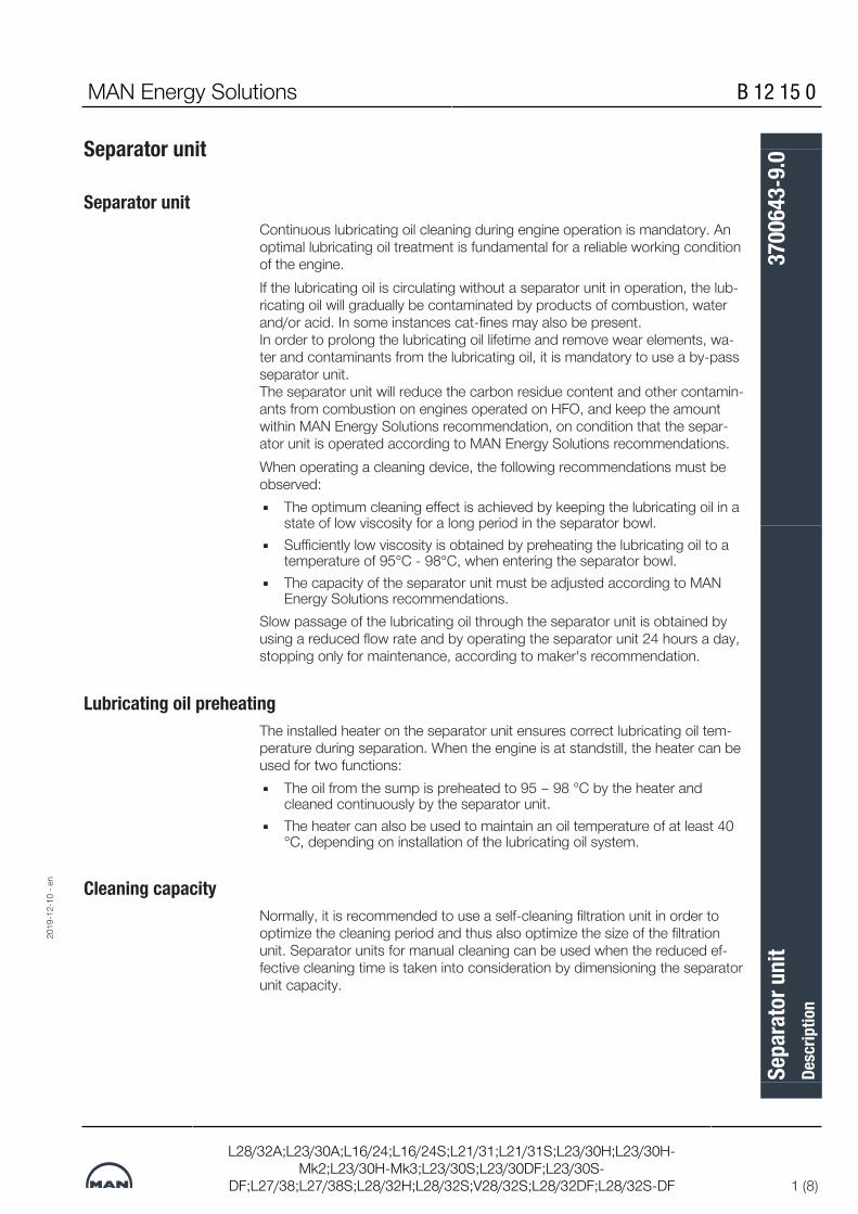
MAN Energy Solutions B 12 15 0
L28/32A;L23/30A;L16/24;L16/24S;L21/31;L21/31S;L23/30H;L23/30H-Mk2;L23/30H-Mk3;L23/30S;L23/30DF;L23/30S-
DF;L27/38;L27/38S;L28/32H;L28/32S;V28/32S;L28/32DF;L28/32S-DF 1 (8)
Separator unit
Separator unitContinuous lubricating oil cleaning during engine operation is mandatory. Anoptimal lubricating oil treatment is fundamental for a reliable working conditionof the engine.If the lubricating oil is circulating without a separator unit in operation, the lub-ricating oil will gradually be contaminated by products of combustion, waterand/or acid. In some instances cat-fines may also be present. In order to prolong the lubricating oil lifetime and remove wear elements, wa-ter and contaminants from the lubricating oil, it is mandatory to use a by-passseparator unit. The separator unit will reduce the carbon residue content and other contamin-ants from combustion on engines operated on HFO, and keep the amountwithin MAN Energy Solutions recommendation, on condition that the separ-ator unit is operated according to MAN Energy Solutions recommendations.When operating a cleaning device, the following recommendations must beobserved:▪ The optimum cleaning effect is achieved by keeping the lubricating oil in a
state of low viscosity for a long period in the separator bowl.▪ Sufficiently low viscosity is obtained by preheating the lubricating oil to a
temperature of 95°C - 98°C, when entering the separator bowl.▪ The capacity of the separator unit must be adjusted according to MAN
Energy Solutions recommendations.Slow passage of the lubricating oil through the separator unit is obtained byusing a reduced flow rate and by operating the separator unit 24 hours a day,stopping only for maintenance, according to maker's recommendation.
Lubricating oil preheatingThe installed heater on the separator unit ensures correct lubricating oil tem-perature during separation. When the engine is at standstill, the heater can beused for two functions:▪ The oil from the sump is preheated to 95 – 98 °C by the heater and
cleaned continuously by the separator unit.▪ The heater can also be used to maintain an oil temperature of at least 40
°C, depending on installation of the lubricating oil system.
Cleaning capacityNormally, it is recommended to use a self-cleaning filtration unit in order tooptimize the cleaning period and thus also optimize the size of the filtrationunit. Separator units for manual cleaning can be used when the reduced ef-fective cleaning time is taken into consideration by dimensioning the separatorunit capacity.
2019
-12-
10 -
en
Sepa
rato
r uni
tDe
scrip
tion
3700
643-
9.0

B 12 15 0 MAN Energy Solutions
2 (8)
L28/32A;L23/30A;L16/24;L16/24S;L21/31;L21/31S;L23/30H;L23/30H-Mk2;L23/30H-Mk3;L23/30S;L23/30DF;L23/30S-
DF;L27/38;L27/38S;L28/32H;L28/32S;V28/32S;L28/32DF;L28/32S-DF
The centrifuging process in separator bowlEfficient lubricating oil cleaning relies on the principle that - provided thethrough-put is adequate and the treatment is effective - an equilibrium condi-tion can be reached, where the engine contamination rate is balanced by thecentrifuge separation rate i.e.:▪ Contaminant quantity added to the lubricating oil per hour = contaminant
quantity removed by the centrifuge per hour.It is the purpose of the centrifuging process to ensure that this equilibriumcondition is reached, with the lubricating oil insolubles content being as low aspossible.Since the cleaning efficiency of the centrifuge is largely dependent upon theflow rate, it is very important that this is optimised.A centrifuge can be operated at greatly varying flow rates (Q).Practical experience has revealed that the content of insolubles, before andafter the centrifuge, is related to the flow rate as shown in Fig. 1.
Figure 1: .
Fig. 1 illustrates that the amount of insolubles removed will decrease withrising flow rate (Q).It can be seen that:▪ At low flow rate (Q), only a small portion of the lubricating oil is passing the
centrifuge/hour, but is being cleaned effectively.▪ At high flow rate (Q), a large quantity of lubricating oil is passing the centri-
fuge/hour, but the cleaning is less effective.Thus, by correctly adjusting the flow rate, an optimal equilibrium cleaning levelcan be obtained (Fig. 2).
Figure 2: .
2019
-12-
10 -
en
Sepa
rato
r uni
tDe
scrip
tion
3700
643-
9.0

MAN Energy Solutions B 12 15 0
L28/32A;L23/30A;L16/24;L16/24S;L21/31;L21/31S;L23/30H;L23/30H-Mk2;L23/30H-Mk3;L23/30S;L23/30DF;L23/30S-
DF;L27/38;L27/38S;L28/32H;L28/32S;V28/32S;L28/32DF;L28/32S-DF 3 (8)
This minimum contamination level is obtained by employing a suitable flowrate that is only a fraction of the stated maximum capacity of the centrifuge(see the centrifuge manual).The most important factor is the particle size (risk of scratching and wear ofthe bearing journals). In general the optimum centrifuge flow rate for a deter-gent lubricating oil is about 25% of the maximum centrifuge capacity.
Operation flowIn order to calculate the required operation flow through the separator unit,MDT recommends to apply the following formula:
Q = required operation flow [l/h]
P = MCR (maximum continuous rating) [kW]
t = actual effective separator unit separating time per day [hour] (23.5 h separating time and 0.5 h for sludge discharge = 24h/day)
n = number of turnovers per day of the theoretical oil volumecorresponding to 1.36 [l/kW] or 1 [l/HP]
The following values for "n" are recommended:
n = 6 for HFO operation (residual)
n = 4 for MDO operation
n = 3 for distillate fuel
Example 1 For multi-engine plants, one separator unit per engine in operation is recom-mended.For example, for a 1,000 kW engine operating on HFO and connected to aself-cleaning separator unit, with a daily effective separating period of 23.5hours, the calculation is as follows:
2019
-12-
10 -
en
Sepa
rato
r uni
tDe
scrip
tion
3700
643-
9.0

B 12 15 0 MAN Energy Solutions
4 (8)
L28/32A;L23/30A;L16/24;L16/24S;L21/31;L21/31S;L23/30H;L23/30H-Mk2;L23/30H-Mk3;L23/30S;L23/30DF;L23/30S-
DF;L27/38;L27/38S;L28/32H;L28/32S;V28/32S;L28/32DF;L28/32S-DF
Figure 3: One separator per engine plant
Example 2 (GenSet) As an alternative, one common separator unit for three engines can be in-stalled, with one in reserve if possible.For the calculation in this example it is necessary include the combined aver-age power demand of the multi-engine plant. The load profile experienced forthe majority of merchant vessels is that the average power demand is around43-50% of the total GenSet power installed. With three identical engines thiscorresponds to 1.3-1.5 times the power of one engine.▪ Bulk carrier and tankers : ~1.3 times the power of one engine▪ Container vessel : ~1.5 times the power of one engineFor example, for a bulk carrier with three 1,000 kW engines operating on HFOand connected to a common self-cleaning separator unit, with a daily effectiveseparating period of 23.5 hours, the calculation is as follows:
With an average power demand higher than 50% of the GenSet power in-stalled, the operation flow must be based on 100% of the GenSet power in-stalled.
Separator unit installationWith multi-engine plants, one separator unit per engine in operation is recom-mended (see figure 3), but if only one separator unit is in operation, the follow-ing layout can be used:▪ A common separator unit (see figure 4) can be installed, with one in re-
serve, if possible, for operation of all engines through a pipe system,which can be carried out in various ways. The aim is to ensure that theseparator unit is only connected to one engine at a time. Thus there willbe no suction and discharging from one engine to another.
It is recommended that inlet and outlet valves are connected so that they canonly be changed over simultaneously.With only one engine in operation there are no problems with separating, but ifseveral engines are in operation for some time it is recommended to split upthe separation time in turns on all operating engines.With 2 out of 3 engines in operation the 23.5 hours separating time must besplit up in around 4-6 hours intervals between changeover.
2019
-12-
10 -
en
Sepa
rato
r uni
tDe
scrip
tion
3700
643-
9.0

MAN Energy Solutions B 12 15 0
L28/32A;L23/30A;L16/24;L16/24S;L21/31;L21/31S;L23/30H;L23/30H-Mk2;L23/30H-Mk3;L23/30S;L23/30DF;L23/30S-
DF;L27/38;L27/38S;L28/32H;L28/32S;V28/32S;L28/32DF;L28/32S-DF 5 (8)
1 Interconnected valvesFigure 4: One common separator unit for multi-engine installation
Stokes' lawThe operating principles of centrifugal separation are based on Stokes’ Law.
V = settling velocity [m/sec]
rω2 = acceleration in centrifugal field [m/sec2]
d = diameter of particle [m]
ρp = density of particle [kg/m3]
ρl = density of medium [kg/m3]
µ = viscosity of medium [kg/m, sec.]
The rate of settling (V) for a given capacity is determined by Stokes’ Law. Thisexpression takes into account the particle size, the difference between densityof the particles and the lubricating oil, and the viscosity of the lubricating oil.Density and viscosity are important parameters for efficient separation. Thegreater the difference in density between the particle and the lubricating oil,the higher the separation efficiency. The settling velocity increases in inverseproportion to viscosity. However, since both density and viscosity vary withtemperature, separation temperature is the critical operating parameter.Particle size is another important factor. The settling velocity increases rapidlywith particle size. This means that the smaller the particle, the more challen-ging the separation task. In a centrifuge, the term (rω2) represents the centrifu-
2019
-12-
10 -
en
Sepa
rato
r uni
tDe
scrip
tion
3700
643-
9.0

B 12 15 0 MAN Energy Solutions
6 (8)
L28/32A;L23/30A;L16/24;L16/24S;L21/31;L21/31S;L23/30H;L23/30H-Mk2;L23/30H-Mk3;L23/30S;L23/30DF;L23/30S-
DF;L27/38;L27/38S;L28/32H;L28/32S;V28/32S;L28/32DF;L28/32S-DF
gal force which is several thousand times greater than the acceleration due togravitational force. Centrifugal force enables the efficient separation ofparticles which are only a few microns in size.The separation efficiency is a function of:
Operating parametersVarious operating parameters affect separation efficiency. These include tem-perature, which controls both lubricating oil viscosity and density, flow rateand maintenance.
2019
-12-
10 -
en
Sepa
rato
r uni
tDe
scrip
tion
3700
643-
9.0

MAN Energy Solutions B 12 15 0
L28/32A;L23/30A;L16/24;L16/24S;L21/31;L21/31S;L23/30H;L23/30H-Mk2;L23/30H-Mk3;L23/30S;L23/30DF;L23/30S-
DF;L27/38;L27/38S;L28/32H;L28/32S;V28/32S;L28/32DF;L28/32S-DF 7 (8)
Temperature of lubricating oil before separator unitIt is often seen that the lubricating oil pre-heaters are undersized, have verypoor temperature control, the steam supply to the pre-heater is limited or thetemperature set point is too low.Often the heater surface is partly clogged by deposits. These factors all leadto reduced separation temperature and hence the efficiency of the separatorunit. In order to ensure that the centrifugal forces separate the heavy contam-inants in the relatively limited time that they are present in the separator bowl,the separator unit must always be operated with an inlet temperature of95-98°C for lubricating oil.A control circuit including a temperature transmitter and a PI-type controllerwith accuracy of ±2°C must be installed. If steam-heated, a correctly sizedsteam valve should be fitted with the right KvS value. The steam trap must bea mechanical float type. The most common heaters on board are steam heat-ers. This is due to the fact that steam in most cases is available at low cost.Most ships are equipped with an exhaust boiler utilizing the exhaust gases togenerate steam.A large proportion of smaller tonnage does, however, use electric heaters.It is essential to keep the incoming oil temperature to the separator unitsteady with only a small variation in temperature allowed (maximum ±2°C).The position of the interface between oil and water in the separator bowl is aresult of the density and the viscosity of the oil, which in turn depends on thetemperature.
Flow rateIt is known that separation efficiency is a function of the separator unit’s flowrate. The higher the flow rate, the more particles are left in the oil and there-fore the lower the separation efficiency. As the flow rate is reduced, the effi-ciency with which particles are removed increases and cleaning efficiencythus improves. It is, however, essential to know at what capacity adequateseparation efficiency is reached in the specific case.In principle, there are three ways to control the flow:▪ Adjustment of the built-in safety valve on the pump.
This method is NOT recommended since the built-on valve is nothing buta safety valve.The opening pressure is often too high and its characteristic far from lin-ear.In addition, circulation in the pump may result in oil emulsions and cavita-tion in the pump.
▪ A flow regulating valve arrangement on the pressure side of the pump,which bypasses the separator unit and re-circulates part of the untreatedlubricating oil back to the treated oil return line, from the separator unitand NOT directly back to the suction side of the pump.The desired flow rate is set manually by means of the flow regulatingvalve. Further, the requirement for backpressure in the clean oil outletMUST also be fulfilled, helping to maintain the correct interface position.
▪ Speed control of the pump motor with a frequency converter or a 2-speed motor.
2019
-12-
10 -
en
Sepa
rato
r uni
tDe
scrip
tion
3700
643-
9.0

B 12 15 0 MAN Energy Solutions
8 (8)
L28/32A;L23/30A;L16/24;L16/24S;L21/31;L21/31S;L23/30H;L23/30H-Mk2;L23/30H-Mk3;L23/30S;L23/30DF;L23/30S-
DF;L27/38;L27/38S;L28/32H;L28/32S;V28/32S;L28/32DF;L28/32S-DF
This is a relatively cheap solution today and is a good alternative for flowcontrol.
MaintenanceProper maintenance is an important, but often overlooked operating para-meter that is difficult to quantify. If the bowl is not cleaned in time, deposits willform on the bowl discs, the free channel height will be reduced, and flow velo-city increases. This further tends to drag particles with the liquid flow towardsthe bowl’s centre resulting in decreased separation efficiency.40541387019
2019
-12-
10 -
en
Sepa
rato
r uni
tDe
scrip
tion
3700
643-
9.0

MAN Energy Solutions B 12 15 0
L28/32A;L23/30A;L16/24;L16/24S;L21/31;L21/31S;L23/30H;L23/30H-Mk2;L23/30H-Mk3;L23/30S;L23/30DF;L23/30S-
DF;L27/38;L27/38S;L28/32H;L28/32S;V28/32S;L28/32DF;L28/32S-DF 1 (4)
Treatment and maintenance of lubricating oil
GeneralDuring operation of trunk engines the lubricating oil will gradually be contamin-ated by small particles originating from the combustion.Engines operated on heavy fuels will normally increase the contamination dueto the increased content of carbon residues and other contaminants.Contamination of lubricating oil with either freshwater or seawater can alsooccur.A certain amount of contaminants can be kept suspended in the lubricating oilwithout affecting the lubricating properties.The condition of the lubricating oil must be kept under observation (on a regu-lar basis) by analyzing oil samples. See Section B 12 15 0 / 504.04 "Criteriafor Cleaning/Exchange of Lubricating Oil".The condition of the lubricating oil can be maintained / re-established by ex-changing the lubricating oil at fixed intervals or based on analyzing oilsamples.The moving parts in the engine are protected by the built-on lubricating oil fil-ter.
Operation on Marine Diesel Oil (MDO) & Marine Gas Oil (MGO)For engines exclusively operated on MDO/MGO we recommend to install abuilt-on centrifugal filter as an additional filter to the built-on lubricating oil filter.It is advisable to run bypass cleaning equipment continuously for engines op-erated on MDO/MGO.
Operation on Heavy Fuel Oil (HFO)HFO-operated engines require effective lubricating oil cleaning. In order to en-sure a safe operation it is necessary to use supplementary cleaning equip-ment together with the built-on lubricating oil filter.Built-on centrifugal filter is mandatoryIt is also mandatory to run cleaning equipment continuously for engines oper-ated on HFO, as an optimal lubricating oil treatment is fundamental for a reli-able working condition. Therefore it is mandatory to clean the lubricating oilwith a bypass cleaning equipment, so that the wear rates are reduced and thelifetime of the engine is extended.
Bypass cleaning equipmentAs a result of normal operation, the lubricating oil contains abraded particlesand combustion residues which have to be removed by the bypass cleaningsystem and to a certain extent by the built-on lubricating oil filter as well.With automatic mesh filters this can result in an undesirable and hazardouscontinuous flushing. In view of the high cost of cleaning equipment for remov-ing micro impurities, this equipment is only rated for a certain proportion of theoil flowing through the engine since it is installed in a bypass.
2019
-12-
10 -
en
Trea
tmen
t and
mai
nten
ance
of l
ubric
atin
g oi
lDe
scrip
tion
1643
494-
3.12

B 12 15 0 MAN Energy Solutions
2 (4)
L28/32A;L23/30A;L16/24;L16/24S;L21/31;L21/31S;L23/30H;L23/30H-Mk2;L23/30H-Mk3;L23/30S;L23/30DF;L23/30S-
DF;L27/38;L27/38S;L28/32H;L28/32S;V28/32S;L28/32DF;L28/32S-DF
The bypass cleaning equipment is operate continuously when the engine is inoperation or at standstill.For cleaning of lubricating oil the following bypass cleaning equipment can beused:▪ Separator unit▪ Decanter unit▪ Self cleaning automatic bypass mesh filter▪ Built-on centrifugal bypass filter (standard on MAN Energy Solutions,
Holeby GenSets)▪ Bypass depth filterThe decanter unit, the self-cleaning automatic bypass mesh filter and the by-pass depth filter capacity must be adjusted according to maker’s recom-mendations.If the selected bypass cleaning equipment cannot remove water it is recom-mended to have portable separator available.In case full flow filtration equipment is chosen, this must only be installed asin-line cleaning upstream to the built-on lubricating oil filter.The most appropriate type of equipment for a particular application dependson the engine output, the type and amount of combustion residues, the an-nual operating time and the operating mode of the plant. Even with a relativelylow number of operating hours there can be a great deal of combustionresidues if, for instance, the engine is inadequately preheated and quickly ac-celerated and loaded.
Check of lubricating oil systemFor cleaning of the lubricating oil system after overhauls and inspection of thelubricating oil piping system the following checks must be carried out:
1. Examine the piping system for leaks.2. Retighten all bolts and nuts in the piping system.3. Move all valves and cocks in the piping system. Lubricate valve spindles
with graphite or similar.4. Blow through drain pipes.5. Check flexible connections for leaks and damages.6. Check manometers and thermometers for possible damages.7. Engines running at HFO, will as standard be delivered with centrifugal by-
pass filter mounted on engine. Centrifugal by-pass filter can be used asindicator of lubricating oil system condition.Define a cleaning interval (ex. 100 hours). Check the sludge weight. If thesludge weight is raising please check separator and lubricating oil systemcondition in general.
Deterioration of oilOil seldomly loses its ability to lubricate, i.e. to form a friction-decreasing oilfilm, but it may become corrosive to the steel journals of the bearings in sucha way that the surface of these journals becomes too rough and wipes thebearing surface.
2019
-12-
10 -
en
Trea
tmen
t and
mai
nten
ance
of l
ubric
atin
g oi
lDe
scrip
tion
1643
494-
3.12

MAN Energy Solutions B 12 15 0
L28/32A;L23/30A;L16/24;L16/24S;L21/31;L21/31S;L23/30H;L23/30H-Mk2;L23/30H-Mk3;L23/30S;L23/30DF;L23/30S-
DF;L27/38;L27/38S;L28/32H;L28/32S;V28/32S;L28/32DF;L28/32S-DF 3 (4)
In that case the bearings must be renewed, and the journals must also be pol-ished. The corrosiveness of the lubricating oil is either due to far advanced ox-idation of the oil itself (TAN) or to the presence of inorganic acids (SAN). Inboth cases the presence of water will multiply the effect, especially sea wateras the chloride ions act as an inorganic acid.
Signs of deteriorationIf circulating oil of inferior quality is used and the oxidative influence becomesgrave, prompt action is necessary as the last stages in the deterioration willdevelop surprisingly quickly, within one or two weeks. Even if this seldomlyhappens, it is wise to be acquainted with the signs of deterioration.These may be some or all of the following:▪ Sludge precipitation in the separator unit multiplies▪ Smell of oil becomes acrid or pungent▪ Machined surfaces in the crankcase become coffee-brown with a thin
layer of lacquer▪ Paint in the crankcase peels off or blisters▪ Excessive carbon is formed in the piston cooling chamberIn a grave case of oil deterioration the system must be cleaned thoroughlyand refilled with new oil.
Oxidation of oilsAt normal service temperature the rate of oxidation is insignificant, but the fol-lowing factors will accelerate the process:High temperature If the coolers are ineffective, the temperature level will generally rise. A hightemperature will also arise in electrical pre-heaters if the circulation is not con-tinued for 5 minutes after the heating has been stopped, or if the heater isonly partly filled with oil.Catalytic action Oxidation of the oil will be accelerated considerably if catalytic particles arepresent in the oil. Wear particles of copper are especially harmful, but also fer-rous particles and rust are active. Furthermore, the lacquer and varnish oxida-tion products of the oil itself have an accelerating effect. Continuous cleaningof the oil is therefore important to keep the sludge content low.
Water washingWater washing of HD oils (heavy duty) must not be carried out.
Water in the oilIf the TAN is low, a minor increase in the fresh water content of the oil is notimmediately detrimental while the engine is in operation. Naturally, it should bebrought down again as quickly as possible (below 0.2% water content, whichis permissible, see description "B 12 15 0/504.04 criteria for exchange of lubeoil”). If the engine is stopped while corrosion conditions are unsatisfactory, thecrankshaft must be turned ½ - ¾ revolution once every hour by means of the
2019
-12-
10 -
en
Trea
tmen
t and
mai
nten
ance
of l
ubric
atin
g oi
lDe
scrip
tion
1643
494-
3.12

B 12 15 0 MAN Energy Solutions
4 (4)
L28/32A;L23/30A;L16/24;L16/24S;L21/31;L21/31S;L23/30H;L23/30H-Mk2;L23/30H-Mk3;L23/30S;L23/30DF;L23/30S-
DF;L27/38;L27/38S;L28/32H;L28/32S;V28/32S;L28/32DF;L28/32S-DF
turning gear. Please make sure that the crankshaft stops in different positions,to prevent major damage to bearings and journals. The lubricating oil must becirculated and separated continuously to remove water.Water in the oil may be noted by steam formation on the sight glasses, by ap-pearance, or ascertained by immersing a piece of glass or a soldering ironheated to 200-300°C in an oil sample. If there is a hissing sound, water ispresent. If a large quantity of water has entered the lubricating oil system, ithas to be removed. Either by sucking up sediment water from the bottom, orby replacing the oil in the sump. An oil sample must be analysed immediatelyfor chloride ions.90071997312454667
2019
-12-
10 -
en
Trea
tmen
t and
mai
nten
ance
of l
ubric
atin
g oi
lDe
scrip
tion
1643
494-
3.12

MAN Energy Solutions B 12 15 0
L16/24;L16/24S;L21/31;L21/31S;L23/30A;L23/30H;L23/30H-Mk2;L23/30H-Mk3;L23/30S;L23/30DF;L23/30S-
DF;L27/38;L27/38S;L28/32A;L28/32H;L28/32S;V28/32S;L28/32DF;L28/32S-DF,1440000, 540000 1 (3)
Criteria for cleaning/exchange of lubricating oil
Replacement of lubricating oilThe expected lubricating oil lifetime in operation is difficult to determine. Thelubricating oil lifetime is depending on the fuel oil quality, the lubricating oilquality, the lubricating oil consumption, the lubricating oil cleaning equipmentefficiency and the engine operational conditions.In order to evaluate the lubricating oil condition a sample should be drawn onregular basis at least once every three month or depending on the latest ana-lysis result. The lubricating oil sample must be drawn before the filter at enginein operation. The sample bottle must be clean and dry, supplied with sufficientidentification and should be closed immediately after filling. The lubricating oilsample must be examined in an approved laboratory or in the lubricating oilsuppliers own laboratory.A lubricating oil replacement or an extensive lubricating oil cleaning is requiredwhen the MAN Energy Solutions exchange criteria's have been reached.
Evaluation of the lubricating oil conditionBased on the analysis results, the following guidance are normally sufficientfor evaluating the lubricating oil condition. The parameters themselves can notbe jugded alonestanding, but must be evaluated together in order to concludethe lubricating oil condition.
1. ViscosityLimit value:
Normal value min. value max. valueSAE 30 [cSt@40° C]
SAE 30 [cSt@100° C]
SAE 40 [cSt@40° C]
SAE 40 [cSt@100° C]
95 - 125
11 - 13
135 - 165
13.5 - 15.0
75
9
100
11
160
15
220
19
Unit : cSt (mm2/s)
Possible testmethod
: ASTM D-445, DIN51562/53018, ISO 3104
Increasing viscosity indicates problems with insolubles, HFO contamination,water contamination, oxidation, nitration and low load operation. Decreasingviscosity is generally due to dilution with lighter viscosity oil.
2. Flash pointMin. value : 185° C
Possible testmethod
: ASTM D-92, ISO 2719
Normally used to indicate fuel dilution.
2019
-10-
25 -
en
Crite
ria fo
r clea
ning
/exc
hang
e of l
ubric
atin
g oi
lDe
scrip
tion
1609
533-
1.9

B 12 15 0 MAN Energy Solutions
2 (3)
L16/24;L16/24S;L21/31;L21/31S;L23/30A;L23/30H;L23/30H-Mk2;L23/30H-Mk3;L23/30S;L23/30DF;L23/30S-
DF;L27/38;L27/38S;L28/32A;L28/32H;L28/32S;V28/32S;L28/32DF;L28/32S-DF,1440000, 540000
3. Water contentMax. value : 0.2 %
Unit : Weight %
Possible testmethod
: ASTM D4928, ISO 3733
Water can originate from separator, contaminated fuel oil, an engine coolingwater leak or in minor amount formed as part of the combustion process. Ifwater is detected also Sodium, Glycol or Boron content should be checked inorder to confirm engine coolant leaks.If ship installation have no separator unit it is recommend to have a portableseparator available to remove water.
4. Base numberMin. value : The BN value should not be lower than 50% of fresh lub-
ricating oil value, but minimum BN level never to be lowerthan 10-12 at operating on HFO!
Unit : mg KOH/g
Possible testmethod
: ASTM D-2896, ISO 3771
The neutralization capacity must secure that the acidic combustion products,mainly sulphur originate from the fuel oil, are neutralized at the lube oil con-sumption level for the specific engine type. Gradually the BN will be reduced,but should reach an equilibrium.
5. Total acid number (TAN)Max. value : 3.0 acc. to fresh oil value
Unit : mg KOH/g
Possible testmethod
: ASTM D-664
TAN is used to monitor oil degradation and is a measure of the total acidspresent in the lubricating oil derived from oil oxidation (weak acids) and acidicproducts of fuel combustion (strong acids).
6. Insolubles contentMax. value : 1.5 % generally, depending upon actual dispersant value
and the increase in viscosity
Unit : Weight %
Possible testmethod
: ASTM D-893 procedure B in Heptane, DIN 51592
2019
-10-
25 -
en
Crite
ria fo
r clea
ning
/exc
hang
e of l
ubric
atin
g oi
lDe
scrip
tion
1609
533-
1.9

MAN Energy Solutions B 12 15 0
L16/24;L16/24S;L21/31;L21/31S;L23/30A;L23/30H;L23/30H-Mk2;L23/30H-Mk3;L23/30S;L23/30DF;L23/30S-
DF;L27/38;L27/38S;L28/32A;L28/32H;L28/32S;V28/32S;L28/32DF;L28/32S-DF,1440000, 540000 3 (3)
Additionally test : If the level in n-Heptane insolubles is considered high forthe type of oil and application, the test could be followedby a supplementary determination in Toluene.
Total insolubles is maily derived from products of combustion blown by thepiston rings into the crankcase. It also includes burnt lubricating oil, additiveash, rust, salt, wear debris and abrasive matter.
7. Metal contentMetal content Remarks Attention limitsIronChromiumCopperLeadTinAluminiumSilicon
Depend upon engine typeand operating conditions
max. 50 ppmmax. 10 ppmmax. 15 ppmmax. 20 ppmmax. 10 ppmmax. 20 ppmmax. 20 ppm
3602880504170151536028805041701515
2019
-10-
25 -
en
Crite
ria fo
r clea
ning
/exc
hang
e of l
ubric
atin
g oi
lDe
scrip
tion
1609
533-
1.9

This page is intentionally left blank3602880504170151536028805041701515
2019
-10-
25 -
en
B 12 15 0 MAN Energy Solutions
L16/24;L16/24S;L21/31;L21/31S;L23/30A;L23/30H;L23/30H-Mk2;L23/30H-Mk3;L23/30S;L23/30DF;L23/30S-
DF;L27/38;L27/38S;L28/32A;L28/32H;L28/32S;V28/32S;L28/32DF;L28/32S-DF,1440000, 540000
Crite
ria fo
r clea
ning
/exc
hang
e of l
ubric
atin
g oi
lDe
scrip
tion
1609
533-
1.9

MAN Energy Solutions B 13 00 0
L21/31;L27/38, 1400000 1 (12)
Cooling water system
Cooling water diagram
Figure 1: Cooling water diagram
Item Description Item Description1 Seachest low 19 Diesel oil cooler
2 Seachest high 29 LT expansion tank
3 Sea water filter 30 HT pump
4 Sea water pump 31 HT stand-by pump
9 Overboard discharge valve 32 Charging air cooler HT section
10 LT pump 33 Adjustment valve for heat recovery
11 LT standby pump 34 Thermostatic valve for heat recovery
12 Regulating valve for charge air preheating (optional, only L27/38)
35 Heat recovery
13 Charging air cooler, LT section 36 HT thermostatic valve
14 Orifice for cooling water to gearbox 37 HT fresh water cooler
15 Gear oil cooler 38 Circulating pump for preheater
16 Engine lubricating oil cooler 39 Preheater
17 LT thermostatic valve 49 HT expansion tank
18 Central cooler
2020
-01-
10 -
en
Cool
ing
wate
r sys
tem
Desc
riptio
n16
9492
5-0.
6
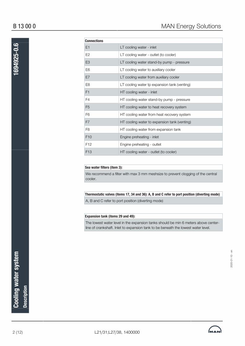
B 13 00 0 MAN Energy Solutions
2 (12) L21/31;L27/38, 1400000
ConnectionsE1 LT cooling water - inlet
E2 LT cooling water - outlet (to cooler)
E3 LT cooling water stand-by pump - pressure
E6 LT cooling water to auxiliary cooler
E7 LT cooling water from auxiliary cooler
E8 LT cooling water tp expansion tank (venting)
F1 HT cooling water - inlet
F4 HT cooling water stand-by pump - pressure
F5 HT cooling water to heat recovery system
F6 HT cooling water from heat recovery system
F7 HT cooling water to expansion tank (venting)
F8 HT cooling water from expansion tank
F10 Engine preheating - inlet
F12 Engine preheating - outlet
F13 HT cooling water - outlet (to cooler)
Sea water filters (item 3):We recommend a filter with max 3 mm meshsize to prevent clogging of the centralcooler.
Thermostatic valves (items 17, 34 and 36): A, B and C refer to port position (diverting mode)A, B and C refer to port position (diverting mode)
Expansion tank (items 29 and 49):The lowest water level in the expansion tanks should be min 6 meters above center-line of crankshaft. Inlet to expansion tank to be beneath the lowest water level.
2020
-01-
10 -
en
Cool
ing
wate
r sys
tem
Desc
riptio
n16
9492
5-0.
6

MAN Energy Solutions B 13 00 0
L21/31;L27/38, 1400000 3 (12)
Figure 2: Cooling water diagram
Item Description Item Description1 Seachest low 19 Diesel oil cooler
2 Seachest high 29 LT expansion tank
3 Sea water filter 30 HT pump
4 Sea water pump 31 HT stand-by pump
9 Overboard discharge valve 32 Charging air cooler HT section
10 LT pump 33 Adjustment valve for heat recovery
11 LT standby pump 34 Thermostatic valve for heat recovery
12 Regulating valve (optional) 35 Heat recovery
13 Charging air cooler, LT section 36 HT thermostatic valve
14 Orifice for cooling water to gearbox 37 HT fresh water cooler
15 Gear oil cooler 38 Circulating pump for preheater
16 Engine lubricating oil cooler 39 Preheater
17 LT thermostatic valve 49 HT expansion tank
18 Central cooler
ConnectionsE1 LT cooling water - inlet
E2 LT cooling water - outlet (to cooler)
E3 LT cooling water stand-by pump - pressure
2020
-01-
10 -
en
Cool
ing
wate
r sys
tem
Desc
riptio
n16
9492
5-0.
6

B 13 00 0 MAN Energy Solutions
4 (12) L21/31;L27/38, 1400000
ConnectionsE6 LT cooling water to auxiliary cooler
E7 LT cooling water from auxiliary cooler
E8 LT cooling water tp expansion tank (venting)
F1 HT cooling water - inlet
F4 HT cooling water stand-by pump - pressure
F5 HT cooling water to heat recovery system
F6 HT cooling water from heat recovery system
F7 HT cooling water to expansion tank (venting)
F8 HT cooling water from expansion tank
F10 Engine preheating - inlet
F12 Engine preheating - outlet
F13 HT cooling water - outlet (to cooler)
Sea water filters (item 3):We recommend a filter with max 3 mm meshsize to prevent clogging of the centralcooler.
Thermostatic valves (items 17, 34 and 36): A, B and C refer to port position (diverting mode)A, B and C refer to port position (diverting mode)
Expansion tank (items 29 and 49):The lowest water level in the expansion tanks should be min 6 meters above center-line of crankshaft. Inlet to expansion tank to be beneath the lowest water level.
Cooling Water SystemThe engine is designed for freshwater cooling only. Therefore the cooling wa-ter system has to be arranged as a centralised or closed cooling water sys-tem. All recommendable types are described in the following.The engine design is almost pipeless, i.e. the water flows through internal cav-ities inside the front-end box and the cylinder units. The front-end box con-tains all large pipe connections. On the aft-end, the water to the gear oilcooler has to be connected by the yard.The engine is equipped with built-on freshwater pumps for both the high andlow temperature cooling water systems. To facilitate automatic start-up ofstand-by pumps, non-return valves are standard.Thermostatic valve elements, which control the high and low temperaturecooling water system, are also integrated parts of the front-end box.In case the HT cooler as alternative is a part of the LT cooling water systemthe LT thermostatic valves are to be replaced by “dummies” inside the front-end box and an external thermostatic valve housing is required to be placed inthe LT circuit just after the HT freshwater cooler.
2020
-01-
10 -
en
Cool
ing
wate
r sys
tem
Desc
riptio
n16
9492
5-0.
6

MAN Energy Solutions B 13 00 0
L21/31;L27/38, 1400000 5 (12)
The engine is equipped with a two stage charge air cooler. The first stage isplaced in the high temperature cooling water system. The charging air tem-perature after the turbocharger is at its maximum, making a higher degree ofheat recovery possible, when the heat is dissipated to the high temperaturecooling water.The second stage of the charge air cooler is placed in the low temperaturesystem.It will cool the charging air further down before entering the combustionchamber.For special applications i.e. sailing in arctic waters with low air temperaturesand direct air intake from deck, a regulating system can be applied to controlthe water flow to the second stage of the charge air cooler in order to in-crease the charging air temperature, at low load.
Water qualityThe fresh water used as coolant, should be as clean as possible.The pH value should be between 6.5 and 8 at 20°C.The total hardness of the water must be max 10°dH (German hardness de-grees). If the hardness is higher, the water should be diluted with some softwater.The contents of chlorine, chloride, silicate and sulphate must be as low aspossible and must not exceed the following values:▪ Chlorine: 10 PPM▪ Chloride: 50 PPM▪ Silicate: 150 PPM▪ Sulphate: 100 PPMThe fresh water must be treated with additives in order to reduce the risk ofcorrosion in the engine. Anti corrosive agents are not included in our usualscope of supply. The freshwater cooling system should be treated prior tocarrying out sea trials.There are two basic types of chemical additives:▪ Chromate base▪ Nitrite base or similarAdditives of chromate base are often considered to be more effective, but weadvise against using them due to their extreme poisonousness and they arenot permitted if a freshwater generator is incorporated in the plant.For information on additives recommended by us, please refer to “Coolingwater inhibitors”, which can be forwarded on request.New engines, supplied by us are cleaned and nitrated. Providing the freshwa-ter inhibiting is correctly maintained then future cleaning of the system shouldhardly be necessary. However if it should be required, we would be pleasedto assist with recommendations for degreasing, de-scaling with acid and in-hibiting.Velocity recommendations for freshwater and sea water pipes:▪ Freshwater
– Suction pipe : 2.0 - 2.5 m/s– Delivery pipe: 2.0 - 2.5 m/s
2020
-01-
10 -
en
Cool
ing
wate
r sys
tem
Desc
riptio
n16
9492
5-0.
6

B 13 00 0 MAN Energy Solutions
6 (12) L21/31;L27/38, 1400000
▪ Sea water– Suction pipe : 1.0 - 1.5 m/s– Delivery pipe: 1.5 - 2.5 m/s
Central cooling water systemSea water filter, item 3 Design data
Capacity : See sea water pump
Pressure drop across clean filter : max 0.05 bar
Pressure drop across dirty filter : max 0.1 bar
Mesh size : 3-5 mm
Free filter hole area : min two times the normal pipe area
Sea water pumps, item 4 The pumps should always be installed below sea water level when the ship isunloaded.
Figure 3: Pump characteristic
The pumps in parallel, layout point 2 see figure 3, are as standard designed tofulfil:
Capacity : Determined by the cooler manufacturer.Approx 100 - 175% of fresh water flow inthe cooler, depending on the centralcooler.
Pressure : 1.8 - 2.0 bar
Sea water temperature : max 32° C
The volume of sea water required to circulate through a known sized cooler toremove a known amount of heat, is very sensitive and dependent on the seawater temperature.The relation between sea water temperature and the necessary water flow inthe central cooler is shown in figure 4. 20
20-0
1-10
- en
Cool
ing
wate
r sys
tem
Desc
riptio
n16
9492
5-0.
6

MAN Energy Solutions B 13 00 0
L21/31;L27/38, 1400000 7 (12)
Figure 4: Necessary water flow
Depending on the actual characteristic of the system resistance curve and thepump characteristic curve, the sea water flow with only one pump in servicewill be approx 75%. This means that the cooling capacity can be obtainedwith only one pump until reaching a sea water temperature of approx 30°C.The back pressure in single pump operation must be observed as a low backpressure may lead to unfavourable operation and cavitation of impeller. Weare pleased to advise on more specific questions concerning the layout ofpumps and location of orifices, etc.
Central cooler(s), item 18 If we are to supply the central cooler(s), it will be a plate cooler with titaniumplates.
Design data
Heat transfer : See list of capacities
Pressure drop LT : max 0.5 bar
Pressure drop SW : max 0.5 bar standardmax 1.0 bar if HT cooler is in LT system
Two central coolers in par-allel
For an extra investment of 20-25% for the central cooler a much greatersafety margin can be achieved by installing two central coolers each of 50%required capacity, operating in parallel instead of one cooler at 100% capa-city.With such flexibility it is possible to carry out repair and maintenance during avoyage especially in temperate climates where the sea water temperature isbelow the design temperature.
LT freshwater pump, Item10
The built-on low temperature pump is of the centrifugal type. The maximumback pressure in the low temperature section with clean cooler must not ex-ceed 2.5 bar.For multi engine installations with a common centralised cooling water systemthe built-on pumps should be replaced with common electrically drivenpumps for full flow.
Design data : See list of capacities
LT stand-by pump, item 11 The stand-by pumps should be of the centrifugal type.
2020
-01-
10 -
en
Cool
ing
wate
r sys
tem
Desc
riptio
n16
9492
5-0.
6

B 13 00 0 MAN Energy Solutions
8 (12) L21/31;L27/38, 1400000
Design data
Capacity : See list of capacities, for the built-on freshwaterpump
Pressure : See list of capacities, for the built-on freshwaterpump
HT sea water cooler, item37
The HT sea water cooler will be a plate cooler in titanium as standard.
Design data
Heat transfer : See list of capacities
Pressure drop HT : max 0.5 bar
Pressure drop SW : max 0.5 bar
HT fresh water cooler (op-tion)
The HT cooler can as an alternative be installed as a part of the LT coolingwater system. This will require a separate thermostatic valve for the LT coolingwater system.The HT freshwater cooler will be a plate cooler in stainless steel.
Design data
Heat transfer : See list of capacities
Pressure drop HT : max 0.5 bar
Pressure drop LT : max 0.5 bar
LT thermostatic valve, item17
The temperature of the LT cooling water to the charge air cooler is normallycontrolled by thermostatic valve elements of the expanding agent type.The function of the thermostatic valve is to maintain the outlet temperature ofthe low temperature water within 29°C to 41°C depending on operating con-ditions, by re-circulating the water to the suction of the pump or let it inthrough the central cooler (item 18).The re-circulated water is led directly to the suction side of the built-onpumps.
Expansion tanks, items 29and 49
Separate expansion tanks for the LT and HT system should be installed to ac-commodate for changes of volume due to varying temperatures and possibleleakage in the LT and HT systems. The separated HT and LT systems facilit-ates trouble shooting.The minimum water level in the expansion tank should be no less than 6 mabove the centre line of the crankshaft. This will ensure sufficient suction headto the freshwater pump and reduce the possibility of cavitation, as well aslocal “hot spots” in the engine.The expansion tank should be equipped with a vent pipe and flange for fillingthe tank with water and inhibitors.The vent pipe should be installed below the minimum water level to reduceoxidation of the cooling water due to splashing from the vent pipe.
Volume : min 10% of water volume, however, min 100 litres
HT stand-by pump, item 31 The stand-by pumps should be of the centrifugal type.
Design data
Capacity : See list of capacities, for the built-on freshwater pump
2020
-01-
10 -
en
Cool
ing
wate
r sys
tem
Desc
riptio
n16
9492
5-0.
6

MAN Energy Solutions B 13 00 0
L21/31;L27/38, 1400000 9 (12)
Pressure : See list of capacities, for the built-on freshwater pump
Temperature : max 95° C
Circulating pump for pre-heater, item 38
For preheating the engine a pump should be installed to circulate high tem-perature cooling water trough the preheater.
Design data
Capacity :
Q : Heat radiation from engine in kW, see belowCp : Specific heat for water 4.187 kJ/kg° Ct : The desired temperature drop across engine = 5° C
Pressure : max 2 bar
Temperature : max 85° C
Preheater, item 39 The engine must be fitted with preheating facilities. Preheating is required toavoid producing unnecessary shock loads that may arise as a result of tem-perature differences if the engine is started from cold.
Design data
Preheating temperature MDOengine
: min 40° C
Preheating temperature HFOengine
: 60 - 70° C
The heating power required for electrical preheating is stated below:
Engine type Heating power Engine type Heating power6L21/31 7 kW 6L27/38 9 kW
7L21/31 8 kW 7L27/38 10.5 kW
8L21/31 9 kW 8L27/38 12 kW
9L21/31 10 kW 9L27/38 13.5 kW
The figures are based on raising the engine temperature to 40°C (20-60°C) fora period of 10 hours including the cooling water contained within the engine.The preheater can be of the electrical type. If sufficient central heating capa-city is available, a plate type heat exchanger can be installed. It is importantthat the inhibited fresh water, used in the main engine cooling system, is notmixed with water from the central heating system.
Thermostatic valve for heatrecovery, item 34
If the heat recovery is below 25% of the heat rejection from engine jacket wa-ter the heat recovery equipment (item 35) can be connected in series with theHT freshwater cooler.By utilisation of more than 25% of the heat in the HT cooling water section, anadditional thermostatic valve, item 34, should be installed for bypassing of theHT fresh water cooler thus avoiding unnecessary cooling after the heat recov-ery equipment (item 35).
2020
-01-
10 -
en
Cool
ing
wate
r sys
tem
Desc
riptio
n16
9492
5-0.
6

B 13 00 0 MAN Energy Solutions
10 (12) L21/31;L27/38, 1400000
Connection of heat recovery or freshwater generatorBy layout of the freshwater generator we recommend that no more than 90%of the heat available at MCR is utilised due to safety margins, part load opera-tion and deviations in ambient conditions.The expected obtainable freshwater production using a normal generator ofthe single vacuum evaporator type can be estimated.
Design data
Capacity : m = 0.03 x Q m3/24h
Pressure : max 2.5 bar
Pressure drop : max 0.5 bar
Temperature : 80° C
Different arrangements of central cooling systemsThere are many variations of centralised cooling systems and we are availableto discuss various changes to suit an owner’s or builder’s specific wishes.For each plant, special consideration should be given to the following designcriteria: Sea water temperatures, pressure loss in coolers, valves and pipes,pump capacities etc, for which reason these components have not been spe-cified in this guide.
Closed cooling systemsSeveral systems have been developed to avoid sea water. The benefits are:▪ Minimising the use of expensive corrosion resistant pipes, valves and
pumps▪ Sea water pumps at reasonable costs▪ No cleaning of plate type central heat exchangersSuch systems are advantageous in the following conditions:▪ Sailing in shallow waters▪ Sailing in very cold waters▪ Sailing in corrosive waters (e.g. some harbours)▪ Sailing in water with high contents of solids (dredging and some rivers)A disadvantage of most closed cooling water systems is the poor heat trans-fer coefficient.LT coolers with very small temperature differences between the cooling waterand the sea or raw water, require a relatively large heat exchanger to enablesufficient heat transfer.MAN-ES propulsion engine is a high efficient main engine calling for high effi-cient coolers. Therefore some designs cannot be recommended.We are available to offer advice for specific cooler types, but the final respons-ibility for design, pressure losses, strength and system maintenance remainswith the yard and the ship owner. We reserve the right not to accept pro-posed coolers, which seems to be insufficient for its purpose.
2020
-01-
10 -
en
Cool
ing
wate
r sys
tem
Desc
riptio
n16
9492
5-0.
6

MAN Energy Solutions B 13 00 0
L21/31;L27/38, 1400000 11 (12)
Also when using other types of closed cooling water systems the HT and LTcooling water systems have to be separated.
Box coolerThe box cooling system has through many years proven to be a reliableclosed cooling water system. The box cooler is a pre-manufactured tubebundle for mounting in a sea chest.The movement of the sea water across the heat exchanger is initiated by themovement of the heated sea water upwards because of the lower densitycompared with that of the surrounding water. This means that the heat trans-fer is less dependant on the ship’s speed, compared to coolers mounted onthe shell of the vessel. However the speed of the vessel does have some influ-ence on the cooling area. For vessels sailing at below 3 knots at MCR, i.e.tugs, dredgers etc, the speed has to be considered when designing thecooler.The temperature of the sea water has influence on the heat exchanger effi-ciency as well. We recommend that a temperature of 25°C or 32°C is used,depending on the vessel’s operating area.The tube bundle is normally of corrosion resistant material with a non-metalliccoating. The coating protects the vessel from galvanic corrosion between thesea chest and the box cooler. Uncoated coolers may be used, but specialconsideration has to be given to the galvanic separation of the box cooler andthe hull.In waters with mussels and shell fish these might want to live on the tubebundle, which the different box cooler manufacturers have different solutionsto avoid.If the box cooler is supplied by us, it consists of a steel frame for welding tothe hull, a tube bundle and a topbox, delivered complete with counter flanges,gaskets and bolts.
Design data
Heat transfer : See list of capacities
Pressure drop through all coolers : max 0.5 bar
Min vessel speed at MCR : Normally more than 3 knots
2020
-01-
10 -
en
Cool
ing
wate
r sys
tem
Desc
riptio
n16
9492
5-0.
6
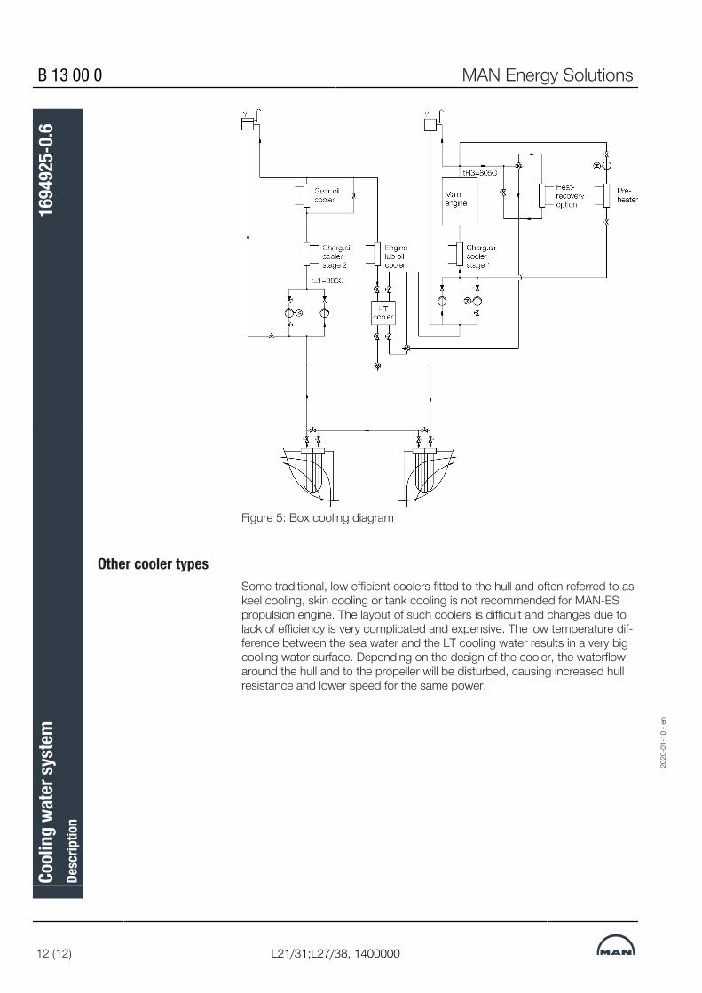
B 13 00 0 MAN Energy Solutions
12 (12) L21/31;L27/38, 1400000
Figure 5: Box cooling diagram
Other cooler typesSome traditional, low efficient coolers fitted to the hull and often referred to askeel cooling, skin cooling or tank cooling is not recommended for MAN-ESpropulsion engine. The layout of such coolers is difficult and changes due tolack of efficiency is very complicated and expensive. The low temperature dif-ference between the sea water and the LT cooling water results in a very bigcooling water surface. Depending on the design of the cooler, the waterflowaround the hull and to the propeller will be disturbed, causing increased hullresistance and lower speed for the same power.18014432900173963
2020
-01-
10 -
en
Cool
ing
wate
r sys
tem
Desc
riptio
n16
9492
5-0.
6

MAN Energy Solutions 010.000.002-04
General, M010.000.002-04-0001 1 (3)
Coolant systemcleaning
SummaryRemove contamination/residue from operating fluid systems, ensure/re-estab-lish operating reliability.Coolant systems containing deposits or contamination prevent effective cool-ing of parts. Contamination and deposits must be regularly eliminated. This comprises the following: Cleaning the system and, if required, removal of limescale deposits,flushing the system.
CleaningThe coolant system must be checked for contamination at regular intervals.Cleaning is required if the degree of contamination is high. This work shouldideally be carried out by a specialist who can provide the right cleaning agentsfor the type of deposits and materials in the cooling circuit. The cleaningshould only be carried out by the engine operator if this cannot be done by aspecialist.
Oil sludge Oil sludge from lubricating oil that has entered the cooling system or a highconcentration of anticorrosive agents can be removed by flushing the systemwith fresh water to which some cleaning agent has been added. Suitablecleaning agents are listed alphabetically in the table entitled Cleaning agentsfor removing oil sludge. Products by other manufacturers can be used provid-ing they have similar properties. The manufacturer's instructions for use mustbe strictly observed.
Manufacturer Product Concentration Duration of cleaning procedure/temperatureDrew HDE - 777 4 – 5% 4 h at 50 – 60 °C
Nalfleet MaxiClean 2 2 – 5% 4 h at 60 °C
Unitor Aquabreak 0.05 – 0.5% 4 h at ambient temperature
Vecom Ultrasonic Multi Cleaner
4% 12 h at 50 – 60 °C
Table 1: Cleaning agents for removing oil sludge
Lime and rust deposits Lime and rust deposits can form if the water is especially hard or if the con-centration of the anticorrosive agent is too low. A thin lime scale layer can beleft on the surface as experience has shown that this protects against corro-sion. However, limescale deposits with a thickness of more than 0.5 mm ob-struct the transfer of heat and cause thermal overloading of the componentsbeing cooled.Rust that has been flushed out may have an abrasive effect on other parts ofthe system, such as the sealing elements of the water pumps. Together withthe elements that are responsible for water hardness, this forms what isknown as ferrous sludge which tends to gather in areas where the flow velo-city is low.
2016
-09-
08 -
de
Cool
ant s
yste
mCo
olan
t sys
tem
Wor
k Ca
rd

010.000.002-04 MAN Energy Solutions
2 (3) General, M010.000.002-04-0001
Products that remove limescale deposits are generally suitable for removingrust. Suitable cleaning agents are listed alphabetically in the table entitledCleaning agents for removing limescale and rust deposits. Products by othermanufacturers can be used providing they have similar properties. The manu-facturer's instructions for use must be strictly observed. Prior to cleaning,check whether the cleaning agent is suitable for the materials to be cleaned.The products listed in the table entitled Cleaning agents for removing limes-cale and rust deposits are also suitable for stainless steel.
Manufacturer Product Concentration Duration of cleaning procedure/temperatureDrew SAF-Acid
Descale-ITFerroclean
5 – 10 %5 – 10 %
10 %
4 h at 60 – 70 °C4 h at 60 – 70 °C4 – 24 h at 60 – 70 °C
Nalfleet Nalfleet 9 - 068 5 % 4 h at 60 – 75 °C
Unitor Descalex 5 – 10 % 4 – 6 h at approx. 60 °C
Vecom Descalant F 3 – 10 % ca. 4 h at 50 – 60 °C
Table 2: Cleaning agents for removing lime scale and rust deposits
In emergencies only Hydrochloric acid diluted in water or aminosulphonic acid may only be used inexceptional cases if a special cleaning agent that removes limescale depositswithout causing problems is not available. Observe the following during ap-plication:▪ Stainless steel heat exchangers must never be treated using diluted hy-
drochloric acid.▪ Cooling systems containing non-ferrous metals (aluminium, red bronze,
brass, etc.) must be treated with deactivated aminosulphonic acid. Thisacid should be added to water in a concentration of 3 – 5 %. The temper-ature of the solution should be 40 – 50 °C.
▪ Diluted hydrochloric acid may only be used to clean steel pipes. If hydro-chloric acid is used as the cleaning agent, there is always a danger thatacid will remain in the system, even when the system has been neutral-ised and flushed. This residual acid promotes pitting. We therefore recom-mend you have the cleaning carried out by a specialist.
The carbon dioxide bubbles that form when limescale deposits are dissolvedcan prevent the cleaning agent from reaching boiler scale. It is therefore abso-lutely necessary to circulate the water with the cleaning agent to flush awaythe gas bubbles and allow them to escape. The length of the cleaning pro-cess depends on the thickness and composition of the deposits. Values areprovided for orientation in the table entitled Cleaning agents for removinglimescale and rust deposits.
Following cleaning The cooling system must be flushed several times once it has been cleanedusing cleaning agents. Replace the water during this process. If acids areused to carry out the cleaning, neutralise the cooling system afterwards withsuitable chemicals then flush. The system can then be refilled with water thathas been prepared accordingly.
2016
-09-
08 -
de
Cool
ant s
yste
mcle
anin
gW
ork
Card

MAN Energy Solutions 010.000.002-04
General, M010.000.002-04-0001 3 (3)
Only carry out cleaning procedure with cooled engineOnly begin the cleaning procedure when the engine has cooled down.Hot engine parts may not come into contact with cold water. After re-filling the cooling system, open the venting pipes. Blocked venting pipesprevent the air from escaping and may cause thermal overload of theengine.
Danger of chemical burnsFrom cleaning agents poisonous gases and fumes can develop, whichmay cause light to severe person injuries.• Wear protective clothing• Provide adequate ventilation• Do not inhale developed gases and fumes• Observe Safety Data Sheets or Operating Instructions of the relevant
manufacturer
The applicable instructions for disposing of cleaning agents or acids are to beobserved.27021599511822731
2016
-09-
08 -
de
Cool
ant s
yste
mcle
anin
gW
ork
Card

This page is intentionally left blank27021599511822731
2016
-09-
08 -
de
010.000.002-04 MAN Energy Solutions
General, M010.000.002-04-0001
Cool
ant s
yste
mcle
anin
gW
ork
Card

MAN Energy Solutions 010.000.002-03
General, M010.000.002-03-0001 1 (2)
Coolantinspecting
SummaryAcquire and check typical values of the operating media to prevent or limitdamage.The fresh water used to fill the coolant circuits must satisfy the specifications.The coolant in the system must be checked regularly in accordance with themaintenance schedule. The following work/steps is/are necessary: Acquisition of typical values for the operating fluid,evaluation of the operating fluid and checking the anticorrosive agent concen-tration.
Tools/equipment requiredEquipment for checking thefresh water quality
The following equipment can be used:▪ The water testing kit, or similar testing kit, with all necessary instruments
and chemicals that determine the water hardness, pH value and chloridecontent (obtainable from or Mar-Tec Marine, Hamburg).
Equipment for testing theconcentration of additives
When using chemical additives:▪ Testing equipment in accordance with the supplier's recommendations.
Testing kits from the supplier also include equipment that can be used todetermine the fresh water quality.
Testing the typical values of waterShort specificationTypical value/property Water for filling
and refilling (without additive)Circulating water(with additive)
Water type Fresh water, free of foreign matter Treated coolant
Total hardness ≤ 10 dGH1) ≤ 10 dGH1)
pH value 6.5 – 8 at 20 °C ≥ 7.5 at 20 °C
Chloride ion content ≤ 50 mg/l ≤ 50 mg/l2)
Table 1: Quality specifications for coolants (short version)
1) dGH German hardness
1 dGH = 10 mg/l CaO= 17.8 mg/l CaCO3
= 0.178 mmol/L2) 1 mg/l = 1 ppm
2019
-11-
11 -
de
Cool
ant
Cool
ant
Wor
k Ca
rd

010.000.002-03 MAN Energy Solutions
2 (2) General, M010.000.002-03-0001
Testing the concentration of rust inhibitorsShort specificationAnti-corrosion agent ConcentrationChemical additives in accordance with quality specification in volume 010.005 Engine – operating manual
010.000.023-14
Antifreeze in accordance with quality specification in volume 010.005 Engine – operating manual010.000.023-14
Table 2: Concentration of coolant additives108086392803849099
Testing the concentration ofchemical additives
The concentration should be tested every week, and/or according to themaintenance schedule, using the testing instruments, reagents and instruc-tions of the relevant supplier.Chemical anti-corrosion agents can only provide effective protection if theconcentration is precisely maintained. Respectively, the concentrations re-commended by (quality specifications in volume 010.005 Engine – operatingmanual 010.000.023-14) must be maintained under all circumstances. Theserecommended concentrations may deviate from those specified by the manu-facturer.
Testing the concentration ofanti-freeze agents
The concentration must be checked in accordance with the manufacturer'sinstructions or the test can be outsourced to a suitable laboratory. If in doubt,consult .
Regular water samplings Small quantities of lube oil in coolant can be found by visual check during reg-ular water sampling from the expansion tank.
Testing Regular analysis of coolant is very important for safe engine operation. Wecan analyse fuel for customers at laboratory PrimeServLab.108086392803849099108086392803849099
2019
-11-
11 -
de
Cool
ant
insp
ectin
gW
ork
Card
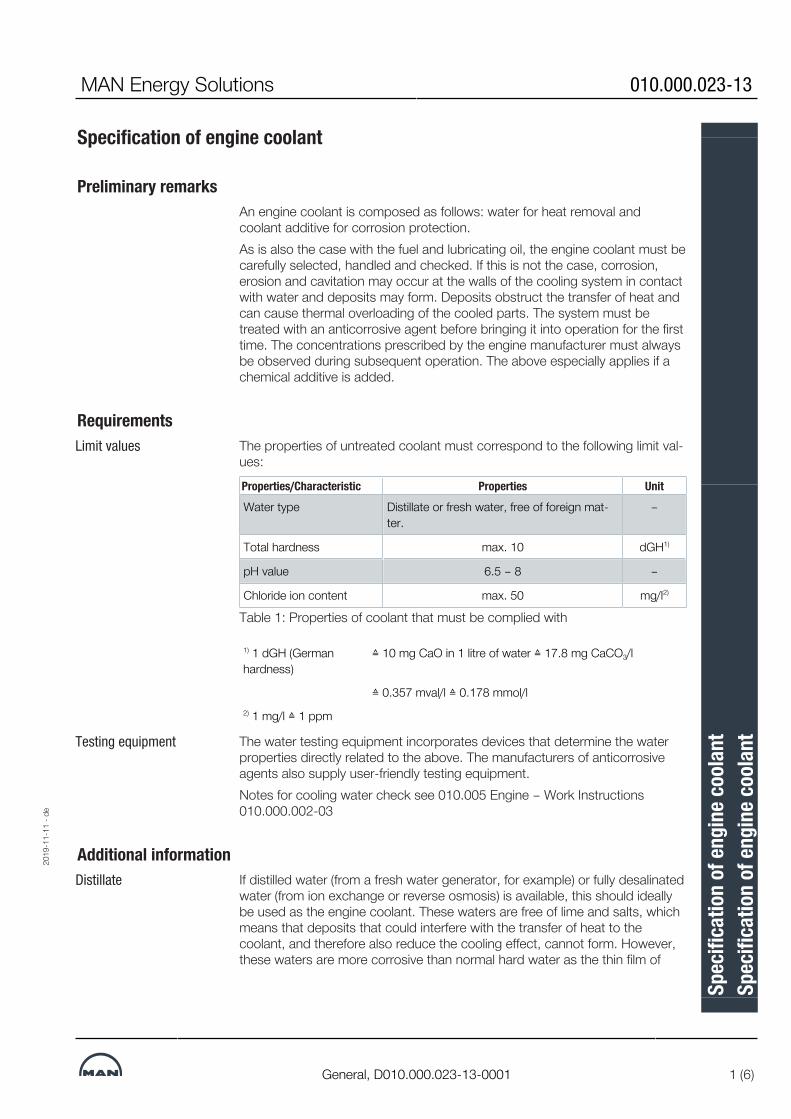
MAN Energy Solutions 010.000.023-13
General, D010.000.023-13-0001 1 (6)
Specification of engine coolant
Preliminary remarksAn engine coolant is composed as follows: water for heat removal andcoolant additive for corrosion protection.As is also the case with the fuel and lubricating oil, the engine coolant must becarefully selected, handled and checked. If this is not the case, corrosion,erosion and cavitation may occur at the walls of the cooling system in contactwith water and deposits may form. Deposits obstruct the transfer of heat andcan cause thermal overloading of the cooled parts. The system must betreated with an anticorrosive agent before bringing it into operation for the firsttime. The concentrations prescribed by the engine manufacturer must alwaysbe observed during subsequent operation. The above especially applies if achemical additive is added.
RequirementsLimit values The properties of untreated coolant must correspond to the following limit val-
ues:
Properties/Characteristic Properties UnitWater type Distillate or fresh water, free of foreign mat-
ter.–
Total hardness max. 10 dGH1)
pH value 6.5 – 8 –
Chloride ion content max. 50 mg/l2)
Table 1: Properties of coolant that must be complied with
1) 1 dGH (Germanhardness)
≙ 10 mg CaO in 1 litre of water ≙ 17.8 mg CaCO3/l
≙ 0.357 mval/l ≙ 0.178 mmol/l2) 1 mg/l ≙ 1 ppm
Testing equipment The water testing equipment incorporates devices that determine the waterproperties directly related to the above. The manufacturers of anticorrosiveagents also supply user-friendly testing equipment.Notes for cooling water check see 010.005 Engine – Work Instructions010.000.002-03
Additional informationDistillate If distilled water (from a fresh water generator, for example) or fully desalinated
water (from ion exchange or reverse osmosis) is available, this should ideallybe used as the engine coolant. These waters are free of lime and salts, whichmeans that deposits that could interfere with the transfer of heat to thecoolant, and therefore also reduce the cooling effect, cannot form. However,these waters are more corrosive than normal hard water as the thin film of
2019
-11-
11 -
de
Spec
ifica
tion
of en
gine
cool
ant
Spec
ifica
tion
of en
gine
cool
ant
Oper
atin
g In
stru
ctio
n

010.000.023-13 MAN Energy Solutions
2 (6) General, D010.000.023-13-0001
lime scale that would otherwise provide temporary corrosion protection doesnot form on the walls. This is why distilled water must be handled particularlycarefully and the concentration of the additive must be regularly checked.
Hardness The total hardness of the water is the combined effect of the temporary andpermanent hardness. The proportion of calcium and magnesium salts is ofoverriding importance. The temporary hardness is determined by the carbon-ate content of the calcium and magnesium salts. The permanent hardness isdetermined by the amount of remaining calcium and magnesium salts (sulph-ates). The temporary (carbonate) hardness is the critical factor that determinesthe extent of limescale deposit in the cooling system.Water with a total hardness of > 10°dGH must be mixed with distilled water orsoftened. Subsequent hardening of extremely soft water is only necessary toprevent foaming if emulsifiable slushing oils are used.
Damage to the coolant systemCorrosion Corrosion is an electrochemical process that can widely be avoided by select-
ing the correct water quality and by carefully handling the water in the enginecooling system.
Flow cavitation Flow cavitation can occur in areas in which high flow velocities and high turbu-lence is present. If the steam pressure is reached, steam bubbles form andsubsequently collapse in high pressure zones which causes the destruction ofmaterials in constricted areas.
Erosion Erosion is a mechanical process accompanied by material abrasion and thedestruction of protective films by solids that have been drawn in, particularly inareas with high flow velocities or strong turbulence.
Stress corrosion cracking Stress corrosion cracking is a failure mechanism that occurs as a result ofsimultaneous dynamic and corrosive stress. This may lead to cracking andrapid crack propagation in water-cooled, mechanically-loaded components ifthe coolant has not been treated correctly.
Treatment of engine coolantFormation of a protectivefilm
The purpose of treating the engine coolant using anticorrosive agents is toproduce a continuous protective film on the walls of cooling surfaces andtherefore prevent the damage referred to above. In order for an anticorrosiveagent to be 100 % effective, it is extremely important that untreated water sat-isfies the requirements in the paragraph Requirements.Protective films can be formed by treating the coolant with anticorrosivechemicals or emulsifiable slushing oil.Emulsifiable slushing oils are used less and less frequently as their use hasbeen considerably restricted by environmental protection regulations, and be-cause they are rarely available from suppliers for this and other reasons.
Treatment prior to initialcommissioning of engine
Treatment with an anticorrosive agent should be carried out before the engineis brought into operation for the first time to prevent irreparable initial damage.
2019
-11-
11 -
de
Spec
ifica
tion
of en
gine
cool
ant
Spec
ifica
tion
of en
gine
cool
ant
Oper
atin
g In
stru
ctio
n

MAN Energy Solutions 010.000.023-13
General, D010.000.023-13-0001 3 (6)
Treatment of the coolantThe engine may not be brought into operation without treating thecoolant.
Additives for coolantsOnly the additives approved by and listed in the tables under the paragraphentitled Permissible cooling water additives may be used.
Required release A coolant additive may only be permitted for use if tested and approved asper the latest directives of the ICE Research Association (FVV) “Suitability testof internal combustion engine cooling fluid additives.” The test report must beobtainable on request. The relevant tests can be carried out on request inGermany at the staatliche Materialprüfanstalt (Federal Institute for MaterialsResearch and Testing), Abteilung Oberflächentechnik (Surface Technology Di-vision), Grafenstraße 2 in D-64283 Darmstadt.Once the coolant additive has been tested by the FVV, the engine must betested in a second step before the final approval is granted.
In closed circuits only Additives may only be used in closed circuits where no significant consump-tion occurs, apart from leaks or evaporation losses. Observe the applicableenvironmental protection regulations when disposing of coolant containingadditives. For more information, consult the additive supplier.
Chemical additivesSodium nitrite and sodium borate based additives etc. have a proven track re-cord. Galvanised iron pipes or zinc sacrificial anodes must not be used incooling systems. This corrosion protection is not required due to the pre-scribed coolant treatment and electrochemical potential reversal that may oc-cur due to the coolant temperatures which are usual in engines nowadays. Ifnecessary, the pipes must be deplated.
Slushing oilThis additive is an emulsifiable mineral oil with additives for corrosion protec-tion. A thin protective film of oil forms on the walls of the cooling system. Thisprevents corrosion without interfering with heat transfer, and also preventslimescale deposits on the walls of the cooling system.Emulsifiable corrosion protection oils have lost importance. For reasons of en-vironmental protection and due to occasional stability problems with emul-sions, oil emulsions are scarcely used nowadays.It is not permissible to use corrosion protection oils in the cooling water circuitof engines.
Antifreeze agentsIf temperatures below the freezing point of water in the engine cannot be ex-cluded, an antifreeze agent that also prevents corrosion must be added to thecooling system or corresponding parts. Otherwise, the entire system must beheated.Sufficient corrosion protection can be provided by adding the products listedin the table entitled Antifreeze agent with slushing properties (Military specific-ation: Federal Armed Forces Sy-7025), while observing the prescribed min-
2019
-11-
11 -
de
Spec
ifica
tion
of en
gine
cool
ant
Spec
ifica
tion
of en
gine
cool
ant
Oper
atin
g In
stru
ctio
n

010.000.023-13 MAN Energy Solutions
4 (6) General, D010.000.023-13-0001
imum concentration. This concentration prevents freezing at temperaturesdown to –22 °C and provides sufficient corrosion protection. However, thequantity of antifreeze agent actually required always depends on the lowesttemperatures that are to be expected at the place of use.Antifreeze agents are generally based on ethylene glycol. A suitable chemicalanticorrosive agent must be added if the concentration of the antifreeze agentprescribed by the user for a specific application does not provide an appropri-ate level of corrosion protection, or if the concentration of antifreeze agentused is lower due to less stringent frost protection requirements and does notprovide an appropriate level of corrosion protection. Considering that the anti-freeze agents listed in the table Antifreeze agents with slushing properties alsocontain corrosion inhibitors and their compatibility with other anticorrosiveagents is generally not given, only pure glycol may be used as antifreezeagent in such cases.Simultaneous use of anticorrosive agent from the table Nitrite-free chemicaladditives together with glycol is not permitted, because monitoring the anti-corrosive agent concentration in this mixture is no more possible.Antifreeze agents may only be added after approval by .Before an antifreeze agent is used, the cooling system must be thoroughlycleaned.If the coolant contains emulsifiable slushing oil, antifreeze agent may not beadded as otherwise the emulsion would break up and oil sludge would form inthe cooling system.
BiocidesIf you cannot avoid using a biocide because the coolant has been contamin-ated by bacteria, observe the following steps:▪ You must ensure that the biocide to be used is suitable for the specific
application.▪ The biocide must be compatible with the sealing materials used in the
coolant system and must not react with these.▪ The biocide and its decomposition products must not contain corrosion-
promoting components. Biocides whose decomposition products containchloride or sulphate ions are not permitted.
▪ Biocides that cause foaming of coolant are not permitted.
Prerequisite for effective use of an anticorrosive agent
Clean cooling systemAs contamination significantly reduces the effectiveness of the additive, thetanks, pipes, coolers and other parts outside the engine must be free of rustand other deposits before the engine is started up for the first time and afterrepairs of the pipe system.The entire system must therefore be cleaned with the engine switched off us-ing a suitable cleaning agent (see 010.005 Engine – Work Instructions010.000.001-01 and 010.000.002-04).Loose solid matter in particular must be removed by flushing the system thor-oughly as otherwise erosion may occur in locations where the flow velocity ishigh.
2019
-11-
11 -
de
Spec
ifica
tion
of en
gine
cool
ant
Spec
ifica
tion
of en
gine
cool
ant
Oper
atin
g In
stru
ctio
n
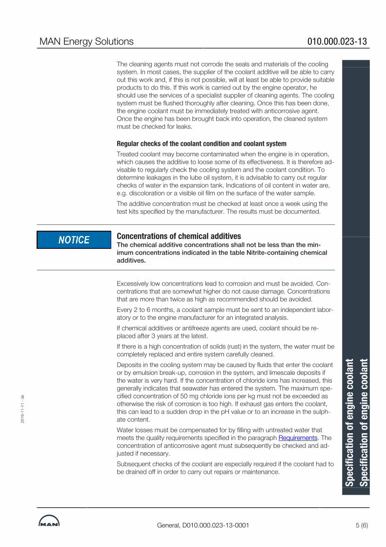
MAN Energy Solutions 010.000.023-13
General, D010.000.023-13-0001 5 (6)
The cleaning agents must not corrode the seals and materials of the coolingsystem. In most cases, the supplier of the coolant additive will be able to carryout this work and, if this is not possible, will at least be able to provide suitableproducts to do this. If this work is carried out by the engine operator, heshould use the services of a specialist supplier of cleaning agents. The coolingsystem must be flushed thoroughly after cleaning. Once this has been done,the engine coolant must be immediately treated with anticorrosive agent.Once the engine has been brought back into operation, the cleaned systemmust be checked for leaks.
Regular checks of the coolant condition and coolant systemTreated coolant may become contaminated when the engine is in operation,which causes the additive to loose some of its effectiveness. It is therefore ad-visable to regularly check the cooling system and the coolant condition. Todetermine leakages in the lube oil system, it is advisable to carry out regularchecks of water in the expansion tank. Indications of oil content in water are,e.g. discoloration or a visible oil film on the surface of the water sample.The additive concentration must be checked at least once a week using thetest kits specified by the manufacturer. The results must be documented.
Concentrations of chemical additivesThe chemical additive concentrations shall not be less than the min-imum concentrations indicated in the table Nitrite-containing chemicaladditives.
Excessively low concentrations lead to corrosion and must be avoided. Con-centrations that are somewhat higher do not cause damage. Concentrationsthat are more than twice as high as recommended should be avoided.Every 2 to 6 months, a coolant sample must be sent to an independent labor-atory or to the engine manufacturer for an integrated analysis.If chemical additives or antifreeze agents are used, coolant should be re-placed after 3 years at the latest.If there is a high concentration of solids (rust) in the system, the water must becompletely replaced and entire system carefully cleaned.Deposits in the cooling system may be caused by fluids that enter the coolantor by emulsion break-up, corrosion in the system, and limescale deposits ifthe water is very hard. If the concentration of chloride ions has increased, thisgenerally indicates that seawater has entered the system. The maximum spe-cified concentration of 50 mg chloride ions per kg must not be exceeded asotherwise the risk of corrosion is too high. If exhaust gas enters the coolant,this can lead to a sudden drop in the pH value or to an increase in the sulph-ate content.Water losses must be compensated for by filling with untreated water thatmeets the quality requirements specified in the paragraph Requirements. Theconcentration of anticorrosive agent must subsequently be checked and ad-justed if necessary.Subsequent checks of the coolant are especially required if the coolant had tobe drained off in order to carry out repairs or maintenance.
2019
-11-
11 -
de
Spec
ifica
tion
of en
gine
cool
ant
Spec
ifica
tion
of en
gine
cool
ant
Oper
atin
g In
stru
ctio
n

010.000.023-13 MAN Energy Solutions
6 (6) General, D010.000.023-13-0001
Protective measuresAnticorrosive agents contain chemical compounds that can pose a risk tohealth or the environment if incorrectly used. Comply with the directions in themanufacturer's material safety data sheets.Avoid prolonged direct contact with the skin. Wash hands thoroughly afteruse. If larger quantities spray and/or soak into clothing, remove and washclothing before wearing it again.If chemicals come into contact with your eyes, rinse them immediately withplenty of water and seek medical advice.Anticorrosive agents are generally harmful to the water cycle. Observe the rel-evant statutory requirements for disposal.
Auxiliary enginesIf the coolant system used in a two-stroke main engine is used in a marine en-gine of type 16/24, 21/ 31, 23/30H, 27/38 or 28/32H, the coolant recom-mendations for the main engine must be observed.
Analysiscan analyse antifreeze agent for their customers in the chemical laboratoryPrimeServLab. A 0.5 l sample is required for the test.
Permitted coolant additivesA list of currently approved coolant additives can be found at https://corpor-ate.man-es.com/lubrication.234187182382806539234187182382806539
2019
-11-
11 -
de
Spec
ifica
tion
of en
gine
cool
ant
Spec
ifica
tion
of en
gine
cool
ant
Oper
atin
g In
stru
ctio
n

MAN Energy Solutions 010.000.023-21
General, D010.000.023-21-0001 1 (2)
Specification of compressed air
GeneralFor compressed air quality observe the ISO 8573-1:2010. Compressed airmust be free of solid particles and oil (acc. to the specification).
RequirementsCompressed air quality ofstarting air system
The starting air must fulfil at least the following quality requirements accordingto ISO 8573-1:2010.
Purity regarding solid particles
Particle size > 40µm
Quality class 6
max. concentration < 5 mg/m3
Purity regarding moisture
Residual water content
Quality class 7
< 0.5 g/m3
Purity regarding oil Quality class X
Additional requirements are:▪ The air must not contain organic or inorganic silicon compounds.▪ The layout of the starting air system must ensure that no corrosion may
occur.▪ The starting air system and the starting air receiver must be equipped with
condensate drain devices.▪ By means of devices provided in the starting air system and via mainten-
ance of the system components, it must be ensured that any hazardousformation of an explosive compressed air/lube oil mixture is prevented in asafe manner.
Compressed air quality inthe control air system
Please note that control air will be used for the activation of some safety func-tions on the engine – therefore, the compressed air quality in this system isvery important.Control air must meet at least the following quality requirements according toISO 8573-1:2010.
▪ Purity regarding solid particles Quality class 5
▪ Purity regarding moisture Quality class 4
▪ Purity regarding oil Quality class 3
For catalystsThe following specifications are valid unless otherwise defined by any otherrelevant sources:
Compressed air quality forsoot blowing
Compressed air for soot blowing must meet at least the following quality re-quirements according to ISO 8573-1:2010.
▪ Purity regarding solid particles Quality class 3
▪ Purity regarding moisture Quality class 4
▪ Purity regarding oil Quality class 2
Compressed air quality forreducing agent atomisation
Compressed air for atomisation of the reducing agent must fulfil at least thefollowing quality requirements according to ISO 8573-1:2010.
2018
-02-
27 -
de
Spec
ifica
tion
of co
mpr
esse
d ai
r

010.000.023-21 MAN Energy Solutions
2 (2) General, D010.000.023-21-0001
▪ Purity regarding solid particles Quality class 3
▪ Purity regarding moisture Quality class 4
▪ Purity regarding oil Quality class 2
Clogging of catalystsTo prevent clogging of catalysts and catalyst lifetime shortening, thecompressed air specification must always be observed.
For gas valve unit control (GVU)Compressed control airquality for the gas valve unitcontrol (GVU)
Compressed air for the gas valve unit control (GVU) must meet at least the fol-lowing quality requirements according to ISO 8573-1:2010.
▪ Purity regarding solid particles Quality class 2
▪ Purity regarding moisture Quality class 3
▪ Purity regarding oil Quality class 2630504034677854836305040346778548363050403467785483
2018
-02-
27 -
de
Spec
ifica
tion
of co
mpr
esse
d ai
r

MAN Energy Solutions B 14 00 0
L27/38;L21/31, 1450000 1 (6)
Starting air system
GeneralThe compressed air system on the engine consists of a starting system, start-ing control system and safety system. Further, the system supplies air to thejet system and the stop cylinders on each fuel injection pump.The compressed air is supplied from the starting air receivers (30 bar) througha reduction station, where from compressed air at max. 10 bar is supplied tothe engine. The reduction station should be located as near the starting air re-ceiver as possible.
To avoid dirt particles in the internal system, a strainer equipped with a drainvalve is mounted in the inlet line to the engine.
Starting SystemThe engine is started by means of a built-on air starter, which is a turbine mo-tor with gear box, safety clutch and drive shaft with pinion. Further, there is amain starting valve.
Control SystemThe air starter is activated electrically with a pneumatic 3/2-way solenoidvalve. The valve can be activated manually from the starting box on the en-gine, and it can be arranged for remote control, manual or automatic.For remote activation the starting coil is connected so that every starting sig-nal to the starting coil goes through the safe start function which is connectedto the safety system mounted on the engine.Further, the starting valve also acts as an emergency starting valve whichmakes it possible to activate the air starter manually in case of power failure.
Safety SystemAs standard the engine is equipped with an emergency stop. It consists ofone on-off valve, see diagram, which activates one stop cylinder on each fuelinjection pump.Air supply must not be interrupted when the engine is running.
Pneumatic Start SequenceWhen the starting valve is opened, air will be supplied to the drive shaft hous-ing of the air starter.The air supply will - by activating a piston - bring the drive pinion into engage-ment with the gear rim on the engine flywheel.When the pinion is fully engaged, the pilot air will flow to, and open the mainstarting valve, whereby air will be led to the air starter, which will start to turnthe engine.When the RPM exceeds approx. 158, at which firing has taken place, thestarting valve is closed whereby the air starter is disengaged.
2019
-05-
21 -
en
Star
ting
air s
yste
mDe
scrip
tion
3700
212-
6.2

B 14 00 0 MAN Energy Solutions
2 (6) L27/38;L21/31, 1450000
22 x
2
30 bar10 bar
Drain mounted atlowest point to drain
to drain
M M1A1
2
3
4
5
DN 50
DN 6
***
to c
onsu
mer
s
DN32**
DN32**
10 x 1
12 x 1.5
A
B
CG
F
E
FG
C
A
B
E
22 x
2
PSL
3A
6
7
PI
PIPT
1322
PT1312
A1 A2
2161
560-
9.1
Fig 1 Starting air diagram
Item Description
11A233A4567
CompressorCompressorFilter with water trapStarting air receiverStarting air receiverFilterPressure reducing valveSelf closing safety valveTyphon
Connections:
A1A2
Starting air - inletStarting air - before pressure reducing valve
**The pipe length between receiver and main engine starting air pipe is to be as shortas possible
***max 10 m from air receiver to engine
The pressure switch for aut. START/STOP of the compressor (items 1 and 1 A)should be connected to the charging air pipe as close as possible to the starting airreceiver (items 3 and 3A) to compensate for pressure peaks from the compressor.
2019
-05-
21 -
en
Star
ting
air s
yste
mDe
scrip
tion
3700
212-
6.2

MAN Energy Solutions B 14 00 0
L27/38;L21/31, 1450000 3 (6)
Starting air receiver (items 3 and 3A): 'A', 'B', 'C', 'E', 'F' and 'G' refer to corres-ponding connections on the starting air receiver, if supplied by MAN Energy Solu-tions, Frederikshavn.
Vertical installation of the starting air receiver is recommended. For horizontal installa-tion, the slope must be min 5 degrees as shown.
Compressor, items 1 and 1AAccording to most classification societies, two or more air compressors mustbe provided. At least one of the air compressors must be driven independ-ently of the main engine and must supply at least 50 % of the required totalcapacity.The pressure switch (PSL) for aut start/stop of the compressors 1 and 1A isto be connected to the charging air pipe as close as possible to the startingair receiver, to compensate for pressure peaks from the compressor. If thepipe is short, a buffer tank or damper is recommended.
All of the starting air receivers, items 3 and 3A, should be pressurized to 30bar for approx 60 minutes.
All of the starting air receivers, items 3 and 3A, should be pressurized to 30bar for approx 60 minutes.
Compressors are to be installed with total capacity sufficient for charging airreceivers of capacities specified from atmospheric to full pressure in thecourse of one hour.
Two or more compressors of total capacity as specified are to be installed’.
Calculation (example):
The compressor capacities are calculated as follows:
P [Nm3/h] Total volumetric delivery capacity of the compressors
V [litres] Total volume of the starting air receivers at 30 bar service pressure
P = Total capacity of the compressors (m3/h)V = Total volume of the starting air receiver (dm3) at service pressure of 30bar)
Example: 1 x 250 ltr + 1 x 500 ltr
2019
-05-
21 -
en
Star
ting
air s
yste
mDe
scrip
tion
3700
212-
6.2

B 14 00 0 MAN Energy Solutions
4 (6) L27/38;L21/31, 1450000
Filter with water trap, item 2A filter with water trap should be installed in the charging air pipe between thecompressors and the starting air receivers.
Starting air receiver, items 3 and 3AThe starting air receiver should, preferably, be vertically installed and securedto a bulkhead, thus ensuring easy access to the water drain valve. If spaceconditions do not permit vertical mounting, the receiver may be minimum 5°off the horizontal, with the drain valve at the lowest position.
Two starting air receivers are standard equipment for each plant. Table onnext page describe minimum values of starting air capacity.
Pressure reducing valve, item 5As standard the engines are fitted with a 10 bar air starter. Therefore the airsupply needs to be reduced from 30 bar to 10 bar before inlet engine.
If the engine is fitted with a 30 bar air starter (option), there will be a pressurereducing valve for stop air pressure installed.
If a pressure drop should occur, it is alarmed by the pressure switch (PT1322) on the engine control system. To have this indication there need to be apipe from before the pressure reducing station to location of pressure switch(PT 1322).
Starting air and charging air pipeThe starting and charging air pipes are to be installed with a slope towardsthe starting air receiver, preventing possible condensed water from runninginto the air starting motor or the compressors. A drain valve has to be installedat the lowest position of the starting air pipe, as shown in fig 1.
Dimensioning starting air receivers, compressors
Starting air receiversThe starting air supply is to be split up into not less than two starting air re-ceivers of nominally the same size, which can be used independently of eachanother.The engine requires compressed air for starting, for the jet assist function aswell as several pneumatic controls. The design of the pressure air receiver dir-ectly depends on the air consumption and the requirements of the classifica-tion societies.
Calculation for starting air receiver of engines with jet assist and Slow Turn:
2019
-05-
21 -
en
Star
ting
air s
yste
mDe
scrip
tion
3700
212-
6.2
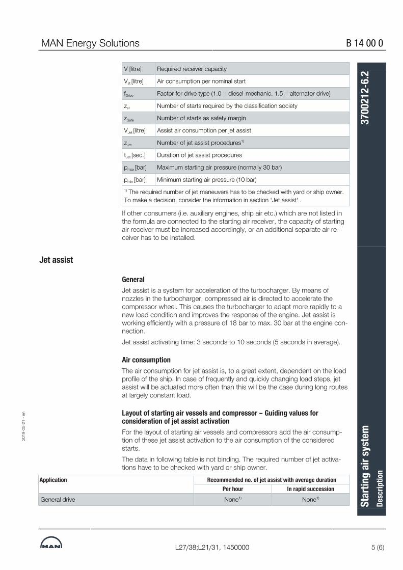
MAN Energy Solutions B 14 00 0
L27/38;L21/31, 1450000 5 (6)
V [litre] Required receiver capacity
Vst [litre] Air consumption per nominal start
fDrive Factor for drive type (1.0 = diesel-mechanic, 1.5 = alternator drive)
zst Number of starts required by the classification society
zSafe Number of starts as safety margin
VJet [litre] Assist air consumption per jet assist
zJet Number of jet assist procedures1)
tJet [sec.] Duration of jet assist procedures
pmax [bar] Maximum starting air pressure (normally 30 bar)
pmin [bar] Minimum starting air pressure (10 bar)1) The required number of jet maneuvers has to be checked with yard or ship owner.To make a decision, consider the information in section 'Jet assist' .
If other consumers (i.e. auxiliary engines, ship air etc.) which are not listed inthe formula are connected to the starting air receiver, the capacity of startingair receiver must be increased accordingly, or an additional separate air re-ceiver has to be installed.
Jet assist
GeneralJet assist is a system for acceleration of the turbocharger. By means ofnozzles in the turbocharger, compressed air is directed to accelerate thecompressor wheel. This causes the turbocharger to adapt more rapidly to anew load condition and improves the response of the engine. Jet assist isworking efficiently with a pressure of 18 bar to max. 30 bar at the engine con-nection.Jet assist activating time: 3 seconds to 10 seconds (5 seconds in average).
Air consumptionThe air consumption for jet assist is, to a great extent, dependent on the loadprofile of the ship. In case of frequently and quickly changing load steps, jetassist will be actuated more often than this will be the case during long routesat largely constant load.
Layout of starting air vessels and compressor – Guiding values forconsideration of jet assist activationFor the layout of starting air vessels and compressors add the air consump-tion of these jet assist activation to the air consumption of the consideredstarts.The data in following table is not binding. The required number of jet activa-tions have to be checked with yard or ship owner.
Application Recommended no. of jet assist with average durationPer hour In rapid succession
General drive None1) None1)
2019
-05-
21 -
en
Star
ting
air s
yste
mDe
scrip
tion
3700
212-
6.2

B 14 00 0 MAN Energy Solutions
6 (6) L27/38;L21/31, 1450000
Application Recommended no. of jet assist with average durationPer hour In rapid succession
Diesel-mechanical drive without shifting clutch None1) None1)
Diesel-mechanical drive with shifting clutch 3 x 5 sec 2 x 5 sec
Diesel-mechanical drive with shaft-driven alternator(> 50 % MCR)
2 x 5 sec 2 x 5 sec
Electric propulsion 3 x 5 sec 2 x 5 sec
Electric propulsion offshore applications – Semisub pro-duction/drilling applications and drillships2)
(10 x 5 sec) (5 x 5 sec)
Ships with frequent load changes (e.g. ferries) 3 x 5 sec 3 x 5 sec
Auxiliary engine 3 x 5 sec 2 x 5 sec
High-torque applications 2 x 20 sec 2 x 20 sec1) According the necessity of the application "jet assist" please check figure Load application. If the curve "without jetassist" is sufficient, jet assist can be omitted.2) For these applications please contact MAN Energy Solutions for a project specific estimation.
Table 1: Guiding values for the number of jet assist maneuvers dependent on application34390975755
Dynamic positioning for drilling vessels, cable-laying vessels, off-shoreapplicationsWhen applying dynamic positioning, pulsating load application of > 25 % mayoccur frequently, up to 30 times per hour. In these cases, the possibility of aspecially adapted, separate compressed air system has always to bechecked.
Air supplyGenerally, larger air receivers are to be provided for the air supply of the jetassist.For the design of the jet assist air supply the temporal distribution of eventsneeds to be considered, if there might be an accumulation of events.In each case the delivery capacity of the compressors is to be adapted to theexpected jet assist requirement per unit of time.34390975755
2019
-05-
21 -
en
Star
ting
air s
yste
mDe
scrip
tion
3700
212-
6.2

MAN Energy Solutions B 15 00 0
V28/32S;L28/32S;L28/32H;L27/38S;L27/38;L23/30S;L23/30H;L21/31S;L21/31;L16/24S;L16/24 1 (4)
Combustion air system for arctic operation
GeneralMachinery for ships to operate in arctic areas must be able to stand up to ex-tremely low ambient temperatures (such as down to minus 60°C).
Engine operation under arc-tic conditions
Artic condition is defined as:Air intake temperatures of the engine below 0 °C.If engines operate under arctic conditions (intermittently or permanently), theengine equipment and plant installation have to hold certain design featuresand meet special requirements. They depend on the possible minimum air in-take temperature of the engine and the specification of the fuel used.Minimum air intake temperature of the engine, tx:▪ Category 1
0 °C > tx > −15 °C▪ Category 2
−15 °C ≥ tx > −60 °C
Figure 1: Diagram
In order not to undercool the engine room, the diesel engines cannot be sup-plied with combustion air from the engine room. They must be connected toan air trunk system taking in air of low temperature from the outside.If not compensated for, the low air temperature could cause two problems forthe engine performance; (namely) a too high combustion pressure and a toolow charge air temperature.With air of low temperature and consequently high density the turbochargerwill supply the engine with such a large amount of charge air (by weight) thatthe combustion pressure during engine operation in the high load range willbecome unacceptably high.
2018
-08-
07 -
en
Com
bust
ion
air s
yste
m fo
r arc
tic o
pera
tion
Desc
riptio
n16
3145
3-3.
3

B 15 00 0 MAN Energy Solutions
2 (4)V28/32S;L28/32S;L28/32H;L27/38S;L27/38;L23/30S;L23/30H;L21/31S;L21/31;L
16/24S;L16/24
This problem can be compensated for by blowing off a certain amount of airfrom the engine air inlet bend returning it back to the air inlet bend of the tur-bocharger, see fig. 1. This recirculation will not only adjust the charge airamount but also raise the air inlet temperature.When running MAN SCR besides charge air blow off there can also be wastegate for regeneration.Starting the engine on arctic temperatures is difficult and sometimes im-possible at extreme cold temperature. It is recommended that a bypasschangeover flap with air intake filter is installed in the pipe connection from thelouver to the turbocharger on the engine. The changeover flap is to be openduring start of the engine, and thereby heated air from the engine room is en-tering the turbocharger. When the engine has reached a cooling water tem-perature of more than 50 degrees, the bypass changeover flap is closed, andthereby the air is supplied from the outside louver.
1 Combustion air duct con-nected
2 Louver*
3 Combustion air duct 4 Changeover flap with airfilter (outside- / inside air)for starting in cold climate
Figure 2: Engine room ventilation, air duct connected to the turbocharger
*Always to be equipped with a filter when an air duct is connected to the tur-bocharger according to "Specification of intake air", 010.000.023-17.
2018
-08-
07 -
en
Com
bust
ion
air s
yste
m fo
r arc
tic o
pera
tion
Desc
riptio
n16
3145
3-3.
3

MAN Energy Solutions B 15 00 0
V28/32S;L28/32S;L28/32H;L27/38S;L27/38;L23/30S;L23/30H;L21/31S;L21/31;L16/24S;L16/24 3 (4)
Plant installation▪ Cooling down of engine room due to cold ambient air can be avoided by
supplying the engine directly from outside with combustion air. For thisthe combustion air must be filtered. See D010.000.023-17, Specificationof intake air. Moreover a droplet separator and air intake silencer becomenecessary. According to classification rules it may be required to installtwo air inlets from the exterior, one at starboard and one at portside.
▪ Cold intake air from outside is preheated in front of the cylinders in thecharge air cooler. HT water serves as heat source. Depending on loadand air temperature additional heat has then to be transferred to the HTcircuit by a HT preheating module
▪ It is necessary to ensure that the charge air cooler cannot freeze when theengine is out of operation (and the cold air is at the air inlet side). HT-cool-ing water preheating will prevent this. Additionally it is recommentded thoprepare the combustion air duct upstream of the engine for the installationof a blanking plate, necessary to be installed in case of malfunction on theHT-cooling water preheating system.
Category 1▪ Charge air blow-off is activated at high engine load with low combustion
air temperature. With a blow-off air duct installed in the plant, it can be re-circulated in the combustion air duct upstream of the engine. Alternatively,only if blow-off air is deviated downstream of the charge air coolers and iscold (depending on engine type), blow-off air can be directly released inthe engine room. Then a blow-off air silencer installed in the plant be-comes necessary.
▪ Alternatively engine combustion air and engine room ventilation air can besupplied together in the engine room, if heated adequately and if accep-ted by the classification company.
Category 2▪ Please contact MAN Diesel & Turbo.
Instruction for minimum ad-missible fuel temperature
▪ In general the minimum viscosity before engine of 2.0 cSt must not be un-dershoot.
▪ The fuel specific characteristic values “pour point” and “cold filter pluggingpoint” have to be observed to ensure pumpability respectively filterabilityof the fuel oil.
▪ Fuel temperatures of ≤ –10 °C are to be avoided, due to temporarily em-brittlement of seals used in the engines fuel oil system. As a result theymay suffer a loss of function.
Minimum engine room tem-perature
▪ Ventilation of engine roomThe air of the engine room ventilation must not be too cold (preheating isnecessary) to avoid the freezing of the liquids in the engine room systems.
▪ Minimum power house/engine room temperature for design ≥ +5 °C.Coolant and lube oil sys-tems
▪ Coolant and lube oil system have to be preheated for each individual en-gine, see section Starting conditions.See also the specific information regarding special arrangements for arcticconditions, see section Lube oil system and Water systems.
▪ Maximum permissible antifreeze concentration (ethylene glycol) in the en-gine cooling water.An increasing proportion of antifreeze decreases the specific heat capa-city of the engine cooling water, which worsens the heat dissipation fromthe engine and will lead to higher component temperatures.
2018
-08-
07 -
en
Com
bust
ion
air s
yste
m fo
r arc
tic o
pera
tion
Desc
riptio
n16
3145
3-3.
3

B 15 00 0 MAN Energy Solutions
4 (4)V28/32S;L28/32S;L28/32H;L27/38S;L27/38;L23/30S;L23/30H;L21/31S;L21/31;L
16/24S;L16/24
Therefore, the antifreeze concentration of the engine cooling water sys-tems (HT and LT) within the engine room, respectively power house,should be below a concentration of 40 % glycol. Any concentration of> 55 % glycol is forbidden.
▪ If a concentration of anti-freezing agents of > 50 % in the cooling watersystems is required, contact MAN Diesel & Turbo for approval.
▪ For information regarding engine cooling water see section Specificationfor engine supplies.
Insulation The design of the insulation of the piping systems and other plant parts(tanks, heat exchanger, external intake air duct etc.) has to be modified anddesigned for the special requirements of arctic conditions.
Heat tracing To support the restart procedures in cold condition (e.g. after unmanned sur-vival mode during winter), it is recommended to install a heat tracing system inthe pipelines to the engine.
A preheating of the lube oil has to be ensured. If the plant is notequipped with a lube oil separator (e.g. plants only operating on MGO)alternative equipment for preheating of the lube oil must be provided.For plants taken out of operation and cooled down below temperaturesof +5 °C additional special measures are required – in this case contactMAN Diesel & Turbo.
18014427560202507
2018
-08-
07 -
en
Com
bust
ion
air s
yste
m fo
r arc
tic o
pera
tion
Desc
riptio
n16
3145
3-3.
3

MAN Energy Solutions B 15 00 0
L27/38;L21/31, 1400000 1 (1)
Engine ventilation
DescriptionThe air intake to the engine room should be dimensioned in such a way that asufficient quantity of air is available not only for the main engine, auxiliaries,boilers etc, but also to ensure adequate ventilation and fresh air when workand service are in progress.We recommend the ventilation capacity should be min 50% more than re-quired air consumption (in tropical conditions more than 100% should be con-sidered) for main engine, auxiliaries, boilers etc.It is important that the air is free of oil and sea water to prevent fouling of theventilators and filters.The air consumption of the main engine appears from the planning data.Approx 50% of the ventilating air should be blown in at the level of the top ofthe main engine close to the air inlet of the turbocharger. Air should not beblown directly onto heat emitting components or directly onto electric or otherwater sensitive apparature.A small airflow should be evenly distributed around the engine and reductiongear in order to dissipate radiated heat.With closed engine room and all air consuming equipment operating, thereshould always be positive air pressure in the engine room.Surplus air should be led up through the casing via special exhaust openings.Alternatively extraction fans should be installed.Fire arresting facilities must be installed within the casings of the fans andventilation trunkings to retard the propagation of fire.34394661259
2019
-01-
18 -
en
Engi
ne ve
ntila
tion
Desc
riptio
n16
9075
1-3.
1

This page is intentionally left blank34394661259
2019
-01-
18 -
en
B 15 00 0 MAN Energy Solutions
L27/38;L21/31, 1400000
Engi
ne ve
ntila
tion
Desc
riptio
n16
9075
1-3.
1
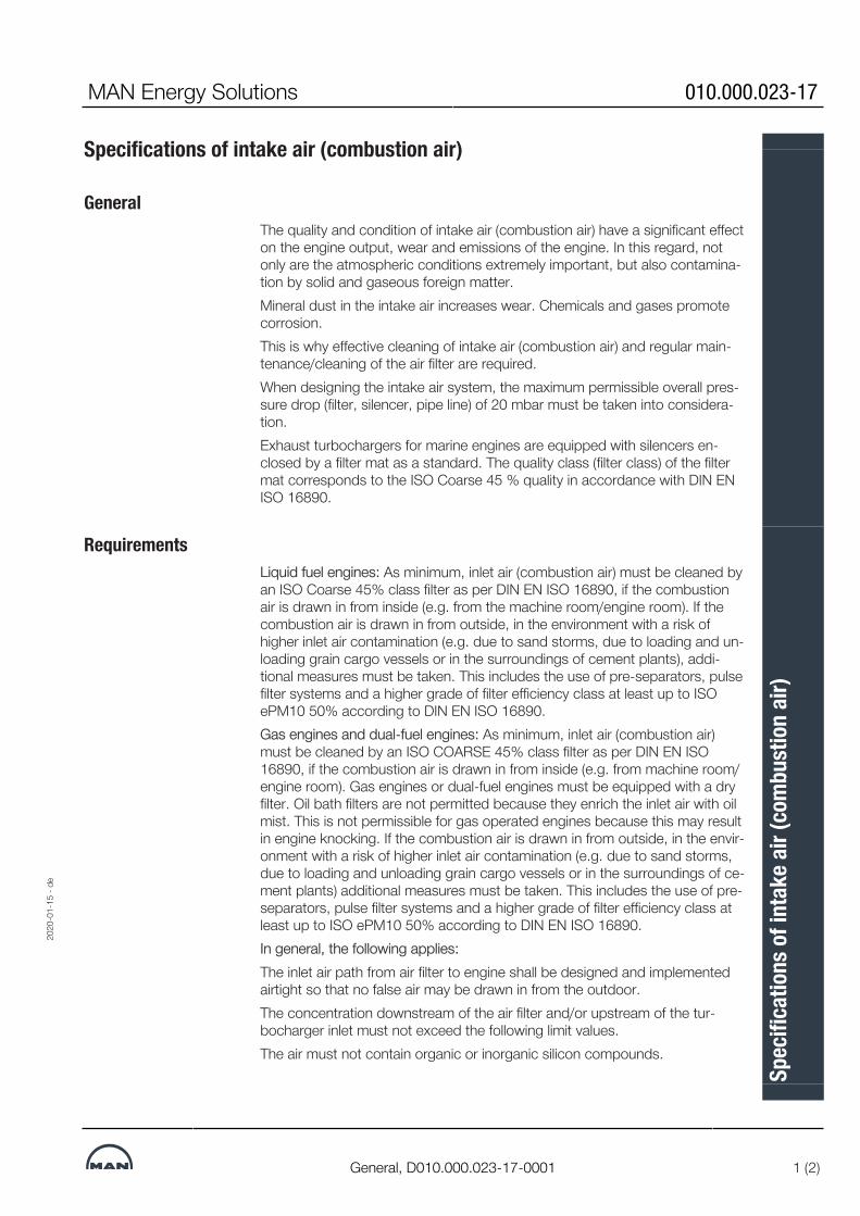
MAN Energy Solutions 010.000.023-17
General, D010.000.023-17-0001 1 (2)
Specifications of intake air (combustion air)
GeneralThe quality and condition of intake air (combustion air) have a significant effecton the engine output, wear and emissions of the engine. In this regard, notonly are the atmospheric conditions extremely important, but also contamina-tion by solid and gaseous foreign matter.Mineral dust in the intake air increases wear. Chemicals and gases promotecorrosion.This is why effective cleaning of intake air (combustion air) and regular main-tenance/cleaning of the air filter are required.When designing the intake air system, the maximum permissible overall pres-sure drop (filter, silencer, pipe line) of 20 mbar must be taken into considera-tion.Exhaust turbochargers for marine engines are equipped with silencers en-closed by a filter mat as a standard. The quality class (filter class) of the filtermat corresponds to the ISO Coarse 45 % quality in accordance with DIN ENISO 16890.
RequirementsLiquid fuel engines: As minimum, inlet air (combustion air) must be cleaned byan ISO Coarse 45% class filter as per DIN EN ISO 16890, if the combustionair is drawn in from inside (e.g. from the machine room/engine room). If thecombustion air is drawn in from outside, in the environment with a risk ofhigher inlet air contamination (e.g. due to sand storms, due to loading and un-loading grain cargo vessels or in the surroundings of cement plants), addi-tional measures must be taken. This includes the use of pre-separators, pulsefilter systems and a higher grade of filter efficiency class at least up to ISOePM10 50% according to DIN EN ISO 16890.Gas engines and dual-fuel engines: As minimum, inlet air (combustion air)must be cleaned by an ISO COARSE 45% class filter as per DIN EN ISO16890, if the combustion air is drawn in from inside (e.g. from machine room/engine room). Gas engines or dual-fuel engines must be equipped with a dryfilter. Oil bath filters are not permitted because they enrich the inlet air with oilmist. This is not permissible for gas operated engines because this may resultin engine knocking. If the combustion air is drawn in from outside, in the envir-onment with a risk of higher inlet air contamination (e.g. due to sand storms,due to loading and unloading grain cargo vessels or in the surroundings of ce-ment plants) additional measures must be taken. This includes the use of pre-separators, pulse filter systems and a higher grade of filter efficiency class atleast up to ISO ePM10 50% according to DIN EN ISO 16890.In general, the following applies:The inlet air path from air filter to engine shall be designed and implementedairtight so that no false air may be drawn in from the outdoor.The concentration downstream of the air filter and/or upstream of the tur-bocharger inlet must not exceed the following limit values.The air must not contain organic or inorganic silicon compounds.
2020
-01-
15 -
de
Spec
ifica
tions
of i
ntak
e air
(com
bust
ion
air)

010.000.023-17 MAN Energy Solutions
2 (2) General, D010.000.023-17-0001
Properties Limit Unit 1)
Dust (sand, cement, CaO, Al2O3 etc.) max. 5 mg/Nm3
Chlorine max. 1.5
Sulphur dioxide (SO2) max. 1.25
Hydrogen sulphide (H2S) max. 5
Salt (NaCl) max. 11) One Nm3 corresponds to one cubic meter of gas at 0 °C and 101.32 kPa.
Table 1: Typical values for intake air (combustion air) that must be compliedwith
Explosion due to flammable intake airSevere personal injury due to the explosion of flammable intake air.• Intake air must not be explosive.• Intake air must not contain flammable gases.• Intake air must not be drawn in from ATEX zones.
90071994308172043
2020
-01-
15 -
de
Spec
ifica
tions
of i
ntak
e air
(com
bust
ion
air)

MAN Energy Solutions B 15 01 1
L28/32A;L27/38;L23/30A;L21/31, Make MAN, 1459000 1 (1)
Turbocharger
DescriptionThe engines are as standard equipped with a turbocharger of the radial typeMAN NR/R, NR/S and TCR.The rotor, comprising compressor, turbine wheel and shaft, is supported infloating plain bearing bushes.The turbine wheel is an integrated part of the shaft.Gas admission casing with gas outlet diffusor matched to the exhaust pipe ar-rangement and a turbine nozzle ring made of a special wear resistant material.Air intake silencer with filter, and compressor casing with one outlet.Lubrication of the two plain bushes is an integrated part of the engine lub. oilsystem.The turbocharger has no water cooling.
L21/31
215 kW/cyl.1000 rpm
6 cyl. TCR16
7 cyl. TCR18
8 cyl. TCR18
9 cyl. TCR1834394666763
L28/32A
245 kW/cyl.775 rpm
6 cyl. NR24/R
7 cyl. NR24/R
8 cyl. NR24/R
9 cyl. NR26/R34394666763
L27/38
340 kW/cyl.800 rpm
6 cyl. TCR18
7 cyl. TCR20
8 cyl. TCR20
9 cyl. TCR20
365 kW/cyl.800 rpm
6 cyl. TCR18
7 cyl. TCR20
8 cyl. TCR20
9 cyl. TCR2034394666763
L23/30A
160 kW/cyl.900 rpm
6 cyl. NR20/R
8 cyl. NR20/R3439466676334394666763
2019
-01-
18 -
en
Turb
ocha
rger
Desc
riptio
n37
0019
6-9.
1

This page is intentionally left blank3439466676334394666763343946667633439466676334394666763
2019
-01-
18 -
en
B 15 01 1 MAN Energy Solutions
L28/32A;L27/38;L23/30A;L21/31, Make MAN, 1459000
Turb
ocha
rger
Desc
riptio
n37
0019
6-9.
1

MAN Energy Solutions B 16 00 0
L27/38;L21/31, TCR, 1459000 1 (2)
Exhaust gas system
Exhaust pipeIt is important that the exhaust piping is as short and with as few sweepbends as possible.Sharp bendings and small diameter exhaust pipes produce high back pres-sures which will affect the engine combustion.The exhaust back pressure should not exceed 250 mm WC at MCR. An ex-haust gas velocity of max 35 m/sec at MCR through the exhaust system isusually acceptable, but depends on the actual installation and flow resistance.Each engine must have its own separate exhaust system to avoid fouling ofthe turbocharger when an engine is not in operation.We will be pleased to assist in making a calculation of the exhaust back pres-sure.The gas outlet from the turbocharger, expansion bellows, connecting piece,exhaust pipes and silencers must be insulated with suitable material. The in-sulation should be protected by a thin metal plating and comply with classand national authority requirements.Care must be taken when installing silencers with spark arresters to ensurethat the access doors are situated to permit ease of removal for cleaning.The minimum dimensions of the exhaust pipes are stated in the planning data.
Exhaust pipe mountingWhen the exhaust system is designed, consideration must be given to the ra-diation of heat and noise.Because the exhaust system is subject to considerable thermal fluctuations, itis necessary to incorporate flexible as well as rigid suspension points.In order to compensate for thermal expansion in the longitudinal direction, ex-pansion bellows must be inserted as shown. Depending on the actual exhaustpiping system, it may be necessary to insert extra expansion bellows. The ex-pansion bellows should preferably be placed at the rigid suspension points.The exhaust piping must exert no force on the gas outlet of the turbocharger.The pipe work should be easily removable to facilitate ease of cleaning andmaintenance. Each connection in the pipe line should be fitted with a gasket.A pipe branch should be welded into the exhaust line to enable measure-ments of the exhaust back pressure to be taken.To prevent the ingress of water, the terminal outlet should be provided with acollar, as shown in fig 1.The exhaust piping is to be provided with water drains, which are to be keptopen constantly for draining the condensation water or possible leak waterfrom waste heat boilers.
2019
-01-
10 -
en
Exha
ust g
as sy
stem
Desc
riptio
n16
9686
4-1.
2

B 16 00 0 MAN Energy Solutions
2 (2) L27/38;L21/31, TCR, 1459000
Figure 1: Exhaust gas system34408215947
2019
-01-
10 -
en
Exha
ust g
as sy
stem
Desc
riptio
n16
9686
4-1.
2

MAN Energy Solutions B 16 00 0
L23/30H-Mk3;L23/30H-Mk2;L28/32S;L23/30S;L27/38S;L21/31S;L16/24S;V28/32S-
DF;V28/32H;L23/30DF;L28/32DF;V28/32S;L16/24;L21/31;L23/30H;L27/38;L28/32H, 1459000 1 (3)
Pressure drop in exhaust gas system
General
Figure 1: Nomogram for pressure drop in exhaust gas piping system.
2020
-01-
09 -
en
Pres
sure
dro
p in
exha
ust g
as sy
stem
Desc
riptio
n16
2446
0-4.
3

B 16 00 0 MAN Energy Solutions
2 (3)
L23/30H-Mk3;L23/30H-Mk2;L28/32S;L23/30S;L27/38S;L21/31S;L16/24S;V28/32S-
DF;V28/32H;L23/30DF;L28/32DF;V28/32S;L16/24;L21/31;L23/30H;L27/38;L28/32H, 1459000
Permissible total resistance:IMO Tier II: 30 mbarIMO Tier III (SCR), scrubber and other aftertreatment: 50 mbar
2020
-01-
09 -
en
Pres
sure
dro
p in
exha
ust g
as sy
stem
Desc
riptio
n16
2446
0-4.
3

MAN Energy Solutions B 16 00 0
L23/30H-Mk3;L23/30H-Mk2;L28/32S;L23/30S;L27/38S;L21/31S;L16/24S;V28/32S-
DF;V28/32H;L23/30DF;L28/32DF;V28/32S;L16/24;L21/31;L23/30H;L27/38;L28/32H, 1459000 3 (3)
Density of airDensity of air can be determined by following empiric, formula*:
* This formula is only valid between -20° to 60°C.ExampleAt ambient air conditions 20°C and pressure 0.98 bar, the density is:
36028804179402123
2020
-01-
09 -
en
Pres
sure
dro
p in
exha
ust g
as sy
stem
Desc
riptio
n16
2446
0-4.
3

This page is intentionally left blank36028804179402123
2020
-01-
09 -
en
B 16 00 0 MAN Energy Solutions
L23/30H-Mk3;L23/30H-Mk2;L28/32S;L23/30S;L27/38S;L21/31S;L16/24S;V28/32S-
DF;V28/32H;L23/30DF;L28/32DF;V28/32S;L16/24;L21/31;L23/30H;L27/38;L28/32H, 1459000
Pres
sure
dro
p in
exha
ust g
as sy
stem
Desc
riptio
n16
2446
0-4.
3

MAN Energy Solutions B 16 00 0
L27/38;L21/31, 1459000 1 (20)
SCR (Selective Catalytic Reduction)
Introduction
SCR technologyMAN Energy Solutions decided to develop it's own SCR technology to beable to optimise the emissions technology and the engine performance in ad-dition with the MAN Energy Solutions own SCR control programme to the ut-most customer benefit.Common SCR systems require constantly high exhaust gas temperatures.The MAN Energy Solutions SCR system however is an integrated system (en-gine + SCR) that is automatically adjusting the exhaust gas temperature in anoptimal way to ensure ideal operation of both engine and SCR. For example,the engine is operating at optimum condition, however the system is register-ing an increasing backpressure over the SCR reactor. To resolve this, the re-generation feature of the integrated SCR system is activated and the wasteg-ate engaged to increase exhaust gas temperature. After a short time, the SCRsystem is regenerated and the engine can continue operation in the designpoint area. Thus the SCR assures ideal engine operation by regenerating theSCR system whenever necessary to achieve minimum fuel oil consumption.Nevertheless, the SCR system complies with the IMO Tier III regulations onNOX emissions at any time.
Fuels for operation with SCR catalystThe SCR components were special designed for operation with heavy fuel oil(HFO) in accordance with specification DIN ISO 8217 up to sulphur content of3.5 %. See description 010.000.023-05, "Specification of Heavy Fuel Oil(HFO)".
2019
-01-
10 -
en
SCR
(Sele
ctive
Cat
alyt
ic Re
duct
ion)
Desc
riptio
n37
0047
3-7.
1
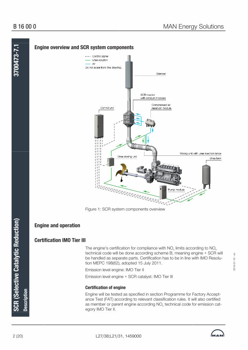
B 16 00 0 MAN Energy Solutions
2 (20) L27/38;L21/31, 1459000
Engine overview and SCR system components
Figure 1: SCR system components overview
Engine and operation
Certification IMO Tier IIIThe engine's certification for compliance with NOx limits according to NOxtechnical code will be done according scheme B, meaning engine + SCR willbe handled as separate parts. Certification has to be in line with IMO Resolu-tion MEPC 198(62), adopted 15 July 2011.Emission level engine: IMO Tier IIEmission level engine + SCR catalyst: IMO Tier III
Certification of engineEngine will be tested as specified in section Programme for Factory Accept-ance Test (FAT) according to relevant classification rules. It will also certifiedas member or parent engine according NOx technical code for emission cat-egory IMO Tier II.
2019
-01-
10 -
en
SCR
(Sele
ctive
Cat
alyt
ic Re
duct
ion)
Desc
riptio
n37
0047
3-7.
1

MAN Energy Solutions B 16 00 0
L27/38;L21/31, 1459000 3 (20)
Certification of complete system (engine plus SCR system)Certification of SCR catalyst and components will be done in accordance toMEPC 198(62) for a scaled, standardised SCR reactor and SCR componentsbased on product features and following scaled parameters:▪ Exhaust gas mass flow▪ Exhaust gas composition (NOx, O2, CO2, H2O, SO2)▪ Exhaust gas temperature▪ Catalyst modules (AV, SV or LV value)▪ Reducing agent▪ Desired NOx conversion rateThe On-board Confirmation Test required for a scheme B certification will bedone for the parent engine plus SCR system for a group according to IMOresolution MEPC 198(62).
SCR - Special notesPrinciple of SCR technology The selective catalytic reduction SCR uses ammonia (NH3) to convert nitrogen
oxides in the exhaust gas to harmless nitrogen and water within a catalyst.However, ammonia is a hazardous substance which has to be handled care-fully to avoid any dangers for crews, passengers and the environment. There-fore urea as a possible ammonia source is used. Urea is harmless and, solvedin water, it is easy to transport and to handle. Today, aqueous urea solutionsof 32.5 % or 40 % are the choice for SCR operation in mobile applications onland and at sea.Using urea, the reaction within the exhaust gas pipe and the catalyst consistsof two steps. In the beginning, the urea decomposes in the hot exhaust gasto ammonia and carbon dioxide using the available water in the injected solu-tion and the heat of the exhaust gas:(NH2)2CO + H2O -> 2NH3 + CO2 [1]The literal NOx-reduction takes place supported by the catalyst, where am-monia reduces nitrogen oxides to nitrogen and water.4NO + 4NH3 + O2 -> 4N2 + 6H2O [2]
System overview The MAN Energy Solutions SCR system is available in different sizes to coverthe whole medium speed engine portfolio. The SCR system consists of the re-actor, the mixing unit, the urea supply system, the pump module, the dosingunit, the control unit and the soot-blowing system.After initial start-up of the engine, the SCR system operates continuously inautomatic mode. The amount of urea injection into the SCR system dependson the operating conditions of the engine. Since the control unit of the SCRsystem is connected to the engine control system all engine related informa-tions are continuously and currently available. This is one of the important be-nefits of the MAN Energy Solutions SCR system.The urea is sprayed into the mixing unit which is part of the exhaust gas duct.Entering the reactor the reducing agent starts to react with NOx coming fromthe combustion. The amount of reducing agent is controlled by the dosingunit, which is supported by a pump connected to an urea tank. It furthermoreregulates the compressed air flow for the injector.
2019
-01-
10 -
en
SCR
(Sele
ctive
Cat
alyt
ic Re
duct
ion)
Desc
riptio
n37
0047
3-7.
1

B 16 00 0 MAN Energy Solutions
4 (20) L27/38;L21/31, 1459000
Each reactor is equipped with a soot blowing system to prevent blocking ofthe SCR catalyst by ashes and soot.
Scope of supply ▪ Engine in standard configuration according stated emission level (seeabove).
▪ Engine attached equipment for control of the temperature after turbine.▪ Engine SaCoS software including functions for control of temperature
after turbine and for optimising engine + SCR performance.▪ IMO Tier III Certificate.▪ MAN Energy Solutions will act as "Applicant" within the meaning of the
IMO.
Main components of SCRsystem in the standardscoper supply
▪ SCR reactor▪ Catalyst modules▪ Soot blowing system▪ Dosing unit▪ Mixing unit▪ Urea injection lance▪ Control unit SCR▪ Pump module▪ Compressed air reservoir module
Not included in the standardscope of supply, amongothers
▪ Urea storage tank▪ Urea storage tank minimum level switch▪ Piping▪ insulation
Operation Standard operationCommon SCR systems provided by third parties require constantly high ex-haust gas temperatures. The MAN Energy Solutions SCR system on the otherhand is an integrated engine + SCR system that allows operation on lower ex-haust gas temperature levels.The MAN Energy Solutions SCR system automatically adjusts the engine ex-haust gas temperature to ensure both optimum engine + SCR operation. Fora maximum on safety the surveillance mode is always activated.
Enhanced operationThe MAN Energy Solutions SCR system assures ideal engine operation, re-generating the SCR system whenever necessary to account for a minimumfuel oil consumption while complying with IMO Tier III emission limits at alltimes. Dependent on the ambient conditions it may be needed to adapt theengine load during the regeneration phase.
2019
-01-
10 -
en
SCR
(Sele
ctive
Cat
alyt
ic Re
duct
ion)
Desc
riptio
n37
0047
3-7.
1

MAN Energy Solutions B 16 00 0
L27/38;L21/31, 1459000 5 (20)
Boundary conditions forSCR operation
Please consider following boundary conditions for the SCR operation:▪ Temperature control of temperature turbine outlet:
– By adjustable waste gate (attached to engine).– Set point 320 °C as minimum temperature for active SCR.– Set point 290 °C as minimum temperature for deactivated SCR.
▪ Fuel:– In line with MAN Energy Solutions specification, maximum 3.5 % sul-
fur content.▪ SCR active in following range:
– 10 °C (arctic) up to 45 °C (tropic) intake air temperature.– In the range of 25 % to 100 % engine load.
▪ IMO requirements for handling of SCR operation disturbances:– In case of SCR malfunction IMO regulations allow that the system will
be turned off and the ship's journey will be continued to the port ofdestination. There, the ship needs to be repaired, if the emission limitsof the harbor/sea area would be exceeded.Accordingly, the vessel may leave a port in case it will only sail inareas requiring IMO II, even if the SCR system is still out of service.
▪ Differential pressure Δp SCR (normal operation):– Max. 20 mbar.
For the design of the complete exhaust gas line, please consider:▪ Maximum permissible exhaust gas back pressure (to be calculated from
engine turbocharger outlet to end of complete exhaust gas line):– Max. 50 mbar (at 100 % engine load).
▪ Maximum permissible temperature drop of exhaust gas line (to be calcu-lated as difference of exhaust gas temperature turbine outlet and temper-ature SCR inlet):– Max. 5 K in the range of 25 % to 100 % engine load (calculated at 5
°C air temperature in the engine room).▪ Recommended for exhaust gas line:
– Insulation according to SOLAS standard.
The SCR system requires high exhaust gas temperatures for an effectiveoperation. MAN Energy Solutions therefore recommends to arrange theSCR as the first device in the exhaust gas line, followed by other auxili-aries like boiler, silencer etc.
Performance coverage forSCR system
▪ Performance guarantee for engine plus SCR within defined in sectionBoundary conditions for SCR operation.
▪ Guarantee for engine plus SCR for marine applications to meet IMO Tier IIIlevel as defined by IMO within defined in section Boundary conditions forSCR operation (details will be handled within the relevant contracts).
2019
-01-
10 -
en
SCR
(Sele
ctive
Cat
alyt
ic Re
duct
ion)
Desc
riptio
n37
0047
3-7.
1

B 16 00 0 MAN Energy Solutions
6 (20) L27/38;L21/31, 1459000
Please be awareAll statements in this document refer to MAN Energy Solutions SCR sys-tems only.MAN Energy Solutions can only deliver an IMO Tier III certificate and actas “Applicant” (within the meaning of the IMO) if the engine plus SCRsystem is supplied by MAN Energy Solutions.If the engine is supplied without MAN Energy Solutions SCR system,only a standard warranty for a single engine will be given. No guaranteeregarding minimum exhaust gas temperature after turbine or emissionsafter third party SCR or suitability of the engine in conjunction with athird party SCR system can be given.If the engine is supplied without MAN Energy Solutions SCR system, nooptimisation function within SaCoS can be applied and as maximum ex-haust gas temperature after turbine only will be possible:▪320 °C (25 % load – 100 % load).
Main dimensions, weights and views of SCR componentsDepending on the individual projects SCR properties may vary. The followingdimensions and weights are for guidance only.
2019
-01-
10 -
en
SCR
(Sele
ctive
Cat
alyt
ic Re
duct
ion)
Desc
riptio
n37
0047
3-7.
1

MAN Energy Solutions B 16 00 0
L27/38;L21/31, 1459000 7 (20)
SCR reactor
Figure 2: SCR reactor
Controlcab.
Engine power ap-proximately
L(Total length)
D(Without in-
sulation)
W(Without in-
sulation)
A(With anchor-
age)
Maximum weightstructurally1)
Service space
No. kW mm mm mm mm kg min. mm1 0 – 800 2,800 1,000 1,000 1,600 1,350 750
2 801 – 1,400 2,900 1,250 1,250 1,800 2,050 750
3 1,401 – 2,400 3,000 1,500 1,500 2,000 2,950 750
4 2,401 – 3,650 3,100 1,750 1,750 2,300 3,900 750
5 3,651 – 4,900 3,200 2,000 2,000 2,680 5,050 750
6 4,901 – 6,000 3,400 2,350 2,350 2,930 6,550 750
7 6,001 – 7,800 3,600 2,900 2,350 2,930 8,000 750
8 7,801 – 9,000 3,600 2,900 2,900 3,430 9,600 750
2019
-01-
10 -
en
SCR
(Sele
ctive
Cat
alyt
ic Re
duct
ion)
Desc
riptio
n37
0047
3-7.
1

B 16 00 0 MAN Energy Solutions
8 (20) L27/38;L21/31, 1459000
Controlcab.
Engine power ap-proximately
L(Total length)
D(Without in-
sulation)
W(Without in-
sulation)
A(With anchor-
age)
Maximum weightstructurally1)
Service space
No. kW mm mm mm mm kg min. mm9 9,001 – 12,000 3,900 3,400 2,900 3,430 11,450 750
10 12,001 – 13,700 3,900 3,400 3,400 4,030 13,300 750
11 13,701 – 15,000 4,100 3,950 3,400 4,030 15,300 750
12 15,001 – 17,000 4,100 3,950 3,950 4,630 17,450 750
13 17,001 – 20,000 4,300 4,450 3,950 4,630 19,700 750
14 20,001 – 21,600 4,300 4,450 4,450 5,130 21,950 750
DRW 11686100042 D-0011) See section .
Table 1: SCR reactor
In accordance with applicable security policies there must be providedadequate maintenance space, which permits the safe execution of allnecessary maintenance work
Figure 3: Mixing unit with urea lance20
19-0
1-10
- en
SCR
(Sele
ctive
Cat
alyt
ic Re
duct
ion)
Desc
riptio
n37
0047
3-7.
1

MAN Energy Solutions B 16 00 0
L27/38;L21/31, 1459000 9 (20)
Mixing unit with urea lanceMixing unit Engine power approximately Mixing pipe1) Length straight mixing pipe (L)No. kW DN mm1 0 – 1,000 500 3,400
2 1,001 – 2,000 600 3,400
3 2,001 – 3,000 800 3,550
4 3,001 – 4,200 1,000 3,650
5 4,201 – 5,400 1,100 3,700
6 5,401 – 6,800 1,200 3,800
7 6,801 – 8,500 1,400 3,850
8 8,501 – 10,500 1,500 4,000
9 10,501 – 13,000 1,600 4,400
10 13,001 – 20,000 2,100 4,610
11 20,001 – 21,600 2,300 5,0101) Diameter mixing pipe differs from exhaust pipe diameter.
Table 2: Mixing unit with urea lance
Dosing unitDosing unit Height Width Depth WeightNo. mm mm mm kg1 800 800 300 80
Table 3: Dosing unit
SCR control cabinetControl cabinet Height Width Depth WeightNo. mm mm mm kg1 2,100 800 400 220
Table 4: SCR control cabinet
Pump modulePump module Height Width Depth WeightNo. mm mm mm kg1 1,300 700 300 120
Table 5: Pump module
Compressed air reservoir moduleAir module Height Width Depth WeightNo. mm mm mm kg1 1,050 1,500 500 250
Table 6: Compressed air reservoir module
2019
-01-
10 -
en
SCR
(Sele
ctive
Cat
alyt
ic Re
duct
ion)
Desc
riptio
n37
0047
3-7.
1

B 16 00 0 MAN Energy Solutions
10 (20) L27/38;L21/31, 1459000
Waste gateTemperature after turbinecontrol by continuously ad-justable waste gate (seeflap 7 in figure 4)
The waste gate is used to by-pass the turbine of the turbocharger with a partof the exhaust gas. This leads to a charge air pressure reduction and the tem-perature after turbine is increased.For plants with an SCR catalyst, waste gate is necessary in order to ensureproper performance of SCR.In case the temperature before SCR falls below the set minimum exhaust gastemperature value, the waste gate is opened gradually in order to blow-off ex-haust gas before the turbine until the exhaust gas temperature before theSCR catalyst has reached the required level.
Figure 4: Overview flaps
2019
-01-
10 -
en
SCR
(Sele
ctive
Cat
alyt
ic Re
duct
ion)
Desc
riptio
n37
0047
3-7.
1

MAN Energy Solutions B 16 00 0
L27/38;L21/31, 1459000 11 (20)
Specification for engine supplies
Specification of urea solutionUse of good quality urea solution is essential for the operation of a SCR cata-lyst. Using urea solution not complying with the specification below e.g. agri-cultural urea, can either cause direct operational problems or long-term prob-lems like deactivation of the catalyst.
The overall SCR system is designed for one of the two possible ureasolution qualities (32.5 % AdBlue® or 40 % concentration) as listed inthe tables below. This must be taken into account when ordering. Themixture of the both different solutions is not permissible!
Urea solution concentration[%]
39 - 41
ISO 22241-2 Annex C
Density at 20 °C [g/cm3] 1.105-1.115 DIN EN ISO 12185
Refractive index at 20 °C 1.3930-1.3962 ISO 22241-2 Annex C
Biuret [%] max. 0.5 ISO 22241-2 Annex E
Alkality as NH3 [%] max. 0.5 ISO 22241-2 Annex D
Aldehyde [mg/kg] max. 10 ISO 22241-2 Annex F
Insolubles [mg/kg] max. 20 ISO 22241-2 Annex G
Phosphorus (as PO4) [mg/kg]
max. 0.5 ISO 22241-2 Annex H
Calcium [mg/kg] max. 0.5 ISO 22241-2 Annex I
Iron [mg/kg] max. 0.5 ISO 22241-2 Annex I
Magnesium [mg/kg] max. 0.5 ISO 22241-2 Annex I
Sodium [mg/kg] max. 0.5 ISO 22241-2 Annex I
Potassium [mg/kg] max. 0.5 ISO 22241-2 Annex I
Copper [mg/kg] max. 0.2 ISO 22241-2 Annex I
Zinc [mg/kg] max. 0.2 ISO 22241-2 Annex I
Chromium [mg/kg] max. 0.2 ISO 22241-2 Annex I
Table 7: Urea 40 % solution specification
Urea solution concentration[%]
31.8 - 33.2
ISO 22241-2 Annex C
Density at 20 °C [g/cm3] 1.087-1.093 DIN EN ISO 12185
Refractive index at 20 °C 1.3814-1.3843 ISO 22241-2 Annex C
Biuret [%] max. 0.3 ISO 22241-2 Annex E
2019
-01-
10 -
en
SCR
(Sele
ctive
Cat
alyt
ic Re
duct
ion)
Desc
riptio
n37
0047
3-7.
1

B 16 00 0 MAN Energy Solutions
12 (20) L27/38;L21/31, 1459000
Urea solution concentration[%]
31.8 - 33.2
ISO 22241-2 Annex C
Alkality as NH3 [%] max. 0.2 ISO 22241-2 Annex D
Aldehyde [mg/kg] max. 5 ISO 22241-2 Annex F
Insolubles [mg/kg] max. 20 ISO 22241-2 Annex G
Phosphorus (as PO4) [mg/kg]
max. 0.5 ISO 22241-2 Annex H
Calcium [mg/kg] max. 0.5 ISO 22241-2 Annex I
Iron [mg/kg] max. 0.5 ISO 22241-2 Annex I
Magnesium [mg/kg] max. 0.5 ISO 22241-2 Annex I
Sodium [mg/kg] max. 0.5 ISO 22241-2 Annex I
Potassium [mg/kg] max. 0.5 ISO 22241-2 Annex I
Copper [mg/kg] max. 0.2 ISO 22241-2 Annex I
Zinc [mg/kg] max. 0.2 ISO 22241-2 Annex I
Chromium [mg/kg] max. 0.2 ISO 22241-2 Annex I
Table 8: Urea 32.5 % solution specification
2019
-01-
10 -
en
SCR
(Sele
ctive
Cat
alyt
ic Re
duct
ion)
Desc
riptio
n37
0047
3-7.
1

MAN Energy Solutions B 16 00 0
L27/38;L21/31, 1459000 13 (20)
Engine supply systems
SCR systemGeneral The SCR system uses aqueous urea solution and a catalyst material to trans-
form the pollutant nitrogen oxides into harmless nitrogen and water vapor.The main components of the SCR system are described in the following sec-tion.For further information read section "SCR - Special notes".
As-delivered conditions andpackaging
All components will be delivered and packaged in a seaworthy way (with dryagent, wooden boxing, shrink wrapped). Black carbon steel components willbe coated with an anti-corrosive painting. Stainless steel components will notbe coated.The original packaging should not be removed until the date of installation.The physical integrity of the packaging must be checked at the date of deliv-ery.
Transportation and handling Compressed air reservoir module (MOD-085)Transport of the compressed air reservoir module can be organised by crane,via installed metal eyelets on the top side or fork‐lifter.
Urea pump module (MOD‐084)Transport of the urea pump module can be organised by crane, via installedmetal eyelets on the top side.
Dosing unit (MOD‐082)Transport of the dosing unit can be organised by crane, via installed metaleyelets on the top side.
Urea injection lance and mixing unit (MOD‐087)Transport of the mixing unit can be organised by crane, via two installed metaleyelets. For horizontal lifting it is sufficient using one of the metal eyelets.Using a vertical way, the two cables each fixed on one metal eyelet have to bestabilised by a transversal bar.
The metal eyelets are designed to carry only the segments of the mixingunit, further weights are not allowed (e.g. complete welded mixing pipe).
SCR reactor (R‐001)Transport of the reactor can be organised by crane, via installed metal eyeletson the top side.
SCR control unitTransport of the reactor can be organised by crane, via installed metal eyeletson the top side.
2019
-01-
10 -
en
SCR
(Sele
ctive
Cat
alyt
ic Re
duct
ion)
Desc
riptio
n37
0047
3-7.
1

B 16 00 0 MAN Energy Solutions
14 (20) L27/38;L21/31, 1459000
Storage Compressed air reservoir module (MOD‐085), urea pump module (MOD‐084),dosing unit (MOD‐082), SCR control unit and sensor elements have to bestored in dry and weather‐resistant conditions.Catalyst elements shall be handled free from shocks and vibrations. Further-more, catalyst elements have to be stored in dry and weather‐resistant condi-tions. Keep oils or chemicals away from catalyst elements. Seaworthy pack-aging is only a temporary protection.
Components and assem-blies of the SCR system
Catalyst elementsThe catalyst elements are placed in metallic frames, so called modules. Dueto the honeycomb structure of the catalyst elements, the catalytic surface isincreased. The active component Vanadium pentoxide (V2O5) in the surfacesupports the reduction of NOx to harmless nitrogen.The effectivity of the catalytic material decreases over time because of poison-ing via fuel oil components or thermal impact. The durability depends on thefuel type and conditions of operation.The status of catalyst deactivation is monitored continuously and the amountof urea injected is adapted according to the current status of the catalyst.
Compressed air reservoir module (MOD-085) and soot blowing system(MOD-086)The compressed air required for the operation of the SCR system is providedby the compressed air module. It receives its compressed air via the ship´scompressed air grid. For the quality requirements read section Specification ofcompressed air. The main supply line feeds the compressed air reservoirmodule, where a compressed air tank is installed. This high-pressure tank is areservoir with enough capacity to ensure the supply of the dosing unit and theair consumption for the periodically cleaning of the catalysts´ surface, byavoiding fluctuations in the soot blowing system. In case of black out thevolume of the tank will be used for flushing the urea line and nozzle.The module has to be positioned close to the reactor and the dosing unit. Themaximum length of the compressed air line to the soot blowing system is 10m.The soot blower valves are positioned upstream each catalyst layer in order toclean the complete surface of the catalyst elements by periodical air flushing.The soot blowing always has to be in operation while engine running.
Urea pump modul (MOD-084)The urea pump module boosts urea to the dosing unit and maintains an ad-equate pressure in the urea lines. The complete module is mounted in astandard cabinet for wall fastening. Upstream of the supply pump, a filter is in-stalled for protection of solid pollutants. Downstream, the module is equippedwith a return line to the urea storage tank with a pressure relief valve to ensurethe required urea flow.The urea pump module has to be positioned on a level below the minimumurea level of the urea storage tank. The pump accepts a maximum pressureloss of 2 bar. One urea pump module can supply up to four SCR systems.
2019
-01-
10 -
en
SCR
(Sele
ctive
Cat
alyt
ic Re
duct
ion)
Desc
riptio
n37
0047
3-7.
1

MAN Energy Solutions B 16 00 0
L27/38;L21/31, 1459000 15 (20)
Urea quality according section Specification of urea solution is required.For urea consumption calculation for Tier III read section Urea consump-tion for emission standard IMO Tier III.
Dosing unit (MOD-082)The dosing unit controls the flow of urea to the injection nozzle based on theoperation of the engine. Furthermore it regulates the compressed air flow tothe injector.In order to avoid clogging due to the evaporation of urea in the urea pipe andin the nozzle, a line between compressed air line and urea line is installed. Aninstalled solenoid valve will open to flush and cool the urea line and nozzlewith compressed air before and after injecting urea into the exhaust gas.The dosing unit has to be installed close to the urea injection lance and mixingunit (maximum pipe length 5 m).
Urea injection lance and mixing unit (MOD-087)The urea solution will be injected into the exhaust gas using a two-phasenozzle. The urea will be atomised with compressed air. The evaporation of theurea occurs immediately when the urea solution gets in contact with the hotexhaust gas.The urea injection and the mixing unit have to be positioned according toMAN Energy Solutions requirements. In general, the mixing section is between3.0 – 4.5 m long and of DN 500 to DN 2,300. The mixing duct is a straightpipe upstream of the reactor. The exact length has to be calculated. Addi-tional, it has to be considered that an inlet zone upstream the reactor of 0.5 xdiameter of the exhaust gas pipe has to be foreseen.
SCR reactor (R-001)Each engine is equipped with its own SCR reactor and it is fitted in the ex-haust gas piping without a by-pass. The SCR reactor housing is a steel struc-ture with an inlet cone. The reactor configuration is vertical and consists ofseveral layers of catalysts. For horizontal installation, please contact MAN En-ergy Solutions. The reactor is equipped with differential pressure and temper-ature monitoring, openings for inspection, a maintenance door for service andthe soot blowing system for each layer.The maximum temperature of the exhaust gas is 450 °C and a minimum ex-haust gas temperature is required to ensure a reliable operation. Thereforetemperature indicators are installed in the inlet and outlet of the reactor in or-der to monitor and control the optimum operating range.
2019
-01-
10 -
en
SCR
(Sele
ctive
Cat
alyt
ic Re
duct
ion)
Desc
riptio
n37
0047
3-7.
1
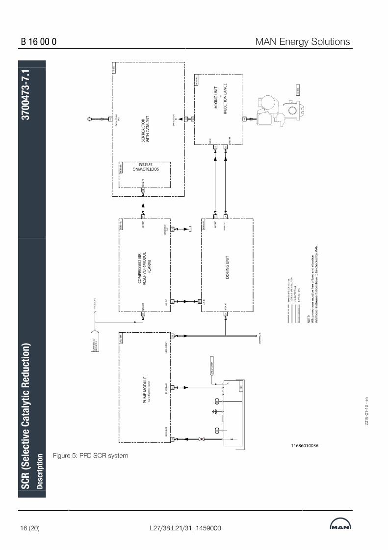
B 16 00 0 MAN Energy Solutions
16 (20) L27/38;L21/31, 1459000
Figure 5: PFD SCR system
2019
-01-
10 -
en
SCR
(Sele
ctive
Cat
alyt
ic Re
duct
ion)
Desc
riptio
n37
0047
3-7.
1

MAN Energy Solutions B 16 00 0
L27/38;L21/31, 1459000 17 (20)
Urea pipes (for SCR only)Galvanised steel pipe, brass and copper components must not be used forthe piping of the system.Proposed material (EN)X6CrNiMoTi17-12-2
Installation of the SCR sys-tem
All modules are check regarding pressure and tightness.
Catalyst elements For handling the catalyst elements sufficient space and supply tracks have tobe foreseen. Depending on the amount of catalyst elements transport deviceslike carriages, pulleys, fork lifter or elevators are required.
Reactor and soot blowingsystem
A service space of recommended 800 mm in front of the inspection doors ofthe reactor for mounting and dismounting the catalyst elements has to beforeseen. Further 750 mm space for service and maintenance of the sootblower equipment and the differential pressure device has to be consideredaccording the installation side of the soot blowing system.
Reactor and piping In case of a bend before the reactor inlet, a straight inlet duct to the reactor of0.5 times exhaust gas pipe diameter and a bend radius of 1.5 times exhaustgas pipe diameters has to be considered.
Mixing unit The mixing unit is designed for vertical or horizontal installation. Bend on thedownstream side has to be in accordance to above mentioned “Reactor andPiping”. Upstream of the mixing unit a bend can be installed according theMAN Energy Solutions requirements mentioned on the planning drawing.
Recommendations All parts mentioned in this paragraph are not MAN Energy Solutions scope ofsupply.
Piping in general All piping's have to be in accordance with descriptions P 69 00 0, 3700402-0,"Pipeline treatment requirements for piping manufacture" and010.000.001-01, "Operating Fluid Systems, flushing and cleaning". Piping for fluids shall be mounted in an increasing/decreasing way. Siphonsshould be avoided, drainage system be foreseen.
Exhaust gas piping The complete inside wall of the exhaust gas piping between engine outlet andSCR reactor inlet should not be coated by any protection material. Poisoningof the catalyst honeycombs could occur.
Preferred materials All materials used for the construction of tanks and containers including tubes,valves and fittings for storage, transportation and handling must be compat-ible with urea 40 % solution to avoid any contamination of urea and corrosionof device used. In order to guarantee the urea quality the following materialsfor tank, pipes and fittings are compatible: Stainless steel (1.4301 or 1.4509)or urea-resistant plastics (e.g. PA12). For gaskets EPDM or HNBR. Piping forcompressed air see section Specification of materials for piping.
Unsuitable materials Unsuitable materials for tank, pipes and fittings are among others: Aluminum,unalloyed steel, galvanised steel, copper and brass.In case incompatible material is used, clogging of urea filter inside the pumpmodule may occur, or even worse, the catalyst elements may be damaged bycatalyst poisons derived from this material. In this case, exchanging the cata-lyst modules may be necessary.
Urea tank Store this material in cool, dry, well-ventilated areas. Do not store at temperat-ures below 10 °C and above 55 °C. The storage capacity of the urea tankshould be designed depending on ship load profile and bunker cycle.
2019
-01-
10 -
en
SCR
(Sele
ctive
Cat
alyt
ic Re
duct
ion)
Desc
riptio
n37
0047
3-7.
1

B 16 00 0 MAN Energy Solutions
18 (20) L27/38;L21/31, 1459000
The urea supply line should be provided with a strainer and a non-return valvein order to assure a correct performance for the suction of the urea pump,which is installed downstream the tank. A level switch with the possibility toread out the signal will protect the pump of a dry run. A return line from theurea pump module over a pressure relief valve is entering the tank.
Urea solution quality Use of good quality urea is essential for the operation of an SCR catalyst. Us-ing urea not complying with the specification below e.g. agricultural urea, caneither cause direct operational problems or long term problems like deactiva-tion of the catalyst. For quality requirements, see section Specification of ureasolution.
Insulation The quality of the insulation has to be in accordance with the safety require-ments. All insulations for service and maintenance spaces have to be dis-mountable. The delivered modules have no fixations, if fixations are necessarytake care about the permissible material combination. Regarding max. per-missible thermal loss see section Boundary conditions for SCR operation.
Water trap Water entry into the reactor housing must be avoided, as this can cause dam-age and clogging of the catalyst. Therefore a water trap has to be installed, ifthe exhaust pipe downstream of the SCR reactor is facing upwards.
2019
-01-
10 -
en
SCR
(Sele
ctive
Cat
alyt
ic Re
duct
ion)
Desc
riptio
n37
0047
3-7.
1

MAN Energy Solutions B 16 00 0
L27/38;L21/31, 1459000 19 (20)
Engine room planning
Exhaust gas ductingExample: Ducting arrange-ment
Figure 6: Example: Exhaust gas ducting arrangement
General details for Tier IIISCR system duct arrange-ment
MAN Energy Solutions recommends that the SCR reactor housing should bemounted before all other components (e.g. boiler, silencer) in the exhaustduct, coming from the engine side. A painting on the inside wall of the ex-haust duct in front of the the SCR system is not allowed.
2019
-01-
10 -
en
SCR
(Sele
ctive
Cat
alyt
ic Re
duct
ion)
Desc
riptio
n37
0047
3-7.
1

B 16 00 0 MAN Energy Solutions
20 (20) L27/38;L21/31, 1459000
All of the spaces/openings for cleaning and maintenance on the entire unit, in-cluding air reservoir module, dosing unit and reactor housing with soot-blowers must be accessible.We strongly recommend that in front of the reactor housing sufficient spacefor the maintenance personal and/or for the temporary storage of the catalysthoneycombs has to be foreseen (see section SCR System).Catalyst elements could reach a weight of 25 kg, the reactor openings couldreach a total weight of about 70 kg, MAN Energy Solutions strongly recom-mends a lifting capability above the reactors.A very important point is the transportation way and storage space of thecatalyst honeycombs within the funnel for supply of the SCR reactor duringmaintenance or catalyst refreshment, one reactor could contain more than100 elements.To avoid time-consuming or implementation of a scaffolding, MAN EnergySolutions strongly recommends at minimum a lifting device in the funnel orany kind of material elevator. A porthole from outside rooms on level with thereactor housing is also a possibility, as far as those rooms could be suppliedwith the catalyst honeycombs.34400982027
2019
-01-
10 -
en
SCR
(Sele
ctive
Cat
alyt
ic Re
duct
ion)
Desc
riptio
n37
0047
3-7.
1

MAN Energy Solutions B 16 01 0
L27/38;L21/31, 1459000 1 (2)
Exhaust gas velocity
Exhaust gas velocityEngine type Exhaust gas flow Exhaust gas temp. DN
Nominal diameterExhaust gas velo-
citykg/h °C mm m/sec.
6L21/31, 1000 rpm (215 kW)
7L21/31, 1000 rpm (215 kW)
8L21/31, 1000 rpm (215 kW)
9L21/31, 1000 rpm (215 kW)
10200
11900
13600
15200
319
319
319
319
450
500
500
550
32.1
30.3
34.6
32.0
6L27/38, 800 rpm (340 kW)
7L27/38, 800 rpm (340 kW)
8L27/38, 800 rpm (340 kW)
9L27/38, 800 rpm (340 kW)
14700
17100
19600
22000
360
360
360
360
550
600
650
650
33.1
32.2
29.8
33.5
6L27/38, 800 rpm (365 kW)
7L27/38, 800 rpm (365 kW)
8L27/38, 800 rpm (365 kW)
9L27/38, 800 rpm (365 kW)
15300
17900
20400
23000
385
385
385
385
550
600
650
650
35.9
34.9
32.3
36.334400971147
Density of exhaust gases ρA ~ 0.6 kg/m3
The exhaust gas velocities are based on the pipe dimensions in the table be-low.
34400971147
2019
-01-
18 -
en
Exha
ust g
as ve
locit
yDe
scrip
tion
3700
195-
7.1

B 16 01 0 MAN Energy Solutions
2 (2) L27/38;L21/31, 1459000
DN
Nominal dia-meter
D1
mm
D2
mm
T
mm
Flow area A
10-3 m2
300 323.9 309.7 7.1 75.331
350 355.6 339.6 8.0 90.579
400 406.4 388.8 8.8 118.725
450 457.0 437.0 10.0 149.987
500 508.0 486.0 11.0 185.508
550 559.0 534.0 12.5 223.961
600 610.0 585.0 12.5 268.7833440097114734400971147
2019
-01-
18 -
en
Exha
ust g
as ve
locit
yDe
scrip
tion
3700
195-
7.1

MAN Energy Solutions B 16 02 0
L27/38, 1459000 1 (2)
Exhaust gas system - position of gas outlet on turbocharger
Position of gas outlet on turbocharger
The turbocharger outlet is fitted with a round flange, adapted for direct install-ation of an expansion bellow.
Fig 1 shows alternative positions for the exhaust gas outlet and if requestedthe outlet can be turned to a desired position prior to dispatch.
Fig 1 Position of exhaust gas outlet34400976651
Enginetype
Amm
Bmm
Cmm
Dmm
Emm
Fmm
G*mm
6L27/38(TCR 18)
703 1053 1798 427 315 762 550
7L27/38(TCR 20)
754 1053 1844 514 315 822 600
2019
-01-
18 -
en
Exha
ust g
as sy
stem
- po
sitio
n of
gas
out
let o
n tu
rboc
harg
er
Desc
riptio
n37
0019
9-4.
1

B 16 02 0 MAN Energy Solutions
2 (2) L27/38, 1459000
Enginetype
Amm
Bmm
Cmm
Dmm
Emm
Fmm
G*mm
8L27/38(TCR 20)
754 1053 1844 514 315 822 650
9L27/38(TCR 20)
805 1053 1844 514 315 822 650
* Exhaust pipe dimension3440097665134400976651
2019
-01-
18 -
en
Exha
ust g
as sy
stem
- po
sitio
n of
gas
out
let o
n tu
rboc
harg
er
Desc
riptio
n37
0019
9-4.
1

MAN Energy Solutions E 16 01 2
L27/38, 1459000, separate delivery 1 (1)
Exhaust gas system - exhaust gas compensator
Exhaust gas compensatorThe exhaust gas compensator is required after the gas outlet of the tur-bocharger (see description Exhaust gas system, B16020_3700199-4) in orderto prevent transmission of forces of the turbocharger. These forces result fromthe weight, thermal expansion, later displacement of the exhaust gas pipingas well as vibrations caused by the engine. As the vibrations depend on themounting of engine, figure 1 shows exemplary compensators for rigid (left)and resilient (right) mounting.
Figure 1: Exhaust gas compensators
As the length of the exhaust gas compensators may vary due to project spe-cific requirements, the measures in table are for guidance only.
Exhaust pipe dimension (mm) ø550 ø600 ø650Number of cylinder 6 7 8 / 9
Outer flange diameter A 703 754 805
Pitch circle diameter BC 650 700 750
Exhaust pipe dimension DN 550 600 650
Free length for rigid mounting 315 370 345
Free length for resilient mounting 890 1002 990
Number of holes N x øD 20 x ø22 20 x ø22 20 x ø22
Table 1: Measure of exhaust gas compensators3494031706734940317067
2019
-02-
04 -
en
Exha
ust g
as sy
stem
- ex
haus
t gas
com
pens
ator
Desc
riptio
n37
0020
0-6.
2

This page is intentionally left blank3494031706734940317067
2019
-02-
04 -
en
E 16 01 2 MAN Energy Solutions
L27/38, 1459000, separate delivery
Exha
ust g
as sy
stem
- ex
haus
t gas
com
pens
ator
Desc
riptio
n37
0020
0-6.
2

MAN Energy Solutions B 17 00 0
L27/38S;L16/24S;L21/31S;L16/24;L21/31;L27/38 1 (2)
Starting of engine
General
The engine can be loaded according to the following procedure:A) Normal start without pre-heated cooling water. Only on MDO/MGO. Con-tinuous pre-lubrication.B) Normal start with pre-heated cooling water. On MDO/MGO or HFO. Con-tinuous pre-lubrication.C) Stand-by engine. Emergency start, with pre-heated cooling water. OnMDO/MGO or HFO. Continuous pre-lubrication.The curves indicate the absolute shortest load-up time and we advise thatloading up to 100% take some more minutes.
Starting on HFODuring shorter stops or if the engine is in a standby position on HFO, the en-gine must be pre-heated, and HFO viscosity must be in the range 12–18 cSt.During, pre-heating the jacket cooling water temperature must be kept ashigh as possible at least 60°C (± 5°C) either by cooling water from engineswhich are running or with a built-in pre-heater.If the engine normally runs on HFO, pre-heated fuel must be circulatedthrough the injection pumps while pre-heating the engine, although the enginejust has run or has been flushed on MDO/MGO for a short period.
2020
-02-
04 -
en
Star
ting
of en
gine
Desc
riptio
n16
5520
4-8.
9

B 17 00 0 MAN Energy Solutions
2 (2) L27/38S;L16/24S;L21/31S;L16/24;L21/31;L27/38
Starting on MDO/MGOFor starting on MDO/MGO, there are no restrictions except for the lubricatingoil viscosity, which may not be higher than 1500 cSt (10°C for SAE 40).Initial ignition may be difficult if the engine and the ambient temperature arelower than 5°C and the cooling water temperature is lower than 15°C.
PrelubricatingContinuous pre-lubrication is standard.Pre-lubrication at intervals is not allowed for stand-by engines.If the pre-lubrication, has been switch-off for more than 20 minutes the startvalve will be blocked.27021604584456075
2020
-02-
04 -
en
Star
ting
of en
gine
Desc
riptio
n16
5520
4-8.
9
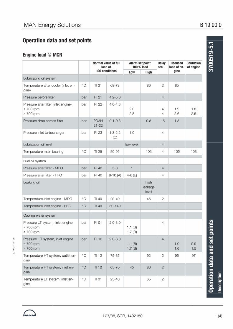
MAN Energy Solutions B 19 00 0
L27/38, SCR, 1402150 1 (4)
Operation data and set points
Engine load @ MCRNormal value at full
load at ISO conditions
Alarm set point 100 % load
Delaysec.
Reducedload of en-
gine
Shutdownof engine
Low HighLubricating oil system
Temperature after cooler (inlet en-gine)
°C TI 21 68-73 80 2 85
Pressure before filter bar PI 21 4.2-5.0 4
Pressure after filter (inlet engine)< 700 rpm> 700 rpm
bar PI 22 4.0-4.82.02.8
44
1.92.6
1.82.5
Pressure drop across filter bar PDAH21-22
0.1-0.3 0.8 15 1.3
Pressure inlet turbocharger bar PI 23 1.3-2.2(C)
1.0 4
Lubrication oil level low level 4
Temperature main bearing °C TI 29 80-95 103 4 105 108
Fuel oil system
Pressure after filter - MDO bar PI 40 5-8 1 4
Pressure after filter - HFO bar PI 40 8-10 (A) 4-6 (E) 4
Leaking oil highleakage
level
Temperature inlet engine - MDO °C TI 40 20-40 45 2
Temperature inlet engine - HFO °C TI 40 80-140
Cooling water system
Pressure LT system, inlet engine< 700 rpm> 700 rpm
bar PI 01 2.0-3.01.1 (B)1.7 (B)
4
Pressure HT system, inlet engine< 700 rpm> 700 rpm
bar PI 10 2.0-3.01.1 (B)1.7 (B)
41.01.6
0.91.5
Temperature HT system, outlet en-gine
°C TI 12 75-85 92 2 95 97
Temperature HT system, inlet en-gine
°C TI 10 65-70 45 80 2
Temperature LT system, inlet en-gine
°C TI 01 25-40 65 2
2019
-01-
15 -
en
Oper
atio
n da
ta a
nd se
t poi
nts
Desc
riptio
n37
0051
9-5.
1

B 19 00 0 MAN Energy Solutions
2 (4) L27/38, SCR, 1402150
Normal value at fullload at
ISO conditions
Alarm set point 100 % load
Delaysec.
Reducedload of en-
gine
Shutdownof engine
Low HighTemperature LT system, outlet en-gine
°C 35-45
Exhaust gas and charge air
Exhaust gas temperature inlet TC340 kW365 kW
°C TI 62480-530480-560
570 (N) 30 590
Exhaust gas temperature outlet cyl340 kW365 kW
°C TI 60370-450370-500
average(K)
±100
510 (N)average
(K)±50
30 530average
(K)±70
Exhaust gas temperature outlet TC340 kW365 kW
°C TI 61300-425300-440
450 (N) 30
Charge air pressure after cooler bar PI 31 2.9-3.1
Charge air temperature after cooler °C TI 31 40-55 25 55 2 58
Starting air system
Press. inlet engineTDI
Gali
bar PI 13127-8
(max 10)< 30
6.5
15
4
Speed control system
Engine speed rpm SI 90 800 880 0 920
Turbocharger speed rpm (L) 97% 100%
Safety control air pressure bar PI 1322 7-8 6 4
High temperature alarms can occur for some engine types running 100%MCR with SCR catalyst (50 mbar exhaust back pressure) and tropicalcondition (ambient air 45°C & LT-water 38°C).
2019
-01-
15 -
en
Oper
atio
n da
ta a
nd se
t poi
nts
Desc
riptio
n37
0051
9-5.
1

MAN Energy Solutions B 19 00 0
L27/38, SCR, 1402150 3 (4)
Remarks to individual parameters
A. Fuel oil pressure, HFO operationWhen operating on HFO, the system pressure must be sufficient to depressany tendency to gasification of the hot fuel.The system pressure has to be adjusted according to the fuel oil preheatingtemperature.
B. Cooling water pressure, alarm set pointsAs the system pressure in case of pump failure will depend on the height ofthe expansion tank above the engine, the alarm set point has to be adjustedto 0.4 bar plus the static pressure. The static pressure set point can be adjus-ted in the display module.
C. Lubricating oil pressure, offset adjustmentAt charge air pressure below 1.0 bar the lub. oil pressure to turbocharger isnormal at 0.6 ±0.1 bar.The read outs of lubricating oil pressure has an offset adjustment because ofthe transmitter placement. This has to be taken into account in case of testand calibration of the transmitter.
E. Set points depending on fuel temperature
Figure 1: Set point curve
F. Start interlockThe following signals are used for start interlock/blocking:
1. Turning must not be engaged2. Engine must not be running3. "Remote" must be activated4. No shutdowns must be activated.5. The prelub. oil pressure must be OK, 20 min. after stop.6. "Stop" signal must not be activated
2019
-01-
15 -
en
Oper
atio
n da
ta a
nd se
t poi
nts
Desc
riptio
n37
0051
9-5.
1

B 19 00 0 MAN Energy Solutions
4 (4) L27/38, SCR, 1402150
G. Start failureIf remote start is activated and the engine is in blocking or local mode or turn-ing is engaged the alarm time delay is 2 sec.Start failure will be activated if revolutions are below 50 rpm within 5 sec. fromstart or revolutions are below 210 rpm 10 sec. from start.Start failure alarm will automatically be released after 30 sec. of activation.
H. Alarm hystereseOn all alarm points a hysterese of 0.1 bar are present.
I. Engine run signalThe engine run signal is activated when engine rpm >780 lube oil pressure>3.0 bar or TC rpm >5000 rpm.If engine rpm is above 210 rpm but below 780 rpm within 30 sec. the enginerun signal will be activated.
K. Exhaust gas temperaturesThe exhaust gas temperature deviation alarm is normally ±50° C with a delayof 1 min., but at start-up the delay is 5 min. Furthermore the deviation limit is±100° C if the average temperature is below 200° C.
L. Turbocharger speedNormal value at full load of the turbocharger is dependent on engine type (cyl.no) and engine rpm. The value given is just a guide line. Actual values can befound in the acceptance test protocol or name plate on turbocharger.
N. Alarm at 110% loadDuring shop test of 110% load it can occur that there is exhaust gas temper-ature alarm, this can be caused to high air temperature before compressorcombined with low ambient air pressure.10° C change in ambient temperature correspond to approx. 15° C exhaustgas temperature change.9007233667015051
2019
-01-
15 -
en
Oper
atio
n da
ta a
nd se
t poi
nts
Desc
riptio
n37
0051
9-5.
1

MAN Energy Solutions B 19 00 0
L27/38;L21/31, SaCoS 1 (17)
System description - SaCoSone
General Informationis a market leader in the development and production of large diesel enginesfor marine and power stations. An independent third-party certification is man-datory to provide an assurance of compliance with relevant industry standardsand guidelines. Applicable assessments involve inspection of requirements,design, verification, validation, configuration management and maintenance.SaCoSone is the new Safety and Control System for the engine managementof four-stroke diesel and gas engines of for marine and Genset applications.SaCoSone is developed and produced by the Group Function Systems Auto-mation applying a standard development process that conforms to the re-quirements of certification societies and authorities.SaCoSone PROPULSION is the safety and control system for MAN small borediesel engines, types L21/31 and L27/38.All engine-mounted sensors and actuators are connected to the system andcontrolled by the engine-attached SaCoSone PROPULSION.SaCoSone PROPULSION controls and monitors all engine functions includingclutch control and the visualisation of engine-related pre-alarms, systemalarms, safety actions, operating values and operation status.In this context, safety actions mean shutdown of the engine, as well as re-quest for load reductions and if required, auto disengagement.Optionally, the system also monitors and supervises the gearbox. Additionally,there is the possibility of monitoring propeller sensors like shaft bearing tem-peratures.Optionally, an oil mist detector installed directly at the engine is analyzed bythe SaSoSone system.Another option is the Extension Cabinet. This wall-mounted control cabinet issuitable for off-engine installation in the engine room. The Extension Cabinetcan provide the following, optionally available functions:▪ EDS Interface used to forward engine operating data to a data logging
system. A data logger is not included in this option.▪ Data logger for recording engine operating data▪ Master / Slave coupling. This is required for operating two engines con-
nected to one gearbox.
Areas of applicationDue to the system architecture and control modules used, the product linecan only be used for the following engines and areas of application:▪ In-line engines with a max. no. of 9 cylinders, types L21/31 and L27/38▪ Engines with Pt1000 temperature sensors
2019
-12-
15 -
en
Syst
em d
escr
iptio
n - S
aCoS
one
Desc
riptio
n37
0007
1-1.
2

B 19 00 0 MAN Energy Solutions
2 (17) L27/38;L21/31, SaCoS
Schematic
2019
-12-
15 -
en
Syst
em d
escr
iptio
n - S
aCoS
one
Desc
riptio
n37
0007
1-1.
2

MAN Energy Solutions B 19 00 0
L27/38;L21/31, SaCoS 3 (17)
System Architecture
Standard version
Version with wheelhouse operation
2019
-12-
15 -
en
Syst
em d
escr
iptio
n - S
aCoS
one
Desc
riptio
n37
0007
1-1.
2

B 19 00 0 MAN Energy Solutions
4 (17) L27/38;L21/31, SaCoS
Version for connection of second engine
Components
Control UnitThe housing is made of powder-coated sheet steel of the colour RAL7035RAL 7035. The protection rating is IP 55. The Control Unit is supplied togetherwith rubber buffers. The mounting bracket is supplied by the licensee. TheControl Unit has been designed in a way requiring the cables to enter from theside. Cable entry is done via cable glands complying with the EMC directive.Single-wire numbering is not required.
Splash-oil Unit (option)The Splash-oil Unit is optional and is required for splash-oil monitoring. Theunit contains one Control Module S/Splash-oil which includes the wholesplash-oil monitoring functionality, such as pre-alarm, shutdown, sensor mon-itoring, etc. It is installed directly at the engine (exhaust side).
Gateway Cabinet (option)The Gateway Cabinet (GC) is optional and is required in case of EDS or aWheelhouse Operating Panel (WOP) being requested. The Gateway Cabinetwill also be supplied if the ship alarm system must be connected via MOD-BUS TCP. A Gateway Module (GM) is installed there.
Local Gear and Propeller Control (option)The Local Propulsion Control System (LPCS) consists of two Control ModulesSmall (A/B). The functions pitch control, wind milling detection, engine runningdetection and gear/shaft readiness are controlled via the corresponding out-put signals. Pitch control is designed as a redundant system. Each modulecan generate operational alarms, reductions and shutdowns.
2019
-12-
15 -
en
Syst
em d
escr
iptio
n - S
aCoS
one
Desc
riptio
n37
0007
1-1.
2
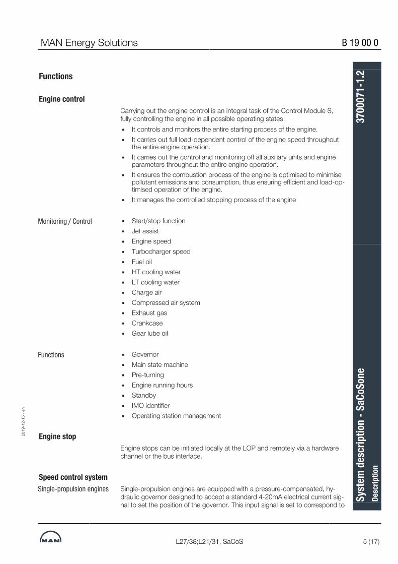
MAN Energy Solutions B 19 00 0
L27/38;L21/31, SaCoS 5 (17)
Functions
Engine controlCarrying out the engine control is an integral task of the Control Module S,fully controlling the engine in all possible operating states:▪ It controls and monitors the entire starting process of the engine.▪ It carries out full load-dependent control of the engine speed throughout
the entire engine operation.▪ It carries out the control and monitoring off all auxiliary units and engine
parameters throughout the entire engine operation.▪ It ensures the combustion process of the engine is optimised to minimise
pollutant emissions and consumption, thus ensuring efficient and load-op-timised operation of the engine.
▪ It manages the controlled stopping process of the engine
Monitoring / Control ▪ Start/stop function▪ Jet assist▪ Engine speed▪ Turbocharger speed▪ Fuel oil▪ HT cooling water▪ LT cooling water▪ Charge air▪ Compressed air system▪ Exhaust gas▪ Crankcase▪ Gear lube oil
Functions ▪ Governor▪ Main state machine▪ Pre-turning▪ Engine running hours▪ Standby▪ IMO identifier▪ Operating station management
Engine stopEngine stops can be initiated locally at the LOP and remotely via a hardwarechannel or the bus interface.
Speed control systemSingle-propulsion engines Single-propulsion engines are equipped with a pressure-compensated, hy-
draulic governor designed to accept a standard 4-20mA electrical current sig-nal to set the position of the governor. This input signal is set to correspond to
2019
-12-
15 -
en
Syst
em d
escr
iptio
n - S
aCoS
one
Desc
riptio
n37
0007
1-1.
2

B 19 00 0 MAN Energy Solutions
6 (17) L27/38;L21/31, SaCoS
the required engine speed range. The driver actuates a stepper motor thatmoves the fuel admission control linkage. The position of the fuel control leverdetermines the compression of a spring and therefore determines theprovided fuel quantity to reach the desired engine speed. A minor alarm con-tact on the driver box can be used to limit the maximum speed setting.
Multi-propulsion engines For multi-propulsion engines, the electronic speed control is realised by theControl Module S (CMS). The engine is equipped with an electro-hydraulic ac-tuator. Engine speed detection is carried out by means of redundant sen-sorsat the camshaft.The electronic speed governor is a part of the software in the CMS/Alarmmodule and controls the electro-hydraulic actuator installed at the engine. Astepper motor is installed in the governor to adjust the fuel admission controllinkage. A contactless position transducer, attached to the shaft of the speedgovernor, returns a feedback signal to the Control Module. The Control Mod-ule will actuate the speed governor until the feedback signal matches the4-20mA command input.The minimum and maximum limits for the speed adjustment range can beparameterized in the Control Module S.
Speed adjustmentRemote speed setting is either possible via an analogue 4-20 mA signal or byusing binary lower/raise contacts.
Clutch, gearbox and propeller controlSaCoSone PROPULSION monitors the relevant temperatures and pressures ofthe gearbox and the propeller. The system also provides hardwired interfacesfor controlling the clutch. For details on the relevant signals, refer to the inter-face description of the respective gearbox control.9007233667071627
Alarm/monitoring system
AlarmingThe alarm function of SaCoSone PROPULSION monitors all necessary para-meters and generates alarms to indicate discrepancies when required. Thealarms will be transferred to the ship alarm system via Modbus data commu-nication.
Self-monitoringSaCoSone PROPULSION carries out independent self-monitoring functions.Thus, for example, the connected sensors are checked constantly for func-tioning and wire break. In case of a fault SaCoSone PROPULSION reports theoccurred malfunctions in individual system components via system alarms.
ControlSaCoSone PROPULSION controls all engine-internal functions as well as ex-ternal components, for example:Start/stop sequences:▪ Local and remote start/stop sequence
2019
-12-
15 -
en
Syst
em d
escr
iptio
n - S
aCoS
one
Desc
riptio
n37
0007
1-1.
2

MAN Energy Solutions B 19 00 0
L27/38;L21/31, SaCoS 7 (17)
▪ Activation of start device. Control (auto start/stop signal) regarding Pre-lubrication oil pump
▪ Monitoring and control of the acceleration periodJet system:▪ For air-fuel ratio control purposes, compressed air is led to the tur-
bocharger at the start and at load stepsControl signals for external functions:▪ HT cooling water pre-heating unit▪ Pre-lubrication oil pump controlRedundant shutdown functions:▪ Engine overspeed▪ Lube oil pressure at engine inlet low▪ HT cooling water temperature outlet too high9007233667071627
SafetyThe SaCoSone safety system is an electronic system to protect the engine fromserious damage. If critical parameters exceed the permissible limits, one ormore of the following security features is enabled: The engine load is reducedto a lower value, or the engine is stopped automatically.These measures have been designed in accordance with the requirements ofclassification societies. The automatic reduction of the load is controlled bythe SaCoSone. The load reduction is only one part of the system. The main ele-ment is the Control Unit interfacing the different auxiliary equipment. Thesedevices can be classified into three different categories: operating panels,sensors/actuators and external systems. The Control Unit consists of modulesfor different applications. The security system works independently of the re-mote control and alarm system. Therefore, malfunctions in this system are ir-relevant to the safety system. The SaCoSone was developed so that it adaptsto the needs of our four-stroke engines and provides a user-friendly system.The safety system monitors all operating data of the engine and initiates therequired actions, i.e. engine shutdown, in case the limit values are exceeded.The safety system is integrated in the CMS/Safety. The safety system directlyactuates the emergency shutdown device and the stop mechanism of thespeed governor.
2019
-12-
15 -
en
Syst
em d
escr
iptio
n - S
aCoS
one
Desc
riptio
n37
0007
1-1.
2

B 19 00 0 MAN Energy Solutions
8 (17) L27/38;L21/31, SaCoS
Figure 1: Safety function principle
Emergency stopEmergency stop is an engine shutdown initiated by an operator’s manual ac-tion like pressing an emergency stop button. An emergency stop button isplaced at the LOP on engine (ROP, WOP optional). For connection of an ex-ternal emergency stop button there is one input channel at the Control Unit.
Figure 2: Emergency stop principle
2019
-12-
15 -
en
Syst
em d
escr
iptio
n - S
aCoS
one
Desc
riptio
n37
0007
1-1.
2

MAN Energy Solutions B 19 00 0
L27/38;L21/31, SaCoS 9 (17)
Automatic safety functionsSaCoSone PROPULSION monitors all operating data of the engine and initiatesthe required actions, i.e. load reduction or engine shutdown, in case the limitvalues are exceeded. The SaCoSone Safety system is integrated in the ControlUnit and subdivided into the CMS/Alarm and the CMS/Safety. The safety sys-tem initiates automatic shutdowns and requests load reductions.
Automatic shutdown An auto shutdown is an engine shutdown initiated by any device monitoringinternal engine parameters automatically. If an engine shutdown is triggeredby the safety system, the emergency stop signal has an immediate effect onthe emergency shutdown device and the speed control. At the same time thatthe emergency stop is triggered, SaCoSone issues a signal resulting in disen-gaging the clutch. The following list stipulates criteria leading to an automaticshutdown. For more details see the “List of measuring and control devices”.▪ Engine overspeed (redundant, alarm system)▪ HT cooling water pressure inlet too low▪ HT cooling water temperature outlet too high (redundant, alarm sys-tem)▪ Lube oil pressure at engine inlet low (redundant, alarm system)▪ Gearbox lube oil pressure too low▪ Gearbox bearing temperature too high (optional)▪ Splash-oil temperature front bearing too high (optional)▪ Main bearing temperature too high (optional)▪ High oil mist concentration in crankcase (optional)▪ Remote shutdown (optional)▪ Governor - major failure active (configurable)▪ Additional shutdown (e.g. from gearbox)
Load reductions A load reduction to 60% is necessary after exceeding certain parameters. Thesafety system supervises these parameters and requests a load reduction, ifnecessary. The load reduction has to be carried out by an external system(PCS, PMS). SaCoSone PROPULSION will not reduce the load by itself. Thefollowing list stipulates criteria leading to a load reduction request. For moredetails see the “List of measuring and control devices”.▪ Turbocharger speed high▪ Exhaust gas temperature at cylinder too low/high▪ Exhaust gas temperature at turbocharger inlet too high▪ HTCW pressure too low▪ HTCW temperature at cylinder row outlet too high▪ Charge air temperature too high▪ Lube oil filter differential pressure too high▪ Lube oil pressure too low▪ Lube oil temperature too high▪ Additional load reduction (e.g. from gearbox)
Auto disengagement If SaCoSone PROPULSION is used for clutch monitoring, it will carry out auto-matic disengagements of the clutch to protect the gearbox, propeller or en-gine against destruction. In this case, the clutch will be opened as fast aspossible.
2019
-12-
15 -
en
Syst
em d
escr
iptio
n - S
aCoS
one
Desc
riptio
n37
0007
1-1.
2

B 19 00 0 MAN Energy Solutions
10 (17) L27/38;L21/31, SaCoS
The following list stipulates criteria leading to an automatic disengagement.For more details see “System messages”.▪ Automatic shutdown of the engine▪ Manual emergency stop of the engine▪ Overspeed▪ Clutch oil pressure low▪ External signal
OverrideThe override mode suppresses the initiation of safety functions by SaCoSonePROPULSION in critical situations (e.g. entering a port, difficult passages,etc.). The override mode can suppress the initiation of the following safetyfunctions:▪ automatic shutdown▪ automatic request of a load reduction▪ automatic disengagementWith the override mode active, the safety system will only emit an alarm mes-sage instead of triggering the safety function. The override mode cannot sup-press the initiation of the following safety functions:▪ Manual emergency stop▪ Shutdown due to engine overspeedThe active state of the override mode is indicated on the LOP touchscreen.Alarms concerning automatic shutdowns or load reductions will also be dis-played on the LOP touchscreen. The following message will be displayedevery 3 seconds for the time of the override mode being active:
9007233667071627
2019
-12-
15 -
en
Syst
em d
escr
iptio
n - S
aCoS
one
Desc
riptio
n37
0007
1-1.
2

MAN Energy Solutions B 19 00 0
L27/38;L21/31, SaCoS 11 (17)
Operation
Local Operating PanelThe Local Operating Panel (LOP) consists of two Display Modules. It is in-stalled at the engine. This display can be used independently for operatingand monitoring.In case of using a gearbox (AT3000 only) all functions will be provided onLOP2.In case of a malfunction of one display, the engine can be operated with theother display (backup function).In case of a malfunction of one display (gearbox configuration), all the func-tions (engine and gear) are controlled with the backup display.All operating values available in the system as well as alarms, shutdowns, sys-tem alarms and the engine operating status are displayed on the LOP. Fur-thermore, some basic operator actions are handled from the LOP:▪ Engine start▪ Engine stop▪ Acknowledgment and reset of alarms, shutdowns, etc.▪ Manual emergency stop▪ Engine speed increase/decrease▪ Clutch engagement/disengagement (optional)▪ Pitch setting (optional)
Remote Operating Panel (option)The optional Remote Operating Panel (ROP) can be installed within the enginecontrol room. It consists of one Display Module on which operating valuesand status are indicated. The ROP provides the same functions as the LOP.
Wheelhouse Operating Panel (option)The optional Wheelhouse Operating Panel (WOP) can be installed within thewheelhouse. Operating values and status are indicated on the HMI (touch-screen). The WOP provides the same functions as the LOP.
Start/Stop Panel (option)The optional Start Stop Panel (SSP) can only be installed in the wheelhouse.The panel also includes analogue speed indication.
Interfaces to External SystemsThese interfaces serve for data exchange to ship alarm systems or integratedautomation systems (IAS).It is possible to transmit the status messages, alarms and safety actionswhich are generated in the system. All measuring values and alarms acquiredby SaCoSone are available for transfer.SaCoSone uses the Modbus RTU protocol.
2019
-12-
15 -
en
Syst
em d
escr
iptio
n - S
aCoS
one
Desc
riptio
n37
0007
1-1.
2

B 19 00 0 MAN Energy Solutions
12 (17) L27/38;L21/31, SaCoS
Provided data includes measured values and alarm or status information ofthe engine.Measured values are digitized analogue sensor values which are stored in afixed register of the Control Module Small. Measured values include mediavalues (pressures, temperatures) where, according to the rules of classifica-tion, monitoring has to be done by the machinery alarm system. The datatype used is a signed integer of 16-bit size. Measured values are scaled by aconstant factor in order to provide decimal values.Pre-alarms, shutdowns and status information from the SaCoSone system areavailable as single bits in fixed registers. The data type used is unsigned of16-bit size. The corresponding bits of alarm or state information are set to thebinary value “1” if the event is active.
2019
-12-
15 -
en
Syst
em d
escr
iptio
n - S
aCoS
one
Desc
riptio
n37
0007
1-1.
2

MAN Energy Solutions B 19 00 0
L27/38;L21/31, SaCoS 13 (17)
Interface
2019
-12-
15 -
en
Syst
em d
escr
iptio
n - S
aCoS
one
Desc
riptio
n37
0007
1-1.
2

B 19 00 0 MAN Energy Solutions
14 (17) L27/38;L21/31, SaCoS
System Requirements
Equipotential bonding and EMCThe manufacturer of the control system and the operator must take measuresto comply with the EMC directive and ensure electromagnetic compatibility ofa plant (control system + machinery).Cable routing:▪ Avoid inductive coupling (crosstalk).▪ If possible, twist unshielded cables of the same electric circuit.▪ Lay cables close to housing parts.▪ If possible, route signal cables to the cabinet only from one side (e.g. bot-
tom side).▪ Avoid unnecessary cable lengths.
2019
-12-
15 -
en
Syst
em d
escr
iptio
n - S
aCoS
one
Desc
riptio
n37
0007
1-1.
2

MAN Energy Solutions B 19 00 0
L27/38;L21/31, SaCoS 15 (17)
▪ If possible, lay cables for setpoint and actual values without interruption.Ensure proper shield when joining interrupted cables.
▪ Ensure corrosion resistance of the earth connections, especially concern-ing contact corrosion and resistance to external influences
Fixing cable shields:▪ Connect both sides of the shield of data cables and analogue signal
cables to earth, creating a large-surface, well-conducting connection▪ Using product-specific cable glands at device housings ensures a proper
shield connection.▪ Only use metallic or metallized cable entries for shielded cables
Note: Incorrect shield connections can result in incorrect indications and ana-lyses of the system.Uniform reference potential of plant▪ If system components are located in different cabinets, they must be con-
nected via, for example, an equipotential bonding conductor.▪ Use sufficiently sized conductors in order to prevent potential differ-ences
between system parts.
2019
-12-
15 -
en
Syst
em d
escr
iptio
n - S
aCoS
one
Desc
riptio
n37
0007
1-1.
2

B 19 00 0 MAN Energy Solutions
16 (17) L27/38;L21/31, SaCoS
Power supply
The plant has to provide electricity for the automation and monitoring system.In general, a redundant, uninterrupted 24V DC (+20% -30%, max. ripple 10%)power supply is required for SaCoSone.
2019
-12-
15 -
en
Syst
em d
escr
iptio
n - S
aCoS
one
Desc
riptio
n37
0007
1-1.
2

MAN Energy Solutions B 19 00 0
L27/38;L21/31, SaCoS 17 (17)
Technical dataDimensions Width Height Depth Weight
Control Unit 800 mm 560 mm 155 mm tba
Local Operating Panel 700 mm 400 mm ca.140 mm tba
Splash-Oil Unit 310 mm 400 mm 100 mm tba
Local Propulsion ControlUnit
388 mm 540 mm 165 mm tba
9007233667071627
Additional Information
SaCoSone EXPERTSaCoSone EXPERT is a parameterisation tool for configuring and paramet-erising two and four-stroke diesel engines for marine propulsion and station-ary power plants equipped with the SaCoSone control system.The Ethernet interface at the Display Module can be used for connectingSaCoSone EXPERT. If available, it is also possible to use the Ethernet interfaceof the Gateway Cabinet.
CoCoS-EDS (optional)The Ethernet connection to CoCoS-EDS (Computer Controlled SurveillanceEngine Diagnostic System) is established via the Gateway Cabinet (GC),which is connected to the Control Unit via the system bus.Customers can order EDS as a measurement and reporting system. It is alsoconfigured to provide diagnostic messages to the customer.
AbbreviationsAbbreviation Meaning
CMS Control Module Small
CU Control Unit
DM Display Module
GM Gateway Module
LPCU Local Propulsion Control Unit
LPCS Local Propulsion Control System
GC Gateway Cabinet
LOP Local Operating Panel
ROP Remote Operating Panel
WOP Wheelhouse Operating Panel
SMU Splash-oil Monitoring Unit90072336670716279007233667071627
2019
-12-
15 -
en
Syst
em d
escr
iptio
n - S
aCoS
one
Desc
riptio
n37
0007
1-1.
2

This page is intentionally left blank900723366707162790072336670716279007233667071627900723366707162790072336670716279007233667071627
2019
-12-
15 -
en
B 19 00 0 MAN Energy Solutions
L27/38;L21/31, SaCoS
Syst
em d
escr
iptio
n - S
aCoS
one
Desc
riptio
n37
0007
1-1.
2

MAN Energy Solutions B 19 00 0
L27/38;L21/31 1 (3)
Modbus interface - SaCoS
Data Bus Interface (Machinery Alarm System)This interface serves for data exchange to ship alarm systems or integratedautomation systems (IAS). The status messages, alarms and safety actions,which are generated in the system, can be transferred. All measuring valuesand alarms acquired by SaCoSone PROPULSION are available for transfer. The Modbus RTU protocol is the standard protocol used for the communica-tion with ship alarm system.
Modbus RTU protocol The bus interface provides a serial connection. The protocol is implementedaccording to the following definitions:▪ Modbus application protocol specification, Modbus over serial line spe-
cification and implementation guide,Available interface:▪ RS422 – Standard, 4 + 2 wire (cable length <= 100m), cable type as spe-
cified by the circuit diagram, line termination: 150 OhmsSettingsThe communication parameters are set as follows:
Modbus Slave SaCoS
Modbus Master Machinery alarm system
Slave ID (default) 1
Data rate (default) 57600 baud
Data rate (optionally available) 4800 baud9600 baud19200 baud38400 baud115200 baud
Data bits 8
Stop bits 1
Parity None
Transmission mode Modbus RTU34412336267
Function CodesThe following function codes are available to gather data from the SaCoSonecontrollers:
2019
-01-
10 -
en
Mod
bus i
nter
face
- Sa
CoS
Desc
riptio
n37
0057
2-3.
1

B 19 00 0 MAN Energy Solutions
2 (3) L27/38;L21/31
FunctionCode
Function Code(hexadecimal)
Description
1 0x01 read coils
3 0x03 read holding registers
5 0x05 write coil
6 0x06 write single register
15 0x0F write multiple coils
16 0x10 write multiple registers
22 0x16 mask write register
23 0x17 read write multiple registers34412336267
Message Frame Separation Message frames shall be separated by a silent interval of at least 4 charactertimes.
Provided Data Provided data includes measured values and alarm or state information of theengine.Measured values are digitized analogue values of sensors, which are stored ina fixed register of the Control Module Small. Measured values include mediavalues (pressures, temperatures) where, according to the rules of classifica-tion, monitoring has to be done by the machinery alarm system. The datatype used is signed integer of size 16 bit. Measured values are scaled by aconstant factor in order to provide decimals of the measured.Pre-alarms, shutdowns and state information from the SaCoSone system areavailable as single bits in fixed registers. The data type used is unsigned ofsize 16 bit. The corresponding bits of alarm or state information are set to thebinary value „1“, if the event is active.Contents of List of SignalsFor detailed information about the transferred data, please refer to the ”list ofsignals“ of the engine’s documentation set. This list contains the following in-formation:
Field DescriptionAddress The address (e.g.: MW15488) is the software address
used in the Control Module Small.
HEX The hexadecimal value (e.g.: 3C80) of the software ad-dress that has to be used by the Modbus master whencollecting the specific data.
Bit Information of alarms, reduce load, shutdown, etc. areavailable as single bits. Bits in each register are counted 0to 15.
Meas. Point The dedicated denomination of the measuring point orlimit value as listed in the „list of measuring and controldevices“.
Description A short description of the measuring point or limit value.
Unit Information about how the value of the data has to beevaluated by the Modbus master (e.g. „°C/100“ means:reading a data value of „4156“ corresponds to 41,56 °C).
2019
-01-
10 -
en
Mod
bus i
nter
face
- Sa
CoS
Desc
riptio
n37
0057
2-3.
1

MAN Energy Solutions B 19 00 0
L27/38;L21/31 3 (3)
Field DescriptionOrigin Name of the system where the specific sensor is connec-
ted to, or the alarm is generated.
Signal range The range of measured value.34412336267
Life Bit In order to enable the alarm system to check whether the communication withSaCoS is working, a life bit is provided in the list of signals (MW15861; Bit2).This Bit is alternated every 10 seconds by SaCoS. Thus, if it remains un-changed for more than 10 seconds, the communication is down.34412336267
2019
-01-
10 -
en
Mod
bus i
nter
face
- Sa
CoS
Desc
riptio
n37
0057
2-3.
1

This page is intentionally left blank34412336267344123362673441233626734412336267
2019
-01-
10 -
en
B 19 00 0 MAN Energy Solutions
L27/38;L21/31
Mod
bus i
nter
face
- Sa
CoS
Desc
riptio
n37
0057
2-3.
1

MAN Energy Solutions B 20 00 0
L27/38 1 (5)
Foundation for engine - rigid mounting
Dimensions
Engine seating - 6L27/3834416668299
Engine seating - 7L27/3834416668299
2019
-01-
10 -
en
Foun
datio
n fo
r eng
ine -
rigi
d m
ount
ing
Desc
riptio
n16
9642
2-7.
4

B 20 00 0 MAN Energy Solutions
2 (5) L27/38
Engine seating - 8L27/3834416668299
Engine seating - 9L27/3834416668299
2019
-01-
10 -
en
Foun
datio
n fo
r eng
ine -
rigi
d m
ount
ing
Desc
riptio
n16
9642
2-7.
4

MAN Energy Solutions B 20 00 0
L27/38 3 (5)
34416668299
2019
-01-
10 -
en
Foun
datio
n fo
r eng
ine -
rigi
d m
ount
ing
Desc
riptio
n16
9642
2-7.
4

B 20 00 0 MAN Energy Solutions
4 (5) L27/38
34416668299
2019
-01-
10 -
en
Foun
datio
n fo
r eng
ine -
rigi
d m
ount
ing
Desc
riptio
n16
9642
2-7.
4

MAN Energy Solutions B 20 00 0
L27/38 5 (5)
3441666829934416668299
2019
-01-
10 -
en
Foun
datio
n fo
r eng
ine -
rigi
d m
ount
ing
Desc
riptio
n16
9642
2-7.
4

This page is intentionally left blank3441666829934416668299344166682993441666829934416668299344166682993441666829934416668299
2019
-01-
10 -
en
B 20 00 0 MAN Energy Solutions
L27/38
Foun
datio
n fo
r eng
ine -
rigi
d m
ount
ing
Desc
riptio
n16
9642
2-7.
4

MAN Energy Solutions B 20 00 0
L27/38, Resilient mounting 1 (3)
Foundation for engine - resilient mounting
Dimensions
2019
-04-
30 -
en
Foun
datio
n fo
r eng
ine -
resil
ient m
ount
ing
Desc
riptio
n16
9986
6-5.
2

B 20 00 0 MAN Energy Solutions
2 (3) L27/38, Resilient mounting
2019
-04-
30 -
en
Foun
datio
n fo
r eng
ine -
resil
ient m
ount
ing
Desc
riptio
n16
9986
6-5.
2

MAN Energy Solutions B 20 00 0
L27/38, Resilient mounting 3 (3)
9007233671414411
2019
-04-
30 -
en
Foun
datio
n fo
r eng
ine -
resil
ient m
ount
ing
Desc
riptio
n16
9986
6-5.
2

This page is intentionally left blank9007233671414411
2019
-04-
30 -
en
B 20 00 0 MAN Energy Solutions
L27/38, Resilient mounting
Foun
datio
n fo
r eng
ine -
resil
ient m
ount
ing
Desc
riptio
n16
9986
6-5.
2

MAN Energy Solutions E 23 00 0
L27/38, 1402000 1 (1)
Weights of main components
Weight of main componentsDescription Approx. weight (kg)Cover for crankcase (max) 22
Cylinder head, incl. rocker arms 300
Piston 43
Cylinder liner 150
Connection rod (excl. marine head) 52
Cylinder unit, complete 700
Marine head bearing 20
Turbocharger NR24/S 665
Turbocharger NR26/R 790
Turbocharger NR29/S 990
Turbocharger TCR16 290
Turbocharger TCR18 440
Turbocharger TCR20 740
Charging air cooler 487
Fuel injection pump 57
Lubricating oil pump 59
Lubricating oil filter 40
Lubricating oil cooler 280
Lubricating oil thermostatic valve housing 70
Cooling water thermostatic valve housing 242
Cooling water pump 65
Engine operator panel 2590072336729734519007233672973451
2019
-01-
10 -
en
Weig
hts o
f mai
n co
mpo
nent
sDe
scrip
tion
1694
916-
6.4

This page is intentionally left blank90072336729734519007233672973451
2019
-01-
10 -
en
E 23 00 0 MAN Energy Solutions
L27/38, 1402000
Weig
hts o
f mai
n co
mpo
nent
sDe
scrip
tion
1694
916-
6.4

MAN Energy Solutions E 23 00 0
L27/38S;L27/38, 2015.12.07 - Tier II, stationary 1 (5)
Weight and dimensions of principal parts
Cylinder head incl. rocker arms approx.400 kg
Piston approx. 66 kg
Cylinder liner approx. 140 kg Charge air cooler approx. 490 kg
Please note: 5 cyl. only for GenSet
2015
-12-
07 -
en
Weig
ht a
nd d
imen
sions
of p
rincip
al p
arts
Desc
riptio
n16
8947
6-6.
4

E 23 00 0 MAN Energy Solutions
2 (5) L27/38S;L27/38, 2015.12.07 - Tier II, stationary
Cylinder unit approx. 700 kg Connecting rod approx. 120 kg
Front end box for GenSet approx. 2420kg
Front end box for propulsion approx.2170 kg
Please note: 5 cyl. only for GenSet
2015
-12-
07 -
en
Weig
ht a
nd d
imen
sions
of p
rincip
al p
arts
Desc
riptio
n16
8947
6-6.
4

MAN Energy Solutions E 23 00 0
L27/38S;L27/38, 2015.12.07 - Tier II, stationary 3 (5)
Base frame for GenSet
Length (L)*[mm]
one/twobearing
Weight [kg]one/twobearing
5 cyl. 5245/ - 5121 / -
6 cyl. 6168/6868 5500/6300
7 cyl. 6800/7500 5687/6583
8 cyl. - /8100 - /7100
9 cyl. - /8700 - /7600
Width: 1770 mm* Depending on alternator type
Oil panfor propul-
sion
Length (L)*[mm]
Weight [kg]
6 cyl. 3367 1186
7 cyl. 3812 1320
8 cyl. 4251 1587
9 cyl. 4702 1720
Width: 1370 mm
Turbochar-ger
Length (L)[mm]
Height (H)[mm]
Weight (kg)[mm]
TCR18 1328 772 460
TCR20 1661 953 780
Please note: 5 cyl. only for GenSet
2015
-12-
07 -
en
Weig
ht a
nd d
imen
sions
of p
rincip
al p
arts
Desc
riptio
n16
8947
6-6.
4

E 23 00 0 MAN Energy Solutions
4 (5) L27/38S;L27/38, 2015.12.07 - Tier II, stationary
Valve cam-shaft
Length (L)[mm]
Weight [kg]
5 cyl. 2378 376
6 cyl. 2823 427
7 cyl. 3268 477
8 cyl. 3713 528
9 cyl. 4158 579
Injectioncamshaft
Length (L)[mm]
Weight [kg]
5 cyl. 2570 455
6 cyl. 3015 528
7 cyl. 3460 601
8 cyl. 3905 674
9 cyl. 4350 747
Crankshaftwith
counterweights
Length (L)[mm]
Weight [kg]
5 cyl. 2920 2755
6 cyl. 3365 3145
7 cyl. 3810 3585
8 cyl. 4255 4030
9 cyl. 4700 4475
Please note: 5 cyl. only for GenSet
2015
-12-
07 -
en
Weig
ht a
nd d
imen
sions
of p
rincip
al p
arts
Desc
riptio
n16
8947
6-6.
4

MAN Energy Solutions E 23 00 0
L27/38S;L27/38, 2015.12.07 - Tier II, stationary 5 (5)
Frame Length (L)[mm]
Weight (kg)
5 cyl. 2658 8503
6 cyl. 3103 9886
7 cyl. 3548 11268
8 cyl. 3993 12652
9 cyl. 4438 14053
Flywheel with gear rimonly for GenSet
Small: 1451 kgMedium: 1927 kgLarge: 2671 kg
Flywheel with gear rimonly for propulsion
1196 kg
9007212827564939
Please note: 5 cyl. only for GenSet9007212827564939
2015
-12-
07 -
en
Weig
ht a
nd d
imen
sions
of p
rincip
al p
arts
Desc
riptio
n16
8947
6-6.
4

This page is intentionally left blank90072128275649399007212827564939
2015
-12-
07 -
en
E 23 00 0 MAN Energy Solutions
L27/38S;L27/38, 2015.12.07 - Tier II, stationary
Weig
ht a
nd d
imen
sions
of p
rincip
al p
arts
Desc
riptio
n16
8947
6-6.
4

MAN Energy Solutions P 23 01 1
L27/38, 1487000 1 (4)
Spare parts for unrestricted service
GeneralSpare parts for unrestricted service, according to the Classification Societiesrequirements/recommendations. For multi-engine installations spares are only necessary for one engine.
2019
-01-
11 -
en
Spar
e par
ts fo
r unr
estri
cted
serv
iceDe
scrip
tion
3700
019-
8.2
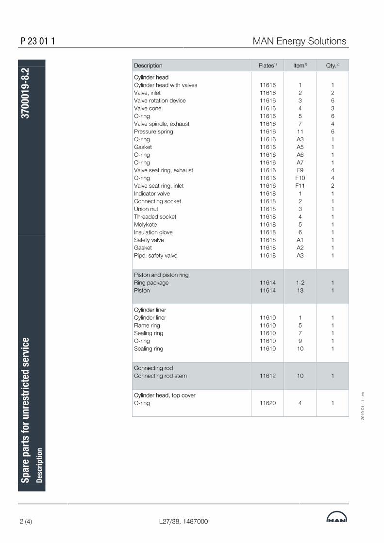
P 23 01 1 MAN Energy Solutions
2 (4) L27/38, 1487000
Description Plates1) Item1) Qty.2)
Cylinder headCylinder head with valves Valve, inlet Valve rotation device Valve cone O-ring Valve spindle, exhaust Pressure spring O-ring Gasket O-ring O-ring Valve seat ring, exhaust O-ring Valve seat ring, inlet Indicator valve Connecting socket Union nut Threaded socket Molykote Insulation glove Safety valve Gasket Pipe, safety valve
1161611616116161161611616116161161611616116161161611616116161161611616116181161811618116181161811618116181161811618
123457
11A3A5A6A7F9
F10F11123456
A1A2A3
12636461111442111111111
Piston and piston ringRing packagePiston
1161411614
1-213
11
Cylinder linerCylinder liner Flame ring Sealing ring O-ring Sealing ring
1161011610116101161011610
1579
10
11111
Connecting rodConnecting rod stem 11612 10 1
Cylinder head, top coverO-ring 11620 4 1
2019
-01-
11 -
en
Spar
e par
ts fo
r unr
estri
cted
serv
iceDe
scrip
tion
3700
019-
8.2

MAN Energy Solutions P 23 01 1
L27/38, 1487000 3 (4)
Frame with main bearingO-ringTie rodNutNutTie rod, cylinder headO-ringRingNutProtecting capMain bearing shell, 2/2Thrust bearing ring
1101211012110121101211012110121101211012110121101211012
4546474863646566
66AA1A2
22222222212
Connecting rod accessoriesPiston pin bush Connecting rod bearing, 2/2 Connecting rod bolt Nut Connecting rod bolt Nut Cylindrical pin
11612 11612 11612 11612 11612 11612 11612
20 9 2 1 5 6 7
1 1 4 4 2 2 2
Charging air receiverO-ring 11814 7 2
Fuel injection pumpFuel injection pump, Complete 12016 0 1
Fuel injection valveFuel injection valve, completeO-ringO-ring
120181201812018
189
1/cyl.1/cyl.1/cyl.
Fuel injection pipeConnecting pipeO-ringO-ringO-ringFuel injecting pipe, complete
1202012020120201202012020
1345
14
11111
Cooling water connectionsIntermediate pieceIntermediate pieceO-ring
130161301613016
89
11
44
12
1. Plate and Item No. refer to the spare part plates in the instruction manual.2. Quantity is in force per engine type per plant.
2019
-01-
11 -
en
Spar
e par
ts fo
r unr
estri
cted
serv
iceDe
scrip
tion
3700
019-
8.2

P 23 01 1 MAN Energy Solutions
4 (4) L27/38, 1487000
Notice:Scope of this list are subject to change and therefore the latest version of thisdocument should always be used, please see MAN Diesel & Turbo homepageor Extranet. Spare parts listed may also vary if optional components are selec-ted. Please notice that the content of spare parts for specific projects may varyfrom the list of standard spare parts.3442388737134423887371
2019
-01-
11 -
en
Spar
e par
ts fo
r unr
estri
cted
serv
iceDe
scrip
tion
3700
019-
8.2

MAN Energy Solutions P 23 01 1
L27/38, 1487000 1 (1)
Spare parts for restricted service
GeneralSpare parts for restricted service, according to the Classification Societies re-quirements/recommendations.
Description Plates1) Item1) Qty.2)
Cylinder head accessoriesValve, inletValve rotation deviceValve spindle, exhaustPressure springValve seat ring, exhaustValve seat ring, inlet
116161161611616116161161611616
237
11F9
F11
242422
Valves on cylinder headSafety valvePacking ring
1161811618
A1A2
11
Fuel injection valveFuel injection valve, completeO-ringO-ring
120181201812018
189
333
Kit for cylinder unitKit for cylinder unit 51704 021 1
1. Plate and Item No. refer to the spare part plates in the instruction manual.2. Quantity is in force per engine type per plant.
Notice:Scope of this list are subject to change and therefore the latest version of thisdocument should always be used, please see MAN Diesel & Turbo homepageor Extranet. Spare parts listed may also vary if optional components are selec-ted. Please notice that the content of spare parts for specific projects may varyfrom the list of standard spare parts.3442685901934426859019
2019
-01-
11 -
en
Spar
e par
ts fo
r res
trict
ed se
rvice
Desc
riptio
n37
0002
0-8.
2

This page is intentionally left blank3442685901934426859019
2019
-01-
11 -
en
P 23 01 1 MAN Energy Solutions
L27/38, 1487000
Spar
e par
ts fo
r res
trict
ed se
rvice
Desc
riptio
n37
0002
0-8.
2

MAN Energy Solutions P 24 00 0
L28/32H;L28/32DF;V28/32S;L28/32S;L27/38S;L27/38;L23/30DF;L23/30S;L23/30H;L21/31S;L21/31;L16/24S;L16/24 1 (1)
Introduction to spare part plates for tools
DescriptionFor our GenSets the following three tool packages are available:
Standard tool for normal maintenance This package is delivered as standard, this tool package do consist of a mixof special designed tools as well as ordinary available tools needed in connec-tion with the operation of the engine and to perform daily engine maintenance. The tool do as well consists of tools to perform emergency repair as requiredby the various classification societies.
Additional tools This tool package can only be ordered as single parts from the list in additionto the standard tool package. The tool package consists of special toolsneeded in addition to the standard tool in case a major overhaul or a part ofthis is to be carried out.
Hand Tools This tool package can be ordered as a whole or partly in addition to thestandard tool package. The tool package consists of ordinary hand toolsneeded in addition to the delivered standard tool for normal maintenance, inconnection with the daily maintenance as well as major overhauls.27021619039465227
2019
-09-
05 -
en
Intro
duct
ion
to sp
are p
art p
late
s for
tool
sDe
scrip
tion
3700
496-
5.0

This page is intentionally left blank27021619039465227
2019
-09-
05 -
en
P 24 00 0 MAN Energy Solutions
L28/32H;L28/32DF;V28/32S;L28/32S;L27/38S;L27/38;L23/30DF;L23/30S;L23/30H;L21/31S;L21/31;L16/24S;L16/24
Intro
duct
ion
to sp
are p
art p
late
s for
tool
sDe
scrip
tion
3700
496-
5.0

MAN Energy Solutions P 24 01 1
L27/38S;L27/38 1 (10)
Standard tools
Cylinder headName Sketch Supply per ship Drawing Remarks
Working Spare Item noValve spring tighteningdevice
1 014
Lifting tool for cylinder unit 1 038
Broad chissel 1 473
2019
-04-
23 -
en
Stan
dard
tool
sDe
scrip
tion
3700
125-
2.5

P 24 01 1 MAN Energy Solutions
2 (10) L27/38S;L27/38
Piston, connecting rod and cylinder linerName Sketch Supply per ship Drawing Remarks
Working Spare Item noRemoving device for flamering
1 021
Guide bush for piston 1 045
Tool for fixing of marinehead for counterweight
1 060
Fit and removal device forconnecting rod bearing, incleye screws (2 pcs)
1 069
2019
-04-
23 -
en
Stan
dard
tool
sDe
scrip
tion
3700
125-
2.5

MAN Energy Solutions P 24 01 1
L27/38S;L27/38 3 (10)
Name Sketch Supply per ship Drawing RemarksWorking Spare Item no
Lifting device for cylinderliner
1 082
Lifting device for piston andconnecting rod
1 104
Piston ring opener 1 190
Supporting device for con-necting rod and piston inthe cylinder liner
1 212
2019
-04-
23 -
en
Stan
dard
tool
sDe
scrip
tion
3700
125-
2.5

P 24 01 1 MAN Energy Solutions
4 (10) L27/38S;L27/38
Operating gear for inlet and exhaust valvesName Sketch Supply per ship Drawing Remarks
Working Spare Item noFeeler gauge 1 010
Socket wrench 1 652
Socket wrench and torquespanner
11
664676
2019
-04-
23 -
en
Stan
dard
tool
sDe
scrip
tion
3700
125-
2.5

MAN Energy Solutions P 24 01 1
L27/38S;L27/38 5 (10)
Crankshaft and main bearingsName Sketch Supply per ship Drawing Remarks
Working Spare Item noDismantling tool for mainbearing upper shell
1 035
2019
-04-
23 -
en
Stan
dard
tool
sDe
scrip
tion
3700
125-
2.5

P 24 01 1 MAN Energy Solutions
6 (10) L27/38S;L27/38
Turbocharger systemName Sketch Supply per ship Drawing Remarks
Working Spare Item noEye screw for lifting 1 036
Container complete for wa-ter washing of compressorside
Reducing pieceFittingFitting
1 355
355a355b355c
Blowgun for dry cleaning ofturbocharger
Snap couplingBall valveSnap couplingSnap couplingPacking ringsSoft blast (granulate)
1 136
136a136b136c136d136e136f
Water washing of turbineside, complete
Snap couplingRegulating valveBall valveSnap couplingSnap coupling
1 481
481a481b481c481d481e
2019
-04-
23 -
en
Stan
dard
tool
sDe
scrip
tion
3700
125-
2.5

MAN Energy Solutions P 24 01 1
L27/38S;L27/38 7 (10)
Fuel oil systemName Sketch Supply per ship Drawing Remarks
Working Spare Item noPressure testing tool, incl item 051, 053, 054
Clamping bracket for fuel injector
Fuel pipe
Pressure pump
1
1
1
1
050
051
053
054
Grinding device for nozzle seat, incl item 747, 759
Grinding paper
Plier
1
1
1
074
747
759
Extractor device for injectorvalve
1 407
Eye screw for lifting 1 032
Combination spanner, 36mm
1 772
2019
-04-
23 -
en
Stan
dard
tool
sDe
scrip
tion
3700
125-
2.5

P 24 01 1 MAN Energy Solutions
8 (10) L27/38S;L27/38
Name Sketch Supply per ship Drawing RemarksWorking Spare Item no
Crow foot, 36 mm 1 784
Long socket spanner 3/4"41 mm
1 880
Adapter for torque spanner1/2" - 3/4"
1 892
Torque spanner 1/2"50-300 Nm
1 902
2019
-04-
23 -
en
Stan
dard
tool
sDe
scrip
tion
3700
125-
2.5

MAN Energy Solutions P 24 01 1
L27/38S;L27/38 9 (10)
Hydraulic toolsName Sketch Supply per ship Drawing Remarks
Working Spare Item noHydraulic tools complete consisting of the following 3 boxes: 806
Pressure pump box 1, consisting of:
Pressure pump, complete
Manometer
Gasket
Quick coupling
Distributor
-
1
1
1
1
1
-
011
023
024
025
026
Hydraulic tools box 2 consisting of:
Pressure part, long M39 x 2
Pressure part, short M39 x 2
Tension screw M39 x 2
Hydraulic tightening cylinder M39 x 2
1
4
2
4
4
633
059
072
118
263
2019
-04-
23 -
en
Stan
dard
tool
sDe
scrip
tion
3700
125-
2.5

P 24 01 1 MAN Energy Solutions
10 (10) L27/38S;L27/38
Name Sketch Supply per ship Drawing RemarksWorking Spare Item no
Hydraulic tools box 3 consisting of:
Pressure part M24/27 x 2
Tension screw M24/27 x 2
Distribution piece, cylinder head
Distribution piece, main bearing
Hose with unions for cylinder head
Hose with unions for connecting of oil pump and distributing block
Spare parts for hydraulic tool M39 x 2
Spare parts for hydraulic tool M36 x 2
Spare parts for hydraulic tool M30 x 2
Spare parts for hydraulic tool M24 x 2
Hydraulic tightening cylinder M24/27 x 2
Hydraulic tightening cylinder M36 x 2
Hydraulic tightening cylinder M30 x 2
Angle piece
Tommy bar
Tommy bar
Pressure part M36 x 2
Pressure part M30 x 2
1
2
2
1
1
4
1
1
1
1
1
2
2
2
2
1
1
2
2
581
096
131
143
167
180
202
226
238
251
322
246
275
287
358
334
556
371
383
Measuring device(not a part of hydraulic toolscomplete, to be orderedseparately)
2 533
4503601062075290745036010620752907
2019
-04-
23 -
en
Stan
dard
tool
sDe
scrip
tion
3700
125-
2.5

MAN Energy Solutions P 24 01 1
L27/38 1 (8)
Standard tools (restricted service)
Cylinder headName Sketch Supply per ship Drawing Remarks
Working Spare Item noValve spring tighteningdevice
1 014
Lifting tool for cylinder unit 1 038
Broad chissel 1 473
2019
-04-
23 -
en
Stan
dard
tool
s (re
stric
ted
serv
ice)
Desc
riptio
n37
0012
7-6.
3

P 24 01 1 MAN Energy Solutions
2 (8) L27/38
Piston, connecting rod and cylinder linerName Sketch Supply per ship Drawing Remarks
Working Spare Item noRemoving device for flamering
1 021
Guide bush for piston 1 045
2019
-04-
23 -
en
Stan
dard
tool
s (re
stric
ted
serv
ice)
Desc
riptio
n37
0012
7-6.
3

MAN Energy Solutions P 24 01 1
L27/38 3 (8)
Operating gear for inlet and exhaust valvesName Sketch Supply per ship Drawing Remarks
Working Spare Item noFeeler gauge 1 010
Socket wrench 1 652
Socket wrench and torquespanner
11
664676
2019
-04-
23 -
en
Stan
dard
tool
s (re
stric
ted
serv
ice)
Desc
riptio
n37
0012
7-6.
3

P 24 01 1 MAN Energy Solutions
4 (8) L27/38
Turbocharger systemName Sketch Supply per ship Drawing Remarks
Working Spare Item noEye screw for lifting 1 036
Container complete for wa-ter washing of compressorside
Reducing pieceFittingFitting
1 355
355a355b355c
Blowgun for dry cleaning ofturbocharger
Snap couplingBall valveSnap couplingSnap couplingPacking ringsSoft blast (granulate)
1 136
136a136b136c136d136e136f
Water washing of turbineside, complete
Snap couplingRegulating valveBall valveSnap couplingSnap coupling
1 481
481a481b481c481d481e
2019
-04-
23 -
en
Stan
dard
tool
s (re
stric
ted
serv
ice)
Desc
riptio
n37
0012
7-6.
3
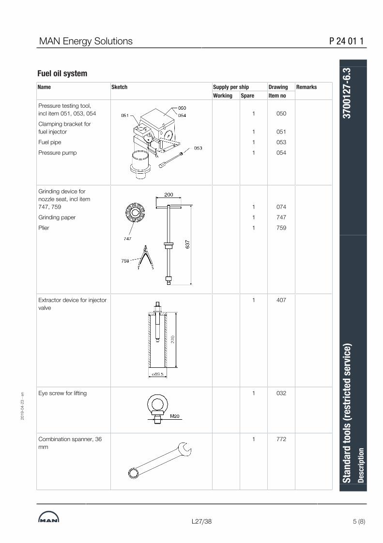
MAN Energy Solutions P 24 01 1
L27/38 5 (8)
Fuel oil systemName Sketch Supply per ship Drawing Remarks
Working Spare Item noPressure testing tool, incl item 051, 053, 054
Clamping bracket for fuel injector
Fuel pipe
Pressure pump
1
1
1
1
050
051
053
054
Grinding device for nozzle seat, incl item 747, 759
Grinding paper
Plier
1
1
1
074
747
759
Extractor device for injectorvalve
1 407
Eye screw for lifting 1 032
Combination spanner, 36mm
1 772
2019
-04-
23 -
en
Stan
dard
tool
s (re
stric
ted
serv
ice)
Desc
riptio
n37
0012
7-6.
3

P 24 01 1 MAN Energy Solutions
6 (8) L27/38
Name Sketch Supply per ship Drawing RemarksWorking Spare Item no
Crow foot, 36 mm 1 784
Long socket spanner 3/4"41 mm
1 880
Adapter for torque spanner1/2" - 3/4"
1 892
Torque spanner 1/2"50-300 Nm
1 902
2019
-04-
23 -
en
Stan
dard
tool
s (re
stric
ted
serv
ice)
Desc
riptio
n37
0012
7-6.
3

MAN Energy Solutions P 24 01 1
L27/38 7 (8)
Hydraulic toolsName Sketch Supply per ship Drawing Remarks
Working Spare Item noHydraulic tools complete consisting of the following 3 boxes: 806
Pressure pump box 1, consisting of:
Pressure pump, complete
Manometer
Gasket
Quick coupling
Distributor
-
1
1
1
1
1
-
011
023
024
025
026
Hydraulic tools box 2 consisting of:
Pressure part, long M39 x 2
Pressure part, short M39 x 2
Tension screw M39 x 2
Hydraulic tightening cylinder M39 x 2
1
4
2
4
4
633
059
072
118
263
2019
-04-
23 -
en
Stan
dard
tool
s (re
stric
ted
serv
ice)
Desc
riptio
n37
0012
7-6.
3

P 24 01 1 MAN Energy Solutions
8 (8) L27/38
Name Sketch Supply per ship Drawing RemarksWorking Spare Item no
Hydraulic tools box 3 consisting of:
Pressure part M24/27 x 2
Tension screw M24/27 x 2
Distribution piece, cylinder head
Distribution piece, main bearing
Hose with unions for cylinder head
Hose with unions for connecting of oil pump and distributing block
Spare parts for hydraulic tool M39 x 2
Spare parts for hydraulic tool M36 x 2
Spare parts for hydraulic tool M30 x 2
Spare parts for hydraulic tool M24 x 2
Hydraulic tightening cylinder M24/27 x 2
Hydraulic tightening cylinder M36 x 2
Hydraulic tightening cylinder M30 x 2
Angle piece
Tommy bar
Tommy bar
Pressure part M36 x 2
Pressure part M30 x 2
1
2
2
1
1
4
1
1
1
1
1
2
2
2
2
1
1
2
2
581
096
131
143
167
180
202
226
238
251
322
246
275
287
358
334
556
371
383
Measuring device(not a part of hydraulic toolscomplete, to be orderedseparately)
2 533
3621183706736211837067
2019
-04-
23 -
en
Stan
dard
tool
s (re
stric
ted
serv
ice)
Desc
riptio
n37
0012
7-6.
3

MAN Energy Solutions P 24 03 9
L27/38S;L27/38 1 (14)
Additional tools
Cylinder headName Sketch Supply per ship Drawing Remarks
Working Spare Item noGrinding tool for cylinder head/liner 1 126
Max. pressure indicator, 0-250 bar 1 138
Handle for indicator valve 1 498
Turning device for cylinder unit 1 114
2017
-07-
10 -
en
Addi
tiona
l too
lsDe
scrip
tion
3700
126-
4.12

P 24 03 9 MAN Energy Solutions
2 (14) L27/38S;L27/38
Name Sketch Supply per ship Drawing RemarksWorking Spare Item no
Grinding machine for valve seat ring
Supporting spider
Mandrel
Cutting tool
Carbide cutting insert
1
1
1
1
1
199
208
209
210
211
Grinding tool for valves 1 283
Grinding machine for valve seat rings
Frequence converter
Tool holder
Turning bit
Pilot spindle incl. stabilizer
Cleaning tool
Tool holder bracket
1
1
1
1
1
1
1
222
761
773
785
797
807
819
2017
-07-
10 -
en
Addi
tiona
l too
lsDe
scrip
tion
3700
126-
4.12

MAN Energy Solutions P 24 03 9
L27/38S;L27/38 3 (14)
Name Sketch Supply per ship Drawing RemarksWorking Spare Item no
Grinding machine for valvespindle, complete
Grinding wheel hub
Balancing apparatus
Grinding wheel dresser
Grinding wheel, grain size 46
Grinding wheel, grain size 80
Stabilizer (valve stem ø10-18 mm)
1
1
1
1
1
1
1
285
820
832
844
856
868
881
Fit and removing device for valve guides 1 258
Fitting device for valve seat rings 1 295
Extractor for valve seat rings
Plate (used with item 329)
1
1
329
317
Lifting tool for cylinder unit (low dismantling height) 1 474
2017
-07-
10 -
en
Addi
tiona
l too
lsDe
scrip
tion
3700
126-
4.12

P 24 03 9 MAN Energy Solutions
4 (14) L27/38S;L27/38
Name Sketch Supply per ship Drawing RemarksWorking Spare Item no
Reamer for valve guide 1 748
Touching up device 1 893
Electronic indicator, HLV2000
1 903
2017
-07-
10 -
en
Addi
tiona
l too
lsDe
scrip
tion
3700
126-
4.12

MAN Energy Solutions P 24 03 9
L27/38S;L27/38 5 (14)
Piston, connecting rod and cylinder linerName Sketch Supply per ship Drawing Remarks
Working Spare Item noTool for fixing of marinehead for counterweight
1 060
Fit and removal device forconnecting rod bearing, incleye screws (2 pcs)
1 069
Lifting device for cylinderliner
1 082
Lifting device for piston andconnecting rod
1 104
Plier for piston pin lock ring 1 759
2017
-07-
10 -
en
Addi
tiona
l too
lsDe
scrip
tion
3700
126-
4.12

P 24 03 9 MAN Energy Solutions
6 (14) L27/38S;L27/38
Name Sketch Supply per ship Drawing RemarksWorking Spare Item no
Piston ring opener 1 190
Supporting device for con-necting rod and piston inthe cylinder liner, incl. fork
1 212
Testing mandrel for pistonring grooves, 7.43 mm
1 149
Testing mandrel for pistonring grooves, 6.43 mm
1 151
Testing mandrel for pistonring grooves, 8.43 mm
1 163
Fit and removing device forconnecting rod bearing
1 569
Support for connecting rod 1 570 2017
-07-
10 -
en
Addi
tiona
l too
lsDe
scrip
tion
3700
126-
4.12

MAN Energy Solutions P 24 03 9
L27/38S;L27/38 7 (14)
Name Sketch Supply per ship Drawing RemarksWorking Spare Item no
Micrometer screw250-270 mm
1 425
2017
-07-
10 -
en
Addi
tiona
l too
lsDe
scrip
tion
3700
126-
4.12

P 24 03 9 MAN Energy Solutions
8 (14) L27/38S;L27/38
Camshaft and camshaft driveName Sketch Supply per
shipWorking
Spare Item no
Mounting device for injection camshaft
1 940
Mounting device for valve camshaft
1 952
Crankshaft and main bearingsName Sketch Supply per ship Drawing Remarks
Working Spare Item noDismantling tool for mainbearing upper shell
1 035
Crankshaft alignmentgauge (autolog)
1 067
2017
-07-
10 -
en
Addi
tiona
l too
lsDe
scrip
tion
3700
126-
4.12

MAN Energy Solutions P 24 03 9
L27/38S;L27/38 9 (14)
Name Sketch Supply per ship Drawing RemarksWorking Spare Item no
Lifting straps for main bear-ing cap
1 545
Lifting handle for main bear-ing cap
1 557
2017
-07-
10 -
en
Addi
tiona
l too
lsDe
scrip
tion
3700
126-
4.12

P 24 03 9 MAN Energy Solutions
10 (14) L27/38S;L27/38
Turbocharger systemName Sketch Supply per ship Drawing Remarks
Working Spare Item noEye screw for lifting 1 036
Fit and removing device forcooler insert
1 401
Closing cover, TCR20
Closing cover, TCR18
(standard with only onepropulsion engine)
1
1
486
450
Differential pressure tools,complete
1 915
2017
-07-
10 -
en
Addi
tiona
l too
lsDe
scrip
tion
3700
126-
4.12

MAN Energy Solutions P 24 03 9
L27/38S;L27/38 11 (14)
Compressed air systemName Sketch Supply per ship Drawing Remarks
Working Spare Item noSet of tools, TDI air starterT100
1 929
Fuel oil systemName Sketch Supply per ship Drawing Remarks
Working Spare Item noFitting and removal ofmonoblock cylinder
1 031
Disassembly tools 1 043
Fitting / removing device forinjection pump
1 055
2017
-07-
10 -
en
Addi
tiona
l too
lsDe
scrip
tion
3700
126-
4.12

P 24 03 9 MAN Energy Solutions
12 (14) L27/38S;L27/38
Name Sketch Supply per ship Drawing RemarksWorking Spare Item no
Fit and removing device forfuel injection pump
1 342
Setting device for fuel injec-tion pump
1 366
Assembly device for sealing ring, complete
Assembly cone
Expanding sleeve
Assembly cone
Sizing sleeve
1
1
1
1
1
689
690
700
712
724
2017
-07-
10 -
en
Addi
tiona
l too
lsDe
scrip
tion
3700
126-
4.12

MAN Energy Solutions P 24 03 9
L27/38S;L27/38 13 (14)
Lubricating oil systemName Sketch Supply per ship Drawing Remarks
Working Spare Item noEye screw for lifting lubric-ating oil cooler
1 032
Mandrel for lubricating oilcooler
1 508
Fitting device for lubricatingoil cooler
1 521
2017
-07-
10 -
en
Addi
tiona
l too
lsDe
scrip
tion
3700
126-
4.12

P 24 03 9 MAN Energy Solutions
14 (14) L27/38S;L27/38
Hydraulic toolsName Sketch Supply per ship Drawing Remarks
Working Spare Item noResetting device for hy-draulic cylinder
1 092
Air driven high pressurepump for hydraulic valve
1 653
Remote controlled unit forhydraulic bolt tensioning
1 939
630504093638516596305040936385165963050409363851659
2017
-07-
10 -
en
Addi
tiona
l too
lsDe
scrip
tion
3700
126-
4.12

MAN Energy Solutions P 24 05 1
L27/38S;L27/38;L21/31S;L21/31;L16/24S;L16/24, 2015.10.14 1 (3)
Hand tools
Hand toolsName Sketch Supply per ship Drawing Remarks
Working Spare Item noSet of tools, consists of:
Item 01 Ratchet
Item 02 Extension, 125 mm
Item 03 Extension, 250 mm
Item 04 Universal
Item 05, Socketsdouble hexagon, 10 mmdouble hexagon, 13 mmdouble hexagon, 17 mmdouble hexagon, 19 mmdouble hexagon, 22 mminternal hexagon, 5 mminternal hexagon, 6 mminternal hexagon, 7 mminternal hexagon, 8 mminternal hexagon, 10 mminternal hexagon, 12 mmscrew driver, 1.6x10 mmcross head screw, 2 mmcross head screw, 3 mmcross head screw, 4 mm
1 019
Combination spanner, 10 mm
Combination spanner, 12 mm
Combination spanner, 13 mm
Combination spanner, 14 mm
Combination spanner, 17 mm
Combination spanner, 19 mm
Combination spanner, 22 mm
Combination spanner, 24 mm
Combination spanner, 30 mm
Combination spanner, 16 mm
1
1
1
1
1
1
1
1
1
1
032
044
056
068
081
093
103
115
127
223
2019
-03-
19 -
en
Hand
tool
sDe
scrip
tion
3700
414-
0.0

P 24 05 1 MAN Energy Solutions
2 (3) L27/38S;L27/38;L21/31S;L21/31;L16/24S;L16/24, 2015.10.14
Name Sketch Supply per ship Drawing RemarksWorking Spare Item no
Combination spanner, 18 mm 1 235
Tee handle 1/2" squaredrive
1 139
Ratchet, 20 mm 1 140
Extension bar 1 152
Socket spanner, squaredrive, size 24
1 164
Socket spanner, squaredrive, size 30
1 176
Socket spanner, squaredrive, size 36
1 188
Bit, hexagon socket screw,square drive, size 8
1 247
Bit, hexagon socket screw,square drive, size 10
1 259
Bit, hexagon socket screw,square drive, size 12
1 260
Torque spanner, 20-120 Nm - 1/2"
Torque spanner, 40-200 Nm - 1/2"
Torque spanner, 30-320 Nm - 1/2"
1
1
1
272
284
296
2019
-03-
19 -
en
Hand
tool
sDe
scrip
tion
3700
414-
0.0

MAN Energy Solutions P 24 05 1
L27/38S;L27/38;L21/31S;L21/31;L16/24S;L16/24, 2015.10.14 3 (3)
Name Sketch Supply per ship Drawing RemarksWorking Spare Item no
Hexagon key 7 mm
Hexagon key 8 mm
Hexagon key 10 mm
Hexagon key 12 mm
Hexagon key 14 mm
Hexagon key 17 mm
Hexagon key 19 mm
1
1
1
1
1
1
1
331
343
355
367
379
380
392900721575424935590072157542493559007215754249355
2019
-03-
19 -
en
Hand
tool
sDe
scrip
tion
3700
414-
0.0

This page is intentionally left blank900721575424935590072157542493559007215754249355
2019
-03-
19 -
en
P 24 05 1 MAN Energy Solutions
L27/38S;L27/38;L21/31S;L21/31;L16/24S;L16/24, 2015.10.14
Hand
tool
sDe
scrip
tion
3700
414-
0.0

MAN Energy Solutions B 53 00 0
L27/38, 200010 1 (4)
Project planning data
Standard propeller plantsA complete range of propulsion systems has been developed to enable theselection of an optimum solution.The range is particularly suitable for selecting the right combination of engine,gearbox and propeller equipment in the project stage. The condition chosenfor optimisation is characterised by:
Dim. Open propeller Ducted propellerEngine power % 85 85
Engine revolutions % 98 98
Ship speed knots 14 4
The dimensioning of the equipment is carried out at 100% MCR according tothe rules of classification societies without ice class notation.In case the optimization criteria deviate considerably from the table above orthe vessel has an ice class notation, please do contact us for a detailed calcu-lation.
Optimizing the propeller equipmentWe have the facilities and expertise to design and supply a propulsion pack-age, optimized to a customer’s specific requirements provided adequate datais available.The design of the propeller, giving regard to the main variables which includediameter, rpm, area ratio etc, is determined by the requirements for maximumefficiency and minimum vibrations and noise levels.
2019
-02-
06 -
en
Proj
ect p
lann
ing
data
Desc
riptio
n16
9640
2-4.
3

B 53 00 0 MAN Energy Solutions
2 (4) L27/38, 200010
The chosen diameter should be as large as the hull can accommodate, allow-ing the propeller revolutions to be selected according to optimum efficiency.The optimum propeller revolutions corresponding to the chosen diameter canbe found from fig 1 for a given reference condition.For a specific plant please fill in the page “Project layout data”.
Figure 1: Optimum propeller diameter - open propeller 14 knots
2019
-02-
06 -
en
Proj
ect p
lann
ing
data
Desc
riptio
n16
9640
2-4.
3

MAN Energy Solutions B 53 00 0
L27/38, 200010 3 (4)
Standard programme L27/38 - open propellerEnginetype
MCRPower(kW)
Propellerspeed at
MCR(RPM)
Propellerhub type
Propellerdiameter(mm) D
Q (mm) R (mm) Wmin (mm) ODG size
6L27/38 2040 258 VBS660 2650 501 631 1,320 ODG200
6L27/38 2040 218 VBS720 2950 547 650 1,350 ODG225
6L27/38 2040 191 VBS790 3200 639 692 1,350 ODG225
6L27/38 2040 163 VBS790 3500 639 692 1,350 ODG225
6L27/38 2040 152 VBS860 3650 653 745 1,350 ODG225
7L27/38 2380 247 VBS720 2800 547 513 1,350 ODG225
7L27/38 2380 211 VBS720 3100 547 513 1,350 ODG225
7L27/38 2380 186 VBS790 3350 639 692 1,350 ODG225
7L27/38 2380 161 VBS860 3650 653 745 1,400 ODG250
7L27/38 2380 150 VBS860 3800 653 745 1,400 ODG250
8L27/38 2720 242 VBS720 2900 547 513 1,350 ODG225
8L27/38 2720 209 VBS790 3200 639 692 1,350 ODG225
8L27/38 2720 186 VBS790 3450 639 692 1,400 ODG250
8L27/38 2720 173 VBS860 3600 653 745 1,400 ODG250
8L27/38 2720 147 VBS940 3950 714 886 1,400 ODG250
9L27/38 3060 243 VBS720 2950 547 513 1,350 ODG225
9L27/38 3060 206 VBS790 3300 639 692 1,400 ODG250
9L27/38 3060 184 VBS860 3550 653 745 1,400 ODG250
9L27/38 3060 172 VBS860 3700 653 745 1,400 ODG250
9L27/38 3060 147 VBS940 4050 714 886 1,530 ODG280
Table 1: Standard package examples34619983243
2019
-02-
06 -
en
Proj
ect p
lann
ing
data
Desc
riptio
n16
9640
2-4.
3

B 53 00 0 MAN Energy Solutions
4 (4) L27/38, 200010
3461998324334619983243
2019
-02-
06 -
en
Proj
ect p
lann
ing
data
Desc
riptio
n16
9640
2-4.
3
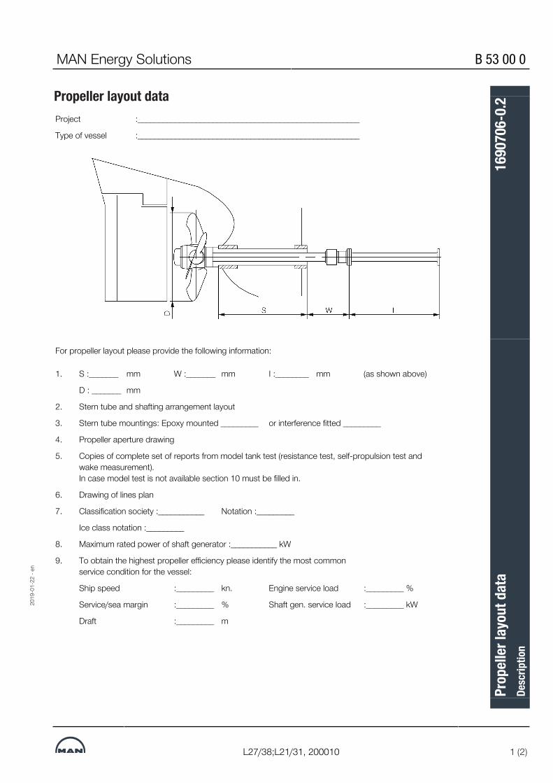
MAN Energy Solutions B 53 00 0
L27/38;L21/31, 200010 1 (2)
Propeller layout dataProject :_____________________________________________________
Type of vessel :_____________________________________________________34668957067
34668957067
For propeller layout please provide the following information:34668957067
1. S :_______ mm W :_______ mm I :________ mm (as shown above)
D : _______ mm
2. Stern tube and shafting arrangement layout
3. Stern tube mountings: Epoxy mounted _________ or interference fitted _________
4. Propeller aperture drawing
5. Copies of complete set of reports from model tank test (resistance test, self-propulsion test andwake measurement). In case model test is not available section 10 must be filled in.
6. Drawing of lines plan
7. Classification society :___________ Notation :_________
Ice class notation :_________
8. Maximum rated power of shaft generator :___________ kW
9. To obtain the highest propeller efficiency please identify the most commonservice condition for the vessel:
Ship speed :_________ kn. Engine service load :_________ %
Service/sea margin :_________ % Shaft gen. service load :_________ kW
Draft :_________ m34668957067
2019
-01-
22 -
en
Prop
eller
layo
ut d
ata
Desc
riptio
n16
9070
6-0.
2

B 53 00 0 MAN Energy Solutions
2 (2) L27/38;L21/31, 200010
10. Vessel Main Dimensions (Please fill-in if model test is not available)34668957067
Symbol Unit Ballast LoadedLength between perpendiculars LPP m
Length of load water line LWL m
Breadth B m
Draft at forward perpendicular TF m
Draft at aft perpendicular TA m
Displacement s m3
Block coefficient (LPP) CB -
Midship coefficient CM -
Waterplane area coefficient CWL -
Wetted surface with appendages S m2
Centre of buoyancy forward of LPP/2 LCB m
Propeller centre height above baseline H m
Bulb section area at forward perpendicular AB m2
34668957067
11. Comments: ________________________________________________________________________
___________________________________________________________________________________
___________________________________________________________________________________
___________________________________________________________________________________
Date: _________ Signature: _________3466895706734668957067
2019
-01-
22 -
en
Prop
eller
layo
ut d
ata
Desc
riptio
n16
9070
6-0.
2

MAN Energy Solutions B 53 00 0
V28/32A;L21/31;L28/32A;L27/38;L23/30A;V23/30A, 200010 1 (2)
Layout of Fix-Pitch-Propeller
Propeller curveThe relation between power and propeller speed for a fixed pitch propeller isdescribed by means of the propeller law, i.e. the third power curve:P = c × n3, in which:P = engine power for propulsionn = propeller speedc = constantThe exponent i=3 is valid for frictional resistance. For vessels having sufficientengine power to sail fast enough to experience significant wave-making resist-ance, the exponent may be higher in the high load range.
Propeller designNormally, estimates of the necessary propeller power and speed are basedon theoretical calculations for loaded ship, and often experimental tank tests,both assuming optimum operating conditions, i.e. a clean hull and goodweather.The combination of speed and power obtained may be called the ship’s pro-peller design point.
Fouled hullWhen the ship has sailed for some time, the hull and propeller become fouledand the hull’s resistance will increase. Consequently, the ship’s speed will bereduced unless the engine delivers more power to the propeller, i.e. the pro-peller will be further loaded and will be heavy running (HR).
Sea margin and heavy weatherIf the weather is bad with headwind, the ship’s resistance may increase com-pared to operating in calm weather conditions. When determining the neces-sary engine power, it is normal practice to add an extra power margin, the so-called sea margin, so that the design speed can be maintained in averageconditions at sea. The sea margin is traditionally about 15% of the power re-quired to achieve design speed with a clean hull in calm weather.
Engine layout (heavy propeller)When determining the necessary engine layout speed that considers the influ-ence of a heavy running propeller for operating at high extra ship resistance, itis recommended to choose a heavier propeller line. The propeller curve forclean hull and calm weather may then be said to represent a ‘light run-ning’ (LR) propeller.We recommend using a light running margin (LRM) of normally 4.0-7.0%,however for special cases up to 10%, that is, for a given engine power, thelight running propeller RPM is 4.0 to 10.0% higher than the RPM on the en-gine layout curve.
2018
-08-
14 -
en
Layo
ut o
f Fix-
Pitc
h-Pr
opell
erDe
scrip
tion
3700
579-
3.0
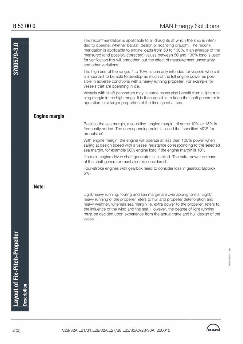
B 53 00 0 MAN Energy Solutions
2 (2) V28/32A;L21/31;L28/32A;L27/38;L23/30A;V23/30A, 200010
The recommendation is applicable to all draughts at which the ship is inten-ded to operate, whether ballast, design or scantling draught. The recom-mendation is applicable to engine loads from 50 to 100%. If an average of themeasured (and possibly corrected) values between 50 and 100% load is usedfor verification this will smoothen out the effect of measurement uncertaintyand other variations.The high end of the range, 7 to 10%, is primarily intended for vessels where itis important to be able to develop as much of the full engine power as pos-sible in adverse conditions with a heavy running propeller. For example forvessels that are operating in ice.Vessels with shaft generators may in some cases also benefit from a light run-ning margin in the high range. It is then possible to keep the shaft generator inoperation for a larger proportion of the time spent at sea.
Engine marginBesides the sea margin, a so-called ‘engine margin’ of some 10% or 15% isfrequently added. The corresponding point is called the ‘specified MCR forpropulsion’.With engine margin, the engine will operate at less than 100% power whensailing at design speed with a vessel resistance corresponding to the selectedsea margin, for example 90% engine load if the engine margin is 10%.If a main engine driven shaft generator is installed. The extra power demandof the shaft generator must also be considered.Four-stroke engines with gearbox need to consider loss in gearbox (approx5%).
Note:Light/heavy running, fouling and sea margin are overlapping terms. Light/heavy running of the propeller refers to hull and propeller deterioration andheavy weather, whereas sea margin i.e. extra power to the propeller, refers tothe influence of the wind and the sea. However, the degree of light runningmust be decided upon experience from the actual trade and hull design of thevessel.31388356107
2018
-08-
14 -
en
Layo
ut o
f Fix-
Pitc
h-Pr
opell
erDe
scrip
tion
3700
579-
3.0

MAN Energy Solutions B 53 00 0
V28/32A;L28/32A;L27/38;V23/30A;L23/30A;L21/31, 200010 1 (8)
Propeller operation
Operating range for controllable-pitch propeller
Fig 1 Operating range for controllable-pitch propeller
2018
-08-
10 -
en
Prop
eller
ope
ratio
nDe
scrip
tion
3700
068-
8-8.
2

B 53 00 0 MAN Energy Solutions
2 (8) V28/32A;L28/32A;L27/38;V23/30A;L23/30A;L21/31, 200010
Rated output/operating rangeMaximum continuous rating (MCR)Range I: Operating range for continuous operation.Range II: Operating range which is temporarily admissible e.g. during acceler-ation and manoeuvring.The combinator curve must keep a sufficient distance to the load limit curve.For overload protection, a load control has to be provided.Transmission losses (e.g. by gearboxes and shaft power) and additionalpower requirements (e.g. by PTO) must be taken into account.
General requirements for propeller pitch controlPitch control of the propeller plantFor mechanical speed governorsAs a load indication a 4–20 mA signal from the engines admission teletrans-mitter is supplied to the propeller control system.For electronic speed governorsAs a load indication a 4–20 mA signal from the engines electronic governor issupplied to the propeller control system.GeneralA distinction between constant-speed operation and combinator-curve opera-tion has to be ensured.Combinator-curve operation: The 4–20 mA signal has to be used for the assignment of the propeller pitchto the respective engine speed. The operation curve of engine speed and pro-peller pitch (for power range, see Fig 1, Operating range for controllable-pitchpropeller) has to be observed also during acceleration/load increase and un-loading.
Acceleration/load increaseThe engine speed has to be increased before increasing the propeller pitch(see Fig 2, Example to illustrate the change from one load step to another).Or if increasing both synchronic the speed has to be increased faster than thepropeller pitch. The area above the combinator curve should not be reached.
Deceleration/unloading the engineThe engine speed has to be reduced later than the propeller pitch (see Fig 2,Example to illustrate the change from one load step to another).Or if decreasing both synchronic the propeller pitch has to be decreasedfaster than the speed. The area above the combinator curve should not bereached.
2018
-08-
10 -
en
Prop
eller
ope
ratio
nDe
scrip
tion
3700
068-
8-8.
2

MAN Energy Solutions B 53 00 0
V28/32A;L28/32A;L27/38;V23/30A;L23/30A;L21/31, 200010 3 (8)
Fig 2 Example to illustrate the change from one load step to another2018
-08-
10 -
en
Prop
eller
ope
ratio
nDe
scrip
tion
3700
068-
8-8.
2

B 53 00 0 MAN Energy Solutions
4 (8) V28/32A;L28/32A;L27/38;V23/30A;L23/30A;L21/31, 200010
Windmilling protectionIf a stopped engine (fuel admission at zero) is being turned by the propeller,this is called "windmilling". The permissible period for windmilling is short, be-cause windmilling can cause, due to poor lubrication at low propeller speed,excessive wear of the engines bearings.Single-screw shipThe propeller control has to ensure that the windmilling time is less than 40sec.Multiple-screw shipThe propeller control has to ensure that the windmilling time is less than 40sec. In case of plants without shifting clutch, it has to be ensured that astopped engine won't be turned by the propeller.(Regarding maintenance work a shaft interlock has to be provided for eachpropeller shaft.)
Binary signals from engine controlOverload contactThe overload contact will be activated when the engines fuel admissionreaches the maximum position. At this position, the control system has tostop the increase of the propeller pitch. If this signal remains longer than thepredetermined time limit, the propeller pitch has to bo decreased.Operation close to the limit curves (only for electronic speed governors)This contact is activated when the engine is ope-rated close to a limit curve(torque limiter, charge air pressure limiter ....). When the contact is activated,the propeller control system has to keep from increasing the propeller pitch. Incase the signal remains longer than the predetermined time limit, the propellerpitch has to be decreased.Propeller pitch reduction contactThis contact is activated when disturbances in engine operation occur, for ex-ample too high exhaust-gas mean-value deviation. When the contact is activ-ated, the propeller control system has to reduce the propeller pitch to 60% ofthe rated engine output, without change in engine speed.
Distinction between normal manoeuvre and emergency manoeuvreThe propeller control system has to be able to distinguish between normalmanoeuvre and emergency manoeuvre (i.e., two different acceleration curvesare necessary).MAN Energy Solutions's guidelines concerning acceleration times and powerrange, see page 5 and page 1.
2018
-08-
10 -
en
Prop
eller
ope
ratio
nDe
scrip
tion
3700
068-
8-8.
2

MAN Energy Solutions B 53 00 0
V28/32A;L28/32A;L27/38;V23/30A;L23/30A;L21/31, 200010 5 (8)
Acceleration timesAcceleration times for controllable pitch-propeller plantsNotes on designFor remote controlled propeller drives for ships with unmanned or centrallymonitored engine room operation, a load programme has to be provided forthe engines. Within the scope of the remote control system (for the pitch ad-justment of the controllable pitch propeller or reversing and load application ofthe engine).This programme serves to protect the preheated engine(s) (lube oil temperat-ure ≥ 40oC and fresh water temperature ≥ 60oC) against excessive thermalstresses, increased wear and exhaust gas turbidity, when the engines areloaded for the first time – possibly up to the rated output.In case of a manned engine room, the engine room personnel is responsiblefor the soft loading sequence, before control is handed over to the bridge.The lower time limits for normal and emergency manoeuvres are given in ourdiagrams for application and shedding of load. We strongly recommend thatthe limits for normal manoeuvring will be observed during normal operation, toachieve trouble-free engine operation on a long-term basis. An automaticchange-over to a shortened load programme is required for emergency man-oeuvres.The final design of the programme should be jointly determined by all the in-volved parties, considering the demands for manoeuvring and the actual ser-vice capacity.Please note that the time constants for the dynamic behaviour of the primemover and the vessel are in the ratio of about 1:100. It can be seen from thisthat an extremely short load application time generally don't lead to an im-provement in ships manoeuvring behaviour (except tugs and small, fast ves-sels).
2018
-08-
10 -
en
Prop
eller
ope
ratio
nDe
scrip
tion
3700
068-
8-8.
2

B 53 00 0 MAN Energy Solutions
6 (8) V28/32A;L28/32A;L27/38;V23/30A;L23/30A;L21/31, 200010
Fig 3 Control lever setting / propeller pitch
2018
-08-
10 -
en
Prop
eller
ope
ratio
nDe
scrip
tion
3700
068-
8-8.
2

MAN Energy Solutions B 53 00 0
V28/32A;L28/32A;L27/38;V23/30A;L23/30A;L21/31, 200010 7 (8)
Operating range for fixed-pitch propellerSingle shaft vessel
9007230644204555
Fig 4 Operating range for fixed-pitch propeller9007230644204555
2018
-08-
10 -
en
Prop
eller
ope
ratio
nDe
scrip
tion
3700
068-
8-8.
2

B 53 00 0 MAN Energy Solutions
8 (8) V28/32A;L28/32A;L27/38;V23/30A;L23/30A;L21/31, 200010
▪ Maximum continuous rating (MCR), fuel stop power▪ Range I
Operating range for continuous service subject to a propeller light-runningof 4–7% and in special cases up to 10%, see B 53 00 0 'Layout of fix-pitch propeller'.
▪ Range II (torque limit)Operating range which is temporarily admissible e.g. during acceleration,manoeuvring.
▪ Theoretical propeller curveApplies to a fully loaded vesel after a fairly long operating time and to apossible works trial run with zero-thrust propeller.
▪ FPDesign range for fixed-pitch propeller. A new propeller must be designedto operate in this range.
Engine operation in a speed range between 103% and 106% is permiss-ible for maximum 1 hour!
The propeller design depends on type and application of the vessel. Thereforethe determination of the installed propulsive power in the ship is always theexclusive responsiblity of the yard.Determining the engine power: The energy demand or the energy losses fromall at the engine additionally attached aggregates has to be considered (e.g.shaft alternators, gearboxes). That means, after deduction of their energy de-mand from the engine power the remaining engine power must be sufficientfor the required propulsion power.
Type testing of the engines is carried out at 110% rated output and103% rated engine speed.
9007230644204555
2018
-08-
10 -
en
Prop
eller
ope
ratio
nDe
scrip
tion
3700
068-
8-8.
2

MAN Energy Solutions B 53 00 0
L27/38;L21/31, 227000 1 (2)
Stern tube
Net cutter and net pick-upTo avoid fishing lines and nets being wound−up by the rotating propeller andcausing damage to the AFT stern tube seal, two precautions can be taken.By installing net cutters, a first barrier which will try to cut the net and line intosmaller pieces is established.The net cutters consist of 4 to 10 knives (depending on the AFT seal size)which are bolted on the rope guard. The net cutters are overlapping the rotat-ing part of the propeller.A second barrier may be applied by installing a line guard which will wind-upthe net before it reaches the AFT stern tube seal, in case the lines are able topass the net cutters. The Line Guard is placed under the protection cover atthe fore-end of the propeller hub.
Figure 1: Line guard
Figure 2: Net cutter
2019
-02-
06 -
en
Ster
n tu
beDe
scrip
tion
1690
716-
7.1

B 53 00 0 MAN Energy Solutions
2 (2) L27/38;L21/31, 227000
InstallationInstallation of propeller equipment into the ship’s hull shows many differentsolutions depending on installation requirements from the ship yard and theship owners operational demands.We have the expertise and knowledge of all the different possible stern tubeinstallations to meet specific wishes and requirements.34758582667
2019
-02-
06 -
en
Ster
n tu
beDe
scrip
tion
1690
716-
7.1

MAN Energy Solutions B 53 00 0
L27/38, 200010 1 (1)
Propeller clearanceTo reduce emitted pressure impulses and vibrations from the propeller to thehull, MAN Energy Solutions recommend a minimum tip clearance as shown infig 1.
For ships with slender aft body and favourable inflow conditions the lower val-ues can be used whereas full after body and large variations in wake fieldcause the upper values to be used.In twin-screw ships the blade tip may protrude below the base line.
34692767499
Hub Dismantling ofcap
X mm
High skew propeller
Y mm
Non-skew propeller
Y mm
Baselineclearance
Z mm
VBS660 115
15-20% of D 20-25% of DMinimum50-100VBS720 120
VBS790 125
VBS860 130
VBS940 14034692767499
Fig 1 Recommended tip clearance3469276749934692767499
2019
-02-
19 -
en
Prop
eller
clea
ranc
eDe
scrip
tion
1696
403-
6.2

This page is intentionally left blank34692767499346927674993469276749934692767499
2019
-02-
19 -
en
B 53 00 0 MAN Energy Solutions
L27/38, 200010
Prop
eller
clea
ranc
eDe
scrip
tion
1696
403-
6.2

MAN Energy Solutions B 53 00 0
L27/38;L21/31, 200010 1 (1)
Direction of rotation
DefinitionsThe direction of rotation is defined seen from aft. The normal direction is anti-clockwise for the propeller. Opposite rotating direction can also be suppliedby changing direction of the engine.
Twin-screw propulsion plantsThe direction of rotation of the propellers for twinscrew propulsion plants canbe chosen in two ways, as shown in fig 1 and fig 2.Usually, we recommend the propellers to turn towards each other at the top.This solution will normally give the propellers the highest efficiency, becausethe flow around the stern of most vessels will favour this direction of rotation.However, it is not possible to give an opinion concerning this, unless modeltests are carried out for the specific vessel.The configuration in fig 2 is recommended for icebreakers, river craft or thelike, which operate in areas prone to dunnage, trees, ice etc floating in thewater.Outward turning propellers will tend to throw out foreign matter rather thanwedging it in.
Figure 1: Inward turning propellers
Figure 2: Outward turning propellers34688142091
2019
-02-
06 -
en
Dire
ctio
n of
rota
tion
Desc
riptio
n16
9070
8-4.
2

This page is intentionally left blank34688142091
2019
-02-
06 -
en
B 53 00 0 MAN Energy Solutions
L27/38;L21/31, 200010
Dire
ctio
n of
rota
tion
Desc
riptio
n16
9070
8-4.
2

MAN Energy Solutions B 54 00 0
L27/38;L21/31, Alphatronic 3000 1 (18)
Propulsion control system
We offer single source solutionsOur state-of-the-art medium-speed propulsion package:MAN Alpha controllable pitch propellers with tailored stem tubes, seals, tailshafts, intermediate shafts, couplings and the Alphatronic 3000 control sys-tem => optimized and fine-tuned for the wide range for small-bore MANL21/31 or L27/38 engines.
Benefits at a glance▪ High efficiency and low noise▪ Low operational costs▪ Low installation costs▪ Superior package value
Figure 1: Propulsion package – MAN L27/38 with controllable pitch propeller(CPP)
Our state-of-the-art propulsion control system
Figure 2: Alphatronic 3000 control station for geared propulsion systems –twin screw CPP example
2019
-04-
12 -
en
Prop
ulsio
n co
ntro
l sys
tem
Desc
riptio
n37
0060
9-4.
0

B 54 00 0 MAN Energy Solutions
2 (18) L27/38;L21/31, Alphatronic 3000
Propulsion control system – Propeller
System overviewAlphatronic 3000 (AT3000) is the propulsion remote control system developedby MAN Energy Solutions for the MAN diesel and gas engine range.The basic features of the Alphatronic 3000 system design are:▪ Main engine start/stop▪ Main engine setpoint (combinator, constant rpm and separate)▪ Main engine load control (load control limitations)▪ Main engine load reduction (rpm and/ or load reduction)▪ Main engine speed measurement (and indication)▪ Combinator control from single lever in ECR and on the bridge▪ Controllable pitch propeller (CPP) setpoint system (combinator curves)▪ Control transfer (bridge/ECR setpoint selection)▪ Propulsion mode selection (combinator, constant rpm and separate)▪ Bridge wing control with wing panels and electric shaft on setpoint levers▪ Serial interface to Alphacomm units on the main engine (if mounted)▪ Alarm announcement and indicationThe Alphatronic 3000 can be extended with the following options:▪ Clutch control (ME, PTO and PTI (engage/ disengage))▪ Propeller shaft speed measurement and indication▪ Interface to PTO connected shaft generator (SG waiting station)▪ Alternative propulsion (PTI mode)▪ Power boost (ME + PTI simultaneously)▪ Reverse power from witches▪ Speed Pilot integrated in the system▪ Maneuvering order printer integrated in the system
ModularityDepending on the propulsion engines’ application, plant scope and functional-ity, additional display and control functions can be added in order to meet therequirements of the classification societies and customers. As central ele-ment, the PCU (propulsion control unit) communicates between the controlstations as well as with engines and plant equipment. Due to its modularity,the complete control system can be customized up to a high degree in orderto fulfill the customer’s individual needs.
2019
-04-
12 -
en
Prop
ulsio
n co
ntro
l sys
tem
Desc
riptio
n37
0060
9-4.
0
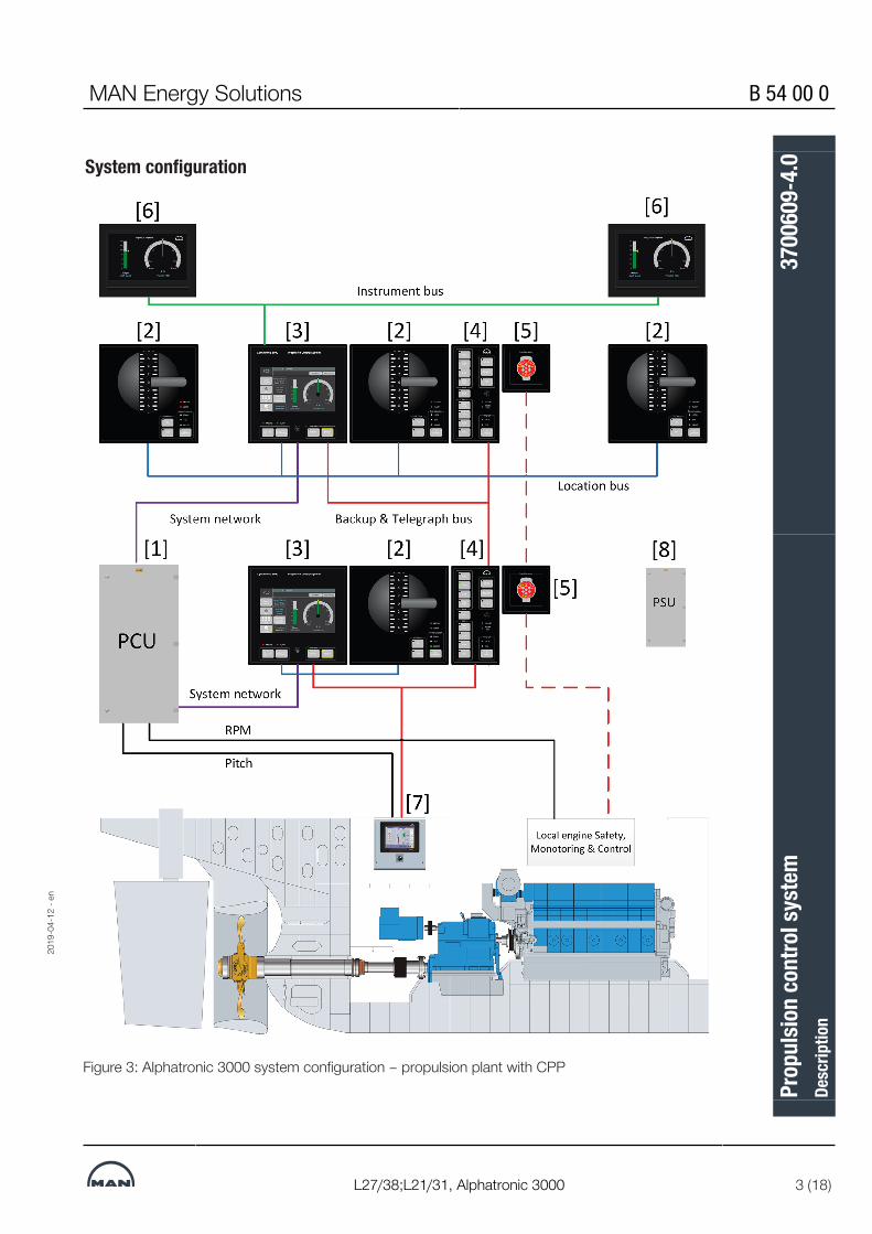
MAN Energy Solutions B 54 00 0
L27/38;L21/31, Alphatronic 3000 3 (18)
System configuration
Figure 3: Alphatronic 3000 system configuration – propulsion plant with CPP
2019
-04-
12 -
en
Prop
ulsio
n co
ntro
l sys
tem
Desc
riptio
n37
0060
9-4.
0
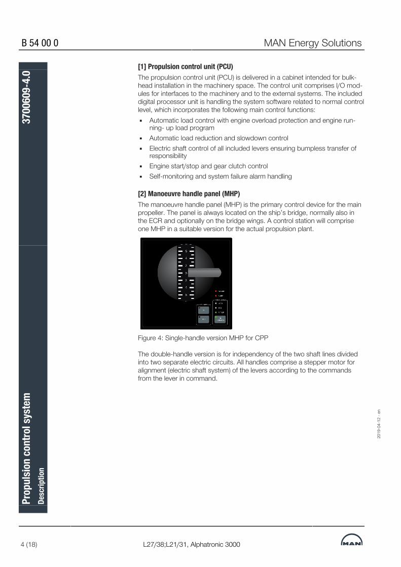
B 54 00 0 MAN Energy Solutions
4 (18) L27/38;L21/31, Alphatronic 3000
[1] Propulsion control unit (PCU)The propulsion control unit (PCU) is delivered in a cabinet intended for bulk-head installation in the machinery space. The control unit comprises I/O mod-ules for interfaces to the machinery and to the external systems. The includeddigital processor unit is handling the system software related to normal controllevel, which incorporates the following main control functions:▪ Automatic load control with engine overload protection and engine run-
ning- up load program▪ Automatic load reduction and slowdown control▪ Electric shaft control of all included levers ensuring bumpless transfer of
responsibility▪ Engine start/stop and gear clutch control▪ Self-monitoring and system failure alarm handling
[2] Manoeuvre handle panel (MHP)The manoeuvre handle panel (MHP) is the primary control device for the mainpropeller. The panel is always located on the ship’s bridge, normally also inthe ECR and optionally on the bridge wings. A control station will compriseone MHP in a suitable version for the actual propulsion plant.
Figure 4: Single-handle version MHP for CPP
The double-handle version is for independency of the two shaft lines dividedinto two separate electric circuits. All handles comprise a stepper motor foralignment (electric shaft system) of the levers according to the commandsfrom the lever in command.
2019
-04-
12 -
en
Prop
ulsio
n co
ntro
l sys
tem
Desc
riptio
n37
0060
9-4.
0

MAN Energy Solutions B 54 00 0
L27/38;L21/31, Alphatronic 3000 5 (18)
Figure 5: MHP in a simple control station console – with PCP and TOP
[3] Propulsion control panel (PCP) 7" display moduleThe propulsion control panel (PCP) with 7" display module comprises a touchscreen with soft keys for handling transfer of control responsibility and setupof propulsion power. In addition to propulsion setup the display is handling thegeneral monitoring and alarm for the propulsion control system as well.The control functions related to "shutdown" and "load reduction" from the en-gine safety system are also available in the display panel.The PCP is optional for bridge wing positions.
Figure 6: Propulsion control panel – PCP – For CPP
[3A] Information display 15"Like for the 7" touch screen in the PCP, a separate 15" information displaycan be tailor-made to the specific engine and propulsion system applications.
2019
-04-
12 -
en
Prop
ulsio
n co
ntro
l sys
tem
Desc
riptio
n37
0060
9-4.
0

B 54 00 0 MAN Energy Solutions
6 (18) L27/38;L21/31, Alphatronic 3000
Figure 7: PCP information display
[4] Telegraph order panel (TOP)The telegraph order panel (TOP) is operating totally independently of thepropulsion remote control system. According to SOLAS requirements, at leastone telegraph panel per propeller shaft must be available on the bridge controllocation and in the engine room for safety and redundancy reasons. However,the telegraph panel can be placed on any bridge control station where thetelegraph order communication is expected to be relevant.
Figure 8: Telegraph order panel – TOP
The telegraph can be used for independent order communication from thebridge to the engine room.
2019
-04-
12 -
en
Prop
ulsio
n co
ntro
l sys
tem
Desc
riptio
n37
0060
9-4.
0

MAN Energy Solutions B 54 00 0
L27/38;L21/31, Alphatronic 3000 7 (18)
[5] Emergency stop panel (ESP)The propulsion power emergency stop panel (ESP) is operating totally inde-pendently of the propulsion remote control system. According to regulatory,at least one emergency stop panel per propeller shaft must be available onthe bridge control location and in the ECR. For safety reasons, it is recom-mended to incorporate an emergency stop panel on all control stations.
Figure 9: Emergency stop panel – ESP
[6] Propeller indicator panelStandard indoor panel (Panama instrument) showing propeller speed andpitch.
Figure 10: Propeller indicator panel – PIP
[7] – Locas Propulsion Control system LPCS and Local Operator Panel-Propeller LOP-PThe LPCS is the propeller closed loop control system and take care of pitchcontrol, gearbox clutch control, and BACKUP and Telegraph functionality. Onsmall bore engine systems the LOP-P displat can be shared with the engineLOP-E.
2019
-04-
12 -
en
Prop
ulsio
n co
ntro
l sys
tem
Desc
riptio
n37
0060
9-4.
0

B 54 00 0 MAN Energy Solutions
8 (18) L27/38;L21/31, Alphatronic 3000
Figure 11: Monitor
Figure 12: Propulsion overview
Alphatronic 3000 requirementsThe following item is part of the Alphatronic 3000 system configuration, seefigure Alphatronic 3000 system configuration. There the power supply isnumbered with [8].
[8] Power supply with battery backupBeing an essential consumer, the power to the propulsion control system isdivided into two different distribution lines. The main supply for the two powersupplies must be from independent sections of the main power system onboard the vessel. In the installation documentation, the two supplies are de-scribed as Power A and Power B. Power A must be supplied by an AC/DCconverter to ensure galvanic isolation, and Power B must be a 24 V DC no-break power supply with at least 30 minutes battery backup. The power fromthe two power supplies are distributed in three groups each:▪ Propulsion control system: Nominal load 80 W, peak load 150 W▪ Bridge propulsion control panels: Nominal load 100 W, peak load 200 W▪ Local propulsion control system: Nominal load 150 W, peak load 200 WThe power supply is normally a standard required yard supply. On request, apower supply unit with duplicated power input, battery backup and fuses forpower distribution to the propulsion control systems can be incorporated inthe Alphatronic 3000 scope of delivery.
2019
-04-
12 -
en
Prop
ulsio
n co
ntro
l sys
tem
Desc
riptio
n37
0060
9-4.
0

MAN Energy Solutions B 54 00 0
L27/38;L21/31, Alphatronic 3000 9 (18)
Figure 13: Power supply unit
Alphatronic 3000 functionality
Speed pilot – OptionalA speed pilot feature is available with connection to the ship‘s GPS system for"Speed over ground" (SOG) input. The speed pilot optimizes the voyage plan-ning and operational speeds e.g. for pulling, steaming and convoy sailing –with fuel saving potentials of up to 4 %.
Alphatronic 3000 interfaces
Standard engine interface for engineThe interface comprises hardwired interface for engine safety system, controltransfer and engine speed and load control. Optionally remote start and stopof engines can be included.
Optional interface for shaft brake controlA propeller shaft brake can be controlled by Alphatronic 3000. Some gearboxdesigns feature the possibility of automatically activating a hydraulic shaftbrake when clutching out. Please contact the gearbox supplier in every case.
2019
-04-
12 -
en
Prop
ulsio
n co
ntro
l sys
tem
Desc
riptio
n37
0060
9-4.
0

B 54 00 0 MAN Energy Solutions
10 (18) L27/38;L21/31, Alphatronic 3000
The Alphatronic 3000 propeller/gear interface features shaft brake control viahardwired interfaces to the gearbox control and enables independent func-tionality in normal and backup control level. The interfaces comprise function-ality for oil pump control, remote clutch control and shaft brake control. Inter-faces to external control and monitoring systems
Optional interface to ship alarm systemAlarm and monitoring parameters provided by the Alphatronic 3000 propul-sion control system for monitoring and announcement in the ship’s alarm sys-tem are specified in a plant-specific summary of alarms. The data transmittedon the modbus to the ship’s alarm system comprises a combination of alarmparameters requiring the attention from an engineer, propulsion status andmonitoring parameters available for general information in the ship’s alarm andcontrol system. Refer to our standard reference drawing: 2173577-0 Sum-mary of Alarms (A 7-page document not inserted in this Project Guide – willbe forwarded upon request).
Optional interface to voyage data recorder (VDR)The status in the normal control system is transmitted to the voyage data re-corder system via a NMEA serial line according to IEC/EN 61996 and IEC/EN61162-1. The status in the telegraph system is independent of the normalcontrol status and is also transmitted to the voyage data recorder system viaan NMEA serial line according to IEC/EN 61996 and IEC/EN 61162-1. Referto our standard reference drawing: 2171083-3 VDR interface for normal con-trol level (A 5-page document not inserted in this Project Guide – will be for-warded upon request). And refer to our standard reference drawing:2171084-5 VDR interface for telegraph orders and backup control level (A 4-page document not inserted in this Project Guide – will be forwarded upon re-quest).
Optional interface to GPS for Alphatronic 3000 speed pilot and master clockAn interface from the GPS is required if the optional Alphatronic 3000 speedpilot is included in the supply. The interface is made according to the NMEA0183 standard for interfacing marine electric devices.A GPRMC sentence comprising "Speed over ground" information is expectedto be received from the GPS. The interface for the GPS can as well comprisethe master clock functionality with control of UTC and local time via a ZDAsentence from the GPS to Alphatronic 3000. Refer to:▪ our standard reference drawing: 2172660-2 Interface for Speed Pilot and▪ our standard reference drawing: 2188788-6 Interface to Master Clock.Further, the Alphatronic 3000 can include interface to the ship’s navigationsystem if the ship speed and course are intended to be automatically con-trolled by a high level route planning system.
Optional interface to DP and joystick control systemIt’s possible to transfer the control of the main propeller to an external controlsystem such as a dynamic positioning system or a joystick control system.Control can be transferred to an external system when the manoeuvring re-sponsibility is on the bridge, the engine is running and the propeller is en-gaged. During joystick control, the engine is still fully protected against over-load.
2019
-04-
12 -
en
Prop
ulsio
n co
ntro
l sys
tem
Desc
riptio
n37
0060
9-4.
0

MAN Energy Solutions B 54 00 0
L27/38;L21/31, Alphatronic 3000 11 (18)
With independent interfaces to a dynamic positioning system and a joystickcontrol system the Alphatronic 3000 system fulfils the IMO requirements fordynamic position class 2 (DP2).Refer to our standard reference drawing: 2176193-8 Interface to DP systemand/or joystick control system (A 3-page document not inserted in this ProjectGuide – will be forwarded upon request).
Alphatronic 3000 installation
Cable plans and cablingCable plans and connection lists showing each cable connection to controlsystem terminals are supplied by MAN Energy Solutions – when a purchasecontract has been signed and upon receipt of all necessary shipyard informa-tion. In order to ensure the optimum function, reliability and safety of the con-trol system, without compromise, the following installation requirements mustbe taken into consideration:▪ Power supply cables must be at least of size 2.5 mm2
▪ If the supply cable length between the bridge and the engine room is inexcess of 60 metres, the voltage drop should be considered
▪ The signal cables should have wires with cross sectional area of min. 0.75and max. 1.5 mm2
▪ All cables should be shielded and the screen must be connected to earth(terminal boxes) at both ends
▪ Signal cables are not to be located alongside any other power cablesconducting high voltage (i.e. large motors) or radio communication cables.The remote control signals can be disturbed by current induced into thecables from their immediate environment. Induced current may disturb oreven damage the electronic control system if the cables are not installedaccording to our guidance
Installation guidance
PurposeThe purpose of this document is to describe the general requirements for in-stallation of an Alphatronic 3000 propulsion control system on board a ship.
Installation documentationFor mechanical installation of delivered equipment refer to the dimensiondrawings of the individual units to be installed. For each workstation our re-commended layout for the workstation is forwarded. The types of cables spe-cified in this document are referring to the plant specific cable installation doc-uments forwarded to the yard. For interfaces to external systems, descriptionsof expected signals exchanged with the external systems are forwarded.
Mechanical installationThe delivered control cabinet is intended for installation on the bulkhead, al-lowing 30 to 100 centimetres of free space between the bottom of the cabinetand the deck. This provides space for cables coming in through the cableflanges in the bottom of the cabinet. The cable flanges may be removed fordrilling of holes for cable glands suitable for the cables delivered by the install-
2019
-04-
12 -
en
Prop
ulsio
n co
ntro
l sys
tem
Desc
riptio
n37
0060
9-4.
0

B 54 00 0 MAN Energy Solutions
12 (18) L27/38;L21/31, Alphatronic 3000
ation yard. Components delivered in terminal boxes or cabinets must not beremoved from their casing. For electrical noise protection, an electric groundconnection must be made from the cabinet to the ship’s hull. The cabinetsmust be installed on a place suitable for service inspection. Do not install thecabinets close to devices generating heat. The enclosure protection of cabin-ets intended for indoor installation on bridge or in machinery space is IP54.The enclosure protection of units intended for open deck or bridge wings isIP56.The delivered control panels are fixed in the consoles by 4 M6 nuts from therear after insertion of the panel from the front. For arrangement of propulsioncontrol stations, refer to the layout drawings delivered for the vessel in ques-tion.
As standard the control panels are delivered for indoor installation. Pan-els intended for open deck or open bridge wings will be delivered withspecial gaskets for enclosure protection IP56 according to required pro-tection for equipment on ship’s deck.
Power supplyAs an essential consumer the power to the propulsion control system must bedivided in two different distribution systems. The main supply for the twopower supplies must be from independent sections of the main power systemon board the vessel. In the installation documentation the two supplies aredescribed as Power A and Power B.Power A must be supplied by an AC/DC converter to ensure galvanic isola-tion, and Power B must be a 24 V DC no break power supply with at least 30minutes battery backup.
Voltage 24 V DC + 30 % – 25 % incl. voltageripple
Voltage ripple 10 % AC rms over steady DC voltage
The power from the two power supplies are distributed in three groups each:
Propulsion control system Nominal load 80 W, peak load 150 W
Bridge propulsion control panels Nominal load 100 W, peak load 200 W
Local propulsion control system Nominal load 150 W, peak load 200 W
Max. current each 10 Amp, fused
Type of cables used for the Alphatronic 3000 system
Type 1Cables used for power supplies and hardwired input/output: Shielded cableswith stranded wires must be used. The size of the power supply cables isspecified in the cable plan, but must always have sufficient capacity to ensurethat the voltage drop does not exceed 1 volt from power supply to last con-sumer in the system.
2019
-04-
12 -
en
Prop
ulsio
n co
ntro
l sys
tem
Desc
riptio
n37
0060
9-4.
0

MAN Energy Solutions B 54 00 0
L27/38;L21/31, Alphatronic 3000 13 (18)
Type 2Communication cable for serial input/outputs: Shielded cables with strandedwires twisted in pairs must be used.
Type 3Network communication cables:The network cables between the propulsion control unit and the control pan-els.
Wires Four twisted pairs, stranded wires (4 x 2x 0.5 or 4 x 2 x 0.75)
Impedance Approximately 100 ohm
Shielding Copper braid shield with drain wire on thecable
Examples of cables BELDEN AWG 24, type No. 8102LOCAP, type AWG 20, Digital No.17-0130-01NK Cables, type LJST-HF 2 x 2 x 0.5FMGCG 2 x 2 x 0.75
Type 4Industrial ethernet Cat 5e ES cable:
TCP/IP communication Electrical data at 20 °CLoop resistance ≤ 120 ohm/kmSignal run time ≤ 5.3 ns/mInsulation resistance ≤ 500 mohm*kmCharacteristic impedance 1 – 100 MHz(100 ±15) ohmSurface transfer impedance of screen 10MHz ≤ 10 mohm/mTest voltage (wire/wire/screen rms 50 Hz1 min) = 700 V
Examples of cables:
Supplier LEONI Special Cables GmbH
Type L-9YH(ST)CH 2 X 2 X 0.34/1.5-100 GNVZ
Supplier part number 202280 L45467-J16-B26
Type 5CAN bus communication cables:SaCoSone CAN bus communication and propeller indication panels.
Type Databus 120 ohm, 2 x 0.5 + 0.5
Impedance 120 ohm
2019
-04-
12 -
en
Prop
ulsio
n co
ntro
l sys
tem
Desc
riptio
n37
0060
9-4.
0

B 54 00 0 MAN Energy Solutions
14 (18) L27/38;L21/31, Alphatronic 3000
Example of cables:
Supplier HUBER+SUHNER
Type 6Not used.
Type 7Data cable 4 x 2 x 0.5 Cat 5e SFTP marine approved cable.
Type 8Data cable 4 x 2 x 0.5 Cat 5e SFTP marine approved cable with RJ45 con-nectors.From the C-Rail with ethernet terminals on bridge and in ECR to the displaypanels the yard must deliver patch cables type Cat 5e SFTP with RJ45 maleconnectors.
Type 9LEONI fiber breakout cable AT-V(ZN)H(ZN)H4 fiber type G 62,5 126 OM1STB900 H with cable color (1-red, 2-green, 3-blue, 4-yellow) DNV-GL ap-proved or similar.NB Fiber cable to be connected with SC connector type on all 4 fibers in bothends. SC connector type HUBER+SUHNER SC Plug G50-125;G62,5/125 orsimilar.
Only stranded Cu wires are accepted for installations on ships.
Cable installationFor layout of cables and specific terminal connections, refer to the cable planand connection lists delivered for the vessel in question.
The individual cables shown on the cable plan must not be put togetheras one.
Laying-up of cablesWhen placing the cables in the vessel, the following must be taken into con-sideration:▪ Paralleling with mains voltage or radio cables (both radio supply and an-
tenna) for more than 5 m, must be at a minimum distance of 500 mm.Crossing of mains voltage or radio cables in right angles must be at aminimum distance of 200 mm
▪ All screens must be connected to the cabinets and made as short andbroad as possible
2019
-04-
12 -
en
Prop
ulsio
n co
ntro
l sys
tem
Desc
riptio
n37
0060
9-4.
0

MAN Energy Solutions B 54 00 0
L27/38;L21/31, Alphatronic 3000 15 (18)
Cable specificationExample: W051A 4 x 2 x 0.75 (3)W Reference for a cable to be delivered by the yard 051A Identification num-ber for a specific cable, where the extension A indicates that the cable is aconnection between units located on a common control station
4 x 2 Number of wires in the cable (here 8 wires arranged in 4 sets of twistedpairs)
x 0.75 Wire size (cross-sectional area in mm2)
(3) Cable type according to cable specifications in this document
Marking of cables and wiresAll cables must be marked so they are easily recognisable, according to theMAN Energy Solutions forwarded cable plan. All wires must be marked withthe marking of the plug and terminal they are inserted in
Cable screensOnly shielded cables must be used for the Alphatronic 3000 system. Thecable screen must be connected in both ends of the cable. Three types ofscreen connections are used in the Alphatronic 3000 system.
Terminal boxes in engine roomCables connected to units located in the engine room will enter the terminalbox through a special EMC cable gland designed for connection of the cablescreen inside the cable gland. To fulfil the requirements of the enclosure pro-tection IP54 all cable glands not used must be sealed before the ship goesinto service.
Control cabinet intended for location in ECRCables connected to control cabinets located in the engine control room oron the bridge have a ground (GND) rail for connection of the cable screens in-side the cabinet close to the entrance of the cable.
Consoles mounted control panelsCables connected to control panels in engine control room and on the bridgeconsoles must be fitted to the panel protection cover with the cable screenconnected to the cover close to the terminal plugs.
Checking wiresWe recommend portable digital multimeter for measuring ohm values, whenchecking the installation by the "ringing through" method.
2019
-04-
12 -
en
Prop
ulsio
n co
ntro
l sys
tem
Desc
riptio
n37
0060
9-4.
0

B 54 00 0 MAN Energy Solutions
16 (18) L27/38;L21/31, Alphatronic 3000
The wires must not be tested for short circuits by high voltage equip-ment, i.e. meggers.
LabelLabel placed inside propulsion control cabinet – Valid for the complete install-ation
Figure 14: Label placed inside propulsion control cabinet – Valid for the com-plete installation
2019
-04-
12 -
en
Prop
ulsio
n co
ntro
l sys
tem
Desc
riptio
n37
0060
9-4.
0

MAN Energy Solutions B 54 00 0
L27/38;L21/31, Alphatronic 3000 17 (18)
Layout measures
Figure 15: Layout measures for control station modules – Standard single screw example
2019
-04-
12 -
en
Prop
ulsio
n co
ntro
l sys
tem
Desc
riptio
n37
0060
9-4.
0

B 54 00 0 MAN Energy Solutions
18 (18) L27/38;L21/31, Alphatronic 3000
Layout measures for standard cabinetsPropulsion control unit – PCU – H x W x D cabinet dimensions: 600 x 600 x300 mmPower supply unit – PSU – H x W x D cabinet dimensions: 800 x 600 x 200mm
Cut-out measures
Figure 16: Cut-out measures for control station modules – standard single screw example36256291467
2019
-04-
12 -
en
Prop
ulsio
n co
ntro
l sys
tem
Desc
riptio
n37
0060
9-4.
0

MAN Energy Solutions P 98 05 1
L27/38;L21/31, 912000 1 (2)
Lifting instructions
Lifting of engineThe engine should only be lifted in the two wire straps. Normally, the liftingtools and the wire straps are mounted by the factory. If not, it must be ob-served that the fixing points for the lifting tools are placed differently depend-ing on the number of cylinders.The lifting tools are to be removed after the installation and the protectivecaps should be fitted.
Fig 1: Lifting tools
Fig. 2: Lifting tools and wires placing on engine
2019
-02-
04 -
en
Liftin
g in
stru
ctio
nsDe
scrip
tion
3700
398-
3.1

P 98 05 1 MAN Energy Solutions
2 (2) L27/38;L21/31, 912000
EngineType
App. dryweight
Lifting beam fastened to extension studs from cylin-
der no
Lifting wires fastened withshackles to hole no.
6L21/31 16.0 ton 2 and 4 1 and 8
7L21/31 17.5 ton 3 and 5 1 and 8
8L21/31 19.0 ton 4 and 6 1 and 8
9L21/31 20.5 ton 4 and 6 1 and 8
6L27/38 31.0 ton 3 and 5 1 and 6
7L27/38 34.0 ton 3 and 5 2 and 7
8L27/38 37.0 ton 4 and 6 1 and 5
9L27/38 40.5 ton 4 and 6 2 and 73487539546734875395467
2019
-02-
04 -
en
Liftin
g in
stru
ctio
nsDe
scrip
tion
3700
398-
3.1