
Magnetophoretic circuits for digital control of single particles and cells
10
ARTICLE Received 11 Oct 2013 | Accepted 9 Apr 2014 | Published 14 May 2014 Magnetophoretic circuits for digital control of single particles and cells Byeonghwa Lim 1,2, *, Venu Reddy 1,2, *, XingHao Hu 1,2 , KunWoo Kim 1,2 , Mital Jadhav 2 , Roozbeh Abedini-Nassab 3,4 , Young-Woock Noh 2 , Yong Taik Lim 5 , Benjamin B. Yellen 3,4 & CheolGi Kim 1,2 The ability to manipulate small fluid droplets, colloidal particles and single cells with the precision and parallelization of modern-day computer hardware has profound applications for biochemical detection, gene sequencing, chemical synthesis and highly parallel analysis of single cells. Drawing inspiration from general circuit theory and magnetic bubble technology, here we demonstrate a class of integrated circuits for executing sequential and parallel, timed operations on an ensemble of single particles and cells. The integrated circuits are constructed from lithographically defined, overlaid patterns of magnetic film and current lines. The magnetic patterns passively control particles similar to electrical conductors, diodes and capacitors. The current lines actively switch particles between different tracks similar to gated electrical transistors. When combined into arrays and driven by a rotating magnetic field clock, these integrated circuits have general multiplexing properties and enable the precise control of magnetizable objects. DOI: 10.1038/ncomms4846 OPEN 1 Department of Emerging Materials Science, Daegu Gyeongbuk Institute of Science and Technology (DGIST), Daegu 711-873, Republic of Korea. 2 School of Engineering, Chungnam National University, Daejeon 305-764, Republic of Korea. 3 Department of Mechanical Engineering and Materials Science, Duke University, Box 90300 Hudson Hall, Durham, North Carolina 27708, USA. 4 University of Michigan–Shanghai Jiao Tong University Joint Institute, Shanghai Jiao Tong University, Shanghai 200240, People’s Republic of China. 5 SKKU Advanced Institute of Nanotechnology (SAINT), School of Chemical Engineering, Sungkyunkwan University, Suwon 440-746, Republic of Korea. *These authors contributed equally to this work. Correspondence and requests for materials should be addressed to B.B.Y. (email: [email protected]) or to C.K. (email: [email protected]). NATURE COMMUNICATIONS | 5:3846 | DOI: 10.1038/ncomms4846 | www.nature.com/naturecommunications 1 & 2014 Macmillan Publishers Limited. All rights reserved.
Transcript of Magnetophoretic circuits for digital control of single particles and cells
ARTICLE
Received 11 Oct 2013 | Accepted 9 Apr 2014 | Published 14 May 2014
Magnetophoretic circuits for digital controlof single particles and cellsByeonghwa Lim1,2,*, Venu Reddy1,2,*, XingHao Hu1,2, KunWoo Kim1,2, Mital Jadhav2, Roozbeh Abedini-Nassab3,4,
Young-Woock Noh2, Yong Taik Lim5, Benjamin B. Yellen3,4 & CheolGi Kim1,2
The ability to manipulate small fluid droplets, colloidal particles and single cells with the
precision and parallelization of modern-day computer hardware has profound applications for
biochemical detection, gene sequencing, chemical synthesis and highly parallel analysis of
single cells. Drawing inspiration from general circuit theory and magnetic bubble technology,
here we demonstrate a class of integrated circuits for executing sequential and parallel,
timed operations on an ensemble of single particles and cells. The integrated circuits are
constructed from lithographically defined, overlaid patterns of magnetic film and current lines.
The magnetic patterns passively control particles similar to electrical conductors, diodes and
capacitors. The current lines actively switch particles between different tracks similar to gated
electrical transistors. When combined into arrays and driven by a rotating magnetic field
clock, these integrated circuits have general multiplexing properties and enable the precise
control of magnetizable objects.
DOI: 10.1038/ncomms4846 OPEN
1 Department of Emerging Materials Science, Daegu Gyeongbuk Institute of Science and Technology (DGIST), Daegu 711-873, Republic of Korea. 2 School ofEngineering, Chungnam National University, Daejeon 305-764, Republic of Korea. 3 Department of Mechanical Engineering and Materials Science, DukeUniversity, Box 90300 Hudson Hall, Durham, North Carolina 27708, USA. 4 University of Michigan–Shanghai Jiao Tong University Joint Institute, ShanghaiJiao Tong University, Shanghai 200240, People’s Republic of China. 5 SKKU Advanced Institute of Nanotechnology (SAINT), School of Chemical Engineering,Sungkyunkwan University, Suwon 440-746, Republic of Korea. * These authors contributed equally to this work. Correspondence and requests for materialsshould be addressed to B.B.Y. (email: [email protected]) or to C.K. (email: [email protected]).
NATURE COMMUNICATIONS | 5:3846 | DOI: 10.1038/ncomms4846 | www.nature.com/naturecommunications 1
& 2014 Macmillan Publishers Limited. All rights reserved.
One of the main goals of lab-on-a-chip research is todevelop generic platforms for manipulating small fluiddroplets, colloidal particles and single cells with the
flexibility, scalability and automation of modern-day computercircuits. Single-cell arrays represent one high impact applicationof lab-on-a-chip tools, which are increasingly being adopted toevaluate rare biological responses in small-cell subsets that areoverlooked by the ensemble averaging approaches of traditionalbiology. Improved understanding of these rare cellular responsescan profoundly impact the development of vaccines andpharmaceuticals for curing infectious diseases and cancer1,2;however there are few existing techniques with the scale andflexibility to unmask single-cell heterogeneity and pave the wayfor new medical breakthroughs3–7.
In particular, there is an urgent need for tools to organize largearrays of single cells and single-cell pairs, evaluate the temporalresponses of individual cell and cell-pair interactions over longdurations, and retrieve specific cells from the array for follow-onanalyses. The desired capabilities of single-cell arrays bear strongresemblance to random access memory (RAM) computer chips,including the ability to introduce and retrieve single cells fromprecise locations of the chip (writing data), and query thebiological state of specified cells at future time points (readingdata). Existing particle handling tools based on hydrodynamic8–11,optic12–18, electric19–22 and magnetic23–36 trapping forces canachieve parts of this desired functionality; however, no singletechnique to our knowledge encompasses the scalability, flexibilityand automation that allows single-cell chips to perform with thelevel of integration of computer circuits.
Our approach has significant similarities with magnetic bubblememory technology37, which was originally developed to storememory and implement logic through the precise manipulationof ‘magnetization bubbles’ in iron garnet films. Previous worksdemonstrated that magnetization bubbles could be moved alongspecific tracks and into desired storage locations by controllingthe electrical and magnetic circuitry patterned on top of thegarnet films. Magnetic patterns were used to establish a networkof highways to move the magnetization bubbles in controlleddirections along the pathways of minimum magnetic energy.Current lines were used to switch the bubbles between differenthighways and store them locally as digital memory.
Here, we use a combination of magnetic patterns and currentlines to instead control an aqueous suspension of magneticparticles and magnetic-nanoparticle-labelled cells that behave likemagnetization bubbles suspended in thin fluid films. Themagnetic patterns are used to create passive circuitry analogousto the lumped element conductors, capacitors and diodes ofelectronic circuits. The current lines are used to establish activecircuitry for switching particles and cells between different tracks.When combined together into small arrays, we demonstrate ascalable platform with general multiplexing properties, therebypaving the way for the development of digital circuitry forparallelized control of matter.
Magnetic-microparticles and magnetic-nanoparticle-labelledsingle cells can be reasonably approximated as magnetic pointdipoles if they are exposed to weakly inhomogeneous magneticfield distributions on the length scale of the particle. In such cases,the magnetic objects are moved towards the nearest locations ofthe instantaneous minima of the magnetostatic potential energythat occurs where the local substrate field is parallel to theexternal field. By shifting the energy minima across the substratein a programmable manner, the trajectory of single particles canbe precisely controlled. If the magnetic field distribution ismodulated in time at a sufficiently slow rate, a simple model candemonstrate the similarity between current of magnetic particlesand Ohm’s law for electrical circuits, thereby providing
motivation for pursuing more complex circuit analogies. Themagnetostatic potential energy of a spherical superparamagneticparticle with linear volumetric susceptibility, wv, in a space- andtime-varying magnetic field B is given by:
U ~r; tð Þ ¼ � 12wvVm0
~B2; ð1Þ
where, V is the volume of the particle, m0 is the vacuum
a0
300y
�250
200
150
100
50Bea
d sp
eed
(µm
s–1
)
0
0 5 10Frequency (Hz)
15 20
1e
b f
c g
d
i
h
x
7.96 kA m–1
9.95 kA m–1
11.94 kA m–1
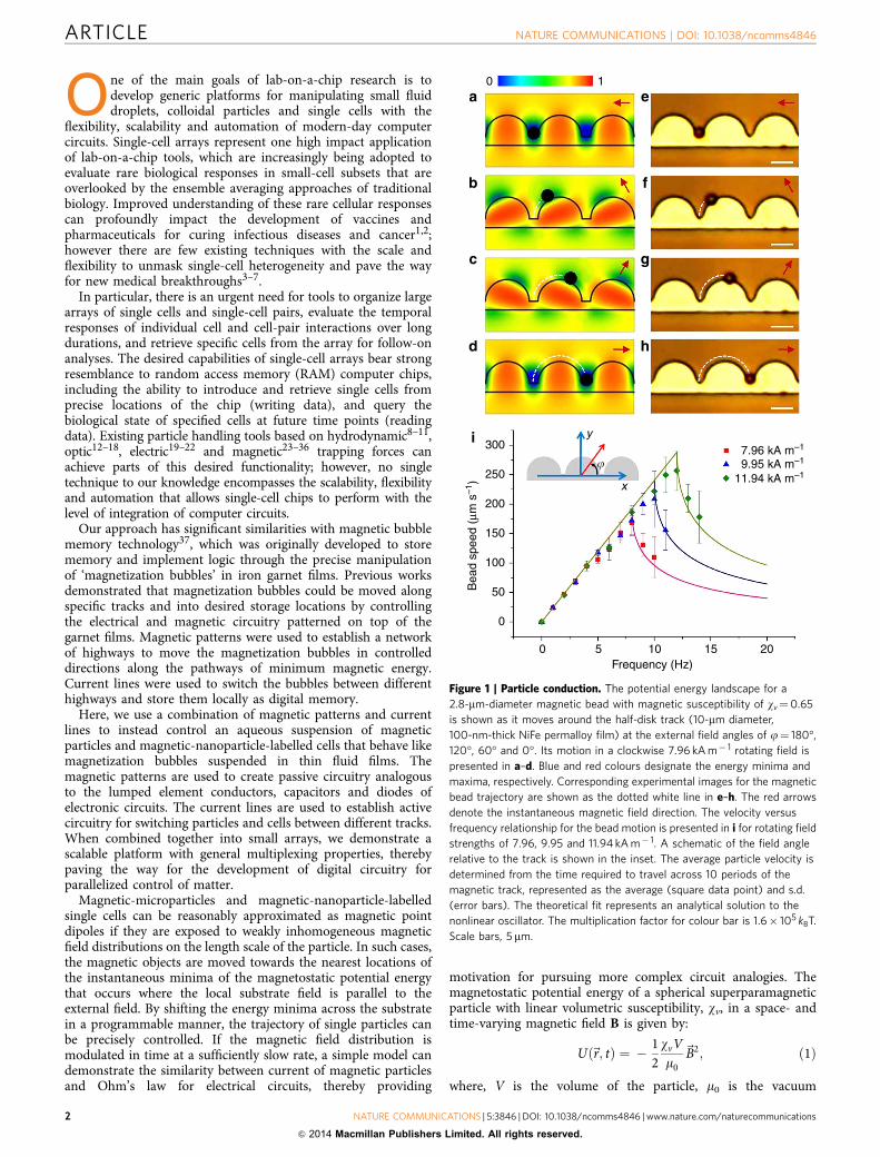
Figure 1 | Particle conduction. The potential energy landscape for a
2.8-mm-diameter magnetic bead with magnetic susceptibility of wv¼0.65
is shown as it moves around the half-disk track (10-mm diameter,
100-nm-thick NiFe permalloy film) at the external field angles of j¼ 180�,
120�, 60� and 0�. Its motion in a clockwise 7.96 kA m� 1 rotating field is
presented in a–d. Blue and red colours designate the energy minima and
maxima, respectively. Corresponding experimental images for the magnetic
bead trajectory are shown as the dotted white line in e–h. The red arrows
denote the instantaneous magnetic field direction. The velocity versus
frequency relationship for the bead motion is presented in i for rotating field
strengths of 7.96, 9.95 and 11.94 kA m� 1. A schematic of the field angle
relative to the track is shown in the inset. The average particle velocity is
determined from the time required to travel across 10 periods of the
magnetic track, represented as the average (square data point) and s.d.
(error bars). The theoretical fit represents an analytical solution to the
nonlinear oscillator. The multiplication factor for colour bar is 1.6� 105 kBT.
Scale bars, 5 mm.
ARTICLE NATURE COMMUNICATIONS | DOI: 10.1038/ncomms4846
2 NATURE COMMUNICATIONS | 5:3846 | DOI: 10.1038/ncomms4846 | www.nature.com/naturecommunications
& 2014 Macmillan Publishers Limited. All rights reserved.
permeability and B¼BextþBsub is the total magnetic fieldgenerated at the particle centre, which is the sum of a uniformrotating external field, Bext(t), and a space–time-varying substratefield, Bsub(r,t). The local field reaches a maximum at locationswhere the external field adds to the local substrate field (when thein-plane component of Bsub is instantaneously parallel with Bext),and manifests as a potential energy minimum because of the fieldsquared dependence. Conversely, when the local substrate fieldpartially cancels the external field (when the in-plane componentof Bsub is instantaneously antiparallel with Bext), the localpotential energy is at a maximum and manifests as a local energybarrier.
We intentionally design an asymmetry in the substrateperiodicity so that the energy minima can be moved smoothlyalong desired pathways. We achieve this with a geometry oflinearly magnetizable disks, whose magnetization attempts tosynchronize with the rotating field direction. The lack of stronghysteresis of the magnetic patterns (Supplementary Fig. 1)justifies this linear approximation. From classical magneto-statics39, it is well known that the locations of energy minimumfor linear magnetizable systems will occur at positions where theoutward normal of the film curvature is aligned parallel to theexternal field (depicted as the blue regions in simulations ofFigs 1–5). By rotating the external magnetic field in-plane, thelocations of the energy minima are continuously shifted aroundthe perimeter of the disk. For substrates consisting of a lineararray of half disks connected by linear segments, the motion ofthe energy minima shifts continuously from one half disk to thenext, moving exactly two disk periods, D, for each cycle of therotating field. The particle transport process is thus similar to aratchet (or step motor) that transports objects along controlleddirections in discrete steps. Here, the local magnetic energyminima can be conceptualized as the nodes in the ratchet.
The particle currents can be approximated mathematically bymodelling the tangential force, Ft, of a magnetic particle aroundthe circumference of a thin disk-shaped micro-magnet:
Ft ¼ f Z; yð Þsin 2c� 2oexttð Þ; ð2Þwhere f(Z,y) is the forcing magnitude, which depends on theexternal field as well as geometric and material properties. Thecoordinates Z and y represent the position of the particle centre inoblate spheroid coordinates, which is the most natural coordinatesystem to model the particle trajectory around a thin disk, andleads to convenient analytical expressions. In equation (2), theparameter c represents the angular location of the particlerelative to the horizontal axis, and oext is the frequency of therotating external field. When re-written in the travelling referenceframe by using the change of variable, O¼c�oextt, thedynamics is equivalent to the ratchet motion of a non-uniformoscillator: dO/dt¼ –oextþoc sin(2O), where oc¼ f(Z,y)/6pZfRpDis the maximum driving frequency that satisfies the linearregime of Ohm’s law for a particle of radius, Rp, in a fluidof viscosity, Zf. The parameter, O, represents the phase lag ofthe bead behind the nearest energy minima. For subcriticalfrequencies (oextroc), the phase lag is small but constant(2Orp/2), allowing the particle find a stable phase wheredO/dt¼ 0, called the phase-locked regime. In this regime, theparticle moves deterministically with time-averaged velocity:
~vh i ¼ 2Doext oext�rð Þ; ð3Þwhere oext is the sense of the rotating external field, and r isthe unit vector pointing away from the centre of a given disk.The linear relationship between frequency and magneticparticle current (Ib¼oext/Rb) behaves analogously to Ohm’slaw (Ie¼V/Re), in which the resistance, Rb, is inversely related tothe pattern periodicity, 2D.
At higher frequencies (oext4oc), the particle’s phase lag is nolonger able to satisfy the inequality 2Orp/2 because of theincrease in viscous force beyond a critical threshold, which causethe particle to periodically slip out of a given potential energyminima into the nearest adjacent minima. The resulting phase-slipping motion is characterized by oscillating attractive andrepulsive forces on the particle and an overall decrease in theparticle’s time-averaged velocity, as well as periodic changes indirection.
ResultsConductors for reversible current flow. Figure 1 presents theparticle trajectory as a function of the time-varying field angle,f¼oextt, where increasing angles correspond to a counter-clockwise rotating field. Simulations of the potential energy dis-tribution (Fig. 1a–d) compared with the experimental trajectory(Fig. 1e–h) demonstrate that the particle position is correlated tothe shifting regions of potential energy minima (blue). The par-ticles move along the upper section of the track because it has thedeepest energy minima. The linear segment connecting adjacentmagnets provides an energy barrier that confines the local energyminima to one side of the magnetic track.
For sufficiently low driving frequencies, the particles moveexactly two array periods for each complete cycle of field rotation,demonstrating the linear relationship between frequency andmagnetic particle current for the phase-locked regime (Fig. 1i).Clockwise field rotation leads to particle motion along thepositive x direction, whereas counter-clockwise rotation producesmotion along the negative x direction (Supplementary Movie 1).The asymmetry in the track design is essential for achieving a netparticle current. If the track were designed with full disks insteadof half disks, then the particles confined to the lower portion ofthe track would move in the opposite direction of the particles onthe upper portion, thereby negating net current flow. At higherfrequencies, the particles enter the phase-slipping regime, and theanalogies with Ohm’s law breaks down (Fig. 1i).
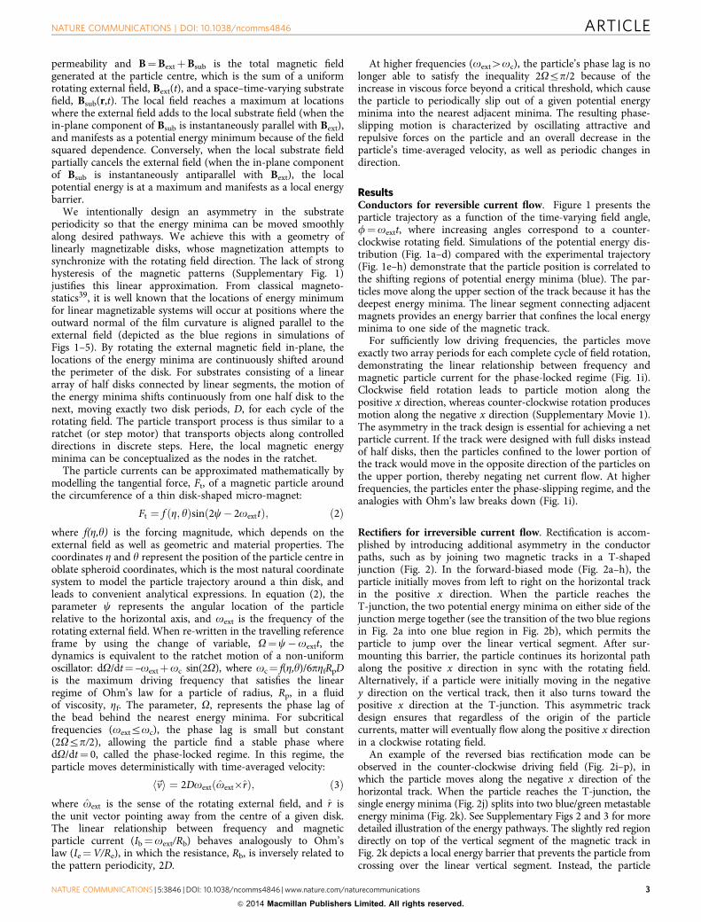
Rectifiers for irreversible current flow. Rectification is accom-plished by introducing additional asymmetry in the conductorpaths, such as by joining two magnetic tracks in a T-shapedjunction (Fig. 2). In the forward-biased mode (Fig. 2a–h), theparticle initially moves from left to right on the horizontal trackin the positive x direction. When the particle reaches theT-junction, the two potential energy minima on either side of thejunction merge together (see the transition of the two blue regionsin Fig. 2a into one blue region in Fig. 2b), which permits theparticle to jump over the linear vertical segment. After sur-mounting this barrier, the particle continues its horizontal pathalong the positive x direction in sync with the rotating field.Alternatively, if a particle were initially moving in the negativey direction on the vertical track, then it also turns toward thepositive x direction at the T-junction. This asymmetric trackdesign ensures that regardless of the origin of the particlecurrents, matter will eventually flow along the positive x directionin a clockwise rotating field.
An example of the reversed bias rectification mode can beobserved in the counter-clockwise driving field (Fig. 2i–p), inwhich the particle moves along the negative x direction of thehorizontal track. When the particle reaches the T-junction, thesingle energy minima (Fig. 2j) splits into two blue/green metastableenergy minima (Fig. 2k). See Supplementary Figs 2 and 3 for moredetailed illustration of the energy pathways. The slightly red regiondirectly on top of the vertical segment of the magnetic track inFig. 2k depicts a local energy barrier that prevents the particle fromcrossing over the linear vertical segment. Instead, the particle
NATURE COMMUNICATIONS | DOI: 10.1038/ncomms4846 ARTICLE
NATURE COMMUNICATIONS | 5:3846 | DOI: 10.1038/ncomms4846 | www.nature.com/naturecommunications 3
& 2014 Macmillan Publishers Limited. All rights reserved.
follows the deeper energy minimum that moves in the positive ydirection and enforces the asymmetry of the conduction mechan-ism. The overall effect is that particles can conduct along thepositive x direction in a clockwise rotating field, but cannotconduct along the negative x direction in a counter-clockwiserotating field. The irreciprocal motion of the particle pathway is
also depicted in Supplementary Movie 2. The velocity versusfrequency relationship for the matter rectifier is presented inFig. 2q. Note that the critical frequency that defines the transitionbetween the phase-locked and phase-slipping regimes is loweredfor the diode relative to the conductor track of Fig. 1, owing to themodified energy landscape of the T-junction.
a0
–4 –2 0Frequency (Hz)
2 4 6 8 10
1
e
b f
c g
d
q 120
100
80
60
40
20 Counterclockwiserotation
Reverse
Phase-locked Phase-slipping
Forward
Clockwiserotation
Bea
d sp
eed
(µm
s–1
)
0
h
i
j
k
l
m
n
o
p
Figure 2 | Particle rectification. The potential energy landscape in a clockwise 7.96 kA m� 1 rotating field in the forward-biased diode mode is shown when
the external field has angular orientation of j¼ 180�, 105�, 45� and 0� as presented in a–d. The red arrows denote the instantaneous external field
direction. The blue energy minima correspond to the particle locations in the experimental images of e–h. The potential energy landscape for the reverse
conditions for field angles of j¼0�, 75�, 135� and 180� is presented in i–l along with the associated experimental images in m–p. The velocity versus
frequency relationship for the matter rectifier is presented in q. The average particle velocity is determined from the time required to travel across 10
periods of the magnetic track, represented as the average (square data point) and s.d. (error bars). The theoretical fit represents an analytical solution to
the nonlinear oscillator. The multiplication factor for colour bar is 1.6� 105 kBT. Scale bars, 5 mm.
ARTICLE NATURE COMMUNICATIONS | DOI: 10.1038/ncomms4846
4 NATURE COMMUNICATIONS | 5:3846 | DOI: 10.1038/ncomms4846 | www.nature.com/naturecommunications
& 2014 Macmillan Publishers Limited. All rights reserved.

Capacitors for local storage of single particles and cells.Rectification and conduction pathways can be geometricallyarranged in closed loops to store small single particles and cells inwell-defined spatial regions, operating in a manner similar to anelectrical capacitor. Figure 3a shows an array of magnetic con-duction tracks and square apartments that are configured suchthat the T-junction entry way is in the forward bias mode andallows particles or cells to enter the apartment. In a clockwise
driving field, single immune cells labelled with 50-nm magneticnanoparticles are moved into the apartments, where they subse-quently remain trapped in a closed spatial orbit. Upon reversingthe field rotation, the cells remain trapped in their apartmentsbecause of the reverse bias of the diode junction (SupplementaryMovie 3). By this mechanism, single T- and B-cell lymphocytes(Supplementary Movie 4) can be arrayed in individual apart-ments that allows for long-term analysis of single cells and
a b c
d
e
Figure 3 | Local storage of magnetically labelled single cells. Bright-field and fluorescent images of (a) single T lymphocytes and (b) B lymphocytes
trapped in individual apartments are shown. Real-time analysis of biological process, such as mitosis, can be observed in c. A homogeneous pairing of
(d) B lymphocytes and a heterogeneous pairing (e) of a B- and T lymphocytes can be trapped in a single apartment, demonstrating the ability to arrange
single-cell pairs. Scale bars, 40mm.
a0 1
I
I
I
b
c
d
e
f
Figure 4 | Type I transistor for local switching of single particles and cells. A small gap fabricated between two adjacent magnets allows a single particle
to be selectively transported in the positive or negative x direction based on whether a 100-mA current applied is turned ON or OFF. Parts a–c show
the potential energy landscape, and the experimental trajectory (white dotted line) of a single particle or cell when the current line is OFF. Parts d–f show
the same conditions when the current is ON. The merger of the energy minima causes the particles to move across the gap only when the current
line is ON. The red arrows denote the instantaneous external field direction. The multiplication factor for colour bar is 1.6� 105 kBT. Scale bars, 20mm.
NATURE COMMUNICATIONS | DOI: 10.1038/ncomms4846 ARTICLE
NATURE COMMUNICATIONS | 5:3846 | DOI: 10.1038/ncomms4846 | www.nature.com/naturecommunications 5
& 2014 Macmillan Publishers Limited. All rights reserved.
visualization of biological processes such as cell mitosis (Fig. 3d).The ability to trap pairs of cells in individual apartments,including a homogeneous pair of B-lymphocyte cells (Fig. 3e) or aheterogeneous pair of B- and T-lymphocyte cells (Fig. 3f), canserve as a platform for studying single cell–cell communication.
Type I transistors for local matter switching. The ability toperform selective operations on a specific particle or cell within alarge array can be accomplished by combining passive transportelements with locally addressible active elements to switchparticles along different tracks as well as into (or out of) a localapartment. Here we show one mechanism for switching a particlebetween two different pathways by creating a controlled gapbetween two disks in the magnetic track. A current line placed atone edge of the gap generates a competing magnetic field thattunes the local energy landscape and switches the particlebetween conductive and non-conductive states. This transportbehaviour has analogies with the action of a gate electrode inswitching currents at a semiconducting junction. When the cur-rent is OFF, the energy landscape is a bistable double-wellpotential, which can be visualized as the two blue energy minimaregions on either side of the gap in Fig. 4a. The double-wellpotential restricts the particle to one side of the gap and reversesits direction of motion (white dotted in line in Fig. 4b,c). Whenthe 100 mA current is ON, the two bistable energy minima
merges into a single energy minimum that causes the gap tobecome conductive and moves the particles across the gap alongthe positive x direction (black dotted line in Fig. 4e,f). By timingthe current pulses in sync with the rotating magnetic field clock,it is possible to selectively transfer one particle whilepreventing another particle from crossing the gap (Fig. 4b,e andSupplementary Movie 5). Selective operations can also beperformed on single cells (Fig. 4e,f and Supplementary Movie 6).In Fig. 4e,f, pseudo-coloring is used to increase the contrast of thecell relative to the background.
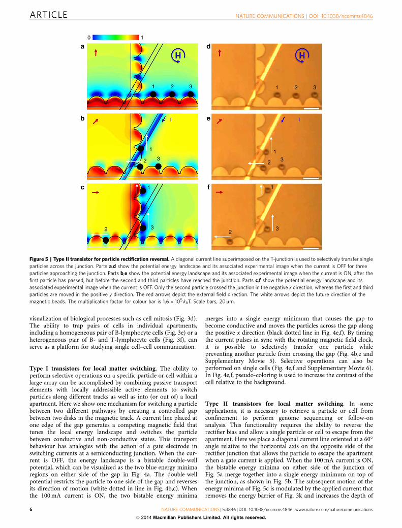
Type II transistors for local matter switching. In someapplications, it is necessary to retrieve a particle or cell fromconfinement to perform genome sequencing or follow-onanalysis. This functionality requires the ability to reverse therectifier bias and allow a single particle or cell to escape from theapartment. Here we place a diagonal current line oriented at a 60�angle relative to the horizontal axis on the opposite side of therectifier junction that allows the particle to escape the apartmentwhen a gate current is applied. When the 100 mA current is ON,the bistable energy minima on either side of the junction ofFig. 5a merge together into a single energy minimum on top ofthe junction, as shown in Fig. 5b. The subsequent motion of theenergy minima of Fig. 5c is modulated by the applied current thatremoves the energy barrier of Fig. 3k and increases the depth of
a0 1
1 2 3
1
2 3
1
2 3
1
1
2
2
3
3
1 2 3
I Ib
c
d
e
f
Figure 5 | Type II transistor for particle rectification reversal. A diagonal current line superimposed on the T-junction is used to selectively transfer single
particles across the junction. Parts a,d show the potential energy landscape and its associated experimental image when the current is OFF for three
particles approaching the junction. Parts b,e show the potential energy landscape and its associated experimental image when the current is ON, after the
first particle has passed, but before the second and third particles have reached the junction. Parts c,f show the potential energy landscape and its
associated experimental image when the current is OFF. Only the second particle crossed the junction in the negative x direction, whereas the first and third
particles are moved in the positive y direction. The red arrows depict the external field direction. The white arrows depict the future direction of the
magnetic beads. The multiplication factor for colour bar is 1.6� 105 kBT. Scale bars, 20mm.
ARTICLE NATURE COMMUNICATIONS | DOI: 10.1038/ncomms4846
6 NATURE COMMUNICATIONS | 5:3846 | DOI: 10.1038/ncomms4846 | www.nature.com/naturecommunications
& 2014 Macmillan Publishers Limited. All rights reserved.
the energy minima on the opposite side of the rectifier junction.After passing the junction, the particle continues along thenegative x direction of the horizontal track. Owing to the deter-ministic nature of particle transport, the switching process can besynchronized with the external field clock to permit the second
particle, but not the first or third particle, to move across thejunction. The paths of the three particles are illustrated with thewhite arrows and are shown more clearly in SupplementaryMovie 7 for single particles and Supplementary Movie 8 forsingle cells.
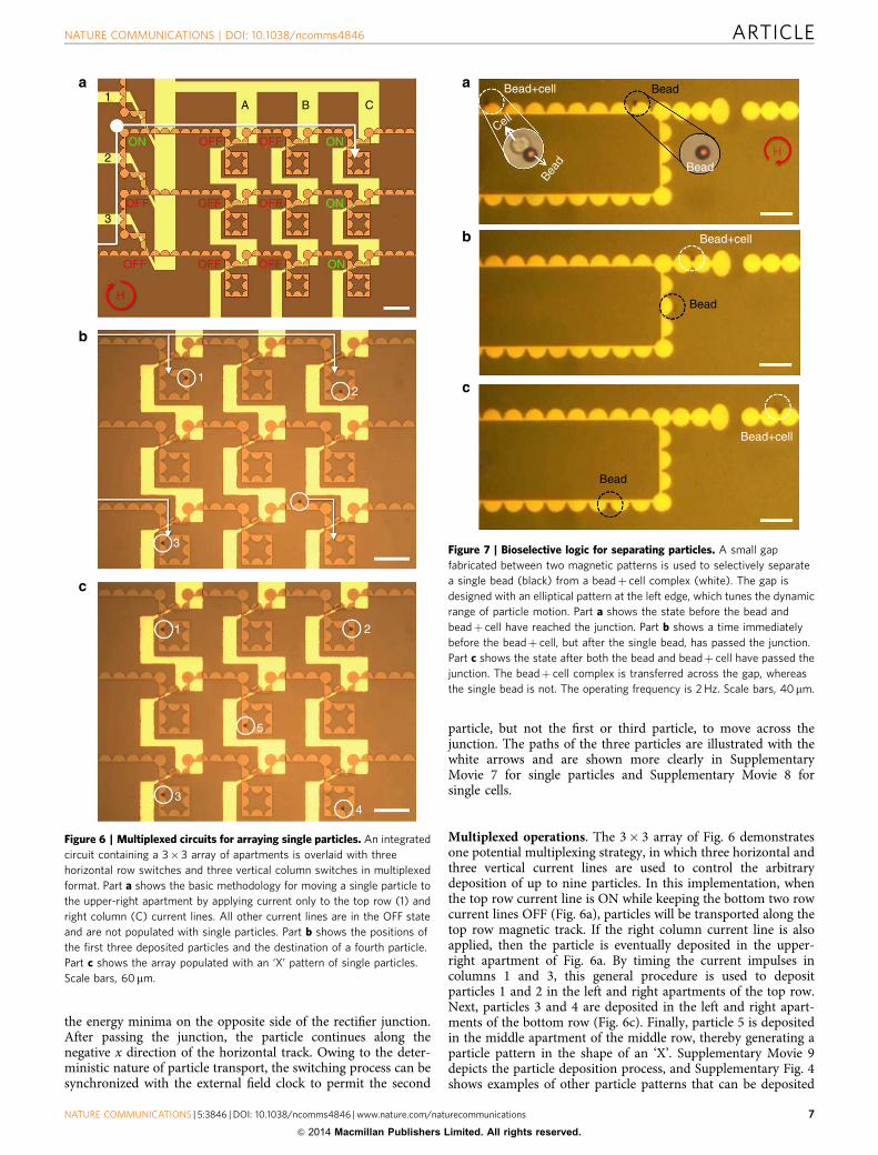
Multiplexed operations. The 3� 3 array of Fig. 6 demonstratesone potential multiplexing strategy, in which three horizontal andthree vertical current lines are used to control the arbitrarydeposition of up to nine particles. In this implementation, whenthe top row current line is ON while keeping the bottom two rowcurrent lines OFF (Fig. 6a), particles will be transported along thetop row magnetic track. If the right column current line is alsoapplied, then the particle is eventually deposited in the upper-right apartment of Fig. 6a. By timing the current impulses incolumns 1 and 3, this general procedure is used to depositparticles 1 and 2 in the left and right apartments of the top row.Next, particles 3 and 4 are deposited in the left and right apart-ments of the bottom row (Fig. 6c). Finally, particle 5 is depositedin the middle apartment of the middle row, thereby generating aparticle pattern in the shape of an ‘X’. Supplementary Movie 9depicts the particle deposition process, and Supplementary Fig. 4shows examples of other particle patterns that can be deposited
a
b
c
1
1
1
2
2
3
3
5
4
2ON OFF
OFF
OFF
H
OFF
OFF
OFF
OFF
OFF ON
ON
ON
3
A B C
Figure 6 | Multiplexed circuits for arraying single particles. An integrated
circuit containing a 3� 3 array of apartments is overlaid with three
horizontal row switches and three vertical column switches in multiplexed
format. Part a shows the basic methodology for moving a single particle to
the upper-right apartment by applying current only to the top row (1) and
right column (C) current lines. All other current lines are in the OFF state
and are not populated with single particles. Part b shows the positions of
the first three deposited particles and the destination of a fourth particle.
Part c shows the array populated with an ‘X’ pattern of single particles.
Scale bars, 60mm.
a Bead+cell
Bead+cell
Bead+cell
Bead
H
Bead
Bead
Bead
Bead
Cell
b
c
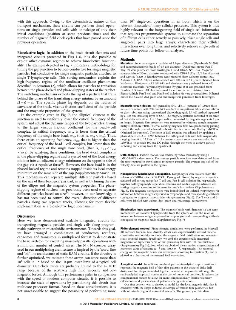
Figure 7 | Bioselective logic for separating particles. A small gap
fabricated between two magnetic patterns is used to selectively separate
a single bead (black) from a beadþ cell complex (white). The gap is
designed with an elliptical pattern at the left edge, which tunes the dynamic
range of particle motion. Part a shows the state before the bead and
beadþ cell have reached the junction. Part b shows a time immediately
before the beadþ cell, but after the single bead, has passed the junction.
Part c shows the state after both the bead and beadþ cell have passed the
junction. The beadþ cell complex is transferred across the gap, whereas
the single bead is not. The operating frequency is 2 Hz. Scale bars, 40mm.
NATURE COMMUNICATIONS | DOI: 10.1038/ncomms4846 ARTICLE
NATURE COMMUNICATIONS | 5:3846 | DOI: 10.1038/ncomms4846 | www.nature.com/naturecommunications 7
& 2014 Macmillan Publishers Limited. All rights reserved.
with this approach. Owing to the deterministic nature of thistransport mechanism, these circuits can perform timed opera-tions on single particles and cells with knowledge of only theirinitial conditions (position at some previous time) and thenumber of magnetic field clock cycles that have passed since theprevious operation.
Bioselective logic. In addition to the basic circuit elements andintegrated circuits presented in Figs 1–6, it is also possible toexploit other dynamic regimes to achieve bioselective function-ality. The example depicted in Fig. 7 indicates a methodology fortuning the gap junction to be non-conductive for single magneticparticles but conductive for single magnetic particles attached tosingle T-lymphocyte cells. This sorting mechanism exploits thehigh-frequency regime of the nonlinear oscillator phenomenadescribed in equation (2), which allows for particles to transitionbetween the phase-locked and phase-slipping states of the ratchet.The switching mechanism exploits the lag of a particle that trailsbehind the phase of the translating energy minima by an amountO¼c�j. The specific phase lag depends on the radius ofcurvature of the track, viscous friction coefficient of the particleand the magnetic properties of the system.
In the example given in Fig. 7, the elliptical element at thejunction is used to uniformly lower the critical frequency of thesystem and adjust the dynamic ranges of the two particles. Owingto the larger viscous friction coefficient for the beadþ cellcomplex, its critical frequency, oc1, is lower than the criticalfrequency of the single bare bead, oc2, (that is, oc1ooc2). Thus,there exists an operating frequency, oext that is higher than thecritical frequency of the beadþ cell complex, but lower than thecritical frequency of the single bare bead, (that is, oc1ooext
ooc2). By satisfying these conditions, the beadþ cell complex isin the phase-slipping regime and is ejected out of the local energyminima into an adjacent energy minimum on the opposite side ofthe gap via a repulsive force38. However, the bare bead is in thephased-locked regime and remains trapped inside its local energyminimum on the same side of the gap (Supplementary Movie 10).This mechanism can separate multiple different particles basedon the size of their biological payload, as well as by tuning the sizeof the ellipse and the magnetic system properties. The phase-slipping regime of ratchets has previously been used to separatedifferent particles based on size24; however, to our knowledge ithas not been used to control the overall direction of differentparticles along two separate tracks, allowing for more flexibleimplementation as a bioselective logic mechanism.
DiscussionHere we have demonstrated scalable integrated circuits fortransporting magnetic particles and single cells along program-mable pathways in microfluidic environments. Towards this goal,we have arranged a combination of conductors, rectifiers,capacitors and transistors in multiplexed format to demonstratethe basic skeleton for executing massively parallel operations witha mininum number of control wires. The N�N crossbar arrayused in our multiplexing architecture is inspired by the ‘word’ lineand ‘bit’ line architecture of static RAM circuits. If the circuitry isfurther optimized, we estimate these arrays can store more than106 cells in� 2 based on the 10-mm lower limit of a typical celldiameter. Our clock cycles are probably limited to the 1–10 Hzrange because of the relatively high fluid viscosity and lowmagnetic forces. Although this performance pales in comparisonwith the speed of modern computer circuits, it is possible toincrease the scale of operations by partitioning this circuit intomulticore processor format. Based on these considerations, it isnot unreasonable to suggest the possibility of performing more
than 106 single-cell operations in an hour, which is on therelevant timescale of many cellular processes. This system is thushighly relevant to the burgeoning field of single-cell informaticsthat requires programmable systems to automate the separationof different cells either actively or passively; place single cells andsingle-cell pairs into large arrays; characterize their cellularinteractions over long times; and selectively retrieve single cells atfuture time points for follow-on analyses.
MethodsMaterials. Superparamagnetic particles of 2.8-mm diameter (Dynabeads M-280)and superparamagnetic beads of 4.5-mm diameter (Dynabeads mouse Pan T;Thy1.2) were purchased from Invitrogen, Grand Island, NY, USA. Magneticnanoparticles of 50-nm diameter conjugated with CD90.2 (Thy1.2; T lymphocytes)and CD45R (B220; B lymphocytes) were procured from Miltenyi Biotec Inc.,Auburn, CA, USA. Silicon wafers coated with 200 nm of SiO2 were obtained fromWafermart. Photoresist (AZ 5214-E) and developer was purchased from AZelectronic materials. Polydimethylsiloxane (Sylgard 184) was procured fromDowhitech Silicone. All chemicals used for cell media were obtained fromSigma-Aldrich. Pan T-cell and Pan B-cell isolation kit were procured from MiltenyiBiotec Inc. Calcein AM green and red/orange was purchased from Invitrogen.
Magnetic circuit design. Soft permalloy (Ni82.6Fe17.4) patterns of 100 nm thick-ness are combined with 200-nm thick conductive Au patterns fabricated on siliconor glass substrates using conventional photolithographic lift-off method separatedby a 150-nm insulating layer of SiO2. The magnetic patterns consisted of an arrayof half disks with either 5 or 10-mm radius, connected by magnetic segments 2 mmin length. Magnetic film properties were measured by vibrating sample magneto-metry (Lakeshore 7400). External rotating magnetic field was produced by passingcurrent through pairs of solenoid coils with ferrite cores controlled by LabVIEW(National Instruments). The sense of field rotation was adjusted by applying aphase difference, d¼ ±90� between the orthogonal coils with field magnitudesranging from 0 to 15.9 kA m� 1. A constant current source was controlled byLabVIEW to provide 100 mA DC pulses through the wires to achieve particleswitching and exiting from the apartment.
Data analysis. Particle motion was tracked by video microscopy using aIMC-1040FT video camera. The average particle velocities were determined fromthe time required to travel across 10 pattern periods. The average and s.d. of thevelocity data are plotted in the figures.
Nanoparticle–lymphocytes conjugation. Lymphocytes were isolated from thespleens of C57BL6 mice (KOATECH, Pyeongtaek, Korea) by negative magnetic-activated cell sorting using Pan T-cell and Pan B-cell isolation kit, respectively,together with lymphocyte separation columns and Midi-magnetic-activated cellsorting magnets according to the manufacturer’s instructions (SupplementaryFig. 5). The magnetic nanoparticles were immobilized on isolated lymphocytes viainteraction between antigen expressed in lymphocytes and corresponding antibodyconjugated to magnetic nanoparticles (Supplementary Fig. 6). The T cells and Bcells were labelled with calcein dye (green and red/orange, respectively).
Bioselective logic experiment. The magnetic beads with diameter 4.5 mm wereimmobilized on isolated T lymphocytes from the spleens of C57BL6 mice viainteraction between antigen expressed in lymphocytes and corresponding antibodyconjugated to magnetic beads (Supplementary Fig. 7)
Finite element method. Finite element simulations were performed in Maxwell3D software (version 12.2, Ansoft), which used experimentally derived materialconstitutive relationships to model the magnetic field distribution and magneto-static potential energy. Specifically, we used the experimentally measuredmagnetization hysteresis curve of thin permalloy film with 100-nm thickness(Supplementary Fig. 1b), from which we obtained the saturation magnetization andcoercivity value of 668 emu cc� 1 and 190 A m� 1, respectively. The potentialenergy on the magnetic beads was determined according to equation (1), and isplotted as a function of the external field orientation.
Analytical model. In addition, we developed semi-analytical approximations torepresent the magnetic field of thin film patterns in the shape of disks, halfdisks, and thin strips connected together in serial arrangements. Although thesemi-analytical approach comes at the cost of numerical precision, it reduces thecomputational burden to allow for more computationally feasible trajectorycalculations and presentation of potential energy animations.
Our first concern was to develop a model for the local magnetic field that isconsistent with the shape-induced anisotropy of various film geometries, butwithout introducing local numerical artefacts. The geometry of thin disks
ARTICLE NATURE COMMUNICATIONS | DOI: 10.1038/ncomms4846
8 NATURE COMMUNICATIONS | 5:3846 | DOI: 10.1038/ncomms4846 | www.nature.com/naturecommunications
& 2014 Macmillan Publishers Limited. All rights reserved.
connected together by short strips can be approximately modelled as anoverlapping set of paramagnetic ellipsoids and oblate spheroids. Thisapproximation has the advantage of accurately capturing the influence of shape-induced demagnetizing factors on the local magnetization; however, near theoverlapping regions this approach introduces spurious magnetic pole distributionsthat influence the local magnetic fields and forces. At the other end of themodelling spectrum, magnetic thin film patterns exposed to in-plane magneticfields are commonly approximated as line charges around the perimeter of thepatterned film; however, these approximations do not account for shaped-induceddemagnetizing factors. Ultimately, we settled on a hybrid model that achieves asemi-self-consistent solution for local magnetization without introducing spuriouspole distributions. Although these models represent an approximation to thenumerically exact, finite element analyses, they markedly increase the computationspeed.
The magnetic field of a uniformly magnetized ellipsoid with semi-principal axesof length a, b and c along the x-, y- and z directions, respectively, has previouslybeen derived by Stratton39. The analytical expression for the magnetic potentialinside and outside a paramagnetic ellipsoid is given by:
jout ¼ jext þjs ¼ F1 xð ÞF2 Zð ÞF3 zð Þ C1 þC2
Z1x
dsRs sþ a2ð Þ
264
375; ð4Þ
jin ¼ C3F1 xð ÞF2 Zð ÞF3 zð Þ; ð5Þ
Rs ¼ffiffiffiffiffiffiffiffiffiffiffiffiffiffiffiffiffiffiffiffiffiffiffiffiffiffiffiffiffiffiffiffiffiffiffiffiffiffiffiffiffiffiffiffiffisþ a2ð Þ sþ b2ð Þ sþ c2ð Þ
p; ð6Þ
where jext and js represent the uniform external field and ellipsoid potential in thex direction, respectively. The functions F1 ¼
ffiffiffiffiffiffiffiffiffiffiffiffixþ a2p
, F2 ¼ffiffiffiffiffiffiffiffiffiffiffiffiZþ a2
pand F3 ¼ffiffiffiffiffiffiffiffiffiffiffiffi
zþ a2p
are one-dimensional orthogonal expansions in the ellipsoidal coordinatesystem, in which the coordinate x can be considered as the radial term, whereas theZ and z coordinates represent the angular distribution, with a characteristic lengthscale of Rs for the system. The coefficients, C1, C2 and C3 are determined bymatching the boundary conditions of equation (4–6) which must satisfy thecontinuity of the magnetic potential and its normal first derivative at the boundary:
jout x¼0j ¼ jin x¼0j ; ð7Þ
m01
hx
@jout
@x
� �x¼0
¼ m11
hx
@jin
@x
� �x¼0
; ð8Þ
where x¼ 0 represents ellipsoid’s surface and where m0 and m1 are the magneticpermeability outside and inside the ellipsoid, respectively. Similar equations can beachieved for the external field in the y- and z directions by replacing a inequation (1) with b and c, respectively. Owing to the high magnetic permeability ofpermalloy material used in experiments, we make the assumption that m144m0
with the surrounding medium assumed to be vacuum. The metric coefficient isgiven by:
hx ¼12
x� Zð Þ x� zð Þxþ a2ð Þ xþ b2ð Þ xþ c2ð Þ
� �0:5
; ð9Þ
After deriving the matching coefficients C1, C2 and C3 and inserting them inequations (4–8), the potentials inside and outside the ellipsoid are determinedto be:
jin ¼ �1m0
~Bext � xAx 0;1ð Þ þ
~Bext � yAy 0;1ð Þ þ
~Bext � zAz 0;1ð Þ
" #; ð10Þ
jout ¼ jextAx 0; xð Þ
Ax 0;1ð Þ þAy 0; xð Þ
Ay 0;1ð Þ þAz 0; xð Þ
Az 0;1ð Þ
� �; ð11Þ
Ax p; qð Þ ¼ 1þ abc2
m1 � m0
m0
� �Zqp
dssþ x2ð ÞRs
; ð12Þ
while p and q take values of 0, x and N. Assuming a¼ b4c, equations (10 and 11)can be solved analytically for the magnetic potential of an oblate spheroid40,41;however, ellipsoidal solutions require either tabulated integrals or direct evaluationof the Ai components through numerical integration.
In experiments, the magnetic tracks are formed from a thin continuous filmcomposed of magnetic disks (or half disks) connected by short linear segments.The ellipsoidal models described above are a good approximation for the fielddistributions far from the intersections of the disk and linear segments; however,these approximations produce spurious poles at the intersection points that do notmatch the expected pole distribution of these geometries. In order to reduce theseinconsistencies, we further refine our model to approximate the substrate as acontinuous line charge spanning the areal perimeter of the magnetic tracks. Bymatching the line charge model with the ellipsoidal model, we ensure that theshape-induced demagnetizing factors reflect the local magnetization of differentparts of the pattern without introducing spurious poles. The advantage of thisapproach is that the simulation time for calculating the magnetic field of thesubstrate can be reduced from days to minutes.
The magnitude of the line charge density is determined by the localmagnetization mismatch across the materials boundary at the edges of themagnetic film. The divergence condition inside uniformly magnetized ellipsoids isrepresented as a surface charge distribution:
sM ¼ ~Hout �~Hin� �
� n; ð13Þ
where Hout and Hin are the fields outside and inside the ellipsoid, respectively, withn representing the local outward normal of the ellipsoid curvature. Since themagnetic patterns of experiment are very high aspect ratio (approximately flat), themajority of magnetic poles are confined to the edges of the ellipsoid, which allow itto be approximated as a line charge with density:
l ¼ gcsM; ð14Þ
where 2c is the thickness of the film. We use a numerical matching coefficient, g, inorder to match the far field approximation of the line charge model with theellipsoid model. This matching coefficient is determined by least squares analysisbetween the volume averaged field of the line charge from equation (14) and theanalytical solution for the ellipsoid’s field from equations (10 and 11). In theexperimental geometries, the value of g is found to be 0.124 and 0.0406 for the diskand linear segments, respectively.
The linear segments are approximated as a spatially constant line charge, whichvaries with the time-varying vector product between the field direction and thesubstrate normal. The disk segments are approximated as a continuously varyingline charge density with the maximum occurring at the location where thesubstrate normal is parallel to the external field.
The line charge density of equation (14) varies in time due with angular rotationof the external field, oext. By accounting for this time-varying substrate poledensity, we obtain an approximation of the magnetic potential by performingone-dimensional integrations over the exterior of the of the magnetic pattern asfollows:
jout ¼m0
4p
Il ns; tð Þ~r�~rsj j dls; ð15Þ
where ~r�~rsj j represents the distance between an element of the line charge and theobservation point. The line charge density, l(t), varies with time and the outwardnormal of the local pattern curvature, ns. The magnetic field is determined bytaking the negative gradient of the magnetic potential.
For the active switches, we assume the current lines are infinitely thin comparedwith the planar dimensions. The magnetic field produced by these sheet currentscan be calculated from the Biot–Savart law:
~B ~rð Þ ¼ m0
4p
Z ZS
~K ~rsð Þ� ~r�~rsð Þ~r�~rsj j3
dS; ð16Þ
where ~K ~rsð Þ is the magnitude of the local sheet current, and ~r�~rsj jis the location ofthe observation point, r, relative to the source point, rs. For simplicity, we assumethat the sheet currents do not interact with the magnetization patterns, and that thecurrents are uniformly distributed within the current lines.
The magnetic force on particles exposed to this combination of time-varyingmagnetic fields is approximated as the force of a point dipole in an external fieldgradient:
~F ¼ ~m � rð Þ~B: ð17Þ
The force in the vertical direction, Fz, is ignored as it is usually o0 and is thereforeattractive towards the surface. The moments of the magnetic beads (or magnetizedbiological particles) are assumed to obey a linear relationship with the fields givenby: m¼ wvVB/m0, which is valid for fields kept below the saturation magnetizationof 120 Oes for commonly available magnetic beads.
For small particles in aqueous fluids, the particle motion is typically modelledwith overdamped first order equations of motion. The particle velocity is assumedto be proportional to the magnetic force and inversely proportional to the Stoke’sfriction coefficient for a sphere in a quiescent fluid, 6pZfRp. The particle trajectoryis determined by integrating the velocity in a simple forward difference scheme,ri¼ ri� 1þ vi� 1 Dt, in which the particle position at the ith timestep, ri, isdetermined from its position and velocity at the previous timestep, ri� 1 andvi� 1.The timestep, Dt, is chosen to simultaneously optimize numerical convergenceand computational expense.
References1. Dominguez, M. H. et al. Highly multiplexed quantitation of gene expression on
single cells. J. Immunol. Methods 391, 133–145 (2013).2. Ma, C. et al. A clinical microchip for evaluation of single immune cells reveals
high functional heterogeneity in phenotypically similar T cells. Nat. Med. 17,738–743 (2011).
3. Prakash, M. & Gershenfeld, N. Microfluidic bubble logic. Science 315, 832–835(2007).
4. Unger, M. A., Chou, H.-P., Thorsen, T., Scherer, A. & Quake, S. R. Monolithicmicrofabricated valves and pumps by multilayer soft lithography. Science 288,113–116 (2000).
NATURE COMMUNICATIONS | DOI: 10.1038/ncomms4846 ARTICLE
NATURE COMMUNICATIONS | 5:3846 | DOI: 10.1038/ncomms4846 | www.nature.com/naturecommunications 9
& 2014 Macmillan Publishers Limited. All rights reserved.
5. Love, K. R., Bagh, S., Choi, J. & Love, J. C. Microtools for single-cell analysis inbiopharmaceutical development and manufacturing. Trends Biotechnol. 31,280–286 (2013).
6. Yin, H. B. & Marshall, D. Microfluidics for single cell analysis. Curr. Opin.Biotechnol. 23, 110–119 (2012).
7. Lindstrom, S. & Andersson-Svahn, H. Overview of single-cell analyses:microdevices and applications. Lab. Chip 10, 3363–3372 (2010).
8. Skelley, A. M., Kirak, O., Suh, H. Y., Jaenisch, R. & Voldman, J. Microfludiccontrol of cell pairing and fusion. Nat. Methods 6, 147–152 (2009).
9. Di Carlo, D., Irimia, D., Tompkins, R. G. & Toner, M. Continuous inertialfocusing, ordering, and separation of particles in microchannels. Proc. NatlAcad. Sci. USA 104, 18892–18897 (2007).
10. Kuntaegowdanahalli, S. S., Bhagat, A. A. S., Kumar, G. & Papautsky, I.Inertial microfluidics for continuous particle separation in spiralmicrochannels. Lab. Chip 9, 2973–2980 (2009).
11. Herzenberg, L. A. et al. The history and future of the fluorescence activated cellsorter and flow cytometry: a view from Stanford. Clin. Chem. 48, 1819–1827(2002).
12. Ashkin, A. Optical trapping and manipulation of neutral particles using lasers.Proc. Natl Acad. Sci. USA 94, 4853–4860 (1997).
13. Block, S. M., Goldstein, L. S. & Schnapp, B. J. Bead movement by single kinesinmolecules studied with optical tweezers. Nature 348, 348–352 (1990).
14. Xiao, K. & Grier, D. G. Sorting colloidal particles into multiple channels withoptical forces: Prismatic optical fractionation. Phys. Rev. E 82, 051407 (2010).
15. Roichman, Y., Wong, V. & Grier, D. G. Colloidal transport through opticaltweezer arrays. Phys. Rev. E 75, 011407 (2007).
16. Pelton, M., Ladavac, K. & Grier, D. G. Transport and fractionation in periodicpotential-energy landscapes. Phys. Rev. E 70, 031108 (2004).
17. Ladavac, K., Kasza, K. & Grier, D. G. Sorting mesoscopic objects with periodicpotential landscapes: Optical fractionation. Phys. Rev. E 70, 010901 (2004).
18. Chiou, P. Y., Ohta, A. T. & Wu, M. C. Massively parallel manipulation of singlecells and microparticles using optical images. Nature 436, 370–372 (2005).
19. Kortmann, H. et al. The Envirostat-a new bioreactor concept. Lab. Chip 9, 576–585 (2009).
20. Gascoyne, P. R. C. & Vykoukal, J. Particle separation by dielectrophoresis.Electrophoresis 23, 1973–1983 (2002).
21. Green, N. G. & Morgan, H. Dielectrophoretic separation of nano-particles.J. Phys. D Appl. Phys. 30, L41–L44 (1997).
22. Pethig, R. Review Article-Dielectrophoresis: Status of the theory, technology,and applications. Biomicrofluidics 4, 022811 (2010).
23. Gao, L., Tahir, M. A., Virgin, L. N. & Yellen, B. B. Multiplexingsuperparamagnetic beads driven by multi-frequency ratchets. Lab. Chip 11,4214–4220 (2011).
24. Yellen, B. B. et al. Traveling wave magnetophoresis for high resolution chipbased separations. Lab. Chip 7, 1681–1688 (2007).
25. Ouyang, Y., Tahir, M. A., Lichtenwalner, D. J. & Yellen, B. B. Origin ofmultiplexing capabilities of multifrequency magnetic ratchets. Phys. Rev. E 85,041407 (2012).
26. Gao, L., Gottron, III N., Virgin, L. & Yellen, B. B. The synchronization ofsuperparamagnetic beads driven by a micro-magnetic ratchet. Lab. Chip 10,2108–2114 (2010).
27. Friedman, G. & Yellen, B. B. Magnetic separation, manipulation and assemblyof solid phase in fluids. Curr. Opin. Colloid Interface Sci. 10, 158–166 (2005).
28. Kose, A. R., Fischer, B., Mao, L. & Koser, H. Label-free cellular manipulationand sorting via biocompatible ferrofluids. Proc. Natl Acad. Sci. USA 106,21478–21483 (2009).
29. Tierno, P., Sagues, F., Johansen, T. H. & Fischer, T. M. Colloidal transport onmagnetic garnet films. Phys. Chem. Chem. Phys. 11, 9615–9625 (2009).
30. Tierno, P., Reddy, S. V., Yuan, J., Johansen, T. H. & Fischer, T. M. Transport ofloaded and unloaded microcarriers in a colloidal magnetic shift register. J. Phys.Chem. B 111, 13479–13482 (2007).
31. Gunnarsson, K. et al. Programmable motion and separation of single magneticparticles on patterned magnetic surfaces. Adv. Mater. 17, 1730–1734 (2005).
32. Venu, R. et al. On-chip manipulation and trapping of microorganismsusing a patterned magnetic pathway. Microfluid. Nanofluid. 14, 277–285(2013).
33. Anandakumar, S. et al. Translocation of bio-functionalized magnetic beadsusing smart magnetophoresis. Biosens. Bioelectron. 26, 1755–1758 (2010).
34. Rapoport, E. & Beach, G. S. D. Dynamics of superparamagnetic microbeadtransport along magnetic nanotracks by magnetic domain walls. Appl. Phys.Lett. 100, 082401 (2012).
35. Lee, H., Liu, Y., Ham, D. & Westervelt, R. M. Integrated cell manipulationsystem--CMOS/microfluidic hybrid. Lab. Chip 7, 331–337 (2007).
36. Lee, H., Purdon, A. M., Chu, V. & Westervelt, R. M. Controlled assembly ofmagnetic nanoparticles from magnetotactic bacteria using microelectromagnetsarrays. Nano Lett. 4, 995–998 (2004).
37. Chang, H. Magnetic Bubble Technology: Integrated Circuit Magnetic for DigitalStorage and Processing (IEEE Press, 1975).
38. Hu, X., Lim, B., Jeong, I., Adarsh, S. & Kim, C. Optimization of pathway patternsize for programmable biomolecule actuation. IEEE Trans. Magn. 49, 408–413(2013).
39. Stratton, J. A. Electromagnetic Theory (McGraw Hill Book Company, 1941).40. Tejedor, M., Rubio, H., Elbaile, L. & Iglesias, R. External fields created by
uniform magnetized ellipsoids and spheroids. IEEE Trans. Magn. 31, 830–836(1995).
41. Chang, H. Fields external to open-structure magnetic devices represented byellipsoid or spheroid. Br. J. Appl. Phys. 12, 160–163 (1961).
AcknowledgementsThis research was supported by Basic Science Research Program through the NationalResearch Foundation of Korea(NRF) funded by the Ministry of Science, ICT and FuturePlanning (NRF-2013R1A1A2065222), National Science Foundation (CMMI-0800173),China’s Youth 1000 Scholars Plan, and the Research Triangle Materials Research Scienceand Engineering Center (DMR-1121107).
Author contributionsB.L. designed and fabricated the magnetic patterns and performed the experiments;V.R. performed the cell experiments and contributed to the discussion and manuscriptpreparation; X.H. performed computational simulations of the energy landscape inMAXWELL; K.K. contributed to the experimental setup; R.A.-N. performedanalytical simulations of the energy landscapes and created the SupplementaryAnimations; M.J. contributed to the manuscript preparation; Y.-W.N. suppliedlymphocytes; Y.T.L. contributed to the discussion for cell experiments; B.B.Y. derivedthe analytical model for bead conduction, co-guided the research, and co-wrote themanuscript; C.K. oversaw the project including analysis, discussion, and conceptualguidance and co-wrote the manuscript.
Additional informationSupplementary Information accompanies this paper at http://www.nature.com/naturecommunications
Competing financial interests: The authors declare no competing financial interests.
Reprints and permission information is available online at http://npg.nature.com/reprintsandpermissions/
How to cite this article: Lim, B. et al. Magnetophoretic circuits for digital control ofsingle particles and cells. Nat. Commun. 5:3846 doi: 10.1038/ncomms4846 (2014).
This work is licensed under a Creative Commons Attribution 3.0Unported License. The images or other third party material in this
article are included in the article’s Creative Commons license, unless indicated otherwisein the credit line; if the material is not included under the Creative Commons license,users will need to obtain permission from the license holder to reproduce the material.To view a copy of this license, visit http://creativecommons.org/licenses/by/3.0/
ARTICLE NATURE COMMUNICATIONS | DOI: 10.1038/ncomms4846
10 NATURE COMMUNICATIONS | 5:3846 | DOI: 10.1038/ncomms4846 | www.nature.com/naturecommunications
& 2014 Macmillan Publishers Limited. All rights reserved.