Magma-induced strain localization in centrifuge models of transfer zones
14
Magma-induced strain localization in centrifuge models of transfer zones Giacomo Corti a, * , Marco Bonini b , Francesco Mazzarini c , Mario Boccaletti d , Fabrizio Innocenti a , Piero Manetti d,e , Genene Mulugeta f , Dimitrios Sokoutis g a Dipartimento di Scienze della Terra, Universita ` degli Studi di Pisa, via S. Maria, 53, 56126 Pisa, Italy b Instituto di Geoscienze e Georisorse (I.G.G.-CNR), Sezione di Firenze, via La Pira, 4, 50121 Firenze, Italy c Instituto di Geoscienze e Georisorse (I.G.G.-CNR) Sede, c/o Dipartimento di Scienze della Terra, Universita ` degli Studi di Pisa, via di S. Maria, 53, 56126 Pisa, Italy d Instituto di Geoscienze e Georisorse (I.G.G.-CNR) Sede, via G. Moruzzi, 1, 56124 Pisa, Italy e Dipartimento di Scienze della Terra, Universita ` degli Studi di Firenze, via La Pira, 4, 50121 Florence, Italy f Hans Ramberg Tectonic Laboratory, Institute of Earth Sciences, Uppsala University, Villavagen 16, 752 36 Uppsala, Sweden g Netherlands Center for Integrated Earth Sciences, Faculty of Earth Sciences, Vrije Universiteit Amsterdam, De Boelelaan 1085, 1081 HV, Amsterdam, The Netherlands Accepted 18 January 2002 Abstract Scaled centrifuge experiments have been used to investigate the dynamic relations between deformation and magma distribution in rift-related transfer zones. The physical models were built using suitable analogue materials, such as sand to represent the brittle upper crust, various kinds of silicone mixtures to simulate the lower crust and upper mantle and glycerol to reproduce magma. Models simulated the development of transfer zones across pre-existing glycerol reservoirs placed at the base of the analogue continental crust. In plan view, different geometries, dimensions and positions of subcrustal reservoirs were reproduced in three different sets of experiments; to compare results, models were also performed without magma-simulating glycerol. Set 1 experiments, incorporating a narrow rectangular glycerol reservoir, show that the low-viscosity material is able to localise deformation into the overlying crust, giving rise to discrete transfer zones. This concentrated surface deformation corresponds at depth to major magma accumulation. Set 2 experiments, with an initial wide squared glycerol reservoir, show instead that deformation is distributed across the whole model surface, corresponding at depth to relatively minor magma accumulation. Set 3 experiments explored various positions of a small squared reservoir that invariably localised faulting in the overlying analogue brittle crust at the onset of model deformation. The overall model behaviour suggests that magma distribution at depth can effectively control the strain distribution in the overlying crust and the deformative pattern of transfer zones. Strain distribution, in turn, may control magma emplacement as localized deformation would favour major accumulation of magma at transfer zones. Coupled to a strong thermal weakening of the country rocks, this process may ultimately lead to a positive feedback interaction between magma and deformation. D 2002 Elsevier Science B.V. All rights reserved. Keywords: Transfer zones; Strain localisation; Magma emplacement; Centrifuge models 0040-1951/02/$ - see front matter D 2002 Elsevier Science B.V. All rights reserved. PII:S0040-1951(02)00063-X * Corresponding author. Tel.: +39-50-847-260. E-mail address: [email protected] (G. Corti). www.elsevier.com/locate/tecto Tectonophysics 348 (2002) 205– 218
-
Upload
independent -
Category
Documents
-
view
1 -
download
0
Transcript of Magma-induced strain localization in centrifuge models of transfer zones

Magma-induced strain localization in centrifuge
models of transfer zones
Giacomo Corti a,*, Marco Bonini b, Francesco Mazzarini c, Mario Boccaletti d,Fabrizio Innocenti a, Piero Manetti d,e, Genene Mulugeta f, Dimitrios Sokoutis g
aDipartimento di Scienze della Terra, Universita degli Studi di Pisa, via S. Maria, 53, 56126 Pisa, ItalybInstituto di Geoscienze e Georisorse (I.G.G.-CNR), Sezione di Firenze, via La Pira, 4, 50121 Firenze, Italy
cInstituto di Geoscienze e Georisorse (I.G.G.-CNR) Sede, c/o Dipartimento di Scienze della Terra, Universita degli Studi di Pisa,
via di S. Maria, 53, 56126 Pisa, ItalydInstituto di Geoscienze e Georisorse (I.G.G.-CNR) Sede, via G. Moruzzi, 1, 56124 Pisa, Italy
eDipartimento di Scienze della Terra, Universita degli Studi di Firenze, via La Pira, 4, 50121 Florence, ItalyfHans Ramberg Tectonic Laboratory, Institute of Earth Sciences, Uppsala University, Villavagen 16, 752 36 Uppsala, Sweden
gNetherlands Center for Integrated Earth Sciences, Faculty of Earth Sciences, Vrije Universiteit Amsterdam,
De Boelelaan 1085, 1081 HV, Amsterdam, The Netherlands
Accepted 18 January 2002
Abstract
Scaled centrifuge experiments have been used to investigate the dynamic relations between deformation and magma
distribution in rift-related transfer zones. The physical models were built using suitable analogue materials, such as sand to
represent the brittle upper crust, various kinds of silicone mixtures to simulate the lower crust and upper mantle and glycerol to
reproduce magma. Models simulated the development of transfer zones across pre-existing glycerol reservoirs placed at the base
of the analogue continental crust. In plan view, different geometries, dimensions and positions of subcrustal reservoirs were
reproduced in three different sets of experiments; to compare results, models were also performed without magma-simulating
glycerol. Set 1 experiments, incorporating a narrow rectangular glycerol reservoir, show that the low-viscosity material is able to
localise deformation into the overlying crust, giving rise to discrete transfer zones. This concentrated surface deformation
corresponds at depth to major magma accumulation. Set 2 experiments, with an initial wide squared glycerol reservoir, show
instead that deformation is distributed across the whole model surface, corresponding at depth to relatively minor magma
accumulation. Set 3 experiments explored various positions of a small squared reservoir that invariably localised faulting in the
overlying analogue brittle crust at the onset of model deformation. The overall model behaviour suggests that magma
distribution at depth can effectively control the strain distribution in the overlying crust and the deformative pattern of transfer
zones. Strain distribution, in turn, may control magma emplacement as localized deformation would favour major accumulation
of magma at transfer zones. Coupled to a strong thermal weakening of the country rocks, this process may ultimately lead to a
positive feedback interaction between magma and deformation. D 2002 Elsevier Science B.V. All rights reserved.
Keywords: Transfer zones; Strain localisation; Magma emplacement; Centrifuge models
0040-1951/02/$ - see front matter D 2002 Elsevier Science B.V. All rights reserved.
PII: S0040 -1951 (02 )00063 -X
* Corresponding author. Tel.: +39-50-847-260.
E-mail address: [email protected] (G. Corti).
www.elsevier.com/locate/tecto
Tectonophysics 348 (2002) 205–218

1. Introduction
Continental rifts are often segmented by transfer
zones in which boundary faults interact to conserve
extensional strain (e.g., Nelson et al., 1992). The areas
of mechanical interactions between extensional seg-
ments are structurally complex, including discrete
zones of strike– and oblique–slip faults and/or wide
regions of deformation characterised by overlapping
fault terminations (see Peacock et al., 2000). Several
works highlighted the coincidence of magmatic pro-
cesses at transfer zones: examples include the East
African Rift System (Rosendahl, 1987; Ebinger,
1989; Ebinger et al., 1989; Hayward and Ebinger,
1996), the Rio Grande Rift (Chapin and Chater,
1994), the Oslo Rift (Bartley, 1995) and the basin and
range province (Faulds and Varga, 1998 and references
therein). However, the processes that cause magmatic
activity to concentrate at transfer zones, as well as the
dynamic relations between the presence of magma and
deformation in these structurally complex areas, are not
well defined. Indeed, the relations between magmatism
and deformation at transfer zones may be viewed as
either a pre-existing magma body controlling the trans-
fer zone location and structural pattern, or a pre-exist-
ing transfer zone controlling the magma migration
(e.g., Ruppel, 1995; Faulds and Varga, 1998).
In this study, we simulated the development of a
transfer zone progressively propagating across a pre-
existing magma body that is assumed to have under-
plated the continental crust, as occurs beneath con-
tinental rift systems (e.g., Parsons et al., 1992; Olsen
and Morgan, 1995). Doing so, we have focused our
investigations on magma intrusions in a crustal-scale
brittle–ductile system undergoing extension. Particu-
larly, we present six-scaled centrifuge models
designed to explore the dynamic relations between
magma intrusions and strain distribution, focusing on
the processes that cause magma emplacement in the
lower crust to concentrate along transfer zones.
2. Experimental procedure, materials and scaling
2.1. Experimental setting
Experiments were performed at the Hans Ramberg
Tectonic Laboratory (Uppsala University) by using
the large-capacity centrifuge (Ramberg, 1981) in
which 7�7�1.9 cm models, built in a Plexiglas
box, were accelerated to gravitational forces at about
200�g. During the experiments, we extended two
halves of the models in opposite directions in order to
reproduce two distinct rift segments with opposite
border faults polarity (e.g., Serra and Nelson, 1988;
Fig. 1). With this set-up, the central part of the model
acted as a transfer zone linking the two rift segments
and thus, accommodating the imposed differential
movement (Fig. 1). Notably, this set-up created a
central velocity discontinuity (VD) that, however, did
not correspond to a discrete VD as that resulting in
case of models built above moving rigid plates (e.g.,
Allemand et al., 1989). In this setting, the imposed
extension direction is roughly parallel to the long side
of the Plexiglas wall, although a local reorientation of
the stress field may occur approaching the transfer
zone (see the following: Experimental results and
Discussion). Hereafter, the term extension direction
indicates the imposed direction of the extension vector,
representing the regional minimum principal stress
(r3) that drives deformation in nature.
Extension was controlled by sequentially removing
thin slices of confining Plasticine to allow the brittle–
ductile system to expand into the open space (Fig. 1):
we allowed the models to stretch laterally at increments
of about 3.5 mm during 30-s intervals, which corre-
Fig. 1. Cartoon showing the sequential deformation of models TrZn4 (a– f ), TrZn2 (g–m) and TrZn3 (n–s). Experimental set-up (a–b, g–h, n–
o), initial strength profiles (c, i, p), sequential top-view line drawings of the main deformation steps (d–e, j–k, q– r) andmodels cross-section (f, m,
s). In models TrZn2 and TrZn3, the initial position of the glycerol reservoir is indicated. Note that in the experimental procedure, two narrow bands
of silicone (1-cmwidth) were placed at the extremities of the sand layer in order to confine it and to prevent the collapse of sand once the confining
plasticine is removed. Numbers indicate the progressive development of faults. The black arrows indicate the imposed extension direction that is
roughly parallel to longer side of the box; the rotation of the main structures approaching the transfer zone points to a local stress field reorientation.
Grey dashed lines represent the passive grid markers. Dashed rectangular boxes indicate the inferred location of the transfer zones, which are
formed by structures developed to accommodate the imposed differential movement between the two halves of the model. The b factor has been
computed as the ratio between the final and initial length of themodel brittle crust. UC: upper crust (sand); LC: lower crust (sand–siliconemixture);
UM: upper mantle (high-density sand–silicone mixture); lvm: low-viscosity material (glycerol); GR: initial glycerol reservoir.
G. Corti et al. / Tectonophysics 348 (2002) 205–218206

G. Corti et al. / Tectonophysics 348 (2002) 205–218 207

spond to model extension rates ofc1.2�10�1 mm s�1
(Table 1). The lateral edges and the bottom of the
models were lubricated with liquid soap to provide
free-slip boundaries, allowing deformation to be evenly
distributed along the direction of extension. As a
consequence, the brittle–ductile model was uniformly
thinned in the central zone and the deformation of the
brittle layer was driven by viscous traction at its base. In
all models, the brittle layer was extended up to about
20% bulk extension (Table 1). After every successful
experiment, the models were frozen before taking a
number of cross-sections to study their 3-D internal
geometry.
2.2. Materials
Following previous analogue works (Bonini et al.,
2001; Corti et al., 2001), the characteristic strength
profiles of the continental lithosphere were repro-
duced by using sand for the brittle layers and sili-
cone–sand mixtures for the ductile behaviour of the
lower crust and upper mantle. The rheological proper-
ties of these materials are summarised in Table 2.
During the experiments, we simplified the initial
rheological conditions in natural rifts assuming a
magma body underplated at the base of the crust
(e.g., Parsons et al., 1992; Olsen and Morgan, 1995).
The occurrence of underplated magma also implies a
high thermal state and a consequent ‘‘anomalous’’
ductile rheology for the upper mantle, although it
still exhibits a higher resistance than the lower
crust (see model strength profiles; Fig. 1c, i and p).
Magma was reproduced in the experiments by using
glycerol, which was mixed with a red pigment to
enhance the colour contrast (see Table 2 for rheolog-
ical properties).
Table 2
Characteristics of experimental materials
Prototype
layer
Analogue
material
Thickness
(mm)
Density
(kg m�3)
Coefficient of
internal friction
Cohesion
(Pa s)
Rheological
characteristics
Viscosity
(Pa s)
Upper crust sanda 7 quc = 1300 l = 0.6 400 brittle behaviour
Lower crust sand + rhodorsil
gomme 70009
8 qlc = 1500 near-newtonian
behaviour
c105b
Upper mantle sand + rhodorsil
gomme 70009
4 qum = 1600 near-newtonian
behaviour
c5�105b
Magma glycerol 2 qm = 1260 newtonian behaviour c1c
a The sand was soaked with paraffin oil to enhance the cohesion and to avoid its collapse when introducing the models vertically in the
centrifuge.b Measured at the experimental strain rate of c10�3 s�1 and room temperature (c23 jC).c After Cruden et al. (1995).
Table 1
Parameters of models deformation
Model Glycerol reservoir geometry Glycerol reservoir
dimensions (cm)
Glycerol reservoir
positionaExtension rateb
(mm s�1)
Final amount of
extension (b)b
TrZn2 (Set 2) wide squared reservoir (WSR) 5� 5� 0.2 0, 0 1.2� 10� 1 1.20
TrZn3 (Set 1) narrow rectangular reservoir (NRR) 5� 1� 0.2 0, 0 1.2� 10� 1 1.18
TrZn4 no glycerol no glycerol no glycerol 1.2� 10� 1 1.19
TrZn5 (Set 3) small squared reservoir (SSR) 1.5� 1.5� 0.2 0, 1.5 1.2� 10� 1 1.17
TrZn9 (Set 3) small squared reservoir (SSR) 1.5� 1.5� 0.2 �1.5, 1 1.1� 10� 1 1.20
TrZn12 (Set 3) small squared reservoir (SSR) 1.5� 1.5� 0.2 0, 0 1.1� 10� 1 1.20
a Values are in centimeters and indicate the x and y initial position of the centre of the reservoir with respect to the centre of the model (see
Fig. 5a).b Both the extension rate and the final amount of extension (b) represent an average value measured considering a single extending half of
the model.
G. Corti et al. / Tectonophysics 348 (2002) 205–218208

2.3. Type of models
In order to model the influence on deformation of
the underplated magma body, we designed different
model set-up in which we changed the dimensions
and the position of the initial (magma-simulating)
glycerol reservoir (see Figs. 1, 5 and 6; Table 1). In
particular, we performed three sets of experiments
simulating the occurrence (in plan view) of a narrow
rectangular reservoir (NRR, 1�5�0.2 cm; Set 1,
model TrZn3; Fig. 1n–s), a wide squared reservoir
(WSR, 5�5�0.2 cm; Set 2, model TrZn2; Fig. 1g–
m) and a small squared reservoir (SSR, 1.5�1.5�0.2
cm; Set 3, models TrZn5, 9 and 12; Figs. 5 and 6).
The NRR and the WSR were placed in the middle of
the model (Fig. 1), whereas different positions were
investigated for the SSR (Figs. 5 and 6; Table 1). In all
models, the glycerol reservoir was built below the
upper mantle–lower crust interface (Figs. 1 and 5).
For a comparison, one model (TrZn4; Fig. 1a–f) was
performed without glycerol (Table 1).
2.4. Scaling
Geometrical similarity of our models was achieved
by imposing a linear scaling factor of h*c4.5�10� 7
(1 cm in the model corresponds to about 20 km in
nature). This length ratio implies that the thickness of
the initial glycerol reservoir scales down to c4-km
thick magmatic underplating, a realistic value for
extensional settings (e.g., Gans, 1987; Mechie et al.,
1994).
Following Ramberg (1981), the condition of dy-
namic similarity between models and nature has been
tested calculating dimensionless ratios of forces acting
in the system. For the condition of dynamic similarity
to be satisfied, these ratios are equal in the experi-
ments and the natural prototype. For the viscous
deformation, we calculated the ratio of gravitational
to viscous stresses (Ramberg number; Weijermars and
Schmeling, 1986)
Rm ¼ qdghd
ge¼ qdgh
2d
gV
where qd, hd and g are the density, thickness and
viscosity of the lower crust, g is the gravitational
acceleration, e is the experimental strain rate and V is
the extension rate (see Table 3).
Analogously, we calculated the ratio of gravita-
tional to cohesive stresses for the brittle deformation
(see Ramberg, 1981; Mulugeta, 1988)
Rs ¼qbghb
sc
where qb and hb are the density and the thickness of
the upper crust and sc is the cohesive strength (see
Table 3). Since both models and nature share similar
Rm and Rs numbers, we assume that experiments are
dynamically scaled (Table 3). Particularly, assuming a
reasonable lower crust viscosity in the order of 1021–
1022 Pa s, we can estimate that the models simulate an
extension rate ranging between 2 and 20 mm year� 1,
values that compare well with those estimated in
natural extensional settings (e.g., in the Main Ethio-
pian Rift and Afar system; Hayward and Ebinger,
1996).
2.5. Simplifications of modelling
The present analogue modelling necessarily sim-
plifies the investigated continental extension process,
which is accompanied by important thermal and
rheological variations. In particular, during our experi-
ments, we could not reproduce the thermal effects
induced by the emplacement of magma at the base or
within the continental crust. This limitation prevents
the possibility of taking into account thermal weak-
ening of the country rocks, a mechanism which is
invoked to influence rifting and strain localisation
(e.g., Morley, 1999a,b). However, when considered
in the light of the current models, these thermal effects
are expected mostly to enhance strain localisation
highligthed by the experimental results (see Discus-
sion).
Beside the thermal effects, other simplifications
concern the rheological characteristics of the under-
plated material. Particularly, glycerol is only five
orders of magnitude less viscous than the silicone
simulating the lower crust. Implying that when
scaled to nature, glycerol is only able to simulate a
crystal-rich magma (gc1016–1017 Pa s), not a
crystal-free melt (gc102–106 Pa s; Clemens and
Petford, 1999; Petford et al., 2000). This feature
G. Corti et al. / Tectonophysics 348 (2002) 205–218 209

affects the mechanism of magma transfer within the
lower crust because the relatively high viscosity allows
the glycerol to rise upwards, mostly in a diapiric way
rather than to penetrate the lower crust as narrow sills or
dykes (e.g., Ramberg, 1971). This means that our
models, mainly accounting for only one (i.e., diapir-
ism) of the three main mechanisms which explain
magma transfer into the continental crust (e.g., dyking,
pervasive transport through shear zones and diapirism;
Petford et al., 2000), simplify the complex modalities
of the natural process under investigation.
Since our investigations were exclusively focussed
on the dynamic interactions between deformation into
a transfer zone and the presence of a low-viscosity
body introducing a rheological heterogeneity within
the crust, we consider the current analogue simula-
tions relevant despite the above mentioned simplifica-
tions.
3. Experimental results
3.1. Progressive deformation of models
In the model without magma-simulating glycerol
(TrZn4), normal faults formed obliquely to the direc-
tion of extension and evolved in grabens that widened
and lengthened, changing their trend during progres-
sive extension (Fig. 1d and e). A complex transfer
zone composed of oblique grabens developed to
accommodate the differential movement between the
two extending halves of the model. The final fault
pattern is dominated by discrete grabens exhibiting a
marked curvilinear trend (Fig. 1e). Along the central
part of the model, in correspondence to the central
VD, the grabens tend to parallel the direction of
extension with the master faults showing a significant
transcurrent component (see displacement of passive
grid markers in Fig. 1e). Thinning of the upper crust
resulted in the exhumation of the lower crust along an
oblique dome emplaced within the major graben (Fig.
1e and f).
In Set 2 (model TrZn2), extension was accommo-
dated by oblique normal faults that progressively
affected the model surface, giving rise to a wide
transfer zone characterised by diffuse deformation
(Fig. 1j and k). This structural pattern resulted in a
low amplitude doming within the ductile crust and aTable
3
Scalingparam
etersofmodelsandnaturalexam
ples
q d(lower
crust
density,
kgm
�3)
q b(upper
crust
density,
kgm
�3)
g(gravitational
acceleration,
ms�
2)
hd(lower
crust
thickness,
m)
hb(upper
crust
thickness,
m)
l(coefficient
ofinternal
frictionof
theupper
crust)
g(lower
crust
viscosity,
Pas)
V(extension
rate,m
s�
1)
s c(cohesive
strength,Pa)
Rm¼
qdghd2
gVRs¼
q bghb
s c
Models1500
1300
1962
8�10�
37�10�
30.6
105
1.1�10�
4400
17
44
Nature
2900
2700
9.81
1.8�104
1.6�104
0.6
1021�1022
6�10�
10
�6�10�
11
107
15
42
Scalingparam
etersreferto
theonsetofdeform
ation.Naturalbrittle
param
eterscomputedaccordingto
Byerlee’scriterion.
G. Corti et al. / Tectonophysics 348 (2002) 205–218210

limited upwelling of the layer simulating magma,
which gave rise to a glycerol body (representing a
magma chamber in nature) with a relatively high
aspect ratio (Fig. 1m).
In Set 1 (model TrZn3), the first structure to
develop was a graben trending obliquely to the
direction of extension and located above the initial
glycerol reservoir (Fig. 1q). With increasing stretch-
ing, a discrete strike–slip transfer fault formed in the
centre of the model, then a new oblique graben
developed at the left margin (Fig. 1r). A prominent
uprising of glycerol occurred in the form of two
domes above the pre-existing rectangular reservoir
(Figs. 1c, 2, 3c and e). The major glycerol accumu-
lation occurred along the transfer zone beneath the
main graben, where the low-viscosity material raised
above the brittle–ductile interface and ponded below
the footwall of a major normal fault (Fig. 2c–d). 3-D
analysis of the deformation of model TrZn3 (Fig. 3)
shows that most of the deformation was localized
within the transfer zone, which was characterized by
high shear strain (Fig. 3a) and marked doming of the
ductile crust (Figs. 3b–e and 4). The major glycerol
accumulation (gb1 in Fig. 3c and e) was associated
Fig. 2. (a) Final 3-D picture of model TrZn3. (b) Transversal section highlighting the two main glycerol bodies which emplaced above the initial
reservoir. (c) Detail of the main glycerol body, with correspondent line-drawing (d), showing the uprising of the low-viscosity material at the
brittle–ductile interface. Note that the glycerol at the base of the brittle crust is trapped below the footwall of a major normal fault.
G. Corti et al. / Tectonophysics 348 (2002) 205–218 211

with strong thinning of the upper crust (Fig. 3c) and
doming of the ductile crust, whereas the other glycerol
body (gb2) was associated a slight deformation in the
upper crust with no significant rising of the brittle/
ductile interface (see Figs. 3c and 4).
3.2. Magma-induced strain localisation
As described in the section above, during the first
stages of deformation of model TrZn3, faults were
concentrated in the central part of the model (in
Fig. 3. 3-D structures of model TrZn3. (a) Variation in shear strain (expressed as c = tan /, where / is angle of rotation of the extension–
orthogonal passive grid markers) along section 2. (b)– (d) Transversal cross-sections. Traces of cross-sections are reported in a model top-view.
Graphs on the left side indicate the variation of the 1/b value along the sections; 1/b is the ratio between the final and the initial thickness of the
model crust (1/b values less than 1 indicates thinning of the considered layer). gb: Glycerol body; other abbreviations as in Fig. 1. (e)
Extension–parallel cross-section. In (c), the major glycerol body (gb1) is clearly associated with strong deformation of both brittle and ductile
crust along the transfer zone, whereas the structural development of the other glycerol body (gb2) is rather enigmatic, being associated with no
significant deformation in the upper crust. Possibly, gb2 developed in relation to the transfer zone-related differential movement segmenting the
initial low-viscosity material reservoir and isolating discrete glycerol bodies within the lower crust.
G. Corti et al. / Tectonophysics 348 (2002) 205–218212

correspondence to the VD) above the initial glycerol
reservoir, suggesting the role played by the low-
viscosity heterogeneity in localising strain in the
overlying crust. This influence was further investi-
gated by varying the initial position of the SSR in Set
3 models (TrZn5, 9 and 12; Figs. 5 and 6; Table 1).
Fig. 5 portrays the evolution of model TrZn9
which is taken as representative for this set of models.
In a similar manner to model TrZn3 (Fig. 1q–r),
deformation of model TrZn9 started with the develop-
ment of an oblique narrow graben that typically
formed in an eccentric position, coinciding at depth
with the position of the initial small reservoir (Figs. 5b
and 6b). With increasing extension, the deformation
progressed with the lengthening of the oblique graben
and the development, in correspondence of the central
VD, of discrete strike–slip structures nucleating from
the grabens extremities (Fig. 5c). As shown by the
transversal cross-section reported in Fig. 5d, uprising
of the glycerol occurred below the oblique graben,
exhibiting a suspect dyking-like structure.
Models TrZn5 and TrZn12 also display a similar
control of the glycerol reservoir on the position of the
first surface structures (Fig. 6). Indeed, when the
position of the SSR was varied, the grabens invariably
formed in geometrical correspondence to the initial
reservoir (Fig. 6).
These results clearly highlight that the presence of
glycerol (i.e., magma) plays an important role on
deformation by localising strain in the crust overlying
Fig. 4. Final fault pattern of model TrZn3 superimposed onto a map
of the elevations of the top of the ductile crust. This map has been
obtained removing the sand layer at the end of the experiment and
measuring the elevations of the top of the ductile crust in several
transversal and longitudinal cross-sections. Notice the oblique
arrangement of domes in the ductile crust along the transfer zone.
Small circles indicate the approximate position of the two major
glycerol bodies (gb1 and gb2 as in Fig. 3).
Fig. 5. Experimental set-up (a), sequential top-view line drawings of
the main steps during deformation (b–c) and transversal cross-
section (d) of model TrZn9. Note the suspect dyke-like glycerol
intrusion below the central graben. The small mantle dome to the
left of the glycerol accumulation might be associated with a deep-
seated shear zone delimiting the main graben. The reference system
used to indicate the position of the magma reservoir in Table 1 is
indicated in (a). Symbols and abbreviations as in Fig. 1.
G. Corti et al. / Tectonophysics 348 (2002) 205–218 213
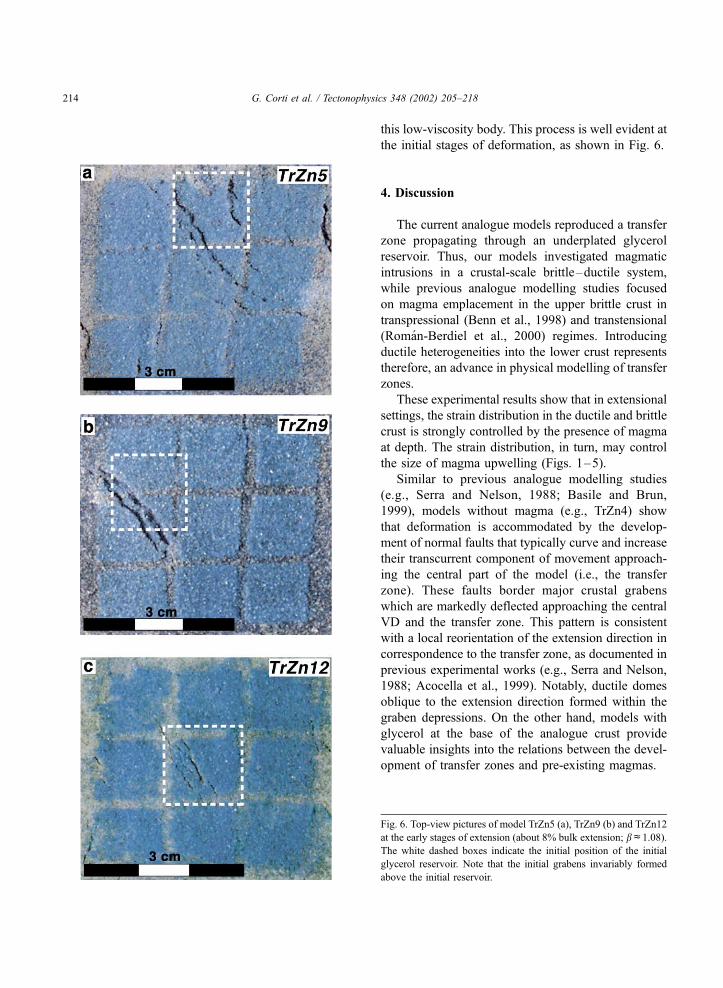
this low-viscosity body. This process is well evident at
the initial stages of deformation, as shown in Fig. 6.
4. Discussion
The current analogue models reproduced a transfer
zone propagating through an underplated glycerol
reservoir. Thus, our models investigated magmatic
intrusions in a crustal-scale brittle–ductile system,
while previous analogue modelling studies focused
on magma emplacement in the upper brittle crust in
transpressional (Benn et al., 1998) and transtensional
(Roman-Berdiel et al., 2000) regimes. Introducing
ductile heterogeneities into the lower crust represents
therefore, an advance in physical modelling of transfer
zones.
These experimental results show that in extensional
settings, the strain distribution in the ductile and brittle
crust is strongly controlled by the presence of magma
at depth. The strain distribution, in turn, may control
the size of magma upwelling (Figs. 1–5).
Similar to previous analogue modelling studies
(e.g., Serra and Nelson, 1988; Basile and Brun,
1999), models without magma (e.g., TrZn4) show
that deformation is accommodated by the develop-
ment of normal faults that typically curve and increase
their transcurrent component of movement approach-
ing the central part of the model (i.e., the transfer
zone). These faults border major crustal grabens
which are markedly deflected approaching the central
VD and the transfer zone. This pattern is consistent
with a local reorientation of the extension direction in
correspondence to the transfer zone, as documented in
previous experimental works (e.g., Serra and Nelson,
1988; Acocella et al., 1999). Notably, ductile domes
oblique to the extension direction formed within the
graben depressions. On the other hand, models with
glycerol at the base of the analogue crust provide
valuable insights into the relations between the devel-
opment of transfer zones and pre-existing magmas.
Fig. 6. Top-view pictures of model TrZn5 (a), TrZn9 (b) and TrZn12
at the early stages of extension (about 8% bulk extension; bc1.08).
The white dashed boxes indicate the initial position of the initial
glycerol reservoir. Note that the initial grabens invariably formed
above the initial reservoir.
G. Corti et al. / Tectonophysics 348 (2002) 205–218214

Wide glycerol reservoir experiments (Set 2 models;
TrZn2) are equivalent to an areally extensive under-
plating of magma. These models exhibit a diffuse
deformation accompanied by a relatively limited
glycerol upwelling that produced local magma cham-
bers in the lower crust beneath the faulted upper crust
(Fig. 1m). We suggest that this configuration would
give rise to scattered volcanism coupled to the actual
fault distribution.
Narrow glycerol reservoir (Set 1 models; TrZn3)
and small reservoir experiments (Set 3 models; TrZn5,
TrZn9 and TrZn12) simulate localized magmas
beneath extending areas. In these cases, deformation
notably started above the low-viscosity material, with
the formation of an oblique graben. With increasing
extension, deformation propagated along discrete
strike–slip faults accommodating the transcurrent
component along the transfer zone. On this basis,
we interpret these grabens as pull-apart-like structures
(see Figs. 1r and 5c). Shearing along the transfer zone
and thinning of the brittle crust in the oblique grabens
produced doming of the ductile crust (Fig. 1f) and
favoured a marked glycerol upwelling (Fig. 1s), with
the low-viscosity material collecting at the brittle–
ductile interface below the footwall of major normal
faults (Fig. 2c and d). This deformation pattern
suggests that the emplacement of magmatic bodies
may be strongly controlled by the rheological dis-
continuity between the upper and the lower crust, as
also outlined by models on laccolith formation
(Roman-Berdiel et al., 1995). The process of emplace-
ment is very similar to the ‘‘extensional footwall
growth’’ model developed by Quirk et al. (1998),
proposing that viscous fluids, such as magma or salt,
preferentially migrate and collect in the low-stress
zone in the normal fault footwall. Similar patterns of
emplacement were obtained in previous experiments
on magma intrusions in the brittle crust, also showing
that strain and intrusions are strongly coupled during
model deformation (Roman-Berdiel et al., 2000).
The strong upwelling below the central pull-apart-
like graben implies a lateral migration of glycerol
toward the transfer zone, in a direction that is orthog-
onal to the imposed extension vector. Consequently,
this process may account for the occurrence of sig-
nificant magma accumulation into transfer zones. We
suggest that model TrZn3 points to a striking relation-
ship between strain localization, thinning of the brittle
crust and important magma upwelling associated to
ductile crust doming. In particular, the strong crustal
strength reduction associated with a localized pre-
existing magma is able to generate a perturbation in
the strain field that propagates into the overlying crust
(Arzi, 1978), facilitating strain localization and con-
trolling the position and the structural pattern of
transfer zones (Ruppel, 1995; Faulds and Varga,
1998). In the so-created areas of localized strain,
important magma accumulation is expected, enhanc-
ing thermal softening of the country rocks and favour-
ing further deformation (e.g., Morley, 1999a,b). This
process may lead to a positive feedback interaction
between tectonics and magmatism which has also
been recognised in transpressional settings (e.g.,
Brown and Solar, 1998), as well as during post-
orogenic collapse (McCaffrey et al., 1999).
4.1. Comparison with nature
In the current modelling we have investigated, in
general terms, a process involving the mutual
dynamic interactions between deformation and
magma emplacement during the development of a
transfer zone. Therefore, the results of modelling may
be applied to a wide range of structural settings, such
as transfer zones connecting different continental rift
segments, or developing within single rift depressions.
However, before comparing the results of modelling
to nature, we draw attention to the fact that the
structures in the models formed after the generation
of underplated magma. Therefore, this model evolu-
tion would be better applied to active rifting pro-
cesses, although model results may provide clues even
in case of magmatic underplating related to an
advanced passive rifting stage. Furthermore, in the
comparison of models with nature, other limitations
may concern the initial geometry of the magma layer,
whose extent may vary during successive stages of
rifting (e.g., Morley, 1994, 1999a), as well as the
occurrence of large volumes of volcanic rocks that
may prevent the observation of early structures. Addi-
tionally, no anisotropy has been introduced in the
models, whereas in nature, reactivation of pre-existing
fabrics in the brittle crust may play a major role during
extension (e.g., Morley, 1999c).
Wide reservoir models (Set 2) can be compared
with the transfer zone between the southern Main
G. Corti et al. / Tectonophysics 348 (2002) 205–218 215

Ethiopian Rift (MER) and the northern Kenya Rift
(KR) in the East African Rift System (EARS), where
large volumes of flood basalts erupted at the begin-
ning of rifting suggest significant amounts of magma
underplating (Braile et al., 1995; Prodehl et al., 1997).
Similar to results of model TrZn2 (Fig. 1j–k), the
diffused deformation within this ~300-km wide E–W
transfer zone (Morley, 1999b; Morley et al., 1999;
Ebinger et al., 2000; Fig. 7a) suggests that the width
of this transfer zone may be related to widespread
intrusions at the base of the ductile crust (e.g., Morley
et al., 1999). Underplating beneath the Lake Turkana
and the northern end of the Kenya Rift has indeed
been imaged in seismic profiles in the form of a
relatively high-velocity lower crust layer (e.g., Pro-
dehl et al., 1997).
Narrow reservoir models (Set 1) may be applied to
transfer zones in the Western Rift (WR) of the EARS,
where the volcanic products are almost one order of
magnitude less than those erupted in the KR (Braile et
al., 1995) suggesting a limited underplating that is
also hypothesised on the base of seismic data (Prodehl
et al., 1997). In the WR, the distinct volcanic prov-
inces coincide with major transfer zones, character-
ized by oblique to strike–slip faults (Rosendahl,
1987; Ebinger, 1989; Fig. 7b). Similar to our models,
this concentration of magma at transfer zones may be
driven by a lateral migration of magma, in a direction
that is orthogonal to the regional extension direction.
Concerning the models deformed without glycerol
at the base of the analogue crust, they may be applied
to natural areas undergoing extension where under-
plated magma is absent or its influence on large-scale
deformation is negligible. Notably, the fault pattern of
model TrZn4 strikingly matches that observed in
transfer zones on passive continental margins, such
as the United Kingdom Continental Shelf (Fig. 7c,
compare with Fig. 1e).
Fig. 7. Natural examples of transfer zones. (a) Distributed de-
formation between the Main Ethiopian Rift and the Kenya Rift (after
Moore and Davidson, 1978). Inset shows the distribution of
Eocene–Quaternary volcanic rocks. (b) Transfer zones in the
Western Rift of the EARS (after Rosendahl, 1987; Ebinger, 1989).
(c) Structural pattern in the United Kingdom Continental Shelf and
adjacent areas (after Gibbs, 1989). Stippled and dark greyed areas
represent rift depressions and volcanic rocks, respectively. Dashed
rectangular boxes indicate the inferred location of the transfer zones.
Notice the concentration of volcanism along the transfer zones in (b).
G. Corti et al. / Tectonophysics 348 (2002) 205–218216

5. Conclusions
Centrifuge scaled models suggest the following
main conclusions:
(1) Distribution of magma at depth can effectively
control the strain distribution in the overlying con-
tinental crust and the evolution and the structural
pattern of transfer zones. Narrow magma reservoirs
result in a localized deformation accommodated by
the development of discrete transfer faults, whereas
areally extensive magma underplating results in a
distributed deformation over a broad area.
(2) The presence of magma at depth in extensional
settings can play a major role in controlling the
structural evolution, representing therefore, an impor-
tant parameter that must be taken into account in the
study of such processes (see also Morley, 1999a,b).
(3) Magma-induced strain distribution may in turn
control magma uprising: distributed deformation
would result in scarce magma upwelling, whereas
concentrated deformation is expected to localize mag-
matism into the transfer zone by favouring magma
uprising and accumulation.
Acknowledgements
We thank the journal reviewers K.J.W. McCaffrey,
T. Roman-Berdiel and O. Dauteuil and the Editor in
Chief, J.P. Burg, for the stimulating and constructive
criticism, which helped to improve this manuscript.
We are also indebted with A.R. Cruden, C.K. Morley
and G. Musumeci for fruitful suggestions on an earlier
version of the manuscript. Research was sponsored by
CNR and MURST (responsibles F. Innocenti and P.
Manetti) grants. D. Sokuotis wishes to thank ISES
(the Netherlands Centre for Integrated Earth Science)
for financial support. G. Corti was partially supported
by Progetto Giovani Ricercatori-CNR-Agenzia 2000.
References
Acocella, V., Faccenna, C., Funiciello, R., Rossetti, F., 1999. Sand-
box modelling of basement-controlled transfer zones in exten-
sional domains. Terra Nova 11, 149–156.
Allemand, P., Brun, J.P., Davy, P., Van Den Driessche, J., 1989.
Symetrie et asymetrie des rifts et mecanismes d’amincissement
de la lithospere. Bulletin de la Societe Geologique de France 8,
445–451.
Arzi, A.A., 1978. Critical phenomena in the rheology of partially
melted rocks. Tectonophysics 44, 173–184.
Bartley, J.M., 1995. Magmatism and extension in the great basin
and the Oslo rift: implications for rift mechanisms and segmen-
tation. Geological Society of America Abstracts with programs
27, 120.
Basile, C., Brun, J.P., 1999. Transtensional faulting patterns ranging
from pull-apart basins to transform continental margins: an ex-
perimental investigation. Journal of Structural Geology 21, 23–
37.
Benn, K., Odonne, F., Saint-Blanquat, M., 1998. Pluton emplace-
ment during transpression in brittle crust: new views from ana-
logue experiments. Geology 26, 1079–1082.
Bonini, M., Sokoutis, D., Mulugeta, G., Boccaletti, M., Corti, G.,
Innocenti, F., Manetti, P., Mazzarini, F., 2001. Dynamics of
magma emplacement in centrifuge models of continental exten-
sion with implications for flank volcanism. Tectonics 20, 1053–
1065.
Braile, L.W., Keller, G.R., Wendlandt, R.F., Morgan, P., Khan,
M.A., 1995. The East African rift system. In: Olsen, K.H.
(Ed.), Continental Rifts: Evolution, Structure, Tectonics. Devel-
opments in Geotectonics, vol. 25, Elsevier, Amsterdam, 213–
231.
Brown, M., Solar, G.S., 1998. Shear-zone systems and melts: feed-
back relations and self-organization in orogenic belts. Journal of
Structural Geology 20, 211–227.
Chapin, C.E., Chater, S.M., 1994. Tectonic setting of the axial
basins of the northern and central Rio Grande rift. In: Keller,
G.R., Chater, S.M. (Eds.), Basins of the Rio Grande Rift:
Structure, Stratigraphy, and Tectonic Setting. Geological Soci-
ety of America Special Paper, vol. 291, Geol. Soc. Am., Boul-
der, CO, pp. 5–25.
Clemens, J.D., Petford, N., 1999. Granitic melt viscosity and silicic
magma dynamics in contrasting tectonic settings. Journal of the
Geological Society (London) 156, 1057–1060.
Corti, G., Bonini, M., Innocenti, F., Manetti, P., Mulugeta, G., 2001.
Centrifuge models simulating magma emplacement during ob-
lique rifting. Journal of Geodynamics 31, 557–576.
Cruden, A.R., Koyi, H., Schmeling, H., 1995. Diapiric basal en-
trainment of mafic into felsic magma. Earth and Planetary Sci-
ence Letters 131, 321–340.
Ebinger, C.J., 1989. Geometric and kinematic development of bor-
der faults and accommodation zones, Kivu-Rusizi rift, Africa.
Tectonics 8, 117–133.
Ebinger, C.J., Deino, A.L., Drake, R.E., Tesha, A.L., 1989. Chro-
nology of volcanism and rift basin propagation: Rungwe Vol-
canic Province, East Africa. Journal of Geophysical Research
94, 15785–15803.
Ebinger, C.J., Yemane, T., Harding, D.J., Tesfaye, S., Kelley, S.,
Rex, D.C., 2000. Rift deflection, migration, and propagation:
linkage of the Ethiopian and eastern rifts, Africa. Geological
Society of America Bulletin 112, 163–176.
Faulds, J.E., Varga, R.J., 1998. The role of accommodation zones
and transfer zones in the regional segmentation of extended
terranes. In: Faulds, J.E., Stewart, J.H. (Eds.), Accommodation
G. Corti et al. / Tectonophysics 348 (2002) 205–218 217
Zones and Transfer Zones: the Regional Segmentation of the
Basin and Range Provinces. Geological Society of America
Special Paper, vol. 323, Geol. Soc. Am., Boulder, CO, pp.1–45.
Gans, P.B., 1987. An open-system, two-layer crustal stretching
model for the eastern Great Basin. Tectonics 6, 1–12.
Gibbs, A.D., 1989. A model for linked basin development around
the British isles. In: Tankard, A.J., Balkwill, H.R. (Eds.), Exten-
sional Tectonics and Stratigraphy of the North Atlantic margins
American Association of Petroleum Geologists Memoir, vol. 46,
The Am. Assoc. of Petr. Geol., Tulsa, OK, pp. 81–93.
Hayward, N.J., Ebinger, C.J., 1996. Variations in the along-axis
segmentation of the Afar Rift system. Tectonics 15, 244–
257.
McCaffrey, K.J.W., Miller, C.F., Karlstrom, K.E., Simpson, C.,
1999. Synmagmatic deformation patterns in the Old Woman
Mountains, SE California. Journal of Structural Geology 21,
335–349.
Mechie, J., Keller, G.R., Prodehl, C., Gaciri, S.J., Braile, L.W.,
Mooney, W.D., Gajewski, D., Sandmeier, K.J., 1994. Crustal
structure beneath the Kenya Rift from axial profile data. Tecto-
nophysics 236, 179–200.
Moore, J.M., Davidson, A., 1978. Rift structure in southern Ethio-
pia. Tectonophysics 46, 159–173.
Morley, C.K., 1994. Interaction of deep and shallow processes in
the evolution of the Kenya Rift. Tectonophysics 236, 81–91.
Morley, C.K., 1999a. Tectonic evolution of the East African Rift
System and the modifying influence of magmatism: a review.
Acta Vulcanologica 11, 1–19.
Morley, C.K., 1999b. Basin evolution trend in East Africa. In: Mor-
ley, C.K. (Ed.), Geoscience of Rift Systems—Evolution of East
Africa. American Association of Petroleum Geologists Studies
in Geology, vol. 44, The Am. Assoc. of Petr. Geol., Tulsa, OK,
pp. 131–150.
Morley, C.K., 1999c. How successful are analogue models in ad-
dressing the influence of pre-existing fabrics on rift structures?
Journal of Structural Geology 21, 1267–1274.
Morley, C.K., Karanja, F.M., Wescott, W.A., Stone, D.M., Harper,
R.M., Wigger, S.T., Day, R.A., 1999. Geology and geophysics
of the western Turkana Basins. In: Morley, C.K. (Ed.), Geo-
science of Rift Systems—Evolution of East Africa. American
Association of Petroleum Geologists Studies in Geology, vol.
44, The Am. Assoc. of Petr. Geol., Tulsa, OK, pp. 19–54.
Mulugeta, G., 1988. Squeeze box in a centrifuge. Tectonophysics
148, 323–335.
Nelson, R.A., Patton, T.L., Morley, C.K., 1992. Rift-segment inter-
action and its relation to hydrocarbon exploration in rift systems.
American Association of Petroleum Geologists Bulletin 74,
1153–1169.
Olsen, K.H., Morgan, P., 1995. Introduction: progress in under-
standing continental rifts. In: Olsen, K.H. (Ed.), Continental
Rifts: Evolution, Structure, Tectonics. Developments in
Geotectonics, vol. 25, Elsevier, Amsterdam, pp. 3–25.
Parsons, T., Sleep, N.H., Thompson, G.A., 1992. Host rock rheol-
ogy controls on the emplacement of tabular intrusions: implica-
tions for underplating of extending crust. Tectonics 11, 1348–
1356.
Peacock, D.C.P., Knipe, R.J., Sanderson, D.J., 2000. Glossary of
normal faults. Journal of Structural Geology 22, 291–305.
Petford, N., Cruden, A.R., McCaffrey, K.J.W., Vigneresse, J.-L.,
2000. Granite magma formation, transport and emplacement
in the Earth’s crust. Nature 408, 669–673.
Prodehl, C., Fuchs, K., Mechie, J., 1997. Seismic-refraction studies
of the Afro–Arabian rift system—a brief review. Tectonophy-
sics 278, 1–13.
Quirk, D.G., D’Lemos, R.S., Mulligan, S., Rabti, M.R., 1998. In-
sights into the collection and emplacement of granitic magma
based on 3D seismic images of normal fault-related salt struc-
tures. Terra Nova 10, 268–273.
Ramberg, H., 1971. Dynamic models simulating rift valleys and
continental drift. Lithos 4, 259–276.
Ramberg, H., 1981. Gravity, Deformation and the Earth’s Crust
Academic Press, London.
Roman-Berdiel, T., Brun, J.P., Gapais, D., 1995. Analogue models
of laccolith formation. Journal of Structural Geology 17, 1337–
1346.
Roman-Berdiel, T., Aranguren, A., Cuevas, J., Tubıa, J.M., Gapais,
D., Brun, J.P., 2000. Experiments on granite intrusions in trans-
tension. In: Vigneresse, J.L., Mart, Y., Vendeville, B. (Eds.),
Salt, Shale and Igneous Diapirs in and Around Europe. Geo-
logical Society, London, Special Publications, vol. 174, The
Geol. Soc., London, pp. 21–42.
Rosendahl, B.L., 1987. Architecture of continental rifts with special
reference to east Africa. Annual Review of Earth and Planetary
Sciences 15, 445–503.
Ruppel, C., 1995. Extensional processes in continental lithosphere.
Journal of Geophysical Research 100, 24187–24215.
Serra, S., Nelson, R.A., 1988. Clay modelling of rift asymmetry and
associated structures. Tectonophysics 153, 307–312.
Weijermars, R., Schmeling, H., 1986. Scaling of Newtonian and
non-Newtonian fluid dynamics without inertia for quantitative
modelling of rock flow due to gravity (including the concept of
rheological similarity). Physics of the Earth and Planetary Inte-
riors 43, 316–330.
G. Corti et al. / Tectonophysics 348 (2002) 205–218218