MacBeath, Alan (2006) Ultrasonic bone cutting. PhD thesis.
170
Glasgow Theses Service http://theses.gla.ac.uk/ [email protected] MacBeath, Alan (2006) Ultrasonic bone cutting. PhD thesis. http://theses.gla.ac.uk/2220/ Copyright and moral rights for this thesis are retained by the author A copy can be downloaded for personal non-commercial research or study, without prior permission or charge This thesis cannot be reproduced or quoted extensively from without first obtaining permission in writing from the Author The content must not be changed in any way or sold commercially in any format or medium without the formal permission of the Author When referring to this work, full bibliographic details including the author, title, awarding institution and date of the thesis must be given
-
Upload
khangminh22 -
Category
Documents
-
view
2 -
download
0
Transcript of MacBeath, Alan (2006) Ultrasonic bone cutting. PhD thesis.

Glasgow Theses Service http://theses.gla.ac.uk/
MacBeath, Alan (2006) Ultrasonic bone cutting. PhD thesis. http://theses.gla.ac.uk/2220/ Copyright and moral rights for this thesis are retained by the author A copy can be downloaded for personal non-commercial research or study, without prior permission or charge This thesis cannot be reproduced or quoted extensively from without first obtaining permission in writing from the Author The content must not be changed in any way or sold commercially in any format or medium without the formal permission of the Author When referring to this work, full bibliographic details including the author, title, awarding institution and date of the thesis must be given

ULTRASONIC BONE CUTTING
by
Alan MacBeath
BEng
UNIVERSITY Of
GLASGOW
A Doctoral Thesis submitted in fulfi'rnent of the requirements for the award of Doctor of Philosophy of the University of Glasgow
March 2006
copyright by Alan MacBeath, 2006

ABSTRACT
1. ABSTRACT
Ultrasonic cutting using one or more tuned blades has been used in many fields including
food processing, wood surface treatment, medical applications and polymer cutting. The
technology utilises piezoelectric transducers which convert an electrical signal into a
mechanical vibration that is used to excite a cutting blade. The blade is used to cut material
at faster speeds, at lower applied loads, with reduced noise and increased accuracy in
comparison to conventional serrated reciprocal cutting saws and rotary drills. Ultrasonic
cutting is becoming more readily accepted in surgery as an alternative technology for
minimally invasive procedures on soft tissue. The technology has not been as successfully
adopted for deeper incisions in more difficult to cut materials such as bone. One of the
fundamental restrictions associated with bone cutting is temperature. Cellular bone necrosis has been reported to occur at 52 - 550C if these temperatures are experienced for 30
seconds or longer.
This thesis reports on the design of ultrasonic bone cutting blades and the effect of various
cutting parameters such as applied load, blade tip vibration velocity and frequency on cutting
speed and temperature, two performance indicators used by orthopaedic clinicians. A range
of high gain blades was developed to investigate the correlation between the frequency
response predicted by finite element analysis (FEA) and the frequency response measured
using an experimental modal analysis (EMA) technique. It has been found that FEA
frequency predictions are within 1.5 % of measured frequencies. FEA has also been used to
develop two novel ultrasonic cutting models which allow the effect of blade progression on
cutting performance to be investigated. The models have been used to predict the
relationship between applied load and cutting speed in single layer and multi-layer materials,
and have shown that cutting speed decreases as cortical layer thickness increases, a trend
also found from cutting experiments. Ongoing developments to predict temperature from both
cutting models have produced a preliminary result which locates regions of maximum cutting
temperature. The result influenced the design of blades with modified tip geometries that
have been used to reduce cutting temperature.

ABSTRACT
Ultrasonic cutting experiments were performed on bovine bone, two bone substitute
materials and various grades of wood. Deep incisions were made for a range of applied loads and cutting speeds to investigate the effect of various cuffing parameters on cutting temperature. Two temperature peaks were recorded. The first temperature peak regularly
exceeded 1000C but only for a very short time duration and was influenced by the contact
coupling between the blade and the specimen. The second peak, due to heat conduction from the cut site, was found to be the most dangerous to the regeneration of bone as it
regularly exceeded the necrosis temperature for longer than 30 seconds. Conduction
temperature was found to decrease if cutting speed, and thus applied load was increased.
Methods of reducing temperature using parameter control and geometrical modifications
were examined and found, in some cases to reduce conduction temperature by up to 400C.
Ultrasonic cutting has been successfully applied to perform deep incisions in bone whilst
maintaining substrate temperature to within critical levels. Two innovative modelling techniques have been used to simulate ultrasonic cutting and demonstrate their potential for
revolutionising blade design, and surgical trials.

ACKNOWLEDGEMENTS
11. ACKNOWLEDGEMENTS
I assume that this is the section of the thesis in which I get to tell you how hard worked I have
been over the last three years? Blood, grit and sweat have been combined along with some
very long nights and some even longer days. In all honesty though, the work presented in
this thesis would not have been possible if it were not for the help of various individuals.
Firstly I thank my supervisor, Dr. Margaret Lucas for all of her support, enthusiasm and
expertise. Thanks to Dr. Andrea Cardoni for his unlimited knowledge in the field and his
talent for shouting sporadic Italian phrases at certain pieces of experimental equipment, a
skill that I have unfortunately been unable to acquire. Thanks to all the guys in the workshop for the titanium blades that they have crafted over the last few years, especially Brian Robb
and Alex Tory. Thanks must also go to the great team of researchers that I have had the
pleasure of working alongside, without your assistance and mildly amusing banter the road
would have been a lot less fair. I must also take this opportunity to apologise to my close family and friends for having undergone a complete personality alteration over the last few
months and to thank them all for their support and encouragement throughout.

CONTENTS
Ill. CONTENTS
PAGE
ABSTRACT ACKNOWLEDGEMENTS CONTENTS
CHAPTER1 INTRODUCTION 1 1.1 Ultrasound 2 1.2 The high-power ultrasonic system 3 1.3 Industrial applications 4 1.4 Dental and medical applications 7 1.5 Making deep cuts in bone 10
CHAPTER 2 REVIEW OF LITERATURE 12 2.1 A history of ultrasound 12 2.2 Ultrasonic cutting in surgery 15 2.3 Ultrasonic cutting of bone 16 2.4 Cutting temperatures in bone 21 2.5 Other ultrasonic cutting applications 24 2.6 Ultrasonic component design 26 2.7 Finite element modelling of ultrasonic bone 29
cutting
CHAPTER 3 METHODOLOGY FOR THE DESIGN OF 32 ULTRASONIC CUTTING BLADES
3.1 Introduction 32 3.2 A methodology for ultrasonic cutting blade 35
design 3.2.1 Predicting tuned length of ultrasonic 35 components 3.2.1.1 Theoretical length of a 35 kHz cylindrical bar 36 3.2.1.2 More complex geometries 39 3.2.2 Finite element modelling 41 3.2.3 Experimental modal analysis (EMA) 44 3.2.3.1 FEF 46 3.2.3.2 FFT analysis 47 3.2.3.3 Modal parameter estimation (curve fitting) 48
3.3 Design of high gain ultrasonic cutting blades 51

CONTENTS
3.3.1 FE analysis 52 3.3.2 EMA & FE validation 54 3.3.2.1 Excitation 55 3.3.2.2 Ultrasonic unit 55 3.3.2.3 FRF measurement 56 3.3.2.4 Modal predictions 58 3.3.2.5 Validating FE modal predictions 58
3.4 Preliminary ultrasonic cutting experiments 59 3.5 Further design considerations 61
3.5.1 Materials for ultrasonic cuffing blades 61 3.5.2 Multi-component systems 63 3.5.2.1 Mechanical impedance 63 3.5.2.2 Connecting components 64 3.5.3 Manufacturing 65
3.6 Conclusions 66
CHAPTER 4 FINITE ELEMENT MODELLING 68 4.1 Introduction 68 4.2 Ultrasonic blades for bone cutting 69 4.3 Ultrasonic cutting as a linear-elastic fracture 72
mechanics model 4.4 FEA of ultrasonic cutting 75
4.4.1 Material properties 75 4.4.1.1 Material property measurement 76 4.4.1.2 Fracture criterion estimation 77 4.4.2 Blade-specimen interface surface 79 behaviour 4.4.2.1 Coulomb friction 79 4.4.2.2 Debris movement on an ultrasonically 80 vibrating surface 4.4.3 2D crack propagation model 81 4.4.4 2D element erosion model 84
4.5 Results 85 4.6 FE cutting model development 88 4.7 Discussion 89
CHAPTER 5 EFFECTS OF ULTRASONIC CUTTING 92 PARAMETERS ON CUTTING PERFORMANCE
5.1 Introduction 92 5.2 Methodology 94
5.2.1 Experimental configuration 94 5.2.1.1 Experimental test rigs for constant load and 94 constant cutting speed 5.2.1.2 Monitoring temperature 96 5.2.1.3 Monitoring blade tip vibration 97 5.2.2 Specimens 97

CONTENTS
5.3 Cutting under constant applied load 99 5.3.1 Variables affecting temperature 99 5.3.1.1 Thermal responses during ultrasonic cutting 99 5.3.1.2 Effects of applied load and cutting speed on 101 thermal response 5.3.1.3 Effect of tuned frequency and blade tip 102 vibration velocity on cutting speed 5.3.1.4 Effect of tuned frequency and blade tip 103 vibration velocity on thermal response 5.3.2 Effect of blade tip profile on temperature 104 5.3.3 Effect of slicing mode cutting on 106 temperature 5.3.4 Quantifying levels of necrosis 109 5.3.5 Effect of thermal response on the specimen
5.4 Ultrasonic cutting at constant speeds 112 5.4.1 Effect of tuned frequency and blade tip 113 vibration velocity on cutting load 5.4.2 Variables affecting temperature 114 5.4.3 Quantifying levels of necrosis 115 5.4.4 Effects of cutting temperature on the 116 specimen
5.5 Discussion 117
CHAPTER 6 METHODS FOR REDUCING TEMPERATURE 119 6.1 Introduction 119 6.2 Methodology 120
6.2.1 Blade designs for reducing temperature 121 6.3 Effect of blade design on cutting temperature 123
6.3.1 Cutting under conditions of constant 123 appliedload 6.3.1.135 kHz blades 123 6.3.1.2 20 kHz blades 125
6.4 Blade redesign for improved vibration 126 performance 6.4.1 Linear modal coupling 127 6.4.2 Nonlinear modal coupling 128 6.4.3 Improving blade tuned responses via 129 profile alteration
6.5 Effect of blade profile 3 on temperature 130 6.6 Cutting under conditions of constant speed 131 6.7 Effect of blade design on specimen cut site 133 6.8 Conclusions 134
CHAPTER 7 CONCLUSIONS 135

CONTENTS
CHAPTER 8 RECOMMENDATIONS FOR FUTURE WORK 142 8.1 Finite element modelling 142 8.2 Ultrasonic blade design 143
Appendix 1 List of Publications 145
References 147

Chapter 1: Introduction
CHAPTER 1
INTRODUCTION
This thesis reports the development of new ultrasonic instruments for cutting materials which have a tendency to burn when ultrasonic vibrations are used to assist the cutting process. The main aim of any orthopaedic cutting instrument is to successfully cut bone without inflicting severe damage to ensure post operative regeneration. High gain blades were designed to investigate the correlation between finite element analysis (FEA) response
predictions and experimental modal analysis measurements (EMA). This process was used to develop a range of new ultrasonic cutting blades which can make deep cuts in difficult to
cut materials which tend to burn, such as wood, foam, composite materials and bone. The
effect which various cutting parameters including cutting speed, frequency, applied load and blade tip vibration amplitude have on cutting temperature and performance were investigated. Two finite element models of ultrasonic cutting were developed to enhance blade design and allow cutting predictions to be made on materials which are hard to obtain,
such as human bone. The objective of developing simulations was to predict the effect of
varying cutting parameters on cutting temperature to design blades which cut bone without
causing cellular necrosis. Cellular necrosis is known to have a direct effect on the
regeneration capabilities of the substrate and has been documented to occur at a
temperature of 52-550C [1] that is experienced for durations in excess of 30 seconds. FEA
was also used to investigate the effect of geometrical modifications that reduce the contact
surface area between the blade and material specimen. Ultrasonic cutting blades were
manufactured and experimental investigations were performed to investigate the effect of
cutting parameters on cutting temperature. Blades with reduced contact areas were also
manufactured to investigate the degree to which temperature was reduced to determine
whether the technology was suitable for orthopaedic applications.

Chapter 1: Introduction
The main aims of this study are to:
1) Investigate the correlation between the frequency response of ultrasonic cutting blades predicted using FEA and measured using EMA and assess the ability of both for ultrasonic cutting blade design.
2) Develop novel ultrasonic cutting FE models to predict cutting performance. 3) Design and develop ultrasonic bone cutting blades for investigations into the effects of various cutting parameters on cutting performance. 4) Provide a strategy for reducing ultrasonic cutting temperature by either controlling ultrasonic cutting parameters or by modifying blade geometries.
1.1 Ultrasound
Ultrasound is a term used to describe vibrations which have frequencies that are too high to be detected by the human ear. The lowest ultrasonic frequency is usually regarded as being between 18 - 20 kHz and the upper limit (can be GHz) is limited only by the ability to
generate the signal. Ultrasonics is the application and investigations of these vibrations.
The field of ultrasonics can be divided into two distinct sub-groups which are characterised by their frequency ranges and associated power levels. Low power ultrasonic (up to about ten watts) applications use frequencies above 1 MHz and include non-destructive scanning
procedures, where the transmitted energy does not transform or affect the structure being
scanned, for example material testing and medical imaging.
High power ultrasonic (from hundreds of watts to tens of kilowatts) applications utilise frequencies in the range of 18 - 100 kHz (low frequencies) and transfer mechanical vibration
energy to solids, liquids or gases using tuned components. High power ultrasonic
applications expose the work-piece to enough vibratory energy to cause a permanent
physical change. The components are commonly tuned to a specific mode of vibration,
usually longitudinal but sometimes torsional, radial, or combinations of these, at the required
excitation frequency. Longitudinal components often have profiles which are designed to
amplify vibrations. They can be stepped, conical, exponential or catedoidal depending on the
degree of amplification that is required. Radial modes are achieved using discs or cylindrical
components and vibration amplification is achieved by additional tuned booster components.
2

Chapter 1: Introduction
Typically, high power ultrasonic industrial applications will operate with 10 - 150 pm peak to peak displacement amplitudes. High power ultrasound is characterised by very high oscillation velocities and accelerations for small displacements.
The technology was introduced shortly after the Second World War and has grown steadily since. The five main industrial applications which use high power ultrasonic techniques include welding of metals and plastics, cleaning, soldering and machining. These are well established technologies and there are also some high power ultrasonic instruments
appearing in dental and medical applications.
1.2 The high-power ultrasonic system
The ultrasonic system is driven by a generator which transforms a low frequency signal into a high frequency, ultrasonic signal. The acoustic unit of the system incorporates a transducer,
any number of ultrasonic components and a fixture, Figure 1.1. The transducer (transformer)
converts the electrical signal from the generator into a mechanical vibration. Transducers for
ultrasonic applications can take two main forms, electrostrictive or magnetostrictive, the latter
not being commonly used due to high electromechanical conversion inefficiencies and their
size. Most modern transducers use piezoelectric ceramic elements which contract and
expand under the application of a voltage, providing a mechanical vibration. The vibration from the transducer is transmitted either directly to the ultrasonic tool which will contact the
work-piece, or through a booster/holder section used for changing (magnifying) the
magnitude of the vibration and/or for holding the acoustic unit for operational purposes.
3

unapier -v mrroauction
Ultrasonic 20 generator 50 Hz
10 0k
IHz
Transducer Booster 11 Tool
6- 100
microns 6-8
microns
The Acoustic Unit
Figure 1.11: High-power ultrasonic system.
The ultrasonic components are also commonly called sonotrodes or horns (concentrators),
whereby the definition of a sonotrode is a confined elastic medium capable of transmitting
vibrations (longitudinal, bending, radial, etc. ) from their source to a load. A horn (velocity
transformer) is simply a sonotrode whose cross-section varies axially according to a certain law to amplify vibration amplitudes [2]. The accurate design of concentrators is essential for
the efficient operation of the ultrasonic system. A correctly designed component can operate
under lower power conditions for the same tip vibration amplitude and influence the
mechanical stress increasing its lifespan.
1.3 Industrial applications
All high power ultrasonic applications rely on a vibration-induced phenomena occurring at the
work-piece. These phenomena include cavitation and micro-streaming in liquids, surface
instability occurring at liquid-liquid and liquid-gas interfaces and heating and fatiguing in
solids [3]. Graff [4] reviews the process applications of power ultrasonics and introduces the
fundamental pieces of literature which define its evolution. There are four main established
industrial applications of high power ultrasonics: cleaning, welding, machining and cutting;
and there are several established medical applications as well as numerous developing
technologies.
Ultrasonic cleaning is the oldest industrial application of power ultrasound. The phenomenon
responsible for ultrasonic cleaning is cavitation. High frequency oscillations in a liquid
produce microscopic voids which grow to a certain size, then collapse, causing very high
4

Chapter 1: Introduction
instantaneous temperatures and pressures. Cleaning equipment normally operates in the range 20 - 50 kHz, where cavitational shock intensity is higher at lower frequency, however delicate parts have been known to be damaged in such cases. Ultrasonic cleaning is often combined with other operations including pre-soaking and vapour rinsing and uses a variety of cleaning solutions and detergents. The advantage of ultrasonic cleaning over conventional methods is that the process does not rely on the contact of brushes and in a well-designed cleaner, cavitation is evenly distributed through the volume of the liquid and has the potential to reach normally inaccessible locations.
Plastic welding was developed towards the end of the 1970's and was quickly adopted for
the production of toys and appliances. The process is fast, clean, does not require highly
skilled operators and can be easily automated. Plastic welding operations predominantly
operate at around 20 kHz and at power outputs below 1000 Wafts. Ultrasonic horns are designed to match (mechanical impedance) the work-piece, improving the transfer of energy from the acoustic unit to the weld zone. In addition to this, the systems are designed to track
the resonance of the welding horn and maintain vibration amplitudes whilst loads vary. In
essence, high frequency vibrations produce heat which melts the plastic, permitting welding. The generation of heat is localised and confined to the weld zone, limiting heating of
surrounding material. Heat is generated in the material and not conducted from the ultrasonic
horn which allows welding to occur in internal and minimal access locations. Most
thermoplastics have characteristics suitable for ultrasonic welding including the ability to
transmit and absorb vibration, as well as low thermal conductivity.
Metal welding was introduced in the 1950's for use in the semiconductor industry. The
process is conducted at relatively low temperatures in comparison to the melting point of the
metals and relies on shearing of the surfaces of the materials being joined and then bringing
them together under pressure to instigate solid-state bonding. The equipment for ultrasonic
metal welding ranges from low power (hundreds of watts) systems operating between 40 and
60 kHz to machines of several kilowatt output capacity operating between 10 and 20 kHz for
welding larger parts.
Ultrasonic impact grinding and ultrasonic rotary machining are the two main types of
ultrasonic machining. Ultrasonic impact grinding uses abrasive slurry which is fed between
the longitudinally vibrating tool and the work-piece. The process is fairly slow. Ultrasonic
5

Chapter 1: Introduction
rotary machining superimposes ultrasonic vibration on the rotary motion of a drill. Diamond impregnated drills with internal cooling are generally used and the operation can be considered as high speed abrasion. The process increases cutting rates, extends tool life and increases accuracy whilst reducing chipping due to reduced applied loads. The operation is usually performed at 20 kHz.
Ultrasonic food cutting technologies were adopted in the food industry in the mid-1990's. A
variety of tuned ultrasonic devices have been developed to make the process easy and effective, especially for large volumes of material and under automated conditions. Food
cutting has been reviewed by Mason and Povey [5] who state that the main advantages of the process include improved quality of cut for reduced cutting forces, reduced cutting debris,
less requirement for blade sharpness and that brittle products are less likely to shatter. A
selection of ultrasonic cutting tools used in the food industry and produced by Dukane
Corporation are shown in Figure 1.2.
Figure 1.2: Ultrasonic knives used for guillotine type and slicing type food cutting [6].
Ultrasonic cutting has also been used for cutting polymers. The technology was adopted by
Volkov et al in 2001 who argued that ultrasonic cutting of polymer materials was largely free
of disadvantages associated with conventional cutting methods such as mechanical, heated
tool, gas heat carrier, plasma, laser and high frequency currents (HFC) [7]. Such cutting
methods can be divided into thermal and mechanical processes. The mechanical methods
are distinguished by their efficiency and require a large variety of tools to operate on the
vastly differing properties typical to plastics. Friction during cutting also leads to burning and
melting at the cut site which can require additional finishing work. Thermal cutting methods
heat the material to achieve separation. The heat can result in fusion and edge destruction,
6

Chapter 1: Introduction
making welding almost impossible without further work and ruins the cosmetic appearance of the product. HFC can only be used with certain polymers in which dielectric losses are high, and laser methods require very large set-up costs. The frequencies of the ultrasound used in the operations are in the range of 18 - 30 kHz, and complex horns are used to amplify vibration amplitudes supplied by piezoelectric transducers (typically 4-5 pm).
1.4 Dental and medical applications
High power ultrasonic cutting instruments were first introduced in dentistry in 1953. The
technology was made redundant soon after (1959) with the introduction of the rotary drill.
The use of high-power ultrasonic instruments for removing deposits from the surface of teeth,
prophylaxis (de-scaling teeth), became an accepted procedure and in 1960 the instruments
were considered to be an acceptable alternative to, whilst being as effective as, hand scalers [8]. A typical instrument used for prophylaxis, periodontia and other areas of operative dentistry is shown in Figure 1.3. The instruments have a variety of inter-changeable inserts
which are used for various de-scaling techniques. The instruments use longitudinal
movements to produce a reciprocating motion at 25 kHz. Cavitation of the water spray at the
tool ends is currently being investigated to determine if it aids de-scaling.
Figure 1.3: Ultrasonic dental scaler [9].
High power ultrasound is mainly used in medicine for surgical applications. The use of
ultrasound in surgery has increased dramatically since the introduction of cavitational
dissection in 1972 and ultrasonic cutting and coagulation in 1991. Surgical ultrasound has
advanced so rapidly that it is now accepted as an alternative to electrosurgery for cutting and
coagulation. Almost all laparoscopic procedures can be performed with ultrasound and
mechanical clips and scissors can be replaced with ultrasonic surgical techniques. Two such
7

Chapter 1: Introduction
systems are the ultrasonic cavitational aspirators (which operate at 18 kHz), and the ultrasonically activated cutting and coagulation devices (which operate at 55 kHz). The aspirators harness the ultrasonic energy for material division and are used for removing cataracts in the eye (phaco-emulsification) and for debulking solid tumours, such as rectal turnours. Cutting and coagulation devices use the high power ultrasonic energy, along with sharper tool tips, to cut and coagulate tissue. Devices which cut and coagulate are typically referred to as ultrasurgical devices to distinguish them from cavitational devices.
There are a number of ultrasurgical devices commercially available. Figure 1.4 is a picture of an ultrasurgical device available from Ethicon Endosurgery. All operate with maximum vibration amplitude displacements in the range of 15 - 350 pm, although some have been
seen to have maximum longitudinal displacements in the region of 200 pm. It should be
noted that temperature is a critical factor in both cutting and coagulation of tissue. Tissue
generally coagulates at 600C to 800C and is however, damaged irreparably at around 100'C.
Figure 1A Ultrasonic cutting and coagulation device with various cutting blades [10].
Although such devices have made an impact on surgery there are still very few devices for
making larger incisions in more difficult to cut bio-materials such as bone, which has been
shown to lose regenerative qualities when exposed to excessive temperature. The
composition and structure of bone varies depending on skeletal site, physiological function,
the age and sex of the subjects and the type of vertebrate species. In its simplest form, bone
can be summarised as a composite material made up of two distinct material layers,
Figurel. 5. The outer layer, cortical bone, makes up 80% of skeletal mass and is the most
difficult to cut. Beneath this outer shell is a softer, spongier material called trabecular or
8

Chapter 1: Introduction
cancellous bone. The cortical bone is fibrous and distinct cutting challenges are presented depending on the orientation of the osteons in relation to the blade.
Trabecu I ar J(cancel I ous) Bone
Figure 1.5: Bone structure as depicted in Basic Human Anatomy, Spence, A. (1986) [11 ].
Current ultrasonic instrumentation can be used to perform surface bone grafting operations and limited access surgery, however when deeper surgical incisions are needed such devices tend to raise temperatures in bone to levels which, if experienced for any prolonged periods, can cause irreversible damage. Bone necrosis occurs in the temperature range 47
OC - 700C depending on the condition of the bone, however temperatures up to three times
this value are thought to be acceptable if the bone is only exposed to such conditions for a
short period of time. Although cooling can be used in such conditions, the introduction of forced air or fluids into the wound site can provide opportunities for cross-contamination.
Manual Reciprocating Saws
0 10
Figure 1 -6: Typical orthopaedic manual [12] and power oscillating [131 saws.
A selection of the current bone cutting devices, reciprocating saws, chisels, drills and
oscillating saws, are illustrated in Figure 1.6. Some of these devices have been used since
Victorian times. The saws use serrated cutting edges which collect material debris making
9
Cotical (compact) Ronp
Po,. ver Oscillatin2 Saws

Chapter 1: Introduction
such tools very difficult to sterilise. They are also generally very noisy and require considerable applied forces to perform cuts.
1.5 Making deep cuts in bone with ultrasonic cutting
At present ultrasonic cutting is restricted to minimally invasive surface bone work in maxillofacial surgery and bone grafting. There is potential to advance the technology for use in full amputations and deep orthopaedic cuts. There have been ongoing investigations into the possibility of using variable tool tip sections to perform minimally invasive incisions in bone for dental and facial reconstruction [14-16]. It is from this work and some preliminary work on minimally invasive orthopaedic cutting that this work originates, however all previous investigations have reported that deep incisions in bone are greatly restricted by the high temperature associated with ultrasonic cutting which can lead to irreparable damage to the bone. Ultrasonic cutting has many advantages over conventional cutting methods. The technology is noise free and thus reduces patient distress and clinician discomfort. Ultrasonic cutting blades can use non-serrated cutting tips which improve the ease of post operative sterilisation and reduce the production of swarf.
There is very little reported work into the effects which ultrasonic cutting parameters have on cutting temperatures in difficult to cut materials such as wood, foams, composite materials and bone. The majority of documented work is published for minimally invasive bone
operations in dental applications. Ultrasonic cutting has not been exploited for deep bone
cutting applications and therefore effects of applied load, vibration amplitude, frequency,
cutting speed, feed rate and temperature have not been investigated for such procedures. Many of the current devices use external cooling solutions to reduce cutting temperature however there are limited reports which isolate the effects of cutting parameters on cutting temperature. There is further potential to investigate the possibility of reducing cutting temperature through parameter control and/or geometry alteration which has not been widely
reported.
Until now the performance of ultrasonic blades has been determined using experimental
programmes which are expensive and time consuming. There is scope for ultrasonic cutting
to be modelled prior to design to investigate the effects of cutting parameters and geometric
profiles on cutting performance. Additionally, the performance of novel blade designs could
10

Chapter 1: Introduction
be studied quickly and inexpensively and materials which are hard to obtain, such a human
bone, may be included in models to predict the capability of such blades in surgical
situations.

Chapter 2: Review of Literature
CHAPTER 2
REVIEW OF LITERATURE
2.1 A history of ultrasound
Although ultrasound is above the frequency of human hearing, it has been applied in nature for millions of years by animals that have perfected very sophisticated range-finding, target
identification and communication techniques using ultrasound. Water is an ideal medium for
the transmission of acoustic waves over long distances and is used by Mammals such as Whales and Dolphins. Anthropologists have also suggested that primitive humans
domesticated wolves to aid their hunting efforts. This could be considered as the
development of the first ultrasonic instrument, the hunting dog, which is to this day a
favourite among hunters and herders.
Prior to the 1 9th century there were some significant developments which initiate interest in
high-frequency applications. The first ever ultrasonic generator, the Savart wheel, which
worked up to 24 kHz, was designed in 1830 by the French physicist, Felix Savart [17,18].
Investigations into the limits of animal hearing saw the introduction of the Galton whistle in
1876 [19] which had a basic frequency specification in the range of 3- 30 kHz and Koenig
[20] developed tuning forks which operated up to 90 kHz. In conjunction with these
technological advances, there was a further understanding of acoustic wave propagation,
including the velocity of sound in air (Paris 1783), iron (Biot 1808) and water (Calladon and
Strum 1826). Results from these investigations are reasonably comparable with today's
known values. One of the most significant discoveries which stimulated the emergence of
ultrasonics was piezoelectricity. In 1880 Pierre and Paul-Jacques Curie [17,21] managed to
12

Chapter 2: Review of Literature
convert an electrical signal to a mechanical signal and vice versa, the direct and inverse effect which amazingly remained a laboratory curiosity for several decades afterwards. In the early 20th century, Lord Rayleigh (John W. Strutt) defined the fundamental discoveries in acoustics and optics that are basic to wave propagation, including atomization, acoustic surface (Rayleigh) waves, molecular relaxation, acoustic pressure, nonlinear effects, and bubble collapse. The theory of sound [17] still remains, to this day, one of the leading publications in acoustical literature. Advances in underwater detection systems were ignited in 1912 after the RMS Titanic collided with an iceberg mid-Atlantic on her maiden voyage and then again in 1914 with the rise of World War I when it was quickly demonstrated that the resolution of object detection was greatly improved at higher frequencies. Graff [22] reports that Langevin conducted experiments in 1915 in Paris, a period which is commonly considered as the birth of ultrasonics. At that time, M. C. Chilowski, had developed an ultrasonic device for the French navy but its acoustic intensity was too weak to be practical. Langevin headed a joint U. S., British and French venture which in the space of 3 years had
succeeded in producing high ultrasonic intensities by means of piezoelectric transducers
operating at resonance. The destructive capability of ultrasound was first realized during initial pulse echo investigations at high frequency (150 kHz) which where of such intensity
that they killed fish that were placed in line with the ultrasonic beam. The introduction of
quartz and then steel-quartz-steel sandwich transducers led to the first practical and efficient
use of piezoelectric transducers [23]. From 1920 to World War 11 single-crystal Rochelle salt (sodium potassium tartrate tetrahydrate) was the standard underwater transducer crystal
used by the US Navy. After the end of World War 11, barium titanate (BaTi03) ceramic was first produced and by the early 1950s was well established as a piezoelectric transducer
material [24]. In 1954 lead zirconate titanate (PbZrTi03-PbTiO3) or PZT ceramics were developed and replaced the barium titanate in all fields of piezoelectric applications. PZT
ceramics are the most widely used of all ceramic materials, because of their excellent
properties [251. Much of the work carried out from the 1960s to the present day has been in
developing applications for the PZT materials (such as in ceramic capacitors). However,
research continues into the development of potential new materials as piezoelectrics. For
example, in 1997 Grupp and Goldman found a giant piezoelectric effect in strontium titanate
(SrTi03) at very low temperatures (maximum effect at 1.6 K) [26].
After World War I the work involving ultrasound progressed in two clear directions. Large-
scale probing techniques within vast regions of the ocean were reduced to small-scale
13

Chapter 2: Review of Literature
probing applications of tiny structures in laboratories, factories and hospitals. This work was pioneered by Russian scientist S. J. Sokolov in 1920 whose work extended over the next three decades and explored the possibilities of using ultrasound to detect flaws and voids within manufactured parts [27]. The main area of development was in high power sources and the principle work was conducted by Wood and Loomis [28] who designed a very high power oscillator tube in the range 200 to 500 kHz which was applied to a number of high- power applications, including radiation pressure, etching, drilling, and heating. Wood and Loomis also made observations of the modal patterns of rods, tubes, and plates and gave some of the first experimental data on phase velocity in rods and disks. They made an ultrasonic horn by drawing down a glass tube to a tapered point to concentrate the energy at the point of application. Publication of these results started avenues of work being exploited to the present day. This was mainly a period of research and development and it was only between 1940-55 when industrial machines were produced and high-power ultrasonics arrived in industry.
World War 11 saw the maturation of sonar for use in antisubmarine warfare and the growth of power ultrasonic applications became stagnant. The period also saw the rapid development
of non-destructive testing techniques and radar applications were enhanced by the introduction of ultrasonic delay lines. In the years following the war, piezoelectric ceramics
with enhanced material properties were introduced and ultrasonics became a major sector in
industry. It was the improvement of transducer materials and technology in the field of
electronics which sparked a burst of activity in power ultrasonics [22] . By 1955 the broad
areas firstly exploited by Wood and Loomis were under full scale development and new
applications in measurement and control were discovered, as well as in medicine. A more
advanced understanding of the role of ultrasound in nature was also established.
Wood and Loomis discovered the drilling-cutting action of ultrasonics in 1927 but this area
was not further investigated until 1939-1945 when it was applied for the cutting and drilling of
precious stones on a limited scale [29]. Lewis Balamuth stated that he first uncovered the
machining process in 1942 [30] whilst investigating the dispersion of solids in liquids using a
magnetostrictive vibrating nickel tube. Balamuth founded several ultrasonic companies and
filed a British Patent [31] in 1945. By the early 1950's there were many companies supplying
ultrasonic drills and Neppiras's articles [32-34] which are some of the best known, review the
numerous applications of high power ultrasonics from this period. In these publications,
14

Chapter 2: Review of Literature
operating variables such as vibration amplitude, operating frequency, static load and tool area are discussed in detail together with their impact on tool design and choice of transducer. Ultrasonic machining became accepted in 1955, although the cutting process was not readily accepted until the 1960's [35]. There was also some initial work in the 1950's
at Battelle Memorial Institute which investigated ultrasonic drilling of rock on a large scale for
use in the oil industry [36].
The period 1940 - 55 saw extensive application of ultrasound in medicine which could be
sectioned into therapeutic (low power), diagnostic and measurement (low power) and surgical (high power). Ultrasound in surgery was first recorded at the University of Illinois by
William J. Fry who investigated the technologies capability for neurosurgical applications. Alongside his brother, Frank, Fry studied the effects of high intensity ultrasound on various tissue types [37] and developed techniques for focusing ultrasound at selected locations on the brains of test animals to map the nerve paths within the brain. Lesions made in the brain
of a cat were recorded in 1953 and in 1955 a programme was started between the University
of Iowa Hospital and Dr. Russell Meyers which was to lead to the first use of ultrasonic
neurosurgery on humans in 1958 [38-40]. Dr Michele Arslan developed the first ultrasonic
tool and technique for treating Meniere's disease (effecting the inner ear) and published the
first results in 1953 [41,42]. From this period forward the applications of ultrasound diversified
and many major industrial applications such as plastic welding, cleaning and machining were
also commercially established.
2.2 Ultrasonic cutting in surgery
The use of ultrasonic energy in surgery increased dramatically after the introduction of
ultrasonic cavitational dissection in 1972. Ultrasonic cutting (and coagulation) techniques
have however only been implemented for surgical procedures in the last couple of decades
and have become established as alternative surgical cutting techniques to conventional
methods (electrosurgery). There are two surgical instruments which utilise high power
ultrasound to promote cutting, coagulation and dissection: the ultrasonic cavitational
aspirator and the ultrasonically activated cutting and coagulation device.
As early as 1974 Polyakov was performing investigations into the possibilities of cutting
tissue with an ultrasonic scalpel [43]. The ultrasonic instrument vibrated longitudinally with tip
15
Chapter 2: Review of Literature
amplitudes of vibration in the range 30 - 60 pm and frequencies between 22 - 30 kHz. Cutting variables associated with soft tissue cutting such as the frequency used for the operation, the amplitude of the vibrations, the pressure exerted and the cutting rate were investigated and the degree of damage to the tissue, its ability to regenerate and the ability of the blood to coagulate were used as criteria for evaluating the quality of cutting. Cutting trials on pig skin established that frequency had limited effect on performance and that ultrasonic cutting procedures required 1/7 - 1/10 of the pressure required to perform mechanical (conventional) cutting. The investigations also noted that the ultrasonic scalpel was especially effective on dense tissue such as scars and tendons
Ultrasonic instruments which cut and coagulate tissues such as the Harmonic Scalpel by Ethicon Endo-Surgery, the Autosonix by U. S. Surgical Corporation and SonoSurg by Olympus Corporation are often referred to as ultrasurgical devices to distinguish them from
ultrasonic aspirators. The Harmonic Scalpel and the AutoSonix systems operate at a frequency of 55.5 kHz, whereas the SonoSurg system uses a frequency of 23.5 kHz and with maximum tip vibration amplitudes of 80,110 and 200 pm respectively. The challenge with cutting and coagulation instruments is that cutting is improved with sharp blades whereas haemostasis is improved with a blade of large flat surface area and a blunt edge [44]. Ethicon Endo-Surgery has become established as one of the leading suppliers and developers of ultrasonic surgical instruments in the world. They produce one of the most documented cutting and coagulation systems, the harmonic scalpel, and released their first
patent in 1995 for a clamp coagulation/cutting system which has recently been updated [45].
Since 1994 they have performed fundamental investigations into the performance of the
Harmonic Scalpel in operative situations [46].
Although many of the ultrasurgical systems are capable of making small surface incisions or
light grafting operations in bone, they are not suitable for performing deep incisions and can
not therefore be used successfully for full amputations or deep bone cutting.
2.3 Ultrasonic cutting of bone
Bone cutting has always been difficult for surgeons because bone is a hard living material
and many osteotomes (bone cutting instruments) are still very crude tools, some of which
have designs which date back to the 17 th and 18 th
century when they were used for wood
16

Chapter 2: Review of Literature
processing [47]. Bone cutting has also been studied using oscillating saws [48-50], laser cutting [51-53] and water-jet cutting [54]. Variations of the conventional instruments currently used for cutting bone, both powered and non-powered, are illustrated by Chapman [55].
High frequency longitudinally vibrational cutting tools for biological materials date back to 1955. Vang's vibrating surgical tool operated at frequencies in the range of 6 to 12 kHz. With the introduction of improved piezoelectric technology, the design was upgraded in 1958 by Shaefer and further improved in 1974 by Sawyer who patented an electrically powered knifed based on the same principles as Vang's earlier model but with an improved design. In 1960 Mazorow [56] was one of the first to use bone repair as a criterion for comparing bone
removal with an engine-driven mallet, an ultrasonic device and a bur rotating at high speed. The experiments were conducted on dogs and reported that the ultrasonic device was the least effective method of cutting bone. The rotary bur was shown to be the most efficient as it
was the fastest at removing bone, smooth and extremely precise and the rate of post
operative bone regeneration was enhanced. Giraud [47] reported that the first ultrasonic
cutting instrument that was used in bone surgery was the URSK 7N which was of Russian
invention. The designer, Loschilov, used an ultrasonic concentrator to amplify the mechanical
vibration supplied by a magnetostrictive transducer. The device was tested in 1964 by Volkov
and Shepeleva [14] for transection, rejoining and sawing of biological tissue. The device
operated with a tip vibration amplitude of 50 prn at a frequency of between 25 - 30 kHz. In
addition to this, temperatures were measured in bone during rejoining and were found not to
exceed 70 - 800C and due to the brief duration of heat (5 - 10 seconds) cellular necrosis
was minimal. In another article Volkov [57] stated that the thickness of the necrotic layer in a
bone dissected with an ultrasonic instrument is insignificant in comparison to the necrotic
layer formed with a conventional cutting instrument, and does not exceed 50 pm. 311
operations were conducted with the ultrasonic instrument between 1969 and 1971 by Volkov
who concluded that the technique greatly simplified orthopaedic operations.
Polyakov, Volkov, Loshchilov et al. [43] performed one of the most in depth investigations of
high power ultrasonic bone cutting in 1974. The study used the USRK 7N on biological
materials of high density (1500 - 2000 kgM-3) with a frequency between 20 and 50 kHz. The
effects of various cutting parameters such as operative frequency, cutting force, cutting rate
and feed rate were investigated. It was found that cutting force was increased with the
pressures applied by surgeons. As cutting amplitude of vibration increased the cutting rate
17

Chapter 2: Review of Literature
was seen to increase and required pressures were reduced. Additionally it was noted that varying the frequency of the operative vibrations had little to no effect on cutting rate and required pressure. The study also reported that cutting rates were significantly improved by increasing the pitch of the instruments serrations and required pressures were in turn reduced. Cutting was recorded to be more difficult with high pitch serrated blades as instruments were more difficult to guide. Temperature was measured at a location in the specimens using thermocouples and was found to be dependant on both the geometry of the instrument and the pressures applied by surgeons. Temperatures were found to range from 58 - 1200C as instrument tip/base ratios tend towards 1 and serration separation is increased from 0.4 - 1.2 mm. The authors recommend using a cutting speed of 6 cms-1 to limit the
maximum temperature in the incision. Polyakov et al. [43] used a high speed camera to investigate the cutting mechanism during ultrasonic cutting of bone whilst using the serrated
saw. They noted that the size of the bone chips on the forward cutting strokes were between
10 and 100 pm and those expelled on the backward stroke were between 45 and 90 pm. Finally, cutting comparisons were made for the same instrument with and without
superimposed ultrasonic vibrations and it was found that instrument excitation, at resonant longitudinal conditions, greatly increased the cutting rate for reduced applied pressures. Investigations were also recorded for cutting experiments performed on soft tissue (<1500
kgM-3) with an ultrasonic scalpel blade as discussed in the previous section. Petrov et al. filed
patent number US4188952 in 1980 for their surgical instrument for ultrasonic separation of
biological tissue based on this preliminary work [58].
Various investigations compared the URSK 7N and similar ultrasonic cutting saw designs to
more traditional bone cutting methods. Weis [591 observed that, in comparison to a Gigli saw,
ultrasonic cutting with an instrument based on the design of the URSK 7N was made easier
as it was as quick as the conventional method of cutting and offered greater operational
control of the instrument. Grasshof and Beckert [60] concluded that the ultrasonic saw was
limited to the cutting of small bones. Advantages included the natural haemostatic effects at
the level of cuts, the improved manoeuvrability of the instrument and that cut surfaces were
smoother in comparison to a conventional saw. Disadvantages included longer cutting times
and increased cutting temperatures. In comparison to oscillating saws Picht et al [61]
concluded that the ultrasonic technique did not offer any significant advantages apart from
making cutting easier and thus more accurate and that ultrasonic cutting was limited by the
thickness of the bone. Aro et al. [62] also found that cutting was made easier and proved
18

Chapter 2: Review of Literature
more accurate, however found the ultrasonic apparatus to be cumbersome and prone to overheating during operation. Operation time was not improved using ultrasound and overall healing rates were found to be similar. Bone cut using ultrasonic instrumentation was however found to heal more slowly, at the beginning of the regenerative process, than bone
cut with the oscillating saw. The surface made by the ultrasonic saw was found to be rougher than that produced by the oscillating saw but was without micro fractures. Horton et al. [63]
studied the ability of a hand-held ultrasonic chisel to remove bone compared to a rotary burr.
Their initial investigations found that the healing process was similar for both techniques and that the cut surface was rougher after ultrasonic cutting. Later investigations agreed with this
initial work and concluded that the ultrasonic chisel was easy to use at surgical sites, precise
and offered haemorrhage control. Again the instrument was found to be useful predominantly for small bone cutting. In 2000 Kahambay and Walmsley [64,65] conducted a two part investigation into the use of an ultrasonic chisel to cut bone. The device was based on designs used by Horton et al. [63] and comparisons of applied pressures by clinicians and
the rate of depth of cutting between the ultrasonic device and a conventional rotary burr
hand-piece were investigated. The cutting trials were performed on fresh heifer's femur cut
from one animal to improve consistency. Five clinicians were used for the study which
concluded that the conventional rotary burr was more efficient that the ultrasonic instrument,
however the latter may have an advantage in its precision of cutting. Additionally the study
recognised that results could be reflective of the degree of familiarity to which the clinicians
had whilst using conventional rotary burrs in comparison to the new ultrasonic device. The
cutting rate was found to increase with applied load. The devices used by Horton et al. and
Kahambay were predominantly investigated for dental applications and are therefore not
appropriate for orthopaedic cutting.
Ultrasonic cutting was shown to reduce the damage to bone when compared with
conventional methods in an application to extend the length of a patients leg in a study
conducted at the University of Tokyo in 2001 [66]. The medical treatment period was shown
to be reduced using ultrasonic cutting instruments as a direct result of this. The research
group applied an ultrasonic scalpel to make multiple low-invasive cuts over a period of 4-6
months which slowly regenerate increasing the overall length of the leg.
Over the last couple of years a number of high quality low-invasive bone cutting instruments
and combined ultrasonic systems have been released. Mectron [67] produce one of the
19

Chapter 2: Review of Literature
leading, and most widely documented, piezoelectric bone cutting devices (piezosurgery) used in dental applications. The device, designed in 1988, uses piezoelectric ceramics to convert electrical energy into mechanical micro vibrations. The advances in piezoelectric materials and transducer configuration have reduced the instrument size considerably in comparison to earlier devices used by Horton et al. [63] which were found to be cumbersome. The instrument operates at a frequency of 25 - 29 kHz and offers various interchangeable tool tips which vibrate at displacement amplitudes of 60 - 210 pm. The system contains a peristaltic pump for cooling with a jet of solution (physiological sodium chloride at 40C) that discharges at 0- 60 ml/min and removes detritus from the cutting area. Over the last couple of years various authors have published many articles on the cutting abilities of the Mectron piezoelectric bone cutting system. In 2004 Eggers et al. [68] investigated the instrument's ability to cut bone in craniofacial surgery on children and in operations to lift the sinus. They found that the cutting speed was dependant on the thickness of the bone and for a thickness greater than 3 mm, cutting was slow but precise. The investigation concluded that the system cut bone precisely without damaging soft tissue and with limited bleeding. In the same year Robiony et al. [69] investigated the performance of the device in segmental maxillary Le Fort I osteotomy. Again the preliminary results of their evaluation found that the high safety and precision of the piezoelectric cut was useful in
cases when there are anatomic difficulties due to intra-operative visibility limitations and/or the presence of delicate structures such as neurovascular bundles or soft tissue. Similar
results were found in 2005 by Scaller et al. [16] who investigated the use of piezosurgery in
minimally invasive cranial base and spinal surgery. The investigation found that the only limit
of piezoelectric bone surgery is that it takes slightly longer than traditional techniques. It is
found essential that surgeons gain adequate dexterity when using the instrument as it
handles differently to traditional osteotomes. The report advises against increased pressure
on the hand tool as increasing the working pressure above critical levels impedes the
vibrations of the tip, energy is transformed into heat and tissue damage can occur. Vercellotti
[15] published guidelines for the correct use of the piezoelectric instrument in 2004 in two
mainstream operations, the sinus lift and periodontal surgery. His work stated that
piezoelectric bone surgery can be used to cut bone without damaging adjacent soft tissues
and that the technology can be applied to vertebral surgery, orthopaeclic surgery, paediatric
surgery, and neurosurgery.
20

Chapter 2: Review of Literature
Over the last decade there have been a number of commercially available ultrasonic surgical cutting systems, but still very few specific bone cutting systems. One of the most relevant was developed by Misonix inc. who filed Patent [70] for an ultrasonic cutting blade with cooling in 2002. This blade has a smooth continuous cutting edge which does not rely on serrations. In 2005 Misonix announced that they had entered into an agreement with the University of Pittsburgh Medical Centre to evaluate the ultrasonic osteotome on animal laminectornies. The forecast release date for the instrument is in 2006.
The literature shows that all ultrasonic cutting tools currently available for use on bone are restricted to minimally invasive operations and that they rely on irrigation systems to limit
cutting temperatures ensuring the regenerative properties of the tissue. One of the major difficulties with osteotomy (bone cutting) is ensuring that the bone is not excessively damaged ensuring post-operative recovery. Giraud's review [47] lists the parameters on which successful bone regeneration is dependant, three of which are directly connected to the osteotome used for the operation. Firstly, products deposited at the cut site during the
operation have an effect on regeneration. Dirt, debris and other products, whether associated
with cutting or not should be avoided at the cut site. Secondly, Shockey et al. [71] found that
the roughness of the cutting surfaces which come into contact with the bone affect contact
stability and therefore regeneration. Smoother surfaces provided better contact however
rougher surfaces provided greater stability. Most significantly, bone temperatures at the cut
site have been shown by many authors to greatly effect its regeneration. One of the major
problems with all instruments designed to work on bone is the possible thermal damage that
they can cause due to their cutting action.
2.4 Cutting temperatures in bone
In the 1970's and the early 1980's thermal necrosis was thought to occur above 500C and be
irreparable if temperatures exceeded 700C, although these limits were known to be greatly
effected by exposure time [47]. Temperatures above 550C were reported to produce
coagulation and cell necrosis of the cell structures. Eriksson and Albrektsson [72,73]
reported some significant findings with regards to the temperature threshold levels for heat-
induced bone tissue injury in rabbits and the effects of heat on bone regeneration. They
found that the extent of surgically induced bone necrosis at implant installations was mainly
due to the frictional heat generation during bone cutting. At 0.5 mm from the site of interest,
21

Chapter 2: Review of Literature
bone exposed to temperatures of 50'C for a period of 1 minute lost all of its regenerative capacity. Reducing the temperature to 470C for the same exposure time reduced the adverse effects on the regenerative process and heating to 440C for 1 minute caused no observable disturbances to bone regeneration. Eriksson concluded that the threshold temperature level to limit thermal necrosis was 44 - 470C but this limit is greatly dependant on exposure time. Lundskog [1] suggested that the relationship between exposure time and affected area is linear and stated that if cutting temperatures of 52 - 550C are experienced for longer than 30 seconds, cellular necrosis will be induced [74]. Direct comparisons between various investigations are difficult to make, as various exposure times, observation times, and criteria for tissue injury which influence the results have been used. The exact temperature of human femoral bone death due to overheating is not known, but from the literature available for human bone it can be estimated to be 52 - 550C for 30 seconds or less with severe damage occurring at 700C.
Hippocrates [75,76] was one of the first to expose the damaging effect of temperature during
mechanical bone cutting and advised that the cutting tool should be removed frequently,
plunged into cold water to cool it and drilling should be performed more slowly to prevent the bone from heating. In 1958 however, Thompson [77] had been investigating the heat
generated in the mandible of a dog during surgical procedures at various drilling speeds. No
coolant was used and temperatures were found to range from 38.50C to 650C. In 1962 Rafel
[78] improved this technique by comparing the effects of coolant, intermittent cuts and different tool tips. The research concluded that temperatures in the mandible never exceeded 23.50C. The effect of heat on bone grafts was investigated by Jacobs and Ray [79] using
power instruments and hand tools, who found that even a slight increase in temperature
(50C) could result in the non-union of bone grafts. Previous studies have demonstrated that
parameters such as force [80-84], instrument type [28,81,85,86], and irrigation [28,81,85,861,
effect cortical bone temperatures. Such literature confirms that sharp cutting tools which are
readily cooled effectively limit excessive drilling temperatures. There is still however some
disagreement as to the effect applied drilling load has on cortical bone temperature. Many
researchers have reported that reduced cutting times lead to reduced cutting temperature.
Matthews and Hirsch [81] studied the temperature rise in bone due to drilling as a function of
drilling speed and applied load. They found that applied force was more important than
rotational speed on the magnitude and duration of temperature elevations, and temperature
conditions in bone could easily exceed thermal necrosis temperatures if conditions were less
22

Chapter 2: Review of Literature
than ideal. It was found that increasing the applied load resulted in a faster cut, a decrease in the duration of the temperature rise (from 35 seconds to almost zero) and therefore the maximum temperature. Keeping the cutting time required for cutting as short as possible, using new tools and forms of irrigation that directed a fluid onto the point at which a drill penetrates bone were found to be effective in reducing temperature rise. Abouzgia and Symington also found that temperatures and their duration decreased with increasing applied load, for loads increasing from 1.5 N to 9N [84], and later confirmed these findings for loads between 4-9N [80]. Increasing applied load from 12 - 24 N was also reported to decrease the cortical temperatures by Brisman [82]. Bachus et al. recently found that as drilling loads increased from 57 to 130N not only did the maximum temperatures decrease, but the duration of this temperature above 500C also decreased [87]. Other researchers have found the opposite, with a recent study reporting that cortical temperatures increased with applied loads in the range of 1.5 -4N [80] and with slower drill speeds [82], contradicting previously cited investigations. The diversity in results could be due to the various different cutting tool
parameters used for dental studies and by orthopaedic clinicians and researchers [87].
Polyakov et al. [43] measured the temperature in rabbit bone during ultrasonic cutting in 1974. Thermocouples were placed within 1 mm of the moving blade and temperatures were found to never exceed 750C. In 1977 Krause et al. [88] noted that saw tooth temperatures
could be as high as 1500C without, and as low as 50C with water coolant application. Krause
later investigated the temperature elevations in orthopaedic cutting operations on both
human and bovine cortical bone using power drills and saws. The effect of cutting
parameters such as feed rate, depth of cut, angle of attack (saw teeth) and rotation speed
were investigated and it was found that the temperature was reduced for lesser depths of cut
at slower rotation speeds. Also, faster feed rates which result in reduced operation times
were seen to reduce the temperatures reached during cutting. Krause et al. [88] also
concluded that to limit the temperature increase and prevent the possibilities of thermal
necrosis a method of irrigation is essential, for which they used a saline solution at 250C.
Firoozbakhsh et al. [89] also recently found that increased feed rates result in reduced
temperature.
Although there are discrepancies with regards to the effect of applied load on the maximum
cutting temperatures and their duration, there is almost definite assurance that cooling via
irrigation and sharp tool conditions improve the thermal conditions during bone cutting.
23

Chapter 2: Review of Literature
2.5 Other ultrasonic cutting applications
Other non-medical cutting procedures have also adopted ultrasonic cutting to enhance their performance. All of the cutting procedures reported here rely on the direct contact between the cutting blade and the work-piece to produce incisions, unlike ultrasonic machining which uses abrasive slurry which is directed between the vibrating instrument and the work-piece to slowly remove material. Ultrasonic cutting is widely used in the food industry to improve cutting in large automated production line processes and in small single-standing machine cutting operations. All areas of ultrasonic food processing, including cutting, were reviewed in 1998 by Povey and Mason (4]. They reported ultrasonic cutting instruments which operated at 20 kHz and cut in guillotine and slicing orientations. With ultrasonic cutting, cut quality was seen to improve, cutting force, smearing, crumb and debris production and intervals between sharpening were found to reduce and cutting speeds were found to be similar to conventional methods of cutting. Additionally many difficult-to-cut materials such as sticky confectionary were found be cut more successfully with ultrasonic instruments. Ultrasonic food cutting is thriving and there are numerous commercial systems available. Dukane corporation manufacture and supply various ultrasonic food cutting products and state that the technology reduces processing times as material does not stick to the blade which in turn does not have to be cleaned [6]. Ultrasonic cutting further reduces the friction between the blade and the material and the pressure required for cutting is thus reduced. Shneider et al.
conducted a qualitative process evaluation of ultrasonic cutting of food [90] and found similar
advantages to those reported by Povey et al. and by Dukane. The investigation highlighted
some of the disadvantages associated with ultrasonic food cutting: homogeneous, compact food solids and porous food solids were found to undergo shape modifications and liquid
outflows during ultrasonic cutting. Many of the automated food cutting systems which use a
slicing cutting motion have multiple blade configurations which are driven by a single
transducers. In these cases a tuned block horn is used to connect two or more blades to one
transducer. Lucas and Cardoni have been instrumental in investigating the parameters
affecting the design of such complex vibratory configurations and proposed strategies for
their design [91-93].
Ultrasonic cutting has also been documented in wood, glass and plastic processing. Sinn et
al. [94,95] performed ultrasonic-assisted cutting trials on two wood species in dry and wet
states. A 20 kHz system was used to compare orthogonal cutting with and without
24

Chapter 2: Review of Literature
superimposed ultrasonic vibration. The investigation concluded that superimposed ultrasonic vibrations reduce friction between the blade and the wood and therefore reduce the cutting force in machining dry and wet softwood and hardwood. Cutting forces are found to decrease
as the ultrasonic vibration amplitudes increase. At vibration amplitudes of 30 pm, the
required cutting forces are around 20-30% of the respective forces measured whilst cutting without superimposed vibration. The mean roughness of wood samples after ultrasonic cutting and conventional cutting were reported to be similar which was confirmed with Electron Microscopy. In 2002 Zhou et al. performed ultrasonic vibration diamond cutting of
glasses to investigate the effect of tool vibration on the brittle-ductile transition mechanism [96]. The effect of cutting speed on the critical depth was also studied by groove cutting
experiments. In 2001 Volkov and Sannikov performed ultrasonic cutting of polymer materials [971. They found that increasing frequency from 20 kHz to 50 kHz had no effect on the
performance of cutting. Increasing the amplitude of the vibrations of the blade tip and increasing the applied pressure were found to improve the performance of the cutting
process and advised that these parameters are increased together to provide an efficient
process. In 2004 Kuriyama filed the first patent [98] for a cutting and dividing device for
timber, wood material and plastic using an ultrasonic vibration cutting tool.
There have been some diverse applications of ultrasonic-assisted cutting. Gao et al.
investigated the effects of ultrasonic cutting on the microstructure of ultra-thin wall parts [991
and found that ultrasonic cutting performed better than conventional methods for the same
conditions. Miura investigated the use of the technology for cutting eggshells in an operation
to extract urine to produce a vaccine for Newcastle disease that afflicts poultry [1001. Pure
longitudinal vibrations and a combination of longitudinal and torsional vibrations were
investigated. Miura reported that as pure longitudinal amplitude of vibration increased, the
cutting time sharply decreased. In addition, pure longitudinal cutting methods were quicker
than combined longitudinal and torsional methods. Arai et al. recently developed and trialled
a micro knife which uses ultrasonic vibration to cut minute objects such as individual cells
[101 ].
25

Chapter 2: Review of Literature
2.6 Ultrasonic component design
The design of ultrasonic cutting components in its simplest form consists of an ultrasonic concentrator with a cutting tip section. The design of axial-mode (longitudinal) ultrasonic tools is relatively straightforward provided the diameter of the tool is less than about a quarter of the wavelength. Merkulov [102] was the first researcher to derive the equations for computing the resonant dimensions of rods with variable cross-sections. In 1957 he defined equations for ultrasonic concentrators (sonotrodes) which were shaped in the form of conical, exponential and catenoidal horns to calculate the resonant length and the particle velocity gain coefficients. Merkulov concluded that concentrators with caternoidal profiles produced the highest particle velocity gain factors which were limited only by the mechanical strength of the material. Two years later, Ensminger derived formulae for determining particle velocity, particle velocity gain, stresses, component length and mechanical impedance of solid cones in longitudinal resonance [103]. The calculations were derived in a more useful way than by Merkulov by assuming that the systems are lossless and that Poisson's ratio may be
neglected. The calculations were used to show that the maximum velocity amplification possible from a half-wavelength conical section of steel at 20 kHz is approximately 4.61
compared to Merkulov's earlier prediction of 4.6.
Neppiras published a review of geometric profiles which produced very large mechanical
motions, or amplitudes of vibration. In a letter to the editor of Acustica in 1963 [104],
Neppiras compared cylindrical, exponential and Gaussian type concentrators and
commented on the choice of materials. It was concluded that Titanium alloys were a suitable
choice as internal loss factors were low and stress endurance limits were high. Belford [105]
investigated means of obtaining comparatively large amplitudes of motion using a solid
stepped horn. Belford reported the ability of the stepped horn to produce large motion
amplification and showed that the amplitude coefficient is larger than that of straight (conical)
and exponentially tapered concentrators for a given ratio of end diameters. For a required
magnification factor and large end diameter, the stepped horn gives a larger end diameter
than the other types of horns. This is desirable in many applications and the simple shape of
the profile decreases production time and quality as a machinist can produce the
concentrator in minutes without templates or special attachments. The validity of theoretical
solutions were checked experimentally and were found to agree if the lateral dimensions of
26

Chapter 2: Review of Literature
al the concentrator was less than a quarter of the wavelength, and for larger values of P=1, where a is the axial length of the larger section and / is the overall length of the concentrator.
In 1976 Amza and Drimer [106] found by experiment that in the region of the longitudinal vibrations, torsional and radial vibrations also appeared with sometimes undesirable effects. It was reported that the particle vibration amplitude amplification factor had a significant influence on the appearance of these undesired modes of vibration which became more evident at higher amplifications. The undesired modes of vibration are also stated to absorb a great part of the useful (longitudinal) energy. Amza and Drimer also found that the measured resonant frequency of transducer-horn assemblies was always lower than that calculated from the horn equations. This resonant frequency variation implied a modification of the concentration focus and the position of the nodal points. Using the deviations of the
resonant frequency in systems incorporating conical, exponential, and catenoidal horns, Amza and Drimer included a length correction factor in original derivations to achieve an expression for computing the effective lengths which could be adapted to a range of horns.
Satyanarayana and Reddy [107] reviewed the rod, conical, stepped and exponential profiles for concentrators used for ultrasonic machining. The report provides formulae to calculate the
resonant length, amplification factor, coordinate of displacement node and the coordinate of
maximum stress in each profile type and concludes that exponential concentrators provide the highest amplitude magnification but are the most difficult to make, a finding which is the
opposite for conical type concentrators. Muhlen [108] discussed issues associated with
concentrator design and choice and in particular stated that concentrators should not be too
slender due to the difficulties of machining and to avoid lateral modes of vibration which
could damage the device. Additionally he advised that stepped concentrators have low
energy transfer factors as a result of the intense stresses in the junction plane of the
cylinders that may cause fractures in the material.
Although the derivation of expressions to calculate the resonant length, the vibration
amplitude magnification factor and the location of the maximum stress were fundamental in
early ultrasonic component design, the advancement in finite element software reduced
these methods to initial design guides. Ultrasonic concentrators became more complex and
finite element solutions could be achieved quickly and accurately. Derks [109], who was
concerned with the design of plastic welding sonotrodes, harnessed finite element analysis
2

Chapter 2: Review of Literature
with the aim of exciting axial modes of vibration in complex cylindrical and rectangular resonators. These are resonators for which the dimension perpendicular to the vibrations is
greater than a quarter wavelength, so simple approaches to concentrator design are not applicable. In 1996 Amin et al. [110] established a procedure for designing horn profiles and materials based on finite element analysis. Amin stated that the only variable which affects the vibration amplitude magnification is the horn profile. Finite element analysis was used to include the means of attaching the horn to the transducer, and include tip sections, which was not possible with previous techniques, to improve the accuracy of component design. Amin followed an optimisation procedure to design a horn which maximises vibration magnification for higher rates of material removal which resulted in a horn profile consisting
of an upper conical section and a cylindrical section towards the tip. In 1997 Pis et al. [111 ]
used a program system called DERIVE as a tool to compute the design parameters of
various concentrator profiles. Pis et al. verified previous findings and stated that
concentrators with greater vibration magnification have higher maximum stress conditions.
Although finite element methods provided an easy and reliable approach for designing
relatively simple ultrasonic components, the reliable design of tuned, highly complex
components could only be successful if modal parameters in a frequency threshold of
several kHz around the operating frequency were accurately identified. High surface
accelerations associated with ultrasonic concentrators made attachment of accelerometers
very difficult. Non-contacting probes which retained linearity at ultrasonic frequencies were
also limited. In the 1980s and 1990s, advances in laser technology saw the introduction of
devices for vibration measurement offering accurate and reliable non-contact measurement
techniques to validate numerical design procedures. The most widely used techniques for
surface measurements of ultrasonic components were 1D Laser Doppler Vibrometers
(LDV's), for measurement of normal to surface vibration velocities, and electronic speckle
pattern interferometry (ESPI), for detection of in-plane and out-of-plane vibrations of
surfaces. Lucas et al. [112-1151 were instrumental in applying ESPI for experimental modal
analysis of ultrasonic horns and were amongst the first to utilise the technique as a critical
tool in the design process. The vibration response of a variety of ultrasonic components was
measured using ESPI combined with a1D LDV and predicted using finite element models
[92,116,117]. Redesign strategies were proposed which altered the structural geometry to
improve the response of the system and enhance the resonance conditions of the
components. Lucas et al. used this technique to design bar and block components which
28

Chapter 2: Review of Literature
were successfully used in ultrasonic cutting applications [118,119] and to detect and characterise the nonlinear vibration behaviour of single and multiple component ultrasonic instruments [120]. In these publications the importance of identifying in-plane responses via ESPI was demonstrated by the measurement of jump phenomena, frequency shifts, and hysteresis cycles, typical features of nonlinear systems. Further advances in ultrasonic tooling design and nonlinear behaviour characterisation became possible with the arrival of 3D LDVs. Cardoni and Lucas [91,93,118,120-124] used experimental modal analysis (EMA) as a validation technique to propose strategies for reducing stress in ultrasonic cutting systems [931. Additionally fundamental investigations into the non-linear behaviour of high power ultrasonic systems were studied and used to optimize the vibrational response of cutting systems [122,125,126].
In the last couple of decades investigations have been made into harnessing other lateral
and torsional modes of vibration to perform certain high-power ultrasonic applications. The introduction of the sandwich torsional and sandwich long itud i nal-torsi onal transducers ignited
the possibility of using alternative modes of vibration and in 1996 Lin [127] proposed an
ultrasonic welding system in which an exponential horn was tuned in a longitudinal -torsional mode of vibration. Zhou et al [128] advanced these investigations by studying, experimentally
and theoretically, the use of longitudinal-bending and torsional-bending complex modes for
an ultrasonic system consisting of a sandwiched transducer and an attached horn. Tsujino et
al [129-133] have published many papers on producing and utilising complex modes of
vibration for ultrasonic welding.
2.7 Finite element modelling of ultrasonic bone cutting
The material and fracture properties of bone are widely documented [134-138]. The range
which these properties encompass is large in comparison to more consistent materials as
bone is variable between test batches and can be affected by age, sex, fitness, and other
factors. The literature generally agrees that fracture toughness of bone, both bovine and
human, is lower for cracks which are orientated in the longitudinal direction compared to
cracks directed transversely [139-141 ].
Although ultrasonic blade and component design has been thoroughly reviewed in the
literature for food, surgical and other cutting applications there are very few documented
29

Chapter 2: Review of Literature
investigations which utilise FEA to predict cutting performance. in 1996 Smith et al [142] investigated the possibilities of using FEA to predict the effect of blade tip vibration amplitude on stress intensity factor. The investigation used prescribed displacements at the cracked surface to replicate the vibration amplitude conditions of the cutting blade tip. The stress intensity factor was found to increase as the constant displacement amplitude approached the crack tip. This increase is indicative of a fracture failure where, as the blade nears the crack tip, the critical stress limit is exceeded and the crack propagates. As the crack propagates, the distance between the blade and the crack tip increases and the stress subsequently falls back to within critical limits. Fracture failure is suggested to resume when the blade moves closer to the crack tip, thus raising stress intensity. Smith et al proposed such a fracture mechanism for ultrasonic cutting of brittle materials. Smith [143] reviewed this earlier work in his thesis in 1997.
Smith and Lucas [144] adopted this approach for bone cutting, using de-calcified bovine
compact tension (CT) specimens to compare modelling predictions to experiments. The FEA
compact tension tests used prescribed displacements on the crack surface to replicate the
conditions of an ultrasonic cutting blade used in experiments. Both FEA and experimental investigations found that the load required to cause mode I cleavage was reduced with the
superposition of an ultrasonic vibration at the crack surface and that for increasing blade tip
vibration amplitude, the load was further reduced. This result was fundamental in proving that
ultrasonic cutting promotes cleavage and thus cutting. Additionally blades with higher tip
vibration amplitudes were seen to also promote cutting.
Although these documented investigations show that ultrasound can promote mode I
cleavage they are limited to the period of crack initiation. There are no papers that report on
progressive cutting models which show blade progression and model ultrasonic cutting to a
pre-specified incision depth. Such an analysis would allow the effects of various cutting
parameters such as frequency, vibration amplitude, vibration velocity, applied load and
geometry on cutting performance indicators such as cutting temperature and cutting speed to
be investigated.
The literature shows that ultrasonic cutting is a fairly established field of high-power
ultrasonics and that minimally invasive bone surgery has been performed successfully
[14,16,43,63,65,66,68,69] and has been accepted as viable alternative to conventional
30

Chapter 2: Review of Literature
cutting techniques. The literature also confirms that there is scope to investigate the
possibilities of utilising the technology for deep incision bone surgery.
31

Chapter 3: Methodology for the design of ultrasonic cutting blades
CHAPTER 3
METHODOLOGY FOR THE DESIGN OF ULTRASONIC CUTTING BLADES
The literature reviewed in Chapter 2 emphasises the extent to which ultrasonic cutting has been restricted to minimally invasive operations, primarily on soft tissue. Polyakov et al [43,57] researched the possibility of utilising the technology for bone cutting with a serrated blade, however even these investigations were limited by incision depth. The literature also emphasises the extent to which ultrasonic cutting blade design has been, to date,
experimentally depenclant. There have been only a few academic papers published in the last decade which have addressed the possibilities of predicting the effects of ultrasonic
cutting using FEA, both of which where concerned solely on the period of cut initiation. There
was therefore scope to further investigate the possibilities of using FEA to predict the effects
of cutting blade design on cutting performance for a known depth of cut. Ultrasonic cutting
was also investigated experimentally to determine the possibility of using the technology for
deep bone cuts, and the extent to which associated cutting parameters had on cutting
performance.
3.1 Introduction
Ultrasonic cutting instruments, based on a tuned blade (or blades) resonant in a longitudinal
mode, have been used for guillotine cutting and slicing cutting of a range of materials. In
particular, these devices have been designed for cutting food products such as
confectionery, baked products and frozen foods [91,145]. Other materials have proved more
32
Chapter 3: Methodology for the design of ultrasonic cutting blades
difficult to cut due to the material being harder and/or more liable to burn, and these include materials such as wood, cortical bone, some foams and composite materials.
Ultrasonically vibrated tools, such as knives and chisels, have been developed successfully for surgical applications, but have been limited to small incisions in soft tissue and surface chipping of bone rather than replacing surgical tools such as oscillating saws. To advance the technology for surgical procedures involving cutting through long bone, an ultrasonic blade is required which allows a greater depth of cut.
In ultrasonic cutting devices, blade excitation is provided by a piezoelectric transducer, which converts an oscillating electrical signal into mechanical vibration. For most high power applications, including cutting, the required vibration amplitude at the tool/work-piece interface is greater than that delivered by the transducer and, hence, amplitude gain is designed into the device by altering cross-sectional areas. For cutting devices, amplitude gain is typically achieved by tapering blade profiles [146]. However, a high amplitude of vibration at the blade tip is often achieved at the expense of high stress levels, which can lead to blade failure [93].
The design of ultrasonic components is a precise procedure that involves optimising critical vibration parameters without compromising the stability and integrity of the component. The design procedure has evolved, alongside technological advances, from a try and test
process to a more customised methodology. High power ultrasonic components are used in
many applications to focus high energy at very precise locations on a work-piece. The
harmonic conditions of correctly designed ultrasonic components offer a highly efficient way
of transmitting high power, low frequency (in the ultrasonic range) vibration.
Ultrasonic components are designed to resonate, depending on their application, either in a
single mode of vibration (as in this thesis), or a combination of modes. The precision
components and their constituent connectors are designed to operate above the level of
human hearing (18-20 kHz) and within material endurance thresholds. Ultrasonic systems
usually employ tuned horn components, which can act directly as the tool, or as a booster, or
extension piece to transmit vibration to other tuned components. As an example, Figure 3.1
shows a tuned half-wavelength /2) radial profiled cutting blade attached to a 35 kHz
transducer.
33

Chapter 3: Methodology for the design of ultrasonic cutting blades
DIRECTION OF CUT 3MM CUTTING TIP
SECTION
Figure 3.1: 35 kHz ultrasonic cutting unit consisting of a piezoelectric transducer and a tuned cutting blade.
Figure 3.1 shows that such blades are operational in the longitudinal direction only (guillotining) due to the configuration of the cutting tip section, and that cuts can only be
performed to a depth of 3 mm due to the increasing taper of the blade profile directly behind the cutting tip section.
Until very recently ultrasonic components were designed, manufactured, and then subjected to numerous fine-tuning steps before the component was ready for operation or, commonly, found to be incompatible with the global system. The rapid growth of finite element analysis (FEA) and experimental modal analysis (EMA) in the latter half of last century enabled this
time intensive, material exhaustive process to evolve in to a more accurate and efficient
procedure. Components can now be designed, manufactured, validated, and depending on
manufacturing tolerances, become immediately operational. The flexibility of FE techniques
and its cost efficiency has enabled radical new components to be designed and complex
vibration conditions to be investigated readily and inexpensively.
3.1.1 Overview
This chapter reports on the fundamental stages in the design of high power ultrasonic
components. The chapter combines well documented theory of sonotrode design [2,102] and
EMA [147] with fundamental FEA and EMA investigations that lead to the design and
manufacture of two high gain radial ultrasonic cutting blades that are applied to make primary
incisions in various grades of wood and bovine bone. The theoretical foundations of
ultrasonic component design are outlined using a simple uniform aluminium rod and are then
used to provide a strategy for the design of guillotine-type ultrasonic cutting blades with
34
TRANSDUCER CUTTING BLADE

Chapter 3: Methodology for the design of ultrasonic cutting blades
increased gain. The geometric length of one of the blades, resonating longitudinally at 35 kHz, is approximated using calculations and the distribution of stress and displacement along the blade length is discussed. The blade is computationally modelled using FEA to (a) validate calculations and (b) fine tune its longitudinal mode of vibration to the driving frequency of the ultrasonic generator. FEA is also used to investigate the distribution of modes and the proximity of these modes to the driving frequency (modal density). Two
ultrasonic cutting blades are manufactured and an EMA is performed to validate initial FE
modal predictions. Preliminary cutting tests on a variety of material samples, including four
grades of wood, de-calcified bovine bone, and fresh bovine bone are performed and discussed. The choice of blade material and methods of component connection are also discussed.
All ultrasonic cutting investigations throughout this thesis are performed with the blade in a
guillotine cutting orientation unless otherwise specified, whereby the blade cuts in the
direction of the applied longitudinal vibration. The effects of slicing are discussed in Chapter
5 using a range of cutting blades designed specifically to cut in both guillotine and slicing
orientations.
3.2 A methodology for ultrasonic cutting blade design
3.2.1 Predicting tuned length of ultrasonic components
Ultrasonic horns can be analysed as dynamic response problems with distributed mass and
elasticity [2,1101, a technique that has lost importance due to advances in discrete and finite
element analysis. Assuming components are modelled as perfectly elastic with infinite
degrees of freedom, partial differential equations of motion can be extracted by applying
Newton's laws or alternative work considerations. The solutions for the equations of free
vibration provide information on the natural frequencies and their mode shapes of the
component and its dynamic response to load. In particular, critical design factors such as
component length and the distribution of stress can be estimated.
35

Chapter 3: Methodology for the design of ultrasonic cutting blades
3.2.1.1 Theoretical len-ath of a 35 kHz cylindrical bar
A uniform elastic rod with free end boundary conditions is assumed to be isotropic with negligible internal losses. The axial stress conditions of an element within the uniform rod are depicted in Figure 3.2 for axial motion in the x (longitudinal) direction.
0- ti = 110c, t)
Ax
Au Aor+
Figure 3.2: Axial (longitudinal) motion of a uniform rod where (T is the axial stress and x is the initial position of an element cross section.
The element free body diagram leads to:
Au' -Au= pAiiAx 1
where A is the cross sectional area, p is the material density and ii is the acceleration in
the x direction. The increase of stress, a', due to this displacement is defined as:
au Ax 3.2
ax
which leads to:
au a2l,
= pA- 3.3 ax at2
36

Chapter 3: Methodology for the design of ultrasonic cutting blades
it all
Ax ox
Figure 3.3: Axial strain in element of width Ax.
The axial strain for the same element, illustrated in Figure 3.3, can be defined as:
it + au
Ax -u au ax Ax ax
For uniaxial stress in a material with Young's modulus E:
a == E. F
and combining Equations 3.4 and 3.5 leads to:
aIuI It
AE pA- ax 2 at2
a2U "
a2l,
or -= C-- at2 ax 2
3.4
3.5
3.6
This is the wave equation where c is the speed of the stress wave through a bar and is equal
to j lp . If a standing wave solution of the form f (x) =A cos kx +B sin kx is applied then,
"(x)+ 2f = () 3.7
which has the general solution (where ývc = k):
(x) = Acos 0) x+Bsin
0) x 3.8
cc
Considering free end boundary conditions:
37

Chapter 3: Methodology for the design of ultrasonic cutting blades
au =o ,
au =O and (u),
=o=O 3.9 ax x=I
axx=o
the displacement function becomes:
u= uo cos(kx) 3.10
where uO is the maximum displacement at the rod ends. Combining Equations 3.8 and 3.10 the tuned length of the horn can be defined as:
/Tc 3.11 k co
where co = 2zf
1= c 3.12 2f
Equation 3.12 is valid for components whose length is considerably larger that their diameter. For guidance, the diameter (D) to length ratios should be in the region of Dll!! ý I. At diameter
to length ratios above 1 the vibrations in the components become more complex than pure longitudinal and Equation 3.12 can yield inaccurate lengths.
In accordance with Equation 3.12, a stainless steel, grade 316, rod component with C--4911
rns-1 should have an axial length of 70.2 mm to resonate longitudinally at 35 kHz. If the same
component is required to operate longitudinally at 20 kHz, the tuned length would be 122.8
mm. Both of these results are for the first longitudinal mode of vibration and both define the
length of aA/2component.
The axial stress in a uniform rod can also be defined using strain, Equation 3.5, and the
speed of the stress wave in the material as:
a= -cooctio sin(kx) 3.13
38

Chapter 3: Methodology for the design of ultrasonic cutting blades
The distribution of stress and displacement in a uniform rod under ultrasonic loading is shown in Figure 3.4. The maximum stress coincides with the position of zero displacement (displacement node) and is zero at either ends of the uniform rod (displacement anti-node).
node
Figure 3A Distribution of stress and displacement in aA/2 rod of uniform cross-section.
3.2.1.2 More complex qeometries
Ultrasonic components are almost always designed to magnify low input vibration amplitudes, =5- 10 pm, to provide sufficient output surface vibration amplitude for the
application. Vibration amplitude magnification, gain, can be built into a component by
reducing its cross sectional area along its length, Figure 3.5. The resultant output vibration
amplitude is the product of the input amplitude, from the transducer, and the nominal gain factor of the component. Unfortunately in real systems, this gain factor is lower than nominal
values predicted in theory due to small lateral motions of the component. Theoretical
solutions for a uniform rod, Equation 3.12, show that the tuned component length is
dependant on the driving frequency of the system and the speed of sound in the component
material.
39

Chapter 3: Methodology for the design of ultrasonic cutting blades
r
A
z
Figure 3.5: Stress distribution in a small section of an axial ly-symmetric horn for defining its equation of motion [102].
Component cross section reduction can be easily performed with FEA however knowledge of the effect of tapering components is critical for achieving enough vibration amplitude gain, without exceeding critical stress limits. A few of the fundamental reduction profiles are introduced. A series of solutions is introduced from developed theory [102] for ultrasonic components with cross-sectional dimensions which are significantly smaller than the
wavelength. The theory proposes that for components which experience minimal lateral
movements, only one of the stress tensor components will deviate from zero. The equation of motion for a small section, Figure 3.5, can be therefore defined as:
pSdz a'll,
-a Sdz + as
a--dz at2 az az 3.14
where p is the density of the component material, S is the area of the cross section, -7 is the
longitudinal axis and u- is the displacement in the z axis. If free end boundary conditions are
assumed, as in Equation 3.9, and the expressions for the deformation along the axial length
of the horn are included [102], the resonant length (ý for three component profiles, conical,
exponential and catenoidal, can be determined from the following equations [2]:
For a component with a conical profile, where k= colc and kI are the roots of the equation.
A (kl) 3.15
40

Chapter 3: Methodology for the design of ultrasonic cutting blades
For a component with an exponential profile
ý+ (In Ný n
Tn ý
22 /T 2
For a component with a catenoidal profile, where k'= Vk ý-7, and
k'l are the roots of the equation [2].
Lkl ý +(a rcchN 2 2
3.17
where N= (RI IR2 )(Figure 3.5), A= c1f , and n=1,2,3 ..... These common geometrical profiles are illustrated in Figure 3.6 along with the distribution of axial vibration amplitude and stress along the length of the components. Components with catenoidal profiles are shown to supply the greatest tip amplitude of vibration for any input,
however they also experience the highest stress conditions. Both conical and exponentially
profiled components are a good choice for ultrasonic cutting blades as fairly high tip vibration
amplitudes can be achieved without extreme stress conditions.
-- -----.
�
Amplftude of ýAbration a an Node posibon
--
�I
Stress
Figure 3.6: Complex ultrasonic component profiles, used to magnify vibration amplitudes, showing the distribution of stress and vibration amplitude along their length.
3.2.2 Finite Element Modelling
FEA was introduced in the 1940's by Courant who used minimisation of variational calculus
to obtain approximate solutions to vibration systems. In the early 70's, FIE modelling was
limited to expensive mainframe computers used in the defence, automobile and aeronautical
industries. With the increased availability of powerful computers, the technique has become
3.16
I arcch
R and I R2
41

Chapter 3: Methodology for the design of ultrasonic cutting blades
widely available and many FIE packages are now commercially available. The FIE software that is used to analyse ultrasonic components is ABAQUS v6.4. FEMAP v8.2 and Solid Edge
are used, in some cases, for mesh construction and computer aided manufacture.
ABAQUS is a powerful finite element package that analyses the dynamic and static response
of loaded structures. As a guide to accuracy, frequency convergence is investigated for
various mode shapes to ensure that element densities are sufficient to provide accurate
modal solutions. Figure 3.7 shows the effect of element density in the longitudinal direction of
a uniform rod which has free-end boundary conditions, for three typical modes of vibration. The rod has been tuned to the L, mode at a nominal 35 kHz. The three modes are the first
longitudinal (Li), the first bending (131) and the first torsional (Ti) mode, where the subscript depicts the harmonic number of the mode. Plane stress reduced integration elements with 8
nodes and 12 midside-nodes are used (C3D20R in ABAQUS), as elements with fewer nodes
require significantly higher element densities to achieve convergence.
35.1 C. )
V
V
34.9-
21.8-
21.6-
10.2.
9.8 ý
B1
48 12 16 Number of elements
(longitudinal direction)
Figure IT Effect of element density on frequency convergence for three modes
of vibration: first longitudinal (1-1), first torsional (Ti) and first bending (131).
42

Chapter 3: Methodology for the design of ultrasonic cutting blades
The higher harmonic modes appearing close to L, are more important and will require a much higher mesh density to converge. Frequency convergence was found to occur for ultrasonic components which were modelled with 6 elements in the longitudinal direction and 4 in the transverse direction.
Vibration analysis of ultrasonic components is prescribed in two steps in ABAOUS. The first frequency step uses a Lanczos eigensolver to extract the natural frequencies and their
corresponding mode shapes within a pre-defined frequency range, or in the region of a particular frequency of interest. This is followed by a steady-state dynamics (SSD) step. SSID
analysis provides the steady-state amplitude and phase of the response of a system due to harmonic excitation at a given frequency. The procedure performs a frequency sweep by
applying a specified load at different frequencies and recording the response. The SSID
analysis provides information on the stress and displacement distribution (allowing vibration
amplitude gain to be estimated) on the basis of maintaining a specified blade-tip vibration
amplitude. Materials are assumed to be linear elastic in both steps. Harmonically varying thermal strains can be visualised in the SSID analysis by including thermal expansion
coefficients. Figure 3.8 shows the Von Mises stress distribution and distribution of
displacement (u) in a 35 kHz cylindrical rod component with a gain of unity.
co 0) u c
Figure 3.8: Von Mises stress distribution in a 35 kHz uniform cylindrical rod with unit gain.
Complex ultrasonic components incorporate most of their operational defects during
manufacture. Perfectly tuned computational components are always manufactured within
tolerance, however even slight non-symmetric errors can introduce lots of nonlinear and
complex dynamic phenomena as illustrated in Section 6.4.
43

Chapter 3: Methodology for the design of ultrasonic cutting blades
3.2.3 Experimental Modal Analysis (EMA)
Experimental modal analysis (EMA) is a technique that is widely used to understand the vibration response, validate theoretical predictions and perform a realistic and detailed analysis of vibrating structures [123,126,148]. EMA is a powerful tool that has grown from the method defined by Kennedy and Pancu in 1947 for vibration analysis of aircraft. Advances in technology for analysis techniques and computation led to the invention of the fast Fourier transform (FFT) algorithm in the 1960's. EMA is now readily used for many engineering applications and, combined with FEA, characterises the modern engineering structural and dynamic design process, Figure 3.9.
Finite ElementAnalysis Differential
Fourier System Matrix Adrix , IV
Equations -4 1ý 10 M Aýt) + Cx(t) + K, ýO =f(t)
Tran, vftwn (Mcd + Cco+ K)X(O = F(ah IV rNe
I Eýtýensolution
Modal Parameters
Experimental Modal Analysis
FRF Matrix ,
Fmiricr.. Impulse Response X(m) = [H((v)jF((o) TranViwin I(f)
I Cifn, e Fit
Modal Parameters
I Cun, e Fit
Modal Parameters
Figure 3.9: Modal analysis [149]
Modal analysis is a method of characterising the dynamic properties of an elastic structure in
terms of its modes of vibration. Each mode of vibration is defined by a natural frequency,
damping factor and mode shape. These modal parameters can be defined from a set of
frequency response function (FRF) measurements taken from a grid of points on the excited
structure. The FRIF measurements are processed using a multi-channel Fast Fourier
Transform (FFT) analyzer and modal parameters are estimated using curve-fitting
procedures.
The theoretical basis of modal analysis techniques are well documented [147,150] and are of
paramount importance to the techniques successful implementation. Although most practical
structures could not realistically be represented as single-degree-of-freedom (SIDOF)
systems, the properties of such a simple system can be superimposed to represent a multi-
degree-of-freedom (MDOF) system. In essence, MIDOF systems can be solved using a
44

Chapter 3: Methodology for the design of ultrasonic cutting blades
series of SDOF equations of motion. Figure 3.10 shows a diagram of a SDOF system where f(t) and x(t) are the general time-varying force and displacement response quantities and the model consists of a mass (m) and a spring (k) plus when damped either a viscous dashpot (c) or a hysteretic damper (h).
T X(t)
Figure 3.10: Single-degree-of-freedom (SDOF) system
For a forced response when f (t) = Fe""' and assuming x(t) = Xe"' the equation of motion:
(- o)'m +i oic + k) Xe "' = Fe ""' 3.18
gives a receptance FRF of the form
a(co) =13.19 co'm) + i(ox)
Equation 3.19 has been introduced in order to obtain an entity that is independent of the
exciting force and is complex, containing both magnitude and phase information.
Note that:
a(CO)l x 3.20 F f(k + (arý
and
Za(w) = ZX - ZF = tan-' (- oxl(k _ Oj2M)) = _oa 3.21
45

Chapter 3: Methodology for the design of ultrasonic cutting blades
Close inspection of the behaviour of real structures suggests that an assumption of a SDOF viscous damping model used above is not representative of MDOF systems as real structures exhibit a frequency dependence which is not described by a standard viscous dashpot [147]. A hysteric damper provides an alternative theoretical damping model, where the damper rate varies inversely with frequency, c, =(dlw), and which is simpler for MDOF systems. In such a model the SIDOF equation of motion becomes:
Fe "' = Xe"« (- oi 2 m+k+id)
giving
x -=a(o)= F co'm) i(d) or a(w) =(I
Ilk -(0)/ COO )2 + ij7
3.22
3.23
where rl is the structural damping loss factor and replaces the critical damping ratio, y, used for the viscous damping model. The same equation applied for a MDOF system, with the
excitation force at point k and the response at point j, becomes:
a (o)) h 0) Vjr Vlkr
jk (61
jk z-4 I_ 0)2 +' l7r CO, 2 )
1,1 (Wl-
3.24
which is an expression for an FRF of the system where hik (0)) is the summation of the
SDOF systems for each mode with a multiplication factor of V,, Vk, in the numerator. o), - is
the is the r" eigenvalue, or natural frequency squared, and Vr is the mode shape
corresponding to that natural frequency [147]. The numerator, as well as the denominator, is
complex as a result of the complexity of the mode shapes.
3.2.3.1 FRF
The basic compliance FRIF is defined as the ratio between the harmonic displacement
response and the harmonic force. The FRIF is a fundamental measurement which isolates
the inherent dynamic properties of a mechanical structure [149]. Each FRIF is a measure of
the magnitude of response of a structure (in terms of displacement, velocity or acceleration)
46

Chapter 3: Methodology for the design of ultrasonic cutting blades
at an individual output DOF for every unit of excitation force at the individual input DOF FRF measurements contain vital experimental modal parameters such as frequency, damping and mode shape. Figure 3.11 shows the relationship between output response and input excitation as a function of frequency and also shows that an FRF is defined as the ratio of the Fourier transform of the output (X(co)) to the Fourier transform of the input
excitation (F(co)).
Time: F(t) X(t)
Mechanical System
Frequency: F(o)) X [H (o. )) X (0))
Figure 3.11: Block diagram of a FRF [149].
An FRIF is a complex valued function of frequency which is represented by two numbers at
each frequency, a real and imaginary part. Depending on the units of measured response (displacement, velocity or acceleration) the FRF data can have a variety of representations
[149].
3.2.3.2 FFT analysis
FFT analysers compute multiple discrete Fourier transforms (DTF) every second to calculate
a variety of other frequency domain functions including Auto Power Spectra (APS), Cross
Power Spectra (XPS) and FRF. Although FRF calculation has been defined, Figure 3.11, as
the ratio of Fourier transforms of an output response signal to input excitation, actual FFT
analyser calculations remove frequency response distortions and extraneous random noise
when performing FRF estimates using spectrum averaging techniques. Figure 3.12 shows
the tri-spectrurn averaging loop around which the FRF measurement capability of all multi-
channel FFT analysers is built.
47

Chapter 3: Methodology for the design of ultrasonic cutting blades
5ampie Calculate Time Apply DFT Update
START Wavefor Window )0 IXOW)l Average m (if needed
for leakage) L, using
I DFT
X(t) FFT
Eý More Post- --K, Averages'?
Process NO I/ and
Disr)lav
Figure 3.12: Tri-spectrum averaging loop
The tri-spectrum loop assumes that two or more time domain signals are simultaneously
sampled. An estimate of the APS for each channel and the XPS between channels are
calculated in the averaging loop. When the averaging loop has completed, and distortion and
noise has been removed, a variety of other cross-channel measurements (FRF and
coherence) are calculated from these three basic estimates. In a multi-channel analyser, tri-
spectrum averaging can be applied to as many signal pairs as is needed.
3.2.3.3 Modal parameter estimation (curve fitting) methods
The most common local SDOF and local MDOF curve fitting methods are shown Table 3.1.
The SDOF curve fitting methods are almost self-explanatory. MFPF approximates modal
frequencies on actual FRF resonance peaks and MDPW uses the width of the modal peak at
the half-power point to measure the modal damping. MWQP uses the peak values of the
imaginary part of the Compliance and Receptance FRFs and the peak values of the real part
of the Impedance FRFs as components of the mode shape. These methods are dependant
on the resolution of the measurement and are used for lightly damped structures with definite
frequency separation.
48

Chapter 3: Methodology for the design of ultrasonic cutting blades
Local SDOF Local IVIDOF Modal frequency as peak frequency Complex Exponential
(MFPF) (CE) Modal damping as peak width Rational Fraction Polynomial
(MDPW) (RFP) Mode width from quadrature peaks
(MWQP)
Table 3.1: SDOF and MDOF modal parameter estimation techniques
For MDOF systems, the Complex Exponential (CE) and the Rational Fraction Polynomial (RFP) are two of the most popular curve fitting methods. The RFP method applies the RFP
expressions, Figure 3.13, directly to an FRF measurement over a selected frequency band. The degrees of both the numerator and denominator polynomials need to be specified, where the degree of the denominator polynomial always equals 2m, where m is the number
of modes.
N (jo. ))k polynomial coefftcientý Z b4,
Rational Fraction Polynomial Ht (w) = k: =O (akk =0 ..... 2m) 2m
t)) k
a (j( k (bkk =0..... N)
k--O
Figure 3.13 Rational Fraction Polynomial
The advantage of this method is that it can be applied over any frequency range, therefore
permitting accuracy in resonance regions by specifying extra numerator polynomial terms in
order to compensate for the residual effects of out-of-band modes.
The CE method fits experimental impulse response data to an analytical expression for
structural impulse as shown in Figure 3.14. The Figure also shows the leakage caused by
the inverse FFT, which distorts the impulse response data. Impulse data is normally obtained
by applying the inverse FFT to a set of FRF measurements, Figure 3.11.
49

Chapter 3: Methodology for the design of ultrasonic cutting blades
M N(t) I e"' + Rk* e P"
., (Rk
/ 4=1
Residue component Frequency and of mode shape damping
leaknue
IMPULSE RESPONSE FUNCTION ---
Figure 3.14: Complex Exponential curve fitting expression and impulse response function
The advantage of the CE curve fitting method is computational speed for many modes and the numerical stability of the estimate. Unfortunately, as with many modern modal analysis curve-fitters, the ability to fit almost any number of modes results in the procedure identifying numerous computational (unreal) modes as well as genuine (real) system modes. This process can take time to trial before the ideal number of modes is specified to achieve accurate results.
In local SIDOF and MDOF modal parameter estimate methods natural frequencies and damping factors are performed on each of the individual FRF. To obtain mode shape information a further stage of processing is required where individual modal results are combined. More recent curve-fitting procedures are capable of performing a multi-curve fit instead of working with individual curves. The procedures fit several FRF curves simultaneously by considering that the properties of all the individual curves are related by being from the same structure. A set of measurement FRF curves may be used collectively, rather than singly, by summing multiple individual single composite Response Functions.
aik (0» --": 1
(C
KAlki,
t ýr2 2 __
a)2 + i77 r=I r
0)t- 3.25
These techniques are referred as Global and Multi-Reference methods. These methods can
provide a useful means of determining a single (average) value for the natural frequency and
damping factor for each mode where individual functions would each indicate slightly
different values.
The curve fitting methods that have been discussed are only a selection (the most common)
of the many algorithms that exist. The curve fitting methods available for any EMA depend on
50

Chapter 3: Methodology for the design of ultrasonic cutting blades
the modal analysis software that is used, however almost all have good selections of SDOF and MDOF curve fitting methods.
3.3 Design of high gain ultrasonic cuffing blades
It has been shown that an ultrasonic component in the form of a half-wavelength cylinder has
a vibration amplitude gain of unity (Figure 3.4) and that reduction in blade cross-section increases gain. The gain is dependent on the rate of change of cross-section. Blade profiles can be stepped, conical, exponential, catenoidal or combinations of these to amplify the
vibration amplitude, and the relationship between component profile and gain has been
widely researched [93,102,105,1110]. In this section the theoretical steps reviewed in section 3.2 are applied to design a range of ultrasonic cutting blades. The cutting blades are profiled such that the curve of the reducing cross-section is the radius of a circle. Blades with this
type of radial profile are investigated with the aim of providing sufficient gain to cut materials that have previously been difficult to cut. Incremented reductions of the circle radius produce
a series of blade models (Figure 3.15), which allow the relationships between the position of the node, the gain and the stress to be investigated. In blades with very high gain, operating
stress can be close to the endurance limit of the material, and therefore stress becomes a
critical parameter in the design of these blades.
Radius of cut-out -100
275 250 225 200 (mm) Gain factor 9.9 10.7 12.3 14.6 19.1
CLIt-OLIt from .0
circle radius R I-
20 18
16 14 1 -) 108 L
200
Figure 3.15: A range of radial profile cutting blades showing vibration amplitude gain and stress.
I-, ---
L
IIýý 300
51
22 5 250 275 Radius ot'cut-out (nim)

Chapter 3: Methodology for the design of ultrasonic cutting blades
3.3.1 FE analysis
Finite element models of each of the five blades in Figure 3.15 have been developed to compare the effects that incremented alterations in the radius of the profile have on the amplitude of vibration gain factor. The modal distribution, and in particular the location of the nodal plane, and the location and magnitude of the maximum stress, are investigated. Blades are meshed with 15 elements in the longitudinal direction and 6 elements in the transverse direction to over-satisfy frequency convergence. The tuned length of a 35 kHz
radial cutting blade with a vibration amplitude gain factor of 10 is found, using ABAQUS, to be 98.9 mm.
Results from FE analysis in Figure 3.16 show that stress increases with reduction in the
radius of the profile. Previous research into the design of ultrasonic cutting blades has shown that altering the location of the longitudinal node, via blade re-profiling, affects the magnitude
of the stress in stepped profile blades. An investigation by Cardoni [93] reported that stress is
maximised if the node coincides with the location of maximum stress. Cardoni found that
using geometry modifications to detune the acoustic unit could alter the proximity of the node
to the location of maximum stress whilst maintaining the tuned driving frequency. FEA
predictions (Figure 3.16) show that cross-section variations in blades with radial profiles do
not alter the position of the node, as found by Cardoni in his investigation on stepped profile
blades. Maximum stress increases and its location moves closer to the tip of the blade as the
radius of the profile decreases. For blades with this type of radial profile there is a linear
relationship between gain and maximum stress for the range of profiles studied, Figure 3.15.
The FEA predictions show that although the node and stress locations move further away
from each other, maximum stress increases with increased gain. The stress endurance limit
of each blade is estimated using Equation 3.25. The ultimate tensile strength of the material
is multiplied by a safety factor (SF ), in this case 0.45, which takes into consideration various
factors including size, load and temperature. A series of blades were manufactured using
safety factors in the range 0.3 - 0.55 and through a process of experimental testing a safety
factor of 0.45 was chosen to allow ultrasonic cutting blades to be designed with sufficient
amplitude gain characteristics whilst providing instruments which could be used frequently
without the risk of failure.
52

Chapter 3: Methodology for the design of ultrasonic cutting blades
1.0
0.85
. 1-0.71 cn
0.57
E 0.43 0 z 0.29
0.1
Normalised
Radial Factor cut-out of gain
1.0 (nim) C: (1) 300 9.9 E 0.83--_ý 275 10.7 CU ........ 250 12.3 -a 0.67- - Cn 225 14.6
0.50-- (D 200 19.9
0.33--
0 Z 0.17-\
0.2 0.4 0.6 0.8 1.0 Normalised blade lenoth
Figure 3.16: Maximum (a) stress and (b) displacement along blade length for five blades.
gEnehown(e= (SF)aurs 3.26
The consequence is that for very high gain blades the maximum stress can commonly
exceed stress endurance limits of the blade material. This can be overcome by serially
coupling multiple half-wavelength components together which act to boost vibration
amplitude over a longer blade length. For example, when a blade with radial cut out of 300
mm, with a gain of 10, is combined with an additional tuned half-wavelength component with
a gain of 2, the blade becomes a wavelength device with a gain of 20 (similar to the gain of a blade with radial cut out of 200 mm). The maximum stress is reduced and the blade length is
increased. As the number of components increases however, the number of modes
occurring in the region of the driving frequency can increase as the unit becomes more
responsive transversely and torsionally. EMA is used in such situations to monitor the
response of the system in a controlled, linear excitation environment before the system is
used operationally. Further design modifications may be required to manipulate
combinational modes of vibration, a process which is applied and discussed in section 6.4.
Although computational modelling offers a fast and efficient method for natural frequency
extraction, vibration systems, operating under high excitation levels often demonstrate
53

Chapter 3: Methodology for the design of ultrasonic cutting blades
unpreclicted behaviour. It is therefore essential to experimentally validate all high precision ultrasonic components before they are deemed suitable for operation.
3.3.2 EMA & FE validation
To validate the FE models, the radial profile ultrasonic cutting blade with amplitude of vibration gain factor 10 is manufactured and an experimental modal analysis (EMA) is
conducted over a frequency range of 0-50 kHz. The experimental equipment used to perform an EMA on ultrasonic components is introduced in this section. The results from the EMA are used to validate the modal predictions made by FEA.
Figure 3.17 shows the experimental configuration used to measure the modal response of a 35 kHz cutting blade manufactured to dimensions predicted by FE. The amplified sinusoidal
signal from a function generator is used to excite a 35 kHz transducer attached to the blade.
The response of the system is measured using a 3D laser Doppler vibrometer as velocity
components in the x, y and z directions. The measurements are processed with a multi-
channel dynamic signal analyser and interpreted with modal analysis software on a portable
computer.
Function Generator
Figure 3.17: EMA diagram with pictures of the instrumentation
54

Chapter 3: Methodology for the design of ultrasonic cutting blades
3.3.2.1. Excitation
A TTi-TG550 function generator, shown in Figure 3.17, is used to produce a low amplitude sinusoidal input signal which sweeps over a pre-defined frequency range (0-50 kHz for a 35 kHz cutting blade) at constant input voltage amplitude to investigate the modal contributions, and their relative magnitude to each other, of the system. Sinusoidal waveforms are used for
response testing with frequency distortions being rated at less than 0.5%. Voltage control of frequency enables a source of swept frequency to be generated for frequency response testing. Sweep rates can be adjusted to any value in the range 20ms-20s per sweep, although faster sweep rates are generally used. The input signal is amplified using a LIDS PA 25E amplifier.
3.3.2.2. Ultrasonic unit
All ultrasonic units consist of a transducer attached to one or more tuned components. Most
high power ultrasonic systems use piezoelectric transducers to convert electrical power into
a mechanical vibration. The piezoelectric effect was implemented by the Curie brothers in
1880 [17,21], who found that if an electron potential of appropriate frequency is applied
across certain types of crystals, then the crystals will vibrate and generate pressure waves in
any medium with which they are in contact. Piezoelectric ceramics modify their internal
elastic tension and thus their shape, when an electrical field is applied to them. High power
ultrasonic applications such as cutting operate with half-wavelength piezoelectric transducers
at frequencies 20 or 35 kHz. The external casing and internal components of a 35 kHz
piezoelectric transducer are shown in Figure 3.18.
r ceramics 4IN6
mping bolt
Casing-
Figure 3.18: Piezoelectric transducer.
55

Chapter 3: Methodology for the design of ultrasonic cutting blades
The transducer is a tuned component that operates at the system's driving frequency. There is a central axial thread (clamping screw) which is used to clamp the ceramic discs together. The ceramic discs are kept under a constant compressive load to prevent them from cracking. Electrodes are positioned either side of each ceramic disc to provide the voltage which causes them to expand and contract. Piezoelectric transducers are always constructed using ceramic pairs to ensure that short-circuits between the clamping screw and the two surfaces of a single ceramic do not occur. Ceramic pairs are aligned so that two equal polarities are opposite each other. The transducer is connected to the cutting blade using a low-pitch stud with, preferably, the same material properties as the blade.
3.3.2.3. FRF measurement
A 3D laser Doppler Vibrometer (LDV), based on the principle of the detection of the Doppler
shift of coherent laser light which is scattered from a small area of the test structure, is used to measure the response of the structure at various locations on its surface. The structure
scatters or reflects light from the laser beam and the Doppler frequency shift is used to
measure the component of velocity which lies along the axis of the laser beam, v x, vy and
v z, the directions of which are illustrated in Figure 3.19.
3mm;
M CUT Mot Vy ..
Am vy
VZ
SPECIMEN
Figure 3.19: Blade orientation during guillotine cutting and for 3D LDV velocity measurements.
The 3D LDV has a measurement spot diameter of 80 pm and a bandwidth of 250 kHz
allowing all three components of a high frequency vibration to be measured accurately. It
gathers enough light from poorly reflecting surfaces such that little or no reflective
enhancement is needed. It is possible to increase the reflectivity of a surface using retro-
reflective tape or paint. The laser used for the 3D laser Doppler vibrometer is a helium neon
(He-Ne) laser. This gas laser is an extremely low-noise light source and therefore ideally
suited for low excitation dynamic response analysis.
56

Chapter 3: Methodology for the design of ultrasonic cutting blades
The 3D LDV optical sensor contains the optical components of three independent sensors. Each output laser beam is inclined at a 120 angle with respect to the surface, but from three slightly different directions. A 120 angle is acute enough to allow the sensors to collect enough back-scattered light to make a high-quality measurement, but still large enough for good sensitivity to the in-plane vibration components.
The 3D LDV provides separate outputs for the vibration velocity in the direction of the three laser beams. A single output module conditions the raw Doppler signals from the three laser beams and Outputs VLj VR andVT. The single geometry module outputs the true vx, vy and vz components in real time. The raw outputs are directly connected to a multi-channel data acquisition system, Figure 3.17. Dataphysics software on the laptop performs an FFT
algorithm to extract FRF components for each Cartesian direction.
Figure 3.20 shows the controller unit which is divided into upper and lower sections. The
lower section contains three CLV laser modules (CLV-810) plus the master power supply
module. The upper section generates the three analog velocity outputs vx, vy and v, in
addition to the "raw" Outputs VLi VR and VT. Each input module generates an LED bar
proportional to gathered light which is used as a reference for the quality of the
measurement.
The main advantage of using a laser Doppler vibrometer is its non-contact nature. The modal
distribution of high precision ultrasonic instruments can be altered with the attachment of
sensors to the surface. Additionally, for structures with a high number of measurement
points, LDV's can be orientated and manipulated easily to make many measurements
without having to make time-consuming surface re-attachments.
57
Figure 3.20: 3D LDV [151 ]

Chapter 3: Methodology for the design of ultrasonic cutting blades
3.3.2.4. Modal predictions
DataPhysics signal analysis software is used to sample structural response data acquired from the 3D LDV. The response is sampled at 120 kHz and averaged over 100 measurements in a Hanning window to improve response accuracy by limiting leakage. An FIFT algorithm is performed on response data to provide FRIF results for three structural movement directions using an 8-channel dynamic signal analyzer, Figure 3.17. Figure 3.21
shows a typical FRF result from the software at a single point on the surface of a 35 kHz
ultrasonic radial cutting blade. The response shown in Figure 3.21 is over the range 30 - 60
kHz and although the measurement could be subject to aliasing issues as the upper range of the measurement is approaching the Nyquist frequency, a response over the range 0- 40
kHz has been used to accurately tune and isolate the accurate response conditions of the
blade in the region of the driving frequency. Generally the highest frequency that is used in
analysis is less than half the sampling frequency and anti-aliasing filters are used.
vz
'--'0.5 - a)
tb C73 17,0 41
fi
0
30 40 50 60 Frequency kHz
Figure 3.21: Experimental Modal response from SignalCalc620 at a single point on the tip of a radial profiled, 35 kHz ultrasonic cutting blade
STARmodal modal analysis software is used to extract modal parameters from the FRF data
using SDOF or MDOF parameter estimations methods depending on the extent of modal
coupling in the response.
3.3.2.5 Validatinq FE modal predictions
FIE and EMA results for four of the modes are shown in Figure 3.22 (a). The discrepancies
between the FIE and EMA modal frequencies is within 1.5% for all the modes in the
58

Chapter 3: Methodology for the design of ultrasonic cutting blades
measured frequency range, which is sufficient to allow the FE model to be adapted to investigate the effects of redesign of the cutting blade.
15 187 H2 25627 Hz 34629 M
15341 Hz 25442 Hz 34291 H;
(b) B, 1.0-
-1.19 Hz
7) -ABAQUS 641 4-T > Sign alCalc620
E 3753 E 0.5-
ITI
01-
36965 Hz, io 32 34 36 38 40
Frequency kHz
Figure 3.22: EMA and mode and frequency predictions for a radial profiled blade with amplitude gain of 10 and radial cutout of 300 mm.
Another method for comparing the FE modal predictions with the experimental modal
response of the system is to compare frequency response data for a steady-state sine sweep
over a defined frequency range at a single point on the blade geometry. Figure 3.22 (b) is a
plot of the frequency response at the tip of the radial horn predicted from ABAQUS compared to the frequency response measured from the corresponding point on the experimental
geometry using DataPhysics software. The experimentally measured data is in its raw form
and has not been curve fit, but Figure 3.22 (b) highlights the powerful ability of this technique
to act as an initial guide and a very quick method of validating FIE predictions.
The stress response predicted using FEA is used as a guideline to aid ultrasonic cutting
blade design. Accurate natural frequency prediction, and stress distribution using FEA relies
on accurate material definition. EMA is used to check the free and forced dynamic response
of the system predicted from models. FEA frequency distributions tend to be within 1.5% of
EMA measurements validating the modelling procedure allowing stress predictions to be
used to enhance blade design.
3.4 Preliminary ultrasonic cutting experiments
Two radial profile ultrasonic blades with vibration gain factors of 10 and 20 were
manufactured and initial tests on four different wood types were performed. The depth of the
cut and the static force applied to the blades were 3 mm and 1 ON respectively and the
59

Chapter 3: Methodology for the design of ultrasonic cutting blades
influence of amplitude gain and power level on the cutting speed was measured [152]. The amplitude of vibration supplied at the transducer-blade interface was increased from 50% to 80% of the maximum available (100 pm) for one of the blades and results are plotted in Figure 3.23(a) which shows that increasing the amplitude of vibration results in increased cutting speeds. The average cutting speed of both blades in each wood type is reviewed in Figure 3.23(b). Initial tests show that doubling the gain can increase the cutting speed by up to 45%.
(a) -2 (b)
X10 r------ 50% x1o 2.0- 70% 2.0
80%1
V) 1.0- 1.0
0 Balsa Plywood Pine Mahogany
MATERIAL
Figure 3.23: Effect of (a) vibration amplitude and (b) gain on cutting speed in four wood types
Further tests are carried out in order to measure the cutting velocity of a radial blade in more difficult to cut materials including mahogany (hardwood), de-calcified and fresh bovine bone.
The static force applied to the blade is increased from 0 to 50 N in increments of 5N to
provide an insight into the relationship between applied load and cutting velocity.
Experimental data shown in Figure 3.24 reveal an increase in the cutting velocity for
increased applied load in all materials [153]. In particular it can be noticed that, for
mahogany, once the cut is initiated, the cutting velocity increases almost linearly with the
applied force. The measurements show that in increasing the static force from 0N up to 30
N, the cutting velocities in all materials increase with load. In increasing the applied force
from 30 N to 50 N, the cutting velocity of the blade in de-calcified bovine bone decreases,
whereas in fresh bovine samples, this drop in cutting speed does not occur until loads
greater than 40 N are applied. Schaller et al [161 reported a similar drop in cutting speed at
applied pressures above a critical pressure above which blade tip vibrations are impeded
and energy is transformed into significant heat.
60
Balsa Plywood Pine Mahogany MATERIAL

Chapter 3: Methodology for the design of ultrasonic cutting blades
XI 03
4-- Fresh bone Mahogany
3 -- 0 De-calcified bone
00 mP?, 0
11
.I, -f111 -r--ý 0 10 20 30 40 50 Applied Load (N)
Figure 3.24: Relationship between applied load and cutting speed in three difficult to cut materials using a radial profile blade with vibration amplitude gain of 10
Comparison of the data from tests carried out in hardwood and in fresh bone demonstrates that the cutting velocities achievable using radial profiled cutting blades are sufficient to successfully cut bone. For hardwood there is no comparable drop-off in cutting velocity with increased applied static load in the 0-50 N range. According to previous investigations performed by Schaller et al [16], the critical applied load for ultrasonic cutting of de-calcified bovine samples from Figure 3.24 is 30 N and for fresh bovine samples is 40 N. Critical load limits will be specific for individual blade geometries and operating conditions.
3.5 Further design considerations
3.5.1 Materials for ultrasonic cutting blades
The choice of material for ultrasonic waveguide-tools is critical in achieving maximum system
efficiency [154]. The waveguide material must have the lowest possible acoustic loss factor
(y) to maximise the energy transmitted to the work-piece. Waveguides used in applications involving strenuous loading conditions, in particular ultrasonic cutting of difficult to cut
materials, require high strength and should have low internal friction coefficients to minimise
temperature caused during vibration transmission.
Stainless steel grade 316 (SS316) is selected for the range of high-gain ultrasonic cutting
blades due to its availability, cost, high strength and durability. The grade is widely used for
cutting blades used in domestic, industrial and surgical applications for its strength and
corrosive properties. Unfortunately it is not the ideal material for ultrasonic cutting blades.
61

Chapter 3: Methodology for the design of ultrasonic cutting blades
Stainless steel has a high acoustic loss that can result in high blade temperatures if the instrument is operational for long periods of time. High acoustic loss due to internal friction were found to cause SS316 high-gain ultrasonic blades to heat up significantly in free-air conditions, a scenario which alters the resonance conditions of the waveguide causing system stalling and, in extreme cases, can damage the piezoelectric ceramic elements in the transducer. As operating temperatures increase, the piezoelectric performance of the transducer decreases, until complete and permanent depolarization occurs at the material's Curie temperature. The Curie point is the absolute maximum exposure temperature for any piezoelectric ceramic. When the ceramic element is heated above the Curie point, all piezoelectric properties are lost. Additionally, the material's temperature limitation decreases
with continuous operation or exposure. At elevated temperatures, the ageing process accelerates, piezoelectric performance decreases and the maximum safe stress level is
reduced.
The quality factor (Q) of a material is commonly used as an indication of its acoustic
performance and is inversely proportional to the acoustic loss (19), Equation 3.27 [154]
. Table 3.2 highlights the some materials used for conventional and ultrasonic cutting instruments.
19 3.27
Material Ultimate Endurance Young's Density Speed Impedance Loss Quality Strength Limit Modulus A of pC (Xj 0-6) Coeff. Factor cruts, MPa crE, MPa E, GlPa kg/M3 Sound Kglm2. s y 0
C, M/S X1 0-4
Aluminium 500 225 72 2660 5200 13.83 3.0 3333
Tool Steel 740 333 218 7900 5253 41.50 3.8 2632
SS316 600 270 193 8000 4912 39.30 4.6 2174
Mild Steel 680 306 209 7850 5160 40.51 4.0 2500
TiqOAl6V4 850 383 110 4420 4989 24.88 1.4 7143
Table 3.2: Material properties [154].
Although there are many materials with high quality factors, it is critical that materials for high
power ultrasonic cutting blades, in particular for operation on difficult to cut materials such as
62

Chapter 3: Methodology for the design of ultrasonic cutting blades
bone, also display high stress endurance limits (Equation 3.26). Aluminium alloys have lower internal loss indicators than many steels however do not have the strength characteristics required for ultrasonic bone cutting. Most Steels have high endurance capabilities but, because of large frictional losses, do not meet acoustic performance levels needed for efficient waveguide performance. Titanium alloy of grade 5 (75) is used for the remainder of blades developed in this thesis. Ti5 is an alloy which consists of 90% titanium, 6% aluminium and 4% vanadium and is also referred to as TigOA16V4. Ti5 exhibits high stress endurance limits combined with a very low acoustic loss factor (high mechanical Q). The oscillation amplitudes achievable at the end face (blade tip) of the waveguide are thus greatest in Ti5 waveguides which has an acoustic loss factor which is 3.3 times lower than SS316, Table 3.2. Titanium alloy is also highly resistant to wear.
3.5.2 Multi-component systems
3.5.2.1 Acoustic impedance
The acoustic impedance of a material is the product of the density and the speed of sound in
the medium, Equation 3.28 [154]. The impedance of various materials commonly used for
ultrasonic waveguide manufacture are shown in Table 3.2. When numerous ultrasonic
components are used in series it is essential to ensure that their impedance is as closely
matched as possible to maximise energy transfer. If components of different materials are
used, the difference in their impedance should be kept as small as possible and, where
required, tuned intermediate components should act as a gradual impedance step to limit
energy losses at component interfaces.
ZA :- JOC 3.28
Aluminium alloys are ideal materials for waveguide components used in low stress
operations, for example to boost vibration amplitudes or increase operational lengths, as the
material is inexpensive, readily available and has low internal friction losses. The impedance
of aluminium alloy is the closest match to Ti5, out of the materials given in Table 3.2, and is
used for additional components which are not directly in contact with the work-piece.
63

Chapter 3: Methodology for the design of ultrasonic cutting blades
3.5.2.2 Connectina comDonents
The efficiency of ultrasonic systems is also dependant on the type and quality of connectors between waveguide sections and the connection between them and the transducer. Energy loss is minimized by connecting sections at points of zero strain (strain nodes) or maximum displacements (displacement anti-nodes). The most effective method of connection is
soldering as it is simple, reliable, and provides a good acoustic contact between mating parts
minimising energy loss. Other connection methods include threads, tightening of nodal flanges and waveguide section which can be connected using an electromagnetic clutch.
Ultrasonic cutting blades are coupled using threaded connections to allow for frequent blade
replacements and multiple waveguide additions. The threads are low-pitch to prevent
unscrewing during application. Threaded connections fail to provide a perfect acoustic
contact between mating parts and thus propagating elastic waves are partially reflected from
joints.
The position of the thread between components has a direct effect on the frequency of the
system and can, in some instances, alter the driving frequency by several hundred Hertz. An
investigation into this effect was performed using FEA. The connection of two cylindrical bar
sections was modelled and the position of the connector stud was investigated. The
connection is modelled, not as a contact problem with a threaded connector, but as material
distribution within a one wavelength component as shown in Figure 3.25(a). The model
represents a% transducer section connected to aA/2 blade section connected together via a
stud contained within a connection chamber. The location of the stud within the connection
chamber is varied (by arranging element position) to investigate the effect of its position on
the frequency of the first longitudinal mode of vibration, 1-1.
Figure 3.25(b) plots the frequency of L, as a 15mm stud is moved, in uniform steps, along
the connection chamber from a position fully within the transducer section to a position fully
within the component (blade) section. An 18 mm stud is used in this investigation within a 30
mm connection chamber. If the stud was to fill the chamber, the resonant frequency of the
system would be 35 kHz. The position of the stud and its length are shown to affect the
frequency of L, by up to 700 Hz. This can seriously alter the vibration characteristics of the
system, and in some cases render the unit unusable. The stud location is modified by
64

Chapter 3: Methodology for the design of ultrasonic cutting blades
deleting elements to create a space in the connection chamber (dark grey areas in Figure 3.25) and the stud location is visually represented using yellow elements in Figure 3.25 (a) and (b).
Transducer Waveguide,
L11-
Threaded stud
-4-
3 4.
3 4.4
34.46
34.44 -
3 4.4
34.4- of Cr
34.38
02468 10 121 Width of connector chamber (nini)
Figure 3.25: (a) Position of connector stud and (b) effect of connector position on the frequency of the acoustic unit, where the yellow elements visually represent the connector
and the dark grey areas are element free zones.
Ultrasonic components are connected to the transducer with low-pitch threaded connection
studs that are fully positioned in the transducer side of the connection chamber. This ensures that the maximum vibration is transmitted to the base of the attached component. It is
common practice to strongly tighten component connections to improve the efficiency of
vibration transmission. Although it is critical to achieve acceptable contact coupling between
mating components it is equally as important to make sure they are not over tightened. A
torque wrench should be used to ensure that the connection is secure, however efficient.
3.5.3 Manufacturing
Ultrasonic cutting blades contain thin cutting tip sections that need to be manufactured
accurately. Manufacturing errors need to be accounted for prior to operation to allow
components to be tuned to match system operating conditions. Removing length from a
component will shift the resonant frequency of L, upwards, whereas adding length will shift L,
clownwards. Ultrasonic cutting blades are commonly made slightly longer than computational
predictions to allow further material to be removed gradually which in turn gradually
increases the resonant frequency (1-1) to exactly match the operating conditions of the driving
65

Chapter 3: Methodology for the design of ultrasonic cutting blades
system. This process is known as fine tuning and, although it is time consuming, it prevents blades being made which are too short, and therefore need to be completely re- manufactured.
Ultrasonic cutting blades are shaped in CNC machines (milling and lathe) using computer aided manufacturing software (CAM). The machines use solid carbide ball nose cutters, which are cooled with soluble oil solution to increase tool life and to control the temperature of the work-piece.
3.6 Conclusion
The method of combining FEA and EMA to design ultrasonic cutting blades has been introduced. FEA was used to design a range of high gain blades for bone cutting. The blades were designed to vibrate in the first longitudinal mode at 35 kHz within stress endurance limits of the blade material. FEA was used to predict the blade length needed to match it to driving frequency and after manufacture EMA was used to determine the accuracy of FEA
predictions. EMA has shown that FEA predictions are within 1.5 % of the measured response.
Two of the high gain blade designs with gain 10 and 20 were manufactured and used to cut various grades of wood, fresh bovine bone and de-calcified bovine bone. Preliminary
experiments found that bone could be successfully cut using the designed blades, although incisions were limited to 3mm holes, and that the blades reached high surface temperatures
if cutting was performed for prolonged periods of time. Cutting speed was found to increase
with load in all wood grades and that increasing blade tip amplitudes also improved cutting
speed. Temperature was not measured locally in the specimens in preliminary investigations.
Experiments conducted with the high gain blades were found to be unsuitable for deep
incisions due to the blade profile. The radial profiles of the blades do not aid the progression
of the material over the blade surface, and thus blades were found to stall. An alternative
blade profile was required to meet the demands for orthopaedic applications to meet
challenges such as cuts in excess of 10 mm in the axial and traverse direction. Ultrasonic
bone cutting blades were required to operate at low temperature to ensure that the substrate
is not damaged. Cellular necrosis has been reported to depend on temperature and its
66

Chapter 3: Methodology for the design of ultrasonic cutting blades
duration. Many current orthopaedic instruments use cooling techniques to enhance post
operative regeneration, although systems which use such techniques rely on foreign
solutions, which can carry infection, to remove heat. An ultrasonic cutting blade that can
operate within necrotic thresholds without external cooling solutions would have significant benefits in orthopaeclics. The experimental findings presented have been used to develop
blades which can perform deep incisions in bone at reduced cutting temperature to advance
the technology for suitable and safe orthopaedic application.
67

Chapter 4: Finite element modelling
CHAPTER 4
FINITE ELEMENT MODELLING
4.1 Introduction
Although ultrasonic cutting is an established technology, FEA representations of cutting are limited [142,155-158]. The performance of cutting operations has been shown to be dependant on cutting parameters and the geometrical design of the blades [124,155,156]. The blade design process typically uses FE models validated by experimental modal analysis (EMA) to develop blades that are tuned to a specific mode of vibration [93,118,119,126]. The optimal cutting conditions for the material to be cut are usually determined from experimental testing. This tends to be an iterative process which could be
reduced or eliminated if cutting parameters such as the blade tip vibration velocity and
cutting speed could be predicted prior to blade design and manufacture. High power
ultrasonic cutting is gaining interest for medical applications, offering significant advantages to patients and surgeons from reduced operation times to improved accuracy. Applying FEA
to medical applications replicates procedures used by engineers designing industrial and
consumer products. Once a model can duplicate the results of experiments it can be run
multiple times to investigate new designs, which would alternatively be studied over a costly
physical experiment timetable, present design concepts and procedures, and lower the risk
to companies developing medical technology.
Two ultrasonic blades have been designed for bone cutting and FE models of ultrasonic
cutting of a synthetic bone substitute material have been developed. Two elastic-plastic
biomechanical test materials, epoxy and polyurethane foam, were used for the study to
represent cortical and trabecular bone respectively. The materials are readily available to
allow mechanical test data to be incorporated in the model making experimental validation
achievable and offering a more consistent alternative to real bone.
68

Chapter 4: Finite element modelling
4.2 Ultrasonic blades for bone cutting
High gain blades investigated in the previous chapter have been shown to successfully cut bone. The blades were designed to maximise the vibration amplitude characteristics achieved at the blade tip whilst limiting stress conditions within endurance limits of the blade material. The blades were manufactured from stainless steel grade 316 and were found to exhibit high surface temperatures caused by internal losses which, on occasion, forced the system to move out of resonance which terminated cutting. Incisions made in bone with high gain blades were similar to holes produced with rotary drill tools and were limited to cutting depths of 3 mm at a diameter equivalent to the blade tip. The blades were capable of performing guillotine cutting procedures only in the axial direction of the vibration (longitudinal), and been found to be ideal for minimally invasive, light surface bone work: for
example grafting and surface chipping.
Cutting instruments for use in maximally invasive bone surgical operations require blades that can perform incisions to a depth of at least 10 mm with scope to perform full amputations on human femur. Current orthopaedic tools tend to utilise serrated cutting edges to advance
cutting [14,43,55,57]. One of the fundamental aims of this investigation was to study the
capabilities of cutting without serrated cutting edges to remove the need for costly post
operative sterilisation procedures and minimise the risk of infection which can occur when cut
material debris gets trapped and caught between serrations. Many of the oscillatory tools
used for current bone cutting procedures also use cooling techniques to limit the temperature
experienced during bone cutting.
Two ultrasonic cutting blades were designed to operate at 35 kHz and 20 kHz to investigate
the effects of cutting parameters such as frequency, blade tip vibration velocity, applied load
and cutting speed on cutting performance. Both blades were resonant in their first
longitudinal mode of vibration and thus differed in length. Each blade incorporated a 15 mm
cutting tip which was capable of cutting axially in the longitudinal direction (guillotine cutting)
and laterally in a slicing motion. The cutting tip was :51.5 mm in thickness, a geometrical
restriction suggested by a collaborating orthopaedic surgeon. The blades were used to
investigate the effect of various cutting parameters and geometrical modifications on cutting
speed using both FEA and experiments. Cutting experiments in Chapter 5 and 6 found that
69

Chapter 4: Finite element modelling
cutting temperature (conduction of frictional heat from the cut site) was dependant on cutting speed.
Each system (20 & 35 kHz) required a specific generator and transducer configuration, both of which were matched at the driving frequency. The 35 kHz generator provided a maximum power of 800 W compared to 1000 W available from the 20 kHz generator. Powers of such magnitude were never required during ultrasonic cutting of various grades of wood, fresh and decalcified bone, or biomaterials such as foam and epoxy.
The blades were designed using natural frequency extraction and mode based steady-state dynamic analysis steps in ABAQUS. Firstly, the post processor utilised a Lancoz solver to
extract the eigenvalue and eigenmode solutions of the structure in a free, boundary condition environment. These natural frequency predictions were then used in a second step, with prescribed boundary conditions, to predict the stress distribution throughout the blades for a
constant blade tip vibration velocity. FEA provides a method for ensuring that the material
endurance limits of the blade are not exceeded to prolong the life of the blades, minimising
manufacturing and material costs, and improving operator safety.
stress distributi
1/2 wavelength blade
displacemeni distfibution
Von Mise Stress
ýmin.
Figure 4.1: (a) Stress and displacement distribution in blade designed for bone cutting and (b) a stress contour plot as predicted by FEA.
The frequency response of each blade was validated using EMA, a technique that is detailed
in Section 3.3.2.5 for a range of high gain blades. Figure 4.1 (a) shows the stress and
displacement distribution in a blade designed for bone cutting. Figure 4.1(b) illustrates the
distribution of stress on the surface of a 35 kHz blade designed for bone cutting as predicted
from FEA. The maximum stress in the blades was maintained within the endurance limits of
the blade material (Ti5) for all blade tip vibration velocities.
70

Chapter 4: Finite element modelling
FEA has become an important tool in the design of ultrasonic concentrators. The software has also been used to model quasi-static cutting processes to investigate the effects of tool geometry and temperature on chip formation in metal cutting [142,157]. Several chip separation criteria have been adopted to simulate chip separation during ultrasonic metal cutting processes. Strenkowski and Carroll [159] used a critical plastic strain ahead of the tool tip to simulate chip formation, lwata et al. [160] introduced a chip separation criterion based on the stress history, Lin and Lin [161] proposed a separation criterion based on the strain energy density and Shih [162] suggested a criterion which depended on the distance ahead of the tool tip as the controlling factor. Lucas et al investigated the load required to promote crack propagation in mode I opening cleavage in compact tension specimens of bovine bone, with and without superimposed vibration at the crack tip, using an ultrasonic cutting blade. The investigation was concerned with the onset of cracking, and found that an ultrasonic vibration, applied at the crack tip could reduce the tensile load required to initiate fracture. By validating against simple LEFM compact tension specimen FE models, it was concluded that mode I fracture could be used to model ultrasonic cutting.
It was the aim of this investigation to further the work conducted by Lucas et al [142,157] by
modelling the progression of the vibrating tool in the material to a prescribed incision depth.
This can provide an understanding of the mechanism involved in cutting and the degree to
which cutting parameters, such as cutting speed, frequency and blade geometry affect
cutting performance. Two preliminary FE models are presented for ultrasonic cutting which
have been used to investigate cutting of polyurethane foam, a readily available material
which mimics the mechanical and thermal properties of human trabecular bone [163,164].
For ultrasonic cutting applications on materials that have limited or restricted access, as in
the case of human bone, an accurate simulation of the cutting process could provide
fundamental information that may influence the geometrical design of cutting tools, or
operational conditions of the cutting system. However, in this study FEA has primarily been
used to investigate the relationship between cutting speed and applied load. Cutting
experiments (Chapter 5) have found that speed increases linearly with load. The measured
thermal response of the specimen during ultrasonic cuffing contains two peak temperatures.
The second peak was shown to be the most dangerous during bone cutting as it can be
above the necrotic temperature for well in excess of 30 seconds. It was found that the
second peak temperature could be reduced if cuts were performed at higher speeds. FE
models have been used to predict that cutting speed increases with applied load providing a
71

Chapter 4: Finite element modelling
method of reducing bone cutting temperature to within necrotic thresholds to improve the substrate's post-operative regeneration.
4.3 Ultrasonic cutting as a linear-elastic fracture mechanics model
The fracture of bone is of interest in the fields of orthopaedics and biomechanics and many studies have investigated the fracture properties of bone [165]. Most of these studies have been experimental investigations, using compact tension (CT) specimens to characterise the fracture toughness of bone for longitudinal and transverse cracks in long bone and for specimens cut at a range of angles to the orientation of the osteons [166].
Previous studies have shown that, for some materials, a linear elastic fracture mechanics (LEFM) approach can be adopted, which assumes that the blade sets up stress conditions in the material such that a crack will propagate ahead of the blade in a controlled mode 1
opening, at the same speed as the blade [157]. Such a cutting mechanism offers the
opportunity to investigate ultrasonic cutting of bone by adopting a standard LEFM analysis of fracture toughness and experiments based on standard compact tension specimens.
In a previous study at the University of Glasgow [144], a half-wavelength 35 kHz tuned
cutting blade manufactured from tool steel (Figure 4-2), with a gain of 6, typically used in
cutting food products, was adopted. Tool steel is a cheaper alternative to Titanium alloy
which also has low internal losses and a comparatively high ultimate tensile strength. The
experimental approach was based on comparing the tension force, P, required to propagate
a mode 1 crack in a standard compact tension (CT) specimen, with and without the
ultrasonic blade loading the crack. The blade tip vibration velocity during cutting was derived
to allow the required cutting vibration velocity to be determined for CT specimens under a
range of loading conditions below the critical load, Pc. Experiments were conducted for
specimens aligned with the orientation of the osteons (00) and aligned transverse to the
orientation of the osteons (90'). The CT specimens were mounted in a Lloyds test machine
so that a specimen could be loaded by controlling the movement of the cross-head. The
ultrasonic blade was mounted in a rig so that progression into the crack could be controlled
and a 3D laser Doppler vibrometer (LDV) measured the blade vibration velocity as the blade
entered the bone sample. For each selected blade tip amplitude, the applied static tensile
load, P, which resulted in propagation of the crack, was determined. Twelve longitudinal
72

Chapter 4: Finite element modelling
specimens were cut from one bone and twelve transverse specimens were cut from another bone to offer consistency throughout sample sets.
Figure 4.2: Half-wavelength 35 kHz cutting blade with vibration amplitude gain 6.
A two-dimensional model was created of a CT specimen of bone (Figure. 4.3 (a)) using 15 node quadratic triangular prism elements and 20 node quadratic brick elements. The dimensions of the CT specimen were based on an FE benchmark [167] and although a half model of the specimen is shown in Figure 4.3 (a) a half model could be used due to symmetry. The bone specimens were assumed to be isotropic and the mechanical properties were determined from experiments and previously published data [157]. The critical loads, Pc, for longitudinal and transverse specimens, and the associated critical stress intensity factors, Kjc, used to identify that the crack would propagate, were also determined from a previous experimental investigation [157].
A blade tip vibration velocity was applied to the nodes near the crack tip of the CT specimen
model by defining contact surfaces. Models were created for both longitudinal (00) and transverse (900) specimens. For both orientations, the blade tip vibration velocity required to
produce the critical stress intensity factor, Kjc, was calculated, firstly with ultrasonic vibration
of the blade in the specimen only, and then with the specimen also loaded statically with a force, P, below the critical load, Pc. The results are presented in Figure 4.3 (b). The
experimentally determined trends of reduction in applied static load with increased blade tip
vibration velocity are predicted and it is shown that the blade vibration velocity required to cut
transversely aligned specimens is greater than for longitudinally aligned specimens. The
discrepancies that occur between the measured and calculated blade tip vibration velocities
are largely a result of the range of Pc and Kjc values obtained in fracture toughness
experiments [7], which are averaged here to provide data for the FE models. Each bone has
distinct fracture toughness and, further, specimens cut from a single bone have distinct
fracture toughness within a smaller range [166]. Using an average of the experimental data
allows a single Kic value to be adopted for FE simulations but with the consequence that the
73

Chapter 4: Finite element modelling
results can only be described as typical of bone and cannot be directly compared with a particular set of measured data.
(a) (b)
140 -
120- 13
100- 13
80-
60- 13
40-
20-
0- II T- o 8.8 17.6 26.4
Blade tip vibration velocity (m/s)
Figure 4.3: (a) FE model of CT specimen; (b) Experimental and FE data of ultrasonic cutting vibration velocity for CT specimens under different static loads.
Although the blade aided the initiation of a crack in the specimens for all of the experiments, the data with no applied static load, P, were achieved experimentally by using the blade at the limit of its vibration velocity capability. The blade design used for the study had an extreme step reduction in cross section to achieve its gain characteristics. Blades of this design tend to be characterised by very short operative life spans and have been found to fail, during bone cutting, as the location of maximum stress is in close proximity to the node. Blades of this design have been readily used for food cutting in which the material being cut does not pose as many problems as more difficult to cut materials such as bone.
Documented investigations into the possibilities of modelling ultrasonic cutting as a linear
elastic fracture mechanics model are limited [142,156,157]. Present methods do not use
crack propagation techniques to monitor the progression of a blade through a specific depth
of material product, but focus on the effects ultrasonic vibrations have on the stresses
associated with crack onset. This technique does not consider the propagation of the crack.
A computational model of cutting, which includes blade progression, has been developed in
this study in an attempt to reduce the costs associated with the blade design process which
has been, for a long time, reliant on iterative trial and modification stages. Cutting blades
could be designed for cutting a specific material and a cutting model could be made for
74

Chapter 4: Finite element modelling
materials that have been traditionally difficult to model, for example human bone. To progress the understanding of how ultrasonic cutting parameters affect cutting it was necessary to develop a model that simulated progression of a cutting blade through a fixed incision depth, such that the cutting rate was dependant on the obtainable rate of localised material failure.
4.4 Advancement of FEA of ultrasonic cutting to model ultrasonic blade progression
Ultrasonic cutting was modelled using two different failure techniques available in ABAQUS. Ultrasonic cutting was initially modelled as a LEFM problem, whereby a crack propagates ahead of the blade tip, in Mode I opening. An element erosion model was also developed in which shear failure is prescribed as a percentage of the equivalent strain. Elements which fail are instantaneously removed from the analysis and the blade progresses into the material.
Biomechanical test blocks of polyurethane foam were used as the primary material in the FE models. Foam was tested for its material and fracture properties for inclusion in the models. The material and failure properties of E-glass filled epoxy resin were also measured as the
material can be used to mechanically replicate cortical bone. The contact condition at the interface between the vibrating blade and the specimen was incorporated in the model using a Coulomb friction condition estimated from experiments [7].
4.4.1 Material properties
E-Glass filled epoxy resin and polyurethane foam mechanically mimic the mechanical and thermal properties of human bone [163,164] and, when layered, represent the transition
through cortical to trabecular bone. The materials allow the FE models to simulate cutting of layered biological materials for surgical applications. The materials were tested in tension to
extract values for Young's modulus and stress-strain data used to define the FE material
model. Experimental single edge notch bend (SENB) studies were performed to establish the
applied load at which failure occurs. A FE SENB model was developed and failure loads
were validated against the experimental SENB findidngs. The FE SENB model was used to
predict the critical stress and its location along the crack path in Mode I opening conditions,
values that specify crack propagation using a critical stress fracture criterion in ABAQUS.
The density and poisson's ratio were assigned using manufacturer supplied data.
75

Chapter 4: Finite element modelling
4.4.1.1 Material property measurement
Epoxy resin and polyurethane foam were tested in uniaxial tension using a Lloyds testing
machine. Cross-head velocities of 5,10 and 15 mm/min were used to investigate the strain- rate dependencies of the materials. The test specimens were cut from the same batch, to
provide uniformity, and tests were performed at room temperature. Material specimens were milled using a diamond-tipped cutter to minimise the production of small hairline fractures in
the material. Although all of the specimens were manufactured from the same batch, small inaccuracies may have occurred during specimen development, handling and test
preparation. Natural materials such as bone, as with many other materials, also vary within batches making reproducible mechanical properties data difficult to obtain. The nominal
stress-nominal strain results for epoxy and foam, used to provide Young's modulus and yield
stress estimations are plotted in Figure 4.4(a). For input into the FE model, experimental tension test stress-strain data was smoothed using a curve fitting procedure [168], in this
case a fourth order polynomial. The dog bone specimens used for the tests are depicted in
Figure 4.4(b).
(a) 80
260 cn
(h)
E 40
Figure 4A (a) Nominal stress nominal strain measurement of epoxy and foam and (b) tensile
specimen configuration.
76
0 0.02 0.04 0.06 0.08 0.1 Nominal Strain

Chapter 4: Finite element modelling
4.4.1.2 Fracture criterion estimation
SENB tests are commonly used to determine fracture toughness of materials and were used due to the quick and simple testing procedure [168]. Specimens of 92 x 20 x 10 mm were tested on a Lloyds testing machine for an a1w ratio of 0.5, Figure 4.5(a).
(a) (b)
, 0)
L4
Figure 4.5: (a) Single edge notch bend (SENB) specimen and (b) a theoretical crack tip.
In 1957 Irwin [169] demonstrated that fracture occurs when a critical stress distribution ahead of crack tip is reached. The stress distribution was defined by the 'intensity factor. Irwin reported the stress field equations about a crack tip as:
I-sin 0
sin 22 "9)
- uvm o
I+sin 0
sin 30)
4.1 Y VY; ýý 222
0 Cos
0 COS
30 222
where a is the crack length, r and 0 are the polar coordinates defining position about the
crack tip as shown in Figure 4.5(b), and a is the stress remote from the crack tip. The
equations show that the magnitude of stress about a crack tip is dependant upon Orvmv
the stress intensity factor for Mode I opening, K, . In the case of ultrasonic cutting, the crack
is assumed to propagate along the x-axis leading from the crack tip, 0=0. The critical
normal stress from Equation 4.1 can therefore be simplified to:
77
90 O>

Chapter 4: Finite element modelling
K, 4.2
2 -ITr
A 3D SENB FE model was designed to replicate experiments using the mechanical properties from tension tests. The model was used to evaluate the critical stress at which material failure occurs and its location ahead of the crack tip, information which was used to define the failure criteria in ultrasonic cutting models. The critical stress and its location ahead of the crack tip were found by plotting the normal stress along rat 0=0 as illustrated in Figure 4.5(b) [170]. The 3D SENB FE model was also used to compare stress-strain data derived from SENB experiments. This allowed the material model used in the FE analysis to be validated.
7S '-" C 12 0 CL4
4ýý
ýA ---- cn 2-1 go
4-1
m E 0 60-
30 r----- 0 Epoxy I
E3 Foam 0000
000000
11 C3 13 13 13 C3 C3 C3 C3 C3 00a00 C3 01111
0 0.002 0.004 0.006 0.008 0.01 Distance ahead of crack tip, r (mm)
Figure 4.6: Critical stress and distance, r, ahead of the crack tip.
Figure 4.6 plots the normal stress along the crack path (rat 0=0 in Figure 4.5(b)) in material
specimens of epoxy and polyurethane foam, as predicted from the 3D SENB FE model. The
critical stress is characterised by a peak stress located at a distance ahead of the crack tip,
Figure 4.6, which is achieved by including the elastic-plastic tension test data. If the material
is defined using purely elastic data the stress response along the crack path does not have a
peak and tends towards infinity as Mends to zero (Equation 4.1). The predicted critical stress
values and their locations ahead of the crack tip are used to define crack propagation as a
critical stress failure criterion.
0
0 0
78

Chapter 4: Finite element modelling
The material properties measured at room temperature for each test material are surnmarised in Table 4.1.
Polyurethane Material Epoxy Foam
Yield Stress (MPa) 60 8
Young's Modulus (GPa) 2.93 0.182
Critical Stress (MPa) 95.4 19
Distance, r (km) 1 0.40 0.31
Table 4.1: Material properties derived from experiments.
4.4.2 Blade-specimen interface surface behaviour
4.4.2.1 Coulomb friction
Experiments were conducted to derive the coefficients of dry friction at the interface between
the cutting blade and specimen for use in the ultrasonic cutting models. A titanium alloy block
horn (grade 5) was designed using FE analysis to provide an ultrasonically vibrating flat
surface. The block horn was designed to resonate in its first longitudinal mode of vibration.
Predicted natural frequencies and their mode shapes (using FEA) were validated by
experimental modal analysis EMA. Figure 4.7(a) shows a diagram of the experimental rig.
Specimens of epoxy and polyurethane foam were moved at constant velocity across the
block under a constant applied load using a pulley and free weight configuration. A Coulomb
friction method was used to calculate the coefficient of dynamic friction, Pd. The coefficient of
static friction, p, was also calculated using the same experimental rig. A high-speed camera
sampling at 400 frames per second was used to monitor the velocity of the specimens. Tests
were conducted with and without ultrasonic excitation of the block horn.
79

Chapter 4: Finite element modelling
Dead Load
Mate -ial Specimen
Block Horn Titanium Alloy
Tuning section
Ultrasonic Transducer
Node
3x
Figure 4.7: (a) A plan view of the experimental rig used to investigate the effect of ultrasonic vibration on Coulomb friction condition and (b) the movement of debris across a block horn.
Table 4.2 shows that the coefficient of static and dynamic friction derived from experiments. The table shows that the coefficient of dynamic friction is significantly reduced with ultrasonic oscillations of the contact surface. A previous investigation by Littmann et al. [171] which studied the effect of ultrasonic vibration on sliding friction in the direction of the vibration (longitudinal) found that friction was reduced with vibration and that friction was dependant
on the vibration velocity. The study illustrated in Figure 4.7(a) investigated the effect of
superimposed vibration on sliding friction orthogonal to the direction of vibration.
p Epoxy Polyurethane Foam
Ps
1
0.343 _
0.348 Ild (without ultrasound) 0.282 0.228
Pd (with ultrasound) 0.030 0.025
Table 4.2: Coefficient of static friction and the coefficients of dynamic friction between cutting blades and material specimens of polyurethane foam and epoxy with and without
superimposed ultrasonic vibration.
4.4.2.2 Debris movement on an ultrasonically vibrating surface
Since debris, largely in the form of dust, is know to be created by ultrasonic cutting of bone
and bone substitute materials, it is of interest to know how such debris will move during
cutting. One way to study this was to monitor the movement of particles on the surface of the
(a) (b)
Debris Movement
80
Transducer

Chapter 4: Finite element modelling
block horn. Low friction spherical bearings were arranged on the surface of the horn. A Perspex sheet was placed on top of the bearings to prevent them from jumping from, whilst permitting movement across, the surface of the horn. The experiment was monitored using a high-speed camera until all bearings had been removed from the surface, and this was used as an insight into the behaviour of cut debris around the blade-specimen interface and across the surface of the blade. Figure 4.7(b) illustrates the movement of the bearings between the block horn surface and the Perspex sheet. Material debris is seen to move towards the nodal position, away from the extremities of the horn where vibration velocities are maximum. The bearings are then forced along the nodal axis and off the side of the horn. Ultrasonic cutting can therefore be expected to promote the removal of material from the cut site if the nodal position of the blade is external to the cut site. Unfortunately, in most cases, there is very little room for debris to be evacuated from the cut site and this loose material gets trapped between the blade and the specimen and, when subject to high temperatures, ignites easily and acts as a catalyst for further thermal damage.
4.4.3 2D crack propagation model
Orthopaedic instruments are restricted by thermal limitations that are dependant on the
necrosis temperature of bone. Cellular necrosis has been reported to occur if the cutting temperature is greater than 52-550C for a duration in excess of 30 seconds [1]. Ultrasonic
cutting experiments in Chapter 5 illustrate that the most dangerous temperature peak (heat
conduction from the cut site) can be reduced if cutting speed is increased. For this study, the
performance of ultrasonic cutting blades has therefore been measured in relation to cutting
speed. Ultrasonic cutting was modelled in 2D to make solution time more manageable. The
cutting blade was assumed to be rigid and the analysis used linear, first order elements. Coulomb friction was prescribed between contacting surfaces using the dynamic friction
coefficients recorded in Table 4.2.
A 2D half-model was developed (taking advantage of symmetry) to simulate ultrasonic
cutting as a LEFM crack propagation problem. Critical stress was used to define crack
propagation. Normal stress values at connected nodes on the crack path that reach critical
limits, at a known distance ahead of the crack tip (ý, separate (debond) allowing the crack to
propagate and the blade to progress. The critical stress failure criterion is typically used for
crack propagation in brittle materials and is defined as:
81

Chapter 4: Finite element modelling
&ý I
max(a 0) 4.3
where a^,, is the normal component of stress carried across the interface at the distance
ahead of the crack tip specified; -r, and -r,, are the shear stress components in the interface;
and uj' and r, J are the normal and shear failure stresses, which are pre-specified. The
second component of the shear failure stress, 'r, , is not relevant in a two-dimensional
analysis therefore, the value of z-, f was not specified. The crack-tip nodes debond when the
fracture criterion, f, reaches the value 1 [172].
70 A4 o- 20- 100 kHz
5- 50 m/s Bo 7)
/ .J( ':
\ CA --0
m, m/s,
Tied surfaces Distance
Figure 4.8: 2D FIE cutting as a crack propagation model defined by a critical stress failure criterion in Mode I opening.
A diagram of the cutting model is shown in Figure 4.8 and the mesh at the blade-specimen
interface is illustrated in Figure 4.9. Cutting is characterised using a 2D mode I crack opening
condition and is assumed to be linear elastic. A crack tip and its propagation direction are
defined along the blade-specimen interface using contact definitions between the specimen
and a reference analytical rigid surface. Nodes at a specified distance ahead of the crack tip,
on this interface, have the ability to debond from the reference surface if normal stress
values meet or exceed critical stress limits, releasing the constraints on the nodes and
allowing them to deform in any degree of freedom. To maximise computational efficiency and
solution convergence, the blade was modelled as an analytical rigid surface that oscillates at
35 kHz with peak-to-peak vibration velocity of 8.8 ms-' (the maximum blade tip vibration
82

Chapter 4: Finite element modelling
velocity used for cutting experiments). A Coulomb friction condition is specified between the vibrating blade and the material to be cut, from measured data tabulated in Table 4.2. Material specimens are pre-notched to promote the generation of stress normal to the crack that is essential to promote crack propagation.
The analysis was performed in two steps. The first step was used to establish surface-
surface contact between the master and slave surfaces (blade and specimen respectively). No crack growth was specified during this stage. In the second step the crack was allowed to
propagate whilst the specimen was fed towards the oscillating blade at a constant velocity or
under a constant applied load. The relief of residual stresses through creep was not
analyzed. The normal stress distribution in both the blade and a deformed specimen is
shown in Figure 4.9 during a cut using a 35 kHz blade with a tip vibration velocity of 8.8 ms-'.
Figure 4.9: Normal stress at the crack tip. Figure 4.10: Sampling the analysis at 8 increments per cycle.
To achieve valid results the results were sampled eight times per cycle as shown in Figure
4.10. For example, a step time of 1 second was divided into 280,000 increments, each of
which was 3.5714 E-06 seconds for a simulated cut performed with a 35 kHz blade.
83

Chapter 4: Finite element modelling
4.4.4 2D element erosion model
Ultrasonic cutting was also modelled as a 2D element erosion problem in which material failure was defined at a percentage of the equivalent plastic strain, in this case 100%, at which point the element was removed from the analysis instantaneously. Figure 4.11 shows a diagram of the element erosion model.
>
(U
-WA M)
Strain
Figure 4.11: FE cutting as an element erosion model in which element failure is defined by material shear failure.
A 2D half-model was developed (taking advantage of symmetry) to simulate ultrasonic
cutting as a material shear failure problem. The blade tip cutting section was assumed to be
rigid and isothermal. The specimen was partitioned into two material sections, one of which
was prescribed failure properties (Figure 4.11). Contact was defined between an element-
based surface of the rigid blade and a node-based surface of the specimen to ensure that
after an element failed it was removed instantaneously from the analysis and interior nodes
were exposed to contact with the surface of the rigid blade. The ABAQUS/Explicit solver was
used for its element erosion capabilities. The explicit solver also offered improved contact
definitions, solution controls and adaptive mesh capabilities.
Both modelling techniques were used to predict the effects of various cutting parameters on
the reaction force experienced by the blade and cutting speed. The FE models were also
used to investigate methods of modelling ultrasonic cutting of a multi-layer material. In these
early developments of ultrasonic cutting models, the problems associated with the very high
A
I- I f/\ --1
20- 100 kHz 5- 50 m/s
84

Chapter 4: Finite element modelling
computational time required to achieve a converged solution have been managed by setting unrealistically high cutting speeds or short time durations. In this case, cutting speeds in the range 0.2 - 10 ms-1 allowed a converged solution to be achieved in approximately 8 hours. This is a limitation of the current models but it has still allowed a model to be developed that
can simulate ultrasonic cutting and investigate the relationship between applied load and cutting speed. However, this limitation meant that data derived from the cutting models could not be compared directly (nominally) with experimental data at this stage. The models were used primarily to investigate methods of successfully modelling blade progression during
ultrasonic cutting, the effect of various cutting parameters on cutting speed, and the impact
that different material layers have on the relationship between cutting speed and applied load, parameters which have been shown experimentally to have a significant affect on
cutting temperature.
4.5 Results
The effect of varying frequency and the blade tip velocity on reaction force and cutting speed
were investigated with the aim of developing a modelling technique that could be used to
enhance ultrasonic blade design. It was found, Figure 4.12(a), that the reaction force on the
blade can be predicted and shows the maximum and minimum oscillatory force
superimposed on the static reaction force, such that an increase in the blade vibration
velocity is seen as an increase in the maximum and minimum oscillatory force response. For
the result shown in Figure 4.12(b), a blade operating at a fixed blade tip vibration velocity of
11 ms-1 was modelled at 35 kHz and 17.5 kHz. The operating frequency was found to have a
negligible effect on the maximum and minimum oscillatory reaction force. Both figures show
an initial peak in reaction force before the first node debonds which has been termed crack
initiation.
85

Chapter 4: Finite element modelling
(a)
z -30
25
20
15
Crack Initiation
101
5
'00,0,0, ý
/001.
m/s 116.2nVs III m/s I MEAN L----i
0 0.2 0.4 0.6 0.8 1.0 1.2 IAE-03 Time (s)
(b)
Z- 30
Crack 25- LT. Initiation
20-
151
10- -------- 1ý &
17.5 kHz 5-
MEAN
0- 0 0.2 0: 4 0: 6 8 l'O 1'2 1,4E-03
Time (s)
Figure 4.12: FIE predictions of the effect of (a) blade tip vibration velocity and (b) frequency on the reaction force experienced by the rigid blade from the 2D crack propagation model for
a3 mm cut in polyurethane foam.
The results were found using cutting simulations that were described for a fixed cut depth at
constant cutting speed. The model was adjusted to enable the effect of applied load on
cutting speed to be investigated. Loads in the range 20 - 150N were applied for a fixed time
duration and the depth of cut was measured to calculate cutting speed. Figure 4.13(a) plots the cutting speed measured from cutting experiments detailed in Chapter 5 for a applied loads in the range 20 - 150 N. Figure 4.13(b) compares the cutting speed predicted from
each cutting model for applied loads in the range 20 - 150 N. Figure 4.13 illustrates how
cutting speed increases with applied load. As will be seen in Chapter 5, these predictions are
in agreement with experimentally derived trends. The relationship between cutting speed and
load was not found to be in close agreement for the two different FEA model approaches.
The effect of frequency and vibration velocity on the cutting speed under conditions of
constant applied load was found to be negligible. The noticeable difference in relationship
between applied load and cutting speed predicted by both FE models is due to the failure
criterion used. The LEFM model assumes failure occurs at a critical stress measured using
SENB experiments on pre-notched specimens. Specimens cut ultrasonically are not pre-
notched and thus the failure stress in the LEFM model is lower than the critical stress
required to promote crack propagation in specimens which are not pre-notched. Element
erosion failure uses stress-strain material data, and the model does not use a pre-notched
specimen. The element erosion model is deemed the most accurate representation of
ultrasonic cutting at this stage in the research and has been used to investigate the effect of
material architecture on cutting speed.
86

Chapter 4: Finite element modelling
(a) 6---------
o 35 kHz 8.8m/s S 5- 1* 35 kHz 5.0m/s
j 4-
3
U
I
0 0 20
0
(b) 3.5- -------------
o Element Erosion
7ý Ie LEFM crack propagation L-------------
c. 2.5 - Cn 2- 0
0 u 1.5-
0.5-
0
.
i
40 60 80 100 120 140 NJ 0 20 410610810 100 120 140 5ý, Applied Load (N) Applied Load (N)
Figure 4.13: (a) Cutting speed against applied load measured experimentally and (b) predicted using both FEA models.
The effect of specimen material composition on cutting speed was investigated using a multi- layer material model. The material was configured, Figure 4.14(a), to mimic bone and
consisted of a5 mm layer of epoxy (cortical bone) and a 10 mm layer of polyurethane foam
(trabecular bone). The material data recorded for epoxy was used to improve the accuracy of the simulation. Figure 4.14(b) plots the cutting speed at applied loads in the range 20 - 150N. Cutting speed increases with load and cutting speed is found to be slower in
specimens with an initial epoxy layer in comparison to single layer specimens of
polyurethane foam.
(a) (b) 3.5 ---------------
io Sin-le-layer (Foam) 5 mm L- I 7ý 3- 19 Multi-Layer (Epoxy & Foam) I
L---------------- 2.5- 0
cn 0 2-
10 mm U 1.5-
F
0.5-
01 0 20 40 60 80 100 120 140
AppI led Load (N)
Figure 4.14: (a) Multi-layer material model composition and (b) a plot of the applied load
against cutting speed in single and multi-layer materials for loads in the range 20 - 150 N
measured using a 2D FE element erosion model.
87

Chapter 4: Finite element modeffing
The effect that the thickness of the epoxy layer (cortical) has on cutting speed was also investigated. Figure 4.15 plots the applied load against cutting speed for specimens with epoxy layers of different thickness. The simulation shows how cutting speed is reduced as the thickness of the cortical layer increases from 0-5 mm. This result suggests that as the cortical thickness of a specimen increases, cutting speed decreases for the same applied load. This gives some initial indication of the effect of on cutting temperature as it will be seen in Chapter 5 that temperature can be kept within necrotic limits if cutting speed is high.
'-" 7
L3
2
I
0 012345
Epoxy layer thickness (mm) Figure 4.15: Effect of cortical layer thickness on cutting speed measured using a 2D FE
element erosion model.
4.6 FE cutting model development
The potential of two innovative FE solutions to model ultrasonic cutting has been highlighted
in this Chapter. Ultrasonic cutting has also been found to produce cutting temperatures which
can be in excess of the quoted cellular necrosis limits of human bone. A significant amount of
development is being undergone at the University of Glasgow to include the effect of
temperature in FE simulations. Temperature dependant material data is being collated and
included in material definitions to account for frictional heating between the blade and the
specimen and to account for thermal strain. Two fully coupled thermal-stress models are
being used to investigate the effect of applied load, cutting speed, blade tip vibration velocity
and frequency on cutting temperature at various locations in the material specimen and on
the blade tip. The 2D simulations can be used to locate the areas of maximum temperature
on the blade to allow geometrical modifications to be made to reduce cutting temperature.
Figure 4.16 shows an initial prediction of cutting temperature in a specimen cut to an incision
88

Chapter 4: Finite element modelling
depth of 10 mm with a 35 kHz blade using a fully coupled thermal-stress 2D element erosion cutting model. Thermal properties were prescribed for specimen and blade materials according to the manufacturer's specifications. All of the energy generated by friction between the blade and the specimen was converted into heat and distributed evenly to each contact surface. Thermal expansion was also used to account for thermal strain. The thermal contour plot in Figure 4.16 can be used to locate thermal concentrations and this fully coupled thermal-stress approach offers opportunities to modify blade geometries to reduce cutting temperature. Such a technique is detailed in Chapter 6.
Nodal Temperature
Max.
Min. (Room temp. )
Figure 4.16: Temperature contours predicted using a 2D element erosion model that has been developed to account for frictional heating and thermal strain.
Cutting temperature is critical in orthopaedics as cellular necrosis is reported to occur as a
result of prolonged exposure to temperatures in excess of 52-550C. Both of the models introduced in this Chapter are being developed to improve blade design and offer a novel
method of investigating ultrasonic cutting performance in surgical applications.
4.7 Discussion
Test materials of epoxy and polyurethane foam have been used in FE models of ultrasonic
cutting due to their availability and mechanical properties which are similar to human bone.
The material properties have been derived using conventional material testing methods and
values for critical stress and distance ahead of the crack tip determined from FE benchmark
SENB models. The sliding friction at the blade and specimen interface has been shown to
reduce under the application of an ultrasonic vibration. Tests carried out on an ultrasonic
block horn, orthogonal to the direction of the ultrasonic vibrations, have recorded significant
reductions in the coefficient of dynamic friction. Ultrasonic cutting is shown to aid debris
removal from the cut site if the nodal position of the blade is external to the cut site. Surface
debris was found to move from horn extremities to the node.
89

Chapter 4: Finite element modelling
Two innovative 2D ultrasonic cutting models were developed using ABAQUS. The models predicted that the maximum reaction force applied by the cutting blade increased with blade tip vibration velocity in simulations performed at a uniform cutting speed. The cutting speed range used in both simulations was set very high to overcome problems of solution
convergence time. The models were therefore not directly comparable to ultrasonic cutting
experiments. The relationships and interdependencies between cutting speed, blade
geometry and vibration velocity, however can be predicted using the FE models and give
some initial insights into methods of reducing cutting temperature, a performance factor
which governs the post-operative regeneration of bone. Preliminary FE results correspond
with previous experimental findings by various authors [124,155,173]. Under constant
applied load, FE models predicted that cutting speed increases with applied load and that
frequency and tip vibration velocity had a negligible effect on cutting speed. These
predictions are consistent with experimental results from cutting experiments on
polyurethane foam, epoxy, fresh and decalcified bovine bone, and soft tissues in which
cutting speed was found to increase with applied load and that frequency did not effect
cutting speed.
The models were also used to investigate the effect of material composition on cutting speed
for the same range of applied loads. A multi-layer material consisting of a5 mm layer of
epoxy and a 10 mm layer of polyurethane foam was used as a simple model of the
composition of human bone. The 2D element erosion model was used to investigate the
effect of applied load on cutting speed and compare this to similar results predicted from a
single-layer material model of polyurethane foam. It was shown that cutting speed was
reduced at all loads when a5 mm layer of epoxy was included in material models. The
cutting speed was also found to decrease as the epoxy layer thickened.
Two innovative methods of predicting the effect of ultrasonic cutting parameters on cutting
speed have been presented. Current work is ongoing on the development of fully coupled
thermal-stress simulations in an attempt to predict the effect of ultrasonic cutting parameters
on cutting temperature and to validate cutting predictions to cutting experiments on
polyurethane foam. The only current limitation is cutting speed. To bring the cutting speed
down to speeds that can be validated by experiments will require a very large increase in
computational time and resources and this work is currently ongoing. FE simulations of
cutting have the potential to completely revolutionise blade design for a wide range of blades,
90

Chapter 4: Finite element modelling
and specimen materials that are currently difficult and expensive to test in the laboratory. An
early result from a fully coupled thermal-stress element erosion model has been introduced
and used to locate temperature concentrations. This initial result highlights the potential of
the simulations and has been used to develop cutting blades with modified geometries which
significantly reduce cutting temperature.
91

Chapter 5: Effects of ultrasonic cutting parameters on cutting performance
CHAPTER 5
EFFECTS OF ULTRASONIC CUTTING PARAMETERS ON CUTTING PERFORMANCE
5.1 Introduction
There are very few documented investigations into the abilities of ultrasonic cutting instruments to make maximally invasive operative incisions in bone [43,57], and earlier dental cutting trials [15,63] and minimally invasive orthopaedic cutting studies [14,66] do not
provide a realistic insight into the effects of different cutting parameters in such procedures. Such investigations have confirmed that parameters such as the applied load, cutting speed,
vibration velocity and vibration displacement amplitudes have a direct effect on the
instrument's cutting performance. Previous studies used a range of very different bone types,
including bovine, dog and human bone. Specimens are generally inconsistent due to factors
such as bone age, location, subject sex, subject health etc. It is the aim of this investigation
to report on the ability of ultrasonic cutting blades, Figure 5.1, to make deep incisions in a
synthetic bone material, providing material consistency between specimens, to study the
effects of various cutting parameters on the instrument's cutting performance.
41M
Figure 5.1: 20 & 35 kHz titanium alloy ultrasonic cutting blades for 15mm incisions in synthetic bone specimens.
92

Chapter 5: Effects of ultrasonic cutting parameters on cutting performance
The two blades in Figure 5.1 were designed to resonate longitudinally at 20 and 35 kHz whilst maintaining an identical cutting tip profile and tip vibration velocity. The blades were used to investigate the effects of various cutting parameters on cutting performance. Both blades provide a similar vibration amplitude magnification to achieve blade tip vibration velocities in the range 5-8.8 ms-1. The blades are manufactured from grade 5 titanium alloy (TigOA16V4) which has a high mechanical Q (low internal losses) and sufficient stress endurance limits, as discussed in Section 3.5.1.
The effects of various cutting parameters have been investigated using two separate cutting performance factors. Performance of the ultrasonic cutting blades is initially quantified as a measure of cutting time and applied load, to provide an insight into the relationship between
other cutting parameters such as frequency and blade tip vibration velocity. Secondly, and more importantly for bone cutting applications, the performance of ultrasonic cutting instruments is quantified as a measure of the temperatures reached during cutting. Temperature has been found to be critical in all cutting procedures performed on bone. Cell
necrosis has been reported to occur at temperatures as low as 470C [72,73]. Although
precise values at which necrosis occurs is widely disputed, the regeneration of bone has
been widely found to depend on a combination of the maximum temperatures reached and the duration for which the bone is exposed to such temperatures. For the purpose of this
investigation, cell necrosis is assumed to occur if specimens are exposed to temperatures of
52-550C for 30 seconds or more, and necrotic damage is deemed severe if prolonged
temperatures exceed 700C. These values are in accordance with results reported by
Lundskog[l].
Ultrasonic cutting has been investigated under conditions of constant applied load, as in
surgical applications whereby such instruments would be used by a clinician. The application
of ultrasonic cutting has also been investigated under conditions of constant cutting speeds,
as in automated systems whereby procedures are executed by a robot. Both investigat ions
have found similar dependencies between load, cutting speed, and temperature and offer
insight into the capabilities of each method for bone cutting.
93

Chapter 5: Effects of ultrasonic cutting parameters on cutting performance
5.2 Methodology
Experiments performed monitored various cutting parameters to quantify the performance of each ultrasonic blade. The experiments were conducted using two cutting rigs. The first rig enabled cutting tests to be performed under conditions of constant applied load and was used to investigate the effect of cutting parameters in guillotine and slicing cutting procedures. The rig was also used to investigate the effect of coupling between the blade tip
and the specimen to quantify the effect of blade tip geometry on cutting performance. The
second test rig enabled cutting tests to be conducted under conditions of constant cutting speed (rate at which the blade progresses through the material). Ultrasonic cutting was investigated under constant load in the range 20 - 125 N, and under constant speed in the
range of 5- 150 mm/min.
5.2.1 Experimental configuration
_q speed 5.2.1.1 Experimental test rýqs for constant load and constant cuttin
Cutting under constant applied load was achieved using the test rig detailed in Figure 5.2.
The specimen to be cut is secured in a holding device above a horizontal guide. The
piezoelectric transducer is structurally mounted, at its nodal position, on a slider which is free
to move with minimal friction along the guide. Cutting is initiated by applying a static load to
the slider, using a cable and pulley with a known weight attached. For these experiments, the
depth of cut is set to 15 mm and is monitored by a dial gauge and a trigger system. Cutting
time is recorded as the time duration for which ultrasonic vibration is applied to perform the
15 mm incision.
Clar ire
-Amphfier
�. l.. __.,.
" Z-
IF
Ultra sollic Genevator
Bhde
Transducer
4p 0 -8 ---zq
specunen 7 7, ý: ýx;
di; /
Probe % U114 gC ýLkk-
Figure 5.2: Ultrasonic cutting rig for cutting under constant applied loads.
94

Chapter 5: Effects of ultrasonic cutting parameters on cutting performance
Figure 5.2 depicts the components used to monitor all cutting procedures. A Kistler load cell (9321 B) is used to monitor the load applied to the specimen during cutting. The quartz load cell can measure over a load range of ± 10 kN and has a natural frequency of 55 kHz (sufficiently higher than the operative range of both blades). The force sensor is mounted under preload between two nuts and can measure compression and tensile forces, however
cutting operations are predominantly in compression. The quartz element yields an electric charge which is proportional to the force. The charge signal measured by an electrode is transferred to a charge amplifier (Kistler 5015A), which converts it into a proportional output voltage. It was paramount that the contact faces which transmit the force to the force link
were flat, rigid and clean and that the fixing bolts did not touch the bottom of the threaded holes of the force link. In both experiments the Kistler load cell is attached to an aluminium plate using a 10 mm thread on which the specimen is pre-loaded. The position of the
specimen, and the direction of cutting, were as near concentric to the longitudinal axis as is
possible to minimize eccentric forces, bending moments, torques and shear forces which can damage the load cell and lead to erroneous results.
K-Type thermocouple probes were used to measure the temperature at various locations
within the specimens. The probes are suitable for measuring temperatures in the range 50 - 2500C and have 1mrn diameter sheaths which can be inserted to a depth of 400 mm. The
response from the load cell and the thermocouples were sampled 80 times per second using
a multi-channel data acquisition system and the signals were displayed in real time using
dynamic analysis software (DataPhysics). The output voltage from the thermocouples was
of the order of 10 pV/OC therefore the signal was amplified before analysis. The
thermocouples were calibrated using known temperatures of boiling water and melting ice.
Linearity of the calibration curve was confirmed with a regression curve fit. At the beginning
of each test, the calibration of the thermocouples was verified against a digital laboratory
thermometer to within ± 0.250C.
95

Chapter 5: Effects of ultrasonic cutting parameters on cutting performance
5.2.12 Monitorin-c7 temperature
(a)
, 65 u
55
45
ý' 35
25
15
I
2'\ 3 lit
I
6 5 4
0 50 100 150 200 250 Time (s)
(b)
Figure 5.3: Temperature response from six thermocouple probes during a cut with a 35 kHz blade vibrating with 5ms-1 tip velocity (a), and their location within each specimen (b).
Temperature during cutting was monitored using six thermocouple probes embedded in each
specimen. The thermocouple probes were calibrated and positioned along the line of the cut
as shown in Figure 5.3 (b). Probes 1-3 are positioned 1 mm from the cutting line, at depths of 5,10 and 15 mm, to measure temperatures as close as possible to, but without coming into
contact with, the blade. Probes 4-6 are positioned at the same three depths of cut but 2 mm from the line of cut. The probes are not cemented into the specimen but are under constant
pressure to ensure that contact is maintained between them and the specimen during
cutting. Figure 5.3 (a) shows a typical response from the six thermocouples during a cut with
an ultrasonic blade cutting under constant applied loads, in this case a 35 kHz ultrasonic
blade with a tip vibration velocity of 8.8 ms-1. The graph of temperature against time confirms
that the thermocouples closest to the line of cut experience the highest temperatures. A 15
mm incision, in any of the specimen materials, does not take in excess of 120 seconds. The
temperatures within the specimens were recorded until they returned to room temperature
which always occurred within a5 minute test period. The effects of various ultrasonic cutting
parameters on the temperature experienced within the specimens were studied and it was
found that a detailed understanding of the effects of cutting parameters could improve
instrument performance. Temperature experienced during ultrasonic cutting procedures can
be reduced by modifying one or more cutting parameters.
96

Chapter 5: Effects of ultrasonic cutting parameters on cutting performance
5.2.1.3 Monitorina blade tiD vibration
The vibration condition at the tips of the blades was monitored before and after each cutting trial using a 3D laser Doppler vibrometer to ensure instrument continuity between tests. It
was not possible to monitor the blade tip vibration during cutting as (a) the critical areas of the tip were concealed within the specimen and (b) exposed sections of the blade were progressing in the longitudinal axis making single point measurements very difficult. In
certain ultrasonic applications a1D LDV can be used with a mirror system to measure points on the base of horns which ensures that measurements are recorded at a single location. The ultrasonic cutting blades used in this study have base diameters which are smaller or
equal to the output face diameter of the transducers making such measurements
unachievable. However, the ultrasonic generators used in these experiments incorporate a tracking system which maintains the blade tip vibration amplitude during cutting by adjusting the power supplied to the acoustic unit. This, therefore, provided an indication of the cutting tip vibration.
5.2.2 Specimens
Ultrasonic cutting has been performed on various materials such as woods, composite
materials and bovine bone. Biomechanical testing of bone has provided valuable information,
including Young's modulus and elastic-plastic stress-strain data, however the reliability of
these studies are often affected by the wide variation in the mechanical properties of the
substrate [134,174]. Differences between samples have been associated with the location of
the bone, age, sex, and pre-existing metabolic conditions. Obtaining fresh disease-free
cadaver bones is expensive and difficult. Only a handful of specimens can be prepared from
each bone and properties vary with the even when specimens are prepared from the same
bone. The handling and storing of human cadaver specimens prior to and during tests can
also cause problems leading to changes in properties during the course of the test [174].
A composite material which consists of a2 mm layer of epoxy and a 38 mm layer of
polyurethane foam was used for the majority of the tests as it is representative of the basic
structure of human bone [163] which has an outer cortical and an inner trabecular layer
(cancellous bone). The synthetic material has similar mechanical properties to those of
human bone. The material is readily available and provides specimens with consistent
97

Chapter 5: Effects of ultrasonic cutting parameters on cutting performance
properties which are independent of the factors affecting bone. Such materials have been shown, Szivek et al [175], to have stress-strain curves which are similar to those recorded in studies examining the properties of human bone.
The synthetic materials were supplied by Sawbones Ltd. [163], a manufacturer of biomechanical and orthopaedic test materials. Each specimen was cut to size (40x4Ox2O mm) from blocks of the synthetic material. The location of blade entry was marked at the centre of the cutting face and the thermocouple holes were drilled (1.1 mm diameter) at pre- specified locations to pre-specified depths. The thermocouple holes closest to the cut were drilled in one process to maintain uniform depths and this process was repeated for the probe holes at depths further from the cut site. All cutting tests have also been performed on various wood types and fresh and de-calcified bovine bone to identify factors which are consistent and associated in general with ultrasonic cutting, and those which are material specific.
The effects of cutting parameters on the cutting performance of an ultrasonic cutting device in a multi-layer biomaterial used to mechanically substitute bone is studied for cuts conducted under constant applied loads. Vaitekunas et al [173] performed a similar investigation to determine the effects of frequency on the cutting ability of an ultrasonic surgical instrument which is used to cut and coagulate soft tissue. The harmonic scalpel, discussed in Section 2.2, is one of the most widely used minimally invasive ultrasonic surgical tools. The investigation used cutting speed as a performance indicator and found that applied load and end-effecter vibration velocity were the primary determinants of cutting speed. The study also reported that frequency had an insignificant effect on cutting speed, and thus performance, at any given tip vibration velocity.
The applied loads used in the study are similar to those used by Bachus et al [87] for drilling
cortical bone. To determine appropriate forces to apply, six orthopedic surgeons drilled into a
separate femoral specimen in the laboratory using a battery powered drill in a manner and force they deemed "normal" for surgical drilling. The force each surgeon applied to the drill
was measured with a 500 N load cell anchored directly underneath the specimen. Based on
the average force they applied to the drill, four representative forces were chosen for their
study; 57,83,93, and 130 N. Therefore, for investigating the effects of applied load on
ultrasonic cutting in this study, loads in the range 20 - 125 N have been used.
98

Chapter 5: Effects of ultrasonic cutting parameters on cutting performance
Temperature has been shown to be one of the most significant restrictions with the advancement of bone cutting techniques as it plays a significant part in the materials regeneration capability. Post operation recovery is fundamental in all surgical procedures and if bone is exposed to damaging temperatures for any length of time, the ability of the material to repair itself can be seriously hindered. Using temperature as a measure of a blades performance is paramount and has been shown to provide an understanding of cutting parameters that can lead to reduced cutting temperatures without the application of additional cooling techniques. Reducing temperatures without applying coolant removes the need to expose cut sites to foreign solutions which can introduce infections. If temperatures can be significantly reduced before the addition of coolant, then they can be further controlled with cooling techniques if required by operators.
5.3 Cutting under constant applied load
5.3.1 Variables affecting temperature
5.3.1.1 Thermal responses during ultrasonic cuttin
Ultrasonic cutting tests performed in bone and two different types of wood have identified a common thermal response characteristic consisting of two temperature peaks (Figure 5.4).
Although the thermal response is dependant on cutting conditions, such as applied static
load, blade tip vibration velocity and frequency, the phenomena associated with the response
can be surnmarised for a general case.
U70 Bovine Bone
0 60
40 Mahogany Wood
301 6-. 0,
20 Elm Wood 151 1 0 50 100 150 260 2ýO
Time (s)
Figure 5A Thermal response from the most responsive thermocouple probe in bovine bone and two types of wood cut with a 35 kHz blade with a tip vibration velocity of 8.8 ms-'.
99

Chapter 5: Effects of ultrasonic cutting parameters on cutting performance
In Figure 5.3 (a), the responses measured by the 6 thermocouples in a bone specimen, being cut using the 35 kHz blade with an applied load of 20 N and a blade tip vibration velocity of 8.8 ms-', are presented. Figure 5.4 shows the response measured by thermocouple 1 during cutting tests using the same cutting blade with a higher applied load, in bone and the two woods.
Thermal conduction through the specimen, due to heat generated by the interaction of the
ultrasonic blade and the specimen, is the most predictable thermal response to ultrasonic cutting. The temperature detected in the specimen increases throughout cutting and after cutting finishes and then decreases gradually back to room temperature. The maximum temperature measured and the temperature's time response depends on the location of the
probe in relation to the cut site. The closer the probe to the blade and the cut initiation site, the higher the maximum temperature and the earlier it is reached (Figure 5.3).
A second thermal response which occurs over a very short period of time during cut initiation
results prior to thermal conduction. Although this initial peak is visible in every measurement
that has been conducted, in all test materials, the source of temperature rise is still not fully
understood. The initial temperature can elevate, in some instances to 1500C and then drop,
almost instantaneously, back to room temperature as cutting is progressed. It is therefore
possible that this temperature rise could be due to friction between the thermocouple probes
and the specimen material as such a rapid reduction in peak temperature would not be
characteristic of the highly insulatvie materials used. During post operative blade removal
however, ultrasonic excitation is used to free the blade from the specimen enabling it to be
prepared for the next experiment. When the blade is excited, the external surfaces of the
specimen heat up instantly to a temperature which cannot be gripped with bare hands and
then rapidly drops to within manageable thresholds as soon as the blade is removed. It has
therefore also been proposed that the initial temperature peak could be due to the
transmission of ultrasonic vibration from the blade into the material when the blade initially
contacts the specimen surface. In this interval the propagation of the ultrasonic wave in the
material sample results in friction between the constitutive molecules of the material which, in
turn, produces heat [176,177]. Although a definitive explanation of the source of the first
temperature peak is still being investigated, Figure 5.3 (a) illustrates that all 6 thermocouple
probes simultaneously detect this sudden increase in temperature in the specimen. Again,
the maximum temperature detected depends on the proximity of the probe to the cut initiation
100

Chapter 5: Effects of ultrasonic cutting parameters on cutting performance
site. The initial temperature peak has been exposed in every cutting experimental investigation performed on specimens of varying size and at all thermocouple locations and is a temperature response that has been recorded by Williams and Walmsley [178] whilst conducting experiments with an ultrasonic dental device.
Figure 5.4 shows that this thermal response is consistent for ultrasonic cutting tests performed in bone and wood specimens. The control of these temperature peaks will have an impact on the design of ultrasonic cutting blades, if thermal damage to cut specimens is to be avoided. Research was therefore conducted to investigate the relationships between the cutting parameters of frequency, applied static load, blade tip vibration velocity and cutting speed, and the thermal response measured by the thermocouples. This study concentrates on the measurements recorded in synthetic bone samples allowing comment on the issue of prevention of thermal necrosis as well as addressing the issue of burning of the cut surfaces. A full set of measurements was conducted on the two wood samples introduced which found identical trends.
5.3.1.2 Effects of applied load and cutting speed on thermal response
The effect of static load on ultrasonic cutting temperature has been investigated for five
applied loads, ranging from 20 to 125 N. These static loads incorporate the range usually applied when using a hand-held ultrasonic cutting device. Figure 5.5 illustrates the temperature measured by thermocouple 1 in bone substitute samples using the 35 kHz
cutting blade with a blade tip vibration velocity of 5 ms-1. From Figure 5.5 (a), the static load is shown to have two effects on the temperature response. Firstly, the initial temperature
peak, which occurs during the initial blade and specimen contact, increases with static load.
At higher applied loads, better coupling between the blade and the specimen is achieved,
and therefore the temperature increases.
Secondly, the maximum temperature due to conduction of heat from the cuffing site
progressively decreases with increased static load. As seen in Figure 5.5 (b) for the same
thermal response as Figure 5.5 (a), as the applied load increases the cutting time decreases
(or the cutting speed increases). As a result, the temperature measured due to heat
conduction from the blade to the specimen decreases. Figure 5.5 (a) and (b) are the same
101

Chapter 5: Effects of ultrasonic cutting parameters on cutting performance
temperature measurement, Figure 5.5 (b) is depicted for clarity to the duration of cut in respect to the temperature in the specimen.
(a)
E
Figure 5.5: (a) Effect of static load on the temperature response and (b) insert showing the same response with cutting time located using orange markers.
Of significance to surgical applications, the results suggest that by judicious control of the
applied load it is possible to design an ultrasonic cutting device that maintains both
temperature peaks below the temperature of thermal necrosis during cutting. However,
previous studies of bone cutting have stated that if the duration of a high temperature is very
short, temperatures well above the commonly cited temperature of thermal necrosis will not
result in necrosis [179]. This offers further opportunities to concentrate the design of
ultrasonic cutting devices on controlling the cutting temperature due to thermal conduction
rather than the very short duration temperature peak prior to cut initiation.
5.3.1.3 Effect of tuned frequency and blade tip vibration velocity on cutting speed
Figure 5.6 shows the relationship between applied static load and cutting speed using the
two blades tuned at 20 kHz and 35 kHz. Each blade has been used to cut bone samples
using two different blade tip vibration velocities: 5 ms-land 8.8 ms-1. The results in Figure 5.6
show that the cutting speed, for a given blade tip vibration velocity, is independent of the
blade tuned frequency. These findings agree with previous experimental studies of ultrasonic
cutting of soft tissue in surgical procedures [173]. At the higher vibration velocity the cutting
speed is increased for the same applied static load.
102
0 50 100 150 200 250 Time (s)
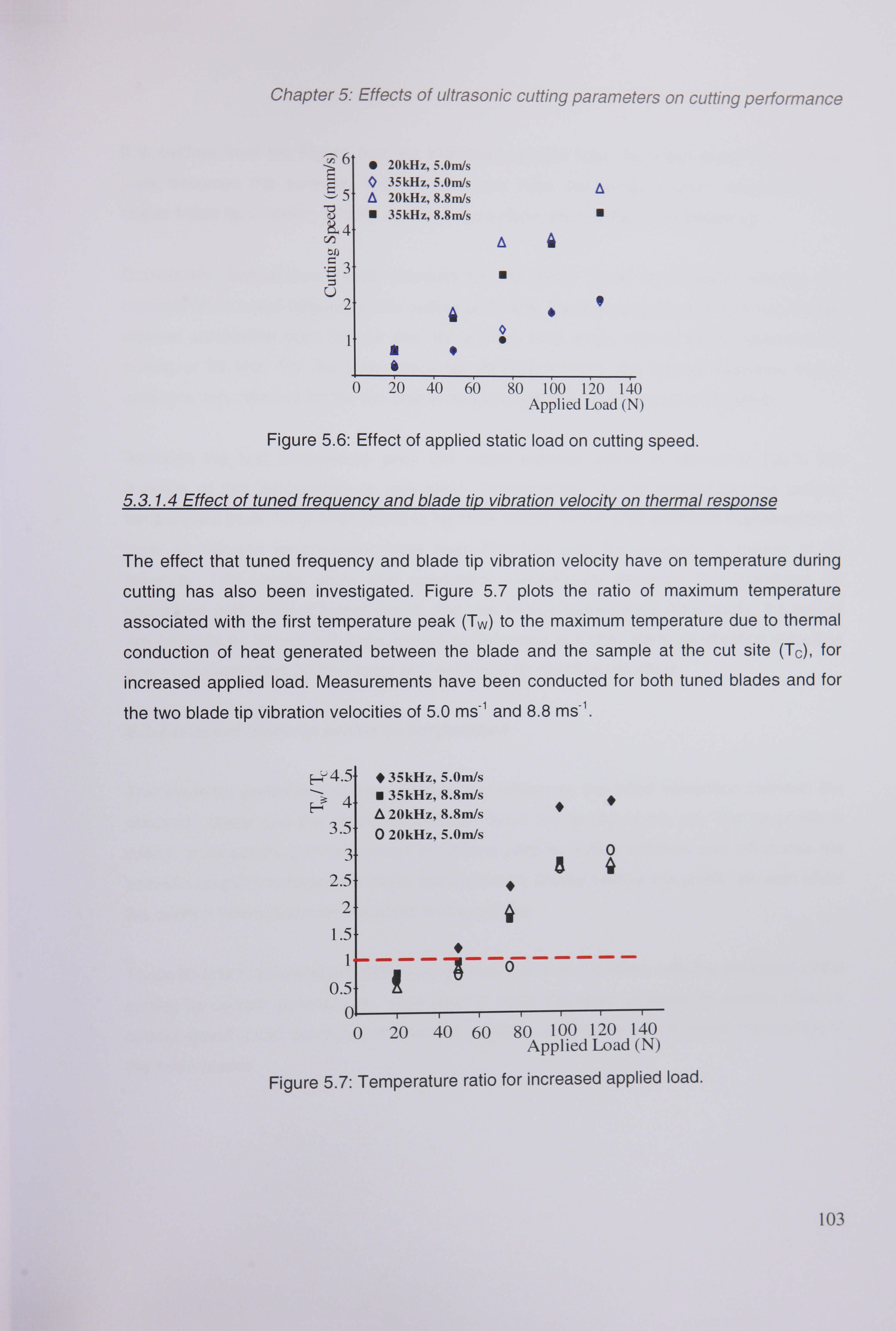
Chapter 5: Effects of ultrasonic cutting parameters on cutting performance
6
S5
"53 c-) 2
0 20kHz, 5.0m/s 35kHz, 5.0m/s 20kHz, 8.8m/s 35kHz, 8.8nlJs
a
U
U
4 0 S
I
0 20 40 60 80 16o iýo i4o Applied Load (N)
Figure 5.6: Effect of applied static load on cutting speed.
5.3.1.4 Effect of tuned freguencv and blade tip vibration velocitjý on thermal respons
The effect that tuned frequency and blade tip vibration velocity have on temperature during
cutting has also been investigated. Figure 5.7 plots the ratio of maximum temperature
associated with the first temperature peak (Tw) to the maximum temperature due to thermal
conduction of heat generated between the blade and the sample at the cut site (Tc), for
increased applied load. Measurements have been conducted for both tuned blades and for
the two blade tip vibration velocities of 5.0 ms-' and 8.8 ms-1.
ýý4-5j #35kHz, 5.0m/s 4 35kHz, 8.8m/s
A 20kHz, 8.8m/s 3.5 0 20kHz, 5.0m/s
3 2.5
2 1.5
1
0.5
0 20 40 60 80 100 120 140 Applied Load (N)
Figure 5.7: Temperature ratio for increased applied load.
103

Chapter 5: Effects of ultrasonic cutting parameters on cutting performance
It is evident from the Figure that, for increased applied load, the initial sharp temperature peak becomes the dominant thermal response. Also, temperature ratios obtained at the higher blade tip vibration velocity appear to be independent of the tuned frequency
Conversely, temperature ratios obtained for the lower blade tip vibration velocity are dependent on tuned frequency. For cutting at 20 kHz, the temperature ratio is dominated by thermal conduction from the cut site, for a wider load range than in those measured for
cutting at 35 kHz. For the lower blade tip vibration velocity, the thermal response during
cutting is very different for the two blades even though the cutting speed is the same.
Although the first temperature peak can reach nominal values in excess of 1 OOOC the duration of this temperature is very short. Temperatures due to conduction, the second temperature peak, have been found to be more critical for the post operative regeneration of bone as necrotic temperatures have been found to exist for durations in excess of 30
seconds. The results show that conduction temperature becomes less dominant for
operations performed at higher speed, and thus higher applied load. Additionally, the results
are found to be almost fully independent of frequency at higher blade tip vibration velocities
and more dependant on frequency at lower blade tip vibration velocities.
5.3.2 Effect of blade tip profile on temperature
The blade tip profile is a cutting variable that influences the initial interaction between the
ultrasonic blade and the specimen and can affect the quality of the cut. The tip profile is
critical in establishing initial contact conditions prior to cutting initiation and influences the
acoustic coupling between the blade and specimen. During cutting, the profile can also affect
the contact friction between the blade and specimen.
Three 35 kHz titanium alloy blades with identical geometric profiles, with the exception of the
cutting tip contact surface area, were used to study the effect of blade tip surface area on
cutting speed under conditions of constant applied load. Figure 5.8 (a) shows the profiles of
the three blades.
104

Chapter 5: Effects of ultrasonic cutting parameters on cutting performance
(a)
-------------- Iý -'-X' e ý
Con
U
(b)
35kHz, 8.8m/s (A) A 35 kHz, 5. Oni/s (A) 0 35kHz, 8.8m/s (B) 0 35kHz, 5. OnVs (B) M 35kHz, 8.8ni/s (C) 0 35kHz, 5.0m/s (C)
A
A
0 0 0 13
A 13 13
a 13
20 40 66 ýo 160 1 ýo 140 0 Applied Load (N)
Figure 5.8: (a) Three ultrasonic cutting blade tip profiles and (b) the effect they have on cutting speed for increasing applied loads.
Figure 5.8 (b) shows the relationship between applied static load and cutting speed using three blades tuned at 35 kHz with different tip profiles, at blade tip vibration velocities of 5 ms-1 and 8.8 ms-1. Figure 5.8 (b) shows that, for a given vibration velocity, cutting speed is
dependant on the static load, as shown previously, but also, on the blade tip profile. For a blade with a smaller cutting edge area cutting occurs more rapidly. This is as expected since, for a particular cutting speed, sharper blades or blades with smaller tip area, will cut under
lower static loading conditions.
(a)
035kHz5nt/sTip(A) 0 35kHz 5ni/s Tip (B)
F- A 35kHz 5nVs Tip (C)
1.5
0 13
0.5--
ol -4 ii 0 20 40 60
0
13
A
3
2.5
2
1.5 0 A
80 100 120 140 Applied Load (N)
0.5
0ý 0
0 35kHz 8.8m/s Tip (A)
0 35kHz 8.8ni/s Tip (B)
13
13 00
13
13 0
0
20 40 60 80
0 13
100 120 140 Applied Load (N)
Figure 5.9: Effect of blade tip profile on the temperature ratio versus static load, for cutting at 35 kHz with tip vibration velocities of (a) 5 ms-' and (b) 8.8 ms-'.
105

Chapter 5: Effects of ultrasonic cutting parameters on cutting performance
Figure 5.9 (a) and (b) plot the temperature ratios of maximum recorded initial temperature response peak (T, ) to the maximum temperature due to thermal conduction of heat
generated between the blade and the sample at the cut site (T,, ), for increased applied load. Measurements have been conducted for blade tip vibration velocities of 5 ms-' and 8.8 ms-1, Figure 5.9 (a) and Figure 5.9 (b) respectively.
From these figures it is evident that blade tip vibration velocity affects the thermal response during cutting. At the lower vibration velocity, blade tips B and C cut more slowly than tip A
and the temperature of heat conduction from the cut site dominates the response at low
static loads. For increased static load, the maximum sample temperature is dominated by Tw,
a result governed by the improved initial coupling contact between the blade and the
specimen.
Figure 5.9 shows that conduction temperature becomes less dominant for operations
performed at higher speed, and thus higher applied load. At lower blade tip vibration
velocities cutting takes longer. As a result, the thermal response, Figure 5.9 (a), is shown to
be dominated by conduction for applied loads :5 70N for a blade with tip A, and for the
majority of loads in the range 20 - 125N for a blade with tip B and tip C. At the higher blade
tip vibration velocity cutting occurs more rapidly. Temperature due to conduction only
dominates for applied loads: 5 60N for a blade with tip A and tip B. It is also clear that sharper
blades cut faster which results in less dominance by conductive temperature at lower blade
tip vibration velocities. The result shows that a sharp blade cuts faster and thus limits
temperature due to conduction, which is seen to be more critical for tests performed with a
lower blade tip vibration velocity.
5.3.3 Effect of slicing mode cutting on temperature
The same cutting rig configuration is used to investigate the effects of cutting parameters on
temperature during slicing procedures. Figure 5.10 illustrates how the mounting platform was
rotated through 900 so that the longitudinal motion of the blade was orthogonal to the
direction of cutting. Loads of 20,50 and 80 N were used to prolong the life span of the blades
under flexural bending load and provide a suitable set of results to compare slicing cutting
with guillotine cutting. Slicing experiments are performed with the blade tip inserted 10 mm
106

Chapter 5: Effects of ultrasonic cutting parameters on cutting performance
into the specimen and 15 mm slices were made, Figure 5.10 (a) and load, depth, time, cutting speed and cutting temperature were monitored as in guillotine cutting experiments.
(a) 7-7-7- L7 -Lo a7 Ce F1 B ladý
II T: Transducer S: Specimen L-
Applied Load
v
L)
F-
15 nim
Mo
0
E-.
(b)
-
Figure 5.10: Method of performing (a) slicing type showing the cutting depth and thermocouple location and (b) guillotine-type cutting under constant applied loads.
Figure 5.11 (a) illustrates that the thermal response is similar for slicing, as well as guillotine
cutting procedures. T,, is shown to increase with load, whereas Tc decreases with increasing
applied load as found previously in guillotine cutting. Figure 5.11 (b) illustrates that cutting
speed increases with applied load and that slicing cutting is faster than guillotine cutting at
both blade tip vibration velocities (5 ms-1 and 8.8 ms-1). Cutting tests also found that the 35
kHz blade cut faster than the 20 kHz blade at both blade tip vibration velocities. This
difference could be associated with the significant difference in length between the two
blades. The 20 kHz system is almost twice the length of the 35 kHz blade and is therefore
exposed to increased bending loads for the same cutting load.
107

Chapter 5: Effects of ultrasonic cutting parameters on cutting performance
(a) (b) : i, ý 4.0 - 1: 1 35kHz 8.8m/s Slicing U 70 20 N
0 .... 50N Te
0 35kHz 8.8nVs Guillotine 13 80 N C:: 3.5 -0 35kHz 5rn/s Slicing 2 60-
7ý 0 35kHz 5nVs Guillotine M 3.0- 0 50 13 Tw 2.5-
0 Ell 13 -2.0- 40-
U0
1.5 30- 1.0
20- 0.5
35kHz 5rn/s 10 1 0.0
-50 0 50 100 150 200 2ýO 300 10 20 30 40 50 60 70 80 Time (s) Applied Load (N)
Figure 5.11: (a) Temperature response form probe 1 at various loads and (b) cutting speeds for 15 mm incisions under slicing and guillotine type cutting conditions.
Cutting temperatures measured by thermocouple probe number 1 in guillotine and slicing cutting under applied loads of 20 and 50 N using a 35 kHz blade at both blade tip vibration
velocities, 5 ms-1 and 8.8 ms-1, are shown in Figure 5.12 (a) and (b). The figures show that at both loads, and at both tip vibration velocities, guillotine cutting produces higher cutting
temperatures than slicing at a measurement depth 1 mm from the cut site. This difference
can be attributed to the cutting speed of the ultrasonic blades, as the most significant
temperature deviation occurs during heat conduction, which has been shown to be
depenclant on cutting speed.
The measured values of T, are always slightly higher during guillotine cutting than slicing as
the load is applied centrally through the axis during guillotine operations. During slicing, the
applied load is slightly off center and there is some rotation when the blades are pre-loaded.
This is confirmed with slightly load eadings from the Kistler load cell.
108

Chapter 5: Effects of ultrasonic cutting parameters on cutting performance
(a) (b) 100- 50NI U 80. I= I ...... 20 N
...... % 0 I ..... 27
80- V/ : 70-
Guillothic
60- 60
Y
40- Slicing .f , 40-
Sli i %- WýIe. V c ng
30- V -e. - _IZI: 202m : JI.,
20-
01 35kHz 5nVs
r---r- I 3-; kHz 8.8rn/s 10. r-r---- 0 50 100 1ý0 200 250 300 0 50 100 150 260 250 300
Time (s) Ti rn e (s) Figure 5. 12: Temperatures from thermocouple 1 during slicing and guillotine type cutting at
blade tip vibration velocities of (a) 5 ms-1 and (b) 8.8 ms-1.
5.3.4 Ouantifying levels of necrosis
Although the specific thermal conditions at which bone necrosis occurs is uncertain, there
are strong arguments which support that necrosis is dependant on a combination of both the
magnitude of, and the duration for which bone is exposed to an increased temperature
[1,63,72,73]. To determine the optimum parameters for bone cutting procedures, the
thermocouples in all of the experiments recorded the thermal response until the specimen
returned to room temperature. This allowed the duration for which each probe was exposed
to temperatures above 50"C to be measured. Cutting parameters are compared using a
measure of the time period for which specimens are exposed to necrotic conditions. Thermal
necrosis can be quantified as the number of seconds at which a specimen is exposed to a
temperature greater than 50'C for longer than 30 seconds. Operations which expose
specimens to necrotic conditions for longer than 30 seconds are considered to be unsuitable
for bone cutting unless alternative methods of cooling or parameter controls are adopted.
109

Chapter 5: Effects of ultrasonic cutting parameters on cutting performance
(a) (b)
01,250- 251 Tip (C) 10 Tip (B)
, )200- 10 Tip (A)l 2 01
150- 13 15( 2
z 100- 0 210(
501 13 50
35kHz, 5nVs 0 0 20 40 60 80 1 ýO I ýO
140 Applied Load (N)
U -T TP (7) 10 Tip (A)
13 13 000
35kHz, 8.8ffds 0 20 40 60 80 1 ýO I ýO 140
Applied Load (N)
Figure 5.13: Blade performance under conditions of constant applied static loads using necrotic indicators for blade tip vibration velocities of (a) 5 ms-1 and (b) 8.8 ms-1.
Figure 5.13 shows the extent to which the cutting blade tip profile affects the specimen using thermal necrosis as a performance indicator. Figure 5.13 plots the total time for which the measured sample temperature is above the bone necrosis temperature at thermocouple 1 in each of the blade tip profiles introduced in section 5.3.2. Although the thermocouple is 1 mm from the cutting axis, and therefore not directly measuring temperature at the cut site, the data provides some insight into the way cutting parameters can be controlled to reduce cutting temperature below a critical value. Blade tip profiles A, B and C are used to cut synthetic bone samples at 35 kHz with blade tip vibration velocities of 5.0 ms-1 and 8.8 ms-1, Figure 5.13 (a) and (b) respectively. The results show that for the higher blade tip vibration velocity, the sample spends less time above the critical temperature and this exposure time is largely independent of applied load. Conversely, for the lower blade tip vibration velocity, the sample spends longer above the critical temperature, however this time is reduced with increased applied load. Additionally, the blade tip with the smaller cutting edge area spends less time above the critical temperature for both blade tip vibration velocities. It is evident that in a cutting test where Tc is found to be dominant, the sample temperature is above the
critical temperature for longer than a cutting test where the maximum recorded temperature
is due to Tw.
Using thermal necrosis as an indication of blade performance has confirmed that sharp blades cut more efficiently than blunt blades. Sharp blades have been shown to limit the
dominance of conduction in temperature measurements by improving cutting speed at both
blade tip vibration velocities. The effect that blade tip sharpness has on necrosis is not as
110

Chapter 5: Effects of ultrasonic cutting parameters on cutting performance
obvious at higher blade tip vibration velocities as cutting occurs more rapidly, but recorded results at 5 ms-1 confirm that blade tip sharpness is an important factor which can help limit
cutting temperature in bone cutting operations.
5.3.5 Effect of thermal response on the specimen
Figure 5.14 shows two synthetic bone samples which have been cut by the 35 kHz blade.
After ultrasonic cutting the specimen has been sectioned to expose the cut surface for the
figure. The photograph in Figure 5.14 (a) was taken after a cut was conducted under a 20 N
applied static load. Under this load the cutting speed of the blade is low and the thermal
response is predominantly heat conduction from the cutting site. In such thermal conditions
the sample is exposed to high temperatures for a long time interval and signs of burning are
evident. Figure 5.14 (b) illustrates another bone sample cut using the same blade operating
at the same frequency and blade tip vibration velocity but under a higher applied load of 125
N. In this case the cutting speed is considerably higher and the temperature response is
dominated by the initial peak, Tw. The sample shows less evidence of burning at the cut
surfaces. Despite the fact that this temperature peak is high, it is also of very short duration,
hence thermal damage can be considerably reduced.
. 'Z 4
(a) (b)
Figure 5.14: Specimen samples after ultrasonic guillotine cutting, with an applied static load of (a) 20 N, (b) 125 N.
Figure 5.15 illustrates two synthetic bone samples which were cut using an ultrasonic slicing
approach. Both specimens were cut using the same 35 kHz blade under an applied load of
(a) 20 N and (b) 50N. The figure shows that burning is more evident after ultrasonic slicing at
lower applied loads, and thus lower cutting speeds.

Chapter 5: Effects of ultrasonic cutting parameters on cutting performance
aiM (a) (b)
Figure 5.15: Specimen cut sites after slicing under and applied load of (a) 20 N and (b) 50 N.
5.4 Ultrasonic cutting at constant speeds
A Lloyd's test machine was used to perform ultrasonic cutting at constant speed. The cross- head rate and axial displacement of the machine was programmed prior to cutting and the
internal load cell monitored the reaction force exerted on the specimens. Two mounting
frames were designed to hold the 20 kHz and 35 kHz acoustic units at nodal positions and
are shown in Figure 5.16.
Each specimen was placed on an aluminium plate and preloaded to 17 N to fix its position.
Cutting speeds in the range 5- 150 mm/min were used to investigate the effects Of constant
cutting speed on load and temperature. The effects of blade tip profile and slicing are not
investigated under conditions of constant cutting speeds due to difficulties associated with
orientation and fixture.
Figure 5.16: Ultrasonic cutting rigs for attachment to a Lloyds machine to cut at constant speed.
112

Chapter 5: Effects of ultrasonic cutting parameters on cutting performance
5.4.1 Effect of tuned frequency and blade tip vibration velocity on cutting load
A typical reading from the internal load cell in the machine, validated by the Kistler load cell positioned between the specimen and the fixture plate, recorded varying loads over the duration of the cutting tests, an example of which is shown in Figure 5.17 (a) for a 35 kHz blade progressing at constant velocities in the range 20 - 125 mm/min into a synthetic bone sample. Experiments performed under constant applied loads always exhibit contact between the blade tip and the specimen which promotes blade progression, although cutting velocity may vary. Experiments performed at a constant cutting speed, for the range of speeds tested, do not always exhibit contact between the blade tip and the specimen during blade progression and thus contact coupling is not necessarily maintained throughout
cutting. The applied load has therefore been found to be variable, as in Figure 5.17 (a).
(a) (b)
Z- 180 - 125 mm/min 2180- A 20 kHz. 5m/s
160 - 160 - 0 20 kHz. 8.8m/s
LL. 140 - LE 140- 0 35 kHz. 5m/s
35 kHz. 8.8m/s a
120 c-- 120- 0
U 100 - jfý80 mm/min 100-
80 - 1: 1 % 60 mm/min cx, 80 - = 60 -
0 0 0 0
60 X
I. - t 40 X 8 0 0 0 0 0 40 Ir : I. I M
- 7 20 A6 20 do-O :- mmlmin .. 0
' 0 20 30 40 50 60 70 80 0 20 ýo 6 0 80 100 120 1 ýO I ýO
Time (s) Cutting Speed (mm/min)
Figure 5.17: A plot of (a) load against time for cutting tests performed at 20 - 150 mm/min with a 35 kHz blade with a tip vibration velocity of 8 ms-1 and (b) cutting speed against load
for all four ultrasonic blades.
Figure 5.17 (b) is a plot of the maximum reaction force against cutting speed. The figure
shows that at faster cutting speeds larger reaction forces are exerted on the blade.
Frequency is shown to affect the reaction load experienced by the blades. In Figure 5.17 (b)
the 20 kHz blade is shown to experience higher reaction forces than that recorded during
tests with the 35 kHz blade, at both blade tip vibration velocities (generators monitor
impedance to track cutting conditions). Each resonant system (20 kHz and 35 kHz) uses a
separate generator which may react slightly differently to conditions of varying load to
maintain blade tip vibration velocities. Trials performed under conditions of constant speed
113

Chapter 5: Effects of ultrasonic cutting parameters on cutting performance
do not permit the effects which frequency has on cutting load to be investigated unless identical generators are used. Experiments conducted under constant applied loads do not require the generators to compensate for small blade tip fluctuations caused by varying coupling conditions and provide a more useful method for comparing the effects of instrument frequency. Although the contact coupling between the blade and the specimen is inconsistent in cutting experiments performed under conditions of constant velocity the
maximum reaction load is confirmed to increase with cutting speed.
5.4.2 Variables affecting temperature
The thermal response in a synthetic bone sample cut with a 35 kHz blade under constant
cutting speed is depicted in Figure 5.18. The figure shows that the thermal response is
consistent with data recorded from tests conducted under constant applied load. The first
peak response, (T, ), is seen to increase with cutting speed as maximum reaction load
increases and coupling between the blade and specimen is improved (at higher loads). The
second peak response, due to heat conduction from the cut site (T, ), is shown to decrease
as cutting speed increases and the cutting time decreases.
70
60
50
40
30
201 1- --- H IU IIIII 0 100 200 300 400 0 100 200 300 400
Time (s) Time (s) Figure 5.18: Thermal response measured in a synthetic bone specimen during cutting with a blade tip vibration velocity of 8 ms-1 from (a) all six thermal probes under a constant speed of
40 mm/min and (b) from probe 1 at various cutting speeds
Figure 5.18 (a) is a plot from all six thermocouple probes during a 15 mm incision with a 35
kHz blade with a blade tip vibration velocity of 8.8 ms-1 and a cutting speed of 40 mm/min.
Figure 5.18 (b) illustrates the response measured by thermocouple probe 1 in a specimen
cut by a 35 kHz blade vibrating with a tip velocity of 8.8 ms-1. An increase in cutting speed is
114
(a) 14C 13C 12C I ic
L-
i) I oc go
80 70 60 50 40 30 20
(b) T,,,
150 mm/min
T, 11 .. - *% 20 mm/min

Chapter 5: Effects of ultrasonic cutting parameters on cutting performance
shown, Figure 5.18(b), to increase Tw and reduce the temperature associated with thermal conduction.
3.0
2.5
2.0
1.5
0.0
,L 35kHz 8.8ni/s 0 35kHz 5m/s
1.0 91
0.5-
(b)
E7ý 3.5 20kHz 8.8nVs
A 3.0
10
20kHz 5m/s
2.5-
2.0-
0 1.5-
91 1.0-
0.51
. 5nKHZ 9 0.0
0 20 40 60 80 100 120 140 160 Cutting Speed (mm/min)
0 20 40 60 80 100 120 140 160 Cutting Speed (mm/min)
Figure 5.19: Ratio of T,, /T, at thermocouple 1 during tests at constants speeds using blade tip vibration velocities of 5 ms-1 and 8.8 ms-1 at (a) 35 kHz and (b) 20 kHz.
The cutting temperature ratio, T,, /Tc, over a range of cutting speeds, 20 - 150 mm/min, is illustrated in Figure 5.19 for both blades, (a) 35 kHz and (b) 20 kHz, at both tip vibration velocities. Figure 5.19 (a) shows that cutting using the 35 kHz blade with a blade tip vibration velocity of 5 ms-1 is generally dominated by Tc for cutting speeds that are :5 125 mm/min. The temperature response measured during experiments with a 35 kHz blade with a blade tip
vibration velocity of 8.8 ms-' is dominated by Tc for cutting speeds < 100 mm/min and by Tw for cutting speeds ý: 100 mm/min. Figure 5.19 (b) plots the temperature ratio for specimens
cut with a 20 kHz blade at the same two tip vibration velocities. Tw dominates at faster cutting
speeds (ý! 100mm/min) due to improved contact coupling conditions between the blade and the specimen. Additionally, the heat conduction temperature dominates at the slower cutting
speeds. These results reinforce findings from cutting tests performed under conditions of
constant applied load.
5.4.3 Quantifying levels of necrosis
Figure 5.20 shows the extent to which cutting under conditions of constant speed affects the
specimen using thermal necrosis as a performance indicator. Figure 5.20 plots the total time
for which the measured sample temperature is above the bone necrosis temperature at
thermocouple 1 at each of the cutting speeds in the range 20 - 150 mm/min. Synthetic bone
samples cut at 35 kHz and 20 kHz, with blade tip vibration velocities of 5.0 ms-1 and 8.8 ms-1,
115

Chapter 5: Effects of ultrasonic cutting parameters on cutting performance
are shown Figure 5.20 (a) and (b). From Figure 5.20 (a) it is evident that for cuts performed with higher blade tip vibration velocities, samples spend less time above the critical temperature and this exposure time is independent of cutting speed. A similar result is shown for cuts performed with a 20 kHz blade, Figure 5.20 (b). The time for which samples are exposed to necrotic temperatures is shorter for higher tip vibration velocities for tests performed at the majority of cutting speeds.
(a) (b) 200-
0 200- '2180- cl 00 180- 160- 0 160-
140- 140- R. 120- 120- z 100,1 W
80- 80-
60- 60-
---- 40- 40 35kHz i-8-nV'sl
20- 3,5kHz 5nVs Io
20 111
50 20kHz 8.8ni/sl
LQ 20kHz 5ni/s-l
0 0
0
0 20 40 60 80 100 120 140 160 0 20 40 60 80 100 120 140 160 Cutting Speed (mnVmin) Cutting Speed (mrrVmin)
Figure 5.20: Blade performance under conditions of constant cutting speeds using necrotic indicators using (a) a 35 kHz and (b) 20 kHz blade with blade tip vibration
velocities of 5 ms-1 and 8.8 ms-1.
5.4.4 Effects of cutting temperatures on the specimen
The picture in Figure 5.21 shows two synthetic bone samples cut with a 35 kHz blade at
constant speeds of (a) 20 mm/min and (b) 150 mm/min. Figure 5.21 shows that the slower
cutting speed results in increased burning at the cut site due to prolonged cut durations,
increased blade temperature and increased exposure time (of the sample to the blade). At
slower cutting speeds reaction force is seen to decrease, in some instances to zero. During
such cuts temperature due to conduction has been shown to be dominant and the specimen
is exposed to necrotic temperatures for longer, resulting in a localised material burn at the
cut site. As cutting speeds increase, cutting time is reduced along with the amount of time
the specimen is exposed to the blade. Material burning at the cut site is less evident, as
illustrated in Figure 5.21 (b).
116

Chapter 5: Effects of ultrasonic cutting parameters on cutting performance
(a) -
(h)
Figure 5.21: Specimen samples after ultrasonic cutting with a 35 kHz blade under constant cutting speeds of (a) 20 mm/min and (b) 150 mm/min.
5.5 Discussion
Thermal induced bone damage has important clinical implications, therefore researchers and clinicians have investigated ways to limit the excessive heating of cortical bone during surgical procedures with conventional cutting instruments. Although it is widely documented that most current ultrasonic cutting systems utilized a sharp, irrigated cutting tool, experiments have shown that ultrasonic cutting parameters can be used to minimize damaging temperatures associated with thermal conduction. This study has explored the
effect of various cutting parameters on the performance of ultrasonic blades designed for large operative incisions in more difficult to cut materials, such as bone. Cutting speed and applied load were used as a performance indicators to quantify the relationship between
applied load, cutting speed, frequency, blade tip vibration velocity, blade tip profile and the
cutting technique (slicing or guillotine type) for a 15 mm incision. The investigation reports
similar findings to those documented by Vaitekunas et al [173] during ultrasonic cutting trials
in soft tissues.
Temperature measurements in bone and wood samples during ultrasonic cutting under
constant applied load and constant cutting speed have identified a consistent form of the
thermal response which exhibits two temperature peaks. The first peak is observed as a
sudden rise in temperature occurring as the ultrasonic blade initially contacts the specimen. This response, which is of very short duration, is not fully understood and at this stage in the
research is believed to be either due to the friction between the thermocouple probes and the
specimen or a result of the absorption of ultrasonic energy into the specimen. Improved
coupling between the blade and the specimen at higher load increases the temperature of
this response. Further investigations are being conducted at the University of Glasgow to
117

Chapter 5: Effects of ultrasonic cutting parameters on cutting performance
investigate this temperature response to ultrasonic cutting. The second peak is due to heat conduction from the blade and specimen contact during cutting. As cutting force or cutting speed increases (from 20 to 125 N or 20 to 150 mm/min) the maximum temperature associated with conduction generally decreases. Both peak temperatures decrease for increased blade tip vibration velocity but, from experiments conducted under constant applied load, they are not significantly affected by cutting at different ultrasonic frequencies
Tests have shown that cutting speed is dependant on the profile of the blade tip. A blade with a smaller cutting edge area allows faster cutting for the same applied static load and therefore measured peak temperatures are lowered. Conversely, a blade with a larger cutting edge contact area both improves the initial coupling between the blade and the specimen and increases cutting time for the same applied load, and therefore both measured temperature peaks in the response increase. These effects on the measured thermal
response become less significant for a higher blade tip vibration velocity. Slicing cutting has
also been shown to be faster than guillotine cutting. Due to this, peak temperatures recorded due to thermal conduction are found to be lower for cuts performed using slicing.
In ultrasonic cutting experiments where the measured thermal response is dominated by the
heat conduction temperature maintain high temperatures for a longer interval. For
orthopaedics applications, a blade tip profile with a smaller cutting edge area, a higher blade
tip vibration velocity and a high cutting speed is shown to both limit damaging temperatures
and the time for which the bone sample is exposed to a high temperature. This may allow
control of ultrasonic cutting below the temperature of bone necrosis, which improves the
postoperative condition of the bone and maximises recovery.
A prolonged period at high temperature results in localised thermal damage in the specimen.
The results of this investigation have provided some insights into the control of temperature
at the design stage by considering the cutting edge profile and by controlling cutting
parameters.
118

Chapter 6: Methods for reducing temperature
CHAPTER 6
METHODS FOR REDUCING TEMPERATURE
6.1 Introduction
Bone cutting instruments, such as burs, saws and chisels, offer limited precision and manoeuvrability to surgeons [1] and often result in tissue burning, formation of debris and damage of adjacent tissue. An alternative bone cutting device is an ultrasonic blade
which is tuned to a longitudinal vibration mode at a frequency in the low ultrasonic range (20 - 100 kHz). The reported benefits of ultrasonic cutting of hard tissue include
elimination of swarf, reduced reaction forces and a more accurate cut. The current
challenge for ultrasonic bone cutting resides in the development of tuned systems
capable of delivering sufficient acoustic power to cut hard tissue without exceeding the
temperature of bone necrosis. To overcome the problem of tissue burning, ultrasonic
cutting devices usually need to incorporate cooling systems, which deliver water (or
saline solution) to the cut site [3,4], but this offers additional problems of cross-
contamination. This study investigates opportunities for controlling the cutting
temperature, by studying the effects of cutting parameters and cutting blade geometry on
cutting temperature, with the aim of designing an ultrasonic cutting device capable of
deep cuts in bone without the need for a cooling system.
Cutting investigations detailed in Chapter 5 have shown that the thermal response,
measured during ultrasonic cutting of a variety of materials, exhibited two temperature
peaks [5,6]. Figure 5.4 shows a typical thermal response measured in a bovine femur
specimen. Qualitatively similar responses were measured in artificial bone and several
grades of wood. The first sharp temperature peak in the measured response occurs over
a very short time interval in the material sample during cut initiation. The temperature
peak magnitude increases with increased static load applied to the blade. This is because
increasing the static load improves coupling between the blade and material, thus
119

Chapter 6: Methods for reducing temperature
favouring the transmission of vibration energy into the sample. The temporal response is independent of the location of the measurement sensor in the specimen [4].
The second peak in temperature in the measured response occurs due to heat conduction generated by friction between the blade and specimen as the blade penetrates the material, resulting in a gradual increase then decay in temperature during the measurement period. In this case, the temporal response depends on the location of the sensor in the specimen. For the same cutting depth, the peak conduction temperature
measured in the response decreases with increasing applied static load, mainly because the cut occurs more quickly. In the previous chapter, the conduction temperature was shown to be critical in bone cutting as it exposes the specimen to damaging temperatures for longer periods than the temperature associated with Tw which, although sometimes in
excess of 1000C, is only experienced for a few seconds. The control of the conduction temperature, due to frictional heating, was therefore identified as a primary aim of blade design.
A study was carried out to investigate the performance of a number of ultrasonic blades
tested in an artificial bone material. In particular, the effects of the cutting section
geometry on the thermal response in artificial bone specimens were investigated. This
chapter aims to investigate the effect of blade profile on the cutting temperature during
ultrasonic cutting of artificial bone and, in particular, the impact of blade geometries with different areas of contact between the blade and the bone. Therefore, two different cutting
edge profiles, one with a constant section and a sharp tip (blade profile 1), and the other
with an indented profile terminating in an identical tip (blade profile 2), were incorporated
in the tuned blades for each selected frequency introduced in the previous chapter,
Figure 6.1.
6.2 Methodology
Cutting experiments were performed under conditions of constant applied load and
constant cutting speed using experimental rigs described in Section 5.3 and Section 5.4.
The experiments were performed under identical cutting conditions to quantify the effect
the blades with an indented profile have on cutting temperature in comparison to blades
with a constant cutting tip profile. Cutting experiments were conducted on a range of
material specimens, including various grades of wood, fresh and de-calcified bovine bone
and biornechanical test materials developed to mimic human bone, to enable
comparisons to be made with previous findings. Six thermocouple probes were used to
120

Chapter 6: Methods for reducing temperature
measure the thermal response at various locations within the specimen during cutting, as described previously in Section 5.2.1.1. Blades with profile 2 have been designed primarily to reduce temperatures in guillotine cutting. The blades were tested under loads in the range of 20 - 75 N, and at constant cutting speeds in the range 20 - 150 mm/min, to represent a range of operational forces and cut rates applied by clinicians and which result in the highest thermal conductance temperature peaks. Cutting tip vibration velocities of 5 and 8.8 ms-1 were used, as previously to investigate the influence of cutting amplitude and frequency.
6.2.1 Blade designs for reducing temperature
(a) (b) r 7mrriN-ci
SECTION
PROFILE
PROFILE 2
Figure 6.1: (a) Ultrasonic blades for reducing cutting temperatures. (b) Diagram of the indent incorporated in blades with altered tip sections.
Four grade 5 titanium alloy ultrasonic cutting blades tuned to resonate longitudinally at two distinct frequencies were designed and manufactured for the study (Figure 6.1 (a)).
The dimensions of the blades were determined using finite element analysis (FEA). Two
blades were tuned to operate at 20 kHz and two were tuned at 35 kHz. Although different
lengths were required to tune the blades to the two frequencies, the vibration amplitude
gain was constant and the cutting profile was consistent for each blade design.
Previous cutting experiments revealed that the sample temperature associated with the
initial thermal peack could reach elevated peaks, well above the temperature normally
quoted for bone necrosis. However, it is known that the necrosis temperature is not a
constant and depends on the duration for which bone experiences the elevated
temperature. In fact, bone can withstand higher temperatures without thermal damage if
the duration is very short [7]. The experiments also showed that heat conduction during
cutting exposed bone samples to prolonged intervals of high temperature. This
mechanism of frictional heat generation is normally associated with the cutting
temperature due to heat conduction from the cut site. Methods of reducing cutting friction
were investigated to aid the reduction of the most damaging cutting temperature.
121

Chapter 6: Methods for reducing temperature
-------- ---
BLADE SPECIMEN
DEBRIS IMEN
-P ý
-C- -- Debris
Collection Debris
Removal
(b)
L SPECINIFN
LIP
Figure 6.2: Material debris at the cut site in blades with (a) tip profile 1 and (b) tip profile 2.
Blades with an indented profile are primarily designed to reduce the friction contact surface between the blade and the specimen. However, the indent at the cutting section of the blade, Figure 6.2 (b) promotes the removal of debris generated at the cut site in two ways. Firstly the indent also creates a channel between the blade and the specimen behind the location of cutting, along which material can travel. It was shown in section 4.3.2 that material on the surface of an ultrasonic horn (cutting blade) moves towards the
node. In A12cutting blades the node is distant from, and external to the cut site. Material is
therefore naturally pushed away from the cutting section of the blade. This natural movement of material is prevented using blades with profile 1 as there is limited
separation between the blade and the specimen. Cutting debris becomes trapped between the specimen and the heated blade and can initiate cut site burning. Cutting
blades with profile 2 create a separation channel between the blade and the specimen
allowing material movement. Secondly the indent creates a lip at the tip of the blade. The
lip promotes the removal of material along the channel created by including the indent by
pushing it away from the tip, 35000 times a second. A further advantage of profile 2 is
that the channel may offer a method of routing cooling solutions to limited access tip
sections of the blades, producing access for coolant and a channel to flush out debris
material.
The most significant advantage of using cutting blade section with profile 2 is that the
contact area between the blade and the specimen is reduced. Frictional heating, a major
contributor to conduction temperature, should therefore be reduce in specimens cut using
blades with profile 2 in comparison to profile 1.
The effect of the indented profile on the blade's resonant frequency, stress and amplitude
gain was estimated using FEA, Figure 6.3, for three different indents of depths 0.125 mm,
0.25 mm and 0.325 mm. Frequency was altered by up to 3502 Hz by removing material
without adjusting blade length.
122

(a) (b) 1.2- (. A. ) 00 1*0" -Z -O-3T5-m-m"I
a) C> t, ) f-A I- E C> 0ý 0-0.5 mm 1 N. ) 11- 0.625 mm I (4
0.85-- No Indent I I 2-5-m-m-i n-d e-n
_0 0.71 -- 0.25 mm indent I C6 ., 0.8- 1 11 1-
-I "C mII110.325 Tm indenti 0.57-- "' 0.6- 0.43 S ss
... .... ... 0 0.4 0.29--
INDENT Disp), ficement 0.2- 0.14
.ý
L==N
01 1
30 33 35 3,7 39 41 43 45 O-A -0.6 0.8 Frequency (kHz) Normalised blade length
Figure 6.3: (a) Frequency shift of longitudinal mode of vibration with blade tip indents of depth 0.125,0.25 and 0.375 mm predicted using FEA. (b) FE prediction for the effect of
indent depth on stress and displacement.
Figure 6.3 (b) shows that with increased indent depth, the node position moves further
away from the blade tip and into a thicker part of the blade. As a result, the associated maximum stress is reduced (first peak). The second stress peak is due to a stress concentration at the location of the indent. This stress increases as the depth of the indent increases. Stress concentrators can limit the life span of ultrasonic blades which are exposed to cyclic environments. Severe changes in the blade's cross section are
monitored during manufacture and in some instances these reductions are graduated to
reduce the concentration of stress. Using FEA, the blades were tuned to 20 and 35 kHz.
Although different lengths were now required to tune the blades to the first longitudinal
mode, the vibration amplitude gain was adjusted to allow similar blade tip vibration
velocities to be compared. In order to make valid comparisons between blades with
constant and indented tip profiles, the blades were designed to operate under tip vibration
velocities of 5 and 8.8 ms-1.
6.3 Effect of blade design on cutting temperatures
6.3.1 Cutting under conditions of constant applied load
6.3.1.135 kHz blades
Firstly, cutting experiments used the pair of blades tuned to 35 kHz. The ultrasonic blade
tip vibration velocity was set to 5 ms-1 for both blade configurations (profiles 1 and 2), and
tests were performed at a series of applied static loads in the range 20-75 N. For each
0
123

Chapter 6: Methods for reducing temperature
cutting experiment, the temperature of the sample was monitored for 300 seconds, to allow the specimen to cool back to room temperature, independent of the cutting time.
In Figure 6.4 the responses detected by the six thermocouples positioned in the bone specimens, being cut using 35 kHz blades with profiles 1 and 2 and with an applied load of 20 N, are shown. It is clear that significantly lower temperatures are recorded by all the probes when cutting with the blade with the indented profile (profile 2) as shown in Figure 6.4 (b) and, in particular, a peak temperature 400C lower was detected by probe 1.
(a)
U 120- 0
Probe I - Probe
100- C Probe - ----
A
1
- Probe 4
'- 80- I- - Probe 51
Probe 000 L:... Probe 61
E 60-
40 ........... -------------------
20
0 0 50 100 150 200 250 300
Time (s)
(b) 120- ------ Probe 1
Probe 100- ... Probe 3 1 Probe4
Probe 1-4 u 80- ... Probe 61
60-
40- 0----
20-
0 0 50 100 150 200 250 300
Time (s)
Figure 6A Thermal response measured experimentally from six thermocouple probes in specimens cut using a blade with (a) profile 1 and (b) profile 2 at 35 kHz with a blade tip
vibration velocity of 5 ms-1.
These improved thermal conditions stem from the reduction in the frictional contact area between the blade and specimen during cutting. This also results in a faster cut and facilitates the removal of bone debris from the cut site. As a result, debris combustion
through frictional heating, which was previously cited as a key cause of tissue damage,
could be reduced [5,6]. The effects of applied static load on temperature, using blade
profiles 1 and 2, are shown in Figure 6.5 for blade tip vibration velocities of 5 ms-1 and 8.8
ms-1. In the figure, the difference in peak cutting temperature recorded between blade
profile 1 and blade profile 2, is plotted against the applied static load. The measurements
consistently recorded a reduction in the peak temperature when using blade profile 2. A
small number of deviations from this trend appear due to slight inaccuracies in positioning
of the probes.
124

Chapter 6: Methods for reducing temperature
(a) (b)
Probes 60 ---------- L131 02 A3 M4 05 A6ý; Probes
35 4- 1 02 05 A6A 40 13
25 7D 0
E3 E 13
20 00 13
iEA10
015-&0 1---r 0- 1 0 40 60 80 -5- 40 60 80 Load (N) Load (N)
-20- -35 A
Figure 6.5: Experimental peak temperature (conduction) reduction for increased applied loads for a 35 kHz blade with tip vibration velocities of (a) 5 ms-' and (b) 8.8 ms-1.
Table 6.1 shows the cutting speeds measured using both blade tip profiles at different vibration velocities. As expected the cutting speed increased with tip vibration velocity and, for a given tip vibration velocity, the blade with the indented profile cut consistently faster as a result of the reduced frictional contact area.
Cutting speed of 35 kHz blades I
(MM/S)
Cutting speed of 20 kHz blades
(MM/S)
Static
l
I PROFILE 1 PROFILE 2 I PROFILE 11 PROFILE 2 PROFILE 3 oad (N)
5
M/S
8.8 5
M/S M/S
8.8
M/S
5
M/S
8.8 15
M/S M/S
8.8 5
M/S M/S
8.8
M/S 20 0.29 0.77 0.49 0.94 0.20 0.71 0.21 0.27
35 0.38 1.27 0.53 1.55
1
0.37 1.81 1 0.46 0.37
50 0.64 1.60 1.60 4.17 0.72 2.27 1 0.72 0.97
62 0.85 2.24 1.56 4.41 1.1 3.12 1 0.83 1.76
75 1.13 2.54 1 2.14 5.36 1.49 3.49 1 0.98 1.97
Table 6.1: Cutting speed of the blades measured in artificial bone specimens.
6.3.1.2 20 kHz blades
To confirm these findings and to investigate whether varying the tuned frequency had an
effect on temperature during cutting, a pair of 20 kHz blades with profiles 1 and 2 were
125

Chapter 6: Methods for reducing temperature
tested. The 20 kHz blades were initially tested with a tip vibration velocity of 5 ms-' and under increasing applied load.
By comparing Figure 6.6 (a) with Figure 6.5 (a) it is seen that the measured temperature differences between profile 1 and profile 2 are much smaller than for the 35 kHz blades and, therefore, at 20 kHz the peak cutting temperature is not so dependant on the cutting edge profile for the same blade tip vibration velocity. Again, at 20 kHz, the blade with profile 2 cuts faster than the blade with profile 1.
(a) 40
-!: I
ILI
20 E
X
Probes 1-(Ti-i 7 iý 3 W51; 167j
0
-20
40 60 X 80
Load (N) 0.00
XYD&ttrlnom XYData-Lom XYData-3norsk
5.00 10.00 15.00 20.00 25.00 30.00 35.00 40.00 (XIO
Frequency
Figure 6.6: (a) Experimental peak temperature reduction for increased applied loads for a 20 kHz blade with a tip vibration velocity of 5 ms-1. (b) FEA steady state frequency
response in the region of the longitudinal mode of vibration.
The cutting tests conducted using the 20 kHz blade with profile 2 were characterised by
audible noise, prior to and throughout cutting. The noise level increased when the tip
vibration velocity was increased. The FE calculated frequency response of the blade,
Figure 6.6 (b) shows that there are bending (x-axis) and torsional (x and z axis) modes
occurring at frequencies close to the tuned modal frequency. Audible noise indicates that
energy may be leaking into lower, un-tuned frequencies and therefore a further vibration
analysis of this blade is necessary to identify this behaviour.
6.4 Blade redesign for improved vibration performance
In order to find explanations for the temperature and cutting speed deviations observed, a
study of the vibration characteristics of the 20 kHz blade with profile 2 was performed.
The blade was analysed at both high and low excitation levels in order to investigate any
linear and non linear modal coupling phenomena.
(b)
1.00
0.80
0.60
0.40
0.20
126

m
Chapter 6: Methods for reducing temperature
6.4.1 Linear modal coupling
The vibration behaviour of the 20 kHz blade with indented configuration was studied using EMA using LMS modal analysis software. Blade modal parameters were extracted from frequency response function measurements performed using a 3D LDV. Measurements were carried out at low excitation levels to ensure the analysis was within a linear regime.
TRANSDUCER 20kHzBLADE BOOS E
Un-deformed
Deformed
(a) D;
476 H. 71
Figure 6.7: Mode shape and resonant longitudinal frequency of a 20 kHz blade with tip profile 2 as (a) measured by EMA and (b) predicted by FEA.
Figure 6.7 provides a top view of the mode shape and resonant frequency of the tuned
longitudinal mode, obtained via EMA (Figure 6.7 (a)), alongside the corresponding modal data predicted by the FE model of the blade (Figure 6.7 (b)). Measured and predicted
resonant frequencies are seen to be within 3% of each other.
The side view of the measured tuned longitudinal mode shape illustrated in Figure 6.8 (a)
reveals a significant flexural contribution to the longitudinal motion of the blade. Figure 6.8
(b) shows a flexural mode occurring at a resonant frequency very close to the longitudinal
mode frequency. This multimode participation at the tuned frequency could have been a
cause of the cutting speed reduction and could also have affected the specimen
temperature. Flexural responses also result in higher stresses in the blade with a
consequent risk of blade failure, as the flexural motion alters the frictional contact at the
blade-specimen interface and provides an additional lateral vibration loading to the cut
surface. Therefore a means to isolate the longitudinal frequency from the nearby flexural
mode was necessary.
127
L '10030 Hz

Chapter 6: Methods for reducing temperature
(a)
19476 Hz 19422 Hz L-- -1
Figure 6.8: Flexural motion of the 20 kHz blade with alternative cutting tip section (a) at the longitudinal frequency and (b) at a mode in close proximity to the longitudinal frequency measured by EMA.
6.4.2 Nonlinear modal coupling
Subsequently the same blade was excited using a slow sweep of the excitation frequency
over a narrow band of 300 Hz around the longitudinal mode frequency detected at 19.476 kHz. The swept-sine measurements were repeated for increased excitation voltages until a5 ms-1 blade tip vibration velocity was achieved. Figure 6.9 shows the frequency
response measured by the 3D LDV. It can be observed that when the device was driven
at the tuned frequency an internal mode at around half of the driving frequency occurred in the response. This measurement is characteristic of a principal parametric resonance [1531. When a principal parametric resonance occurs, a large amount of energy leaks
from the tuned mode to the internal mode(s). Figure 6.9 shows that the internal mode and the longitudinal mode produced similar response levels when the blade was excited with
a nominal blade tip vibration velocity of 5 ms-1. This modal interaction was responsible for
the audible noise.
Figure 6.9: Experimental frequency response for system driven at 19.5 kHz in tuned longitudinal mode with a blade tip vibration velocity of 5 ms-1.
The internally excited mode corresponds to a blade torsional mode occurring at 9.9 kHz
which is shown in Figure 6.10 (a). The FE model predicted the mode at a frequency 2.5
128
Frequency (kHz)

Chapter 6: Methods for reducing temperature
kHz higher than the measured value (Figure 6.10 (b)). Such a discrepancy between EMA and FEA data derives from not including the transducer in the FE model [180]. Unfortunately the various transducer material properties required for the FE model were unavailable. It is in such circumstances that EMA becomes a vital tool in characterising vibration behaviour.
(a)
9936 Hz
(b)
--1-2425 Hz
Figure 6.10: Comparison between the modal data of the internal mode determined by (a) EMA and (b) FEA.
The experimental investigations showed that the performance of the 20 kHz blade with
profile 2 was hampered by linear and nonlinear modal coupling phenomena. Such modai interactions of flexural and torsional modes with the longitudinal mode would result in
slower blade cutting speeds which, in turn, influence the thermal response. An
investigation is conducted to eliminate modal interactions at the tuned frequency, by
modifying the blade geometry.
6.4.3 Improving blade tuned responses via profile alteration
The vibration measurements have illustrated that the response of the 19.5 kHz blade is
characterised by both linear and nonlinear modal interactions. Such energy leakages
could have an influence on the thermal response during cutting and, hence, a redesign is
proposed to eliminate these effects. The requirements were to uncouple the longitudinal
mode from the untuned flexural and torsional modes without altering the blade length and
maintain sufficient amplitude gain in the blade profile to allow the blade to operate at the
required tip vibration amplitudes [9,10].
Two further indents were incorporated, in this case to alter the width of the blade, as
shown in Figure 6.11 (blade profile 3). EMA of the new blade measured a significant shift
in the flexural mode frequency that uncoupled the flexural mode response from the tuned
longitudinal mode response. Also, the indented width profile significantly affected the
modal frequency of the torsional mode, achieving a frequency reduction of 1.1 kHz, with
the result that the nonlinear modal coupling was also eliminated. The response of the
129

Chapter 6: Methods for reducing temperature
modified blade exhibited a linear single frequency response for blade tip vibration velocities up to 6.9 ms-'.
(b)
Cut depth Indents
Figure 6.11: Top views of the 20 kHz blade with (a) profile 2, and (b) profile 3.
6.5 Effect of blade profile 3 on temperature
Further cutting temperature measurements were carried out using the 19.5 kHz blade
with blade profile 3 at 5 ms-1 blade tip vibration velocity. Figure 6.12 shows the difference in peak cutting temperature (2 nd peak due to thermal conduction from the cut site) between the 19.5 kHz blades with profiles 1 and 3, for increasing static load. Despite the improvement in cutting speed (Table 6.1) due to the new design of profile 3, and the
elimination of modal interactions in the vibration characteristics as an influencing factor in
the experiments, no significant temperature reductions could be achieved using this blade
design. At a higher ultrasonic vibration velocity, of 6.9 ms-1, improved temperature
reductions were recorded in the specimens. The results suggest that at 19.5 kHz, the
influence of the cutting edge configuration on temperature is more significant at higher
ultrasonic blade tip velocities.
(a) (b)
'ý 60 u Probes
-- ' 60 u
Probes - 0 1 LOI 02 A3 04 05 A6. j
0 LOI 02 A3 04 05 A6ý. j
U 40 - 2 40
ILI
E 13 0
20- 13 20 13 0
0 m
6 1 02 0 40 60 0 80 0 40
IAI, 60 80 1
A Load (N) Load (N)
-20 -201
Figure 6.12: Experimental peak temperature differences for increasing applied loads between a 20 kHz blade with profile 1 and profile 3 at tip vibration velocities of (a) 5 ms-',
and (b) 6.9 ms-1.
130

Chapter 6: Methods for reducing temperature
6.6 Cutting under conditions of constant speed
The ability of blades with tip profile 2 to reduce the conduction temperature was further investigated for cutting under constant speeds in the range 20 - 150 mm/min. Experiments were conducted for 15 mm incisions. Applied load and temperature was measured as detailed in Section 5.4. Thermocouple probes were positioned at a similar location to probes used in experiments performed under constant applied loads with both blade profiles (1 and 2).
Figure 6.13 plots the temperature recorded at thermocouple probe 1 during cuts performed with a 35 kHz blade with a tip vibration velocity of 8.8 ms-1 with (a) profile 1 and (b) profile 2 at increasing cutting speeds from 20 mm/min up to 100 mm/min. Lower temperatures are recorded at all cutting speeds at probe 1, Figure 6.13. In particular, under a constant cutting speed of 20 mm/min, probe 1 recorded a 14'C reduction in the temperature conduction peak when the blade with profile 2 was used.
(a) (b) 140- T, 140 -
150 mm/min 20 120 -
100 - 1-1100 E
go- T, 80 Ou nI in. lu/ ml, inT
"*% T *00
c -.. 20 mnVmin 60- 60
40- 40 0 alr-5ý nm7nvnl 20 35kHz 8.8m/s 20
35kHz 8.8m/s
0 100 200 360 400 0 100 200 360 460 Time (s) Time (s)
Figure 6.13: Temperatures measured experimentally from probe 1 at cutting speeds in the range 20 - 150 mm/min for a 35 kHz blade with tip vibration velocity of 8.8 ms-' and
(a) tip profile 1 and (b) tip profile 2.
Thermal measurements were recorded from tests performed with the two cutting blade tip
configurations under increased cutting speeds. Figure 6.14 (a) and (b) plot the difference
in peak temperature T, measured in the specimens at a blade tip vibration velocity of 5
ms-1 and 8.8 ms-1 respectively. The results show that there is a reduction in temperature
when blades with profile 2 are used in comparison to blades with profile 1- The small
number of results which show that temperatures are increased when using blades with
profile 2 are within experimental error bounds.
131

Chapter 6: Methods for reducing temperature
(a) Probes
u 40 - COI-11-2 -AT74 13 5A6
30- A
20- 0
0 0 13 10-1 Q
0
19
&a01 0- Ea r) P00 El ZI 20 40 8,0 MO 120 140 160
-10- 11 Cutting Speed (mm/min)
-10
8
60 80 100 12d 140f9160 Cutting Spee@ (mm/min)
Figure 6.14: Conduction temperature variations against cutting speed measured experimentally using the 35 kHz blade profile 1 and profile 2, at tip amplitude vibration of
(a) 5 ms-1, and (b) 8.8 ms-1.
The extent to which such blades affect the cutting temperature can also be investigated
by using the necrotic indicator. Figure 6.15 plots the duration spent above the necrosis
temperature, over a 300 second test period, for a 35 kHz blade with profile 1 and profile 2
at both tip vibration velocities. The figures plot data recorded by thermocouple probe 1. It
can be seen that a 35 kHz blade with profile 2 and tip vibration velocity of 8.8 ms-1 can
make 15 mm incisions without reaching the necrosis temperatures at three out of the
seven cutting speeds used (Figure 6.15 (b)). At lower blade tip vibration velocities, cutting
temperatures are reduced, however tend to exceed necrosis thresholds, Figure 6.15 (a).
200
loo
0.4
0.2
30
13 13 13
13 13 13 13
(b) Probes
ý)40-L-OL-13-2 A3 04---,, -
13 5A 6-1
13 30-
Ll o , L) 20- 0
10 A0
(b) -180-
160- 140- 120- 100- 60- 60- A (1 4
IiWrof-ae 71 -- ?o 00 ICI Profile 2 20-B 0-
-ý3 3'5 37 39 41 43 45 0
Applied Load (N)
If Fro File 77 -1 13
Profile 2
13
20 40 60 80 III, E3 , E3 i
100 120 140 160 Applied Load (N)
Figure 6.15: Duration spent above 500C in cutting experiments performed at increasing
cutting speeds with a 35 kHz blade with profile 1 and profile 2 at tip vibration velocities of (a) 5 ms-1 and (b) 8.8 ms-1.
132

Chapter 6: Methods for reducing temperature
6.7 Effect of blade design on specimen cut site burning
Figure 6.16 illustrates how the altered cutting blade affects the specimen after performing a 15 mm incision under a constant load of 50 N with a 35 kHz blade vibrating with a tip velocity of 5 ms-1. This combination of load and vibration velocity was used because
specimens cut under such conditions were found to show signs of burning using the blades with profile 1, Figure 6.16 (a). A specimen cut with the same cutting parameters with a blade with profile 2 is shown in Figure 6.16 (b). The specimens in Figure 6.16
confirm that cutting blades with an indented tip section produce less signs of burning at the specimen cut site. The improved cut site damage is consistent with recorded reductions in conductive temperature when blades with profile 2 are used for cutting.
(b)
Figure 61 16: The effect of cutting with a 35 kHz blade with a tip velocity of vibration of 5 ms on the specimen surface using a blade with (a) profile 1 and (b) profile 2.
Specimens cut under conditions of constant cutting speed show a similar result. Figure
6.17 shows the cut site of two specimens cut with the two different blade tips at 35 kHz
with a tip vibration velocity of 5ms-1 at a constant cutting speed of 60 mm/min. Figure
6.17 clearly shows that specimen burning is reduced after cutting with a blade with profile
2. Figure 6.17 (a) shows a specimen cut using a blade with profile 1 and shows definite
signs of material burning on the cut surface. Figure 6.17 (b) shows a specimen cut using
a blade with profile 2 and identical cutting conditions. The results are consistent with the
measured reductions in Tc.
(a) (b)
Fi - yure 6.17: The effect of cutting with a 35 kHz blade with a tip velocity of vibration of 5
ms under a constant cutting speed of 60 mm/min on the specimen surface using a blade with (a) profile 1 and (b) profile 2.
133

Chapter 6: Methods for reducing temperature
The quantitative findings correlate with the visual evidence, showing that cutting temperatures can be reduced by careful modification of the blade tip. A strategy for reducing the cutting temperature in bone has been proposed which not only reduces the cutting temperature measured using thermal sensors, but also visibly reduces the amount of burning which occurs at the cut site.
6.8 Conclusions
The performance of ultrasonic blades with altered cutting edge profiles (profile 2) was investigated in comparison to ultrasonic blades with cutting tip profile 1 in cutting procedures which utilised constant cutting loads or constant cutting speeds. The study has shown that slight modifications to improve the tip contact conditions can reduce the temperature, due to thermal conduction, by up to 400C. More significantly, it has been found that certain blades can perform deep incisions (15 mm) in synthetic materials which mechanically mimic human bone, without reaching the necrosis temperature at a measurement location 1 mm from the cut site.
The impact of the blade vibration behaviour on the sample temperature and blade cutting
speed were also evaluated. A method has been proposed and tested, which relies on
modifications made to the vibration characteristics of the cutting device, to eliminate linear
and nonlinear modal interactions. Further indentations were included in 20 kHz blades
with profile 2 to adjust the modal behaviour of the blade and reduce noise. The technique
has enabled the blade to operate at higher blade tip vibration velocities.
Reducing the contact area between the blade and specimen reduces the cutting
temperature measured in the sample. In particular, at the higher frequency, cutting edge
alterations have proved to be effective for both blade tip vibration velocities tested, under
constant load and constant cutting speed. Conversely, at the lower frequency,
temperature reductions have been achieved only at the higher tip vibration velocity under
static load test conditions.
The research has demonstrated that by combining a blade re-profiling strategy with an
analysis of the vibration characteristics of the cutting blade, it is possible to design bone
cutting devices that operate within necrosis limits.
134

Chapter 7. - Conclusions
CHAPTER 7
CONCLUSIONS
4.1 Conclusions
This study has developed a design strategy that combines innovative FEA and experimental investigations to enhance the design of ultrasonic cutting blades. Blades have been designed to operate on bone, a material whose post-operative regeneration depends significantly on cutting temperature. Previous research has shown that thermal
necrosis results due to a combination of temperature and its duration, the threshold used in this study was 52-550C for duration in excess of 30 seconds. The effectiveness of FEA
used in coalition with EMA to design ultrasonic components is highlighted and used to develop ultrasonic bone cutting instruments operative at 20 and 35 kHz. Two 2D models
of ultrasonic cutting were developed to investigate the effect of various cutting parameters
on cutting speed, a performance indicator which is used by orthopaedic clinicians and has
been experimentally shown to reduce cutting temperature. The blades were investigated
experimentally and results were found to complement predictions made by FEA. Cutting
temperature has been shown to be maintainable within necrotic thresholds by using
cutting parameter control and geometric modification. Such cutting devices do not require
additional cooling techniques: usually external solutions which are directed onto the cut
site increasing the risk of post operative infection.
A range of high gain blades was designed using FEA to operate at 35 kHz. The blades
were designed to have vibration velocity gain factors in the range 10 - 20, using
incremented radial cut-outs, making blade tip vibration velocities in the range 17.6 - 44
ms-1 achievable. FEA was used to design the blades ensuring that they were
longitudinally resonant at the driving frequency; the accuracy of simulation predictions
was established using experimental modal analysis. The investigation found that the
135

Chapter T Conclusions
critical modes of the system were predicted to within 1.5 % of those measured. FEA was additionally used to estimate maximum stress values in the blades to ensure that material endurance limits were not exceeded. Two of the high gain blades were used to cut various grades of wood, fresh bovine bone and decalcified bovine bone. The preliminary results found the blades to be successful for bone cutting to a depth of 3 mm. Experiments on all grades of wood exposed a linear relationship between the cutting speed and applied load. Blade tip vibration velocity was also found to increase cutting speed for all materials however cutting temperature was not measured in this preliminary study. Stainless Steel grade 316 was used for the high gain blades due to its availability and cost. The surface temperature of the blades was found to increase when cut durations were excessive and in some instances this could force the system to shift from
resonance.
Two ultrasonic bone cutting blades were then designed using the same combination of FEA and EMA, to operate at 20 and 35 kHz to investigate the effect of frequency on cutting temperature and speed. The blades were designed with a novel cutting tip which enabled cutting in the longitudinal (guillotine cutting) and traverse (slicing) directions. The
tips were designed to enable incisions of 10 -15 mm to be made and were 1.5 mm thick,
a specification proposed by collaboration with orthopaedic surgeons. Both blades were designed to operate with tip vibration velocities of 5 and 8.8 ms-1 by careful modification
of the profiles. The blades were also designed to be within the endurance limits of the
material by a combination of profiling and material choice. Grade 5 titanium alloy was
used due to its low internal loss and high endurance limits. The blades were
manufactured to investigate the effects of various cutting parameters such as vibration
velocity, applied load, cutting speed and frequency on cutting temperature.
Ultrasonic blades have been designed using a combination of FEA and EMA to tune the
instrument to the system driving conditions and monitor the frequency response. The
effect of cutting parameters on cutting performance has been confined to laboratory
investigations which are time consuming and expensive, especially if materials which are
restricted and hard to obtain, such as human bone are required. Two novel methods of
simulating ultrasonic cutting were developed using FEA. In a previous study ultrasonic
cutting was modelled as a linear elastic fracture mechanics problem to investigate the
effect of superimposed ultrasonic excitation on the critical load required to initiate crack
propagation in a compact tension specimen of bovine bone. An ultrasonic blade was
found to assist crack onset and, more significantly, a higher blade tip vibration velocity
136

Chapter T Conclusions
was found to reduce the critical load. This initial study modelled cutting by assigning a vibration to the crack surfaces to replicate the conditions of an ultrasonic blade.
In this current study, polyurethane foam and epoxy resin were used as substitute materials for human trabecular and cortical bone due to their availability and specimen reproducibility. The materials have been found to have mechanical and thermal properties which are in the documented ranges reported in literature for human bone. Both materials were tested to failure in tension and using single edge notch bend experiments on a Lloyds test machine. The data was used to improve the material definition and prescribe fracture criteria in FE ultrasonic cutting models. Polyurethane foam and epoxy offered a more consistent foundation for FEA to be compared with cutting experiments. The Coulomb friction between an ultrasonic horn and specimens of epoxy and foam was measured experimentally. A 20 kHz titanium block horn was used to provide a large
surface area in order to investigate the effect of vibration on the coefficient of dynamic friction. It was found that ultrasonic vibration significantly reduced friction.
A 2D linear elastic fracture mechanics FEA model was developed whereby a resonant blade stimulates crack propagation. The progression of the blade was monitored to an incision depth of 10 mm and the effects of cutting parameters on cutting speed were
predicted. The accuracy of the simulation was enhanced by measured material data and
experimentally evaluated fracture criteria conditions. Crack propagation was defined
using a critical stress failure criterion in ABAQUS. Connected nodes along a predefined
crack path are able to separate if critical stress values, at a predefined distance ahead of the crack tip, are exceeded. Node pairs that separate allow the blade to progress deeper
into the material. Ultrasonic vibration was assigned to the blade using a periodic
amplitude curve and the material specimen was moved towards the blade at a constant
velocity, or under a constant applied load.
The 2D linear elastic fracture mechanics FE model predicted that cutting speed increased
with applied load. Frequency was found to have a negligible effect on cutting speed.
These findings were consistent with experimental findings in which temperature was
found to decrease at faster cutting speeds. The FE prediction suggests that cutting
temperature would also be reduced during tests performed at higher applied loads and
cutting speeds. However, the model was limited to high velocity or small time duration.
Reducing the cutting speed (or increasing the cutting time) resulted in extremely high
solution time, unmanageable within the timescale of the project. The results from this
137

Chapter T Conclusions
preliminary model can be used as guide to the trends associated with increasing applied load, cutting speed, frequency and vibration velocity.
A 2D FE element erosion model was also developed in which material shear failure was prescribed at a percentage of the equivalent plastic strain. When elements reach failure they are instantaneously removed from the analysis and have no further effect on the solution. The model was used to investigate the cutting speed in a multi-layer material which was unachievable using the linear elastic fracture mechanics approach due to solution convergence, computational resource, and because specimens in LEFIVI simulations are required to be pre-notched to promote cleavage. The multi-layer material was modelled as a thin layer of epoxy (cortical bone) proceeded by a thicker layer of polyurethane foam (trabecular bone). A 2D element erosion model predicted cutting speed to decrease in a multi-layer material. The material model was further modified to investigate the effect of cortical bone thickness on cutting speed. Cutting speed was found to decrease with thickness. These initial results from the simulations are consistent with trends recorded from ultrasonic cutting tests. In such experiments, cutting temperature was found to reduce at higher cutting speeds. It is essential that ultrasonic cutting models are validated to experiments. An initial result from a current project has
been introduced whereby temperature concentrations have been located and used to
modify ultrasonic blade design to improve cutting performance.
The ultrasonic block horn used to investigate friction was also used to show the
movement of material debris across the surface of the horn during excitation. The simple
study used low friction ball bearings positioned between the side face of the horn and a Perspex sheet. During excitation of the horn, the bearings were seen to move towards the
node. The result shows that cutting debris would be forced towards the node and in the
case of the 1/2 wavelength blades designed for bone cutting, away from the cut site.
Unfortunately due to the geometry of the blades debris material gets trapped between the
blade and the specimen and acts as a catalyst to further material burning.
The ultrasonic bone cutting blades were manufactured and used in various cutting
experiments to offer an insight into the effects of cutting parameters on cutting speed and
temperature. Experiments were performed under constant applied loads in the range 20 -
125 N and at constant velocities in the range 20 - 150 mm/min. Six thermocouple probes
were used at locations in the specimen to measure cutting temperature. All of the
experiments found that there were two temperature peaks associated with ultrasonic
cutting. The first temperature peak occurred over a very short time period and has been
138

Chapter 7 Conclusions
thought to be either an erroneous inclusion due to friction between the thermocouple probes and the specimen during excitation or due to the absorption of ultrasonic energy and increased with improved coupling between the blade and the specimen, which was achieved at higher applied loads and cutting speeds. The second temperature peak was due to heat conduction from the cut site and was found to increase if cutting duration increased or applied load was reduced. Conduction temperature was determined to be the most critical in bone cutting as cutting temperature was commonly above necrotic thresholds. The initial temperature peak was found in some cases to exceed 100'C but only for a very short time duration. A ratio of the two peak temperatures was used to determine which was most dominant during cutting. It was found that temperature due to conduction was most dominant at lower applied load and at slower cutting speed. To
minimise cellular damage, ultrasonic cutting should therefore be performed under a high
applied load or at a faster cutting speed. Cutting speed was found to be independent of frequency for experiments performed under constant applied loads and cutting speed was found to increase with applied load, trends which were also predicted by both FE
ultrasonic cutting models. Cutting speed was also found to increase if higher vibration velocities were used.
The blades were used to compare cutting temperature during guillotine and slicing cutting
operations. Both temperature peaks were recorded in the study. The investigation found
that slicing was faster that guillotine cutting for the same applied load and vibration
velocity, and as a result cutting temperature due to conduction was lower. Experiments
were conducted for a 15 mm incision after which material is forced up the taper of the
blade profile in guillotine cutting compared with slicing where the material loses contact
with the blade.
A further two blades were designed with slight geometric modifications to investigate the
effect of contact area on cutting temperature. All four blades were used in experiments
under constant applied load and at constant cutting speeds. The investigation found that
cutting temperature was reduced by up to 400C in experiments conducted under constant
applied load and by up to 140C in experiments at constant cutting velocity. The effect of
blade geometry on cutting temperature was quantified using a necrotic indicator that was
calculated as the duration of time spent above the necrotic threshold. It was shown that
the blades with slight geometric alterations (that reduced the contact area between blade
and specimen) reduced the necrotic indicator at every cutting velocity. The result also
showed that cellular necrosis conditions were not experienced for almost half of the
velocities tested with blades operating at blade tip vibration velocities of 8.8 ms-1. This
139
Chapter T Conclusions
result emphasises the extent to which blade design can limit cutting temperature without requiring additional cooling.
Cuffing blades with complex geometries have been shown to be susceptible to excite combinational modes of vibration and sub-harmonics. The frequency response of the 20 kHz blade used in this study was found to be highly populated with modes around the longitudinal mode driving frequency. Under a high power excitation the blade was found to emit severe noise. Closer examination of the frequency response at both low power and high power excitation levels revealed a sub harmonic torsional mode at half the driving frequency resulting in a principle parametric resonance. The blade was modified to manipulate the frequency of this undesired mode of vibration. The modification strategy shifted the torsional mode frequency without greatly affecting the longitudinal driving frequency, thus enabling the blade to be used at an upper blade tip vibration velocity of 6.3 ms-1.
The innovations achieved in this study include:
1) Development of two novel ultrasonic cutting models which enable incisions of up to 15 mm to be simulated and the relationship between applied load and cutting
speed to be predicted. Although the models need further refinement they offer a
powerful tool for future blade design. The technology will allow surgeons to predict
the performance of various cutting tools on almost any material which can be
accurately modelled, reducing experimental costs and the risk to patients.
2) Ultrasonic blades have been designed, at 20 and 35 kHz, which successfully cut
bone and bone substitute materials in both a guillotine and slicing direction.
3) The measured thermal response of the specimen during ultrasonic cutting has
been shown to contain two peak temperatures. The first peak is still being
investigated at the University of Glasgow and is thought to be due to ultrasonic
absorption, although the rapid reduction in temperature after the peak is
uncharacteristic of materials which have insulative thermal properties. The second
is a result of heat conduction from the cut site. Although the first peak can reach
very high temperatures, they are experienced for a very short time duration. The
second peak has been shown to be the most dangerous during bone cutting as it
can be above the necrotic temperature for well in excess of 30 seconds.
Ultrasonic cutting experiments have shown that cutting temperature can be finely
controlled by close consideration of the cutting parameters used, and more
significantly by geometrical modification of the cutting blades. Blades with a
140

Chapter T Conclusions
reduced contact area have been found to reduce cutting temperatures by up to
40'C.
5) A simple strategy for manipulating the frequency response of blades has been
proposed, whereby undesired modes excited during cutting can be frequency
shifted away from the longitudinal driving mode frequency.
141

Chapter 8: Recommendations for future work
CHAPTER 8
RECOMMENDATIONS FOR FUTURE WORK
8.1 Finite Element Modelling
This study has developed two ultrasonic cutting models which rely on certain assumptions. Firstly, the models do not consider the cutting temperature which has been shown to be critical in laboratory investigations on bone. The material is assumed to be isotropic and homogeneous, which bone and its substitute materials are not. Crack
propagation in bone has been documented to occur after an initial series of micro cracks, whereas in FEA crack propagation models, these micro cracks are not modelled. Current
work is being performed in the ultrasonics group at the University of Glasgow to improve
the material data used in FE models and modify ultrasonic cutting models to cut for durations which are comparable to experiments performed. In addition, thermal material properties are being included in simulations to allow frictional heating to be generated at
contact interfaces allowing predictions to be made into the conduction cutting temperature
reached in specimens. The material data that was used in this study was not temperature
dependant. All material and fracture tests were performed at room temperature. The
specimen material would be more accurately defined in FEA if elastic-plastic data and
critical stress components at various temperatures in the range 20 - 250 OC were included. The ultrasonic cutting models need to be validated against experimental cutting
at comparable cutting speeds. Although trends associated with various cutting
parameters have been predicted, true cutting temperature predictions can not be made
until the models are defined as fully coupled thermal-stress simulations and validated.
Bone substitute materials offer a reliable validation material as the specimens are more
consistent between batches in contrast to bone. There is a prospect for further work to be
done to incorporate a bone material structure which is anisotropic and multi-layered in FE
models, to more accurately predict the effect of ultrasonic cutting on cellular necrosis.
142

Chapter 8: Recommendations for future work
Element erosion models currently rely on material failure which occurs at a percentage of the equivalent plastic strain. As the elements fail, they are removed instantaneously from the analysis and have no further effect on the solution. Element erosion models would more accurately represent ultrasonic cutting if material failure was prescribed using damage initiation and damage evolution. A current project within the ultrasonics group at the University of Glasgow is investigating cutting temperature in erosion models where element failure begins at damage initiation but the elements are not removed until they have proceeded through a stage of damage evolution. At the end of this period the elements are removed from the analysis and then have no effect on the solution. In such an analysis, cutting temperature is hypothesised to be higher than those predicted using simple shear failure definitions as elements are not removed instantaneously but over a prescribed evolution period.
Ultrasonic cutting has been modelled in 2D to limit computational requirements. The development of a 3D model would allow both slicing and guillotine cutting to be modelled together. The temperature response throughout the specimen could be analysed to locate
temperature concentrations in both the specimen and the blade to further advance either the design of cutting blades or control of the parameters used to reduce temperature.
Ultrasonic cutting has a potential place in surgery and is already well established as an
alternative cutting technique for operations on soft tissue. This study has shown that
cutting temperature in substitute bone specimens can be kept within necrotic thresholds
without the addition of any form of cooling. The future of this technology in orthopaedics
depends significantly on the temperature at the cut site interface, crucial data which FE
models have the potential to predict.
8.2 Ultrasonic blade design
This study has shown that cutting temperature in bone can be kept within necrotic limits
by close parameter control and geometric alteration. Almost all of the current orthopaedic
instruments use cooling solutions which are pumped into the cut site to reduce
temperature and aid debris removal. The application of cooling solutions has not been
investigated and would undoubtedly reduce cutting temperature even further. This
emphasises the potential that this technology has for orthopaedic and other surgical
cutting procedures. Further work could be done to investigate which coolants would work
best with the technology and aid the reduction of temperature and removal of debris.
143

Chapter 8: Recommendations for future work
Ultrasonic blades with geometrical alterations were shown to reduce temperature by up to 40'C. The channel created due to the blade alteration could be used as a method of injecting fluid to areas of the cut site to cool the blade and to flush out debris. Internal cooling systems in which coolant is not directed at the cut site but used in a continuous flow within the blade may reduce blade temperature whilst minimising the risk of infection. In such systems the coolant solution would be recycled in a closed loop flow.
A range of ultrasonic bone cutting blades were designed and used to successfully cut various materials, including fresh and de-calcified bovine bone. There is potential for a multi-tip ultrasonic cutting device which could be used for a range of orthopaedic operations. A universal booster section that provides sufficient vibration velocity gain (and
the possibility of internal cooling canals) could be connected to numerous cutting tip
sections which are designed for specific surgical procedures. The instruments could be
used for bone grafting or full amputations in the same operation. Ultrasonic bone cutting
may be more efficient if cuts are initiated with chisel like blades, of similar tip design to the
high gain blades introduced in Chapter 3, and then continued with a tip similar in profile to
the bone cutting blades used in Chapters 5&6. This study has provided an experimental
and modelling basis from which these developments can, and are currently taking place.
144

Appendix 1: List of publications
LIST OF PUBLICATIONS
[1] Cardoni A, Macbeath A, Lucas M. Cutting bone using high-gain cutting blades. 12th International conference on experimental mechanics. Bari, Italy, (2004).
[2] MacBeath A, Cardoni A, Lucas M. Ultrasonic cutting with high gain blades. Advances in Experimental Mechanics. York, UK: Trans Tech Publications, Switzerland, (2004). pp. 45.
[31 Lucas M, Cardoni A, MacBeath A. Temperature effects in ultrasonic cutting of natural materials. CIRP Annals - Manufacturing Technology (2005); vol. 54, no. l. pp, 195-8.
[4] Lucas M, Cardoni A, MacBeath A. Vibration parameter and temperature dependencies in ultrsaonic cutting of wood, bone and artificial bone material. Ultrasonics Industries Association Symposium, Las Vegas (USA), (March 2005).
Lucas M, MacBeath A, Cardoni A. Methods for reducing ultrasonic bone cutting temperature. World Congress in Ultrasonics Merged with Ultrasonics International.
Beijing, China, (2005).
Lucas M, MacBeath A, McCulloch E, Cardoni A. A finite element model of
ultrasonic cutting. World Congress in Ultrasonics Merged with Ultrasonics International.
Beijing, China, (2005).
MacBeath A, Cardoni A, Lucas M. Design of an ultrasonic blade for cutting bone.
Advances in Experimental Mechanics IV. Southampton, UK.: Trans Tech Publications,
Switzerland, (2005). pp. 79.
[8] Lucas M, MacBeath A, Cardoni A. Methods for reducing ultrasonic bone cutting
temperature. Ultrasonics (2006) In press.
Lucas M, MacBeath A, McCulloch E, Cardoni A. A finite element model of
ultrasonic cutting. Ultrasonics (2006) In Press.
145

Appendix 1: List of publications
[101 McCulloch E, MacBeath A, Lucas M. A finite element model for ultrasonic cutting
of toffee. Modern Practices in Stress and Vibration Analysis. Bath, UK, (2006).
146

References
REFERENCES
[1] Lundskog, J. Heat and Bone Tissue. University of Goteborg. (1 972)
[2] Abramov, ON. High-Intensity Ultrasonics : Theory and Industrial Applications. Gordon & Breach. (1998).
[3] Shoh, A. Industrial Applications of Ultrasound -A Review. 1. High-Power Ultrasound. IEEE Transactions on Sonics and Ultrasonics. (1 975); vol. su-22, no. 2, pp. 60- 71.
Graff, K. F. Process Applications of Power Ultrasonics -A Review. Ultrasonics
Symposium Proceedings. The Ohio State University, Columbus, Ohio. (1974) pp. 628-41.
[5] Povey M. J. W, M. T. J. Ultrasound in food processing. Blackie Academic and Professional. (1998).
[6] DukaneCorp. Ultrasonic Food Processing Products.; (08/12/2005).
http: //www. dukcorp. com.
Volkov SS, S. D. Ultrasonic Cutting of Polymer Materials. Svarochnoe
Proizvodstvo. (2001); vol. 10, pp. 31-4.
[8] Drisko CL, C. D., Blieden T, Bouwsma OJ, Cohen RE, Damoulis P, Fine JB,
Greenstein G, Hinrichs J, Somerman MJ, Iacono V, Genco RJ. Position paper: sonic and
ultrasonic scalers in periodontics. Research, Science and Therapy Committee of the
American Academy of Periodontology. Joumal of periodontology. (2000); vol. 71,
no. 11, pp. 1792-80 1.
191 Industry, Y. D. Yimei Ultrasonic Dental Scaler; (09/12/2005). hftp: //uk. vimeick. com.
[10] Johnson&Johnson. Harmonic Scalpel.; (24/12/2005. ).
http: //www. harmonicscalpel. com.
[11] Spence, A. Basic Human Anatomy. Benjamin/Cummings Pub. Co. (1986).
[121 Georgetiemann. Othopaeclic Saw Catalog.
147

References
[13] Orthomedex. Orthomedex Single Use Sterile Power Equipment.; (24/12/2005). http: //www. orthomedex. com.
[14] Volkov, M. V., Shepeleva, I. S. The Use of Ultrasonic Instrumentation for the Transection and Uniting of Bone Tissue in Orthopedic Surgery. Reconstr. Surg. Traumat. . (1 974); vol. 1 4, pp. 147-52.
[15] Vercellotti, T. Technological Characteristics and Clinical Indications of Piezoelectric Bone Surgery. Minerva Stomatologica. (2004); vol. 53, no. 5, pp. 207-1 1.
[16] Schaller, BJ, Gruber, R., Merten, H. A., Kruschat, T., Schliephake, H., Buchfelder,
M., Ludwig, H. C. Piezoelectric Bone Surgery: A Revolutionary Technique for Minimally
Invasive Surgery in Cranial Base and Spinal Surgery. Operative Neurosurgery.
(2005); vol. 57, no. 4.
[17] Rayleigh, J. W. S., Lindsay, R. B. The Theory of Sound. Dover Publications. (1976).
[18] Savart, F. translated in Lindsay (1974). Annals of Physical Chemistry.
(1 830); vol. 20, pp-290.
[19] Galton, F. Nature. (1 883); vol. 27, no. 491.
[20] Koenig, R. Annals of Physical Chemistry. (1 899); vol. 69, pp. 626,721.
[21] Curie, J. -P., Curie, P. translated in Lindsay (1973). C. R. Acad. Sci. Paris.
(1 880); vol. 9l, pp. 294.
[22] Graff, k. F. Physical Acoustics - Chapter 1. A History of Ultrasonics. Academic
Press. (1981).
[23] Mason, W. P. Piezoelectricity, its History and Applications. Joumal of the Acoustic
Society of Amenca. (1 981); vol. 70, pp. 1561-6.
[24] Berlincourt, D. Piezoelectric Ceramics: Characteristics and Applications. Joumal
of the Acoustic Society of America. (198 1); vol. 70, pp. 1568-95.
[25] Damjanovic, D. Ferroelectric, Dielectric and Piezoelectric Properties of
Ferroelectric Thin Films and Ceramics. Rep. Prog. Phys. (1 998); vol. 61, pp. 1267-324.
[26] Grupp, D. E., Goldman, A. M. Giant Piezoelectric Effect in Strontium Titanate at
Cryogenic Temperatures. Science. (1 997); vol. 276, pp. 392-4.
148

References
[27] Sokolov, S. Means for Indicating Flaws in Materials. (1939) no. US: 2,164,125.
[28] Lavelle, C., Wedgewood, D. Effect of Internal Irrigation of Frictional Heat Generated from Bone Drilling. Joumal of Oral Surgery. (1 980); vol. 38, pp. 499-503.
[29] Nepiras, E. A. Report on Ultrasonic Machining. Metalworking Production. (1 956); vol. 100, pp. 1283-8.
[30] LD Rozenberg, V. F. K., L0 Makarov, DF Yakhimovich Ultrasonic Cutting. Consultants Bureau. (1964).
[31] Balamuth, L. Method of Abrading. (1948) no. 602801.
[32] Neppiras, E. A. Ultrasonic Machining. Ceaver Hume Press Ltd. (1959).
[33] Markov, A. I. Ultrasonic machining of intractable materials. I-Liffe books Ltd. (1966).
[34] Neppiras, E. A. New Materials for the Detection and Excitation of Vibrations. Joumal of Physics. (1 973); vol. 6, pp. 952-62.
[35] Graff, k. F. Macrosonics in Industry - 5. Ultrasonic Machining. Ultrasonics.
(1975); vol. 13, no. 3, pp. 103-9.
[36] Dehlinger, P. A Study of Rock Properties Affecting Vibrating Drill of Oil Wells and
of Electromechanical Transducers for Drilling Oil Wells. Series of Battelle Memorial
Institute Technical Reports (1950).
[37] Fry, F. J. Biological Effects of Ultrasound. Proceedings of the IEEE. (1979); vol. 67,
no. 4, pp. 604-19.
[38] Herrick, J. F., Krusen, F. H. Ultrasound and Medicine. A Survey of Experimental
Studies. Poceedings of the Nat/. Electron. Conf. (1 954); vol. 26, no. 2, pp. 236-43.
[39] Kelly, E. Ultrasound in Biology and Medicine. American Institute of Biological
Sciences. (1957).
[401 Kingery, R. A., Berg, R. D., Schillinger, E. H. Men and Ideas in Engineering: Twelve
Histories from Illinois. (1967).
Kelly, E. Ultrasonic Energy, Biological Investigations and Medical Applications.
University of Illinois Press. (1965).
149

References
[42] Gordon, D. Ultrasound as a Diagnostic and Surgical Tool. Williams and Wilkins. (1964).
[43] Polyakov, V. A., Nikolaev, G. A., Volkov, M. V., Loshchilov, V. I., Petrov, V. I. Ultrasonic Bonding of Bones and Cutting of Live Biological Tissue. Mir Publishers. (1974).
[44] Soper, N., Eubanks, W. S., Swanstorm, L. L. Mastery of Endoscopic and Laparoscopic Surgery. Lippincott Williams and Wilkins. (2004).
[45] Davison, T. W., Dimatteo, S., Smith, P., Whipple, G. Clamp Coagulator/Cutting System for Ultrasonic Surgical Instruments. (2004) no. EP1433425.
[46] Feil, W., Dallemagne, B., Degueldre, M., Kauko, M., Lohlein, D., Walther, B. Ultrasonic Energy for Cutting Coagulating and Dissecting. Thieme Publishing Group. (2004).
[47] Giraud J. Y., V. S., Daramana R., CahuzacJ. Ph., Autefage A. and Morucci J. P. . Bone Cutting. Clin. Phys. PhysioL Meas. (1991); vol. 12, no. l, pp. 1-19.
[48] Ark, T. W., Thacker, J. G., McGregor, W., Rodeheaver, G. T., Edlich, R. F. Durability
of Oscillating Bone Saw Blades. Journal of Long-Term Effects of Medical Implants.
(1977); vol. 7, no. 3&4, pp. 271-8.
[49] Ark, T. W., Thacker, J. G., McGregor, W., Rodeheaver, G. T., Edlich, R. F.
Innovations in Oscillating Bone Saw Blades. Journal of Long-Term Effects of Medical
Implants. (1 977); vol. 7, no. 3&4, pp. 279-86.
[50] Ark, T. W., Thacker, J. G., McGregor, W., Rodeheaver, G. T., Edlich, R. F. A
Technique for Quantifying the Performance of Oscillating Bone Saw Blades. Journal of
Long-Term Effects of Medical Implants. (1 977); vol. 7, no. 3&4, pp. 255-70.
Small, I. A., Osborn, T. P., Fuller, T., Hussain, M., Kobernick, S. Observations of
Carbon Dioxide Laser and Bone Burr in the Osteotomy of the Rabbit Tibia. Journal of
Oral Surgery. (1 979); vol. 37, pp. 159-66.
[52] Stern, R. H., Vahl, J., Sognnaes, R. F. Lased Enamel: Ultrastructural Observations
of Pulsed Carbon Dioxide Laser Effects. Journal of Dent Res. (1 972); vol. 5l, pp. 4556-60.
[53] Biyikli, S., Modest, M. F. Energy Requirements for Osteotomy of Femora and
Tibiae with a MovingCWC02 Laser. Laser Surg. Med. (1987); vol. 7, pp. 512-9.
150

References
[541 Schweiger, K., Carrero, V., Rentzsch, R., Becker, A., Bishop, N., Hille, E., Louis, H., Morlock, M., Honl, M. Abrasive Water Jet Cutting as a New Procedure for Cutting Cancellous Bone - In Vitro Testing in Comparison with the Oscillating Saw. (2001) pp. 223-8.
[55] Chapman, M. W. Chapman's Orthopaeclic Surgery. Williams and Wilkins. (2001).
[56] Mazoro, H. Bone Repair after Experimentally Produced Defects. Joumal of Oral Surgery. (1960); vol. 18, pp. 107-15.
[57] Polyakov, V. A Precision Ultrasonic Tool. Contemporary Surgery. (1 972); vol. 4, no. 3, pp. 58-60.
[58] Petrov, V. I., Loshchilov, V. I., Zasypkin, V. Surgical Instrument for Ultrasonic Seperation of Biological Tissue. (1980) no. US4188952, pp. 1-9.
[59] Weis, E. B. A Sonic Tool for Spinal Fusion. Orthop. Clin. North Am. (1 977); vol. 8, pp-43-55.
[60] Grasshof, H., Beckert, M. Osteotomy with Ultrasonics. Beitr. Orthop. Traumatol.
(1 981); vol. 28, pp. 299-305.
Picht, U., Schumpe, G., Milachowski, K. Sawing and Welding with Ultrasonics.
Orthop. (1 977); vol. 115, pp. 82-9.
[62] Aro, H., Kallionierni, H., Aho, A. J., Kellokumpu-Lehtinen, P. Ultrasonic Device in
Bone Cutting. Acta. Orthop. Scand. (1981); vol. 52, pp. 5-10.
[63] Horton, J. E., Tarpley, T. M., Jacomay, J. R. Clinical Applications of Ultrasonic
Instrumentation in the Surgical Removal of Bone. Oral Surgery. (1 981); vol. 5l, pp. 236-42.
[64] Khambay, B. S., Walmsley, A. D. Investigations Into the use of an Ultrasonic Chisel
to Cut Bone. Part 1: Forces Applied by Clinicians. Journal of Dentistry.
(2000); vol. 28, pp-31-7.
[65] Khambay, B. S., Walmsley, A. D. Investigations Into the use of an Ultrasonic Chisel
to Cut Bone. Part 2: Cutting Ability. Journal of Dentistry. (2000); vol. 28, pp. 39-44.
[66] Fuji Technology Press. Low-Invasive Bone Cutting with Ultrasonic Scalpel.
Techno Japan. (2001); vol. 34, no. 8, pp. 41.
151

References
[67] Mectron. Mectron Medical Technology.; (20/12/2005). httr): //www. mectron. com/index enql. html.
[68] Eggers, G., Klein, J., Blank, J., Hassfeld, S. Piezosurgery: An Ultrasound Device for Cutting Bone and its use and Limitations in Maxillofacial Surgery. British Journal of Oral and Maxillofacial Surgery. (2004); vol. 42, pp-451-3.
[69] Robiony, M. D., Polini, F., Costa, F., Vercellotti, T., Politi, M. Piezoelectric Bone Cutting in Multipiece Maxillary Osteotomies. Joumal of Maxillofacial Surgery. (2004); vol. 62, pp. 759-61.
[70] Voic, D., Dealbuquerque, S. P., Novak, T. A. D., Sladek-Maharg, W. Ultrasonic Cutting Blade with Cooling. (2002) no. US6443969, pp. pp. 1 -6.
Shockey, J. S., VonFraunhofer, J. A., Seligson, D. A Measurement of the Cooefficient of Static Friction of Human Long Bones. Surf. Technol.
. (1 985); vol. 25, pp. 167-73.
[72] Eriksson, R. A., Albrektsson, T. The Effect of Heat on Bone Regeneration: An Experimental Study in the Rabbit Using the Bone Growth Chamber. Journal of Oral and Maxillofacial Surgery. (1 984); vol. 42, pp. 705-1 1.
[73] Eriksson, R. A., Albrektsson, T. Temperature Threshold Levels for Heat-Induced
Bone Tissue Injury. Joumal of Prosthetic Dentistry. (1983); vol. 50, pp. 101.
[74] Hillery, M. T., Shuaib, 1. Temperature Effects in the Drilling of Human and Bovine
Bone. Journal of Materials Processing Technology. (1 999); vol. 92-93, pp. 302-8.
[75] Phillips, E. D. Greek Medicine. Camelot Press. (1973).
[76] Majino, G. The Healing Hand. Harvard University Press. (1975).
[77] Thompson, H. C. Effect of Drilling Into Bone. Joumal of Oral Surgety.
(1 958); vol. 1 6, pp. 22.
[78] Rafel, S. S. Temperature Changes During High-Speed Drilling on Bone. Joumal of
Oral Surgery. (1 962); vol. 20, pp. 21-3.
[79] Jacobs, R. L., Ray, R. D. The Effect of Heat on Bone Healing. Arch. Surg.
(1 972); vol. 104, pp. 687-9 1.
152

References
[80] Abouzgia, M. B., James, D. F. Temperature Rise During Drilling Through Bone. Intemational Joumal of Oral Maxillofacial Implants. (1 997); vol. 1 2, pp. 342-53.
Matthews, L. S., Hirsch, C. Temperatures Measured in Human Corical Bone when Drilling. Journal of Bone and Joint Surgery. (1 972); vol. 54-A, pp-297-308.
[82] Brisman, D. L. The Effect of Speed, Pressure, and Time on Bone Temperature During the Drilling of Implant Sites. Intemational Joumal of Oral Maxillofacial Implants. (1 996); vol. 1 l, pp. 35-7.
[83] Abouzgia, M. B., James, D. F. Measurements of Shaft Speed While Drilling Through Bone. Journal of Oral and Maxillofacial Surgery. (1 995); vol. 53, pp. 1 308-15.
[84] Abouzgia, M. B., Surnington, J-M. Effect of Drill Speed on Bone Temperature. Intemational Joumal of Oral Maxillofacial Implants. (1 996); vol. 25, pp. 394-9.
[85] Costich, E. R., Youngblood, P. J., Walden, J. M. A Study of the Effects of High- Speed Rotary Instruments on Bone Repair in Dogs. Oral Surgery Oral Medicine Oral
Pathology Oral Radiol. Endod. (1 964); vol. 1 7, pp. 563-71.
[86] Moss, R. W. Histopathologic Reaction of Bone to Surgical Cutting. Oral Surgery
Oral Medicine Oral Pathology Oral Radiol. Endod. (1 964); vol. 1 7, pp. 405-14.
[87] Bachus, K. N., Rondina, M. T., Hutchinson, D. T. The Effects of Drilling Force on Cortical Temperatures and their Duration: An in vitro Study. Medical Engineering and
Physics. (2000); VOI. 22, pp. 685-91.
[88] Krause, W. R. Bone Cutting : Mechanical and Thermal Effects. Bull. Hosp. A Dis.
Orthop. Inst (1 977); vol. 38, pp. 5-7.
[89] Firoozbakhsh, K., Moneim, M. D., Mikola, E., Halton, B. S. Heat Generation During
Ulnar Osteotomy with Microsagittal Saw Blades. Iowa Orthopaedic Joumal.
(2003); vol. 23, pp. 46-50.
[90] Schneider, Y., Zahn, S., Linke, L. Qualitative Process Evaluation for Ultrasonic
Food Cutting. Engineering Life Sciences. (2002); vol. 2, no. 6, pp. 153-7.
[91] Cardoni, A., Lucas, M. Enhanced Vibration Performance of Ultrasonic Block
Horns. Ultrasonics. (2002); vol. 40, no. 1-8, pp. 365-9.
153

References
[92] Lucas, M., Smith, A. C. Redesign of Ultrasonic Block Horns for Improved Vibration Pe rfo rm an ce. Transactions of the A SME. Journal of Vibra tion and A coustics. (1 997); vol. 119, no. 3, pp. 410-14.
[93] Cardoni, A., Lucas, M. Strategies for Reducing Stress in Ultrasonic Cutting Systems. Strain. (2005); vol. 41, no. 1, pp. 11-8.
[94] Sinn, G., Zettl, B., Mayer, H., Stanzl-Tschegg, S. Ultrasonic-Assisted Cutting of Wood. Journal of Materials Processing Technology. (2005); vol. 1 70, pp. 42-9.
[95] Sinn, G., Zettl, B., Mayer, H. Surface Properties of Wood and MDF After Ultrasonic-Assisted Cutting. Journal of Materials Science. (2005); vol. 40, pp. 4325-32.
(96] Zhou, M., Wang, X. J., Ngoi, B. K. A., Gan, J. G. K. Brittle-Ductile Transition in the Diamond Cutting of Glasses with the Aid of Ultrsaonic Vibration. Journal of Materials Processing Technology. (2000); vol. 121, pp. 243-51.
[97] Volkov, S. S., Sannikov, D. V. Ultrasonic Cutting of Polymer Materials. Svarochnoe Proizvodstvo. (2001); vol. 10, pp. 31-4.
[98] Kuriyama, Y., Kikura, K., Sajima, T. Cutting and Dividing Device for Timber, Wood Material and Plastic Using an Ultrasonic Vibration Cutting Tool. (2004) no. JP2004243425.
[99] Gao, G. F., Zhao, B., Jiao, F., Liu, C. S. Research on the Influence of the Cutting
Conditions on the Surface Microstructure of Ultra-Thin Wall Parts in Ultrasonic Vibration
Cutting. Journal of Materials Processing Technology. (2002); vol. 1 29, pp. 66-70.
(100] Miura, H. Eggshell Cutter Using Ultrasonic Vibration. The Japan Society of Applied Physics. (2003); vol. 42, no. 1- 5B, pp. 2996-9.
(101] Arai, F., Amano, T., Fukuda, T., Satoh, H. Microknife Using Ultrasonic Vibration.
International Symposium on Micromechatronics and Human Science. (2000) pp. 195-200.
[102] Merkulov, L. G. Design of Ultrasonic Concentrators. Soviet Physical Acoustics.
(1 957); vol. 3, pp-230-8
[103] Ensminger, D. Solid Cone in Longitudinal Half-Wave Resonance. The Joumal of
the Acoustical Society of America. (1 959); vol. 32, no. 2, pp. 194-6.
[104] Neppiras, E. Mechanical Transformers for Producing Very Large Motion. Acustica.
(1 963); vol. 1 3, pp. 368-70.
154

References
[105] Belford, J. F. The Stepped Horn. Proceeding of the NationalElectronics Conference. Chicago. (1960) pp. 814-22.
[106] Amza, G., Drimer, D. The Design and Construction of Solid Concentrators for Ultrasonic Energy. Ultrasonics. (1976) pp. 223-6.
[107] Satyanarayana, A., Krishna, R. B. G. Design of Velocity Transformers for Ultrasonic Machining. Electrica India. (1984) pp. 11-20.
[108] Muhlen, S. S. Design of an Optimized High-Power Ultrasonic Transducer. Ultrasonics Symposium. Brasil. (1990) pp. 1631-4.
[109] Derks, P. L. L. M. The Design of Ultrasonic Resonators with Wide Output Cross- Sections. Eindhoven University of Technology. (l 984)
[110] Amin, S. G., Ahmed, M. H. M., Youssef, H. A. Computer-Aided Design of Acoustic Horns for Ultrasonic Machining Using Finite-Element Analysis. Joumal of Materials
Processing Technology. (1995); vol. 55, no. 3-4, pp. 254-60.
[111 ] Pis, P., Balaz, I., Minarik, M. Design of an Ultrasonic Concentrator. Joumal of Electrical Engineen . ng. (1997); vol. 48, no. 5-6, pp. 131-9.
[112] Lucas, M., Chapman, G. M. Vibration Analysis at Ultrasonic Frequencies.
American Society of Mechanical Engineers, Design Engineering Division. Montreal.
(1989); vol. 18, pp. 235-40.
[113] Chapman, G. M., Lucas, M. Frequency Analysis of an Ultrasonically Excited Thick
Cylinder. Intemational Joumal of Mechanical Sciences. (1 990); vol. 32, no. 3, pp. 205-14.
[114] Graham, G., Petzing, J., Lucas, M., Tyrer, J. Quantitative Modal Analysis using
Electronic Speckle Pattern Interferometry. Optics and Lasers in Engineering.
(1999); vol. 31, no. 2, pp. 147-61.
[115] Graham, G., Petzing, J. N., Lucas, M., Tyrer, J. R. Whole-field modal analysis using
electronic speckle pattern interferometry. Proceedings of SPIE - The International Society
for Optical Engineering. Washington. (1 996); vol. 2868, pp. 352-61.
[116] Graham, G., Petzing, J. N., Lucas, M. Modal Analysis of Ultrasonic Block Horns by
ESPI. Ultrasonics. (1999); vol. 37, no. 2, pp. 149-57.
155

References
[117] Lucas, M. Vibration Sensitivity in the Design of Ultrasonic Forming Dies. Ultrasonics. (1996); vol. 34, no-1, pp. 35-41.
[118] Lucas, M., Petzing, J. N., Cardoni, A., Smith, L. Design and Characterisation of Ultrasonic Cutting Tools. Annals of CIRP. (2001); vol. 50, pp. 149-52.
[119] Lucas, M., Graham, G., Smith, A. C. Enhanced Vibration Control of an Ultrasonic Cutting Process. Ultrasonics. (1 996); vol. 34, no. 2-5, pp. 205-1 1.
[120] Cardoni, A., Lucas, M., Cartmell, M., Lim, F. A Novel Multiple Blade Ultrasonic
Cutting Device. Ultrasonics. (2004); vol. 42, pp. 69-74.
[121 ] Cardoni, A., Lucas, M. Design of Ultrasonic Block Horns by Finite Element
Analysis. 18th International CAPE Conference. Edinburgh, UK. (2003,18-19th March).
[122] Lim, F. C. N., Cartmell, M. P., Cardoni, A., Lucas, M. A Preliminary Investigation into
Optimising the Response of Vibrating Systems used for Ultrasonic Cutting. Joumal of
Sound and Vibration. (2004); vol. 272, no. 3-5, pp. 1047-69.
[123] Lucas, M., Cardoni, A., Lim, F. C. N., Cartmell, M. P. Effects of Modal Interactions
on Vibration Performance in Ultrasonic Cutting. CIRPAnnals. (2003); vol. 52, no. l, pp. 193-
6.
[124] Lucas, M., Cardoni, A., MacBeath, A. Temperature Effects in Ultrasonic Cutting of
Natural Materials. CIRPAnnals. (2005); vol. 54, no. l, pp. 195-8.
[125] Cartmell, M. P., Lim, F. C. N., Cardoni, A., Lucas, M. Optimisation of the Vibrational
Response of Ultrasonic Cutting Systems. IMA Joumal of Applied Mathematics (Institute of
Mathematics and Its Applications). (2005); vol. 70, no. 5, pp. 645-56.
[126] Cardoni, A., Lucas, M., Cartmell, M. P., Lim, F. C. N. Nonlinear and Parametric
Vibrations in Ultrasonic Cutting Systems. Materials Science. (2003); vol. 440-441, pp. 397-
404.
[127] Lin, S. Sandwiched Piezoelectric Ultrasonic Transducers of Longitudinal-Torsional
Compound Vibrational Modes. IEEE Transactions on Ultrasonics, Ferroelectrics, and
Frequency Control. (1 997); vol. 44, no. 6, pp. 1189-97.
[128] Zhou, G., Zhang, Y., Zhang, B. The Complex-Mode Vibration of Ultrasonic
Vibration Systems. Ultrasonics. (2002); vol. 40, no. 1 -8, pp. 907-1 1.
156

References
[129] Tsujino, J., lhara, S., Harada, Y., Kasahara, K., Sakamaki, N. Characteristics of Coated Copper Wire Specimens Using High Frequency Ultrasonic Complex Vibration Welding Equipments. Ultrasonics. (2004); vol. 42, pp. 121-4.
[130] Hongoh, M., Yoshikuni, M., Hashi, H., Ueoka, T., Tsujino, I Welding Characteristics of 67 kHz Ultrasonic Plastic Welding System Using Fundamental and H igher-Resonance- Frequency Vibrations. Japanese Journal of Applied Physics, Part 1: Regular Papers and Short Notes and Review Papers. (2003); vol. 42, no. 5 B, pp. 2981-5.
[131] Ueoka, T., Tsujino, J. Welding Characteristics of Aluminum and Copper Plate Specimens Welded by a 19 kHz Complex Vibration Ultrasonic Seam Welding System. Japanese Journal of Applied Physics, Part 1: Regular Papers and Short Notes and Review Papers. (2002); vol. 41, no. 5 B, pp. 3237-42.
[132] Tsujino, J., Ueoka, T., Sano, T. Welding Characteristics of 27 kHz and 40 kHz
Complex Vibration Ultrasonic Metal Welding Systems. Proceedings of the IEEE
Ultrasonics Symposium. Caesars Tahoe, USA. (1 999); vol. 1, pp. 773-8.
[133] Tsujino, J., Harada, Y., Sano, T. Ultrasonic Complex Vibration Welding Systems
of 100 kHz to 200 kHz with Large Welding Tip Area for Packaging in Microelectronics.
Proceedings of the IEEE Ultrasonics Symposium. Atlanta. (2001); vol. 1, pp. 665-8.
[134] Pournarat, G., Squire, P. Comparison of Mechanical Properties of Human, Bovine
Bone and a New Processed Bone Xenograft. Biomaterials. (1993); vol. 14, no. 5, pp. 337-40.
[135] Melvin, J. W. Fracture Mechanics of Bone. Journal of Biomedical Engineering.
(1 993); vol. 115, pp - 549.
[136] Bonfield, W. Advances in the Fracture Mechanics of Cortical Bone. J.
Biomechanics. (1 987); vol. 20, no. 11/1 2, pp. 1071-81.
[137] Moyle, D. D., Gavens, A. J. Fracture Properties of Bovine Tibial Bone. J.
Biomechanics. (1 986); vol. 19, no. 1 l, pp. 919-27.
[138] Kaneko, T. S., Bell, J. S., Pejcic, M. R., Tehranzadeh, J., Keyak, J. H. Mechanical
Properties, Density and Quantitative CT Scan Data of Trabecular Bone with and without
Metastases. Joumal of Biomechanics. (2004); vol. 37, pp. 523-30.
157

References
[139] Lucksanasombool, P., Higgs, W. A. J., Higgs, R. J. E. D., Swain, M. V. Fracture Toughness of Bovine Bone: Influence of Orientation and Storage Media. Biomaterials. (2001); vol. 22, pp. 3127-32.
[140] Behiri, J. C., Bonfield, W. Orientation Dependence of the Fracture Mechanics of Cortical Bone. Joumal of Biomechanics. (1 989); vol. 22, no. 8/9, pp-863-72.
[141] Feng, Z., Rho, J., Han, S., Ziv, 1. Orientation and Loading Condition Dependence of Fracture Toughness in Cortical Bone. Materials Science and Engineering C. (2000); voi. 1 l, pp. 41-6.
[142] Smith, A., Nurse, A., Graham, G., Lucas, M. Ultrasonic Cutting -A Fracture Mechanics Model. Ultrasonics. (1996); vol. 34, no. 2-5, pp. 197-203.
(143] Smith, A. C. Design of High Power Ultrasonic Manufacturing Tools -A Systematic Approach. Department of mechanical engineering. Loughborough University. (1997)
[144] Smith, L., Lucas, M. Fracture Model of Ultrasonically Assisted Osteotomy. 9th
International Congress on Experimental Mechanics. (2000) pp. 571.
[145] Zahn S, Schneider Y, Zucker Gregor, Rohm H. Impact of Excitation and Material
Parameters on the Efficiency of Ultrasonic Cutting of Bakery Products. Joumal of Food
Science. (2005); vol. 70, no. 9, pp. 510-3.
[146] Sun, D., Zhou, Z. Y., Liu, Y. H., Shen, W. Z. Development and Application of
Ultrasonic Surgical Instruments. IEEE Transactions on Biomedical Engineen . ng.
(1 997); vol. 44, no. 6, pp. 462-7.
[147] Ewins, D. J. Modal Testing: Theory, Practice and Application. Taylor& Francis
Group. (2001).
[148] Graham, G., Petzing, J. N., Lucas, M. Modal analysis of ultrasonic block horns by
ESPI. Ultrasonics. (1999); vol. 37, no. 2, pp. 149-57.
[149] Schwarz, BJ, Richardson, M. H. Experimental Modal Analysis. CSIReliability
Week. Orlando. (1999).
[150] Zhi-Fang Fu, J. H. Modal Analysis Butterworth Heinemann. (2001).
[151] Polytec. Non-Contact3D Vibration Measurements; (22/11/05).
: Com.
158

References
[1521 MacBeath, A. C., A. Lucas, M. Ultrasonic cutting with high gain blades. Advances in experimental mechanics. York, UK. (2004); vol. 1 -2, pp. 45-50.
[1531 Cardoni A, MacbeathA, Lucas M. Cutting Bone Using High-Gain Cutting Blades. 12th International Conference on Experimental Mechanics. Bari, Italy. (2004).
[154] Volkov, S. S., Garanin, I. N., Kholopov, Y. V. Choice of Waveguide Material for Ultrasonic Welding. Russian Ultrasonics. (1 998); vol. 28, no. 3, pp. 102-8.
[155] MacBeath, A., Cardoni, A., Lucas, M. Ultrasonic Cutting with High Gain Blades. Advances in Experimental Mechanics. (2004); vol. 1 -2, pp. 45.
[156] Cardoni, A., Lucas M. Strategies for Reducing Stress in Ultrasonic Cutting Systems. Strain. (2005); vol. 41, no. 1, pp. 11-8.
[157] Lucas, M., Petzing JN, Cardoni A, Smith L. Design and Characterisation of Ultrasonic Cutting Tools. Annals of the CIRP. (2001); vol. 50, pp. 149-52.
[158] Lan L., McCallion H. A Cellular Finite Element Model for the Cutting of Softwood
Across the Grain. Intemational Joumal of Mechanical Sciences. (2000); vol. 42, no. 2283.
[159] Strenkowski, J. S., Carroll, J. T. A Finite Element Model of Orthogonal Metal
Cutting. J. Eng. Ind. (1985); vol. 107, pp. 347-54.
[160] lwata, K., Osakada, K., Terasaka, Y. Process Modeling of Orthogonal Cutting by
the Rigid-Plastic Finite Element Method. Journal of Engineering Material Technology V. 7
(1 984); vol. 106, pp. 132-8.
[161] Lin, Z. C., Lin, S. Y. A Coupled Finite Element Model of Thermo-Elastic-Plastic
Large Deformation for Orthogonal Cutting. Journal of Engineering Material Technology.
(1 992); vol. 114, pp. 21 8-26.
[1162] Shih, A. J. Finite Element Simulation of Orthogonal Metal Cutting. J. Eng. Ind.
(1 995); Vol. 1 17, pp. 84-93.
[163] Sawbones. Biornechanical Test Materials; (25/05/2005).
http: //www. sawbones. com.
[164] Szivek, J., Thomas, M., Benjamin, J. B. Characterisation of a Synthetic Foam asa
Model for Human Cancellous Bone. Joumal of Applied Biomaterials. (1 993); vol. 4, pp. 269-
72.
159

References
(1651 Bonfield W. Advances in the Fracture Mechanics of Cortical None. Biomechanics. (1 987); vol. 20, no. 11/1 2, pp. 1071-81.
[1661 Bonfield W., Behiri J. Orientation Dependence of the Fracture Mechanics of Cortical Bone. Biomechanics. (1 989); vol. 22, no. 8/9, pp. 863-72.
[167] Pang H. Linear Elastic Fracture Mechanics Benchmarks: 2D Finite Element Test Cases. Engineering Fracture Mechanics. (1 993); vol. 44, no. 5, pp. 741-51.
[168] Goh S. M., Charalambides M. N., Williams J. G. Large Strain Time Depenclant Behaviour of Cheese. Joumal of Rheology. (2001); vol. 47, pp. 701.
[169] Irwin, G. Analysis of Stresses and Strains Near the End of a Crack. ASME Joumal
of Applied Mechanics. (1 957); vol. 24, pp. 361.
[170] Ewalds H. L., Wanhill R. J. H. Fracture Mechanics. Edward Arnold. (1989).
[171] LittmannW., Storck H., WallascheckJ. Sliding Friction in the Presence of Ultrsaonic Oscillations: Superposition of longitudinal oscillations. Archive of Applied
Mechanics. (2001); vol. 7l, pp. 549.
[172] Abaclus/Stanclard User's Manual. Hibbit, Karlsson &Sorensen, Inc. (2002)
http: //www. abaqus. com.
[173] Vaitekunas, J. J., Stulen, F. B., Grood, E. S. Effects of Frequency on the Cutting
Ability of an Ultrasonic Surgical Instrument. 31st Ultrasonic Industry Association
SYMPOS/ . um. Atlanta. (2001).
[174] An, Y. H., Draughn, R. A. Mechanical Testing of Bone at the Bone-Implant
Interface. CRC Press. (1999).
[175] Szivek, J., Thomas M, Benjamin JB. Characterization of a Synthetic Foam asa
Model for Human Cancellous Bone. Joumal of Applied Biomaterials.
((1 993)); vol. 4, pp. 269-72.
Welding for Engineering Plastics using Langevin Transducer Equipped with Half-wave-
length Step Horn. . Ultrasonics. (1 998); vol. 36, pp. 75-8.
[1761 Takeda, K., Tanaka, H., Tsuchiya, T., Kaneko, S. Molecular Movement during
160

References
[177] Schwaller, P., Gröning, P., Shneuwly, A., Boschung, P., Müller, E., Blanc, M., S. Surface and Friction Characterization by Thermoelectric Measurements during Ultrasonic Friction Processes. . Ultrasonics. (2000); vol. 38, pp. 212-4.
[1781 Goh, S. M., Charalambides, M. N., Williams, J. G. Large Strain Time Depenclant Behaviour of Cheese. Joumal of Rheology. (2001); vol. 47, pp. 701.
[179] Malawer, M. M., Bickels, J., Meller, 1., Buch, R. G., Henshaw, R. M., Kollender, Y. Cryosurgery in the Treatment of Giant Cell Tumor. A long term followup study. Clinical
orthopaedics and related research. (1 999); vol. 359, pp. 176-88.
[180] Cardoni, A. Characterising the Dynamic Response of Ultrasonic Cutting Devices.
Department of Mechanical Engineering. University of Glasgow. (2003)
- GLASGOW UrN, VJlViiRSiTY
Ry _*LIBBA
Y
161