M Series Digital Limit Alarms Communication Functions
64
User’s Manual Yokogawa Electric Corporation IM 77J04J11-01E 2nd Edition M Series Digital Limit Alarms Communication Functions
-
Upload
khangminh22 -
Category
Documents
-
view
0 -
download
0
Transcript of M Series Digital Limit Alarms Communication Functions
User’sManual
Yokogawa Electric Corporation
IM 77J04J11-01E2nd Edition
M SeriesDigital Limit Alarms Communication Functions

iIM 77J04J11-01E
IntroductionThis user’s manual describes the communication functions of the M Series digital limit alarms (hereinafter simply referred to as M Series) and contains information on how to create communication programs.
Read the manual carefully to understand the communication functions of the M Series.
The M Series have the following communication protocols.
• PC link communication protocol• MODBUS communication protocol• Ladder communication protocol
Note that the M Series cannot communicate with a higher-level device with a communica- tion protocol other than these.
You are required to have background knowledge of the communication specifications of higher-level devices, their communication hardware, language used for creating communi- cation programs, and so on.
Intended ReadersThis manual is intended for people familiar with the functions of the M Series, control engineers and personnel in charge of maintaining instrumentation and control equipment.
Related DocumentsThe following user’s manuals all relate to the communication functions of the M Series. Read them as necessary.
• Model MVHK Digital Limit Alarm (DC Input Type) Document number: IM 77J04H31-01E
• Model MVRK Digital Limit Alarm (RTD Input Type) Document number: IM 77J04R31-01E
• Model MVTK Digital Limit Alarm (Thermocouple Input Type) Document number: IM 77J04T31-01E The user’s manuals above describe mounting, wiring, and how to operate the digital limit alarms.
QR codeThe product may have a QR Code pasted for efficient plant maintenance work and asset information management. It enables confirming the specifications of purchased products and user’s manuals. For more details, please refer to the following URL. https://www.yokogawa.com/qr-code
* QR Code is a registered trademark of DENSO WAVE INCORPORATED.
2nd Edition: October 14, 2019 (YK)All Right Reserved, Copyright © 2006, Yokogawa Electric Corporation
ii IM 77J04J11-01E
Documentation Conventions
SymbolsThe following symbols are used in this manual.
Symbols Used in the Main Text
Note Draws attention to information that is essential for understanding the operation and/or features of the product.
TIP Gives additional information to complement the present topic.
See Also Gives reference locations for further information on the topic.
Description of Displays(1) Some of the representations of product displays shown in this manual may be exag-
gerated, simplified, or partially omitted for reasons of convenience when explaining them.
(2) Although, figures and illustrations representing the digital limit alarm’s displays may differ from the real displays in regard to the position and/or indicated characters (upper-case or lower-case, for example), the extent of difference does not impair a correct understanding of the functions and the proper operations and monitoring of the system.
iiiIM 77J04J11-01E
Notices
Regarding This User’s Manual(1) This manual should be passed on to the end user. Keep the manual in a safe place.(2) Read this manual carefully to gain a thorough understanding of how to operate this
product before you start using it.(3) This manual is intended to describe the functions of this product. Yokogawa Electric
Corporation (hereinafter simply referred to as Yokogawa) does not guarantee that these functions are suited to the particular purpose of the user.
(4) Under absolutely no circumstance may the contents of this manual, in part or in whole, be transcribed or copied without permission.
(5) The contents of this manual are subject to change without prior notice.(6) Every effort has been made to ensure accuracy in the preparation of this manual.
Should any errors or omissions come to your attention however, please contact your nearest Yokogawa representative or our sales office.
Regarding Protection, Safety, and Prohibition Against Unauthorized Modification(1) In order to protect the product and the system controlled by it against damage and
ensure its safe use, be certain to strictly adhere to all of the instructions and precau- tions relating to safety contained in this document. Yokogawa does not guarantee safety if products are not handled according to these instructions.
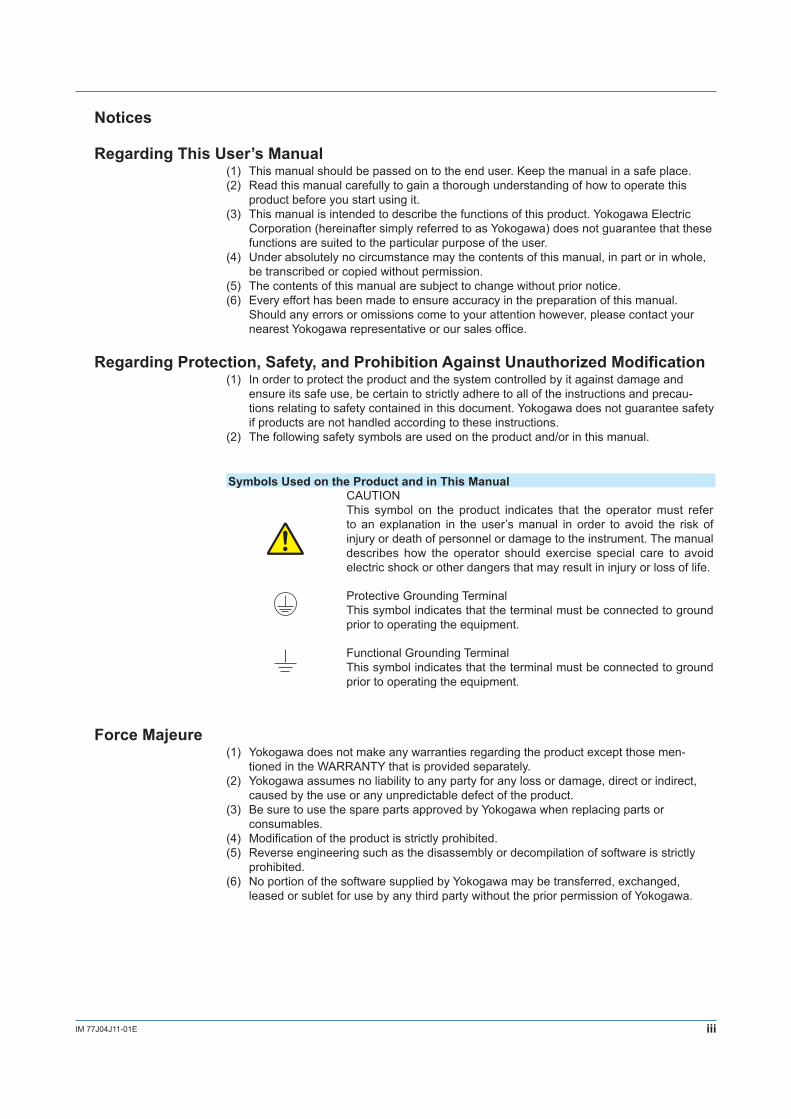
(2) The following safety symbols are used on the product and/or in this manual.
Symbols Used on the Product and in This ManualCAUTIONThis symbol on the product indicates that the operator must refer to an explanation in the user’s manual in order to avoid the risk of injury or death of personnel or damage to the instrument. The manual describes how the operator should exercise special care to avoid electric shock or other dangers that may result in injury or loss of life.
Protective Grounding TerminalThis symbol indicates that the terminal must be connected to ground prior to operating the equipment.
Functional Grounding TerminalThis symbol indicates that the terminal must be connected to ground prior to operating the equipment.
Force Majeure(1) Yokogawa does not make any warranties regarding the product except those men-
tioned in the WARRANTY that is provided separately.(2) Yokogawa assumes no liability to any party for any loss or damage, direct or indirect,
caused by the use or any unpredictable defect of the product.(3) Be sure to use the spare parts approved by Yokogawa when replacing parts or
consumables.(4) Modification of the product is strictly prohibited.(5) Reverse engineering such as the disassembly or decompilation of software is strictly
prohibited.(6) No portion of the software supplied by Yokogawa may be transferred, exchanged,
leased or sublet for use by any third party without the prior permission of Yokogawa.

Blank

vIM 77J04J11-01E
1
2
3
4
5
6
7
App
Contents
Introduction ................................................................................................................................................ iDocumentation Conventions .................................................................................................................... iiNotices iii
Chapter 1 Setup1.1 Setup Procedure .................................................................................................................1-11.2 Notes on Setting Parameters ..............................................................................................1-2
Chapter 2 Communication Specifications2.1 RS-485 Communication Specifications ...............................................................................2-1
Chapter 3 PC Link Communication3.1 Overview .............................................................................................................................3-1
3.1.1 Configuration of Command ....................................................................................................3-23.1.2 Configuration of Response .....................................................................................................3-33.1.3 Response Error Codes ...........................................................................................................3-43.1.4 Specifying Broadcast .............................................................................................................3-5
3.2 Commands ..........................................................................................................................3-63.2.1 List of Commands ..................................................................................................................3-6
3.3 Communication with Higher-level Devices ........................................................................3-203.3.1 Communication with UT Link Module ...................................................................................3-20
Chapter 4 Ladder Communication4.1 Overview .............................................................................................................................4-14.2 Commands/Responses at the PLC .....................................................................................4-2
4.2.1 Configuration of Command/Response ...................................................................................4-24.2.2 Reading Parameters ..............................................................................................................4-34.2.3 Writing Parameters ................................................................................................................4-44.2.4 Response Error Codes ...........................................................................................................4-5
Chapter 5 MODBUS Communication5.1 Overview .............................................................................................................................5-1
5.1.1 Configuration of Message ......................................................................................................5-25.1.2 Specifying D Registers ...........................................................................................................5-35.1.3 Error Check ............................................................................................................................5-35.1.4 Configuration of Responses ...................................................................................................5-6
5.2 Function Codes ...................................................................................................................5-75.2.1 List of Function Codes ...........................................................................................................5-75.2.2 Response Error Codes .........................................................................................................5-125.2.3 Specifying Broadcast ...........................................................................................................5-13
Chapter 6 Functions and Usage of D Registers6.1 Overview of D Registers .....................................................................................................6-16.2 Interpretation of D Register Map Table ...............................................................................6-16.3 D Register Map Table ..........................................................................................................6-2
6.3.1 Contents of D Registers .........................................................................................................6-4
Chapter 7 Functions and Usage of I Relays7.1 Status ..................................................................................................................................7-1
Revision Information

1-1IM 77J04J11-01E
Setup
1
2
3
4
5
6
7
App
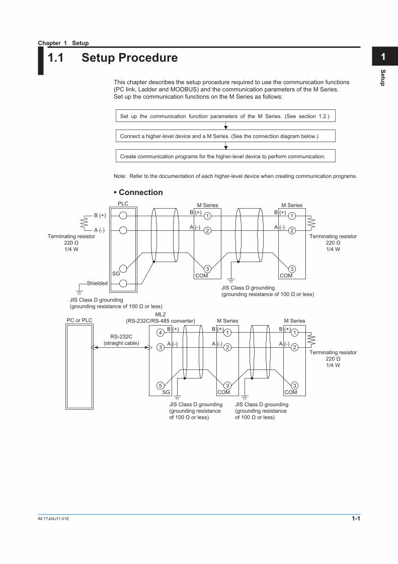
1.1 Setup Procedure
This chapter describes the setup procedure required to use the communication functions (PC link, Ladder and MODBUS) and the communication parameters of the M Series.Set up the communication functions on the M Series as follows:
Set up the communication function parameters of the M Series. (See section 1.2.)
Connect a higher-level device and a M Series. (See the connection diagram below.)
Create communication programs for the higher-level device to perform communication.
Note: Refer to the documentation of each higher-level device when creating communication programs.
B (+)
A (-)
Shielded
B (+)
A (-)
B (+)
A (-)
M Series M SeriesPLC
JIS Class D grounding(grounding resistance of 100 Ω or less)
JIS Class D grounding(grounding resistance of 100 Ω or less)
Terminating resistor220 Ω1/4 W
Terminating resistor220 Ω1/4 W
• Connection
1
2
3
1
2
3SG COMCOM
B (+)
A (-)
B (+)
A (-)
B (+)
A (-)
M Series M SeriesPC or PLC
JIS Class D grounding(grounding resistance of 100 Ω or less)
Terminating resistor220 Ω1/4 W
JIS Class D grounding(grounding resistance of 100 Ω or less)
1
2
3
1
2
3COMCOM
ML2(RS-232C/RS-485 converter)
RS-232C(straight cable)
4
3
5SG
Chapter 1 Setup
1-2 IM 77J04J11-01E
1.2 Notes on Setting Parameters
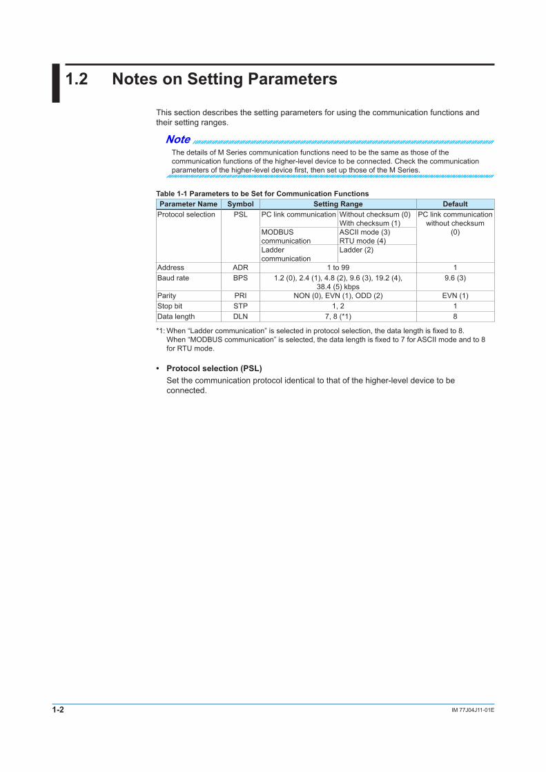
This section describes the setting parameters for using the communication functions and their setting ranges.
NoteThe details of M Series communication functions need to be the same as those of the communication functions of the higher-level device to be connected. Check the communication parameters of the higher-level device first, then set up those of the M Series.
Table 1-1 Parameters to be Set for Communication FunctionsParameter Name Symbol Setting Range Default
Protocol selection PSL PC link communication Without checksum (0)With checksum (1)
PC link communication without checksum
(0)MODBUS communication
ASCII mode (3)RTU mode (4)
Ladder communication
Ladder (2)
Address ADR 1 to 99 1Baud rate BPS 1.2 (0), 2.4 (1), 4.8 (2), 9.6 (3), 19.2 (4),
38.4 (5) kbps9.6 (3)
Parity PRI NON (0), EVN (1), ODD (2) EVN (1)Stop bit STP 1, 2 1Data length DLN 7, 8 (*1) 8
*1: When “Ladder communication” is selected in protocol selection, the data length is fixed to 8. When “MODBUS communication” is selected, the data length is fixed to 7 for ASCII mode and to 8 for RTU mode.
• Protocol selection (PSL) Set the communication protocol identical to that of the higher-level device to be
connected.
1-3IM 77J04J11-01E
Setup
1
2
3
4
5
6
7
App
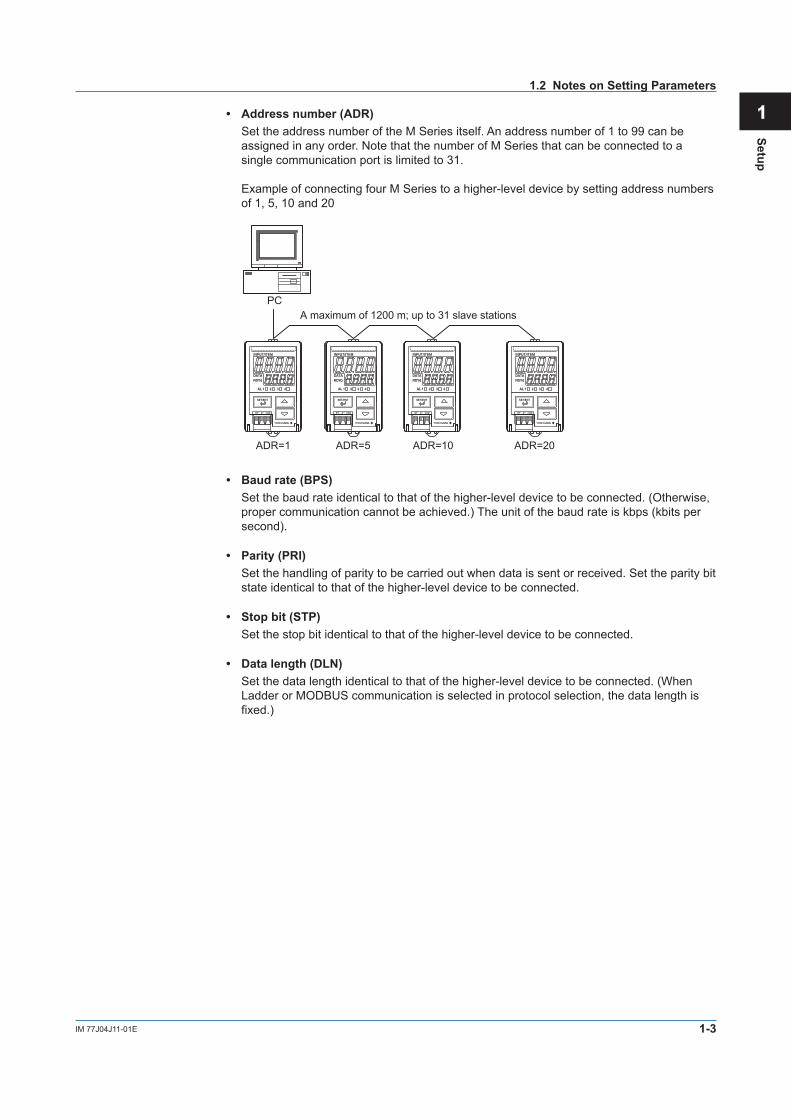
• Address number (ADR) Set the address number of the M Series itself. An address number of 1 to 99 can be
assigned in any order. Note that the number of M Series that can be connected to a single communication port is limited to 31.
Example of connecting four M Series to a higher-level device by setting address numbers of 1, 5, 10 and 20
ADR=1 ADR=20ADR=10ADR=5
A maximum of 1200 m; up to 31 slave stationsPC
• Baud rate (BPS) Set the baud rate identical to that of the higher-level device to be connected. (Otherwise,
proper communication cannot be achieved.) The unit of the baud rate is kbps (kbits per second).
• Parity (PRI) Set the handling of parity to be carried out when data is sent or received. Set the parity bit
state identical to that of the higher-level device to be connected.
• Stop bit (STP) Set the stop bit identical to that of the higher-level device to be connected.
• Data length (DLN) Set the data length identical to that of the higher-level device to be connected. (When
Ladder or MODBUS communication is selected in protocol selection, the data length is fixed.)
1.2 Notes on Setting Parameters

Blank
2-1IM 77J04J11-01E
Com
munication Specifications
1
2
3
4
5
6
7
App
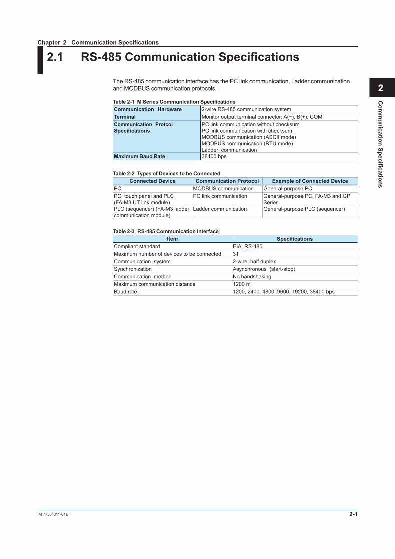
2.1 RS-485 Communication Specifications
The RS-485 communication interface has the PC link communication, Ladder communication and MODBUS communication protocols.
Table 2-1 M Series Communication SpecificationsCommunication Hardware 2-wire RS-485 communication systemTerminal Monitor output terminal connector: A(−), B(+), COMCommunication Protcol Specifications
PC link communication without checksumPC link communication with checksumMODBUS communication (ASCII mode)MODBUS communication (RTU mode)Ladder communication
Maximum Baud Rate 38400 bps
Table 2-2 Types of Devices to be ConnectedConnected Device Communication Protocol Example of Connected Device
PC MODBUS communication General-purpose PCPC, touch panel and PLC (FA-M3 UT link module)
PC link communication General-purpose PC, FA-M3 and GP Series
PLC (sequencer) (FA-M3 ladder communication module)
Ladder communication General-purpose PLC (sequencer)
Table 2-3 RS-485 Communication InterfaceItem Specifications
Compliant standard EIA, RS-485Maximum number of devices to be connected 31Communication system 2-wire, half duplexSynchronization Asynchronous (start-stop)Communication method No handshakingMaximum communication distance 1200 mBaud rate 1200, 2400, 4800, 9600, 19200, 38400 bps
Chapter 2 Communication Specifications

Blank
3-1IM 77J04J11-01E
PC Link C
omm
unication
1
2
3
4
5
6
7
App
3.1 Overview
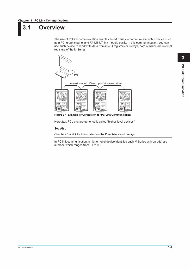
The use of PC link communication enables the M Series to communicate with a device such as a PC, graphic panel and FA-M3 UT link module easily. In this commu- nication, you can use such device to read/write data from/into D registers or I relays, both of which are internal registers of the M Series.
PC
A maximum of 1200 m; up to 31 slave stations
Figure 3-1 Example of Connection for PC Link Communication
Hereafter, PCs etc. are generically called “higher-level devices.”
See Also
Chapters 6 and 7 for information on the D registers and I relays.
In PC link communication, a higher-level device identifies each M Series with an address number, which ranges from 01 to 99.
Chapter 3 PC Link Communication
3-2 IM 77J04J11-01E
3.1.1 Configuration of Command
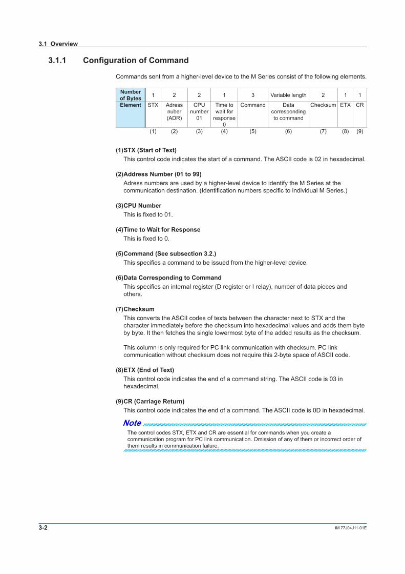
Commands sent from a higher-level device to the M Series consist of the following elements.
Number of Bytes 1 2 2 1 3 Variable length 2 1 1
Element STX Adress nuber (ADR)
CPUnumber
01
Time to wait for
response 0
Command Data corresponding to command
Checksum ETX CR
(1) (2) (3) (4) (5) (6) (7) (8) (9)
(1) STX (Start of Text)
This control code indicates the start of a command. The ASCII code is 02 in hexadecimal.
(2) Address Number (01 to 99)Adress numbers are used by a higher-level device to identify the M Series at the communication destination. (Identification numbers specific to individual M Series.)
(3) CPU NumberThis is fixed to 01.
(4) Time to Wait for ResponseThis is fixed to 0.
(5) Command (See subsection 3.2.)This specifies a command to be issued from the higher-level device.
(6) Data Corresponding to CommandThis specifies an internal register (D register or I relay), number of data pieces and others.
(7) ChecksumThis converts the ASCII codes of texts between the character next to STX and the character immediately before the checksum into hexadecimal values and adds them byte by byte. It then fetches the single lowermost byte of the added results as the checksum. This column is only required for PC link communication with checksum. PC link communication without checksum does not require this 2-byte space of ASCII code.
(8) ETX (End of Text)This control code indicates the end of a command string. The ASCII code is 03 in hexadecimal.
(9) CR (Carriage Return)This control code indicates the end of a command. The ASCII code is 0D in hexadecimal.
NoteThe control codes STX, ETX and CR are essential for commands when you create a communication program for PC link communication. Omission of any of them or incorrect order of them results in communication failure.
3.1 Overview

3-3IM 77J04J11-01E
PC Link C
omm
unication
1
2
3
4
5
6
7
App
3.1.2 Configuration of Response
Responses from the M Series with respect to a command sent from the higher-level device consist of the following elements, which differ depending on the condition of communication; normal or failure.
1) Normal CommunicationIf communication succeeded, a character string “OK” is returned with the data corresponding to a command.
Number of Bytes 1 2 2 2 Variable length 2 1 1
Element STX Address nuber (ADR)
CPUnumber
01
OK Parameter data Checksum ETX CR
2) In the Event of FailureIf communication failed, a character string “ER” is returned with error codes (EC1 and EC2). (See subsection 3.1.3, “Response Error Codes.”)
• No response is returned in case of an error in address number specification or CPU number specification.
• If ETX in a command cannot be received, a response may not be returned.
Note: As a countermeasure, provide a timeout process in the communication functions of the higher-level device or in communication programs.
Number of Bytes 1 2 2 2 2 2 3 2 1 1
Element STX Address number (ADR)
CPUnumber
01
ER EC1 EC2 Command Checksum ETX CR
3.1 Overview

3-4 IM 77J04J11-01E
3.1.3 Response Error Codes
See Also
3.1.2, “Configuration of Response”, for the structure of response in the event of error.
The error codes (EC1) and detailed error codes (EC2) of responses are as follows.
Table 3-1 List of Error Codes EC1Error Code Meaning Cause(s)
02 Command error • No command exists.• Command not executable
03 Register specification error • No register number exists.• Invalid specification of bit register (I relay) when it is used on
a word basis04 Out of setpoint range • Any character other than 0 or 1 is used for bit setting.
• A value other than 0000 to FFFF has been specified in word specification.
• The position of a start for a data load is out of the address range.
05 Out of data count range • The specification of the number of bits, words, etc. is out of the range of use.
• The number of data specified and that of parameters for registers and others are not consistent.
06 Monitor error • An attempt was made to execute monitoring without specifying the monitor (BRS or WRS).
08 Parameter error • An illegal parameter is set.42 Sum error • The sum does not match the expected value.43 Internal buffer overflow • A data value greater than the specified was received.44 Character reception
interval timeout• The end-of-data or end-of-text character has not been
received.
Table 3-2 List of Detailed Error Codes EC2Error Code
(EC1) Meaning Detailed Error Code (EC2)
03 Register specification error Parameter number where error occurred (HEX)This is the sequence number of a parameter that first resulted in an error when counted from the leading parameter.
e.g.: Register specification error↓
[STX]01010BRR02 I0001,D0001[ETX][CR]Parameter numbers 1 2 3
[STX]0101ER0303BRR[ETX][CR]
04 Out of setpoint range05 Out of data count range
08 Parameter error • An illegal parameter is set.
For error codes other than those noted as EC1, there is no EC2 meaning.
Priority of Error CodesPriority Error code EC1
High 44434202
Low 03, 04, 05, 06, 08
When no response is returned(1) Retransmission error (overrun, framing, parity)(2) When the communication address in the command is wrong (including broadcast specification)(3) When the CPU No. in the command is not “01”
3.1 Overview

3-5IM 77J04J11-01E
PC Link C
omm
unication
1
2
3
4
5
6
7
App
3.1.4 Specifying Broadcast
Broadcast addressing allows the corresponding multiple M Series to receive the command.(1) To use this function, specify BM for the address number in a command.(2) Broadcast addressing works independently of the address number.(3) Broadcast addressing is only applicable to write commands (BWR, BRW, BRS, WWR,
WRW, WRS).(4) No response is returned if broadcast addressing is used.
Higher-level device (master)
Broadcast data.
* No response from slaves
A maximum of 1200 m; up to 31 slave stations
For the M Series communication, D registers and I relays are used.
3.1 Overview

3-6 IM 77J04J11-01E
3.2 Commands
3.2.1 List of Commands
The following shows lists of commands available in PC link communication. Their details are explained in the description of each command.
(1) Bit-basis Access Commands Dedicated to I Relays
Command Description Number of Bits to be HandledBRD Bit-basis read 1 to 256 bitsBWR Bit-basis write 1 to 256 bitsBRR Bit-basis random read 1 to 32 bitsBRW Bit-basis random write 1 to 32 bitsBRS Specifies registers to be monitored on a bit-by-bit basis. 1 to 32 bitsBRM Bit-basis monitoring –––––––––––––––––––––––––––
(2) Word-basis Access Commands
Command Description Number of Words to be HandledWRD Word-basis read 1 to 64 wordsWWR Word-basis write 1 to 64 wordsWRR Word-basis random read 1 to 32 wordsWRW Word-basis random write 1 to 32 wordsWRS Specifies registers to be monitored on a word-by-word
basis.1 to 32 words
WRM Word-basis monitoring –––––––––––––––––––––––––––
(3) Information Command
Command Description Number of Units to be HandledINF Reads model, input range code, number of alarms and
revision.1
3-7IM 77J04J11-01E
PC Link C
omm
unication
1
2
3
4
5
6
7
App
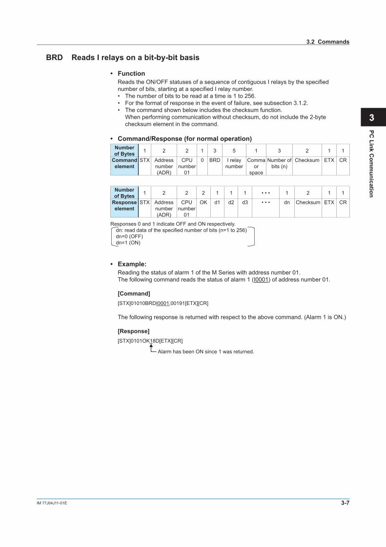
BRD Reads I relays on a bit-by-bit basis
• Function Reads the ON/OFF statuses of a sequence of contiguous I relays by the specified
number of bits, starting at a specified I relay number.• The number of bits to be read at a time is 1 to 256.• For the format of response in the event of failure, see subsection 3.1.2.• The command shown below includes the checksum function.
When performing communication without checksum, do not include the 2-byte checksum element in the command.
• Command/Response (for normal operation)Number of Bytes 1 2 2 1 3 5 1 3 2 1 1
Command element
STX Address number (ADR)
CPUnumber
01
0 BRD I relay number
Comma or
space
Number of bits (n)
Checksum ETX CR
Number of Bytes 1 2 2 2 1 1 1 • • • 1 2 1 1
Response element
STX Address number (ADR)
CPUnumber
01
OK d1 d2 d3 • • • dn Checksum ETX CR
Responses 0 and 1 indicate OFF and ON respectively.dn: read data of the specified number of bits (n=1 to 256) dn=0 (OFF)dn=1 (ON)
• Example: Reading the status of alarm 1 of the M Series with address number 01. The following command reads the status of alarm 1 (I0001) of address number 01.
[Command] [STX]01010BRDI0001,00191[ETX][CR]
The following response is returned with respect to the above command. (Alarm 1 is ON.)
[Response] [STX]0101OK18D[ETX][CR]
Alarm has been ON since 1 was returned.
3.2 Commands
3-8 IM 77J04J11-01E
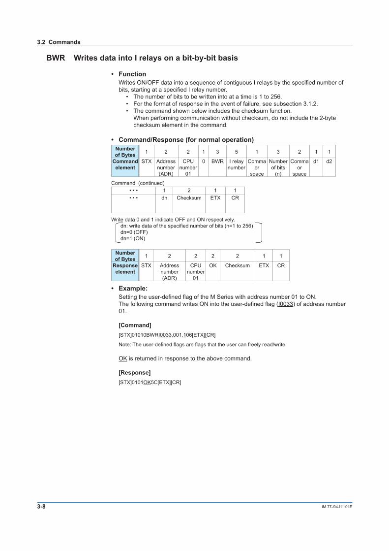
BWR Writes data into I relays on a bit-by-bit basis
• Function Writes ON/OFF data into a sequence of contiguous I relays by the specified number of
bits, starting at a specified I relay number.• The number of bits to be written into at a time is 1 to 256.• For the format of response in the event of failure, see subsection 3.1.2.• The command shown below includes the checksum function.
When performing communication without checksum, do not include the 2-byte checksum element in the command.
• Command/Response (for normal operation)Number of Bytes 1 2 2 1 3 5 1 3 2 1 1
Command element
STX Address number (ADR)
CPUnumber
01
0 BWR I relay number
Comma or
space
Number of bits
(n)
Comma or
space
d1 d2
Command (continued)• • • 1 2 1 1• • • dn Checksum ETX CR
Write data 0 and 1 indicate OFF and ON respectively.dn: write data of the specified number of bits (n=1 to 256)dn=0 (OFF)dn=1 (ON)
Number of Bytes 1 2 2 2 2 1 1
Response element
STX Address number (ADR)
CPUnumber
01
OK Checksum ETX CR
• Example:Setting the user-defined flag of the M Series with address number 01 to ON.The following command writes ON into the user-defined flag (I0033) of address number 01.
[Command][STX]01010BWRI0033,001,106[ETX][CR]
Note: The user-defined flags are flags that the user can freely read/write.
OK is returned in response to the above command.
[Response][STX]0101OK5C[ETX][CR]
3.2 Commands
3-9IM 77J04J11-01E
PC Link C
omm
unication
1
2
3
4
5
6
7
App
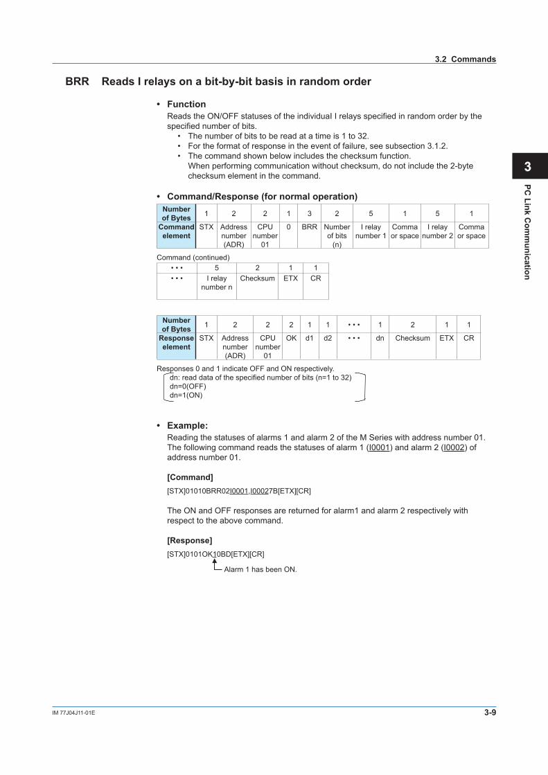
BRR Reads I relays on a bit-by-bit basis in random order
• Function Reads the ON/OFF statuses of the individuaI I relays specified in random order by the
specified number of bits.• The number of bits to be read at a time is 1 to 32.• For the format of response in the event of failure, see subsection 3.1.2.• The command shown below includes the checksum function.
When performing communication without checksum, do not include the 2-byte checksum element in the command.
• Command/Response (for normal operation)Number of Bytes 1 2 2 1 3 2 5 1 5 1
Command element
STX Address number (ADR)
CPUnumber
01
0 BRR Number of bits
(n)
I relay number 1
Comma or space
I relay number 2
Comma or space
Command (continued)• • • 5 2 1 1• • • I relay
number nChecksum ETX CR
Number of Bytes 1 2 2 2 1 1 • • • 1 2 1 1
Response element
STX Address number (ADR)
CPUnumber
01
OK d1 d2 • • • dn Checksum ETX CR
Responses 0 and 1 indicate OFF and ON respectively.dn: read data of the specified number of bits (n=1 to 32)dn=0(OFF)dn=1(ON)
• Example:Reading the statuses of alarms 1 and alarm 2 of the M Series with address number 01.The following command reads the statuses of alarm 1 (I0001) and alarm 2 (I0002) of address number 01.
[Command][STX]01010BRR02I0001,I00027B[ETX][CR]
The ON and OFF responses are returned for alarm1 and alarm 2 respectively with respect to the above command.
[Response][STX]0101OK10BD[ETX][CR]
Alarm 1 has been ON.
3.2 Commands
3-10 IM 77J04J11-01E
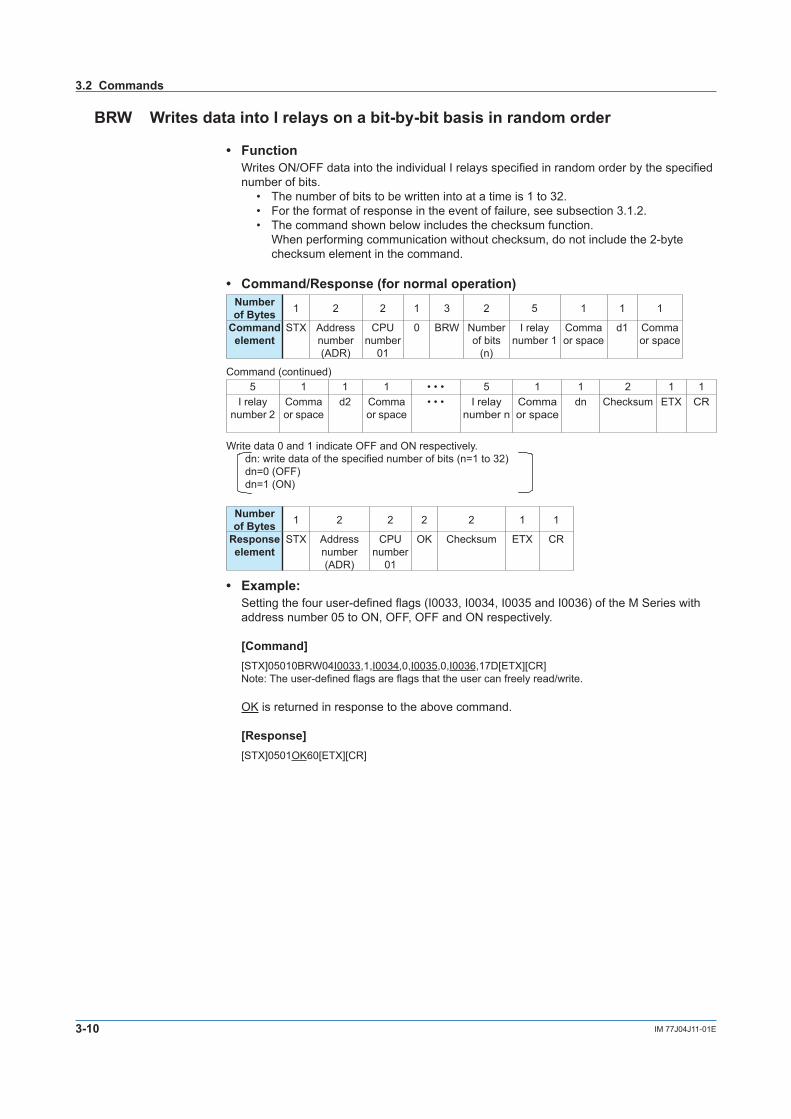
BRW Writes data into I relays on a bit-by-bit basis in random order
• Function Writes ON/OFF data into the individual I relays specified in random order by the specified
number of bits.• The number of bits to be written into at a time is 1 to 32.• For the format of response in the event of failure, see subsection 3.1.2.• The command shown below includes the checksum function.
When performing communication without checksum, do not include the 2-byte checksum element in the command.
• Command/Response (for normal operation)Number of Bytes 1 2 2 1 3 2 5 1 1 1
Command element
STX Address number (ADR)
CPUnumber
01
0 BRW Number of bits
(n)
I relay number 1
Comma or space
d1 Comma or space
Command (continued)5 1 1 1 • • • 5 1 1 2 1 1
I relay number 2
Comma or space
d2 Comma or space
• • • I relay number n
Comma or space
dn Checksum ETX CR
Write data 0 and 1 indicate OFF and ON respectively.dn: write data of the specified number of bits (n=1 to 32)dn=0 (OFF)dn=1 (ON)
Number of Bytes 1 2 2 2 2 1 1
Response element
STX Address number (ADR)
CPUnumber
01
OK Checksum ETX CR
• Example:Setting the four user-defined flags (I0033, I0034, I0035 and I0036) of the M Series with address number 05 to ON, OFF, OFF and ON respectively.
[Command][STX]05010BRW04I0033,1,I0034,0,I0035,0,I0036,17D[ETX][CR]Note: The user-defined flags are flags that the user can freely read/write.
OK is returned in response to the above command.
[Response][STX]0501OK60[ETX][CR]
3.2 Commands
3-11IM 77J04J11-01E
PC Link C
omm
unication
1
2
3
4
5
6
7
App
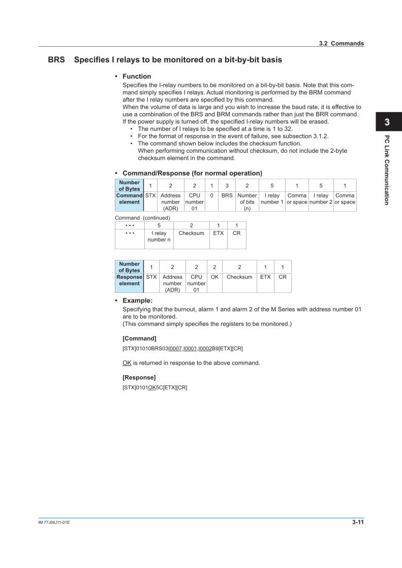
BRS Specifies I relays to be monitored on a bit-by-bit basis
• FunctionSpecifies the I-relay numbers to be monitored on a bit-by-bit basis. Note that this com- mand simply specifies I relays. Actual monitoring is performed by the BRM command after the I relay numbers are specified by this command.When the volume of data is large and you wish to increase the baud rate, it is effective to use a combination of the BRS and BRM commands rather than just the BRR command.If the power supply is turned off, the specified I-relay numbers will be erased.
• The number of I relays to be specified at a time is 1 to 32.• For the format of response in the event of failure, see subsection 3.1.2.• The command shown below includes the checksum function.
When performing communication without checksum, do not include the 2-byte checksum element in the command.
• Command/Response (for normal operation)Number of Bytes 1 2 2 1 3 2 5 1 5 1
Command element
STX Address number (ADR)
CPUnumber
01
0 BRS Number of bits
(n)
I relay number 1
Comma or space
I relay number 2
Comma or space
Command (continued)• • • 5 2 1 1• • • I relay
number nChecksum ETX CR
Number of Bytes 1 2 2 2 2 1 1
Response element
STX Address number (ADR)
CPUnumber
01
OK Checksum ETX CR
• Example:Specifying that the burnout, alarm 1 and alarm 2 of the M Series with address number 01 are to be monitored.(This command simply specifies the registers to be monitored.)
[Command][STX]01010BRS03I0007,I0001,I0002B9[ETX][CR]
OK is returned in response to the above command.
[Response][STX]0101OK5C[ETX][CR]
3.2 Commands
3-12 IM 77J04J11-01E
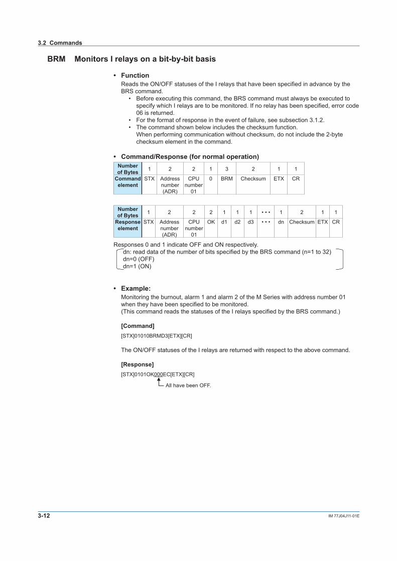
BRM Monitors I relays on a bit-by-bit basis
• Function Reads the ON/OFF statuses of the I relays that have been specified in advance by the
BRS command.• Before executing this command, the BRS command must always be executed to
specify which I relays are to be monitored. If no relay has been specified, error code 06 is returned.
• For the format of response in the event of failure, see subsection 3.1.2.• The command shown below includes the checksum function.
When performing communication without checksum, do not include the 2-byte checksum element in the command.
• Command/Response (for normal operation)Number of Bytes 1 2 2 1 3 2 1 1
Command element
STX Address number (ADR)
CPUnumber
01
0 BRM Checksum ETX CR
Number of Bytes 1 2 2 2 1 1 1 • • • 1 2 1 1
Response element
STX Address number (ADR)
CPUnumber
01
OK d1 d2 d3 • • • dn Checksum ETX CR
Responses 0 and 1 indicate OFF and ON respectively.dn: read data of the number of bits specified by the BRS command (n=1 to 32)dn=0 (OFF)dn=1 (ON)
• Example:Monitoring the burnout, alarm 1 and alarm 2 of the M Series with address number 01 when they have been specified to be monitored.(This command reads the statuses of the I relays specified by the BRS command.)
[Command][STX]01010BRMD3[ETX][CR]
The ON/OFF statuses of the I relays are returned with respect to the above command.
[Response][STX]0101OK000EC[ETX][CR]
All have been OFF.
3.2 Commands

3-13IM 77J04J11-01E
PC Link C
omm
unication
1
2
3
4
5
6
7
App
WRD Reads D registers and I relays on a word-by-word basis
• FunctionReads a sequence of contiguous register data on a word-by-word basis by the specified number of words, starting at a specified register number.
• The number of words to be read at a time is 1 to 64.• For the format of response in the event of failure, see subsection 3.1.2.• The command shown below includes the checksum function.
When performing communication without checksum, do not include the 2-byte checksum element in the command.
• Command/Response (for normal operation)Number of Bytes 1 2 2 1 3 5 1 2 2 1 1
Command element
STX Address number (ADR)
CPUnumber
01
0 WRD Register number
Comma or
space
Number of words
(n)
Checksum ETX CR
Number of Bytes 1 2 2 2 4 4 • • • 4 2 1 1
Response element
STX Address number (ADR)
CPUnumber
01
OK dddd1 dddd2 • • • ddddn Checksum ETX CR
The response is returned in a 4-digit character string (0000 to FFFF) in hexadecimal.ddddn: read data of the specified number of words ddddn is a character string in hexadecimal.n=1 to 64
• Example:Reading the alarm-1 setpoint (D0101) of the M Series with address number 01.
[Command][STX]01010WRDD0101,0172[ETX][CR]
The alarm-1 setpoint 500 (01F4 [HEX]) is returned in response to the above command (50.0 is expressed as 500).
[Response][STX]0101OK01F437[ETX][CR]
500 in decimal (Alarm-1 setpoint [A1] is 50.0.)
3.2 Commands

3-14 IM 77J04J11-01E
WWR Writes data into D registers and I relays on a word-by-word basis
• FunctionWrites data into a sequence of contiguous registers on a word-by-word basis by the specified number of words, starting at a specified register number .
• The number of words to be written into at a time is 1 to 64.• For the format of response in the event of failure, see subsection 3.1.2.• The command shown below includes the checksum function.
When performing communication without checksum, do not include the 2-byte checksum element in the command.-
• Command/Response (for normal operation)Number of Bytes 1 2 2 1 3 5 1 2 1 4
Command element
STX Address number (ADR)
CPUnumber
01
0 WWR Register number
Comma or space
Number of words
(n)
Comma or space
dddd1
Command (continued)4 • • • 4 2 1 1
dddd2 • • • ddddn Checksum ETX CR
Write data is specified in a 4-digit character string (0000 to FFFF) in hexadecimal.ddddn: write data of the specified number of wordsddddn is a character string in hexadecimal.n=1 to 64
Number of Bytes 1 2 2 2 2 1 1
Response element
STX Address number (ADR)
CPUnumber
01
OK Checksum ETX CR
• Example:Writing 200 (00C8 [HEX]) into the alarm-1 setpoint (D0101) of the M Series with address number 03.
[Command][STX]03010WWRD0101,01,00C88E[ETX][CR]
OK is returned in response to the above command.
[Response][STX]0301OK5E[ETX][CR]
3.2 Commands

3-15IM 77J04J11-01E
PC Link C
omm
unication
1
2
3
4
5
6
7
App
WRR Reads D registers and I relays on a word-by-word basis in random order
• FunctionReads the statuses of the individul registers on a word-by-word basis specified in random order by the specified number of words.
• The number of words to be read at a time is 1 to 32.• For the format of response in the event of failure, see subsection 3.1.2.• The command shown below includes the checksum function.
When performing communication without checksum, do not include the 2-byte checksum element in the command.
• Command/Response (for normal operation)Number of Bytes 1 2 2 1 3 2 5 1 5 1
Command element
STX Address number (ADR)
CPUnumber
01
0 WRR Number of words
(n)
Register number 1
Comma or space
Register number 2
Comma or space
Command (continued)• • • 5 2 1 1• • • Register
number nChecksum ETX CR
Number of Bytes 1 2 2 2 4 4 • • • 4 2 1 1
Response element
STX Address number (ADR)
CPUnumber
01
OK dddd1 dddd2 • • • ddddn Checksum ETX CR
The response is returned in a 4-digit character string (0000 to FFFF) in hexadecimal.ddddn: read data of the specified number of wordsddddn is a character string in hexadecimal.n=1 to 32
• Example:Reading the alarm-1 setpoint (D0101) and alarm-2 setpoint (D0102) of the M Series with address number 01.
[Command][STX]01010WRR02D0101,D010288[ETX][CR]
The alarm-1 setpoint 500 (01F4 [HEX]) and alarm-2 setpoint 500 (01F4 [HEX]) are re- turned with respect to the above command (50.0 is expressed as 500).
[Response][STX]0101OK01F4 01F412[ETX][CR]
500 in decimal 500 in decimal(Alarm-1 setpoint is 50.0.) (Alarm-2 setpoint is 50.0.)
3.2 Commands
3-16 IM 77J04J11-01E
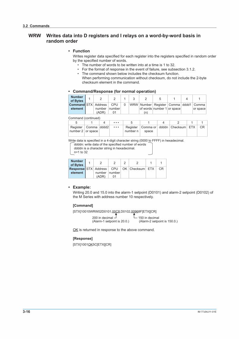
WRW Writes data into D registers and I relays on a word-by-word basis in random order
• Function Writes register data specified for each register into the registers specified in random order
by the specified number of words.• The number of words to be written into at a time is 1 to 32.• For the format of response in the event of failure, see subsection 3.1.2.• The command shown below includes the checksum function.
When performing communication without checksum, do not include the 2-byte checksum element in the command.
• Command/Response (for normal operation)Number of Bytes 1 2 2 1 3 2 5 1 4 1
Command element
STX Address number (ADR)
CPUnumber
01
0 WRW Number of words
(n)
Register number 1
Comma or space
dddd1 Comma or space
Command (continued)5 1 4 • • • 5 1 4 2 1 1
Register number 2
Comma or space
dddd2 • • • Register number n
Comma or space
ddddn Checksum ETX CR
Write data is specified in a 4-digit character string (0000 to FFFF) in hexadecimal.ddddn: write data of the specified number of wordsddddn is a character string in hexadecimal.n=1 to 32
Number of Bytes 1 2 2 2 2 1 1
Response element
STX Address number (ADR)
CPUnumber
01
OK Checksum ETX CR
• Example:Writing 20.0 and 15.0 into the alarm-1 setpoint (D0101) and alarm-2 setpoint (D0102) of the M Series with address number 10 respectively.
[Command][STX]10010WRW02D0101,00C8,D0102,00968F[ETX][CR]
200 in decimal 150 in decimal(Alarm-1 setpoint is 20.0.) (Alarm-2 setpoint is 150.0.)
OK is returned in response to the above command.
[Response][STX]1001OK5C[ETX][CR]
3.2 Commands
3-17IM 77J04J11-01E
PC Link C
omm
unication
1
2
3
4
5
6
7
App
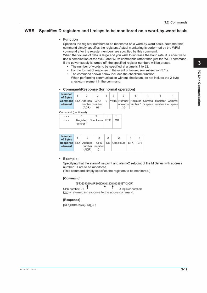
WRS Specifies D registers and I relays to be monitored on a word-by-word basis
• FunctionSpecifies the register numbers to be monitored on a word-by-word basis. Note that this command simply specifies the registers. Actual monitoring is performed by the WRM command after the register numbers are specified by this command.When the volume of data is large and you wish to increase the baud rate, it is effective to use a combination of the WRS and WRM commands rather than just the WRR command.If the power supply is turned off, the specified register numbers will be erased.
• The number of words to be specified at a time is 1 to 32.• For the format of response in the event of failure, see subsection 3.1.2.• The command shown below includes the checksum function.
When performing communication without checksum, do not include the 2-byte checksum element in the command.
• Command/Response (for normal operation)Number of Bytes 1 2 2 1 3 2 5 1 5 1
Command element
STX Address number (ADR)
CPUnumber
01
0 WRS Number of words
(n)
Register number 1
Comma or space
Register number 2
Comma or space
Command (continued)• • • 5 2 1 1• • • Register
number nChecksum ETX CR
Number of Bytes 1 2 2 2 2 1 1
Response element
STX Address number (ADR)
CPUnumber
01
OK Checksum ETX CR
• Example:Specifying that the alarm-1 setpoint and alarm-2 setpoint of the M Series with address number 01 are to be monitored(This command simply specifies the registers to be monitored.)
[Command][STX]01010WRS02D0101,D010289[ETX][CR]
CPU number: 01 D register numbersOK is returned in response to the above command.
[Response][STX]0101OK5C[ETX][CR]
3.2 Commands
3-18 IM 77J04J11-01E
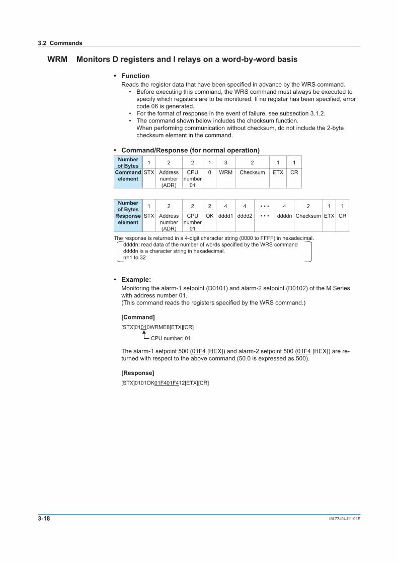
WRM Monitors D registers and I relays on a word-by-word basis
• FunctionReads the register data that have been specified in advance by the WRS command.
• Before executing this command, the WRS command must always be executed to specify which registers are to be monitored. If no register has been specified, error code 06 is generated.
• For the format of response in the event of failure, see subsection 3.1.2.• The command shown below includes the checksum function.
When performing communication without checksum, do not include the 2-byte checksum element in the command.
• Command/Response (for normal operation)Number of Bytes 1 2 2 1 3 2 1 1
Command element
STX Address number (ADR)
CPUnumber
01
0 WRM Checksum ETX CR
Number of Bytes 1 2 2 2 4 4 • • • 4 2 1 1
Response element
STX Address number (ADR)
CPUnumber
01
OK dddd1 dddd2 • • • ddddn Checksum ETX CR
The response is returned in a 4-digit character string (0000 to FFFF) in hexadecimal.ddddn: read data of the number of words specified by the WRS command ddddn is a character string in hexadecimal.n=1 to 32
• Example:Monitoring the alarm-1 setpoint (D0101) and alarm-2 setpoint (D0102) of the M Series with address number 01.(This command reads the registers specified by the WRS command.)
[Command][STX]01010WRME8[ETX][CR]
CPU number: 01
The alarm-1 setpoint 500 (01F4 [HEX]) and alarm-2 setpoint 500 (01F4 [HEX]) are re- turned with respect to the above command (50.0 is expressed as 500).
[Response][STX]0101OK01F401F412[ETX][CR]
3.2 Commands
3-19IM 77J04J11-01E
PC Link C
omm
unication
1
2
3
4
5
6
7
App
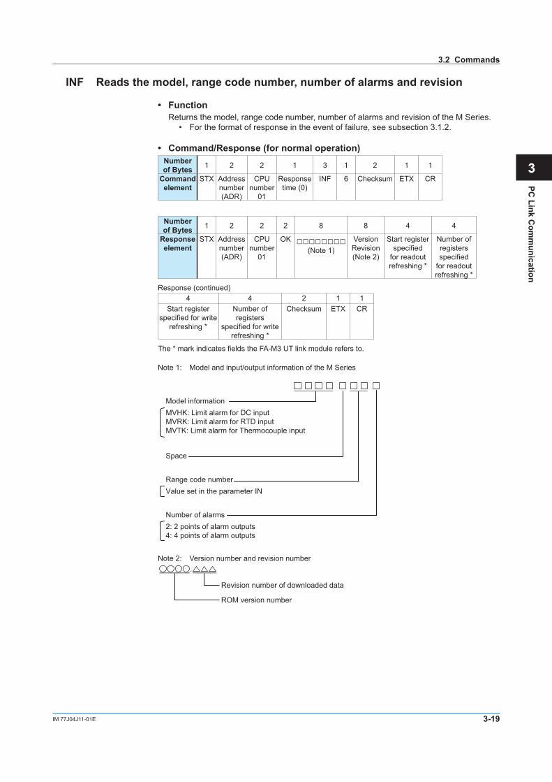
INF Reads the model, range code number, number of alarms and revision
• FunctionReturns the model, range code number, number of alarms and revision of the M Series.
• For the format of response in the event of failure, see subsection 3.1.2.
• Command/Response (for normal operation)Number of Bytes 1 2 2 1 3 1 2 1 1
Command element
STX Address number (ADR)
CPUnumber
01
Response time (0)
INF 6 Checksum ETX CR
Number of Bytes 1 2 2 2 8 8 4 4
Response element
STX Address number (ADR)
CPUnumber
01
OK (Note 1)
Version Revision (Note 2)
Start register specified
for readout refreshing *
Number of registers specified
for readout refreshing *
Response (continued)4 4 2 1 1
Start register specified for write
refreshing *
Number of registers
specified for write refreshing *
Checksum ETX CR
The * mark indicates fields the FA-M3 UT link module refers to.
Note 1: Model and input/output information of the M Series
Model informationMVHK: Limit alarm for DC inputMVRK: Limit alarm for RTD inputMVTK: Limit alarm for Thermocouple input
Number of alarms2: 2 points of alarm outputs4: 4 points of alarm outputs
Range code number Value set in the parameter IN
Space
Note 2: Version number and revision number
Revision number of downloaded data
ROM version number
.
3.2 Commands

3-20 IM 77J04J11-01E
3.3 Communication with Higher-level Devices
Higher-level devices are those capable of using the PC link communication protocol. As an example of a communication program, the Basic program created using Microsoft Visual Basic is given in subsection 3.3.1. Further, communications with an FA-M3 UT link module or touch panel can be achieved without creating a complex program. Examples of communication with them are given in subsections 3.3.2 and 3.3.3.
3.3.1 Communication with UT Link Module
Communication with FA-M3 is achieved by simply connecting the M Series to a UT link module using the PC link communication protocol. Set the communication conditions of the M Series identical to those of the UT link module.
FA-M3
Model of UT link module: F3LC51-2N
A maximum of 1200 m; up to 31 slave stations
The UT link module supports the following two types of communication modes and command communication, which allow you to communicate with FA-M3 without being aware of it. For more information, see the optionally available “UT Link Module User’s Manual (IM 34M6H25-01E).”
1. Automatic mode This mode enables the instrument’s fixed devices (those that cannot be specified by the user) to be constantly refreshed by reading from them. The fixed devices are D0001 to D0004. They are read-only areas and cannot be written into.
2. Manual mode This mode enables the instrument’s devices (those that can be specified by the user) to be constantly refreshed by reading from and/or writing into them.
See Also
The devices mentioned here are D registers and I relays. For more information on D registers and I relays, see Chapters 6 and 7.
3. Command communication Command communication allows the user to communicate with instruments as and when required.
4-1IM 77J04J11-01E
Ladder Com
munication
1
2
3
4
5
6
7
App
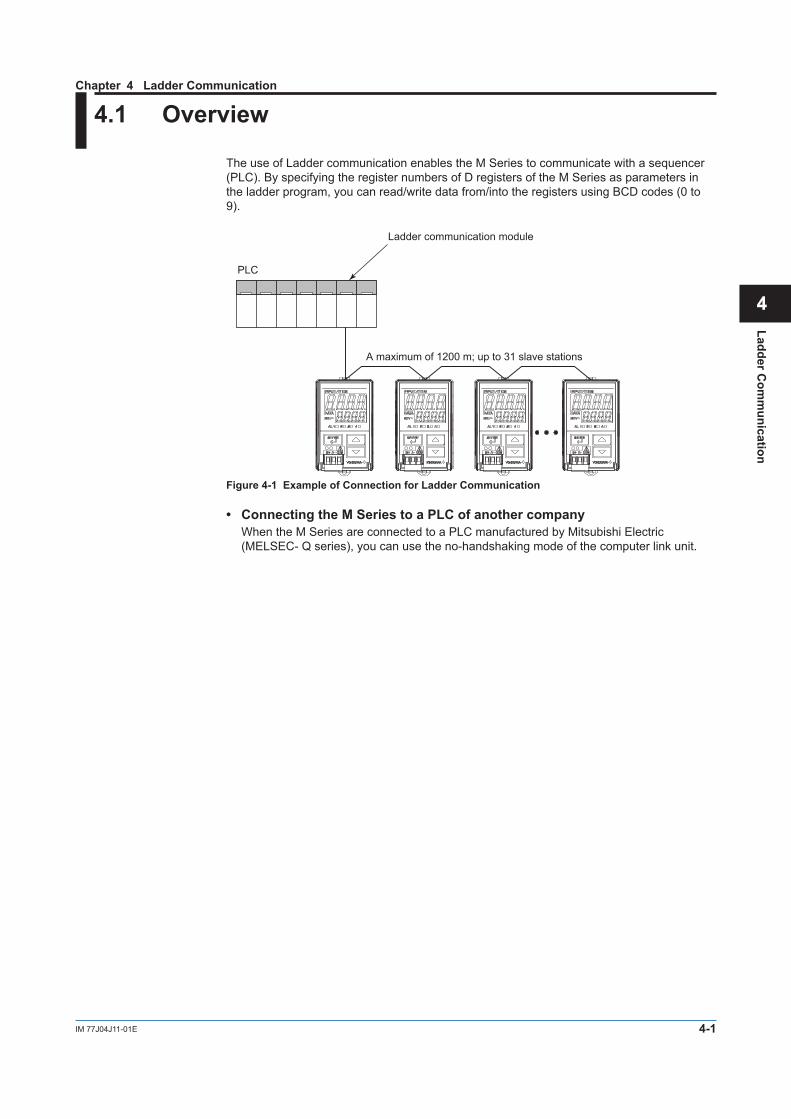
4.1 Overview
The use of Ladder communication enables the M Series to communicate with a sequencer (PLC). By specifying the register numbers of D registers of the M Series as parameters in the ladder program, you can read/write data from/into the registers using BCD codes (0 to 9).
Ladder communication module
PLC
A maximum of 1200 m; up to 31 slave stations
Figure 4-1 Example of Connection for Ladder Communication
• Connecting the M Series to a PLC of another company When the M Series are connected to a PLC manufactured by Mitsubishi Electric
(MELSEC- Q series), you can use the no-handshaking mode of the computer link unit.
Chapter 4 Ladder Communication
4-2 IM 77J04J11-01E
4.2 Commands/Responses at the PLC
The PLC sends commands and receives responses to these commands. The com- mands and responses that can be used are as follows.
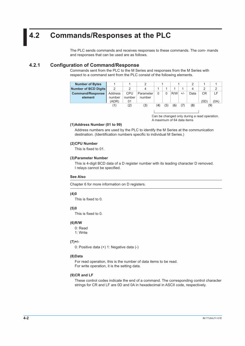
4.2.1 Configuration of Command/ResponseCommands sent from the PLC to the M Series and responses from the M Series with respect to a command sent from the PLC consist of the following elements.
Number of Bytes 1 1 2 1 1 2 1 1Number of BCD Digits 2 2 4 1 1 1 1 4 2 2Command/Response
elementAddress number (ADR)
CPUnumber
01
Parameter number
0 0 R/W +/- Data CR
(0D)
LF
(0A)(1) (2) (3) (4) (5) (6) (7) (8) (9)
Can be changed only during a read operation. A maximum of 64 data items
(1) Address Number (01 to 99)Address numbers are used by the PLC to identify the M Series at the communication destination. (Identification numbers specific to individual M Series.)
(2) CPU Number This is fixed to 01.
(3) Parameter NumberThis is 4-digit BCD data of a D register number with its leading character D removed. I relays cannot be specified.
See Also
Chapter 6 for more information on D registers.
(4) 0This is fixed to 0.
(5) 0This is fixed to 0.
(6) R/W0: Read 1: Write
(7) +/-0: Positive data (+) 1: Negative data (-)
(8) DataFor read operation, this is the number of data items to be read. For write operation, it is the setting data.
(9) CR and LFThese control codes indicate the end of a command. The corresponding control character strings for CR and LF are 0D and 0A in hexadecimal in ASCII code, respectively.

4-3IM 77J04J11-01E
Ladder Com
munication
1
2
3
4
5
6
7
App
4.2.2 Reading Parameters
Shown below are the configurations of commands and responses when parameters in the M Series are read by the PLC. (The maximum number of data items to be read is 64.)
• Command/ResponseNumber of Bytes 1 1 2 1 1 2 1 1
Number of BCD Digits 2 2 4 1 1 1 1 4 2 2Command element Address
number (ADR)
CPUnumber
01
Parameter number
0 0 0 0 Number of read data
(n)
CR
(0D)
LF
(0A)
Number of Bytes 1 1 2 1 1 2 1 1 2Number of BCD Digits 2 2 4 1 1 1 1 4 1 1 1 1 4
Response element Address number (ADR)
CPUnumber
01
Parameter number
0 0 0 +/- dddd1 0 0 0 +/- dddd2
Data of parameter Data of parameter
number (a) number (b)
• • • 1 1 2 1 11 1 1 1 4 2 2
• • •0 0 0 +/- ddddn CR
(0D)
LF
(0A)
Data of parameter number (n)
• Example:Reading the input value (D0003) of the M Series with address number 01.
[Command]01010003000000010D0A
The input value 500 (BCD code) is returned with respect to the above command (50.0 is expressed as 500).
[Response]01010003000005000D0A
4.2 Commands/Responses at the PLC

4-4 IM 77J04J11-01E
4.2.3 Writing Parameters
Shown below are the configurations of commands and responses when the parameters are written into the M Series from the PLC.
• Command/ResponseNumber of Bytes 1 1 2 1 1 2 1 1
Number of BCD Digits 2 2 4 1 1 1 1 4 2 2Command element Address
number (ADR)
CPUnumber
01
Parameter number
0 0 1 +/- dddd CR
(0D)
LF
(0A)
Number of Bytes 1 1 2 1 1 2 1 1Number of BCD Digits 2 2 4 1 1 1 1 4 2 2
Response element Address number (ADR)
CPUnumber
01
Parameter number
0 0 1 +/- dddd CR
(0D)
LF
(0A)
• Example:Writing 200 into the alarm-1 setpoint (D0101) of the M Series with address number 01.
[Command]01010101001002000D0A
The alarm-1 setpoint 200 (BCD code) is returned with respect to the above command (20.0 is expressed as 200).
[Response]01010101001002000D0A
4.2 Commands/Responses at the PLC

4-5IM 77J04J11-01E
Ladder Com
munication
1
2
3
4
5
6
7
App
4.2.4 Response Error Codes
Data that the master station (PLC) will receive in the event of an error and the description of errors are given in the table below.
0101/0103/0000/0001/CR/LF
Read/write data
0, 0, R/W, and +/-
Parameter number
Address number and CPU numberNote: Slashes (/) in the following send and receive data examples are used for explanatory purposes
only, and are not part of the actual data string.
Table 4-2 List of Error Codes
Description of Error Example of Data Sent by Master Station
Data Received by Master Station
A non-existent parameter was set. 0101/0451/0000/0001/CR/LF 0101/0451/0000/FFFF/CR/LF
FFFF is returned.Characters other than a BCD code (0 to 9)were used other than in an address number.* This excludes LF (0A).
0101/0420/0000/000B/CR/LF0101/0420/000B/0000/CR/LF0101/0420/0B00/0000/CR/LF0101/042B/0000/0000/CR/LF
0101/FFFF/FFFF/FFFF/CR/LF
An LF code (0A) was used other than in an address number.
0101/0420/0000/000A/CR/LF0101/0420/000A/0000/CR/LF0101/0420/0A00/0000/CR/LF0101/040A/0000/0000/CR/LF
No response
An address differed from the address numbers of the M Series.* In the example at right, none of the address
numbers exist.
0103/0420/0000/0000/CR/LF0001/0420/0000/0000/CR/LF3301/0420/0000/0000/CR/LF
No response
The command length (length of the send data) is incorrect.* The command length, including CR and LF, must
be 10 bytes.
0101/0420/0000/00/CR/LF0101/0420/0/CR/LF0101/0/CR/LF
No response
A timeout occurred during communication.* Timeout is 2 seconds.
0101/012 No response
The buffer overflowed.* This error occurs when the buffer overflow exceeds
368 bytes.
– No response
A framing error or a parity error occurred.
– No response
NoteIf a parameter not existing in the D register table is read, an error will not occur. In this case, 0 will be returned instead.
4.2 Commands/Responses at the PLC

Blank
5-1IM 77J04J11-01E
MO
DB
US C
omm
unication
1
2
3
4
5
6
7
App
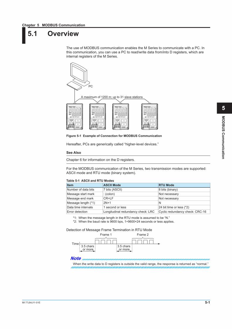
5.1 Overview
The use of MODBUS communication enables the M Series to communicate with a PC. In this communication, you can use a PC to read/write data from/into D registers, which are internal registers of the M Series.
PC
A maximum of 1200 m; up to 31 slave stations
Figure 5-1 Example of Connection for MODBUS Communication
Hereafter, PCs are generically called “higher-level devices.”
See Also
Chapter 6 for information on the D registers.
For the MODBUS communication of the M Series, two transmission modes are supported: ASCII mode and RTU mode (binary system).
Table 5-1 ASCII and RTU ModesItem ASCII Mode RTU ModeNumber of data bits 7 bits (ASCII) 8 bits (binary)Message start mark : (colon) Not necessaryMessage end mark CR+LF Not necessaryMessage length (*1) 2N+1 NData time intervals 1 second or less 24 bit time or less (*2)Error detection Longitudinal redundancy check: LRC Cyclic redundancy check: CRC-16
*1: When the message length in the RTU mode is assumed to be “N.”*2: When the baud rate is 9600 bps, 1÷9600×24 seconds or less applies.
Detection of Message Frame Termination in RTU Mode
Time
Frame 1 Frame 2
3.5 chars or more
3.5 chars or more
NoteWhen the write data to D registers is outside the valid range, the response is returned as “normal.”
Chapter 5 MODBUS Communication

5-2 IM 77J04J11-01E
5.1.1 Configuration of Message
Messages sent from a higher-level device to the M Series consist of the following elements.
Element Start of Message
Mark
Address Number (ADR)
Function Code
Data Error Check
End of Message
MarkNumber of bytes in RTU mode None 1 1 2n 2 NoneNumber of bytes in ASCII mode 1 2 2 4n 2 2
(1) (2) (3) (4) (5) (6)
(1) Start of Message MarkThis mark indicates the start of a message. Note that only ASCII mode requires a colon (:).
(2) Address Number (01 to 99)Address numbers are used by a higher-level device to identify the M Series at the communication destination. (Identification numbers specific to individual M Series, which is expressed in hexadecimal in the message.)
(3) Function Code (See subsection 5.2.1, “List of Function Codes.”)This specifies a command (function code) from the higher-level device.
(4) DataThis specifies D register numbers, the number of D registers, parameter values, or others in accordance with the function code. (It is expressed in hexadecimal in the message.)
(5) Error CheckIn RTU mode : Carried out by the cyclic redundancy check (CRC-16) system. In ASCII mode : Carried out by the longitudinal redundancy check (LRC) system.
(6) End of Message MarkThis mark indicates the end of a message. Note that only ASCII mode requires CR + LF.
5.1 Overview

5-3IM 77J04J11-01E
MO
DB
US C
omm
unication
1
2
3
4
5
6
7
App
5.1.2 Specifying D Registers
When you use a commercially available SCADA or the like or a user-created communication program, you must be careful when specifying D register numbers contained in messages because in both cases, you cannot use the original D register numbers as they are.
1) When using a commercially available SCADA or the like, specify D register numbers by changing them into reference numbers. To change them into a reference number, replace the D register number’s leading character “D” with “4.”
2) In a user-created communication program, specify a D register using the hexadecimal number of the value obtained by subtracting “40001” from the D register’s reference number. (Specify this hexadecimal number.)
Example:
Specifying a value (alarm-1 setpoint [D0101])
1) For a messages using commercially available SCADA or the like, specify reference number “40101.”
2) For a messages in a user-created communication program, specify “0064,” the hexadecimal number of “100 ,” which is obtained by subtracting 40001 from the reference number.
5.1.3 Error CheckThe error checking of the ASCII mode is different from the RTU mode.
ASCII mode In the ASCII mode, error checking is performed by the longitudinal redundancy check
(LRC). Each individual byte from the communication address up to the final data (excluding “:”,
“CR” and “LF”) is added, and the 2’s complement of the result becomes LRC. Ignore the uppermost carry during addition.Example: How to calculate the LRC in the case of command [:]110307E10004[LRC][CR]
[LF] for reading four values continuously from D register D0218 of the controller at communication address 17.
(1) Communication address 17 is expressed as “0x11” in Hex. D00201 is “0x00C8”. This is the number “200” (number obtained by subtracting 40001
from reference No. 400201) expressed in Hex. When this is converted to 1-byte Hex data, this becomes “11,03,00,C8,00,04”.
(In Modbus/ASCII messages, “11” is ASCII code “H’ 31, H’ 31”, which comprises two bytes.)
(2) This 1-byte Hex data is added one byte at a time as follows:→ 11+03+00+C8+00+04 = E0(3) 2’s complement of the lowermost 1 byte of the result of addition is “20”. 11100000 (0xE0) → 00011111 (complement) +1=00100000 (20)
5.1 Overview

5-4 IM 77J04J11-01E
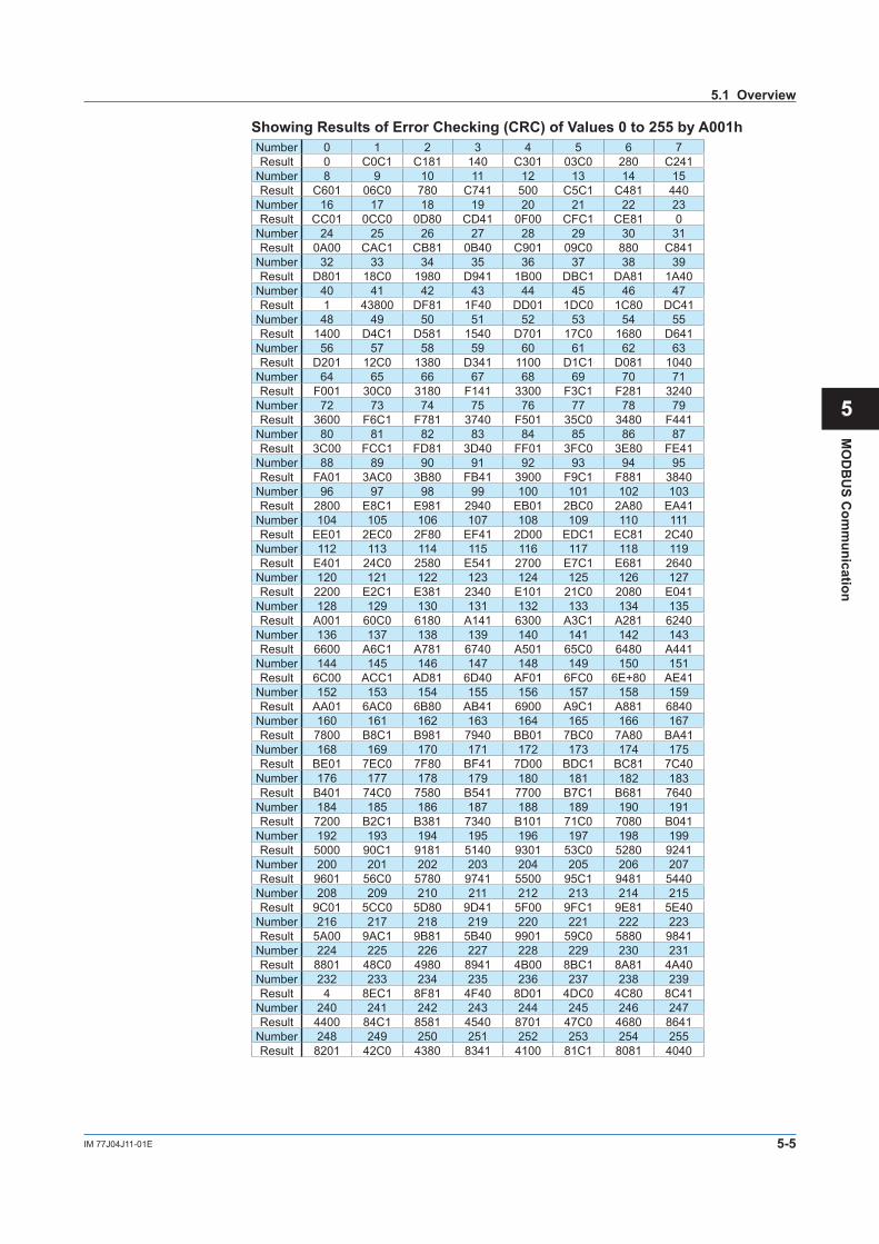
RTU Mode In the RTU mode, error checking is performed by the cyclic redundancy check (CRC-16). Of all message blocks (from communication address through to final data), eight bits
(excluding start bit, stop bit and parity bit) are aligned serially, and the remainder (16 bits) when the result is divided by predetermined binary 17 bits becomes the CRC-16.
Example (CRC-16 calculation example) When reading four data from D register D2018 by function code 03 (read status of
multiple D registers) from the slave at communication address 11 (0Bh). “0B03002A0004” is sent as the send command.(1) Default is FFFF. This is XORed (exclusive ORed) with the 1st byte (= slave address 11).(2) The lower byte of the result is referenced, and the value corresponding to that value in
the following table is obtained. In this case, the 244th value in the table is referenced to obtain 8701h as the result is F4h.
(3) The upper byte of the result of the XOR in (1) is XORed with the result of (2).(4) The result (remainder) of (3) is taken as the next default, and the same operation is
performed on the 2nd byte (=function code 03).
Default value FF FFCommunication address
XORReference to table
XORFunctio n code
XORReference to table
XOR
XORLast character
XORReference to table
Resulting error
FF FF 0B
FF F4 87 01
87 FE 03
87 FD 81 C1
81 46
E5 9E 04
E5 9A6B 80
6B 65
Convert the hex value to a decimal value, find the corresponding number in table of next page (TableShowing Results of Error Checking (CRC) of Values 0 to 255 by A001h), and substitute the number into the formula.In the example shown on the left, hex value “F4” is converted to decimal value 244. From table of next page, the number correspond-ing to 244 proves to be “8701”.This number is substituted into the formula.
(5) From here on, steps (1) to (4) are repeated to calculate up to the final “04”.(6) The upper and lower bytes of the result of calculation “6B65” are inverted, and “656B” is
appended to the final. 0B03002A0004656B
5.1 Overview
5-5IM 77J04J11-01E
MO
DB
US C
omm
unication
1
2
3
4
5
6
7
App
Showing Results of Error Checking (CRC) of Values 0 to 255 by A001hNumber 0 1 2 3 4 5 6 7Result 0 C0C1 C181 140 C301 03C0 280 C241
Number 8 9 10 11 12 13 14 15Result C601 06C0 780 C741 500 C5C1 C481 440
Number 16 17 18 19 20 21 22 23Result CC01 0CC0 0D80 CD41 0F00 CFC1 CE81 0
Number 24 25 26 27 28 29 30 31Result 0A00 CAC1 CB81 0B40 C901 09C0 880 C841
Number 32 33 34 35 36 37 38 39Result D801 18C0 1980 D941 1B00 DBC1 DA81 1A40
Number 40 41 42 43 44 45 46 47Result 1 43800 DF81 1F40 DD01 1DC0 1C80 DC41
Number 48 49 50 51 52 53 54 55Result 1400 D4C1 D581 1540 D701 17C0 1680 D641
Number 56 57 58 59 60 61 62 63Result D201 12C0 1380 D341 1100 D1C1 D081 1040
Number 64 65 66 67 68 69 70 71Result F001 30C0 3180 F141 3300 F3C1 F281 3240
Number 72 73 74 75 76 77 78 79Result 3600 F6C1 F781 3740 F501 35C0 3480 F441
Number 80 81 82 83 84 85 86 87Result 3C00 FCC1 FD81 3D40 FF01 3FC0 3E80 FE41
Number 88 89 90 91 92 93 94 95Result FA01 3AC0 3B80 FB41 3900 F9C1 F881 3840
Number 96 97 98 99 100 101 102 103Result 2800 E8C1 E981 2940 EB01 2BC0 2A80 EA41
Number 104 105 106 107 108 109 110 111Result EE01 2EC0 2F80 EF41 2D00 EDC1 EC81 2C40
Number 112 113 114 115 116 117 118 119Result E401 24C0 2580 E541 2700 E7C1 E681 2640
Number 120 121 122 123 124 125 126 127Result 2200 E2C1 E381 2340 E101 21C0 2080 E041
Number 128 129 130 131 132 133 134 135Result A001 60C0 6180 A141 6300 A3C1 A281 6240
Number 136 137 138 139 140 141 142 143Result 6600 A6C1 A781 6740 A501 65C0 6480 A441
Number 144 145 146 147 148 149 150 151Result 6C00 ACC1 AD81 6D40 AF01 6FC0 6E+80 AE41
Number 152 153 154 155 156 157 158 159Result AA01 6AC0 6B80 AB41 6900 A9C1 A881 6840
Number 160 161 162 163 164 165 166 167Result 7800 B8C1 B981 7940 BB01 7BC0 7A80 BA41
Number 168 169 170 171 172 173 174 175Result BE01 7EC0 7F80 BF41 7D00 BDC1 BC81 7C40
Number 176 177 178 179 180 181 182 183Result B401 74C0 7580 B541 7700 B7C1 B681 7640
Number 184 185 186 187 188 189 190 191Result 7200 B2C1 B381 7340 B101 71C0 7080 B041
Number 192 193 194 195 196 197 198 199Result 5000 90C1 9181 5140 9301 53C0 5280 9241
Number 200 201 202 203 204 205 206 207Result 9601 56C0 5780 9741 5500 95C1 9481 5440
Number 208 209 210 211 212 213 214 215Result 9C01 5CC0 5D80 9D41 5F00 9FC1 9E81 5E40
Number 216 217 218 219 220 221 222 223Result 5A00 9AC1 9B81 5B40 9901 59C0 5880 9841
Number 224 225 226 227 228 229 230 231Result 8801 48C0 4980 8941 4B00 8BC1 8A81 4A40
Number 232 233 234 235 236 237 238 239Result 4 8EC1 8F81 4F40 8D01 4DC0 4C80 8C41
Number 240 241 242 243 244 245 246 247Result 4400 84C1 8581 4540 8701 47C0 4680 8641
Number 248 249 250 251 252 253 254 255Result 8201 42C0 4380 8341 4100 81C1 8081 4040
5.1 Overview
5-6 IM 77J04J11-01E
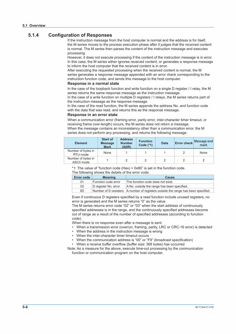
5.1.4 Configuration of ResponsesIf the instruction message from the host computer is normal and the address is for itself, the M series moves to the process execution phase after it judges that the received content is normal. The M series then parses the content of the instruction message and executes processing.However, it does not execute processing if the content of the instruction message is in error. In this case, the M series either ignores received content, or generates a response message to inform the host computer that the received content is in error.After executing the requested processing when the received content is normal, the M series generates a response message appended with an error check corresponding to the instruction function code, and sends this message to the host computer.Response in a normal stateIn the case of the loopback function and write function on a single D register / I relay, the M series returns the same response message as the instruction message.In the case of a write function on multiple D registers / I relays, the M series returns part of the instruction message as the response message.In the case of the read function, the M series appends the address No. and function code with the data that was read, and returns this as the response message.Response in an error stateWhen a communication error (framing error, parity error, inter-character timer timeout, or receiving frame over-length) occurs, the M series does not return a message.When the message contains an inconsistency other than a communication error, the M series does not perform any processing, and returns the following message.
ElementStart of
Message Mark
Address Number (ADR)
Function Code (*1) Data Error check Message end
mark
Number of bytes in RTU mode None 1 1 1 2 None
Number of bytes in ASCII mode 1 2 2 2 2 2
*1: The value of “function code (Hex) + 0x80” is set in the function code. The following shows the details of the error code.
Error code Meaning Cause01 Function code error The function code does not exist.02 D register No. error A No. outside the range has been specified.03 Number of D resisters A number of registers outside the range has been specified.
Even if continuous D registers specified by a read function include unused registers, no error is generated and the M series returns “0” as the value.
The M series returns error code “02” or “03” when the start address of continuously specified addresses is in the range, and the continuously specified addresses become out of range as a result of the number of specified addresses (according to function code).When there is no response even after a message is sent:• When a transmission error (overrun, framing, parity, LRC or CRC-16 error) is detected• When the address in the instruction message is wrong• When the inter-character timer timeout occurs• When the communication address is “00” or “F9” (broadcast specification)• When a receive buffer overflow (buffer size: 368 bytes) has occurred
Note: As a measure for the above, execute time-out processing by the communication function or communication program on the host computer.
5.1 Overview
5-7IM 77J04J11-01E
MO
DB
US C
omm
unication
1
2
3
4
5
6
7
App
5.2 Function Codes
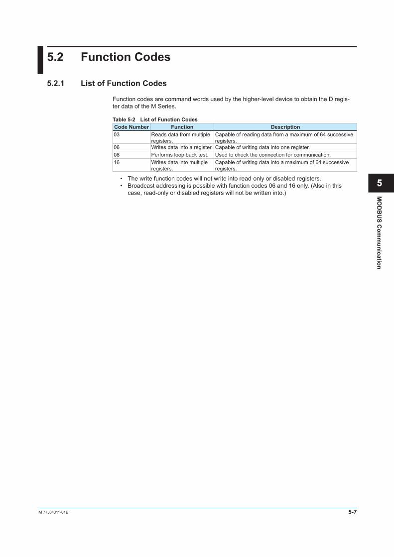
5.2.1 List of Function Codes
Function codes are command words used by the higher-level device to obtain the D regis- ter data of the M Series.
Table 5-2 List of Function CodesCode Number Function Description03 Reads data from multiple
registers.Capable of reading data from a maximum of 64 successive registers.
06 Writes data into a register. Capable of writing data into one register.08 Performs loop back test. Used to check the connection for communication.16 Writes data into multiple
registers.Capable of writing data into a maximum of 64 successive registers.
• The write function codes will not write into read-only or disabled registers.• Broadcast addressing is possible with function codes 06 and 16 only. (Also in this
case, read-only or disabled registers will not be written into.)
5-8 IM 77J04J11-01E
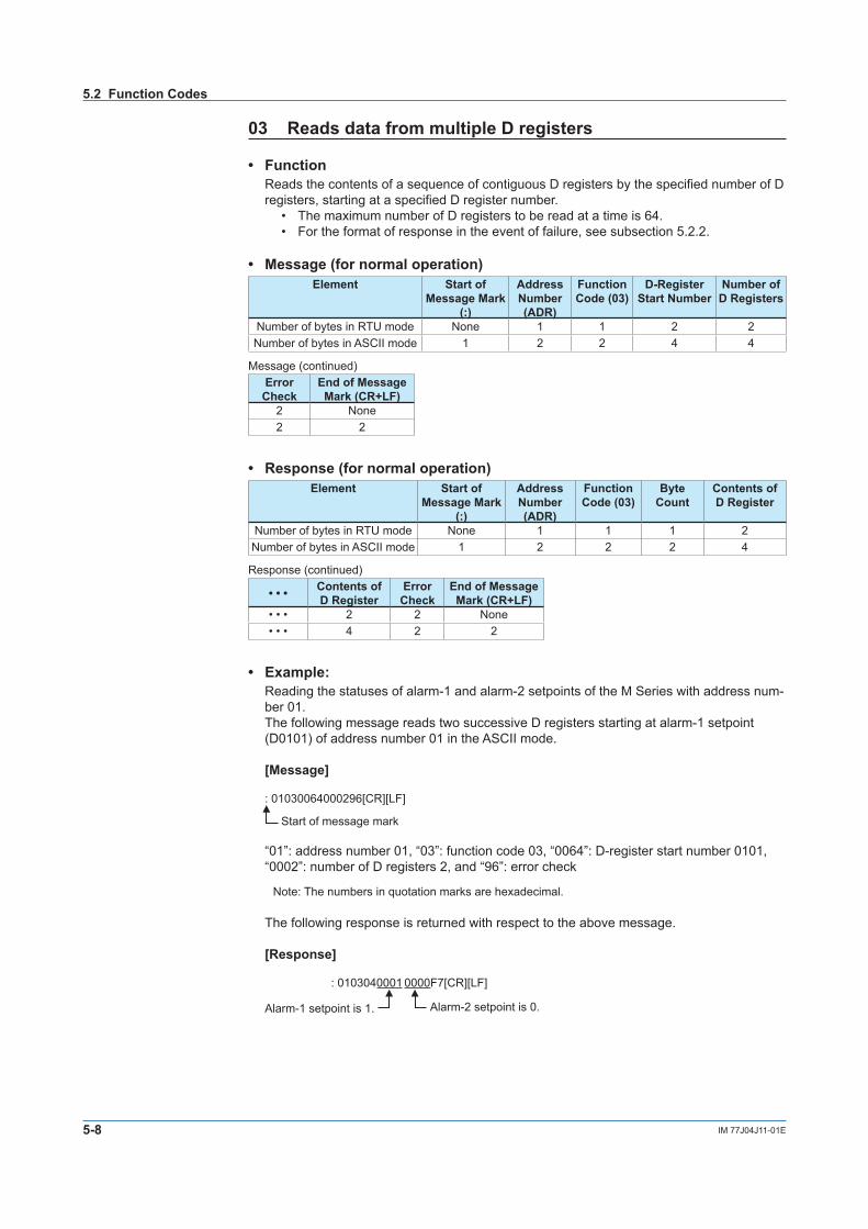
03 Reads data from multiple D registers
• FunctionReads the contents of a sequence of contiguous D registers by the specified number of D registers, starting at a specified D register number.
• The maximum number of D registers to be read at a time is 64.• For the format of response in the event of failure, see subsection 5.2.2.
• Message (for normal operation)Element Start of
Message Mark (:)
Address Number (ADR)
Function Code (03)
D-Register Start Number
Number of D Registers
Number of bytes in RTU mode None 1 1 2 2Number of bytes in ASCII mode 1 2 2 4 4
Message (continued)Error Check
End of Message Mark (CR+LF)
2 None2 2
• Response (for normal operation)Element Start of
Message Mark (:)
Address Number (ADR)
Function Code (03)
Byte Count
Contents of D Register
Number of bytes in RTU mode None 1 1 1 2Number of bytes in ASCII mode 1 2 2 2 4
Response (continued)
• • • Contents of D Register
Error Check
End of Message Mark (CR+LF)
• • • 2 2 None• • • 4 2 2
• Example:Reading the statuses of alarm-1 and alarm-2 setpoints of the M Series with address num- ber 01.The following message reads two successive D registers starting at alarm-1 setpoint (D0101) of address number 01 in the ASCII mode.
[Message]
: 01030064000296[CR][LF]
Start of message mark
“01”: address number 01, “03”: function code 03, “0064”: D-register start number 0101, “0002”: number of D registers 2, and “96”: error check
Note: The numbers in quotation marks are hexadecimal.
The following response is returned with respect to the above message.
[Response]
: 0103040001 0000F7[CR][LF]
Alarm-1 setpoint is 1. Alarm-2 setpoint is 0.
5.2 Function Codes
5-9IM 77J04J11-01E
MO
DB
US C
omm
unication
1
2
3
4
5
6
7
App
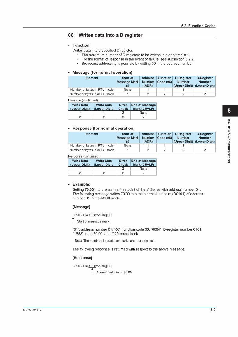
06 Writes data into a D register
• Function Writes data into a specified D register.
• The maximum number of D registers to be written into at a time is 1.• For the format of response in the event of failure, see subsection 5.2.2.• Broadcast addressing is possible by setting 00 in the address number.
• Message (for normal operation)Element Start of
Message Mark (:)
Address Number (ADR)
Function Code (06)
D-Register Number
(Upper Digit)
D-Register Number
(Lower Digit)Number of bytes in RTU mode None 1 1 1 1Number of bytes in ASCII mode 1 2 2 2 2
Message (continued)Write Data
(Upper Digit)Write Data
(Lower Digit)Error Check
End of Message Mark (CR+LF)
1 1 2 None2 2 2 2
• Response (for normal operation)Element Start of
Message Mark (:)
Address Number (ADR)
Function Code (06)
D-Register Number
(Upper Digit)
D-Register Number
(Lower Digit)Number of bytes in RTU mode None 1 1 1 1Number of bytes in ASCII mode 1 2 2 2 2
Response (continued)Write Data
(Upper Digit)Write Data
(Lower Digit)Error Check
End of Message Mark (CR+LF)
1 1 2 None2 2 2 2
• Example:Setting 70.00 into the alarms-1 setpoint of the M Series with address number 01.The following message writes 70.00 into the alarms-1 setpoint (D0101) of address number 01 in the ASCII mode.
[Message]
: 010600641B5822[CR][LF]
Start of message mark
“01”: address number 01, “06”: function code 06, “0064”: D-register number 0101, “1B58”: data 70.00, and “22”: error check
Note: The numbers in quotation marks are hexadecimal.
The following response is returned with respect to the above message.
[Response]
: 010600641B5822[CR][LF]
Alarm-1 setpoint is 70.00.
5.2 Function Codes
5-10 IM 77J04J11-01E
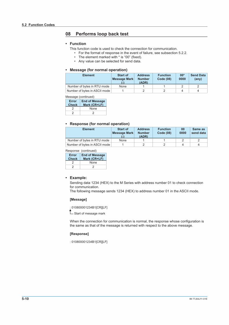
08 Performs loop back test
• Function This function code is used to check the connection for communication.
• For the format of response in the event of failure, see subsection 5.2.2.• The element marked with * is “00” (fixed).• Any value can be selected for send data.
• Message (for normal operation)Element Start of
Message Mark(:)
AddressNumber(ADR)
FunctionCode (08)
00*0000
Send Data(any)
Number of bytes in RTU mode None 1 1 2 2Number of bytes in ASCII mode 1 2 2 4 4
Message (continued)Error Check
End of Message Mark (CR+LF)
2 None2 2
• Response (for normal operation)Element Start of
Message Mark(:)
AddressNumber(ADR)
FunctionCode (08)
000000
Same assend data
Number of bytes in RTU mode None 1 1 2 2Number of bytes in ASCII mode 1 2 2 4 4
Response (continued)Error Check
End of Message Mark (CR+LF)
2 None2 2
• Example:Sending data 1234 (HEX) to the M Series with address number 01 to check connection for communication.The following message sends 1234 (HEX) to address number 01 in the ASCII mode.
[Message]
: 010800001234B1[CR][LF]
Start of message mark
When the connection for communication is normal, the response whose configuration is the same as that of the message is returned with respect to the above message.
[Response]
: 010800001234B1[CR][LF]
5.2 Function Codes
5-11IM 77J04J11-01E
MO
DB
US C
omm
unication
1
2
3
4
5
6
7
App
5.2 Function Codes
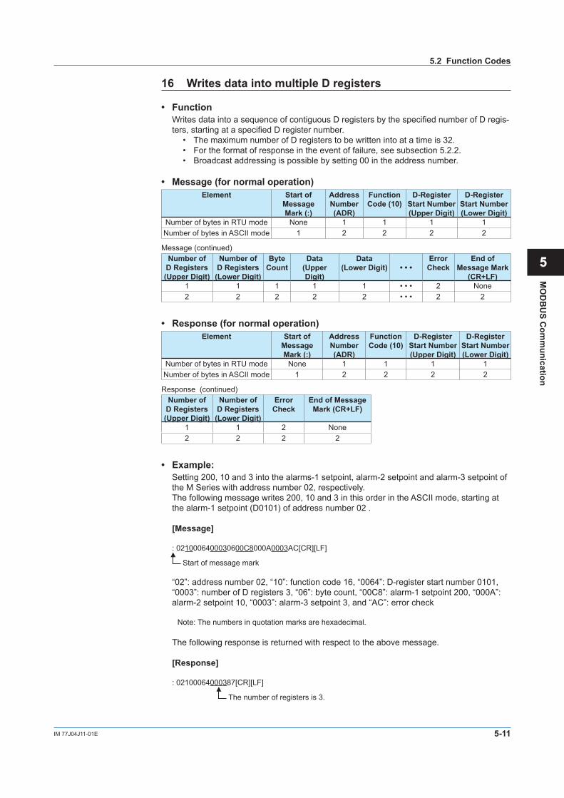
16 Writes data into multiple D registers
• Function Writes data into a sequence of contiguous D registers by the specified number of D regis-
ters, starting at a specified D register number.• The maximum number of D registers to be written into at a time is 32.• For the format of response in the event of failure, see subsection 5.2.2.• Broadcast addressing is possible by setting 00 in the address number.
• Message (for normal operation)Element Start of
Message Mark (:)
Address Number (ADR)
Function Code (10)
D-Register Start Number (Upper Digit)
D-Register Start Number (Lower Digit)
Number of bytes in RTU mode None 1 1 1 1Number of bytes in ASCII mode 1 2 2 2 2
Message (continued)Number of
D Registers (Upper Digit)
Number of D Registers (Lower Digit)
Byte Count
Data (Upper Digit)
Data (Lower Digit) • • •
Error Check
End of Message Mark
(CR+LF)1 1 1 1 1 • • • 2 None2 2 2 2 2 • • • 2 2
• Response (for normal operation)Element Start of
Message Mark (:)
Address Number (ADR)
Function Code (10)
D-Register Start Number (Upper Digit)
D-Register Start Number (Lower Digit)
Number of bytes in RTU mode None 1 1 1 1Number of bytes in ASCII mode 1 2 2 2 2
Response (continued)Number of
D Registers (Upper Digit)
Number of D Registers (Lower Digit)
Error Check
End of Message Mark (CR+LF)
1 1 2 None2 2 2 2
• Example:Setting 200, 10 and 3 into the alarms-1 setpoint, alarm-2 setpoint and alarm-3 setpoint of the M Series with address number 02, respectively.The following message writes 200, 10 and 3 in this order in the ASCII mode, starting at the alarm-1 setpoint (D0101) of address number 02 .
[Message]
: 0210006400030600C8000A0003AC[CR][LF]
Start of message mark
“02”: address number 02, “10”: function code 16, “0064”: D-register start number 0101,“0003”: number of D registers 3, “06”: byte count, “00C8”: alarm-1 setpoint 200, “000A”: alarm-2 setpoint 10, “0003”: alarm-3 setpoint 3, and “AC”: error check
Note: The numbers in quotation marks are hexadecimal.
The following response is returned with respect to the above message.
[Response]
: 02100064000387[CR][LF]
The number of registers is 3.

5-12 IM 77J04J11-01E
5.2.2 Response Error Codes
• Message Format in the Event of Error If there are any inconsistencies other than communication errors in a message, the M
Series does nothing, but returns the following message.
Element Address Number (ADR)
Function Code (*1)
Error Code Error Check [CR] [LF]
Number of bytes in RTU mode 1 1 1 2 NoneNumber of bytes in ASCII mode 2 2 2 2 2
*1: In this case, a value of [function code (hexadecimal number) + number 80 (hexadecimal number)] is set.
• Response Error Codes
Table 5-3 List of Error CodesError Code Meaning Cause
01 Function code error No such function code exists.02 D-register number error Specified D register number is out of the range.03 D-register count error Specified number of D registers is out of the range.
• Even when a message is sent, no response returns if:• Retransmission error (overrun, framing, parity, LRC, or CRC-16 error) was detected.• Address in a command message is incorrect.• Interval between data composing a message was 2 seconds or more.• CRC-16 or LRC values are incorrect.• Broadcase is specified (address number: 00).
Note: As a countermeasure, provide a timeout process in the communication functions of a higher-level device or in the communication program.
5.2 Function Codes
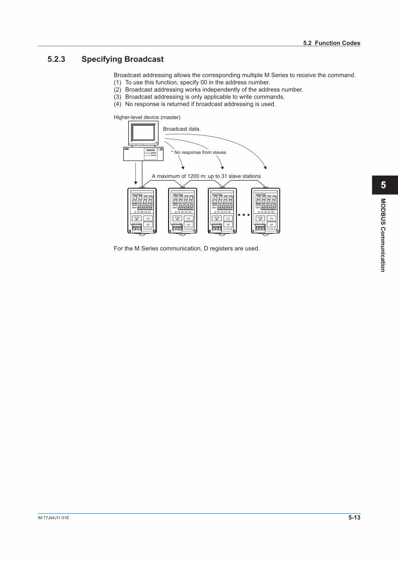
5-13IM 77J04J11-01E
MO
DB
US C
omm
unication
1
2
3
4
5
6
7
App
5.2.3 Specifying Broadcast
Broadcast addressing allows the corresponding multiple M Series to receive the command.(1) To use this function, specify 00 in the address number.(2) Broadcast addressing works independently of the address number.(3) Broadcast addressing is only applicable to write commands.(4) No response is returned if broadcast addressing is used.
Higher-level device (master)
Broadcast data.
* No response from slaves
A maximum of 1200 m; up to 31 slave stations
For the M Series communication, D registers are used.
5.2 Function Codes

Blank
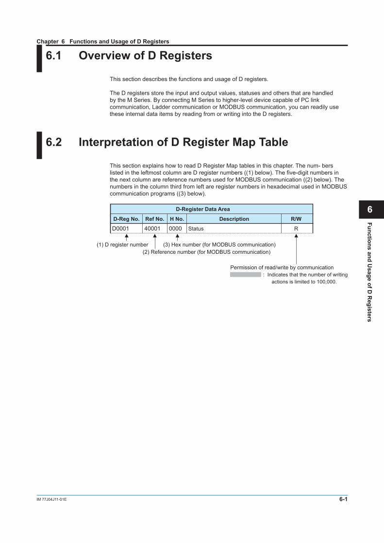
6-1IM 77J04J11-01E
Functions and Usage of D
Registers
1
2
3
4
5
6
7
App
6.1 Overview of D Registers
This section describes the functions and usage of D registers.
The D registers store the input and output values, statuses and others that are handled by the M Series. By connecting M Series to higher-level device capable of PC link communication, Ladder communication or MODBUS communication, you can readily use these internal data items by reading from or writing into the D registers.
6.2 Interpretation of D Register Map Table
This section explains how to read D Register Map tables in this chapter. The num- bers listed in the leftmost column are D register numbers ((1) below). The five-digit numbers in the next column are reference numbers used for MODBUS communication ((2) below). The numbers in the column third from left are register numbers in hexadecimal used in MODBUS communication programs ((3) below).
D-Reg No. Ref No. H No. Description R/W
D0001 40001 0000 Status R
D-Register Data Area
(1) D register number (2) Reference number (for MODBUS communication)
Permission of read/write by communication : Indicates that the number of writing actions is limited to 100,000.
(3) Hex number (for MODBUS communication)
Chapter 6 Functions and Usage of D Registers
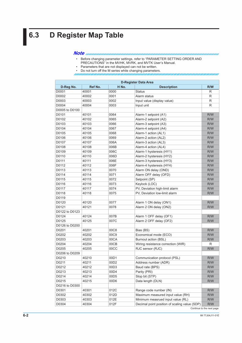
6-2 IM 77J04J11-01E
6.3 D Register Map Table
Note• Before changing parameter settings, refer to “PARAMETER SETTING ORDER AND
PRECAUTIONS” in the MVHK, MVRK, and MVTK User’s Manual.• Parameters that are not displayed can not be written.• Do not turn off the M series while changing parameters.
D-Register Data AreaD-Reg No. Ref No. H No. Description R/W
D0001 40001 0000 Status RD0002 40002 0001 Alarm status RD0003 40003 0002 Input value (display value) RD0004 40004 0003 Input unit RD0005 to D0100D0101 40101 0064 Alarm-1 setpoint (A1) R/WD0102 40102 0065 Alarm-2 setpoint (A2) R/WD0103 40103 0066 Alarm-3 setpoint (A3) R/WD0104 40104 0067 Alarm-4 setpoint (A4) R/WD0105 40105 0068 Alarm-1 action (AL1) R/WD0106 40106 0069 Alarm-2 action (AL2) R/WD0107 40107 006A Alarm-3 action (AL3) R/WD0108 40108 006B Alarm-4 action (AL4) R/WD0109 40109 006C Alarm-1 hysteresis (HY1) R/WD0110 40110 006D Alarm-2 hysteresis (HY2) R/WD0111 40111 006E Alarm-3 hysteresis (HY3) R/WD0112 40112 006F Alarm-4 hysteresis (HY4) R/WD0113 40113 0070 Alarm ON delay (OND) R/WD0114 40114 0071 Alarm OFF delay (OFD) R/WD0115 40115 0072 Setpoint (SP) R/WD0116 40116 0073 Keylock (LOC) R/WD0117 40117 0074 PV, Deviation high-limit alarm R/WD0118 40118 0075 PV, Deviation low-limit alarm R/WD0119D0120 40120 0077 Alarm 1 ON delay (ON1) R/WD0121 40121 0078 Alarm 2 ON delay (ON2) R/WD0122 to D0123D0124 40124 007B Alarm 1 OFF delay (OF1) R/WD0125 40125 007C Alarm 2 OFF delay (OF2) R/WD0126 to D0200D0201 40201 00C8 Bias (BS) R/WD0202 40202 00C9 Economical mode (ECO) R/WD0203 40203 00CA Burnout action (BSL) R/WD0204 40204 00CB Wiring resistance correction (WIR) RD0205 40205 00CC RJC sensor (RJC) R/WD0206 to D0209D0210 40210 00D1 Communication protocol (PSL) R/WD0211 40211 00D2 Address number (ADR) R/WD0212 40212 00D3 Baud rate (BPS) R/WD0213 40213 00D4 Parity (PRI) R/WD0214 40214 00D5 Stop bit (STP) R/WD0215 40215 00D6 Data length (DLN) R/WD0216 to D0300D0301 40301 012C Range code number (IN) R/WD0302 40302 012D Maximum measured input value (RH) R/WD0303 40303 012E Minimum measrued input value (RL) R/WD0304 40304 012F Decimal point position of scaling value (SDP) R/W
Continue to the next page
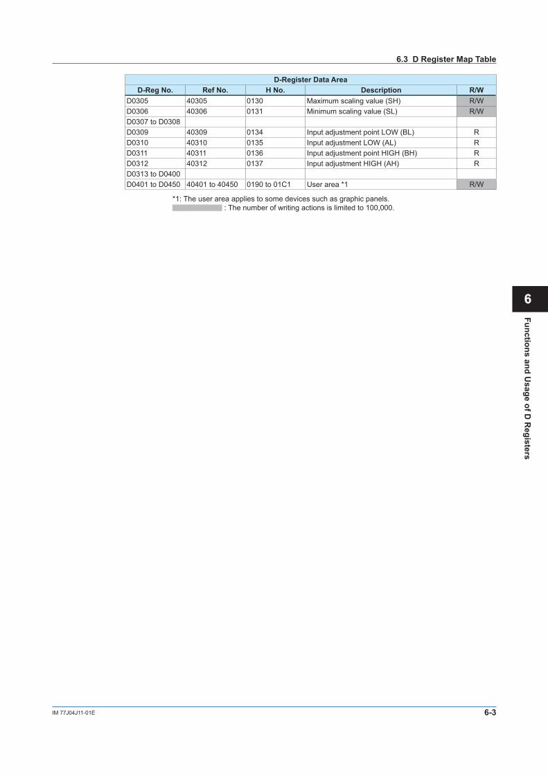
6-3IM 77J04J11-01E
Functions and Usage of D
Registers
1
2
3
4
5
6
7
App
D-Register Data AreaD-Reg No. Ref No. H No. Description R/W
D0305 40305 0130 Maximum scaling value (SH) R/WD0306 40306 0131 Minimum scaling value (SL) R/WD0307 to D0308D0309 40309 0134 Input adjustment point LOW (BL) RD0310 40310 0135 Input adjustment LOW (AL) RD0311 40311 0136 Input adjustment point HIGH (BH) RD0312 40312 0137 Input adjustment HIGH (AH) RD0313 to D0400D0401 to D0450 40401 to 40450 0190 to 01C1 User area *1 R/W
*1: The user area applies to some devices such as graphic panels. : The number of writing actions is limited to 100,000.
6.3 D Register Map Table
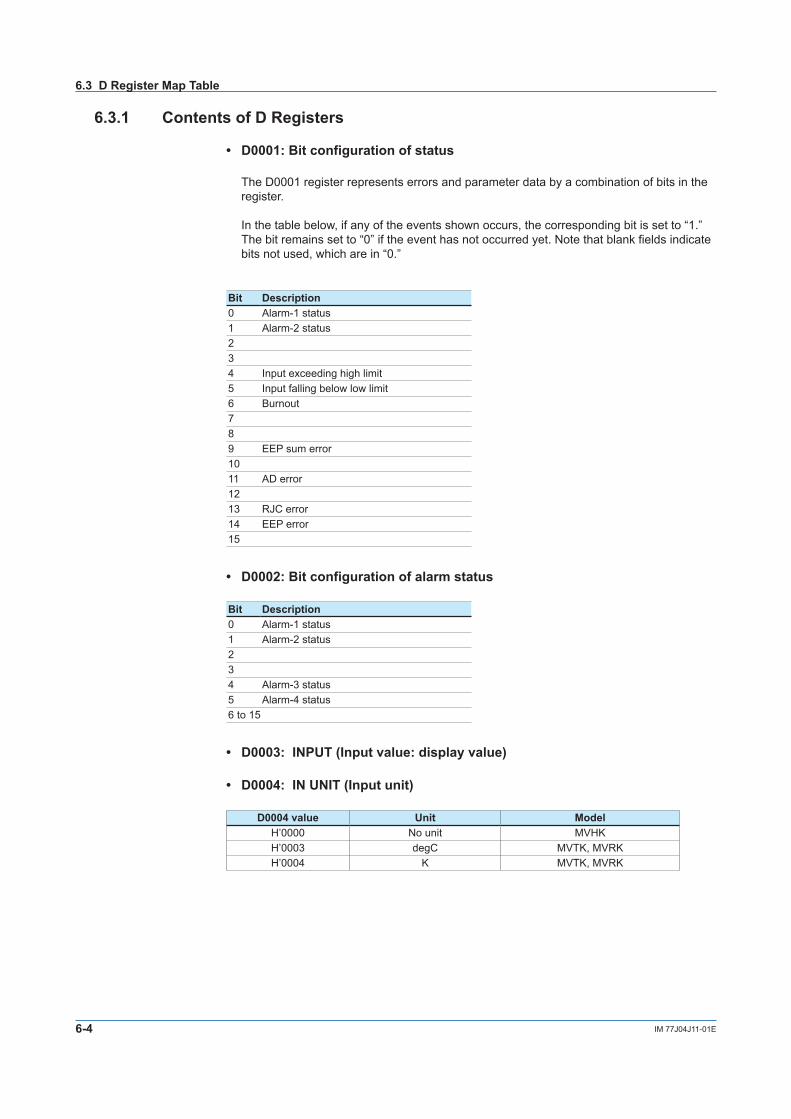
6-4 IM 77J04J11-01E
6.3.1 Contents of D Registers
• D0001: Bit configuration of status
The D0001 register represents errors and parameter data by a combination of bits in the register.
In the table below, if any of the events shown occurs, the corresponding bit is set to “1.” The bit remains set to “0” if the event has not occurred yet. Note that blank fields indicate bits not used, which are in “0.”
Bit Description0 Alarm-1 status1 Alarm-2 status234 Input exceeding high limit5 Input falling below low limit6 Burnout789 EEP sum error1011 AD error1213 RJC error14 EEP error15
• D0002: Bit configuration of alarm status
Bit Description0 Alarm-1 status1 Alarm-2 status234 Alarm-3 status5 Alarm-4 status6 to 15
• D0003: INPUT (Input value: display value)
• D0004: IN UNIT (Input unit)
D0004 value Unit ModelH’0000 No unit MVHKH’0003 degC MVTK, MVRKH’0004 K MVTK, MVRK
6.3 D Register Map Table

Blank

Blank
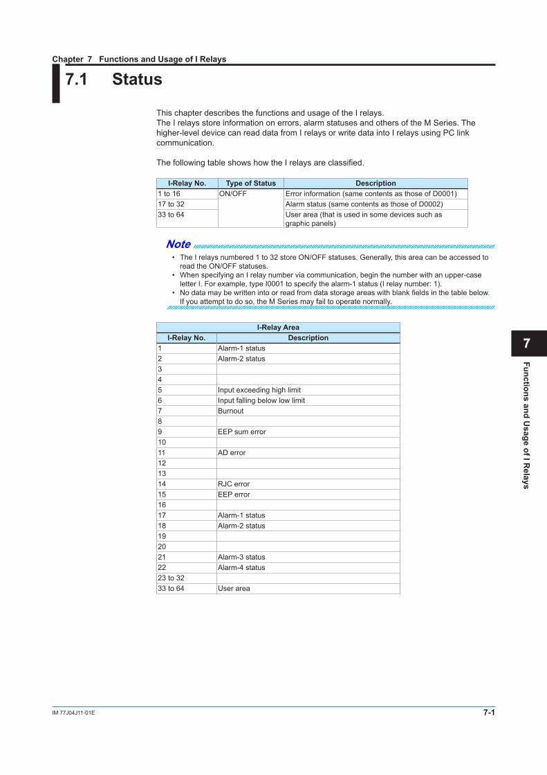
7-1IM 77J04J11-01E
Functions and Usage of I R
elays
1
2
3
4
5
6
7
App
7.1 Status
This chapter describes the functions and usage of the I relays.The I relays store information on errors, alarm statuses and others of the M Series. The higher-level device can read data from I relays or write data into I relays using PC link communication.
The following table shows how the I relays are classified.
I-Relay No. Type of Status Description1 to 16 ON/OFF Error information (same contents as those of D0001)17 to 32 Alarm status (same contents as those of D0002)33 to 64 User area (that is used in some devices such as
graphic panels)
Note• The I relays numbered 1 to 32 store ON/OFF statuses. Generally, this area can be accessed to
read the ON/OFF statuses.• When specifying an I relay number via communication, begin the number with an upper-case
letter I. For example, type I0001 to specify the alarm-1 status (I relay number: 1).• No data may be written into or read from data storage areas with blank fields in the table below.
If you attempt to do so, the M Series may fail to operate normally.
I-Relay AreaI-Relay No. Description
1 Alarm-1 status2 Alarm-2 status345 Input exceeding high limit6 Input falling below low limit7 Burnout89 EEP sum error1011 AD error121314 RJC error15 EEP error1617 Alarm-1 status18 Alarm-2 status192021 Alarm-3 status22 Alarm-4 status23 to 3233 to 64 User area
Chapter 7 Functions and Usage of I Relays

Blank

iIM 77J04J11-01E
Title : M Series Digital Limit Alarms Communication FunctionsManual No. : IM 77J04J11-01E
Aug. 2006 1st Edition Newly publishedOct. 2019 2nd Edition Revision
Written by Yokogawa Electric Corporation
Published by Yokogawa Electric Corporation 2-9-32 Nakacho, Musashino-shi, Tokyo 180-8750, JAPAN
Revision Information

Blank