Optimal Synthesis of Boolean Functions by Threshold Functions
10
Optimal synthesis of Boolean functions by threshold functions Jos´ e Luis Subirats, Iv´an G´omez, Jos´ e M. Jerez, and Leonardo Franco Departamento de Lenguajes y Ciencias de la Computaci´on Universidad de M´alaga, Campus de Teatinos S/N, 29071 M´alaga, Spain {jlsubirats, ivan, jja, lfranco}@lcc.uma.es http://www.lcc.uma.es/~lfranco/ Abstract. We introduce a new method for obtaining optimal architec- tures that implement arbitrary Boolean functions using threshold func- tions. The standard threshold circuits using threshold gates and weights are replaced by nodes computing directly a threshold function of the inputs. The method developed can be considered exhaustive as if a so- lution exist the algorithm eventually will find it. At all stages different optimization strategies are introduced in order to make the algorithm as efficient as possible. The method is applied to the synthesis of cir- cuits that implement a flip-flop circuit and a multi-configurable gate. The advantages and disadvantages of the method are analyzed. 1 Introduction In this paper we introduce an algorithm for finding a set of threshold functions (also called linearly separable functions) that will compute a desired (target) arbitrary Boolean function. This problem is known as the synthesis problem of Boolean functions and has been much studied since the 60’s ([1–3]). The interest in using threshold gates or linearly threshold functions instead of standard logical AND, NOT and OR gates relies on the fact that threshold elements are more powerful than standard gates and as a consequence, the size of the circuits that can be constructed to compute the desired functions can be smaller. There is an extra interest in the study of threshold circuits as they are very close related to neural networks models, and thus some of the properties and characteristics of the circuits also apply to neural networks architectures. Our main motivation for the development of this method is the study of neural networks architectures [4, 5]. The standard practice for the architecture selection process within the field of artificial neural networks is the trial-and-error method that is very time consuming. Knowing and characterizing which architectures are best suited for a given class (or set) of functions can much help to the development and refinement of existing methods for constructing better neural architectures and also for gaining further understanding on the learning process. The problem of finding optimal architectures is relevant also for a more theoretical point of view within
-
Upload
independent -
Category
Documents
-
view
6 -
download
0
Transcript of Optimal Synthesis of Boolean Functions by Threshold Functions

Optimal synthesis of Boolean functions bythreshold functions
Jose Luis Subirats, Ivan Gomez, Jose M. Jerez, and Leonardo Franco
Departamento de Lenguajes y Ciencias de la ComputacionUniversidad de Malaga,
Campus de Teatinos S/N, 29071 Malaga, Spain{jlsubirats, ivan, jja, lfranco}@lcc.uma.es
http://www.lcc.uma.es/~lfranco/
Abstract. We introduce a new method for obtaining optimal architec-tures that implement arbitrary Boolean functions using threshold func-tions. The standard threshold circuits using threshold gates and weightsare replaced by nodes computing directly a threshold function of theinputs. The method developed can be considered exhaustive as if a so-lution exist the algorithm eventually will find it. At all stages differentoptimization strategies are introduced in order to make the algorithmas efficient as possible. The method is applied to the synthesis of cir-cuits that implement a flip-flop circuit and a multi-configurable gate.The advantages and disadvantages of the method are analyzed.
1 Introduction
In this paper we introduce an algorithm for finding a set of threshold functions(also called linearly separable functions) that will compute a desired (target)arbitrary Boolean function. This problem is known as the synthesis problem ofBoolean functions and has been much studied since the 60’s ([1–3]). The interestin using threshold gates or linearly threshold functions instead of standard logicalAND, NOT and OR gates relies on the fact that threshold elements are morepowerful than standard gates and as a consequence, the size of the circuits thatcan be constructed to compute the desired functions can be smaller. There isan extra interest in the study of threshold circuits as they are very close relatedto neural networks models, and thus some of the properties and characteristicsof the circuits also apply to neural networks architectures. Our main motivationfor the development of this method is the study of neural networks architectures[4, 5]. The standard practice for the architecture selection process within thefield of artificial neural networks is the trial-and-error method that is very timeconsuming. Knowing and characterizing which architectures are best suited for agiven class (or set) of functions can much help to the development and refinementof existing methods for constructing better neural architectures and also forgaining further understanding on the learning process. The problem of findingoptimal architectures is relevant also for a more theoretical point of view within

the area of circuit complexity, as different existing bounds can checked and/orimproved ([6]).
The method introduced in this paper permits the synthesis of Boolean func-tions in terms of the set of threshold Boolean functions. The standard thresholdcircuits, use threshold gates connected by weights that in the present formulationare replaced by threshold functions. Obtaining the whole set of linear separablefunctions is a complicate and computationally intensive problem and the setfunctions of threshold functions have been only obtained up to N = 10 variables([3]).
Research in threshold logic synthesis was done mostly in the 1960s ([1–3]).Nowadays, different implementations of circuits by threshold gates are available,and several theoretical results have been obtained [6–9] together with differentapplications ([10]). The main difference with previous approaches is that thepresent work is aimed to find optimal architectures.
2 Synthesis of Boolean functions by linearly separablefunctions
We introduce in this work a new method for finding a set of linearly separatefunctions that will compute a given desired Boolean function (the target func-tion). The method use the linearly separable set of functions as basis functions(or primitives) and thus assumes that whether a list of the functions is avail-able or that a method for testing whether a given function is linearly separableis provided (the first approach is used throughout this work). One importantdifference with previous works is that our approach works straightforward withthe set of threshold functions as basis functions and not through their equivalentrepresentation by threshold gates and weights.
2.1 The algorithm
Without loss of generality, we will analyze the case of architectures comprisinga single layer of hidden nodes. The algorithm can be straightforwardly extendedto the case of several layers of nodes. The algorithm is aimed to find a set oflinearly separable functions for the hidden nodes and for the output node thatimplement a desired target function. The choice of the output function is crucialfor the procedure as once that an output function has been chosen, the algo-rithm will test all possible solutions and then the choice of the output functionhas a multiplicative computational effect. However, the search procedure of thehidden node functions is the most intensive and complicated step, and differentoptimization strategies can be implemented.
Selection procedure for the output function From first principles, thereare two “logic” choices for the output function: the first one would be to selectan output function as the most similar threshold function to the target one. This

procedure is not straightforward as a measure of similarity between the functionsis needed, but a simple choice seems to select the closest linearly separablefunction in terms of the Hamming distance (number of different bits) between theoutputs of the two functions. The second logic choice could be to select the outputfunction according to the success rate of the functions (or of similar functions inlower dimensions) in previous cases. While the two mentioned approaches seemsto merit consideration, there is also a computationally effective oriented choice.In this case functions that will generate a shorter node search procedure willbe considered first. This was the approach used in this work. It will be moreclear later in the work after the node search algorithm is introduced, but thegeneral idea is that as the node search algorithm generate a tree of possiblesolutions and as the number of branches at a ramification point is proportionalto the number of solutions, the more computational intensive cases will occur foroutput functions with a balanced number of 0’s and 1’s. Thus, functions with anon-balanced number of 1’ and 0’s will be considered earlier as candidates forthe output function. This choice, even if motivated by computational efficiency,may be not the more efficient, specially if unbalanced functions results to benot very good for the synthesis problem. On the contrary, if almost all functionsare more or less equivalent, or if unbalanced functions are well suited for thistask of generating non-threshold functions, then the approach taken might be themost computationally effective as it was intended. Some preliminary experimentsshowed that the unbalanced functions seem to be good as output functions.
Selection procedure of the hidden nodes function Once the output func-tion has been set to a given linearly separable function, the problem translatesinto finding a set of linearly separable functions for the hidden nodes that wouldmake the circuit to implement the target function. The algorithm analyze thedifferent possibilities of mapping the inputs into a set of recoded inputs for theoutput function, in way such that the output function might be able to mapthem correctly onto the solution. To exemplify the procedure, we will analyzethe simple case of finding the optimal circuit for the NXOR function. The NXORfunction is a Boolean function of two input bits where the output of the functionis 0 if the sum of the two input bits is 1 and the output is 1 if the sum of theinput bits is even (inputs 0-0 and 1-1 ). The NXOR function is a classic exampleof a non linearly separable function and thus an architecture with two hiddennodes, at least, is needed for their implementation with threshold functions (itis known that 2 hidden nodes are enough for implementing this function). Forexemplifying the procedure we use an architecture with two hidden nodes, bothconnected to the two inputs. In Fig. 1 such an architecture is shown, where I0
and I1 indicate the input nodes that will feed their values into the hidden nodes.The hidden nodes will compute two linearly separable functions named f0 andf1 while the output function is indicated in the figure by fout.
For the example under consideration, we will analyze the situation in whichthe output function has been already selected. We consider as output functionthe function AND, that produce an output 1 only for input values 1-1. The

f
f f 1
I 0 I 1
INPUT
OUTPUT
0
out
Fig. 1. A two hidden node architecture used for showing the procedure of finding asolution for the NXOR function. The inputs to the network are indicated by I0 and I1.The hidden nodes will compute as a function of the input bits two linearly separablefunctions indicated by f0 and f1 that will send their outputs to the output node functionindicated by fout.
functions will be designated according to the outputs that the function producein response to the inputs, with values ordered according to their binary value.For the present case, in which input functions of two bits are considered the orderof the inputs and outputs is as follows: first, the output in response to the input0-0, second to the input 0-1, third to 1-0 and finally the output correspondingto the input 1-1. In this way, the AND function is indicated by 0001, while theNXOR function would be coded as 1001. The procedure for finding the thresholdfunctions for the node functions f0 and f1 proceeds in a number of steps in whichthe possible outputs for f0 and f1 are considered.
Now we consider the first output bit of the target function, that is equal to 1(in response to the first input 0-0). As the function AND was selected as outputfunction (fout), and this function produce a 1 in response only to an input 1-1, itis needed that both node functions, f0 and f1, produce an output 1 in responseto the input pattern 0-0. That is, the node functions have to recode the originalinput of the network, the input 0-0, into the input 1-1 for the output node,otherwise the output function would not coincide with the target one. Now theprocedure continues with the second input bit, 0-1, for which the target outputis 0. The selected output function produce a 0 in response to three input casesand then there are three possible cases into which the input 0-1 can be recodedby the node functions. The function fout gives a 0 in response to the inputs 0-0,0-1 and 1-0 and then we obtain, putting together the results for the first andsecond output bits the following tree of possibilities, shown in Fig. 2. The threecases are indicated in the diagram as branches of the first case on the top, forwhich there was a single possibility.
The procedure continues considering the rest of the cases corresponding tothe third and fourth input bits. The whole tree generated as the procedure is

1 0 0 1 0 0 0 1
11
??
??
??
10
??
??
11
10
??
??
11
01
??
??
1 0 0 1 0 0 0 1
11
Target
Output
Target
Output
Fig. 2. The possible cases for the node functions f0 and f1 as the two first input bitsare considered for the case of choosing the NXOR as target function and the AND asoutput function. Within the boxes, the 4 pairs of values correspond to the outputs ofthe two functions in response to the 4 inputs. The question mark indicates that thevalue is still undetermined.
applied is shown in Fig. 3. The nine boxes in the last two bottom rows containthe nine function candidates for the node functions, but the only possible onesare those boxes containing two threshold (linearly separable) functions (the twoboxes at the rightmost end of the bottom row containing functions with onlyone output bit equal to 1, as all the other boxes contain the function 1001 thatis non-linearly separable).
11
??
??
??
11
00
??
??
11
10
??
??
11
01
??
??
11
00
00
??
11
00
10
??
11
00
01
??
11
10
00
??
11
10
10
??
11
10
01
??
11
01
00
??
11
01
10
??
11
01
01
??
11
00
00
11
11
00
10
11
11
00
01
11
11
10
00
11
11
10
10
11
11
10
01
11
11
01
00
11
11
01
10
11
11
01
01
11
Fig. 3. The whole tree of possibilities for the choices of the node functions for the caseof the NXOR target function. The nine boxes in the last two bottom rows are thenine candidates for the functions but the only possible ones are those in which bothfunctions are linearly separable functions (See the text for details).
The node searching procedure ends if two linearly separable functions arefound, but if this is not the case, a different output function, fout, is chosen from
the set of threshold functions and the whole procedure is repeated until all thethreshold functions with a number of variables equal to the number of nodes aretested. If a solution is not found, the number of nodes is augmented by one andthe whole procedure repeated, and so on.
2.2 Optimization steps: order of branching and pruning by testinglinear separability
Several optimization steps were introduced to speed up the computational pro-cess. We will refer here to only the most important ones. The first optimizationstep is about the order in which the input bits are considered for the node search-ing process. If the output function is unbalanced, it is convenient to analyze firstthe inputs of the output function that produce an output that occur less in-frequently as the degeneracy of the output values is related to the number ofbranches that are created in the tree of possible choices for threshold functions.The second optimization concern the test of linear separability for the partialdefined functions. It is possible to analyze by previously constructing a tree withall the linearly separable functions, whether a partial defined Boolean functionwill end up producing some threshold functions. If the partially defined functionwill not produce any threshold function, the branching process is ended at thatpoint, and the tree is pruned. Alternatively, the checking for linear separabilitycan be done by testing the unateness of the variables, as all threshold functionsare unate (but not conversely, so the test is a partial one).
3 Application of the algorithm to the construction ofoptimal architectures for a flip-flop circuit and aconfigurable gate circuits
We applied the algorithm developed in the previous section to the construction ofthreshold circuits that implement in an optimal way (with a minimum numberof nodes in a single hidden layer) a flip-flop circuit and a configurable gate.The flip-flop circuit (or bistable) is a standard digital circuit in electronics thatincorporates the storage of memory in its functioning.
The resulting architecture obtained by the algorithm has three nodes in theunique hidden layer and is depicted in Fig. 4.
The three hidden functions receive input from the 4 inputs and then projectinto the two outputs units. The “fan-in max” (maximum number of connectionsthat a node receives) is 4 and thus, the whole set of threshold functions of up to4 variables was needed. The four inputs of the circuit are the Memory input bit(M), the Enable bit (EN), the Input bit (IN) and the Read/Write bit (R/W).The circuit has two output nodes, the first one (fM ) feedbacks into the memorybit permitting the storage of memory and the second one is the true output ofthe circuit, designated in the figure as (fout) . When the enable bit is OFF (value0), the circuit outputs the value of the Input bit (I). When the Enable (EN) bitis ON the circuit works depending on the value of the R/W bit, reading the

M
EN
IN
R/W
f
f
f
f
f
0
1
2
M
out
Fig. 4. The architecture designed to implement a flip-flop circuit. The architecture hasa single hidden layer containing three nodes and two outputs nodes. One of the outputnodes, indicated as fM , feedbacks the input value to the memory neuron, and the otheroutput, fout, can be considered as the real output of the network.
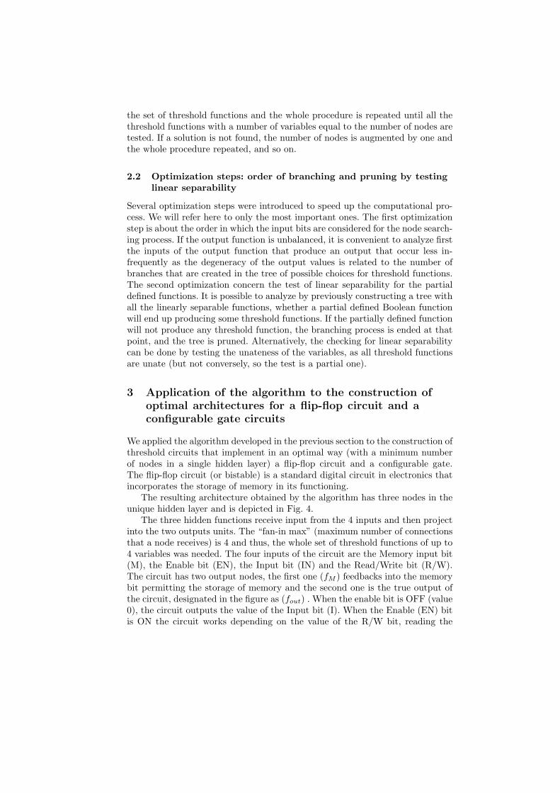
value stored in memory and sending it to the output or by writing the value ofthe input into the memory. The truth table for the flip-flop circuit implementedis shown in Fig. 5.
In Table 1 the output values of the obtained functions that implement thecircuit are shown. The case shown is only one of the 120 cases obtained.
Table 1. The threshold functions obtained for one of the solutions found for the flip-flop circuit. The node functions are functions of N=4 input bits and then 16 outputvalues exists, while the output functions have a fan-in of 3 and then 8 binary valuesare needed to code them.
Function Output bits
f0 0000000111111111f1 0011001100111011f2 1011000011111010fM 00000111fout 00010001
Also a circuit to implement a multi-configurable gate was constructed. Thecircuit can compute as desired a AND, OR, NXOR or NAND as a function of
M EN IN R\W Out-M OUTPUT0 0 0 0 0 00 0 0 1 0 00 0 1 0 0 10 0 1 1 0 10 1 0 0 0 00 1 0 1 0 #0 1 1 0 0 00 1 1 1 1 #1 0 0 0 1 01 0 0 1 1 01 0 1 0 1 11 0 1 1 1 11 1 0 0 1 11 1 0 1 0 #1 1 1 0 1 11 1 1 1 1 #
Fig. 5. Truth table of a flip-flop (bistable) circuit. The circuit, when the Enable (EN)input is activated, can store a value in memory (Write procedure) or transmit thestored value (Read procedure) depending of the value of the R/W input bit. If theEnable bit is off, the network simply output the value of the single input (IN).
the two inputs (IN0 and IN1). The function to be computed is selected by twoextra input bits (C0 and C1), and the truth table of this multi-configurable gateis shown in Fig. 6.
The architecture implementing the multi-configurable gate is shown in Fig.7 where it is also shown, close to the nodes, the functions obtained from theprocedure coded by their outputs. It is also shown in the figure, the operationof the circuit for two inputs, the first and the fourth, showing for the first inputhow this is mapped by the node functions to the first bit of the output nodeto produce a desired output of 0. For the fourth input, the output of the threehidden nodes recoded it as 1-0-1 producing a desired output of 1 by the outputnode.
4 Discussion
We have introduced a new method for finding the optimal circuit architecturethat computes an arbitrary Boolean function in terms of linear separable prim-itives. Starting from different “smart” choices of the output function the algo-rithm tries to find linearly separable functions for the hidden nodes accordingto the values of the output and target function. Eventually if a solution hasnot been found, the algorithm searches for all the possible solutions and in thatway does an exhaustive search. Different optimization steps were introduced toimprove the computational efficiency. The method was successfully applied tothe construction of threshold circuits for the flip-flop circuit and for a multi-configurable gate. For both implementations the whole synthesis procedure tookless than half of a minute, but we are aware that they only involved nodes

C0 C1 IN0 IN1 OUTPUT
0 0 0 1 00 0 1 0 00 0 1 1 10 1 0 0 00 1 0 1 10 1 1 0 10 1 1 1 11 0 0 0 11 0 0 1 01 0 1 0 01 0 1 1 11 1 0 0 11 1 0 1 11 1 1 0 11 1 1 1 0
0 0 0 0 0
Fig. 6. Truth table of a multi-configurable circuit with N=2 inputs. The two selectionbits,(C0 and C1), indicate which function should be computed.
C0
C1
IN0
IN 1
0 0 0 1 0 1 1 1 1 0 0 1 1 1 1 0
0 0 0 1 0 1 1 1 1 1 1 1 1 1 1 1
0 0 0 0 0 1 1 1
0 0 0 1 0 0 0 1 0 0 0 1 0 0 0 0
0 0 0 0 1 1 1 0 1 0 0 0 1 1 1 0
f0
f 1
2f
fout
Fig. 7. The architecture of the circuit computing a multi-configurable gate that canwork depending of the value of the indicator bits (C0 and C1) as a AND, OR, NXORor NAND gate. Close to the nodes, the functions that make the circuit to work asdesired are indicated by the value of their outputs in response to the input patterns.(See the text for more details)

with a fan-in max of 4. The worst case complexity of the algorithm is of orderO(2MN2
2M2), where N is the number of input variables, M is the number of
hidden nodes and the factors of the type 2N2arise because that is the order
of the number of threshold functions on N variables (It is worth noting, as areference value, that the total number of Boolean functions on N variables is22N
). We are currently computing the average case complexity for the case of allfunctions on 4 variables that can be treated exhaustively. We believe that thealgorithm can be of practical application for larger dimensions of up to 8 or 10 inits present way and it seems also possible to develop from the current algorithmnon-optimal procedures for larger dimensions. We are currently analyzing all theoptimal architectures for all the existing Boolean functions of 4 variables, mea-suring the speed of the algorithm against standard benchmarks and studyingthe properties of multi-layer and modular neural network architectures.
5 Acknowledgements
The authors acknowledge support from CICYT (Spain) through grant TIN2005-02984 (including FEDER funds). Leonardo Franco acknowledges support fromthe Spanish Ministry of Education and Science through a Ramon y Cajal fel-lowship.
References
1. Winder, R.O. (1962). Threshold Logic, Ph.D. dissertation, Department of Mathe-matics, Princeton University.
2. Dertouzos, M.L. (1965) Threshold Logic: A Synthesis Approach. Cambridge, MA:The M.I.T. Press.
3. Muroga, S. (1971).Threshold Logic and its Applications, Wiley, New York4. Franco, L. (2006). Generalization ability of Boolean functions implemented in feed-
forward neural networks. Neurocomputing. In Press.5. Franco, L. and Anthony, M. (2006). The influence of oppositely classified examples
on the generalization complexity of Boolean functions. IEEE Transactions on NeuralNetworks. In Press.
6. Siu, K.Y., Roychowdhury, V.P., and Kailath, T. (1991). Depth-Size Tradeoffs forNeural Computation IEEE Transactions on Computers, 40, 1402-1412.
7. Oliveira, A. L. and Sangiovanni-Vincentelli, A. (1991). LSAT: an algorithm for thesynthesis of two level threshold gate networks. In: Proceedings of the ACM/IEEEInternational Conference on Computer Aided Design, Santa Clara, CA, IEEE Com-puter Society Press, 130-133.
8. Noth, W., Hinsberger, U., and Kolla, R. (1996). TROY: A Tree-Based Approachto Logic Synthesis and Technology Mapping, In: Proceedings of the 6th Great LakesSymposium on VLSI, p. 188.
9. Zhang, R., Gupta, P., Zhong, L. and Jha, N. K. (2005). Threshold Network Synthesisand Optimization and Its Application to Nanotechnologies, IEEE Transactions oncomputer-aided design of integrated circuits and systems, 24, 107-118.
10. Beiu, V., Quintana, J.M. and Avedillo, M.J. (2003). LSI implementations of thresh-old logic - A comprehensive survey, IEEE Trans. Neural Networks, 14, 1217-1243.