Infoblox Installation Guide - Network Automation 2200 Appliance
Upload
khangminh22Category
view
4download
0
Print the attached pages according to the printing instructions.
Do not print this page. Printing Instructions
Document File #’s: 34086-001-A_LTV2_2200-2150_OpMnl.pdf - This file contains the LTV2 2200/2150 Ventilator Operator's Manual, with embedded high-resolution graphics.
Print high resolution, black, double sided, book style, 8½” X 11”, white, 20 lb (or equiv) paper.
34086-001-A_CoverPage.pdf - This file contains the cover page with embedded high-resolution color graphics.
Print the binder cover with high-resolution color, on 9 ±¼” X 11”, white, 100# gloss text #2 grade (or equiv) paper, laminated.
Binding: Plastic Spiral “O”, black, 1” (± 1/4”) (inside diameter of the spiral), or equivalent. Paper: Cover pages (front / back), 9 ±¼” X 11” white, 100# gloss text #2 grade or
equivalent paper. Laminate inside and outside front cover page and outside back cover page (back cover inside and inside pocket optional at buyer’s discretion).
Text - 8½” X 11 “, White, 20 lb (or equivalent) paper. Ink: Color copied or 4CP (at buyer’s discretion) from MS Word, Adobe Acrobat,
InDesign, or source file supplied. Pages: Page size and pagination according to the source file supplied with the
order. Text - 8½” X 11, Cover Pages - 9 ±¼” X 11”, portrait orientation, double sided, book
style. Artwork: Graphics files embedded high-resolution digital format (.jpg, .tiff, etc). Fulfillment: Contents - Collate cover and text. Proofs Required: Printer to provide two proof copies to Vyaire Medical for review and approval before
printing production order quantities. • One copy to be retained by Vyaire Medical documentation management as a control
copy. Second copy to be returned to the vendor as the vendor control copy.
Packaging: Shrinkwrap each copy and package according to the purchase order instructions. Provide a certificate of conformance with each shipment.
Note: All files and/or materials supplied are Vyaire Medical confidential information, remain its sole and exclusive property and may not be used, disclosed, copied, or reproduced without the prior written permission of Vyaire Medical.
Versions
Ver. Chg. Order Description
A 102858 Initial Release
Vyaire Medical, Inc. Cover Sheet
Title: LTV2 2200/2150 Operator’s Manual
Part no.: 34086-001 Ver.: A

34086-001 Version A
LTV2™ 2200/2150 Ventilators Operator’s Manual
FDA has authorized the emergency use of the device.

ii
34086-001 Version A
This document is protected by United States and international copyright laws.
This document may not be copied, reproduced, translated, stored in a retrieval system, transmitted in any form, or reduced to any electronic medium or machine-readable form, in whole or in part, without the written permission of Vyaire Medical, Inc. Information in this document is subject to change without notice.
This document is only for informational purposes and does not replace nor supplement the terms and conditions of the License Agreement.
© 2020 Vyaire. Vyaire, the Vyaire logo, and LTV are trademarks or registered trademarks of Vyaire Medical, Inc., or one of its affiliates.
Manufacturer
Vyaire Medical, Inc. 26125 North Riverwoods Blvd. Mettawa, IL 60045 USA
vyaire.com
Customer and Clinical Support Product, Accessories, and Parts Ordering 1-833-327-3284 [email protected]

iii
34086-001 Version A
Warranty Vyaire Medical warrants that the LTV2™ 2200/2150 ventilator is free from defects in material and workmanship for a period of two years from the date of shipment, or 17,600 hours as measured on the usage meter, whichever comes first, with the following limitation:
The internal battery is warranted for 90 days from date of shipment.
Vyaire Medical will, at its option, either repair, replace, or issue credit for products that prove to be defective during the warranty period.
For warranty service or repair, the product must be returned to Vyaire Medical or a service facility designated by Vyaire Medical, shipping prepaid by the Buyer.
Limitation of Warranty Ordinary maintenance, as specified in the LTV2 2200/2150 ventilator operator’s and service manuals, is not covered under the foregoing warranty.
The foregoing warranty does not apply to defects or damage to the unit resulting from:
• Improper use or misuse
Improper or Inadequate Maintenance • Unauthorized modifications or repairs
• Use of the unit with unauthorized accessories such as an external battery or AC adapter
• Use or storage outside the specified environment
No Implied Warranties This warranty is exclusive. There are no other warranties expressed or implied.
Limitation of Liability Vyaire Medical shall not be liable for loss of profits, loss of use, consequential damages, or any other claim based on breach of warranty. Vyaire Medical liability for damages of any kind shall be limited to the purchase price of the defective unit.

iv
34086-001 Version A
Contents
Introduction ..................................................................................................................... 1-1
Operator’s Safety Information .............................................................................................................. 1-2
Warnings .............................................................................................................................................. 1-3
Cautions ............................................................................................................................................... 1-9
Symbols ............................................................................................................................................. 1-11
Ventilator Overview ........................................................................................................ 2-1
Indications for Use ............................................................................................................................... 2-2
Intended Use ....................................................................................................................................... 2-2
Contraindications ................................................................................................................................. 2-2
Essential Performance Requirements per ISO 80601-2-12:2011 ....................................................... 2-2
Power/Supplies Required .................................................................................................................... 2-3
Information/Assistance ........................................................................................................................ 2-3
Breath Types ................................................................................................................... 3-1
Volume Control Breaths ...................................................................................................................... 3-1
Sigh Breaths ........................................................................................................................................ 3-2
Pressure Control Breaths .................................................................................................................... 3-2
Pressure Support Breaths ................................................................................................................... 3-4
Spontaneous Breaths .......................................................................................................................... 3-5
Ventilation Modes ........................................................................................................... 4-1
Volume and Pressure Ventilation ........................................................................................................ 4-1
Control Mode ....................................................................................................................................... 4-1
Assist/Control Mode ............................................................................................................................. 4-2
SIMV Mode .......................................................................................................................................... 4-2
CPAP Mode ......................................................................................................................................... 4-3
NPPV Mode ......................................................................................................................................... 4-4
Apnea Backup ..................................................................................................................................... 4-5
Using the Controls and Indicators ................................................................................ 5-1
Ventilator Controls ............................................................................................................................... 5-1
Setting a Control .................................................................................................................................. 5-2
Variable Settings .................................................................................................................................. 5-3
Buttons ................................................................................................................................................. 5-3
Scroll Knob .......................................................................................................................................... 5-3
Extended Features .............................................................................................................................. 5-3
Bright, Dim, and Blank Control Displays.............................................................................................. 5-4

v
34086-001 Version A
Flashing Controls ................................................................................................................................. 5-4
Dashes ................................................................................................................................................. 5-4
Control Limiting .................................................................................................................................... 5-5
Control Locking .................................................................................................................................... 5-5
Control Retention ................................................................................................................................. 5-6
Control Panel .................................................................................................................. 6-1
Menu/Select ......................................................................................................................................... 6-1
Monitored Data .............................................................................................................................. 6-1
Extended Features ........................................................................................................................ 6-1
Battery Check ...................................................................................................................................... 6-1
Scroll Knob .......................................................................................................................................... 6-1
Variable Controls ........................................................................................................................... 6-2
Extended Features ........................................................................................................................ 6-2
Power/Standby .................................................................................................................................... 6-2
Breath Rate .......................................................................................................................................... 6-3
Inspiratory Time ................................................................................................................................... 6-4
Tidal Volume ........................................................................................................................................ 6-4
The Effect of Circuit Compliance on Delivered Tidal Volume ....................................................... 6-5
The Effect of Altitude or Barometric Pressure on Delivered Tidal Volume ................................... 6-5
Pressure Control .................................................................................................................................. 6-7
Pressure Support ................................................................................................................................. 6-8
Pressure Support in NPPV Mode ................................................................................................. 6-8
PEEP Control ....................................................................................................................................... 6-9
PEEP Control in NPPV Mode ....................................................................................................... 6-9
FiO2 (Flush) (LTV2™ 2200 only) ....................................................................................................... 6-10
Sensitivity ........................................................................................................................................... 6-11
Flow Trigger ................................................................................................................................ 6-11
Pressure Trigger ......................................................................................................................... 6-11
Volume/Pressure Mode ..................................................................................................................... 6-12
Assist/Control – SIMV/CPAP – NPPV ............................................................................................... 6-12
Inspiratory / Expiratory Hold .............................................................................................................. 6-13
Inspiratory Hold ........................................................................................................................... 6-13
Expiratory Hold ............................................................................................................................ 6-15
Manual Breath ................................................................................................................................... 6-17
Low Pressure O2 Source (LTV2 2200 only) ...................................................................................... 6-18
Control Lock ....................................................................................................................................... 6-21
Alarm Silence ..................................................................................................................................... 6-21

vi
34086-001 Version A
Silencing Alarms ......................................................................................................................... 6-21
Preemptive Silence Period .......................................................................................................... 6-21
Alarm Reset ....................................................................................................................................... 6-22
High Pressure Limit ........................................................................................................................... 6-22
Low Peak Pressure ............................................................................................................................ 6-22
Low Minute Volume ........................................................................................................................... 6-22
Displays and Indicators ................................................................................................. 7-1
Airway Pressure ................................................................................................................................... 7-2
Display Window ................................................................................................................................... 7-2
Indicators ............................................................................................................................................. 7-2
Patient Effort ................................................................................................................................. 7-2
Alarm Status .................................................................................................................................. 7-2
Power Source ................................................................................................................................ 7-3
Monitored Data ................................................................................................................ 8-1
Automatic or Manual Data Display Scrolling ....................................................................................... 8-1
Monitored Data .................................................................................................................................... 8-1
PIP xxx cmH2O .............................................................................................................................. 8-2
MAP xx cmH2O ............................................................................................................................. 8-2
PEEP xx cmH2O ............................................................................................................................ 8-2
RATE xxx bpm .............................................................................................................................. 8-2
Vte xxx ml ...................................................................................................................................... 8-2
VE xx.x L ....................................................................................................................................... 8-2
I:E xx:xx ......................................................................................................................................... 8-2
I:Ecalc xx:xx .................................................................................................................................. 8-3
Vcalc xxx Lpm ............................................................................................................................... 8-3
SBT xxx MIN ................................................................................................................................. 8-3
xxx f/Vt xx f .................................................................................................................................... 8-3
Informational Messages ...................................................................................................................... 8-3
SIGH ON ....................................................................................................................................... 8-3
PRES TRIG ON ............................................................................................................................ 8-3
BIAS FLO OFF .............................................................................................................................. 8-3
O2 CONSRV ON ........................................................................................................................... 8-3
HI PEEP OFF ................................................................................................................................ 8-4
LO PEEP OFF ............................................................................................................................... 8-4
HI RATE OFF ................................................................................................................................ 8-4
LPP PS OFF ................................................................................................................................. 8-4

vii
34086-001 Version A
LO PP OFF.................................................................................................................................... 8-4
HMV OFF ...................................................................................................................................... 8-4
LMV OFF ....................................................................................................................................... 8-4
SBT HI f OFF ................................................................................................................................ 8-4
SBT LO f OFF ............................................................................................................................... 8-4
HI f/Vt OFF .................................................................................................................................... 8-4
LO f/Vt OFF ................................................................................................................................... 8-4
Ventilator Alarms ............................................................................................................ 9-1
Low Priority (Advisory) Alarm ........................................................................................................ 9-1
Medium Priority (Caution) Alarm ................................................................................................... 9-1
High Priority (Warning) Alarm ....................................................................................................... 9-2
Multiple Alarm Priorities ................................................................................................................ 9-3
Alarms .................................................................................................................................................. 9-4
APNEA, APNEA xx bpm ............................................................................................................... 9-4
Apnea Interval ............................................................................................................................... 9-5
Check Circuit (CHK CIRCUIT) ...................................................................................................... 9-5
DEFAULTS.................................................................................................................................... 9-6
DEFAULTS SET ........................................................................................................................... 9-8
External Power Lost (EXT PWR LOST) ........................................................................................ 9-8
External Power Low (EXT PWR LOW) ......................................................................................... 9-9
High Minute Volume (HI MIN VOL) ............................................................................................... 9-9
High Respiratory Rate (HI RESP RATE) .................................................................................... 9-10
High Oxygen Inlet Pressure (HI O2 PRES) (LTV2™ 2200 only) ................................................ 9-11
High PEEP (HI PEEP) ................................................................................................................. 9-11
High Inspiratory Pressure (HI PRESSURE) ................................................................................ 9-12
Hardware Fault (HW FAULT) ...................................................................................................... 9-14
Ventilator Inoperable (INOP) ....................................................................................................... 9-15
Internal Battery Empty (IntBat EMPTY) ...................................................................................... 9-15
Internal Battery Fault (IntBat FAULT) ......................................................................................... 9-16
Internal Battery Low (IntBat LOW) .............................................................................................. 9-17
Internal Battery Temperature Critical (IntBat TEMP) .................................................................. 9-18
Internal Battery Temperature High (IntBatTempHi) .................................................................... 9-18
Internal Battery Temperature Low (IntBatTempLo) .................................................................... 9-18
Low Minute Volume (LOW MIN VOL) ......................................................................................... 9-19
Low O2 Source Pressure (LOW O2 PRES) (LTV2™ 2200 only) ................................................ 9-20
LOW PEEP ................................................................................................................................. 9-21
Low Peak Inspiratory Pressure (LO PRESSURE) ...................................................................... 9-21

viii
34086-001 Version A
No Calibration Data (NO CAL DATA) ......................................................................................... 9-23
Removable Battery Empty (RemBat EMPTY) ............................................................................ 9-23
Removable Battery Fault (RemBat FAULT) ................................................................................ 9-24
Removable Battery Low (RemBat LOW) .................................................................................... 9-25
Removable Battery Temperature Critical (RemBat Temp) ......................................................... 9-25
Removable Battery Temperature High (RemBatTempHi) .......................................................... 9-26
Removable Battery Temperature Low (RemBatTempLo) .......................................................... 9-26
Remove Patient from Circuit (REMOVE PTNT) .......................................................................... 9-27
RESET / RESET 1 ...................................................................................................................... 9-27
Spontaneous Breathing Trial Ended (SBT OFF) ........................................................................ 9-28
Low Respiratory Rate during SBT (LO SBT RATE) ................................................................... 9-28
High Respiratory Rate during SBT (HI SBT RATE) .................................................................... 9-29
Low f/Vt During SBT (LO SBT f/Vt) ............................................................................................. 9-29
High f/Vt During SBT (HI SBT f/Vt) ............................................................................................. 9-30
Transducer Fault (XDCR FAULT) ............................................................................................... 9-30
LOCKED ...................................................................................................................................... 9-31
WARMUP WAIT .......................................................................................................................... 9-31
Extended Features ...................................................................................................... 10-1
Navigating the Extended Features Menus ........................................................................................ 10-2
Alarm Operations ............................................................................................................................... 10-2
Alarm Volume .............................................................................................................................. 10-3
Apnea Interval ............................................................................................................................. 10-3
High Minute Volume .................................................................................................................... 10-3
High Pressure Alarm Delay ......................................................................................................... 10-3
Low Peak Pressure Alarm ........................................................................................................... 10-3
HI RESP RATE ........................................................................................................................... 10-4
High PEEP .................................................................................................................................. 10-4
Low PEEP ................................................................................................................................... 10-4
Nurse Call.................................................................................................................................... 10-4
Exit .............................................................................................................................................. 10-5
Vent Operations ................................................................................................................................. 10-5
Variable Rise Time ...................................................................................................................... 10-6
Variable Flow Termination .......................................................................................................... 10-7
Variable Time Termination .......................................................................................................... 10-8
Pressure Control Flow Termination ............................................................................................ 10-8
Leak Compensation .................................................................................................................. 10-10
O2 Conserve (LTV2™ 2200 only) ............................................................................................. 10-11

ix
34086-001 Version A
O2 Flush (LTV2™ 2200 only) .................................................................................................... 10-12
Control Unlock ........................................................................................................................... 10-12
Language Selection .................................................................................................................. 10-13
Software Version ....................................................................................................................... 10-13
Usage Meter .............................................................................................................................. 10-13
Communications Setting ........................................................................................................... 10-13
Set Date .................................................................................................................................... 10-13
Set Time .................................................................................................................................... 10-14
Date Format .............................................................................................................................. 10-15
PIP LED ..................................................................................................................................... 10-15
Model Number / Serial Number ................................................................................................ 10-15
Valve Home Position ................................................................................................................. 10-16
Set Defaults ............................................................................................................................... 10-16
O2 Cylinder Duration (LTV2™ 2200 only) ................................................................................ 10-17
Sigh ........................................................................................................................................... 10-19
Bias Flow ................................................................................................................................... 10-19
Queries ............................................................................................................................................ 10-20
Selecting the Preset Patient Size .............................................................................................. 10-21
LTV2™ 2200/2150 Presets Table ............................................................................................. 10-22
Turning Patient Query on or off ................................................................................................. 10-23
Leak Test Query ........................................................................................................................ 10-23
SBT Operations ............................................................................................................................... 10-24
Exit ............................................................................................................................................ 10-26
SBT Alarms ...................................................................................................................................... 10-27
BATTERY OPS ................................................................................................................................ 10-27
Exit ............................................................................................................................................ 10-28
Transducer Autozero ....................................................................................................................... 10-28
Airway Pressure Transducer Autozero ..................................................................................... 10-29
Bi-directional Flow Transducer Differential Autozero ................................................................ 10-29
Exhalation Flow Transducer Differential Autozero–Wide ......................................................... 10-29
Exhalation Flow Transducer Differential Autozero–Narrow ...................................................... 10-30
Real Time Transducers ................................................................................................................... 10-31
Ventilator Checkout Tests ......................................................................................... 11-1
VENT CHECK .................................................................................................................................... 11-1
Alarm Test ......................................................................................................................................... 11-4
Backup Alarm Test ............................................................................................................................ 11-5
Display Test ....................................................................................................................................... 11-6

x
34086-001 Version A
Control Test ....................................................................................................................................... 11-8
Leak Test ......................................................................................................................................... 11-10
Vent Inop Alarm Test ....................................................................................................................... 11-11
Exit ................................................................................................................................................... 11-12
Operating Procedure .................................................................................................. 12-1
Turning the Ventilator On .................................................................................................................. 12-1
Before Connecting the Ventilator to a Patient ................................................................................... 12-3
Procedure for Control Mode Set Up .................................................................................................. 12-4
Procedure for Assist/Control Mode Set Up ....................................................................................... 12-6
Procedure for SIMV Mode Set Up ..................................................................................................... 12-8
Procedure for CPAP Mode Set Up .................................................................................................. 12-10
Procedure for NPPV Mode Set Up .................................................................................................. 12-10
To Turn the Ventilator Off ................................................................................................................ 12-12
Cleaning and Disinfecting the Ventilator and Accessories .................................... 13-1
Cleaning the Ventilator and Accessories ........................................................................................... 13-2
Disinfecting the Ventilator and Accessories ...................................................................................... 13-2
Cleaning or Replacing the Fan Filter ................................................................................................. 13-4
Cleaning or Replacing the Air Inlet Filter ........................................................................................... 13-5
Cleaning or Replacing the O2 Inlet Filter (LTV2™ 2200 only) ........................................................... 13-6
Power and Battery Operation .................................................................................... 14-1
Internal and Removable Battery Use ................................................................................................. 14-2
Charging Priority ......................................................................................................................... 14-2
Charging the removable battery .................................................................................................. 14-3
Checking the battery charge level ............................................................................................... 14-3
Exchanging the Removable Battery in an LTV2 Series Ventilator ............................................. 14-4
Battery Calibration/Relearn ......................................................................................................... 14-5
Desktop Battery Charger ................................................................................................................... 14-5
Using the AC Adapter ........................................................................................................................ 14-7
Using an External Battery .................................................................................................................. 14-8
Caring for the Internal and Removable Batteries ............................................................................ 14-10
Battery Replacement ................................................................................................................. 14-10
Battery Disposal ........................................................................................................................ 14-10
Cleaning .................................................................................................................................... 14-10
Troubleshooting ......................................................................................................... 15-1
Displays and Buttons ......................................................................................................................... 15-2
Ventilator Performance ...................................................................................................................... 15-5

xi
34086-001 Version A
Power and Battery Operation .......................................................................................................... 15-10
Alarms .............................................................................................................................................. 15-14
Checkout Test Failures .................................................................................................................... 15-20
Test Lung Operations ...................................................................................................................... 15-21
Ventilator Specifications ........................................................................................... A-1
Modes and Breath Types ................................................................................................................... A-1
Variable Controls ................................................................................................................................ A-1
Button Controls ................................................................................................................................... A-3
Mechanical Controls ........................................................................................................................... A-3
Alarms ................................................................................................................................................. A-3
Variable Alarms ............................................................................................................................ A-3
Fixed Alarms ................................................................................................................................ A-5
Alarm Delay .................................................................................................................................. A-6
Alarm Sound Level ....................................................................................................................... A-6
Circuit Limb Occlusion Alarm ....................................................................................................... A-6
Circuit Disconnect Alarm (Disconnected or occluded circuit limbs) ............................................. A-7
Circuit Disconnect Alarm (Disconnected or occluded sense lines) .............................................. A-7
High PEEP Alarm ......................................................................................................................... A-8
High Pressure Alarm .................................................................................................................... A-8
Monitors .............................................................................................................................................. A-9
Measurement Uncertainty ............................................................................................................ A-9
Smoothing and Filtering Techniques ......................................................................................... A-10
Displays ............................................................................................................................................ A-10
Usage Meter ..................................................................................................................................... A-10
Packaging and Materials .................................................................................................................. A-10
Storage and Operating Conditions ................................................................................................... A-10
Storage ....................................................................................................................................... A-10
Operating.................................................................................................................................... A-10
Orientation .................................................................................................................................. A-10
Oxygen Inlet ............................................................................................................................... A-11
Shock and Vibration ................................................................................................................... A-11
Spillage ....................................................................................................................................... A-11
External Surface Temperature ................................................................................................... A-11
Shipping Requirements .............................................................................................................. A-11
Sound Levels (with no alarms active) ........................................................................................ A-11
Communications ............................................................................................................................... A-11
Power ................................................................................................................................................ A-12

xii
34086-001 Version A
External Power ........................................................................................................................... A-12
Internal and Removable Battery ................................................................................................ A-12
Desktop Removable Battery Charger ........................................................................................ A-12
Battery Durations ....................................................................................................................... A-13
Breathing Circuit and Filters ............................................................................................................. A-13
Inlet Air Filtration ........................................................................................................................ A-13
Recommended Breathing System Filter Requirements ............................................................. A-13
Breathing Circuit Conformance .................................................................................................. A-14
Internal Compliance of Ventilator ............................................................................................... A-14
DOT Requirements ........................................................................................................................... A-14
Equipment Classification .................................................................................................................. A-14
Ventilator Service Life ....................................................................................................................... A-14
EMC and RF Environments .............................................................................................................. A-15
RTCA/DO160G: 2010 EMC Tests ............................................................................................. A-15
Set Up / Maintenance ................................................................................................. B-1
Recommended Maintenance Schedule.............................................................................................. B-1
Service Assistance ............................................................................................................................. B-2
Installation and Checkout .......................................................................................... C-1
Installation and Setup ......................................................................................................................... C-1
Unpacking the Ventilator – Instructions ....................................................................................... C-1
Patient Breathing Circuit – Connection Instructions .................................................................... C-1
Ventilator without Humidifier ............................................................................................................... C-3
Ventilator with Humidifier and Water Trap .......................................................................................... C-5
Oxygen Lines – Connection Instructions ............................................................................................ C-6
Nurse Call System – Connection Instructions .................................................................................... C-8
Communications Port ......................................................................................................................... C-9
Using the Remote Alarm/Nurse Call Cable ........................................................................................ C-9
Ventilator Open-source XML Protocol (VOXP) Port ......................................................................... C-10
Checking the Ventilator for Proper Operation .................................................................................. C-11
Ventilator Proper Operation Worksheet............................................................................................ C-13
Technical Description ................................................................................................ D-1
Overview ............................................................................................................................................. D-1
Event Trace ................................................................................................................. E-1
Event Codes ....................................................................................................................................... E-3
Event Codes by Code Number .................................................................................................... E-3
Event Codes by Event Name ....................................................................................................... E-5

xiii
34086-001 Version A
Event Trace Data Definitions ....................................................................................................... E-7
Glossary........................................................................................................................ F-1
Approved Accessory Listing .................................................................................... G-1
Gas and Electrical Accessories .......................................................................................................... G-1
Stands and Carrying Devices ............................................................................................................. G-1
Other Stands and Carrying Accessories ............................................................................................ G-1
Electrical Power Accessories ............................................................................................................. G-2
Breathing Circuits and Other Consumables ....................................................................................... G-2
Index ............................................................................................................................ H-1

xiv
34086-001 Version A
Intentionally left blank.

1-1
34086-001 Version A
Introduction This Operator’s Manual contains detailed information and instructions which when adhered to ensure the safe and effective set up, use and simple maintenance of the LTV2 2200 ventilator / LTV2 2150 ventilator.
This manual is designed for use by respiratory therapists, nurses or other qualified and trained personnel under the direction of a physician and in accordance with applicable laws and regulations. It contains the following:
• Ventilator Overview
• Installation and Checkout
• Using the Controls and Indicators
• Monitored Data
• Ventilator Alarms
• Extended Features
• Ventilator Checkout tests
• Operating Procedure
• Troubleshooting
• Cleaning and Disinfecting
• Set Up / Maintenance
• Power and Battery Operation
Service tests, calibration, and major maintenance operations are described in the LTV2 2200/2150 Ventilator Service Manual.

1-2
34086-001 Version A
Operator’s Safety Information Read and ensure that you understand the following information about Warning, Caution and Note statements before operating the ventilator.
WARNING Warnings identify conditions or practices that could result in serious adverse reactions or potential safety hazards.
CAUTION Cautions identify conditions or practices that could result in damage to the ventilator or other equipment.
NOTE Notes provide additional information to clarify an explanation or instruction.
Bold Text: Words that appear in bold text typically represent text as it appears on the ventilator itself, or as it appears on the ventilator user interface. Bold is also occasionally used as emphasis.
Abbreviations: “LTV2 2200/2150” ventilator, “LTV2,” and “the ventilator” are used interchangeably throughout this document.

1-3
34086-001 Version A
Warnings • Untrained Personnel. To prevent patient injury, only properly trained personnel should operate the
ventilator. The LTV2 2200/2150 ventilator is a restricted medical device designed for use by respiratory therapists, nurses, or other properly trained and qualified personnel under the direction of a physician and in accordance with applicable state laws and regulations.
• Before operating the LTV2, read the following Warning and Caution statements.
• Please retain this document for reference.
• Reading this document is not a substitute for proper training.
• We recommend that personnel responsible for using the LTV2 ventilator undergo yearly competency training.
• Patient Monitoring. To prevent patient serious injury or death, patients who are dependent on a ventilator must be constantly monitored by qualified personnel and appropriate monitors (such as pulse oximetry). Such personnel must be prepared to address equipment malfunctions and circumstances where equipment becomes inoperative.
• Use of Masks. Masks used with the LTV2 2200/2150 must be non-vented (no holes or leak vents). With a vented mask, the patient's exhaled air escapes through holes or vents in the mask, elbow or swivel connector. With a non-vented mask, the patient's exhaled air escapes through the ventilator exhalation valve. Using a vented mask depletes the oxygen supply faster, and also may lead to patient-ventilator dyssynchrony.
Excessive leakage can also occur if the mask is not properly sealed to the patient’s face. Leaks around the mask may cause the exhaled tidal volume measured by the ventilator to be different than what is actually exhaled from the patient. An end-tidal CO2 monitor (complying with ISO 80601-2-55) with alarms should be used during non-invasive ventilation.
• Leak Testing the Patient Breathing Circuit. The patient circuit must be leak tested in the VENT CHECK mode before connection to the patient. In addition, the Ventilator Checkout mode should be used to check for correct operation of the ventilator alarm, displays and controls. Harm to the patient or ineffective ventilation may result from failure to leak test the patient breathing circuit before connection to a patient. When using a heated humidifier, include it in the circuit when performing leak testing. Leak test the patient circuit with all accessories connected before connection to the patient. Failing to do this can result in ineffective ventilation and possible harm to the patient. Refer to Leak Test on page 11-10 for detailed instructions.
• Adjustable and Critical Alarms. To prevent patient injury, all adjustable alarms and all critical alarms must be set appropriately and checked to ensure proper operation. Setting an alarm to extreme values can render it useless for protecting the patient.
• Alarms Function Verification. To prevent patient injury, all alarms must be verified as functioning properly before use. If any alarm malfunctions, immediately contact a certified Vyaire Medical service technician or Vyaire Medical.
• Audible Alarm Volume. The LTV2 has an adjustable alarm volume. The volume of the alarm must be set to an appropriate level so it can be identified by caregivers to help ensure a quick response to prevent patient injury.
• Alternative Ventilation. To reduce the risk of death or serious injury, an alternative means of ventilating the patient (such as a manual resuscitation device or backup ventilator) must be available at all times, and all ventilator operators and caregivers must be fully familiar with emergency ventilation procedures.
• Fire or Explosion. Under no circumstances is the ventilator to be operated when explosive gases are present. The presence of nitrous oxide or flammable anesthetics presents a danger to the patient and operator. Operation of the LTV2 2200/2150 ventilator in the presence of flammable gases or any other flammable atmosphere could cause a fire or explosion.

1-4
34086-001 Version A
• Patient Breathing Circuit Disconnection. Inadvertent disconnection of the patient from the patient breathing circuit can lead to patient harm.
• Patient Breathing Circuit and Cable Positioning. Carefully drape or position the breathing circuit and any cables so as to not allow the patient or bystanders to become strangled or entangled leading to injury.
• Critical Alarms. Failure to appropriately set the critical alarms such as the Low Minute Volume alarm and the Low Pressure alarm may cause non-detection (no alarm) for a disconnection of the lower sense line or the exhalation valve drive line.
• Sustained High Pressure Alarm. During a sustained High Pressure alarm condition (HI PRESSURE), the ventilator’s turbine is stopped and gas is not delivered to the patient. Disconnect the patient from the ventilator and ventilate the patient using an alternative method to reduce the risk of patient harm. For additional information concerning the HI PRESSURE alarm, see page 9-12.
• IntBat EMPTY Alarm. An IntBat EMPTY alarm indicates the internal battery is almost depleted. Connect the ventilator to an external power source or insert a charged, removable battery immediately to reduce the chance of cessation of ventilation.
• Depleted battery and shutdown. If the LTV2 2200/2150 ventilator operates on its removable and/or internal batteries to the point that they are completely depleted, the ventilator shuts down and ventilation stops.
• Battery Relearn. If battery run times are different than what is expected, the battery status should be checked to determine if the relearn process should be completed. This will help ensure a more accurate measurement and display of battery charge level and reduces the chance of interruption of ventilation.
• Battery Run Time. When the battery reaches the IntBat LOW level, the ventilator will only run for approximately ten minutes before generating an internal battery empty alarm (IntBat EMPTY). The approximate times shown here are based on tests using the nominal settings, a new battery and a full charge cycle as specified in “Appendix A:–Ventilator Specifications.” Actual run time may be more or less depending on ventilator settings, patient demand, and battery age or condition. It is highly recommended that an alternate power source is connected BEFORE the ventilator reaches the IntBat EMPTY alarm condition to ensure continuous, uninterrupted patient ventilation. If the LTV2 2200/2150 ventilator is operated on its removable and/or internal batteries to the point that they are completely depleted, the ventilator will shut down.
• Battery Fault Condition. In the event of a battery fault condition such as the Internal Battery Fault (IntBat Fault) and the Removable Battery Fault (RemBatFault), change the power source and contact a certified Vyaire Medical service technician.
• INOP Alarm. If an INOP alarm occurs during ventilator operation, ventilation will be interrupted. Manually ventilate the patient using an alternative method disconnect the ventilator, and immediately contact a certified Vyaire Medical service technician or Vyaire Medical.
• NO CAL Condition. Operation of the LTV2 2200/2150 ventilator under a NO CAL condition may result in inaccurate pressure and volume measurements and delivery leading to incorrect ventilation. If this condition occurs, disconnect the patient from the ventilator, provide an alternative method of ventilation, and immediately contact a certified Vyaire Medical service technician or Vyaire Medical.
• XDCR FAULT Alarm. Continued operation of the LTV2 2200/2150 ventilator with an activated XDCR FAULT alarm may result in inaccurate flow and volume measurements and delivery. If this condition occurs, disconnect the patient from the ventilator and provide an alternative method of ventilation to reduce the risk of patient harm. Contact a certified Vyaire Medical service technician or Vyaire Medical immediately.
• Personal Injury and Electric Shock. Operation of the LTV2 2200/2150 ventilator if any of its panels have been removed may result in electrical shock to the patient or operator. All servicing must be performed by a certified Vyaire Medical service technician.

1-5
34086-001 Version A
• Audible Alarms. Failure to immediately identify and correct audible alarm situations may result in serious patient injury.
• Equipment Malfunction or Failure. The LTV2 2200/2150 ventilator has alarms to notify operators of certain conditions and to cease operating upon detecting a possibly dangerous condition leading to serious patient injury. An alternative method of ventilation must be available and users are fully familiar with emergency ventilation procedures.
• Improperly Functioning Ventilator. Operation of a ventilator that does not appear to be working properly may be hazardous to the patient or user. If the ventilator is damaged, fails Ventilator Checkout tests or malfunctions in any way, discontinue its use and immediately, provide an alternate means of ventilatory support and contact a certified Vyaire Medical service technician or Vyaire Medical.
• Ventilator Checkout Tests. Be aware that gas is not delivered to the patient during these tests. To prevent patient injury, disconnect the patient from the ventilator and ventilate the patient using an alternative method before running the ventilator checkout tests.
• Ventilator Checkout and Maintenance Modes. The LTV2 2200/2150 ventilator does not deliver gas during the Ventilator Checkout mode (VENT CHECK) or Ventilator Maintenance mode (VENT MTNCE). To prevent patient injury, do not attempt to ventilate a patient while the ventilator is in one of these modes.
• Inspired Oxygen (FiO2) Concentration. If the patient has a variable respiratory rate, his/her minute ventilation will fluctuate. The LTV2 2200/2150 does not have integrated oxygen monitoring equipment. An oxygen monitor (complying with ISO 80601-2-55) with high and low oxygen delivery alarms must be used to monitor and help ensure delivered oxygen concentration and reduce the risk of patient injury.
• End-Tidal CO2 Monitoring. The LTV2 2200/2150 does not have integral end-tidal CO2 monitoring equipment. To reduce the chance of harm, we recommend that an end-tidal CO2 monitor (complying with ISO 80601-2-55) with alarms be used. Follow instructions for use that accompany the CO2 monitoring equipment for proper use and sensor placement.

1-6
34086-001 Version A
• O2 Cylinder Duration Information (LTV2 2200 only). The accuracy of the displayed useable amount of oxygen remaining in an external O2 cylinder (O2 DUR hh:mm) is dependent on the precision of the pressure gauge used on the O2 cylinder, any system leaks, the O2 cylinder, and the accuracy of the information provided by the operator in the O2 CYL DUR menu settings. The calculated/displayed useable amount of oxygen information is to be used for reference purposes only. Monitor gas usage and change the O2 cylinder as needed to prevent the loss of delivered oxygen.
• Magnetic Resonance Imaging (MRI). To prevent patient, bystander, and equipment harm, do not operate or place this ventilator in an MRI environment.
• Connecting Sense Lines. To ensure proper operation and to prevent patient harm, when connecting the sense to the ventilator, twist the connectors two full turns to ensure a snug fit to the Luer fitting.
• Control Mode. The use of control mode should be used with caution. This mode disables the sensitivity and therefore does not allow spontaneous breathing and may affect patient comfort and adequacy of ventilation.
• Ventilation Variables and O2 Consumption. Variations in the patient’s minute ventilation, that is, ratio and/or ventilator setting changes or equipment status (for example, circuit leaks) affect the consumption rate of oxygen. When warranted by a patient’s condition, we recommend that a back-up cylinder or alternative source of oxygen be available at all times to prevent the loss of delivered oxygen.
• Unauthorized Parts or Accessories. Serious harm to the patient may result from the use of unauthorized circuits, devices, cables, parts, or accessories. To reduce the risk of patient or bystander harm, only items expressly approved by Vyaire Medical may be used in conjunction with the LTV2 2200/2150 ventilators.
• Unapproved Adapters and Accessories. Only Vyaire Medical Accessories should be used to connect the ventilator to Nurse Call Systems, communication and data ports. These accessories incorporate safety features to reduce the risk of shock or interruption in ventilation. Do not attempt to modify these accessories in any way. Refer to Appendix G: for a listing of approved accessories.
• Nurse Call Connector. To reduce the risk of shock, do not apply more than 25V rms or 32 Vdc to the Nurse Call connector.
• Ventilator Service and Repair. To prevent serious injury, all servicing or repair of the LTV2 2200/2150 ventilator must be performed only by a service technician certified by Vyaire Medical.

1-7
34086-001 Version A
• Patient Circuit Accessories. The use of accessories such as speaking valves, inline suction catheters, heat-moisture exchangers, and filters create additional patient circuit resistance and, in the event of a disconnection, may impede the generation of a low pressure alarm. To reduce the risk of serious harm to the patient, ensure the low pressure alarm is set high enough (above the pressure created by the speaking valve or circuit accessory) to detect a circuit disconnect, even if the speaking valve is still attached to the circuit. Adding accessories to the breathing circuit (for example, filters, nebulizers, and in-line suction catheters) may add resistance to gas flow that may harm the patient.
• Conductive Breathing Circuits. To reduce the risk of electrical shock, do not use antistatic or electrically conductive hoses in the breathing circuit. Use only Vyaire Medical breathing circuits.
• Inline Suction Catheters. When a closed-suction (inline) catheter system is being used, the suctioning procedure can be accomplished using the existing mode, breath type, and settings. If a closed airway suction catheter is used, delivered volume, flow, and pressure may be affected during the airway suction procedure. Monitor the patient closely to ensure proper ventilation and to prevent harm. Refer to the suction catheter instructions for more information regarding its use.
• Breathing Circuit Filters. Breathing circuit filters must comply with ISO 23328-1:2003 and ISO 23328-2:2002 and must be checked regularly for any increased resistance and blockage, especially if nebulizers are used to prevent patient harm.
• Heat and Moisture Exchangers. If used, must comply with ISO 9360-1:2000 or ISO 9360-2:2001 and must be checked regularly for any increased resistance and blockage to prevent patient harm.
• Humidifiers. Humidifiers may increase resistance and compliance of the patient circuit resulting in a reduction in delivered tidal volume. Keep the humidifier chamber filled (such as with an auto-feed system) to reduce the risk of under-delivery of tidal volume. Any humidifier used with the LTV2 must comply with ISO 8185:2007 to prevent patient harm.
• Low Minute Ventilation Alarm. The low minute ventilation alarm is important to help detect circuit disconnects. If the low minute ventilation alarm is set to zero, ensure the low peak airway pressure alarm is set appropriately to prevent patient injury. Speaking valves (and other circuit accessories) may generate enough resistance (back pressure) to generate some airway pressure even if the circuit is disconnected from the patient. Ensure the low pressure alarm is set high enough (above the pressure created by the speaking valve or circuit accessory) to detect a circuit disconnect even if the speaking valve is still attached to the circuit.
• Low Minute Volume Control Settings. To help prevent serious patient injury, the Low Min. Vol. control should be set to its highest clinically appropriate value. If there is a clinical need to set the Low Minute Volume alarm to lower values or off (“- - -“), perform a clinical assessment to determine if an alternative monitor (i.e. a pulse oximeter with an audible alarm, or a cardiorespiratory monitor) should be used.
• Rolling Stand. To avoid tipping the equipment over when moving the ventilator on the rolling stand, use the handle to push (do not push the ventilator or pole), any humidifier water bags must be no more than a liter and lower the circuit support arm. Failure to do so may result in patient or bystander injury.
• Rolling Stand. Ensure that the straps are securely fastened and tightened around compressed gas cylinder to help reduce the risk of equipment damage or personal injury.
• Rolling Stand. Lock the wheels when attaching the ventilator or compressed gas cylinders to the stand to help reduce the risk of equipment damage or personal injury.
• Hyperbaric Oxygen. To reduce the risk of fire, the LTV2 ventilator must not be used in a hyperbaric oxygen environment.
• Helium. To prevent patient injury due to inaccurate volume delivery, the LTV2 ventilator must not be used with helium gas mixtures.

1-8
34086-001 Version A
• Nebulizers. The use of a gas powered nebulizer may affect displayed and delivered volumes, accuracy, and trigger sensitivity. Adjust ventilation parameters accordingly and monitor closely when using a gas powered nebulizer to prevent patient harm.
• Equipment Modifications. To avoid injury, no modification of this equipment is allowed.
• Remote Alarm. To prevent patient injury, always verify that the remote alarm properly reports the LTV2 2200/2150 ventilator alarms before use.
• Prop 65 Warning. This product contains chemicals known to the State of California to cause cancer and birth defects or other reproductive harm.
• Power Supplies. The use of power supplies, cables or accessories other than those provided by Vyaire Medical may result in increased emission or decreased immunity of the ventilator. To reduce the risk of patient harm, the ventilator should not be used adjacent to or stacked with other equipment. If adjacent or stacked use is necessary, observe and verify normal operation of the ventilator in the preferred configuration.
• Cleaning and Disinfection. To avoid the risk of electrical shock, the AC power adapter must be unplugged from AC power before cleaning and disinfection.
• Carrying Case/Backpack. To prevent adverse ventilator performance, which can result in patient harm, use only the carrying case/backpack supplied by Vyaire Medical.
• Radio Frequency Devices. Performance degradation could result in patient harm if portable radiofrequency communications equipment, including peripherals, are used closer than 30 cm (12 inches) to any part of the ventilator, its cables, or accessories.
• Compressed Oxygen Pipeline Systems. This ventilator is a high flow device. To provide adequate ventilation if the ventilator is connected to a compressed oxygen pipeline system, ensure that the flow meets the requirements specified in “Appendix A:–Ventilator Specifications.”
• Altitude and Temperature Restrictions. Do not use the ventilator at an altitude above 16,000 feet (4,877 meters) or outside the temperature range specified in “Appendix A:–Ventilator Specifications.” Using the ventilator outside of this temperature range or above this altitude can affect the ventilator performance which consequently can result in patient harm.
• O2 Conserve. When CONSERVE ON is selected, the LTV2 2200 automatically turns off the bias flow and selects pressure triggering. Ensure that the set pressure trigger is appropriate for the patient so that work-of-breathing is minimized.
• Presets and Defaults. Presets and/or defaults are not appropriate for every patient, because there can be risks of inappropriate ventilator and alarm settings. Patient harm may occur if inappropriate ventilator and alarm settings are used.
• Air Inlet Filter. To prevent foreign material from being drawn into the ventilator resulting in patient injury and damage to the ventilator, ensure that the foam air inlet filter is clean and in place while in operation.
• Equipment Contamination. The inspiratory filter, patient circuit tubing, air inlet filter, exhalation valve, as well as any accessories placed in the circuit can become contaminated with bodily fluids during normal use and single fault conditions. The use of bacterial filters is required to prevent the contamination of the ventilator and reduce the risk of infection. Filters used in conjunction with the LTV2 2200/2150 ventilator must comply with all procedures as specified by the filter manufacturer.
• Circuit Reuse. To reduce the risk of infection and patient injury, do not clean, disinfect, or otherwise reprocess single patient use (SPU) circuits for reuse. The reuse of disposable circuits may result in cross-contamination between patients and degrade circuit performance.
• Monitored Tidal Volume. When lower tidal volumes are being delivered (< 300mL), the displayed monitored tidal volume may be lower than the set tidal volume when O2 Conserve is enabled. Do not use O2 Conserve when relying on exhaled tidal volume monitoring and low tidal volumes are being delivered.

1-9
34086-001 Version A
Cautions • Ventilator Sterilization. To avoid irreparable damage to the LTV2 2200/2150 ventilator, do not attempt to
sterilize it.
• Cleaning and Disinfecting Agents. To avoid damaging the ventilator and/or accessories, use only those chemicals (or their equivalent) recommended by Vyaire Medical.
• Liquid Cleaners. Do not pour or spray liquid cleaners into the ventilator or the battery charger. Do not allow the contacts of the battery or battery charger to become wet.
• Ventilator Immersion. Do not immerse the ventilator in liquids.
• Differential Pressure Ports. A syringe or a low pressure air nozzle with a flow less than 10 liters-per-minute should be used for cleaning the differential pressure ports.
• Front Panel Cleaning. Do not pour or spray liquid cleaners directly onto the front panel.
• Wet or Damp Filters. Do not install a wet or damp filter into the LTV2 2200/2150 ventilator. This could damage the ventilator.
• Oxygen Supply Contamination. The accuracy of the oxygen delivery capabilities of LTV2 2200/2150 ventilator can be compromised by foreign debris contamination in the oxygen supply system. To reduce the risk of airborne contaminants entering the ventilator, ensure that any oxygen supply connected to the ventilator is clean, properly filtered and that the ventilator’s O2 Inlet Port Cap is securely installed on the O2 Inlet Port whenever the ventilator is not connected to an external oxygen supply.
• Proximal Sense Lines. Do not remove the proximal sense lines from the patient wye.
• Remote Alarm. Always verify that the remote alarm/nurse call properly reports the LTV2 ventilator alarms before use. Always follow the remote alarm manufacturer’s usage and maintenance requirements to guarantee proper function of the device.
• Power Connector Release. To avoid damaging the ventilator or the power connector, pull the knurled sleeve of the connector back while removing it from the ventilator.
• Power Connector Handling. Use caution when moving the ventilator while the power connector is attached. Too much pressure causing the connector to twist while it is engaged in the port may damage the ventilator and/or power connector.
• Device Communication
• Always verify that the LTV2 and other device are communicating properly before use.
• Always follow the instructions of the manufacturer of the VOXP-enabled device and maintenance requirements to guarantee proper function of the device.
• The other device must meet IEC 60601-1 standards.
• Do not cover the ventilator. To avoid damage to the ventilator, do not cover while operating or position relative to other objects such that the operation or performance of the ventilator may be adversely affected. Ensure that sufficient space exists around the ventilator while in use to allow free circulation of gases.
• Electrostatic Discharge. The use of electrically conductive hoses and tubing is not recommended. The use of such materials may result in damage to the ventilator from electrostatic discharge.
• External DC Power Source or External Battery. Only use the approved method and connectors specified in “Chapter 14:–Power and Battery Operation,” when connecting the LTV2 2200/2150 ventilator to an external DC power source or external battery.
• AC Power Source. Only use the approved LTV2 AC Power Adapter, when connecting the ventilator to an AC power source.

1-10
34086-001 Version A
• AC Power Earth Ground Validity. If the validity of the AC power earth ground connection is in doubt, use the internal battery, an external battery, or an external DC power source to operate the LTV2 2200/2150 ventilator.
• Fuse Fire Hazard. Replacement of existing fuses with fuses with different voltage or electrical current ratings may cause a fire.
• Storage Temperature. Storing the LTV2 2200/2150 ventilator at temperatures above 60°C (140°F) for long periods can damage the internal battery and cause expected battery duration to degrade.
• Ventilator Checkout Tests. LTV2 2200/2150 ventilator checkout tests must be performed before initial use of the ventilator. Rerun the tests whenever a question about the ventilator’s operation arises.
• Sale of Device. Federal law restricts this device to sale by or on the order of a physician.
• Handling Tubing. To avoid damage, attach and detach tubing by handling only the cuffs, not the tubing.
• Table Top Stand Cleaning. Do not use products containing sodium hypochlorite (chlorine bleach) to clean the table stand.
• Breathing Circuit Tubing Installation. Hold the large-bore tubing by the cuffs and push to attach the tubing to each component. Pull straight out from the connection to detach. Do not push, pull, or twist the tubing itself.
• Internal Battery Use. The length of time the ventilator operates on internal power is a function of many factors such as settings, charge level and condition or age of the battery; therefore, prolonged use of the internal battery as a standard operating practice is not recommended.
• Federal law restricts this device to sale by or on the order of a physician.

1-11
34086-001 Version A
Symbols
Symbol Meaning
General warning ISO 7010-W001
Caution ISO 7000-0434A
Manufacturer. Indicates the medical device manufacturer, as defined in ISO 15223-1: 2016.
Date of Manufacture. Indicates the date when the medical device was manufactured.
Quantity. Indicates the amount of a labeled part number inside the given package.
Serial Number. Labels the equipment serial number.
Catalogue Number. Labels the equipment part number.
Part number. Labels the equipment part number.
Protected from touch by fingers and objects of greater than 12 millimeters.
Do not use if package is damaged.
Caution: Federal law restricts this device to sale by or on the order of a licensed healthcare practitioner.
To indicate the fuse boxes, for example, and their location.
To identify an output terminal when it is necessary to distinguish between inputs and outputs.
To identify any terminal which is intended for connection to an external protective conductor for protection against electric shock in case of a fault or the terminal of a protective earth (ground) electrode.
To mark a type BF equipment.
To indicate on the rating plate that the equipment is suitable for direct current only; to identify relevant terminals.
To indicate on the rating plate that the equipment is suitable for alternating current only; to identify relevant terminals.
To identify equipment meeting safety requirements specified for Class II equipment.
To identify Waste Electrical and Electronic Equipment (WEEE) that is not to be disposed of as unsorted municipal waste and is to be collected separately.
Alarm audio silenced

1-12
34086-001 Version A
Symbol Meaning
Alarm reset
Follow instructions for use
Consult instructions for use
Restriction of Hazardous Substances (RoHS) Indicates the product is RoHS compliant.
Nurse Call
Do not block port.
Air Inlet
Humidity Limitation Indicates the range of humidity to which the medical device can be safely exposed.
Temperature Limit Indicates the temperature limits to which the medical device can be safely exposed.
Not User Serviceable Indicates that there are no user serviceable parts inside the device.
To label a solid green LED as when a battery in the port is fully charged.
To label a flashing green LED as when a battery in the port is still charging.
To label a solid red LED as when a fault is detected in the battery charger.
To label a flashing red LED as when a fault is detected in a battery in the port.
Medical device

2-1
34086-001 Version A
Ventilator Overview The LTV2 2200/2150 ventilator is a lightweight, high performance ventilator that is designed to provide the maximum functionality in the smallest possible package. The LTV2 2200/2150 ventilator provides the following features:
• High performance ventilation in a small lightweight package (10.75” x 14” x 3.5”, 11.5 lbs.).
• Turbine technology allows the ventilator to operate without an external compressed gas source.
• Continuous Positive Airway Pressure (CPAP), Synchronized Intermittent Mandatory Ventilation (SIMV), Control, assist/control and apnea backup ventilation modes.
• Non-invasive Positive Pressure Ventilation (NPPV) mode ventilation.
• Volume control, pressure control and pressure support ventilation.
• Sigh breaths
• Spontaneous Breathing Trial (SBT) to assist with weaning and discontinuation of ventilatory support.
• Variable alarm settings including High Peak Pressure, Low Peak Pressure, Low Minute Volume, High Minute Volume, Apnea, High Breath Rate, High PEEP and Low PEEP.
• Oxygen Bleed-in from a low-pressure oxygen source.
• Oxygen Blending from a high-pressure oxygen source, O2 flush, and O2 cylinder duration (LTV2 2200 only).
• Lockable front panel controls.
• Monitors for Breath Rate, I:E Ratio, MAP, Minute Ventilation (VE), PEEP, PIP and Tidal Volume (Vte).
• Real-time patient circuit pressure display with Peak Inspiratory Pressure indicator.
• Variable termination conditions for Pressure Support breaths, including maximum inspiratory time termination and percentage of peak flow.
• Selectable percentage of peak flow termination for pressure control breaths.
• Presets to facilitate rapid ventilator set-up.
• Leak compensation to improve triggering when a circuit leak is present.
• Single or dual tone output capabilities for nurse call systems.
• Operation from a variety of power sources including AC power, internal battery, hot-swappable removable battery and external DC power sources.
• Data output to connect to physiologic monitors, nurse call and/ or other electronic medical records systems.
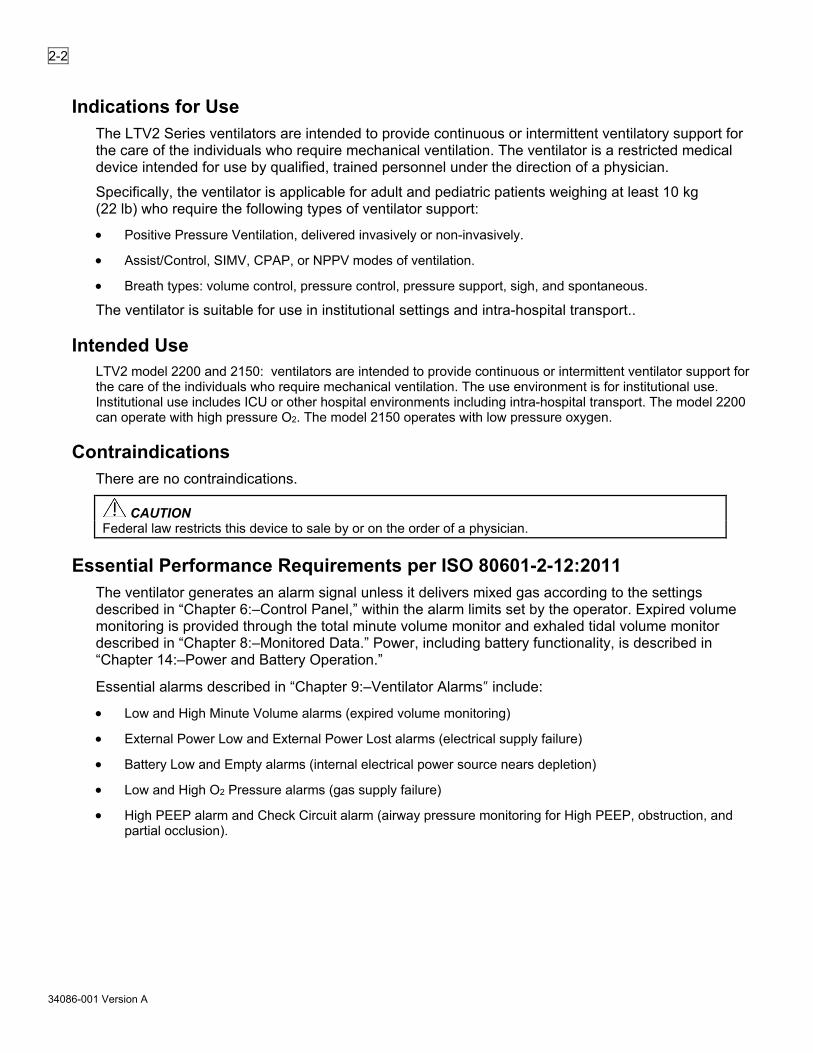
2-2
34086-001 Version A
Indications for Use The LTV2 Series ventilators are intended to provide continuous or intermittent ventilatory support for the care of the individuals who require mechanical ventilation. The ventilator is a restricted medical device intended for use by qualified, trained personnel under the direction of a physician.
Specifically, the ventilator is applicable for adult and pediatric patients weighing at least 10 kg (22 lb) who require the following types of ventilator support:
• Positive Pressure Ventilation, delivered invasively or non-invasively.
• Assist/Control, SIMV, CPAP, or NPPV modes of ventilation.
• Breath types: volume control, pressure control, pressure support, sigh, and spontaneous.
The ventilator is suitable for use in institutional settings and intra-hospital transport..
Intended Use LTV2 model 2200 and 2150: ventilators are intended to provide continuous or intermittent ventilator support for the care of the individuals who require mechanical ventilation. The use environment is for institutional use. Institutional use includes ICU or other hospital environments including intra-hospital transport. The model 2200 can operate with high pressure O2. The model 2150 operates with low pressure oxygen.
Contraindications There are no contraindications.
CAUTION Federal law restricts this device to sale by or on the order of a physician.
Essential Performance Requirements per ISO 80601-2-12:2011 The ventilator generates an alarm signal unless it delivers mixed gas according to the settings described in “Chapter 6:–Control Panel,” within the alarm limits set by the operator. Expired volume monitoring is provided through the total minute volume monitor and exhaled tidal volume monitor described in “Chapter 8:–Monitored Data.” Power, including battery functionality, is described in “Chapter 14:–Power and Battery Operation.”
Essential alarms described in “Chapter 9:–Ventilator Alarms” include:
• Low and High Minute Volume alarms (expired volume monitoring)
• External Power Low and External Power Lost alarms (electrical supply failure)
• Battery Low and Empty alarms (internal electrical power source nears depletion)
• Low and High O2 Pressure alarms (gas supply failure)
• High PEEP alarm and Check Circuit alarm (airway pressure monitoring for High PEEP, obstruction, and partial occlusion).

2-3
34086-001 Version A
Power/Supplies Required To operate the LTV2 2200/2150 ventilator, you will need the following:
• Power source: Vyaire Medical AC Adapter 100V to 250V AC power source or 11V to 29 Vdc power source. This may be an external battery or an approved DC power system.
• For enriched FiO2: High-pressure oxygen source providing between 40 psig and 80 psig (LTV2 2200 only), or low-flow, low-pressure oxygen source providing less than 10 psig.
WARNING Untrained Personnel. To prevent patient injury, only properly trained personnel should operate the ventilator. The LTV2 2200/2150 ventilator is a restricted medical device designed for use by respiratory therapists, nurses, or other properly trained and qualified personnel under the direction of a physician and in accordance with applicable state laws and regulations.
Patient Monitoring. To prevent patient serious injury or death, patients who are dependent on a ventilator should be constantly monitored by qualified personnel and appropriate monitors (such as pulse oximetry). Such personnel should be prepared to address equipment malfunctions and circumstances where equipment becomes inoperative. An alternative method of ventilation should be available for all patients dependent on the ventilator, and qualified personnel should be fully familiar with emergency ventilation procedures.
Information/Assistance For additional information or troubleshooting assistance concerning the operation of the LTV2 2200/2150 ventilator contact a certified Vyaire Medical service technician or Vyaire Medical Customer Care:
Vyaire Medical, Inc. 26125 North Riverwoods Blvd. Mettawa, IL 60045 USA vyaire.com
Customer and Clinical Support Product, Accessories, and Parts Ordering 1-833-327-3284 [email protected]

2-4
34086-001 Version A
Intentionally left blank.

3-1
34086-001 Version A
Breath Types This chapter contains information regarding the breath types available on the LTV2 2200/2150 ventilator. It covers how breaths are initiated, limited and cycled, and when each type of breath is given.
The following terms are used in discussing how breaths are given: Initiate What causes a breath to start? Breaths may be initiated by a patient trigger, a press
of the Manual Breath button, or by the ventilator based on the set breath rate and ventilation mode.
Limit How the breath is controlled. Breaths may be limited to a maximum circuit pressure or flow.
Cycle What causes the breath to be cycled from the inspiratory phase to the exhalation phase? Breaths may be cycled by the ventilator when a set time or delivered volume has been reached, or when an alarm condition such as a high pressure limit has been reached. Breaths may also cycle when inspiratory flow begins to slow.
Breaths are defined by how they are initiated, limited and cycled. The breath types are Machine, Assist, and Patient.
Machine Assist Patient
Initiated by: Ventilator Patient Patient
Limited by: Ventilator Ventilator Ventilator
Cycled by: Ventilator Ventilator Patient
Breaths may be given in any of the following forms: Volume Control, Pressure Control, Pressure Support and Spontaneous. These breaths are given as described in the sections below.
The following parameters apply to all breaths:
• The minimum inspiratory time is 300 milliseconds.
• The minimum exhalation time is 346 milliseconds.
• Triggered breaths are only detected during exhalation after the minimum exhalation time has expired.
Volume Control Breaths Volume breaths may be machine or assist type breaths. For volume control breaths, the set tidal volume is delivered over the set inspiratory time and flow is delivered in a decelerating taper flow waveform. Peak flow is calculated based on the tidal volume, inspiratory time, and set bias flow. The final flow will be the bias flow or 50% of the peak flow, whichever is greater.
When the calculated peak flow of a volume type breath is greater than or equal to two times the set bias flow, flow is decelerated from the calculated peak flow to 50% (±15%) of the calculated peak flow, or 5 lpm, whichever is greater.
When the calculated peak flow of a volume type breath is between the set bias flow and two times set bias flow, the waveform is flattened to allow the volume to be delivered in the specified inspiratory time with a final flow of the set bias flow (±15%).

3-2
34086-001 Version A
Sigh Breaths A sigh breath is a special breath type available in the volume mode (either assist control or SIMV). Sigh breaths are typically used when an occasional larger breath is preferred. If enabled, sigh breaths are delivered every 99 breaths or seven (7) minutes (whichever comes first).
Sigh breaths are different than a typical volume control breath in the following ways:
• Tidal volume: 1.5 times the set tidal volume
• Inspiratory time: 1.5 times the set inspiratory time
• Breath period (total cycle time for one breath): 1.5 times the breath period
• High pressure limit: 1.5 times the set high pressure limit (or 99 cmH2O, whichever is less)
See Sigh on page 10-19 for further information.
Pressure Control Breaths For Pressure Control breaths, flow is delivered to elevate the circuit pressure to the Pressure Control setting and maintain it at that pressure for the set Inspiratory Time. Pressure Control breaths may be machine or assist type breaths. Figure 3-1 shows example flow patterns for two different patient conditions.
Figure 3-1. Pressure Control Breaths
1 Flow delivered to meet the set pressure 2 Breath cycles at the set inspiratory time 3 Flow delivered to meet the set pressure 4 Breath cycles at the set inspiratory time 5 Set pressure 6 Set inspiratory time 7 Set inspiratory time 8 Set pressure

3-3
34086-001 Version A
Pressure Control settings are in addition to PEEP. For example, a Pressure Control setting of 20 cmH2O and a PEEP setting of 10 cmH2O results in a Peak Inspiratory Pressure (PIP) of 30 cmH2O (20 cmH2O over the set PEEP of 10 cmH2O ).
Adjusting the Rise Time Profile changes the flow and pressure waveforms for Pressure Control breaths.
Figure 3-2. Adjusting Rise Time on Pressure Control Breaths
1 Profile #2–faster rise time 3 Profile #9–slower rise time 2 Set pressure 4 Set pressure
Pressure Control breaths have an optional flow termination criteria. If PC Flow Termination is ON Pressure Control breaths have the additional ability to be flow terminated. If the flow drops to the set FLOW TERM level before the inspiratory time is completed, the inspiration is cycled.
Figure 3-3. PC Flow TERM settings
PC FLOW TERM set to OFF Pressure control breath terminates normally
PC FLOW TERM set to ON Pressure control breath terminates at the same
percentage of peak flow as pressure support breaths

3-4
34086-001 Version A
1 Peak flow 6 Peak flow 2 Set pressure is maintained and
inspiratory flow goes to zero 7 Breath terminates at the set percentage
of peak flow 3 Breath terminates at the set inspiratory
time 8 Set pressure
4 Set pressure 9 Set inspiratory time 5 Set inspiratory time
Pressure Support Breaths For Pressure Support breaths, flow is delivered to elevate the circuit pressure to the Pressure Support setting and maintain it at that pressure until the flow drops below a variable (user set) percentage of the peak flow. Pressure Support breaths may also be cycled by a variable time limit, or by exceeding 2 breath periods. Pressure support breaths are patient type breaths.
Figure 3-4. Pressure Support Breaths
1 Measured peak flow 2 Flow delivered to meet set pressure 3 Breath cycles at set percentage of peak flow (Flow Term) 4 When set % of peak flow is not reached, breath is cycled at set Time Term. 5 Set pressure 6 Set pressure
Pressure Support settings are in addition to PEEP. For example, a Pressure Support setting of 20 cmH2O and a PEEP setting of 10 cmH2O results in an approximate Peak Inspiratory Pressure of 30 cmH2O (20 cmH2O over the set PEEP of 10 cmH2O).
For some patients, it may be useful to adjust the variable flow termination percentage. Adjusting the FLOW TERM setting between 10% and 70% will change the length, volume and comfort of the inspiration. A higher flow termination setting will terminate the breath sooner.

3-5
34086-001 Version A
Figure 3-5. Adjusting Flow Term on Pressure Support Breaths
1 Measured peak flow 4 Set pressure 2 Higher percentage of peak flow (40%) 5 Longer inspiratory time 3 Lower percentage of peak flow (10%)
Spontaneous Breaths For Spontaneous breaths, flow is delivered to meet patient demand and maintain the circuit pressure at the measured PEEP from the previous breath. The breath is cycled when the flow drops below the Pressure Support Flow Termination setting, or below 5 lpm. Spontaneous breaths may also be terminated by exceeding two breath periods. Spontaneous breaths are patient type breaths. Figure 3-6 shows an example flow for two different patient conditions.
Figure 3-6. Spontaneous Breaths
1 Measured peak flow 2 Flow delivered to meet patient demand and maintain PEEP 3 Breath cycles at Pressure Support Flow Termination setting 4 Breath cycles at <5 lpm 5 PEEP 6 Pressure maintained at PEEP

3-6
34086-001 Version A
Intentionally left blank.

4-1
34086-001 Version A
Ventilation Modes The LTV2 2200/2150 ventilator provides the following modes of ventilation:
• Control
• Assist/Control
• SIMV (Synchronized Intermittent Mandatory Ventilation)
• CPAP (Continuous Positive Airway Pressure)
• NPPV (Non-Invasive Positive Pressure Ventilation)
• Apnea Backup Ventilation
Each of these modes is described below.
Volume and Pressure Ventilation The LTV2 2200/2150 ventilator offers both Volume and Pressure ventilation.
When Volume is selected, all machine and assist breaths are Volume breaths. Breaths are given according to the Tidal Volume and Inspiratory Time controls. For more information on Volume Control breaths, see “Chapter 6:–Control Panel.”
When Pressure is selected, all machine and assist breaths are Pressure breaths. Breaths are given according to the Pressure Control and Inspiratory Time controls. For more information on Pressure Control breaths, see “Chapter 6:–Control Panel.”
Control Mode Control mode ventilation is selected when Assist/Control is selected and Sensitivity is set to a dash “-”. In Control mode, Volume or Pressure Controlled machine breaths are given at the rate specified by the Breath Rate setting and no triggered breaths are allowed.
Figure 4-1. Pressure Control Machine Breaths
Breath period

4-2
34086-001 Version A
Assist/Control Mode Assist/Control ventilation is selected when Assist/Control is selected and Sensitivity is on. In Assist/Control mode, the ventilator guarantees a minimum number of Volume or Pressure Controlled breaths are given. The patient may trigger additional Volume or Pressure Controlled assist breaths.
Figure 4-2. Pressure Control Machine and Assist Breaths
1 Machine breath 4 Patient trigger 2 Assist breath 5 Breath period 3 Breath period
SIMV Mode SIMV mode is selected when SIMV/CPAP is selected and the Breath Rate is set between 1 and 80. In SIMV mode, machine, assist and patient breaths may be given.
For the first patient trigger detected within a breath period, an assist breath is given. For all subsequent patient triggers within the same breath period, spontaneous patient breaths or pressure support if set, are given.
At the beginning of a breath period, if no triggered breaths were given in the previous breath period, a machine breath is given. If there was a patient trigger in the previous breath cycle, the ventilator will not give a machine breath in the current breath period unless the set Apnea Interval is exceeded. Figure 4-3. Pressure Control Machine and Assist Breaths, and Pressure Support Breaths
Figure 4-4. Pressure Control Machine and Assist Breaths, and Pressure Support Breaths
1 Machine 2 Assist 3 Pressure support 4 Patient triggers

4-3
34086-001 Version A
CPAP Mode CPAP mode is selected when SIMV/CPAP is selected and the Breath Rate is set to dashes “- -”. In CPAP mode, when a patient trigger is detected, a patient breath is given. Breaths will be Pressure Support or Spontaneous breaths according to the Pressure Support setting.
Figure 4-5. Pressure Support Patient Breaths
1 Pressure support 2 Patient triggers
Figure 4-6. Spontaneous Patient Breaths
1 PEEP 2 Spontaneous breaths
NOTE The LTV2 ventilator provides an Apnea Backup mode of ventilation. When the set Apnea Interval (maximum time allowed between the beginning of one breath and the beginning of the next breath) is exceeded, the APNEA alarm is generated and the ventilator will enter Apnea Backup ventilation mode.
NOTE If the ventilator is set to CPAP mode, the Sensitivity setting will not be able to be set to off.

4-4
34086-001 Version A
NPPV Mode Non-invasive Positive Pressure Ventilation (NPPV) can be selected as the primary mode of ventilation. This mode of ventilation is indicated for patients without an artificial airway (e.g. endotracheal or tracheostomy tube). NPPV requires the use of a non-vented mask as the patient interface. See “Procedure for NPPV Mode Set Up” on page 12-10.
The following modalities are available in NPPV: • CPAP • PEEP with Pressure Support • Timed Pressure Controlled breaths (either time or flow terminated) with pressure support (flow terminated)
spontaneous breaths.
NOTE When NPPV mode is selected, the Pressure Control setting is used to set both pressure support and pressure control values.
NOTE When NPPV is selected, the breath type automatically changes to Pressure and Flow Termination is selected. Upon exiting the NPPV mode (by pressing the Ventilation Mode control button), the ventilator returns the Pressure Control Flow Termination setting to its setting before entering the NPPV mode (within the same power cycle).
WARNING Use of Masks. Masks used with the LTV2 2200/2150 must be non-vented (no holes or leak vents). With a vented mask, the patient's exhaled air escapes through holes or vents in the mask, elbow or swivel connector. With a non-vented mask, the patient's exhaled air escapes through the ventilator exhalation valve. Using a vented mask depletes the oxygen supply faster, and also may lead to patient-ventilator dyssynchrony.
Excessive leakage can also occur if the mask is not properly sealed to the patient’s face. Leaks around the mask may cause the exhaled tidal volume measured by the ventilator to be different than what is actually exhaled from the patient. An end-tidal CO2 monitor (complying with ISO 80601-2-55) with alarms should be used during non-invasive ventilation.
Figure 4-7. Non-invasive Positive Pressure Ventilation Patient Breaths
1 PEEP 2 Pressure support breaths 3 Patient triggers 4 Mandatory pressure control breaths

4-5
34086-001 Version A
Apnea Backup The LTV2 2200/2150 ventilator provides an Apnea Backup mode of ventilation. Apnea Backup ventilation begins when the time since the last breath start is greater than the set Apnea Interval.
When an apnea alarm occurs: The ventilator begins Apnea Backup ventilation in the Assist/Control mode according to the current control settings. The active controls are displayed at full intensity, and all other controls are dimmed.
The breath rate for Apnea Backup mode is determined as follows:
• If the set Breath Rate is ≥12 bpm, the Apnea breath rate is the set Breath Rate.
• If the set Breath Rate is <12 bpm and the set Breath Rate is not limited by other control settings, the Apnea breath rate is 12 bpm.
• If the set Breath Rate is limited to <12 bpm by other control settings, the Apnea breath rate will be the highest allowed rate.
The ventilator exits the Apnea Backup mode and returns to the previous mode of ventilation when the operator resets the Apnea alarm or when two consecutive patient-initiated breaths occur.
NOTE Apnea Ventilation in NPPV. When the ventilator is in NPPV mode with Pressure Control set to -- (OFF) and enters the Apnea Backup mode, the unit ventilates in Assist/Control mode using a pressure Control value of 15. The display alternates between “APNEA xx bpm” and “APNEA 15 cmH2O”. See “Procedure for NPPV Mode Set Up” on page 12-10.
The Apnea Interval may be changed using the Extended Features menu.
Figure 4-8. Machine Rate = 9 bpm, Inspiratory Time = 0.3 seconds, Apnea Interval = 10 seconds

4-6
34086-001 Version A
1 Patient trigger 5 3.64 seconds No breath Start Activity
2 0.3-second breath start 6 Apnea backup mode starts 3 9 bpm / 6.66 seconds 7 10 seconds
No breath Start Activity
4 6.36 seconds No breath Start activity
Figure 4-9. Machine Rate = 12 bpm, Inspiratory time = 0.3 seconds, Apnea Interval = 10 seconds
1 Patient trigger 5 5.0 seconds No breath Start Activity
2 0.3-second breath start 6 Machine breath 3 12 bpm / 5.0 seconds 7 9.7 seconds
No breath Start Activity
4 4.7 seconds No breath Start activity

5-1
34086-001 Version A
Using the Controls and Indicators
Ventilator Controls The following diagram shows how the LTV2 2200 front panel controls and displays are arranged.
Figure 5-1. LTV2 2200 Front Panel Controls/Display Arrangement
1 Display window 8 Scroll Knob 2 Patient Effort indicator 9 Breath Type & Mode Selection 3 Battery Check button 10 Power/Standby 4 Alarm Silence button 11 Button Controls 5 Alarm Reset button 12 Variable Control Settings 6 Alarms Panel 13 Airway Pressure Display 7 Power Source

5-2
34086-001 Version A
The following diagram shows how the LTV2 2150 front panel controls and displays are arranged.
Figure 5-2. LTV2 2150 Front Panel Controls/Display Arrangement
1 Display window 8 Scroll Knob 2 Patient Effort indicator 9 Breath type & Mode Selection 3 Battery Check button 10 Power/Standby 4 Alarm Silence button 11 Button Controls 5 Alarm Reset button 12 Variable Control Settings 6 Alarms panel 13 Airway Pressure Display 7 Power Source
Setting a Control There are 5 kinds of controls on the LTV2 2200/2150 ventilator. They are:
Variable Controls Controls and alarms that have front panel displays. Buttons Buttons that select an option or perform a function. Scroll Knob Used to set control values, modes, and breath types as well as
navigation of extended features menus. Extended Features Ventilation options that do not have front panel controls but are
available through a special menu. Mechanical Controls Controls, such as Over Pressure Relief, that are hardware regulated
and not operator adjustable.
The following sections describe how to set each kind of control.

5-3
34086-001 Version A
Variable Settings To set a variable setting (controls or alarms): 1. Select the control by pressing the associated button. The display for the selected control will be displayed at
normal brightness, but the remaining control displays will dim.
2. Change the control value by rotating the Scroll knob. Rotate clockwise to increase and counter-clockwise to decrease the value. Turning the control knob slowly will change the setting by a small increment. Turning the control knob more quickly will change the setting by a larger increment.
3. Press the associated button again to accept/confirm the new setting.
The new control value goes into effect only if the selected button is pressed again. If any other control button is pressed, fifteen seconds have elapsed or the Control Lock button is pressed, the setting will be deselected and revert to the previous value. When the control is deselected, all displays will return to their normal brightness.
Buttons Button controls do one of three things:
• Turn a feature on or off, such as Control Lock.
• Perform a function, such as Manual Breath.
• Select controls for change.
To prevent an accidental shutdown, the ventilator requires a longer press of the Power/Standby button to put the ventilator in the Standby state. To put the ventilator in Standby, press and hold the Power/Standby button for 3 seconds.
Scroll Knob Use the Scroll knob to set control values, modes, breath types, and to navigate extended features menus.
To change the setting for a variable control, select the control then turn the knob clockwise or counter-clockwise until the preferred setting is reached.
For information on how to use the Scroll knob to navigate the extended features menus, see “Chapter 10:–Extended Features.”
Extended Features The Extended Features menus allow you to set ventilation parameters that do not have dedicated front panel controls. For information on how to use the Scroll knob to navigate the extended features menus, see “Chapter 10:–Extended Features.”

5-4
34086-001 Version A
Bright, Dim, and Blank Control Displays Variable controls will be displayed at normal or dimmed intensity, or may be blanked.
A display will be displayed at normal intensity:
• When it is selected for change. All other displays will be dimmed.
• When it is active in the current ventilation mode. Dimmed displays are not active in the current mode.
NOTE Be sure to set any controls that may be used in Apnea Backup ventilation to appropriate values. Even though these controls are dimmed, they will be used if apnea should occur.
Some controls may be inactive for a given mode; however, they may still be participating in the Control Limiting feature (see page 5-5).
A display will be displayed at dimmed intensity:
• When another control is selected for change.
• When it is not active in the current ventilation mode.
A display will be blank:
• To conserve battery power while operating from battery power:
If no button presses or control knob activity occur for 60 seconds, the displays are turned off. The display window, 7-segment control displays, and LEDs are turned off. Anytime an alarm occurs, or if an alarm message is already displayed, the display window will remain active. The Airway Pressure display is always active.
• Pressing any button or turning the Scroll knob will turn the displays back on.
• When an option, such as oxygen blending, is not installed.
• When a control feature is not available, such as during Ventilator Checkout tests.
Flashing Controls Variable controls and alarms will be displayed solid or flashing. A flashing control means one of the following things:
• If you are changing a control setting, and the display flashes, you have reached a limited value for the control. Control Limiting is covered later in this section.
• If an alarm display flashes, it indicates that an alarm has occurred or is occurring. For more information on this, see “Chapter 9:–Ventilator Alarms.”
• If a control display flashes, it indicates a special condition such as time termination of a pressure support breath. For more information, see “Chapter 6:–Control Panel.”
• If the Control Lock LED flashes, it indicates you have tried to change the control settings while the front panel controls are locked. For more information, see “Chapter 6:–Control Panel.”
Dashes If a control display is set to dashes “- - ”, it indicates that control is turned off, or is not available in the current ventilation mode.

5-5
34086-001 Version A
Control Limiting Variable control settings may be limited to less than their specified range for any of the following reasons:
• To prevent inverse I:E ratios of greater than 4:1
• To ensure a minimum inspiration time of 300 ms
• To ensure a minimum exhalation time of 346 ms
• To ensure a minimum initial flow of 5 lpm for Volume Controlled breaths
• To ensure a maximum initial flow of 100 lpm for Volume Controlled breaths
• To ensure the bias flow is not less than the inspiratory flow
• To ensure the bias flow is not less than the sensitivity setting (flow triggering)
When you are updating a control and have reached a limited condition, the following will happen:
• The control stops updating and will remain displayed at the highest (or lowest) allowed value.
• The control display will flash.
• The displays for other controls involved in the limited condition will flash.
To set the control to a value outside the limited range, you will need to change the settings for other controls involved in the limit condition. For instance, if the Breath Rate is set to 12, the maximum allowed Inspiratory Time is 4.0 seconds. To set the Inspiratory Time to more than 4.0 seconds, you must first decrease the Breath Rate.
Control Locking The front panel controls may be locked so that settings cannot be accidentally changed. When the controls are locked, the Control Lock LED will be on. If you try to select or change a control while the Control Lock is on, the message LOCKED will be displayed in the display window and the Control Lock LED will flash.
Two different levels of difficulty can be set for control unlocking: Easy and Hard. The Easy unlocking method should be used when only trained personnel have access to the ventilator. The Hard method should be used when children or others may have access to the ventilator and you want to prevent accidental changes to the control settings. Easy unlocking is the default and this setting is changed using the Extended Features menus. For more information, see page 10-12. To turn the Control Lock on:
• Press the Control Lock button.
• The Control Lock LED is on whenever the front panel controls are locked.

5-6
34086-001 Version A
If you press a button while the controls are locked:
• The Control Lock LED will flash.
• LOCKED will be displayed in the display window.
• The button press is ignored.
To turn the Control Lock off with Easy unlocking: Press the Control Lock button.
To turn the Control Lock off with Hard unlocking: Press and hold the Control Lock button for 3 seconds.
These controls are not affected by the Control Lock and operate even when the Control Lock is on: Manual Breath, Alarm Reset, Alarm Silence, Battery Check, Control Lock, or Menu/Select.
NOTE The Control Lock button also serves as an “escape” key to back out of the Extended Features sub menus.
Control Retention After a control value is set, that value is retained in non-volatile memory. The settings retained in non-volatile memory may be used when the ventilator is next powered up and are not erased when the ventilator is turned off or disconnected.

6-1
34086-001 Version A
Control Panel This section explains how the LTV2 2200/2150 ventilator front panel controls work.
Menu/Select Use this button to change the monitor in the display window and to select items in the Extended Feature menus.
Monitored Data The monitored data displays may be automatically or manually scrolled.
To cycle through the available monitored data automatically from a halted scan: 1. Press the monitor Menu/Select button twice within 0.3 seconds.
2. Pressing the Menu/Select button once while scan is active will halt scanning and the currently displayed data remains in the display window.
3. Each time you press the button once, the next data item in the list will be displayed.
4. To resume scan, press the Menu/Select button twice.
The monitored data displays for three seconds.
Extended Features
To enter the Extended Features menu: Press and hold the Menu/Select button for three seconds.
The first Menu Item appears–for example: ALARM OP. For more information on how to use the Extended Features menu, see “Chapter 10:–Extended Features.”
Battery Check The Battery Check button allows the user to determine the charge level of the internal and removable (if installed) batteries.
Pressing the Battery Check button causes the ventilator to display IntBat xxx%, where xxx is the percent charge of the internal battery. Then, if the removable battery is inserted, the display changes to RemBat xxx%, where xxx is the percent charge of the removable battery. To manually advance between IntBat xxx% and RemBat xxx%, press the battery check button.
The Battery Check button is functional if the LTV2 is powered on or is in standby/off. However, if the ventilator is in standby/off, it may take a few seconds to wake the CPU to be able to display the charge levels.
NOTE The LTV2 does not charge external batteries, and their charges will not be displayed.
Scroll Knob Use the Scroll knob to establish control values, modes, breath types, and to navigate extended features menus.

6-2
34086-001 Version A
Variable Controls
To change the setting for a variable control: 1. Press the button for the control to be modified.
2. Turn the Scroll knob clockwise to increase the value, or
3. Turn the Scroll knob counter-clockwise to decrease the value.
4. Press the button again to accept the change.
To change the setting by small increments, turn the knob slowly. To change the setting by larger increments, turn the knob more quickly.
Extended Features
To navigate through a list of items in an Extended Features menu: 1. Turn the Scroll knob clockwise to display the next menu item, or
2. Turn the Scroll knob counter-clockwise to display the previous menu item.
Power/Standby This button switches the ventilator between the off/standby and on states.
The ventilator operates on external power if it is available. If there is no external power, the LTV2 will switch to the removable (if inserted) or internal battery (in that order).
To turn the ventilator on from the Standby state:
• Press the Power/Standby button.
If the Patient Query feature is enabled/on when the ventilator is powered up, ventilation and alarm activation are suspended and the message SAME PATIENT appears (see Queries on page 10-20).
• To enable the suspended alarms and begin ventilation with the settings in use during the last power cycle, press the Menu/Select button while SAME PATIENT appears
OR
• To enable the suspended alarms and begin ventilation with Presets values appropriate for a new patient, turn the Scroll knob until NEW PATIENT appears and press the Menu/Select button. Then turn the Scroll knob until the preferred patient type appears (PEDIATRIC or ADULT) and press the Menu/Select button.
Turning the Scroll knob until EXIT appears and pressing the Menu/Select button returns the ventilator to the SAME PATIENT menu option/message
If no controls are activated for fifteen (15) seconds, while either the SAME PATIENT or NEW PATIENT options are being displayed, an audible alert sounds. Activation of any control resets the delay of the audible alert.
If the Patient Query feature is disabled/off when the ventilator is powered up and passes Power On Self Tests (POST), it will begin ventilation (appropriate alarms enabled) using the settings in use during the last power cycle.
To prevent auto-triggering, the Leak Compensation feature (if enabled/on) is suspended during the first 30 seconds of operation.

6-3
34086-001 Version A
To prevent nuisance alarms, the LOW MIN VOL alarm (Low Minute Volume) is suspended for the first 20 seconds and the HI RESP RATE alarm (High Breath Rate) is suspended for the first 60 seconds of operation.
To put the ventilator into Standby: 1. Press and hold the Power/Standby button for about three seconds.
2. An Inop alarm will occur. To cancel the Inop alarm, press the Alarm Reset button.
3. The Check Battery button remains functional when the ventilator is in Standby. The display window will illuminate to display the charge level of the internal battery and removable battery (if installed).
After several minutes in the Standby state, the ventilator will automatically transition to the Off state if external power is not present. Functionally, the Standby and Off states are the same. However, when in the off state, battery charge is conserved to a greater extent.
NOTE When not in use, external batteries should be disconnected from the LTV2 external power input. The external battery drains if left connected.
Breath Rate Use the Breath Rate control to establish the minimum rate of machine or assist breaths that the ventilator will deliver per minute.
To set the Breath Rate: 1. Press the Breath Rate button.
2. Change the setting using the Scroll knob.
3. Press the Breath Rate button to confirm change.
Range: “- -”, 1 to 80 bpm
Default: 12 bpm
NOTE When SIMV/CPAP is selected, the ventilator will be in SIMV or CPAP mode, depending on the Breath Rate setting.
• If Breath Rate is set to dashes “- -”, the ventilator will be operating in CPAP mode.
• If Breath Rate is set to any other value, the ventilator will be operating in SIMV mode.
NOTE If Breath Rate is set to dashes “- -”, the Sensitivity setting will not be able to be set to off.

6-4
34086-001 Version A
Inspiratory Time This control sets the length of the inspiratory period for Volume Controlled and Pressure Controlled breaths.
The Inspiratory Time and Volume control settings are used to determine the peak flow for Volume controlled breaths. While the Inspiratory Time is being updated, the Calculated Peak Flow will be displayed in the display window.
To set the Inspiratory Time: 1. Press the Inspiratory Time button.
2. Change the setting using the Scroll knob.
3. Press the Inspiratory Time button to confirm change.
Range: 0.3 to 9.9 seconds
Default: 1.5 seconds
NOTE When an attempted change to the Inspiratory Time setting would make the initial flow less than the minimum initial flow or greater than the maximum initial flow, the control’s display will stop updating and will remain displayed at the last allowed setting. The Tidal Volume and Inspiration Time dedicated displays will flash, and the message “BIAS FLOW xx” will flash, where xx is the current value of the Bias Flow setting.
Tidal Volume Use the Tidal Volume control to establish the volume of gas which the ventilator will produce and deliver during Volume Controlled breaths. Flow is delivered in a decelerating (tapered) waveform over the set Inspiratory Time. The peak flow is calculated based on the Tidal Volume and Inspiratory Time with a maximum flow of 100 lpm and a minimum flow of 5 lpm. Flow is decelerated from the calculated peak flow to 50% of the calculated peak flow.
Figure 6-1. Taper Waveform.
1 Peak Flow 2 50% Peak Flow 3 Inspiratory Time
While the Tidal Volume is being updated, the Calculated Peak Flow appears in the display window.

6-5
34086-001 Version A
The Effect of Circuit Compliance on Delivered Tidal Volume The LTV2 ventilator does not use compliance compensation (compensating for the reduction in delivered tidal volume delivered to the patient due to the compliance of the breathing circuit). To measure the amount of volume remaining in the circuit for each breath, refer to this equation:
Circuit compliance x (PIP – PEEP) = volume remaining in the circuit.
LTV2 breathing circuit compliance values are found in the breathing circuit instructions for use for the breathing circuit.
The Effect of Altitude or Barometric Pressure on Delivered Tidal Volume Altitude and barometric pressure have an effect on the actual tidal volume delivered to the patient by the LTV2 ventilator.
To prevent potential over delivery of tidal volume when Volume ventilation is required, use the following instructions to calculate a Tidal Volume control setting necessary to compensate for the effect of altitudes or barometric pressures. 1. Ascertain the pertinent environmental condition (altitude or barometric pressure) in which the ventilator is to
be operated.
• Altitude (above sea level). Determine the altitude if the ventilator is to be operated at altitudes above 6,500 feet sea level if NOT contained within a pressurized compartment.
• Barometric Pressure (mmHg/kPa). Determine the barometric pressure of the pressurized compartment that the ventilator is to be operated within
2. Refer to the table, select the row in which the listed altitude or barometric pressure is closest to the pertinent environmental condition, and scroll across to the “Volume Compensation Factor” column to determine the associated compensation factor.
3. According to the equation shown below, the “Tidal Volume (ml) control setting” to be used/set is equal to the “Intended Tidal Volume (ml)” to be delivered, divided by the “Compensation Factor”.
Tidal volume control setting (ml) = required tidal volume ÷ compensation factor1
4. To correct the monitored tidal volume for the effects of altitude, use this equation (monitored VTE is the measured tidal volume displayed on the ventilator):
Actual measured tidal volume (ml) = monitored tidal volume x compensation factor2 Altitude
(f) Pressure (mmHg)
Pressure (kPa)
Compensation Factor1 (to correct delivery)
Compensation Factor2 (to correct monitor)
-2500 831 110.820 0.922 0.964 -2000 817 108.866 0.934 0.973 -1500 802 106.939 0.945 0.983 -1000 788 105.041 0.957 0.992 -500 774 103.169 0.969 1.001
0 760 101.325 0.981 1.011 500 746 99.508 0.994 1.020
1000 733 97.717 1.006 1.030 1500 720 95.952 1.019 1.040 2000 707 94.213 1.032 1.050 2500 694 92.500 1.045 1.060 3000 681 90.812 1.059 1.070 3500 669 89.149 1.073 1.081 4000 656 87.511 1.086 1.091 4500 644 85.897 1.101 1.102 5000 632 84.307 1.115 1.113 5500 621 82.742 1.130 1.124 6000 609 81.200 1.144 1.135 6500 605 80.647 1.150 1.139 7000 595 79.314 1.163 1.149

6-6
34086-001 Version A
Altitude (f)
Pressure (mmHg)
Pressure (kPa)
Compensation Factor1 (to correct delivery)
Compensation Factor2 (to correct monitor)
7500 584 77.847 1.178 1.160 8000 574 76.514 1.193 1.171 8500 564 75.181 1.207 1.181 9000 553 73.715 1.224 1.194 9500 543 72.382 1.240 1.205
10000 533 71.049 1.256 1.217 10500 522 69.583 1.274 1.230 11000 512 68.250 1.291 1.243 11500 502 66.917 1.309 1.256 12000 496 66.117 1.320 1.263 12500 486 64.784 1.339 1.277 13000 476 63.451 1.358 1.291 13500 465 61.985 1.381 1.307 14000 460 61.318 1.391 1.314 14500 450 59.985 1.412 1.329 15000 440 58.652 1.435 1.345 15500 434 57.852 1.448 1.355 16000 424 56.519 1.472 1.371
WARNING Altitude and Temperature Restrictions. Do not use the ventilator at an altitude above 16,000 feet (4,877 meters) or outside the temperature range specified in “Appendix A:–Ventilator Specifications.” Using the ventilator outside of this temperature range or above this altitude can affect the ventilator performance which consequently can result in patient harm.
To set the Tidal Volume: 1. Press the Tidal Volume button.
2. Change the setting using the Scroll knob.
3. Press the Tidal Volume button again to deselect the setting and accept the new value.
Range: 50 to 2000 ml
Default: 500 ml
NOTE • Be sure that Volume ventilation is selected.
• Volume ventilation at higher altitudes or lower barometric pressures may require the use of compensation calculations to ensure correct delivered and measured tidal volumes.

6-7
34086-001 Version A
Pressure Control This control establishes the target pressure above the PEEP setting for Pressure Control breaths as well as Pressure Support breaths in NPPV.
NOTE Delivered pressure is controlled by the Pressure Control setting and is affected by the PEEP setting. For example, a Pressure Control setting of 20 cmH2O and a PEEP setting of 10 cmH2O results in a Peak Inspiratory Pressure (PIP) of 30 cmH2O.
The inspiratory time for the Pressure Control breath is determined by the Inspiratory Time setting.
Figure 6-2. Rise Time Profiles for the Pressure Control Breaths
1 Fastest Peak Rise Time (Profile #1) 3 Pressure Control 2 Slowest Peak Rise Time (Profile #9) 4 PEEP
The ventilator controls inspiratory flow to maintain the set circuit pressure for the set time.
To set the Pressure Control level: 1. Press the Pressure Control button.
2. Change the setting using the Scroll knob.
3. Press the Pressure Control button to confirm change.
To select Pressure Control: 1. Press the Volume Pressure breath type button.
2. Change the setting using the Scroll knob.
3. Press the Volume Pressure breath type button to confirm change.
Range: 4 to 98 cmH2O
Range: Off, 4 to 60 cmH2O (in NPPV)
Flow Termination for Pressure Control breaths may be enabled under Extended Features. If flow termination is enabled, the Pressure Control display will flash briefly after each flow terminated breath. See “Variable Flow Termination” on page 10-7 for instructions on how to set the Variable Flow Termination percentage and enable Flow Termination for Pressure Control breaths.
The Rise Time profile for Pressure Control breaths may be selected under Extended Features. See “Extended Features” on page 10-1 for instructions on how to set the Flow Rise Time profile.
Profile #1—Faster Rise Time Profile #9—Slower Rise Time

6-8
34086-001 Version A
NOTE When an attempted change to the Pressure Control setting would make Pressure Control + set PEEP > 98 cmH2O (> 60 cmH2O in NPPV), the control’s display stops updating and remains displayed at the last allowed setting and the PEEP Control and Pressure Control dedicated displays flash.
Pressure Support This control establishes the target pressure above the PEEP setting for Pressure Support patient breaths. If Pressure Support is set to dashes “- -“, all patient breaths will be given as Spontaneous breaths. Inspiratory flow for Pressure Support and Spontaneous breaths is controlled to meet the patient demand.
To set Pressure Support: 1. Press the Pressure Support button.
2. Change the setting using the Scroll knob.
3. Press the Pressure Support button to confirm change.
Range: Off “- -”, 1 to 60 cmH2O
Default: 1 cmH2O
NOTE Pressure Support in NPPV Mode. When NPPV mode is selected, the Pressure Control setting is used to set both pressure support and pressure control values.
Pressure Support breaths may be terminated by flow or by time.
Flow Termination: Pressure Support breaths are flow terminated when the flow decreases to a set percentage of the peak flow delivered for that breath. See “Chapter 10:–Extended Features.”
Time Termination: Pressure Support breaths are time terminated when the inspiratory time exceeds two breath periods, or when the inspiratory time exceeds the set Time Termination Limit before the flow termination criteria is reached. The Pressure Support display will flash briefly after each time terminated breath. Pressure Support breaths are flow and/or time terminated (Time Termination must be enabled).
The Rise Time profile for Pressure Support breaths may be selected under Extended Features.
NOTE Delivered pressure is controlled by the Pressure Support setting and is affected by the PEEP setting. For example, a Pressure Support setting of 15 cmH2O and a PEEP setting of 5 cmH2O results in a Peak Inspiratory Pressure (PIP) of 20 cmH2O.
NOTE When an attempted change to the Pressure Support setting would make Pressure Support + set PEEP) > 60 cmH2O, the control’s display will stop updating and remains displayed at the last allowed setting and the PEEP Control and Pressure Support dedicated displays flash.
Pressure Support in NPPV Mode When NPPV mode is selected, the Pressure Control setting is used to set both the pressure support and pressure control values.

6-9
34086-001 Version A
PEEP Control The PEEP control establishes the Positive End Expiratory Pressure.
To set the PEEP: 1. Press the PEEP control button.
2. Change the setting using the Scroll knob.
3. Press the PEEP control button to confirm change.
Range: 0 to 20 cmH2O
Default: 3 cmH2O
NOTE When an attempted change to the PEEP Control setting would make Pressure Control + set PEEP >98 cmH2O the control’s display stops updating and remains displayed at the last allowed setting and the PEEP Control and Pressure Control dedicated displays flash.
When an attempted change to the PEEP Control setting would make Pressure Support + set PEEP >60 cmH2O the control’s display stops updating and remains displayed at the last allowed setting and the PEEP Control and Pressure Control dedicated displays flash.
Figure 6-3. Pressure Control and Pressure Support settings are delivered above the set PEEP
On the left, the ventilator is set to deliver a pressure target breath such as Pressure Support (or Pressure Control) of 20 cmH2O with no PEEP. On the right, the ventilator is set to deliver the same Pressure Support (or Pressure Control) breath of 20 cmH2O. Note that 5 cmH2O of PEEP have been added. The resulting PIP is 25 cmH2O (PC or PCV setting + PEEP).
To view the measured PEEP in the display window: Use the Menu/Select button to display the measured PEEP in the display window.
PEEP Control in NPPV Mode When NPPV mode is selected, the PEEP control is used to set the PEEP/CPAP value.

6-10
34086-001 Version A
FiO2 (Flush) (LTV2™ 2200 only) The FiO2 (Flush) button is a dual function control (FiO2 and O2 Flush).
• When being used to set the fraction of inspired oxygen delivered by the ventilator through the oxygen blending system (O2%), press and release the FiO2 (Flush) button as described below.
• When being used to elevate the FiO2 to 1.0 for a preset period of time (Flush), press and hold the FiO2 (Flush) button for 3 seconds, as described in “O2 Flush (LTV2™ 2200 only)” on page 10-12.
The FiO2 (Flush) control establishes the fraction of inspired oxygen to be delivered through the oxygen blending system. Oxygen blending requires a high pressure oxygen source and is active only when Low Pressure O2 Source is not selected. When Low Pressure O2 Source is selected, this control displays as dashes “--” and may not be modified.
To set the fraction of inspired oxygen delivered by the ventilator: 1. Press and release the FiO2 (Flush) button.
2. Change the setting using the Scroll knob.
3. Press the FiO2 (Flush) button to confirm change.
Range: 21 to 1.0
Default: 21
WARNING Inspired Oxygen (FiO2) Concentration. If the patient has a variable respiratory rate, his/her minute ventilation will fluctuate. The LTV2 2200/2150 does not have integrated oxygen monitoring equipment. An oxygen monitor (complying with ISO 80601-2-55) with high and low oxygen delivery alarms must be used to monitor and help ensure delivered oxygen concentration and reduce the risk of patient injury.
CAUTION Oxygen Supply Contamination. The accuracy of the oxygen delivery capabilities of LTV2 2200/2150 ventilator can be compromised by foreign debris contamination in the oxygen supply system. To reduce the risk of airborne contaminants entering the ventilator, ensure that any oxygen supply connected to the ventilator is clean, properly filtered and that the ventilator’s O2 Inlet Port Cap is securely installed on the O2 Inlet Port whenever the ventilator is not connected to an external oxygen supply.
NOTE The Oxygen Inlet High Pressure alarm at 85 psig and Oxygen Inlet Low Pressure alarm at 35 psig are only active when Low Pressure O2 Source is off and the FiO2 (Flush) setting is greater than 21%.

6-11
34086-001 Version A
Sensitivity Use the Sensitivity control to establish the threshold level to allow the patient to trigger delivered breaths. Flow triggering is enabled by default.
Flow Trigger A flow triggered breath occurs when Bias Flow is turned on and the flow measured at the patient wye during the exhalation phase of the breath is greater than or equal to the Sensitivity setting.
• When the O2 Conserve feature is ON (O2 CONSRV ON) (LTV2 2200 only) flow trigger is unavailable and pressure trigger is selected automatically.
• A backup pressure triggered breath occurs when the Sensitivity is set between 1 and 9 (any value other than a dash “-”) and the airway pressure drops below -3 cmH2O during the exhalation phase of the breath.
NOTE The LEAK measurement displayed in the RT XDCR DATA menu may be useful to help select an appropriate sensitivity value. Typically, the sensitivity value is set higher than the displayed LEAK measurement. For instance, if the measured LEAK is 2.53, a minimum sensitivity of 3 would be appropriate.
Pressure Trigger A pressure triggered breath occurs when Bias Flow is turned off and the pressure measured in the circuit during the exhalation phase of the breath meets or exceeds the Sensitivity setting.
When the O2 Conserve feature is ON (O2 CONSRV ON) (LTV2 2200 only) pressure trigger is selected automatically.
When a trigger is detected, the Patient Effort LED illuminates briefly.
NOTE Triggers are disabled when the Sensitivity setting is set to “-”. The Sensitivity setting cannot be set to off (“-”) when in CPAP mode.
NOTE The bias flow cannot be lower than the set sensitivity setting. If there is an attempt to set bias flow below sensitivity or the sensitivity above the bias flow, the control stops updating and both values will flash. Correct the limiting parameter to continue with the change. See “Control Limiting” on page 5-5.

6-12
34086-001 Version A
To set Sensitivity: 1. Press the Sensitivity button.
2. Change the setting using the Scroll knob.
3. Press the Sensitivity button to confirm change. Range: 1 to 9, Off (“-“) (Sensitivity is in lpm for flow triggering and in cmH2O for pressure triggering.) Default: 2 lpm
Volume/Pressure Mode Use this button to switch between Pressure control and Volume control types of ventilation.
To set the breath type to Volume or Pressure: 1. Press the Breath Type button.
2. Change the setting using the Scroll knob.
3. Press the Breath Type button to confirm change.
The ventilator begins operating in the new breath type as soon as the change is confirmed.
Assist/Control – SIMV/CPAP – NPPV This button is used to switch between Assist/Control, SIMV/CPAP, and NPPV modes of ventilation.
To set the mode of ventilation: 1. Press the Mode button.
2. Change the setting using the Scroll knob.
3. Press the Mode button to confirm change.
The ventilator begins operating in the new mode as soon as the change is confirmed.
NOTE If the ventilator is set to the NPPV mode, the breath type is changed to Pressure, and Pressure Control Flow Termination is enabled. Upon exiting the NPPV mode (by pressing the Ventilation Mode control button), the ventilator returns the Pressure Control Flow Termination setting to its setting before entering the NPPV mode (within the same power cycle).
For more information, see “Procedure for NPPV Mode Set Up” on page 12-10.
NOTE When Assist/Control is selected, the ventilator will be in Control or Assist/Control mode, depending on the Sensitivity setting. • If Sensitivity is set to dashes “- -”, the ventilator will be operating in Control mode. • If Sensitivity is set to any other value, the ventilator will be operating in Assist/Control mode. When SIMV/CPAP is selected, the ventilator will be in SIMV or CPAP mode, depending on the Breath Rate setting. • If Breath Rate is set to dashes “- -”, the ventilator will be operating in CPAP mode. • If Breath Rate is set to any other value, the ventilator will be operating in SIMV mode.

6-13
34086-001 Version A
NOTE If the ventilator is set to CPAP mode, the Sensitivity setting will not be able to be set to off.
Inspiratory / Expiratory Hold Pressing the Insp/Exp (Inspiratory/Expiratory) Hold control button causes the ventilator to toggle between the following messages in the display window. Each press causes the next item in sequence to be displayed: INSP HOLD EXP HOLD Normal monitor display
While INSP HOLD or EXP HOLD displays:
• The Insp/Exp Hold control button LED will flash on and off.
• If the Insp/Exp Hold control button is not pressed within 60 seconds, the message will be removed and the LED will turn off.
Inspiratory Hold An Inspiratory Hold maneuver holds the inspiratory phase of a delivered breath for a duration sufficient to determine Δ Pres pressure and static lung compliance of the patient.
To perform the Inspiratory Hold maneuver: 1. Press the Insp/Exp Hold control button once and the display window will toggle from normal monitor display
to INSP HOLD.
2. Press and hold the Insp/Exp Hold button during a volume inspiration.
• The ventilator will perform an Inspiratory Hold on the next Volume breath.
• P Plat (Plateau Pressure) --- displays in the display window.
• All buttons that are not lockable will operate normally.
• All buttons that are lockable will be ignored.

6-14
34086-001 Version A
3. Continue holding the button until the Volume inspiration is completed. During the maneuver:
• The exhalation valve will remain closed.
• Flow will be set to 0 lpm.
• P Plat xxx will be displayed in the display window, where xxx is the real time circuit pressure.
• The breath period will remain in inspiration phase so no breath triggers are allowed.
• CHK CIRCUIT, HI PEEP, and HI PRESSURE alarms will terminate the maneuver.
4. Release the button when the pressure setting is P Plat (or when 6.0 seconds elapse, whichever comes first):
• The exhalation valve will be opened and a normal exhalation phase will begin.
• The display will cycle every 2 seconds between Δ Pres xxx where xxx is the change in pressure (Plat Pressure – PEEP) derived from the last breath, C Static xxx where xxx is the static compliance (calculated as set delivered volume / Δ Pres) and P Plat xxx where xxx is the plateau pressure.
NOTE Breath period timing and apnea timing will be suspended while the maneuver is performed. As a result, the apnea alarm will not alarm during the maneuver.
Range: P Plat 0 to 99 cmH2O
Δ Pres 0 to 99 cmH2O
C Static 1 to 999 ml/cmH2O
NOTE The ventilator will not perform an Inspiratory Hold maneuver during Pressure Control, Pressure Support or Spontaneous breaths. If the button is held during exhalation or any non-volume inspiration: • The associated LED blinks. • All buttons that are not lockable operate normally. • All buttons that are lockable are ignored. If the button is released before the inspiration is complete, the display will return to INSP HOLD. After the maneuver is completed, if any buttons are touched or an alarm occurs, the Δ Pres, C Static or P Plat display will be cleared. After 60 seconds, the display will be cleared.

6-15
34086-001 Version A
Figure 6-4. Inspiratory Hold on Volume Control Breath
1 Flow delivered in taper waveform 2 Breath cycles at end of maneuver 3 Set Insp 4 Insp Hold
Expiratory Hold
An Expiratory Hold maneuver holds the expiratory phase of a delivered breath to determine the AutoPEEP of a patient.

6-16
34086-001 Version A
To perform the Expiratory Hold maneuver: 1. Press the Insp/Exp Hold button twice and the display window will toggle from normal monitor display to EXP
HOLD.
2. Press and hold the Insp/Exp Hold button during a Volume or Pressure Control exhalation and the ventilator will perform an Expiratory Hold at the end of that exhalation.
• Exhalation will proceed normally with the exhalation valve open and normal bias flow.
• All buttons that are not lockable will operate normally.
• All buttons that are lockable will be ignored.
• The breath will remain in exhalation phase.
• If a Patient Effort is detected, the maneuver will be terminated and the appropriate breath will be given.
• CHK CIRCUIT, HI PEEP, and HI PRESSURE alarm conditions will terminate the maneuver.
3. Continue holding the button until P Exp with a numeric value displays, or the next breath is scheduled to begin, either due to Breath Rate or a Manual Breath button press. During the maneuver:
• The exhalation valve will be closed.
• Flow will be set to 0 lpm.
• P Exp xxx appears in the display window, where xxx is the real time circuit pressure. AutoPEEP is calculated as P Exp at end of Expiratory Hold maneuver minus P Exp at end of normal exhalation (monitored PEEP).
• The breath will remain in expiration phase.
• CHK CIRCUIT and HI PRESSURE alarm conditions will terminate the maneuver.
• If a Patient Effort is detected, the maneuver will be terminated and the appropriate breath will be given.
4. Release the button (or when 6.0 seconds elapse, whichever comes first):
• A normal inspiration phase will begin.
• AutoPEEP xxx will be displayed where xxx is the AutoPEEP.
• Any machine breath starts or apnea alarms that were held off will resume.
NOTE Breath period timing and apnea timing will be suspended while the maneuver is performed. As a result, the apnea alarm will not alarm during the maneuver.
Range: P Exp 0 to 99 cmH2O
AutoPEEP 0 to 99 cmH2O

6-17
34086-001 Version A
NOTE The ventilator will not perform an Expiratory Hold maneuver during Pressure Support or Spontaneous breaths. If the button is held during inspiration or during Pressure Support or exhalation: • The associated LED will be blinking. • All buttons that are not lockable will operate normally. • All buttons that are lockable will be ignored. If the button is released before the expiration is complete, the display will return to EXP HOLD. After the maneuver is completed, if any buttons are touched or an alarm occurs, the AutoPEEP display will be cleared. After 60 seconds, the AutoPEEP display will be cleared.
Figure 6-5. Expiratory Hold on Pressure Control Breath
1 Set Inspiratory Time 2 Next Scheduled Breath 3 Expiratory Hold 4 Set Pressure
Manual Breath Use the Manual Breath button to deliver one (1) Machine breath. The breath will be a Volume Control or Pressure Control breath based on the current ventilator settings. The Manual Breath LED is on during the Manual Breath inspiration.
To deliver a Manual breath: Press the Manual Breath button.
The Manual Breath button is only active during exhalation.

6-18
34086-001 Version A
Low Pressure O2 Source (LTV2 2200 only) When selected, this option allows oxygen to be supplied from a low pressure / low flow oxygen source such as oxygen from a flow meter. Oxygen from the low pressure source is mixed with air inside the ventilator. The O2 percent delivered to the patient is determined by the O2 inlet flow and the total minute volume and is not regulated by the ventilator. Use the Input O2 Flow charts in Figures 6-6, 6-7, and 6-8 to determine the correct O2 flow for the preferred FiO2. When the Low Pressure O2 Source option is selected and a high O2 pressure source is attached to the ventilator, an Automatic High O2 Switch Over safety response generates a HI O2 PRES alarm, switches the ventilator to High Pressure O2 Source mode and sets the percentage of oxygen to be delivered in the gas flow to 21%.
When the Low Pressure O2 Source option is not selected, a high pressure oxygen source is required, and oxygen blending is done within the ventilator. The ventilator requires an oxygen source with a pressure of 40 to 80 psig. The O2 percent delivered to the patient is determined by the FiO2 (Flush) setting on the ventilator front panel.
To toggle the state of the Low Pressure O2 Source:
• Press and hold the Low Pressure O2 Source button for three (3) seconds.
• While the Low Pressure O2 Source button is being held, the associated LED will be flashing.
• When the Low Pressure O2 Source is selected, the associated LED will be on continually.
While Low Pressure O2 Source is on:
• The Low O2 Inlet Pressure alarm is inactive.
• The O2 Pressure High alarm is set to activate at > 10 psig.
• The FiO2 (Flush) display shows dimmed dashes.
• A specific FiO2 cannot be set.
• Oxygen inlet flow must be set to obtain the preferred oxygen percentage.
NOTE The Oxygen Inlet High Pressure alarm at 10 psig is only active when Low Pressure O2 Source is on.
While Low Pressure O2 Source is off:
• The O2 Inlet Pressure Low alarm is set to activate at less than 35 psig.
• The O2 Pressure High alarm is set to activate at greater than 85 psig.
• The FiO2 (Flush) may be used to set the preferred percentage of oxygen.
NOTE The Oxygen Inlet High Pressure alarm at 85 psig and Oxygen Inlet Low Pressure alarm at 35 psig are only active when Low Pressure O2 Source is off and the FiO2 (Flush) setting is greater than 21%.

6-19
34086-001 Version A
When the Oxygen Blending option is not installed (LTV2 2150 only): The Low Pressure O2 Source button is only active when the oxygen blending option is installed. Oxygen may still be supplied through the low pressure, low flow inlet, but the Low Pressure O2 Source button, FiO2 (Flush) control, and the Oxygen Inlet Pressure alarms are inactive.
Low Pressure O2 Blending: Oxygen will be supplied through the low pressure, low flow inlet. Use this chart to determine the approximate O2 flow required to deliver the preferred FiO2.
Figure 6-6. Chart for Determining the O2 flow required to deliver the preferred FiO2.
1 Input O2 Flow (lpm) 2 VE (minute volume) 3 FiO2 Level
WARNING Inspired Oxygen (FiO2) Concentration. If the patient has a variable respiratory rate, his/her minute ventilation will fluctuate. The LTV2 2200/2150 does not have integrated oxygen monitoring equipment. An oxygen monitor (complying with ISO 80601-2-55) with high and low oxygen delivery alarms must be used to monitor and help ensure delivered oxygen concentration and reduce the risk of patient injury.
To determine the required O2 input flow: 1. Find the required FiO2 (bottom of chart).
2. Calculate the patient’s minute ventilation rate by using the following formula: Tidal volume x breath rate.
3. Follow the FiO2 up to the applicable slanted VE (minute volume) line (right side of chart).
4. Read across horizontally to the left side of chart to the required Input O2 Flow (lpm).

6-20
34086-001 Version A
Figure 6-7. Example for Determining the Required O2 Input Flow
1 FiO2 Level 2 Applicable VE (minute volume) 3 Input O2 Flow (lpm)
To determine the delivered O2 concentration: 5. Find the Input O2 Flow (left side of chart).
6. Follow the Input O2 Flow across horizontally to the right to the applicable slanted VE (minute volume) line.
7. Read down to the FiO2 (bottom of chart).
Figure 6-8. Example for Determining the Delivered O2 Concentration
1 Input O2 Flow (lpm) 2 Applicable VE 3 FiO2 Level

6-21
34086-001 Version A
Control Lock The LTV2 2200/2150 ventilator front panel controls may be locked so that settings are not accidentally changed. Two different levels of difficulty can be set for control unlocking: Easy and Hard. Easy unlocking is the default and this setting is changed using the Extended Features menus. For more information on using the Control Lock, see “Control Lock” on page 6-21.
To turn the Control Lock on: Press the Control Lock button.
The Control Lock LED is on whenever the front panel controls are locked.
To turn the Control Lock off with Easy unlocking: Press the Control Lock button.
To turn the Control Lock off with Hard unlocking: Press and hold the Control Lock button for 3 seconds.
These controls are not affected by the Control Lock and operate even when the Control Lock is on: Manual Breath, Alarm Reset, Alarm Silence, Battery Check, Menu/Select and Control Lock.
Alarm Silence Use the Alarm Silence button to silence an alarm for 60 seconds or to start a 60-second preemptive silence period.
Two important definitions for understanding how the Alarm Silence buttons works:
• Active alarm: An alarm for which the condition currently exists.
• Inactive alarm: An alarm that has occurred, but for which the condition no longer exists.
Silencing Alarms To silence an active alarm for 60 seconds: Press the Alarm Silence button. The audible alarm will be silenced for 60 seconds. After the silence period expires, the audible alarm will resume sounding.
Preemptive Silence Period
To start a preemptive silence period: Press the Alarm Silence button. A 60 second silence period will begin. For any alarms that occur during the silence period, the visual displays will flash, but the audible alarm will remain silenced until the end of the silence period.
NOTE The Alarm Silence or preemptive Alarm Silence will not silence an internal battery empty alarm.

6-22
34086-001 Version A
Alarm Reset Use this button to reset an inactive alarm. Also, when pressed while the vent is in Standby, the audible power off alarm (Inop) will be cleared. To clear an inactive alarm: Press the Alarm Reset button. The visual alarm displays will be cleared.
High Pressure Limit Use the High Pressure Limit to establish the maximum pressure permitted in the patient circuit.
Low Peak Pressure The Low Pressure alarm can be set to apply to all breaths or to Volume Control and Pressure Control breaths only. For information on selecting breath types, see “Low Peak Pressure Alarm” on page 10-3. The Low Pressure alarm establishes the minimum expected circuit pressure for the selected breath types.
Low Minute Volume The Low Minute Volume alarm sets the minimum expected exhaled Minute Volume. The exhaled Minute Volume is recalculated after every breath. See Setting the Low Minute Volume Alarm on page 9-19.

7-1
34086-001 Version A
Displays and Indicators This section describes each of the LTV2 2200/2150 ventilator front panel displays.
Figure 7-1. LTV2 2200/2150 Ventilator Front Panel Displays
1 Display window Alarm messages Monitored data Extended features menus
8 Power Source Source and Charge Levels
2 Patient Effort indicator 9 Scroll Knob Change control settings Navigate Extended Features menus
3 Battery Check indicator 10 Breath & Mode Selection Select breath types Select ventilation mode
4 Alarm Silence button 11 Power/Standby 5 Alarm Status Indicator 12 Button Controls 6 Alarm Reset button 13 Variable Control Settings
Set ventilation characteristics 7 Alarms panel – for setting variable
alarm levels 14 Airway Pressure Display
Real-time Airway Circuit Pressure

7-2
34086-001 Version A
Airway Pressure The Airway Pressure display is a bar of LEDs that is used to display the real-time airway circuit pressure. The displayed pressures range from -10 cmH2O to 100 cmH2O in increments of 2 cmH2O. In addition to displaying the real-time airway pressure, a single LED may be lit showing the Peak Inspiratory Pressure of the previous breath when the PIP LED ON setting is selected in the extended features.
When the PIP Displayed control setting is ON, the Airway Pressure bar graph display marks a breath’s peak inspiratory pressure during the breath’s exhalation phase.
Display Window The display window is a 12 character, 5x7 dot matrix array that is used to display alarms, monitored data, and Extended Features menu items. Messages are displayed with the following priorities (highest to lowest): 1. Control Locked message
2. Active Alarms
3. De-activated alarms
4. Control limiting messages
5. Battery Status messages (from pressing Battery Check)
6. Extended Features menu items
7. Monitored Data
Indicators The following sections describe the LED indicators on the front panel that do not have associated front panel controls.
Patient Effort This LED is lit briefly each time a patient trigger is detected.
Alarm Status Alarms have three priority levels. The LTV2 has a bi-color LED (red and yellow) to visually indicate the priority of an alarm. When multiple active alarms exist at the same time, alarm messages are displayed in the display window in order of priority.
For more information on ventilator alarms, see “Chapter 9:–Ventilator Alarms.”

7-3
34086-001 Version A
Power Source In addition to the external power source (an AC wall power adapter, for example) the LTV2 2200 and 2150 ventilators are capable of running from an internal (fixed) battery and a removable battery.
The Power Source LED will be illuminated to indicate from which source the LTV2 2200/2150 is drawing power.
• External Power
• Removable Battery
• Internal Battery
The External Power indicator will illuminate if the ventilator is using an external power source (an AC power adapter or external power source).
The Internal Battery indicator will illuminate (solid on) if the ventilator is using the internal battery and will flash if the internal battery is being charged. The Removable Battery indicator will illuminate (solid on) if the ventilator is using the LTV2’s removable battery and will flash if the removable battery is being charged. These LEDs only indicate power source and do not indicate charge level status.
WARNING Battery run time. When the battery reaches the IntBat LOW level, the ventilator will only run for approximately ten minutes before generating an internal battery empty alarm (IntBat EMPTY). The approximate times shown here are based on tests using the nominal settings, a new battery and a full charge cycle as specified in “Appendix A:–Ventilator Specifications.” Actual run time may be more or less depending on ventilator settings, patient demand, and battery age or condition. It is highly recommended that an alternate power source is connected BEFORE the ventilator reaches the IntBat EMPTY alarm condition to ensure continuous, uninterrupted patient ventilation. If the LTV2 2200/2150 ventilator is operated on its removable and/or internal batteries to the point that they are completely depleted, the ventilator will shut down.
CAUTION AC Power Source. Only use the approved LTV2 AC Power Adapter, when connecting the ventilator to an AC power source. External DC Power Source or External Battery. Only use the approved method and connectors specified in “Chapter 14:–Power and Battery Operation,” when connecting the LTV2 2200/2150 ventilator to an external DC power source or external battery. Internal Battery Use. The length of time the ventilator will operate on internal power is a function of many factors such as settings, charge level and condition or age of the battery; therefore, prolonged use of the internal battery as a standard operating practice is not recommended.

7-4
34086-001 Version A
Intentionally left blank.

8-1
34086-001 Version A
Monitored Data This section describes each of the monitored data displays and how the data is calculated. Monitored data is shown in the Display Window and is actively updated whenever alarms and extended features are not displayed.
NOTE Some monitored data depends on valid transducer calibrations. If valid calibration data is not available, the monitored data display will be replaced with the message NO CAL.
WARNING NO CAL Condition. Operation of the LTV2 2200/2150 ventilator under a NO CAL condition may result in inaccurate pressure and volume measurements and delivery leading to incorrect ventilation. If this condition occurs, disconnect the patient from the ventilator, provide an alternative method of ventilation, and immediately contact a certified Vyaire Medical service technician or Vyaire Medical.
Automatic or Manual Data Display Scrolling The monitored data displays may be automatically or manually scrolled.
To cycle through the available monitored data automatically from a halted scan: 1. Press the monitor Menu/Select button twice within 0.3 seconds.
2. Pressing the Menu/Select button once while scan is active will halt scanning and the currently displayed data will remain in the display window.
3. Each time you press the button once, the next data item in the list will be displayed.
4. To resume scan, press the Menu/Select button twice.
Monitored Data
Monitored data displays for 3 seconds, in the following order:
Display Monitored Data Units
PIP Peak Inspiratory Pressure cmH2O
MAP Mean Airway Pressure cmH2O
PEEP Positive End Expiratory Pressure cmH2O
RATE Total Breath Rate Breaths per minute
Vte Exhaled Tidal Volume Milliliters
VE Minute Volume Liters
I:E I:E Ratio Smaller unit normalized to 1
I:Ecalc Calculated I:E ratio based on Breath Rate and Inspiratory Time Smaller unit normalized to 1
Vcalc Calculated Peak Flow for Volume Breaths Liters per minute
SBT min Remaining time for SBT mode of ventilation Minutes

8-2
34086-001 Version A
Display Monitored Data Units
f/Vt f Total Breath Rate divided by the Average Exhaled Tidal Volume, and the Total Breath
f/Vt and breaths per minute
Following the displayed monitored data, the Informational Messages will be displayed for 3 seconds each. See Informational Messages on page 8-3.
NOTE If there are any active or inactive alarms, they will be displayed instead of monitored values until each alarm message is cleared with the Alarm Reset button.
PIP xxx cmH2O The Peak Inspiratory Pressure (PIP) monitor displays the greatest pressure measured during the inspiratory phase and the first 348 ms of exhalation.
Monitored PIP data is updated every breath cycle.
MAP xx cmH2O The Mean Airway Pressure (MAP) monitor displays a running average of the airway pressure for the last 60 seconds. MAP data is recalculated and displayed in 10 second intervals.
PEEP xx cmH2O The Positive End Expiratory Pressure (PEEP) monitor displays the pressure in the patient circuit at the completion of exhalation. PEEP data updates at the completion of exhalation.
RATE xxx bpm The Total Breath Rate displays the breaths-per-minute based on the last 8 breaths, and includes all breath types. Total Breath Rate is recalculated and updated at the end of each exhalation or every 20 seconds.
Vte xxx ml The Exhaled Tidal Volume (Vte) monitor displays the tidal volume as measured at the patient wye. Vte data is recalculated and displayed at the completion of every exhalation. The default setting is measured and displayed after one breath. The Exhaled Tidal Volume display can be changed by an authorized Vyaire Medical trained service technician to display the average of of the last two, three, four, five, six, seven, or eight breaths. See “Tidal Volume” on page 6-4 for altitude compensation.
VE xx.x L The Minute Volume (VE) monitor displays the exhaled tidal volume for the last 60 seconds as calculated from the last 8 breaths (if less than 8 breaths are available, the number available will be used). VE data is recalculated and displayed at the completion of every exhalation or every 20 seconds, whichever occurs first. See “Tidal Volume” on page 6-4 for altitude compensation.
I:E xx:xx The I:E Ratio displays the unit-less ratio between measured inspiratory time and measured exhalation time. The smaller of the inspiratory and exhalation times is normalized to one. Both normal and inverse I:E Ratios are displayed.

8-3
34086-001 Version A
I:Ecalc xx:xx The Calculated I:E ratio (I:Ecalc) display is based on the set Breath Rate and Inspiratory Time. The display is updated in real-time while either setting is being changed. In modes where Vcalc displays during Inspiratory Time changes, the display can be toggled between Vcalc and I:E calc using the Menu/Select button.
Vcalc xxx Lpm The Calculated Peak Flow is based on the Tidal Volume and Inspiratory Time settings. Vcalc is included in the list of monitored values when Volume ventilation is selected, and is not included when Pressure ventilation is selected. Vcalc is automatically displayed when Tidal Volume or Inspiratory Time is selected for change. When both controls are deselected, the previously displayed monitored data will be restored to the display window.
Vcalc is only displayed while Inspiratory Time is selected if Volume Mode is selected. Vcalc displays any time Tidal Volume is selected regardless of the current ventilation mode.
SBT xxx MIN During the SBT mode of ventilation, the monitor displays the time remaining until the number of minutes preset in the SBT OP, MINUTES menu have elapsed. When this preset time has elapsed, the SBT mode of ventilation is terminated, an SBT OFF alarm is generated and the ventilator returns to the previously set modes/settings.
xxx f/Vt xx f During a SBT, when DISPLAY ON has been selected in the SBT DISPLAY f/Vt menu, the monitor displays the current values of the Total Breath Rate divided by the Average Exhaled Tidal Volume (f/Vt), and the Total Breath Rate (f). f/Vt is computed every time the Total Breath Rate (f) or Total Minute Volume (VE) is calculated.
At the completion of the SBT mode of ventilation, the final values of the Total Breath Rate divided by the Average Exhaled Tidal Volume (f/Vt), and Total Breath Rate (f) are displayed and retained for an additional five minutes.
Informational Messages While automatic scrolling is active and when applicable, the following messages may also be displayed along with the monitored data.
SIGH ON This message displays if the sigh function is enabled.
PRES TRIG ON This message displays if the Bias Flow is turned off such as when O2 Conserve feature is enabled.
BIAS FLO OFF This message displays if the Bias Flow is set to “Off.”
O2 CONSRV ON This message displays if the O2 Conserve function is enabled.

8-4
34086-001 Version A
HI PEEP OFF This message displays if the High PEEP alarm is disabled.
LO PEEP OFF This message displays if the Low PEEP alarm is disabled
HI RATE OFF This message displays if the High Respiratory Rate alarm is disabled.
LPP PS OFF This message displays if the Low Peak Pressure Alarm is set to VC/PC ONLY and the LMV alarm is disabled.
LO PP OFF This message displays if the Low Peak Pressure Alarm is set to VC/PC ONLY and the LMV alarm is not disabled.
HMV OFF This message displays if the High Minute Ventilation alarm is disabled.
LMV OFF This message displays if the Low Minute Ventilation alarm is disabled and the Low Peak Pressure alarm is set to all breaths.
SBT HI f OFF This message displays if the SBT High Respiratory Rate alarm is disabled when the spontaneous breathing trial function is active.
SBT LO f OFF This message displays if the SBT Low Respiratory Rate alarm is disabled when the spontaneous breathing trial function is active.
HI f/Vt OFF This message displays if the SBT High f/VT alarm is disabled when the spontaneous breathing trial function is active.
LO f/Vt OFF
This message displays if the SBT Low f/VT alarm is disabled when the spontaneous breathing trial
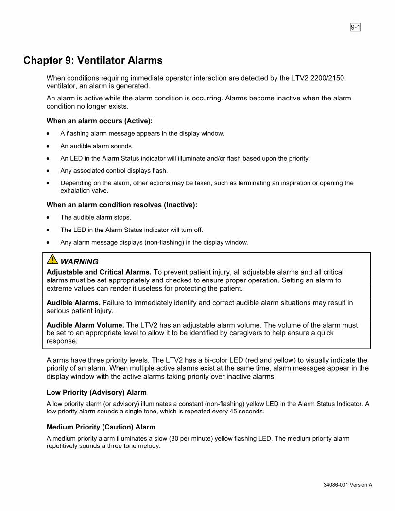
9-1
34086-001 Version A
Ventilator Alarms When conditions requiring immediate operator interaction are detected by the LTV2 2200/2150 ventilator, an alarm is generated.
An alarm is active while the alarm condition is occurring. Alarms become inactive when the alarm condition no longer exists.
When an alarm occurs (Active):
• A flashing alarm message appears in the display window.
• An audible alarm sounds.
• An LED in the Alarm Status indicator will illuminate and/or flash based upon the priority.
• Any associated control displays flash.
• Depending on the alarm, other actions may be taken, such as terminating an inspiration or opening the exhalation valve.
When an alarm condition resolves (Inactive):
• The audible alarm stops.
• The LED in the Alarm Status indicator will turn off.
• Any alarm message displays (non-flashing) in the display window.
WARNING Adjustable and Critical Alarms. To prevent patient injury, all adjustable alarms and all critical alarms must be set appropriately and checked to ensure proper operation. Setting an alarm to extreme values can render it useless for protecting the patient.
Audible Alarms. Failure to immediately identify and correct audible alarm situations may result in serious patient injury.
Audible Alarm Volume. The LTV2 has an adjustable alarm volume. The volume of the alarm must be set to an appropriate level to allow it to be identified by caregivers to help ensure a quick response.
Alarms have three priority levels. The LTV2 has a bi-color LED (red and yellow) to visually indicate the priority of an alarm. When multiple active alarms exist at the same time, alarm messages appear in the display window with the active alarms taking priority over inactive alarms.
Low Priority (Advisory) Alarm A low priority alarm (or advisory) illuminates a constant (non-flashing) yellow LED in the Alarm Status Indicator. A low priority alarm sounds a single tone, which is repeated every 45 seconds.
Medium Priority (Caution) Alarm A medium priority alarm illuminates a slow (30 per minute) yellow flashing LED. The medium priority alarm repetitively sounds a three tone melody.

9-2
34086-001 Version A
High Priority (Warning) Alarm This category of alarm requires immediate action. For a high priority alarm, the alarm illuminates a fast (120 per minute) red flashing LED. A high priority alarm repetitively sounds a five tone melody. If applicable, the affected alarm parameter display will also blink during an active alarm.
NOTE For optimal legibility of an alarm state, the ideal operator position is one meter in front of the ventilator.
Alarm Name Displayed Alarm Priority Level APNEA Apnea High BATT EJECTED Removable battery was ejected Medium CHK CIRCUIT Circuit or Sense lines disconnected or occluded High DEFAULTS Defaults Medium DEFAULTS SET Defaults Set Medium EXT PWR LOST External Power Lost Low EXT PWR LOW External Power Low Low HI MIN VOL High minute volume Medium HI O2 PRES* O2 Pressure High Medium HI PEEP High PEEP Medium HI PRESSURE High Pressure High HI RESP RATE High respiratory rate Medium HI SBT f/Vt High f/Vt during an SBT Low HI SBT RATE High Respiratory Rate during an SBT Low HW FAULT Hardware Fault Medium INOP Inoperable High IntBat EMPTY Internal battery: About 5 minutes of power remaining High IntBat FAULT Internal battery fault High IntBat LOW Internal battery: About 15 minutes of power
remaining Medium
IntBat Temp Internal battery temperature critically high High IntBatTempHi Internal battery temperature high High IntBatTempLo Internal battery temperature low Low LO SBT f/Vt Low f/Vt during an SBT Low LO SBT RATE Low Respiratory Rate during an SBT Low LOW MIN VOL Low Minute Volume High LOW O2 PRES* O2 Pressure Low High LOW PEEP Low PEEP Medium LO PRESSURE Low Peak Pressure High NO CAL DATA No Calibration Data Medium RemBat EMPTY Removable battery: About 5 minutes of power
remaining High
RemBat FAULT Removable battery fault High

9-3
34086-001 Version A
Alarm Name Displayed Alarm Priority Level RemBat LOW Removable battery: About 15 minutes of power
remaining Medium
RemBat Temp Removable battery temperature critically high High RemBatTempHi Removable battery temperature high Medium RemBatTempLo Removable battery temperature low Low REMOVE PTNT Remove Patient High RESET or RESET 1 Reset Medium SBT OFF SBT Off Low Start-up query Not ventilating. Awaiting response. High XDCR FAULT Transducer fault Medium
*LTV2 2200 only
Multiple Alarm Priorities When multiple active alarms occur at the same time, the alarm with the highest priority level will be displayed. When a highest priority active alarm is reset, any remaining alarms will be displayed in order of priority, one by one as each alarm is reset.
When multiple alarms are active at the same time, alarm messages appear in the display window in the following priority:
1. Remove Patient 2. Apnea 3. Startup Query Inactivity 4. Check Circuit 5. Internal Battery Temperature Critical 6. Internal Battery Temperature High 7. Removable Battery Temperature Critical 8. Internal Battery Empty 9. Internal Battery Fault 10. Removable Battery Empty 11. O2 Pressure Low 12. High Pressure 13. Low Minute Volume 14. Low Peak Pressure 15. Removable Battery Fault 16. Internal Battery Low 17. High Minute Volume 18. Removable Battery Temperature High 19. Removable Battery Low 20. O2 Pressure High
21. Defaults 22. No Calibration Data 23. Hardware Fault 24. Transducer Fault 25. High PEEP 26. High Rate 27. Low PEEP 28. Reset 29. Removable Battery Ejected 30. Defaults Set 31. Internal Battery Temperature Low 32. Removable Battery Temperature Low 33. External Power Lost 34. External Power Low 35. SBT High Breath Rate 36. SBT Low Breath Rate 37. SBT High f/Vt 38. SBT Low f/Vt 39. SBT Off

9-4
34086-001 Version A
Alarms NOTE The ventilator settings and the alarm settings remain in memory after a power cycle as long as New Patient is not selected upon ventilator startup. If a new patient is being ventilated, the ventilator and alarm settings revert to their default values.
APNEA, APNEA xx bpm When the time since the start of the last breath is longer than the set Apnea Interval, the APNEA alarm is generated. When an Apnea alarm occurs, the ventilator will enter Apnea Backup ventilation mode. For more information on Apnea Backup mode, see “Apnea Backup” on page 4-5.
When an APNEA alarm occurs:
• Any inspiration in progress is terminated (except an Inspiratory Hold maneuver).
• The ventilator changes to Apnea Backup ventilation.
• The APNEA xx bpm backup ventilation breath rate displays.
• Control displays used while in Apnea Backup mode are illuminated and all other control displays are dimmed.
• The audible alarm sounds.
• This is a high priority alarm.
While in Apnea Backup mode, the alarm will continue to sound and the alarm message and breath rate will be flashed in the display window. Apnea backup mode will continue until the operator resets the alarm or the patient triggers 2 consecutive breaths.
When the APNEA alarm is reset by two (2) consecutive triggered breaths:
• Apnea Backup Ventilation terminates and the ventilator returns to the previous mode.
• The Apnea alarm message remains in the window but the breath rate is no longer displayed.
• Control displays used in the selected ventilation mode are illuminated and all other control displays are dimmed.
• The audible alarm is silenced.
To reset the APNEA alarm and exit Apnea Backup ventilation:
• Press the Alarm Reset button.

9-5
34086-001 Version A
Apnea Interval The apnea interval is the maximum time allowed between the beginning of one breath and the beginning of the next breath. To modify the Apnea Interval:
1. Scroll to APNEA INT in the ALARM OPS menu in Extended Features (see “Chapter 10:–Extended Features”).
2. Press the Menu/Select button while APNEA INT displays.
3. APNEA xx sec displays.
4. Turn the Scroll knob until the preferred setting displays.
5. Press the Menu/Select button.
Range: 10 to 60 seconds
NOTE Apnea Ventilation in NPPV. When the ventilator is in NPPV mode with Pressure Control set to -- (OFF) and enters the Apnea Backup mode, the unit ventilates in Assist/Control mode using a pressure control value of 15. The Apnea alarm display alternates between “APNEA xx bpm” and “APNEA 15 cmH2O”. See “Procedure for NPPV Mode Set Up” on page 12-10.
Check Circuit (CHK CIRCUIT) When the ventilator detects one of the following conditions, the CHK CIRCUIT alarm is generated:
• The breathing circuit becomes disconnected or occluded. See “Appendix A:–Ventilator Specifications” for a description of how the occlusion and disconnects are detected.
• When a sense line has become disconnected, pinched, or occluded.
The ventilator detects circuit pressure during the beginning of each inspiration. If an appropriate pressure change is not detected, a CHK CIRCUIT alarm occurs.
When a CHK CIRCUIT alarm occurs:
• The CHK CIRCUIT message flashes in the display window.
• The audible alarm sounds.
• This is a high priority alarm.
To reset the CHK CIRCUIT alarm: 1. Press the Alarm Silence button to silence the alarm.
2. Press the Alarm Reset button to reset the alarm.

9-6
34086-001 Version A
DEFAULTS All controls and extended features on the LTV2 2200/2150 ventilator have factory-set default values. When the operator makes changes to the controls or extended features settings, the ventilator stores the new settings in non-volatile memory and will remain there between power cycles. During POST, the ventilator checks the stored settings. If the ventilator detects an invalid stored setting, the DEFAULTS alarm occurs and the affected settings are set to the default values.
When a DEFAULTS alarm is generated:
• An audible alarm sounds.
• The DEFAULTS message flashes in the display window.
• All affected controls or features are set to their default values.
To reset the DEFAULTS alarm: 1. Press the Alarm Reset button.
2. Select and return the control(s) or features to the preferred settings.
NOTE Be sure to check all Controls, Alarms and Extended Features options and return them to the preferred settings. Repeated occurrences of the DEFAULTS alarm may indicate a problem with the ventilator’s non-volatile memory. Please immediately contact a certified Vyaire Medical service technician. Control values are re-set to default values each time the ventilator is turned on, only if an invalid stored setting is detected during POST.
The factory-set default Control settings are: (For detailed information concerning specific Controls, see “Chapter 6:–Control Panel”)
Control – Default Control – Default Breath Rate – 12 bpm FiO2 (Flush)* – 21% Control Lock – ON PEEP - – 0 cmH2O Data Display Scrolling – Auto-On Pressure Control – 15 cmH2O High Pressure Limit – 20 cmH2O Pressure Support – 1 cmH2O Inspiratory/Expiratory Hold – Off Sensitivity – 2 lpm Inspiratory Time – 1.5 seconds Tidal Volume – 500 ml Low Minute Volume – 2.5 lpm Ventilation Mode – Assist/Control Low Pressure – 5 cmH2O Volume Pressure Mode – Volume Low Pressure O2 Source* – Off *LTV2 2200 only

9-7
34086-001 Version A
The factory-set default Extended Features settings are: (For detailed information concerning specific Features, see “Chapter 10:–Extended Features.”) Feature – Default Feature – Default Alarm Volume – 5 (maximum) Nurse Call – NORMAL Apnea Interval – 20 seconds Patient Query – ON Com Setting – MONITOR Patient Size – PEDIATRIC Control Unlock – EASY PC Flow Termination – OFF Date Format – MM/DD/YYYY PIP LED – ON High Minute Volume – 30.0 lpm Rise Time Profile – 4 High Respiratory Rate Alarm – OFF SBT Display f/Vt Alarm – ON High Respiratory Rate Alarm Delay – 30 seconds SBT FiO2 – 21% HI PEEP Alarm – PEEP +5 cmH2O High SBT Rate Alarm – 35 bpm HP Alarm Delay – NO DELAY High SBT f/Vt Alarm – 105 f/Vt Language – English Low SBT Rate Alarm – 10 bpm Leak Compensation – ON Low SBT f/Vt Alarm – 70 f/Vt Low PEEP Alarm – PEEP -5 cmH2O SBT Mode – OFF Low Peak Pressure Alarm – ALL BREATHS SBT Mode Run Time – 20 MIN O2 Conserve* – OFF SBT PEEP – 0 cmH2O O2 Cylinder Pressure* – 0 psi or 0 bar SBT Pressure Support – 10 cmH2O O2 Cylinder Type* – 622 liters Variable Flow Termination – 25% Flush Period* – 3 min Variable Time Termination – 1.5 seconds Bias Flow – 10 lpm Sigh – OFF Patient Query – ON Leak Test Query – OFF *LTV2 2200 only

9-8
34086-001 Version A
DEFAULTS SET The DEFAULTS SET alarm is generated when the LTV2 2200/2150 ventilator is first powered up after the SET DEFAULTS option has been used to reset all controls and extended features settings to their factory-set default values.
Language, Time/Date Format and Com settings are not reset to default values when the SET DEFAULTS option is used in Extended Features.
When a Defaults SET alarm is generated:
• The Defaults SET message flashes in the display window.
• The audible alarm sounds.
To reset the DEFAULTS SET alarm: 1. Press the Alarm Reset button. 2. Select and return the control(s) and extended features settings to the preferred settings.
NOTE Be sure to check all Controls, Alarms and Extended Features options and return them to the preferred settings.
External Power Lost (EXT PWR LOST) When the ventilator is powered up without an external source of power, or is operating on external power and switches to the internal or removable battery, the EXT PWR LOST alarm is generated.
• The change to a battery is made when the external power voltage drops below the usable level. • There is no interruption in ventilation if there is sufficient charge in the batteries.
When a EXT PWR LOST alarm occurs:
• The EXT PWR LOST message is displayed. • The External Power LED is turned off. • One of the Battery Power Source LEDs are lit indicating which battery is in use. • The ventilator begins operating from the internal or removable battery. • The audible alarm sounds. • After 60 seconds, the displays are turned off to conserve battery power. To turn the displays on,
press any button or turn the Scroll knob.
To reset the EXT PWR LOST alarm: Press the Alarm Reset button.

9-9
34086-001 Version A
External Power Low (EXT PWR LOW) When the ventilator is operating from an external power source and the power source becomes insufficient to run the ventilator and charge a battery, the ventilator activates the External Power Low Alarm. The ventilator reduces or eliminates battery charging in an attempt to continue operating the ventilator from external power.
There is no interruption in ventilation.
When a EXT PWR LOW alarm occurs:
• The EXT PWR LOW message is displayed in the window.
• The audible alarm sounds.
• This is a low priority alarm.
To reset the EXT PWR LOW alarm: Press the Alarm Reset button.
NOTE The External Power Low alarm may occur while charging the battery during periods of high ventilator demand (sigh breaths or high minute ventilation or flow settings).
High Minute Volume (HI MIN VOL) When the current exhaled minute volume reaches the set high minute volume alarm value, an audible alarm will be sounded and a flashing HI MIN VOL message will be displayed. When a HI MIN VOL alarm occurs:
• The HI MIN VOL message flashes in the display window.
• The audible alarm sounds.
• This is a medium priority alarm.
To reset the HI MIN VOL alarm: Press the Alarm Reset button.
To modify the HI MIN VOL alarm value: 1. Scroll to HI MIN VOL in the ALARM OPS menu in Extended Features (see “Chapter 10:–Extended
Features”).
2. Press the Menu/Select button while HI MIN VOL appears.
3. HMV OFF or HMV xx.x L appears.
4. Turn the Scroll knob until the preferred setting appears.
5. Press the Menu/Select button.
Range: Off, 0.1 through 99.0 L
NOTE The High Minute Volume alarm may not be set lower than the Low Minute Volume setting.

9-10
34086-001 Version A
High Respiratory Rate (HI RESP RATE) When the total breath rate exceeds the set high breath rate value for the set time period alarm value, the HI RESP RATE alarm is generated.
To prevent nuisance alarms, the HI RESP RATE alarm is suspended for the first 60 seconds of ventilator operation after power up and passing the Power On Self Tests.
When a HI RESP RATE alarm occurs:
• The HI RESP RATE message flashes in the display window.
• The audible alarm sounds.
• This is a medium priority alarm.
To reset the HI RESP RATE alarm: 1. Press the Alarm Silence button to silence the audible alarm.
2. Press the Alarm Reset button to reset the alarm.
Setting the High Respiratory Rate alarm Rate and Time values
To set the high breath rate and time period alarm values: 1. Scroll to HI RESP RATE in the ALARM OPS menu in Extended Features (see “Chapter 10:–Extended
Features”).
2. Press the Menu/Select button while HI RESP RATE displays and RATE displays.
3. Press the Menu/Select button while RATE displays and HI RATE OFF or RATE xx bpm displays.
4. Turn the Scroll knob until the preferred setting displays, press the Menu/Select button and the high breath rate alarm value is set.
Range: 5 to 80 bpm (in increments of 1) – HI RATE OFF
5. Turn the Scroll knob until TIME displays, press the Menu/Select button and xx sec displays.
6. Turn the Scroll knob until the preferred setting displays and press the Menu/Select button. The high breath rate time period alarm value is set.
Range: 0 to 60 seconds, in increments of 10
The HI RATE OFF message displays when the High Breath Rate alarm is turned off by being set to HI RATE OFF. The HI RATE OFF message is not displayed during SBT mode. This is an informational message only. The message displays at power up, when monitored data is being scrolled automatically, and when no front panel activity is detected for 60 seconds.

9-11
34086-001 Version A
High Oxygen Inlet Pressure (HI O2 PRES) (LTV2™ 2200 only) When the average oxygen inlet pressure exceeds the acceptable limit for the type of oxygen source, the HI O2 PRES alarm is generated:
• If the Low Pressure O2 Source is selected, the inlet pressure is >10 psig.
• If the Low Pressure O2 Source is not selected and the oxygen concentration is set to greater than 21%, the inlet pressure is >85 psig.
When the Low Pressure O2 Source option is selected and a high O2 pressure source is attached to the ventilator, an automatic High O2 Switch Over safety response generates a HI O2 PRES alarm, switches the ventilator to High Pressure O2 Source mode and sets the percentage of oxygen to be delivered in the gas flow to 21%.
When a HI O2 PRES alarm occurs:
• The HI O2 PRES message flashes in the display window.
• The FiO2 (Flush) control display flashes.
• The audible alarm sounds.
• This is a medium priority alarm.
To reset the HI O2 PRES alarm: 1. Press the Alarm Silence button to silence the alarm.
2. Adjust the oxygen inlet pressure.
3. Press the Alarm Reset button to reset the alarm.
High PEEP (HI PEEP) When the patient circuit positive end expiratory pressure (PEEP) exceeds the High PEEP alarm setting, the HI PEEP alarm is generated.
When a HI PEEP alarm occurs:
• The HI PEEP message flashes in the display window.
• The audible alarm sounds.
• This is a medium priority alarm.
To reset the HI PEEP alarm: 1. Press the Alarm Silence button once to silence the audible alarm.
2. Press the Alarm Reset button to reset the alarm.
NOTE The High PEEP alarm will be suspended for three breaths after the High PEEP alarm is reset.

9-12
34086-001 Version A
Setting the HI PEEP alarm
To modify the HI PEEP alarm value: 1. Scroll to HI PEEP in the ALARM OPS menu in Extended Features (see “Chapter 10:–Extended Features”).
2. Press the Menu/Select button while HI PEEP displays.
3. HI PEEP OFF or PEEP+XX cmH2O displays.
4. Turn the Scroll knob until the preferred setting displays.
5. Press the Menu/Select button.
Range: PEEP +3 through PEEP +20 cmH2O, HI PEEP OFF
The HI PEEP OFF message displays when the High PEEP alarm is turned off by being set to HI PEEP OFF. This is an informational message only. The message displays at power up, when monitored data is being scrolled automatically, and when no front panel activity is detected for 60 seconds.
High Inspiratory Pressure (HI PRESSURE) When the pressure in the patient circuit is greater than the High Pressure Limit setting, the HI PRESSURE alarm is generated. When this alarm occurs, any inspiration in progress is terminated and the exhalation valve is opened. The turbine is stopped to allow the circuit pressure to evacuate when the high pressure condition persists for more than four times the set inspiratory time or more than 3 seconds, whichever is less.
WARNING Sustained High Pressure Alarm. During a sustained High Pressure alarm condition (HI PRESSURE), the ventilator’s turbine is stopped and gas is not delivered to the patient. Disconnect the patient from the ventilator and ventilate the patient using an alternative method to reduce the risk of patient harm. For additional information concerning the HI PRESSURE alarm, see page 9-12.
Immediate or delayed audible alarms for high pressure conditions can be selected using the Extended Features. If immediate notification is selected, the audible alarm will sound on every high pressure occurrence. If delayed notification is selected, the audible alarm will sound on the second or third consecutive breath terminated by the HI PRESSURE alarm. The audible alarm will sound anytime a high pressure condition persists, which stops the turbine.
NOTE All alarm output signals activate the ventilator’s Nurse Call Port for use with Remote Alarm systems. This signal is dependent on the selected setting (NORMAL or PULSE) in the Extended Features, NURSE CALL menu. For instructions on setting the Nurse Call Port output signal for use with single or dual tone Remote Alarm systems, see “Nurse Call” on page 10-4.

9-13
34086-001 Version A
The HI PRESSURE alarm becomes inactive and is automatically silenced using the one of following criteria:
• When the airway pressure drops below set PEEP +5 cmH2O and the airway pressure remains below the High Pressure Limit through the next breath cycle.
• Or when an inspiratory limb to ambient condition has occurred and the high pressure condition is removed.
• Or when an inspiratory limb to ambient condition has occurred and has been present for more than three times the mandatory breath period.
When a HI PRESSURE alarm occurs:
• Inspiration is immediately terminated and exhalation begins.
• The HI PRESSURE message flashes in the display window.
• The High Pressure Limit control display flashes.
• The audible alarm sounds.
• This is a high priority alarm
To reset the HI PRESSURE alarm: 1. Press the Alarm Silence button to silence the alarm.
2. Resolve the high pressure problem.
3. Press the Alarm Reset button to reset the alarm.
NOTE During an active HI PRESSURE condition, the alarm cannot be reset.
Setting the High Pressure Alarm
To set the High Pressure Limit: 1. Press the High Pres. Limit button on the front panel
2. Change the setting using the Scroll knob.
3. Press the High Pres. Limit to confirm change.
Range: 5 to 99 cmH2O
Setting the High Pressure Alarm Delay
To modify the High Pressure Alarm Delay: 1. Scroll to HP DELAY in the ALARM OPS menu in Extended Features (see “Chapter 10:–Extended
Features”).
2. Press the Menu/Select button while HP DELAY displays.
NO DELAY, DELAY 1 BRTH, or DELAY 2 BRTH displays.
3. Turn the Scroll knob until the preferred setting displays.
4. Press the Menu/Select button.
Options: NO DELAY, DELAY 1 BRTH, DELAY 2 BRTH

9-14
34086-001 Version A
When NO DELAY is selected, the audible alarm sounds for all High Pressure alarms.
When DELAY 1 BRTH or DELAY 2 BRTH is selected and a high pressure condition occurs, the breath is terminated and the HI PRESSURE message is posted. The audible alarm is not sounded until the number of consecutive breaths with a high pressure condition meets the delay setting, (two breaths for DELAY 1, three breaths for DELAY 2).
Hardware Fault (HW FAULT) When the ventilator detects one of the following hardware faults, the HW FAULT alarm is generated:
• The ventilator fan is not operating, or the fan filter may be blocking the fan (for cleaning and installation instructions, see “Cleaning or Replacing the Fan Filter” on page 13-4).
• A problem is detected with the real-time clock (to verify or reset date and time settings, see “Set Date” on page 10-13 and “Set Time” on page 10-14.
• A problem is detected with the analog to digital converters.
• A problem is detected with the flow valve.
• A problem is detected with the processor.
• A problem is detected with the EEPROM memory.
• A problem is detected writing data to the EEPROM during system shutdown.
• A problem is detected with the audible alarm circuitry.
• A problem is detected with the alarm sounder.
The HW FAULT alarm may occur as a result of electrostatic discharge or other transient causes. If the problem is temporary, the alarm will automatically silence when the condition clears. If the problem persists, or you experience repeated HW FAULT alarms, immediately contact a certified Vyaire Medical service technician or Vyaire Medical.
To determine the type of hardware fault detected by the ventilator, see “Appendix E:–Event Trace.”
When a HW FAULT alarm occurs:
• The HW FAULT message flashes in the display window.
• The audible alarm sounds.
• This is a medium priority alarm.
To reset the HW FAULT alarm: 1. Press the Alarm Reset button.
2. If the alarm occurs again, immediately contact a certified Vyaire Medical service technician or Vyaire Medical.
NOTE Repeated or continuous HW FAULT alarms may indicate a hardware failure that could prevent the ventilator from performing within its specifications. Remove the ventilator from service and immediately contact a certified Vyaire Medical service technician or Vyaire Medical.

9-15
34086-001 Version A
Ventilator Inoperable (INOP) An INOP alarm is generated when:
• The ventilator is switched from On to Standby.
• The ventilator detects any condition that is deemed to make the ventilator unsafe.
When an INOP occurs, the ventilator shuts down and sets the hardware to a safe state, no breaths are delivered and the patient can breathe from room air.
When an INOP alarm occurs:
• Inspiratory flow is stopped and the exhalation valve is opened, allowing the patient to breathe spontaneously from room air.
• The oxygen blending solenoids are closed.
• The red Alarm Status LED is illuminated.
• The audible alarm sounds continuously.
• This is a high priority alarm
The INOP alarm is generally non-silenceable. However, during shutdown, the INOP alarm will activate. To silence this INOP Alarm:
Press the Alarm Reset button to clear the alarm.
WARNING Alternative Ventilation. To help ensure uninterrupted ventilation, an alternative means of ventilating the patient (such as a manual resuscitation device or backup ventilator) must be available at all times and all ventilator operators must be fully familiar with emergency ventilation procedures. INOP Alarm. If an INOP alarm occurs during operation, ventilation will be interrupted. Manually ventilate the patient using an alternative method, disconnect the ventilator, and immediately contact a certified Vyaire Medical service technician or Vyaire Medical.
NOTE An INOP alarm is generated as a part of the normal process of switching the ventilator from On to the Standby state and does not indicate a problem with the ventilator.
Internal Battery Empty (IntBat EMPTY) When the ventilator is operating on internal battery power and the internal battery charge level falls below the empty threshold, less than approximately 5 minutes remaining, the IntBat EMPTY alarm is generated. For patient safety, this alarm cannot be silenced or silenced preemptively. The alarm will continue to sound and display until an alternate power source is provided or the battery is depleted and the ventilator enters the INOP state. This alarm will always sound at maximum volume.

9-16
34086-001 Version A
WARNING Battery Run Time. When the battery reaches the IntBat LOW level, the ventilator will only run for approximately ten minutes before generating an internal battery empty alarm (IntBat EMPTY). The approximate times shown here are based on tests using the nominal settings, a new battery and a full charge cycle as specified in “Appendix A:–Ventilator Specifications.” Actual run time may be more or less depending on ventilator settings, patient demand, and battery age or condition. It is highly recommended that an alternate power source is connected BEFORE the ventilator reaches the IntBat EMPTY alarm condition to ensure continuous, uninterrupted patient ventilation. If the LTV2 2200/2150 ventilator is operated on its removable and/or internal batteries to the point that they are completely depleted, the ventilator will shut down.
When an IntBat EMPTY alarm occurs:
• The IntBat EMPTY message displays.
• The audible alarm sounds.
• This is a high priority alarm
NOTE The IntBat EMPTY alarm cannot be silenced and cannot be reset until a charged removable battery is installed or external power supplied. For patient safety, this alarm will always sound at full volume.
NOTE Internal Battery Use: The length of time the ventilator will operate on internal power is a function of many factors such as settings, charge level, and the condition or age of the battery; therefore, prolonged use of the internal battery as a standard operating practice is not recommended.
WARNING Depleted battery and shutdown. If the LTV2 2200/2150 ventilator operates on its removable and/or internal batteries to the point that they are completely depleted, the ventilator shuts down and ventilation stops.
Internal Battery Fault (IntBat FAULT) When the ventilator is running, an audible and visual alarm is provided when a fault is detected in the internal battery. When the Internal Battery Fault alarm is active, the ventilator will not attempt to charge the internal battery.

9-17
34086-001 Version A
When a IntBat FAULT alarm occurs:
• The IntBat FAULT message displays.
• The audible alarm sounds.
• This is a high priority alarm
To reset the IntBat FAULT alarm: Press the Alarm Reset button.
The Internal Battery Fault alarm will be reset for 5 minutes. The IntBat FAULT alarm will reactivate after 5 minutes if the fault condition remains.
Internal Battery Low (IntBat LOW) When the ventilator is operating on internal battery power and the battery charge level falls below the low threshold, less than approximately 15 minutes remaining, an IntBat LOW alarm is generated.
When a IntBat LOW alarm occurs:
• The IntBat LOW message displays.
• The audible alarm sounds.
• This is a medium priority alarm.
To reset the IntBat LOW alarm: Press the Alarm Reset button.
WARNING Battery run time. When the battery reaches the IntBat LOW level, the ventilator will only run for approximately ten minutes before generating an internal battery empty alarm (IntBat EMPTY). The approximate times shown here are based on tests using the nominal settings, a new battery and a full charge cycle as specified in “Appendix A:–Ventilator Specifications.” Actual run time may be more or less depending on ventilator settings, patient demand, and battery age or condition. It is highly recommended that an alternate power source is connected BEFORE the ventilator reaches the IntBat EMPTY alarm condition to ensure continuous, uninterrupted patient ventilation. If the LTV2 2200/2150 ventilator is operated on its removable and/or internal batteries to the point that they are completely depleted, the ventilator will shut down.
NOTE Internal Battery Use: The internal battery is intended for use during short periods while switching between external power supply connections, changing removable batteries, or emergency situationsor short duration transports. The length of time the ventilator will operate on internal power is a function of factors such as settings, charge level and condition or age of the battery; therefore, prolonged use of the internal battery as a standard operating practice is not recommended.

9-18
34086-001 Version A
Internal Battery Temperature Critical (IntBat TEMP) The IntBat TEMP (critical internal battery high temperature) alarm activates when the temperature of the internal battery reaches the maximum safe operating temperature of the battery pack. Ventilator shutdown is imminent at this high operating temperature. If no other power source is immediately available, the ventilator shuts down and activates the INOP alarm. Switch to an alternate power source immediately.
When the IntBat TEMP alarm occurs:
• IntBat TEMP flashes in the display window.
• The audible alarm sounds.
• This is a high priority alarm
To reset the Int Bat TEMP alarm: Press the Alarm Reset button.
Internal Battery Temperature High (IntBatTempHi) The IntBatTempHi (internal battery high temperature) alarm activates when the temperature of the internal battery is elevated and is nearing its high operating temperature. Switch to an alternate power source immediately. Move to a cooler location if possible.
When the IntBatTempHi alarm occurs:
• IntBatTempHi flashes in the display window.
• The audible alarm sounds.
• This is a high priority alarm
To reset the IntBatTempHi alarm: Press the Alarm Reset button.
Internal Battery Temperature Low (IntBatTempLo) The IntBatTempLo (internal battery low temperature) alarm will activate when the temperature of the internal battery is nearing its low operating temperature threshold.
When the IntBatTempLo alarm occurs:
• IntBatTempLo flashes in the display window.
• The audible alarm sounds.
• This is a low priority alarm.
To reset the IntBatTempLo alarm: Press the Alarm Reset button.

9-19
34086-001 Version A
Low Minute Volume (LOW MIN VOL) When the exhaled minute volume (VE) is less than the Low Minute Volume setting, the LOW MIN VOL alarm is generated.
To prevent nuisance alarms, the LOW MIN VOL alarm is suspended for the first 20 seconds of ventilator operation after power up and passing the Power On Self Tests.
When a LOW MIN VOL alarm occurs:
• The LOW MIN VOL message flashes in the display window.
• The Low Min. Vol. control display flashes.
• The audible alarm sounds.
• This is a high priority alarm
To reset the LOW MIN VOL alarm: Press the Alarm Reset button.
Setting the Low Minute Volume Alarm
NOTE When a Low Minute Volume alarm has been reset, the Low Minute Volume is disabled for 60 seconds.
To set the Low Minute Volume alarm: 1. Press the Low Min. Vol. button on the front panel.
2. Change the setting using the Scroll knob.
3. Press the Low Min. Vol. button to confirm change.
Range: Off, 0.1 to 99 L
The LMV OFF message displays when the Low Minute Volume alarm is turned off by being set to dashes and the LPP alarm set to ALL BREATHS. This is an informational message only. The message displays at power up, when monitored data is being scrolled automatically, and when no front panel activity is detected for 60 seconds.
NOTE The Low Minute Volume may not be set higher than the High Minute Volume setting.
NOTE The Low Minute Volume alarm and Low Peak Pressure alarms may only be turned off simultaneously when NPPV mode is selected.

9-20
34086-001 Version A
WARNING Low Minute Ventilation Alarm. The low minute ventilation alarm is important to help detect circuit disconnects. If the low minute ventilation alarm is set to zero, ensure the low peak airway pressure alarm is set appropriately to prevent patient injury. Speaking valves (and other circuit accessories) may generate enough resistance (back pressure) to generate some airway pressure even if the circuit is disconnected from the patient. Ensure the low pressure alarm is set high enough (above the pressure created by the speaking valve or circuit accessory) to detect a circuit disconnect even if the speaking valve is still attached to the circuit.
Low Minute Volume Control Settings. To help prevent serious patient injury, the Low Min. Vol. control should be set to its highest clinically appropriate value. If there is a clinical need to set the Low Minute Volume alarm to lower values or off (“- - -“), perform a clinical assessment to determine if an alternative monitor (i.e. a pulse oximeter with an audible alarm, or a cardiorespiratory monitor) should be used.
Low O2 Source Pressure (LOW O2 PRES) (LTV2™ 2200 only) When the average oxygen inlet pressure is less than the minimum inlet pressure of 35 psig, the LOW O2 PRES alarm is generated. This alarm is only active when Low Pressure O2 Source is not selected and the oxygen concentration is set to greater than 21%.
NOTE The LTV2 2200 features an enhanced Low O2 Pressure alarm algorithm which allows a brief, temporary drop of the O2 pressure supply while maintaining the delivered O2 percent.
When a LOW O2 PRES alarm occurs:
• The LOW O2 PRES message flashes in the display window.
• The FiO2 (Flush) control display flashes.
• The audible alarm sounds.
• This is a high priority alarm
To reset the LOW O2 PRES alarm: 1. Press the Alarm Silence button to silence the alarm.
2. Correct the ventilator’s oxygen inlet pressure.
3. Press the Alarm Reset button to reset the alarm.

9-21
34086-001 Version A
LOW PEEP When the patient circuit positive end expiratory pressure (PEEP) is less than the Low PEEP alarm setting, the LOW PEEP alarm is generated.
To prevent nuisance alarms, the LOW PEEP alarm is suspended for the first three (3) breaths or 60 seconds (whichever is longer) after power on and ventilation begins.
When a LOW PEEP alarm occurs:
• The LOW PEEP message flashes in the display window.
• The audible alarm sounds.
• This is a medium priority alarm.
To reset the LOW PEEP alarm: 1. Press the Alarm Silence button to silence the audible alarm.
2. Press the Alarm Reset button to reset the alarm.
When the LOW PEEP alarm is reset, the alarm is suspended for the next 60 seconds.
The 60 second suspension of the LOW PEEP alarm is only enabled when the alarm is manually reset by pressing the Alarm Reset button. The suspension is not enabled when the LOW PEEP alarm is automatically reset, because the patient’s PEEP is no longer less than the set LOW PEEP alarm value.
Setting the Low PEEP alarm
To set the LOW PEEP alarm value: 1. Scroll to LOW PEEP in the ALARM OPS menu in Extended Features (see Chapter 10:–Extended Features).
2. Press the Menu/Select button while LOW PEEP displays.
3. LO PEEP OFF or PEEP -XX cmH2O displays.
4. Turn the Scroll knob until the preferred setting displays.
5. Press the Menu/Select button.
Range: PEEP -3 through PEEP -20 cmH2O, LO PEEP OFF
Low Peak Inspiratory Pressure (LO PRESSURE) When the peak inspiratory pressure for a selected breath is less than the Low Pressure setting, the LO PRESSURE alarm is generated. The Low Pressure alarm can be set to apply to all breaths (ALL BREATHS) or to Volume Control (VC) and Pressure Control (PC) breaths only.
When a LO PRESSURE alarm occurs:
• The LO PRESSURE message flashes in the display window.
• The Low Pressure control display flashes.
• The audible alarm sounds.
• This is a high priority alarm.
To reset the LO PRESSURE alarm: Press the Alarm Reset button.

9-22
34086-001 Version A
Setting the Low Peak Pressure Alarm
To set the Low Pressure alarm: 1. Press the Low Pressure button on the front panel
2. Change the setting using the Scroll knob.
3. Press the Low Pressure button to confirm change.
Range: Off (NPPV only), 1 to 60 cmH2O
Setting the Low Peak Pressure Alarm Breath Type
Use the LPP ALARM item in the Alarm Ops menu in Extended Features to select the type of breaths that the Low Pressure alarm applies.
When ALL BREATHS is selected, the Low Pressure alarm setting applies to all breath types: Volume Control, Pressure Control, Pressure Support, and Spontaneous. When the peak pressure during any breath does not exceed the Low Pressure setting, the LO PRESSURE alarm occurs.
When VC/PC ONLY is selected, the Low Pressure alarm setting applies only to Volume Control and Pressure Control breaths. It does not apply to Pressure Support and Spontaneous breaths. When the peak pressure during any Volume Control or Pressure Control breath does not exceed the Low Pressure setting, the LO PRESSURE alarm occurs.
To set the Low Peak Pressure alarm values: 1. Scroll to LPP ALARM in the ALARM OPS menu in Extended Features (see “Chapter 10:–Extended
Features”).
2. Press the Menu/Select button while LPP ALARM displays.
3. Turn the Scroll knob until the preferred setting displays, press the Menu/Select button and the high breath rate alarm value is set.
• Options: ALL BREATHS, VC/PC ONLY
• The LO PP OFF message displays when the LPP alarm is set to VC/PC ONLY (when this setting is selected, the Low Pressure alarm applies only to Volume Control and Pressure Control breaths) and the LMV alarm is not set to dashes “- -”. This is an informational message only. This message displays when monitored data is being scrolled automatically, and when no front panel activity is detected for 60 seconds.
• The LPP PS OFF message displays when the LPP alarm is set to VC/PC ONLY (when this setting is selected, the Low Pressure alarm applies only to Volume Control and Pressure Control breaths) and the LMV alarm is set to dashes “- -”. This is an informational message only. This message displays when monitored data is being scrolled automatically, and when no front panel activity is detected for 60 seconds.
NOTE The Low Minute Volume alarm and Low Peak Pressure alarms may only be turned off simultaneously when NPPV mode is selected.
NOTE The Low Peak Pressure alarm may only be turned off when NPPV mode is selected. If the Low Peak Pressure alarm is off, and NPPV is turned off, the Low Peak Pressure alarm will be set to the default setting.

9-23
34086-001 Version A
WARNING Patient Circuit Accessories. The use of accessories such as speaking valves, inline suction catheters, heat-moisture exchangers, and filters create additional patient circuit resistance and, in the event of a disconnection, may impede the generation of a low pressure alarm. To reduce the risk of serious harm to the patient, ensure the low pressure alarm is set high enough (above the pressure created by the speaking valve or circuit accessory) to detect a circuit disconnect, even if the speaking valve is still attached to the circuit. Adding accessories to the breathing circuit (for example, filters, nebulizers, and in-line suction catheters) may add resistance to gas flow that may harm the patient.
No Calibration Data (NO CAL DATA) When the ventilator detects invalid or missing calibration records on power up, the NO CAL DATA alarm is generated. When this happens, default calibration values are used, and although the ventilator will continue to operate, the accuracy of volumes and pressures may be reduced.
A NO CAL message is posted in place of affected monitored values when the ventilator is operating without valid transducer calibration data.
When the NO CAL DATA alarm occurs:
• The NO CAL DATA message flashes in the display window.
• The audible alarm sounds.
• The ventilator continues to operate.
• Default transducer data is used.
• Vte, PIP, MAP, PEEP, and VE monitored values are displayed as “NO CAL”.
To clear the NO CAL DATA alarm: 1. Press the Alarm Reset button. This will clear the alarm and the ventilator will continue to operate; however,
the NO CAL message will still be displayed in place of affected monitored values.
2. Take the unit out of service and perform the Calibration procedure found in the Service Manual.
To clear the NO CAL message: Take the unit out of service and perform the Calibration procedure found in the Service Manual.
WARNING NO CAL Condition. Operation of the LTV2 2200/2150 ventilator under a NO CAL condition may result in inaccurate pressure and volume measurements and delivery leading to incorrect ventilation. If this condition occurs, disconnect the patient from the ventilator, provide an alternative method of ventilation, and immediately contact a certified Vyaire Medical service technician or Vyaire Medical.
Removable Battery Empty (RemBat EMPTY) When the ventilator is operating on the removable battery power and the removable battery charge falls to the point where there is less than about 5 minutes remaining, the RemBat EMPTY alarm will occur. Pressing the Alarm Reset button acknowledges and resets the alarm. The battery continues to operate on the removable battery without the alarm, and switches to the internal battery when there is insufficient charge remaining in the removable battery
Precautions should be taken to ensure a power source is available by either confirming the internal battery is charged, or by swapping the removable battery for a charged battery.

9-24
34086-001 Version A
When a RemBat EMPTY alarm occurs:
• RemBat EMPTY flashes in the display window.
• The audible alarm sounds.
• This is a high priority alarm.
To reset the RemBat EMPTY alarm: 1. Press the Alarm Reset button, or
2. Restore external power, or
3. Eject the removable battery.
WARNING Battery Run Time. When the battery reaches the IntBat LOW level, the ventilator will only run for approximately ten minutes before generating an internal battery empty alarm (IntBat EMPTY). The approximate times shown here are based on tests using the nominal settings, a new battery and a full charge cycle as specified in “Appendix A:–Ventilator Specifications.” Actual run time may be more or less depending on ventilator settings, patient demand, and battery age or condition. It is highly recommended that an alternate power source is connected BEFORE the ventilator reaches the IntBat EMPTY alarm condition to ensure continuous, uninterrupted patient ventilation. If the LTV2 2200/2150 ventilator is operated on its removable and/or internal batteries to the point that they are completely depleted, the ventilator will shut down.
Removable Battery Fault (RemBat FAULT) When the ventilator is running, an audible and visual alarm is provided when a fault is detected in the Removable Battery. When the Removable Battery Fault alarm is active, the ventilator will not attempt to charge the Removable battery.
When a RemBat FAULT alarm occurs:
• The RemBat FAULT message displays.
• The audible alarm sounds.
• This is a high priority alarm.

9-25
34086-001 Version A
To reset the RemBat FAULT alarm: Press the Alarm Reset button.
The Removable Battery Fault alarm cannot be reset until the Internal Battery is available for use.
WARNING Battery Fault Condition. In the event of a battery fault condition such as the Internal Battery Fault (IntBat Fault) and the Removable Battery Fault (RemBatFault), change the power source and contact a certified Vyaire Medical service technician.
Removable Battery Low (RemBat LOW) When the ventilator is operating on the removable battery power and the removable battery charge falls to the point where there is less than about 15 minutes remaining, the RemBat LOW alarm will occur. Precautions should be taken to ensure a power source is available. Depress the Battery Check button to determine charge level of the Internal Battery. Plug the ventilator in to an external power source, if needed.
When a RemBat LOW alarm occurs:
• RemBat LOW flashes in the display window.
• The audible alarm sounds.
• This is a medium priority alarm
To reset the RemBat LOW alarm: Press the Alarm Reset button.
WARNING Battery Run Time. When the battery reaches the IntBat LOW level, the ventilator will only run for approximately ten minutes before generating an internal battery empty alarm (IntBat EMPTY). The approximate times shown here are based on tests using the nominal settings, a new battery and a full charge cycle as specified in “Appendix A:–Ventilator Specifications.” Actual run time may be more or less depending on ventilator settings, patient demand, and battery age or condition. It is highly recommended that an alternate power source is connected BEFORE the ventilator reaches the IntBat EMPTY alarm condition to ensure continuous, uninterrupted patient ventilation. If the LTV2 2200/2150 ventilator is operated on its removable and/or internal batteries to the point that they are completely depleted, the ventilator will shut down.
Removable Battery Temperature Critical (RemBat Temp) The RemBat Temp (critical removable battery high temperature) alarm will activate when the temperature of the removable battery reaches the maximum safe operating temperature of the battery pack. The ventilator will attempt to switch to the internal battery, and will shut down if no other power source is available. Precautions should be taken to ensure a power source is available. Plug the ventilator in to an external power source, if needed.

9-26
34086-001 Version A
When the RemBat Temp alarm occurs:
• RemBat Temp flashes in the display window.
• The audible alarm sounds.
• This is a high priority alarm
To reset the RemBat Temp alarm: Press the Alarm Reset button.
Removable Battery Temperature High (RemBatTempHi) The RemBatTempHi (removable battery high temperature) alarm will activate when the temperature of the removable battery is elevated and is nearing its high operating temperature. Move to a cooler location. Plug the ventilator in to an external power source, if needed.
When the RemBatTempHi alarm occurs:
• RemBatTempHi flashes in the display window.
• The audible alarm sounds.
• This is a medium priority alarm.
To reset the RemBatTempHi alarm: Press the Alarm Reset button.
Removable Battery Temperature Low (RemBatTempLo) The RemBatTempLo (removable battery low temperature) alarm will activate when the temperature of the removable battery is nearing its low operating temperature threshold.
When the RemBatTempLo alarm occurs:
• RemBatTempLo flashes in the display window.
• The audible alarm sounds.
• This is a low priority alarm.
To reset the RemBatTempLo alarm: Press the Alarm Reset button.

9-27
34086-001 Version A
Remove Patient from Circuit (REMOVE PTNT) When the ventilator is powered up in the Ventilator Checkout or Ventilator Maintenance modes, the REMOVE PTNT alarm is generated to remind you to remove the patient from the ventilator before proceeding. Use the Ventilator Checkout mode to check for correct operation of the displays and controls and to check the patient circuit for leaks. Ventilator Maintenance mode is used by technical personnel to perform maintenance or calibration.
WARNING Ventilator Checkout and Maintenance Modes. The LTV2 2200/2150 ventilator does not deliver gas during the Ventilator Checkout mode (VENT CHECK) or Ventilator Maintenance mode (VENT MTNCE). To prevent patient injury, do not attempt to ventilate a patient while the ventilator is in one of these modes.
When you enter Ventilator Checkout mode or Ventilator Maintenance mode, a REMOVE PTNT alarm occurs:
• The REMOVE PTNT message displays.
• The audible alarm sounds.
• This is a high priority alarm
To reset the REMOVE PTNT alarm: Press the Alarm Reset button.
RESET / RESET 1 A RESET or a RESET 1 alarm occurs if the ventilator restarts following a condition other than being shut down by pressing the Power/Standby button.
The ventilator runs an ongoing set of self-tests to verify that it is operating correctly. If the ventilator detects a condition that makes safe ventilator operation uncertain, it reinitializes itself to allow the more sophisticated Power On Self Tests (POST) to be performed. If the POST does not detect any further problems, the ventilator will resume operation and a RESET or a RESET 1 alarm is posted. If the POST detects a problem that could cause continued operation to be unsafe, a ventilator INOP will occur.
Conditions that could cause a RESET or a RESET 1 alarm:
• Operating the ventilator on the internal battery until it is fully depleted.
• Electrostatic Discharge (ESD)
• Other transient causes.

9-28
34086-001 Version A
When a RESET or a RESET 1 alarm is generated:
• An error code is written to the Event Trace indicating the type of problem detected.
• The ventilator resets itself and performs the Power On Self Tests (POST).
• If no further problems are detected, the ventilator resumes operation.
• The RESET or RESET 1 message flashes in the display window.
• The audible alarm sounds.
• This is a medium priority alarm.
To reset the RESET or a RESET 1 alarm: Press the Alarm Reset button.
NOTE When a RESET or RESET 1 alarm has occurred, check the Event Trace for more information about the problem. For more information about events, see “Appendix E:–Event Trace.” Repeated occurrences of the RESET or RESET 1 alarm may indicate a problem with the ventilator’s hardware. Please immediately contact a certified Vyaire Medical service technician.
Spontaneous Breathing Trial Ended (SBT OFF) When the minutes preset in the SBT OP, MINUTES menu have elapsed and a SBT mode of ventilation is terminated, the SBT OFF alarm is generated.
For additional information concerning the SBT mode, see “SBT Operations” on page 10-24.
When a SBT OFF alarm is generated:
• The SBT OFF message flashes in the display window.
• The audible alarm sounds.
• This is a low priority alarm.
To clear the SBT OFF flashing display: Press the Alarm Reset button.
Low Respiratory Rate during SBT (LO SBT RATE) When the SBT mode of ventilation is on and the measured breath rate is less than the LO SBT RATE setting (low limit of breath rate range) for 30 seconds, the LO SBT RATE alarm is generated.
For additional information concerning the SBT mode, see “SBT Operations” on page 10-24.

9-29
34086-001 Version A
When a LO SBT RATE alarm is generated:
• The LO SBT RATE message flashes in the display window.
• The audible alarm sounds.
• This is a low priority alarm.
To reset the LO SBT RATE alarm: Press the Alarm Reset button to reset the alarm.
When an SBT alarm has been active in excess of 5 minutes, the SBT mode of ventilation is terminated, the ventilator clears the alarm status, silences the audible alarm and returns to its previous mode of ventilation / settings. To remove the SBT alarm message from the display window, press the Alarm Reset button.
High Respiratory Rate during SBT (HI SBT RATE) When the SBT mode of ventilation is on and the patient’s breath rate is greater than the HI SBT RATE setting for 30 seconds, the HI SBT RATE alarm is generated.
For additional information concerning the SBT mode, see “SBT Operations” on page 10-24.
When a HI SBT RATE alarm is generated:
• The HI SBT RATE message flashes in the display window.
• The audible alarm sounds.
• This is a low priority alarm.
To reset the HI SBT RATE alarm: Press the Alarm Reset button to reset the alarm.
If an SBT alarm has been active in excess of 5 minutes, the SBT mode of ventilation is terminated, the ventilator clears the alarm status, silences the audible alarm and returns to its previous mode of ventilation / settings. To remove the flashing SBT alarm message from the display window, press the Alarm Reset button.
Low f/Vt During SBT (LO SBT f/Vt) When the SBT mode of ventilation is on and the monitored f/Vt (Total Breath Rate divided by the Average Exhaled Tidal Volume) is less than the LO SBT f/Vt setting (low limit of the f/Vt range) for 30 seconds, the LO SBT f/Vt alarm is generated.
For additional information concerning the SBT mode, see “SBT Operations” on page 10-24.
When a LO SBT f/Vt alarm is generated:
• The LO SBT f/Vt message flashes in the display window.
• The audible alarm sounds.
• This is a low priority alarm.

9-30
34086-001 Version A
To reset the LO SBT f/Vt alarm: Press the Alarm Reset button.
When an SBT alarm has been active in excess of 5 minutes, the SBT mode of ventilation is terminated, the ventilator clears the alarm status, silences the audible alarm and returns to its previous mode of ventilation / settings. To remove the SBT alarm message from the display window, press the Alarm Reset button.
High f/Vt During SBT (HI SBT f/Vt) When the SBT mode of ventilation is on and the monitored f/Vt (Total Breath Rate divided by the Average Exhaled Tidal Volume) is greater than the HI SBT f/Vt setting (high limit of the f/Vt range) for 30 seconds, the HI SBT f/Vt alarm is generated.
For additional information concerning the SBT mode, see “SBT Operations” on page 10-24.
When a HI SBT f/Vt alarm is generated:
• The HI SBT f/Vt message flashes in the display window.
• The audible alarm sounds.
• This is a low priority alarm.
To reset the HI SBT f/Vt alarm: Press the Alarm Reset button to reset the alarm.
When an SBT alarm has been active in excess of 5 minutes, the SBT mode of ventilation is terminated, the ventilator clears the alarm status, silences the audible alarm and returns to its previous mode of ventilation / settings. To remove the SBT alarm message from the display window, press the Alarm Reset button.
Transducer Fault (XDCR FAULT) When a transducer autozero test fails, the XDCR FAULT alarm is generated. Transducer autozeros are scheduled at periodic intervals during ventilator operation. This allows the ventilator to adjust the zero pressure readings as the ventilator warms up and environmental conditions change. If an autozero test fails, it will be automatically rescheduled to run again on the next breath. The XDCR FAULT alarm will remain active until a valid autozero can be done. If the XDCR FAULT persists, remove the ventilator from service and immediately contact a certified Vyaire Medical service technician or Vyaire Medical.
When a XDCR FAULT alarm occurs:
• The autozero for the transducer is rescheduled to run again on the next breath.
• The XDCR FAULT message flashes in the display window.
• The audible alarm sounds.
To reset the XDCR FAULT alarm: Press the Alarm Reset button.

9-31
34086-001 Version A
WARNING XDCR FAULT alarm. Continued operation of the LTV2 2200/2150 ventilator with an activated XDCR FAULT alarm may result in inaccurate flow and volume measurements and delivery. If this condition occurs, disconnect the patient from the ventilator and provide an alternative method of ventilation to reduce the risk of patient harm. Contact a certified Vyaire Medical service technician or Vyaire Medical immediately.
NOTE Repeated or continuous XDCR FAULT alarms may indicate a problem with the ventilator that could prevent the ventilator from performing within its specifications. Discontinue use of the ventilator and immediately contact a certified Vyaire Medical service technician.
LOCKED The LOCKED message displays when a button is pressed while the controls are locked. No audible alarm is given.
When a LOCKED message displays:
• The LOCKED message flashes in the display window for 5 seconds or until the controls are unlocked.
• Control settings may not be changed.
There are two methods for unlocking the controls: EASY and HARD. The unlock method is selected under the Extended Features menus. See “Chapter 10:–Extended Features.”
To unlock the controls with EASY unlocking: Press the Control Lock button.
To unlock the controls with HARD unlocking: Press and hold the Control Lock button for 3 seconds.
WARMUP WAIT When the ventilator is first powered up, the transducers require up to 60 seconds of warm-up time before they will operate within their normal tolerances. During this warm-up period, the ventilator will not allow you to run the leak test or calibration. If you select an option that is not available during the warm-up period, the WARMUP WAIT message displays. When the warm-up period has expired, the message is removed.
When a WARMUP WAIT message occurs:
• The WARMUP WAIT message is displayed in the window.
• The ventilator does not allow the leak test or calibration to be performed.
To reset the WARMUP WAIT message: The WARMUP WAIT message will automatically reset when the warm-up period has expired.

9-32
34086-001 Version A
Intentionally left blank.

10-1
34086-001 Version A
Extended Features This section describes the options and features available under the Extended Features menus and how to access them. The Extended Features menus (Figure 10-1) are representative of both the LTV2 2200/2150 ventilators.
Alarm Operations, Ventilator Operations, Transducer Autozero, and Real-time Transducers are covered in this chapter. The other items are covered in “Chapter 11:–Ventilator Checkout Tests,” “Appendix E:–Event Trace,” and in the LTV2 2200 and 2150 Ventilator Service Manual (PN 33177-001).
Figure 10-1. The Extended Features menus

10-2
34086-001 Version A
Navigating the Extended Features Menus To enter the Extended Features menu (in normal ventilation mode):
Press and hold the Menu/Select button for three seconds.
To view the next item in a menu: Turn the Scroll knob clockwise.
To view the previous item: Turn the Scroll knob counterclockwise.
To enter a menu item or select a setting: Press the Menu/Select button.
To exit a menu:
• Turn the Scroll knob until the EXIT option displays, and then press the Menu/Select button. Or
• Press the Control Lock button.
To toggle the state of an option on or off: Press the Menu/Select button.
NOTE You cannot enter the Extended Features menu when the controls are locked or if there are active or inactive alarms being displayed. Active alarms must be corrected, and inactive alarms must be cleared to enter the Extended Features menu.
NOTE The Control Lock button serves as an “escape” key to back out of the Extended Features sub menus.
Alarm Operations Use the Alarm Operations menu to set up alarm conditions that are not available directly from front panel controls. The menu is set up as follows:
ALARM OP ALARM VOL APNEA INT HI MIN VOL HP DELAY LPP ALARM HI RESP RATE HIGH PEEP LOW PEEP NURSE CALL EXIT

10-3
34086-001 Version A
Alarm Volume Use this menu item to set the loudness of the audible alarm.
To modify the Alarm Volume: 1. Press the Menu/Select button, while ALARM VOL displays.
2. VOL xx displays and a repeating tone is produced to demonstrated alarm volume.
3. Turn the Scroll knob until the preferred setting displays.
4. Press the Menu/Select button.
• Range: 1 to 5 (maximum)
NOTE Fixed Volume Alarms. The volume of the Internal Battery Empty alarm cannot be lowered. For patient safety, this alarm always sounds at full volume. If the battery depletes to point that the ventilator goes INOP, the Vent Inop audible alarm sounds at maximum volume for five minutes.
Apnea Interval Use this menu item to establish the apnea interval. The apnea interval is the maximum time allowed between the beginning of one breath and the beginning of the next breath. See “Apnea Interval” on page 9-5 for more information on this alarm.
Range: 10 to 60 seconds
High Minute Volume Use this menu item to set a high minute volume alarm. When the current exhaled minute volume reaches the set high minute volume alarm value, an audible alarm will be sounded and a flashing HI MIN VOL message will be displayed. See “High Minute Volume (HI MIN VOL)” on page 9-9 for more information on this alarm.
Range: Off, 0.1 through 99.0 L
High Pressure Alarm Delay Use this menu item to select immediate or delayed audible notification for High Pressure alarms. See “Setting the High Pressure Alarm Delay” on page 9-13 for more information on this alarm.
Options: NO DELAY, DELAY 1 BRTH, DELAY 2 BRTH
Low Peak Pressure Alarm Use the LPP ALARM item to select the type of breaths that the Low Pressure alarm applies to. See “Setting the Low Peak Pressure Alarm” on page 9-22 for more information on this alarm.
Options: ALL BREATHS, VC/PC ONLY

10-4
34086-001 Version A
HI RESP RATE Use this menu item to set the high breath rate and time period alarm values. When the Total Breath Rate (f) exceeds the set high breath rate and time period alarm values, an audible alarm will be sounded and a flashing HI RESP RATE message will be displayed. See page 9-10 for more information on this alarm.
Range: 5 to 80 bpm (in increments of 1) – HI RATE OFF
Range: 0 to 60 seconds, in increments of 10
High PEEP Use this menu item to set a high PEEP alarm. When the current PEEP value exceeds the set high PEEP alarm value, an audible alarm will be sounded and a flashing HI PEEP message will be displayed. See “High PEEP (HI PEEP)” on page 9-11 for more information on this alarm.
Range: PEEP +3 through PEEP +20 cmH2O, HI PEEP OFF
Low PEEP Use this menu item to set a low PEEP alarm. When the current PEEP value is less than the set low PEEP alarm value, an audible alarm will be sounded and a flashing LOW PEEP message will be displayed. See “LOW PEEP” on page 9-21 for more information on this alarm.
Range: PEEP -3 through PEEP -20 cmH2O, LO PEEP OFF
Nurse Call Use the NURSE CALL menu item to configure the Nurse Call port output signal to be generated for use with remote alarm systems.
Allows for the changing of the nurse call alarm output signal used with remote alarm systems, which in turn will allow users a means of distinguishing the high pressure alarm (HI PRESSURE) from other alarms.
To select the Nurse Call output signal: Press the Menu/Select button while NURSE CALL displays.
NORMAL or PULSE displays.
• When NORMAL is selected, the ventilator sets the Nurse Call Port output signal continuously on for all alarms and is for use with single tone remote alarm and patient assist call systems. NORMAL is the factory set default setting.
• When PULSE is selected, the ventilator sets the Nurse Call Port output signal continuous on for the HI PRESSURE alarm, cycles the Nurse Call output signal on / off for all other alarms and is for use with dual tone remote alarm systems.
1. Turn the Scroll knob until the preferred setting displays.
2. Press the Menu/Select button.
Range: PULSE or NORMAL

10-5
34086-001 Version A
Exit
To return to the top of the ALARM OP menu: Press the Menu/Select button while EXIT displays.
Vent Operations Use the Vent Operations menu to set up ventilator controls and options that are not available directly from front panel controls. The menu is set up as follows:
VENT OP RISE TIME FLOW TERM TIME TERM PC FLOW TERM LEAK COMP O2 CONSERVE (LTV2 2200 only) O2 FLUSH (LTV2 2200 only) CTRL UNLOCK LANGUAGE VER xx.xx USAGE xxxxx.x COM SETTING SET DATE SET TIME DATE FORMAT PIP LED LTVxxxx VHome xxx DEFAULTS (accessed through Vent Check menu) O2 CYL DUR (LTV2 2200 only) SIGH BIAS FLOW EXIT

10-6
34086-001 Version A
Variable Rise Time Use the Variable Rise Time option to select the rise time profile for Pressure Control and Pressure Support breaths. The rise time profiles are numbered 1 through 9 where 1 is the fastest rise time and 9 is the slowest rise time
Figure 10-2. Rise Time Profiles for Pressure Control and Pressure Support breaths
1 Fastest Peak Rise Time (Profile #1) 2 Slowest Peak Rise Time (Profile #9) 3 Pressure Control 4 PEEP
To modify the Rise Time Profile: 1. Press the Menu/Select button while RISE TIME displays.
PROFILE x displays.
2. Turn the Scroll knob until the preferred Rise Time Profile displays.
3. Press the Menu/Select button.
Range: 1 to 9, where 1 is the fastest and 9 is the slowest
Profile #1—Faster Rise Time Profile #9—Slower Rise Time

10-7
34086-001 Version A
Variable Flow Termination Use the Variable Flow Termination to select the percentage of peak flow used for cycling Pressure Support breaths. Pressure Support breaths are cycled from inspiration to exhalation when the flow reaches the set percentage of the peak flow, or when flow goes below 2 lpm.
When Pressure Control Flow Termination is enabled, the Variable Flow Termination setting is used for flow termination of Pressure Control breaths as well.
Figure 10-3. Variable Flow Termination
1 Peak Flow 2 High Percentage of Peak Flow 3 Low Percentage of Peak Flow 4 Inspiratory Flow.
To modify the Variable Flow Termination: 1. Press the Menu/Select button while FLOW TERM displays.
% OF PEAK xx displays.
2. Turn the Scroll knob until the preferred Variable Flow Termination percentage displays.
3. Press the Menu/Select button.
Range: 10% to 70%

10-8
34086-001 Version A
Variable Time Termination Use the Variable Time Termination to select the maximum inspiratory time for cycling Pressure Support breaths. Pressure Support Breaths are cycled from inspiration to exhalation if this time is reached before the flow reaches the set percentage of the peak flow. When a breath is cycled based on the time setting, the Pressure Support display flashes briefly.
Figure 10-4. Variable Time Termination
1 Peak Flow 2 Set Percentage of Peak Flow 3 Set Time Termination
To modify the Variable Time Termination: 1. Press the Menu/Select button while TIME TERM displays.
TERM x.x sec displays.
2. Turn the Scroll knob until the preferred Variable Time Termination displays.
3. Press the Menu/Select button.
Range: 0.3 to 3.0 seconds
Pressure Control Flow Termination Use the Pressure Control Flow Termination option to enable or disable flow termination for Pressure Control breaths.
When this option is ON, Pressure Control breaths are cycled at the set percentage of the peak flow if it is reached before the set Inspiratory Time elapses. The percentage of peak flow is set in the Variable Flow Termination option.
When this option is OFF, Pressure Control breaths are cycled when the set Inspiratory Time is reached.
NOTE The control value flashes when the breath is terminated by flow and not time.

10-9
34086-001 Version A
Figure 10-5. Pressure Control Flow Termination: Left–PC Flow Term set to Off (Pressure Control Breath
terminates normally); Right–PC Flow Term set to ON (Pressure Control Breath Terminates at the same Percentage of Peak Flow as Pressure Support breaths).
1 Peak Flow 2 Set pressure is maintained and inspiratory flow
goes to zero 3 Breath terminates at set Insp Time 4 Set Pressure 5 Set Insp Time 6 Breath terminates at percentage of peak flow 7 Set Percentage of Peak Flow
To modify the Pressure Control Flow Termination setting: 1. Press the Menu/Select button while PC FLOW TERM displays.
PC FLOW ON or PC FLOW OFF displays.
2. Turn the Scroll knob until the preferred state displays.
3. Press the Menu/Select button.
Options: ON or OFF
NOTE When NPPV is selected, the breath type automatically changes to Pressure and Flow Termination is selected. Upon exiting NPPV mode (by pressing the Ventilation Mode control button), the ventilator returns the Pressure Control Flow Termination setting to its setting before entering NPPV mode (within the same power cycle).

10-10
34086-001 Version A
Leak Compensation Use the Leak Compensation option to enable or disable tracking of the baseline flow to improve triggering when a circuit leak is present.
When Leak Compensation is on, the system is gradually adjusted to maintain set sensitivity if the leak is stable and there is no auto-triggering. The level of Leak Compensation available is based of the set Bias Flow:
• Maximum leak compensation = (set Bias Flow - 4 lpm) for Bias Flow greater than 8.
• Maximum leak compensation = (set Bias Flow - 3 lpm) for Bias Flow of 8 or 7.
• Maximum leak compensation = (set Bias Flow - 2 lpm) for Bias Flow of 6 or 5.
• If a leak is unstable during exhalation, it will not be detected and will not be compensated for.
If auto-triggering is occurring, it can be manually eliminated as follows: Set Sensitivity to OFF (see “Sensitivity” on page 6-11) or higher than the leak amount (see LEAK xx.xx lpm in the “Real Time Transducers” section on page 10-31). 1. Set Leak Compensation to COMP ON (see instructions below).
2. Wait for a period of 10 to 15 breaths.
3. Reset sensitivity to preferred level (See “Sensitivity” on page 6-11).
Figure 10-6. Leak Compensation–Off to On.
1 Sensitivity Setting 2 Leak 2 lpm 3 Recognize Trigger 4 Leak Compensated 5 Leak Comp Off 6 Leak Comp On
To modify the Leak Compensation setting: 1. Press the Menu/Select button while LEAK COMP displays.
COMP ON or COMP OFF displays.
2. Turn the Scroll knob until the preferred state displays.
3. Press the Menu/Select button.
Options: ON or OFF

10-11
34086-001 Version A
O2 Conserve (LTV2™ 2200 only) Use the O2 Conserve option to minimize the use of oxygen from an O2 source while maintaining the FiO2 during inspiration.
WARNING Monitored Tidal Volume. When lower tidal volumes are being delivered (< 300mL), the displayed monitored tidal volume may be lower than the set tidal volume when O2 Conserve is enabled. Do not use O2 Conserve when relying on exhaled tidal volume monitoring and low tidal volumes are being delivered.
When CONSERVE ON is selected, the ventilator provides no bias flow and automatically selects pressure triggering. Oxygen is supplied during inspiration, but not during expiration. Flow trigger is disabled. The pressure trigger will be set at the same value as the flow trigger setting.
When CONSERVE OFF is selected, the ventilator provides a bias flow of 10 lpm (or the highest setting that is not limited by other settings) and automatically selects flow triggering. O2 Conserve OFF provides the best trigger sensitivity and should be used when the conservation of oxygen is not a priority.
• The O2 Conserve option is not affected by turning the ventilator on or off. The ventilator retains the preferred setting through power up and power down cycles.
• If O2 Conserve is set to ON, the informational messages O2 CONSRV ON, BIAS FLO OFF and PRES TRIG ON will scroll through the display when the ventilator is in operation.
To modify the O2 CONSERVE setting: 1. Press the Menu/Select button while O2 CONSERVE displays.
CONSERVE ON or CONSERVE OFF displays.
2. Turn the Scroll knob until the preferred state displays.
3. Press the Menu/Select button.
Options: ON or OFF
WARNING O2 Conserve. When CONSERVE ON is selected, the LTV2 2200 automatically turns off the bias flow and selects pressure triggering. Ensure that the set pressure trigger is appropriate for the patient so that work-of-breathing is minimized.

10-12
34086-001 Version A
O2 Flush (LTV2™ 2200 only) Use the Flush option to elevate the delivered FiO2 to 1.0 for a preset period of time.
To initiate a Flush: Press and hold the FiO2 (Flush) button on the ventilator front panel for three seconds to initiate the elevation of delivered FiO2 to 100% for the preset number of minutes.
The FiO2 displayed changes to 1.0 and the O2 Flush maneuver starts immediately (regardless of the current ventilation mode, breath rate, or phase).
Flush will not be initiated if Low Pressure O2 Source is selected.
• Flush will stop when the preset minutes have elapsed or the FiO2 (Flush) button is pressed again.
• When Flush is stopped, the delivered FiO2 returns (ramp down) to the preset O2% setting.
To modify the Flush setting: 1. Press the Menu/Select button while O2 FLUSH displays and x MIN displays.
2. Turn the Scroll knob until the preferred number of minutes appears, and then press the Menu/Select button. The Flush time period is set.
Range: 1 to 3 minutes, in increments of 1
Control Unlock Use the Control Unlock option to select the Easy or Hard unlocking method for unlocking the controls. The Easy unlocking method should be used when only trained personnel have access to the ventilator. The Hard method should be used when children or others may have access to the ventilator and you want to prevent accidental changes to the control settings.
When the Easy method is selected, unlock the controls by pressing the Control Lock button.
When the Hard method is selected, unlock the controls by pressing and holding the Control Lock button for 3 seconds.
To modify the Control Unlock setting: 1. Press the Menu/Select button while CTRL UNLOCK displays.
UNLOCK EASY or UNLOCK HARD displays.
2. Turn the Scroll knob until the preferred setting displays.
3. Press the Menu/Select button.
Options: EASY or HARD

10-13
34086-001 Version A
Language Selection Use the Language Selection option to select the language used in the display window for all messages, alarms and menus.
To modify the Language setting: 1. Press the Menu/Select button while LANGUAGE displays.
ENGLISH or the currently selected language displays.
2. Turn the Scroll knob until the preferred language displays.
3. Press the Menu/Select button.
Software Version Use the Software Version option to verify the software version installed in the ventilator. The software version number displays as: VER xx.xx
Usage Meter Use the Usage Meter to view the time the ventilator has been in use. It is updated every 1/10 hour up to 139,000.0 hours and displays as USAGE xxxxxx.x
Communications Setting The ventilator may be connected to a printer, or a modem, or it may be set up to output system diagnostic data. Use the COM SETTING option to select the communications protocol for data transmission.
Use the DATA setting to export the Event Trace Log or monitor other vent diagnostic information.
To modify the Communications Setting: 1. Press the Menu/Select button while COM SETTING displays.
DATA or the currently selected protocol displays.
2. Turn the Scroll knob until the preferred protocol displays.
3. Press the Menu/Select button.
Options: DATA and MONITOR
Set Date Use the Set Date option to view or set the current date stored in the ventilator.
To view the Date: 1. Press the Menu/Select button while SET DATE displays.
The current date displays in the currently selected date format.
2. Press the Control Lock button to exit.

10-14
34086-001 Version A
To modify the Date: 1. Press the Menu/Select button while SET DATE displays.
The current date displays in the currently selected date format (MM/DD/YYYY, DD/MM/YYYY, or YYYY/MM/DD).
2. Press the Menu/Select button, YEAR xxxx displays.
3. Turn the Scroll knob until the preferred year displays.
4. Press the Menu/Select button, MONTH xx displays.
5. Turn the Scroll knob until the preferred month displays.
6. Press the Menu/Select button, DAY xx displays.
7. Turn the Scroll knob until the preferred day displays.
8. Press the Menu/Select button to accept the new date.
Range: 1/1/1998 to 12/31/2097
Set Time Use the Set Time option to view or set the current time stored in the ventilator.
To view the Time: 1. Press the Menu/Select button while SET TIME displays.
The current time displays.
2. Press the Control Lock button to exit.
To modify the Time: 1. Press the Menu/Select button while SET TIME displays.
The current date displays as hh:mm:ss.
2. Press the Menu/Select button, HOUR xx displays.
3. Turn the Scroll knob until the preferred hour displays.
4. Press the Menu/Select button, MIN xx displays.
5. Turn the Scroll knob until the preferred minute displays.
6. Press the Menu/Select button to accept the new date. The seconds are automatically reset to 00.
Range: 00:00:00 to 23:59:59

10-15
34086-001 Version A
Date Format Use the Date Format option to select the display format for the current date.
To modify the Date Format: 1. Press the Menu/Select button while DATE FORMAT displays.
MM/DD/YYYY or the currently selected date format displays.
2. Turn the Scroll knob until the preferred format displays.
3. Press the Menu/Select button.
Options: MM/DD/YYYY, DD/MM/YYYY, YYYY/MM/DD
PIP LED Use the PIP LED option to turn the display of the PIP LED on the airway display on or off. When the PIP LED is on, the Airway Pressure display LED representing the Peak Inspiratory Pressure of the previous breath remains lit during exhalation.
To modify the PIP LED Setting: 1. Press the Menu/Select button while PIP LED displays.
PIP LED ON or PIP LED OFF displays.
2. Turn the Scroll knob until the preferred setting displays.
3. Press the Menu/Select button.
Options: ON or OFF
Model Number / Serial Number Use the Model Number / Serial Number option to view the model or serial number of the LTV2 .
To view the LTV2 model number: 1. Turn the Scroll knob while in the VENT OP menu until LTVxxxx displays.
• The model number displays as: LTVxxxx where xxxx is the model of the ventilator.
• The model number is set when the ventilator is manufactured.
2. Press the Control Lock button to exit, or the Menu/Select button to display the serial number option.
To view the LTV2™ serial number: 1. Press the Menu/Select button when the LTV2 model number (LTVxxxx) displays.
The serial number displays on the left side of the display area as: xxxxxx where xxxxxx is the serial number of the ventilator.
The serial number is set when the ventilator is manufactured. 2. Press the Control Lock button or the Menu/Select button to return to the model number option.

10-16
34086-001 Version A
Valve Home Position Use the Valve Home Position option to view the home position for the LTV2’s flow valve. The home position displays as: VHome xxx where xxx is the home position for the valve installed in the ventilator.
The home position is determined by the revision of the flow valve and is set when the ventilator is manufactured or when the flow valve is replaced by a certified Vyaire Medical service technician.
Set Defaults The DEFAULTS option is only displayed and accessed through the Ventilator Checkout menu (VENT CHECK) or Ventilator Maintenance menu (VENT MTNCE) and is used to reset user settable Controls and Extended Features settings to their factory-set default values. For factory-set default values, see DEFAULTS on page 9-6.
To enable the Ventilator Checkout menu: To enable the Ventilator Checkout menu, the patient must be disconnected from the ventilator (ventilate the patient using an alternative method of ventilation), the ventilator must be turned off, and a special power on sequence used to turn it back on. For important information and instructions, see “Chapter 11:–Ventilator Checkout Tests,” before proceeding.
To set the default values: 1. When the VENT CHECK menu displays, turn the Scroll knob until VENT OP displays and press
Menu/Select.
2. Turn the Scroll knob until DEFAULTS displays and press Select. SET DEFAULTS will be displayed.
3. Press Menu/Select while SET DEFAULTS displays. DEFAULTS will be displayed.
Except for the Language selected and the Date/Time settings and format, all user settable Controls and Extended Features options are reset to their factory-set default values.
A DEFAULTS event is recorded in the Event Trace log (for additional information, see “Appendix E:–Event Trace”) along with the date and time the settings were reset.
To exit the Ventilator Checkout menu and enter normal ventilation mode: Turn the Scroll knob through the Ventilator Operations sub-menus until EXIT displays, and press the Menu/Select or Control Lock button. VENT OP will be displayed.
POST will be performed, the ventilator will begin ventilation using the factory set default settings and a DEFAULTS SET alarm will be generated (for additional information and instructions to reset the DEFAULTS SET alarm, see page 9-8).

10-17
34086-001 Version A
O2 Cylinder Duration (LTV2™ 2200 only) Use the O2 Cylinder Duration option to calculate the approximate remaining usable time (in hours and minutes) of an external O2 cylinder.
To obtain an accurate duration time estimate, the current cylinder pressure must be entered before each calculation.
WARNING O2 Cylinder Duration Information (LTV2 2200 only). The accuracy of the displayed useable amount of oxygen remaining in an external O2 cylinder (O2 DUR hh:mm) is dependent on the precision of the pressure gauge used on the O2 cylinder, any system leaks, the O2 cylinder, and the accuracy of the information provided by the operator in the O2 CYL DUR menu settings. The calculated/displayed useable amount of oxygen information is to be used for reference purposes only. Monitor gas usage and change the O2 cylinder as needed to prevent the loss of delivered oxygen. Ventilation Variables and O2 Consumption. Variations in the patient’s minute ventilation, that is, ratio and/or ventilator setting changes or equipment status (for example, circuit leaks) affect the consumption rate of oxygen. When warranted by a patient’s condition, we recommend that a back-up cylinder or alternative source of oxygen be available at all times to prevent the loss of delivered oxygen.

10-18
34086-001 Version A
To modify the O2 Cylinder Duration settings: 1. Press the Menu/Select button while O2 CYL DUR displays and CYL TYPE displays.
2. Press the Menu/Select button while CYL TYPE displays and SIZE xxx L displays.
3. Turn the Scroll knob until the applicable O2 cylinder size displays (volume in compressed Liters), press the Menu/Select button and the cylinder size is set.
Range: 75 to 9,900 compressed Liters, in increments of 1.
This setting is retained by the ventilator (through shut downs and power ups) until re-set by an operator, and used to calculate the remaining oxygen.
After changing this, or any ventilation setting, wait approximately 20 seconds before selecting CALCULATE, to allow the ventilator to monitor the oxygen flow that will be used in the calculation and display of the remaining usable time of the external O2 cylinder.
4. Turn the Scroll knob until CYL PRES displays, press the Menu/Select button and xxx psi displays.
5. Turn the Scroll knob until the applicable cylinder pressure displays, press the Menu/Select button and the cylinder pressure is set.
Range: 0 to 2300 psi, in increments of 25, or
Range: 5 to 150 bar, in increments of 1 (if the selected language uses the bar unit of measurement)
This setting is not retained by the ventilator through shut downs and power ups, will be reset to the factory set default value if the Language setting is changed, and will need to be reviewed/reset by the operator each time the O2 Cylinder Duration option is used.
After changing this, or any ventilation setting, wait approximately 20 seconds before selecting CALCULATE, to allow the ventilator to monitor the oxygen flow that will be used in the calculation and display of the remaining usable time of the external O2 cylinder.
6. Turn the Scroll knob until CALCULATE displays and press the Menu/Select button.
To obtain an accurate duration time estimate, the current cylinder pressure must be entered before each calculation.
After changing any ventilation setting, wait approximately 20 seconds before selecting CALCULATE, to allow the ventilator to monitor the oxygen flow that will be used in the calculation and display of the remaining usable time of the external O2 cylinder.
When CALCULATE is selected, the ventilator uses the current ventilation values and settings to calculate the remaining usable time of the external O2 cylinder specified and displays O2 DUR hh:mm (O2 duration in hours and minutes) for 60 seconds or until the message is acknowledged by pressing the Select or Control Lock button, or by rotating the Scroll knob on the front panel.
Breath to breath variations may cause slightly different results in consecutive calculations.

10-19
34086-001 Version A
Sigh Use the Sigh option to enable a periodic sigh breath while in VOLUME mode. If enabled, one sigh breath will be delivered every 99 breaths or seven (7) minutes, whichever comes first.
The sigh breath will be delivered at 1.5 times the set tidal volume using an inspiratory time of 1.5 times the set inspiratory time. The breath period for the sigh breath will be increased by 1.5 times. During a sigh breath, the high pressure limit will be increased by 1.5 times or set to 99 cmH2O, whichever is less. The first sigh breath will be delivered upon making the change.
• The default setting for Sigh is OFF.
• The Sigh option is not affected by turning the ventilator on or off. The ventilator retains the preferred setting through power up and power down cycles.
• If Sigh is set to ON, the informational message SIGH ON will scroll through the alphanumeric display when the ventilator is in operation.
To modify the SIGH setting: 1. Press the Menu/Select button while SIGH displays.
SIGH ON or Sigh OFF displays.
2. Turn the Scroll knob until the preferred setting displays.
3. Press the Menu/Select button.
Bias Flow The LTV2 2200/2150 ventilator provides an adjustable bias flow of OFF or 5 to 15 lpm during exhalation to assist with patient triggering. Setting the bias flow to OFF automatically changes the triggering method to pressure.
When the O2 Conserve option is ON (LTV2 2200 only), the bias flow is turned off and pressure triggering is selected. For more information on bias flow using the O2 Conserve option, see “O2 Conserve (LTV2™ 2200 only)” on page 10-11.
WARNING O2 Conserve. When CONSERVE ON is selected, the LTV2 2200 automatically turns off the bias flow and selects pressure triggering. Ensure that the set pressure trigger is appropriate for the patient so that work-of-breathing is minimized.
NOTE The peak flow to the patient cannot be lower than the set bias flow. Therefore, some combinations of settings may not be possible. (Example: a high bias flow and a low tidal volume). The default setting for Bias Flow is 10 lpm.
NOTE The bias flow cannot be lower than the set sensitivity setting. If there is an attempt to set bias flow below sensitivity setting or the sensitivity above the bias flow, the control stops updating and both values will flash. Correct the limiting parameter to continue with the change. See “Control Limiting” on page 5-5.

10-20
34086-001 Version A
The Bias Flow option is not affected by turning the ventilator on or off. The ventilator retains the preferred setting through power up and power down cycles.
To modify the Bias Flow Setting: 1. Press the Menu/Select button while BIAS FLOW displays.
BIAS xx Lpm
2. Turn the Scroll knob until the preferred setting displays.
3. Press the Menu/Select button.
Range: Off, 5 through 15 lpm
NOTE The inspiratory flow cannot be lower than the set bias flow. Therefore, some combinations of settings may not be possible. See “Control Limiting” on page 5-5.
When setting the bias flow, the full range (5 to 15 lpm) may not be displayed if a potential setting would be lower than the current calculated inspiratory flow.
This limitation applies to Pressure Control as well. The tidal volume setting (dimmed) is used in the calculated flow rate. Changing the tidal volume may broaden the range of an acceptable bias flow setting.
Queries Use the Queries section of the Extended Features menu to:
• Select the Patient Size (available in the Ventilator Checkout menu)
• Turn the Patient Query feature on or off
• Turn the Startup Leak Test Query on or off
• The menu is set up as follows:
QUERIES PRESETS LEAK QUERY

10-21
34086-001 Version A
Selecting the Preset Patient Size Set the Patient Size so that the ventilator settings and Extended Features menu settings are adjusted to accommodate the type of patient (pediatric or adult). See the Presets table below for preset values. 1. After entering the Ventilator Checkout menu using the special start up procedure (see “Chapter 11:–
Ventilator Checkout Tests”), turn the Scroll knob until QUERIES displays and press the Menu/Select button.
2. Turn the Scroll knob until PRESETS displays and press the Menu/Select button.
3. Turn the Scroll knob until PATIENT SIZE displays and press the Menu/Select button and ADULT or PEDIATRIC displays.
4. Turn the Scroll knob until the preferred setting displays and press the Menu/Select button.
WARNING Presets and Defaults. Presets and/or defaults are not appropriate for every patient, because there can be risks of inappropriate ventilator and alarm settings. The clinician must ensure the ventilator and alarm settings are appropriate for the patient. Patient harm may occur if inappropriate ventilator and alarm settings are used.

10-22
34086-001 Version A
LTV2™ 2200/2150 Presets Table Feature/Function Pediatric
(10 to 40 kg) Adult
(> 40 kg) Alarm volume 5 (maximum) 5 (maximum) HP delay NO DELAY NO DELAY LPP alarm ALL BREATHS ALL BREATHS HI RESP RATE alarm 60 bpm, 30 seconds 40 bpm, 30 seconds HI PEEP alarm PEEP +5 cmH2O PEEP +5 cmH2O Low PEEP alarm PEEP -3 cmH2O PEEP -3 cmH2O Rise Time 4 4 FLOW TERM 30% 25% TIME TERM TERM 1.0 seconds TERM 2.0 seconds PC FLOW TERM Off Off Leak Comp LEAK COMP ON LEAK COMP ON Breath Rate 15 bpm 12 bpm Breath type Pressure Volume Tidal Volume 250 ml 500 ml Inspiratory Time 0.7 seconds 1.0 seconds Pressure Control 15 cmH2O 15 cmH2O Pressure Support 10 cmH2O 10 cmH2O Sensitivity 3 lpm 3 lpm High Pres. Limit 30 cmH2O 40 cmH2O Low Pressure 10 cmH2O 10 cmH2O High Min. Vol. 15 L 20 L Low Min. Vol. 1.0 L 3.0 L PEEP 5 cmH2O 5 cmH2O Mode Assist/Ctrl Assist/Ctrl Sigh Off Off Bias Flow 10 lpm 10 lpm O2 CONSERVE (LTV2200 only)
OFF OFF

10-23
34086-001 Version A
Turning Patient Query on or off 1. After entering the Extended Features menu, turn the Scroll knob until QUERIES displays and press the
Menu/Select button.
2. Turn the Scroll knob until PRESETS displays, press the Menu/Select button.
3. Turn the Scroll knob until PTNT QUERY displays, press the Menu/Select button and either QUERY ON or QUERY OFF displays.
4. Turn the Scroll knob until the preferred setting displays and press the Menu/Select button.
• If QUERY ON is selected, when the ventilator is next powered up and passes POST, ventilation and alarm activation are suspended and the message SAME PATIENT displays.
− To begin ventilation with the settings in use before the last power cycle, press the Menu/Select button while SAME PATIENT displays
– OR–
− To begin ventilation with Presets values appropriate for a new patient, turn the Scroll knob until NEW PATIENT displays and press the Menu/Select button. Then turn the Scroll knob until the preferred patient type displays (PEDIATRIC or ADULT) and press the Menu/Select button
• Turning the Scroll knob until EXIT displays and pressing the Menu/Select button returns the ventilator to the SAME PATIENT menu option/message
If no controls are activated for fifteen (15) seconds while either the SAME PATIENT or NEW PATIENT options are being displayed, an audible alert sounds. Activation of any control resets the 15 second delay of the audible alert. If QUERY OFF is selected, when the ventilator is powered up and passes POST, it will begin ventilation (appropriate alarms enabled) using the settings in use during the last power cycle.
Leak Test Query 5. After entering the Extended Features menu, turn the Scroll knob until QUERIES displays and press the
Menu/Select button.
6. Turn the Scroll knob until LEAK QUERY displays; press the Menu/Select button.
7. Turn the Scroll knob until either QUERY ON or QUERY OFF displays; press the Menu/Select button. If QUERY ON is selected, when the ventilator is next powered up and passes POST, LEAK TEST YES displays.
− To begin the Leak Test press the Menu/Select button and continue with Leak test as described in “Leak Test” on page 11-10.
– OR–
− To skip the Leak Test, turn the Scroll knob until LEAKTEST NO displays. If PTNT QUERY ON is set, NEW PATIENT / SAME PATIENT query displays. If PTNT QUERY OFF is set ventilation commences based on the Patient Size Preset.
If no controls are activated for fifteen (15) seconds while either the LEAKTEST YES or LEAKTEST NO options are being displayed, an audible alert sounds. Activation of any control resets the 15 second delay of the audible alert.

10-24
34086-001 Version A
SBT Operations Use the SBT Operations menu to set up ventilator controls and options that are not available directly from front panel controls. The menu is set up as follows:
SBT OP SBT START PRES SUPPORT PEEP SBT FIO2 (LTV2 2200 only) MINUTES HIGH f/Vt LOW f/Vt SBT HIGH f SBT LOW f DISPLAY f/Vt EXIT
Using the SBT option you can temporarily minimize ventilatory support and perform clinical assessments of a patient’s dependence on, or ability to be removed from positive pressure ventilation. SBT mode should be used only while attended by a Respiratory Therapist or other properly trained and qualified personnel.
WARNING Untrained Personnel. To prevent patient injury, only properly trained personnel should operate the ventilator. The LTV2 2200/2150 ventilator is a restricted medical device designed for use by respiratory therapists, nurses, or other properly trained and qualified personnel under the direction of a physician and in accordance with applicable state laws and regulations.
When the SBT mode is turned on (SBT ON selected):
• The ventilator switches to CPAP mode.
• Pressure Support and FiO2 control settings on the front panel are overridden with the values preset in the SBT OP menus.
• The High Breath Rate alarm (HI RESP RATE) in the ALARM OP menu is disabled (as long as the SBT mode is on).
The SBT mode will be terminated and ventilation will return to the previously set modes/settings when:
• The minutes preset in the SBT OP, MINUTES menu have elapsed.
• An SBT alarm (LO SBT RATE, HI SBT RATE, LO SBT f/Vt, or HI SBT f/Vt) has been active in excess of 5 minutes (for additional information, see “Alarms” on page 9-4).
• An Apnea alarm (APNEA) is generated and the ventilator automatically enters the Apnea Backup mode of ventilation (for additional information, see “APNEA, APNEA xx bpm” on page 9-4).

10-25
34086-001 Version A
NOTE The ventilator settings and the alarm settings remain in memory after a power cycle, as long as New Patient is not chosen at ventilator startup. If a new patient is being ventilated, the ventilator and alarm settings revert to their default values.
• A High Pressure alarm (HI PRESSURE) is generated during which the ventilator’s turbine is stopped to allow the circuit pressure to evacuate (for additional information, see “High Inspiratory Pressure (HI PRESSURE)” on page 9-12.
• The operator selects SBT OFF in the SBT OP, SBT START menu.
• The operator presses any control button, other than the Manual Breath, Select, Control Lock, Alarm Silence or Alarm Reset.
To modify the SBT settings: 1. Turn the Scroll knob until SBT START displays, press the Menu/Select button, and SBT OFF or SBT ON
displays.
2. Turn the Scroll knob until the preferred setting displays, and press the Menu/Select button.
When SBT ON is selected, the SBT ventilation mode is turned on using the current SBT menu settings. If the SBT menu settings were not previously reset, the factory set default settings will be used.
All SBT menu settings are to be reviewed for applicability and/or set as necessary before selecting the SBT ON menu option.
When the SBT ventilation mode is active and SBT OFF is selected, the SBT ventilation mode is terminated and ventilation returns to the previously set modes/settings.
3. Turn the Scroll knob until PRES SUPPORT displays, press the Menu/Select button and xx cmH2O displays.
4. Turn the Scroll knob until the preferred setting displays, press the Menu/Select button, and the SBT Pressure Support value is set.
Range: 0 to 30 cmH2O, in increments of 1
5. Turn the Scroll knob until PEEP displays, press the Menu/Select button, and xx cmH2O displays.
6. Turn the Scroll knob until the preferred setting displays, press the Menu/Select button, and the SBT PEEP value is set.
Range: 0 to 20 cmH2O, in increments of 1
7. Turn the Scroll knob until SBT FIO2 displays, press the Menu/Select button, and xxx O2% displays.
8. Turn the Scroll knob until the preferred setting displays, press the Menu/Select button, and the SBT O2% value is set.
Range: 21 to 100 %, in increments of 1
9. Turn the Scroll knob until MINUTES displays, press the Menu/Select button, and xxx MIN displays.
10. Turn the Scroll knob until the preferred setting displays, press the Menu/Select button, and the SBT ventilation mode run time is set.
Range: 15 to 120 minutes, in increments of 5 11. Turn the Scroll knob until HIGH f/Vt displays, press the Menu/Select button, and xxx f/Vt displays.
12. Turn the Scroll knob until the preferred setting displays, press the Menu/Select button, and the HI SBT f/Vt alarm value is set (for additional information, see page 9-30).
Range: HI f/Vt OFF or 70 to 900 f/Vt, in increments of 5

10-26
34086-001 Version A
The HI f/Vt OFF message displays during the SBT mode of ventilation when the SBT Hi f/Vt alarm is turned off by being set to HI f/Vt OFF. This message displays when monitored data is being scrolled automatically, and when no front panel activity is detected for 60 seconds.
13. Turn the Scroll knob until LOW f/Vt displays, press the Menu/Select button, and xxx f/Vt displays.
14. Turn the Scroll knob until the preferred setting displays, press the Menu/Select button, and the LO SBT f/Vt alarm value is set (for additional information, see “Chapter 9:–Ventilator Alarms”).
Range: LO f/Vt OFF, 5 to 90 f/Vt, in increments of 5
The LO f/Vt OFF message displays during the SBT mode of ventilation when the SBT Low f/Vt alarm is turned off by setting LO f/Vt OFF. This is an informational message only. The message displays when monitored data is being scrolled automatically, and when no front panel activity is detected for 60 seconds.
15. Turn the Scroll knob until SBT HIGH f displays, press the Menu/Select button, and xxx bpm displays.
16. Turn the Scroll knob until the preferred setting displays, press the Menu/Select button, and the SBT HIGH f alarm value is set (for additional information, see “Chapter 9:–Ventilator Alarms”).
Range: SBT HI F OFF or 15 to 80 bpm, in increments of 1
The SBT HI f OFF message displays during the SBT mode of ventilation when the SBT High Breath Rate alarm is turned off by being set to SBT HI f OFF. This is an informational message only. The message displays when monitored data is being scrolled automatically, and when no front panel activity is detected for 60 seconds.
17. Turn the Scroll knob until SBT LOW f displays, press the Menu/Select button, and xxx bpm displays.
18. Turn the Scroll knob until the preferred setting displays, press the Menu/Select button, and the SBT LOW f alarm value is set (for additional information, see “Chapter 9:–Ventilator Alarms”).
Range: SBT LO F OFF or 1 to 40 bpm, in increments of 1
The SBT LO f OFF message displays during the SBT mode of ventilation when the SBT Low Breath Rate alarm is turned off by being set to SBT LO f OFF. This is an informational message only. The message displays when monitored data is being scrolled automatically, and when no front panel activity is detected for 60 seconds.
19. Turn the Scroll knob until DISPLAY f/Vt displays, press the Menu/Select button, and DISPLAY OFF or DISPLAY ON displays.
20. Turn the Scroll knob until the preferred setting displays, press the Menu/Select button, and the SBT scrolling display status (on or off) of the monitored xxx f/Vt value is set (for additional information, see “Chapter 8:–Monitored Data”).
Exit
To return to the top of the SBT OP menu: Press the Menu/Select button while EXIT displays.

10-27
34086-001 Version A
SBT Alarms For information concerning SBT related alarms, see “Chapter 9:–Ventilator Alarms.”
BATTERY OPS Use the Battery Ops menu to check battery settings and statistics. The battery ops menu will always display information for the internal battery and will show information for the removable battery when it is installed.
BATTERY OPS IntBat INFO RemBat INFO EXIT
For each battery (internal or external) the following data is available for display. More extensive information is availabe in Maintenance Mode and is described in the Service Manual.
Percent Charge Status nnn% will be displayed where nnn is the relative charge reported by the battery.
State of Health (SOH) The Internal and Removable Batteries degrade over time. Select this to display the SOH reported by the battery. One of the following messages will be displayed based on the reported health of the battery:
SOH NEW when the battery is determined to be new.
SOH GOOD when the battery health is determined to be good.
SOH POOR when the battery health is determined to be poor and should be replaced soon.
SOH REPLACE when the battery health indicates the battery cannot support powering the ventilator.
FAULT when the internal battery indicates a fault condition.
Cycle count CYCLES nnn will be displayed where nnn is the number of cycles reported by the battery.
Relearn Status RELEARN xxx where xxx is YES or NO if the battery’s re-learn flag is set recommending the reconditioning of the battery to help insure the proper estimation of battery run time.
Battery Temperature Displays the battery’s temperature as nn˚C where nn is the temperature of the battery.
Battery Voltage Displays the battery’s temperature as nn.nn VDS where nn.nn is the voltage reported by the battery.
Battery Current Displays the battery’s temperature as nn.n A where nn.n is the current reported by the battery.
Serial Number

10-28
34086-001 Version A
Displays the serial number of the battery as SN yymmxxxxx where yy is the manufacturing year, mm is the manufacturing month, and xxxxx is the serial number reported by the battery.
Battery Date of Manufacturer Display the date of manufacture as mm/dd/yyyy, dd/mm/yyyy or yyyy/mm/dd (depending on the "DATE FORMAT" setting), where dd is the day of the month, mm is the number of the month, yyyy is the year.
Exit
To return to the top of the BATTERY OPS menu: Press the Menu/Select button while EXIT displays.
Transducer Autozero Use the Transducer Autozero menu to manually schedule transducer autozeros and to view previous autozero results. Autozeros are automatically scheduled at appropriate intervals during ventilator operation, so manual scheduling of autozeros is not commonly performed, but may occasionally be done.
The menu is set up as follows:
XDCR ZERO AP xxxx P FDb xxxx P FDw xxxx P FDn xxxx P XDCR EXIT

10-29
34086-001 Version A
Airway Pressure Transducer Autozero Use this item to view the Airway Pressure Transducer Autozero results and schedule the Airway Pressure Transducer Autozero to be run.
To view the Airway Pressure Transducer Autozero results: 1. The previous results, AP xxxx P, are displayed. The final P indicates the previous autozero results were
within the required tolerance and the previous autozero passed. If a final F displays, the previous autozero results were outside the required tolerance and the autozero failed. An asterisk indicates that an autozero is scheduled for the next breath.
2. Turn the Scroll knob to display the XDCR EXIT option.
3. Press the Menu/Select button.
To schedule the Airway Pressure Transducer Autozero: 1. The previous results, AP xxxx P, are displayed.
2. Press the Menu/Select button. An asterisk appears, the pass / fail indicator is removed from the display and the test is scheduled for the next breath.
3. After the autozero is run on the next breath, the new autozero value and the pass / fail indicator are displayed.
If an autozero fails, it will be automatically rescheduled for the next breath.
Bi-directional Flow Transducer Differential Autozero Use this item to view the Bi-directional Flow Transducer Differential Autozero results and schedule Autozeros to be run.
To view the Bi-directional Flow Transducer Differential Autozero results: 1. The previous results, FDb xxxx P, are displayed. The final P indicates the previous autozero results were
within the required tolerance and the previous autozero passed. If a final F displays, the previous autozero results were outside the required tolerance and the autozero failed. An asterisk indicates that an autozero is scheduled for the next breath.
2. Turn the Scroll knob to display the XDCR EXIT option.
3. Press the Menu/Select button.
To schedule the Bi-directional Flow Transducer Differential Autozero: 1. The previous results, FDb xxxx P, are displayed.
2. Press the Menu/Select button. An asterisk appears, the pass / fail indicator is removed from the display and the autozero test is scheduled for the next breath.
3. After the autozero is run on the next breath, the new autozero value and the pass / fail indicator are displayed.
If the autozero fails, it will be automatically rescheduled for the next breath.
Exhalation Flow Transducer Differential Autozero–Wide Use this item to view the Exhalation Flow Transducer Differential Autozero–Wide results and schedule the Exhalation Flow Transducer Differential Autozeros–Wide to be run.

10-30
34086-001 Version A
To view the Exhalation Flow Transducer Differential Autozero – Wide results: 1. The previous results, FDw xxxx P, are displayed. The final P indicates the previous autozero results were
within the required tolerance and the previous autozero passed. If a final F displays, the previous autozero results were outside the required tolerance and the autozero failed. An asterisk indicates that an autozero is scheduled for the next breath.
2. Turn the Scroll knob to display the XDCR EXIT option.
3. Press the Menu/Select button.
To schedule the Exhalation Flow Transducer Differential Autozero–Wide: 1. The previous results, FDw xxxx P, are displayed.
2. Press the Menu/Select button. An asterisk appears, the pass / fail indicator is removed from the display and the autozero test is scheduled for the next breath.
3. After the autozero is run on the next breath, the new autozero value and the pass / fail indicator are displayed.
If the autozero fails, it will be automatically rescheduled for the next breath.
Exhalation Flow Transducer Differential Autozero–Narrow Use this item to view the Exhalation Flow Transducer Differential Autozero – Narrow results and schedule the Exhalation Flow Transducer Differential Autozero–Narrow to be run.
To view the Exhalation Flow Transducer Differential Autozero– Narrow results: 4. The previous results, FDn xxxx P, are displayed. The final P indicates the previous autozero results were
within the required tolerance and the previous autozero passed. If a final F displays, the previous autozero results were outside the required tolerance and the autozero failed. An asterisk indicates that an autozero is scheduled for the next breath.
5. Turn the Scroll knob to display the XDCR EXIT option.
6. Press the Menu/Select button.
To schedule the Exhalation Flow Transducer Differential Autozero–Narrow: 1. The previous results, FDn xxxx P, are displayed.
2. Press the Menu/Select button. An asterisk appears, the pass / fail indicator is removed from the display and the autozero test is scheduled for the next breath.
3. After the autozero is run on the next breath, the new autozero value and the pass / fail indicator are displayed.
If the autozero fails, it will be automatically rescheduled for the next breath.

10-31
34086-001 Version A
Real Time Transducers Use the Real Time Transducer data to view the real time activity in the ventilator. The real time transducer menu is set up as follows:
RT XDCR DATA AP xx.xx cmH2O FDb xx.xx lpmH2O FDw xx.xx lpmH2O FDn xx.xx lpmH2O FTw, FTb, or FTn xx.xx lpm LEAK xx.xx lpm FVd xx.xx lpmH2O FV xx.xx lpm STEP xxxx TS xxxx rpm O2 xx.xx PSI (LTV2 2200 only) PPP xx.xx cmH2O RT EXIT
Each item displays real time activity in the displayed units. For some items, transducer counts can also be displayed. Pressing Select while the item displays displays additional transducer data. Refer to the Service Manual for more information on transducers.

10-32
34086-001 Version A
Display Real Time Data AP xx.xx cmH2O Airway pressure as measured at the patient wye using the high side
proximal sense line. FDb xx.xx cmH2O Flow differential pressure as measured at the patient wye using the bi-
directional transducer. Differential pressure is measured between the high and low side proximal sense lines.
FDw xx.xx cmH2O Flow differential pressure as measured at the patient wye using the wide scale transducer. Differential pressure is measured between the high and low side proximal sense lines.
FDn xx.xx cmH2O Flow differential pressure as measured at the patient wye using the narrow scale transducer. Differential pressure is measured between the high and low side proximal sense lines. The narrow scale transducer is only used for differential pressures between -0.35 cmH2O and 0.35 cmH2O (approximately –15 lpm to 15 lpm).
FTw xx.xx Lpm or FTn xx.xx Lpm or FTb xx.xx Lpm
Flow in lpm calculated from the differential pressure measured at the patient wye. When the value is calculated using the wide scale differential pressure, FTw displays. When the value is calculated using the narrow scale differential pressure, FTn displays. When the value is calculated using the bidirectional differential pressure, FTb displays. When Leak Compensation is on, FTw xx.xx, FTn xx.xx, and FTb xx.xx lpm values are offset by the value of LEAK xx.xx lpm. Transducer count display is not available for this item.
LEAK xx.xx Lpm Leak flow calculated from the differential pressure transducer, measured at the patient wye during exhalation. This value will be approximately 0.0 when the ventilator is auto-triggering. Eliminate auto-triggering by turning the sensitivity off before reviewing this measurement.
FVd xx.xx cmH2O Differential pressure as measured across the flow valve. FV xx.xx Lpm Flow valve flow in lpm calculated from the differential pressure measured
across the flow valve. STEP xxxx Commanded flow valve motor step position.
Transducer count display is not available for this item. TS xxxx rpm The monitored speed of the turbine in rpms. O2 xx.xx PSI Oxygen inlet pressure in psig as measured at the inlet pressure
transducer. PPP xx.xx cmH2O Pressure in the PEEP accumulator (PEEP Pilot Pressure)

11-1
34086-001 Version A
Ventilator Checkout Tests This chapter details five test procedures accessed through the Vent Check menu and used to verify the proper operation of the LTV2 2200 /2150. These tests should be performed as shown in the schedule in “Appendix B:–Set Up / Maintenance” for periodic maintenance and testing of the ventilator.
The five test procedures are: Test Test used to: Alarm Test Verify that the audible alarm is working correctly. Backup Alarm Test Verify that the audible backup alarm is working correctly. Display Test Verify that the ventilator displays are working correctly. Control Test Verify that the buttons and the Scroll knob are working correctly. Leak Test Test the patient circuit for leaks. Vent Inop Alarm Test Verify that the Vent Inop alarm is working correctly.
VENT CHECK The Vent Check Menu is set up as follows:
VENT CHECK ALARM BACKUP ALARM DISPLAY CONTROL LEAK EXIT
WARNING Ventilator Checkout Tests. Be aware that gas is not delivered to the patient during these tests. To prevent patient injury, disconnect the patient from the ventilator and ventilate the patient using an alternative method before running the ventilator checkout tests. Leak Testing the Patient Breathing Circuit. The patient circuit must be leak tested in the VENT CHECK mode before connection to the patient. In addition, the Ventilator Checkout mode should be used to check for correct operation of the ventilator alarm, displays and controls. Harm to the patient or ineffective ventilation may result from failure to leak test the patient breathing circuit before connection to a patient. When using a heated humidifier, include it in the circuit when performing leak testing. Leak test the patient circuit with all accessories connected before connection to the patient. Failing to do this can result in ineffective ventilation and possible harm to the patient. Refer to Leak Test on page 11-10 for detailed instructions.

11-2
34086-001 Version A
To enter the Ventilator Checkout menu: 1. Disconnect the patient from the ventilator and ventilate the patient using an alternative method.
2. Turn the ventilator off.
3. Ensure that the AC adapter is connected to a valid AC power source and verify that the External Power LED is illuminated.
4. Press and hold the Menu/Select button. Continue to hold the Menu/Select button and press the Power/Standby button. REMOVE PTNT should be displayed. If not, power down the ventilator and repeat steps 2 through 4.
5. An audible alarm will sound while REMOVE PTNT displays.
Figure 11-1. Ventilator Checkout Menu–REMOVE PTNT displays
1 Menu/Select Button (Press and hold first) 2 Display Area (REMOVE PTNT displays) 3 Power/Standby Button (Press second)

11-3
34086-001 Version A
6. Clear the alarm by pressing the Alarm Reset button. The audible alarm silences and the display changes to VENT CHECK.
Figure 11-2. Ventilator Checkout Menu–VENT CHECK displays
1 Display Area (VENT CHECK displays) 2 Alarm Silence Button 3 Alarm Reset Button
7. Press the Menu/Select button. The first Ventilator Checkout Test, ALARM, displays.

11-4
34086-001 Version A
Alarm Test Use the Alarm Test to verify that the audible alarm is working correctly.
To run the Alarm Test: 1. Press the Menu/Select button while ALARM displays.
2. Verify that the audible alarm sounds.
3. If a Nurse Call System or Remote Alarm is connected to the ventilator’s Nurse Call Port, verify the device also activates (audible/visual), as specified by its manufacturer.
4. When the alarm has sounded for at least 2 seconds, press the Menu/Select button again.
5. The audible alarm is silenced and the next menu item displays.
Figure 11-3. Alarm Test–ALARM displays
1 Menu/Select Button 2 Display Area (ALARM displays)
If the Alarm Test fails, see “Chapter 15:–Troubleshooting,” for more information.

11-5
34086-001 Version A
Backup Alarm Test Use the Backup Alarm Test to verify that the backup audible alarm is working correctly.
To run the Backup Alarm Test: 1. Press the Menu/Select button while BACKUP ALARM displays.
2. Verify that the backup audible alarm sounds.
The alarm will be a repeating beep rather than a repeating melody.
If a Nurse Call System or Remote Alarm is connected to the ventilator’s Nurse Call Port, verify the device also activates (audible/visual), as specified by its manufacturer.
3. When the alarm has sounded for at least 2 seconds, press the Menu/Select button again.
The audible alarm is silenced and the next menu item displays.
Figure 11-4. Alarm Test–BACKUP ALARM displays
1 Menu/Select Button 2 Display Area (BACKUP ALARM displays)
If the Backup Alarm Test fails, see “Chapter 15:–Troubleshooting,” for more information.

11-6
34086-001 Version A
Display Test Use the Display Test to verify that the ventilator displays are working correctly.
To run the Display Test: 1. Press the Menu/Select button while DISPLAY displays.
2. All segments of the 7-segment control displays, all dots of the dot-matrix window displays and all LEDs are illuminated.
Figure 11-5. Display Test–DISPLAY displays
1 Menu/Select Button 2 Display Area (DISPLAY displays)
NOTE The External Power LED is tested and verified when the AC adapter is connected to the ventilator (see “Chapter 11:–Ventilator Checkout Tests”).

11-7
34086-001 Version A
Verify displays are illuminated in the following colors: Display Color Display Color Airway Pressure Display Green Volume Mode LED Green Patient Effort LED Green Pressure Mode LED Green Display Window Display Red Assist/Control Mode LED Green Breath Rate Display Green SIMV/CPAP Mode LED Green Inspiratory Time Display Green NPPV Mode LED Green Tidal Volume Display Green Inspiratory / Expiratory Hold LED Green Pressure Control Display Green Manual Breath LED Green Pressure Support Display Green Control Lock LED Green PEEP Display Green External Power Source LED Green FiO2 (Flush) Display (LTV2 2200 only) Green Low Pressure O2 Source LED
(LTV2 2200 only) Green
Sensitivity Display Green Removable Battery Power Source LED Green
High Pressure Limit Alarm Display Red Internal Battery Power Source LED Green Low Peak Pressure Alarm Display Red Alarm Silence LED Green
Low Minute Volume Alarm Display Red Alarm Status LED (LEDs alternate colors)
Red and Yellow
3. To end the display test, press the Menu/Select button again and the next menu item displays.
If the Display Test fails, see “Chapter 15:–Troubleshooting,” for more information.

11-8
34086-001 Version A
Control Test Use the Control Test to verify that the ventilator buttons and the Scroll knob are working correctly.
To run the Control Test: 1. Press the Menu/Select button while CONTROL displays.
Figure 11-6. Control Test–CONTROL displays
1 Menu/Select Button 2 Display Area (CONTROL displays)
2. SELECT displays in the display window.
Figure 11-7. Control Test–SELECT displays
1 Menu/Select Button 2 Display Area (SELECT displays)

11-9
34086-001 Version A
3. Test each control by pressing each button, one at a time. When pressed, verify that the name of the button pressed displays in the display window. Control names are as shown in the table below. Control Display Display Select SELECT Breath Rate BREATH RATE Tidal Volume TIDAL VOLUME Pressure Control PRES CONTROL Inspiratory Time INSP TIME Pressure Support PRES SUPPORT FiO2 (Flush) (LTV2 2200 only)
FIO2
Sensitivity SENSITIVITY High Pres Limit HI PRESSURE Low Peak Pres LO PRESSURE Low Min Vol LOW MIN VOL Alarm Silence SILENCE Alarm Reset ALARM RESET Power/Standby ON / STNDBY Volume & Pressure MODE VOL/PRS Assist/Control & SIMV/CPAP MODE A/C S/C Insp / Exp Hold IE HOLD Manual Breath MANUAL BRTH Low Pressure O2 Source (LTV2 2200 only)
LOW PRES O2
Control Lock CONTROL LOCK Scroll knob rotate Left ROTATE LEFT Scroll knob rotate Right ROTATE RIGHT PEEP PEEP Battery Check BATT STATUS
4. Test the Scroll knob by turning it clockwise and counterclockwise. Verify that the direction of rotation displays in the display window.
5. To exit the control test, press the Menu/Select button again and the next menu item displays.
If the Control Test fails, see “Chapter 15:–Troubleshooting” for more information.

11-10
34086-001 Version A
Leak Test Use the Leak Test to test the patient circuit for leaks.
Leak Test is available upon powering on the ventilator (if Leak Test Query is enabled in the Queries section of the Extended Features Menu) or with Leak Test in the Vent Check section of the Extended Features.
To run the Leak Test (from the Ventilator Checkout menu): 1. Scroll to LEAK in Ventilator Checkout (VENT CHECK) submenu.
2. Attach all patient circuit accessories (such as water traps, heated circuits and humidifiers) to the patient circuit.
3. Connect the patient circuit to the ventilator.
4. With a clean, gloved hand or cap, occlude the proximal end of the patient circuit.
5. Press the Menu/Select button while LEAK displays.
6. If the ventilator is cold, the WARMUP WAIT message may be displayed.
7. The display will show BLOCK WYE. Ensure the wye is blocked. No keypress is required; pressing any key will abort the Leak Test. The Leak Test will begin automatically after several seconds.
8. After several seconds, the display shows LEAK x.x PASS, LEAK FAIL (if the ventilator fails to achieve a circuit pressure of 60 cmH20), or LEAK x.x FAIL indicating the Leak Test results (where x.x is the amount of leak). The Leak Test will fail if the leak flow is greater than 1 lpm or if the ventilator is unable to reach the required pressure.
9. To exit the Leak Test, press the Menu/Select button, then again to exit.
If the ventilator fails the Leak Test, see “Chapter 15:–Troubleshooting” for more information.
To run the Leak Test (after ventilator power on):
NOTE The Leak Test may not be able to be run until the ventilator has been running for 60 seconds. If you attempt to run the leak test before the warm-up period has completed, a WARMUP WAIT message may be displayed. When the warm-up period is complete, the Leak Test menu item is redisplayed.
1. Attach all patient circuit accessories (such as water traps, heated circuits and humidifiers) to the patient circuit.
2. Connect the patient circuit to the ventilator.
3. With a clean, gloved hand or cap, occlude the proximal end of the patient circuit.
4. Press the Power/Standby button.
5. Press the Menu/Select button while LeakTest YES displays.
6. Press Alarm Reset to clear the Remove PTNT alarm message.
7. If the ventilator is cold, the WARMUP WAIT message may be displayed.
8. The display will show BLOCK WYE. Ensure the wye is blocked. No keypress is required. The Leak Test begins automatically after several seconds.
9. After several seconds, the display shows LEAK x.x PASS, LEAK FAIL (if the ventilator fails to achieve a circuit pressure of 60 cmH20), or LEAK x.x FAIL indicating the Leak Test results (where x.x is the amount of leak). The Leak Test will fail if the leak flow is greater than 1 lpm or if the ventilator is unable to reach the required pressure.

11-11
34086-001 Version A
10. To exit the Leak Test, press the Menu/Select button. The ventilator will restart and present the LeakTest YES message again. If the previous leak test passed, turn the Scroll knob to LeakTest NO and press the Menu/Select button to continue with startup.
If the ventilator fails the Leak Test, see “Chapter 15:–Troubleshooting” for more information.
Vent Inop Alarm Test Use the Vent Inop Alarm Test to verify that the Vent Inop alarm is working correctly.
To run the Vent Inop Alarm Test: 1. To run the Vent Inop Alarm Test, the ventilator must be on (running) for at least 60 seconds.
2. Turn the ventilator off by pressing and holding the Power/Standby button for a minimum of 3 seconds. DO NOT press the Alarm Reset button.
3. Observe the ventilator for two (2) minutes.
Figure 11-8. Vent Inop Alarm Test
1 Alarm Status (red) LED (2-min continuous illumination) 2 Alarm Silence
4. Verify that both of the following occurred:
The high priority alarm tone sounded for the full two (2) minutes.
The red Alarm Status LED illuminated for the full two (2) minutes.
If the Inop Alarm fails the test, discontinue use of the ventilator and immediately contact a certified Vyaire Medical service technician.

11-12
34086-001 Version A
Exit To exit the vent check mode and return to normal ventilation mode at any point proceed as follows:
Figure 11-9. Exit VENT CHECK mode–EXIT displays
1 Scroll Knob 2 Menu/Select Button 3 Display Area (EXIT displays)
Enter normal ventilation mode: 1. Turn the Scroll knob to scroll through the main menu entries (VENT OP, ALARM OP, VENT CHECK, etc.)
until EXIT displays.
2. Press the Menu/Select button while EXIT displays.
3. Alternatively, press the Control Lock button until normal ventilation mode is restored.
POST will be performed and the ventilator will begin ventilation using the previously stored setting.

12-1
34086-001 Version A
Operating Procedure This section describes how to turn the LTV2 2200/2150 ventilator on and off, and how to set up the ventilation modes.
NOTE In the absence of an external power source, the ventilator automatically begins operation using the internal or, if installed, removable battery.
Turning the Ventilator On 1. Connect the unit to a source of power. The AC power adapter, internal and removable batteries, or other
power source () may be used.
Press the Battery Check button to determine the charge level of the internal and removable (if installed) battery.
2. Press the Power/Standby button and the ventilator will commence operation:
The Power On Self Tests (POST) are performed:
• The front panel displays light up.
• The backup audible alarm sounds for 1 second (to be verified by operator).
• The audible alarm generates a single tone (to be verified by operator).
Power On Self Tests are tests the ventilator performs when turned on to verify the operational integrity of the Processor, Displays, Audible Alarm, Backup Audible Alarm, SRAM, Program Memory and EEPROM (some tests require operator visual and/or audible verification).
WARNING Compressed Oxygen Pipeline Systems. This ventilator is a high flow device. To provide adequate ventilation if the ventilator is connected to a compressed oxygen pipeline system, ensure that the flow meets the requirements specified in “Appendix A:–Ventilator Specifications.”

12-2
34086-001 Version A
If the Power On Self Tests are passed successfully: The ventilator starts operation using the stored control settings, with the following exceptions:
If the Patient Query feature is enabled/on when the ventilator is powered up, ventilation and alarm activation are suspended and the message SAME PATIENT displays (see Queries on page 10-22).
• To enable the suspended alarms and begin ventilation with the settings in use during the last power cycle, press the Menu/Select button while SAME PATIENT displays
OR
• To enable the suspended alarms and begin ventilation with Presets values appropriate for a new patient, turn the Scroll knob until NEW PATIENT displays and press the Menu/Select button. Then turn the Scroll knob until the preferred patient type displays (PEDIATRIC or ADULT) and press the Menu/Select button (for detailed settings information, see “LTV2™ 2200/2150 Presets Table” on page 10-22.
• Turning the Scroll knob until EXIT displays and pressing the Menu/Select button returns the ventilator to the SAME PATIENT menu option/message.
If no controls are activated for fifteen (15) seconds while either the SAME PATIENT or NEW PATIENT options are being displayed, an audible alert sounds. Activation of any control resets the 15 second delay of the audible alert.
If the Patient Query feature is disabled/off when the ventilator is powered up and passes POST, it will begin ventilation (appropriate alarms enabled) using the settings in use during the last power cycle.
To prevent auto-triggering, the Leak Compensation feature (if enabled/on) is suspended during the first 30 seconds of operation.
To prevent nuisance alarms, the LOW MIN VOL alarm (Low Minute Volume) is suspended for the first 20 seconds and the HI RESP RATE alarm (High Breath Rate) is suspended for the first 60 seconds of operation.
If the Power On Self Tests fail: The mode of failure (CPU, SRAM, INT VECTOR, ROM CRC or EEPROM) displays in the message window and an audible alarm sounds continuously.
• Turn the ventilator off by pressing the Power/Standby button
• Silence the alarm by pressing the Alarm Reset button
• Discontinue use of the ventilator and immediately contact a certified Vyaire Medical service technician or Vyaire Medical

12-3
34086-001 Version A
Before Connecting the Ventilator to a Patient Perform the following steps before connecting the ventilator to a patient: 1. If this is the initial use of the ventilator, follow the checkout procedures in “Appendix C: Installation and
Setup” before proceeding.
2. If preferred, you may connect the ventilator to a Nurse Call system. See “Appendix C: Installation and Setup” for details.
3. If required, connect a low or high pressure oxygen source to the ventilator (high pressure O2 source is only available on the LTV2 2200). If you connect a low pressure oxygen source, make sure to select the Low Pressure O2 Source option on the front panel (LTV2 2200 only). See “Appendix C:–Installation and Setup” for connection and setup details.
WARNING Inspired Oxygen (FiO2) Concentration. If the patient has a variable respiratory rate, his/her minute ventilation will fluctuate. The LTV2 2200/2150 does not have integrated oxygen monitoring equipment. An oxygen monitor (complying with ISO 80601-2-55) with high and low oxygen delivery alarms must be used to monitor and help ensure delivered oxygen concentration and reduce the risk of patient injury.
4. Connect the Patient Circuit. To keep moisture out of the sense lines attached at the patient wye, be sure to connect the exhalation valve and circuit to the wye so the proximal sense lines are oriented up (see Figure 12-1.). Connect a test lung to the circuit.
Figure 12-1. Patient Circuit
1 CAUTION: Install Wye so sense line connections are oriented up while operating
2 Wye 3 Patient Connection Port 4 Sense Line Connections (DO NOT REMOVE) 5 Expiratory Limb 6 Exhalation Valve 7 Exhalation Drive Line 8 Luer Fittings 9 Low Pressure Sense Line 10 High Pressure Sense Line 11 Connector 22mm 12 Inspiratory Limb
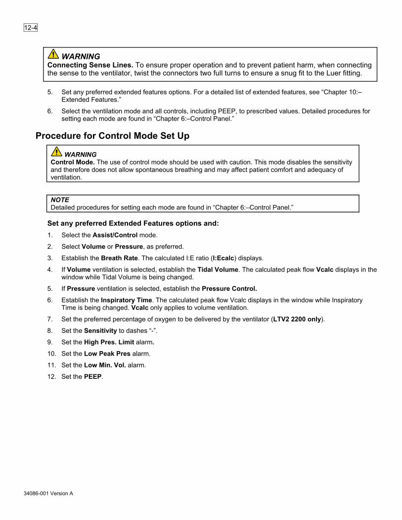
12-4
34086-001 Version A
WARNING Connecting Sense Lines. To ensure proper operation and to prevent patient harm, when connecting the sense to the ventilator, twist the connectors two full turns to ensure a snug fit to the Luer fitting.
5. Set any preferred extended features options. For a detailed list of extended features, see “Chapter 10:–Extended Features.”
6. Select the ventilation mode and all controls, including PEEP, to prescribed values. Detailed procedures for setting each mode are found in “Chapter 6:–Control Panel.”
Procedure for Control Mode Set Up
WARNING Control Mode. The use of control mode should be used with caution. This mode disables the sensitivity and therefore does not allow spontaneous breathing and may affect patient comfort and adequacy of ventilation.
NOTE Detailed procedures for setting each mode are found in “Chapter 6:–Control Panel.”
Set any preferred Extended Features options and: 1. Select the Assist/Control mode.
2. Select Volume or Pressure, as preferred.
3. Establish the Breath Rate. The calculated I:E ratio (I:Ecalc) displays.
4. If Volume ventilation is selected, establish the Tidal Volume. The calculated peak flow Vcalc displays in the window while Tidal Volume is being changed.
5. If Pressure ventilation is selected, establish the Pressure Control.
6. Establish the Inspiratory Time. The calculated peak flow Vcalc displays in the window while Inspiratory Time is being changed. Vcalc only applies to volume ventilation.
7. Set the preferred percentage of oxygen to be delivered by the ventilator (LTV2 2200 only).
8. Set the Sensitivity to dashes “-”.
9. Set the High Pres. Limit alarm.
10. Set the Low Peak Pres alarm.
11. Set the Low Min. Vol. alarm.
12. Set the PEEP.

12-5
34086-001 Version A
Figure 12-2. Control Mode Set up
1 Assist/Control, SIMV/CPAP, NPPV Mode Selection Button 2 Volume/Pressure Ventilation Breath Type Button 3 Breath Rate Control Button 4 Tidal Volume Control Button 5 Pressure Control Button 6 Inspiratory Time Control Button 7 FiO2 Control Button 8 Sensitivity Control Button 9 High Pres. Limit Variable Alarm Button 10 Low Peak Pres. Variable Alarm Button 11 Low Min. Vol Variable Alarm Button 12 PEEP Control Button

12-6
34086-001 Version A
Procedure for Assist/Control Mode Set Up NOTE Detailed procedures for setting each mode are found in “Chapter 6:–Control Panel.”
Set any preferred Extended Features options and: 1. Select the Assist/Control mode.
2. Select Volume or Pressure, as preferred.
3. Establish the Breath Rate. The calculated I:E ratio (I:Ecalc) displays.
4. If Volume ventilation is selected, establish the Tidal Volume. The calculated peak flow Vcalc displays in the window while Tidal Volume is being changed.
5. If Pressure ventilation is selected, establish the Pressure Control.
6. Establish the Inspiratory Time. The calculated peak flow Vcalc displays in the window while Inspiratory Time is being changed. Vcalc only applies to volume ventilation.
7. Set the preferred percentage of oxygen to be delivered by the ventilator (LTV2 2200 only).
8. Set the Sensitivity to a setting from 1 to 9.
9. Set the High Pres. Limit alarm.
10. Set the Low Peak Pres alarm.
11. Set the Low Min. Vol. alarm.
12. Set the PEEP.

12-7
34086-001 Version A
Figure 12-3. Assist/Control Mode Set Up
1 Assist/Control, SIMV/CPAP, NPPV Mode Selection Button 2 Volume/Pressure Ventilation Breath Type Button 3 Breath Rate Control Button 4 Tidal Volume Control Button 5 Pressure Control Button 6 Inspiratory Time Control Button 7 FiO2 Control Button 8 Sensitivity Control Button 9 High Pres. Limit Variable Alarm Button 10 Low Peak Pres. Variable Alarm Button 11 Low Min. Vol Variable Alarm Button 12 PEEP Control Button

12-8
34086-001 Version A
Procedure for SIMV Mode Set Up NOTE Detailed procedures for setting each mode are found in “Chapter 6:–Control Panel.”
Set any preferred Extended Features options and: 1. Select the SIMV/CPAP mode.
2. Select Volume or Pressure, as preferred.
3. Establish the Breath Rate.
4. If Volume ventilation is selected, establish the Tidal Volume. The calculated peak flow Vcalc displays in the window while Tidal Volume is being changed.
5. If Pressure ventilation is selected, establish the Pressure Control.
6. Establish the Inspiratory Time. The calculated peak flow Vcalc displays in the window while Inspiratory Time is being changed. Vcalc only applies to volume ventilation.
7. Set the Pressure Support, if preferred.
8. Set the preferred percentage of oxygen to be delivered by the ventilator (LTV2 2200 only).
9. Set the Sensitivity to a setting from 1 to 9.
10. Set the High Pres. Limit alarm.
11. Set the Low Peak Pres alarm.
12. Set the Low Min. Vol. alarm.
13. Set the PEEP.

12-9
34086-001 Version A
Figure 12-4. SIMV Mode Set Up
1 Assist/Control, SIMV/CPAP, NPPV Mode Selection Button 2 Volume/Pressure Ventilation Breath Type Button 3 Breath Rate Control Button 4 Tidal Volume Control Button 5 Pressure Control Button 6 Inspiratory Time Control Button 7 Pressure Support Control Button 8 FiO2 Control Button 9 Sensitivity Control Button 10 High Pres. Limit Variable Alarm Button 11 Low Peak Pres. Variable Alarm Button 12 Low Min. Vol Variable Alarm Button 13 PEEP Control Button

12-10
34086-001 Version A
Procedure for CPAP Mode Set Up NOTE Detailed procedures for setting each mode are found in “Chapter 6:–Control Panel.”
Set any preferred Extended Features options and: 1. Select the SIMV/CPAP mode.
2. Select Volume or Pressure, as preferred.
3. Establish the Breath Rate to dashes “- -”.
4. If Volume ventilation is selected, establish the Tidal Volume for apnea backup. The calculated peak flow Vcalc displays in the window while Tidal Volume is being changed.
5. If Pressure ventilation is selected, establish the Pressure Control for apnea backup.
6. Establish the Inspiratory Time for apnea backup. The calculated peak flow Vcalc displays in the window while Inspiratory Time is being changed. Vcalc only applies to volume ventilation.
7. Set the Pressure Support, if needed.
8. Set the preferred percentage of oxygen to be delivered by the ventilator (LTV2 2200 only).
9. Set the Sensitivity to a setting from 1 to 9.
10. Set the High Pres. Limit alarm.
11. Set the Low Peak Pres alarm for apnea backup.
12. Set the Low Min. Vol. alarm.
13. Set the PEEP.
Procedure for NPPV Mode Set Up The NPPV mode allows the ventilator to be configured to deliver the following modalities:
• CPAP
• PEEP with pressure support
• Timed pressure controlled breaths (either time or flow terminated) with pressure support (flow terminated) spontaneous breaths.
NOTE When NPPV is selected, the pressure control setting range is - - (off), 4 to 60. The pressure control setting is used to set the inspiratory pressure for mandatory breaths as well as pressure support breaths.
NOTE Detailed procedures for setting each mode are found in “Chapter 6:–Control Panel.”

12-11
34086-001 Version A
Set any preferred Extended Features options and: 1. Select the NPPV mode.
NOTE When NPPV is selected, the breath type automatically changes to Pressure and Flow Termination is selected.
NOTE If the Pressure Control setting plus PEEP setting is greater than 60 cmH2O upon entering NPPV, the mode change is not accepted and the Pressure Control setting flashes. Set the Pressure Control setting to an acceptable value (4 to 60 cmH2O) and try again.
2. Set the Breath Rate if mandatory mechanical breaths are preferred.
3. If a breath rate is selected, set the Inspiratory Time. The Inspiratory Time control dims if no breath rate is set.
4. The Pressure Control parameter is used to set the inspiratory pressure for both Pressure Control (if a rate greater than 0 is set) and Pressure Support breaths.
NOTE Mandatory and supported breaths have the same inspiratory pressure setting.
5. Set the PEEP.
6. Set the preferred percentage of oxygen to be delivered by the ventilator (LTV2 2200 only).
7. Set the High Pres. Limit alarm.
8. Set the Low Peak Pres alarm.
9. Set the Low Min. Vol. alarm
NOTE If the Pressure Control setting is - - (off) upon exiting NPPV, the mode change will not be accepted and Pressure Control setting will flash. Set the Pressure control setting to an acceptable value (4 to 98 cmH2O) and try again.
NOTE Apnea Ventilation in NPPV - When the ventilator is in NPPV mode with Pressure Control set to -- (off) and enters the Apnea Backup mode, the ventilator will ventilate in Assist/Control mode using a pressure control value of 15. The display will alternate between “APNEA xx bpm” and “APNEA 15 cmH2O”. See Apnea Backup on page 4-5.

12-12
34086-001 Version A
Figure 12-5. NPPV Mode Set Up
1 Assist/Control, SIMV/CPAP, NPPV Mode Selection Button 2 Scroll Knob 3 Pressure Control Button 4 Scroll Knob 5 PEEP Control Button 6 Scroll Knob 7 Breath Rate Control Button 8 FiO2 Control Button 9 High Pres. Limit Variable Alarm Button
To Turn the Ventilator Off 1. Disconnect the ventilator from the patient and provide another means of ventilation (if required).
2. Press and hold the Power/Standby button for 3 seconds. The ventilator ceases operating, the audible alarm sounds and the red Alarm Status LED is lit.
3. Stop the audible alarm from sounding by pressing the Alarm Reset button.
4. The ventilator continues to charge the internal battery and removable battery, if installed, as long as it is connected to an external power source.

13-1
34086-001 Version A
Cleaning and Disinfecting the Ventilator and Accessories The external surfaces of the ventilator and accessories should be cleaned and disinfected before initial use, before and after each patient use, and as required.
The following chemicals (or their equivalent) have been verified as being safe to use to clean the LTV2 ventilator and its accessories (except where noted) when used per the manufacturer’s instructions and stated concentration limits.
Quaternary ammonium compounds
• Control III® Disinfectant Germicide (Maril Products)
• Aniosyme® (Anios)
• CaviWipes™ (Metrex)*
Sodium hypochlorite (chlorine bleach) compounds
• Chlorine bleach solution (≤10% of 0.525% ) (generic)*
• Bleach Germicidal Wipe (Clorox Healthcare®)
Generic compounds
• ≤ 90% Isopropyl alcohol compounds
• ≤ 5% Hydrogen peroxide compounds
*Indication chemical was validated for efficacy.
Preparing the ventilator and accessories to be cleaned and disinfected: 1. Unplug all equipment from AC power before cleaning and disinfecting.
2. Initiate cleaning and disinfection of device as soon as possible after use (recommended within two hours).
3. Remove excess visible soil as soon as possible after use by wiping the device.
4. Follow the instructions below to clean the ventilator and accessories.

13-2
34086-001 Version A
Cleaning the Ventilator and Accessories 1. Using unfolded CaviWipes (or equivalent), remove heavy soil from the external surfaces of the device paying
particular attention to cracks, crevices, and hard to reach areas.
2. Using an additional fresh wipe that has been unfolded, wipe the device to wet all external contaminated surfaces. Use additional wipes as needed ensuring the surfaces remain wet for a minimum of five (5) minutes.
3. Wipe the external surfaces of the device with disposable, lint-free cloths dampened with lukewarm (27 to 44°C or 81 to 111°F) potable tap water for a minimum of 30 seconds three (3) times using fresh tap water each time.
4. Dry the device with a clean, soft cloth.
5. Visually examine each device for cleanliness. If visible soil remains, repeat the cleaning procedure until the device is thoroughly clean.
Disinfecting the Ventilator and Accessories NOTE Only one disinfection method is required.
Disinfection method #1
1. Clean the ventilator and/or accessories by the method described above
2. Prepare a 10% bleach disinfectant solution (0.525% sodium hypochlorite concentration) according to the manufacturer’s directions
Mix one part bleach with nine parts tap water.
3. Using a soft, clean cloth saturated with the disinfectant solution, wipe the external surfaces of the device, paying particular attention to cracks, crevices, and hard to reach areas.
4. Ensure the external surfaces of the device remain wet for a minimum of 5 minutes.
5. Wipe the external surfaces of the device with disposable, lint-free cloths dampened with lukewarm (27 to 44°C or 81 to 111°F) potable tap water for a minimum of 30 seconds three (3) times using fresh tap water each time.
6. Dry the device with a clean, soft cloth. Disinfection method #2
1. Clean the ventilator and/or accessories by the method described above.
2. Using an unfolded Clorox Healthcare® Bleach Germicidal Wipe (or equivalent), wipe the external surfaces of the device, paying particular attention to cracks, crevices, and hard to reach areas.
3. Using an additional fresh disinfectant wipe that has been unfolded, wipe the device to wet all external surfaces. Use additional wipes as needed, ensuring the surfaces of the device remain wet for a minimum of five minutes.
4. Wipe the external surfaces of the device with disposable, lint-free cloths dampened with lukewarm (27 to 44°C or 81 to 111°F) potable tap water for a minimum of 30 seconds three (3) times using fresh tap water each time.
5. Dry the device with a clean, soft cloth.

13-3
34086-001 Version A
WARNING Cleaning and Disinfection. To avoid the risk of electrical shock, the AC power adapter must be unplugged from AC power before cleaning and disinfection.
Circuit Reuse. To reduce the risk of infection and patient injury, do not clean, disinfect, or otherwise reprocess single patient use (SPU) circuits for reuse. The reuse of disposable circuits may result in cross-contamination between patients and degrade circuit performance.
CAUTION Ventilator Sterilization. To avoid irreparable damage to the LTV2 2200/2150 ventilator, do not attempt to sterilize it.
Cleaning Agents. To avoid damaging the ventilator and/or accessories, use only those chemicals (or their equivalent) recommended by Vyaire Medical.
Liquid Cleaners. Do not pour or spray liquid cleaners into the ventilator or the battery charger. Do not allow the contacts of the battery or battery charger to become wet.
Ventilator Immersion. Do not immerse the ventilator in liquids.
Follow the manufacturer’s instructions for any cleaning agents used.
Follow your institutional guidelines for cleaning reusable medical equipment.
Table Top Stand Cleaning. Do not use products containing sodium hypochlorite (chlorine bleach) to clean the table stand.

13-4
34086-001 Version A
Cleaning or Replacing the Fan Filter Check the Fan Filter daily and clean or replace when soiled, worn, or damaged.
To clean the fan filter: 1. Remove the fan filter by squeezing the foam filter gently with your fingers and pulling it out.
Figure 13-1. Removing the Fan Filter for Cleaning or Replacement
1 Fan Filter
NOTE Hardware Fault -If you touch the fan blades while removing the fan filter grill or filter, an HW FAULT may occur. This is normal. Clear the HW FAULT alarm by using the Alarm Reset button.
2. Gently bathe the filter in a solution of mild detergent and warm water.
3. Rinse thoroughly in warm water.
4. Examine the filter for excessive wear or damage. Discard and replace with a new filter if necessary.
5. Allow the filter to thoroughly air dry before reinstallation.
6. Reinstall the filter.
7. Reposition the filter grill over the filter and apply light pressure until it fully seats (“clicks”) into the filter housing.
CAUTION Wet or Damp Filters. Do not install a wet or damp filter into the LTV2 2200/2150 ventilator. This could damage the ventilator.

13-5
34086-001 Version A
Cleaning or Replacing the Air Inlet Filter Check the Air Inlet Filter daily and replace when soiled, worn, or damaged.
To change the Inlet Filter: 1. Remove the Inlet Filter by squeezing the filter gently with your fingers and pulling it out.
Figure 13-2. Replacing the Inlet Filter
1 Inlet Filter
2. Gently bathe the filter in a solution of mild detergent and warm water.
3. Rinse thoroughly in warm water.
4. Examine the filter for excessive wear or damage. Discard and replace with a new filter if necessary.
5. Allow the filter to thoroughly air dry before reinstallation.
6. Reinstall the filter.
WARNING Air Inlet Filter. To prevent foreign material from being drawn into the ventilator resulting in patient injury and damage to the ventilator, ensure that the foam air inlet filter is clean and in place while in operation.

13-6
34086-001 Version A
Cleaning or Replacing the O2 Inlet Filter (LTV2™ 2200 only) The O2 filter should be cleaned or replaced when it becomes soiled. Failure to do this can affect ventilator performance.
CAUTION Oxygen Supply Contamination. The accuracy of the oxygen delivery capabilities of LTV2 2200/2150 ventilator can be compromised by foreign debris contamination in the oxygen supply system. To reduce the risk of airborne contaminants entering the ventilator, ensure that any oxygen supply connected to the ventilator is clean, properly filtered and that the ventilator’s O2 Inlet Port Cap is securely installed on the O2 Inlet Port whenever the ventilator is not connected to an external oxygen supply.
To clean or replace the O2 Inlet Filter: 1. If a high pressure O2 source is being used, disconnect the high pressure O2 hose from the oxygen block on
the left side of the ventilator.
2. If a low pressure O2 source is being used, disconnect the O2 line from the barbed oxygen adapter. Unscrew and remove the barbed adapter from the oxygen block on the left side of the ventilator.
Figure 13-3. Cleaning or Replacing the O2 Inlet Filter
1 High Pressure O2 Connection 2 Low Flow O2 Connection
3. Using a pick, gently remove the rubber O-Ring from inside the O2 inlet port. Use caution: Do not damage the O-Ring while removing it. Tip the ventilator to allow the O2 Inlet Filter to slide out.

13-7
34086-001 Version A
Figure 13-4. Removing the Rubber O-Ring from inside the O2 Inlet Port
1 O2 Inlet Filter 2 O-Ring
4. Clean the filter using a mild cleanser, warm water and a soft brush. Rinse the filter thoroughly to remove all traces of the cleanser. Allow the filter to dry completely before replacing it in the ventilator.
5. Inspect the filter for damage. If the filter is not intact, shows signs of damage or cannot be completely cleaned, replace it with a new O2 Inlet Filter (P/N 19845-001) and O-Ring (P/N 10609), available from Vyaire Medical.
6. Replace the filter by sliding it back into the O2 inlet port. Replace the O-Ring, making sure it is completely tucked under the retaining lip on the inside of the O2 inlet port.
7. Reconnect the high pressure O2 line or the barbed adapter and low pressure O2 line.
CAUTION Wet or Damp Filters. Do not install a wet or damp filter into the LTV2 2200 ventilators. This could damage the ventilator.

13-8
34086-001 Version A
Intentionally left blank.

14-1
34086-001 Version A
Power and Battery Operation The LTV2 2200/2150 ventilator operates on direct current (11 to 29 Vdc) supplied by the AC power adapter, or by the internal (fixed) lithium-ion battery, by the removable lithium-ion battery, or another suitable external DC power source. While the ventilator is being powered by the AC power adapter or external DC power source, the internal battery and the removable battery (if installed) charge.
The ventilator is able to run for approximately 3.5 hours on the internal battery and an additional 4 hours on the removable battery (7.5 hours total) under nominal operating conditions and with new batteries.
• The removable battery is hot-swappable in that it may be removed and replaced without interrupting ventilation (assuming the internal battery is sufficiently charged). When the removable battery is depleted or not installed, the ventilator switches to the fixed internal battery.
• One of the three Power Source LEDs illuminate to indicate which power source is supplying power to the ventilator.
• External power. The External Power indicator illuminates when the ventilator is being powered by the AC
power adapter or external DC power source.
• Removable battery. The Removable Battery indicator illuminates (solid on) when the ventilator is using the LTV2 removable battery and flashes when the removable battery is being charged.
• Internal battery. The Internal Battery indicator illuminates (solid on) when the ventilator is using the internal (fixed) battery and flashes when the internal battery is being charged.
These LEDs only indicate the power source and do not indicate the charge level status.

14-2
34086-001 Version A
Internal and Removable Battery Use Upon inserting the removable battery into the LTV2, the current charge level of the removable will be displayed as RemBat xxx% where xxx is the current charge level of the specified battery. If the removable battery is ejected, the medium priority BATT EJECTED alarm is generated.
• When both internal and removable batteries are installed, the removable battery is the first battery to be used.
• When the removable battery is exhausted (or removed) ventilation continues on the internal battery.
• When the removable battery is replaced, the LTV2 will switch back to the removable battery.
WARNING Battery Run Time. When the battery reaches the IntBat LOW level, the ventilator will only run for approximately ten minutes before generating an internal battery empty alarm (IntBat EMPTY). The approximate times shown here are based on tests using the nominal settings, a new battery and a full charge cycle as specified in “Appendix A:–Ventilator Specifications.” Actual run time may be more or less depending on ventilator settings, patient demand, and battery age or condition. It is highly recommended that an alternate power source is connected BEFORE the ventilator reaches the IntBat EMPTY alarm condition to ensure continuous, uninterrupted patient ventilation. If the LTV2 2200/2150 ventilator is operated on its removable and/or internal batteries to the point that they are completely depleted, the ventilator will shut down.
Pressing the Battery Check button will force the immediate display of the battery charge status (percentage of charge remaining) of both batteries in the display window. This battery check function works when the ventilator is powered on or powered off.
NOTE The display only indicates charge levels of the internal and removable (if installed) batteries, and does not display a battery charge level of a battery that is connected using the external power source port.
Charging Priority Battery charging takes place when the ventilator is connected to a sufficient external power source (such as an AC adapter). When the ventilator is able to charge, batteries are charged in the following order:
• The internal battery charges first.
• When the internal battery is charged to approximately 80%, the removable battery (if installed) begins to charge.
• When both batteries are at about 80%, they will charge simultaneously until they reach 100%.
A battery will charge to approximately 80% capacity in about two-and-a-half (2.5) hours from a fully discharged state under normal operating conditions.

14-3
34086-001 Version A
NOTE The LTV2 ventilator only begins charging the battery if its charge level is below 95%.
NOTE If the external power to the ventilator falls outside the level required for full ventilator functionality, the ventilator reduces (if possible) the charging current applied to the internal and/or removable battery or stops charging the internal and/or removable battery to reduce power consumption in an effort to maintain ventilation.
Charging the removable battery The Vyaire Medical LTV2 Removable Battery can be charged in an LTV2 Series ventilator, when the ventilator is connected to an adequate external power source. A flashing LED in the Power Source section of the front panel indicates that charging is in progress.
The LTV2 Removable Battery can also be charged in an LTV2 Battery Desktop Charger, part number 22766-001. A flashing green LED on the top panel of the Desktop Charger indicates that charging is in progress.
NOTE To help ensure the reported battery percentage maintains the highest level of accuracy, the battery should be recharged to at least 40% before disconnecting it from external power.
Checking the battery charge level
Determining charge of a removable battery To determine the charge level of the LTV2 Removable Battery, press and release the Battery Check button on the Removable Battery, just below the LED gauge. The number of LEDs that illuminate indicates the charge level of the battery. Refer to Table 14-1 to determine the level of charge based on the LEDs.
Figure 14-1. LTV2 Removable Battery and Battery Check LED Gauge.

14-4
34086-001 Version A
Table 14-1. Level of Charge (out of charger) LED 5 Solid on Over 80% charged LED 4 Solid on 60 to 79% charged LED 3 Solid on 40 to 59% charged LED 2 Solid on 20 to 39% charged LED 1 Solid on 11 to 19% charged
Blinking Battery less than 11% full
Table 14-2. Level of Charge (while charging) LED 5 Blinking 80 to 100% charged LED 4 Blinking 60 to 79% charged LED 3 Blinking 40 to 59% charged LED 2 Blinking 20 to 39% charged LED 1 Blinking Less than 20% charged
Determining charge of a removable battery docked in the desktop charger When charging is in progress, the LEDs on the Removable Battery illuminate to indicate the charge level. The number of LEDs that illuminate indicates the charge level of the battery. Refer to Table 14-2 to determine the level of charge based on the LEDs.
When charging is complete, the LED on the Desktop Charger top panel is a solid green color and the LEDs on the battery will turn off.
Determining charge of a removable battery installed in an LTV2 Series Ventilator Press the Battery Check button on the LTV2 ventilator front panel. The button is located to the right of the display window. The charge level appears in the display window. RemBat XXX% (where XXX is the percent charge remaining)
Exchanging the Removable Battery in an LTV2 Series Ventilator 1. Press the Eject button located on the right side of the ventilator.
2. Grasp the protruding end of the battery, and remove it with a firm, straight motion.
3. Orient the new battery using the arrow on the label as a guide.
4. Insert the new battery with a firm, straight motion.
5. Confirm the charge level of the new battery displayed in Display Window.
NOTE Removable battery: If there is no display of charge level when inserting the removable battery into the LTV2, reinsert battery. If the battery is totally discharged, charging must be done in the desktop charger.
NOTE Battery Use: The length of time the ventilator will operate on battery power is a function of many factors such as settings, charge level and condition or age of the battery.

14-5
34086-001 Version A
Battery Calibration/Relearn The internal and removable batteries are considered “intelligent” as they keep track of charge/discharge cycles, remaining run-time, overall health, etc. Periodically, these batteries may need to be calibrated to “relearn” their usable capacity. This may manifest as reduced accuracy of the battery LED gauge or ventilator displayed parameters. To determine if a battery needs to go through the relearn process, enter the Battery Ops menu in Extended Functions. Scroll to and select IntBat INFO or, if preferred and installed, RemBat INFO. Scroll to RELEARN. If RELEARN NO displays, the internal circuitry of the battery is indicating no relearn process is required. If RELEARN YES displays, the battery relearn procedure should be carried out soon.
The relearn process must be done when the ventilator is not in use, and is typically done during routine preventative maintenance since it may take as long as 20 hours to accomplish. The LTV2 ventilator must be used to perform the relearn process for both the internal and removable batteries.
Refer to the LTV2 Service Manual for instructions on completing the battery relearn process.
WARNING Battery Relearn. If battery run times are different than what is expected, the battery status should be checked to determine if the relearn process should be completed. This will help ensure a more accurate measurement and display of battery charge level and reduces the chance of interruption of ventilation.
Desktop Battery Charger
Figure 14-2. Desktop Battery Charger

14-6
34086-001 Version A
The Desktop Battery Charger is capable of charging two (2) removable batteries simultaneously. Batteries will charge to 80% capacity in about two (2) hours from a fully discharged state.
To charge a removable battery, simply insert the battery (arrow pointing down) into the Desktop Battery Charger. The side with the LEDs should face toward the front. The LEDs will be visible during the charging cycle to indicate charge status.
The Desktop Battery Charger has no buttons; placing the battery in the charger will automatically start the charging cycle. Two LEDs on the charger indicates the status of the charger and battery. The desktop charger LED panel type varies by country of use.
Figure 14-3. Desktop Battery Charger LED Panels
Color State Meaning
Green On (steady) Battery charging completed
On (Flashing) Battery is currently charging
Red On (steady) Charger fault – See “Chapter 15:–Troubleshooting.”
On (Flashing) Battery fault – See “Chapter 15:–Troubleshooting.”
- Off No battery is detected or, Desktop battery charger is unplugged from AC current
NOTE Removable battery: If the LEDs indicate a battery fault, remove and then replace the battery. If the fault remains, remove the battery from service and call Vyaire Medical Technical Support.
Fully recharge the battery every six (6) months while the ventilator is in storage. Recharge the battery by plugging the ventilator into an AC power source for five hours. If the battery charge status does not indicate a full charge after five hours, contact a certified Vyaire Medical service technician or Vyaire Medical.

14-7
34086-001 Version A
Using the AC Adapter To run the ventilator from the Vyaire Medical AC Power Adapter: 1. Attach the power connector from the AC Adapter to the ventilator as shown here.
Figure 14-4. Vyaire Medical AC Power Adapter
1 Adapter Connector
2 AC Adapter
2. Connect the proper AC power cable (110V or 220V plug) to the AC Power Adapter.
3. Connect the 110V or 220V power cable to a suitable power source. Verify the External Power, Power Source LED is illuminated.
While the ventilator is plugged into external power, the internal and removable (if installed) batteries will be charged.
CAUTION Power Connector Release. To avoid damaging the ventilator or the power connector, pull the knurled sleeve of the connector back while removing it from the ventilator.
Power Connector Handling. Use caution when moving the ventilator while the power connector is attached. Too much pressure causing the connector to twist while it is engaged in the port may damage the ventilator and/or power connector.
CAUTION Unplugging the power cord from the wall outlet is required to disconnect the LTV2 ventilator from AC power. Therefore, do not position the LTV2 so that it is difficult to disconnect the power cord from the wall outlet.

14-8
34086-001 Version A
Using an External Battery An optional Externalpower cableis available from Vyaire Medical.
CAUTION External Battery. The External Battery should only be connected to the LTV2 2200/2150 ventilator using a Medical External power Cable. This cable is pre-wired and properly terminated to ensure safe connection of the External Battery to the ventilator.
To run the ventilator from an external battery: 1. Connect the power cable to the external battery, following the cable IFU.
Figure 14-5. External Battery Cable and Quick Connector
1 Battery Connector
2 To External Battery
2. Connect the power connector on the battery cable to the power port on the left side of the ventilator as shown here. Verify the External Power LED is illuminated.
While the ventilator is connected to the external battery, the internal battery will be charged.
NOTE The External Battery can only be recharged using the Vyaire Medical External Battery Charger. The External Battery must be disconnected from the LTV2 2200/2150 ventilator before connecting to the External Battery Charger. See the instruction sheet that comes with the External Battery Charger for information on how to properly configure the charger for your AC voltage and frequency. The external battery is a sealed lead acid battery. Some states and countries require that these batteries must be disposed of through an authorized recycling or hazardous materials center. Contact the proper agency for appropriate disposal procedures.

14-9
34086-001 Version A
For more detailed information on using or charging the external batteries, or for information on replacing power cable fuse, see the LTV2 External power cable Operator's Manual.
The battery may be set and operated from any position, but always secure the battery in place and keep the battery in a stable, accessible position near the LTV2 ventilator. Keep all cords away from footpaths and moveable equipment, and tie them to unmoving surfaces such as the ventilator stand or bed post.
Refer to the LTV2 External power cable Kit Operator’s Manual for other safety information, extended operating procedures, and troubleshooting techniques.
WARNING Before Using Power Outlets. Before using Power Outlets as a power source for the LTV2
2200/2150 ventilator, ensure that the ventilator’s internal battery is in good condition and fully charged. Poor power outlet connections, electrical system defects (battery, charging system, etc.), could result in less than the required voltage being delivered to the ventilator, generate an EXT PWR LOST alarm, and switch the ventilator’s power source to the internal battery. Failure to do so may result in loss of power and cessation of ventilation.

14-10
34086-001 Version A
Caring for the Internal and Removable Batteries The LTV2 2200/2150 ventilator uses a rechargeable, lithium ion internal battery.
To preserve maximum battery life:
• Fully recharge the internal battery every six (6) months while the ventilator is in storage. Recharge the battery by plugging the ventilator into an AC power source for five hours. If the battery charge status does not indicate a full charge after five hours, contact a certified Vyaire Medical service technician or Vyaire Medical.
• Fully recharge the removable battery every six (6) months when not used. Recharge the removable battery in the ventilator by inserting the battery and plugging the ventilator into an AC power source for eight (8) hours. Alternatively, if the desktop charger is used, charge for five (5) hours. If the battery charge status does not indicate a full charge after charging, contact a certified Vyaire Medical service technician or Vyaire Medical.
• Store the ventilator at temperatures less than 60°C (140°F).
CAUTION Storage Temperature. Storing the LTV2 2200/2150 ventilator at temperatures above 60°C (140°F) for long periods can damage the internal battery and cause expected battery duration to degrade. Internal Battery Use. The length of time the ventilator operates on internal power is a function of many factors such as settings, charge level and condition or age of the battery; therefore, prolonged use of the internal battery as the only available power source as a standard operating practice is not recommended.
Battery Replacement When necessary, the LTV2 2200/2150 ventilator’s internal battery can be replaced by a trained service technician.
Battery Disposal The LTV2 2200/2150 ventilator uses lithium ion batteries. Some jurisdictions consider these batteries hazardous materials subject to special disposal regulations. Contact the proper agency for information on permissible methods of transporting and disposing of used batteries.
Cleaning Keep the removable battery clean and dry. If the battery terminals become dirty, wipe them with a clean, dry cloth.

15-1
34086-001 Version A
Troubleshooting This chapter describes troubleshooting for the LTV2 2200/2150 ventilator. Some problems can result from improper operation and can easily be corrected without any modification to the ventilator. Other problems may require that the ventilator be recalibrated or have parts replaced.
Do not attempt to repair or replace any part of the ventilator unless you are trained and authorized for service on the LTV2 2200/2150 ventilator.
This chapter is organized into five sections: Displays and Buttons Includes problems with control and window
displays and with setting controls.
Ventilator Includes problems with delivered or monitored pressure, volume or PEEP, accuracy, sensitivity and triggering.
Power and Battery Operation Includes problems with turning the ventilator on, operating from external power sources, battery operation or duration, and ventilator inoperative conditions.
Alarms Includes problems with recurring alarms.
Checkout Test Failures Includes problems detected while performing the VENT CHECK tests.
Test Lung Operation Includes problems encountered when operating the ventilator with a test lung.
The troubleshooting tables are organized by symptom, then by possible causes and methods of diagnosing and resolving the problem. If you do not find the symptom you are looking for under one section, you may find it listed under another section, or you may be able to diagnose the problem by reading sections with related symptoms. For information on resolving problems that are not listed here, contact Vyaire Medical.

15-2
34086-001 Version A
Displays and Buttons Some of the symptoms listed in this section are part of the normal operation of the ventilator and do not indicate any problem with the ventilator. They are included here for completeness.
Symptoms Possible Causes What to Do Pressure Control display flashing.
Pressure Control breath terminated by flow – PC FLOW TERM is set to on.
Pressure Control breaths are normally terminated when the set inspiratory time expires. Flow termination of Pressure Control breaths is allowed when PC FLOW TERM is set to ON (see page 10-8). When a Pressure Control breath is terminated by flow instead of time, the Pressure Control display flashes.
Pressure Support display flashing.
Pressure support breath terminated by time - set under TIME TERM.
Pressure support breaths are normally terminated when the flow drops below the set percentage of the peak flow. Pressure support breaths may also terminate on time when the variable time limit is reached before the flow drops to the set level. (For explanations of the FLOW TERM and TIME TERM features, see pages 10-7 and 10-8) When a pressure support breath is terminated based on time, the Pres Support display flashes.
High Pres. Limit display flashing.
HI PRESSURE alarm occurred.
The High Pres. Limit display flashes and the HI PRESSURE message displays when a high pressure alarm occurs. The display will continue to flash until the condition clears. (For an explanation of the HI PRESSURE alarm feature, see page 9-12)
Low Pressure display flashing.
LO PRESSURE alarm occurred.
The Low Pressure display flashes and the LO PRESSURE message displays when a low pressure alarm occurs. The display will continue to flash until the condition clears. For an explanation of the LO PRESSURE alarm feature, see page 9-21.
Low Min Vol display flashing.
LOW MIN VOL alarm occurred.
The Low Min Vol display flashes and the LOW MIN VOL message displays when a low minute volume alarm occurs. The display will continue to flash until the condition clears. For an explanation of the LOW MIN VOL alarm feature, see page 9-19.
FiO2 (Flush) display flashing (LTV2 2200 only).
LOW O2 PRES or HI O2 PRES alarm occurred.
The FiO2 (Flush) display flashes and the LOW O2 PRES or HI O2 PRES message displays when a low or high O2 pressure alarm occurs. The display will continue to flash until the condition clears. For explanations of the LOW O2 PRES and HI O2 PRES alarm features, see pages 9-20 and 9-11.
Control display flashing when setting a control.
Control setting is limited. A control's value may be limited by the current settings of other controls. For an explanation of Control Limiting, see page 5-5.
A display or LED does not illuminate.
Internal problem with the ventilator.
Do a display test (for instructions, see page 11-6). If the display or LED does not illuminate, immediately contact a certified Vyaire Medical service technician.

15-3
34086-001 Version A
Symptoms Possible Causes What to Do Ventilator is running but displays are turned off.
Displays are blanked while on battery power.
To conserve battery life while running from the internal battery, most of the displays are turned off when no changes are made to the control settings for 60 seconds. To turn the displays back on, touch any control or button or turn the Scroll knob.
Internal problem with the ventilator.
Do a display test (for instructions, see page 11-6). If the display or LED does not illuminate, immediately contact a certified Vyaire Medical service technician.
A control doesn't operate. Scroll knob doesn't operate.
Control not active in selected mode.
If a control is dimmed, it is not active in the currently selected mode and changing its setting does not affect ventilation. For an explanation of Bright, Dim and Blank Control Displays, see page 5-4.
Controls are locked. If the controls are locked, a LOCKED message will be displayed when a control is selected. To unlock in EASY mode, press the Control Lock button. To unlock in HARD mode, press and hold the Control Lock button for 3 seconds. For an explanation of the CTRL UNLOCK feature and Control Lock button, see page 5-5.
Control is not selected. Before a control value can be changed, the control must be selected. To select a control, press the associated button. When a control is selected it displays at normal intensity and all other controls are dimmed. For an explanation of how to use the controls, see page 5-2.
Controls are limited. A control's value may be limited by the current settings of other controls. To change the value of the current control, change the value of the flashing controls. For an explanation of Control Limiting, see page 5-5.
Internal problem with the ventilator.
Do a control test (for instructions, see page 11-8). If the control does not operate, immediately contact a certified Vyaire Medical service technician.
Can’t unlock the controls.
Hard unlock method selected under CTRL UNLOCK.
Two unlock methods are available on the LTV2 ventilator: For an explanation of CTRL UNLOCK, see page 5-5. To unlock in EASY mode, press the Control Lock button. To unlock in HARD mode, press and hold the Control Lock button for 3 seconds.
Volume/Pressure mode button does not operate, both LEDs are off.
Wrong model selected in maintenance mode.
Immediately contact a certified Vyaire Medical service technician.
Pressure Control button does not operate, associated display is off.
Wrong model selected in maintenance mode.
Immediately contact a certified Vyaire Medical service technician.

15-4
34086-001 Version A
Symptoms Possible Causes What to Do FiO2 (Flush) button does not operate, associated display is off (LTV2 2200 only).
Wrong model selected in maintenance mode.
Immediately contact a certified Vyaire Medical service technician.
Low Pressure O2 Source button and associated LED does not operate.
Wrong model selected in maintenance mode.
Immediately contact a certified Vyaire Medical service technician.
LMV OFF displays. Low Minute Volume alarm is turned off.
This is an informational message only. For an explanation of this feature, see page 8-4.
LPPS OFF displays. LPP ALARM has been set to VC/PC ONLY.
This is an informational message only. For an explanation of this feature, see page 8-4.
HI PEEP OFF displays. The High PEEP alarm is turned off.
This is an informational message only. For an explanation of this feature see page 8-4.
HI RATE OFF displays. The High Breath Rate alarm is turned off.
This is an informational message only. For an explanation of this feature, see page 8-4.
HI f/Vt OFF displays. The SBT HI f/Vt alarm is turned off during the SBT mode of ventilation.
This is an informational message only. For an explanation of this feature, see page 8-4.
LO SBT f/Vt OFF displays.
The SBT Low f/Vt alarm is turned off during the SBT mode of ventilation.
This is an informational message only. For an explanation of this feature, see page 8-4.
SBT LO f OFF displays.
The SBT Low Breath Rate alarm is turned off during the SBT mode of ventilation.
This is an informational message only. For an explanation of this feature, see page 8-4.
RC Enabled displayed at start-up.
Remote Control was left enabled after servicing.
This is an informational message only. Contact a certified Vyaire Medical service technician.

15-5
34086-001 Version A
Ventilator Performance
Symptoms Possible Causes What to Do Ventilator is auto-triggering, monitored volumes are very small, RT XDCR DATA item FTx shows negative flows during exhalation and positive flows during inspiration.
Sense lines are reversed. The sense lines are not designed to be removed from either the wye or the Luer fittings. If the sense lines have been removed and replaced incorrectly, they may not seal correctly when replaced. Replace the patient wye and sense lines with a known good assembly.
Ventilator won’t allow patient to exhale.
Sense lines occluded or pinched.
Check high and low pressure sense lines to be sure they are correctly attached and securely seated at both the ventilator and wye ends. Verify lines are not occluded or pinched.
Internal problem with the ventilator.
Immediately contact a certified Vyaire Medical service technician.
Set pressure not reached and turbine is humming. Turbine sounds like inspiration even during exhalation.
Failed calibration or internal problem with the ventilator.
Immediately contact a certified Vyaire Medical service technician.
Monitored volume is high. Delivered volume is high.
Very small ET tube connected directly to wye.
A very small ET tube connected directly to the wye may cause turbulence that causes the flow differential to be read incorrectly. To reduce this turbulence, add a short larger bore extension between the ET tube and wye. In this case, the monitored volume is high, but the delivered volume is accurate.
Monitored volume is high. Delivered volume is high.
Low side sense line or elbow at patient wye loose or leaking. High or low sense lines are occluded. High or low sense ports in the wye are occluded.
Check high and low pressure sense lines to be sure they are correctly attached and securely seated at both the ventilator and wye ends. Check the Luer fitting connections for leaks. Check the elbow connectors at the wye to be sure they have not loosened or been broken loose. Verify lines are not occluded or pinched.
Sense lines are reversed. The sense lines are not designed to be removed from either the wye or the Luer fittings. If the sense lines have been removed and replaced incorrectly, they may not seal correctly when replaced. Replace the patient wye and sense lines with a known good assembly.
Failed autozero. Perform an autozero under XDCR ZERO. For more information, see page .
Failed calibration or internal problem with the ventilator.
Immediately contact a certified Vyaire Medical service technician.
Delivered volume is twice the set volume.
VHome setting does not match flow valve.
Immediately contact a certified Vyaire Medical service technician.
Monitored volume is low. Delivered volume is low.
Circuit leak. Perform a leak test and reseat or replace the leaking parts or connections. For instructions, see “Leak Test” on page 11-10.

15-6
34086-001 Version A
Symptoms Possible Causes What to Do Monitored volume is low. Delivered volume is low.
High or low side sense line or elbow at patient wye loose or leaking. High or low sense lines are occluded. High or low sense ports in the wye are occluded.
Check high and low pressure sense lines to be sure they are correctly attached and securely seated at both the ventilator and wye ends. Check the Luer fitting connections for leaks. Check the elbow connectors at the wye to be sure they have not loosened or been broken loose. Verify lines are not occluded or pinched.
Exhalation drive line leaking or loose. Exhalation valve leaking during inspiration.
Check the exhalation drive line at both the ventilator and exhalation valve ends. Verify that the line is securely seated and not leaking. Verify that the exhalation valve is not leaking during inspiration. If it is leaking, replace the breathing circuit.
Sense lines are reversed. The sense lines are not designed to be removed from either the wye or the Luer fittings. If the sense lines have been removed and replaced incorrectly, they may not seal correctly when replaced. Replace the patient wye and sense lines with a known good assembly.
Leak Compensation is not on.
Verify that the Leak Compensation extended features option is set to On (default setting is on). For instructions, see page 10-10.
Failed autozero. Perform an autozero under XDCR ZERO. For more information, see page 10-27.
Failed calibration or internal problem with the ventilator.
Immediately contact a certified Vyaire Medical service technician.
Delivered volume is half the set volume.
VHome setting does not match flow valve.
Immediately contact a certified Vyaire Medical service technician.
Delivered pressure is low, PEEP is low, ventilator is auto-triggering. Delivered pressure is low. Monitored pressure is low.
Circuit leak. Perform a leak test and reseat or replace the leaking parts or connections. For instructions, see “Leak Test” on page 11-10.

15-7
34086-001 Version A
Symptoms Possible Causes What to Do Delivered pressure is low, PEEP is low, ventilator is auto-triggering. Delivered pressure is low. Monitored pressure is low.
High or low side sense line or elbow at patient wye loose or leaking. High or low sense lines are occluded. High or low sense ports in the wye are occluded.
Check high and low pressure sense lines to be sure they are correctly attached and securely seated at both the ventilator and wye ends. Check the Luer fitting connections for leaks. Check the elbow connectors at the wye to be sure they have not loosened or been broken loose. Verify lines are not occluded or pinched. Check the exhalation drive line at both the ventilator and exhalation valve ends. Verify the line is securely seated and not leaking.
Exhalation drive line leaking or loose. Exhalation valve leaking during inspiration.
Check the exhalation drive line at both the ventilator and exhalation valve ends. Verify that the line is securely seated and not leaking. Verify that the exhalation valve is not leaking during inspiration. If it is leaking, replace the breathing circuit.
Sense lines are reversed. The sense lines are not designed to be removed from either the wye or the Luer fittings. If the sense lines have been removed and replaced incorrectly, they may not seal correctly when replaced. Replace the patient wye and sense lines with a known good assembly.
Leak Compensation is not on.
Verify that the Leak Compensation extended features option is set to On (default setting is on). For instructions, see page 10-10
Failed autozero. Perform an autozero under XDCR ZERO. For more information, see page 10-27.
Failed calibration or internal problem with the ventilator.
Immediately contact a certified Vyaire Medical service technician.
Delivered pressure is high. Monitored pressure is high.
High or low side sense line or elbow at patient wye loose or leaking. High or low sense lines are occluded. High or low sense ports in the wye are occluded.
Check high and low pressure sense lines to be sure they are correctly attached and securely seated at both the ventilator and wye ends. Check the Luer fitting connections for leaks. Check the elbow connectors at the wye to be sure they have not loosened or been broken loose. Verify lines are not occluded or pinched. Check the exhalation drive line at both the ventilator and exhalation valve ends. Verify the line is securely seated and not leaking.
Failed autozero. Perform an autozero under XDCR ZERO. For more information, see page 10-27.
Failed calibration or internal problem with the ventilator.
Immediately contact a certified Vyaire Medical service technician.

15-8
34086-001 Version A
Symptoms Possible Causes What to Do Delivered pressure increases towards end of inspiration.
VHome setting does not match flow valve.
Immediately contact a certified Vyaire Medical service technician.
Delivered flow is high. Delivered flow is low.
Disconnected Exhalation Drive Line. Leaks in the Patient Circuit.
Verify lines are not occluded or pinched. Check the exhalation drive line at both the ventilator and exhalation valve ends. Verify the line is securely seated and not leaking.
Failed autozero. Perform an autozero under XDCR ZERO. For more information, see page 10-27.
Failed calibration or internal problem with the ventilator.
Immediately contact a certified Vyaire Medical service technician.
BIAS FLO OFF displays
Bias flow is turned off when O2 Conserve (LTV2 2200 only) is enabled.
This is an informational message only
PRES TRIG ON displays
This message displays when bias flow is turned off (flow triggering is off).
This is an informational message only
Sensitivity does not appear to be accurate. Ventilator is auto-triggering.
Circuit leak. Perform a leak test and reseat or replace the leaking parts or connections. For instructions, see “Leak Test” on page 11-10.
Sense lines are reversed. The sense lines are not designed to be removed from either the wye or the Luer fittings. If the sense lines have been removed and replaced incorrectly, they may not seal correctly when replaced. Replace the patient wye and sense lines with a known good assembly.
High or low side sense line or elbow at patient wye loose or leaking. High or low sense lines are occluded. High or low sense ports in the wye are occluded.
Check high and low pressure sense lines to be sure they are correctly attached and securely seated at both the ventilator and wye ends. Check the Luer fitting connections for leaks. Check the elbow connectors at the wye to be sure they have not loosened or been broken loose. Verify lines are not occluded or pinched. Check the exhalation drive line at both the ventilator and exhalation valve ends. Verify the line is securely seated and not leaking.
Pressure Control or Pressure Support set below PEEP.
Verify the control values are appropriately set.
Failed autozero. Perform an autozero under XDCR ZERO. For more information, see page 10-27.
Leak Compensation is not on.
Verify that the Leak Compensation extended features option is set to On (default setting is on). For instructions, see page 10-10.
Failed calibration or internal problem with the ventilator.
Immediately contact a certified Vyaire Medical service technician.

15-9
34086-001 Version A
Symptoms Possible Causes What to Do O2% is high. O2 inlet pressure too
high when Low O2 Source selected. O2 inlet flow too high when Low O2 Source selected.
Verify the low pressure O2 inlet has been correctly calculated and set using the Input O2 Flow Chart (see page 6-19). Vyaire Medical recommends the use of an O2 monitor to verify delivered O2 percent. Adjust the entrained O2 flow so the monitored value shows the preferred FiO2. See pages 6-10 and 6-18 for information on using the Low O2 Source and O2% features.
O2% is high. Low Pressure O2 Source incorrectly selected.
Verify that the Low Pressure O2 Source is on when using a low flow, low pressure source and off when using a high pressure source (LTV2 2200 only). See pages 6-10 and 6-18 for information on using the Low O2 Source and O2% features.
Failed calibration or internal problem with the ventilator.
Immediately contact a certified Vyaire Medical service technician.
VHome setting does not match flow valve.
Immediately contact a certified Vyaire Medical service technician.
O2% is low. O2 inlet flow too low when Low Pressure O2 Source selected.
Verify the low pressure O2 inlet has been correctly calculated and set using the Input O2 Flow Chart (see page 6-19). Vyaire Medical recommends the use of an O2 monitor to verify delivered O2 percent. Adjust the entrained O2 flow so the monitored value shows the preferred FiO2. See pages 6-10 and 6-18 for information on using the Low O2 Source and O2% features.
Failed calibration or internal problem with the ventilator.
Immediately contact a certified Vyaire Medical service technician.
VHome setting does not match flow valve.
Immediately contact a certified Vyaire Medical service technician.
PEEP not working. PEEP low. PEEP sags during exhalation.
Circuit leak. Perform a leak test and reseat or replace the leaking parts or connections. For instructions, see “Leak Test” on page 11-10.
PEEP not working. PEEP low. PEEP drops during exhalation.
High side sense line or elbow at patient wye loose or leaking.
Check high and low pressure sense lines to be sure they are correctly attached and securely seated at both the ventilator and wye ends. Check the Luer fitting connections for leaks. Check the elbow connectors at the wye to be sure they have not loosened or been broken loose. Verify lines are not occluded or pinched.
Failed calibration or internal problem with the ventilator.
Immediately contact a certified Vyaire Medical service technician.

15-10
34086-001 Version A
Symptoms Possible Causes What to Do Ventilator won't trigger at sensitivity setting of 1 lpm.
Patient effort inadequate. Some very small patients and patients with very weak inspiratory efforts may not be able to generate a 1 lpm effort.
Failed autozero. Perform an autozero under XDCR ZERO. For more information, see page 10-27.
Leak Compensation is not on.
Verify that the Leak Compensation extended features option is set to On (default setting is on). For instructions, see page 10-10.
Failed calibration or internal problem with the ventilator.
Immediately contact a certified Vyaire Medical service technician.
Condensation in sense lines.
High or low sense lines are occluded. High or low sense ports in the wye are occluded.
Verify lines are not occluded or pinched and/or clear the lines with a low flow (less than 10 lpm) gas source.
Defective purge solenoids.
Immediately contact a certified Vyaire Medical service technician.
Ventilator is on, gas is not delivered and turbine is running.
Failed calibration or internal problem with the ventilator.
Immediately contact a certified Vyaire Medical service technician.
Ventilator gets excessively hot.
Patient circuit leaks. The ventilator must run harder to maintain PEEP.
Perform a Leak Test and reseat or replace the leaking parts or connections. For instructions, see “Leak Test” on page 11-10.
Internal problem with the ventilator.
Immediately contact a certified Vyaire Medical service technician.
Power and Battery Operation
Problem Possible Causes What To Do The ventilator does not power up.
Faulty power connection, AC power source or adapter and depleted internal battery.
Verify the power cord for the AC adapter is fully seated. Connect the ventilator to a verified source of AC power. Allow the internal battery to charge a minimum of five (5) hours.
Internal problem with the ventilator.
Immediately contact a certified Vyaire Medical service technician.
Red Alarm Status LED is on and ventilator is not ventilating.
Vent in Standby. After the vent has been turned off and the external power is reconnected, the Red Alarm Status LED is lit. This is normal. Press the Power/Standby button to turn ventilator on.
Ventilator was running on internal battery and battery became depleted.
Connect the ventilator to a good external power source.
Vent Inop. Power up the vent and check the EVENT TRACE for events indicating the reason for Inop. For information on reading the event trace, see “Appendix E:–Event Trace.”
Internal problem with the ventilator.
Immediately contact a certified Vyaire Medical service technician.

15-11
34086-001 Version A
Problem Possible Causes What To Do The ventilator doesn’t operate from external power.
Defective AC source. AC adapter power cord loose.
Make sure the AC adapter is securely plugged into a verified source of AC power and is securely connected to the ventilator. Verify the power cord for the adapter is fully seated.
Defective AC adapter. Replace the AC adapter. Internal problem with the ventilator.
Immediately contact a certified Vyaire Medical service technician.
The ventilator does not operate from internal battery. The ventilator shuts off when external power is removed.
Internal battery depleted. If the battery is depleted, fully charge the battery by connecting the ventilator to an external AC adapter and plugging it into a good AC source or charge the removable battery in the Desktop Charger.
Internal problem with the ventilator.
Immediately contact a certified Vyaire Medical service technician.
Battery percent charge changes irregularly.
Internal or removable battery out of calibration
See “Battery Calibration/Relearn” on page 14-5.
Defective internal battery or internal problem with the ventilator.
Immediately contact a certified Vyaire Medical service technician.
Battery is not charging. Battery does not fully charge
Battery charge level above 95%.
Operate the ventilator from the battery to discharge the battery below a 95% charge level.
Defective battery or internal problem with the ventilator.
Immediately contact a certified Vyaire Medical service technician.
A Power Source LED is illuminated
LED indication which power source the ventilator is operating from.
This is an informational message only
A Power Source LED is blinking
LED indicates if a battery is charging.
This is an informational message only
Red LED flashing on Desktop Battery Charger
Battery faulty Remove battery and reseat battery in charger. If fault condition remains, remove the battery from service and contact a certified Vyaire Medical service technician.
Charger momentarily lost power.
Steady red LED on Desktop Battery Charger
Battery charger faulty Disconnect AC power from charger, and then reconnect. If fault condition remains, remove the charger from service and contact a certified Vyaire Medical service technician.
BATT EJECTED displays
Removable battery ejected
This is an informational message only
EXT PWR LOST External Power has been lost
Disconnect AC power from charger, and then reconnect. External power (AC or other source): The LTV2 will run on Internal and Removable batteries if they are charged.

15-12
34086-001 Version A
Problem Possible Causes What To Do EXT PWR LOW External power is low for
current ventilator demand The External Power Low alarm may occasionally occur while charging the battery during periods of high ventilator demand (sigh breaths or high minute ventilation or flow settings). Allow the internal and or removable battery to completely charge (alarm may occasionally occur). Use the desktop charger to charge the removable battery.
IntBat TEMP displays Internal battery temperature has reached the maximum safe operating temperature
The internal battery is at its maximum operating temperature and will shut down. Ensure an alternate power source is available.
IntBatTempHi displays Internal battery temperature is nearing the temperature limit
The battery is approaching its maximum operating temperature and may shut down. Place ventilator in a cooler environment and/or change power source.
RemBatTemp displays Removable battery temperature has reached the maximum safe operating temperature
The removable battery is at its maximum operating temperature and will shut down. Ensure an alternate power source is available.
RemBatTempHi displays
Removable battery temperature is nearing the temperature limit
Place ventilator in a cooler environment and/or change power source.
IntBatTempLo displays Internal battery temperature is at the low operating temperature limit
Place ventilator in a warmer environment.
RemBatTempLo displays
Removable battery temperature is at the low operating temperature limit
Place ventilator in a warmer environment.
IntBat FAULT displays Internal battery fault Change power source. Contact a certified Vyaire Medical service technician.
RemBat FAULT displays
Removable battery not communicating with ventilator
Remove battery, ensure electrical contacts are clean and dry, then re-insert the battery in the ventilator.
Removable battery fault Change power source. Contact a certified Vyaire Medical service technician.
IntBat EMPTY displays Internal Battery: about 5 minutes of remaining power
Insert charged removable battery. Plug the LTV2 into an external power source such as wall AC power or battery.
IntBat LOW displays Internal Battery: about 15 minutes of remaining power
Insert charged removable battery. Plug the LTV2 into an external power source such as wall AC power or battery.
RemBat EMPTY displays
Removable battery: about 5 minutes of remaining power
Confirm internal battery is charged by pressing the Battery Check Button on the LTV2. Consider plugging the LTV2 into an external power source such as wall AC power or battery.
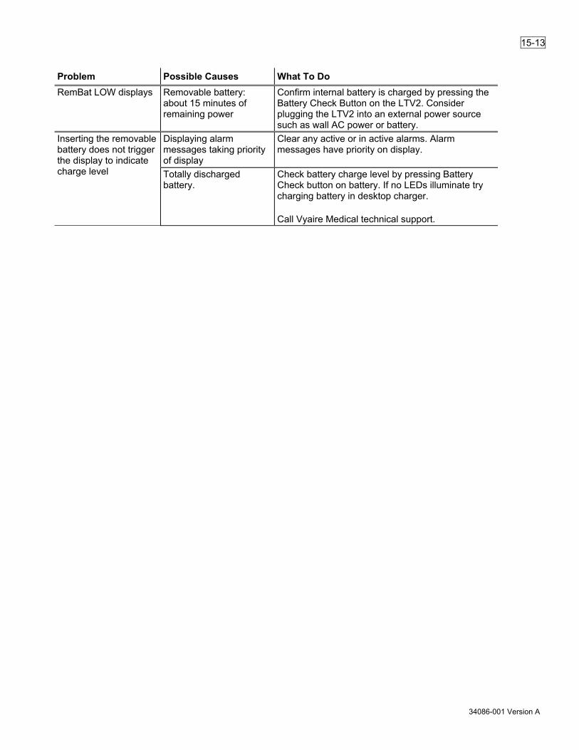
15-13
34086-001 Version A
Problem Possible Causes What To Do RemBat LOW displays
Removable battery: about 15 minutes of remaining power
Confirm internal battery is charged by pressing the Battery Check Button on the LTV2. Consider plugging the LTV2 into an external power source such as wall AC power or battery.
Inserting the removable battery does not trigger the display to indicate charge level
Displaying alarm messages taking priority of display
Clear any active or in active alarms. Alarm messages have priority on display.
Totally discharged battery.
Check battery charge level by pressing Battery Check button on battery. If no LEDs illuminate try charging battery in desktop charger. Call Vyaire Medical technical support.

15-14
34086-001 Version A
Alarms Many alarms such as HI PRESSURE or LOW O2 PRES can occur during normal operation. Information on addressing alarms is covered in “Chapter 9–Ventilator Alarms.” Single occurrences of some alarms, such as HW FAULT or RESET may be caused by electrostatic discharge. If these alarms reoccur, and for other alarms that do not usually occur during normal operation, follow the instructions in this section or immediately contact Vyaire Medical.
Symptoms Possible Causes What to Do HI PRESSURE occurred but alarm did not sound.
Alarm silence was already active (Alarm Silence LED is red).
The ventilator alarms can be silenced for 60 seconds by pressing the Alarm Silence button. If the alarm is already silenced (Alarm Silence LED is green), it will not sound again until the silence period expires.
High pressure alarm delay is on - HP DELAY is set to DELAY 1 BRTH or DELAY 2 BRTH.
When a high pressure condition is detected, the HI PRESSURE message displays and the High Pres. Limit control flashes. If the HP DELAY option is set to NO DELAY, the audible alarm sounds immediately. When the HP DELAY option is set to DELAY 1 BRTH or DELAY 2 BRTH, the audible is not sounded until the second or third consecutive breath with a high pressure condition. For an explanation of HP DELAY, see page 10-3.
Alarm automatically silenced after 3 seconds because condition cleared.
When an alarm occurs, the audible alarms sound for a minimum of 3 seconds or for as long as the condition exists. Some alarms, such as HI PRESSURE may clear almost immediately and the alarm will sound for only 3 seconds.
Alarm doesn’t sound. Internal problem with the ventilator.
Immediately contact a certified Vyaire Medical service technician.
Ventilator won’t exhale, repeated HI PRESSURE alarms, turbine stops and pressure drops, then auto-triggers a breath up to HI PRESSURE again.
Exhalation Drive line occluded or pinched.
Check the exhalation drive line to be sure it is correctly attached and secured at both the ventilator and exhalation valve ends. Verify the line is not occluded or pinched.
Repeated CHK CIRCUIT alarms.
Exhalation valve leaking during inspiration
Verify the exhalation valve is not leaking during inspiration. If it is leaking, replace the breathing circuit.
Patient circuit disconnected at patient, ventilator or circuit component.
Check the circuit and exhalation valve to verify the circuit is securely connected and the valve is intact.
Sense lines disconnected, miss-threaded, or disconnected at the ventilator.
Check high and low pressure sense lines to be sure they are correctly attached and securely seated at both the ventilator and wye ends.
Sense line or elbow at patient wye loose or leaking.
Check the Luer fitting connections for leaks. Check the elbow connectors at the wye to be sure they have not loosened or been broken loose.

15-15
34086-001 Version A
Symptoms Possible Causes What to Do Sense lines are occluded. Verify lines are not occluded or pinched. High or low sense ports in the wye are occluded.
Check the exhalation drive line at both the ventilator and exhalation valve ends. Verify the line is securely seated and not leaking.
Exhalation drive line leaking or loose.
Check the exhalation drive line at both the ventilator and exhalation valve ends. Verify the line is securely seated and not leaking.
Internal problem with the ventilator.
Immediately contact a certified Vyaire Medical service technician.
Repeated XDCR FAULT alarms.
Internal problem with the ventilator.
Immediately contact a certified Vyaire Medical service technician.
HW FAULT alarm Electro static discharge (ESD).
Clear the alarm. Reduce static causing conditions in the operating environment.
Fan was bumped or temporarily stopped while cleaning fan filter.
Clear the alarm. No further action required if alarm does not reoccur.
Transient high current load in ventilator due to patient circuit occlusion.
Clear the alarm. Temporary high current conditions will clear when the occlusion is removed.
Internal problem with the ventilator.
If problem reoccurs, immediately contact a certified Vyaire Medical service technician.
RESET alarm occurs after ventilator is operated on internal battery until it is fully depleted.
Internal battery depleted. This is normal. Clear the alarm and charge the internal battery. For instructions on charging the internal battery, see “Caring for the Internal and Removable Batteries” on page 14-10.
RESET, CRC, STACK, POST, or RUNAWAY alarms
Electro static discharge (ESD).
Clear the alarm. Reduce static causing conditions in the operating environment.
Internal problem with the ventilator.
If problem reoccurs, immediately contact a certified Vyaire Medical service technician.
NO CAL DATA alarm. NO CAL displayed in place of monitored values.
Failed or missing calibration records.
Immediately contact a certified Vyaire Medical service technician.
DEFAULTS alarm. Event Log shows DEFAULTS.
DEFAULTS option was selected in extended features.
Clear the alarm. Review all ventilator settings and set them appropriately as directed for the patient.
Electro static discharge (ESD).
Some or all control settings were found to be invalid or out of range on power up and were restored to the default settings. Clear the alarm. Reduce static causing conditions in the operating environment.
Internal problem with the ventilator.
If problem reoccurs, immediately contact a certified Vyaire Medical service technician.
Repeated HI RESP RATE alarms.
Total Breath Rate exceeds the set HI RESP RATE alarm values.
Check HI RESP RATE alarm values. For instructions, see page 9-10.

15-16
34086-001 Version A
Symptoms Possible Causes What to Do Patient Circuit leak, causing auto-triggering.
Perform a Leak test and reseat or replace the leaking parts or connections. For instructions, see “Leak Test” on page 9-10.
Internal problem with the ventilator.
If problem reoccurs, immediately contact a certified Vyaire Medical service technician.
Repeated HI PEEP alarms.
Monitored PEEP exceeds the set HIGH PEEP alarm value.
Check HI PEEP alarm value. For instructions, see page 9-11.
Patient circuit and/or Exhalation valve occluded.
Disassemble, clean and reassemble the Patient Circuit and Exhalation Valve.
Internal problem with the ventilator.
If problem reoccurs, immediately contact a certified Vyaire Medical service technician.
Remote Alarm System does not work with the ventilator.
Defective or improper connections.
Check the Remote Alarm cable connection between the ventilator’s Nurse Call Port and the Remote Alarm System. For instructions, see page C-9.
Defective Remote Alarm cable.
Replace Remote Alarm cable. For instructions, see page C-9.
Defective Remote Alarm System.
Contact Remote Alarm System manufacturer or service personnel.
Internal problem with the ventilator.
Immediately contact a certified Vyaire Medical service technician.
Remote Alarm System (single tone system) generates a pulsating tone and manufacturer’s instructions indicate it should be a continuous tone.
Nurse Call option set to PULSE.
Set Nurse Call option to NORMAL. For instructions, see page 10-4.
Defective Remote Alarm System.
Contact Remote Alarm System manufacturer or service personnel.
Internal problem with the ventilator.
Immediately contact a certified Vyaire Medical service technician.
Remote Alarm System (dual tone system) only generates one continuous tone.
Nurse Call option set to NORMAL.
Set Nurse Call option to PULSE. For instructions, see page 10-4.
Defective Remote Alarm System.
Contact Remote Alarm System manufacturer or service personnel.
Internal problem with the ventilator.
Immediately contact a certified Vyaire Medical service technician.
Nurse Call System does not work with the ventilator.
Incorrect Nurse Call cable installed (Normally Open versus Normally Closed system/cable mismatch)
Establish whether the Nurse Call System is a Normally Open or Normally Closed system and verify the appropriate Nurse Call Cable (Normally Open or Normally Closed) is installed. For instructions, see page C-8.
Defective or improper connections.
Check the Nurse Call Cable connection between the ventilator’s Nurse Call Port and the Nurse Call System. For instructions, see page C-8.
Defective Nurse Call cable. Replace Nurse Call Cable. Defective Nurse Call System. Contact Nurse Call System manufacturer or
service personnel. Internal problem with the ventilator.
Immediately contact a certified Vyaire Medical service technician.

15-17
34086-001 Version A
Symptoms Possible Causes What to Do Nurse Call System generates a pulsating tone or light and manufacturer’s instructions indicate it should be a continuous tone or light.
Nurse Call option set to PULSE.
Set Nurse Call option to NORMAL. For instructions, see page 10-4.
Defective Nurse Call System. Contact Nurse Call System manufacturer or service personnel.
Internal problem with the ventilator.
Immediately contact a certified Vyaire Medical service technician.
Repeated HI SBT RATE alarms.
Total Breath Rate (f) exceeds the set HI SBT RATE alarm value.
Check HI SBT RATE alarm value. For instructions, see page 9-29.
Patient Circuit leak, causing auto-triggering.
Perform a Leak test and reseat or replace the leaking parts or connections. For instructions, see “Leak Test” on page 11-10.
Internal problem with the ventilator.
If problem reoccurs, immediately contact a certified Vyaire Medical service technician.
Repeated LO SBT RATE alarms.
Total Breath Rate (f) is less than the set LO SBT RATE alarm value.
Check LO SBT RATE alarm value. For instructions, see page 9-28.
Patient Circuit leak. Perform a Leak test and reseat or replace the leaking parts or connections. For instructions, see “Leak Test” on page 11-10.
Internal problem with the ventilator.
If problem reoccurs, immediately contact a certified Vyaire Medical service technician.
Repeated HI SBT f/Vt alarms.
Total Breath Rate (f) exceeds the set HI SBT f/Vt alarm value.
Check HI SBT f/Vt alarm value. for instructions, see page 9-30.
Patient Circuit leak. Perform a Leak test and reseat or replace the leaking parts or connections. For instructions, see “Leak Test” on page 11-10.
Internal problem with the ventilator.
If problem reoccurs, immediately contact a certified Vyaire Medical service technician.
Repeated LO SBT f/Vt alarms.
Total Breath Rate (f) is less than the set LO SBT f/Vt alarm value.
Check LO SBT f/Vt alarm value. For instructions, see page 9-29.
Patient Circuit leak. Perform a Leak test and reseat or replace the leaking parts or connections. For instructions, see “Leak Test” on page 11-10.
Internal problem with the ventilator.
If problem reoccurs, immediately contact a certified Vyaire Medical service technician.
PIP >99 cmH2O displays Peak Inspiratory pressure over range
Check patient and patient circuit for blockage or occlusion and confirm settings are correct. If problem reoccurs, immediately contact a certified Vyaire Medical service technician.
PIP < RANGE displays Peak Inspiratory pressure under range
Check patient and patient circuit for blockage or occlusion and confirm settings are correct. If problem reoccurs, immediately contact a certified Vyaire Medical service technician.
PIP NO CAL displays Invalid Airway Pressure calibration
If problem reoccurs, immediately contact a certified Vyaire Medical service technician.

15-18
34086-001 Version A
Symptoms Possible Causes What to Do MAP >99 cmH2O displays
Mean airway pressure over range condition.
Check patient and patient circuit for blockage or occlusion and confirm settings are correct. If problem reoccurs, immediately contact a certified Vyaire Medical service technician.
MAP < RANGE displays Mean airway pressure under range condition
Check patient and patient circuit for blockage or occlusion and confirm settings are correct. If problem reoccurs, immediately contact a certified Vyaire Medical service technician.
MAP NO CAL displays Invalid Airway Pressure calibration
If problem reoccurs, immediately contact a certified Vyaire Medical service technician.
PEEP >99 cmH2O displays
PEEP over range condition. Check patient and patient circuit for blockage or occlusion and confirm settings are correct. If problem reoccurs, immediately contact a certified Vyaire Medical service technician.
PEEP < RANGE displays
PEEP under range Check patient and patient circuit for blockage or occlusion and confirm settings are correct. If problem reoccurs, immediately contact a certified Vyaire Medical service technician.
PEEP NO CAL displays Invalid Airway Pressure calibration
If problem reoccurs, immediately contact a certified Vyaire Medical service technician.
RATE > MAX Total breath rate over range Check patient and patient circuit for blockage or occlusion and confirm settings are correct. If problem reoccurs, immediately contact a certified Vyaire Medical service technician.
Rate -- bpm displays Total breath rate under range Check patient and patient circuit for blockage or occlusion and confirm settings are correct. If problem reoccurs, immediately contact a certified Vyaire Medical service technician.
VE >99.9 L displays Total Minute Volume over range condition
Check patient and patient circuit. If problem reoccurs, immediately contact a certified Vyaire Medical service technician.
VE < RANGE displays Total Minute Volume under range condition
Check patient and patient circuit. If problem reoccurs, immediately contact a certified Vyaire Medical service technician.
VE NO CAL displays Invalid Flow Sensor calibration
If problem reoccurs, immediately contact a certified Vyaire Medical service technician.
Vte > 4000 ml displays Exhaled Tidal Volume over range condition
Check patient and patient circuit. If problem reoccurs, immediately contact a certified Vyaire Medical service technician.
Vte < 0 ml displays Exhaled Tidal Volume under range condition
Check patient and patient circuit. If problem reoccurs, immediately contact a certified Vyaire Medical service technician.
Vte NO CAL displays Invalid Flow Sensor calibration
If problem reoccurs, immediately contact a certified Vyaire Medical service technician.
I:E > 99:1 displays I:E ratio over range condition occurs
Check patient and patient circuit. If problem reoccurs, immediately contact a certified Vyaire Medical service technician.

15-19
34086-001 Version A
Symptoms Possible Causes What to Do I:E < 1:99 displays I:E ratio under range condition Check patient and patient circuit.
If problem reoccurs, immediately contact a certified Vyaire Medical service technician.
I:Ecalc > 1:99 I:Ecalc > 1:-- displays
I:E under range condition occurs (when breath rate setting is disabled)
Check patient and patient circuit. If problem reoccurs, immediately contact a certified Vyaire Medical service technician.

15-20
34086-001 Version A
Checkout Test Failures Symptoms Possible Causes What to Do Alarm Test Audible alarm level excessive.
Alarm volume set too high. Set the alarm volume under the Extended Features Menu. For an explanation of the ALARM VOL feature, see page 10-3.
Alarm Test Audible alarm too soft.
Alarm volume set too low. Set the alarm volume under the Extended Features Menu. For an explanation of the ALARM VOL feature, see page 10-3.
Alarm sounder blocked. Check the alarm sounder opening in the right side of the ventilator to verify the opening is not blocked.
Internal problem with the ventilator.
Immediately contact a certified Vyaire Medical service technician.
Alarm Test Alarm does not sound.
Alarm sounder blocked. Check the alarm sounder opening in the right side of the ventilator to verify the opening is not blocked.
Internal problem with the ventilator.
Immediately contact a certified Vyaire Medical service technician.
Backup Alarm Test Backup Alarm does not sound.
Audible alarm did not sound long enough before test was terminated.
Repeat the Alarm Test and allow audible alarm to sound for at least 2 seconds before pressing the Menu/Select button. For instructions, see page 11-4.
Internal problem with the ventilator.
Immediately contact a certified Vyaire Medical service technician.
Display Test A display or LED fails to light.
Internal problem with the ventilator.
Immediately contact a certified Vyaire Medical service technician.
Control Test Correct message is not displayed when Scroll knob is turned, or incorrect message displays.
Internal problem with the ventilator.
Immediately contact a certified Vyaire Medical service technician.
Control Test Volume Pressure Mode button, Pressure Control button, FiO2 (Flush) button (LTV2 2200 only), or Low Pressure O2 Source (LTV2 2200 only) button do not display message when pressed.
Wrong model selected in maintenance mode.
Immediately contact a certified Vyaire Medical service technician.
Leak Test Leak test fails
Circuit connections or accessories are leaking. Wye is not properly capped.
Reseat or replace the leaking circuit parts, accessories or connections. Verify the wye is securely capped.
Internal problem with the ventilator.
Immediately contact a certified Vyaire Medical service technician.
Leak Test Leak test fails with LEAK --- FAIL message.
Internal problem with the turbine.
Immediately contact a certified Vyaire Medical service technician.

15-21
34086-001 Version A
Symptoms Possible Causes What to Do Vent Inop Alarm Test Audible alarm too soft.
Alarm sounder blocked. Check the alarm sounder opening in the right side of the ventilator to verify the opening is not blocked.
Internal problem with the ventilator.
Immediately contact a certified Vyaire Medical service technician.
Vent Inop Alarm Test Alarm does not sound.
Alarm sounder blocked. Check the alarm sounder opening in the right side of the ventilator to verify the opening is not blocked.
Internal problem with the ventilator.
Immediately contact a certified Vyaire Medical service technician.
Vent Inop Alarm Test The Red Alarm Status LED is not illuminated.
Internal problem with the ventilator.
Immediately contact a certified Vyaire Medical service technician.
Vent Inop Alarm Test
Audible alarm did not sound long enough before test was terminated.
Repeat the Vent Inop Alarm Test and allow audible alarm to sound for at least 15 seconds before pressing the Alarm Reset button. For instructions, see “Vent Inop Alarm Test” on page 11-11.
Internal problem with the ventilator.
Immediately contact a certified Vyaire Medical service technician.
Test Lung Operations Symptoms Possible Causes What to Do Delivered pressure higher than set pressure on test lung.
Pressure> 40 cmH2O used on small test lung (Vyaire Medical or Siemens 190.)
The compliance characteristics of some small test lungs (Vyaire Medical or Siemens 190) cause incorrect readings when high pressures are used. For these lungs, use pressures under 40 cmH2O or change to a larger lung.
Monitored volumes very high on test lung.
Test lung with small aperture connected directly to wye.
Some test lungs have a narrow opening or a restrictor, which may cause jetting and cause the flow differential to be read incorrectly. To reduce the jetting effect, add a short extension between the test lung and the wye.
Very small ET tube connected directly to wye.
A very small ET tube connected directly to the wye may cause jetting and cause the flow differential to be read incorrectly. To reduce the jetting effect, add a short larger bore extension between the ET tube and the wye.

15-22
34086-001 Version A
Intentionally left blank.

A-1
34086-001 Version A
Ventilator Specifications
Modes and Breath Types Breath Types: Volume, Pressure, Pressure Support, Sigh, Spontaneous
Modes: Control, Assist/Control, SIMV, CPAP, NPPV, Apnea Backup
Variable Controls Control Range Tolerance Backup Pressure Trigger –3 cmH2O (–2.9 hPa) +1, –2 cmH2O (+0.98, –1.96 hPa) Breath Rate “--”, 1 to 80 bpm ±11% of the breath period for breath rates <9
±1 bpm for breath rates ≥9 bpm Date Format mm/dd/yyyy, dd/mm/yyyy,
yyyy/mm/dd not applicable
Display Select Toggles between manual or automatic display scrolling and changes monitor displayed.
not applicable
Inspiratory/Expiratory Hold One press toggles monitor window display between normal display, INSP HOLD and EXP HOLD.
not applicable
While INSP HOLD displays, a press and hold initiates an Inspiratory Hold.
not applicable
While EXP HOLD displays, a press and hold initiates an Expiratory Hold.
not applicable
Inspiratory Time 0.3 to 9.9 seconds ±0.1 seconds Leak Compensation On, Off not applicable Language English (English)
not applicable
FiO2 (LTV2 2200 only)
0.21 to 1.0 O2 % mean: 21 to 50%: ±3% 51 to 94%: ±5% 95 to 100% +5 to –10% Steady-state only For artificial airways ≤3.0 mm ID 21 to 100%: +5 to –10% Time to change (21 to 90%)
Vt 50 to 300 ml <180 seconds Vt 300 to 2000 ml <90 seconds
(Flush) (LTV2 2200 only)
O2: 100% +5 to –10%
Time: 1, 2, or 3 minutes ±1 second Patient Query On, Off not applicable PEEP/CPAP 0 to 20 cmH2O (0 to 19.6 hPa) ±(1 cmH2O (0.98 hPa) +5% of setting) PIP LED Display On, Off not applicable

A-2
34086-001 Version A
Control Range Tolerance Pressure Control 4 to 98 cmH2O
(3.9 to 96.1 hPa) ±(1.7 cmH2O (1.67 hPa) +7.5% of setting)
Pressure Control Flow Termination
On, Off not applicable
Pressure Support Off (“--”), 1 to 60 cmH2O (0.98 to 58.8 hPa)
±(1.7 cmH2O (1.67 hPa) +7.5% of setting)
Set Date 1/1/1998 to 12/31/2097 not applicable Set Time 00:00:00 to 23:59:59 not applicable Sensitivity 1 to 9 lpm, “-” –1 lpm to +2 lpm Tidal Volume 50 to 2000 ml For artificial airways greater than
3.0 mm ID: ±(5 ml +10% of setting) for temperatures from 20 to 30°C only, standard atmospheric pressure. Error type: Bias and linearity All volume deliveries are compensated for a compliance of 0.8 ml/cmH2O at the patient connection. For ventilator operation above 6,500 feet sea level or barometric pressures less than 605 millimeters of mercury absolute (mmHg), see page 6-4 for altitude and barometric pressure compensation information.
Tidal Volume 50 ml For artificial airways 3.0 mm ID or smaller: ±(10 ml +15% of setting) for temperatures from 20 to 30°C only, standard atmospheric pressure. Error type: Bias and linearity All volume deliveries are compensated for a compliance of 0.8 ml/cmH2O at the patient connection. For ventilator operation above 6,500 feet sea level or barometric pressures less than 605 millimeters of mercury absolute (mmHg), see page 6-4 for altitude and barometric pressure compensation information.
Variable Flow Termination 10 to 70% ±15% or 2 lpm, whichever is greater Variable Rise Time 1 to 9 not applicable Variable Time Termination 0.3 to 3.0 seconds ±0.1 second
Bias Flow Off or 5 to 15 lpm (during exhalation)
+20/-0% or +2/-0 lpm BTPS
SBT Start On - Off not applicable SBT PS 0 to 30 cmH2O (0 to 29.4 hPa) ±(1.7 cmH2O (1.6 hPa) +7.5% of setting) SBT PEEP 0 to 20 cmH2O (0 to 19.6 hPa) ±(1 cmH2O (0.98 hPa) +5% of setting)

A-3
34086-001 Version A
Control Range Tolerance SBT FiO2
(LTV2 2200 only) 21–100% O2 % mean: 21 to 50%: ±3%
51 to 94%: ±5% 95 to 100%: +5 to –10% Steady-state only For artificial airways ≤ 3.0 mm ID 21 to 100%: +5 to –10% Time to change (21 to 90%)
Vt 50 to 300 ml <180 seconds Vt 300 to 2000 ml <90 seconds
SBT Minutes 15 to120 minutes not applicable Display f/Vt On - Off not applicable
Button Controls Button Function Control Lock Locks front panel controls, can be set to Easy or Hard unlocking. It also
cancels some functions. Manual Breath Generates a machine breath Power/Standby Puts ventilator in On or Standby state Low Pressure O2 Source (LTV2 2200 only)
Selects Low Pressure O2 Source
Alarm Reset Resets alarm indicators Alarm Silence Silences most alarms for 60 seconds Insp/Exp Hold Performs an inspiratory or expiratory hold maneuver Battery Check Initiates the display of the internal and removable (if installed) batteries
charge level.
Mechanical Controls Control Range Tolerance Over Pressure Relief * ≤125 cmH2O (122.6 hPa) not applicable Sub-Ambient Relief * Pressure Drop: ≤ 5 cmH2O (4.9 hPa at 50 lpm) not applicable
*Not user settable
Alarms
Variable Alarms Control Range Tolerance Apnea Interval (APNEA xxx bpm)
10 to 60 seconds not applicable
High Breath Rate (HI RESP RATE)
Off, 5 to 80 bpm not applicable Time: 0 to 60 seconds not applicable
High PEEP (HI PEEP)
3 to 20 cmH2O (2.94 to 19.6 hPa) above set PEEP not applicable
Low PEEP (LOW PEEP)
-3 to 20 cmH2O (-2.94 to 19.6 hPa) below set PEEP not applicable

A-4
34086-001 Version A
Control Range Tolerance High Pressure Limit (HI PRESSURE)
5 to 99 cmH2O (4.9 to 97.1 hPa) not applicable
HP Delay No delay, 1 breath, 2 breaths Only audible portion of alarm notification is delayed.
Low Minute Volume (LOW MIN VOL)
Off, 0.1 to 99 liters not applicable
Low Peak Pressure (LO PRESSURE)
Off , 1 to 60 cmH2O (0.98 to 58.8 hPa) not applicable
Low Peak Pressure All Breaths, VC/PC Only Select breath types Low Pressure alarm applies to.
High SBT f/Vt (HI SBT f/Vt)
Off, 70 to 900 not applicable
Low SBT f/Vt (LO SBT f/Vt)
Off, 5 to 90 not applicable
High SBT Rate (HI SBT RATE)
Off, 15 to 80 bpm not applicable
Low SBT Rate (LO SBT RATE)
Off, 1 to 40 bpm not applicable

A-5
34086-001 Version A
Fixed Alarms Control Range Tolerance Default Settings (DEFAULTS SET)
EEPROM problem detected not applicable
Check Circuit (CHK CIRCUIT) (Low Pressure Sense Line Disconnect)
Positive (exhaled) airway flow during first 200 ms of inspiration and exhaled tidal volume (Vte) of previous breath is more than 4000 ml
not applicable
Check Circuit (CHK CIRCUIT) (High Pressure Sense Line Disconnect)
Airway pressure changes by <0.1 cmH2O during 200 ms after inspiratory start OR After initial 200 ms of inspiration airway pressure drops below 0.125 cmH2O and can’t be raised more than 0.5 cmH2O in next 500 ms
±0.5 cmH2O not applicable
External Power Lost (EXT PWR LOST)
When external power falls below a functional level.
Hardware Fault (HW FAULT)
Hardware problem detected not applicable
Internal Battery Empty (IntBat EMPTY)
About 7 minutes of power remaining ±2 minutes
Internal Battery Low (IntBat LOW)
About 15 minutes of power remaining ±5 minutes
Removable Battery Empty (RemBat EMPTY)
About 7 minutes of power remaining ±2 minutes
Removable Battery Low (RemBat LOW)
About 15 minutes of power remaining ±5 minutes
Internal Battery Temp Critical (IntBat TEMP )
Internal battery upper temperature limit exceeded
not applicable
Internal Battery Temp High (IntBatTempHi)
Internal battery is approaching the upper temperature limit
not applicable
Internal Battery Temp Low (IntBatTempLo)
Internal battery is approaching the lower temperature limit
not applicable
Internal Battery Fault (IntBat Fault)
not applicable not applicable
Removable Battery Temp Critical (RemBatTemp )
Removable battery upper temperature limit exceeded
not applicable
Removable Battery Temp High (RemBatTempHi)
Removable battery is approaching the upper temperature limit
not applicable
Removable Battery Temp Low (RemBatTempLo)
Removable battery is approaching the lower temperature limit
not applicable
Removable Battery Fault (RemBat Fault)
not applicable not applicable
Removable Battery Ejected (BATT EJECTED)
not applicable not applicable
High O2 Pressure (LTV2 2200 only)
High pressure source: > 85 psig (5.86 bar) Low pressure source: > 10 psig (0.69 bar)
±2 psig (0.14 bar) ±1 psig (0.07 bar)
Low O2 Pressure (LTV2 2200 only)
<35 psig (2.41 bar) ±2 psig (0.14 bar)

A-6
34086-001 Version A
Control Range Tolerance Reset (RESET) (RESET 1)
Processor problem detected not applicable
Transducer Fault (XDCR FAULT)
Autozero value outside specifications not applicable
Spontaneous Breathing Trial termination (SBT OFF)
End of an SBT period not applicable
Ventilator Inoperative (INOP)
not applicable not applicable
Alarm Delay The delay period from the time the alarm is condition occurs until alarm annunciation is imperceptible.
Alarm Sound Level Alarm Alarm Priority Tolerance Primary Alarm Volume With Volume Setting 5 (Max) (Measured per 60601-1-8, Section 6.3.3.2 c)
High Priority Alarm: 80 dBA Medium Priority Alarm: 80 dBA Low Priority Alarm: 80 dBA
±5 dBA ±5 dBA ±5 dBA
Primary Alarm Volume With Volume Setting 1 (Min) (Measured per 60601-1-8, Section 6.3.3.2 c)
High Priority Alarm: 63 dBA Medium Priority Alarm: 63 dBA Low Priority Alarm: 63 dBA
±5 dBA ±5 dBA ±5 dBA
Backup Alarm Volume (Measured per ISO 3744, Annex F, Position 4 at 1 meter)
Alarm > 65 dBA not applicable
Circuit Limb Occlusion Alarm The ventilator activates the Check Circuit alarm within five seconds or two breath cycles (whichever is greater) if the breathing tube becomes occluded such that one or more of the following conditions occur:
• Increase in expiratory circuit resistance such that the airway pressure fails to drop below the greater of set PEEP plus 5 cmH2O or 80% of the difference between end-inspiratory pressure and set PEEP for one second.
• Increase in expiratory circuit resistance such that the exhaled tidal volume is less than 7 ml and airway pressure failed to drop below set PEEP plus 5 cmH2O and for one second.
• Increase in expiratory circuit resistance such that the exhaled tidal volume is less than 7 ml and airway pressure failed to drop below set PEEP plus 5 cmH2O by the start of the next inspiratory phase.

A-7
34086-001 Version A
Circuit Disconnect Alarm (Disconnected or occluded circuit limbs) The ventilator activates the Check Circuit alarm within five seconds or two breath cycles (whichever is greater) if there is a:
• Continuous loss of pressure, or: Airway pressure < baseline loss threshold (value derived from PEEP setting) for at least 8 seconds at the end of exhalation phase
• Repeated loss of pressure over multiple breaths, or: Airway pressure < baseline loss threshold (value derived from PEEP setting) for 200ms at end of the inspiratory phase and 200ms at the end of the exhalation phase for 4 consecutive breaths
• Repeated loss of pressure and monitored exhaled volume over multiple breaths, or: Airway pressure < baseline loss threshold (value derived from PEEP setting) for 200 ms at end of the exhalation phase and Vte < 5% delivered volume for 4 consecutive breaths
• Repeated presence of excessive compliance over multiple breaths, or: Estimated total patient compliance > 1000 ml/cmH2O for 4 consecutive breaths
• High volume loss, or: Volume lost (delivered - measured) > 75% volume delivered
• Continuous volume loss: Volume lost (delivered - measured) > 50% volume delivered for 2 consecutive breaths
Circuit Disconnect Alarm (Disconnected or occluded sense lines) The ventilator will activate Check Circuit alarm within five seconds or two breath cycles (whichever is greater) if there is a:
• High inspiratory flow during inspiration: Flow at wye > delivered flow +20 lpm and flow at wye >130% delivered flow for at least 75% of the inspiratory time period.
• High expiratory flow during inspiration: Flow at wye < –40 lpm for at least 75% of the inspiratory time period.
• High inspiratory flow during expiratory phase: Flow at the wye > delivered flow +20 lpm for at least 50% of the expiratory time period plus 2.5 seconds.
• High expiratory flow during expiratory phase: Flow at wye < –40 lpm for at least 50% of the expiratory time period plus 2.5 seconds.

A-8
34086-001 Version A
High PEEP Alarm
• High PEEP Alarm conditions are evaluated every breath at the end of exhalation. An exception for the PEEP evaluation is in cases where set PEEP has been changed, the evaluations are suspended for 3 breaths.
• The High PEEP Alarm is activated if the High PEEP Alarm is enabled and the measured PEEP is greater than Set PEEP + High PEEP Alarm setting.
• During an active High PEEP Alarm condition, the active alarm state will be removed if a successive PEEP measurement is less than or equal to the Set PEEP + High PEEP Alarm limit.
High Pressure Alarm
• The circuit airway pressure is measure every 2 ms and is used for the evaluation of the High Pressure Alarm conditions. The ventilator settings that are used to evaluate conditions are High Pressure Alarm Limit and HP Delay (none, 1, or 2 breaths). The High Pressure Alarm is activated when measured pressure is greater than the High Pressure Alarm Limit. The audible portion of the alarm may be delayed by the HP Delay setting (the number of consecutive breaths with high pressure conditions before sounding). The visual portion of the alarm will not be delayed. If the High Pressure Alarm Limit is exceeded, the ventilator will immediately cycle the ventilator to the exhalation phase to reduce the pressure in the circuit. The High Pressure Alarm condition will not be cleared until one complete breath has been completed with the measured pressures all at or below the High Pressure Alarm Limit.
• The ventilator will track the duration of the High Pressure Alarm condition to determine if additional measures are needed to reduce the pressure. If no reduction occurs, the ventilator will sound the alarm regardless of the HP Delay setting and shut down the turbine to allow the high pressure to evacuate backwards through the system. For example, this condition could happen in the case the exhalation valve has been blocked in the closed position by a pinched exhalation line.
If the ventilator is recovering from a turbine stopped condition on the previous breath and the current breath has exceeded the High Pressure Alarm Limit again, the ventilator ignores the HP Delay setting for the audible alarm sounding immediately and will cycle to exhalation and shut down the turbine immediately.

A-9
34086-001 Version A
Monitors Monitor Range Tolerance Calculated Peak Flow 5 to 100 lpm +4/-0 lpm BTPS of commanded peak
flow or +20/-0% of calculated, whichever is greater
Exhaled Tidal Volume 50 to 4000 ml ±(4.0 ml +15% of the measure expired volume) for artificial airways > 3.0 mm ID.
Exhaled Tidal Volume ≤ 50 ml ±(20.0 ml of the measure expired volume) for artificial airways ≤3.0 mm ID.
I:E Ratio, Measured 99:1 and 1:99 Based on the measured inspiratory / exhalation times
Accuracy for times are ±50 ms or 5%, whichever is greater
I:E Ratio, Calculated 1:99 to 4.0:1 based on set breath rate and inspiratory time
not applicable
Mean Airway Pressure 0 to 99 cmH2O (0 to 97.1 hPa) ±(2 cmH2O (1.96 hPa) + 4% of measured pressure)
O2 Cylinder Duration (LTV2 2200 only)
0 to 99 hours and 59 minutes not applicable
Peak Inspiratory Pressure (text)
0 to 99 cmH2O (0 to 97.1 hPa) ±(2 cmH2O (1.96 hPa) + 4% of measured pressure)
Airway Pressure (bar graph)
−10 to 100 cmH2O (–9.81 to 98.06 hPa)
±(2 cmH2O (1.96 hPa) + 4% of measured pressure)
PEEP 0 to 99 cmH2O (0 to 97.1 hPa) ±(2 cmH2O (1.96 hPa) + 4% of measured pressure)
Total Breath Rate 0 to 98 breaths-per-minute ±1 bpm or within 5% of the breath period, whichever is greater
Total Minute Volume 0 to 99.9 liters ±((4.0 ml X total breath rate) + 15% of measured total minute volume)
SBT Minutes Remaining
1 to 120 minutes ±1 minute
f/Vt and f
0 to 900 0 to 96 bpm
not applicable ±1 bpm or within 5% of breath period, whichever is greater
All references to compressible flow and compressible volume in the patient pneumatic pathway are BTPS unless stated otherwise. Local ambient pressure assumed by the ventilator is 101.325 kPa.
Measurement Uncertainty
Measurement Uncertainty Volume 0.408% of reading Flow 0.408% of reading Pressure 0.204% of reading Gas Temperature 0.204°C Oxygen Concentration 0.204% Ambient Pressure 0.408% Relative Humidity 2.858%

A-10
34086-001 Version A
Smoothing and Filtering Techniques The LTV2 ventilator uses multiple pressure transducers to measure system pressures. Raw values are processed by software using various types of low pass filters to smooth the signals used for control and display purposes.
Displays
Display Range Tolerance Airway Pressure –10 to 100 cmH2O
(–9.81 to 98.1 hPa) ±(2 cmH2O (1.96 hPa) + 4% of measured pressure)
Display Window 12 characters not applicable Patient Effort Green LED not applicable Charge Status Green LED not applicable Power Source Green LED not applicable
Usage Meter
Range Tolerance Usage Meter 1 to 139,000 hrs. not applicable
Packaging and Materials
Size 3.50” x 10.75” x 14” (8.9 cm x 27.3 cm x 35.6) Weight 11.5 lbs. (5.2 kg)
Note: size and weight include protective boots. Latex The ventilator and its accessories do not contain natural rubber latex.
Storage and Operating Conditions
Storage
Specification Tolerance Temperature -20 to +60°C not applicable Humidity 10 to 93% Relative, non-condensing not applicable
Operating
Specification Tolerance Temperature +5 to +40°C not applicable Humidity 15 to 95% Relative, non-condensing not applicable
Orientation The ventilator functions within its performance specifications when operated in any orientation.

A-11
34086-001 Version A
Oxygen Inlet
Inlet Range Tolerance DISS or NIST Connector Inlet Pressure Range (LTV2 2200 only)
40 to 80 psig (2.76 to 5.52 bar)
not applicable
Tapered Tubing Connector Inlet Pressure Range
0 to 10 psig (0 to 0.69 bar)
not applicable
The ten second average oxygen inlet flow at a pressure of 280 kPa (40.6 psi) in normal operation with the most adverse operating settings is not to be greater than 60 lpm.
The three second average oxygen inlet flow at a pressure of 280 kPa (40.6 psi) in normal operation with the most adverse operating settings is not to be greater than 200 lpm.
Shock and Vibration The ventilator is designed to withstand shock and vibration in accordance with relevant requirements set forth in the following standards:
IEC 60068-2-27 Shock IEC 60068-2-6 Vibration IEC 60068-2-64 Vibration IEC 60068-2-31 Rough handling shock
Spillage The ventilator resists fluid spillage when tested in accordance with the spillage requirements specified in IEC 60601-1.
Ingress Protection rating: IP22 (Ventilator enclosure protects against ingress of objects > 12.5 mm and dripping water with the ventilator tilted to 15°).
External Surface Temperature
All plastic, molded materials, or thermally conductive equivalent coated material (including the painted weldment) shall not exceed 71°C, and all exposed metal surfaces shall not exceed 56°C.
Shipping Requirements The ventilator, packed in its shipping container, conforms to the International Safe Transit Association requirements for packaged products weighing less than 100 pounds.
Sound Levels (with no alarms active)
Sound pressure level Not to exceed 55 dBA at one meter per ISO 80601-2-12:2011 Sound power level Not to exceed 63 dBA at one meter per ISO 80601-2-12:2011
Communications
Port Connector Specification Communications RJ11-6 Protocol Options: Data, Monitor Nurse Call / Remote Alarm
RJ9-4 Closed contact resistance: ≤ 1 ohm
VOXP RJ45-8 Vyaire Medical

A-12
34086-001 Version A
Power
External Power Approved Vyaire AC adapters: Class I (part number 25312-001)
Feature Range Tolerance / Indicators Input Voltage 11 to 29 Vdc ±2% AC Adapter Input: 100 to 240 Vac,
50 to 60 Hz Output: 15 Vdc
±5%
Power Rating for External Supplies
150 Watts Nominal 100 Watts Minimum (may limit battery charging)
Leakage Current Total leakage current to Earth ground for the ventilator with only approved accessories attached is not to exceed 5 milliamps during normal operation, according to IEC 60601-1, Edition 3.1. Total leakage current to Earth ground for the ventilator is not to exceed 10 milliamps when any single fault condition is present, according to IEC 60601-1, Edition 3.1.
Dielectric Strength The ventilator is able to survive 1500 volts applied from either phase of the AC power inlet to Earth ground for a period of one minute, according to IEC 60601-1.
Internal and Removable Battery Cell Construction: Lithium-ion
Electrical Rating: 10.8 VDC
8.7 Ah
94.0 Wh
Battery Charge Time Condition Internal battery charge time
2.5 hours to ≥80% from fully discharged state.
When external power is present, and the temperature is between 10 and 40°C.
Removable battery charge time
2.5 hours to ≥80% from fully discharged state.
When external power is present, internal battery is at ≥80% charge and the temperature is between 10 and 40°C.
Desktop Removable Battery Charger P/N 22770-001 (English)
P/N 22770-201 (Icon/International)
Electrical Rating: 100-240 VAC
2.0 A
50/60Hz
175 VA Max
Protection Class I
Continuous service

A-13
34086-001 Version A
Battery Durations
Internal Battery Removable Battery
Approximate time from battery full to IntBat LOW alarm: 3 hours 15 minutes*
Approximate time from battery full to RemBat LOW alarm: 3 hours 45 minutes*
Approximate time between IntBat LOW alarm and IntBat EMPTY alarm: 10 (±5) minutes*
Approximate time between RemBat LOW alarm and RemBat EMPTY alarm: 10 (±5) minutes*
Approximate time from IntBat EMPTY alarm to ventilator shutdown and INOP alarm: 7 (±2) minutes*
Approximate time from RemBat EMPTY alarm and change over to internal battery: 7 (±2) minutes*
* At nominal load and battery temperature.
Nominal Load Settings
Mode Volume A/C
Breath Rate (bpm) 20
Tidal Volume 800
Inspiratory Time (seconds) 1.0
Sensitivity Off
PEEP 0
O2% 21%
Bias Flow 10 lpm
Lung Compliance (ml/cmH2O) C50
Lung Resistance R5
Display Off
Temperature 25°C
Breathing Circuit and Filters
Inlet Air Filtration The ventilator air filter is cleanable and replaceable by the operator.
Recommended Breathing System Filter Requirements Resistance: <2.0cmH2O at 60 slpm and <3.0cmH2O at 100 slpm
Filtration
• HEPA
• BFE and VFE > 99.999% at 48 slpm
Fittings: Connection 22 mm ISO female to 22 mm ISO male
Regulatory Compliance: ISO 23328-1:2003 and ISO 23328-2:2002

A-14
34086-001 Version A
Breathing Circuit Conformance ISO 5367 and ISO 8185 (for circuits with heated wires)
Inspiratory limb circuit resistance
Pediatric: 0.32 cmH2O to 1.48 cmH2O at 15 lpm Adult: 0.64 cmH2O to 3.94 cmH2O at 30 lpm
Expiratory limb circuit resistance
Pediatric: 0.18 cmH2O to 1.37 cmH2O at 15 lpm Adult: 0.53 cmH2O to 3.68 cmH2O at 30 lpm
Circuit compliance Pediatric: .0008 to .0019 L/cmH2O Adult: .0014 to .0046 L/cmH2O
Shelf life of single patient use breathing circuits: five (5) years from date of manufacture.
Internal Compliance of Ventilator Compliance <0.1 ml/cm
DOT Requirements Unregulated, meets the requirements of 49 CFR 173, 159 (d).
Equipment Classification
Classification The ventilator is rated as Class I equipment per IEC 60601-1 Type The ventilator is specified as Type BF equipment per IEC 60601-1 Applied Part Patient end of the breathing circuit (wye) connected to the patent interface.
Ventilator Service Life 10 years or 50,000 hours from date of manufacture

A-15
34086-001 Version A
EMC and RF Environments
RTCA/DO160G: 2010 EMC Tests
Test Test Condition Power Sources Test Description Test Method
Per Section
Emissions 120 VAC, 60Hz
2-prong AC Adapter; 3-prong AC Adapter; Internal Battery
Conductive RF 21.4 Category M
Radiated RF 21.5 Category M
The following tables are provided in compliance with 60601-1-2, and describe the tested EMC limitations of the LTV2 Ventilator used with the LTV2 AC Adapter.
Table 201 – IEC 60601-1-2:2007 Guidance and manufacturer’s declaration–electromagnetic emissions The LTV2 Ventilator is intended for use in the electromagnetic environment specified below. The customer or the user of the ventilator should ensure that it is used in such an environment. Emissions test Compliance Electromagnetic environment–guidance RF radiated emissions CISPR 11
Class B The LTV2 Ventilator uses RF energy only for its internal function. Therefore, its RF emissions are very low and are not likely to cause any interference in nearby electronic equipment.
RF conducted emissions CISPR 11
Class B The LTV2 Ventilator is suitable for use in all establishments, including domestic establishments and those directly connected to the public low-voltage power supply network that supplies buildings used for domestic purposes.
Harmonic emissions IEC 61000-3-2
Class A
Voltage fluctuations/ flicker emissions IEC 61000-3-3
Complies
Table 202 – IEC 60601-1-2:2007
Guidance and manufacturer’s declaration–electromagnetic immunity The LTV2 Ventilator is intended for use in the electromagnetic environment specified below. The customer or the user of the ventilator should ensure that it is used in such an environment. Immunity Test IEC 60601 test level Compliance Level Electromagnetic environment–
guidance Electrostatic discharge (ESD) IEC 61000-4-2
± 8 kV contact ± 15 kV air
± 8 kV contact ± 15 kV air
Floors should be wood, concrete or ceramic tile. If floors are covered with synthetic material, the relative humidity should be at least 30 %.
Electrical fast transient/burst IEC 61000-4-4
± 2 kV for power supply lines ± 1 kV for input/output lines
± 2 kV for power supply lines ± 1 kV for input/output lines
Mains power quality should be that of a typical commercial or hospital environment.
Surge IEC 61000-4-5
± 1 kV differential mode ± 2 kV common mode
± 1 kV differential mode ± 2 kV common mode
Mains power quality should be that of a typical commercial or hospital environment.
Voltage dips, short interruptions and voltage variations on power supply input lines IEC 61000-4-11
<5 % UT (>95 % dip in UT) for 0,5 cycle 40 % UT (60 % dip in UT) for 5 cycles 70 % UT (30 % dip in UT) for 25 cycles <5 % UT (>95 % dip in UT) for 5 sec
<5 % UT (>95 % dip in UT) for 0,5 cycle 40 % UT (60 % dip in UT) for 5 cycles 70 % UT (30 % dip in UT) for 25 cycles <5 % UT (>95 % dip in UT) for 5 sec
Mains power quality should be that of a typical commercial or hospital environment. If the user of the LTV2 Ventilator requires continued operation during power mains interruptions, We recommend that the ventilator be powered from an uninterruptible power supply or a battery.
Power frequency (50/60 Hz) Magnetic field IEC 61000-4-8
3 A/m
3 A/m
Power frequency magnetic fields should be at levels characteristic of a typical location in a commercial or hospital environment.
NOTE UT is the A.C. mains voltage before application of the test level.

A-16
34086-001 Version A
Table 203 – IEC 60601-1-2:2007 Guidance and manufacturer’s declaration–electromagnetic immunity The LTV2 Ventilator is intended for use in the electromagnetic environment specified below. The customer or the user of the ventilator should ensure that it is used in such an environment. Immunity Test IEC 60601 test level Compliance Level Electromagnetic environment–guidance Portable and mobile RF communications equipment
should be used no closer to any part of the LTV2 Ventilator, including cables, than the recommended separation distance calculated from the equation applicable to the frequency of the transmitter. Recommended separation distance
Conducted RF IEC 61000-4-6
3 Vrms 150 kHz to 80 MHz1 outside ISM bands
3V
𝑑𝑑 = 1.2√𝑃𝑃
Radiated RF IEC 61000-4-3
10 V/m 80 MHz to 2.5 GHz
10 V/m 𝑑𝑑 = 1.2√𝑃𝑃 80 MHz to 800 MHz
𝑑𝑑 = 2.3√𝑃𝑃 800 MHz to 2.5 GHz Where P is the maximum output power rating of the transmitter in watts (W) according to the transmitter manufacturer and d is the recommended separation distance in meters (m). Field strengths from fixed RF transmitters, as determined by an electromagnetic site survey2 should be less than the compliance level in each frequency range3. Interference may occur in the vicinity of equipment marked with the following symbol:
NOTE 1 At 80 MHz and 800 MHz, the higher frequency range applies. NOTE 2 These guidelines may not apply in all situations. Electromagnetic propagation is affected by absorption and reflection from
structures, objects and people.
1 The ISM (industrial, scientific and medical) bands between 150 kHz and 80 MHz are 6.765 MHz to 6.795 MHz; 13.553 MHz to 13.567 MHz; 26.957
MHz to 27.283 MHz; and 40.66 MHz to 40.70 MHz. 2 Field strengths from fixed transmitters, such as base stations for radio (cellular/cordless) telephones and land mobile radios, amateur radio, AM and
FM radio broadcast and TV broadcast cannot be predicted theoretically with accuracy. To assess the electromagnetic environment due to fixed RF transmitters, an electromagnetic site survey should be considered. If the measured field strength in the location in which the ventilator is used exceeds the applicable RF compliance level above, the ventilator should be observed to verify normal operation. If abnormal performance is observed, additional measures may be necessary, such as reorienting or relocating the ventilator.
3 Over the frequency range 150 kHz to 80 MHz, field strengths should be less than 3 V/m..

A-17
34086-001 Version A
Table 205 – IEC 60601-1-2:2007 Recommended separation distances between portable and mobile RF communications equipment and the LTV2 Ventilator. The LTV2 Ventilator is intended for use in an electromagnetic environment in which radiated RF disturbances are controlled. The customer or the user of the ventilator can help prevent electromagnetic interference by maintaining a minimum distance between portable and mobile RF communications equipment (transmitters) and the LTV2 Ventilator as recommended below, based on the maximum output power of the communications equipment.
Rated maximum output power of transmitter (W)
Separation distance according to frequency of transmitter (m) 150 kHz to 80 MHz outside ISM bands
150 kHz to 80 MHz in ISM bands 80 MHz to 800 MHz 800 MHz to 2,5 GHz
𝑑𝑑 = 1.2√𝑃𝑃 𝑑𝑑 = 1.2√𝑃𝑃 𝑑𝑑 = 1.2√𝑃𝑃 𝑑𝑑 = 2.3√𝑃𝑃 0.01 0.12 0.12 0.12 0.23 0.1 0.38 0.38 0.38 0.73 1 1.20 1.20 1.20 2.30
10 3.79 3.79 3.79 7.27 100 12.00 12.00 12.00 23.00
For transmitters rated at a maximum output power not listed above, the recommended separation distance d in meters (m) can be determined using the equation applicable to the frequency of the transmitter, where P is the maximum output power rating of the transmitter in watts (W) according to the transmitter manufacturer. NOTE 1 At 80 MHz and 800 MHz, the separation distance for the higher frequency range applies. NOTE 2 The ISM (industrial, scientific and medical) bands between 150 kHz and 80 MHz are 6.765 MHz to 6.795 MHz; 13.553 MHz
to 13.567 MHz; 26.957 MHz to 27.283 MHz; and 40.66 MHz to 40.70 MHz. NOTE 3 An additional factor of 10/3 is used in calculating the recommended separation distance for transmitters in the ISM
frequency bands between 150 kHz and 80 MHz and in the frequency range 80 MHz to 2.5 GHz to decrease the likelihood that mobile/portable communications equipment could cause interference if it is inadvertently brought into patient areas.
NOTE 4 These guidelines may not apply in all situations. Electromagnetic propagation is affected by absorption and reflection from structures, objects and people.

A-18
34086-001 Version A
Intentionally left blank.

B-1
34086-001 Version A
Set Up / Maintenance
Recommended Maintenance Schedule The LTV2 2200/2150 ventilator is designed to operate for extended periods with minimal routine maintenance. The following table describes recommended periodic maintenance. Refer to the service manual for a detailed description of preventative maintenance procedures.
Frequency Maintenance Required Before initial use • Charge the internal battery by plugging the ventilator into an AC power
source. • Setup the ventilator/accessories according to “Appendix C:–Installation
and Checkout.” • Check the ventilator for proper operation according to “Appendix C:–
Installation and Checkout.” While in storage, every six months
• Charge the internal battery by plugging the ventilator into an AC power source.
Daily • Check the air inlet filter, clean or replace if necessary. • Check the fan filter, clean if necessary.
Every year • Replace the air inlet filter. • Replace the O2 inlet filter (LTV2 2200 only). • Replace the fan filter.
Every two years* • Replace the main internal battery. • Replace the backup (alarm) single-cell battery. • Calibrate the transducers.
Every 30,000 hours or six years, whichever comes first*
• Replace the rotary switch assembly. • Replace the accumulator. • Replace the fan assembly. • Replace all silicone tubing. • Check the thermos-pads for compression and replace them if necessary. • Replace the oxygen blender (LTV2 2200 only). • Replace the power board. • Calibrate the transducers.
Every 45,000 hours or nine years, whichever comes first*
• Replace the flow valve. • Replace the turbine manifold assembly. • Replace the solenoid manifold. • Replace the solenoid mount assembly. • Replace the coin battery on the main printed circuit board assembly. • Replace the alarm speaker. • Replace the backup alarm sounder. • Calibrate the transducers.
*Must be performed by Vyaire Medical authorized service personnel only.

B-2
34086-001 Version A
Service Assistance For assistance in servicing the LTV2 2200/2150 ventilator, contact a certified Vyaire Medical service technician, or:
Vyaire Medical, Inc. 26125 North Riverwoods Blvd. Mettawa, IL 60045 USA vyaire.com
Customer and Clinical Support Product, Accessories, and Parts Ordering 1-833-327-3284 [email protected]

C-1
34086-001 Version A
Installation and Checkout
Installation and Setup
Unpacking the Ventilator – Instructions 1. Inspect the exterior of the ventilator transport container for evidence of damage during transit.
If present, notify the delivering service.
2. Take the ventilator and all accessories out of the transport container.
3. Confirm the presence of all items listed on the packing slip. Notify an authorized sales representative or Vyaire Medical of any discrepancies.
4. Examine all components for visible damage. If present, notify the delivering service.
5. Retain the transport container for potential ventilator service or maintenance returns.
Patient Breathing Circuit – Connection Instructions 1. Choose a ventilator circuit and accessories that are appropriate for the size of the patient.
2. Connect a bacteria filter to the 22 mm outlet port on the right side of the ventilator using the 22 mm outlet port adapter.
3. Connect the main breathing tube of the breathing circuit to the bacteria filter.
4. Place the flex-tube adaptor in the patient port of the wye.
5. Connect the two exhalation flow transducer sense lines to the upper two fittings on the right side of the ventilator. These are non-interchangeable Luer fittings. To reduce the chance of the tubing becoming twisted, do the following: before connecting the tubing connector to the Luer fitting on the ventilator, slightly rotate the tubing (one quarter turn) counter-clockwise, and then tighten the fitting to the port on the ventilator. Ensure the tubing is completely secured.
6. Connect the exhalation valve drive line to the lower fitting on the right side of the ventilator.
Figure C-1. Patient Breathing Circuit–Expanded View for Connection Instructions
1 Flow Sense Line 2 Flow Sense Line 3 Exhalation Valve Drive Line 4 Ventilator 22 mm Outlet Port Adapter 5 Filter

C-2
34086-001 Version A
WARNING Unauthorized Parts or Accessories. Serious harm to the patient may result from the use of unauthorized circuits, devices, cables, parts, or accessories. To reduce the risk of patient or bystander harm, only items expressly approved by Vyaire Medical may be used in conjunction with the LTV2 2200/2150 ventilators.
Circuit Reuse. To reduce the risk of infection and patient injury, do not clean, disinfect, or otherwise reprocess single patient use (SPU) circuits for reuse. The reuse of disposable circuits may result in cross-contamination between patients and degrade circuit performance.
CAUTION Breathing Circuit Tubing Installation. Hold the large-bore tubing by the cuffs and push to attach the tubing to each component. Pull straight out from the connection to detach. Do not push, pull, or twist the tubing itself.
Patient Wye Installation. After cleaning the patient wye, install it in the patient circuit so the proximal sense lines are oriented up while operating.
WARNING Patient Breathing Circuit and Cable Positioning. Carefully drape or position the breathing circuit and any cables so as to not allow the patient or bystanders to become strangled or entangled leading to injury.
NOTE Disposal of breathing circuits and accessories - Contact the proper agency for information on permissible methods of disposing of used breathing circuits and accessories.
WARNING Patient Circuit Accessories. The use of accessories such as speaking valves, inline suction catheters, heat-moisture exchangers, and filters create additional patient circuit resistance and, in the event of a disconnection, may impede the generation of a low pressure alarm. To reduce the risk of serious harm to the patient, ensure the low pressure alarm is set high enough (above the pressure created by the speaking valve or circuit accessory) to detect a circuit disconnect, even if the speaking valve is still attached to the circuit. Adding accessories to the breathing circuit (for example, filters, nebulizers, and in-line suction catheters) may add resistance to gas flow that may harm the patient.

C-3
34086-001 Version A
Ventilator without Humidifier 1. Connect a bacteria filter to the 22 mm outlet port on the right side of the ventilator using the 22 mm outlet
port adapter. 2. Connect the main breathing tube of the breathing circuit to the bacteria filter. 3. Place the flex tube adapter in the patient port of the wye. 4. Connect the two exhalation flow transducer sense lines to the upper two fittings on the right side of the
ventilator. These are non-interchangeable Luer fittings. 5. Connect the exhalation valve drive line to the lower fitting on the right side of the ventilator.
Figure C-2. Patient Circuit Assembly without Humidifier
1 CAUTION: Install circuit so connectors are UP
NOTE When not using a humidifier, we recommend using an HME or similar device when the patient has an artificial airway (endotracheal or tracheostomy tube) in place.

C-4
34086-001 Version A
Ventilator with Humidifier 1. Connect a bacteria filter to the 22 mm outlet port on the right side of the ventilator using the
22 mm outlet port adapter. 2. Attach the main breathing tube to the outlet port on the humidifier. 3. Connect the humidifier circuit tube (not included in reusable circuit configurations) to the bacteria filter and to
the inlet port of the humidifier. 4. Connect the two exhalation flow transducer sense lines to the upper two fittings on the right side of the
ventilator. These are non-interchangeable Luer fittings. 5. Connect the exhalation valve driveline to the lower fitting on the right side of the ventilator.
Figure C-3. Patient Circuit Assembly with Humidifier
1 Inlet Port 2 Humidifier 3 Outlet Port 4 CAUTION: Install circuit so connectors are UP

C-5
34086-001 Version A
Ventilator with Humidifier and Water Trap 1. Connect a bacteria filter to the 22 mm outlet port on the right side of the ventilator using the
22 mm outlet port adapter.
2. Attach the main breathing tube to the outlet port on the Water Trap and the patient wye.
3. Connect the water trap circuit tube (not included in reusable circuit configurations) to the outlet port on the humidifier and to the inlet port on the water trap.
4. Connect the humidifier circuit tube (not included in reusable circuit configurations) to the bacteria filter and to the inlet port of the humidifier.
5. Connect the two exhalation flow transducer sense lines to the upper two fittings on the right side of the ventilator. These are non-interchangeable Luer fittings.
6. Connect the exhalation valve driveline to the lower fitting on the right side of the ventilator.
Figure C-4. Patient Circuit Assembly with Humidifier and Water Trap
1 Inlet Port 2 Humidifier 3 Outlet Port 4 Water Trap 5 CAUTION: Install circuit so connectors are UP

C-6
34086-001 Version A
Oxygen Lines – Connection Instructions
CAUTION Oxygen Supply Contamination. The accuracy of the oxygen delivery capabilities of LTV2 2200/2150 ventilator can be compromised by foreign debris contamination in the oxygen supply system. To reduce the risk of airborne contaminants entering the ventilator, ensure that any oxygen supply connected to the ventilator is clean, properly filtered and that the ventilator’s O2 Inlet Port Cap is securely installed on the O2 Inlet Port whenever the ventilator is not connected to an external oxygen supply.
For Operation from a High Pressure Oxygen Source (LTV2 2200 only): To operate the ventilator from a high pressure (40 to 80 psig) oxygen source, connect an oxygen hose to the female DISS oxygen inlet fitting on the left side of the ventilator.
Figure C-5. High Pressure Oxygen Source Fitting for LTV2 2200 Only.
1 High pressure O2 hose

C-7
34086-001 Version A
For Operation from a Low Pressure Oxygen Source (LTV2 2200 only): For operation from a low pressure oxygen source, attach the low pressure adapter to the O2 inlet fitting located on the left side of the ventilator. Then attach the oxygen supply line to the hose barb on the adapter.
Figure C-6. Low Pressure Oxygen Source Fitting with Low Pressure Adapter for LTV2 2200 Only.
1 Low pressure O2 adapter
For Operation from a Low Pressure Oxygen Source (LTV2 2150 only): For operation from a low pressure oxygen source, attach the low pressure hose to the O2 inlet fitting located on the left side of the ventilator.
Figure C-7. Low Pressure Oxygen Source Fitting for LTV2 2150 Only.
1 Low Pressure Hose

C-8
34086-001 Version A
Nurse Call System – Connection Instructions The ventilator is configured to interface with a Nurse Call System requiring either normally-closed or normally-open contact sets. Devices connected to the Nurse Call port must be IEC 60601-1 compliant.
• If your nurse call system is Normally Open, use Nurse Call Cable, Normally Open, P/N 24425-001.
• If your nurse call system is Normally Closed, use Nurse Call Cable, Normally Closed, P/N 24426-001.
To connect the ventilator to the nurse call system: 1. Insert the RJ9-4 connector into the port labeled Nurse Call on the left hand side of the ventilator.
2. Connect the jack on the other end of the cable to your nurse call system.
Figure C-8. Connecting the Telephone Jack Connector to the Nurse Call System
1 To Nurse Call port on ventilator
2 To the hospital Nurse Call Jack

C-9
34086-001 Version A
3. Test the connection by performing an Alarm test (see “Chapter 11:–Ventilator Checkout Tests”) or by causing an alarm and verifying the nurse call activates.
WARNING Unapproved Adapters and Accessories. Only Vyaire Medical Accessories should be used to connect the ventilator to Nurse Call Systems, communication and data ports. These accessories incorporate safety features to reduce the risk of shock or interruption in ventilation. Do not attempt to modify these accessories in any way. Refer to Appendix G: for a listing of approved accessories.
Nurse Call Connector. To reduce the risk of electric shock, do not apply more than 25V rms or 32 Vdc to the Nurse Call connector.
Communications Port The Communications Port on the LTV2 2200/2150 ventilator allows attachment to, and communication with, accessories such as graphics monitors or printers. Currently the printer option is only available for use by service personnel.
Use the Communications Setting option in the Extended Features menu to modify the communications protocol (for instructions, see “Communications Setting” on page 10-13).
Using the Remote Alarm/Nurse Call Cable Use the Remote Alarm/Nurse Call Cable to connect the LTV2 ventilator to third party, single or dual tone remote alarm systems requiring a normally closed input signal terminated with a 51K ohm series resistor. Devices connected to the nurse call port must be IEC 60601-1-1 certified. For instructions on setting the Nurse Call Port output signal for use with single or dual tone remote alarm systems, see “Nurse Call” on page 10-4.
Because the ventilator does not include an internal series resistor in the Nurse Call output, a special cable has been designed which incorporates the resistor into the cable assembly itself. The series resistor allows the remote alarm to detect and report both ventilator alarms and a disconnected remote alarm cable.
Do not apply more than 120 Volts AC (Vac) to a remote alarm when it is connected to the ventilator.
CAUTION Remote Alarm. Always verify that the remote alarm/nurse call properly reports the LTV2 ventilator alarms before use. Always follow the remote alarm manufacturer’s usage and maintenance requirements to guarantee proper function of the device.
To connect the ventilator to the remote alarm/nurse call system: 1. Plug the cable’s modular jack into the Nurse Call port on the side of the ventilator.
2. If the remote alarm has a female BNC plug, connect the cable directly to the remote alarm's input cable or connector and twist to secure.
3. If the remote alarm has a male BNC plug, insert the included BNC adapter into the cable's connector and twist to secure. Then connect the adapter to the remote alarm's input cable or connector.

C-10
34086-001 Version A
Figure C-9. Connecting the Ventilator to the Remote Alarm Using the Optional Adapter.
1 Alarm Cable 2 Press in and turn 3 BNC Adapter (optional)
4. Create an alarm condition at the ventilator and verify that the remote alarm reflects the alarm state properly.
5. Clear the ventilator alarm condition and verify that the remote alarm reflects the alarm state properly.
Ventilator Open-source XML Protocol (VOXP) Port The VOXP Port on the LTV2 2200/2150 ventilator allows attachment to, and communication with, VOXP compatible devices such as some physiologic monitors and electronic medical record access points.
To connect the ventilator to the VOXP enabled device: 1. Plug the cable’s RJ-45 connector into the VOXP port on the side of the ventilator.
2. Plug the RJ-45 connector into the VOXP enabled device.
3. Enable VOXP communication on the other device.
4. Confirm that the other device is receiving ventilator data. The LTV2 VOXP data connection is always enabled, and is pre-configured for the following parameters:
19,200 bits-per-second 8 data bits No parity 1 stop bit No flow control Waveform data is not supported

C-11
34086-001 Version A
Figure C-10. VOXP Data Connection
1 RJ-45 Connector 2 RJ-45 Connector
CAUTION Device Communication. Confirm that data is received on the other device before use. Always follow the instructions of the manufacturer of the VOXP enable device and maintenance requirements to guarantee proper function of the device. The other device must meet IEC 60601-1 standards.
Checking the Ventilator for Proper Operation 5. Verify that the ventilator is functioning properly by performing the Ventilator Checkout Tests. (See “Chapter
11:–Ventilator Checkout Tests” for more information)
Disconnect the patient from the ventilator and ventilate the patient using an alternative method before running the Ventilator Checkout tests.
6. Connect the AC adapter to a valid AC power source. Connect the patient circuit to the ventilator and to a test lung with a compliance of 10 ml/cmH2O and a resistance of 5 cm/L/sec. Do not connect the Oxygen supply. Turn the ventilator on and proceed with the checkout as defined in the following table:
Ventilator Settings and Procedure Performance Requirement A) Configure the ventilator settings as follows,
and run the equipment for at least two minutes: Mode: Volume, Assist/Ctrl Low Press O2: Off (LTV2 2200 only) Breath Rate: 12 Tidal Volume: 500 Inspiratory Time: 1 second Pressure Support: Off O2%: 21 (LTV2 2200 only) Sensitivity: 3 High Pressure Limit: 99 Low Pressure Alarm: 5
Selected Monitors should read as follows: • Exhaled Tidal Volume: 383 to 633 ml • I:E Ratio : 1:3.8 to 1:4.2 • Total Breath Rate: 12 bpm • Total Minute Vol: 4.6 to 7.6 L • No alarms

C-12
34086-001 Version A
Ventilator Settings and Procedure Performance Requirement Hi Min Vol: 20.0 Low Min Vol: 3.0 PEEP: 0
B) Set the O2% control to 22% (LTV2 2200 only)
LOW O2 PRES alarm activates after a short pause
C) Reset O2% to 21 and clear the alarm (LTV2 2200 only). Set the Low Min. Vol. alarm to 15 L
LOW MIN VOL alarm activates
D) Reset the Low Min. Vol. alarm to 1.0 and clear the alarm. Set the Hi Min Vol alarm to 4 L.
HI MIN VOL alarm activates
E) Reset the Hi Min. Vol. alarm to 20.0 and clear the alarm. Set the Low Pressure alarm to 60.
LO PRESSURE alarm activates
F) Reset the Low Pressure alarm to 5 and clear the alarm. Set the High Pres. Limit to 10 cmH2O below the Peak Inspiratory Pressure.
HI PRESSURE alarm activates
G) Reset the High Pres. Limit alarm to 99 and clear the alarm.
Not applicable.
H) Completely occlude the inspiratory limb of the patient circuit.
CHK CIRCUIT alarm activates on the next breath
I) Disconnect the high pressure sense line from the ventilator.
CHK CIRCUIT alarm activates on the next breath
J) Reconnect the high pressure sense line and clear the alarm.
K) Change control settings as follows: Mode: Pressure, Assist/Cntl Pressure Control: 20 PEEP: 20
Selected Monitors should read as follows: • PIP: 36 to 44 cmH2O • PEEP: 17 to 23 cmH2O • No alarms activate
L) Disconnect AC adapter from ventilator The following happens: • EXT PWR LOST alarm activates. • Ventilator continues to operate from the internal
battery. • The Power Source LED illuminates indicating
either the removable or internal battery is in use. M) With the removable battery removed, allow
the ventilator to operate on the internal battery until it nears depletion (about 3.5 hours if the internal battery is fully charged).
IntBat LOW alarm activates.
N) Reset the alarm and continue to allow the ventilator to operate on the internal battery.
IntBat EMPTY alarm activates.

C-13
34086-001 Version A
Ventilator Proper Operation Worksheet SERIAL NUMBER: ________________ CONDUCTED BY: ______________________
DATE: ________________
TEST
DESCRIPTION PAGE / STEP
MEAS. VALUE
REQUIREMENT PASS / FAIL
Ventilator Checkout Tests (“Chapter 11:–Ventilator Checkout Tests”) Alarm Test 11-4 Audible alarm must activate for a
minimum of 2 seconds
Backup Alarm Test 11-3 Audible alarm must activate for a
minimum of 2 seconds
Display Test 11-6 All displays must light Control Test 11-8 Correct messages displayed in
window
Leak Test 11-10 “X.X PASS”, Record value displayed Vent Inop Alarm Test 11-11 Alarm sounds and the Red Alarm
Status LED illuminates.
Circuit Occlusion Alarm n/a Alarm sounds, CHK CIRCUIT displays, and the Red Alarm Status LED illuminates.
Checking the Ventilator for Proper Operation (page C-11) Ventilator Settings: Settings:
Mode: Volume, Assist/Ctrl Low Press O2: Off (LTV2 2200 only) Breath Rate: 12 Tidal Volume: 500 Inspiratory Time: 1 second O2%: 21 (LTV2 2200 only) Sensitivity: 3 High Pressure Limit: 99 Low Pressure Alarm: 5 Hi Min Vol: 20.0 Low Min Vol: 3.0 PEEP: 0
C-11 6 A)
Selected Monitors should read as follows:
Exhaled Tidal Volume: 383 to 633 ml
I:E Ratio : 1:3.8 to 1:4.2
Total Breath Rate: 12 bpm
Total Minute Vol: 4.6 to 7.6 L
No alarms

C-14
34086-001 Version A
Procedure: Set the O2% control to 22%
(LTV2 2200 only) C-12 6 B)
LOW O2 PRES alarm activates after a short pause
Reset O2% to 21 and clear the alarm (LTV2 2200 only). Set the Low Min. Vol. alarm to 15 L
C-12 6 C)
LOW MIN VOL alarm activates
Reset the Low Min. Vol. alarm to 1.0 and clear the alarm. Set the Hi Min Vol alarm to 4 L.
C-12 2 D)
HI MIN VOL alarm activates
Reset the Hi Min. Vol. alarm to 20.0 and clear the alarm. Set the Low Pressure alarm to 60.
C-12 6 E)
LO PRESSURE alarm activates
Set the Low Pressure alarm to 5 and clear the alarm. Set the HI PRESSURE Limit to 10 cmH2O below the Peak Inspiratory Pressure.
C-12 6 F)
HI PRESSURE alarm activates.
Reset the High Pres. Limit alarm to 99 and clear the alarm.
C-12 6 F)
Disconnect the high pressure sense line from the ventilator
C-12 6 I)
CHK CIRCUIT alarm activates on the next breath
Reconnect the high pressure sense line and clear the alarm
C-12 6 J)
Change control settings as follows: Mode: Pressure, Assist/Cntl Pressure Control: 20 PEEP: 20
C-12 6 K)
Selected Monitors should read as follows:
PIP: 36 to 44 cmH2O PEEP: 17 to 23 cmH2O
No alarms activate Disconnect AC Adapter from
Ventilator at adapter connector. C-12 6 L)
EXT PWR LOST alarm activates
The Power Source LED should illuminate indicating either the removable or internal battery is in use.
Ventilator continues to operate from battery

D-1
34086-001 Version A
Technical Description
Overview The LTV2 2200/2150 ventilator utilizes an electromechanical pneumatic system under the control of a microprocessor to deliver patient ventilation. The following diagram and description illustrates the major components of the ventilator and their respective functions.
Figure D-1. Pneumatic Diagram for the LTV2 2200/2150 Ventilator
1 Microprocessor Control System 2 Differential Pressure Transducer 3 Airway Pressure Transducer 4 Solenoid Valve 5 Internal PEEP 6 Accumulator Silencer 7 Air Inlet Filter 8 Flow Valve 9 Silencer 10 Rotary Compressor Turbine 11 Bypass Valve 12 Oxygen Bleed-in Block 13 Sub-ambient Relief Valve 14 Over Pressure Relief Valve 15 Exhalation Valve 16 Wye and Flow Sensor
Room air enters the ventilator through a foam Inlet Filter. After exiting the filter, the air enters an Accumulator/Silencer where it mixes with oxygen delivered from the Oxygen Blender (LTV2 2200 only) or Oxygen Bleed-in Block (LTV2 2150 only). In addition, this chamber provides acoustic silencing to reduce the Rotary Compressor input noise. Mixed gas then enters the Rotary Compressor, where energy is added to the gas stream as required to meet the pressure and flow delivery requirements of the current ventilation settings.

D-2
34086-001 Version A
Gas exiting the Rotary Compressor output port enters another Silencer. This chamber dampens acoustic noise from the Rotary Compressor. Upon exiting the silencing chamber, the gas flow splits in two paths. Gas flow for ventilation diverts to the Flow Valve, while excess flow is recirculated through the Bypass Valve to the inlet Accumulator/Silencer. The Bypass Valve maintains Flow Valve inlet pressure high enough above Flow Valve outlet pressure to ensure a positive differential pressure across the valve, yet low enough to ensure that excess energy is not wasted when operating from batteries.
Ventilation flow enters the Flow Valve, which controls all inspiratory gas flow to the patient. The valve is driven by a rotary actuator, and translates circular motion to a poppet position, which in turn meters flow to the patient. The valve is characterized such that gas flow is a known function of differential pressure across the valve and actuator position. A Differential Pressure Transducer is provided to measure the differential flow valve pressure.
Ventilation gas exiting the Flow Valve is connected to the Exhalation Valve by a patient circuit. The Exhalation Valve provides the following functions: 1. Closes the exhalation port during inspiration to divert gas to the patient.
2. Opens the exhalation port during exhalation to allow patient gases to be exhausted to the atmosphere.
3. Measures the exhaled flow using a fixed orifice type transducer. Transducer sensor ports are located between the patient and ventilator connection ports.
The Solenoids (Pilot-in and Pilot-out) are used to control the pressure in the new pressure accumulator that is used to control the exhalation valve on the patient circuit. The activation of the exhalation circuit controls the PEEP (positive end expiratory pressure) at the patient wye during the expiratory phase.
A PEEP Transducer is used to monitor the pilot pressure in the accumulator. This pilot pressure is used in conjunction with the airway pressure transducer by the LTV2 software to control delivered PEEP.
A Differential Pressure Transducer is provided to measure the delta pressure developed across the flow transducer at the patient wye. This transducer also monitors volume and flow to trigger alarms. The transducer is autozeroed to ambient pressure and the sense lines are purged to prevent moisture migration into the transducer.
(LTV2 2200 only) The Oxygen Blender accepts pressurized oxygen from an external source and as directed by the control system meters the oxygen flow to meet the requirements of the current FiO2 setting and ventilation flow demand. The O2 Pressure Transducer measures inlet pressure and is used by the blender control system to compensate the oxygen delivery for variations in oxygen inlet pressure.
(LTV2 2150 only) The Oxygen Bleed-in Block accepts low pressure oxygen from an external regulated source.
The Sub-Ambient Relief Valve allows the patient to inspire spontaneously from room air in the event of a failure of the main ventilator system. The Over Pressure Relief Valve provides an independent mechanical means to limit the maximum inspiratory pressure. Both of these functions are physically included in the Flow Valve Body.

D-3
34086-001 Version A
The Airway Pressure Transducer measures pressure at the patient airway and is used for a feedback signal during the delivery of pressure breaths. This transducer also monitors airway pressure to trigger alarms. The transducer is autozeroed to ambient pressure and the sense lines are purged to prevent moisture migration into the transducer.
WARNING Ventilator Service and Repair. To prevent serious injury, all servicing or repair of the LTV2 2200/2150 ventilator must be performed only by a service technician certified by Vyaire Medical.
Equipment Modifications. To avoid injury, no modification of this equipment is allowed.

D-4
34086-001 Version A
This page intentionally left blank.

E-1
34086-001 Version A
Event Trace The Event Trace is a list of events recorded by the ventilator. These events may be normal conditions, such as turning the ventilator on or off, or alarm conditions such as HW FAULT or HI PRESSURE.
• Initial occurrences of events are recorded the first time they occur after power up, along with the date, time and associated data, if any.
• A second occurrence of the same type of event (same event code) is recorded as a separate line item along with the latest date, time, and associated data. The quantity of occurrences increases by one (1) for each additional occurrence (for example, a quantity of 2 displays).
• Additional occurrences (3rd or more) of the same type of event will update the secondary occurrence line items with the latest date, time, and associated data. The quantity of occurrences will be increased by one (1) for each additional occurrence (for example, the quantity of 2 increases to 3).
• When the vent is powered down via the Power/Standby button, a power down event (VENT 0) is logged in the Event Trace with a time/date stamp.
• When the Event Trace reaches full capacity, the oldest record is removed to allow space for the newer record.
NOTE Event log entries are only one of many diagnostic tools used to troubleshoot the ventilator. Additional information is often required to accurately identify the root cause of a problem. For more information, see “Chapter 15:–Troubleshooting.”
NOTE Event log entries remain in non-volatile memory intact through power cycles as well as power loss.
To view the events: 1. Enter the Extended Features menu by pressing and holding the Menu/Select button for 3 seconds.
2. Turn the Scroll knob until EVENT TRACE displays.
3. Press the Menu/Select button while EVENT TRACE displays.
xxx:eventname displays.
xxx is the chronological number of the event occurrence.
eventname is the name of the event. 4. Press the Menu/Select button.
xx:EyCz displays.
xx is the chronological number of the event occurrence.
y is the event code number of the event.
z is the quantity of occurrences since power up (maximum number of occurrences recorded is 455).

E-2
34086-001 Version A
5. Press the Menu/Select button.
xx:eventdate displays.
xx is the chronological number of the event occurrence.
eventdate is the date of the first occurrence. 6. Press the Menu/Select button.
xx:hh:mm:ss displays.
xx is the chronological number of the event occurrence.
hh:mm:ss is the time of the first occurrence. 7. Press the Menu/Select button.
xx:data displays.
xx is the chronological number of the event occurrence.
data is the data associated with the first occurrence of this event. For some events, the data field will be blank.
8. Press the Menu/Select button to return to the initial display.
9. Turn the Scroll knob clockwise or counterclockwise to view other events.
10. To exit the EVENT TRACE, turn to EXIT and press the Menu/Select button or press Control Lock.
NOTE For a detailed list of the event codes and information about how these codes are used, see the LTV2 2200/2150 Ventilator Service Manual or contact a certified Vyaire Medical service technician.

E-3
34086-001 Version A
Event Codes This section includes a list of the event codes that can be recorded in the Event Trace.
Event Codes by Code Number
Code Event Name Event Associated Alarm 01 VENT 1 Power on None 02 VENT 0 Power off None 03 HOUR MTR Set hour meter None 04 VENT CHK Operation of vent in non-patient mode REMOVE PTNT 05 APNEA 1 Apnea mode entered APNEA 06 APNEA 0 Apnea mode exited APNEA 07 CHKCIRC1 Patient circuit fault CHK CIRCUIT 08 N/A Not used. 09 N/A Not used 10 CHK CIRCUIT Circuit disconnect exited CHK CIRCUIT 11 INT EMP1 Internal battery empty occurred IntBat EMPTY 12 INT EMP0 Internal battery empty exited IntBAT EMPTY 13 INT LOW1 Internal battery low occurred IntBat LOW 14 INT LOW0 Internal battery low exited IntBat LOW 15 EXT LST1 External power lost occurred POWER LOST 16 EXT LST0 External power lost exited POWER LOST 17 EXT LOW1 External power low occurred POWER LOW 18 EXT LOW0 External power low exited POWER LOW 19 XDC FLT1 XDCR fault occurred XDCR FAULT 20 XDC FLT0 XDCR fault exited XDCR FAULT 21 O2 LOW 1 O2 pressure low occurred LOW O2 PRES 22 O2 LOW 0 O2 pressure low exited LOW O2 PRES 23 O2 HI 1 O2 pressure high occurred HIGH O2 PRES 24 O2 HI 0 O2 pressure high exited HIGH O2 PRES 25 DEFAULTS Defaults, or Set Defaults occurred DEFAULTS / DEFAULTS, SET 26 NO CAL No calibration data found NO CAL DATA 27 FAN FLT1 Fan fault occurred HW FAULT 28 FAN FLT0 Fan fault exited HW FAULT 29 N/A Not used 30 N/A Not used 31 INTRRPT1 Spurious interrupt occurred ms RESET or RESET 1 32 INTRRPT2 Spurious interrupt occurred ls RESET or RESET 1 33 ADC ERR ADC Error HW FAULT 34 ADC ERR1 ADC Error on a specific channel HW FAULT 35 ADC ERR0 ADC Error cleared HW FAULT 36 SYNCER1 Stepper motor lost sync occurred HW FAULT 37 SYNCER0 Stepper motor lost sync exited HW FAULT 38 HOME ER1 Stepper motor home failure occurred HW FAULT 39 HOME ER0 Stepper motor home failure exited HW FAULT 40 EEPROM EEPROM degraded HW FAULT 41 CRC Memory CRC check failed RESET 42 HI PRES1 High pressure occurred HIGH PRES 43 HI PRES0 High pressure exited HIGH PRES 44 TBN ISTP Turbine immediate stop occurred HIGH PRES 45 TBN ZERO Turbine set to zero flow occurred HIGH PRES 46 TBN ESTP Turbine emergency stop occurred HIGH PRES or CHK CIRCUIT 47 LOW VE 1 Low minute volume occurred LOW MIN VOL 48 LOW VE 0 Low minute volume exited LOW MIN VOL 49 LO PRES1 Low peak pressure occurred LOW PRES 50 LO PRES0 Low peak pressure exited LOW PRES 51 CLR EVNT Event log cleared N/A 52 CLR CTRL Control settings cleared N/A
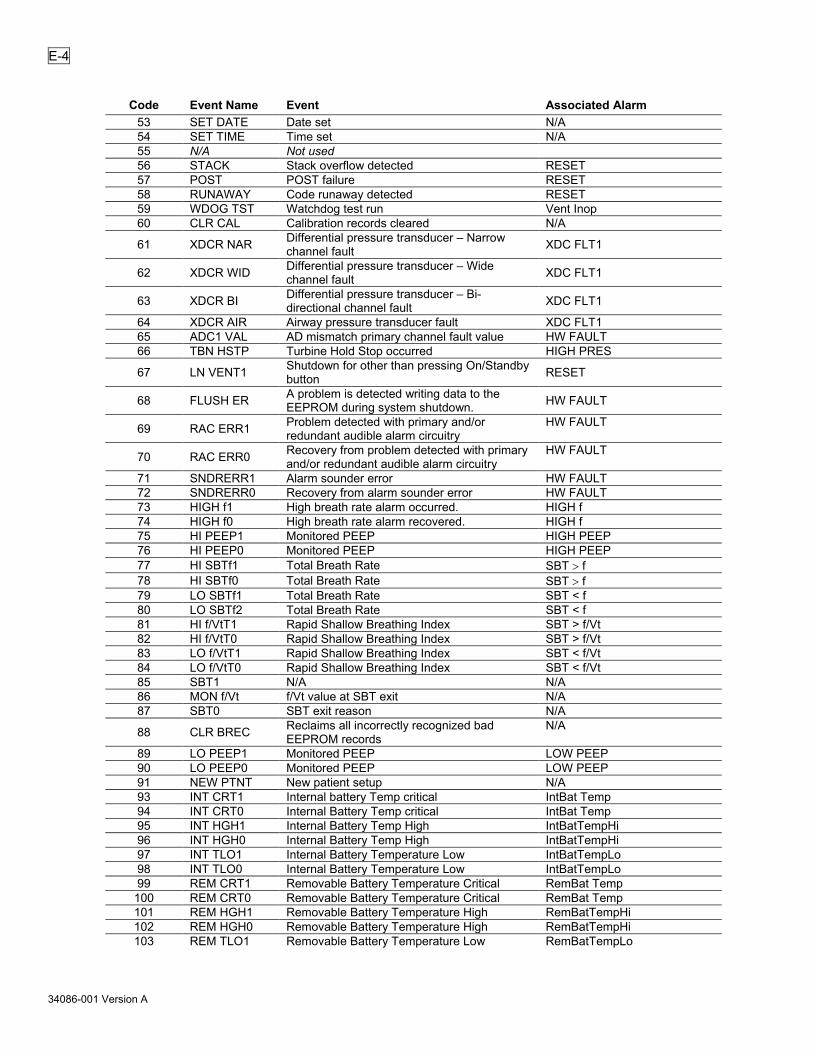
E-4
34086-001 Version A
Code Event Name Event Associated Alarm 53 SET DATE Date set N/A 54 SET TIME Time set N/A 55 N/A Not used 56 STACK Stack overflow detected RESET 57 POST POST failure RESET 58 RUNAWAY Code runaway detected RESET 59 WDOG TST Watchdog test run Vent Inop 60 CLR CAL Calibration records cleared N/A
61 XDCR NAR Differential pressure transducer – Narrow channel fault XDC FLT1
62 XDCR WID Differential pressure transducer – Wide channel fault XDC FLT1
63 XDCR BI Differential pressure transducer – Bi-directional channel fault XDC FLT1
64 XDCR AIR Airway pressure transducer fault XDC FLT1 65 ADC1 VAL AD mismatch primary channel fault value HW FAULT 66 TBN HSTP Turbine Hold Stop occurred HIGH PRES
67 LN VENT1 Shutdown for other than pressing On/Standby button RESET
68 FLUSH ER A problem is detected writing data to the EEPROM during system shutdown. HW FAULT
69 RAC ERR1 Problem detected with primary and/or redundant audible alarm circuitry
HW FAULT
70 RAC ERR0 Recovery from problem detected with primary and/or redundant audible alarm circuitry
HW FAULT
71 SNDRERR1 Alarm sounder error HW FAULT 72 SNDRERR0 Recovery from alarm sounder error HW FAULT 73 HIGH f1 High breath rate alarm occurred. HIGH f 74 HIGH f0 High breath rate alarm recovered. HIGH f 75 HI PEEP1 Monitored PEEP HIGH PEEP 76 HI PEEP0 Monitored PEEP HIGH PEEP 77 HI SBTf1 Total Breath Rate SBT > f 78 HI SBTf0 Total Breath Rate SBT > f 79 LO SBTf1 Total Breath Rate SBT < f 80 LO SBTf2 Total Breath Rate SBT < f 81 HI f/VtT1 Rapid Shallow Breathing Index SBT > f/Vt 82 HI f/VtT0 Rapid Shallow Breathing Index SBT > f/Vt 83 LO f/VtT1 Rapid Shallow Breathing Index SBT < f/Vt 84 LO f/VtT0 Rapid Shallow Breathing Index SBT < f/Vt 85 SBT1 N/A N/A 86 MON f/Vt f/Vt value at SBT exit N/A 87 SBT0 SBT exit reason N/A
88 CLR BREC Reclaims all incorrectly recognized bad EEPROM records
N/A
89 LO PEEP1 Monitored PEEP LOW PEEP 90 LO PEEP0 Monitored PEEP LOW PEEP 91 NEW PTNT New patient setup N/A 93 INT CRT1 Internal battery Temp critical IntBat Temp 94 INT CRT0 Internal Battery Temp critical IntBat Temp 95 INT HGH1 Internal Battery Temp High IntBatTempHi 96 INT HGH0 Internal Battery Temp High IntBatTempHi 97 INT TLO1 Internal Battery Temperature Low IntBatTempLo 98 INT TLO0 Internal Battery Temperature Low IntBatTempLo 99 REM CRT1 Removable Battery Temperature Critical RemBat Temp 100 REM CRT0 Removable Battery Temperature Critical RemBat Temp 101 REM HGH1 Removable Battery Temperature High RemBatTempHi 102 REM HGH0 Removable Battery Temperature High RemBatTempHi 103 REM TLO1 Removable Battery Temperature Low RemBatTempLo

E-5
34086-001 Version A
Code Event Name Event Associated Alarm 104 REM TLO0 Removable Battery Temperature Low RemBatTempLo 105 INT FLT1 Internal Battery fault alarm IntBat FAULT 106 INT FLT0 Internal Battery fault alarm IntBat FAULT 107 REM EMP1 Removable Battery Empty Alarm RemBatEMPTY 108 REM EMP0 Removable Battery Empty Alarm RemBatEMPTY 109 REM FLT1 Removable Battery Fault Alarm RemBat FAULT 110 REM FLT0 Removable Battery Fault Alarm RemBat FAULT 111 REM LOW1 Removable Battery Low alarm RemBat LOW 112 REM LOW0 Removable Battery Low alarm RemBat LOW 113 RBAT RM1 Removable Battery Ejected alarm BATT EJECTED 114 RBAT RM0 Removable Battery has been inserted BATT EJECTED 115 MUX FLT1 Battery Multiplexer hardware fault HW FAULT 116 MUX FLT0 Battery Multiplexer hardware fault HW FAULT 117 QUERY1 Query inactivity alarm None 118 QUERY0 Query inactivity alarm None 120 RTCBATT1 Real-time Clock Battery Error HW FAULT 121 SNDBATT1 Audible Alarm Module Battery Error HW FAULT 122 HIGH VE1 High Minute Volume HIGH MINUTE VOLUME 123 HIGH VE0 High Minute Volume HIGH MINUTE VOLUME 126 CLKDRFT1 Clock Drift hardware fault HW FAULT 127 CLKDRFT0 Clock Drift hardware fault HW FAULT
Event Codes by Event Name
Event Name Code Event Associated Alarm ADC ERR 33 ADC Error HW FAULT ADC ERR0 35 ADC Error cleared HW FAULT ADC ERR1 34 ADC Error on a specific channel HW FAULT ADC1 VAL 65 AD mismatch primary channel fault value HW FAULT APNEA 0 06 Apnea mode exited APNEA APNEA 1 05 Apnea mode entered APNEA CHK CIRCUIT 10 Circuit disconnect exited CHK CIRCUIT CHKCIRC1 07 Patient circuit fault CHK CIRCUIT CLKDRFT0 127 Clock Drift hardware fault HW FAULT CLKDRFT1 126 Clock Drift hardware fault HW FAULT
CLR BREC 88 Reclaims all incorrectly recognized bad EEPROM records
N/A
CLR CAL 60 Calibration records cleared N/A CLR CTRL 52 Control settings cleared N/A CLR EVNT 51 Event log cleared N/A CRC 41 Memory CRC check failed RESET DEFAULTS 25 Defaults, or Set Defaults occurred DEFAULTS / DEFAULTS, SET EEPROM 40 EEPROM degraded HW FAULT EXT LOW0 18 External power low exited POWER LOW EXT LOW1 17 External power low occurred POWER LOW EXT LST0 16 External power lost exited POWER LOST EXT LST1 15 External power lost occurred POWER LOST FAN FLT0 28 Fan fault exited HW FAULT FAN FLT1 27 Fan fault occurred HW FAULT
FLUSH ER 68 A problem is detected writing data to the EEPROM during system shutdown. HW FAULT
HI f/VtT0 82 Rapid Shallow Breathing Index SBT > f/Vt HI f/VtT1 81 Rapid Shallow Breathing Index SBT > f/Vt HI PEEP0 76 Monitored PEEP HIGH PEEP HI PEEP1 75 Monitored PEEP HIGH PEEP HI PRES0 43 High pressure exited HIGH PRES HI PRES1 42 High pressure occurred HIGH PRES

E-6
34086-001 Version A
Event Name Code Event Associated Alarm HI SBTf0 78 Total Breath Rate SBT > f HI SBTf1 77 Total Breath Rate SBT > f HIGH f0 74 High breath rate alarm recovered. HIGH f HIGH f1 73 High breath rate alarm occurred. HIGH f HIGH VE0 123 High Minute Volume HIGH MINUTE VOLUME HIGH VE1 122 High Minute Volume HIGH MINUTE VOLUME HOME ER0 39 Stepper motor home failure exited HW FAULT HOME ER1 38 Stepper motor home failure occurred HW FAULT HOUR MTR 03 Set hour meter None INT CRT0 94 Internal Battery Temp critical IntBat Temp INT CRT1 93 Internal battery Temp critical IntBat Temp INT EMP0 12 Internal battery empty exited IntBAT EMPTY INT EMP1 11 Internal battery empty occurred IntBat EMPTY INT FLT0 106 Internal Battery fault alarm IntBat FAULT INT FLT1 105 Internal Battery fault alarm IntBat FAULT INT HGH0 96 Internal Battery Temp High IntBatTempHi INT HGH1 95 Internal Battery Temp High IntBatTempHi INT LOW0 14 Internal battery low exited IntBat LOW INT LOW1 13 Internal battery low occurred IntBat LOW INT TLO0 98 Internal Battery Temperature Low IntBatTempLo INT TLO1 97 Internal Battery Temperature Low IntBatTempLo INTRRPT1 31 Spurious interrupt occurred ms RESET or RESET 1 INTRRPT2 32 Spurious interrupt occurred ls RESET or RESET 1
LN VENT1 67 Shutdown for other than pressing On/Standby button RESET
LO f/VtT0 84 Rapid Shallow Breathing Index SBT < f/Vt LO f/VtT1 83 Rapid Shallow Breathing Index SBT < f/Vt LO PEEP0 90 Monitored PEEP LOW PEEP LO PEEP1 89 Monitored PEEP LOW PEEP LO PRES0 50 Low peak pressure exited LOW PRES LO PRES1 49 Low peak pressure occurred LOW PRES LO SBTf1 79 Total Breath Rate SBT < f LO SBTf2 80 Total Breath Rate SBT < f LOW VE 0 48 Low minute volume exited LOW MIN VOL LOW VE 1 47 Low minute volume occurred LOW MIN VOL MON f/Vt 86 f/Vt value at SBT exit N/A MUX FLT0 116 Battery Multiplexer hardware fault HW FAULT MUX FLT1 115 Battery Multiplexer hardware fault HW FAULT N/A 29 Not used N/A 30 Not used N/A 55 Not used NEW PTNT 91 New patient setup N/A NO CAL 26 No calibration data found NO CAL DATA O2 HI 0 24 O2 pressure high exited HIGH O2 PRES O2 HI 1 23 O2 pressure high occurred HIGH O2 PRES O2 LOW 0 22 O2 pressure low exited LOW O2 PRES O2 LOW 1 21 O2 pressure low occurred LOW O2 PRES POST 57 POST failure RESET QUERY0 118 Query inactivity alarm None QUERY1 117 Query inactivity alarm None
RAC ERR0 70 Recovery from problem detected with primary and/or redundant audible alarm circuitry
HW FAULT
RAC ERR1 69 Problem detected with primary and/or redundant audible alarm circuitry
HW FAULT
RBAT RM0 114 Removable Battery has been inserted BATT EJECTED RBAT RM1 113 Removable Battery Ejected alarm BATT EJECTED REM CRT0 100 Removable Battery Temperature Critical RemBat Temp

E-7
34086-001 Version A
Event Name Code Event Associated Alarm REM CRT1 99 Removable Battery Temperature Critical RemBat Temp REM EMP0 108 Removable Battery Empty Alarm RemBatEMPTY REM EMP1 107 Removable Battery Empty Alarm RemBatEMPTY REM FLT0 110 Removable Battery Fault Alarm RemBat FAULT REM FLT1 109 Removable Battery Fault Alarm RemBat FAULT REM HGH0 102 Removable Battery Temperature High RemBatTempHi REM HGH1 101 Removable Battery Temperature High RemBatTempHi REM LOW0 112 Removable Battery Low alarm RemBat LOW REM LOW1 111 Removable Battery Low alarm RemBat LOW REM TLO0 104 Removable Battery Temperature Low RemBatTempLo REM TLO1 103 Removable Battery Temperature Low RemBatTempLo RTCBATT1 120 Real-time Clock Battery Error HW FAULT RUNAWAY 58 Code runaway detected RESET SBT0 87 SBT exit reason N/A SBT1 85 N/A N/A SET DATE 53 Date set N/A SET TIME 54 Time set N/A SNDBATT1 121 Audible Alarm Module Battery Error HW FAULT SNDRERR0 72 Recovery from alarm sounder error HW FAULT SNDRERR1 71 Alarm sounder error HW FAULT STACK 56 Stack overflow detected RESET SYNCER0 37 Stepper motor lost sync exited HW FAULT SYNCER1 36 Stepper motor lost sync occurred HW FAULT TBN ESTP 46 Turbine emergency stop occurred HIGH PRES or CHK CIRCUIT TBN HSTP 66 Turbine Hold Stop occurred HIGH PRES TBN ISTP 44 Turbine immediate stop occurred HIGH PRES TBN ZERO 45 Turbine set to zero flow occurred HIGH PRES VENT 0 02 Power off None VENT 1 01 Power on None VENT CHK 04 Operation of vent in non-patient mode REMOVE PTNT WDOG TST 59 Watchdog test run Vent Inop XDC FLT0 20 XDCR fault exited XDCR FAULT XDC FLT1 19 XDCR fault occurred XDCR FAULT XDCR AIR 64 Airway pressure transducer fault XDC FLT1
XDCR BI 63 Differential pressure transducer – Bi-directional channel fault XDC FLT1
XDCR NAR 61 Differential pressure transducer – Narrow channel fault XDC FLT1
XDCR WID 62 Differential pressure transducer – Wide channel fault XDC FLT1
Event Trace Data Definitions XDC FLT1 Four binary digits ABCD, where: A represents the Flow Differential narrow (FDn) transducer channel B represents the Flow Differential wide (FDw) transducer channel C represents the Flow Differential bi-directional (FDb) transducer channel D represents the Airway Pressure (AP) transducer 1 = fault, 0 = okay
For example, 0100 represents a failed auto zero on the FDw channel.
HOME ER1
-1 or 1, where -1 represents the clockwise direction 1 represents the counterclockwise direction

E-8
34086-001 Version A
AD MMTCH, AD MTCH1
xx = A/D channel, where 0 = Flow Differential Narrow (FDn) 1 = Flow Differential Wide (FDw) 2 = Flow Valve Differential (FVd) 3 = Airway Pressure (AP) 4 = Oxygen Pressure (O2) 5 = not used 6 = Flow Valve Temperature (FVt) 7 = External Voltage (EV) 8 = Battery Voltage (BV) 9 = not used 10 = Flow Differential Bi-Directional (FDb) 11 = V ref/2 signal on power board 12 = V ref -ve signal on power board 13 = V ref +ve signal on power board
yyyy = signed difference of A/D 1 count – A/D 2 count

F-1
34086-001 Version A
Glossary TERM DEFINITION AC Alternating current. Airway circuit The airway tubing that connects the ventilator and the patient. Airway pressure The airway pressure measured at the exhalation valve. Airway pressure display The bar graph type display showing the real-time airway circuit
pressure from –10 cmH2O to 99 cmH2O. Alarm An audible and visual announcement that an alarm condition has been
met. Audible notification includes an oscillating or continuous tone. Visual notification may include flashing displays, illuminated LEDs, and text messages shown in the display window.
Apnea Apnea happens when the time between breath starts exceeds the set apnea interval.
Apnea backup ventilation Apnea Backup Ventilation begins when an apnea alarm occurs and continues until the patient initiates 2 consecutive breaths or the alarm is canceled by an operator. Apnea Backup Ventilation is given in the Assist/Control mode.
Apnea interval The maximum period of time allowed between breath starts. If the time between breath starts exceeds this interval, an Apnea alarm occurs.
Assist/Control mode A mode of ventilation where the patient receives a minimum number of machine and assist breaths. The available breath types are Volume Control and Pressure Control.
Assist breath A volume or pressure breath that the patient triggers, and which is then controlled and cycled by the ventilator. Assist breaths may occur in Assist/Control and SIMV modes.
Autozero The procedure for determining the transducer zero offset for ambient pressure.
Bias flow A constant gas flow through the patient circuit during the exhalation phase of the breath.
bpm Breaths per minute. Breath period The time between consecutive ventilator-started breaths. The Breath
Period is determined by the Breath Rate per minute setting. For instance, a Breath Rate of 6 would give a Breath Period of 10 seconds (60 seconds divided by 6 bpm).
Breath rate, set The minimum quantity of machine breaths given in a minute. BTPD Body Temperature, Pressure Dry. Circuit See airway circuit. Circuit pressure See airway pressure. cmH2O Centimeters of water. A unit of measure for pressure. Control mode A ventilation mode where the ventilator delivers machine breaths at a
set rate. In Control Mode, patient triggers are not allowed. CPAP Continuous Positive Airway Pressure. The ventilator continuously
maintains Positive gas pressure through the patient circuit during the entire breath cycle.
CPAP mode A ventilation mode where the patient triggers all breaths. Available breath types are Pressure Support and Spontaneous.
Display window A set of 12 dot-matrix displays used to show monitored data, alarm messages and Extended Feature menu items.
EEPROM Electrically Erasable Programmable Read Only Memory. Nonvolatile electronic memory that is used by the ventilator to maintain calibration data, control setting and other data when power is not applied to the ventilator.

F-2
34086-001 Version A
TERM DEFINITION Event Any condition noted in the ventilator’s event trace. This may include
both error conditions and normal operational events. Exhaled tidal volume See Tidal Volume. Expiratory hold A maneuver which holds the expiratory phase of a delivered breath for
a duration sufficient to determine the AutoPEEP of a patient. Extended features A set of ventilator controls and options that are not associated with front
panel controls. Extended Features are accessed through a menu shown in the display window.
Rate See Total Breath Rate, monitored. Flow The velocity of gas delivery to the patient, quantified in lpm. Flow trigger A patient effort in which the amount of bias flow routed into the patient’s
lungs exceeds the Sensitivity setting. A flow trigger will result in delivery of an Assist or Patient breath, according to the ventilation mode.
f/Vt Total Breath Rate divided by the average Exhaled Tidal Volume. f/Vt f Total Breath Rate divided by the average Exhaled Tidal Volume, and
the Total Breath Rate. I:E ratio, monitored The ratio of the inspiration period to the expiration period for a breath.
The lesser value is normalized to 1. I:E ratio, calculated Calculated Inspiratory:Expiratory ratio, based upon the Inspiratory Time
setting and the Breath Rate setting Inspiratory hold A maneuver which holds the inspiratory phase of a volume delivered
breath for a duration sufficient to determine Δ Pres pressure and static lung compliance of the patient.
L Liters Leak compensation Leak Compensation improves triggering when a circuit leak is present. LED Light Emitting Diode. An indicator that is illuminated on the front panel. lpm Liters per minute. Flow rate. Machine breath A volume or pressure breath that is started by the operator or the
ventilator, and is controlled and cycled by the ventilator. Machine Breaths may occur in Control and Assist/Control modes. The operator may cause a machine breath in any mode using the Manual Breath Button.
Manual breath A Machine Breath initiated by the operator pressing the Manual Breath Button.
MAP Mean airway pressure. The average airway pressure over a series of breaths.
Minimum exhalation time The minimum time required for exhalation is 346 msec. Control settings are limited to ensure the Minimum Exhalation Time is provided. Breaths may not be triggered during the Minimum Exhalation Time.
Minimum inspiratory time The minimum time required for inspiration is 300 msec. Control settings are limited to ensure the Minimum Inspiratory Time is provided.
Minute volume, monitored (VE)
The total volume exhaled by the patient for the last 60 seconds. VE is refreshed at the conclusion of each breath and is based on the last 8 breaths.
msec Millisecond: One one-thousandth of a second. Non-volatile memory Memory that is retained when ventilator is in Standby mode or powered
off. O2 Oxygen. Patient breath A Pressure Support or Spontaneous breath that is started by the
patient, controlled by the ventilator and cycled by the patient. Patient breaths may occur in SIMV and CPAP ventilation modes.
Patient effort Inspiratory effort by the patient. PEEP Positive end expiratory pressure. The circuit pressure measured at the
end of exhalation.

F-3
34086-001 Version A
TERM DEFINITION PIP Peak inspiratory pressure. The maximum circuit pressure occurring
during the inspiration and first 348 ms exhalation phase of a breath. PIP is measured at the patient wye.
POST Power On Self Tests. A set of self-tests the ventilator performs when turned on to verify the operational integrity of the Processor, Displays, Audible alarm, Confirming Audible Chirp, SRAM, Program Memory and EEPROM (some tests require operator visual and/or audible verification).
Preset A feature allowing ventilator parameters to be “preset” for a pediatric or an adult patient.
Pressure control breath A machine or assist breath where the circuit pressure is elevated to an operator-set pressure for an operator-set period of time. Pressure Control breaths have an optional flow termination criteria.
Pressure support breath A patient breath where the circuit pressure is raised to an operator-set pressure and maintained until flow decreases to an operator-set percentage of the peak flow achieved. Pressure Support Breaths may also be terminated by an operator-set maximum time, or by exceeding 2 breath periods.
Pressure Trigger A patient effort in which the pressure below PEEP is less than the Sensitivity setting. A pressure trigger will result in a delivered breath.
psig Pounds per square inch gauge. A unit for measuring pressure. rpm Revolutions per minute. Turbine speed is measured in rpm. Scrolling, monitored data display
Displays the monitored values statically or allows automatic scrolling. While scrolling is active, each monitored value will be displayed for 3 seconds then the next value will be automatically displayed.
SIMV Synchronized Intermittent Mandatory Ventilation. SIMV mode A ventilation mode where a minimum number of machine or assist
breaths are given, and the patient is allowed to trigger additional Patient breaths. Available breath types are volume control, pressure control, pressure support, and spontaneous.
Spontaneous breath A breath which the patient starts and cycles. Spontaneous breaths are cycled at 10% of peak flow, set variable time termination, or when they exceed 2 breath periods.
Spontaneous Breathing Trial (SBT)
A ventilation mode used to temporarily minimize ventilatory support and perform clinical assessments of a patient’s dependence on, or ability to be removed from positive pressure ventilation.
Tidal volume, monitored (Vte)
The exhaled volume quantified at the patient wye. Exhaled volume is measured for all breath types.
Total breath rate, monitored (f)
The quantity of breaths given per minute; includes all breath types.
Transducer A measuring device. Transducers can be used to quantify flow or pressure.
Vcalc A monitor that displays the calculated peak flow for volume control breaths. Vcalc is calculated based on the set tidal volume and the set inspiratory time.
VE See minute volume, monitored.

F-4
34086-001 Version A
TERM DEFINITION Volume control breath A time-triggered or patient assist breath where an operator-set volume
is delivered over an operator-set time. Flow is delivered in a decelerating waveform where the peak and final flows are calculated so that the final flow is 50% of the peak flow.
Vte See tidal volume, monitored.

G-1
34086-001 Version A
Approved Accessory Listing
Gas and Electrical Accessories
Vyaire Medical Part Number Description
31604-001 Adapter, DISS to NIST
24424-001 VOXP cable
24425-001 Cable, nurse call, normally open
24426-001 Cable, nurse call, normally closed
10701 Adapter, low pressure oxygen
25531-001 Hose, oxygen, green, DISS/DISS
25534-001 Hose, oxygen, white, NIST/NIST
Stands and Carrying Devices
Vyaire Medical Part Number Description
28767-001 Rolling floor stand
28768-001 Basket
28769-001 Cord wrap bracket
28774-001 O2 cylinder mount
29241-001 Fisher & Paykel humidifier mounting bracket
11452 Long crossbar (required for the circuit support arm)
12140-001 Patient circuit support arm
Other Stands and Carrying Accessories
Vyaire Medical Part Number Description
30509-001 Table stand

G-2
34086-001 Version A
Electrical Power Accessories Vyaire Medical Part Number Description
22770-001 Desktop charger (English-based overlay)
34093-001 LTV2, external power cable
26618-001 Battery, removable
17986-001 Adapter, electrical, F&P 900 MR 900 dual heated limb
17987-001 Adapter, electrical, F&P 900 MR 901 single heated limb
Breathing Circuits and Other Consumables (Breathing circuits are single patient use.)
Vyaire Medical Part Number Description
29657-001 Patient circuit, 22 mm, no water trap (10/pkg.)
29658-001 Patient circuit, 15 mm, no water trap (10/pkg.)
29659-001 Patient circuit, 22 mm, single heated wire, Fisher & Paykel (10/pkg.)
29660-001 Patient circuit, 15 mm, single heated wire, Fisher & Paykel (10/pkg.)
29701-001 Patient circuit, 22 mm, dual heated wire, Fisher & Paykel (10/pkg.)
29703-001 Patient circuit, 15 mm, dual heated wire, Fisher & Paykel (10/pkg.)

H-1
34086-001 Version A
Index
A
AC Adapter · 14-7 AC Power Source · 14-7 Accessories
Breathing Circuits and Consumables · G-2 Electrical Power · G-2 Gas and Electrical · G-1 Stands and Carrying Devices · G-1
Active Alarm · 6-21 Airway Pressure Display · 7-2 ALARM · 11-4 Alarm Clearing · 6-22 ALARM OP · 10-2 Alarm Operations · 10-2 Alarm Reset · 6-22 Alarm Silence · 6-21 Alarm Status · 7-2 Alarm Status Messages
HI PEEP OFF · 9-12 LMV OFF · 9-19 LO f/Vt OFF · 10-26 LO PP OFF · 9-22 LOCKED · 9-31 LP PS OFF · 9-22 SBT f OFF · 10-26 SBT HI f OFF · 10-26 WARMUP WAIT · 9-31
Alarm Test · 11-4, 11-5, 15-20 ALARM VOL · 10-3, 15-20 Alarm Volume · 10-3, 15-20 Alarms
APNEA · 4-3, 9-4, 9-5, 10-3 APNEA xx bpm · 4-3, 9-4 BATT EJECTED · 14-2 CHK CIRCUIT · 9-5 DEFAULTS · 9-6, 15-15 DEFAULTS SET · 9-8 EXT PWR LOST · 9-8 EXT PWR LOW · 9-9 HI MIN VOL · 9-9, 10-3 HI O2 PRES · 6-18, 9-11 HI PEEP · 9-11, 10-4 HI PRESSURE · 9-12 HI RESP RATE · 9-10, 10-4 HI SBT f/Vt · 9-30 HI SBT RATE · 9-29 HIGH O2 PRES · 15-2 HIGH PRES · 15-2 HIGH PRESSURE · 9-14 High Priority · 9-2
HW FAULT · 9-14, 13-4 INOP · 9-15 IntBat EMPTY · 9-15 IntBat FAULT · 9-16 IntBat LOW · 9-17 IntBat TEMP · 9-18 IntBatTempHi · 9-18 IntBatTempLo · 9-18 LO PRESSURE · 9-21 LO SBT f/Vt · 9-29 LO SBT RATE · 9-28 LOCKED · 5-5, 5-6 LOW MIN VOL · 9-19, 15-2 Low Minute Volume · 6-22 LOW O2 PRES · 9-20, 15-2 LOW PEEP · 9-21, 10-4 Low Priority · 9-1 LPP ALARM · 10-3 Medium Priority · 9-1 Multiple Alarm Priorities · 9-3 NO CAL · 8-1, 9-23 NO CAL DATA · 9-23, 15-15 Nurse Call · 10-4 Oxygen Inlet High Pressure · 6-18 Oxygen Inlet Low Pressure · 6-18 POWER LOST · 14-9 RemBat EMPTY · 9-23 RemBat FAULT · 9-24 RemBat LOW · 9-25 RemBat Temp · 9-25 RemBatTempHi · 9-26 RemBatTempLo · 9-26 REMOVE PTNT · 9-27 RESET · 9-27, 15-15 SBT OFF · 9-28 Variable Settings · 5-3 XDCR FAULT · 9-30
ALL BREATHS · 9-22 Altitude · 6-5 Apnea · 4-3, 9-4 Apnea Backup · 4-3, 4-5, 9-4 Apnea Backup Rate · 4-5 APNEA INT · 9-5 Apnea Interval · 4-5, 9-5, 10-3 APNEA xx bpm · 4-3, 9-4 Assist/Control · 6-12 Assist/Control Mode · 4-2 Audible Alarm Test · 11-4, 11-5 Audible Alarm Volume · 10-3 Autocycling · 15-5 Automatic High O2 Switch Over · 6-18, 9-11 Automatic Scrolling · 8-3

H-2
34086-001 Version A
AutoPEEP · 6-16 Autozero · 9-30, 10-28
B
BACKUP ALARM · 11-5 Barometric Pressure · 6-5 Battery
Calibration/Relearn · 14-5 Charge Level, Removable · 14-3 Charging Priority · 14-2 Charging, Removable · 14-3 Desktop Charger · 14-4, 14-6 External Battery · 14-8 Internal · 14-2, 14-10 Removable · 14-2 Removable, Determining Charge · 14-4 Removable, Exchanging · 14-4 Use · 14-2
Battery Check · 6-1, 14-2, 14-4 Battery Durations · A-13 Bias Flow · 1-8, 3-1, 5-5, 6-4, 6-11, 6-16, 8-3,
10-10, 10-11, 10-19, 15-8, A-2 BIAS FLOW · 10-20 Blanked Controls, Displays · 5-4 BLOCK WYE · 11-10 Breath Rate · 6-3 Breath Type
Pressure Control · 3-2 Pressure Support · 3-4 Sigh Breath · 3-2 Spontaneous · 3-5 Volume Control · 3-1
Breathing Circuit · 1-3, 1-4, 1-7, 1-10, 9-5, 11-1, C-1, C-2, G-2
Conformance · A-14 Button
Battery Check · 6-1 Menu/Select · 6-1
Button Controls · 5-3 Buttons
Alarm Reset · 6-22, 9-13 Alarm Silence · 6-21, 9-13 Battery Check · 14-2, 14-4 Breath Type · 6-12 Control Lock · 6-21 FiO2 (Flush) · 6-10 High Pres. Limit · 9-13 Insp/Exp Hold · 6-13, 6-16 Low Pressure O2 Source · 6-18 Manual Breath · 6-17 PEEP · 6-9 Pressure Control · 6-7 Pressure Support · 6-8 Sensitivity · 6-12 Tidal Volume · 6-6
Volume Pressure · 6-7
C
C Static · 6-14 CALCULATE · 10-18 Calculated I:E Ratio · 8-3 Calculated Peak Flow · 6-4, 8-1, 8-3 Calibration · B-1 Cautions · 1-9 Charge Status · 14-10 Check Circuit · 9-5 Checkout Tests · 11-1 CHK CIRCUIT · 9-5 Circuit
Compliance · 6-5 Connecting · C-1, C-3 Connecting, With Humidifier · C-4, C-5
Cleaning · 13-1 Fan Filter · 13-4 Inlet Filter · 13-5 O2 Inlet Filter · 13-6
COM SETTING · 10-13 Communications Port · C-9 Communications Setting · C-9 Compliance · 6-5 Connecting to a Patient · 12-3 CONTROL · 11-8 Control Limiting · 5-5 Control Lock · 5-5, 6-21, 9-31, 15-3 Control Mode · 4-1 Control Test · 11-8 Control Unlock · 10-12 Controls · 5-1, 5-2, 6-1
Alarm Reset · 6-22 Alarm Silence · 6-21 Blank · 5-4 Breath Rate · 6-3 Buttons · 5-3 Dashes · 5-4 Dimmed · 5-4, 15-3 FiO2 (Flush) · 6-10 Flashing · 5-4 High Pressure Limit · 14-9, 15-2 Inspiratory Time · 6-4 Limiting · 5-5 Lock · 5-5, 6-21, 9-31, 10-12, 15-3 Low Minute Volume · 6-22, 15-2 Low Pressure · 6-22, 15-2 Low Pressure O2 Source · 6-18, 9-11 Manual Breath · 6-17 Memory · 5-6 Menu/Select · 6-1 O2% (O2 Flush) · 15-2 PEEP Control · 6-9 Power/Standby · 6-2

H-3
34086-001 Version A
Pressure Control · 6-7, 15-2 Pressure Support · 6-8, 15-2 Retention · 5-6 Scroll Knob · 5-3, 6-1 Sensitivity · 6-11 Setting · 5-2 Tidal Volume · 6-4, 6-5, 6-6 Unlock · 10-12 Variable · 6-2 Variable Settings · 5-3 Volume/Pressure Mode · 6-12, 15-3
CPAP · 6-12 CPAP Mode · 4-3 CRC · 15-15 CTRL UNLOCK · 10-12, 15-3 CYL PRES · 10-18
D
Dashes in Display · 5-4 Date · 10-13, 10-15 DATE FORMAT · 10-15 Decelerating Waveform · 3-1, 6-4 Default Control Settings · 9-6 Default Extended Features Settings · 9-7 DEFAULTS · 9-6, 15-15 DEFAULTS SET · 9-8 definitions
AD MMTCH · E-8 AD MTCH1 · E-8 HOME ER1 · E-7 XDC FLT1 · E-7
Desktop Battery Charger · 14-6 Dimmed Controls, Displays · 5-4, 15-3 Disinfecting · 13-1, 13-2 DISPLAY · 11-6 DISPLAY f/Vt · 10-26 Display Language · 10-13 Display Select · 11-9, A-1 Display Test · 11-6 Display Window · 7-2 Displays · 5-1, 5-2, 7-1
Airway Pressure · 7-2, 10-15 Blank · 5-4 Dashes · 5-4 Dimmed · 5-4, 15-3 Flashing · 5-4 Window · 7-2
DOT Requirements · A-14
E
Effort LED · 6-11 EMC and RF Environments · A-15 Equipment Classification · A-14 ET Tube · 15-21
Event Codes · E-3 Event Trace · E-1 Exhaled Minute Volume · 8-2 Exhaled Tidal Volume · 8-1, 8-2 EXP HOLD · 6-13, A-1 Expiratory Hold · 6-13, 6-16, A-1 EXT PWR LOST · 9-8 EXT PWR LOW · 9-9 Extended Features · 5-3, 6-1, 6-2, 10-1
Navigation · 10-2 External Battery · 14-8
Disposal · 14-8 External Power · 7-3, 14-1, 14-8
F
f · 8-1, 8-2 f/Vt f · 8-2, 8-3 Fan Filter · 13-4
Cleaning · 13-4 Replacement · 13-4
Filter O2 Inlet · 13-6
FiO2 (Flush) · 6-10 Flashing Controls, Displays · 5-4 FLOW TERM · 3-3, 3-4, 6-7, 6-8, 10-7, 10-8 Flow Trigger · 5-5, 6-11, 10-11 Flush · 10-12 Front Panel · 7-1
Controls and Displays · 5-1, 5-2
H
Help · 2-3, B-2 HI MIN VOL · 9-9, 10-3 HI O2 PRES · 9-11 HI PEEP · 9-11, 10-4, 15-16 HI PEEP OFF · 9-12 HI PRESSURE · 9-12, 9-13, 9-14 HI RESP RATE · 9-10 HI SBT f/Vt · 9-30 HI SBT RATE · 9-29 HIGH f/Vt · 10-25 High Minute Volume · 9-9, 10-3, C-12 HIGH O2 PRES · 15-2 High PEEP · 8-4, 9-11, 9-12, 10-4 HIGH PEEP · 15-16 HIGH PRES · 15-2 High Pressure Alarm Delay · 10-3 High Pressure Limit · 9-13, 14-9, 15-2 Hours in Operation · 10-13 HP DELAY · 9-13, 15-14 Humidifier · C-4, C-5 HW FAULT · 9-14, 13-4

H-4
34086-001 Version A
I I:Ecalc · 8-3 IE Ratio · 8-1, 8-2 Inactive Alarm · 6-21 Informational Messages · 8-3 Inlet Filter · 13-5
Cleaning · 13-5 Replacement · 13-5
INOP · 9-15 INSP HOLD · 6-13, A-1 Insp/Exp · 6-13 Insp/Exp Hold · 6-13, 6-16 Inspiratory Hold · 6-13, A-1 Inspiratory Time · 6-4 Inspiratory/Expiratory · 6-13, 6-16, 9-6, A-1 IntBat EMPTY · 9-15 IntBat FAULT · 9-16 IntBat LOW · 9-17 IntBat TEMP · 9-18 IntBatTempHi · 9-18 IntBatTempLo · 9-18 Internal Battery · 7-3, 14-1, 14-10
Battery Life · 14-10 Charge Status · 14-10 Charging · 14-10 Disposal · 14-10 Replacing · 14-10
L
LANGUAGE · 10-13 LEAK · 11-10, 11-11 Leak Compensation · 10-10 Leak Test Query · 10-23 LEAK YES · 11-10 LED Indicators
Alarm Status · 7-2 External Power · 7-3, 14-1 Internal Battery · 7-3, 14-1 Patient Effort · 7-2 Power Source · 7-3 Removable Battery · 7-3, 14-1
Limiting · 5-5, 15-2, 15-3 LMV OFF · 9-19 LO f/Vt · 10-26 LO f/Vt OFF · 10-26 LO PP OFF · 9-22 LO PRESSURE · 9-21 LO SBT f/Vt · 9-29 LO SBT RATE · 9-28 LOCKED · 5-5, 5-6, 9-31, 15-3 LOW MIN VOL · 9-19, 15-2 Low Minute Volume · 6-22, 9-19, 15-2 LOW O2 PRES · 9-20, 15-2 LOW PEEP · 9-21, 10-4
Low Pressure Alarm · 6-22, 9-22, 15-2 Low Pressure O2 Source · 6-18, 9-11 LP PS OFF · 9-22 LPP ALARM · 6-22, 9-22, 10-3
M
Maintenance · B-1 Manual Breath Button · 6-17 MAP · 8-1, 8-2 Mean Airway Pressure · 8-1, 8-2 Memory · 5-6 Menu/Select Button · 6-1 Message Window · 7-2 Minimum Exhalation Time · 3-1 Minimum Inspiratory Time · 3-1 Minute Volume · 8-1, 8-2 MINUTES · 10-25 Model Number · 10-15 Modes · 4-1
Apnea Backup · 4-3, 4-5 Assist/Control · 4-2, 6-12, 12-6 Control · 4-1 CPAP · 4-3, 6-12, 12-10 NPPV · 4-4, 6-8, 6-9, 6-12, 12-11 Pressure · 4-1, 6-12 SIMV · 4-2, 6-12 SIMV/CPAP · 6-12, 12-8 VENT CHECK · 9-27 VENT MTNCE · 9-27 Volume · 4-1, 6-12
Monitored Data · 8-1 Monitored Data Displays · 6-1, 8-1 Monitors
Calculated I:E Ratio · 8-3 Calculated Peak Flow · 8-1, 8-3 Exhaled Minute Volume · 8-2 Exhaled Tidal Volume · 8-1, 8-2 f · 8-2 f/Vt f · 8-2, 8-3 IE Ratio · 8-1, 8-2 MAP · 8-1, 8-2 Mean Airway Pressure · 8-1, 8-2 Minute Volume · 8-1 NO CAL · 9-23, 15-15 Peak Inspiratory Pressure · 8-1, 8-2 PEEP · 8-1, 8-2 PIP · 8-1, 8-2 SBT min · 8-1, 8-3 Total Breath Rate · 8-1, 8-2 Vcalc · 8-1, 8-3 VE · 8-1, 8-2 Vte · 8-1, 8-2

H-5
34086-001 Version A
N
NO CAL · 8-1, 9-23, 15-15 NO CAL DATA · 9-23, 15-15 Non-Invasive Positive Pressure Ventilation · 4-4 NPPV · 4-4, 6-8, 6-12, 12-11
Apnea Ventilation · 9-5 Nurse Call · 10-4 Nurse Call Port · 9-12 Nurse Call System
Connection · C-8
O
O2 Conserve · 1-8, 6-11, 8-3, 10-11, 10-19 O2 Cylinder Duration · 10-17 O2 Flush · 10-12 O2 Inlet Filter · 13-6
Cleaning · 13-6 Replacement · 13-6
O2% · 15-2 Operating Procedures · 12-1
Connect to a Patient · 12-3 Oxygen
Blending · 6-10 Concentration · 6-20 Connecting · C-6 Source · 2-3
P
P Exp · 6-16 P Plat · 6-13 Packaging and Materials · A-10 Patient Circuit
Connecting · C-1, C-3 Connecting, With Humidifier · C-4, C-5
Patient Connection · 12-3 Patient Effort · 6-11, 7-2 Patient Size · 10-21 PC FLOW TERM · 3-3, 6-7, 10-7, 10-8, 10-9,
15-2 Peak Flow · 6-4 Peak Inspiratory Pressure · 8-1, 8-2 PEEP · 10-25 PEEP Control · 6-9 PEEP, Monitored · 8-1, 8-2 PIP · 8-1, 8-2, 10-15 PIP LED · 10-15 Pneumatic Diagram · D-1 POST · 15-15 POWER LOST · 14-9 Power On Self Tests (POST) · 12-1 Power Source · 2-3, 7-3
AC · 14-7 Power/Standby Button · 6-2
PRES SUPPORT · 10-25 Presets · 10-20 Presets Table · 10-22 Pressure Control · 6-7, 15-2 Pressure Control Breath · 3-2 Pressure Control Flow Termination · 3-3, 10-8 Pressure Mode · 4-1, 6-12 Pressure Support · 6-8, 15-2 Pressure Support Breath · 3-4 Pressure Trigger · 1-8, 4-2, 6-11, 10-11, 10-19,
A-1 Preventative Maintenance · B-1
Q
Queries · 10-20 Leak Test Query · 10-23 Patient · 10-23 Patient Size · 10-21
R
Real Time Transducers · 10-31 RemBat EMPTY · 9-23 RemBat FAULT · 9-24 RemBat LOW · 9-25 RemBat Temp · 9-25 RemBatTempHi · 9-26 RemBatTempLo · 9-26 Remote Alarm
Connection · C-9 Remote Alarm Cable · C-9 Remote Alarm System · 15-16 Removable Battery · 7-3, 14-1
Charge Level · 14-3 REMOVE PTNT · 9-27, 11-2 RESET · 9-27, 15-15 RISE TIME · 3-3, 6-7, 6-8, 10-6 RT XDCR DATA · 10-31, 15-5 RUNAWAY · 15-15
S
Safety Information · 1-2 SBT f OFF · 10-26 SBT FIO2 · 10-25 SBT HI f OFF · 10-26 SBT HIGH f · 10-26 SBT LOW f · 10-26 SBT min · 8-1, 8-3 SBT OFF · 9-28 SBT OP · 10-24 SBT Operations · 10-24
DISPLAY f/Vt · 10-26 HIGH f/Vt · 10-25 LO f/Vt · 10-26

H-6
34086-001 Version A
MINUTES · 10-25 PEEP · 10-25 PRES SUPPORT · 10-25 SBT FIO2 · 10-25 SBT HIGH f · 10-26 SBT LOW f · 10-26 SBT START · 10-25
SBT START · 10-25 Scroll Knob · 6-1 Scrolled Automatically · 9-19 Scrolling · 8-1 SELECT · 11-8 Sensitivity · 6-11 Serial Number · 10-15 Service · 2-3, B-2 Service Life · A-14 SET DATE · 10-13 Set Defaults · 10-16 SET TIME · 10-14 Set Up
CPAP Mode · 12-10 NPPV Mode · 12-11 SIMV/CPAP Mode · 12-8
Setting a Control · 5-2 Shipping Requirements · A-11 Shock and Vibration · A-11 Sigh · 10-19 Sigh Breath · 3-2 Silence Period · 6-21 Silencing Alarms · 6-21 SIMV · 6-12 SIMV Mode · 4-2 SIMV/CPAP · 6-12 Software Version · 10-13 Sound Levels · A-11 Specifications · A-1
Alarms · A-3 Breathing Circuit and Filters · A-13 Button Controls · A-3 Communications · A-11 Desktop Removable Battery Charger · A-12 Displays · A-10 EMC and RF Environments · A-15 Internal and Removable Battery · A-12 Mechanical Controls · A-3 Modes and Breath Types · A-1 Monitors · A-9 Packaging and Materials · A-10 Power · A-12 Storage and Operating Conditions · A-10 Usage Meter · A-10 Variable Controls · A-1
Spillage · A-11 Spontaneous Breath · 3-5 Spontaneous Breathing Trial (SBT) · 10-24 STACK · 15-15
Standby · 6-2 Storage and Operating Conditions · A-10
T
Taper Waveform · 3-1, 6-4 Technical Description · D-1 Temperature
External Surface · A-11 Test
Alarm · 15-20 Tidal Volume · 6-4, 6-5, 6-6, 8-2 Time · 10-14 TIME TERM · 3-4, 6-8, 10-8, 15-2 Total Breath Rate · 8-1, 8-2 Transducer Autozero · 10-28 Triggers · 6-11, 7-2, 10-19 Troubleshooting · 15-1
Alarms · 15-14 Checkout Test Failures · 15-20 Displays and Buttons · 15-2 Power and Battery Operation · 15-10 Test Lung Operations · 15-21 Ventilator Performance · 15-5
U
Unlock · 10-12, 15-3 Unpacking · C-1 Usage Meter · 10-13, A-10 USAGE xxxxx.x · 10-13
V
Valve Home Position · 10-16 Variable Controls · 6-2 Variable Flow Termination · 10-7 Variable Rise Time · 10-6 Variable Time Termination · 3-4 Vcalc · 8-1, 8-3 VE · 8-1, 8-2 VENT CHECK · 9-27, 10-16, 11-3
EXIT · 11-12 VENT CHECK Menu · 11-1 Vent Inop Alarm Test · 11-11 VENT MTNCE · 9-27 VENT OP · 10-5, 10-16, 10-20 Vent Operations · 10-5 Ventilator Checkout · 9-27, 10-16, C-11 Ventilator Checkout Test
Alarm Test · 11-4, 11-5 Control Test · 11-8 Display Test · 11-6 Leak Test · 11-10 Vent Inop Alarm Test · 11-11
Ventilator Checkout Tests · 11-1

H-7
34086-001 Version A
Ventilator Maintenance · 9-27 Ventilator Proper Operation Checkout
Worksheet · C-13 VER xx.xx X · 10-13 VHome · 10-16, 15-5, 15-6, 15-8, 15-9 Volume Control Breath · 3-1 Volume Mode · 4-1, 6-12 Volume/Pressure Mode · 6-12, 15-3 VOXP
Data Connection · C-10 VOXP Port · C-10 Vte · 8-1, 8-2
W
WARMUP WAIT · 9-31, 11-10
Warnings · 1-3 Warranty · iii Waveform · 3-1, 6-4 Worksheets
Ventilator Proper Operation Checkout · C-13
X
XDCR FAULT · 9-30 XDCR ZERO · 10-27, 10-28, 15-5, 15-6, 15-7,
15-8, 15-10
Δ
Δ Pres · 6-14
Copyright © 2022 FDOKUMEN