Multilink EP 2200-T
76
Multilink EP 2200-T Transportation / ITS UPS Battery Backup System EP 2200-T Transportation UPS Installation, Operation and Maintenance Manual Rev 10 04/05/2017
-
Upload
khangminh22 -
Category
Documents
-
view
0 -
download
0
Transcript of Multilink EP 2200-T

Multilink EP 2200-T
Transportation / ITS UPS Battery Backup System
EP 2200-T Transportation UPS
Installation, Operation and Maintenance Manual
Rev 10 04/05/2017

TABLE OF CONTENTS UNPACKING AND INSPECTION CHECKLIST VI
SAVE THE ORIGINAL SHIPPING BOX VII
READ THE OPERATOR’S MANUAL VII
■ Section 1: Installation & Start-Up Manual 8
1.1 DESCRIPTION 9
1.1.1 System Description 9
1.1.2 EP 2200-T UPS 11
1.1.3 Power Transfer Switch 11
1.1.4 Batteries 12
1.2 MOUNTING 12
1.3 WIRING 13
1.4 START-UP AND TEST 16
1.5 SHUTDOWN 18
1.5.1 EP 2200-T UPS 18
1.5.2 PTS 19
1.6 TROUBLESHOOTING 20
1.7 SPECIFICATIONS 21
1.8 EMERGENCY SHUTDOWN PROCEDURE 22
■ Section 2: Operator’s Manual 23
2.1.1 THE ADVANTAGES 25
2.1.2 A TOUR OF THE EP 2200-T 26
2.2.1 LCD PANEL 32
2.2.2 EP 2200-T OPERATING MODES 33
2.2.3 SELF TEST 34
2.2.4 START UP 35
2.2.5 SHUTDOWN 36
2.2.6 BATTERY REPLACEMENT 37
2.2.7 LCD MENU TREE 38
2.2.8 STATUS SUBMENU 40
2.2.9 CONTROL SUBMENU 42
2.2.10 SETTINGS MENU 43
2.2.11 MAINTENANCE MENU 44
2.2.12 ALARM MENU 45
2.2.13 FAULT MENU 46
2.2.14 EVENT LOG VIEW 47
2.2.15 LOW BATTERY MODE STATUS 48
2.3.1 RS232/USB SET-UP 49
2.3.1.1 Wiring Set-up Procedure 49
2.3.2 Comport &Terminal Settings 50
2.3.3 MAIN MENU 51
2.3.4 MENU TREE & RS232/USB SUB MENUS 54
2.3.4.1 RS232/USB Menu Tree 54
The complete MENU Tree with all default values 55

2.3.4.2 Unit Specifications, Input/Output Values 56
2.3.4.3 Input / Output Values 56
2.3.4.4 Maintenance 57
2.3.4.5 Line Slow Detection Parameters 59
2.3.5 MENU TUTORIAL 61
2.4.1 BATTERY BACK-UP TIME TEST 64
2.4.2 EP 2200-T RETURN INSTRUCTIONS 65
2.4.3 TROUBLESHOOTING 66
CONTRAST ADJUSTMENT LCD DISPLAY 67
2.4.4 BATTERY MAINTENANCE 67
2.4.5 SPECIFICATIONS 68
2.4.6 WARRANTY 70
2.4.7 EMERGENCY SHUTDOWN PROCEDURE 71

IMPORTANT SAFETY INSTRUCTIONS ARE
CONTAINED IN THIS MANUAL
Three different levels of safety admonishments are used within this instruction manual;
specifically DANGER, WARNING, and CAUTION.
Trois niveaux différents d'avertissements de sécurité sont utilisés dans ce mode d'emploi;
spécifiquement DANGER, AVERTISSEMENT et ATTENTION.
DANGER The statement following the DANGER heading alerts the equipment user of a potentially life or health-
threatening situation unless preCAUTIONs are taken against it. Admonishments of this nature usually
entail the hazards of electrical shock or those encountered that may result in physical injury.
La déclaration sous la rubrique DANGER avertit l'utilisateur de l'équipement d'une situation
potentiellement mortelle ou mortelle, sauf si des préCAUTIONs sont prises contre lui. Les admonistances
de cette nature entraînent habituellement les dangers d'un choc électrique ou ceux rencontrés qui peuvent
entraîner des blessures physiques.
WARNING / AVERTISSEMENT
The statement following the WARNING heading alerts the equipment user of a condition or
procedure that could result in interruption of service to the users or subscribers of the service
receiving power from this product.
La déclaration sous le chapitre AVERTISSEMENT avertit l'utilisateur de l'équipement d'une
condition ou d'une procédure qui pourrait entraîner une interruption de service pour les
utilisateurs ou les abonnés du service qui reçoit l'alimentation de ce produit.
CAUTION / ATTENTION
The statement following the CAUTION heading alerts the equipment user of a condition that
could result in damage to the subject equipment or ancillary equipment if care is not exercised
during certain maintenance or operating procedures.
La déclaration suivant la rubrique ATTENTION avertit l'utilisateur de l'équipement d'une condition qui
pourrait endommager l'équipement concerné ou l'équipement auxiliaire si les soins ne sont pas exercés
pendant certaines procédures de maintenance ou d'exploitation.

DANGER: Do not expose the EP 2200-T to rain or moisture.
DANGER: Total Earth ground leakage current of loads connected to the
EP 2200-T should not exceed 2.4 mA.
The EP 2200-T generates, uses and can radiate radio frequencies if not installed and tested in
accordance with the instructions contained in this manual. It has been tested and found to comply
with the limits established for a Class A computing device pursuant to part 15 of FCC rules when
it is operated alone. It also complies with the radio interference regulations of DOC, which are
designed to provide a reasonable protection against such interference, when this type of
equipment is used in a commercial environment. If there is interference to radio or TV reception,
which is determined by switching it on and off. Relocate the equipment or use an electrical circuit
other than the one used by the EP 2200-T.
III
IMPORTANT SAFETY PRECAUTIONS Only qualified personnel should service or supervise the service of the EP 2200-T.
Danger: Sealed lead-acid batteries with high energy and chemical hazards are used. This manual
contains important operation and safety instructions.
EP 2200-T Safety System Checklist
• Carefully unpack the EP 2200-T. Report any shipping damage at once.
• Read this manual. If you have any questions about safe installation, operations or maintenance of the system, contact Manufacturer service department.
• Before installation, confirm that the voltage and current requirements of the load(s) are compatible with the
system’s output. Confirm that the line voltage and current is compatible with the system’s input requirements.
• The system should be installed on a dedicated power circuit.
• Place a warning label on the enclosure indicating that an Uninterruptible Power Supply (UPS) is located inside, in
case of an emergency.
• Use proper lifting techniques when moving system.
• The EP 2200-T has more than one live circuit. It is fed from AC as well as battery power. Power may be present
at the output(s) even if the system is disconnected from line power.
• When installing a system in other than a Manufacturer cabinet, ensure that the environment meets the
system specifications shown in Section 1.7, “Specifications” of this manual.
SAVE THIS MANUAL This manual contains important instructions that should be followed during installation and
maintenance of the UPS and batteries.
Keep it in a safe place
IV

Battery Safety Checklist
• High & dangerous voltages are present inside the system. Only qualified personnel should perform installation
and maintenance.
• Live battery wires must not touch the EP 2200-T chassis or any other metal objects. This can cause a fire or
explosion.
• Inspect the batteries once a year for signs of cracks, leaks, or swelling. Replace as needed.
• When batteries are in storage, charge them at least once every three months for optimum performance and to
extend their lifetime.
• Always replace batteries with the ones of identical type and rating. Never install old or untested batteries. Never
mix old with new batteries. Never mix the different amp hour rated batteries within one system. • Use insulated tools during servicing.
• Remove all rings, watches, jewelry, or other conductive items before working inside the enclosure. • Follow local regulations for the disposal of batteries. Recycling is the best method.
• Never burn batteries to dispose of them. They may explode.
• Do not open the batteries. The contents are toxic.
Stand-By Generator
Note: If the EP 2200-T constantly switches between Battery and Line modes because of line
fluctuations, the input parameters should be broadened from Normal to Generator (see Section
2.2.10 “Sense Type”)
In Generator mode, the acceptable range of input frequency and voltage is expanded to accommodate the
voltage and frequency fluctuations created by a generator or a power source of such kind.
Use a generator with electronic speed and voltage controls which typically produces the Total Harmonic
Distortion in % (THD) to be less than 10%. Generators with mechanical governors can force the system to run
continuously in Battery mode.
Before installation, compare the generator’s output voltage to the EP 2200-T’s input voltage requirements as listed
on both nameplates. To insure the system’s smooth operation, use a generator capable of supplying 2X or twice as
much power as required by the total load.
V

Unpacking and Inspection Checklist Purpose: Describes the unpacking and inspection procedures.
Carefully remove the EP 2200-T from its box. Inspect the contents and make sure the following items are
included:
• One EP 2200-T UPS System.
• One plastic bag containing the following:
• Temperature sensor probe cable with 3-pin connector.
• Installation, Operations and Maintenance manual.
• Warranty Card.
The Power Transfer Switch (PTS) and all the associated wiring & hardware required for installation is supplied in a
separate box.
The set of four (4) batteries may be shipped separately. For optimum performance Multilink MultiMax UPS Batteries are specified.
Tip: If any items are missing or damaged, contact Manufacturer and the shipping company at once.
Most shippers have a short claim period.
SAVE THE ORIGINAL SHIPPING BOX When returning the EP 2200-T for servicing, use the original shipping box with the supplied Styrofoam protectors.
Manufacturer is not responsible for damage caused by improper packaging of returned systems.
READ THE OPERATOR’S MANUAL
Before installation, become familiar with the EP 2200-T by reviewing the procedures and drawings in this manual.
If you have any questions about safe installation, operation, or maintenance, contact Manufacturer customer
service department.
Complete the following for records & future servicing Model No.: EP 2200-T __________________
Serial No.: _
(Above items can be found on the nameplate label attached to the side of the unit)
Products Sales Order No.____________________________
EP 2200-T P/N: _
Your Purchase Order No.:__________________________ Purchased from: _
(Following details are for installation location)
Installation date: _
Installed by: _
City: _ State/Province: _
Zip/Postal Code: _
Country: _
Telephone #: _ Fax #: __
E-Mail : ___________________________________________
Street names of location: _____________________________
Cabinet / controller type: ____________________________
VII


Multilink EP 2200-T
Uninterruptible Power Supply / Battery Backup System
■ Section 1: Installation & Start-Up Manual
8

1.1 Description Purpose: Describes the operation of the EP 2200-T System (Figure 1, 2 & 3).
1.1.1 System Description
The EP 2200-T System provides backup power to traffic control signal equipment. It consists of the EP 2200-T
Uninterruptible Power Supply (UPS) System, the Power Transfer Switch (PTS), and batteries that provide back up
power when the line is unqualified. These three components can be mounted inside an enclosure to provide
protection from most weather conditions.
Figure 1
Simplified EP 2200-T System Block Diagram
9
EP 2200-T UPS / BBS
* ACTIVATE WHEN BUCK / BOOST IS ENABLED
CONTINOUS
RS232 & USB
CONNECTION
UPS OUTPUT
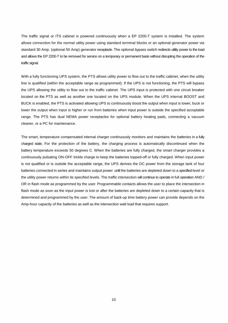
The traffic signal or ITS cabinet is powered continuously when a EP 2200-T system is installed. The system
allows connection for the normal utility power using standard terminal blocks or an optional generator power via
standard 30 Amp. (optional 50 Amp) generator receptacle. The optional bypass switch redirects utility power to the load
and allows the EP 2200-T to be removed for service on a temporary or permanent basis without disrupting the operation of the
traffic signal.
With a fully functioning UPS system, the PTS allows utility power to flow out to the traffic cabinet, when the utility
line is qualified (within the acceptable range as programmed). If the UPS is not functioning, the PTS will bypass
the UPS allowing the utility to flow out to the traffic cabinet. The UPS input is protected with one circuit breaker
located on the PTS as well as another one located on the UPS module. When the UPS internal BOOST and
BUCK is enabled, the PTS is activated allowing UPS to continuously boost the output when input is lower, buck or
lower the output when input is higher or run from batteries when input power is outside the specified acceptable
range. The PTS has dual NEMA power receptacles for optional battery heating pads, connecting a vacuum
cleaner, or a PC for maintenance.
The smart, temperature compensated internal charger continuously monitors and maintains the batteries in a fully
charged state. For the protection of the battery, the charging process is automatically discontinued when the
battery temperature exceeds 50 degrees C. When the batteries are fully charged, the smart charger provides a
continuously pulsating ON-OFF trickle charge to keep the batteries topped-off or fully charged. When input power
is not qualified or is outside the acceptable range, the UPS derives the DC power from the storage tank of four
batteries connected in series and maintains output power until the batteries are depleted down to a specified level or
the utility power returns within its specified levels. The traffic intersection will continue to operate in full operation AND /
OR in flash mode as programmed by the user. Programmable contacts allows the user to place the intersection in
flash mode as soon as the input power is lost or after the batteries are depleted down to a certain capacity that is
determined and programmed by the user. The amount of back-up time battery power can provide depends on the
Amp-hour capacity of the batteries as well as the intersection watt load that requires support.
10

1.1.2 EP 2200-T BBS
The EP 2200-T UPS System shown below provides control functions and backup power as described above.
For more information, please see Section 2 of this manual.
Figure 2
EP 2200-T Front Panel
1.1.3 Power Transfer Switch
The Power Transfer Switch (PTS) shown below allows the UPS to be removed for service, replacement or
maintenance without interrupting power to the traffic cabinet.
Figure 3
Power Transfer Switch Front Panel
1. The wires from the neutral and ground bus of the traffic cabinet are connected to this terminal block.
2. The Input line power is connected to the terminal block marked with “L IN”.
3. The Output power is connected to the terminal block marked with “L OUT”.
11

4. An optional surge suppressor, external PC or a vacuum cleaner for maintenance may be plugged into this
receptacle. 5. The optional battery heater mat is plugged into this receptacle.
6. This “UPS OUT” cord is connected to the OUTPUT AC terminal block on the EP 2200-T.
7. The Black and Red PTS control wires are connected at terminals 21 & 22 of the green terminal block on the
EP 2200-T. 8. This “UPS IN” cord is connected to INPUT AC terminal blocks on EP 2200-T.
9. This circuit breaker provides input power protection for the EP 2200-T UPS.
10. The dual receptacles are protected by this circuit breaker.
1.1.4 Batteries
Different Amp-hour capacities or sizes of batteries can be used in the EP 2200-T system to provide various
backup times. Four batteries are connected in series for the required 48VDC. Contact customer service at
Manufacturer for information on the battery best suited for your application. The battery harness supplied with the
system is polarized and equipped with Molex type connectors. The battery harness provides a heavy-duty
connection for each battery, so it is possible to unplug or hot swap them. Each of the four batteries may be connected
in any order using the provided harness.
1.2 Mounting Purpose: Describes how to mount the EP 2200-T System into an enclosure.
The EP 2200-T system components shall be mounted into a single external cabinet or into an existing traffic
cabinet.
EXTERNAL MOUNT:
The factory supplied external cabinet can be bolted onto an existing or new traffic cabinet or this external cabinet
can be pad mounted on a concrete slab or be pole mounted. The separate base for the cabinet for installation in
the concrete slab, bolts & hardware for bolting onto the side of the traffic cabinet, bushing for the wire ducts,
brackets for pole mounting and all the required accessories including mechanical hardware and electrical wiring
are supplied to make the installation easy for the contractor. External cabinets such as BC100, BC80, etc. are
outdoor type, weather proofed provided with internal exhaust fan that is temperature controlled, an intake filter
that can be cleaned or replaced, a non-corrosive rubber mat for batteries, 3 point locking mechanism, lockable
handle with dual keys and a unique internal keyed lock. The quality of cabinets bears a reputable industry trade
name such as Manufacturer. The factory-supplied cabinet meets or exceeds the requirements of various NEMA
classifications.
INTERNAL MOUNT:
The EP 2200-T components can also be mounted inside an existing NEMA or 332 or various other traffic
cabinets. The special Swing Tray designed to hold the four batteries is easily mounted inside an existing 332 type
or other equivalent cabinet using the hardware that is provided, or they can be shelf mounted in a NEMA or
equivalent cabinet. The EP 2200-T can be bolted into an industry standard 19” rack using the supplied ears or
brackets, or it can be shelf mounted in a NEMA type enclosure. The PTS supplied with or without optional
Generator & Bypass switch comes in many configurations that can be shelf mount, 19” rack mount, back plate
mount, etc.
12

1.3 Wiring Purpose: Describes how to wire the EP 2200-T System.
CAUTION: To reduce the risk of fire, connect only to a circuit provided with 20A maximum branch circuit overcurrent protection in accordance with the National Electrical code, ANSI/NFPA 70 and the Canadian Electrical Code, Part 1, C22.1
Before wiring the system, determine the size of the load:
START
Is the load over or
under 2000 VA
/1500 W?
OVER
Put the Intersection in FLASH mode as soon as EP 2200-
T goes into Battery mode, by connecting any one of the six
programmed contacts to “ON BATT” from C, NO or NC type
at the EP 2200-T to the AUTO / FLASH circuit of any
controller.
Go to Step 1
UNDER
Run the intersection in FLASH mode connected as above.
or
Keep the intersection running normal in full phase until the
battery completely depletes down to shutdown resulting in blackout
or
Keep the intersection running normal in full phase for certain time or
until battery depletes down to certain capacity, both of which are
programmable. Run the intersection in flash mode after that, until the
battery depletes down completely resulting in blackout if utility does not
return. Connect Traffic controller’s AUTO / FLASH circuit to any one of the
six programmable contacts on the EP 2200-T programmed for the
“Timer” or “Low Battery”. This method is recommended to ride out
small power outages, which is what occurs during most utility
interruptions.
TIP: Each of the six contacts are of form C type, meaning Normally Open (NO), Common (C) and Normally
Closed (NC) dry contact rated for 1 Amp at 120VAC. Each of these contacts can be individually programmed to
energize and stay latched for ON BATTERY, LOW BATTERY, TIMER, ALARM, FAULT and many other conditions
as described in subsequent chapters. The ON BATTERY contact/(s) are activated as soon as the EP 2200-T is
transferred to Battery mode. LOW BATTERY contact/(s) are activated only in the Battery mode, as soon as the
discharged battery reaches the lower value battery capacity as set by user and remains latched as long as the
system remains in Battery mode. The TIMER contact/(s) are activated only in the Battery mode after the user-
programmed time is attained, that can be set in 15 minutes interval from 15 minutes to 8 hours.
TIP: Verify that all breakers, AC and battery breakers are OFF prior to wiring.
13

Step 1: Connect CONTROL wires.
START
Tape the Battery Temperature
Sensor to the case of the
middle battery-
Plug the connector on the other
end into the EP 2200-T
Connect the External
Cabinet Fan and the RS232/ USB Computer Cable (if used)
Connect the programmable
contacts: ON BATT, LOW BATT,
TIMER or SELF TEST contacts
from EP 2200-T to traffic cabinet
for Flash mode (if used)
Wrap a tie around the
strain relief loop and the
battery temperature
sensor to prevent the
connector from
disconnecting during an
earthquake or other
severe vibrations.
NOTE: External chassis ground is provided by ground lug on front of UPS. Max wire size is 10 AWG.
TIP: Torque status/self
test terminal block to a
maximum of 4.4 lb-in (0.5
Nm). Maximum wire size
is 14 AWG.
Figure 4
EP 2200-T Front Panel
TIP: (See Section 2.1.2, Fig. 16) of this manual for details
on the layout, operation, and specifications of the Control
Terminal Block.
GO TO STEP 2 Step 2: Connect PTS to the EP 2200-T.
START
Connect the Black & Red
control wires from the PTS to
the EP 2200-T Control TB
21 & 22 respectively
Connect the cord from UPS
OUT at PTS to the AC OUT
terminal block on EP 2200-T
Connect the cord from UPS
IN on PTS to AC IN terminal
blocks on EP 2200-T
UPS IN
UPS OUT
GO TO STEP 3
PTS CONTROL Figure 5
MP 20 EP 2200-T Front & Power Transfer Switch
14

Step 3: Connect the output or Signal Cabinet and Battery.
START
Connect the supplied black
wire from the L OUT terminal
at PTS to the INPUT HOT
TIPS:
1. The wires from Ground and
Neutral Bus Bars from the
traffic cabinet are extended
to PTS Terminal Block as
shown in step 4.
terminal in the signal cabinet
Plug the Red & Black Battery
connector into the EP 2200-T
UPS
GO TO STEP 4
L OUT
Figure 6
Power Transfer Switch
Figure 7
EP 2200-T Front Panel
2. OPEN the upstream
breaker feeding utility
power to the signal
cabinet.
3. Disconnect the HOT wire
(Black) connected
between utility and traffic
cabinet.
4. The cabinet side HOT wire
is connected to “L OUT” on
the PTS.
5. The utility side HOT wire is
connected to “L IN” on the
PTS.
6. Torque the PTS terminal
block to a maximum of 10.0
lb-in (1.1 Mm).
Step 4: Connect the Utility Input Line Power.
DANGER: Make sure the upstream circuit breaker feeding the utility power is OFF before beginning
this step. Leave the NEUTRAL and GROUND wires connected from utility to signal cabinet. Extend
the NEUTRAL and GROUND wires from their corresponding bus bars in the traffic cabinet to the
terminal block on the PTS.
START
Connect the input HOT black
wire from utility to “L IN” on
PTS. Run wires from neutral
and ground bus bars of traffic
cabinet to PTS neutral &
ground terminal blocks
LINE IN
NEUTRAL
GROUND
Start and test the EP 2200-T
as described in Section 1.4
Figure 8
Power Transfer Switch
WIRING FINISHED
15

1.4 Start-Up and Test
Purpose: Describes how to Start-up and test the system.
TIP: If the system does not perform as described below, see the troubleshooting section in Section 1.6 of this
manual.
Step 1: Turn on the Utility Input line Power
START STARTUP PROCEDURE TIPS
The EP 2200-T automatically starts up in Standby mode. After the AC line
Verify that the AC Input & is qualified (default 30 seconds) the BBS switches to On Line mode.
Output as well as Battery The PTS is a safeguard that the cabinet will always revert to utility
Circuit Breakers on the power if there is ever a failure of the EP 2200-T or batteries.
EP 2200-T are OFF
Turn ON the upstream Utility
Input Circuit Breaker
GO TO STEP 2
Step 2: Turn on the UPS.
START
Turn On the AC input &
output circuit breaker
Turn On the battery
circuit breaker
The LCD display shows
Standby
In 30 seconds, The LCD
display changes to “ ON
LINE”, the Green
Output LED is lit
indicating Input power to
be within acceptable
frequency and voltage
ranges and the output is
powered from utility.
GO TO STEP 3
16
Verify the load is turned ON

Step 3: Test the system.
START
Turn OFF the upstream
circuit breaker
The OUTPUT Green LED will
flash and the LCD displays ON
BATT, indicating that output AC
power is supplied from battery
power.
Turn ON the
upstream circuit
breaker Within 30 seconds
the PTS switches
back to line power
Observe the Red Alarm LED. If
it is on or flashes, follow the
troubleshooting sequence as
below:
1. Investigate the alarm
2. Perform a self-test with the
load(s) connected
3. If it passes the self-test,
verify that that loads are
operating normally
4. See the troubleshooting
chart in the EP 2200-T
manual, Section
2.4.3
5. Contact Manufacturer
technical support
The Green Output
LED is lit and the
display shows “ON
LINE”
START UP AND TESTING FINISHED
TIP: To test the UPS, perform the self-test feature via the control submenu (see this manual, Section 2.2.3, “Self
Test”).
17

1.5 Shutdown
Purpose: Describes how to shut down the system components for removal or maintenance. 1.5.1 EP 2200-T UPS
DANGER: Shutting down the EP 2200-T does not necessarily disconnect power to the loads.
START
Turn OFF the Battery Circuit
Breaker
Turn OFF the AC Input &
Output Circuit Breaker
Unplug the battery
connector.
Disconnect the AC input
wires
Disconnect the AC
output(s) wires
DANGER: The AC input wires from PTS are still HOT or Live. Insulate the bare wires using wire nuts.
Disconnect, mark and insulate
wires at the Green Control
Terminal Block, the plug for
Ext. Fan, the plug for battery
temperature sensor and the
RS232 or USB connector.
Remove and perform the
maintenance on EP 2200-T.
Perform this procedure in
reverse order to reinstall the
unit.
PROCEDURE FINISHED
TIP: For additional information on how to operate the EP 2200-T manual, (see Section 2.2).
18

1.5.2 PTS
START
Turn OFF the upstream
circuit breaker
TIP: Verify that both the AC
and Battery Breaker are OFF
at the EP 2200-T.
Disconnect the UPS OUT
Cord at the EP 2200-T
Disconnect the UPS IN cord
at the EP 2200-T
Disconnect the Red & Black
PTS control wires at the EP
2200-T
Disconnect the wires from
L IN, NEUTRAL, GROUND
and L OUT from the PTS
Remove and perform
maintenance on the PTS Figure 9
Power Transfer Switch
Perform this procedure in
reverse order to reinstall the
PTS
PROCEDURE FINISHED
19

1.6 Troubleshooting
TIP: For troubleshooting the EP 2200-T UPS, (see Sections 2.2.3 and 2.4.3) of this manual.
EP 2200-T System Troubleshooting Chart
SYMPTOM CAUSE REMEDY
Upstream utility circuit breaker or
fuse may be OPEN
CLOSE the upstream utility
breaker or fuse
No Output
Utility AC Power not available Check with the AC voltmeter &
contact the Utility Company
available from PTS
Wiring error PTS terminal block Correct wiring at PTS
Faulty PTS
If 120 VAC is present at “L IN” and
NEUTRAL at the PTS terminal
block, replace the PTS
EP 2200-T output power not
connected to PTS
Verify that “UPS OUT” cord from
PTS is properly connected to the
AC OUTPUT terminal block at the
EP 2200-T
PTS won’t allow
transfer to Battery
mode
“UPS INPUT” circuit breaker at
PTS is open
Black and red control wires from
PTS are not connected at the
Green Control terminal block TB
21 & 22 on the EP 2200-T
Reset the breaker & clear the
fault
Check the connection at the
EP 2200-T
48VDC signal missing at TB 21
and 22 of Green Control terminal
block at the EP 2200-T
Refer to Section 2.4.3 of this
manual for further troubleshooting
Faulty PTS Replace PTS
EP 2200-T does
not return back to
input Line mode
Utility input line power is missing
Verify that “UPS IN” cord from PTS
is properly connected to the AC
INPUT Terminal Block at the EP
2200-T
Verify that the “UPS INPUT” circuit
breaker at PTS is closed
Ensure that the utility input is
present
Figure 10
Troubleshooting Table
20

1.7 Specifications
INPUT
System Technical Specifications
ENVIRONMENTAL
Operating Temp
(See Notes below)
–34 to + 74 °C
Voltage Range, VAC 100~130VAC (120 VAC Nominal) Prog. 90–150VAC
Storage Temp –50 to +75 °C
Frequency 60 +/- 3 Hz
Current 30A (Resistive)
Humidity (Non-Condensing)
< 95%
Step Load Response (50% Load Change)
1/2 Cycle Full Recovery (Full resistive load)
Altitude (Note 2) 10,000ft /3000 m
PTS MECHANICAL
Short Circuit Protection
15 A circuit breaker
Dimensions (WxDxH) inch/mm
4.75/ 120.6 (W)
6.5/165 (D)
Battery String Voltage 48VDC (Four 12VDC Battery)
OUTPUT
4.6/116.8 (H)
Weight (lb/kg) 7.0/3.2
Mounting Rack Mount EARS, 4 points
Power, VA / W (Line or Inverter mode)
2000VA / 1500W
optional 19” rack mount
Input Connection Terminal block Power Factor 0.75
Output Connection
Terminal block Output Voltage, VAC
Line and Boost Mode
100~130 +/- 2 VAC (follows
the input voltage)
To Loads
Output Connection To UPS
6 foot line cords ready for hard
wiring to UPS terminal blocks
Inverter Mode
120VAC +/- 5%
Cooling Convection (Approx 7 W contactor coil dissipation)
Output Waveform Sine Wave
DESIGNED TO MEET
Output Waveform THD
< 3% (Resistive load)
Electrical Safety UL –1778, CSA-107.1,
Load Crest Factor 3:1 (Max)
Overload Capacity 110% for 3 minutes
PERFORMANCE
PTS Transfer Time < 65 ms Buck & Boost mode <10 ms
UL 60950-1
EMI FCC Class A
Surge Immunity IEC 1000-4-5, IEEE C62.41
Note:
1. Between 55 ~ 74 °C, the system is de-rated to a maximum rectified-capacitive load of 1500 VA /1200 W.
2. De-rate operating temperature above 4900 ft (1500m) by 2°C per 1000 ft (300m). 3. Refer to Section 2.4.5 at the end of this manual for additional specifications.
Due to ongoing product improvements, specifications are subject to change without notice.
21

1.8 EMERGENCY SHUTDOWN PROCEDURE The EP 2200-T UPS is connected to more than one energy source. In an emergency, DISCONNECT utility input
power, battery power, as well as an optional generator power, if utilized. Disconnecting all the AC and DC power
sources will ensure that the output circuit is not live.
START
Turn OFF the battery circuit breaker
Turn OFF the AC input & output circuit breaker
Unplug the Line Figure 11
Cord and turn EP 2200-T Front Panel off the Utility line power circuit breaker
EMERGENCY
SHUTDOWN
22

Multilink EP 2200-T System
Battery Backup / Uninterruptible Power Supply System
■ Section 2: Operator’s Manual
23

Section 2.1
Introduction
This section introduces the various features of the Multilink EP 2200-T UPS / BBS System
2.1.1 The Advantages
2.1.2 A Tour of the EP 2200-T
24

2.1.1 The Advantages
Advanced Power Protection Technology EP 2200-T is an Uninterruptible Power Supply (UPS) also known as a Battery Backup System (BBS)
designed for both indoor and outdoor applications. The EP 2200-T provides continuous power to traffic and
signal equipment.
♦ Advanced Communications The RS232 and/or USB ports allow for local or remote monitoring of the EP 2200-T.
♦ Smart Charging Multilink smart charge technology ensures the batteries are always at peak performance.
♦ User Friendly Supervision The LCD panel provides “At A Glance” monitoring and control.
♦ Service Friendly
The batteries can be changed without shutting down the intersection loads or the EP 2200-T.
25

2.1.2 A Tour of the EP 2200-T Purpose: Describes the display, connections and switches on the EP 2200-T front panel (Figures 12, 13 &14).
4 2 1
↓ ↓ ↓ ← 3
Figure 12 EP 2200-T Front Panel 1. 48VDC Battery Connector
Connects the battery to the unit. The battery string voltage is 48VDC.
2. Battery Circuit Breaker Acts as an ON/OFF switch for battery power. Must be in the ON position for normal operation.
3. Battery Voltage Test Points Battery voltage can be measured at these Test Jacks only when the battery circuit breaker is turned ON.
TIP: TEST JACKS ARE NOT DC POWER OUTLET TERMINALS.
4. Liquid Crystal Display (LCD) Control Panel The UPS can be controlled and monitored via this LCD panel. See Section 2.2 for further information.
26

5
↓
↑ ↑
6 7
Figure 13 EP 2200-T Front Panel
5. AC Input & Output Circuit Breaker Acts as a line and output power ON/OFF switch to facilitate the unit’s maintenance or replacement. Must be
in the ON position for normal operation.
6. AC Input Inlet Anderson PP45/4P provided for the input of line power.
7. AC Output
Outlet Anderson PP45/4P provides the connection for the output of line power. 8 ↓
Figure 14
EP 2200-T Front Panel
8. USB / Serial Interface / RS232 Connector
The USB and /or DB-9 female connector is used to connect the EP 2200-T to the host computer for remote
control, monitoring and calibration via RS232 commands.
For the USB or DB-9 female RS232 connections use computer industry standard computer cable between the
computer’s USB or RS232 port and the EP 2200-T unit’s USB or RS232 ports.
See Section 2.3 for more details about connection and use.
27

↑
9
Figure 15 EP 2200-T Front Panel
9. Green Control Terminal Block
This 22 position terminal block provides communication with the intersection controller, controls the Power Transfer Switch (PTS) and Programmable Input contact. Figure 16 shows its layout and operation.
Note: This terminal block is opto-isolated and shares a common ground with the serial interface. Each of
the six programmable contacts can be programmed for one or more functions such as: The Timer, Low
Battery and On Batt. The relay contacts are Form C type, i.e. Each of the six programmable contacts has
Common (C); Normally Closed (NC) and Normally Open (NO) contact position.
• On Batt: This relay energizes when Utility Input line power is unqualified.
• TIP: When the AC input and output circuit breaker is turned OFF, an auxiliary switch of the circuit breaker
opens which disables the On Batt. contact at the Green Control Terminal Block. This prevents the
intersection lights from flashing.
• Low Battery: These relays energize when the battery drops below the programmed battery capacity. The
default value is 47.5VDC or 40% battery capacity.
• TIP: You can change the preprogrammed value to match the batteries used and the actual operating
conditions. See Section 2.3.4.4, “Maintenance” # 35, “Battery Voltage Level @40% of Capacity”.
• Timer: These relays energize after the unit has been in Battery mode for the programmed time period.
The factory default value is 2 hours.
• TIP: The time can be programmed to be from 15 min. to 8 hours in 15 minute increments
• Program Input : The programmable input contact can be programmed for one function such as : Self-test, EXT Alarm, EXT Battery Alarm, EXT Fan Failure, Door Interlock. Jumper the TB 19 & 20 on the Green Control Terminal Block and the program alarm will show on LCD display.
• PTS: EP 2200-T sends a 48VDC signal from the batteries to the PTS, which activates the PTS, resulting
in transfer from Input power to BBS power. See Section 1.3, Wiring, of this manual for connection
instructions.
28

EP 2200-T Interior
C1
Note: These contacts have a maximum rating of 1 Amp at 120V. Only the first On Batt contact is illustrated. The remaining 5 contacts for Low Battery, Timer, etc., are similar.
Microprocessor
Note: The PTS contacts provide a direct
connection to the batteries through a 3 Amp PCB
mounted fuse.
C2 C3 C4 C5 C6 48VDC
1 2 3 4 5 6 | 7
8 9 10 11 12 13|
14 15 16 17 18 |
| 21 22
NO C NC NO C NC | NO C NC NO C NC | NO C NC NO C NC | 19 20 |
ON BATT | LOW
| TIMER | | 21 & 22: BATTERY 2 Hours
19 & 20: PTS
47.5 VDC
Note:
1. 6 sets of programmable contacts have the
following factory default settings:
C1, C2 =“On Batt”
C3, C4 =“Low Batt @ 47.5VDC”
C5, C6 =“Timer @ 2.00 Hours”
2. User may program each of the six contacts for one
or more functions. See Section 2.2 Sub Menus for
more detailed information.
| | Program Input
|
Note: The Programmable Input
is performed by jumpering TB19 & 20
Figure 16
Green Control Terminal Block Layout and Operation
29
+ -

↑ ↑ ↑
13 12 10/11
Figure 17 EP 2200-T Front Panel
10. Battery Temperature Sensor Strain Relief This secures the Battery Temperature Sensor cord to the panel and prevents connector disconnection
during an earthquake or other severe vibrations.
First plug the sensor cable into the connector. Then use one of the ties provided in the mounting kit to attach
the sensor cord to the strain relief loop. Ensure that the cable is secure.
11. Battery Temp Sensor It attaches the battery temperature probe to the unit for monitoring battery temperature. The charging voltage
is temperature dependent. The microprocessor of the smart charger adjusts the voltage for optimum
charging.
The temperature probe connector must be plugged in for normal operation. The sensor end should be
firmly attached to the terminal of the battery.
TIP: If the EP 2200-T is not charging the batteries check the temperature probe. To test the
temperature probe unplug it from the face of the UPS. Check the resistance of the
temperature probe by inserting the probes of an ohm meter into the top and bottom pins
of the connector. The meter should read approximately 12,000 Ohms at 25°C (77 °F). If
resistance is not in this range, replace temperature probe.
12. Ext Fan 48VDC
Provides DC Power (48VDC, 1 Amp (Max)), which could be used to power an optional 48VDC fan,
mounted inside the enclosure for regulation of the interior temperature.
13. Internal Fan This microprocessor-controlled fan regulates the unit’s internal temperature. It must not be blocked. The
filter in front of the fan is removable for cleaning.
TIP: Inspect the filter every 6 months, or as often as required. Clean by removing it, running water through
the filter and air-drying before reinstallation.
30

Section 2.2 Operation
This section describes how to start, shutdown and operate the EP 2200-T:
2.2.1 The LCD Panel
2.2.2 The EP 2200-T Operating Modes
2.2.3 The Self-Test
2.2.4 Start-Up
2.2.5 Shutdown
2.2.6 Battery Replacement
2.2.7 LCD Menu Tree
2.2.8 STATUS Submenu
2.2.9 CONTROL Submenu
2.2.10 SETTINGS Submenu
2.2.11 MAINTENANCE Submenu
2.2.12 ALARM Menu
2.2.13 FAULT Menu
2.2.14 Event Log View
2.2.15 Low Battery Mode Status
2.2.16 Parameter Changes
31

2.2.1 LCD Panel
Purpose: Describes the LCD display menus (Figure 18) and use of user-friendly sub-menus (Figure19).
When the Output LED is :
• ON, the line is qualified and
the input power flows to
output.
Operating Modes
MM/DD format
24-Hour • FLASHING, the unit is in
Battery mode.
• OFF, the output is OFF, Input
line is not qualified or the unit
detected a fault.
If both LEDs are OFF and the
LCD is BLANK, the unit is shut
off.
When the Alarm LED Is:
• ON, the unit detected a
Fault.
• FLASHING, the unit
detected an Alarm.
Pushing the ENTER button
displays the problem.
STANDBY 07/01 13:34
UPS STATUS
Pressing the ESC button
moves up one level in the
menu tree.
UPS STATUS
Pressing the ENTER
button moves down one
level in the menu tree.
Pressing the Up or Down
buttons moves sideways
through the menu tree.
Figure 18
LCD Panel Key Functions
TIP: When the ambient air temperature drops below -20°C (-4°F), the LCD may turn DARK until the temperature
rises above -20°C (-4°F). However the unit will operate normally.
UPS STATUS : Page1 → Page2 → … → Page16 MAIN SCREEN
Sub Menus
Sub Menus
STATUS CONTROL SETTINGS MAINTENANCE
Up Down
TIP: The complete menu tree is
shown in Section 2.2.7, Figure 20.
STATUS
V(in) = 121.3 VAC
Sideways
Figure 19
LCD Panel and the Menu Tree
32

2.2.2 EP 2200-T Operating Modes
Purpose: Describes the Operating modes.
TIP: The LCD automatically displays the following modes when they change.
LCD Shows Explanation
This mode is displayed when the unit is first turned on. The inverter remains off and the
EP 2200-T does not provide output power to the loads. If input line power is qualified, it STANDBY
automatically switches to line mode. To provide battery power to the loads, use the
manual on function (see Section 2.2.9)
ON LINE The normal operating mode. Input line power is provided to the loads, the batteries are
charging and the EP 2200-T is ready to provide backup power
BOOST* The unit automatically transfers to BOOST mode to raise the lower input line voltage
when output drops below the user programmable preset limit
ON BATT The unit automatically transfers to battery when input line power is unqualified or not
present. The batteries provide power to the loads
BUCK* The unit automatically transfers to BUCK mode to reduce the higher input line voltage
when output raises above the user programmable preset limit
When “Self Test” mode is active, the unit will enter “Battery Mode” automatically to test or
SELF TEST
check if output voltage and waveform is correct. After the programmed duration, the unit
returns back to “Line Mode”. Users may use “Maintenance Mode” to configure a longer
time for self-test. Default time for self-test is 1 minute.
When the unit is in “Battery Mode” the batteries begins to discharge. If the battery
LOW BATT voltage falls below the user programmed (40% default setting) of its capacity, “Low Bat”
warning appears.
* When enabled.
The following mode may be programmed by the User (see Section 2.2.10)
Sense Type (Generator / Normal Mode)
This is used to broaden the input parameters to
accommodate the voltage fluctuations created by a
backup generator or a noisy line.
The factory default setting is normal, where the unit
runs on normal parameters. Switching to Generator
makes it run on noisy generator parameters.
If the unit constantly switches between line and
battery modes due to a noisy line, select generator
mode to prevent unnecessary transfers / returns.
Normal Parameters
Line Mode
Normal Parameters
Generator Parameters
Normal Line Generator or Noisy Line
33

2.2.3 Self Test
Purpose: Describes the Self-Test.
CAUTION: This procedure should not be performed when critical loads are running that depend on the
unit for backup power.
The Self Test confirms that the unit can transfer into and out of Battery mode while
supporting the output load at the same time.
Procedure:
SELFTEST 07/01 15:29
UPS STATUS
START Self Test
TIP: The duration of self-test can be adjusted via
RS232 / USB menu (see Section 2.3.4.4,
Maintenance Menu # 30, Battery Test Options).
Is the unit in
Line Mode?
Do Not Proceed until the input line is stable.
NO
YES
Activate the Self Test mode in LCD display,
under CONTROL menu.
OR
Jumper TB 19 & 20 of Green Control terminal
block
OR
Use Menu # 301 via RS232 / USB (Section 2.3.5)
The Output Green LED lights
during the self-test.
In approximately one and a half minutes, if
no problem is detected, the UPS will return
to the mode it was in before the self-test
was started.
If a problem is detected, the red ALARM LED will turn on solid or flash ( See Sections 2.2.12 & 2.2.13) the counter will increment by one and the timer will accumulate the run time.
Self-Test Finished
34

2.2.4 Start Up
Purpose: Describes the Start Up procedure.
START
Turn OFF:
All Loads, the AC Input &
Output, Battery and Utility
Power circuit breakers
Turn On the upstream
utility input circuit breaker
One at a time, turn ON
the output / loads
Warning: Never run the
EP 2200-T when it is
overloaded. Damage to
its inverter, batteries or
unexpected shutdowns
may result.
If the unit detects a load
greater than 2000 VA, it
automatically shuts itself
down after 3 minutes.
Turn ON the AC input & output circuit breaker. It will take 30 seconds for the unit to go to Line mode from Standby mode (see Section 2.2.2)
Turn ON the battery circuit breaker Standby will be displayed on the LCD
Perform a self-test (see Section 2.2.3)
Watch the Alarm LED. If it
lights up or flashes, stop
turning on the loads and
follow this troubleshooting
sequence: 1. Investigate the Alarm.
2. Perform a self-test with
the load(s) connected.
3. If it passes the self-test,
verify that the load(s)
are operating normally.
4. See the troubleshoot-
ing chart (Section
2.4.3)
5. Contact
Manufacturer.
technical support.
START UP FINISHED
35

2.2.5 Shutdown
Purpose: Describes the shutdown procedure.
START
Turn OFF the battery
circuit breaker
Turn OFF the AC
input & output
circuit breaker
Turn OFF the upstream
utility input circuit
breaker and unplug
the battery cable
SHUTDOWN
FINISHED
36

2.2.6 Battery Replacement
Purpose: Describes how to change the battery.
CAUTION: While the battery is being changed, the EP 2200-T cannot provide backup power. This
procedure should not be done while critical loads are running that depend upon the EP 2200-T’s
backup power.
CAUTION: a) Risk of energy hazard, 12V, 110Ahr battery. Before replacing batteries, remove
conductive jewlery such as chains, wrist watches, and rings. High energy through conductive
materieals could cause sever burns.
CAUTION: b) Do not dispose of batteries in a fire. The batteries may explode.
CAUTION: c) Do not open or mutilate batteres. Released material is harmful to the ksin and eyes. It
may be toxic.
BATTERY CHANGING PROCEDURE
NOTE: The ALARM LED remains ON during this procedure.
START
Turn OFF the battery
circuit breaker
Unplug the old battery
Plug in the new battery
Turn ON the battery
circuit breaker
BATTERY REPLACEMENT FINISHED 37

2.2.7 LCD Menu Tree and Main Screen
Purpose: Shows the Menu Tree (Figure 20).
TIP:
• The Alarm and Fault submenus alert the operator of a problem with the EP 2200-T. When the alarm LED is ON
or FLASHING, press the ENTER button. One of the conditions described in Section 2.2.12 or 2.2.13
appears on the LCD screen.
• The status submenu provides measurements of important EP 2200-T inputs, output, and other
parameters via the LCD screen (Section 2.2.8).
• The control submenu allows the operator to manage the EP 2200-T (Section 2.2.9)
• To learn the value of a specific measurement, when it appears on the LCD screen, press the ENTER button.
• To start a command, when it appears on the LCD screen, press the ENTER button.
Figure 20
38

Purpose: Shows the Main screen.
ITEM LCD SHOWS DESCRIPTION
Page 1
Input Voltage
ON LINE 07/05 13:00
V (in) = 120.0 VAC
The Utility Input line voltage
Page 2
Output Voltage
ON LINE 07/05 13:02
V (out) = 120.0 VAC
The output voltage (ture RMS)
Page 3
Output Power
ON LINE 07/05 13:04
P (out) = 1230 Watts
The output Power (watts)
Page 4
Input Frequency
ON LINE 07/05 13:06
F (in) = 60.0 Hz
The Utility Input line frequency
Page 5
Battery Voltage
ON LINE 07/05 13:08
V (batt) = 55.2 VDC
The average battery voltage
Page 6
Battery Temperature
ON LINE 07/05 13:10
Batt. Temp. = +24 ° C
The temperature of Battery case
Page 7
Inv. Events
ON LINE 07/05 13:12
Inv. Events = 00016
The number of times the unit has been in Battery Mode
Page 8
Inv. Timer
ON LINE 07/05 13:14
Inv. Timer = 0000.1h
The Total amount of time the unit has been in Battery Mode
since the last reset. Each decimal indicates 6 minutes (0.1 x 6
minutes). The decimal increments by 2 or every 12 minutes.
Page 9
Buck Events
ON LINE 07/05 13:16
BUCK Events = 00002
The number of times the unit has been in Buck Mode
Page 10
Buck Timer
ON LINE 07/05 13:18
BUCK Timer = 0000.6h
The Total amount of time the unit has been in Buck Mode
since the last reset.
Page 11
Boost Events
ON LINE 07/05 13:20
BOOST Events= 00000
The number of times the unit has been in Boost Mode
Page 12
Boost Timer
ON LINE 07/05 13:22
BOOST Timer= 0000.6h
The Total amount of time the unit has been in Boost Mode
since the last reset.
Page 13
Program Contact
C1~C3 status
ON LINE 07/05 13:24
C1=OFF C2=OFF C3=OFF
The status of the program contact C1,C2,C3.
Page 14
Program Contact
C4~C6 status
ON LINE 07/05 13:26
C4=OFF C5=OFF C6=OFF
The status of the program contact C4,C5,C6.
Page 15
Line Detection
High Limit and Low Limit
ON LINE 07/05 13:28
H/Lmt=130 L/Lmt=100
The values of the line detection high limit and low limit.
Page 16
Line Detection
High Buck and Low Boost
ON LINE 07/05 13:28
Buck =126 Boost=108
The values of the line detection high buck and low boost.
39

2.2.8 Status Submenu
Purpose: Describes how to use the Status Submenu to measure the input and output parameters.
Procedure: When the desired item appears
on the LCD screen, press ENTER to
measure it. To see the updated reading,
press ENTER again.
Status V (in) = 123.2 VAC
Push ENTER to measure the
item (Output VA shown)
ITEM LCD SHOWS DESCRIPTION
Input Voltage
S T A T U S
V (in) = 120.0 VAC
The Utility Input line voltage
Output Voltage
S T A T U S
V (out) = 120.0 VAC
The output voltage (ture RMS)
Output Power
S T A T U S
P (out) = 1230 Watts
The output Power (watts)
Input Frequency
S T A T U S
F (in) = 60.0 Hz
The Utility Input line frequency
Battery Voltage
S T A T U S
V (batt) = 55.2 VDC
The average battery voltage
Battery Temperature
S T A T U S
Batt. Temp. = +24 ° C
The temperature of Battery case
Inv. Events
S T A T U S
Inv. Events = 00016
The number of times the unit has been in Battery Mode
Inv. Timer
S T A T U S
Inv. Timer = 0000.1h
The Total amount of time the unit has been in Battery Mode
since the last reset. Each decimal indicates 6 minutes (0.1 x 6
minutes). The decimal increments by 2 or every 12 minutes.
Buck Events
S T A T U S
BUCK Events = 00002
The number of times the unit has been in Buck Mode
Buck Timer
S T A T U S
BUCK Timer = 0000.6h
The Total amount of time the unit has been in Buck Mode
since the last reset.
Boost Events
S T A T U S
BOOST Events= 00000
The number of times the unit has been in Boost Mode
40

Boost Timer
S T A T U S
BOOST Timer= 0000.6h
The Total amount of time the unit has been in Boost Mode
since the last reset.
Program Contact
C1~C3 status
S T A T U S
C1=OFF C2=OFF C3=OFF
The status of the program contact C1,C2,C3.
Program Contact
C4~C6 status
S T A T U S
C4=OFF C5=OFF C6=OFF
The status of the program contact C4,C5,C6.
Version No.
S T A T U S
Version = 2.2 / 2.2
The software version used in this unit.
2.2Control board, 2.2LCD Board
Program Input Contact
S T A T U S
Program I/P Contact↲
It indicates Programmed values of Input Contact
Program Contact
S T A T U S
Program Contact ↲
It indicates Programmed values of all 6 Contacts
Line Conditioning
S T A T U S
Line Conditioning ↲
It indicates Programmed values of all input Line Detection
parameter & warning levels
Alarms
S T A T U S
Alarms ↲
It indicates Alarms (see 2.2.12)
Faults
S T A T U S
Faults ↲
It indicates Faults (see 2.2.13)
41

2.2.9 Control Submenu
Purpose: Describes how to use the control submenu to operate the unit.
Procedure: When the desired function appears on the LCD screen,
pressing the ENTER button calls it up.
Many functions have more than one option available. Scroll through them
Function Menu
Control Self Test
by pressing the toggle buttons. When the desired option appears, pressing
the ENTER button switches the unit to the new option.
Operation
Mode
Toggle
Buttons
Enter
Button
FUNCTION LCD SHOWS ACTION
SELF TEST
C O N T R O L
Self Test ↲
Pressing ENTER starts the self test [Section 2.2.3]
CAUTION: The unit must be in Line Mode before starting the
self-test.
PROGRAM CONTACTS
TEST
C O N T R O L
Pro. Contacts Test ↲
Pressing ENTER starts the program contact switch test.
EXTERNAL FAN TEST
C O N T R O L
Ext. Fan Test ↲
Pressing ENTER starts the external fan switch test.
MANUAL ON/RESET
C O N T R O L
Manual On/Reset
This function is available only when the unit is first turned on
the LCD shows Standby. Pressing ENTER manually starts
the unit and the Battery supplies the output power.
EVENTS/TIMER RESET
C O N T R O L
Events/Timer Reset ↲
Press ENTER when the LCD displays the message.
This resets the event and timer counters to zero.
LOG RESET
C O N T R O L
Log Reset ↲
Press ENTER when the LCD displays the message.
This clears all the messages from the Event Log.
PASSWORD
PROTECTION
C O N T R O L
Pswrd Protection ↲
This feature allows user to control the access of the
Maintenance Menu with or without the password.
When the Password access to the Maintenance Menu is
Enabled here, the Maintenance Menu can ONLY be
accessed when the correct Password is entered.
When the Password access to the Maintenance Menu is
DISABLED here, the Maintenance Menu can be accessed
without the Password.
42

2.2.10 Settings Menu
Purpose: Describes how to access and program various critical parameters.
Procedure: When the desired function appears on the LCD screen, pressing
the ENTER button calls it up.
Many functions have more than one option available. Scroll through them
by pressing the toggle buttons. When the desired option appears, pressing
the ENTER button switches the unit to the new option.
Function Menu
Maintenance
INV ON / OFF
Operation
Mode
Toggle
Buttons
Enter
Button
FUNCTION LCD SHOWS ACTION
PROGRAM CONTACTS
S E T T I N G S
Program contacts ↲
Indicates programmed values of all 6 contacts and allows
values to be changed.
AVR FEATURE
S E T T I N G S
AVR Feature ↲
Enable and Disable Buck and Boost function.
LINE QUALITY
S E T T I N G S
Line Quality ↲
Indicates the setting for AC recovery time. The selection
options are: 3 sec, 10 sec, or 30 sec. Default recovery time is
30 sec.
EXTERNAL FAN
CONTROL
S E T T I N G S
Ext. Fan Control ↲
Indicates temperature setting for external fan.
SENSE TYPE
S E T T I N G S
Sense Type ↲
Toggle between Generator [Generator parameter] and
Normal [Normal parameters]. This broadens the unit’s input
parameters to accommodate the fluctuations created by a
generator or noisy line
BATTERY
TEMPERATUER
COMPENSATED
S E T T I N G S
Batt Temp. Comp. ↲
This adjusts the battery charging temperature compensated
voltage to -3 / -4 / or -5 mV/°C/Cell.
Consult the manufacture's specifications to find out which
setting is best suited for your batteries. The factory default
setting is -3 mV/°C /Cell.
SET DATE/TIME
S E T T I N G S
Set Date/Time ↲
It indicates setting for date and time.
DAYLIGHT SAVING
S E T T I N G S
Daylight Saving ↲
Enable and Disable daylight saving function.
PROGRAM INPUT
CONTACT
S E T T I N G S
Program I/P Contact↲
Indicates programmed value of input contact and allow value
to be changed.
43

2.2.11 Maintenance Menu
Purpose: Describes how to access, and view and modify various parameters for the maintenance.
Function Menu
ONLY trained and qualified personnel normally use this menu, consequently the password protection option is provided to access this Menu.
Maintenance Event Log View
Operation
Mode
Toggle
Buttons
Enter
Button
FUNCTION LCD SHOWS ACTION
PASSWORD ACCESS
Enter Password
Password : 0000 ↲
If a Password access is Enabled in CONTROL Menu, than it
must be entered here before the Maintenance Menu can be
accessed.
Use the UP / DOWN arrow key with ENTER keys to enter a
correct Password. Reentry is required if an error is made
entering a Password.
BATTERY TEST
OPTION
MAINTENANCE
Batt Test Option ↲
Battery Test Option can be verified here. Battery Test period
of 1 to 255 minutes can be selected here in 1 minute
increments.
The EP 2200-T can be tested to run on Battery for
Maintenance purposes here.
INVERTER ON/OFF
MAINTENANCE
Inverter On/Off
Inverter can be turned ON or OFF. This option is available
ONLY when the EP 2200-T is in Battery or Standby Mode.
EVENT LOG VIEW
MAINTENANCE
Event Log View ↲
The Event Log with Date & Time is viewed here in Binary
digital format. (See Section 2.2.14) for details.
LINE CONDITIONING
MAINTENANCE
Line Conditioning ↲
Indicates programmed values of all input Line Detection
parameters & warning levels and allows values to be
changed.
CHANGE PASSWORD
MAINTENANCE
Change Password ↲
The Password for the access of the Maintenance Menu is
changed here. Use the UP / DOWN arrow key with ENTER
keys to enter a correct Password. Reentry is required if an
error is made entering a Password.
44

2.2.12 Alarm Menu Purpose: Describes the Alarm Submenu and how to use the LCD for troubleshooting. (Figures 21, 22 and 23)
Procedure:
When the Red ALARM LED is FLASHING, the unit has an alarm, indicating a condition not serious enough to
stop it from providing output power. Press ENTER to see the alarm.
ALARM 07/06 14:44
MAIN SCREEN
Alarms
Batt Not Conn
1. Red Alarm
LED FLASHING
2. Press ENTER 3. Unit has ALARM
condition
4. Type of alarm, e.g. Battery
is Not Connected. see figure 23 below for various alarms for Alarm menu.
Figure 21 Figure 22
LED Shows an Alarm LCD Displays the Alarm
LCD SHOWS Alarm DESCRIPTION
Line Freq Line Frequency The Input frequency is fluctuating & out of tolerance.
Low O/P Volt Low Output Voltage The output voltage is low, but still usable.
NO Temp. Probe Temperature Probe Unplugged The battery temperature probe is unplugged or damaged.
When the unit detects the probe is unplugged, it will continue
to operate but the charger voltage will automatically be set to
the lowest value.
Over Load Overload The loads are drawing more power from the EP 2200-T than
it can provide.
BATT not Conn Battery Not Connect The Battery is not connected.
High Temp High Temperature The Battery temperature is high.
Low Temp Low Temperature The Battery temperature is low.
Ext. Alarm External Alarm The external alarm of the program input contact.
Ext. Batt Alarm External Battery Alarm The external battery alarm of the program input contact.
Ext. Fan Fail External Fan Fail The external fan fail of the program input contact.
Door Interlock Door Interlock The door interlock of the program input contact.
Note: The alarms are self-resetable. After the alarm condition is removed, the unit automatically returns to Line
mode if the line is qualified, or battery mode if the line is unqualified.
Figure 23 Alarm Table
45

2.2.13 Fault Menu
Purpose: Describes the Fault Submenu and how to use the LCD for troubleshooting. (Figures 24, 25 and 26)
Procedure:
When the red ALARM LED is continuously ON, the unit has a fault, indicating a condition where backup
power is unavailable. Press ENTER to display fault description.
TIP: When the unit has a fault and line power is qualified and available, the output loads are directly
connected to the Input line with no line conditioning or backup power provided.
FAULT 07/06 14:44
MAIN SCREEN
Faults
Short Circuit
1. Alarm LED on
steady
4.Type of fault (e.g. short
2. Press ENTER 3. Unit has FAULT
circuit). See Fig. 26 below for
various faults.
Figure 24 Figure 25
LED Shows a Fault LCD Displays Fault
LCD SHOWS Fault DESCRIPTION
Short Circuit Short Circuit The load is short-circuited or the inverter did not start.
Batt. Low Volt Low Battery Voltage * The batteries output voltage is low.
Batt. High Volt High Battery Voltage * The batteries output voltage is high.
Temp High High Temperature * The battery temperature or the EP 2200-T internal
temperature is high.
Over Load Overload The loads are drawing more power than the EP 2200-T can
provide.
Figure 26
Fault Table
* These faults are self-resetting. After the fault condition is removed, the unit automatically returns to Line
mode if the line is qualified or Battery mode if not. For all other faults, the unit is reset by shutting it down
and restarting it using the AC and battery breakers. The faults can also be reset in the Control Menu of the
LCD display.
46

2.2.14 Event Log View
Purpose: Describes how to view and interpret the Event Log or Alarm Log.
Procedure:
In the LCD panel, scroll down to the Maintenance Menu. Enter the password, using up / down arrows, to access
the Maintenance Menu. The password is required only when the access to this menu is password protected in the
control menu. The factory default password is 1111. Consult the factory if the programmed password is lost or
forgotten. The last item in the Maintenance Menu is the EVENT LOG VIEW. The LCD screen displays the
information in digital binary form. The full descriptive details can be seen using your PC in RS232 / USB mode.
ALARM IS DISPLAYED IN THE DIGITAL BINARY FORM Two blocks of numbers appear on the second line of the LCD screen. Each block has 8 digits, for a total of 16
digits. The position of each one of the 16 digits indicates a unique event. A value of 1 indicates the presence of
an event represented by the position of that digit, while a value of 0 indicates an absence of that event. The
assignment of events for each of these 16 digits is identified below.
Example
MAINTENANCE ↕E 07/06/11 14:57 ↕E
← Event Log View ← 01100000 01000010
Position 1
12345678 12345678
Position 16
1st Block of 8 digits 2nd block of 8 digits
At the Event Log view menu press ENTER to access the Event Log View function. The first line indicates the date
(MM/DD/YY) and time (HH:MM) of the event occurrence. The second line shows Events in UPS. Pressing UP allows to
the next event, pressing DOWN allows to view the previous event.
1st Block of 8 Digits:
1 2 3 4 5 6 7 8
AC High AC Low Black-Out Over Load Hi Temp Battery High
Voltage
Battery Low
Voltage Short Circuit
2nd Block of 8 Digits:
9 10 11 12 13 14 15 16
Battery Low Freq Low Freq High AC Fail External
Alarm
Battery Temp
Over-Range
No Temp.
Probe
Battery Not
Connect
47

2.2.15 Low Battery Mode Status
Purpose: Describes the various states of the Low Battery Mode (Figure 27).
Low Battery Warning default set at 47.5VDC, USER PROGRAMMABLE.
Fully Charged 56VDC
Low Battery Warning @ 47.5VDC
Low Battery Shutdown @ 42.5VDC
Low Battery Shutdown @ 42.5VDC in 3 seconds
Low Battery Disconnect @ 40VDC in 10 seconds
Low Battery Disconnect @ 40VDC
Output Green
LED
Flashing
Output Green
LED Flashing
Output Green
LED OFF
All LEDs and LCD are OFF
Battery Voltage
Start 45 Min.
Time
Figure 27
Low Battery Modes Status
Note: Not to scale. All values are shown for illustrative purpose only and will charge under different
operating and battery conditions. Actual times will be different. Perform a run time test (Section 2.4.1) for
application specific operating conditions.
Low Battery Warning
The batteries will continue to power the load, but they are almost discharged and cannot provide power much longer.
TIP: The operator should shut down unnecessary loads to extend battery backup time.
Low Battery Shutdown
When the battery decreases to 42.5VDC for 3 seconds, the unit automatically shuts output OFF and goes into
SLEEP mode waiting for input power to return. The batteries are considered fully discharged and can no longer
support the load, but they have enough power to keep the unit’s monitoring and control circuits active. The
housekeeping power supply is kept alive.
Low Battery Disconnect
When the battery discharges to 40VDC for 10 seconds, the unit automatically goes into this mode. The batteries
are disconnected from the unit to protect the batteries from being damaged by a deep discharge. Both the LED and
LCD shut OFF, showing the unit is shut off. The unit stays off until line power or a backup generator is available or
fresh batteries are connected. To prevent battery damage, if the EP 2200-T is to remain in a low battery
disconnect state for an extended period. The EP 2200-T and battery circuit breakers must be switched OFF
and the manual bypass switch must be switched to the Bypass position. For additional protection disconnect
the Anderson style battery connector from the EP 2200-T.
Note: only authorized personnel should perform all parameter changes, as it may affect the
performance of the traffic intersection.
48

Section 2.3
Communication
This section describes how to communicate with EP 2200-T using a Personal Computer via
RS232 / USB communications:
2.3.1 RS232 / USB Set-Up
2.3.2 The Main Menu
2.3.3 Menu Tree and Sub Menus
2.3.4 Menu Tutorial
49

2.3.1 RS232/USB Set-Up Purpose: Describes how to set-up communication between any PC and the EP 2200-T using the RS232 or
USB port. The EP 2200-T uses a standard DB-9, RS232 cable or USB cable.
When the DB-9F, (female connector) on the front panel is connected to a PC with Windows 3.1, 9X, XP
terminal emulation software, the EP 2200-T can be remotely monitored, controlled and calibrated using
RS232
ASCII commands.
2.3.1.1 Wiring Set-Up Procedure
START
Insert the male DB9 connector into the front panel of the EP 2200-T and the DB9 or DB25 female connector into the computer’s COM port. If a USB cable is used insert the barrel end into the face of the EP 2200-T front panel and the flat connector end into the computer’s USB port
Configure the communications parameters to the values shown in the terminal set up table
WIRING
FINISHED
TERMINAL SET UP TABLE
Emulation Type VT 100 or Compatible
Duplex Mode Half Duplex Xon/Xoff Flow
Control NONE
RTS/CTS Flow
Control OFF
Line Wrap ON
Screen Scroll ON
CR Translation CR
Back Space N/A (See Note)
Break Length N/A
Inquiry N/A
COMMUNICATION PARAMETERS
Handshaking Software Handshaking
Baud Rate 2400 bps
Data Format 8 Bit Data, No Parity, 1 Stop Bit
TIP: the program ignores the Backspace and Delete
keys. If a command is wrong, press Enter and retype
the command. Consult the manual provided with you terminal emulation software for instructions on how to apply the required terminal
settings.

50

2.3.2 Main Menu
Purpose: Describes the Main Menu (Figures 36 to 39).
The RS232 / USB menus are hierarchical. Press ENTER to access the top-level menu (Figure 36).
Figure 40 shows the menu tree.
The main menu displays the sub menu numbers, the line status, the unit’s output status and any faults or alarms
that may be present.
TIP: The factory set default password 1111 is required to access and set many functions, such as in menu 34 &
menu 35.
Procedure:
To access a particular sub menu, type in the sub menu number and press Enter. To update the screen, press
Enter.
Sub Menu Numbers
Status, Faults and
Alarms Readouts
EP 2200-T
[0-MAIN MENU]
1 Unit Specification
2 Input / Output Values
3 Maintenance
4 Line Conditioning Setup
5 Programmable Contacts Setup
6 Event Log View
7 Load Setup Defaults
Date & Time : 07/06/11 , 16:16:57
Sense Type : Normal
Line Status : Normal
Output Status : Line mode
Contact Status :
Contact C1 ==> [ON BATT]/[Not Activated]
Contact C2 ==> [LOW BATT : 47.5 Volts]/[Not Activated]
Contact C3 ==> [LOW BATT : 47.5 Volts]/[Not Activated]
Contact C4 ==> [TIMER : 2.00 Hours]/[Not Activated]
Contact C5 ==> [TIMER : 2.00 Hours]/[Not Activated]
Contact C6 ==> [ALARM : Any alarm]/[Not Activated]
PROGRAM I/P CONTACT ==> [Self-test]/[Not Activated]
Ext.Fan Status : [Not Activated]
Faults: NONE
Alarms: NONE
TIP : The Status, Faults, and Alarms readouts are not automatically updated. Press ENTER to obtain the up to date status.
Figure 36
Main Menu Screen
51

Tabulation of various items that appears under the Line Status, Output Status, Faults and Alarms are shown in
Figures: 37, 38 and 39.
Line Status: [Current Status]
Output Status: [Current Status]
Content Status: [Current Status]
Ext. Fan Status: [Current Status]
Faults: [If any, otherwise blank]
Alarms: [If any, otherwise blank]
>_
LINE STATUS
Normal Input power is normal
Boost Input power is out of tolerance. Boost mode is
activated Buck Input power is out of tolerance. Buck mode is activated
Blackout Input voltage is not available
Low Input voltage is lower than programmed low limit
High Input voltage is higher than programmed Hi limit
Freq low Input frequency is too low (<55 Hz)
Freq high Input frequency is too high (>65 Hz)
Figure 37
Line Status Displays
Line Status: [Current Status]
Output Status: [Current Status]
Content Status: [Current Status]
Ext. Fan Status: [Current Status]
Faults: [If any, otherwise blank]
Alarms: [If any, otherwise blank]
>_
OUTPUT STATUS
Line mode
Inverter mode
Inverter mode. Low bat,
warning
Inverter mode (testing
battery)
Boost mode
Buck mode
Hot swap mode
Shutdown due to fault
Shutdown due to low battery
Figure 38
Output Status Displays
Shutdown due to no line
52

Line Status: [Current Status]
Output Status: [Current Status]
Content Status: [Current Status]
Ext. Fan Status: [Current Status]
Faults: [If any, otherwise blank]
Alarms: [If any, otherwise blank]
>_
FAULT DISPLAYS
Short-Circuit Output Short Circuit
Vout_Hi Output Voltage High
Vbat_Hi Battery Voltage High
Vbat_Lo Battery Voltage Low
Temp_Hi Ambient Battery Temperature High or Internal
Temperature High
Lout_Hi Output Current High EEPROM_ERROR Error Reading EEPROM
Wout_Hi Output Power High (Overload)
Bad_Battery Bad battery
ALARM DISPLAYS
Vout_Lo Output Voltage Low
Lout_Hi Output Current High
Overload Output Overload
Temp_Hi Ambient Battery Temperature High
Temp_Lo Ambient Battery Temperature Low
PII Phase Lock Loop Cannot Lock with Input
Line_Freq AC Line Frequency High or Low
Temp_Probe_
Disconnect
Temperature probe uninstalled or disconnected.
Batt_Brk_Off The battery breaker is off or the batteries are
discharged
Program Input The program input contact alarm detected.
Alarm
Figure 39
Fault and Alarm Displays
53

2.3.3 Menu Tree & RS232 / USB Sub Menus
Purpose: Describes the RS232 / USB Menu Tree that include: Unit Specifications, Input/Output Values,
Maintenance and Line Slow Detection Setup Sub Menus (Figures 40 to 45)
2.3.4.1 RS232 / USB Menu Tree
The complete MENU Tree is shown on the next page with all default values.
Press ENTER to
go back to the
Main Menu
TIP: To access any item from the Main Menu. Type in the
function number and press ENTER.
54

RS232 / USB Menu Tree
Myers Products - MP2000
[0-MAIN MENU]
1 Unit Specification
2 Input / Output Values
3 Maintenance
4 Line Conditioning Setup
5 Programmable Contacts Setup
6 Event Log View
7 Load Setup Defaults
Date & Time : 07/07/11 , 15:28:00
Sense Type : Normal
Line Status : Normal
Output Status : Line mode
Contact Status :
Contact C1 ==> [ON BATT]/[Not Activated]
Contact C2 ==> [LOW BATT : 47.5 Volts]/[Not Activated]
Contact C3 ==> [LOW BATT : 47.5 Volts]/[Not Activated]
Contact C4 ==> [TIMER : 2.00 Hours]/[Not Activated]
Contact C5 ==> [TIMER : 2.00 Hours]/[Not Activated]
Contact C6 ==> [ALARM : Any alarm]/[Not Activated]
PROGRAM I/P CONTACT ==> [DOOR INTERLOOK]/[Not Activated]
Ext.Fan Status : [Not Activated]
Faults: NONE
Alarms: NONE
[0-MAIN MENU]
[1-UNIT SPECIFICATION]
Unit Model MP2000
Unit Freq 60 hertz
Input Voltage 120 volts
Output Voltage 120 volts
Output VA 2000 VA
Battery Voltage 48 volts
Max Chgr Current 10.0 amps
EEPROM Version 02.2
[0-MAIN MENU]
[2-INPUT/OUTPUT VALUES]
Input:-
Voltage 121 Volts
Freq 60.2 Hertz
Output:-
Voltage 121 Volts
Freq 60.0 Hertz
Power 0000 Watts
Battery:-
Temperature 24 Deg C
Voltage 55.3 Volts
Evt/Timer
INV Event 00020
INV Timer 0000 Hours 07 Minutes
BUCK Event 00000
BUCK Timer 0000 Hours 00 Minutes
BOOST Event 00000
BOOST Timer 0000 Hours 00 Minutes
[0-MAIN MENU]
[3-MAINTENANCE]
30) Battery Test Options (available in Line Mode)
31) Output Shutdown
32) Inverter On/Off (available in Standby/Battery Mode)
33) Change Password (can only be changed in Line Mode)
34) Line Qualify Time
35) Battery Voltage Low Warning
36) Load Shed Timer On/Off (available in Battery Mode only)
37) Resets The Event/Timer Counters (available in Line Mode)
38) Battery Charging Temperature Compensation
39) Ext. Fan On/Off By Temperature
[0-MAIN MENU]
[4-LINE CONDITIONING SETUP]
40) High Lmt [150] Vac
41) Low Lmt [090] Vac
42) High Hyst *[145] Vac
43) Low Hyst *[095] Vac
44) Boost High *[107] Vac
45) Boost Low [102] Vac
46) Buck High [130] Vac
47) Buck Low *[125] Vac
48) High Gap [005] Vac
49) Low Gap [005] Vac
[0-MAIN MENU]
[5-PROGRAMMABLE CONTACTS SETUP]
50) Contact C1 = [ON BATT]
51) Contact C2 = [LOW BATT : 47.5 Volts]
52) Contact C3 = [LOW BATT : 47.5 Volts]
53) Contact C4 = [TIMER : 2.00 Hours]
54) Contact C5 = [TIMER : 2.00 Hours]
55) Contact C6 = [ALARM : Any alarm]
56) PROGRAM I/P CONTACT = [DOOR INTERLOOK]
[0-MAIN MENU]
[6-EVENT LOG VIEW]
60) Display Event Records
61) Reset Event Log
[0-MAIN MENU]
[6-EVENT LOG VIEW]
[60-DISPLAY EVENT RECORDS]
600) Event #001-#100
601) Event #101-#200
602) Event #201-#300
603) Event #301-#400
604) Event #401-#500
605) Event #501-#600
>
[0-MAIN MENU]
[5-PROGRAMMABLE CONTACTS SETUP]
[50-CONTACT C1]
Current Setting is [ON BATT]
1) Set to [ON BATT]
2) Set to [LOW BATT]
3) Set to [TIMER]
4) Set to [ALARM]
5) Set to [FAULT]
6) Set to [DISABLE]
>
[0-MAIN MENU]
[6-PROGRAMMABLE CONTACTS SETUP]
[56-PROGRAM I/P CONTACT]
Current Setting is [DOOR INTERLOOK]
1) Set to [Self-test]
2) Set to [EXT. Alarm]
3) Set to [EXT. BATT Alarm]
4) Set to [EXT. FAN Alarm]
5) Set to [DOOR INTERLOCK]
>
[0-MAIN MENU]
[5-PROGRAMMABLE CONTACTS SETUP]
[51-CONTACT C2]
Current Setting is [LOW BATT : 47.5 Volts]
1) Set to [ON BATT]
2) Set to [LOW BATT]
3) Set to [TIMER]
4) Set to [ALARM]
5) Set to [FAULT]
6) Set to [DISABLE]
>2
Set Low Battery Voltage Level.
Enter new value. (42..55)
>
[0-MAIN MENU]
[5-PROGRAMMABLE CONTACTS SETUP]
[53-CONTACT C4]
Current Setting is [TIMER : 2.00 Hours]
1) Set to [ON BATT]
2) Set to [LOW BATT]
3) Set to [TIMER]
4) Set to [ALARM]
5) Set to [FAULT]
6) Set to [DISABLE]
>3
Set Timer ON Delay. (Unit = 0.25 Hour)
Enter new value. (1..32)
>
[0-MAIN MENU]
[5-PROGRAMMABLE CONTACTS SETUP]
[55-CONTACT C6]
Current Setting is [ALARM : Any alarm]
1) Set to [ON BATT]
2) Set to [LOW BATT]
3) Set to [TIMER]
4) Set to [ALARM]
5) Set to [FAULT]
6) Set to [DISABLE]
>4
Set Alarm Condition
1) Set to [Any alarm]
2) Set to [Line freq. un-match]
3) Set to [Output under voltage]
4) Set to [Temp. probe disconnct]
5) Set to [Over load]
6) Set to [Batt. Not Connect]
7) Set to [Batt Hi_Temp. > +40 Deg C]
8) Set to [Batt Lo_Temp. < -15 Deg C]
>
[0-MAIN MENU]
[5-PROGRAMMABLE CONTACTS SETUP]
[55-CONTACT C6]
Current Setting is [ALARM : Any alarm]
1) Set to [ON BATT]
2) Set to [LOW BATT]
3) Set to [TIMER]
4) Set to [ALARM]
5) Set to [FAULT]
6) Set to [DISABLE]
>5
Set Fault Condition
1) Set to [Any fault]
2) Set to [Short circuit]
3) Set to [Battery under voltage]
4) Set to [Battery over voltage]
5) Set to [Battery over temperature]
6) Set to [Over load]
>
HIGH LIMIT [150]
Enter new value. (120..150).
>
[0-MAIN MENU]
[3-MAINTENANCE]
[30-BATTERY TEST OPTIONS]
300) Set battery test period [001] (Unit = minutes)
301) Battery test ON/Off [OFF]
>
[0-MAIN MENU]
[3-MAINTENANCE]
[31-OUTPUT SHUTDOWN OPTIONS]
311) Activate/cancel shutdown[OFF]
>
[0-MAIN MENU]
[3-MAINTENANCE]
[32-INVERTER CONTROL OPTIONS]
320) Set inverter-off delay [000] (Unit = 0.5 seconds)
321) Inverter On/Off [ON]
>
[0-MAIN MENU]
[3-MAINTENANCE]
[34-LINE QUALIFY OPTIONS]
Current line qualify time is [3
seconds ]
1) Set to 3 seconds
2) Set to 10 seconds
3) Set to 30 seconds (default)
>
[0-MAIN MENU]
[3-MAINTENANCE]
[35-BATTERY VOLTAGE LOW WARNING]
Current voltage setting is [47.5 Volts]
Enter new value. (42..55)
>
[0-MAIN MENU]
[3-MAINTENANCE]
[36-LOAD SHED TIMER ON/OFF]
Load Shed now [OFF]
1) Load Shed Timer ON
2) Load Shed Timer OFF
>
[0-MAIN MENU]
[3-MAINTENANCE]
[38-BATTERY CHARGING TEMPERATURE COMPENSATION]
Current setting is [-3.0mV/Deg C/Cell]
1) Set to -2.5 mV/Deg C/Cell
2) Set to -3.0 mV/Deg C/Cell
3) Set to -4.0 mV/Deg C/Cell
4) Set to -5.0 mV/Deg C/Cell
>
[0-MAIN MENU]
[3-MAINTENANCE]
[39-EXT. FAN ON/OFF BY TEMPERATURE]
Current setting is [30 Deg C]
Enter new value. (20..55)
>
B
55
Figure 40

2.3.3.2 Unit Specifications, Input/Output Values Menu 1 below (Figure 41) lists the EP 2200-T’s specifications.
Procedure: At the main menu, type 1 and press Enter. The screen displays the Unit Specifications as shown
below. To return to the main menu, press Enter.
[ 1 - Unit Specifications ]
Unit Model EP 2200-T The model name
Unit Freq 60 hertz Nominal operating frequency
Input Voltage 120 Volts Nominal Input voltage
Output Voltage 120 Volts Nominal output voltage
Output VA 2000 VA The output VA capacity
Battery Voltage 48 Volts Nominal battery capacity
Max Charge Current 10 amps MAX charge capacity
EEPROM Version 02.2 EEPROM version of the EP 2200-T
Figure 41
Unit Specifications Menu
2.3.3.3 Input / Output Values Menu 2 below (Figure 42) lists the actual measurements of various input / output parameters.
Procedure: At the main menu, type 2 and press Enter. The screen displays the Unit Specifications as shown
below. To return to the main menu, press Enter.
[ 2 – Input / Output Value ]
INPUT
Voltage 120 Volts The Input voltage
Freq 60.0 Hertz The Input frequency
OUTPUT
Voltage 120 Volts The output voltage
Freq 60.0 Hertz The output frequency
Power 0000 Watts The output power in watts
BATTERY
Temperature 25 Deg C The ambient temperature of the battery case as
read via attached temperature probe
Voltage 55.3 Volts The battery DC voltage
EVT/TIMER
INV Event 00019 The numbers of Input Power Failures
INV Timer 0000 Hours 07 Minutes Total time that the battery was discharged since
the last RESET
BUCK Event 00000 The numbers of BUCK function active
BUCK Timer 0000 Hours 00 Minutes Total time that the BUCK function since the last
RESET
BOOST Event 00000 The numbers of BOOST function active
BOOST Timer 0000 Hours 00 Minutes Total time that the BOOST function since the last
RESET
Figure 42
Input/Output Values Menu
56

2.3.3.4 Maintenance Menu 3 below (Figure 43) lists the various maintenance options.
Procedure
At the main menu, type 3 and press ENTER. The Maintenance Menu shown below is displayed. To return to the
main menu, press ENTER.
[ 3 - Maintenance ]
30 Battery Test Options
The start - stop for the Battery Test / Self Test is initiated here. The
test duration is user programmable in 1 minute intervals from 1 to
255 minutes. The factory default setting is 1 minute.
Tip: The time duration can be changed only when EP 2200-T is in
line mode.
31 Output Shutdown
This allows output to be switched OFF or Shutdown. EP 2200-T
switches to STANDBY mode when this option is activated.
32 Inverter On/Off
During the BATTERY or STANDBY mode, this option allows the
inverter to be switched OFF or turned ON after the user
programmable delay time.
The delay can be user programmable in 0.5 seconds steps from 0
to a maximum setting of 255 steps (128 seconds). The delay is
only available in Standby or Battery modes. When the unit returns
to Line Mode, the delay resets back to a default of 0 seconds.
Thus during a battery discharge or ON BATTERY mode, operator
can stop the inverter immediately after user.
33 Change Password *
This option allows for the change of password. The factory set
default password is 1111.
Tip: the password can only be changed in Line mode.
34 Line Qualify Time
When the input power returns and it is qualified, i.e. it is within
acceptable range, the transfer from Battery mode to Line mode is
delayed by user programmed 3 /10 / 30 seconds herein that allows
the returned utility power to settle down. The factory set default
value is 30 seconds.
35 Battery Voltage
Low Warning
The level for LOW BATTERY ALARM is set here.
The Voltage level is user programmable in 0.5VDC increments
from 42VDC to 55VDC. The factory default setting is 47.5VDC or
40%). The relationship between Remaining % capacity of battery
and its DC Voltage depends on the characteristics of the batteries
used.
57

36 Load Shed Timer
On/Off
The programmable timer contacts are manually activated /
deactivated ON DEMAND using this option. Certain Loads /
Signals connected to this timer can be shed or dropped earlier to
extend the back-up time.
This function is available only in “Battery Mode”.
37 Resets The
Event/Timer Counters
Resets INV, BUBK, BOOST Event to 0
Resets INV, BUBK, BOOST Timer to 0
38 Battery Charging
Temperature
Compensation
Temperature compensated smart charger is utilized in EP 2200-T.
The rate of charging is adjusted here based on the battery case
temperature. The factory default value is set at -3mv/deg°C /Cell.
It can be configured to -3 / -4 / -5 mv/deg°C /Cell.
39 Ext. Fan On/Off
By Temperature
Set the temperature in °C, above which the 48VDC power will be
provided for external cooling fan. The temperature can be set in
1°C increment from 20 to 55°C. The factory default temperature is
set at +25°C.
Figure 43
Maintenance Menu
*Password Changing Procedure
1. Go to Menu 33.
2. Type the current password (the factory set password is 1111) and press Enter.
3. The words “Enter New Password” appears on the screen. Type the new password (any combination of 4
digits) and press Enter.
NOTE: The password can ONLY be four numeric digits – NO ALPHA CHARACTERS.
4. The words “Re-enter New Password” appear on the screen. Retype the new password and press Enter. If
the wrong password is retyped, the screen displays “Error in entering data… please try again.” Type the
correct password and press Enter.
If the retyped password is correct, the screen returns to the main menu.
For a tutorial on how to use the menu screens, (see Section 2.3.5).
58

2.3.3.5 Line Slow Detection Parameters
This option allows user to change various detection and warning levels for input AC voltages, qualified and
unqualified values, Transfer & Retransfer set points for going in & out of Battery mode / Boost / Buck modes. The
factory set default values concur with those specified by major DOTs (Department of Transportations). See
Figure 45 for a description of each parameter.
Electrical equipment is designed to operate at maximum efficiency at a specific standard supply voltage. Buck
and boost is an ideal solution when the line voltage is consistently higher or lower than nominal. The transformer
can buck (lower) or boost (raise) the supply voltage without having to go onto battery or involve any other active
EP 2200-T board level components. The EP 2200-T input transformer has a second tap off the primary winding.
When activated, the transformer will automatically switch to the secondary tap to buck or boost the voltage output
10%, thereby keeping the output within an acceptable range.
CAUTION: Improperly set parameter values can cause permanent damage to the unit. Changes
should only be made by Manufacturer trained personnel.
Contact Manufacturer before making any adjustment.
Note: Parameter values are interdependent, changing one value can affect range and permissible
value in another field. This feature is to protect the user from entering conflicting values.
2.3.3.5.1 Parameter Change Procedure
1. Go to the Menu 4.
2. “Enter Password” appears (the factory set password is 1111), Type the password and press Enter.
If the wrong password is typed, the screen displays “Error in entering data… please try again.” Type the
correct password.
3. The Parameter Change Screen appears (Figure 44). Type the new value that is within the range of
acceptable parameter limits and press Enter.
The screen returns to the Line Slow Detection Screen. For example:
Name of
Parameter
HIGH LIMIT [130]
Enter new value. (120..150)
Current
Parameter Status
Prompt
>_. Acceptable
Parameter
Limits Figure 44
Parameter Change Screen
(Slow Detect High Limit Screen Shown)
For a tutorial on how to use the menu screen, see Section 2.3.5
59

2.3.3.5.2 Parameter Descriptions (All levels are user programmable; some values are interdependent)
AVR Feature Disable AVR Feature Enable
Default
Setting
RANGE Default
Setting
RANGE
40 Slow Detect High Lmt
When input voltage exceeds this level, EP 2200-T
transfers to Battery Mode from either Buck Mode
(when enabled) or Line mode.
On Battery Mode
Line / Buck to Battery
130VAC 120~150VAC 150VAC 120~150VAC
42 Slow Detect High Hyst
When input voltage returns below this level, EP
2200-T transfers back to Line Mode from Battery
Mode.
Battery to Line
--------------------
*125VAC
( High Lmt - High Gap )
*145VAC
( High Lmt - High Gap )
46 Slow Detect Buck High
When input voltage exceeds this level, EP 2200-T
transfers to Buck Mode (when enabled) reducing
the output.
Line to Buck
--------------------
[DISABLE]
130VAC
[DISABLE]
47 Slow Detect Buck Low
When input voltage returns below this level, EP
2200-T releases the Buck Mode (when enabled)
and transfers back to the Line Mode.
Buck to Line
--------------------
[DISABLE]
*125VAC
( Buck High - High Gap )
Normal
--------------------
44 Slow Detect Boost High
When input voltage returns above this level, EP
2200-T releases the Boost Mode (when enabled)
and transfers back to the Line Mode.
Boost to Line
--------------------
[DISABLE]
*107VAC
( Boost Low + Low Gap )
45 Slow Detect Boost Low
When input voltage reduces below this level, EP
2200-T transfers to Boost Mode (when enabled)
increasing the output.
Line to Boost
--------------------
[DISABLE]
102VAC
[DISABLE]
43 Slow Detect Low Hyst
When input voltage returns above this level, EP
2200-T transfers back to the Line Mode from
Battery Mode.
Battery to Line
--------------------
*105VAC
( Low Lmt + Low Gap )
*95VAC
( Low Lmt + Low Gap )
40 Slow Detect Low Lmt
When input voltage reduces below this level, EP
2200-T transfers to Battery Mode from either Boost
Mode (when enabled) or Line Mode.
Line / Boost to Battery
On Battery Mode
100VAC
90~120VAC
90VAC
90~120VAC
48 High Gap 5VAC 3~7VAC 5VAC 3~7VAC
49 Low Gap 5VAC 3~7VAC 5VAC 3~7VAC
Figure 45
Parameter Values
60

2.3.4 Menu Tutorial Purpose: shows how to use the menus (Figures 46 to 49)
This tutorial shows how to change the Battery Test Options. The other menus function in the same manner.
1. At the main menu (Figure 36), type 3 and press Enter.
The Maintenance Menu 3 appears as below (Figure 46).
Menu
Number
[0- MAIN MENU]
[3-MAINTENANCE]
30 Battery Test Options (available Line mode)
31 Output Shutdown
32 Inverter On/Off (available in Standby/Battery
Mode)
33 Change Password (can only be changed in line
mode)
34 Line Qualify Time
35 Battery voltage Level % capacity remaining
36 Load Shed Timer On/OFF (available in Battery
Mode only)
37 Resets the Event/Timer Counters (available in
Line Mode)
38 Battery charging Temperature compensation
39 Ext. Fan On/Off By Temperature
Prompt >_
Figure 46 Maintenance Menu Screen
To the left of each maintenance option is a Menu number. Typing 30 and pressing Enter calls up the Battery
Test Options screen (Figure 47).
2. Numbers or words inside square brackets show the present status value of that menu item.
[0-MAIN MENU]
[3-MAINTENANCE]
[30-BATTERY TEST OPTIONS]
300) Set battery test period [001] (Unit = minutes)
301) Battery Test On/Off [OFF]
>
Current
Value
Units of Measurement
Current
Status
To calculate the Test Period: Test Period = Current Value X Units
Example: Test Period = 001 x 1 Minute = 1 Minute
Figure 47
Battery Test Options Screen
61

3. To change the battery test period, type 300 and press Enter.
The words “Enter Password” appear on the screen. Type the password (the factory set password is 1111) and
press Enter. If the wrong password is typed, the screen displays “Error in entering data… please try again.”
Type the correct password and press Enter.
The Set Battery Test Period screen appears as below (Figure 48).
[300-SET BATTERY TEST PERIOD] Battery
Test period [100] (minutes)
Enter new value (1…225)
>_
Present
Value (minutes)
Range of
Acceptable
Values
Figure 48 Set Battery Test Period Screen
Type in the new value within the acceptable range and press Enter to change the test period and go back to
the maintenance menu screen.
4. To change the Battery Test On/Off status, type 301 and press Enter.
The words “Enter Password” appear on the screen. Type the password and press Enter.
The battery Test Screen appears (Figure 49).
Battery Test now OFF
1) Start battery test
2) Stop battery test
>_
Figure 49
Battery Test Screen
Type 1 to start the battery test, or 2 to stop the battery test, and press Enter. This will change the battery test
status and return you to the maintenance menu screen.
62
Present setting

Section 2.4
Maintenance
This section describes how to maintain the EP 2200-T:
2.4.1 Battery Back-Up Time Test
2.4.2 EP 2200-T Return Instruction
2.4.3 Troubleshooting 2.4.4 Battery Maintenance
2.4.5 Specification
2.4.6 Warranty
2.4.7 Emergency Shutdown Procedure
63

2.4.1 Battery Back-Up Time Test
Purpose: Describes how to measure the back up capacity of batteries.
This test provides the measurement of back-up time during power outage by actually discharging the batteries.
The back-up time is load as well as battery dependent, thus more back-up time is available with a lower load (in Amps
or Watts) and less time with more load.
Tip: It is recommended to perform this test every 6 months.
Tip: Make sure the batteries are fully charged before starting this test.
PROCEDURE START
Disconnect the incoming Utility Power
EXAMPLE: Start time is 1PM.
ON BAT contact if selected, is activated.
Front Panel LCD indicates ON
BATT. Battery supplies the
power to the load. Record the
start time
Low Battery Alarm LED appears at 4PM.
LOW BAT contact at selected value will be activated.
LOW BATT is displayed
Low Battery capacity battery back-up time will be the time
difference between 4PM and 1PM or 3 hours.
The time between the two is
the LOW BATTERY
CAPACITY back-up time
Shutdown time is 5PM. Battery reserve time will be the time difference between 4PM and 5PM or 1 hour.
Record the time when the unit
shuts off. (Both LEDs are off
and the LCD display indicates
STANDBY)
The Total Battery Back-up time is the sum of Low Battery capacity back-up time and Battery Reserve time or the time difference between 5PM and 1PM or 4 hours.
TURN ON the incoming
Utility Power for recharging
the batteries
RUN TIME TEST COMPLETED
64

2.4.2 EP 2200-T Return Instructions
Purpose: Describes how to return the EP 2200-T for repairs.
Note: Manufacturer does not assume responsibility for damage caused by improper packaging of returned units. The EP 2200-T weighs approximately 46 lbs and should only be shipped in a box or carton of sufficient thickness to withstand handling.
Before returning a EP 2200 or any system component for repair or replacement, including batteries, a Return
Material Authorization (RMA) number must be obtained from Customer service at the following Telephone /
Address. Clearly write the RMA number on the original shipping container. If you do not have the original
container, pack the unit with at least three inches of shock absorbing material, but do not use popcorn type
material. Returns should be prepaid and insured (COD and freight collect cannot be accepted).
Contact Customer Service for ordering any parts or service.
For service, parts or technical information contact:
65

2.4.3 Troubleshooting Purpose: Describes the most common problems with the EP 2200-T.
There are NO Maintenance items inside the EP 2200-T and it should be opened or serviced only by factory
authorized service personnel, failure to do so will void the WARRANTY. If it fails to perform a specific function,
Figure 50 below lists typical symptoms, causes and solutions. If you cannot resolve a problem, contact
Manufacturer customer service department (see 2.4.2 above).
SYMPTOM CAUSE REMEDY
No Output
AC input & output circuit breaker
is OFF
Turn input & output circuit breaker on
No incoming utility line power Apply incoming utility power by closing upstream
breaker
Read the FAULT under Status Menu of LCD
Red LED is lit solid on front
indicating FAULT
display. See 2.2.13. Clear the fault. Shut off both
the breakers on the front panel. Restart. Contact
the factory, if fault persists
Output LED OFF
Incoming utility power or battery
power not available
Apply qualified input power and verify battery
breaker is closed
Faulty unit Contact factory
Battery Not connected Connect batteries (48VDC nominal)
Unit does not
transfer to Battery
mode during a
power failure
OR
Backup time is
less than rated
Battery circuit breaker OFF Close battery breaker
Battery is not fully charged
Fully recharge the battery then test backup time
(see 2.4.1)
Dead battery Replace with a good battery
Battery failure Clean and tighten battery connections
Check batteries and replace if needed
Faulty unit Contact vendor
Alarm LED is lit
Red LED steady ON indicates
FAULT Correct the Fault (see 2.2.13)
Red LED flashing indicates
ALARM
Correct the Alarm (see 2.2.12). Contact the factory
if Alarm persists
66

Batteries will NOT
charge
Battery circuit OPEN
Wrong or bad temperature probe
connected at front panel
Check that battery connection$ have proper torque
Check battery cable harness for connection error,
loose / open connections
Check 46 to 53VDC present at the battery
connector to EP 2200-T
Check if battery breaker is closed
Replace the bad battery, if any
Use Factory supplied temperature probe reading
approximately 12,000 OHMS @ 25°C (77°F)
LCD screen NOT
readable
Adjust the contrast for LCD
screen
Press and hold ESC button.
Press ENTER button
Adjust the contrast using UP or DOWN arrow
buttons
Press ENTER when completed
Faulty unit Contact Factory
Password Access
NOT available
Entered Password is LOST or forgotten
Call factory for resetting of the new password
Figure 50
Troubleshooting Table
CONTRAST ADJUSTMENT FOR LCD DISPLAY
1. While pushing the ESC button on the front panel
2. Press the ENTER button and adjust the contrast up or down 3. Press ENTER when adjustment is complete
2.4.4 Battery Maintenance The batteries are maintenance-free. Battery life can be affected by many factors such as: operating temperature,
number of discharges during the battery’s life, and periodic Preventative Maintenance (see 2.4.1). This system
complies with the battery manufacturer’s specifications for optimum performance and the longest possible battery
life.
67

2.4.5 Specifications
Functions
Electrical Specifications
Brownout Protection This unit boosts the output voltage (or
transfers to battery) during brownout or
low input line conditions and returns to
On Line when input power stabilizes and
returns to normal. The values for
Transfer / Retransfer, To / From Battery
/ Boost mode are user programmable.
Output Apparent Power, VA 2000 (Inverter Mode)
2000 (Line Mode)
Output Active Power, W 1500 (Inverter Mode)
1500 (Line Mode) Power Factor 0.75
Generator
Compatibility
Generator mode allows for more
variations in input voltage and frequency
for use with an AC generator.
Input Frequency, Hz +/- 3HZ 60
Input Voltage Range, VAC 90 to 150 VAC User program-
able. Defaults set @ 100
Battery Charger 10A PFC switch-mode charger is temperature-compensated (-3 to -5 mV/°C /Cell) with automatic shut off above 50°C.
Inverter Mode Capable of running continuously in
inverter mode.
Output Voltage
Inverter Mode
~ 130 VAC +/- 2 VAC.
120 Nom (Tolerances are user
programmable)
120 VAC+/-5%
Inverter Mode Current
Limit
Measurements
available for remote
monitoring
Continuous electronic current limit is
provided. - Input and output voltages - Input line frequency - Battery voltage and current - Battery and heat sink temp
Maximum Input Current, A 30 Transformer Linear (Non-Isolated) Transfer Time, msec <65 msec. Buck & Boost enabled <10 msec. Inrush Current Load dependant Output Waveform THD, % < 3 (Resistive Load) Load Crest Ratio 3:1
Mechanical Specifications Efficiency, Line Mode > 95% (Resistive Load)
Dimensions (H x W x
D), inch (mm)
5.25” x 17” x 10.5”, 3U size
Efficiency, Inverter Mode > 80% (Resistive Load)
(133 mm x 432 mm x 267 mm)
Weight, lb (kg) 46.2 (21)
Nominal Battery String 48VDC
Voltage, VDC
Input Connection Anderson PP45/4P Connect
Output Connection Anderson PP45/4P Connect
Mounting 19” (483 mm) or 23” (584 mm) rack or
shelf mount
Cooling Microprocessor controlled, 12VDC,
3.62” (92 mm) fan
Step Load Response (50%) 1Cycle full recovery
Over current Protection Double Pole Single Throw Circuit
Breaker Rated at 30 Amp for input
and output
DC Bus: 60 Amp circuit breaker
Transient Suppression MOV transient suppression
elements (>150V)
Audible Noise Level,
dBA
Operating
Temperature, ℃
Storage Temperature
℃
<40
-37° to +74°C (See Notes 1 and 2)
-50° to +75°C
DC Power Drawn from batteries NOTES:
1. Between 55° and 74°C, the unit is de-rated to a
maximum load of 1600VA/1200W.
2. De-rate operating temperature above 4900 ft
Humidity Less than or equal to 95%, Non-Condensing
Altitude, ft (m) 10, 000 (3048) (See Note 2)
(1500m) by 5 deg. C per each additional 1000 ft
(300m).
Note: Specifications subject to change without notice.
Certain functions require activation.
68

22 Position Terminal Block
Functions A. Provides 6 sets of programmable contacts at pin 1 thru pin 18 for intersection flash control, Remote Alarms, Pagers
or other user interface.
1. “Low Batt”: batteries have reached approximately 40% capacity remaining
2. “On Batt”: unit is in inverter mode
3. “Timer”: unit has been in inverter mode for 2 hours (programmable)
4. “Alarm”: any of the following conditions occur:
a. Line Frequency error
b. Low Output voltage
c. No Temperature Probe
d. Overload
e. No battery connected
f. High temperature
g. Low temperature
5. “Fault”: any of the following conditions occur:
a. Short circuit
b. Batt low voltage
c. Batt high voltage
d. High temperature
e. Overload
B. Provides 48 VDC signal to PTS on pins 21 & 22
C. Provides programmable input contact on pins 19&20.
1. Self-test
2. EXT Alarm
3. EXT Battery Alarm
4. EXT Fan Alarm
5. Door Interlock
Contact Type Form C. Dry contacts rated 1 Amp at 120V
Wiring Uses 14-26 AWG
Communication Specifications
RS-232/USB/Ethernet
ports Monitors, controls and calibrates with terminal emulation software for service personnel to obtain unit diagnostics
RS-232 DB-9, Female, Opto-Isolated, straight-thru cable
USB B-Type receptacle
Ethernet (optional) 10/100 Mbps Ethernet, auto-detected
Display Panel 2-line LCD
Note: Specifications subject to change without notice.
69

2.4.6 WARRANTY
LIMITED 24-MONTH WARRANTY
Manufacturer warrants its equipment to be free of manufacturing defects in material and workmanship for a period of 24
months from the date of shipment. The liability of Manufacturer under this warranty is solely limited to repairing, replacing, or issuing credit for such equipment (at the discretion of Manufacturer) provided that: Manufacturer’s Customer Service
Department is promptly notified, by facsimile or telephone, that a failure or defect has occurred. Manufacturer’s Customer Service Department issues a Return Materials Authorization (RMA) number, and designates
the service location. The RMA must be clearly marked on the outside of the shipping container. Purchaser is responsible for all in-bound shipping and handing charges (COD and freight collect will not be accepted without
prior approval from Manufacturer). Manufacturer will pay out-bound surface shipping charges for return of repaired equipment.
A satisfactory examination of the returned unit by Manufacturer’s Customer Service personnel shall disclose that defects have not been caused by misuse, neglect, improper installation, repair, alteration, or accident, or failure to follow instructions furnished by Manufacturer. If Manufacturer’s Customer Service personnel determine that the unit has been
damaged due to one of these causes, or if the unit is free of defects, a handing or repair fee may be assessed prior to returning the unit.
BATTERIES, PERIPHERAL DEVICES, ATTACHMENTS OR APPARATUS MANUFACTURED BY THIRD PARTIES: MANUFACTURER WILL ASSIGN TO THE PURCHASER, ITS RIGHTS UNDER THE THIRD PARTY MANUFACTURER’S WARRANTY OF SUCH BATTERIES, PERIPHERAL DEVICES, ATTACHMENTS OR
APPARATUS, BUT OFFERS NO ADDITIONAL WARRANTIES IN CONNECTION THEREWITH. BATTERIES SHALL NOT BE CONSIDERED FOR WARRANTY REPLACEMENT UNLESS THEY HAVE DROPPED TO LESS THAN 80% OF ORIGINAL NEW CAPACITY DURING THE WARRANTY PERIOD AS DEMONSTRATED BY
CAPACITY TESTING THAT MEETS IEEE STANDARD 1188-2005 PRACTICES. THE WARRANTY PERIOD MAY BE REDUCED BASED ON OPERATING TEMPERATURES, FREQUENCY AND DEPTH OF DISCHARGE. RESETTING OF INVERTER EVENT COUNTER AND TIMER INVALIDATES BATTERY WARRANTY.
THIS LIMITED 24-MONTH WARRANTY IS IN LIEU OF ALL OTHER WARRANTIES, EXPRESS OR IMPLIED, INCLUDING, BUT NOT LIMITED TO, IMPLIED WARRANTIES OF MERCHANT ABILITY AND FITNESS FORA
PARTICULAR PURPOSE. IN NO CASE SHALL MANUFACTURER BE LIABLE FOR ANY INCIDENTAL, SPECIAL OR CONSEQUENTIAL
DAMAGES WTHATSOEVER, INCLUDING WITHOUT LIMITATION ANY CLAIM FOR LOST PROFITS OR REVENUES, EVEN IF MANUFACTURER HAS BEEN ADVISED OF THE POSSIBILITY OF SUCH, FOR BREACH OR THIS OR ANY OTHER WARRANTY, EXPRESS OR IMPLIED.
Any action for breach of this limited 24-month warranty must be brought within a period of 24 months from date of shipment.
This limited 24-month warranty does not extend to any unit that has been repaired or altered by any party other than Manufacturer, or its Authorized Customer Service Center.
Manufacturer reserves the right to discontinue particular models and to make modifications in design and/or function at
any time, without notice and without incurring obligations to modify previously purchased units.
70

2.4.7 EMERGENCY SHUTDOWN PROCEDURE TURN-OFF BOTH THE AC & BATTERY BREAKER IN AN EMERGENCY. The EP 2200-T contains more than
one live circuit. In an emergency, AC line power may be disconnected at the system’s input, but output AC power
may still be present from batteries.
START
Turn OFF the battery circuit breaker
Turn OFF the AC input & output circuit breaker
Unplug the Line Figure 51
Cord or turn off the incoming utility EP 2200-T Front Panel
input breaker located upstream, supplying power
EMERGENCY
SHUTDOWN
FINISHED
71

RELEASE HISTORY Issue. 10 - UL Revisions (04/05/2017)
Contact us at: MULTILINK Inc. www.gomultilink.com 580 Ternes Ave. 440-366-6966 (Telephone) Elyria, Ohio 44035 440-366-1036 (Fax) USA