LTE L12 Protocols and Procedure (2)
300
LTE L12 Protocols and Procedures STUDENT BOOK LZT1380549 R1A LZT1380549 R1A
-
Upload
independent -
Category
Documents
-
view
11 -
download
0
Transcript of LTE L12 Protocols and Procedure (2)

LTE L12 Protocols and Procedures
STUDENT BOOK LZT1380549 R1A
LZT1380549 R1A

LTE L12 Protocols and Procedures
- 2 - © Ericsson AB 2011 LZT1380549 R1A
DISCLAIMER
This book is a training document and contains simplifications.
Therefore, it must not be considered as a specification of the
system.
The contents of this document are subject to revision without
notice due to ongoing progress in methodology, design and
manufacturing.
Ericsson shall have no liability for any error or damage of any kind
resulting from the use of this document.
This document is not intended to replace the technical
documentation that was shipped with your system. Always refer to
that technical documentation during operation and maintenance.
© Ericsson AB 2011
This document was produced by Ericsson.
• The book is to be used for training purposes only and it is
strictly prohibited to copy, reproduce, disclose or distribute it in
any manner without the express written consent from Ericsson.
This Student Book, LZT1380549, R1A supports course number
LZU1088558 .

Table of Contents
LZT1380549 R1A © Ericsson AB 2011 - 3 -
Table of Contents
1 EPS PROTOCOLS INTRODUCTION ................................................9
1.1 INTRODUCTION TO PROTOCOLS ............................................10
1.2 EVOLVED PACKET SYSTEM (EPS)...........................................14
1.2.1 EPS BEARER...........................................................................17
1.2.2 LTE UE STATES AND AREA CONCEPTS...............................17
1.3 EPS PROTOCOLS ......................................................................18
1.3.1 EPS CONTROL PLANE............................................................18
1.3.2 EPS USER PLANE...................................................................21
1.3.3 EPS PROTOCOL CATEGORIES .............................................22
2 QUALITY OF SERVICE AND SECURITY IN LTE...........................23
1.1 QOS (QUALITY OF SERVICE) IN GENERAL TERMS ................24
1.2 SECURITY IN LTE.......................................................................26
1.2.1 AUTHENTICATION AND KEY AGREEMENT...........................31
1.2.2 NAS CONTEXT ESTABLISHMENT..........................................33
1.2.3 ACCESS STRATUM CONTEXT ESTABLISHMENT.................35
1.3 TRANSPORT NETWORK LAYER SECURITY ............................36
1.4 SERVICE INTEGRITY.................................................................39
1.5 QUALITY OF SERVICE CLASS IDENTIFIER..............................42
1.5.1 EXAMPLE OF QOS MAPPING FOR IMS MMTEL SERVICE ...44
1.6 LTE QOS HANDLING..................................................................46
1.6.1 RN QUALITY OF SERVICE......................................................48
1.6.2 TN QUALITY OF SERVICE ......................................................49
3 L3 SIGNALING PROTOCOLS.........................................................57
1.1 NAS: NON ACCESS STRATUM..................................................58
1.1.1 UE MODE OF OPERATION .....................................................59
1.1.2 EMM STATES ..........................................................................60

LTE L12 Protocols and Procedures
- 4 - © Ericsson AB 2011 LZT1380549 R1A
1.1.3 UE CONTEXT IN MME.............................................................63
1.1.4 EMM ELEMENTARY PROCEDURES ......................................65
1.1.5 ELEMENTARY PROCEDURES FOR EPS MM ........................68
1.1.6 ELEMENTARY PROCEDURES FOR EPS SESSION MANAGEMENT....................................................................................72
1.2 RRC PROTOCOL........................................................................75
1.2.1 ECM/EMM AND RRC STATE...................................................76
1.2.2 RRC FUNCTIONS AND SERVICES PROVIDED TO UPPER LAYERS ...............................................................................................79
1.2.3 BROADCAST OF SYSTEM INFORMATION ............................80
1.2.4 IDLE MODE TASKS .................................................................84
1.2.5 CELL SELECTION....................................................................87
1.2.6 CELL RESELECTION PROCESS ............................................88
1.2.7 PAGING....................................................................................89
1.2.8 ESTABLISHMENT, MAINTENANCE AND RELEASE OF RRC CONNECTION.............................................................................90
1.2.9 SECURITY MODE PROCEDURE ............................................92
1.2.10 COUNTER CHECK.................................................................93
1.2.11 TRANSPARENT MESSAGE TRANSFER...............................94
1.2.12 UE CAPABILITY TRANSFER .................................................95
1.2.13 RADIO LINK FAILURE............................................................96
1.2.14 ATTACH REQUEST ...............................................................97
1.2.15 CONNECTION REACTIVATION...........................................100
1.2.16 RRC MOBILITY MANAGEMENT ..........................................103
1.2.17 MEASUREMENT CONFIGURATION ...................................103
1.2.18 MEASUREMENT REPORTING............................................106
1.3 S1 INTERFACE.........................................................................108
1.3.1 S1 PROTOCOL MODEL.........................................................108
1.3.2 S1 APPLICATION PART S1AP PROTOCOL..........................111
1.3.3 S1AP ELEMENTARY PROCEDURES....................................113
1.4 X2 PROTOCOL MODEL............................................................116
1.4.1 X2 APPLICATION PART X2AP PROTOCOL..........................117

Table of Contents
LZT1380549 R1A © Ericsson AB 2011 - 5 -
1.5 GTP-C GPRS TUNNELING PROTOCOL -CONTROL...............121
1.5.1 CONNECTIVITY MECHANISMS ............................................122
1.5.2 SESSION RELATED SIGNALLING ........................................123
4 PDCP, RLC, MAC AND GTP-U .....................................................127
1.1 PACKET DATA CONVERGENCE PROTOCOL (PDCP) ...........128
1.1.1 SEQUENCE NUMBERING.....................................................131
1.1.2 HEADER COMPRESSION AND DECOMPRESSION ............132
1.1.3 SECURITY HANDLING ..........................................................134
1.1.4 PDCP PDU FORMATS...........................................................138
1.2 RADIO LINK CONTROL PROTOCOL .......................................140
1.2.1 RLC TM ENTITY.....................................................................142
1.2.2 RLC UM ENTITY ....................................................................143
1.2.3 RLC AM ENTITY ....................................................................145
1.2.4 RLC PDU................................................................................146
1.2.5 TCP OPTIMIZATION FEATURE.............................................156
1.3 MEDIUM ACCESS CONTROL PROTOCOL..............................160
1.3.1 MAPPING BETWEEN LOGICAL CHANNELS AND TRANSPORT CHANNELS .................................................................163
1.3.2 LOGICAL CHANNEL PRIORITIZATION.................................166
1.3.3 MAC PDU ...............................................................................167
1.3.4 MAC PROCEDURES..............................................................170
1.3.5 RANDOM ACCESS ................................................................170
1.3.6 UPLINK TIMING ALIGNMENT MAINTENANCE .....................174
1.3.7 DL/UL SCH DATA TRANSFER USING HARQ OPERATION .175
1.3.8 PCH RECEPTION ..................................................................177
1.3.9 BCH RECEPTION ..................................................................178
1.3.10 DISCONTINUOUS RECEPTION ..........................................178
1.3.11 DATA FLOW AND MULTIPLEXING......................................179
1.4 GPRS TUNNELING PROTOCOL ..............................................181
1.4.1 GTP-U PROTOCOL ENTITY ..................................................182
1.4.2 PATH MANAGEMENT MESSAGES.......................................187

LTE L12 Protocols and Procedures
- 6 - © Ericsson AB 2011 LZT1380549 R1A
5 MOBILITY ......................................................................................189
1.1 MOBILITY..................................................................................190
1.2 X2 HANDOVER.........................................................................192
1.2.1 U-PLANE HANDLING.............................................................200
1.2.2 DATA FORWARDING ............................................................202
1.3 S1 HANDOVER.........................................................................205
1.4 COVERAGE TRIGGERED SESSION CONTINUITY TO WCDMA/GERAN/CDMA OR TO DIFFERENT LTE FREQUENCY.....210
1.5 COVERAGE TRIGGERED INTER - FREQUENCY HANDOVER .......................................................................................212
1.6 INTERWORKING WITH 2G/3G .................................................215
1.6.1 CELL RESELECTION.............................................................215
1.6.2 IRAT HO PRINCIPLES ...........................................................217
1.6.3 COVERAGE TRIGGERED WCDMA IRAT HANDOVER.........218
1.6.4 CS FALLBACK .......................................................................238
1.6.5 UE MODE OF OPERATION ...................................................242
1.6.6 ATTACH PROCEDURE..........................................................243
1.6.7 MOBILE ORIGINATING CALL................................................247
1.7 SERVICE TRIGGERED MOBILITY ...........................................252
1.8 SUBSCRIBER TRIGGERED MOBILITY....................................254
1.8.1 IDLE MODE MOBILITY ..........................................................255
1.8.2 CONNECTED MODE MOBILITY............................................256
1.8.3 CELL RESERVED FOR OPERATOR USE.............................257
1.9 REDIRECT WITH SYSTEM INFORMATION .............................257
6 ABBREVIATIONS..........................................................................261
1.1 TABLE .......................................................................................262
7 APPENDIX .....................................................................................281
1.1 APPENDIX ................................................................................282
1.2 S1 BASED HANDOVER ............................................................283

Table of Contents
LZT1380549 R1A © Ericsson AB 2011 - 7 -
1.3 E-UTRAN TO UTRAN IU MODE INTER RAT HO,.....................284
1.3.1 PREPARATION PHASE .........................................................284
1.3.2 EXECUTION PHASE..............................................................285
1.4 E-UTRAN TO GERAN A/GB MODE INTER RAT HANDOVER..286
1.4.1 PREPARATION PHASE .........................................................286
1.4.2 EXECUTION PHASE..............................................................287
1.5 E-UTRAN TO HRPD HANDOVER.............................................288
1.6 CS FALLBACK ..........................................................................289
1.6.1 MOBILE ORIGINATING CALL IN ACTIVE MODE - PS HO SUPPORTED .....................................................................................289
1.6.2 MOBILE ORIGINATING CALL IN ACTIVE MODE – NO PS HO SUPPORT....................................................................................290
1.6.3 MOBILE TERMINATING CALL IN ACTIVE MODE - PS HO SUPPORTED .....................................................................................291
1.6.4 MOBILE TERMINATING CALL IN ACTIVE MODE - NO PS HO SUPPORT....................................................................................292
1.6.5 CS MT CALL USING FALLBACK TO CDMA 1X RTT NETWORK.........................................................................................293
1.7 IDENTIFIERS ............................................................................294
1.7.1 GLOBALLY UNIQUE TEMPORARY UE IDENTITY (GUTI) ....294
1.7.2 RNTI .......................................................................................295
INDEX ................................................................................................297

LTE L12 Protocols and Procedures
- 8 - © Ericsson AB 2011 LZT1380549 R1A
Intentionally Blank

EPS Protocols Introduction
LZT1380549 R1A © Ericsson AB 2011 - 9 -
1 EPS Protocols Introduction
Objectives
After this chapter the participants will be able to:
1. Distinguish between the different EPS protocol types.
2. Explain the EPS architecture, Bearer and Tracking Area.
3. Draw a simplified EPS diagram showing the protocols used.
Figure 1-1 Objectives of Chapter 1

LTE L12 Protocols and Procedures
- 10 - © Ericsson AB 2011 LZT1380549 R1A
1.1 Introduction to Protocols
What is the meaning of the word ‘protocol’? Depending on the use, the word
protocol has different meanings. The definition of protocols when used in
computers is found below.
Definition for computers:
Protocol is a set of rules governing the
format of messages that are
exchanged between computers.
Figure 1-2: What is a ‘Protocol’?
The Open System Interconnection (OSI) Model, illustrated above, is a way of
sub-dividing a System into smaller parts (called layers) from the point of view of
communications. A layer is a collection of conceptually similar functions that
provide services to the layer above it and receives services from the layer below
it. On each layer an instance provides services to the instances at the layer above
and requests service from the layer below. For example, a layer that provides
error-free communications across a network provides the path needed by
applications above it, while it calls the next lower layer to send and receive
packets that make up the contents of the path. Conceptually two instances at one
layer are connected by a horizontal protocol connection on that layer.
Alternatively protocols can be divided into two different categories based on their
functions as illustrated in Figure 1-3 below.

EPS Protocols Introduction
LZT1380549 R1A © Ericsson AB 2011 - 11 -
• Signalling Protocols (Layer 3)These protocols are used to communicate between nodes using various
messages with a defined structure.
An example of a signalling protocol (Layer 3) is the X2 Application Protocol
(X2AP) which is used by eNodeBs to communicate across the X2 interface.
• Transport Protocols (Layer 2)These protocols are used to transport signalling and user data across the
EPC interfaces and are responsible for the following functions:
- Header Compression/Decompression
- Ciphering
- Segmentation and concatenation
- In sequence delivery
- Automatic Retransmission reQuest (ARQ)
An example of a transport protocol (Layer 2) is the Radio Link Control (RLC)
protocol used to carry signalling and user data across the air interface.
Figure 1-3 Protocol Categories
The analogy of ‘Freddy’s Restaurant’ in Figure 1-4 below can be used to
illustrated the difference between these protocol categories.
#1 #2
#3 #4
#5 #6
#7 #8
Figure 1-4 Freddy’s Restaurant

LTE L12 Protocols and Procedures
- 12 - © Ericsson AB 2011 LZT1380549 R1A
The waiter in Freddy’s Restaurant could use the ‘MenuAP’ layer 3 Signaling
Protocol illustrated in Figure 1-5 below to signal the food order to the kitchen.
If Order Type = 00 then
000: Clams Casino
001: Mussels Provencale
010: Chicken Buffalo wings
011: Salchipaspas
100: Chicken Fingers
101: Coconut Breaded Shrimp
110: Yuca Rellena
111: Papa Rellena
If Order Type = 01 then
000: Chupe de Camarones
001: Soup of the day
010: Cesar salad
011: Cesar salad with chicken
100: Caribbean salad
101: Grilled chicken salad
110: Greek salad
111: Freddy’s salad
If Order Type = 10 then
000: Linguini carbonara
001: Linguini Alfredo
010: Linguini with chicken
011: Rigatoni San Paolo
100: Cheese Tortellini
101: Meat lasagna
110: Reserved for future
111: Reserved for future
If Order Type = 11 then
000: Chicken Picata
001: Chicken Marsala
010: Chicken Roma
011: Laura’s Chicken
100: Chicken Chapaco
101: Grilled chicken
110: Sauteed chicken
111: Reserved for future
x x y y y z z
Order Type:
00: Appetizer
01: Soup/Salad
10: Pasta
11: Chicken
Number required:
00: 1
01: 2
10: 3
11: 4
Figure 1-5 MenuAP L3 Signaling Protocol
The Table Link Control (TLC) layer 2 Transport Protocol illustrated in Figure
1-6 below could be used to let the kitchen know which table the order is for.
#1 #2
#3 #4
#5 #6
#7 #8
000: Table #1
001: Table #2
010: Table #3
011: Table #4
100: Table #5
101: Table #6
110: Table #7
111: Table #8
TLC
MenuAP
TLC Header MenuAP Message
Protocol Stack
Figure 1-6 TLC L2 Transport Protocol
The L2 transport protocol is always shown below the L3 signaling protocol in the
Protocol Stack but can be viewed as a header added to the L3 signaling message
as illustrated in Figure 1-6 above.

EPS Protocols Introduction
LZT1380549 R1A © Ericsson AB 2011 - 13 -
An example of a complete order showing L2 TLC transport protocol and L3
MenuAP signaling protocol is illustrated in Figure 1-7 below.
0000010001010010110100011110101
Order for
table #1
Appetizer
Chicken
FingersX2
Soup/Salad
Soup of
the dayX2
Pasta
Cheese
TortelliniX2
Chicken
Grilled
ChickenX2
L2 L3
Figure 1-7 Freddy’s Restaurant Order Example
The TLC header ‘000’ is read first and specifies that the order is for table #1 as
illustrated in Figure 1-7 above. After TLC has been decoded the MenuAP
message is passed to L3 for decoding.
The first two bits of the MenuAP message ‘00’ specify that that an appetizer is
required. The type of appetizer is specified by the next three bits which in this
example are ‘100’ which implies ‘Chicken Fingers’. The next two bits specify
the number required which in this example is ‘01’ which decodes as ‘2’. So, an
order of 2 portions of ‘Chicken Fingers’ has been encoded with 7 bits.
The next 7 bits is decoded as an order for two soup of the day with the next 7 bits
decoding as two Cheese Tortellini’s and finally the last 7 bits decoded as two
grilled chickens as illustrated in Figure 1-7 above.

LTE L12 Protocols and Procedures
- 14 - © Ericsson AB 2011 LZT1380549 R1A
1.2 Evolved Packet System (EPS)
In December 2004 the 3GPP Technical Specifications Group for the Radio
Access Network (TSG RAN, Figure 1-8) initiated the Long Term Evolution
(LTE) work item.
Figure 1-8 TSG Organization
The objective of this work item is "to develop a framework for the evolution of
the 3GPP radio-access technology towards a high-data-rate, low-latency and
packet-optimized radio-access technology". The result of the 3GPP LTE work
item is the creation of the 36 series specifications which cover all aspects of the
Evolved UTRAN (EUTRAN) as illustrated in Figure 1-9 below.
LTE EUTRAN Specifications
(36 series)
TSG RAN
Specification Group Work ItemResult
SAE EPC Specifications
(From Rel 8 onwards)
TSG SA
Specification Group Work ItemResult
LTE: Long Term Evolution
EUTRAN: Evolved UMTS Terrestrial Radio Access Network
SAE: System Architecture Evolution
EPC: Evolved Packet Core
Figure 1-9 3GPP LTE and SAE Work Items

EPS Protocols Introduction
LZT1380549 R1A © Ericsson AB 2011 - 15 -
In the same year the 3GPP Technical Specifications Group for Service &
Systems Aspects (TSG SA) initiated the System Architecture Evolution (SAE)
work item. The objective of this work item is "to develop a framework for an
evolution or migration of the 3GPP system to a higher-data-rate, lower-latency,
packet-optimized system that supports, multiple Radio Access Technologies
(RATs). The focus of this work [is] on the Packet Switched (PS) domain with the
assumption that voice services are supported in this domain". The result of the
3GPP SAE work item is the production of technical specifications that relate to
the Evolved Packet Core (EPC) as illustrated in Figure 1-9 above. 3GPP SA WG
Technical Specifications from Release 8 onwards contain information related to
the EPC.
Technical specifications used in this course are included in the Figure 1-10.
36.201 – Physical layer general description
36.211 – Physical channels and modulation
36.212 – Multiplexing and channel coding
36.213 – Physical layer procedures
36.214 – Physical layer measurements
36.300 – E-UTRA overall description
36.302 – Services provided by the physical layer
36.304 – UE Functions related to idle mode
36.306 – UE radio access capabilities
36.321 – Medium Access Control (MAC)
Protocol Specification
36.322 – Radio Link Control (RLC)
Protocol Specification
36.323 – Packet Data convergence Protocol (PDCP)
Protocol Specification
36.331 – Radio Resource Control (RRC)
Protocol Specification
36.101 – UE radio transmission and reception (FDD)
36.104 – BTS radio transmission and reception (FDD)
36.113 – Base station EMC
36.133 – Requirements for support of Radio Resource
Management (FDD)
36.141 – Base station conformance testing (FDD)
36.401 – E-UTRA Architecture Description
36.410 – S1 interface general aspects & principle
36.411 – S1 interface Layer 1
36.412 – S1 interface signalling transport
36.413 – S1 application protocol S1AP
36.414 – S1 interface data transport
36.420 – X2 interface general aspects and principles
36.421 – X2 interface layer1
36.422 – X2 interface signalling transport
36.423 – X2 interface application part X2AP
36.442 – UTRAN Implementation Specific O&M Transport
29.274 – GTP-C
29.281 – GTP-U
All specifications can be found on the
web site www.3gpp.org
23.002 – Network Architecture
23.003 – Numbering, addressing and identification
23.009 – Handover Procedures
23.048 – Security mechanisms for USIM application
23.401 – GPRS enhancements for eUTRA
23.203 – QoS Concept
23.272 – CS Fallback in EPS
24.301 – NAS Protocol for Evolved Packet System (EPS)
24.302 – Access to the EPC via non 3GPP networks
33.401 – System Architecture Evolution (SAE);
Security Architecture
Figure 1-10 TS used in this course
More information on the TSG RAN and TSG SA can be found on the 3GPP
website at www.3gpp.org.
The Evolved Packet System (EPS) is made up of the Evolved UTRAN
(EUTRAN) and Evolved Packet Core (EPC) as illustrated in Figure 1-11 below.

LTE L12 Protocols and Procedures
- 16 - © Ericsson AB 2011 LZT1380549 R1A
S1-MME S1-U
SGSNS3
S11
S6a
SGi
X2
S5/S8
EPC
IP Networks
EUTRAN
HSSGx
PGW
eNodeBeNodeB
SGW
MSC/VLR
PCRF
GPRS Network
UE
UE: User Equipment
HSS: Home Subscriber Server
PGW: Packet Data Network Gateway
SGW: Serving Gateway
MME: Mobility Management Entity
eNodeB: Enhanced Node B
PCRF: Policy and Charging Rules Function
SGSN: Serving GPRS Support Node
MSC: Mobile Switching Centre
VLR: Visitor Location Register
EPC: Evolved Packet Core
EUTRAN: Evolved UTRAN
LTE Uu LTE Uu: LTE UTRAN UE Interface
MME
S10
Only most important
interfaces shown here
S4
User Plane
Control Plane
Figure 1-11 Evolved Packet System (EPS)
The EUTRAN which contains the Enhanced Node B (eNodeB) provides
connectivity between the User Equipment (UE) and EPC over the LTE UTRAN
UE interface (LTE Uu) and S1-U interface for user data and S1-MME for
signaling. To support handover in the EUTRAN the eNodeBs are interconnected
using the X2 interface as illustrated in Figure 1-11 above.
The Serving Gateway (SGW) and Packet Data Network Gateway (PGW) in the
EPC provide connectivity for user plane data from the eNodeB to the external IP
Networks over the S5/S8 interface between the SGW and PGW and SGi interface
between the PGW and the external IP Networks. The Policy and Charging Rules
Function (PCRF) which handles policy control decisions and flow-based
charging control communicates with the PGW over the Gx interface as illustrated
in Figure 1-11 above.
The SGW uses the S11 interface to communicate with the MME and S4 to
communicate with the Serving GPRS Support Node (SGSN) in the GPRS
Network as illustrated in Figure 1-11.
The Mobility Management Entity (MME) is the control node in the EPS and uses
the S11 interface to signal to the SGW, the S1-MME to signal to the eNodeB and
the S6a to signal to the Home Subscriber Server (HSS). Communication between
MMEs is supported by the S10 interface as illustrated in Figure 1-11.

EPS Protocols Introduction
LZT1380549 R1A © Ericsson AB 2011 - 17 -
1.2.1 EPS Bearer
An EPB Bearer carries traffic between the UE and PGW using an Enhanced
Radio Access Bearer (E-RAB) between the UE and SGW and an S5/S8 Bearer
between the SGW as illustrated in Figure 1-12 below.
PGWSGW PeerEntity
UE eNodeB
EPS Bearer
Data Radio Bearer S1 Bearer
End-to-end Service
External Bearer
Uu S5/S8
IP Network
S1-U
EUTRAN EPC
SGi
E-RAB S5/S8 Bearer
Established by UE at connection to network and maintained
until UE is switched off or out of coverage. (no QoS defined)Default Bearer:
Established by network to allow flow of traffic between UE and
PGW and is maintained until data is transferred. (various QoS)Dedicated Bearer:
Figure 1-12 EPS Bearer
There are two types of EPS Bearers used in LTE:
• Default Bearer: This bearer is established by the UE at connection to
the network when it receives its IP address. This bearer has no
defined QoS and is maintained until the UE is switched off or goes
out of LTE coverage.
• Dedicated Bearer: This bearer is established by the network to allow
the flow of traffic between the UE and PGW. The QoS used for this
bearer will depend on the type of traffic carried (background,
interactive, streaming or conversational) and is maintained untill the
data has been transferred.
1.2.2 LTE UE states and area concepts
LTE is developed to have a simpler architecture (fewer nodes) and less signaling
(fewer messages) than the UTRAN. Also, the number of states which the UE can
be in (corresponding to RRC states) are reduced from five in the UTRAN
(DETACHED, IDLE, URA_PCH, CELL_FACH, CELL_DCH) to only three in
the EUTRAN (DETACHED, IDLE and CONNECTED) as illustrated in Figure
1-13 below.

LTE L12 Protocols and Procedures
- 18 - © Ericsson AB 2011 LZT1380549 R1A
ECM-IDLE
EMM-
DEREGISTERED
MME
Tracking Area (TA)
UE
position
not known
in network
Signaling
connection
establishment
Signaling
connection
release
Attach accept,
TAU accept
Detach, Attach reject,
TAU reject
EMM-
REGISTERED
ECM-CONNECTED
Tracking Area Update
(TAU)Handover
PLMN selection
UE position known on Cell
level in eNodeBUE pos known on TA level in MME
eNodeB
RRC_IDLE RRC_IDLE RRC_CONNECTED
ECM: EPC Connection
Management
EMM: EPC Mobility
Management
RRC: Radio Resource
Management
Figure 1-13 LTE UE States
Furthermore, the area concept is somewhat simplified in LTE compared to
UTRAN. In LTE only one area for idle mode mobility is defined, that is the
Tracking Area (TA). In UTRAN, Routing Area (RA) and UTRAN Registration
Area (URA) is defined for PS traffic and Location Area (LA) for CS traffic.
In ECM-IDLE (EPS Connection Management IDLE) the UE position is only
known by the network on TA level by the MME, which means that the UE must
perform TA Updates if when it moves into the coverage of a cell belonging to a
new TA. In ECM-CONNECTED, the UE location is known on cell level by the
eNodeB.
1.3 EPS Protocols
The EPS uses a selection of standard IP protocols to transfer the control and user
plane protocols that have been specified by the 3GPP. These protocols can be
divided into EPS Control and User plane.
1.3.1 EPS Control Plane
The EPS control plane protocols are illustrated in Figure 1-14 below.

EPS Protocols Introduction
LZT1380549 R1A © Ericsson AB 2011 - 19 -
MMEeNodeBUE
L1
PDCP
RRC
NAS
SCTP
L2
L1
IP
MAC
RLC
PDCP
S1APRRC
L1
Relay
LTE Uu
L2
L1
IP
SCTP
S1AP
NAS
L2
L1
IP
UDP
GTP-C
L2
L1
IP
UDP
GTP-C
PGW
L2
L1
IP
UDP
GTP-C
SGW
S1-MME
S11 S5/S8
eNodeB
L2
L1
IP
SCTP
X2AP
X2
eNodeB
L2
L1
IP
SCTP
X2AP
MME
L2
L1
IP
UDP
GTP-C
S10
MME
L2
L1
IP
UDP
GTP-C
MAC
RLC
Figure 1-14 EPS Control Plane Protocols
In this course we will concentrate on the highlighted EPC control plane protocols
that are specified by the 3GPP. Those not highlighted are standard protocols
from the IP world.
The Non Access Stratum (NAS) signaling between the UE and MME illustrated
in Figure 1-14 above consists of the Session Management (SM) and EPS
Mobility Management (EMM) layers. This layer is responsible for mobility
management of idle UEs, UE Authentication, EPS bearer management,
configuration and control of security.
The NAS messages are transported by the Radio Resource Control (RRC) layer
either as dedicated messages or concatenated with other RRC messages. The
Packet Data Convergence Protocol (PDCP) protects applies ciphering and
integrity protection to the RRC messages. The Radio Link Control (RLC)
protocol supports unacknowledged mode (UM) and acknowledged mode (AM)
transfer of the RRC messages.
The Medium Access Control (MAC) layer is responsible for Hybrid Automatic
Retransmission request (HARQ), priority handling (scheduling), transport format
selection of L1 data that is carried by the LTE Air Interface (Uu) between the UE
and eNodeB.

LTE L12 Protocols and Procedures
- 20 - © Ericsson AB 2011 LZT1380549 R1A
The eNodeB acts as a relay between RRC the S1 Application Protocol (S1AP).
The S1AP messages are carried by Stream Control Transmission Protocol
(SCTP) over Internet Protocol (IP) which is carried by L2 and L1.
GPRS Tunneling Protocol for Control plane (GTP-C) is used to signal between
the MME and SGW across the S11 interface and between SGW and PGW across
the S5/S8 interface. The GTP-C messages are carried by User Datagram Protocol
(UDP) over Internet Protocol (IP) which is carried by L2 and L1.
The X2 Application Protocol (X2AP) is used by eNodeBs to communicate with
each other across the X2 interface to support handover. The X2AP messages are
carried by Stream Control Transmission Protocol (SCTP) over Internet Protocol
(IP) which is carried by L2 and L1.
GPRS Tunneling Protocol for Control plane (GTP-C) is used by MMEs to
communicate across the S10 interface to support mobility between MME service
areas. The GTP-C messages are carried by User Datagram Protocol (UDP) over
Internet Protocol (IP) which is carried by L2 and L1.
The L2 protocol normally used for the EPC is Ethernet.

EPS Protocols Introduction
LZT1380549 R1A © Ericsson AB 2011 - 21 -
1.3.2 EPS User Plane
The EPC user plane protocols are illustrated in Figure 1-15 below.
L1
GTP-U
L2
IP
L1
GTP-U
L2
IP
L1
GTP-U
L2
IP
EPS User Plane
eNodeB
L2
L1
IP
UDP
X2*
eNodeB
L2
L1
IP
UDP
S5/S8
L2
L1
IP
SGiS1-U LTE Uu
RLC
PDCP
MAC
L1
RLC
MAC
L1
IP
Application
Relay Relay
SGWeNodeBUE PGW
* X2 User plane used
to support ‘Data
forwarding at intra
LTE handover’
L1
UDP
GTP-U
L2
IP
UDPUDP
GTP-U GTP-U
PDCP
UDP
Figure 1-15 EPS User Plane Protocols
In this course we will concentrate on the highlighted EPC user plane protocols
that are specified by the 3GPP. Those not highlighted are standard protocols
from the IP world.
The Packet Data Convergence Protocol (PDCP) performs IP header
compression/decompression of the IP packets to/from the application layer. The
Radio Link Control (RLC) protocol supports acknowledged mode (AM) transfer
of the user date between the UE and eNodeB. The Medium Access Control
(MAC) layer is responsible for Hybrid Automatic Retransmission request
(HARQ), priority handling (scheduling), transport format selection of L1 data
that is carried by the LTE Air Interface (Uu) between the UE and eNodeB.

LTE L12 Protocols and Procedures
- 22 - © Ericsson AB 2011 LZT1380549 R1A
The eNodeB acts as a relay between PDCP and GPRS Tunneling Protocol User
(GTP-U). The GTP-U packets are carried by User Datagram Protocol (UDP)
over Internet Protocol (IP) which is carried by L2 and L1 between the eNodeB
and SGW and SGW and PGW as illustrated in Figure 1-15 above.
User plane data is only carried across the X2 interface when the ‘Data forwarding
at intra LTE handover’ L11 feature is used. This packet forwarding drastically
reduces the risk for TCP fall back into slow start due to handover as no packets
are lost. Recovery time from slow start may be the order of many seconds and
consequently impacts throughput during and after handover. The most benefit
from this feature is achieved at high data rates.
1.3.3 EPS Protocol Categories
Figure 1-16: EPS Protocol Categories below gives a brief explanation of the EPS
protocols that are covered in this course showing how they fit into the L3
signaling and L2 transport protocol categories.
L3 Signalling L2 Transport
• Non Access Stratum (NAS)
Communication between UE and MME
• Radio Resource Control (RRC)
Communication between UE and eNodeB
• Packet Data Convergence Protocol (PDCP)
- Ciphering and integrity protection for RRC messages
- IP header compression/decompression for user plane
• Radio Link Control (RLC)
- Transfer of RRC messages and user data using:
* Acknowledged Mode (AM)
* Transparent Mode (TM) or
* Unacknowledged Mode (UM)
- Error Correction (ARQ)
• Medium Access Control (MAC)
- Error Correction (HARQ)
- Transfer of RRC messages and user data using:
- Priority handling (scheduling)
- Transport Format selection • GPRS Tunneling Protocol Control (GTP-C)
- Communication between MME and SGW
- Communication between SGW and PGW
- Communication between MME and MME
• S1 Application Protocol (S1AP)
Communication between eNodeB and MME
• X2 Application Protocol (X2AP)
Communication between eNodeB and eNodeB
• GPRS Tunneling Protocol User (GTP-U) Transfers data between GPRS tunneling endpoints
Figure 1-16: EPS Protocol Categories

Quality of service and security in LTE
LZT1380549 R1A © Ericsson AB 2011 - 23 -
2 Quality of service and security in LTE
Objectives
After this chapter the participants will be able to:
1. Explain the concept of Quality of Service
2. Explain the purpose of EPS Bearer Services and eUTRA Radio
Bearers
3. List the different attributes of the eUTRA Radio Bearer and
explain how they are used
4. Explain Authentication Procedure
5. Explain Radio Access Security
6. Explain TN Security
Figure 2-1 Objectives

LTE L12 Protocols and Procedures
- 24 - © Ericsson AB 2011 LZT1380549 R1A
1.1 QOS (Quality of Service) in General Terms
Terms for QoS are defined in the CCITT Recommendation E.880.
Quality of service: How the subscriber is satisfied with the overall service
Accessibility: To be able to get in contact with the network
Retainability: To continue the connection with the network until all tasks are
successfully terminated
Service Integrity: To be able to perform a service and to keep the quality of the
connection on a level where the information can successfully be exchanged in the
shortest possible time
Support Performance: The ability of the operator to provide the service and to
use its utilization
Operability Performance: The ability of a service to be successfully and easily
used by the user
Security: EIR, secure billing, no unauthorized monitoring, TMSI, etc.
User (subscriber)
Service
integrity
Service
integrity
Quality
of service
Quality
of service
Service
support
performance
Service
support
performance
Service
operability
performance
Service
operability
performance
Service
accessibility
performance
Service
accessibility
performance
Service
retainability
performance
Service
retainability
performance
Serveability performance
Provider (operator)
Service
security
performance
Service
security
performance
Quality of Service
Network Performance
Figure 2-2. Quality of Service

Quality of service and security in LTE
LZT1380549 R1A © Ericsson AB 2011 - 25 -
� Accessibility:– To be able to get in contact with the network
� Retainability:– To continue the connection with the network until all tasks are
successfully terminated
� Service Integrity:– To be able to perform a service and to keep the quality of the
connection on a level, where the information can successfully beexchanged in the shortest possible time
� Support Performance:– The ability of the operator to provide the service and to use its
utilization
� Operability Performance:– The ability of a service to be successfully and easily used by the user
� Security:– EIR, secure billing, no unauthorized monitoring, TMSI, etc.
Figure 2-3. QoS: How the user is satisfied with the overall service.
In this chapter we will address Service Integrity from the LTE (E – UTRAN)
point of view. What is needed to set up a service? How to differentiate between
the services and what are the mechanisms in LTE that provides security and
service integrity

LTE L12 Protocols and Procedures
- 26 - © Ericsson AB 2011 LZT1380549 R1A
1.2 Security in LTE
One of QoS aspects required both by the end user and the operator is the security.
The security concepts are listed in Figure 2-4.
� Authentication– I know who I am talking to and who is talking to me.
� Integrity Protection– Nobody has tampered with the data I am sending/receiving
� Confidentiality– I know that nobody else can listen other than who my information
is intended for.
� Keys– Shared pieces of information to enable authentication, integrity
protection and ciphering. Eg password
� Security Algorithms– Used with keys to
� Authenticate users and network.� Digitally sign a piece of information to enable integrity
protection.� Turn unencrypted information into encrypted information
and vice-versa.
Figure 2-4 Network Security Concepts
• Authentication is the act of establishing or confirming
something (or someone) as authentic. This might involve
confirming the identity of a UE/Network tracing the origins of
an artifact, ensuring that a UE/Network is what it claims to be.
• Integrity as a concept has to do with perceived consistency of
data. Data has not been altered in an unauthorized way. In LTE
there is also replay protection that rejects messages that are
using old sequence number.
• Ciphering (encryption) provides confidentiality
In order to be able to run the above listed functions we need
security keys and security algorithms.

Quality of service and security in LTE
LZT1380549 R1A © Ericsson AB 2011 - 27 -
IP Network Security(defined by IETF RFCs)
LTE Security(defined by 3GPP )
Physical
MAC
RLC
PDCP
Physical
MAC
RLC
PDCP
Physical
IP
UDP
GTP-U
Data Link
Physical
IP
UDP
GTP-U
Data LinkPhysical
MAC
RLC
PDCP
Physical
MAC
RLC
PDCP
Physical
IP
UDP
GTP-U
Data Link
Physical
IP
UDP
GTP-U
Data Link
Physical
IP
SCTP
S1AP
Data Link
Physical
IP
SCTP
S1AP
Data LinkPhysical
MAC
RLC
PDCP
RRC
Physical
MAC
RLC
PDCP
RRC
Physical
MAC
RLC
PDCP
RRC
Physical
MAC
RLC
PDCP
RRC
Physical
IP
SCTP
S1AP
Data Link
Physical
IP
SCTP
S1AP
Data Link
RRC:
Integrity and ciphering.
Implemented in PDCP layer.
User plane (Uu component):
Ciphering only.
Implemented on PDCP layer.
NAS NAS
NAS signalling:
Integrity and ciphering.
Implemented in NAS protocol.
IPsec IPsec
IPsec IPsec
Transport network:
Integrity and ciphering.
Secured by IPsec tunnels
eNBeNBSGWSGW
Uu S1
User Plane
Control Plane
IP Payload
eNBeNBSGWSGW
eNBeNBMMEMME
Figure 2-5 Security over Uu and S1
As Figure 2-5 illustrates security in LTE. 3GPP addresses RRC and UP signaling
over Uu security and NAS signaling security while IETF specifies IP Network
Security.
For the User Plane signaling RAN provides Ciphering of the data and TN
provides IP security.
Control plane is integrity protected and ciphered over radio. On top of Uu
ciphering and Integrity protection NAS messages are also both ciphered and
integrity protected.
The protocol that provides security functions over Uu interface is PDCP (please
refer to the PDCP subchapter).
Security over S1 is provided by IP layer for the TN and by NAS for ESM
and EMM signaling (NAS).
Figure 2-6 shows the relation ship between security functions, security
keys and permitted algorithms.

LTE L12 Protocols and Procedures
- 28 - © Ericsson AB 2011 LZT1380549 R1A
UE, eNB
PDCP Layer
UE, eNB
PDCP Layer
UE, eNB
PDCP Layer
UE, MME
NAS Layer
UE, MME
NAS Layer
Security
Endpoints /
Protection Layer
EEA0
EEA1
EEA2
(selected algorithm same as selected
RRC ciphering algorithm)
User Plane
Ciphering
EEA0
EEA1
EEA2
RRC Ciphering
EIA1
EIA2RRC Integrity
EEA0 (Null ciphering)
EEA1 (UEA2 based on SNOW 3G)
EEA2 (AES in CTR mode)
NAS Ciphering
EIA1 (UIA2 based on SNOW 3G)
EIA2 (AES in CMAC mode)NAS Integrity
Permitted AlgorithmsKey
UE, eNB
PDCP Layer
UE, eNB
PDCP Layer
UE, eNB
PDCP Layer
UE, MME
NAS Layer
UE, MME
NAS Layer
Security
Endpoints /
Protection Layer
EEA0
EEA1
EEA2
(selected algorithm same as selected
RRC ciphering algorithm)
User Plane
Ciphering
EEA0
EEA1
EEA2
RRC Ciphering
EIA1
EIA2RRC Integrity
EEA0 (Null ciphering)
EEA1 (UEA2 based on SNOW 3G)
EEA2 (AES in CTR mode)
NAS Ciphering
EIA1 (UIA2 based on SNOW 3G)
EIA2 (AES in CMAC mode)NAS Integrity
Permitted AlgorithmsKey
KRRC-intKRRC-int
KRRC-encKRRC-enc
KUP-encKUP-enc
KNAS-intKNAS-int
KNAS-encKNAS-enc
Figure 2-6 LTE/EPS Security Keys and Algorithms
EPS Authentication and Key Agreement (AKA) produce keying material forming
a basis for UP, RRC and NAS ciphering as well as RRC and NAS Integrity
protection. Key hierarchy is illustrated in Figure 2-7. A secret key K is stored in
the Authentication Center (AUC) and USIM. Based on that one HSS and the UE
will generate CK and IK using Key Derivation Function (KDF– 3GPP 33.401).
Note that CK and IK are used in WCDMA which means that the same key
structure can be used in case of mobility to/from WCDMA.

Quality of service and security in LTE
LZT1380549 R1A © Ericsson AB 2011 - 29 -
(Basic structure)
KRRC-encKRRC-encKRRC-intKRRC-intKUP-encKUP-enc
KeNBKeNBKNAS-intKNAS-int KNAS-encKNAS-enc
KASMEKASME
CKCK IKIK
KK
USIM/AUC
UE/HSS
UE/MME
UE/eNBUE/MME
Notation:
An Access Security Management Entity (ASME)
is an entity which receives the top-level keys in an
access network from the HSS, i.e., the MME.
Same as UMTS
Figure 2-7 Key hierarchy
CK and IK are used to generate KASME. ASME stands for Access Stratum
Management Entity (in LTE it is MME). The key KASME shall be identified by the
key set identifier eKSI. eKSI may be either of type KSIASME or of type KSISGSN.
An eKSI shall be stored in the UE and the MME together with KASME and the
temporary identifier GUTI, if available. The GUTI points to the MME where the
KASME is stored.
The key hierarchy further includes the following keys: KeNB, KNASint, KNASenc,
KUPenc, KRRCint and KRRCenc
KeNB is a key derived by ME and MME from KASME or by ME and source eNB.
Keys for NAS traffic:
KNASint is a key, which shall only be used for the protection of NAS traffic with a
particular integrity algorithm This key is derived by ME and MME from KASME,
as well as an identifier for the integrity algorithm using the KDF.
KNASenc is a key, which shall only be used for the protection of NAS traffic with a
particular encryption algorithm. This key is derived by ME and MME from
KASME, as well as an identifier for the encryption algorithm using the KDF..
Keys for UP traffic:
KUPenc is a key, which shall only be used for the protection of UP traffic with a
particular encryption algorithm. This key is derived by ME and eNB from KeNB,
as well as an identifier for the encryption algorithm using the KDF.

LTE L12 Protocols and Procedures
- 30 - © Ericsson AB 2011 LZT1380549 R1A
Keys for RRC traffic:
KRRCint is a key, which shall only be used for the protection of RRC traffic with a
particular integrity algorithm. KRRCint is derived by ME and eNB from KeNB, as
well as an identifier for the integrity algorithm using the KDF.
KRRCenc is a key, which shall only be used for the protection of RRC traffic with a
particular encryption algorithm. KRRCenc is derived by ME and eNB from KeNB as
well as an identifier for the encryption algorithm using the KDF.
Intermediate keys:
NH is a key derived by ME and MME to provide forward security for mobility.
KeNB* is a key derived by ME and eNB when performing a horizontal or vertical
key derivation in case of handover.
(Basic structure)
KRRC-encKRRC-encKRRC-intKRRC-intKUP-encKUP-enc
KeNBKeNBKNAS-intKNAS-int KNAS-encKNAS-enc
KASMEKASME
CKCK IKIK
KK
USIM/AUC
UE/HSS
UE/MME
UE/eNBUE/MME
Notation:
An Access Security Management Entity (ASME)
is an entity which receives the top-level keys in an
access network from the HSS, i.e., the MME.
AS security context
Established during AKA
NAS security context
Figure 2-8 LTE Key Hierarchy
CK , IK and KASME. are generated during EPS Authentication and Key Agreement
procedure. KNASint and KNASenc are generated during ESM set up and KeNB that is a
base for KRRCint, KRRCenc and KUPenc keys keys are generated during RRC Connection
Establishment procedure and regenerated at handovers (intra eNB, S1 Handover
and X2 Handover)

Quality of service and security in LTE
LZT1380549 R1A © Ericsson AB 2011 - 31 -
1.2.1 Authentication and Key Agreement
UE
RAND, AUTN,,KASME, XRES
RAND, AUTN, eKSI
KASME, XRES, AUTN, RAND
NAS: Authentication RequestNAS: Authentication Response
IMSI
AUTN, RAND, eKSI
Check RES = XRES
UE Authenticated
KDFPLMN (SN-ID)
KDF
PLMN / IMSI
Kasme
USIMIMSI
IK, CK, RES, XMAC-A
RAND
f1 f2 f3 f4 f5
AuC
IMSI
IK, CK, XRES, AUTN, RAND
RAND,AMF,SQN
f1 f2 f3 f4 f5
assigned eKSI
RES
Check MAC-A = XMAC-A
Network Authenticated
14
5
7
8
10
11
12
Agreed key that is
tied to specific
network.
Diameter Messages
XMAC-A
MAC-A
SQN
⊕⊕⊕⊕ AK
2
Key Set
KASME
eKSIKey Set
KASMEKASME
eKSI
Key Set
KASME
eKSIKey Set
KASMEKASME
eKSI
KK
KK
HSS
MME
UE
3
6
9
PLMN (SN-ID)
SQN ⊕ AK
Figure 2-9 Authentication and Key Agreement
The Authentication and Key Agreement procedure (AKA) is very similar to that
of UMTS. The same quintet of IK, CK, XRES, AUTN and RAND is generated
by the AuC and the USIM. This authentication procedure means that a new
USIM is not required in LTE/SAE. The authentication part of the procedure is the
same as UMTS, the agreed key for a UE context is a little different.
AuC and USIM have a shared fixed key K.
MME Sends IMSI and PLMN to HSS
1 HSS computes the authentication vector quintet as in UMTS (IK,
CK, AUTN, RAND).
2 Kasme is a new key for evolved packet services. It is derived from
the CK/IK and is bound to the serving network ID, which is
distinguished by its PLMN. Part of the authentication token (SQN
XOR AK) is also used in the derivation of Kasme. Unlike UMTS, IK
and CK are not sent outside HSS. All other keys for ciphering and
integrity protection are derived from Kasme.

LTE L12 Protocols and Procedures
- 32 - © Ericsson AB 2011 LZT1380549 R1A
3 Kasme, XRES, AUTN & RAND are sent from HSS to the MME
using the Diameter protocol.
4 MME assigns a key set identifier (or eKSI) for Kasme. This is similar
to the KSI in UMTS in that it identifies this particular Kasme for use
later without invoking the authentication procedure. The MME and
UE size of the eKSI is 3 bits.
5 The MME sends AUTN, RAND & eKSI to the UE via the NAS
message “Authentication Request”.
6 The USIM function will take RAND as an input and produce IK, CK,
RES, XMAC-A.
7 The Kasme is derived from IK, CK, part of the AUTN (SQN XOR
AK), and the serving network ID by its PLMN. Here the PLMN is
that read on the System Information Block (SIB) in the air. This is
how Kasme is tied to a specific network.
8 UE Authenticates network with XMAC-A (computed) and MAC-A
(received). MAC-A is part of the AUTN received in the
Authentication Request.
9 UE Sends RES to MME via the Authentication Response NAS
message.
10 MME Authenticates UE by comparing XRES with RES.
11 MME and UE now have an agreed key Kasme for EPS services.

Quality of service and security in LTE
LZT1380549 R1A © Ericsson AB 2011 - 33 -
1.2.2 NAS Context Establishment
UE
eKSI, Selected Algorithms,
Security Capabilities
(replayed)
NAS: Security Mode Command
(Integrity Protected)
NAS: Security Mode Complete
(Integrity Protected &
Ciphered)
14
Activate Key Set
KDFKDF
UE Security Capabilities(received previously in attach request)
Algorithm Selection
NAS Security Header
KDFKDF KDFKDFKDF
eKSI, Selected Algorithms,
Security Capabilities
(replayed)
eKSI, Selected Algorithms,
Security Capabilities
(replayed)
NAS Security Header
eKSI, Selected Algorithms,
Security Capabilities
(replayed), IMEI req
NAS Security Header
eKSI, Selected Algorithms,
Security Capabilities
(replayed), IMEI req
NAS Security Header
SM Complete: IMEI (optional)
Ciphertext
Ciphered
NAS Security Header
KDF KDF
KDFNAS algorithms
NAS algorithms
Add security header
With KNAS-int
NAS Security HeaderNAS Security Header
Ciphertext
NAS Security Header
Ciphertext
NAS Security Header
Verify NAS header
with KNAS-int
Ciphertext
SM Complete: IMEI (optional)
UE Security Capabilities(sent previously in attach request)
2
4
6
9
10
11
12
15
16Decipher with
KNAS-enc
Cipher with
KNAS-enc
Verify NAS header
with KNAS-int
5
13
Add security header
With KNAS-int
8
3
Key Set
KASME
eKSIKey Set
KASMEKASME
eKSI
Key Set
KASME
eKSIKey Set
KASMEKASME
eKSI
7
KNAS-intKNAS-intKNAS-encKNAS-encKNAS-intKNAS-intKNAS-encKNAS-enc
KNAS-intKNAS-intKNAS-encKNAS-enc
MME
UE
1
Figure 2-10 NAS Security Context Establishment
MME and UE have already established a key set or key sets during the previous
AKA procedure (either in this attach or a previous attach where a key set is re-
activated).
12 The UE has informed the MME of the last used key set in the attach request message prior to key activation.
13 The MME selects the algorithms to be used based on the UE capabilities which were sent previously in the attach request and a
locally configured priority list of algorithms.
14 The MME derives 2 keys for NAS encryption and integrity protection. These keys are tied to a selected algorithm, i.e. they
cannot be reused for other algorithms.
15 The MME constructs a Security Mode Command NAS message with the selected key (identified by eKSI), the selected algorithms for
integrity and ciphering, and replays the UE security capabilities to
that the UE sent in the attach request. This is to detect a man in the
middle attack during the attach request whereby the UE capabilities
may have been tampered with. The Security Mode Command
message will be integrity protected so it cannot be tampered with
without detection.

LTE L12 Protocols and Procedures
- 34 - © Ericsson AB 2011 LZT1380549 R1A
16 The MME adds a security header and signs this with the K-NAS-int key.
17 MME sends the NAS integrity protected message (Security Mode Command) to the UE. This message is not ciphered as the UE does
not know which algorithms are to be used. It is transported over the
S1AP and RRC protocol (which currently does not have any security
activated).
18 The UE selects the key-set requested in the message. The UE and MME may have stored up to 7 of these.
19 The UE derives the keys from Kasme and the algorithms to be used.
20 The UE checks the security capabilities again what was previously sent in the attach request. If these don’t match it could signal a man
in the middle attack
21 The header of the NAS message is checked with the newly derived key. Note, in this case the message is read prior to the integrity of the
message being checked. This is a special case and only occurs for the
Security Mode Command.
22 The UE constructs a Security Mode Complete message. This can include the IMEI if requested by the MME in the Security Mode
Command.
23 The message is ciphered with the new K-NAS-enc key.
24 The message is integrity protected with the K-NAS-int key.
25 The UE sends the Security Mode Complete NAS integrity protected and ciphered message to the MME.
26 The MME verifies the integrity of the message.
27 The message is deciphered by the MME.
A NAS security context now exists between the MME and UE. All following
NAS messages will be integrity protected and ciphered on the NAS layer. This
integrity protection and ciphering does not affect lower layers.
Note as NAS is ciphered it is unable to be decoded by the eUTRAN network. As
a result NAS messages cannot be decoded on the eNB.

Quality of service and security in LTE
LZT1380549 R1A © Ericsson AB 2011 - 35 -
1.2.3 Access Stratum Context Establishment
UE
RRC: Security Mode
Command (Integrity Protected)
RRC: Security Mode Complete
(Integrity Protected)
2
13
Security mode complete
Selected
Algorithm
Add MAC with
KRRC-int
PDCP Header
Verify MAC
with KRRC-int
7
15
11
14
Activate ciphering
on PDCP layer for future
Messages (both UP & CP)
Verify MAC with
KRRC-int
12
Add MAC with
KRRC-int
S1AP: Initial UE Context Setup Request
KDF
NAS UL Count
NAS UL Count
KD
F
Algorithm Selection
KeNB, UE Security Capabilities, M
UE Security Capabilities
RRC Algorithms
UE Security Capabilities
Adapted RAN
UE Security Capabilities
6
8
10
Key Set
KASME
eKSIKey Set
KASMEKASME
eKSI
1
Key Set
KASME
eKSIKey Set
KASMEKASME
eKSI
1
KeNBKeNB
KeNBKeNB
KDF KDFKDF KDFKDF KDFKDFKDF KDFKDF KDFKDFKDF KDFKDFKDF
KRRC-encKRRC-intKUP-enc
KDF KDFKDF KDFKDF KDFKDFKDF KDFKDF KDFKDFKDF KDFKDFKDF
KRRC-encKRRC-encKRRC-intKRRC-intKUP-encKUP-enc
KDF KDFKDF KDFKDF KDFKDFKDF KDFKDF KDFKDFKDF KDFKDFKDF
KRRC-encKRRC-intKUP-enc
KDF KDFKDF KDFKDF KDFKDFKDF KDFKDF KDFKDFKDF KDFKDFKDF
KRRC-encKRRC-encKRRC-intKRRC-intKUP-encKUP-enc
3
4
9
5
PDCP Header
Security mode complete
Message Authentication CodeMessage Authentication Code
PDCP Header
Security mode complete
Message Authentication CodeMessage Authentication Code
PDCP Header
Security mode complete
Message Authentication CodeMessage Authentication Code
Security mode complete
PDCP Header
Message Authentication Code
Security mode complete
PDCP Header
Message Authentication CodeMessage Authentication Code
Security mode complete
PDCP Header
Message Authentication Code
Security mode complete
PDCP Header
Message Authentication CodeMessage Authentication Code
Security mode complete
PDCP Header
Message Authentication Code
Selected Algorithms, NCC
PDCP Header
Message Authentication CodeMessage Authentication Code
Selected Algorithms, NCC
PDCP Header
Message Authentication Code
Selected Algorithms, NCC
PDCP Header
Message Authentication CodeMessage Authentication Code
Selected Algorithms, NCC
MME
eNB
UE
Figure 2-11 AS Security Context Establishment
1 The MME and UE have derived the Kasme in the Authentication and
Key Agreement Procedure, and have agreed which one to use in the
NAS Security Mode Command procedure.
2 The MME derives a KeNB key using the Kasme and NAS UL count
as input.
3 The MME sends the Initial Context Setup Request on S1AP to the
eNB with the KeNB and UE Security Capabilities.
4 The ENB selects which algorithms to use based upon the UE security
capabilities and a locally configured priority list of algorithms.
5 The KeNB and the algorithm to be used is used to derive the keys for
the AS security context.
6 The eNB constructs an RRC Security Mode Command message with
the algorithms it has selected and the next hop chaining count. A
Message authentication code is added to the message on the PDCP
layer to provide integrity protection.
7 The message is sent from the eNB to the UE.

LTE L12 Protocols and Procedures
- 36 - © Ericsson AB 2011 LZT1380549 R1A
8 The UE also derives KeNB from the NAS UL count and Kasme.
9 The KeNB along with the algorithm selection is used to
independently derive the keys used for AS security.
10 The message authentication code (MAC_I) in the PDCP message is used to provide authentication of the PDCP PDU. Note, in this case
the message is read prior to the integrity of the message being
checked. This is a special case and only occurs for the Security Mode
Command.
11 The security mode complete message is constructed.
12 The MAC is added on the PDCP layer. Note the RRC security mode complete message is not ciphered (unlike the respective NAS
message).
13 The message is sent from the UE to the eNB.
14 The MAC is verified by the eNB.
15 Ciphering is now activated on RRC and user plan messages on the PDCP layer.
1.3 Transport Network Layer Security
As there is no LTE/SAE Application security between eNBs and CN nodes
(SGW and MME) apart from NAS signaling IPsec over TN interface is a solution
that can be used.
� There is no LTE/SAE Application security between the
eNB and core network nodes (SGW and MME).– With the exception of NAS messages.
� The solution is IPsec on the following interfaces– X2-C
– X2-U
– S1-MME
– S1-U
� IPsec can run in transport and ESP tunnel mode.– Only tunnel mode is supported in the Ericsson eNB.
Figure 2-12 TNL security

Quality of service and security in LTE
LZT1380549 R1A © Ericsson AB 2011 - 37 -
The security protocols used on the S1/X2 interfaces are the Internet Protocol
Security (IPsec) protocols defined in Internet Engineering Task Force (IETF)
RFC2401 (Security Architecture for the Internet Protocol) and RFC4301. The
latter reference is the successor of RFC2401 that describes the evolved security
architecture.
The requirement for IPsec protocols applies to both control plane and user plane
traffic. Additional security measures implemented between security domains may
include filtering policies and firewall functions, which are not required in 3GPP
TS 33.210 Network Domain Security; IP network layer security .
IPsec provides integrity protection, encryption and replay protection for S1 and
X2 user plane and control plane traffic and Synchronization over IP (SoIP) traffic
between the host (eNodeB) and Security Gateway using IPsec tunnels. It also
provides the same protection for OAM traffic between the eNodeB and the
Security Gateway in the OAM network.
Automatic key exchange using IKEv2 with certificate-based authentication is
supported to allow mutual authentication of the communicating nodes and to
establish/maintain security associations.
Inner IP address A
Outer IP address X
X to Y A to BX to Y A to B
Inner IP address B
Outer IP address Z
Y to Z A to BY to Z A to B
RBS1 RBS2
Inner IP
address A
Inner IP
address B
Outer IP
address YOuter IP
address X
X to Y A to BX to Y A to BA to B A to B
RBS CN SEG CN Node
RBS host application Integrated Security
Gateway (IPSec)
Outer IP
address Y
CN SEG
Packet is encrypted,
enclosed in outer IP packet
and sent over the
transport network
IP Packet is forwarded
directly to the
RBS integrated IPsec function
Inner IP Packet is decrypted
and sent unprotected
on the trusted core network
Figure 2-13: IPsec in LTE RAN
IPsec tunnels can be set up between RBSs and the EPC (S1 interface) and
between RBSs (X2 interface). X2 traffic uses the same IPsec tunnel as S1 and is
routed via the security gateway. A direct IPsec tunnel for X2 when RBSs are
directly connected is not supported.

LTE L12 Protocols and Procedures
- 38 - © Ericsson AB 2011 LZT1380549 R1A
IPsec tunnel mode with Encapsulating Security Payload (ESP) for data integrity,
authenticity, and confidentiality is supported. Tunnel Mode means the entire
original IP packet is encapsulated with a new packet header. ESP protects the
entire inner IP packet, while the outer IP header is unprotected. Null encryption is
supported, which means the inner IP packet is not encrypted, but the IP packet
can be authenticated. This option may be relevant if the authenticity of the packet
is more important than its confidentiality. It will also decrease the load on the
Security Gateway.
The following algorithms for ESP and IKEv2 are supported:
ESP Algorithms
* Ciphering algorithms:
- ESP_NULL
- ESP_3DES
- AES-CBC (128 & 256 bit key)
* Integrity protection algorithms:
- ESP_HMAC_MD5
- ESP_HMAC_SHA-1
- (ESP_NULL not supported in eNB due to HW limitations)
IKEv2 Algorithms
* Ciphering algorithms:
- 3DES-CBC
- AES-CBC (128 & 256 bit key)

Quality of service and security in LTE
LZT1380549 R1A © Ericsson AB 2011 - 39 -
1.4 Service Integrity
For E-UTRAN access to the EPC the PDN connectivity service is provided by
an EPS bearer. An EPS bearer uniquely identifies traffic flows that receive a
common QoS treatment between a UE and a PDN GW.
P-GWS-GW Peer
Entity
UE eNB
EPS Bearer
Radio Bearer S1 Bearer
End-to-end Service
External Bearer
Radio S5/S8
Internet
S1
E-UTRAN EPC
Gi
E-RAB S5/S8 Bearer
Figure 2-14. Bearer concept.
The packet filters signalled in the NAS procedures are associated with a unique
packet filter identifier on per-PDN connection basis.
An EPS bearer is the level of granularity for bearer level QoS control in the
EPC/E-UTRAN. That is, all traffic mapped to the same EPS bearer receive the
same bearer level packet forwarding treatment (e.g. scheduling policy, queue
management policy, rate shaping policy, RLC configuration, etc.). Providing
different bearer level packet forwarding treatment requires separate EPS bearers
One EPS bearer is established when the UE connects to a PDN, and that remains
established throughout the lifetime of the PDN connection to provide the UE with
always-on IP connectivity to that PDN. That bearer is referred to as the default
bearer. Any additional EPS bearer that is established for the same PDN
connection is referred to as a dedicated bearer. The distinction between default
and dedicated bearers is transparent to the access network (E-UTRAN )

LTE L12 Protocols and Procedures
- 40 - © Ericsson AB 2011 LZT1380549 R1A
For of E-UTRAN, the decision to establish or modify a dedicated bearer can only
be taken by the EPC, and the bearer level QoS parameter values are always
assigned by the EPC. Therefore, the MME shall not modify the bearer level QoS
parameter values received on the S11 reference point during establishment or
modification of a dedicated bearer. Instead, the MME shall only transparently
forwards those values to the E-UTRAN. Consequently, "QoS negotiation"
between the E-UTRAN and the EPC during dedicated bearer establishment /
modification is not supported. The MME may, however, reject the establishment
or modification of a dedicated bearer
An EPS bearer is referred to as a GBR bearer if dedicated network resources
related to a Guaranteed Bit Rate (GBR) value that is associated with the EPS
bearer are permanently allocated (e.g. by an admission control function in the
eNodeB) at bearer establishment/modification. Otherwise, an EPS bearer is
referred to as a Non-GBR bearer.
NOTE: Admission control can be performed at establishment / modification of a
Non-GBR bearer even though a Non-GBR bearer is not associated with a GBR
value.
A dedicated bearer can either be a GBR or a Non-GBR bearer. A default bearer
shall be a Non-GBR bearer.
NOTE: A default bearer provides the UE with IP connectivity throughout the
lifetime of the PDN connection. That motivates the restriction of a default bearer
to bearer type Non-GBR.
Serving GW PDN GW eNB
Radio Bearer S5/S8 Bearer
Application / Service Layer
UL-TFT → RB-ID
DL Traffic Flow Aggregates
DL-TFT
DL-TFT S5/S8-TEID
RB-ID ↔ S1-TEID
S1 Bearer
S1-TEID S5/S8-TEID
UE
UL Traffic Flow Aggregates
UL-TFT
Serving GW PDN GW eNodeB
→
UE
↔
TS 23.401TS 23.401TS 23.401
Figure 2-15 Two unicast EPS Bearers.
An EPS bearer is realized by the following elements:

Quality of service and security in LTE
LZT1380549 R1A © Ericsson AB 2011 - 41 -
- In the UE, the UL TFT maps a traffic flow aggregate to an EPS bearer in the
uplink direction;
- In the PDN-GW, the DL TFT maps a traffic flow aggregate to an EPS bearer in
the downlink direction;
- A radio bearer transports the packets of an EPS bearer between a UE and an
eNodeB. If a radio bearer exists, there is a one-to-one mapping between an EPS
bearer and this radio bearer;
- An S1 bearer transports the packets of an EPS bearer between an eNodeB and a
Serving GW;
- An E-RAB (E-UTRAN Radio Access Bearer) refers to the concatenation of an
S1 bearer and the corresponding radio bearer.
- An S5/S8 bearer transports the packets of an EPS bearer between a Serving GW
and a PDN GW;
- A UE stores a mapping between an uplink packet filter and a radio bearer to
create the mapping between a traffic flow aggregate and a radio bearer in the
uplink;
- A PDN GW stores a mapping between a downlink packet filter and an S5/S8
bearer to create the mapping between a traffic flow aggregate and an S5/S8
bearer in the downlink;
- An eNodeB stores a one-to-one mapping between a radio bearer and an S1
Bearer to create the mapping between a radio bearer and an S1 bearer in both the
uplink and downlink;
- A Serving GW stores a one-to-one mapping between an S1 Bearer and an S5/S8
bearer to create the mapping between an S1 bearer and an S5/S8 bearer in both
the uplink and downlink.
EPS bearer identity
An EPS bearer identity uniquely identifies an EPS bearer for one UE accessing
via E-UTRAN. The EPS Bearer Identity is allocated by the MME. There is a one
to one mapping between EPS RB and EPS Bearer, and the mapping between EPS
RB Identity and EPS Bearer Identity is made by E-UTRAN. The E-RAB ID
value used at S1 and X2 interfaces to identify an E-RAB is the same as the EPS
Bearer ID value used to identify the associated EPS Bearer.

LTE L12 Protocols and Procedures
- 42 - © Ericsson AB 2011 LZT1380549 R1A
1.5 Quality of Service Class Identifier
p2p file sharing, progressive video, etc.99
TCP-based (e.g., www, e-mail, chat, ftp,88
Video (Buffered Streaming)10-6
300 ms
67
Interactive Gaming
Video (Live streaming)
Voice,
10-3100 ms76
IMS Signalling10-6100 ms1
Non GBR
5
Real Time Gaming10-350 ms34
Non-Conversational Video (Buffered Streaming)
10-6300 ms53
Conversational Video (Live Streaming)10-3150 ms42
Conversational Voice10-2100 ms2
GBR
1
Example ServicesPacket
Error
Loss
Rate
Packet
Delay
Budget
PriorityResource
Type
QCI
TS 23.203
Figure 2-16. Standardized QCI.
The EPS bearer QoS profile includes the parameters QCI, ARP, GBR and MBR.
Each EPS bearer (GBR and Non-GBR) is associated with the following bearer
level QoS parameters:
1. QoS Class Identifier (QCI);
2. Allocation and Retention Priority (ARP) .
QoS Class Identifier - QCI is a scalar that is used as a reference to access node-
specific parameters that control bearer level packet forwarding treatment (e.g.
scheduling weights, admission thresholds, queue management thresholds, link
layer protocol configuration, etc.), and that have been pre-configured by the
operator owning the access node (eNodeB)
Standardized QCI values describe the packet forwarding treatment that an SDF
receives edge-to-edge between the UE and the PCEF in terms of the following
performance characteristics:
1. Resource Type (GBR or Non-GBR);
2. Priority;
3. Packet Delay Budget;
4. Packet Error Loss Rate.

Quality of service and security in LTE
LZT1380549 R1A © Ericsson AB 2011 - 43 -
The Resource Type determines if dedicated network resources related to a
service or bearer level Guaranteed Bit Rate (GBR) value are permanently
allocated (e.g. by an admission control function in a radio base station). GBR
SDF aggregates are therefore typically authorized "on demand" which requires
dynamic policy and charging control.
The Packet Delay Budget (PDB) defines an upper bound for the time that a
packet may be delayed between the UE and the PCEF. For a certain QCI the
value of the PDB is the same in uplink and downlink. The purpose of the PDB is
to support the configuration of scheduling and link layer functions (e.g. the
setting of scheduling priority weights and HARQ target operating points).
Every QCI (GBR and Non-GBR) is associated with a Priority level. Priority
level 1 is the highest Priority level. The Priority levels shall be used to
differentiate between SDF aggregates of the same UE, and it shall also be used to
differentiate between SDF aggregates from different UEs. Via its QCI an SDF
aggregate is associated with a Priority level and a PDB. Scheduling between
different SDF aggregates shall primarily be based on the PDB. If the target set by
the PDB can no longer be met for one or more SDF aggregate(s) across all UEs
that have sufficient radio channel quality then Priority shall be used as follows: in
this case a scheduler shall meet the PDB of SDF aggregates on Priority level N in
preference to meeting the PDB of SDF aggregates on Priority level N+1.
The Packet Error Loss Rate (PELR) defines an upper bound for the rate of
SDUs (e.g. IP packets) that have been processed by the sender of a link layer
protocol (e.g. RLC in E-UTRAN) but that are not successfully delivered by the
corresponding receiver to the upper layer (e.g. PDCP in E-UTRAN). Thus, the
PELR defines an upper bound for a rate of non congestion related packet losses.
The purpose of the PELR is to allow for appropriate link layer protocol
configurations (e.g. RLC and HARQ in E-UTRAN). For a certain QCI the value
of the PELR is the same in uplink and downlink.
Allocation and Retention Priority - ARP contains information about the
priority level (scalar), the pre-emption capability (flag) and the pre-emption
vulnerability (flag). The primary purpose of ARP is to decide whether a bearer
establishment / modification request can be accepted or needs to be rejected in
case of resource limitations (typically available radio capacity in case of GBR
bearers). The priority level information of the ARP is used for this decision to
ensure that the request of the bearer with the higher priority level is preferred.

LTE L12 Protocols and Procedures
- 44 - © Ericsson AB 2011 LZT1380549 R1A
In addition, the ARP can be used (e.g. by the eNodeB) to decide which bearer(s)
to drop during exceptional resource limitations (e.g. at handover). The pre-
emption capability information of the ARP defines whether a bearer with a lower
ARP priority level should be dropped to free up the required resources. The pre-
emption vulnerability information of the ARP defines whether a bearer is
applicable for such dropping by a pre-emption capable bearer with a higher ARP
priority value. Once successfully established, a bearer's ARP shall not have any
impact on the bearer level packet forwarding treatment (e.g. scheduling and rate
control). Such packet forwarding treatment should be solely determined by the
other EPS bearer QoS parameters: QCI, GBR and MBR, and by the AMBR
parameters. The ARP is not included within the EPS QoS Profile sent to the UE.
Each GBR bearer is additionally associated with the following bearer level QoS
parameters:
• Guaranteed Bit Rate (GBR);
• Maximum Bit Rate (MBR).
The GBR denotes the bit rate that can be expected to be provided by a GBR
bearer. The MBR limits the bit rate that can be expected to be provided by a GBR
bearer.
QoS for Emergency Services
Where local regulation requires supporting calls from an unauthorised caller, the
MME may not have subscription data. Additionally, the local network may want
to provide IMS emergency call support differently than what is allowed by a UE
subscription. Therefore, the initial QoS values used for establishing emergency
bearer services are configured in the MME in the MME Emergency
Configuration Data.
This functionality is used by the Attach procedure and by the UE Requested PDN
Connectivity procedure, in both cases when establishing emergency bearer
services.
1.5.1 EXAMPLE OF QOS MAPPING FOR IMS MMTEL SERVICE
Figure 2-17 shows an example of how is it possible to map different IMS services
to LTE QoS.
According to the illustration 4 RBs will be needed to carry out MMTel service:
• One Default Radio Bearer
• One Radio Bearer that is needed for IMS (SIP) signaling
• One for voice and
• One for video.

Quality of service and security in LTE
LZT1380549 R1A © Ericsson AB 2011 - 45 -
1
2
3
4
5
6
7
8
9
GBR
2
4
5
3
1
7
6
8
9
Non-GBR
100 ms
150 ms
300 ms
50 ms
100 ms
100 ms
300 ms
10-2
10-3
10-6
10-3
10-6
10-3
10-6
MMTel full duplex voice
MMTel real time video
IMS signaling
Default bearer
MMTel: text communication,
file transfer, picture/video clip etc.
Packet error
loss rate
Packet delay
budget
Resource
typePriorityQCI Example services
1
2
3
4
5
6
7
8
9
GBR
2
4
5
3
1
7
6
8
9
Non-GBR
100 ms
150 ms
300 ms
50 ms
100 ms
100 ms
300 ms
10-2
10-3
10-6
10-3
10-6
10-3
10-6
MMTel full duplex voice
MMTel real time video
IMS signaling
Default bearer
MMTel: text communication,
file transfer, picture/video clip etc.
1
2
3
4
5
6
7
8
9
GBR
2
4
5
3
1
7
6
8
9
Non-GBR
100 ms
150 ms
300 ms
50 ms
100 ms
100 ms
300 ms
10-2
10-3
10-6
10-3
10-6
10-3
10-6
MMTel full duplex voice
MMTel real time video
IMS signaling
Default bearer
MMTel: text communication,
file transfer, picture/video clip etc.
Packet error
loss rate
Packet delay
budget
Resource
typePriorityQCI Example services
Figure 2-17 QoS Mapping IMS Example
Video telephony is one use case where it may be beneficial to use EPS bearers
with different ARP values for the same UE. In this use case an operator could
map voice to one bearer with a higher ARP, and video to another bearer with a
lower ARP. In a congestion situation (e.g. cell edge) the eNB can then drop the
"video bearer" without affecting the "voice bearer". This would improve service
continuity.

LTE L12 Protocols and Procedures
- 46 - © Ericsson AB 2011 LZT1380549 R1A
1.6 LTE QoS Handling
The LTE Quality of Service (QoS) Handling coordinates and assigns the
appropriate QoS to other functions in LTE RAN. The RBS maps QCIs to
priorities for different Data Radio Bearers (DRBs) in the LTE radio interface and
different data flows in the transport network. The RBS also ensures that different
traffic types can be separated in the uplink by configuration of logical channel
groups.
The LTE QoS Handling complies with the 3GPP Rel 8 QoS concept as in 3GPP
TS 23.203. It provides service differentiation per user equipment by support of
multiple parallel bearers, see Figure 2-18.
LTE
RRC_
CONNECTE
D
RRC_
CONNECTE
D
MME
SGW/ PGW
PCRF
WWWWWW
EPS BEARER
SIGNALLING RADIO BEARER S1 BEARER
EPS BEARER
EPS BEARER
EPS BEARER
QCI=5
QCI=1
QCI=9
QCI=2
Max 8
Figure 2-18 Multiple Data Radio Bearer
Moreover, service differentiation is enabled by mapping of QCIs to priorities as
defined in 3GPP TS 23.203.
The transport network benefits from QoS by mapping QCI to DiffServ Code
Point (DSCP) in the RBS. This enables the transport network to prioritize
between its different data flows over the S1 interface in the uplink and over the
X2 interface for the downlink data in case of Packet Forwarding.
All QoS class identifiers defined by 3GPP are supported.

Quality of service and security in LTE
LZT1380549 R1A © Ericsson AB 2011 - 47 -
Radio Network:
Scheduler strategy (per RBS)
Ul/DL Scheduling
QoS TableQCI
Prio,LCG
:
:
:
:
:
::
:
10-256
9
2
1
QCI
0310
1239
1
2
LCG
364
462
DSCPPrio
:
:
:
:
:
::
:
10-256
9
2
1
QCI
0310
1239
1
2
LCG
364
462
DSCPPrio
MME
Transport Network:
X2 Packet Forwarding
S1 UL Packet treatment
OSS-RC
DSCP
Operator specific QoS parameters
Figure 2-19 QoS Framework.
QoS Handling is based on mapping QCIs received from the core network (MME)
to RBS-specific parameters.
If a user has multiple bearers with different QCI, these will be separated in the
radio network into different bearers. This separation will achieve benefits for the
end-user QoS as it removes the risk that one service such as file download would
block the traffic for a voice call.
The LTE QoS Handling is realized by a central function in the RBS, which
directly influences the radio and transport network behavior.
The Scheduler is an essential QoS enabler over the Air. In the downlink, the
Scheduler operates on individual logical channels, with scheduling priorities
based on chosen scheduling strategy (Round Robin or Proportional Fair). In the
uplink, the scheduling in the RBS operates on Logical Channel Groups (LCGs)
using similar scheduling strategies as in the downlink to grant resources.
In uplink, the distribution of the granted resources is done per logical channel
internally within the user equipment using the rate control function. The RBS
maps the QCI to LCG and informs the user equipment about the association of a
logical channel to an LCG and the logical channel priority for each logical
channel.
Standardized QCIs (1-9) are used, Figure 2-16, according to 3GPP TS 23.203.
Non-standardized QCIs (10-256) are all given the same priority, which shall be
lower compared to priorities for the standardized QCIs. The priority settings
enable traffic separation of the different data flows in the RBS. For the uplink,
the priorities associated with QCI are mapped to logical channel priorities which
are sent to the UE. The UE will prioritize between its logical channels.

LTE L12 Protocols and Procedures
- 48 - © Ericsson AB 2011 LZT1380549 R1A
1.6.1 RN Quality of Service
To provide service differentiation in the uplink, traffic separation must be
ensured between the different data flows within the user equipment. This is done
by offering an operator-configurable mapping between QCIs and LCGs (Logical
Channel Groups, also sometimes referred to as radio bearer groups).
Signaling Radio Bearers (SRBs) are assigned higher priority than Data Radio
Bearers (DRBs). SRB1 has higher priority than SRB2.
In the uplink, these priorities will serve as a basis for the user equipment to
establish differentiation/prioritization between its logical channels.
Mapping QCIs to Logical Channel Groups (LCGs) can be configured in OSS-RC
and enables traffic separation in the uplink. There are three LCGs (1-3) available.
By default, LCG 1 is assigned to all QCIs.
In Figure 2-20, an example showing when QCI 1-3 are mapped to LCG 1, QCI 4-
6 are mapped to LCG 2 and QCI 7-9 and 10-256 are mapped to LCG 3 is shown.
The non-standardized QCIs are always mapped to the same LCG (In this example
LCG 3).
An example on how to use the QoS support would be to map voice on QCI 1 and
to let QCI 1 be assigned to its own logical channel group.
QCI 1
QCI 2
QCI 3
LCG 1 LCG 2 LCG 3
QCI 4
QCI 5
QCI 6
QCI 7
QCI 8
QCI 9
QCI 10-256
UE
3 8 5 6 4 7
28
77
36
35
84
33
QCILogical
Channel
28
77
36
35
84
33
QCILogical
Channel
Logical
channels
Example of mapping of logical
channels to logical channel
groups in uplink
1
3
2
1
3
1
LCG
1
3
2
1
3
1
LCG
310-256
37-9
24-6
11-3
LCGQCI
310-256
37-9
24-6
11-3
LCGQCI
LCG 0
1 2
Figure 2-20 UL traffic separation Example.

Quality of service and security in LTE
LZT1380549 R1A © Ericsson AB 2011 - 49 -
1.6.2 TN Quality of Service
Transport Network QoS is provided by mapping QCI to DiffServ Code Point
(DSCP) for the uplink over S1 and in the downlink for packet forwarding over
X2 can be configured in OSS-RC. Several QCIs can be mapped to the same
DSCP value. Non-standardized QCIs are all given the same configurable DSCP
value.
The 8-bit ‘Differentiated Services’ (DiffServ) field in the IP Header of the IP
PDU, see Figure 2-21 allows the classification of the IP packet into a number of
different priorities supporting various Quality of Service (QoS) classes in the
packet network. Although the DiffServ is an 8-bit field only the first 6 bits are
used giving a range of values from 0 to 63.
+ Bits 0-3 Bits 4-7 Bits 8-15 Bits 16-18 Bits 19-31
0 Version IHL DiffServ Total Length
32 Identification Flags Fragment offset
64 Time to live Protocol Header Checksum
96 Source Address
128 Destination Address
160 Options
160
or
190+
Figure 2-21 IP v4 Header
The six most significant bits of the DiffServ field is called the Differentiated
Services Code Point (DSCP) while the last two are used as Explicit Congestion
Notification (ECN) bits allowing advance notification of congestion. The DSCP
field, an explanation of each value and an example is given in Figure 2-22.

LTE L12 Protocols and Procedures
- 50 - © Ericsson AB 2011 LZT1380549 R1A
IP
Header
Precedence Level
DS5 DS4 DS3 DS2 DS1 DS0 ECNECNDS5 DS4 DS3 DS2DS5DS5 DS4DS4 DS3DS3 DS2DS2 DS1DS1 DS0DS0 ECNECN
Precedence
Level Description
7 Stays the same
6 Stays the same
5 Express Forwarding (EF)
4 Class 4
3 Class 3
2 Class 2
1 Class 1
0 Best Effort
Assured Forwarding (AF)
Drop Class 1 Class 2 Class 3 Class 4
Low 001 010 DSCP= 10
010 010 DSCP= 18
011 010 DSCP= 26
100 010 DSCP= 34
Medium 001 100 DSCP= 12
010 100 DSCP= 20
011 100 DSCP= 28
100 100 DSCP= 36
High 001 110 DSCP= 14
010 110 DSCP= 22
011 110 DSCP= 30
100 110 DSCP= 38
Eg. Best Effort 000000 DSCP =0 and Class 2, low drop 010010 DSCP=18
Figure 2-22 IP DiffServ Field
The DSCP values may also be mapped to Ethernet Priority Bits (Pbits), which are
used for prioritization on the Ethernet layers, see Figure 2-23 and Figure 2-24
+ Bits 0-7 Bits 8-15 Bits 16-23 Bits 24-31
0 Preamble
32 (7 Bytes) SFD
64 Destination
96 Address (6 Bytes) Source
128 Address (6 Bytes)
160 Tag Protocol ID (8100H) P
(3 bits)
CFI
(1 bit) VLAN ID (12 bits)
172 Ethernet Type/Length Data (42 – 1496 Bytes)
XX Frame Check Sequence (4 Bytes)
Figure 2-23 Ethernet Frame
Ethernet Switches offer a different QoS level to each Ethernet frame depending
on the value of the Pbit field as illustrated in Figure 2-24.

Quality of service and security in LTE
LZT1380549 R1A © Ericsson AB 2011 - 51 -
Ethernet
Header
Pbit
(binary)
Pbit
(Decimal) Description
000 0 Best effort
001 1 Background
010 2 Spare
011 3 Excellent effort
100 4 Controlled load
101 5 Voice, less than 100 ms delay
110 6 Voice, less than 10 ms delay
111 7 Network control
X X XX X X
Figure 2-24 Ethernet Pbit
Please note that even though the IEEE standard supports up to eight priority level
definitions, different vendor equipment may support just two, three or four
priority queues in their Ethernet switches. It is therefore of utmost importance to
understand how different Ethernet vendors have mapped the different priority
levels to the device's traffic queues.
Figure 2-25 summarizes EPS Bearer quality of service mapping.
Bearer Qos details from MME QCI MBR/GBR ARP
IP datagram Data
Mapping
function
DSCP DataEthernet
frame
Mapping
function
Takes place in devices
on edge between
L3 and L2 network
Takes place in
RBS and SGW
DSCP
P-bits
(Transport) IP header
Ethernet header
Figure 2-25 Mapping from QCI to DSCP and Pbits
During the Initial Attach procedure MME will trigger the creation of the Default
Radio Bearer by sending QoS Parameters in the Session Request to PDN GW via
S-GW. Once default bearer is created the request is forwarded to the eNB see
Figure 2-26

LTE L12 Protocols and Procedures
- 52 - © Ericsson AB 2011 LZT1380549 R1A
S1AP: Initial Context Setup RequestMMEeNodeB SGW
GTP-C: Create Session Request
Figure 2-26 Default Bearer Set up
Recommended settings for the default Bearer are shown in
44012AF12QCI9-Non-GBR TCP Default Bearer
08CS1OAM Bulk Data
110AF11QCI8-Non-GBR TCP ’Premium bearer’
316CS2OAM Access
3
3
3
3318AF22QCI7-Non-GBR Voice/Video Interactive Gaming
424CS3S1AP/X2AP-Inter-node Signalling
428AF32QCI6-Non-GBR TCP Specific Services 22
426AF31QCI4-GBR Non-Conversational Video (Buffered Streaming)
536AF42QCI2–GBR Conversational Video (Live Streaming)
534AF41QCI3–GBR Real Time Gaming 11
22
546EFQCI1–GBR Conversational Voice
22640CS5QCI5–IMS Signalling
748CS6Routing, Network Control11
11
749LUNetwork Synch
3 CoS4 CoS3 CoS4 CoS
Minimized jitter & Bandwidth
guarantees
Minimized Starvation &
Strict Priority
P-bitsDSCP
code
DSCPTraffic Type
DSCP = 12, P-bits = 0
Figure 2-27 Default Bearer QoS Recommended Settings
It is possible to define the mapping using RBS Element Manager see Figure 2-28

Quality of service and security in LTE
LZT1380549 R1A © Ericsson AB 2011 - 53 -
Figure 2-28 QCI Predefined Mapping
Figure 2-29 DSCP to P-Bit Mapping
For data radio bearer setting might look like Figure 2-30

LTE L12 Protocols and Procedures
- 54 - © Ericsson AB 2011 LZT1380549 R1A
S1AP: E-RAB Setup Request
MMEeNodeB SGW
GTP-C: Create Bearer Request
Figure 2-30 Dedicated Bearer Setup
QoS mapping for QCI 5 can be as in the example in the figures Figure 2-31,
Figure 2-32 and Figure 2-33.
44012AF12QCI9-Non-GBR TCP Default Bearer
08CS1OAM Bulk Data
110AF11QCI8-Non-GBR TCP ’Premium bearer’
316CS2OAM Access
3
3
3
3318AF22QCI7-Non-GBR Voice/Video Interactive Gaming
424CS3S1AP/X2AP-Inter-node Signalling
428AF32QCI6-Non-GBR TCP Specific Services 22
426AF31QCI4-GBR Non-Conversational Video (Buffered
Streaming)
536AF42QCI2–GBR Conversational Video (Live Streaming)
534AF41QCI3–GBR Real Time Gaming 11
22
546EFQCI1–GBR Conversational Voice
22640CS5QCI5–IMS Signalling
748CS6Routing, Network Control11
11
749LUNetwork Synch
3 CoS4 CoS3 CoS4 CoS
Minimized jitter & Bandwidth
guarantees
Minimized Starvation &
Strict Priority
P-bitsDSCP
code
DSCPTraffic Type
DSCP = 40, P-bits = 6
Figure 2-31 Dedicated Bearer QoS (QCI 5)

Quality of service and security in LTE
LZT1380549 R1A © Ericsson AB 2011 - 55 -
Figure 2-32 QCI 5 Predefined Mapping
6 Not Default setting
Figure 2-33 DSCP to P-Bit Mapping

LTE L12 Protocols and Procedures
- 56 - © Ericsson AB 2011 LZT1380549 R1A
Intentionally Blank

L3 Signaling Protocols
LZT1380549 R1A © Ericsson AB 2011 - 57 -
3 L3 Signaling Protocols
Objectives
After this chapter the participants will be able to:
› Explain the purpose with Non Access Stratum NAS protocol
› Explain the functions and services of NAS such as Authentication..
› Explain the interaction between RRC and the lower layers in the control plane
› Explain the RRC Service States and the difference between connected and idle mode
› Explain the functions and services of RRC such as System Information Broadcast, Paging, Cell Selection and Mobility
› Explain the main functions and procedures of X2AP signaling protocol.
› Explain the main functions and procedures of S1AP signaling protocol.
› Explain the main functions and procedures of the signaling protocol GTP-C.
Figure 3-1 Objectives

LTE L12 Protocols and Procedures
- 58 - © Ericsson AB 2011 LZT1380549 R1A
1.1 NAS: Non Access Stratum
The non-access stratum (NAS) forms the highest stratum of the control plane
between UE and MME at the radio interface.
EMM - REGISTEREDEMM - REGISTERED
MME
•Support of Session management
•Support of UE mobility
•NAS Security
Figure 3-2 NAS UE<->MME Signaling
Main functions of the protocols that are part of the NAS are:
• Support of session management procedures to establish and
maintain IP connectivity between the UE and a packet data
network gateway (PDN GW).
• Support of mobility of the user equipment (UE)
• NAS security is an additional function of the NAS providing
services to the NAS protocols, e.g. integrity protection and
ciphering of NAS signalling messages.
For the support of the above functions, the following procedures are supplied
within this specification:
• elementary procedures for EPS mobility management and
• elementary procedures for EPS session management.
EPS Elementary
Procedures
EPS Session Management EPS Mobility Management
"ready-to-use" IP connectivity and an "always-on" experience
Figure 3-3 NAS Elementary Procedures

L3 Signaling Protocols
LZT1380549 R1A © Ericsson AB 2011 - 59 -
The NAS for EPS follows the protocol architecture model for layer 3 however,
due to the objective of EPS to provide the subscriber with a "ready-to-use" IP
connectivity and an "always-on" experience, there is a linkage between mobility
management and session management procedures during the attach procedure.
During the EPS attach procedure the network activates a default EPS bearer
context. Additionally, the network can activate one or several dedicated EPS
bearer contexts in parallel. To this purpose the EPS session management
messages for the default EPS bearer context activation are transmitted in an
information element in the EPS mobility management messages.
The UE and the network execute the attach procedure, the default EPS bearer
context activation procedure, and the dedicated EPS bearer context activation
procedure in parallel. The UE and network shall complete the combined default
EPS bearer context activation procedure and the attach procedure before the
dedicated EPS bearer context activation procedure is completed. The success of
the attach procedure is dependent on the success of the default EPS bearer
context activation procedure. If the attach procedure fails, then the ESM
procedures also fail.
1.1.1 UE Mode of Operation
CS/PS
Mode 1PS Mode 1
CS/PS
Mode 2 PS Mode 2
Voice Centric
Data Centric
CS/PS Mode1:
UE registeres to EPS
services and non EPS
Services
UE usage is voice centric
PS Mode1:
UE registeres only to
EPS services
and UE usage is voice
centric
PS Mode:
UE registeres only to
EPS services
UE usage is data centric
CS/PS Mode2:
UE registeres to EPS
services and non EPS
Services
UE usage is data centric
Figure 3-4 UE Mode of Operation
A UE attached for EPS services operates in one of the following operation
modes:
• PS mode 1 of operation: the UE registers only to EPS services,
and UE's usage setting is "voice centric"

LTE L12 Protocols and Procedures
- 60 - © Ericsson AB 2011 LZT1380549 R1A
• PS mode 2 of operation: the UE registers only to EPS services,
and UE's usage setting is "data centric"
• CS/PS mode 1 of operation: the UE registers to both EPS and
non-EPS services, and UE's usage setting is "voice centric" and
• CS/PS mode 2 of operation: the UE registers to both EPS and
non-EPS services, and UE's usage setting is "data centric".
The UE mode of operation can change as a result of a change of
UE's usage setting for a CS voice capable UE or a change of voice
domain preference for a CS voice capable UE; an indication of
unsuccessful IMS registration from the upper layers; or a change in
UE configuration regarding the use of SMS.
UEs that operate in CS/PS mode 1 or CS/PS mode 2 of operation use combined
EPS/IMSI attach procedure in order to attach to both EPS and non-EPS services.
UEs that operate in CS/PS mode 1 or CS/PS mode 2 of operation and are already
attached to both EPS and non-EPS services shall use the combined tracking area
updating and periodic tracking area updating procedures.
UEs that operate in CS/PS mode 1 or CS/PS mode 2 of operation and are already
attached to both EPS and non-EPS services shall perform a combined detach
procedure in order to detach for non-EPS services.
1.1.2 EMM States
Figure 3-5 illustrates EMM states. For complete figure and transitions please see
TS 24.301

L3 Signaling Protocols
LZT1380549 R1A © Ericsson AB 2011 - 61 -
EMM NULL
EMM
DEREGISTERED
Any State
EMM REGISTERED
EMM main states in the UE EMM main states in the MME
1
2 3
EMM-TRACKING-
AREA-UPDATING-
INITIATED
EMM-SERVICE-
REQUEST-
INITIATED
EMM-
DEREGISTERED
-INITIATED
EMM-
REGISTERED
-INITIATED
EMM
DEREGISTEREDEMM REGISTERED
1 2
EMM-
DEREGISTERED
-INITIATED
EMM-
COMMON PROC
-INITIATED
Figure 3-5 EMM States
Left side of the Figure 3-5 illustrates the EMM States of the UE while the right
side illustrates UE Context states in the MME.
EMM-NULL
The EPS capability is disabled in the UE. No EPS mobility management function
shall be performed in this state.
EMM-DEREGISTERED
In the state EMM-DEREGISTERED, no EMM context has been established and
the UE location is unknown to an MME and hence it is unreachable by an MME.
In order to establish an EMM context, the UE has to trigger attach or combined
attach procedure
EMM-REGISTERED-INITIATED
A UE enters the state EMM-REGISTERED-INITIATED after it has started the
attach or the combined attach procedure and is waiting for a response from the
MME

LTE L12 Protocols and Procedures
- 62 - © Ericsson AB 2011 LZT1380549 R1A
EMM REGISTEREDEMM IDLE EMM CONNECTED
NOTE:
EMM-CONNECTED mode: A UE is in EMM-CONNECTED mode when a NAS signalling connection
between UE and network is established. The term EMM-CONNECTED mode used in the TS 24.301
corresponds to the term ECM-CONNECTED state used in 3GPP TS 23.401.
EMM-IDLE mode: A UE is in EMM-IDLE mode when no NAS signalling connection between UE and
network exists. The term EMM-IDLE mode used in the TS 24.301 corresponds to the term ECM-IDLE
state used in 3GPP TS 23.401
Figure 3-6 EMM Registered State
EMM-REGISTERED
In the state EMM-REGISTERED, see Figure 3-6 an EMM context has been
established and a default EPS bearer context has been activated in the UE. When
the UE is in EMM-IDLE mode, the UE location is known to the MME with an
accuracy of a list of tracking areas containing a certain number of tracking areas.
When the UE is in EMM-CONNECTED mode, the UE location is known to the
MME with an accuracy of a serving eNodeB. The UE may initiate sending and
receiving user data and signaling information and reply to paging. Additionally,
tracking area updating or combined tracking area updating procedure is
performed.
EMM-DEREGISTERED-INITIATED
A UE enters the state EMM-DEREGISTERED-INITIATED after it has requested
release of the EMM context by starting the detach or combined detach procedure
and is waiting for a response from the MME.
EMM-TRACKING-AREA-UPDATING-INITIATED
A UE enters the state EMM-TRACKING-AREA-UPDATING-INITIATED after
it has started the tracking area updating or combined tracking area updating
procedure and is waiting for a response from the MME.
EMM-SERVICE-REQUEST-INITIATED

L3 Signaling Protocols
LZT1380549 R1A © Ericsson AB 2011 - 63 -
A UE enters the state EMM-SERVICE-REQUEST-INITIATED after it has
started the service request procedure and is waiting for a response from the
MME.
1.1.3 UE Context in MME
At initial Attach Procedure MME will create a UE context in the MME, logical
representation of the UE in the MME. It will allocate a Globally Unique
Temporary Identity (GUTI) that will be used to identify the UE.
• GUTI
• TA List
• COUNT
• SGW TEID
• eNB S1AP id
• eNB TEID
<GUTI> = <GUMMEI><M-TMSI>
<GUMMEI> = <MCC><MNC><MMEI>
<MMEI> = <MMEGI><MMEC>
<S-TMSI> = <MMEC><M-TMSI>
Figure 3-7 UE Context in MME
The purpose of the GUTI is to provide an unambiguous identification of the UE
that does not reveal the UE or the user's permanent identity in the Evolved Packet
System (EPS). It also allows the identification of the MME and network. It can
be used by the network and the UE to establish the UE's identity during signaling
between them in the EPS. See 3GPP TS 23.401 [75].
The GUTI has two main components:
• one that uniquely identifies the MME which allocated the
GUTI; and
• one that uniquely identifies the UE within the MME that
allocated the GUTI.
Within the MME, the mobile is identified by the M-TMSI.
The Globally Unique MME Identifier (GUMMEI) is constructed from the
Mobile Country Code (MCC), Mobile Network Code (MNC) and MME
Identifier (MMEI).

LTE L12 Protocols and Procedures
- 64 - © Ericsson AB 2011 LZT1380549 R1A
The MMEI is constructed from an MME Group ID (MMEGI) and an MME Code
(MMEC).
The GUTI is constructed from the GUMMEI and the M-TMSI.
For paging purposes, the mobile is paged with the S-TMSI. The S-TMSI is
constructed from the MMEC and the M-TMSI.
The operator has to ensure that the MMEC is unique within the MME pool area
and, if overlapping pool areas are in use, unique within the area of overlapping
MME pools.
The GUTI is used to support subscriber identity confidentiality, and, in the
shortened S-TMSI form, to enable more efficient radio signaling procedures (e.g.
paging and Service Request).
The format and size of the GUTI is therefore the following:
<GUTI> = <GUMMEI><M-TMSI>,
Where
<GUMMEI> = <MCC><MNC><MME Identifier> and
<MME Identifier> = <MME Group ID><MME Code>
MCC and MNC shall have the same field size as in earlier 3GPP systems.
M-TMSI shall be of 32 bits length.
MME Group ID shall be of 16 bits length.
MME Code shall be of 8 bits length.

L3 Signaling Protocols
LZT1380549 R1A © Ericsson AB 2011 - 65 -
1.1.4 EMM Elementary Procedures
EMM Common Procedures
› Establishment of NAS Signaling Connection
› Release of the NAS Signaling Connection
› GUTI Reallocation Procedure
› Authentication Procedure
› Security Mode Command Procedure
› Identification Procedure
› EMM Information Procedure
Figure 3-8: Elementary Procedures for EPS MM - Common
EMM Common Procedures:
• Establishment of the NAS signaling connection
When the UE is in EMM-IDLE mode and needs to transmit an initial NAS
message, the UE requests the lower layer to establish a RRC connection. In this
request to the lower layer the NAS provides to the lower layer the RRC
establishment cause and the call type.
Initial NAS messages are:
-ATTACH REQUEST;
-DETACH REQUEST;
-TRACKING AREA UPDATE REQUEST;
-SERVICE REQUEST; and
-EXTENDED SERVICE REQUEST.

LTE L12 Protocols and Procedures
- 66 - © Ericsson AB 2011 LZT1380549 R1A
For the routing of the initial NAS message to the appropriate MME, the UE NAS
provides the lower layers with either the S-TMSI or the registered globally
unique MME identifier (GUMMEI) that consists of the PLMN ID, the MME
group ID, and the MME code
• Release of the NAS signaling connection
The signaling procedure for the release of the NAS signaling connection is
initiated by the network.
In S1 mode, when the RRC connection has been released, the UE shall enter
EMM-IDLE mode and consider the NAS signaling connection released.
• GUTI reallocation procedure
The purpose of the GUTI reallocation procedure is to allocate a GUTI and
optionally to provide a new TAI list to a particular UE.
The reallocation of a GUTI can only be initiated by the MME in state EMM-
REGISTERED.
The GUTI can also be implicitly reallocated at attach or tracking area updating
procedures. The PLMN identity in the GUTI indicates the current registered
PLMN.
NOTE 1: The GUTI reallocation procedure is usually performed in ciphered
mode.
NOTE 2: Normally, the GUTI reallocation will take place in conjunction with
another mobility management procedure, e.g. as part of tracking area updating.
• Authentication procedure
The purpose of the EPS authentication and key agreement (AKA) procedure is to
provide mutual authentication between the user and the network and to agree on a
key KASME (see chapter 2).
The EPS AKA procedure is always initiated and controlled by the network.
However, the UE can reject the EPS authentication challenge sent by the
network.
The UE shall proceed with an EPS authentication challenge only if a USIM is
present.

L3 Signaling Protocols
LZT1380549 R1A © Ericsson AB 2011 - 67 -
An EPS security context is established in the UE and the network when an EPS
authentication is successfully performed. During a successful EPS authentication,
the CK and IK keys are computed by the USIM. CK and IK are then used by the
ME as key material to compute a new key, KASME. KASME is stored in the EPS
security contexts of both the network and in the volatile memory of the ME, and
is the root for the EPS integrity protection and ciphering key hierarchy.
• Security mode control procedure
The purpose of the NAS security mode control procedure is to take an EPS
security context into use, and initialize and start NAS signaling security between
the UE and the MME with the corresponding NAS keys and security algorithms.
Furthermore, the network may also initiate a SECURITY MODE COMMAND in
order to change the NAS security algorithms for a current EPS security context
already in use. For more details see chapter 2.
• Identification procedure
The identification procedure is used by the network to request a particular UE to
provide specific identification parameters, e.g. the International Mobile
Subscriber Identity (IMSI) or the International Mobile Equipment Identity
(IMEI).
• EMM information procedure
The purpose of sending the EMM INFORMATION message is to allow the
network to provide information to the UE. The message implementation is
optional in the network. The UE may use the received information if the UE
supports implementing this message.
The EMM information procedure may be invoked by the network at any time
during an established EMM context.

LTE L12 Protocols and Procedures
- 68 - © Ericsson AB 2011 LZT1380549 R1A
1.1.5 Elementary Procedures for EPS MM
EMM Specific Procedures
› Attach Procedure
› Detach Procedure
› Tracking Area Update Procedure
EMM Connection Management Procedures
› Service Request
› Paging Procedure
› Transport of NAS Messages Procedure
› EMM Information Procedure
Figure 3-9 Elementary Procedures for EPS MM
• Attach procedure
The attach procedure is used to attach to an EPC for packet services in EPS.
The attach procedure is used for two purposes:
-by a UE in PS mode of operation to attach for EPS services only; or
-by a UE in CS/PS mode 1 or CS/PS mode 2 of operation to attach for both EPS
and non-EPS services.
With a successful attach procedure, a context is established for the UE in the
MME, and a default bearer is established between the UE and the PDN GW, thus
enabling always-on IP connectivity to the UE. The network may also initiate the
activation of dedicated bearers as part of the attach procedure.
During the attach procedure, the UE may also obtain the home agent IPv4 and
IPv6 addresses.

L3 Signaling Protocols
LZT1380549 R1A © Ericsson AB 2011 - 69 -
• Detach procedure
The detach procedure is used:
-by the UE to detach for EPS services only;
-by the UE to disconnect from the last PDN it is connected to;
-by the UE in CS/PS mode 1 or CS/PS mode 2 of operation to detach for both
EPS services and non-EPS services or for non-EPS services only via a combined
detach procedure;
-by the network to inform the UE that it is detached for EPS services or non-EPS
services or both; and
-by the network to disconnect the UE from the last PDN to which it is connected
to.
• Tracking area updating procedure (S1 mode only)
The tracking area updating procedure is always initiated by the UE and is used
for the following purposes:
-normal tracking area updating to update the registration of the actual tracking
area of a UE in the network;
-combined tracking area updating to update the registration of the actual tracking
area for a UE in CS/PS mode 1 or CS/PS mode 2 of operation;
-periodic tracking area updating to periodically notify the availability of the UE
to the network;
-IMSI attach for non-EPS services when the UE is attached for EPS services.
This procedure is used by a UE in CS/PS mode 1 or CS/PS mode 2 of operation;
-in various cases of inter-system change from Iu mode to S1 mode or from A/Gb
mode to S1 mode.
-S101 mode to S1 mode inter-system change;
-MME load balancing;
-to update certain UE specific parameters in the network.
-recovery from certain error cases.
-to indicate that the UE enters S1 mode after CS fallback or 1xCS fallback; and

LTE L12 Protocols and Procedures
- 70 - © Ericsson AB 2011 LZT1380549 R1A
-to indicate to the network that the UE has selected a CSG cell whose CSG
identity is not included in the UE's Allowed CSG list.
A UE initiating the tracking area updating procedure in EMM-IDLE mode may
request the network to re-establish the radio and S1 bearers for all active EPS
bearer contexts during the procedure.
• Normal and periodic tracking area updating procedure initiation
The UE in state EMM-REGISTERED shall initiate the tracking area updating
procedure by sending a TRACKING AREA UPDATE REQUEST message to the
MME,
a) when the UE detects entering a tracking area that is not in the list of tracking
areas that the UE previously registered in the MME;
b) when the periodic tracking area updating timer T3412 expires;
c) when the UE enters EMM-REGISTERED.NORMAL-SERVICE and the UE's
TIN indicates "P-TMSI";
d) when the UE performs an inter-system change from S101 mode to S1 mode
and has no user data pending;
e) when the UE receives an indication from the lower layers that the RRC
connection was released with cause "load balancing TAU required";
f) when the UE deactivated EPS bearer context(s) locally while in EMM-
REGISTERED.NO-CELL-AVAILABLE, and then returns to EMM-
REGISTERED.NORMAL-SERVICE;
g) when the UE changes the UE network capability information or the MS
network capability information or both;
h )when the UE changes the UE specific DRX parameter;
i) when the UE receives an indication of "RRC Connection failure" from the
lower layers and has no user uplink data pending;
j) when the UE enters S1 mode after 1xCS fallback;
k) when due to manual CSG selection the UE has selected a CSG cell whose
CSG identity is not included in the UE's Allowed CSG list;
l) when the UE reselects an E-UTRAN cell while it was in GPRS READY state
or PMM-CONNECTED mode;

L3 Signaling Protocols
LZT1380549 R1A © Ericsson AB 2011 - 71 -
m) when the UE supports SRVCC to GERAN or UTRAN and changes the
mobile station classmark 2 or the supported codecs, or the UE supports SRVCC
to GERAN and changes the mobile station classmark 3; or
n) when the UE changes the radio capability for GERAN or cdma2000® or both.
For all cases except case b, the UE shall set the EPS update type IE to "TA
updating". For case b, the UE shall set the EPS update type IE to "periodic
updating".
• Service request procedure
The purpose of the service request procedure is to transfer the EMM mode from
EMM-IDLE to EMM-CONNECTED mode and establish the radio and S1
bearers when uplink user data or signaling is to be sent. Another purpose of this
procedure is to invoke MO/MT CS fallback procedures.
This procedure is used when:
-the network has downlink signaling pending;
-the UE has uplink signaling pending;
-the UE or the network has user data pending and the UE is in EMM-IDLE mode;
-the UE in EMM-IDLE or EMM-CONNECTED mode has requested to perform
mobile originating/terminating CS fallback;
-the network has downlink cdma2000® signaling pending; or
-the UE has uplink cdma2000® signaling pending.
The service request procedure is initiated by the UE, however, for the downlink
transfer of signaling, cdma2000® signaling or user data in EMM-IDLE mode, the
trigger is given by the network by means of the paging procedure
The UE shall invoke the service request procedure when:
a) the UE in EMM-IDLE mode receives a paging request with CN domain
indicator set to "PS" from the network;
b) the UE, in EMM-IDLE mode, has pending user data to be sent;
c) the UE, in EMM-IDLE mode, has uplink signaling pending;
d) the UE in EMM-IDLE or EMM-CONNECTED mode is configured to use CS
fallback and has a mobile originating CS fallback request from the upper layer;

LTE L12 Protocols and Procedures
- 72 - © Ericsson AB 2011 LZT1380549 R1A
e) the UE in EMM-IDLE mode is configured to use CS fallback and receives a
paging request with CN domain indicator set to "CS", or the UE in EMM-
CONNECTED mode is configured to use CS fallback and receives a CS
SERVICE NOTIFICATION message;
f) the UE in EMM-IDLE or EMM-CONNECTED mode is configured to use
1xCS fallback and has a mobile originating 1xCS fallback request from the upper
layer;
g) the UE in EMM-CONNECTED mode is configured to use 1xCS fallback and
accepts cdma2000® signaling messages containing a 1xCS paging request; or
h) the UE, in EMM-IDLE mode, has uplink cdma2000® signaling pending.
• Paging procedure
The paging procedure is used by the network to request the establishment of a
NAS signaling connection to the UE. The NAS signaling connection thus
established can also be used to transport cdma2000® signaling messages to the
UE. Another purpose of the paging procedure is to prompt the UE to reattach if
necessary as a result of a network failure. If the UE is not attached when it
receives a paging for EPS services, the UE shall ignore the paging.
Additionally, the network can use the paging procedure to initiate the mobile
terminating CS fallback procedure or SMS.
1.1.6 Elementary procedures for EPS session management
The main function of the ESM sub layer is to support the EPS bearer context
handling in the UE and in the MME.
The ESM comprises procedures for:
-the activation, deactivation and modification of EPS bearer contexts; and
-the request for resources (IP connectivity to a PDN or dedicated bearer
resources) by the UE.

L3 Signaling Protocols
LZT1380549 R1A © Ericsson AB 2011 - 73 -
ESM Procedures Related to EPS Bearer
› Default EPS Bearer Context Activation
› Dedicated EPS Bearer Context Activation
› EPS Bearer Context Modification
› EPS Bearer Context Deactivation
ESM Transaction Related Procedures
› PDN Connectivity Procedure
› PDN Disconnect Procedure
› Bearer Resource Allocation Procedure
› Bearer Resource Modification Procedure
Figure 3-10 Elementary Procedures for EPS SM
Each EPS bearer context represents an EPS bearer between the UE and a PDN.
EPS bearer contexts can remain activated even if the radio and S1 bearers
constituting the corresponding EPS bearers between UE and MME are
temporarily released.
An EPS bearer context can be either a default bearer context or a dedicated bearer
context.
A default EPS bearer context is activated when the UE requests a connection to a
PDN.
Generally, ESM procedures can be performed only if an EMM context has been
established between the UE and the MME, and the secure exchange of NAS
messages has been initiated by the MME by use of the EMM procedures
described in chapter 2. The first default EPS bearer context, however, is activated
during the EPS attach procedure. Once the UE is successfully attached, the UE
can request the MME to set up connections to additional PDNs. For each
additional connection, the MME will activate a separate default EPS bearer
context. A default EPS bearer context remains activated throughout the lifetime
of the connection to the PDN.
A dedicated EPS bearer context is always linked to a default EPS bearer context
and represents additional EPS bearer resources between the UE and the PDN.
The network can initiate the activation of dedicated EPS bearer contexts together
with the activation of the default EPS bearer context or at any time later, as long
as the default EPS bearer context remains activated.

LTE L12 Protocols and Procedures
- 74 - © Ericsson AB 2011 LZT1380549 R1A
Default and dedicated EPS bearer contexts can be modified. Dedicated EPS
bearer contexts can be released without affecting the default EPS bearer context.
When the default EPS bearer context is released, then all dedicated EPS bearer
contexts linked to it are released, too.
The UE can request the network to allocate, modify or release additional EPS
bearer resources. The network decides whether to fulfill a request for additional
resources by activating a new dedicated EPS bearer context or modifying an
existing dedicated or default EPS bearer context.
Types of ESM procedures
Two types of ESM procedures can be distinguished:
1) Procedures related to EPS bearer contexts. These procedures are initiated by
the network and are used for the manipulation of EPS bearer contexts:
-default EPS bearer context activation;
-dedicated EPS bearer context activation;
-EPS bearer context modification;
-EPS bearer context deactivation.
2)Transaction related procedures
These procedures are initiated by the UE to request for resources, i.e. a new PDN
connection or dedicated bearer resources, or to release these resources:
- PDN connectivity procedure;
- PDN disconnect procedure;
- bearer resource allocation procedure;
- bearer resource modification procedure.
When combined with the attach procedure, the PDN connectivity procedure can
trigger the network to execute the following transaction related procedure:
-ESM information request procedure.
A successful transaction related procedure initiated by the UE triggers the
network to execute one of the procedures related to EPS bearer contexts. The UE
treats the start of the procedure related to the EPS bearer context as completion of
the transaction related procedure.

L3 Signaling Protocols
LZT1380549 R1A © Ericsson AB 2011 - 75 -
1.2 RRC Protocol
RRC IDLE
/RRC CONNECTED
RRC IDLE
/RRC CONNECTED
Idle Mode Support
E-RAB Management Support
Mobility Management Support
RAN Security Support
Radio Connection Supervision Support
Transparent Signaling Support
Idle Mode Support
E-RAB Management Support
Mobility Management Support
RAN Security Support
Radio Connection Supervision Support
Transparent Signaling Support
Figure 3-11 RRC UE<-> eNB Signaling
The RRC protocol controls and signals the allocation of radio resources to the
UE. Most of the control signaling between UE and E-UTRAN is Radio Resource
Control (RRC). The RRC messages carry parameters required to set up, modify
and release layer 2 and even layer1 protocol entities. RRC Signaling is also used
to convey NAS messages to/from UE
Header
Compression
TM AMUM
Physical Layer
L2
PDCP
RLC
MAC
RRC
NAS
Integrity/
Ciphering
System Info
Aquisition
Cell
Selection
Paging
Reception
Mobility
Management
Session
Management
Connected
Mode
Mobility
NAS Security
IP
Application
AS SecurityRRC
Connection
RB
Managementv
Measurement
Reporting
Con
trol/R
eport
SA
Ps
RA ControlHARQ
Control
Figure 3-12 RRC Protocol Stack – UE Side

LTE L12 Protocols and Procedures
- 76 - © Ericsson AB 2011 LZT1380549 R1A
Examples of the L2 parameters that are defined by RRC would be: mode of the
RLC, retransmission timers and buffer sizes, priority of the logical channels,
MAC time alignment and UL SCH Configuration, HARQ Configuration.
Examples for the L1 parameters are pusch configuration, cqi reporting, antenna
information etc.
The local control and local measurements reporting is handled through the
control Service Access Points (SAPs) between RRC and the lower layers.
In the physical layer, measurements on the neighbor cells for handover and cell
selection are performed. When events/criteria are fulfilled, RRC measurement
reports are sent from the UE to the e-NodeB.
1.2.1 ECM/EMM and RRC State
In order to be able to dig in into the RRC procedures it is essential to understand
the main RRC States and its relationship with 3GPP standardized ECM and
EMM states. Figure 3-13 illustrates ECM/EMM states and actions that trigger
transitions between them.
ECM-CONNECTED(EMM-REGISTERED)
EMM-DEREGISTERED
ECM-IDLE(EMM- REGISTERED)
Attach
Detach
Detach
Connection Re-activation
MME-initiated
Connection Release
Tracking Area UpdateTracking Area Update
Figure 3-13 LTE/SAE State Model
The NAS state model is based on a two-dimensional model which consists of
EPS Mobility Management (EMM) states describing the mobility management
states that result from the mobility management procedures e.g. Attach and
Tracking Area Update procedures, and of EPS Connection Management (ECM)
states describing the signaling connectivity between the UE and the EPC.
The ECM and EMM states are independent of each other. When the UE is in
EMM-REGISTERED state this does not imply that the user plane (radio and S1
bearers) is established.

L3 Signaling Protocols
LZT1380549 R1A © Ericsson AB 2011 - 77 -
The relation between NAS and AS states is characterized by the following
principles:
EMM-DEREGISTERED & ECM-IDLE ⇒⇒⇒⇒ RRC_IDLE:
- Mobility: PLMN selection.
- UE Position: not known by the network.
EMM-REGISTERED & ECM-IDLE ⇒⇒⇒⇒ RRC_IDLE:
- Mobility: cell reselection.
- UE position: known by network at TA level.
EMM-REGISTERED & ECM-CO>>ECTED with radio bearers
established ⇒⇒⇒⇒ RRC_CO>>ECTED.
- Mobility: handover.
- UE Position: known by the network at cell level
RRC-CONNECTED(EMM-REGISTERED)
RRC-IDLE(EMM- REGISTERED)
Connection Re-activation
MME-initiated
Connection Release or
Tracking Area UpdateTracking Area Update
RL Failure
Figure 3-14 RRC States
RRC_IDLE:
UE controlled mobility;
The UE:
1 Monitors a Paging channel to detect incoming calls, system information change, and for ETWS capable UEs, ETWS notification,
2 Performs neighboring cell measurements and cell
(re-)selection
3 Acquires system information.

LTE L12 Protocols and Procedures
- 78 - © Ericsson AB 2011 LZT1380549 R1A
RRC_CO>>ECTED:
-Transfer of unicast data to/from UE.
-Network controlled mobility, i.e. handover and cell change order with optional
network assistance (NACC) to GERAN;
The UE:
1 Monitors a Paging channel and/ or System Information Block Type 1
contents to detect system information change, and for ETWS capable UEs,
ETWS notification;
2 Monitors control channels associated with the shared data channel to
determine if data is scheduled for it;
3 Provides channel quality and feedback information;
4 Performs neighboring cell measurements and measurement reporting
5 Acquires system information

L3 Signaling Protocols
LZT1380549 R1A © Ericsson AB 2011 - 79 -
1.2.2 RRC Functions and services provided to upper layers
Figure 3-15 lists all the RRC functions that will be discussed in this course book
such as: broadcast and acquisition of System Information; Idle mode behavior:
Cell Selection and Cell reselection; Transition from Idle to Connected mode
including Paging, RRC Connection establishment/reconfiguration/re-
establishment/release will be explained.
Connected mode behavior such as Measurement Reporting, Mobility and transfer
of transparent messages will be discussed both in RRC Chapter but also in X2
and S1.
� System information
� Cell Selection / Reselection
� Connection control– Paging– RRC connection establishment– Security activation– RRC connection reconfiguration– RRC connection re-establishment– RRC connection release– Radio link failure related actions
� Measurement Control– Measurement configuration– Measurement reporting
� Mobility Management– Inter/Intra E-UTRA mobility– Mobility from E-UTRA– Handover to E-UTRA
� Other procedures– DL Direct Transfer– UL Direct Transfer– UE capability transfer– Protocol error handling
RRC
System Info
Aquisition
Cell
Selection
Paging
ReceptionConnected
Mode
Mobility
AS SecurityRRC
Connection
RB
Managementv
Measurement
Reporting
RRC
System Info
Aquisition
Cell
Selection
Paging
ReceptionConnected
Mode
Mobility
AS SecurityRRC
Connection
RB
Managementv
Measurement
Reporting
TS 36.331
Figure 3-15 RRC Procedures
Protocol Error Handling procedure is outside the scope of this course. However,
it is listed in Figure 3-15 for reference.
The above mentioned functions are supervised by different signaling procedures.
For example, how should the UE act upon receiving a paging message or when it
detects a change in Tracking Area? A procedure is triggered within the UE and
the RRC will generate a suitable message for the task.
The RRC messages carry information that is structured into Information
Elements (IEs). The messages are exchanged between the RRC in the eNodeB
and RRC in the UE.
Figure 3-16 lists RRC messages as defined in 36.331

LTE L12 Protocols and Procedures
- 80 - © Ericsson AB 2011 LZT1380549 R1A
� CounterCheck
� CounterCheckResponse
� CSFBParametersRequest
� CSFBParametersResponse
� DLInformationTransfer
� HandoverFromEUTRAPreparationRequest
� MasterInformationBlock
� MeasurementReport
� MobilityFromEUTRACommand
� Paging
� RRCConnectionReconfiguration
� RRCConnectionReconfigurationComplete
� RRCConnectionReestablishment
� RRCConnectionReestablishmentComplete
� RRCConnectionReestablishmentReject
� RRCConnectionRelease
� RRCConnectionRequest
� RRCConnectionSetup
� RRCConnectionSetupComplete
� SecurityModeCommand
� SecurityModeComplete
� SecurityModeFailure
� SystemInformation
� SystemInformationBlockType1
� UECapabilityEnquiry
� UECapabilityInformation
� ULHandoverPreparationTransfer
� ULInformationTransfer
� CSFBParametersRequestCDMA2000
� CSFBParametersResponseCDMA2000
� HandoverFromEUTRAPreparationRequest (CDMA2000)
� ULHandoverPreparationTransfer (CDMA2000)
Figure 3-16 RRC Messages (extract from 3gpp 36.331)
The RRC functions and procedures are explained in detail in this section.
1.2.3 Broadcast of system information
The system information is a set of parameters that defines rules for the UE how to
behave while visiting the cell.
The UE shall apply the system information acquisition procedure upon selecting
(e.g. upon power on) and upon re-selecting a cell, after handover completion,
after entering E-UTRA from another RAT, upon return from out of coverage,
upon receiving a notification that the system information has changed, upon
receiving an indication about the presence of an ETWS notification and upon
exceeding the maximum validity duration. Unless explicitly stated otherwise in
the procedural specification, the system information acquisition procedure
overwrites any stored system information.

L3 Signaling Protocols
LZT1380549 R1A © Ericsson AB 2011 - 81 -
MASTER INFORMATION BLOCK (MIB)
SYSTEM INFORMATION 1
SYSTEM INFORMATION N
Figure 3-17 System Information Broadcast
System information is divided into the Master Information Block (MIB) and a
number of System Information Blocks (SIBs). The MIB includes a limited
number of most essential and most frequently transmitted parameters that are
needed to acquire other information from the cell, and is transmitted on BCH.
SIBs other than System Information Block Type 1 are carried in System
Information (SI) messages and mapping of SIBs to SI messages is flexibly
configurable by scheduling Info List included in System Information Block
Type1, with restrictions that: each SIB is contained only in a single SI message,
only SIBs having the same scheduling requirement (periodicity) can be mapped
to the same SI message, and System Information Block Type 2 is always mapped
to the SI message that corresponds to the first entry in the list of SI messages in
scheduling Info List. There may be multiple SI messages transmitted with the
same periodicity.
System Information BlockType1 and all SI messages are transmitted on DL-SCH
as illustrated in Figure 3-18

LTE L12 Protocols and Procedures
- 82 - © Ericsson AB 2011 LZT1380549 R1A
MIB SIB1 SIB2 SIB3 SIB4
SI-2SI-1
SIB5
BCCH
BCH
PBCH PDSCH
BCCH
DL-SCH
PDSCH
DL-SCH
BCCH
TTI=80 TTI= 160 TTI= 320TTI= 40
Figure 3-18 System Information Mapping- Example
Different system information blocks may have different characteristics, for
instance regarding their repetition rate and the requirements on UEs to re-read the
SIBs.
System Information that is broadcasted in MIB is sent with 40 ms Transmission
Time Interval (TTI) while the rest of the system information will have different
TTI.
Main idea with SIBs is to group system information elements of the same nature,
for example, cell selection and cell reselection parameters.

L3 Signaling Protocols
LZT1380549 R1A © Ericsson AB 2011 - 83 -
Grouping can be identified in Figure 3-19 below.
xxETWS notification
xhome eNodeB
xInter RAT reselection (CDMA2000)
xInter RAT reselection (GRAN)
xInter RAT reselection (UTRA)
x
Neighbouring Cells -inter
frequency
x
Neighbouring Cells -intra
frequency
xCell Reselection
xPaging Info
xCommon Radio Resource Conf
xDL Bandwith
xUL Bandwith
xUL EARFCN
xSIB Scheduling
xFrequency Band Indicator
xCell Barred
xCell Id
xTracking Area Code
xPLMN-id
xCell Selection Info
SIB
11
SIB
10
SIB
9
SIB
8
SIB
7
SIB
6
SIB
5
SIB
4
SIB
3
SIB
2
SIB
1MIBSystem Parameters Related to
Figure 3-19 System Information carried in the System Information Blocks
Please note that the table is incomplete, it is only here to illustrate the grouping of
the parameters. For example, MIBs apart from DL Bandwidth will also carry
PHICH Configuration (PHICH duration and PHICH resources) and System
Frame Number (SFN).
Detailed information for each System Information Block can be found in the
3GPP 36.331
1.2.3.1 Change of System Information
When the System Information is changed, a value tag in the scheduling info in
System Information Block 1 is set.

LTE L12 Protocols and Procedures
- 84 - © Ericsson AB 2011 LZT1380549 R1A
The RRC Paging message is used to inform UEs in IDLE and RRC Connected
mode about the System Information Change. When the UE receives Paging
message that includes “System Info Modification” it knows that the System
Information will change in the next modification period boundary. However at
this stage UE doesn’t know which part of the System Info that will be changed.
In order to find out that UE needs to decode the SIB 1. UE will identify system
information blocks that have been changed and will reread them as well.
PCCH/PCH ”Paging: System Info Modification”
a) RRC_IDLE and RRC_CONNECTED - Paging
b) UE needs to reread SIB1 and check value tag
Figure 3-20 Re-reading of System Information
E-UTRAN may not update system Info Value Tag upon change of some system
information e.g. ETWS information, regularly changing parameters like
CDMA2000 system time. Similarly, E-UTRAN may not include the system Info
Modification within the Paging message upon change of some system
information
In order to understand the mechanisms for rereading of system information see
the Paging.
1.2.4 IDLE MODE Tasks
The idle mode tasks can be subdivided into four processes:
• PLMN selection;
• Cell selection and reselection;
• Location registration;
• Support for manual CSG ID selection.
The relationship between these processes is illustrated in the Figure 3-21.

L3 Signaling Protocols
LZT1380549 R1A © Ericsson AB 2011 - 85 -
PLMN Selection
Location Registration
PLMNsavailable
PLMN selected
LocationRegistration
response
Registration Area
changes
Indication to user
Manual Mode Automatic mode
Service requests
�AS Control
Radio measurements
Cell Selection
and Reselection
Support for manual CSG ID selection
AvailableCSG IDsto NAS
CSG IDselected
Figure 3-21 Idle Mode Tasks
The UE shall, if necessary, then register its presence by means of a NAS
registration procedure in the tracking area of the chosen cell and as outcome of a
successful Location Registration the selected PLMN becomes the registered
PLMN.
If the UE finds a more suitable cell, according to the cell reselection criteria, it
reselects on to that cell and camps on it. If the new cell does not belong to at least
one tracking area to which the UE is registered, location registration is
performed.
If necessary, the UE shall search for higher priority PLMNs at regular time
intervals and search for a suitable cell if another PLMN has been selected by
NAS.
Search of available CSG IDs may be triggered by NAS to support manual CSG
ID selection within the registered PLMN.
If the UE loses coverage of the registered PLMN, either a new PLMN is selected
automatically (automatic mode) or an indication of which PLMNs are available is
given to the user so that a manual selection can be made (manual mode).
Registration is not performed by UEs only capable of services that need no
registration.

LTE L12 Protocols and Procedures
- 86 - © Ericsson AB 2011 LZT1380549 R1A
The purpose of camping on a cell in idle mode is fourfold:
a) It enables the UE to receive system information from the PLMN.
b) When registered and if the UE wishes to establish an RRC connection, it can
do this by initially accessing the network on the control channel of the cell on
which it is camped.
c) If the PLMN receives a call for the registered UE it knows (in most cases) the
set of tracking areas in which the UE is camped. It can then send a "paging"
message for the UE on the control channels of all the cells in this set of tracking
areas. The UE will then receive the paging message because it is tuned to the
control channel of a cell in one of the registered tracking areas and the UE can
respond on that control channel.
d) It enables the UE to receive ETWS notifications.
If the UE is unable to find a suitable cell to camp on, or the USIM is not inserted,
or if the location registration failed UE enters a "limited service" state in which it
can only attempt to make emergency calls. The support of emergency calls in an
LTE network is broadcasted to the UEs inSIB1 and it is associated with the L12
feature “Limited service mode emergency call support”.

L3 Signaling Protocols
LZT1380549 R1A © Ericsson AB 2011 - 87 -
1.2.5 Cell Selection
Stored Information
Cell Selection
Initial
Cell Selection
Cell Selection when
leaving connected
mode
Cell Selection when
leaving connected
mode
Cell Reselection
Evaluation Process
Cell Reselection
Evaluation Process
Connected
ModeAny Cell
Selection
Cell Reselection
Evaluation Process
Cell Reselection
Evaluation Process
Camped on
any cell
Connected Mode
(Emergency calls only)
2
Camped
Normally
go here whenever
a new PLMN is selected
no cell information
stored for the PLMN
cell information
stored for the PLMN
no suitable cell found
suitable cell found
Selected PLMN
is rejected
suitable cell found
no suitable
Cell found
return to
Idle ModeLeave Idle Mode
triggerSuitable
Cell found
no suitable
Cell found
go here
When no USIM
in the UE
11
11
USIM inserted
22
Acceptable
Cell Found
Suitable
Cell found
no acceptable cell found
Cell Selection when
leaving connected
mode
Cell Selection when
leaving connected
mode
triggerAcceptable
Cell found
no acceptable
Cell Found
leave
Idle Mode
Acceptable
Cell found
return to
Idle Mode
suitable cell found
Figure 3-22 Cell Selection
The UE shall use one of the following two cell selection procedures:
a) Initial Cell Selection
This procedure requires no prior knowledge of which RF channels are E-UTRA
carriers. The UE shall scan all RF channels in the E-UTRA bands according to its
capabilities to find a suitable cell. On each carrier frequency, the UE need only
search for the strongest cell. Once a suitable cell is found this cell shall be
selected.
b) Stored Information Cell Selection
This procedure requires stored information of carrier frequencies and optionally
also information on cell parameters, from previously received measurement
control information elements or from previously detected cells. Once the UE has
found a suitable cell the UE shall select it. If no suitable cell is found the Initial
Cell Selection procedure shall be started.

LTE L12 Protocols and Procedures
- 88 - © Ericsson AB 2011 LZT1380549 R1A
1.2.6 Cell Reselection process
When camped on a cell, the UE shall regularly search for a better cell according
to the cell reselection criteria. If a better cell is found that cell is selected. The
change of cell may imply a change of RAT.
For normal service, the UE shall camp on a suitable cell and tune to that cell's
control channel(s) so that the UE can:
- receive system information from the PLMN; and
- receive registration area information from the PLMN, e.g.,
tracking area information; and
- receive other AS and NAS Information;
and if registered:
- receive paging and notification messages from the PLMN;
- initiate transfer to connected mode.
The UE shall only perform cell reselection evaluation for E-UTRAN frequencies
and inter-RAT frequencies that are given in system information and for which the
UE has a priority provided.
The UE shall not consider any blacklisted cells as candidates for cell reselection.
When evaluating for reselection purposes UE shall use parameters provided by
the serving cell. The cell-ranking criterion is applied.

L3 Signaling Protocols
LZT1380549 R1A © Ericsson AB 2011 - 89 -
1.2.7 Paging
The purpose of this procedure is to transmit paging information to a UE in
RRC_IDLE and/ or to inform UEs in RRC_IDLE and UEs in
RRC_CONNECTED about a system information change and/ or about an ETWS
primary notification and/ or ETWS secondary notification. The paging
information is provided to upper layers, which in response may initiate RRC
connection establishment, e.g. to receive an incoming call.
TAC
1
S1AP Paging message
RRC Paging message
TAC 2
The MME sends the PAGING message to each eNode B
with cells belonging to the tracking area(s) in which the UE
is registered.
Each eNode B can contain cells belonging to different
tracking areas, whereas each cell can only belong to one
TA.
UEs use DRx when in idle mode in order to wake at
regular intervals to check for paging messages.
The paging response back to the MME is initiated on NAS
layer and is sent by the eNB based on NAS-level routing
information.
MME
Figure 3-23 CN Initiated Paging
E-UTRAN initiates the paging procedure by transmitting the Paging message at
the UE’s paging occasion.
The MME initiates a paging message which is
sent to all eNode Bs in a tracking area(s)
UEs use the Random
Access procedure to
initiate access to the
serving cell
NAS messaging
continues in order to
set up the call
S1-AP: INITIAL UE MESSAGE (FFS)+ NAS: Service Request+ eNB UE signalling connection ID
Random Access Procedure
NAS: Service Request
RRC PAGINGS1AP:Paging
MME
Figure 3-24 RRC Paging

LTE L12 Protocols and Procedures
- 90 - © Ericsson AB 2011 LZT1380549 R1A
1.2.8 Establishment, Maintenance and Release of RRC Connection
When the UE receives a paging message (Idle mode UE), has changed Tracking
Area, or is going to set up a session, it needs to set up a signaling connection with
the core network.
LTE
RRC_CONNECTED
RRC_CONNECTED
MME
SIGNALLING RADIO BEARER 1S1 BEARER
SIGNALLING RADIO BEARER 2
SIGNALLING RADIO BEARER 0
RRC
Connection
Signalling Connection
Figure 3-25 RRC Connection
Signaling Connection consist of RRC Connection and S1 bearer.
Setting up of the signaling connection is initiated with an RRC Connection
Establishment procedure. The RRC Connection is a dedicated connection used
for control signaling between the E-UTRAN and one UE. It comprises the
connection between the UE and the E-UTRAN including all the resources, i.e.
L1, L2 and L3. Before a signaling exchange can occur a radio bearer is needed.
The radio bearer available for transmission of RRC messages is defined as
Signaling Radio Bearer. There exist three different signaling radio bearers as
illustrated in Figure 3-26.

L3 Signaling Protocols
LZT1380549 R1A © Ericsson AB 2011 - 91 -
� Signalling Radio Bearers (SRBs) are offered by the PDCP layer tothe RRC layer for transport of RRC (and NAS) messages
– SRB0: Used for RRC messages on the CCCH
– SRB1: Used for RRC and NAS messages on the DCCH
– SRB2: Used for NAS messages, SRB2 has a lower-priority than SRB1 and is always configured by E-UTRAN after security activation.
PDCP
RRC
SRB0 SRB1 SRB2
Figure 3-26 Signaling Radio Bearers
Signalling Radio Bearers" (SRBs) are defined as Radio Bearers (RB) that are
used only for the transmission of RRC and NAS messages. More specifically, the
following three SRBs are defined:
• SRB0 is for RRC messages using the CCCH logical channel;
• SRB1 is for RRC messages (which may include a piggybacked
NAS message) as well as for NAS messages prior to the
establishment of SRB2, all using DCCH logical channel;
• SRB2 is for NAS messages, using DCCH logical channel.
SRB2 has a lower-priority than SRB1 and is always configured
by E-UTRAN after security activation.
In downlink, piggybacking of NAS messages is used only for one dependent (i.e.
with joint success/ failure) procedure: bearer establishment/ modification/ release.
In uplink NAS message piggybacking is used only for transferring the initial
NAS message during connection setup.
The NAS messages transferred via SRB2 are also contained in RRC messages,
which however do not include any RRC protocol control information.
Once security is activated, all RRC messages on SRB1 and SRB2, including
those containing NAS or non-3GPP messages, are integrity protected and
ciphered by PDCP. NAS independently applies integrity protection and ciphering
to the NAS messages.
1.2.8.1 Establishment of RRC Connection
The UE initiates the procedure when upper layers request establishment of an
RRC connection while the UE is in RRC_IDLE state

LTE L12 Protocols and Procedures
- 92 - © Ericsson AB 2011 LZT1380549 R1A
� RRC Connection Request is initiated by
the higher layers in the UE
� RRC Connection Setup
(C-RNTI is allocated)
� RRC connection establishment procedure
creates the signaling radio bearer RB#1,
”RRC Connection Request” CCCH/ULSCH
DLSCH ”RRC Connection Setup”
”RRC Connection Setup Complete” DCCH/ULSCH
RRC IDLE
RRC
CONNECTED
Figure 3-27 RRC Connection Establishment
The purpose of this procedure is to establish a control plane signalling between
UE and E-UTRAN - an RRC connection.
RRC connection establishment involves SRB1 establishment. The procedure is
also used to transfer the initial NAS dedicated information/ message from the UE
to E-UTRAN.
E-UTRAN applies the procedure to establish SRB1 only.
A unique UE Identity C-RNTI is allocated by MAC during preamble procedure
(see MAC Chapter) and returned to the E-UTRAN in the RRC Connection
Request message.
Different reasons that can trigger this procedure are listed in Figure 3-28
Emergency Call,
High Priority Access,
MT-Access,
MO-Signalling,
MO-Data
RRC Establishment Cause
IE type and referenceIE/Group Name
Emergency Call,
High Priority Access,
MT-Access,
MO-Signalling,
MO-Data
RRC Establishment Cause
IE type and referenceIE/Group Name
Figure 3-28 Establishment Cause
1.2.9 Security Mode Procedure
E-UTRAN initiates the security mode command procedure to a UE in
RRC_CONNECTED. Moreover, E-UTRAN applies the procedure when only
SRB1 is established and. prior to establishment of SRB2 and/ or DRBs

L3 Signaling Protocols
LZT1380549 R1A © Ericsson AB 2011 - 93 -
MME
INITIAL CONTEXT SETUP REQUEST
(Integrity Protection Algorithm EIA;
Ciphering Algorithm EEA;
Security Key)
SECURITY MODE COMMAND(EEA;EIA)
SECURITY MODE COMPLETE
2. Decide Algorithms, Derive Keys
Activate Security for SRB
INITIAL CONTEXT SETUP RESPONSE
Figure 3-29 Security Related Procedures
RRC Security Mode Command is triggered by the EPC (MME) at Initial Context
Setup Request. This message includes all security setting needed to start Integrity
Protection of the control plane signaling and Encryption of the both user plane
and control plane signaling. Security setting includes Integrity Algorithm (EIA)
Ciphering Algorithm (EEA) and Security key.
Integrity Protection and Encryption are part of the Packet Data Convergence
Protocol (PDCP) and more details about actual integrity protection and ciphering
can be found in the PDCP chapter.
Additional security measures are added to LTE/SAE by adding Counter check
function.
1.2.10 Counter check
The counter check procedure is used by E-UTRAN to request the UE to verify
the amount of data sent/ received on each DRB. More specifically, the UE is
requested to check if, for each DRB, the most significant bits of the COUNT
match with the values indicated by E-UTRAN.

LTE L12 Protocols and Procedures
- 94 - © Ericsson AB 2011 LZT1380549 R1A
RRC COUNTER CHECK
RRC COUNTER CHECK RESPONSE
Used by UTRAN to request from
the UE to verify the amount of data
sent/received for each DRB
Figure 3-30: Counter Check
The procedure enables E-UTRAN to detect packet insertion by an intruder (a
‘man in the middle’).
1.2.11 Transparent Message Transfer
The purpose of this procedure is to transfer NAS or (tunneled) non-3GPP
dedicated information from the UE to E-UTRAN
A UE in RRC_CONNECTED initiates the UL information transfer procedure
whenever there is a need to transfer NAS or non-3GPP dedicated information,
except at RRC connection establishment in which case the NAS information is
piggybacked to the RRC Connection Setup Complete message. The UE initiates
the UL information transfer procedure by sending the UL Information Transfer
message. When CDMA2000 information has to be transferred, the UE shall
initiate the procedure only if SRB2 is established.

L3 Signaling Protocols
LZT1380549 R1A © Ericsson AB 2011 - 95 -
RRC UL INFORMATION TRANSFER (NAS message)
RRC DL INFORMATION TRANSFER (NAS message)
Figure 3-31: UL/DL Information Transfer
The purpose of this procedure is to transfer NAS or (tunneled) non-3GPP
dedicated information from E-UTRAN to a UE in RRC_CONNECTED
E-UTRAN initiates the DL information transfer procedure whenever there is a
need to transfer NAS or non-3GPP dedicated information. E-UTRAN initiates the
DL information transfer procedure by sending the DL Information Transfer
message
1.2.12 UE Capability Transfer
E-UTRAN initiates the procedure to a UE in RRC_CONNECTED when it needs
(additional) UE radio access capability information.
The eNodeB requests the UE Radio Capability by sending RRC UE Capability
Enquiry message.
The UE responds to the eNodeB with requested UE Capability in the UE
Capability Information message. The eNodeB forwards the received “UE Radio
Capabilities” to the MME in the UE Capability Info Indication.

LTE L12 Protocols and Procedures
- 96 - © Ericsson AB 2011 LZT1380549 R1A
RRC UE CAPABILITY ENQUIRY
RRC UE CAPABILITY INFORMATION
S1AP: UE Capability Info Indication
Figure 3-32 RRC UE Capability Enquiry/Information
1.2.13 Radio Link Failure
RRC CONNECTION RE-ESTABLISHMENT REQUEST
RRC CONNECTION RE-ESTABLISHMENT REJECT
RRC CONNECTION RE-ESTABLISHMENT COMPLETE
RRC CONNECTION RE-ESTABLISHMENT REQUEST
RRC CONNECTION RE-ESTABLISHMENT
Not supported in L11
Figure 3-33: Radio Link Failure
Upon "radio link problems” detected, the UE starts the timer T310. In case radio
link recovery happens before T310 expires the UE stops the timer T310 and
continues in state RRC Connected.
At T310 expiry UE starts timer T311 and start searches for a cell.
If the UE finds a cell before T311 expires RRC Connection re-establishment
procedure is triggered. In case T311 expiries before UE finds a cell than the UE
enters idle mode.
Traffic case:

L3 Signaling Protocols
LZT1380549 R1A © Ericsson AB 2011 - 97 -
1.2.14 Attach Request
MME
7. INITIAL UE MESSAGE (Attach Request)
14. INITIAL CONTEXT SETUP REQUEST
(EPS bearers, Attach Accept, Security)
22. INITIAL CONTEXT SETUP RESPONSE
(EPS bearers)
1. System Information *
4. RRC CONNECTION REQUEST
5. RRC CONNECTION SETUP
15. RRC SECURITY MODE COMMAND
16.RRC SECURITY MODE COMPLETE
6. RRC CONNECTION SETUP COMPLETE (Attach Request)
2. Random Access Preamble
3. Random Access Response
20. RRC CONNECTION RECONFIGURATION (Attach Accept, Bearer Setup)
21. RRC CONNECTION RECONFIGURATION COMPLETE
10.RRC DL INFORMATION TRANSFER (Authentication Request)
11. RRC UL INFORMATION TRANSFER (Authentication Response)
DL NAS TRANSPORT (Authentication)
UL NAS TRANSPORT (Auth. Response)
12. RRC DL INFORMATION TRANSFER (Security Mode Command)
13. RRC UL INFORMATION TRANSFER (Security Mode Complete)
DL NAS TRANSPORT (NAS SMC)
UL NAS TRANSPORT (NAS SMC)
Cell
Select *
23. RRC UL INFORMATION TRANSFER (Attach Complete)) UL NAS TRANSPORT (Attach Complete)
RRC IDLE
RRC IDLE
8.RRC DL INFORMATION TRANSFER (UE Identity Request)
9. RRC UL INFORMATION TRANSFER (UE Identity Response)
DL NAS TRANSPORT (UE Identity Req)
UL NAS TRANSPORT (UEid Response)
17. RRC UE CAPABILITY ENQUIRY
18. RRC UE CAPABILITY iNFORMATION19. UE CAPABILITY INFO INDICATION
(UE Radio Capability)
24. UE CONTEXT RELEASE COMMAND
26. RRC CONNECTION RELEASE 25. UE CONTEXT RELEASE COMPLETE
RRC
CONNECTED
Figure 3-34: UE Attach
1 The UE reads the System Information, broadcasted in the cell.
2 The UE performs cell selection, based on the cell selection
parameters received system information and reads the rest of the
system information in the selected cell. Information available in the
system info is also the available set of PRACH resources and their
corresponding RA-RNTIs (more about this part can be found in
MAC chapter). UE will randomly select Random Access Preamble
and send it to the eNodeB (MAC Protocol)

LTE L12 Protocols and Procedures
- 98 - © Ericsson AB 2011 LZT1380549 R1A
3 eNodeB answers with Random Access Response (MAC Protocol)
4 The UE requests establishment of the RRC connection by sending
the message RRC Connection Request to the eNodeB. The UE
provides the UE id (S-TMSI or a random identifier) and the
Establishment Cause of the RRC connection establishment.
>ote! The UE is identified by the S-TMSI if the UE is registered in
the TA of the current cell.
5 The eNodeB creates SRB1 and its low layer entities and initiates
establishment of the RRC connection by sending the message RRC
Connection Setup to the UE.
6 The UE finalizes the establishment of the RRC connection by
sending the message RRC Connection Setup Complete to the
eNodeB. The UE indicates the selected PLMN and provides a NAS
message to the eNodeB. In this case the NAS message is Attach
Request.
7 The Attach Request message is provided to the MME in the “Initial
UE Message”. The UE is identified either by the GUTI or the IMSI
(in the Attach Request message). More about S1 signaling is
provided in S1AP chapter.
8 As this is Initial Attach, EPC will request UE Identity by sending a
NAS “UE Identity Request” message.
9 UE will send its IMSI in NAS “UE Identity Response”.
10 MME sends Authentication Information Request to HSS including the IMSI to identify the UE/Subscriber. HSS responds with
Authentication Information Answer including the requested number
of Authentication Vectors (Kasme, RAND, AUTN, XRES) used for
security and authentication between the UE and the network. The
MME requests Authentication of the UE by sending the NAS
message “Authentication Request” to the UE including the selected
RAND and AUTN, using the RRC DL Information Transfer.
11 The UE verifies the AUTN, calculates the Kasme and sends calculated
RES to the MME in the NAS message “Authentication Response” to
the MME, using the RRC UL Information Transfer procedure.
12 If the RES from UE corresponds to the value XRES received from HSS, the MME sends the NAS message “Security Mode Command”
to the UE to activate the NAS security functions (ciphering and
integrity protection), using the DL Information Transfer procedure.

L3 Signaling Protocols
LZT1380549 R1A © Ericsson AB 2011 - 99 -
13 The UE acknowledges the activation of the NAS security functions by sending the NAS message “Security Mode Complete” to the
MME, using the UL Information Transfer procedure.
14 The default Radio Bearer, i.e. the Radio Bearer supporting the default EPS Bearer, is established using the Initial Radio Bearer
Establishment procedure. The Tunnel Endpoint Identifier (TEID) and
the IP address for the UL (Serving GW) of the user plane received
from the Serving GW are used. The NAS message “Attach Accept”
(including the session management message “Activate Default EPS
Bearer Context Request”) is transferred to the UE using Initial
Context Setup Request.
15 eNodeB can initiate Integrity protection of RRC signaling and NAS signaling and encryption of the data using RRC Security Mode
Command.
16 UE response using RRC Security Mode Complete
17 If no UE Capability was received in Initial Context Setup Request message than the UE Capability is fetched by sending “RRC UE
Capability Enquiry” message.
18 UE will send its capabilities
19 And eNodeB will forward them to the MME.
20 eNodeB will piggy back NAS Attach Accept message in RRC Radio Reconfiguration message.
21 The default Radio Bearer, i.e. the Radio Bearer supporting the default EPS Bearer, in the UE as well and the answer is sent to eNodeB
using RRC Connection reconfiguration Complete.
22 The confirmation is also sent to the MME in Initial Context Setup Response.
23 Finally, the NAS message “Attach Complete” (including the session management message “Activate Default EPS Bearer Context
Accept”) is transferred from the UE, using the UL Information
Transfer procedure and further to the MME using UL NAS Transport
over S1 Interface. For more details see the S1AP chapter.
24 MME can release a connection by sending S1AP UE Context Release Command that will trigger RRC Connection Release to the
UE.

LTE L12 Protocols and Procedures
- 100 - © Ericsson AB 2011 LZT1380549 R1A
1.2.15 Connection Reactivation
Op
tio
na
l
MME
7. INITIAL UE MESSAGE (Service Request)
12. INITIAL CONTEXT SETUP REQUEST
(EPS bearers, Security, UECap Request)
20. INITIAL CONTEXT SETUP RESPONSE
(EPS bearers)
1. System Information *
4. RRC CONNECTION REQUEST
5. RRC CONNECTION SETUP
13. RRC SECURITY MODE COMMAND
14.RRC SECURITY MODE COMPLETE
6. RRC CONNECTION SETUP COMPLETE (Service Request)
2. Random Access Preamble
3. Random Access Response
18. RRC CONNECTION RECONFIGURATION
(Bearer Setup,Measurement conf))
19. RRC CONNECTION RECONFIGURATION COMPLETE
8.RRC DL INFORMATION TRANSFER (Authentication Request)
9. RRC UL INFORMATION TRANSFER (Authentication Response)
DL NAS TRANSPORT (Authentication)
UL NAS TRANSPORT (Auth. Response)
10. RRC DL INFORMATION TRANSFER (Security Mode Command)
11. RRC UL INFORMATION TRANSFER (Security Mode Complete)
DL NAS TRANSPORT (NAS SMC)
UL NAS TRANSPORT (NAS SMC)
Cell
Select *
Op
tio
na
l
15. RRC UE CAPABILITY ENQUIRY
16. RRC UE CAPABILITY iNFORMATION17. UE CAPABILITY INFO INDICATION
(UE Radio Capability)
RRC IDLE
RRC
CONNECTED
Op
tio
na
lO
pti
on
al
MME
7. INITIAL UE MESSAGE (Service Request)
12. INITIAL CONTEXT SETUP REQUEST
(EPS bearers, Security, UECap Request)
20. INITIAL CONTEXT SETUP RESPONSE
(EPS bearers)
1. System Information *
4. RRC CONNECTION REQUEST
5. RRC CONNECTION SETUP
13. RRC SECURITY MODE COMMAND
14.RRC SECURITY MODE COMPLETE
6. RRC CONNECTION SETUP COMPLETE (Service Request)
2. Random Access Preamble
3. Random Access Response
18. RRC CONNECTION RECONFIGURATION
(Bearer Setup,Measurement conf))
19. RRC CONNECTION RECONFIGURATION COMPLETE
8.RRC DL INFORMATION TRANSFER (Authentication Request)
9. RRC UL INFORMATION TRANSFER (Authentication Response)
DL NAS TRANSPORT (Authentication)
UL NAS TRANSPORT (Auth. Response)
10. RRC DL INFORMATION TRANSFER (Security Mode Command)
11. RRC UL INFORMATION TRANSFER (Security Mode Complete)
DL NAS TRANSPORT (NAS SMC)
UL NAS TRANSPORT (NAS SMC)
Cell
Select *
Op
tio
na
l
15. RRC UE CAPABILITY ENQUIRY
16. RRC UE CAPABILITY iNFORMATION17. UE CAPABILITY INFO INDICATION
(UE Radio Capability)
RRC IDLE
RRC
CONNECTED
Op
tio
na
l
RRC
CONNECTED
Figure 3-35: Connection Reactivation
Steps 1 – 5 are exactly as in the previous traffic case Attach Request. The
difference starts with step 6.
1 The UE reads the System Information, broadcasted in the cell.

L3 Signaling Protocols
LZT1380549 R1A © Ericsson AB 2011 - 101 -
2 The UE performs cell selection, based on the cell selection
parameters received system information and reads the rest of system
information in the selected cell. Information available in the system
info is also the available set of PRACH resources and their
corresponding RA-RNTIs (more about this part can be found in
MAC chapter). UE will randomly select Random Access Preamble
and send it to the eNodeB (MAC Protocol)
3 eNodeB answers with Random Access Response (MAC Protocol)
4 The UE requests establishment of the RRC connection by sending
the message RRC Connection Request to the eNodeB. The UE
provides the UE id (S-TMSI) and the Establishment Cause of the
RRC connection establishment.
>ote! The UE is identified by the S-TMSI if the UE is registered in
the TA of the current cell.
5 The eNodeB creates SRB1 and its low layer entities and initiates
establishment of the RRC connection by sending the message RRC
Connection Setup to the UE.
6 The UE finalizes the establishment of the RRC connection by
sending the message RRC Connection Setup Complete to the
eNodeB. The UE indicates the selected PLMN and provides a NAS
message to the eNodeB. In this case the NAS message is Service
Request ( re-activation could have been triggered by Paging, user
activity or re-entering the service area)
7 Optional Step: As UE has already been authenticated the network can
skip the authentication and NAS Security procedures.
8 … Authentication and NAS security Procedure
9 …are explained in the Traffic Case
10 …Attach request
11 …

LTE L12 Protocols and Procedures
- 102 - © Ericsson AB 2011 LZT1380549 R1A
12 The MME requests the eNodeB to establish the S1 UE context, by sending the Initial Context Setup Request message to the eNodeB.
This message includes EPS Bearer parameters (e.g. QCI(s) and the
UL TEID(s)) received from the Serving GW to be applied to the user
plane connection(s) (i.e. GTP-U tunnel(s)) for the EPS Bearer(s),
Security parameters, and optionally the UE Radio Capability Request
and/or a NAS message to be sent to the UE. Optionally the message
may also include Trace Activation information.
eNodeB can re-initiate Integrity protection of RRC signaling and
NAS signaling and encryption of the data using RRC Security Mode
Command.
13 UE response using RRC Security Mode Complete
14 If UE capability was requested by MME it will be fetched from UE using RRC UE Capability Enquiry message.
15 UE Responds with RRC UE Capability Information.
16 This information is forwarded to the MME using S1 signaling UE Capability Info Indication.
17 The eNodeB establishes the Radio Bearer(s) needed to support the initial EPS Bearer(s) requested in the Initial Context Setup Request
message, as well as the measurement configuration to be applied by
the UE. If a NAS message was received in step 12, this message is
transferred to the UE in the RRC message establishing the Radio
Bearer.
18 UE confirms RRC Reconfiguration by sending RRC Reconfiguration Complete.
19 After successfully establishing the initial Radio Bearer(s), the eNodeB respond to the MME with the Initial Context Setup
Response message. This message includes EPS Bearer parameters
(e.g. the DL TEID(s) and IP Address)
20 Now the UE is in the ECM and RRC CONNECTED state
21 The RRC Connected state takes us to the next RRC chapter that is RRC Mobility Management.

L3 Signaling Protocols
LZT1380549 R1A © Ericsson AB 2011 - 103 -
1.2.16 RRC Mobility Management
� In RRC_IDLE state, the UE performs cell reselection
based on measurements on neighbouring cells
� In RRC_CONNECTED state, the network always controls
the UE mobility using handover based on measurement
reporting
� Inter-RAT mobility is standardized– Intra-3GPP (UTRA, GSM)
– Non-3GPP (cdma2000)
Figure 3-36 RRC Mobility
RRC IDLE mobility was covered at Idle Mode Behavior. The aim for this
subchapter is to describe Connected Mode Mobility or Network Assisted
mobility.
In order to be able to do that lets look into the Measurement and Measurement
Reporting mechanisms.
1.2.17 Measurement Configuration
RRC CONNECTION RECONFIGURATION
(Measurement configuration)
RRC CONNECTION RECONFIGURATION COMPLETE
� Reporting criteria– Reporting threshold
– Hysteresis
– Time-to-trigger
– Reporting interval
Figure 3-37 Measurement Configuration

LTE L12 Protocols and Procedures
- 104 - © Ericsson AB 2011 LZT1380549 R1A
The UE reports measurement information in accordance with the measurement
configuration as provided by E-UTRAN. E-UTRAN provides the measurement
configuration applicable for a UE in RRC_CONNECTED by means of dedicated
signaling, i.e. using the RRC Connection Reconfiguration message.
The UE can be requested to perform the following types of measurements:
• Intra-frequency measurements: measurements at the downlink
carrier frequency of the serving cell.
• Inter-frequency measurements: measurements at frequencies
that differ from the downlink carrier frequency of the serving
cell.
• Inter-RAT measurements of UTRA frequencies.
• Inter-RAT measurements of GERAN frequencies.
• Inter-RAT measurements of CDMA2000 HRPD or
CDMA2000 1xRTT frequencies.

L3 Signaling Protocols
LZT1380549 R1A © Ericsson AB 2011 - 105 -
The measurement configuration includes the following parameters:
1. Measurement objects: The objects on which the UE shall perform the
measurements.
• For intra-frequency and inter-frequency measurements a
measurement object is a single E-UTRA carrier frequency.
Associated with this carrier frequency, E-UTRAN can
configure a list of cell specific offsets and a list of ‘blacklisted’
cells. Blacklisted cells are not considered in event evaluation or
measurement reporting.
• For inter-RAT UTRA measurements a measurement object is a
set of cells on a single UTRA carrier frequency.
• For inter-RAT GERAN measurements a measurement object is
a set of GERAN carrier frequencies.
• For inter-RAT CDMA2000 measurements a measurement
object is a set of cells on a single (HRPD or 1xRTT) carrier
frequency.
2. Reporting configurations: A list of reporting configurations where each
reporting configuration consists of the following:
• Reporting criteria: The criteria that trigger the UE to send a
measurement report. This can either be periodical or a single
event description.
• Reporting format: The quantities that the UE includes in the
measurement report and associated information (e.g. number of
cells to report).
3. Measurement identities: A list of measurement identities where each
measurement identity links one measurement object with one reporting
configuration. By configuring multiple measurement identities it is possible to
link more than one measurement object to the same reporting configuration, as
well as to link more than one reporting configuration to the same measurement
object. The measurement identity is used as a reference number in the
measurement report.
4. Quantity configurations: One quantity configuration is configured for intra-
frequency measurements, one for inter-frequency measurements and one per
RAT type. The quantity configuration defines the measurement quantities and
associated filtering used for all event evaluation and related reporting of that
measurement type. One filter can be configured per measurement quantity.
5. Measurement gaps: Periods that the UE may use to perform measurements,
i.e. no (UL, DL) transmissions are scheduled.
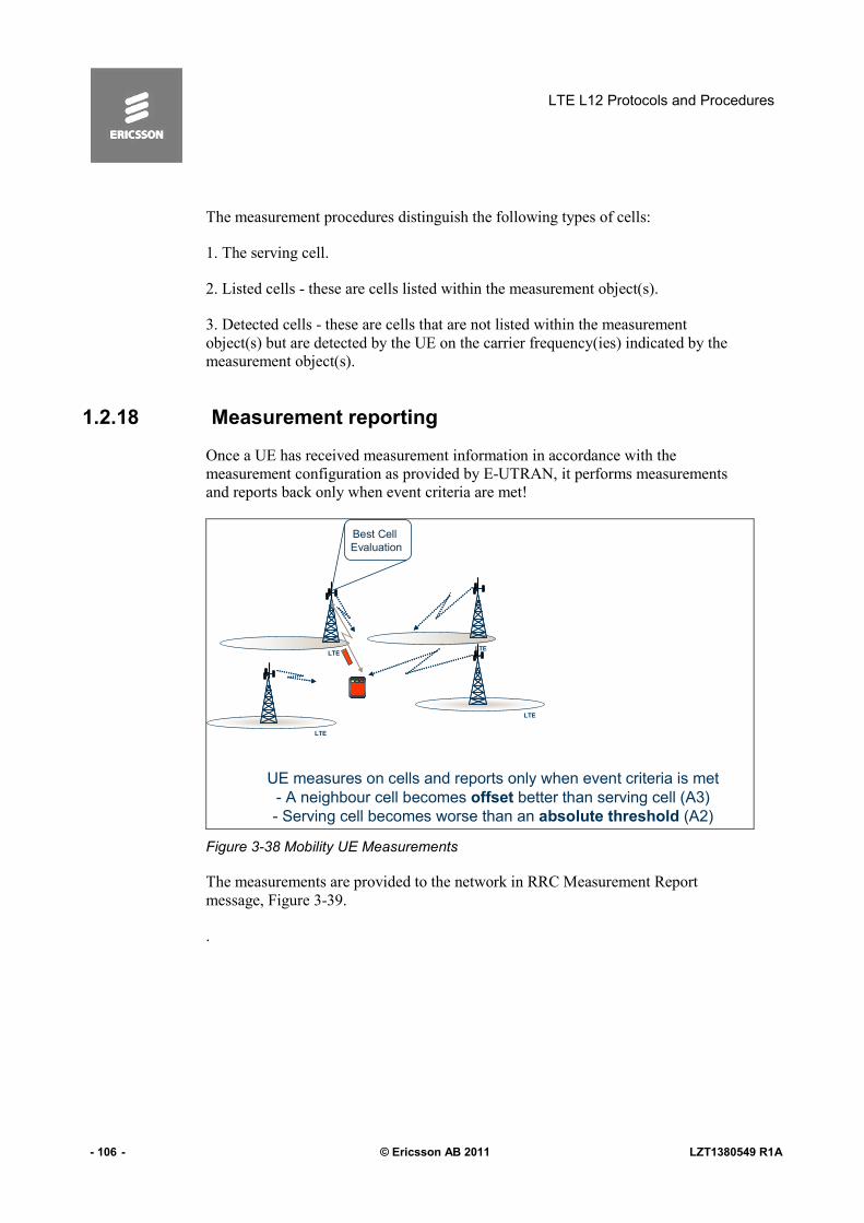
LTE L12 Protocols and Procedures
- 106 - © Ericsson AB 2011 LZT1380549 R1A
The measurement procedures distinguish the following types of cells:
1. The serving cell.
2. Listed cells - these are cells listed within the measurement object(s).
3. Detected cells - these are cells that are not listed within the measurement
object(s) but are detected by the UE on the carrier frequency(ies) indicated by the
measurement object(s).
1.2.18 Measurement reporting
Once a UE has received measurement information in accordance with the
measurement configuration as provided by E-UTRAN, it performs measurements
and reports back only when event criteria are met!
LTELTE
Best Cell
Evaluation
LTE
LTE
UE measures on cells and reports only when event criteria is met
- A neighbour cell becomes offset better than serving cell (A3)
- Serving cell becomes worse than an absolute threshold (A2)
Figure 3-38 Mobility UE Measurements
The measurements are provided to the network in RRC Measurement Report
message, Figure 3-39.
.

L3 Signaling Protocols
LZT1380549 R1A © Ericsson AB 2011 - 107 -
� Measured results
– Event id
– Cell identity
– Measured measurement quantity
RRC MEASUREMENT REPORT
(Measured results)
Reporting criteria
fulfilled
Figure 3-39 Event Triggered Measurement Reporting
Serving becomes worse than threshold1 and inter RAT neighbour becomes better than threshold2Event B2
Inter RAT neighbour becomes better than thresholdEvent B1
Serving becomes worse than threshold1 and neighbour becomes better than threshold2Event A5
Neighbour becomes better than thresholdEvent A4
Neighbour becomes offset better than servingEvent A3
Serving becomes worse than thresholdEvent A2
Serving becomes better than thresholdEvent A1
CriteriaEvent Name
Figure 3-40 Event List
How Measurement Command and Measurement reports are inter working is
further discussed in the Mobility Chapter and in the course LTE Radio Network
Functionality.

LTE L12 Protocols and Procedures
- 108 - © Ericsson AB 2011 LZT1380549 R1A
1.3 S1 Interface
1.3.1 S1 Protocol Model
S1-AP
Transport
Network
Layer
GTP-U
UDP
IP
Data link layer
Physical layer
User PlanePDUs
SCTP
IP
Data link layer
Physical layer
Radio
Network
Layer
Control Plane User Plane
Transport Network
User Plane
Transport Network
User Plane
S1-AP
Transport
Network
Layer
GTP-U
UDP
IP
Data link layer
Physical layer
GTP-U
UDP
IP
Data link layer
Physical layer
User PlanePDUs
SCTP
IP
Data link layer
Physical layer
SCTP
IP
Data link layer
Physical layer
Radio
Network
Layer
Control Plane User Plane
Transport Network
User Plane
Transport Network
User Plane
Figure 3-41 S1 Interface
The E-UTRAN is layered into a Radio Network Layer (RNL) and a Transport
Network Layer (TNL). The E-UTRAN architecture, i.e. the E-UTRAN logical
nodes and interfaces between them, are defined as part of the Radio Network
Layer.
The E-UTRAN architecture consists of a set of eNBs connected to the EPC
through the S1. The S1 interface is specified at the boundary between the EPC
and the E-UTRAN. From the S1 perspective, the E-UTRAN access point is an
eNB, and the EPC access point is either the control plane MME logical node or
the user plane S-GW logical node. Two types of S1 interfaces are thus defined at
the boundary depending on the EPC access point: S1-MME towards an MME
and S1-U towards an S- GW.

L3 Signaling Protocols
LZT1380549 R1A © Ericsson AB 2011 - 109 -
There may be multiple S1-MME logical interfaces towards the EPC from any one
eNB. The selection of the S1-MME interface is then determined by the NAS
Node Selection Function. There may be multiple S1-U logical interfaces towards
the EPC from any one eNB. The selection of the S1-U interface is done within
the EPC and signaled to the eNB by the MME.
S1 signaling bearer provides the following functions:
- Provision of reliable transfer of S1-AP message over S1-MME interface.
- Provision of networking and routing function
- Provision of redundancy in the signaling network
- Support for flow control and congestion control
SCTP will be supported as the transport layer of S1-MME signaling bearer.
SCTP refers to the Stream Control Transmission Protocol developed by the
Sigtran working group of the IETF for the purpose of transporting various
signaling protocols over IP network.
There shall be only one SCTP association established between one MME and
eNB pair.
The eNB shall establish the SCTP association.
Within the SCTP association established between one MME and eNB pair:
- a single pair of stream identifiers shall be reserved for the sole use of S1AP
elementary procedures that utilize non UE-associated signaling.
- At least one pair of stream identifiers shall be reserved for the sole use of S1AP
elementary procedures that utilize UE-associated signaling. However a few pairs
(i.e. more than one) should be reserved.
- A single UE-associated signaling shall use one SCTP stream and the stream
should not be changed during the communication of the UE-associated signaling.
Transport network redundancy may be achieved by SCTP multi-homing between
two end-points, of which one or both is assigned with multiple IP addresses.
SCTP end-points shall support a multi-homed remote SCTP end-point. For SCTP
endpoint redundancy an INIT may be sent from MME or eNB, at any time for an
already established SCTP association.
Using an implementation specific mechanism the SCTP congestion control may,
initiate higher layer protocols to reduce the signaling traffic at the source and
prioritize certain messages.

LTE L12 Protocols and Procedures
- 110 - © Ericsson AB 2011 LZT1380549 R1A
The eNB and MME shall support IPv6 and/or IPv4.
The IP layer of S1-MME only supports point-to-point transmission for delivering
S1-AP message.
The eNB and MME shall support the Diffserv Code Point marking.
The support of any suitable data link layer protocol, e.g. PPP, Ethernet, etc., shall
not be prevented.
The GTP-U protocol over UDP over IP shall be supported as the transport for
data streams on the S1 interface.
The transport bearer is identified by the GTP-U TEID and the IP address (source
TEID, destination TEID, source IP address, destination IP address).
The path protocol used shall be UDP.
The UDP port number for GTP-U shall be as defined.
The eNB and the EPC shall support fragmentation and assembly of GTP packets
at the IP layer.
The eNB and the EPC shall support IPv6 and/or IPv4.
There may be one or several IP addresses in the eNB and in the EPC. The packet
processing function in the EPC shall send downstream packets of a given E-RAB
to the eNB IP address (received in S1-AP) associated to that particular E-RAB.
The packet processing function in the eNB shall send upstream packets of a given
E-RAB to the EPC IP address (received in S1-AP) associated to that particular E-
RAB.

L3 Signaling Protocols
LZT1380549 R1A © Ericsson AB 2011 - 111 -
1.3.2 S1 Application Part S1AP Protocol
•E-RAB Management
•Initial Context Transfer Function
•Common ID management
•UE Capability Info Indication Function
•Mobility Function for UEs in LTE_ACTIVE
•Paging
•S1 Interface Management Functions
•NAS signaling Transport between UE and MME
•S1 UE Context Release Function
•UE Context Modification Function
•Status Transfer
•Trace Function
•Location Reporting
•S1 CDMA 2000 Tunneling Function
•Warning Message Transmission Function
MME
Figure 3-42 S1AP eNB <->MME Signaling
S1AP protocol has the following functions:
E-RAB management function: This overall functionality is responsible for setting
up, modifying and releasing E-RABs which are triggered by the MME. The
release of E-RABs may be triggered by the eNB as well.
Initial Context Transfer function: This functionality is used to establish an S1UE
context in the eNB, to setup the default IP connectivity, to setup one or more E-
RAB(s) if requested by the MME, and to transfer NAS signaling related
information to the eNB if needed.
UE Capability Info Indication function: This functionality is used to provide the
UE Capability Info when received from the UE to the MME.
Mobility Functions for UEs in LTE_ACTIVE in order to enable a change of
eNBs within SAE/LTE (Inter MME/Serving SAE-GW Handovers) via the S1
interface (with EPC involvement).
Paging: This functionality provides the EPC with the capability to page the UE.

LTE L12 Protocols and Procedures
- 112 - © Ericsson AB 2011 LZT1380549 R1A
S1 interface management functions comprise the following:
- Reset functionality to ensure a well defined initialization on the S1 interface.
- Error Indication functionality to allow a proper error reporting/handling in cases
where no failure messages are defined.
- Overload function to indicate the load situation in the control plane of the S1
interface.
- Load balancing function to ensure equally loaded MMEs within an MME pool
area.
- S1 Setup functionality for initial S1 interface setup for providing configuration
information.
- eNB and MME Configuration Update functions are to update application level
configuration data needed for the eNB and MME to interoperate correctly on the
S1 interface.
NAS Signaling transport function between the UE and the MME is used:
- to transfer NAS signaling related information and to establish the S1 UE context
in the eNB.
- to transfer NAS signaling related information when the S1 UE context in the
eNB is already established.
S1 UE context Release function: This functionality is responsible for managing
the release of UE specific context in the eNB and the MME.
UE Context Modification function: This functionality allows modification of the
established UE Context in part.
Status Transfer: This functionality transfers PDCP SN Status information from
source eNB to target eNB in support of in-sequence delivery and duplication
avoidance at intra LTE handover.
Trace function: This functionality is to control a trace recording for a UE in
ECM_CONNECTED.
Location Reporting: This functionality allows MME to be aware of the UE’s
current location.
S1 CDMA2000 Tunneling function: This functionality is used to carry
CDMA2000 signaling between UE and CDMA2000 RAT over the S1 Interface.

L3 Signaling Protocols
LZT1380549 R1A © Ericsson AB 2011 - 113 -
Warning message transmission function:
This functionality provides the means to start and overwrite the broadcasting of
warning message.
1.3.3 S1AP elementary procedures
Figure 3-43 below shows the S1AP Elementary Procedures
HANDOVER FAILUREHANDOVER REQUEST
ACKNOWLEDGE
HANDOVER REQUESTHandover Resource Allocation
INITIAL CONTEXT SETUP
FAILURE
INITIAL CONTEXT SETUP
RESPONSE
INITIAL CONTEXT SETUP
REQUEST
Initial Context Setup
E-RAB RELEASE RESPONSEE-RAB RELEASE COMMANDE-RAB Release
E-RAB MODIFY RESPONSEE-RAB MODIFY REQUESTE-RAB Modify
E-RAB SETUP RESPONSEE-RAB SETUP REQUESTE-RAB Setup
HANDOVER CANCEL
ACKNOWLEDGE
HANDOVER CANCELHandover Cancellation
PATH SWITCH REQUEST
FAILURE
PATH SWITCH REQUEST
ACKNOWLEDGE
PATH SWITCH REQUESTPath Switch Request
HANDOVER PREPARATION
FAILURE
HANDOVER COMMANDHANDOVER REQUIREDHandover Preparation
Unsuccessful outcome
Response Message
Successful Outcome
Response Message
Initiating MessageElementary
Procedure, class 1
Figure 3-43. S1AP Elementary Procedures – Class 1

LTE L12 Protocols and Procedures
- 114 - © Ericsson AB 2011 LZT1380549 R1A
S1 SETUP FAILURES1 SETUP RESPONSES1 SETUP REQUESTS1 Setup
WRITE-REPLACE WARNING
RESPONSE
WRITE-REPLACE WARNING
REQUEST
Write-Replace Warning
MME CONFIGURATION
UPDATE FAILURE
MME CONFIGURATION
UPDATE ACKNOWLEDGE
MME CONFIGURATION
UPDATE
MME Configuration Update
ENB CONFIGURATION
UPDATE FAILURE
ENB CONFIGURATION
UPDATE ACKNOWLEDGE
ENB CONFIGURATION
UPDATE
eNB Configuration Update
UE CONTEXT MODIFICATION
FAILURE
UE CONTEXT MODIFICATION
RESPONSE
UE CONTEXT
MODIFICATION REQUEST
UE Context Modification
UE CONTEXT RELEASE
COMPLETE
UE CONTEXT RELEASE
COMMAND
UE Context Release
RESET ACKNOWLEDGERESETReset
Unsuccessful outcome
Response Message
Successful Outcome
Response Message
Initiating MessageElementary
Procedure, class 1
Figure 3-44. S1AP Elementary Procedures – Class 1
TRACE STARTTrace Start
DEACTIVATE TRACEDeactivate Trace
MME STATUS TRANSFERMME Status Transfer
ENB STATUS TRANSFEReNB Status Transfer
UE CAPABILITY INFO INDICATIONUE Capability Info Indication
UPLINK S1 CDMA2000 TUNNELINGUplink S1 CDMA2000 Tunneling
DOWNLINK S1 CDMA 2000 TUNNELINGDownlink S1 CDMA 2000 Tunneling
UE CONTEXT RELEASE REQUESTUE Context Release Request
ERROR INDICATIONError Indication
NAS NON DELIVERY INDICATIONNAS non delivery Indication
UPLINK NAS TRANSPORTUplink NAS Transport
DOWNLINK NAS TRANSPORTDownlink NAS Transport
INITIAL UE MESSAGEInitial UE Message
PAGINGPaging
E-RAB RELEASE INDICATIONE-RAB Release Indication
HANDOVER NOTIFYHandover Notification
Initiating MessageElementary procedure, class 2
Figure 3-45 S1AP Elementary Procedures – Class 2
The following applies with regard to interference between Elementary
Procedures:

L3 Signaling Protocols
LZT1380549 R1A © Ericsson AB 2011 - 115 -
• The Reset procedure takes precedence over all other EPs.
• The UE Context Release procedure takes precedence over all
other EPs that are using UE-associated signaling.
CELL TRAFFIC TRACECell Traffic Trace
MME CONFIGURATION TRANSFERMME Configuration Transfer
ENB CONFIGURATION TRANSFEReNB Configuration Transfer
MME DIRECT INFORMATION TRANSFERMME Direct Information Transfer
ENB DIRECT INFORMATION TRANSFEReNB Direct Information Transfer
OVERLOAD STOPOverload Stop
OVERLOAD STARTOverload Start
LOCATION REPORTLocation Report
LOCATION REPORTING FAILURE INDICATIONLocation Reporting Failure Indication
LOCATION REPORTING CONTROLLocation Reporting Control
TRACE FAILURE INDICATIONTrace Failure Indication
Initiating MessageElementary procedure, class 2
Figure 3-46 S1 AP Elementary Procedures – Class 2

LTE L12 Protocols and Procedures
- 116 - © Ericsson AB 2011 LZT1380549 R1A
1.4 X2 protocol model
There is a clear separation between the Radio Network Layer and the Transport
Layer. Therefore, the radio network signaling and X2 data streams are separated
from the data transport resource and traffic handling.
X2-AP
Transport
Network
Layer
GTP-U
UDP
IP
Data link layer
Physical layer
User PlanePDUs
SCTP
IP
Data link layer
Physical layer
Radio
Network
Layer
Control Plane User Plane
Transport Network
User Plane
Transport Network
User Plane
X2-AP
Transport
Network
Layer
GTP-U
UDP
IP
Data link layer
Physical layer
GTP-U
UDP
IP
Data link layer
Physical layer
User PlanePDUs
SCTP
IP
Data link layer
Physical layer
SCTP
IP
Data link layer
Physical layer
Radio
Network
Layer
Control Plane User Plane
Transport Network
User Plane
Transport Network
User Plane
Figure 3-47 X2 Protocol Model
Radio >etwork Layer, defines the procedures related to the interaction between
eNBs. It consists of a Radio Network Control Plane and a Radio Network User
Plane.
Transport >etwork Layer provides services for user plane and signaling
transport.

L3 Signaling Protocols
LZT1380549 R1A © Ericsson AB 2011 - 117 -
1.4.1 X2 Application Part X2AP Protocol
Mobility Management
Load Management
Reporting of General Error Situations
Resetting the X2
Setting up the X2
eNodeB Configuration Update
Figure 3-48 X2AP: eNB<->eNB Signaling
1.4.1.1 Intra LTE-Access-System mobility support for ECM-CONNECTED UE
This function allows the eNB to handover the control of a certain UE to another
eNB.
1.4.1.2 Context transfer from source eNB to target eNB
This function allows the transferring of information required to maintain the E-
UTRAN services for an UE in ECM-CONNECTED from source to target eNB.
1.4.1.3 Control of user plane transport bearers between source eNB and target eNB
This function allows the establishing and releasing of transport bearers between
source and target eNB to allow for data forwarding. At most, one user plane
transport bearer per E-RAB allocated to the UE may be established for relaying
DL data received from the EPC from the source eNB to the target eNB. At most,
one user plane transport bearer per E-RAB allocated to the UE may be
established for relaying the UL data received from the UE from the source eNB
to the target eNB.

LTE L12 Protocols and Procedures
- 118 - © Ericsson AB 2011 LZT1380549 R1A
1.4.1.4 Handover cancellation
This function allows informing an already prepared target eNB that a prepared
handover will not take place. It allows releasing the resources allocated during a
preparation.
1.4.1.5 UE context release in source eNB
This function allows the target eNB to trigger the release of the resources
allocated to the UE in the source eNB.
1.4.1.6 Load Management
This function allows exchanging of overload and traffic load information
between eNBs such that the eNBs can control the traffic load appropriately. This
information may be spontaneously sent to selected neighbor eNBs or reported as
configured by a neighbor eNB.
1.4.1.7 Inter-cell interference coordination
This function allows for keeping inter-cell interference under control. To achieve
this, neighboring eNBs exchange appropriate information allowing the eNBs to
make radio resource assignments such that interference is mitigated.
1.4.1.8 Uplink interference load management
This function allows indicating an uplink interference overload and resource
blocks especially sensitive to inter-cell interference between neighboring eNBs.
Neighbor eNBs can co-ordinate with each other such that the mutual interference
caused by their uplink radio resource allocations is mitigated.
1.4.1.9 Downlink interference avoidance
This function allows an eNB to inform its neighbor eNBs about downlink power
restrictions in its own cells, per resource block, for interference aware scheduling
by the neighbor eNBs.
1.4.1.10 General X2 management and error handling functions
These functions allow for managing of signaling associations between eNBs,
surveying X2 interface and recovering from errors.

L3 Signaling Protocols
LZT1380549 R1A © Ericsson AB 2011 - 119 -
1.4.1.11 Error indication
This function allows the reporting of general error situations on application level.
1.4.1.12 Reset
This function allows an eNB1 to inform another eNB2 that it has recovered from
an abnormal failure and that all the contexts related to eNB1 and stored in eNB2
shall be deleted, and the associated resources released.
1.4.1.13 Trace functions
Trace recoding sessions on E-UTRAN interfaces for a particular UE is initiated
by the EPC. The trace initiation information is also propagated to the Target eNB
during handover, attached to certain handover messages on X2.
1.4.1.14 Application level data exchange between eNBs
This function allows two eNBs to exchange application level data when an X2
connection is setup and to update this information at any time.

LTE L12 Protocols and Procedures
- 120 - © Ericsson AB 2011 LZT1380549 R1A
1.4.1.15 X2AP Elementary Procedures
In the following figures all EPs are divided into Class 1 and Class 2 EPs.
RESET RESPONSERESET REQUESTRESET
RESOURCE STATUS
FAILURE
RESOURCE STATUS
RESPONSE
RESOURCE STATUS
REQUEST
RESOURCE STATUS REPORTING
INITIATION
ENB CONFIGURATION
UPDATE FAILURE
ENB CONFIGURATION
UPDATE ACKNOWLEDGE
ENB CONFIGURATION
UPDATE
ENB CONFIGURATION UPDATE
X2 SETUP FAILUREX2 SETUP RESPONSEX2 SETUP REQUESTX2 SETUP
HANDOVER PREPARATION
FAILURE
HANDOVER REQUEST
ACKNOWLEDGE
HANDOVER REQUESTHANDOVER PREPARATION
Unsuccessful outcome
Response Message
Successful Outcome
Response Message
Initiating MessageElementary
Procedure, class 1
Figure 3-49 X2 AP Elementary Procedures - Class
ERROR INDICATIONERROR INDICATION
RESOURCE STATUS UPDATERESOURCE STATUS REPORTING
UE CONTEXT RELEASEUE CONTEXT RELEASE
SN STATUS TRANSFERSN STATUS TRANSFER
HANDOVER CANCELHANDOVER CANCEL
LOAD INFORMATIONLOAD INDICATION
Initiating MessageElementary procedure, class 2
ERROR INDICATIONERROR INDICATION
RESOURCE STATUS UPDATERESOURCE STATUS REPORTING
UE CONTEXT RELEASEUE CONTEXT RELEASE
SN STATUS TRANSFERSN STATUS TRANSFER
HANDOVER CANCELHANDOVER CANCEL
LOAD INFORMATIONLOAD INDICATION
Initiating MessageElementary procedure, class 2
Figure 3-50 X2AP Elementary Procedures - Class 2

L3 Signaling Protocols
LZT1380549 R1A © Ericsson AB 2011 - 121 -
1.5 GTP-C GPRS Tunneling Protocol -Control
GPRS Tunneling Protocol (GTP) is a group of IP-based communications
protocols, see Figure 3-52 used to carry General Packet Radio Service (GPRS)
within GSM , UMTS and LTE networks.
SGW
•Path Management
•Tunnel Management
•Mobility Management
•CS Fallback and SRVCC related msgs
•Non 3GPP related msgs
MME
PGWMME
Figure 3-51 GTP-C v2 MME <-> MME; MME <-> SGW; SGW<->PGW Signalions
GTP can be decomposed into separate protocols, GTP-C, GTP-U.
There are two versions of GTP-C.
GTP-C v2 is used in EPC for signaling between two MMEs, between MME and
SGW and between SGW and PGW, Figure 3-51.
Main procedures of the GTP-C protocol procedures related to:
• Path Management
• Tunnel Management
• Mobility Management
• CS Fallback and SRVCC related messages
• Non 3GPP related messages.
As this is an LTE course we will not focus on the GTP_C protocols details it is
only here for better understanding of RAN procedures.

LTE L12 Protocols and Procedures
- 122 - © Ericsson AB 2011 LZT1380549 R1A
GTP
UDP
IP
L2
L1
GTP
UDP
IP
L2
L1
GTPv2 entity GTPv2 entity
GTPv2 based
interface
Figure 3-52 GTP-C Protocol Stack
1.5.1 Connectivity mechanisms
Apart from the common message structure, there is also a common mechanism
for verifying connectivity from one GTP-C node to another. This uses two
messages.
TS 29.280 [15]Reserved for Sv
interface
25 to 31
TS 29.276 [14]Reserved for S101
interface
4 to 24
XVersion Not Supported
Indication
3
XXEcho Response2
XXEcho Request1
Reserved0
GTP-UGTP-CReferenceMessageMessage Type value (Decimal)
TS 29.280 [15]Reserved for Sv
interface
25 to 31
TS 29.276 [14]Reserved for S101
interface
4 to 24
XVersion Not Supported
Indication
3
XXEcho Response2
XXEcho Request1
Reserved0
GTP-UGTP-CReferenceMessageMessage Type value (Decimal)
Path Management
Figure 3-53 GTP Message Types
As often as every 60 seconds, a GTP-C node (MME, SGW, PGW) can send an
echo request to every other GTP-C node with which it has an active connection.
If the other end does not respond it can be treated as down and active connections
to it deleted.
Echo Request and Echo Response are two messages that are common for GTP-C
and GTP-U protocols.

L3 Signaling Protocols
LZT1380549 R1A © Ericsson AB 2011 - 123 -
› Echo Request
› Echo Response
SGW/
ECHO Request
T3-RESPONSE
ECHO Response
N3-REQUESTS
MME
MME PGW
N3-REQUESTS
T3-RESPONSE
EC
HO
Re
qu
est
EC
HO
Re
spo
nse
EC
HO
Requ
est
EC
HO
Re
spo
nse
T3-RESPONSE
N3-REQUESTS
Figure 3-54 Path Management
1.5.2 Session Related Signalling
GTP-C Control Part is related to the messages used to establish, modify and
delete a session. Direction is from MME to PGW via SGW.
SGWMME
PGW
S11
S5/S8
Create Session Request (QoS)
Cre
ate
Se
ssio
n R
eq
uest
(Qo
S)
Session Creation:
•E-UTRAN Initial Attach
•UE requested PDN connectivity
Figure 3-55 MME -> SGW -> PGW

LTE L12 Protocols and Procedures
- 124 - © Ericsson AB 2011 LZT1380549 R1A
The Create Session Request message is sent on the S11 interface by the MME to
the SGW, and on the S5/S8 interface by the SGW to the PGW as part of the
procedures:
E-UTRAN Initial Attach
UE requested PDN connectivity
The message can also be sent on S4 interface by the SGSN to the SGW, and on
the S5/S8 interface by the SGW to the PGW as part of the procedures:
-PDP Context Activation
The message is also sent on the S11 interface by the MME to the SGW as part of
the procedures:
-Tracking Area Update procedure with Serving GW change
-S1/X2-based handover with SGW change
-UTRAN Iu mode to E-UTRAN Inter RAT handover with SGW change
-GERAN A/Gb mode to E-UTRAN Inter RAT handover with SGW change
-3G Gn/Gp SGSN to MME combined hard handover and SRNS relocation
procedure
-Gn/Gp SGSN to MME Tracking Area Update procedure
and on the S4 interface by the SGSN to the SGW as part of the procedures:
-Routing Area Update with MME interaction and with SGW change
-Gn/Gp SGSN to S4 SGSN Routing Area Update
-E-UTRAN to UTRAN Iu mode Inter RAT handover with SGW change
-E-UTRAN to GERAN A/Gb mode Inter RAT handover with SGW change
-Serving RNS relocation
-Combined hard handover and SRNS relocation
-Combined Cell / URA update and SRNS relocation
-Enhanced serving RNS relocation with SGW relocation

L3 Signaling Protocols
LZT1380549 R1A © Ericsson AB 2011 - 125 -
If the new Create Session Request message is received with TEID 0 in the header
for an existing active PDN connection context, this Create Session Request
message shall be treated as a request for a new session. The existing PDN
connection context should be deleted locally, before a new session is created.
Some of the messages are listed in the Figure 3-56.
For a complete table see TS 29.274.
XDelete Session Response37
XDelete Session Request36
XModify Bearer Response35
XModify Bearer Request34
XCreate Session Response33
XCreate Session Request32
SGSN/MME to PGW (S4/S11, S5/S8)
GTP-CMessageMessage Type value
(Decimal)
XDelete Session Response37
XDelete Session Request36
XModify Bearer Response35
XModify Bearer Request34
XCreate Session Response33
XCreate Session Request32
SGSN/MME to PGW (S4/S11, S5/S8)
GTP-CMessageMessage Type value
(Decimal)
Figure 3-56 MME -> SGW -> PGW

LTE L12 Protocols and Procedures
- 126 - © Ericsson AB 2011 LZT1380549 R1A
Intentionally Blank

PDCP, RLC, MAC and GTP-U
LZT1380549 R1A © Ericsson AB 2011 - 127 -
4 PDCP, RLC, MAC and GTP-U
Objectives
After this chapter the participants will be able to:
1. Explain the PDCP functions and services such as header compression
and ciphering.
2. Explain the RLC Functions
3. List different modes of RLC (transparent, unacknowledged and
acknowledged) and explain the structure of the PDU involved in these
cases
4. Explain the MAC functions such as HARQ, BCH Reception, PCH
Reception
5. Explain MAC Architecture, its entities and their usage for the mapping of
transport channels
6. List the content of the MAC Packet Data Unit (PDU).
7. Explain the main functions and procedures of the transport protocol
GTP-U
Figure 4-1 Objectives

LTE L12 Protocols and Procedures
- 128 - © Ericsson AB 2011 LZT1380549 R1A
1.1 Packet Data Convergence Protocol (PDCP)
PDCP provides its services to the NAS / RRC at the UE or the relay at the
evolved Node B (eNB).
The Packet Data Convergence Protocol supports the following functions:
• header compression and decompression of IP data flows using
the ROHC (Robust Header Compression) protocol, at the
transmitting and receiving entity respectively.
• transfer of data (user plane or control plane). This function is
used for conveyance of data between users of PDCP services.
• maintenance of PDCP sequence numbers for radio bearers
mapped on RLC acknowledged mode.
• in-sequence delivery of upper layer PDUs at Handover
• duplicate elimination of lower layer SDUs at Handover for
radio bearers mapped on RLC acknowledged mode
• ciphering and deciphering of user plane data and control plane
data
• integrity protection of control plane data
• timer based discard
PDCP uses the services provided by the Radio Link Control (RLC) sublayer.

PDCP, RLC, MAC and GTP-U
LZT1380549 R1A © Ericsson AB 2011 - 129 -
� PDCP Services– Transfer of user plane data– Transfer of control plane data– Header compression– Integrity protection of control plane– Ciphering both control and user plane
� PDCP Functions– Header compression/decompression
of IP data flows using ROHC– Transfer of data– Maintenence of SNs for radio bearers– In sequence delivery of upper layer
PDUs at re-establishment of lower layers
– Duplicate detection of lower layer SDUs at re-establishment
– Integrity protection/verification of CP– Ciphering/deciphering of data– Timer based discard– Duplicate discarding
TS 36.323
Figure 4-2. Packet Data Convergence Protocol.
Services provided to upper layers:
PDCP provides its services to the RRC and user plane upper layers at the UE or
to the relay at the evolved Node B (eNB). The following services are provided by
PDCP to upper layers:
• transfer of user plane data;
• transfer of control plane data;
• header compression;
• ciphering;
• integrity protection.
The maximum supported size of a PDCP SDU is 8188 octets.
Services expected from lower layers:
• acknowledged data transfer service, including indication of
successful delivery of PDCP PDUs
• unacknowledged data transfer service
• in-sequence delivery, except at re-establishment of lower layers
• Duplicate discarding, except at re-establishment of lower
layers.

LTE L12 Protocols and Procedures
- 130 - © Ericsson AB 2011 LZT1380549 R1A
The PDCP entities are located in the PDCP layer. Several PDCP entities may be
defined for a UE. Each PDCP entity that carries user plane data may be
configured to use header compression.
Radio Bearers
UE/E-UTRAN
PDCP ...
RLC
PDCP - PDU
RLC - SDU
C-SAP
PDCP-SAP
RLC UM-SAP RLC AM-SAP
PDCP entity PDCP entity
PDCP-SAP
...
TS 36.323
Figure 4-3. PDCP Architecture.
Each RB (i.e. DRB and SRB, except for SRB0) is associated with one PDCP
entity. Each PDCP entity is associated with one or two RLC entities (one for each
direction) depending on the RB characteristic (i.e. uni-directional or bi-
directional) and RLC mode. The PDCP entities are located in the PDCP sublayer.
The PDCP sublayer is configured by upper layers.

PDCP, RLC, MAC and GTP-U
LZT1380549 R1A © Ericsson AB 2011 - 131 -
Radio Interface (Uu)
UE/E-UTRAN E-UTRAN/UE
Transmitting
PDCP entity
Ciphering
Header Compression
(user plane only)
Receiving
PDCP entity
Sequence numbering
Integrity Protection
(control plane only)
Add PDCP header
Deciphering
Remove PDCP Header
In order delivery and duplicate
Detection (U plane)
Integrity Verification
(control plane only)
Packets associated
to a PDCP SDU
Header Compression
(user plane only)
Packets associated
to a PDCP SDU
Packe
ts N
OT
associa
ted
to a
PD
CP
SD
U
Packets
NO
T a
ssocia
ted
to a
PD
CP
SD
U
Figure 4-4. PDCP Entity.
Each PDCP entity carries the data of one radio bearer. In this version of the
specification only the robust header compression protocol (ROHC) is supported.
Every PDCP entity uses at most one ROHC instance.
A PDCP entity is associated either with the control plane or the user plane,
depending on which radio bearer it is carrying data for.
1.1.1 Sequence Numbering
Sequence numbering is the first PDCP task at reception of an IP package. There
are several functions that use the sequence number:
• Reordering of the PDCP PDUs at the receiver side
• Duplicate detection in case of packet forwarding at handover

LTE L12 Protocols and Procedures
- 132 - © Ericsson AB 2011 LZT1380549 R1A
• Calculation of COUNT, used for integrity protection and
ciphering. As illustrated in Figure 4-5 PDCP SN is part of the
least significant bits of the COUNT counter.
UEUEUE
CtxUE
Ctx
SRB1_UL
DRB_UL
COUNT
COUNT
COUNT
COUNT
HOW:
PDCP SN:
Next_PDCP_TX_SN
TX_HFN
COUNT
WHY: * Reordering
* Duplicate detection
* Integrity protection
* Ciphering
eNB
SRB1_DLSRB1_DL
SRB1_UL
DRB_DLDRB_DL
DRB_UL
HFN PDCP SNHFN PDCP SN
COUNT
COUNT
COUNT
COUNT
Figure 4-5. Sequence numbering.
1.1.2 Header compression and decompression
In many services and applications e.g. Voice over IP, interactive games,
messaging etc, the payload of the IP packet is sometimes even smaller than the
header. Over an end-to-end connection comprised of multiple hops the content of
the IP header is extremely important. However, over just one link (UE to eNodeB
, hop-to-hop) some information can be omitted as it will never change due to its
static nature during a connection time. It is possible to compress those headers in
many cases up to 90%. As a consequence link budget can be improved by several
dB due to the decrease in header size.

PDCP, RLC, MAC and GTP-U
LZT1380549 R1A © Ericsson AB 2011 - 133 -
WHY: Saving the bandwith by
HOW: *removing redundant info
*Encoding important info
*Hop by Hop
*Unidirectional
RB_ULRB_ULHeader PDCP PDUHeader PDCP PDU PDCP PDUHeaderPDCP PDU HeaderPDCP PDU
Timestamp
Destination address
Source address
Sequence no
Destination portSource port
PTMCCV P X
TTL Protocol Checksum
Fragment offsetFlagsIdentification
Packet lengthTOSV=4 Hlen
IPv
4
UD
P
STATIC
INFERRED
CHANGES
RARELY
CHANGES
OFTEN
RT
P
Appr. 30 of
40 octets are
static or
easily
compressible!
Checksum
SSRC Identifier
Length
8
CRC
checksum covering the header before
compression is included in the compressed header
Compressed Header
Contains encoded data
UE/UE Context
UE/UE Context
Figure 4-6. Header Compression.
In the low bandwidth networks the use of header compression results in a better
response time due to smaller packet sizes.
Header Compression has to be negotiated at the time of the link setup. Both sides
of the link need to be capable of running the same header compression
algorithms.
The header compression protocol specified in PDCP is based on the Robust
Header Compression (ROHC) framework IETF RFC 3095. There are multiple
header compression algorithms, called profiles, defined for the ROHC
framework. Each profile is specific to the particular network layer, transport layer
or upper layer protocol combination e.g. TCP/IP and RTP/UDP/IP.

LTE L12 Protocols and Procedures
- 134 - © Ericsson AB 2011 LZT1380549 R1A
1.1.2.1 Header compression
The header compression protocol generates two types of output packets:
• compressed packets, each associated with one PDCP SDU
• standalone packets not associated with a PDCP SDU, i.e.
interspersed ROHC feedback packets.
A compressed packet is associated with the same PDCP SN and COUNT value as
the related PDCP SDU.
Interspersed ROHC feedback packets are not associated with a PDCP SDU. They
are not associated with a PDCP SN and are not ciphered.
1.1.2.2 Header decompression
If header compression is configured by upper layers for PDCP entities associated
with u-plane data the PDCP PDUs are de-compressed by the header compression
protocol after performing deciphering.
1.1.3 Security Handling
Traffic security for the radio interface comprises integrity protection and
ciphering of the RRC messages as well as ciphering of UP data messages.
Integrity protection is implemented in the PDCP layer in order to ensure that the
data origin of the signaling data is indeed the one claimed. It also allows the
receiving entity to verify that the received data has not been modified in an
unauthorized way.
The purpose of the data encryption (ciphering) is to ensure that the user data
cannot be eavesdropped on the radio.

PDCP, RLC, MAC and GTP-U
LZT1380549 R1A © Ericsson AB 2011 - 135 -
1.1.3.1 Integrity Protection and Verification
The integrity protection function includes both integrity protection and integrity
verification and is performed in PDCP for PDCP entities associated with SRBs.
The data unit that is integrity protected is the PDU header and the data part of the
PDU before ciphering.
EIAEIACOUNT
Direction
K_eNB_RRCInt
PDCP PDUPDCP PDU
HeaderPDCP SDU
Bearer Id
MAC-I
PD
CP
PD
U
He
ad
er
PD
CP
SD
UP
DC
P P
DU
He
ad
er
PD
CP
SD
U
EIAEIACOUNT
Direction
K_eNB_RRCInt
PDCP PDUPDCP PDU
HeaderPDCP SDU
Bearer Id
XMAC-I
XMAC-IMAC-I =
Sending Side
UE/eNBReceiving Side
UE/eNB
WHY: To ensure data origin
Figure 4-7 Integrity Protection.
The integrity protection key to be used by the PDCP entity is generated from
KASME that is generated during EPS Authentication and Key Agreement (AKA)
procedure.
UE computes the KASME based on the parameters received in the Authentication
Request message and the MME receives the KASME. from HSS. KASME is further
used to generate K_eNB. Using key derivation function KRRCenc, KRRC int and KUPenc
are derived from K_eNB whenever the UE goes into RRC-CONNECTED state
(from idle or on the initial attach). The keys are also changed at each handover.
Which algorithm to use is decided by eNodeB by during RRC security activation,
the integrity protection function shall be applied to all control plane PDUs for the
downlink and the uplink, respectively.

LTE L12 Protocols and Procedures
- 136 - © Ericsson AB 2011 LZT1380549 R1A
NOTE: The RRC message which activates the integrity protection function is
itself integrity protected with the configuration included in this RRC message.
Therefore this message needs first to be decoded by RRC before the integrity
protection verification could be performed for the PDU in which the message was
received.
The parameters that are required by PDCP for integrity protection are defined in
3GPP TS 33.401 and are input to the integrity protection algorithm. The required
inputs to the integrity protection function include the COUNT value, and
DIRECTION (DL or UL). The parameters required by PDCP which are provided
by upper layers are:
• BEARER, defined as the radio bearer identifier, (SRB1 will use
the value RB identity –1)
• KEY (KRRCint).
At transmission the UE computes the value of the Message Authentication Code
– Integrity (MAC-I) field and at reception it verifies the integrity of the PDCP
PDU by calculating the Expected Message Authentication Code Integrity (X-
MAC-I) based on the input parameters as specified above. If the calculated X-
MAC is equal to the received MAC-I then integrity protection has been verified
successfully.
When a PDCP entity receives a PDCP PDU that contains reserved or invalid
values the PDCP entity shall discard the received PDU.

PDCP, RLC, MAC and GTP-U
LZT1380549 R1A © Ericsson AB 2011 - 137 -
1.1.3.2 Ciphering and Deciphering.
The ciphering function in PDCP includes both ciphering and deciphering and is
performed in PDCP. For the control plane, the data unit that is ciphered is the
data part of the PDCP PDU and the MAC-I. For the user plane, the data unit that
is ciphered is the data part of the PDCP PDU; ciphering is not applicable to
PDCP Control PDUs.
PLAINTEXT
BLOCK PLAINTEXT
BLOCK
EEA
COUNTDIRECTION
BEARER LENGTH
KEYUPenc
KEYSTREAM
BLOCK
CIPHERTEXT
BLOCK CIPHERTEXT
BLOCK
EEA
DIRECTION
BEARER LENGTH
KEYSTREAM
BLOCK
PLAINTEXT
BLOCK PLAINTEXT
BLOCK
Sender Receiver
EEA0
EEA1
EEA2
COUNT
WHY: To protect the data over radio
KEYUPenc
Figure 4-8. Ciphering.
The encryption key to be used by the PDCP entity is generated generated from
KASME that is generated EPS Authentication and Key Agreement (AKA)
procedure.
UE Computes the KASME based on the parameters received in the Authentication
Request message and the MME receives the KASME. from HSS. KASME is further
used to generate K_eNB.. Then, using key derivation function, KRRCenc, KRRC int and
KUPenc are derived from K_eNB whenever the UE goes into RRC-CONNECTED
state (from idle or on the initial attach). The keys are also changed at each
handover.
The ciphering function is activated by upper layers as defined in 3GPP TS
36.331. After security activation the ciphering function shall be applied to all
PDCP PDUs indicated by upper layers for the downlink and the uplink,
respectively.

LTE L12 Protocols and Procedures
- 138 - © Ericsson AB 2011 LZT1380549 R1A
The parameters that are required by PDCP for ciphering are defined in
3GPP TS 33.401 and are input to the ciphering algorithm. The required inputs to
the ciphering function include the:
• COUNT
• DIRECTION (DL or UL)
• BEARER (defined as the radio bearer identifier )
• KEY (the ciphering keys for the control plane and for the user
plane are KRRCenc and KUPenc, respectively).
1.1.4 PDCP PDU formats
There are two type of PDCP PDUs:
• PDCP Data PDUs
• PDCP Control PDUs
As listed in Figure 4-9 PDCP Data PDUs are used to convey both
Control plane and User plane SDUs.
The PDCP Data PDU is used to convey:
1. A PDCP SDU SN
2. User plane data containing uncompressed PDCP SDU
3. User plane data containing compressed PDCP SDU
4. Control plane data
5. MAC-I field (for SRB only)
Figure 4-9. PDCP Data PDU.
The left part of Figure 4-10 shows the format of the PDCP Data PDU carrying
data for control plane SRBs.
The upper right part of Figure 4-10 shows the format of the PDCP Data PDU
when a 12 bit SN length is used. This format is applicable for PDCP Data PDUs
carrying data from DRBs mapped on RLC AM or RLC UM.
Lower right part of Figure 4-10 shows the format of the PDCP Data PDU when a
7 bit SN length is used. This format is applicable for PDCP Data PDUs carrying
data from DRBs mapped on RLC UM.

PDCP, RLC, MAC and GTP-U
LZT1380549 R1A © Ericsson AB 2011 - 139 -
Oct 1
Oct 2
Oct N
Oct N-1
Oct N-2
Oct N-3
...
Data
PDCP SNR R R
MAC-I
MAC-I (cont.)
MAC-I (cont.)
MAC-I (cont.)
Oct 1
Oct 2
Oct N
Oct N-1
Oct N-2
Oct N-3
...
Data
PDCP SNR R R
MAC-I
MAC-I (cont.)
MAC-I (cont.)
MAC-I (cont.)
...
PDCP SN (cont.)
Data
D/C PDCP SNR R R Oct 1
Oct 2
Oct 3
...
D/C PDCP S N Oct 1
Oct 2Data
PDCP Data: PDU format SRB PDCP Data: PDU format DRB:
SN 12 bits mapped to RLC AM/UM
SN 7 bits mapped to RLC UM
Figure 4-10. PDCP Data PDU format.
The left part of Figure 4-11 shows the format of the PDCP Control PDU carrying
one interspersed ROHC feedback packet. This format is applicable for DRBs
mapped on RLC AM or RLC UM.
The right part of Figure 4-11 shows the format of the PDCP Control PDU
carrying one PDCP status report. This format is applicable for DRBs mapped on
RLC AM.
PDCP Control: ROHC feedback
...
Interspersed ROHC feedback packet
D/C PDU Type R RR R Oct 1
Oct 2
PDCP Control: STATUS Report
...
Bitmap 1 (optional)
D/C PDU Type
BitmapN (optional )
FMS (cont.)
FMS Oct 1
Oct 2
Oct 3
Oct 2+N
D/C Data/Control
FMS First Missing PDCP SN
ROHC RObust Header Compression
Figure 4-11. PDCP Control PDU format.

LTE L12 Protocols and Procedures
- 140 - © Ericsson AB 2011 LZT1380549 R1A
1.2 Radio Link Control Protocol
Radio Link Control (RLC) Protocol Layer is a Layer 2 protocol.
It is controlled and configured by RRC layer, but it offers services both to RRC
and PDCP protocols. As listed in the figure below, RLC is responsible for
providing data transfer to/from the upper layers (PDCP and RRC) in three
different modes:
› RLC Services
RLC Services provided to upper layers:
– Transparent data transfer
– Unacknowledged data transfer
– Acknowledged data transfer
RLC Services expected from lower layers:
– Data transfer
– Notification of a transmission opportunity
– Notification of HARQ delivery failure from transmitting MAC entity
› RLC Functions
– Segmentation, re-segmentation and assembly
– Concatenation
– Padding
– Transfer of user data in TM, UM and AM.
– Error correction (ARQ)
– In-sequence delivery
– Duplicate detection
– Flow control
– RLC Re-establishment
– Protocol Error Detection and Recovery
TS 36.322
Figure 4-12: RLC Protocol Entity - Functions and Services
• TM Transparent Mode
• UM Unacknowledged Mode
• AM Acknowledged Mode

PDCP, RLC, MAC and GTP-U
LZT1380549 R1A © Ericsson AB 2011 - 141 -
Functions of the RLC protocols are performed by the RLC entities. For an RLC
entity in eNB there is a corresponding RLC entity in the UE and vice versa. An
RLC entity can be configured to operate in TM, UM or AM mode. Figure 4-13
illustrates RLC entities. TM and UM RLC entities are independent of each other
in UL and DL and are configured to be either a receiving or a transmitting entity.
For AM mode RLC entities there is dependency that is related to the ARQ
mechanism. AM RLC entities are also configured to be either receiving or
transmitting entities.
radio interface
lower layers(i.e. MAC sub layer and physical layer)
transmittingTM RLC entity
transmittingUM RLC entity
AM RLC entityreceiving
TM RLC entityreceiving
UM RLC entity
receivingTM RLC entity
receivingUM RLC entity
AM RLC entitytransmitting
TM RLC entitytransmitting
UM RLC entity
lower layers(i.e. MAC sub layer and physical layer)
upper layer (i.e. RRC layer or PDCP sub layer)
upper layer (i.e. RRC layer or PDCP sub layer)
eNB
UE
SAP betweenupper layers
logical channel
logical channel
SAP betweenupper layers
Figure 4-13 Overview model of the RLC
The following applies to all three RLC entity types:
• RLC SDUs of variable sizes are byte aligned
• RLC PDUs are formed only when transmission opportunity has
been notified by lower layer and then delivered to lower layer
Differences are described in following subchapters.

LTE L12 Protocols and Procedures
- 142 - © Ericsson AB 2011 LZT1380549 R1A
1.2.1 RLC TM Entity
Transparent Mode RLC entity is illustrated in Figure 4-14.
Transmission
buffer
Transmitting
TM-RLC
entity
TM-SAP
radio interface
Receiving
TM-RLC
entity
TM-SAP
UE/ENB ENB/UE
BCCH/PCCH/CCCH BCCH/PCCH/CCCH
Figure 4-14 RLC TM Entity
It can be configured to deliver/receive RLC PDUs through the following logical
channels:
• BCCH Broadcast Control Channel (System Information
transfer)
• DL/UL CCCH Common Control Channel ( example: RRC
Connection Request )
• PCCH Paging Control Channel (Paging)
When transmitting TM RLC SDUs, TM Entity does not perform any
segmentation nor concatenation of the data received and does not include any
header information.
The size of the data, i.e the fraction that is scheduled for the RLC TM entity
indicated by the lower layer at the particular transmission opportunity, must be
large enough to fit TMD PDU.
Receiving TM Entity just sends received data to the upper layer (RRC).

PDCP, RLC, MAC and GTP-U
LZT1380549 R1A © Ericsson AB 2011 - 143 -
1.2.2 RLC UM Entity
RLC UM Entity is illustrated in Figure 4-15.
Transmission
buffer
Segmentation &
Concatenation
Add RLC header
Transmitting
UM-RLC
entity
UM-SAP
radio interface
Receiving
UM-RLC
entity
UM-SAP
UE /ENB ENB /UE
DTCH DTCH
Reception
buffer & HARQ
reordering
SDU reassembly
Remove RLC header
Figure 4-15 RLC UM Entity
It can be configured to send or receive the data sent on the DL/UL DTCH, i.e.
UM RLC entity is supposed to carry user data payload for the time critical
services that tolerate a higher packet loss rate, such as Voice over IP. In LTE
RAN the RLC in Unacknowledged Mode feature is a licensed feature.
The transmitting UM RLC entity segments and/or concatenates the RLC SDUs so
that the UMD PDU fits within the total size of RLC PDU indicated by the lower
layer at the particular transmission opportunity. As segmentation and/or
concatenation is applicable an RLC header needs to be included.
Receiving UM RLC Entity:
1 Detects whether or not the UMD PDUs have been received already (duplicate
detection) and if so discard the UMD PDU.

LTE L12 Protocols and Procedures
- 144 - © Ericsson AB 2011 LZT1380549 R1A
2 Reorders in case UMD PDUs are received out of sequence.
3 Reassembles RLC SDUs from reordered UMD PDUs and delivers
the RLC SDUs to upper layer in ascending order of RLC SN.
4 Discards received UMD PDUs that can not be re assembled into RLC
SDUs due to loss at lower layers.
5 In case of RLC reestablishment the receiving UM RLC Entity
6 If possible reassembles RLC SDUs from UMD PDUs that are
received out of sequence and delivers them to upper layer
7 Discards any remaining UMD PDUs that could not be reassembled
into RLC SDUs.

PDCP, RLC, MAC and GTP-U
LZT1380549 R1A © Ericsson AB 2011 - 145 -
1.2.3 RLC AM Entity
RLC Am Entity is illustrated in Figure 4-16.
Transmission
buffer
Segmentation &
Concatenation
Add RLC header
Retransmission
buffer
RLC control
Routing
Reception
buffer & HARQ
reordering
SDU reassembly
DCCH /DTCH DCCH /DTCH
AM -SAP
Remove RLC header
Figure 4-16 RLC AM Entity
It can be configured to send or receive the data sent on the DL/UL DTCH DL/UL
DCCH, i.e. majority of the signaling and user data will be sent using RLC AM
entity.
When the transmitting side of an AM RLC entity forms AMD PDUs from RLC
SDUs, it:
1 Segments and/or concatenates the RLC SDUs so that the AMD PDUs fit
within the total size of RLC PDU(s) indicated by lower layer at the particular
transmission opportunity notified by lower layer.

LTE L12 Protocols and Procedures
- 146 - © Ericsson AB 2011 LZT1380549 R1A
2 The transmitting side of an AM RLC entity supports retransmission
of RLC data PDUs (ARQ). If the RLC data PDU to be retransmitted
does not fit within the total size of RLC PDU(s) indicated by lower
layer at the particular transmission opportunity notified by lower
layer, the AM RLC entity can re-segment the RLC data PDU into
AMD PDU segments. The number of re-segmentation is not limited.
3 When the transmitting side of an AM RLC entity forms AMD PDUs
from RLC SDUs received from upper layer or AMD PDU segments
from RLC data PDUs to be retransmitted, it includes relevant RLC
headers in the RLC data PDU.
When the receiving side of an AM RLC entity receives RLC data PDUs it:
1 Detects whether or not the RLC data PDUs have been received in duplication, and discards duplicated RLC data PDUs
2 Reorders the RLC data PDUs if they are received out of sequence
3 Detects the loss of RLC data PDUs at lower layers and request
retransmissions to its peer AM RLC entity
4 Reassembles RLC SDUs from the reordered RLC data PDUs and
deliver the RLC SDUs to upper layer in sequence.
At the time of RLC re-establishment the receiving side of an AM RLC entity
(eNodeB):
1 if possible, reassembles RLC SDUs from the RLC data PDUs that are received out of sequence and delivers them to upper layer
2 Discards any remaining RLC data PDUs that could not be
reassembled into RLC SDUs
3 Initializes relevant state variables and stop relevant timers.
1.2.4 RLC PDU
As listed in the Figure 4-17 there are two types of RLC PDUs:
� RLC Data PDU– TM PDU, UM PDU, AM PDU and AMD PDU
Segment
� RLC Control PDU– STATUS PDU
Figure 4-17 RLC PDU Types

PDCP, RLC, MAC and GTP-U
LZT1380549 R1A © Ericsson AB 2011 - 147 -
RLC Data PDUs will carry signaling that origins from PDCP while RLC Control
PDUs carries control information between RLC peers.
1.2.4.1 RLC TM PDU
TM PDU is illustrated in Figure 4-18 and as already mentioned does not
introduce any overhead in terms of RLC header. It consists of Data field only and
is octet aligned.
� The RLC TM PDU introduces no overhead
� TM is used for signaling on BCCH and PCCH.
Figure 4-18 RLC TM PDU Format
1.2.4.2 RLC UM PDU
UM PDU is illustrated in Figure 4-19, Figure 4-20 and Figure 4-21
� UM RLC Entity configured by RRC to use either 5 bit SN or 10 bit SN
� Header: Fixed Part (FI, E, SN) + Extension Part (E(s), LI(s))
UMD PDU with 5 bit SN (No LI )UMD PDU with 10 bit SN (No LI )
E Extension Field
FI Framing Indicator
SN Sequence Number
Figure 4-19 RLC UM PDU Format No LI

LTE L12 Protocols and Procedures
- 148 - © Ericsson AB 2011 LZT1380549 R1A
LI2
E LI2 (if K>=3)
E LI1
LI1
EFI SN
Data
Oct N
Oct 1
Oct 2
Oct 3
Oct 4
LIK-1
E LIK-1
E LIK-2
LIK-2
Padding
E LIK
LIK Oct [2.5+1.5*K-1]
Oct [2.5+1.5*K-2]
Oct [2.5+1.5*K-3]
Oct [2.5+1.5*K-4]
Oct [2.5+1.5*K-5]
Oct [2.5+1.5*K]
Present
if K >= 3
UMD PDU with 5 bit SN
(Odd number of LIs, i.e. K = 1, 3, 5, N)
PDU with 5 bit SN
(Even number of LIs, i.e. K = 2, 4, 6, N)
E Extension Field
FI Framing Information
SN Sequence Number
Figure 4-20 RLC UM PDU Format with LI SN 5
UMD PDU with 10 bit SN
(Odd number of LIs, i.e. K = 1, 3, 5, N)
UMD PDU with 10 bit SN
(Even number of LIs, i.e. K = 2, 4, 6, N)
E Extension Field
FI Framing Information
SN Sequence Number
Figure 4-21 RLC UM PDU with LI SN 10
UMD PDU consists of a Data field and an UMD PDU header.
UMD PDU header consists of a fixed part (fields that are present for every UMD
PDU) and an extension part (fields that are present for an UMD PDU when
necessary). The fixed part of the UMD PDU header itself is octet aligned and
consists of an FI, an E and an SN. The extension part of the UMD PDU header
consists of E(s) and LI(s).
An UM RLC entity is configured by RRC to use either a 5 bit SN or a 10 bit SN.
When the 5 bit SN is configured, the length of the fixed part of the UMD PDU
header is one byte. When the 10 bit SN is configured, the fixed part of the UMD
PDU header is identical to the fixed part of the AMD PDU header, except for
D/C, RF and P fields all being replaced with R1 fields. The extension part of the
UMD PDU header is identical to the extension part of the AMD PDU header
(regardless of the configured SN size).

PDCP, RLC, MAC and GTP-U
LZT1380549 R1A © Ericsson AB 2011 - 149 -
A UMD PDU header consists of an extension part only when more than one Data
field element is present in the UMD PDU, in which case an E and an LI are
present for every Data field element except the last. Furthermore, when an UMD
PDU header consists of an odd number of LI(s), four padding bits follow after the
last LI.
1.2.4.3 RLC AM PDU
RLC AM PDU is illustrated in Figure 4-22 and Figure 4-23
� AM RLC Entity uses10 bit SN
� Header: Fixed Part (D/C, RF, P, FI, E, SN) + Extension Part (E(s), LI(s))
AMD PDU with 10 bit SN (No LI )
D/C Data/Control
E Extension Field
FI Framing Information
P Poll Bit
RF Resegmentation Flag
SN Sequence Number
Figure 4-22 RLC AM PDU No LI
SO
SOLSF Oct 3
Oct 4
LI2
E LI2 (if K>=3)
E LI1
LI1
D/C RF P FI E SN
SN
Data
Oct N
Oct 1
Oct 2
Oct 5
Oct 6
Oct 7
LIK-1
E LIK-1
E LIK-2
LIK-2
Padding
E LIK
LIK Oct [4.5+1.5*K]
Oct [4.5+1.5*K-1]
Oct [4.5+1.5*K-2]
Oct [4.5+1.5*K-3]
Oct [4.5+1.5*K-4]
Oct [4.5+1.5*K+1]
Present if K >= 3
D/C Data/Control
E Extension Field
FI Framing Info
LSF Last Segment Flag
P Poll Bit
RF Resegmentation Flag
SN Sequence Number
SO Segment Offset
Figure 4-23 RLC AM PDU with LI and SN
AMD PDU consists of a Data field and an AMD PDU header.

LTE L12 Protocols and Procedures
- 150 - © Ericsson AB 2011 LZT1380549 R1A
AMD PDU header consists of a fixed part (fields that are present for every AMD
PDU) and an extension part (fields that are present for an AMD PDU when
necessary). The fixed part of the AMD PDU header itself consists of a D/C, a RF,
a P, a FI, an E and a SN. The extension part of the AMD PDU header consists of
E(s) and LI(s).
An AMD PDU header consists of an extension part only when more than one
Data field element is present in the AMD PDU, in which case an E and an LI are
present for every Data field element except the last. Furthermore, when an AMD
PDU header consists of an odd number of LI(s), four padding bits follow after the
last LI
AMD PDU segment
AMD PDU segment consists of a Data field and an AMD PDU segment header.
AMD PDU segment header consists of a fixed part (fields that are present for
every AMD PDU segment) and an extension part (fields that are present for an
AMD PDU segment when necessary). The fixed part of the AMD PDU segment
header consists of a D/C, an RF, a P, an FI, an E, an SN, an LSF and an SO. The
extension part of the AMD PDU segment header consists of E(s) and LI(s).
An AMD PDU segment header consists of an extension part only when more
than one Data field element is present in the AMD PDU segment, in which case
an E and an LI are present for every Data field element except the last.
Furthermore, when an AMD PDU segment header consists of an odd number of
LI(s), four padding bits follow after the last LI.
1.2.4.4 STATUS PDU
RLC Control PDU – Status PDU is illustrated in Figure 4-24.
Figure 4-24 RLC Status PDU
STATUS PDU consists of a STATUS PDU payload and a RLC control PDU
header.

PDCP, RLC, MAC and GTP-U
LZT1380549 R1A © Ericsson AB 2011 - 151 -
RLC control PDU header consists of a D/C (Data/Control) and a CPT (Control
PDU Type) field.
The STATUS PDU payload starts from the first bit following the RLC control
PDU header and it consists of one ACK_SN and one E1, zero or more sets of a
NACK_SN, an E1 and an E2, and possibly a set of a SOstart and a SOend for
each NACK_SN. When necessary one to seven padding bits are included in the
end of the STATUS PDU to achieve octet alignment.
1.2.4.4.1 FIELD DEFINITIONS
Extension Bit
A set of E field and LI field follows from the octet following the
fixed part of the header
1
Data field follows from the octet following the fixed part of the
header
0
DescriptionValue
A set of E field and LI field follows from the octet following the
fixed part of the header
1
Data field follows from the octet following the fixed part of the
header
0
DescriptionValue
A set of E field and LI field follows from the bit following the LI
field following this E field
1
Data field follows from the octet following the LI field following
this E field
0
DescriptionValue
A set of E field and LI field follows from the bit following the LI
field following this E field
1
Data field follows from the octet following the LI field following
this E field
0
DescriptionValue
Fixed header
Extension part of the header
Figure 4-25 Extension Bit: Table 1 fixed header; Table2 extension part of the header
� Length Indicator (LI) field
The LI field indicates the length in bytes of the
corresponding Data field element present in the RLC data
PDU delivered/received by an UM or an AM RLC entity.
The value 0 is reserved.
Figure 4-26 Length Indicator

LTE L12 Protocols and Procedures
- 152 - © Ericsson AB 2011 LZT1380549 R1A
First byte of the Data field does not correspond to the first byte of a RLC SDU.
Last byte of the Data field does not correspond to the last byte of a RLC SDU.
11
First byte of the Data field does not correspond to the first byte of a RLC SDU.
Last byte of the Data field corresponds to the last byte of a RLC SDU.
10
First byte of the Data field corresponds to the first byte of a RLC SDU.
Last byte of the Data field does not correspond to the last byte of a RLC SDU.
01
First byte of the Data field corresponds to the first byte of a RLC SDU.
Last byte of the Data field corresponds to the last byte of a RLC SDU.
00
DescriptionValue
First byte of the Data field does not correspond to the first byte of a RLC SDU.
Last byte of the Data field does not correspond to the last byte of a RLC SDU.
11
First byte of the Data field does not correspond to the first byte of a RLC SDU.
Last byte of the Data field corresponds to the last byte of a RLC SDU.
10
First byte of the Data field corresponds to the first byte of a RLC SDU.
Last byte of the Data field does not correspond to the last byte of a RLC SDU.
01
First byte of the Data field corresponds to the first byte of a RLC SDU.
Last byte of the Data field corresponds to the last byte of a RLC SDU.
00
DescriptionValue
Figure 4-27 Framing Information field
� The Segment Offset field indicates the position of the AMD
PDU segment in bytes within the original AMD PDU.
The first byte in the Data field of the original AMD PDU is
referred by the SO field value "000000000000001", i.e.,
numbering starts at one
Figure 4-28 Segment Offset
Last byte of the AMD PDU segment corresponds to the last byte of an AMD PDU.1
Last byte of the AMD PDU segment does not correspond to the last byte of an AMD PDU.0
DescriptionValue
Last byte of the AMD PDU segment corresponds to the last byte of an AMD PDU.1
Last byte of the AMD PDU segment does not correspond to the last byte of an AMD PDU.0
DescriptionValue
Figure 4-29 Last Segment Flag field
AMD PDU segment1
AMD PDU0
DescriptionValue
AMD PDU segment1
AMD PDU0
DescriptionValue
Figure 4-30: Re-segmentation Flag

PDCP, RLC, MAC and GTP-U
LZT1380549 R1A © Ericsson AB 2011 - 153 -
Status report is requested1
Status report not requested0
DescriptionValue
Status report is requested1
Status report not requested0
DescriptionValue
Figure 4-31 Polling Bit
Reserved
(PDUs with this coding will be discarded by the receiving entity for this
release of the protocol)
001-111
STATUS PDU000
DescriptionValue
Reserved
(PDUs with this coding will be discarded by the receiving entity for this
release of the protocol)
001-111
STATUS PDU000
DescriptionValue
Figure 4-32 Control PDU Type
1.2.4.5 Variables Constants and Timers AM mode
RETX_COUNT
T_status_prohibit
T_reorderingT_poll_retransmit
Timers
BYTE_WITHOUT_POLL
PDU_WITHOUT_POLL
Counters
VR(H)Highest received state variable
VR(MS)Maximum STATUS transmit state variablePOLL_SNPoll send state variable
VR(X)T_reordering state variableVT(S)Send state variable
VR(MR)Maximum acceptable receive state variableVT(MS)Maximum send state variable
VR(R)Receive state variableVT(A)Acknowledgement state variable
Receiving sideTransmitting side
Figure 4-33 Transmitting vs Receiving RLC AM Entity variables, constants and timers
The transmitting side of each AM RLC entity maintains the following state
variables:

LTE L12 Protocols and Procedures
- 154 - © Ericsson AB 2011 LZT1380549 R1A
a) VT(A) – Acknowledgement state variable
This state variable holds the value of the SN of the next AMD PDU for which a
positive acknowledgment is to be received in-sequence, and it serves as the lower
edge of the transmitting window. It is initially set to 0 and is updated whenever
the AM RLC entity receives a positive acknowledgment for an AMD PDU with
SN = VT(A).
b) VT(MS) – Maximum send state variable
This state variable equals VT(A) + AM_Window_Size, and it serves as the higher
edge of the transmitting window.
c) VT(S) – Send state variable
This state variable holds the value of the SN to be assigned for the next newly
generated AMD PDU. It is initially set to 0 and is updated whenever the AM
RLC entity delivers an AMD PDU with SN = VT(S).
d) POLL_SN – Poll send state variable
This state variable holds the value of VT(S)-1 upon the most recent transmission
of a RLC data PDU with the poll bit set to “1”. It is initially set to 0.
The transmitting side of each AM RLC entity maintains the following counters:
a) PDU_WITHOUT_POLL – Counter
This counter is initially set to 0. It counts the number of AMD PDUs sent since
the most recent poll bit was transmitted.
b) BYTE_WITHOUT_POLL – Counter
This counter is initially set to 0. It counts the number of data bytes sent since the
most recent poll bit was transmitted.
c) RETX_COUNT – Counter
This counter is initially set to 0. It counts the number of retransmissions of an
AMD PDU.
The receiving side of each AM RLC entity maintains the following state
variables:
a) VR(R) – Receive state variable

PDCP, RLC, MAC and GTP-U
LZT1380549 R1A © Ericsson AB 2011 - 155 -
This state variable holds the value of the SN following the last in-sequence
completely received AMD PDU and it serves as the lower edge of the receiving
window. It is initially set to 0 and is updated whenever the AM RLC entity
receives an AMD PDU with SN = VR(R).
b) VR(MR) – Maximum acceptable receive state variable
This state variable equals VR(R) + AM_Window_Size. It holds the value of the
SN of the first AMD PDU that is beyond the receiving window and serves as the
higher edge of the receiving window.
c) VR(X) – T_reordering state variable
This state variable holds the value of the SN following the SN of the RLC data
PDU which triggered T_reordering. It is initially set to NULL.
d) VR(MS) – Maximum STATUS transmit state variable
This state variable holds the highest possible value of the SN which can be
indicated by “ACK_SN” when a STATUS PDU needs to be constructed. It is
initially set to 0.
e) VR(H) – Highest received state variable
This state variable holds the value of the SN following the SN of the RLC data
PDU with the highest SN among received RLC data PDUs. It is initially set to 0.
1.2.4.6 Variable Constants and Timers UM Mode
VR(UH)UM Highest received state variable
VR(UX)UM_T_reordering state variableVT(S)Send state variable
VR(UR)Receive state variableVT(US)Acknowledgement state variable
Receiving sideTransmitting side
VR(UH)UM Highest received state variable
VR(UX)UM_T_reordering state variableVT(S)Send state variable
VR(UR)Receive state variableVT(US)Acknowledgement state variable
Receiving sideTransmitting side
Figure 4-34 Transmitting vs Receiving RLC UM Entity variables, constants and timers
Each transmitting UM RLC entity maintains the following state variables:
a) VT(US)
This state variable holds the value of the SN to be assigned for the next newly
generated UMD PDU. It is initially set to 0, and is updated whenever the UM
RLC entity delivers an UMD PDU with SN = VT(US).
Each receiving UM RLC entity maintains the following state variables:

LTE L12 Protocols and Procedures
- 156 - © Ericsson AB 2011 LZT1380549 R1A
a) VR(UR) – UM receive state variable
This state variable holds the value of the SN of the earliest UMD PDU that is still
considered for reordering. It is initially set to 0.
b) VR(UX) – UM T_reordering state variable
This state variable holds the value of the SN following the SN of the UMD PDU
which triggered T_reordering. It is initially set to NULL.
c) VR(UH) – UM highest received state variable
This state variable holds the value of the SN following the SN of the UMD PDU
with the highest SN among received UMD PDUs. It serves as the higher edge of
the reordering window. It is initially set to 0.
1.2.5 TCP Optimization Feature
The TCP optimization feature is useful to provide a low delay, while maintaining
high throughput, improving the perceived end-user performance. It also maintains
a more stable throughput.
It uses the Active Queue Management (AQM) algorithm discarding packets
before the buffer is full, and thus provides rapid feedback to the traffic sender for
Transmission Control Protocol (TCP) traffic. Delay-based AQM is mainly tuned
for TCP traffic, but is also able to handle other types of traffic.

PDCP, RLC, MAC and GTP-U
LZT1380549 R1A © Ericsson AB 2011 - 157 -
› Delay-based Active Queue
Management algorithm
– Applied only for DL
– implemented in RLC with
different configurations for
› non-GBR bearers
› for GBR bearers
– by using timestamps
– The goal is to achieve good link
utilization and low delays
Packet
source
MAC
Packet source
MAC
UE
RLC
Packet sink
Packet sinkApplication
Application
eNodeB
PDCP PDCP
RLC
Packet
source
MAC
Packet source
MAC
UE
RLC
Packet sink
Packet sinkApplication
Application
eNodeB
PDCP PDCP
RLC
Packet
source
MAC
Packet source
MAC
UE
RLC
Packet sink
Packet sinkApplication
Application
eNodeB
PDCP PDCP
RLC
Buffe
r
AQM
QCI
Table
QCI
Table
Figure 4-35: TCP OPTIMIZATION
The delay-based AQM algorithm in the eNodeB makes use of the TCP
congestion avoidance algorithm. A smaller congestion window in the eNodeB
leads to smaller volume of data in the buffer, and therefore also less queuing.
Note that in the eNodeB itself, TCP (of the user traffic) is not involved.
In LTE RAN, the AQM algorithm is implemented in RBS for the downlink only.
There are no queues in the uplink, as the UE is responsible for its own queues.
The eNodeB assists the UE by sending PDCP SDU timer value (as specified by
3GPP).
The delay-based AQM algorithm makes use of parameters based on the type of
traffic managed.
• For non-Guaranteed Bit Rate (GBR) data traffic, the algorithm
discard packets once they reach a threshold of age in the buffer, at
the same time maintaining a minimum of packets in the buffer,
ensuring an optimal use and providing a faster queue in the buffer.
• For GBR traffic, the timer threshold is given by Packet Delay Budget
(PDB) value, as defined in 3GPP TS 23.203.
If AQM is not selected, queues apply drop from tail which means that the
incoming packets are dropped. This delays the congestion signal to the TCP
sender which can lead to more packet loss.

LTE L12 Protocols and Procedures
- 158 - © Ericsson AB 2011 LZT1380549 R1A
Incoming SDUs are
time stamped
Lower drop threshold
Non GBR traffic
› Packets that reach a threshold of
age are discarded
› A minimum number of packets are
maintained in the buffer
GBR Traffic
› Min and max packet age in the
queue depend on the packet delay
budget (PDB).
› Define a minimum packet age before
which it may not be discarded.
› Define a maximum packet age after
which packets are discarded.
AQM not used
› Queues apply drop from tail.
Max buffer size
Figure 4-36: PACKET DROPPING STRATEGY
The operator can select between three AQM modes for each Quality of Service
Class Indicator (QCI): one mode where AQM is turned off, one mode that is
recommended for TCP traffic and one mode that is recommended for real time /
delay sensitive traffic (e.g. GBR bearers).
Packet Delay Budget (PDB) is a configurable parameter, and the default values
are set according to the 3GPP spec for different QCIs.
Note that the minAge and maxAge threshold values are not configurable by
command. The minAgeThreshold value is related to the estimated end-to-end
RTT for that type of traffic for AQM Mode 1, and to the PDB value for Mode 2.
These thresholds, together with packetAge control how the drops should be
carried out. These parameters also influence the PDCP SDU Timer value that is
sent to the UE which could then be used for uplink queue management.

PDCP, RLC, MAC and GTP-U
LZT1380549 R1A © Ericsson AB 2011 - 159 -
1 s
1 s
1 s
N/A
2•PDB
2•PDB
2•PDB
2•PDB
maxAge
200 ms
200 ms
200 ms
N/A
PDB
PDB
PDB
PDB
minAge
Video (Buffered Streaming)
TCP-based (e.g., www, e-mail, chat, ftp, p2p file
sharing, progressive video, etc.)
Voice, Video (Live Streaming)
Interactive Gaming
Video (Buffered Streaming)
TCP-based (e.g., www, e-mail, chat, ftp, p2p file
sharing, progressive video, etc.)
IMS Signalling
Non-Conversational Video (Buffered Streaming)
Real Time Gaming
Conversational Video (Live Streaming)
Conversational Voice
Example Services
19
300 ms
18
100 ms17
300 ms16
100 ms05
Non-
GBR
300 ms24
50 ms23
150 ms22
100 ms21
GBR
PDBAQM
modeQCI
Resource
Type
1 s
1 s
1 s
N/A
2•PDB
2•PDB
2•PDB
2•PDB
maxAge
200 ms
200 ms
200 ms
N/A
PDB
PDB
PDB
PDB
minAge
Video (Buffered Streaming)
TCP-based (e.g., www, e-mail, chat, ftp, p2p file
sharing, progressive video, etc.)
Voice, Video (Live Streaming)
Interactive Gaming
Video (Buffered Streaming)
TCP-based (e.g., www, e-mail, chat, ftp, p2p file
sharing, progressive video, etc.)
IMS Signalling
Non-Conversational Video (Buffered Streaming)
Real Time Gaming
Conversational Video (Live Streaming)
Conversational Voice
Example Services
19
300 ms
18
100 ms17
300 ms16
100 ms05
Non-
GBR
300 ms24
50 ms23
150 ms22
100 ms21
GBR
PDBAQM
modeQCI
Resource
Type
Source 3GPP TS 23.203
Figure 4-37: QCI Table

LTE L12 Protocols and Procedures
- 160 - © Ericsson AB 2011 LZT1380549 R1A
1.3 Medium Access Control Protocol
Medium Access Control (MAC) Protocol Layer is a Layer 2 protocol.
It is configured by RRC. E-UTRA defines two MAC Entities:
• One in the UE
• One in the eNodeB
Functions performed by these function entities are different: MAC
entity on the E-UTRAN side is responsible for handling
transmission/reception of the data for/from more than one UE
whereas MAC entity on the UE side is responsible for
transmission/reception of own data.
� MAC Services
– Data Transfer
– Reallocation of resources
� MAC Functions
– Mapping between logical channels and transport channels
– Multiplexing of MAC SDUs from one or different logical channels onto
transport block (TB) to be delivered to the physical layer on a transport
channel
– Demultiplexing of MAC SDUs from one or different logical channels
from transport block (TB) to be delivered from the physical layer on a
transport channel
– Scheduling information reporting
– Error Correction (HARQ)
– Priority handling between UEs by means of dynamic scheduling
– Priority handling between logical channels of one UE
– Logical channel prioritization
– Transport Format selection
Random Access Control
PCCH BCCH CCCH DCCH DTCH MAC-control
Upper layers
PCH BCH DL-SCH UL-SCH RACH
Lower layer
(De-) Multiplexing
Logical Channel Prioritization (
HARQ
Control
Figure 4-38 MAC Protocol Entity.

PDCP, RLC, MAC and GTP-U
LZT1380549 R1A © Ericsson AB 2011 - 161 -
Figure 4-39 illustrates MAC structure on the UE side.
Random
Access Control
PCCH BCCH CCCH DCCH DTCH MAC-control
Upper layers
PCH BCH DL-SCH UL-SCH RACH
Lower layer
(De-) Multiplexing
Logical Channel Prioritization (UL only)
HARQ
Control
Figure 4-39 MAC Structure UE Side
Figure 4-40 illustrates MAC Architecture on the E-UTRAN (eNodeB) side.

LTE L12 Protocols and Procedures
- 162 - © Ericsson AB 2011 LZT1380549 R1A
Scheduling / Priority Handling
Multiplexing
DCCH DTCHCCCH
HARQ
DL-SCH HARQ
Feedback
Control
HARQ
Demultiplexing
DCCH DTCH
UL-SCH
CCCH
MAC Control
BCCHPCCH
Scheduling / Priority
Handling
HARQ
HARQ
Feedback PD
CC
H
PU
CC
HS
RS
che
dule
r
BCHPCH DL-SCH
Figure 4-40 MAC Structure – E-UTRAN side (RACH not shown)
The exact location of the functions for each MAC entity can be seen in the Figure
4-41.
XXScheduling information reporting
XXLogical Channel prioritisation
XXXPriority handling between logical channels of one
UE
XXXPriority handling between UEs
XXXTransport Format Selection
XXX
XXXError correction through HARQ
XX
XXDemultiplexing
XX
XXMultiplexing
XXX
XXXMapping between logical channels and transport
channels
UplinkDownlinkeNBUEMAC function
Figure 4-41 MAC Function location

PDCP, RLC, MAC and GTP-U
LZT1380549 R1A © Ericsson AB 2011 - 163 -
1.3.1 Mapping Between Logical Channels and Transport Channels
Mapping of the logical channels to transport channels is the task for both MAC
entities. In DL the MAC function entity placed in the E-UTRAN is responsible
for mapping Logical channels to Transport channels and mapping from Transport
Channels to Logical Channels in UL.
What is a Logical Channel? What is a Transport Channel?
Logical Channel is a service that MAC provides to upper protocol layer (RLC)
and indicates WHAT type of the data is sent:
• Control Information
• Traffic Information
Control Channels provided by MAC to RLC are listed in Figure
4-42
� Broadcast Control Channel (BCCH)– DL broadcast of system control information.
� Paging Control Channel (PCCH)– DL paging information. UE position not known on cell level
� Common Control Channel (CCCH)– UL/DL. When no RRC connection exists.
� Multicast Control Channel (MCCH)– DL point-to-multipoint for MBMS scheduling and control, for one
or several MTCHs.
� Dedicated Control Channel (DCCH)– UL/DL dedicated control information. Used by UEs having an
RRC connection.
Figure 4-42 Control Logical Channels
Traffic Channels provided by MAC to RLC are listed in Figure 4-43
� Dedicated Traffic Channel (DTCH)– UL/DL Dedicated Traffic to one UE, user information.
� Multicast Traffic Channel (MTCH)– DL point-to-multipoint. MBMS user data.
Figure 4-43 Traffic Logical Channels
Transport Channel is a service that is provided to MAC by Physical layer and
indicated HOW and with WHAT CHARACTERISTICS the data will be sent.
Figure 4-44 and Figure 4-45 are listing DL and UL Transport Channels

LTE L12 Protocols and Procedures
- 164 - © Ericsson AB 2011 LZT1380549 R1A
� Broadcast Channel (BCH)– System Information broadcasted in the entire coverage area of
the cell. Beamforming is not applied.
� Downlink Shared Channel (DL-SCH)– User data, control signaling and System Info. HARQ and link
adaptation. Broadcast in the entire cell or beamforming. DRX and MBMS supported.
� Paging Channel (PCH) – Paging Info broadcasted in the entire cell. DRX
� Multicast Channel (MCH) – MBMS traffic broadcasted in entire cell. MBSFN is supported.
Figure 4-44 Transport Channels DL
� Uplink Shared channel (UL-SCH)– User data and control signaling. HARQ and link adaptation.
Beamforming may be applied.
� Random Access Channel (RACH)– Random Access transmissions (asynchronous and
synchronous). The transmission is typically contention based. For UEs having an RRC connection there is some limited support for contention free access.
Figure 4-45 Transport Channel UL
Further there are Physical channels that do not belong to MAC Protocol layer but
are L1 property. However, they are listed here for the completeness of the
channel picture.
Physical channels
� Physical Downlink Shared Channel (PDSCH)– transmission of the DL-SCH transport channel
� Physical Uplink Shared Channel (PUSCH)– transmission of the UL-SCH transport channel
� Physical Control Format Indicator Channel (PCFICH)– indicates the PDCCH format in DL
� Physical Downlink Control Channel (PDCCH)– DL L1/L2 control signaling
� Physical Uplink Control Channel (PUCCH)– UL L1/L2 control signaling
� Physical Hybrid ARQ Indicator Channel (PHICH)– DL HARQ info
� Physical Broadcast Channel (PBCH)– DL transmission of the BCH transport channel.
� Physical Multicast Channel (PMCH)– DL transmission of the MCH transport channel.
� Physical Random Access Channel (PRACH)– UL transmission of the random access preamble as given by the RACH transport channel.
Physical signals
� Reference Signals (RS)– support measurements and coherent demodulation in uplink and downlink.
� Primary and Secondary Synchronization signals (P-SCH and S-SCH)– DL only and used in the cell search procedure.
� Sounding Reference Signal (SRS)– supports UL scheduling measurements
Figure 4-46 Physical Channels and Reference Signals

PDCP, RLC, MAC and GTP-U
LZT1380549 R1A © Ericsson AB 2011 - 165 -
UL-SCHPCHPCH DL-SCH
PCCHPCCHLogical Channels “type of information”
(traffic/control)
Transport Channels“how and with what
characteristics”
(common/shared/mc/bc)
Downlink Uplink
PDSCHPDSCH
Physical Channels“bits, symbols,
modulation, radio
frames etc”
MTCHMTCH MCCHMCCH BCCHBCCH DTCHDTCH DCCHDCCH DTCHDTCH DCCHDCCH CCCHCCCH
PRACHPRACH
RACHRACH
CCCHCCCH
MCH BCH
PUSCHPUSCHPBCHPBCH PCFICHPCFICH PUCCHPUCCH
-CQI
-ACK/NACK
-Sched req.
-Sched TF DL
-Sched grant UL
-Pwr Ctrl cmd
-HARQ info
MIB SIB
PMCHPMCH PHICHPHICHPDCCHPDCCH
ACK/NACKPDCCH
info
Physical Signals“only L1 info”
RSRS SRSSRSP-SCHP-SCH S-SCHS-SCH RSRS
-meas for DL sched
-meas for mobility
-coherent demod
-half frame sync
-cell id -frame sync
-cell id group -coherent demod-measurements
for UL scheduling
Figure 4-47 Channel Mapping
1.3.1.1 DL Mapping:
The MAC entity in eNodeB is responsible for mapping of DL Logical Channels
to DL Transport Channels. In Figure 4-47 it is possible to see that there is one to
one mapping between PCCH and PCH, BCCH and BCH while all other channels
are mapped to
DL-SCH (MTCH and MCCH can also be mapped MCH). The reason why is in
“how and with what characteristics”. PCH, BCH and DL-SCH Transport
Channels are treated differently by the MAC Scheduler. Further difference is in
the fact that data that is sent using PCH and BCH is not associated with any
HARQ entity.
1.3.1.2 UL Mapping
The MAC entity in the UE is responsible for mapping of UL Logical Channels to
UL Transport Channels. In Figure 4-47 it is possible to see that all logical
channels are mapped to UL-SCH and will be associated with a HARQ entity.

LTE L12 Protocols and Procedures
- 166 - © Ericsson AB 2011 LZT1380549 R1A
1.3.2 Logical Channel Prioritization
The Logical Channel Prioritization procedure is applied when a new transmission
is performed.
RRC influences the scheduling of uplink data by signalling for each logical
channel: priority where an increasing priority value indicates a lower priority
level, prioritisedBitRate (e.g bytes per sec) which sets the Prioritized Bit Rate
(PBR), bucketSizeDuration (ms) which sets the Bucket Size Duration (BSD).
DTCHDTCH DCCHDCCH DCCHDCCH
B3 B2 B1
DTCHDTCH
Bj
...
...
UL-SCH
Max Bucket size= PBR x BSD
At each TTI
Bucket size = bucket size + PBR
TTI n+1TTI n+1
Priority order
TTI nTTI n
TTI n+2TTI n+2
TTI n+3TTI n+3
PBR LCH1
PBR LCH2
PBR LCH3
PBR LCH4
Figure 4-48 Logical Channel Prioritization
The UE maintains a variable Bj for each logical channel j. Bj is initialized to zero
when the related logical channel is established. It is incremented by the product
PBR × TTI duration for each TTI, where PBR is Prioritized Bit Rate of logical
channel j. However, the value of Bj can never exceed the bucket size and if the
value of Bj is larger than the bucket size of logical channel j, it is set to the bucket
size. The bucket size of a logical channel is equal to PBR × BSD, where PBR and
BSD are configured by upper layers.

PDCP, RLC, MAC and GTP-U
LZT1380549 R1A © Ericsson AB 2011 - 167 -
The UE performs the following Logical Channel Prioritization procedure when a
new transmission is performed:
The UE allocates resources to the logical channels in the following steps:
1. All the logical channels with Bj > 0 are allocated resources in a decreasing priority order. If the PBR of a radio bearer is set to “infinity”,
the UE allocates resources for all the data that is available for transmission
on the radio bearer before meeting the PBR of the lower priority radio
bearer(s).
2. the UE decrements Bj by the total size of MAC SDUs served to logical channel j in Step 1.
NOTE: The value of Bj can be negative.
3. if any resources remain, all the logical channels are served in a strict
decreasing priority order (regardless of the value of Bj) until either the
data for that logical channel or the UL grant is exhausted, whichever
comes first. Logical channels configured with equal priority are be served
equally.
1.3.3 MAC PDU
Logical Channel Multiplexing and De-multiplexing can be understood by looking
at the MAC Header. Figure 4-49 illustrates the MAC PDU header. This header
consists of more than one MAC Sub header, where each Sub header is associated
with a logical channel (see Figure 4-49).

LTE L12 Protocols and Procedures
- 168 - © Ericsson AB 2011 LZT1380549 R1A
LCID Logical Channel ID
E Extension Bit
R Reserved
F Length Flag
L Length
MAC Control element 1
...MAC header
MAC payload
...R/R/E/LCID/F/L
sub-header
MAC Control element 2
MAC SDU MAC SDU Padding
(opt)
R/R/E/LCID/F/L
sub-header
R/R/E/LCID/F/L
sub-header
R/R/E/LCID/F/L
sub-header
R/R/E/LCID/F/L
sub-header
R/R/E/LCID padding
sub-header
Figure 4-49 MAC PDU
A MAC PDU header consists of one or more MAC PDU subheaders; each
subheader corresponds to either a MAC SDU, a MAC control element or
padding.
A MAC PDU subheader consists of the six header fields R/R/E/LCID/F/L except
for the last subheader in the MAC PDU and for fixed sized MAC control
elements. The last subheader in the MAC PDU and subheaders for fixed sized
MAC control elements consist solely of the four header fields R/R/E/LCID. A
MAC PDU subheader corresponding to padding consists of the four header fields
R/R/E/LCID.

PDCP, RLC, MAC and GTP-U
LZT1380549 R1A © Ericsson AB 2011 - 169 -
LCIDR
F L
R/R/E/LCID/F/L sub-header with
7-bits L field
R/R/E/LCID/F/L sub-header with
15-bits L field
R E LCIDR
F L
R E
L
Oct 1
Oct 2
Oct 1
Oct 2
Oct 3
LCIDR
R/R/E/LCID sub-header
R E Oct 1
Figure 4-50 MAC Sub header
MAC Control Element:
Buffer Status Report (BSR) MAC control elements consist of either:
- Short BSR and Truncated BSR format: one LCG ID field and one
corresponding Buffer Size field
or
- Long BSR format: four Buffer Size fields, corresponding to LCG IDs #0
through #3
Buffer SizeLCG ID Oct 1
Buffer Size #0Buffer Size #1
Buffer Size #1 Buffer Size #2
Buffer
Size #2Buffer Size #3
Oct 1
Oct 2
Oct 3
Short BSR
Long BSR
Figure 4-51 MAC Control Element

LTE L12 Protocols and Procedures
- 170 - © Ericsson AB 2011 LZT1380549 R1A
The BSR formats are identified by MAC PDU subheaders with LCIDs as
specified in table 6.2.1.-1.
The fields LCG ID and Buffer Size are defined as follows:
- LCG ID: The Logical Channel Group ID field identifies the group of logical
channel(s) which buffer status is being reported. The length of the field is 2 bits;
- Buffer Size: The Buffer Size field identifies the total amount of data available
across all logical channels of a logical channel group after the MAC PDU has
been built. The amount of data is indicated in number of bytes. It shall include all
data that is available for transmission in the RLC layer and in the PDCP layer; the
definition of what data shall be considered as available for transmission is
specified in [3] and [4] respectively. The size of the RLC and MAC headers are
not considered in the buffer size computation. The length of this field is 6 bits
For more information regarding additional control MAC PDUs see 36.321.
1.3.4 MAC Procedures
� Random Access
� Maintenance of Uplink Time Alignment
� DL-SCH data transfer
� UL-SCH data transfer
� PCH reception
� BCH reception
� Discontinuous Reception (DRX)
� MAC reconfiguration
� MAC Reset
� Semi-Persistent Scheduling
Figure 4-52 MAC Procedures
1.3.5 Random Access
The purpose with Random Access Procedure is to:
• enable initial access for the UE to the E-UTRAN,
• establish UL synchronization,
• Indicate presence of UL data.

PDCP, RLC, MAC and GTP-U
LZT1380549 R1A © Ericsson AB 2011 - 171 -
� Purpose
– Initial access
– Establish UL synchronization
– Indicate presence of UL data
� Two cases
– Contention-based
– Contention-free
� Consists of four phases
1. Random Access Preamble2. Random Access Response
3. RRC Connection Request
4. RRC Connection Setup
Figure 4-53 RA Procedure General
There are two types of random access:
1. CBRA Contention Based Random Access
2. CFRA Contention Free Random Access
CBRA is used at initial access and is subject to collision. CFRA is used for
UEs in handover and a special preamble is reserved for it.
In the following figure details of the Initial Random Access procedure can be
seen.
4
CBRA CFRA
Random Access Preamble
(Randomly selected Preamble Id)
Random Access Response
RRC Connection Request
UE eNB
1.
2.
3.
4.RRC Connection Setup
Random Access Preamble
(Pre-allocated Preamble Id)
Random Access Response
RRC Connection Request
UE eNB
1.
2.
3.
4.RRC Connection Setup
Figure 4-54 CBRA vs CFRA

LTE L12 Protocols and Procedures
- 172 - © Ericsson AB 2011 LZT1380549 R1A
eNodeB
BCCH: System Information
CCCH: RRC Connection Request
(Initial UE identity, Cause)
CCCH: RRC Connection Setup
(SRB1 parameters)
DCCH: RRC Connection Setup Complete
(Selected PLMN id, NAS: Attach Request *)
PRACH: RACH preamble
DL-SCH: RACH response
(RAPID; TC-RNTI);
RRCRRC RRCRRC
RRCRRC RRCRRC
RRCRRC RRCRRC
RRCRRC RRCRRC
rach-Configuration {
preambleInformation { numberOfRA-Preambles n64 },
powerRampingParameters { powerRampingStep dB2,
preambleInitialReceivedTargetPower dBm-104 },
ra-SupervisionInformation { preambleTransMax n10,
ra-ResponseWindowSize sf4,
mac-ContentionResolutionTimer sf48 },
maxHARQ-Msg3Tx 1 },
UE randomly selects
one of the 64 preambles and send it with
preambleInitialReceivedTargetPower PRACH: RACH preamble
If no answer is received within
ra-ResponseWindowSize preamble is
sent again with
preambleInitialReceivedTargetPower + powerRampingStep
PDCCH: RA-RNTI; Scheduling Grant;TA
RA-RNTI = 1+ t_id + 10f_id
MAC allocate TC-RNTI
PUSCH: TC-RNTI
UL SCH: RA message3
PDCCH: TC-RNTI; Scheduling Grant
DL-SCH: C-RNTI; Contention Resolution
UL-SCH: C-RNTI; BSR
Use TC-RNTI to decode DL SCH. If the UE contention
resolution
identity MAC control element matches the RRC
connection request
message promote TC-RNTI to C_RNTI.
The TC-RNTI is "promoted" to a C-RNTI,
i.e. the same 16-bit value
allocated for TC-RNTI
will continue to be used as C-RNTI
after the random access procedure
is successfully concluded.
The 40-bit MAC "UE contention resolution
identity" is identical to the RRC Connection
Request sent in RA message 3.
If the UE sees its preamble, it
will respond with RRCConnectionReq
Including its 40 bit UE-id and Est.
Cause)
MACMACMACMAC
MACMAC MACMAC
MACMACMACMAC
MACMAC MACMAC
MACMACMACMAC
Figure 4-55: Initial Random Access
Figure 4-56 illustrates Random Access procedure in case UE:
• Has no PUCCH resources and wants to send the data in UL
• Has no UL Synch (Timing Advance Timer is not running)
• Has repeated scheduling request on PUCCH maximum number
of times without receiving scheduling grant

PDCP, RLC, MAC and GTP-U
LZT1380549 R1A © Ericsson AB 2011 - 173 -
eNodeB
BCCH: System Information
PRACH: RACH preamble
DL-SCH: RACH response
(RAPID; TC-RNTI);
RRCRRC RRCRRC
rach-Configuration {
preambleInformation { numberOfRA-Preambles n64 },
powerRampingParameters { powerRampingStep dB2,
preambleInitialReceivedTargetPower dBm-104 },
ra-SupervisionInformation { preambleTransMax n10,
ra-ResponseWindowSize sf4,
mac-ContentionResolutionTimer sf48 },
maxHARQ-Msg3Tx 1 },
UE randomly selects
one of the 64 preambles and send it with
preambleInitialReceivedTargetPowerPRACH: RACH preamble
If no answer is received within
ra-ResponseWindowSize preamble is
sent again with
preambleInitialReceivedTargetPower + powerRampingStep
PDCCH: RA-RNTI; Scheduling Grant;TA
RA-RNTI = 1+ t_id + 10f_id
MAC allocate TC-RNTI
PUSCH: C-RNTI
UL SCH: msg3 (BSR, PHR)
PDCCH: C-RNTI; Scheduling Grant
UL-SCH: C-RNTI; BSRUse C-RNTI to decode DL SCH..
MACMAC
C-RNTI provides contention resolution
If the UE sees its preamable, it
will respond with Scheduling Request by
sending msg3 containing MAC control
elements( BSR and/or PHR) and identified
by C-RNTI
•no PUCCH resources
•no UL Synch (TAT is not running)
•has repeated SR on PUCCH max no of times
RLCRLC DTCH/DCCH:
Scheduled Unicast Transmission
MACMAC
MACMACMACMAC
MACMAC MACMAC
MACMACMACMAC
MACMAC
MACMAC MACMAC
MACMAC
Figure 4-56 SR Random Access

LTE L12 Protocols and Procedures
- 174 - © Ericsson AB 2011 LZT1380549 R1A
1.3.6 Uplink Timing Alignment Maintenance
The transmit-timing control operates such that the network measures the received
uplink timing of the different UEs. If the received timing of a specific UE is
“lagging” behind then the UE is commanded to advance it’s transmit timing a
certain amount. Similarly, a UE can be ordered to retard it transmit timing. The
timing-control commands are transmitted as higher-layer signaling (MAC) to the
UEs.
� When the UE gets Timing
- Random Access Response
- Piggy Backed together with data
Timing Advance CommandR R Oct 1
TA +TA +
TA -TA -
UE 2
UE 1
Figure 4-57 Maintenance of Uplink Time Alignment
Different UEs within a cell will experience different propagation delay to/from
the cell site depending on their exact position within the cell coverage area. If
UEs set their transmit timing based only on the timing of the received downlink
timing, their corresponding uplink transmissions will thus arrive at the cell site
with potentially very different timing. If these receive-timing differences are too
large the orthogonality between the uplink transmissions of different UEs will not
be retained. Thus, an active uplink transmit-timing control is needed to ensure
that uplink transmissions from different UEs are received with approximately the
same timing at the cell site. The UE has a configurable timer,
timeAlignmentTimer, which is used to control how long the UE is considered
uplink time aligned. The timeAlignmentTimer is valid only in the cell for which it
was configured and started

PDCP, RLC, MAC and GTP-U
LZT1380549 R1A © Ericsson AB 2011 - 175 -
1.3.7 DL/UL SCh Data Transfer using HARQ Operation
Downlink assignments transmitted on the PDCCH indicate if there is a
transmission on the DL-SCH for a particular UE and provide the relevant HARQ
information.
In order to transmit on the UL-SCH the UE must have a valid uplink grant
(except for non-adaptive HARQ retransmissions) which it may receive
dynamically on the PDCCH or in a Random Access Response or which may be
configured semi-persistently. To perform requested transmissions the MAC layer
receives HARQ information from the lower layers.
Receiver processing
NAK
Receiver processing
NAK
Receiver processing
NAK
Receiver processing
NAK
Receiver processing
ACK
TrBlk 2
Receiver processing
ACK
TrBlk 2
Receiver processing
TrBlk 1
ACK
Receiver processing
TrBlk 1
ACK
Receiver processingReceiver processing
1 ms TTI
TrBlk 0
CFN0
1 ms TTI
TrBlk 0
CFN0
Hybrid
ARQ
processes
Hybrid
ARQ
processes
Receiver processing
ACK
TrBlk 5
NAK
Receiver processingReceiver processing
ACK
Receiver processing
ACK
TrBlk 5
NAK
Receiver processing
NAK
Receiver processing
Fixed timing relation
NAK
Fixed timing relation
NAKNAK
Demultiplexed into logical channels and forwarded to RLC for reordering
TrBlk 0
TrBlk 0
4
ACK
Receiver processing
Demultiplexed into logical channels and forwarded to RLC for reordering
TrBlk 0
TrBlk 0
4
ACK
Receiver processing
TrBlk 0
TrBlk 0
4
ACK
Receiver processing
TrBlk 0
4
ACK
Receiver processing
3
TrBlk 3
2
TrBlk 2
1
TrBlk 1
7
TrBlk 3
6
TrBlk 5
5 9
TrBlk 4 TrBlk 4TrBlk 0
83
TrBlk 3
2
TrBlk 2
1
TrBlk 1
3
TrBlk 3
2
TrBlk 2
1
TrBlk 1
7
TrBlk 3
6
TrBlk 5
5 9
TrBlk 4 TrBlk 4TrBlk 0
87
TrBlk 3
6
TrBlk 5
5 9
TrBlk 4 TrBlk 4TrBlk 0
8
Figure 4-58 HARQ Operation
Both UL and DL Data Transfer uses HARQ operation. There is one HARQ entity
at the UE, which maintains a number of parallel HARQ processes allowing
transmissions to take place continuously while waiting for HARQ feedback on
the successful or unsuccessful reception of previous transmissions. There is also
one HARQ entity per UE in eNodeB maintains a number of parallel HARQ
processes in DL.

LTE L12 Protocols and Procedures
- 176 - © Ericsson AB 2011 LZT1380549 R1A
1.3.7.1 HARQ and ARQ Relationship
UL ARQ
Transmitter
UL ARQ
Receiver
UL HARQ
Transmitter
DL HARQ
ReceiverDL HARQ
Transmitter
UL HARQ
Receiver
Sliding Window ARQ
Stop and Wait HARQ
Uplink L1
Downlink L1
RLC Status
(DL HARQ data)RLC Status RLC PDUs
RLC PDUs
Transport Block +CRC
BLER ~10-1
RLC
MAC
BLER ~10-4 to 10-3 BLER ~10-4 to 10-3
RLC PDUs
BLER ~10-4 to 10-3
RLC SDUsBLER ~10-6
BLER ~10-1
Figure 4-59: HARQ and ARQ
Link Layer, Network layer (IP) and transport network protocols are not prepared
to cope with bit errors in headers and the majority of the protocols are not capable
of handling errors in the payload either. Therefore a fundamental design choice
for LTE was NOT to propagate any bit errors to higher layers, but rather to drop
and retransmit the entire data unit containing bit errors.
Physical layer includes CRC checksum to the data units thus allowing the
receiver to detect bit errors.
HARQ scheme on the MAC sublayer performs retransmissions of the corrupted
transport blocks and corrects the majority of all transmission errors.
However HARQ feedback is only one bit thus probability for misinterpreting a
negative acknowledgement as a positive acknowledgement is high and causes a
residual packet loss in the order of 10-4 to 10-3. Furthermore, certain errors in
other control signaling, such as scheduling information, result in HARQ failure.
Due to the above errors the HARQ mechanism - with low overhead ACK/NACK
bits and retransmissions with incremental redundancy - is complemented by a
high reliable window-based selective repeat ARQ mechanism that resides in RLC
sublayer.

PDCP, RLC, MAC and GTP-U
LZT1380549 R1A © Ericsson AB 2011 - 177 -
When a CRC check is successful the MAC HARQ receiver delivers RLC PDU to
the corresponding RLC entity. If the RLC receiver detects the gap in the
sequence of the received PDU it starts the reordering timer assuming that the
missing packet is still being processed by MAC HARQ. In case reordering timer
expires an RLC AM entity sends the STATUS message listing sequence number
of the missing RLC PDUs to its transmitting peer entity. The MAC layer treats
the RLC STATUS message as any other data, meaning that it also applies the
same HARQ operation. Upon reception of the RLC STATUS message the ARQ
transmitter triggers a retransmission of the indicated PDU(s). The HARQ does
not attempt to combine the RLC retransmission with the previous transmission,
but treats it as new data.
This two layer ARQ operations achieves low latency and low overhead without
scarifying reliability.
1.3.8 PCH Reception
When in RRC IDLE mode the UE monitors its paging occasions.
What is a Paging Occasion?
The UE may use Discontinuous Reception (DRX) in idle mode in order to reduce
power consumption.
� Paging channel (PCH) uses PDSCH transmission
� Paging indicated on PDCCH
– DRX cycle defined
– Special ‘paging MAC ID’ indicating paging group
– If ID matches � UE reads PDSCH to find which UE that is paged
subframe
DRX cycle
UE receiver circuitry switched off
Possibility to page this terminal
UE receiver circuitry switched off
PDCCH
Figure 4-60 Paging DRX Cycle on PDCCH
One Paging Occasion (PO) is a subframe where there may be
P-RNTI transmitted on PDCCH addressing the paging message. One Paging
Frame (PF) is one Radio Frame, which may contain one or multiple Paging
Occasion(s). When DRX is used the UE needs only to monitor one PO per DRX
cycle.

LTE L12 Protocols and Procedures
- 178 - © Ericsson AB 2011 LZT1380549 R1A
1.3.9 BCH Reception
The MIB is ASN.1 encoded as a BCCH-message by the RRC layer. It is then
transported transparently through the RLC and MAC layers. The MIB is fitted
and transparently transported in the fixed size byte aligned TB of BCH and
delivered to the physical layer which uses the physical-layer-processing chain
applicable for BCH (adding CRC etc). The physical-layer-processing chain maps
one segment of modulated symbols in each of the four consecutive radio frames
which each and all corresponds to the SFN div 4 contained in the MIB.
0 5
10 ms
40 ms
SFN=408 SFN=409 SFN=410 SFN=411 SFN=412
0 5 0 5 0 5 0 5 0
Coding etc.
MIB
10 ms
SFN-div-4 = 102
Coding etc.
MIB
SFN-div-4 = 103
0 5
10 ms
40 ms
SFN=408 SFN=409 SFN=410 SFN=411 SFN=412
0 5 0 5 0 5 0 5 0
Coding etc.
MIB
10 ms
SFN-div-4 = 102
Coding etc.
MIB
SFN-div-4 = 103
Figure 4-61 BCH Reception
The UE combines the received data with the data currently in the soft buffer
related to the reception process for this BCH TTI. As soon as the data is
successfully decoded the UE delivers the decoded MAC PDU to RRC. Figure
4-61 illustrates how the BCH is mapped to the physical layer. It is mapped in
SF#0 of each radio frame]
1.3.10 Discontinuous Reception
LTE supports DRX to enable UE power savings by turning off some or all of its
radio circuitry, thereby increasing the battery lifetime of the UE.
The DRX function is configured and controlled by the network. The UE behavior
is based on a set of rules that define when the UE must monitor the PDCCH for
scheduling assignments.
When the UE does not have an established radio-resource control (RRC)
connection, that is, no radio bearers configured for data transmission, it wakes up
and monitors the paging channel every DRX cycle. When the UE has an RRC
connection the DRX function is characterized by a DRX cycle, an on-duration
period, and an inactivity timer.

PDCP, RLC, MAC and GTP-U
LZT1380549 R1A © Ericsson AB 2011 - 179 -
The UE wakes up and monitors the PDCCH at the beginning of every DRX cycle
for the entire on-duration period. If no scheduling assignment is received the UE
falls asleep again. Whenever the UE receives an assignment from the network it
starts (or restarts) the inactivity timer and continues to monitor the PDCCH until
the timer expires. Note that the HARQ operation overrides the DRX function.
Thus, the UE wakes up for possible HARQ feedback, as well as for possible
retransmissions during a configurable amount of time as soon as a retransmission
can be expected.
Inactivity Timer
On Duration
DRX Cycle
A+
D
A+
D
A+
D
Opportunity for DRX Opportunity for DRX
DL
RX
UL
TX
DRX Retransmission Timer
(if DL retransmission expected)HARQ RTT Timers
G G
Na
ck
Ack
AC
K
D
Na
ck
D D
Ack
Ack
(restarted)
(one per process)
Figure 4-62 DRX Operation
Optionally, the network may configure the UE with two DRX cycles of different
lengths, in which case the UE moves to the longer cycle after a given period
without receiving a scheduling assignment.
1.3.11 Data flow and multiplexing
The user plane data flow for an IP packet transmitted in downlink is illustrated in
Figure 4-63. ROHC Header compression is (optionally) performed in the PDCP
layer. In addition, the PDCP SDU is ciphered. The PDCP header carries the
required information for ROHC decompression and deciphering.
Each PDCP PDU corresponds to an RLC SDU. RLC performs segmentation and
concatenation of those SDUs and adds an RLC header. The RLC PDUs form
MAC SDUs. MAC SDUs from several radio bearers may be multiplexed in
MAC. Depending on the amount of scheduled resources, more, or less, bits are
selected for each transport block. The scheduling decision affects the
concatenation and segmentation in RLC and the multiplexing in MAC.

LTE L12 Protocols and Procedures
- 180 - © Ericsson AB 2011 LZT1380549 R1A
In order delivery is proposed to be performed per radio bearer (logical channel)
by means of RLC sequence numbers. In contrast to current MAC-hs, MAC in
LTE supports multiplexing of MAC SDUs from different radio bearers into the
same MAC PDU. Therefore, a MAC PDU will include an RLC sequence number
per RLC PDU but no sequence number per MAC PDU. It is assumed that the
RLC retransmission unit is an RLC PDU or an RLC PDU segment while the
HARQ retransmission unit is the MAC PDU.
Finally, MAC delivers the transport block to the physical layer, where a Cyclic
Redundancy Check (CRC) is added.
IPvia S1 or from
UE’s stack
Payloade.g. 1460 Byte
IP20B
L1Coding,
Interleaving,
Modulation
CRC3B
Transport BlockL1Coding,
Interleaving,
Modulation
CRC3B
Transport Block
TCP20B
Payloade.g. 50 Byte
IP20B
TCP20B
PDCPHeader Compression
& CipheringPDCP SDU
H~3B
PDCP2B
H~3B
PDCP2B
PDCP
PDU
PDCPHeader Compression
& CipheringPDCP SDU
H~3B
PDCP2B
H~3B
PDCP2B
PDCP
PDU
RLCSegmentation
concatenation
RLC4B
RLC SDU
Concatenation
Segmentation
RLC SDURLC
PDURLC
2B
RLCSegmentation
concatenation
RLC4B
RLC SDU
Concatenation
Segmentation
RLC SDURLC
PDURLC
2B
MACMultiplexing
MAC SDU (e.g. 927 Byte)MAC
4B
Multiplexing (Padding)MAC1B
MAC SDU (e.g. 599 Byte)
MAC
PDU
MACMultiplexing
MAC SDU (e.g. 927 Byte)MAC
4B
Multiplexing (Padding)MAC1B
MAC SDU (e.g. 599 Byte)
MAC
PDU
Figure 4-63 Data Flow, Summary

PDCP, RLC, MAC and GTP-U
LZT1380549 R1A © Ericsson AB 2011 - 181 -
1.4 GPRS Tunneling Protocol
� Tunnel Management
GTP-U Tunnel IP transport
Error Indication
End Marker
� Path Management
Echo Request
Echo Response
Figure 4-64 GTP-U functions
LTE
RRC_
CONNECTE
D
RRC_
CONNECTE
D
SGW PGW
PCRF
WWWWWW
GTP GTP
Figure 4-65: GPRS Tunneling Protocol

LTE L12 Protocols and Procedures
- 182 - © Ericsson AB 2011 LZT1380549 R1A
1.4.1 GTP-U Protocol Entity
The GTP-U protocol entity provides packet transmission and reception services
to user plane entities in the RNC, SGSN, GGSN, eNodeB, SGW and PDN-GW.
GTP-U carries IP packets. Up to L11B the IP packet maximum transmission unit
(MTU) was 1500Bytes. In L12 the jumbo frames were introduced for the S1 and
X2 interfaces, so the IP packet MTU can reach 2000Bytes. This reduces the IP
packet fragmentation and it improves the delay and the throughput.
The GTP-U protocol entity receives traffic from a number of GTP-U tunnel
endpoints and transmits traffic to a number of GTP-U tunnel endpoints. There is
a GTP-U protocol entity per IP address.
LTE
WWWWWW
GTP
GTP
GTP
RRC_
CONNECTE
D
RRC_
CONNECTE
D
S1UP
X2UP
SGW PGW
PCRF
Figure 4-66: GPRS Tunnelling Protocol
The TEID in the GTP-U header is used to de-multiplex traffic incoming from
remote tunnel endpoints so that it is delivered to the User plane entities in a way
that allows multiplexing of different users, different packet protocols and
different QoS levels. Therefore no two remote GTP-U endpoints shall send traffic
to a GTP-U protocol entity using the same TEID value except for data forwarding
as part of mobility procedures.

PDCP, RLC, MAC and GTP-U
LZT1380549 R1A © Ericsson AB 2011 - 183 -
Tunnel Endpoint IDentifier (TEID): unambiguously identifies a tunnel endpoint in the receiving GTP-U protocol entity
The receiving end side of a GTP tunnel locally assigns the TEID value the transmitting side has to use.
The TEID values are exchanged between tunnel endpoints using S1AP/X2AP signalling
GTP UDP IP Eth Phy GTPUDPIPEthPhyGTP UDP IP Eth PhyGTP UDP IP Eth Phy GTPUDPIPEthPhy GTPUDPIPEthPhy
GTP-U Header
UDP/IP Path: connection-less unidirectional or bidirectional path defined by two end-points
An IP address and a UDP port number define an end-point.
A UDP/IP path carries GTP messages
Figure 4-67 TEID vs Path
Next Extension Header Type12
N-PDU Number11
Sequence Number (2nd Octet)10
Sequence Number (1st Octet)9
Tunnel Endpoint Identifier (4th Octet)8
Tunnel Endpoint Identifier (3rd Octet)7
Tunnel Endpoint Identifier (2nd Octet)6
Tunnel Endpoint Identifier (1st Octet)5
Length (2nd Octet)4
Length (1st Octet)3
Message Type2
P
NSE(*)PTVersion1
12345678Octets
Next Extension Header Type12
N-PDU Number11
Sequence Number (2nd Octet)10
Sequence Number (1st Octet)9
Tunnel Endpoint Identifier (4th Octet)8
Tunnel Endpoint Identifier (3rd Octet)7
Tunnel Endpoint Identifier (2nd Octet)6
Tunnel Endpoint Identifier (1st Octet)5
Length (2nd Octet)4
Length (1st Octet)3
Message Type2
P
NSE(*)PTVersion1
12345678Octets TS 29.281
Figure 4-68: GTP-U Header

LTE L12 Protocols and Procedures
- 184 - © Ericsson AB 2011 LZT1380549 R1A
The GTP-U header is a variable length header (minimum length is 8 bytes).
There are three flags that are used to signal the presence of additional optional
fields: the PN flag, the S flag and the E flag. The PN flag is used to signal the
presence of N-PDU Numbers. The S flag is used to signal the presence of the
GTP Sequence Number field. The E flag is used to signal the presence of the
Extension Header field, used to enable future extensions of the GTP header
defined in this document, without the need to use another version number. If and
only if one or more of these three flags are set then the fields Sequence Number,
N-PDU and Extension Header shall be present. The sender shall set all the bits of
the unused fields to zero. The receiver shall not evaluate the unused fields.
Always present fields:
-Version field: This field is used to determine the version of the GTP-U protocol.
The version number shall be set to '1'.
-Protocol Type (PT): This bit is used as a protocol discriminator between GTP
(when PT is '1') and GTP' (when PT is '0'). GTP is described in this document
and the GTP' protocol in 3GPP TS 32.295 [8]. Note that the interpretation of the
header fields may be different in GTP' than in GTP.
-Extension Header flag (E): This flag indicates the presence of a meaningful
value of the Next Extension Header field. When it is set to '0', the Next Extension
Header field either is not present or, if present, shall not be interpreted. When it is
set to '1', the Next Extension Header field is present, and shall be interpreted, as
described below in this section.
- Sequence number flag (S): This flag indicates the presence of a meaningful
value of the Sequence Number field. When it is set to '0', the Sequence Number
field either is not present or, if present, shall not be interpreted. When it is set to
'1', the Sequence Number field is present, and shall be interpreted, as described
below in this section.
For the GTP-U messages Echo Request, Echo Response, Error Indication and
Supported Extension Headers Notification, the S flag shall be set to '1'. The
PGW, SGW and eNodeB should set the flag to 0.
- N-PDU Number flag (PN): This flag indicates the presence of a meaningful
value of the N-PDU Number field. When it is set to '0', the N-PDU Number field
either is not present, or, if present, shall not be interpreted. When it is set to '1',
the N-PDU Number field is present, and shall be interpreted, as described below
in this section.
- Message Type: This field indicates the type of GTP-U message.
- Length: This field indicates the length in octets of the payload, i.e. the rest of
the packet following the mandatory part of the GTP header (that is the first 8
octets). The Sequence Number, the N-PDU Number or any Extension headers
shall be considered to be part of the payload, i.e. included in the length count.

PDCP, RLC, MAC and GTP-U
LZT1380549 R1A © Ericsson AB 2011 - 185 -
- Tunnel Endpoint Identifier (TEID): This field unambiguously identifies a tunnel
endpoint in the receiving GTP-U protocol entity. The receiving end side of a GTP
tunnel locally assigns the TEID value the transmitting side has to use. The TEID
shall be used by the receiving entity to find the PDP context, except for the
following cases:
- The Echo Request/Response and Supported Extension Headers notification
messages, where the Tunnel Endpoint Identifier shall be set to all zeros.
- The Error Indication message where the Tunnel Endpoint Identifier shall be set
to all zeros.
Optional fields:
- Sequence Number: This field is an optional field in G-PDUs. An increasing
sequence number for T-PDUs is transmitted via GTP-U tunnels, when
transmission order must be preserved. For GTP-U messages Supported Extension
Headers Notification and Error Indication the Sequence Number shall be ignored
by the receiver. The PGW, SGW and eNodeB should ignore the value in the
Sequence Number field.
- N-PDU Number: This field is used at the Inter SGSN Routing Area Update
procedure and some inter-system handover procedures (e.g. between 2G and 3G
radio access networks). This field is used to co-ordinate the data transmission for
acknowledged mode of communication between the MS and the SGSN. The
exact meaning of this field depends upon the scenario. (For example, for
GSM/GPRS to GSM/GPRS, the SNDCP N-PDU number is present in this field).
-Next Extension Header Type: This field defines the type of Extension Header
that follows this field in the GTP-PDU.

LTE L12 Protocols and Procedures
- 186 - © Ericsson AB 2011 LZT1380549 R1A
XG-PDU255
XEnd Marker254
Reserved in 3GPP TS 29.060 [6]32-253
XSupported Extension Headers Notification31
Reserved in 3GPP TS 29.060 [6]27-30
XError Indication26
Reserved in 3GPP TS 32.295 [8] and
3GPP TS 29.060 [6]
3-25
XEcho Response2
XEcho Request1
GTP-UMessageMessage Type
value
(Decimal)
XG-PDU255
XEnd Marker254
Reserved in 3GPP TS 29.060 [6]32-253
XSupported Extension Headers Notification31
Reserved in 3GPP TS 29.060 [6]27-30
XError Indication26
Reserved in 3GPP TS 32.295 [8] and
3GPP TS 29.060 [6]
3-25
XEcho Response2
XEcho Request1
GTP-UMessageMessage Type
value
(Decimal)
Figure 4-69 GTP-U Message Types
GTP-U defines a set of messages between the two ends of the user plane of the
interfaces S1-U and X2-U.
GTP-U messages are sent across a GTP user plane tunnel. A GTP-U message
may be either a signalling message across the user plane tunnel, or a G-PDU
message.
-GTP-U signalling messages are used for user plane path management, or for user
plane tunnel management.
-G-PDU is a vanilla user plane message, which carries the original packet (T-
PDU). In G-PDU message, GTP-U header is followed by a T-PDU.
A T-PDU is an original packet, for example an IP datagram, from a UE, or from a
network node in an external packet data network.
The complete range of message types defined for GTPv1 is defined in 3GPP TS
29.060.

PDCP, RLC, MAC and GTP-U
LZT1380549 R1A © Ericsson AB 2011 - 187 -
1.4.2 Path Management Messages
� Echo Request
� Echo Response
SGW/
ECHO Request
T3-RESPONSE
ECHO Response N3-REQUESTS
Figure 4-70 Path Management Messages
1.4.2.1 Echo Request
A GTP-U peer may send an Echo Request on a path to the other GTP-U peer to
find out if it is alive. Echo Request messages may be sent for each path in use. A
path is considered to be in use if at least one PDP context, EPS Bearer, MBMS
UE context, or MBMS bearer context uses the path to the other GTP-U peer.
When and how often an Echo Request message may be sent is implementation
specific, but an Echo Request shall not be sent more often than every 60 s on
each path.
A GTP-U peer shall be prepared to receive an Echo Request at any time and it
shall reply with an Echo Response.
1.4.2.2 Echo Response
The message shall be sent as a response to a received Echo Request.
The Restart Counter value in the Recovery information element shall not be used,
i.e. it shall be set to zero by the sender and shall be ignored by the receiver. The
Recovery information element is mandatory due to backwards compatibility
reasons.

LTE L12 Protocols and Procedures
- 188 - © Ericsson AB 2011 LZT1380549 R1A
1.4.2.3 Path Failure
� Path Failure
SGW/ECHO Request
T3-RESPONSE
N3-REQUESTS
ECHO Request
ECHO Request+ 1
Figure 4-71 Path Failure
A path counter shall be reset each time an Echo Response is received on the path
and incremented when the T3-RESPONSE timer expires for any Echo Request
message sent on the path. The path shall be considered to be down if the counter
exceeds N3-REQUESTS. In this case, the GTP-U peer may notify the Operation
and Maintenance network element. The GTP-U peer shall also notify the upper
layer of the path failure so that PDP or EPS contexts associated with the path may
be deleted.

Mobility
LZT1380549 R1A © Ericsson AB 2011 - 189 -
5 Mobility
Objectives
After this chapter the participants will be able to
explain Mobility in LTE
1.Intra-frequency Handover (X2 and S1 Handover)
2.Coverage triggered session continuity
3.Inter-frequency Handover
4.IRAT Handover
5.CS Fall Back
6.Various mobility features
Figure 5-1: Objectives of Chapter 5

LTE L12 Protocols and Procedures
- 190 - © Ericsson AB 2011 LZT1380549 R1A
1.1 Mobility
This chapter covers the mobility aspects for the UEs that are in RRC connected
mode. In RRC idle mode there is no signaling between the UEs and the Network,
except for the IRAT case. Here is a short summary of mobility in RRC_Idle
mode:
› The eNodeB broadcasts idle mode information that assists and
controls the UE to select PLMN and best suitable LTE cell.
› The UE performs tracking area updates when needed. Otherwise
no signaling between the UE and the Network, except for the
IRAT case.
› The user context (IP address etc) is maintained by the EPC.
Figure 5-2: Mobility in RRC_Idle mode
There are several types of mobility for the UEs that are in RRC_Connected
mode.
› Intra-frequency handover– X2 Handover
– S1 Handover
› Coverage Triggered Session Continuity to WCDMA / GERAN/ CDMA or different LTE frequency
› Coverage triggered Inter-frequency Handover
› Coverage triggered WCDMA IRAT Handover
› CS Fallback
› Redirect with System Information
› Service Triggered Mobility
› Subscriber Triggered Mobility
Figure 5-3: Mobility in RRC_CONNECTED mode

Mobility
LZT1380549 R1A © Ericsson AB 2011 - 191 -
The Intra-E-UTRAN-Access Mobility Support for UEs in ECM-CONNECTED
handles all necessary steps for relocation/handover procedures, like processes
that precede the final HO decision on the source network side (control and
evaluation of UE and eNB measurements taking into account certain UE specific
area restrictions), preparation of resources on the target network side,
commanding the UE to the new radio resources and finally releasing resources on
the (old) source network side. It contains mechanisms to transfer context data
between evolved nodes, and to update node relations on C-plane and U-plane.
In E-UTRAN RRC_CONNECTED state, network-controlled UE-assisted
handovers are performed and various DRX cycles are supported.
The UE makes measurements of attributes of the serving and neighbor cells to
enable the process. Here are some mobility principles for UEs in
RRC_Connected mode:
› The UE makes measurements;
› No need of neighbor cell lists. E-UTRAN relies on the UE to detect the
neighboring cells;
› A neighbor cell list (NCL) can be provided by the serving cell for
specific cases of intra- and inter-frequency neighboring cells. This NCL
contains cell specific cell reselection parameters for specific
neighboring cells;
› Carrier frequencies are indicated to UE in case of inter-frequency
mobility;
› Network signals reporting criteria for event-triggered and periodical
reporting;
› Black lists can be provided to prevent the UE from measuring specific
neighboring cells.
Figure 5-4: Mobility principles in RRC_CONNECTED mode

LTE L12 Protocols and Procedures
- 192 - © Ericsson AB 2011 LZT1380549 R1A
1.2 X2 Handover
LTE Node BLTE Node B
LTE NodeBLTE NodeB
LTE Node BLTE Node B
X2X2
› Simplified mobility
scheme to handle the
most common scenario
› Forwarding of user data
on X2 interface (Selective
Forwarding)
› After handover is
completed, EPC is
informed and the route is
optimized
SGWSGWMMEMME
Figure 5-5 X2 based Handover
The intra E-UTRAN HO in RRC_CONNECTED state is UE assisted NW
controlled HO, with HO preparation signaling in E-UTRAN. HO command
comes from the target eNB and is transparently forwarded to the UE by the
source eNB. In order to prepare the HO, the source eNB passes all necessary
information to the target eNB.
At the handover both the source eNB and UE keep some context details (e.g. C-
RNTI) that enables the return of the UE in case of HO failure;
UE accesses the target cell via RACH following a contention-free procedure
(CFRA see MAC Chapter) using a dedicated RACH preamble or following a
contention-based (CBRA) procedure if dedicated RACH preambles are not
available. The UE uses the dedicated preamble until the handover procedure is
finished (successfully or unsuccessfully);
If the RACH procedure towards the target cell is not successful within a certain
time then the UE initiates radio link failure recovery using the best cell;
Note: No ROHC context is transferred at handover.
Let’s study X2 Handover with some details now.

Mobility
LZT1380549 R1A © Ericsson AB 2011 - 193 -
MME
RRC
CONNECTED
S-GW
Source eNB Target eNB1. RRC CONNECTION RECONFIGURATION
(Bearer Setup,Measurement conf))
2. RRC Measurement Report
(Event A3)3. HO
Decision
4. X2 HANDOVER REQUEST
5.Admission
Control
6. X2 HANDOVER REQUEST
ACKNOWLEDGE
10. RRC CONNECTION RECONFIGURATION
(Handover Command,Measurement conf)
7. X2 SN STATUS TRANSFER 8. Start Data
forwarding
9. Buffer
Forwarded
Data11 MAC: CFRA Random Access Preamble
12. MAC Random Access Response (UL allocation + TA)
13. RRC CONNECTION RECONFIGURATION COMPLETE
(Handover Complete)15. S1 PATH SWITCH REQUEST
16. S5 USER PLANE
UPDATE REQ 18. S5 USER PLANE
UPDATE RSPONSE19. S1 PATH SWITCH RESPONSE
20. X2 UE CONTEXT RELEASE RRC
CONNECTED
14.Data Transfer in Target
21. Forward if any
Data in transition
and release
T304
TRELOCprep
Regenerate
Security Keys
17.Data Transfer in Target
Figure 5-6: X2 Handover
The previous figure illustrates X2 handover sequence. The HO procedure is
performed without EPC involvement, i.e. preparation messages are directly
exchanged between the eNBs. The release of the resources at the source side
during the HO completion phase is triggered by the eNB. The figure below
depicts the basic handover scenario where neither MME nor Serving Gateway
changes.
The UE context within the source eNB contains information regarding roaming
restrictions which where provided either at connection establishment or at the last
TA update.
1. The source eNB configures the UE measurement procedures according to the area restriction information. Measurements provided
by the source eNB may assist the function controlling the UE's
connection mobility. Measurement Command message is included in
RRC Connection Reconfiguration message.
2. When a certain criteria is fulfilled (in our example event A3) UE will inform the source eNB by sending Measurement Report.
3. Source eNB makes a decision based on Measurement Report and
RRM information to hand off the UE.

LTE L12 Protocols and Procedures
- 194 - © Ericsson AB 2011 LZT1380549 R1A
4. The source eNB issues a X2: Handover Request message to the target
eNB passing necessary information to prepare the HO, Figure 5-7 at
the target side (UE X2 signaling context reference at source eNB, UE
S1 EPC signaling context reference, target cell ID, KeNB*, RRC
context including the C-RNTI of the UE in the source eNB, AS-
configuration, E-RAB context and physical layer ID of the source
cell + MAC for possible RLF recovery). UE X2 / UE S1 signaling
references enable the target eNB to address the source eNB and the
EPC. The E-RAB context includes necessary RNL and TNL
addressing information, and QoS profiles of the E-RABs.
indicates that both the UE and the MME are SRVCC-capableOSRVCC Operation Possible
E-UTRAN Trace ID; Depth; Ip to reportOTrace Activation
Last Visited Cell ListMUE History Information
Event and Report AreaO>Location Reporting Information
area roaming or access restrictions for handoverO>Handover Restriction List
OCTET STRING; Includes the RRC Handover Preparation Information messageM> RRC Context
Transport Layer Address and GTP TEID;SGW endpoint of the S1 transport bearer. For
delivery of UL PDUs
M>>> UL GTP Tunnel Endpoint
indicates that the E-RAB is proposed for forwarding of downlink packetsO>>> DL Forwarding
QCI;ARP;GBR QoS (Max BitrateUL/DL;Guaranteed itrate UL/DL)M>>> E-RAB Level QoS Parameters
This IE uniquely identifies an E-RAB for a UEM>>> E-RAB ID
<1..maxnoof Bearers> maxnoofBearers = 256>>E-RABs To Be Setup Item
>E-RABs To Be Setup List
(1..256)O> Subscriber Profile ID for RAT/Frequency priority
UE Aggregate Maximum Bit Rate Uplink/DlM> UE Aggregate Maximum Bit Rate
KeNB; NextHop Chaining CountM>AS Security Information
Encryption and Integrity AlgorithmsM> UE Security Capabilities
INTEGER (0..232 -1) MME UE S1AP ID allocated at the MMEM> MME UE S1AP ID
UE Context Information
Globally unique MME identityMGUMMEI
ECGI; E-UTRAN Cell Global Identifier (ECGI) is used to globally identify a cell MTarget Cell ID
e.g Handover Desirable for Radio ReasonsMCause
eNB UE X2AP ID Integer (0..4095) Allocated at the source eNBMOld eNB UE X2AP ID
Handover RequestMMessage Type
IE type and referencePIE/Group Name
Figure 5-7 X2 Handover Request message

Mobility
LZT1380549 R1A © Ericsson AB 2011 - 195 -
5. Admission Control is performed by the target eNB dependent on the received E-RAB QoS information to increase the likelihood
of a successful HO, if the resources can be granted by target
eNB. The target eNB configures the required resources according
to the received E-RAB QoS information and reserves a C-RNTI
and optionally a RACH preamble. The AS-configuration to be
used in the target cell can either be specified independently (i.e.
an "establishment") or as a delta compared to the AS-
configuration used in the source cell (i.e. a "reconfiguration").
6. Target eNB prepares HO with L1/L2 and sends the X2:
Handover Request Acknowledge to the source eNB. The
Handover Request Acknowledge message includes a transparent
container to be sent to the UE as an RRC message to perform the
handover. The container includes a new C-RNTI, target eNB
security algorithm identifiers for the selected security algorithms,
may include a dedicated RACH preamble.
OCTET STRING; Includes the RRC E-UTRA Handover Command message
MTarget eNB To Source eNB Transparent Container
E-RAB ListOE-RABs Not Admitted List
GTP Tunnel Endpoint; Identifies the X2 transport bearer. used for forwarding of DL PDUs
O>> DL GTP Tunnel Endpoint
GTP Tunnel Endpoint; Identifies the X2 transport bearer used for forwarding of UL PDUs
O>> UL GTP Tunnel Endpoint
M>> E-RAB ID
1 to <maxnoof
Bearers>
> E-RABs Admitted Item
1E-RABs Admitted List
eNB UE X2AP ID Allocated at the target eNBMNew eNB UE X2AP ID
eNB UE X2AP ID; Allocated at the source eNBMOld eNB UE X2AP ID
Handover Request AcknowledgeMMessage Type
IE type and referenceRangePIE/Group Name
RRC Connection ReconfigurationRRC Connection Reconfiguration
Figure 5-8 X2: Handover Request Acknowledge message

LTE L12 Protocols and Procedures
- 196 - © Ericsson AB 2011 LZT1380549 R1A
7. The source eNB sends the SN STATUS TRANSFER message to the target eNB to convey the uplink PDCP SN receiver status and
the downlink PDCP SN transmitter status of E-RABs for which
PDCP status preservation applies (i.e. for RLC AM). The uplink
PDCP SN receiver status includes at least the PDCP SN of the
first missing UL SDU and may include a bit map of the receive
status of the out of sequence UL SDUs that the UE needs to
retransmit in the target cell if there are any such SDUs. The
downlink PDCP SN transmitter status indicates the next PDCP
SN that the target eNB shall assign to new SDUs, not having a
PDCP SN yet. The source eNB may omit sending this message if
none of the E-RABs of the UE shall be treated with PDCP status
preservation.
8. As soon as the source eNB receives the HANDOVER REQUEST ACKNOWLEDGE, or as soon as the transmission of
the handover command is initiated in the downlink, data
forwarding is initiated if necessary.
9. The target eNB has to buffer received DL data until the UE access the new cell.
10. The source eNB sends the received RRC message to perform the handover, i.e RRCConnectionReconfiguration that was included
in X2: message Handover Request Acknowledge including the
mobilityControlInformation, to the UE.
The source eNB performs the necessary integrity protection and
ciphering of the message. The UE receives the
RRCConnectionReconfiguration message with necessary
parameters. The UE does not need to delay the handover
execution for delivering the HARQ/ARQ responses to source
eNB. After receiving the RRCConnectionReconfiguration
message including the mobilityControlInformation,

Mobility
LZT1380549 R1A © Ericsson AB 2011 - 197 -
RRCConnectionReconfiguration message
RRCConnectionReconfiguration-r8-IEs {
measConfig
mobilityControlInfo
radioResourceConfigDedicated
securityConfigHO
MobilityControlInfo ::=
targetPhysCellId
carrierFreq O
carrierBandwidth O
additionalSpectrumEmission O
t304 ENUMERATED { ms50, ms100, ms150, ms200, ms500, ms1000,
ms2000, spare1},
newUE-Identity C-RNTI,
radioResourceConfigCommon
rach-ConfigDedicated ra-PreambleIndex INTEGER (0..63),
ra-PRACH-MaskIndex INTEGER (0..15)
CarrierBandwidthEUTRA ::= SEQUENCE {
dl-Bandwidth ENUMERATED { n6, n15, n25, n50, n75, n100}
ul-Bandwidth ENUMERATED {n6, n15, n25, n50, n75, n100}
CarrierFreqEUTRA ::=
dl-CarrierFreq
ul-CarrierFreq O
SecurityConfigHO ::=handoverType CHOICE {
intraLTE {
securityAlgorithmConfig O
keyChangeIndicator BOOLEAN,
nextHopChainingCount
},
interRAT {
securityAlgorithmConfig
nas-SecurityParamToEUTRA
5 MHz
Figure 5-9 RRC Container, extract
11. the UE performs synchronization to target eNB and accesses the target cell via RACH, following a contention-free procedure if a
dedicated RACH preamble was indicated in the
mobilityControlInformation, or following a contention-based
procedure if no dedicated preamble was indicated. UE derives
target eNB specific keys and configures the selected security
algorithms to be used in the target cell.
12. The target eNB responds with UL allocation and timing advance.
13. When the UE has successfully accessed the target cell, the UE sends the RRCConnectionReconfigurationComplete message (C-
RNTI) to confirm the handover, along with an uplink Buffer
Status Report, whenever possible, to the target eNB to indicate
that the handover procedure is completed for the UE. The target
eNB verifies the C-RNTI sent in the
RRCConnectionReconfigurationComplete message.
14. The target eNB can now begin sending data to the UE.
15. The target eNB sends an S1: PATH SWITCH message to MME to inform that the UE has changed cell.

LTE L12 Protocols and Procedures
- 198 - © Ericsson AB 2011 LZT1380549 R1A
Encryption and Integrity Protection AlgorithmsMUE Security Capabilities
uniquely identify a Tracking AreaMTAI
used to globally identify a cell ME-UTRAN CGI
The MME UE S1AP ID uniquely identify the UE association
over the S1 interface within the MME.
MSource MME UE S1AP ID
To deliver DL PDUsM>> GTP-TEID
The Radio Network Layer is not supposed to interpret the
address information. It should pass it to the transport layer
for interpretation.
M>> Transport layer address
This element uniquely identifies a radio access bearer for a
particular UE, which makes the E-RAB ID unique over one
S1 connection. The E-RAB ID shall remain the same for
the duration of the E-RAB even if the UE-associated
logical S1-connection is released or moved using S1
handover.
M>> E-RAB ID
>E-RABs Switched in Downlink Item IEs
ME-RAB To Be Switched in Downlink List
The eNB UE S1AP ID uniquely identify the UE association
over the S1 interface within the eNB
MeNB UE S1AP ID
PathSwitchRequestMMessage Type
Semantics descriptionIE type and referencePIE/Group Name
Figure 5-10: S1 Path Switch Request
16. The MME sends an UPDATE USER PLANE REQUEST message to the Serving Gateway.
17. The Serving Gateway switches the downlink data path to the target side. The Serving gateway sends one or more "end marker"
packets on the old path to the source eNB and then can release
any U-plane/TNL resources towards the source eNB.
18. Serving Gateway sends an UPDATE USER PLANE RESPONSE message to MME.
19. The MME confirms the PATH SWITCH message with the PATH SWITCH ACKNOWLEDGE message.

Mobility
LZT1380549 R1A © Ericsson AB 2011 - 199 -
One pair of
{NCC, NH} is
provided
The purpose of the Security Context IE is to provide security related parameters to the
eNB which are used to derive security keys for user plane traffic and RRC signalling
messages and for security parameter generation for subsequent X2 or intra eNB
Handovers, or for the security parameters for the current S1 Handover
MSecurity Context
E-RAB List OE-RAB To Be Released List
This information element is the GTP Tunnel Endpoint Identifier to be used for the
user plane transport between eNB and the serving gateway
M>> GTP-TEID
The Radio Network Layer is not supposed to interpret the address information. It
should pass it to the transport layer for interpretation.
M>> Transport Layer Address
This element uniquely identifies a radio access bearer for a particular UE, which
makes the E-RAB ID unique over one S1 connection. The E-RAB ID shall remain the
same for the duration of the E-RAB even if the UE-associated logical S1-connection is
released or moved using S1 handover.
M>> E-RAB ID
> E-RABs Switched in Uplink Item IEs
OE-RAB To Be Switched in Uplink List
The UE Aggregate Maximum Bitrate is applicable for all Non-GBR bearers per UE
which is defined for the Downlink and the Uplink direction and provided by the
MME to the eNB.
OUE Aggregate Maximum Bit Rate
The eNB UE S1AP ID uniquely identify the UE association over the S1 interface
within the eNB
MeNB UE S1AP ID
The MME UE S1AP ID uniquely identify the UE association over the S1 interface
within the MME.
MMME UE S1AP ID
PathSwitchRequestAckMMessage Type
Semantics
description
IE type and referencePIE/Group Name
Figure 5-11 S1 Path Switch Acknowledge
20. By sending UE CONTEXT RELEASE, the target eNB informs success of HO to source eNB and triggers the release of
resources by the source eNB. The target eNB sends this message
after the PATH SWITCH ACKNOWLEDGE message is
received from the MME.
21. Upon reception of the UE CONTEXT RELEASE message, the source eNB can release radio and C-plane related resources
associated to the UE context. Any ongoing data forwarding may
continue.

LTE L12 Protocols and Procedures
- 200 - © Ericsson AB 2011 LZT1380549 R1A
1.2.1 U-plane handling
The U-plane handling during the Intra-E-UTRAN-Access mobility activity for
UEs in ECM-CONNECTED takes the following principles into account to avoid
data loss during HO:
During HO preparation U-plane tunnels are established between the source eNB
and the target eNB. There is one tunnel established for uplink data forwarding
and another one for downlink data forwarding for each E-RAB for which data
forwarding is applied.
During HO execution user data is forwarded from the source eNB to the target
eNB. The forwarding is not specified by 3GPP.
Forwarding of downlink user data from the source to the target eNB should take
place as long as packets are received at the source eNB from the EPC or the
source eNB buffer has not been emptied.
At HO completion (UE Detection on the target side) the target eNB sends a
PATH SWITCH message to MME to inform that the UE has gained access and
MME sends a USER PLANE UPDATE REQUEST message to the Serving
Gateway, the U-plane path is switched by the Serving Gateway from the source
eNB to the target eNB.
The source eNB should continue forwarding of U-plane data as long as packets
are received at the source eNB from the Serving Gateway or the source eNB
buffer has not been emptied.
1.2.1.1 For RLC-AM bearers:
For in-sequence delivery and duplication avoidance, PDCP SN is maintained on a
bearer basis and the source eNB informs the target eNB about the next DL PDCP
SN to allocate to a packet which does not have a PDCP sequence number yet
(either from source eNB or from the Serving Gateway).
For security synchronization, HFN is also maintained and the source eNB
provides to the target one reference HFN for the UL and one for the DL i.e. HFN
and corresponding SN.

Mobility
LZT1380549 R1A © Ericsson AB 2011 - 201 -
The occurrence of duplicates over the air interface in the target eNB is minimized
by means of PDCP SN based reporting at the target eNB by the UE. In uplink,
the reporting is optionally configured on a bearer basis by the eNB and the UE
should first start by transmitting those reports when granted resources in the
target eNB. In downlink, the eNB is free to decide when and for which bearers a
report is sent and the UE does not wait for the report to resume uplink
transmission.
The target eNB re-transmits and prioritizes all downlink PDCP SDUs forwarded
by the source eNB (i.e. the target eNB should send data with PDCP SNs from X2
before sending data from S1), with the exception of PDCP SDUs of which the
reception was acknowledged through PDCP SN based reporting by the UE.
The UE re-transmits in the target eNB all uplink PDCP SDUs starting from the
first PDCP SDU following the last consecutively confirmed PDCP SDU i.e. the
oldest PDCP SDU that has not been acknowledged at RLC in the source,
excluding the PDCP SDUs of which the reception was acknowledged through
PDCP SN based reporting by the target.
1.2.1.2 For RLC-UM bearers:
-The PDCP SN and HFN are reset in the target eNB.
-No PDCP SDUs are retransmitted in the target eNB.
-The target eNB prioritize all downlink PDCP SDUs forwarded by the source
eNB if any (i.e. the target eNB should send data with PDCP SNs from X2 before
sending data from S1),.
-The UE PDCP entity does not attempt to retransmit any PDCP SDU in the target
cell for which transmission had been completed in the source cell. Instead UE
PDCP entity starts the transmission with other PDCP SDUs.
1.2.1.3 Path Switch
After the downlink path is switched at the Serving GW downlink packets on the
forwarding path and on the new direct path may arrive interchanged at the target
eNB. The target eNodeB should first deliver all forwarded packets to the UE
before delivering any of the packets received on the new direct path.
In order to assist the reordering function in the target eNB, the Serving GW shall
send one or more "end marker" packets on the old path immediately after
switching the path for each E-RAB of the UE. The "end marker" packet shall not
contain user data. The "end marker" is indicated in the GTP header. After
completing the sending of the tagged packets the GW shall not send any further
user data packets via the old path.

LTE L12 Protocols and Procedures
- 202 - © Ericsson AB 2011 LZT1380549 R1A
Upon receiving the "end marker" packets, the source eNB shall, if forwarding is
activated for that bearer, forward the packet toward the target eNB.
On detection of an "end marker" the target eNB shall discard the end marker
packet and initiate any necessary processing to maintain in sequence delivery of
user data forwarded over X2 interface and user data received from the serving
GW over S1 as a result of the path switch.
On detection of the "end marker", the target eNB may also initiate the release of
the data forwarding resource.
EPC may change the uplink end-point of the tunnels with Path Switch procedure.
However, the EPC should keep the old GTP tunnel end-point(s) sufficiently long
time in order to minimize the probability of packet losses and avoid unintentional
release of respective E-RAB(s).
1.2.2 Data forwarding
1.2.2.1 For RLC-AM DRBs
Upon handover, the source eNB may forward in order to the target eNB all
downlink PDCP SDUs with their SN that have not been acknowledged by the
UE. In addition, the source eNB may also forward fresh data without a PDCP SN
arriving over S1 to the target eNB.
The source eNB discards any remaining downlink RLC PDUs. Correspondingly,
the source eNB does not forward the downlink RLC context to the target eNB.
Upon handover, the source eNB forwards to the Serving Gateway the uplink
PDCP SDUs successfully received in-sequence until the sending of the Status
Transfer message to the target eNB. Then at that point of time the source eNB
stops delivering uplink PDCP SDUs to the S-GW and shall discard any
remaining uplink RLC PDUs. Correspondingly, the source eNB does not forward
the uplink RLC context to the target eNB.
Then the source eNB discards the uplink PDCP SDUs received out of sequence if
the source eNB has not accepted the request from the target eNB for uplink
forwarding or if the target eNB has not requested uplink forwarding for the bearer
during the Handover Preparation procedure,
-forward to the target eNB the uplink PDCP SDUs received out of sequence if the
source eNB has accepted the request from the target eNB for uplink forwarding
for the bearer during the Handover Preparation procedure.

Mobility
LZT1380549 R1A © Ericsson AB 2011 - 203 -
The PDCP SN of forwarded SDUs is carried in the "PDCP PDU number" field of
the GTP-U extension header. The target eNB shall use the PDCP SN if it is
available in the forwarded GTP-U packet.
In-sequence delivery of upper layer PDUs during handover is based on a
continuous PDCP SN and is provided by the "in-order delivery and duplicate
elimination" function at the PDCP layer:
-in the downlink, the "in-order delivery and duplicate elimination" function at the
UE PDCP layer guarantees in-sequence delivery of downlink PDCP SDUs;
S-GW
Transmitter State
5
6
4
Receiver State
5
6
4
456
Status:
ACK 4 & 5
X2AP�ext S� = 7
PDCP SN is continuous
through Handover
end marker
• Source forwards outstanding un-ACK:ed SDUs to target with their SN attached.
• Source tells Target what PDCP SN to allocate next.
• Non-outstanding SDUs are forwarded (in order) without SN
• Target “prioritizes” forwarded SDUs.
• UE re-orders PDCP SDUs based on the SN.
• UE may submit a PDCP Status to guide Target re-Tx
• NO Data forwarding for SRBs; PDCP SN and HFN are reset @ target
Source eNB Target eNB
Figure 5-12 DL Data Forwarding
-in the uplink, the "in-order delivery and duplicate elimination" function at the
target eNB PDCP layer guarantees in-sequence delivery of uplink PDCP SDUs.
After handover, when the UE receives a PDCP SDU from the target eNB, it can
deliver it to higher layer together with all PDCP SDUs with lower SNs,
regardless of possible gaps.

LTE L12 Protocols and Procedures
- 204 - © Ericsson AB 2011 LZT1380549 R1A
“3”
“4”Receiver State
4
5
3
Transmitter State
4
5
3
X2_AP:
ACK�4, �ACK 5
PDCPStatus report:
ACK�4, �ACK 5
6
6
6
5
S-GW
• Source forwards SDUs received out-of-sequence to
Target with their SN attached.
• Target re-orders PDCP SDUs.
• Target may submit a PDCP Status
(or, a Status tunneled from Source)
to UE to guide re-transmissions to Target.
PDCP SN is continuous
through Handover
Target eNBSource eNB
Figure 5-13 UL Data Forwarding
1.2.2.2 For RLC-UM DRBs
Upon handover, the source eNB does not forward to the target eNB downlink
PDCP SDUs for which transmission had been completed in the source cell.
PDCP SDUs that have not been transmitted may be forwarded. In addition, the
source eNB may forward fresh downlink data arriving over S1 to the target eNB.
The source eNB discards any remaining downlink RLC PDUs. Correspondingly,
the source eNB does not forward the downlink RLC context to the target eNB.
Upon handover, the source eNB forwards all uplink PDCP SDUs successfully
received to the Serving Gateway (i.e. including the ones received out of
sequence) and discards any remaining uplink RLC PDUs. Correspondingly, the
source eNB does not forward the uplink RLC context to the target eNB.
1.2.2.3 SRB handling
There is neither forwarding nor retransmissions of RRC messages in the target
for the RRC signaling. The PDCP SN and HFN are reset in the target.

Mobility
LZT1380549 R1A © Ericsson AB 2011 - 205 -
1.3 S1 Handover
LTE NodeB
� S1 handover:– Relocation of MME
or SGW– Handover to UTRAN
or GSM– Change of MME pool
area
� Signalling is done via EPC and does not assume the existance of an X2 interface.
� Similar to inter-RAT handover
� Forwarding of user data either directly between eNodeB or in-direct via S-GW (Selective Forwarding)
MMEMMESGWSGW SGWSGWMMEMME
Figure 5-14 S1 Handover
S1 handover imply relocation of MME or S-GW. Signaling is done via EPC
when X2 is non existent between source eNB and target eNB.
S1 Handover and IRAT Handover are very similar. Major difference is in
creation of Source to Target Transparent Container.
So what does the signaling look like?

LTE L12 Protocols and Procedures
- 206 - © Ericsson AB 2011 LZT1380549 R1A
RRC
CONNECTED
S-GW
Source eNB Target eNB1. RRC CONNECTION RECONFIGURATION
(Bearer Setup,Measurement conf))
2. RRC Measurement Report
(Event A3)3. HO
Decision
4. S1 HANDOVER REQIRED
(Source to Target Transparent Container )
8. Admission
Control9. S1 HANDOVER REQUEST ACKNOWLEDGE
13. RRC CONNECTION RECONFIGURATION
(Handover Command,Measurement conf)
14 MAC: CFRA Random Access Preamble
15. MAC Random Access Response (UL allocation + TA)
16. RRC CONNECTION RECONFIGURATION COMPLETE
(Handover Confirm)
RRC
CONNECTED
T304
TS1RELOCprep
Regenerate
Security Keys
18.Data Transfer in Target
MME MMES-GW
TargetTarget
5. S10 FORWARD RELOCATION
REQUEST6. S11 CREATE SESSION REQ/RES
7. S1 HANDOVER REQUEST
10. S10 FORWARD RELOCATION
RESPONSE
12. S1 HANDOVER COMMAND
19. S10 FORWARD RELOCATION
COMPLETE/ ACK
Source Source
20. S1 UE CONTEXT RELEASE
COMMAND
(Cause: Successful Handover)
UP Forwarding
Source eNB Target eNB SourceSource eNB Target eNB TargetSourceSource eNB Target eNB SourceTargetSourceSource eNB Target eNB TargetSourceTargetSourceSource eNB Target eNB
11. S11 CREATE BEARER REQ/RES
17. S1 HANDOVER NOTIFY
Figure 5-15: S1 Handover
1. The source eNB configures the UE measurement procedures according to the area restriction information. Measurements
provided by the source eNB may assist the function controlling
the UE's connection mobility. Measurement Command message
is included in RRC Connection Reconfiguration message.
2. When a certain criteria is fulfilled (in our example event A3) UE will inform the source eNB by sending Measurement Report
3. Source eNB makes a decision based on Measurement Report and
RRM information to hand off the UE.

Mobility
LZT1380549 R1A © Ericsson AB 2011 - 207 -
4. The source eNB initiates the handover preparation by sending the HANDOVER REQUIRED message to the serving MME. When
the source eNB sends the HANDOVER REQUIRED message, it
shall start the timer TS1RELOCprep. The source eNB shall indicate
the appropriate cause value for the handover in the Cause IE.
The source eNB shall include the Source to Target Transparent
Container IE in the HANDOVER REQUIRED message.
In case of intra-system handover, the container shall be encoded
according to the definition of the Source e�B to Target e�B
Transparent Container IE. In case of handover to UTRAN, the
information in the Source to Target Transparent Container IE
shall be encoded according to the Source R�C to Target R�C
Transparent Container IE definition as specified in [19]. If the
handover is to GERAN A/Gb mode then the Source to Target
Transparent Container IE shall be encoded according to the
definition of the Source BSS to Target BSS Transparent
Container IE.
5. Source MME identifies Target MME (MME Selection Function) and sends S10 Forward Relocation Request (MME UE Context
,Source to Target Transparent Container, target eNB Id).
6. At the reception of the S10 Forward Relocation Request Target
MME checks if old S-GW can be used. If not it will select
serving GW and orders allocation of the resources in target S-
GW This also triggers GTP tunnel setup between P-GW and
target S-GW.
7. Once S-GW resources are ordered and GTP Tunnel is set up S1
Handover Request message is sent to Target eNB.
8. Target eNodeB will perform Admission Control for each E-RAB that needs to be set up.
9. If any of the requested E-RABs (with requester QoS) is admitted target eNB will create Target to Source Container and will send
it to the UE via Target MME in S1 Handover Request
Acknowledge message.
10. Target will pass received Target to Source Container to Source
eNB using S10 Forward Relocation Response message

LTE L12 Protocols and Procedures
- 208 - © Ericsson AB 2011 LZT1380549 R1A
11. If indirect forwarding is applicable the source MME sends Create Bearer Request (Cause, addresses and TEIDs for forwarding) to
the Serving GW. In case the Serving GW is relocated it includes
the tunnel identifier to the target serving GW. Cause indicates
that the bearer(s) are subject to data forwarding. The Serving GW
responds with a Create Bearer Response (Serving GW addresses
and TEIDs for forwarding) message to the source MME.
12. Source MME responds with the S1 Handover Command message
to the source eNB. If the Target to Source Transparent Container
IE has been received by the MME from the handover target then
the transparent container shall be included in the S1 Handover
Command message.
Upon reception of the S1 Handover Command message the
source eNB shall stop the timer TS1RELOCprep and start the timer
TS1RELOCOverall.
13. The source eNB sends the received RRC message to perform the handover, i.e RRCConnectionReconfiguration that was included
in S1: message Handover Command including the
mobilityControlInformation, to the UE.
The source eNB performs the necessary integrity protection and
ciphering of the message. The UE receives the
RRCConnectionReconfiguration message with necessary
parameters. The UE does not need to delay the handover
execution for delivering the HARQ/ARQ responses to source
eNB. After receiving the RRCConnectionReconfiguration
message including the mobilityControlInformation.
14. UE performs synchronization to target eNB and accesses the target cell via RACH, following a contention-free procedure if a
dedicated RACH preamble was indicated in the
mobilityControlInformation, or following a contention-based
procedure if no dedicated preamble was indicated. UE derives
target eNB specific keys and configures the selected security
algorithms to be used in the target cell.
15. The target eNB responds with UL allocation and timing advance.
16. When the UE has successfully accessed the target cell, the UE sends the RRCConnectionReconfigurationComplete message (C-
RNTI) to confirm the handover, along with an uplink Buffer
Status Report, whenever possible, to the target eNB to indicate
that the handover procedure is completed for the UE. The target
eNB verifies the C-RNTI sent in the
RRCConnectionReconfigurationComplete message.

Mobility
LZT1380549 R1A © Ericsson AB 2011 - 209 -
17. The target eNB informs Target MME that the UE has selected the target cell by sending S1 Handover �otify.
18. Target MME informs P-GW to switch path (NOTE: not shown in the sequence).
19. Target MME informs Source MME that Handover was successful by sending S10 Forward Relocation Complete and
the source responds with S10 Forward Relocation Complete Ack.
20. Source MME initiates release in source eNB by sending S1 Ue
Context Release Command with IE cause Successful Handover.

LTE L12 Protocols and Procedures
- 210 - © Ericsson AB 2011 LZT1380549 R1A
1.4 Coverage triggered session continuity to WCDMA/GERAN/CDMA or to different LTE frequency
When a UE in RRC_CONNECTED mode measures poor coverage in the
current LTE frequency, the eNodeB can redirect it towards a
• different LTE frequency
• WCDMA network
• GERAN network
• CDMA network
The redirection is controlled by the network and triggered by UE
measurement reports of the serving LTE cell.
The Coverage-Triggered Session Continuity features use the Event A2
(serving cell becomes worse than threshold) to indicate poor coverage. The
UE measurements are reported to the serving eNodeB to make the final
decision on redirection to another frequency or to another network.
The eNodeB will configure two Event A2 measurements in the UE to
detect poor coverage, and using the default settings, one of them will be
based on RSRP and one on RSRQ. The eNodeB will consider the UE in
poor coverage when at least one of the measurements has reported poor
coverage.
When the eNodeB receives a measurement report with event A2, it
determines whether to release the UE with redirection information,
depending on the UE capabilities, eNodeB licenses, and redirection
priority. If redirection is possible, when the UE reports poor coverage,
there are two possibilities:
a. The eNodeB can directly transfer the UE to one of the
candidate frequencies, by sending RRC Connection Release with
redirection information to another IRAT network or to another LTE
frequency. This happens when the eNB parameter ueMeasurementsActive is false.
b. The release message contains:
• information about one or several GERAN frequencies, or
• information about one or several WCDMA frequencies, or
• information about one or several CDMA frequencies, or

Mobility
LZT1380549 R1A © Ericsson AB 2011 - 211 -
• the E-UTRA Absolute Radio Frequency channel Number (EARFCN)
to help the UE find a suitable cell.
c. The eNodeB can configure a new measurement in the UE to
help it detect possible frequencies where the UE can be transferred. This
happens if the eNB parameter ueMeasurementsActive is true.
The eNodeB also configures a cell to broadcast SIBs which contains information
and parameters required by the UE to perform idle mode reselection. Here
are the SIBs depending on the case:
• SIB 5, which contains information about alternative LTE
frequencies
• SIB 6 , which contains information about the WCDMA network
• SIB 7 , which contains information about the GERAN network
• SIB 8 , which contains information about the CDMA network.
In the following slide, the Coverage triggered WCDMA Session continuity Call
flow is presented.

LTE L12 Protocols and Procedures
- 212 - © Ericsson AB 2011 LZT1380549 R1A
Call flow for Coverage triggered session continuity to WCDMA
MME
eNB
RRC Connection Reconfiguration
(Measurement conf)
RRC Measurement Report (Event A2)
UE context Release Request
UE context release command
RRC CONNECTION ESTABLISHMENT
ROUTING AREA UPDATE & SERVICE REQUEST
RRC Connection Release
(redirection information)
UE context Release complete
RNC
Parameter
ueMeasurementsActive
= False
MME
eNB
RRC Connection Reconfiguration
(Measurement conf)
RRC Measurement Report (Event A2)
UE context Release Request
UE context release command
RRC CONNECTION ESTABLISHMENT
ROUTING AREA UPDATE & SERVICE REQUEST
UE context Release complete
RNC
Parameter
ueMeasurementsActive
= True
RRC Connection Reconfiguration
(Measurement conf – event B2)
SGSN
SGSN
RRC Measurement Report (Event B2)
RRC Connection Release
(redirection information)
Figure 5-16: Coverage triggered session continuity features WCDMA/GERAN/CDMA or LTE IF
1.5 Coverage triggered Inter - Frequency Handover
The Coverage-Triggered Inter frequency Handover feature requires the Coverage
Triggered inter-Frequency Session Continuity feature and extends it with the
option of initiating a handover to a cell in a different LTE frequency, instead of
initiating a release.
The Coverage-Triggered inter-Frequency Handover feature operates as follows:
The source eNodeB configures an Event A2 (serving cell becomes worse than
threshold) measurement in the UE. When the UE is in poor coverage area, it
sends a measurement report with event A2 to the eNodeB. The eNodeB
determines the set of LTE candidate frequencies where the UE can be transferred.
1. If any of the candidate frequencies is LTE frequency and a cell on this frequency is fully covering the source LTE cell, the eNodeB triggers a blind
inter frequency handover to this cell.

Mobility
LZT1380549 R1A © Ericsson AB 2011 - 213 -
2. If none of the LTE frequency candidates has a cell that fully covers the source cell, and the eNodeB is configured to start measurements for an Event A2
measurement report, an Event A5 measurement for each of the candidate
frequencies will be configured in the UE.
� When an Event A5 measurement report is received from the UE, the
eNodeB will investigate the reported cells and select a target cell to
which it is possible to do a handover. If none of the reported cells can be
used for handover, the UE will be released with redirect, as described in
Inter-frequency Session Continuity, Coverage-Triggered, to the
frequency reported by the Event A5 measurement.
� If the eNodeB is configured to not start measurements for an Event A2
measurement report, or the eNodeB times out while waiting for the A5
measurement report no target cell will be selected and instead the UE will
be released with redirect to one of the candidate frequencies.
If a target cell was selected for handover, the eNodeB proceeds to prepare and
execute the handover attempt. The procedure is described in the following figure.
The events sent from the eNodeB during handover preparation and execution will
contain information saying that it is a "Inter frequency handover" and whether the
handover was initiated based on a preconfigured target cell (blind handover) or
whether an Event A5 measurement was used to find a target cell (measurement
based handover).
Source eNB Target eNB
RRC MEASUREMENT REPORT
(Event A2)
RRC CONNECTION RECONFIGURATION
(Handover Command)
HANDOVER REQUEST
(HO PREPARATION INFORMATION)
Source eNB Target eNBSource eNB Target eNBSource eNB Target eNBSource eNB Target eNBSource eNB Target eNB
HANDOVER REQUEST ACKNOWLEDGE
(Handover Command)
SN STATUS TRANSFER
UE CONTEXT RELEASE COMMAND
RRC CONNECTION RECONFIGURATION COMPLETE
MME
PATH SWITCH REQUEST
PATH SWITCH ACKNOWLEDGE
F2 LTE cell fully
covers f1 LTE cell
UE CONTEXT RELEASE COMPLETE
Figure 5-17: Coverage triggered Inter-Frequency blind handover

LTE L12 Protocols and Procedures
- 214 - © Ericsson AB 2011 LZT1380549 R1A
RRC MEASUREMENT REPORT
(Event A2)
RRC CONNECTION RECONFIGURATION
(Handover Command)
HANDOVER REQUEST
(HO PREPARATION INFORMATION)
Source eNB Target eNB
HANDOVER REQUEST ACKNOWLEDGE
(Handover Command)
SN STATUS TRANSFER
RRC CONNECTION RECONFIGURATION COMPLETE
MME
PATH SWITCH REQUEST
PATH SWITCH ACKNOWLEDGE
RRC CONNECTION RECONFIGURATION
(Measurement configuration – event A5)
RRC MEASUREMENT REPORT
(Event A5)
Timer started –
expect eA5
Measurement Report received, or
Timer expired
UE CONTEXT RELEASE COMMAND
UE CONTEXT RELEASE COMPLETE
Figure 5-18: Coverage triggered Inter-Frequency handover (event A5)

Mobility
LZT1380549 R1A © Ericsson AB 2011 - 215 -
1.6 Interworking with 2G/3G
Handover
CELL_PCH
URA_PCH
CELL_DCH
UTRA_Idle
E-UTRA
RRC_CONNECTED
E-UTRA
RRC Idle
GSM_Idle/
GPRS Idle
GPRS Packet
transfer mode
GSM_Connected
Reselection Reselection
ReselectionConnection
establishment/release
CCO,
Reselection
CCO with
NACC
CELL_FACH
CCO, Reselection +
PDP context est*
PMM_CONNECTED
PMM_IDLE
* PDP Context establishment is needed if no PDP context exists
Reselection +
PDP context est*
ECM -CONNECTED
ECM -IDLE
PMM_DETACHED EMM-DEREGISTERED Idle
Cell change
without signaling
Cell change
without signaling
Handover
Connection
establishment/release
Connection
establishment/release
Figure 5-19: Interworking with 2G/3G
1.6.1 Cell Reselection
A UE in RRC_IDLE performs cell reselection. The principles of this procedure
according to 36.300 are as follows:
The UE makes measurements of attributes of the serving and neighbor cells to
enable the reselection process:
• For a UE to search and measure neighboring GERAN cells, the
ARFCNs of the BCCH carriers need to be indicated in the serving
cell system information (i.e., an NCL). The NCL does not contain
BSICs or cell specific offsets and Qrxlevmin is given per
frequency band.
• For a UE to search and measure neighboring UTRAN cells, the
serving cell can indicate an NCL containing a list of carrier
frequencies and scrambling codes.

LTE L12 Protocols and Procedures
- 216 - © Ericsson AB 2011 LZT1380549 R1A
• Measurements may be omitted if the serving cell attribute fulfils
particular search or measurement criteria.
• Cell reselection identifies the cell that the UE should camp on. It
is based on cell reselection criteria which involves measurements
of the serving and neighbor cells:
• Inter-RAT reselection is based on absolute priorities where UE
tries to camp on highest priority RAT available. Absolute priorities
for inter-RAT reselection are provided only by the RPLMN and
valid only within the RPLMN; priorities are given by the system
information and valid for all UEs in a cell, specific priorities per
UE can be signaled in the RRC Connection Release message. A
validity time can be associated with UE specific priorities.
• It should be possible to prevent the UE from reselecting to specific
detected neighboring cells;
• The UE is allowed to "leave" the source E-UTRAN cell to read the
target GERAN cell broadcast, in order to determine its
"suitability", prior to completing the cell reselection;
• Cell reselection can be speed dependent
(speed detection based on UTRAN solution);
Cell access restrictions apply as for UTRAN, which consist of access class (AC)
barring and cell reservation (e.g. for cells "reserved for operator use") applicable
for mobiles in RRC_IDLE mode.
When performing cell reselection while the UE is camped on another RAT, the
principles of this procedure are as follows:
The UE measures attributes of the E-UTRA neighboring cells:
Only the carrier frequencies need to be indicated to enable the UE to search and
measure E-UTRA neighboring cells;
Cell reselection identifies the cell that the UE should camp on. It is based on cell
reselection criteria which involve measurements of the serving and neighbor
cells:
For E-UTRA neighboring cells, there is no need to indicate cell-specific cell
reselection parameters i.e. these parameters are common to all neighboring cells
on an E-UTRA frequency;
Cell reselection parameters are applicable to all UEs in a cell, but it is possible to
configure specific reselection parameters per UE group or per UE.

Mobility
LZT1380549 R1A © Ericsson AB 2011 - 217 -
It should be possible to prevent the UE from reselecting to specific detected
neighboring cells.
SGSNSGSN
RNC
MME
PDN-GW
S-GW
1a. Routing Area Update Request
1b. Routing Area Update Request
2. Context Request
3. Context Response
4. Context Acknowledge
5. Update Bearer Request
6. Update Bearer Request
7. Update Bearer Response
8. Update Bearer Response
9. Routing Area Update Accept
10. Routing Area Update Complete
2
1b 3
1a
6
7
4
58
9
10
SGSNSGSN
RNC
MME
Figure 5-20: LTE to 3G Cell-reselection
1.6.2 IRAT HO principles
According to the 36.300 Inter RAT HO is designed so that changes to GERAN
and UTRAN are minimized. This can be done by following the principles
specified for GERAN to/from UTRAN intersystem HO. In particular the
following principles are applied to E-UTRAN Inter RAT HO design:
• Inter RAT HO is network controlled through source access system.
The source access system decides about starting the preparation
and provides the necessary information to the target system in the
format required by the target system. That is, the source system
adapts to the target system. The actual handover execution is
decided in the source system.
• Inter RAT HO is backwards handover, i.e. radio resources are
prepared in the target 3GPP access system before the UE is
commanded by the source 3GPP access system to change to the
target 3GPP access system.

LTE L12 Protocols and Procedures
- 218 - © Ericsson AB 2011 LZT1380549 R1A
• To enable backwards handover, and while RAN level interfaces
are not available a control interface exists in CN level. In Inter
RAT HO involving E-UTRAN access this interface is between
2G/3G SGSN and corresponding MME/Serving Gateway.
• The target access system will be responsible for giving exact
guidance for the UE on how to make the radio access there (this
includes radio resource configuration, target cell system
information etc.). This information is given during the handover
preparation and should be transported completely transparently
through the source access system to the UE.
• Mechanisms for avoiding or mitigating the loss of user data (i.e.
forwarding) can be used until the 3GPP Anchor determines that it
can send DL U-plane data directly to the target system.
• The handover procedure should not require any UE to CN
signaling in order for data to start to flow in the target system. This
requires that the security context, UE capability context and QoS
context is transferred (or translated) within the network between
source and target system.
• Similar handover procedure should apply for handovers of both
real time and non-real time services.
• Similar handover procedure should apply for both Inter RAT
Handover and intra-LTE Handover with EPC node change.
• Network controlled mobility is supported even if no prior UE
measurements have been performed on the target cell and/or
frequency i.e. “blind HO” is supported.
1.6.3 Coverage triggered WCDMA IRAT Handover
The Coverage-Triggered WCDMA IRAT Handover feature requires the
Coverage Triggered WCDMA Session Continuity feature and extends it with the
option of initiating a handover to a WCDMA cell, instead of initiating a release.
Also, it handles an incoming handover from a WCDMA cell to an LTE cell. In
addition, the Coverage-Triggered WCDMA IRAT Handover function can also
help to off-load an LTE cell, depending on measurement threshold settings.
The Coverage-Triggered WCDMA IRAT Handover feature operates as follows:
The source eNodeB configures an Event A2 (serving cell becomes worse than
threshold) measurement in the UE. When the UE is in poor coverage area, it
sends a measurement report with event A2 to the eNodeB. The eNodeB
determines the set of candidate frequencies where the UE can be transferred.

Mobility
LZT1380549 R1A © Ericsson AB 2011 - 219 -
1. If any of the candidate frequencies is a WCDMA frequency and a cell on this frequency is fully covering the source LTE cell, the eNodeB triggers a
WCDMA blind handover to this cell.
2. If none of the WCDMA frequency candidates has a cell that fully covers the source cell, and the eNodeB is configured to start measurements for an Event
A2 measurement report, an Event B2 measurement for each of the candidate
WCDMA frequencies will be configured in the UE.
� When an Event B2 measurement report is received from the UE, the
eNodeB will investigate the reported cells and select a target cell to
which is possible to do a handover. If none of the reported cells can be
used for handover, the UE will be released with redirect, as described in
WCDMA Session Continuity, Coverage-Triggered, to the frequency
reported by the Event B2 measurement.
� If the eNodeB is configured to not start measurements for an Event A2
measurement report or the eNodeB times out while waiting for the B2
measurement report, no target cell will be selected and instead the UE
will be released with redirect to one of the candidate frequencies.
This procedure is summarized and combined with the session continuity feature
in the following slide.
Event A2
Serving cell
worse than
threshold
Event B2Serving worse
than threshold1
AND IRAT
neighbor better
than threshold2
Blind release
with redirect (to
one of the candidate freq)
RBS determines a
set of candidate
frequencies* Is there a WCDMA
frequency cell that fully
covers the source cell?
Blind IRAT HO
YES
NO
ueMeasurementActive=?
FALSE
TRUE
covTriggeredBlindHoAllowed=true
mobilityAction=HANDOVER
coverageIndicator=covers
isHoAllowed=true
UtranCellRelation
isHoAllowed=true
externalUtranCellFDD
lac≠0 and rac≠-1
mobilityAction=
?
IRAT HO
HANDOVER
REDIRECT
Release with
redirect (to freq
reported by B2)
Session continuity
Handover
a5B2MobilityTimer
Event A1
Good coverage
detected
*also taking into
account possible
SPID values
Bad Coverage
Figure 5-21: IRAT Mobility to WCDMA

LTE L12 Protocols and Procedures
- 220 - © Ericsson AB 2011 LZT1380549 R1A
If a target cell was selected for handover, the eNodeB proceeds to prepare and
execute the handover attempt. The procedure is described in the following two
figures and it is separated in preparation and execution phases. The events sent
from the eNodeB during handover preparation and execution will contain
information saying that it is a "WCDMA handover" and whether the handover
was initiated based on a preconfigured target cell (blind handover) or whether an
Event B2 measurement was used to find a target cell (measurement based
handover).
In the following figures you can see the LTE to 3G and 3G to LTE handovers.
Details about the call flows can be found in 3GPP 23.401.
1.6.3.1 Preparation phase LTE to 3G Handover
Figure 5-22: LTE to 3G Handover – preparation phase
1. The source eNodeB receives a measurement report with event B2 or A2 and it initiates an Inter-RAT handover to the target access network, UTRAN Iu mode. If
the UE has an ongoing emergency bearer service the source eNodeB shall not
initiate PS handover to a UTRAN cell that is not IMS voice capable.
2. The source eNodeB sends a Handover Required (S1AP Cause, Target RNC
Identifier, CSG ID, CSG access mode, Source eNodeB Identifier, Source to Target
Transparent Container) message to the source MME to request the CN to establish
resources in the target RNC, target SGSN and the Serving GW. The bearers that
will be subject to data forwarding (if any) are identified by the target SGSN in a
later step (see step 7 below). When the target cell is a CSG cell or a hybrid cell, the
source eNodeB shall include the CSG ID of the target cell. If the target cell is a
hybrid cell, the CSG access mode shall be indicated.

Mobility
LZT1380549 R1A © Ericsson AB 2011 - 221 -
3. The source MME determines from the 'Target RNC Identifier' IE that the type of
handover is IRAT Handover to UTRAN Iu mode. The Source MME initiates the
Handover resource allocation procedure by sending a Forward Relocation Request
(IMSI, Target Identification, CSG ID, CSG Membership Indication, MM Context,
PDN Connections, MME Tunnel Endpoint Identifier for Control Plane, MME
Address for Control plane, Source to Target Transparent Container, RAN Cause,
MS Info Change Reporting Action (if available), CSG Information Reporting
Action (if available), UE Time Zone, ISR Supported) message to the target SGSN.
The information ISR Supported is indicated if the source MME and associated
Serving GW are capable to activate ISR for the UE. When ISR is activated the
message should be sent to the SGSN that maintains ISR for the UE when this SGSN
is serving the target identified by the Target Identification. This message includes
all PDN Connections active in the source system and for each PDN Connection
includes the associated APN, the address and the uplink Tunnel endpoint
parameters of the Serving GW for control plane, and a list of EPS Bearer Contexts.
RAN Cause indicates the S1AP Cause as received from source eNodeB.
The source MME shall perform access control by checking the UE's CSG
subscription when CSG ID is provided by the source eNodeB. If there is no
subscription data for this CSG ID or the CSG subscription is expired, and the target
cell is a CSG cell, the source MME shall reject the handover with an appropriate
cause.
The source MME includes the CSG ID in the Forward Relocation Request when the
target cell is a CSG cell or hybrid cell. When the target cell is a hybrid cell, the CSG
Membership Indication indicating whether the UE is a CSG member shall be
included in the Forward Relocation Request message.
The target SGSN maps the EPS bearers to PDP contexts 1-to-1 and maps the EPS
Bearer QoS parameter values of an EPS bearer to the Release 99 QoS parameter
values of a bearer context as defined in Annex E
Prioritization of PDP Contexts is performed by the target core network node, i.e.
target SGSN.
The MM context contains security related information, e.g. supported ciphering
algorithms as described in TS 29.274.
The target SGSN shall determine the Maximum APN restriction based on the APN
Restriction of each bearer context in the Forward Relocation Request, and shall
subsequently store the new Maximum APN restriction value.
4. The target SGSN determines if the Serving GW is to be relocated, e.g., due to
PLMN change. If the Serving GW is to be relocated, the target SGSN selects the
target Serving GW and sends a Create Session Request message (IMSI, SGSN
Tunnel Endpoint Identifier for Control Plane, SGSN Address for Control plane,
PDN GW address(es) for user plane, PDN GW UL TEID(s) for user plane, PDN
GW address(es) for control plane, and PDN GW TEID(s) for control plane, the
Protocol Type over S5/S8, Serving Network) per PDN connection to the target

LTE L12 Protocols and Procedures
- 222 - © Ericsson AB 2011 LZT1380549 R1A
Serving GW. The Protocol Type over S5/S8 is provided to Serving GW which
protocol should be used over S5/S8 interface.
The target SGSN establishes the EPS Bearer context(s) in the indicated order. The
SGSN deactivates, as provided in step 7 of the execution phase, the EPS Bearer
contexts which cannot be established.
4a. The target Serving GW allocates its local resources and returns a Create Session
Response (Serving GW address(es) for user plane, Serving GW UL TEID(s) for
user plane, Serving GW Address for control plane, Serving GW TEID for control
plane) message to the target SGSN.
5. The target SGSN requests the target RNC to establish the radio network resources
(RABs) by sending the message Relocation Request (UE Identifier, Cause, CN
Domain Indicator, Integrity protection information (i.e. IK and allowed Integrity
Protection algorithms), Encryption information (i.e. CK and allowed Ciphering
algorithms), RAB to be setup list, CSG ID, CSG Membership Indication, Source
RNC to Target RNC Transparent Container, Service Handover related information).
If the Access Restriction is present in the MM context, the Service Handover related
information shall be included by the target SGSN for the Relocation Request
message in order for RNC to restrict the UE in connected mode to handover to the
RAT prohibited by the Access Restriction.
For each RAB requested to be established, RABs To Be Setup shall contain
information such as RAB ID, RAB parameters, Transport Layer Address, and Iu
Transport Association. The RAB ID information element contains the NSAPI value,
and the RAB parameters information element gives the QoS profile. The Transport
Layer Address is the Serving GW Address for user plane (if Direct Tunnel is used)
or the SGSN Address for user plane (if Direct Tunnel is not used), and the Iu
Transport Association corresponds to the uplink Tunnel Endpoint Identifier Data in
Serving GW or SGSN respectively.
Ciphering and integrity protection keys are sent to the target RNC to allow data
transfer to continue in the new RAT/mode target cell without requiring a new AKA
(Authentication and Key Agreement) procedure. Information that is required to be
sent to the UE (either in the Relocation Command message or after the handover
completion message) from RRC in the target RNC shall be included in the RRC
message sent from the target RNC to the UE via the transparent container. More
details are described in TS 33.401.
The Target SGSN shall include the CSG ID and CSG Membership Indication when
provided by the source MME in the Forward Relocation Request message.
In the target RNC radio and Iu user plane resources are reserved for the accepted
RABs. Cause indicates the RAN Cause as received from source MME. The Source
RNC to Target RNC Transparent Container includes the value from the Source to
Target Transparent Container received from the source eNodeB.
If the target cell is a CSG cell, the target RNC shall verify the CSG ID provided by
the target SGSN, and reject the handover with an appropriate cause if it does not

Mobility
LZT1380549 R1A © Ericsson AB 2011 - 223 -
match the CSG ID for the target cell. If the target cell is in hybrid mode, the target
RNC may use the CSG Membership Indication to perform differentiated treatment
for CSG and non-CSG members.
5a. The target RNC allocates the resources and returns the applicable parameters to the
target SGSN in the message Relocation Request Acknowledge (Target RNC to
Source RNC Transparent Container, RABs setup list, RABs failed to setup list).
Upon sending the Relocation Request Acknowledge message the target RNC shall
be prepared to receive downlink GTP PDUs from the Serving GW, or Target SGSN
if Direct Tunnel is not used, for the accepted RABs.
Each RABs setup list is defined by a Transport Layer Address, which is the target
RNC Address for user data, and the Iu Transport Association, which corresponds to
the downlink Tunnel Endpoint Identifier for user data.
Any EPS Bearer contexts for which a RAB was not established are maintained in
the target SGSN and the UE. These EPS Bearer contexts shall be deactivated by the
target SGSN via explicit SM procedures upon the completion of the routing area
update (RAU) procedure.
6. If 'Indirect Forwarding' and relocation of Serving GW apply and Direct Tunnel is
used the target SGSN sends a Create Indirect Data Forwarding Tunnel Request
message (Target RNC Address and TEID(s) for DL data forwarding) to the Serving
GW. If 'Indirect Forwarding' and relocation of Serving GW apply and Direct Tunnel
is not used, then the target SGSN sends a Create Indirect Data Forwarding Tunnel
Request message (SGSN Address and TEID(s) for DL data forwarding) to the
Serving GW.
Indirect forwarding may be performed via a Serving GW which is different from the
Serving GW used as the anchor point for the UE.
6a. The Serving GW returns a Create Indirect Data Forwarding Tunnel Response
(Cause, Serving GW Address(es) and Serving GW DL TEID(s) for data
forwarding) message to the target SGSN.
7. The target SGSN sends the message Forward Relocation Response (Cause, SGSN
Tunnel Endpoint Identifier for Control Plane, SGSN Address for Control Plane,
Target to Source Transparent Container, Cause, RAB Setup Information, Additional
RAB Setup Information, Address(es) and TEID(s) for User Traffic Data
Forwarding, Serving GW change indication) to the source MME. Serving GW
change indication indicates a new Serving GW has been selected. The Target to
Source Transparent Container contains the value from the Target RNC to Source
RNC Transparent Container received from the target RNC.
The IE 'Address(es) and TEID(s) for User Traffic Data Forwarding' defines the
destination tunnelling endpoint for data forwarding in target system, and it is set as
follows:
- If 'Direct Forwarding' applies, or if 'Indirect Forwarding' and no relocation of
Serving GW apply and Direct Tunnel is used, then the IE 'Address(es) and TEID(s)

LTE L12 Protocols and Procedures
- 224 - © Ericsson AB 2011 LZT1380549 R1A
for User Traffic Data Forwarding' contains the addresses and GTP-U tunnel
endpoint parameters to the Target RNC received in step 5a.
- If 'Indirect Forwarding' and relocation of Serving GW apply, then the IE
'Address(es) and TEID(s) for User Traffic Data Forwarding' contains the addresses
and DL GTP-U tunnel endpoint parameters to the Serving GW received in step 6.
This is independent from using Direct Tunnel or not.
- If 'Indirect Forwarding' applies and Direct Tunnel is not used and relocation of
Serving GW does not apply, then the IE 'Address(es) and TEID(s) for User Traffic
Data Forwarding' contains the DL GTP-U tunnel endpoint parameters to the Target
SGSN.
8. If "Indirect Forwarding" applies, the Source MME sends the message Create
Indirect Data Forwarding Tunnel Request (Address(es) and TEID(s) for Data
Forwarding (received in step 7)), EPS Bearer ID(s)) to the Serving GW used for
indirect forwarding.
Indirect forwarding may be performed via a Serving GW which is different from the
Serving GW used as the anchor point for the UE.
8a. The Serving GW returns the forwarding parameters by sending the message Create
Indirect Data Forwarding Tunnel Response (Cause, Serving GW Address(es) and
TEID(s) for Data Forwarding). If the Serving GW doesn't support data forwarding,
an appropriate cause value shall be returned and the Serving GW Address(es) and
TEID(s) will not be included in the message.

Mobility
LZT1380549 R1A © Ericsson AB 2011 - 225 -
1.6.3.2 Execution phase LTE to 3G handover
Figure 5-23: LTE to 3G Handover – execution phase
The source eNodeB continues to receive downlink and uplink user plane PDUs.
1. The source MME completes the preparation phase towards source eNodeB by
sending the message Handover Command (Target to Source Transparent Container,
E-RABs to Release List, Bearers Subject to Data Forwarding List). The "Bearers
Subject to Data forwarding list" IE may be included in the message and it shall be a
list of 'Address(es) and TEID(s) for user traffic data forwarding' received from
target side in the preparation phase (Step 7 of the preparation phase) when 'Direct

LTE L12 Protocols and Procedures
- 226 - © Ericsson AB 2011 LZT1380549 R1A
Forwarding' applies, or the parameters received in Step 8a of the preparation phase
when 'Indirect Forwarding' applies.
The source eNodeB initiates data forwarding for bearers specified in the "Bearers
Subject to Data Forwarding List". The data forwarding may go directly to target
RNC or alternatively go via the Serving GW if so decided by source MME and or/
target SGSN in the preparation phase.
2. The source eNodeB will give a command to the UE to handover to the target access
network via the message HO from E-UTRAN Command. This message includes a
transparent container including radio aspect parameters that the target RNC has set-
up in the preparation phase. The details of this E-UTRAN specific signalling are
described in TS 36.300.
Upon the reception of the HO from E-UTRAN Command message containing the
Handover Command message, the UE shall associate its bearer IDs to the respective
RABs based on the relation with the NSAPI and shall suspend the uplink
transmission of the user plane data.
3. Void.
4. The UE moves to the target UTRAN Iu (3G) system and executes the handover
according to the parameters provided in the message delivered in step 2. The UE
locally deactivates ISR by setting its TIN from "RAT-related TMSI" to "GUTI", if
any EPS bearer context activated after the ISR was activated in the UE exists.
5. When the new source RNC-ID + S-RNTI are successfully exchanged with the UE,
the target RNC shall send the Relocation Complete message to the target SGSN.
The purpose of the Relocation Complete procedure is to indicate by the target RNC
the completion of the relocation from the source E-UTRAN to the RNC. After the
reception of the Relocation Complete message the target SGSN shall be prepared to
receive data from the target RNC. Each uplink N-PDU received by the target SGSN
is forwarded directly to the Serving GW.
6. Then the target SGSN knows that the UE has arrived to the target side and target
SGSN informs the source MME by sending the Forward Relocation Complete
Notification (ISR Activated, Serving GW change) message. If indicated, ISR
Activated indicates to the source MME that it shall maintain the UE's context and
that it shall activate ISR, which is only possible when the S-GW is not changed. The
source MME will also acknowledge that information. A timer in source MME is
started to supervise when resources in Source eNodeB and Source Serving GW (for
Serving GW relocation) shall be released.
When the timer expires and ISR Activated is not indicated by the target SGSN the
source MME releases all bearer resources of the UE. If Serving GW change is
indicated and this timer expires the source MME deletes the EPS bearer resources
by sending Delete Session Request (Cause) messages to the Source Serving GW.
Cause indicates to the Source Serving GW that the Serving GW changes and the
Source Serving GW shall not initiate a delete procedure towards the PDN GW. If
Serving GW change is indicated and has been activated before this procedure, the

Mobility
LZT1380549 R1A © Ericsson AB 2011 - 227 -
cause also indicates to the Source S-GW that the Source S-GW shall delete the
bearer resources on the other old CN node by sending Delete Bearer Request
message(s) to that CN node.
Upon receipt of the Forward Relocation Complete Acknowledge message the target
SGSN starts a timer if the target SGSN allocated S-GW resources for indirect
forwarding.
7. The target SGSN will now complete the Handover procedure by informing the
Serving GW (for Serving GW relocation this will be the Target Serving GW) that
the target SGSN is now responsible for all the EPS Bearer Contexts the UE has
established. This is performed in the message Modify Bearer Request (SGSN
Tunnel Endpoint Identifier for Control Plane, NSAPI(s), SGSN Address for Control
Plane, SGSN Address(es) and TEID(s) for User Traffic for the accepted EPS
bearers (if Direct Tunnel is not used) or RNC Address(es) and TEID(s) for User
Traffic for the accepted EPS bearers (if Direct Tunnel is used) and RAT type, ISR
Activated) per PDN connection. If the PDN GW requested UE's location and/or
User CSG information (determined from the UE context), the SGSN also includes
the User Location Information IE and/or User CSG Information IE in this message.
If the UE Time Zone has changed, the SGSN includes the UE Time Zone IE in this
message. If indicated, the information ISR Activated indicates that ISR is activated,
which is only possible when the S-GW is not changed. When the Modify Bearer
Request does not indicate ISR Activated and S-GW is not changed,, the S-GW
deletes any ISR resources by sending a Delete Bearer Request to the other CN node
that has bearer resources on the S-GW reserved.
The SGSN releases the non-accepted EPS Bearer contexts by triggering the Bearer
Context deactivation procedure. If the Serving GW receives a DL packet for a non-
accepted bearer, the Serving GW drops the DL packet and does not send a
Downlink Data Notification to the SGSN.
8. The Serving GW (for Serving GW relocation this will be the Target Serving GW)
may inform the PDN GW(s) the change of for example for Serving GW relocation
or the RAT type that e.g. can be used for charging, by sending the message Modify
Bearer Request per PDN connection. The S-GW also includes User Location
Information IE and/or UE Time Zone IE and/or User CSG Information IE if they
are present in step 7. Serving Network should be included if it is received in step 4.
For Serving GW relocation, the Serving GW allocates DL TEIDs on S5/S8 even for
non-accepted bearers. The PDN GW must acknowledge the request with the
message Modify Bearer Response. In the case of Serving GW relocation, the PDN
GW updates its context field and returns a Modify Bearer Response (Charging Id,
MSISDN, etc.) message to the Serving GW. The MSISDN is included if the PDN
GW has it stored in its UE context.
If PCC infrastructure is used, the PDN GW informs the PCRF about the change of,
for example, the RAT type.
9. The Serving GW (for Serving GW relocation this will be the Target Serving GW)
acknowledges the user plane switch to the target SGSN via the message Modify
Bearer Response (Cause, Serving GW Tunnel Endpoint Identifier for Control Plane,

LTE L12 Protocols and Procedures
- 228 - © Ericsson AB 2011 LZT1380549 R1A
Serving GW Address for Control Plane, Protocol Configuration Options). At this
stage the user plane path is established for all EPS Bearer contexts between the UE,
target RNC, target SGSN if Direct Tunnel is not used, Serving GW (for Serving
GW relocation this will be the Target Serving GW) and PDN GW.
If the Serving GW does not change, the Serving GW shall send one or more "end
marker" packets on the old path immediately after switching the path.
10. When the UE recognises that its current Routing Area is not registered with the
network, or when the UE's TIN indicates "GUTI", the UE initiates a Routing Area
Update procedure with the target SGSN informing it that the UE is located in a new
routing area. It is RAN functionality to provide the PMM-CONNECTED UE with
Routing Area information.
The target SGSN knows that an IRAT Handover has been performed for this UE as
it received the bearer context(s) by handover messages and therefore the target
SGSN performs only a subset of the RAU procedure, specifically it excludes the
context transfer procedures between source MME and target SGSN.
11. When the timer started at step 6 expires, the source MME sends a Release
Resources message to the Source eNodeB. The Source eNodeB releases its
resources related to the UE.
When the timer started in step 6 expires and if the source MME received the
Serving GW change indication in the Forward Relocation Response message, it
deletes the EPS bearer resources by sending Delete Session Request (Cause)
messages to the Source Serving GW. Cause indicates to the Source Serving GW
that the Source Serving GW shall not initiate a delete procedure towards the PDN
GW. The Source Serving GW acknowledges with Delete Session Response (Cause)
messages. If ISR has been activated before this procedure, the cause also indicates
to the Source S-GW that the Source S-GW shall delete the bearer resources on the
other old CN node by sending Delete Bearer Request message(s) to that CN node.
12. If indirect forwarding was used then the expiry of the timer at source MME started
at step 6 triggers the source MME to send a Delete Indirect Data Forwarding Tunnel
Request message to the S-GW to release the temporary resources used for indirect
forwarding.
13. If indirect forwarding was used and the Serving GW is relocated, then the expiry of
the timer at target SGSN started at step 6 triggers the target SGSN to send a Delete
Indirect Data Forwarding Tunnel Request message to the target S-GW to release
temporary resources used for indirect forwarding.
The incoming handover from WCDMA to LTE is presented in the following two
figures.

Mobility
LZT1380549 R1A © Ericsson AB 2011 - 229 -
1.6.3.3 Preparation phase 3G to LTE handover
Figure 5-24: 3G to LTE Handover – preparation phase
1. The source RNC decides to initiate an Inter-RAT handover to the E-UTRAN. At
this point both uplink and downlink user data is transmitted via the following:
Bearers between UE and source RNC, GTP tunnel(s) between source RNC, source
SGSN (only if Direct Tunnel is not used), Serving GW and PDN GW.
2. The source RNC sends a Relocation Required (Cause, Target eNodeB Identifier,
CSG ID, CSG access mode, Source RNC Identifier, Source RNC to Target RNC
Transparent Container) message to the source SGSN to request the CN to establish
resources in the target eNodeB, Target MME and the Serving GW. The bearers that
will be subject to data forwarding (if any) are identified by the target MME in a
later step (see step 7 below). When the target cell is a CSG cell or a hybrid cell, the
source RNC shall include the CSG ID of the target cell. If the target cell is a hybrid
cell, the CSG access mode shall be indicated.
3. The source SGSN determines from the 'Target eNodeB Identifier' IE that the type of
handover is IRAT Handover to E-UTRAN. The Source SGSN initiates the
Handover resource allocation procedure by sending Forward Relocation Request
(IMSI, Target Identification, CSG ID, CSG Membership Indication, MM Context,
PDN Connections, SGSN Tunnel Endpoint Identifier for Control Plane, SGSN

LTE L12 Protocols and Procedures
- 230 - © Ericsson AB 2011 LZT1380549 R1A
Address for Control plane, Source to Target Transparent Container, RAN Cause,
MS Info Change Reporting Action (if available), CSG Information Reporting
Action (if available), UE Time Zone, ISR Supported) message to the target MME.
This message includes all EPS Bearer contexts corresponding to all the bearers
established in the source system and the uplink Tunnel endpoint parameters of the
Serving GW. If the information ISR Supported is indicated, this indicates that the
source SGSN and associated Serving GW are capable to activate ISR for the UE.
When ISR is activated the message should be sent to the MME that maintains ISR
for the UE when this MME is serving the target identified by the Target
Identification. RAN Cause indicates the Cause as received from source RNC. The
Source to Target Transparent Container contains the value from the Source RNC to
Target RNC Transparent Container received from the Source RNC.
The source SGSN shall perform access control by checking the UE's CSG
subscription when CSG ID is provided by the source RNC. If there is no
subscription data for this CSG ID or the CSG subscription is expired, and the target
cell is a CSG cell, the source SGSN shall reject the handover with an appropriate
cause.
The source SGSN includes the CSG ID in the Forward Relocation Request when
the target cell is a CSG cell or hybrid cell. When the target cell is a hybrid cell, the
CSG Membership Indication indicating whether the UE is a CSG member shall be
included in the Forward Relocation Request message.
This message includes all PDN Connections active in the source system and for
each PDN Connection includes the associated APN, the address and the uplink
tunnel endpoint parameters of the Serving GW for control plane, and a list of EPS
Bearer Contexts.
Prioritization of EPS Bearer Contexts is performed by the target core network node.
The MM context contains security related information, e.g. UE Network capabilities
and used UMTS integrity and ciphering algorithm(s) as well as keys.
The target MME selects the NAS ciphering and integrity algorithms to use. These
algorithms will be sent transparently from the target eNodeB to the UE in the Target
to Source Transparent Container (EPC part).
The MME establishes the EPS bearer(s) in the prioritized order. The MME
deactivates, as provided in step 8 of the execution phase, the EPS bearers which
cannot be established.
The target MME shall determine the Maximum APN restriction based on the APN
Restriction of each bearer context received in the Forward Relocation Request, and
shall subsequently store the new Maximum APN restriction value.
4. The target MME determines if the Serving GW is to be relocated, e.g., due to
PLMN change. If the Serving GW is to be relocated, the target MME selects the
target Serving GW. The target MME sends a Create Session Request message
(IMSI, MME Address and TEID, MME Tunnel Endpoint Identifier for Control
Plane, MME Address for Control plane, PDN GW address(es) for user plane, PDN

Mobility
LZT1380549 R1A © Ericsson AB 2011 - 231 -
GW UL TEID(s) for user plane, PDN GW address for control plane, and PDN GW
TEID(s) for control plane, the Protocol Type over S5/S8, Serving Network) per
PDN connection to the target Serving GW. The Protocol Type over S5/S8 is
provided to Serving GW which protocol should be used over S5/S8 interface.
4a. The target Serving GW allocates its local resources and returns them in a Create
Session Response (Serving GW address(es) for user plane, Serving GW UL
TEID(s) for user plane, Serving GW Address for control plane, Serving GW TEID
for control plane) message to the target MME.
5. The target MME requests the target eNodeB to establish the bearer(s) by sending
the message Handover Request (UE Identifier, S1AP Cause, KeNB, allowed AS
Integrity Protection and Ciphering algorithm(s), NAS Security Parameters to E-
UTRAN, EPS Bearers to be setup list, CSG ID, CSG Membership Indication,
Source to Target Transparent Container). The NAS Security Parameters to
E-UTRAN includes the NAS Integrity Protection and Ciphering algorithm(s), eKSI
and NONCEMME are targeted for the UE. S1AP Cause indicates the RAN Cause
as received from source SGSN. The Source to Target Transparent Container
contains the value from the RAN Transparent Container received from the source
SGSN.
NOTE 2: The target MME derives K'ASME from CK and IK in the MM context and
associates it with eKSI and selects NAS Integrity Protection and Ciphering
algorithm(s). The MME and UE derive the NAS keys and KeNB from K'ASME. If
the MME shares an EPS security association with the UE, the MME may activate
this native EPS security context by initiating a NAS SMC procedure after having
completed the handover procedure.
For each EPS bearer requested to be established, 'EPS Bearers To Be Setup' IE shall
contain information such as ID, bearer parameters, Transport Layer Address, "Data
forwarding not possible" indication, and S1 Transport Association. The target MME
ignores any Activity Status Indicator within an EPS Bearer Context and requests the
target eNodeB to allocate resources for all EPS Bearer Contexts received from the
source side. The Transport Layer Address is the Serving GW Address for user data,
and the S1 Transport Association corresponds to the uplink Tunnel Endpoint
Identifier Data. "Data forwarding not possible" indication shall be included if the
target MME decides the corresponding bearer will not be subject to data
forwarding.
The target MME shall include the CSG ID and CSG Membership Indication when
provided by the source SGSN in the Handover Request message.
The information about the selected NAS ciphering and integrity protection
algorithm(s), KSI and NONCEMME will be sent transparently from the target
eNodeB to the UE in the Target to Source Transparent Container, and in the
message UTRAN HO Command from source RNC to the UE. This will then allow
data transfer to continue in the new RAT/mode target cell without requiring a new
AKA (Authentication and Key Agreement) procedure. More details are described in
TS 33.401.

LTE L12 Protocols and Procedures
- 232 - © Ericsson AB 2011 LZT1380549 R1A
If the target cell is a CSG cell, the target eNodeB shall verify the CSG ID provided
by the target MME, and reject the handover with an appropriate cause if it does not
match the CSG ID for the target cell. If the target eNodeB is in hybrid mode, it may
use the CSG Membership Status to perform differentiated treatment for CSG and
non-CSG members.
5a. The target eNodeB allocates the requested resources and returns the applicable
parameters to the target MME in the message Handover Request Acknowledge
(Target to Source Transparent Container, EPS Bearers setup list, EPS Bearers failed
to setup list). The target eNodeB shall ignore it if the number of radio bearers in the
Source to Target Transparent container does not comply with the number of bearers
requested by the MME and allocate bearers as requested by the MME. Upon
sending the Handover Request Acknowledge message the target eNodeB shall be
prepared to receive downlink GTP PDUs from the Serving GW for the accepted
EPS bearers.
The target eNodeB selects AS integrity and ciphering algorithm(s). In addition to
the information provided by the MME (eKSI, NAS Integrity Protection and
Ciphering algorithm(s) and NONCEMME), the target eNodeB inserts AS integrity
and ciphering algorithm(s) into the UTRAN RRC message, which is contained in
the Target to Source Transparent Container.
6. If 'Indirect Forwarding' and relocation of Serving GW apply the target MME sends
a Create Indirect Data Forwarding Tunnel Request message (Target eNodeB
Address, TEID(s) for DL data forwarding) to the Serving GW.
Indirect forwarding may be performed via a Serving GW which is different from the
Serving GW used as the anchor point for the UE.
6a. The Serving GW returns a Create Indirect Data Forwarding Tunnel Response
(Cause, Serving GW Address(es) and Serving GW DL TEID(s) for data
forwarding) message to the target MME.
7. The target MME sends the message Forward Relocation Response (Cause, List of
Set Up RABs, EPS Bearers setup list, MME Tunnel Endpoint Identifier for Control
Plane, RAN Cause, MME Address for control plane, Target to Source Transparent
Container, Address(es) and TEID(s) for Data Forwarding, Serving GW change
indication) to the source SGSN. Serving GW change indication indicates whether a
new Serving GW has been selected. The Target to Source Transparent Container
includes the value from the Target to Source Transparent Container received from
the target eNodeB.
The IE 'Address(es) and TEID(s) for User Traffic Data Forwarding' defines the
destination tunnelling endpoint for data forwarding in target system, and it is set as
follows. If 'Direct Forwarding' or if 'Indirect Forwarding' but no relocation of
Serving GW applies, then the IEs 'Address(es) and TEID(s) for Data Forwarding'
contains the forwarding DL GTP-U tunnel endpoint parameters to the eNodeB
received in step 5a.

Mobility
LZT1380549 R1A © Ericsson AB 2011 - 233 -
If 'Indirect Forwarding' and relocation of Serving GW apply the IEs 'Address(es)
and TEID(s) for Data Forwarding' contains the DL GTP-U tunnel endpoint
parameters to the Target eNodeB or to the forwarding Serving GW received in
step 6a.
8. If "Indirect Forwarding" applies, the source SGSN shall send the message Create
Indirect Data Forwarding Tunnel Request (Address(es) and TEID(s) for Data
Forwarding (received in step 7)) to the Serving GW used for indirect forwarding.
Indirect forwarding may be performed via a Serving GW which is different from the
Serving GW used as the anchor point for the UE.
8a. The Serving GW returns the forwarding user plane parameters by sending the
message Create Indirect Data Forwarding Tunnel Response (Cause, Serving GW
Address(es) and TEID(s) for data forwarding). If the Serving GW doesn't support
data forwarding, an appropriate cause value shall be returned and the Serving GW
Address(es) and TEID(s) will not be included in the message.

LTE L12 Protocols and Procedures
- 234 - © Ericsson AB 2011 LZT1380549 R1A
1.6.3.4 Execution phase 3G to LTE handover
Figure 5-25: 3G to LTE Handover – execution phase
The source RNC continues to receive downlink and uplink user plane PDUs.
1. The source SGSN completes the preparation phase towards source RNC by sending
the message Relocation Command (Target RNC to Source RNC Transparent
Container, RABs to be Released List, RABs Subject to Data Forwarding List). The
"RABs to be Released list" IE will be the list of all NSAPIs (RAB Ids) for which a
Bearer was not established in Target eNodeB. The "RABs Subject to Data
forwarding list" IE may be included in the message and it shall be a list of
'Address(es) and TEID(s) for user traffic data forwarding' received from target side
in step 7 of the preparation phase when 'Direct Forwarding' applies. If 'Indirect
Forwarding' is applicable and Direct Tunnel is used the "RABs Subject to Data
Forwarding List" IE includes the parameters received in Step 8a of the preparation
phase. If 'Indirect Forwarding' is applicable and Direct Tunnel is not used the
"RABs Subject to Data Forwarding List" IE includes the source SGSN address(es)
and TEID(s) allocated for indirect data forwarding by Source SGSN. The Target

Mobility
LZT1380549 R1A © Ericsson AB 2011 - 235 -
RNC to Source RNC Transparent Container contains the value from the Target to
Source Transparent Container received from the target MME.
2. The source RNC will command to the UE to handover to the target eNodeB via the
message HO from UTRAN Command. The access network specific message to UE
includes a transparent container including radio aspect parameters that the target
eNodeB has set-up in the preparation phase.
The source RNC may initiate data forwarding for the indicated RABs/EPS Bearer
contexts specified in the "RABs Subject to Data Forwarding List". The data
forwarding may go directly to target eNodeB, or alternatively go via the Serving
GW if so decided by source SGSN and/or target MME in the preparation phase.
Upon the reception of the HO from UTRAN Command message containing the
Relocation Command message, the UE shall associate its RAB IDs to the respective
bearers ID based on the relation with the NSAPI and shall suspend the uplink
transmission of the user plane data.
3. Void.
4. The UE moves to the E-UTRAN and performs access procedures toward target
eNodeB.
The UE locally deactivates ISR by setting its TIN from "RAT-related TMSI" to "P-
TMSI", if any PDP context activated after the ISR was activated in the UE exists.
5. When the UE has got access to target eNodeB it sends the message HO to E-
UTRAN Complete.
The UE shall implicitly derive the EPS bearers for which an E-RAB was not
established from the HO from UTRAN Command and deactivate them locally
without an explicit NAS message at this step.
6. When the UE has successfully accessed the target eNodeB, the target eNodeB
informs the target MME by sending the message Handover Notify (TAI+ECGI).
7. Then the target MME knows that the UE has arrived to the target side and target
MME informs the source SGSN by sending the Forward Relocation Complete
Notification (ISR Activated, Serving GW change) message. If ISR Activated is
indicated, this indicates to the source SGSN that it shall maintain the UE's contexts
and activate ISR, which is only possible when the S-GW is not changed. The source
SGSN shall also acknowledge that information. A timer in source SGSN is started
to supervise when resources in the in Source RNC and Source Serving GW (for
Serving GW relocation) shall be released
Upon receipt of the Forward Relocation Complete Acknowledge message the target
MME starts a timer if the target MME applies indirect forwarding.
8. The target MME will now complete the Inter-RAT Handover procedure by
informing the Serving GW (for Serving GW relocation this will be the Target
Serving GW) that the target MME is now responsible for all the bearers the UE
have established. This is performed in the message Modify Bearer Request (Cause,

LTE L12 Protocols and Procedures
- 236 - © Ericsson AB 2011 LZT1380549 R1A
MME Tunnel Endpoint Identifier for Control Plane, EPS Bearer ID, MME Address
for Control Plane, eNodeB Address(es) and TEID(s) for User Traffic for the
accepted EPS bearers and RAT type, ISR Activated) per PDN connection. If the
PDN GW requested UE's location and/or User CSG information (determined from
the UE context), the MME also includes the User Location Information IE and/or
User CSG Information IE in this message. If the UE Time Zone has changed, the
MME includes the UE Time Zone IE in this message. If indicated, the information
ISR Activated indicates that ISR is activated, which is only possible when the
S-GW was not changed. When the Modify Bearer Request does not indicate ISR
Activated and S-GW is not changed, the S-GW deletes any ISR resources by
sending a Delete Bearer Request to the other CN node that has bearer resources on
the S-GW reserved.
The MME releases the non-accepted bearers by triggering the bearer release
procedure. If the Serving GW receives a DL packet for a non-accepted bearer, the
Serving GW drops the DL packet and does not send a Downlink Data Notification
to the MME.
9. The Serving GW (for Serving GW relocation this will be the Target Serving GW)
may inform the PDN GW the change of for example for Serving GW relocation or
the RAT type that e.g. can be used for charging, by sending the message Modify
Bearer Request per PDN connection. The S-GW also includes User Location
Information IE and/or UE Time Zone IE and/or User CSG Information IE if they
are present in step 8. Serving Network should be included if it is received in step 4.
For Serving GW relocation, the Serving GW allocates DL TEIDs on S5/S8 even for
non-accepted bearers. The PDN GW must acknowledge the request with the
message Modify Bearer Response. In the case of Serving GW relocation, the PDN
GW updates its context field and returns a Modify Bearer Response (Charging Id,
MSISDN, etc.) message to the Serving GW. The MSISDN is included if the PDN
GW has it stored in its UE context.
If PCC infrastructure is used, the PDN GW informs the PCRF about the change of,
for example, the RAT type.
10. The Serving GW (for Serving GW relocation this will be the Target Serving GW)
acknowledges the user plane switch to the target MME via the message Modify
Bearer Response (Cause, Serving GW Tunnel Endpoint Identifier for Control Plane,
Serving GW Address for Control Plane, Protocol Configuration Options). At this
stage the user plane path is established for all bearers between the UE, target
eNodeB, Serving GW (for Serving GW relocation this will be the Target Serving
GW) and PDN GW.
If the Serving GW does not change, the Serving GW shall send one or more "end
marker" packets on the old path immediately after switching the path in order to
assist the reordering function in the target eNodeB.
11. The UE initiates a Tracking Area Update procedure when one of the conditions
listed in clause "Triggers for tracking area update" applies.

Mobility
LZT1380549 R1A © Ericsson AB 2011 - 237 -
The target MME knows that an IRAT Handover has been performed for this UE as
it received the bearer context(s) by handover messages and therefore the target
MME performs only a subset of the TA update procedure, specifically it excludes
the context transfer procedures between source SGSN and target MME.
12. When the timer started in step 7 expires the source SGSN will clean-up all its
resources towards source RNC by performing the Iu Release procedures. When
there is no longer any need for the RNC to forward data, the source RNC responds
with an Iu Release Complete message.
When the timer started in step 7 expires and if the source SGSN received the
Serving GW change indication in the Forward Relocation Response message, it
deletes the EPS bearer resources by sending Delete Session Request (Cause)
messages to the Source Serving GW. Cause indicates to the Source Serving GW
that the Serving GW changes and the Source Serving GW shall not initiate a delete
procedure towards the PDN GW. The Source Serving GW acknowledges with
Delete Session Response (Cause) messages. If ISR has been activated before this
procedure, the cause also indicates to the Source S-GW that the Source S-GW shall
delete the bearer resources on the other old CN node by sending Delete Bearer
Request message(s) to that CN node.
13. If indirect forwarding was used then the expiry of the timer at source SGSN started
at step 7 triggers the source SGSN to send a Delete Indirect Data Forwarding
Tunnel Request message to the S-GW to release the temporary resources used for
indirect forwarding.
14. If indirect forwarding was used and the Serving GW is relocated, then the expiry of
the timer at target MME started at step 7 triggers the target MME to send a Delete
Indirect Data Forwarding Tunnel Request message to the target S-GW to release
temporary resources used for indirect forwarding.

LTE L12 Protocols and Procedures
- 238 - © Ericsson AB 2011 LZT1380549 R1A
1.6.4 CS FallBack
CS Fallback function in EPS enables the provisioning of the CS services when
the UE is served by E-UTRAN. A CS Fallback enabled terminal connected to E-
UTRAN can use GERAN or UTRAN to connect to the CS domain. Figure 5-26
illustrated reference architecture for the CS Fallback function.
X2-UP
S1-UP
EPC
S1-CP
E-UTRAN
eNodeBeNodeBeNodeBeNodeB
S11MME
S-GW
P-GW
S5/S8
X2-CP
HSS
GERAN
UTRAN
GPRS Packet
Core
SGSN
GGSNS6a
CS Core
MSC
GWMSC S3
S4
S6d
Uu
SGs
Figure 5-26 CS Fallback to GERAN/UTRAN
The CS Fallback and SMS over SGs in EPS are realized by using SGs interface
between Control Plane nodes MME and MSC Server. The main purpose with
SGs interface is to provide mechanisms for mobility management and paging
procedures between EPS domain and CS Domain. It is also used for signaling
needed for both MO and MT procedures.

Mobility
LZT1380549 R1A © Ericsson AB 2011 - 239 -
In addition there is a reference model for CS Fallback to CDMA2000 network as
illustrated in Figure 5-27.
X2-UP
S1-UP
EPC
S1-CP
E-UTRAN
eNodeBeNodeBeNodeBeNodeB
S11
MME
S-GW
P-GW
S5/S8
X2-CP
HSS
CDMA2000
HRPD
(EV-DO)S6a
PDSN
S103
S2a
RNCS101
Uu
CDMA2000
Access
1XCS IWS
1XCS MSC
Tunneled 1xRTT message
A1
Figure 5-27 CS Fallback to 1xRTT CDMA2000
The CS Fallback for 1xRTT in EPS enables the delivery of CS domain services
by reuse of 1xCS infrastructure when the UE is served by E-UTRAN. The CS
fallback to 1xRTT and SMS over S102 in EPS function is realized by reusing the
S102 reference point between the MME and the 1xCS IWS. The S102 reference
point provides a tunnel between MME and 3GPP2 1xCS IWS to relay 3GPP2
1xCS signaling messages.
1.6.4.1 Why CS Fallback?
LTE/SAE provides connectivity towards PS domain and supports packet based
services only. That implies that traditional CS services such as CS Voice, CS
Data, SMS are not supported. In order to provide smooth migration CS Fallback
solution is provided by 3GPP.

LTE L12 Protocols and Procedures
- 240 - © Ericsson AB 2011 LZT1380549 R1A
� The alternative if investment in IMS should be avoided
� Based on reuse of legacy CS access
� CS Fallback may be used as a generic telephony
fallback method.– E.g. secure functionality for incoming roamers.
– Terminals are expected to support it even if IMS/MMtel is
supported
Figure 5-28 Why CS Fallback?
A CS fallback enabled terminal, connected to E UTRAN may use
GERAN/UTRAN or CDMA 1xRTT to connect to the CS domain. This function
is only available in case E UTRAN coverage is overlapped by either
GERAN/UTRAN or CDMA coverage.
CS Fallback may be used as a generic telephony fallback method securing
functionality for incoming roamers as well.
� Subscribers roaming with preference on LTE access, no CS-voice service available (i.e. IMS is not used as voice engine)
� Fallback triggered to overlapping CS domain (2G/3G) whenever voice service is requested
� Resumed LTE access for PS services after call completion (cell reselection)
LTE
LTE
LTE
LTE
GERAN/UTRAN
LTE island
PSPS
CS (+PS)CS (+PS)
PSPSPS
Figure 5-29 CS Fallback Concept
As illustrated in Figure 5-29 LTE coverage will initially only be deployed in
islands. Outside these islands, the subscriber must receive its services from a non
LTE environment..
This can either be a HSPA network, over which MMTel is run or a classical CS
network without MMTel capabilities.

Mobility
LZT1380549 R1A © Ericsson AB 2011 - 241 -
MSS
MSC-SM-MGw
MGCFIM-MGw
MRFP
Packet Core
GSM / WCDMA RAN
LTE RAN
RC
MME SAE Gw
GGSNSGSN
4. Page over
SGs-interfaceCSFB
Terminal
1. Subscriber registered
in MSC but roam in LTE
3. Incoming call to
subscriber in LTE
CS signaling
2. CS domain updated of subscribers
whereabouts through CS signaling
over MME-MSC (LUP, SMS etc.)
CS signalingCS signaling
2. CS domain updated of subscribers
whereabouts through CS signaling
over MME-MSC (LUP, SMS etc.)
payload
6. Page response
and call setup
over 2G/3G radio
payloadpayload
6. Page response
and call setup
over 2G/3G radio
CSFB
Terminal5. RAN triggers
an release with
redirect
Figure 5-30 MSS as voice engine for LTE subscribers
Figure 5-30 illustrates one scenario when providing CS services to an LTE
subscriber. Prerequisite for CS Fallback to work is that UE is dual radio capable
UE and it is registered in the CS Domain.
1.6.4.2 Emergency Call for CS Fallback
UTRANCS 112CS 112
GRAN
• WCDMA network as CS fallback for ordinary calls
GSM network is preferred for emergency calls
Frequency Relation:
CS FallbackPriority
Emergency Call
[7-0]
Figure 5-31 Emergency Call Support for CS Fallback
The Emergency Call Support for CS Fallback feature enables the operator to set
unique frequency and frequency group priorities for emergency calls. The
operator might prefer to use the WCDMA network as CS fallback for ordinary
calls while the GSM network is preferred for emergency calls.

LTE L12 Protocols and Procedures
- 242 - © Ericsson AB 2011 LZT1380549 R1A
With the feature “Limited service mode emergency call support”, it is possible
for UEs in limited service mode to make emergency calls over CS fallback.
1.6.5 UE Mode of Operation
CS fallback capable UE: A UE that uses a
CS infrastructure for a voice call and
other CS-domain services by falling back
to A/Gb or Iu mode if the UE is served by
E-UTRAN when a CS service is requested.
1x CS fallback capable UE: A UE that uses a
CS infrastructure for a voice call and other
CS-domain services by falling back to
cdma2000® 1x access network
if the UE is served by E-UTRAN
when a CS service is requested.
CS/PS
Mode 1PS Mode 1
CS/PS
Mode 2 PS Mode 2
Voice Centric
Data Centric
CS
Fa
llba
ck M
od
es
Figure 5-32 UE Mode of Operation
A UE attached for EPS services operates in one of the following operation
modes, see Figure 5-32:
• PS mode 1 of operation: the UE registers only to EPS services, and
UE's usage setting is "voice centric";
• PS mode 2 of operation: the UE registers only to EPS services, and
UE's usage setting is "data centric";
• CS/PS mode 1 of operation: the UE registers to both EPS and non-
EPS services, and UE's usage setting is "voice centric"; and
• CS/PS mode 2 of operation: the UE registers to both EPS and non-
EPS services, and UE's usage setting is "data centric".
A UE configured to use CS fallback, operates in CS/PS mode 1 or CS/PS mode 2.
Such UE may also be configured to use IMS, in which case the voice domain
preference is used for the selection of the domain for originating voice
communication services.
A UE configured to use SMS over SGs, but not configured to use CS fallback,
also operates in CS/PS mode 1 or CS/PS mode 2.

Mobility
LZT1380549 R1A © Ericsson AB 2011 - 243 -
The behavior of the UE in CS/PS mode 1 of operation, upon failure to access the
CS domain or upon reception of a "CS fallback not preferred" or "SMS only"
indication, will depend on the availability of voice over IMS.
Change of UE mode of operation
The UE mode of operation can change as a result of e.g.:
• a change of UE's usage setting for a CS voice capable UE;
• a change of voice domain preference for a CS voice capable
UE;
• an indication of unsuccessful IMS registration from the upper
layers; or
• a change in UE configuration regarding the use of SMS
1.6.6 Attach Procedure
1.6.6.1 EPS and GERAN/UTRAN Registration:
MME
LOCATION UPDATE ACCEPT
RRC CONNECTION SETUP COMPLETE
(Attach Request)
LOCATION UPDATE REQ
RRC Connection Set up Procedure
EPS attach type IE:
001 EPS attach
010 combined EPS/IMSI attach
110 EPS emergency attach
111 reserved
MSC
Server/
VLRHSS
Attach Procedure according to 23.401
Update Location in CS domain
Attach Procedure according to 23.401
Derive VLR number;
Allocate default LAI
Figure 5-33: Attach Procedure – CS Fallback – GERAN / UTRAN

LTE L12 Protocols and Procedures
- 244 - © Ericsson AB 2011 LZT1380549 R1A
1. The UE initiates the attach procedure by the transmission of an Attach Request including the Attach Type and Mobile Station
Classmark 2 message to the MME. The Attach Type indicates that
the UE requests a combined EPS/IMSI attach and informs the
network that the UE is capable and configured to use CS fallback
and/or SMS over SGs.
If the UE needs SMS service but not CSFB, the UE shall include an
"SMS-only" indication in the combined EPS/IMSI Attach Request.
2. EPS Attach procedure are performed as specified in chapter 4.
3. The VLR shall be updated according to the combined GPRS/IMSI Attach procedure. If the Attach Request message includes an Attach
Type indicating that the UE requests a combined EPS/IMSI attach.
The MME allocates a LAI for the UE. The MME derives a VLR
number based on the allocated LAI and on an IMSI. The MME starts
the location update procedure towards the new MSC/VLR upon
receipt of the subscriber data from the HSS in step 2. This operation
marks the MS as EPS-attached in the VLR.
4. The MME sends a Location Update Request (new LAI, IMSI, MME name, Location Update Type) message to the VLR.
5. The VLR creates an association with the MME by storing MME name.
6. The VLR performs Location Updating procedure in CS domain.
7. The VLR responds with Location Update Accept (VLR TMSI) to the MME.
8. The EPS Attach procedure is completed by as specified in chapter 4. The existence of LAI and VLR TMSI indicates successful attach to
CS domain.
9. If the UE requests combined EPS/IMSI Attach Request without the "SMS-only" indication, and if the network supports only SMS over
SGs, the network performs the IMSI attach and the MME indicates in
the Attach Accept message that the IMSI attach is for "SMS-only".
When the network accepts a combined EPS/IMSI attach without
limiting to "SMS-only", the network may provide a "CSFB Not
Preferred" indication to the UE.
10. If the UE requests combined EPS/IMSI Attach Request with the "SMS-only" indication, and if the network supports SMS over SGs
only or if it supports CSFB and SMS over SGs, the network shall
perform the IMSI attach and the MME shall indicate in the Attach
Accept message that the IMSI attach is for "SMS-only".

Mobility
LZT1380549 R1A © Ericsson AB 2011 - 245 -
11. The network provides the "SMS-only" or "CSFB Not Preferred" indications based on locally configured operator policies based on
e.g. roaming agreement.
1.6.6.2 EPS and CDMA2000 Registration:
MME1xCS
IWS
1xRTT
MSC
4. 1xRTT CS registration request
4a. UL Inf Transfer
6. 1xRTT CS registration response
1. UE attaches to E-UTRAN
5. Location update to
1x RTT CS Domain
2. Decision to register
in 1xRTT CS
3. Service Request procedure if the UE is in idle state
4b. S1 CDMA2000
Tunneling
4c. S102 Direct Transfer
6c. DL Inf Transfer 6b. S1 CDMA2000
Tunneling
6a. S102 Direct Transfer
Figure 5-34 1x RTT CS Pre-Registration over EPS Procedure
1. The UE attaches to E-UTRAN as specified in TS 23.401 [2]. The UE includes an indication of enhanced CS fallback to 1xRTT and may
also include concurrent 1xRTT and HRPD PS session handling
capabilities as part of the UE radio capabilities.
2. Based on a radio layer trigger (e.g. an indication from the E-UTRAN when the UE is in connected state or an indication over the broadcast
channel), the UE decides to register with the 1xRTT CS domain.
3. If the UE is in idle state, in order to create a signalling connection with the MME, it performs the Service Request procedure.

LTE L12 Protocols and Procedures
- 246 - © Ericsson AB 2011 LZT1380549 R1A
4. The UE generates a 1xRTT CS registration request.
a) The 1xRTT CS message is transferred from the UE to E-UTRAN.
b) E-UTRAN forwards the 1xRTT CS message to the MME
including the CDMA2000 Reference Cell ID.
c) The MME selects a 1xCS IWS node based on the CDMA2000
Reference Cell ID. The IMSI is used to distinguish S102 signalling
transactions belonging to different UEs. The MME sends a S102
Direct Transfer message (IMSI, 1xCS message) to the 1xCS IWS
node.
5. 1xRTT CS registration is then performed by the 1xCS IWS node.
6. And 1XRTT CS Registration response is sent to the UE
a) 1xRTT CS registration response is tunnelled back to the MME in a
S102 Direct Transfer message (IMSI, 1xCS message).
b) The MME forwards the 1xRTT CS message to the E-UTRAN
using S1 CDMA2000 Tunnelling
c) The E-UTRAN forwards the 1xRTT CS message to the UE.
If the triggers for 1xCS registration change over time, the UE (both in idle or
connected state), uses this information to update the 1xCS registration via the
tunnel.

Mobility
LZT1380549 R1A © Ericsson AB 2011 - 247 -
1.6.7 Mobile Originating Call
1.6.7.1 CS Fallback to GERAN or UTRAN
MMEBSS/RNS MSC
10b. Location Area Update
10a. Service Reject
10c. CS MO call
3a. NACC 3b,3c RRC Connection Release
1a. Extended Service Request
SGW/PGW
4.S1AP: S1 UE Context Release Request
1b. S1AP UE Context Modification Request message with CS Fallback Indicator
7a. Suspend (see 23.060)
8. Update bearer(s)
SGSN
7b. Suspend Request / Response
If the MSC is changed
e
9. CM Service Request 9. A/Iu cs message (with CM service Request )
1c. S1AP UE Context Modification Response
5. S1 UE Context Release
6.UE changes RAT then LA Update or Combined RA/LA Update or LAU and RA
2. Measurement Report Solicitation
11. Routing Area Update or Combined RA/LA Update
Figure 5-35 MO Call PS HO not Supported

LTE L12 Protocols and Procedures
- 248 - © Ericsson AB 2011 LZT1380549 R1A
1. 1a.The UE sends an Extended Service Request (CS Fallback Indicator) to the MME. Extended Service Request message is encapsulated in RRC
and S1-AP messages. CS Fallback Indicator indicates MME to perform
CS Fallback. The UE only transmits this request if it is attached to CS
domain (with a combined EPS/IMSI Attach) and can not initiate an IMS
voice session (because e.g. the UE is not IMS registered or IMS voice
services are not supported by the serving IP-CAN, home PLMN or UE).
1b. The MME sends an S1-AP UE Context Modification Request
message to eNB that includes a CS Fallback Indicator. This message
indicates to the eNB that the UE should be moved to UTRAN/GERAN.
1c.The eNB shall reply with S1-AP UE Context Modification Response
message.
2. The eNodeB may optionally solicit a measurement report from the UE to
determine the target GERAN/UTRAN cell to which the redirection procedure
will be performed.
The network performs one of steps 3a or 3b or 3c.
3a. If the UE and network support inter-RAT cell change order to GERAN
and the target cell is GERAN. The eNodeB can trigger an inter RAT cell
change order (optionally with NACC) to a GERAN neighbour cell by sending
an RRC message to the UE. The inter-RAT cell change order may contain a
CS Fallback Indicator which indicates to UE that the cell change order is
triggered due to a CS fallback request. If the inter-RAT cell change order
contains a CS Fallback Indicator and the UE fails to establish connection to
the target RAT, then the UE considers that CS fallback has failed. Service
Request procedure is considered to be successfully completed when cell
change order procedure is completed successfully.
3b. If the UE or the network does not support inter-RAT PS handover from
E-UTRAN to GERAN/UTRAN nor inter-RAT cell change order to GERAN
or the network does not wish to use these procedures. The eNodeB can
trigger RRC connection release with redirection to GERAN or UTRAN.
3c. If the UE and network support "RRC connection release with redirection
and Multi Cell System Information to GERAN/UTRAN". The eNodeB can
trigger RRC connection release with redirection to GERAN or UTRAN and
include one or more physical cell identities and their associated System
Information.
NOTE: Service Request procedure supervision timer shall be sufficiently
long considering the optional measurement reporting at step 2.
4. The eNodeB sends an S1AP UE Context Release Request message to the
MME. If the target cell is GERAN and either the target cell or the UE does
not support DTM the message includes an indication that the UE is not
available for the PS service.
5. The MME releases the UE Context in the eNodeB as well as all eNodeB
related information in the S-GW.

Mobility
LZT1380549 R1A © Ericsson AB 2011 - 249 -
In case the Cause indicates that RRC was released due to abnormal
conditions, e.g. radio link failure, the MME suspends the EPS bearers (Step
8).
The UE performs one of steps 6a or 6b or 6c and THE> performs
step 6d.
6a.(Step 6a is performed if step 3a, Cell Change Order to GERAN, was
performed).
The UE moves to the new cell in GERAN. The UE uses the NACC
information and/or receives the broadcast System Information and when it
has all of the necessary information to access the GERAN cell, establishes a
radio signalling connection.
6b. (Step 6b is performed if step 3b, RRC release with redirection, was
performed).
The UE moves to the target RAT, identifies a suitable cell preferably of the
same PLMN as received in LAI IE of combined EPS/IMSI Attach/TAU
Accept message, receives the broadcast System Information and when it has
the necessary information to access GERAN/UTRAN, establishes a radio
signalling connection.
6c. (Step 6c is performed if step 3c, RRC connection release with redirection
and Multi Cell System Information, was performed).
The UE moves to the target RAT and identifies a suitable cell preferably of
the same PLMN as received in LAI IE of combined EPS/IMSI Attach/TAU
Accept message. The UE uses the NACC information and/or receives the
broadcast System Information and when it has all of the necessary
information to access GERAN/UTRAN, the UE establishes the radio
signalling connection.
6d. When the UE arrives at the target cell, if target RAT is UTRAN: The UE
establishes the radio signalling connection by sending an RRC Initial Direct
Transfer message that contains a NAS message. The CN Domain Indicator is
set to "CS" in the Initial Direct Transfer message.
If target RAT is GERAN A/Gb mode: The UE establishes a radio signalling
connection by using the procedures specified in (i.e. UE requests and is
assigned a dedicated channel where it sends a SABM containing a NAS
message to the BSS and the BSS responds by sending a UA). Upon receiving
the SABM (containing the NAS message) the BSS sends a COMPLETE
LAYER 3 INFORMATION message (containing the NAS message) to the
MSC which indicates CS resources have been allocated in the GERAN cell.
After the establishment of the main signalling link the UE enters either Dual
Transfer Mode or Dedicated Mode.

LTE L12 Protocols and Procedures
- 250 - © Ericsson AB 2011 LZT1380549 R1A
If the LA of the new cell is different from the one stored in the UE, the UE
shall initiate a Location Area Update or a Combined RA/LA Update
procedure for the different Network Modes of Operation (NMO). The UE
shall set the "follow-on request" flag in the LAU Request in order to indicate
to the MSC not to release the Iu/A connection after the LAU procedure is
complete. Further the UE performs any Routing Area Update procedure.
In NMO I a CSFB UE may perform separate LAU with "follow-on request"
flag and RAU procedures instead of a Combined RA/LA Update procedure to
speed up the CSFB procedure.
7. If the target RAT is GERAN and DTM is not supported, the UE starts the
Suspend procedure. This triggers the SGSN to send a Suspend Request
message to the MME. The MME returns a Suspend Response to the SGSN
even though the GUTI cannot be derived from the P-TMSI and RAI pair.
8. If the S1-AP UE Context Release Request message, received from the
eNodeB in step 4, indicates that the UE is not available for the PS service in
the target cell the MME starts the preservation and suspension of non-GBR
bearers and the deactivation of GBR bearers towards S-GW and P-GW(s).
The MME stores in the UE context that UE is in suspended status.
NOTE: Step 8 can not be triggered by the Suspend procedure since the full
GUTI can not be derived from the P-TMSI and RAI included in the Suspend
Request message.
9. The UE continues with the MO call setup procedure with sending CM
Service Request.
10a. If the UE is not registered in the MSC serving the 2G/3G cell or the UE
is not allowed in the LA, the MSC shall reject the service request, if implicit
location update is not performed.
10b. A UE detecting that the MSC rejected the service request shall perform
the Location Area Update or a Combined RA/LA procedure according to
existing GERAN or UTRAN for the different Network Modes of Operation
(NMO).
10c. The UE initiates the CS call establishment procedure.

Mobility
LZT1380549 R1A © Ericsson AB 2011 - 251 -
11. After the CS voice call is terminated and if the UE is in GERAN and PS
services are suspended, then the UE shall resume PS services. A Gn/Gp -
SGSN resume the PDP Context(s). An S4 SGSN will resume the bearers, and
informs the S-GW and P-GW(s) to resume the suspended bearers. If the UE
has returned to E-UTRAN after the CS voice call was terminated, then the
UE shall resume PS service by sending TAU to MME. The MME will in
addition inform S-GW and P-GW(s) to resume the suspended bearers.
Resuming the suspended bearers in the S-GW and in the P-GW should be
done by implicit resume using the Modify Bearer request message if it is
triggered by the procedure in operation, e.g. RAU, TAU or Service Request.
The S-GW is aware of the suspend state of the bearers and will forward the
Modify Bearer request to the P-GW. Explicit resume using the Resume
Notification message should be used in cases when Modify Bearer Request is
not triggered by the procedure in operation.
If the UE remains on UTRAN/GERAN after the CS voice call is terminated
the UE performs normal mobility management procedures.
1.6.7.2 CS Fallback to CDMA2000
MME1xCS
IWS
1xRTT
MSC
1 UE is E-UTRAN attached and registered with 1xRTT
11. 1x RTT MO call establishment
4. S1 UE Context Modification
3. Extended Service Request
S-GW/
P-GW
7. S1 UE Context Release
8. Suspend notification
9. Suspend Acknowledge
10. S1 UE Context Release
6. E-UTRAN triggers
RRC connection Release with redirection
2 Decision to make a
MO Call in 1xRTT CS
5. S1 UE Context Modification Resp
Figure 5-36: CS MO Call Using Fallback to CDMA 1x RTT Network
1. UE is E-UTRAN attached and registered with 1xRTT CS.

LTE L12 Protocols and Procedures
- 252 - © Ericsson AB 2011 LZT1380549 R1A
2. UE makes a decision to perform a mobile originated CS call.
3. UE sends an Extended Service Request (CS Fallback Indicator) to the MME.
4. MME sends a S1-AP message that includes: a CS Fallback Indicator to indicate the E-UTRAN to move the UE to 1xRTT.
5. E-UTRAN may optionally solicit a 1xRTT measurement report from the UE to determine the target 1xRTT cell to which the CS Fallback
will be performed.
6. The E-UTRAN triggers RRC connection release with redirection to 1xCS.
7. E-UTRAN sends an S1 UE Context Release Request (Cause) message to the MME. Cause indicates that the S1 UE Context
Release was caused by CS fallback to 1xRTT.
8. Suspend Notification: The S1-U bearers are released and the MME starts the preservation and suspension of non-GBR bearers and the
deactivation of GBR bearers towards S-GW and P-GW(s).
9. S-GW and P-GW(s) acknowledges the bearer updates Suspend Notification and marks the UE as suspended. The P-GW discards
downlink data if the UE is marked as suspended.
10. S1 UE Context in the E-UTRAN is released.
11. UE moves to 1xRTT and performs the procedure for mobile originating call.
The UE returns to E-UTRAN once CS service ends in the 1xCS domain by
performing reselection. The EPS service is resumed.
For further information regarding MT calls and SMS see Appendix in this book
or visit www.3gpp.org TS 23.272.
1.7 Service Triggered mobility
The Service Triggered Mobility feature enables coverage-triggered mobility
based on the Quality of Service (QoS) defined for the User Equipment (UE)
bearers. The feature applies dynamic levels of coverage thresholds based on the
QoS Class Identifier (QCI) profiles of the bearers.

Mobility
LZT1380549 R1A © Ericsson AB 2011 - 253 -
Each QCI profile holds offsets for the thresholds for Event A1, Event A2, Event
A5, and Event B2. An eNodeB reconfigures the threshold levels in a UE based on
the changing bearer QCI profile constellation. A bearer QCI profile constellation
can change due to a bearer setup, release, or modify procedure execution.
Each threshold configured in a UE at a particular point in time, is based on the
highest of the offsets found in all bearers' QCI profiles.
This means, for example, that a UE with bearers requiring high signal quality will
report poor coverage earlier than another UE with bearers not requiring as high
signal quality.
QCI=2QCI=2
QCI=5QCI=5
Bearers:
QCI=4QCI=4a2ThresholdRsrpPrimUE2
a2ThresholdRsrpPrimUE1
Different thresholds for events
A1, A2, A5 and B2 to each UE,
due to different bearer QCI
constellation =
Service based mobility
Reconfiguration of UE
measurements when:
•bearer(s) with new QoS profile
(QCI) are set up/modified, or
•last bearer with QCI leading to
max thresholds is released
Figure 5-37: Service Triggered Mobility

LTE L12 Protocols and Procedures
- 254 - © Ericsson AB 2011 LZT1380549 R1A
1.8 Subscriber Triggered Mobility
This feature enables individual control of mobility characteristics for a User
Equipment (UE) based on Subscriber Profile ID for RAT/Frequency Priority
(SPID).
The use of SPID makes it possible to create and sell differentiated subscription
types. For example the operator can define gold subscribers who have better
chance to camp on LTE network (when other RATs are also available) and silver
or bronze subscribers that will camp on a 2G or 3G cell even if LTE cell was
available. At the same time the network can treat incoming roamers differently
compared to own subscribers, or keep M2M subscribers on a specific RAT.
A configuration of dedicated frequency at release, target redirect frequency at
release, target frequency at CS Fallback and target frequency at emergency CS
Fallback can be associated with each SPID value. The configuration is done in
the eNB via the OSS.
› Gives opportunity to sell differentiated subscriptions
› Enables an operator to differentiate between UEs regarding:
– Technology/frequency/cell prioritization in IDLE and CONNECTED mode
based on SPID
– Permission to connect to a “reserved for operator use” cell via incoming
handover
› Subscriber Profile ID (SPID): index per subscriber, defined in HSS, referring to
user information
User information can include:
– mobility profile
– service usage profile
Figure 5-38: Subscriber Triggered Mobility
The RAT/Frequency Selection Priority (RFSP) values are defined in the HSS and
may be modified by MME. The MME translates the RFSP to a SPID value. In the
eNB the SPID values are mapped to a specific set of RAT/IRAT priorities. The
SPID value is transferred from MME to eNB at the S1 AP message “INITIAL
CONTEXT SETUP REQUEST”. The eNB stores the SPID together with the UE
context and it forwards it to target eNB over X2 and S1 in case of handover.

Mobility
LZT1380549 R1A © Ericsson AB 2011 - 255 -
1.8.1 Idle mode mobility
Without the subscriber triggered mobility feature, all UEs get the same
information and priorities for idle mode mobility. The UE uses these priorities to
decide on which RAT and frequency it should camp on when in IDLE mode.
With this feature; SPID lists are used to choose UEs for which to override
priority information broadcasted in system information for a configurable period
of time.
The override information can only be sent when UE goes from CONNECTED to
IDLE mode in an IE called idleModeMobilityControlInfo. The UE (SPID)
adapted priority is configured under a new MO Class called RATFreqPrio that
apart from the cell reselection priority part also contains a list of SPID values that
should use the priorities.
When the RRC Connection is released, the eNB determines if SPID based
priorities should be used for this UE by checking if the SPID value associated
with the UE can be found in any of the RATFreqPrio MO. If this is the case, the
eNB includes the IdleModeMobilityControlInfo IE in the RRC CONNECTION
RELEASE message. The UE is now in IDLE mode and it will perform a new cell
reselection based on the SPID based priorities (if received).
The UE in idle mode will use for a period of time the dedicated cell reselection priorities (instead of the
priorities broadcasted by the SI) to determine on which RAT or frequency to camp on.
eNB MME HSS
Attach requestInitial UE Message
”UE Id Request” (S6a)
Subscription
added
Mapping of SPID to
a specific set of
RAT/IRAT priorities
NAS security
”UE Id Response” (S6a)- RFSP value
Initial Context Setup- SPID value
2
4
5
1
Attach completes, UE in Connected mode
6b6a
7RRC Connection Release- IdleModeMobilityControlInfo
UE release8
3
RRC
Idle
UE or eNB initiates release
Figure 5-39: Simple release- UE goes to idle mode

LTE L12 Protocols and Procedures
- 256 - © Ericsson AB 2011 LZT1380549 R1A
Action per subscriber category is possible to achieve for dedicated frequency at
release, target redirect frequency at release, target frequency at CS Fallback and
target frequency at emergency CS Fallback.
1.8.2 Connected Mode Mobility
Without this feature, when a UE in connected mode performs release with
redirect or handover, the parameter connectedModeMobilityPrio is used when
selecting which frequencies/bands the UE shall perform measurements on in
order to determine the target frequency or RAT. Also when performing CS
fallback and CS emergency fallback the eNB uses the priority parameter called
csFallbackPrio and csFallbackPrioEC to decide which target that should be
used. Without the subscriber triggered mobility feature, all UEs are using the
same priority.
With this feature, the SPID lists are used to specify groups of UEs to override the
priority configuration in the frequency relation MOs. The override priority will
affect measurements, release with redirect, handover and CS fallback. This
information is sent to the UE in the RRC Connection Release message.
UE eNB MME HSS
Attach requestInitial UE Message
”UE Id Request” (S6a)NAS security
”UE Id Response” (S6a)- RFSP value
Initial Context Setup- SPID value
2
4
5
1
Attach completes, UE in Connected mode
7RRC Connection Release- IdleModeMobilityControlInfo
- RedirectedCarrierInfo UE release8
3
Measurement report6
Mapping of SPID to
a specific set of
RAT/IRAT priorities Subscription
added
Handover/release/CS Fallback – SPID specific target frequency/
technology chosen for a UE – only if relation to frequency/cell exists
Figure 5-40: Release with Redirect

Mobility
LZT1380549 R1A © Ericsson AB 2011 - 257 -
1.8.3 Cell reserved for operator use
The feature also includes support for handover restriction in case of “cell
reserved for operator use”. In case of “cell reserved for operator use” UEs will
not access the cell, however incoming handover are not restricted in the normal
case, i.e. not allowed UEs may end up in a cell restricted for operator use. With
this feature it is possible to assign a specific SPID value that allows for incoming
handover and all other SPID values, including no SPID value, will not be allowed
for incoming handover. The restriction is only valid if the feature is configured
with a SPID value for cell reserved for operator use.
›Only UEs with specific SPID value have permission to connect to a “reserved for operator use” cell at incoming handover
›Handover White Lists
Figure 5-41: Cell Reserved for Operator Use
1.9 Redirect with System Information
The redirect with system information feature improves outage time when the UE
is redirected from LTE
a. to GERAN or WCDMA during coverage triggered session continuity, or
b. to GSM during CS fall back triggered RRC Connection Release with redirect.
This feature makes the connection to the new RAT much faster. It saves
approximately 0.3 sec during Release with Redirect (RwR) to WCDMA and 2sec
during RwR to GERAN.
› It improves outage time when the UE is redirected from
LTE
– to GERAN or WCDMA during coverage triggered session continuity,
or
– to GSM during CS fall back triggered RRC Connection Release with
redirect.
› Saves approximately 0.3s (UTRAN) / 2s (GERAN)
Figure 5-42: Redirect with System Information

LTE L12 Protocols and Procedures
- 258 - © Ericsson AB 2011 LZT1380549 R1A
The feature enhances the IRAT Session continuity feature by adding system
information details of the potential target cell (a.k.a NACC information, System
Information tunneling) in the release message. The total procedure includes bad
coverage detection, optionally measurement on target RAT and the release with
redirect including the system information details of the target cell to the UE, so
that the UE saves time not having to read system information before accessing
the target cell.
Target cells are selected from available IRAT neighbor in the following order:
For coverage triggered release with redirect including NACC:
1. Cell that covers serving cell, 2. cells that have no coverage relation defined, 3. cells that are overlapping to serving cell and finally, 4. cells that are contained in the serving cell.
For CS Fallback triggered release with redirect including NACC:
1. Cell that covers serving cell, 2. cells that are overlapping to serving cell, 3. cells that are contained in the serving cell.
Core Network
NB / BTS
eNB
UE attached1 UE attached1 UE attached1
RIM – Request UTRA SI / GSM NACC2 RIM – Request UTRA SI / GSM NACC2 RIM – Request UTRA SI / GSM NACC2
UTRA SI / GSM NACC3 UTRA SI / GSM NACC3 UTRA SI / GSM NACC3
Release with Redirect
with System Info
4
5
7
Attach6
Figure 5-43: Network Assisted Cell Change
For the Redirect with System Information feature to function properly, the system
information must be accessible to the eNB.
The eNB requests system information from the target cells using Ran Information
Methods (RIMs) and this feature must be supported by the target RAT. This
requires that the RIM NACC Packet Data Unit (PDU) is used for retrieving
system information from GERAN target cells. Packet core and target RAT must
support the RIM procedure for system information.

Mobility
LZT1380549 R1A © Ericsson AB 2011 - 259 -
An IRAT Release with Redirect with NACC is either blind or based on
measurements.
eNB MME / SGSN BSC / RNC
RIM-INFORMATION-REQUEST/Multiple ReportRIM-INFORMATION-REQUEST/Multiple Report
RIM-INFORMATION/Initial Multiple ReportRIM-INFORMATION/Initial Multiple Report
RIM-INFORMATION/Multiple ReportRIM-INFORMATION/Multiple Report
RIM-INFORMATION/Multiple ReportRIM-INFORMATION/Multiple Report
RIM-INFORMATION/Multiple ReportRIM-INFORMATION/Multiple Report
RIM-INFORMATION/AckRIM-INFORMATION/Ack
RIM-INFORMATION/AckRIM-INFORMATION/Ack
RIM-INFORMATION/AckRIM-INFORMATION/Ack
RIM-INFORMATION-REQUEST/StopRIM-INFORMATION-REQUEST/Stop
Figure 5-44: Example RIM Sequences

LTE L12 Protocols and Procedures
- 260 - © Ericsson AB 2011 LZT1380549 R1A
Intentionally Blank

Abbreviations
LZT1380549 R1A © Ericsson AB 2011 - 261 -
6 Abbreviations

LTE L12 Protocols and Procedures
- 262 - © Ericsson AB 2011 LZT1380549 R1A
1.1 Table
3GPP 3rd Generation Partnership Project
ACIR Adjacent Channel Interference Ratio
ACK Acknowledgement
ACLR Adjacent Channel Leakage Ratio
ACP Automatic Cell Planning
ACS Adjacent Channel Selectivity
AES Advanced Encryption Standard
AGW Access Gateway
AIF Auto-Integration Function
AIR Automated Integration of RBS
AISG Antenna Interface Standards Group
AM Acknowledged Mode
AMBR Aggregate Maximum Bit Rate
A-MPR Additional Maximum Power Reduction
ANR Automated Neighbor Relation
APAC Asia Pacific
API Application Programming Interface
APN Access Point Name
ARP Allocation and Retention Priority
ARQ Automatic Repeat Request
ARW Add RBS Wizard
AS Access Stratum
AS Application Server
A-SBG Access SBG

Abbreviations
LZT1380549 R1A © Ericsson AB 2011 - 263 -
ASC Antenna System Controller
ASD Automatic SW Download
ASSL Adjacent Subcarrier Set Leakage
ASSR Adjacent Subcarrier Set Rejection
BCCH Broadcast Control Channel
BCH Broadcast Channel
BEM Block Edge Masks
BM-SC Broadcast-Multicast Service Center
BS Base Station
BSR Buffer Status Report
BW Bandwidth
C/I Carrier-to-Interference Power Ratio
CA Certificate Authority
CAPEX Capital Expenditure
CAZAC Constant Amplitude Zero Auto-Correlation
CCCH Common Control Channel
CDD Cyclic Delay Diversity
CDF Cumulative Distribution Function
CDMA Code Division Multiple Access
CE Carrier Ethernet
CEPT
The European Conference of Postal and Telecommunications
Administrations
CFR Channel Feedback Report
CM Configuration Management
CMC Connection Mobility Control
CMDB Configuration Management Data Base

LTE L12 Protocols and Procedures
- 264 - © Ericsson AB 2011 LZT1380549 R1A
CN Core Network
COMINF Common O&M Infrastructure
CO-OP Cooperative Open-OSS Project (interface also called Itf-P2P)
CORBA Common Object Request Broker Architecture
CP Cyclic Prefix
CP Control Plane
CPC Continous Packet Connectivity
C-plane Control Plane
CPRI Common Packet Radio Interface
CQI Channel Quality Indicator
CRC Cyclic Redundancy Check
C-RNTI Cell RNTI
CS Circuit Switched
CSCF Call Session Control Function
CSFB Circuit Switched FallBack
CSV Comma-Separated Values
CTR Cell Trace
CW Codeword
CW Continuous-wave
DCCH Dedicated Control Channel
DCH Dedicated Channel
DCI Downlink Control Information
DCN Data Communication Network
DFT Discrete Fourier Transform
DFT-S-OFDM DFT Spread OFDM
DHCP Dynamic Host Configuration Protocol

Abbreviations
LZT1380549 R1A © Ericsson AB 2011 - 265 -
DL Downlink
DL-SCH Downlink Shared Channel
DNS Domain Name Service
DRB Data Radio Bearer
DRX Discontinuous Reception
DSCP Differentiated Services Code Point
DTCH Dedicated Traffic Channel
DTX Discontinuous Transmission
DwPTS Downlink Pilot Time Slot
EBS Event Based Statistics
ECC Electronic Communications Committee
ECGI E-UTRAN Cell Global Identifier
ECM EPS Connection Management
E-DCH Enhanced DCH
EHPLMN Equivalent Home PLMN
EIR Equipment Identity Regisrty
EMEA Europe, Middle East and Africa
EMM EPS Mobility Management
eNB E-UTRAN NodeB
eNode B E-UTRAN NodeB
EPC Ericsson Policy Control
EPC Evolved Packet Core
EPS Evolved Packet System (E-UTRAN and EPC)
E-RAB E-UTRAN Radio Access Bearer
ESM EPS Subscription Manager
ESM EPS Session Management

LTE L12 Protocols and Procedures
- 266 - © Ericsson AB 2011 LZT1380549 R1A
ETSI European Telecommunications Standards Institute
ETWS Earth Quake and Tsunami Warning System
E-UTRA Evolved UTRA
E-UTRAN Evolved UTRAN, used as synonym for LTE in the document.
EV-DO Evolution – Data Optimized
EVM Error Vector Magnitude
FCC Federal Communications Commission
FDD Frequency Division Duplex
FDM Frequency Division Multiplexing
FDMA Frequency Division Multiple Access
FEC Forward Error Correction
FFS For Further Study
FFT Fast Fourier Transform
FM Fault Management
FMX Fault Management Expert
FQDN Fully Qualified Domain Name
FS Frame Structure
FTP File Transfer Protocol
GBR Guaranteed Bit Rate
GCL Generalized Chirp Like
GE Gigabit Ethernet
GERAN GSM EDGE Radio Access Network
GINR Gain to Interference and Noise Ratio
GGSN Gateway GPRS Support Node
GMPLS Generalized Multi-Protocol Label Switching
GNSS Global Navigation Satellite System

Abbreviations
LZT1380549 R1A © Ericsson AB 2011 - 267 -
GP Guard Period
GPRS General Packet Radio Service
GSM Global System for Mobile communication
GTP GPRS Tunneling Protocol
GTP-C GTP Control
GTP-U GTP User Data Tunneling
GUI Graphical user Interface
GUTI Globally Unique Temporary Identifier
GW Gateway
HA-CS High Availability Cluster Solution
HARQ Hybrid ARQ
HFN Hyperframe number
HO Handover
HOM Higher Order Modulation
HPLMN Home PLMN
HRPD High Rate Packet Data
HSDPA High Speed Downlink Packet Access
HS-DSCH High Speed Downlink Shared Channel
HSPA High Speed Packet Access
HSS Home Subscriber Server
HSUPA High Speed Uplink Packet Access
HTTP Hypertext Transfer Protocol
HW Hardware
IASA Inter-Access Anchor
ICIC Inter-Cell Interference Coordination
I-CSCF Interrogating CSCF

LTE L12 Protocols and Procedures
- 268 - © Ericsson AB 2011 LZT1380549 R1A
ID Identifier
IEEE Institute of Electrical and Electronics Engineers
IETF Internet Engineering Task Force
IFFT Inverse FFT
IMEI International Mobile Equipment Identity
IMT IP Multimedia Telephony
IMS IP Multimedia subsystem
IMSI Individual Mobile Subscriber Identity
IMT International Mobile Telecommunications
IP Internet Protocol
IRAT Inter Radio Access Technology
IS Integrated Site
ISI Inter Symbol Interference
ISM IMS Subscription Manager
ISR Idle mode Signaling Reduction
ITU International Telecommunications Union
ITU-R ITU Radio communication Sector
IWS CDMA200 InterWorking Solution
JSR Java Specification Request
KPI Key Performance Indicator
LB Load Balancing
LCID Logical Channel ID
LCR Low Chip Rate
LCR-TDD Low Chip Rate TDD
LDC Linear Dispersion Code
LDPC Low-Density Parity-check Code

Abbreviations
LZT1380549 R1A © Ericsson AB 2011 - 269 -
LED Light Emitting Diode
LTE Long Term Evolution, used as synonym for E-UTRAN in the
document.
MAC Medium Access Control
MBA Management Based Activation
MBMS Multimedia Broadcast Multicast Service
MBR Maximum Bit Rate
MBSFN Multicast Broadcast Single Frequency Network
MCCH Multicast Control Channel
MCE Multi-cell/multicast Coordination Entity
MCH Multicast Channel
MCS Modulation and Coding Scheme
MEF Mobile Entertainment Forum
MGC Media Gateway Controller
MGW Media Gateway
MIB Master Information Block
MIB Management Information Base
MIMO Multiple Input Multiple Output
ML-PPP Multilink point to point protocol
MM Multi Mediation
MM Mobility Management
MME Mobility Management Entity
MMS Multimedia Messaging Service Managed Objects interface (MOCI)
MMTel Multi Media Telephony
MOCI Managed Object Configuration Interface
MOP Maximum Output Power

LTE L12 Protocols and Procedures
- 270 - © Ericsson AB 2011 LZT1380549 R1A
MPLS Multiple Protocol Label Switching
MPR Maximum Power Reduction
MS Management Services
MSAP MCH Subframe Allocation Pattern
MTAS Multimedia Telephony Application Server
MTCH Multicast Traffic Channel
MU-MIMO Multiple User-MIMO
mUPE MBMS UPE
NACK Negative Acknowledgement
NAS Non-Access Stratum
NAT Network Address Translation
NCC Network Color Code
NCL Neighbour Cell List
NCLI Node Command Line Interface
NCS Neighbouring Cell Support
NE Network Element
NEM Network Element Manager
NGMN Next Generation Mobile Networks
NGSA Next Generation Service Assurance
NH Next Hop Key
NM Network Management
NMS Network Management System
NMX Network level deployment of expert rules
NOC Network Operations Center
NR Neighbor cell Relation
NRT Non Real Time

Abbreviations
LZT1380549 R1A © Ericsson AB 2011 - 271 -
N-SBG Network SBG
O&M Operation and Maintenance
OAM Operations Administration and Management
OFDM Orthogonal Frequency Division Multiplexing
OFDMA Orthogonal Frequency Division Multiple Access
OMC Operation and Maintenance Center
OOB Out Of Band
OPEX Operating Expenditures
OSI Open System Architecture
OSS Operation and Support System
OSS-RC Operation and Support System Radio and Core
OTN Operator Terminal Network
P(N)CCH Paging (and Notification) Control Channel
P2P Peer-to-Peer
PA Power Amplifier
PAPR Peak to Average Power Ratio
PAR Peak to Average Ratio
PARC Per Antenna Rate Control
PBBTE Provider Backbone Bridge Traffic Engineering
PBC Power and Battery Cabinet
PBCH Physical Broadcast Channel
PBN Packet Backbone Network
PBR Prioritized Bit Rate
PCC Policy Charging Control
PCCH Paging Control Channel
PCEF Policy Charging Enforcement Function

LTE L12 Protocols and Procedures
- 272 - © Ericsson AB 2011 LZT1380549 R1A
PCFICH Physical Control Format Indicator Channel
PCH Paging Channel
PCI Physical Cell ID
PCRF Policy Control and Charging Rules Function
P-CSCF Proxy – Call Session Control Function
PDCCH Physical Downlink Control Channel
PDCP Packet Data Convergence Protocol
PDN Packet Data Network
PDP Packet Data Protocol
PDSCH Physical Downlink Shared Channel
PDSN Packet Data Serving Node is a component of a CDMA2000 mobile
network
PDU Protocol Data Unit
P-GW PDN Gateway
PHICH Physical Hybrid ARQ Indicator Channel
PHR Power Headroom Report
PHS Personal Handy-phone System
PHY Physical layer
PLMN Public Land Mobile Network
PM Performance Management
PMCH Physical Multicast Channel
PMI Precoding Matrix Indicator
PMIP Proxy Mobile IP
PnP Plug and Play
PoP Point of Presence
PRACH Physical Random Access Channel

Abbreviations
LZT1380549 R1A © Ericsson AB 2011 - 273 -
PRB Physical Resource Block
P-RNTI Paging RNTI
PS Packet Switched
PSC Packet Scheduling
P-SCH Primary Synchronization Channel
PSD Power Spectrum Density
PSK Pre-Shared Keys
PSTN Public Switched Telephone Network
PTT Push to Talk
PUCCH Physical Uplink Control Channel
PUSCH Physical Uplink Shared Channel
QAM Quadrature Amplitude Modulation
QCI QoS Class Identifier
QoS Quality of Service
QPP Quadrature Permutation Polynomial
QPSK Quadrature Phase Shift Keying
RA Random Access
RA Registration Authority
RAC Radio Admission Control
RACH Random Access Channel
RAN Radio Access Network
RANAP RAN Application Part
RA-RNTI Random Access RNTI
RAT Radio Access Technology
RB Radio Bearer
RB Resource Block

LTE L12 Protocols and Procedures
- 274 - © Ericsson AB 2011 LZT1380549 R1A
RBC Radio Bearer Control
RBG Radio Bearer Group
RBS Radio Base Station
RET Remote Electrical Tilt
RF Radio Frequency
RFC Request For Comment
RI Rank Indicator
RLC Radio Link Control
RM Rate Matching
RNC Radio Network Controller
RNL Radio Network Layer
RNTI Radio Network Temporary Identifier
ROHC Robust Header Compression
ROP Recording Output Periods
RPLMN Registered PLMN
RRC Radio Resource Control
RRM Radio Resource Management
RRU Radio Remote Unit
RS Reference Symbols
RS Reference Signal
RSN Retransmission SN
RSRP Reference Signal Received Power
RSRQ Reference Signal Received Quality
RT Real Time
RTCP RTP Control Protocol
RTP Real Time Transport Protocol

Abbreviations
LZT1380549 R1A © Ericsson AB 2011 - 275 -
RTSP Real Time Streaming Protocol
RU Resource Unit
RwR Release with Redirect
RX Receiver
S1-MME S1 for the control plane
S1-U S1 for the user plane
SAE System Architecture Evolution
SAP Service Access Point
SB Scheduling Block
SBC Session Border Controller
SBG Session Border Gateway
SCCH Shared Control Channel
SCCP Signaling Connection Control Part
SCEP Simple Certificate Enrolment Protocol
SC-FDMA Single Carrier – Frequency Division Multiple Access
SCH Synchronization Channel
S-CSCF Serving CSCF
SCTP Streaming Control Transmission Protocol
SDF Service Data Flow
SDH Synchronous Digital Hierarchy
SDMA Spatial Division Multiple Access
SDP Session Description Protocol
SDU Service Data Unit
SeGW Security Gateway
SEM Spectrum Emission Mask
SFN System Frame Number

LTE L12 Protocols and Procedures
- 276 - © Ericsson AB 2011 LZT1380549 R1A
SFP Small Form factor Pluggable
S-FTP Secure File transfer protocol
SGSN Serving GPRS Support Node
S-GW Serving Gateway
SI System Information
SIB System Information Block
SINR Signal to Interference and Noise Ratio
SIP Session Initiation Protocol
SI-RNTI System Info RNTI
SISO Single Input Single Output
SLA Service Level Agreement
SLO Service Level Objectives
SM Session Management
SMO Software Manager Organizer
SMRS Software Management Repository
SMS Short Message Service
SN Sequence Number
SNF Service Network Framework
SNR Signal to Noise Ratio
SON Self Organizing Networks
SOX Simple Outline XML
S-PARC Selective PARC
SPID Subscriber Profile ID for RAT/Frequency Priority
SQL Structured Query Language
SR Scheduling Request
SRB Signaling Radio Bearer

Abbreviations
LZT1380549 R1A © Ericsson AB 2011 - 277 -
SRVCC Single Radio Voice Call Continuity
S-SCH Secondary Synchronization Channel
SSH Secure Shell
SSL Secure Sockets Layer
SSLIOP IIOP over SSL
SU Scheduling Unit
SU-MIMO Single-User MIMO
SW Soft Ware
TA Tracking Area
TAS Telephony Application Server
TAU Tracking Area Update
TB Transport Block
TBD To Be Decided
TCP Transmission Control Protocol
TDD Time Division Duplex
TF Transport Format
TFCI Transport Format Combination Indicator
TFP Traffic Forwarding Policy
TFT Traffic Flow Template
TLA Three Letter Acronym
TLP TEMS LinkPlanner
TM Transparent Mode
TMA Tower Mounted Amplifier
TMO T-Mobile International AG
TNL Transport Network Layer
TPC Transmit Power Control

LTE L12 Protocols and Procedures
- 278 - © Ericsson AB 2011 LZT1380549 R1A
TSG Technical Specification Group
TSP Ericsson Telecom Server Platform
TTI Transmission Time Interval
TX Transmitter
UCI Uplink Control Information
UE User Equipment
UETR UE TRace
UL Uplink
UL-SCH Uplink Shared Channel
UM Unacknowledged Mode
UMTS Universal Mobile Telecommunication System
UP User Plane
UPE User Plane Entity
U-plane User plane
UpPTS Uplink Pilot Time Slot
URA UTRAN Routing Area
UTRA UMTS Terrestrial Radio Access
UTRAN UMTS Terrestrial Radio Access Network
VoIP Voice over IP
VPLMN Visited PLMN
VRB Virtual Resource Block
WAP Wireless Access Protocol
WAPECS Wireless Access Policy for Electronic Communications Services
WCDMA Wideband Code Division Multiple Access
WDM Wavelength Division Multiplexing
X2-C X2-Control plane

Abbreviations
LZT1380549 R1A © Ericsson AB 2011 - 279 -
X2-U X2-User plane
XML Extensible Markup Language
1xRTT operating mode of CDMA2000
1x (the number of 1.25MHz channels) Radio Transmission
Technology

LTE L12 Protocols and Procedures
- 280 - © Ericsson AB 2011 LZT1380549 R1A
Intentionally Blank

Appendix
LZT1380549 R1A © Ericsson AB 2011 - 281 -
7 Appendix
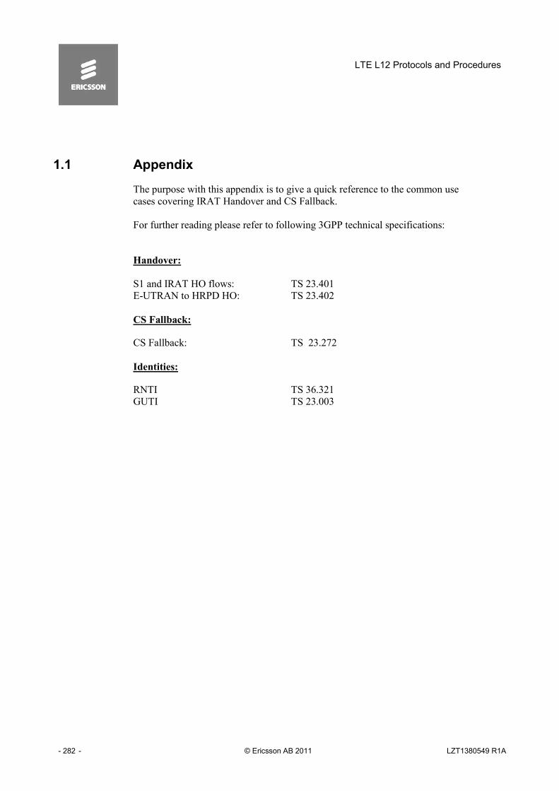
LTE L12 Protocols and Procedures
- 282 - © Ericsson AB 2011 LZT1380549 R1A
1.1 Appendix
The purpose with this appendix is to give a quick reference to the common use
cases covering IRAT Handover and CS Fallback.
For further reading please refer to following 3GPP technical specifications:
Handover:
S1 and IRAT HO flows: TS 23.401
E-UTRAN to HRPD HO: TS 23.402
CS Fallback:
CS Fallback: TS 23.272
Identities:
RNTI TS 36.321
GUTI TS 23.003

Appendix
LZT1380549 R1A © Ericsson AB 2011 - 283 -
1.2 S1 Based Handover
UE
Source eNodeB
Source MME
Source Serving GW PDN GW
Target MME
Target Serving GW
Target eNodeB
Detach from old cell and synchronize to new cell
HSS
16. Update Bearer Request
17. Update Bearer Response
15. Update Bearer Request
Downlink User Plane data
2. Handover Required
Downlink User Plane data
1. Decision to trigger a relocation via S1
3. Forward Relocation Request
5. Handover Request
5a. Handover Request Acknowledge
7. Forward Relocation Response
9. Handover Command
9a. Handover Command
11a. Only for Direct forwarding of data
12. Handover Confirm Downlink data
13. Handover Notify
14. Forward Relocation Complete
14b. Forward Relocation Complete Acknowledge
16a. Update Bearer Response
.
8a. Create Bearer Response
(A)
11b. Only for Indirect forwarding of data
18. Tracking Area Update procedure
19c. Delete Bearer Request
(B) 19a. UE Context Release Command
Uplink User Plane data
8. Create Bearer Request
6a. Create Bearer Response
6. Create Bearer Request
4a. Create Bearer Response
4. Create Bearer Request
19b. UE Context Release Complete
19d. Delete Bearer Response
20a. Delete Bearer Request
20b. Delete Bearer Response
21a. Delete Bearer Request
21b. Delete Bearer Response
10. eNB Status Transfer
10c. eNB Status Transfer
10a. Forward SRNS Context
10b. Forward SRNS Context Ack
Figure 7-1 Si Based Handover.

LTE L12 Protocols and Procedures
- 284 - © Ericsson AB 2011 LZT1380549 R1A
1.3 E-UTRAN to UTRAN Iu mode Inter RAT HO,
1.3.1 Preparation phase
UE Source eNodeB Target RNC Source MME Target SGSN Serving GW HSS
1. Handover Initiation
2. Handover Required 3. Forward Relocation Request
5. Relocation Request
5a. Relocation Request Acknowledge
8. Create Bearer Request
7. Forward Relocation Response
PDN GW
8 a. Create Bearer Response
Uplink and Downlink User Plane PDUs
Target Serving GW
4. Create Bearer Request
4a. Create Bearer Response
6. Create Bearer Request
6a. Create Bearer Response
Figure 7-2 E-UTRAN TO UTRAN IU MODE INTER RAT HO, Preparation phase

Appendix
LZT1380549 R1A © Ericsson AB 2011 - 285 -
1.3.2 Execution phase
UE
Source eNodeB Target RNC Source MME Target SGSN Serving GW HSS PDN GW
Uplink and Downlink User Plane PDUs
1. Handover Command
2. HO from E-UTRAN Command -
Sending of uplink data possible
4. UTRAN Iu Access Procedures
5. Relocation Complete
6. Forward Relocation Complete
6a. Forward Relocation Complete Acknowledge
7. Update Bearer Request
8a. Update Bearer Response
9. Update Bearer Response
Uplink and Downlink User Plane PDUs (Via Target SGSN if Direct Tunnel is not used)
4a. Handover to UTRAN Complete
Downlink User Plane PDUs
If Direct Forwarding applies
If Indirect Forwarding applies.
Target Serving GW
(A) 8. Update Bearer Request
Via Target SGSN in case Direct Tunnel is not used
10. Routeing Area Update procedure
11. Delete Bearer Request
(B) 11a. Delete Bearer Response
11b. Release Resources
For Serving GW relocation Steps 7, 8 and 9, and the following User Plane path, will be handled by Target Serving GW
12. Delete Bearer
Figure 7-3 E-UTRAN TO UTRAN IU MODE INTER RAT HO, Execution phase

LTE L12 Protocols and Procedures
- 286 - © Ericsson AB 2011 LZT1380549 R1A
1.4 E-UTRAN to GERAN A/Gb mode Inter RAT handover
1.4.1 Preparation Phase
UE Source eNodeB Target BSS Source MME Target SGSN Serving GW HSS
1. Handover Initiation 2. Handov er Required
3. Forward Relocation Request
5. PS Handover Request
5a. PS Handover Request Acknowledge
8. Create Bearer Request
7 . Forward Relocation Response
PDN GW
8 a. Create Bearer Response
Uplink and Downlink User Plane PDUs
Target Serving GW
4 . Create Bearer Request
4a . Create Bearer Response
6.
Create Bearer Request
6a . Create Bearer Response
Figure 7-4 E-UTRAN TO GERAN A/GB MODE INTER RAT HANDOVER, Preparation phase

Appendix
LZT1380549 R1A © Ericsson AB 2011 - 287 -
1.4.2 Execution Phase
UE
Source eNodeB Target BSS Source MME Target SGSN Serving GW HSS
PDN GW
Uplink and Downlink User Plane PDUs
1. Handover Command
2. HO from E-UTRAN Command
Sending of uplink data possible
4. GERAN A/Gb Access Procedures
5. XID Response
6. PS Handover Complete
8. Forward Relocation Complete
8a. Forward Relocation Complete Acknowledge
9. Update Bearer Request
11. Update Bearer Response
Uplink and Downlink User Plane PDUs
7. XID Response
12. XID Negotiation for LLC ADM
12a. SABM UA exchange re-establishment and XID negotiation for LLC ABM)
Downlink User Plane PDUs
Only if ”Direct Forwarding” applies
Target Serving GW
For Serving GW relocation Steps 9, 10 and 11, and the following User Plane path, will be handled by Target Serving GW
(A) 10. Update Bearer Request
10a. Update Bearer Response
13. Routeing Area Update procedure
14b. Release Resource
14. Delete Bearer Request
(B)
14a. Delete Bearer Response
Only if ”Indirect Forwarding” applies
Figure 7-5 Figure 12 4 E-UTRAN TO GERAN A/GB MODE INTER RAT HANDOVER, Execution phase

LTE L12 Protocols and Procedures
- 288 - © Ericsson AB 2011 LZT1380549 R1A
1.5 E-UTRAN to HRPD handover
1. CDMA measurements
3. Handover from E-UTRA preparation request
7. A11 Signalling
11. Data Forwarding
13. HRPD TCC
16. UE Context Release
15a. Notification Request (HO Complete)
0. UE connected via E-UTRAN
2. Handover decision
6. Direct Transfer Request
9a. Create forwarding tunnels Request
9b. Create forwarding tunnels Response
10. Downlink S1 CDMA2000 Tunneling
11. Mobility from E-UTRA
17a. Delete Bearer Request
17b. Delete Bearer Response
4. UL handover preparation transfer
5. Uplink S1 CDMA2000 Tunneling
8. Direct Transfer Request
UE MME
HRPD Access Network AAA HSGW E-UTRAN PCRF S-GW
PDN GW
14b. Proxy Binding Update
14a. A11 Request Signalling
14c. Proxy Binding Acknowledge
15b. Notification Response
12. HRPD AN acquires UE
14d. A11 Response Signalling
18. P-GW initiates resource allocation deactivation procedure at E-UTRAN
14e. PCEF Initiated IP-CAN Session Modification Procedure
Figure 7-6 E-UTRAN to HRPD handover

Appendix
LZT1380549 R1A © Ericsson AB 2011 - 289 -
1.6 CS FallBack
1.6.1 Mobile Originating call in Active Mode - PS HO supported
UE/MS MME BSS/RNS MSC eNodeB SGSN Serving
GW
2. Optional Measurement Report Solicitation
4b. A/Iu-cs message (with CM Service Request)
4b. CM Service Request
Location Area Update or Combined RA/LA Update
5. CM Service Reject 5. CM Service Reject
If the MSC is changed
3a. PS HO as specified in 23.401 [2] (preparation phase and start of execution phase)
6. CS call establishment procedure
1a. Extended Service Request
1b. S1-AP Request message with CS Fallback indicator
7. PS HO as specified in 23.401 [2] (continuation of execution phase)
1c. S1-AP Response message
4a. Location Area Update or Combined RA/LA Update
3c. Update Bearer(s) 3b. Suspend
P-GW/ GGSN
Figure 7-7CS Call Request in E-UTRAN, Call in GERAN/UTRAN

LTE L12 Protocols and Procedures
- 290 - © Ericsson AB 2011 LZT1380549 R1A
1.6.2 Mobile Originating call in Active Mode – No PS HO support
UE/ MS MME BSS /RNS MSC eNodeB
2. Optional Measurement Report Solicitation
10b. Location Area Update
10a. Service Reject
10c. CS MO call
6. UE changes RAT then LA Update or Combined RA/LA Update or RA Update or LAU and RAU
3 a . NACC ,
5. S1 UE Context Release
1a. Extended Service Request
SGW/PGW
4. S1 - AP: S1 UE Context Release Request
1b. S1 - AP Request message with CS Fallback indicator
7 a. Suspend (see 23.060)
8 . Update bearer(s)
SGSN
7b. Suspend Request / Response
11. Routing Area Update or Combined RA/LA Update
3b, 3c . RRC connection release
If the MSC is changed
1c. S1 - AP Response message
9. CM Service Request 9. A/Iu-cs message (with CM Service Request)
Figure 7-8: CS Call Request in E-UTRAN, Call in GERAN/UTRAN without PS HO

Appendix
LZT1380549 R1A © Ericsson AB 2011 - 291 -
1.6.3 Mobile Terminating call in Active Mode - PS HO supported
4a. Location Area Update or Combined RA/LA
4b. Paging Response 4b. A/Iu-cs message (with Paging Response)
5b. Signalling Connection Release 5b. Connection Reject If the MSC is changed
5b. Location Area Update or Combined RA/LA Update
5b. CS call establishment procedure
6. PS HO as specified in 23.401 [2] (continuation of execution phase)
5a. Establish CS connection
Option 1: MSC is not changed
3c. Update Bearer(s) 3b. Suspend
P-GW/ GGSN
UE/MS MME BSS/RNS MSC eNodeB SGSN Serving GW
2. Optional Measurement Report Solicitation
3a. PS HO as specified in 23.401 [2] (preparation phase and start of execution phase)
1b. Extended Service Request
1d. S1-AP Message with CS Fallback indicator
1a. Paging Request 1a. CS Paging Notification
1c. CS Paging Reject
1a. Service Request
Figure 7-9: Mobile Terminating call in Active Mode - PS HO supported

LTE L12 Protocols and Procedures
- 292 - © Ericsson AB 2011 LZT1380549 R1A
1.6.4 Mobile Terminating call in Active Mode - No PS HO support
IF THE MSC IS CHANGED
UE/MS MME MSC
3a. CCO/NACC, 3b, 3c. Signalling connection release
eNodeB
2. Optional Measurement Report
9. Paging Response
9c. Location Area Update or Combined RA/LA Update
9b. Signalling Connection Release
S-GW
1b. Extended Service Request
1d. S1-AP message with CS Fallback indicator
1c. CS Paging Reject
7a. Suspend (see TS 23.060)
8. Update bearer(s)
7b. Suspend Request / Response
9b. CONNECTION REJECT
1A. CS SERVICE NOTIFICATION 1A. PAGING REQUEST
SGSN
6.UE changes RAT then, LAU OR COMBINED RA/LA UPDATE OR RA UPDATE OR LAU AND RAU
5. S1 UE CONTEXT RELEASE
BSS/RNS
4. S1-AP: S1 UE CONTEXT RELEASE REQUEST
1A. SERVICE REQUEST
1e. S1-AP Response message
9a. Establish CS connection
Figure 7-10 Mobile Terminating call in Active Mode - No PS HO support

Appendix
LZT1380549 R1A © Ericsson AB 2011 - 293 -
1.6.5 CS MT call using fallback to CDMA 1x RTT network
6b. Extended Service Request
Figure 7-11CS MT call using fallback to CDMA 1x RTT network

LTE L12 Protocols and Procedures
- 294 - © Ericsson AB 2011 LZT1380549 R1A
1.7 Identifiers
1.7.1 Globally Unique Temporary UE Identity (GUTI)
The purpose of the GUTI is to provide an unambiguous identification of the UE
that does not reveal the UE or the user's permanent identity in the Evolved Packet
System (EPS). It also allows the identification of the MME and network. It can
be used by the network and the UE to establish the UE's identity during signalling
between them in the EPS. See 3GPP TS 23.401.
The GUTI has two main components:
- one that uniquely identifies the MME which allocated the GUTI; and
- one that uniquely identifies the UE within the MME that allocated the GUTI.
Within the MME, the mobile shall be identified by the M-TMSI.
The Globally Unique MME Identifier (GUMMEI) shall be constructed from the
MCC, MNC and MME Identifier (MMEI).
The MMEI shall be constructed from an MME Group ID (MMEGI) and an MME
Code (MMEC).
The GUTI shall be constructed from the GUMMEI and the M-TMSI.
For paging purposes, the mobile is paged with the S-TMSI. The S-TMSI shall be
constructed from the MMEC and the M-TMSI.
The operator shall need to ensure that the MMEC is unique within the MME pool
area and, if overlapping pool areas are in use, unique within the area of
overlapping MME pools.
The GUTI shall be used to support subscriber identity confidentiality, and, in the
shortened S-TMSI form, to enable more efficient radio signalling procedures (e.g.
paging and Service Request).
The format and size of the GUTI is therefore the following:
<GUTI> = <GUMMEI><M-TMSI>,
where <GUMMEI> = <MCC><MNC><MME Identifier>

Appendix
LZT1380549 R1A © Ericsson AB 2011 - 295 -
and <MME Identifier> = <MME Group ID><MME Code>
MCC and MNC shall have the same field size as in earlier 3GPP systems.
M-TMSI shall be of 32 bits length.
MME Group ID shall be of 16 bits length.
MME Code shall be of 8 bits length.
1.7.2 RNTI
N/AN/APhysical layer Uplink power controlTPC-PUSCH-RNTI
N/AN/APhysical layer Uplink power controlTPC-PUCCH-RNTI
N/AN/ASemi-Persistently scheduled unicast transmission
(deactivation)
Semi-Persistent Scheduling
C-RNTI
DCCH, DTCHDL-SCH,
UL-SCH
Semi-Persistently scheduled unicast transmission
(activation, reactivation and retransmission)
Semi-Persistent Scheduling
C-RNTI
N/AN/ATriggering of PDCCH ordered random accessC-RNTI
DCCH, DTCHDL-SCH,
UL-SCH
Dynamically scheduled unicast transmissionC-RNTI
CCCH, DCCH,
DTCH
UL-SCHMsg3 transmissionTemporary C-RNTI
CCCHDL-SCHContention Resolution (when no valid C-RNTI is
available)
Temporary C-RNTI
N/ADL-SCHRandom Access ResponseRA-RNTI
BCCHDL-SCHBroadcast of System InformationSI-RNTI
PCCHPCHPaging and System Information change notificationP-RNTI
Logical Channel
Transport Channel
UsageRNTI
Figure 7-12 Radio Network Temporary Ids

LTE L12 Protocols and Procedures
- 296 - © Ericsson AB 2011 LZT1380549 R1A
Intentionally Blank

Appendix
LZT1380549 R1A © Ericsson AB 2011 - 297 -
Index
2 2nd Generation, 185, 215, 218, 250, 254 3 3rd Generation, 124, 185, 215, 217, 218,
220, 225, 226, 229, 234, 250, 254 A Access Point Name, 221, 230, 262 Adjunct processor or Application platform,
109, 110, 115, 120, 248, 250, 252, 254 Anonymity key, 31, 32 Application Modularity, 19, 21, 138, 139, 140,
141, 145, 146, 149, 150, 154, 155, 177, 196, 200, 202, 262
Application System, 35, 36, 77, 88, 194, 195, 231, 232, 262
Area code, 62, 65, 70 ARP, 42, 43, 44, 45 Authentication and Key Agreement, 28, 31,
33, 66, 135, 137, 222, 231 Authentication Centre, 28 Authentication Token, 31, 32, 98 B Base Station, 263 Base Station System, 207, 249 C CDMA2000, 94, 104 Central Building Clock, 38 Central Processor, 264 Charge Area, 263 Ciphering Key, 28, 29, 30, 31, 32, 67, 222,
231 Circuit Switching, 18, 60, 68, 69, 71, 72, 121,
238, 239, 240, 241, 242, 243, 244, 245, 246, 247, 248, 249, 250, 251, 252, 254, 256, 257, 258, 264, 267, 282, 289, 290, 293
Code Division Multiple Access, 210, 211, 212, 240, 251, 263, 293
Common Object Request Broker Architecture, 264
Connection Element, 263 Connection Management, 250, 263 Core Network, 36, 71, 72, 89, 218, 220, 222,
227, 228, 229, 236, 237, 249, 264 Counter check, 93 D Data Radio Bearers, 46, 48 default Radio Bearer, 99 DiffServ Code Point, 46, 49 E eNB, 29, 30, 34, 35, 36, 38, 45, 51, 75, 108,
109, 110, 111, 112, 117, 118, 119, 128, 129, 135, 137, 141, 191, 192, 193, 194, 195, 196, 197, 198, 199, 200, 201, 202, 203, 204, 205, 206, 207, 208, 209, 210, 211, 248, 254, 255, 256, 258, 265
Encryption, 93 Enhanced Data Rate for GSM XE "Global
System for Mobile Communication (Groupe Special Mobile)" Evolution, 266
Enhanced Data Rate for GSM Evolution, 71, 78, 104, 105, 124, 207, 210, 211, 212, 215, 216, 217, 238, 240, 243, 247, 248, 249, 250, 251, 257, 258, 266
Enhanced Data Rate for GSM Evolution, 286 Enhanced Data Rate for GSM Evolution, 286 Enhanced Data Rate for GSM Evolution, 287 Enhanced Data Rate for GSM Evolution, 289 Enhanced Data Rate for GSM Evolution, 290 Equipment Identity Register, 24, 265 ETWS, 77, 78, 80, 84, 86, 89 European Telecommunication Standard
Institute, 266 EXpected user RESponse, 31, 32, 98 F Federal Communications Commission, 266 File Transfer Protocol, 266, 276

LTE L12 Protocols and Procedures
- 298 - © Ericsson AB 2011 LZT1380549 R1A
Frequency Modulation, 266 G Gateway, 39, 41, 51, 58, 68, 99, 102, 108,
111, 124, 182, 201, 202, 205, 207, 208, 209, 220, 221, 222, 223, 224, 226, 227, 228, 229, 230, 231, 232, 233, 235, 236, 237, 248, 250, 251, 252, 267, 272, 276
Gateway GPRS XE "Tunnelling Protocol for User Plane" XE "General Packet Radio Service" Support Node, 182, 266
GBR bearer, 40, 44 General Packet Radio Service, 16, 20, 22,
70, 102, 110, 121, 122, 123, 124, 127, 181, 182, 183, 184, 185, 186, 187, 188, 201, 202, 203, 207, 218, 220, 221, 222, 223, 224, 226, 227, 228, 229, 230, 231, 232, 233, 234, 235, 237, 244, 250, 251, 266, 267, 276
Global System for Mobile Communication, 121, 185, 241, 257, 266, 267
Global System for Mobile Communication (Groupe Special Mobile), 71, 78, 104, 105, 124, 207, 210, 211, 212, 215, 216, 217, 238, 240, 243, 247, 248, 249, 250, 251, 257, 258, 266, 286, 287, 289, 290
GPRS XE "Tunnelling Protocol for User Plane" XE "General Packet Radio Service" Tunneling Protocol, 20, 22, 102, 110, 121, 122, 123, 127, 181, 182, 183, 184, 185, 186, 187, 188, 201, 202, 203, 207, 223, 224, 229, 232, 233, 267
Graphical User Interface,, 267 GSM XE "Global System for Mobile
Communication (Groupe Special Mobile)" -EDGE XE "Enhanced Data Rate for GSM Evolution" Radio Access Network, 71, 78, 104, 105, 124, 207, 210, 211, 212, 215, 216, 217, 238, 240, 243, 247, 248, 249, 250, 251, 257, 258, 266, 286, 287, 289, 290
H Hardware, 38, 267 Home Public Land Mobile Network, 267 Hypertext Transfer Protocol, 267 I Identification, 31, 32, 41, 64, 66, 84, 85, 169,
170, 194, 220, 221, 222, 224, 226, 229,
230, 231, 232, 235, 236, 246, 254, 268, 272, 276, 294, 295
Initial Cell Selection, 87 Integrated Services Digital Network, 227, 236 Integrity, 24, 25, 26, 27, 28, 38, 39, 93, 99,
102, 134, 135, 136, 222, 231, 232 Integrity Key, 28, 29, 30, 31, 32, 67, 222, 231 Integrity Protection, 93 Interface Switch, 268 International Mobile Subscriber Identity, 31,
60, 67, 69, 98, 221, 229, 230, 244, 246, 248, 249, 268
International Telecommunication Union, 268 Internet Engineering Task Force, 27, 37, 109,
133, 268 Internet Inter-ORB Protocol, 277 Internet Protocol, 16, 17, 18, 19, 20, 21, 22,
27, 37, 38, 39, 40, 43, 49, 50, 58, 59, 68, 72, 99, 102, 109, 110, 111, 121, 128, 131, 132, 133, 143, 176, 179, 182, 186, 248, 268, 272, 278
L Lawful Intercept, 148, 149, 150 Layer 2, 12, 13, 20, 22, 76, 90, 195 Location Area, 18, 250 Location Area Identity, 244, 249 Logical Channel Groups, 47, 48 M Master Information Block, 81 Measurement gaps, 105 Measurement identities, 105 Measurement objects, 105 Media Access Control, 19, 21, 32, 36, 76, 92,
97, 98, 101, 127, 136, 137, 160, 161, 162, 163, 164, 165, 167, 168, 169, 170, 174, 175, 176, 177, 178, 179, 180, 192, 194, 269
Media Gateway, 269 Media Gateway Controller, 269 Mobile Country Code, 63, 64, 294, 295 Mobile Equipment, 29, 30, 67 Mobile Network Code Digits, 63, 64, 294, 295 Mobile Originated, 71, 238, 247, 250, 251,
255 Mobile Services switching Centre, 238, 244,
249, 250 Mobile Services Switching Centre/Visitor
Location Register, 244

Appendix
LZT1380549 R1A © Ericsson AB 2011 - 299 -
Mobile Station, 70, 155, 156, 185, 221, 230, 244, 270
Mobile Station ISDN XE "Integrated Services Digital Network" Number, 227, 236
Mobility, 16, 19, 76, 77, 79, 102, 103, 106, 107, 111, 121, 189, 190, 191, 219, 252, 253, 254, 256, 263, 265, 269
Multimedia Messaging Service, 269 N Network Management System, 270 Network Operator, 70 O Operation and Maintenance, 264, 271 Operation and Support System, 48, 49, 254,
264, 271 P Packet Data Protocol, 124, 185, 187, 188,
221, 235, 251, 272 Packet Delay Budget, 42, 43 Packet Error Loss Rate, 42, 43 Packet Switching, 15, 18, 59, 60, 68, 69, 71,
220, 239, 242, 243, 245, 247, 248, 250, 251, 273, 289, 290, 291, 292
paging occasion, 89 PDCP, 128 Performance Measurement, 272 Point-to-Point Protocol, 110, 269 Power Distribution Unit, 36, 49, 135, 136,
137, 138, 139, 142, 143, 145, 146, 147, 148, 149, 150, 151, 154, 155, 156, 157, 167, 168, 170, 177, 178, 179, 180, 184, 185, 186, 203, 226, 258, 272
Public Land Mobile Network, 31, 32, 66, 77, 84, 85, 86, 88, 98, 101, 221, 230, 248, 249, 265, 267, 272, 274, 278
Public Switched Telephone Network, 273 Q QCI, 42, 43, 44, 46, 47, 48, 49 QoS, 17, 24, 25, 26, 39, 40, 42, 44, 45, 46,
47, 48, 49, 50, 51, 52, 54, 182, 194, 195, 207, 218, 221, 222, 252, 273
Quantity configurations, 105 R Radio Access Bearer, 17, 41, 110, 111, 117,
194, 195, 200, 201, 202, 207, 222, 223, 234, 235, 265
Radio Access Network, 14, 15, 27, 37, 46, 121, 143, 158, 218, 221, 222, 228, 230, 231, 232, 273
Radio Access Network Application Protocol, 273
Radio Network Controller, 182, 207, 220, 221, 222, 223, 224, 226, 227, 228, 229, 230, 231, 234, 235, 237, 274
Radio Resource Control, 75 Random challenge, 31, 32, 98 Register Functions, 207 Reporting configurations, 105 Request For Comments, 133, 274 Resource Type, 42 RLC, 19, 21, 39, 43, 76, 127, 128, 130, 138,
139, 140, 141, 142, 143, 144, 145, 146, 147, 148, 149, 150, 151, 154, 155, 156, 163, 170, 176, 177, 178, 179, 180, 196, 200, 201, 202, 204, 274
RRC, 17, 19, 20, 27, 28, 30, 34, 35, 36, 65, 66, 70, 75, 76, 77, 78, 79, 80, 84, 86, 89, 90, 91, 92, 93, 94, 95, 96, 98, 99, 101, 102, 103, 104, 106, 128, 129, 134, 135, 136, 137, 140, 142, 149, 160, 166, 177, 178, 190, 191, 192, 193, 194, 195, 196, 197, 204, 206, 208, 210, 215, 216, 222, 232, 248, 249, 252, 255, 256, 257, 274
RRC States, 76 S S1, 16, 20, 27, 30, 34, 35, 37, 41, 46, 49, 66,
69, 70, 71, 73, 76, 79, 90, 98, 99, 102, 108, 109, 110, 111, 112, 113, 114, 115, 124, 182, 186, 194, 197, 198, 199, 201, 202, 204, 205, 206, 207, 208, 209, 220, 221, 231, 246, 248, 250, 252, 254, 275, 282, 283
Security, 24, 26, 27, 28, 33, 34, 35, 36, 37, 38, 67, 92, 93, 98, 99, 101, 102, 134, 231, 275
Sequence number, 31, 32 Service Access Points, 76 Service Capability, 263, 275 Service Control Point, 46, 49 Service Indicator, 81, 276 Serving GPRS XE "Tunnelling Protocol for
User Plane" XE "General Packet Radio Service" Service Node, 16, 124, 182, 185, 218, 220, 221, 222, 223, 224, 226, 227,

LTE L12 Protocols and Procedures
- 300 - © Ericsson AB 2011 LZT1380549 R1A
228, 229, 230, 231, 232, 233, 234, 235, 237, 250, 251, 276
Serving Radio Network Subsystem, 124 Session Initiation Protocol, 44, 276 Short Message, 19, 73, 223, 276 Short Message Service, 60, 72, 238, 239,
242, 243, 244, 245, 252, 276 Signaling Connection, 90 Signaling Radio Bearers, 48 Signalling Connection Control Part, 275 Signalling Gateway, 16, 17, 20, 22, 36, 121,
122, 123, 124, 125, 182, 184, 185 Software, 263, 277 Software Management Organizer, 276 Standardized internal Personal Computer
bus, 272 Stored Information Cell Selection, 87 Stream Control Transmission Protocol, 20,
109, 275 Synchronous Digital Hierarchy, 275 system information, 80 System Information Blocks, 81 T Technical Specification, 15, 37, 46, 47, 60,
63, 125, 136, 137, 138, 158, 184, 186, 221, 222, 226, 231, 245, 252, 282, 294
Temporary Mobile Subscriber Identity, 24, 63, 64, 66, 70, 98, 101, 226, 235, 244, 250, 294, 295
Terminal Adapter, 18, 71, 77, 98, 101, 193, 237, 277
Third Generation Partnership Project, 14, 15, 18, 19, 21, 27, 28, 37, 46, 47, 63, 64, 76,
83, 91, 94, 95, 121, 136, 137, 138, 158, 184, 186, 200, 217, 218, 220, 239, 262, 282, 294, 295
Transmission Control Protocol, 22, 133, 157, 158, 277
Transmission Control Protocol/Internet Protocol, 133
Tunnelling Protocol for User Plane, 16, 20, 22, 70, 102, 110, 121, 122, 123, 124, 127, 181, 182, 183, 184, 185, 186, 187, 188, 201, 202, 203, 207, 218, 220, 221, 222, 223, 224, 226, 227, 228, 229, 230, 231, 232, 233, 234, 235, 237, 244, 250, 251, 266, 267, 276
U Universal Mobile Telecommunication System,
31, 32, 121, 230, 278 Universal Subscriber Identity Module, 28, 31,
32, 66, 67, 86 UTRAN Registration Area, 17, 18, 124, 278 V Video telephony, 45 Visitor Location Register, 244 W
Wideband Code Division Multiple Access, 28, 210, 211, 212, 218, 219, 220, 228, 241, 257, 278
Wireless Application Protocol, 278 X X2, 16, 20, 22, 30, 37, 41, 46, 49, 79, 116,
117, 118, 119, 120, 124, 182, 186, 192, 193, 194, 195, 196, 201, 202, 205, 254, 278, 279