A simplified method of estimating drilling and blasting costs of ...
International Journal of Machine Tools & Manufacture 43 (2003) 1413–1418
Loose abrasive blasting as an alternative to slurry polishing ofoptical fibre end faces
Yousef A. Gharbia, Jayantha Katupitiya∗
School of Mechanical and Manufacturing Engineering, The University of New South Wales, Sydney, NSW 2052, Australia
Received 23 June 2003; accepted 25 June 2003
Abstract
A novel method of polishing the end face of an optical fibre by blasting it with loose dry abrasive grit travelling at high speedsis presented. The method, called loose abrasive blasting (LAB), is specifically designed to improve the surface quality of micro-lenses ground at the tips of optical fibres. Thus, the method described is suitable for polishing non-flat surfaces. Blasting is carriedout by immersing the fibre tip in a stream of high kinetic energy abrasive grit. The surface finish attainable using LAB is comparedwith that of cleaved, ground and slurry polished fibre end faces. Optical microscopy photographs are presented as a qualitativecomparison. The surface roughnesses are measured using atomic force microscopy (AFM). For cleaved fibres, the surface roughnessimproved by a factor of 2 and 6 for slurry polished and dry diamond blasted fibres, respectively. 2003 Elsevier Ltd. All rights reserved.
Keywords: Loose abrasive blasting; Slurry polishing; Optical fibre
1. Introduction
This paper presents a new method called loose abras-ive blasting (LAB) that can be used to polish opticalfibre end faces. The method can be used on a mass scaleto improve the surface quality of micro-lenses that aremechanically ground at the end faces of optical fibres.The surface quality attained with the LAB method wascompared with that attained using slurry polishing. Thefibre end faces used in these two experiments were eithercleaved or mechanically ground to form flat end faces.
Mirror finish of optical surfaces is needed in manyapplications in the optics industry. One such example isthe light coupling from a laser diode to a single modefibre. Scattering of laser light incident on the fibre endface is a major contributor in degrading the light coup-ling efficiency. Light scatter is a direct result of poorsurface quality[1]. In general, mechanically ground sur-faces may have scratch marks left on them by the grind-ing surface. Although cleaved surfaces are thought to
∗ Corresponding author. Tel.:+612-9385-4096; fax:+612-9663-1222.
E-mail address: [email protected] (J. Katupitiya).
0890-6955/$ - see front matter 2003 Elsevier Ltd. All rights reserved.doi:10.1016/S0890-6955(03)00181-0
have good surface quality, depending on the cleaver andfibre quality, the cleaved fibres can have surface qualityas low asRa = 45 nm. Therefore, there is a strong needto develop a cost effective method to polish end facesof cleaved as well as ground fibres in bulk quantities.
Surface qualities attainable using various methods arewidely reported in the literature. Chen et al.[2] usedultra-precision grinding of optical aspherical surfacesand reported best surface roughnesses ofRa = 6.5 nm.Golini et al. [3] used slurry micro-grinding of thetitanium doped fused silica glass known as ULE, andZeroder to study the effect of slurry chemistry in trans-forming brittle material removal to ductile materialremoval. Several slurry agents including water, meth-anol, ethanol, propanol and a series of homogeneousn-alcohols have been used in experiments. These studiesfound that by changing the slurry chemistry, brittlematerial removal can be transformed to ductile. Wet pol-ishing, in which the surface being polished wasimmersed in a slurry of abrasives, has produced goodquality surfaces[4]. Other polishing techniques of brittlematerials reported in the literature are mechanochemicalpolishing[5], hydroform polishing[6], chemical etching[7,8] and carbon dioxide laser polishing[9].
While slurry polishing, sometimes referred to as
1414 Y.A. Gharbia, J. Katupitiya / International Journal of Machine Tools & Manufacture 43 (2003) 1413–1418
chemical–mechanical polishing (CMP), has been studiedwidely as an attractive means of polishing fairly flat sur-faces [10–16], loose diamond blasting as described inthis paper has not been reported to the authors’ knowl-edge. Probably the technique closest to LAB reported iswhat is known as abrasive jet machining (AJM) [17–20]. However neither the mechanism nor the purpose ofAJM has much in common with LAB presented in thispaper except for the fact that dry loose abrasives are usedin both. LAB has the added advantage that it can be usedto polish non-flat surfaces. The slurry polishing that hasbeen used in this study was also adapted to suit the pol-ishing of micro-lenses.
2. Experimental set-up
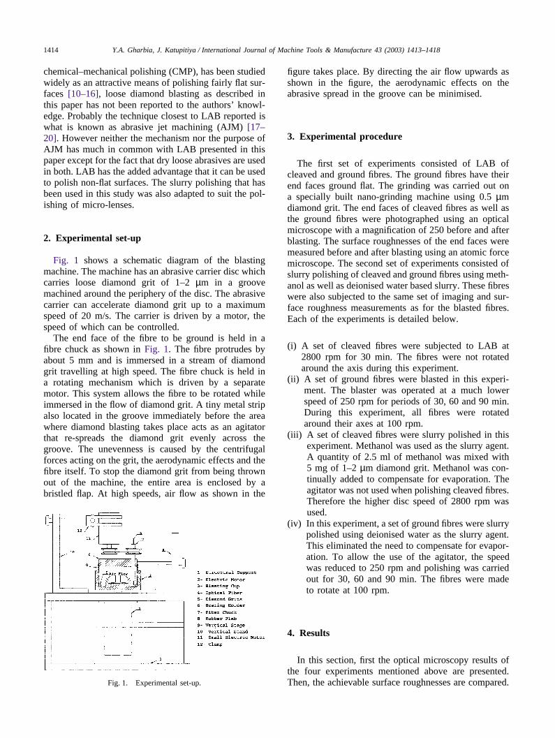
Fig. 1 shows a schematic diagram of the blastingmachine. The machine has an abrasive carrier disc whichcarries loose diamond grit of 1–2 µm in a groovemachined around the periphery of the disc. The abrasivecarrier can accelerate diamond grit up to a maximumspeed of 20 m/s. The carrier is driven by a motor, thespeed of which can be controlled.
The end face of the fibre to be ground is held in afibre chuck as shown in Fig. 1. The fibre protrudes byabout 5 mm and is immersed in a stream of diamondgrit travelling at high speed. The fibre chuck is held ina rotating mechanism which is driven by a separatemotor. This system allows the fibre to be rotated whileimmersed in the flow of diamond grit. A tiny metal stripalso located in the groove immediately before the areawhere diamond blasting takes place acts as an agitatorthat re-spreads the diamond grit evenly across thegroove. The unevenness is caused by the centrifugalforces acting on the grit, the aerodynamic effects and thefibre itself. To stop the diamond grit from being thrownout of the machine, the entire area is enclosed by abristled flap. At high speeds, air flow as shown in the
Fig. 1. Experimental set-up.
figure takes place. By directing the air flow upwards asshown in the figure, the aerodynamic effects on theabrasive spread in the groove can be minimised.
3. Experimental procedure
The first set of experiments consisted of LAB ofcleaved and ground fibres. The ground fibres have theirend faces ground flat. The grinding was carried out ona specially built nano-grinding machine using 0.5 µmdiamond grit. The end faces of cleaved fibres as well asthe ground fibres were photographed using an opticalmicroscope with a magnification of 250 before and afterblasting. The surface roughnesses of the end faces weremeasured before and after blasting using an atomic forcemicroscope. The second set of experiments consisted ofslurry polishing of cleaved and ground fibres using meth-anol as well as deionised water based slurry. These fibreswere also subjected to the same set of imaging and sur-face roughness measurements as for the blasted fibres.Each of the experiments is detailed below.
(i) A set of cleaved fibres were subjected to LAB at2800 rpm for 30 min. The fibres were not rotatedaround the axis during this experiment.
(ii) A set of ground fibres were blasted in this experi-ment. The blaster was operated at a much lowerspeed of 250 rpm for periods of 30, 60 and 90 min.During this experiment, all fibres were rotatedaround their axes at 100 rpm.
(iii) A set of cleaved fibres were slurry polished in thisexperiment. Methanol was used as the slurry agent.A quantity of 2.5 ml of methanol was mixed with5 mg of 1–2 µm diamond grit. Methanol was con-tinually added to compensate for evaporation. Theagitator was not used when polishing cleaved fibres.Therefore the higher disc speed of 2800 rpm wasused.
(iv) In this experiment, a set of ground fibres were slurrypolished using deionised water as the slurry agent.This eliminated the need to compensate for evapor-ation. To allow the use of the agitator, the speedwas reduced to 250 rpm and polishing was carriedout for 30, 60 and 90 min. The fibres were madeto rotate at 100 rpm.
4. Results
In this section, first the optical microscopy results ofthe four experiments mentioned above are presented.Then, the achievable surface roughnesses are compared.
1415Y.A. Gharbia, J. Katupitiya / International Journal of Machine Tools & Manufacture 43 (2003) 1413–1418
4.1. Loose abrasive blasting
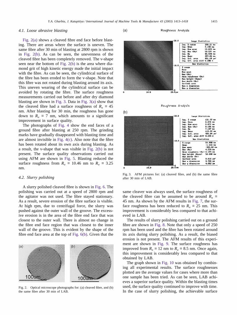
Fig. 2(a) shows a cleaved fibre end face before blast-ing. There are areas where the surface is uneven. Thesame fibre after 30 min of blasting at 2800 rpm is shownin Fig. 2(b). As can be seen, the unevenness of thecleaved fibre has been completely removed. The v-shapeseen near the bottom of Fig. 2(b) is the area where dia-mond grit of high kinetic energy made the initial impactwith the fibre. As can be seen, the cylindrical surface ofthe fibre has been eroded to form the v-shape. Note thatthis fibre was not rotated during blasting around its axis.This uneven wearing of the cylindrical surface can beavoided by rotating the fibre. The surface roughnessmeasurements carried out before and after dry diamondblasting are shown in Fig. 3. Data in Fig. 3(a) show thatthe cleaved fibre had a surface roughness of Ra = 45nm. After blasting for 30 min, the roughness has gonedown to Ra = 7 nm, which amounts to a significantimprovement in surface quality.
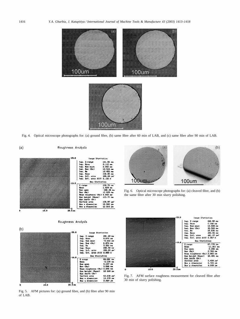
The photographs of Fig. 4 show the end faces of aground fibre after blasting at 250 rpm. The grindingmarks have gradually disappeared with blasting time andare almost invisible in Fig. 4(c). Also note that the fibrehas been rotated about its own axis during blasting. Asa result, the v-shape that was visible in Fig. 2(b) is notpresent. The surface quality observations carried outusing AFM are shown in Fig. 5. Blasting reduced thesurface roughness from Ra = 10.46 nm to Ra = 3.25nm.
4.2. Slurry polishing
A slurry polished cleaved fibre is shown in Fig. 6. Thepolishing was carried out at a speed of 2800 rpm andthe agitator was not used. The fibre stayed stationary.As a result, severe erosion of the fibre surface is visible.At high rpm, due to centrifugal force, the slurry waspushed against the outer wall of the groove. The excess-ive erosion is in the area of the fibre end face that wasclosest to the outer wall. There is almost no change inthe fibre end face region that was closest to the innerwall of the groove. This is evident by the shape of thefibre end face area at the top of Fig. 6(b). Given that the
Fig. 2. Optical microscope photographs for: (a) cleaved fibre, and (b)the same fibre after 30 min of LAB.
Fig. 3. AFM pictures for: (a) cleaved fibre, and (b) the same fibreafter 30 min of LAB.
same cleaver was always used, the surface roughness ofthe cleaved fibre can be assumed to be around Ra =45 nm. As shown by the AFM results in Fig. 7, the sur-face roughness has been reduced to Ra = 25 nm. Thisimprovement is considerably less compared to that achi-eved in LAB.
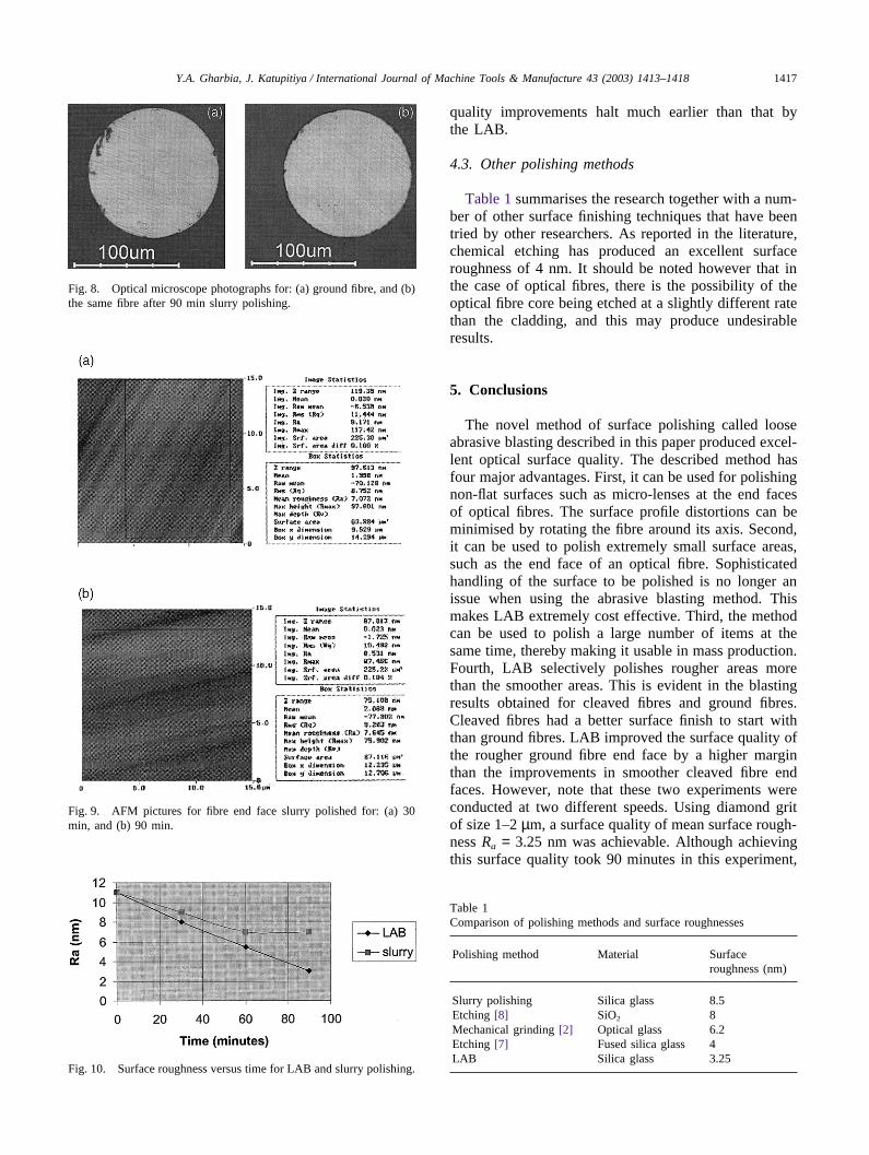
The results of slurry polishing carried out on a groundfibre are shown in Fig. 8. Note that only a speed of 250rpm has been used and the fibre has been rotated aroundits axis during slurry polishing. As a result, the biasederosion is not present. The AFM results of this experi-ment are shown in Fig. 9. The surface roughness hasimproved from Ra = 12 nm to Ra = 8.5 nm. Once again,this improvement is considerably less compared to thatobtained by LAB.
The graph shown in Fig. 10 was obtained by combin-ing all experimental results. The surface roughnessesplotted are the average values for cases where more thanone sample has been tried. As can be seen, LAB achi-eves a superior surface quality. Within the blasting timesused, the surface quality continued to improve with time.In the case of slurry polishing, the achievable surface
1416 Y.A. Gharbia, J. Katupitiya / International Journal of Machine Tools & Manufacture 43 (2003) 1413–1418
Fig. 4. Optical microscope photographs for: (a) ground fibre, (b) same fibre after 60 min of LAB, and (c) same fibre after 90 min of LAB.
Fig. 5. AFM pictures for: (a) ground fibre, and (b) fibre after 90 minof LAB.
Fig. 6. Optical microscope photographs for: (a) cleaved fibre, and (b)the same fibre after 30 min slurry polishing.
Fig. 7. AFM surface roughness measurement for cleaved fibre after30 min of slurry polishing.
1417Y.A. Gharbia, J. Katupitiya / International Journal of Machine Tools & Manufacture 43 (2003) 1413–1418
Fig. 8. Optical microscope photographs for: (a) ground fibre, and (b)the same fibre after 90 min slurry polishing.
Fig. 9. AFM pictures for fibre end face slurry polished for: (a) 30min, and (b) 90 min.
Fig. 10. Surface roughness versus time for LAB and slurry polishing.
quality improvements halt much earlier than that bythe LAB.
4.3. Other polishing methods
Table 1 summarises the research together with a num-ber of other surface finishing techniques that have beentried by other researchers. As reported in the literature,chemical etching has produced an excellent surfaceroughness of 4 nm. It should be noted however that inthe case of optical fibres, there is the possibility of theoptical fibre core being etched at a slightly different ratethan the cladding, and this may produce undesirableresults.
5. Conclusions
The novel method of surface polishing called looseabrasive blasting described in this paper produced excel-lent optical surface quality. The described method hasfour major advantages. First, it can be used for polishingnon-flat surfaces such as micro-lenses at the end facesof optical fibres. The surface profile distortions can beminimised by rotating the fibre around its axis. Second,it can be used to polish extremely small surface areas,such as the end face of an optical fibre. Sophisticatedhandling of the surface to be polished is no longer anissue when using the abrasive blasting method. Thismakes LAB extremely cost effective. Third, the methodcan be used to polish a large number of items at thesame time, thereby making it usable in mass production.Fourth, LAB selectively polishes rougher areas morethan the smoother areas. This is evident in the blastingresults obtained for cleaved fibres and ground fibres.Cleaved fibres had a better surface finish to start withthan ground fibres. LAB improved the surface quality ofthe rougher ground fibre end face by a higher marginthan the improvements in smoother cleaved fibre endfaces. However, note that these two experiments wereconducted at two different speeds. Using diamond gritof size 1–2 µm, a surface quality of mean surface rough-ness Ra = 3.25 nm was achievable. Although achievingthis surface quality took 90 minutes in this experiment,
Table 1Comparison of polishing methods and surface roughnesses
Polishing method Material Surfaceroughness (nm)
Slurry polishing Silica glass 8.5Etching [8] SiO2 8Mechanical grinding [2] Optical glass 6.2Etching [7] Fused silica glass 4LAB Silica glass 3.25

1418 Y.A. Gharbia, J. Katupitiya / International Journal of Machine Tools & Manufacture 43 (2003) 1413–1418
it is possible to blast a large number of fibre end facesat the same time, thereby reducing the time spent perfibre. Further, the speed of the abrasive carrier can besignificantly increased, thereby reducing the blastingtime further. For comparable surfaces, the best surfaceroughness achievable using slurry polishing was onlyRa = 8.5 nm. It should also be noted that in the case ofslurry polishing a consistent slurry viscosity must bemaintained. In LAB, no viscosity maintenance or haz-ardous chemical handling is needed.
References
[1] E. Marx, L.x. Cao, T.V. Vorburger, Determination of surfaceroughness from scattered light, Antennas Propagation Soc. Int.Symp. Ap-s. Dig. 1 (1989) 192–194.
[2] M. Chen, F. Zhang, Q. Zhao, S. Dong, Study on utra-precisiongrinding machining of aspheric surface in ductile mode, opticalmanufacturing and testing IV, Proceedings of SPIE 4451 (2001)191–198.
[3] D. Golini, S.D. Jacobs, Physics of loose abrasive microgrinding,Applied Optics 30 (19) (1991) 2761–2777.
[4] J.M. Bennett, J. Shaffer, Y. Shibano, Y. Namba, Float polishingof optical materials, Applied Optics 26 (4) (1987) 696–703.
[5] N. Yasunaga, A. Obara, O. Imanaka, Mechanochemical polishingof single crystals with soft powders, in: Proceedings, InternationalConference on Production Engineering, Tokyo, Japan, 1974, pp.32–37.
[6] J.V. Gormley, M.J. Manfra, A.R. Calawa, Hydroplane polishingof semiconductor crystals, Rev. Sci. Instrum. 52 (8) (1981)1256–1259.
[7] K. Zimmer, A. Braun, R. Bohme, Etching of fused silica andglass with excimer laser at 351 nm, Applied Surface Science 208–209 (2003) 199–204.
[8] M. Ferstl, Highly selective etching of deep silica componentsusing electron cyclotron resonance plasma, Microeletronic Engin-eering 61–62 (2002) 881–886.
[9] P.A. Tample, W.H. Lowdermilk, D. Milam, Carbon dioxide laserpolishing of fused silica for increased laser damage resistance at1064 nm, Applied Optics 21 (1982) 3249.
[10] L. Shih-Chieh, W. Meng-Long, A study of the effects of pol-ishing parameters on material removal rate and non-uniformity,International Journal of Machine Tools and Manufacture 42(2002) 99–103.
[11] R. Bajaj, Effect of polishing pad material properties on chemicalmechanical polishing (CMP) process, Materials Research SocietySymposium Proceedings 337 (1994) 637–644.
[12] P.L. Flaitz, M. Neisser, Polishing of substrates, American Cer-amic Society Bulletin 73 (5) (1994) 42–46.
[13] Y. Liu, K. Zhang, F. Wang, W. Di, Investigation on the finalpolishing slurry and technique of silicon substrate in ULSI,Microelectronic Engineering 66 (2003) 438–444.
[14] Z. Lu, S. Lee, S.V. Babu, E. Matijevic, The use of monodispersedcolloids in the polishing of copper and tantalum, Journal of Col-loid and Interface Science 261 (2002) 55–64.
[15] B. Mullany, G. Byrne, The effect of slurry viscosity on chemicalmechanical polishing of silicon Wafer, Journal of Material Pro-cessing Technology 132 (2003) 28–34.
[16] W.T. Tseng, C.W. Lin, B.T. Dai, C.F. Yeh, Effect of mechanicalcharacteristics on chemical–mechanical polishing of dielectricthin films, Thin Solid Films 290-291 (1996) 458–463.
[17] M. Wakuda, Y. Yamauchi, S. Kanzaki, Material response to par-ticle impact during abrasive jet machining of alumina ceramics,Journal of Material Processing Technology 132 (2003) 177–183.
[18] R.B. Shukla, Abrasive jet machining, in: Proceedings of theAbrasive Engineering Society Conference, 1985, p. 91.
[19] H. Wensink, M.C. Elwenspoek, Reduction of sidewall inclinationand blasting lag of powder blasted channels, Sensors and Actu-ators A 102 (2002) 157–164.
[20] D. Herbert, Blast finishing, Metal Finishing 97 (1) (1999) 93.
Copyright © 2022 FDOKUMEN