Study on the Polishing Characteristics of the Rotating Cylinder ...
13
processes Article Study on the Polishing Characteristics of the Rotating Cylinder-Based Magnetic Gel Abrasive Finishing Kuan-Yu Chen 1, *, Tse-Yi Tu 1 , Yi-Hua Fan 1 , A-Cheng Wang 2 and Pei-Keng Fu 1 Citation: Chen, K.-Y.; Tu, T.-Y.; Fan, Y.-H.; Wang, A.-C.; Fu, P.-K. Study on the Polishing Characteristics of the Rotating Cylinder-Based Magnetic Gel Abrasive Finishing. Processes 2021, 9, 1794. https://doi.org/ 10.3390/pr9101794 Academic Editor: Zhou Li Received: 3 September 2021 Accepted: 8 October 2021 Published: 10 October 2021 Publisher’s Note: MDPI stays neutral with regard to jurisdictional claims in published maps and institutional affil- iations. Copyright: © 2021 by the authors. Licensee MDPI, Basel, Switzerland. This article is an open access article distributed under the terms and conditions of the Creative Commons Attribution (CC BY) license (https:// creativecommons.org/licenses/by/ 4.0/). 1 Department of Mechanical Engineering, Chung Yuan Christian University, Taoyuan City 320314, Taiwan; [email protected] (T.-Y.T.); [email protected] (Y.-H.F.); [email protected] (P.-K.F.) 2 Department of Mechanical Engineering, Chien Hsin University of Science and Technology, Taoyuan City 320312, Taiwan; [email protected] * Correspondence: [email protected]; Tel.: +886-3-265-4322 Abstract: Magnetic gel abrasive finishing is a high-precision polishing method that uses magnetic forces to attract and restrain a gel abrasive, composed of aqueous slime gel, steel grits, and silicon carbon (SiC), for polishing workpieces. However, the magnetic adsorption performance of the gel abrasive will drop quickly when polishing non-ferromagnetic material such as stainless-steel or brass. Moreover, centrifugal force will push out the gel abrasive from the machining surface reducing the stability of polishing. Therefore, this paper developed a rotating cylinder-based magnetic finishing setup to allow the gel abrasive and workpieces to tumble and rotate together during the polishing process. To make the gel abrasive produce irregular and complicated movement paths for improving the polishing performance, this study first analyzed and compared the average surface roughness and removed material weight of workpieces using three kinds of motor operating modes; a unidirectional trapezoidal wave mode, a bidirectional sine wave mode, and a bidirectional trapezoidal wave mode. After identifying the best motor operating mode, the study further compared the polishing characteristics using several SiC particle and steel grit sizes. The experimental results showed that the rotating cylinder driven using a bidirectional trapezoidal wave could obtain better results for average surface roughness and removed material weight than the other two operating modes, while use of the larger steel grit size also obtained improved results. However, different silicon carbide particle sizes did not have a significant impact on the polishing characteristics. Keywords: gel abrasive; magnetic gel abrasive finishing; rotating cylinder; surface roughness 1. Introduction In a situation where it is difficult to improve the surface roughness by traditional finishing methods due to the varying shapes of workpieces, magnetic abrasive finishing (MAF) has the potential to perform well in the machining processes. MAF is an advanced machining technique that drives a magnetic abrasive, for polishing or grinding the work- piece surface, through a magnetic field. The machining process first places a hard abrasive and a magnetic abrasive in the processing area. When the magnetic abrasive is attracted to a magnetic field, the abrasive particles will orient along the magnetic lines of force to form a magnetic brush [1,2]. When these magnetic brushes move relative to the workpiece surface, the micro-protruding edges on the workpiece surface can be removed by the grinding action of abrasive particles. In addition, the magnetic brush formed by these abrasive particles is able to flexibly adapt to various types of workpiece surfaces. There are four main advantages of MAF. First, MAF can be used not only for grinding planes but also for grinding cylinders, inner holes, tubes, or complex curved surfaces [3,4]. Second, in addition to the rotating motion, the MAF provides a reciprocating motion that can generate staggering movements to improve polishing performance [5]. Third, the flexible abrasive will keep rolling and moving during the process of MAF, so that the abrasive particles can Processes 2021, 9, 1794. https://doi.org/10.3390/pr9101794 https://www.mdpi.com/journal/processes
-
Upload
khangminh22 -
Category
Documents
-
view
1 -
download
0
Transcript of Study on the Polishing Characteristics of the Rotating Cylinder ...

processes
Article
Study on the Polishing Characteristics of the RotatingCylinder-Based Magnetic Gel Abrasive Finishing
Kuan-Yu Chen 1,*, Tse-Yi Tu 1 , Yi-Hua Fan 1, A-Cheng Wang 2 and Pei-Keng Fu 1
�����������������
Citation: Chen, K.-Y.; Tu, T.-Y.; Fan,
Y.-H.; Wang, A.-C.; Fu, P.-K. Study on
the Polishing Characteristics of the
Rotating Cylinder-Based Magnetic
Gel Abrasive Finishing. Processes
2021, 9, 1794. https://doi.org/
10.3390/pr9101794
Academic Editor: Zhou Li
Received: 3 September 2021
Accepted: 8 October 2021
Published: 10 October 2021
Publisher’s Note: MDPI stays neutral
with regard to jurisdictional claims in
published maps and institutional affil-
iations.
Copyright: © 2021 by the authors.
Licensee MDPI, Basel, Switzerland.
This article is an open access article
distributed under the terms and
conditions of the Creative Commons
Attribution (CC BY) license (https://
creativecommons.org/licenses/by/
4.0/).
1 Department of Mechanical Engineering, Chung Yuan Christian University, Taoyuan City 320314, Taiwan;[email protected] (T.-Y.T.); [email protected] (Y.-H.F.); [email protected] (P.-K.F.)
2 Department of Mechanical Engineering, Chien Hsin University of Science and Technology,Taoyuan City 320312, Taiwan; [email protected]
* Correspondence: [email protected]; Tel.: +886-3-265-4322
Abstract: Magnetic gel abrasive finishing is a high-precision polishing method that uses magneticforces to attract and restrain a gel abrasive, composed of aqueous slime gel, steel grits, and siliconcarbon (SiC), for polishing workpieces. However, the magnetic adsorption performance of the gelabrasive will drop quickly when polishing non-ferromagnetic material such as stainless-steel or brass.Moreover, centrifugal force will push out the gel abrasive from the machining surface reducing thestability of polishing. Therefore, this paper developed a rotating cylinder-based magnetic finishingsetup to allow the gel abrasive and workpieces to tumble and rotate together during the polishingprocess. To make the gel abrasive produce irregular and complicated movement paths for improvingthe polishing performance, this study first analyzed and compared the average surface roughness andremoved material weight of workpieces using three kinds of motor operating modes; a unidirectionaltrapezoidal wave mode, a bidirectional sine wave mode, and a bidirectional trapezoidal wavemode. After identifying the best motor operating mode, the study further compared the polishingcharacteristics using several SiC particle and steel grit sizes. The experimental results showed thatthe rotating cylinder driven using a bidirectional trapezoidal wave could obtain better results foraverage surface roughness and removed material weight than the other two operating modes, whileuse of the larger steel grit size also obtained improved results. However, different silicon carbideparticle sizes did not have a significant impact on the polishing characteristics.
Keywords: gel abrasive; magnetic gel abrasive finishing; rotating cylinder; surface roughness
1. Introduction
In a situation where it is difficult to improve the surface roughness by traditionalfinishing methods due to the varying shapes of workpieces, magnetic abrasive finishing(MAF) has the potential to perform well in the machining processes. MAF is an advancedmachining technique that drives a magnetic abrasive, for polishing or grinding the work-piece surface, through a magnetic field. The machining process first places a hard abrasiveand a magnetic abrasive in the processing area. When the magnetic abrasive is attracted toa magnetic field, the abrasive particles will orient along the magnetic lines of force to form amagnetic brush [1,2]. When these magnetic brushes move relative to the workpiece surface,the micro-protruding edges on the workpiece surface can be removed by the grindingaction of abrasive particles. In addition, the magnetic brush formed by these abrasiveparticles is able to flexibly adapt to various types of workpiece surfaces. There are fourmain advantages of MAF. First, MAF can be used not only for grinding planes but alsofor grinding cylinders, inner holes, tubes, or complex curved surfaces [3,4]. Second, inaddition to the rotating motion, the MAF provides a reciprocating motion that can generatestaggering movements to improve polishing performance [5]. Third, the flexible abrasivewill keep rolling and moving during the process of MAF, so that the abrasive particles can
Processes 2021, 9, 1794. https://doi.org/10.3390/pr9101794 https://www.mdpi.com/journal/processes

Processes 2021, 9, 1794 2 of 13
constantly grind the workpiece surface with sharp cutting edges which become increas-ingly sharpened, known as the self-sharpening phenomenon, which greatly improves theprecision and efficiency of finishing [6,7]. Finally, MAF can grind both ferromagnetic andnon-ferromagnetic materials.
The type of abrasive is one of the important factors affecting the efficiency of MAF [8].The production methods of magnetic abrasives can be divided into two categories: un-bonded magnetic abrasives (UMAs) and bonded magnetic abrasives (BMAs) [3,6,9]. TheUMA method uses a mixture of magnetic particles and hard abrasive particles. By usingthe magnetic field and the processing pressure, the UMA will be tightly attached to theworkpiece surface for grinding. However, the hard abrasive particles in the UMA areeasily jettisoned from the processing area during machining due to their non-magneticproperties. This phenomenon will reduce the stability of the grinding process and stainthe machining equipment. The BMA method can counter the disadvantages of the UMAapproach mentioned above. The BMA approach uses chemical or mixing methods to sintermagnetic particles and hard abrasive particles together. Therefore, the non-magnetic hardabrasive particles will not be ejected from the processing area with rotation of the machine.However, the BMA has some major disadvantages, which include complex manufacturingprocesses, high manufacturing costs, and inability to produce finer abrasive particles.
Recently, a magnetic gel abrasive finishing (MGAF) method has been proposed toaddress the shortcomings of MAF; after polishing using the MGAF method, surface char-acteristics were significantly improved [10–12]. Wang et al. [10] used silicone gel as acarrier to mix steel grits and SiC in the production of a magnetic gel abrasive for polishingcylindrical workpieces. The experimental results showed that surface roughness withMGAF could reduce from 0.677 to 0.038 µmRa within 30 min. The polishing efficiencyof MGAF was triple that of applying MAF over the same time period [6]. The magneticgel abrasive restrains steel grits and SiC particles inside the silicone gel, such that the SiCparticles do not scatter during the polishing process. In addition to improving the stabilityof the magnetic polishing, the MGAF method does not stain the machining equipment. Fur-thermore, the MGAF method has been proven to generate the advantages of low grindingpressure, non-deformation of the workpiece, and non-deterioration or micro-cracking ofthe polished surface. Therefore, the surface roughness of the workpiece can be effectivelyimproved by using the MGAF method [13,14]. Some extensive research has sought to solvethe problems associated with the multi-directional machining of workpieces [15–17]. Suchresearch has involved the design of complex motion mechanisms to achieve machininggoals and has obtained good results. However, these particular mechanisms take up morespace and entail high development and production costs.
In order to replace the complex reciprocating mechanism, accomplish size reduction,and reduce development and production costs, the current study developed a rotatingcylinder-based magnetic finishing setup to allow the gel abrasive and workpieces to tumbleand rotate together during the polishing process. Furthermore, three methods of servo mo-tor control, including a unidirectional trapezoidal wave method, a bidirectional sine wavemethod, and a bidirectional trapezoidal wave method, were adopted in this study to drivethe cylinder to create irregular and complex motions, so that the gel abrasive can performpolishing well. In addition, this study also involved comparison of polishing characteristicsusing several SiC particle and steel grit sizes to obtain the optimal polishing solutions. Ingeneral, the rotating cylinder-based magnetic gel abrasive finishing setup, proposed in thispaper, not only improved polishing performance but also achieved improved quality ofthe surface of the workpiece.
2. Materials and Methods2.1. Gel Abrasive in Internal Magnetic Finishing
MAF uses the magnetic brush formed on the inner wall of the tube to rub againstthe workpiece, which will remove micro-protrusions on the surface of the workpiece. Themagnetic brush is constituted with the silicon carbide (SiC) as the abrasive, the steel grit

Processes 2021, 9, 1794 3 of 13
controlled by the magnetic field, and the slime gel or guar gum, to link all materials in thegel abrasive. The gel abrasive spreads to the inner tube. The servo motor is controlled bythe magnetic field of the abrasive, which controls the specimen’s finishing in a clockwiseand counterclockwise rotation.
The rotating cylinder-based magnetic gel abrasive finishing process incorporates atube placed in the rotary drum, with powerful magnets placed between the drum andthe tube, to create a stirring system, with the workpiece placed inside the tube. The gelabrasives consist of slime gel and steel grit (magnetic particles) and are used to fill theremaining space in the tube. The gel will affect the efficiency and the precision of MAF.The finishing is controlled by the steel grit in the gel through the magnetic field steered bythe servo motor. In this study, a multi-directional finishing path is generated during thechanging motor process. Concurrently, the colloidal magnetic abrasive continues to rolland shift during processing. This gel abrasive is self-sharpening because the old abrasiveis squeezed to the back, and the new abrasive is replenished.
2.2. The Magnetic Gel Abrasive Finishing with Servo Controller
The rotating cylinder-based magnetic gel abrasive finishing with servo controller isshown in Figure 1a,b. The MAF process abrades the particles on the surface, removesirregular peaks, and polishes the surface. The structure of the MAF mechanism is aworkpiece-like stainless-steel plate and round bar, with small magnets fixed on the innersurface of a stainless-steel pipe. The remaining space of the pipe is filled with gel abra-sive. When changing the rotating motion mode of the stainless-steel pipe via the servocontroller, the MAF mechanism finishes the workpiece. The rotating cylinder, the fixture,and other structures of finishing were designed with computer-aided design software andsolid models and were manufactured by CNC wire-cut electrical discharge machining.Subsequently, the different rotational motions of the pipe were developed and programmedin a visual studio.
2.3. Experimental Material and Setup
Three different material workpieces, including aluminum (Al), medium carbon steelplate, and stainless-steel plate were used in the MAF mechanism. In the beginning, thegeometry size of these three workpieces was normalized to measure the surface roughness.These different abrasives were mixed with three kinds of steel grit particle, of sizes #45,#50, and #70 (specified in JIS R 6001), respectively, in the silicon carbide and aqueousslime gel. As shown in Figure 2, the workpiece was placed in the fixture, and the roundbar with a small magnet was placed in the center of the pipe. The remaining space ofthe pipe was filled with gel abrasive with magnetic adsorption. The servo motor drovethe rotating cylinder using three operating modes to bring about the different finishingeffects via the graphical user interface. In the experiment, the servo operating modes,the servo motor operating speed, the size of silicon carbide particles, the size of steelgrit, and the different materials of the workpieces were the independent variables. Theoutcome variables were the observed mean surface roughness and the material removalrate measured at 15 randomly chosen points. When measuring surface roughness, theevaluation length was 4 mm and the cut-off length was 0.8 mm.
Based on the initial experimental results, the conventional MAF method and thedeveloped MAF methods were applied to polish a surface of cylindrical medium carbonsteel. The MAF mechanism was designed to the following specifications: the servo motoroperating mode was a bidirectional trapezoidal wave, the servo motor operating speedwas 1200 rpm, the size of steel grit was #70, the size of silicon carbide particles was #2000,and the material of the workpiece was medium carbon steel. The experimental resultsare shown in Figures 2 and 3. After 6 min of polishing, the surface roughness of theconventional MAF reduction was 0.2 µm and the surface roughness of the developed MAFmethods reduction was 0.46 µm. In addition, the average material removal weight of theconventional MAF and the developed MAF methods were 0.03 g and 0.13 g, respectively.

Processes 2021, 9, 1794 4 of 13
Whether it was the improvement of the average surface roughness or the average materialremoval weight, the developed MAF methods in this research were more effective than theconventional MAF method.
Processes 2021, 9, 1794 4 of 15
(a)
(b)
Figure 1. Schematic diagram of the rotating cylinder-based magnetic gel abrasive finishing setup: (a) section view of the rotating cylinder; (b) the setup configuration.
2.3. Experimental Material and Setup Three different material workpieces, including aluminum (Al), medium carbon steel
plate, and stainless-steel plate were used in the MAF mechanism. In the beginning, the geometry size of these three workpieces was normalized to measure the surface roughness. These different abrasives were mixed with three kinds of steel grit particle, of sizes #45, #50, and #70 (specified in JIS R 6001), respectively, in the silicon carbide and aqueous slime gel. As shown in Figure 2, the workpiece was placed in the fixture, and the round bar with a small magnet was placed in the center of the pipe. The remaining space of the pipe was filled with gel abrasive with magnetic adsorption. The servo motor drove the rotating cyl-inder using three operating modes to bring about the different finishing effects via the graphical user interface. In the experiment, the servo operating modes, the servo motor operating speed, the size of silicon carbide particles, the size of steel grit, and the different materials of the workpieces were the independent variables. The outcome variables were the observed mean surface roughness and the material removal rate measured at 15 ran-domly chosen points. When measuring surface roughness, the evaluation length was 4 mm and the cut-off length was 0.8 mm.
Figure 1. Schematic diagram of the rotating cylinder-based magnetic gel abrasive finishing setup:(a) section view of the rotating cylinder; (b) the setup configuration.
Processes 2021, 9, 1794 5 of 15
Figure 2. Comparison chart of average surface roughness and polishing time of MGAF and MAF.
Based on the initial experimental results, the conventional MAF method and the de-veloped MAF methods were applied to polish a surface of cylindrical medium carbon steel. The MAF mechanism was designed to the following specifications: the servo motor operating mode was a bidirectional trapezoidal wave, the servo motor operating speed was 1200 rpm, the size of steel grit was #70, the size of silicon carbide particles was #2000, and the material of the workpiece was medium carbon steel. The experimental results are shown in Figures 2 and 3. After 6 min of polishing, the surface roughness of the conven-tional MAF reduction was 0.2 μm and the surface roughness of the developed MAF meth-ods reduction was 0.46 μm. In addition, the average material removal weight of the con-ventional MAF and the developed MAF methods were 0.03 g and 0.13 g, respectively. Whether it was the improvement of the average surface roughness or the average material removal weight, the developed MAF methods in this research were more effective than the conventional MAF method.
Figure 3. Comparison chart of average material weight and polishing time of MGAF and MAF.
3. Experimental Results The main purpose of this experiment was to increase the material removal rate (MR)
(the larger the better) and to obtain a high quality of mean surface roughness (Ra) (the smaller the better). The surface roughness, measured by SE1700α (Kosaka Laboratory),
Figure 2. Comparison chart of average surface roughness and polishing time of MGAF and MAF.

Processes 2021, 9, 1794 5 of 13
Processes 2021, 9, 1794 5 of 15
Figure 2. Comparison chart of average surface roughness and polishing time of MGAF and MAF.
Based on the initial experimental results, the conventional MAF method and the de-veloped MAF methods were applied to polish a surface of cylindrical medium carbon steel. The MAF mechanism was designed to the following specifications: the servo motor operating mode was a bidirectional trapezoidal wave, the servo motor operating speed was 1200 rpm, the size of steel grit was #70, the size of silicon carbide particles was #2000, and the material of the workpiece was medium carbon steel. The experimental results are shown in Figures 2 and 3. After 6 min of polishing, the surface roughness of the conven-tional MAF reduction was 0.2 μm and the surface roughness of the developed MAF meth-ods reduction was 0.46 μm. In addition, the average material removal weight of the con-ventional MAF and the developed MAF methods were 0.03 g and 0.13 g, respectively. Whether it was the improvement of the average surface roughness or the average material removal weight, the developed MAF methods in this research were more effective than the conventional MAF method.
Figure 3. Comparison chart of average material weight and polishing time of MGAF and MAF.
3. Experimental Results The main purpose of this experiment was to increase the material removal rate (MR)
(the larger the better) and to obtain a high quality of mean surface roughness (Ra) (the smaller the better). The surface roughness, measured by SE1700α (Kosaka Laboratory),
Figure 3. Comparison chart of average material weight and polishing time of MGAF and MAF.
3. Experimental Results
The main purpose of this experiment was to increase the material removal rate (MR)(the larger the better) and to obtain a high quality of mean surface roughness (Ra) (thesmaller the better). The surface roughness, measured by SE1700α (Kosaka Laboratory),and the amount of material removal, were measured by a microbalance. The main factorsaffecting MR and Ra were the motion mode of the servo motor and the material of themagnetic gel abrasive, reflecting the effects of the polishing motion and its frequency.The different levels of the independent variables used in the experiment were: servooperating modes (unidirectional trapezoidal wave, bidirectional wave, and bidirectionaltrapezoidal wave, as shown in Figure 4); servo motor operating speed (800 rpm, 1000 rpm,and 1200 rpm); the size of silicon carbide particles (#800, #1000, #2000); the size of steel grit(#50 and#70); and the different materials of the workpiece (aluminum, medium carbon steel,and stainless-steel). Each set was operated for 6 min, then the average surface roughnessat 15 random points, and the amount of material removal, was recorded at 0 min, 2 min,4 min, and 6 min, respectively. The experimental method and results are described below.
Processes 2021, 9, 1794 6 of 15
and the amount of material removal, were measured by a microbalance. The main factors affecting MR and Ra were the motion mode of the servo motor and the material of the magnetic gel abrasive, reflecting the effects of the polishing motion and its frequency. The different levels of the independent variables used in the experiment were: servo operating modes (unidirectional trapezoidal wave, bidirectional wave, and bidirectional trapezoidal wave, as shown in Figure 4); servo motor operating speed (800 rpm, 1000 rpm, and 1200 rpm); the size of silicon carbide particles (#800, #1000, #2000); the size of steel grit (#50 and#70); and the different materials of the workpiece (aluminum, medium carbon steel, and stainless-steel). Each set was operated for 6 min, then the average surface roughness at 15 random points, and the amount of material removal, was recorded at 0 min, 2 min, 4 min, and 6 min, respectively. The experimental method and results are described below.
(a) (b) (c)
Figure 4. Three motor operating modes: (a) unidirectional trapezoidal wave; (b) bidirectional sine wave; (c) bidirectional trapezoidal wave.
3.1. The Servo Operating Mode The servo motor outside of the rotating cylinder drove the MAF process. The mag-
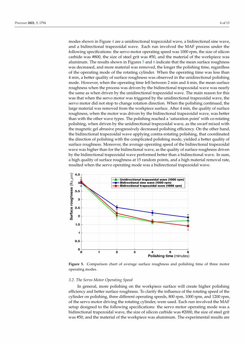
netic field was changed by the permanent magnet synchronously with the movements of the rotating cylinder. The workpiece was in highly synchronous movement with the ro-tating cylinder, which was then rubbed with gel abrasive. The three kinds of servo oper-ating modes shown in Figure 4 are a unidirectional trapezoidal wave, a bidirectional sine wave, and a bidirectional trapezoidal wave. Each run involved the MAF process under the following specifications: the servo motor operating speed was 1000 rpm, the size of silicon carbide was #800, the size of steel grit was #50, and the material of the workpiece was aluminum. The results shown in Figures 5 and 6 indicate that the mean surface rough-ness was decreased, and more material was removed, the longer the polishing time, re-gardless of the operating mode of the rotating cylinder . When the operating time was less than 4 min, a better quality of surface roughness was observed in the unidirectional pol-ishing mode. However, when the operating time fell between 2 min and 4 min, the mean surface roughness when the process was driven by the bidirectional trapezoidal wave was nearly the same as when driven by the unidirectional trapezoidal wave. The main reason for this was that when the servo motor was triggered by the unidirectional trapezoidal wave, the servo motor did not stop to change rotation direction. When the polishing con-tinued, the large material was removed from the workpiece surface. After 4 min, the qual-ity of surface roughness, when the motor was driven by the bidirectional trapezoidal wave, was better than with the other wave types. The polishing reached a ‘saturation point’ with co-rotating polishing, when driven by the unidirectional trapezoidal wave, as the swarf mixed with the magnetic gel abrasive progressively decreased polishing effi-ciency. On the other hand, the bidirectional trapezoidal wave applying contra-rotating polishing, that coordinated the direction of polishing with the complicated polishing mode, yielded a better quality of surface roughness. Moreover, the average operating speed of the bidirectional trapezoidal wave was higher than for the bidirectional wave, as the quality of surface roughness driven by the bidirectional trapezoidal wave performed
Figure 4. Three motor operating modes: (a) unidirectional trapezoidal wave; (b) bidirectional sine wave; (c) bidirectionaltrapezoidal wave.
3.1. The Servo Operating Mode
The servo motor outside of the rotating cylinder drove the MAF process. The magneticfield was changed by the permanent magnet synchronously with the movements of therotating cylinder. The workpiece was in highly synchronous movement with the rotatingcylinder, which was then rubbed with gel abrasive. The three kinds of servo operating
Processes 2021, 9, 1794 6 of 13
modes shown in Figure 4 are a unidirectional trapezoidal wave, a bidirectional sine wave,and a bidirectional trapezoidal wave. Each run involved the MAF process under thefollowing specifications: the servo motor operating speed was 1000 rpm, the size of siliconcarbide was #800, the size of steel grit was #50, and the material of the workpiece wasaluminum. The results shown in Figures 5 and 6 indicate that the mean surface roughnesswas decreased, and more material was removed, the longer the polishing time, regardlessof the operating mode of the rotating cylinder. When the operating time was less than4 min, a better quality of surface roughness was observed in the unidirectional polishingmode. However, when the operating time fell between 2 min and 4 min, the mean surfaceroughness when the process was driven by the bidirectional trapezoidal wave was nearlythe same as when driven by the unidirectional trapezoidal wave. The main reason for thiswas that when the servo motor was triggered by the unidirectional trapezoidal wave, theservo motor did not stop to change rotation direction. When the polishing continued, thelarge material was removed from the workpiece surface. After 4 min, the quality of surfaceroughness, when the motor was driven by the bidirectional trapezoidal wave, was betterthan with the other wave types. The polishing reached a ‘saturation point’ with co-rotatingpolishing, when driven by the unidirectional trapezoidal wave, as the swarf mixed withthe magnetic gel abrasive progressively decreased polishing efficiency. On the other hand,the bidirectional trapezoidal wave applying contra-rotating polishing, that coordinatedthe direction of polishing with the complicated polishing mode, yielded a better quality ofsurface roughness. Moreover, the average operating speed of the bidirectional trapezoidalwave was higher than for the bidirectional wave, as the quality of surface roughness drivenby the bidirectional trapezoidal wave performed better than a bidirectional wave. In sum,a high quality of surface roughness at 15 random points, and a high material removal rate,resulted when the servo operating mode was a bidirectional trapezoidal wave.
Processes 2021, 9, 1794 7 of 15
better than a bidirectional wave. In sum, a high quality of surface roughness at 15 random points, and a high material removal rate, resulted when the servo operating mode was a bidirectional trapezoidal wave.
Figure 5. Comparison chart of average surface roughness and polishing time of three motor operat-ing modes.
Figure 6. Comparison chart of average material removal weight and polishing time of three motor operating modes.
3.2. The Servo Motor Operating Speed In general, more polishing on the workpiece surface will create higher polishing ef-
ficiency and better surface roughness. To clarify the influence of the rotating speed of the cylinder on polishing, three different operating speeds, 800 rpm, 1000 rpm, and 1200 rpm, of the servo motor driving the rotating cylinder, were used. Each run involved the MAF setup designed to the following specifications: the servo motor operating mode was a bi-directional trapezoidal wave, the size of silicon carbide was #2000, the size of steel grit was #50, and the material of the workpiece was aluminum. The experimental results are shown in Figures 7 and 8. The mean surface roughness was decreased, and the amount of
Figure 5. Comparison chart of average surface roughness and polishing time of three motoroperating modes.
3.2. The Servo Motor Operating Speed
In general, more polishing on the workpiece surface will create higher polishingefficiency and better surface roughness. To clarify the influence of the rotating speed of thecylinder on polishing, three different operating speeds, 800 rpm, 1000 rpm, and 1200 rpm,of the servo motor driving the rotating cylinder, were used. Each run involved the MAFsetup designed to the following specifications: the servo motor operating mode was abidirectional trapezoidal wave, the size of silicon carbide was #2000, the size of steel gritwas #50, and the material of the workpiece was aluminum. The experimental results are

Processes 2021, 9, 1794 7 of 13
shown in Figures 7 and 8. The mean surface roughness was decreased, and the amount ofmaterial removed was increased, with increased polishing time, regardless of the speed ofthe rotating cylinder. In addition, a higher speed of the rotating cylinder led to a highermaterial removal rate. The rotating cylinder, driven by a servo motor with 1200 rpm, wasthe highest speed used for polishing the workpiece surface. After 6 min, the materialremoval reached a saturation point and the surface roughness did not change further.
Processes 2021, 9, 1794 7 of 15
better than a bidirectional wave. In sum, a high quality of surface roughness at 15 random points, and a high material removal rate, resulted when the servo operating mode was a bidirectional trapezoidal wave.
Figure 5. Comparison chart of average surface roughness and polishing time of three motor operat-ing modes.
Figure 6. Comparison chart of average material removal weight and polishing time of three motor operating modes.
3.2. The Servo Motor Operating Speed In general, more polishing on the workpiece surface will create higher polishing ef-
ficiency and better surface roughness. To clarify the influence of the rotating speed of the cylinder on polishing, three different operating speeds, 800 rpm, 1000 rpm, and 1200 rpm, of the servo motor driving the rotating cylinder, were used. Each run involved the MAF setup designed to the following specifications: the servo motor operating mode was a bi-directional trapezoidal wave, the size of silicon carbide was #2000, the size of steel grit was #50, and the material of the workpiece was aluminum. The experimental results are shown in Figures 7 and 8. The mean surface roughness was decreased, and the amount of
Figure 6. Comparison chart of average material removal weight and polishing time of three motoroperating modes.
Processes 2021, 9, 1794 8 of 15
material removed was increased, with increased polishing time, regardless of the speed of the rotating cylinder. In addition, a higher speed of the rotating cylinder led to a higher material removal rate. The rotating cylinder, driven by a servo motor with 1200 rpm, was the highest speed used for polishing the workpiece surface. After 6 min, the material re-moval reached a saturation point and the surface roughness did not change further.
Figure 7. Comparison chart of average surface roughness and polishing time at three motor speeds.
Figure 8. Comparison chart of average material removal weight and polishing time at three motor speeds.
3.3. The Size of Silicon Carbide SiC refers to the abrasive used in the MAF process, with the size of abrasive affecting
the efficiency of polishing. To assess the influence of the size of SiC particles on the quality of polishing, three different sizes of SiC, #800 (the average diameter of SiC is 14.5 μm), #1000 (the average diameter of SiC is 11.5 μm), and #2000 (the average diameter of SiC is 6.9 μm) were used. The size of SiC particle was specified by JIS R 6001: bonded abrasives-determination and designation of grain size distribution. Each run involved the MAF
Figure 7. Comparison chart of average surface roughness and polishing time at three motor speeds.
3.3. The Size of Silicon Carbide
SiC refers to the abrasive used in the MAF process, with the size of abrasive affectingthe efficiency of polishing. To assess the influence of the size of SiC particles on the qualityof polishing, three different sizes of SiC, #800 (the average diameter of SiC is 14.5 µm),#1000 (the average diameter of SiC is 11.5 µm), and #2000 (the average diameter of SiC is6.9 µm) were used. The size of SiC particle was specified by JIS R 6001: bonded abrasives-

Processes 2021, 9, 1794 8 of 13
determination and designation of grain size distribution. Each run involved the MAFsetup designed to the following specifications: the servo motor operating mode was abidirectional trapezoidal wave, the servo motor operating speed was 1000 rpm, the sizeof steel grit was #50, and the material of the workpiece was aluminum. The experimentalresults are shown in Figures 9 and 10. At 4 min, the polishing quality of the abrasivewith #800 SiC particle size was better than at other particle sizes. The average diameterof #800 SiC particles was larger than for the #1000 SiC and #1200 SiC particles, with fastmaterial removal rate and deep shear marks occurring at the beginning of polishing. Theeffect of the polishing operation stabilized rapidly and soon did not further improve thequality of polishing. On the other hand, the #1000 SiC particle size did not improve thematerial removal rate compared to #800 SiC, but did result in a flatter polishing surface.After 6 min, the mean roughness of the workpiece polished with #1000 SiC was lowerthan for #800 SiC. Moreover, the mean diameter of #2000 SiC was too small to effectivelycomplete the polishing. In sum, the MAF process with the #1000 SiC abrasive had thelowest mean surface roughness.
Processes 2021, 9, 1794 8 of 15
material removed was increased, with increased polishing time, regardless of the speed of the rotating cylinder. In addition, a higher speed of the rotating cylinder led to a higher material removal rate. The rotating cylinder, driven by a servo motor with 1200 rpm, was the highest speed used for polishing the workpiece surface. After 6 min, the material re-moval reached a saturation point and the surface roughness did not change further.
Figure 7. Comparison chart of average surface roughness and polishing time at three motor speeds.
Figure 8. Comparison chart of average material removal weight and polishing time at three motor speeds.
3.3. The Size of Silicon Carbide SiC refers to the abrasive used in the MAF process, with the size of abrasive affecting
the efficiency of polishing. To assess the influence of the size of SiC particles on the quality of polishing, three different sizes of SiC, #800 (the average diameter of SiC is 14.5 μm), #1000 (the average diameter of SiC is 11.5 μm), and #2000 (the average diameter of SiC is 6.9 μm) were used. The size of SiC particle was specified by JIS R 6001: bonded abrasives-determination and designation of grain size distribution. Each run involved the MAF
Figure 8. Comparison chart of average material removal weight and polishing time at three motor speeds.
Processes 2021, 9, 1794 9 of 15
setup designed to the following specifications: the servo motor operating mode was a bi-directional trapezoidal wave, the servo motor operating speed was 1000 rpm, the size of steel grit was #50, and the material of the workpiece was aluminum. The experimental results are shown in Figures 9 and 10. At 4 min, the polishing quality of the abrasive with #800 SiC particle size was better than at other particle sizes. The average diameter of #800 SiC particles was larger than for the #1000 SiC and #1200 SiC particles, with fast material removal rate and deep shear marks occurring at the beginning of polishing. The effect of the polishing operation stabilized rapidly and soon did not further improve the quality of polishing. On the other hand, the #1000 SiC particle size did not improve the material removal rate compared to #800 SiC, but did result in a flatter polishing surface. After 6 min, the mean roughness of the workpiece polished with #1000 SiC was lower than for #800 SiC. Moreover, the mean diameter of #2000 SiC was too small to effectively complete the polishing. In sum, the MAF process with the #1000 SiC abrasive had the lowest mean surface roughness.
Figure 9. Comparison chart of average surface roughness and polishing time of three kinds of silicon carbide particle size.
Figure 9. Comparison chart of average surface roughness and polishing time of three kinds of siliconcarbide particle size.

Processes 2021, 9, 1794 9 of 13
Processes 2021, 9, 1794 9 of 15
setup designed to the following specifications: the servo motor operating mode was a bi-directional trapezoidal wave, the servo motor operating speed was 1000 rpm, the size of steel grit was #50, and the material of the workpiece was aluminum. The experimental results are shown in Figures 9 and 10. At 4 min, the polishing quality of the abrasive with #800 SiC particle size was better than at other particle sizes. The average diameter of #800 SiC particles was larger than for the #1000 SiC and #1200 SiC particles, with fast material removal rate and deep shear marks occurring at the beginning of polishing. The effect of the polishing operation stabilized rapidly and soon did not further improve the quality of polishing. On the other hand, the #1000 SiC particle size did not improve the material removal rate compared to #800 SiC, but did result in a flatter polishing surface. After 6 min, the mean roughness of the workpiece polished with #1000 SiC was lower than for #800 SiC. Moreover, the mean diameter of #2000 SiC was too small to effectively complete the polishing. In sum, the MAF process with the #1000 SiC abrasive had the lowest mean surface roughness.
Figure 9. Comparison chart of average surface roughness and polishing time of three kinds of silicon carbide particle size.
Figure 10. Comparison chart of average material removal weight and polishing time of three kindsof silicon carbide particle size.
3.4. The Size of Steel Grit
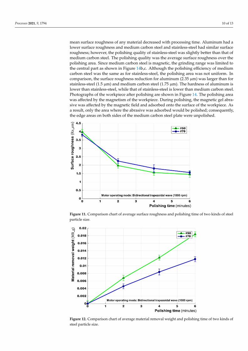
The steel grit used was a magnetic medium mixture of abrasives. After mixing thesteel grit, the gel abrasive becomes magnetic, and then the polishing path can be drivenby a magnetic field which is generated by the permanent magnet of the rotating cylinder.Furthermore, the size of steel grits affects the magnetic attraction force. To assess theinfluence of the size of SiC particles on the quality of polishing, two different sizes ofSiC were used in the MAF process: #50 (the average diameter is 350 µm) and #70 (theaverage diameter is 230 µm). Each run involved the MAF setup designed to the followingspecifications: the servo motor operating mode was a bidirectional trapezoidal wave, theservo motor operating speed was 1000 rpm, the size of silicon carbide was #2000, andthe material of the workpiece was aluminum. The experimental results are shown inFigures 11 and 12. The mean of surface roughness decreased and the amount of materialincreased with increased polishing time, regardless of the size of steel grit in the abrasive.At the beginning of polishing, the polishing effect of abrasives mixed with #50 steel gritwas better than that of abrasives mixed with #70 steel grit, but the surface roughness afterpolishing with #50 steel grit did not change over time. When the abrasive was mixed with#50 steel grit, the amount of material removed was greater than when the abrasive wasmixed with #70 steel grit throughout the polishing process. After 6 min, the mean surfaceroughness of the workpiece was equivalent when polishing with abrasives mixed with#50 steel grit and with abrasives mixed with #70 steel grit. The gel abrasive mixed with#50 steel grit could effectively remove the protrusions on the surface of the workpiece. Thediameter of the #70 steel grit was small, and the steel grit could not follow the change ofthe magnetic field to drive the silicon carbide off the abrasive for polishing. Therefore, theeffect of material removal rate was poor when small size steel grits were chosen to mixwith the abrasive.
3.5. The Different Material Workpiece
To assess the polishing quality of MAF using different materials, three different mate-rials, including aluminum, medium carbon steel, and stainless-steel, were used. Amongthese materials, the medium carbon steel was magnetic and the other two materials werenon-magnetic. Each run involved the MAF setup designed to the following specifications:the servo motor operating mode was a unidirectional trapezoidal wave. Each set wasperformed four times (0 min, 1 min, 2 min, and 3 min), then the average surface roughnessat 15 random points was recorded. The experimental results are shown in Figure 13. The
Processes 2021, 9, 1794 10 of 13
mean surface roughness of any material decreased with processing time. Aluminum had alower surface roughness and medium carbon steel and stainless-steel had similar surfaceroughness; however, the polishing quality of stainless-steel was slightly better than that ofmedium carbon steel. The polishing quality was the average surface roughness over thepolishing area. Since medium carbon steel is magnetic, the grinding range was limited tothe central part as shown in Figure 14b,c. Although the polishing efficiency of mediumcarbon steel was the same as for stainless-steel, the polishing area was not uniform. Incomparison, the surface roughness reduction for aluminum (2.35 µm) was larger than forstainless-steel (1.5 µm) and medium carbon steel (1.75 µm). The hardness of aluminum islower than stainless-steel, while that of stainless-steel is lower than medium carbon steel.Photographs of the workpiece after polishing are shown in Figure 14. The polishing areawas affected by the magnetism of the workpiece. During polishing, the magnetic gel abra-sive was affected by the magnetic field and adsorbed onto the surface of the workpiece. Asa result, only the area where the abrasive was adsorbed would be polished; consequently,the edge areas on both sides of the medium carbon steel plate were unpolished.
Processes 2021, 9, 1794 11 of 15
3.4. The Size of Steel Grit The steel grit used was a magnetic medium mixture of abrasives. After mixing the
steel grit, the gel abrasive becomes magnetic, and then the polishing path can be driven by a magnetic field which is generated by the permanent magnet of the rotating cylinder. Furthermore, the size of steel grits affects the magnetic attraction force. To assess the in-fluence of the size of SiC particles on the quality of polishing, two different sizes of SiC were used in the MAF process: #50 (the average diameter is 350 μm) and #70 (the average diameter is 230 μm). Each run involved the MAF setup designed to the following specifi-cations: the servo motor operating mode was a bidirectional trapezoidal wave, the servo motor operating speed was 1000 rpm, the size of silicon carbide was #2000, and the mate-rial of the workpiece was aluminum. The experimental results are shown in Figures 11 and 12. The mean of surface roughness decreased and the amount of material increased with increased polishing time, regardless of the size of steel grit in the abrasive. At the beginning of polishing, the polishing effect of abrasives mixed with #50 steel grit was bet-ter than that of abrasives mixed with #70 steel grit, but the surface roughness after polish-ing with #50 steel grit did not change over time. When the abrasive was mixed with #50 steel grit, the amount of material removed was greater than when the abrasive was mixed with #70 steel grit throughout the polishing process. After 6 min, the mean surface rough-ness of the workpiece was equivalent when polishing with abrasives mixed with #50 steel grit and with abrasives mixed with #70 steel grit. The gel abrasive mixed with #50 steel grit could effectively remove the protrusions on the surface of the workpiece. The diame-ter of the #70 steel grit was small, and the steel grit could not follow the change of the magnetic field to drive the silicon carbide off the abrasive for polishing. Therefore, the effect of material removal rate was poor when small size steel grits were chosen to mix with the abrasive.
Figure 11. Comparison chart of average surface roughness and polishing time of two kinds of steel particle size.
Figure 11. Comparison chart of average surface roughness and polishing time of two kinds of steelparticle size.
Processes 2021, 9, 1794 12 of 15
Figure 12. Comparison chart of average material removal weight and polishing time of two kinds of steel particle size.
3.5. The Different Material Workpiece To assess the polishing quality of MAF using different materials, three different ma-
terials, including aluminum, medium carbon steel, and stainless-steel, were used. Among these materials, the medium carbon steel was magnetic and the other two materials were non-magnetic. Each run involved the MAF setup designed to the following specifications: the servo motor operating mode was a unidirectional trapezoidal wave. Each set was per-formed four times (0 min, 1 min, 2 min, and 3 min), then the average surface roughness at 15 random points was recorded. The experimental results are shown in Figure 13. The mean surface roughness of any material decreased with processing time. Aluminum had a lower surface roughness and medium carbon steel and stainless-steel had similar surface roughness; however, the polishing quality of stainless-steel was slightly better than that of medium carbon steel. The polishing quality was the average surface roughness over the polishing area. Since medium carbon steel is magnetic, the grinding range was limited to the central part as shown in Figure 14b,c. Although the polishing efficiency of medium carbon steel was the same as for stainless-steel, the polishing area was not uniform. In comparison, the surface roughness reduction for aluminum (2.35 μm) was larger than for stainless-steel (1.5 μm) and medium carbon steel (1.75 μm). The hardness of aluminum is lower than stainless-steel, while that of stainless-steel is lower than medium carbon steel. Photographs of the workpiece after polishing are shown in Figure 14. The polishing area was affected by the magnetism of the workpiece. During polishing, the magnetic gel abra-sive was affected by the magnetic field and adsorbed onto the surface of the workpiece. As a result, only the area where the abrasive was adsorbed would be polished; conse-quently, the edge areas on both sides of the medium carbon steel plate were unpolished.
Figure 12. Comparison chart of average material removal weight and polishing time of two kinds ofsteel particle size.

Processes 2021, 9, 1794 11 of 13Processes 2021, 9, 1794 13 of 15
Figure 13. Comparison chart of average surface roughness and polishing time of three types of ma-terials.
(a) (b) (c)
Figure 14. Polishing effect of three types of materials: (a) aluminum; (b) medium carbon steel; (c) stainless-steel.
4. Discussion In the MAF system, magnetic forces, the gel abrasive, and the workpiece affected the
quality of polishing. Three factors, including the rotating mode of the cylinder with per-manent magnets, the rotating speed of the cylinder, and the size of steel grit of the gel abrasive, were affected by the magnetic field. The efficiency of polishing was affected by the size of silicon carbide particles in the abrasive. In sum, in this paper, five factors have been discussed and evaluated with respect to their effect on polishing.
First, the rotating mode of the cylinder with permanent magnets applied included a unidirectional trapezoidal mode, a bidirectional sine mode, and a bidirectional trapezoi-dal mode. For surface roughness, the same polishing rotating direction and speed were maintained in the unidirectional trapezoidal mode for high-speed polishing, which quickly reduced the mean surface roughness in the initial stage of processing. However, in the middle phase, the polishing capacity quickly reached saturation due to the single direction of rotation. The bidirectional mode used different rotating directions to improve
Figure 13. Comparison chart of average surface roughness and polishing time of three types of materials.
Processes 2021, 9, 1794 13 of 15
Figure 13. Comparison chart of average surface roughness and polishing time of three types of ma-terials.
(a) (b) (c)
Figure 14. Polishing effect of three types of materials: (a) aluminum; (b) medium carbon steel; (c) stainless-steel.
4. Discussion In the MAF system, magnetic forces, the gel abrasive, and the workpiece affected the
quality of polishing. Three factors, including the rotating mode of the cylinder with per-manent magnets, the rotating speed of the cylinder, and the size of steel grit of the gel abrasive, were affected by the magnetic field. The efficiency of polishing was affected by the size of silicon carbide particles in the abrasive. In sum, in this paper, five factors have been discussed and evaluated with respect to their effect on polishing.
First, the rotating mode of the cylinder with permanent magnets applied included a unidirectional trapezoidal mode, a bidirectional sine mode, and a bidirectional trapezoi-dal mode. For surface roughness, the same polishing rotating direction and speed were maintained in the unidirectional trapezoidal mode for high-speed polishing, which quickly reduced the mean surface roughness in the initial stage of processing. However, in the middle phase, the polishing capacity quickly reached saturation due to the single direction of rotation. The bidirectional mode used different rotating directions to improve
Figure 14. Polishing effect of three types of materials: (a) aluminum; (b) medium carbon steel; (c) stainless-steel.
4. Discussion
In the MAF system, magnetic forces, the gel abrasive, and the workpiece affectedthe quality of polishing. Three factors, including the rotating mode of the cylinder withpermanent magnets, the rotating speed of the cylinder, and the size of steel grit of the gelabrasive, were affected by the magnetic field. The efficiency of polishing was affected bythe size of silicon carbide particles in the abrasive. In sum, in this paper, five factors havebeen discussed and evaluated with respect to their effect on polishing.
First, the rotating mode of the cylinder with permanent magnets applied included aunidirectional trapezoidal mode, a bidirectional sine mode, and a bidirectional trapezoidalmode. For surface roughness, the same polishing rotating direction and speed weremaintained in the unidirectional trapezoidal mode for high-speed polishing, which quicklyreduced the mean surface roughness in the initial stage of processing. However, in themiddle phase, the polishing capacity quickly reached saturation due to the single directionof rotation. The bidirectional mode used different rotating directions to improve polishingefficiency and solve the problem of saturation associated with single direction polishing.
Processes 2021, 9, 1794 12 of 13
Furthermore, comparison of the bidirectional sine mode and bidirectional trapezoidalmode showed that the average speed of the bidirectional trapezoidal mode was higher.Therefore, regardless of the mean surface roughness or the amount of material removal, thepolishing ability of the bidirectional trapezoidal mode was higher than for the other modes.The different rotating cylinder speeds correspond to the amount of polishing applied tothe workpiece in unit time. That is, the higher the rotation speed, the greater the number ofrelative movements effected between the abrasive and the workpiece per unit time, andthe higher the amount of material removed in a short period. When sufficient speed wasattained, the material removal rate reached a saturation point with no further change inthe degree of surface roughness. As the experimental results showed, rotating cylinderspeeds of 1000 rpm produced a better quality of polishing. Thirdly, when the silicon carbideparticle size is smaller, the effect of fine processing is improved. However, the less thesurface protrusions were removed, the longer the completion of polishing took. When thesilicon carbide particle size was larger, the surface protrusions were more quickly removedin the initial stage. Although the rough polishing effect was strong, the average surfaceroughness could not be reduced further with increased polishing time. As the experimentalresults showed, the abrasive mix with SiC #1000 produced a better quality of polishing, butthere was not a significant difference between the three kinds of SiC at the end of polishing.Fourthly, the steel grit with a larger particle size was more affected by the magnetic field,which drove off the abrasive. Increasing the content of magnetic abrasives or using largemagnetic steel grit could improve the quality of polishing and the amount of materialremoved from the MAF. In the experimental results, the abrasive mix with steel grit #50achieved a better quality of polishing. Finally, the hardness of the workpiece affected thequality of surface roughness. In the MAF process, aluminum resulted in lower surfaceroughness. However, the material with magnetic abrasives affected the polishing area. Themagnetic workpieces, such as medium carbon steel, remained unpolished in edge areas onboth sides.
5. Conclusions
The magnetic gel abrasive finishing method was successfully designed and developed.The rotating cylinder-based magnetic finishing setup allowed the gel abrasive and work-pieces to perform tumbling and rotating motions side-by-side during the polishing process.Magnetic gel abrasive finishing is a high-precision polishing method that uses magneticforces to attract a gel abrasive, which was composed, in this study, of aqueous slime gel,steel grits, and SiC, for polishing workpieces. In the MAF system, the magnetic forces,the components of the gel abrasive, and the material of the workpiece affected the qualityof polishing. Three factors, the rotating mode of the cylinder with permanent magnets,the rotating speed of the cylinder, and the size of steel grit in the gel abrasive, had aneffect on the magnetic field. The efficiency of polishing was affected by the size of siliconcarbide particles in the abrasive. In sum, five factors were discussed and evaluated withrespect to their effect on polishing. The results suggested that the optimal MAF processingconditions were: a servo operating mode with a bidirectional trapezoidal wave, a servomotor operating speed of 1200 rpm, silicon carbide particles of size #1000, steel grit of size#50, and an aluminum workpiece. However, the size of silicon carbide did not have asignificant effect on the polishing characteristics. The experimental results showed thatthe rotating cylinder driven with a bidirectional trapezoidal wave could obtain improvedresults for average surface roughness and material removal weight compared to the othertwo operating modes, and that larger steel grit size could also yield improved results.
Author Contributions: Conceptualization, A.-C.W., K.-Y.C. and Y.-H.F.; methodology, A.-C.W. and Y.-H.F.; validation, K.-Y.C., T.-Y.T. and P.-K.F.; investigation, K.-Y.C., T.-Y.T. and P.-K.F.; resources, K.-Y.C.,A.-C.W. and Y.-H.F.; data curation, K.-Y.C., T.-Y.T. and P.-K.F.; writing—original draft preparation,K.-Y.C., T.-Y.T. and A.-C.W.; writing—review and editing, K.-Y.C., T.-Y.T. and A.-C.W.; visualization,K.-Y.C. All authors have read and agreed to the published version of the manuscript.

Processes 2021, 9, 1794 13 of 13
Funding: This work was supported by the Ministry of Science and Technology of Taiwan (R.O.C.)under grant number MOST 110-2221-E-033-028.
Institutional Review Board Statement: Not applicable.
Informed Consent Statement: Not applicable.
Data Availability Statement: Not applicable.
Acknowledgments: The authors would like to thank the Ministry of Science and Technology ofTaiwan (R.O.C.) for financial support of this work.
Conflicts of Interest: The authors declare no conflict of interest.
References1. Shinmura, T. Development of a unit system magnetic abrasive finishing apparatus using permanent magnets. J. Jpn. Soc. Pre. Eng.
1990, 56, 1027–1032. [CrossRef]2. Yamaguchi, H.; Srivastava, A.K.; Tan, M.; Hashimoto, F. Magnetic abrasive finishing of cutting tools for high-speed machining of
Titanium alloys. CIRP J. Manuf. Sci. Tech. 2014, 7, 299–304. [CrossRef]3. Wang, Y.; Hu, D. Study on the inner surface finishing of tubing by magnetic abrasive finishing. Int. J. Mach. Tools Manuf. 2005, 45,
43–49. [CrossRef]4. Ko, S.L.; Baron, Y.M.; Park, J.I. Micro deburring for precision parts using magnetic abrasive finishing method. J. Mater. Process.
Technol. 2007, 187–188, 19–25. [CrossRef]5. Jain, V.K.; Kumar, P.; Behera, P.K.; Jayswal, S.C. Effect of working gap and circumferential speed on the performance of magnetic
abrasive finishing process. Wear 2001, 250, 384–390. [CrossRef]6. Chang, G.W.; Yan, B.H.; Hsu, R.T. Study on cylindrical magnetic abrasive finishing using unbonded magnetic abrasives. Int. J.
Mach. Tools Manuf. 2002, 42, 575–583. [CrossRef]7. Yan, B.H.; Chang, G.W.; Cheng, J.T.; Hsu, R.T. Electrolytic magnetic abrasive finishing. Int. J. Mach. Tools Manuf. 2003, 43,
1355–1366. [CrossRef]8. Yamaguchi, H.; Shinmura, T. Study of an internal magnetic abrasive finishing using a pole rotation system: Discussion of the
characteristic abrasive behavior. Preci. Eng. 2000, 24, 237–244. [CrossRef]9. Yan, B.H.; Chang, G.W.; Chang, J.H.; Hsu, R.T. Improving electrical discharge machined surfaces using magnetic abrasive
finishing. Mach. Sci. Technol. 2004, 8, 103–118. [CrossRef]10. Wang, A.C.; Lee, S.J. Study the characteristics of magnetic finishing with gel abrasive. Int. J. Mach. Tools Manuf. 2009, 49,
1063–1069. [CrossRef]11. Wang, A.C.; Tsai, L.; Liu, C.H.; Liang, K.Z.; Lee, S.J. Elucidating the optimal parameters in magnetic finishing with gel abrasive.
Mater. Manuf. Process. 2011, 26, 786–791. [CrossRef]12. Tsai, L.; Wang, A.C.; Chou, S.H.; Zhong, C.J. Investigating of flexible self-sharpening and optimal parameters in magnetic
finishing with gel abrasive. Int. J. Precis. Eng. Manuf. 2012, 13, 655–661. [CrossRef]13. Chou, S.H.; Wang, A.C.; Lin, Y.C. Elucidating the rheological effect of gel abrasives in magnetic abrasive finishing. Procedia CIRP.
2016, 42, 866–871. [CrossRef]14. Zhang, J.; Hu, J.; Wang, H.; Kumar, A.S.; Chaudhari, A. A novel magnetically driven polishing technique for internal surface
finishing. Precis. Eng. 2018, 54, 222–232. [CrossRef]15. Kala, P.; Pandey, P.M. Comparison of finishing characteristics of two paramagnetic materials using double disc magnetic abrasive
finishing. J. Manuf. Process. 2015, 17, 63–77. [CrossRef]16. Yamaguchi, H.; Fergani, O.; Wu, P.Y. Modification using magnetic field-assisted finishing of the surface roughness and residual
stress of additively manufactured components. CIRP Ann. Manuf. Technol. 2017, 66, 305–308. [CrossRef]17. Zhang, J.; Chaudhari, A.; Wang, H. Surface quality and material removal in magnetic abrasive finishing of selective laser melted
316L stainless steel. J. Manuf. Process. 2019, 45, 710–719. [CrossRef]