Liquid-sample introduction in plasma spectrometry
10
Liquid-sample introduction in plasma spectrometry Juan Mora, Salvador Maestre, Vicente Hernandis, Jose´ L. Todolı ´ Plasma-spectrometry techniques, namely inductively coupled plasma atomic emission spectrometry (ICP-AES) and plasma-based mass spectro- metry (MS), are the most commonly used in analytical laboratories for elemental analysis in a wide variety of samples. In these techniques, the quality of the analysis strongly depends on appropriate selection of the sample-introduction system. For liquid samples, it basically comprises a nebulizer, which transforms the bulk solution into an aerosol, and a spray chamber, which modifies the characteristics of this aerosol and transports it to the plasma base through an injector tube. Sometimes, a desolvation system is incorporated to reduce the solvent load into the plasma. This article describes the different components of the sample-introduction system, emphasizing their main advantages and drawbacks. A review of the processes that affect the aerosol between generation and reaching the plasma is also included. # 2003 Published by Elsevier Science B.V. Keywords: Desolvation system; Inductively coupled plasma atomic emission spectrometry (ICP-AES); Inductively coupled plasma mass spectrometry (ICP-MS); Nebulizer; Spray chamber 1. Introduction Plasma-spectrometry techniques, namely inductively coupled plasma atomic emis- sion spectrometry (ICP-AES) and induc- tively coupled plasma mass spectrometry (ICP-MS), are widely used in the analy- tical laboratories, mainly because of their low limits of detection (LOD), high sensi- tivity, precision and analytical through- put. In these techniques, the analytical response depends directly on the number of analyte atoms present in the plasma and, therefore, on the analyte concen- tration in the sample. In ICP-AES, the radiation generated is ¢nally measured using an appropriate detection system. In ICP-MS, analyte ions are extracted from the plasma and then directly registered. The main goal of a sample-introduction system is to introduce the maximum amount of analyte into the plasma in the most suitable form. A great variety of devices have been designed so far to introduce liquid, gas and solid samples into the plasma [1^4]. The appropriate selection of the sample-introduction sys- tem is a critical step when particular ana- lytical ¢gures of merit are required. Moreover, some kinds of interference can be minimized or even eliminated by a judicious selection of the sample-intro- duction system [5,6]. 2. Description of the liquid sample- introduction system Usually, the sample is supplied as a liquid solution because of its homogeneity, ease of handling and the possibility of prepar- ing calibration standards. In this case, the main components of the sample- introduction system are (Fig. 1): (i) a nebulizer, which spreads out the liquid bulk generating an aerosol; (ii) a spray chamber, which ¢lters the aerosol and transports it to the plasma; (iii) a desolvation system to reduce the mass of solvent reaching the plasma; and, (iv) an injector tube to introduce the aerosol into the plasma base. 2.1. Nebulizers The aerosol-generation process (i.e., nebulization) requires the supply of energy to a liquid bulk by means of a nebulizer [7]. The characteristics of the aerosols are greatly dependent on the amount of available energy and on the e⁄ciency of the energy transfer. Usually, nebulizers have been classi¢ed on the basis of the type of energy employed. Thus, aerosols can be originated: Juan Mora*, Salvador Maestre, Vicente Hernandis, Jose´ L. Todolı´ Department of Analytical Chemistry, University of Alicante, P.O. Box 99, E-03080 Alicante, Spain *Corresponding author; E-mail: [email protected] Trends in Analytical Chemistry, Vol. 22, No. 3, 2003 Trends 0165-9936/03/$ - see front matter # 2003 Published by Elsevier Science B.V. doi:10.1016/S0165-9936(03)00301-7 123
Transcript of Liquid-sample introduction in plasma spectrometry
Liquid-sample introduction inplasma spectrometryJuan Mora, Salvador Maestre, Vicente Hernandis, Jose L. Todolı
Plasma-spectrometry techniques, namely inductively coupled plasmaatomic emission spectrometry (ICP-AES) and plasma-based mass spectro-metry (MS), are the most commonly used in analytical laboratories forelemental analysis in a wide variety of samples. In these techniques, thequality of the analysis strongly depends on appropriate selection of thesample-introduction system. For liquid samples, it basically comprises anebulizer, which transforms the bulk solution into an aerosol, and a spraychamber, which modifies the characteristics of this aerosol and transportsit to the plasma base through an injector tube. Sometimes, a desolvationsystem is incorporated to reduce the solvent load into the plasma. Thisarticle describes the different components of the sample-introductionsystem, emphasizing their main advantages and drawbacks. A review ofthe processes that affect the aerosol between generation and reaching theplasma is also included.# 2003 Published by Elsevier Science B.V.
Keywords: Desolvation system; Inductively coupled plasma atomic emissionspectrometry (ICP-AES); Inductively coupled plasma mass spectrometry (ICP-MS);Nebulizer; Spray chamber
1. Introduction
Plasma-spectrometry techniques, namelyinductively coupled plasma atomic emis-sion spectrometry (ICP-AES) and induc-tively coupled plasma mass spectrometry(ICP-MS), are widely used in the analy-tical laboratories, mainly because of theirlow limits of detection (LOD), high sensi-tivity, precision and analytical through-put. In these techniques, the analyticalresponse depends directly on the numberof analyte atoms present in the plasmaand, therefore, on the analyte concen-tration in the sample. In ICP-AES, theradiation generated is ¢nally measuredusing an appropriate detection system. InICP-MS, analyte ions are extracted fromthe plasma and then directly registered.
The main goal of a sample-introductionsystem is to introduce the maximumamount of analyte into the plasma in themost suitable form. A great variety of
devices have been designed so far tointroduce liquid, gas and solid samplesinto the plasma [1^4]. The appropriateselection of the sample-introduction sys-tem is a critical step when particular ana-lytical ¢gures of merit are required.Moreover, some kinds of interference canbe minimized or even eliminated by ajudicious selection of the sample-intro-duction system [5,6].
2. Description of the liquid sample-introduction system
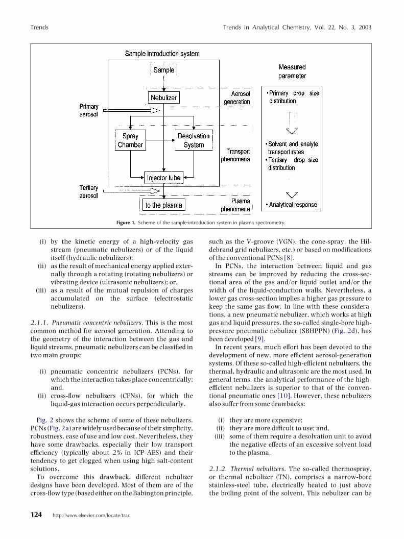
Usually, the sample is supplied as a liquidsolution because of its homogeneity, easeof handling and the possibility of prepar-ing calibration standards. In this case,the main components of the sample-introduction system are (Fig. 1):
(i) a nebulizer, which spreads out theliquid bulk generating an aerosol;
(ii) a spray chamber, which ¢lters theaerosol and transports it to theplasma;
(iii) a desolvation system to reduce themass of solvent reaching theplasma; and,
(iv) an injector tube to introduce theaerosol into the plasma base.
2.1. NebulizersThe aerosol-generation process (i.e.,nebulization) requires the supply of energyto a liquid bulk by means of a nebulizer [7].The characteristics of the aerosols aregreatly dependent on the amount ofavailable energy and on the e⁄ciency ofthe energy transfer. Usually, nebulizershave been classi¢ed on the basis of thetype of energy employed. Thus, aerosolscan be originated:
Juan Mora*, Salvador Maestre,
Vicente Hernandis, Jose
L. Todolı
Department of AnalyticalChemistry, University of
Alicante, P.O. Box 99, E-03080
Alicante, Spain
*Corresponding author;
E-mail: [email protected]
Trends in Analytical Chemistry, Vol. 22, No. 3, 2003 Trends
0165-9936/03/$ - see front matter # 2003 Published by Elsevier Science B.V. doi:10.1016/S0165-9936(03)00301-7 123
(i) by the kinetic energy of a high-velocity gasstream (pneumatic nebulizers) or of the liquiditself (hydraulic nebulizers);
(ii) as the result of mechanical energy applied exter-nally through a rotating (rotating nebulizers) orvibrating device (ultrasonic nebulizers); or,
(iii) as a result of the mutual repulsion of chargesaccumulated on the surface (electrostaticnebulizers).
2.1.1. Pneumatic concentric nebulizers. This is the mostcommon method for aerosol generation. Attending tothe geometry of the interaction between the gas andliquid streams, pneumatic nebulizers can be classi¢ed intwo main groups:
(i) pneumatic concentric nebulizers (PCNs), forwhich the interaction takes place concentrically;and,
(ii) cross-£ow nebulizers (CFNs), for which theliquid-gas interaction occurs perpendicularly.
Fig. 2 shows the scheme of some of these nebulizers.PCNs (Fig. 2a) are widely used because of their simplicity,robustness, ease of use and low cost. Nevertheless, theyhave some drawbacks, especially their low transporte⁄ciency (typically about 2% in ICP-AES) and theirtendency to get clogged when using high salt-contentsolutions.
To overcome this drawback, di¡erent nebulizerdesigns have been developed. Most of them are of thecross-£ow type (based either on the Babington principle,
such as the V-groove (VGN), the cone-spray, the Hil-debrand grid nebulizers, etc.) or based on modi¢cationsof the conventional PCNs [8].
In PCNs, the interaction between liquid and gasstreams can be improved by reducing the cross-sec-tional area of the gas and/or liquid outlet and/or thewidth of the liquid-conduction walls. Nevertheless, alower gas cross-section implies a higher gas pressure tokeep the same gas £ow. In line with these considera-tions, a new pneumatic nebulizer, which works at highgas and liquid pressures, the so-called single-bore high-pressure pneumatic nebulizer (SBHPPN) (Fig. 2d), hasbeen developed [9].
In recent years, much e¡ort has been devoted to thedevelopment of new, more e⁄cient aerosol-generationsystems. Of these so-called high-e⁄cient nebulizers, thethermal, hydraulic and ultrasonic are the most used. Ingeneral terms, the analytical performance of the high-e⁄cient nebulizers is superior to that of the conven-tional pneumatic ones [10]. However, these nebulizersalso su¡er from some drawbacks:
(i) they are more expensive;(ii) they are more di⁄cult to use; and,
(iii) some of them require a desolvation unit to avoidthe negative e¡ects of an excessive solvent loadto the plasma.
2.1.2. Thermal nebulizers. The so-called thermospray,or thermal nebulizer (TN), comprises a narrow-borestainless-steel tube, electrically heated to just abovethe boiling point of the solvent. This nebulizer can be
Figure 1. Scheme of the sample-introduction system in plasma spectrometry.
Trends Trends in Analytical Chemistry, Vol. 22, No. 3, 2003
124 http://www.elsevier.com/locate/trac
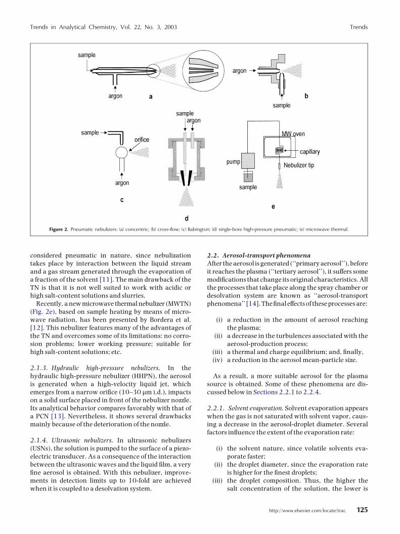
considered pneumatic in nature, since nebulizationtakes place by interaction between the liquid streamand a gas stream generated through the evaporation ofa fraction of the solvent [11]. The main drawback of theTN is that it is not well suited to work with acidic orhigh salt-content solutions and slurries.
Recently, a new microwave thermal nebulizer (MWTN)(Fig. 2e), based on sample heating by means of micro-wave radiation, has been presented by Bordera et al.[12]. This nebulizer features many of the advantages ofthe TN and overcomes some of its limitations: no corro-sion problems; lower working pressure; suitable forhigh salt-content solutions; etc.
2.1.3. Hydraulic high-pressure nebulizers. In thehydraulic high-pressure nebulizer (HHPN), the aerosolis generated when a high-velocity liquid jet, whichemerges from a narrow ori¢ce (10^30 mm i.d.), impactson a solid surface placed in front of the nebulizer nozzle.Its analytical behavior compares favorably with that ofa PCN [13]. Nevertheless, it shows several drawbacksmainly because of the deterioration of the nozzle.
2.1.4. Ultrasonic nebulizers. In ultrasonic nebulizers(USNs), the solution is pumped to the surface of a piezo-electric transducer. As a consequence of the interactionbetween the ultrasonic waves and the liquid ¢lm, a very¢ne aerosol is obtained. With this nebulizer, improve-ments in detection limits up to 10-fold are achievedwhen it is coupled to a desolvation system.
2.2. Aerosol-transport phenomenaAfter the aerosol is generated (‘‘primary aerosol’’), beforeit reaches the plasma (‘‘tertiary aerosol’’), it su¡ers somemodi¢cations that change its original characteristics. Allthe processes that take place along the spray chamber ordesolvation system are known as ‘‘aerosol-transportphenomena’’ [14]. The ¢nal e¡ects of these processes are:
(i) a reduction in the amount of aerosol reachingthe plasma;
(ii) a decrease in the turbulences associated with theaerosol-production process;
(iii) a thermal and charge equilibrium; and, ¢nally,(iv) a reduction in the aerosol mean-particle size.
As a result, a more suitable aerosol for the plasmasource is obtained. Some of these phenomena are dis-cussed below in Sections 2.2.1 to 2.2.4.
2.2.1. Solvent evaporation. Solvent evaporation appearswhen the gas is not saturated with solvent vapor, caus-ing a decrease in the aerosol-droplet diameter. Severalfactors in£uence the extent of the evaporation rate:
(i) the solvent nature, since volatile solvents eva-porate faster;
(ii) the droplet diameter, since the evaporation rateis higher for the ¢nest droplets;
(iii) the droplet composition. Thus, the higher thesalt concentration of the solution, the lower is
Figure 2. Pneumatic nebulizers: (a) concentric; (b) cross-flow; (c) Babington; (d) single-bore high-pressure pneumatic; (e) microwave thermal.
Trends in Analytical Chemistry, Vol. 22, No. 3, 2003 Trends
http://www.elsevier.com/locate/trac 125

the droplet-evaporation rate. This fact is becauseof the decrease of the partial pressure vapor ofthe solvent at the surface of the droplet; and,¢nally,
(iv) the temperature di¡erence between the dropletsurface and the surrounding gas and the velocityat which the droplet environment is renewed.
2.2.2. Nucleation. Droplet formation and growththrough condensation of the vapor on an appropriatesurface is known as ‘nucleation’. This process is theopposite of evaporation, since its e¡ect is to increase themean size and the number of the aerosol droplets.Nucleation depends on the saturation ratio (i.e., theratio between the partial gas vapor pressure and thesaturation vapor pressure) in the droplet environment.It takes place when saturation ratios higher than 1 areachieved. For a given saturation ratio, nucleationdepends on the original droplet diameter and on theaerosol composition.
2.2.3. Coagulation. The net e¡ect of this phenomenon isan increase in the droplet diameter because of collisionswith other droplets and, therefore, a decrease in thenumber of droplets contained in a given aerosolvolume. The origin of these collisions lies in the di¡er-ent motion of the droplets contained in the aerosol.Coagulation rate increases with the magnitude of thedi¡erence between droplets velocities.
2.2.4. Impact losses. In this case, a fraction of the aero-sol particles or droplets collide against the walls of someof the components of the sample-introduction system.Therefore, a reduction in the number of aerosol dropletsand a decrease in the aerosol mean size result. Depend-ing on the main mechanism of droplet collision, theimpact losses can be divided into three main groups:
(i) gravitational settling. The gravitational ¢eld isresponsible for droplet removal from the aerosolstream. On taking into account the range of dia-meters of the aerosols used in plasma spectro-metry, it can be stated that this mechanism is notsigni¢cant in comparison with those remaining;
(ii) turbulence deposition. Because gas turbulencescan act in any spatial direction, the study and thecharacterization of this mechanism is really dif-¢cult. The rate of turbulent deposition losses isproportional to the square of the drop diameterand the acceleration su¡ered by the dropletwhen a force acts on it; and,
(iii) inertial deposition. In some instances, thesample-introduction system includes an impactsurface placed along the aerosol path to removethe coarsest droplets. When the aerosol reaches
this surface it is forced to change its trajectory(Fig. 3). Because of its lower inertia, a smalldroplet is more likely to follow any sharptrajectory change than a coarse one. A largedroplet requires a longer time to accommodateits trajectory to the new path than a smallerone. Therefore, large droplets are more likely toimpact against the surface walls.
2.3. Spray chambersThe main function of the spray chamber is to ¢lter theaerosol generated by the nebulizer (primary aerosol), soas to allow the smallest droplets to be conductedtowards the plasma. It is recognized that, when less of5% of the analyte nebulized is transported to theplasma, the spray chamber, rather than the nebulizer(i.e., conventional pneumatic nebulizers), determinesthe characteristics of the aerosol injected into theplasma [15].
Spray chambers (Fig. 4) can be classi¢ed into:
(i) double-pass (DPSC), so-called Scott type orreverse-£ow type;
(ii) cyclonic (CSC), which includes several modi¢-cations such as vortex type, Sturman-Master orvertical rotary; and,
(iii) single-pass or cylindrical type, also called directspray chamber.
2.3.1. Double-pass spray chambers. The DPSC is themost widely used design. As can be seen in Fig. 4a, itcomprises two concentric tubes. The aerosol is intro-duced in the inner tube and, after turning back at itsend, leaves the spray chamber through an upper exit. Afraction of the droplets is removed from the primaryaerosol stream by collision against the inner-tube walls.Another bene¢t of the inner tube is damping of the tur-bulences associated with the nebulization processwhich, otherwise, would degrade the signal stability. In
Figure 3. Paths of particles of different sizes around: (a) a spherical or
cylindrical surface; (b) a flat surface.
Trends Trends in Analytical Chemistry, Vol. 22, No. 3, 2003
126 http://www.elsevier.com/locate/trac

addition, the 180� change in direction of the aerosol£ow promotes the inertial elimination of those dropletsthat cannot modify their direction (i.e., large droplets).This also contributes to the reduction in the aerosol-drop mean size in a very e⁄cient way.
This spray chamber design has inner volumes (calleddead volumes) that are not easily renewed by the nebu-lizer gas. The presence of these volumes increases thewash-out time (i.e., the time required by the system toachieve 1% of the steady-state signal) of the systembetween samples.
2.3.2. Cyclonic spray chambers. In the CSC (Fig. 4b), theaerosol is introduced tangentially to the main body. Theaerosol path inside a CSC is not really clear, but it has beenstated that the aerosol describes a double concentricspiral movement. In a design like that shown in Fig. 4b,the aerosol generated inside the spray chamber movesdownwards in an external spiral movement, close tothe spray-chamber walls. When the droplets reach thebottom of the chamber, a second inner spiral carries theaerosol towards the top of the spray chamber [16]. Thiscomplicated £ow dynamic generates turbulences insidethe spray chamber that promote the droplet selectionprocess by collision against the inner walls of the spraychamber. It has been reported that centrifugal lossesare not relevant in this design [15].
Several studies have been performed comparing theanalytical behavior of the two most common spraychamber designs in ICP-AES (DPSC and CSC) [17]. Ingeneral terms, the DPSC produces ¢ner tertiary aerosolsthan the CSC. As a result of the worse ¢ltering action,the CSC a¡ords higher analyte and solvent transportrates to the plasma than the DPSC, thus usually causingimprovements in the analytical ¢gures of merit.
The wash-out times are lower for the CSC than for theDPSC. This can be explained by taking into account thesmaller inner volume of the CSC and the fact that thesolution deposited on the spray-chamber walls can beeasily removed in the CSC.
2.3.3. Single-pass spray chambers. Another spray cham-ber design also described in the literature is the single-pass or direct spray chamber (see Fig. 4c). This design isused with systems that do not require a strong ¢lteringaction of the aerosol. It must be borne in mind that,with this chamber, a signi¢cant fraction of the aerosolreaches the plasma and, hence, a desolvation system ishighly recommended.
2.4. Desolvation systemsTo reduce the solvent load going into the plasma and,therefore, di¡erent spectral and non-spectral inter-ferences, several desolvation systems have been proposed.
Figure 4. Different designs of spray chamber: (a) double pass; (b) cyclonic; (c) single pass; (d) Genie.
Trends in Analytical Chemistry, Vol. 22, No. 3, 2003 Trends
http://www.elsevier.com/locate/trac 127

The simplest device used to control the solvent loadgoing into the plasma comprises a thermostated spraychamber. In this design, the solvent vapor generatedinside the spray chamber is removed from the aerosolstream. It is specially interesting when coupled to athermospray nebulizer or when using volatile solvents.
Most of desolvation systems, the so-called two-stepdesolvation systems (TSDSs), comprise a ¢rst heatingstep, in which the solvent is totally or partially evapo-rated from the aerosol droplets, and a second step, inwhich solvent vapor is removed from the aerosolstream. The desolvation conditions determine the frac-tion of solvent and analyte transported.
Aerosol heating can take place in the spray chamber orin a glass extension tube placed at the exit of the spraychamber. Usually, the walls of the aerosol conductiontube are heated by a heating tape wounded round it. Heatis transferred to the aerosol droplets by a conduction/con-vection mechanism. It gives rise to temperature gradientsas well as turbulences and contributes to increases in thebackground and signal noise as a result of pressure £uc-tuations caused by the sudden and violent evaporation ofdroplets impacting against the hot walls [18]. Moreover,the analyte contained in these droplets remains adheredto the walls, causing the analyte transport rate todecrease and memory e¡ects to become more signi¢cant.All these factors degrade the analytical response.
Aerosol heating can also be accomplished by absorp-tion of radiation, such as infrared (IR) [19] or ultraviolet-visible (UV-VIS) [20], instead of convection/conduc-tion. Recently, a microwave desolvation system(MWDS), based on microwave aerosol heating, hasbeen developed (Fig. 5) and its behavior evaluated bothin ICP-AES and ICP-MS [21,22]. In general, aerosolradiative heating is faster than resistive heating andreduces, but does not completely eliminate, the draw-backs of the latter.
Vapor removal is usually carried out by condensationon cold surfaces. This is the simplest way to reduce thesolvent load going into the plasma. However, its e¡ec-tiveness is hampered because of nucleation, since agiven fraction of the droplets formed by nucleation isnot removed, contributing to an increase in the solventload going into the plasma. The extent of nucleationcan be reduced by carrying out condensation in twosteps at two di¡erent temperatures. Vapor removalfrom the aerosol stream can also be done through mem-brane extraction [23]. This mechanism reduces nuclea-tion. However, it shows a limited capability for vaporremoval (i.e., its vapor removal rate is not as high asthat of condensation systems).
2.5. DiagnosticsAn ideal liquid sample-introduction system must ful¢llthe following requirements:
(i) high analyte-transport e⁄ciency. This para-meter is de¢ned as the amount of analytereaching the plasma relative to the amount ofanalyte introduced into the sample-introduc-tion system;
(ii) low solvent-transport e⁄ciency, so as to avoidplasma deterioration and interferences causedby the solvent;
(iii) good reproducibility;(iv) low memory e¡ects, thus allowing high analy-
tical throughput;(v) robustness, i.e., stability of the system against
changes in the sample matrix; and,(vi) ease of handling and low maintenance cost.
To achieve these requirements, all the components ofthe sample-introduction system should work as e⁄-ciently as possible. Points (i) and (ii) are directly related
Figure 5. Experimental setup of the microwave desolvation system: (1) microwave oven; (2) spray chamber; (3) nebulizer; (4) peristaltic pump; (5) sample;
(6) spray chamber drain; (7) aerosol conduction; (8) condensation unit; (9) condensation unit drain; (10) water to prevent magnetron damage.
Trends Trends in Analytical Chemistry, Vol. 22, No. 3, 2003
128 http://www.elsevier.com/locate/trac
to the characteristics of the primary aerosols and to thetransport phenomena that take place along the path-way to the plasma.
2.5.1. Nebulizer diagnostics. The ideal nebulizer wouldhave the following characteristics, among others:
(i) low sample consumption;(ii) the ability to nebulize a wide range of solution
types (solutions with high solid or salt contentswithout clogging or premature failure, acids,organics, etc);
(iii) simplicity of use;(iv) ruggedness; and,(v) low cost.
Nonetheless, the key factor in the success of analysis isthe production of an aerosol as ¢ne and monodisperse aspossible in order to improve aerosol transport to theplasma. Therefore, the diagnosis of a given nebulizer mustbe done in terms of the characteristics of the aerosolsgenerated, since it in£uencesboth thesignaland thenoise.To this end, the aerosol droplet-size distribution (DSD) andthe meandropdiameterare theparametersusedmost.
A good aerosol for plasma purposes would have aDSD with both mean drop size and width as small aspossible. Ideally the DSD width would be zero, i.e.,monodisperse aerosol, although, in general, poly-disperse aerosols with droplets ranging from a few nmto 200 mm are generated.
Other parameters than must be considered in esti-mating the quality of an aerosol are:
(i) the aerosol yield., i.e., the fraction of the samplemass pumped to the nebulizer that is trans-formed into an aerosol. This parameter, whichideally should be 100%, depends on the nebu-lizer and the experimental conditions; and,
(ii) the aerosol cone angle, since a large cone angleincreases the amount of aerosol that impactsagainst the side walls of the spray chamber.
2.5.2. Aerosol-transport-system characterization. Anideal aerosol-transport system (i.e., spray chamberand/or desolvation system) must have the followingcharacteristics:
(i) the ability to transport as much analyte mass tothe plasma as possible without degrading itsexcitation properties. Analyte and solventtransport rates (i.e., the amount of analyte andsolvent that reaches the plasma per time unit,respectively) are the most widely used para-meters to quantify the magnitude of the aerosoltransport phenomena. Sometimes, analyte andsolvent transport e⁄ciencies are also employed;
(ii) production of a tertiary aerosol as ¢ne as possibleand less turbulent than the primary aerosol.Similarly to that for the primary aerosols, theDSD and mean size of the tertiary aerosols areparameters of great interest in characterizing thebehavior of an aerosol-transport system. TheDSD of the tertiary aerosols can be related tocharacteristics of the primary aerosols and thetransport phenomena that take place along theaerosol-transport system;
(iii) similar behavior with samples of very di¡erentnature and composition;
(iv) minimization of memory e¡ects. To this end, thewash-out time is the diagnostic parameter usedmost. Wash-out time depends on the design ofthe aerosol-transport system. The material alsoplays a signi¢cant role in terms of memorye¡ects. Thus, for instance, it is well known thatPd shows long wash-out times because it is pre-ferentially adsorbed onto polymer surfaces.Thus, when working with this kind of element,glass, instead of any polymer, is the preferredmaterial; and,
(v) mechanical simplicity and low cost.
3. Low sample-consumption systems
The analysis of very small volumes of sample solutionsis becoming one of the key research subjects in ICP-AESand ICP-MS, because of the great number of areas inwhich the sample size may be limited: semiconductors;clinical; geological; on-chip technology; liquid separa-tion; spectroscopic coupled techniques; etc. In addition,low sample-consumption rates also mean a reductionin waste-management costs. One of the most acceptedsolutions proposed in these instances is to reducethe nebulizer-liquid uptake rates to the microliter perminute (ml/min) level.
Although conventional nebulizers can be used atrates under 1 ml/min, their design is not optimized forthis purpose. Therefore, nebulizers specially designed towork e⁄ciently at rates as low as 10ml/min, the so-calledmicronebulizers (MN), are needed. Several pneumaticconcentric micronebulizers have been described [2]:
(i) the high-e⁄ciency nebulizer (HEN);(ii) the MicroConcentric nebulizer (MCN);
(iii) the MicroMist (MM);(iv) the direct-injection nebulizer (DIN); and,(v) the direct-injection high-e⁄ciency nebulizer
(DIHEN).
Some others micronebulizers based on di¡erent prin-ciples, such as the micro-ultrasonic nebulizer or theoscillating capillary nebulizer, have also been proposed.
Trends in Analytical Chemistry, Vol. 22, No. 3, 2003 Trends
http://www.elsevier.com/locate/trac 129
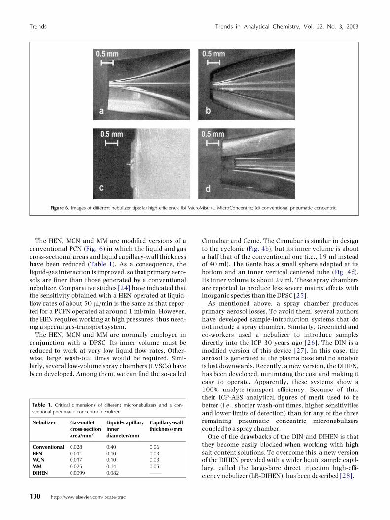
The HEN, MCN and MM are modi¢ed versions of aconventional PCN (Fig. 6) in which the liquid and gascross-sectional areas and liquid capillary-wall thicknesshave been reduced (Table 1). As a consequence, theliquid-gas interaction is improved, so that primary aero-sols are ¢ner than those generated by a conventionalnebulizer. Comparative studies [24] have indicated thatthe sensitivity obtained with a HEN operated at liquid-£ow rates of about 50 ml/min is the same as that repor-ted for a PCFN operated at around 1 ml/min. However,the HEN requires working at high pressures, thus need-ing a special gas-transport system.
The HEN, MCN and MM are normally employed inconjunction with a DPSC. Its inner volume must bereduced to work at very low liquid £ow rates. Other-wise, large wash-out times would be required. Simi-larly, several low-volume spray chambers (LVSCs) havebeen developed. Among them, we can ¢nd the so-called
Cinnabar and Genie. The Cinnabar is similar in designto the cyclonic (Fig. 4b), but its inner volume is abouta half that of the conventional one (i.e., 19 ml insteadof 40 ml). The Genie has a small sphere adapted at itsbottom and an inner vertical centered tube (Fig. 4d).Its inner volume is about 29 ml. These spray chambersare reported to produce less severe matrix e¡ects withinorganic species than the DPSC [25].
As mentioned above, a spray chamber producesprimary aerosol losses. To avoid them, several authorshave developed sample-introduction systems that donot include a spray chamber. Similarly, Green¢eld andco-workers used a nebulizer to introduce samplesdirectly into the ICP 30 years ago [26]. The DIN is amodi¢ed version of this device [27]. In this case, theaerosol is generated at the plasma base and no analyteis lost downwards. Recently, a new version, the DIHEN,has been developed, minimizing the cost and making iteasy to operate. Apparently, these systems show a100% analyte-transport e⁄ciency. Because of this,their ICP-AES analytical ¢gures of merit used to bebetter (i.e., shorter wash-out times, higher sensitivitiesand lower limits of detection) than for any of the threeremaining pneumatic concentric micronebulizerscoupled to a spray chamber.
One of the drawbacks of the DIN and DIHEN is thatthey become easily blocked when working with highsalt-content solutions. To overcome this, a new versionof the DIHEN provided with a wider liquid sample capil-lary, called the large-bore direct injection high-e⁄-ciency nebulizer (LB-DIHEN), has been described [28].
Figure 6. Images of different nebulizer tips: (a) high-efficiency; (b) MicroMist; (c) MicroConcentric; (d) conventional pneumatic concentric.
Table 1. Critical dimensions of different micronebulizers and a con-
ventional pneumatic concentric nebulizer
Nebulizer
Gas-outletcross-sectionarea/mm2Liquid-capillaryinnerdiameter/mm
Capillary-wallthickness/mm
Conventional
0.028 0.40 0.06 HEN 0.011 0.10 0.03 MCN 0.017 0.10 0.03 MM 0.025 0.14 0.05 DIHEN 0.0099 0.082 ——Trends Trends in Analytical Chemistry, Vol. 22, No. 3, 2003
130 http://www.elsevier.com/locate/trac
Tab
le2.
Comparativeofdifferentsample-introductionsystems(seetextforsymbolsexplanation)
Co
up
lin
gC
ost
Figu
res
of
mer
itSa
mp
leco
nsu
mp
tio
nA
nal
ytic
alth
rou
ghp
ut
Com
mer
cial
avai
lab
ilit
yR
ob
ust
nes
sSk
ill
nee
ded
Aci
ds
Org
anic
sO
ils
Salt
sSl
urr
ies
PCN/DPSC
verylow
verypoor
medium
medium
Yes
poor
poor
verypoor
verypoor
verypoor
verylow
PCN/CSC
verylow
poor
medium
high
Yes
medium
medium
verypoor
verypoor
verypoor
verylow
PCN/TSDS
medium
medium
low
low
Yes
good
good
verypoor
verypoor
verypoor
low
VGN/DPSC
verylow
verypoor
medium
medium
Yes
poor
poor
verypoor
good
good
verylow
CFN/DPSC
verylow
verypoor
medium
medium
Yes
poor
poor
verypoor
good
good
verylow
MN/LVSC
low
poor
verylow
high
Yes
verypoor
verypoor
verypoor
verypoor
verypoor
verylow
USN/TSDS
veryhigh
verygood
medium
verylow
Yes
medium
medium
verypoor
poor
medium
high
SBHPPN/TSDS
high
verygood
low
low
No
good
medium
verygood
verygood
verypoor
high
TN/TSDS
high
verygood
veryhigh
low
No
verypoor
medium
poor
verypoor
verypoor
high
HHPN/TSDS
high
verygood
veryhigh
low
Yes
verypoor
medium
medium
verygood
verypoor
high
4. Conclusion
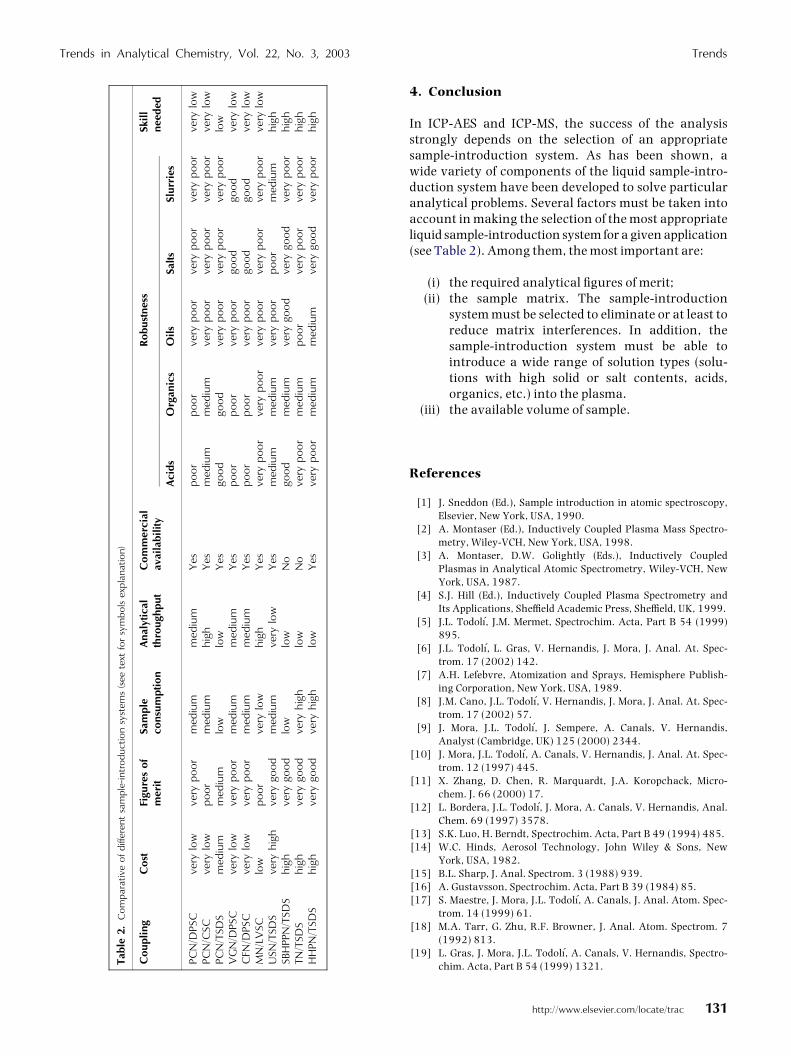
In ICP-AES and ICP-MS, the success of the analysisstrongly depends on the selection of an appropriatesample-introduction system. As has been shown, awide variety of components of the liquid sample-intro-duction system have been developed to solve particularanalytical problems. Several factors must be taken intoaccount in making the selection of the most appropriateliquid sample-introduction system for a given application(see Table 2). Among them, the most important are:
(i) the required analytical ¢gures of merit;(ii) the sample matrix. The sample-introduction
system must be selected to eliminate or at least toreduce matrix interferences. In addition, thesample-introduction system must be able tointroduce a wide range of solution types (solu-tions with high solid or salt contents, acids,organics, etc.) into the plasma.
(iii) the available volume of sample.
References
[1] J. Sneddon (Ed.), Sample introduction in atomic spectroscopy,Elsevier, New York, USA, 1990.
[2] A. Montaser (Ed.), Inductively Coupled Plasma Mass Spectro-metry, Wiley-VCH, New York, USA, 1998.
[3] A. Montaser, D.W. Golightly (Eds.), Inductively CoupledPlasmas in Analytical Atomic Spectrometry, Wiley-VCH, NewYork, USA, 1987.
[4] S.J. Hill (Ed.), Inductively Coupled Plasma Spectrometry andIts Applications, She⁄eld Academic Press, She⁄eld, UK, 1999.
[5] J.L. Todol��, J.M. Mermet, Spectrochim. Acta, Part B 54 (1999)895.
[6] J.L. Todol��, L. Gras, V. Hernandis, J. Mora, J. Anal. At. Spec-trom. 17 (2002) 142.
[7] A.H. Lefebvre, Atomization and Sprays, Hemisphere Publish-ing Corporation, New York, USA, 1989.
[8] J.M. Cano, J.L. Todol��, V. Hernandis, J. Mora, J. Anal. At. Spec-trom. 17 (2002) 57.
[9] J. Mora, J.L. Todol��, J. Sempere, A. Canals, V. Hernandis,Analyst (Cambridge, UK) 125 (2000) 2344.
[10] J. Mora, J.L. Todol��, A. Canals, V. Hernandis, J. Anal. At. Spec-trom. 12 (1997) 445.
[11] X. Zhang, D. Chen, R. Marquardt, J.A. Koropchack, Micro-chem. J. 66 (2000) 17.
[12] L. Bordera, J.L. Todol��, J. Mora, A. Canals, V. Hernandis, Anal.Chem. 69 (1997) 3578.
[13] S.K. Luo, H. Berndt, Spectrochim. Acta, Part B 49 (1994) 485.[14] W.C. Hinds, Aerosol Technology, John Wiley & Sons, New
York, USA, 1982.[15] B.L. Sharp, J. Anal. Spectrom. 3 (1988) 939.[16] A. Gustavsson, Spectrochim. Acta, Part B 39 (1984) 85.[17] S. Maestre, J. Mora, J.L. Todol��, A. Canals, J. Anal. Atom. Spec-
trom. 14 (1999) 61.[18] M.A. Tarr, G. Zhu, R.F. Browner, J. Anal. Atom. Spectrom. 7
(1992) 813.[19] L. Gras, J. Mora, J.L. Todol��, A. Canals, V. Hernandis, Spectro-
chim. Acta, Part B 54 (1999) 1321.
Trends in Analytical Chemistry, Vol. 22, No. 3, 2003 Trends
http://www.elsevier.com/locate/trac 131
[20] P.D. Goulden, D.H. Anthony, J. Anal. Chem. 54 (1982) 1678.[21] L. Gras, J. Mora, J.L. Todol��, A. Canals, V. Hernandis, Spectro-
chim. Acta, Part B 52 (1997) 1201.[22] J. Mora, A. Canals, V. Hernandis, E.H. van Veen, M.T.C. de
Loos-Vollebregt, J. Anal. At. Spectrom. 13 (1998) 175.[23] A. Gustavsson, Spectrochim. Acta, Part B 43 (1988) 917.[24] J.L. Todol��, V. Hernandis, A. Canals, J.M. Mermet, J. Anal. At.
Spectrom. 14 (1999) 1289.
[25] J.L. Todol��, S. Maestre, J. Mora, A. Canals, V. Hernandis,Fresenius’ J. Anal. Chem. 368 (2000) 773.
[26] S. Green¢eld, I.L. Jones, C.T. Berry, D.I. Spash, U.K. Patent1,109,602 (1968).
[27] D.R. Wiederin, F.G. Smith, R.S. Houk, Anal. Chem. 63 (1991)219.
[28] J.A. McLean, B.W. Acon, A. Montaser, J. Singh, D.E. Pritchard,S.R. Patierno, Appl. Spectrosc. 54 (2000) 659.
Trends Trends in Analytical Chemistry, Vol. 22, No. 3, 2003
132 http://www.elsevier.com/locate/trac