LINEAR FIBER OPTIC BOARD - Industrial Indexing Systems
18
IB-11B034 CONTROL SYSTEMS JANUARY 2000 LFC-XXX LINEAR FIBER OPTIC BOARD INSTRUCTION BOOK INDUSTRIAL INDEXING SYSTEMS, Inc. Proprietary information of Industrial Indexing Systems, Inc. furnished for customer use only. No other uses are authorized without the prior written permission of Industrial Indexing Systems, Inc. Revision - A Approved By:
-
Upload
khangminh22 -
Category
Documents
-
view
0 -
download
0
Transcript of LINEAR FIBER OPTIC BOARD - Industrial Indexing Systems

IB-11B034
CONTROL SYSTEMS JANUARY 2000
LFC-XXX
LINEAR FIBER OPTIC BOARD
INSTRUCTION BOOK
INDUSTRIAL INDEXING SYSTEMS, Inc.
Proprietary information of Industrial Indexing Systems, Inc. furnished for customer use only. No other uses are authorized without the prior written permission of
Industrial Indexing Systems, Inc.
Revision - A Approved By:

INDUSTRIAL INDEXING SYSTEMS, Inc. IB-11B034 LFC-XXX LINEAR FIBER OPTIC BOARD INSTRUCTION MANUAL
JANUARY 2000 PAGE 1 OF 16
TABLE OF CONTENTS
1.0 INTRODUCTION...............................................................................................2
2.0 IDENTIFYING LFC-XXX CONFIGURATIONS ..................................................2
3.0 OPERATION .....................................................................................................2
4.0 INSTALLATION.................................................................................................3
5.0 SPECIFICATIONS.............................................................................................5
6.0 CONTROL & INDICATORS...............................................................................6
7.0 DIMENSIONS....................................................................................................7
8.0 SETUP INSTRUCTIONS...................................................................................7 8.1 PURPOSE ..............................................................................................7 8.2 TEST EQUIPMENT REQUIRED.............................................................8 8.3 PROCEDURE.........................................................................................8
9.0 LVM-110 LVDT VOLTAGE MODULE................................................................9 9.1 GAIN SELECTION..................................................................................10 9.2 CONNECTIONS .....................................................................................11 9.3 FREQUENCY SELECT SWITCH ...........................................................11 9.4 MULTIPLE LVDT APPLICATIONS .........................................................11 9.4.1 Stand-Alone Configuration ........................................................12
9.4.2 Master Configuration .................................................................12 9.4.3 Slave Configuration ...................................................................12
9.5 DIMENSIONS (mm), MATING CONNECTOR (OPTIONAL) ..................13
10.0 RECOMMENDED GAIN SETTING – LVM-110 FOR ±10 Vdc OUTPUT AND ±FS DISPLACEMENT...............................................................................14
11.0 ZERO SWITCHES.............................................................................................15
12.0 CALIBRATION...................................................................................................15
13.0 CALIBRATION WITH 100% ZERO SUPPRESSION.........................................16
IB-11B034 INDUSTRIAL INDEXING SYSTEMS, Inc. INSTRUCTION MANUAL LFC-XXX LINEAR FIBER OPTIC BOARD
PAGE 2 OF 16 JANUARY 2000
1.0 INTRODUCTION The LFC-XXX is part of a product line of converters specifically designed to provide a way of bringing some types of system parameters into the master angle bus format. The system parameter is typically a shaft angle position. The transducer for the shaft angle could be a resolver or an encoder. The RFC-100 and EFC-100 converters have a resolver interface and encoder interface respectively. The LFC-XXX is designed to convert analog voltage into the master angle format. The master angle bus format is then transmitted to the motion controller by a fiber optic cable. This format is used on DeltaMax controllers manufactured by Industrial Indexing Systems. 2.0 IDENTIFYING LFC-XXX CONFIGURATIONS The LFC-XXX configuration can be identified as follows.
LFC-XXX
Number of channels (1-4) Series designator Power supply: 1 – 115VAC 2 – 220VAC 3.0 OPERATION The analog voltage to fiber optic converter will take a voltage and convert it into a position value to be transmitted on the master angle bus of an DeltaMax Controller via a fiber optic cable. The range of the differential voltage is between +10 volts and -10 volts and within a frequency range between 0 (DC) to 100 Hz. On power up no transmission will occur for a minimum of 100 milliseconds. When the converter starts converting, transmission of the master angle will start. The master angle is then used by the DeltaMax by locking an axis to the angle bus in various configurations. Action will not take place until the axis controller has been locked. Lock methods are described in the Development System Manual (Refer to IB-11C001).
INDUSTRIAL INDEXING SYSTEMS, Inc. IB-11B034 LFC-XXX LINEAR FIBER OPTIC BOARD INSTRUCTION MANUAL
JANUARY 2000 PAGE 3 OF 16
4.0 INSTALLATION A. Physical Mounting 1. Location The LFC-XXX may be mounted up to 100 feet from the Motion Controller.
Preferably as close to the analog voltage source as possible but not exceeding 10 feet of analog cable. This arrangement will reduce noise pick up and keep positional variations to a minimum.
2. Position The orientation of LFC-XXX is not critical but keep in mind the fiber optic
cable does have a minimum bend radius of approximately 1.5 inches. The AC power wiring should be dressed away from the analog input wiring.
3. Clearance Keep at least 5 inches of clearance above the LFC-XXX for proper
ventilation for the transformer and voltage regulators. 4. Panel Mounting The LFC-XXX can be directly mounted to the enclosure backplane using (4)
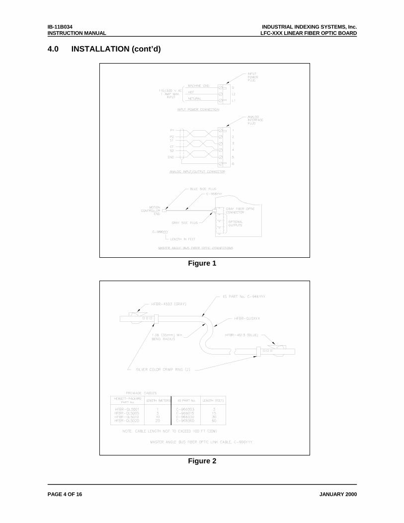
½” standoffs and appropriate mounting hardware. B. Cable Interface Connections Figures 1 & 2 show the various cable configurations to reference when installing
the LFC-XXX controller.
IB-11B034 INDUSTRIAL INDEXING SYSTEMS, Inc. INSTRUCTION MANUAL LFC-XXX LINEAR FIBER OPTIC BOARD
PAGE 4 OF 16 JANUARY 2000
4.0 INSTALLATION (cont’d)
Figure 1
Figure 2
INDUSTRIAL INDEXING SYSTEMS, Inc. IB-11B034 LFC-XXX LINEAR FIBER OPTIC BOARD INSTRUCTION MANUAL
JANUARY 2000 PAGE 5 OF 16
5.0 SPECIFICATIONS A. Analog Input Differential Input Voltage: +10 volt -10 volt range Overvoltage Protection: max ±40 volts Maximum Frequency: 100 Hz B. Voltage Reference +V Output: +10 volt buffered 10 mA Max. -V Output: -10 volt buffered 10 mA Max. C. Input Filtering Hi-frequency Oscillation: Low pass set @ 3.81 KHz Impedance Mismatches: Inductors in each input line DC Input Bias Currents: 60 KΩ input impedance D. Power Requirements Input Voltage: 220/115V AC ± 10% Frequency: 50-60 Hz Input Current: 1.0 Amp Maximum E. Size Length: 8.50 in. Max. Width: 5.75 in. Max. Height: 2.56 in. Ref. F. Mounting Panel mount G. Environment Operating Temperature: 0 to 60°C Ventilation: Unit must have 5 inches of free air flow above Humidity: 30% to 90% relative (non-condensing)

IB-11B034 INDUSTRIAL INDEXING SYSTEMS, Inc. INSTRUCTION MANUAL LFC-XXX LINEAR FIBER OPTIC BOARD
PAGE 6 OF 16 JANUARY 2000
6.0 CONTROL & INDICATORS
A. Mode Select Switch The mode select switch is a 16 position rotary switch (SWI), which is used to
configure resolution of the analog voltage as it relates to master angle position and allows a selection of test modes to use in the system.
The user may select one of four different resolutions for the ±10 volts range of the
input voltage. See Table 1 for the selections available.
Configuration Switch
Settings
Resolver Type
Resolution (Bit)
Counts per Voltage Range
Voltage Resolution Millivolts/Count
Description
0 1 2 3* 4* 5* 6* 7 8 9 A B C D E F
12 14 16 12 12 12 12 12 12 12 12 12 12 12 12 10
4096 16384 65536 4096 4096 4096 4096 4096 4096 4096 4096 4096 4096 4096 4096 1024
4.882 1.221 0.305 N/A N/A N/A N/A
19.53
12 Bit Mode 14 Bit Mode 16 Bit Mode
Test Mode 100 CW Test Mode 1000 CW Test Mode 100 CCW Test Mode 1000 CCW
Table 1 - Mode Configuration Switch Selections * Test Modes 3-6 simulate a mechanical shaft turning at the noted speed and
direction to simulate Master Position Angle or for Trouble Shooting the system. CAUTION
HAZARDOUS VOLTAGES ARE PRESENT ON THE UNIT UNDER TEST AND ON THE FIXTURE DURING PORTIONS OF THE FOLLOWING TEST. BE CAREFUL!!!
B. Count Indicators Three LED indicators provide the status of most significant bit and the two least significant bits of the analog conversion into the angle bus data sent to the motion controller.

INDUSTRIAL INDEXING SYSTEMS, Inc. IB-11B034 LFC-XXX LINEAR FIBER OPTIC BOARD INSTRUCTION MANUAL
JANUARY 2000 PAGE 7 OF 16
6.0 CONTROL & INDICATORS (cont’d)
The most significant bit (MSB) is in actually the sign indication in the data word. The least significant bit (LSB) indicators show the smallest bit resolution status of the data word.
C. Fault Indicator
The fault indicator will show status of the controller. When the fault indicator is on steady, the processor is indicating difficulty in the analog conversion process.
7.0 DIMENSIONS
Figure 3
8.0 SETUP INSTRUCTIONS 8.1 PURPOSE The purpose of this test procedure is to instruct the technician on how to completely test the operation of LFC-XXX mainboard.

IB-11B034 INDUSTRIAL INDEXING SYSTEMS, Inc. INSTRUCTION MANUAL LFC-XXX LINEAR FIBER OPTIC BOARD
PAGE 8 OF 16 JANUARY 2000
8.2 TEST EQUIPMENT REQUIRED
1. Unit Under Test (UUT) LFC electronics. 2. Digital Multimeter (DMM). 3. DeltaMax Controller with fiber optic cable. 4. PC with Serial Communications Cable C-987YYY or equivalent. 5. Adjustable regulated DC power supply.
8.3 PROCEDURE 1. Connect test equipment as shown in Figure 2 as follows.
LFC-1XX: 115VAC LFC-2XX: 220VAC
Fiber Optic Cable
LFC
Dmax RS232
CAUTION THE LVM-110 BOARD MUST NOT BE INSTALLED IN J1 WHEN PERFORMING THIS TEST!
Figure 2
2. Verify that SW1 is in POS 2. 3. Program DMAX to read the fiber optic input.
declare ON Count integer Loop get_for_ang 2,1,Count goto Loop
4. Download and run the above program on the DMAX. 5. Connect the DMM to the UUT. The positive lead on TP4 (U6-PIN 3) and the
negative lead on TP1 (gnd). 6. Adjust R6 such that the DMM reads 2.500 volts. 7. Connect to the DMAX via the Mpro2 analyzer, once connected view the variable
integer “Count” as programmed in the DMAX in step 1.
INDUSTRIAL INDEXING SYSTEMS, Inc. IB-11B034 LFC-XXX LINEAR FIBER OPTIC BOARD INSTRUCTION MANUAL
JANUARY 2000 PAGE 9 OF 16
8.3 PROCEDURE (cont’d)
8. Using test clips short together TP2 and TP3. 9. Adjust R17 such that “Count “ reads ZERO via the Analyzer.
10. Set an Adjustable Power Supply for 5.00Volts, verify the setting with the DMM.
11. Connect the Adjustable Power Supply to the UUT. Positive terminal is TP3 and
negative or ground terminal is TP2.
12. Verify that the “Count” now reads -16384 as viewed by the Analyzer.
13. Program the DeltaMax to read the fiber optic angle speed.
declare_on speed integer loop get_for_spd 2,1,speed goto loop
14. Download the following program to the DeltaMax controller. 15. Verify the rotary switch setting on the LFC-XXX is on pos 3 and cycle power. 16. Connect to the DeltaMax via the analyzer and verify speed variable reads 100. 17. Repeat steps 15 and 16 using switch pos 4-6 and verify speeds 1000, -100, -1000 respectively.
9.0 LVM-110 LVDT VOLTAGE MODULE The LVM-110 LVDT Voltage Module is a DC-powered LVDT and RVDT signal conditioner board consisting of an oscillator, AC amplifier, demodulator, filter and DC amplifier. Excitation can be either 2.5, 5 or 10 kHz, selected by a plug-in jumper. There are six jumper selectable ranges to match the full range output of the LVDT or RVDT to the full range input of the readout device or PLC analog input module. A board-mounted gain control with a 2.5 to 1 ratio is provided to adjust within a range. The LVM-110 module is designed for either plug-in connection, to a 10 position PC card edge connector or hard wiring to a 10 point screw terminal barrier strip. It may be rack mounted with card edge guides or stacked by permanently attached threaded standoffs.

IB-11B034 INDUSTRIAL INDEXING SYSTEMS, Inc. INSTRUCTION MANUAL LFC-XXX LINEAR FIBER OPTIC BOARD
PAGE 10 OF 16 JANUARY 2000
9.0 LVM-110 LVDT VOLTAGE MODULE (cont’d) The board mounted zero control provides a ±2 volt (±20%) range. Two plug-in jumpers provide a ±4 volt fixed step, thus allowing a total range of ±6 volts or up to 120% zero offset with the board configured for ±5 Vdc full scale. This will allow the board to be set up for a 0 Vdc to 10 Vdc output from minus full scale to plus full scale of the LVDT. Greater than 100% suppression may be useful for fault detection by allowing the zero to be suppressed below the full scale range of the LVDT, thus providing a voltage output throughout the entire linear range of the sensor.
9.1 GAIN SELECTION Switch S1 controls the first stage gain. One of three gains (X0.4, X1.0 or X4.0) may be selected. Switch S2 controls the gain of the second stage. Either a high or low gain may be selected.
1st Stage Gain
Switch S1
2nd Stage Gain
Switch S2
Sensitivity Vrms Input For 10
Vdc Out
Gain X0.4 Lo 2.1 to 5.56 1.798 to 4.76
Hi .994 to 2.64 3.788 to 10.06
X1 Lo .84 to 2.22 4.5 to 11.9 Hi .4 to 1.055 9.47 to 25
X4 Lo .21 to .556 17.98 to 47.62 Hi .0994 to .264 37.88 to 100.6
X0.4 Install Jumper
Across Bottom of S1
X1.0 Install Jumper In Row of S1
X4.0 Install Jumper In Row 2 of S1
To Select High Gain Install Jumper In Row 1 of S2
To Select Low Gain Install Jumper In Row 2 of S2
INDUSTRIAL INDEXING SYSTEMS, Inc. IB-11B034 LFC-XXX LINEAR FIBER OPTIC BOARD INSTRUCTION MANUAL
JANUARY 2000 PAGE 11 OF 16
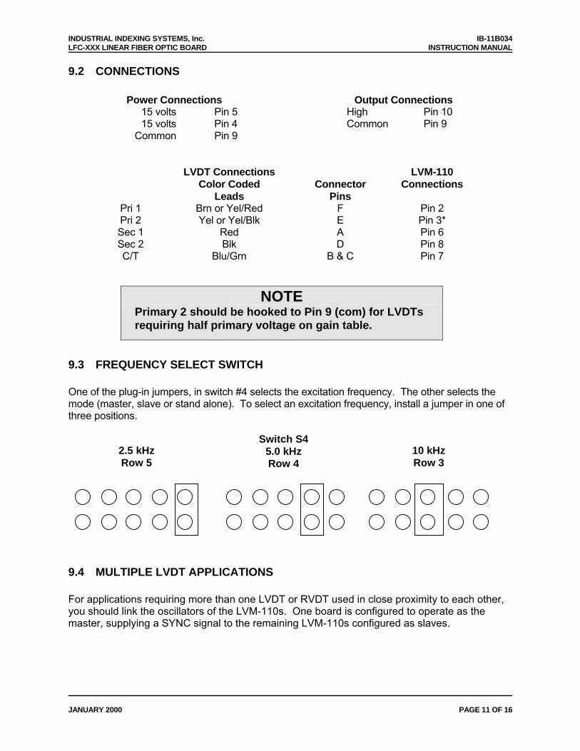
9.2 CONNECTIONS
Power Connections Output Connections 15 volts Pin 5 High Pin 10 15 volts Pin 4 Common Pin 9
Common Pin 9
LVDT Connections LVM-110 Color Coded Connector Connections Leads Pins
Pri 1 Brn or Yel/Red F Pin 2 Pri 2 Yel or Yel/Blk E Pin 3* Sec 1 Red A Pin 6 Sec 2 Blk D Pin 8 C/T Blu/Grn B & C Pin 7
NOTE
Primary 2 should be hooked to Pin 9 (com) for LVDTs requiring half primary voltage on gain table.
9.3 FREQUENCY SELECT SWITCH One of the plug-in jumpers, in switch #4 selects the excitation frequency. The other selects the mode (master, slave or stand alone). To select an excitation frequency, install a jumper in one of three positions.
2.5 kHz Row 5
Switch S4 5.0 kHz Row 4
10 kHz Row 3
9.4 MULTIPLE LVDT APPLICATIONS For applications requiring more than one LVDT or RVDT used in close proximity to each other, you should link the oscillators of the LVM-110s. One board is configured to operate as the master, supplying a SYNC signal to the remaining LVM-110s configured as slaves.

IB-11B034 INDUSTRIAL INDEXING SYSTEMS, Inc. INSTRUCTION MANUAL LFC-XXX LINEAR FIBER OPTIC BOARD
PAGE 12 OF 16 JANUARY 2000
9.4.1 Stand-Alone Configuration The LVM-110 should be configured, for most applications, in the stand-alone mode. This is done by installing a jumper across the top terminals of rows 1 and 2 isolating the oscillator from the SYNC terminal. This is a storage position for the jumper. An excitation frequency must be selected, as shown above, when the board is set up to operate in the stand-alone mode. 9.4.2 Master Configuration Install a jumper across row 1. The oscillator drives the SYNC terminal with a synchronizing signal. An excitation frequency must be selected for the master a shown above. 9.4.3 Slave Configuration Installing a jumper across row 2 will allow the oscillator of the slave to use the SYNC as an input. The SYNC bus must be driven by a master module. SYNC terminals (Pin 1) of all LVMs must be connected for master/slave operation. Do not select an excitation frequency on the slave module. The frequency-select jumper may be stored across the bottom of rows 4 and 5.
STAND-ALONE 2.5 kHz
Freq. Selected
Master 5.0 kHz
Freq. Selected
Slave No
Freq. Selected

INDUSTRIAL INDEXING SYSTEMS, Inc. IB-11B034 LFC-XXX LINEAR FIBER OPTIC BOARD INSTRUCTION MANUAL
JANUARY 2000 PAGE 13 OF 16
9.5 DIMENSIONS (mm), MATING CONNECTOR (OPTIONAL)

IB-11B034 INDUSTRIAL INDEXING SYSTEMS, Inc. INSTRUCTION MANUAL LFC-XXX LINEAR FIBER OPTIC BOARD
PAGE 14 OF 16 JANUARY 2000
10.0 RECOMMENDED GAIN SETTING – LVM-110 FOR ±10 Vdc OUTPUT AND ±FS DISPLACEMENT
Frequency 2.5kHz 2.5kHz 2.5kHz 10kHz 2.5kHz 2.5kHz 2.5kHz 2.5kHz 2.5kHz 5kHz 2.5kHz
Transducer Series
HR MP
HPA, GPA HCA, GPA
E MHR 10kHz
XS-A XS-C XS-D XS-Z, ZT & ZTR
LBB LoSen
LBB STD
M12
± FS
0.005 NR 0.010 X4 HI** 0.020 X4 HI* X1 HI 0.025 X4 LO* 0.040 X4 HI** X1 HI 0.050 X1 LO X.1 HI X1 HI X1 HI 0.100 X1 LO X.1 HI X1 LO NR X4 LO* X.4 HI 0.125 X.1 LO X1 HI 0.150 X1 LO 0.200 X.4 HI X.1 LO X.4 X1 LO 0.250 X.1 LO X.4 HI X4 LO* X1 LO NR 0.300 X1 LO X.1 LO 0.400 X1 LO X1 LO 0.500 X1 LO X.4 HI X.1 LO X.4 HI X1 LO X.4 HI NR 1.000 X1 LO X.4 LO X.4 LO X1 LO* X.4 HI X.4 LO X4 LO* NR 2.000 X1 LO X.4 HI X.4 LO X.4 HI X1 LO X4 LO* X.5 HI 3.000 NR X.4 HI X.4 HI X1 HI* 4.000 X.4 LO X.4 LO 5.000 X.4 LO X.4 LO X.1 LO X.4 HI X.4 LO 10.000 X.4 LO X.4 LO NR X.4 HI 25.000 X.4 LO
* Must be connected for half primary voltage. See connections. ** Must be connected for half primary voltage. See connections also may not get ±10 Vdc
adj. for ±5 Vdc. NR Not recommended.
Notes: 2.5 kHz not recommended for MHR Series LVD’s. LVM-110 is not recommended for use with XS-B LVD’s.

INDUSTRIAL INDEXING SYSTEMS, Inc. IB-11B034 LFC-XXX LINEAR FIBER OPTIC BOARD INSTRUCTION MANUAL
JANUARY 2000 PAGE 15 OF 16
11.0 ZERO SWITCHES Switch S3 selects the range of the zero control. One of three positions (+ OFF -) may be selected. To Select OFF
Install Jumper In Row 1 of S3
To Select OFF Install Jumper In Row 1 of S3
Zero range
To Select - Install Jumper
Across Bottom of S3
Zero range
Zero range
±2 Vdc +2 to +6 Vdc -6 to -2 Vdc 12.0 CALIBRATION Turn unit on, allow 15 minute warm-up. Set frequency and gain plug-in jumper to the correct position for the LVDT being used. Connect LVDT to the LVM-110 except for the Secondary 2 lead, (black lead). Place a temporary jumper from pin 6 to pin 8. Turn the Zero control to obtain an output of 0.0 Vdc. Remove the temporary jumper and connect the black lead to pin 8. Adjust the LVDT core to get as close to zero volts output possible. This is the Null position of the transducer from which the plus and minus displacements are measured.
NOTE If this adjustment is mechanically difficult or impractical,
approximate the correct position as closely as possible and then turn the Zero control to obtain a zero reading. However, the mechanically zero of the core must be within at least 5% of the rated full scale displacement. Turn the Span control until the output reads the desired full scale voltage, usually ±10 Vdc. If the required full scale reading cannot be obtained by adjusting the Span control, change the gain to the next lower or higher step by changing the jumpers in switches S1 and S2.

IB-11B034 INDUSTRIAL INDEXING SYSTEMS, Inc. INSTRUCTION MANUAL LFC-XXX LINEAR FIBER OPTIC BOARD
PAGE 16 OF 16 JANUARY 2000
13.0 CALIBRATION WITH 100% ZERO SUPPRESSION The above calibration procedure will calibrate the instrument for an output of ±10 Vdc for full stroke (-full scale to +full scale) displacement. For some applications, it is desirable to calibrate the instrument to go from zero to +10 Vdc for full stroke displacement. First follow the above calibration procedure but adjust the Span control for half the full scale voltage usually +5 Vdc. You will now have the unit calibrated for ±5 Vdc. Move the core to the -full scale position. The output will be -5 Vdc. Move the jumper in switch S3 from the OFF position to the +position and adjust the zero control for zero volts output. You will now have an output of 0 to ±10 Vdc for full travel displacement.

INDUSTRIAL INDEXING SYSTEMS INC. 626 FISHERS RUN VICTOR, NEW YORK 14564 (585) 924-9181 FAX: (585) 924-2169
PRINTED IN USA © 2000
IB-11B034