
Fast and accurate modeling of waveguide grating couplers. II.Three-dimensional vectorial case
Upload
independentCategory
view
0download
0
Linear and Triangle Order of NX3 Optical Directional Couplers: Variation Coupling Coefficient
Dedi Irawan1, Saktioto1,2, Jalil Ali 1 1Advanced Photonics Science Institute, Faculty of Science, Universiti Teknologi Malaysia
Johor, Malaysia. [email protected] 2Physics Dept, Math and Sciences Faculty, University of Riau, Pekanbaru, Indonesia
Abstract
Fabrication of single-mode fiber coupler has widely expands. However, directional fiber coupler
geometry always affects the power propagation either two or three ports. This paper describes
power launching by NX3 single mode fiber, examined using a matrix transfer for linear and
triangle order, calculated from the eigenvalue and the eigenvector. This eigenvalue is referred to
the coupling coefficient, where it can be expressed as an effective power transmitted to another
fiber. The ratio of coupling coefficient between adjacent axial fibers varies, which can be
achieved by adjusting separation of fiber and refractive index of core and cladding. A calculation
has been shown in 3D that both power transmission and phase are affected by not only the
geometry order, but also the variation of coupling coefficient, assuming the propagation
constants, cross section, and separation of coupling length fiber axis are held constant. This
calculation can be applied for any sources of wavelength and junction.
Keywords: Optical directional coupler, power transfer, coupling coefficient, matrix transfer.
1. Introduction
The great utilization of single mode fiber coupler has led to the extensive research and
development. The development and fabrication of single-mode fiber coupler has been widely
expanding for both tunable filter and optical waveguide switch in telecommunication and device
sensor. Optical directional couplers are commonly used for several guided wave devices and for
optical switching networks [1]. Directional couplers may refer as devices that used to combine
and split optical signals. Significant interaction between three coupled waveguides will occur and
thus lead to a significant power exchange between the waveguides [2]. For waveguides that are in
parallel condition and propagating with the same phase velocities of guided modes causes the
losses and the fraction of power or total power to be transferred from one waveguide to the other
waveguides [3]. The power transfer is investigated by constructing a matrix transfer model. Then,
Photonic Fiber and Crystal Devices: Advances in Materials and Innovationsin Device Applications IV, edited by Shizhuo Yin, Ruyan Guo, Proc. of SPIE Vol. 7781
77810J · © 2010 SPIE · CCC code: 0277-786X/10/$18 · doi: 10.1117/12.862573
Proc. of SPIE Vol. 7781 77810J-1
Downloaded from SPIE Digital Library on 14 Oct 2010 to 66.165.46.178. Terms of Use: http://spiedl.org/terms
the coupling coefficient varied as a function of position. Otherwise, propagation constants, and
cross section of fibers are hold to be constant. The input power is only at one input port source
and focusing on the power splitting phenomenon as the function of phase variation along the
coupling length axis [4]. Based on the placement, linear and triangle order of NX3 fiber couplers
can be used as power splitters and routers respectively. N represents power input ports and 3 is
for output ports. For the extent of application purpose, it can be developed as optical switch. An
optical switching device is built by fabricating coupler on electro-optic material and applying a
voltage into the active region [5].
2. Optical Directional Couplers; Matrix transfer model
The physical properties of the waveguides are explained using matrix methods to describe the
optical directional couplers. Modes for a coupled structure consist of two or many waveguides
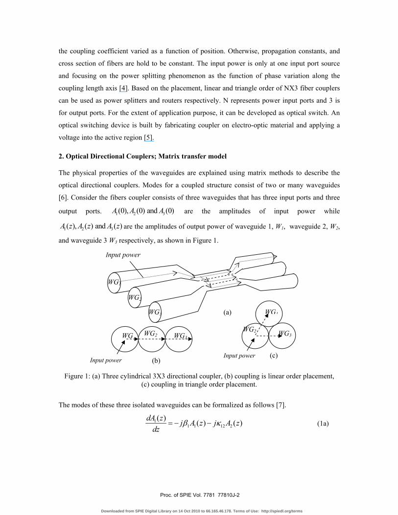
[6]. Consider the fibers coupler consists of three waveguides that has three input ports and three
output ports. 1 2 3(0), (0) and (0)A A A are the amplitudes of input power while
1 2 3( ), ( ) and ( )A z A z A z are the amplitudes of output power of waveguide 1, W1, waveguide 2, W2,
and waveguide 3 W3 respectively, as shown in Figure 1.
Figure 1: (a) Three cylindrical 3X3 directional coupler, (b) coupling is linear order placement, (c) coupling in triangle order placement.
The modes of these three isolated waveguides can be formalized as follows [7].
11 1 12 2
( ) ( ) ( )dA z j A z j A zdz
β κ= − − (1a)
(b) Input power
WG WG2 WG3 � WG2
WG1
WG3
(c) Input power
�
(a)
WG2
WG3
WG1
Input power
Proc. of SPIE Vol. 7781 77810J-2
Downloaded from SPIE Digital Library on 14 Oct 2010 to 66.165.46.178. Terms of Use: http://spiedl.org/terms
22 2 21 1 23 3
( ) ( ) ( ) ( )dA z j A z j A z j A zdz
β κ κ= − − − (1b)
33 3 32 2
( ) ( ) ( )dA z j A z j A zdz
β κ= − − (1c)
Where ( )A z represents the coefficient of mode on z. The value of 12 13 21 2 23 31 32, , , , , ,κ κ κ κ κ κ κ are
the coupling constants between waveguide 1, waveguide 2 and waveguide 3, and 1 2 3, ,β β β are
their propagation constants. The coupled mode equation for the 3X3 coupler can be modified in
term of matrix [8].
1 1 12 13 1
2 21 2 23 2
3 31 32 3 3
( ) ( )( ) ( )( ) ( )
A z k k A zd A z j k k k A zdz
A z k k A z
β
β
⎡ ⎤ ⎡ ⎤ ⎡ ⎤⎢ ⎥ ⎢ ⎥ ⎢ ⎥= −⎢ ⎥ ⎢ ⎥ ⎢ ⎥⎢ ⎥ ⎢ ⎥ ⎢ ⎥⎣ ⎦ ⎣ ⎦ ⎣ ⎦
(2)
Consider a directional coupler has three identical and equally spaced
waveguides, 1 2 3β β β β= = = , and 21 23,κ κ κ= = . Since the interaction between the three
waveguides occurs from the waveguide 1 to the nearest waveguide, waveguide 2, thus the
coupling coefficient of waveguide 1 to waveguide 3, while 13 31and κ κ can be neglected. Based
on eigenvectors of matrix 3X3, [ ]V can be constructed as,
[ ]1 1 2
1 2 2 02
1 1 2
V
⎡ ⎤−⎢ ⎥
= ⎢ ⎥⎢ ⎥
− −⎢ ⎥⎣ ⎦
(3)
and by defining[ ] [ ] [ ]1U V A−= , Equation 1 can be transformed to matrix differential equation:
1 1
2 2
3 3
2 0 0( ) ( )( ) 0 2 0 ( )( ) 0 0 ( )
kU z U zd U z j k U zdz
U z U z
β
ββ
⎡ ⎤+⎡ ⎤ ⎡ ⎤⎢ ⎥⎢ ⎥ ⎢ ⎥= − −⎢ ⎥⎢ ⎥ ⎢ ⎥⎢ ⎥⎢ ⎥ ⎢ ⎥⎣ ⎦ ⎣ ⎦⎢ ⎥⎣ ⎦
(4)
Substituting Equation 1 to [ ] [ ][ ]A V U= will yield matrix transfer for 3X3 optical directional
coupler as follows.
Proc. of SPIE Vol. 7781 77810J-3
Downloaded from SPIE Digital Library on 14 Oct 2010 to 66.165.46.178. Terms of Use: http://spiedl.org/terms
( )( )( )
( ) ( )
( ) ( )
( )( )( )
1 1
2 2
3 3
1 1cos 2 1 sin 2 cos 2 12 22 0
sin 2 cos 2 sin 2 02 2 0
1 1cos 2 1 sin 2 cos 2 12 22
j z
jz z zA z A
j jA z e z z z AA z A
jz z z
β
κ κ κ
κ κ κ
κ κ κ
−
⎡ ⎤+ − −⎢ ⎥⎢ ⎥⎡ ⎤ ⎡ ⎤⎢ ⎥⎢ ⎥ ⎢ ⎥= − −⎢ ⎥⎢ ⎥ ⎢ ⎥⎢ ⎥⎢ ⎥ ⎢ ⎥⎣ ⎦ ⎣ ⎦⎢ ⎥− − +⎢ ⎥⎣ ⎦
(5)
The waveguides are assumed having constant cross section, otherwise coupling changes with the
position along the coupling length and due to the separation of fiber axis and refractive indices of
core and cladding [9].
3. Result and Discussion
Since power is fed in one waveguide, the power transfers between three waveguides can be
determined from matrix transform which is given by Equation (5) in two conditions. The first
condition, power is launched in to waveguide 1 or waveguide 3 as a linear order. By
substituting ( )1 2 3(0) 1, and (0) (0) 0A A A= = = in Equation (5) as shown in Figure 4 will yield as
follow.
( ) ( )11 cos 2 12
j zA z z e βκ −= − (6a)
( ) ( )21 sin 22
j zA z j z e βκ −= − (6b)
( ) ( )31 cos 2 12
j zA z z e βκ −= + (6c)
Proc. of SPIE Vol. 7781 77810J-4
Downloaded from SPIE Digital Library on 14 Oct 2010 to 66.165.46.178. Terms of Use: http://spiedl.org/terms
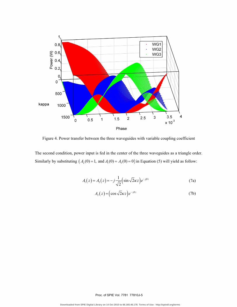
Figure 4. Power transfer between the three waveguides with variable coupling coefficient
The second condition, power input is fed in the center of the three waveguides as a triangle order.
Similarly by substituting ( )2 1 3(0) 1, and (0) (0) 0A A A= = = in Equation (5) will yield as follow:
( ) ( ) ( )1 31 sin 22
j zA z A z j z e βκ −= = − (7a)
( ) ( )2 cos 2 j zA z z e βκ −= (7b)
Proc. of SPIE Vol. 7781 77810J-5
Downloaded from SPIE Digital Library on 14 Oct 2010 to 66.165.46.178. Terms of Use: http://spiedl.org/terms
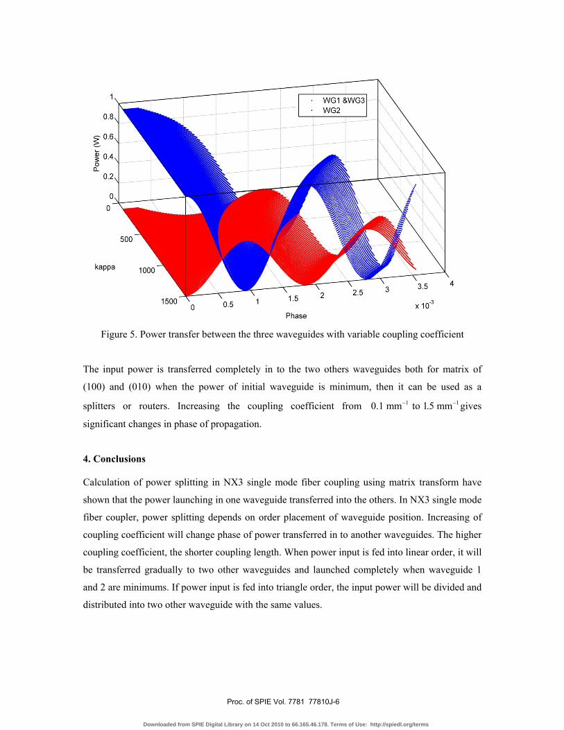
Figure 5. Power transfer between the three waveguides with variable coupling coefficient
The input power is transferred completely in to the two others waveguides both for matrix of
(100) and (010) when the power of initial waveguide is minimum, then it can be used as a
splitters or routers. Increasing the coupling coefficient from 1 10.1 mm to 1.5 mm− − gives
significant changes in phase of propagation.
4. Conclusions
Calculation of power splitting in NX3 single mode fiber coupling using matrix transform have
shown that the power launching in one waveguide transferred into the others. In NX3 single mode
fiber coupler, power splitting depends on order placement of waveguide position. Increasing of
coupling coefficient will change phase of power transferred in to another waveguides. The higher
coupling coefficient, the shorter coupling length. When power input is fed into linear order, it will
be transferred gradually to two other waveguides and launched completely when waveguide 1
and 2 are minimums. If power input is fed into triangle order, the input power will be divided and
distributed into two other waveguide with the same values.
Proc. of SPIE Vol. 7781 77810J-6
Downloaded from SPIE Digital Library on 14 Oct 2010 to 66.165.46.178. Terms of Use: http://spiedl.org/terms
5. Acknowledgement
We would like to thank the Institute of Advanced Photonic Science, Faculty of Science,
Universiti Teknologi Malaysia (UTM), and Physics Dept. University of Riau for generous
support in this research.
6. References
[1] H. Okayama, T. Ushikubo, and T. Ishida, “Directional coupler with reduced voltage-
length product,” IEEE J. Lightwave Technolgy, Vol. 9, No. 11, pp. 1561-1566 (1991).
[2] Saktioto, Jalil Ali, Mohamed Fadhali, “Simplified coupling power model for fiber
fusion”, Journal of Opto-electronic Review. Springler Link Journal, Vol. 17, No.3,
pp.193-199, (2009).
[3] J. Ctyroky and L. Thylen, “Analysis of a directional coupler by coupled modes of a
single waveguide,” Opt. Lett., Vol. 19, pp. 1621-1623 (1994).
[4] Nor Faridah Hanim, Saktioto, Jalil Ali, Rosly Abdul Rahman.”Modeling of Induced
Voltage Silicon Dioxide Fiber Coupling”, Journal of Nonlinear Optic Physics and
Materials, World Scientific Publishing Company. Vol.18, No3, pp. 481-488, 2009.
[5] H. Kogelnik and R. V. Schmidt, “Switched directional couplers with alternating βΔ ,”
IEEE Journal of Quantum Electronics, VOL. QE-12, no. 7, 396-401 (July 1976).
[6] T. Wongcharoen, B.M.A Rahman, K.T.V. Grattan, “Finite Element Analysis of Optical
Directional Couplers”, Department of EIEE, City University, Northampton Square,
London (1995)
[7] Alan W. Snyder and Jhon D. Love, “Optical Waveguide Theory” London, (1983).
[8] Chin-Lin Chen, “Foundations For Guided-Wave Optics, Perdue University, West
Lafayette, Indiana, (2007)
[9] Saktioto, Jalil Ali, Mohamed Fadhali, “Theoretical and empirical comparison of
coupling coefficient and refractive index estimation for coupled waveguide fiber”,
Journal of Aplied Science and Engineering Technology. (2008).
Proc. of SPIE Vol. 7781 77810J-7
Downloaded from SPIE Digital Library on 14 Oct 2010 to 66.165.46.178. Terms of Use: http://spiedl.org/terms
Copyright © 2022 FDOKUMEN