
Life cycle assessment of alternatives for hydrogen production from renewable and fossil sources
11
Life cycle assessment of alternatives for hydrogen production from renewable and fossil sources Javier Dufour a,b, *, David P. Serrano a,b , Jose ´ L. Ga ´ lvez c , Antonio Gonza ´lez c , Enrique Soria d , Jose ´ L.G. Fierro e a Department of Chemical and Energy Technology, ESCET, Universidad Rey Juan Carlos, c/Tulipa ´n s/n, 28933 Mo ´stoles, Madrid, Spain b Instituto IMDEA Energı´a, c/Tulipa ´n s/n, 28933 Mo ´stoles, Madrid, Spain c Renewable Energy Area, National Institute of Aerospace Technology (INTA), Crtra. Ajalvir Km 4, 28850 Torrejo ´n de Ardoz, Madrid, Spain d Renewable Energy Division, CIEMAT, Avenida Complutense 22, 28040 Madrid, Spain e Instituto de Cata ´lisis y Petroleoquı´mica, CSIC, Cantoblanco, 28049 Madrid, Spain article info Article history: Received 30 May 2011 Received in revised form 21 September 2011 Accepted 22 September 2011 Available online 22 October 2011 Keywords: Life Cycle Assessment Hydrogen production Methane decomposition Photosplitting Thermochemical cycles Conventional production methods abstract New processes under development for producing hydrogen have been assessed using a life cycle methodology and compared to conventional ones. The aim of this paper is to determine the main obstacles to be beaten or the critical aspects to be addressed to ensure the feasibility of these processes. Water photosplitting, solar two-step thermochemical cycles and automaintained methane decomposition with different lay-outs were studied. They have been compared to methane steam reforming with CCS and electrolysis with different electricity sources. The results show the good behaviour of the automaintained methane decomposition. This process is one of the best options when the greenhouse effect emissions are evalu- ated. Nevertheless, the consumption of a great amount of a non-renewable resource, i.e., natural gas, as reagent can be negative. The two-step thermochemical cycles based on NiFe 2 O 4 is also an interesting option, but its behaviour depends largely on the infrastruc- ture materials employed on the installations. The most promising option is photosplitting with CdS as catalysts. This process shows the best performance. Copyright ª 2011, Hydrogen Energy Publications, LLC. Published by Elsevier Ltd. All rights reserved. 1. Introduction The global warming, the need for increasing the energy independence of regions and the search for new sustainable energy generation scenarios have made researchers to focus on alternative ways to the conventional fuels and current energy systems. During the last years, a very important effort has been made in the development of hydrogen and its applications as an energy carrier. Hydrogen is a clean fuel with high heating value. Its storage can solve the problems of the intermittent character of renewable sources and the use of fuel cells with hydrogen produces higher yields than the combustion of gasoline or diesel in conventional thermal engines. However, the development of some of these tech- nologies is still in an early stage as well as the market pene- tration would be slow due to the lack of infrastructures. During the recent years, research on hydrogen has been focused on all the life cycle stages (production, storage, * Corresponding author. IMDEA Energı´a, Edificio CAT, Universidad Rey Juan Carlos, c/Tulipa ´n s/n, Mo ´ stoles 28933, Spain. Tel.: þ34 914888138; fax: þ34 914887068. E-mail address: [email protected] (J. Dufour). Available online at www.sciencedirect.com journal homepage: www.elsevier.com/locate/he international journal of hydrogen energy 37 (2012) 1173 e1183 0360-3199/$ e see front matter Copyright ª 2011, Hydrogen Energy Publications, LLC. Published by Elsevier Ltd. All rights reserved. doi:10.1016/j.ijhydene.2011.09.135
-
Upload
independent -
Category
Documents
-
view
3 -
download
0
Transcript of Life cycle assessment of alternatives for hydrogen production from renewable and fossil sources
ww.sciencedirect.com
i n t e r n a t i o n a l j o u r n a l o f h y d r o g e n en e r g y 3 7 ( 2 0 1 2 ) 1 1 7 3e1 1 8 3
Available online at w
journal homepage: www.elsevier .com/locate/he
Life cycle assessment of alternatives for hydrogen productionfrom renewable and fossil sources
Javier Dufour a,b,*, David P. Serrano a,b, Jose L. Galvez c, Antonio Gonzalez c, Enrique Soria d,Jose L.G. Fierro e
aDepartment of Chemical and Energy Technology, ESCET, Universidad Rey Juan Carlos, c/Tulipan s/n, 28933 Mostoles, Madrid, Spainb Instituto IMDEA Energıa, c/Tulipan s/n, 28933 Mostoles, Madrid, SpaincRenewable Energy Area, National Institute of Aerospace Technology (INTA), Crtra. Ajalvir Km 4, 28850 Torrejon de Ardoz, Madrid, SpaindRenewable Energy Division, CIEMAT, Avenida Complutense 22, 28040 Madrid, Spaine Instituto de Catalisis y Petroleoquımica, CSIC, Cantoblanco, 28049 Madrid, Spain
a r t i c l e i n f o
Article history:
Received 30 May 2011
Received in revised form
21 September 2011
Accepted 22 September 2011
Available online 22 October 2011
Keywords:
Life Cycle Assessment
Hydrogen production
Methane decomposition
Photosplitting
Thermochemical cycles
Conventional production methods
* Corresponding author. IMDEA Energıa, Ed914888138; fax: þ34 914887068.
E-mail address: [email protected] (J. D0360-3199/$ e see front matter Copyright ªdoi:10.1016/j.ijhydene.2011.09.135
a b s t r a c t
New processes under development for producing hydrogen have been assessed using a life
cycle methodology and compared to conventional ones. The aim of this paper is to
determine the main obstacles to be beaten or the critical aspects to be addressed to ensure
the feasibility of these processes. Water photosplitting, solar two-step thermochemical
cycles and automaintained methane decomposition with different lay-outs were studied.
They have been compared to methane steam reforming with CCS and electrolysis with
different electricity sources.
The results show the good behaviour of the automaintained methane decomposition.
This process is one of the best options when the greenhouse effect emissions are evalu-
ated. Nevertheless, the consumption of a great amount of a non-renewable resource, i.e.,
natural gas, as reagent can be negative. The two-step thermochemical cycles based on
NiFe2O4 is also an interesting option, but its behaviour depends largely on the infrastruc-
ture materials employed on the installations. The most promising option is photosplitting
with CdS as catalysts. This process shows the best performance.
Copyright ª 2011, Hydrogen Energy Publications, LLC. Published by Elsevier Ltd. All rights
reserved.
1. Introduction high heating value. Its storage can solve the problems of the
The global warming, the need for increasing the energy
independence of regions and the search for new sustainable
energy generation scenarios have made researchers to focus
on alternative ways to the conventional fuels and current
energy systems. During the last years, a very important effort
has been made in the development of hydrogen and its
applications as an energy carrier. Hydrogen is a clean fuel with
ificio CAT, Universidad R
ufour).2011, Hydrogen Energy P
intermittent character of renewable sources and the use of
fuel cells with hydrogen produces higher yields than the
combustion of gasoline or diesel in conventional thermal
engines. However, the development of some of these tech-
nologies is still in an early stage as well as the market pene-
tration would be slow due to the lack of infrastructures.
During the recent years, research on hydrogen has been
focused on all the life cycle stages (production, storage,
ey Juan Carlos, c/Tulipan s/n, Mostoles 28933, Spain. Tel.: þ34
ublications, LLC. Published by Elsevier Ltd. All rights reserved.
Nomenclature
AD automaintained decomposition
CCS carbon capture and storage
CED cumulative energy demand
CExD cumulative exergy demand
E electrolysis
IPCC Intergovernmental Panel for Climate Change
ISO International Organization for Standardization
LCA life cycle assessment
PD photodecomposition
PSA pressure swing adsorption
SMR steam methane reforming
TSTC two-step thermochemical cycles
Table 1 e Assessed processes for hydrogen production.
Process Acronym
Automaintained decomposition of AD-I
i n t e rn a t i o n a l j o u r n a l o f h y d r o g e n en e r g y 3 7 ( 2 0 1 2 ) 1 1 7 3e1 1 8 31174
transport and use) and always looking for the most sustain-
able option, i.e. the one that minimizes resources, emissions
and costs [1]. Thus, Life Cycle Assessment (LCA) is a key tool
for these research purposes. An LCA is the systematic study of
all the inputs and outputs of a product system for the evalu-
ation of the environmental impact which is associated to all
the life cycle stages, from raw materials extraction to final
wastes management [2]. This kind of study has been essential
for the development of the ecodesign of products, but its
application can also be crucial to the development of new
sustainable energy sources [3,4].
There is an important number of hydrogen LCAs studied in
the literature: some of them are focused on production [5,6],
storage [7] and use [8], and other studies are aimed at the
evaluation of integrated systems [9,10]. All of these studies are
centred on the environmental benefits of hydrogen from the
global warming potential point of view, evaluating also the life
cycle efficiency and the global impact in some of them. In this
work, a comprehensive assessment of alternatives for
hydrogen production is shown. We have evaluated three
technologies at their early developing stages: methane
decompositionwithcarboncatalysts,waterphotosplittingand
water decomposition with two-step thermochemical cycles.
The focus has beenmade on greenhouse gases emissions, the
consumption of fossil resources, and the energy and exergy
balances. The assessment has been also made over conven-
tional processes as steam reforming of natural gas and water
electrolysis, in order to compare the results of the studied
alternatives. A sensitivity analysis has also been performed in
order to determine the influence of the reaction conversion or
the thermal efficiency of the assessed processes.
methane, heated with natural gas
Automaintained decomposition
of methane, heated with solar
concentrator
AD-II
Water photosplitting, CdZnS as
photocatalyst
PD-I
Water photosplitting, CdSeZnSeZnO
as photocatalyst
PD-II
Two-step thermochemical cycles
with nickel ferrite, NiFe2O4
TSTC-I
Two-step thermochemical cycles
with zinc oxide, ZnO
TSTC-II
Natural gas reforming with CO2
capture and storage system
SMR-CCS
Water electrolysis, electricity
from grid
Grid-E
Water electrolysis, electricity
from wind turbine
Wind-E
Water electrolysis, electricity
from photovoltaic panels
Solar-E
2. Systems definition
The methodology used in this work corresponds to the LCA
standards (ISO 14040:2006 and ISO 14044:2006). For all the
assessed processes, the system boundary has been located at
the end of the production schemes, including the raw mate-
rials acquisition stage, because the aim of the study is to
compare manufacturing technologies, although it is remark-
able that the stages after the production process usually have
a low influence in the impact of the hydrogen life cycle [9,10].
The main purpose is not to establish the accurate impact, but
the potential capacity of each process from the environmental
point of view, with a special regard on the processes under
development and their comparison to the conventional
production schemes. Table 1 shows all the evaluated cases in
this work, which are described in the next sections.
2.1. Automaintained decomposition of methane
The reaction for methane decomposition is CH4$Cþ 2H2. It
is endothermic and needs high temperatures to be carried out.
This reaction is used in the carbon black production at the
process known as Thermal Black, developed in 1970 [11]. The
temperature in the reactor of this process is 1400 �C and the
produced hydrogen is consumed as fuel for heating purposes.
Recent trends show that the operating temperature can be
reduced to 500e600 �C if metallic catalysts are used [12,13] or
to 800e900 �C if carbonaceous catalysts are employed [14e16].
The use of carbon-based materials as catalysts has made
researchers to suggest the use of the carbon being produced
during the reaction as the reaction catalyst after an activation
process. Then, the reaction can be called automaintained
[17e19]. Anyway, it is important to remark that no CO2
emissions are produced during the reaction since C is kept as
solid carbon.
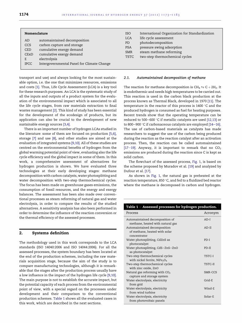
The flowchart of the assessed process, Fig. 1, is based on
the scheme proposed by Muradov et al. [19] and analyzed by
Dufour et al. [17].
As shown in Fig. 1, the natural gas is preheated at the
reaction temperature, 850 �C, and fed to a fluidized bed reactor
where the methane is decomposed in carbon and hydrogen.
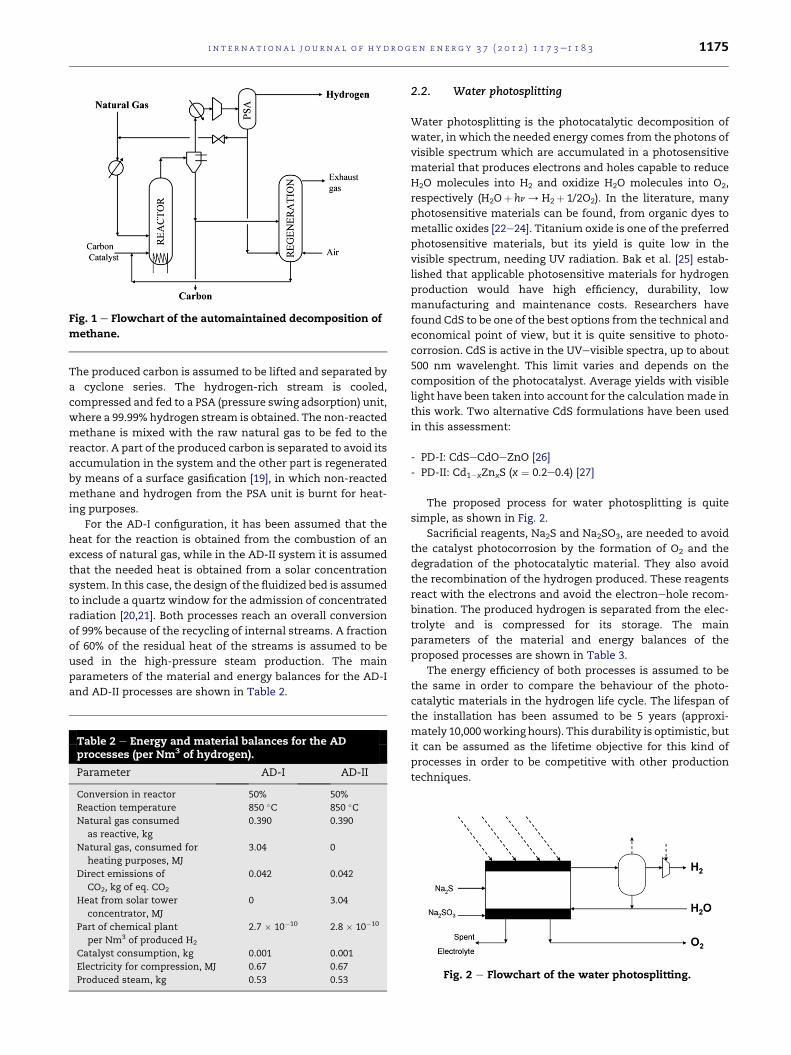
Fig. 1 e Flowchart of the automaintained decomposition of
methane.
i n t e r n a t i o n a l j o u r n a l o f h y d r o g e n en e r g y 3 7 ( 2 0 1 2 ) 1 1 7 3e1 1 8 3 1175
The produced carbon is assumed to be lifted and separated by
a cyclone series. The hydrogen-rich stream is cooled,
compressed and fed to a PSA (pressure swing adsorption) unit,
where a 99.99% hydrogen stream is obtained. The non-reacted
methane is mixed with the raw natural gas to be fed to the
reactor. A part of the produced carbon is separated to avoid its
accumulation in the system and the other part is regenerated
by means of a surface gasification [19], in which non-reacted
methane and hydrogen from the PSA unit is burnt for heat-
ing purposes.
For the AD-I configuration, it has been assumed that the
heat for the reaction is obtained from the combustion of an
excess of natural gas, while in the AD-II system it is assumed
that the needed heat is obtained from a solar concentration
system. In this case, the design of the fluidized bed is assumed
to include a quartz window for the admission of concentrated
radiation [20,21]. Both processes reach an overall conversion
of 99% because of the recycling of internal streams. A fraction
of 60% of the residual heat of the streams is assumed to be
used in the high-pressure steam production. The main
parameters of the material and energy balances for the AD-I
and AD-II processes are shown in Table 2.
Table 2 e Energy and material balances for the ADprocesses (per Nm3 of hydrogen).
Parameter AD-I AD-II
Conversion in reactor 50% 50%
Reaction temperature 850 �C 850 �CNatural gas consumed
as reactive, kg
0.390 0.390
Natural gas, consumed for
heating purposes, MJ
3.04 0
Direct emissions of
CO2, kg of eq. CO2
0.042 0.042
Heat from solar tower
concentrator, MJ
0 3.04
Part of chemical plant
per Nm3 of produced H2
2.7 � 10�10 2.8 � 10�10
Catalyst consumption, kg 0.001 0.001
Electricity for compression, MJ 0.67 0.67
Produced steam, kg 0.53 0.53
2.2. Water photosplitting
Water photosplitting is the photocatalytic decomposition of
water, in which the needed energy comes from the photons of
visible spectrum which are accumulated in a photosensitive
material that produces electrons and holes capable to reduce
H2O molecules into H2 and oxidize H2O molecules into O2,
respectively (H2Oþ hn/H2þ 1/2O2). In the literature, many
photosensitive materials can be found, from organic dyes to
metallic oxides [22e24]. Titanium oxide is one of the preferred
photosensitive materials, but its yield is quite low in the
visible spectrum, needing UV radiation. Bak et al. [25] estab-
lished that applicable photosensitive materials for hydrogen
production would have high efficiency, durability, low
manufacturing and maintenance costs. Researchers have
found CdS to be one of the best options from the technical and
economical point of view, but it is quite sensitive to photo-
corrosion. CdS is active in the UVevisible spectra, up to about
500 nm wavelenght. This limit varies and depends on the
composition of the photocatalyst. Average yields with visible
light have been taken into account for the calculationmade in
this work. Two alternative CdS formulations have been used
in this assessment:
- PD-I: CdSeCdOeZnO [26]
- PD-II: Cd1�xZnxS (x ¼ 0.2e0.4) [27]
The proposed process for water photosplitting is quite
simple, as shown in Fig. 2.
Sacrificial reagents, Na2S and Na2SO3, are needed to avoid
the catalyst photocorrosion by the formation of O2 and the
degradation of the photocatalytic material. They also avoid
the recombination of the hydrogen produced. These reagents
react with the electrons and avoid the electronehole recom-
bination. The produced hydrogen is separated from the elec-
trolyte and is compressed for its storage. The main
parameters of the material and energy balances of the
proposed processes are shown in Table 3.
The energy efficiency of both processes is assumed to be
the same in order to compare the behaviour of the photo-
catalytic materials in the hydrogen life cycle. The lifespan of
the installation has been assumed to be 5 years (approxi-
mately 10,000working hours). This durability is optimistic, but
it can be assumed as the lifetime objective for this kind of
processes in order to be competitive with other production
techniques.
Fig. 2 e Flowchart of the water photosplitting.
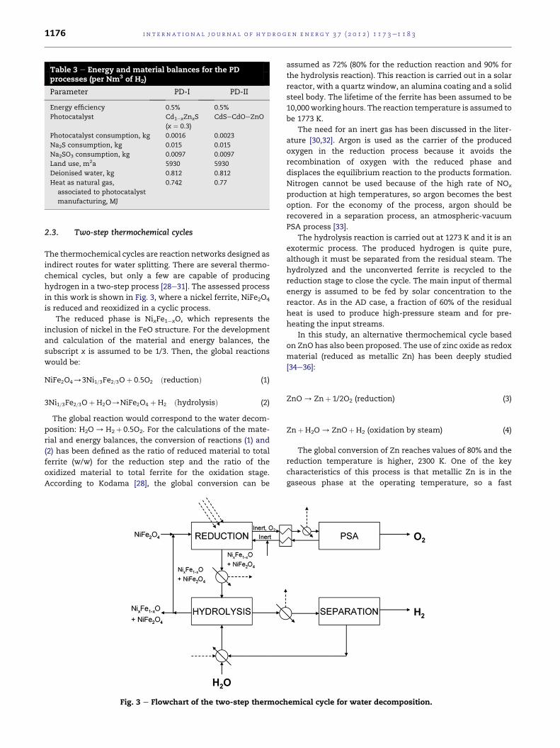
Table 3 e Energy and material balances for the PDprocesses (per Nm3 of H2)
Parameter PD-I PD-II
Energy efficiency 0.5% 0.5%
Photocatalyst Cd1�xZnxS
(x ¼ 0.3)
CdSeCdOeZnO
Photocatalyst consumption, kg 0.0016 0.0023
Na2S consumption, kg 0.015 0.015
Na2SO3 consumption, kg 0.0097 0.0097
Land use, m2a 5930 5930
Deionised water, kg 0.812 0.812
Heat as natural gas,
associated to photocatalyst
manufacturing, MJ
0.742 0.77
i n t e rn a t i o n a l j o u r n a l o f h y d r o g e n en e r g y 3 7 ( 2 0 1 2 ) 1 1 7 3e1 1 8 31176
2.3. Two-step thermochemical cycles
The thermochemical cycles are reaction networks designed as
indirect routes for water splitting. There are several thermo-
chemical cycles, but only a few are capable of producing
hydrogen in a two-step process [28e31]. The assessed process
in this work is shown in Fig. 3, where a nickel ferrite, NiFe2O4
is reduced and reoxidized in a cyclic process.
The reduced phase is NixFe1�xO, which represents the
inclusion of nickel in the FeO structure. For the development
and calculation of the material and energy balances, the
subscript x is assumed to be 1/3. Then, the global reactions
would be:
NiFe2O4/3Ni1=3Fe2=3Oþ 0:5O2 ðreductionÞ (1)
3Ni1=3Fe2=3OþH2O/NiFe2O4 þH2 ðhydrolysisÞ (2)
The global reaction would correspond to the water decom-
position: H2O/H2þ 0.5O2. For the calculations of the mate-
rial and energy balances, the conversion of reactions (1) and
(2) has been defined as the ratio of reduced material to total
ferrite (w/w) for the reduction step and the ratio of the
oxidized material to total ferrite for the oxidation stage.
According to Kodama [28], the global conversion can be
Fig. 3 e Flowchart of the two-step thermoch
assumed as 72% (80% for the reduction reaction and 90% for
the hydrolysis reaction). This reaction is carried out in a solar
reactor, with a quartz window, an alumina coating and a solid
steel body. The lifetime of the ferrite has been assumed to be
10,000working hours. The reaction temperature is assumed to
be 1773 K.
The need for an inert gas has been discussed in the liter-
ature [30,32]. Argon is used as the carrier of the produced
oxygen in the reduction process because it avoids the
recombination of oxygen with the reduced phase and
displaces the equilibrium reaction to the products formation.
Nitrogen cannot be used because of the high rate of NOx
production at high temperatures, so argon becomes the best
option. For the economy of the process, argon should be
recovered in a separation process, an atmospheric-vacuum
PSA process [33].
The hydrolysis reaction is carried out at 1273 K and it is an
exotermic process. The produced hydrogen is quite pure,
although it must be separated from the residual steam. The
hydrolyzed and the unconverted ferrite is recycled to the
reduction stage to close the cycle. The main input of thermal
energy is assumed to be fed by solar concentration to the
reactor. As in the AD case, a fraction of 60% of the residual
heat is used to produce high-pressure steam and for pre-
heating the input streams.
In this study, an alternative thermochemical cycle based
on ZnO has also been proposed. The use of zinc oxide as redox
material (reduced as metallic Zn) has been deeply studied
[34e36]:
ZnO/ Znþ 1/2O2 (reduction) (3)
ZnþH2O/ ZnOþH2 (oxidation by steam) (4)
The global conversion of Zn reaches values of 80% and the
reduction temperature is higher, 2300 K. One of the key
characteristics of this process is that metallic Zn is in the
gaseous phase at the operating temperature, so a fast
emical cycle for water decomposition.
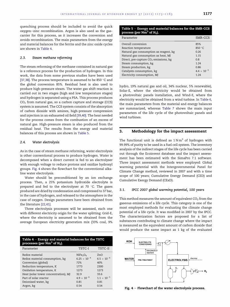
Table 5 e Energy and material balances for the SMR-CCSprocess (per Nm3 of H2).
Parameter SMR-CCS
Overall conversion 85%
Reaction temperature 850 �CNatural gas consumption as reagent, kg 0.26
Natural gas consumption as heat, MJ 1.15
Direct, pre-capture CO2 emissions, kg 0.8
Steam consumption, kg 1.24
Steam production, kg 0.86
Catalysts consumption, kg 4.4 � 10�5
Electricity consumption, MJ 1.24
i n t e r n a t i o n a l j o u r n a l o f h y d r o g e n en e r g y 3 7 ( 2 0 1 2 ) 1 1 7 3e1 1 8 3 1177
quenching process should be included to avoid the quick
oxygenezinc recombination. Argon is also used as the gas-
carrier for this process, as it increases the conversion and
avoids recombination. The main parameters from the energy
and material balances for the ferrite and the zinc oxide cycles
are shown in Table 4.
2.3. Steam methane reforming
The steam reforming of the methane contained in natural gas
is a reference process for the production of hydrogen. In this
work, the data from some previous studies have been used
[37,38]. The process temperature is assumed to be 850 �C and
the global conversion 85%. Residual heat is also used to
produce high-pressure steam. The water gas shift reaction is
carried out in two stages (high and low temperature stages)
and hydrogen is separated using a PSA. This process produces
CO2 from natural gas, so a carbon capture and storage (CCS)
system is assumed. The CCS system consists of the absorption
of carbon dioxide with amines, high-pressure compression
and injection in an exhausted oil field [39,40]. The heat needed
for the process comes from the combustion of an excess of
natural gas. High-pressure steam is also produced from the
residual heat. The results from the energy and material
balances of this process are shown in Table 5.
2.4. Water electrolysis
As in the case of steammethane reforming, water electrolysis
is other conventional process to produce hydrogen. Water is
decomposed when a direct current is fed to an electrolyser
with enough voltage to reduce protons and oxidize hydroxyl
groups. Fig. 4 shows the flowchart for the conventional alka-
line water electrolysis.
Water should be preconditioned by an ion exchange
process. Then, a 25% potassium hydroxide electrolyte is
prepared and fed to the electrolyser at 70 �C. The gases
produced are dried by condensation and compressed to 37 bar,
in the case of hydrogen, and released to the atmosphere in the
case of oxygen. Design parameters have been obtained from
the literature [22,41].
Three electrolysis processes will be assessed, each one
with different electricity origin for the water splitting: Grid-E,
where the electricity is assumed to be obtained from the
average European electricity generation mix (33% coal, 9%
Table 4 e Energy and material balances for the TSTCprocesses (per Nm3 of H2).
Parameter TSTC-I TSTC-II
Redox material NiFe2O4 ZnO
Redox material consumption, kg 6.25 � 10�4 6.5 � 10�4
Conversion (global) 72% 40%
Reduction temperature, K 1773 2300
Oxidation temperature, K 1273 1273
Heat (solar tower concentration), MJ 32.9 33.6
Part of solar reactor 4.9 � 10�6 1.1 � 10�5
Deionised water, kg 0.81 0.81
Argon, kg 0.54 0.54
hydro, 19% natural gas and oil, 34% nuclear, 5% renewable),
Solar-E, where the electricity would be obtained from
a photovoltaic panels installation, and Wind-E, where the
electricity would be obtained from a wind turbine. In Table 6,
the main parameters from the material and energy balances
are summarized, whereas Table 7 shows the main input
parameters of the life cycle of the photovoltaic panels and
wind turbines.
3. Methodology for the impact assessment
The functional unit is defined as 1 Nm3 of hydrogen with
99.99% of purity to be used in a fuel cell system. The inventory
analysis of the indirect stages of the life cycle has been carried
out through the Ecoinvent database and the impact assess-
ment has been estimated with the SimaPro 7.1 software.
Three impact assessment methods were employed: Global
warming potential with the Intergovernmental Panel for
Climate Change method, reviewed in 2007 and with a time
scope of 100 years; Cumulative Energy Demand (CED) and
Cumulative Exergy Demand (CExD).
3.1. IPCC 2007 global warming potential, 100 years
Thismethodmeasures the amount of equivalent CO2 from the
gaseous emissions of a life cycle. This category is one of the
most employed methods for evaluating the climate change
potential of a life cycle. It was modified in 2007 by the IPCC.
The characterization factors are proposed for a list of
substances contributing to climate change where the impact
is measured as the equivalent amount of carbon dioxide that
would produce the same impact as 1 kg of the evaluated
Fig. 4 e Flowchart of the water electrolysis process.

i n t e rn a t i o n a l j o u r n a l o f h y d r o g e n en e r g y 3 7 ( 2 0 1 2 ) 1 1 7 3e1 1 8 31178
substance. The stability of the emissions is a key factor to
calculate the global warming potential, so three sets of factors
are proposed for three different time scopes: 25 years, 100
years and 500 years. The medium-term, 100 years, has been
chosen for this assessment.
3.2. Cumulative energy demand (CED)
This method is focused on the use of energy in each stage of
a life cycle. It was developed in the mid-1970s as a conse-
quence of the energy crisis and it was aimed to detect the
stages of a life cycle where main savings could be achieved
[42]. Although it has a strong link with the environmental
impact, it has to be employed as a complement of other
assessment methods [43]. The method is divided in two main
categories, renewable and non-renewable, where the subcat-
egories are divided by the type of resource (fossil, nuclear,
biomass,.). In this work, twomain characteristics of each life
cycle have been determined:
- Fossil resources consumption, which is the direct result of
the subcategory ‘non-renewable, fossil’ from CED. In the
evaluation of the fossil resources consumption, a distinction
has been made between energy purposes and reagent
purposes, as the methane decomposition or the steam
reforming consume CH4 as reagent for H2 production.
- Renewability, defined by Neelis et al. [7], and calculatedwith
Eq. (5), has been used to determine the renewable character
of the produced hydrogen with the evaluated alternatives.
H2 renewability; % ¼ renewable energy inputrenewable energyþ non� renewable energy inputs
(5)
3.3. Cumulative exergy demand (CExD)
Cumulative exergy demand is quite similar to CED, but it
evaluates the flow of available work, i.e. exergy, in a life cycle
[44]. This method is used to calculate the exergy efficiency in
the whole life cycle of hydrogen. The main property of this
method is that the exergy consumed in the generation of
renewable energy is null, i.e., the renewable energy is ‘free’
from the exergetic point of view [45,46]. In this work, the
exergy efficiency has been calculated from the definition given
by Dincer et al. [45]:
Exergy efficiency ¼ Hydrogen exergy ð10:6 MJ=Nm�3ÞLife cycle exergy consumption ðfossil;nuclear and minerals extracionÞ (6)
This parameter was defined by Granovskii et al. [46] for
determining the production of available work, i.e., exergy,
from 1 MJ of non-renewable exergy. Then, the exergy effi-
ciency can be higher than 1, if the life cycle is producing net
exergy, and lower than 1 if there is net consumption of non-
renewable exergy.
3.4. Sensitivity analysis
The influence of the process efficiency on the results of the
LCA has been evaluated for the proposed processes: auto-
maintained decomposition ofmethane, where conversion has
been varied in the AD-II alternative, water photosplitting,
where the energy efficiency has been varied in the PD-I option
and the water decomposition with two-step thermochemical
cycles, where the conversion of the reduction stage has been
evaluated.
4. Results and discussion
4.1. Greenhouse gases emissions
The calculated emissions of each alternative are shown in
Fig. 5. It should be noticed the high amount of CO2 emissions
associated to the production of hydrogen through electrolysis
with grid electricity. There is a large contribution of the
associated emissions from the carbon combustion and other
fossil fuels coming from the electricity generation. One of the
main features of Fig. 5 is how the solar processes (Solar-E and
the two options for thermochemical cycles) have higher
impact on this category.
An important focus must be put on the life cycle stages no
directly related to the production process of hydrogen because
it has a negligible contribution to this category. For the ther-
mochemical cycles, the great amount of steel and construc-
tion materials needed for the installation is the key factor
influencing the environmental behaviour. There is a low
difference between both alternatives, although the NiFe2O4
process gets lower emissions due to less energy requirements
of the thermochemical cycle.
In the case of the photovoltaic-electrolytic hydrogen, the
manufacturing of panels is the responsible of the high thermal
energy consumption. The high emissions associated to
photovoltaic hydrogen can also be observed in the literature:
0.5 kg CO2 per Nm3 of hydrogen calculated by Utgikar et al. [47]
and Koroneos et al. [6], which is close to the value obtained in
this work, 0.59 kg CO2. The crucial parameter of the photovol-
taic panels life cycle is the durability: Granovskii et al. [10]
calculated 0.22 kg CO2 per Nm3 of hydrogen when the lifetime
was 30 years. However, in this work, 30,000 solar hours of
working time have been assumed as average to consider the
timeof a solar cellworking at themaximumefficiency (varying
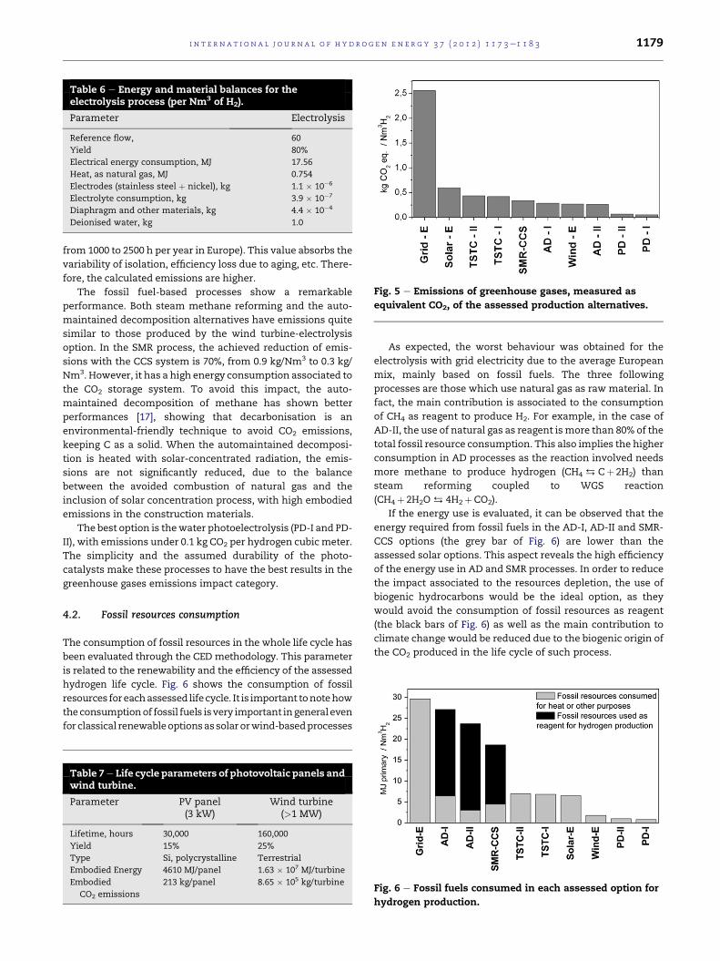
Fig. 5 e Emissions of greenhouse gases, measured as
equivalent CO2, of the assessed production alternatives.
Table 6 e Energy and material balances for theelectrolysis process (per Nm3 of H2).
Parameter Electrolysis
Reference flow, 60
Yield 80%
Electrical energy consumption, MJ 17.56
Heat, as natural gas, MJ 0.754
Electrodes (stainless steel þ nickel), kg 1.1 � 10�6
Electrolyte consumption, kg 3.9 � 10�7
Diaphragm and other materials, kg 4.4 � 10�4
Deionised water, kg 1.0
i n t e r n a t i o n a l j o u r n a l o f h y d r o g e n en e r g y 3 7 ( 2 0 1 2 ) 1 1 7 3e1 1 8 3 1179
from 1000 to 2500 h per year in Europe). This value absorbs the
variability of isolation, efficiency loss due to aging, etc. There-
fore, the calculated emissions are higher.
The fossil fuel-based processes show a remarkable
performance. Both steam methane reforming and the auto-
maintained decomposition alternatives have emissions quite
similar to those produced by the wind turbine-electrolysis
option. In the SMR process, the achieved reduction of emis-
sions with the CCS system is 70%, from 0.9 kg/Nm3 to 0.3 kg/
Nm3. However, it has a high energy consumption associated to
the CO2 storage system. To avoid this impact, the auto-
maintained decomposition of methane has shown better
performances [17], showing that decarbonisation is an
environmental-friendly technique to avoid CO2 emissions,
keeping C as a solid. When the automaintained decomposi-
tion is heated with solar-concentrated radiation, the emis-
sions are not significantly reduced, due to the balance
between the avoided combustion of natural gas and the
inclusion of solar concentration process, with high embodied
emissions in the construction materials.
The best option is thewater photoelectrolysis (PD-I and PD-
II), with emissions under 0.1 kg CO2 per hydrogen cubicmeter.
The simplicity and the assumed durability of the photo-
catalysts make these processes to have the best results in the
greenhouse gases emissions impact category.
4.2. Fossil resources consumption
The consumption of fossil resources in the whole life cycle has
been evaluated through the CED methodology. This parameter
is related to the renewability and the efficiency of the assessed
hydrogen life cycle. Fig. 6 shows the consumption of fossil
resources foreachassessed lifecycle. It is important tonotehow
theconsumptionof fossil fuels isvery important ingeneral even
for classical renewableoptionsassolarorwind-basedprocesses
Table 7e Life cycle parameters of photovoltaic panels andwind turbine.
Parameter PV panel(3 kW)
Wind turbine(>1 MW)
Lifetime, hours 30,000 160,000
Yield 15% 25%
Type Si, polycrystalline Terrestrial
Embodied Energy 4610 MJ/panel 1.63 � 107 MJ/turbine
Embodied
CO2 emissions
213 kg/panel 8.65 � 105 kg/turbine
As expected, the worst behaviour was obtained for the
electrolysis with grid electricity due to the average European
mix, mainly based on fossil fuels. The three following
processes are those which use natural gas as raw material. In
fact, the main contribution is associated to the consumption
of CH4 as reagent to produce H2. For example, in the case of
AD-II, the use of natural gas as reagent ismore than 80% of the
total fossil resource consumption. This also implies the higher
consumption in AD processes as the reaction involved needs
more methane to produce hydrogen (CH4$Cþ 2H2) than
steam reforming coupled to WGS reaction
(CH4þ 2H2O$ 4H2þCO2).
If the energy use is evaluated, it can be observed that the
energy required from fossil fuels in the AD-I, AD-II and SMR-
CCS options (the grey bar of Fig. 6) are lower than the
assessed solar options. This aspect reveals the high efficiency
of the energy use in AD and SMR processes. In order to reduce
the impact associated to the resources depletion, the use of
biogenic hydrocarbons would be the ideal option, as they
would avoid the consumption of fossil resources as reagent
(the black bars of Fig. 6) as well as the main contribution to
climate change would be reduced due to the biogenic origin of
the CO2 produced in the life cycle of such process.
Fig. 6 e Fossil fuels consumed in each assessed option for
hydrogen production.
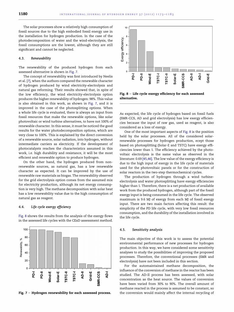
Fig. 8 e Life cycle exergy efficiency for each assessed
alternative.
i n t e rn a t i o n a l j o u r n a l o f h y d r o g e n en e r g y 3 7 ( 2 0 1 2 ) 1 1 7 3e1 1 8 31180
The solar processes show a relatively high consumption of
fossil sources due to the high embodied fossil energy use in
the installation for hydrogen production. In the case of the
photodecomposition of water and the wind-electrolysis, the
fossil consumptions are the lowest, although they are still
significant and cannot be neglected.
4.3. Renewability
The renewability of the produced hydrogen from each
assessed alternative is shown in Fig. 7.
The concept of renewability was first introduced by Neelis
et al. [7], when the authors compared the renewable character
of hydrogen produced by wind electricity-electrolysis and
natural gas reforming. Their results showed that, in spite of
the low efficiency, the wind electricity-electrolysis option
produces the higher renewability of hydrogen: 98%. This value
is also obtained in this work, as shown in Fig. 7, and it is
improved in the case of the photosplitting options. When
a whole life cycle is evaluated, there is always an input from
fossil resources that make the renewable options, like solar
photovoltaic or wind turbine alternatives, to have not 100% of
renewable character. In this sense, it must be noticed the good
results for the water photodecomposition options, which are
very close to 100%. This is explained by the direct conversion
of a renewable source, solar radiation, into hydrogen, without
intermediate carriers as electricity. If the development of
photocatalysts reaches the characteristics assumed in this
work, i.e. high durability and resistance, it will be the most
efficient and renewable option to produce hydrogen.
On the other hand, the hydrogen produced from non-
renewable sources, as natural gas, has a low renewable
character as expected. It can be improved by the use of
renewable rawmaterials as biogas. The renewability observed
for the grid electrolysis option comes from the assumed mix
for electricity production, although its net energy consump-
tion is very high. The methane decomposition with solar heat
has a low renewability value due to the high consumption of
natural gas as reagent.
4.4. Life cycle exergy efficiency
Fig. 8 shows the results from the analysis of the exergy flows
in the assessed life cycles with the CExD assessment method.
Fig. 7 e Hydrogen renewability for each assessed process.
As expected, the life cycle of hydrogen based on fossil fuels
(SMR-CCS, AD and grid electrolysis) has low exergy efficien-
cies because the input of raw gas, used as reagent, is also
considered as a loss of exergy.
One of the most important aspects of Fig. 8 is the position
held by the solar processes. All of the considered solar-
renewable processes for hydrogen production, ecept those
based on photosplitting (Solar-E and TSTC) have exergy effi-
ciencies lower than 1. The efficiency achieved by the photo-
voltaic electrolysis is the same value as observed in the
literature: 0.69 [45,46]. The low value of the exergy efficiency is
due to the high input of exergy in the life cycle of materials
used for the photovoltaic panels or for the construction of
solar reactors in the two-step thermochemical cycles.
The production of hydrogen through a wind turbine-
electrolysis and water photosplitting have exergy efficiencies
higher than 1. Therefore, there is a net production of available
work from the produced hydrogen, although part of the fossil
exergy input is being consumed in the life cycle. The observed
maximum is 9.6 MJ of exergy from each MJ of fossil exergy
input. There are two main factors affecting this result: the
simplicity of the PD life cycle, with very low fossil resources
consumption, and the durability of the installation involved in
the life cycle.
4.5. Sensitivity analysis
The main objective of this work is to assess the potential
environmental performance of new processes for hydrogen
production. In this way, we have considered some sensitivity
analyses to study the possibilities of improving the proposed
processes. Therefore, the conventional processes (SMR and
electrolysis) have not been included in this section.
For the automaintained methane decomposition, the
influence of the conversion ofmethane in the reactor has been
studied. The AD-II process has been assessed, with solar
concentration as the heat source. The values of conversion
have been varied from 30% to 90%. The overall amount of
methane reacted in the process is assumed to be constant, so
the conversion would mainly affect the internal recycling of
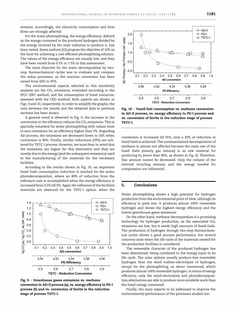
Fig. 10 e Fossil fuel consumption vs. methane conversion
in AD-II process, vs. energy efficiency in PD-I process and
vs. conversion of ferrite in the reduction stage of process
TSTC-I.
i n t e r n a t i o n a l j o u r n a l o f h y d r o g e n en e r g y 3 7 ( 2 0 1 2 ) 1 1 7 3e1 1 8 3 1181
streams. Accordingly, the electricity consumption and heat
flows are strongly affected.
For the water photosplitting, the energy efficiency, defined
as the energy contained in the produced hydrogen divided by
the energy received by the solar radiation to produce it, has
been varied. Some authors [22] propose the objective of 10% as
the limit for achieving a cost efficient photosplitting solution.
The values of the energy efficiency are usually low, and they
have been varied from 0.5% to 7.5% in this assessment.
The main objective for the water decomposition by two-
step thermochemical cycles was to evaluate and compare
the redox processes, so the reaction conversion has been
varied from 60% to 95%.
The environmental aspects selected in this sensitivity
analysis are the CO2 emissions, evaluated according to the
IPCC 2007 method, and the consumption of fossil resources,
assessed with the CED method. Both aspects are shown in
Figs. 9 and 10, respectively. In order to simplify the graphs, the
ratio between the results and the obtained data in previous
sections has been drawn.
A general trend is observed in Fig. 9, the increase in the
conversion or the efficiency reduces the CO2 emissions. This is
specially remarked for water photosplitting with values close
to zero-emissions for an efficiency higher than 5%. Regarding
AD process, the emissions are decreased down to 20% when
conversion is 90%. Finally, similar reductions (20%) are ach-
ieved for TSTC-I process. However, wemust bear in mind that
the emissions are higher for this alternative and they are
mostly due to the energy (and the subsequent emissions) used
in the manufacturing of the materials for the necessary
facilities.
According to the results shown in Fig. 10, an important
fossil fuels consumption reduction is reached for the water
photodecomposition, where an 80% of reduction from the
reference case is accomplished when the energy efficiency is
increased from0.5% till 5%. Again the influence of the facilities
materials are observed for the TSTC-I option, when the
Fig. 9 e Greenhouse gases emissions vs. methane
conversion in AD-II process (a), vs. energy efficiency in PD-I
process (b) and vs. conversion of ferrite in the reduction
stage of process TSTC-I.
conversion is increased till 95%, only a 20% of reduction in
fossil fuels is achieved. The automaintained decomposition of
methane is almost not affected because the main use of the
fossil fuels (mainly gas natural) is as raw material for
producing H2 (more than 80%, as shown in Fig. 6). Therefore,
this amount cannot be decreased. Only the volume of the
internal recycling streams and the energy needed for
compression are influenced.
5. Conclusions
Water photosplitting shows a high potential for hydrogen
production from the environmental point of view, although its
efficiency is quite low. It produces almost 100% renewable
hydrogen and shows the highest exergy efficiency and the
lowest greenhouse gases emissions.
On the other hand, methane decomposition is a promising
technology for hydrogen production, as the associated CO2
emissions are low, but it needs high amounts of fossil fuels.
The production of hydrogen through two-step thermochem-
ical cycles shows a good process performance, but several
concerns arise when the life cycle of the materials needed for
the production facilities is considered.
The renewable character of the produced hydrogen has
been determined, being correlated to the energy input to its
life cycle. The solar options usually produce less renewable
hydrogen than the wind turbine-electrolysis of hydrogen,
except for the photosplitting, as above mentioned, which
produces almost 100% renewable hydrogen. In terms of exergy
efficiency, only the wind-electrolysis and photodecomposi-
tion alternatives are able to producemore available work than
the fossil exergy consumed.
Finally, the main aspects to be addressed to improve the
environmental performance of the processes studied are:

i n t e rn a t i o n a l j o u r n a l o f h y d r o g e n en e r g y 3 7 ( 2 0 1 2 ) 1 1 7 3e1 1 8 31182
- Water photoelectrolysis shows good results even for the low
efficiencies studied, but an increment on it would yield an
improvement in its environmental impacts. As well, more
durable and resistant photocatalysts are important aspects.
- The automaintained decomposition of methane is also
a clean process, but the fossil origin of methane makes this
option to be far from sustainability. The change of the origin
of methane and other hydrocarbons to biogenic sources
would improve its environmental feasibility.
- Thermochemical cycles with solar-concentrated heat
shows a good performance for the production stage that
could be improved if the reaction conversion is increased.
The main drawback comes from the materials used in the
production facilities whose manufacturing demands large
amounts of energy, yielding important environmental
impacts. Therefore, the sustainability of the materials
manufacturing is one of the main aspects to be solved.
Acknowledgements
The authors wish to acknowledge the funding received from
‘Comunidad de Madrid’ through PHISICO2 (S-0505/ENE/
000404) and RESTOENE (S2009/ENE-1743) programmes. J.L.G.
acknowledges the funding received for his contract from
European Social Fund and ‘Comunidad de Madrid’.
r e f e r e n c e s
[1] Sorensen B. Hydrogen and fuel cells. London: ElsevierAcademic Press; 2005.
[2] International Organization for Standardization. ISO 14040:2006 and ISO 14044:2006: environmental management e lifecycle assessment e principles and framework.
[3] Udo de Haes HA, Heijungs R. Life-cycle assessment forenergy analysis and management. Appl Energy 2007;84:817e27.
[4] Wagner U, Geiger B, Schaefer H. Energy life cycle analysis ofhydrogen systems. Int J Hydrogen Energy 1998;23(1):1e6.
[5] Solli C, Stromman AH, Hergtwich EG. Fission or fossil: lifecycle assessment of hydrogen production. Proc IEEE 2006;94(10):1785e94.
[6] Koroneos C, Dompros A, Roumbas G, Moussiopoulos N. Lifecycle assessment of hydrogen fuel production processes. IntJ Hydrogen Energy 2004;29:1443e50.
[7] Neelis M-L, van der Kooi HJ, Geerlings JJC. Exergetic life cycleanalysis of hydrogen production and storage systems forautomotive applications. Int J Hydrogen Energy 2004;29:537e45.
[8] Koroneos C, Dompros A, Roumbas G, Moussiopoulos N.Advantages of the use of hydrogen fuel as compared tokerosene. Resour Conserv Recycl 2005;44:99e113.
[9] Ally J, Pryor T. Life-cycle assessment of diesel, natural gasand hydrogen fuel cell bus transportation systems. J PowerSources 2007;170:401e11.
[10] Granovskii M, Dincer I, Rosen MA. Life cycle assessment ofhydrogen fuel cell and gasoline vehicles. Int J HydrogenEnergy 2006;21:337e52.
[11] Horn JH, Morehead WR. Thermal carbon black process.United States Patent US3523010; 1970.
[12] Bonura G, Di Blasi O, Spadaro L, Arena F, Frusteri F. A basicassessment of the reactivity of Ni catalysts in thedecomposition of methane for the production of ‘‘COx-free’’hydrogen for fuel cells application. Catal Today 2006;116:298e303.
[13] Otsuka K, Takenaka S, Ohtsuki H. Production of purehydrogen by cyclic decomposition of methane and oxidativeelimination of carbon nanofibers on supported-Ni-basedcatalysts. Appl Catal A Gen 2004;273:113e24.
[14] Serrano DP, Botas JA, Guil-Lopez R. H2 production frommethane pyrolysis over commercial carbon catalysts: kineticand deactivation study. Int J Hydrogen Energy 2009;34(10):4488e94.
[15] Jung JU, Nam W, Yoon KJ, Han GY. Hydrogen production bycatalytic decomposition of methane over carbon catalysts ina fluidized bed. Korean J Chem Eng 2007;24(4):674e8.
[16] Suelves I, Lazaro MJ, Moliner R, Pinilla JL, Cubero H.Hydrogen production by methane decarbonization:carbonaceous catalysts. Int J Hydrogen Energy 2007;32:3320e6.
[17] Dufour J, Serrano DP, Galvez JL, Moreno J, Garcıa C. Life cycleassessment of processes for hydrogen production:environmental feasibility and reduction of greenhouse gasesemissions. Int J Hydrogen Energy 2009;34:1370e6.
[18] Pinilla JL, Suelves I, Utrilla R, Galvez ME, Lazaro MJ, Moliner R.Hydrogen production by termo-catalytic decomposition ofmethane: regeneration of active carbons using CO2. J PowerSources 2007;169:103e9.
[19] Muradov N, Veziroglu TN. From hydrocarbon to hydrogen-carbon to hydrogen economy. Int J Hydrogen Energy 2005;30:225e37.
[20] Abanades S, Flamant G. Solar hydrogen production from thethermal splitting of methane in a high temperature solarchemical reactor. Sol Energy 2006;80:1321e32.
[21] Kogan M, Kogan A. Production of hydrogen and carbon bysolar thermal methane splitting. I. The unseeded reactor. IntJ Hydrogen Energy 2003;28:1187e98.
[22] Rajeshwar K, McConnell R, Licht S. Chapters 3 and 7. In: Solarhydrogen generation. Solar hydrogen generation. Towarda renewable energy future. New York: Springer Science; 2008.
[23] Aroutiounian VM, Arakelyan VM, Shahnazaryan GE. Metaloxide photoelectrodes for hydrogen using solar radiation-driven water splitting. Sol Energy 2005;78:581e92.
[24] Amouyal E. Photochemical production of hydrogen andoxygen from water: a review and state of the art. Sol EnergyMater Sol Cells 1995;38:249e76.
[25] Bak T, Nowotny J, Rekas M, Sorrell CC. Photo-electrochemicalhydrogengeneration fromwaterusing solar energy.Materials-related aspects. Int J Hydrogen Energy 2002;27:991e1022.
[26] Navarro RM, del Valle F, Fierro JLG. Photocatalytic hydrogenevolution from CdS-ZnOeCdO systems under visible lightirradiation: effect of thermal treatment and presence of Ptand Ru cocatalysts. Int J Hydrogen Energy 2008;33:4265e73.
[27] Del Valle F, Ishikawa A, Domen K, Villoria de la Mano JA,Sanchez-Sanchez MC, Gonzalez ID, et al. Influence of Znconcentration in the activity of Cd1�xZnxS solid solutions forwater splitting under visible light. Catal Today 2009;143:51e6.
[28] Kodama T, Gokon N, Yamamoto R. Thermochemical two-step water splitting by ZrO2-supported NixFe3�xO4 for solarhydrogen production. Sol Energy 2008;82:73e9.
[29] Diver RB, Miller JE, Allendorf MD, Siegel N, Hogan RE. Solarthermochemical water-splitting ferrite-cycle heat engine. In:Morehouse JH, Krarti M, editors. Proceedings of the ASMEInternational Solar Energy Conference, Solar Engineering2006. Nueva York: ASME; 2006.
[30] Kodama T, Gokon N. Thermochemical Cycles for High-Temperature Solar Hydrogen Production. Chem Rev 2007;107:4048e77.

i n t e r n a t i o n a l j o u r n a l o f h y d r o g e n en e r g y 3 7 ( 2 0 1 2 ) 1 1 7 3e1 1 8 3 1183
[31] Abanades S, Charvin P, Flamant G, Neveu P. Screening ofwater-splitting thermochemical cycles potentially attractivefor hydrogen production by concentrated solar energy.Energy 2006;31:2805e22.
[32] Perkins C, Weimer AW. Likely near-term solar-thermal watersplitting technologies. Int J Hydrogen Energy 2004;29:1587e99.
[33] Rege SU, Yang RT. Kinetic separation of oxygen and argonusing molecular sieve carbon. Adsorpt J Int Adsorpt Soc 2000;6:15e22.
[34] Charvin P, Abanades S, Lemort F, Flamant G. Analysis ofsolar chemical processes for hydrogen production fromwater splitting thermochemical cycles. Energy ConversManage 2008;49:1547e56.
[35] Steinfeld A. Solar hydrogen production via a two-step water-splitting thermochemical cycle based on Zn/ZnO redoxreactions. Int J Hydrogen Energy 2002;27:611e9.
[36] Steinfeld A. Solar thermochemical production of hydrogen e
a review. Sol Energy 2005;78:603e15.[37] Dufour J, Serrano DP, Galvez JL, Moreno J, Gonzalez A.
Hydrogen production from fossil fuels: life cycle assessmentof technologies with low greenhouse gases emissions.Energy Fuels 2011;25:2194e202.
[38] Spath, M.L., Mann, M.K. Life cycle assessment of hydrogenproduction via natural gas steam reforming. NREL technicalreport NREL/TP-570-27637; 2001. Available from: www.osti.gov/bridge.
[39] Odeh NA, Cockerill TT. Life cycle GHG assessment of fossilfuel power plants with carbon capture and storage. EnergyPol 2008;36:367e80.
[40] Damen K, Van Troost M, Faaij A, Turkenburg W. Acomparison of electricity and hydrogen production systemswith CO2 capture and storage. Part A: review and selection ofpromising conversion and capture technologies. Prog EnergyCombust Sci 2006;32:215e46.
[41] Ivy J. Summary of electrolytic hydrogen production. NRELreport MP-560-36734; 2004. Available from: www.nrel.gov.
[42] Bousted I, Hancock GF. Handbook of industrial energyanalysis. Chapter 1. Chichester: Ellis Horwood Ltd.; 1979.
[43] Frischknecht R, Jungbluth N. (Eds). Implementation of lifecycle impact assessment methods. Ecoinvent report (no. 3);2007. Available from: www.ecoinvent.org.
[44] Boesch ME, Hellweg S, Huijbregts MAJ, Frischknet R.Applying cumulative exergy demand (CExD) indicators to theecoinvent database. Int J Life Cycle Assess 2007;12(3):181e90.
[45] Dincer I, Rosen MA. Exergy. Chapter 19. Oxford: Elsevier;2008.
[46] Granovskii M, Dincer I, Rosen MA. Exergetic life cycleassessment of hydrogen production from renewables. JPower Sources 2007;167:461e71.
[47] Utgikar V, Thiesen T. Life cycle assessment of hightemperature electrolysis for hydrogen production via nuclearenergy. Int J Hydrogen Energy 2006;31:939e44.