LHC beam dump: energy deposition and accident scenarios ...
24
LHC beam dump: energy deposition and accident scenarios (Run II, Run III and HL-LHC) A. Lechner, C. Bracco, M. Calviani, S. Gilardoni, M. Frankl, B. Goddard, A. Perillo Marcone, T. Polzin, V. Rizzoglio, C. Wiesner Studies carried out within HL-LHC WP14 LHC Beam Dump System Review Feb 5 th , 2019 A. Lechner (EN/STI) Feb 5 th , 2019 1 / 23
-
Upload
khangminh22 -
Category
Documents
-
view
0 -
download
0
Transcript of LHC beam dump: energy deposition and accident scenarios ...
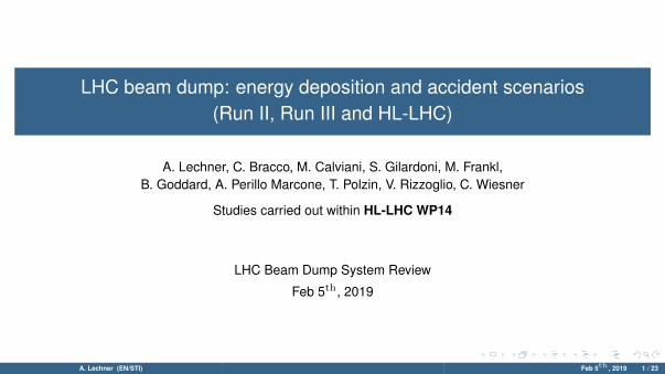
LHC beam dump: energy deposition and accident scenarios(Run II, Run III and HL-LHC)
A. Lechner, C. Bracco, M. Calviani, S. Gilardoni, M. Frankl,B. Goddard, A. Perillo Marcone, T. Polzin, V. Rizzoglio, C. Wiesner
Studies carried out within HL-LHC WP14
LHC Beam Dump System Review
Feb 5th, 2019
A. Lechner (EN/STI) Feb 5th , 2019 1 / 23
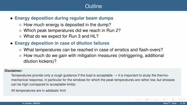
Outline
• Energy deposition during regular beam dumps◦ How much energy is deposited in the dump?◦ Which peak temperatures did we reach in Run 2?◦ What do we expect for Run 3 and HL?
• Energy deposition in case of dilution failures◦ What temperatures can be reached in case of erratics and flash-overs?◦ How much do we gain with mitigation measures (retriggering, additional
dilution kickers)?
Disclaimer:Temperatures provide only a rough guidance if the load is acceptable→ it is important to study the thermo-mechanical response, in particular for the windows for which the peak temperatures are rather low, but stressescan be high (compared to acceptable limits)
All temperatures are in adiabatic limit
A. Lechner (EN/STI) Feb 5th , 2019 2 / 23

TDE core
70 cm (1.77 g/cm3)
2mm sheets (1.1-1.2 g/cm3)
8 cm(1.72 g/cm3)
8 cm(1.72 g/cm3)
70 cm (1.77 g/cm3)
342 cm
TDE core:low and high-density graphitesegments
TDE graphitecore in stainlesssteel shell
beam
A. Lechner (EN/STI) Feb 5th , 2019 3 / 23

TDE windows
T. Polzin
*) Downstream windowwill be upgraded in LS2
(different design, Ti Grade 5)*) Upstream window upgrade
in Run 3 being assessed,- see Antonio's talk
TDE downstreamwindow
TDE upstream window
beam
Upstream window: → exposed to swept bunches
• Isolates dump transfer line vacuum fromnitrogen atmosphere
• CfC for robustness reasons, leak tightnessassured by a thin steel layer
Thickness Material Density
#1 15 mm CfC ( R©SIGRABOND 1501G) ∼1.5 g/cm3
#2 0.2 mm Stainless steel (AISI 316L) 8 g/cm3
Downstream window: → exposed to secondaryparticles leaking from TDE core
Thickness Material Density
#1 10 mm Titanium Grade 2 (ASTMB265)
4.5 g/cm3
A. Lechner (EN/STI) Feb 5th , 2019 4 / 23
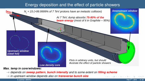
Energy deposition and the effect of particle showers
beam
Upstream window(steel foil)
Low density core
Downstream window
Plots in arbitrary units, but should illustrate the effect of particle showers
At 7 TeV, dump absorbs 75-80% of the beam energy (most of it in Graphite – 95%)
Nλ ≈ 15 (>99.9999% of 7 TeV protons have an inelastic collision)
Max. temp in core/windows:→ depends on sweep pattern, bunch intensity and to some extent on filling scheme→ in upstream window depends also on transverse bunch size
A. Lechner (EN/STI) Feb 5th , 2019 5 / 23

Proton beam parameters from Run 2 to HL-LHC
LHC design (7 TeV) Run 2 (6.5 TeV) Run 3 (6.5-7 TeV) HL-LHC (7 TeV)
Nominal [1]:
1.15x10¹¹ ppb, 3.75 μm·rad1.2x1011 ppb, 3.40 μm·rad
Ultimate [1]:
1.7x10¹¹ ppb, 3.75 μm·rad1.8?x1011 ppb, 3.40 μm·rad
2017/2018 (BCMS) [2]:
1.2x10¹¹ ppb, 1.7-2.1 μm·rad1.2x1011 ppb, 1.3-1.4 μm·rad
+2017 8b4e/8b4e (BCS)
2020 (BCMS) [3]:
1.4x10¹¹ ppb, 1.8 μm·rad1.4x1011 ppb, 1.3 μm·rad
2021/22 (BCMS) [3]:
1.8x10¹¹ ppb, 1.8 μm·rad1.8x1011 ppb, 1.3 μm·rad
HL std [4]:
2.2x10¹¹ ppb, 2.2 μm·rad2.3x1011 ppb, 2.0 μm·rad
HL BCMS [4]:
2.2x10¹¹ ppb, 2.2 μm·rad2.3x1011 ppb, 1.7 μm·rad
prev. LIU BCMS (inj):
2.0x10¹¹ ppb, 1.37 μm·rad
[1] LHC design report, [2] Y. Papaphilippou, LHC Emittance Preservation WG, [3] S. Fartoukh, Run III Configuration WG, [4] HL-LHC parameter table V 7.0.0
On paper the dump was designed for LHC ultimate
Black = beam parameters in collisionsGray = beam parameters at injection
For the HL TDE studies we use a conservative approach: no emittancegrowth and no intensity loss in ramp
A. Lechner (EN/STI) Feb 5th , 2019 6 / 23

Temperatures in the dump core with Run 2 [email protected] (2017/18)
Longitudinal peak temperature profile: Temperature along sweep [email protected] m depth:
8b4e/8b4e BCS (2017)
25 ns BCMS (2017/18)
25 ns BCMS (2017/18)
8b4e/8b4e BCS (2017)
⇒ reached up to 1000◦C in cases when beams were dumped early in 6.5 TeV fills in 2017/18
A. Lechner (EN/STI) Feb 5th , 2019 7 / 23

Temperatures in the dump core with Run 3/HL beams@7TeVLongitudinal peak temperature profile: Temperature along sweep [email protected] m depth:
Run 3
HL-LHC
Run 3
HL-LHC
⇒ expect ∼1500◦C for 1.8×10¹¹ ppb, and ∼1800-1900◦C for HL beams (2.3×10¹¹ ppb)⇒ as of now, cannot conclude if 1800-1900◦C acceptable (better material characterization needed – see later talks)
A. Lechner (EN/STI) Feb 5th , 2019 8 / 23

General remarks on sweep failures
◦ Peak temp. depends on minimum sweep speed→ after about 15µs when the V dilution changes direction
◦ In addition: there are only 4 H kickers, while there are 6 V kickers→ relative kick strength/kicker is higher in H plane
◦ Hence failure scenarios involving H kickers are generally more critical for TDE
Bunch positions at front face:Transverse energy density in core (3 m depth)
regular sweep:
Transverse energy density in core (3 m depth)two MKBH missing:
Figures courtesy of C. Wiesner and M. Frankl
A. Lechner (EN/STI) Feb 5th , 2019 9 / 23

Temperatures in the dump core with reduced dilution (7 TeV, HL beams)
+1000°C
Peak temperatures in the TDE core forHL std (2.3×10¹¹ ppb, 2.08µm) andHL BCMS (2.3×10¹¹ ppb, 1.7µm) beams
# active MKBV
6 5 4
# active MKBH
4 1840°C1860°C
1860°C1880°C
1920°C1950°C
3 2200°C2240°C
2240°C2270°C
2280°C2310°C
2 2800°C2840°C
2840°C2880°C
2900°C2960°C
⇒ In the case of 2H kicker failing, peak temperature would reach almost 3000◦C with HL beams – acceptable in rareevents? (to be assessed if we can reach such temperatures in HRM with post-LS2 beams)
A. Lechner (EN/STI) Feb 5th , 2019 10 / 23

Dilution failure scenarios - lessons from Run 2
What we consideredas worst case threeyears ago ...
Generator
Erratic pre-fire of a single MKBHLoss of <40% in H plane (antiphaseto other kickers)
Flash-over leads to loss of dilution, can affect 2 MKBHsin the same tank Loss of 50% in H plane
From C. Wiesner Magnet(vacuum tank)
A. Lechner (EN/STI) Feb 5th , 2019 11 / 23

Dilution failure scenarios - lessons from Run 2
What we consideredas worst case threeyears ago ...
Generator
Erratic pre-fire of a single MKBHLoss of <40% in H plane (antiphaseto other kickers)
What we know now ...
Flash-over leads to loss of dilution, can affect 2 MKBHsin the same tank Loss of 50% in H plane
Common cause failures can leadto pre-fire of two kickersLoss of >70% in H plane in case ofdouble erratic (antiphase to other kickers)
Current can persist in magnetafter flash-over, can affect 2 MKBHsin the same tank Depending on phase can lead to crossing sweep pattern
observed end of 2016 observed in summer 2018
See:MPP 27/04/2018LMC 01/08/2018MPP 28/09/2018HL TCC 04/10/2018
From C. Wiesner
NEW
Magnet(vacuum tank)
A. Lechner (EN/STI) Feb 5th , 2019 11 / 23

Dilution failure scenarios - lessons from Run 2
What we consideredas worst case threeyears ago ...
Generator
Erratic pre-fire of a single MKBHLoss of <40% in H plane (antiphaseto other kickers)
What we know now ...
Flash-over leads to loss of dilution, can affect 2 MKBHsin the same tank Loss of 50% in H plane
Common cause failures can leadto pre-fire of two kickersLoss of >70% in H plane in case ofdouble erratic (antiphase to other kickers)
Current can persist in magnetafter flash-over, can affect 2 MKBHsin the same tank Depending on phase can lead to crossing sweep pattern
observed end of 2016 observed in summer 2018
See:MPP 27/04/2018LMC 01/08/2018MPP 28/09/2018HL TCC 04/10/2018
From C. Wiesner
NEWReduction of generator voltage (LS2)
Installation of MKB retrigger system (LS2)– see previous talks
Magnet(vacuum tank)
A. Lechner (EN/STI) Feb 5th , 2019 12 / 23

Temp. in the dump core in case of pre-fire+retriggering (7 TeV, HL beams)
HL std beams (2.3×10¹¹ ppb, 2.08µm)
Total time delay (<96 μsec) =reaction time (<6 μsec) +delay until abort gap arrives (<89 μsec)
Pre-fire → retrigger all MKBs → execute synchronous beam dump
Dilution pattern changes as a function of eventual retriggering delay!
HL-STD 3 MKBH missing(i.e. only 25% dilution in H)
⇒ Pre-fires: retriggering allows keeping the temperature in the graphite core below the previously assumedworst case (loss of 2 MKBH), but temperatures still very high
A. Lechner (EN/STI) Feb 5th , 2019 13 / 23

Temp. in the windows in case of pre-fire+retriggering (7 TeV, HL beams)
Upstream window(steel foil)
Downstream window
⇒ Pre-fires: retriggering helps but stresses still too high even for Run 3 beams (see talk of Tobias)
A. Lechner (EN/STI) Feb 5th , 2019 14 / 23

Dilution failure scenarios - lessons from Run 2
What we consideredas worst case twoyears ago ...
Generator
Erratic pre-fire of a single MKBHLoss of <40% in H plane (antiphaseto other kickers)
What we know now ...
Flash-over leads to loss of dilution, can affect 2 MKBHsin the same tank Loss of 50% in H plane
Common cause failures can leadto pre-fire of two kickersLoss of >70% in H plane in case ofdouble erratic (antiphase to other kickers)
Current can persist in magnetafter flash-over, can affect 2 MKBHsin the same tank Depending on phase can lead to crossing sweep pattern
observed end of 2016 observed in summer 2018
See:MPP 27/04/2018LMC 01/08/2018MPP 28/09/2018HL TCC 04/10/2018
From C. Wiesner
NEW
Magnet(vacuum tank)
Mitigation measures being studied (improved Insulation of busbars, additional H kickers?)
– see previous talks
A. Lechner (EN/STI) Feb 5th , 2019 15 / 23

Temperatures in the dump core in case of a flash-over (7 TeV, HL beams)HL BCMS beams (2.3×10¹¹ ppb, 1.7µm) V. Rizzoglio, C. Wiesner
1st [email protected] μsec:
1st flash-over after 16 μsec:
time delay until 1st flash-over
⇒ New failure might lead to temperatures exceeding 3200◦C for HL beams
⇒ Stresses in windows to be studied
A. Lechner (EN/STI) Feb 5th , 2019 16 / 23

4 MKBH vs 6 MKBH in case of flash-overs (7 TeV, HL beams)
HL BCMS beams (2.3×10¹¹ ppb, 1.7µm) V. Rizzoglio, C. Wiesner
4 MKBH
6 MKBH
⇒ Two additional kickers reduce the effect of a flash-over, but temperatures still very high
⇒ Further reduction could be possible through enlargement of dilution pattern (only if 6 MKBH)A. Lechner (EN/STI) Feb 5th , 2019 17 / 23

Summary and conclusions (1/2)
• Regular beam dumps
◦ Reached up to ∼1000◦C in Graphite core in Run 2◦ Expect ∼1500◦C for Run 3 target beam parameters, and ∼1800-1900◦C for HL
beam parameters - cannot conclude yet if the latter is acceptable for regulardumps (material characterisation needed -see later talk)
• Impact of erratics
◦ MKB retrigger system to be installed in LS2 largely mitigates the effect of doubleerratics, but:→ relatively high core temperatures are still possible (∼2400◦C with Run 3
beams, ∼3000◦C with HL beams) – acceptable if rare events?→ stresses in present windows would still be too high for Run 3 beams
(possible Run 3 upgrades - see talks of A. Perillo and T. Polzin)
A. Lechner (EN/STI) Feb 5th , 2019 18 / 23
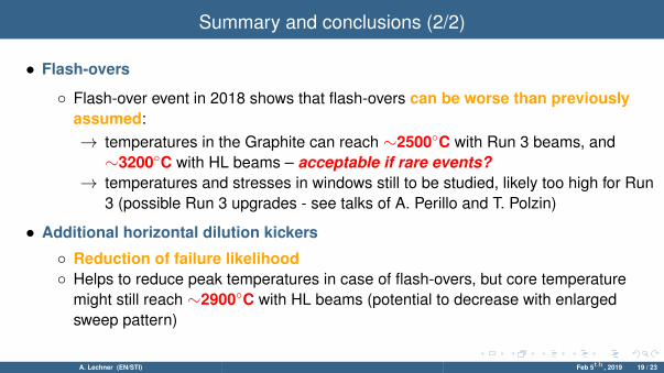
Summary and conclusions (2/2)
• Flash-overs
◦ Flash-over event in 2018 shows that flash-overs can be worse than previouslyassumed:→ temperatures in the Graphite can reach ∼2500◦C with Run 3 beams, and∼3200◦C with HL beams – acceptable if rare events?
→ temperatures and stresses in windows still to be studied, likely too high for Run3 (possible Run 3 upgrades - see talks of A. Perillo and T. Polzin)
• Additional horizontal dilution kickers
◦ Reduction of failure likelihood◦ Helps to reduce peak temperatures in case of flash-overs, but core temperature
might still reach ∼2900◦C with HL beams (potential to decrease with enlargedsweep pattern)
A. Lechner (EN/STI) Feb 5th , 2019 19 / 23

Contents
Backup
A. Lechner (EN/STI) Feb 5th , 2019 20 / 23

Sweep pattern with 6H kickers - general remarks
• Option #1: keep the same sweep patternKick strength per H kicker 66% of present strength
• Option #2: increase the sweep patternKick strength per H kicker 67%-100% of present strength
Blue = presentRed = 6H kickersat 66% of present
kick strength
Blue = presentRed = 6H kickersat 86% of present
kick strength
→ Likelihood of dilution failures reduced compared to 4H kickers
→ Effect of worst case (flash-over) reduced compared to 4H kickers
→ Likelihood of dilution failures reduced, but not as much as forOpt#1
→ Core temperature in regular dumps reduced wrt Opt#1
→ Effect of worst case (flash-over) further reduced wrt Opt#1
A. Lechner (EN/STI) Feb 5th , 2019 21 / 23

6 MKBH: increased sweep pattern in regular dumps? (7 TeV, HL beams)HL std beams (2.3×10¹¹ ppb, 2.0µm) M. Frankl, C. Wiesner
66%73%80%86%93%100%
6 horizontal kickers:kick strength per MKBHwrt to present kick strength per MKBH
⇒ Depending on kick strength, the max. temperature in regular dumps can be reduced by up to a few 100 K
⇒ But load on steel jacked and downstream flanges increases...A. Lechner (EN/STI) Feb 5th , 2019 22 / 23

Comparison of shower codes: FLUKA vs Geant4 (7 TeV p, σ=1 mm, Carbon)
A. Lechner (EN/STI) Feb 5th , 2019 23 / 23