LGH/LCH IMPORTANT WARNING CAUTION
95
© 2018 Lennox Industries Inc. Litho U.S.A. Corp. 1806-L1 LGH/LCH Service Literature 35, 40, 45, 50 TON (123, 140.7, 158.3, 175.9 kW) 01-2018 LGH/LCH SERIES The LGH/LCH high and standard efficiency 35, 40, 45 and 50 ton (123, 140.7, 158.3 and 175.9 kW) units, are config- ure to order units (CTO) with a wide selection of factory in- stalled options. The LGH/LCH rooftop units are available in 500,000 Btuh or 800,000 Btuh (146.5 kW or 234.4kW) heating inputs. Gas heat sections are designed with alu- minized or stainless steel tube heat exchangers. LGH and LCH units are equipped with the same cooling sections and cooling components. The LGH/LCH units utilize four scroll compressors with each compressor equipped with a crank- case heater. LGH/LCH units are designed for R-410A (high efficiency). Service equipment for R-410A units must be rated for R-410A refrigerant. Optional electric heat is factory installed in LCH units. Electric heat operates in single or multiple stages depending on the kW input size. 30kW through 90kW heat sections are avail- able for the LCH units in all voltages G, J and Y while105kW through 180kW heat sections are available for LCH G and J voltage units only. IMPORTANT Improper installation, adjustment, alteration, service or maintenance can cause property damage, person- al injury or loss of life. Installation and service must be performed by a qualified installer or service agen- cy . The LGH/LCH units are designed to accept any of several different energy management thermostat control systems with minimum field wiring. Factory or field provided control options connect to the unit with jack plugs. When "plugged in" the controls become an integral part of the unit wiring. If the unit must be lifted for service, rig unit by attaching eight cables to the holes located in the unit base rail (two holes at each corner and center of frame). Refer to the installation in- structions for the proper rigging technique. Information contained in this manual is intended for use by qualified service technicians only. All specifications are subject to change. Procedures outlined in this manual are presented as a recommendation only and do not super- sede or replace local or state codes. WARNING Electric shock hazard. Can cause injury or death. Before attempting to perform any service or maintenance, turn the electrical power to unit OFF at discon- nect switch(es). Unit may have multiple power supplies. CAUTION Danger of sharp metallic edges. Can cause injury. Take care when servicing unit to avoid accidental contact with sharp edges.
-
Upload
khangminh22 -
Category
Documents
-
view
1 -
download
0
Transcript of LGH/LCH IMPORTANT WARNING CAUTION

© 2018 Lennox Industries Inc.Litho U.S.A.
Corp. 1806-L1
LGH/LCH
Service Literature
35, 40, 45, 50 TON(123, 140.7, 158.3, 175.9 kW)01-2018
LGH/LCH SERIES The LGH/LCH high and standard efficiency 35, 40, 45 and
50 ton (123, 140.7, 158.3 and 175.9 kW) units, are config
ure to order units (CTO) with a wide selection of factory in
stalled options. The LGH/LCH rooftop units are available in
500,000 Btuh or 800,000 Btuh (146.5 kW or 234.4kW)
heating inputs. Gas heat sections are designed with alu
minized or stainless steel tube heat exchangers. LGH and
LCH units are equipped with the same cooling sections and
cooling components. The LGH/LCH units utilize four scroll
compressors with each compressor equipped with a crank
case heater.
LGH/LCH units are designed for R-410A (high efficiency).
Service equipment for R-410A units must be rated for
R-410A refrigerant.
Optional electric heat is factory installed in LCH units. Electric
heat operates in single or multiple stages depending on the
kW input size. 30kW through 90kW heat sections are avail
able for the LCH units in all voltages G, J and Y while105kW
through 180kW heat sections are available for LCH G and J
voltage units only.
IMPORTANTImproper installation, adjustment, alteration, serviceor maintenance can cause property damage, personal injury or loss of life. Installation and service mustbe performed by a qualified installer or service agency.
The LGH/LCH units are designed to accept any of several
different energy management thermostat control systems
with minimum field wiring. Factory or field provided control
options connect to the unit with jack plugs. When "plugged
in" the controls become an integral part of the unit wiring.
If the unit must be lifted for service, rig unit by attaching eight
cables to the holes located in the unit base rail (two holes at
each corner and center of frame). Refer to the installation in
structions for the proper rigging technique.
Information contained in this manual is intended for use by
qualified service technicians only. All specifications are
subject to change. Procedures outlined in this manual are
presented as a recommendation only and do not super
sede or replace local or state codes.
WARNINGElectric shock hazard. Can cause injuryor death. Before attempting to performany service or maintenance, turn theelectrical power to unit OFF at disconnect switch(es). Unit may have multiplepower supplies.
CAUTIONDanger of sharp metallic edges. Can cause injury.Take care when servicing unit to avoid accidentalcontact with sharp edges.

Page 2
TABLE OF CONTENTS
Introduction Page 1. . . . . . . . . . . . . . . . . . . . . . . . . . .
Options / Accessories Page 3. . . . . . . . . . . . . . . . . . .
Specifications Page 5. . . . . . . . . . . . . . . . . . . . . . . . . .
Blower Data Page 13. . . . . . . . . . . . . . . . . . . . . . . . . .
Blower Drive Kits Page 21. . . . . . . . . . . . . . . . . . . . .
Energy Recovery Wheel Specifications Page 22. .
Electrical Data Page 23. . . . . . . . . . . . . . . . . . . . . . . .
Manufacturer's Drive Numbers Page 43. . . . . . . . .
Parts Arrangement Page 44. . . . . . . . . . . . . . . . . . . .
I- UNIT COMPONENTS Page 46. . . . . . . . . . . . . . . . .
Control Box Components Page 46. . . . . . . . . . . . . .
Cooling Components Page 52. . . . . . . . . . . . . . . . . .
Blower Compartment Page 55. . . . . . . . . . . . . . . . . .
Gas Heat Components Page 59. . . . . . . . . . . . . . . .
Electric Heat Components Page 64. . . . . . . . . . . . .
II-PLACEMENT AND INSTALLATION Page 65. . . . . .
III- START UP Page 65. . . . . . . . . . . . . . . . . . . . . . . . . . .
Preliminary Checks Page 66. . . . . . . . . . . . . . . . . . .
Cooling Start Up Page 66. . . . . . . . . . . . . . . . . . . . . .
Charging Page 67. . . . . . . . . . . . . . . . . . . . . . . . . . . .
Heating Start Up Page 68. . . . . . . . . . . . . . . . . . . . . .
Safety or Emergency Shutdown Page 69. . . . . .
IV-SYSTEM SERVICE CHECKS Page 69. . . . . . . . . . .
Heating System Service Checks Page 69. . . . . . . .
Cooling System Service Checks Page 71. . . . . . . .
V-MAINTENANCE Page 71. . . . . . . . . . . . . . . . . . . . . . .
Filters Page 71. . . . . . . . . . . . . . . . . . . . . . . . . . . . . . .
Lubrication Page 72. . . . . . . . . . . . . . . . . . . . . . . . . .
Supply Air Blower Wheel Page 73. . . . . . . . . . . . . .
Evaporator and Condenser Coil Page 73. . . . . . . .
Electrical Page 73. . . . . . . . . . . . . . . . . . . . . . . . . . . .
Combustion Air Inducer Page 73. . . . . . . . . . . . . . .
Burners Page 73. . . . . . . . . . . . . . . . . . . . . . . . . . . . .
Flue Box Page 73. . . . . . . . . . . . . . . . . . . . . . . . . . . . .
VI-ACCESSORIES Page 74. . . . . . . . . . . . . . . . . . . . . . .
Mounting Frame Page 74. . . . . . . . . . . . . . . . . . . . . .
Outdoor Air Dampers Page 75. . . . . . . . . . . . . . . . .
Economizers Page 75. . . . . . . . . . . . . . . . . . . . . . . . .
Variable Frequency Drive (VAV) Page 76. . . . . . . .
Gravity Exhaust Dampers Page 77. . . . . . . . . . . . . .
Power Exhaust Fans Page 77. . . . . . . . . . . . . . . . . .
Control Systems Page 79. . . . . . . . . . . . . . . . . . . . . .
Smoke Detectors Page 79. . . . . . . . . . . . . . . . . . . .
Energy Recovery Wheel Page 79. . . . . . . . . . . . . . .
Blower Proving Switch Page 80. . . . . . . . . . . . . . . . .
Dirty Filter Switch Page 80. . . . . . . . . . . . . . . . . . . . .
Indoor Air Quality Sensor Page 80. . . . . . . . . . . . . .
Drain Pan Overflow Switch Page 80. . . . . . . . . . . . .
Humiditrol Page 80. . . . . . . . . . . . . . . . . . . . . . . . . . .
Modulating Gas Valve Page 83. . . . . . . . . . . . . . . . .
Outdoor Air CFM Control Page 84. . . . . . . . . . . . . .
Hot Gas Bypass Page 84. . . . . . . . . . . . . . . . . . . . . .
WIRING DIAGRAMS Page 86. . . . . . . . . . . . . . . . . . . . .

Page 3
OPTIONS/ACCESSORIESItem Factory Field
COOLING SYSTEMCorrosion Protection - Condenser and Evaporator Coils ODischarge Air Temperature Sensor (MSAV models only) ODrain Pan Overflow Switch OHigh Efficiency - R-410A (35, 40 Ton Models) OHot Gas Bypass (Not available with Humiditrol® Dehumidification Option) OStandard Efficiency - R-410A (35, 40, 45, 50 Ton Models) OService Valves OSpring Isolation (compressor deck) OStainless Steel Drain Pan OAIR FILTERSMERV 8 - Two Inch OMERV 8 - Four Inch OMERV 13 High Efficiency - Two Inch OMERV 13 High Efficiency - Four Inch OCleanable Metal Mesh - Two Inch OBLOWERSupply Motor - 5, 7.5, 10, 15, 20, 25, 30 hp OSupply VFD Blower Bypass OSpring Isolation (blower frame) OCABINETAir Flow - Vertical OAir Flow - Horizontal ODouble Wall Construction OHinged Louvered Condenser Section Panels O1 ROOF CURBS - STANDARD14 in. height E1CURB71E-1 X24 in. height E1CURB73E-1 XCONTROLSBlower Proving Switch OCommercial Controls Prodigy® Control System - BACnet® Module - C0CTRL60AE1L O X
Prodigy® Control System - LonTalk® Module - C0CTRL65FF1 O XNovar® ETM-2051 Unit Controller - E0CTRL30C1 O
Novar® LSE Unit Controller OCPC Einstein Unit Controller O
L Connection® Network Control System XDirty Filter Switch O XGeneral Purpose Control Kit E1GPBK30C1 XSupply Static Pressure Limit Switch - Duct Mounted C0SNSR11AE1 (Switch) X
C0SNSR12AE1- (Mounting Kit) XSmoke Detector Return O
Supply OSupply & Return O
ELECTRICALVoltage (60HZ) - 208/230V-3 phase, 460V-3 phase or 575V-3 phase OHACR Circuit Breakers - 70, 80, 90, 100, 110, 125, 150, 175, 200, 225, 250 amp Not available for units with electric heat and dual point power supply
O
Disconnect Switch - 150, 250 amp Not available for units with electric heat and dual point power supply
O
GFI Service Outlets 15 amp non-powered, field-wired (208/230V, 460V, 575V) LTAGFIK10/15 O X15 amp factory-wired and powered (208/230V, 460V, 575V) O
20 amp non-powered, field-wired (575V only) C1GFCI20FF1 O XWeatherproof Cover for GFI C1GFCI99FF1 X1 Also available - Roof curbs for vibration isolation, seismic conditions, seismic with wind restraints. Contact your Sales Representative for additional information.
O = Configure to Order (Factory Installed).X = Field Installed.

Page 4
OPTIONS/ACCESSORIESItem Factory Field
ELECTRIC HEAT (NOT AVAILABLE WITH HORIZONTAL CONFIGURED UNITS)35 ton units - 30-45-60-75-90 kW (all voltages) O35 ton units - 105-120 kW (460V & 575V only) O40 ton units - 30-45-60-75-90 kW (all voltages) O40 ton units - 105-120-135-150 kW (460V & 575V only) O45 ton units - 45-60-75-90 kW (all voltages) O45 ton units - 105-120-135-150-165 kW (460V & 575V only) O50 ton units - 45-60-75-90 kW (all voltages) O50 ton units - 105-120-135-150-165-180 kW (460V & 575V only) OSingle-Point Power Supply OHUMIDITROL® CONDENSER REHEAT (MSAV UNITS ONLY)Humiditrol® Dehumidification Option OHumidity Sensor Kit, Remote Mounted (required) XRemote Sensor Wall Seal Plate Xindoor air qualitySensor - Wall-mount, off-white plastic cover with LCD display C0SNSR50AE1L XSensor - Wall-mount, off-white plastic cover, no display C0SNSR52AE1L XSensor - Black plastic case with LCD display, rated for plenum mounting C0SNSR51AE1L XSensor - Wall-mount, black plastic case, no display, rated for plenum mounting C0MISC19AE1 XCO Sensor Duct Mounting Kit - for downflow applications C0MISC19AE1- XAspiration Box - for duct mounting non-plenum rated CO (87N53 or 77N39) sensors
C0MISC16AE1- X
ECONOMIZER/OUTDOOR AIR/EXHAUSTStandard Economizer (Not for Title 24) OHigh Performance Economizer (Approved for California Title 24 Building Standards / AMCA Class 1A Certified)
O
Economizer ControlsDifferential Sensible (factory setting) OGlobal Control OSingle Enthalpy (Not for Title 24) ODifferential Enthalpy (Not for Title 24) OFresh Air Tempering OOutdoor Air CFM Control OOutdoor Air Dampers - Manual or Motorized OBarometric Relief Dampers (Exhaust Hood Furnished for Field Installation) OPower Exhaust (see next page for specifications)50% Standard Static O100% Standard Static O50% High Static Power Exhaust O100% High Static Power Exhaust O50% High Static Power Exhaust with VFD O100% High Static Power Exhaust with VFD O50% High Static Power Exhaust with VFD and Bypass O100% High Static Power Exhaust with VFD and Bypass OPower Exhaust ControlsDamper Position Control O1 Differential Pressure Transducer OPressure Switch (order two) C0SNSR10AE1 XHigh Static Power Exhaust OptionsSpring Isolation (blower frame) OEnergy Recovery Wheel (not available with horizontal configured units) O1 Furnished as standard with High Static Power Exhaust with VFD.
O = Configure to Order (Factory Installed).X = Field Installed.

Page 5
SPECIFICATIONS - OPTIONAL POWER EXHAUSTStandard Static (50%)
(No.) Motor output (1) 1 hpMotor rpm 1140
(No.) Diameter - in. (1) 26No. of blades 4
Standard Static (100%)
(No.) Motor output (2) 1 hpMotor rpm 1140
(No.) Diameter - in. (2) 26No. of blades 4
High Static (50%)
(No.) Nominal motor output (1) 3, 5 or 7.5 hp available See Blower Data Tables for selection
Motor - Drive Kit 690 to 1065 rpm available See Blower Drive Kit Tables for selection
(No.) Blower wheel nominal diameter x width (1) 18 x 15High Static (100%)
(No.) Nominal motor output (2) 3, 5 or 7.5 hp available See Blower Data Tables for selection
Motor - Drive Kit 690 to 1065 rpm available See Blower Drive Kit Tables for selection
(No.) Blower wheel nominal diameter x width (2) 18 x 15

Page 6
SPECIFICATIONS - 35 TON STANDARD EFFICIENCYGeneral Data
Nominal Tonnage 35 Ton 35 TonModel No. 420S4M 420S4V
Efficiency Type Standard StandardBlower Type MSAV® (Multi-Stage Air Volume) Variable Air Volume (VAV)
Cooling Performance
Gross Cooling Capacity - Btuh 433,000 433,0001 Net Cooling Capacity - Btuh 410,000 410,000
AHRI Rated Air Flow - cfm 14,000 14,000Total Unit Power - kW 41.0 41.0
1 EER (Btuh/Watt) 10.0 10.02 IEER (Btuh/Watt) 13.5 13.2
Refrigerant Type R-410A R-410ARefrigerant Charge
FurnishedCircuit 1 22 lbs. 0 oz. 22 lbs. 0 oz.Circuit 2 22 lbs. 0 oz. 22 lbs. 0 oz.Circuit 3 22 lbs. 0 oz. 22 lbs. 0 oz.Circuit 4 22 lbs. 0 oz. 22 lbs. 0 oz.
Refrigerant Charge Furnished with
Humiditrol® Dehumidification
Option
Circuit 1 27 lbs. 0 oz. - - -Circuit 2 27 lbs. 0 oz. - - -Circuit 3 22 lbs. 0 oz. - - -Circuit 4 22 lbs. 0 oz. - - -
Compressor Type (no.) Scroll (4) Scroll (4)Condenser Coils
Net face area - sq. ft. total 94.1 94.1Tube diameter - in. 3/8 3/8
Number of rows 2 2Fins per inch 20 20
Condenser Fans
Motor horsepower (6) 3/4 (6) 3/4Motor rpm 1075 1075
Total Motor watts 4800 4800Diameter - in. (6) 24 (6) 24No. of blades 4 4
Total Air volume - cfm 30,000 30,000Evaporator Coils
Net face area - sq. ft. total 37.4 37.4Tube diameter - in. 3/8 3/8
No. of rows 4 4Fins per inch 14 14
Drain connection - number and size (1) 1 in. NPT coupling (1) 1 in. NPT couplingExpansion device type Balanced Port Thermostatic Expansion Valve, removeable power head
Indoor Blower and Drive Selection
Nominal motor output 5 to 30 hp available - See Blower Data Tables for selectionMotor - Drive kit 510 to 1340 rpm available - See
Blower Drive Kit Tables for selection510 to 1340 rpm available - See
Blower Drive Kit Tables for selectionBlower wheel nominal dia. x width - in. (2) 20 x 15 (2) 20 x 15
Filters Type of filter Disposable, pleated MERV 4No. and size - in. (11) 25 x 16 x 2
Electrical characteristics 208/230V, 460V or 575V - 60 hertz - 3 phaseNOTE - Net capacity includes evaporator blower motor heat deduction. Gross capacity does not include evaporator blower motor heat deduction.1 Tested at conditions included in AHRI Standard 340/360; 95°F outdoor air temperature and 80°F db/67°F wb entering evaporator air; minimum external duct static pressure.2 Integrated Energy Efficiency Ratio tested according to AHRI Standard 340/360.

Page 7
SPECIFICATIONS - 35 TON HIGH EFFICIENCYGeneral Data
Nominal Tonnage 35 Ton 35 TonModel No. 420H4M 420H4V
Efficiency Type High HighBlower Type MSAV® (Multi-Stage Air Volume) Variable Air Volume (VAV)
Cooling Performance
Gross Cooling Capacity - Btuh 443,000 443,0001 Net Cooling Capacity - Btuh 420,000 420,000
AHRI Rated Air Flow - cfm 14,000 14,000Total Unit Power - kW 38.9 38.9
1 EER (Btuh/Watt) 10.8 10.82 IEER (Btuh/Watt) 14.5 14.0
Refrigerant Type R-410A R-410ARefrigerant Charge
FurnishedCircuit 1 31 lbs. 0 oz. 31 lbs. 0 oz.Circuit 2 31 lbs. 0 oz. 31 lbs. 0 oz.Circuit 3 31 lbs. 0 oz. 31 lbs. 0 oz.Circuit 4 31 lbs. 0 oz. 31 lbs. 0 oz.
Refrigerant Charge Furnished with
Humiditrol® Dehumidification
Option
Circuit 1 36 lbs. 0 oz. - - -Circuit 2 36 lbs. 0 oz. - - -Circuit 3 31 lbs. 0 oz. - - -Circuit 4 31 lbs. 0 oz. - - -
Compressor Type (no.) Scroll (4) Scroll (4)Condenser Coils
Net face area - sq. ft. total 111.2 111.2Tube diameter - in. 3/8 3/8
Number of rows 3 3Fins per inch 20 20
Condenser Fans
Motor horsepower (6) 1 (6) 1Motor rpm 1140 1140
Total Motor watts 5000 5000Diameter - in. (6) 24 (6) 24No. of blades 4 4
Total Air volume - cfm 35,000 35,000Evaporator Coils
Net face area - sq. ft. total 37.4 37.4Tube diameter - in. 3/8 3/8
No. of rows 4 4Fins per inch 14 14
Drain connection - number and size (1) 1 in. NPT coupling (1) 1 in. NPT couplingExpansion device type Balanced Port Thermostatic Expansion Valve, removeable power head
Indoor Blower and Drive Selection
Nominal motor output 5 to 30 hp available - See Blower Data Tables for selectionMotor - Drive kit 510 to 1340 rpm available - See
Blower Drive Kit Tables for selection510 to 1340 rpm available - See
Blower Drive Kit Tables for selectionBlower wheel nominal dia. x width - in. (2) 20 x 15 (2) 20 x 15
Filters Type of filter Disposable, pleated MERV 4No. and size - in. (11) 25 x 16 x 2
Electrical characteristics 208/230V, 460V or 575V - 60 hertz - 3 phaseNOTE - Net capacity includes evaporator blower motor heat deduction. Gross capacity does not include evaporator blower motor heat deduction.1 Tested at conditions included in AHRI Standard 340/360; 95°F outdoor air temperature and 80°F db/67°F wb entering evaporator air; minimum external duct static pressure.2 Integrated Energy Efficiency Ratio tested according to AHRI Standard 340/360.

Page 8
SPECIFICATIONS - 40 TON STANDARD EFFICIENCYGeneral Data
Nominal Tonnage 40 Ton 40 TonModel No. 480S4M 480S4V
Efficiency Type Standard StandardBlower Type MSAV® (Multi-Stage Air Volume) Variable Air Volume (VAV)
Cooling Performance
Gross Cooling Capacity - Btuh 476,000 476,0001 Net Cooling Capacity - Btuh 450,000 450,000
AHRI Rated Air Flow - cfm 14,800 14,800Total Unit Power - kW 45.0 45
1 EER (Btuh/Watt) 10.0 10.02 IEER (Btuh/Watt) 13.5 13.2
Refrigerant Type R-410A R-410ARefrigerant Charge
FurnishedCircuit 1 22 lbs. 0 oz. 22 lbs . 0 oz.Circuit 2 22 lbs. 0 oz. 22 lbs . 0 oz.Circuit 3 22 lbs. 0 oz. 22 lbs . 0 oz.Circuit 4 22 lbs. 0 oz. 22 lbs . 0 oz.
Refrigerant Charge Furnished with
Humiditrol® Dehumidification
Option
Circuit 1 27 lbs. 0 oz. - - -Circuit 2 27 lbs. 0 oz. - - -Circuit 3 22 lbs. 0 oz. - - -Circuit 4 22 lbs. 0 oz. - - -
Compressor Type (no.) Scroll (4) Scroll (4)Condenser Coils
Net face area - sq. ft. total 94.1 94.1Tube diameter - in. 3/8 3/8
Number of rows 2 2Fins per inch 20 20
Condenser Fans
Motor horsepower (6) 3/4 (6) 3/4Motor rpm 1075 1075
Total Motor watts 4800 4800Diameter - in. (6) 24 (6) 24No. of blades 4 4
Total Air volume - cfm 30,000 30,000Evaporator Coils
Net face area - sq. ft. total 37.4 37.4Tube diameter - in. 3/8 3/8
No. of rows 4 4Fins per inch 14 14
Drain connection - number and size (1) 1 in. NPT coupling (1) 1 in. NPT couplingExpansion device type Balanced Port Thermostatic Expansion Valve, removeable power head
Indoor Blower and Drive Selection
Nominal motor output 5 to 30 hp available - See Blower Data Tables for selectionMotor - Drive kit 510 to 1340 rpm available - See
Blower Drive Kit Tables for selection510 to 1340 rpm available - See
Blower Drive Kit Tables for selectionBlower wheel nominal dia. x width - in. (2) 20 x 15 (2) 20 x 15
Filters Type of filter Disposable, pleated MERV 4No. and size - in. (11) 25 x 16 x 2
Electrical characteristics 208/230V, 460V or 575V - 60 hertz - 3 phaseNOTE - Net capacity includes evaporator blower motor heat deduction. Gross capacity does not include evaporator blower motor heat deduction.1 Tested at conditions included in AHRI Standard 340/360; 95°F outdoor air temperature and 80°F db/67°F wb entering evaporator air; minimum external duct static pressure.2 Integrated Energy Efficiency Ratio tested according to AHRI Standard 340/360.

Page 9
SPECIFICATIONS - 40 TON HIGH EFFICIENCYGeneral Data
Nominal Tonnage 40 Ton 40 TonModel No. 480H4M 480H4V
Efficiency Type High HighBlower Type MSAV® (Multi-Stage Air Volume) Variable Air Volume (VAV)
Cooling Performance
Gross Cooling Capacity - Btuh 494,000 494,0001 Net Cooling Capacity - Btuh 470,000 470,000
AHRI Rated Air Flow - cfm 14,000 14,000Total Unit Power - kW 43.5 43.5
1 EER (Btuh/Watt) 10.8 10.82 IEER (Btuh/Watt) 14.5 14.0
Refrigerant Type R-410A R-410ARefrigerant Charge
FurnishedCircuit 1 31 lbs. 0 oz. 31 lbs. 0 oz.Circuit 2 31 lbs. 0 oz. 31 lbs. 0 oz.Circuit 3 31 lbs. 0 oz. 31 lbs. 0 oz.Circuit 4 31 lbs. 0 oz. 31 lbs. 0 oz.
Refrigerant Charge Furnished with
Humiditrol® Dehumidification
Option
Circuit 1 36 lbs. 0 oz. - - -Circuit 2 36 lbs. 0 oz. - - -Circuit 3 31 lbs. 0 oz. - - -Circuit 4 31 lbs. 0 oz. - - -
Compressor Type (no.) Scroll (4) Scroll (4)Condenser Coils
Net face area - sq. ft. total 111.2 111.2Tube diameter - in. 3/8 3/8
Number of rows 3 3Fins per inch 20 20
Condenser Fans
Motor horsepower (6) 1 (6) 1Motor rpm 1140 1140
Total Motor watts 5000 5000Diameter - in. (6) 24 (6) 24No. of blades 4 4
Total Air volume - cfm 35,000 35,000Evaporator Coils
Net face area - sq. ft. total 37.4 37.4Tube diameter - in. 3/8 3/8
No. of rows 4 4Fins per inch 14 14
Drain connection - number and size (1) 1 in. NPT coupling (1) 1 in. NPT couplingExpansion device type Balanced Port Thermostatic Expansion Valve, removeable power head
Indoor Blower and Drive Selection
Nominal motor output 5 to 30 hp available - See Blower Data Tables for selectionMotor - Drive kit 510 to 1340 rpm available - See
Blower Drive Kit Tables for selection510 to 1340 rpm available - See
Blower Drive Kit Tables for selectionBlower wheel nominal dia. x width - in. (2) 20 x 15 (2) 20 x 15
Filters Type of filter Disposable, pleated MERV 4No. and size - in. (11) 25 x 16 x 2
Electrical characteristics 208/230V, 460V or 575V - 60 hertz - 3 phaseNOTE - Net capacity includes evaporator blower motor heat deduction. Gross capacity does not include evaporator blower motor heat deduction.1 Tested at conditions included in AHRI Standard 340/360; 95°F outdoor air temperature and 80°F db/67°F wb entering evaporator air; minimum external duct static pressure.2 Integrated Energy Efficiency Ratio tested according to AHRI Standard 340/360.

Page 10
SPECIFICATIONS - 45 TON STANDARD EFFICIENCYGeneral Data
Nominal Tonnage 45 Ton 45 TonModel No. 540S4M 540S4V
Efficiency Type Standard StandardBlower Type MSAV® (Multi-Stage Air Volume) Variable Air Volume (VAV)
Cooling Performance
Gross Cooling Capacity - Btuh 549,000 549,0001 Net Cooling Capacity - Btuh 520,000 520,000
AHRI Rated Air Flow - cfm 15,000 15,000Total Unit Power - kW 52.0 52.0
1 EER (Btuh/Watt) 10.0 10.02 IEER (Btuh/Watt) 13.7 13.6
Refrigerant Type R-410A R-410ARefrigerant Charge
FurnishedCircuit 1 31 lbs. 0 oz. 31 lbs. 0 oz.Circuit 2 31 lbs. 0 oz. 31 lbs. 0 oz.Circuit 3 31 lbs. 0 oz. 31 lbs. 0 oz.Circuit 4 31 lbs. 0 oz. 31 lbs. 0 oz.
Refrigerant Charge Furnished with
Humiditrol® Dehumidification
Option
Circuit 1 36 lbs. 0 oz. - - -Circuit 2 36 lbs. 0 oz. - - -Circuit 3 31 lbs. 0 oz. - - -Circuit 4 31 lbs. 0 oz. - - -
Compressor Type (no.) Scroll (4) Scroll (4)Condenser Coils
Net face area - sq. ft. total 111.2 111.2Tube diameter - in. 3/8 3/8
Number of rows 3 3Fins per inch 20 20
Condenser Fans
Motor horsepower (6) 3/4 (6) 3/4Motor rpm 1075 1075
Total Motor watts 4900 4900Diameter - in. (6) 24 (6) 24No. of blades 4 4
Total Air volume - cfm 29,000 29,000Evaporator Coils
Net face area - sq. ft. total 37.4 37.4Tube diameter - in. 3/8 3/8
No. of rows 4 4Fins per inch 14 14
Drain connection - number and size (1) 1 in. NPT coupling (1) 1 in. NPT couplingExpansion device type Balanced Port Thermostatic Expansion Valve, removeable power head
Indoor Blower and Drive Selection
Nominal motor output 5 to 30 hp available - See Blower Data Tables for selectionMotor - Drive kit 510 to 1340 rpm available - See
Blower Drive Kit Tables for selection510 to 1340 rpm available - See
Blower Drive Kit Tables for selectionBlower wheel nominal dia. x width - in. (2) 20 x 15 (2) 20 x 15
Filters Type of filter Disposable, pleated MERV 4No. and size - in. (11) 25 x 16 x 2
Electrical characteristics 208/230V, 460V or 575V - 60 hertz - 3 phaseNOTE - Net capacity includes evaporator blower motor heat deduction. Gross capacity does not include evaporator blower motor heat deduction.1 Tested at conditions included in AHRI Standard 340/360; 95°F outdoor air temperature and 80°F db/67°F wb entering evaporator air; minimum external duct static pressure.2 Integrated Energy Efficiency Ratio tested according to AHRI Standard 340/360.

Page 11
SPECIFICATIONS - 50 TON STANDARD EFFICIENCYGeneral Data
Nominal Tonnage 50 Ton 50 TonModel No. 600S4M 600S4V
Efficiency Type Standard StandardBlower Type MSAV® (Multi-Stage Air Volume) Variable Air Volume (VAV)
Cooling Performance
Gross Cooling Capacity - Btuh 598,000 598,0001 Net Cooling Capacity - Btuh 565,000 565,000
AHRI Rated Air Flow - cfm 16,000 16,000Total Unit Power - kW 56.5 56.5
1 EER (Btuh/Watt) 10.0 10.02 IEER (Btuh/Watt) 13.5 13.2
Refrigerant Type R-410A R-410ARefrigerant Charge
FurnishedCircuit 1 31 lbs. 0 oz. 31 lbs. 0 oz.Circuit 2 31 lbs. 0 oz. 31 lbs. 0 oz.Circuit 3 31 lbs. 0 oz. 31 lbs. 0 oz.Circuit 4 31 lbs. 0 oz. 31 lbs. 0 oz.
Refrigerant Charge Furnished with
Humiditrol® Dehumidification
Option
Circuit 1 36 lbs. 0 oz. - - -Circuit 2 36 lbs. 0 oz. - - -Circuit 3 31 lbs. 0 oz. - - -Circuit 4 31 lbs. 0 oz. - - -
Compressor Type (no.) Scroll (4) Scroll (4)Condenser Coils
Net face area - sq. ft. total 111.2 111.2Tube diameter - in. 3/8 3/8
Number of rows 3 3Fins per inch 20 20
Condenser Fans
Motor horsepower (6) 1 (6) 1Motor rpm 1140 1140
Total Motor watts 5000 5000Diameter - in. (6) 24 (6) 24No. of blades 4 4
Total Air volume - cfm 35,000 35,000Evaporator Coils
Net face area - sq. ft. total 37.4 37.4Tube diameter - in. 3/8 3/8
No. of rows 4 4Fins per inch 14 14
Drain connection - number and size (1) 1 in. NPT coupling (1) 1 in. NPT couplingExpansion device type Balanced Port Thermostatic Expansion Valve, removeable power head
Indoor Blower and Drive Selection
Nominal motor output 5 to 30 hp available - See Blower Data Tables for selectionMotor - Drive kit 510 to 1340 rpm available - See
Blower Drive Kit Tables for selection510 to 1340 rpm available - See
Blower Drive Kit Tables for selectionBlower wheel nominal dia. x width - in. (2) 20 x 15 (2) 20 x 15
Filters Type of filter Disposable, pleated MERV 4No. and size - in. (11) 25 x 16 x 2
Electrical characteristics 208/230V, 460V or 575V - 60 hertz - 3 phaseNOTE - Net capacity includes evaporator blower motor heat deduction. Gross capacity does not include evaporator blower motor heat deduction.1 Tested at conditions included in AHRI Standard 340/360; 95°F outdoor air temperature and 80°F db/67°F wb entering evaporator air; minimum external duct static pressure.2 Integrated Energy Efficiency Ratio tested according to AHRI Standard 340/360.

Page 12
SPECIFICATIONS - GAS HEAT Gas Heating Performance (2 Stage)
Heat Input Type Standard 2 Stage
High 2 Stage
Input - First Stage Btuh (kW) 330,000 (96.6) 528,000 (154.6)Input - Second Stage Btuh (kW) 500,000 (146.4) 800,000 (234.4)
Output - First Stage Btuh (kW) - - - - - -Output - Second Stage Btuh (kW) 400,000 (117.1) 640,000 (187.4)
Gas Heating Performance (4 Stage)
Heat Input Type Standard 4 Stage
High 4 Stage
Input - First Stage Btuh (kW) 165,000 (48.3) 264,000 (77.4)Input - Second Stage Btuh (kW) 330,000 (96.7) 528,000 (154.7)
Input - Third Stage Btuh (kW) 415,000 (121.6) 664,000 (194.6)Input - Fourth Stage Btuh (kW) 500,000 (146.5) 800,000 (234.4)Output - First Stage Btuh (kW) - - - - - -
Output - Second Stage Btuh (kW) - - - - - -Output - Third Stage Btuh (kW) - - - - - -
Output - Fourth Stage Btuh (kW) 400,000 (117.2) 640,000 (187.5)Gas Heating Performance (Fully Modulating)
Heat Input Type Standard Fully Modulating
High Fully Modulating
Input - Minimum Btuh (kW) 125,000 (36.6) 200,000 (58.6)Input - Full Btuh (kW) 500,000 (146.5) 800,000 (234.4)
Output - Minimum Btuh (kW) - - - - - -Output - Full Btuh (kW) 400,000 (117.2) 640,000 (187.5)
Temperature Rise Range - °F 10 - 40 25 - 55Thermal Efficiency 80%
Gas Supply Connections 1-1/4 in. NPTRecommended Gas Supply Pressure Natural 7 in. w.g. (1.5 kPa)
LPG/Propane 11 in. w.g. (2.7 kPa)
HIGH ALTITUDE INFORMATIONUnits are certified for operation from 0 to 2000 feet above sea level. If the unit is installed at altitudes above 2000 feet, the unit must be derated 4% for every 1000 feet above sea level. Thus, at an altitude of 4000 feet, the unit would require a 16% derate.

Page 13
BLOWER DATABLOWER TABLE INCLUDES RESISTANCE FOR BASE UNIT ONLY WITH DRY INDOOR COIL AND AIR FILTERS IN PLACE
Add factory installed options air resistance, then determine from blower table blower motor output and drive kit required. See page 19 for horizontal configured unit air resistance. See page 20 for factory installed options air resistance data. See page 21 for factory installed drive kit specifications.
TOTAL STATIC PRESSURE - 0.2 Thru 2.4 in. w.g. For 2.6 thru 4.6 in. w.g., see next page
Air Volume
cfm
0.2 0.4 0.6 0.8 1.0 1.2 1.4 1.6 1.8 2.0 2.2 2.4
RPM BHP RPM BHP RPM BHP RPM BHP RPM BHP RPM BHP RPM BHP RPM BHP RPM BHP RPM BHP RPM BHP RPM BHP
8000 - - - - - - - - - - - - 562 0.90 593 1.76 625 2.59 658 3.37 692 4.11 728 4.81 765 5.48 802 6.14 838 6.80 873 7.46
8500 - - - - - - 539 0.45 569 1.31 600 2.16 632 2.97 664 3.75 699 4.48 735 5.17 772 5.84 808 6.51 844 7.17 879 7.83
9000 - - - - - - 547 0.87 576 1.73 607 2.57 639 3.38 672 4.14 706 4.87 743 5.56 779 6.23 815 6.90 851 7.56 885 8.22
9500 526 0.47 555 1.32 584 2.16 615 3.00 647 3.80 680 4.56 715 5.29 751 5.97 787 6.65 823 7.32 858 7.99 892 8.65
10,000 535 0.94 563 1.78 593 2.62 624 3.45 655 4.25 689 5.01 724 5.72 760 6.41 796 7.09 831 7.76 865 8.44 899 9.11
10,500 544 1.42 572 2.26 602 3.09 633 3.92 665 4.71 698 5.47 733 6.19 769 6.88 805 7.56 840 8.24 874 8.93 906 9.60
11,000 553 1.92 582 2.75 612 3.59 642 4.41 675 5.21 708 5.96 744 6.68 779 7.37 815 8.06 849 8.75 882 9.44 914 10.12
11,500 564 2.44 592 3.27 622 4.11 653 4.93 685 5.72 719 6.48 754 7.20 790 7.89 825 8.59 859 9.29 891 9.99 922 10.67
12,000 574 2.98 603 3.81 633 4.65 664 5.47 697 6.27 731 7.02 766 7.74 801 8.45 835 9.16 869 9.87 900 10.57 930 11.25
12,500 585 3.55 614 4.38 644 5.22 676 6.04 708 6.84 743 7.59 778 8.32 813 9.03 846 9.75 879 10.48 910 11.18 939 11.86
13,000 597 4.13 626 4.97 656 5.81 688 6.64 721 7.44 756 8.20 790 8.93 825 9.66 858 10.39 889 11.12 919 11.83 948 12.51
13,500 609 4.73 638 5.58 669 6.44 701 7.28 734 8.07 769 8.84 803 9.58 837 10.32 869 11.06 900 11.80 929 12.51 957 13.19
14,000 622 5.34 651 6.21 682 7.09 715 7.95 748 8.76 783 9.53 817 10.28 850 11.02 881 11.77 911 12.51 939 13.22 966 13.91
14,500 635 5.98 665 6.88 696 7.79 729 8.67 763 9.49 797 10.27 830 11.02 863 11.77 893 12.52 922 13.26 950 13.97 976 14.66
15,000 648 6.67 679 7.61 711 8.55 745 9.44 778 10.27 812 11.05 845 11.81 876 12.55 905 13.30 933 14.04 960 14.75 986 15.45
15,500 663 7.42 694 8.40 727 9.35 760 10.25 794 11.09 827 11.87 859 12.62 889 13.36 918 14.11 945 14.85 971 15.56 996 16.28
16,000 679 8.23 710 9.24 743 10.21 777 11.12 810 11.95 842 12.72 873 13.46 902 14.20 930 14.95 956 15.68 981 16.41 1006 17.15
16,500 695 9.11 727 10.14 760 11.11 793 12.01 826 12.83 857 13.60 887 14.33 915 15.06 942 15.81 967 16.56 992 17.30 1016 18.06
17,000 712 10.04 745 11.08 778 12.05 810 12.94 842 13.74 872 14.49 901 15.22 928 15.95 954 16.70 979 17.46 1003 18.23 1027 19.02
17,500 730 11.02 763 12.06 795 13.02 827 13.88 858 14.68 888 15.41 915 16.13 941 16.87 967 17.63 991 18.41 1015 19.21 1038 20.03
18,000 748 12.04 781 13.07 813 14.00 844 14.85 874 15.63 903 16.36 929 17.07 955 17.81 979 18.59 1003 19.41 1026 20.24 1049 21.10
18,500 767 13.10 799 14.10 831 15.02 861 15.85 890 16.61 917 17.33 943 18.05 968 18.81 992 19.62 1015 20.46 1038 21.34 1060 22.23
19,000 786 14.20 818 15.17 849 16.06 878 16.87 906 17.62 932 18.34 957 19.08 981 19.86 1005 20.70 1028 21.59 1050 22.50 1072 23.42
19,500 806 15.32 837 16.26 866 17.13 895 17.92 922 18.66 947 19.40 971 20.17 995 20.99 1018 21.86 1040 22.78 1063 23.72 1084 24.67
20,000 825 16.48 855 17.39 884 18.23 911 19.01 937 19.75 962 20.51 985 21.32 1008 22.17 1031 23.09 1053 24.04 1075 25.01 1097 25.98
20,500 845 17.67 874 18.55 902 19.37 928 20.13 953 20.89 976 21.68 1000 22.53 1022 23.43 1045 24.38 1067 25.37 1088 26.37 1110 27.35
21,000 864 18.89 892 19.74 919 20.53 944 21.30 968 22.09 991 22.92 1014 23.80 1036 24.75 1059 25.75 1080 26.77 1102 27.79 1123 28.78
21,500 883 20.13 910 20.95 936 21.73 960 22.52 984 23.34 1006 24.22 1029 25.15 1051 26.15 1073 27.19 1094 28.24 1116 29.27 1137 30.26
22,000 902 21.38 928 22.18 953 22.98 976 23.80 999 24.66 1021 25.59 1044 26.59 1066 27.64 1087 28.71 1109 29.77 1130 30.80 1151 31.79
22,500 921 22.65 945 23.46 969 24.28 992 25.14 1015 26.06 1037 27.05 1059 28.11 1081 29.20 1102 30.29 1123 31.36 1144 32.39 1165 33.37
NOTE − Minimum CFM requirements for units with electric heat:LCH420 − 9800 cfm, LCH480 − 11,200 cfm, LCH540 − 12,600 cfm, LCH600 − 14,000 cfm.

Page 14
BLOWER DATABLOWER TABLE INCLUDES RESISTANCE FOR BASE UNIT ONLY WITH DRY INDOOR COIL AND AIR FILTERS IN PLACE
Add factory installed options air resistance, then determine from blower table blower motor output and drive kit required. See page 19 for horizontal configured unit air resistance. See page 20 for factory installed options air resistance data. See page 21 for factory installed drive kit specifications.
TOTAL STATIC PRESSURE - 2.6 Thru 4.6 in. w.g. For .2 thru 2.4 in. w.g., see previous page
Air Volume
cfm
2.6 2.8 3.0 3.2 3.4 3.6 3.8 4.0 4.2 4.4 4.6
RPM BHP RPM BHP RPM BHP RPM BHP RPM BHP RPM BHP RPM BHP RPM BHP RPM BHP RPM BHP RPM BHP
8000 908 8.1 940 8.72 970 9.33 1000 9.95 1029 10.59 1057 11.25 1084 11.91 1110 12.60 1136 13.31 1161 14.01 1188 14.71
8500 913 8.47 944 9.10 975 9.73 1004 10.36 1032 11.00 1059 11.66 1086 12.35 1113 13.06 1139 13.79 1165 14.54 1191 15.30
9000 918 8.87 949 9.51 979 10.15 1007 10.78 1035 11.43 1062 12.10 1089 12.81 1115 13.54 1141 14.28 1168 15.04 1194 15.83
9500 924 9.30 954 9.95 983 10.59 1011 11.24 1038 11.89 1065 12.58 1092 13.30 1118 14.03 1144 14.79 1170 15.56 1197 16.36
10,000 930 9.76 960 10.42 988 11.07 1015 11.72 1042 12.39 1068 13.08 1095 13.81 1121 14.55 1147 15.31 1173 16.09 1199 16.90
10,500 937 10.26 966 10.91 994 11.57 1020 12.24 1046 12.92 1072 13.62 1098 14.35 1124 15.10 1150 15.86 1176 16.65 1202 17.45
11,000 944 10.78 972 11.44 999 12.11 1025 12.79 1051 13.48 1076 14.19 1102 14.93 1128 15.68 1153 16.44 1178 17.22 1204 18.02
11,500 951 11.33 979 12.00 1005 12.68 1031 13.37 1056 14.08 1081 14.80 1106 15.54 1131 16.29 1156 17.05 1181 17.82 1207 18.61
12,000 959 11.92 986 12.6 1012 13.29 1037 13.99 1062 14.71 1086 15.44 1111 16.18 1135 16.93 1160 17.69 1185 18.46 1210 19.25
12,500 967 12.54 993 13.23 1018 13.93 1043 14.65 1068 15.38 1092 16.12 1116 16.87 1140 17.62 1164 18.37 1189 19.14 1214 19.92
13,000 975 13.19 1001 13.89 1026 14.61 1050 15.34 1074 16.09 1098 16.84 1121 17.59 1145 18.34 1169 19.09 1193 19.85 1218 20.64
13,500 983 13.88 1008 14.59 1033 15.33 1057 16.08 1081 16.84 1104 17.60 1127 18.36 1151 19.11 1174 19.85 1198 20.61 1223 21.40
14,000 992 14.61 1017 15.33 1041 16.09 1064 16.86 1088 17.63 1111 18.40 1134 19.16 1157 19.91 1180 20.66 1204 21.42 1229 22.21
14,500 1001 15.37 1025 16.12 1049 16.89 1072 17.68 1095 18.47 1118 19.24 1141 20.00 1163 20.75 1187 21.50 1210 22.26 1235 23.05
15,000 1010 16.18 1034 16.94 1057 17.73 1080 18.54 1103 19.34 1125 20.12 1148 20.88 1170 21.63 1193 22.38 1217 23.14 1242 23.94
15,500 1020 17.03 1043 17.81 1066 18.62 1089 19.44 1111 20.25 1133 21.04 1156 21.80 1178 22.55 1201 23.29 1224 24.06 1249 24.88
16,000 1029 17.92 1052 18.73 1075 19.56 1097 20.39 1120 21.20 1142 21.99 1164 22.75 1186 23.50 1209 24.25 1232 25.03 1258 25.86
16,500 1039 18.86 1062 19.69 1084 20.54 1107 21.37 1128 22.19 1150 22.98 1172 23.74 1194 24.49 1217 25.25 1241 26.05 1266 26.89
17,000 1050 19.85 1072 20.70 1094 21.56 1116 22.40 1138 23.22 1159 24.01 1181 24.77 1203 25.53 1226 26.30 1250 27.11 1275 27.97
17,500 1060 20.89 1082 21.76 1104 22.62 1126 23.47 1147 24.29 1169 25.07 1190 25.84 1213 26.61 1236 27.40 1260 28.22 1285 29.10
18,000 1071 21.99 1093 22.87 1115 23.74 1136 24.58 1157 25.40 1179 26.19 1200 26.96 1223 27.74 1246 28.54 1270 29.38 1296 30.27
18,500 1082 23.14 1104 24.03 1125 24.90 1147 25.75 1168 26.56 1189 27.35 1211 28.13 1233 28.92 1256 29.73 1281 30.58 1306 31.48
19,000 1094 24.34 1115 25.25 1136 26.12 1158 26.96 1179 27.78 1200 28.57 1222 29.35 1244 30.14 1267 30.96 1292 31.81 1317 32.71
19,500 1106 25.61 1127 26.52 1148 27.39 1169 28.23 1190 29.04 1211 29.83 1233 30.61 1255 31.40 1279 32.21 1303 33.06 1329 33.95
20,000 1118 26.93 1139 27.84 1160 28.71 1181 29.55 1202 30.35 1223 31.13 1245 31.91 1267 32.69 1290 33.50 1315 34.34 - - - - - -
20,500 1131 28.30 1152 29.21 1172 30.08 1193 30.90 1214 31.70 1235 32.47 1257 33.23 1279 34.01 - - - - - - - - - - - - - - - - - -
21,000 1144 29.73 1165 30.63 1185 31.48 1206 32.30 1226 33.08 1247 33.84 - - - - - - - - - - - - - - - - - - - - - - - - - - - - - -
21,500 1157 31.20 1178 32.09 1198 32.93 1218 33.73 1239 34.49 - - - - - - - - - - - - - - - - - - - - - - - - - - - - - - - - - - - -
22,000 1171 32.72 1191 33.59 1211 34.41 - - - - - - - - - - - - - - - - - - - - - - - - - - - - - - - - - - - - - - - - - - - - - - - -
22,500 1185 34.28 - - - - - - - - - - - - - - - - - - - - - - - - - - - - - - - - - - - - - - - - - - - - - - - - - - - - - - - - - - - -
NOTE − Minimum CFM requirements for units with electric heat:LCH420 − 9800 cfm, LCH480 − 11,200 cfm, LCH540 − 12,600 cfm, LCH600 − 14,000 cfm.
Page 15
BLOWER DATAPOWER EXHAUST BLOWERS 1 50% HIGH STATIC OPERATION, NO ERW
Air Volume
cfm
Return Duct Negative Static Pressure - Inches Water Gauge (Pa)
0 0.1 0.2 0.3 0.4 0.5 0.6 0.7 0.8 0.9 1.0
RPM BHP RPM BHP RPM BHP RPM BHP RPM BHP RPM BHP RPM BHP RPM BHP RPM BHP RPM BHP RPM BHP
4000 410 0.75 465 1.00 520 1.25 575 1.50 630 1.80 685 2.15 740 2.50 795 2.85 845 3.25 900 3.70 955 4.15
4500 460 1.10 510 1.35 560 1.60 610 1.90 655 2.20 705 2.55 755 2.90 805 3.30 850 3.70 900 4.15 945 4.55
5000 510 1.50 555 1.75 600 2.05 645 2.40 690 2.70 735 3.10 775 3.40 820 3.85 865 4.25 910 4.70 950 5.15
5500 560 2.00 600 2.25 645 2.60 685 2.95 725 3.30 765 3.70 805 4.05 845 4.50 885 4.90 925 5.35 965 5.85
6000 610 2.55 650 2.90 685 3.25 725 3.60 760 3.95 800 4.40 835 4.80 870 5.20 910 5.65 945 6.10 980 6.55
6500 665 3.30 700 3.65 730 3.95 765 4.35 800 4.75 835 5.20 870 5.60 905 6.10 935 6.50 970 7.00 1005 7.50
7000 715 4.10 745 4.45 780 4.90 810 5.25 840 5.65 875 6.15 905 6.55 940 7.05 970 7.50 1000 8.00 1030 8.50
7500 765 5.05 795 5.45 825 5.85 855 6.30 885 6.75 915 7.20 945 7.65 975 8.15 - - - - - - - - - - - - - - - - - -
8000 815 6.10 845 6.55 870 6.95 900 7.45 930 7.95 955 8.35 - - - - - - - - - - - - - - - - - - - - - - - - - - - - - -
8500 865 7.30 895 7.80 920 8.25 - - - - - - - - - - - - - - - - - - - - - - - - - - - - - - - - - - - - - - - - - - - - - - - -
POWER EXHAUST BLOWERS 1 100% HIGH STATIC OPERATION, NO ERW
Air Volume
cfm
Return Duct Negative Static Pressure - Inches Water Gauge (Pa)
0 0.1 0.2 0.3 0.4 0.5 0.6 0.7 0.8 0.9 1.0
RPM BHP RPM BHP RPM BHP RPM BHP RPM BHP RPM BHP RPM BHP RPM BHP RPM BHP RPM BHP RPM BHP
8000 410 1.45 450 1.70 495 2.05 535 2.35 580 2.70 625 3.10 665 3.50 710 3.95 750 4.40 790 4.85 835 5.35
8500 435 1.70 475 2.00 515 2.35 555 2.70 595 3.05 635 3.45 675 3.85 715 4.30 755 4.75 795 5.25 835 5.75
9000 460 2.05 495 2.35 535 2.70 575 3.05 610 3.40 650 3.85 690 4.30 725 4.70 765 5.20 800 5.65 840 6.20
9500 485 2.40 520 2.70 555 3.05 595 3.45 630 3.85 665 4.25 700 4.70 740 5.20 775 5.65 810 6.15 845 6.65
10,000 510 2.80 545 3.15 580 3.50 615 3.90 650 4.35 680 4.70 715 5.15 750 5.65 785 6.15 820 6.65 855 7.20
10,500 535 3.20 570 3.60 600 3.95 635 4.40 665 4.80 700 5.25 730 5.70 765 6.20 795 6.65 830 7.20 860 7.70
11,000 560 3.70 590 4.05 625 4.50 655 4.90 685 5.35 720 5.85 750 6.30 780 6.75 810 7.25 840 7.75 875 8.40
11,500 585 4.20 615 4.60 645 5.05 675 5.45 705 5.90 735 6.40 765 6.90 795 7.40 825 7.90 855 8.45 885 9.00
12,000 610 4.80 640 5.20 670 5.70 700 6.15 725 6.55 755 7.05 785 7.60 815 8.10 840 8.60 870 9.15 900 9.75
12,500 635 5.40 665 5.90 690 6.30 720 6.80 750 7.30 775 7.75 805 8.30 830 8.80 860 9.40 885 9.90 915 10.55
13,000 660 6.10 690 6.60 715 7.00 740 7.45 770 8.05 795 8.50 820 9.00 850 9.65 875 10.15 900 10.70 930 11.35
13,500 690 6.90 715 7.35 740 7.80 765 8.30 790 8.80 815 9.30 840 9.85 865 10.40 895 11.05 920 11.65 945 12.20
14,000 715 7.65 740 8.15 765 8.65 785 9.10 810 9.60 835 10.15 860 10.70 885 11.30 910 11.90 935 12.50 960 13.10
14,500 740 8.50 765 9.05 785 9.45 810 10.00 835 10.60 860 11.20 880 11.65 905 12.25 930 12.90 955 13.55 975 14.05
15,000 765 9.40 785 9.85 810 10.45 835 11.05 855 11.50 880 12.15 905 12.75 925 13.30 950 13.95 970 14.50 995 15.20
15,500 790 10.35 810 10.85 835 11.45 855 11.95 880 12.60 900 13.15 925 13.80 945 14.35 970 15.05 990 15.65 1015 16.35
16,000 815 11.40 835 11.90 860 12.55 880 13.10 900 13.65 925 14.35 945 14.90 965 15.50 990 16.20 1010 16.85 - - - - - -
16,500 840 12.50 860 13.05 885 13.70 905 14.30 925 14.85 945 15.45 965 16.05 990 16.80 - - - - - - - - - - - - - - - - - -
17,000 865 13.65 885 14.20 905 14.80 925 15.40 950 16.15 970 16.80 - - - - - - - - - - - - - - - - - - - - - - - - - - - - - -
17,500 890 14.85 910 15.50 930 16.10 950 16.75 - - - - - - - - - - - - - - - - - - - - - - - - - - - - - - - - - - - - - - - - - -
18,000 915 16.15 935 16.80 - - - - - - - - - - - - - - - - - - - - - - - - - - - - - - - - - - - - - - - - - - - - - - - - - - - - - -
NOTE - See page 21 for factory installed drive kit specifications.1 Size power exhaust blowers in economizer mode to minimize building static pressure during free” cooling.

Page 16
BLOWER DATAPOWER EXHAUST BLOWERS 1 50% HIGH STATIC OPERATION WITH ERW (BY-PASS DAMPERS CLOSED)
Air Volume
cfm
Return Duct Negative Static Pressure - Inches Water Gauge (Pa)
0 0.1 0.2 0.3 0.4 0.5 0.6 0.7 0.8 0.9 1.0
RPM BHP RPM BHP RPM BHP RPM BHP RPM BHP RPM BHP RPM BHP RPM BHP RPM BHP RPM BHP RPM BHP
2500 390 0.35 460 0.50 530 0.70 600 0.90 670 1.15 735 1.40 805 1.70 870 2.00 935 2.35 1005 2.75 1070 3.10
3000 465 0.60 525 0.75 585 1.00 645 1.20 700 1.45 760 1.75 815 2.05 870 2.35 930 2.70 985 3.05 1040 3.45
3500 545 0.95 595 1.15 645 1.35 695 1.60 745 1.90 795 2.20 845 2.50 895 2.85 945 3.20 990 3.55 1040 3.95
4000 620 1.35 665 1.60 710 1.90 755 2.15 800 2.45 840 2.75 885 3.10 930 3.45 975 3.80 1015 4.15 1060 4.60
4500 700 1.95 740 2.25 780 2.55 820 2.85 855 3.10 895 3.45 935 3.80 975 4.20 1015 4.60 1050 4.95 - - - - - -
5000 775 2.70 815 3.00 850 3.30 885 3.65 920 4.00 955 4.35 990 4.70 1025 5.10 1060 5.50 - - - - - - - - - - - -
5500 855 3.60 885 3.90 920 4.25 950 4.60 985 5.00 1015 5.35 1050 5.75 - - - - - - - - - - - - - - - - - - - - - - - -
6000 935 4.70 965 5.05 990 5.35 1020 5.75 1050 6.15 - - - - - - - - - - - - - - - - - - - - - - - - - - - - - - - - - - - -
POWER EXHAUST BLOWERS 1 100% HIGH STATIC OPERATION WITH ERW (BY-PASS DAMPERS CLOSED)
Air Volume
cfm
Return Duct Negative Static Pressure - Inches Water Gauge (Pa)
0 0.1 0.2 0.3 0.4 0.5 0.6 0.7 0.8 0.9 1.0
RPM BHP RPM BHP RPM BHP RPM BHP RPM BHP RPM BHP RPM BHP RPM BHP RPM BHP RPM BHP RPM BHP
5000 445 0.85 505 1.15 565 1.45 625 1.85 680 2.20 740 2.65 800 3.15 855 3.60 910 4.15 970 4.75 1025 5.30
5500 490 1.15 545 1.45 600 1.80 650 2.15 705 2.55 760 3.05 810 3.50 865 4.00 915 4.55 970 5.15 1020 5.70
6000 535 1.45 585 1.80 635 2.15 685 2.60 735 3.00 780 3.45 830 3.95 880 4.50 925 5.00 975 5.60 1020 6.15
6500 580 1.85 625 2.20 670 2.60 715 3.00 760 3.45 805 3.95 850 4.45 895 4.95 940 5.50 985 6.10 1030 6.75
7000 625 2.35 665 2.70 710 3.15 750 3.55 795 4.05 835 4.50 880 5.05 920 5.60 960 6.15 1005 6.80 1045 7.40
7500 670 2.90 710 3.30 750 3.75 790 4.20 825 4.65 865 5.15 905 5.70 945 6.25 985 6.85 1025 7.50 1060 8.05
8000 715 3.50 750 3.90 790 4.40 825 4.85 860 5.35 900 5.90 935 6.45 975 7.05 1010 7.65 1045 8.25 - - - - - -
8500 760 4.20 795 4.65 830 5.15 865 5.65 900 6.20 935 6.75 970 7.30 1000 7.85 1035 8.45 1070 9.10 - - - - - -
9000 800 4.90 835 5.45 870 5.95 900 6.45 935 7.05 970 7.65 1000 8.20 1035 8.85 1065 9.40 - - - - - - - - - - - -
9500 845 5.80 880 6.35 910 6.85 940 7.40 975 8.05 1005 8.60 1035 9.20 1065 9.80 - - - - - - - - - - - - - - - - - -
10,000 890 6.75 920 7.30 950 7.85 980 8.45 1010 9.05 1040 9.65 1070 10.30 - - - - - - - - - - - - - - - - - - - - - - - -
10,500 935 7.85 965 8.45 995 9.05 1020 9.60 1050 10.25 - - - - - - - - - - - - - - - - - - - - - - - - - - - - - - - - - - - -
11,000 980 9.00 1010 9.65 1035 10.25 1060 10.80 - - - - - - - - - - - - - - - - - - - - - - - - - - - - - - - - - - - - - - - - - -
11,500 1025 10.30 1050 10.90 - - - - - - - - - - - - - - - - - - - - - - - - - - - - - - - - - - - - - - - - - - - - - - - - - - - - - -
12,000 1070 11.75 - - - - - - - - - - - - - - - - - - - - - - - - - - - - - - - - - - - - - - - - - - - - - - - - - - - - - - - - - - - -
NOTE - See page 21 for factory installed drive kit specifications. 1 Size power exhaust blowers with ERW in economizer mode to minimize building static pressure during free” cooling.

Page 17
BLOWER DATAPOWER EXHAUST BLOWERS 1 50% HIGH STATIC OPERATION WITH ERW IN ECONOMIZER MODE (BY-PASS DAMPERS OPEN)
Air Volume
cfm
Return Duct Negative Static Pressure - Inches Water Gauge (Pa)
0 0.1 0.2 0.3 0.4 0.5 0.6 0.7 0.8 0.9 1.0
RPM BHP RPM BHP RPM BHP RPM BHP RPM BHP RPM BHP RPM BHP RPM BHP RPM BHP RPM BHP RPM BHP
3500 380 0.55 435 0.70 495 0.90 555 1.10 615 1.35 675 1.60 730 1.85 790 2.15 845 2.45 900 2.80 960 3.15
4000 430 0.80 485 1.00 535 1.20 585 1.40 640 1.65 690 1.95 740 2.20 790 2.50 845 2.85 895 3.20 945 3.55
4500 485 1.10 530 1.30 575 1.55 625 1.80 670 2.05 715 2.35 760 2.65 805 2.95 855 3.30 900 3.65 945 4.00
5000 540 1.55 580 1.75 620 2.00 665 2.30 705 2.55 745 2.85 790 3.20 830 3.50 870 3.85 910 4.15 950 4.55
5500 590 2.05 630 2.30 670 2.60 705 2.85 745 3.15 780 3.45 820 3.80 855 4.10 895 4.50 930 4.80 970 5.25
6000 645 2.65 680 2.90 715 3.20 750 3.50 785 3.85 820 4.15 855 4.50 890 4.85 925 5.25 960 5.65 995 6.05
6500 700 3.35 730 3.65 765 4.00 795 4.30 830 4.65 860 5.00 890 5.30 925 5.70 955 6.10 990 6.50 1020 6.90
7000 755 4.20 785 4.55 815 4.90 845 5.20 875 5.60 905 5.95 935 6.35 960 6.65 990 7.05 1020 7.45 1050 7.90
7500 805 5.15 835 5.50 865 5.90 890 6.20 920 6.60 945 6.95 975 7.40 1000 7.75 1030 8.20 1060 8.65 - - - - - -
8000 860 6.25 885 6.60 915 7.05 940 7.40 965 7.80 990 8.15 1020 8.65 1045 9.05 1070 9.45 - - - - - - - - - - - -
8500 915 7.55 940 7.90 965 8.35 990 8.75 1015 9.15 1040 9.60 1060 9.95 - - - - - - - - - - - - - - - - - - - - - - - -
POWER EXHAUST BLOWERS 1 100% HIGH STATIC OPERATION WITH ERW IN ECONOMIZER MODE (BY-PASS DAMPERS OPEN)
Air Volume
cfm
Return Duct Negative Static Pressure - Inches Water Gauge (Pa)
0 0.1 0.2 0.3 0.4 0.5 0.6 0.7 0.8 0.9 1.0
RPM BHP RPM BHP RPM BHP RPM BHP RPM BHP RPM BHP RPM BHP RPM BHP RPM BHP RPM BHP RPM BHP
7000 415 1.15 470 1.50 520 1.80 570 2.10 620 2.50 675 2.90 725 3.35 775 3.80 825 4.30 875 4.80 925 5.35
7500 445 1.45 495 1.75 540 2.05 590 2.45 640 2.85 685 3.25 735 3.70 780 4.15 825 4.65 875 5.20 920 5.70
8000 475 1.75 520 2.05 565 2.40 610 2.80 655 3.20 700 3.65 745 4.10 790 4.55 835 5.10 880 5.60 920 6.10
8500 505 2.10 545 2.40 590 2.80 635 3.25 675 3.60 715 4.05 760 4.55 800 5.00 845 5.55 885 6.05 925 6.60
9000 535 2.50 575 2.85 615 3.25 655 3.65 695 4.10 735 4.55 775 5.00 815 5.50 855 6.05 895 6.60 935 7.15
9500 565 2.95 600 3.30 640 3.70 680 4.15 715 4.55 755 5.05 790 5.50 830 6.05 870 6.60 905 7.15 945 7.75
10,000 595 3.45 630 3.80 665 4.20 700 4.65 740 5.15 775 5.65 810 6.10 845 6.65 880 7.15 920 7.80 955 8.35
10,500 625 4.00 660 4.40 690 4.80 725 5.25 760 5.75 795 6.25 830 6.75 865 7.30 900 7.90 935 8.50 965 9.00
11,000 655 4.60 685 4.95 720 5.45 750 5.90 785 6.40 820 6.95 850 7.45 885 8.05 915 8.55 950 9.20 980 9.75
11,500 680 5.15 715 5.65 745 6.10 775 6.60 810 7.15 840 7.65 870 8.20 905 8.80 935 9.40 965 9.95 995 10.55
12,000 710 5.85 740 6.35 775 6.90 805 7.40 835 7.95 865 8.50 895 9.05 925 9.65 955 10.25 985 10.85 1015 11.50
12,500 740 6.65 770 7.15 800 7.70 830 8.25 860 8.80 885 9.30 915 9.90 945 10.50 975 11.15 1005 11.80 1030 12.35
13,000 770 7.50 800 8.05 825 8.50 855 9.10 885 9.70 910 10.20 940 10.85 965 11.40 995 12.10 1020 12.65 1050 13.40
13,500 800 8.40 830 9.00 855 9.50 880 10.00 910 10.65 935 11.20 965 11.90 990 12.50 1015 13.10 1045 13.85 - - - - - -
14,000 830 9.35 855 9.90 885 10.55 910 11.10 935 11.70 960 12.30 985 12.90 1010 13.50 1040 14.25 1065 14.90 - - - - - -
14,500 860 10.40 885 11.00 910 11.55 935 12.15 960 12.75 985 13.40 1010 14.05 1035 14.70 1060 15.40 - - - - - - - - - - - -
15,000 890 11.55 915 12.15 940 12.75 965 13.40 985 13.95 1010 14.60 1035 15.30 1060 16.00 - - - - - - - - - - - - - - - - - -
15,500 920 12.75 945 13.40 965 13.90 990 14.60 1015 15.30 1035 15.85 1060 16.60 - - - - - - - - - - - - - - - - - - - - - - - -
16,000 950 14.00 970 14.55 995 15.25 1020 16.00 1040 16.60 1065 17.35 - - - - - - - - - - - - - - - - - - - - - - - - - - - - - -
16,500 980 15.35 1000 15.95 1025 16.70 1045 17.30 1065 17.95 - - - - - - - - - - - - - - - - - - - - - - - - - - - - - - - - - - - -
17,000 1010 16.80 1030 17.45 1050 18.10 - - - - - - - - - - - - - - - - - - - - - - - - - - - - - - - - - - - - - - - - - - - - - - - -
NOTE - See page 21 for factory installed drive kit specifications. 1 Size power exhaust blowers with ERW in economizer mode to minimize building static pressure during free” cooling.

Page 18
BLOWER DATA
POWER EXHAUST BLOWERSSTANDARD STATIC (1 TWO BLOWER OPERATION)
Return Duct Negative Static Pressure
Inches Water Gauge
Air Volume cfm
Return Duct Negative Static Pressure
Inches Water Gauge
Air Volume cfm
0 12,100 0.50 57000.05 11,600 0.55 50000.10 11,150 0.60 43000.15 10,600 0.65 38000.20 10,100 0.70 34000.25 9500 0.75 30000.30 8900 0.80 25000.35 8200 0.85 23000.40 7400 0.90 20000.45 6500
1 For one blower operation, use half of the air volume value.
OUTDOOR AIR PERCENTAGE VS. FRESH AIR DAMPER ANGLE - Less ERW
Fresh Air Damper
Opening Angle
Percentage of Outdoor Air Available at Various Return Duct Static Pressures - in. w.g.
0.2 0.4 0.6 0.810° 5% 11% 16% 21%20° 19% 25% 30% 36%30° 34% 39% 44% 50%40° 48% 53% 59% 64%50° 62% 68% 73% 79%60° 77% 82% 87% 93%70° 91% 96% 100% 100%80° 100% 100% 100% 100%
NOTE - Outdoor air percentage will vary when a variable frequency drive (VFD) drive is used on the supply air blower.
1 ERW Static
Pressure
Percentage of Outdoor Air Available at Various Return Duct Static Pressures0.6 Return Duct Static 0.8 Return Duct Static
in. w.g. 1.2 1.0 0.8 0.6 0.4 0.2 1.2 1.0 0.8 0.6 0.4 0.2
Fresh Air Damper Opening
Angle
10° - - - - - - - - - - - - - - - - - - - - - - - - - - - - - - - - - - - -20° 25% 19% 14% 9% 4% - - - 30% 25% 19% 14% 9% 4%30° 39% 34% 28% 23% 18% 13% 44% 39% 34% 28% 23% 18%40° 54% 48% 43% 38% 32% 27% 59% 54% 48% 43% 38% 32%50° 68% 62% 57% 52% 46% 41% 73% 68% 62% 57% 52% 46%60° 84% 77% 71% 66% 61% 55% 87% 84% 77% 71% 66% 61%70° 97% 91% 86% 81% 75% 70% 100% 97% 91% 86% 81% 75%80° 100% 100% 100% 95% 89% 84% 100% 100% 100% 100% 95% 89%
NOTE - Outdoor air percentage will vary when a variable frequency drive (VFD) drive is used on the supply air blower.1 See page 22 for Energy Recovery Wheel Specifications.
OUTDOOR AIR PERCENTAGE VS. FRESH AIR DAMPER ANGLE - With ERW1 ERW Static
Pressure
Percentage of Outdoor Air Available at Various Return Duct Static Pressures0 Return Duct Static 0.2 Return Duct Static 0.4 Return Duct Static
in. w.g. 1.2 1.0 0.8 0.6 0.4 0.2 1.2 1.0 0.8 0.6 0.4 0.2 1.2 1.0 0.8 0.6 0.4 0.2
Fresh Air Damper Opening
Angle
10° - - - - - - - - - - - - - - - - - - - - - - - - - - - - - - - - - - - - - - - - - - - - - - - - - - - - - -20° 9% 4% - - - - - - - - - - - - 14% 9% 4% - - - - - - - - - 19% 14% 9% 4% - - - - - -30° 23% 18% 13% 8% 2% - - - 28% 23% 18% 13% 8% 2% 34% 28% 23% 18% 13% 8%40° 38% 32% 27% 22% 17% 11% 43% 38% 32% 27% 22% 17% 48% 43% 38% 32% 27% 22%50° 52% 46% 41% 36% 31% 25% 57% 52% 46% 41% 36% 31% 62% 57% 52% 46% 41% 36%60° 66% 61% 55% 50% 45% 39% 71% 66% 61% 55% 50% 45% 77% 71% 66% 61% 55% 50%70° 81% 75% 70% 64% 59% 54% 86% 81% 75% 70% 64% 59% 91% 86% 81% 75% 70% 64%80° 95% 89% 84% 78% 73% 68% 100% 95% 89% 84% 78% 73% 100% 100% 95% 89% 84% 78%

Page 19
BLOWER DATAAIR RESISTANCEHORIZONTAL AIRFLOW APPLICATIONS
Air Volume
Standard Static Power Exhaust Fans
or No Power Exhaust Fans
50% High Static Power Exhaust Blowers
100% High Static Power Exhaust Blowers
cfm in. w.g. in. w.g. in. w.g.
10,000 .20 .23 .25
10,500 .20 .25 .30
11,000 .20 .25 .30
11,500 .20 .30 .40
12,000 .20 .33 .45
12,500 .20 .35 .50
13,000 .20 .38 .55
13,500 .25 .43 .60
14,000 .25 .45 .65
14,500 .25 .48 .70
15,000 .30 .55 .80
15,500 .30 .58 .85
16,000 .30 .63 .95
16,500 .30 .63 .95
17,000 .30 .68 1.05
17,500 .30 .70 1.10
18,000 .30 .75 1.20
18,500 .30 .78 1.25
19,000 .30 .83 1.35
19,500 .30 .83 1.40
20,000 .30 .90 1.50
20,500 .35 .94 1.60
21,000 .35 .98 1.70
21,500 .35 1.02 1.80
22,000 .35 1.04 1.90
22,500 .35 1.10 2.00

Page 20
BLOWER DATAFACTORY INSTALLED OPTIONS ACCESSORY AIR RESISTANCEECONOMIZER RETURN AIR DAMPER WITH ERWOutdoor Air Volume
With ERW cfm
Return Duct Negative Static Pressure 0 in. w.g.
0.2 0.4 0.6 0.8 1.0
3250 0.32 0.12 - - - - - - - - -3500 0.36 0.16 - - - - - - - - -3750 0.40 0.20 - - - - - - - - -4000 0.44 0.24 0.04 - - - - - -4250 0.48 0.28 0.08 - - - - - -4500 0.52 0.32 0.12 - - - - - -4750 0.57 0.37 0.17 - - - - - -5000 0.60 0.40 0.20 - - - - - -5250 0.65 0.45 0.25 0.05 - - -5500 0.68 0.48 0.28 0.08 - - -5750 0.73 0.53 0.33 0.13 - - -6000 0.76 0.56 0.36 0.16 - - -6250 0.81 0.61 0.41 0.21 0.016500 0.84 0.64 0.44 0.24 0.046750 0.89 0.69 0.49 0.29 0.097000 0.93 0.73 0.53 0.33 0.137250 0.97 0.77 0.57 0.37 0.177500 1.01 0.81 0.61 0.41 0.217750 1.05 0.85 0.65 0.45 0.258000 1.09 0.89 0.69 0.49 0.298250 1.13 0.93 0.73 0.53 0.338500 1.17 0.97 0.77 0.57 0.378750 1.21 1.01 0.81 0.61 0.419000 1.25 1.05 0.85 0.65 0.45
FACTORY INSTALLED OPTIONS ACCESSORY AIR RESISTANCE
Air Volume cfm
Wet Indoor Coil
Humiditrol® Condenser Reheat Coil
Electric Heat Economizer
FiltersMERV 8 MERV 13
2 inch 4 inch 2 inch 4 inchin. w.g. in. w.g. in. w.g. in. w.g. in. w.g. in. w.g. in. w.g. in. w.g.
8000 0.16 - - - 0.07 - - - 0.03 0.05 0.11 0.069000 0.21 - - - 0.07 - - - 0.03 0.05 0.13 0.07
10,000 0.25 - - - 0.07 0.02 0.04 0.06 0.14 0.0811,000 0.29 - - - 0.07 0.08 0.04 0.06 0.16 0.0812,000 0.32 - - - 0.07 0.12 0.05 0.07 0.17 0.0913,000 0.37 - - - 0.07 0.17 0.05 0.07 0.18 0.1014,000 0.42 0.01 0.07 0.19 0.05 0.08 0.20 0.1115,000 0.46 0.01 0.08 0.22 0.06 0.09 0.21 0.1116,000 0.51 0.02 0.09 0.23 0.06 0.09 0.23 0.1217,000 0.56 0.04 0.10 0.25 0.06 0.10 0.24 0.1318,000 0.60 0.06 0.13 0.26 0.07 0.10 0.26 0.1419,000 0.68 0.09 0.14 0.26 0.07 0.11 0.27 0.1420,000 0.70 0.11 0.18 0.26 0.07 0.11 0.28 0.1521,000 0.78 0.15 0.20 0.26 0.08 0.12 0.30 0.1622,000 0.82 0.19 0.21 0.26 0.08 0.12 0.31 0.17

Page 21
BLOWER DRIVE KITS
DRIVE KIT SPECIFICATIONSNominal
hpMaximum
hpDrive Kit Number
RPM Range (Adjustable Pulley)
5 5.751 510 - 640
2 630 - 760
7.5 8.633 635 - 770
4 750 - 905
10 11.5
5 670 - 825
4 750 - 905
6 880 - 1050
15 17.25
7 745 - 900
8 875 - 1045
9 965 - 1190
20 2310 825 - 1020
11 1010 - 1240
25 28.7512 930 - 1085
13 1075 - 1285
30 34.513 1075 - 1285
14 1150 - 1340NOTE - Using total air volume and system static pressure requirements determine from blower performance tables rpm and motor output required. Maximum usable output of motors furnished are shown. In Canada, nominal motor hp is also maximum usable motor hp. If motors of comparable output are used, be sure to keep within the service factor limitations outlined on the motor nameplate.For Variable Frequency Drive applications, nominal motor output is also maximum usable motor output.
HIGH STATIC POWER EXHAUST BLOWERS - DRIVE KIT SPECIFICATIONS
Nominal hp
per blower
1 Maximum hp
per blower
RPM Range 3 Adjustable
Drive Kit Number
50% Applications Rear Position
2 100% Applications Order One Each:
Front Position Rear Position
3 3.45735-920 6(A)-B35 6(B)-B36 6(A)-B35
690-845 5(A)-B35 5(B)-B36 5(A)-B35
5 5.75795-975 3(A)-B35 3(B)-B36 3(A)-B35
735-920 4(A)-B35 4(B)-B36 4(A)-B35
7.5 8.63850-1065 1(A)-B35 1(B)-B36 1(A)-B35
820-980 2(A)-B35 2(B)-B36 2(A)-B351 In VFD applications, nominal motor output is also maximum usable motor output.2 Two drive kits are required for the same rpm, one for the front blower position and one for the rear blower position because of different belt length requirements.3 Adjustable motor pulleys are factory set for maximum RPM in VFD applications.

Page 22
ENERGY RECOVERY WHEEL SPECIFICATIONS 1 Enthalpy Wheel AHRI Rating Data
Nominal Airflow 6600 cfm
EATR - Exhaust Air Transfer Ratio
at minus 1 in. w. c. 4.6%
at 0 in. w.c. 1.9%
at 1 in. w.c. 0.9%
OACF Outdoor Air Correction Factor
at minus 1 in. w. c. 0.99%
at 0 in. w.c. 1.05%
at 1 in. w.c. 1.08%1 Thermal Ratings at 0.95 in. w.c. Pressure Differential
Sensible Latent Total
Total Effectiveness
100% Airflow Heating 68 60 65
75% Airflow Heating 73 67 71
100% Airflow Cooling 68 60 63
75% Airflow Cooling 73 67 70
Net Effectiveness
100% Airflow Heating 68 60 65
100% Airflow Cooling 68 60 63
Dimensions diameter x width - in. (mm) 63 x 3 (1600 x 76)1 Rated in accordance with AHRI Standard 1060-2001. For further information, please reference AHRI 1060-2005 Standard For Rating Air-to-Air Heat Exchangers For
Energy Recovery Ventilation Equipment.
EFFECTIVENESS
Air Flow cfm
Static Pressure in. w.c.
Effectiveness (%)
Sensible LatentTotal
Cooling Heating3250 0.45 79.7 75.1 76.9 78.03500 0.48 78.8 73.9 75.9 77.03750 0.52 77.9 72.8 74.9 76.14000 0.55 77.0 71.7 73.8 54.14250 0.59 76.1 70.6 72.8 74.14500 0.62 75.3 69.4 71.8 73.24750 0.66 74.4 68.3 70.7 72.25000 0.69 73.5 67.2 69.7 71.25250 0.73 72.6 66.1 68.7 70.35500 0.76 71.8 64.9 67.7 69.35750 0.80 70.9 63.8 66.6 68.36000 0.83 70.0 62.7 65.6 67.46250 0.87 69.1 61.6 64.6 66.46500 0.90 68.2 60.4 63.5 65.46750 0.94 67.4 59.3 62.5 64.57000 0.97 66.5 58.2 61.5 63.57250 1.01 65.6 57.1 60.4 62.57500 1.04 64.7 55.9 59.4 61.67750 1.08 63.8 54.8 58.4 60.68000 1.11 62.9 53.6 57.3 59.68250 1.15 62.0 52.5 56.3 58.78500 1.18 61.1 51.4 55.2 57.78750 1.22 60.3 50.2 54.2 56.79000 1.25 59.4 49.1 53.1 55.7

Page 23
ELECTRICAL DATA
35 TON STANDARD EFFICIENCY (R-410A) LCH420S41 Voltage - 60hz 208/230V - 3 Ph
Compressor 1 Rated Load Amps 29.5
Locked Rotor Amps 195
Compressor 2 Rated Load Amps 29.5
Locked Rotor Amps 195
Compressor 3 Rated Load Amps 29.5
Locked Rotor Amps 195
Compressor 4 Rated Load Amps 29.5
Locked Rotor Amps 195
Outdoor FanMotors (6)
Full Load Amps 3.7
(total) (22.2)
Service Outlet 115V GFI (amps) 15
Indoor Blower Motor
Horsepower 5 7.5 10 15 20 25 30
Full Load Amps 16.7 24.2 30.8 46.2 59.4 74.8 78
2 Maximum Overcurrent Protection
Unit Only 175 200 200 225 250 4 300 4 300
Power Exhaust
50% Standard Static (1) 1 hp motor 200 200 200 250 250 4 300 4 300
100% Standard Static (2) 1 hp motor 200 200 200 250 250 4 300 4 300
50% High Static (1) 3 hp motor 200 200 200 250 250 4 300 4 300
100% High Static (2) 3 hp motor 200 200 225 250 250 4 300 4 300
50% High Static (1) 5 hp motor 200 200 225 250 250 4 300 4 300
100% High Static (2) 5 hp motor 225 225 225 250 4 300 4 300 4 350
50% High Static (1) 7.5 hp motor 200 225 225 250 4 300 4 300 4 300
100% High Static (2) 7.5 hp motor 225 250 250 250 4 300 4 350 4 350
3 Minimum Circuit Ampacity
Unit Only 167 175 181 201 217 236 240
Power Exhaust
50% Standard Static (1) 1 hp motor 172 179 186 206 222 241 245
100% Standard Static (2) 1 hp motor 177 184 191 210 227 246 250
50% High Static (1) 3 hp motor 178 185 192 211 228 247 251
100% High Static (2) 3 hp motor 188 196 203 222 238 258 262
50% High Static (1) 5 hp motor 184 191 198 217 234 253 257
100% High Static (2) 5 hp motor 200 208 215 234 251 270 274
50% High Static (1) 7.5 hp motor 191 199 205 221 234 249 253
100% High Static (2) 7.5 hp motor 215 223 230 249 266 285 289
NOTE - All units have a minimum Short Circuit Current Rating (SCCR) of 5000 amps.1 Extremes of operating range are plus and minus 10% of line voltage.2 HACR type breaker or fuse.3 Refer to National or Canadian Electrical Code manual to determine wire, fuse and disconnect size requirements.4 Factory installed circuit breaker not available.

Page 24
ELECTRICAL DATA
35 TON STANDARD EFFICIENCY (R-410A) LCH420S41 Voltage - 60hz 460V - 3 Ph
Compressor 1 Rated Load Amps 14.8
Locked Rotor Amps 95
Compressor 2 Rated Load Amps 14.8
Locked Rotor Amps 95
Compressor 3 Rated Load Amps 14.8
Locked Rotor Amps 95
Compressor 4 Rated Load Amps 14.8
Locked Rotor Amps 95
Outdoor Fan Motors (6)
Full Load Amps 1.9
(total) (11.4)
Service Outlet 115V GFI (amps) 15
Indoor Blower Motor
Horsepower 5 7.5 10 15 20 25 30
Full Load Amps 7.6 11 14 21 27 34 35
2 Maximum Overcurrent Protection
Unit Only 90 100 100 110 125 125 150
Power Exhaust
50% Standard Static (1) 1 hp motor 100 100 100 110 125 150 150
100% Standard Static (2) 1 hp motor 100 100 100 110 125 150 150
50% High Static (1) 3 hp motor 100 100 100 110 125 150 150
100% High Static (2) 3 hp motor 100 100 100 110 125 150 150
50% High Static (1) 5 hp motor 100 100 110 125 125 150 150
100% High Static (2) 5 hp motor 110 110 110 125 125 150 150
50% High Static (1) 7.5 hp motor 100 110 110 125 125 150 150
100% High Static (2) 7.5 hp motor 125 125 125 125 150 150 150
3 Minimum Circuit Ampacity
Unit Only 84 87 90 99 106 115 116
Power Exhaust
50% Standard Static (1) 1 hp motor 86 89 92 101 108 117 118
100% Standard Static (2) 1 hp motor 88 92 95 103 111 120 121
50% High Static (1) 3 hp motor 88 92 95 103 111 120 121
100% High Static (2) 3 hp motor 93 97 100 108 116 124 126
50% High Static (1) 5 hp motor 91 95 98 106 114 122 124
100% High Static (2) 5 hp motor 99 102 105 114 121 130 131
50% High Static (1) 7.5 hp motor 95 98 101 110 117 126 127
100% High Static (2) 7.5 hp motor 106 109 112 121 128 137 138
NOTE - All units have a minimum Short Circuit Current Rating (SCCR) of 5000 amps.1 Extremes of operating range are plus and minus 10% of line voltage.2 HACR type breaker or fuse.3 Refer to National or Canadian Electrical Code manual to determine wire, fuse and disconnect size requirements.

Page 25
ELECTRICAL DATA
35 TON STANDARD EFFICIENCY (R-410A) LCH420S41 Voltage - 60hz 575V - 3 Ph
Compressor 1 Rated Load Amps 12.2
Locked Rotor Amps 80
Compressor 2 Rated Load Amps 12.2
Locked Rotor Amps 80
Compressor 3 Rated Load Amps 12.2
Locked Rotor Amps 80
Compressor 4 Rated Load Amps 12.2
Locked Rotor Amps 80
Outdoor Fan Motors (6)
Full Load Amps 1.6
(total) (9.6)
Service Outlet 115V GFI (amps) 20
Indoor BlowerMotor
Horsepower 5 7.5 10 15 20 25 30
Full Load Amps 6.1 9 11 17 22 27 32
2 Maximum Overcurrent Protection
Unit Only 80 80 80 90 100 110 125
Power Exhaust
50% Standard Static (1) 1 hp motor 80 80 80 90 110 110 125
100% Standard Static (2) 1 hp motor 80 80 80 100 110 110 125
50% High Static (1) 3 hp motor 80 80 80 100 110 110 125
100% High Static (2) 3 hp motor 80 90 90 100 110 125 125
50% High Static (1) 5 hp motor 80 80 90 100 110 125 125
100% High Static (2) 5 hp motor 90 90 90 100 110 125 125
50% High Static (1) 7.5 hp motor 80 90 90 100 110 125 125
100% High Static (2) 7.5 hp motor 90 100 100 110 125 125 125
3 Minimum Circuit Ampacity
Unit Only 69 72 74 81 87 94 100
Power Exhaust
50% Standard Static (1) 1 hp motor 71 74 76 83 89 96 102
100% Standard Static (2) 1 hp motor 73 76 78 85 91 98 104
50% High Static (1) 3 hp motor 73 76 78 85 91 98 104
100% High Static (2) 3 hp motor 77 80 82 89 95 101 108
50% High Static (1) 5 hp motor 75 78 80 87 93 100 106
100% High Static (2) 5 hp motor 81 84 86 93 100 106 112
50% High Static (1) 7.5 hp motor 78 81 83 90 96 103 109
100% High Static (2) 7.5 hp motor 87 90 92 99 105 112 118
NOTE - All units have a minimum Short Circuit Current Rating (SCCR) of 5000 amps.1 Extremes of operating range are plus and minus 10% of line voltage.2 HACR type breaker or fuse.3 Refer to National or Canadian Electrical Code manual to determine wire, fuse and disconnect size requirements.

Page 26
ELECTRICAL DATA
35 TON HIGH EFFICIENCY (R-410A) LCH420H41 Voltage - 60hz 208/230V - 3 Ph
Compressor 1 Rated Load Amps 29.5
Locked Rotor Amps 195
Compressor 2 Rated Load Amps 29.5
Locked Rotor Amps 195
Compressor 3 Rated Load Amps 29.5
Locked Rotor Amps 195
Compressor 4 Rated Load Amps 29.5
Locked Rotor Amps 195
Outdoor FanMotors (6)
Full Load Amps 4.8
(total) (28.8)
Service Outlet 115V GFI (amps) 15
Indoor Blower Motor
Horsepower 5 7.5 10 15 20 25 30
Full Load Amps 16.7 24.2 30.8 46.2 59.4 74.8 78
2 Maximum Overcurrent Protection
Unit Only 200 200 200 250 250 4 300 4 300
Power Exhaust
50% Standard Static (1) 1 hp motor 200 200 200 250 250 4 300 4 300
100% Standard Static (2) 1 hp motor 200 200 225 250 250 4 300 4 300
50% High Static (1) 3 hp motor 200 200 225 250 250 4 300 4 300
100% High Static (2) 3 hp motor 200 225 225 250 4 300 4 300 4 300
50% High Static (1) 5 hp motor 200 225 225 250 250 4 300 4 300
100% High Static (2) 5 hp motor 225 225 250 250 4 300 4 350 4 350
50% High Static (1) 7.5 hp motor 225 225 225 250 4 300 4 300 4 300
100% High Static (2) 7.5 hp motor 250 250 250 4 300 4 300 4 350 4 350
3 Minimum Circuit Ampacity
Unit Only 174 181 188 207 224 243 247
Power Exhaust
50% Standard Static (1) 1 hp motor 178 186 193 212 229 248 252
100% Standard Static (2) 1 hp motor 183 191 198 217 233 253 257
50% High Static (1) 3 hp motor 184 192 199 218 234 254 258
100% High Static (2) 3 hp motor 195 202 209 229 245 264 268
50% High Static (1) 5 hp motor 190 198 205 224 241 260 264
100% High Static (2) 5 hp motor 207 215 221 241 257 276 280
50% High Static (1) 7.5 hp motor 198 205 212 227 241 256 259
100% High Static (2) 7.5 hp motor 222 230 236 256 272 291 295
NOTE - All units have a minimum Short Circuit Current Rating (SCCR) of 5000 amps.1 Extremes of operating range are plus and minus 10% of line voltage.2 HACR type breaker or fuse.3 Refer to National or Canadian Electrical Code manual to determine wire, fuse and disconnect size requirements.4 Factory installed circuit breaker not available.
Page 27
ELECTRICAL DATA
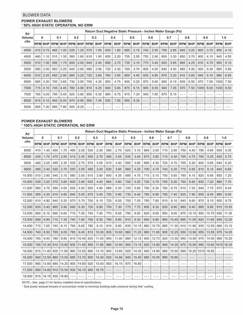
35 TON HIGH EFFICIENCY (R-410A) LCH420H41 Voltage - 60hz 460V - 3 Ph
Compressor 1 Rated Load Amps 14.8
Locked Rotor Amps 95
Compressor 2 Rated Load Amps 14.8
Locked Rotor Amps 95
Compressor 3 Rated Load Amps 14.8
Locked Rotor Amps 95
Compressor 4 Rated Load Amps 14.8
Locked Rotor Amps 95
Outdoor Fan Motors (6)
Full Load Amps 2.4
(total) (14.4)
Service Outlet 115V GFI (amps) 15
Indoor Blower Motor
Horsepower 5 7.5 10 15 20 25 30
Full Load Amps 7.6 11 14 21 27 34 35
2 Maximum Overcurrent Protection
Unit Only 100 100 100 110 125 150 150
Power Exhaust
50% Standard Static (1) 1 hp motor 100 100 100 110 125 150 150
100% Standard Static (2) 1 hp motor 100 100 110 125 125 150 150
50% High Static (1) 3 hp motor 100 100 110 125 125 150 150
100% High Static (2) 3 hp motor 100 100 110 125 125 150 150
50% High Static (1) 5 hp motor 100 110 110 125 125 150 150
100% High Static (2) 5 hp motor 110 110 110 125 150 150 175
50% High Static (1) 7.5 hp motor 110 110 110 125 125 150 175
100% High Static (2) 7.5 hp motor 125 150 150 125 150 150 175
3 Minimum Circuit Ampacity
Unit Only 87 90 93 102 109 118 125
Power Exhaust
50% Standard Static (1) 1 hp motor 89 92 95 104 111 120 128
100% Standard Static (2) 1 hp motor 91 95 98 106 114 123 130
50% High Static (1) 3 hp motor 91 95 98 106 114 123 130
100% High Static (2) 3 hp motor 96 100 103 111 119 127 135
50% High Static (1) 5 hp motor 94 98 101 109 117 125 133
100% High Static (2) 5 hp motor 102 105 108 117 124 133 140
50% High Static (1) 7.5 hp motor 98 101 104 113 120 129 136
100% High Static (2) 7.5 hp motor 109 112 115 124 131 140 147
NOTE - All units have a minimum Short Circuit Current Rating (SCCR) of 5000 amps.1 Extremes of operating range are plus and minus 10% of line voltage.2 HACR type breaker or fuse.3 Refer to National or Canadian Electrical Code manual to determine wire, fuse and disconnect size requirements.

Page 28
ELECTRICAL DATA
35 TON HIGH EFFICIENCY (R-410A) LCH420H41 Voltage - 60hz 575V - 3 Ph
Compressor 1 Rated Load Amps 12.2
Locked Rotor Amps 80
Compressor 2 Rated Load Amps 12.2
Locked Rotor Amps 80
Compressor 3 Rated Load Amps 12.2
Locked Rotor Amps 80
Compressor 4 Rated Load Amps 12.2
Locked Rotor Amps 80
Outdoor Fan Motors (6)
Full Load Amps 2
(total) (12)
Service Outlet 115V GFI (amps) 20
Indoor Blower Motor
Horsepower 5 7.5 10 15 20 25 30
Full Load Amps 6.1 9 11 17 22 27 32
2 Maximum Overcurrent Protection
Unit Only 80 80 80 100 110 110 125
Power Exhaust
50% Standard Static (1) 1 hp motor 80 80 90 100 110 110 125
100% Standard Static (2) 1 hp motor 80 90 90 100 110 125 125
50% High Static (1) 3 hp motor 80 90 90 100 110 125 125
100% High Static (2) 3 hp motor 90 90 90 100 110 125 125
50% High Static (1) 5 hp motor 80 90 90 100 110 125 125
100% High Static (2) 5 hp motor 90 90 100 110 110 125 125
50% High Static (1) 7.5 hp motor 90 90 90 100 110 125 125
100% High Static (2) 7.5 hp motor 100 100 100 110 125 125 150
3 Minimum Circuit Ampacity
Unit Only 71 74 76 84 90 96 102
Power Exhaust
50% Standard Static (1) 1 hp motor 73 76 78 86 92 98 104
100% Standard Static (2) 1 hp motor 75 78 80 88 94 100 106
50% High Static (1) 3 hp motor 75 78 80 87 94 100 106
100% High Static (2) 3 hp motor 79 82 84 91 98 104 110
50% High Static (1) 5 hp motor 78 80 82 90 96 102 108
100% High Static (2) 5 hp motor 84 87 89 96 102 108 114
50% High Static (1) 7.5 hp motor 80 83 85 93 99 105 111
100% High Static (2) 7.5 hp motor 89 92 94 102 108 114 120
NOTE - All units have a minimum Short Circuit Current Rating (SCCR) of 5000 amps.1 Extremes of operating range are plus and minus 10% of line voltage.2 HACR type breaker or fuse.3 Refer to National or Canadian Electrical Code manual to determine wire, fuse and disconnect size requirements.

Page 29
ELECTRICAL DATA
40 TON STANDARD EFFICIENCY (R-410A) LCH480S41 Voltage - 60hz 208/230V - 3 Ph
Compressor 1 Rated Load Amps 30.1
Locked Rotor Amps 225
Compressor 2 Rated Load Amps 30.1
Locked Rotor Amps 225
Compressor 3 Rated Load Amps 30.1
Locked Rotor Amps 225
Compressor 4 Rated Load Amps 30.1
Locked Rotor Amps 225
Outdoor Fan Motors (6)
Full Load Amps 3.7
(total) (22.2)
Service Outlet 115V GFI (amps) 15
Indoor Blower Motor
Horsepower 5 7.5 10 15 20 25 30
Full Load Amps 16.7 24.2 30.8 46.2 59.4 74.8 78
2 Maximum Overcurrent Protection
Unit Only 175 200 200 225 250 4 300 4 300
Power Exhaust
50% Standard Static (1) 1 hp motor 200 200 200 250 250 4 300 4 300
100% Standard Static (2) 1 hp motor 200 200 200 250 250 4 300 4 300
50% High Static (1) 3 hp motor 200 200 225 250 250 4 300 4 300
100% High Static (2) 3 hp motor 200 225 225 250 4 300 4 300 4 300
50% High Static (1) 5 hp motor 200 200 225 250 250 4 300 4 300
100% High Static (2) 5 hp motor 225 225 225 250 4 300 4 300 4 350
50% High Static (1) 7.5 hp motor 200 225 225 250 4 300 4 300 4 300
100% High Static (2) 7.5 hp motor 225 250 250 250 4 300 4 350 4 350
3 Minimum Circuit Ampacity
Unit Only 170 178 184 204 220 239 243
Power Exhaust
50% Standard Static (1) 1 hp motor 175 182 189 208 225 244 248
100% Standard Static (2) 1 hp motor 180 187 194 213 230 249 253
50% High Static (1) 3 hp motor 181 188 195 214 231 250 254
100% High Static (2) 3 hp motor 191 199 205 225 241 260 264
50% High Static (1) 5 hp motor 187 194 201 220 237 256 260
100% High Static (2) 5 hp motor 203 211 218 237 253 273 277
50% High Static (1) 7.5 hp motor 194 202 208 224 237 252 256
100% High Static (2) 7.5 hp motor 218 226 233 252 268 288 292
NOTE - All units have a minimum Short Circuit Current Rating (SCCR) of 5000 amps.1 Extremes of operating range are plus and minus 10% of line voltage.2 HACR type breaker or fuse.3 Refer to National or Canadian Electrical Code manual to determine wire, fuse and disconnect size requirements.4 Factory installed circuit breaker not available.

Page 30
ELECTRICAL DATA
40 TON STANDARD EFFICIENCY (R-410A) LCH480S41 Voltage - 60hz 460V - 3 Ph
Compressor 1 Rated Load Amps 16.7
Locked Rotor Amps 114
Compressor 2 Rated Load Amps 16.7
Locked Rotor Amps 114
Compressor 3 Rated Load Amps 16.7
Locked Rotor Amps 114
Compressor 4 Rated Load Amps 16.7
Locked Rotor Amps 114
Outdoor Fan Motors (6)
Full Load Amps 1.9
(total) (11.4)
Service Outlet 115V GFI (amps) 15
Indoor Blower Motor
Horsepower 5 7.5 10 15 20 25 30
Full Load Amps 7.6 11 14 21 27 34 35
2 Maximum Overcurrent Protection
Unit Only 100 110 110 125 125 150 150
Power Exhaust
50% Standard Static (1) 1 hp motor 110 110 110 125 125 150 150
100% Standard Static (2) 1 hp motor 110 110 110 125 125 150 150
50% High Static (1) 3 hp motor 110 110 110 125 125 150 150
100% High Static (2) 3 hp motor 110 110 110 125 125 150 150
50% High Static (1) 5 hp motor 110 110 110 125 125 150 150
100% High Static (2) 5 hp motor 110 125 125 125 150 150 150
50% High Static (1) 7.5 hp motor 110 110 125 125 150 150 150
100% High Static (2) 7.5 hp motor 125 150 150 150 150 175 175
3 Minimum Circuit Ampacity
Unit Only 92 95 98 106 114 122 124
Power Exhaust
50% Standard Static (1) 1 hp motor 94 97 100 109 116 125 126
100% Standard Static (2) 1 hp motor 96 100 103 111 118 127 128
50% High Static (1) 3 hp motor 96 100 103 111 118 127 128
100% High Static (2) 3 hp motor 101 105 108 116 123 132 133
50% High Static (1) 5 hp motor 99 103 106 114 121 130 131
100% High Static (2) 5 hp motor 107 110 113 121 129 138 139
50% High Static (1) 7.5 hp motor 103 106 109 117 125 133 135
100% High Static (2) 7.5 hp motor 114 117 120 128 136 144 146
NOTE - All units have a minimum Short Circuit Current Rating (SCCR) of 5000 amps.1 Extremes of operating range are plus and minus 10% of line voltage.2 HACR type breaker or fuse.3 Refer to National or Canadian Electrical Code manual to determine wire, fuse and disconnect size requirements.

Page 31
ELECTRICAL DATA
40 TON STANDARD EFFICIENCY (R-410A) LCH480S41 Voltage - 60hz 575V - 3 Ph
Compressor 1 Rated Load Amps 12.2
Locked Rotor Amps 80
Compressor 2 Rated Load Amps 12.2
Locked Rotor Amps 80
Compressor 3 Rated Load Amps 12.2
Locked Rotor Amps 80
Compressor 4 Rated Load Amps 12.2
Locked Rotor Amps 80
Outdoor Fan Motors (6)
Full Load Amps 1.6
(total) (9.6)
Service Outlet 115V GFI (amps) 20
Indoor Blower Motor
Horsepower 5 7.5 10 15 20 25 30
Full Load Amps 6.1 9 11 17 22 27 32
2 Maximum Overcurrent Protection
Unit Only 80 80 80 90 100 110 125
Power Exhaust
50% Standard Static (1) 1 hp motor 80 80 80 90 110 110 125
100% Standard Static (2) 1 hp motor 80 80 80 100 110 110 125
50% High Static (1) 3 hp motor 80 80 80 100 110 110 125
100% High Static (2) 3 hp motor 80 90 90 100 110 125 125
50% High Static (1) 5 hp motor 80 80 90 100 110 125 125
100% High Static (2) 5 hp motor 90 90 90 100 110 125 125
50% High Static (1) 7.5 hp motor 80 90 90 100 110 125 125
100% High Static (2) 7.5 hp motor 90 100 100 110 125 125 125
3 Minimum Circuit Ampacity
Unit Only 69 72 74 81 87 94 100
Power Exhaust
50% Standard Static (1) 1 hp motor 71 74 76 83 89 96 102
100% Standard Static (2) 1 hp motor 73 76 78 85 91 98 104
50% High Static (1) 3 hp motor 73 76 78 85 91 98 104
100% High Static (2) 3 hp motor 77 80 82 89 95 101 108
50% High Static (1) 5 hp motor 75 78 80 87 93 100 106
100% High Static (2) 5 hp motor 81 84 86 93 100 106 112
50% High Static (1) 7.5 hp motor 78 81 83 90 96 103 109
100% High Static (2) 7.5 hp motor 87 90 92 99 105 112 118
NOTE - All units have a minimum Short Circuit Current Rating (SCCR) of 5000 amps.1 Extremes of operating range are plus and minus 10% of line voltage.2 HACR type breaker or fuse.3 Refer to National or Canadian Electrical Code manual to determine wire, fuse and disconnect size requirements.

Page 32
ELECTRICAL DATA
40 TON HIGH EFFICIENCY (R-410A) LCH480H41 Voltage - 60hz 208/230V - 3 Ph
Compressor 1 Rated Load Amps 30.1
Locked Rotor Amps 225
Compressor 2 Rated Load Amps 30.1
Locked Rotor Amps 225
Compressor 3 Rated Load Amps 30.1
Locked Rotor Amps 225
Compressor 4 Rated Load Amps 30.1
Locked Rotor Amps 225
Outdoor Fan Motors (6)
Full Load Amps 4.8
(total) (28.8)
Service Outlet 115V GFI (amps) 15
Indoor Blower Motor
Horsepower 5 7.5 10 15 20 25 30
Full Load Amps 16.7 24.2 30.8 46.2 59.4 74.8 78
2 Maximum Overcurrent Protection
Unit Only 200 200 200 250 250 4 300 4 300
Power Exhaust
50% Standard Static (1) 1 hp motor 200 200 225 250 250 4 300 4 300
100% Standard Static (2) 1 hp motor 200 200 225 250 250 4 300 4 300
50% High Static (1) 3 hp motor 200 200 225 250 250 4 300 4 300
100% High Static (2) 3 hp motor 225 225 225 250 4 300 4 300 4 300
50% High Static (1) 5 hp motor 200 225 225 250 4 300 4 300 4 300
100% High Static (2) 5 hp motor 225 225 250 250 4 300 4 350 4 350
50% High Static (1) 7.5 hp motor 225 225 225 250 4 300 4 300 4 350
100% High Static (2) 7.5 hp motor 250 250 250 4 300 4 300 4 350 4 350
3 Minimum Circuit Ampacity
Unit Only 177 184 191 210 227 246 250
Power Exhaust
50% Standard Static (1) 1 hp motor 181 189 196 215 231 251 255
100% Standard Static (2) 1 hp motor 186 194 200 220 236 255 259
50% High Static (1) 3 hp motor 187 195 201 221 237 256 260
100% High Static (2) 3 hp motor 198 205 212 231 248 267 271
50% High Static (1) 5 hp motor 193 201 208 227 243 263 267
100% High Static (2) 5 hp motor 210 218 224 244 260 279 283
50% High Static (1) 7.5 hp motor 201 208 215 230 244 259 262
100% High Static (2) 7.5 hp motor 225 233 239 259 275 294 298
NOTE - All units have a minimum Short Circuit Current Rating (SCCR) of 5000 amps.1 Extremes of operating range are plus and minus 10% of line voltage.2 HACR type breaker or fuse.3 Refer to National or Canadian Electrical Code manual to determine wire, fuse and disconnect size requirements.4 Factory installed circuit breaker not available.

Page 33
ELECTRICAL DATA
40 TON HIGH EFFICIENCY (R-410A) LCH480H41 Voltage - 60hz 460V - 3 Ph
Compressor 1 Rated Load Amps 16.7
Locked Rotor Amps 114
Compressor 2 Rated Load Amps 16.7
Locked Rotor Amps 114
Compressor 3 Rated Load Amps 16.7
Locked Rotor Amps 114
Compressor 4 Rated Load Amps 16.7
Locked Rotor Amps 114
Outdoor FanMotors (6)
Full Load Amps 2.4
(total) (14.4)
Service Outlet 115V GFI (amps) 15
Indoor Blower Motor
Horsepower 5 7.5 10 15 20 25 30
Full Load Amps 7.6 11 14 21 27 34 35
2 Maximum Overcurrent Protection
Unit Only 110 110 110 125 125 150 150
Power Exhaust
50% Standard Static (1) 1 hp motor 110 110 110 125 125 150 150
100% Standard Static (2) 1 hp motor 110 110 110 125 125 150 150
50% High Static (1) 3 hp motor 110 110 110 125 125 150 150
100% High Static (2) 3 hp motor 110 110 125 125 150 150 150
50% High Static (1) 5 hp motor 110 110 110 125 150 150 150
100% High Static (2) 5 hp motor 125 125 125 125 150 150 175
50% High Static (1) 7.5 hp motor 110 125 125 125 150 150 150
100% High Static (2) 7.5 hp motor 125 125 125 150 150 175 175
3 Minimum Circuit Ampacity
Unit Only 95 98 101 109 117 125 127
Power Exhaust
50% Standard Static (1) 1 hp motor 97 100 103 112 119 128 129
100% Standard Static (2) 1 hp motor 99 103 106 114 121 130 131
50% High Static (1) 3 hp motor 99 103 106 114 121 130 131
100% High Static (2) 3 hp motor 104 108 111 119 126 135 136
50% High Static (1) 5 hp motor 102 106 109 117 124 133 134
100% High Static (2) 5 hp motor 110 113 116 124 132 141 142
50% High Static (1) 7.5 hp motor 106 109 112 120 128 136 138
100% High Static (2) 7.5 hp motor 117 120 123 131 139 147 149
NOTE - All units have a minimum Short Circuit Current Rating (SCCR) of 5000 amps.1 Extremes of operating range are plus and minus 10% of line voltage.2 HACR type breaker or fuse.3 Refer to National or Canadian Electrical Code manual to determine wire, fuse and disconnect size requirements.

Page 34
ELECTRICAL DATA
40 TON HIGH EFFICIENCY (R-410A) LCH480H41 Voltage - 60hz 575V - 3 Ph
Compressor 1 Rated Load Amps 12.2
Locked Rotor Amps 80
Compressor 2 Rated Load Amps 12.2
Locked Rotor Amps 80
Compressor 3 Rated Load Amps 12.2
Locked Rotor Amps 80
Compressor 4 Rated Load Amps 12.2
Locked Rotor Amps 80
Outdoor Fan Motors (6)
Full Load Amps 2
(total) (12)
Service Outlet 115V GFI (amps) 20
Indoor Blower Motor
Horsepower 5 7.5 10 15 20 25 30
Full Load Amps 6.1 9 11 17 22 27 32
2 Maximum Overcurrent Protection
Unit Only 80 80 80 100 110 110 125
Power Exhaust
50% Standard Static (1) 1 hp motor 80 80 90 100 110 110 125
100% Standard Static (2) 1 hp motor 80 90 90 100 110 125 125
50% High Static (1) 3 hp motor 80 90 90 100 110 125 125
100% High Static (2) 3 hp motor 90 90 90 100 110 125 125
50% High Static (1) 5 hp motor 80 90 90 100 110 125 125
100% High Static (2) 5 hp motor 90 90 100 110 110 125 125
50% High Static (1) 7.5 hp motor 90 90 90 100 110 125 125
100% High Static (2) 7.5 hp motor 100 100 100 110 125 125 150
3 Minimum Circuit Ampacity
Unit Only 71 74 76 84 90 96 102
Power Exhaust
50% Standard Static (1) 1 hp motor 73 76 78 86 92 98 104
100% Standard Static (2) 1 hp motor 75 78 80 88 94 100 106
50% High Static (1) 3 hp motor 75 78 80 87 94 100 106
100% High Static (2) 3 hp motor 79 82 84 91 98 104 110
50% High Static (1) 5 hp motor 78 80 82 90 96 102 108
100% High Static (2) 5 hp motor 84 87 89 96 102 108 114
50% High Static (1) 7.5 hp motor 80 83 85 93 99 105 111
100% High Static (2) 7.5 hp motor 89 92 94 102 108 114 120
NOTE - All units have a minimum Short Circuit Current Rating (SCCR) of 5000 amps.1 Extremes of operating range are plus and minus 10% of line voltage.2 HACR type breaker or fuse.3 Refer to National or Canadian Electrical Code manual to determine wire, fuse and disconnect size requirements.

Page 35
ELECTRICAL DATA
45 TON STANDARD EFFICIENCY (R-410A) LCH540S41 Voltage - 60hz 208/230V - 3 Ph
Compressor 1 Rated Load Amps 33.3
Locked Rotor Amps 239
Compressor 2 Rated Load Amps 33.3
Locked Rotor Amps 239
Compressor 3 Rated Load Amps 33.3
Locked Rotor Amps 239
Compressor 4 Rated Load Amps 33.3
Locked Rotor Amps 239
Outdoor Fan Motors (6)
Full Load Amps 3.7
(total) (22.2)
Service Outlet 115V GFI (amps) 15
Indoor Blower Motor
Horsepower 5 7.5 10 15 20 25 30
Full Load Amps 16.7 24.2 30.8 46.2 59.4 74.8 78
2 Maximum Overcurrent Protection
Unit Only 200 200 225 250 250 4 300 4 300
Power Exhaust
50% Standard Static (1) 1 hp motor 200 225 225 250 250 4 300 4 300
100% Standard Static (2) 1 hp motor 225 225 225 250 4 300 4 300 4 300
50% High Static (1) 3 hp motor 225 225 225 250 4 300 4 300 4 300
100% High Static (2) 3 hp motor 225 225 250 250 4 300 4 300 4 350
50% High Static (1) 5 hp motor 225 225 225 250 4 300 4 300 4 350
100% High Static (2) 5 hp motor 225 250 250 4 300 4 300 4 350 4 350
50% High Static (1) 7.5 hp motor 225 225 250 250 4 300 4 350 4 350
100% High Static (2) 7.5 hp motor 250 250 250 4 300 4 300 4 350 4 350
3 Minimum Circuit Ampacity
Unit Only 184 191 198 216 233 252 256
Power Exhaust
50% Standard Static (1) 1 hp motor 188 196 203 221 238 257 261
100% Standard Static (2) 1 hp motor 193 201 207 226 242 262 266
50% High Static (1) 3 hp motor 194 202 208 227 243 263 267
100% High Static (2) 3 hp motor 205 212 219 238 254 273 277
50% High Static (1) 5 hp motor 200 208 214 233 250 269 273
100% High Static (2) 5 hp motor 217 225 231 250 266 285 289
50% High Static (1) 7.5 hp motor 208 215 222 237 251 266 269
100% High Static (2) 7.5 hp motor 232 240 246 265 281 300 304
NOTE - All units have a minimum Short Circuit Current Rating (SCCR) of 5000 amps.1 Extremes of operating range are plus and minus 10% of line voltage.2 HACR type breaker or fuse.3 Refer to National or Canadian Electrical Code manual to determine wire, fuse and disconnect size requirements.4 Factory installed circuit breaker not available.

Page 36
ELECTRICAL DATA
45 TON STANDARD EFFICIENCY (R-410A) LCH540S41 Voltage - 60hz 460V - 3 Ph
Compressor 1 Rated Load Amps 17.9
Locked Rotor Amps 125
Compressor 2 Rated Load Amps 17.9
Locked Rotor Amps 125
Compressor 3 Rated Load Amps 17.9
Locked Rotor Amps 125
Compressor 4 Rated Load Amps 17.9
Locked Rotor Amps 125
Outdoor Fan Motors (6)
Full Load Amps 1.9
(total) (11.4)
Service Outlet 115V GFI (amps) 15
Indoor Blower Motor
Horsepower 5 7.5 10 15 20 25 30
Full Load Amps 7.6 11 14 21 27 34 35
2 Maximum Overcurrent Protection
Unit Only 110 110 110 125 125 150 150
Power Exhaust
50% Standard Static (1) 1 hp motor 110 110 110 125 125 150 150
100% Standard Static (2) 1 hp motor 110 110 125 125 125 150 150
50% High Static (1) 3 hp motor 110 110 125 125 125 150 150
100% High Static (2) 3 hp motor 110 125 125 125 150 150 150
50% High Static (1) 5 hp motor 110 125 125 125 150 150 150
100% High Static (2) 5 hp motor 125 125 125 150 150 175 175
50% High Static (1) 7.5 hp motor 125 125 125 125 150 150 150
100% High Static (2) 7.5 hp motor 125 125 125 150 150 175 175
3 Minimum Circuit Ampacity
Unit Only 97 100 103 111 118 127 128
Power Exhaust
50% Standard Static (1) 1 hp motor 99 103 106 113 121 130 131
100% Standard Static (2) 1 hp motor 102 105 108 116 123 132 133
50% High Static (1) 3 hp motor 102 105 108 116 123 132 133
100% High Static (2) 3 hp motor 106 110 113 121 128 137 138
50% High Static (1) 5 hp motor 104 108 111 119 126 135 136
100% High Static (2) 5 hp motor 112 115 118 126 134 142 144
50% High Static (1) 7.5 hp motor 108 111 114 122 129 138 139
100% High Static (2) 7.5 hp motor 119 122 125 133 140 149 150
NOTE - All units have a minimum Short Circuit Current Rating (SCCR) of 5000 amps.1 Extremes of operating range are plus and minus 10% of line voltage.2 HACR type breaker or fuse.3 Refer to National or Canadian Electrical Code manual to determine wire, fuse and disconnect size requirements.

Page 37
ELECTRICAL DATA
45 TON STANDARD EFFICIENCY (R-410A) LCH540S41 Voltage - 60hz 575V - 3 Ph
Compressor 1 Rated Load Amps 12.8
Locked Rotor Amps 80
Compressor 2 Rated Load Amps 12.8
Locked Rotor Amps 80
Compressor 3 Rated Load Amps 12.8
Locked Rotor Amps 80
Compressor 4 Rated Load Amps 12.8
Locked Rotor Amps 80
Outdoor Fan Motors (6)
Full Load Amps 1.6
(total) (9.6)
Service Outlet 115V GFI (amps) 20
Indoor Blower Motor
Horsepower 5 7.5 10 15 20 25 30
Full Load Amps 6.1 9 11 17 22 27 32
2 Maximum Overcurrent Protection
Unit Only 80 80 80 100 110 110 125
Power Exhaust
50% Standard Static (1) 1 hp motor 80 80 90 100 110 110 125
100% Standard Static (2) 1 hp motor 80 90 90 100 110 125 125
50% High Static (1) 3 hp motor 80 90 90 100 110 125 125
100% High Static (2) 3 hp motor 90 90 90 100 110 125 125
50% High Static (1) 5 hp motor 90 90 90 100 110 125 125
100% High Static (2) 5 hp motor 90 90 100 110 110 125 125
50% High Static (1) 7.5 hp motor 90 90 90 100 110 125 125
100% High Static (2) 7.5 hp motor 100 100 100 110 125 125 150
3 Minimum Circuit Ampacity
Unit Only 72 74 76 84 90 96 102
Power Exhaust
50% Standard Static (1) 1 hp motor 74 76 78 86 92 98 104
100% Standard Static (2) 1 hp motor 76 78 80 88 94 100 106
50% High Static (1) 3 hp motor 75 78 80 87 94 100 106
100% High Static (2) 3 hp motor 79 82 84 91 98 104 110
50% High Static (1) 5 hp motor 78 81 83 90 96 102 108
100% High Static (2) 5 hp motor 84 87 89 96 102 108 114
50% High Static (1) 7.5 hp motor 81 83 85 93 99 105 111
100% High Static (2) 7.5 hp motor 90 92 94 102 108 114 120
NOTE - All units have a minimum Short Circuit Current Rating (SCCR) of 5000 amps.1 Extremes of operating range are plus and minus 10% of line voltage.2 HACR type breaker or fuse.3 Refer to National or Canadian Electrical Code manual to determine wire, fuse and disconnect size requirements.

Page 38
ELECTRICAL DATA
50 TON STANDARD EFFICIENCY (R-410A) LCH600S41 Voltage - 60hz 208/230V - 3 Ph
Compressor 1 Rated Load Amps 48.1
Locked Rotor Amps 245
Compressor 2 Rated Load Amps 48.1
Locked Rotor Amps 245
Compressor 3 Rated Load Amps 48.1
Locked Rotor Amps 245
Compressor 4 Rated Load Amps 48.1
Locked Rotor Amps 245
Outdoor Fan Motors (6)
Full Load Amps 4.8
(total) (28.8)
Service Outlet 115V GFI (amps) 15
Indoor Blower Motor
Horsepower 5 7.5 10 15 20 25 30
Full Load Amps 16.7 24.2 30.8 46.2 59.4 74.8 78
2 Maximum Overcurrent Protection
Unit Only 4 300 4 300 4 300 4 300 4 350 4 350 4 350
Power Exhaust
50% Standard Static (1) 1 hp motor 4 300 4 300 4 300 4 300 4 350 4 350 4 400
100% Standard Static (2) 1 hp motor 4 300 4 300 4 300 4 300 4 350 4 400 4 400
50% High Static (1) 3 hp motor 4 300 4 300 4 300 4 300 4 350 4 400 4 400
100% High Static (2) 3 hp motor 4 300 4 300 4 300 4 350 4 350 4 400 4 400
50% High Static (1) 5 hp motor 4 300 4 300 4 300 4 300 4 350 4 400 4 400
100% High Static (2) 5 hp motor 4 300 4 300 4 350 4 350 4 350 4 400 4 400
50% High Static (1) 7.5 hp motor 4 300 4 300 4 300 4 350 4 350 4 400 4 400
100% High Static (2) 7.5 hp motor 4 350 4 350 4 350 4 350 4 400 4 400 4 400
3 Minimum Circuit Ampacity
Unit Only 253 260 267 282 298 317 321
Power Exhaust
50% Standard Static (1) 1 hp motor 258 265 272 287 303 322 326
100% Standard Static (2) 1 hp motor 262 270 276 292 308 327 331
50% High Static (1) 3 hp motor 263 271 277 293 309 328 332
100% High Static (2) 3 hp motor 274 281 288 303 319 339 343
50% High Static (1) 5 hp motor 269 277 284 299 315 334 338
100% High Static (2) 5 hp motor 286 294 300 316 332 351 355
50% High Static (1) 7.5 hp motor 277 284 291 306 320 335 338
100% High Static (2) 7.5 hp motor 301 309 315 331 347 366 370
NOTE - All units have a minimum Short Circuit Current Rating (SCCR) of 5000 amps.1 Extremes of operating range are plus and minus 10% of line voltage.2 HACR type breaker or fuse.3 Refer to National or Canadian Electrical Code manual to determine wire, fuse and disconnect size requirements.4 Factory installed circuit breaker not available.

Page 39
ELECTRICAL DATA
50 TON STANDARD EFFICIENCY (R-410A) LCH600S41 Voltage - 60hz 460V - 3 Ph
Compressor 1 Rated Load Amps 18.6
Locked Rotor Amps 125
Compressor 2 Rated Load Amps 18.6
Locked Rotor Amps 125
Compressor 3 Rated Load Amps 18.6
Locked Rotor Amps 125
Compressor 4 Rated Load Amps 18.6
Locked Rotor Amps 125
Outdoor Fan Motors (6)
Full Load Amps 2.4
(total) (14.4)
Service Outlet 115V GFI (amps) 15
Indoor Blower Motor
Horsepower 5 7.5 10 15 20 25 30
Full Load Amps 7.6 11 14 21 27 34 35
2 Maximum Overcurrent Protection
Unit Only 110 110 125 125 150 150 150
Power Exhaust
50% Standard Static (1) 1 hp motor 110 125 125 125 150 150 150
100% Standard Static (2) 1 hp motor 125 125 125 125 150 150 150
50% High Static (1) 3 hp motor 125 125 125 125 150 150 150
100% High Static (2) 3 hp motor 125 125 125 150 150 175 175
50% High Static (1) 5 hp motor 125 125 125 125 150 150 175
100% High Static (2) 5 hp motor 125 125 125 150 150 175 175
50% High Static (1) 7.5 hp motor 125 125 125 150 150 175 175
100% High Static (2) 7.5 hp motor 125 150 150 150 150 175 175
3 Minimum Circuit Ampacity
Unit Only 103 106 109 117 124 133 134
Power Exhaust
50% Standard Static (1) 1 hp motor 105 109 112 119 127 135 137
100% Standard Static (2) 1 hp motor 108 111 114 122 129 138 139
50% High Static (1) 3 hp motor 108 111 114 122 129 138 139
100% High Static (2) 3 hp motor 112 116 119 126 134 143 144
50% High Static (1) 5 hp motor 110 114 117 124 132 141 142
100% High Static (2) 5 hp motor 118 121 124 132 139 148 149
50% High Static (1) 7.5 hp motor 114 117 120 128 135 144 145
100% High Static (2) 7.5 hp motor 125 128 131 139 146 155 156
NOTE - All units have a minimum Short Circuit Current Rating (SCCR) of 5000 amps.1 Extremes of operating range are plus and minus 10% of line voltage.2 HACR type breaker or fuse.3 Refer to National or Canadian Electrical Code manual to determine wire, fuse and disconnect size requirements.

Page 40
ELECTRICAL DATA
50 TON STANDARD EFFICIENCY (R-410A) LCH600S41 Voltage - 60hz 575V - 3 Ph
Compressor 1 Rated Load Amps 14.8
Locked Rotor Amps 100
Compressor 2 Rated Load Amps 14.8
Locked Rotor Amps 100
Compressor 3 Rated Load Amps 14.8
Locked Rotor Amps 100
Compressor 4 Rated Load Amps 14.8
Locked Rotor Amps 100
Outdoor Fan Motors (6)
Full Load Amps 2
(total) (12)
Service Outlet 115V GFI (amps) 20
Indoor Blower Motor
Horsepower 5 7.5 10 15 20 25 30
Full Load Amps 6.1 9 11 17 22 27 32
2 Maximum Overcurrent Protection
Unit Only 90 90 100 110 110 125 125
Power Exhaust
50% Standard Static (1) 1 hp motor 90 100 100 110 110 125 125
100% Standard Static (2) 1 hp motor 100 100 100 110 125 125 125
50% High Static (1) 3 hp motor 100 100 100 110 125 125 125
100% High Static (2) 3 hp motor 100 100 100 110 125 125 150
50% High Static (1) 5 hp motor 100 100 100 110 125 125 150
100% High Static (2) 5 hp motor 100 110 110 110 125 125 150
50% High Static (1) 7.5 hp motor 100 100 110 110 125 125 150
100% High Static (2) 7.5 hp motor 110 110 110 125 125 150 150
3 Minimum Circuit Ampacity
Unit Only 82 85 87 94 100 106 113
Power Exhaust
50% Standard Static (1) 1 hp motor 84 87 89 96 102 108 115
100% Standard Static (2) 1 hp motor 86 89 91 98 104 110 117
50% High Static (1) 3 hp motor 86 89 91 98 104 110 117
100% High Static (2) 3 hp motor 90 93 95 102 108 114 120
50% High Static (1) 5 hp motor 89 91 93 100 106 113 119
100% High Static (2) 5 hp motor 95 98 100 106 112 119 125
50% High Static (1) 7.5 hp motor 91 94 96 103 109 115 122
100% High Static (2) 7.5 hp motor 100 103 105 112 118 124 131
NOTE - All units have a minimum Short Circuit Current Rating (SCCR) of 5000 amps.1 Extremes of operating range are plus and minus 10% of line voltage.2 HACR type breaker or fuse.3 Refer to National or Canadian Electrical Code manual to determine wire, fuse and disconnect size requirements.

Page 41
ELECTRICAL DATAOPTIONAL ACCESSORIES
208/230V - 3 Ph
Optional Power Exhaust
Static Type Standard 50%
Standard 100%
High 50%
High 100%
High 50%
High 100%
High 50%
High 100%
Motor hp 1 1 3 3 5 5 7.5 7.5
Number of Motors 1 2 1 2 1 2 1 2
Full load amps total 4.8 9.6 10.6 21.2 16.7 33.4 24.2 48.4
Locked rotor amps total 23 46 66 132 105 210 152 304
Optional Energy Recovery Wheel (ERW)
(No.) hp (1) 1/4
Full load amps 2.3
460V - 3 Ph
Optional Power Exhaust
Static Type Standard 50%
Standard 100%
High 50%
High 100%
High 50%
High 100%
High 50%
High 100%
Motor hp 1 1 3 3 5 5 7.5 7.5
Number of Motors 1 2 1 2 1 2 1 2
Full load amps total 2.4 4.8 4.8 9.6 7.6 15.2 11.0 22.0
Locked rotor amps total 11.5 23 26.8 53.6 45.6 91.2 66.0 132.0
Optional Energy Recovery Wheel (ERW)
(No.) hp (1) 1/4
Full load amps 1.2
575V - 3 Ph
Optional Power Exhaust
Static Type Standard 50%
Standard 100%
High 50%
High 100%
High 50%
High 100%
High 50%
High 100%
Motor hp 1 1 3 3 5 5 7.5 7.5
Number of Motors 1 2 1 2 1 2 1 2
Full load amps total 2 4 3.9 7.8 6.1 12.2 9 18
Locked rotor amps total 8.9 17.8 23.4 46.8 36.6 73.2 54 108
Optional Energy Recovery Wheel (ERW)
(No.) hp (1) 1/4
Full load amps 1.0

Page 42
ELECTRIC HEAT ELECTRICAL DATA
Electric Heat Size
(kW)
208/230V-3 phase 460V-3 phase 575V-3 phase
Rated Amps
Minimum Circuit
Ampacity
Maximum Overcurrent Protection
(amps)
Rated Amps
Minimum Circuit
Ampacity
Maximum Overcurrent Protection
(amps)
Rated Amps
Minimum Circuit
Ampacity
Maximum Overcurrent Protection
(amps)30 72.2 91 100 36.1 46 50 28.9 37 4045 108.3 136 150 54.1 68 70 43.3 55 6060 144.3 145 150 72.2 73 80 57.7 58 6075 180.4 181 200 90.2 91 100 72.2 73 8090 216.5 217 225 108.3 109 110 86.6 87 90
105 - - - - - - - - - 126.3 127 150 101.0 101 110120 - - - - - - - - - 144.3 145 150 115.5 116 125135 - - - - - - - - - 162.4 163 175 129.9 130 150150 - - - - - - - - - 180.4 181 200 144.3 145 150165 - - - - - - - - - 198.5 199 200 158.8 159 175180 - - - - - - - - - 216.5 217 225 173.2 174 175
NOTE - All units have a minimum Short Circuit Current Rating (SCCR) of 5000 amps.
ELECTRIC HEAT MATCHES 35 ton units - 30-45-60-75-90 kW (all voltages)35 ton units - 105-120 kW (460V & 575V only)40 ton units - 30-45-60-75-90 kW (all voltages)40 ton units - 105-120-135-150 kW (460V & 575V only)45 ton units - 45-60-75-90 kW (all voltages)45 ton units - 105-120-135-150-165 kW (460V & 575V only)50 ton units - 45-60-75-90 kW (all voltages)50 ton units - 105-120-135-150-165-180 kW (460V & 575V only)
ELECTRIC HEAT CAPACITIES
Volts Input
30 kW 45 kW 60 kW 75 kW 90 kW 105 kW
kW Input
Btuh Output
No. of
Steps
kW Input
Btuh Output
No. of
Steps
kW Input
Btuh Output
No. of
Steps
kW Input
Btuh Output
No. of
Steps
kW Input
Btuh Output
No. of
Steps
kW Input
Btuh Output
No. of
Steps208 22.5 76,800 1 33.8 115,300 2 45.0 153,600 2 56.3 192,100 3 67.6 230,700 3 - - - - - - - - -220 25.2 86,000 1 37.8 129,000 2 50.4 172,000 2 63.0 215,000 3 75.6 258,000 3 - - - - - - - - -230 27.5 93,900 1 41.3 141,000 2 55.1 188,000 2 68.9 235,100 3 82.7 282,200 3 - - - - - - - - -240 30.0 102,400 1 45.0 153,600 2 60.0 204,800 2 75.0 255,900 3 90.0 307,100 3 - - - - - - - - -440 25.2 86,000 1 37.8 129,000 2 50.4 172,000 2 63.0 215,000 3 75.6 258,000 3 88.2 301,000 4460 27.5 93,900 1 41.3 141,000 2 55.1 188,000 2 68.9 235,100 3 82.7 282,200 3 96.4 329,000 4480 30.0 102,400 1 45.0 153,600 2 60.0 204,800 2 75.0 255,900 3 90.0 307,100 3 105.0 358,300 4550 25.2 86,000 1 37.8 129,000 2 50.4 172,000 2 63.0 215,000 3 75.6 258,000 3 88.2 301,000 4575 27.5 93,900 1 41.3 141,000 2 55.1 188,000 2 68.9 235,100 3 82.7 282,200 3 96.4 329,000 4600 30.0 102,400 1 45.0 153,600 2 60.0 204,800 2 75.0 255,900 3 90.0 307,100 3 105.0 358,300 4
ELECTRIC HEAT CAPACITIES
Volts Input
120 kW 135 kW 150 kW 165 kW 180 kWkW
InputBtuh
OutputNo. of Steps
kW Input
Btuh Output
No. of Steps
kW Input
Btuh Output
No. of Steps
kW Input
Btuh Output
No. of Steps
kW Input
Btuh Output
No. of Steps
440 100.8 344,000 4 113.4 386,900 4 126.0 430,000 4 138.6 473,000 4 151.2 516,000 4460 110.2 376,100 4 124.0 423,100 4 137.7 469,900 4 151.5 517,000 4 165.2 563,700 4480 120.0 409,500 4 135.0 460,700 4 150.0 511,900 4 165.0 563,100 4 180.0 614,200 4550 100.8 344,000 4 113.4 386,900 4 126.0 430,000 4 138.6 473,000 4 151.2 516,000 4575 110.2 376,100 4 124.0 423,100 4 137.7 469,900 4 151.5 517,000 4 165.2 563,700 4600 120.0 409,500 4 135.0 460,700 4 150.0 511,900 4 165.0 563,100 4 180.0 614,200 4

Page 43
BLOWER DRIVE COMPONENT MANUFACTURER'S NUMBERS
DriveNo.
DRIVE COMPONENTS
MOTOR PULLEY BLOWER PULLEY BLOWER BUSHING BELTS
OEM Part No. Browning No. OEM Part No. Browning No. OEM Part No. Browning No.OEM Part
No. Browning No.
1 P-8-2237 1VP62 X 1-1/8 78M9001 1B5V160 79M0601 B - 1-11/16 78M6401 5VX900
2 100239-03 1VP65 X 1-1/8 78M8901 1B5V154 79M0601 B - 1-11/16 78M6401 5VX900
3 78M7101 1VP65 X 1-3/8 78M9001 1B5V160 79M0601 B - 1-11/16 78M6401 5VX900
4 78M7001 1VP62 X 1-3/8 78M8701 1B5V124 79M0601 B - 1-11/16 78M5901 5VX830
5 78M5601 1VP71 X 1-3/8 78M8901 1B5V154 79M0601 B - 1-11/16 78M6401 5VX900
6 78L5601 1VP71 X 1-3/8 78M8801 1B5V136 79M0601 B - 1-11/16 78M6201 5VX860
7 78M7201 1VP62 X 1-5/8 78M8801 1B5V136 79M0601 B - 1-11/16 78M6001 5VX840
8 78M7401 1VP75 X 1-5/8 78M8701 1B5V124 79M0601 B - 1-11/16 78M5901 5VX830
9 78M7501 2VP71 X 1-5/8 79M0001 2B5V124 79M0601 B - 1-11/16 78M5901 5VX830
10 78M7601 2VP75 X 1-5/8 78M9901 2B5V110 79M0601 B - 1-11/16 78M5701 5VX800
11 78L7701 2V58B70 X 1-7/8 79M0001 2B5V124 79M0601 B - 1-11/16 78M5801 5VX810
12 78M7801 2V68B80 X 1-7/8 79M0001 2B5V124 79M0601 B - 1-11/16 78M5901 5VX830
13 78M7701 2V58B70 X 1-7/8 78M9901 2B5V110 79M0601 B - 1-11/16 78M5701 5VX800
14 78M7701 2V58B70 X 1-7/8 79M0201 2Q5V103 79M0801 Q - 1-11/16 78M5601 5VX780
POWER EXHAUST DRIVE COMPONENT MANUFACTURER'S NUMBERS
Drive No.
DRIVE COMPONENTS
MOTOR PULLEY BLOWER PULLEY BELTS
Browning No. OEM Part No. Browning No. OEM Part No.Browning
No. OEM Part No.
1A 1VP60 x 1 3/8 78L5501 BK100 x 1 7/16 39L1301 BX68 88K3401
1B 1VP60 x 1 3/8 78L5501 BK100 x 1 7/16 39L1301 BX62 57A7701
2A 1VP60 x 1 3/8 78L5501 BK110 x 1 7/16 81M0401 BX70 31K9601
2B 1VP60 x 1 3/8 78L5501 BK110 x 1 7/16 81M0401 BX64 24L5001
3A 1VP56 x 1 1/8 P-8-1492 BK100 x 1 7/16 39L1301 BX68 88K3401
3B 1VP56 x 1 1/8 P-8-1492 BK100 x 1 7/16 39L1301 BX61 93J9801
4A 1VP60 x 1 1/8 41C1301 BK115 x 1 7/16 81M0501 BX71 31K9701
4B 1VP60 x 1 1/8 41C1301 BK115 x 1 7/16 81M0501 BX64 24L5001
5A 1VP56 x 7/8 P-8-1494 BK115 x 1 7/16 81M0501 BX71 31K9701
5B 1VP56 x 7/8 P-8-1494 BK115 x 1 7/16 81M0501 BX64 24L5001
6A 1VP60 x 7/8 80K5501 BK115 x 1 7/16 81M0501 BX71 31K9701
6B 1VP60 x 7/8 80K5501 BK115 x 1 7/16 81M0501 BX64 24L5001
NOTE - A drives for rear blower assembly; B drives for front blower assembly.

Pag
e 4
4
LGH/LCH PARTS ARRANGEMENT
FIGURE 1
HEAT RECOVERY WHEEL(optional) ECONOMIZER
(optional)FILTERS
(eleven 16 x 25 x 2" OR16 x 25 x 4"
BLOWERS
OUTDOORFANS (6)
POWER EXHAUSTDISCHARGE
(optional)
EVAPORATORCOIL
HUMIDITROL COIL(optional)
BURNERS(LGH) GAS
VALVE 2(LGH) CONDENSER
COIL
CONTROLBOX
COMPRESSORS(4)
CONDENSATEDRAIN
FILTERDRIER
LOUVERS(optional)

LGH/LCH CONTROL BOX PARTS ARRANGEMENT
FIGURE 2
K149
K150
K152
K153
F10
TB47
K3
K199 K201
TB40 TB41
K1 K2 K14 K146S42
T1
T18
TB24
TB18
TB3
C1 C2
C20
C18 C19
C21
A55 - UNIT CONTROLLER
C1 - CAP. OUTDOOR FAN 1
C2 - CAP. OUTDOOR FAN 2
C18 - CAP. OUTDOOR FAN 3
C19 - CAP. OUTDOOR FAN 4
C20 - CAP. OUTDOOR FAN 5
C21 - CAP. OUTDOOR FAN 6
F10 - FUSE OUTDOOR FAN MOTOR
K1 - CONTACTOR COMPRESSOR 1
K2 - CONTACTOR COMPRESSOR 2
K3 - BLOWER CONTACTOR
K10 - RELAY OUTDOOR FAN 1
K14 - CONTACTOR COMPRESSOR 3
K68 - RELAY OUTDOOR FAN 2
K146 - CONTACTOR COMPRESSOR 4
K149 - RELAY OUTDOOR FAN 3
K150 - RELAY OUTDOOR FAN 4
K152 - RELAY OUTDOOR FAN 5
K153 - RELAY OUTDOOR FAN
K199 - CONTACTOR EXHAUST BLOWER 1
K201 - CONTACTOR EXHAUST BLOWER 2
T1 - TRANSFORMER CONTROL
T18 - TRANSFORMER CONTACTOR
TB18 - TERMINAL STRIP INVERTER
A55
F37 F38
F38 - FUSE (Y VOLTAGE)
F37 - FUSE (Y VOLTAGE)
S42 - BLOWER OVERLOAD RELAY
T43
TB13
T43 - TRANSFORMER HUMIDITROL
TB40 - TERMINAL STRIP COMP 1
TB41 - TERMINAL STRIP COMP 2
TB47 - TERMINAL STRIP EXHAUST FANS
K50 - RELAY DESICCANT WHEEL
K61 - RELAY DESICCANT WHEEL
K94 - RELAY DESICCANT WHEEL
K203 - RELAY INVERTER BLOWER
K207 - RELAY INVERTER EXHAUST BLOWER
TB3 - TERMINAL BLOCK ELECTRIC HEAT
TB13 - TERMINAL BLOCK SUB-FUSE
TB24 - TERMINAL STRIP COMMON
K203
K94
K50
K61
K68
K10
K207
DL43
DL43 - DELAY, CYCLE TIMER
Pag
e 4
5
A178 - C3 CONTROLLER
A187 - GENERAL PURPOSE
A178A178

Page 46
I-UNIT COMPONENTS
CAUTIONElectrostatic discharge can affect electronic components. Take precautions during installation andservice to protect the unit's electronic controls.Precautions will help to avoid control exposure toelectrostatic discharge by putting the unit, thecontrol and the technician at the same electrostatic potential. Neutralize electrostatic charge bytouching hand and all tools on an unpainted unitsurface, such as the gas valve or blower deck, before performing any service procedure.
ELECTROSTATIC DISCHARGE (ESD)
Precautions and Procedures
LGH/LCH units are configure to order units (CTO). All units
come standard with hinged unit panels. The unit panels may
be held open with the door rod located inside the unit.
A-Control Box Components
Control box components are shown in figure 2, The control
box is located above the compressor compartment.
1-Disconnect Switch S48
All units may be equipped with an optional disconnect switch
S48. S48 is a switch which can be used by the service techni
cian to disconnect power to the unit.
NOTE - S48 is not an over current protection switch. If
unit is equipped with S48 other means of over current
protection must be used.
2-Control Transformer T1
All units use a T1 line voltage to 24VAC transformer
mounted in the control box. Transformer supplies power
to control circuits in the unit. The transformer is rated at
90VA and is protected by a 6 amp circuit breaker (CB8).
The 208/230 (Y) voltage transformer has two primary
voltage taps as shown
in figure 3. Units will be
factory wired for 230V
(orange and black).
208V (red and black)
applications must be
re-wired in the field.
3-Contactor Transformer T18
T18 is a single line voltage to 24VAC transformer used in
all units. Transformer T18 is rated at 90VA and protected
by a 6 amp circuit breaker (CB18). The transformer supplies
24VAC power to the contactors.
4-Humiditrol Transformer T43T43 is a single line voltage to 24VAC transformer used on op
tional Humiditrol units. Transformer T43 is rated at 70VA and
is protected by a 3.5 amp circuit breaker (CB8). The trans
former supplies 24VAC power to the reheat solenoid valves.
5-Terminal Strips TB18 and TB24TB18 is used any time power exhaust or modulating gas
heat is installed in the unit. It is also used in VAV applica
tions. TB24 is common on all units. See unit wiring diagram.
6-Terminal Blocks TB2, TB13, TB25, TB40,TB41 and TB47
All L1, L2 and L3 wiring is color coded; L1 is red, L2 is yellow
and L3 is blue. TB40 distributes line voltage to compressor
B1 through contactors K1 and to inverter A96 . TB40 also
distributes line voltage to optional power exhaust blowers
B35, B36 through contactors K199, K201. TB41 distributes
line voltage to compressors B2, B13 and B20 through con
tactors K2, K14 and K146. TB47 distributes line voltage to
condenser fans B4, B5, B21, B22, B23 and B24 through re
lays K10, K68, K149, K150, K152 and K153. TB2 and TB13
are single point power installations only and distribute line
voltage power to unit line voltage components. TB25 distrib
utes line voltage power to the blower motor B3. See unit
wiring diagram.
7-Outdoor Fan Motor Fuse Block & Fuses F10(all units)
Three line voltage, F10 fuses provide overcurrent protec
tion to all condenser fans in all units. The fuses are rated at
40A in three phase, 208/230V applications. All others use
30A fuses.
8-Fuses F37 and F38 (Y volt and G, J volt withelectric heat)
Three line voltage fuses F37 provide overcurrent protection for
compressor B1, blower B3 and optional exhaust blower B35
and B36. Three line voltage fuses F38 provide overcurrent pro
tection for compressor B2, B13 and B20.
9-Outdoor Fan Capacitors C1, C2, C18, C19,C20, C21 (single phase motors only)
Fan capacitors C1, C2, C18, C19, C20 and C21 are used to
assist in the start up of condenser fans B4, B5, B21, B22, B23
and B24 respectively. Ratings will be on condenser fan motor
nameplate or see side of capacitor.
FIGURE 3
BLUE YELLOW
ORANGE
RED
BLACK
230 VOLTS
208 VOLTS
PRIMARY
SECONDARY
208/230V TRANSFORMER

Page 47
10-Compressor Contactor K1, K2, K14 & K146All compressor contactors are three-pole double-break
contactors with a 24VAC coil. In all LGH/LCH units, K1
(energized by A55), K2 (energized by A55), K14 (ener
gized by A178) and K146 (energized by A178) controls
compressors B1, B2, B13 and B20 respectively in re
sponse to cooling demands.
11-Blower Bypass Contactors K3 & K202
Blower contactors K3 and K202, used in bypass units, are
three-pole double-break contactors with a 24VAC coil used
to energize the indoor blower motor B3 in response to blow
er demand. K202 or K3 is energized by A55 Unit Controller.
12-Outdoor Fan Relay K10, K68, K149, K150,K152, K153 (all units)
Outdoor fan relays K10, K68, K149, K150, K152 and K153
are DPDT in single phase units and 3PDT in three phase
units. All have 24VAC coils. In all units, K10 (energized by
A55), K68 (energized by A55), K149, K150, K152 and K153
(energized by A178) controls condenser fans B4 (fan 1), B5
(fan 2), B21 (fan 3), B22 (fan 4), B23 (fan 5) and B24 (fan 6)
respectively, in response to cooling demand.
13-Burner Controls A3 & A12 (LGH units)
All LGH units have two burner controls. A3 controls gas heat
section one, while A12 controls gas heat section two. The
first gas heat section and the second gas heat section burn
er controls are identical. Both burner controls are factory set
and are not adjustable. The control makes three attempts at
ignition and then locks out the system if ignition is not ob
tained after the third trial. Reset after lockout requires only
breaking and remaking thermostat demand. The control
shuts off gas flow immediately in the event of a gas or power
failure. Upon restoration of gas and power, the control will
restart the ignition sequence and continue until flame is es
tablished or system locks out. For a more detailed descrip
tion see the Gas Heat Components section.
14-Power Exhaust Contactors K199 & K201
Contactors K199 and K201 are N.O. DPDT contactors with
a 24VAC coil. K199, K201 are used in all units equipped with
optional power exhaust less inverters. When K199 and
K201 close, the exhaust blowers B35 and B36 are ener
gized.
15-Blower Motor Overload Relay S42Relay S42 is located in the control box and is connected
in line with the blower motor to monitor the current flow to
the motor. When the relay senses an overload condition,
a set of normally closed contacts open to de-energize
DI-2 P299-4 of the A55 Unit Controller. A55 de-en
ergizes all outputs.
16-Desiccant Wheel Relays K50, K61, K94
Desiccant wheel relays K50 and K61 are SPDT relays and
K94 is a 3PDT relay. All have a 24VAC coil. Relays are used
in all units equipped with optional desiccant wheel.
17-Supply Blower Auxiliary Relay K203
Blower relay K203, used in all VFD units, is a 24VAC sin
gle pole relay used to energize the B3 indoor blower mo
tor in response to blower demand. K203 is energized by
the A55 Unit Controller.
18-Exhaust Blower Auxiliary Relay K207
Power exhaust K207 is used in optional variable speed
power exhaust. K207 is used to energize the exhaust
blowers B35 and B36 in response to exhaust demand.
K207 is energized by the A55 Unit Controller.
UNIT CONTROL BOARDS
Units are equipped with a series of control boards which in
tegrates most control functions required for the LGH/LCH
units. The control boards are located in the lower right hand
corner of the control box. The control includes complete unit
diagnostics with permanent code storage, field program
mable control parameters and control options, on‐site test
ing and serial communications. Several different printed cir
cuit boards (see figure 4) make‐up the modular
configurations for the LGH/LCH units. See figure 4 for con
trol location. For further information refer to the Unit Control
ler manual sent with each unit.
19-Unit Controller A55 (all units)
The A55 Unit Controller is the heart of the system. It controls
two compressors, two two‐stage gas valves or two banks of
electric heat, one outdoor fan and one blower. A55 includes
the thermostat inputs, serial communications ports, diag
nostic code display, control pushbutton, system configura
tion dip switches and four expansion ports.
20-General Purpose GP3 Module A187
The GP3 Board communicates with the A55 board to con
trol the Modulating Gas Valves (MGV) and Power Exhaust
operation. Dip switches 1 & 2 should be set to off, off for reg
ular operation of MGV and P.E.
21-Compressor 3 & 4 Control Module A178(all units)
The compressor 3 & 4 control module A178 controls twoadditional compressor stages for the LGH/LCH units.A178 includes all inputs and outputs required for compressor and fan control, compressor stage diagnostics and lowambient control. A178 also controls outputs for secondstage heating operation.

Page 48
FIGURE 4
CONTROLLER INPUTS AND OUTPUTS
L CONNECTION
controller software)tion method for unit
USB CONNECTION(for unit controller
software)
OR
BACnet orLonTalk
connectionsSmartWire
To disconnectTSTAT.COM fromCOM cut jumper.
To disconnectHMD.COM fromCOM cut jumper.
EXPANSIONPORT
EXPANSIONPORT
Connection forC3 Control
(A178)
cv
Connection forGP3 Control
(A187)Connection foradditional
daughter−board
MODBUSconnector
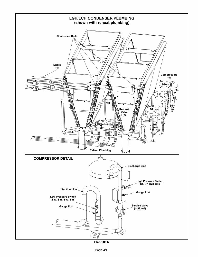
Page 49
LGH/LCH CONDENSER PLUMBING(shown with reheat plumbing)
FIGURE 5
COMPRESSOR DETAIL
Driers(4)
Re-HeatValve
(2)
Compressors(4)
B1
B2
B13
B20
Condenser Coils
Reheat Plumbing
Discharge Line
Suction Line
High Pressure SwitchS4, S7, S28, S96
Low Pressure SwitchS87, S88, S97, S98
Service Valve(optional)
Gauge Port
Gauge Port

Page 50
LGH/LCH EVAPORATOR PLUMBINGMSAV with Re-Heat
FIGURE 6
Top CoilBottom Coil
Re-Heat In Circuit 1
Re-Heat Out Circuit 1
Re-Heat Out Circuit 2
Re-Heat In Circuit 2
Re-Heat Lines FromCondenser Section

Page 51
LGH/LCH EVAPORATOR PLUMBINGVAV and MSAV
FIGURE 7
Evaporator Coilcircuit 2 and 4
Evaporator Coilcircuit 1 and 3
Expansion Valve(typical)
Sensing Bulb(typical)
Row Split Coil
Row Split Coil

Page 52
B-Cooling Components
All units use independent cooling circuits consisting of sepa
rate compressors, condenser coils and evaporator coils. See
figures 5, 6 and 7. Six draw-through type condenser fans are
used in all units. All units are equipped with belt‐drive blowers
which draw air across the evaporator during unit operation.
Cooling may be supplemented by a factory installed
economizer. Evaporators on all units are row split and are
stacked. See figures 6 and 7 for more detail. Each evapora
tor uses a thermostatic expansion valve as the primary ex
pansion device. Each evaporator is also equipped with en
hanced fins and rifled tubing. In all units, each compressor is
protected by a crankcase heater, high pressure switch and
low pressure switch. Additional protection is provided by low
ambient switches and freezestats (on each evaporator).
1-Compressors B1, B2, B13 & B20
All units use scroll compressors and are equipped with
independent cooling circuits. The capacity of each com
pressor is added to reach the total capacity of the unit.
Compressor electrical specifications can be found in the
SPECIFICATIONS section in this manual.
WARNINGElectrical shock hazard. Compressor must begrounded. Do not operate without protective coverover terminals. Disconnect power before removingprotective cover. Failure to follow these precautionscould cause electrical shock resulting in injury ordeath.
Each compressor is energized by a corresponding com
pressor contactor.
NOTE-Refer to the wiring diagram section for specific unit
operation.
2-Crankcase Heaters HR1, HR2, HR5 & HR11
All units use belly‐band type crankcase heaters. Heater HR1
is installed around compressor B1, heater HR2 compressor
B2, HR5 compressor B13 and HR11 compressor B20.
3-High Pressure Switches S4, S7, S28 & S96
The high pressure switch is an auto‐reset SPST N.C. switch
which opens on a pressure rise. All units are equipped with this
switch. The switch is located in the compressor discharge line
and is wired in series with the compressor contactor coil.
S4 (first circuit), S7 (second circuit), S28 (third circuit) and S96
(fourth circuit) are wired in series with the respective compres
sor contactor coils.
A55 Unit Controller has a three-strike counter before lock
ing out the particular compressor circuit. This means the
control allows three high pressure trips per one cooling
demand. The control can be reset by breaking and remak
ing the cooling demand.
When discharge pressure rises to 640 ± 10 psig (4413 ±
69 kPa) (indicating a problem in the system) the switch
opens and the respective compressor is de-energized
(the economizer can continue to operate). When dis
charge pressure drops to 475 ± 20 psig (3275 ± 138 kPa)
the pressure switch will close.
4-Low Ambient Switches S11, S84, S85 & S94
The low ambient switch is an auto‐reset SPST N.O. pres
sure switch which allows for mechanical cooling opera
tion at low outdoor temperatures. All units are equipped
with this switch. In all models a switch is located in each
liquid line prior to the indoor coil section.
In the LGH/LCH units S11 (compressor one), S84 (com
pressor two) are wired in parallel, to the outdoor fan relay
K149 while S85 (compressor three) and S94 (compressor
four) are in parallel, wired to outdoor fan relay K150.
Units charged with R-410A
When liquid pressure rises to 450 +10 psig (3102 + 69
kPa), the switch closes and the condenser fans for that
circuit are energized. When discharge pressure in one re
frigerant circuit drops to 240 + 10 psig (1655 + 69 kPa), the
switch opens and the condenser fan in that refrigerant cir
cuit is de-energized. This intermittent fan operation results
in higher condensing temperature allowing the system to
operate without losing capacity.
5-Low Pressure Switches S87, S88, S97 & S98
The low pressure switch is an auto‐reset SPST N.O. switch
(held N.C. by refrigerant pressure) which opens on a pres
sure drop. All units are equipped with this switch. The switch
is located in the compressor suction line.
S87 (compressor one), S88 (compressor two), S98 (com
pressor three) and S97 (compressor four) are wired in se
ries with the A55 Unit Controller.
The Unit Controller governs the low pressure switches by
shunting the switches during start up until pressure is stabi
lized. After the shunt period, the control has a three‐strike
counter, during each cooling demand, before the com
pressor is locked out. The control is reset by breaking and
remaking the cooling demand.
NOTE - Shunt time period varies according to
compressor off time and the outdoor temperature.
Refer to Integrated Modular Control Guide sent with
each unit.
When suction pressure drops to 40 + 5 psig (276 ± 34 kPa)
(indicating low pressure), the switch opens and the com
pressor is de-energized. The switch automatically resets
when pressure in the suction line rises to 90 + 5 psig (620
± 34 kPa).

Page 53
6-Service Valve (optional all units)
Units may be equipped with service valves located in the
discharge and liquid lines. The service valves are manu
ally operated valves used for service operation.
7-Filter Drier (all units)
All units have a filter drier located in the liquid line of each
refrigerant circuit behind the panel above the heat sec
tion. The drier removes contaminants and moisture from
the system.
8-Freezestats S49, S50, S53 & S95
Each unit is equipped with a low temperature switch (freezes
tat) located on the return bend of each evaporator coil. S49
(first circuit), S50 (second circuit), S53 (third circuit) and
S95 (fourth circuit) are located on the corresponding
evaporator coils.
Each freezestat is wired to the A55 Unit Controller. Each
freezestat is a SPST N.C. auto-reset switch which opens at
29°F + 3°F (‐1.7°C + 1.7°C) on a temperature drop and
closes at 58°F + 4°F (14.4°C + 2.2°C) on a temperature
rise. To prevent coil icing, freezestats open during com
pressor operation to temporarily disable the respective
compressor until the coil warms sufficiently to melt any ac
cumulated frost.
A55 Unit Controller has a three-strike counter before lock
ing out the particular compressor circuit. This means the
control allows three freezestat trips per one cooling de
mand. The control can be reset by breaking and remaking
the cooling demand.
If the freezestats are tripping frequently due to coil icing,
check the unit charge, airflow and filters before allowing unit
back in operation. Make sure to eliminate conditions which
might promote evaporator ice buildup.
9-Condenser Fans B4, B5, B21, B22, B23 &
B24
See Specifications section in this manual for specifica
tions of condenser fans used in LGH/LCH units. All units
are equipped with six condenser fans. The complete fan
assembly may be removed for servicing and cleaning.
See steps below. Reverse order when reassembling. See
figure 8.
1 - Unscrew 6 fan grill screws and remove grill.
2 - Loosen fan blade hub set screw and slide fan off motor
shaft.
3 - Loosen motor bracket bolt.
4 - Disconnect motor wire jack/plug and remove motor.
Motor and fan blades can now be serviced.

Page 54
FIGURE 8
CONDENSER FAN MOTORCONDENSER FAN
ORIFICE RINGCONDENSER FAN GRILL
FAN AND RAIN SHIELD LOCATION
3/16 ± 1/32
1 1/2
Condenser Fan Removal and Operation
Description
40°F
Symbol
55°F
3
1
2
4
6
5
UNIT CONTROLLEROUTPUT
RELAY ENERGIZED
FAN ENERGIZED
B1
B2
B13
B20CONDENSER FANS
P118-8, K150, B22
P118-9, K152, B23
P118-10, K153, B24
P265-6, K10, B4
P265-7, K68, B5
P118-5, K149, B21
S85S94
S84S11
55°F
40°F
COMPRESSORS
1 A55 de-energizes all compressors below 0°F (-18°C) .2 Multiple low ambient switches on same fan must all be
open to de-energize fan.
55°F
40°F
Fan energized when liquid pressure is higherthan 450 psig R-410ADe-energized when liquid line pressure less than240 psig R-410A.
A55 (TP2) De-energizes fan below 55°F/13°C
A55 (TP1) De-energizes fan below 40°F/4.4°C
A55 delays the fan 2 seconds after thermostatdemand

Page 55
C-Blower Compartment
The blower compartment in all units is located between the
evaporator coil and the heat section.
1-Blower Wheels (all units)
All units have two 20 in. x 15 in. (508 mm x 381 mm) blower
wheels. Both wheels are driven by one motor.
2-Indoor Blower Motor B3 (all units)All units use three‐phase single‐speed blower motors. CFM ad
justments are made by adjusting the motor pulley (sheave).
Motors are equipped with sealed ball bearings. All motor speci
fications are listed in the SPECIFICATIONS section in this
manual. Units may be equipped with motors manufactured by
various manufacturers, therefore electrical FLA and LRA speci
fications will vary. See unit rating plate for information specific to
your unit.
OPERATION / ADJUSTMENT
Initiate blower demand at thermostat according to instruc
tions provided with thermostat. Unit will cycle on thermostat
demand. The following steps apply to applications using a
typical electro-mechanical thermostat.
1- Blower operation is manually set at the thermostat sub
base fan switch. With fan switch in ON position, blowers
will operate continuously.
2- With fan switch in AUTO position, the blowers will cycle
with demand.
In zone sensor applications the blower will cycle with de
mand (default). For continuous blower operation refer to the
Unit Controller manual.
Determining Supply CFM
1- The following measurements must be made with a dry
indoor coil. Run blower without a cooling demand. Air
filters must be in place when measurements are taken.
2- Set the VFD to 60Hz by referring to the Unit Controller
manual provided with unit.
3- Measure the indoor blower shaft RPM.
4- With all access panels in place, measure static pres
sure external to unit (from supply to return).
5- Referring to blower data in the front of this manual, use
static pressure and RPM readings to determine unit
CFM.
6- The blower RPM can be adjusted at the motor pulley.
Loosen Allen screw and turn adjustable pulley clockwise
to increase CFM. Turn counterclockwise to decrease
CFM. See figure 9 and 10.
Loosen both Allen screws on units equipped with two
belts. Remove the key and turn the inner sheave the op
posite direction of the outer sheave. Replace the key
before securing Allen screws.
BLOWER PULLEY ADJUSTMENT
TO INCREASE CFMLOOSEN ALLEN SCREW &
TURN PULLEY CLOCKWISE
SECURE ALLEN SCREWS
TO DECREASE CFMTURN PULLEY
COUNTERCLOCKWISE
SECURE ALLEN SCREWSPULLEY
MOTOR ALLENSCREW
SIDE VIEW
FIGURE 9
Note - Pulley minimum number of turns open:1.Maximum number of turns open: 6.
OUTER SHEAVE
MOTOR
ALLENSCREWS
INNER SHEAVE
UNITS EQUIPPED WITH TWO BELTS:
LOOSEN BOTH ALLEN SCREWS AND REMOVE
KEY. TURN INNER SHEAVE THE OPPOSITE DI
RECTION OF THE OUTER SHEAVE. REPLACE
KEY BEFORE SECURING ALLEN SCREWS
7- Supply Air Blowers With VFD -
In addition to adjusting the motor pulley, the supply
CFM can be adjusted at the Unit Controller.
The default maximum blower output is (100% or 60Hz).
To decrease the blower CFM output through the Unit
Controller, adjust Parameter 49 for VAV units and Pa
rameter 12 for MSAV units.
The default minimum blower output is 33% (20Hz). Re
fer to parameter 27 and 28 to adjust the VFD minimum
output.
Optional Power Exhaust Blowers
1- Determine the power exhaust CFM in the same manner
as the supply CFM with one exception: measure the re
turn duct static pressure instead of total external pres
sure. See power exhaust fans blower tables in BLOW
ER DATA section.
2- The RPM can be adjusted at the motor pulley. Loosen
Allen screw and turn adjustable pulley clockwise to in
crease CFM. Turn counterclockwise to decrease CFM.
Secure Allen screw. See figure 10.

Page 56
BLOWER ASSEMBLY
BLOWERMOTOR
PULLEYBELT TENSIONADJUSTMENT
BOLTSMOTOR
SUPPORTPLATE
TO TIGHTEN BELTTurn lower nuts on bothadjustment bolts clockwise. Secure supportplate with upper nuts.
TO LOOSEN BELTTurn upper nut on both adjustment bolts counterclockwise. Secure supportplate with lower nuts.
LOWERADJUSTMENT
NUT
UPPERADJUSTMENT
NUTLOCKWASHER
FIGURE 10
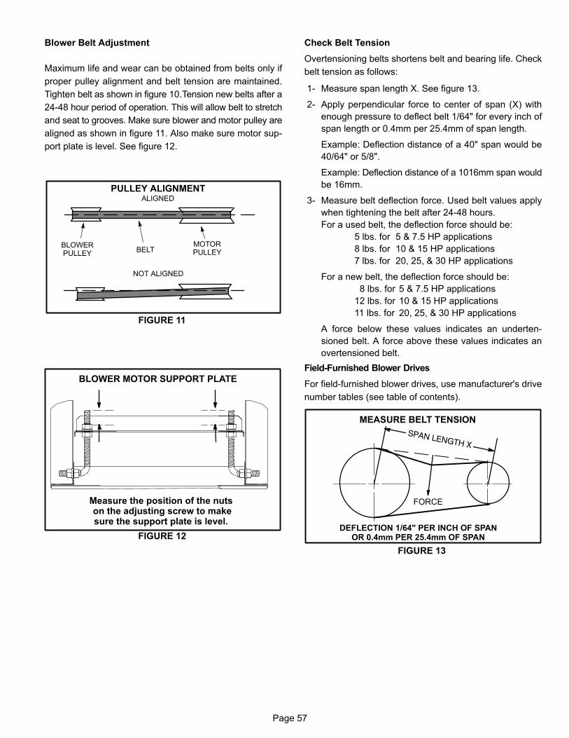
Page 57
Blower Belt Adjustment
Maximum life and wear can be obtained from belts only if
proper pulley alignment and belt tension are maintained.
Tighten belt as shown in figure 10.Tension new belts after a
24-48 hour period of operation. This will allow belt to stretch
and seat to grooves. Make sure blower and motor pulley are
aligned as shown in figure 11. Also make sure motor sup
port plate is level. See figure 12.
PULLEY ALIGNMENT
BELTBLOWERPULLEY
MOTORPULLEY
NOT ALIGNED
ALIGNED
FIGURE 11
BLOWER MOTOR SUPPORT PLATE
Measure the position of the nuts on the adjusting screw to makesure the support plate is level.
FIGURE 12
Check Belt Tension
Overtensioning belts shortens belt and bearing life. Check
belt tension as follows:
1- Measure span length X. See figure 13.
2- Apply perpendicular force to center of span (X) with
enough pressure to deflect belt 1/64" for every inch of
span length or 0.4mm per 25.4mm of span length.
Example: Deflection distance of a 40" span would be
40/64" or 5/8".
Example: Deflection distance of a 1016mm span would
be 16mm.
3- Measure belt deflection force. Used belt values apply
when tightening the belt after 24-48 hours.
For a used belt, the deflection force should be:
5 lbs. for 5 & 7.5 HP applications
8 lbs. for 10 & 15 HP applications
7 lbs. for 20, 25, & 30 HP applications
For a new belt, the deflection force should be:
8 lbs. for 5 & 7.5 HP applications
12 lbs. for 10 & 15 HP applications
11 lbs. for 20, 25, & 30 HP applications
A force below these values indicates an underten
sioned belt. A force above these values indicates an
overtensioned belt.
Field-Furnished Blower Drives
For field-furnished blower drives, use manufacturer's drive
number tables (see table of contents).
MEASURE BELT TENSION
DEFLECTION 1/64" PER INCH OF SPANOR 0.4mm PER 25.4mm OF SPAN
FORCE
FIGURE 13

Page 58
LGH HEATING PARTS ARRANGEMENT(high heat 11 burner, tube & standard heat 7 burner, tube)
HEAT EXCHANGER
GAS VALVECOMBUSTIONAIR INDUCER
PROVESWITCH
COLLECTOR BOX
BURNER MANIFOLD ASSEMBLY
ROLLOUT SWITCH
FIGURE 14
BURNER MANIFOLDASSEMBLY
GAS VALVE
COLLECTOR BOX
ROLLOUT SWITCH
HEAT EXCHANGER

Page 59
D-GAS HEAT COMPONENTS
All units are available in 500,000 BTUH (146.5 kW) (stan
dard gas heat - 7 burner and tube heat-exchanger) or
800,000 BTUH (234.4 kW) (high gas heat - 11 burner and
tube heat exchanger) sizes. All units are equipped with two
gas heat sections (figure 15). In downflow position each
section is protected by a high temperature control limit, S10
and S99. In horizontal position only, one primary limit is
used (S10) and it is located in the blower compartment. For
both applications a secondary limit (S21) is located in the
blower compartment. See figure 19. Flexible pipe is used to
connect the gas supply from one heat section to the other.
Cast iron pipe will feed the supply gas to each gas valve.
NOTE - Care should be taken to insure flexible pipe
does not touch any other part of the unit. Breaks or tears
in the flexible pipe will result in a gas leak.
Heat Section Electrical Components
The heat section (see figure 15) houses the burner controls
A3 and A12, combustion air inducers transformers T3 and
T13 (480V & 575V only), combustion air inducer relays K13
and K19, gas relays K72 and K73 and limit relay K123.
LGH HEAT SECTION
IGNITION CONTROLA12
Gas RelayK73
Combustion AirRelay Relay
K19
Ignition ControlA3
Limit RelayK123
Gas RelayK72
Combustion Air RelayRelay K13
CAI TransformerT3
CAI TransformerT13
FIGURE 15

Page 60
WARNINGSHOCK HAZARD. SPARK RELATED COMPONENTSCONTAIN HIGH VOLTAGE WHICH CAN CAUSEPERSONAL INJURY OR DEATH. DISCONNECTPOWER BEFORE SERVICING. CONTROL IS NOTFIELD REPAIRABLE. UNSAFE OPERATION WILLRESULT. IF THE CONTROL IS INOPERABLE, SIMPLY REPLACE THE ENTIRE CONTROL.
1-Burner Ignition Control A3 (heat section 1)
& A12 (heat section 2)
The ignition controls are located in the control box. Two dif
ferent manufacturers' (Utec and Fenwal) controls are used in
the LGH units. Both ignition controls operate the same.
The ignition control provides three main functions: gas
valve control, ignition and flame sensing. The unit will usu
ally ignite on the first attempt; however, the ignition attempt
sequence provides three trials for ignition before locking
out. The lockout time for the Utec is 5 minutes. The lockout
time for the Fenwal control is 5 minutes. After lockout, the
ignition control automatically resets and provides three
more attempts at ignition. Manual reset after lockout re
quires breaking and remaking power to the ignition control.
Both controls have LEDS for troubleshooting. See table 1.
TABLE 1
UTEC
LED Flashes Indicates
Steady Off No power or control hardware fault.
Steady On Power applied. Control OK.
3 Flashes Ignition lockout from too many trials.
4 FlashesIgnition lockout from too many flamelosses within single call for heat.
5 Flashes Control hardware fault detected.
Kidde Fenwal
LED Flashes Indicates
Steady On Internal control failure.
2 Flashes Flame with no call for heat.
3 Flashes Ignition lockout.
Flame rectification sensing is used on all LGH units.
Loss of flame during a heating cycle is indicated by an ab
sence of flame signal (0 microamps). If this happens, the con
trol will immediately restart the ignition sequence and then lock
out if ignition is not gained after the third trial. See table 12 for
microamp signal values .
The control shuts off gas flow immediately in the event of a
power failure. Upon restoration of gas and power, the control
will restart the ignition sequence and continue until flame is es
tablished or system locks out.
On a heating demand, the ignition control is energized by
the A55 Unit Controller. The ignition control then allows 30
to 40 seconds for the combustion air blower to vent exhaust
gases from the burners. When the combustion air blower is
purging the exhaust gases, the combustion air prove switch
is closing proving that the combustion air blower is operat
ing before allowing the ignition control to energize. When
the combustion air prove switch is closed and the delay is
over, the ignition control activates gas valve, the spark elec
trode and the flame sensing electrode. Sparking stops im
mediately after flame is sensed. The combustion air blower
continues to operate throughout the heating demand. If the
flame fails or if the burners do not ignite, the ignition control
will attempt to ignite the burners up to two more times. If igni
tion cannot be obtained after the third attempt, the control
will lock out. The ignition control is not adjustable.
The Utec control is illustrated in figure 16 and Fenwal control
in figure 17. The spade connections are used to connect the
control to unit. Each of the spade terminals are identified by
function. The spark electrode wire connects to the
spark‐plug‐type connector on top of the control.

Page 61
FIGURE 16
UTEC IGNITION CONTROL
FIGURE 17
FENWAL IGNITION CONTROL
V2
V1/P
1
TH
/W
GN
DS
1
FC−
FC
+
DS
2
SPARK TERMINAL
2-Combustion Air Inducer Relay K13
Combustion air inducer relay K13, used in all LGH units, is a
DPDT relay with a 24VAC coil. K13 is energized by the A55
Unit Controller after a standard heating demand from the
thermostat. K13 remains energized throughout the heating
demand. When energized, K13 N.O. contacts close to ener
gize the combustion air inducer and begin a heating se
quence. Prove switch S18 closes as combustion air static
pressure falls to “prove" combustion air inducer operation.
When S18 closes, the ignition control and gas valve is ener
gized to begin a heating sequence.
3-Combustion Air Inducer Relay K19
Combustion air inducer relay K19, used in all LGH units, is a
DPDT relay with a 24 VAC coil. K19 is energized by the
A178 Unit Controller after a standard heat demand from the
thermostat. K19 remains energized throughout the de
mand. When energized, K19 N.O. contacts close to ener
gize the second heat section combustion air inducer and
begin second section heating sequence. Prove switch S45
closes as combustion air static pressure falls to “prove"
combustion air inducer operation. When S45 closes, the ig
nition control and gas valve is energized to begin the heat
ing sequence.
4-Limit Relay K123
Relay K123 is a 3PDT relay wired in series with primary lim
its S10, S99 and secondary S21. K123 remains energized
as long as S10, S99 and S21 contacts remain closed. If any
of the three limits open, K123 is de-energized shutting down
heat sections.
5-Gas Valve Relays K72 & K73
K72 and K73 are SPDT relays wired in series with combus
tion air inducer relays K13 and K19 respectively and with
gas valves GV1 and GV3. On a call for second stage heat
(W2), the relays normally open terminals “5" and “7" close,
energizing combustion air inducers B6 and B15 on second
stage heat (high speed).
6-C.A.I. Transformers T3 & T13 (460 & 575
Volts Only)
LGH 460 (G) and 575 (J) voltage units use two autotrans
formers to provide 230VAC. Transformers are mounted in
the heat section. The transformers have an output rating of
0.5A. T3 supplies 230VAC power to combustion air inducer
B6, while T13 supplies power to combustion air inducer B15.
7-Heat Exchanger (Figure 14)
The LGH units use aluminized steel inshot burners with
matching tubular aluminized steel (stainless steel is an op
tion) heat exchangers and two‐stage redundant gas valves.
LGH uses two eleven tube/burners for high heat and two
seven tube/burners for standard heat. Each burner uses a
burner venturi to mix gas and air for proper combustion.
Combustion takes place at each tube entrance. As hot com
bustion gases are drawn through each tube by the combus
tion air blower, exhaust gases are drawn out and fresh air/
gas mixture is drawn in . Heat is transferred to the air stream
from all surfaces of the heat exchanger tubes. The supply
air blowers, controlled by the A55 Unit Controller, force air
across all surfaces of the tubes to extract the heat of com
bustion. The shape of the tubes ensures maximum heat ex
change.
The gas valves accomplish staging by allowing more or less
gas to the burners as called for by heating demand.
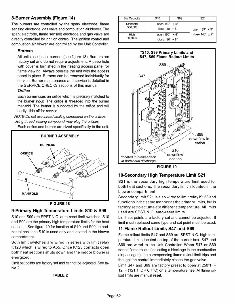
Page 62
8-Burner Assembly (Figure 14)
The burners are controlled by the spark electrode, flame
sensing electrode, gas valve and combustion air blower. The
spark electrode, flame sensing electrode and gas valve are
directly controlled by ignition control. The ignition control and
combustion air blower are controlled by the Unit Controller.
Burners
All units use inshot burners (see figure 18). Burners are
factory set and do not require adjustment. A peep hole
with cover is furnished in the heating access panel for
flame viewing. Always operate the unit with the access
panel in place. Burners can be removed individually for
service. Burner maintenance and service is detailed in
the SERVICE CHECKS sections of this manual.
Orifice
Each burner uses an orifice which is precisely matched to
the burner input. The orifice is threaded into the burner
manifold. The burner is supported by the orifice and will
easily slide off for service.
NOTE-Do not use thread sealing compound on the orifices.
Using thread sealing compound may plug the orifices.
Each orifice and burner are sized specifically to the unit.
FIGURE 18
BURNER ASSEMBLY
BURNERS
MANIFOLD
ORIFICE
9-Primary High Temperature Limits S10 & S99
S10 and S99 are SPST N.C. auto-reset limit switches. S10
and S99 are the primary high temperature limits for the heat
sections. See figure 19 for location of S10 and S99. In hori
zontal positions S10 is used only and located in the blower
compartment.
Both limit switches are wired in series with limit relay
K123 which is wired to A55. Once K123 contacts open
both heat sections shuts down and the indoor blower is
energized.
Limit set points are factory set and cannot be adjusted. See ta
ble 2.
TABLE 2
Btu Capacity S10 S99 S21
Standard 500,000
open 140° + 5°
close 110 + 8° open 185° + 5°
close 145° + 7°High800,000
open 150° + 5°
close 120 + 8°
*S10, S99 Primary Limits andS47, S69 Flame Rollout Limits
S10downflowlocation
S99downflow lo
cation
FIGURE 19
S69
S47
*located in blower deck in horizontal discharge
10-Secondary High Temperature Limit S21
S21 is the secondary high temperature limit used for
both heat sections. The secondary limit is located in the
blower compartment.
Secondary limit S21 is also wired to limit relay K123 and
functions in the same manner as the primary limits, but is
factory set to actuate at a different temperature. All limits
used are SPST N.C. auto-reset limits.
Limit set points are factory set and cannot be adjusted. If
limit must replaced same type and set point must be used.
11-Flame Rollout Limits S47 and S69
Flame rollout limits S47 and S69 are SPST N.C. high tem
perature limits located on top of the burner box. S47 and
S69 are wired to the Unit Controller. When S47 or S69
sense flame rollout (indicating a blockage in the combustion
air passages), the corresponding flame rollout limit trips and
the ignition control immediately closes the gas valve.
Limit S47 and S69 are factory preset to open at 250�F +
12�F (121.1�C + 6.7�C) on a temperature rise. All flame rol
lout limits are manual reset.
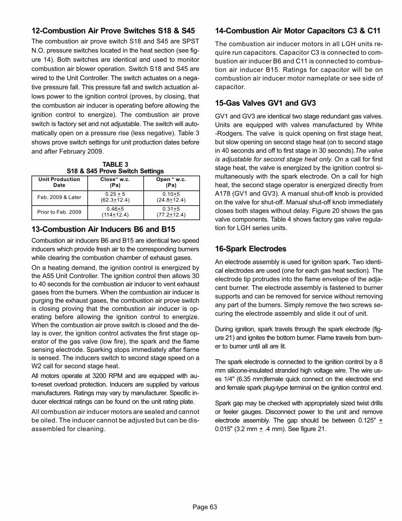
Page 63
12-Combustion Air Prove Switches S18 & S45
The combustion air prove switch S18 and S45 are SPST
N.O. pressure switches located in the heat section (see fig
ure 14). Both switches are identical and used to monitor
combustion air blower operation. Switch S18 and S45 are
wired to the Unit Controller. The switch actuates on a nega
tive pressure fall. This pressure fall and switch actuation al
lows power to the ignition control (proves, by closing, that
the combustion air inducer is operating before allowing the
ignition control to energize). The combustion air prove
switch is factory set and not adjustable. The switch will auto
matically open on a pressure rise (less negative). Table 3
shows prove switch settings for unit production dates before
and after February 2009.
TABLE 3S18 & S45 Prove Switch Settings
Unit ProductionDate
Close“ w.c.(Pa)
Open “ w.c.(Pa)
Feb. 2009 & Later0.25 + 5
(62.3+12.4)0.10+5
(24.8+12.4)
Prior to Feb. 20090.46+5
(114+12.4)0.31+5
(77.2+12.4)
13-Combustion Air Inducers B6 and B15
Combustion air inducers B6 and B15 are identical two speed
inducers which provide fresh air to the corresponding burners
while clearing the combustion chamber of exhaust gases.
On a heating demand, the ignition control is energized by
the A55 Unit Controller. The ignition control then allows 30
to 40 seconds for the combustion air inducer to vent exhaust
gases from the burners. When the combustion air inducer is
purging the exhaust gases, the combustion air prove switch
is closing proving that the combustion air inducer is op
erating before allowing the ignition control to energize.
When the combustion air prove switch is closed and the de
lay is over, the ignition control activates the first stage op
erator of the gas valve (low fire), the spark and the flame
sensing electrode. Sparking stops immediately after flame
is sensed. The inducers switch to second stage speed on a
W2 call for second stage heat.
All motors operate at 3200 RPM and are equipped with au
to‐reset overload protection. Inducers are supplied by various
manufacturers. Ratings may vary by manufacturer. Specific in
ducer electrical ratings can be found on the unit rating plate.
All combustion air inducer motors are sealed and cannot
be oiled. The inducer cannot be adjusted but can be dis
assembled for cleaning.
14-Combustion Air Motor Capacitors C3 & C11
The combustion air inducer motors in all LGH units re
quire run capacitors. Capacitor C3 is connected to com
bustion air inducer B6 and C11 is connected to combus
tion air inducer B15. Ratings for capacitor will be on
combustion air inducer motor nameplate or see side of
capacitor.
15-Gas Valves GV1 and GV3
GV1 and GV3 are identical two stage redundant gas valves.
Units are equipped with valves manufactured by White
-Rodgers. The valve is quick opening on first stage heat,
but slow opening on second stage heat (on to second stage
in 40 seconds and off to first stage in 30 seconds).The valve
is adjustable for second stage heat only. On a call for first
stage heat, the valve is energized by the ignition control si
multaneously with the spark electrode. On a call for high
heat, the second stage operator is energized directly from
A178 (GV1 and GV3). A manual shut-off knob is provided
on the valve for shut-off. Manual shut‐off knob immediately
closes both stages without delay. Figure 20 shows the gas
valve components. Table 4 shows factory gas valve regula
tion for LGH series units.
16-Spark Electrodes
An electrode assembly is used for ignition spark. Two identi
cal electrodes are used (one for each gas heat section). The
electrode tip protrudes into the flame envelope of the adja
cent burner. The electrode assembly is fastened to burner
supports and can be removed for service without removing
any part of the burners. Simply remove the two screws se
curing the electrode assembly and slide it out of unit.
During ignition, spark travels through the spark electrode (fig
ure 21) and ignites the bottom burner. Flame travels from burn
er to burner until all are lit.
The spark electrode is connected to the ignition control by a 8
mm silicone‐insulated stranded high voltage wire. The wire us
es 1/4" (6.35 mm)female quick connect on the electrode end
and female spark plug-type terminal on the ignition control end.
Spark gap may be checked with appropriately sized twist drills
or feeler gauges. Disconnect power to the unit and remove
electrode assembly. The gap should be between 0.125" +
0.015" (3.2 mm + .4 mm). See figure 21.

Page 64
FIGURE 20
WHITE-RODGERS 36C GAS VALVE
GASVALVE KNOB
SHOWN IN “ON"POSITION
INLETPRESSURE
TAP
SECOND STAGEADJUSTMENT
TABLE 4
GAS VALVE REGULATION FOR LGH UNITS
Operating Pressure(outlet) Factory Setting
Natural L.P.
3.7+0.3"W.C.920+75Pa
Low High Low High
1.6+0.2"W.C.398+50Pa
10.5+0.5"W.C.2611+125Pa
5.5+0.3"W.C.1368+75Pa
FIGURE 21
GROUND
ELECTRODE
.125" ± .015"(3.2 mm ± .4 mm)
NOTE-IN ORDER TO MAXIMIZE SPARK ENERGY TO
ELECTRODE, HIGH VOLTAGE WIRE SHOULD TOUCH
UNIT CABINET AS LITTLE AS POSSIBLE.
17-Flame Sensors
A flame sensor is located on the top end of each burner
support. The sensor is mounted through a hole in the burner
support and the tip protrudes into the flame envelope of the
right most burner. The sensor assembly is fastened to burner
supports and can be removed for service without removing any
part of the burners.
When flame is sensed by the flame sensor (indicated by
microamp signal through the flame) sparking stops imme
diately. During operation, flame is sensed by current
passed along the ground electrode (located on the spark
electrode), through the flame and into the sensing elec
trode. The ignition control allows the gas valve to stay open
as long as a flame signal (current passed through the
flame) is sensed.
E-ELECTRIC HEAT COMPONENTS See ELECTRIC HEAT DATA tables (table of contents) for pos
sible LCH to EHA match-ups and electrical ratings.
EHA parts arrangement is shown in figure 22. All electric
heat sections consist of electric heating elements exposed
directly to the air stream. Multiple‐stage elements are se
quenced on and off in response to thermostat demand.
1-Electric Heat Relay K9
LCH units equipped with 75 to 180kW electric heat use an
electric heat relay K9. K9 is a N.O. SPST pilot relay in
tended to electrically isolate the unit's 24V circuit from the
electric heat 24V circuit. K9 is energized by the A55 Unit
Controller. K9-1 closes, enabling the unit controller to en
ergize the electric heat contactors.
2-Contactors K15, K16 and K17 all voltages
Contactors K15, K16 and K17 are all three‐pole dou
ble‐break contactors located on the electric heat vestibule.
All contactors are equipped with a 24VAC coil. The coils in
the K15, K16 and K17 contactors are energized by the Unit
Controller. Contactors K15 and K16 energize the first stage
heating elements, while K17 energizes the second stage
heating elements.
3-Contactors K18, K75 and K76
These contactors are found on G and J voltage, 105
through 180kW EHA units. Contactors K18, K75 and K76
are identical to contactors K15. K16 and K17. The coils on
these contactors are energized by the Unit Controller and
relay K9. K18, K75 and K76 energize the second stage
heating elements.
4-Primary Limit S15
S15 is an auto‐reset thermostat wired in series with contactor
K15 and relay K9. When S15 opens, indicating a problem in the
system, K15 and K9 are de-energized and first stage and all
subsequent stages of heat are de‐energized. S15 is factory set
and cannot be adjusted.

Page 65
FIGURE 22
EHA VESTIBULE PANEL
K9 TB26 TB60 TB64
K16 K17 K15 K18 K75 K76
S158 S159 S160 S161 S20 S157
RT6
F44 F43 F45 F46 F3 F42
5-Secondary Limits S20, S157, S158, S159,
S160 and S161
S20, S157, S158, S159, S160 and S161 are manual reset
limit switches that provide back up high temperature protec
tion. Each limit is wired in series with a contactor and heat
ing element. When one or more limit opens the heating ele
ment is de-energized which in turn de-energizes the
heating element. See EHA diagram for secondary limit /
contactor match-up.
6-Heating Elements HE1 through HE12
Heating elements are composed of helix wound bare nich
rome wire exposed directly to the air stream. Three ele
ments are connected in a three‐phase arrangement. The el
ements in 208/230V units are connected in a “Delta"
arrangement. Elements in 460 and 575V units are connect
ed in “Wye" arrangement. See EHA wiring diagrams in back
of this manual. Each stage is energized independently by
the corresponding contactors located on the electric heat
vestibule panel. Once energized, heat transfer is instanta
neous. High temperature protection is provided by primary
and redundant high temperature limits and overcurrent pro
tection is provided by fuses.
7-Fuses F3, F42, F43, F44, F45, F46
F3, F42, F43, F44, F45 and F46 are 250V 60 amp (Y volt
age) and 660V 60 amp (G and J voltage) fuses that provide
overcurrent protection to HE1 through HE12. Each fuse is
connected in series with a heating element. See EHA dia
gram for specific fuse / heating element match up.
8-Terminal Block TB3
Terminal block TB3 is used to distribute power to electric
heat components.
9-Terminal Blocks TB26, TB64 and TB60
These terminal blocks are used to distribute power from L1,
L2 and L3 to its respective heating element. See EHA dia
grams.
II-PLACEMENT AND INSTALLATION
Make sure the unit is installed in accordance with the in
stallation instructions and all applicable codes. See ac
cessories section for conditions requiring use of the op
tional roof mounting frame (RMFE-14).
III-START UP - OPERATION
IMPORTANT-The crankcase heater must be energized for 24
hours before attempting to start compressor. Set thermostat
so there is no demand to prevent compressors from cycling.

Page 66
A-Preliminary Checks
1- Make sure that unit is installed in accordance with the
installation instructions and applicable codes.
2- Inspect all electrical wiring, both field‐ and factory‐in
stalled, for loose connections. Tighten as required.
3- Check to ensure that refrigerant lines do not rub against
the cabinet or against other refrigerant lines.
4- Check voltage at disconnect switch. Voltage must be
within range listed on nameplate. If not, consult power
company and have voltage condition corrected before
starting unit.
5- Make sure filters are in place before start‐up.
B-Cooling Start-Up
1- Initiate first and second stage cooling demands accord
ing to instructions provided with thermostat.
2- 2 Heat / 2 Cool Thermostat -
First-stage thermostat demand will energize com
pressors 1 and 2. Second-stage thermostat demand
will energize compressors 3 and 4. On units with an
economizer, when outdoor air is acceptable, a first-
stage demand will energize the economizer; a sec
ond-stage demand will energize compressors 1 and
2. Refer to the Unit Controller manual provided with
each unit for other staging options.
3- Each refrigerant circuit is separately charged with
R-410A refrigerant. See unit rating plate for correct
amount of charge. See figure 23 for refrigerant routing
on VAV units and MSAV units without re-heat. See fig
ure 42 for refrigerant routing on units equipped with a
reheat coil (Humiditrol).
4- Refer to Cooling Operation and Adjustment section for
proper method to check refrigerant charge.
Manifold gauge sets used with systems charged with
R-410A refrigerant must be capable of handling the higher
system operating pressures. The gauges should be rated
for use with pressures of 0-800 on the high side and a low
side of 30" vacuum to 250 psi with dampened speed to 500
psi. Gauge hoses must be rated for use at up to 800 psi of
pressure with a 4000 psi burst rating.
FIGURE 23
REFRIGERANT CIRCUITS - UNITS EQUIPPED WITH VFD SUPPLY AIR BLOWERS
EVAPORATORCOILS
CONDENSERCOILS
1 Refrigerant circuit 12 Refrigerant circuit 23 Refrigerant circuit 34 Refrigerant circuit 4
COMPRESSORS
(ROW SPLIT)
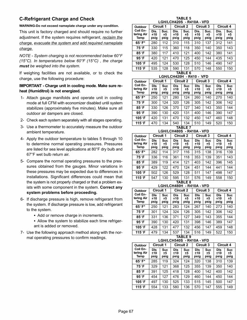
Page 67
C-Refrigerant Charge and Check
WARNING-Do not exceed nameplate charge under any condition.
This unit is factory charged and should require no further
adjustment. If the system requires refrigerant, reclaim the
charge, evacuate the system and add required nameplate
charge.
NOTE - System charging is not recommended below 60°F
(15°C). In temperatures below 60°F (15°C) , the charge
must be weighed into the system.
If weighing facilities are not available, or to check the
charge, use the following procedure:
IMPORTANT - Charge unit in cooling mode. Make sure re
heat (Humiditrol) is not energized.
1- Attach gauge manifolds and operate unit in cooling
mode at full CFM with economizer disabled until system
stabilizes (approximately five minutes). Make sure all
outdoor air dampers are closed.
2- Check each system separately with all stages operating.
3- Use a thermometer to accurately measure the outdoor
ambient temperature.
4- Apply the outdoor temperature to tables 5 through 10
to determine normal operating pressures. Pressures
are listed for sea level applications at 80°F dry bulb and
67°F wet bulb return air.
5- Compare the normal operating pressures to the pres
sures obtained from the gauges. Minor variations in
these pressures may be expected due to differences in
installations. Significant differences could mean that
the system is not properly charged or that a problem ex
ists with some component in the system. Correct any
system problems before proceeding.
6- If discharge pressure is high, remove refrigerant from
the system. If discharge pressure is low, add refrigerant
to the system.
� Add or remove charge in increments.
� Allow the system to stabilize each time refriger
ant is added or removed.
7- Use the following approach method along with the nor
mal operating pressures to confirm readings.
TABLE 5LGH/LCH420S - R410A - VFD
OutdoorCoil Entering Air
Temp
Circuit 1 Circuit 2 Circuit 3 Circuit 4
Dis.+10psig
Suc.+5
psig
Dis.+10psig
Suc.+5
psig
Dis.+10psig
Suc.+5
psig
Dis.+10psig
Suc.+5
psig
65�F* 280 112 310 115 310 137 312 141
75�F 330 115 360 118 350 140 350 143
85�F 380 117 410 121 400 142 380 141
95�F 420 121 470 125 450 144 435 143
105�F 495 124 530 128 510 146 490 147
115�F 535 128 590 131 570 148 550 150
TABLE 6LGH/LCH420H - R410 - VFD
OutdoorCoil Entering Air
Temp
Circuit 1 Circuit 2 Circuit 3 Circuit 4
DIs+10psig
Suc+5
psig
Dis+10psig
Suc+5
psig
DIs+10psig
Suc+5
psig
DIs+10psig
Suc+5
psig
65�F* 250 121 280 124 260 140 270 140
75�F 300 124 320 126 305 142 306 142
85�F 330 126 370 127 340 143 350 144
95�F 390 130 420 131 400 146 390 147
105�F 420 131 470 132 450 147 460 148
115�F 470 134 540 134 510 149 520 150
TABLE 7LGH/LCH480S - R410A - VFD
OutdoorCoil Entering Air
Temp
Circuit 1 Circuit 2 Circuit 3 Circuit 4
DIs+10psig
Suc+5
psig
Dis+10psig
Suc+5
psig
DIs+10psig
Suc+5
psig
DIs+10psig
Suc+5
psig
65�F* 282 114 317 116 315 138 316 139
75�F 336 116 361 118 353 139 351 143
85�F 389 119 414 121 403 142 396 145
95�F 429 122 470 124 451 144 441 144
105�F 502 126 529 128 511 147 498 147
115�F 547 130 595 131 576 149 558 150
TABLE 8LGH/LCH480H - R410A - VFD
OutdoorCoil Entering Air
Temp
Circuit 1 Circuit 2 Circuit 3 Circuit 4
DIs+10psig
Suc+5
psig
Dis+10psig
Suc+5
psig
DIs+10psig
Suc+5
psig
DIs+10psig
Suc+5
psig
65�F* 250 121 283 124 267 140 273 140
75�F 301 124 324 126 305 142 306 142
85�F 331 136 371 127 349 143 355 144
95�F 390 130 420 131 398 146 389 147
105�F 428 131 477 132 456 147 459 148
115�F 479 134 537 134 516 149 522 150
TABLE 9LGH/LCH540S - R410A - VFD
OutdoorCoil Entering Air
Temp
Circuit 1 Circuit 2 Circuit 3 Circuit 4
DIs+10psig
Suc+5
psig
Dis+10psig
Suc+5
psig
DIs+10psig
Suc+5
psig
DIs+10psig
Suc+5
psig
65�F* 285 119 324 124 320 138 310 139
75�F 329 121 368 125 355 139 350 140
85�F 391 125 418 128 400 142 400 142
95�F 454 127 476 129 460 144 450 144
105�F 497 130 525 133 515 145 500 147
115�F 554 133 580 136 570 147 555 149

Page 68
TABLE 10LGH/LCH600S - R410A - VFD
OutdoorCoil Entering Air
Temp
Circuit 1 Circuit 2 Circuit 3 Circuit 4
DIs+10psig
Suc+5
psig
Dis+10psig
Suc+5
psig
DIs+10psig
Suc+5
psig
DIs+10psig
Suc+5
psig
65�F* 251 109 300 111 297 135 295 135
75�F 304 111 342 113 338 136 335 137
85�F 343 114 388 115 382 139 384 140
95�F 398 117 433 117 433 141 424 142
105�F 445 119 489 119 485 142 477 144
115�F 490 122 545 121 537 145 521 146
D-Charge Verification - Approach Method -
AHRI TESTING
1- Using the same thermometer, compare liquid tempera
ture to outdoor ambient temperature.
Approach Temperature = Liquid temperature (at con
denser outlet) minus ambient temperature.
2- Approach temperature should match values in table 11.
An approach temperature greater than value shown indi
cates an undercharge. An approach temperature less
than value shown indicates an overcharge.
3- The approach method is not valid for grossly over or un
dercharged systems. Use tables 5 through 10 as a
guide for typical operating pressures.
TABLE 11APPROACH TEMPERATURES
420S, 540S 8°F + 1 (4.4 + 0.5)
420H, 480H, 6°F + 1 (3.3 + 0.5)
480S 9°F + 1 (5.0 + 0.5)
600S 7°F + 1 (3.9 + 0.5)
E-Heating Start Up
FOR YOUR SAFETY READ BEFORE LIGHTING
BEFORE LIGHTING smell all around the appliance area for
gas. Be sure to smell next to the floor because some gas is
heavier than air and will settle on the floor.
Use only your hand to push in or turn the gas control knob.
Never use tools. If the knob will not push in or turn by hand,
do not try to repair it, call a qualified service technician.
Force or attempted repair may result in a fire or explosion.
WARNINGElectric shock hazard. Can causeinjury or death. Before attempting toperform any service or maintenance,turn the electrical power to unit OFF atdisconnect switch(es). Unit may havemultiple power supplies.
WARNINGDanger of explosion. Can cause injuryor product or property damage. Ifoverheating occurs or if gas supplyfails to shut off, shut off the manual gasvalve to the appliance before shuttingoff electrical supply.
WARNINGSMOKE POTENTIAL
The heat exchanger in this unit could be a source ofsmoke on initial firing. Take precautions with respectto building occupants and property. Vent initial supply air outside when possible.
WARNINGDanger of explosion. Can cause injury ordeath. Do not attempt to light manually.Unit has a direct spark ignition system.
This unit is equipped with an automatic spark ignition sys
tem. There is no pilot. In case of a safety shutdown, move
thermostat switch to OFF and return the thermostat switch
to HEAT to reset ignition control.
Placing Unit In Operation
WARNINGDanger of explosion and fire. Can causeinjury or product or property damage.You must follow these instructionsexactly.
Gas Valve Operation for White Rodgers 36C Se
ries Valve (Figure 24)
WHITE RODGERS 36C GAS VALVE
GASVALVE KNOB
SHOWN IN “ON"POSITION
FIGURE 24
INLETPRESSURE
TAP
1- Set thermostat to lowest setting.
2- Turn off all electrical power to appliance.
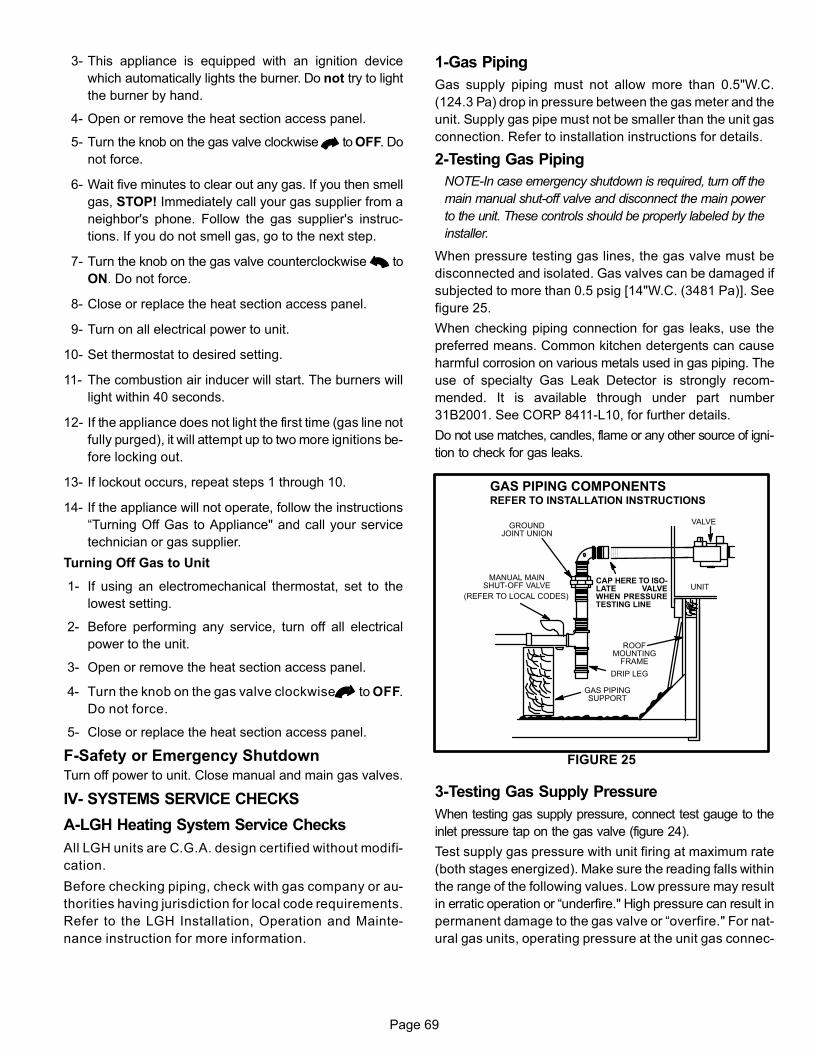
Page 69
3- This appliance is equipped with an ignition device
which automatically lights the burner. Do not try to light
the burner by hand.
4- Open or remove the heat section access panel.
5- Turn the knob on the gas valve clockwise to OFF. Do
not force.
6- Wait five minutes to clear out any gas. If you then smell
gas, STOP! Immediately call your gas supplier from a
neighbor's phone. Follow the gas supplier's instruc
tions. If you do not smell gas, go to the next step.
7- Turn the knob on the gas valve counterclockwise to
ON. Do not force.
8- Close or replace the heat section access panel.
9- Turn on all electrical power to unit.
10- Set thermostat to desired setting.
11- The combustion air inducer will start. The burners will
light within 40 seconds.
12- If the appliance does not light the first time (gas line not
fully purged), it will attempt up to two more ignitions be
fore locking out.
13- If lockout occurs, repeat steps 1 through 10.
14- If the appliance will not operate, follow the instructions
“Turning Off Gas to Appliance" and call your service
technician or gas supplier.
Turning Off Gas to Unit
1- If using an electromechanical thermostat, set to the
lowest setting.
2- Before performing any service, turn off all electrical
power to the unit.
3- Open or remove the heat section access panel.
4- Turn the knob on the gas valve clockwise to OFF.
Do not force.
5- Close or replace the heat section access panel.
F-Safety or Emergency Shutdown
Turn off power to unit. Close manual and main gas valves.
IV- SYSTEMS SERVICE CHECKS
A-LGH Heating System Service Checks
All LGH units are C.G.A. design certified without modifi
cation.
Before checking piping, check with gas company or au
thorities having jurisdiction for local code requirements.
Refer to the LGH Installation, Operation and Mainte
nance instruction for more information.
1-Gas Piping
Gas supply piping must not allow more than 0.5"W.C.
(124.3 Pa) drop in pressure between the gas meter and the
unit. Supply gas pipe must not be smaller than the unit gas
connection. Refer to installation instructions for details.
2-Testing Gas Piping
NOTE-In case emergency shutdown is required, turn off the
main manual shut‐off valve and disconnect the main power
to the unit. These controls should be properly labeled by the
installer.
When pressure testing gas lines, the gas valve must be
disconnected and isolated. Gas valves can be damaged if
subjected to more than 0.5 psig [14"W.C. (3481 Pa)]. See
figure 25.
When checking piping connection for gas leaks, use the
preferred means. Common kitchen detergents can cause
harmful corrosion on various metals used in gas piping. The
use of specialty Gas Leak Detector is strongly recom
mended. It is available through under part number
31B2001. See CORP 8411-L10, for further details.
Do not use matches, candles, flame or any other source of igni
tion to check for gas leaks.
UNIT
GROUNDJOINT UNION
MANUAL MAINSHUT-OFF VALVE
(REFER TO LOCAL CODES)
GAS PIPINGSUPPORT
DRIP LEG
ROOFMOUNTING
FRAME
GAS PIPING COMPONENTSREFER TO INSTALLATION INSTRUCTIONS
FIGURE 25
VALVE
CAP HERE TO ISOLATE VALVEWHEN PRESSURETESTING LINE
3-Testing Gas Supply Pressure
When testing gas supply pressure, connect test gauge to the
inlet pressure tap on the gas valve (figure 24).
Test supply gas pressure with unit firing at maximum rate
(both stages energized). Make sure the reading falls within
the range of the following values. Low pressure may result
in erratic operation or “underfire." High pressure can result in
permanent damage to the gas valve or “overfire." For nat
ural gas units, operating pressure at the unit gas connec

Page 70
tion must be between 4.7"W.C. and 10.5"W.C. (1168 Pa
and 2610 Pa). For L.P. gas units, operating pressure at
the unit gas connection must be between 10.8"W.C. and
13.0"W.C. (2685 Pa and 3232 Pa).
On multiple unit installations, each unit should be checked
separately while operating at maximum rate, beginning with
the one closest to the supply gas main and progressing to
the one furthest from the main. Multiple units should also be
tested with and without the other units operating. Supply
pressure must fall within the range listed in the previous
paragraph.
4-Check and Adjust Manifold Pressure
After line pressure has been checked and adjusted,
check manifold pressure. Move test gauge to the outlet
pressure tap located on unit gas valve GV1. See table 4 in
GAS HEAT COMPONENT section for proper manifold
pressure and figure 20 for location of pressure tap on the
gas valve.
The manifold pressure is factory set and should not re
quire adjustment. If manifold pressure is incorrect and no other
source of improper manifold pressure can be found, the valve
must be replaced. Refer to figure 20 for location of gas valve
(manifold pressure) adjustment screw.
All gas valves are factory regulated. The gas valve should com
pletely and immediately cycle off in the event of gas or power
failure. The manual shut‐off knob can be used to immediately
shut off gas supply.
CAUTIONFor safety, connect a shut‐off valve between themanometer and the gas tap to permit shut off ofgas pressure to the manometer.
Manifold Adjustment Procedure
1- Connect test gauge to the outlet pressure tap on the
gas valve. Start the unit (call for second stage heat)
and allow five minutes for the unit to reach steady
state.
2- While waiting for the unit to stabilize, notice the
flame. The flame should be stable without flashback
and should not lift from the burner heads. Natural gas
should burn basically blue with some clear streaks.
L.P. gas should burn mostly blue with some clear yel
low streaks.
3- After allowing the unit to stabilize for five minutes, re
cord the manifold pressure and compare to the values
given for gas supply pressure in table 4.
CAUTIONDisconnect heating demand as soon as an accuratereading has been obtained.
5-Proper Gas Flow
To check for proper gas flow to burners, determine Btuh input
from unit rating plate or the gas heating capacity tables in the
SPECIFICATIONS section of this manual. Divide this input
rating by the Btuh per cubic foot of available gas. Result is the
number of cubic feet per hour required. Determine the flow of
gas through gas meter for two minutes and multiply by 30 to
get hourly flow of gas to the burners.
NOTE - To obtain accurate reading, shut off all other gas
appliances connected to meter.
6-Burners
Burners are factory set for maximum air and cannot be ad
justed. Always operate unit with access panel in place. A peep
hole is furnished in the heating access panel for flame viewing.
Natural gas should burn basically blue with some clear streaks.
L.P. gas should burn mostly blue with some clear yellow
streaks.
Figure 26 shows how to remove burner assembly.
1- Turn off electrical power and the gas supply to the unit.
2- Open the burner compartment access panel.
3- Remove screws securing burners to burner support
and lift burners from the orifices. See figure 26 . Clean
as necessary. Spark gap on ignition electrode must be
properly set. See figure 21.
4- Replace burners and screws securing burner.
5- Replace the burner compartment access panel.
6- Turn on power and gas supply to unit. T o begin opera
tion see E- Heating Start Up in section III- .
FIGURE 26
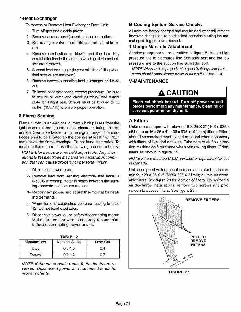
Page 71
7-Heat Exchanger
To Access or Remove Heat Exchanger From Unit:
1- Turn off gas and electric power.
2- Remove access panel(s) and unit center mullion.
3- Remove gas valve, manifold assembly and burn
ers.
4- Remove combustion air blower and flue box. Pay
careful attention to the order in which gaskets and ori
fice are removed.
5- Support heat exchanger (to prevent it from falling when
final screws are removed.)
6- Remove screws supporting heat exchanger and slide
out.
7- To install heat exchanger, reverse procedure. Be sure
to secure all wires and check plumbing and burner
plate for airtight seal. Screws must be torqued to 35
in.‐lbs. (155.7 N) to ensure proper operation.
8-Flame Sensing
Flame current is an electrical current which passes from the
ignition control through the sensor electrode during unit op
eration. See table below for flame signal range. The elec
trodes should be located so the tips are at least 1/2" (12.7
mm) inside the flame envelope. Do not bend electrodes. To
measure flame current, use the following procedure below:
NOTE-Electrodes are not field adjustable. Any alter
ations to the electrode may create a hazardous condi
tion that can cause property or personal injury.
1- Disconnect power to unit.
2- Remove lead from sensing electrode and install a
0-50DC microamp meter in series between the sens
ing electrode and the sensing lead.
3- Reconnect power and adjust thermostat for heat
ing demand.
4- When flame is established compare reading to table
12. Do not bend electrodes.
5- Disconnect power to unit before disconnecting meter.
Make sure sensor wire is securely reconnected
before reconnecting power to unit.
TABLE 12
Manufacturer Nominal Signal Drop Out
Utec 0.5-1.0 0.4
Fenwal 0.7-1.2 0.7
NOTE-If the meter scale reads 0, the leads are re
versed. Disconnect power and reconnect leads for
proper polarity.
B-Cooling System Service Checks
All units are factory charged and require no further adjustment;
however, charge should be checked periodically using the nor
mal operating pressure method.
1-Gauge Manifold Attachment
Service gauge ports are identified in figure 5. Attach high
pressure line to discharge line Schrader port and the low
pressure line to the suction line Schrader port.
NOTE-When unit is properly charged discharge line pres
sures should approximate those in tables 5 through 10.
V-MAINTENANCE
CAUTIONElectrical shock hazard. Turn off power to unitbefore performing any maintenance, cleaning orservice operation on the unit.
A-Filters
Units are equipped with eleven 16 X 25 X 2" (406 x 635 x
x51 mm) or 16 x 25 x 4" (406 x 635 x 102 mm) filters. Filters
should be checked monthly and replaced when necessary
with filters of like kind and size. Take note of air flow direc
tion marking on filter frame when reinstalling filters. Orient
filters as shown in figure 27.
NOTE-Filters must be U.L.C. certified or equivalent for use
in Canada.
Units equipped with optional outdoor air intake hoods con
tain four 20 X 25 X 2" (508 X 635 X 51mm) aluminum clean
able filters. See figure 28 for location of filters. On horizontal
air discharge installations, remove two screws and pivot
screen to access filters. See figure 29.
REMOVE FILTERS
FIGURE 27
PULL TOREMOVEFILTERS

Page 72
FIGURE 28
RETURN AIREND OF UNIT
OUTDOOR AIR FILTERS- VERTICAL AIRFLOW
OUTDOOR AIR FILTERS -HORIZONTAL AIRFLOW
B-Lubrication
All motors are lubricated at the factory. No further lubrication
is required.
Blower shaft bearings are prelubricated. For extended
bearing life, relubricate at least once every two years with a
lithium base grease, such as Alvania 3 (Shell Oil), Chevron
BRB2 (Standard Oil) or Regal AFB2 (Texas Oil). Use a hand
grease gun for relubrication. Add only enough grease to
purge through the bearings so that a bead of grease ap
pears at the seal lip contacts.
FILTER ACCESS HORIZONTAL DISCHARGE OUTDOOR AIRHOOD SCREEN
REMOVE TWO SCREWSTO ACCESS FILTERS
SCREEN
HOOD
FIGURE 29

Page 73
CAUTIONBe careful when servicing unit to avoid accidentalcontact with sharp metallic edges which maycause personal injury.
C-Supply Air Blower Wheel
Annually inspect supply air blower wheel for accumulated
dirt or dust. Turn off power before attempting to remove ac
cess panel or to clean blower wheel. If balancing clips are
removed, make sure they are reinstalled in the same loca
tion when cleaning is completed.
NOTE-Do not lose balancing clips.
D-Evaporator Coil
Inspect and clean coil at beginning of each season. Clean
using mild detergent or commercial coil cleanser. Check con
densate drain pan and line, if necessary. Flush coil and con
densate drain with water taking care not to get insulation,
filters and return air ducts wet. Check connecting lines
and coil for evidence of oil and refrigerant leaks.
E-Condenser Coil
Clean condenser coil annually with detergent or commer
cial coil cleaner and inspect monthly during the cooling
season. Check connecting lines and coil for evidence of
oil and refrigerant leaks.
NOTE-If owner complains of insufficient cooling, the unit
should be gauged and refrigerant charge checked. Re
fer to Gauge Manifold Attachment and Charging sec
tions in this manual.
F-Electrical
1- Check all wiring for loose connections.
2- Check for correct voltage at unit (unit operating).
3- Check amp-draw on both condenser fan motor and
blower motor.
G-Burners
1- Periodically examine burner flames for proper appear
ance during the heating season.
2- Before each heating season examine the burners for any
deposits or blockage which may have occurred.
3- Remove burners as shown in section IV-SYSTEM
SERVICE CHECKS figure 26 and clean as necessary.
Replace burners and check spark gap.
H-Combustion Air Inducer
Under normal operating conditions, the combustion air in
ducer wheel should be checked and cleaned prior to the
heating season. However, it should be examined periodi
cally during the heating season to establish an ideal clean
ing schedule. With power supply disconnected, the condi
tion of the inducer wheel can be determined by looking
through the vent opening.
Clean combustion air inducer as follows:
1- Shut off power supply and gas to unit.
2- Disconnect prove switch air tubing from combustion air
inducer port.
3- Remove and retain screws securing combustion air
inducer to flue box. Remove and retain the screw se
curing the combustion air inducer to the vent connec
tor. See figure 30.
4- Clean inducer wheel blades with a small brush and
wipe off any dust from housing. Clean accumulated
dust from front of flue box cover.
5- Return combustion air inducer motor to the original loca
tion and secure with retained screws. It is recommended
that the combustion air inducer gasket be replaced dur
ing reassembly.
6- Clean combustion air inlet screen on heat access panel
using a small brush.
FIGURE 30
CombustionAir Inducer
VentConnector
Secures ventto combustion
air inducer
Prove switch tubing
C.A.I Port
Flue Box
I-Flue Passageway and Flue Box
1- Remove combustion air inducer assembly as de
scribed in section H-.
2- Remove flue box cover. Clean with a wire brush as re
quired.

Page 74
3- Remove flue baffle retaining bracket and pull tube baf
fles from heat exchanger tubes. Clean tubes and baf
fles with a wire brush. Figure 14 shows a more detailed
view of the heat exchanger.
4- Reinsert tube baffles, secure baffle retaining bracket
and reassemble the unit. The flue box cover gasket and
combustion air inducer gasket should also be replaced
during reassembly.
VI-ACCESSORIES
The accessories section describes the application of most of
the optional accessories which can be factory or field installed
to either the LGH/LCH units.
A- S1CURB Mounting Frame
When installing the LGH/LCH units on a combustible surface ,
S1CURB roof mounting frame is used. The roof mounting
frames are recommended in all other applications but not re
quired. If the units are not mounted on a flat (roof) surface, they
MUST be supported under all edges and under the middle of
the unit to prevent sagging. The units MUST be mounted level
within 1/16" per linear foot or 5mm per meter in any direction.
The assembled S1CURB mounting frame is shown in figure
32. Refer to the roof mounting frame installation instructions for
details of proper assembly and mounting. The roof mounting
frame MUST be squared to the roof and level before mounting.
Plenum system MUST be installed before the unit is set on the
mounting frame. Typical roof curbing and flashing is shown in
figure 31. Refer to the roof mounting frame installation instruc
tions for proper plenum construction and attachment.
FIGURE 31
ROOFMOUNTING FRAME
(Extends around entireperimeter of unit)
FIBERGLASSINSULATION(Furnished)
COUNTER FLASHING(Field Supplied)
UNIT BASEBOTTOM
RIGID INSULATION(Field Supplied)
ROOFINGMATERIAL
CANT STRIP(Field Supplied)
NAILER STRIP(Furnished)
UNIT BASE RAIL
TYPICAL FLASHING DETAIL

Page 75
FIGURE 32
ASSEMBLED ROOF MOUNTING FRAME
BRACE
BRACE
BRACESUPPLY AIR DUCT
RETURN AIR DUCT
B- Outdoor Air Dampers
Dampers may be manually or motor (M) operated to allow up
to 25 percent outside air into the system at all times . Either air
damper can be installed in LGH/LCH units. Washable filter
supplied with the outdoor air dampers can be cleaned with
water and a mild Detergent and should be sprayed with Fil
ter Handicoater when dry prior to reinstallation. Filter Handi
coater is R.P. Products coating no. 418 and is available as Part
No. P-8-5069.
OUTDOOR AIR DAMPER
FIGURE 33
ACTUATOR“M" MODEL ONLY
C-Economizer
(Factory Installed)
Unit may contain an optional modulating economizer con
trolled by the A55 Unit Controller. Economizer dampers
modulate open to use outdoor air for free cooling when tem
perature is suitable during the occupied time period. Refer
to economizer section of unit installation instruction for set
up and operation.

Page 76
Units Equipped With An Energy Recovery Wheel
The economizer minimum damper position must be ad
justed to allow for the air resistance of the ERW.
1- Determine the required outdoor air CFM.
2- Apply the CFM to table 13 to determine the target static
pressure drop across the ERW.
3- Measure the static pressure drop across the ERW. See
figure 34.
4- Adjust the damper to minimum position open.
5- Read the static pressure drop across the ERW and ad
just the damper position as needed to reach the target
pressure drop.
For example, a unit with an outdoor air flow of 6500 CFM
would require an ERW pressure drop of 0.9"w.c.
TABLE 13
Outdoor Flow - cfm Static Pressure - in. w.c.
3250 0.45
3500 0.48
3750 0.52
4000 0.55
4250 0.59
4500 0.62
4750 0.66
5000 0.69
5250 0.73
5500 0.76
5750 0.80
6000 0.83
6250 0.87
6500 0.90
6750 0.94
7000 0.97
7250 1.01
7500 1.04
7750 1.08
8000 1.11
8250 1.15
8500 1.18
8750 1.22
9000 1.25
MEASURE ERW PRESSURE DROP
FIGURE 34
RETURN
AIR
POWER
EXHAUST
Measure the static pressure
drop across the ERW
OUTDOOR
AIR
D-Supply Air Variable Frequency Drive(VAV units only)
LGH/LCH VAV units will contain a supply air blower
equipped with a variable frequency drive A96 (VFD) which
varies supply air CFM. As duct static increases, the supply
air volume will decrease. As duct static decreases, the sup
ply air volume will increase.
The Unit Controller uses input from a field-installed pres
sure transducer (A30) to maintain a 1.0" w.c. (default) static
pressure. Refer to the Unit Controller manual Parameters
386, 387, 388 and 389 to adjust the static pressure setpoint.
Install the transducer according to manufacturer's instruc
tions.
Note -Make sure the transducer is installed in the main duct
at least 2/3 of the distance away from the unit.
The supply air VFD (A96) is located on the front side of the
unit in the return air compartment. See figure 35.
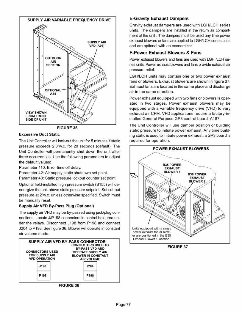
Page 77
FIGURE 35
SUPPLY AIR VARIABLE FREQUENCY DRIVE
SUPPLY AIRVFD (A96)
OUTDOORAIR
SECTION
VIEW SHOWNFROM FRONTSIDE OF UNIT
OPTIONALA34
Excessive Duct Static
The Unit Controller will lock-out the unit for 5 minutes if static
pressure exceeds 2.0"w.c. for 20 seconds (default). The
Unit Controller will permanently shut down the unit after
three occurrences. Use the following parameters to adjust
the default values:
Parameter 110: Error time off delay.
Parameter 42: Air supply static shutdown set point.
Parameter 43: Static pressure lockout counter set point.
Optional field-installed high pressure switch (S155) will de-
energize the unit above static pressure setpoint. Set cut-out
pressure at 2"w.c. unless otherwise specified. Switch must
be manually reset.
Supply Air VFD By-Pass Plug (Optional)
The supply air VFD may be by-passed using jack/plug con
nections. Locate J/P198 connectors in control box area un
der the relays. Disconnect J198 from P198 and connect
J204 to P198. See figure 36. Blower will operate in constant
air volume mode.
FIGURE 36
SUPPLY AIR VFD BY-PASS CONNECTOR
CONNECTORS USEDFOR SUPPLY AIRVFD OPERATION
CONNECTORS USED TOBY-PASS VFD AND
OPERATE SUPPLY AIRBLOWER IN CONSTANT
AIR VOLUME
J198
P198
J204
P198
E-Gravity Exhaust Dampers
Gravity exhaust dampers are used with LGH/LCH series
units. The dampers are installed in the return air compart
ment of the unit . The dampers must be used any time power
exhaust blowers or fans are applied to LGH/LCH series units
and are optional with an economizer.
F-Power Exhaust Blowers & Fans
Power exhaust blowers and fans are used with LGH /LCH se
ries units. Power exhaust blowers and fans provide exhaust air
pressure relief.
LGH/LCH units may contain one or two power exhaust
fans or blowers. Exhaust blowers are shown in figure 37.
Exhaust fans are located in the same place and discharge
air in the same direction.
Power exhaust equipped with two fans or blowers is oper
ated in two stages. Power exhaust blowers may be
equipped with a variable frequency drive (VFD) to vary
exhaust air CFM. VFD applications require a factory-in
stalled General Purpose GP3 control board A187.
The Unit Controller will use damper position or building
static pressure to initiate power exhaust. Any time build
ing static is used to initiate power exhaust, a GP3 board is
required for operation.
FIGURE 37
POWER EXHAUST BLOWERS
B35 POWEREXHAUSTBLOWER 1
B36 POWEREXHAUSTBLOWER 2
Units equipped with a singlepower exhaust fan or blower are positioned in the B35Exhaust Blower 1 location.
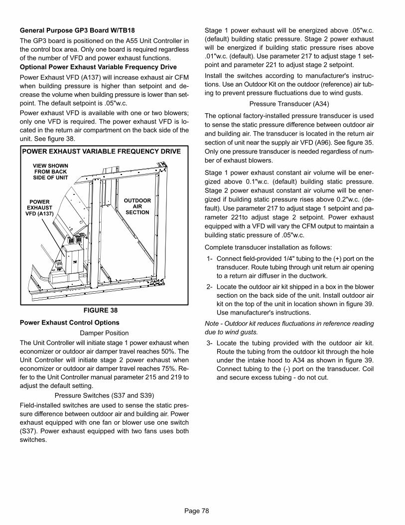
Page 78
General Purpose GP3 Board W/TB18
The GP3 board is positioned on the A55 Unit Controller in
the control box area. Only one board is required regardless
of the number of VFD and power exhaust functions.
Optional Power Exhaust Variable Frequency Drive
Power Exhaust VFD (A137) will increase exhaust air CFM
when building pressure is higher than setpoint and de
crease the volume when building pressure is lower than set
point. The default setpoint is .05"w.c.
Power exhaust VFD is available with one or two blowers;
only one VFD is required. The power exhaust VFD is lo
cated in the return air compartment on the back side of the
unit. See figure 38.
FIGURE 38
POWER EXHAUST VARIABLE FREQUENCY DRIVE
POWEREXHAUSTVFD (A137)
OUTDOORAIR
SECTION
VIEW SHOWNFROM BACKSIDE OF UNIT
Power Exhaust Control Options
Damper Position
The Unit Controller will initiate stage 1 power exhaust when
economizer or outdoor air damper travel reaches 50%. The
Unit Controller will initiate stage 2 power exhaust when
economizer or outdoor air damper travel reaches 75%. Re
fer to the Unit Controller manual parameter 215 and 219 to
adjust the default setting.
Pressure Switches (S37 and S39)
Field-installed switches are used to sense the static pres
sure difference between outdoor air and building air. Power
exhaust equipped with one fan or blower use one switch
(S37). Power exhaust equipped with two fans uses both
switches.
Stage 1 power exhaust will be energized above .05"w.c.
(default) building static pressure. Stage 2 power exhaust
will be energized if building static pressure rises above
.01"w.c. (default). Use parameter 217 to adjust stage 1 set
point and parameter 221 to adjust stage 2 setpoint.
Install the switches according to manufacturer's instruc
tions. Use an Outdoor Kit on the outdoor (reference) air tub
ing to prevent pressure fluctuations due to wind gusts.
Pressure Transducer (A34)
The optional factory-installed pressure transducer is used
to sense the static pressure difference between outdoor air
and building air. The transducer is located in the return air
section of unit near the supply air VFD (A96). See figure 35.
Only one pressure transducer is needed regardless of num
ber of exhaust blowers.
Stage 1 power exhaust constant air volume will be ener
gized above 0.1"w.c. (default) building static pressure.
Stage 2 power exhaust constant air volume will be ener
gized if building static pressure rises above 0.2"w.c. (de
fault). Use parameter 217 to adjust stage 1 setpoint and pa
rameter 221to adjust stage 2 setpoint. Power exhaust
equipped with a VFD will vary the CFM output to maintain a
building static pressure of .05"w.c.
Complete transducer installation as follows:
1- Connect field-provided 1/4" tubing to the (+) port on the
transducer. Route tubing through unit return air opening
to a return air diffuser in the ductwork.
2- Locate the outdoor air kit shipped in a box in the blower
section on the back side of the unit. Install outdoor air
kit on the top of the unit in location shown in figure 39.
Use manufacturer's instructions.
Note - Outdoor kit reduces fluctuations in reference reading
due to wind gusts.
3- Locate the tubing provided with the outdoor air kit.
Route the tubing from the outdoor kit through the hole
under the intake hood to A34 as shown in figure 39.
Connect tubing to the (-) port on the transducer. Coil
and secure excess tubing - do not cut.

Page 79
FIGURE 39
ROUTE TUBING TO OUTDOOR (REFERENCE) AIR
ROUTE REFERENCETUBING THROUGH
HOLE TO (A34)
INSTALL OUTDOORAIR KIT ON UNIT
TO A34TRANSDUCER
Power Exhaust VFD By-Pass Plug (Optional)
The power exhaust VFD may be by-passed using jack/plug
connections. Locate J/P211 connectors in control box area
under the relays. Disconnect J211 from P211 and connect
J215 to P211. See figure 40. Exhaust blower will operate at
maximum speed.
FIGURE 40
POWER EXHAUST VFD BY-PASS CONNECTOR
CONNECTORS USEDFOR EXHAUST VFD
OPERATION
CONNECTORS USED TO BY-PASS VFD AND OPERATE
EXHAUST BLOWER ATMAXIMUM SPEED
J211
P211
J215
P211
G-Control Systems The A55 Unit Controller provides all control function for the
rooftop unit. Default operation requires a standard room
thermostat or direct digital controller (DDC). The A55 can al
so control the unit from a zone temperature sensor. The A55
Unit Controller is a network controller when daisy-chained
to the L Connection Network Control System. For ease of
configuration, the A55 can be connected to a PC with Unit
Controller PC software installed.
H-Smoke Detectors A17 and A64 Photoelectric smoke detectors are a factory installed op
tion. The smoke detectors can be installed in the supply air
section (A64), return air section (A17), or in both the supply
and return air section. Wiring for the smoke detectors are
shown on the temperature control section (C2) wiring dia
gram in back of this manual.
I-Energy Recovery Wheel
LGH/LCH units may contain an optional energy recovery
wheel. The ERW is located in the outdoor air entering and
exhaust air streams. In the heating mode, the wheel rotates
to transfer heat from the exhaust air stream to the outdoor
air intake air stream. In the cooling mode the process re
verses. See figure 41.
The ERW motor (B28) is energized when outdoor air is
above 65°F (monitored by S125), or below 40°F monitored
by S23). Between the temperature range of 40°F and 65°F
the wheel does not operate. This range is for economizer
operation. Thermostats S125 and S23 are located on a pan
el above the inverter for the indoor blower. Refer to wiring
diagram on unit panels.
ENERGY RECOVERY WHEEL
DIVISIONPANEL
ERWMOTOR
BY-PASSDAMPERS
ERWWHEEL
OUTDOORAIR
FIGURE 41
EXHAUSTAIR
EXHAUSTAIR
Note - When the outdoor air temperature is between 65°F
and 40°F, DL43 will energize the ERW for one minute every
ten minutes to clean the wheel.
The adjustable S36 end switch will energize by-pass damp
ers open as outdoor air dampers open. By-pass dampers
will close as outdoor air dampers close or move to minimum
position.
ERW should operate on unit start-up unless the outdoor
temperature is between 40°F and 65°F. When outdoor air
temperature is between 40°F and 65°F, install a jumper be
tween S125 thermostat terminal “R" and K94 relay coil ter
minal “A" to check ERW operation.

Page 80
J-Blower Proving Switch S52 The blower proving switch monitors blower operation and
locks out the unit in case of blower failure. The switch is N.O.
and closes at 0.14" W.C. (34.9 Pa) The switch is mounted
on the upper left hand corner of the blower deck. Wiring for
the blower proving switch is shown on the temperature control
section (C2) wiring diagram in back of this manual.
K-Dirty Filter Switch S27
The dirty filter switch senses static pressure increase indi
cating a dirty filter condition. The switch is N.O. and closes
at 1" W.C. (248.6 Pa) The switch is mounted on the top filter
channel corner. Wiring for the dirty filter switch is shown on the
temperature control section (C2) wiring diagram in back of this
manual. Actuation of this switch does not affect unit operation.
L-Indoor Air Quality (CO2) Sensor A63
The indoor air quality sensor monitors CO2 levels and re
ports the levels to the A55 Unit Controller. The board ad
justs the economizer dampers according to the CO2 lev
els. The sensor is mounted next to the indoor thermostat or
in the return air duct. Refer to the indoor air quality sensor
installation instructions for proper adjustment. Wiring for
the indoor air quality switch is shown on the temperature
control section (C2) wiring diagram in back of this manual.
M-Drain Pan Overflow Switch S149
(optional)
The overflow switch is used to interrupt cooling opera
tion when excessive condensate collects in the drain
pan. The N.O. overflow switch is controlled by K220 and
DL46 relays, located in the unit control panel. When the
overflow switch closes, 24VAC power is interrupted and
after a five-second delay unit compressors are de-ener
gized. Once the condensate level drops below the set
level, the switch will open. After a five-minute delay the
compressor will be energized.
N-Factory-Installed Humiditrol
General
Humiditrol units provide a dehumidifying mode of opera
tion. These units contain a reheat coil adjacent to and
downstream of the evaporator coil. Reheat coil solenoid
valves, L14 and L30, route hot discharge gas from the
compressor to the reheat coil. Return air pulled across the
evaporator coil is cooled and dehumidified; the reheat coil
adds heat to supply air.
See figure 42 for reheat refrigerant routing.
L14 and L30 Reheat Coil Solenoid Valves
When Unit Controller input (P269-9) indicates room condi
tions require dehumidification, L14 and L30 reheat valves
are energized and refrigerant is routed to the reheat coil.
Reheat Setpoint
Reheat is factory-set to energize when indoor relative humid
ity rises above 60% (default). Reheat will terminate when the
indoor relative humidity falls 3% below setpoint, or 57% (de
fault). The reheat setpoint can be adjusted by changing pa
rameter 106. A setting of 100% will disable reheat. The reheat
setpoint can also be adjusted using an optional Network Con
trol Panel (NCP).
A91 Humidity Sensor
Relative humidity should correspond to the sensor (A91)
output voltage listed in table 14. For example: if indoor air
relative humidity is 80% + 3%, the humidity sensor output
should read 8.00VDC.
Check the sensor output annually for accuracy. Keep the air
intake openings on the sensor clean and free of obstruc
tions and debris.
Read Relative Humidity At Unit Controller
When relative humidity sensor is installed, the relative hu
midity percentage can be displayed on the M3 unit con
troller and over the L Connection network via the network
control panel or computer software client.
TABLE 14
Relative Humidity (%RH + 3%) Sensor Output (VDC)
20 2.00
30 3.00
40 4.00
50 5.00
60 6.00
70 7.00
80 8.00
90 9.00

Page 81
FIGURE 42
REHEAT MODE REFRIGERANT ROUTING
2
1
2
3
4
12
S
1
REFRIGERANT
REFRIGERANT
REFRIGERANT
S
3
4
Evaporator Coils(Row Split)
Reheat Coils
CondenserCoils
OutdoorAir
Compressors
NOTE:Circuit 1 and Circuit 2 are similarCircuit 3 and Circuit 4 are similar
1 REFRIGERANT CIRCUIT 1
2 REFRIGERANT CIRCUIT 2
3 REFRIGERANT CIRCUIT 3
4 REFRIGERANT CIRCUIT 4
REHEAT VALVEREHEAT VALVE
CHECK VALVE
THERMALEXPANSIONVALVE
Check-Out
Test Humiditrol operation using the following procedure.
1- Make sure reheat is wired as shown in wiring section.
2- Make sure unit is in local thermostat mode.
3- Select Unit Controller Service - Test - Dehumidifier 1 &
2. The blower, compressor 1 and compressor 2 (reheat)
should be operating. L14 and L30 LED's on the Unit
Controller should also be ON, indicating the reheat
valves are energized. Reheat mode will appear on the
Unit Controller display.
4- De-Select Unit Controller Service - Test - Dehumidifier
1 & 2. Compressor 1 and 2 (reheat) should de-energize,
L14 and L30 LED's should go OFF, blower should still
be energized.
Reheat Operation
The following conditions must be met before reheat will be
energized:
1- Blower must be operating.
2- System must be in occupied mode.
3- System must NOT be operating in heating mode.
4- One cooling demand is required if the unit has been in
heating mode, the Unit Controller has been reset, or at
initial unit start-up.
IMPORTANT - Free cooling does not operate during re
heat. Free cooling will operate as shown in the Unit
Controller manual.
Reheat will operate as shown in table 15.
For other reheat control options, refer to the Unit Controller
manual.
Units are shipped from the factory to provide two stages of
cooling.
Three stages of cooling is available by installing a transfer
relay and a three-stage thermostat.
Four stages of cooling is available in zone sensor mode.
Compressors are not de-energized when unit operation
changes from cooling to reheat or from reheat to cooling. In
stead, L14 and L30 reheat valves are energized (reheat) or
de-energized (cooling).

Page 82
TABLE 15REHEAT OPERATION
Two-Stage Thermostat (2 Cooling Stages, Y1, Y2) -4 Compressors Models:
Demand Compressors Blower Speed EconPos
RH Valve
T'stat Hum 1 2 3 4 C1 C2 C3 C4 1 2
Yes On On Off Off X Min On On
Y1 Yes On On Off Off X Min On On
Y2 Yes On On Off Off X Min Off Off
Three-Stage Thermostat (3 Cooling Stages Y1, Y2, Y3)- 4 Compressor Models:
Demands Compressors Blower Speed EconPos
RH Valve
T' stat Hum 1 2 3 4 C1 C2 C3 C4 1 2
Yes On On Off Off X Min On On
Y1 Yes On On On Off X Min On On
Y2 Yes On On On On X Min On Off
Y3 Yes On On On On X Min Off Off
Zone Sensor (4 Cooling Stages Y1, Y2, Y3, Y4) - 4 Compressors
Demands Compressors Blower Speed EconPos
RH Valve
T'stat Hum 1 2 3 4 C1 C2 C3 C4 1 2
Yes On On Off Off X Min On On
Y1 Yes On On Off Off X Min On On
Y2 Yes On On Off Off X Min On On
Y3 Yes On On Off Off X Min On Off
Y4 Yes On On Off Off X Min Off Off
1- Blower must be operating.
2- System must be in occupied mode.
3- System must NOT be operating in heating mode.
4- One cooling demand is required if the unit has been in
heating mode, the Unit Controller has been reset, or at
initial unit start-up.

Page 83
O-Modulating Gas Valve (MGV)
FIGURE 43
MODULATING GAS VALVE (MGV)
GV1LEFT HEAT
SECTION GASVALVE
GV3RIGHT HEAT
SECTION GASVALVE
GV5RIGHT HEAT SECTION
MODULATINGGAS VALVE
GV4LEFT HEAT SECTION
MODULATINGGAS VALVE
TO LEFT HEATSECTION
TO RIGHTHEAT SECTION
MANIFOLDPRESSURE
PORT
MANIFOLDPRESSURE PORT
GASINLET
Units equipped with optional modulating gas valves (MGV)
contain two modulating gas valves in addition to two stan
dard gas valves. See figure 43.
Operation
The Unit Controller will control modulating gas valves to
maintain 110°F (default) discharge air during the heating cy
cle. The left heat section will operate when 25-50% of
nameplate heat is needed. Both heat sections will operate
when 50-100% of the nameplate heat is needed.
The normally open MGV will allow full heating capacity
should the MGV fail.
Start-Up
1- Operate the unit in heating mode according to the Heat
ing Start-Up section in this manual.
2- After the unit has operated for 5 minutes navigate the
following menu path on the unit controller: MAIN MENU
-> SERVICE -> TEST -> HEAT -> HEAT 2. The unit will
operate at maximum heating capacity.
3- Measure the manifold pressure at the gas valves. Man
ifold pressures should be:
GV1 & GV3:
Natural - 4.0"w.c. LP - 10.8"w.c.
GV4 & GV5:
Natural - 3.7"w.c. LP - 10.5"w.c.
4- After the unit has operated for 5 minutes navigate the
following menu path on the unit controller: MAIN MENU
-> SERVICE -> TEST -> HEAT -> HEAT 1. The unit will
operate at minimum heating capacity.
5- Measure the manifold pressure at the gas valves. Man
ifold pressures should be:
GV1 & GV3:
Natural - 4.0"w.c. LP - 10.8"w.c.
GV4 & GV5:
Natural - 0.9"w.c. LP - 2.6"w.c.
NOTE - BOTH OPT1 AND OPT2 SWITCHES MUST BEOFF FOR NORMAL UNIT OPERATION.
FIGURE 44
GP3 DIP Switches set to OFF, OFF
A55GP3
Unit Controller Output
The Unit Controller 0-10VDC output to the MGVs increases
to modulate valves further closed during a reduced heating
demand. The Unit Controller 0-10VDC output to the MGVs
decreases to modulate valves further open during a higher
heating demand.
HeatingDemandReduces
A55 OutputTo MGVsIncreases
MGVsModulateFurtherClosed
HeatingOutputLowers
HeatingDemandIncreases
A55 OutputTo MGVsReduces
MGVsModulateFurtherOpen
HeatingOutputIncreases

Page 84
P-Outdoor Air CFM Control
Outdoor air CFM Control is a factory-installed option avail
able on units equipped with a supply air variable frequency
drive (VFD) and economizer.
The Unit Controller modulates outdoor air dampers to main
tain a constant amount of outdoor air regardless of blower
speed. This ensures minimum ventilation requirements are
met at lower supply air volumes.
The Unit Controller uses a velocity sensor (A24) that con
nects to P298 on A55 unit controller to modulate dampers.
The sensor is located in the outdoor air stream. See figure
45.
Configuring ID Settings
1- Enable the Outdoor Air Control feature and set the ve
locity sensor range using the M3 Unit Controller SETUP
> INSTALL menu. Navigate to Configuration ID 1. Set
position 8 to:
H Outdoor air control installed with A24 control set for
low range (0-1968ft/min)
Note - The configuration ID velocity range must be set to "H"
and the jumper setting on the A24 control must be set at low
range. No other combinations may be used with the
100501-02 sensor. The jumper is factory-set at low range
(0-1968ft/min)
2- Operate the blower in high speed and adjust the mini
mum damper position. Use SETUP > TEST & BAL
ANCE > DAMPER > MIN DAMPER POSITION menu.
Adjust minimum damper position and press SAVE. The
Unit Controller will automatically save and display the
velocity setpoint. Press SAVE again to confirm.
Note - The minimum damper position setting MUST be set
lower than the OAC max damper position setting (50% de
fault). To modify the max damper position setting, navigate
to SETTINGS > EDIT PARAMETERS and select parameter
117 (DCV MAX DAMPER OPEN).
Additional outdoor air CFM control settings are available.
See parameters 117 and 134 in the Unit Controller manual.
Make adjustments through the SETTINGS > EDIT PARAM
ETERS menu; select the required parameter.
3- Replace A24 control cover.
Velocity Sensor Settings
The A24 control is factory-set for 0-10m/s. (0-1968ft/min.)
VELOCITY SENSOR LOCATION
RETURN AIR
OUTDOOR
AIR
SENSOR LOCATION IN
DOWNFLOW DIS
CHARGE APPLICATIONS
SENSOR LOCATION IN
HORIZONTAL DISCHARGE
APPLICATIONS
DOWNFLOW
O.A. FILTER
HORIZONTAL
O.A. FILTER
FIGURE 45
FIGURE 46
VELOCITY SENSOR (A24) JUMPER SETTINGS
V+GND
AV
0-10m/s (0-1968ft/min.)
24VAC
Common
Airflow Output
(0-10VDC)
123
JUMPERS
t90HIMEDLOIU
t90HI
MEDLOI
U
Sets respond time to 4 sec.
Sets output signal to voltage
Q-Factory Installed Hot Gas Bypass (HGB)
Hot gas bypass is a factory-installed option only. The HGB
valve routes refrigerant from the discharge line to the suc
tion line to keep the evaporator coil from icing when supply
air volume is low. The HGB valve will start to open when the
suction pressure drops below 105 psig (R410A). The de-su
perheating TXV routes cooler gas from the liquid line to the
suction line. This prevents high refrigerant temperatures in
the compressor. See figure 47 for components and figure 48
for refrigerant routing.

Page 85
FIGURE 47
HOT GAS BYPASS (HGB) PIPING - REFRIGERANT CIRCUIT 1 ONLY
DE-SUPERHEATING TXV
HOT GASBYPASS
(HGB) VALVE
SERVICEVALVE
SUCTIONLINE
FROMDISCHARGE
LINE
FROMLIQUID
LINE
HGB valve starts to openwhen suction pressure dropsbelow 105psig or (34°F evap
orator temperature.
REFRIGERANT CIRCUIT 1
Compressor 1
ManualShut-Off
Valve
CondenserCircuit 1
EvaporatorCircuit 1
CAV Units
HGB Valve
De-Superheating TXV
Equalizer
Lines
Suction - GasSuction - Gas
Discharge - Hot Gas
LiquidLiquid
Hot Gas
Tempered
Hot Gas
EvaporatorCircuit 1
VAV Units
FIGURE 48

Pag
e 8
6
1
2
3
4
7
8
11
10
13
2
2
16
12
6
CB8
EQUIPGROUND
NOTE: USE COPPERCONDUCTORS ONLY
1 2 0 VAC F I E L DP R O V I D E D
P O W E R S U PPL YI S R E Q U I R E D
B2 B20B1
F10
B13
L1 L2 L3
T1 T2 T3
L1 L2 L3
T1 T2 T3
L1 L2 L3
T1 T2 T3
L1 L2 L3
T1 T2 T3
K14
9A
B
K15
0A
B
K15
3A
B
K15
2A
B
K10
A
B
K68
A
B
K2
A
B
K14
A
B
K1
A
B
K14
6A
B
K20
1A
B
4
5 5
K10−3
9
6
K15
0−1 7
4
K68−3
9
6
K68−
1 7
4
K14
9−39
6
K14
9−1 7
4
K15
2−1 7
4K15
0−39
6 K15
2−39
6 K15
3−39
6
F38F37
B35 B36
L1 L2 L3
T1 T2 T3
L1 L2 L3
T1 T2 T3
TB
58
TB
59
K19
9A
B
9 8
24V COMMON
24V POWER
66
7
2
7
4
3
T43
T43
L14
L30
DI 4
RSV
R
A55
R S T
W VU G
GA96
K20
3−39
6
STF
A96
SD
10
+
−SE
TR
A
+S
A30
+
−SE
TR
A
+S A34
12
5 5
K20
3 A
B
0-10 VDC IN
C
B
GND
0-10 VDC IN
GND
COM
DI2
DI1
10
5
2 RELAY
GND
FB
(IDB)PWM1/VO
NOTE − IF ANY WIRE IN THIS APPLIANCE IS REPLACED ITMUST BE REPLACED WITH WIRE OF LIKE SIZE, RATING,
TERMINATION AND INSULATION THICKNESS.
WARNING − ELECTRIC SHOCK HAZARD, CAN CAUSE INJURYOR DEATH . UNIT MUST BE GROUNDED IN ACCORDANCEWITH NATIONAL AND LOCAL CODES.DISCONNECT ALL POWER BEFORE SERVICING.
24V POWER
13
K1-2
K2-2
K14-2
K146-2
13
13
R55
PC
24VCOM
14
J248
14
14
14
B43
2 1B5
32 1
B213
2 1B22
32 1
B233
2 1B24
32 1
1
15
1 P.E LESS INVERTER WIRING SHOWN
2 ONLY ON UNITS WITH HUMIDITROLOPTION
3 EXTERNAL HUMIDITROL CONTACTS
4CONNECTS TO SECTION ”A” HEATINGDIAGRAM, MAY BE LOCATED IN HEATINGCOMPARTMENT
5 S49,S50,S53 AND S95 ARE PART OF 5VDCCIRCUIT
6F37 AND F38 ARE NOT USED ON UNITSLESS ELECTRIC HEAT, 480 AND 600 V
7 S37 AND S39 PRESSURE SWITCH CONTROLFOR POWER EXHAUST
8 VOLTAGE CONTROL SINGLE STAGE P.E
9 VOLTAGE CONTROL TWO STAGE P.E
10A30 SENSOR FOR B3 SUPPLY AIR BLOWERIN VAV APPLICATIONS ONLY
11
12
A34 SENSOR AND A137 INVERTERCONTROL FOR B35 AND B36 EXHAUST AIRBLOWERS
A30 MAY BE USED WITH OR WITHOUT A34A34 MAY BE USED WITH OR WITHOUT A30
13FOR UNITS WITH BYPASS OPTION, PLEASEREFER TO SECTION 3B WIRING DIAGRAM
14FOR POWER EXHAUST INVERTER
REFER TO SECTION 5B WIRINGDIAGRAM
15UNITS WILL COME EQUIPPED WITH EITHER S48, CB10 OR TB2 AS POWER ENTRY OPTIONS
3
3
8
6 6
14
169 9
COOLING - VFD
REV. 0

Pag
e 8
7
DESCRIPTIONKEY COMPONENTA30 SENSOR, DUCT STATIC PRESSURE
A34 SENSOR, DIFFERENTIAL PRESSURE
A55 CONTROL BOARD, MAIN
A96 CONTROL, INVERTER SUPPLY
B1 COMPRESSOR 1
B2 COMPRESSOR 2
B3 MOTOR, BLOWER
B4 MOTOR, OUTDOOR FAN 1
B5 MOTOR, OUTDOOR FAN 2
B13 COMPRESSOR 3
B20 COMPRESSOR 4
B21 MOTOR, OUTDOOR FAN 3
B22 MOTOR, OUTDOOR FAN 4
B23 MOTOR, OUTDOOR FAN 5
B24 MOTOR, OUTDOOR FAN 6
B35 MOTOR, EXHAUST BLOWER 1
B36 MOTOR, EXHAUST BLOWER 2
C1 CAPACITOR, OUTDOOR FAN 1
C2 CAPACITOR, OUTDOOR FAN 2
C18 CAPACITOR, OUTDOOR FAN 3
C19 CAPACITOR, OUTDOOR FAN 4
C20 CAPACITOR, OUTDOOR FAN 5
C21 CAPACITOR, OUTDOOR FAN 6
CB8 CIRCUIT, BREAKER T1
CB10 CIRCUIT BREAKER, MAIN DISCONNECT UNIT
CB18 CIRCUIT, BREAKER T18
F10 FUSE, OUTDOOR FAN MOTOR
F30 FUSE, TRANSFORMER T29 PRIMARY
F31 FUSE, TRANSFORMER T29 SECONDARY
F37 FUSE, COMPRESSOR GROUP 1
F38 FUSE, COMPRESSOR GROUP 2
HR1 HEATER COMPRESSOR 1
HR2 HEATER COMPRESSOR 2
HR5 HEATER COMPRESSOR 3
HR11 HEATER COMPRESSOR 4
RT17 SENSOR, OUTDOOR AIR
S4 SWITCH, LIMIT HI PRESS COMPRESS 1
S7 SWITCH, LIMIT HI PRESS COMPRESS 2
S11 SWITCH, LOW PRESS, LOW AMBIENT KIT COMP 1
S28 SWITCH, LIMIT HI PRESS COMPRESS 3
S37 SWITCH, PRESSURE EXHAUST FAN
S39 SWITCH, PRESSURE EXHAUST FAN
S48 SWITCH, DISCONNECT
S49 SWITCH, FREEZE STAT COMPRESS 1
S50 SWITCH, FREEZE STAT COMPRESS 2
S53 SWITCH, FREEZE STAT COMPRESS 3
S84 SWITCH, LOW PRESS, LOW AMBIENT KIT COMP 2
S85 SWITCH, LOW PRESS, LOW AMBIENT KIT COMP 3
S87 SWITCH, LOW PRESS, COMP 1
S88 SWITCH, LOW PRESS, COMP 2
S94 SWITCH, LOW PRESS, LOW AMBIENT KIT COMP 4
S95 SWITCH, FREEZE STAT COMPRESS 4
S96 SWITCH, LIMIT HI PRESS COMPRESS 4
S97 SWITCH, LOW PRESS, COMP 4
S98 SWITCH, LOW PRESS, COMP 3
S117 SWITCH, GFI
T1 TRANSFORMER, CONTROL
T18 TRANSFORMER, CONTACTOR
T29 TRANSFORMER, GFI
TB13 TERMINAL BLOCK, POWER DISTRIBUTION
TB18 TERMINAL STRIP, CYCLE CONTROL
TB25 TERMINAL BLOCK, BLOWER
TB40 TERMINAL BLOCK, COMPRESSOR 1
TB41 TERMINAL BLOCK, COMPRESSOR 2, 3 & 4
TB47 TERMINAL STRIP, OUTDOOR FANS
TB58 TERMINAL BLOCK, POWER EXHAUST
TB59 TERMINAL BLOCK, POWER EXHAUST
J/P JACK / PLUG DESCRIPTION11 GFI, RECEPTACLE
86 OUTDOOR FAN INTERFACE
87 OUTDOOR FAN INTERFACE 2
118 COMPRESSOR 3 AND 4, CONTROL
119 COMPRESSOR 3 AND 4, INPUT
248 VFD CONTROL
263 HIGH AND LOW PRESSURE SWITCHES
264 BLOWER DECK
265 CONTACTORS AND RELAYS267 OUTDOOR FAN AREA
268 TRANSFORMER 1 POWER
269 HUMIDITROL
299 HUMIDITROL INTERFACE
K1 CONTACTOR, COMPRESSOR 1
K2 CONTACTOR, COMPRESSOR 2
K10 RELAY, OUTDOOR FAN 1
K14 CONTACTOR, COMPRESSOR 3
K68 RELAY, OUTDOOR FAN 2
K146 CONTACTOR, COMPRESSOR 4
K149 RELAY, OUTDOOR FAN 3
K150 RELAY, OUTDOOR FAN 4
K152 RELAY, OUTDOOR FAN 5
K153 RELAY, OUTDOOR FAN 6
K199 CONTACTOR, EXHAUST STG 1
K201 CONTACTOR, EXHAUST STG 2
K203 RELAY, INVERTER CONTROL
L14 VALVE, SOLENOID REHEAT COIL 1
A178
A187
L30 VALVE, SOLENOID REHEAT COIL 2
TB24 TERMINAL STRIP, UNIT ADDER
348 CONTROL, GENERAL PURPOSE GP3
259 BLOWER ECM MOTOR
R55 RESISTOR, VFD LOADING, A96
TB2 TERMINAL BLOCK, POWER DISTRIBUTION
COOLING - VFD
REV. 0
537844-01 KEY

Pag
e 8
8
SEQUENCE OF OPERATION - M3 UNIT CONTROLLERPower:
1- Line voltage from TB2, unit disconnect S48, or other factory or field installedoptional power disconnects, such as CB10, energizes transformer T1 and T18.Transformer T1 provides 24VAC power to A55 Unit Controller and T18 provides 24VAC power to A178 Compressor 3 & 4 Controller. The two Controllersprovide 24VAC power to the unit cooling, heating and blower controls and thermostat.
2- Terminal strip TB40, TB41 and TB47 are also energized when the unit disconnect closes. These terminal strips supply line voltage to compressor crankcaseheaters, compressors, blower motors and fan motors.
Blower Operation (OCP input must be on):3- The main control module A55 receives a demand from thermostat terminal G.
A55 energizes inverter relay K203 with 24VAC.
4- N.O. K203‐3 closes, energizing inverter A96 energizing blower B3.1st Stage Cooling
5- First stage cooling demand energizes Y1 and G in the thermostat. G energizesblower, if blower is not already running (see step 3).
6- 24VAC is routed to the A55 Unit Controller. After A55 proves N.C. low pressureswitches S87 and S88, N.C. freezestats S49 and S50 and N.C. high pressureswitches S4 and S7, compressor contactors K1 and K2 are energized.
7- N.O. contacts K1-1 and K2-1 close energizing compressor B1 and B2.
8- A55 Unit Controller and A178 Compressor 3 and 4 Controller energize fan contactors K10, K68 and K149 based on low ambient switch S11 and S84 inputsand pre-defined control logic.
9- N.O. contacts K10-1, K68-1 and K149-1 close energizing condenser fan B4, B5and B21.
10-N.C. auxilary switches on K1 and K2 compressor contactors open de-energizing crankcase heater HR1 and HR2.
2nd Stage Cooling
11- Second stage cooling demand energizes Y2.
12-24VAC is routed to A178 Compressor 3 and 4 Controller. After A178 provesN.C. low pressure switches S98 and S97, N.C. freezestats S53 and S95 andN.C. high pressure switches S28 and S96, compressor contactors K14 andK146 are energized.
13-N.O. contacts K14-1 close energizing compressor B13.
14-N.O. contacts K146-1 close energizing compressor B20.
15-A178 Compressor 3 and 4 Controller energizes fan contactors K150, K152 andK153 based on low ambient switch S85 and S94 inputs and pre-defined UnitController logic.
16-N.O. contacts K150-1, K152-1 and K153-1 close energizing condenser fansB22, B23 and B24.
17-N.C. auxilary switches on K14 and K146 compressor contactors open de-energizing crankcase heater HR5 and HR11.

Page 89
GAS HEAT
2
4
14
2
4
17
14
5
7
7
12
10
12
3
15
11
6
11
S60
S61
S60
S61H2
S100-NC
S69
S99 - NC
S99 - NO
S100 - C
S69
S45
GV3
S45
CAB
H2
CAB
S59 (1 )
S10
K19
S10
S69
S59 (2 )
S99
K123
24 V COMMON
24 V POWER
HEATINGS60 TSTAT, OPEN 20F, CLOSE −10FS61 TSTAT, OPEN 50F, CLOSE 20FS69 SWITCH, FLAME ROLLOUT 2S99 SWITCH, LIMIT PRIMARY BURNER 2T3 TRANSFORMER, COMB AIR BLOWER 1T13 TRANSFORMER, COMB AIR BLOWER 2TB47 TERMINAL STRIP, EXHAUST FANS
J/P JACK/PLUG DESCRIPTION1 COMBUSTION AIR BLOWER 113 COMBUSTION AIR BLOWER 2221 HARNESS BURNER 1222 HARNESS BURNER 2224 CAB POWER 208/240V225 CAB POWER 480/600V226 S10 HORIZONTAL DISCHARGE LIMIT228 VESTIBULE HEATER229 VESTIBULE HEATER CONTROL 1230 VESTIBULE HEATER CONTROL 2231 VESTIBULE HEATER CONTROL PWR265 CONTACTOR RELAY266 HEATING CONTROL STG 1271 HEATING SENSORS STG 1272 HEATING SENSORS STG 2332 HEATING CONTROL STG 2
DESCRIPTIONKEY DESCRIPTION
A3 CONTROL, BURNER 1A12 CONTROL, BURNER 2A55 CONTROL BOARD, MAIN
B6 MOTOR COMBUSTION AIR BLOWER 1B15 MOTOR COMBUSTION AIR BLOWER 2C3 CAPACITOR, COMB AIR BLOWER 1C11 CAPACITOR, COMB AIR BLOWER 2E1 SPARKFS1 SENSOR, FLAMEGV1 VALVE, GAS 1GV3 VALVE, GAS 2HR6 HEATER, −50C LOW AMBIENT KITK13,−1 RELAY, COMBUSTION AIR BLOWER 1K19,−1 RELAY, COMBUSTION AIR BLOWER 2K72, −1 RELAY, GAS 3K73, −1 RELAY, GAS 4K123, −1,2RELAY, PRIMARY LIMITK125,−1 RELAY, HEAT SHUT OFF
A178 CONTROL BOARD, COMP 3 & 4, 2ND STAGE HEAT
S10 SWITCH, LIMIT PRIMARY GASS18 SWITCH, COMB AIR BLOWER 1 PROOFS21 SWITCH, LIMIT SECONDARY GAS HEATS45 SWITCH, COMB AIR BLOWER 2 PROOFS47 SWITCH, FLAME ROLLOUT BURNERS59 TSTAT, OPEN −20F, CLOSE 10F
4
7
1011
15
17
12

Page 90
SEQUENCE OF OPERATIONGAS HEAT
FIRST STAGE HEAT:
1 - Heating demand initiates at W1 in thermostat.
2 - 24VAC is routed to the A55 Unit Controller. Af
ter A55 proves N.C. primary limit S10, the com
bustion air blower relay K13 is energized.
3 - N.O. K13‐1 contacts close allowing line voltage
(or transformer T3 in 460V and 575V only) to ener
gize combustion air blower B6.
4 - After the combustion air inducer B6 has reached full
speed, the combustion air proving switch (S18) con
tacts close. The A55 routes 24VAC through N.C.
burner 1 flame rollout switch S47 and the closed con
tacts of the combustion air proving switch (S18) to
energize the ignition module A3. After a 30 second
delay A3 energizes the W1 terminal (low fire) of gas
valve GV1.
5 - After A178 proves N.C. primary gas heat limit S99
the combustion air inducer relay K19 is energized.
6 - N.O. K19‐1 contacts close allowing line voltage
(or transformer T13 in 460V and 575V only) to
energize combustion air inducer B15.
7 - After the combustion air inducer B15 has reached
full speed, the combustion air proving switch (S45)
contacts close. The A178 routes 24VAC through
N.C. burner 2 flame rollout switch S69 and the
closed contacts of the combustion air proving
switch (S45) to energize the ignition module A12.
After a 30 second delay A12 energizes the W1 ter
minal (low fire) of gas valve GV3. Indoor blower en
ergizes after time delay Time delay is field adjust
able with a factory set default of 40 seconds.
SECOND STAGE HEAT:
8 - With first stage heat operating, an additional
heating demand initiates W2 in the thermostat.
9 - A second stage heating demand is received by
A55 Unit Controller.
10 - A55 and A178 will energize the corresponding W2
terminal (high fire) of gas valves GV1 and GV3 re
spectively.
11 - N.O. terminals 5 and 7 on relays K72 and K73
close, energizing combustion air inducers B6 and
B15 on second stage heat (high speed).
OPTIONAL LOW AMBIENT KIT(C.G.A. ‐50°C LOW AMBIENT KIT):
12 - Line voltage is routed though N.O. contacts on re
lays K125 (1) and K125 (2) to energize low ambi
ent kit heater HR6. N.C. low ambient kit ther
mostats S60 and S61 open to de-energized HR6.
END OF SECOND STAGE HEAT:
13 - Heating demand is satisfied. Terminal W2 is
de‐energized.
14 - Terminals W2 (high fire) of GV1 and GV3 are
de‐energized by the A55 and A178.
15 - Terminals 5 and 7 on K72 and K73 open. Com
bustion air inducers B6 and B15 ramp down to
first stage heat (low speed).
END OF FIRST STAGE HEAT:
16 - Heating demand is satisfied. Terminal W1 is
de‐energized.
17 - Ignition module A3 is de‐energized by A55 in turn
de‐energizing terminal W1 of GV1. Combustion
inducer relay K13 is also de‐energized. At the
same instant, ignition module A12 is de‐energized
by A55 module in turn de‐energizing the W1 termi
nal of GV3. K19 combustion air inducer relay is al
so de‐energized.

Page 91
ELECTRONIC OR ELECTROMECHANICAL THERMOSTAT
2
4
3
1
F/A
K27
A
B
A2
Y1
Y2
Y3
K27−117
TO PROVIDE THREE
COMPRESSOR STAGES.
REQUIRES 3 HEAT, 3COOL THERMOSTAT
AND K27 RELAY.
K55
B
A
K55−17
5
2
S86
J264
A
1
2
J262
B
5
6RT6
RT6
RT16
3
A172
J253
A173P
255
P255
J250J252
P250
P252
P253
J255 1 6 3 4
J255
2
S421
J262
C
10
11
12
P297
P298J298A1
2B
3
4C
5
6
7
P299
D8
9
10J299A
1
2
3B
4
5C
6
7
10
J100
1
4
P100
J99
1
4
P99
D8
9
J297A1
2B
3
4
5
6
7
8C
9
10
A91
VO
VIN
GND J299A1
2
J297A7
6
2
R
OCP
C
G
W1
W2
Y1
Y2
24 V COMMON
24 V POWER
4
S52
S27
J264C
6
7
8
5
W1
W2
P26
2P
262
P26
4C
R
C
AI−1
HUM
TMP
DO−1
C
DO−2
DI−1
R
C
DI−2
R
DI−3
R
DI−4
C
A55
P304
A171
J251
P251
J2611
2
3
4
7
R
OCP
C
G
W1
W2
Y1
Y2
TO R
TO G
TO Y1
TO PROVIDE SUPERMARKET REHEAT SCHEME
USE S86 DEHUMIDISTAT AND K55.
ALL OTHER THERMOSTATSIGNALS REMAIN CONNECTEDAS SHOWN ON THE RIGHT.
TO M3 THERMOSTAT INPUTS2
2
DI1
R
M3
K222−1T8
120V
AC
K22
2A
B
TO PROVIDE COMPRESSOR
SHUT OFF, 120 VAC
PROVIDED BY GENERATOR
S1496
S179
8
1+ EXC
GND
+SIG
A34
2
3
J298A
B
1
2
3
J298A
B
1
2
3
A24
9
9
A63J298A
1
2B
3
4
9
1
2
3
J298A
B
1
2
3
A24
9
6
J26
3P
262
1
10
S135
DESCRIPTIONKEY COMPONENT
A2 SENSOR, ELECTRONIC THERMOSTAT
A24 CONTROL, OUTDOOR AIR CFM FLOW
A34 DIFFERENTIAL PRESSURE TRANSDUCER
A55 CONTROL BOARD, MAIN
A63 SENSOR, CO2 (IAQ) OPTIONAL
A91 SENSOR, HUMIDITY
A171 SENSOR ONE, SMOKE, RETURN AIR
A172 SENSOR TWO, SMOKE, SUPPLY AIR
A173 MODULE, CONTROL SMOKE DETECTION
J99 JACK, RT16 RETURN AIR SENSOR
J100 JACK, RT6 SUPPLY AIR SENSOR
J250 JACK, SMOKE DETECTOR ONE
J251 JACK, SMOKE DETECTOR ONE
J252 JACK, SMOKE DETECTOR TWO
J253 JACK, SMOKE DETECTOR TWO
J255JACK, MODULE, CONTROL SMOKEDETECTION
J261 JACK, SUPPLY SMOKE DETECTOR JUMPER
J262 JACK, ECONOMIZER
J264 JACK, BLOWER DECK
J297 JACK, THERMOSTAT − DDC INTERFACE
J298 JACK, IAQ INTERFACE
J299 JACK, SAFETY INTERFACE
K27, −1 RELAY, TRANSFER
K55,−1 RELAY, BLOWERK222,−1 RELAY, COMPRESSOR LOCKOUT
P99 PLUG, RT16 RETURN AIR SENSOR
P100 PLUG, RT6 SUPPLY AIR SENSOR
P250 PLUG, SMOKE DETECTOR ONE
P251 PLUG, SMOKE DETECTOR ONE
P252 PLUG, SMOKE DETECTOR TWO
P26 PLUG, AIR FLOW CONTROL
J26 JACK, AIR FLOW CONTROL
1
3
P298-8 (DO-1) IS SERVICE RELAY OUTPUT (24VAC)
IF USED CONNECT TO AN INDICATOR LIGHT
FOR MOTORS WITH S42 EXTERNAL OVERLOAD LESS
INVERTER, SEE INVERTER WITH BY PASS FOR S42 HOOK UP
REMOTE LOCATION OF RT6
P253 PLUG, SMOKE DETECTOR TWO
P255PLUG, MODULE, CONTROL SMOKEDETECTION
P262 PLUG, ECONOMIZER
P264 PLUG, BLOWER DECK
P297 PLUG, THERMOSTAT − DDC INTERFACE
P298 PLUG, IAQ INTERFACE
P299 PLUG, SAFETY INTERFACE
P304 PLUG, SYS BUS
RT6 SENSOR, SUPPLY AIR TEMP
RT16 SENSOR, RETURN AIR TEMP
S27 SWITCH, FILTER
S52 SWITCH, AIRFLOW
S42 SWITCH, OVERLOAD RELAY BLOWER MOTOR
S86 SWITCH, DEHUMIDISTAT
S149 SWITCH, OVERFLOW ONE
S179 SWITCH, OVERFLOW TWO
T8 TRANSFORMER, 120 V GENERATOR POWERED
4
USE S86 DEHUMIDISTAT AND K55 FOR OPTIONAL
SUPERMARKET REHEAT SCHEME, PRODIGY PARAMETERS NEED
TO BE MODIFIED UNDER THE SETTINGS MENU OR VIA UC
SOFTWARE FOR SIMULTANEOUS HEATING AND COOLING.
2
THERMOSTAT HOOKUP FOR PROGRAMMABLE CONFIGURATION
OF THE BOARD (A55).5
6 PRODIGY SETTINGS MUST BE MODIFIED WHEN K222, S42,
S52, S149 OR S179 ARE INSTALLED
CONNECT A172 SENSOR TO J261 ON SUPPLY AIR SMOKE
DETECTOR ONLY7
8 S179, OVERFLOW SWITCH USED ON LGH/LCH 420-600 UNITS
ONLY
9 A63, A34 & A24 ARE MUTUALLY EXCLUSIVE
10 FACTORY INSTALLED OPTION FOR LGH/LCH 242-600 UNITS
ONLY
S135 OVERLOAD, BLOWER MOTOR SUPPLY
SEQUENCE OF OPERATION
1 - Terminal block P297 on the A55 Unit Controller energizes the thermostat components with 24VAC.
2 - The A55 Unit Controller proves the op
tional N.O. filter switch S27(indicates
dirty filter when closed) and optional N.O.
air flow switch S52(indicates no air [i.e.
broken belt] system shuts down).
3 - The A55 Unit Controller receives data
from the supply and return smoke detec
tors A171 and A172, blower motor over
load relay S42, discharge sensor RT6, re
turn air sensor RT16 and the outdoor air
sensor RT17.
4 - The A55 Unit Controller receives data
from the electronic thermostat A2 (Y1,
Y2, W1, W2, G, OCP)
and the CO2 sensor (if economizer is
used) via terminal block P297. A55 ener
gizes the appropriate components.
ACCESSORIES
REV. 3

Page 92
EHA-30kW, 45kW, 60kW, 75kW, 90kW Y Voltage
L2
L1 L1L2
L3L3
TB2 TB3
TB64 TB60
TB13
S20
3
4
S202
1
K15-1 L2
T2
K15-1
T1L1
F3
F42
K15-1
T3
L3
F3 S157
21
HE1
HE1
HE1
K242
T1
L1
K242
L2
T2
K242L3T3
F3
F42
S158
1
2
S1583
4
K16-1 L2
T2
K16-1
T1L1F43
F44
K16-1
T3
L3
S159
43
HE4
HE4
HE4
K243
T1
L1
K243
L2
T2
K243L3T3
F43
F44
S160
3
4
S1602
1
K17-1 L2
T2
K17-1
1L 1T
F45
F46
K17-1
T3
L3
F45
F46
S161
21
HE5
HE5
HE5
K244
T1
L1
K244
L2
T2
K244L3T3
F45
F46
F42
F44
F43
NOT USED ON 30 - 60KW UNITS
TB13 IS USED IN SOME UNITS
DENOTES OPTIONAL COMPONENTS
P2
J2
S15
P2
J2
K9-1
H2
A55
H2
A178
K17A B
K16
A B
A B
K9
A B
K15
K242A B
K243A B
K244A B
ELECTRIC HEATING
REV 0
ENERGENCE
1
1
3
3
3
4
4
4
5
6
6
6
6
88
9
9
9
12

Page 93
DESIGNATION VOLTAGE
Y 208−230/60/3
KW HE1 HE2 HE3 HE4 HE5 HE6
30 15 15
45 15 15 15
60 15 15 15 15
75 15 15 15 15 15
90 15 15 15 15 15 15
2 ELECTRIC HEAT
266 HEATING CONTROL STG 1
271 HEATING SENSORS STG 1
272 HEATING SENSORS STG 2
332 HEATING CONTROL STG 2
J/P JACK/PLUG DESCRIPTION
DESCRIPTION
KEY DESCRIPTION
A55 PANEL, MAIN BOARD LENNOX
F3 FUSE, ELECTRIC HEAT 1
F42 FUSE, ELECTRIC HEAT 2
F43 FUSE, ELECTRIC HEAT 3
F44 FUSE, ELECTRIC HEAT 4
F45 FUSE, ELECTRIC HEAT 5
F46 FUSE, ELECTRIC HEAT 6
HE1 ELEMENT, ELECTRIC HEAT 1
HE2 ELEMENT, ELECTRIC HEAT 2
HE3 ELEMENT, ELECTRIC HEAT 3
HE4 ELEMENT, ELECTRIC HEAT 4
HE5 ELEMENT, ELECTRIC HEAT 5
HE6 ELEMENT, ELECTRIC HEAT 6
K9, −1 RELAY, HEAT
K15,−1 CONTACTOR, ELECTRIC HEAT 1
K16,−1 CONTACTOR, ELECTRIC HEAT 2
K17,−1 CONTACTOR, ELECTRIC HEAT 3
S15 SWITCH, LIMIT PRIMARY ELECTRIC HEAT
S20 SWITCH, LIMIT SECONDARY ELECTRIC HEAT 1
S157 SWITCH, LIMIT SECONDARY ELECTRIC HEAT 2
S158 SWITCH, LIMIT SECONDARY ELECTRIC HEAT 3
S159 SWITCH, LIMIT SECONDARY ELECTRIC HEAT 4
S160 SWITCH, LIMIT SECONDARY ELECTRIC HEAT 5
S161 SWITCH, LIMIT SECONDARY ELECTRIC HEAT 6
TB2 TERMINAL BLOCK, UNIT POWER DISTRIBUTION
TB3 TERMINAL BLOCK, ELECTRIC HEAT CIRCUIT
TB26 TERMINAL STRIP, ELECTRIC HEAT CIRCUIT 2
TB60 TERMINAL STRIP, ELECTRIC HEAT CIRCUIT 3
TB64 TERMINAL STRIP, ELECTRIC HEAT CIRCUIT 1
K242 CONTACTOR, ELECTRIC HEAT 1
K243 CONTACTOR, ELECTRIC HEAT 2
K244 CONTACTOR, ELECTRIC HEAT 3
A178 PANEL, COMP 3 & 4, 2ND STAGE HEAT − C3
TB13 TERMINAL BLOCK, POWER DISTRIBUTION
ELECTRIC HEATING
REV 0
ENERGENCE
537221-03 KEY

Page 94
EHA-30Kw / 180Kw G & J Voltage
ELECTIC HEATING
REV 0
ENERGENCE
DESCRIPTIONKEY DESCRIPTIONA55 CONTROL BOARD, MAIN
F3 FUSE, ELECTRIC HEAT 1, 2F42 FUSE, ELECTRIC HEAT 3,4F43 FUSE, ELECTRIC HEAT 5, 6F44 FUSE, ELECTRIC HEAT 7, 8F45 FUSE, ELECTRIC HEAT 9, 10F46 FUSE, ELECTRIC HEAT 11, 12HE1 ELEMENT, ELECTRIC HEAT 1HE2 ELEMENT, ELECTRIC HEAT 2HE3 ELEMENT, ELECTRIC HEAT 3HE4 ELEMENT, ELECTRIC HEAT 4HE5 ELEMENT, ELECTRIC HEAT 5HE6 ELEMENT, ELECTRIC HEAT 6HE7 ELEMENT, ELECTRIC HEAT 7HE8 ELEMENT, ELECTRIC HEAT 8HE9 ELEMENT, ELECTRIC HEAT 9HE10 ELEMENT, ELECTRIC HEAT 10HE11 ELEMENT, ELECTRIC HEAT 11HE12 ELEMENT, ELECTRIC HEAT 12K9, −1 RELAY, HEATK15,−1CONTACTOR, ELECTRIC HEAT 1K16,−1CONTACTOR, ELECTRIC HEAT 2K17,−1CONTACTOR, ELECTRIC HEAT 3K18,−1CONTACTOR, ELECTRIC HEAT 4K75,−1CONTACTOR, ELECTRIC HEAT 5K76,−1CONTACTOR, ELECTRIC HEAT 6
A178 BOARD, COMP 3 & 4, 2ND STAGE HEAT − C3
DESIGNATION VOLTAGEG 460/60/3J 575/60/3
S15 SWITCH, LIMIT PRIMARY ELECTRIC HEAT
S20 SWITCH, LIMIT SECONDARY ELECTRIC HEAT 1
S157 SWITCH, LIMIT SECONDARY ELECTRIC HEAT 2
S158 SWITCH, LIMIT SECONDARY ELECTRIC HEAT 3
S159 SWITCH, LIMIT SECONDARY ELECTRIC HEAT 4
S160 SWITCH, LIMIT SECONDARY ELECTRIC HEAT 5
S161 SWITCH, LIMIT SECONDARY ELECTRIC HEAT 6
TB2 TERMINAL BLOCK, UNIT POWER DISTRIBUTION
TB3 TERMINAL BLOCK, ELECTRIC HEAT CIRCUIT
TB13 TERMINAL BLOCK, POWER DISTRIBUTION
TB26 TERMINAL BLOCK, ELECTRIC HEAT CIRCUIT 2
TB60 TERMINAL BLOCK, ELECTRIC HEAT CIRCUIT 3
TB64 TERMINAL BLOCK, ELECTRIC HEAT CIRCUIT 1
J/P JACK/PLUG DESCRIPTION2 ELECTRIC HEAT266 HEATING CONTROL STG 1271 HEATING SENSORS STG 1272 HEATING SENSORS STG 2332 HEATING CONTROL STG 2
P2
J2
S15
H2
A55
H2
A178
P2
J2
A BK76
A BK18
A BK75
A BK17
A BK16
A BK15
A BK9
P2
J2 NOT USED ON 30 - 60KW UNITS
TB13 IS USED IN SOME UNITS
TB2 TB3
F45
HE9
F45 F45
HE10
S160
F43
HE5
F43 F43
HE6
F44 F44 F44F42 F42 F42F3
HE1
F3 F3
HE2
S20
HE7 HE8
S159
K15-1
K16-1
K17-1
K18-1
K75-1
HE3 HE4
S157S158
TB64 TB26F46 F46
F46
HE11
HE12
S161
K76-1
TB60
TB13
KW HE1 HE2 HE3 HE4 HE5 HE6 HE7 HE8 HE9 HE10 HE11 HE1230 15 1545 15 15 1560 15 15 15 1575 15 15 15 15 1590 15 15 15 15 15 15105 15 15 15 15 15 15 15120 15 15 15 15 15 15 15 15135 15 15 15 15 15 15 15 15 15150 15 15 15 15 15 15 15 15 15 15165 15 15 15 15 15 15 15 15 15 15 15
180 15 15 15 15 15 15 15 15 15 15 15 15
30 − 60 75 − 120 135 − 180
1
23
2
4
3
1
5
2
7
4
9
105 108
1

Page 95
SEQUENCE OF OPERATIONHEATING ELEMENTS:
1 - Terminal strip TB2 (CB10 or S48 may be in place of
TB2) supplies line power to TB3. TB3 supplies line
voltage to the heating element terminal strips. Each
element is protected by a fuse and secondary limit.
EHA Y VOLTAGEFIRST STAGE HEAT:
2 - Heating demand initiates at W1 in thermostat.
3 - 24VAC is routed to the A55 Unit Controller. After A55
proves N.C. primary limit S15, the electric heat con
tactor K15 and heat relay K9 are energized. Indoor
blower is energized with no time delay.
4 - N.O. contact K15‐1 closes energizing heating ele
ments HE1 and HE2.
5 - A178 is energized when N.O. contacts K9‐1
close. A N.O. contact in A178 closes energizing
electric heat relay K17.
6 - N.O. contacts K17‐1 close energizing elements HE5
and HE6.
SECOND STAGE HEAT:
7 - With the first stage heat operating, an additional
heating demand initiates at W2 in the
thermostat.
8 - 24VAC is routed through the A55 Unit Control
ler, which in turn energizes the electric heat
contactor K16.
9 - N.O. contacts K16‐1 close energizing elements
HE3 and HE4.
END OF SECOND STAGE HEAT:
10 - Heating demand is satisfied. Terminal W2 in the ther
mostat is de‐energized.
11 - Electric heat contactors K16 is de‐energized.
12 - Heating elements HE3 and HE4 are de-ener
gized.
END OF FIRST STAGE HEAT:
13 - Heating demand is satisfied. Terminal W1 in the ther
mostat is de‐energized.
14 - Electric heat contactors K15 and K17 are
de‐energized.
15 - Heating elements HE1, HE2, HE5 and HE6 are
de‐energized.
EHA G, J VOLTAGEFIRST STAGE HEAT:
1 - Heating demand initiates at W1 in thermostat.
2 - 24VAC is routed to the A55 Unit Controller. After
A55 proves N.C. primary limit S15, the electric heat
contactor K15 and heat relay K9 are energized. In
door blower is energized with no time delay.
3 - N.O. contact K15‐1 closes energizing heating ele
ments HE1 and HE2.
4 - A55 is energized when N.O. contacts K9‐1
close. N.O. contacts in A55 close energizing
electric heat relays K17and K75.
5 - N.O. contacts K17‐1 and K75-1 close energizing ele
ments HE5, HE6 and HE10.
SECOND STAGE HEAT:
6 - With the first stage heat operating, an additional
heating demand initiates at W2 in the thermostat.
7 - 24VAC is routed through the A55 Unit Control
ler, which in turn energizes the electric heat
contactor K16.
8 - N.O. contacts K16‐1 close energizing elements
HE3 and HE4.
9 - 24VAC is routed through A178 to energize electric
heat contactor K18 and K76.
10 - N.O. Contacts K18-01 and K76-01 close, ener
gizing elements HE7, HE8, HE11 and HE12.
END OF SECOND STAGE HEAT:
11 - Heating demand is satisfied. Terminal W2 in the
thermostat is de‐energized.
12 - Electric heat contactors K18 and K76 are
de‐energized.
13 - Heating elements HE3, HE7, HE8, HE11 and
HE12 are de-energized.
END OF FIRST STAGE HEAT:
14 - Heating demand is satisfied. Terminal W1 in the ther
mostat is de‐energized.
15 - Electric heat contactors K15, K17 and K75 and
are de‐energized.
16 - Heating elements HE1, HE2, HE5, HE6, HE9 and
HE10 are de‐energized.