
LED Sequence Flash Light System Type SFL 961 - TKH ...
55
LED Sequence Flash Light System Type SFL 961 User Manual - GB
-
Upload
khangminh22 -
Category
Documents
-
view
0 -
download
0
Transcript of LED Sequence Flash Light System Type SFL 961 - TKH ...

LED Sequence Flash Light System
Type SFL 961
User Manual - GB

SFL 961 MANUAL-GB
2
Version A:21-08-2014
LIST OF CONTENT
1 General information ...................................................................................................... 3
1.1 The layout of this manual.......................................................................................................... 3
1.2 The use of the manual ............................................................................................................... 3 1.3 Manufacturer information ......................................................................................................... 3 1.4 Document information .............................................................................................................. 3
2 Overall SFL 961 system information ........................................................................... 4
2.1 Relevant standards .................................................................................................................... 4 2.2 Main data................................................................................................................................... 4 2.3 Warranty limitations ................................................................................................................. 4
3 SFL DESCRIPTION ..................................................................................................... 6
3.1 General Information .................................................................................................................. 6 3.2 Controller unit details................................................................................................................ 8 3.3 SFL fixture details ................................................................................................................... 17 3.4 SFL Terminal Box details ....................................................................................................... 20
3.5 Description of SFL 961 module .............................................................................................. 24 3.6 The SFL Menus ....................................................................................................................... 26
4 SFL installation ............................................................................................................ 34
4.1 Unpacking the SFL shipment .................................................................................................. 34
4.2 Before the installation ............................................................................................................. 34 4.3 SFL installation ....................................................................................................................... 34
5 Commissioning ............................................................................................................. 35
5.1 Preparation .............................................................................................................................. 35 5.2 Control of setting in each menu. ............................................................................................. 36
5.3 Step by Step adjustments ........................................................................................................ 37
6 Remote Control ............................................................................................................ 42
6.1 Standard RS485....................................................................................................................... 42 6.2 Redundant Profibus ................................................................................................................. 45 6.3 Parallel control ........................................................................................................................ 50
6.4 Ethernet IP addressable ........................................................................................................... 51 6.5 Dip-switch settings .................................................................................................................. 52
7 Maintenance and Trouble shooting ........................................................................... 53
7.1 Regular Control ....................................................................................................................... 53 7.2 Safety instructions ................................................................................................................... 53

SFL 961 MANUAL-GB
3
Version A:21-08-2014
1 General information
1.1 The layout of this manual
This manual includes technical information about the Hella Induperm LED based Sequence Flash
Light system for Approach (AFL) and Threshold Identification light (TIL).
The system includes controller units based on our well known Constant Current Regulator type CCR
961 and our light fixtures based on our new LED high intensity unidirectional light fixture type 792.
1.2 The use of the manual
The manual is intended to be used for installation, operation, maintenance of a SFL system, as well as
for purchase of spare parts.
1.3 Manufacturer information
The SFL system is developed and manufactured by:
HELLA INDUPERM A/S
Københavnsvej 1
DK-4800 Nykøbing Falster
DENMARK
Tel.: +45 5486 0200
Fax.: +45 5486 0389
E-mail: [email protected]
Homepage: www.induperm.dk or www.hella.com/airportlighting
1.4 Document information
Version Date Author Approved A –First release 2014.8.28 Ole Lund-Hermansen OLH
Version Date Author Approved Comments
This manual includes a number of safety instructions, but national instructions as well as
IEC 61820, Annex C, must be observed.
Hella Induperm A/S reserves the right to changes without notice.
It is not allowed to copy this manual without permission.

SFL 961 MANUAL-GB
4
Version A:21-08-2014
2 Overall SFL 961 system information
2.1 Relevant standards
The SFL 961 system is constructed, manufactured and tested to meet the relevant ICAO and FAA
standards. The performance of the light fixtures SFL 792 has been verified in tests by independent
laboratory in use for steady burning Approach light fixture.
2.2 Main data
A system will include:
A controller unit to be placed in the power station. The controller unit can be in the same
mechanical layout like a CCR 961, or the controller can be supplied in a wall mount cabinet.
Between 1 and 30 nos. Approach flash lights and zero or two Threshold identification lights
A Terminal Box for each light fixture
The connection between the components is shown on the following page.
Standard input voltages are 2x230V (± 10%) - 50Hz or 60Hz (± 2 Hz), max 16A
Features
Other specifications:
Max room temperature: 50 °C
Humidity, max: 95% (not condensing)
Efficiency: 94 - 97%
Power factor better than 0,9 at full load (ohmish)
Cubicle is electro-plated and coated in light grey RAL 7035).
2.3 Warranty limitations
The manufacturer or his representative cannot be held responsible for failures and malfunctions, if the
instructions in this manual are not followed.
The SFL 961 will meet all specifications when installed and operated as specified.
Hella Induperm A/S only has responsibility to replace faulty parts if construction, production or
component failure is proven.
Fully digital control and
monitoring
All adjustments stored on
“Memory Stick” for easy and
fast service
1, 2 or 3 intensity steps
Lamp supervision with two
adjustable alarm levels
Hour meters for 100%
intensity and for total time
All control and monitoring
performed over the power
cable
Heater can be switched-on
independent of the flashing
system.
Individual monitoring of the
RIL fixtures, and automatic
shutdown in case of lamp
failure
Menu language selectable
between DK, D or GB
Stand-alone cubicle with room
for one or two SFL 961
Modules, or Wall mount
cabinet
Remote control through:
o Single or redundant
Profibus
o RS-485 serial
communication
o Parallel interface
Digital display showing:
o Selected intensity
step
o Selected approach
direction
o “The running” lights
o Input voltage
o Time/date through
built-in watch
o Number of faulty
lamps
Built-in lightning protection
Can be supplied with
isolation supervision of the
power cable

SFL 961 MANUAL-GB
5
Version A:21-08-2014

SFL 961 MANUAL-GB
6
Version A:21-08-2014
3 SFL DESCRIPTION
3.1 General Information
The use of high power LED technology instead of traditional discharge tubes is a major step to lower
operational cost, higher personnel safety and very low installation cost.
The LED based SFL system from Hella Induperm is designed to meet the requirements in ICAO
Annex 14 for flash lights used in a center line approach system (AFL), as runway threshold
identification light (TIL), or in a combination of both light systems.
APPLICATION
The system offers control and monitoring of a system with up to 30 nos. approach flash lights (AFL)
and 2 nos. threshold identification lights (TIL), without the use of separate control cables.
The very low power consumption in the LED flash light fixture makes it possible to use installation
cable of maximum 4mm2, and the total installation only requires a 4-wire cable, as can be seen on the
installation diagram.
THE SYSTEM
A complete SFL system includes a SFL Flash controller system in the substation, and a system
dependent number of LED SFL light fixtures with belonging Terminal boxes.
Controller unit
The controller is supplying power for flashing, heating and communication via a 4x4mm2 standard
installation cable connected in one loop to all fixtures.
The power line communication includes the following information to each light fixture:
• Requested light intensity (3 steps)
• Time for one sequence (one or two per second)
• Start signal for each new sequence
The Controller unit can be supplied as a module in the same layout as our well known CCR type 961, and
can be installed in a module cubicle for CCR’s, or the Controller can be supplied as a wall mounted unit.
More information in the following, Controller details.
Flash light fixture
The Flash light fixtures are based on the well proven 792-LED approach light fixtures, only with new
electronic part including features for:
• Power line communication with Controller unit
• Intensity regulation according to received command from Controller
• Each light fixture can be assigned an address
• Pulse counter for correct timing and flashing frequency
More information in the following, SFL fixture details.
Terminal box
The cable from Controller (2 phases, neutral and ground) is connected in a terminal box near each fixture.
The terminal box includes terminals for connection to the next light fixture, as well as the connection to the
light fixture via two nos. safety transformers (each 230V/24V), which means that no voltage above 24VDC
will be present in the light fixtures and secures safe service and adjustments.
More information in the following, Terminal box details.

SFL 961 MANUAL-GB
7
Version A:21-08-2014
OPERATION
The AFL light fixtures will start flashing at the beginning of the approach line towards the threshold.
If the TIL lights are installed, they will flash simultaneously as the last units in one sequence.
The flash frequency can be selected as 1 or 2 flashes / sec.
The system can be supplied for 1 to 3 intensity steps.
The controller output is two phases, where one is only for power supply, while the other phase is for
both the power supply and communication. The controller makes a break in the communication phase,
which is are seen by the light fixtures as a start signal for a new sequence, and the light fixtures starts
counting the half-waves, and compares the number with the address of the fixtures. When the number
of half-waves matches the address, the fixture will flash.
The communication also includes information on the required light intensity. As the intensity
regulation is performed in each light fixture instead of in the controller, there will be no losses and
heating in the controller unit, and not least very little sensitivity to cable resistance from controller to
each light fixture.
As no voltage above 24VDC is present in the light fixtures, the safety is increased drastically
compared to service on traditional discharge flash types. There is no safety problem in working with
the flash light fixtures when these are in operation, but to avoid the high intensity flashes when
working with a fixture, a small switch in each fixture can turn-off the power LED’s, while
synchronization and functionality can still be controlled via small control LED’s in the fixture.
As all supply to the light fixtures is low voltage via transformers in the terminal box, lightning
arrestors are only needed in each end of the supply cable that is in the power station and in the first
terminal box in the approach.
The controller unit can measure the flash current when a flash light fixture is activated, and as the
controller unit knows when each fixture is supposed to flash, the controller can detect and indicate
locally and remotely a faulty light fixture.
The light fixtures are supplied with a small heater and a thermostat to keep the internal free from dew.
The heating can be on, and powered from the same cable as the flashing, even without the flashing
being activated, simply by not sending a break in the supply. The flashing sequence can only be started
by a break (missing pulses) in the supply.
Each light fixture is given an address, which tells the fixture when to flash, and is used by the
controller to identify eventual lamp failure. The address for each fixture position is shown on the
following drawing.

SFL 961 MANUAL-GB
8
Version A:21-08-2014
In each Terminal box is a label of information on how to set the actual dress by means of two 10-
position turning switches, one for tens and one for ones.
The label also tells the functions of the LED signal lamps in the fixture.
Finally is shown a small toggle switch in the fixture. This small switch can disable the power LED
during service on the light fixture.
The label is as follows:
3.2 Controller unit details
Hella Induperm Sequential Flash Light Controller System is based on a digital controller and
monitoring system, in the same mechanical layout, and with the same easy to use menu as the Hella
Induperm Constant Current Regulator type CCR 961.
The SFL 961 is designed to meet the requirements in ICAO Annex 14 for flashlights used in an
Approach Centre line system (AFL) with belonging runway Threshold Identification Light (TIL).
APPLICATION
The system offers control and monitoring of a system with up to 30 nos. approach flash lights (AFL)
and 2 nos. threshold identification lights (TIL), without the use of separate control cables.
The AFL light fixtures starts flashing at the beginning of the approach line towards the threshold. If
TIL lights are installed they will flash simultaneously as the last units in one sequence.
The flash frequency can be selected as one or two flashes / sec.
The system is supplied for maximum three intensity steps, and as the intensity regulation is performed
in the SFL light fixtures, there are no large power components or resistors in the controller.

SFL 961 MANUAL-GB
9
Version A:21-08-2014
MECHANICAL LAY-OUT
The controller can be based on the same module lay-out as for our CCR 961. In this case up to two
nos. modules can be built into a stand-alone cubicle, like our FAA range of CCR’s, or can be mounted
together with CCR modules in our Modular CCR layout.
The controller can also be built as a wall mounted cabinet. In this case it will be possible to extend the
system with built-in circuit selector
FEATURES
SFL 961 Cubicle, Stand-alone model
for maximum two SFL 961 Modules
(shown with one Module)
Fully digital control and
monitoring
All adjustments stored on
“Memory Stick” for easy and
fast service
1, 2 or 3 intensity steps
Lamp supervision with two
adjustable alarm levels
Hour meters for 100% intensity
and for total time
All control and monitoring
performed over the power cable
Heater can be switched-on
independent of the flashing
system.
Individual monitoring of the RIL
fixtures, and automatic shutdown
in case of lamp failure
Menu language selectable between
DK, D or GB
Stand-alone cubicle with room for
one or two SFL 961 Modules, or
Wall mount cabinet
Remote control through:
o Single or redundant
Profibus
o RS-485 serial
communication
o Parallel interface
Digital display showing:
o Selected intensity step
o Selected approach
direction
o “The running” lights
o Input voltage
o Time/date through
built-in watch
o Number of faulty lamps
Built-in lightning protection
Can be supplied with isolation
supervision of the power cable
SFL Controller Parts Type No.
Module for RS 485 SFL 961 – RS 485
Module for Profibus SFL 961 – Profi
Stand-alone cubicle for max. two nos. SFL Modules SFL 961 – Cubicle
Wall mount Cabinet for RS 485
SFL 961-WM-RS
485
Wall mount Cabinet for Profibus SFL 961-WM- Profi
Circuit Selector kit to be built-into Wall mount
cabinet SFL 961-B1/b2
Parallel interface for Module or Wall cabinet, RS
485
H x W x D:
A. Stand-alone cubicle: 1252 x 392 x 605mm
B. Wall mount cabinet: 400 x 600 x 250 mm
Input power: 2 x 230VAC + N + G, 50 HZ, 16A
Temperature range: 0 - 55°C, non-condensing

SFL 961 MANUAL-GB
10
Version A:21-08-2014
Communication signals on Phase T1
Phase T1 is both for supply and for communication. T2 is only for supply.
The controller uses five half waves for the communication (five „bit“). See the functions in the above
table. The controller will remove two „bits“ to tell the fixtures to start a new cycle. „Bits“ 3 and 4
gives the binary information of the desired intensity step, and „bit” 5 the frequency.
The fixtures starts counting the half waves, and when the number is equal to address of the fixture, the
fixture will flash.

SFL 961 MANUAL-GB
11
Version A:21-08-2014
Controller as CCR Cubicle:

SFL 961 MANUAL-GB
12
Version A:21-08-2014

SFL 961 MANUAL-GB
13
Version A:21-08-2014
Board in Cubicle behind SFL module:
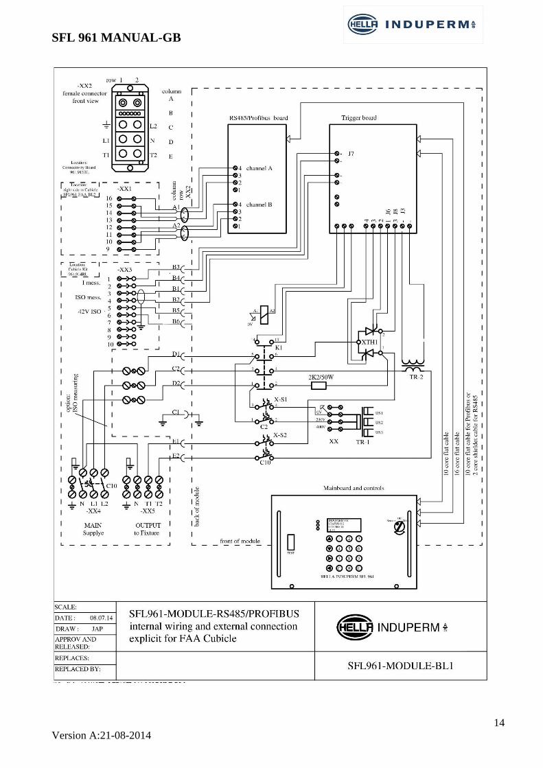
SFL 961 MANUAL-GB
14
Version A:21-08-2014
SFL 961 MANUAL-GB
15
Version A:21-08-2014
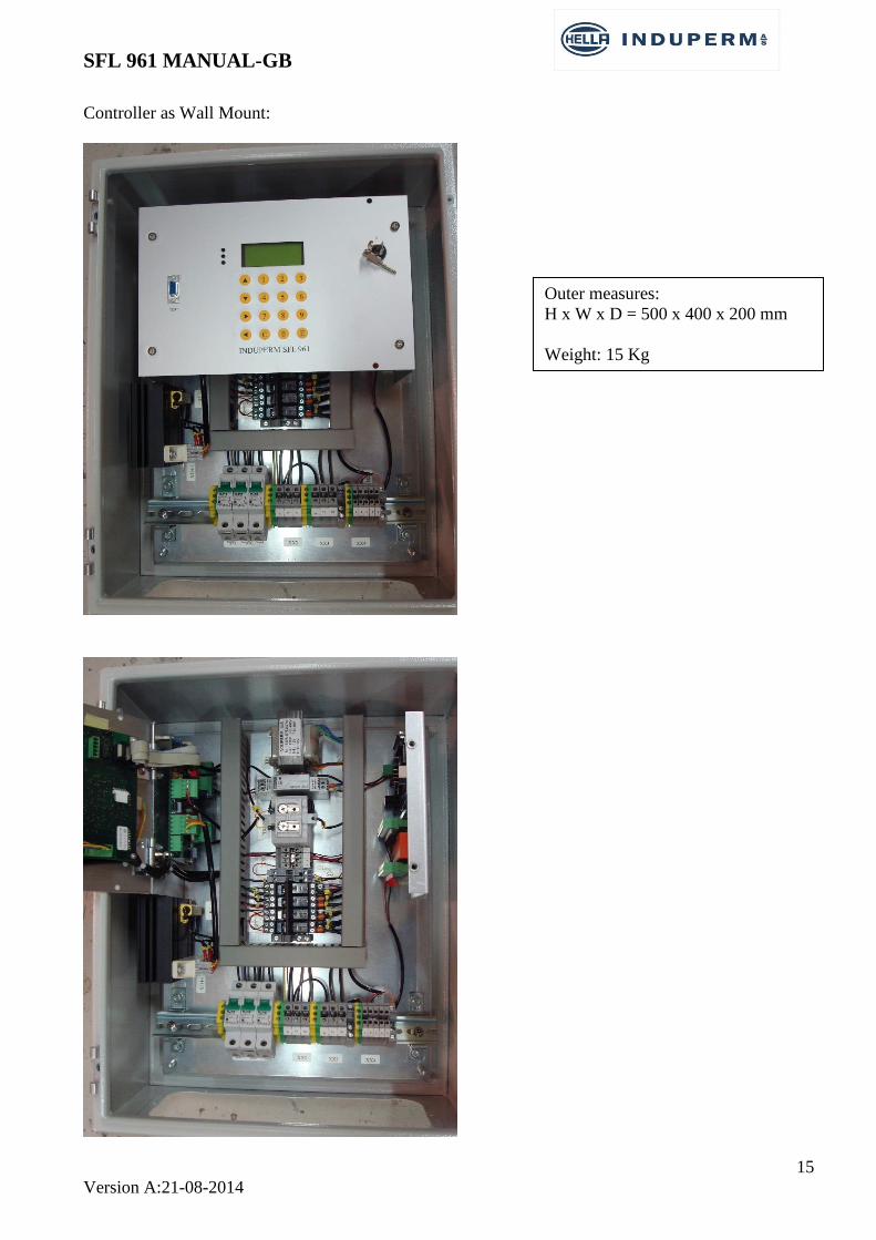
Controller as Wall Mount:
Outer measures:
H x W x D = 500 x 400 x 200 mm
Weight: 15 Kg

SFL 961 MANUAL-GB
16
Version A:21-08-2014

SFL 961 MANUAL-GB
17
Version A:21-08-2014
3.3 SFL fixture details
APPLICATION
The high-intensity LED fixture is intended to be used instead of discharge-type flash light in barrette
Centre line approach system and / or as runway threshold identification lights.
The required intensities are reached with LED’s as used in our standard LED Approach light fixture.
All communication and control via the power cables.
DESCRIPTION
The fitting type is a high-intensity, unidirectional, lightweight, elevated light constructed to meet the
demands for easy mounting, levelling and service, capability to resist jet blast from today’s aircrafts,
and last but not least to give sufficient light intensity, in the right angles with the use of a LED light
source with low power consumption and a long life-time.
Operation Brilliancy control by means of PWM regulation in light fixture, based on step command received via
Power cable. The flashing frequency can be one or two flashes / sec,
The first unit is located at the beginning of the approach, and the last unit is closest to the threshold.
The units are flashing in sequences, and the pilot sees the light moving towards the runway. The
threshold identification lights (TIL/RIL) are flashing simultaneously.
The TILs are connected to same supply cable as the approach sequential flash light system.
Input line voltage is 230V, and the supply cable is connected to the fixture via Transformers in a
Terminal box (see separate Data Sheet).
The supply includes flashing power, synchronization of the flashing sequence as well as power for
heating element in the fixture.
The address of each fixture is set by means of a built-in dipswitch.
FEATURES
The design conforms to the photometric requirement of ICAO, Annex 14, Fig. 2.1 with 40 W
LED module.
LED solution with many advantages compared to discharge tubes, f.i
Spare part price
Lifetime
Power consumption
No high voltages present in the light fixture, max. 24VDC
Front glass according to FAA spec. CAA-1199a.
Extremely easy and adjustment due to patented ball joint.
The shape, the small size and weight (3 kg. – 6ib.) are favourable features in respect to wind
load and mast construction.
The outside surface of the glass is smooth and need no cleaning.
No adjustment after re-lamping.
Mounting on tube, pole or base plates.
Only fully corrosion proof components are used.
Finished in stove enamel aviation yellow
Lamp power, heating supply and synchronisation signals via only low voltage power supply

SFL 961 MANUAL-GB
18
Version A:21-08-2014
MOUNTING DEVICES
The elevated light fixtures can be delivered with various types of
breakable couplings:
Type A: With 2” thread (European standard thread or 11,5
NPT or NPS)
Type C: for 2” pole mounting.
Customer designed couplings.
The breakable coupling is calculated and tested to break at: 64 Kgm
± 4 Kgm which is in according FAA AC 150/5345-46B, sect
3.4.2.1.

SFL 961 MANUAL-GB
19
Version A:21-08-2014
Light fixture types:
Breakable coupling Fixture type
A SFL 792-LED-A
C SFL 792-LED-C
Input power is 2 x 24VDC, via 4 x 1,5 / 2,5mm2 (dependent of cable distance to Terminal box).
4-pole connector mounted in light fixture, connector part for cable is included.
SFL 792-LED light – white

SFL 961 MANUAL-GB
20
Version A:21-08-2014
3.4 SFL Terminal Box details
APPLICATION
A Terminal box is placed within a distance of 1 to 25 m from each Flash Light fixture.
The Terminal box is for the connection of the cable from the Controller unit to each Flash light fixture.
A incoming and an outgoing cable each typical 4 x 4mm2, is used to supply power and communication signals
to the Flash Light fixture via two nos. isolating transformers each 230VAC / 24VDC, both placed in the
Terminal box.
DESCRIPTION
The Terminal box is in stainless steel, and can be mounted in many ways, on poles, on a wall etc.
Size: H x W x D: 360x200x120mm Weight app. 6,6Kg IP 68
Standard Type (in stainless steel): SFL TB1
Lightning arrestor block Type nr: 40-6308
Mounting kit for 60mm pole type: MT 60mm
Cable connections from Terminal box to Flash light fixture: Distance from Box to fixture (m) Cable dimension
1 – 8 3 x 1,5mm2 + Ground
8 – 25 3 x 2,5mm2 + ground
>25 3 x 4 mm2 + ground

SFL 961 MANUAL-GB
21
Version A:21-08-2014
INSTALLATION
The power cables are connected to the two groups of terminals marker Ground – Neutral – T1 and T2
(one set of terminals for in-coming cable and one set for out-going cable to the next Terminal box).
On the farthest away Terminal box, the terminals for the out-going cable is used for the connection of
a lighting arrestor module.
The cable for the light fixture is to be connected to: Ground - 0 – 1 - 2.

SFL 961 MANUAL-GB
22
Version A:21-08-2014

SFL 961 MANUAL-GB
23
Version A:21-08-2014

SFL 961 MANUAL-GB
24
Version A:21-08-2014
3.5 Description of SFL 961 module
(Seen from the front)
1. LED´s
2. Communications port
3. Arrow push buttons
4. LCD display
5. Key Switch
6. Push buttons 0-9 + E & C
INDUPERM CCR 961
TEST
AusFernsteuerung Manuell
E0C
987
4
1 2 3
5 6
1
2
3
4
5
6
5
6
Induperm SFL 961

SFL 961 MANUAL-GB
25
Version A:21-08-2014
LED´s: RED (top) – YELLOW (middle) – GREEN (lower)
RED: Flashing: Key on ”Manuel” or ”off”
Steady Light: Alarm.
YELLOW: Flashing with synchronization speed
GREEN: Steady Light for Main circuit breaker on.
The arrow push buttons can be used to flick through the menus.
LCD display:
Here is shown a number of parameters, such as:
- Analogue values
- General information
- Instructions
The Key Switch has 3 positions: Remote (Fern) – Off (Aus) – Local (Manuel)
- REMOTE
In this position the SFL system can be controlled only via the Remote Control System.
- OFF
The SFL Controller is off.
The SFL Module must be in this position before the Module is mounted or removed from the
cubicle.
- LOCAL
In this position the SFL system can only be controlled locally.
Back-indications, Alarms and analogue values are still transmitted to the Remote Control
System.
Changing the Key position between Remote and Local must be done in a swift manner to prevent the
SFL from being turned off.
When changing from Remote to Local, the SFL will maintain the from Remote selected intensity step.
Independent of the Key position, the arrow keys can be used to flick through the normal menu.
Push buttons 0-9 + E & C:
The keys 1-7 can be used to switch-on the SFL in one of the intensity steps. Key ”0” is used to switch-
off the SFL. If the SFL is switched-off because of an alarm, the key “0” is also used to reset the alarm
situation (Key-selector in position ”OFF”). if the system is provided with circuit selector the keys “6
and 9” are used for this
In the user menu (see later) the max number of active intensity steps can be selected. If locally a key
with a higher number than the max number of steps is activated, the SFL will select the highest active
intensity step. In short:
Key “0”: Switch-OFF or reset
Key “1”: select step 1
Key “2”: select step 2
Key “3”: select step 3
Key “4”: select step 4, which is power on for heaters in the RGL fixtures, but no light
Key “6”: select light direction B1 if circuit selector is provided
Key “9”: select light direction B2 if circuit selector is provided
Key ”E” is for section of one of the two adjustment modes. “E” is also used for acceptance of
changes.
Key ”C” is for abort from a menu.

SFL 961 MANUAL-GB
26
Version A:21-08-2014
Preparation for operation
Before the SFL Module is mounted in the cubicle, the following must be controlled or done:
1) The Memory card (Memboard) must be mounted in the socket on the Mainboard.
2) The Address for the Remote Control must be set (see label on Module).
When mounting the Module, the Key switch must be in the OFF position.
The Module is pushed in position in the cubicle. The last app. 1mm is activating a spring and must be
done by means of the 2 screws in the front.
If the new module is to replace an existing, the Memboard must be moved to the new SFL.
WARNING:
The connecter on the backside of the SFL can give a small shock shortly after the SFL have been in
use.
3.6 The SFL Menus
Operation and adjustments can be performed in different menus, please consult 961.002 for more
details:
Normal Menu (no code) with the menus N1 – N8: Normal CCR operation and data read-out
User Menu (User code) with the menus U1 – U19: Standard user adjustments
Factory Menu (Factory code) with the menus F1 – F8: Special adjustments
To get access to the User or Factory menu, the CCR must be in menu N1 (where the selecte intensity
step is shown), then press ”E”, followed by the relevant code, ending by pressing ”E” again.
Now you can change between the different menus by means of the push button right or left .
When all values are as wanted, go to the final menu to store the new values by pressing ”E”.
In the final menu, you could also select to eliminate the new adjustments by pressing ”C” or you can
select the factory default values by pressing ”5”.
An easy way to get to the final menu where the data are stored is to press arrow right for some
seconds.
Remember, always save data changes when leaving the User menu (>E< in menu U19) or leaving
the Factory Menu (>E< in menu F8).
With the use of arrow keys you can flick through the different menus, as follows:

SFL 961 MANUAL-GB
27
Version A:21-08-2014
SFL 12L
Step: Off B1
Manuel
Hour count:
100%: 3
Total: 15
N1
In this menu is seen the name of the series circuit,
selected intensity step, Runway direction (B1/B2)
and the position of the Key selector.
If the E-key is pressed for some seconds, we jump
directly to menu N8.
N3
Here is shown the ADC value for one chosen light
fixture (First number = ADC value, second
number = Chosen light fixture).
With the number pushbuttons a lamp between 0
and 31 can be entered.
Press ”E” to confirm the entered number.
N4
Here is shown 100 %-running hours, as well as
total number of hours switched-on.
ADC val. / lamp:
0 31
New value input:
0
CCR= off
1-9
Lamp Alarms
N2
Here are shown lamp alarms, if any
U-in:
228V
N5
In this menu point is shown the input voltage

SFL 961 MANUAL-GB
28
Version A:21-08-2014
N7
Here is shown:
Software version – time and date for program, and
actual Remote Control Protocol.
N8
In this menu the different menus can be chosen.
For ”User-menu” press pushbutton 1, for ”Factory-
menu” press pushbutton 2.
N6
Here is shown:
Time – date – and internal temperature.
Time/ date
15:40:56
17/01-2014
Sys temp. 25
SFL 961 V2.00k
13:04-13/08/2014
Com: Profibus
Settings:
1 = User
2 = Factory
U1
Here can be selected if there is a Runway
Identification Light “RIL” active or not.
With the pushbuttons “↑” and “↓” you can switch
between “Active” and “Inactive” to configure if
there is a RIL included in the system or not.
U2
Here can be selected between high frequency (Hi)
and low frequency (Lo).
With the pushbuttons “↑” and “↓” you can switch
between the two configurations.
Frequency:
↑↓ Lo
RIL:
↑↓ Active

SFL 961 MANUAL-GB
29
Version A:21-08-2014
U4
Configuration for “iso measurements” in defined
time intervals can be selected in this menu.
Use the number pushbuttons to enter the desired
value (in hours).
Press ”E” to confirm the entered interval.
U5
Here is chosen the ISO alarm 1. By using the “↑”
and “↓” pushbuttons you can switch between
several preconfigured values (in kΩ).
The last line shows the selected value.
U6
Here is chosen the ISO alarm 2. By using the “↑”
and “↓” pushbuttons you can switch between
several preconfigured values (in kΩ). The last line shows the selected value.
U3
Here can be selected if there is a Heater active in
the system or not.
With the pushbuttons “↑” and “↓” you can switch
between “Active” and “Inactive”.
Heater:
↑↓ Active
Circuit iso.
ISO alarm 1
25K – 50K
U7
Here is configured the lowest lamp address in the
circuit.
Use the number pushbuttons to enter the desired
new value.
Press ”E” to confirm the entered number.
Circuit iso meas
Interval 12 Hour
New value input
0 Hour
1-9
lowest Lamp adress
15
New value input
0
1-9
Circuit iso.
ISO alarm 1
100K – 250K

SFL 961 MANUAL-GB
30
Version A:21-08-2014
U8
Here is configured the maximum of available
intensity steps for regulation of the circuit.
Use the number pushbuttons to enter the desired
new value (between 1 and 3).
Press ”E” to confirm the entered number.
Max step:
3
New value input
0 (1-3)
1-9
U9
In this menu the minimum ADC value for 2 lamps
(RIL system) can be chosen.
Use the number pushbuttons to enter the desired
new value.
Press ”E” to confirm the entered number.
ADC, RIL lo
1500
New value input
0
1-9
U10
In this menu the maximum ADC value for 2 lamps
(RIL system) can be chosen.
Use the number pushbuttons to enter the desired
new value.
Press ”E” to confirm the entered number.
ADC, RIL hi
2000
New value input
0
1-9
U11
In this menu the minimum ADC value for 1 lamp
(AFL system) can be chosen.
Use the number pushbuttons to enter the desired
new value.
Press ”E” to confirm the entered number.
ADC, AFL lo
1500
New value input
0
1-9
U12
In this menu the maximum ADC value for 1 lamp
(AFL system) can be chosen.
Use the number pushbuttons to enter the desired
new value.
Press ”E” to confirm the entered number.
ADC, AFL hi
2000
New value input
0
1-9

SFL 961 MANUAL-GB
31
Version A:21-08-2014
U14
Here is U-in (U-mains) calibrated.
Use the number pushbuttons to enter the desired
new value.
Press ”E” to confirm the entered value.
U13
The name of the series circuit can be selected here.
By using “↑” and “↓” you can toggle between the
possible notations for the digits.
Every digit is to be confirmed by pressing “E”.
U15
Here is the display contrast calibrated.
Use the number pushbuttons to enter the desired
new value (between 1 and 10).
Press ”E” to confirm the entered value.
U-in calibrate
U-in : 228V
New value input.
0V
1-9
Display contrast
Lcd: 5
New value input.
5 (1-10)
1-9
U16
Here is the display light intensity calibrated.
Use the number pushbuttons to enter the desired
new value (between 1 and 10).
Press ”E” to confirm the entered value.
Display Light
Lcd: 7
New value input.
7 (1-10)
1-9
U17
Here is the time/date calibration.
Use the number pushbuttons to enter the desired
new values. By using “↑” and “↓” you can toggle
between the possible notations for the digits.
Press ”E” to confirm the entered value.
SFL name:
SFL 12L
^^^^^^^^^^ SFL
1-9
U18
Here can be selected the systems display language.
With the pushbuttons “↑” and “↓” you can switch
between “Dansk”, “English” and “Deutsch”.
Calibration of watch
15:25 18/01-2014
1-9
Select Language:
English
↑↓

SFL 961 MANUAL-GB
32
Version A:21-08-2014
Warning: The use of the Factory code and menu should only be carried out by properly instructed and
authorized persons.
After entering the Factory code you will gain access to the menus shown in the following.
You can flick through the menus by means of the keys and .
To accept a new value, press key arrow left, and you will get to the next menu.
In the final menu, you will have to select to store changes (”E”), use default values (”5”), or to quit
(”C”).
It is possible to jump directly to the final menu by pressing the key or ”C” for 2 sec.
Store data:
Default data >5<
New data >E<
Quit >C<
U19
Here the selected new data can be stored by means
of key ”E”.
To use the default values in the program use key
”5”.
Return to normal menu without storing changes
use key ”C”.
F1
The hour meter for CCR in the 100 %-step can be
reset here by pressing ”0”.
F2
Here is the calibration of the allowed measurement
delay during the systems switch on.
Use the number pushbuttons to enter the desired
new value (in m sec.).
Press ”E” to confirm the entered value.
1-9
Hour count:
Zero:
>0<
I meas delay
7,0mS
New value input
0,0
1-9
F3
The user password can be changed here.
Use the number pushbuttons to enter the desired
new code.
Press ”E” to confirm the entered value.
User password
5486
New value input
0
1-9
SFL 961 MANUAL-GB
33
Version A:21-08-2014
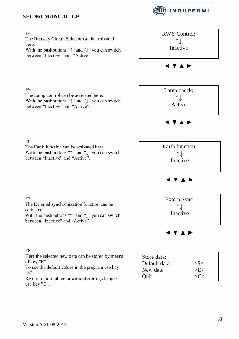
F4
The Runway Circuit Selector can be activated
here.
With the pushbuttons “↑” and “↓” you can switch
between “Inactive” and “Active”.
RWY Control:
↑↓ Inactive
F5
The Lamp control can be activated here.
With the pushbuttons “↑” and “↓” you can switch
between “Inactive” and “Active”.
Lamp check:
↑↓ Active
F6
The Earth function can be activated here.
With the pushbuttons “↑” and “↓” you can switch
between “Inactive” and “Active”.
Extern Sync.
↑↓ Inactive
Store data:
Default data >5<
New data >E<
Quit >C<
F8
Here the selected new data can be stored by means
of key ”E”.
To use the default values in the program use key
”5”.
Return to normal menu without storing changes
use key ”C”.
F7
The External synchronization function can be
activated.
With the pushbuttons “↑” and “↓” you can switch
between “Inactive” and “Active”.
Earth function:
↑↓ Inactive

SFL 961 MANUAL-GB
34
Version A:21-08-2014
4 SFL installation
4.1 Unpacking the SFL shipment
Unpack carefully and check, that all parts are included.
After unpacking the Controller must be stored indoor.
4.2 Before the installation
Check the planned installation location. The floor must be stable, and the SFL cubicle must be
fastened to the floor, alternative for the wall mount type, to the wall. The room must be ventilated
and free air circulation from under the cubicle must be secured. If this cannot be guaranteed, a
special front door with air-inlets must be ordered.
The SFL cubicles can be placed directly next to another, and as all services can be performed from
the front the SFL cubicle can be placed with the backside directly to a wall.
4.3 SFL installation
CCR front view
Comments:
Remote connection for RS485 can be by means of terminals or RJ45 plugs
Input power cable dimension must be min. 2,5 mm2

SFL 961 MANUAL-GB
35
Version A:21-08-2014
5 Commissioning
5.1 Preparation
Commissioning and adjustment normally have to be certified in a protocol.
A. Conditions for a correct adjustment:
The SFL is wired for correct supply voltage (2x230VAC, note correct phases!)
Remote control address is set to correct value
The power lines are controlled for acceptable isolation value and continuity
The remote control cable is connected
B. Assembling:
The Key switch is set in position ”OFF” (= AUS).
Power is switched on
No blinking must occur in the display
The Key - switch is turned to position ”Manual” (local operation)
C. Setting and adjustments:
The following adjustment procedure is valid for SFL’s supplied directly from work, where Default
data are activated.
The User- and Factory menus can only be accessed by the use of a code. The codes will be listed in the
enclosed Factory Test protocol.

SFL 961 MANUAL-GB
36
Version A:21-08-2014
5.2 Control of setting in each menu.
1. The SFL is entered into User Mode (from Normal menu 1), by pressing:
>E<
Enter Code for User Mode
With > < (arrow right) the menus are controlled/corrected as follows:
>
2. The SFL is entered into Factory Mode (from Normal menu 1), by pressing:
>E<
Enter Code for Factory Mode
With > < (arrow right) the menus are controlled/corrected as follows:
Menu
Nr.
Menu
Name
Default
Value
Setting Comments
F1 Hour count Hour counter for 100 % step reset by pressing >0<
F2 I-measure delay 7mS Delay after zero-crossing
F3 User Password 5486
F4 RWY Circuit
selector
Inactive Is circuit selector installed?
F5 Lamp check active
F6 Earth function Inactive
F7 Extern sync? Inactive A flash sequence can be started with external sync.
puls
F8 Store Data New data stored by pressing >E<
Menu
Nr.
Menu
Name
Default
Value
Setting Comments
U1 RIL active active Set active if RIL is part of the system
U2 Frequency Lo Sect between Lo (1 flash/sec) or Hi (2 flash/sec)
U3 Heater Active
U4 ISO Meas. 3 Hours Time between ISO measurements
U5 ISO alarm 1 100k –
250K
Set ISO alarm level 1
U6 ISO alarm 2 10k – 25k Set ISO alarm level 2
U7 No. of lamps 10 No. of lamps in the AFL system
U8 Max. Step 3 No. of active steps to be set
U9 ADC (RIL) 1500
U10 ADC (RIL) 2000
U11 ADC (AFL) 1500
U12 ADC (AFL) 2000
U13 Circuit name Name of series circuit is set
U14 Uin 230 Uin calibration (Phase L1)
U15 Display
Contrast
5
U16 Display
brightness
7
U17 Time/date Factory setting is UTC
U18 Language English Select display-language
U19 Store data New data stored by pressing >E<

SFL 961 MANUAL-GB
37
Version A:21-08-2014
5.3 Step by Step adjustments
Simple adjustments and operation instructions, “Step by step”
3.1. Manual selection of intensity step
3.2. Adjustment of number of intensity steps
3.3. Adjustment of alarm limits for lamp failure
3.4. Adjustment of time / date
3.5. How to change the language in the display
3.6. How to set up the name of the series circuit (f.i. RIL 11)
3.7. Procedure for the change of a SFL module
3.1 Manuel selection of intensity step
The Key switch is turned to position ”Manual”
Switch-on the SFL in step 1 by pressing ”1”. Other intensity steps may be selected in the same
manner. The SFL can be set for up to 3 active intensity steps. Step 4 is heating, only.
3.2 Adjustment of number of intensity steps
The Key switch is turned to position ”Manual”
Press ”E”
Enter the code for User Menu
Press ”E”
Press 7 times to the display shows ”Max no. of steps”
Use the push-buttons 1 – 3 to select the number of active steps
Press some seconds to get to the menu for ”Store data”
Press ”E”
3.3 Adjustment of alarm limits for lamp failure
The Key switch is turned to position ”Manual”
Go to Menu N3 and read the ADC value for the different lamps in step 1 and step3. The value for
address 31 is for both TIL fixtures and therefor much higher than for the other lamps. Note the
values as TIL (lo / hi) and AFL (lo / hi). The AFL values is taken as an app. value from the the
different fixtures.
Press ”E”
Enter the code for User Menu
Press ”E”
Press 8 times to see ”ADC, TIL lo” in the display
Use the push-buttons 0 – 9 to enter the desired value for alarm limit lo, app. ½ of the value found
in step 1 for TIL in menu N3
Press ”E”

SFL 961 MANUAL-GB
38
Version A:21-08-2014
Press
Use the push-buttons 0 – 9 to enter the desired value for alarm limit hi, app. ½ of the value found
in step 3 for TIL in menu N3
Press ”E”
Press
Use the push-buttons 0 – 9 to enter the desired value for alarm limit lo, app. ½ of the value found
in step 1 for AFL in menu N3
Press ”E”
Press
Use the push-buttons 0 – 9 to enter the desired value for alarm limit hi, app. ½ of the value found
in step 3 for AFL in menu N3
Press ”E”
Press some seconds to get to the menu for ”Store data”
Press ”E”
3.4 Adjustment of time / date
The Key switch is turned to position ”Manual”
Press ”E”
Enter the code for User Menu
Press ”E”
Press 16 times to see ”Calibration of watch” in the display
Press and the value for ”Hours” will start flashing
Use the push-buttons 0 – 9 to enter the desired value for hour
Press ”E”
Press and the value for ”Minutes” will start flashing
Use the push-buttons 0 – 9 to enter the desired value for minutes
Press ”E”
Press and the value for ”Day” will start flashing
Use the push-buttons 0 – 9 to enter the desired value for day
Press ”E”
Press and the value for ”Month” will start flashing
Use the push-buttons 0 – 9 to enter the desired value for month
Press ”E”
Press and the value for ”Year” will start flashing
Use the push-buttons 0 – 9 to enter the desired value for year (2 last digits)
Press ”E”
Press some seconds to get to the menu for ”Store data”
Press ”E”
3.5 How to change the language in the display
The Key switch is turned to position ”Manual”
Press ”E”
Enter the code for User Menu
Press ”E”
Press 17 times to see ”Language” or “Sprache” in the display
Press -push buttons to select the desired language
Press some seconds to get to the menu for ”Store data”
Press ”E”

SFL 961 MANUAL-GB
39
Version A:21-08-2014
3.6 I How to set up the name of the series circuit (f.i. RIL 11)
The Key switch is turned to position ”Manual”
Press ”E”
Enter the code for User Menu
Press ”E”
Press 12 times to see ”SFL Name” in the display
The CCR Name (or more correctly the name of the series circuit) is constructed as follows:
XXXX Z1 Z2 Z3 Z4, where:
XXXX can be selected among the following terms:
SFL-AFL-RIL-SPEC!
Each of the digits Z1, Z2, Z3 and Z4 can be selected between the following:
0-9, L, -, space,
If the option SPEC! is selected for XXXX each digit (all together ) can be given an ASCII
value.
Press >E< 4 times until ” ^^^^” is shown in the display.
Press -push buttons to choose the XXXX term
Press >E<
Press -push buttons to select the Z1 value
Press >E<
Press -push buttons to select the Z2 value
Press >E<
Press -push buttons to select the Z3 value
Press >E<
Press -push buttons to select the Z4 value
Press ”E”
Press some seconds to get to the menu for ”Store data”
Press ”E”

SFL 961 MANUAL-GB
40
Version A:21-08-2014
ASCII Code:
( ( ASCII: opening parenthesis
) ) ASCII: closing parenthesis
* * ASCII: asterisk
+ + ASCII: plus sign
- - ASCII: hyphen-minus
. . ASCII: period
0 0 ASCII: digit zero
1 1 ASCII: digit one
2 2 ASCII: digit two
3 3 ASCII: digit three
4 4 ASCII: digit four
5 5 ASCII: digit five
6 6 ASCII: digit six
7 7 ASCII: digit seven
8 8 ASCII: digit eight
9 9 ASCII: digit nine
: : ASCII: colon
= = ASCII: equals sign
A A ASCII: Latin Capital Letter A
B B ASCII: Latin Capital Letter B
C C ASCII: Latin Capital Letter C
D D ASCII: Latin Capital Letter D
E E ASCII: Latin Capital Letter E
F F ASCII: Latin Capital Letter F
G G ASCII: Latin Capital Letter G
H H ASCII: Latin Capital Letter H
I I ASCII: Latin Capital Letter I
J J ASCII: Latin Capital Letter J
K K ASCII: Latin Capital Letter K
L L ASCII: Latin Capital Letter L
M M ASCII: Latin Capital Letter M
N N ASCII: Latin Capital Letter N
O O ASCII: Latin Capital Letter O
P P ASCII: Latin Capital Letter P
Q Q ASCII: Latin Capital Letter Q
R R ASCII: Latin Capital Letter R
S S ASCII: Latin Capital Letter S
T T ASCII: Latin Capital Letter T
U U ASCII: Latin Capital Letter U
V V ASCII: Latin Capital Letter V
W W ASCII: Latin Capital Letter W
X X ASCII: Latin Capital Letter X

SFL 961 MANUAL-GB
41
Version A:21-08-2014
Y Y ASCII: Latin Capital Letter Y
Z Z ASCII: Latin Capital Letter Z
` ` ASCII: spacing grave
a a ASCII: Latin Small Letter A
b b ASCII: Latin Small Letter B
c c ASCII: Latin Small Letter C
d d ASCII: Latin Small Letter D
e e ASCII: Latin Small Letter E
f f ASCII: Latin Small Letter F
g g ASCII: Latin Small Letter G
h h ASCII: Latin Small Letter H
i i ASCII: Latin Small Letter I
j j ASCII: Latin Small Letter J
k k ASCII: Latin Small Letter K
l l ASCII: Latin Small Letter L
m m ASCII: Latin Small Letter M
n n ASCII: Latin Small Letter N
o o ASCII: Latin Small Letter O
p p ASCII: Latin Small Letter P
q q ASCII: Latin Small Letter Q
r r ASCII: Latin Small Letter R
s s ASCII: Latin Small Letter S
t t ASCII: Latin Small Letter T
u u ASCII: Latin Small Letter U
v v ASCII: Latin Small Letter V
w w ASCII: Latin Small Letter W
x x ASCII: Latin Small Letter X
y y ASCII: Latin Small Letter Y
z z ASCII: Latin Small Letter Z
3.7 Procedure for the change of a SFL module
The Key switch is turned to position ”Manual”
The SFL module is removed from the cubicle
The Memory-stick from the ”old” module is mounted in the ”new” module
In the ”new” module the remote control address is set by means of the belonging DIP-switch. See
instruction on the side of the module or simply copy the setting on the ”old” module.
The Log-schema on the side of the module is eventually filled-in.
The Key switch on the ”new” module is set in position ”AUS” (OFF)
The ”new” module is mounted in the cubicle
See, that the display seems to be working normally (no flashing)
The SFL module is switched-on in step 1. If the module seems to be working, the other steps are
tested.
The Key switch can now be turned to the position ”Fern” (remote)
SFL 961 MANUAL-GB
42
Version A:21-08-2014
6 Remote Control
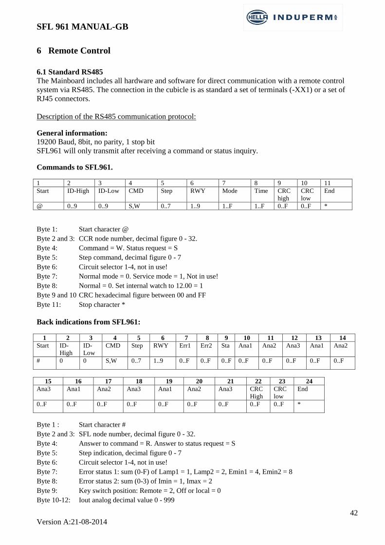
6.1 Standard RS485
The Mainboard includes all hardware and software for direct communication with a remote control
system via RS485. The connection in the cubicle is as standard a set of terminals (-XX1) or a set of
RJ45 connectors.
Description of the RS485 communication protocol:
General information:
19200 Baud, 8bit, no parity, 1 stop bit
SFL961 will only transmit after receiving a command or status inquiry.
Commands to SFL961.
1 2 3 4 5 6 7 8 9 10 11
Start ID-High ID-Low CMD Step RWY Mode Time CRC
high
CRC
low
End
@ 0..9 0..9 S,W 0..7 1..9 1..F 1..F 0..F 0..F *
Byte 1: Start character @
Byte 2 and 3: CCR node number, decimal figure 0 - 32.
Byte 4: Command = W. Status request = S
Byte 5: Step command, decimal figure 0 - 7
Byte 6: Circuit selector 1-4, not in use!
Byte 7: Normal mode = 0. Service mode = 1, Not in use!
Byte 8: Normal = 0. Set internal watch to 12.00 = 1
Byte 9 and 10 CRC hexadecimal figure between 00 and FF
Byte 11: Stop character *
Back indications from SFL961:
1 2 3 4 5 6 7 8 9 10 11 12 13 14
Start ID-
High
ID-
Low
CMD Step RWY Err1 Err2 Sta Ana1 Ana2 Ana3 Ana1 Ana2
# 0 0 S,W 0..7 1..9 0..F 0..F 0..F 0..F 0..F 0..F 0..F 0..F
15 16 17 18 19 20 21 22 23 24
Ana3 Ana1 Ana2 Ana3 Ana1 Ana2 Ana3 CRC
High
CRC
low
End
0..F 0..F 0..F 0..F 0..F 0..F 0..F 0..F 0..F *
Byte 1 : Start character #
Byte 2 and 3: SFL node number, decimal figure 0 - 32.
Byte 4: Answer to command = R. Answer to status request = S
Byte 5: Step indication, decimal figure 0 - 7
Byte 6: Circuit selector 1-4, not in use!
Byte 7: Error status 1: sum (0-F) of Lamp1 = 1, Lamp2 = 2, Emin1 = 4, Emin2 = 8
Byte 8: Error status 2: sum (0-3) of Imin = 1, Imax = 2
Byte 9: Key switch position: Remote = 2, Off or local = 0
Byte 10-12: Iout analog decimal value 0 - 999

SFL 961 MANUAL-GB
43
Version A:21-08-2014
Byte 13-15: Lamp analog decimal value 0 - 999
Byte 16-18: Uout analog decimal value 0 - 999
Byte 19-21: ISO analog decimal value 0 - 999
Byte 22-23: CRC hexadecimal figure between 00 and FF
Byte 24: Stop character *
Command to CCR961 CRC calculation: ^ = Xor
crc = data,1(start character)
crc = crc ^ data,2
crc = crc ^ data,3
etc. (until all bytes are included)
crc value, in Hex, is converted to 2 bytes Ascii
Example: Ascii: Decimal: Xor crc:
Start @ 64 64
ID high 0 48 64 ^ 48 = 112
ID low 9 57 112 ^ 57 = 73
Command W 87 73 ^ 87 = 30
Step 3 51 30 ^ 51 = 45
RWY 1 49 45 ^ 49 = 28
Mode 0 48 28 ^ 48 = 44
Time 0 48 44 ^ 48 = 28
28 decimals = 1C Hex
1 2 3 4 5 6 7 8 9 10 11
Start ID-High ID-Low CMD Step RWY Mode Time CRC
high
CRC
low
End
@ 0 9 W 3 1 0 0 1 C *
Back indication examples: Byte 7:
No failures = ascii 0 = decimal 48
Lamp failure 1 = ascii 1 = decimal 49
Lamp failure 2 = ascii 2 = decimal 50
ISO failure 1 = ascii 4 = decimal 52
ISO failure 2 = ascii 8 = decimal 56
Lamp failure 1 and ISO failure 2 = 1+8 = decimal 57
Lamp failure 2 and ISO failure 2 = 2+8 =ascii a = decimal 65
Byte 8:
No failures = ascii 0 = decimal 48
I min failure = ascii 1 = decimal 49
I max failure = asci 2 = decimal 50
Byte 9(Key switch position)
Remote = ascii 2 = decimal 50
Off or Local = ascii 0 = decimal 48

SFL 961 MANUAL-GB
44
Version A:21-08-2014
Connections on terminals –XX1 for RS485 based remote control communication with the above described
protocol.
In the lower part of the picture is shown that, upon request, the terminals –XX1 can be exchanged to two nos.
RJ45 connector houses, mounted on the board 961.745

SFL 961 MANUAL-GB
45
Version A:21-08-2014
6.2 Redundant Profibus
When a Profibus communication interface to the remote control system is required, the SFL Module
will have a Redundant Profibus Board added internally, and this will then communicate with the SFL
Main board in a RS485 protocol.
The connections in the SFL cubicle is a set of terminals (-XX1).
Description of PROFIBUS The Profibus module can be used as a single or redundant interface to the Main Board via RS485.
The Module is constructed and based on two nos. Siemens ASIC circuit LSPM2, which fulfils the
Profibus format according to IEC 61158.
Redundant use:
Port PB.0 Master Bit determinates which channel (A or B) is controlling the CCR.
The detection of the Master bit is edge triggered (edge sensitive).
The channel with the latest change from 0 to 1 is the controlling channel. This is also the case if the
Master bit is 1 from both channels.
If the Master bit in both channels is permanently set to 1, and there is a failure on one Chanel, there is
a risk that the communication will fail, as no shift is detected in the master bit.
Response time:
The data communication between Profibus board and main board is stroke controlled. The Profibus
module will send data to the main board with fixed intervals of 200mS and the main board will send
data to the Profibus module with fixed intervals of 300mS.
The total time from data received from the Profibus until a response is placed in the buffer on the
Profibus module, which can be read via the Profibus, will vary from app. 10mS to app. 510mS.
(200mS + 300mS + 2 x 5mS (µP program cycle).
PROTOCOL CONVERTER
LSPM2 (IM184)
PORT A PORT CPORT B PORT D
PROFIBUS A
DATA FROM MASTER DATA TO MASTER
µP
CCR 961
PORT E
RUN
MASTER
PROTOCOL CONVERTER
PORT A PORT B PORT DPORT C
PROFIBUS B
PORT E
MASTER
DATA FROM MASTER RUNDATA TO MASTER
RS485
LSPM2 (IM184)
.

SFL 961 MANUAL-GB
46
Version A:21-08-2014
The individual functions are described in the following table and examples. FROM master
IM184 Bit
Port
PA 0 Step bit 0
1 Step bit 1
2 Step bit 2
3
4
5
6
7 Status req. if = 1 cancel step info and set "tx status"
PB 0 Master bit positive edge trig !!
1
2
3 Set time = 12.00 if = 1 set ccr time to 12.00 (noon)
4 0=tx status 1=tx analog
5 analog pointer 0 (Iout=11H, Lamp=31H, Uout=51, E=71H)
6 analog pointer 1
7 analog pointer 2
TO master
IM184 Bit
Port
PC 0 Step bit 0
1 Step bit 1
2 Step bit 2
3
4
5
6
7 Lamp error 1
PD 0 Lamp error 2
1 E min1
2 E min2
3 I min
4 I max
5 Remote
6
7 0=status
PC 0 12 bit analog lsb
1 12 bit analog
2 12 bit analog
3 12 bit analog
4 12 bit analog
5 12 bit analog
6 12 bit analog
7 12 bit analog
PD 0 12 bit analog
1 12 bit analog
2 12 bit analog
3 12 bit analog msb
4 analog pointer 0 (Iout=8xH, Lamp=9xH, Uout=ax, E=bxH)
5 analog pointer 1 (analog pointer + bit7)
6 analog pointer 2
7 1=analog

SFL 961 MANUAL-GB
47
Version A:21-08-2014
Explanations on the Profibus-protocol.
Port PA and PB is receiving the information from MASTER, while port PC and PD delivers the
signals to MASTER.
Bit PA-7, Status req. can be set to 1, to enable a request of tx status or tx analog without sending a
step command at the same time.
If Bit PB-4 is set to 1, the request is for analog values. Which analog value requested is set by
means of the Bits PB 5-6-7.
Port PC and PD are shown on the previous page, both for tx status and for tx analog.
In case of tx status step indications, Warnings and Alarms are send.
In case of tx analog values for Iout, Lamp Failure, Uout or Isolation resistance can be send.
The actual analog value in question can be determinated by means of the Bits PD 4-5-6.
The analog value is given as follows:
1. Iout, Lamp failure and Uout
Value is given only in PC:
Bit 7 6 5 4 3 2 1 0
Binary
value
128 64 32 16 8 4 2 1
Iout: Binary value / 10 = Iout (A)
Uout: Binary value / 100 = Uout (KV)
Lamp failure: Binary value = number of faulty lamps
2. ISO value (Resistance to ground).
Profibus master is sending the following data bit to CCR:
PA: 00000010 Step 2
PB: 01110001 master, tx analog value type 3 ~ ISO value
The analog value is given in KΩ by means of 3 digits: 2 significant digits + number of zero’s
Port D Port C
Bit no: 7 6 5 4 3 2 1 0 7 6 5 4 3 2 1 0
Value: Analog pointer 2048 1024 512 256 128 64 32 16 8 4 2 1
Example:
250K ~ 251: PD: xxxx0000 PC: 11111011
260K ~ 261: PD: xxxx0001 PC: 00000101
56K ~ 560: PD: xxxx0010 PC: 00110000
1,7M ~ 173: PD: xxxx0000 PC: 10101101
Profibus data examples:
Step = 2 (normal) Profibus master will send flg. data bit to CCR:
PA: 00000010 step 2
PB: 00000001 master, Status req.
Profibus module will send flg. data bit to master:
PC: 00000010 step 2
PD: 00100000 remote

SFL 961 MANUAL-GB
48
Version A:21-08-2014
Step = 2 (Emin1 alarm, Emin2 alarm (Emin = ISO)) Profibus master will send flg. data bit to CCR:
PA: 00000010 step 2
PB: 00000001 master, Status req.
Profibus module will send flg. data bit to master:
PC: 00000010 step 2
PD: 00100110 remote, Emin1 alarm, Emin2 alarm
Step = 2 (Imin alarm) Profibus master will send flg. data bit to CCR:
PA: 00000010 step 2
PB: 00000001 master, Status req.
Profibus module will send flg. data bit to master:
PC: 00000000
PD: 00101000 remote, Imin alarm
Step = 2 (Imax alarm) Profibus master will send flg. data bit to CCR:
PA: 00000010 step 2
PB: 00000001 master, Status req.
Profibus module will send flg. data bit to master:
PC: 00000000
PD: 00110000 remote, Imax alarm
Analog values:
I-out:
Step = 2
Profibus master will send flg. data bit to CCR:
PA: 00000010 step 2
PB: 00010001 master, tx analog value type 0 (Iout)
Profibus module will send flg. data bit to master:
PC: 00011001 25 ~ Iout 2.5A
PD: 10000000 analog value type 0 ~ Iout
Lamp failure:
Step = 2
Profibus master will send flg. data bit to CCR:
PA: 00000010 step 2
PB: 00110001 master, tx analog value type 1 ~ lamp failure
Profibus module will send flg. data bit to master:
PC: 00000001 1 ~ lamp failure, one faulty lamp
PD: 10010000 analog value type 1 ~ lamp failure
U-out:
Step = 2
Profibus master will send flg. data bit to CCR:

SFL 961 MANUAL-GB
49
Version A:21-08-2014
PA: 00000010 step 2
PB: 01010001 master, tx analog value type 2 ~ Uout
Profibus module will send flg. data bit to master:
PC: 00110000 48 ~ Uout = 0.48KV
PD: 10100000 analog value type 2 ~ Uout
ISO value (E):
Step = 2
Profibus master will send flg. data bit to CCR:
PA: 00000010 step 2
PB: 01110001 master, tx analog value type 3 ~ ISO
The isolation value is given in KΩ by means of 3 digits: 2 significant digits + number of zero’s (factor
10)
The value is displayed as a binary value on port C + the first 4 bits in port D.
Example 15KΩ: 1 5 0 = 0000 1001 1001
Profibus module will send flg. data bit to master:
PC: 10010110 150
PD: 10110000 analog value type 3 ~ ISO
Connection diagram for Profibus to the terminals –XX1.

SFL 961 MANUAL-GB
50
Version A:21-08-2014
6.3 Parallel control
When a parallel interface is required, a separate parallel interface board is placed in the SFL cubicle,
and this board will communicate with the SFL mainboard via the RS485 serial bus.

SFL 961 MANUAL-GB
51
Version A:21-08-2014
6.4 Ethernet IP addressable
The IP solution is similar to the solution for Parallel control, by mounting a special box in the SFL
cubicle that will convert the IP communication to RS485 towards the SFL.
The Protocol and set-up for this solution can be obtained in a separate document.
Ethernet IP-addressable LAN-COM interface.

SFL 961 MANUAL-GB
52
Version A:21-08-2014
6.5 Dip-switch settings
There are dip switches on the Main Board and on the Profibus Board (only for Profibus solutions). The
drawing below shows the setting of the dip-switches, both on the Main Board and on the Profibus
Board.
In solutions with a parallel remote control interface, the address on both Main Board and on the
Parallel Board is normally set to 1.
SFL 961 MANUAL-GB
53
Version A:21-08-2014
7 Maintenance and Trouble shooting
7.1 Regular Control
There is no direct demand for certain maintenance to be done on the SFL, but in the following is give a
few recommendations, which could improve both MTBF, lifetime of the equipment as well as safety
for maintenance personnel.
Every other year:
The power lines are disconnected from the SFL and the isolation level is measured (Megger).
Every 5 years:
The SFL is cleaned inside with a vacuum cleaner (SFL CUBICLE IS POWERED OFF!), and all
components are visually controlled for changes in color etc.
All power connections are controlled by means of a Thermo camera.
7.2 Safety instructions
Before any service work is done in the SFL cubicle, the power supply must be switched off.
If measurements have to be done with power on, the measurement must be via a measuring
transformer.
Before any work is done on the series circuit:
The key selector on the SFL is set to “OFF”
The SFL front door is clearly marked with a sign “Work is done on the circuit”

SFL 961 MANUAL-GB
54
Version A:21-08-2014
List of spares

SFL 961 MANUAL-GB
55
Version A:21-08-2014
Pos.
Description
No.
1 SFL Module Profibus SFL961Profi
2 SFL Module RS485 SFL961-RS485
3 Memoryboard til 961 961535
4
5


![0 [Type the document subtitle] [Pick the date] Dasar-Dasar Membuat Media Pembelajaran Dengan Dengan Dengan Dengan Flash Flash Flash Flash](https://static.fdokumen.com/doc/165x107/632259f164690856e109202b/0-type-the-document-subtitle-pick-the-date-dasar-dasar-membuat-media-pembelajaran.jpg)

