Lecture 7 – Seismic Load Analysis IBC Code.pdf - Icivil-hu.com
36
Dr. Hazim Dwairi Hashemite University 1 The Hashemite University Department of Civil Engineering Lecture 7 Lecture 7 – Seismic Load Seismic Load Analysis Analysis Dr Hazim Dwairi Dr Hazim Dwairi Dr. Hazim Dwairi Dr. Hazim Dwairi The Hashemite University The Hashemite University Dr. Hazim Dwairi Dr. Hazim Dwairi Credit: Credit: Most of the sketches used in this Most of the sketches used in this Most of the sketches used in this Most of the sketches used in this presentation were acquired from the presentation were acquired from the instructional material complementing instructional material complementing FEMA 451, published by FEMA 451, published by Dr. Hazim Dwairi Dr. Hazim Dwairi The Hashemite University The Hashemite University Dr. Hazim Dwairi
-
Upload
khangminh22 -
Category
Documents
-
view
1 -
download
0
Transcript of Lecture 7 – Seismic Load Analysis IBC Code.pdf - Icivil-hu.com
Dr. Hazim Dwairi
Hashemite University 1
The Hashemite University
Department of Civil Engineering
Lecture 7 Lecture 7 –– Seismic Load Seismic Load AnalysisAnalysis
Dr Hazim DwairiDr Hazim Dwairi
Dr. Hazim DwairiDr. Hazim Dwairi The Hashemite UniversityThe Hashemite University
Dr. Hazim DwairiDr. Hazim Dwairi
Credit:Credit:
Most of the sketches used in this Most of the sketches used in this Most of the sketches used in this Most of the sketches used in this presentation were acquired from the presentation were acquired from the
instructional material complementing instructional material complementing FEMA 451, published by FEMA 451, published by
Dr. Hazim DwairiDr. Hazim Dwairi The Hashemite UniversityThe Hashemite University
Dr. Haz
im D
wairi

Dr. Hazim Dwairi
Hashemite University 2
Current Model CodesCurrent Model Codes
UBC, IBC:UBC, IBC: Provide minimum Provide minimum
provisions for design and construction of structures to resist effects of seismic ground motions.
“…to safeguard against j t t l f il
Dr. Hazim DwairiDr. Hazim Dwairi The Hashemite UniversityThe Hashemite University
major structural failures and loss of life, not to limit damage or maintain function.” (UBC ’97, Section 1626)
Load Analysis Procedure, IBC 2000Load Analysis Procedure, IBC 2000
1.1. Determine building occupancy categoryDetermine building occupancy category
22 D t i d i tD t i d i t2.2. Determine design response spectrumDetermine design response spectrum
3.3. Determine seismic design categoryDetermine seismic design category
4.4. Determine importance factorDetermine importance factor
5.5. Select structural system and system Select structural system and system parameters (R, Cparameters (R, Cdd, , oo))
Dr. Hazim DwairiDr. Hazim Dwairi The Hashemite UniversityThe Hashemite University
6.6. Examine system for configuration irregularitiesExamine system for configuration irregularities
7.7. Determine diaphragm flexibility (flexible, semiDetermine diaphragm flexibility (flexible, semi--rigid, and rigid)rigid, and rigid)
Dr. Haz
im D
wairi

Dr. Hazim Dwairi
Hashemite University 3
Load Analysis Procedure Load Analysis Procedure (continued)(continued)
8.8. Determine redundancy factor (Determine redundancy factor ())
99 D t i l t l f l i dD t i l t l f l i d9.9. Determine lateral force analysis procedureDetermine lateral force analysis procedure
10.10. Compute lateral loadsCompute lateral loads
11.11. Add torsional loads, as applicableAdd torsional loads, as applicable
12.12. Add orthogonal loads as applicableAdd orthogonal loads as applicable
13.13. Perform analysisPerform analysis
Dr. Hazim DwairiDr. Hazim Dwairi The Hashemite UniversityThe Hashemite University
yy
14.14. Combine resultsCombine results
15.15. Check strength, deflection, and stabilityCheck strength, deflection, and stability
1. Occupancy Category (IBC 2000)1. Occupancy Category (IBC 2000)
I.I. Normal Hazard Occupancy: except those Normal Hazard Occupancy: except those listed in categories II III IVlisted in categories II III IVlisted in categories II, III, IVlisted in categories II, III, IV
II.II. Substantial Hazard Occupancy:Substantial Hazard Occupancy: High occupancy (more than 300 people in one High occupancy (more than 300 people in one
room)room) Schools and UniversitiesSchools and Universities Health care more than 50 patient residentsHealth care more than 50 patient residents
J il d d t ti f ilitiJ il d d t ti f iliti
Dr. Hazim DwairiDr. Hazim Dwairi The Hashemite UniversityThe Hashemite University
Jails and detention facilitiesJails and detention facilities Power stations Power stations Water treatment plantWater treatment plant Waste water treatment plantsWaste water treatment plants
Dr. Haz
im D
wairi

Dr. Hazim Dwairi
Hashemite University 4
1. Occupancy Category (IBC 2000)1. Occupancy Category (IBC 2000)
III.III. Essential Facilities:Essential Facilities:Hospitals and emergency facilities with surgeryHospitals and emergency facilities with surgery Hospitals and emergency facilities with surgeryHospitals and emergency facilities with surgery
Fire, rescue, ambulance, police stationsFire, rescue, ambulance, police stations
Designated emergency sheltersDesignated emergency shelters
Aviation control towersAviation control towers
Critical national defense facilitiesCritical national defense facilities
IVIV Low hazard Occupancy:Low hazard Occupancy:
Dr. Hazim DwairiDr. Hazim Dwairi The Hashemite UniversityThe Hashemite University
IV.IV. Low hazard Occupancy: Low hazard Occupancy: Agricultural facilitiesAgricultural facilities
Temporary facilitiesTemporary facilities
Minor storage facilitiesMinor storage facilities
2. Design Response Spectrum2. Design Response Spectrum
Recall Lecture 6Recall Lecture 6
Dr. Hazim DwairiDr. Hazim Dwairi The Hashemite UniversityThe Hashemite University
Dr. Haz
im D
wairi

Dr. Hazim Dwairi
Hashemite University 5
3. Seismic Design Category 3. Seismic Design Category –– Short Short Period AccelerationPeriod Acceleration
Value of SValue of SDSDS Seismic Use GroupSeismic Use Group
II IIII IIIIII
SSDSDS << 0.167g0.167g AA AA AA
0.167g 0.167g SSDSDS << 0.33g0.33g BB BB CC
0.33g 0.33g SSDSDS << 0.50g0.50g CC CC DD
0.50g 0.50g SSDSDS DD DD DD
Dr. Hazim DwairiDr. Hazim Dwairi The Hashemite UniversityThe Hashemite University
Value of SValue of SDSDS Seismic Use GroupSeismic Use Group
II IIII IIIIII
SSDSDS ≥ 0.75g≥ 0.75g EE EE FF
3. Seismic Design Category 3. Seismic Design Category ––11--second Period Accelerationsecond Period Acceleration
Value of SValue of SD1D1 Seismic Use GroupSeismic Use Group
II IIII IIIIII
SSD1D1 << 0.067g0.067g AA AA AA
0.067g 0.067g SSD1D1 << 0.133g0.133g BB BB CC
0.133g 0.133g SSD1D1 << 0.20g0.20g CC CC DD
0.20g 0.20g SSD1D1 DD DD DD
Dr. Hazim DwairiDr. Hazim Dwairi The Hashemite UniversityThe Hashemite University
Value of SValue of SD1D1 Seismic Use GroupSeismic Use Group
II IIII IIIIII
SSD1D1 ≥ 0.75g≥ 0.75g EE EE FF
Dr. Haz
im D
wairi

Dr. Hazim Dwairi
Hashemite University 6
4. Importance Factor (I4. Importance Factor (IEE))
Seismic Occupancy Seismic Occupancy Importance factor (IImportance factor (IEE))p yp yCategoryCategory
p (p ( EE))
II 1.001.00
IIII 1.251.25
IIIIII 1.501.50
Dr. Hazim DwairiDr. Hazim Dwairi The Hashemite UniversityThe Hashemite University
IVIV 1.001.00
*using IBC2000 – Table 1604.5
5. Structural System and System 5. Structural System and System Parameters (R, CParameters (R, Cdd, , oo) )
1.1. Bearing wall systemsBearing wall systems
2.2. Building frame systemsBuilding frame systems
3.3. MomentMoment--resisting frame system (MRF)resisting frame system (MRF)
4.4. Duel systems with special MRFDuel systems with special MRF
5.5. Duel systems with intermediate MRFDuel systems with intermediate MRF
6.6. Inversed pendulum systemInversed pendulum system
Dr. Hazim DwairiDr. Hazim Dwairi The Hashemite UniversityThe Hashemite University
System Parameters:
Response (strength) modification coefficient = R
System over-strength parameter = 0
Deflection amplification factor = Cd
Dr. Haz
im D
wairi

Dr. Hazim Dwairi
Hashemite University 7
Structural SystemsStructural Systems
Dr. Hazim DwairiDr. Hazim Dwairi The Hashemite UniversityThe Hashemite University
Special Moment Steel FrameSpecial Moment Steel Frame
ft
SDC
Dr. Hazim DwairiDr. Hazim Dwairi The Hashemite UniversityThe Hashemite University
Dr. Haz
im D
wairi

Dr. Hazim Dwairi
Hashemite University 8
Special Steel Concentrically Braced Special Steel Concentrically Braced Fame Fame
ft
SDC
Dr. Hazim DwairiDr. Hazim Dwairi The Hashemite UniversityThe Hashemite University
Special Reinforced Concrete Shear Special Reinforced Concrete Shear WallWall
160 ft
SDC
Dr. Hazim DwairiDr. Hazim Dwairi The Hashemite UniversityThe Hashemite University
Dr. Haz
im D
wairi

Dr. Hazim Dwairi
Hashemite University 9
Response Modification Factor RResponse Modification Factor R
•• Account for:Account for:–– Ductility (inelastic action)Ductility (inelastic action)–– OverstrengthOverstrength–– RedundancyRedundancy–– DampingDamping–– Past behaviorPast behavior
•• Maximum = 8Maximum = 8–– Eccentrically braced frame with welded connectionsEccentrically braced frame with welded connections
Dr. Hazim DwairiDr. Hazim Dwairi The Hashemite UniversityThe Hashemite University
Eccentrically braced frame with welded connectionsEccentrically braced frame with welded connections–– Buckling restrained brace with welded connectionsBuckling restrained brace with welded connections–– Special moment frame in steel or concreteSpecial moment frame in steel or concrete
•• Minimum = 1.5 (for cantilever systems)Minimum = 1.5 (for cantilever systems)–– Ordinary plain masonry shear wallsOrdinary plain masonry shear walls
Overstrength Factor Overstrength Factor oo
1. Sequential yielding of critical regions
3. Strength enhancement due to strain hardeningof critical regions
2. Materials strength greater than specified values
due to strain hardening
4. Capacity reduction () factors
Dr. Hazim DwairiDr. Hazim Dwairi The Hashemite UniversityThe Hashemite University
Dr. Haz
im D
wairi

Dr. Hazim Dwairi
Hashemite University 10
Deflection Amplification Factor Deflection Amplification Factor CCdd
Strength
Cd = Ratio of maximum inelastic
FE
FE/R
Cd Ratio of maximum inelastic displacement to maximum displacement of corresponding elastic oscillator
Dr. Hazim DwairiDr. Hazim Dwairi The Hashemite UniversityThe Hashemite University
DisplacementE CdE
6. Structure Irregularity6. Structure Irregularity
•• Buildings shall be classified as regular or Buildings shall be classified as regular or irregular based on the criteria in section 1616 5irregular based on the criteria in section 1616 5irregular based on the criteria in section 1616.5irregular based on the criteria in section 1616.5
•• Plan IrregularityPlan Irregularity:: buildings have one or more of buildings have one or more of the features listed in Table 1616.5.1the features listed in Table 1616.5.1
Dr. Hazim DwairiDr. Hazim Dwairi The Hashemite UniversityThe Hashemite University
•• Vertical IrregularityVertical Irregularity: buildings having one or : buildings having one or more of the features listed in Table 1616.5.2more of the features listed in Table 1616.5.2
Dr. Haz
im D
wairi
Dr. Hazim Dwairi
Hashemite University 11
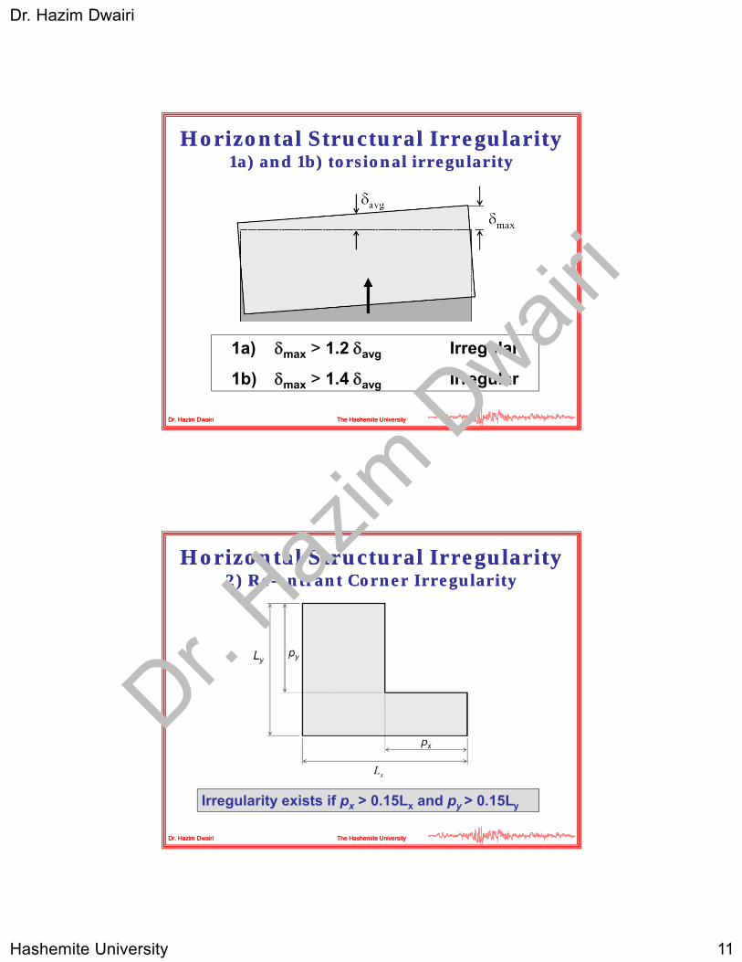
Horizontal Structural Irregularity Horizontal Structural Irregularity 1a) and 1b) torsional irregularity1a) and 1b) torsional irregularity
Dr. Hazim DwairiDr. Hazim Dwairi The Hashemite UniversityThe Hashemite University
1a) max > 1.2 avg Irregular
1b) max > 1.4 avg Irregular
Horizontal Structural Irregularity Horizontal Structural Irregularity 2) Re2) Re--entrant Corner Irregularityentrant Corner Irregularity
Dr. Hazim DwairiDr. Hazim Dwairi The Hashemite UniversityThe Hashemite University
Irregularity exists if px > 0.15Lx and py > 0.15Ly
Dr. Haz
im D
wairi

Dr. Hazim Dwairi
Hashemite University 12
Horizontal Structural Irregularity Horizontal Structural Irregularity 3) Diaphragm Discontinuity Irregularity3) Diaphragm Discontinuity Irregularity
Dr. Hazim DwairiDr. Hazim Dwairi The Hashemite UniversityThe Hashemite University
Irregularity exists if open area > 0.5 times floor area OR if effective diaphragm stiffness varies by more than 50% from one story to the next.
Horizontal Structural Irregularity Horizontal Structural Irregularity 4) Out of Plane Offsets4) Out of Plane Offsets
Dr. Hazim DwairiDr. Hazim Dwairi The Hashemite UniversityThe Hashemite University
Dr. Haz
im D
wairi
Dr. Hazim Dwairi
Hashemite University 13
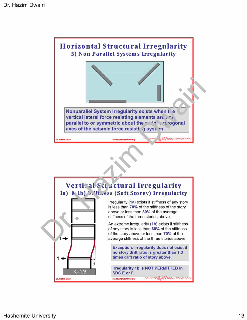
Horizontal Structural Irregularity Horizontal Structural Irregularity 5) Non Parallel Systems Irregularity5) Non Parallel Systems Irregularity
Dr. Hazim DwairiDr. Hazim Dwairi The Hashemite UniversityThe Hashemite University
Nonparallel System Irregularity exists when the vertical lateral force resisting elements are not parallel to or symmetric about the major orthogonal axes of the seismic force resisting system.
Vertical Structural Irregularity Vertical Structural Irregularity 1a) & 1b) Stiffness (Soft Storey) Irregularity1a) & 1b) Stiffness (Soft Storey) Irregularity
Irregularity (1a) exists if stiffness of any story is less than 70% of the stiffness of the story above or less than 80% of the average
Exception: Irregularity does not exist if
above or less than 80% of the average stiffness of the three stories above.
An extreme irregularity (1b) exists if stiffness of any story is less than 60% of the stiffness of the story above or less than 70% of the average stiffness of the three stories above.
Dr. Hazim DwairiDr. Hazim Dwairi The Hashemite UniversityThe Hashemite University
Exception: Irregularity does not exist if no story drift ratio is greater than 1.3 times drift ratio of story above.
Irregularity 1b is NOT PERMITTED in SDC E or F.
Dr. Haz
im D
wairi

Dr. Hazim Dwairi
Hashemite University 14
Vertical Structural Irregularity Vertical Structural Irregularity 2) Weight (Mass) Irregularity2) Weight (Mass) Irregularity
Irregularity exists if the effective mass of any story is more than 150%
Exception: Irregularity does not
of the effective mass of an adjacent story.
A roof that is lighter than the floor before need not be considered.
Dr. Hazim DwairiDr. Hazim Dwairi The Hashemite UniversityThe Hashemite University
Exception: Irregularity does not exist if no story drift ratio is greater than 1.3 times drift ratio of story above.
Vertical Structural Irregularity Vertical Structural Irregularity 3) Vertical Geometric Irregularity3) Vertical Geometric Irregularity
Irregularity exists if the dimension of the lateral force resisting system at any story is more than 130% of that for any adjacent story
Dr. Hazim DwairiDr. Hazim Dwairi The Hashemite UniversityThe Hashemite University
story.Dr. H
azim
Dwair
i

Dr. Hazim Dwairi
Hashemite University 15
Vertical Structural Irregularity Vertical Structural Irregularity 4) In4) In--plane Discontinuity Irregularityplane Discontinuity Irregularity
Irregularity exists if the offset is g ygreater than the width (d) or there exists a reduction in stiffness of the story below.
Dr. Hazim DwairiDr. Hazim Dwairi The Hashemite UniversityThe Hashemite University
Vertical Structural Irregularity Vertical Structural Irregularity 5) Capacity (Weak5) Capacity (Weak--Storey) IrregularityStorey) Irregularity
a) Irregularity exists if the lateral strength of any story is less than 80%strength of any story is less than 80%of the strength of the story above.
b) An extreme irregularity exists If the lateral strength of any story is less than 65% of the strength of the story above. (FEMA 450)
Dr. Hazim DwairiDr. Hazim Dwairi The Hashemite UniversityThe Hashemite University
Irregularities (a) and (b) are NOT PERMITTED in SDC E or F. Irregularity (b) not permitted in SDC D.
Dr. Haz
im D
wairi

Dr. Hazim Dwairi
Hashemite University 16
7. Diaphragm Flexibility7. Diaphragm Flexibility
Diaphragms must be considered as semiDiaphragms must be considered as semi--rigid rigid unless they can be classified as unless they can be classified as FLEXIBLEFLEXIBLE or or RIGIDRIGID..
•• Untopped steel decking and untopped wood structural Untopped steel decking and untopped wood structural panels are considered panels are considered FLEXIBLEFLEXIBLE if the vertical seismic force if the vertical seismic force resisting systems are steel or composite braced frames or are resisting systems are steel or composite braced frames or are shear walls.shear walls.
•• Diaphragms in oneDiaphragms in one-- and twoand two--family residential buildings mayfamily residential buildings may
Dr. Hazim DwairiDr. Hazim Dwairi The Hashemite UniversityThe Hashemite University
Diaphragms in oneDiaphragms in one and twoand two family residential buildings may family residential buildings may be considered be considered FLEXIBLEFLEXIBLE..
•• Concrete slab or concrete filled metal deck diaphragms are Concrete slab or concrete filled metal deck diaphragms are considered considered RIGIDRIGID if the width to depth ratio of the diaphragm if the width to depth ratio of the diaphragm is less than 3 and if no horizontal irregularities existis less than 3 and if no horizontal irregularities exist..
Rigid versus Flexible DiaphragmsRigid versus Flexible Diaphragms
Dr. Hazim DwairiDr. Hazim Dwairi The Hashemite UniversityThe Hashemite University
Based on lateral stiffness ratios Based on tributary area ratios
Dr. Haz
im D
wairi

Dr. Hazim Dwairi
Hashemite University 17
Diaphragm FlexibilityDiaphragm Flexibility
Dr. Hazim DwairiDr. Hazim Dwairi The Hashemite UniversityThe Hashemite University
Diagram taken from ASCE 7-05
8. Redundancy factor (8. Redundancy factor ())
•• Seismic Design Categories Seismic Design Categories A, B, CA, B, C = 1.0= 1.0
•• Seismic Design Categories Seismic Design Categories D, E, FD, E, F compute compute ii
for each storey and use the maximum:for each storey and use the maximum:
ii = 2 = 2 –– 6.1/r6.1/rmax,imax,i√A√Aii
AAii = the floor area in m= the floor area in m22 of the diaphragm level of the diaphragm level
Dr. Hazim DwairiDr. Hazim Dwairi The Hashemite UniversityThe Hashemite University
immediately above the story in considerationimmediately above the story in consideration
rrii = the ratio of the design story shear resisted = the ratio of the design story shear resisted by the most heavily loaded element to the total by the most heavily loaded element to the total story shear for a given direction of loading.story shear for a given direction of loading.
Dr. Haz
im D
wairi

Dr. Hazim Dwairi
Hashemite University 18
Structural Structural systemsystem
rrii
Braced Braced framesframes
Lateral load in the heavily loaded Lateral load in the heavily loaded brace/story shearbrace/story shear
MomentMoment Shear in t o adjacent col mns/stor shearShear in t o adjacent col mns/stor shearMoment Moment framesframes
Shear in two adjacent columns/story shear.Shear in two adjacent columns/story shear.
In two bay frames multiply columns shear In two bay frames multiply columns shear by 0.7by 0.7
Shear wallsShear walls Wall shear x 3.3/LWall shear x 3.3/Lww
Dual Dual tt
Multiply calculated Multiply calculated for all elements by for all elements by 80% d i80% d i
Dr. Hazim DwairiDr. Hazim Dwairi The Hashemite UniversityThe Hashemite University
systemssystems 80% and use maximum80% and use maximum
shall not be less than 1.0 and need not exceed 1.5
Special moment resisting frames need to be arranged in away such that = 1.2 for SDC D and = 1.1 for SDC E & F
9. Lateral Force Analysis Procedure9. Lateral Force Analysis Procedure
•• The equivalent lateral force (ELF) method is The equivalent lateral force (ELF) method is allowed for all buildings in SDC B and C It isallowed for all buildings in SDC B and C It isallowed for all buildings in SDC B and C. It is allowed for all buildings in SDC B and C. It is allowed in all SDC D, E, and F buildings allowed in all SDC D, E, and F buildings EXCEPT:EXCEPT:–– Any structure with Any structure with T > 3.5 TT > 3.5 Tss
–– Structures with Structures with T < 3.5 TT < 3.5 Tss and with Plan Irregularity and with Plan Irregularity 1a 1a or 1bor 1b or Vertical Irregularity or Vertical Irregularity 1, 2 or 31, 2 or 3..
Dr. Hazim DwairiDr. Hazim Dwairi The Hashemite UniversityThe Hashemite University
When the ELF procedure is not allowed, analysis must be performed by the response spectrum analysis procedure or by the linear (or nonlinear) response history analysis procedure.
FEMA 450
Dr. Haz
im D
wairi

Dr. Hazim Dwairi
Hashemite University 19
9.1 Minimum Lateral Force9.1 Minimum Lateral Force
•• Allowed for structures in SDC Allowed for structures in SDC AA
P id l t l f i ti t d i tP id l t l f i ti t d i t•• Provide lateral force resisting system design to Provide lateral force resisting system design to resist Fresist Fii applied at each floor levelapplied at each floor level
FFii = 0.01 w= 0.01 wii
Dr. Hazim DwairiDr. Hazim Dwairi The Hashemite UniversityThe Hashemite University
FFii = design lateral force applied at each floor= design lateral force applied at each floor
wwii = portion of the total effective seismic gravity = portion of the total effective seismic gravity load of the structure, W, assigned to level ‘i’load of the structure, W, assigned to level ‘i’
9.2 Simplified Analysis Procedure9.2 Simplified Analysis Procedure
•• Allowed in the following cases:Allowed in the following cases:Seismic use group ISeismic use group I–– Seismic use group ISeismic use group I
–– Light frame building for up to three storiesLight frame building for up to three stories
–– Two story buildingsTwo story buildings
•• The total design base shear, V, is given as:The total design base shear, V, is given as:
V = 1 2SV = 1 2SDSDSW/RW/R
Dr. Hazim DwairiDr. Hazim Dwairi The Hashemite UniversityThe Hashemite University
V = 1.2SV = 1.2SDSDSW/RW/R
W = Total effective seismic gravity load of the structureW = Total effective seismic gravity load of the structure
SSDSDS = Design spectral acceleration for short period= Design spectral acceleration for short period
R = Response modification factorR = Response modification factor
Dr. Haz
im D
wairi

Dr. Hazim Dwairi
Hashemite University 20
9.2 Simplified Analysis Procedure9.2 Simplified Analysis Procedure
FFii = 1.2S= 1.2SDSDSwwii/R/R
ww portion of the total effective seismic gravity load of theportion of the total effective seismic gravity load of thewwii = portion of the total effective seismic gravity load of the = portion of the total effective seismic gravity load of the structure, W, assigned to level ‘i’structure, W, assigned to level ‘i’
F2
F3
w2
w3
Design Drift: unless exact
Dr. Hazim DwairiDr. Hazim Dwairi The Hashemite UniversityThe Hashemite University
F1
w1
V
analysis is provided, 1% of the storey height shall be assigned as relative inter-storey drift
9.3 Equivalent Lateral Force 9.3 Equivalent Lateral Force Procedure (ELF)Procedure (ELF)
:ShearBaseDesignSeismic
1
0440
Si hSdFESDCiSF
ST.R
IC
S.I.C S
R
IC
Where ; WCV
:ShearBase Design Seismic
Dn
Emax,s
DSEmin,s
DSE
s
sB
Dr. Hazim DwairiDr. Hazim Dwairi The Hashemite UniversityThe Hashemite University
1
1
50
60
SR
I.C
g.SwithStructuresandForESDC in Structures For
Emin,s
D
Dr. H
azim
Dwair
i

Dr. Hazim Dwairi
Hashemite University 21
Effective Seismic Weight, WEffective Seismic Weight, W
•• All Structural and nonstructural elements (Total All Structural and nonstructural elements (Total dead load)dead load)dead load)dead load)
•• 25% of the reduced storage live load, except in 25% of the reduced storage live load, except in open parking structures and public garages it open parking structures and public garages it need not be considered.need not be considered.
•• 500 N/m500 N/m22 minimum partition allowance minimum partition allowance
T t l i ht f t i tT t l i ht f t i t
Dr. Hazim DwairiDr. Hazim Dwairi The Hashemite UniversityThe Hashemite University
•• Total weight of permanent equipments Total weight of permanent equipments
•• 20% of snow load when “flat roof” snow load 20% of snow load when “flat roof” snow load exceeds 1.44 kN/mexceeds 1.44 kN/m22
Approximate Period of Vibration, TApproximate Period of Vibration, Tnn
Tn = Ct (hn)3/4
Ct = 0.085 for steel moment frames
Ct = 0.073 for concrete moment frames and steel eccentrically braced frames
Ct = 0.049 for all other buildings
T 0 1 N
Dr. Hazim DwairiDr. Hazim Dwairi The Hashemite UniversityThe Hashemite University
Tn = 0.1 NBuildings ONLY: For moment frames < 12 stories in height, minimum story height of 3 m. N = number of stories.
Dr. Haz
im D
wairi

Dr. Hazim Dwairi
Hashemite University 22
What to use as the height above the What to use as the height above the base of the building?base of the building?
Dr. Hazim DwairiDr. Hazim Dwairi The Hashemite UniversityThe Hashemite University
When in doubt use the lower (reasonable) value of hn
10. Distribution of Forces along 10. Distribution of Forces along HeightHeight
VCF
nk
kxx
vx
Bvxx
h
hwC
VCF
Dr. Hazim DwairiDr. Hazim Dwairi The Hashemite UniversityThe Hashemite University
i
kiihw
1
Dr. Haz
im D
wairi

Dr. Hazim Dwairi
Hashemite University 23
kk Account for Higher Mode EffectsAccount for Higher Mode Effects
Dr. Hazim DwairiDr. Hazim Dwairi The Hashemite UniversityThe Hashemite University
11. Torsional Effects11. Torsional Effects
ALLALL Induce inherent and accidental Induce inherent and accidental torsion effectstorsion effects
BB Ignore torsional amplificationIgnore torsional amplification
Dr. Hazim DwairiDr. Hazim Dwairi The Hashemite UniversityThe Hashemite University
CC, , D, E, FD, E, F Include torsional amplificationInclude torsional amplification
where Type 1a or 1b irregularitywhere Type 1a or 1b irregularity
existsexists
Dr. Haz
im D
wairi

Dr. Hazim Dwairi
Hashemite University 24
Accidental TorsionAccidental Torsion
Dr. Hazim DwairiDr. Hazim Dwairi The Hashemite UniversityThe Hashemite University
Uncertainty in the location of center of mass and center of rigidity
Amplification to Accidental TorsionAmplification to Accidental Torsion
Dr. Hazim DwairiDr. Hazim Dwairi The Hashemite UniversityThe Hashemite University
0321
2
..
Aavg
maxx
Dr. Haz
im D
wairi

Dr. Hazim Dwairi
Hashemite University 25
Why Amplifying Accidental Torsion?Why Amplifying Accidental Torsion?
Center of rigidity
Dr. Hazim DwairiDr. Hazim Dwairi The Hashemite UniversityThe Hashemite University
12. Orthogonal Load Effects12. Orthogonal Load Effects
•• Earthquake can produce inertia forces in any Earthquake can produce inertia forces in any directiondirectiondirectiondirection
•• Structures should be investigated for forces that Structures should be investigated for forces that act in the direction that causes the “critical load act in the direction that causes the “critical load effect”effect”
•• Since this direction is not easily defined, seismic Since this direction is not easily defined, seismic codes allow loading the structure with 100% ofcodes allow loading the structure with 100% of
Dr. Hazim DwairiDr. Hazim Dwairi The Hashemite UniversityThe Hashemite University
codes allow loading the structure with 100% of codes allow loading the structure with 100% of the seismic force in one direction and 30% of the the seismic force in one direction and 30% of the force acting in the orthogonal direction.force acting in the orthogonal direction.
Dr. Haz
im D
wairi

Dr. Hazim Dwairi
Hashemite University 26
Orthogonal Load Effects, QOrthogonal Load Effects, QEE
A li bl t S D C C D E d F
Dr. Hazim DwairiDr. Hazim Dwairi The Hashemite UniversityThe Hashemite University
• Applicable to S.D.C. C, D, E, and F
• Affect primarily column, especially corner columns
Nonsymmetrical Building ExampleNonsymmetrical Building Example
Orthogonal loading effects and accidental torsionand accidental torsion
Dr. Hazim DwairiDr. Hazim Dwairi The Hashemite UniversityThe Hashemite University
Dr. Haz
im D
wairi

Dr. Hazim Dwairi
Hashemite University 27
14. Basic Load Combinations14. Basic Load Combinations
U = 1.2D + 1.0E + 0.5L + 0.2SU = 1.2D + 1.0E + 0.5L + 0.2S
U = 0.9D + 1.0EU = 0.9D + 1.0E
Dr. Hazim DwairiDr. Hazim Dwairi The Hashemite UniversityThe Hashemite University
Note: Note: 1.0L1.0L instead of instead of 0.5L0.5L may be used when may be used when LLoo≥ 4.79 kN/m≥ 4.79 kN/m22 or in case of public assembly or or in case of public assembly or parking garages.parking garages.
Combination of Load EffectsCombination of Load Effects
In load combinations, substitute the following for In load combinations, substitute the following for earthquake effect E:earthquake effect E:
DS.E QE
EEE
DSvEh
vh
20
earthquake effect, E:earthquake effect, E:
Resulting load combinations:Resulting load combinations:
Dr. Hazim DwairiDr. Hazim Dwairi The Hashemite UniversityThe Hashemite University
gg
E
EDS
QD
SLQDS
)0.2S-(0.9U
2.05.0)2.0(1.2 U
DS
Dr. Haz
im D
wairi

Dr. Hazim Dwairi
Hashemite University 28
Maximum Seismic Load EffectMaximum Seismic Load Effect
•• Special combination for special members Special combination for special members requires by the code:requires by the code:requires by the code:requires by the code:
DS.E QE
EEE
DSvEomh
vmh
20
Resulting load combinations:Resulting load combinations:
Dr. Hazim DwairiDr. Hazim Dwairi The Hashemite UniversityThe Hashemite University
gg
Eo
EoDS
QD
SLQDS
)0.2S-(0.9U
2.05.0)2.0(1.2 U
DS
Special MembersSpecial Members
Dr. Hazim DwairiDr. Hazim Dwairi The Hashemite UniversityThe Hashemite University
Dr. Haz
im D
wairi

Dr. Hazim Dwairi
Hashemite University 29
15. Storey Drift15. Storey Drift
Drift reported by analysis with strength level forces:
h
I e
e
Inelastic Drift (amplified drift):
Dr. Hazim DwairiDr. Hazim Dwairi The Hashemite UniversityThe Hashemite University
Inelastic Drift (amplified drift):
1-P
edC
Drift computed at center of mass of story
Drift LimitsDrift Limits
BuildingBuilding Seismic Use GroupSeismic Use Group
II IIII IIIIII
Structures other than masonryStructures other than masonry
4 stories or less with system4 stories or less with system
Designed to accommodate driftDesigned to accommodate drift
0.025h0.025hsxsx 0.020h0.020hsxsx 0.015h0.015hsxsx
Masonry cantilever shear wall buildingsMasonry cantilever shear wall buildings 0.010h0.010hsxsx 0.010h0.010hsxsx 0.010h0.010hsxsx
Other masonry shear wall buildingsOther masonry shear wall buildings 0.007h0.007hsxsx 0.007h0.007hsxsx 0.007h0.007hsxsx
Dr. Hazim DwairiDr. Hazim Dwairi The Hashemite UniversityThe Hashemite University
Masonry wall frame buildingsMasonry wall frame buildings 0.013h0.013hsxsx 0.013h0.013hsxsx 0.010h0.010hsxsx
All other buildingsAll other buildings 0.020h0.020hsxsx 0.015h0.015hsxsx 0.010h0.010hsxsx
hsx is the story height below level x
Dr. Haz
im D
wairi

Dr. Hazim Dwairi
Hashemite University 30
15. Overturning15. Overturning
The overturning moment at level x: The overturning moment at level x: n
i
xiix )hh(FM1
FFii = portion of V= portion of VBB induced at level induced at level ii
hhii and and hhxx are the heights from the base to levels are the heights from the base to levels ii and xand x
the overturning moment reduction factorthe overturning moment reduction factor
Dr. Hazim DwairiDr. Hazim Dwairi The Hashemite UniversityThe Hashemite University
= the overturning moment reduction factor= the overturning moment reduction factor
= 1.0 for the top 10 stories
= 0.8 for the 20th storey from the top and below
= linear interpolation between 1.0 and 0.8 for the stories between the 10th and the 20th from top
15. Building Separation to Avoid 15. Building Separation to Avoid PoundingPounding
22
21 )()( MMMT
M1 M2
Dr. Hazim DwairiDr. Hazim Dwairi The Hashemite UniversityThe Hashemite University
MT
Dr. Haz
im D
wairi

Dr. Hazim Dwairi
Hashemite University 31
15. P15. P––Delta EffectsDelta Effects
Dr. Hazim DwairiDr. Hazim Dwairi The Hashemite UniversityThe Hashemite University
With gravity loads
Without gravity loads
PP––Delta EffectsDelta Effects
For each story compute :For each story compute :y py p
Px = total vertical design load at story above level x
∆ = computed story design level drift (including Cd)
Vx = total shear in story
Dr. Hazim DwairiDr. Hazim Dwairi The Hashemite UniversityThe Hashemite University
hsx = story height
If < 0.1, ignore P-delta effects
Dr. Haz
im D
wairi
Dr. Hazim Dwairi
Hashemite University 32
PP––Delta EffectsDelta Effects
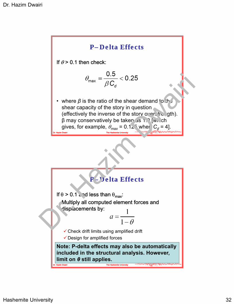
If If > 0.1 then check:> 0.1 then check:
• where β is the ratio of the shear demand to the
Dr. Hazim DwairiDr. Hazim Dwairi The Hashemite UniversityThe Hashemite University
βshear capacity of the story in question (effectively the inverse of the story overstrength). β may conservatively be taken as 1.0 [which gives, for example, max = 0.125 when Cd = 4].
PP––Delta EffectsDelta Effects
If If > 0.1 and less than > 0.1 and less than maxmax::
M lti l ll t d l t f dM lti l ll t d l t f dMultiply all computed element forces and Multiply all computed element forces and displacements by: displacements by:
Check drift limits using amplified drift
Dr. Hazim DwairiDr. Hazim Dwairi The Hashemite UniversityThe Hashemite University
Design for amplified forces
Note: P-delta effects may also be automatically included in the structural analysis. However, limit on θ still applies.
Dr. Haz
im D
wairi

Dr. Hazim Dwairi
Hashemite University 33
Advanced Methods of AnalysisAdvanced Methods of AnalysisAdvanced Methods of AnalysisAdvanced Methods of Analysis
1. Modal response spectrum analysis1. Modal response spectrum analysis
2. Time2. Time--history analysishistory analysis
Dr. Hazim DwairiDr. Hazim Dwairi The Hashemite UniversityThe Hashemite University
Modal Response Spectrum AnalysisModal Response Spectrum Analysis
1.1. Compute modal properties for each modeCompute modal properties for each mode–– Frequency (period)Frequency (period)–– Frequency (period)Frequency (period)–– ShapeShape–– Modal participation factorModal participation factor–– Effective modal massEffective modal mass
2.2. Determine number of modes to use in analysis.Determine number of modes to use in analysis.Use a sufficient number of modes to capture at Use a sufficient number of modes to capture at
Dr. Hazim DwairiDr. Hazim Dwairi The Hashemite UniversityThe Hashemite University
least 90% of total mass in each directionleast 90% of total mass in each direction3.3. Using general spectrum (or compatible ground Using general spectrum (or compatible ground
motion spectrum) compute spectral motion spectrum) compute spectral accelerations for each contributing mode.accelerations for each contributing mode.
Dr. Haz
im D
wairi

Dr. Hazim Dwairi
Hashemite University 34
Modal Response Spectrum AnalysisModal Response Spectrum Analysis
4.4. Multiply spectral accelerations by modal Multiply spectral accelerations by modal participation factor and by (I/R)participation factor and by (I/R)participation factor and by (I/R)participation factor and by (I/R)
5.5. Compute modal displacements for each mode Compute modal displacements for each mode
6.6. Compute element forces in each modeCompute element forces in each mode
7.7. Statistically combine (SRSS or CQC) modal Statistically combine (SRSS or CQC) modal displacements to determine system displacements to determine system di l tdi l t
Dr. Hazim DwairiDr. Hazim Dwairi The Hashemite UniversityThe Hashemite University
displacementsdisplacements
8.8. Statistically combine (SRSS or CQC) Statistically combine (SRSS or CQC) component forces to determine design forcescomponent forces to determine design forces
Modal Response Spectrum AnalysisModal Response Spectrum Analysis
9.9. If the design base shear based on modal If the design base shear based on modal analysis is less than 85% of the base shearanalysis is less than 85% of the base shearanalysis is less than 85% of the base shear analysis is less than 85% of the base shear computed using ELF (and T = Tcomputed using ELF (and T = TaaCCuu), the ), the member forces resulting from the modal member forces resulting from the modal analysis and combination of modes must be analysis and combination of modes must be scaled such that the base shear equals 0.85 scaled such that the base shear equals 0.85 times the ELF base shear.times the ELF base shear.
1010 Add accidental torsion as a static loading andAdd accidental torsion as a static loading and
Dr. Hazim DwairiDr. Hazim Dwairi The Hashemite UniversityThe Hashemite University
10.10.Add accidental torsion as a static loading and Add accidental torsion as a static loading and amplify if necessary.amplify if necessary.
11.11.For determining drift, multiply the results of the For determining drift, multiply the results of the modal analysis (including the I/R scaling but not modal analysis (including the I/R scaling but not the 85% scaling) by Cthe 85% scaling) by Cdd/I./I.
Dr. Haz
im D
wairi

Dr. Hazim Dwairi
Hashemite University 35
Analytical Modeling for Modal Analytical Modeling for Modal Response Spectrum AnalysisResponse Spectrum Analysis
•• Use threeUse three--dimensional analysisdimensional analysis•• For concrete structures, include effect of crackingFor concrete structures, include effect of crackingFor concrete structures, include effect of crackingFor concrete structures, include effect of cracking•• For steel structures, include panel zone deformationsFor steel structures, include panel zone deformations•• Include flexibility of foundation if well enough definedInclude flexibility of foundation if well enough defined•• Include actual flexibility of diaphragm if well enough Include actual flexibility of diaphragm if well enough
defineddefined•• Include PInclude P--delta effects in analysis if program has the delta effects in analysis if program has the
capabilitycapability
Dr. Hazim DwairiDr. Hazim Dwairi The Hashemite UniversityThe Hashemite University
capabilitycapability•• Do not try to include accidental torsion by movement of Do not try to include accidental torsion by movement of
center of mass center of mass •• Include orthogonal load effects by running the fill 100% Include orthogonal load effects by running the fill 100%
spectrum in each direction, and then SRSSing the spectrum in each direction, and then SRSSing the results.results.
TimeTime--history Analysishistory Analysis
•• Follow procedures given in previous slides for Follow procedures given in previous slides for modeling structure When using modal responsemodeling structure When using modal responsemodeling structure. When using modal response modeling structure. When using modal response history analysis, use enough modes to capture history analysis, use enough modes to capture 90% of the mass of the structure in each of the 90% of the mass of the structure in each of the two orthogonal directions.two orthogonal directions.
•• Include accidental torsion (and amplification, if Include accidental torsion (and amplification, if necessary) as additional static load conditionsnecessary) as additional static load conditions
Dr. Hazim DwairiDr. Hazim Dwairi The Hashemite UniversityThe Hashemite University
necessary) as additional static load conditions.necessary) as additional static load conditions.
•• Perform orthogonal loading by applying the full Perform orthogonal loading by applying the full recorded orthogonal horizontal ground motion recorded orthogonal horizontal ground motion simultaneous with the principal direction motion.simultaneous with the principal direction motion.
Dr. Haz
im D
wairi

Dr. Hazim Dwairi
Hashemite University 36
TimeTime--history Analysishistory Analysis
•• Ground motions must have magnitude, fault Ground motions must have magnitude, fault mechanism and fault distance consistent withmechanism and fault distance consistent withmechanism, and fault distance consistent with mechanism, and fault distance consistent with the site and must be representative of the the site and must be representative of the maximum considered ground motionmaximum considered ground motion
•• Where the required number of motions are not Where the required number of motions are not available simulated motions (or modified available simulated motions (or modified motions) may be usedmotions) may be used
Dr. Hazim DwairiDr. Hazim Dwairi The Hashemite UniversityThe Hashemite University
motions) may be usedmotions) may be used
A suite of not less than three ground motions shall be used.
Dr. Haz
im D
wairi