Lecture 16: Pneumatic system design and development part 5
39
Pneumatics and Hydraulics Lecture 16: Pneumatic system design and development part 5 Dr. Ahmad Al-Mahasneh
-
Upload
khangminh22 -
Category
Documents
-
view
13 -
download
0
Transcript of Lecture 16: Pneumatic system design and development part 5

Pneumatics and HydraulicsLecture 16: Pneumatic system design and
development part 5Dr. Ahmad Al-Mahasneh
Outline
•Memory circuit and speed control of a cylinder.
•The quick exhaust valve.
•Pressure dependent control.
•The time delay valve.
• - Development of multiple actuator circuits

Example 10: Memory circuit and speed control of a cylinder
• A double-acting cylinder is to be used to transfer parts from a magazine.
• The cylinder is to fully advance when a push button is operated and then retract automatically.
• Full extension is confirmed by a roller lever valve.
• The cylinder is to continue forward even if the push button is released before full extension is reached.
• The speed of the cylinder is to be adjustable in both directions of motion.
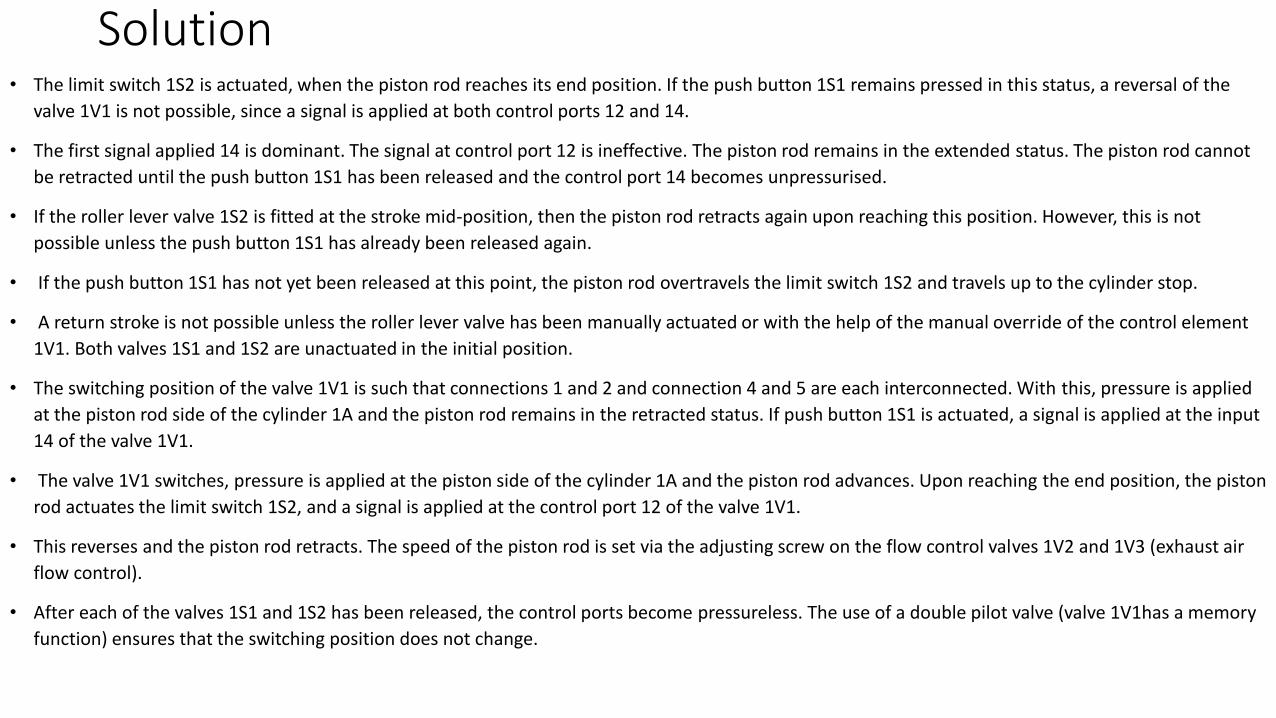
Solution• The limit switch 1S2 is actuated, when the piston rod reaches its end position. If the push button 1S1 remains pressed in this status, a reversal of the
valve 1V1 is not possible, since a signal is applied at both control ports 12 and 14.
• The first signal applied 14 is dominant. The signal at control port 12 is ineffective. The piston rod remains in the extended status. The piston rod cannot
be retracted until the push button 1S1 has been released and the control port 14 becomes unpressurised.
• If the roller lever valve 1S2 is fitted at the stroke mid-position, then the piston rod retracts again upon reaching this position. However, this is not
possible unless the push button 1S1 has already been released again.
• If the push button 1S1 has not yet been released at this point, the piston rod overtravels the limit switch 1S2 and travels up to the cylinder stop.
• A return stroke is not possible unless the roller lever valve has been manually actuated or with the help of the manual override of the control element
1V1. Both valves 1S1 and 1S2 are unactuated in the initial position.
• The switching position of the valve 1V1 is such that connections 1 and 2 and connection 4 and 5 are each interconnected. With this, pressure is applied
at the piston rod side of the cylinder 1A and the piston rod remains in the retracted status. If push button 1S1 is actuated, a signal is applied at the input
14 of the valve 1V1.
• The valve 1V1 switches, pressure is applied at the piston side of the cylinder 1A and the piston rod advances. Upon reaching the end position, the piston
rod actuates the limit switch 1S2, and a signal is applied at the control port 12 of the valve 1V1.
• This reverses and the piston rod retracts. The speed of the piston rod is set via the adjusting screw on the flow control valves 1V2 and 1V3 (exhaust air
flow control).
• After each of the valves 1S1 and 1S2 has been released, the control ports become pressureless. The use of a double pilot valve (valve 1V1has a memory
function) ensures that the switching position does not change.

Circuit diagram

• Try to draw the following:
• Motion diagram:
-Displacement-Step Diagram.
-Displacement-Time Diagram.
• Control chart.
• Function diagram.
• Function chart.
Example 11:The quick exhaust valve
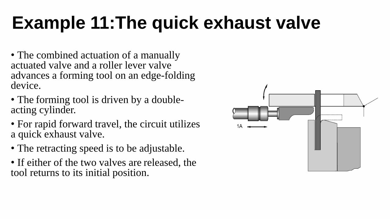
• The combined actuation of a manuallyactuated valve and a roller lever valve advances a forming tool on an edge-folding device.
• The forming tool is driven by a double-acting cylinder.
• For rapid forward travel, the circuit utilizes a quick exhaust valve.
• The retracting speed is to be adjustable.
• If either of the two valves are released, the tool returns to its initial position.

Solution• In the initial position, the inserted workpiece actuates the roller lever valve 1S2.
• The quick exhaust valve 1V4 is closed to atmosphere, pressure is applied at the piston rod side of the cylinder 1A,
and the piston rod remains in the retracted status.
• If the start button 1S1 is actuated, a signal is applied at both inputs 1 and 1(3) of the dual-pressure valve 1V1. The
AND condition is met and the signal is passed to the control port 14 of the control element 1V2.
• The valve 1V2 switches, pressure is applied to the piston side of the cylinder 1A, and the piston rod advances. As a
result of the valve 1V2 reversing, input 1 of the quick exhaust valve 1V4 becomes pressureless.
• The air displaced on the piston rod side of the cylinder during advancing opens the quick exhaust valve and flows
directly to atmosphere via the output 3.
• The flow resistance, created by the valve 1V2 and the lines against the displaced air, no longer applies. The piston
rod is able to advance more rapidly.
• If one of the two valves 1S1 or 1S2 is released, the AND condition at the dual-pressure valve 1V1 is no longer met.
• The final control element 1V2 switches, the quick exhaust valve 1V4 closes and the piston rod retracts. The
retracting speed is set at the restrictor of the one-way flow control valve 1V3.

Circuit diagram

Example 12: Pressure dependent control
• A plastic component is embossed using a
die driven by a double-acting cylinder.
• The die is to advance and emboss the
plastic when a push button is operated.
• The return of the die is to be affected when
a preset pressure is reached.
• The embossing pressure is to be adjustable.

Solution•If the piston rod is not in its initial position, the circuit must be reset by operating the manual override on the 5/2-way double
pilot valve.
• All valves are unactuated in the initial position, pressure is applied at the piston rod side of the cylinder and the piston rod
remains in the retracted state. Actuation of the push button switches the valve 1S to flow and a signal is applied at the control
port 14 of the double pilot valve 1V2.
• The valve 1V2 switches, pressure is applied at the piston side of the cylinder and the piston rod advances.
• The switching status of the double pilot valve 1V2 remains intact if the push button 1S is released. When the piston rod
reaches the workpiece, travel is stopped and pressure starts to build up on the piston side.
• The increasing pressure causes the force of the die to increase.
• The control port 12 of the pressure sequence valve 1V1 is connected to the pressure line on the piston side of the cylinder 1A.
• When the pressure in the cylinder reaches the value set on the pressure sequence valve, the 3/2-way valve switches.
• A signal is now applied at the control port 12 of the valve 1V2. The valve 1V2 switches, pressure is applied at the piston rod
side of the cylinder and the piston rod retracts.
• During retraction, the response pressure set on the pressure sequence valve is not met and the pressure sequence valve returns
to its initial position.
• The response pressure set on the pressure sequence valve must be lower than the system pressure in order to ensure reliable
switching.
• Should the advancing piston rod meet an obstacle, then it will retract again before reaching the embossing position.

Circuit diagram
Example 13: Pressure dependent control; embossing of plastic components
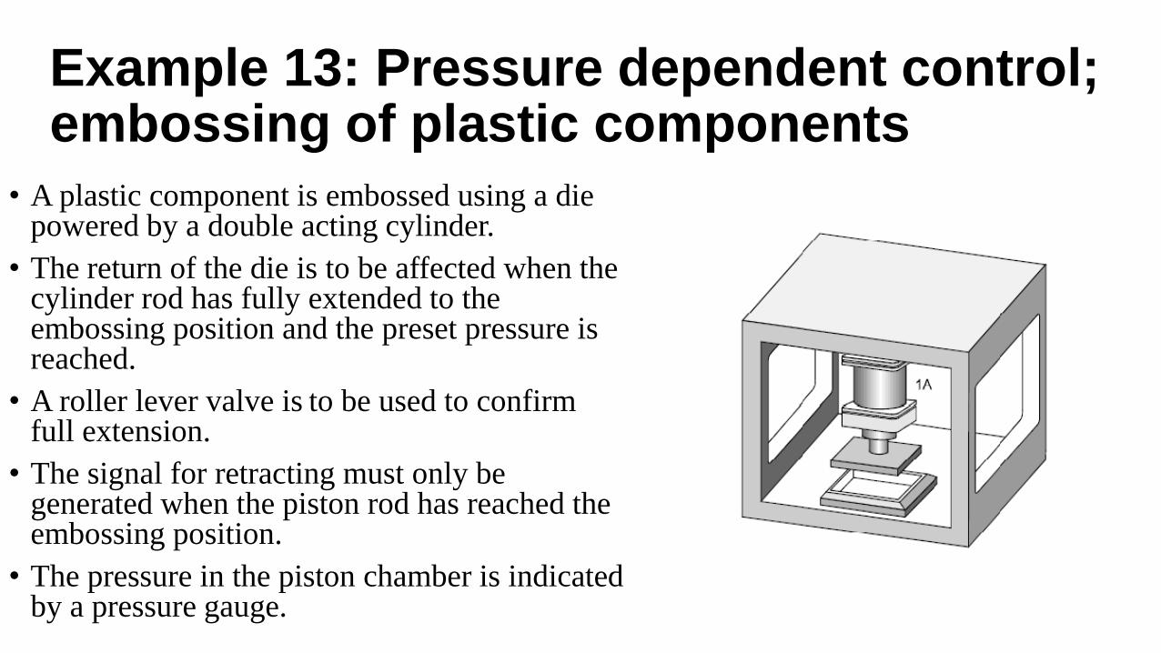
• A plastic component is embossed using a die powered by a double acting cylinder.
• The return of the die is to be affected when the cylinder rod has fully extended to the embossing position and the preset pressure is reached.
• A roller lever valve is to be used to confirm full extension.
• The signal for retracting must only be generated when the piston rod has reached the embossing position.
• The pressure in the piston chamber is indicated by a pressure gauge.

Solution• In the initial position, valves 1S1 and 1S2 are unactuated, pressure is applied at the piston rod side of the cylinder 1A and
the piston rod remains in the retracted state.
• If necessary, the circuit needs to be put into its initial position with the help of the manual override on the control
element 1V2.
• A signal is applied at the control port 14 of the control element 1V2, if the push button 1S1 is actuated. The valve 1V2
switches, pressure is applied at the piston side of the cylinder 1A, and the piston rod advances.
• If the push button 1S1 is released, the switching position of the double pilot valve 1V2 does not change due to its
memory function. Just before reaching the forward end position (embossing position), the limit switch 1S2 is actuated.
• The actuated roller lever valve 1S2 releases the pressure line 1 to the pressure sequence valve 1V1. During the
embossing process, the pressure on the piston side starts to increase.
• The indicator of the pressure gauge turns to the right.
• When this pressure reaches the value set at the control port 12 of the pressure sequence valve, the 3/2-way valve of the
pressure sequence valve switches.
• The control element 1V2 reverses and the piston rod retracts. During the retracting movement, the limit switch 1S2 is
released and the signal at the control port 12 of the valve 1V2 is reset and the pressure sequence valve is also reset.

Circuit diagram
Example 14: The time delay valve
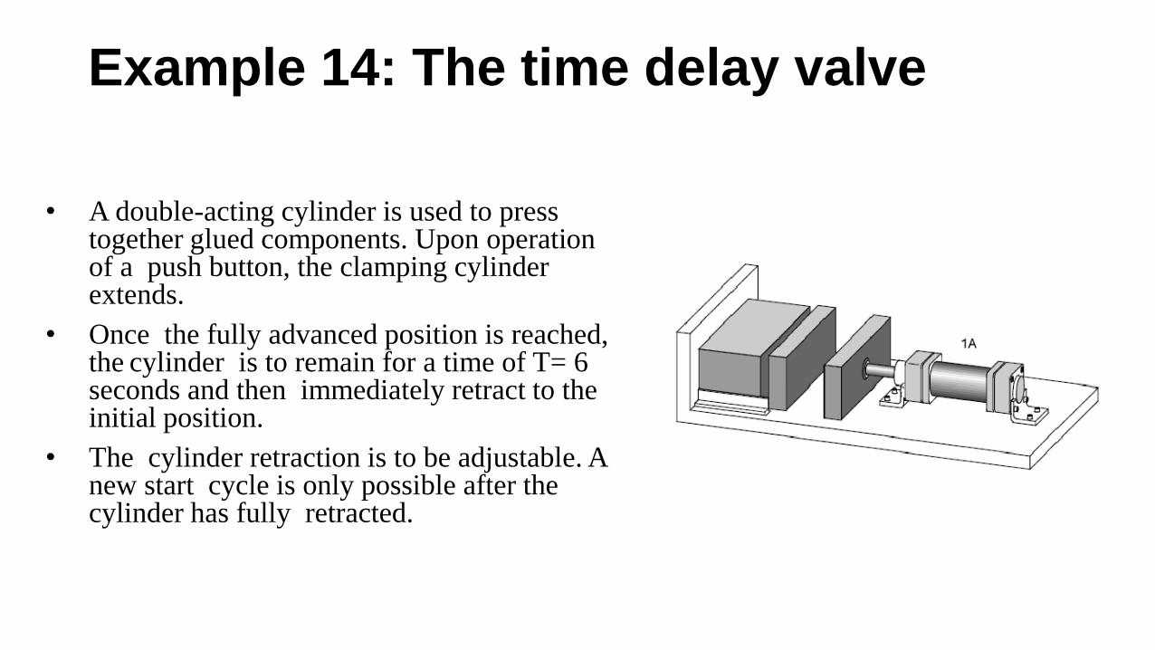
• A double-acting cylinder is used to press together glued components. Upon operation of a push button, the clamping cylinder extends.
• Once the fully advanced position is reached, the cylinder is to remain for a time of T= 6 seconds and then immediately retract to the initial position.
• The cylinder retraction is to be adjustable. A new start cycle is only possible after the cylinder has fully retracted.
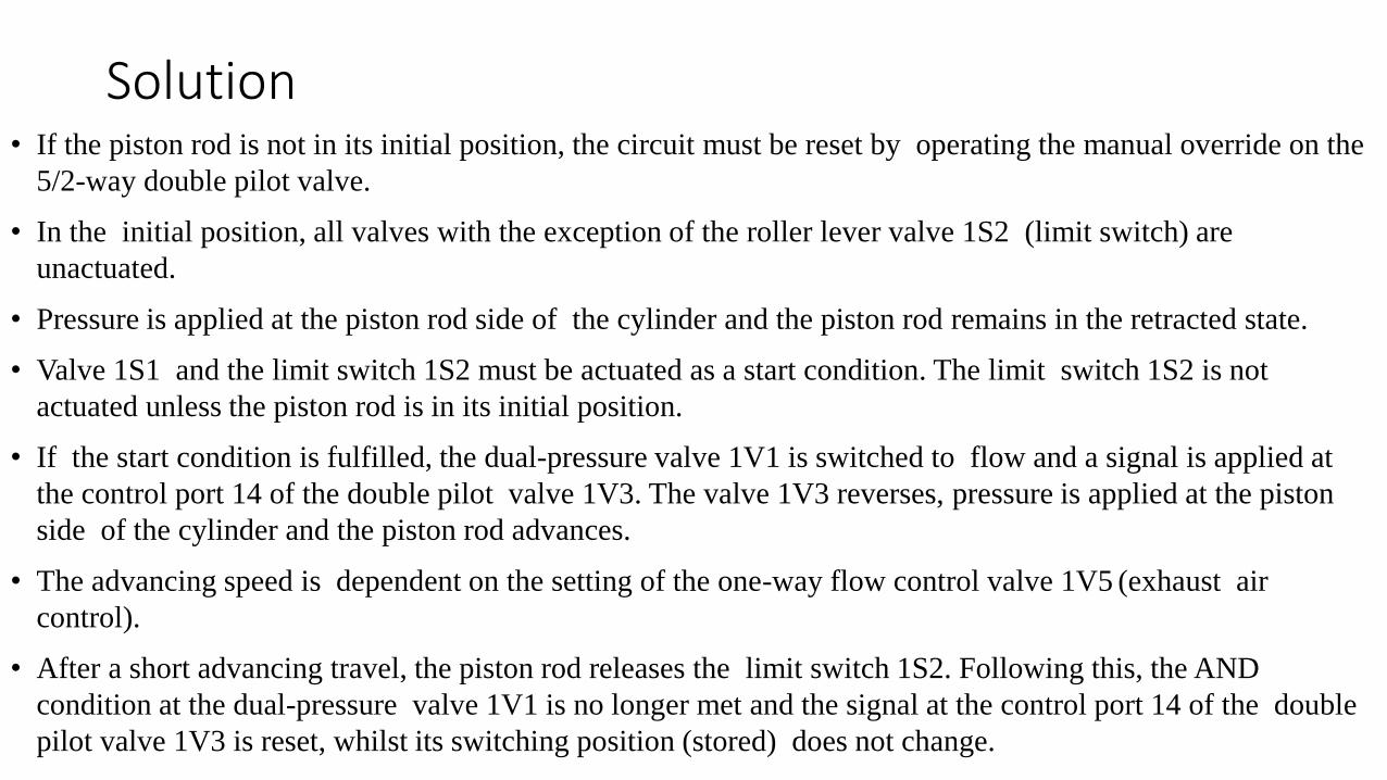
Solution• If the piston rod is not in its initial position, the circuit must be reset by operating the manual override on the
5/2-way double pilot valve.
• In the initial position, all valves with the exception of the roller lever valve 1S2 (limit switch) are
unactuated.
• Pressure is applied at the piston rod side of the cylinder and the piston rod remains in the retracted state.
• Valve 1S1 and the limit switch 1S2 must be actuated as a start condition. The limit switch 1S2 is not
actuated unless the piston rod is in its initial position.
• If the start condition is fulfilled, the dual-pressure valve 1V1 is switched to flow and a signal is applied at
the control port 14 of the double pilot valve 1V3. The valve 1V3 reverses, pressure is applied at the piston
side of the cylinder and the piston rod advances.
• The advancing speed is dependent on the setting of the one-way flow control valve 1V5 (exhaust air
control).
• After a short advancing travel, the piston rod releases the limit switch 1S2. Following this, the AND
condition at the dual-pressure valve 1V1 is no longer met and the signal at the control port 14 of the double
pilot valve 1V3 is reset, whilst its switching position (stored) does not change.

Solution•A renewed actuation of the valve 1S1 is now ineffective until the system has reached its initial status again.
• When the embossing position is reached, the limit switch 1S3 is actuated.
•The air reservoir in the time delay valve 1V2 starts filling up via the integrated one-way flow control valve.
•The rate of pressure increase is dependent on the setting of the integrated restrictor.
•When the pressure is sufficiently high, the 3/2-way valve switches and a signal is applied at the control port 12 of
the double pilot valve 1V3.
•The valve 1V3 reverses, pressure is applied at the piston rod side of the cylinder and the piston rod retracts.
•The retracting speed is dependent on the setting of the one-way flow control valve 1V4.
• When retracting, the limit switch 1S3 reverses and the air reservoir of the time delay valve 1V2 is exhausted to
atmosphere via the non-return valve and the limit switch 1S3.
• As result of this, the 3/2-way valve of the time delay valve switches into its initial position.
• The signal at the control port 12 of the double pilot valve 1V3 is then reset.
• When the piston rod reaches its initial position, the limit switch 1S2 is actuated and a new cycle can be started.
Circuit diagram

Example 15: The time delay valve
• A double-acting cylinder is used to press together glued components.
• Upon operation of a push button, the clamping cylinder slowly advances.
• Once the fully extended position is reached, the cylinder is to remain for a time of•T = 6 seconds and then immediately retract to the initial position.• A new start cycle is only possible after the cylinder has fully retracted and after a delay of 5 seconds. •During this delay the finished part is manually removed and replaced with new parts for gluing. •The retracting speed should be fast, butadjustable.
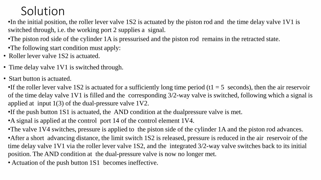
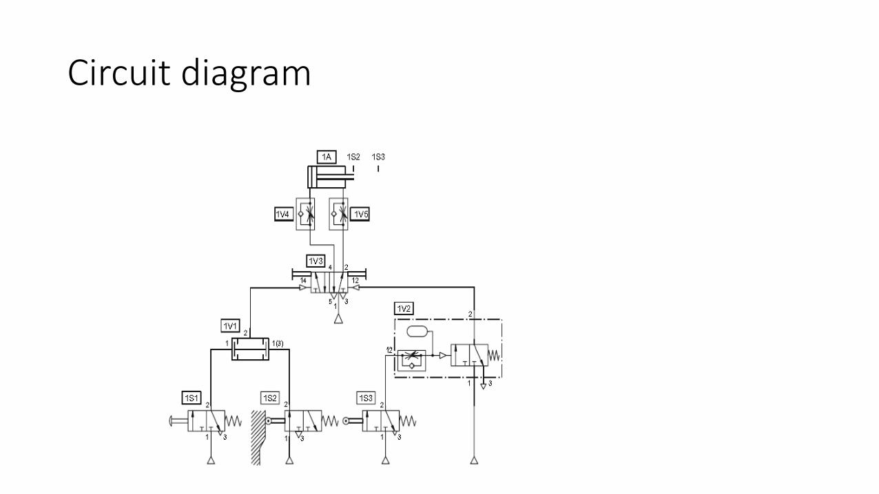
Solution•In the initial position, the roller lever valve 1S2 is actuated by the piston rod and the time delay valve 1V1 is
switched through, i.e. the working port 2 supplies a signal.
•The piston rod side of the cylinder 1A is pressurised and the piston rod remains in the retracted state.
•The following start condition must apply:
• Roller lever valve 1S2 is actuated.
• Time delay valve 1V1 is switched through.
• Start button is actuated.
•If the roller lever valve 1S2 is actuated for a sufficiently long time period (t1 = 5 seconds), then the air reservoir
of the time delay valve 1V1 is filled and the corresponding 3/2-way valve is switched, following which a signal is
applied at input 1(3) of the dual-pressure valve 1V2.
•If the push button 1S1 is actuated, the AND condition at the dualpressure valve is met.
•A signal is applied at the control port 14 of the control element 1V4.
•The valve 1V4 switches, pressure is applied to the piston side of the cylinder 1A and the piston rod advances.
•After a short advancing distance, the limit switch 1S2 is released, pressure is reduced in the air reservoir of the
time delay valve 1V1 via the roller lever valve 1S2, and the integrated 3/2-way valve switches back to its initial
position. The AND condition at the dual-pressure valve is now no longer met.
• Actuation of the push button 1S1 becomes ineffective.

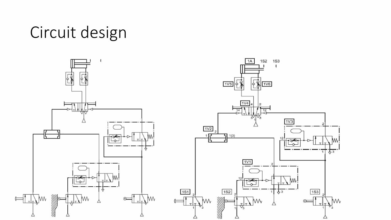
Solution•Upon reaching the advancing position, the piston rod actuates the roller lever valve 1S3.
•The pressure line to the time delay valve 1V3 is now released and pressure in the air reservoir is increased.
•The rate of pressure increase is adjustable via the integrated flow control valve.
• When the switching pressure has been reached, the integrated 3/2-way• valve switches and a signal is applied at the control port 12 of the final control element 1V4. The valve 1V4 reverses and the piston rod retracts. • Upon release of the limit switch 1S3, the time delay valve 1V3 switches to its initial position again. • The limit switch 1S2 is actuated, when the piston rod reaches its initial position. • The pressure in the air reservoir of the time delay valve 1V1 starts to increase until the switching pressure has been reached after t2 = 5 seconds. The integrated 3/2-way valve switches. • The initial status of the system is now reached again and a new cycle can be started. • The piston rod speed is set at the restrictors of the one-way flow control valves 1V5 and 1V6 (exhaust air flow control).
Circuit design

Development of Multiple actuators circuits
• Control of multiple actuators
•In the case of multiple cylinder circuits, a clear definition of the problem is important.
• The representation of the desired motion of all actuators is described using the displacement-step diagram.
•The special conditions for the start of the sequence must also be defined.
•If the motion diagram and auxiliary conditions have been clearly defined, drawing of the circuit diagram can commence.
•In order for a circuit to operate, it is essential to avoid overlapping signals.
• By an overlapping signal, we understand signals applied simultaneously at the two control ports of a double pilot valve.
• The following valves can be used to eliminate signal overlap:• roller lever valves with idle return or toggle lever valves, time delay valves, reversing
valves or sequencers. • To provide a better understanding of the methods, some examples are given for the
use of roller lever valves with idle return and reversing valves.

Example 16: Coordinated motion
• Two cylinders are used to transfer parts from a magazine onto a chute. When a push button is pressed, the first cylinder extends, pushing the part from the magazine and positions it in preparation for transfer by the second cylinder onto the out feed chute.
• Once the part is transferred, the first cylinder retracts, followed by the second.
• Confirmation of all extended andretracted positions are required.

Solution• Roller lever valves with idle return are to be used as limit switches to
detect the return and advance positions of the piston rod.
• The manual signal input is effected via a 3/2- way valve.
• In the initial position, both cylinders are in the retracted state, the limit switches 2S1 and 1S2 are actuated.
• The start condition for a cycle is that the limit switch 2S1 and push button 1S1 must be actuated.
• The motion cycle can be determined from the displacement-step diagram and is subdivided into the following steps:

Solution
1.If push button 1S1 is actuated, the 5/2-way double pilot valve 1V2 switches, and the piston rod of the cylinder 1A advances. The part is ejected from the magazine.
2.When cylinder 1A reaches the forward end position, the limit switch 1S3 is actuated. The 5/2-way double-pilot valve 2V then switches and the piston rod of the cylinder 2A advances. The part is moved onto a chute.3.When cylinder 2A reaches its forward end position, the limit switch 2S2 switches. This causes the control element 1V2 to switch and the piston rod of the cylinder 1A retracts.4.When the retracted end position of the cylinder 1A has been reached, the limit switch 1S2 switches and the control element 2V switches. The piston rod of the cylinder 2A retracts and actuates the limit switch 2S1 upon reaching its retracted end position.5.The initial position of the system has now been reached again. A new cycle can be started by actuating the push button 1S1.

Displacement-step diagram

Circuit diagram
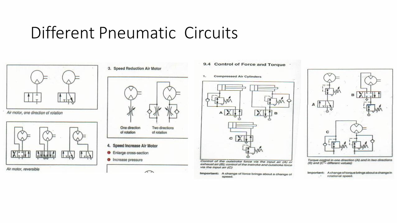
Different Pneumatic Circuits
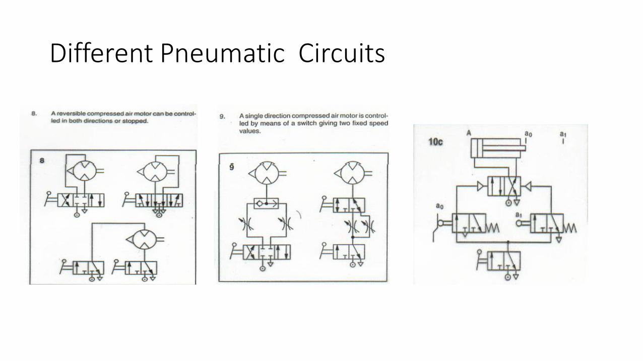
Different Pneumatic Circuits

Different Pneumatic Circuits

Different Pneumatic Circuits
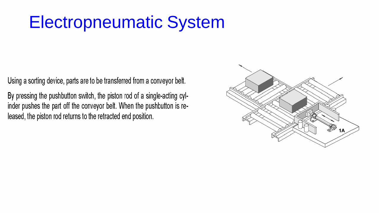
Electropneumatic System
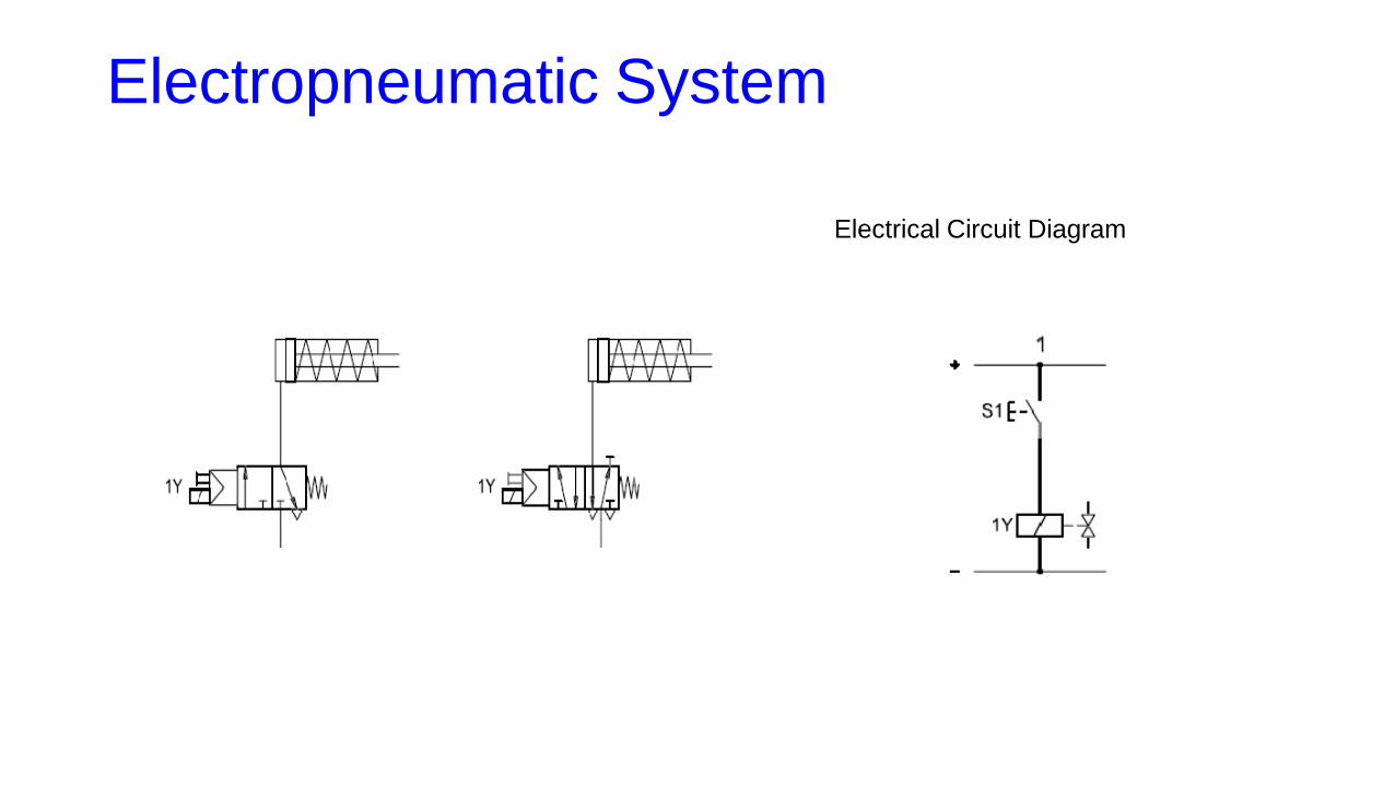
Electropneumatic System
Electrical Circuit Diagram

Example 19: Assembly Station
• In an assembly station components are to be put together.
• By pressing two pushbutton switches the device is advanced and the components are assembled.
• After releasing one or the two pushbutton switches, the device is returned to its start position.
Solution
•By pressing the pushbutton switches S1 and S2, the electric circuit for the solenoid coil 1Y is closed and the 3/2- (5/2-) way solenoid valve is reversed.
•The piston rod of the single-acting (double-acting) cylinder advances to the forward end position.
•After releasing the pushbutton switches S1 and S2 the electric circuit for the solenoid coil 1Y is opened and the 3/2- (5/2-) way solenoid valve is switched back to its initial position by a reset spring.
• The piston rod of the single-acting (double-acting) cylinder returns to the retracted end position.

Circuit design

Questions