Leading Innovation mw. \ m ii^ \V\^
80
Leading Innovation mw. \ m ii^ \V\^ - .\v> tQ \\\i 3 m r- ESK 1 MMiVVAWWISMPr, /W. 'HHin' i —a—\ .^ESWVr. IfllJII'.il i 'M JWUmBBliM' i tWBnnrr 1 « . ; >».« i s iAv lh-i J •,\\ SMMS^ SUPER MODULAR MULTI SYSTEM T1J SHI Bn ^B> « i* a ia a a
-
Upload
khangminh22 -
Category
Documents
-
view
0 -
download
0
Transcript of Leading Innovation mw. \ m ii^ \V\^

Leading Innovation
mw. \
m
ii^
\V\^ -
.\v> tQ
\\\i 3 m
r-
ESK ■ 1 MMiVVAWWISMPr, /W. 'HHin' i —a—\ .^ESWVr. IfllJII'.il i 'M JWUmBBliM' i
tWBnnrr
1 «■.
■; >».« i s iAv lh-i
J •,\\
SMMS^ SUPER MODULAR MULTI SYSTEM
T1JSHIBn ^B>
■■ ■« i* ■ a ia a
■ a

TOSHIBA Leading Innovation »>
i
k
Introduction 3
SMMS-e features Energy saving 8
Diversity 10
Prevent small animals 11
Capacity range 12
SMMS wave tool 14
DC twin-rotary compressor 16
Heat exchanger 17
Piping design flexibility 18
Slimmer pipe size 20
Propeller fan 21
Reliability 22
Operating temperature range 23
Outdoor units
Indoor units line-up for SMMS-e
4-way Air Discharge Cassette type
Compact 4-way Cassette (600 x 600) Type
2-way Air Discharge Cassette Type
1-way Air Discharge Cassette Type
Slim Duct Type
Concealed Duct High Static Pressure Type
Concealed Duct Type
Ceiling Type
High-wall Type (3 series)
Console Type
Floor Standing Cabinet Type
Floor Standing Concealed Type
Floor Standing Type
Large capacity Floor Standing Type
Fresh Air Intake Indoor Unit Type
Air-to-Air Heat Exchanger with DX-coil
Air-to-Air Heat Exchanger
Indoor unit accessories for SMMS-e
Remote controllers
Building management systems
Open network systems
Application controls
Safety precautions
70
74
76
78
80

Toshiba solutions
4
u
.
HI
At Toshiba, we believe that "Evolution is leading the path to a better future". Through the decades, we have been constantly creating innovative and high-quality electrical appliances to increase our consumers' satisfaction. Now, with Toshiba "SMMS-e", the latest commercial air conditioning
for various buildings,
The SMMS-e has been creatively developed and designed under the concept Excellence, Expansion, and Experience to ensure your utmost comfort and convenience like never before.
With the latest technology improved and developed to make SMMS-e the top commercial air conditioning for any solution that intelligently meets your needs, Toshiba will stop at nothing to create innovation to evolution of the future, where life is a step away from perfection.
ISS
> ;7 -ijfz 0
SMMS SUPER MODULAR MULTI SYSTEM

volutic
& XPANSION
SMMS
Air Conditioning for large buildings

& XPERIENCE
& XCELLENCE
TOSHIBA Leading Innovation »>
^chAjm
-X *
, *
JA I ■i
yJk x
Space saving model
Equivalent HP 8HP 10HP | 12HP 14HP 16HP 18HP 20HP 22HP
Appearance 11 Hi UlilE 1
External dimensions (HxWxD) 1,800 x990 x780mm 1,800x 1,21 Ox 780mm 1,800 x 1,600 x 780mm
Refrigerant type R410A
Compressor DC Twin-Rotary Compressor x 2
High efficiency/High diversity model
Equivalent HP 14HP 18HP
Appearance HI Ml 91
External dimensions (HxWxD) 1,800 x 1,210 x 780mm 1,800 x 1,600 x 780mm
Refrigerant type R410A
Compressor DC Twin-Rotary Compressor x 2
Product line up
Space saving model
High efficiency /High diversity model
8HP 1OHP 12HP 14HP 16HP 18HP 20HP 22HP 24HP 26HP 28HP 30HP 32HP 34HP 36HP 38HP 40HP 42HP 44HP 46HP 48HP 50HP 52HP 54HP 56HP 58HP 60HP
•oooooooooooooooooooooooooo
ooooooooooooooooooooooooooo

SMMS SUPER MODULAR MULTI SYSTEM
Greater efficiency performance
&
A
X
ENERGY SAVING
Adopting the highly efficient new DC twin-rotary compressors with various technologies.
7.0
6.5
6.0
5.5
5.0
4.5
4.0
3.5
3.0
2.5
2.0
6.39
50% load
EER
■ 50% load 6.22
5.86 5.70
5A4 5.50
8HP 10HP 12HP 14HP 16HP 18HP
Conditions: Cooling: Indoor air temperature 270C DB/190C WB, outdoor air temperature BSC DB *High efficiency/High diversity model by single outdoor unit

TOSHIBA Leading Innovation »>
7
i 4k
/A
%
Greater diversity
Thanks to the newly developed refrigerant circuit, the diversity of outdoor units has drastically increased. This makes it much easier to design for installations with many rooms or offices.
=== j|| 8HP I SMMS-e (8HP) diversity up to
170%
•c>
High efficiency model/High diversity model
SMMS-e Current
8HP 170% 10HP 150% 12HP 135% 14HP 145% 16HP 135% 18HP 150% 20HP 150% 22HP 140% 24HP 135% 26HP 140% 28HP 145% 30HP 140% 32HP 135% 34HP 140% 36HP 135% 38HP 140% 40HP 140% 42HP 145% 44HP 140% 46HP 140% 48HP 135% 50HP 140% 52HP 135% 54HP 145% 56HP 140% 58HP 135% 60HP 135%
135%

w*
SMMS SUPER MODULAR MULTI SYSTEM &
A
PREVENT SMALL ANIMALS
Prevent small animals getting into the inverter
To prevent the small animals from entering and interfering with the electronic components in the system,
our new inverter box has been upgraded with additional protection, while allowing reliable operation.
The inverter box is fitted with punched sheet metal & resin sheet.
OOCJ
Seal wiring holes The diameter of each with resin sheet punched sheet metal is (j)4mm
*This is applicable for small animals bigger than 4mm.

TOSHIBA Leading Innovation »>
Single unit capacity expanded
SMMS-e comes with 3 new larger capacity units, producing up to 22HP on a single module platform.
Hi i ii E !i B
1012 14 HP 6 18 HP 20 22 HP
Industry-leading installation flexibility •Space saving model
Outdoor units improve performance to achieve greater space efficiency that defies their compact module size to deliver greater freedom in layout design. This minimizes weight-related restrictions and allows for quicker installation.
22HP
Previous model
ri r
10HP 12HP 2i j .aBHLj i_i
SMMS-e
26HP
n n r
10HP 8HP 8HP
m m
1
1
22HP 14HP 12HP Free Space
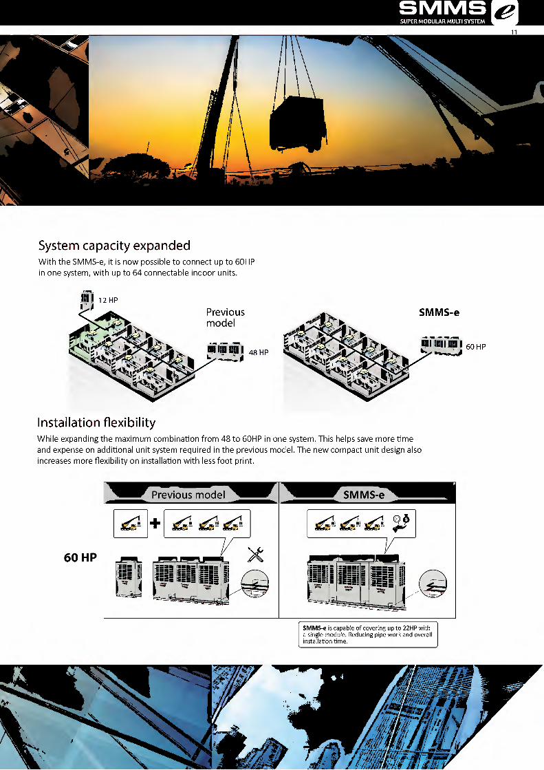
System capacity expanded
With the SMMS-e, it is now possible to connect up to 60HP in one system, with up to 64 connectable indoor units.
SMMS SUPER MODULAR MULTI SYSTEM &
i 12 HP
v:
Previous model
mt im m i 48 HP
SMMS-e
KUI 60 HP
<^43
Installation flexibility
While expanding the maximum combination from 48 to 60HP in one system. This helps save more time and expense on additional unit system required in the previous model. The new compact unit design also increases more flexibility on installation with less foot print.
60 HP
Previous model
+ <WU'o 1 xWo'o '
\.c
=== ===
SMMS-e
l"^1
/
SMMS-e is capable of covering up to 22HP with a single module. Reducing pipe work and overall installation time.
r

TOSHIBA Leading Innovation »>
*
SMMS WAVE TOOL
SMMS wave tool
With SMMS wave Tool, you can read and write data from outdoor unit directly on your smart phone without the needs of connecting PC or opening cabinet.
= :: s •"
o
n Q
By the new smart phone application, the testing and commissioning can be done without opening the cabinet.
In
V-
Previous model
= iii
□
SMMS-e
;
05
I
*Smartphone specification: Android™ OS 5.0

SMMS SUPER MODULAR MULTI SYSTEM
Available data
Whether the product data, system data, fault history or testing and commissioning, all can be obtained easily even in case of under service maintenance or power failure. The data can be easily sent to the distant office via email. Possible to receive system data by e-mail without moving from your office and the operation conditions can be checked in the office.
In case of below situation
* Installation
^Service maintenance
^ Power failure
Available data
Smart phone
Test operation result
The Site The office
1 _

TOSHIBA Leading Innovation »>
m iMi^A
DC TWIN-ROTARY COMPRESSOR
Wide range compressor
More powerful and efficient with the cutting-edge technology of compressor - DC Twin-Rotary operates in wider range of rotation speed.
42 Displacement volume cm3
Displacement volume xl.5 SMMS-e
Displacement volume
DLC coated vane
Increased hardness of the DLC coated vane reduces friction and increase both reliability and performance.
DLC Coat vane
/
Rotary shaft roller.
Crank
V
DLC Coat vane
Cylinder
DLC: Diamond Like Carbon
2-stage vane
With 2-stage vane innovatively designed to reduce friction while increasing hardness and enhancing performance at its best.
Shaft
Contact portions
raiffl
kwm
Contact portions
1\U«!
Itoib
Previous
1 stage
2 stage
SMMS-e
SMMS SUPER MODULAR MULTI SYSTEM &
15
HEAT EXCHANGER
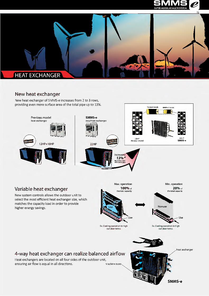
New heat exchanger
New heat exchanger of SMMS-e increases from 2 to 3 rows, providing even more surface area of the total pipe up to 13%
Previous model heat exchanger
=i
12HP+10HP
SMMS-e new heat exchanger
Previous 8 mm dia SMMS-e 7 mm dia
( ani
lllli
22HP
Increased 73%
Variable heat exchanger
New system controls allows the outdoor unit to select the most efficient heat exchanger size, which matches the capacity load in order to provide higher energy savings.
Max. operation 100% of
the total capacity
Use
Ex. Cooling operation in high out door temp.
Min. operation 20% of
the total capacity
Nonuse
Use
Ex. Cooling operation in high out door temp.
4-way heat exchanger can realize balanced airflow
Heat exchangers are located on all four sides of the outdoor unit, ensuring air flow is equal in all directions. Machine room
heat exchanger
SMMS-e

TOSHIBA Leading Innovation »>
V
V
/ 1
/
a
rA i;
Total piping length
Applied with Toshiba's unique and greatly improved technology, SMMS-e can reach up to 1,000 meters maximum piping length.
* 'jP-*
■ijP> ei mnini
Total 1,000m piping length
Farthest pipe from 1 st branch
Even more convenient with the piping distance from the first branch to the furthest indoor unit at 90 meters, increasing the flexibility of the installation within the hotel or office building.
; >' ► 55V 4P
X-
SMMS-e Max. total length Farthest pipe Q/\»y1
from 1 st branch ^ w I
Farthest equivalent length
The maximum equivalent distance between outdoor unit and farthest indoor unit tops at 235 meters, which tops the industry class.
J "V v.
M
J JN , & > ■
■ ■ - ■
r
Farthest O ? ^ m equivalent length I
Height between indoor units
Another industry's top class is a maximum vertical distance between indoor units which reaches up to 40 meters, equal to an entire 11-storied building. SMMS-e's enhanced piping capabilities result in more benefits for the system design, installation flexibility, as well as the less installation cost.
I
W
/ h
Height between indoor unit
SMMS SUPER MODULAR MULTI SYSTEM &
17
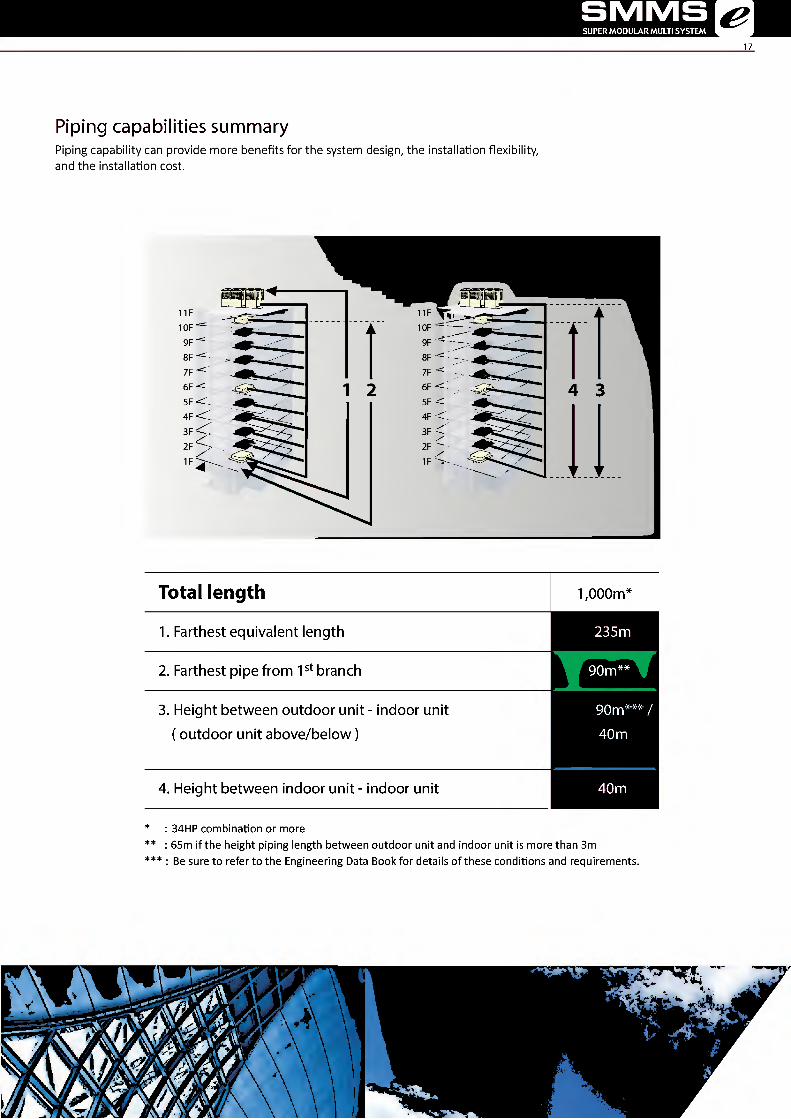
Piping capabilities summary
Piping capability can provide more benefits for the system design, the installation flexibility, and the installation cost.
F OF
1 2
4F
HSIHIIil 1 1 IF i k 10F i k
9F 8F 7F ■=:
6F < ^ 4 3 5F < 4F< 3F< 2F IF
r t r
Total length 1,000m*
1. Farthest equivalent length 235m
2. Farthest pipe from 1st branch 90m**
3. Height between outdoor unit - indoor unit
(outdoor unit above/below)
90m***/
40 m
4. Height between indoor unit - indoor unit 40m
* : 34HP combination or more ** : 65m if the height piping length between outdoor unit and indoor unit is more than 3m *** : Be sure to refer to the Engineering Data Book for details of these conditions and requirements.
r

TOSHIBA Leading Innovation »>
Piping saving costs
With the sub-cool heat exchanger less refrigerant is needed therefore now it is possible to use smaller pipes and save in installation costs.
NEW- ^
SMMS-e Previous model
cp 28.6 mm cp 34.9 mm
One size down
<
22 HP
Sub-cool heat exchanger available in all models

New advanced blade shapes for a better air flow management
Every single blade is designed with a unique profile, a solution that guarantees a smoother air flow without turbulences. The new propeller deliver the same amount of air with less sound pressure level.
Each blade has a unique profile Design improvements
A B New anti-eddy projections on the back of the fan
C D New profiles of the reverse-arc shaped wings
More quiet in comparison with the previous fan
In the same working condition the new design of the propeller ensure a reduction of 1.5 dB compared to the previous models
Sound pressure level Previous fan
SMMS-e
*
Air volume

Backup operation
In case of a compressor failure, SMMS-e can keep working with the backup operation under All Inverter Control to compensate a failed compressor or header unit. This backup operation is available in both a single system or as a module.
Single outdoor unit backup
H
Failed compressor
Module outdoor unit backup
EI IT
W IT
W ZLT
NNNNsnN
DDDDDODODD □
□□□□□□□□□□ [DDDDQDDDQ DDDDDODODD DDDDDDDDDD DDDDDODODD
NNNNsnN
m
Failed outdoor unit
Reliability rotational control
The rotational control in SMMS-e is designed to improve system reliability by controlling the operation of each compressor to work equally under variable conditions.
Comp1/Comp2 <\se v'/ utd, fOV Oc
00r xd0
% 'T^ Ok,
err; v'/ -O'
^ Decrease Air-conditionning load j ^ Increase Air-conditionning load j
Morning
W W iuu^ ii iyu^ ClI Compl/Comp2 Compl/Comp2

-".S •' • v . ••• •••- ■ •
SMMS SUPER MODULAR MULTI SYSTEM &
'A ■ m m
iA
?«■;
frt;
Outdoor temperature range
Utilizing the newly designed compressor, SMMS-e can operate under the wider range of outdoor ambience with the expansion of cooling from -5°C to 46°C.
Operation ambient temperature expansion (Cooling :<tDB,Heating :0CWB)
Cooling
-!■ 5 - 46 rc
-25 0 25 50 ("C)
Note : Based on equivalent piping length of 7.5 m and piping height difference of 0 m.
The external static pressure
The SMMS-e units are suitable for challenging installations
where high external static pressure performance
Airflow simulation diagram
60 pa
§
Note : This result is analytical simulation, that does not guarantee actual temperatures.
sags X A

TOSHIBA Leading Innovation »>
"12^
Outdoor units
Space saving model
ni nni win
Capacity 8HP 10HP 12HP 14HP 16HP 18HP 20HP 22HP
Model Name (MMY-)
50 Hz MAP0806T8P MAP1006T8P MAP1206T8P MAP14B6T8P MAP1606T8P MAP18B6T8P MAP2006T8P MAP2206T8P 60 Hz MAP0806T7P MAP1006T7P MAP1206T7P MAP14B6T7P MAP1606T7P MAP18B6T7P MAP2006T7P MAP2206T7P
Cooling capacity (kW) 22.4 28.0 33.5 40.0 45.0 50.4 56.0 61.5
IIS ill 1 hi m iraniii aninsii
Capacity 24HP 26HP 28HP 30HP 32HP 34HP 36HP 38HP
Model Name 50 Hz AP2416T8P AP2616T8P AP2816T8P AP3016T8P AP3216T8P AP3416T8P AP3616T8P AP3816T8P (MMY-) 60 Hz AP2416T7P AP2616T7P AP2816T7P AP3016T7P AP3216T7P AP3416T7P AP3616T7P AP3816T7P
Units in combination MAP1206T8P MAP1206T8P MAP1406T8P MAP1206T8P MAP14B6T8P MAP14B6T8P MAP1606T8P MAP14B6T8P MAP1606T8P MAP1606T8P MAP18B6T8P MAP1606T8P MAP18B6T8P MAP18B6T8P MAP2206T8P MAP1606T8P (MMY-MAP) MAP1206T7P MAP1206T7P MAP1406T7P MAP1206T7P MAP14B6T7P MAP14B6T7P MAP1606T7P MAP14B6T7P MAP1606T7P MAP1606T7P MAP18B6T7P MAP1606T7P MAP18B6T7P MAP18B6T7P MAP2206T7P MAP1606T7P
Cooling capacity (kW) 67.0 73.5 80.0 85.0 90.0 95.4 100.8 106.5
mwmi mini k iniHKHI nniRni
Capacity 40HP 42HP 44HP 46HP 48HP
Model Name (MMY-)
50 Hz AP4016T8P AP4216T8P AP4416T8P AP4616T8P AP4816T8P 60 Hz AP4016T7P AP4216T7P AP4416T7P AP4616T7P AP4816T7P
Units in combination (MMY-MAP)
MAP2206T8P MAP2206T7P
MAP18B6T8P MAP18B6T7P
MAP2206T8P MAP2206T7P
MAP2006T8P MAP2006T7P
MAP2206T8P MAP2206T7P
MAP2206T8P MAP2206T7P
MAP1606T8P MAP1606T7P
MAP1606T8P MAP1606T7P
MAP14B6T8P MAP14B6T7P
MAP1606T8P MAP1606T7P
MAP1606T8P MAP1606T7P
MAP1606T8P MAP1606T7P
Cooling capacity (kW) 111.9 117.5 123.0 130.0 135.0
immiiiil iiiiniiEiii
Capacity 50HP 52HP 54HP 56HP 58HP 60HP
Model Name (MMY-)
50 Hz AP5016T8P AP5216T8P AP5416T8P AP5616T8P AP5816T8P AP6016T8P 60 Hz AP5016T7P AP5216T7P AP5416T7P AP5616T7P AP5816T7P AP6016T7P
Units in combination (MMY-MAP)
MAP18B6T8P MAP18B6T7P
MAP1606T8P MAP1606T7P
MAP1606T8P MAP1606T7P
MAP18B6T8P MAP18B6T7P
MAP18B6T8P MAP18B6T7P
MAP1606T8P MAP1606T7P
MAP18B6T8P MAP18B6T7P
MAP18B6T8P MAP18B6T7P
MAP18B6T8P MAP18B6T7P
MAP2006T8P MAP2006T7P
MAP18B6T8P MAP18B6T7P
MAP18B6T8P MAP18B6T7P
MAP2206T8P MAP2206T7P
MAP18B6T8P MAP18B6T7P
MAP18B6T8P MAP18B6T7P
MAP2206T8P MAP2206T7P
MAP2206T8P MAP2206T7P
MAP1606T8P MAP1606T7P
Cooling capacity (kW] 140.4 145.8 151.2 156.8 162.3 168.0 * Power: 3-phase 50 Hz 400V (380 - 415V) / 3-phase 60 Hz 380V * The source voltage must not fluctuate more than ±10%. * Rated conditions Cooling: Indoor air temperature 270C DB/190C WB, outdoor air temperature 350C DB
5MMS SUPER MODULAR MULTI SYSTEM &
23
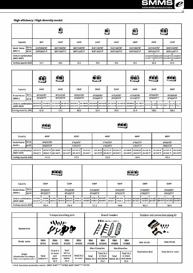
High efficiency / High diversity model
■ 1 ^51 0111 Mi [ iil iill
Capacity 8HP 10HP 12HP 14HP 16HP 18HP 20HP 22HP
Model Name (MMY-)
50 Hz MAP0806T8P MAP1006T8P MAP1206T8P MAP1406T8P MAP1606T8P MAP1806T8P MAP2026T8P MAP2226T8P 60 Hz MAP0806T7P MAP1006T7P MAP1206T7P MAP1406T7P MAP1606T7P MAP1806T7P MAP2026T7P MAP2226T7P
Units in combination (MMY-MAP)
MAP1006T8P MAP1006T7P
MAP1006T8P MAP1006T7P
MAP1206T8P MAP1206T8P
MAP1006T8P MAP1006T8P
Cooling capacity (kW) 22.4 28.0 33.5 40.0 45.0 50.4 56.0 61.5
!ii mi HI m i im nm IpHfif [ "i in mi ■ ■■
Capacity 24HP 26HP 28HP 30HP 32HP 34HP 36HP 38HP
Model Name (MMY-)
50 Hz AP2426T8P AP2626T8P AP2826T8P AP3026T8P AP3226T8P AP3426T8P AP3626T8P AP3826T8P 60 Hz AP2426T7P AP2626T7P AP2826T7P AP3026T7P AP3226T7P AP3426T7P AP3626T7P AP3826T7P
Units in combination (MMY-MAP)
MAP1206T8P MAP1206T7P
MAP1206T8P MAP1206T7P
MAP1406T8P MAP1406T7P
MAP1206T8P MAP1206T7P
MAP1406T8P MAP1406T8P
MAP1406T8P MAP1406T8P
MAP1606T8P MAP1606T7P
MAP1406T8P MAP1406T7P
MAP1606T8P MAP1606T7P
MAP1606T8P MAP1606T7P
MAP1806T8P MAP1806T7P
MAP1606T8P MAP1606T7P — ZZl ::zz ~
Cooling capacity (kW) 67.0 73.5 80.0 85.0 90.0 95.4 100.5 106.5
mmmi mmmi
Capacity 40HP 42HP 44HP 46HP 48HP
Model Name (MMY-)
50 Hz AP4026T8P AP4226T8P AP4426T8P AP4626T8P AP4826T8P 60 Hz AP4026T7P AP4226T7P AP4426T7P AP4626T7P AP4826T7P
Units in combination (MMY-MAP)
MAP1406T8P MAP1406T7P
MAP1406T8P MAP1406T7P
MAP1206T8P MAP1206T7P
MAP1406T8P MAP1406T7P
MAP1406T8P MAP1406T7P
MAP1406T8P MAP1406T7P
MAP1606T8P MAP1606T7P
MAP1406T8P MAP 140617P
MAP1406T8P MAP1406T7P
MAP1606T8P MAP1606T7P
MAP1606T8P MAP1606T7P
MAP1406T8P MAP1406T7P
MAP1606T8P MAP1606T7P
MAP1606T8P MAP1606T7P
MAP1606T8P MAP1606T7P
Cooling capacity (kW) 111.9 117.5 123.0 130.0 135.0
■IBBRI m anil in I
Capacity 50HP 52HP 54HP 56HP 58HP 60HP
Model Name (MMY-)
50 Hz AP5026T8P AP5226T8P AP5426T8P AP5626T8P AP5826T8P AP6026T8P 60 Hz AP5026T7P AP5226T7P AP5426T7P AP5626T7P AP5826T7P AP6026T7P
Units in combination (MMY-MAP)
MAP1806T8P MAP1806T7P
MAP1606T8P MAP1606T7P
MAP1606T8P MAP1606T7P
MAP2006T8P MAP2006T7P
MAP1606T8P MAP1606T7P
MAP1606T8P MAP1606T7P
MAP2006T8P MAP2006T7P
MAP2006T8P MAP2006T7P
MAP1406T8P MAP1406T7P
MAP2006T8P MAP2006T7P
MAP2006T8P MAP2006T7P
MAP1606T8P MAP1606T7P
MAP2206T8P MAP2206T7P
MAP2006T8P MAP2006T7P
MAP1606T8P MAP1606T7P
MAP2206T8P MAP2206T7P
MAP2206T8P MAP2206T7P
MAP1606T8P MAP1606T7P
Cooling capacity (kW] 140.4 145.8 151.2 156.8 162.3 168.0
Y-shape branching joint Branch headers Outdoor unit connection piping kit
Appearance AWi"
■ iiiiimiti
/A ,:
(4-branch headers)
^ t t t
Model name RBM- BY55E
RBM- BY105E
RBM- BY205E
RBM- BY305E
RBM- HY1D43E
RBM- HY2043E
RBM- HY1083E
RBM- HY2083E RBM-BT14E RBM-BT24E
Usage (Classification according to indoor unit capacity code )
Total below 6.4
Total 6.4 or more
and below
14.2
Total 14.2 or
more and below 25.2
Total 25.2 or more
Max.4 branches Max.8 branches Total below 26.0 Total 26.0 or more
Total below 14.2
Total 14.2 or more
and below 25.2
Total below 14,2
Total 14.2 or more
and below 25.2
x Anti-Corrosion protection model: MMY-MAP****HT8JP/ MMY-MAP****HT7JP
TOSHIBA Leading Innovation »>
24
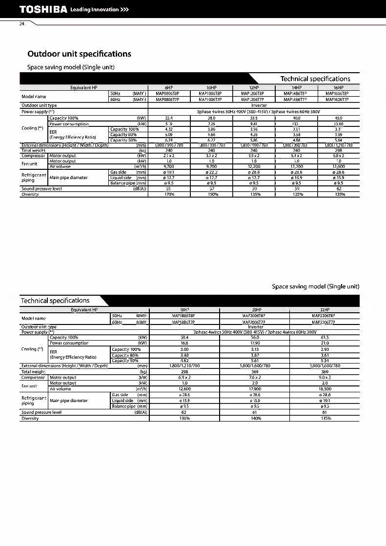
Outdoor unit specifications
Space saving model (Single unit)
Technical specifications Equivalent HP 8HP 10HP 12HP 14HP 16HP
Model name 50Hz (MMY-) MAP0806T8P MAP1006T8P MAP1206T8P MAP14B6T8P MAP1606T8P 60 Hz (MMY-) MAP0806T7P MAP1006T7P MAP1206T7P MAP14B6T7P MAP1606T7P
Outdoor unittype Inverter Power supply (*1) 3phase 4wires 50Hz 400V (380-415V) / 3phase 4wires 60Hz 380V
Capacity 100% (kW) 22.4 28.0 33.5 40.0 45.0
Cooling (*2) Power consumption (kW) 5.19 7.26 9.41 133 13.60 EER (Energy Efficiency Ratio)
Capacity 100% 4.32 3.86 3.56 3.01 3.31 Capacity 80% 5.09 4.66 4.26 3.58 3.99 Capacity 50% 6.39 6.22 5.86 4.88 5.64
External dimensions (Height / Width / Depth) (mm) 1,800/990/780 1,800/990/780 1,800/990/780 1,800/990/780 1,800/1,210/780 Total weight (kg) 240 240 240 240 298 Compressor Motor output (kW) 2.1 x2 3.1 x2 3.9x2 5.4x2 5.8x2 Fan unit Motor output (kW) 1.0 1.0 1.0 1.0 1.0
Air volume (m3/h) 9,700 9,700 12,200 12,200 12,600 Refrigerant piping
Gas side (mm) 0 19.1 0 22.2 0 28.6 0 28.6 0 28.6 Main pipe diameter Liquid side (mm) 0 12.7 0 12.7 0 12.7 0 15.9 0 15.9
Balance pipe (mm) 0 9.5 0 9.5 0 9.5 0 9.5 0 9.5 Sound pressure level (dB(A)) 55 57 59 59 62 Diversity 170% 150% 135% 125% 135%
Space saving model (Single unit)
Technical specifications Equivalent HP 18HP 20HP 22HP
Model name 50Hz MMY- MAP18B5T8P MAP2006T8P MAP2206T8P 60Hz MMY- MAP18B6T7P MAP2006T7P MAP2206T7P
Outdoor unittype Inverter Power supply (*1) 3phase 4wires 50Hz 400V (380-415V) / 3phase 4wires 60Hz 380V
Capacity 100% (kW) 50.4 56.0 61.5 Power consumption (kW) 16.8 17.90 21.0
Cooling (*2) EER Capacity 100% 3.00 3.13 2.93 (Energy Efficiency Ratio) Capacity 80% 3.48 3.87 3.61
Capacity 50% 4.62 5.61 5.34 External dimensions (Height/Width / Depth) (mm) 1,800/1,210/780 1,800/1,600/780 1,800/1,600/780 Total weight (kg) 298 369 369 Compressor Motor output (kW) 6.9x2 7.6x2 9.0x2 Fan unit Motor output (kW) 1.0 2.0 2.0
Air volume (m3/h) 12,600 17,900 18,500 Refrigerant piping
Gas side (mm) 0 28.6 0 28.6 0 28.6 Main pipe diameter Liquid side (mm) 0 15.9 0 15.9 0 19.1
Balance pipe (mm) 0 9.5 0 9.5 0 9.5 Sound pressure level (dB(A)) 62 61 61 Diversity 130% 140% 135%

SMMS SUPER MODULAR MULTI SYSTEM [<?■
25
Space saving model (Combination)
Technical specifications Equivalent HP 1 24HP 26HP 28HP
Model name 50 Hz MMY- AP2416T8P AP2616T8P AP2816T8P 60 Hz MMY- AP2416T7P AP2616T7P AP2816T7P
Outdoor unit type Inverter Power supply (*1) 3phase 4wires 50Hz 400V (380-415V) / 3phase 4wires 60Hz 380V Outdoor unit model
50 Hz MMY- MAP1206T8P MAP1206T8P MAP1406T8P MAP1206T8P MAP14B6T8P MAP14B6T8P 60 Hz MMY- MAP1206T7P MAP1206T7P MAP1406T7P MAP1206T7P MAP14B6T7P MAP14B6T7P
Cooling (*2)
Capacity 100% (kW) 67.0 73.5 80 Power consumption (kW) 18.80 22.7 26.0 EER (Energy Efficiency Ratio)
Capacity 100% 3.56 3.24 3.01 Capacity 80% 4.26 3.86 3.58 Capacity 50% 5.86 5.28 4.88
Total weight (kg) 240 240 240 240 240 240 Compressor Motor output (kW) 3.9x2 3.9x2 4.8x2 3.9x2 5.4x2 5.4x2 Fan unit Motor output (kW) 1.0 1.0 1.0 1.0 1.0 1.0
Air volume (m3/h) 12,200 12,200 12,200 12,200 12,200 12,200 Refrigerant piping Main pipe diameter
Gas side (mm) 0 34.9 0 34.9 0 34.9 Liquid side (mm) 0 19.1 0 19.1 0 19.1 Balance pipe (mm) 0 9.5 0 9.5 0 9.5
Sound pressure level (dB(A)) 62 62 62 Diversity 135% 130% 125%
Space saving model (Combination)
Technical specifications Equivalent HP 30HP 32HP 34HP
Model name 50Hz MMY- AP3016T8P AP3216T8P AP3416T8P 60 Hz MMY- AP3016T7P AP3216T7P AP3416T7P
Outdoor unit type Inverter Power supply (*1) 3phase 4wires 50Hz 400V (380-415V) / 3phase 4wires 60Hz 380V Outdoor unit model
50Hz MMY- MAP1606T8P MAP14B6T8P MAP1606T8P MAP1606T8P MAP18B6T8P MAP1606T8P 60 Hz MMY- MAP1606T7P MAP14B6T7P MAP1606T7P MAP1606T7P MAP18B6T7P MAP1606T7P
Cooling (*2)
Capacity 100% (kW) 85.0 90.0 95.4 Power consumption (kW) 26.9 27.20 30.4 EER (Energy Efficiency Ratio)
Capacity 100% 3.16 3.31 3.14 Capacity 80% 3.79 3.99 3.70 Capacity 50% 5.25 5.64 5.05
Total weight (kg) 298 298 298 298 298 298 Compressor Motor output (kW) 5.8x2 5.4x2 5.8x2 5.8x2 6.9x2 5.8x2 Fan unit Motor output (kW) 1.0 1.0 1.0 1.0 1.0 1.0
Air volume (m3/h) 12,600 12,200 12,600 12,600 12,600 12,600 Refrigerant piping Main pipe diameter
Gas side (mm) 0 34.9 0 34.9 0 34.9 Liquid side (mm) 0 19.1 0 19.1 0 19.1 Balance pipe mm) 0 9.5 0 9.5 0 9.5
Sound pressure level (dB(A)) 64 65 65 Diversity 130% 135% 130%
*1 The source voltage must notflucture more than ±10%. *2 Rated conditions Cooling : Indoor air temperature 270C DB/190C WB, Outdoor air temperature 350C DB
Based on equivalent piping length of 7.5 m and piping height difference of 0 m.

TOSHIBA Leading Innovation »>
26 \
Space saving model (Combination)
^ Te< zhnical specifications Equivalent HP 36HP 38HP 40HP
Model name 50Hz MMY- AP3616T8P AP3816T8P AP4016T8P 60Hz MMY- AP3616T7P AP3816T7P AP4016T7P
Outdoor unit type Inverter Power supply (*1) 3phase 4wires 50Hz 400V (380-415V) / 3phase 4wires 60 Hz 380V Outdoor 50Hz MMY- MAP18B6T8P MAP18B6T8P MAP2206T8P MAP1606T8P MAP2206T8P MAP18B6T8P unit model 60Hz MMY- MAP18B6T7P MAP18B6T7P MAP2206T7P MAP1606T7P MAP2206T7P MAP18B6T7P
Capacity 100% (kW) 100.8 106.5 111.9 Power consumption (kW) 33.6 34.6 37.8
Cooling (*2) EER (Energy Efficiency Ratio)
Capacity 100% 3.00 3.08 2.96 Capacity 8( )% 3.48 3.76 3.55 Capacity 50% 4.62 5.46 4.99
Total weight 298 298 369 298 369 298 Compressor Motor output (kW) 6.9x2 6.9x2 9.0x2 5.8x2 9.0x2 6.9x2 Fan unit Motor output (kW) 1.0 1.0 2.0 1.0 2.0 1.0
Air volume (m3/h) 12,600 12,600 18,500 12,600 18,500 12,600
Refrigerant Gas side (mm) 0 41.3 0 41.3 0 41.3
Main pipe diameter Liquid side (mm) 0 22.2 0 22.2 0 22.2 Balance pipe (mm) 0 9.5 0 9.5 0 9.5
Sound pressure level (dB{A)) 65 64.5 64.5 Diversity 130% 135% 130%
Space saving model (Combination)
Technical specifications Equivalent HP 42HP 44HP 46HP 48HP
Model name 50Hz MMY- AP4216T8P AP4416T8P AP4616T8P AP4816T8P 60Hz MMY- AP4216T7P AP4416T7P AP4616T7P AP4816T7P
Outdoor unit type Inverter Power supply (*1) 3phase 4wires 50Hz 400V (380-415V) / 3phase 4wires 60Hz 380V Outdoor unit model
50Hz MMY- MAP2206T8P MAP2006T8P MAP2206T8P MAP2206T8P MAP1606T8P MAP1606T8P MAP14B6T8P MAP1606T8P MAP1606T8P MAP1606T8P 60Hz MMY- MAP2206T7P MAP2006T7P MAP2206T7P MAP2206T7P MAP1606T7P MAP1606T7P MAP14B6T7P MAP1606T7P MAP1606T7P MAP1606T7P
Cooling (*2)
Capacity 100% (kW) 117.5 123.0 130.0 135.0 Power consumption (kW) 38.9 42.0 40.5 40.8 EER (Energy Efficiency Ratio)
Capacity 100% 3.02 2.93 3.21 3.31 Capacity 80% 3.73 3.61 3.85 3.99 Capacity 50% 5.46 5.34 5.38 5.64
Total weight Compressor
(kg) 369 369 369 369 298 298 298 298 298 298 Motor output (kW) 9.0x2 7.6x2 9.0x2 9.0x2 5.8x2 5.8 x2 5.4x2 5.8x2 5.8x2 5.8x2
Fan unit Motor output (kW) 2.0 2.0 2.0 2.0 1.0 1.0 1.0 1.0 1.0 1.0 Air volume (m3/h) 18,500 17,900 18,500 18,500 12600 12600 12200 12600 12600 12600
Refrigerant piping Main pipe diameter
Gas side (mm) 0 41.3 0 41.3 0 41.3 0 41.3 Liquid side (mm) 0 22.2 0 22.2 0 22.2 0 22.2 Balance pipe (mm) 0 9.5 0 9.5 0 9.5 0 9.5
Sound pressure level (dB(A)) 64 64 66 67 Diversity 135% 135% 130% 135%

SMMS SUPER MODULAR MULTI SYSTEM &
27
Space saving model (Combination)
Technical specifications Equivalent HP 50HP 52HP 54HP
Model name 50Hz MMY- AP5016T8P AP5216T8P AP5416T8P 60 Hz MMY- AP5016T7P AP5216T7P AP5416T7P
Outdoor unit type Inverter Power supply (*2) 3phase 4wires 50Hz 400V {380-415V) / 3phase 4wires 60Hz 380V Outdoor 50Hz MMY- MAP18B6T8P MAP1606T8P MAP1606T8P MAP18B6T8P MAP18B6T8P MAP1606T8P MAP18B6T8P MAP18B6T8P MAP18B6T8P unit model 60 Hz MMY- MAP18B6T7P MAP1606T7P MAP1606T7P MAP18B6T7P MAP18B6T7P MAP1606T7P MAP18B6T7P MAP18B6T7P MAP18B6T7P
Capacity 100% (kW) 140.4 145.8 151.2 Power consumption (kW) 44.0 47.2 50.4
Cooling C*1) EER (Energy Efficiency Ratio)
Capacity 100% 3.19 3.09 3.00 Capacity 8C )% 3.79 3.62 3.48 Capacity 50% 5.22 4.89 4.62
Total weight (kg) 298 298 298 298 298 298 298 298 298 Compressor Motor output (kW) 6.9x2 5.8x2 5.8x2 6.9x2 6.9x2 5.8x2 6.9x2 6.9x2 6.9x2 Fan unit Motor output (kW) 1.0 1.0 1.0 1.0 1.0 1.0 1.0 1.0 1.0
Air volume (mVh) 12,600 12,600 12,600 12,600 12,600 12,600 12,600 12,600 12,600 Refrigerant piping
Gas side (mm) 0 41.3 0 41.3 0 41.3 Main pipe diameter Liquid side (mm) 0 22.2 0 22.2 0 22.2
Balance pipe (mm) 0 9.5 0 9.5 0 9.5 Sound pressure level (dB(A)) 67 67 67 Diversity 130% 130% 130%
Space saving model (Combination)
Technical specifications Equivalent HP 56HP 58HP 60HP
Model name 50Hz MMY- AP5616T8P AP5816T8P AP6016T8P 60 Hz MMY- AP5616T7P AP5816T7P AP6016T7P
Outdoor unit type Inverter Power supply (*2) 3phase 4wires 50Hz 400V (380-415V) / 3phase 4wires 60Hz 380V Outdoor 50Hz MMY- I\/1AP2006T8P I\/1AP18B6T8P MAP1886T8P MAP2206T8P MAP18B6T8P MAP18B6T8P MAP2206T8P MAP2206T8P MAP1606T8P unit model 60 Hz MMY- I\/1AP2006T7P I\/1AP18B6T7P MAP1886T7P MAP2206T7P MAP18B6T7P MAP18B6T7P MAP2206T7P MAP2206T7P MAP1606T7P
Capacity 100% (kW) 156.8 162.3 168.0 Power consumption (kW) 51.5 54.6 55.60
Cooling (*1) EER (Energy Efficiency Ratio)
Capacity 100% 3.04 2.97 3.02 Capacity 8C % 3.61 3.53 3.71 Capacity 50% 4.93 4.87 5.42
Total weight (kg) 369 298 298 369 298 298 369 369 298 Compressor Motor output (kW) 7.6x2 6.9x2 6.9x2 9.0x2 6.9x2 6.9x2 9.0x2 9.0x2 5.8x2 Fan unit Motor output (kW) 2.0 1.0 1.0 2.0 1.0 1.0 2.0 2.0 1.0
Airvolume (mVh) 17,900 12,600 12,600 18,500 12,600 12,600 18,500 18,500 12,600 Refrigerant piping
Gas side (mm) 041.3 0 41.3 0 41.3 Main pipe diameter Liquid side (mm) 0 22.2 0 22.2 0 22.2
Balance pipe (mm) 0 9.5 0 9.5 0 9.5 Sound pressure level (dB(A)) 66.5 66.5 66.5 Diversity 135% 130% 135%
*1 The source voltage must notflucture more than ±10%. *2 Rated conditions Cooling : Indoor air temperature 270C DB/190C WB, Outdoor air temperature 350C DB
The standard piping means that main pipe length is 5m, branching pipe length is 2.5m of branch piping connected with a 0 meter height.

TOSHIBA Leading Innovation »>
28
Outdoor unit specifications
High efficiency / High diversity model (Single unit)
Technical specifications Equivalent HP 8HP 10HP 12HP
Model name 50Hz (MMY-) MAP0806T8P MAP1006T8P MAP1206T8P 60 Hz (MMY-) MAP0806T7P MAP1006T7P MAP1206T7P
Outdoor unittype Inverter Power supply (*1) 3phase 4wires 50Hz 400V (380-415V) / 3phase 4wires 60Hz 380V
Capacity 100% (kW) 22.4 28.0 33.5
Cooling (*2) Power consumption (kW) 5.19 7.26 9.41 EER (Energy Efficiency Ratio)
Capacity 100% 4.32 3.86 3.56 Capacity 80% 5.09 4.66 4.26 Capacity 50% 6.39 6.22 5.86
External dimensions (Height / Width / Depth) (mm) 1,800/990/780 1,800/990/780 1,800/990/780 Total weight (kg) 240 240 240 Compressor Motor output (kW) 2.1 x2 3.1 x2 3.9x2 Fan unit Motor output (kW) 1.0 1.0 1.0
Air volume (m3/h) 9,700 9,700 12,200 Refrigerant piping
Gas side (mm) 0 19.1 0 22.2 0 28.6 Main pipe diameter Liquid side (mm) 0 12.7 0 12.7 0 12.7
Balance pipe (mm) 0 9.5 0 9.5 0 9.5 Sound pressure level (dB(A)) 55 57 59 Diversity 170% 150% 135%
High efficiency / High diversity model (Single unit)
Technical specifications Equivalent HP 14HP 16HP 18HP
Model name 50Hz (MMY-) MAP1406T8P MAP1606T8P MAP1806T8P 60 Hz (MMY-) MAP1406T7P MAP1606T7P MAP1806T7P
Outdoor unittype Inverter Power supply (*1) 3phase 4wires 50Hz 400V (380-415V) / 3phase 4wires 60Hz 380V
Capacity 100% (kW) 40.0 45.0 50.4
Cooling (*2) Power consumption (kW) 115 13.60 14.0 EER (Energy Efficiency Ratio)
Capacity 100% 3.48 3.31 3.6 Capacity 80% 4.16 3.99 4.20 Capacity 50% 5.70 5.64 5.50
External dimensions (Height / Width / Depth) (mm) 1,800/1,210/780 1,800/1,210/780 1,800/1,600/780 Total weight (kg) 298 298 369 Compressor Motor output (kW) 4.8x2 5.8x2 6.5x2 Fan unit Motor output (kW) 1.0 1.0 2.0
Air volume (m3/h) 12,200 12,600 17,300 Refrigerant piping
Gas side (mm) 0 28.6 0 28.6 0 28.6 Main pipe diameter Liquid side (mm) 0 15.9 0 15.9 0 15.9
Balance pipe (mm) 0 9.5 0 9.5 0 9.5 Sound pressure level (dB(A)) 60 62 60 Diversity 145% 135% 150%

SMMS SUPER MODULAR MULTI SYSTEM [<?■
29
High efficiency / High diversity model (Combination)
Technical specifications Equivalent HP 20HP 22HP 24HP 26HP
Model name 50 Hz MMY- MAP2026T8P MAP2226T8P AP2426T8P AP2626T8P 60 Hz MMY- MAP2026T7P MAP2226T7P AP2426T7P AP2626T7P
Outdoor unit type Inverter Power supply (*1) 3phase 4wires 50Hz 400V (380-415V) / 3phase 4wires 60Hz 380V Outdoor unit 50 Hz MMY- MAP1006T8P MAP1006T8P MAP1206T8P MAP1006T8P MAP1206T8P MAP1206T8P MAP1406T8P MAP1206T8P model 60 Hz MMY- MAP1006T7P MAP1006T7P MAP1206T8P MAP1006T8P MAP1206T7P MAP1206T7P MAP1406T7P MAP1206T7P
Capacity 100% (kW) 56.0 61.5 67.0 73.5 Power consumption (kW) 14.5 16.7 18.80 20.9
Cooling (*2) EER (Energy Efficiency Ratio)
Capacity 100% 3.86 3.69 3.56 3.52 Capacity 80% 4.66 4.43 4.26 4.20 Capacity 50% 6.22 6.02 5.86 5.77
Total weight (kg) 240 240 240 240 240 240 298 240 Compressor Motor output (kW) 3.1x2 3.1x2 3.9x2 3.1 x 2 3.9x2 3.9x2 4.8x2 3.9x2 Fan unit Motor output (kW) 1.0 1.0 1.0 1.0 1.0 1.0 1.0 1.0
Air volume (m3/h) 9,700 9,700 9,700 9,700 12,200 12,200 12,200 12,200 Refrigerant piping
Gas side (mm) 0 28.6 0 28.6 0 34.9 0 34.9 Main pipe diameter Liquid side (mm) 0 15.9 0 19.1 0 19.1 0 19.1
Balance pipe (mm) 0 9.5 0 9.5 0 9.5 0 9.5 Sound pressure level (dB(A)) 60 61.5 62 62.5 Diversity 150% 140% 135% 140%
High efficiency / High diversity model (Combination)
Technical specifications Equivalent HP 28HP 30HP 32HP 34HP
Model name 50Hz MMY- AP2826T8P AP3026T8P AP3226T8P AP3426T8P 60 Hz MMY- AP2826T7P AP3026T7P AP3226T7P AP3426T7P
Outdoor unit type Inverter Power supply (*1) 3phase 4wires 50Hz 400V (380-415V) / 3phase 4wires 60Hz 380V Outdoor unit 50Hz MMY- MAP1406T8P MAP1406T8P MAP1606T8P MAP1406T8P MAP1606T8P MAP1606T8P MAP1806T8P MAP1606T8P model 60 Hz MMY- MAP1406T8P MAP1406T8P MAP1606T7P MAP1406T7P MAP1606T7P MAP1606T7P MAP1806T7P MAP1606T7P
Capacity 100% (kW) 80 85.0 90.0 95.4 Power consumption (kW) 23.0 25.1 27.20 27.6
Cooling (*2) EER (Energy Efficiency Ratio)
Capacity 100% 3.48 3.39 3.31 3.46 Capacity 80% 4.16 4.07 3.99 4.10 Capacity 50% 5.70 5.67 5.64 5.57
Total weight (kg) 298 298 298 298 298 298 369 298 Compressor Motor output (kW) 4.8x2 4.8x2 5.8x2 4.8x2 5.8x2 5.8x2 6.5x2 5.8x2 Fan unit Motor output (kW) 1.0 1.0 1.0 1.0 1.0 1.0 2.0 1.0
Air volume (m3/h) 12,200 12,200 12,600 12,200 12,600 12,600 17,300 12,600 Refrigerant piping
Gas side (mm) 0 34.9 0 34.9 0 34.9 0 34.9 Main pipe diameter Liquid side (mm) 0 19.1 0 19.1 0 19.1 0 19.1
Balance pipe mm) 0 9.5 0 9.5 0 9.5 0 9.5 Sound pressure level (dB(A)) 63 64.5 65 64.5 Diversity 145% 140% 135% 140%
*1 The source voltage must notflucture more than ±10%. *2 Rated conditions Cooling : Indoor air temperature 270C DB/190C WB, Outdoor air temperature 350C DB
Based on equivalent piping length of 7.5 m and piping height difference of 0 m.

TOSHIBA Leading Innovation »>
"io \
High efficiency / High diversity model (Combination)
Technical specifications Equivalent HP 36HP 38HP 40HP
Model name 50 Hz MMY- AP3626T8P AP3826T8P AP4026T8P 60Hz MMY- AP3626T7P AP3826T7P AP4026T7P
Outdoor unit type Inverter Power supply (*1) 3phase 4wires 50Hz 400V (380-415V) / 3phase 4wires 60 Hz 380V Outdoor unit model
50 Hz MMY- MAP1206T8P MAP1206T8P MAP1206T8P MAP1406T8P MAP1206T8P MAP1206T8P MAP1406T8P MAP1406T8P MAP1206T8P 60Hz MMY- MAP1206T7P MAP1206T7P MAP1206T7P MAP1406T7P MAP1206T7P MAP1206T7P MAP1406T7P MAP1406T7P MAP1206T7P
Cooling (*2)
Capacity 100% (kW) 100.5 107.0 1135 Power consumption (kW) 28.2 30.3 32.4 EER (Energy Efficiency Ratio)
Capacity 100% 3.56 3.53 3.50 Capacity 80% 4.26 4.22 4.19 Capacity 50% 5.86 5.80 5.74
Total weight Compressor
(kg) 240 240 240 298 240 240 298 298 240 Motor output (kW) 3.9x2 3.9x2 3.9x2 4.8x2 3.9x2 3.9x2 43x2 4.8x2 3.9x2
Fan unit Motor output (kW) 1.0 1.0 1.0 1.0 1.0 1.0 1.0 1.0 1.0 Air volume (m3/h) 12,200 12,200 12,200 12,200 12,200 12,200 12,200 12,200 12,200
Refrigerant piping Main pipe diameter
Gas side (mm) 0 41.3 0 41.3 0 41.3 Liquid side (mm) 0 22.2 0 22.2 0 22.2 Balance pipe (mm) 0 9.5 0 9.5 0 9.5
Sound pressure level (dB(A)) 64 64.5 64.5 Diversity 135% 140% 140%
High efficiency / High diversity model (Combination)
Technical specifications Equivalent HP 42HP 44HP 46HP 48HP
Model name 50Hz MMY- AP4226T8P AP4426T8P AP4626T8P AP4826T8P 60Hz MMY- AP4226T7P AP4426T7P AP4626T7P AP4826T7P
Outdoor unit type Inverter Power supply (*1) 3phase 4wires 50Hz 400V (380-415V) / 3phase 4wires 60Hz 380V Outdoor 50Hz MMY- MAP1406T8P MAP1406T8P MAP1406T8P MAP1606T8P MAP1406T8P MAP1406T8P MAP1606T8P MAP1606T8P MAP1406T8P MAP1606T8P MAP1606T8P MAP1606T8P unit model 60Hz MMY- MAP1406T7P MAP1406T7P MAP1406T7P MAP1606T7P MAP1406T7P MAP1406T7P MAP1606T7P MAP1606T7P MAP1406T7P MAP1606T7P MAP1606T7P MAP1606T7P
Capacity 100% (kW) 120.0 125.0 130.0 135.0 Power consumption (kW) 34.5 36.6 38.7 40.8
Cooling (*2) EER (Energy Efficiency Ratio)
Capacity 100% 3.48 3.42 3.36 3.31 Capacity 80% 4.16 4.10 4.04 3.99 Capacity 50% 5.70 5.68 5.66 5.64
Total weight (kg) 298 298 298 298 298 298 298 298 298 298 298 298 Compressor Motor output (kW) 4.8x2 4.8x2 48x2 5.8x2 4.8x2 4.8x2 5.8 x2 5.8x2 4.8x2 5.8x2 5.8x2 5.8x2 Fan unit Motor output (kW) 1.0 1.0 1.0 1.0 1.0 1.0 1.0 1.0 1.0 1.0 1.0 1.0
Airvolume (mVh) 12,200 12,200 12,200 12,600 12,200 12,200 12,600 12,600 12,200 12,600 12,600 12,600 Refrigerant piping
Gas side (mm) 0 41.3 0 41.3 0 41.3 0 41.3 Main pipe diameter Liquid side (mm) 0 22.2 0 22.2 0 22.2 0 22.2
Balance pipe (mm) 0 9.5 0 9.5 0 9.5 0 9.5 Sound pressure level (dB(A)) 65 65.5 66.5 67 Diversity 145% 140% 140% 135%
SMMS SUPER MODULAR MULTI SYSTEM &
31
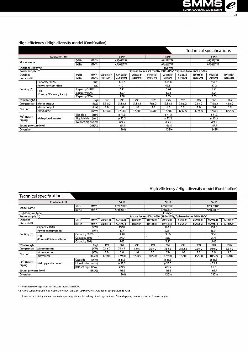
High efficiency / High diversity model (Combination)
Technical specifications Equivalent HP 50HP 52HP 54HP
Model name 50Hz MMY- AP5026T8P AP5226T8P AP5426T8P 60 Hz MMY- AP5026T7P AP5226T7P AP5426T7P
Outdoor unit type Inverter Power supply (*2) 3phase 4wires 50Hz 400V {380-415V) / 3phase 4wires 60Hz 380V Outdoor 50Hz MMY- MAP1806T8P MAP1606T8P MAP1606T8P MAP2006T8P MAP1606T8P MAP1606T8P MAP2006T8P MAP2006T8P MAP1406T8P unit model 60 Hz MMY- MAP1806T7P MAP1606T7P MAP1606T7P MAP2006T7P MAP1606T7P MAP1606T7P MAP2006T7P MAP2006T7P MAP1406T7P
Capacity 100% (kW) 140.4 146.0 152.0 Power consumption (kW) 412 45.1 47.3
Cooling C*1) EER (Energy Efficiency Ratio)
Capacity 100% 3.41 3.24 3.21 Capacity 8C )% 4.07 3.94 3.94 Capacity 50% 5.59 5.63 5.63
Total weight (kg) 369 298 298 369 298 298 369 369 369 Compressor Motor output (kW) 6.5x2 5.8x2 5.8x2 7.6x2 5.8x2 5.8x2 7.6x2 7.6x2 4.8x2 Fan unit Motor output (kW) 2.0 1.0 1.0 2.0 1.0 1.0 2.0 2.0 1.0
Air volume (mVh) 17,300 12,600 12,600 17,900 12,600 12,600 17,900 17,900 12,200 Refrigerant piping
Gas side (mm) 0 41.3 0 41.3 0 41.3 Main pipe diameter Liquid side (mm) 0 22.2 0 22.2 0 22.2
Balance pipe (mm) 0 9.5 0 9.5 0 9.5 Sound pressure level (dB(A)) 66.5 66.5 65.5 Diversity 140% 135% 145%
High efficiency / High diversity model (Combination)
Technical specifications Equivalent HP 56HP 58HP 60HP
Model name 50Hz MMY- AP5626T8P AP5826T8P AP6026T8P 60 Hz MMY- AP5626T7P AP5826T7P AP6026T7P
Outdoor unit type Inverter Power supply (*2) 3phase 4wires 50Hz 400V (380-415V) / 3phase 4wires 60Hz 380V Outdoor 50Hz MMY- I\/1AP2006T8P I\/1AP2006T8P MAP1606T8P MAP2206T8P MAP2006T8P MAP1606T8P MAP2206T8P MAP2206T8P MAP1606T8P unit model 60 Hz MMY- I\/1AP2006T7P I\/1AP2006T7P MAP1606T7P MAP2206T7P MAP2006T7P MAP1606T7P MAP2206T7P MAP2206T7P MAP1606T7P
Capacity 100% (kW) 157.0 162.5 168.0 Power consumption (kW) 49.4 52.5 46.9
Cooling (*1) EER (Energy Efficiency Ratio)
Capacity 100% 3.18 3.10 3.58 Capacity 8C % 3.90 3.80 3.71 Capacity 50% 5.62 5.51 5.42
Total weight (kg) 369 369 298 369 369 298 369 369 298 Compressor Motor output (kW) 7.6x2 76x2 5.8x2 9.0x2 7.6x2 5.8x2 9.0x2 9.0x2 5.8x2 Fan unit Motor output (kW) 2.0 2.0 1.0 2.0 2.0 1.0 2.0 2.0 1.0
Airvolume (mVh) 17,900 17,900 12,600 18,500 17,900 12,600 18,500 18,500 12,600 Refrigerant piping
Gas side (mm) 041.3 0 41.3 0 41.3 Main pipe diameter Liquid side (mm) 0 22.2 0 22.2 0 22.2
Balance pipe (mm) 0 9.5 0 9.5 0 9.5 Sound pressure level (dB(A)) 66.5 66.5 66.5 Diversity 140% 135% 135%
*1 The source voltage must notflucture more than ±10%. *2 Rated conditions Cooling : Indoor air temperature 270C DB/190C WB, Outdoor air temperature 350C DB
The standard piping means that main pipe length is 5m, branching pipe length is 2.5m of branch piping connected with a 0 meter height.
TOSHIBA Leading Innovation »>
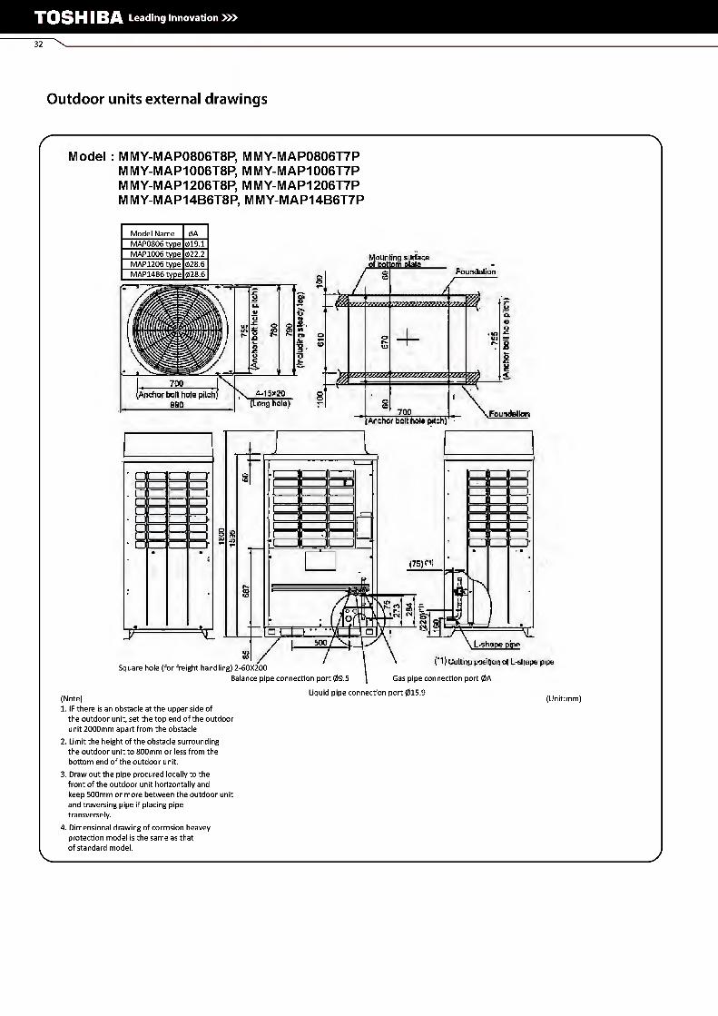
Outdoor units external drawings
Model : MMY-MAP0806T8P, MMY-MAP0806T7P M MY-MAP1006T8P, M MY-MAP1006T7P M MY-MAP1206T8P, M MY-MAP1206T7P MMY-MAP14B6T8P, MMY-MAP14B6T7P
Model Name 0A MAP0806 type 019.1 MAP1006 type 022.2 MAP1206 type 028.6 MAP14B6 type 028.6
Mounting surface of bottom plate Foundation
/ m
& 70:: X 4-15*20
(Long hole) Anchor boll hole pilch)
990 700 Foundalion Anchor boll hole pitch)
.
u i i □ i ] n
■ i i .)■ \ i i i i
■ □ • •
• * , _ JT
(75) ni
.
Square hole (for freight handling) 2-60X200 Balance pipe connection port 09.5
Ushape pipe
("1) Culling position of L-stiape pipe Gas pipe connection port 0A
(Note) 1. IF there is an obstacle at the upper side of
the outdoor unit, set the top end of the outdoor unit 2000mm apart from the obstacle
2. Limit the height of the obstacle surrounding the outdoor unit to 800mm or less from the bottom end of the outdoor unit.
3. Draw out the pipe procured locally to the front of the outdoor unit horizontally and keep 500mm or more between the outdoor unit and traversing pipe if placing pipe transversely.
4. Dimensional drawing of corrosion heavey protection model is the same as that of standard model.
Liquid pipe connection port 015.9 (Unit:mm)

SMMSI SUPER MODULAR MULTI SYSTEM ^ e
Model MMY-MAP1406T8P, MMY-MAP1406T7P M MY-MAP1606T8P, M MY-MAP1606T7P M MY-MAP18B6T8P, M MY-MAP18B6T7P
Mounting surface bottom ofato
Foundation
1 0) o f ^ o ® r^
S r- Q J=. d <
920 (Anchor bolt tiotepTtcti)
1210
1 1 1 1 1 J 1 1 i ^3 1 1 1 i I 1 i 1 i, U 1 f 1 i l
■ 1 I i i- 1 1 1 c 1 1 ! TD
■ I i 1 1 "T ■ •
\ 5-20
Foundation (Long hold) (Anchor bolt hole pitch)
O
n) (75)
~ to
shape EH£ B20
i i i i r-
i i r ■
Square hole (for freight handling) 2-60X200 Balance pipe connection port 09.5
("I >Cutting position of L shape pipe Gas pipe connection port 028.6
(Note) 1.1F there is an obstacle at the upper side of
the outdoor unit, set the top end of the outdoor unit 2000mm apart from the obstacle
2. Limit the height of the obstacle surrounding the outdoor unit to 800mm or less from the bottom end of the outdoor unit.
3. Draw out the pipe procured locally to the front of the outdoor unit horizontally and keep 500mm or more between the outdoor unit and traversing pipe if placing pipe transversely.
4. Dimensional drawing of corrosion heavey protection model is the same as that of standard model.
Liquid pipe connection port 015.9 (Unit:mm)
V J

TOSHIBA Leading Innovation »>
Model : MMY-MAP1806T8P, MMY-MAP1806T7P M MY-MAP2006T8P, M MY-MAP2006T7P M MY-MAP2206T8P, M MY-MAP2206T7P
Model Name 0A MAP1806 type 015.9 MAP2006 type 015.9 MAP2206 type 019.1
m
■
n /iii
BSllI
'ill
III
■
3
SI s % 4>
% £ J3 R S Q i
1310 V 4-15*20 [Long hole) [Anchor bolt hole pitch)
1600
HounUns surlact trf t-dttwi matt!
z
I owwatiori ^Annhor hott hoia pftcti]
u
ztzj
CD' i—:
LZJ
CZI □ □ □
'^rrr
•(ZZ CO
Square hole (for freight handling) 2-60X200
(Note) 1.1F there is an obstacle at the upper side of
the outdoor unit, set the top end of the outdoor unit 2000mm apart from the obstacle
2. Limit the height of the obstacle surrounding the outdoor unit to 800mm or less from the bottom end of the outdoor unit.
3. Draw out the pipe procured locally to the front of the outdoor unit horizontally and keep 500mm or more between the outdoor unit and traversing pipe if placing pipe transversely.
4. Dimensional drawing of corrosion heavey protection model is the same as that of standard model.
1 r i [ 1 i
1 i i 1 i ( i ; :
(CO CZi
1
; i i i ;
; )■ :
r" i r i (ZZ L—J LJ
L-siiape pipe ("^Cutting.position of L-shape pipe
Balance pipe connection port 09.5 \ Gas pipe connection port 028.6 Liquid pipe connection port 0A (Unit:mm)

v £ii\^wr.i:<- m.-
Zz
/ S
^eia^iB^r ,SI5il5JP!aJ:P'
/ ^igfigingta^ ' , w'iwtiririr .-'
sS Vn T^ - ,>.VvvV^VV^Vv V ^
VA V^ V.^ii ^ IL 'V.vvv*»V V vv * ' ' V^V
VVV v^v
z" y y y y
iii
;
% "
Y I
fflS

TOSHIBA Leading Innovation »>
36 \
Indoor units
Cooling capacity (HP equivalent) 4-way air discharge cassette type
Compact 4-way cassette (600 x 600) type
2-way air discharge cassette type
1-way air discharge cassette type Concealed duct type
007 type 2.2 kW (0.8HP) MIV1U-AP0074MH-E IV1IV1U-AP0072WH IV1MU-AP0074YH-E IV1IV1D-AP0076BHP-E
009 type 2.8 kW (1HP) IV1IV1U-AP0094HP-E IV1IV1U-AP0094MH-E MMU-AP0092WH MMU-AP0094YH-E IV1IV1D-AP0096BHP-E
012 type 3.6 kW (1.25HP) MMU-AP0124HP-E MIV1U-AP0124MH-E IV1MU-AP0122WH IV1MU-AP0124YH-E IV1IV1D-AP0126BHP-E
015 type 4.5 kW (1.7HP) IV1MU-AP0154HP-E MIV1U-AP0154MH-E IV1MU-AP0152WH IV1MU-AP0154SH-E IV1IV1D-AP0156BHP-E
018type 5.6 kW (2HP) MMU-AP0184HP-E MIV1U-AP0184MH-E IV1MU-AP0182WH IV1IV1U-AP0184SH-E IV1IV1D-AP0186BHP-E
024 type 7.1 kW (2.5HP) IV1IV1U-AP0244HP-E IV1IV1U-AP0242WH IV1MU-AP0244SH-E IV1IV1D-AP0246BHP-E
027 type 8.0 kW (3HP) IV1MU-AP0274HP-E IV1MU-AP0272WH IV1IV1D-AP0276BHP-E
030 type 9.0 kW (3.2HP) IV1IV1U-AP0304HP-E IV1MU-AP0302WH IV1IV1D-AP0306BHP-E
036 type 11.2 kW (4HP) IV1IV1U-AP0364HP-E IV1MU-AP0362WH IV1IV1D-AP0366BHP-E
048 type 14.0kW(5HP) IV1IV1U-AP0484HP-E MMU-AP0482WH IV1IV1D-AP0486BHP-E
056 type 16.0kW (6HP) MMU-AP0564HP-E IV1MU-AP0562WH IV1IV1D-AP0566BHP-E
072 type 22.4 kW (8HP)
096 type 28.0kW (10HP)
MMD-AP0***6HP-E
Cooling capacity (HP equivalent) Concealed duct high static pressure type Slim duct type Ceiling type High wall type
3 series
007 type 2.2 kW (0.8HP) MIV1D-AP0074SPH-E MIV1K-AP0073H
009 type 2.8 kW (1HP) IV1IV1D-AP0094SPH-E IV1IV1K-AP0093H
012 type 3.6 kW (1.25HP) MIV1D-AP0124SPH-E MIV1K-AP0123H
015 type 4.5 kW (1.7HP) IV1IV1D-AP0154SPH-E IV1IV1C-AP0157HP-E MIV1K-AP0153H
018 type 5.6 kW (2HP) IV1IV1D-AP0186HP-E MIV1D-AP0184SPH-E IV1IV1C-AP0187HP-E MIV1K-AP0183H
024 type 7.1 kW (2.5HP) IV1IV1D-AP0246HP-E MIV1D-AP0244SPH-E IV1IV1C-AP0247HP-E MIV1K-AP0243H
027type 8.0 kW (3HP) IV1IV1D-AP0276HP-E MIV1D-AP0274SPH-E IV1IV1C-AP0277HP-E
030 type 9.0 kW (3.2HP)
036 type 11.2kW(4HP) IV1IV1D-AP0366HP-E IV1IV1C-AP0367HP-E
048 type 14.0kW(5HP) IV1IV1D-AP0486HP-E IV1IV1C-AP0487HP-E
056 type 16.0kW (6HP) IV1IV1D-AP0566HP-E IV1IV1C-AP0567HP-E
072 type 22.4kW (8HP) IV1IV1D-AP0724H-E
096 type 28.0 kW (10HP) IV1IV1D-AP0964H-E

SMMS SUPER MODULAR MULTI SYSTEM &
37
*
gji aJllsiii,
Cooling capacity (HP equivalent) Console Floor standing cabinet type
Floor standing concealed type
Floor standing type
Large capacity floor standing type
007 type 2.2 kW (0.8HP) IV1ML-AP0074NH-E IV1ML-AP0074H-E IV1IV1L-AP0074BH-E
009 type 2.8 kW (1HP) IV1IV1L-AP0094NH-E IV1IV1L-AP0094H-E IV1ML-AP0094BH-E
012 type 3.6 kW (1.25HP) IV1IV1L-AP0124NH-E IV1ML-AP0124H-E IV1ML-AP0124BH-E
015 type 4.5 kW (1.7HP) IV1ML-AP0154NH-E IV1ML-AP0154H-E IV1ML-AP0154BH-E IV1IV1F-AP0156H-E
018 type 5.6 kW (2HP) IV1ML-AP0184NH-E IV1ML-AP0184H-E IV1ML-AP0184BH-E IV1IV1F-AP0186H-E
024 type 7.1 kW (2.5HP) IV1ML-AP0244H-E IV1ML-AP0244BH-E IV1IV1F-AP0246H-E
027 type 8.0 kW (3HP) IV1IV1F-AP0276H-E
030 type 9.0 kW (3.2HP)
036 type 11.2 kW (4HP) IV1IV1F-AP0366H-E
048 type 14.0 kW (5HP) IV1IV1F-AP0486H-E MMF-AP0723DH-V/H-VAA/B
056 type 16.0kW(6HP) IV1IV1F-AP0566H-E MMF-AP0963DH-V/H-VAA/B
072 type 22.4kW (8HP) MMF-AP1443DH-V/H-VA/VB
096 type 28.0 kW (10HP) MMF-API9233DH-V/H-VAA/B
Cato
Air volume Air-to-air heat exchanger with DX-coil type Fresh air intake Indoor unit type Air-to-air heat exchanger*
150 m3/h 150 m3/h VN-M150HE
250 m3/h 250 m3/h VN-IV1250HE
350 m3/h 350 m3/h VN-M350HE
500 m3/h IV1IV1D-VN502HEXE 500 m3/h VN-MSOOHE
650 m3/h 650 m3/h VN-IV1650HE
800 m3/h MMD -VN800HEXE 800 m3/h VN-MSOOHE
1000 m3/h IV1IV1D-VN1002H EXE/2 1000 m3/h VN-M1000HE
1500 m3/h 1500 m3/h VN-M1500HE
2000 m3/h 2000 m3/h VN-M2000HE
1080 m3/h IV1IV1D-AP0481HFE *: Does not connect to refrigerant piping from outdoor unit. Contml wires ran he connected.
1680 m3/h IV1IV1D-AP0721HFE
2100 m3/h IV1IV1D-AP0961HFE

TOSHIBA Leading Innovation »>
4-way Air Discharge Cassette Type
X MMU-AP***4HP-E
Individual louver control
The angles of each of the four louver can be set individually
=> Enables airflow to be adapted to user preferences.
Easy installation
The panel is attached using the bolt
already installed on the indoor unit.
(1) Standard swing (2) Diagonally opposite swing
(3) Turn-around swing
Note: RBC-AMT32E, RBC-AMS41E only
A * N
;!: ( >
tu
RBC-U31 PGP(W)-E
Technical specifications
Model name MMU- AP0094HP-E AP0124HP-E AP0154HP-E AP0184HP-E AP0244HP-E AP0274HP-E AP0304HP-E AP0364HP-E AP0484HP-E AP0564HP-E
Cooling/Heating capacity*1 (kW) 2.8/3.2 3.6/4.0 4.5/5.0 5.6/6.3 7.1/8.0 8.0/9.0 9.0/10.0 11.2/12.5 14.0/16.0 16.0/18.0
Power requirements 1-phase 50Hz230V (220-240V) /1-phase 60Hz220V (Separate power supply for indoor un ts required.)
characteristics Power consumption 0.021/0.021 0.023/ 0.026/ 0.036/0.036 0.043/ 0.088/ 0.112/ 0.112/ 50 Hz/60 Hz (kW) 0.023 0.026 0.043 0.088 0.112 0.112
Appearance (Ceiling panel) Model RBC-U31PGP(W)-E
External Height (mm) 256 (30)* 319(30)* dimensions: Main unit Width (mm) 840 (950)* (Ceiling panel)* Depth (mm) 840 (950)*
Total weight: Main unit (Ceiling panel)* (kg) 18(4)* 20 (4)* 25 (4)*
Fan unit Standard airflow (High/Mid/Low) (mVh) 800/730/680 930/
830/790 1050/
920/800 1290/920/800 1320/ 1110/850
1970/ 1430/1070
2130/ 1430/1130
2130/ 1520/1230
Motor output (W) 14 20 68 72
Gas side (mm) 09.5 012.7 015.9 Connecting pipe Liquid side (mm) 06.4 09.5
Drain port (nominal dia.) (mm) 25 (Polyvinyl chloride tube)
Sound pressure level*2
(High/Mid/Low) (dB(A)) 30/29/27 31/29/27 32/29/27 35/31/28 38/33/30 43/38/32 46/38/33 46/40/33
* Figures in parentheses are for ceiling panels. Note 1 : The capacities are measured underthe conditions specified by JIS B 8615 based on the reference piping.
The reference piping consists of 5 m of main piping and 2.5 m of branch piping connected with 0 m height. Note 2: The sound level are measured in an anechoic chamber in accordance with JIS B 8616.
Normally, the values measured in the actual operating environment become larger than the indicated values due to the effects of external sound. Note: Rated conditions Cooling : Indoor air temperature 270C DB/190C WB, Outdoor air temperature 350C DB
Heating : Indoor air temperature 20oC DB, Outdoor air temperature 70C DB/60C WB

SMMS SUPER MODULAR MULTI SYSTEM &
39
MMU-AP0074HP-E to AP0564HP-E
Electric parts box
Wireless sensor mounting section (RBC-AX32U can be connected four corners)
Air outlet 518
Z view
*( ): AP0364 to AP0564
300 or less (ip"
690±20 Hanging bolt pitch 950 Panel external dimension
T
Check port (1350)
For branch duct knockout square hole qil 50 (Also located on the back)
Bottom face of ceiling / Drain standing-up size
# Space required for installation and servicing
H—lD Model MMD- A B C
AP0094HP-E, AP0124HP-E 256 09.5 06.4 AP0154HP-E, AP0184HP-E 256 012.7 06.4 AP0244HP-E, AP0274HP-E, AP0304HP-E 256 015.9 09.5 AP0364HP-E, AP0484HP-E, AP0564HP-E 319 015.9 09.5
(Unit: mm) * The figure shows the RBC-U31 PG(W)-E panel.
Options
Air discharge direction kit Auxiliary fresh air flange TCB-FF101URE2
o*-
TCB-BC1602UE
Fresh air h ter chamber TCB-GFC1602UE
Fresh air inlet box TCB-GB1602UE
Spacer for height adjustment Ceiling panel TCB-5P1602UE RBC-U31 PG(W)-E
Air inlet grille
TOSHIBA Leading Innovation »>
40
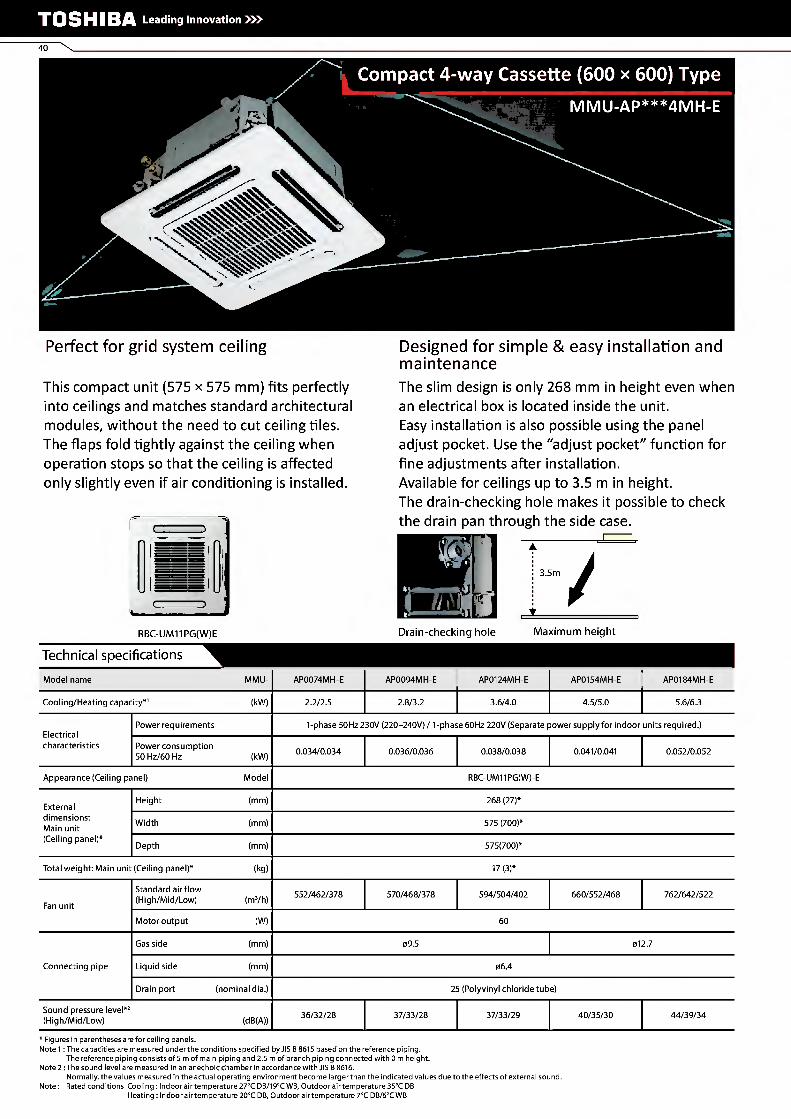
Compact 4-way Cassette (600 x 600) Type
MMU-AP***4MH-E
Perfect for grid system ceiling
This compact unit (575 x 575 mm) fits perfectly
into ceilings and matches standard architectural
modules, without the need to cut ceiling tiles.
The flaps fold tightly against the ceiling when
operation stops so that the ceiling is affected
only slightly even if air conditioning is installed.
Designed for simple & easy installation and maintenance
The slim design is only 268 mm in height even when
an electrical box is located inside the unit.
Easy installation is also possible using the panel
adjust pocket. Use the "adjust pocket" function for
fine adjustments after installation.
Available for ceilings up to 3.5 m in height.
The drain-checking hole makes it possible to check
the drain pan through the side case. , i i
RBC-UM11PG(W)E
3.5nn
/
Drain-checking hole Maximum height
Technical specifications
Model name MMU- AP0074MH-E AP0094MH-E AP0124MH-E AP0154MH-E AP0184MH-E
Cooling/Heating capacity*1 (kW) 2.2/2.5 2.8/3.2 3.6/4.0 4.5/5.0 5.6/6.3
Electrical characteristics
Power requirements 1-phase 50Hz 230V (220-240V) /1-phase 60Hz 220V (Separate power supply for indoor units required.)
Power consumption 50 Hz/60 Hz (kW) 0.034/0.034 0.036/0.036 0.038/0.038 0.041/0.041 0.052/0.052
Appearance (Ceiling panel) Model RBC-UM11PG(W)-E
External Height (mm) 268 (27)* dimensions: Main unit Width (mm) 575 (700)* (Ceiling panel)* Depth (mm) 575(700)*
Total weight: Main unit (Ceiling panel)* (kg) 17(3)*
Fan unit Standard airflow (High/Mid/Low) (mVh) 552/462/378 570/468/378 594/504/402 660/552/468 762/642/522
Motor output (W) 60
Gas side (mm) 09.5 012.7
Connecting pipe Liquid side (mm) 06.4
Drain port (nominal dia.) 25 (Polyvinyl chloride tube)
Sound pressure level*2
(High/Mid/Low) (dB(A)) 36/32/28 37/33/28 37/33/29 40/35/30 44/39/34
* Figures in parentheses are for ceiling panels. Note 1 : The capacities are measured underthe conditions specified by JIS B 8615 based on the reference piping.
The reference piping consists of 5 m of main piping and 2.5 m of branch piping connected with 0 m height. Note 2 : The sound level are measured in an anechoic chamber in accordance with JIS B8616.
Normally, the values measured in the actual operating environment become larger than the indicated values due to the effects of external sound. Note: Rated conditions Cooling : Indoor air temperature 270C DB/190C WB, Outdoor air temperature 350C DB
Heating : Indoor air temperature 20oC DB, Outdoor air temperature 70C DB/60C WB

SMMS SUPER MODULAR MULTI SYSTEM &
41
MMU-AP0074MH-E to AP0184MH-E
Celling bottom surface
Knockout square hole (JilSO
Celling bottom surface
Model MMD- A AP0074MH-E, AP0094MH-E, AP0124MH-E 0 9.5 AP0154MH-E, AP0184MH-E 012.7
149
r s§.
^?r—
j Electric parts box |i
IY1 IY1
l/T o
Refrigerant pipe
Check port (□450)
%
Indoor unit
Bottom face of ceiling Drain standing-up size
Hanging bolt Ml0 orW3/8 procured locally Drain pipe connecting port
• Space required for installation and servicing 1000 or more 1000 or more
11 Mm ^ Ta
For branch duct knockout square hole <))150 Ceiling panel(sold separately)
(Unit: mm)
Options
Auxiliary fresh airflange TCB-FF101URE2
Ceiling panel RBC-UM11 PG(W)E
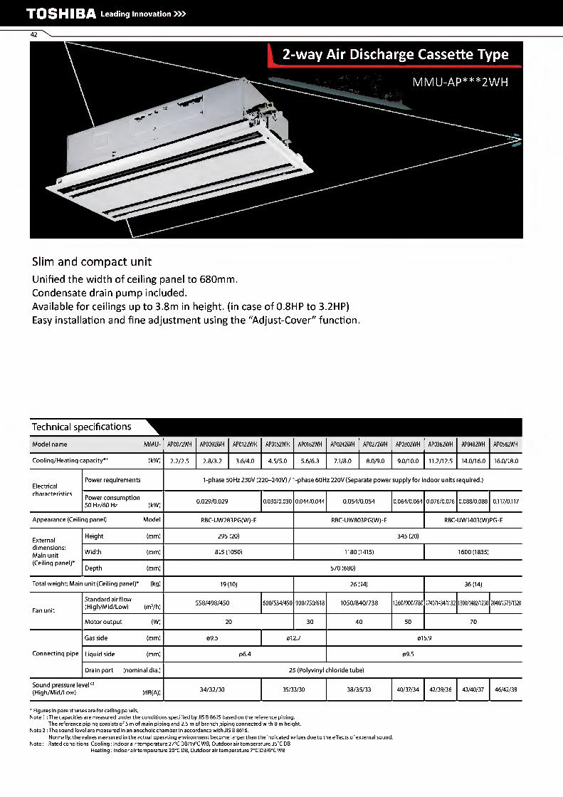
Slim and compact unit
Unified the width of ceiling panel to 680mm.
Condensate drain pump included.
Available for ceilings up to 3.8m in height, (in case of 0.8HP to 3.2HP)
Easy installation and fine adjustment using the "Adjust-Cover" function.
Technical specifications
Model name MMU- AP0072WH AP0092WH AP0122WH AP0152WH AP0182WH AP0242WH AP0272WH AP0302WH AP0362WH AP0482WH AP0562WH
Cooling/Heating capacity*1 (kW) 2.2/2.5 2.8/3.2 3.6/4.0 4.5/5.0 5.6/6.3 7.1/8.0 8.0/9.0 9.0/10.0 11.2/12.5 14.0/16.0 16.0/18.0
Electrical characteristics
Power requirements 1-phase 50Hz 230V (220-240V) / 1-phase 60Hz 220V (Separate power supply for indoor units required.)
Power consumption 50 Hz/60 Hz (kW) 0.029/0.029 0.030/0.030 0.044/0.044 0.054/0.054 0.064/0.064 0.076/0.076 0.088/0.088 0.117/0.117
Appearance (Ceiling panel) Model RBC-UW283PG(W)-E RBC-UW803PG(W)-E RBC-UW1403(W)PG-E
External dimensions: Main unit (Ceiling panel)*
Height (mm) 295 (20) 345 (20)
Width (mm) 815(1050) 1180 (1415) 1600(1835)
Depth (mm) 570 (680)
Total weight: Main unit (Ceiling panel)* (kg) 19(10) 26 (14) 36 (14)
Fan unit Standard airflow (High/Mid/Low) (m3/h) 558/498/450 600/534/450 900/750/618 1050/840/738 1260/900/780 1740/1434/1182 1800/1482/1230 2040/1578/1320
Motor output (W) 20 30 40 50 70
Connecting pipe
Gas side (mm) 09.5 012.7 015.9
Liquid side (mm) 06.4 09.5
Drain port (nominal dia.) 25 (Polyvinyl chloride tube)
Sound pressure level*2
(High/Mid/Low) (dB(A)) 34/32/30 35/33/30 38/35/33 40/37/34 42/39/36 43/40/37 46/42/39
* Figures in parentheses are for ceiling panels. Note 1 :The capacities are measured under the conditions specified by JIS B 8615 based on the reference piping.
The reference piping consists of 5 m of main piping and 2.5 m of branch piping connected with 0 m height. Note 2 :The sound level are measured in an anechoic chamber in accordance with JIS B 8616.
Normally, the values measured in the actual operating environment become larger than the indicated values due to the effects of external sound. Note: Rated conditions Cooling : Indoor air temperature 270C DB/190C WB, Outdoor air temperature 350C DB
Heating : Indoor air temperature 20oC DB, Outdoor air temperature 70C DB/60C WB
SMMS SUPER MODULAR MULTI SYSTEM &
43
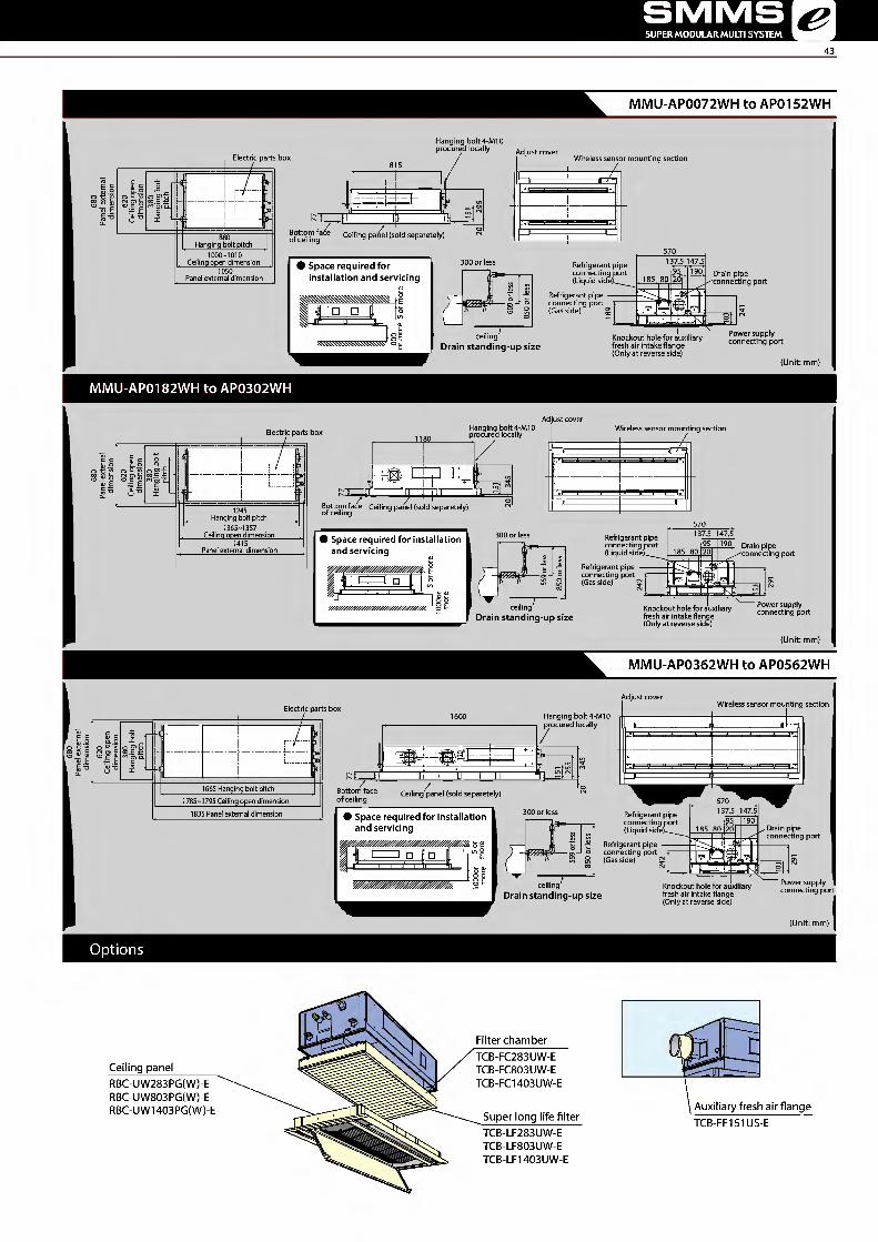
MMU-AP0072WH to AP0152WH
Electric parts box
1111
I H"
i1+
Hanging bolt pitch 1000-1010 Ceiling open dimension
of ceiling
Hanging bolt4-M10 procured locally Adjust cover
> Space required for installation and servicing
Ceiling panel (sold separetely)
Wireless sensor mounting section
Drain pipe --'connecting port
ceiling Drain standing-up size
Knockout hole for auxiliary fresh air intake flange (Only at reverse side) (Unit: mm)
MMU-APOI82WH to AP0302WH
Electric parts box Hanging bolt 4-M10 procured locally Adjust cover
1245 Hanging bolt pitch 1365-1357 Ceiling open dimension
Bottom face Ceiling panel (sold separetely) of ceiling
# Space required for installation and servicing
Wireless sensor mounting section
Refrigerant pipe connecting port (Gas side)
ceiling Drain standing-up size
Drain pipe 'connecting port
Knockout hole for auxiliary fresh air intake flange (Only at reverse side) (Unit: mm)
I\/1I\/1U-AP0362WH to AP0562WH
Electric parts box
1665 Hanging bolt pitch
1835 Panel external dimension 1785-1795 Ceiling open dimension
Bottom face of ceiling
1600 1
isEEEE
Ceiling panel (sold separetely)
# Space required for installation and servicing
Hanging bolt 4-M10 procured locally
ii
Adjust cover Wireless sensor mounting section
ceiling Drain standing-up size
Knockout hole for auxiliary fresh air intake flange (Only at reverse side) Power supply connecting port
(Unit: mm)
Options
Ceiling panel RBC-UW283PG(W)-E RBC-UW803PG(W)-E RBC-UW1403PG(W)-E
Filter chamber TCB-FC283UW-E TCB-FC803UW-E TCB-FC1403UW-E
Super long life filter TCB-LF283UW-E TCB-LF803UW-E TCB-LF1403UW-E
n
Auxiliary fresh air flange TCB-FF151US-E

TOSHIBA Leading Innovation »>
1-way Air Discharge Cassette Type
MMU-AP***4YH-E MMU-AP***4SH-E
The perfect choice for hotels and reception Fresh air intake is possible (MMU-AP***4SH-E) areas
Silent sound design ensures the quiet required for Preparations/connection possible with a circle duct
the office. flange.
Ideal for smaller rooms where one-way air distribution
is required.
Able to blow air straight out.
Condensate drain pump included.
Long-life filters fitted as standard.
Technical specifications
Model name MMU- AP0074YH-E AP0094YH-E AP0124YH-E AP0154SH-E AP0184SH-E AP0244SH-E
Cooling/Heating capacity*1 (kW) 2.2/2.5 2.8/3.2 3.6/4.0 4.5/5.0 5.6/6.3 7.1/8.0
Electrical characteristics
Power requirements 1-phase 50Hz 230V (220-240V) / 1-phase 60Hz 220V (Separate power supply for indoor units required.)
Power consumption 50 Hz/60 Hz (kW) 0.053/0.056 0.042/0.041 0.046/0.045 0.075/0.073
Appearance (Ceiling panel) Model RBC-UY136PG RBC-US21PGE
External dimensions: Main unit (Ceiling panel)*
Height (mm) 235 (18)* 200 (20)*
Width (mm) 850 (1050)* 1000 (1230)*
Depth (mm) 400 (470)* 710(800)*
Total weight: Main unit (Ceiling panel)* (kg) 22 (3.5)* 21 (5.5)* 22 (5.5)*
Fan unit Standard airflow (High/Mid/Low) (m3/h) 540/480/420 750/690/630 780/720/660 1140/960/810
Motor output (W) 22 30
Connecting pipe
Gas side (mm) 09.5 012.7 015.9
Liquid side (mm) 06.4 09.5
Drain port (nominal dia.) 25 (Polyvinyl chloride tube)
Sound pressure level*2
(High/Mid/Low) (dB(A)) 42/39/34 37/35/32 38/36/34 45/41/37
* Figures in parentheses are for ceiling panels. Note 1 :The capacities are measured under the conditions specified by JIS B8615 based on the reference piping.
The reference piping consists of 5 m of main piping and 2.5 m of branch piping connected with 0 m height. Note 2 :The sound level are measured in an anechoic chamber in accordance with JIS B 8616.
Normally, the values measured in the actual operating environment become larger than the indicated values due to the effects of external sound. Note: Rated conditions Cooling : Indoor air temperature 270C DB/190C WB, Outdoor air temperature 350C DB
Heating : Indoor air temperature 20oC DB, Outdoor air temperature 70C DB/60C WB

SMMS SUPER MODULAR MULTI SYSTEM
45
MMU-AP0074YH-E to AP0124YH-E
Panel external dimension 1050 w Spac e required for installation and servicing
F ^r
a- T3 y///////.
fn no
rn
MMU-APOI54SH-E to AP0244SH-E
(pi 12
Fresh air intake ((t)92 knockout hole) Panel external dimension 1230
Wiring connection por t
Ceiling open dimension 1190 Hanging bolt pitch 1060
eF
154 Refrigerant pipe connecting port (Gas side) Refrigerant pipe connecting port (Liguid side)
Ceiling panel (Sold separately) 1230
§
(Wireless sensor mounting sectio n
Hanging boltM10orW3/8 local arrange
Bottom face of ceil n_gj
# Spac e required for installation and servicing Y//////////////////////////////////^ t u Ceiling 1000 or more
1000 or more '//?////////. Obstacl e
Drain standin g-up size (Unit: mm)
Options
AP0074YH-E/AP0094YH-E/AP0124YH-E
Ceiling panel
Front air discharge unit
RBC-UY136PG Auxiliary fresh air flange TCB-FF101URE2
/ TCB-BUS21FIWE
>4
Ceiling panel AP0154SH-E/AP0184SH-E/AP0244SH-E RBC-US21PGE

Functional design
Only 210 mm in height for greater application
flexibility.
4-step static pressure setup.
Concealed installation within a ceiling void.
Auxiliary fresh air intake available.
Slim & quiet
Perfect comfort throughout the room.
Can be used with any style of air diffuser.
Quiet, powerful operation.
Technical specifications
Model name MMD- AP0074SPH-E AP0094SPH-E AP0124SPH-E AP0154SPH-E AP0184SPH-E AP0244SPH-E AP0274SPH-E
Cooling/Heating capacity*1 (kW) 2.2/2.5 2.8/3.2 3.6/4.0 4.5/5.0 5.6/6.3 7.1/8.0 8.0/9.0
Electrical characteristics
Power supply 1-phase 50Hz 230V (220-240V) /1-phase 60Hz 220V (Separate power supply for indoor units required.)
Power consumption 50 Hz/60 Hz (kW) 0.039/0.037 0.043/0.041 0.045/0.043 0.054/0.052 0.105//0.105
External dimensions
Height (mm) 210
Width (mm) 845 1140
Depth (mm) 645
Total weight (kg) 22 23 29
Fan unit
Standard airflow (High/Mid/Low) (m3/h) 540/470/400 600/520/450 690/600/520 780/680/580 1080/1000/900
Motor output (W) 60 120
External static pressure (Pa) 6-16-31-46 (4 steps) 5-15-30-45 (4 steps) 4-14-29-44 (4 steps) 2-12-22-42 (4 steps)
Connecting pipe
Gas side (mm) 09.5 012.7 015.9
Liquid side (mm) 06.4 09.5
Drain port (nominal dia.) 25 (Polyvinyl chloride tube)
Sound pressure level*2
(High/Med./Low)
Under air inlet (dB(A)) 36/33/30 38/35/32 39/36/33 40/38/36 49/47/44
Back air inlet (dB(A)) 28/26/24 29/27/25 32/30/28 33/31/29 38/36/33
Note 1 :The capacities are measured underthe conditions specified by JIS B 8615 based on the reference piping. The reference piping consists of 5 m of main piping and 2.5 m of branch piping connected with 0 m height.
Note 2 :The sound level are measured in an anechoic chamber in accordance with JIS B8616. Normally, the values measured in the actual operating environment become larger than the indicated values due to the effects of external sound.
Note : Rated conditions Cooling: Indoor air temperature 270C DB/190C WB, Outdoor air temperature 350C DB Heating: Indoor air temperature 20oC DB, Outdoor air temperature 70C DB/60C WB

SMMS SUPER MODULAR MULTI SYSTEM
47
MMD-AP0074SPH-E to AP0274SPH-E
■ □,31 '
a -1 803 (inside) 21
3
Fresh air intake (knock-out hole)
Model MMD- AP0074SPH-E to AP0274SPH-E
• Spac e required for installation and servicing
100 or more
235 or more
250 or more
Under air inlet ////////////////////////////////
Ceiling Air inlet
(DSo
2500 or more Floor surface 777777777
Rear air inlet /////////////////////////////////////////-
235 or more
Ceiling
//////////////jjV irTTp it" 235 or
more
2500 or more
Floor surface 777777777
(Unit: mm)
Options
Auxiliary fresh air flange TCB-FF101URE2

TOSHIBA Leading Innovation »>
Concealed Duct High Static Pressure Type
> .1 •* '
MMn-AP^^^eHP-E
MMD-A P-E, MMD-AP0966HP-E
Design flexibility
Satisfies all your design needs.
Compatible with external static pressures
up to 196 Pa.
Can be equipped with the following options:
• high-efficiency filter (65, 90)
• drain pump kit
Construction characteristics
Three-stage-switchable static pressure.
The flexible duct is accessible.
Easy service and installation.
Inspection hole enables easy access and
maintenance.
Technical specifications
Model name MMD- AP0186HP-E AP0246HP-E AP0276HP-E AP0366HP-E AP0486HP-E AP0566HP-E AP0726HP-E AP0966HP-E
Cooling capacity*1 (kW) 5.6 7.1 8.0 11.2 14.0 16.0 22.4 28.0
Electrical characteristics
Power requirements 1-phase 50Hz 230V (220-240V) / 1-phase 60Hz 220V (Separate power supply for indoor units required.)
Power consumption 50 Hz/60 Hz (kW) 0.085 0.115 0.198 0.230 0.290 0.540 0.790
External dimensions
Height (mm) 298 448
Width (mm) 1,000 1,400 1,400
Depth (mm) 750 900
Total weight (kg) 34 43 97
Fan unit
Standard airflow (m3/h) (Medyiow)
800 (660/550)
1,200 (970/800)
1,920 (1,560/1,340)
2,100 (1,740/1,420)
2,400 (2,040/1,660)
3,800 (3,200/2,500)
4,800 (4,200/3,500)
Motor output (W) 250 350 250
External static pressure (factory setting) (Pa) 100 150
External static pressure (Pa) 50-75-125-150-175-200 (7steps) 50-83-117-150-183-217-250 (7steps)
Connecting pipe
Gas side (mm) 012.7 015.9 022.2
Liquid side (mm) 06.4 09.5 012.7
Drain port (nominal dia.) 25 (Polyvinyl chloride tube) 25 (Polyvinyl chloride tube)
Sound pressure level*2
(High/Mid/Low) (dB(A)) 37
(32/30) 38
(34/31) 41
(37/34) 42
(40/35) 45
(42/37) 44
(40/36) 46
(42/38) Note 1 : The cooling capacities and electrical characteristics are measured under the conditions specified by JIS B8615 based on the reference piping.
The reference piping consists of 5m of main piping and 2.5 of branch piping connected with 0 meter height. Note 2 :The sound level are measured in an anechoic chamber in accordance with JIS B 8616.
Normally, the values measured in the actual operating environment become larger than the indicated values due to the effects of external sound. Note: Rated conditions Cooling : Indoor air temperature 270C DB/190C WB, Outdoor air temperature 350C DB

SMM5 SUPER MODULAR MULTI SYSTEM <em
49
MMD-APOI86HP1 -E to AP0276HP1 -E iwmwi lir mtvUvn
I\/1I\/1D-AP0726HP-E, AP0966HP-E
| m 1 S£=x ^ m
—
0
-
MC5 J91
m 'jSBjnmsti
:-S . P
B-tl ■ S nu
_ _
t j.,, lu JJ
MMD-AP0366HP1 -E to AP0566HP1 -E
n - I 3 7" :f I • (Brazing connection)
a 3 BJ
rl
i
li j nl Space required for installation and servicing
IT
„
/Service door (Celling opening) jgr Mien attached the long life filter kit (sold sepa rately)> TO Service door (Celllnq opening) jgi
i V ri(.. ^'.iL
1-c,sr /Service door (Celllnq opening)
(Unit: mm)
Options
Long Life Filter Kit TCB-LK2801DP-E
Drain Pump Kit TCB-DP40DP-E

High static pressure
External static pressure can be raised as high
as 120 Pa, so that all areas of the room can be
reached for even temperature distribution,
no matter how complex the layout.
High-lift drain pump
Built-in high-lift drain pump up to 850 mm.
Technical specifications
Model name MMD- AP0076BHP-E AP0096BHP-E AP0126BHP-E AP0156BHP-E AP0186BHP-E AP0246BHP-E AP0276BHP-E AP0306BHP-E AP0366BHP-E AP0486BHP-E AP0566BHP-E
Cooling/Heating capacity*1 (kW) 2.2/2.5 2.8/3.2 3.6/4.0 4.5/5.0 5.6/6.3 7.1/8.0 8.0/9.0 9.0/10.0 11.2/12.5 14.0/16.0 16.0/18.0
Power requirements 1-phase 50Hz 230V (220-240V) / 1-phase 60Hz 220V (Separate power supply for indoor units required.)
characteristics Power consumption 50 Hz/60 Hz (kW) 0.038/0.038 0.043/0.043 0.062/ 0.062 0.077/0.077 0.094/0.094 0.172/0.172 0.198/0.198
Height (mm) 275 External dimension Width (mm) 700 700 1,000 1,400
Depth (mm) 750
Total weight (kg) 23 30 40
Standard airflow 540/ 570/ 798/ 1,200/990/870 1,260/ 1,920/ 2,100/ (Mid/Low) (mVh) 450/360 480/390 660/540 1,110/930 1,620/1,380 1,740/1,500
Motor output (W) 150 250 Fan unit External static pressure
(factory setting) (Pa) 30 40 50
External static pressure (Pa) 30-40-50-65-80-100-120 (7 steps)
Gas side (mm) 09.5 012.7 015.9 Connecting pipe Liquid side (mm) 06.4 09.5
Drain port dia.)
(nominal 25 (Polypropylene tube)
Sound pressure (High/Mid/Low)
evel*2
(dB(A)) 29/26/23 30/26/23 33/29/25 36/31/27 40/36/33
Note 1 : The capacities are measured under the conditions specified by JIS B 8615 based on the reference piping. The reference piping consists of 5 m of main piping and 2.5 m of branch piping connected with 0 m height.
Note 2 :The sound level are measured in an anechoic chamber in accordance with JIS B 8616. Normally, the values measured in the actual operating environment become larger than the indicated values due to the effects of external sound.
Note: Rated conditions Cooling : Indoor air temperature 270C DB/190C WB, Outdoor air temperature 350C DB Heating: Indoor air temperature 20oC DB, Outdoor air temperature 70C DB/60C WB

SMMS SUPER MODULAR MULTI SYSTEM &
51
MMD-AP0076BHP-E to AP0566BHP-E
Flexible drain hi Space required for installation and servicing
Under air intake type
(Unit:mm)
Model MMD- A B C D AP0076BHP-E, AP0096BHP-E, AP0126BHP-E 765 700 640 654 AP0156BHP-E, AP0186BHP-E 765 700 640 654 AP0246BHP-E, AP0276BHP-E, AP0306BHP-E 1065 1000 940 953.5 AP0366BHP-E, AP0486BHP-E, AP0566BHP-E 1465 1400 1340 1349
* Standard filter is provided, but deeper filtration filter needs to be purchased locally.
Options
Spigot shaped flange TCB-SF56C6BPE TCB-SF80C6BPE TCB-SF160C6BPE
O y<§)
frff --- L o

Smooth curve for pliant Shape
All-new chassis and new rounded design,
This new models have been developed in
response to customers' needs for ceiling
units that better match their room interiors.
Smooth curve for pliant Shape
New fan has adopted the turbulence prevention rib
to optimize the ventilating way.
Air volume has increased and noise level also has
decreased compared with previous model. Winds of
new ceiling type of 4HP to 6HP can be reached up to
4.3 metre. Temperature measuring section
]>
0.5m above the floor f ~~J ijl3"
Temperature (deg.C) KM I Ma M I I I I I I'I I \TD 10 16 22 28 3
Technical specifications
Previous model New model
SI lai []
1
New Designed Wide Flap
The new air oulet has realized both High
noise reduction and large air volume.
Previous model New model
30% Extension
Flap control
The airflow angle is automatically set to
the most suitable setting according to your cooling
or heating needs, and an automatic swing mode
enables airflow to reach all areas of the room
to create a comfortable ambience.
Model name MMC- AP0157HP-E AP0187HP-E AP0247HP-E AP0277HP-E AP0367HP-E AP0487HP-E AP0567HP-E
Cooling/Heating capacity*1 (kW) 4.5/5.0 5.6/6.3 7.1/8.0 8.0/9.0 11.2/12.5 14.0/16.0 16.0/18.0
Electrical characteristics
Power requirements 1-phase 50Hz 230V (220-240V) / 1-phase 60Hz220V (Separate power supply for indoor units required.)
Power consumption 50 Hz/60 Hz (kW) 0.033/0.033 0.034/0.034 0.067/0.067 0.083/0.083 0.111/0.111
External dimensions
Height (mm) 235
Width (mm) 950 1,269 1,586
Depth (mm) 690
Total weight (kg) 24 30 37
Fan unit Standard airflow (High/Mid/Low) (m3/h) 840 /690/540 960 /720/540 1440/1020/750 1860 /1350/1020 1860/1530/1200 2040 /1650/1260
Motor (W) 94 94 139
Connecting pipe
Gas side (mm) 012.7 015.9
Liquid side (mm) 06.4 09.5
Drain port (nominal dia.) 20 (Polyvinyl chloride tube)
Sound pressure level*2
(High/Mid/Low) (dB(A)) 36/34/28 37/35/28 41/36/29 44/38/32 44/41/35 46/42/36
Note 1 : The capacities are measured underthe conditions specified byJIS B 8615 based on the reference piping. The reference piping consists of 5 m of main piping and 2.5 m of branch piping connected with 0 m height.
Note 2: The sound level are measured in an anechoic chamber in accordance with JIS B 8616. Normally, the values measured in the actual operating environment become larger than the indicated values due to the effects of external sound.
Note: Rated conditions Cooling: Indoor air temperature 270C DB/190C WB, Outdoor air temperature 350C DB Heating : Indoor air temperature 20°C DB, Outdoor air temperature 70C DB/60C WB

SMMS SUPER MODULAR MULTI SYSTEM
53
MMC-AP0157HP-E to AP0567HP-E
Upper piping drawing-out port (Knockout) Power supply cable taking-in port (Knockout)
.87.
/ \ (Hanging position)
z ^ Piping drawing-out port (Knockout)
L>
mJi
1 1
Wireless sensor mounting section
Remote controller cable takingnn port I Power supply taking-in port (Knockout)
Remote controller cable taking-in port (Knockout) r;
0 Air taking-in port (Duct sold separately) ( (Knockout hole (ft 92)
Z view
Model MMC- A B
AP0157HP-E, AP0187HP-E 906 950 AP0247HP-E, AP0277HP-E 1223 1269 AP0367HP-E, AP0487HP-E, AP0567HP-E 1540 1586
• Space required for installation and servicing Hanging bolt
A Ceiling surface Unit
/ / / 1
250 or more 250 or more (Front side to be positioned) horizontally
Options
TCB-KP13CE, TCB-KP23CE Elbow piping
TCB-DP31CE Drain pump kit
TCB-PCUC1E Optional connecting kit

TOSHIBA Leading Innovation »>
High-wall Type (3 series)
\ MMK-AP***3H
Elegant and slim
This classic high-wall is elegant and slim;
it can easily blend in with any room interior.
Total comfort is granted, thanks also to the 70°
directional auto-swing louver that provides uniform
air distribution.
oQc Oc
o o ooo oo © o oo c Remote controller
IV1IV1K-AP0073H to AP0243H
a
• Space re quir ed for installation and se rv icing
% jllOor mor e % % 1 850 or 170 or
1 i
Refrigerant connecting pipe (Gas side)
Refrigerant connecting pipe (Liquid side) (Unit: mm)
Technical specifications
Model name MMK- AP0073H AP0093H AP0123H AP0153H AP0183H AP0243H Cooling/Heating capacity*1 (kW) 2.2/2.5 2.8/3.2 3.6/4.0 4.5/5.0 5.6/6.3 7.1/8.0
Electrical characteristics
Power requirements 1-phase 50Hz 230V (220-240V) (Separate power supply for indoor units required.) Power consumption 50 Hz (kW) 0.018 0.021 0.043 0.050
External dimensions
Height (mm) 320 Width (mm) 1050 Depth (mm) 228
Total weight (kg) 15
Fan unit Standard airflow (High/Mid/Low) (m3/h) 570/450/390 600/480/390 840/660/540 1020/750/570
Motor output (W) 30
Connecting pipe Gas side (mm) 09.5 012.7 015.9 Liquid side (mm) 06.4 09.5 Drain port (nominal dia.) 16 (polyvinyl chloride tube)
Sound pressure level*2
(High/Mid/Low) (dB(A)) 35/31/28 37/32/28 41/36/33 46/39/34
Note 1 : The capacities are measured under the conditions specified by JIS B8615 based on the reference piping. The reference piping consists of 5 m of main piping and 2.5 m of branch piping connected with 0 m height.
Note 2: The sound level are measured in an anechoic chamber in accordance with JIS B 8616. Normally, the values measured in the actual operating environment become larger than the indicated values due to the effects of external sound.
Note: Rated conditions Cooling : Indoor air temperature 270C DB/190C WB, Outdoor air temperature 350C DB Heating : Indoor air temperature 20°C DB, Outdoor air temperature 70C DB/60C WB

SMMS SUPER MODULAR MULTI SYSTEM
Features
Elegant & simple design makes this unit a perfect fit for shops,
office buildings, and luxury apartments.
Bottom flow functionality ensures comfortable air bi-flow for
an advantage in heating and floor warming.
Multi-function operation is convenient, making adjustments by
the user possible using the wireless remote controller.
o § o O"-
o o 006 000 0000 Remote controller
MML-AP0074NH-E to AP0184NH-E
Back body
'A \Dia.80mm
Knockout system
3—r \ Vertical louver (Upper air outlet)
Front panel Air inlet grille Airfilter Heat exchanger
Space required for installation and servicing
i
(Unit: mm)
Technical specifications
Model name MML- AP0074NH-E AP0094NH-E AP0124NH-E AP0154NH-E AP0184NH-E Cooling/Heating capacity*1 (kW) 2.2/2.5 2.8/3.2 3.6/4.0 4.5/5.0 5.6/6.3 Electrical Power requirements 1-phase 50Hz230V (220-240V) / 1-phase 60Hz220V (Separate power supply for indoor units required.) characteristics Power consumption 50 Hz/60 Hz (kW) 0.021 0.025 0.034 0.052
External dimensions
Height (mm) 600 Width (mm) 700 Depth (mm) 220
Total weight (kg) 17
Fan unit Standard air flow (High/Mid/Low) (m3/h) 510/366/282 552/408/324 624/468/384 726/528/426 Motor output (W) 41 Gas side (mm) 09.5 012.7
Connecting pipe Liquid side (mm) 06.4 Drain port (nominal dia.) 16 (Polyvinyl chloride tube)
Sound pressure level*2 (High/Mid/Low) (dB(A)) 38/32/26 40/34/29 43/37/31 47/40/34 Note 1 : The capacities are measured under the conditions specified by JIS B 8615 based on the reference piping.
The reference piping consists of 5 m of main piping and 2.5 m of branch piping connected with 0 m height. Note 2: The sound level are measured in an anechoic chamber in accordance with JIS B 8616.
Normally, the values measured in the actual operating environment become larger than the indicated values due to the effects of external sound. Note: Rated conditions Cooling : Indoor air temperature 270C DB/190C WB, Outdoor air temperature 350C DB
Heating : Indoor air temperature 20oC DB, Outdoor air temperature 70C DB/60C WB

Slim & compact design
Under-window mounting does
not block lighting.
Indoor unit size of 2.2 kW to
7.1 kW is the same.
Slim & compact design
Distribution can be reversed
to suit occupant preference.
Air blown from front panel (factory default)
Air blovHfrom top
Lower refrigerant piping port (knockout hole 50x100)
mounting (2 -c|)10) 400
\ 120
o in o r-
t 1
3^
Refrigerant pipe port (both sides) (knockout hole 50x100)
Drain pipe connecting port
Hole for wall mounting (knockout hole)
(100 left side)
MML-AP0074H-E to AP0244H-E
g5 Refrigerant pipe connecting port (Liquid side)
(Liquid) (Gas) Piping positional drawing
# Spac e requir ed fo r inst allation and se rvicin g
Wall '////////////.
(Front side) 500 or more
(Front side) 77777/<
K / / /wall / /
(Unit: mm)
Technical specifications
Model name MML- AP0074H-E AP0094H-E AP0124H-E AP0154H-E AP0184H-E AP0244H-E Cooling/Heating capacity*1 (kW) 2.2/2.5 2.8/3.2 3.6/4.0 4.5/5.0 5.6/6.3 7.1/8.0 Electrical Power requirements 1-phase 50Hz 230V (220-240V) / 1-phase 60Hz 220V (Separate power supply for indoor un its required.) characteristics Power consumption 50 Hz/60 Hz (kW) 0.056/0.053 0.092/0.092 0.102/0.113
External dimensions
Height (mm) 630 Width (mm) 950 Depth (mm) 230
Total weight (kg) 37 40
Fan unit Standard air flow (High/Mid/Low) (mVh) 480/420/360 900/780/650 1080/930/780 Motor output (W) 45 70 Gas side (mm) 09.5 012.7 015.9
Connecting pipe Liquid side (mm) 06.4 09.5 Drain port (nominal dia.) 20 (Polyvinyl chloride tube)
Sound pressure level*2 (High/Mid/Low) (dB(A)) 39/37/35 45/41/38 49/44/39 Note 1 : The capacities are measured under the conditions specified by JIS B 8615 based on the reference piping.
The reference piping consists of 5 m of main piping and 2.5 m of branch piping connected with 0 m height. Note 2 : The sound level are measured in an anechoic chamber in accordance with JIS B8616.
Normally, the values measured in the actual operating environment become largerthan the indicated values due to the effects of external sound. Note: Rated conditions Cooling : Indoor air temperature 270C DB/190C WB, Outdoor air temperature 350C DB
Heating : Indoor air temperature 20oC DB, Outdoor air temperature 70C DB/60C WB

SMMS SUPER MODULAR MULTI SYSTEM &
57
Floor Standing Concealed Type
MML-AP***4BH-E
Cool air makes for a pleasant indoor environment
Install it under a window and air-condition any room
effectively.
Easy maintenance
Simplified design of fan and drainage pipe eases
maintenance.
MML-AP0074BH-E to AP0244BH-E
Hole for floor mounting (Air discharge port size in flange)
(Air discharge port size in flange) A
Ceiling board section # Spac e requir ed for inst allation
and se rvicing
Electric parts box (earth terminal is provided in inner side) /
Model MML- A B C D E AP0074BH-E to AP0124BH-E 610 580 550 4 5 AP0154BH-E to AP0244BH-E 910 880 850 7 8
+ + + + + + _a
3^
2-(|)4.7 hole (left/right side each)
Expansion valve box
Refrigerant pipe connecting port (Liquid side) Refrigerant pipe connecting port ^ (Gas side)
no
(Unit: mm)
Technical specifications
Model name MML- AP0074BH-E AP0094BH-E AP0124BH-E AP0154BH-E AP0184BH-E AP0244BH-E Cooling/Heating capacity*1 (kW) 2.2/2.5 2.8/3.2 3.6/4.0 4.5/5.0 5.6/6.3 7.1/8.0 Electrical Power requirements 1 -phase 50Hz 230V (220-240V) / 1 -phase 60Hz 220V (Separate power supply for indoor un its required.) characteristics Power consumption 50 Hz/60 Hz (kW) 0.056/0.058 0.090/0.096 0.095/0.110
External dimensions
Height (mm) 600 Width (mm) 745 1045 Depth (mm) 220
Total weight (kg) 21 29
Fan unit Standard airflow (High/Mid/Low) (mVh) 460/400/300 740/600/490 950/790/640 Motor output (W) 19 70 Gas side (mm) 09.5 012.7 015.9
Connecting pipe Liquid side (mm) 06.4 09.5 Drain port (nominal dia.) 20 (Polyvinyl chloride tube)
Sound pressure level*2 (High/Mid/Low) (dB(A)) 36/34/32 42/37/33 Note 1 : The capacities are measured under the conditions specified by JIS B8615 based on the reference piping.
The reference piping consists of 5 m of main piping and 2.5 m of branch piping connected with 0 m height. Note 2: The sound level are measured in an anechoic chamber in accordance with JIS B 8616.
Normally, the values measured in the actual operating environment become larger than the indicated values due to the effects of external sound. Note: Rated conditions Cooling : Indoor air temperature 270C DB/190C WB, Outdoor air temperature 350C DB
Heating : Indoor air temperature 20oC DB, Outdoor air temperature 70C DB/60C WB

TOSHIBA Leading Innovation »>
Floor Standing Type
MMF-AP***6H-E
Thin profile suits interior design
Slender, space-saving type (1.7-8.0HP)
Wide outlet
Corner location is also possible, with right and
left auto swing.
Set the vertical angle manually.
auto ^ sl swing /
MMF-APOI56H-E to AP0566H- E
Bracket for wall mounting Air outlet # Space required for installation and servicing
1/ / V//////////A
/ / / / v (Front side)
(Front side) -7-7-7-7-7-
/ / / / / / Wall / / / V
Model MMF- A B C D E F APOI 54H-E to AP0274H-E 200 107 132 157 210 50 AP0364H-E to AP0564H-E 380 125 120 160 390 40
MMF-APOI 51H MMF-AP0361H
ar
m
Refrigerant piping position (Unit: mm)
Technical specifications
Model name MMF- AP0156H-E AP0186H-E AP0246H-E AP0276H-E AP0366H-E AP0486H-E AP0566H-E Cooling/Heating capacity*1 (kW) 4.5/5.0 5.6/6.3 7.1/8.0 8.0/9.0 11.2/12.5 14.0/16.0 16.0/18.0 Electrical Power requirements 1-phase 50Hz 230V (220-240V) / 1-phase 60Hz 220V (Separate power supply for indoor units required.) characteristics Power consumption 50 Hz/60 Hz (kW) 0.055 0.089 0.135 0.160
External dimensions
Height (mm) 1750 Width (mm) 600 Depth (mm) 210 390
Total weight (kg) 46 47 62
Fan unit Standard airflow (High/Mid/Low) (m3/h) 900/780/660 1200/990/840 1920/1620/1380 2160/1730/1560 Motor output (W 62 62 109 109 Gas side (mm) 012.7 012.7
Connecting pipe Liquid side (mm) 06.4 09.5 Drain port (nominal dia.) 20 (one side of male screw)
Sound pressure level*2 (High/Mid/Low) (dB(A)) 46/42/37 49/45/39 51/46/41 54/49/44
Note 1 :The capacities are measured underthe conditions specified by JIS B 8615 based on the reference piping. The reference piping consists of 5 m of main piping and 2.5 m of branch piping connected with 0 m height.
Note 2 : The sound level are measured in an anechoic chamber in accordance with JIS B8616. Normally, the values measured in the actual operating environment become largerthan the indicated values due to the effects of external sound.
Note: Rated conditions Cooling : Indoor air temperature 270C DB/190C WB, Outdoor air temperature 350C DB Heating : Indoor air temperature 20oC DB, Outdoor air temperature 70C DB/60C WB
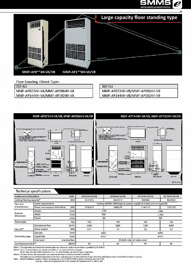
SMMS SUPER MODULAR MULTI SYSTEM
Large capacity floor standing type
ass-
mm ;
MMF-AP0**4H-VA/VB MMF-AP1**4H-VA/VB
Floor Standing <Direct Type>
(50 Hz)
M M F-AP0724H-VA/M M F-AP0964H-VA
MMF-AP1444H-VA/MMF-AP1924H-VA
(60 Hz)
MMF-AP0724H-VB/MMF-AP0964H-VB
MMF-AP1444H-VB/MMF-AP1924H-VB
MMF-AP0724H-VA/VB, MMF-AP0964H-VA/VB I\/1MF-AP1444H-VA/VB, MMF-AP1924H-VA/VB
E
I" ^ For UTR , , 1 !*' 6lA H0LES(6)
For fresh oir intoka ductfRioht sidel
H
RIGHT SIDE VIEW REAR VIEW
17mm niA UTR HOI FSfAT
Air fili3i»r
E
iffl
m LEFT SIDE VIEW RIGHT SIDE VIEW
(Unit: mm)
Technical specifications
Model name (50Hz/60Hz) MMF- AP0724H-VA/VB AP0964H-VA/VB AP1444H-VA/VB AP1924H-VA/VB Cooling/Heating capacity*1 (kW) 22.4/25.0 28.0/31.5 45.0/50.0 56.0/63.0 Electrical Power requirements 3 phase 50/60Hz 400V(Separate power supply for indoor units is required.) characteristics Power consumption 50 Hz/60 Hz (kW) 0.56/0.53 0.80/0.79 1.24/1.19 2.07/2.05
External dimensions
Height (mm) 2,130 2,280 Width (mm) 890 1,300 Depth (mm) 540 760
Total weight (kg) 182 188 320 320 Standard airflow (m3/h) 3,600 4,200 7,200 8,400
Fan unit*2 Motor output (kW) 0.75 1.5 22 2.2 Gas side (mm) 0222 028.6
Connecting pipe Liquid side (mm) 012.7 015.9 Drain port (nominal dia.) 25 (Both sides of male screw)
Sound pressure level*3 (dB(A)) 62 63 64 66 Note 1 : The capacities and electrical characteristics are measured under the conditions specified by JIS B 8615. Note 2 : As air volume is fixed, by remote controller, air volume cannot be charged.
When required high static pressure and air volume change, a pulley change is requested. Note 3 : The sound level are measured in an anechoic chamber in accordance with JIS B 8616.
Normally, the sound level measured in the actual operating environment become bigger than the rated figures due to the effects of external sound. Note: Rated conditions Cooling: Indoor air temperature 27°C DB/190C WB, Outdoor air temperature 350C DB
Heating : Indoor air temperature 20°C DB, Outdoor air temperature 70C DB/60C WB

TOSHIBA Leading Innovation »>
Large capacity floor standing type
60
mi ill
Sl!!li i in I IglRlli III P Ml 11 IJHII iiil ill! It i ill! Ullj urn i
MMF-AP0**4DH-V MMF-AP1**4DH-V
Floor Standing <Duct Type>
(50 Hz/60 Hz)
MMF-AP0724DH-V/MMF-AP0964DH-V
MMF-AP1444DH-V/MMF-AP1924DH-V
MMF-AP0724DH-V, MMF-AP0964DH-V MMF-AP1444DH-V, MMF-AP1924DH-V
■S
TOP VIEW
.IZmm DIA MTG HPU '!xFtw':hAMH&ge
1 I"
12mm OIA MTG H0LES(4) / —190 mt For duct MTG
1 i
779 KRIohl side)
H
LEFT SIDE VIEW RIGHT SIDE VIEW REAR VIEW
//n^
LEFT SIDE VIEW
-R°HHggr.nn-
RIGHT SIDE VIEW
(Unit: mm)
Technical specifications
Model name MMF- AP0724DH-V AP0964DH-V AP1444DH-V AP1924DH-V Cooling/Heating capacity*1 (kW) 22.4/25.0 28.0/31.5 45.0/50.0 56.0/63.0 Electrical Power requirements 3 phase 50/60Hz 400V(Separate power supply for indoor units is required.) characteristics Power consumption 50 Hz/60 Hz (kW) 0.59/0.70 0.80/0.99 1.04/1.28 1.79/2.26
External dimensions
Height (mm) 1820 1870 Width (mm) 890 1300 Depth (mm) 540 760
Total weight (kg) 170 170 280 290 Standard airflow (m3/h) 3600 4200 7200 8400
Fan unit*2 Motor output (kW) 1.5 1.5 22 3.7 External static pressure (50Hz/60Hz) (Pa) 43/122 39/148 28/111 86/222 Gas side (mm) 022.2 028.6
Connecting pipe Liquid side (mm) 012.7 015.9 Drain port (nominal dia.) 25 (Both sides of male screw)
Sound pressure level*3 (dB(A)) 54/56 55/57 61/63 62/64 Note 1 : The capacities and electrical characteristics are measured under the conditions specified by JIS B 8615. Note 2: As air volume is fixed, by remote controller, air volume cannot be charged.
When required high static pressure and air volume change, a pulley change is requested. Note 3 : The sound level are measured in an anechoic chamber in accordance with JIS B 8616.
Normally, the sound level measured in the actual operating environment become bigger than the rated figures due to the effects of external sound. Note: Rated conditions Cooling : Indoor air temperature 270C DB/190C WB, Outdoor air temperature 350C DB
Heating : Indoor air temperature 20oC DB, Outdoor air temperature 70C DB/60C WB

TOSHIBA Leading Innovation »>
Fresh Air Intake Indoor Unit Type
MMD-AP***HFE
Air controller for fresh-air intake
Outside static pressure maximum 230 Pa (in case of 50 Hz of 5HP).
Use of high-performance filter provides more comfortable room environment.
Introduces outdoor air at a temperature close to that of the indoor air.
Primary processing of fresh outdoor air.
Fresh-air intake often influences the system, rendering normal
control of the air conditioner difficult, or placing large loads on
the system and its cooling performance.
Therefore it is frequently adopted to handle the fresh air to
a certain condition before the fresh air will enter in the main
air conditioner.
This device is known as a fresh air intake indoor unit.
Fresh air intake indoor unit \i SMMS-i outdoor unit
i* -
NOTE: The fresh air intake indoor unit is an air conditioner provided to handle the fresh air load and is not to control the room temperature. For correspondence to the load of the indoor air controller, set an air conditioner separately.
Technical specifications
Model name MMD- AP0481HFE AP0721HFE AP0961HFE Cooling/Heating capacity (Note 1) (kW) 14.0/8.9 22.4/13.9 28.0/17.4 Electrical Power supply (kW) 1 -phase 50 Hz 230 V (220-240 V)/60 Hz 220 V characteristics Power consumption (kW) 0.28/0.34 0.45/0.55 0.52/0.65
External dimensions
Height (mm) 492 Main unit Width (mm) 892 1392
Depth (mm) 1262 Total weight (kg) 93 144
Standard airflow (m3/h) 1080 1680 2100
Fan unit Motor output (kW) 0.160 0.160x2 External static pressure 50 Hz/60 Hz (Pa) 170-210-230/115-215-260 140-165-180/150-210-235 160-190-205 / 80-180-220 Air flow limit Lower limit/Upper limit (m3/h) 756/1188 1176/1848 1470/2310 Gas side (mm) 015.9 022.2
Connecting pipe Liquid side (mm) 09.5 012.7 Drain port (mm) 25
Sound pressure level (Note 2) (High/Med./Low) (dB(A)) 45/43/41 46/45/44
Operation range Cooling (Note 3) TO 5 -43 Heating (Note 4) TO -5-43
* The setting temperature is 16 - 270C (standard FCU...18 - 290C). * An optional humidifier is not available with fresh air intake indoor unit. * Height difference between fresh air intake indoor units must be within 0.5 m. Height difference between fresh air intake indoor unit and standard FCU must be within 30 m. NOTE 1 Rated conditions Cooling: Outdoor air temperature 330C DB/280C WB setting temperature 180C
Heating: Outdoor air temperature 0oC DB/-2.90C WB setting temperature 250C Piping: Length 7.5 m/Height 0 m
NOTE 2 Normally, the values measured in the actual operating environment become large than the indicated values due to the effects of external sound. NOTE 3 * When supply air temperature is "setting temperature + 30C" or less, fresh air intake indoor unit operates as FAN mode.
* When supply air temperature is 190C or less, Fresh Air Intake Indoor unit operates as FAN mode. NOTE 4 * When supply air temperature is "setting temperature -30C" or over, fresh air intake indoor unit operates as FAN mode.

SMMS SUPER MODULAR MULTI SYSTEM
Use Conditions
• In COOL mode, if temperature of the fresh air • In HEAT mode, if temperature of the fresh air is above
is below the setup temp, of +3°C, FAN status is the setup temp. -3°C, FAN status is automatically made,
automatically made. When temperature of the fresh When temperature of the fresh air is above 150C, FAN
air is below 19°C, FAN status is also made regardless status is also made regardless of the setup temperature,
of the setup temperature.
Fresh air temp. (°C) -10 0 10 20 30 40 1 50 Fresh air temp. (°C) -1C 10 10 20 30 40 50 i i i i i i i i i i i Setup temp. i i 5 | Tl 1 1 43 "1 I I I i i
l 1 l l l l ^ i Setup temp, i 1 43 1
COOL mode 1 1 ■SSH COOL i HEAT mode i HEAT i i i i ^ * Automatic COOL j operation startsi
i i i i Automatic HEAT ; 30(_ operation starts j
Operable mode and discharge temperature setup range Operation mode At shipment from factory Setup range
COOL 18°C 16 to 27°C HEAT 25°C 16 to 27°C
I\/1I\/1D-AP0481 HFE to AP0961HFE
Long hole for M10 hanging bolt Type Hole dia.-Width x Length 0481 4-(t)12x40
0721,0961 4-^2x92
1328 Hanging bolt pitch 1288
1262
Refrigerative piping work example at local site
# Spac e requir ed for inst allation and se rvicin g
Service space Fresh air intake indoor unit
£ Service space
ni
^ Check port 600
C [~r
F T 1
\ Blow-off port \ Discharge temp sensor
Discharge port connecting flange (K ) (Accessory for main unit of product)
5
Refrigerant pipe connecting port (Gas pipe M )
Electric parts box (With cover) ' Refrigerant pipe connecting port (Liquid pipe N )
, 145.5 / / 528.5
m Suction port
Drain pipe connecting port Suction port connecting flange ( L ) (Accessory for main unit of product)
(Unit: mm)
Model MMD- A B C D E F G H 1 J K L M N AP0961HFE 1392 1260 250 250 250 250 250 250 250 250 10-M6 10-M6 (1)22.2 brazin g (1)12.7 flare AP0721HFE 1392 1260 250 250 250 250 250 250 250 250 10-M6 10-M6 (1)22.2 brazin g (1)12.7 flare AP0481HFE 892 810 215 107.5 107.5 215 — 250 250 — 8-M6 6-M6 (f)! 5.9 flare (1)9.5 flare
Options
Filter chamber TCB-FCY51DFE TCB-FCY100DE
Long life prefilter TCB-PF3DE TCB-PF4D-1E
Drain pump kit TCB-DP32DFE
Fligh-efficiency filter 65 TCB-UFM3DE, TCB-U FM4D-1E
Fligh-efficiency filter 90 TCB-U FH7DE,TCB-UFH8D-1 E

Greater comfort and reduced load
Functionality built into the cooling system reduces load
on cooling beyond that of the heat exchanger itself.
This improves air quality and ensures maximum comfort the needs of the environment and location,
throughout room being cooled.
Flexible control
Supply and exhaust fan speed ratios can be changed
for improved air volume control that best matches
Free cooling at night
When the air outdoors is cooler at night, the system
expels warm air from the room. This reduces the air
conditioning load the next day for improved energy
efficiency. s
Remote controller NRC-01HE
Technical specifi cations
Model name MMD- VN502HEXE VN802HEXE VN1002HEXE VN1002HEXE2 Fresh air Cooling (*1) (kW) 4.10(1.30) 6.56 (2.06) 8.25 (2.32) 8.25 (2.32) conditioning load Heating (*1) (kW) 5.53 (2.33) 8.61 (3.61) 10.92(4.32) 10.92 (4.32)
Power supply 1 -phase 50Hz 230V (220-240V) / 1 -phase 60Hz 220V (Separate power supply for indoor units required.)
1-phase 50Hz230V (220V-240V) (Separate power supply for indoor units is required.)
1-phase 60Hz220V (Separate power supply for indoor unitsisrequired.)
Temperature High (%) 70.5/70.5 70.0/70.0 65.5 exchange efficiency 50Hz/60Hz
Mid (%) 70.5/70.5 70.0/70.0 65.5 Low (%) 71.5/72.0 72.5/73.0 67.5 68.0
High (%) 56.5/56.5 56.0/56.0 52.0
Enthalpy exchange
Cooling Mid (%) 56.5/56.5 56.0/56.0 52.0 Low (%) 57.5/58.0 59.0/59.5 54.5 55.0
efficiency 50Hz/60Hz
High (%) 68.5/68.5 70.0/70.0 66.0 Heating Mid (%) 68.5/68.5 70.0/70.0 66.0
Low (%) 69.0/69.0 73.0/73.5 68.5 69.0
Standard airflow
High (m3/h) 500/500 800/800 950 Mid (m3/h) 500/500 800/800 950
Fan unit Low (m3/h) 440/410 640/600 820 800 50Hz/60Hz
External static pressure
High (Pa) 120/200 120/190 135 195 Mid (Pa) 105/170 100/155 120 160 Low (Pa) 115/150 105/130 105 130
Sound pressure 50Hz/60Hz
High (dB) 37.5/40.0 41.0/43.0 43.0 43.5 Mid (dB) 36.5/38.0 40.0/42.0 42.0 Low (dB) 34.5/36.5 38.0/37.0 40.0
External Dimensions
Height (mm) 430 Width (mm) 1140 1189 Depth (mm) 1690 1739
Total weight (kg) 84 100 101 103 Connecting Gas side (mm) 09.5 012.7 piping Liquid side (mm) 06.4 Drain port (Nominal dia .mm) 25(Polyvinyl chloride tube)
(*1) Cooling and heating capacities are based on the following conditions: Cooling capacities are based on : indoor temperature :27 0CDB/190CWB( Outdoor temperature: 350CDB Heating capacities are based on : indoor temperature :20 0CDB( Outdoor temperature: 7 0CDB/60CWB Fan is based on High and Middle ( ): The figures in ( ) indicate the heat reclaimed from the heat recovery ventilator.

64
SMMS SUPER MODULAR MULTI SYSTEM
MMD-VN502HEXE
4-13 x 30 oval hole (Mangling bracket)
^Heat exchange element Filter Motors, VFans, Maintenance space
1601
5T1
W L
Inspection opening 600 x 600
/Magnetic valve Decompression magnetic valvey Water inlet VHumidification element Maintenance space ) cormechn^
Duct size (Nominal Diameter): (|)200 Drain pipe connecting port \ Refrigerant pipe connecting port (Liquid) 4.6.4 (VP25) Refrigerant pipe connecting port (Gas) <1)9.5
Power supply wire intake
(Unit: mm)
. MMD-VN802HEXE to VN1002 H EXE/2
r 4-13x30 oval hole (Mangling bracket)
^Heat exchange element Filter Motors, VFans, Maintenance space
-w-r"
Power supply wire intake
Inspection opening 600x 600
/Magnetic valve Decompression magnetic valve\ Water inlet VHumidification element Maintenance space / connectina ■Attention 1.Duct size(NominaI diameter): 0250 2.The above dimensions do not include the thickness of the insulation material on the unit body.
Duct size (Nominal Diameter): (|)250 Drain pipe connecting port \ Refrigerant pipe connecting port (Liquid) 4.6.4 (VP25) Refrigerant pipe connecting port (Gas) <|) 12.7 (Unit: mm)
Options
Drain pump kit TCB-DP31HEXE

TOSHIBA Leading Innovation »>
65
Greater comfort and reduced load
Easily integrated into air conditioning systems
of 150m3/h to 2000m3/h air volume,
the air-to-air heat exchangers use exhaust air to
pre-condition the incoming air, thus reducing
the cooling or heating load and the overall size of
the required system.
Flexible control
Supply and exhaust fan speed ratios can be changed
for improved air volume control that best matches
the needs of the environment and location.
: Does not connect to refrigerant piping from outdoor unit. Control wires can be connected.
Free cooling at night
When the air outdoors is cooler at night, the system
expels warm air from the room. This reduces the air
conditioning load the next day for improved energy
efficiency.
Easy maintenance
The heat exchange element can be washed in water.
• 4 y u cjL CjL. a*
"" : 9 ■ «
Remote controller NRC-01HE
Technical specifications
Model name VN- M150HE M250HE M350HE M500HE M650HE M800HE M1000HE M1500HE M2000HE Power supply (V) Fan speed 1-phase 50Hz230V (220-240V) / 1-phase 60Hz220V (Separate power supply for indoor units required.)
(Extra high) 68-78/76 123-138/131 165-182/209 214-238/260 262-290/307 360-383/446 532-569/622 751-786/928 1084-1154/1294 consumption High 59-67/65 99-111/105 135-145/162 176-192/206 240-258/283 339-353/408 494-538/589 708-784/830 1032-1080/1220 50Hz/60Hz(W) Low 42-47/45 52-59/54 82-88/94 128-142/144 178-191/206 286-300/333 353-370/411 570-607/660 702-742/818
(Extra high) 150/150 250/250 350/350 500/500 650/650 800/800 1000/1000 1500/1500 2000/2000 Air volume (m3/h) High 150/150 250/250 350/350 500/500 650/650 800/800 1000/1000 1500/1500 2000/2000
Low no/no 155/155 210/210 390/390 520/520 700/700 755/755 1200/1200 1400/1400
External static pressure (Pa)
(Extra high) 82-102/99 80-98/97 114-125/167 134-150/181 91-107/134 142-158/171 130-150/185 135-156/165 124-143/165 High 52-78/59 34-65/38 56-83/33 69-99/63 58-82/68 102-132/102 97-122/120 103-129/108 92-116/102 Low 47-64/46 28-40/22 65-94/39 62-92/44 61-96/52 76-112/58 84-127/55 112-142/109 110-143/87
Sound pressure level (dB(A))
(Extra high) 26-28/27.5 29.5-30/31.5 34-35/35.5 32.5-34/33.5 34-36/35.5 37-38.5/38 39.5-40.5/41.5 38-39/39.5 41-42.5/42.5 High 24-25.5/24.5 25-27/25 30-32/29.5 29.5-31/29 33-34/34 35.5-37/35 38.5-40/39 36.5-37.5/36.5 39.5-41/40 Low 20-22/20 21-22/21 27-29/23.5 26-29/24.5 31-32.5/29.5 33.5-35/32.5 34-35.5/33.5 36-37.5/35.5 37-38/36.5
Temperature exchange
(Extra high) 81.5/81.5 78/78 74.5/74.5 76.5/76.5 75/75 76.5/76.5 73.5/73.5 76.5/76.5 73.5/73.5 High 81.5/81.5 78/78 74.5/74.5 76.5/76.5 75/75 76.5/76.5 73.5/73.5 76.5/76.5 73.5/73.5
efficiency (%) Low 83/83 81.5/81.5 79.5/79.5 78/78 76.5/76.5 77.5/77.5 77/77 79/79 77.5/77.5 (Extra high) 74.5/74.5 70/70 65/65 72/72 69.5/69.5 71/71 68.5/68.5 71/71 68.5/68.5
for heating High 74.5/74.5 70/70 65/65 72/72 69.5/69.5 71/71 68.5/68.5 71/71 68.5/68.5 Enthalpy exchange Low 76/76 74/74 71.5/71.5 73.5/73.5 71.5/71.5 73.5/73.5 72/72 efficiency (%) (Extra high) 69.5/69.5 65/65 60.5/60.5 64.5/64.5 61.5/61.5 64/64 60.5/60.5 64/64 60.5/60.5
for cooling High 69.5/69.5 65/65 60.5/60.5 64.5/64.5 61.5/61.5 64/64 60.5/60.5 64/64 60.5/60.5 Low 71/71 69/69 67/67 66.5/66.5 64/64 65.5/65.5 64.5/64.5 67/67 65.5/65.5
Dimensions (Length x Width x Height) (mm) 900 x 900 x 290 1140 x 1140x350 1189 x 1189x400 1189x1189x810 Weight (kg) 36 38 53 70 143 Duct diameter (mm) 100 150 200 250 inside: 250, outside: 283 x 730
Operating range Around unit Outdoor Air (OA) -150C(*1)-430C RH Return Air (RA) 50C - 40oC 0% RH or less
* Air volume can be changed over to high (extra high) mode or low mode. * Sound pressure level is measured 1.5m belowthe center of the unit. *Sound pressure level is the value which was measured at the acoustic room. *The actual values in an external operating environment are generally higher than the indicated values due to the contribution from ambient noise. * Sound pressure level is less than 70 dBA

66
SMMS SUPER MODULAR MULTI SYSTEM
VN-M150HEtoVN-M350HE
-£
Outdoor side
U1
m
80 Connecting Diagram
Power supply wire intake
\ L!Z5j 4-13 x 30 Oval hole(Hanging Bracket) " Inspection Opening 450 x 450 or more
Heat Exchange Element Filter Motor,Fans Maintenance Space Duct size (Nominal Diameter): <))200 (Unit: mm)
VN-M500HE, VN-M650HE
Outdoor side
"01
Earth Terminal
80 Connecting Diagram
^ Power supply wire intake
4-13 x 30 Oval hole(Hanging Bracket) " Inspection Opening 450 x 450 or more
Heat Exchange Element Filter Motor,Fans Maintenance Space Duct size (Nominal Diameter): (|)200
(Unit: mm)
VN-M800HE, VN-M1000HE
^ Earth Terminal 454
r < d: fi
35 Connecting Diagra
Power supply wire intake
Heat Exchange Element Filter Motor,Fans Maintenance Space (Unit: mm) Duct size (Nominal Diameter): ((>250
VN-M1500HE, VN-M2000HE
a
810 j f I '1
ra 0 d P
5 \ J - ?
J . 410 . 4-13 x 30 Oval hole(Hanging Bracket) Inspection Opening 450 x 450 or more
Heat Exchange Element Filter Motor,Fans Maintenance Space
r
fl
454
</\ ■ ^ / J
■
' = r
i
s ■ s
-tr / Connecting Diagram
Power supply wire intake
(Unit: mm) Duct size (Nominal Diameter): (|)250

TOSHIBA Leading Innovation »>
67
Indoor unit accessories
Indoor unit Parts Name Model Name Applied Model Notes Remarks
4-way air discharge cassette type
Ceiling panel RBC-U31 PG{W)-E
MMU-AP***4HP-E
Required accessory Fresh air inlet box TCB-GB1602UE For fresh air intake by using the knockout hole of fresh air filter chamber.
{dia.=100 mm) Use with TCB-GFC1602UE
Fresh airfllterchamber TCB-GFC1602UE For fresh air inlet box Auxiliary fresh air flange TCB-FF101URE2 For easy fresh air intake by using the knockout hole of indoor unit.
(dia.=100 mm) Spacer for height TCB-SP1602UE Height=50 mm Air discharge direction kit TCB-BC1602UE Air direction charge by cutting off air discharge port (3 pcs.)
Compact 4-way cassette (600 x 600) type
Ceiling panel RBC-UM11 PG(W)E MMU-AP***4MH-E
Required accessory Auxiliary fresh air flange TCB-FF101URE2 For easy fresh air intake by using the knockout hole of indoor unit.
(dia.=100 mm)
2-way air discharge cassette type
Ceiling panel RBC-UW283PG(W)-E MMU-AP0072 to 0152WH
Required accessory RBC-L)W803PG(W)-E MMU-AP0182 to 0302WH RBC-UW1403PG(W)-E MMU-AP0362/0482/0562WH
Super long life filter TCB-LF283UW-E MMU-AP0072 to 0152WH Dust collecting effect: 50%
(Weight method) Use with TCB-FC283UW-E
TCB-LF803UW-E MMU-AP0182 to 0302WH Use with TCB-FC803UW-E TCB-LF1403UW-E MMU-AP0362/0482/0562WH Use with TCB-FC1403UW-E
Filter chamber TCB-FC283UW-E MMU-AP0072 to 0152WH
For super long life filter TCB-FC803UW-E MMU-AP0182 to 0302WH TCB-FC1403UW-E MMU-AP0362/0482/0562WH
Auxiliary fresh airflange TCB-FF151US-E MMU-AP***2WH For fresh air intake by using the knockout hole of indoor unit.
1-way air discharge cassette type
Ceiling panel RBC-UY136PG MMU-AP***4YH-E Required accessory RBC-US21PGE
MMU-AP***4SH-E Required accessory
Front air discharge unit TCB-BUS21HWE Auxiliary fresh airflange TCB-FF101URE2 For easy fresh air intake by using the knockout hole of indoor unit.
{dia.=100 mm) Concealed duct type Spigot shaped flange
TCB-SF56C6BPE MMD-AP0076 to 0186BHP-E TCB-SF80C6BPE MMD-AP0246/0276/0306BHP-E TCB-SF160C6BPE MMD-AP0366/0486/0566BHP-E
Concealed duct high static pressure type
Long Life Filter Kit TCB-LK801D-E MMD-AP0186/0246/0276HP-E TCB-LK1401D-E MMD-AP0366/0486/0586HP-E
Spigot Shaped Flange TCB-SF80C6BPE MMD-AP0186/0246/0276HP-E TCB-SF160C6BPE MMD-AP0366/0486/0586HP-E
Auxiliary fresh air flange TCB-SF160C6BPE MMD-AP***6HP-E High-efficiency filter 65 TCB-UFM3DE MMD-AP0724/0964H-E Dust collecting effect: 65%(NBS Colorimentric method) High-efficiency filter 90 TCB-UFH7DE MMD-AP0724/0964H-E Dust collecting effect: 90%(NBS Colorimentric method) Long life prefilter TCB-PF3DE MMD-AP0724/0964H-E Dust collecting effect: 50%{Weight method) Filter chamber TCB-FCY100DE MMD-AP0724/0964H-E For high-efficiency filter or long life prefilter Drain pump kit TCB-DP32DE MMD-AP0724/0964H-E Stand-up 330 mm or less (from bottom face of ceiling)
Slim duct type Auxiliary fresh airflange TCB-FF101URE2 MMD-AP***4SPH-E For fresh air intake by using the knockout hole of indoor unit. (dia.=100
Ceiling type Drain pump kit TCB-DP31CE MMC-AP0157/0187HP-E Stand-up 600 or less
(from bottom face of ceiling) Use with TCB-KP13CE
MMC-AP0247 to 0567HP-E Use with TCB-KP23CE Elbow piping kit TCB-KP13CE MMC-AP0157/0187HP-E Needed when drain pump kit is used TCB-KP23CE MMC-AP0247 to 0567HP-E
Air to Air Heat Exchanger with DX-coil
Drain pump kit TCB-DP31HEXE MMD-VN502 to 1002HEXE Stand-up 330 mm or less (from bottom face of ceiling)
Fresh air intake indoor unit type
High-efficiency filter 65 TCB-UFM3DE MMD-AP0721/0961HFE Dust collecting effect: 65% (NBS Colorimemtric method)
Use with TCB-PF3DE TCB-UFM4D-1E MMD-AP0481HFE Use with TCB-PF4D-1E
High-efficiency filter 90 TCB-UFH7DE MMD-AP0721/0961 HFE Dust collecting effect: 90% (NBS Colorimemtric method)
Use with TCB-PF3DE TCB-UFH8D-1E MMD-AP0481HFE Use with TCB-PF4D-1E
Long life prefilter TCB-PF3DE MMD-AP0721/0961HFE Dust collecting effect: 50% (Weight method) TCB-PF4D-1E MMD-AP0481HFE
Filter chamber TCB-FCY51DFE MMD-AP0481HFE For high-efficiency filter or long life prefilter TCB-FCY100DE MMD-AP0721/0961HFE Drain pump kit Drain pump kit MMD- Stand-up 330 or less (from bottom face of ceiling)

TOSHIBA Leading Innovation »>
Remote controllers
Air-conditioning Management System on site
TCB-IFCB640TLE
Open Network System
Analog l/F (DCvoltage)
LonWorks® TCB-IFLN 642TLE/TCB-IF LN 642 U L
I
TCB-IFMB640TLE Modbus®
BACnet®
ICS-Net Relay Interface BMS-LSV4E
BMS-LSV10E BACnet Server
□ a
RS485
Touch-screen Controller BMS-CT5120E
Energy monitoring Relay l/F Power Meter
Digital I/O Relay l/F
iV I/O Device
$
Smart BMS Manager BMS-SM1280HTLE BMS-SM1280ETLE
Energy monitoring Relay l/F BMS-IFWH5E
RS485 TCC-LINK
Intranet
|L □
Power Meter
m
m Digital I/O Relay l/F BMS-IFDD03E
I/O Device
Central Remote Controller
t ifnTrmM
1
— 1^3 ta dti ■pCDLi.j ^ rric.r .... ON-OFF controller TCB-CC163TLE2
Schedule timer TCB-EXS21TLE
Central remote controller BMS-CM1280TLE
1.LonWorks® : Registered trademark by Echelon corporation. 2.BACnet® : ANSI/ASHRAE 135-1995, A data Communication Protocol for Building Automation and Control Network. 3.Modbus® : Registered trademark by Schneider E.

SMMS SUPER MODULAR MULTI SYSTEM &
69
/ ^ Power peak-out control board TCB-PCDM2E External master ON/OFF board TCB-PCM02E Error output control board Error output control board Compressor operation /system operation ratio TCB-PCIN4E
SMMS-e
MiNi-SMMS
o o
V V \
L I L 1
v v V
L L L L L
v v
i \ A
I J
Side remote Master remote
Cable for connector CN32{TCB-KBCN32VEE) CN60{TCB-KBCN600PE) CN61{TCB-KBCN61HAE) CN70{TCB-KBCN700AE) CN73{TCB-KBCN73DEE) CN80{TCB-KBCN80EXE)
Phone
Wire remote controller/Wireless remote controller
—
■ Mi ij" IIM44 o 8 ®
S^CiW *— So 6° qoo O Q OO H 5 @ ' < -i > - _ i O i
0 A ^ t V MM rOBHIRO *11111
Lite-Vision plus Remote Controller Wired remote controller Wired remote controller Simple remote controller Wireless remote RBC-AMS51E-ES with Weekly timer RBC-AMT32{31)E RBC-AS41E2 controller RBC-AMS51E-EN RBC-AMS41E
Remote Sensor TCB-TC41LE

TOSHIBA Leading Innovation »>
Wired remote controller
i'24°
Lite-Vision plus Remote Controller RBC-AMSSIE-ES RBC-AMSSIE-EN
Wired remote controller with a built in 7-day timer-featuring a new multi-language, LCD display with backlight, energy saving options and a return back function.
• Possibilitytoset and display the room name to easily set-up and monitor the working parameter.
• New modern and desirable controller design with menu driven display. • Save mode by schedule timer to optimise energy consumption. • Room temperature display always available. • Two "Hot Keys"(F1, F2) for easy operation of air conditioner functions. • Easy to read layout including display of indoor unit model name and
serial number. • Built-in backup power. Settings are kept in memory up to 72 hours
in case of power failure. • RemoteTA sensor available in controller. • Can be connected to a single indoor unit or a group of up to 8 indoor units.
a o
Standard Remote controller RBC-AMT32E
Standard wired remote controller can be connected to a single indoor unit or a group of up to 8 indoor units. Power save operation limits the greatest current value.The remote controller allows error to be displayed while the protective device works or a error occurs.
Remote controller with weekly timer (7-day timer function)
RBC-AMS41E • Clock display • Schedule timer: Possible to program schedule timer (7-day timer) function Possible to program 8 functions for each day of the week
*The following items can be set in program: operation time, operation start/stop, operation mode, temperature setting, restriction on button operation
Simple wired remote controller RBC-AS41E • Start/Stop • Temperature setting • Air flow changing • Check code display
Wireless remote controller
■j C - Oc
e • ®de OOQ OOOO
Wireless remote controller kit & sensor unit (receiver unit) • Start/Stop -Changing mode -Temperature setting • Airflow changing • Timer function
Either "ON" time or "OFF" time or "CYCLIC" can be set how many 30 min. later ON or OFF is operated.
• Control by 2 remote controllers is available. Two wireless remote controllers can operate one indoor unit. The indoor unit can then be operated separately from the two different locations.
• Check code display *The wireless remote control cannot be connected to concealed duct high static pressure type.
♦ o
RBC-AX33CE Integral receiver (For ceiling) (MMC-AP*«7HP-E)
(MMU-AP*«4SH-E)
TCB-AX32E2 Stand alone receiver (For 4-way air discharge cassette, compact 4-way cassette (600 x 600), 2-way air discharge cassette, ceiling, concealed duct standard, slim duct, floor standing cabinet, floor standing, 1-way discharge cassette (MMU-AP ***4YH-E/SH-E)
RBC-AX32U(W)-E
Integral receiver (For 4-way air discharge cassette) (IV1IV1U-AP*«4HP-E)
RBC-AX23UW(W)-E Integral receiver (For 2-way air discharge cassette) (MMU-AP ***2WH)

SMMS SUPER MODULAR MULTI SYSTEM
Central remote controller
, i_ i__i i_ l i L_J ClZJ L_
Central remote controller BMS-CM1280TLE
• Operation Individual operation of 128 indoor units available Return Back Operation Weekly Schedule Operation* (ON/OFF)
• Schedule timer necessary • Monitoring
Zone setting (64 zones x 2) Individual unit operation mode operation restriction Alarm display Control input Status output
ON-OFF controller TCB-CC163TLE2 • Individual control of up to
16 indoor units. • Setting of simultaneous ON/OFF Btimes per day combined with the weekly timer.
" (9 II
El £:■.«:■ ..-t
Schedule timer TCB-EXS21TLE
> Schedule timer mode 6 programmings per day Enabling 8 groups to be programmed A maximum of 64 indoor units can be controlled A maximum of 100 hours back-up power supply
• Weekly timer mode 7 types of weekly schedule and 3 programmings per day
Other
V
iStiJcb • €5^.
•■■til 5-*7 ^ s B~. CE"
®IOQIS3 t-fT
Remote sensor TCB-TC41LE Install this sensor when outside air has been introduced or when overcooling and overheating are to be minimised.
Wired remote controller for air to air heat exchanger NRC-01HE • Up to 8 units of the Air to Air Fleat Exchanger can be operated using this remote controller.
• Control by 2 remote controllers is available. Two remote controllers can operate a single Air to Air Fleat Exchanger.
• Air conditioning units may be controlled in addition to controlling the Air to Air Fleat Exchanger.
• Central control allows linked ON/OFF operation of air conditioner and Air to Air Fleat Exchanger.
• Central control can be set to allow standalone operation of the Air to Air Fleat Exchanger.
• Switchable ventilation modes (Automatic/Air to Air/Normal) • Switchable ventilation air volume (Extra-high/Fligh-Low)

TOSHIBA Leading Innovation »>
Building management systems
SMART MANAGER / SMART MANAGER WITH DATA ANALYSER
Local Supply
Power Supply
m in in i
1-phase Power unit 220-240V
50Hz 1-phase
o 220V 50Hz
IQ
TCC-L NK TCC-LINK
RS-485
SMART BMS MANAGER BIV1S-SIV11280HTLE or SMART BMS MANAGER WITH DATA ANALYSER BIV1S-SIV11280ETLE SMMS-e MiNi-SMMS
Interface Energy Monitoring Relay Interface Digital I/O Relay Interface
Touch screen controller
> ■ □ □
RS-485
Ethernet
TOUCH SCREEN CONTROLLER BIV1S-CT5120E
Interfaces
Max. 12 units
Max. 128 units
11
Interface Energy Monitoring Relay Interface Digital I/O Relay Interface
TCC-LINK
«!Ss e e #
Max. 512
units
e- - e--

SMMS SUPER MODULAR MULTI SYSTEM &
73
SS 1 5
lj ' ; it;: W -SSff;
SMART BMS MANAGER BMS-SM1280HTLE
Web browser control software • List View available - Displays all indoor units in one screen • Set View available - Shows basic indoor unit settings on main screen • Advanced operation and master schedule functions available • Advanced operation & master schedules can be set on a calendar • Up to 4 concurrent users can be connected • Up to 32 user accounts can be programmed with different levels of access (at least 1 must be administrator level)
• Energy monitoring and billing functions available • Additional digital I/O device available • Thin profile controller and separate power supply unit enables easy
installation.
SMART MANAGER WITH DATA ANALYSER BMS-SM1280ETLE Energy monitoring display
life
3D energy view Daily energy view
a a ■"I D Q
TOUCH SCREEN CONTROLLER BIV1S-CT5120E
• Touch screen controller Using the touch screen controller provides a clear display and enables easy operation. A maximum of 512 units / groups are controllable.
• Energy monitoring and billing application Power meter interface, power meter locally supplied Energy Monitoring relay l/F (BMS-IFWH5E)
• Power meter (Local Supply) 1 kWh/pulseor 10 kWh/pulse (Pulse duration 50 to 1000 ms) (Maximum 8 power meters per interface)
FEATURES
i
'
I
Relay Interface BMS-IFWH5E For Energy Monitoring
Relay Interface BMS-IFDD03E For Digital I/O
Relay Interface BMS-IFLSV4E ForTCS-NET
■ Icon display
■ Return back function
■ Save & demand control for outdoor unit
■ Ventilation unit control & monitoring
■ Setting temp, range control
■ Setting temp, shift

TOSHIBA Leading Innovation »>
74
Open network systems
BACnet® system
Local supply
BACnet®/ IP
BMS-STBNIOE RS-485
^-7
Intelligent server (BACnet® server software required) BMS-LSVIOE TCS-NET Relay
Interface BIV1S-IFLSV4E
TCC-UNK
vj* iiR e
i
LonWorks®
IO Local supply
LN Interface TCB-IFLN642TLE
I TCC-LINK
Modbus®
IP Local supply
L
TCC-LINK
A ^
RS-485
Modbus® Interface TCB-IFMB641TLE

SMMS SUPER MODULAR MULTI SYSTEM
A
r
. i ,
• vr
I'jLlCJClLJa
• BACnet® The BACnet® system operates in conjunction with the BACnet® Server uses object signals to provide the following functions: • Control * Monitoring
Intelligent Server BMS-LSV10E
- ON/OFF - Temperature setting - Fan speed
ON/OFF Operation mode Temperature setting Room temperature Local remote controller: permit / prohibit
a
BACnet® Server Software BMS-STBN10E
*
Relay Interface BMS-IFLSV4E ForTCS-NET
■-
%
LN Interface TCB-IFLN642TLE
• LonWorks® LN Interface The LonWorks® interface manages the MiNi-SMMS air conditioning system as a Lon device to communicate with the custormer's Building Management System and to monitor operational status. A maximum of 64 units / groups are controllable per interface. • SNVT signal Signals and provides the following functions:
• Control - ON/OFF - Temperature setting - Fan speed
• Monitoring - ON/OFF - Operation mode - Temperature setting - Room temperature - Local remote controller: permit / prohibit
3 It
Modbus® Interface TCB-IFMB641TLE
• Modbus® The Modbus® interface manages the MiNi-SMMS air conditioning system as a Modbus® device to communicate with the custormer's Building Management System. Accessible to 64 units / groups per one TCB-IFMB641TLE, 15 TCB-IFMB641 TLEs on one Modbus® Master (prepared by user). Signals and provides the following functions:
• Control - ON/OFF - Temperature setting - Fan speed
• Monitoring - ON/OFF - Operation mode - Temperature setting - Room temperature - Local remote controller: permit / prohibit
1. LonWorks®: Registered trademark Echelon corporation. 2. BACnet®: ANSI/ASHRAE 135-2008, A data Communication Protocol for Building Automation and Control Networks. 3. Modbus® is a registered trademark of Schneider E.

TOSHIBA Leading Innovation »>
Application controls
TCB-PCDM4E
Size: 71 x 85 (mm) Power peak-cut control • Feature The upper limit capacity of the outdoor unit is restricted based on the outdoor power peak selected setting. • Function Two control settings are selectable by setting SW07 on the interface P.C. board on the outdoor unit.
TCB-PCM04E
Size: 55.5 x 60 (mm) Snowfall fan control • Feature The upper limit capacity of the outdoor unit is restricted based on the outdoor power peak selected setting.
External master ON/OFF control • Feature The outdoor unit starts or stops the system.
Night operation (Sound reduction) control • Feature Sound level can be reduced by restricting the compressor and fan speeds.
Operation mode selection control • Feature This control can restrict the selectable operation modes.

SMM5 SUPER MODULAR MULTI SYSTEM
TCB-PCIN4E
Size: 73 x 79 (mm) Error/Operation output control • Feature Enables external output of error and operation signals.
Compressor operation output • Feature Enables external signal output for each compressor that is in operation within any given outdoor unit.This feature provides a practical method for calculating total operating times for each compressor.
Operating rate output • Feature External output of system operating rates enables remote monitoring of operating conditions.
TCB-IFCB-4E2
A
Size: 200 x 170 x 66 (mm) Remote location ON/OFF control box • Feature Start and stopof the air conditioner is possible by an external signal and indication of operation/ alarm externally.
Operation
Interface Remote Controller
Monitoring ON/OFF status (for indoor unit) Alarm status (system & indoor unit stop) ON/OFF command Air conditioner can be turned ON/OFF by the external signals. The external ON/OFF signals will initiate the signals shown below.

TOSHIBA Leading Innovation »>
Safety precautions
General Purpose Interface
General purpose interface TCB-IFCG1TLE
(HA) Daiseikai
I B=s
J ^ ^
Modbus® control
Modbus® l/F
Optional devices I
TCC-LINK
l1 i m
Sensors Switches Pump/ Lights motor
Concept • Controls the operation status of each indoor unit.
• ON/OFF control of peripheral equipment via the relay point of Toshiba's BMS. (1 pt only)
Standard function Central remote controller and Building Management System devices can control ON/OFF function via digital I/O ports.
Optional function Control using the following channels: 4-channel relay control, 6-channel digital input, 2-channel analog voltage input and output, and 2-channel temperature measurement functions via Modbus® l/F.
Analog Interface
Analog interface TCB-IFCB640TLE
0-10V DC
Temperature Rotary indicated encoder controller
TCC-LINK
—-
Concept • Provides access to 64 indoor units.
• Does not require special network knowledge.
• Can control each indoor unit on TCC-LINK, (on/ off, temperature setting, airflow volume, louver position), and monitor status based on 0-10V DC voltage input.
• Enables relay control and status monitoring of general-purpose I/FTCB-IFCG1TLE.
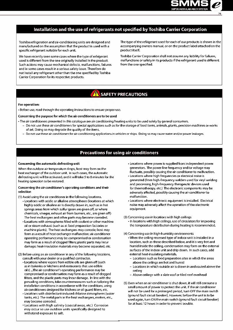
SMMS SUPER MODULAR MULTI SYSTEM &
79
Installation and the use of refrigerants not specified by Toshiba Carrier Corporation
Toshiba refrigeration and air-conditioning units are designed and manufactured on the assumption that the product is used with a specific refrigerant suitable for each unit.
We have recently seen some cases where the type of refrigerant used is different from the one originally installed in the product. Such actions may cause mechanical defects, malfunctions, failures and in some cases result in a serious safety issue. Therefore do not install any refrigerant other than the one specified by Toshiba Carrier Corporation for its respective products.
The type of the refrigerant used for each of our products is shown in the accompanying owners manual, or on the product label attached on the product itself.
Toshiba Carrier Corporation shall not assume any liability for failures, malfunctions or safety in its products if the refrigerant used is different from the one specified.
A SAFETY PRECAUTIONS
For operation: • Before use, read through the operating instructions to ensure proper use.
Concerning the purpose for which the air conditioners are to be used • The air conditioners presented in this catalogue are air conditioning/heating units to be used solely by general consumers.
- Do not use these air conditioners for special applications such as for the storage of food items, animals, plants, precision machines or works of art. Doing so may degrade the quality of the items.
- Do not use these air conditioners for air-conditioning applications in vehicles or ships. Doing so may cause water and/or power leakages.
Precautions for using air conditioners
Concerning the automatic defrosting unit When the outdoor air temperature drops, frost may form on the heat exchanger of the outdoor unit. In such cases, the automatic defrosting unit will be activated, and it will take 5 to 8 minutes for the heating operation to be restored.
Concerning the air conditioner's operating conditions and their selection (1) Avoid using the air conditioner in the following locations.
• Locations with acidic or alkaline atmospheres (locations at which highly acidic or alkaline air is directly drawn in, such as in hot springs areas from which sulfur gases are given off, or where chemicals, vinegar, exhaust air from burners, etc., are given off) The heat exchangers and other parts may become corroded.
• Locations with atmospheres filled with coolant or other machine oil or steam exhaust (such as at food preparation factories or machine plants). The heat exchangers may corrode; frost may form as a result of heat exchanger malfunction; air conditioner operating performance may be compromised or condensation may form as a result of clogged filters; plastic parts may incur damage; heat-insulation materials may become separated, etc.
(2) Before using an air conditioner in any of the following locations, consult with your dealer or a qualified contractor. • Locations where vapors from edible oils are given off (such
as in bakeries or kitchens and restaurants that use edible oils) ...The air conditioner's operating performance may be compromised or condensation may form as a result of clogged filters, and the plastic parts may incur damage. In line with the prevailing conditions, take countermeasures such as tailoring the installation conditions in accordance with the conditions, using air conditioners designed for kitchens or oil guard filters, etc.
• Locations with disinfectant-induced chlorine atmospheres (water tanks, etc.) The metal parts in the heat exchangers, motors, etc., may become corroded.
• Locations with high salinity (coastal areas, etc.) Corrosion may occur so use outdoor units specifically designed to withstand exposure to salt.
• Locations where power is supplied from independent power generators. The power line frequency and/or voltage may fluctuate, possibly causing the air conditioner to malfunction.
• Locations where high frequencies or electrical noise is generated (from high-frequency welders used for vinyl welding and processing, high-frequency therapeutic devices used for thermotherapy, etc.) The electronic components may be adversely affected, possibly causing the air conditioner to malfunction.
• Locations where electronic equipment is installed. Electrical noise may adversely affect the operation of the electronic equipment.
(3) Concerning use in locations with high ceilings • In locations with high ceilings, use of circulators for improving the temperature distribution during heating is recommended.
(4) Concerning use in high-humidity environments • When the ceiling-recessed type of indoor unit is installed in a location, such as those described below, and it is very hot and humid inside the ceiling, condensation may form on the external surfaces of the indoor unit and drip down. In such cases, add external heat-insulating materials. - Locations such as food preparation sites in which the areas
above the ceilings are hot and humid - Locations in which outside air is drawn in and routed above the
ceiling - Above ceilings with a slate roof or tiled roof overhead
(5) Even when an air conditioner is shut down, it will still consume a small amount of power to protect the unit. If the air conditioner will not be used for a prolonged period, turn OFF the main switch (ground fault circuit breaker). However, before the unit is to be used again, turn ON the main switch (ground fault circuit breaker) for at least 12 hours in order to prevent trouble.
ISA
Leading Innovation ^ >H
IS09001 IS014001 TIS18001 OHSAS K-ttlOA
HlFC
Notice : Toshiba is committed to continuously improving its products to ensure the highest quality and reliability standards, and to meet local regulations and market requirements. All features and specifications are subject to change without prior notice.
TOSHIBA CARRIER (THAILAND) CO.,LTD. 144/9 Moo 5, Bangkadi Industrial Park, Tivanon Road,Tambol Bangkadi, Amphur Muang, Pathumthani 12000 T201510C-ASIA/CO